Embed Size (px)
Citation preview
NETYS RT1 1 0 0 - 1 7 0 0 - 2 2 0 0 - 3 3 0 0 V A
Installations- und bedienungsanleitung DE
Installation and operating manual EN
Manual de instalación y uso ES
Asennus- ja käyttöohje FI
Manuel d’installation et d’utilisation FR
Manuale di installazione e uso IT
Прирачник за инсталација и употреба MK Installatie– en bedieningshandleiding NL
Dokumentacja Techniczno-Ruchowa PL
Manual de instalação e funcionamento PT
Руководство по установке и эксплуатации RU
Navodila za priključitev in uporabo SL
Installations- och användarhandbok SV 安装及操作手册 ZH
2 NETYS RT 1.1-3.3 kVA - Ref.: IOMNETRTXX0B-EN 01
This SOCOMEC appliance is guaranteed against manufacturing and material defects for a period of 12 months from the date of purchase (local warranty conditions are applicable in addition to the general conditions). This warranty certificate should NOT be e-mailed, but kept by the customer along with proof of purchase, for use in the event of a claim being made for repairs or replacement under warranty.
The warranty period commences on the date the new product was purchased by the end user at an authorised showroom (reference details are shown on the receipt).
Return-to-base warranty is provided: components and labour for repairs supplied free of charge, any products to be replaced must be returned to SOCOMEC or authorised service centres, at the customer’s own risk and expense.
The warranty is recognized within national territory. If the UPS is exported out of national territory, the warranty shall be limited to the cover of the parts used to repair the fault.
To claim service under the warranty please observe the following:
• The product must be returned in the original packing. Any damage caused during shipping in packaging other than the original will not be covered by the warranty;
• The product must be accompanied by proof of purchase such as an invoice or receipt indicating the date of purchase and prod-uct ID information (model, serial numer). The sender must also attach the reference number issued to authorise the return of the product, together with a detailed description of the defect. If any of this information is missing the warranty will be invalid. The authorisation number is issued by service centres over the telephone on receiving information on the malfunction in question;
• If it is not possible to provide proof of purchase the serial number and date of manufacture will be used to calculate the probable expiry date of the warranty; this could result in a reduction of the original warranty period.
The warranty on the product does not cover damage caused by carelessness (improper use: wrong input power, explosions, exces-sive humidity, temperature, poor ventilation, etc.), tampering or any unauthorised repair work.
During the warranty period, SOCOMEC reserves the right to decide whether the product should be repaired, or whether to replace defective parts with new parts, or used parts that are equivalent to new parts in terms of functionality and performance.
In the case of batteries, warranty is valid only if the battery has been recharged regularly in accordance with the manufacturer’s instructions. On purchasing the product it is advisable to check that the next recharge date indicated on the packaging has not expired.
Battery
• Batteries are treated as consumable parts and warranty only covers manufacturing defects.
• Batteries must be stored in compliance with Supplier recommendations.
• Warranty is valid only if the battery has been recharged regularly in accordance with the manufacturer’s instructions. On purchasing the product it is advisable to check that the next recharge date indicated on the packaging has not expired.
Optionals
A 12-month return-to-base warranty is provided on optionals.
Software products
Software products are guaranteed for 90 days. The software is guaranteed to work as indicated in the manual accompanying the product. Hardware media or accessories (e.g. diskettes, cables, etc.) used with appliances are guaranteed free of material or manufacturing defects under normal conditions of use for a period of 12 months from the date of purchase.
SOCOMEC will not be responsible for damages (including loss of income, interruption of business activity, loss of information or other financial losses, of any nature) arising from the use of the product.
These conditions are subject to Italian law. Disputes shall come under the jurisdiction of Court of Vicenza.
WARRANTY CERTIFICATE AND CONDITIONS
SOCOMEC retains the full and exclusive ownership rights over this document. Only a personal right to utilize the document for the application indicated by SOCOMEC is granted to the recipient of such document. All reproduction, modification, dissemination of this document whether in part or whole and by any manner are expressly prohibited except upon Socomec’s express prior written consent.
This document is not a specification. SOCOMEC reserves the right to make any changes to data without prior notice.
3NETYS RT 1.1-3.3 kVA - Ref.: IOMNETRTXX0B-EN 01
TABLE OF CONTENTS
EN
GL
ISH
1. SAFETY STANDARDS . . . . . . . . . . . . . . . . . . . . . . . . . . . . . . . . . . . . . . . . . . . . . . . . . . . . . . . . . . . . . . .4 1.1 IMPORTANT . . . . . . . . . . . . . . . . . . . . . . . . . . . . . . . . . . . . . . . . . . . . . . . . . . . . . . . . . . . . . .4 1.2 DESCRIPTION OF THE SYMBOLS USED ON THE LABELS APPLIED TO THE UNIT . . . . . . . .5
2. INSTALLATION . . . . . . . . . . . . . . . . . . . . . . . . . . . . . . . . . . . . . . . . . . . . . . . . . . . . . . . . . . . . . . . . . . . .6 2.1 ENVIRONMENTAL . . . . . . . . . . . . . . . . . . . . . . . . . . . . . . . . . . . . . . . . . . . . . . . . . . . . . . . . . .6 2.1 ELECTRICAL . . . . . . . . . . . . . . . . . . . . . . . . . . . . . . . . . . . . . . . . . . . . . . . . . . . . . . . . . . . . .7 2.2 VERTICAL INSTALLATION . . . . . . . . . . . . . . . . . . . . . . . . . . . . . . . . . . . . . . . . . . . . . . . . . . .7 2.3 HORIZONTAL INSTALLATION ON RACK . . . . . . . . . . . . . . . . . . . . . . . . . . . . . . . . . . . . . . . . .9
3. REAR VIEW . . . . . . . . . . . . . . . . . . . . . . . . . . . . . . . . . . . . . . . . . . . . . . . . . . . . . . . . . . . . . . . . . . . . . .12
4. CONNECTIONS . . . . . . . . . . . . . . . . . . . . . . . . . . . . . . . . . . . . . . . . . . . . . . . . . . . . . . . . . . . . . . . . . . .13
5. CONNECTION OF BATTERY EXTENSION . . . . . . . . . . . . . . . . . . . . . . . . . . . . . . . . . . . . . . . . . . . . . . .14 5.1 SAFETY WARNINGS . . . . . . . . . . . . . . . . . . . . . . . . . . . . . . . . . . . . . . . . . . . . . . . . . . . . . . .14 5.2 CONNECTION OF BATTERY EXTENSION . . . . . . . . . . . . . . . . . . . . . . . . . . . . . . . . . . . . . . .14
6. MIMIC PANEL . . . . . . . . . . . . . . . . . . . . . . . . . . . . . . . . . . . . . . . . . . . . . . . . . . . . . . . . . . . . . . . . . . . .16
7. OPERATING MODES . . . . . . . . . . . . . . . . . . . . . . . . . . . . . . . . . . . . . . . . . . . . . . . . . . . . . . . . . . . . . . .17 7.1 BATTERY RECHARGE . . . . . . . . . . . . . . . . . . . . . . . . . . . . . . . . . . . . . . . . . . . . . . . . . . . . . .17 7.2 SWITCHING THE NETYS RT ON AND OFF . . . . . . . . . . . . . . . . . . . . . . . . . . . . . . . . . . . . . .17 7.3 BATTERY TEST . . . . . . . . . . . . . . . . . . . . . . . . . . . . . . . . . . . . . . . . . . . . . . . . . . . . . . . . . . .18 8. VISUAL AND AUDIBLE WARNING SIGNALS . . . . . . . . . . . . . . . . . . . . . . . . . . . . . . . . . . . . . . . . . . . . .19
9. SETTINGS . . . . . . . . . . . . . . . . . . . . . . . . . . . . . . . . . . . . . . . . . . . . . . . . . . . . . . . . . . . . . . . . . . . . . . .20 9.1 SETTING MENU . . . . . . . . . . . . . . . . . . . . . . . . . . . . . . . . . . . . . . . . . . . . . . . . . . . . . . . . . .20 9.2 SETTINGS . . . . . . . . . . . . . . . . . . . . . . . . . . . . . . . . . . . . . . . . . . . . . . . . . . . . . . . . . . . . . . .20
10. COMMUNICATION . . . . . . . . . . . . . . . . . . . . . . . . . . . . . . . . . . . . . . . . . . . . . . . . . . . . . . . . . . . . . . . .22 10.1 COMMUNICATION SOLUTIONS . . . . . . . . . . . . . . . . . . . . . . . . . . . . . . . . . . . . . . . . . . . . .22 10.2 USB INTERFACE . . . . . . . . . . . . . . . . . . . . . . . . . . . . . . . . . . . . . . . . . . . . . . . . . . . . . . . . .22 10.3 RS232 INTERFACE . . . . . . . . . . . . . . . . . . . . . . . . . . . . . . . . . . . . . . . . . . . . . . . . . . . . . . .22 10.4 EPO PORT . . . . . . . . . . . . . . . . . . . . . . . . . . . . . . . . . . . . . . . . . . . . . . . . . . . . . . . . . . . . .22 10.5 WEB/SNMP CARD (OPTION) . . . . . . . . . . . . . . . . . . . . . . . . . . . . . . . . . . . . . . . . . . . . . . .22 10.6 USE OF WARNING RELAY INTERFACE . . . . . . . . . . . . . . . . . . . . . . . . . . . . . . . . . . . . . . . .22
11. MAINTENANCE . . . . . . . . . . . . . . . . . . . . . . . . . . . . . . . . . . . . . . . . . . . . . . . . . . . . . . . . . . . . . . . . . .25 11.1 MINOR TROUBLESHOOTING . . . . . . . . . . . . . . . . . . . . . . . . . . . . . . . . . . . . . . . . . . . . . . .25
12. TECHNICAL SPECIFICATIONS . . . . . . . . . . . . . . . . . . . . . . . . . . . . . . . . . . . . . . . . . . . . . . . . . . . . . .26
4 NETYS RT 1.1-3.3 kVA - Ref.: IOMNETRTXX0B-EN 01
1. SAFETY STANDARDS
1.1 IMPORTANT
This manual should be kept in a safe place near the UPS, so it can be consulted by the operator at any time for information that may be needed regarding correct use of the unit. Read the manual carefully before connecting the unit to the a.c. mains supply and the downstream appliances. Before the UPS is put into commission the user should be completely familiar with its operation, the position of all the controls and the technical and functional characteristics of the unit, so as to ensure there will be no risk to people or the appliance itself.
WARNING!This is a product for commercial and industrial applications in an industrial environment – installation restrictions or additional measures may be needed to prevent electro-magnetic interferences.
• The product you have chosen is designed for commercial and industrial use only.In order to be used for particular “critical applications” such as life support systems, medical applications, commercial transportation, nuclear facilities or any other application or systems where product failure is likely to cause substantial harms to person or property, the products might require compliance with statutory regulations and standards, specific local by-laws and be adapted accordingly.For such uses we would advise you to contact SOCOMEC UPS beforehand to confirm the ability of these products to meet the requested level of safety, performance, reliability and compliance with applicable laws, regulations and specifications.
• Use the UPS in accordance with the technical specifications indicated in this manual.
• To meet Emergency Switch Device (ESD) operating requirements, a specific input with remote ESD/EPO function is available.
DANGER!
To avoid dangerous electric-shock, the UPS must be powered using a socket with protective earth connection. It is manda-tory the use of the provided cable (ref. - CONNECTIONS).
• This earth connection will assure also the safety bonding for the appliances powered by the UPS. The manufacturer declines all liability for any damage or accidents that could result from failure to observe the requirements.
• Should a power outage occur, do not disconnect the power cord from the mains, since this will cut the earth connection, both for the UPS and the appliances.
• The UPS generates a leakage current of approximately 3 mA. Ensure the leakage current generated by the load is no greater than 0.5 mA in order to be compliant with the safety standard. Should the leakage current from the load exceed this limit, directly connect the UPS PE connection to the ground system.
• If a hazardous situation should arise at any time when the UPS is in use, isolate the unit from the power supply (by operating a switch at the upstream PDU if possible) and switch the appliance off completely by running the shutdown procedure.
• The UPS houses a source of electrical energy, i.e. its batteries. The output of the UPS may be powered even when the appliance is not connected to the a.c. mains supply.
• All maintenance operations must only be performed by authorised service engineers. The UPS generates high internal voltages that could be hazardous for a maintenance operative not in possession of the appropriate skills and training for this type of work.
• Never force, break or attempt to open the batteries. These batteries are sealed, maintenance-free components containing substances that are harmful to health and a source of environmental pollution. If liquid can be seen leaking from the battery, or a white powdery residue is noticeable, do not switch the UPS on.
• Avoid exposing the UPS to contact with water or any liquids generally. Do not insert foreign objects into the cabinet.
• Danger of explosion if the batteries are replaced with others of the wrong type.
• Replaced batteries must be disposed of at authorised waste disposal centres.
5NETYS RT 1.1-3.3 kVA - Ref.: IOMNETRTXX0B-EN 01
EN
GL
ISH
1. SAFETY STANDARDS
It is very dangerous to touch any part of the batteries as there is no insulation between the batteries and the mainspower source.
CAUTION!A battery can present a risk of electrical shock and high short circuit current.
• If the appliance is to be disposed off it should only be entrusted to a specialist waste disposal company. These companies will dismantle and dispose of the various components in accordance with statutory regulations in the country of purchase.
CAUTION IF DAMAGEDNON-SPILLABLE BATTERIESTorn, crushed or damaged packaging which exposes the contents should be set aside in an isolated area and inspected by a qualified person. If the package cannot be shipped the contents must be promptly collected, segre-gated, and either the sender or recipient contacted.
All packaging material must be recycled in compliance with the laws in force in the country where the system is installed.
1.2 DESCRIPTION OF THE SYMBOLS
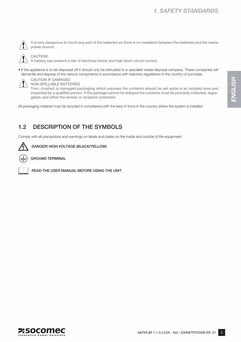
Comply with all precautions and warnings on labels and plates on the inside and outside of the equipment.
DANGER! HIGH VOLTAGE (BLACK/YELLOW)
GROUND TERMINAL
READ THE USER MANUAL BEFORE USING THE UNIT
6 NETYS RT 1.1-3.3 kVA - Ref.: IOMNETRTXX0B-EN 01
2. REQUIREMENTS FOR INSTALLATION
Consult the following check list when installing the UPS:
2.1 ENVIRONMENTAL
• NETYS RT units are designed for use in enclosed environments.
• Position the UPS on a flat and stable surface in a properly ventilated room, well away from heat sources and avoiding direct exposure to sunlight.
• Check that the UPS will not be installed in a dust-laden environment.
• Do not install the UPS system near water or in damp environments.
• Condensation may occur if the UPS system is moved directly from a cold to a warm environment. The UPS system must becompletely dry before being installed. Please allow at least two hours for the UPS system to become acclimatised to the environ-ment.
• Ambient temperature should be maintained between 0 °C and 40 °C, and relative humidity below 90% (without condensation);the optimum temperature in terms of maximizing battery life is 15-20 °C.
• Be certain that a clearance of at least 15 cm is left on front and back sides of the unit to ensure adequate ventilation and provideaccess to the rear panel.
• Take care not to stand the UPS or any other heavy object on cables.
2.2 ELECTRICAL
• Check that the operating voltage and frequency settings are correct for the mains power supply at the installation site. Details for the UPS will be found on the data plate affixed to the rear panel.
• The mains supply socket must be protected by a 30 mA type A residual current circuit breaker.
• The UPS when connected to the mains socket, do not modify the neutral system
• Ensure there is a reliable earth connection.
• Connect the UPS system to an earthed shockproof outlet only, which is easily accessible and close to the UPS system.
• Ensure external battery sources are earthed.
• When making the RS232 serial connection, use only the cables and accessories supplied.
• Do not connect appliances or devices which would overload the UPS system (e.g. laser printers) to the UPS output sockets.
• When the UPS is first used, it is advisable to leave the battery on charge for a minimum of 8 hours.
PRECAUTIONS IN THE EVENT OF DAMAGE
DO NOT OVERTURN THE BATTERIES.
Packing materials that have been broken, punctured or torn in such a way as to reveal the contents must be kept separate in a secure area, and inspected by skilled staff. Any packing considered unsuitable for shipment of the contents must be set aside immediately and kept secure, and the sender or recipient contacted.
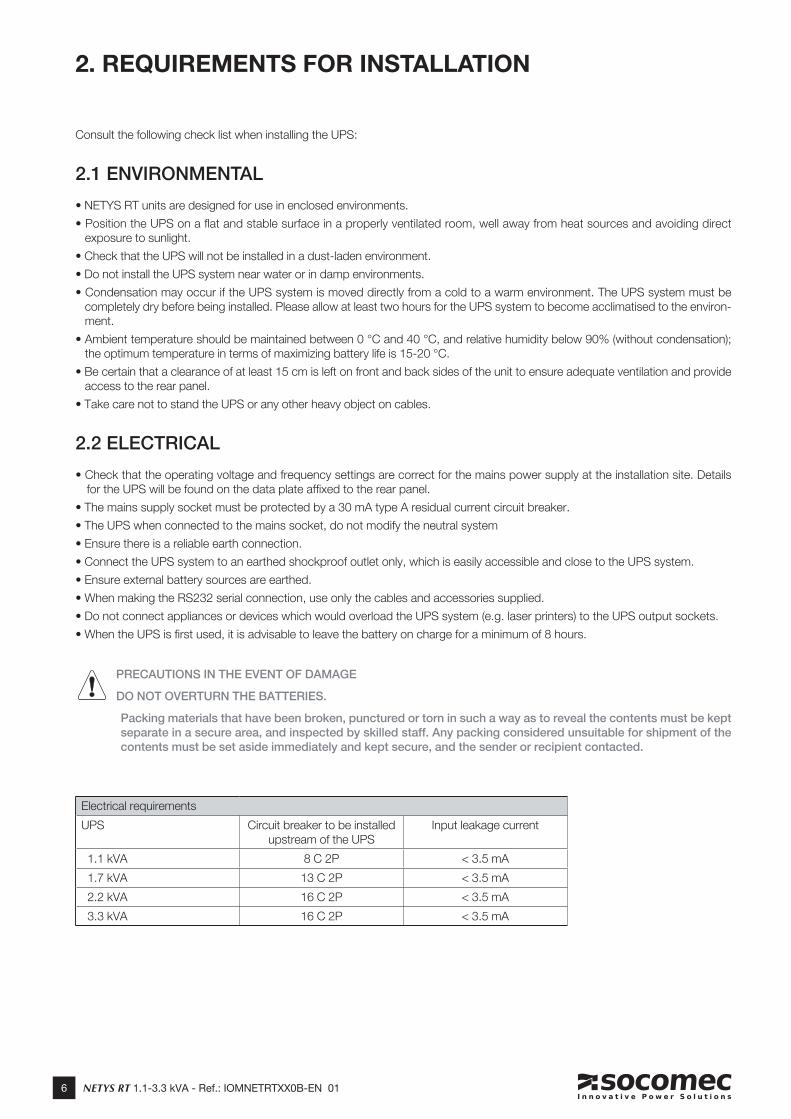
Electrical requirements
UPS Circuit breaker to be installed upstream of the UPS
Input leakage current
1.1 kVA 8 C 2P < 3.5 mA
1.7 kVA 13 C 2P < 3.5 mA
2.2 kVA 16 C 2P < 3.5 mA
3.3 kVA 16 C 2P < 3.5 mA
7NETYS RT 1.1-3.3 kVA - Ref.: IOMNETRTXX0B-EN 01
EN
GL
ISH
=
=189 D
RW
NE
TR
T2-X
X
2. INSTALLATION
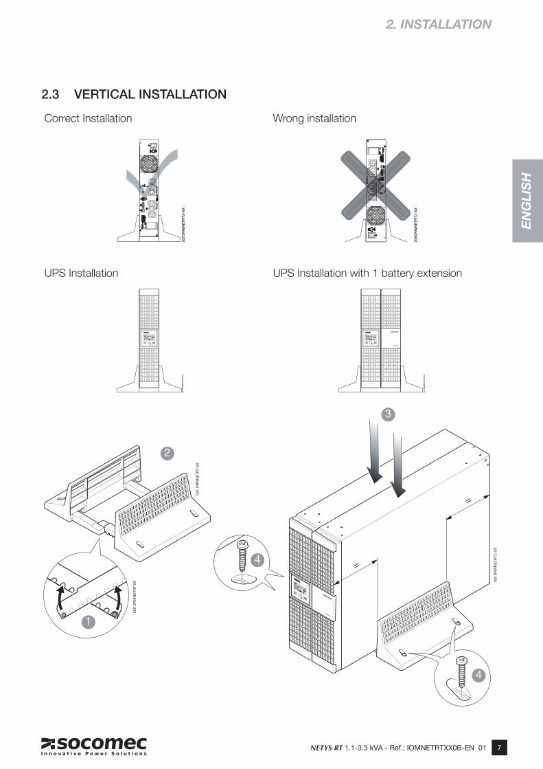
2.3 VERTICAL INSTALLATION
4
4
2
1
3
031
DR
WN
ETR
T-X
X
059
DR
WN
ETR
T-X
X
208D
RW
NE
TR
T2-X
X
207D
RW
NE
TR
T2-X
X0
26
DR
WN
ET
RT
2-X
X
02
7 D
RW
NE
TR
T2
-XX
UPS Installation with 1 battery extension UPS Installation
Wrong installation Correct Installation
8 NETYS RT 1.1-3.3 kVA - Ref.: IOMNETRTXX0B-EN 01
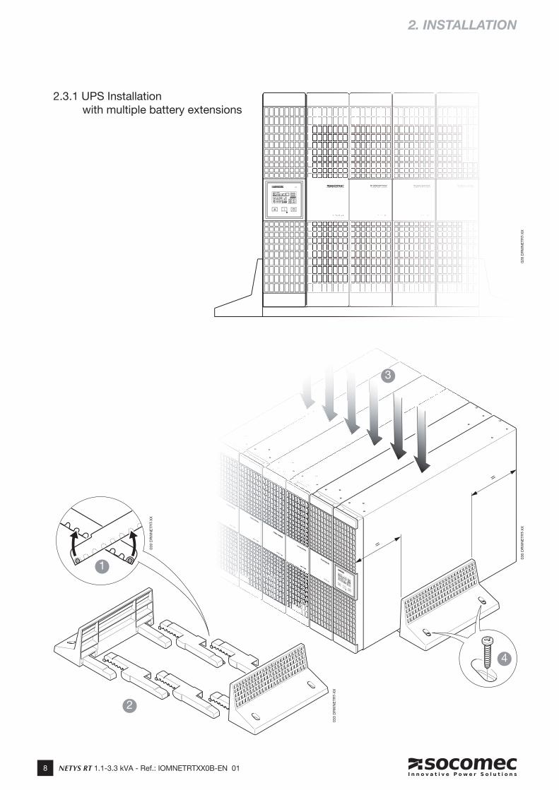
2.3.1 UPS Installation with multiple battery extensions
2. INSTALLATION
=
=
4
2
1
3
036
DR
WN
ETR
T-X
X
033
DR
WN
ETR
T-X
X
059
DR
WN
ETR
T-X
X
028
DR
WN
ETR
T-X
X
9NETYS RT 1.1-3.3 kVA - Ref.: IOMNETRTXX0B-EN 01
EN
GL
ISH
2. INSTALLATION
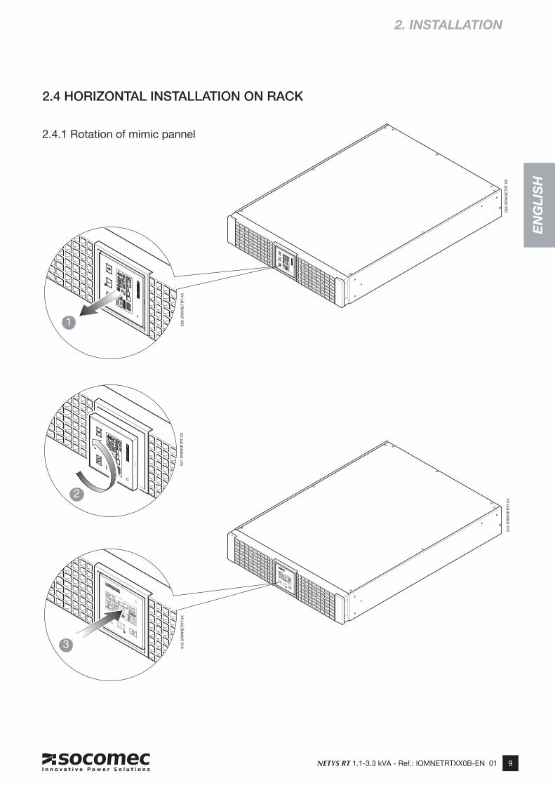
2.4 HORIZONTAL INSTALLATION ON RACK
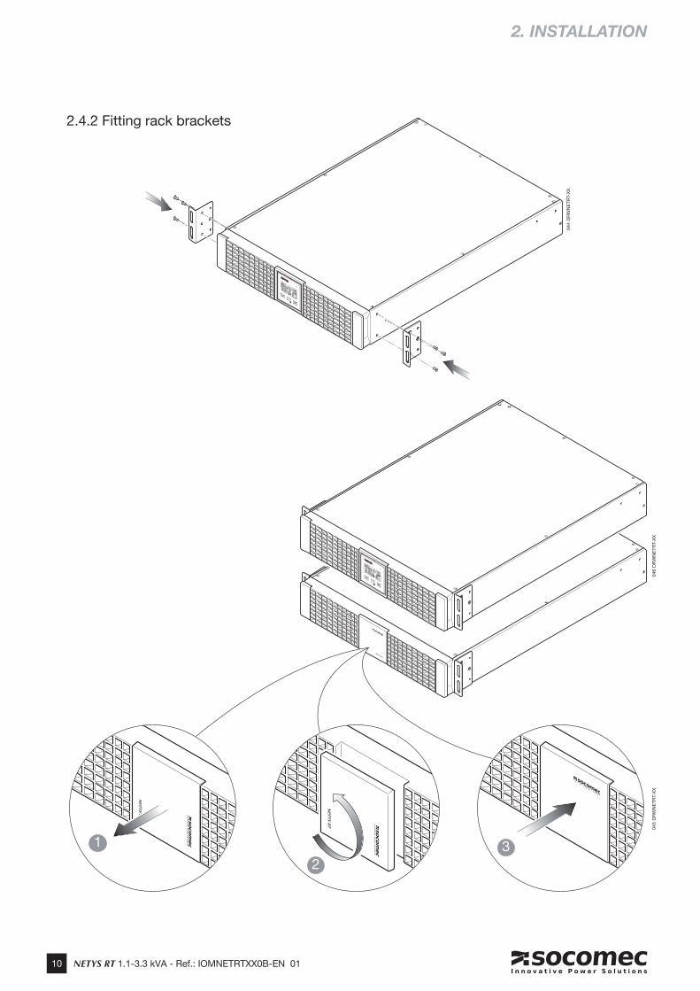
2.4.1 Rotation of mimic pannel
038
DR
WN
ETR
T-X
X04
3 D
RW
NE
TRT-
XX
042
DR
WN
ETR
T-X
X04
1 D
RW
NE
TRT-
XX
039
DR
WN
ETR
T-X
X
1
2
3
10 NETYS RT 1.1-3.3 kVA - Ref.: IOMNETRTXX0B-EN 01
2.4.2 Fitting rack brackets
2. INSTALLATION
044
DR
WN
ETR
T-X
X
046
DR
WN
ETR
T-X
X
1
23
045
DR
WN
ETR
T-X
X
11NETYS RT 1.1-3.3 kVA - Ref.: IOMNETRTXX0B-EN 01
EN
GL
ISH
2. INSTALLATION
MAX 100 kgMAX 100 kg
MAX 100 kgMAX 100 kg
3
3
4
060
DR
WN
ETR
T-X
X
047
DR
WN
ETR
T-X
X
061
DR
WN
ETR
T-X
X
2
1
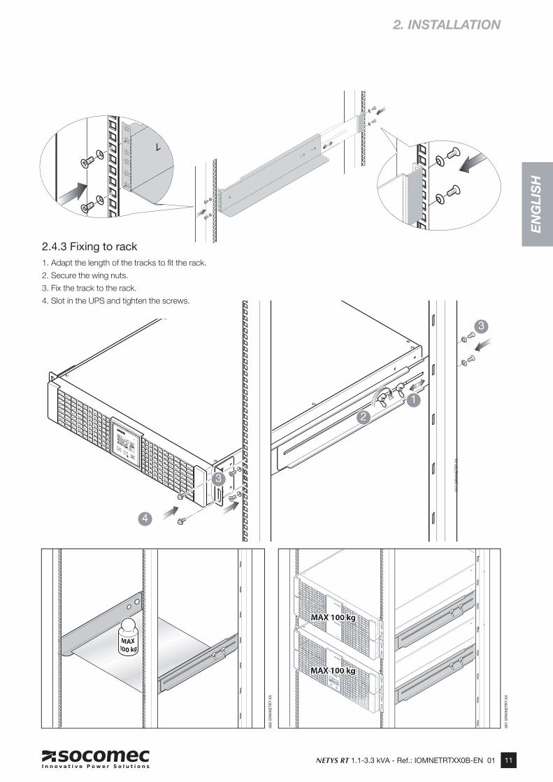
2.4.3 Fixing to rack1. Adapt the length of the tracks to fit the rack.
2. Secure the wing nuts.
3. Fix the track to the rack.
4. Slot in the UPS and tighten the screws.
12 NETYS RT 1.1-3.3 kVA - Ref.: IOMNETRTXX0B-EN 01
3. REAR VIEW
1100 VA 3300 VA1700 VA2200 VA
E
D
B
C
F
L
M
N
H
GA
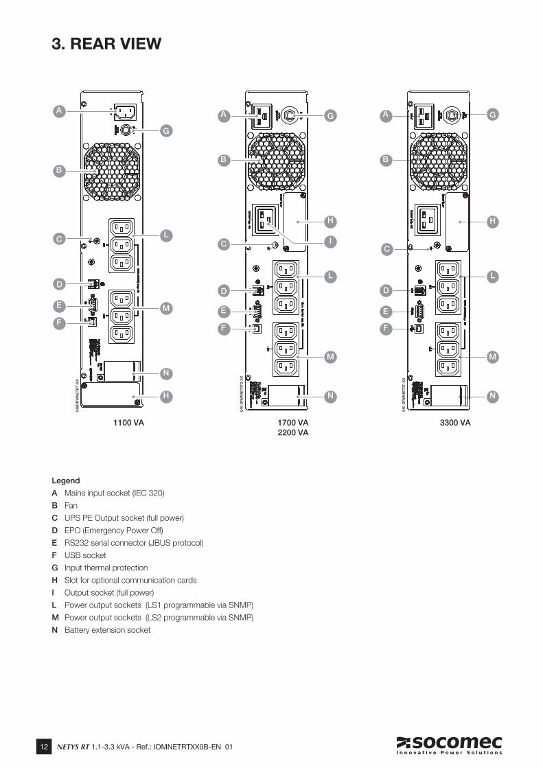
Legend
A Mains input socket (IEC 320)
B Fan
C UPS PE Output socket (full power)
D EPO (Emergency Power Off)
E RS232 serial connector (JBUS protocol)
F USB socket
G Input thermal protection
H Slot for optional communication cards
I Output socket (full power)
L Power output sockets (LS1 programmable via SNMP)
M Power output sockets (LS2 programmable via SNMP)
N Battery extension socket
048D
RW
NE
TR
T-X
X
049 D
RW
NE
TR
T2-X
X
040 D
RW
NE
TR
T-X
X
M
F
E
N
B
C
H
GA
I
L
D
B
A
C
G
L
D
E
F
M
H
N
13NETYS RT 1.1-3.3 kVA - Ref.: IOMNETRTXX0B-EN 01
EN
GL
ISH
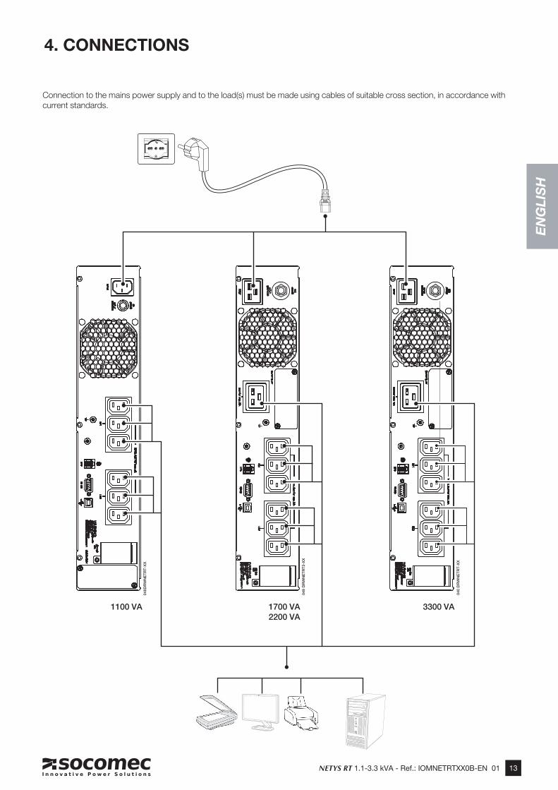
Connection to the mains power supply and to the load(s) must be made using cables of suitable cross section, in accordance with current standards.
4. CONNECTIONS
1100 VA 3300 VA1700 VA2200 VA
048D
RW
NE
TR
T-X
X
049 D
RW
NE
TR
T2-X
X
040 D
RW
NE
TR
T-X
X
14 NETYS RT 1.1-3.3 kVA - Ref.: IOMNETRTXX0B-EN 01
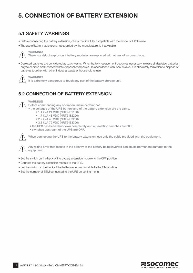
5.1 SAFETY WARNINGS
• Before connecting the battery extension, check that it is fully compatible with the model of UPS in use.
• The use of battery extensions not supplied by the manufacturer is inadvisable.
WARNING!There is a risk of explosion if battery modules are replaced with others of incorrect type.
• Depleted batteries are considered as toxic waste. When battery replacement becomes necessary, release all depleted batteries only to certified and licensed waste disposal companies. In accordance with local bylaws, it is absolutely forbidden to dispose of batteries together with other industrial waste or household refuse.
WARNING!It is extremely dangerous to touch any part of the battery storage unit.
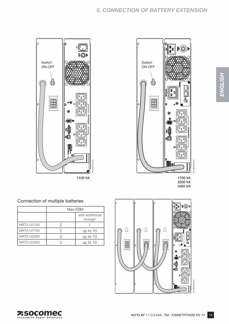
5.2 CONNECTION OF BATTERY EXTENSION
WARNING!Before commencing any operation, make certain that:• the voltages of the UPS battery and of the battery extension are the same,
• 1.1 kVA 24 VDC (NRT2-B1100) • 1.7 kVA 48 VDC (NRT2-B2200) • 2.2 kVA 48 VDC (NRT2-B2200) • 3.3 kVA 72 VDC (NRT2-B3300) • the UPS has been shut down completely and all isolation switches are OFF; • switches upstream of the UPS are OFF.
When connecting the UPS to the battery extension, use only the cable provided with the equipment.
Any wiring error that results in the polarity of the battery being inverted can cause permanent damage to the equipment.
• Set the switch on the back of the battery extension module to the OFF position.
• Connect the battery extension module to the UPS.
• Set the switch on the back of the battery extension module to the ON position.
• Set the number of EBM connected to the UPS on setting menu.
5. CONNECTION OF BATTERY EXTENSION
15NETYS RT 1.1-3.3 kVA - Ref.: IOMNETRTXX0B-EN 01
EN
GL
ISH
5. CONNECTION OF BATTERY EXTENSION
1100 VA 1700 VA2200 VA3300 VA
Connection of multiple batteries
Max EBM
with additional charger
NRT2-U1100 2 /NRT2-U1700 2 up to 10NRT2-U2200 2 up to 10NRT2-U3300 2 up to 10
SwitchON-OFF
SwitchON-OFF
052
DR
WN
ETR
T-X
X
053
DR
WN
ETR
T-X
X05
4 D
RW
NE
TRT-
XX
16 NETYS RT 1.1-3.3 kVA - Ref.: IOMNETRTXX0B-EN 01
001 D
RW
NE
TR
T-X
X
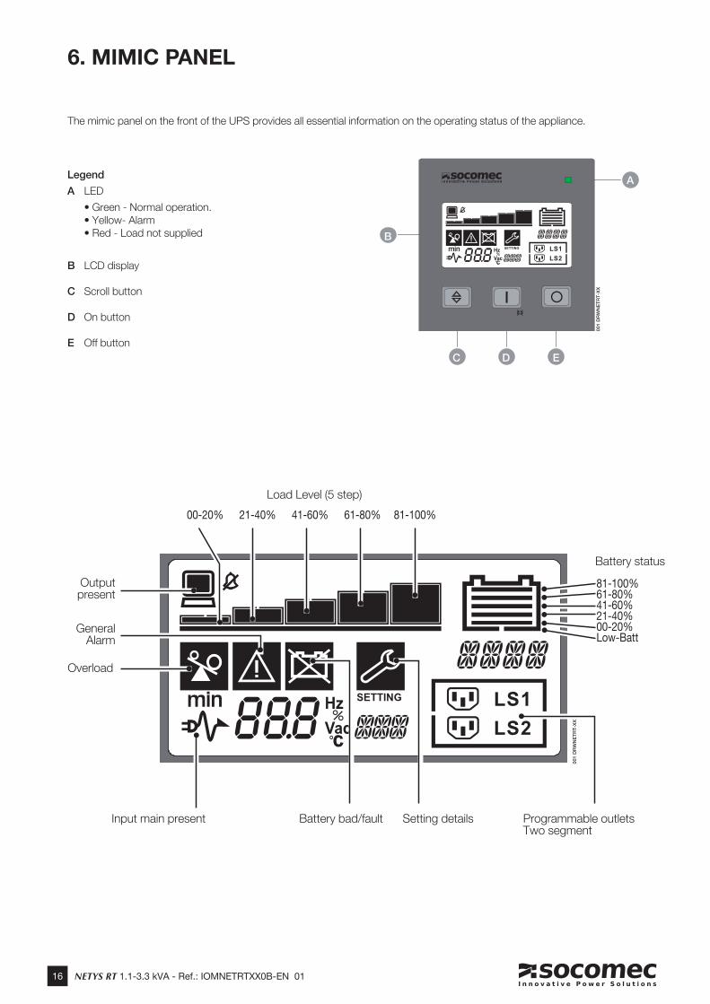
The mimic panel on the front of the UPS provides all essential information on the operating status of the appliance.
6. MIMIC PANEL
E
A
B
Legend
A LED
• Green - Normal operation. • Yellow- Alarm • Red - Load not supplied
B LCD display
C Scroll button
D On button
E Off buttonDC
Output present
Load Level (5 step)
Battery status
Overload
General Alarm
Battery bad/fault Input main present Setting details Programmable outlets Two segment
001 D
RW
NE
TR
T-X
X
81-100%61-80%41-60%21-40%00-20%Low-Batt
81-100%21-40% 41-60% 61-80%00-20%
17NETYS RT 1.1-3.3 kVA - Ref.: IOMNETRTXX0B-EN 01
EN
GL
ISH
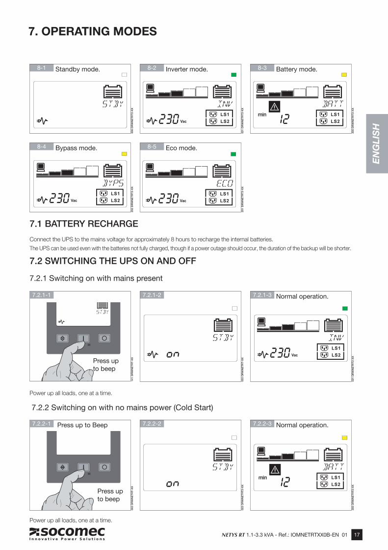
7.1 BATTERY RECHARGE
Connect the UPS to the mains voltage for approximately 8 hours to recharge the internal batteries.
The UPS can be used even with the batteries not fully charged, though if a power outage should occur, the duration of the backup will be shorter.
7. OPERATING MODES
7.2.1-2
7.2.2-2
7.2.1-3 Normal operation.
7.2 SWITCHING THE UPS ON AND OFF
7.2.1 Switching on with mains present
7.2.2 Switching on with no mains power (Cold Start)
Power up all loads, one at a time.
Power up all loads, one at a time.
7.2.2-3 Normal operation.
8-1 Standby mode.
8-4 Bypass mode.
8-2 Inverter mode.
8-5 Eco mode.
8-3 Battery mode.
201 D
RW
NE
TR
T2-X
X
202 D
RW
NE
TR
T2-X
X
021 D
RW
NE
TR
T2-X
X
006 D
RW
NE
TR
T2-X
X
200 D
RW
NE
TR
T2-X
X
022 D
RW
NE
TR
T2-X
X003 D
RW
NE
TR
T-X
X
021 D
RW
NE
TR
T2-X
X200 D
RW
NE
TR
T2-X
X
002 D
RW
NE
TR
T-X
X141 D
RW
NE
TR
T-X
X
7.2.1-1
7.2.2-1 Press up to Beep
Press up to beep
Press up to beep
18 NETYS RT 1.1-3.3 kVA - Ref.: IOMNETRTXX0B-EN 01
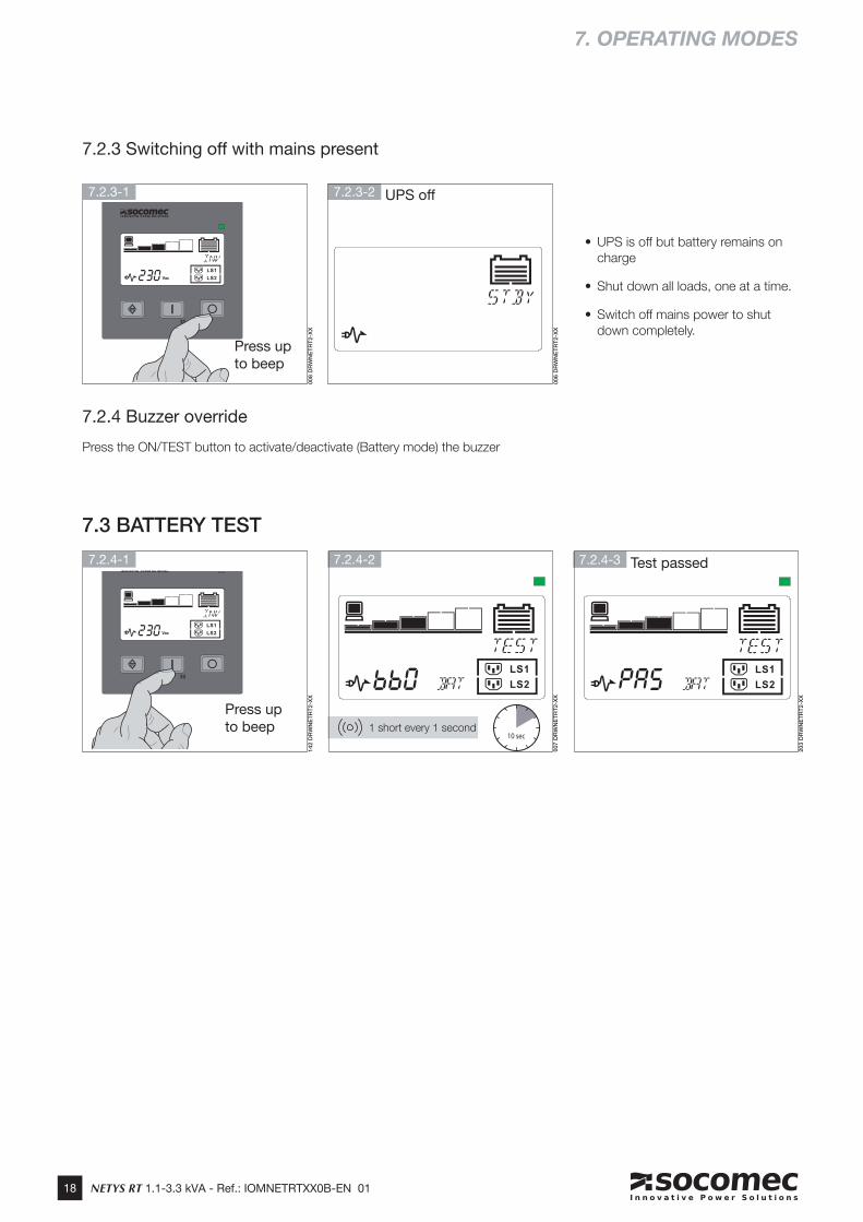
7.2.3 Switching off with mains present
7.3 BATTERY TEST
7.2.4 Buzzer override
Press the ON/TEST button to activate/deactivate (Battery mode) the buzzer
7. OPERATING MODES
• UPS is off but battery remains on charge
• Shut down all loads, one at a time.
• Switch off mains power to shut down completely.
10 sec
7.2.3-2 UPS off
7.2.4-2
1 short every 1 second
7.2.4-3 Test passed
203 D
RW
NE
TR
T2-X
X
142 D
RW
NE
TR
T2-X
X
007 D
RW
NE
TR
T2-X
X006 D
RW
NE
TR
T2-X
X
008 D
RW
NE
TR
T2-X
X
7.2.3-1
7.2.4-1
Press up to beep
Press up to beep
EN
GL
ISH
19NETYS RT 1.1-3.3 kVA - Ref.: IOMNETRTXX0B-EN 01
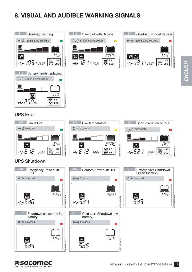
8. VISUAL AND AUDIBLE WARNING SIGNALS
5 second continuous
1 Short every seconds
8-6 Overtemperature.
8-4 Battery needs replacing.
8-1 Overload warning.
8-7 Short-circuit on output.8-5 Fan failure.
8-11 Shutdown caused by fl at battery.
1 Short every seconds
5 second
1 Short every seconds
8-2 Overload with Bypass
1 Short every seconds
8-3 Overload without Bypass
021 D
RW
NE
TR
T2-X
X
011 D
RW
NE
TR
T2-X
X
014 D
RW
NE
TR
T2-X
X
204 D
RW
NE
TR
T2-X
X
023 D
RW
NE
TR
T2-X
X019 D
RW
NE
TR
T2-X
X
023 D
RW
NE
TR
T2-X
X010 D
RW
NE
TR
T2-X
X
8-8 Emergency Power Off EPO.
014 D
RW
NE
TR
T2-X
X
8-9 Remote Power Off RPO.
014 D
RW
NE
TR
T2-X
X
8-10 Battery save Shutdown Green function.
014 D
RW
NE
TR
T2-X
X
8-12 Cold start Shutdown low battery.
014 D
RW
NE
TR
T2-X
X
5 second 5 second 5 second
5 second 5 second
UPS Shutdown
UPS Error
20 NETYS RT 1.1-3.3 kVA - Ref.: IOMNETRTXX0B-EN 01
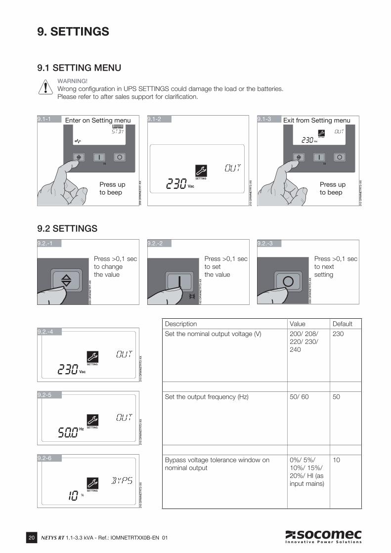
9. SETTINGS
210 D
RW
NE
TR
T2-X
X
9.1-1 Enter on Setting menu 9.1-2
9.1 SETTING MENU
210 D
RW
NE
TR
T2-X
X
9.2.-4
210 D
RW
NE
TR
T2-X
X
9.2-5
210 D
RW
NE
TR
T2-X
X
9.2-6
9.2 SETTINGS
Description Value Default
Set the nominal output voltage (V) 200/ 208/ 220/ 230/ 240
230
Set the output frequency (Hz) 50/ 60 50
Bypass voltage tolerance window on nominal output
0%/ 5%/ 10%/ 15%/ 20%/ HI (as input mains)
10
9.2.-1 9.2.-2
Press >0,1 sec to set the value
Press >0,1 sec to change the value
9.2.-3
Press >0,1 sec to nextsetting
9.1-3 Exit from Setting menu
209 D
RW
NE
TR
T-X
X
142 D
RW
NE
TR
T2-X
X
008 D
RW
NE
TR
T2-X
X
WARNING!
Wrong configuration in UPS SETTINGS could damage the load or the batteries. Please refer to after sales support for clarification.
209 D
RW
NE
TR
T-X
X
212 D
RW
NE
TR
T2-X
X
Press up to beep
Press up to beep
21NETYS RT 1.1-3.3 kVA - Ref.: IOMNETRTXX0B-EN 01
EN
GL
ISH
9. SETTINGS
210 D
RW
NE
TR
T2-X
X
9.2-8
210 D
RW
NE
TR
T2-X
X
9.2-9
210 D
RW
NE
TR
T2-X
X
9.2-10
210 D
RW
NE
TR
T2-X
X
9.2-11
210 D
RW
NE
TR
T2-X
X
9.2-12
210 D
RW
NE
TR
T2-X
X
9.2-13
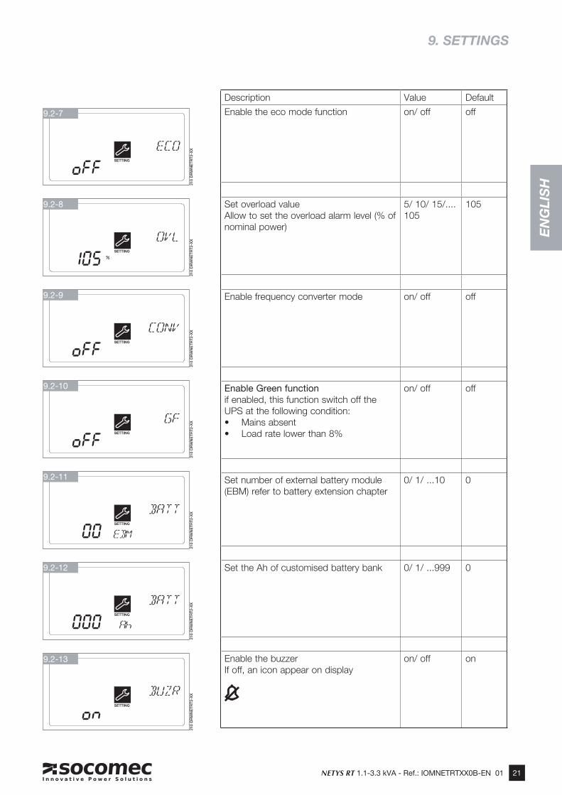
Description Value Default
Enable the eco mode function on/ off off
Set overload valueAllow to set the overload alarm level (% of nominal power)
5/ 10/ 15/.... 105
105
Enable frequency converter mode on/ off off
Enable Green functionif enabled, this function switch off the UPS at the following condition:• Mains absent • Load rate lower than 8%
on/ off off
Set number of external battery module (EBM) refer to battery extension chapter
0/ 1/ ...10 0
Set the Ah of customised battery bank 0/ 1/ ...999 0
Enable the buzzerIf off, an icon appear on display
on/ off on
210 D
RW
NE
TR
T2-X
X
9.2-7
22 NETYS RT 1.1-3.3 kVA - Ref.: IOMNETRTXX0B-EN 01
Communication software and accessories are available for monitoring the status of the UPS, with the end in view of optimizing normal operation and ensuring that shutdown at the end of backup time is managed correctly. Applications allow recording of all power outages and any depletion of battery power so as to enable the activation of an automatic procedure for closing programs in ordered sequence and shutting down the system.
NETYS RT no-break systems are equipped with RS232 and USB serial communication interfaces, and slots for Web/SNMP cards.
10.1 COMMUNICATION SOLUTIONS
• Local View ideal UPS monitoring and shutdown point-to-point solution for Windows®, Linux® and Mac OS X® operating systems.
• Web/SNMP manager (Web/SNMP slot card) allowing control via LAN using TCP/IP protocol, and remote shutdown management.
• BMS (JBUS-RS232 interface), allows the UPS to interface with a Building Management system.
10.2 USB INTERFACE
The UPS can communicate with the server direct by way of the USB interface using HID protocol, if available on the computer operating system, without the need to install any additional software. Once connected, recognition of the UPS occurs in the same way as for any other peripheral, and the operating parameters can be managed by way of the OS service menu. Use the connect-ing cable provided.
10.3 RS232 INTERFACE
This interface is required to run Local View ideal UPS monitoring and shutdown point-to-point solution for Windows®, Linux® and
Mac OS X® operating systems.
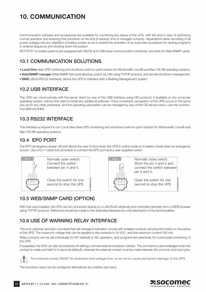
10.4 EPO PORTThe EPO (emergency power off) port allows the user to shut down the UPS in online mode or in battery mode when an emergency occurs. Use a RJ11 cable (not provided) to connect the EPO port and a user-supplied switch.
10. COMMUNICATION
4-2 4-1
10.5 WEB/SNMP CARD (OPTION)
With this card installed, the UPS can be connected directly to a LAN (RJ45 ethernet) and controlled remotely from a WEB browser using TCP/IP protocol. Reference should be made to the dedicated literature for a full description of the functionalities.
10.6 USE OF WARNING RELAY INTERFACE
This is an optional card (slot-mounted) that will manage 6 indication circuits with isolated contacts carrying information on the status of the UPS. The maximum voltage that can be applied to the contacts is 24 VDC, and the maximum current 500 mA.
Relay contacts can be set individually for NO (default) or NC operation, and programmed selectively for customized monitoring of the UPS.
If requested, the UPS can also be switched off utilizing a remote external shutdown contact. The command is acknowledged when the contact is made and held for 3 seconds (default), whereas the external contact must be made between the common and input pins.
The external contact MUST be dedicated and voltage-free, so as not to cause permanent damage to the UPS.
The shutdown input can be configured alternatively as a battery test input.
1 2 3 4 5 6
213 D
RW
NE
TR
T2-X
X
1 2 3 4 5 6
213 D
RW
NE
TR
T2-X
X
Normally open switch. Connect the switch between pin 4 and 5.
Close the switch for one second to stop the UPS
Normally close switch. Short the pin 4 and 5 and connect the switch between pin 3 and 4.
Open the switch for one second to stop the UPS
23NETYS RT 1.1-3.3 kVA - Ref.: IOMNETRTXX0B-EN 01
EN
GL
ISH
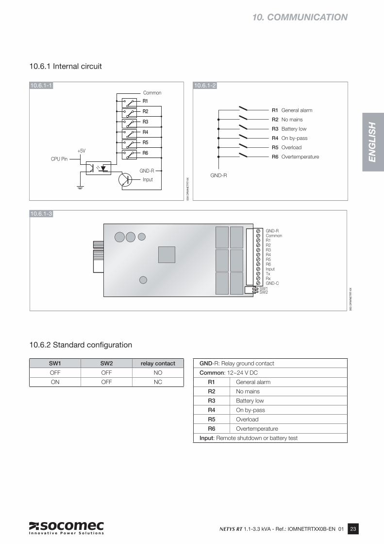
10.6.1 Internal circuit
10.6.2 Standard confi guration
10. COMMUNICATION
R1
R2
R3
R4
R5
Common
GND-R
Input
+5V
CPU PinR6
GND-RCommonR1R2R3R4R5R6InputTxRxGND-C
SW1SW2
GND-R
R1 General alarm
R2 No mains
R3 Battery low
R4 On by-pass
R5 Overload
R6 Overtemperature
10.6.1-1
10.6.1-3
10.6.1-2
SW1 SW2 relay contact
OFF OFF NO
ON OFF NC
GND-R: Relay ground contact
Common: 12~24 V DC
R1 General alarm
R2 No mains
R3 Battery low
R4 On by-pass
R5 Overload
R6 Overtemperature
Input: Remote shutdown or battery test
058
DR
WN
ETR
T-X
X
063
DR
WN
ETR
T-X
X
24 NETYS RT 1.1-3.3 kVA - Ref.: IOMNETRTXX0B-EN 01
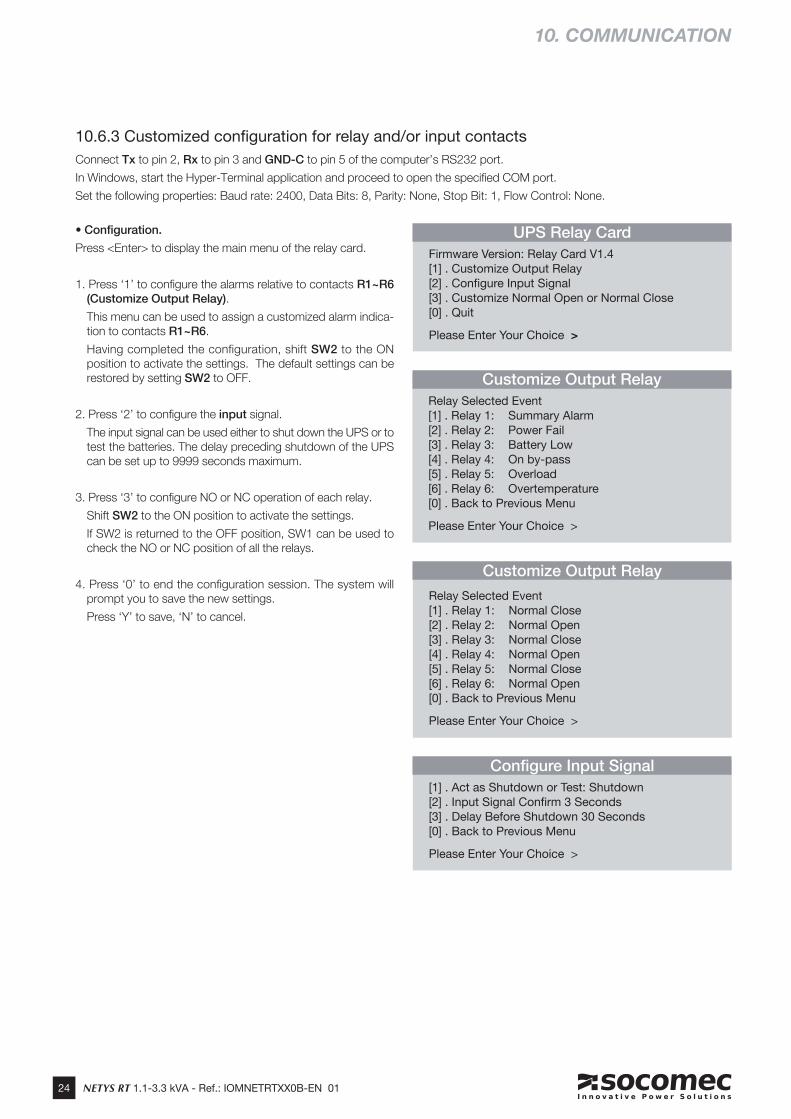
10.6.3 Customized confi guration for relay and/or input contactsConnect Tx to pin 2, Rx to pin 3 and GND-C to pin 5 of the computer’s RS232 port.
In Windows, start the Hyper-Terminal application and proceed to open the specified COM port.
Set the following properties: Baud rate: 2400, Data Bits: 8, Parity: None, Stop Bit: 1, Flow Control: None.
10. COMMUNICATION
• Configuration.
Press <Enter> to display the main menu of the relay card.
1. Press ‘1’ to configure the alarms relative to contacts R1~R6 (Customize Output Relay).
This menu can be used to assign a customized alarm indica-tion to contacts R1~R6.
Having completed the configuration, shift SW2 to the ON position to activate the settings. The default settings can be restored by setting SW2 to OFF.
2. Press ‘2’ to configure the input signal.
The input signal can be used either to shut down the UPS or to test the batteries. The delay preceding shutdown of the UPS can be set up to 9999 seconds maximum.
3. Press ‘3’ to configure NO or NC operation of each relay.
Shift SW2 to the ON position to activate the settings.
If SW2 is returned to the OFF position, SW1 can be used to check the NO or NC position of all the relays.
4. Press ‘0’ to end the configuration session. The system will prompt you to save the new settings.
Press ‘Y’ to save, ‘N’ to cancel.
UPS Relay Card
Firmware Version: Relay Card V1.4 [1] . Customize Output Relay[2] . Confi gure Input Signal[3] . Customize Normal Open or Normal Close[0] . Quit
Please Enter Your Choice >
Confi gure Input Signal
[1] . Act as Shutdown or Test: Shutdown[2] . Input Signal Confi rm 3 Seconds[3] . Delay Before Shutdown 30 Seconds[0] . Back to Previous Menu
Please Enter Your Choice >
Customize Output Relay
Relay Selected Event[1] . Relay 1: Summary Alarm[2] . Relay 2: Power Fail[3] . Relay 3: Battery Low[4] . Relay 4: On by-pass[5] . Relay 5: Overload[6] . Relay 6: Overtemperature[0] . Back to Previous Menu
Please Enter Your Choice >
Customize Output Relay
Relay Selected Event[1] . Relay 1: Normal Close[2] . Relay 2: Normal Open[3] . Relay 3: Normal Close[4] . Relay 4: Normal Open[5] . Relay 5: Normal Close[6] . Relay 6: Normal Open[0] . Back to Previous Menu
Please Enter Your Choice >
EN
GL
ISH
25NETYS RT 1.1-3.3 kVA - Ref.: IOMNETRTXX0B-EN 01
11. MAINTENANCE
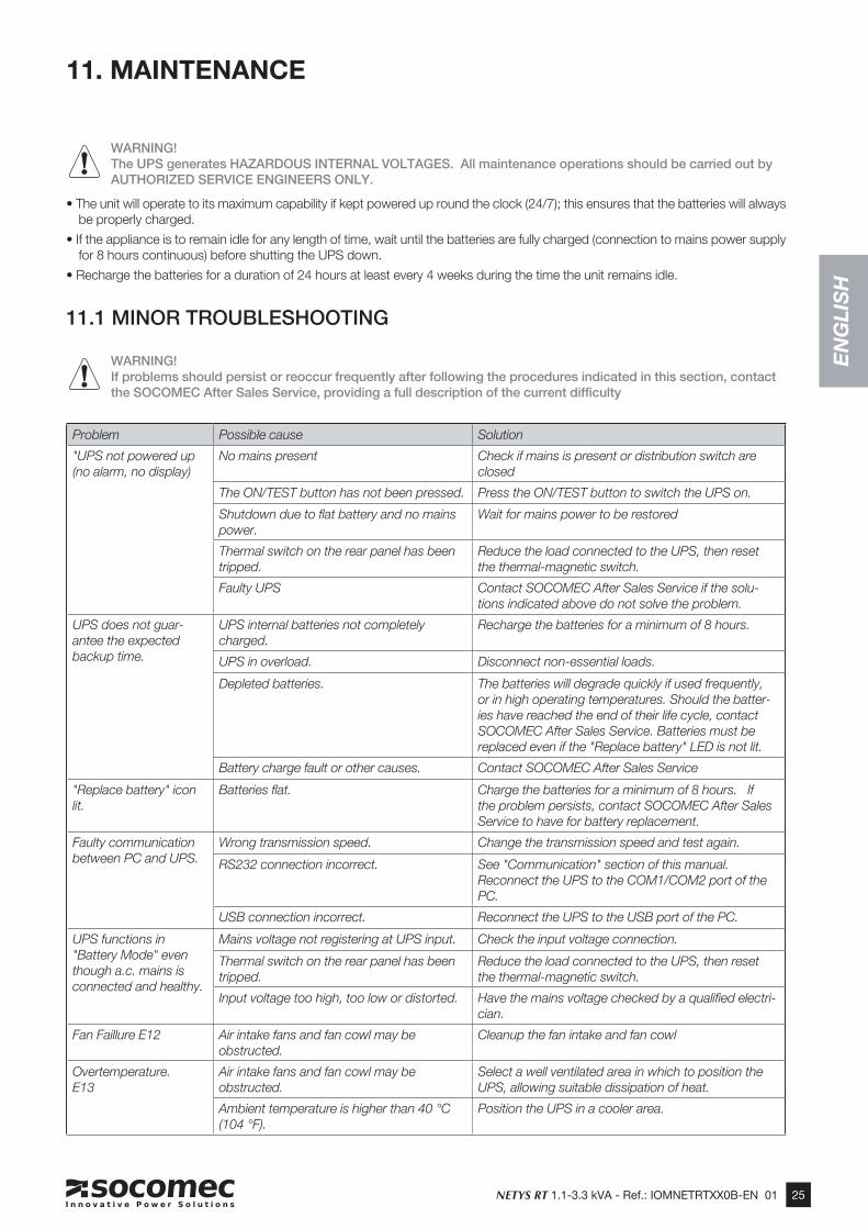
WARNING!The UPS generates HAZARDOUS INTERNAL VOLTAGES. All maintenance operations should be carried out by AUTHORIZED SERVICE ENGINEERS ONLY.
• The unit will operate to its maximum capability if kept powered up round the clock (24/7); this ensures that the batteries will always be properly charged.
• If the appliance is to remain idle for any length of time, wait until the batteries are fully charged (connection to mains power supply for 8 hours continuous) before shutting the UPS down.
• Recharge the batteries for a duration of 24 hours at least every 4 weeks during the time the unit remains idle.
11.1 MINOR TROUBLESHOOTING
WARNING!If problems should persist or reoccur frequently after following the procedures indicated in this section, contact the SOCOMEC After Sales Service, providing a full description of the current difficulty
Problem Possible cause Solution
"UPS not powered up (no alarm, no display)
No mains present Check if mains is present or distribution switch are closed
The ON/TEST button has not been pressed. Press the ON/TEST button to switch the UPS on.
Shutdown due to flat battery and no mains power.
Wait for mains power to be restored
Thermal switch on the rear panel has been tripped.
Reduce the load connected to the UPS, then reset the thermal-magnetic switch.
Faulty UPS Contact SOCOMEC After Sales Service if the solu-tions indicated above do not solve the problem.
UPS does not guar-antee the expected backup time.
UPS internal batteries not completely charged.
Recharge the batteries for a minimum of 8 hours.
UPS in overload. Disconnect non-essential loads.
Depleted batteries. The batteries will degrade quickly if used frequently, or in high operating temperatures. Should the batter-ies have reached the end of their life cycle, contact SOCOMEC After Sales Service. Batteries must be replaced even if the "Replace battery" LED is not lit.
Battery charge fault or other causes. Contact SOCOMEC After Sales Service
"Replace battery" icon lit.
Batteries flat. Charge the batteries for a minimum of 8 hours. If the problem persists, contact SOCOMEC After Sales Service to have for battery replacement.
Faulty communication between PC and UPS.
Wrong transmission speed. Change the transmission speed and test again.
RS232 connection incorrect. See "Communication" section of this manual. Reconnect the UPS to the COM1/COM2 port of the PC.
USB connection incorrect. Reconnect the UPS to the USB port of the PC.
UPS functions in "Battery Mode" even though a.c. mains is connected and healthy.
Mains voltage not registering at UPS input. Check the input voltage connection.
Thermal switch on the rear panel has been tripped.
Reduce the load connected to the UPS, then reset the thermal-magnetic switch.
Input voltage too high, too low or distorted. Have the mains voltage checked by a qualified electri-cian.
Fan Faillure E12 Air intake fans and fan cowl may be obstructed.
Cleanup the fan intake and fan cowl
Overtemperature. E13
Air intake fans and fan cowl may be obstructed.
Select a well ventilated area in which to position the UPS, allowing suitable dissipation of heat.
Ambient temperature is higher than 40 °C (104 °F).
Position the UPS in a cooler area.
26 NETYS RT 1.1-3.3 kVA - Ref.: IOMNETRTXX0B-EN 01
Problem Possible cause Solution
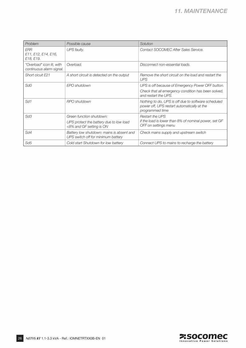
ERR E11, E12, E14, E16, E18, E19.
UPS faulty. Contact SOCOMEC After Sales Service.
"Overload" icon lit, with continuous alarm signal.
Overload. Disconnect non-essential loads.
Short cicuit E21 A short circuit is detected on the output Remove the short circuit on the load and restart the UPS
Sd0 EPO shutdown UPS is off because of Emergency Power OFF button.
Check that all emergency condition has been solved, and restart the UPS.
Sd1 RPO shutdown Nothing to do, UPS is off due to software scheduled power off, UPS restart automatically at the programmed time
Sd3 Green function shutdown:
UPS protect the battery due to low load <8% and GF setting is ON
Restart the UPSif the load is lower than 8% of nominal power, set GF OFF on settings menu
Sd4 Battery low shutdown: mains is absent and UPS switch off for minimum battery
Check mains supply and upstream switch
Sd5 Cold start Shutdown for low battery Connect UPS to mains to recharge the battery
11. MAINTENANCE
EN
GL
ISH
27NETYS RT 1.1-3.3 kVA - Ref.: IOMNETRTXX0B-EN 01
12. TECHNICAL SPECIFICATIONS
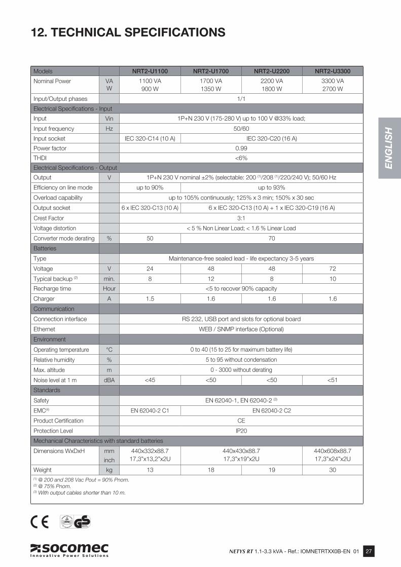
Models NRT2-U1100 NRT2-U1700 NRT2-U2200 NRT2-U3300
Nominal Power VAW
1100 VA900 W
1700 VA1350 W
2200 VA1800 W
3300 VA2700 W
Input/Output phases 1/1
Electrical Specifications - Input
Input Vin 1P+N 230 V (175-280 V) up to 100 V @33% load;
Input frequency Hz 50/60
Input socket IEC 320-C14 (10 A) IEC 320-C20 (16 A)
Power factor 0.99
THDI <6%
Electrical Specifications - Output
Output V 1P+N 230 V nominal ±2% (selectable: 200 (1)/208 (1)/220/240 V); 50/60 Hz
Efficiency on line mode up to 90% up to 93%
Overload capability up to 105% continuously; 125% x 3 min; 150% x 30 sec
Output socket 6 x IEC 320-C13 (10 A) 6 x IEC 320-C13 (10 A) + 1 x IEC 320-C19 (16 A)
Crest Factor 3:1
Voltage distortion < 5 % Non Linear Load; < 1.6 % Linear Load
Converter mode derating % 50 70
Batteries
Type Maintenance-free sealed lead - life expectancy 3-5 years
Voltage V 24 48 48 72
Typical backup (2) min. 8 12 8 10
Recharge time Hour <5 to recover 90% capacity
Charger A 1.5 1.6 1.6 1.6
Communication
Connection interface RS 232, USB port and slots for optional board
Ethernet WEB / SNMP interface (Optional)
Environment
Operating temperature °C 0 to 40 (15 to 25 for maximum battery life)
Relative humidity % 5 to 95 without condensation
Max. altitude m 0 - 3000 without derating
Noise level at 1 m dBA <45 <50 <50 <51
Standards
Safety EN 62040-1, EN 62040-2 (3)
EMC(4) EN 62040-2 C1 EN 62040-2 C2
Product Certification CE
Protection Level IP20
Mechanical Characteristics with standard batteries
Dimensions WxDxH mm
inch
440x332x88.717,3”x13,2”x2U
440x430x88.717,3”x19”x2U
440x608x88.717,3”x24”x2U
Weight kg 13 18 19 30(1) @ 200 and 208 Vac Pout = 90% Pnom.(2) @ 75% Pnom. (3) With output cables shorter than 10 m.
www.socomec.com
HEAD OFFICE
SOCOMEC GROUPS.A. SOCOMEC capital 10 816 800€ R.C.S. Strasbourg B 548 500 149 B.P. 60010 - 1, rue de Westhouse F-67235 Benfeld Cedex - FRANCE Tel. +33 3 88 57 41 41 Fax +33 3 88 74 08 00 [email protected]
Socomec worldwide
BELGIUM
SolarTel. +32 2 340 02 30 Fax +32 2 346 28 99 [email protected]
FRANCE
SolarTel. +33 1 45 14 63 00 Fax +33 1 48 67 31 12 [email protected]
GERMANYPower Control & Energy EfficiencyTel. +49 7243 65292 0 Fax +49 7243 65292 13 [email protected]
UPSTel. +49 621 71 68 40 Fax +49 621 71 68 444 [email protected]
ITALYPower Control & Energy EfficiencyTel.+39 02 98 49 821 Fax +39 02 98 24 33 10 [email protected]
SolarTel. +39 0444 598611 Fax +39 0444 598627 [email protected]
UPS Tel.+39 02 98 242 942 Fax +39 02 98 240 723 [email protected]
NETHERLANDS
SolarTel. +31 30 760 0900 Fax +31 30 637 2166 [email protected]
POLANDPower Control & Energy EfficiencyTel. +48 91 442 64 11 Fax +48 91 442 64 19 [email protected]
UPSTel. +48 22 825 73 60 Fax. +48 22 825 73 60 [email protected]
PORTUGALUPS / SolarTel.+351 261 812 599 Fax +351 261 812 570 [email protected]
ROMANIA
SolarTel. +40 21 319 36 88 Fax +40 21 319 36 89 [email protected]
RUSSIA
SolarTel. +7 495 775 19 85 Fax +7 495 775 19 85 [email protected]
SLOVENIA
SolarTel. +386 1 5807 860 Fax +386 1 561 11 73 [email protected]
SPAIN
SolarTel. +34 93 540 75 75 Fax +34 93 540 75 76 [email protected]
UNITED KINGDOMPower Control & Energy EfficiencyTel. +44 1462 440 033 Fax +44 1462 431 143 [email protected]
UPSTel.+44 1285 863 300 Fax+44 1285 862 304 [email protected]
TURKEY
SolarTel. +90 216 540 71 20-21-22 Fax +90 216 540 71 27 [email protected]
YOUR DISTRIBUTOR
IN ASIA PACIFIC
AUSTRALIAUPSTel. +61 2 9325 3900 Fax +61 2 9888 9544 [email protected]
CHINAUPS / Power Control & Energy EfficiencyTel. +86 21 52 98 95 55 Fax +86 21 62 28 34 68 [email protected]
INDIAPower Control & Energy EfficiencyTel. +91 124 4027210 Fax +91 124 4562738 [email protected]
Tel. +91 44 39215400 Fax +91 44 39215450 & 51 [email protected] [email protected]
SINGAPORE UPS / Power Control & Energy EfficiencyTel.+65 6506 7600 Fax +65 64 58 7377 [email protected]
THAILANDUPSTel. +66 2 941 1644 7 Fax +66 2 941 1650 [email protected]
VIETNAMUPSTel. +84 8 3559 1220 Fax +84 8 3559 1221 [email protected]
IN MIDDLE EAST
UNITED ARAB EMIRATES
SolarTel.+971 4 29 98 441 Fax +971 4 29 98 449 [email protected]
IN AMERICA
USA, CANADA & MEXICOPower Control & Energy EfficiencyTel. +1 617 245 0447 Fax +1 617 245 0437 [email protected]
OTHER COUNTRIES
NORTH AFRICAAlgeria / Morocco / [email protected]
AFRICAOther [email protected]
SOUTH EUROPECyprus / Greece / Israel / [email protected]
SOUTH AMERICATel. +34 93 540 75 75 [email protected]
MORE DETAILSwww.socomec.com/worldwide
IN EUROPE
*IOMNETRTXX0B-EN 01*IOMNETRTXX0B-EN 01 07.2015