Embed Size (px)
Citation preview
0
Molecular Dynamics Simulations of Polymers andMicelles at Interfaces
Dissertation
zur Erlangung des akademischen Grades
doctor rerum naturalium
(Dr. rer. nat.)
im Fach Physik
eingereicht an der
Mathematisch-Naturwissenschaftlichen Fakultät I
der Humboldt-Universität zu Berlin
von
(Diplom-Physiker) Nikolai Severin
geb. 4.1.1971 in Moskau
Präsident der Humboldt-Universität zu Berlin
Prof. Dr. Dr. h.c. H.Meyer
Dekan der Mathematisch-Naturwissenschaftlichen Fakultät I
Prof. Dr. J.P.Rabe
Gutachter/innen 1. Prof. Dr. J.P. Rabe
2. Prof. Dr. E.W. Knapp
3. Prof. Dr. L. Schimansky-Geier
Tag der mündlichen Prüfung: 8.7.99
1
Abstract
Molecular Dynamic (MD) simulation of two different systems wasperformed: 1) Polyethylene- isotactic Polypropylene (PE-iPP) interfaces and2) cylindrical micelles formed by tetradecyl trimethylammonium bromide(C14TAB) molecules in aqueous solution and at solid liquid interfaces.
The general difficulties of simulation of polymer crystalline interfaceswere discussed and one method was proposed for such simulations. Thisemethod was used to simulate epitaxial crystallisation of PE on iPP. Theexperimental results on epitaxial crystallisation were confirmed by MDsimulation and in addition epitaxial crystallisation of PE on iPP surface withhigh dencity of methyl groups was predicted. MD simulation also predictedthat PE should change at the interfacial region from the orthorhombic tomonoclinic crystalline structure.
Several nanoseconds of life of cylindrical micelles were simulated. Thesimulation results for the micelle in aqueous solution were favourablycompared with experimental results. In contradiction to the standard pictureof an ionic micelle the simulated micelle formed hole in its centre and thedensity of the hydrophobic micelle core was inhomogeneous. This effectpartially was explained by the inhomogeneous distribution of the terminalmethyl groups in the micelle core. Cylindrical and half cylindrical micelles ofC14TAB molecules were simulated at the paraffin- and gold-aqueousinterfaces.
Keywords: molecular dynamic simulation, polymer interfaces, micelles.
2
Abstrakt
Molekulardynamik (MD) Simulationen wurden an zweiverschiedenen Systemen durchgeführt: 1. Grenzfläche zwischenPolyethylen und isotaktischem Polypropylen (PE-iPP) und 2.Zylindrische Mizellen, bestehend ausTetradecyltrimethylammoniumbromid (C14TAB), in wässriger Lösungund an Fest-Flüssig-Grenzflächen.
Die allgemeinen Schwierigkeiten bei der Simulation vonGrenzflächen kristalliner Polymere wurden diskutiert und eine Methodefür solche Simulationen vorgeschlagen. Diese Methode wurde zurepitaxialen Kristallisation von PE auf iPP benutzt. ExperimentelleErgebnisse der epitaxialen Kristallisation konnten durch die Simulationbestätigt werden. Ferner konnte vorhergesagt werden, dass PEbevorzugt auf einer iPP-Oberfläche mit hoherMethylgruppenkonzentration kristallisiert. Ebenso wurde durch die MDSimulation vorhergesagt, dass PE in der Grenzflächenregion von einerorthorhombischen zur monoklinischen Kristallstruktur wechselt.
Die Simulationsdauer für die Mizellen betrug einigeNanosekunden. Die Ergebnisse für die Mizellen in wässriger Lösungstehen hierbei in guter Übereinstimmung mit experimentellen Werten.Im Widerspruch zur allgemein üblichen Vorstellung führte dieSimulation der Mizellen zur Ausbildung eines Hohlraums in ihrer Mittesowie zu einer inhomogenen Dichte des hydrophoben Mizellkerns.Dies wurde zum Teil der inhomogenen Verteilung der terminalenMethylgruppen im Mizellkern zugeschrieben. Zylindrische undhalbzylindrische Mizellen wurden an den Paraffin/Wasser- undGold/Wasser-Grenzflächen simuliert.
Schlagworte: Molekulardynamik Simulation, Polymer Grenzfläche,Mizellen.
1
Molecular Dynamics Simulations of polymers and micelles at interfaces
Table of contents:
1. General introduction 2-3
2. Molecular dynamics (MD) simulation method 4-11
3. MD simulation of Polyethylene/isotactic Polypropylene (PE/iPP) interfaces 12-39
3.1 Introductory remarks 12-13
3.2 MD simulations 14-33
3.2.1 Polyethylene, Polypropylene and their blends 14-233.2.2 Models of interfaces used in MD simulations 23-263.2.3 Results of MD simulations 26-303.3.4 Discussion 30-36
3.3 Conclusions 363.4 Literature 37-38
4. MD simulation of cylindrical and half-cylindrical micelles in water 39-86
4.1 Introductory remarks 39-40
4.2 MD simulations 41-83
4.2.1 Micelle formation in liquid and atsolid-liquid interface 41-46
4.2.2 Models of cylindrical andhalf-cylindrical micelles 47-50
4.2.3 Results of MD simulations 51-764.2.4 Discussion 76-82
4.3 Conclusions 834.4 Literature 84-85
5. Summary 85-87
2
1. General introductionThe aim of this work is the atomistic molecular dynamics (MD)
simulation of (1) polyethylene - isotactic polypropylene interfaces and (2)cylindrical and half-cylindrical micelles of amphiphilic molecules at solid-liquid interfaces.
Molecular dynamics solves the classical equations of motions for a systemof N particles interacting according to a potential energy field. In general theparticles may represent different physical objects like satellites in the gravitationfield of earth or atoms of a molecular system. The most important capability ofMD is that during the dynamics simulation a system undergoes conformationaland momentum changes so that different parts of the phase space accessible tothe simulated molecular system can be explored. By providing mechanisms forcontrolling the temperature and pressure of the simulated systems, moleculardynamics also allows to generate statistical ensembles from which variousenergetic, thermodynamic, structural and dynamic properties can be calculated.
The drawback of MD simulation is the limitation in the time span whichcan be simulated and on the system size i.e. the number of particles andinteractions involved in the calculation. The fast progress in the development ofcomputers allows to simulate larger systems with a more detailed description ofinter-particle interactions. However for the detailed description of atomicinteractions the number of atoms included in a simulation is still restricted toseveral tens of thousands. Simulated times of atomistic molecular systems arelimited by several nanoseconds, which is related to the fast vibrations ofchemical bonds. These are very severe restrictions, on the other hand manymolecular systems of particular interest can be simulated. For example it ispossible to simulate the dynamics behaviour of small bio-molecules, which isimportant to understand processes in the cell. A proper simulation of theenvironment of a molecular system allows to increase greatly the range ofapplications for MD simulations.
It is possible to simplify molecular system in order to increase the timespan of MD simulation. The simplifications may range from simple unificationof group of atoms to more general simplifications. For example the methylgroup is replaced by single particle with potentials and dipole moment thatshould represent the methyl group. This simplification allows to increase thenumber of particles involved in the simulation and increase a little bit thesimulation time step. But the information about the coordinates of all atoms isimportant for the short range interactions. The example of more generalsimplification is representation of a polymer molecule as a flexible rubber rod,without detailed consideration of atomic structure. This simplification allows toincrease greatly the time span of MD simulation, it allows even to simulate some
3
long time processes like adsorption of molecules on a solid-liquid interface orprocess of micro/macro phase separation.
In addition to MD method there are several other computer simulationmethods that allow simulation of molecular systems. In the Brownian Dynamic(BD) method the solvent for example is represented as a random forces onatoms. It is also important to mention the Monte Carlo (MC) simulation method.In general it was developed to predict equilibrium distribution of a system. It hasseveral advantages and disadvantages. In many cases MC method samplesconformational space faster than MD method but in general it is not designed toprovide dynamic information on the system.
The restriction to several nanoseconds of the simulated time rendersatomistic MD simulations dependent on the starting configuration of a system.Hence, atomistic MD simulations are bounded to experimentally establishedstructures. On the other hand many experiments provide just a general picture ofthe molecular conformation and do not provide atomic coordinates and in itsturn MD simulation may provide information on the atomic coordinates of amolecular system. That is why MD simulations are a powerful means for theinvestigation of structure and short time dynamics of molecular systems incombination with experimental techniques.
4
2. Molecular dynamics (MD) Simulation
Molecular Dynamics (MD) simulations solve Newton’s equation ofmotion for a system of i particles.
iii amfrr
=where if
r is the force, acting on the i-th particle, mi is the mass and ia
r is theacceleration of the i-th particle. The force can be computed directly from thederivative of the potential energy U:
2
2
dtrdm
rddU i
ii
rr =− (Eq. 1)
With the known expression for the potential energy, known masses and knowninitial positions in coordinate-momentum space it is possible to solve thisequation, i.e. to find the trajectory of the system. Analytically only systems of 1or 2 independent particles can be solved. The numerical solution of Newton’sequation using an empirical fit to the potential energy surface is called moleculardynamics simulations.
A standard method of solving an ordinary differential equation such asEq.1 numerically is the finite-difference method. The general idea is as follows.Given the initial coordinates and velocities and other dynamic information attime t, the positions and velocities at time t t t= + ∆ are calculated. The time-step ∆t depends on the integration method as well as the system itself.
The basic criteria for a good integrator are: it should be fast, it shouldrequire little computer memory, it should permit the use of a relatively long timestep and it must conserve the total energy.
For the MD calculations two different integration algorithms wereapplied, which are described below.
Verlet leap frog integratorThe advantages of the Verlet algorithm is that it requires only one energy
evaluation per time step, modest memory, and it also allows a relatively largetime-step to be used. The Verlet leapfrog algorithm function as follows:
5
( )
mttftta
ttvttrttrtatttvttv
)()(
)2/1()()()2/1()2/1(
∆+=∆+
∆+∆+=∆+∆+∆−=∆+
rr
rrrrrr
Where rr
are coordinates, vr
is the velocity and ar
is an acceleration of anatom. The force )( ttf ∆+
r is evaluated from rddU
r/− at )( ttr ∆+r
.
The Verlet leapfrog method has one major disadvantage: positions andvelocities calculated are displaced by half a time-step out of synchrony.
Verlet velocity integratorThe algorithm is as follows:
[ ])()(21
)()(
)()(
2)(
)()()(2
ttatattvttv
mttftta
tattvttrttr
∆++∆+=∆+
∆+=∆+
∆+∆+=∆+
rrrr
rr
rrrr
A key parameter in the integration algorithms is the integration time step ∆t . Inorder to use computational time more efficiently, as large as possible time-stepshould be used. However, a too large time-step causes instability in theintegration process.
The time-step used depends both on the system as well as on theintegration algorithm. The main limitation to the time-step is a high frequencymotion which should be taken into account. The vibrational period should besplitted into at least 8-10 segments to satisfy the Verlet integrator. In mostmolecular systems, the highest vibrational frequency is the one of C-H bondvibrations, whose period is on the order of 10-14 s. The integration time-stepshould therefor be about 1 fs, which was used during all simulations.
6
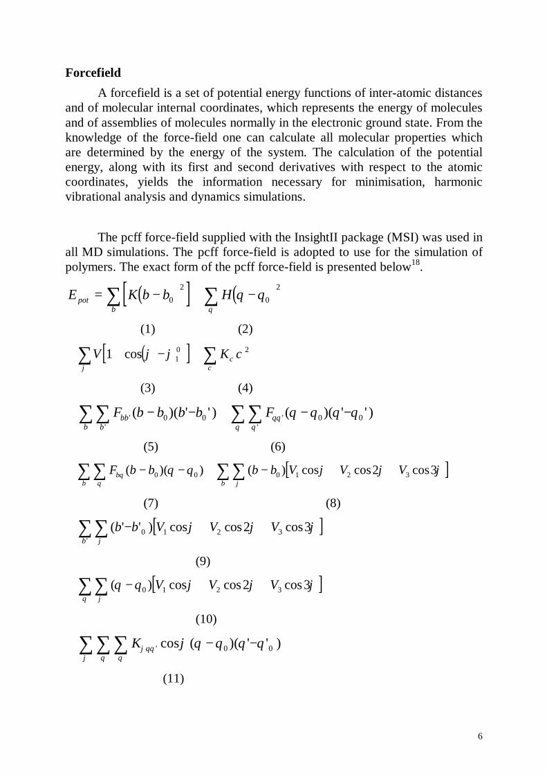
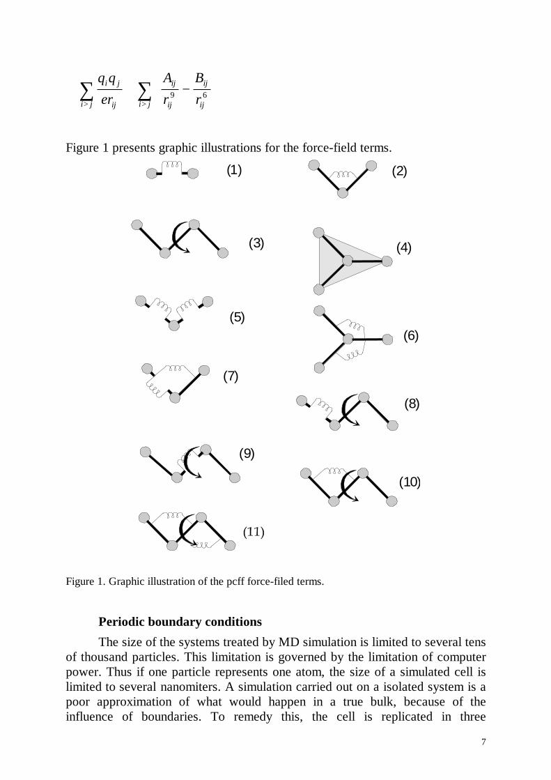
ForcefieldA forcefield is a set of potential energy functions of inter-atomic distances
and of molecular internal coordinates, which represents the energy of moleculesand of assemblies of molecules normally in the electronic ground state. From theknowledge of the force-field one can calculate all molecular properties whichare determined by the energy of the system. The calculation of the potentialenergy, along with its first and second derivatives with respect to the atomiccoordinates, yields the information necessary for minimisation, harmonicvibrational analysis and dynamics simulations.
The pcff force-field supplied with the InsightII package (MSI) was used inall MD simulations. The pcff force-field is adopted to use for the simulation ofpolymers. The exact form of the pcff force-field is presented below18.
( )[ ] ( )E K b b Hpotb
= − + −∑ ∑0
2
0
2θ θθ
(1) (2)
( )[ ]+ + − +∑ ∑V K1 10 2cos ϕ ϕ χ
ϕχ
χ
(3) (4)
+ − − + − −∑∑∑∑ F b b b b Fbbbb
' '''
( )( ' ' ) ( )( ' ' )0 0 0 0θθθθ
θ θ θ θ
(5) (6)
[ ]+ − − + − + +∑∑∑∑ F b b b b V V Vbbb
θϕθ
θ θ ϕ ϕ ϕ( )( ) ( ) cos cos cos0 0 0 1 2 32 3
(7) (8)
[ ]+ − + +∑∑ ( ' ' ) cos cos cos'
b b V V Vb
0 1 2 32 3ϕ ϕ ϕϕ
(9)
[ ]+ − + +∑∑ ( ) cos cos cosθ θ ϕ ϕ ϕϕθ
0 1 2 32 3V V V
(10)
+ − −∑∑∑ Kϕθθθθϕ
ϕ θ θ θ θ' cos ( )( ' ' )0 0
(11)
7
+ + −
>>
∑∑ q qr
Ar
Br
i j
ij
ij
ij
ij
iji ji j ε 9 6
Figure 1 presents graphic illustrations for the force-field terms.
(1) (2)
(3) (4)
(5)(6)
(7)
(8)
(9)
(10)
Figure 1. Graphic illustration of the pcff force-filed terms.
Periodic boundary conditionsThe size of the systems treated by MD simulation is limited to several tens
of thousand particles. This limitation is governed by the limitation of computerpower. Thus if one particle represents one atom, the size of a simulated cell islimited to several nanomiters. A simulation carried out on a isolated system is apoor approximation of what would happen in a true bulk, because of theinfluence of boundaries. To remedy this, the cell is replicated in three
8
dimensions, thus the simulated cell should have translational periodicity. This isa much better representation of a bulk system, because the molecules near thesurface now interact with molecules in adjacent cells. The image atoms are usedto calculate energies and forces on the real atoms.
Cut-offThe periodic boundary conditions method allows to simulate a virtually
infinite system which consist of a base cell and its images. The energies andforces on the imaged atoms are not calculated because their motions arecomputed as symmetry operations on the real atoms. It is now important todefine long range interactions in the system. The simplest way is to allowmolecules to interact with the molecule or molecular image closest to it. Thismethod is called minimum image model. Each molecule interacts only withmolecules and images within a distance of half the cell size. The disadvantage ofthis method is that computational time has a cubic dependence on the number ofatoms in the system. Therefore it is common to introduce a non-bond cut-off, i.e.to neglect the non-bond interactions for pairs of atoms separated by distancesgreater than a cut-off value. The use of cut-off with a van der Waals interactionpotential is quite reasonable, since the van der Waals potential is relatively shortrange and dies out as 1/r6. At r=8-10 Å the energies and forces are quite smallcompared to kbT at room temperature. Thus, it is reasonable to set the cut offlength to about 10 Å for van der Waals interactions. The Coulombic interactionson the other hand die off as 1/r, so at much longer distances Coulombicinteractions are not negligible. However for most of cases polymeric systems arecomposed of neutral groups with electric dipoles or higher multipoles. Thedipole-dipole interaction dies off as 1/r3. The interaction energy of twomonopols of one elementary charge at r=1 nm is about 33 kcal mol-1, while theinteraction energy of two dipoles formed from elementary monopols at thedistance r=1 nm is 0.3 kcal mol-1. It is clear that cutting off monopole-monopoleinteraction at r=1 nm would be misleading, while cutting off dipole-dipoleinteraction at r=1 nm is only a modest approximation.
If periodic boundary conditions are applied to a molecular system,volume and pressure can be defined. Different statistical ensembles can begenerated, depending on which thermodynamic variables are kept fixed. In thepresent simulations the following ensembles were used: 1. NVT: number ofparticles, volume and temperature are constant, and 2. NPT: number of particles,pressure and temperature are constant.
9
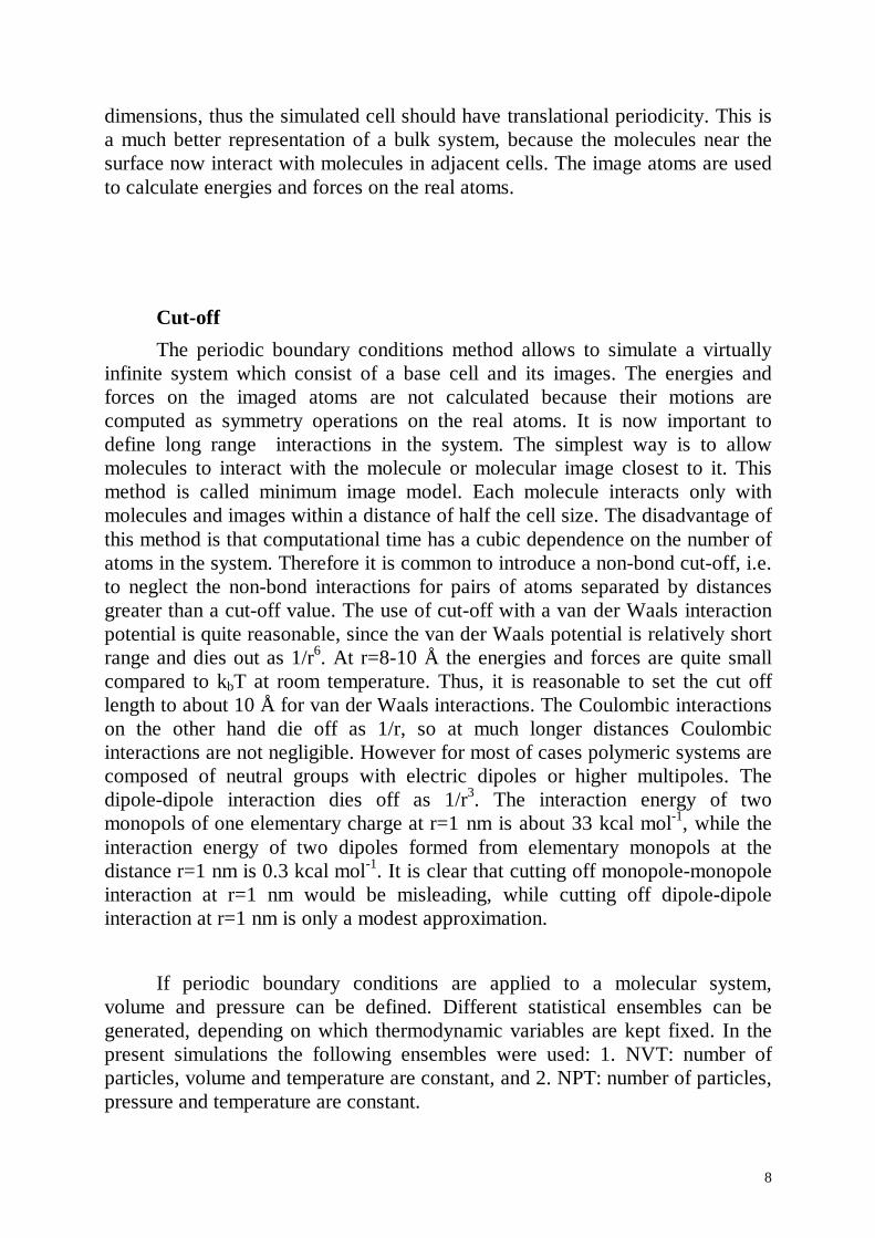
TemperatureThe temperature is a macroscopic quantity, which is related to the
microscopic description of molecular simulations through the kinetic energy,which is calculated from the atomic velocities. The temperature and thedistribution of atomic velocities in a system are related by the Maxwell-Boltzman equation:
vdTk
vmTk
mvdvgBB
rr
rr
−
=
2exp
2)(
22/1
π (2)
In the initial stage the velocities are generated according to Eq. 2, and thegaussian distribution is generated by a random number generator.
During MD simulation the temperature is related to the average kineticenergy of the system through the equipartition principle. This principle states
that every degree of freedom has an average energy of 2
kT associated with it:
Bf
kin
kNET 2=
where T is the instantaneous temperature, Ekin is the total kinetic energy of thesystem and Nf is the number of degrees of freedom. For a nonperiodic isolatedmolecular system Nf is equal to 3N-6 (six degrees of freedom are subtractedbecause both the translation and rotation of the centre of mass are ignored). Fora periodic system Nf is 3N-3 (only the three degrees of freedom correspondingto translational motion can be ignored, since the rotation of a central cellimposes a torque on its neighbouring cells).
The direct Velocity scaling method was used for temperature scaling.Velocities of all atoms were uniformly scaled as follows:
old
newoldnew T
Tvv =
where Tnew is the desired temperature and Told is the current temperature18.
10
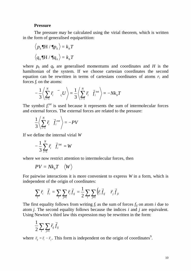
PressureThe pressure may be calculated using the virial theorem, which is written
in the form of generalised equipartition:
p p k Tk k b∂ ∂Η / =
q q k Tk k b∂ ∂Η / =where pk and qk are generalised momentums and coordinates and H is thehamiltonian of the system. If we choose cartesian coordinates the secondequation can be rewritten in terms of cartesians coordinates of atoms ri andforces fi on the atoms:
TNkfrUr b
N
i
totii
N
iri i
−=⋅=∇⋅− ∑∑== 11 3
131 rrrr
The symbol fitot is used because it represents the sum of intermolecular forces
and external forces. The external forces are related to the pressure:
PVfrN
i
extii −=⋅∑
=131 rr
If we define the internal virial W
∑=
=⋅−N
iii Wfr
1
int
31 rr
where we now restrict attention to intermolecular forces, then
WTNkPV b +=For pairwise interactions it is more convenient to express W in a form, which isindependent of the origin of coordinates:
( )∑ ∑ ∑ ∑ ∑≠ ≠
+==⋅i i ij i ij
jijijiijiii frfrfrfrrrrrrrrr
21
The first equality follows from writing fi as the sum of forces fij on atom i due toatom j. The second equality follows because the indices i and j are equivalent.Using Newton’s third law this expression may be rewritten in the form:
∑ ∑≠i ij
ijij frrr
21
where jiij rrrrrr −= . This form is independent on the origin of coordinates9.
11
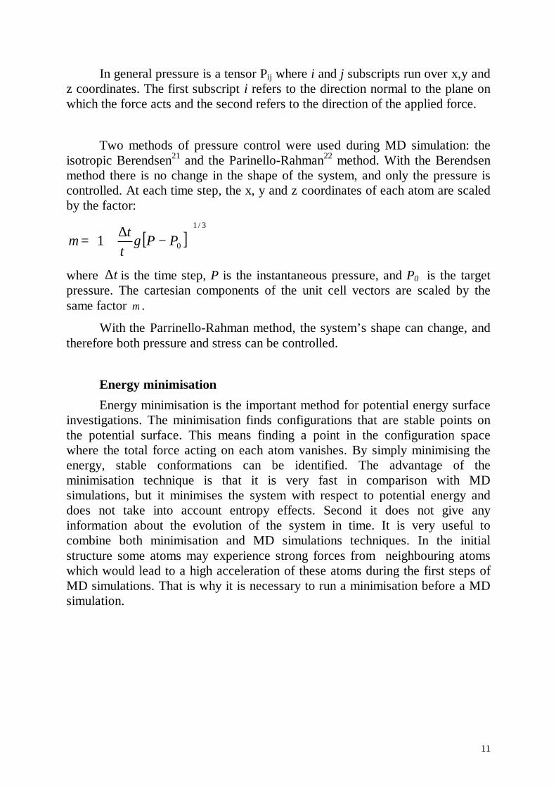
In general pressure is a tensor Pij where i and j subscripts run over x,y andz coordinates. The first subscript i refers to the direction normal to the plane onwhich the force acts and the second refers to the direction of the applied force.
Two methods of pressure control were used during MD simulation: theisotropic Berendsen21 and the Parinello-Rahman22 method. With the Berendsenmethod there is no change in the shape of the system, and only the pressure iscontrolled. At each time step, the x, y and z coordinates of each atom are scaledby the factor:
[ ]3/1
01
−∆+= PP
t γτ
µ
where t∆ is the time step, P is the instantaneous pressure, and P0 is the targetpressure. The cartesian components of the unit cell vectors are scaled by thesame factor µ .
With the Parrinello-Rahman method, the system’s shape can change, andtherefore both pressure and stress can be controlled.
Energy minimisationEnergy minimisation is the important method for potential energy surface
investigations. The minimisation finds configurations that are stable points onthe potential surface. This means finding a point in the configuration spacewhere the total force acting on each atom vanishes. By simply minimising theenergy, stable conformations can be identified. The advantage of theminimisation technique is that it is very fast in comparison with MDsimulations, but it minimises the system with respect to potential energy anddoes not take into account entropy effects. Second it does not give anyinformation about the evolution of the system in time. It is very useful tocombine both minimisation and MD simulations techniques. In the initialstructure some atoms may experience strong forces from neighbouring atomswhich would lead to a high acceleration of these atoms during the first steps ofMD simulations. That is why it is necessary to run a minimisation before a MDsimulation.
12
3. MD simulation of Polyethylene/isotactic Polypropylene(PE/iPP) interfaces.
3.1 Introduction to the simulation of PE - iPP interfacesPlastic waste has become one of the main issues of environmental
concerns. Major polymeric components of plastic waste are polyethylene (PE)and polypropylene (PP). Separation of the plastic waste into individual polymersis costly and complete sorting is sometimes impossible. Thus it is important tostudy blends of PE and PP in order to put recycled blends into effective andefficient use.
It is well known that PE and PP are immiscible polymers. The term‘immiscible’ means that the Gibbs energy of mixing is positive, thus twoimmiscible components tend to macroseparate from their mixture. Theimmiscibility of PE and PP was established by directly visualisingmacroseparation in the blend of molten PE and PP. A thin film of blended PEand PP was placed between two heated glass slides and observed with lightmicroscopy. It was shown that initially small domains of PE and PP tend tomerge leading finally to macroseparation of both polymers. Despite of theimmiscibility of many polymers it is possible to produce their blends. Becauseof the high viscosity of bulk polymers the process of macroseparation takesplace on a long time scale. By extrusion of two immiscible molten componentsand following fast cooling below crystallisation or glass transition points of bothcomponents it is possible to prevent them from macroseparation. It is clear thatproperties of a blend of two immiscible components would strongly depend onthe preparation conditions like, for example on the mixing and cooling rates. Ingeneral, immiscible polymers are also incompatible. The term ‘incompatible’means that the mechanical properties such as impact strength, Youngs modulus,strain and elongation at the stretching limit of the blend are inferior to themechanical properties of the pure components.
Despite the immiscible nature of PE and PP it was recently found that it ispossible to process blends of PE and iPP (isotactic polypropylene) with animpact strength of the blend which is two times higher than the impact strengthsof the pure components. It is very important for industrial applications that byblending of common and cheap polymers one can obtain blends with improvedimpact strength. The blend of PE and iPP with improved impact strength wasprocessed by extrusion of both molten components, followed by fast cooling.Transmission electron microscopy (TEM) images of the blend show that thesepreparation conditions lead to a fine micro-separation of PE and iPP, hence to anincreased total interfacial area between PE and iPP in their blend. It was
13
suggested that the properties of PE - iPP interfaces help to dissipate a sufficientamount of energy in the blend, hence enhanced total interfacial area improvesthe impact performance of the blend. The suggestion of the important role thatinterfaces play in the impact performance of the blend was the starting point ofthis work.
In general one may subdivide the investigation of interfaces on themacroscopic and microscopic level. On the microscopic level the interface ischaracterised on atomistic length scales with changes of the structure of bothcomponents in the interfacial region. When one considers properties ofinterfaces on the macroscopic scale, the roughness of the surfaces of bothcomponents should be taken into account. It is hard to establish micro structureof the interfaces in a real blend, since one finds too many randomly orientedinterfaces. In addition, because of the semi-crystalline nature of polymers oneshould expect four types of interfaces in the PE - iPP blend: amorphous-amorphous, crystallin-crystalline and amorphous-crystalline, crystalline-amorphous interfaces. The model experiment of epitaxial crystallisation of PEand iPP may help to resolve the structure of their interface. In epitaxialcrystallisation one polymer is crystallised in the form of a thin layer on a thinlayer of another polymer. The polymer sandwich is then investigated by X-rayscattering. But the structure of the interface is then difficult to discriminate fromthe structure of the polymers in the films, hence one expects that the material atthe interface has exactly the same structure as in the film. It is obvious that thismethod may not reveal the fine structure of the interface. Molecular dynamics(MD) simulations may help to solve this problem since it allows to simulate theinterface on the atomistic length scales, hence to investigate the fine structure ofinterfaces. That is why it was decided to perform MD simulations of PE and iPPinterfaces in order to establish their exact microscopic structure.
14
3.2.1 Polyethylene, Polypropylene and their blendsPolyethylene macromolecules have the chemical formula:
[ ]CH CH CHn3 2 3− − where n typically is in the range of 103-106. In the
technical literature the term high density polyethylene is used for this linearpolyethylene while the term low density polyethylene is used for branchedpolyethylene. I will focus in the following on the investigation of high densitypolyethylene and will use the abbreviation PE also for high densitypolypropylene instead of HDPE. The melting point of PE is at 138° C and itsglass transition4 is between -128° and -30° C, depending on the history of thesample and the experimental method which is used to determine the glasstransition temperature.
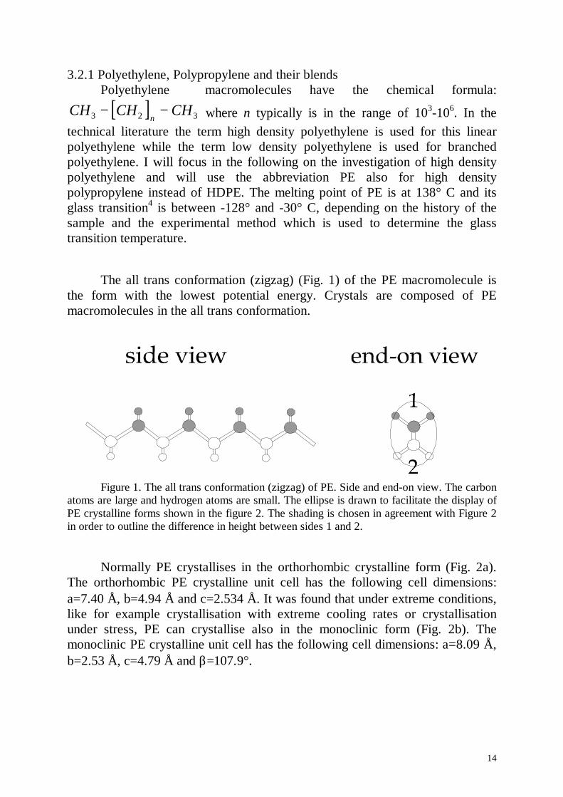
The all trans conformation (zigzag) (Fig. 1) of the PE macromolecule isthe form with the lowest potential energy. Crystals are composed of PEmacromolecules in the all trans conformation.
Figure 1. The all trans conformation (zigzag) of PE. Side and end-on view. The carbonatoms are large and hydrogen atoms are small. The ellipse is drawn to facilitate the display ofPE crystalline forms shown in the figure 2. The shading is chosen in agreement with Figure 2in order to outline the difference in height between sides 1 and 2.
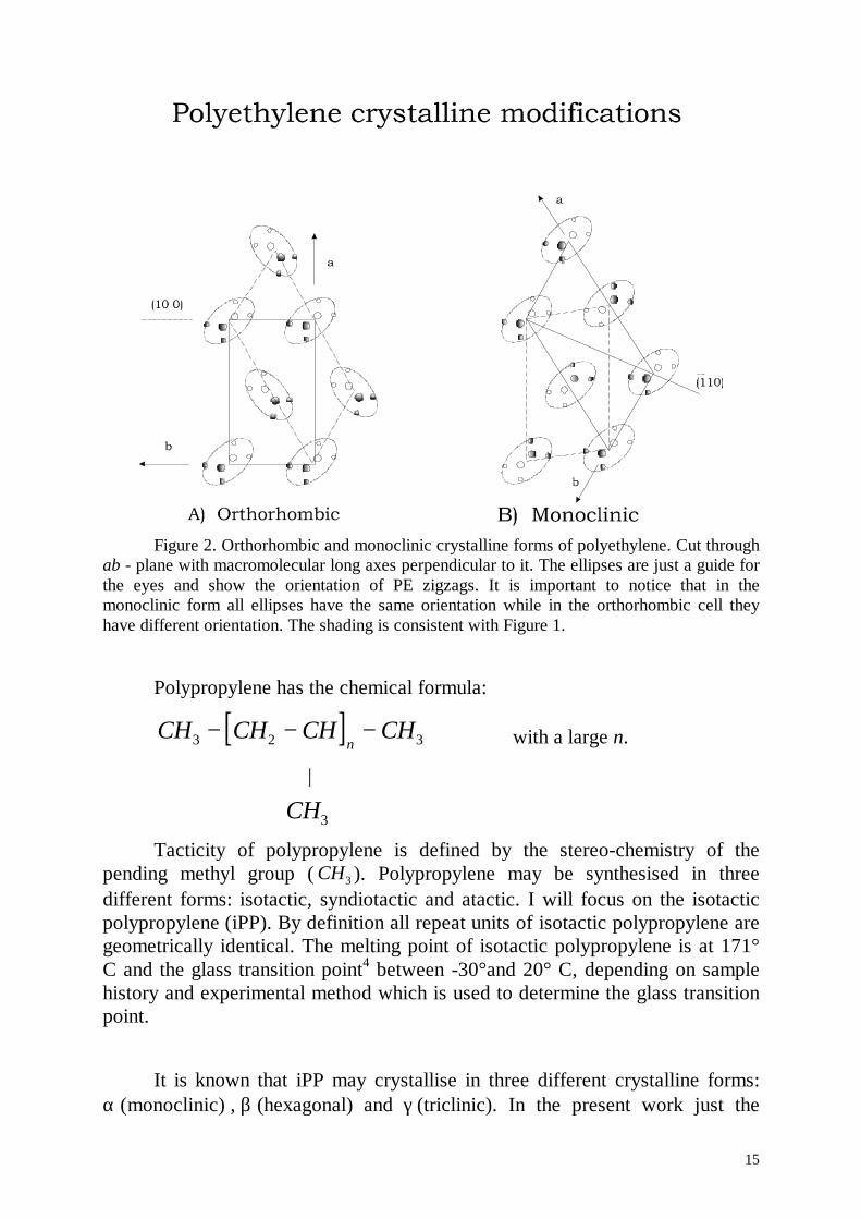
Normally PE crystallises in the orthorhombic crystalline form (Fig. 2a).The orthorhombic PE crystalline unit cell has the following cell dimensions:a=7.40 Å, b=4.94 Å and c=2.534 Å. It was found that under extreme conditions,like for example crystallisation with extreme cooling rates or crystallisationunder stress, PE can crystallise also in the monoclinic form (Fig. 2b). Themonoclinic PE crystalline unit cell has the following cell dimensions: a=8.09 Å,b=2.53 Å, c=4.79 Å and β=107.9 °.
15
Figure 2. Orthorhombic and monoclinic crystalline forms of polyethylene. Cut throughab - plane with macromolecular long axes perpendicular to it. The ellipses are just a guide forthe eyes and show the orientation of PE zigzags. It is important to notice that in themonoclinic form all ellipses have the same orientation while in the orthorhombic cell theyhave different orientation. The shading is consistent with Figure 1.
Polypropylene has the chemical formula:
[ ]CH CH CH CHn3 2 3− − − with a large n.
|
CH3
Tacticity of polypropylene is defined by the stereo-chemistry of thepending methyl group ( CH3 ). Polypropylene may be synthesised in threedifferent forms: isotactic, syndiotactic and atactic. I will focus on the isotacticpolypropylene (iPP). By definition all repeat units of isotactic polypropylene aregeometrically identical. The melting point of isotactic polypropylene is at 171°C and the glass transition point4 between -30°and 20° C, depending on samplehistory and experimental method which is used to determine the glass transitionpoint.
It is known that iPP may crystallise in three different crystalline forms:α (monoclinic) , β (hexagonal) and γ (triclinic). In the present work just the
16
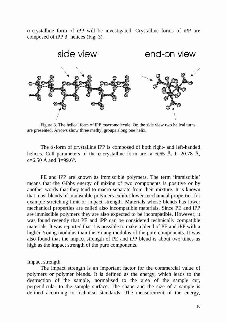
α crystalline form of iPP will be investigated. Crystalline forms of iPP arecomposed of iPP 31 helices (Fig. 3).
Figure 3. The helical form of iPP macromolecule. On the side view two helical turnsare presented. Arrows show three methyl groups along one helix.
The α-form of crystalline iPP is composed of both right- and left-handedhelices. Cell parameters of the α crystalline form are: a=6.65 Å, b=20.78 Å,c=6.50 Å and β=99.6°.
PE and iPP are known as immiscible polymers. The term ‘immiscible’means that the Gibbs energy of mixing of two components is positive or byanother words that they tend to macro-separate from their mixture. It is knownthat most blends of immiscible polymers exhibit lower mechanical properties forexample stretching limit or impact strength. Materials whose blends has lowermechanical properties are called also incompatible materials. Since PE and iPPare immiscible polymers they are also expected to be incompatible. However, itwas found recently that PE and iPP can be considered technically compatiblematerials. It was reported that it is possible to make a blend of PE and iPP with ahigher Young modulus than the Young modulus of the pure components. It wasalso found that the impact strength of PE and iPP blend is about two times ashigh as the impact strength of the pure components.
Impact strengthThe impact strength is an important factor for the commercial value of
polymers or polymer blends. It is defined as the energy, which leads to thedestruction of the sample, normalised to the area of the sample cut,perpendicular to the sample surface. The shape and the size of a sample isdefined according to technical standards. The measurement of the energy,
17
leading to sample destruction is also defined by technical standards. Forexample: a hammer is dropped on a sample from different heights. Theminimum height, which leads to a sample destruction allows to estimate theimpact strength of a sample. It is important to distinguish notched andunnotched impact strength, i.e. whether the sample was notched before impactstrength measurements or not.
Two types of materials with respect to impact strength measurements canbe distinguished: brittle and ductile materials. Brittle materials have usually lowimpact strength. The unnotched impact strength of an ideal brittle materialconsists of the energy for crack formation and the surface energies of surfacesformed by crack propagation. For notched impact strength it is just the secondcomponent. Ductile materials which are also called tough materials, haveusually higher impact strength. The impact strength of ductile materials includesin addition to brittle materials the energy of polymer matrix plastic deformation.
The toughness of polymeric systems has been studied intensively. It wasestablished that a substantial increase in toughness of brittle polymers can beachieved by blending them with rubber particles. The mechanisms which areresponsible for the increasing impact strength are multiple crazing, shearyielding, crazing with shear yielding and rubbery particles stretching andtearing. A common accepted view on the role of rubber particles is that thisparticles alter the stress in the material and induce plastic deformation of thepolymer matrix. In general it is accepted that the plastic deformation in thepolymer matrix, such as multiple crazing and shear yielding or both, absorb amajor part of the total fracture energy.
It was proposed that blends with rubber particles larger than 1 µm prefercrazing, whereas shear deformation in a ductile polymer matrix is favoured byparticles3 smaller than 1 µm.
The multiple crazing mechanismIt was noticed that the fracture of rubber-toughened polystyrene is usually
preceded by an opaque whitening of the stress area. It was also concluded thatwhitening is associated with the absorption of a large amount of energy11. Laterit was established that polymer matrix crazing is responsible for stress whiteningand therefore for the absorption of energy. Transmission electron microscopyshows that extensive crazing occurs in a nylon matrix within the whitening zone.Crazes are micro-cracks filled by voids and fibrils which are formed byyielding12. The energy dissipated by crazing consists of two components: 1.energy dissipated by yielding in fibril formation, and 2. energy stored as surfaceenergy in the craze matter.
18
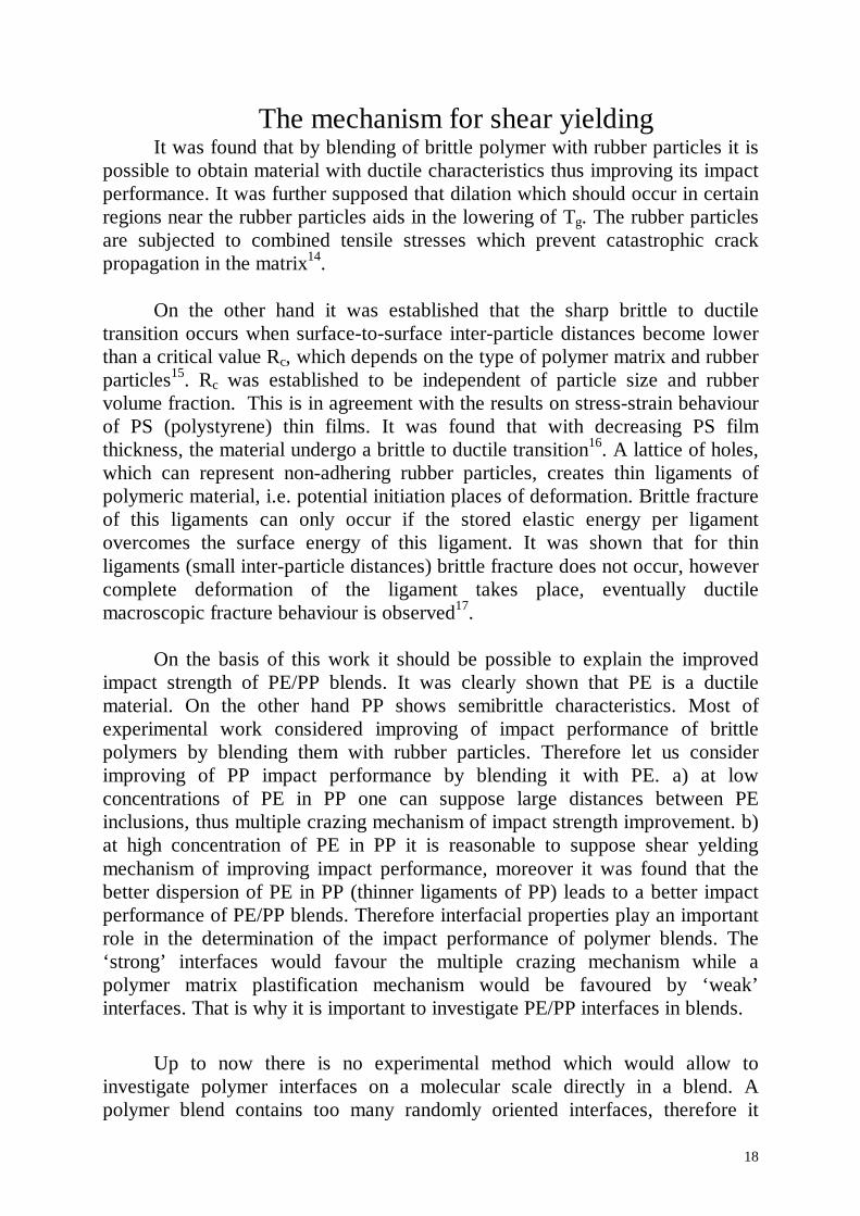
The mechanism for shear yieldingIt was found that by blending of brittle polymer with rubber particles it is
possible to obtain material with ductile characteristics thus improving its impactperformance. It was further supposed that dilation which should occur in certainregions near the rubber particles aids in the lowering of Tg. The rubber particlesare subjected to combined tensile stresses which prevent catastrophic crackpropagation in the matrix14.
On the other hand it was established that the sharp brittle to ductiletransition occurs when surface-to-surface inter-particle distances become lowerthan a critical value Rc, which depends on the type of polymer matrix and rubberparticles15. Rc was established to be independent of particle size and rubbervolume fraction. This is in agreement with the results on stress-strain behaviourof PS (polystyrene) thin films. It was found that with decreasing PS filmthickness, the material undergo a brittle to ductile transition16. A lattice of holes,which can represent non-adhering rubber particles, creates thin ligaments ofpolymeric material, i.e. potential initiation places of deformation. Brittle fractureof this ligaments can only occur if the stored elastic energy per ligamentovercomes the surface energy of this ligament. It was shown that for thinligaments (small inter-particle distances) brittle fracture does not occur, howevercomplete deformation of the ligament takes place, eventually ductilemacroscopic fracture behaviour is observed17.
On the basis of this work it should be possible to explain the improvedimpact strength of PE/PP blends. It was clearly shown that PE is a ductilematerial. On the other hand PP shows semibrittle characteristics. Most ofexperimental work considered improving of impact performance of brittlepolymers by blending them with rubber particles. Therefore let us considerimproving of PP impact performance by blending it with PE. a) at lowconcentrations of PE in PP one can suppose large distances between PEinclusions, thus multiple crazing mechanism of impact strength improvement. b)at high concentration of PE in PP it is reasonable to suppose shear yeldingmechanism of improving impact performance, moreover it was found that thebetter dispersion of PE in PP (thinner ligaments of PP) leads to a better impactperformance of PE/PP blends. Therefore interfacial properties play an importantrole in the determination of the impact performance of polymer blends. The‘strong’ interfaces would favour the multiple crazing mechanism while apolymer matrix plastification mechanism would be favoured by ‘weak’interfaces. That is why it is important to investigate PE/PP interfaces in blends.
Up to now there is no experimental method which would allow toinvestigate polymer interfaces on a molecular scale directly in a blend. Apolymer blend contains too many randomly oriented interfaces, therefore it
19
becomes impossible to focus with experimental method on the structure of asingle interface. In addition both PE and PP are semicrystalline polymers atroom temperature both in the pure state and in the blend. That is why one maysuppose the existence of three types of interfaces: amorphous-amorphous,crystalline-crystalline and amorphous-crystalline, crystalline-amorphous. Thesemicrystalline nature of PE and iPP below their crystallisation temperatures iscommon for all polymers.
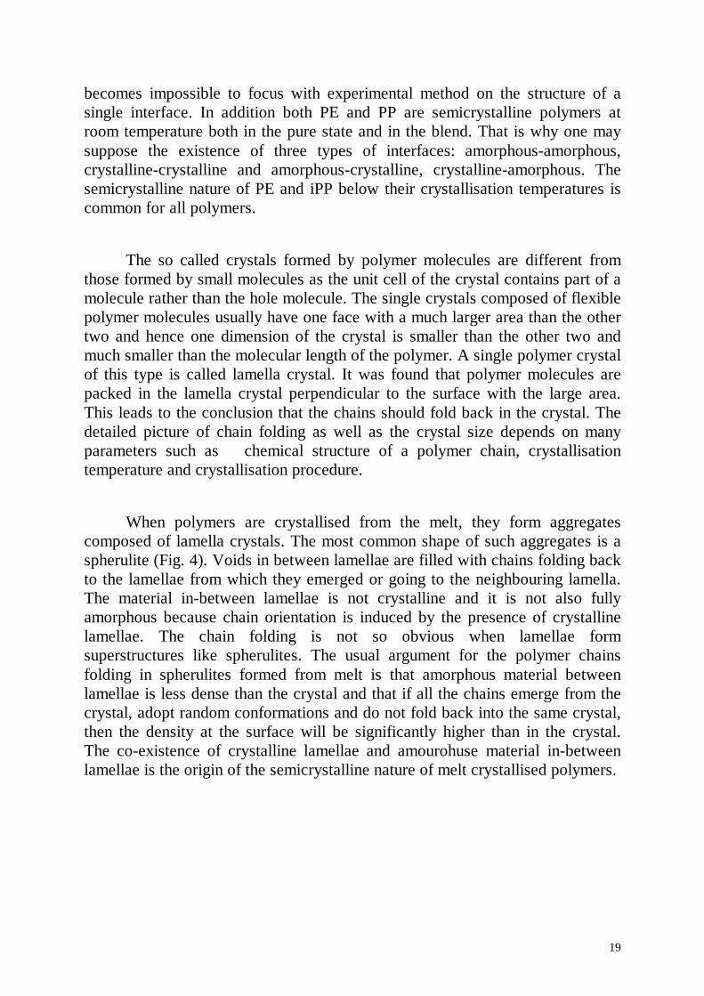
The so called crystals formed by polymer molecules are different fromthose formed by small molecules as the unit cell of the crystal contains part of amolecule rather than the hole molecule. The single crystals composed of flexiblepolymer molecules usually have one face with a much larger area than the othertwo and hence one dimension of the crystal is smaller than the other two andmuch smaller than the molecular length of the polymer. A single polymer crystalof this type is called lamella crystal. It was found that polymer molecules arepacked in the lamella crystal perpendicular to the surface with the large area.This leads to the conclusion that the chains should fold back in the crystal. Thedetailed picture of chain folding as well as the crystal size depends on manyparameters such as chemical structure of a polymer chain, crystallisationtemperature and crystallisation procedure.
When polymers are crystallised from the melt, they form aggregatescomposed of lamella crystals. The most common shape of such aggregates is aspherulite (Fig. 4). Voids in between lamellae are filled with chains folding backto the lamellae from which they emerged or going to the neighbouring lamella.The material in-between lamellae is not crystalline and it is not also fullyamorphous because chain orientation is induced by the presence of crystallinelamellae. The chain folding is not so obvious when lamellae formsuperstructures like spherulites. The usual argument for the polymer chainsfolding in spherulites formed from melt is that amorphous material betweenlamellae is less dense than the crystal and that if all the chains emerge from thecrystal, adopt random conformations and do not fold back into the same crystal,then the density at the surface will be significantly higher than in the crystal.The co-existence of crystalline lamellae and amourohuse material in-betweenlamellae is the origin of the semicrystalline nature of melt crystallised polymers.
20
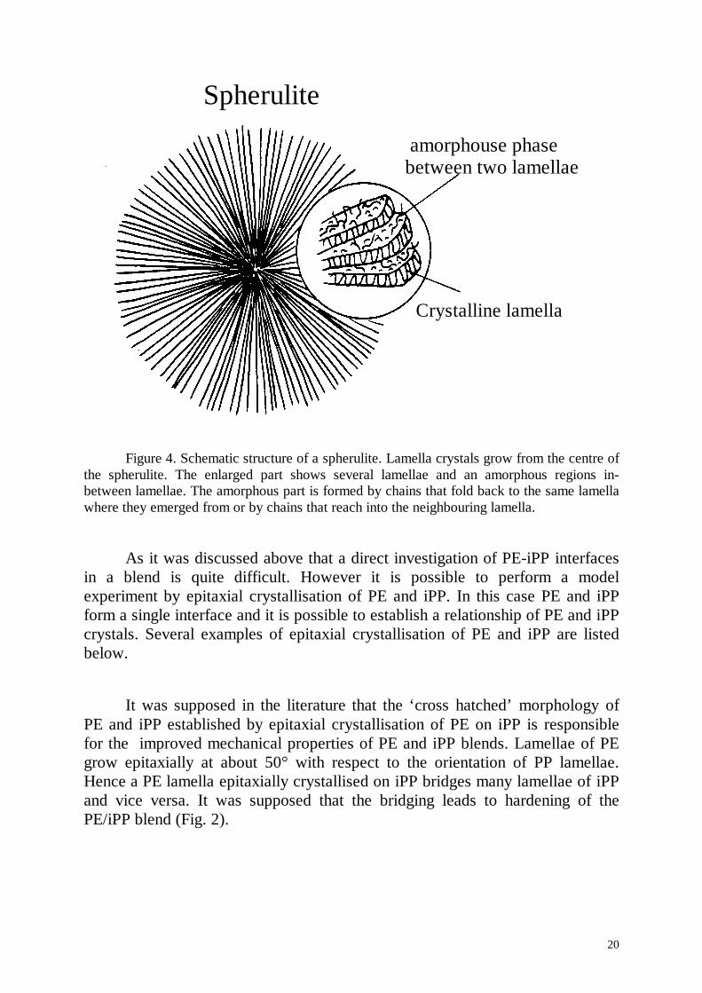
Figure 4. Schematic structure of a spherulite. Lamella crystals grow from the centre ofthe spherulite. The enlarged part shows several lamellae and an amorphous regions in-between lamellae. The amorphous part is formed by chains that fold back to the same lamellawhere they emerged from or by chains that reach into the neighbouring lamella.
As it was discussed above that a direct investigation of PE-iPP interfacesin a blend is quite difficult. However it is possible to perform a modelexperiment by epitaxial crystallisation of PE and iPP. In this case PE and iPPform a single interface and it is possible to establish a relationship of PE and iPPcrystals. Several examples of epitaxial crystallisation of PE and iPP are listedbelow.
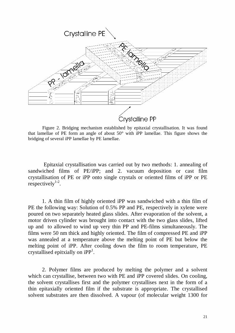
It was supposed in the literature that the ‘cross hatched’ morphology ofPE and iPP established by epitaxial crystallisation of PE on iPP is responsiblefor the improved mechanical properties of PE and iPP blends. Lamellae of PEgrow epitaxially at about 50° with respect to the orientation of PP lamellae.Hence a PE lamella epitaxially crystallised on iPP bridges many lamellae of iPPand vice versa. It was supposed that the bridging leads to hardening of thePE/iPP blend (Fig. 2).
Crystalline lamella
amorphouse phasebetween two lamellae
Spherulite
21
Figure 2. Bridging mechanism established by epitaxial crystallisation. It was foundthat lamellae of PE form an angle of about 50° with iPP lamellae. This figure shows thebridging of several iPP lamellae by PE lamellae.
Epitaxial crystallisation was carried out by two methods: 1. annealing ofsandwiched films of PE/iPP; and 2. vacuum deposition or cast filmcrystallisation of PE or iPP onto single crystals or oriented films of iPP or PErespectively1-2.
1. A thin film of highly oriented iPP was sandwiched with a thin film ofPE the following way: Solution of 0.5% PP and PE, respectively in xylene werepoured on two separately heated glass slides. After evaporation of the solvent, amotor driven cylinder was brought into contact with the two glass slides, liftedup and to allowed to wind up very thin PP and PE-films simultaneously. Thefilms were 50 nm thick and highly oriented. The film of compressed PE and iPPwas annealed at a temperature above the melting point of PE but below themelting point of iPP. After cooling down the film to room temperature, PEcrystallised epitxially on iPP1.
2. Polymer films are produced by melting the polymer and a solventwhich can crystallise, between two with PE and iPP covered slides. On cooling,the solvent crystallises first and the polymer crystallises next in the form of athin epitaxially oriented film if the substrate is appropriate. The crystallisedsolvent substrates are then dissolved. A vapour (of molecular weight 1300 for
22
PE and 3000 for iPP) condenses and crystallises on the substrate surface held atroom temperature2.
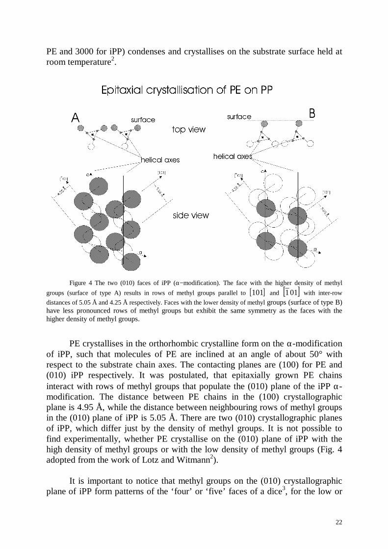
Figure 4 The two (010) faces of iPP (α− modification). The face with the higher density of methylgroups (surface of type A) results in rows of methyl groups parallel to [ ]101 and [ ]011 with inter-rowdistances of 5.05 Å and 4.25 Å respectively. Faces with the lower density of methyl groups (surface of type B)have less pronounced rows of methyl groups but exhibit the same symmetry as the faces with thehigher density of methyl groups.
PE crystallises in the orthorhombic crystalline form on the α-modificationof iPP, such that molecules of PE are inclined at an angle of about 50° withrespect to the substrate chain axes. The contacting planes are (100) for PE and(010) iPP respectively. It was postulated, that epitaxially grown PE chainsinteract with rows of methyl groups that populate the (010) plane of the iPP α-modification. The distance between PE chains in the (100) crystallographicplane is 4.95 Å, while the distance between neighbouring rows of methyl groupsin the (010) plane of iPP is 5.05 Å. There are two (010) crystallographic planesof iPP, which differ just by the density of methyl groups. It is not possible tofind experimentally, whether PE crystallise on the (010) plane of iPP with thehigh density of methyl groups or with the low density of methyl groups (Fig. 4adopted from the work of Lotz and Witmann2).
It is important to notice that methyl groups on the (010) crystallographicplane of iPP form patterns of the ‘four’ or ‘five’ faces of a dice3, for the low or
23
high density of methyl groups, respectively. Diagonals of the dice elements formrows with inter-row distance 5.05 A and 4.25 A.
The advantage of the epitaxial crystallisation method is that it allows toinvestigate the relationship between PE and iPP lamellae. However it does notallow to investigate the detailed structure of the interface. In particular, it doesnot allow to look into structural changes that may occur in a layer of severalangstroms thickness. MD simulations may help to resolve this problem, as it canyield a detailed picture of the interface structure. But MD simulations have otherdisadvantages: while they allow to simulate an interface of very thin layers oftwo components, the properties of an interface between two very thin layerscould be different from the properties of an experimentally investigated ofmicroscopically thick interfaces. That is why it is important to combine resultsof MD simulations with experimental results.
3.2.2 Model for the PE/iPP interfaceAs explained above it was decided to model three types of interfaces:
amorphous/amorphous, crystalline/crystalline and amorphous/crystallineinterfaces of PE and iPP. In order to model these interfaces first amorphous andcrystalline PE and iPP were simulated separately.
Amorphous bulk systems were created by packing 18 molecules in thecase of PE and 16 molecules in the case of iPP into a box with periodicboundary conditions. The densities of amorphous iPP and PE were set to fulfilthe experimental value of the density 0.85 g/cm3 for both iPP and PE. During thepacking procedure the neighbourhood of each atom is checked by the distancecriteria such that the distance between two nonbonded atoms are longer than thesum of the corresponding Van der Waals radii.
The structures of amorphous PE and iPP were then prerelaxed by energyminimisation. In order to optimise the sample further the system was subjectedto annealing cycles of 20 ps duration where the temperature was increasedlinearly from 300 K to 800 K with a 100 K temperature step. After annealing thesystem was cooled down to 300 K with 100 K temperature steps in 20 ps timeintervals. After another 200 ps at constant temperature of 300 K no furtherdecrease of the potential energy could be observed.
The crystalline cells were constructed by adopting the orthorhombic unitcell of PE and the α crystalline form unit cell of iPP. The orthorhombic unit cell
24
of PE has cell dimensions a=7.26 Å, b=4.8 Å, c=2.57 Å, α=β=γ=90°, andconsists of two methylene units ( C H2 4 ) (fig.1 and fig.2). The α− modification ofiPP has cell dimensions: a=6.43 Å, b=20.86 Å, c=6.1 Å, α=γ=9 0° β=83.2°. Allcrystalline iPP modifications are formed by helixes. Each helix consist of threerepeat units ( C H3 6 )5 of iPP (fig.3). The unit cell of α crystalline form of iPPconsists of four helices having the following sequence: 1. Left Up, 2. Right Up,3. Left Down, 4. Right Down, where Left = left handed helix, right = righthanded helix, Up = helix points upwards, Down = helix points downwards.
The structures of crystalline PE and iPP were prerelaxed by energyminimisation, and then subjected to MD simulation with constant pressure. Twopressure control methods were tested to keep constant pressure: 1. isotropicBerendsen and 2. Parinello-Rahman methods. 1. We had to rise the pressure to1.4 GPa in order to keep the crystalline systems stable and with correct density.2. Systems showed good agreement with experimental parameters under apressure 1 Bar. That is why Parinello-Rahman method of pressure control wasused for the simulation of systems containing crystalline PE or iPP. The systemswith crystalline PE or iPP were annealed for 50 ps at the temperatures 400 K,350 K. Heating over 500 K caused gauche defects in PE and a higher potentialenergy of the crystalline system, respectively.
1. amorphous PE - amorphous iPPAmorphous iPP and PE systems were created with exact matching of a
and b cell sizes and with molecules of iPP and PE not crossing ab cell faces. Theinterface of amorphous iPP and PE was created by layering of ab cell faces ofthese systems of amorphous iPP and PE. The combined system was subjected toenergy minimisation and then treated by MD simulation at 300 K for 500 ps.
2. crystalline PE - amorphous iPP, amorphous PE - crystalline iPP.Crystalline iPP was constructed with matching of its (010)
crystallographic plane, (low density of methyl groups on the surface), with abcell face. The amorphous cell of PE was constructed with matching of a and bcell sizes with a and b cell sizes of the iPP crystalline cell. The interface ofcrystalline iPP and amorphous PE was created by layering of this ensembles byab faces.
Crystalline PE was constructed with matching of its (100) crystallographicplane with ab cell face. The amorphous cell of iPP was constructed withmatching of a and b cell sizes with a and b sizes of the PE crystalline cell. The
25
interface of crystalline PE and iPP was created by layering of these ensemblesby ab cell faces. Crystalline - amorphouse interfaces were subjected to energyminimisation and then treated by MD simulation at 300 K for 500 ps.
3. crystalline PE - crystalline iPPDirect layering of the iPP crystalline ensemble with the PE crystalline
ensemble is not a good strategy: due to the periodic boundary conditions, chainsof PE would not be able to rotate during MD simulation with respect to theorientation of iPP chains, and therefore MD simulation of one PE/PP crystalline-crystalline interface would not allow to investigate all possible PE/PPcrystalline-crystalline interfaces. On the other hand the direct simulation ofepitaxial crystallisation of PE on the PP substrate is also not possible, since thecharacteristic times of epitaxial crystallisation are much longer than timesaccessible in the MD simulation. Therefore we decided to create ensembles ofcrystalline PE with different orientations of PE chains inside the cell. Thismethod allows to investigate properties of crystalline-crystalline PE/PP interfacewith a particular orientation of PE molecules with respect to the orientations ofPP chains. The experiments predict several possible orientations of PEmolecules with respect to the orientation of PP molecules, as has been describedabove.
It was decided to restrict the investigation of crystalline-crystallineinterfaces to those established in epitaxial crystallisation and to several referenceinterfaces. Crystalline iPP was constructed with matching of the (010)crystallographic plane, both low and high density of methyl groups, with the abcell face. Crystalline PE was constructed with matching of the (100)crystallographic plane with the ab cell face, and matching of a and b cell sizes asclose as possible to a and b cell sizes of crystalline iPP. The exact matching wasof course impossible and the cell sizes mismatched by 6%-8% of their cell sizes.Initial orientations of crystalline PE chains inside the cell were set to 0°, 90°,47°, -47°, where the angle 47° denotes an interface where PE molecules areparallel to rows formed by methyl groups on the iPP surface with an 5.05 Åinter-row distance.
Ensembles of pure crystalline PE with polyethylene chains initiallyrotated in the cells were treated by MD simulation in order to check whetherthey have the same structural and energy properties as an unrotated PEcrystalline ensemble. The potential energy terms like bond stretching, changingof angle and e.i. of rotated PE ensembles fitted to energetically parameters ofunrotated PE within 5%. The rotated ensembles of crystalline PE preserved theorthorhombic crystalline structure. Since the cell sizes of crystalline PE andcrystalline iPP did not match exactly, the cells sizes were adjusted. The a and bcell sizes of PE and iPP were scaled in order to fit to each other and the c cell

26
sizes were scaled in order to keep the volume constant. For example, for thelayering of the iPP (010) plane with the low density of methyl groups on thesurface and the (100) plane of PE, iPP had a=28.12 Å, b=26.41 Å and a=25.7 Å,b=24.64 Å, which gives 9% and 7% mismatch of the cell sizes, respectively.
Crystalline PE - crystalline iPP interfaces were subjected to energyminimisation and then treated by MD simulation at 300 K. In total they weretreated by 200-500 ps of MD simulation, but since molecules at crystalline-crystalline interfaces do not have much freedom, no further decrease of thepotential energy could be observed after the first 50 ps of MD run.
3.2.3 Results
Energy calculationsIn order to compare crystalline - crystalline interfaces with different initial
orientation of PE molecules with respect to the orientation of iPP chains,adhesion energies were calculated. Adhesion energies were calculated as thesum of the energy of mixing and surface energies.
E E E Eadhesion mixing PE surface PP surface= + +_ _
The energy of mixing was calculated for each particular orientation of PEmolecules with respect to the orientation of iPP chains, as a difference in energyof the combined system and the energies of bulk crystalline PE and iPP.
bulkPPbulkPEerfacePPPEmixing EEEE __int_ −−= +
Surface energies of crystalline PE and PP were calculated in the environment ofbenzene. The calculation of surface energies with vacuum as environmentcaused melting of crystalline surfaces of iPP and PE. Therefore we had to applypressure on the surfaces of iPP and PE. We considered benzene as a betterenvironment. Benzene is a non-polar solvent and should cause less perturbationof PE and PP surfaces.
E E E EPE surface PE benzene PE benzene_ = − −+
E E E EPP surface PP benzene PP benzene_ = − −+
Energies of PE and iPP ensembles as well as combined systems were extractedfrom MD trajectories of this systems. Adhesion energies and surface energieswere normalised to the interfacial (or surface) area.
27
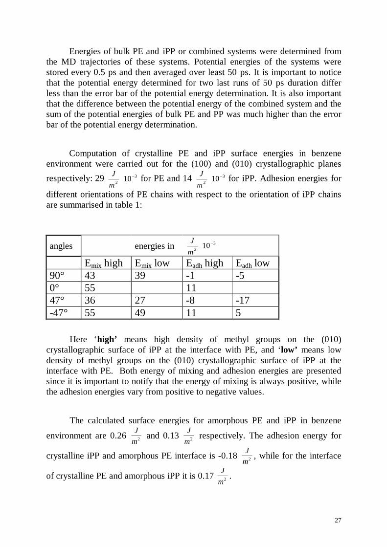
Energies of bulk PE and iPP or combined systems were determined fromthe MD trajectories of these systems. Potential energies of the systems werestored every 0.5 ps and then averaged over least 50 ps. It is important to noticethat the potential energy determined for two last runs of 50 ps duration differless than the error bar of the potential energy determination. It is also importantthat the difference between the potential energy of the combined system and thesum of the potential energies of bulk PE and PP was much higher than the errorbar of the potential energy determination.
Computation of crystalline PE and iPP surface energies in benzeneenvironment were carried out for the (100) and (010) crystallographic planes
respectively: 29 32 10 −⋅
mJ for PE and 14 3
2 10 −⋅mJ for iPP. Adhesion energies for
different orientations of PE chains with respect to the orientation of iPP chainsare summarised in table 1:
angles energies in 32 10 −⋅
mJ
Emix high Emix low Eadh high Eadh low90° 43 39 -1 -50° 55 1147° 36 27 -8 -17-47° 55 49 11 5
Here ‘high’ means high density of methyl groups on the (010)crystallographic surface of iPP at the interface with PE, and ‘low’ means lowdensity of methyl groups on the (010) crystallographic surface of iPP at theinterface with PE. Both energy of mixing and adhesion energies are presentedsince it is important to notify that the energy of mixing is always positive, whilethe adhesion energies vary from positive to negative values.
The calculated surface energies for amorphous PE and iPP in benzene
environment are 0.26 Jm2 and 0.13 J
m2 respectively. The adhesion energy for
crystalline iPP and amorphous PE interface is -0.18 Jm2 , while for the interface
of crystalline PE and amorphous iPP it is 0.17 Jm2 .
28
Structural changing at the interfaceThe structure of crystalline PE and iPP did not change when PE and iPP
were layered with amorphous PE and iPP.
Rotation 47° of PE molecules with respect to the orientation of PPchains, low density of methyl groups on the PP contacting surface
The ensemble consisting of two layers of PE and PP has two PE/PPinterfaces due to the periodic boundary conditions. In order to avoid possibleinterference of two interfaces we constructed model systems, consisting of threelayers - PE layer, PP layer and layer of benzene. It should be mentioned that nosignificant structural difference of PE and iPP between the three layer and thetwo layer systems were observed after MD simulation.
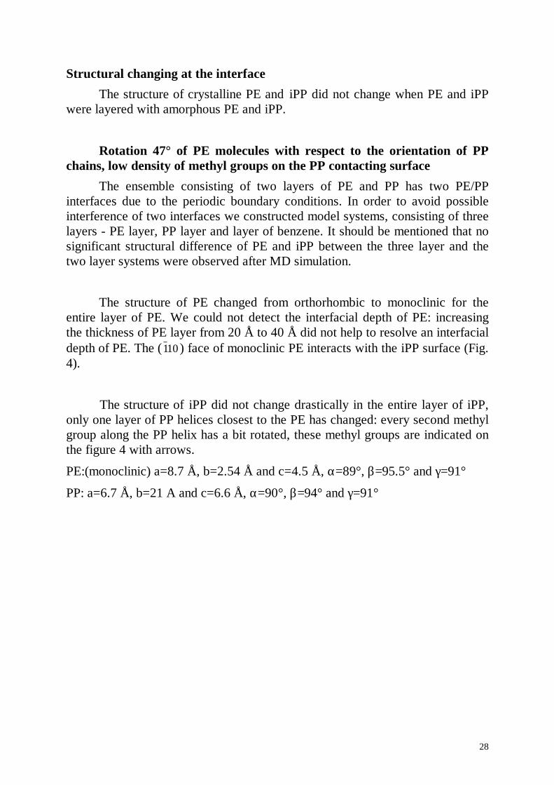
The structure of PE changed from orthorhombic to monoclinic for theentire layer of PE. We could not detect the interfacial depth of PE: increasingthe thickness of PE layer from 20 Å to 40 Å did not help to resolve an interfacialdepth of PE. The (110 ) face of monoclinic PE interacts with the iPP surface (Fig.4).
The structure of iPP did not change drastically in the entire layer of iPP,only one layer of PP helices closest to the PE has changed: every second methylgroup along the PP helix has a bit rotated, these methyl groups are indicated onthe figure 4 with arrows.
PE:(monoclinic) a=8.7 Å, b=2.54 Å and c=4.5 Å, α=89 °, β=9 5.5° and γ=9 1°PP: a=6.7 Å, b=21 A and c=6.6 Å, α=9 0°, β=9 4° and γ=9 1°
29
Figure 4 A) Interface of crystalline iPP and crystalline PE with low density of methylgroups on the PP contacting surface. End on view on PE molecules, iPP molecules are rotatedabout 47° to the point of view. Arrows point out the methyl groups on the surface of iPPwhich were initially oriented upwards. B) Top view on orthorhombic crystalline polyethylene.
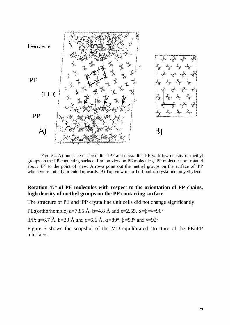
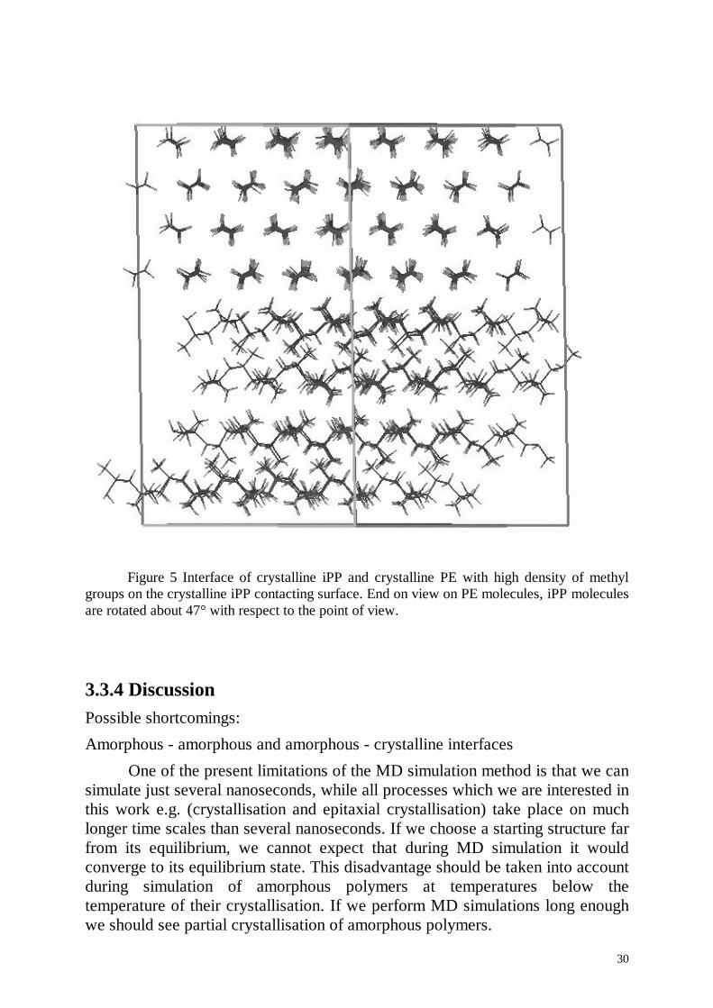
Rotation 47° of PE molecules with respect to the orientation of PP chains,high density of methyl groups on the PP contacting surfaceThe structure of PE and iPP crystalline unit cells did not change significantly.
PE:(orthorhombic) a=7.85 Å, b=4.8 Å and c=2.55, α=β=γ=9 0°iPP: a=6.7 Å, b=20 Å and c=6.6 Å, α=89 °, β=9 3° and γ=9 2°Figure 5 shows the snapshot of the MD equilibrated structure of the PE/iPPinterface.
30
Figure 5 Interface of crystalline iPP and crystalline PE with high density of methylgroups on the crystalline iPP contacting surface. End on view on PE molecules, iPP moleculesare rotated about 47° with respect to the point of view.
3.3.4 DiscussionPossible shortcomings:
Amorphous - amorphous and amorphous - crystalline interfaces
One of the present limitations of the MD simulation method is that we cansimulate just several nanoseconds, while all processes which we are interested inthis work e.g. (crystallisation and epitaxial crystallisation) take place on muchlonger time scales than several nanoseconds. If we choose a starting structure farfrom its equilibrium, we cannot expect that during MD simulation it wouldconverge to its equilibrium state. This disadvantage should be taken into accountduring simulation of amorphous polymers at temperatures below thetemperature of their crystallisation. If we perform MD simulations long enoughwe should see partial crystallisation of amorphous polymers.
31
The fact, that PE and PP are semicrystalline polymers both as neatmaterials and in the blend suggest amorphous - amorphous and crystalline -amorphous interfaces. It should be pointed out that amorphous parts, which givean amorphous halo in X-ray scattering experiments, are not purely amorphous,but are just parts of polymer chains in-between crystalline lamellae, which areforced to stay in a non crystalline state. This state can even not be calledamorphous because the chain orientation is induced by the presence of thecrystalline lamellae as it was mentioned in the introduction. In computersimulation nothing prevents polymers from crystallisation at temperatures belowtemperature of crystallisation.
From the statements made above one can conclude that even when we donot see any further decrease of potential energy with time, this does not meanthat amorphous ensembles are already equilibrated. This is true for the bulkamorphous systems and as well as for the interfaces of two amorphous polymersor for the interfaces of semi-crystalline polymers. If we simulate amorphoussystems for a very long time, we should see crystallisation of bulk amorphousPE and PP and epitaxial crystallisation of layered system.
Crystalline-crystalline interfaces
On the other hand crystalline-crystalline interfaces do not have muchfreedom – e.g. PE macromolecules can not rotate laterally on top of iPP chains.If we assume that the crystalline structures of both PE and iPP do not differ verymuch from bulk crystalline PE and iPP (orthorhombic and α− modificationrespectively), then the system of combined PE and iPP should not undergo largeconformational changes during MD. Therefore, MD trajectories should not bevery long to minimise the energy of crystalline-crystalline ensembles.Experimental investigations of structures, formed by PE during epitaxialcrystallisation show that PE crystallises epitaxially either in the orthorhombicstructure or in the monoclinic depending on substrate and environmentalconditions. iPP can crystallise in three different crystalline forms: α− , β− , andγ− modifications. On the other hand it was established that just the α crystallinemodification of iPP induces epitaxial crystallisation of PE, and iPP crystallisesepitaxially in the α− modification on the PE substrate. Based on the assumptionsmade above one can conclude that it could be possible to investigate by meansof computer simulations crystalline-crystalline interfaces of PE and iPP.
The algorithm of layering of crystalline-crystalline interfaces could causeartificial structural changes. As it was mentioned above ensembles of crystallinePE and PP had a mismatch in cell sizes in the a and b axes. During layering thismismatch was corrected by scaling of the PE and PP cell sizes, which means
32
that bond lengths and angles were scaled as well. For example in the case oflayering of a PE ensemble with PP, when PE molecules were oriented at 47°with respect to the orientation of PP chains, bonds and angles were scaled asfollows:
1. PE: C-C bond length was changed from 1.54 Å to 1.50 Å.
2. PP: C-C bond lengths were changed from 1.54 Å to 1.42,1.59,1.60,1.53 Å.
This artificial scaling of bond length and angles could cause severalshortcomings:
Changing bond lengths without a correlated scaling of the force field leads tostoring of a considerable amount of energy in the system. There could be severalways leading to structural changes in the system due to the stored energy. a) Ifwe assume that energy minimisation does not relax the molecular system to theglobal minimum but stops at a local minimum, then the difference of energybetween global and local minima should be stored in all degrees of freedom.This means that for example the energy stored in bond lengths could bedistributed to torsion potentials, and this could lead to the appearance of gaugedefects in the PE structure and the changing the helical structure of PP. b)Releasing of a large amount of energy during MD simulation could be alsodangerous: for example it may lead to local heating provoking local structuralchanging.
Analysing crystalline - crystalline interfaces shows that bond lengths andangles relax to their normal values. For example in the case of a crystalline -crystalline interface while, PE molecules are oriented at 47° with respect to theorientation of PP chains, low density of methyl groups on the PP surface, bondsand angles have converged to the following values (after energy minimisationand 50 ps of MD simulation):
1. PE: C-C bond length has converged to 1.544 (1.54 before layering).
2. PP: C-C bond length has converged to 1.545 (1.54 before layering).
Analysing of the crystalline - crystalline interface after minimisation and 50 psof MD simulation does not reveal the appearance of gauge defects or destroyingof the helical structure of PP.
Adjusting of cell sizes causes that one part of the combined system wantsto increase the cell size while the second part of these molecular system wants todecrease the cell size. In the case of layering of PE and PP this could be relievedby small rotations of PE molecules with respect to PP molecules or by structuralchanges of PP and PE layers. I do not know how to argue that either structuralchanges of PE and PP in the combined systems were caused by cell sizemismatches or induced by the interaction of PE and PP at the interface. The
33
answer could probably be found by comparing of results of computer simulationwith experimental results.
Comparing of experimental results with results of computer simulationComputer simulated structures of pure crystalline PE and iPP
α− modification slightly differ from experimentally measured structures of PEand iPP α-modification.
PE:
MD simulated: a=7.66 Å, b=5.06 Å and c=2.58 Å, α=β=γ=9 0°experiment: a=7.4 Å, b=4.94 Å and c=2.534 Å, α=β=γ=9 0°
PP:
MD simulated: a=6.57 Å, b=21.5 Å and c=6.01 Å, α=γ=9 0°, β=9 7° experiment: a=6.65 Å, b= 20.78 Å and c=6.50 Å, α=β=9 0°, β=9 9 .6°
It is also important to compare distances between rows of methyl groups:5.05 A, 4.25 Å from experiment and 4.9 A, 4.28 Å from computer simulation.The model of epitaxial crystallisation was based on lattice matching of 5.05 A ofiPP with 4.94 A of PE. Structures of computer simulated crystalline PE and iPPdo not match exactly with experimentally established structures. On the otherhand computer simulated crystalline PE and iPP exhibit a lattice matchingwithin the same error bar.
The calculation of adhesion energies by means of computer simulationallows to establish the structure with the lowest adhesion energy, hence topredict epitaxial crystallisation of PE on PP substrate and vice versa epitaxialcrystallisation of PP on a PE substrate. Adhesion energies for PE - PP interfacesare summarised in the table 1. It is hard to compare the computer calculatedadhesion energy with the experimentally measured energy needed to split aninterface into parts. The computer calculated adhesion energy corresponds to theenergy of an ideal interface - a flat surface of PE interacting with a flat surfaceof PP. In a real experiment the surfaces of both samples are not flat any more,with some interpenetration of one polymer material into another. Depending onthe preparation conditions mixing on the molecular level in the interfacial regionshould be also taken into account. In the particular case of the PE - iPP interfaceit is known that PE forms tongues which penetrate into iPP. The experimentallymeasured adhesion energy includes the energy of yielding of these tongues andconsist mostly of this tongue yielding energy.
34
The calculated adhesion energies and energies of mixing could becompared effectively with experiments. The calculated energy of mixing isalways positive, which means that the computer simulation predicts immisciblityof PP and PE. It was clearly proven experimentally that PE and PP areimmiscible in the melt. Most of the experimental works indicate alsoimmisciblity of PE and PP in the solid form - ‘weak’ PE/iPP interfaces, but itwas supposed as well that improved mechanical properties of PE/iPP blendscould be explained by ‘strong’ PE/iPP interfaces.
The lowest calculated adhesion energy (table 1) corresponds to the case of47° orientation of PE molecules with respect to iPP chains and the low densityof methyl groups on the iPP surface. PE molecules have the same orientationwith rows formed by methyl groups on the iPP surface with an inter-rowdistance of 5.05 Å. The adhesion energy is higher when the PE molecules areoriented 47° with respect to the orientation of iPP chains, and the PE moleculeshave the same orientation with rows formed by methyl groups on the iPP surfacewith an inter-row distance of 4.25 Å. We did not consider by the computersimulation all orientations of PE molecules with respect to the orientation of iPPchains. In addition we did not investigate the interaction of differentcrystallographic planes of both PE and iPP. Within the range of simulatedensembles, from calculated adhesion energies we may conclude that PEmolecules should crystallise epitaxially on iPP at 47° with respect to theorientation of PP chains, and with low density of methyl groups at the surface.
The model of epitaxial crystallisation of PE on the iPP substrate is still indebate in the literature. It was supposed that the ‘cross-hatched’ morphology ofepitaxially crystallised PE on the iPP substrate, is driven by the ‘cross hatched’morphology of the iPP substrate. Due to the lattice matching of crystalline PEand iPP, PE molecules crystallise at about 50° with respect to the orientation ofiPP chains. iPP substrates crystallised under normal conditions, have two chainorientations at 100° to each other. This ‘cross hatched’ nature of iPP substratesinduces the ‘cross hatched’ morphology of epitaxially crystallised PE. Thismodel does not fit to the experimental work1 of epitaxially crystallised PE on thehighly oriented iPP substrate. By drawing, highly oriented films of iPP wereobtained, where molecules of iPP were oriented just in one direction in this film.Epitaxially crystallised PE on this substrate also shows a ‘cross hatched’morphology. In this experiment ‘cross hatched’ morphology of epitaxiallycrystallised PE can not be explained by the ‘cross hatched’ morphology of thesubstrate.
In order to explain the ‘cross hatched’ morphology one should take intoaccount that the probability to find left and right handed helices on the surface of
35
iPP is equal. This leads to the conclusion that the surfaces of different domainsof iPP could be composed of left handed or right handed helices. If the rows ofmethyl groups with an interrow distance of 5.05 Å formed by right handedhelices have the angle 47° with the helical axes then rows of methyl groups with5.05 Å interrow distance formed by left handed helixes have the angle -47° withthe helical axes. The ‘cross hatched’ morphology of epitaxially crystallised PEon iPP could be explained by the presence of both left and right handed heliceson the surface of iPP.
It is not possible to distinguish by X-ray scattering whether PE crystalliseson the (010) crystallographic surface of iPP with high a density of methylgroups or with a low density of methyl groups. On the other hand it wasestablished3 that the (010) surface of iPP, produced for epitaxial crystallisationof PE, contains low density of methyl groups. To produce a (010)crystallographic surface of iPP for epitaxial crystallisation, iPP is crystallised ona crystalline low molecular weight substrate, which induces the (010)crystallographic plane of iPP. After removing of the low molecular weightsubstrate, the (010) crystallographic plane of iPP is ready. This result shows thatthe (010) crystallographic surface of iPP with the low density of methyl groupsis energetically more favourable in contact with a low molecular weight solvent.It also indicates that the (010) crystallographic plane of iPP with low density ofmethyl groups could be energetically more favourable in contact with epitaxiallycrystallised PE.
The energetically most favourable combined ensemble is the ensemblewith PE chains oriented at 47° with respect to the orientation of iPP moleculeswith the low density of methyl groups on the iPP contacting plane (table 1.). Theanalysis of the structural changes shows that the PE structure has changedentirely from orthorhombic to monoclinic. Energetically the orthorhombicstructure is more favourable, but the energy difference between orthorhombicand monoclinic crystalline form is very low, as shown by computersimulation7,8. As it was described above structural changes in the combinedsystem could be induced by additional energy introduced into the system or bytension induced through adjusting cell sizes, especially when the energy oforthorhombic and monoclinic structures does not differ very much. On the otherhand it was found that some substrates do induce epitaxial growth of PE with themonoclinic structure. The observed monoclinic phase is spatially transient: itdoes not go beyond 3 or 5 nm from the substrate surface6. The computersimulation does not allow to go beyond 5 nm thickness of PE layer, so we justcannot see the transition from the monoclinic to the orthorhombic crystallinephase.
36
3.3 Conclusions.MD simulation of PE - iPP interfaces was performed. Amorphous –
amorphous, crystalline - amorphous and crystalline - crystalline interfaces weresimulated. Due to the drawback of the periodic boundary conditions which doesnot allow lateral rotation of one crystalline phase on top of the second one, thesimulations of crystalline-crystalline interfaces were restricted to that adoptedfrom the experiments on epitaxial crystallisation of PE and iPP and to severalreference interfaces.
Adhesion energies in the benzene environment were calculated in order tocompare different types of interfaces. It was found that the strongest adhesionfor crystalline-crystalline interfaces corresponds to the rotation of PEmacromolecules of about 47° with respect to the orientation of iPP helixes withlow density of methyl groups on the iPP surface. At this particular orientationPE molecules fit exactly in the rows formed by methyl groups on the surface ofiPP. Hence the structure model for epitaxial crystallisation of PE and iPP hasbeen proven. Experimental methods do not provide information whether PEcrystallises epitaxially on the surface of iPP with high or low density of methylgroups. Strong adhesion for the case PE-iPP interface with low concentration ofmethyl groups allow to predict epitaxial crystallisation of PE molecules on thesurface of iPP with low surface concentration of methyl groups.
The unexpected transition of crystalline PE from orthorhombic tomonoclinic crystalline form is observed for the interface with the strongestadhesion energy. It is possible that this phenomena is caused by the artefacts ofthe building of a super-cell with an interface of PE and iPP. On the other hand itis also possible that the transition from orthorhombic to monoclinic crystallineform happens just in a very thin layer of PE at the interface, while bulk PE isstill in the orthorhombic crystalline form. Therefore the monoclinic crystallineform can be space transient and was not observed in the experiment on theepitaxial crystallisation because the layer of PE in the monoclinic form was toothin to be detected without special preparation conditions of the experiment.
37
3.4 Literature1. J. Peterman, G. Broza, U. Rieck, A. Kawagushi, J. of Material Science, 22,(1987), 1477-1481.
2. B. Lotz and J.C. Wittmann, J. of Polym. Sci., Part B, 24, (1986), 1559-1575
3. W. Stocker, S.N. Magonov, and H.-J. Cantow, J.C. Wittmann and B. Lotz,Macromolecules, Vol. 26, 22, (1993), 5915-5923.
4. J. Brandrup, E.H. Immergut, “Polymer Handbook”, third edition, John Willeyand Sons.
5. G. Natta and P. Gorradini, Supplemento al Nuovo Cimento, 15, N10, (1960)40-51.
6. J.C. Wittmann and B. Lotz, Polymer, 30, (1989), 27-34.
7. Masymichi Kobayashi and Hiroyuki Tadokoro, Macromolecules, 8, N6,(1975), 897-903.
8. T. Yemni and L.McCullough, J.Polym.Sci., Polym. Phys. Ed., 11, (1973),1385.
9. M.P. Allen, D.J. Tildsley, ‘Computer simulation of liquids’, Clarendon press,Oxford, Science Publications (1987).
10. H. J. C. Berendsen, J. P. M. Postma, W. F. van Gunsteren, A. DiNola, J. R.Haak, ‘Molecular dynamics with coupling to an external bath’, J. Chem. Phys.,81, (1984), 3684-3690.
11. C.B. Bucknall and R.R. Smith. Polymer 6 (1965) 437.
12. E.I. Souheng Wu, J. Polym. Sci. 21 (1983) 699-716.
13. Jingshen Wu, Yiu-Wing Mai, J. Mater. Sci. 28 (1993) 6167-6177.
38
14. S. Strella, J. Polym. Sci. 4 (1996) 527-528.
15. Souheng Wu, Polymer, 26 (1985) 1855-1863.
16. M.C.M. van der Sanden, H.E.H. Meijer and P.J. Lemstra, Polymer 34 N10(1993) 2149-2154.
17. M.C.M. van der Sanden, H.E.H. Meijer and T.A. Tervoot, Polymer 34 N14(1993) 2961-2970.
18. InsightII version 4.0.0 manual
19. B. Gross, J. Petermann, J. of Material Sci., 19 (1984) 105-112.
20. B.L. Schürman, U.Niebergall, N.Severin, Ch.Burger, W.Stocker andJ.P.Rabe, Polymer 39, (1998) 5283-5291.
21. H.J.C. Berendsen, J.P.M. Postma, W.F. van Gunsteren, A. DiNola, and J.R.Haak, J.Chem.Phys. 81 (8), (1984) 3684-3690.
22. M. Parinello, A. Rahman, J.Appl.Phys., 52, (1981) 7182-7190
39
4. MD simulation of cylindrical and half-cylindrical micelles in water and atsolid liquid interfaces.
4.1 Introductory remarks.In the second part of this work MD calculations of aggregates of
amphiphilic molecules at sold-liquid interfaces are presented. Amphiphilicmolecules by definition are composed of two parts, hydrophobic andhydrophilic. These opposing properties in the same molecule are the origin ofmicro-phase separation of amphiphilic molecules and solvent when dissolved ina polar solvent like water. It is well known that amphiphilic molecules form awide variety of different aggregates like spherical micelles, bilayers or evenmore complicated structures of interpenetrating networks of amphiphilicmolecules and solvent18. As amphiphilic molecules are very important inindustry and biology, self aggregation of amphiphilic molecules and thestructure of their aggregates was investigated intensively. Most of experimentaldata lead to a qualitative picture of a micelle. A few experimental techniquesgive as well structure of a micelle quantitatively. But due to a limited resolutionsome aspects of the structure of micelles are not clear.
While the self aggregation of amphiphilic molecules in aqueous solutionis fairly well understood, it is not clear how these aggregates are affected by thepresence of a solid surface. The surface force apparatus provide quantitativemeasures of adsorption, but little information on the aggregate structure.Neutron reflection is a very powerful tool to probe the structure of adsorbedaggregates. Substituting of hydrogens from different parts of amphihpilicmolecule by deuteriums allows to obtain high resolution in the directionperpendicular to the substrate surface. The drawback of neutron reflection is thatit does not resolve the adsorbed structure in the plane parallel to the surface.Another powerful tool for the investigation of structures formed by amphiphilicmolecules on different substrates is scanning force microscopy (SFM). Incontradiction to the neutron reflection SFM provides good resolution in theplane parallel to the surface and relatively poor resolution in the directionnormal to the substrate surface. A combination of these two experimentalmethods allows to propose a picture of the adsorbed structure.
MD simulation is another powerful mean to obtain detailed insight intothe structure and molecular behaviour of amphiphilic aggregates. The advantageof the MD method is that it allows to track the position of each atom in thesystem with time, so that it allows to simulate and predict the exact picture ofmicelles. At present time MD simulation has several limitations. First, the MDmethod allows to simulate the evolution of a micelle on a very short time period,usually several nanoseconds. Second, MD allows to simulate only relatively
40
small molecular systems, consisting of thousands of atoms. In order to simulatethe evolution of micelles on longer time scales some simplifications could bemade. Starting from the models with a unification of atom groups like CH2 orH2O and ending with the models that simulate just main properties ofamphiphilic molecules - hydrophobic and hydrophilic parts. Simplificationsallow to simulate larger amphiphilic systems on much longer times scales, evenselfaggregation of amphiphilic molecules form aqueous media. But, of course,each simplification leads to the loss of some information about a simulatedmolecular system. That is why in order to get a detailed picture of anamphiphilic aggregate one should use an atomistic MD simulation.
Neutron magnetic resonance (NMR) measurements of correlation times inthe micelles show that fast correlation times are in the picosecond range. That iswhy it is supposed that a micelle should equilibrate its structure during the MDsimulation on several nanoseconds. But as the characteristic times of selfaggregation are much longer, it is clear that the simulated structure woulddepend highly on the starting configuration.
Atomistic MD simulation was performed in order to obtain the detailedstructure of the aggregates formed by trimethyl ammonium bromide (TAB)molecules on different substrates. Structures of TAB aggregates on hydrophobicand hydrophilic substrates suggested by SFM were adopted to use as the startingstructures for MD simulation. Half cylindrical micelles on gold and paraffin andcylindrical micelle on gold was simulated. Cylindrical micelle in waterenvironment was also simulated for two reasons: first to compare the simulationdata with experimental data in order to establish the reliability of the simulation,and second to compare the structure of the cylindrical micelle in water withadsorbed aggregates in order to find out how the presence of the substrateaffects their structure.
41
4.2.1 Amphiphilic moleculesThe separation of two immiscible molecular components from their liquid
mixture is described by the fundamental thermodynamic equations of self-assembly8. Equilibrium thermodynamics requires that in a system of moleculesforming aggregated structures in solution like micelles the chemical potential ofall identical molecules in different aggregates should be the same. Foraggregates of the same type but with a different total number M of moleculesthis may be expressed as:
µ µM MMkT
MXM
= +
0 log M=1,2,3...N... eq.1
where µΜ is the mean chemical potential of a molecule in an aggregate ofaggregation number M and XM is the concentration of these molecules in theaggregate. The first term of this formula µm
0 is the standard value of thechemical potential (the mean interaction energy per molecule), the second termis the loss of entropy by aggregation. Combining of these equations for M=1 andM=N yields:
( )[ ]{ }X N X kTN N
N= −1 1
0 0exp /µ µ eq.2
This equation together with the conservation relation for the total concentration
in the solution C X NN
==
∞
∑1
defines the system totally.
When µN0 remains constant for aggregates of different size
( µN0 = µ1
0 ) equation 2 becomes X NXNN= 1 . Since X1<1 we must have XN<<X1.
Hence most molecules will be in the monomer state. Aggregates will be formedwhen there is a difference of cohesive energy for the molecule in the dispersedphase and in the aggregated structures. For sufficiently low monomerconcentration X1 such that ( )[ ]X kTN1 1
0 0exp /µ µ− is less than unity we haveessentially the dispersed phase of molecules. With increasing monomerconcentration micelle formation becomes more favourable. The monomerconcentration (X1)crit at which this occurs is called the critical micelleconcentration (CMC).
( ) [ ]X kTcrit N1 1
0 0≈ − −exp ( ) /µ µ
The self aggregation of amphiphilic molecules is also described by thefundamental thermodynamic equations of self-assembly. The fundamental
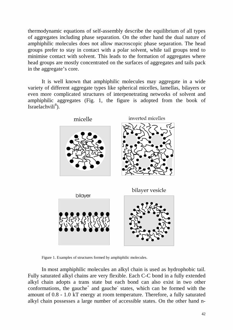
42
thermodynamic equations of self-assembly describe the equilibrium of all typesof aggregates including phase separation. On the other hand the dual nature ofamphiphilic molecules does not allow macroscopic phase separation. The headgroups prefer to stay in contact with a polar solvent, while tail groups tend tominimise contact with solvent. This leads to the formation of aggregates wherehead groups are mostly concentrated on the surfaces of aggregates and tails packin the aggregate’s core.
It is well known that amphiphilic molecules may aggregate in a widevariety of different aggregate types like spherical micelles, lamellas, bilayers oreven more complicated structures of interpenetrating networks of solvent andamphiphilic aggregates (Fig. 1, the figure is adopted from the book ofIsraelachvili8).
Figure 1. Examples of structures formed by amphiphilic molecules.
In most amphiphilic molecules an alkyl chain is used as hydrophobic tail.Fully saturated alkyl chains are very flexible. Each C-C bond in a fully extendedalkyl chain adopts a trans state but each bond can also exist in two otherconformations, the gauche+ and gauche- states, which can be formed with theamount of 0.8 - 1.0 kT energy at room temperature. Therefore, a fully saturatedalkyl chain possesses a large number of accessible states. On the other hand n-
43
alkanes are found to be in a crystalline state at room temperature. One mayconsider that in an aggregate the chains could also pack in an array of parallelall-trans chains, and the head groups are concentrated on two of six faces of acrystalline block and on four faces hydrocarbon chains would contact withwater. Hence, it is impossible to form such an array without energeticallyexpensive hydrocarbon-water contact. Therefore we should expect that the alkylchains in the interior of a micelle are conformationally disordered (liquid like).This expectation is supported by NMR measurements of fast correlation timesand order parameters for alkyl chains in micelles4. The motions of alkyl chainsin a micelle can be classified by two types: fast local motions in the alkyl chainand slow motions, ascribed to tumbling of the whole aggregate and/or diffusionof the amphiphilic molecules in the micelle. The measurements reveal fast intra-chain motions with correlation times around 10-11 s, a value in close agreementwith the correlation times calculated from similar measurements on liquid n-alkanes.
It is important to describe more detailed NMR experiments, by comparingresults of MD simulations with the correlation times measured by NMR. NMRmeasures spin relaxation of the nuclei in the external magnetic field andprovides information on the rotational motion of the atoms. In MD simulations itis better to express atom rotation in terms of rotations of the bonds, for examplerotation of C-H bond in the alkyl chain. This rotation is characterised by theauto-correlation function of bond orientation: ( )C t b b t b= ⋅( ) ( ) / ( )0 02 , where bis the bond vector. In general a time relaxation function C(t) can be representedas a sum of exponentials: A ti i
iexp( / )−∑ τ , where each decay term represents
different types of motion. For example in the case of amphiphilic molecules in amicelle orientation changes of C-H bonds can be due to transition between transand gauche conformations in the alkyl chain (fast modes) or due to rotationalmotions of the micelle as a whole and diffusion of the heads of the amphiphilicmolecules on the micelle surface (slow modes). Fast modes are in the range 1-100 ps and slow modes are in the nanosecond time regime. It is also interestingthat it is possible to distinguish whether carbon atoms in the methyl group or inthe alkyl chain. It is even more important that it is possible to distinguish carbonatoms in alkyl chain i.e. how far they are from the terminal group.Measurements of fast correlation times in amphiphilic micelles show thatcorrelation times for the terminal head groups of alkyl chains are almost thesame as the correlation times for the head groups of the same amphiphilicmolecules in the dispersed state. The values of the fast correlation times areincreasing considering carbons closer to the amphiphilic head group. The alkylchains are anchored to the bulky head groups and therefore carbon atoms closerto the head groups loose their mobility.
44
The very low solubility of water in the bulk n-alkane phase (about onewater molecule for each 2x10⁴ CH2 groups5) allows to predict a negligible waterpenetration into the aggregated micelle hydrophobic core. Indeed this point ofview was supported by NMR relaxation measurements6. Claims of experimentalevidence for extensive water penetration in the core were shown to beunfounded7. NMR may distinguish between CH2 group in contact with watermolecules and CH2 group in the hydrophobic core composed of alkyl chains. Itwas shown that there is extensive contact between CH2 groups and watermolecules, that is why it was concluded that there is extensive water penetrationin the micelle core. On the other hand it was shown later that NMR results maybe explained by fact that water molecules should contact with CH2 groups fromthe amphiphilic molecules in dispersed phase and in addition CH2 groups on theedge on the micelle contact with water molecules. It was shown on the basis ofNMR experiments that water does not mix with alkyl chains, but there is noevidence that water can not be found in the centre of the micelle. Howeverneutron diffraction studies8 give the evidence that water is totally excluded fromthe micelle core.
Accepting the above arguments, lead to the picture that the micelle corecan be considered as a non-polar liquid droplet consisting (almost exclusively)of fully saturated alkyl chains. The packing density of the chains is determinedby the Van der Waals forces and chain etropy. As the chains are chemicallyidentical to n-alkane chains, we should expect a packing density almost identicalto that found for bulk n-alkane.
The standard picture of amphiphilic micelles now may be summarised inthree simple points9:
(i) on average, each amphiphil molecule associated with a micelle hasalmost all of its hydrocarbon chains in the micelle core;
(ii) the ionic head-groups, ions and water are almost completely excludedfrom the micelle core;
(iii) the amphiphil chains are conformationally disordered (liquid like) andfill the core at approximately liquid n-alkane density throughout.
The standard picture implies that the chain-water interface is sharplydefined (with an average roughness in the order of a few Å) and that the head-groups are just outside the micellar core in a layer, again with a roughness of afew Å.
While self aggregation of amphiphilic molecules in free solution is wellunderstood. It is not clear how these aggregates are affected by the presence of asolid boundary surface. Recently the pioneering work of scanning forcemicroscopy (SFM) imaging of surface aggregates formed by tetradecyltrimethylammonium bromide (TAB) molecules was performed2:
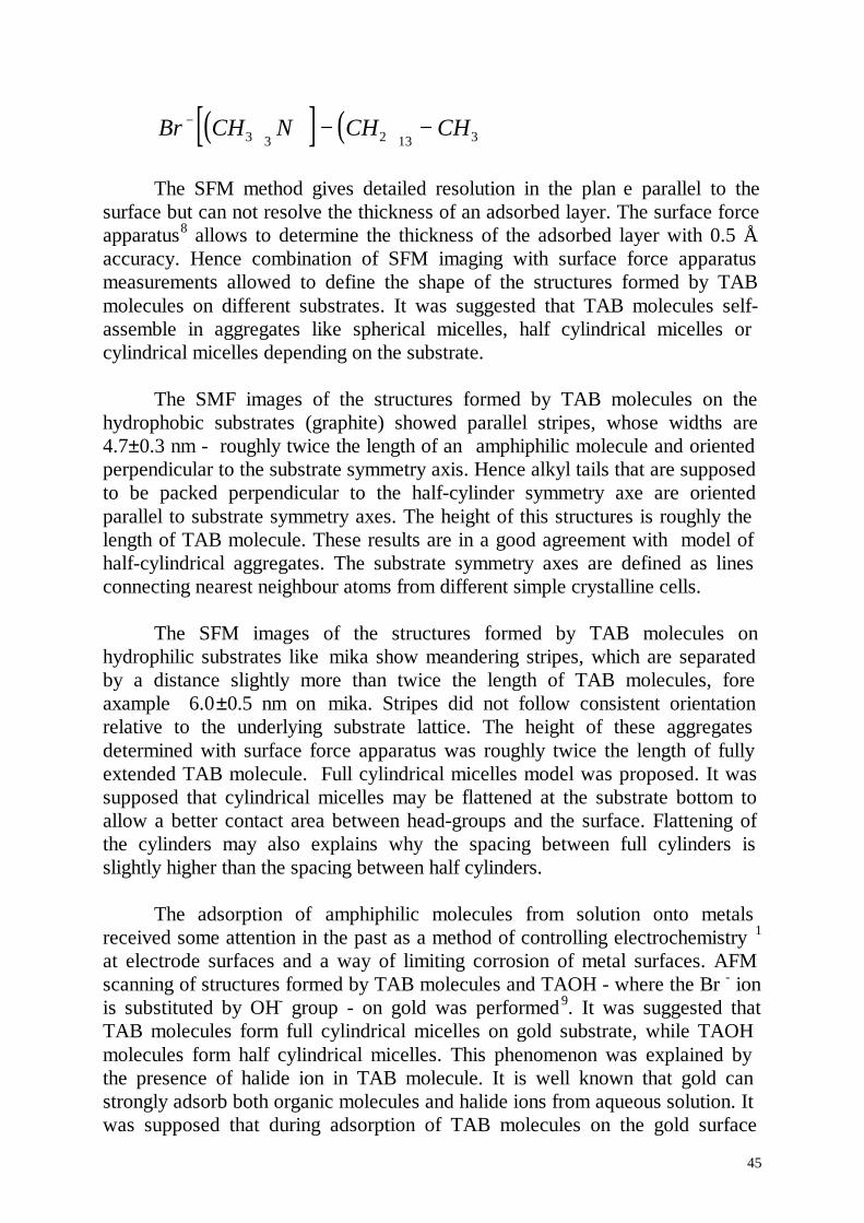
45
( )[ ] ( )Br CH N CH CH− + − −3 3 2 13 3
The SFM method gives detailed resolution in the plan e parallel to thesurface but can not resolve the thickness of an adsorbed layer. The surface forceapparatus8 allows to determine the thickness of the adsorbed layer with 0.5 Åaccuracy. Hence combination of SFM imaging with surface force apparatusmeasurements allowed to define the shape of the structures formed by TABmolecules on different substrates. It was suggested that TAB molecules self-assemble in aggregates like spherical micelles, half cylindrical micelles orcylindrical micelles depending on the substrate.
The SMF images of the structures formed by TAB molecules on thehydrophobic substrates (graphite) showed parallel stripes, whose widths are4.7±0.3 nm - roughly twice the length of an amphiphilic molecule and orientedperpendicular to the substrate symmetry axis. Hence alkyl tails that are supposedto be packed perpendicular to the half-cylinder symmetry axe are orientedparallel to substrate symmetry axes. The height of this structures is roughly thelength of TAB molecule. These results are in a good agreement with model ofhalf-cylindrical aggregates. The substrate symmetry axes are defined as linesconnecting nearest neighbour atoms from different simple crystalline cells.
The SFM images of the structures formed by TAB molecules onhydrophilic substrates like mika show meandering stripes, which are separatedby a distance slightly more than twice the length of TAB molecules, foreaxample 6.0±0.5 nm on mika. Stripes did not follow consistent orientationrelative to the underlying substrate lattice. The height of these aggregatesdetermined with surface force apparatus was roughly twice the length of fullyextended TAB molecule. Full cylindrical micelles model was proposed. It wassupposed that cylindrical micelles may be flattened at the substrate bottom toallow a better contact area between head-groups and the surface. Flattening ofthe cylinders may also explains why the spacing between full cylinders isslightly higher than the spacing between half cylinders.
The adsorption of amphiphilic molecules from solution onto metalsreceived some attention in the past as a method of controlling electrochemistry 1
at electrode surfaces and a way of limiting corrosion of metal surfaces. AFMscanning of structures formed by TAB molecules and TAOH - where the Br - ionis substituted by OH- group - on gold was performed 9. It was suggested thatTAB molecules form full cylindrical micelles on gold substrate, while TAOHmolecules form half cylindrical micelles. This phenomenon was explained bythe presence of halide ion in TAB molecule. It is well known that gold canstrongly adsorb both organic molecules and halide ions from aqueous solution. Itwas supposed that during adsorption of TAB molecules on the gold surface
46
halide ions adsorb preferentially on the gold surface producing a hydrophilicsurface. Then the TAB molecules can form full cylinders to bring the headgroups in contact with adsorbed Br - ions.
The SFM method provides valuable information on the shape of theadsorbed aggregates of amphiphilic molecules, but it does not provide anyinformation either on the detailed structure i.e. the organisation of theamphiphilic molecules in these aggregates nor on the dynamic properties. Thereare few experimental techniques which provide information on structuresadsorbed on the surface. Neutron reflection experiment provide high resolutionin the direction perpendicular to the adsorbate surface but do not yield anystructural information in the plane parallel to the surface. It is interesting tocombine neutron reflection with SFM results because SFM on the other handprovide very good resolution in the plane of the surface but very poor resolutionin the direction normal to the surface. Neutron reflection experiments wereperformed on the structures formed by TAB molecules on silica. It wassuggested that TAB molecules form bilayers with 32±1 Å thickness, while thelength of fully extended TAB molecule is 25 Å. That is why the model of abilayer with interpenetrating tails was proposed. It was also found that about 10% of the bilayer is occupied with water. The SFM imaging of structures formedby TAB molecules on silica showed circular structures. Hence the model ofspherical aggregates was proposed on the basis of SFM data. Combining neutronreflection with SFM imaging one may propose spherical aggregates very pressedtoward the surface. Experimental methods like nuclear magnetic resonance orneutron scattering provide information on bulk materials but can not determinatesignal from the thin layer of amphiphilic molecules at the solid-liquid interfacebeyond noise.
4.2.2 ModelThe present limitation of MD simulation is the length of simulation time.
The characteristic times for aggregation of amphiphilic molecules are in theseconds time range or even longer. MD simulation allow to trace the timeevolution of a system on a nanosecond range only. It is therefor impossible tosee the aggregation of amphiphilic molecules from a polydispersed phase. Thatis why one should create these molecular systems in conformations which areclosely related to experimentally established molecular structures. The SFMexperiments on imaging of structures formed by TAB molecules on differentsubstrates were taken as the starting point for computer simulation.
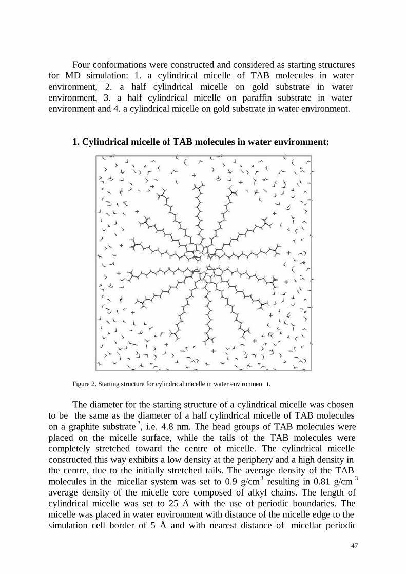
47
Four conformations were constructed and considered as starting structuresfor MD simulation: 1. a cylindrical micelle of TAB molecules in waterenvironment, 2. a half cylindrical micelle on gold substrate in waterenvironment, 3. a half cylindrical micelle on paraffin substrate in waterenvironment and 4. a cylindrical micelle on gold substrate in water environment.
1. Cylindrical micelle of TAB molecules in water environment:
Figure 2. Starting structure for cylindrical micelle in water environmen t.
The diameter for the starting structure of a cylindrical micelle was chosento be the same as the diameter of a half cylindrical micelle of TAB moleculeson a graphite substrate 2, i.e. 4.8 nm. The head groups of TAB molecules wereplaced on the micelle surface, while the tails of the TAB molecules werecompletely stretched toward the centre of micelle. The cylindrical micelleconstructed this way exhibits a low density at the periphery and a high density inthe centre, due to the initially stretched tails. The average density of the TABmolecules in the micellar system was set to 0.9 g/cm 3 resulting in 0.81 g/cm 3
average density of the micelle core composed of alkyl chains. The length ofcylindrical micelle was set to 25 Å with the use of periodic boundaries. Themicelle was placed in water environment with distance of the micelle edge to thesimulation cell border of 5 Å and with nearest distance of micellar periodic
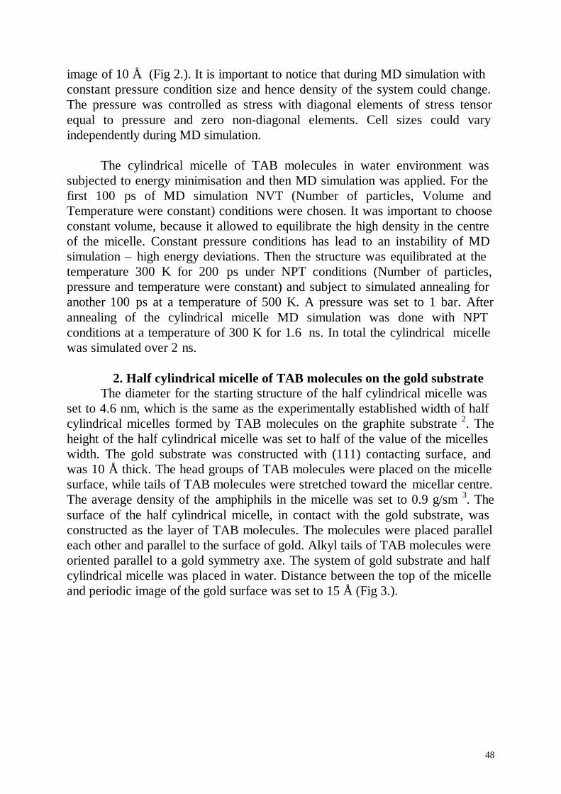
48
image of 10 Å (Fig 2.). It is important to notice that during MD simulation withconstant pressure condition size and hence density of the system could change.The pressure was controlled as stress with diagonal elements of stress tensorequal to pressure and zero non-diagonal elements. Cell sizes could varyindependently during MD simulation.
The cylindrical micelle of TAB molecules in water environment wassubjected to energy minimisation and then MD simulation was applied. For thefirst 100 ps of MD simulation NVT (Number of particles, Volume andTemperature were constant) conditions were chosen. It was important to chooseconstant volume, because it allowed to equilibrate the high density in the centreof the micelle. Constant pressure conditions has lead to an instability of MDsimulation – high energy deviations. Then the structure was equilibrated at thetemperature 300 K for 200 ps under NPT conditions (Number of particles,pressure and temperature were constant) and subject to simulated annealing foranother 100 ps at a temperature of 500 K. A pressure was set to 1 bar. Afterannealing of the cylindrical micelle MD simulation was done with NPTconditions at a temperature of 300 K for 1.6 ns. In total the cylindrical micellewas simulated over 2 ns.
2. Half cylindrical micelle of TAB molecules on the gold substrateThe diameter for the starting structure of the half cylindrical micelle was
set to 4.6 nm, which is the same as the experimentally established width of halfcylindrical micelles formed by TAB molecules on the graphite substrate 2. Theheight of the half cylindrical micelle was set to half of the value of the micelleswidth. The gold substrate was constructed with (111) contacting surface, andwas 10 Å thick. The head groups of TAB molecules were placed on the micellesurface, while tails of TAB molecules were stretched toward the micellar centre.The average density of the amphiphils in the micelle was set to 0.9 g/sm 3. Thesurface of the half cylindrical micelle, in contact with the gold substrate, wasconstructed as the layer of TAB molecules. The molecules were placed paralleleach other and parallel to the surface of gold. Alkyl tails of TAB molecules wereoriented parallel to a gold symmetry axe. The system of gold substrate and halfcylindrical micelle was placed in water. Distance between the top of the micelleand periodic image of the gold surface was set to 15 Å (Fig 3.).
49
Figure 3. Starting structure for half cylindrical micelle on gold substrate in water environment.
The half cylindrical micelle on the gold substrate in a water environmentwas energy minimised and then a MD simulation was started. The system wasequilibrated at a temperature of 300 K for 50 ps under NVT conditions and forthe next 50 ps under NPT conditions. The half cylindrical micelle was thenannealed for 100 ps at a temperature of 500 K. After annealing of the molecularsystem a MD simulation was performed with NPT conditions at a temperatureof 300 K and 1 Bar pressure for 1.8 ns.
3. Half cylindrical micelle of TAB molecules on paraffin substrateIn order to save CPU time used for the equilibration of the molecular
system the output structure after a 500 ps of MD simulation of the halfcylindrical micelle of TAB molecules on the gold substrate was used toconstruct a half cylindrical micelle on a paraffin substrate. The gold substratewas replaced by paraffin substrate. The (100) crystallographic plane of paraffinwas chosen to contact with the half cylindrical micelle. The paraffin substratewas placed with matching of its symmetry axe with the symmetry axe of thegold substrate. The water molecules were not changed.
The half cylindrical micelle on the paraffin substrate was energyminimised and then treated by MD simulation. The structure was first
50
equilibrated at a temperature of 300 K for 100 ps and then simulated annealingat 500 K temperature was done for 100 ps time. After annealing of the molecularsystem MD simulation with NPT conditions at the temperature 300 K wasperformed for 1.3 ns. Paraffin substrate was kept fixed.
4. Cylindrical micelle of TAB molecules on gold substrate in waterenvironment.
In order to save CPU time the atomic coordinates after a 500 ps of MDsimulation of the cylindrical micelle of TAB molecules in water was used toconstruct a cylindrical micelle on the gold substrate. For that purpose the waterenvironment was partially removed and replaced by the gold layer with a (111)contacting crystallographic plane as contact surface. The cylindrical micelle wasput about 3 Å above the gold surface. The layer of gold was constructed with 10Å thickness. An additional layer of water of 5 Å thickness was added in betweenthe cylindrical micelle and the periodic image of gold in order to prevent contactof cylindrical micelle with the periodic image of the gold substrate.
Cylindrical micelle on the gold substrat e in water solution was energyminimised and then treated by MD simulation. The molecular structure wasequilibrated at a temperature of 300 K for 100 ps of time and then annealed at500 K for 100 ps. After annealing the molecular system was subjected to MDsimulation with NPT conditions at 300 K for 800 ps.
4.2.3 ResultsCylindrical micelle in water environment.
A snapshot of the structure of the cylindrical micelle of TAB molecules in waterenvironment after 2 ns of MD simulation is presented in figure 4.
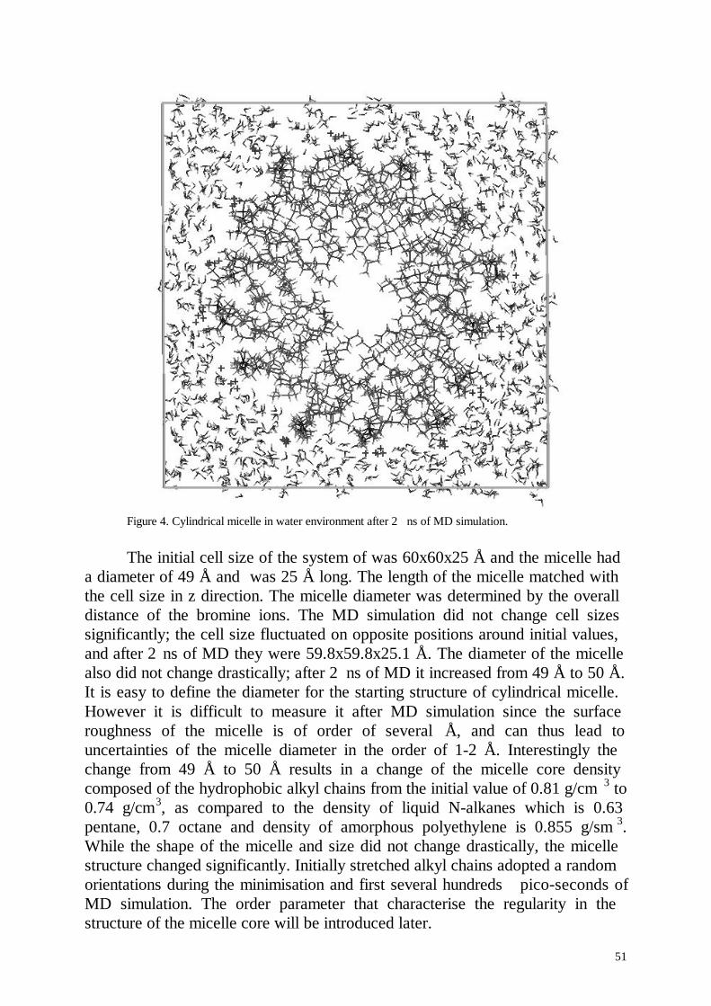
51
Figure 4. Cylindrical micelle in water environment after 2 ns of MD simulation.
The initial cell size of the system of was 60x60x25 Å and the micelle hada diameter of 49 Å and was 25 Å long. The length of the micelle matched withthe cell size in z direction. The micelle diameter was determined by the overalldistance of the bromine ions. The MD simulation did not change cell sizessignificantly; the cell size fluctuated on opposite positions around initial values,and after 2 ns of MD they were 59.8x59.8x25.1 Å. The diameter of the micellealso did not change drastically; after 2 ns of MD it increased from 49 Å to 50 Å.It is easy to define the diameter for the starting structure of cylindrical micelle.However it is difficult to measure it after MD simulation since the surfaceroughness of the micelle is of order of several Å, and can thus lead touncertainties of the micelle diameter in the order of 1-2 Å. Interestingly thechange from 49 Å to 50 Å results in a change of the micelle core densitycomposed of the hydrophobic alkyl chains from the initial value of 0.81 g/cm 3 to0.74 g/cm3, as compared to the density of liquid N-alkanes which is 0.63pentane, 0.7 octane and density of amorphous polyethylene is 0.855 g/sm 3.While the shape of the micelle and size did not change drastically, the micellestructure changed significantly. Initially stretched alkyl chains adopted a randomorientations during the minimisation and first several hundreds pico-seconds ofMD simulation. The order parameter that characterise the regularity in thestructure of the micelle core will be introduced later.
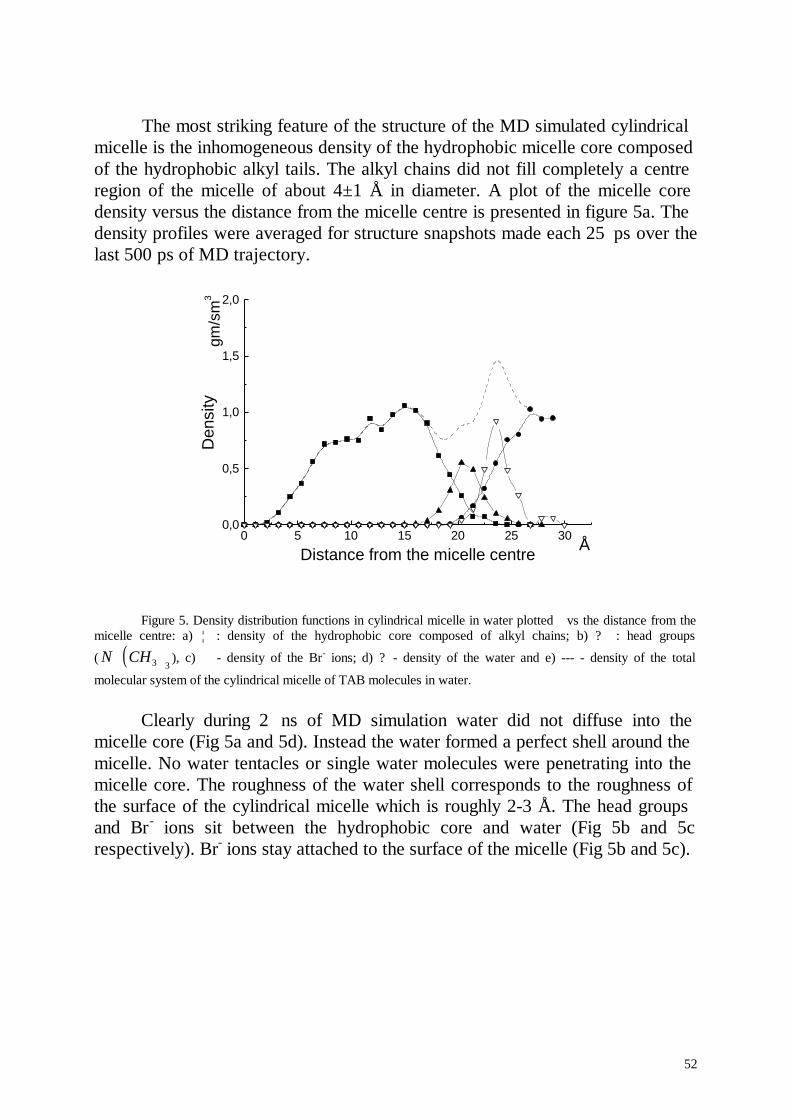
52
The most striking feature of the structure of the MD simulated cylindricalmicelle is the inhomogeneous density of the hydrophobic micelle core composedof the hydrophobic alkyl tails. The alkyl chains did not fill completely a centreregion of the micelle of about 4±1 Å in diameter. A plot of the micelle coredensity versus the distance from the micelle centre is presented in figure 5a. Thedensity profiles were averaged for structure snapshots made each 25 ps over thelast 500 ps of MD trajectory.
0 5 10 15 20 25 300,0
0,5
1,0
1,5
2,0
Å
gm/s
m3
Den
sity
Distance from the micelle centre
Figure 5. Density distribution functions in cylindrical micelle in water plotted vs the distance from themicelle centre: a) ¦ : density of the hydrophobic core composed of alkyl chains; b) ? : head groups
( ( )N CH+3 3
), c) ∇ - density of the Br- ions; d) ? - density of the water and e) --- - density of the total
molecular system of the cylindrical micelle of TAB molecules in water.
Clearly during 2 ns of MD simulation water did not diffuse into themicelle core (Fig 5a and 5d). Instead the water formed a perfect shell around themicelle. No water tentacles or single water molecules were penetrating into themicelle core. The roughness of the water shell corresponds to the roughness ofthe surface of the cylindrical micelle which is roughly 2-3 Å. The head groupsand Br - ions sit between the hydrophobic core and water (Fig 5b and 5crespectively). Br- ions stay attached to the surface of the micelle (Fig 5b and 5c).
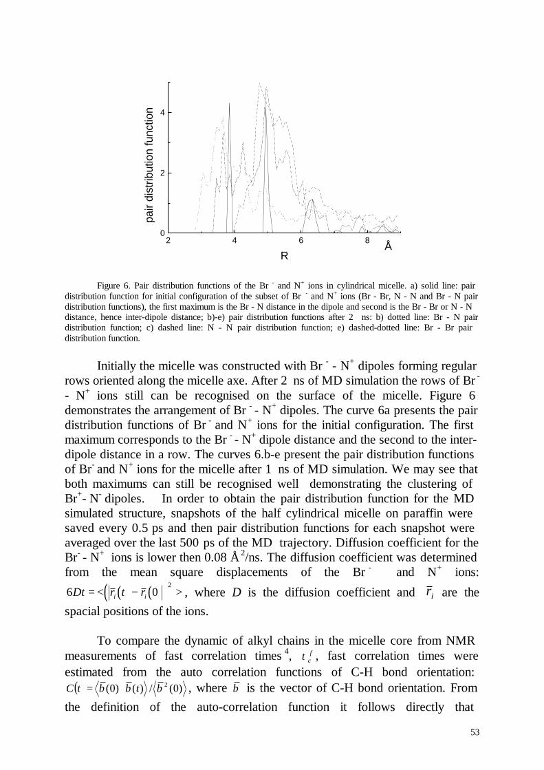
53
2 4 6 80
2
4
Å
pair
dist
ribut
ion
func
tion
R
Figure 6. Pair distribution functions of the Br - and N+ ions in cylindrical micelle. a) solid line: pairdistribution function for initial configuration of the subset of Br - and N+ ions (Br - Br, N - N and Br - N pairdistribution functions), the first maximum is the Br - N distance in the dipole and second is the Br - Br or N - Ndistance, hence inter-dipole distance; b)-e) pair distribution functions after 2 ns: b) dotted line: Br - N pairdistribution function; c) dashed line: N - N pair distribution function; e) dashed-dotted line: Br - Br pairdistribution function.
Initially the micelle was constructed with Br - - N+ dipoles forming regularrows oriented along the micelle axe. After 2 ns of MD simulation the rows of Br -
- N+ ions still can be recognised on the surface of the micelle. Figure 6demonstrates the arrangement of Br - - N+ dipoles. The curve 6a presents the pairdistribution functions of Br - and N+ ions for the initial configuration. The firstmaximum corresponds to the Br - - N+ dipole distance and the second to the inter-dipole distance in a row. The curves 6.b-e present the pair distribution functionsof Br- and N+ ions for the micelle after 1 ns of MD simulation. We may see thatboth maximums can still be recognised well demonstrating the clustering ofBr+- N- dipoles. In order to obtain the pair distribution function for the MDsimulated structure, snapshots of the half cylindrical micelle on paraffin weresaved every 0.5 ps and then pair distribution functions for each snapshot wereaveraged over the last 500 ps of the MD trajectory. Diffusion coefficient for theBr- - N+ ions is lower then 0.08 Å 2/ns. The diffusion coefficient was determinedfrom the mean square displacements of the Br - and N+ ions:
( ) ( )( )6 02
Dt r t ri i= < − > , where D is the diffusion coefficient and ri are thespacial positions of the ions.
To compare the dynamic of alkyl chains in the micelle core from NMRmeasurements of fast correlation times 4, τc
f , fast correlation times wereestimated from the auto correlation functions of C-H bond orientation:
( ) )0(/)()0( 2btbbtC ⋅= , where b is the vector of C-H bond orientation. Fromthe definition of the auto-correlation function it follows directly that
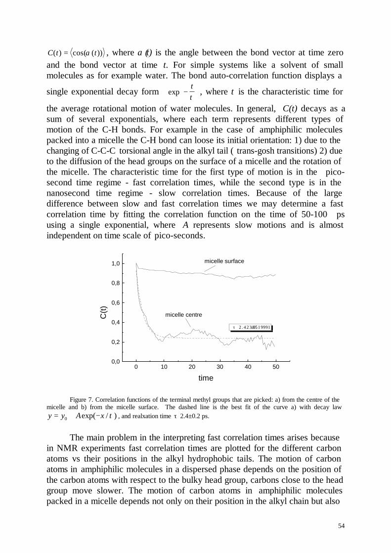
54
C t t( ) cos( ( ))= α , where α (t) is the angle between the bond vector at time zeroand the bond vector at time t. For simple systems like a solvent of smallmolecules as for example water. The bond auto-correlation function displays a
single exponential decay form exp −
tτ , where τ is the characteristic time for
the average rotational motion of water molecules. In general, C(t) decays as asum of several exponentials, where each term represents different types ofmotion of the C-H bonds. For example in the case of amphiphilic moleculespacked into a micelle the C-H bond can loose its initial orientation: 1) due to thechanging of C-C-C torsional angle in the alkyl tail ( trans-gosh transitions) 2) dueto the diffusion of the head groups on the surface of a micelle and the rotation ofthe micelle. The characteristic time for the first type of motion is in the pico-second time regime - fast correlation times, while the second type is in thenanosecond time regime - slow correlation times. Because of the largedifference between slow and fast correlation times we may determine a fastcorrelation time by fitting the correlation function on the time of 50-100 psusing a single exponential, where A represents slow motions and is almostindependent on time scale of pico-seconds.
0 10 20 30 40 500,0
0,2
0,4
0,6
0,8
1,0
micelle centre
micelle surface
τ 2 . 42335±0.1 9 9 9 1
C(t)
time
Figure 7. Correlation functions of the terminal methyl groups that are picked: a) from the centre of themicelle and b) from the micelle surface. The dashed line is the best fit of the curve a) with decay lawy y A x= + −0 exp( / )τ , and realxation time τ 2.4±0.2 ps.
The main problem in the interpreting fast correlation times arises becausein NMR experiments fast correlation times are plotted for the different carbonatoms vs their positions in the alkyl hydrophobic tails. The motion of carbonatoms in amphiphilic molecules in a dispersed phase depends on the position ofthe carbon atoms with respect to the bulky head group, carbons close to the headgroup move slower. The motion of carbon atoms in amphiphilic moleculespacked in a micelle depends not only on their position in the alkyl chain but also
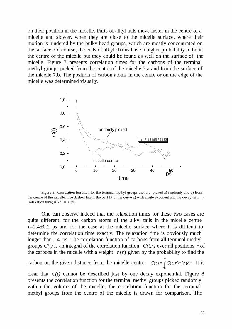
55
on their position in the micelle. Parts of alkyl tails move faster in the centre of amicelle and slower, when they are close to the micelle surface, where theirmotion is hindered by the bulky head groups, which are mostly concentrated onthe surface. Of course, the ends of alkyl chains have a higher probability to be inthe centre of the micelle but they could be found as well on the surface of themicelle. Figure 7 presents correlation times for the carbons of the terminalmethyl groups picked from the centre of the micelle 7.a and from the surface ofthe micelle 7.b. The position of carbon atoms in the centre or on the edge of themicelle was determined visually.
0 10 20 30 40 500,0
0,2
0,4
0,6
0,8
1,0
ps
randomly picked
micelle centre
τ 7 . 9 4 8 8 1±0 .7 5 8 9 5
C(t)
time
Figure 8. Correlation fun ction for the terminal methyl groups that are picked a) randomly and b) fromthe centre of the micelle. The dashed line is the best fit of the curve a) with single exponent and the decay term τ(relaxation time) is 7.9 ±0.8 ps.
One can observe indeed that the relaxation times for these two cases arequite different: for the carbon atoms of the alkyl tails in the micelle centreτ=2.4±0.2 ps and for the case at the micelle surface where it is difficult todetermine the correlation time exactly. The relaxation time is obviously muchlonger than 2.4 ps. The correlation function of carbons from all terminal methylgroups C(t) is an integral of the correlation function C(t,r) over all positions r ofthe carbons in the micelle with a weight ρ( )r given by the probability to find the
carbon on the given distance from the micelle centre: C t C t r r dr( ) ( , ) ( )=∞
∫ ρ0
. It is
clear that C(t) cannot be described just by one decay exponential. Figure 8presents the correlation function for the terminal methyl groups picked randomlywithin the volume of the micelle; the correlation function for the terminalmethyl groups from the centre of the micelle is drawn for comparison. The
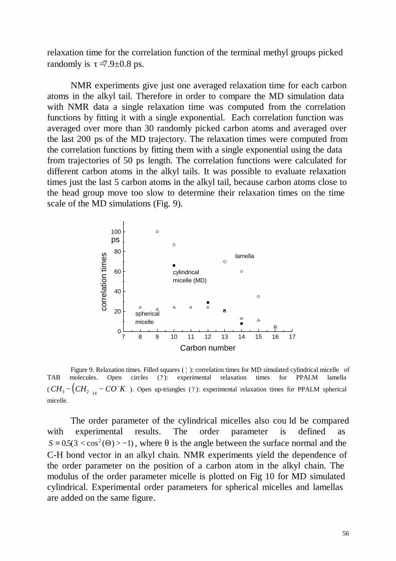
56
relaxation time for the correlation function of the terminal methyl groups pickedrandomly is τ=7.9±0.8 ps.
NMR experiments give just one averaged relaxation time for each carbonatoms in the alkyl tail. Therefore in order to compare the MD simulation datawith NMR data a single relaxation time was computed from the correlationfunctions by fitting it with a single exponential. Each correlation function wasaveraged over more than 30 randomly picked carbon atoms and averaged overthe last 200 ps of the MD trajectory. The relaxation times were computed fromthe correlation functions by fitting them with a single exponential using the datafrom trajectories of 50 ps length. The correlation functions were calculated fordifferent carbon atoms in the alkyl tails. It was possible to evaluate relaxationtimes just the last 5 carbon atoms in the alkyl tail, because carbon atoms close tothe head group move too slow to determine their relaxation times on the timescale of the MD simulations (Fig. 9).
7 8 9 10 11 12 13 14 15 16 170
20
40
60
80
100ps
spherical micelle
cylindricalmicelle (MD)
lamella
corr
elat
ion
times
Carbon number
Figure 9. Relaxation times. Filled squares ( ¦ ): correlation times for MD simulated cylindrical micelle ofTAB molecules. Open circles (? ): experimental relaxation times for PPALM lamella
( ( )CH CH CO K3 2 14− − − + ). Open up-triangles ( ? ): experimental relaxation times for PPALM spherical
micelle.
The order parameter of the cylindrical micelles also cou ld be comparedwith experimental results. The order parameter is defined asS ≡ ⋅< > −0 5 3 12. ( cos ( ) )Θ , where θ is the angle between the surface normal and theC-H bond vector in an alkyl chain. NMR experiments yield the dependence ofthe order parameter on the position of a carbon atom in the alkyl chain. Themodulus of the order parameter micelle is plotted on Fig 10 for MD simulatedcylindrical. Experimental order parameters for spherical micelles and lamellasare added on the same figure.
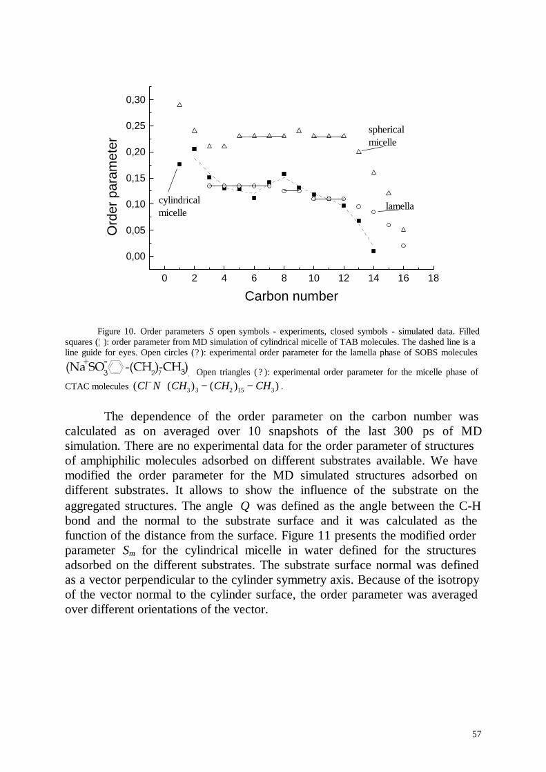
57
0 2 4 6 8 10 12 14 16 18
0,00
0,05
0,10
0,15
0,20
0,25
0,30
cylindrical micelle
lamella
sphericalmicelle
Ord
er p
aram
eter
Carbon number
Figure 10. Order parameters S open symbols - experiments, closed symbols - simulated data. Filledsquares (¦ ): order parameter from MD simulation of cylindrical micelle of TAB molecules. The dashed line is aline guide for eyes. Open circles (? ): experimental order parameter for the lamella phase of SOBS molecules
. Open triangles ( ? ): experimental order parameter for the micelle phase ofCTAC molecules ( ( ) ( ) )Cl N CH CH CH− + − −3 3 2 15 3 .
The dependence of the order parameter on the carbon number wascalculated as on averaged over 10 snapshots of the last 300 ps of MDsimulation. There are no experimental data for the order parameter of structuresof amphiphilic molecules adsorbed on different substrates available. We havemodified the order parameter for the MD simulated structures adsorbed ondifferent substrates. It allows to show the influence of the substrate on theaggregated structures. The angle Θ was defined as the angle between the C-Hbond and the normal to the substrate surface and it was calculated as thefunction of the distance from the surface. Figure 11 presents the modified orderparameter Sm for the cylindrical micelle in water defined for the structuresadsorbed on the different substrates. The substrate surface normal was definedas a vector perpendicular to the cylinder symmetry axis. Because of the isotropyof the vector normal to the cylinder surface, the order parameter was averagedover different orientations of the vector.
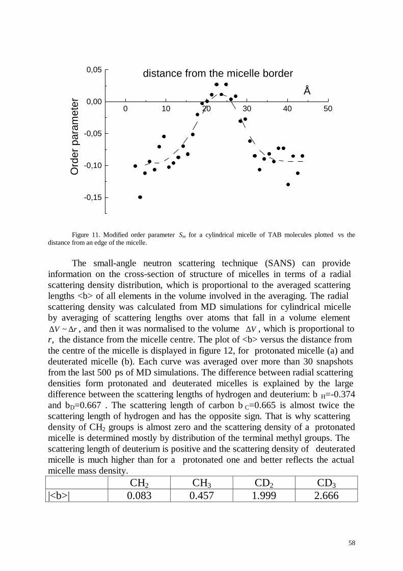
58
0 10 20 30 40 50
-0,15
-0,10
-0,05
0,00
0,05 distance from the micelle border
Å
Ord
er p
aram
eter
Figure 11. Modified order parameter Sm for a cylindrical micelle of TAB molecules plotted vs thedistance from an edge of the micelle.
The small-angle neutron scattering technique (SANS) can provideinformation on the cross-section of structure of micelles in terms of a radialscattering density distribution, which is proportional to the averaged scatteringlengths <b> of all elements in the volume involved in the averaging. The radialscattering density was calculated from MD simulations for cylindrical micelleby averaging of scattering lengths over atoms that fall in a volume element
rV ∆∆ ~ , and then it was normalised to the volume V∆ , which is proportional tor, the distance from the micelle centre. The plot of <b> versus the distance fromthe centre of the micelle is displayed in figure 12, for protonated micelle (a) anddeuterated micelle (b). Each curve was averaged over more than 30 snapshotsfrom the last 500 ps of MD simulations. The difference between radial scatteringdensities form protonated and deuterated micelles is explained by the largedifference between the scattering lengths of hydrogen and deuterium: b H=-0.374and bD=0.667 . The scattering length of carbon b C=0.665 is almost twice thescattering length of hydrogen and has the opposite sign. That is why scatteringdensity of CH2 groups is almost zero and the scattering density of a protonatedmicelle is determined mostly by distribution of the terminal methyl groups. Thescattering length of deuterium is positive and the scattering density of deuteratedmicelle is much higher than for a protonated one and better reflects the actualmicelle mass density.
CH2 CH3 CD2 CD3|<b>| 0.083 0.457 1.999 2.666
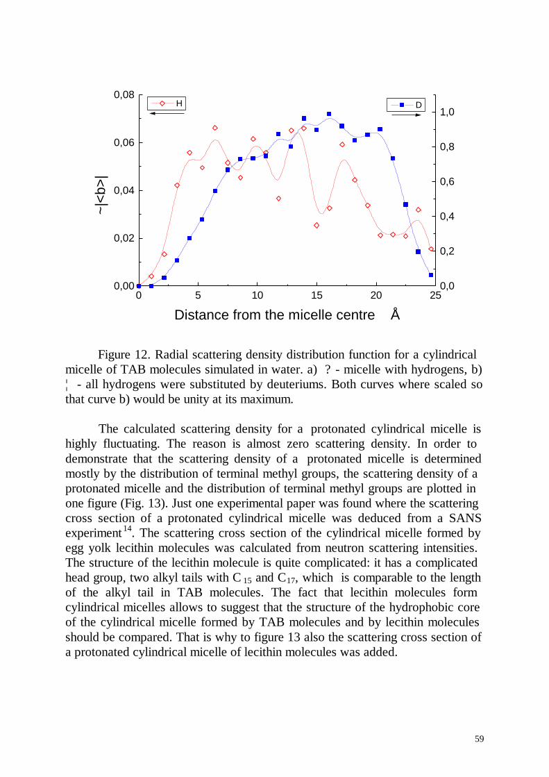
59
0 5 10 15 20 250,00
0,02
0,04
0,06
0,08 H
~|<b
>|
Distance from the micelle centre Å
0,0
0,2
0,4
0,6
0,8
1,0 D
Figure 12. Radial scattering density distribution function for a cylindricalmicelle of TAB molecules simulated in water. a) ? - micelle with hydrogens, b)¦ - all hydrogens were substituted by deuteriums. Both curves where scaled sothat curve b) would be unity at its maximum.
The calculated scattering density for a protonated cylindrical micelle ishighly fluctuating. The reason is almost zero scattering density. In order todemonstrate that the scattering density of a protonated micelle is determinedmostly by the distribution of terminal methyl groups, the scattering density of aprotonated micelle and the distribution of terminal methyl groups are plotted inone figure (Fig. 13). Just one experimental paper was found where the scatteringcross section of a protonated cylindrical micelle was deduced from a SANSexperiment 14. The scattering cross section of the cylindrical micelle formed byegg yolk lecithin molecules was calculated from neutron scattering intensities.The structure of the lecithin molecule is quite complicated: it has a complicatedhead group, two alkyl tails with C 15 and C17, which is comparable to the lengthof the alkyl tail in TAB molecules. The fact that lecithin molecules formcylindrical micelles allows to suggest that the structure of the hydrophobic coreof the cylindrical micelle formed by TAB molecules and by lecithin moleculesshould be compared. That is why to figure 13 also the scattering cross section ofa protonated cylindrical micelle of lecithin molecules was added.
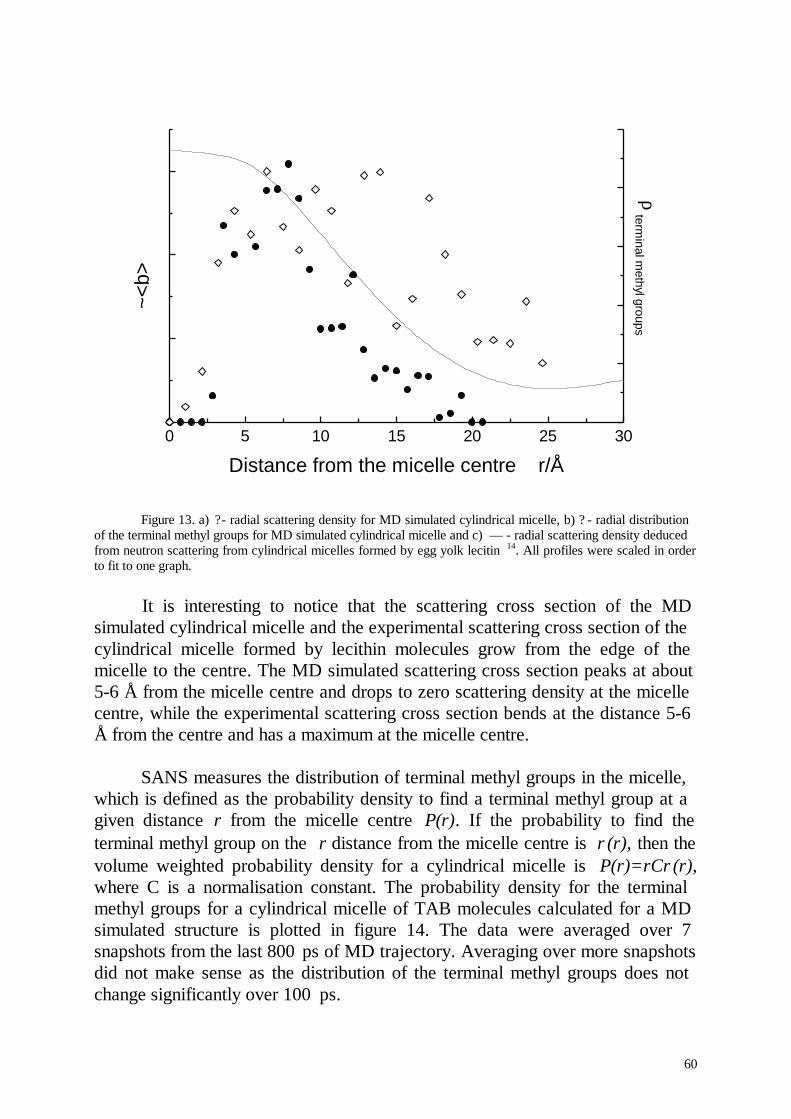
60
0 5 10 15 20 25 30
~<b>
Distance from the micelle centre r/Å
ρ term
inal methyl groups
Figure 13. a) ?- radial scattering density for MD simulated cylindrical micelle, b) ? - radial distributionof the terminal methyl groups for MD simulated cylindrical micelle and c) — - radial scattering density deducedfrom neutron scattering from cylindrical micelles formed by egg yolk lecitin 14. All profiles were scaled in orderto fit to one graph.
It is interesting to notice that the scattering cross section of the MDsimulated cylindrical micelle and the experimental scattering cross section of thecylindrical micelle formed by lecithin molecules grow from the edge of themicelle to the centre. The MD simulated scattering cross section peaks at about5-6 Å from the micelle centre and drops to zero scattering density at the micellecentre, while the experimental scattering cross section bends at the distance 5-6Å from the centre and has a maximum at the micelle centre.
SANS measures the distribution of terminal methyl groups in the micelle,which is defined as the probability density to find a terminal methyl group at agiven distance r from the micelle centre P(r). If the probability to find theterminal methyl group on the r distance from the micelle centre is ρ(r), then thevolume weighted probability density for a cylindrical micelle is P(r)=rCρ(r),where C is a normalisation constant. The probability density for the terminalmethyl groups for a cylindrical micelle of TAB molecules calculated for a MDsimulated structure is plotted in figure 14. The data were averaged over 7snapshots from the last 800 ps of MD trajectory. Averaging over more snapshotsdid not make sense as the distribution of the terminal methyl groups does notchange significantly over 100 ps.
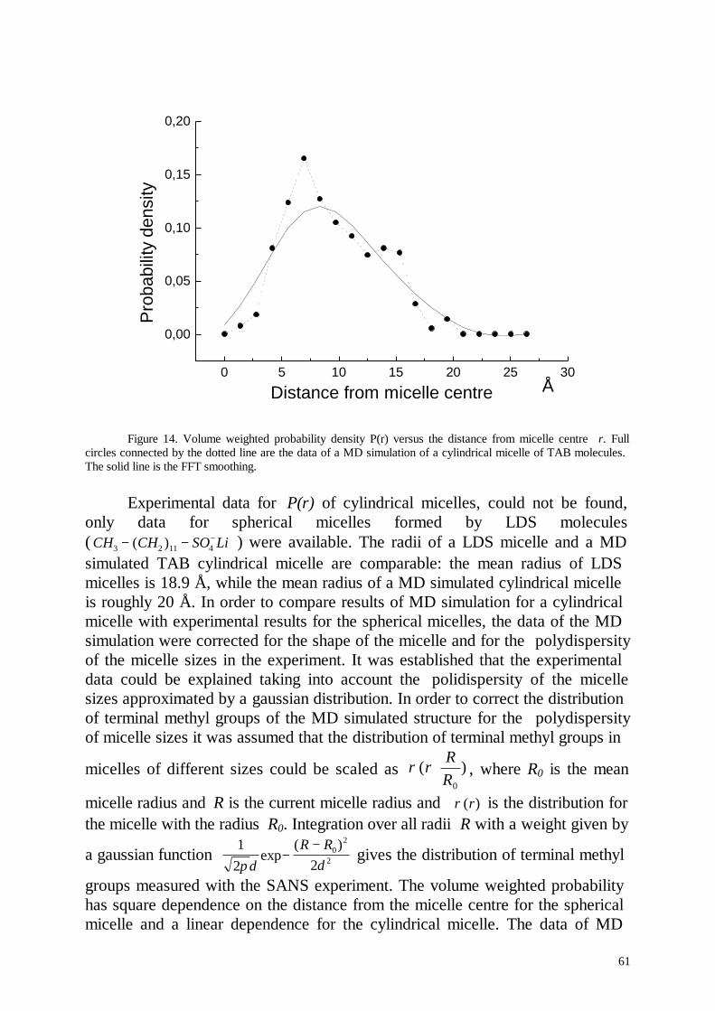
61
0 5 10 15 20 25 30
0,00
0,05
0,10
0,15
0,20
Å
Pro
babi
lity
dens
ity
Distance from micelle centre
Figure 14. Volume weighted probability density P(r) versus the distance from micelle centre r. Fullcircles connected by the dotted line are the data of a MD simulation of a cylindrical micelle of TAB molecules.The solid line is the FFT smoothing.
Experimental data for P(r) of cylindrical micelles, could not be found,only data for spherical micelles formed by LDS molecules( CH CH SO Li3 2 11 4− − − +( ) ) were available. The radii of a LDS micelle and a MDsimulated TAB cylindrical micelle are comparable: the mean radius of LDSmicelles is 18.9 Å, while the mean radius of a MD simulated cylindrical micelleis roughly 20 Å. In order to compare results of MD simulation for a cylindricalmicelle with experimental results for the spherical micelles, the data of the MDsimulation were corrected for the shape of the micelle and for the polydispersityof the micelle sizes in the experiment. It was established that the experimentaldata could be explained taking into account the polidispersity of the micellesizes approximated by a gaussian distribution. In order to correct the distributionof terminal methyl groups of the MD simulated structure for the polydispersityof micelle sizes it was assumed that the distribution of terminal methyl groups in
micelles of different sizes could be scaled as )(0R
Rr ⋅ρ , where R0 is the mean
micelle radius and R is the current micelle radius and )(rρ is the distribution forthe micelle with the radius R0. Integration over all radii R with a weight given by
a gaussian function 1
2 20
2
2πδ δexp( )
−−R R
gives the distribution of terminal methyl
groups measured with the SANS experiment. The volume weighted probabilityhas square dependence on the distance from the micelle centre for the sphericalmicelle and a linear dependence for the cylindrical micelle. The data of MD
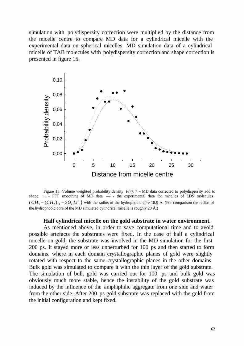
62
simulation with polydispersity correction were multiplied by the distance fromthe micelle centre to compare MD data for a cylindrical micelle with theexperimental data on spherical micelles. MD simulation data of a cylindricalmicelle of TAB molecules with polydispersity correction and shape correction ispresented in figure 15.
0 5 10 15 20 25 30
0,00
0,02
0,04
0,06
0,08
0,10
Pro
babi
lity
dens
ity
Distance from micelle centre
Figure 15. Volume weighted probability density P(r). ? - MD data corrected to polydispersity add toshape. ···· - FFT smoothing of MD data. — - the experimental data for micelles of LDS molecules
( CH CH SO Li3 2 11 4− − − +( ) ) with the radius of the hydrophobic core 18.9 Å. (For comparison the radius ofthe hydrophobic core of the MD simulated cylindrical micelle is roughly 20 Å.)
Half cylindrical micelle on the gold substrate in water environment.As mentioned above, in order to save computational time and to avoid
possible artefacts the substrates were fixed. In the case of half a cylindricalmicelle on gold, the substrate was involved in the MD simulation for the first200 ps. It stayed more or less unperturbed for 100 ps and then started to formdomains, where in each domain crystallographic planes of gold were slightlyrotated with respect to the same crystallographic planes in the other domains.Bulk gold was simulated to compare it with the thin layer of the gold substrate.The simulation of bulk gold was carried out for 100 ps and bulk gold wasobviously much more stable, hence the instability of the gold substrate wasinduced by the influence of the amphiphilic aggregate from one side and waterfrom the other side. After 200 ps gold substrate was replaced with the gold fromthe initial configuration and kept fixed.
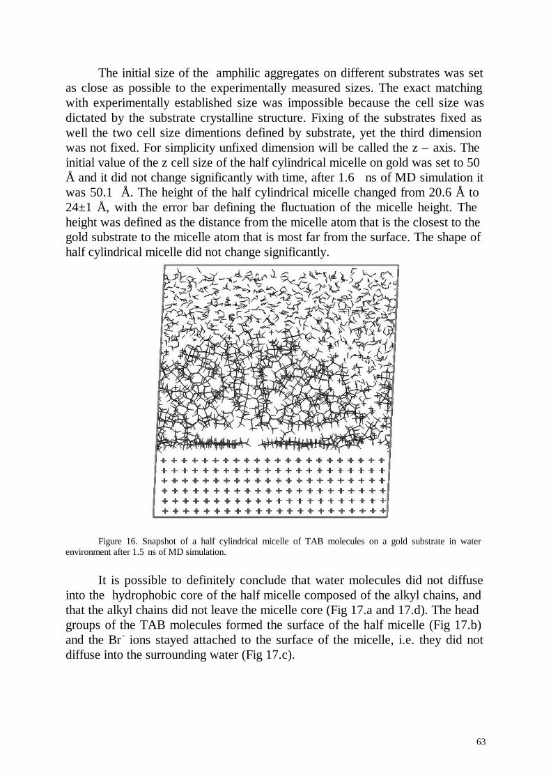
63
The initial size of the amphilic aggregates on different substrates was setas close as possible to the experimentally measured sizes. The exact matchingwith experimentally established size was impossible because the cell size wasdictated by the substrate crystalline structure. Fixing of the substrates fixed aswell the two cell size dimentions defined by substrate, yet the third dimensionwas not fixed. For simplicity unfixed dimension will be called the z – axis. Theinitial value of the z cell size of the half cylindrical micelle on gold was set to 50Å and it did not change significantly with time, after 1.6 ns of MD simulation itwas 50.1 Å. The height of the half cylindrical micelle changed from 20.6 Å to24±1 Å, with the error bar defining the fluctuation of the micelle height. Theheight was defined as the distance from the micelle atom that is the closest to thegold substrate to the micelle atom that is most far from the surface. The shape ofhalf cylindrical micelle did not change significantly.
Figure 16. Snapshot of a half cylindrical micelle of TAB molecules on a gold substrate in waterenvironment after 1.5 ns of MD simulation.
It is possible to definitely conclude that water molecules did not diffuseinto the hydrophobic core of the half micelle composed of the alkyl chains, andthat the alkyl chains did not leave the micelle core (Fig 17.a and 17.d). The headgroups of the TAB molecules formed the surface of the half micelle (Fig 17.b)and the Br - ions stayed attached to the surface of the micelle, i.e. they did notdiffuse into the surrounding water (Fig 17.c).
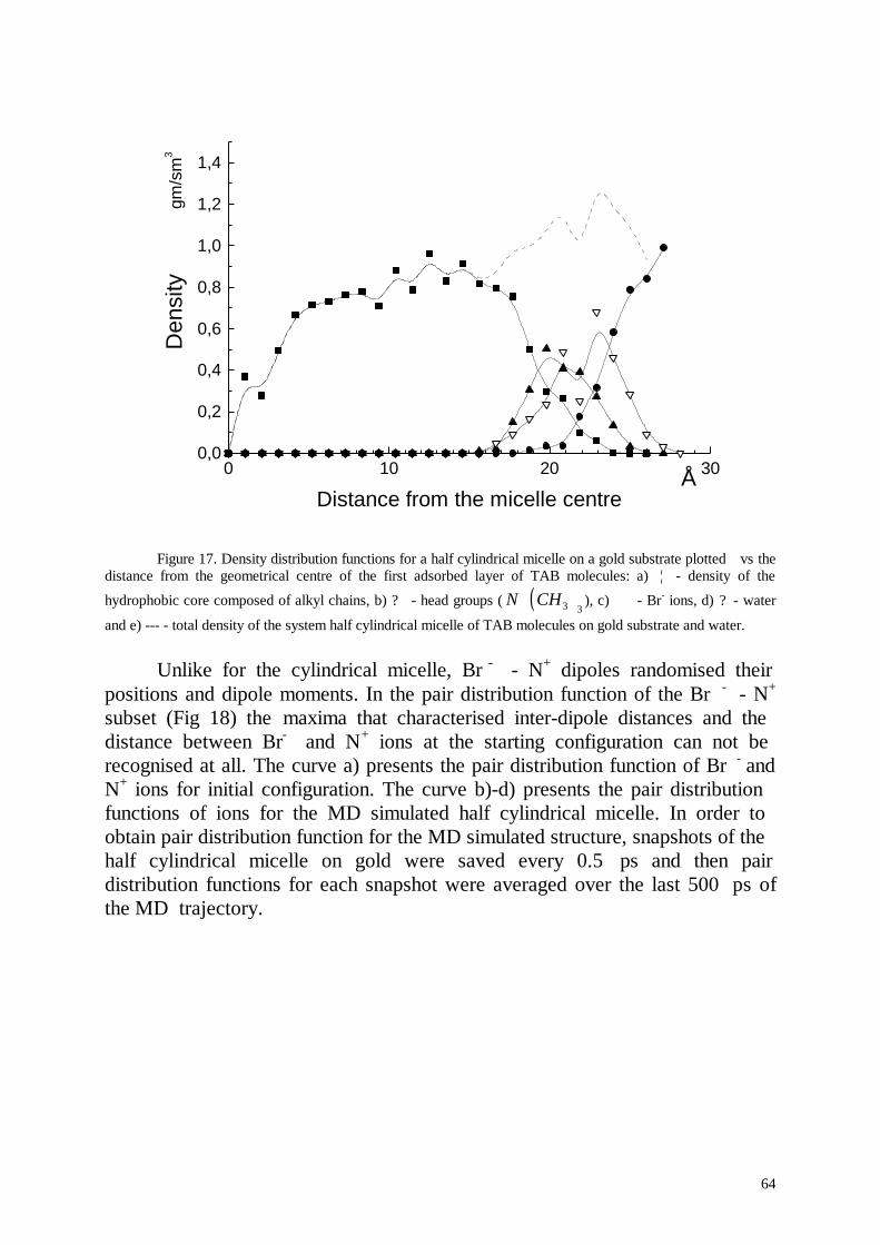
64
0 10 20 300,0
0,2
0,4
0,6
0,8
1,0
1,2
1,4
Å
gm/s
m3
Den
sity
Distance from the micelle centre
Figure 17. Density distribution functions for a half cylindrical micelle on a gold substrate plotted vs thedistance from the geometrical centre of the first adsorbed layer of TAB molecules: a) ¦ - density of the
hydrophobic core composed of alkyl chains, b) ? - head groups ( ( )N CH+3 3
), c) ∇ - Br- ions, d) ? - water
and e) --- - total density of the system half cylindrical micelle of TAB molecules on gold substrate and water.
Unlike for the cylindrical micelle, Br - - N+ dipoles randomised theirpositions and dipole moments. In the pair distribution function of the Br - - N+
subset (Fig 18) the maxima that characterised inter-dipole distances and thedistance between Br- and N+ ions at the starting configuration can not berecognised at all. The curve a) presents the pair distribution function of Br - andN+ ions for initial configuration. The curve b)-d) presents the pair distributionfunctions of ions for the MD simulated half cylindrical micelle. In order toobtain pair distribution function for the MD simulated structure, snapshots of thehalf cylindrical micelle on gold were saved every 0.5 ps and then pairdistribution functions for each snapshot were averaged over the last 500 ps ofthe MD trajectory.
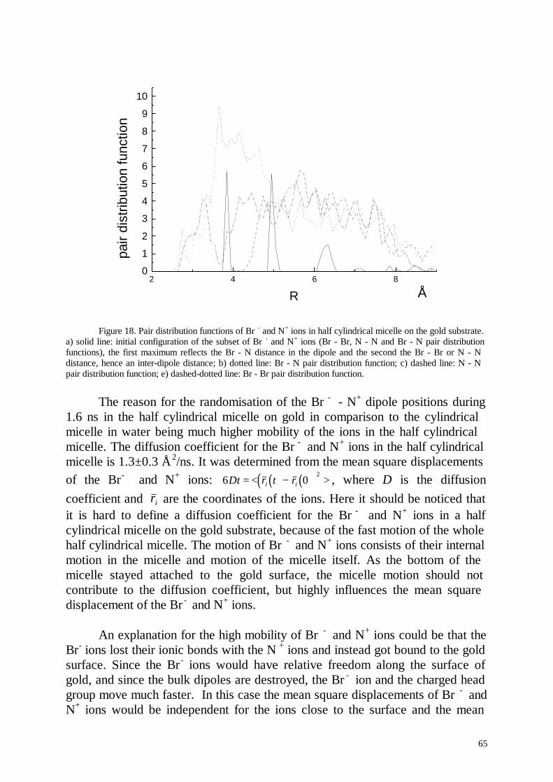
65
2 4 6 80
1
2
3
4
5
6
7
8
9
10
Å
pair
dist
ribut
ion
func
tion
R
Figure 18. Pair distribution functions of Br - and N+ ions in half cylindrical micelle on the gold substrate.a) solid line: initial configuration of the subset of Br - and N+ ions (Br - Br, N - N and Br - N pair distributionfunctions), the first maximum reflects the Br - N distance in the dipole and the second the Br - Br or N - Ndistance, hence an inter-dipole distance; b) dotted line: Br - N pair distribution function; c) dashed line: N - Npair distribution function; e) dashed-dotted line: Br - Br pair distribution function.
The reason for the randomisation of the Br - - N+ dipole positions during1.6 ns in the half cylindrical micelle on gold in comparison to the cylindricalmicelle in water being much higher mobility of the ions in the half cylindricalmicelle. The diffusion coefficient for the Br - and N+ ions in the half cylindricalmicelle is 1.3±0.3 Å2/ns. It was determined from the mean square displacementsof the Br- and N+ ions: ( ) ( )( )6 0
2Dt r t ri i= < − > , where D is the diffusion
coefficient and ri are the coordinates of the ions. Here it should be noticed thatit is hard to define a diffusion coefficient for the Br - and N+ ions in a halfcylindrical micelle on the gold substrate, because of the fast motion of the wholehalf cylindrical micelle. The motion of Br - and N+ ions consists of their internalmotion in the micelle and motion of the micelle itself. As the bottom of themicelle stayed attached to the gold surface, the micelle motion should notcontribute to the diffusion coefficient, but highly influences the mean squaredisplacement of the Br - and N+ ions.
An explanation for the high mobility of Br - and N+ ions could be that theBr- ions lost their ionic bonds with the N + ions and instead got bound to the goldsurface. Since the Br - ions would have relative freedom along the surface ofgold, and since the bulk dipoles are destroyed, the Br - ion and the charged headgroup move much faster. In this case the mean square displacements of Br - andN+ ions would be independent for the ions close to the surface and the mean
66
square displacement of all ions also would be quite different. However thecomparison of the mean square displacements of Br - ions and N+ ions show thatthey are almost identical. This lead to the conclusion that all ionic bonds are stillactive and the supposed explanation for the increased diffusion coefficient of Br -
and N+ ions is not suitable.
The TAB molecules in the laye r close to the substrate stayd moreoverparallel to the surface of gold. The molecules further away from the surface ofgold adopted more random configurations. It is interesting to notice that the holein the centre of the half micelle was not formed, unlike in the cylindrical micellein water.
In order to characterise the influence of the gold substrate on the structureof the half cylindrical micelle, the order parameter was calculated. The orderparameter for the structures adsorbed on the surfaces was redefined incomparison to the order parameter for a cylindrical micelle in water. It wasdefined as: Sm ≡ ⋅ −05 3 12. ( cos ( ) )Θ , where the θ is the angle between the C-Hbonds and the normal to the substrate surface. The order parameter wascalculated as a function on the distance from the substrate surface (Fig 19).
The orientation of the TAB molecules parallel to the surface does notnecessarily result in the orientation of the C-H bonds parallel to the surfacenormal and Sm=1. The TAB molecules are forced by the substrate to orientparallel to the substrate symmetry axes and adopt ideally all transconformations. The alkyl chains with all trans conformation can lie on thesubstrate either perpendicular or parallel to the surface which lead to the twopossible angles between C-H bond and the substrate normal: roughly 35° and55°. The initial conformation was constructed with a 35° angle between the C-Hbonds and the surface normal resulting in an order parameter of 0.46 for the firstlayer of TAB molecules. This is the maximum possible order parameter formolecules which are close to the surface and oriented parallel to it. The orderparameter Sm was normalised to the maximum order parameter Smax=0.46 forgold substrate. The order parameter was averaged by calculating order forstructure snapshot every 25 ps from last 400 ps of MD trajectory. The standarddeviations from the mean or fluctuations of the order parameter are shown aserror bars.
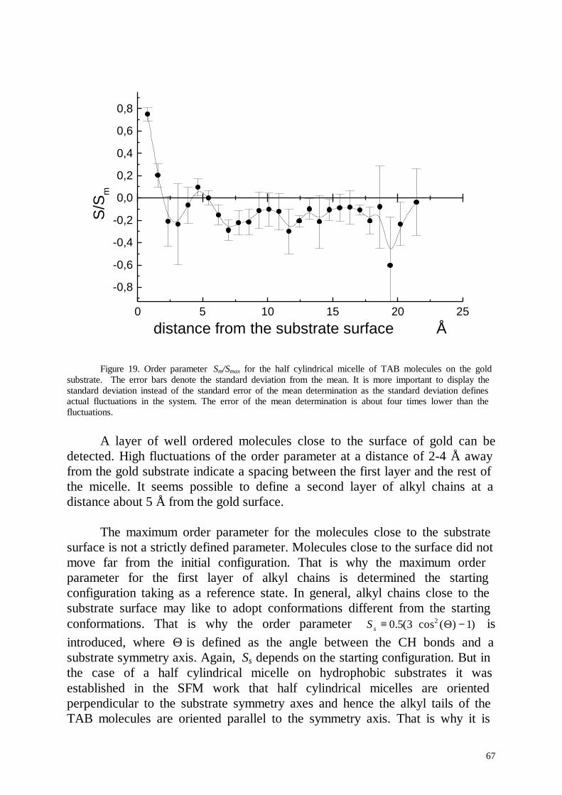
67
0 5 10 15 20 25
-0,8
-0,6
-0,4
-0,2
0,0
0,2
0,4
0,6
0,8S
/Sm
distance from the substrate surface Å
Figure 19. Order parameter Sm/Smax for the half cylindrical micelle of TAB molecules on the goldsubstrate. The error bars denote the standard deviation from the mean. It is more important to display thestandard deviation instead of the standard error of the mean determination as the standard deviation definesactual fluctuations in the system. The error of the mean determination is about four times lower than thefluctuations.
A layer of well ordered molecules close to the surface of gold can bedetected. High fluctuations of the order parameter at a distance of 2-4 Å awayfrom the gold substrate indicate a spacing between the first layer and the rest ofthe micelle. It seems possible to define a second layer of alkyl chains at adistance about 5 Å from the gold surface.
The maximum order parameter for the molecules close to the substratesurface is not a strictly defined parameter. Molecules close to the surface did notmove far from the initial configuration. That is why the maximum orderparameter for the first layer of alkyl chains is determined the startingconfiguration taking as a reference state. In general, alkyl chains close to thesubstrate surface may like to adopt conformations different from the startingconformations. That is why the order parameter )1)(cos3(5.0 2 −Θ⋅≡sS isintroduced, where Θ is defined as the angle between the CH bonds and asubstrate symmetry axis. Again, Ss depends on the starting configuration. But inthe case of a half cylindrical micelle on hydrophobic substrates it wasestablished in the SFM work that half cylindrical micelles are orientedperpendicular to the substrate symmetry axes and hence the alkyl tails of theTAB molecules are oriented parallel to the symmetry axis. That is why it is
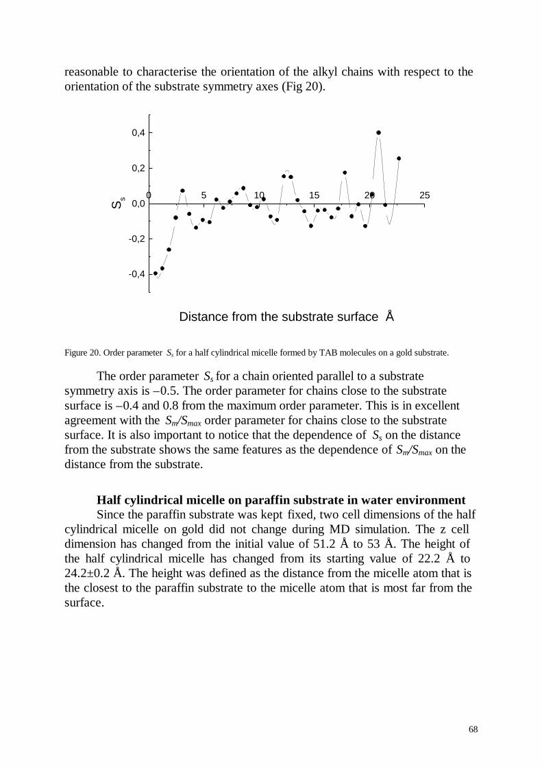
68
reasonable to characterise the orientation of the alkyl chains with respect to theorientation of the substrate symmetry axes (Fig 20).
-0,4
-0,2
0,0
0,2
0,4
0 5 10 15 20 25
Ss
Distance from the substrate surface Å
Figure 20. Order parameter Ss for a half cylindrical micelle formed by TAB molecules on a gold substrate.
The order parameter Ss for a chain oriented parallel to a substratesymmetry axis is –0.5. The order parameter for chains close to the substratesurface is –0.4 and 0.8 from the maximum order parameter. This is in excellentagreement with the Sm/Smax order parameter for chains close to the substratesurface. It is also important to notice that the dependence of Ss on the distancefrom the substrate shows the same features as the dependence of Sm/Smax on thedistance from the substrate.
Half cylindrical micelle on paraffin substrate in water environmentSince the paraffin substrate was kept fixed, two cell dimensions of the half
cylindrical micelle on gold did not change during MD simulation. The z celldimension has changed from the initial value of 51.2 Å to 53 Å. The height ofthe half cylindrical micelle has changed from its starting value of 22.2 Å to24.2±0.2 Å. The height was defined as the distance from the micelle atom that isthe closest to the paraffin substrate to the micelle atom that is most far from thesurface.
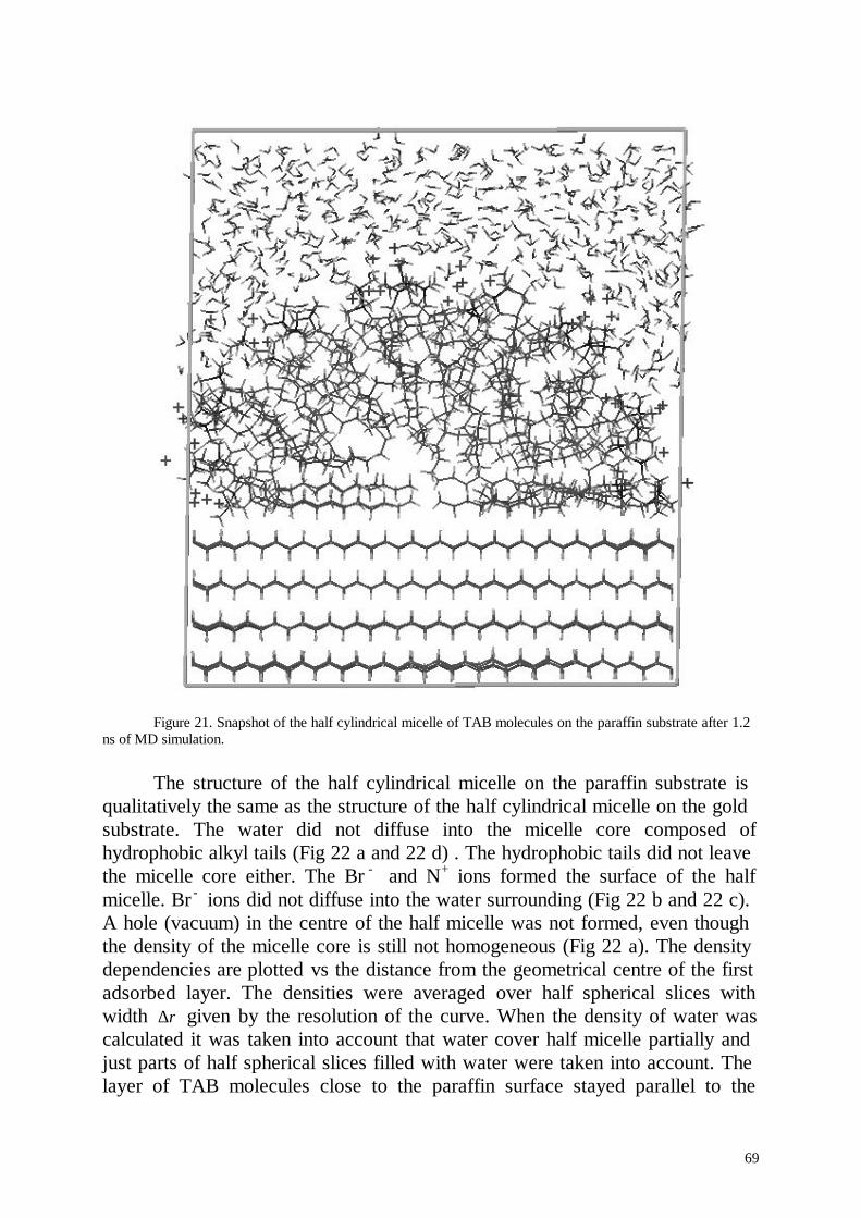
69
Figure 21. Snapshot of the half cylindrical micelle of TAB molecules on the paraffin substrate after 1.2ns of MD simulation.
The structure of the half cylindrical micelle on the paraffin substrate isqualitatively the same as the structure of the half cylindrical micelle on the goldsubstrate. The water did not diffuse into the micelle core composed ofhydrophobic alkyl tails (Fig 22 a and 22 d) . The hydrophobic tails did not leavethe micelle core either. The Br - and N+ ions formed the surface of the halfmicelle. Br - ions did not diffuse into the water surrounding (Fig 22 b and 22 c).A hole (vacuum) in the centre of the half micelle was not formed, even thoughthe density of the micelle core is still not homogeneous (Fig 22 a). The densitydependencies are plotted vs the distance from the geometrical centre of the firstadsorbed layer. The densities were averaged over half spherical slices withwidth ∆r given by the resolution of the curve. When the density of water wascalculated it was taken into account that water cover half micelle partially andjust parts of half spherical slices filled with water were taken into account. Thelayer of TAB molecules close to the paraffin surface stayed parallel to the
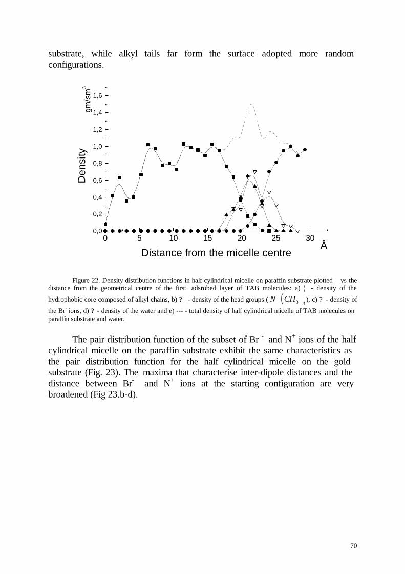
70
substrate, while alkyl tails far form the surface adopted more randomconfigurations.
0 5 10 15 20 25 300,0
0,2
0,4
0,6
0,8
1,0
1,2
1,4
1,6
Å
gm/s
m3
Den
sity
Distance from the micelle centre
Figure 22. Density distribution functions in half cylindrical micelle on paraffin substrate plotted vs thedistance from the geometrical centre of the first adsrobed layer of TAB molecules: a) ¦ - density of the
hydrophobic core composed of alkyl chains, b) ? - density of the head groups ( ( )N CH+3 3
), c) ? - density of
the Br- ions, d) ? - density of the water and e) --- - total density of half cylindrical micelle of TAB molecules onparaffin substrate and water.
The pair distribution function of the subset of Br - and N+ ions of the halfcylindrical micelle on the paraffin substrate exhibit the same characteristics asthe pair distribution function for the half cylindrical micelle on the goldsubstrate (Fig. 23). The maxima that characterise inter-dipole distances and thedistance between Br- and N+ ions at the starting configuration are verybroadened (Fig 23.b-d).
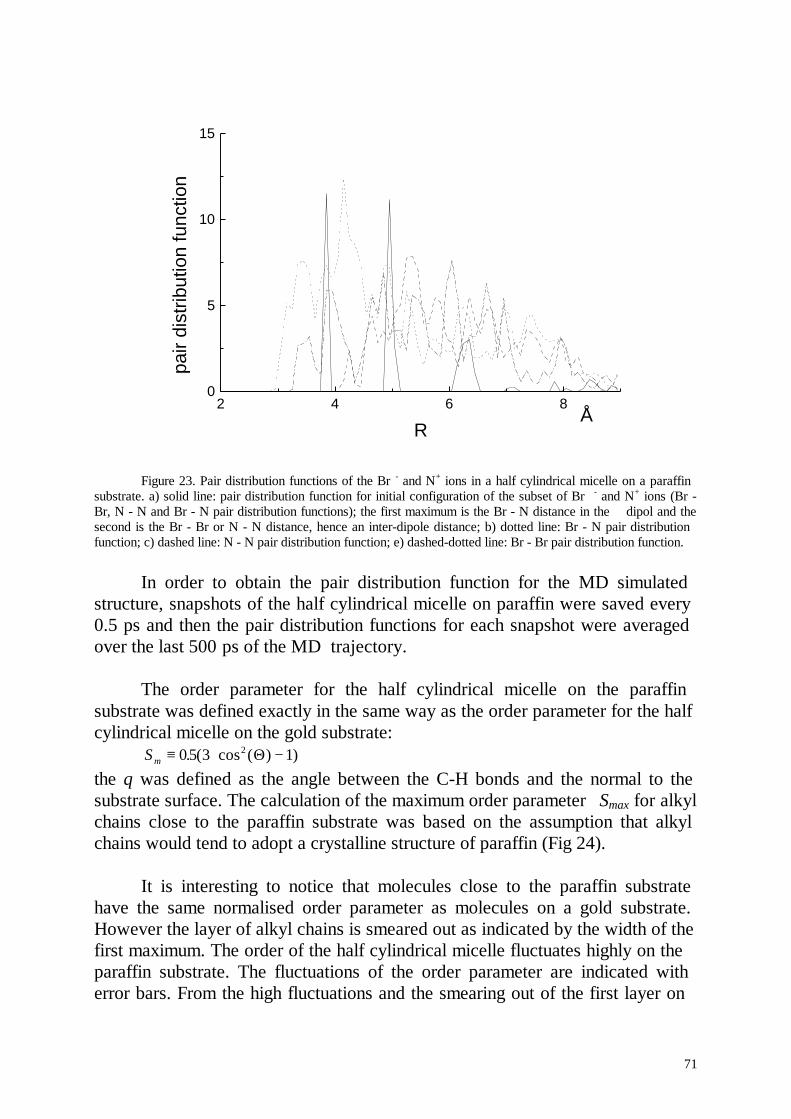
71
2 4 6 80
5
10
15
Å
pair
dist
ribut
ion
func
tion
R
Figure 23. Pair distribution functions of the Br - and N+ ions in a half cylindrical micelle on a paraffinsubstrate. a) solid line: pair distribution function for initial configuration of the subset of Br - and N+ ions (Br -Br, N - N and Br - N pair distribution functions); the first maximum is the Br - N distance in the dipol and thesecond is the Br - Br or N - N distance, hence an inter-dipole distance; b) dotted line: Br - N pair distributionfunction; c) dashed line: N - N pair distribution function; e) dashed-dotted line: Br - Br pair distribution function.
In order to obtain the pair distribution function for the MD simulatedstructure, snapshots of the half cylindrical micelle on paraffin were saved every0.5 ps and then the pair distribution functions for each snapshot were averagedover the last 500 ps of the MD trajectory.
The order parameter for the half cylindrical micelle on the paraffinsubstrate was defined exactly in the same way as the order parameter for the halfcylindrical micelle on the gold substrate:
Sm ≡ ⋅ −05 3 12. ( cos ( ) )Θthe θ was defined as the angle between the C-H bonds and the normal to thesubstrate surface. The calculation of the maximum order parameter Smax for alkylchains close to the paraffin substrate was based on the assumption that alkylchains would tend to adopt a crystalline structure of paraffin (Fig 24).
It is interesting to notice that molecules close to the paraffin substratehave the same normalised order parameter as molecules on a gold substrate.However the layer of alkyl chains is smeared out as indicated by the width of thefirst maximum. The order of the half cylindrical micelle fluctuates highly on theparaffin substrate. The fluctuations of the order parameter are indicated witherror bars. From the high fluctuations and the smearing out of the first layer on
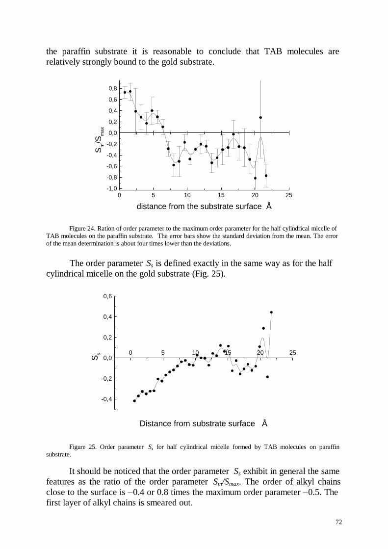
72
the paraffin substrate it is reasonable to conclude that TAB molecules arerelatively strongly bound to the gold substrate.
0 5 10 15 20 25-1,0
-0,8
-0,6
-0,4
-0,2
0,0
0,2
0,4
0,6
0,8
Sm/S
max
distance from the substrate surface Å
Figure 24. Ration of order parameter to the maximum order parameter for the half cylindrical micelle ofTAB molecules on the paraffin substrate. The error bars show the standard deviation from the mean. The errorof the mean determination is about four times lower than the deviations.
The order parameter Ss is defined exactly in the same way as for the halfcylindrical micelle on the gold substrate (Fig. 25).
-0,4
-0,2
0,0
0,2
0,4
0,6
0 5 10 15 20 25
Ss
Distance from substrate surface Å
Figure 25. Order parameter Ss for half cylindrical micelle formed by TAB molecules on paraffinsubstrate.
It should be noticed that the order parameter Ss exhibit in general the samefeatures as the ratio of the order parameter Sm/Smax. The order of alkyl chainsclose to the surface is –0.4 or 0.8 times the maximum order parameter –0.5. Thefirst layer of alkyl chains is smeared out.
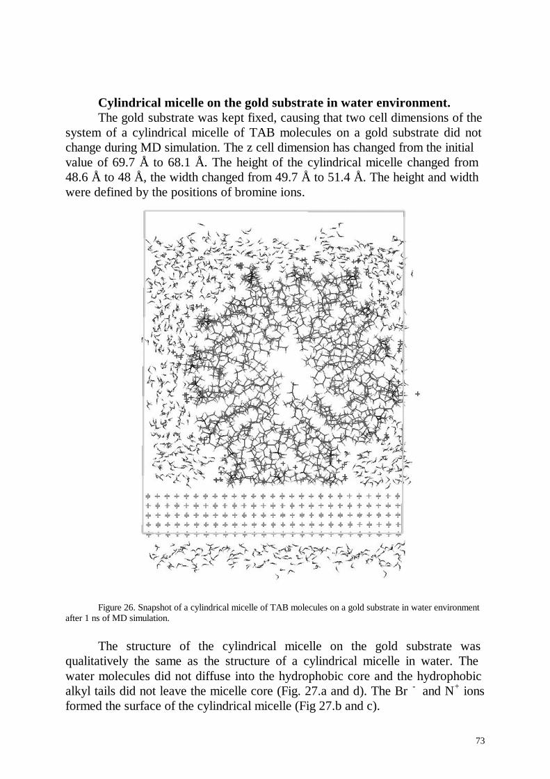
73
Cylindrical micelle on the gold substrate in water environment.The gold substrate was kept fixed, causing that two cell dimensions of the
system of a cylindrical micelle of TAB molecules on a gold substrate did notchange during MD simulation. The z cell dimension has changed from the initialvalue of 69.7 Å to 68.1 Å. The height of the cylindrical micelle changed from48.6 Å to 48 Å, the width changed from 49.7 Å to 51.4 Å. The height and widthwere defined by the positions of bromine ions.
Figure 26. Snapshot of a cylindrical micelle of TAB molecules on a gold substrate in water environmentafter 1 ns of MD simulation.
The structure of the cylindrical micelle on the gold substrate wasqualitatively the same as the structure of a cylindrical micelle in water. Thewater molecules did not diffuse into the hydrophobic core and the hydrophobicalkyl tails did not leave the micelle core (Fig. 27.a and d). The Br - and N+ ionsformed the surface of the cylindrical micelle (Fig 27.b and c).
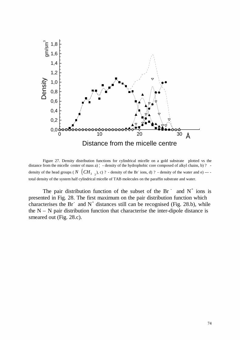
74
0 10 20 300,0
0,2
0,4
0,6
0,8
1,0
1,2
1,4
1,6
1,8
Å
gm/s
m3
Den
sity
Distance from the micelle centre
Figure 27. Density distribution functions for cylindrical micelle on a gold substrate plotted vs thedistance from the micelle center of mass a) ¦ - density of the hydrophobic core composed of alkyl chains, b) ? -
density of the head groups ( ( )N CH+3 3
), c) ? - density of the Br- ions, d) ? - density of the water and e) --- -
total density of the system half cylindrical micelle of TAB molecules on the paraffin substrate and water.
The pair distribution function of the subset of the Br - and N+ ions ispresented in Fig. 28. The first maximum on the pair distribution function whichcharacterises the Br - and N+ distances still can be recognised (Fig. 28.b), whilethe N – N pair distribution function that characterise the inter-dipole distance issmeared out (Fig. 28.c).
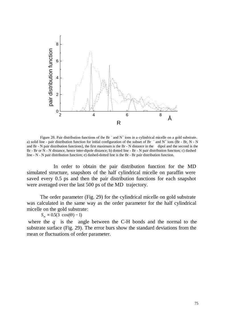
75
2 4 6 80
2
4
6
8
Å
pair
dist
ribut
ion
func
tion
R
Figure 28. Pair distribution functions of the Br - and N+ ions in a cylindrical micelle on a gold substrate.a) solid line - pair distribution function for initial configuration of the subset of Br - and N+ ions (Br - Br, N - Nand Br - N pair distribution functions), the first maximum is the Br - N distance in the dipol and the second is theBr - Br or N - N distance, hence inter-dipole distance; b) dotted line - Br - N pair distribution function; c) dashedline - N - N pair distribution function; e) dashed-dotted line is the Br - Br pair distribution function.
In order to obtain the pair distribution function for the MDsimulated structure, snapshots of the half cylindrical micelle on paraffin weresaved every 0.5 ps and then the pair distribution functions for each snapshotwere averaged over the last 500 ps of the MD trajectory.
The order parameter (Fig. 29) for the cylindrical micelle on gold substratewas calculated in the same way as the order parameter for the half cylindricalmicelle on the gold substrate:
Sm ≡ ⋅ −0 5 3 1. ( cos( ) )Θ where the θ is the angle between the C-H bonds and the normal to thesubstrate surface (Fig. 29). The error burs show the standard deviations from themean or fluctuations of order parameter.
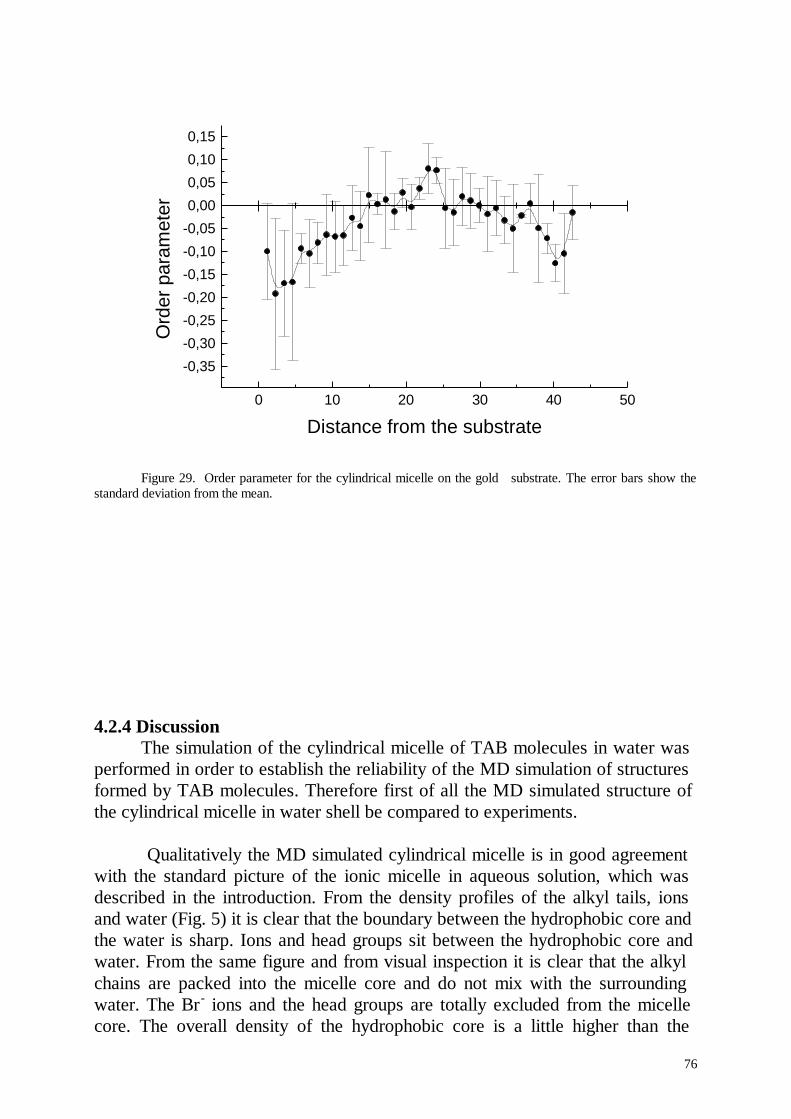
76
0 10 20 30 40 50
-0,35
-0,30
-0,25
-0,20
-0,15
-0,10
-0,05
0,00
0,05
0,10
0,15
Ord
er p
aram
eter
Distance from the substrate
Figure 29. Order parameter for the cylindrical micelle on the gold substrate. The error bars show thestandard deviation from the mean.
4.2.4 DiscussionThe simulation of the cylindrical micelle of TAB molecules in water was
performed in order to establish the reliability of the MD simulation of structuresformed by TAB molecules. Therefore first of all the MD simulated structure ofthe cylindrical micelle in water shell be compared to experiments.
Qualitatively the MD simulated cylindrical micelle is in good agreementwith the standard picture of the ionic micelle in aqueous solution, which wasdescribed in the introduction. From the density profiles of the alkyl tails, ionsand water (Fig. 5) it is clear that the boundary between the hydrophobic core andthe water is sharp. Ions and head groups sit between the hydrophobic core andwater. From the same figure and from visual inspection it is clear that the alkylchains are packed into the micelle core and do not mix with the surroundingwater. The Br - ions and the head groups are totally excluded from the micellecore. The overall density of the hydrophobic core is a little higher than the
77
density of n-alkanes: 0,74 and 0.62-0,7 g/cm 3 respectively. The conformationaldisorder of the alkyl tails requires, however a more quantitative comparison.
As it was described in details in the results section, the comparison of thecorrelation times from the MD simulation with the correlation times given byNMR experiments is questionable.
While it was not possible to find any measurements of the order parameterfor cylindrical micelles, one would expect that the order parameter for acylindrical micelle would be in-between the order parameter for the lamella caseand for the spherical micelle. Indeed, the order parameter for the cylindricalmicelle is in good agreement with the experimental order parameters for thespherical micelle and the lamella cases (Fig. 9). The order parameter is definedsuch that it gives -0.5 when the C-H bonds are oriented parallel to the micellesurface, 1. when the C-H bonds are perpendicular to the micelle surface and 0for complete disorder. The orientation of the alkyl tails perpendicular to themicelle surface automatically means that the C-H bonds are oriented parallel tothe surface, hence the order parameter is -0.5. The orientation of the alkyl tailsparallel to the surface does not necessarily result in the orientation of the C-Hbonds perpendicular to the surface, but the C-H bonds can be oriented randomlyresulting in an order parameter 0. Fig. 9 presents the modulus of the orderparameter in order to compare experiments with the MD simulation. Withouttaking the modulus, the sign of the order parameter is always negative indicatingthat the alkyl tails are oriented preferably perpendicular to the micelle surface.The parts of alkyl tails that are close to the head groups have a more pronouncedorientation perpendicular to the micelle surface, while the ends of the alkyl tailsare conformationally almost disordered.
The modified order parameter Sm is more helpful to explain the spatialdependence of the order parameter in the cylindrical micelle (Fig. 10). Sm for thecylindrical micelle in water varies from -0.1 at the edges to slightly positivevalues in the centre. The negative order parameter at the edges indicates that thealkyl chains have a slightly pronounced orientation perpendicular to the surfaceclose to the surface of the cylindrical micelle. Random orientation of the chainsin the plane parallel to the surface results in an order parameter 0, but when thealkyl chains are oriented parallel to the surface and perpendicular to the cylindersymmetry axis the C-H bonds have just two dimensional disorder resulting in anorder parameter of 0.25. The slightly positive order parameter at the centre ofthe curve indicates this (Fig. 10).
It is interesting to compare the pair distribution functions of Br - and N+
ions for the cylindrical micelle in water and for different structures adsorbed onthe surfaces. The main difference is the well pronounced second maximum onthe pair distribution function for the cylindrical micelle and the complete
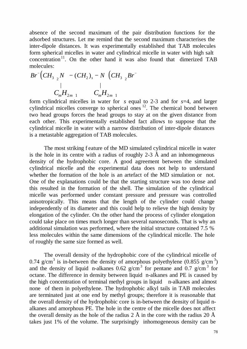
78
absence of the second maximum of the pair distribution functions for theadsorbed structures. Let me remind that the second maximum characterises theinter-dipole distances. It was experimentally established that TAB moleculesform spherical micelles in water and cylindrical micelle in water with high saltconcentration11. On the other hand it was also found that dimerized TABmolecules:
( ) ( )Br CH N CH N CH Brs− + + −− −3 2 2 3 2
( ) | |
C Hm m2 1+ C Hm m2 1+form cylindrical micelles in water for s equal to 2-3 and for s=4, and largercylindrical micelles converge to spherical ones 12. The chemical bond betweentwo head groups forces the head groups to stay at on the given distance fromeach other. This experimentally established fact allows to suppose that thecylindrical micelle in water with a narrow distribution of inter-dipole distancesis a metastable aggregation of TAB molecules.
The most striking f eature of the MD simulated cylindrical micelle in wateris the hole in its centre with a radius of roughly 2-3 Å and an inhomogeneousdensity of the hydrophobic core. A good agreement between the simulatedcylindrical micelle and the experimental data does not help to understandwhether the formation of the hole is an artefact of the MD simulation or not.One of the explanations could be that the starting structure was too dense andthis resulted in the formation of the shell. The simulation of the cylindricalmicelle was performed under constant pressure and pressure was controlledanisotropically. This means that the length of the cylinder could changeindependently of its diameter and this could help to relieve the high density byelongation of the cylinder. On the other hand the process of cylinder elongationcould take place on times much longer than several nanoseconds. That is why anadditional simulation was performed, where the initial structure contained 7.5 %less molecules within the same dimensions of the cylindrical micelle. The holeof roughly the same size formed as well.
The overall density of the hydrophobic core of the cylindrical micelle of0.74 g/cm3 is in-between the density of amorphous polyethylene (0.855 g/cm 3)and the density of liquid n-alkanes 0.62 g/cm 3 for pentane and 0.7 g/cm 3 foroctane. The difference in density between liquid n-alkanes and PE is caused bythe high concentration of terminal methyl groups in liquid n-alkanes and almostnone of them in polyethylene. The hydrophobic alkyl tails in TAB moleculesare terminated just at one end by methyl groups; therefore it is reasonable thatthe overall density of the hydrophobic core is in-between the density of liquid n-alkanes and amorphous PE. The hole in the centre of the micelle does not affectthe overall density as the hole of the radius 2 Å in the core with the radius 20 Åtakes just 1% of the volume. The surprisingly inhomogeneous density can be
79
also explained on the basis of the distribution of the terminal methyl groups.They are mostly concentrated in the centre of the micelle, which causes alowering of the density in the centre of the hydrophobic core. The hydrophobiccore density close to the head groups should be comparable to the density ofamorphous PE . Because of the high order of alkyl chains close to the headgroups, the density of the hydrophobic core could be even higher than thedensity of amorphous PE. The densities of semi-crystalline PE lies in the rangeof 0.92-0.97 gm/sm 3 and the density of crystalline PE is close to 1 g/cm 3. As wecan see the density of the hydrophobic core is indeed a little higher than thedensity of amorphous PE in the region with high order and low concentration ofterminal methyl groups.
The standard picture of the ionic micel le includes a homogeneous densityof the hydrophobic micelle core. It should be noticed that this means obviously ahomogeneous density of electron clouds. However the mass density of thehydrophobic core is not necessarily homogeneous. It was established17 forspherical micelles that most of the terminal methyl groups are concentrated inthe centre of the micelle. It is reasonable to expect that most of the terminalmethyl groups are also concentrated in the centre of a cylindrical micelle. Thevolume of the terminal methyl groups is roughly twice the volume of a CH 2group and that is why a high concentration of terminal methyl groups results inlow mass density. The scattering density of the hydrophobic micelle core is alsonot necessarily homogeneous. As it was already mentioned in the results section,the averaged neutron scattering density of CH 3 group is several times higherthan the averaged scattering density of a CH 2 group. The averaged scatteringdensity of an ionic head group of a TAB molecule is almost zero. That is why itis reasonable to expect that the scattering density of a micelle formed by TABmolecules should grow from the edge of the micelle to the micelle centre. Ingeneral, the scattering density of a micelle would depend on the chemicalformula of the head group; but the scattering density of the hydrophobic coreshould dominate at the micelle centre. It is accepted that head groups sit outsidethe hydrophobic core, hence the scattering density of the hydrophobic coreshould not mix with the scattering density of the head groups. That is why itdoes not look reasonable to use a model of a homogeneous micelle to fit neutronscattering data from protonated micelles.
Despite of the large number of experimental studies it appears that it wasnot possible to establish experimentally the existence of the hole. SANS whichis the most reliable experimental technique does not provide enough resolutionto determine a hole with a radius of several angstroms in the centre of aprotonated micelle13. On the other hand it was established that micelles formedby TAB and similar amphiphilic molecules may have a hydrophobic core with adiameter larger than the length of fully extended alkyl tails. The suggestedexplanation of this phenomena was a non spherical form of the micelles.
80
However the experimental results can be explained as well by the presence ofthe hole in the micelle centre. Interestingly, it should be possible to determinethe inhomogeneous density in the deiteurated micelle centre, but noexperimental studies on neutron scattering were found in the literature, wherethe scattering cross section of a completely deteriorated micelle was determined.
On the other hand it was predicted theoretically that ampiphilic moleculesmay tend to form micelles with a hole in the centre 15,16. The highest possiblecost of the hole formation with a volume of 54 Å 3 was estimated to be 109cal/mol of chains for a spherical micelle with a hydrophobic core radius of 20.4Å. A more realistic estimate gives only 45 cal/ mol of chains. The energy cost ofhole formation was estimated as work against internal pressure in the micelle toform the hole and loss of Van-der-Waals energy by chains surrounding the hole.Different estimates of internal pressure also lead to different estimates forenergy cost of hole formation. The energy of the hole formation is very smallindeed: for comparison, the estimated entropic cost of micelle formation isroughly 0.6 kcal/mol of chains and the experimentally measured free energy,which C12 chain gain when being transferred from water to bulk n-alkane isapproximately 12 kcal/mol. The formation of the hole allows to increase theaggregation number. For example, the formation of a hole with a volume of 54Å3 in a micelle with a radius of 20.4 Å allows to increase the aggregationnumber by 30%. On the other hand it was also argued that even small deviationsaway from a perfect sphere would eliminate a small hole.
The deviation from the spherical shape increases the surface area of themicelle which is energetically unfavourable. On the other hand a deviation fromthe spherical shape eliminates the hole in the centre of the micelle and hencegains energy equal to the cost of hole formation. As the aggregation number ofthe micelle does not change when it changes its form the energy cost ofdeviation from the spherical form is equal to the surface change multiplied bythe tension of the water/n-alkane interface, i.e. 50 mN·m -1. A spherical micellewith a radius of 22 Å and a hole in its centre with a radius of 2 Å shouldconverge to an ellipsoid with main axes equal to 20, 23.1 and 23.1 Å in order toeliminate the hole. The energy cost of the increased surface area is 23 cal/ mol ofchains. Taking into account the estimated energy of the hole formation, theelliptical micelle is energetically more favourable by 2-8 kcal/mol or 3.4-13.6kT. The estimated energy difference between a spherical micelle with the hole inits centre and an elliptical micelle is very small indeed. For example thedifference between gauche and trans conformations in alkyl chains is of theorder of 1 kT. Another example: during 1 ps of MD simulation of a cylindricalmicelle in water the potential energy varied more than by 100 kcal/mol and thetotal potential energy of the system cylindrical micelle of TAB molecules inwater environment was minus 2x10 5 kcal/mol.
81
It should be emphasised again that estimated energy difference between amicelle with a hole and an elliptical micelle is very low. It was assumed that theelimination of the hole does not change the entropy of the micelle, which isobviously wrong. When the micelle adopts an elliptical form the alkyl chainsshould also adopt different conformations and this should lead to additional freeenergy cost. This means that a micelle with a hole could be even energeticallymore favourable. Let us assume that the estimated energies are close to reality.Then amphiphilic aggregates would adopt different shapes between sphericalwith hole and elliptical with probabilities given by the Boltzman distribution:
( )∫ −−
−−sphere
elipselips
elips
dkTEE
kTEE
λλ
λ
/))((exp(
)/))((exp(
where λ denotes the path between spherical and elliptical forms. The estimate ofenergy cost of hole formation was performed for the spherical micelle, but onewould expect that the mechanism of the hole formation in a cylindrical micelleis the same.
It is interesting to notice that when a micelles adopts different shapes fromelliptical to spherical with a hole in the micelle centre and the probabilities aregiven by a Boltzman distribution. On average a micelle would have aninhomogeneous density in its centre.
The simulations of a cylindrical micelle and a half cylindrical micelle ongold suffers from the fact that the metallic properties of gold are not taken intoaccount. The TAB molecules interact with the gold atoms only via Lennard-Jones potentials since the gold atoms are completely uncharged. In classicalphysics it is well known that charge close to the metal surface would cause theredistribution of the free electrons which would lead to the appearance of aneffective mirror charge. If we leave this uncertainty it is interesting to comparehow substrates with different Lennard-Jones interaction with TAB moleculeswould affect the adsorbed structures. For instance the Lennard-Jones interactionbetween gold and carbon atoms is much higher than between carbon and carbon.
The structure of a half cylindrical micelle on gold after MD simulationstill exhibit a very well ordered first layer (Fig 19-20). The layer of TABmolecules close to the substrate is separated from the rest of the micelle byseveral angstroms with relatively low density, which causes high fluctuation ofthe order parameter in this part. In a half cylindrical micelle on paraffin (Fig 24-25) it is also clearly possible to define a layer of TAB molecules oriented by theparaffin substrate. But in comparison to the gold substrate the order fluctuationsare higher and the first layer is smeared out indicating that the half cylindricalmicelle is better bound to the gold substrate. It is interesting to notice that the
82
order for molecules close to the substrate surface is the same for paraffin andgold substrates.
The order parameter Sm for a cylindrical micelle on a gold substrate (Fig.29) clearly indicates that these structure is not yet equilibrated. The deviationfrom the mean of the order parameter for molecules close to the surface is veryhigh indicating that these molecules still have to adopt their equilibriumconformations. Because of the high fluctuations it is questionable to conclude ageneral trend in the order parameter. A lower order parameter for the moleculesclose to the substrate surface indicates that the molecules close to the surfacetend to orient themselves perpendicular to the surface, which is consistent withthe flattening of the cylindrical micelle toward the surface and with neutronreflection experiments 10, where it was shown that aggregates of TAB moleculeson the substrate silica are in good agreement with the model of a bilayer.
83
4.3 Conclusions
MD simulations of a cylindrical micelle formed by TAB molecules inwater environment, a half cylindrical micelle of TAB molecules on gold andparaffin substrates and a cylindrical micelle formed by TAB molecules on a goldsubstrate were performed. A good qualitative and quantitative agreementbetween the simulated cylindrical micelle in water and correspondingexperimental results was found, except for the non-homogeneous density of thehydrophobic core. The simulated cylindrical micelle was qualitatively in goodagreement with the standard picture of an ionic spherical micelle. Goodquantitative agreement was found between experimentally established and MDsimulated structure regarding order parameter and distribution of terminalmethyl groups. It was difficult to compare relaxation times given by NMRexperiments and calculated from MD trajectories. As it was argued it is notpossible to give just a single relaxation time for a given carbon in the alkylchain, rather spectra of relaxation times.
The MD simulated cylindrical micell e formes a hole (vacuum) in itscentre and in addition the density of the hydrophobic core composed of alkylchains was not homogeneous. The proposed explanation of the inhomogeneousdensity of the micelle core was related to the distribution of the terminal methylgroups in the micelle centre. The explanation for the hole formation in the centreof the micelle was based on the work of Gruen15,16. It was argued that theformation of a small hole in the micelle centre lead to sufficient increasing ofmicelle aggregation number, which could be energetically favourable The smalldeviation from the spherical form that may eliminate the hole also increases themicelle surface, hence costs additional energy.
The influence of gold and paraffin substrates on the structure of halfcylindrical micelles was characterised. The ability of metals to form mirrorcharges was not included in the model of gold. The gold was simulated just acrystalline material formed by gold uncharged atoms. Since the model of thegold substrate used in this investigation does not include free electrons, gold andparaffin substrates were compared as two substrates with different Lennard-Jones interaction with adsorbed structures. It was found that the gold substrateinduces higher order in adsorbed half cylindrical micelle than a paraffinsubstrate.
The time evolution of a cylindrical micelle on a gold substrate wassimulated. It was found that the cylindrical micelle started to flatten on the goldsubstrate and the alkyl chains close to the substrate tend to orient perpendicularto the substrate plane. The flattening and the orientation of alkyl chainsperpendicular to the substrate was compared favourably to the experimentalestablished flattening of the structures formed by TAB molecules on silica.
84
4.4 Literature
1. Murray, R. W., Ed. Molecular Design of Electrode Surfaces; John Wiley &Sons: New York, 1992.
2. Srinivas Manne and Hermann Gaub, Science, 270, (1995) 1480-1482.
3. Milton J. Rosen, Surfactants and Interfacial Phenomena, John Wiley & Sons:New York.
4. Harald Walderhaug, Olle Södermann and Peter Stilbs, J. Phys. Chem. 88,(1984), 1655-1662.
5. Schatzberg P, J. Phys. Chem. 67, (1963) 776-779.
6. Halle B, Carlström G, J. Phys. Chem. 85, (1981), 847.
7. Wennerström H, Lindman B, J. Phys. Chem. 83, (1979), 2931.
8. J. Israelachvili, Intermolecular and Surface forces, Second Edition, AcademicPress, London.
9. M. Jaschke, H.J. Butt, H.E. Gaub and S. Manne, Langmuir, 13, (1997) 1381-1384.
10. Giovanna Fragneto and Robert K. Thomas, Adrian R. Rennie, JeffreyPenfold, Langmuir 12, (1996), 6036-6043.
11. S. Ozehi, S.J. Ikeda, J. Colloid Interface Sci., 87, (1982), 424.
12. R. Zana, Y. Talmon Nature, 362, (1993), 228.
13. Jan Skov Pedersen and Peter Schurtenberger, J. Appl. Cryst., 29, (1996),646-661.
14. Jan Skov Pedersen, Stefan U. Egelhaaf, Peter Schurtenberger, J. Phys.Chem. 99, (1995), 1299-1305.
15. D.W.R Gruen, Progr. Colloid and Polymer Sci. 70, (1985), 6-16.
16. D.W.R. Gruen and E.H.B. de Lacey, in: Surfactants in Solution, Vol 1,(1984), 279-307.

85
17. D. Bendedouch, Sow-Hsin Chen and W.C. Koehler, J. Phys. Chem, 87,(1983), 153-159.
18. S. M. Gruen, J. Phys. Chem, 93, (1989), 7562-7570
86
5. SummaryThe key-parts of the work are:
(1) Molecular dynamic (MD) simulation of the Polyethylene (PE) –isotactic Polypropylene (iPP) interfaces.
(2) MD simulation of the cylindrical micelle formed bytetradecyltrimethylammonium bromid (TAB) molecules in waterenvironment.
(3) Influence of the substrate on the structure of the half-cylindricaland cylindrical micelles formed by TAB molecules.
(1) The starting structures of the interfaces were chosen close to thosesuggested in the experiments on the epitaxial crystallisation of PE on iPP andseveral reference interfaces. While it is possible in the experiment to establishthe orientation of the crystallographic axes of PE and iPP at the interface, it isnot possible to establish whether PE crystallises preferably on the iPP surfacewith high or low density of methyl groups. In comparing adhesion energiescomputed from MD simulation of different interfaces it was found that thelowest adhesion energy corresponds to the interface with the low concentrationof methyl groups on the iPP surface. Hence it was suggested that PE crystalliseson the iPP surface with low density of methyl groups.
It was also found that the entire layer of orthorhombic crystalline PE inthe simulated system with the strongest adhesion has transformed to themonoclinic form. This phenomena was critically discussed. It was argued thatwhile the transformation from the monoclinic to the orthorhombic form could bedue to some general shortcoming of the MD simulation, it is also possible thatindeed the thin layer of PE close to the iPP surface transformed to monoclinicform, while bulk PE is still in the orthorhombic crystalline form.
(2) The purpose of the simulation of the cylindrical micelle in water was first tocheck the reliability of the simulation because there are many experimentalresults for the cylindrical micelles. Second, up to now there was not any detailedcomputer simulation of large spherical or cylindrical micelles. The advantage ofthe simulation of the cylindrical micelle over the simulation of the sphericalmicelle is that applying periodic boundary conditions allows to simulatevirtually infinite cylindrical micelles by simulation of a rather small part of thecylindrical micelle, while for a spherical micelle the entire micelle should besimulated.
A good agreement between experimental results and the MD simulatedcylindrical micelle was found. Nevertheless the MD simulated cylindricalmicelle does not exhibit a homogeneous micelle core density, while thecommonly accepted point of view is a homogeneous liquid like micelle core. Itwas argued that the micelle core could be considered just in a first approach as
87
homogeneous. The order in the micelle core is induced by the fact that the headgroups sit on the micelle surface. The non-uniform distribution of the terminalmethyl groups produces the non-homogeneous density of the micelle core.
(3) Half cylindrical micelles formed by TAB molecules on the gold and paraffinsubstrates were simulated. It was found that the gold substrate induces muchhigher order in the half cylindrical micelle than the paraffin substrate.
Also a cylindrical micelle formed by TAB molecules on a gold substratewas simulated. It was found that the cylindrical micelle started to flatten on thegold substrate and the alkyl chains tended to orient perpendicular to thesubstrate plane. The flattening and the reorientation of the alkyl chains wascompared favourably to experimentally established flattening of the structuresformed by TAB molecules on silica.
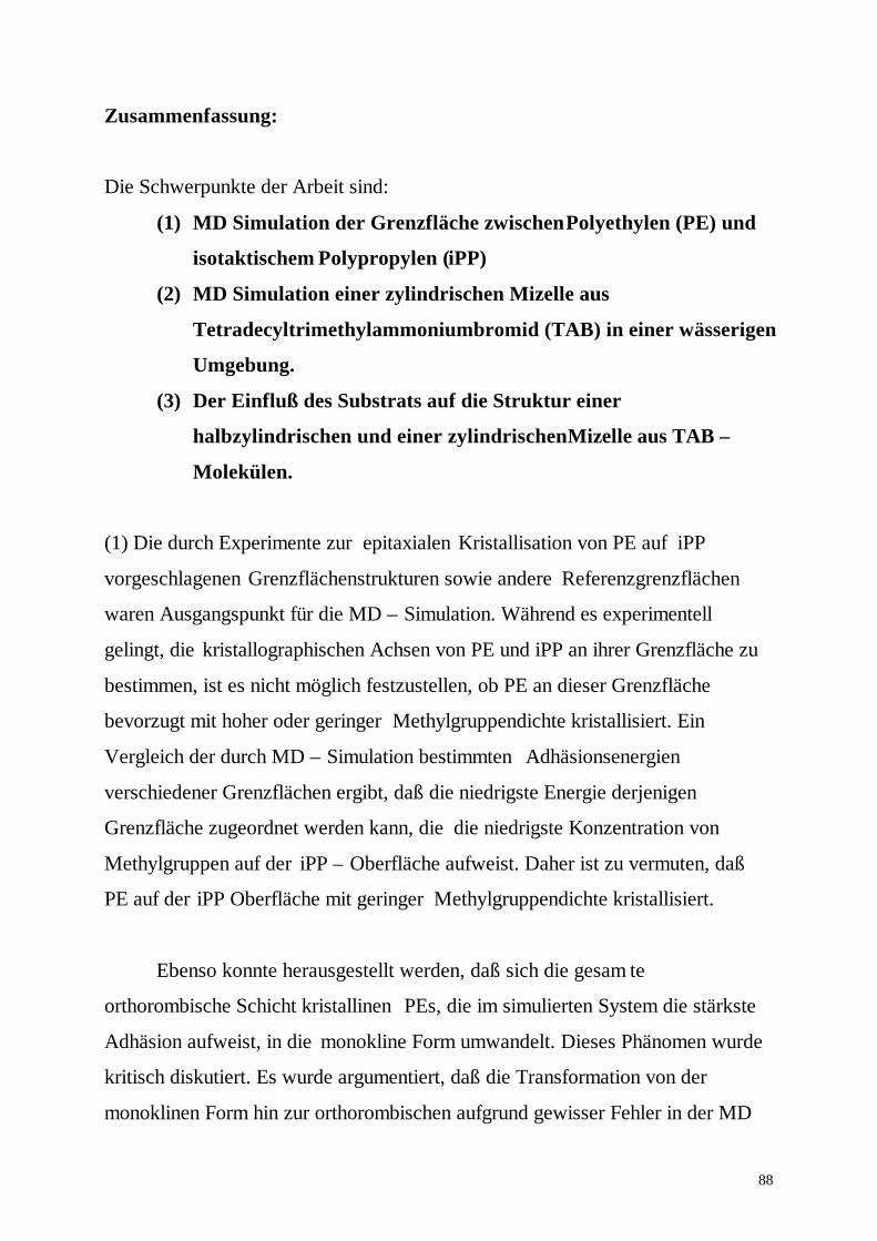
88
Zusammenfassung:
Die Schwerpunkte der Arbeit sind:
(1) MD Simulation der Grenzfläche zwischen Polyethylen (PE) und
isotaktischem Polypropylen (iPP)
(2) MD Simulation einer zylindrischen Mizelle aus
Tetradecyltrimethylammoniumbromid (TAB) in einer wässerigen
Umgebung.
(3) Der Einfluß des Substrats auf die Struktur einer
halbzylindrischen und einer zylindrischen Mizelle aus TAB –
Molekülen.
(1) Die durch Experimente zur epitaxialen Kristallisation von PE auf iPP
vorgeschlagenen Grenzflächenstrukturen sowie andere Referenzgrenzflächen
waren Ausgangspunkt für die MD – Simulation. Während es experimentell
gelingt, die kristallographischen Achsen von PE und iPP an ihrer Grenzfläche zu
bestimmen, ist es nicht möglich festzustellen, ob PE an dieser Grenzfläche
bevorzugt mit hoher oder geringer Methylgruppendichte kristallisiert. Ein
Vergleich der durch MD – Simulation bestimmten Adhäsionsenergien
verschiedener Grenzflächen ergibt, daß die niedrigste Energie derjenigen
Grenzfläche zugeordnet werden kann, die die niedrigste Konzentration von
Methylgruppen auf der iPP – Oberfläche aufweist. Daher ist zu vermuten, daß
PE auf der iPP Oberfläche mit geringer Methylgruppendichte kristallisiert.
Ebenso konnte herausgestellt werden, daß sich die gesam te
orthorombische Schicht kristallinen PEs, die im simulierten System die stärkste
Adhäsion aufweist, in die monokline Form umwandelt. Dieses Phänomen wurde
kritisch diskutiert. Es wurde argumentiert, daß die Transformation von der
monoklinen Form hin zur orthorombischen aufgrund gewisser Fehler in der MD
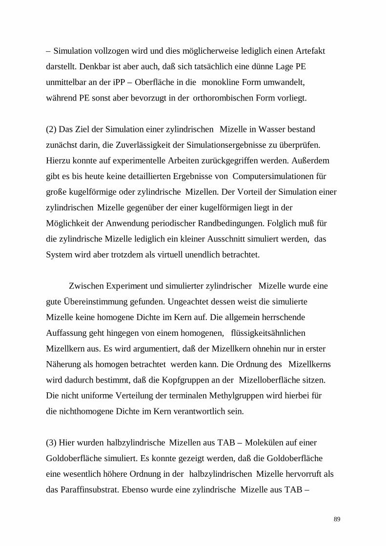
89
– Simulation vollzogen wird und dies möglicherweise lediglich einen Artefakt
darstellt. Denkbar ist aber auch, daß sich tatsächlich eine dünne Lage PE
unmittelbar an der iPP – Oberfläche in die monokline Form umwandelt,
während PE sonst aber bevorzugt in der orthorombischen Form vorliegt.
(2) Das Ziel der Simulation einer zylindrischen Mizelle in Wasser bestand
zunächst darin, die Zuverlässigkeit der Simulationsergebnisse zu überprüfen.
Hierzu konnte auf experimentelle Arbeiten zurückgegriffen werden. Außerdem
gibt es bis heute keine detaillierten Ergebnisse von Computersimulationen für
große kugelförmige oder zylindrische Mizellen. Der Vorteil der Simulation einer
zylindrischen Mizelle gegenüber der einer kugelförmigen liegt in der
Möglichkeit der Anwendung periodischer Randbedingungen. Folglich muß für
die zylindrische Mizelle lediglich ein kleiner Ausschnitt simuliert werden, das
System wird aber trotzdem als virtuell unendlich betrachtet.
Zwischen Experiment und simulierter zylindrischer Mizelle wurde eine
gute Übereinstimmung gefunden. Ungeachtet dessen weist die simulierte
Mizelle keine homogene Dichte im Kern auf. Die allgemein herrschende
Auffassung geht hingegen von einem homogenen, flüssigkeitsähnlichen
Mizellkern aus. Es wird argumentiert, daß der Mizellkern ohnehin nur in erster
Näherung als homogen betrachtet werden kann. Die Ordnung des Mizellkerns
wird dadurch bestimmt, daß die Kopfgruppen an der Mizelloberfläche sitzen.
Die nicht uniforme Verteilung der terminalen Methylgruppen wird hierbei für
die nichthomogene Dichte im Kern verantwortlich sein.
(3) Hier wurden halbzylindrische Mizellen aus TAB – Molekülen auf einer
Goldoberfläche simuliert. Es konnte gezeigt werden, daß die Goldoberfläche
eine wesentlich höhere Ordnung in der halbzylindrischen Mizelle hervorruft als
das Paraffinsubstrat. Ebenso wurde eine zylindrische Mizelle aus TAB –

90
Molekülen auf einem Goldsubstrat mit Hilfe der MD – Simulation studiert.
Hierbei flachte die zylindrische Mizelle ab, wobei die Alkylketten zu einer
senkrechten Ausrichtung bezüglich der Substratebene tendierten. Dieses
Abflachen und die Reorientierung der Alkylketten wurde mit entsprechenden
Experimenten auf Silizium verglichen, wobei auch hier eine gute
Übereinstimmung gefunden werden konnte.
91
Lebenslauf
Persönliche Angaben:
Name: Severin
Vorname: NikolaiAnschrift: Schulstr. 57
14169 BerlinTel.: (030) 46606788
Geburtsdatum: 04.01.1971Geburtsdatum: Moskau (Rußland)Familienstand: verheiratetStaatsangehörigkeit: russisch
Schulbildung:1977-1987 Allgemeine SchuleStudium:1987-1993 Studium der Physik an der Moskauer Lomonosow
Universitäat
01/93 Abschluß: Diplom in Physik1993-1995 Wissenschaftlicher Mitarbeiter an der Moskauer
Lomonosow Universität1995-1998 Doktorand1998- Wissenschaftlicher Mitarbeiter an der Humboldt
Universität
Berlin, den 1.12.1998

92
Selbständigkeitserklärung
Hiermit versichere ich, die vorliegende Arbeit selbständig angefertigt zu haben und keineweiteren als die Hilfsmittel verwendet zu haben.


![ess.cs.uni-dortmund.de file0! & ( % ; $ 8 9 &. ( $ % # 8 9 & + % #! " # +,- - . < 0+ $ class Hello {public static void main(String argv[])](https://img.pdfslide.org/doc/110x75/5e04e2a908500a687f775f3e/esscsuni-8-9-8-9-.jpg)