Embed Size (px)
Citation preview
EWGAE2002
J. Acoustic Emission, 20 (2002) 257 © 2002 Acoustic Emission Group
NON-DESTRUCTIVE EVALUATION OF BRAZED JOINTSBY MEANS OF ACOUSTIC EMISSION
H. TRAXLER1, W. ARNOLD2, W. KNABL1 and P. RÖDHAMMER1
1PLANSEE Aktiengesellschaft, Technology Center, A-6600 Reutte, Austria2Fraunhofer Institut für Zerstörungsfreie Prüfverfahren (IZFP),
D-66123 Saarbrücken, Germany
Abstract
Brazing is a key technology in the production of components made of high performance ma-terials. Due to the extreme operating conditions and stringent safety requirements, there is astrong demand for quality assurance by non-destructive evaluation of brazed components such ascomposite X-ray targets. An established method for non-destructive testing is ultrasonic C-scanning in the pulse-echo mode. This method allows one to detect voids in the brazing interfacesuch as voids, which are caused by inhomogeneous wetting by the filler metal of the parts to bebrazed. Additionally there is an interest for the microstructure of the braze alloy and for testingits loading capacity. To get information on these properties at present metallography or loadingtests up to destructive load levels are required. The results presented here show that acousticemission (AE) during a loading test to a subcritical load level is sensitive to deviations in theprocess parameters causing embrittlement of the brazing alloy. The origin of the AE signals hasbeen identified by the systematic exclusion of the various possible sources in a comparative ex-perimental study. Furthermore, a correlation between the non-destructive AE test and the de-structive load test has been established. Samples, which failed prematurely in the destructiveload test, showed a strongly increased signal rate and a specific type of signals in the AE test.
Keywords: Acoustic emission, Non-destructive testing, Brazing, X-ray target
1. Introduction
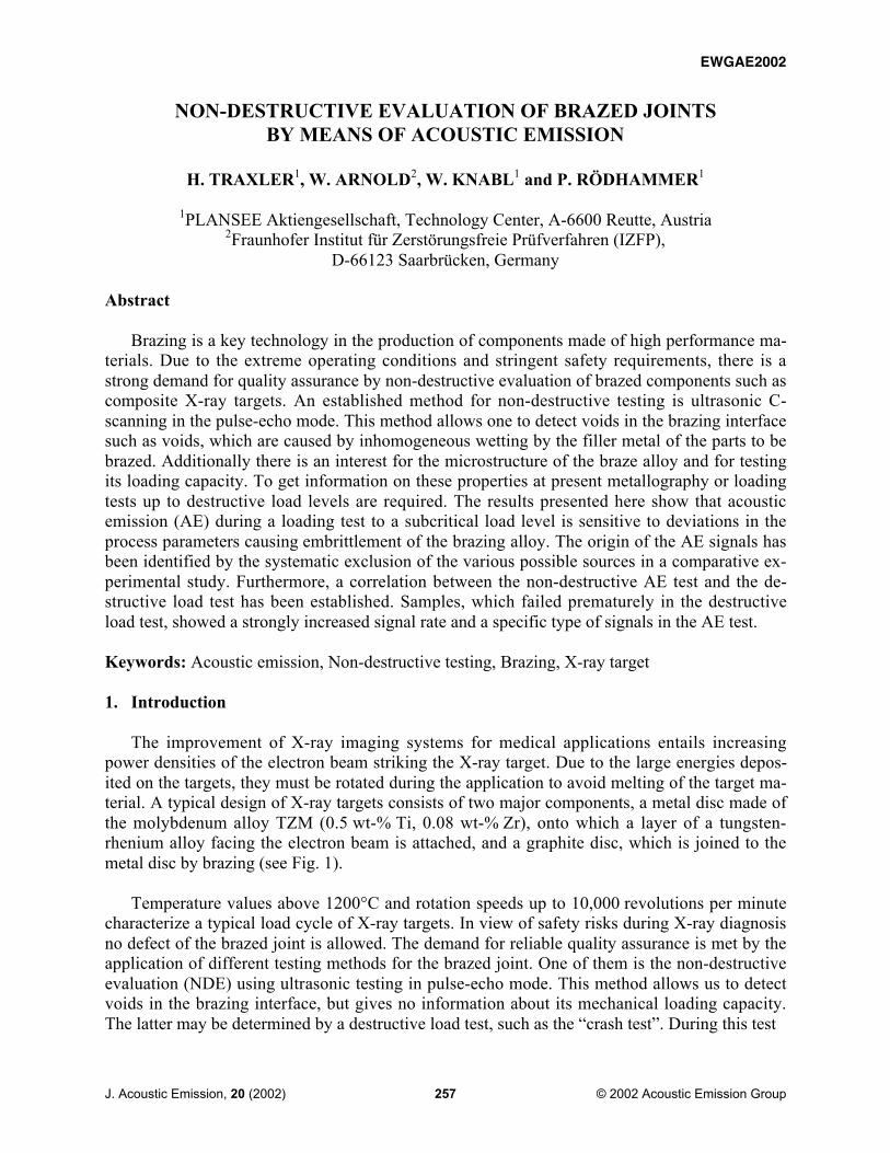
The improvement of X-ray imaging systems for medical applications entails increasingpower densities of the electron beam striking the X-ray target. Due to the large energies depos-ited on the targets, they must be rotated during the application to avoid melting of the target ma-terial. A typical design of X-ray targets consists of two major components, a metal disc made ofthe molybdenum alloy TZM (0.5 wt-% Ti, 0.08 wt-% Zr), onto which a layer of a tungsten-rhenium alloy facing the electron beam is attached, and a graphite disc, which is joined to themetal disc by brazing (see Fig. 1).
Temperature values above 1200°C and rotation speeds up to 10,000 revolutions per minutecharacterize a typical load cycle of X-ray targets. In view of safety risks during X-ray diagnosisno defect of the brazed joint is allowed. The demand for reliable quality assurance is met by theapplication of different testing methods for the brazed joint. One of them is the non-destructiveevaluation (NDE) using ultrasonic testing in pulse-echo mode. This method allows us to detectvoids in the brazing interface, but gives no information about its mechanical loading capacity.The latter may be determined by a destructive load test, such as the �crash test�. During this test
EWGAE2002
258
Fig. 1. Photograph of X-ray target studied.
a target of a production lot is heated up to some hundreds degrees C and afterwards shock-cooledby immersion in cold water. If there is no visible damage at the examined X-ray target after 20cycles of thermal loading, the production lot is released.
The goal of the present work was the development of a non-destructive load test to gauge thebond strength of brazed X-ray targets by applying acoustic emission (AE), and in consequencethe replacement of the crash test. The method applied in this test is to induce � by way of elasticdeformation of the brazed composite � a specific pattern of tensile and shear stresses at the TZM� graphite brazing interface and to monitor the ensuing AE response of the interface in the highkilohertz regime. Until now, a few examples of NDE of material joints by AE are known [1, 2].
2. Experimental Set-Up
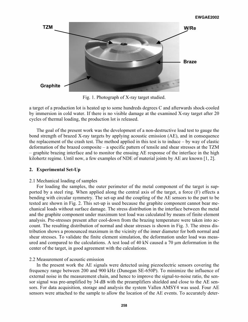
2.1 Mechanical loading of samplesFor loading the samples, the outer perimeter of the metal component of the target is sup-
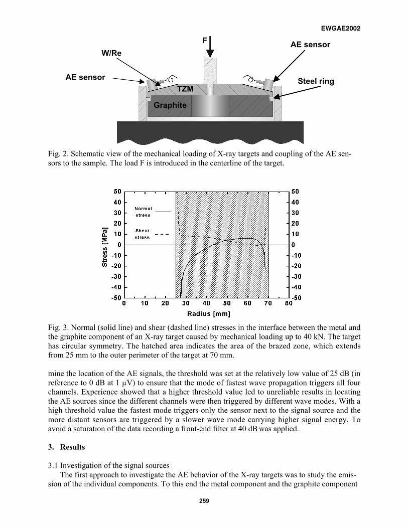
ported by a steel ring. When applied along the central axis of the target, a force (F) effects abending with circular symmetry. The set-up and the coupling of the AE sensors to the part to betested are shown in Fig. 2. This set-up is used because the graphite component cannot bear me-chanical loads without surface damage. The stress distribution in the interface between the metaland the graphite component under maximum test load was calculated by means of finite elementanalysis. Pre-stresses present after cool-down from the brazing temperature were taken into ac-count. The resulting distribution of normal and shear stresses is shown in Fig. 3. The stress dis-tribution shows a pronounced maximum in the vicinity of the inner diameter for both normal andshear stresses. To validate the finite element simulation, the deformation under load was meas-ured and compared to the calculations. A test load of 40 kN caused a 70 µm deformation in thecenter of the target, in good agreement with the calculations.
2.2 Measurement of acoustic emissionIn the present work the AE signals were detected using piezoelectric sensors covering the
frequency range between 200 and 900 kHz (Dunegan SE-650P). To minimize the influence ofexternal noise in the measurement chain, and hence to improve the signal-to-noise ratio, the sen-sor signal was pre-amplified by 34 dB with the preamplifiers shielded and close to the AE sen-sors. For data acquisition, storage and analysis the system Vallen AMSY4 was used. Four AEsensors were attached to the sample to allow the location of the AE events. To accurately deter-
TZM
Graphite
W/Re
Braze
EWGAE2002
259
Fig. 2. Schematic view of the mechanical loading of X-ray targets and coupling of the AE sen-sors to the sample. The load F is introduced in the centerline of the target.
Fig. 3. Normal (solid line) and shear (dashed line) stresses in the interface between the metal andthe graphite component of an X-ray target caused by mechanical loading up to 40 kN. The targethas circular symmetry. The hatched area indicates the area of the brazed zone, which extendsfrom 25 mm to the outer perimeter of the target at 70 mm.
mine the location of the AE signals, the threshold was set at the relatively low value of 25 dB (inreference to 0 dB at 1 µV) to ensure that the mode of fastest wave propagation triggers all fourchannels. Experience showed that a higher threshold value led to unreliable results in locatingthe AE sources since the different channels were then triggered by different wave modes. With ahigh threshold value the fastest mode triggers only the sensor next to the signal source and themore distant sensors are triggered by a slower wave mode carrying higher signal energy. Toavoid a saturation of the data recording a front-end filter at 40 dB was applied.
3. Results
3.1 Investigation of the signal sourcesThe first approach to investigate the AE behavior of the X-ray targets was to study the emis-
sion of the individual components. To this end the metal component and the graphite component
TZM
Graphite
Steel ring
F
W/ReAE sensor
AE sensor
EWGAE2002
260
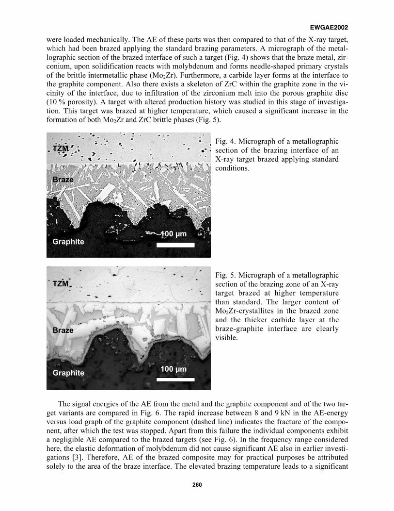
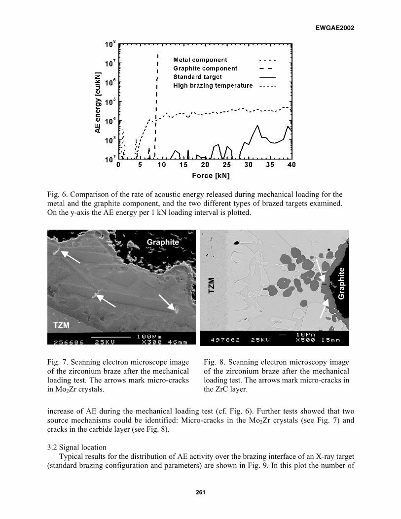
were loaded mechanically. The AE of these parts was then compared to that of the X-ray target,which had been brazed applying the standard brazing parameters. A micrograph of the metal-lographic section of the brazed interface of such a target (Fig. 4) shows that the braze metal, zir-conium, upon solidification reacts with molybdenum and forms needle-shaped primary crystalsof the brittle intermetallic phase (Mo2Zr). Furthermore, a carbide layer forms at the interface tothe graphite component. Also there exists a skeleton of ZrC within the graphite zone in the vi-cinity of the interface, due to infiltration of the zirconium melt into the porous graphite disc(10 % porosity). A target with altered production history was studied in this stage of investiga-tion. This target was brazed at higher temperature, which caused a significant increase in theformation of both Mo2Zr and ZrC brittle phases (Fig. 5).
Fig. 4. Micrograph of a metallographicsection of the brazing interface of anX-ray target brazed applying standardconditions.
Fig. 5. Micrograph of a metallographicsection of the brazing zone of an X-raytarget brazed at higher temperaturethan standard. The larger content ofMo2Zr-crystallites in the brazed zoneand the thicker carbide layer at thebraze-graphite interface are clearlyvisible.
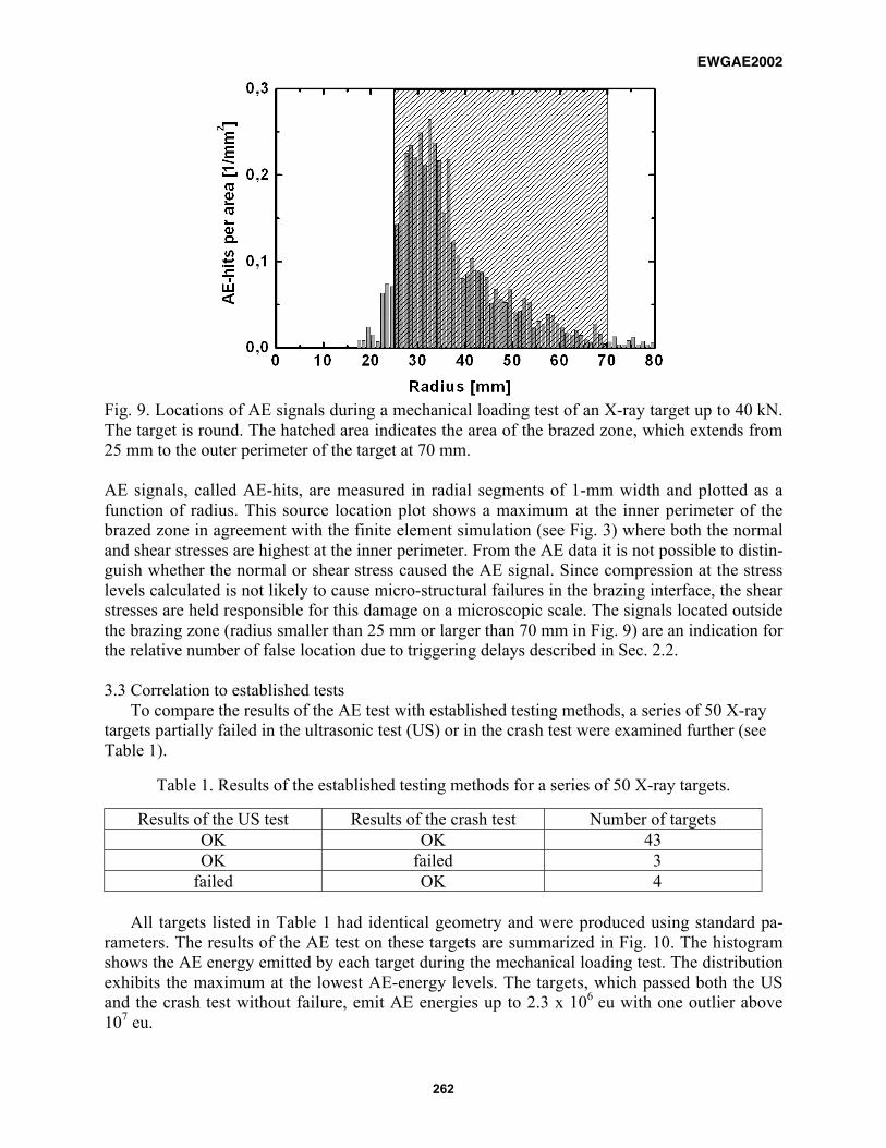
The signal energies of the AE from the metal and the graphite component and of the two tar-get variants are compared in Fig. 6. The rapid increase between 8 and 9 kN in the AE-energyversus load graph of the graphite component (dashed line) indicates the fracture of the compo-nent, after which the test was stopped. Apart from this failure the individual components exhibita negligible AE compared to the brazed targets (see Fig. 6). In the frequency range consideredhere, the elastic deformation of molybdenum did not cause significant AE also in earlier investi-gations [3]. Therefore, AE of the brazed composite may for practical purposes be attributedsolely to the area of the braze interface. The elevated brazing temperature leads to a significant
100 µm
TZM
Braze
Graphite
100 µm
TZM
Braze
Graphite
EWGAE2002
261
Fig. 6. Comparison of the rate of acoustic energy released during mechanical loading for themetal and the graphite component, and the two different types of brazed targets examined.On the y-axis the AE energy per 1 kN loading interval is plotted.
Fig. 7. Scanning electron microscope imageof the zirconium braze after the mechanicalloading test. The arrows mark micro-cracksin Mo2Zr crystals.
Fig. 8. Scanning electron microscopy imageof the zirconium braze after the mechanicalloading test. The arrows mark micro-cracks inthe ZrC layer.
increase of AE during the mechanical loading test (cf. Fig. 6). Further tests showed that twosource mechanisms could be identified: Micro-cracks in the Mo2Zr crystals (see Fig. 7) andcracks in the carbide layer (see Fig. 8).
3.2 Signal locationTypical results for the distribution of AE activity over the brazing interface of an X-ray target
(standard brazing configuration and parameters) are shown in Fig. 9. In this plot the number of
Graphite
TZM
TZ
M
Gra
ph
ite
EWGAE2002
262
Fig. 9. Locations of AE signals during a mechanical loading test of an X-ray target up to 40 kN.The target is round. The hatched area indicates the area of the brazed zone, which extends from25 mm to the outer perimeter of the target at 70 mm.
AE signals, called AE-hits, are measured in radial segments of 1-mm width and plotted as afunction of radius. This source location plot shows a maximum at the inner perimeter of thebrazed zone in agreement with the finite element simulation (see Fig. 3) where both the normaland shear stresses are highest at the inner perimeter. From the AE data it is not possible to distin-guish whether the normal or shear stress caused the AE signal. Since compression at the stresslevels calculated is not likely to cause micro-structural failures in the brazing interface, the shearstresses are held responsible for this damage on a microscopic scale. The signals located outsidethe brazing zone (radius smaller than 25 mm or larger than 70 mm in Fig. 9) are an indication forthe relative number of false location due to triggering delays described in Sec. 2.2.
3.3 Correlation to established testsTo compare the results of the AE test with established testing methods, a series of 50 X-ray
targets partially failed in the ultrasonic test (US) or in the crash test were examined further (seeTable 1).
Table 1. Results of the established testing methods for a series of 50 X-ray targets.
Results of the US test Results of the crash test Number of targetsOK OK 43OK failed 3
failed OK 4
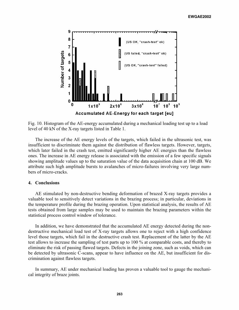
All targets listed in Table 1 had identical geometry and were produced using standard pa-rameters. The results of the AE test on these targets are summarized in Fig. 10. The histogramshows the AE energy emitted by each target during the mechanical loading test. The distributionexhibits the maximum at the lowest AE-energy levels. The targets, which passed both the USand the crash test without failure, emit AE energies up to 2.3 x 10⁶ eu with one outlier above107 eu.
EWGAE2002
263
Fig. 10. Histogram of the AE-energy accumulated during a mechanical loading test up to a loadlevel of 40 kN of the X-ray targets listed in Table 1.
The increase of the AE energy levels of the targets, which failed in the ultrasonic test, wasinsufficient to discriminate them against the distribution of flawless targets. However, targets,which later failed in the crash test, emitted significantly higher AE energies than the flawlessones. The increase in AE energy release is associated with the emission of a few specific signalsshowing amplitude values up to the saturation value of the data acquisition chain at 100 dB. Weattribute such high amplitude bursts to avalanches of micro-failures involving very large num-bers of micro-cracks.
4. Conclusions
AE stimulated by non-destructive bending deformation of brazed X-ray targets provides avaluable tool to sensitively detect variations in the brazing process; in particular, deviations inthe temperature profile during the brazing operation. Upon statistical analysis, the results of AEtests obtained from large samples may be used to maintain the brazing parameters within thestatistical process control window of tolerance.
In addition, we have demonstrated that the accumulated AE energy detected during the non-destructive mechanical load test of X-ray targets allows one to reject with a high confidencelevel those targets, which fail in the destructive crash test. Replacement of the latter by the AEtest allows to increase the sampling of test parts up to 100 % at comparable costs, and thereby toeliminate the risk of passing flawed targets. Defects in the joining zone, such as voids, which canbe detected by ultrasonic C-scans, appear to have influence on the AE, but insufficient for dis-crimination against flawless targets.
In summary, AE under mechanical loading has proven a valuable tool to gauge the mechani-cal integrity of braze joints.
EWGAE2002
264
Acknowledgement
We are grateful to H. Klocker for carrying out the finite element analysis and to A. Planken-steiner for fruitful discussions. The assistance of A. Wolf is gratefully acknowledged.
References
[1] Schmitt-Thomas Kh. and Waterschek R., �Untersuchung der Güte von Weichlötstellen mitHilfe der Schallemissionsanalyse�, Proc. 8th Congress on Material Testing, Vol. 1, Omikk-Technoinform, Budapest (1982), pp. 1180 � 1184.
[2] Sell J. and Weiler L., �Quality Control Proof-test with Acoustic Emission of Ceramic Cool-ing Plates�, Proc. 23rd European Conference on Acoustic Emission Testing, TÜV Vienna,Vienna (1998), pp. 140 � 145.
[3] Traxler H., �Schichtprüfung mittels Schallemissionsanalyse�, Diplomarbeit TechnischeUniversität Wien (1997), pp. 56 � 64, unpublished.