Embed Size (px)
Citation preview
European Standard EN 1435 : 1997 + A1 : 2002 has the status of a DIN Standard.
A comma is used as the decimal marker.
National forewordThis standard has been prepared by CEN/TC 121.The responsible German body involved in its preparation was the Normenausschuss Materialprüfung (Ma-terials Testing Standards Committee), Technical Committee Durchstrahlungsprüfung und Strahlenschutz.
AmendmentsThis standard differs from the October 1997 edition in that it has been editorially revised.
Previous editionsDIN 1914: 1935-08; DIN 54111: 1954-08x; DIN 54111-1: 1973-11, 1977-03, 1988-05; DIN EN 1435: 1997-10.
ICS 25.160.10
Zerstörungsfreie Prüfung von Schweißverbindungen –Durchstrahlungsprüfung von Schweißverbindungen(enthält Änderung A1 : 2002)
Ref. No. DIN EN 1435 : 2002-09English price group 14 Sales No. 1114
03.03
DEUTSCHE NORM September 2002
EN 1435{
EN comprises 25 pages.
© No part of this standard may be reproduced without the prior permission ofDIN Deutsches Institut für Normung e.V., Berlin. Beuth Verlag GmbH, 10772 Berlin, Germany,has the exclusive right of sale for German Standards (DIN-Normen).
Non-destructive testing of welds
Radiographic testing of welded joints(includes Amendment A1)
English version of DIN EN 1435 : 1997 + A1 : 2002
SupersedesOctober 1997 edition.

English version
ICS 25.160.40
Management Centre: rue de Stassart 36, B-1050 Brussels
European Committee for StandardizationComité Européen de NormalisationEuropäisches Komitee für Normung
Non-destructive testing of welds
Radiographic testing of welded joints(includes Amendment A1 : 2002)
© 2002. CEN – All rights of exploitation in any form and by any meansreserved worldwide for CEN national members.
Ref. No. EN 1435 : 1997 + A1 : 2002 E
Contrôle non destructif des assem-blages soudés – Contrôle par radio-graphie des assemblages soudés(Amendement A1 : 2002 inclus)
Zerstörungsfreie Prüfung vonSchweißverbindungen – Durch-strahlungsprüfung vonSchweißverbindungen(enthält Änderung A1 : 2002)
This European Standard was approved by CEN on 1997-08-02. Amendment A1was approved by CEN on 2002-05-02.CEN members are bound to comply with the CEN/CENELEC Internal Regulationswhich stipulate the conditions for giving this European Standard the status of anational standard without any alteration.Up-to-date lists and bibliographical references concerning such nationalstandards may be obtained on application to the Management Centre or to anyCEN member.The European Standards exist in three official versions (English, French, German).A version in any other language made by translation under the responsibility of aCEN member into its own language and notified to the Management Centre hasthe same status as the official versions.CEN members are the national standards bodies of Austria, Belgium, the CzechRepublic, Denmark, Finland, France, Germany, Greece, Iceland, Ireland, Italy,Luxembourg, Malta, the Netherlands, Norway, Portugal, Spain, Sweden, Switzer-land, and the United Kingdom.
ÈÉË
EN 1435 October 1997
+ A1 May 2002
Page 2EN 1435 : 1997 + A1 : 2002
Page
Foreword to EN 1435 : 1997 . . . . . . . . . . . . . . . 2
Foreword to EN 1435 : 1997/A1 : 2002 . . . . . . 2
1 Scope . . . . . . . . . . . . . . . . . . . . . . . . . . . . . . . 3
2 Normative references . . . . . . . . . . . . . . . . . 3
3 Definitions . . . . . . . . . . . . . . . . . . . . . . . . . . . 3
4 Classification of radiographictechniques . . . . . . . . . . . . . . . . . . . . . . . . . . . 4
5 General . . . . . . . . . . . . . . . . . . . . . . . . . . . . . . 45.1 Protection against ionizing radiation . . . . 45.2 Surface preparation and stage of
manufacture . . . . . . . . . . . . . . . . . . . . . . . . 45.3 Location of weld on radiograph . . . . . . . . 45.4 Identification of radiographs . . . . . . . . . . . 45.5 Marking . . . . . . . . . . . . . . . . . . . . . . . . . . . . 45.6 Overlap of films . . . . . . . . . . . . . . . . . . . . . . 55.7 Types and positions of image quality
indicators (IQI) . . . . . . . . . . . . . . . . . . . . . . . 55.8 Evaluation of image quality . . . . . . . . . . . . 55.9 Minimum image quality values . . . . . . . . . 55.10 Personnel qualification . . . . . . . . . . . . . . . 5
6 Recommended techniques for markingradiographs . . . . . . . . . . . . . . . . . . . . . . . . . . 5
6.1 Test arrangements . . . . . . . . . . . . . . . . . . . 56.1.1 General . . . . . . . . . . . . . . . . . . . . . . . . . . . 56.1.2 Radiation source located in front of
the object and with the film on theopposite side . . . . . . . . . . . . . . . . . . . . . . 6
6.1.3 Radiation source located outsidethe object and with the film inside . . . . . 6
6.1.4 Radiation source centrally locatedinside the object and with the filmoutside . . . . . . . . . . . . . . . . . . . . . . . . . . . 7
6.1.5 Radiation source located off-centreinside the object and with the filmoutside . . . . . . . . . . . . . . . . . . . . . . . . . . . 8
Page
6.1.6 Elliptic technique . . . . . . . . . . . . . . . . . . . 86.1.7 Perpendicular technique . . . . . . . . . . . . . 96.1.8 Radiation source located outside
the object and with the film on theopposite side . . . . . . . . . . . . . . . . . . . . . . 9
6.1.9 Technique for different materialthicknesses . . . . . . . . . . . . . . . . . . . . . . . 10
6.2 Choice of tube voltage and radiationsource . . . . . . . . . . . . . . . . . . . . . . . . . . . . . 11
6.2.1 X-ray devices . . . . . . . . . . . . . . . . . . . . . . 116.2.2 Other radiation sources . . . . . . . . . . . . . 116.3 Film systems and screens . . . . . . . . . . . . . 126.4 Alignment of beam . . . . . . . . . . . . . . . . . . . 146.5 Reduction of scattered radiation . . . . . . . . 146.5.1 Filters and collimators . . . . . . . . . . . . . . . 146.5.2 Interception of back scattered
radiation . . . . . . . . . . . . . . . . . . . . . . . . . . 146.6 Source-to-object distance . . . . . . . . . . . . . 146.7 Maximum area for a single exposure . . . . 156.8 Density of radiograph . . . . . . . . . . . . . . . . . 166.9 Processing . . . . . . . . . . . . . . . . . . . . . . . . . 166.10 Film viewing conditions . . . . . . . . . . . . . . 16
7 Test report . . . . . . . . . . . . . . . . . . . . . . . . . . . 16
Annex A (normative) Recommended numberof exposures which give anacceptable test of a circumferentialbutt weld . . . . . . . . . . . . . . . . . . . . . . 17
Annex B (normative) Minimum image qualityvalues . . . . . . . . . . . . . . . . . . . . . . . . . . 22
Annex ZA (informative) Clauses of thisEuropean Standard addressingessential requirements or otherprovisions of EU Directives . . . . . . 25
Contents
Foreword to EN 1435 : 1997This European Standard has been prepared by CEN/TC 121 ‘Welding’, the Secretariat of which is held by DS.This European Standard shall be given the status of a national standard, either by publication of an identicaltext or by endorsement, and conflicting national standards withdrawn, by February 1998 at the latest.In accordance with the CEN/CENELEC Internal Regulations, the following countries are bound to implementthis European Standard:Austria, Belgium, the Czech Republic, Denmark, Finland, France, Germany, Greece, Iceland, Ireland, Italy,Luxembourg, the Netherlands, Norway, Portugal, Spain, Sweden, Switzerland, and the United Kingdom.
Foreword to EN 1435 : 1997/A1 : 2002This Amendment to EN 1435 : 1997 has been prepared by Technical Committee CEN/TC 121 ‘Welding’, theSecretariat of which is held by DS.This Amendment has been prepared under a mandate given to CEN by the European Commission and theEuropean Free Trade Association, and supports essential requirements of the relevant EC Directive. For rela-tionship with this directive, see Annex ZA.
Page 3EN 1435 : 1997 + A1 : 2002
This Amendment shall be given the status of a national standard, either by publication of an identical text orby endorsement, and conflicting national standards withdrawn, by November 2002 at the latest.In accordance with the CEN/CENELEC Internal Regulations, the following countries are bound to implementthis European Standard:Austria, Belgium, the Czech Republic, Denmark, Finland, France, Germany, Greece, Iceland, Ireland, Italy,Luxembourg, Malta, the Netherlands, Norway, Portugal, Spain, Sweden, Switzerland, and the United Kingdom.
1 ScopeThis European Standard specifies fundamental techniques of radiography with the object of enabling satisfac-tory and reproducible results to be obtained economically. The techniques are based on generally recognizedpractice and fundamental theory of the subject.This standard deals with radiographic testing of fusion welded joints in metallic materials.It applies to joints in plates or pipes. Besides its conventional meaning, “pipe” as used in this standard shouldbe understood to cover other cylindrical bodies such as tubes, penstocks, boiler drums and pressure vessels.This standard complies with EN 444.This standard does not specify acceptance levels for the indications.If lower test criteria are permitted by specification, the quality achieved may be significantly lower than if thisstandard is strictly applied.
2 Normative referencesThis European Standard incorporates, by dated or undated reference, provisions from other publications.These normative references are cited at the appropriate places in the text and the publications are listedhereafter. For dated references, subsequent amendments to or revisions of any of these publications apply tothis European Standard only when incorporated in it by amendment or revision. For undated references, thelatest edition of the publication referred to applies.
EN 444 Non-destructive testing – General principles for the radiographic examination of metallic materialsusing X- and gamma-rays
EN 462-1 Non-destructive testing – Image quality of radiographs – Part 1: Concepts, image quality indicators(wire type), determination of image quality value
EN 462-2 Non-destructive testing – Image quality of radiographs – Part 2: Concepts, image quality indicators(step/hole type), determination of image quality value
EN 462-3 Non-destructive testing – Image quality of radiographs – Part 3: Image quality classes for ferrousmetals
EN 462-4 Non-destructive testing – Image quality of radiographs – Part 4: Experimental evaluation of imagequality values and image quality tables
EN 473 Qualification and certification of non-destructive personnel – General principlesEN 584-1 Non-destructive testing – Industrial radiographic film – Part 1: Classification of film systems for
industrial radiographyEN 584-2 Non-destructive testing – Industrial radiographic film – Part 2: Control of film processing by means
of reference valueEN 25580 Non-destructive testing – Industrial radiographic illuminators – Minimum requirements
(ISO 5580 : 1985)
3 DefinitionsFor the purposes of this standard, the following definitions apply.
3.1 Nominal thickness, tThe nominal thickness of the parent material, disregarding any manufacturing tolerance.
3.2 Penetrated thickness, wThe thickness of material in the direction of the radiation beam calculated on basis of the nominal thickness.For multiple wall techniques the penetrated thickness is calculated from the nominal thickness.
3.3 Object-to-film distance, bThe distance between the radiation side of the test object and the film surface measured along the central axisof the radiation beam.
Page 4EN 1435 : 1997 + A1 : 2002
3.4 Source size, dThe size of the radiation source.
3.5 Source-to-film distance, SFDThe distance between the radiation source and the film measured in the direction of the beam.
3.6 Source-to-object distance, fThe distance between the radiation source and the source side of the test object measured along the centralaxis of the radiation beam.
3.7 Diameter, De
The nominal external diameter of the pipe.
4 Classification of radiographic techniquesThe radiographic techniques are divided into two classes:
– Class A: basic techniques;– Class B: improved techniques.
Class B techniques will be used when the class A technique might be insufficiently sensitive.Better techniques compared to class B are possible and may be defined by specification of all appropriate testparameters.The choice of radiographic technique shall be defined by specification.If, for technical reasons, it is not possible to meet one of the conditions specified for class B, such as type ofradiation source or source-to-object distance, it may be defined by specification that the condition selectedmay be that specified for class A. The loss of sensitivity shall be compensated for by an increase of minimumdensity to 3,0 or by choice of a higher contrast film system. Because of the better sensitivity as compared toclass A, the test specimen may be regarded as examined within class B. This does not apply if the special SFDreductions described in 6.6 for test arrangements as in 6.1.3 and 6.1.4 are used.
5 General5.1 Protection against ionizing radiationWARNING. Exposure of any part of the human body to X-rays or gamma-rays can be highly injurious to health.Wherever X-ray equipment or radioactive sources are in use, appropriate legal requirements are to be compliedwith.When using ionizing radiation, international, national or local or safety regulations shall be strictly observed.
5.2 Surface preparation and stage of manufactureIn general, surface preparation is not necessary, but where surface imperfections or coatings might causedifficulty in detecting defects, the surface shall be ground smooth or coatings shall be removed.Unless otherwise specified, radiography shall be carried out after the final stage of manufacture (e.g. aftergrinding or heat treatment).
5.3 Location of weld on radiographWhere the radiograph does not show the weld, high-density markers shall be placed on either side of the weld.
5.4 Identification of radiographsSymbols shall be attached to each section of the object being radiographed. The images of these symbols shallappear in the radiograph outside the region of interest where possible, and shall ensure unambiguous identi-fication of the section.
5.5 MarkingPermanent markings on the object to be tested shall be made in order to accurately locate the position of eachradiograph.Where the nature of the material and/or its service conditions do not permit permanent marking, the locationmay be recorded by means of accurate sketches.
Page 5EN 1435 : 1997 + A1 : 2002
5.6 Overlap of filmsWhen radiographing an area with two or more separate films, the films shall overlap sufficiently to ensure thatthe complete region of interest is radiographed. This shall be verified by a high-density marker on the surfaceof the object which will appear on each film.
5.7 Types and positions of image quality indicators (IQI)The quality of image shall be verified by use of IQI in accordance with EN 462-1 or EN 462-2.The |Q| used shall be placed preferably on the source side of the test object at the centre of the area of intereston the parent metal beside the weld. The IQI shall be in close contact with the surface of the object.Its location shall be made in a section of uniform thickness characterized by a uniform optical density an thefilm.According to the IQI type used, two cases shall be considered:
a) When using a wire IQI, the wires shall be directed perpendicular to the weld and its location shall ensurethat at least 10 mm of the wire length will show in a section of uniform optical density, which is normally inthe parent metal adjacent to the weld. At exposures in accordance with 6.1.5 and 6.1.6, the IQI can be placedwith the wires normal to the pipe axis, and they should not be projected into the image of the weld.b) When using a step/hole IQI, it shall be placed in such way that the hole number required is placed closeto the weld.
At exposures in accordance with 6.1.5 and 6.1.6, the IQI type used can be placed either on the source or onthe film side. If the IQIs cannot be placed in accordance with the above conditions, the IQIs will be placed onthe film side and the image quality shall be determined at least once from a comparative exposure with one IQIplaced at the source side and one at the film side under the same conditions.For double wall exposures, when the IQI is placed on the film side, the above test is not necessary and in thiscase, it should be referred to the tables given in Annex B.Where the IQI’s are placed at the film side, the letter ‘F’ shall be placed near the IQI and it shall be remarkedin the test report.If steps have been taken to ensure that radiographs or similar test objects and regions are produced withidentical exposure and processing techniques and no differences in the image quality value are likely, the imagequality need not be verified for every radiograph, the extent of image quality verification being subject tospecification.For exposures of pipes with diameter 200 mm and above with the source located centrally, at least three IQIsshould be placed at equal spaces around the circumference. The film(s) showing IQI images are then consideredrepresentative for the whole circumference.
5.8 Evaluation of image qualityThe films shall be viewed in accordance with EN 25580. The number of the smallest wire or hole which can beseen on the image on the radiograph shall be established. The image of a wire shall be deemed accepted if acontinuous length of at least 10 mm is clearly visible in a section of uniform optical density. In the case of step/hole IQIs, if there are two holes of the same diameter, both shall be visible in order that the step can beconsidered visible.The image quality obtained shall be indicated in the test report. In each case, the type of indicator used shallbe clearly stated, as shown on the IQI.
5.9 Minimum image quality valuesTables B.1 to B.12 show the minimum quality values for ferrous materials. For other materials these require-ments or corresponding requirements may be defined by specification. The requirements shall be determinedin accordance with EN 462-4.
5.10 Personnel qualificationPersonnel performing non-destructive testing in accordance with this standard shaft be qualified in accordancewith EN 473 or equivalent to an appropriate level in the relevant industrial sector.
6 Recommended techniques for marking radiographs6.1 Test arrangements6.1.1 GeneralNormally, radiographic techniques in accordance with 6.1.2 to 6.1.9 shall be used.The elliptical (double wall/double image) technique in accordance with figure 11 should not be used for externaldiameters, De, above 100 mm, wall thicknesses, t, above 8 mm and weld widths above De/4. Two imagesdisplaced by 90° are sufficient if t/De is less than 0,12. The distance between the two weld images shall be aboutone weld width.
Page 6EN 1435 : 1997 + A1 : 2002
Where it is difficult to carry out an elliptic testing at De not greater than 100 mm, the perpendicular techniquein accordance with 6.1.7 may be used (see figure 12). In this case, three exposures 60° or 120° apart arerequired.For test arrangements in accordance with figures 11, 13 and 14, the inclination of the beam shall be kept as smallas possible and be such as to prevent superimposition of the two images. The source-to-object distance shallbe kept as small as possible, in accordance with 6.6. The IQI shall be placed close to the film with a lead letter ‘F’.Other radiographic techniques may be specified (e.g. for reasons like geometry of the test object or differencesin material thickness). In 6.1.9, an example of such a case is presented. Multi-film techniques shall not be usedto reduce exposure times on uniform sections.NOTE: In Annex A, the minimum number of radiographs necessary is given in order to obtain an acceptable
radiographic coverage of the total circumference of a butt weld in pipe.
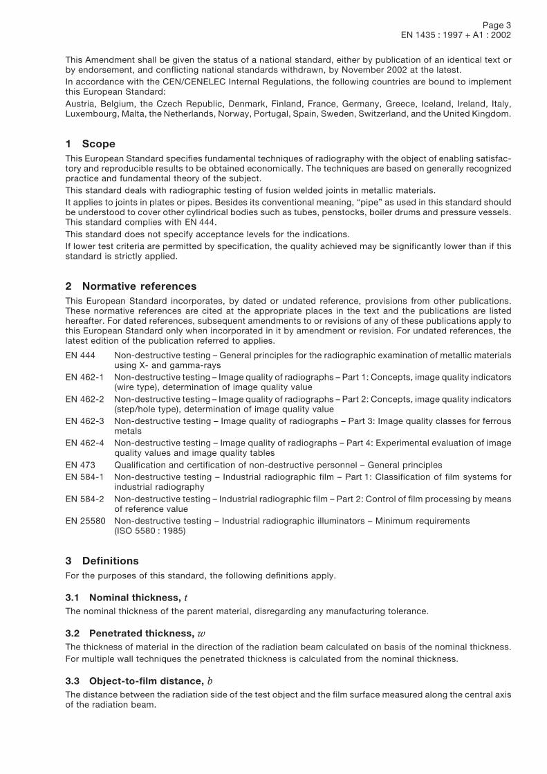
6.1.2 Radiation source located in front of the object and with the film on the opposite side (see figure 1)
S Radiation sourceF Film
Figure 1: Test arrangement for plane walls and single-wall penetration(see clause 3 for f, b, and t)
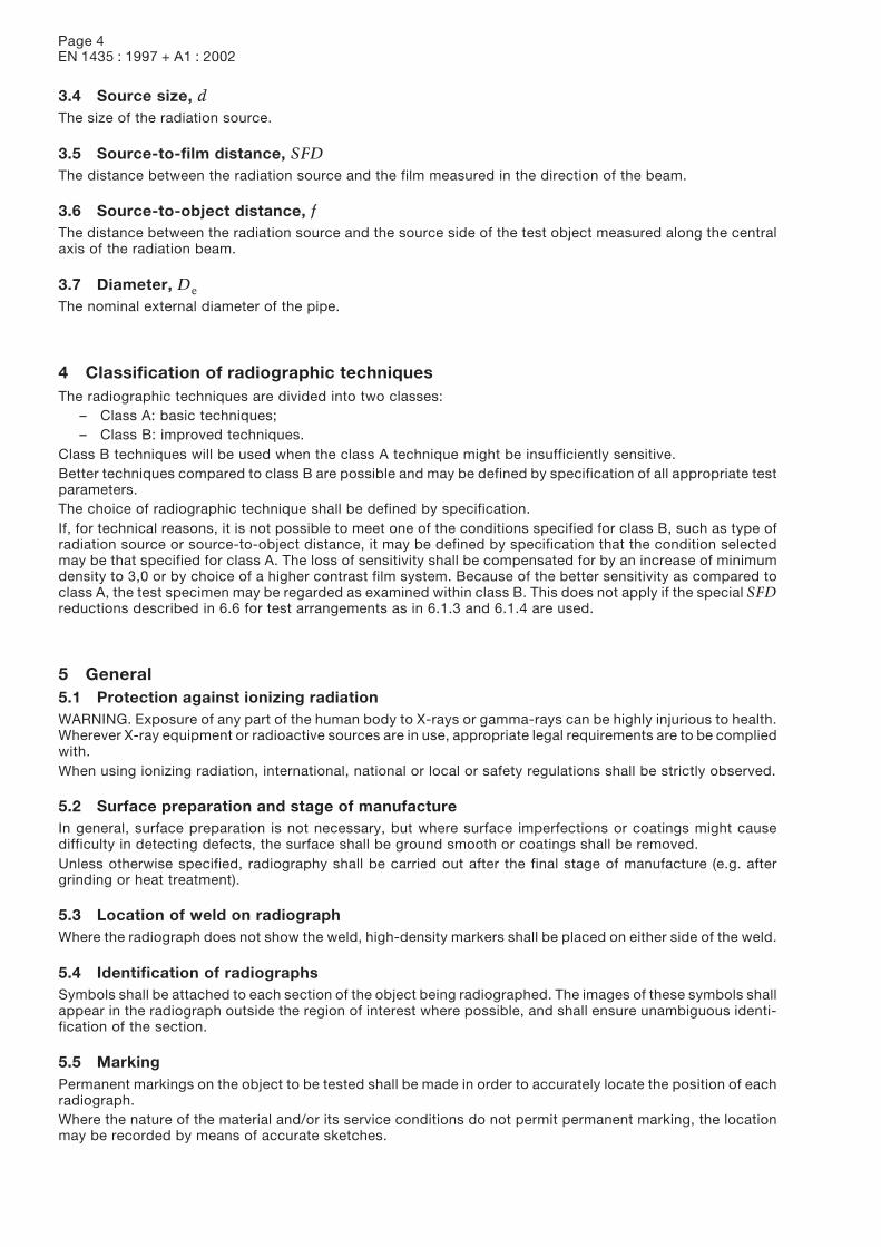
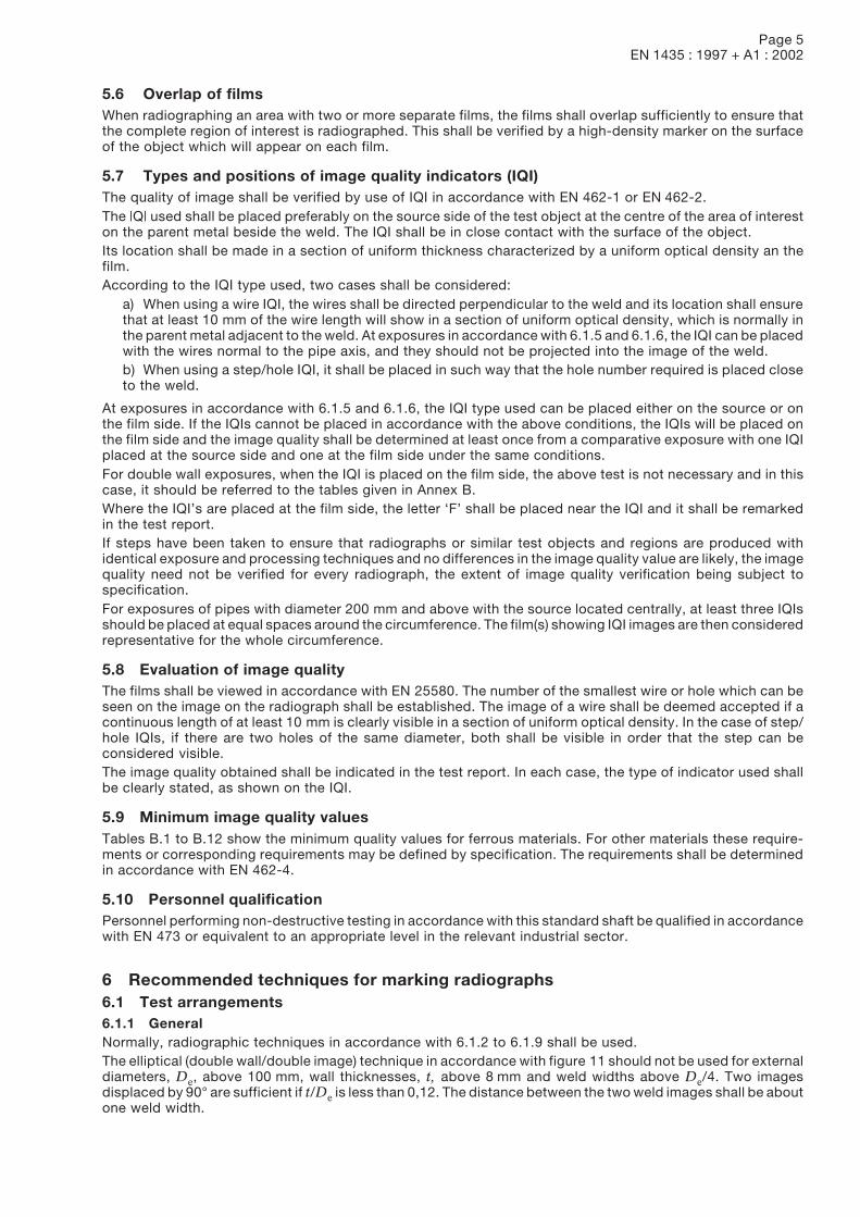
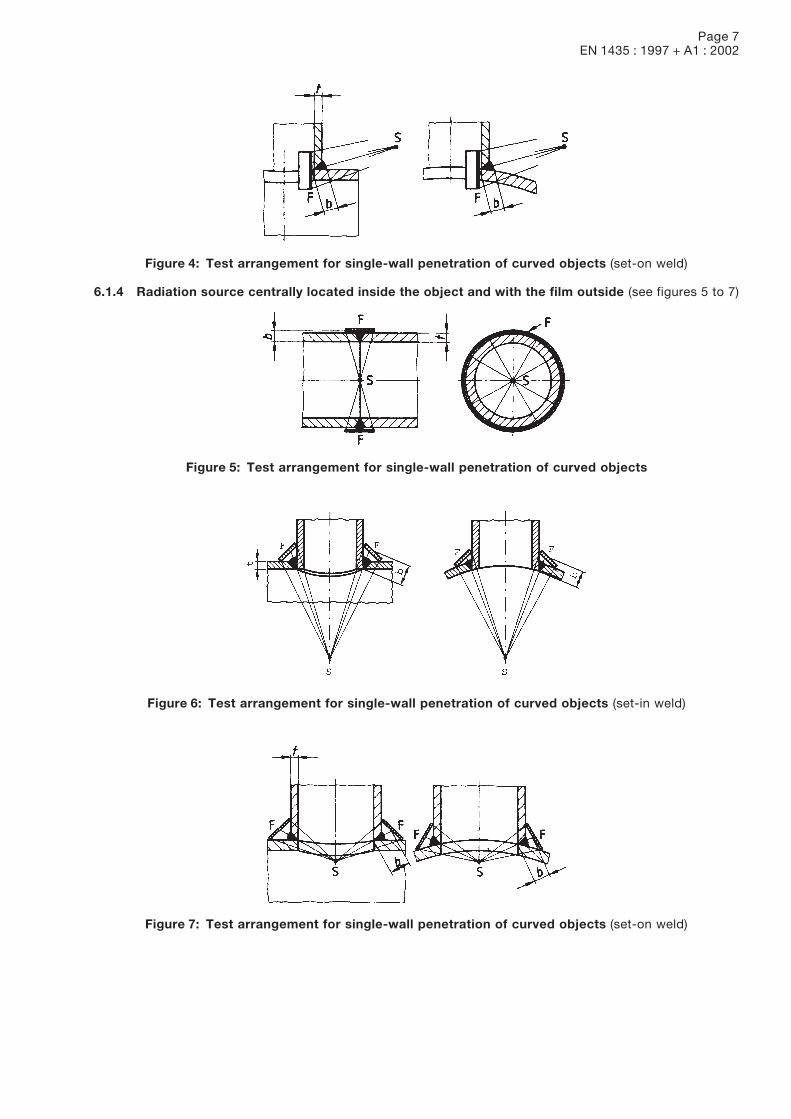
6.1.3 Radiation source located outside the object and with the film inside (see figures 2 to 4)
Figure 2: Test arrangement for single-wall penetration of curved objects
Figure 3: Test arrangement for single-wall penetration of curved objects (set-in weld)
Page 7EN 1435 : 1997 + A1 : 2002
Figure 4: Test arrangement for single-wall penetration of curved objects (set-on weld)
6.1.4 Radiation source centrally located inside the object and with the film outside (see figures 5 to 7)
Figure 5: Test arrangement for single-wall penetration of curved objects
Figure 6: Test arrangement for single-wall penetration of curved objects (set-in weld)
Figure 7: Test arrangement for single-wall penetration of curved objects (set-on weld)
Page 8EN 1435 : 1997 + A1 : 2002
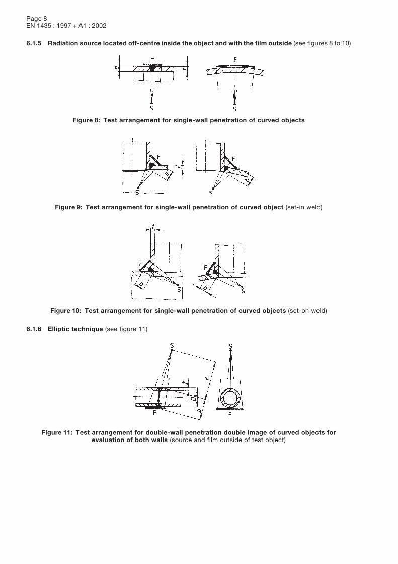
6.1.5 Radiation source located off-centre inside the object and with the film outside (see figures 8 to 10)
Figure 8: Test arrangement for single-wall penetration of curved objects
Figure 9: Test arrangement for single-wall penetration of curved object (set-in weld)
Figure 10: Test arrangement for single-wall penetration of curved objects (set-on weld)
6.1.6 Elliptic technique (see figure 11)
Figure 11: Test arrangement for double-wall penetration double image of curved objects forevaluation of both walls (source and film outside of test object)
Page 9EN 1435 : 1997 + A1 : 2002
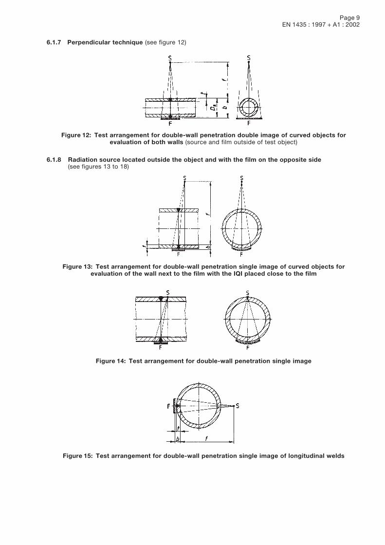
6.1.7 Perpendicular technique (see figure 12)
Figure 12: Test arrangement for double-wall penetration double image of curved objects forevaluation of both walls (source and film outside of test object)
6.1.8 Radiation source located outside the object and with the film on the opposite side(see figures 13 to 18)
Figure 13: Test arrangement for double-wall penetration single image of curved objects forevaluation of the wall next to the film with the IQI placed close to the film
Figure 14: Test arrangement for double-wall penetration single image
Figure 15: Test arrangement for double-wall penetration single image of longitudinal welds
Page 10EN 1435 : 1997 + A1 : 2002
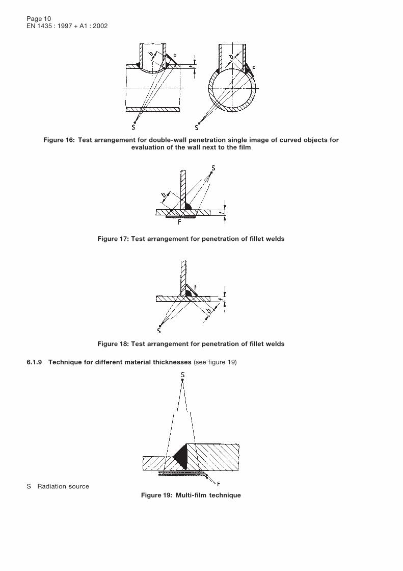
Figure 16: Test arrangement for double-wall penetration single image of curved objects forevaluation of the wall next to the film
Figure 17: Test arrangement for penetration of fillet welds
Figure 18: Test arrangement for penetration of fillet welds
6.1.9 Technique for different material thicknesses (see figure 19)
S Radiation sourceFigure 19: Multi-film technique
Page 11EN 1435 : 1997 + A1 : 2002
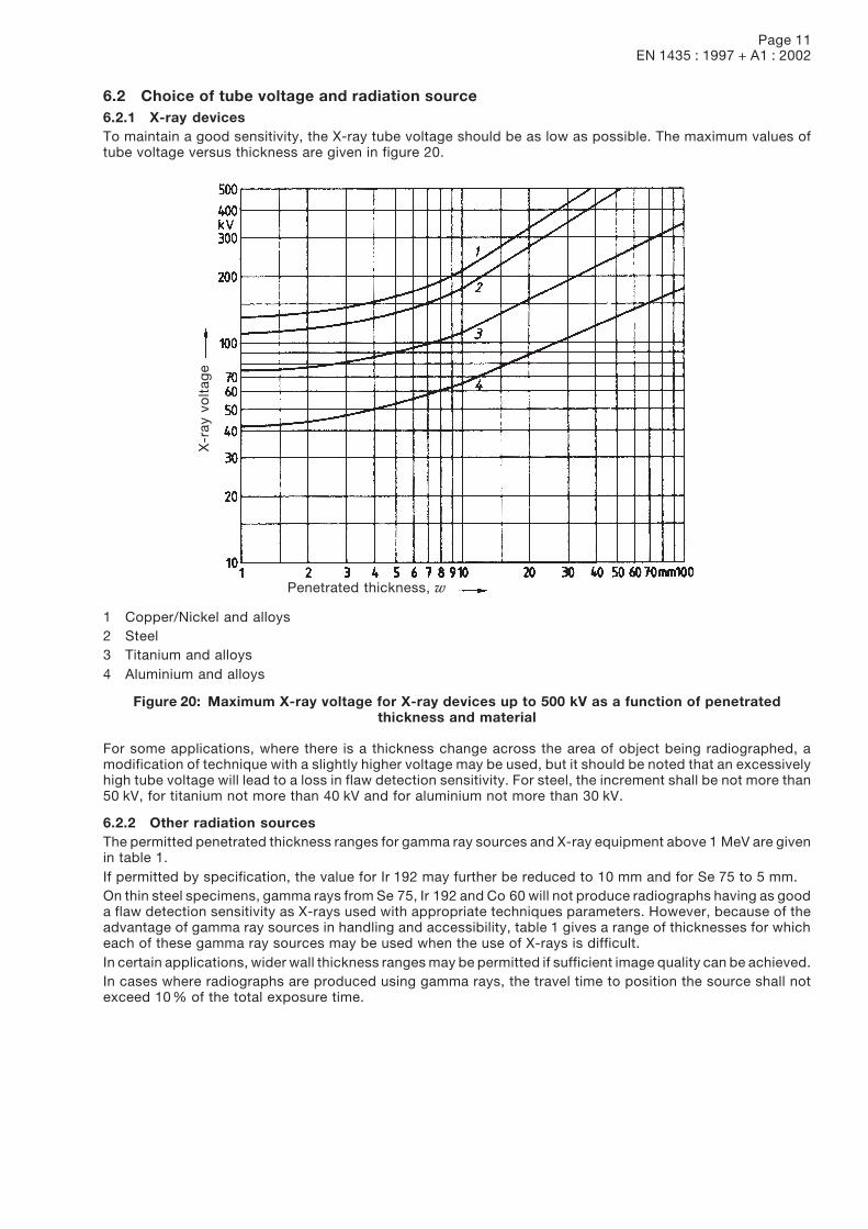
6.2 Choice of tube voltage and radiation source6.2.1 X-ray devicesTo maintain a good sensitivity, the X-ray tube voltage should be as low as possible. The maximum values oftube voltage versus thickness are given in figure 20.
X-r
ay v
olt
age
Penetrated thickness, w
1 Copper/Nickel and alloys2 Steel3 Titanium and alloys4 Aluminium and alloys
Figure 20: Maximum X-ray voltage for X-ray devices up to 500 kV as a function of penetratedthickness and material
For some applications, where there is a thickness change across the area of object being radiographed, amodification of technique with a slightly higher voltage may be used, but it should be noted that an excessivelyhigh tube voltage will lead to a loss in flaw detection sensitivity. For steel, the increment shall be not more than50 kV, for titanium not more than 40 kV and for aluminium not more than 30 kV.
6.2.2 Other radiation sourcesThe permitted penetrated thickness ranges for gamma ray sources and X-ray equipment above 1 MeV are givenin table 1.If permitted by specification, the value for Ir 192 may further be reduced to 10 mm and for Se 75 to 5 mm.On thin steel specimens, gamma rays from Se 75, Ir 192 and Co 60 will not produce radiographs having as gooda flaw detection sensitivity as X-rays used with appropriate techniques parameters. However, because of theadvantage of gamma ray sources in handling and accessibility, table 1 gives a range of thicknesses for whicheach of these gamma ray sources may be used when the use of X-rays is difficult.In certain applications, wider wall thickness ranges may be permitted if sufficient image quality can be achieved.In cases where radiographs are produced using gamma rays, the travel time to position the source shall notexceed 10 % of the total exposure time.
Page 12EN 1435 : 1997 + A1 : 2002
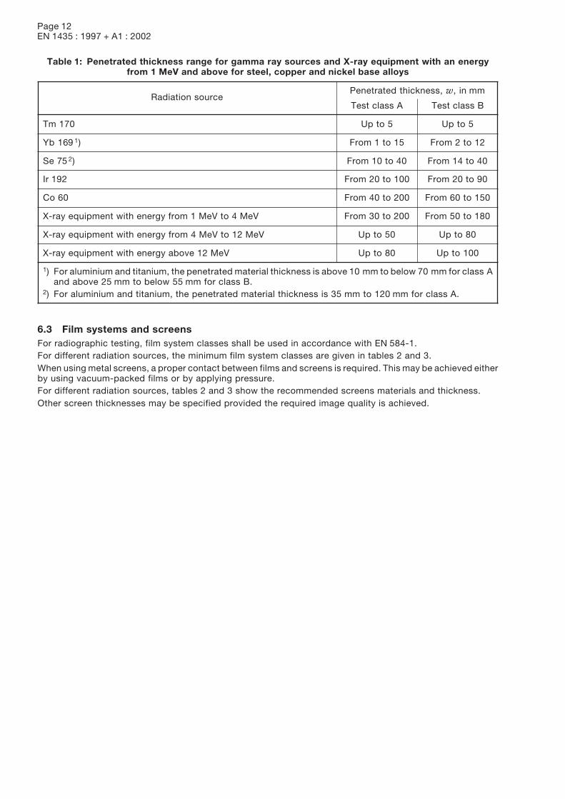
Table 1: Penetrated thickness range for gamma ray sources and X-ray equipment with an energyfrom 1 MeV and above for steel, copper and nickel base alloys
Radiation sourcePenetrated thickness, w, in mm
Test class A Test class B
Tm 170 Up to 5 Up to 5
Yb 169 1) From 1 to 15 From 2 to 12
Se 75 2) From 10 to 40 From 14 to 40
Ir 192 From 20 to 100 From 20 to 90
Co 60 From 40 to 200 From 60 to 150
X-ray equipment with energy from 1 MeV to 4 MeV From 30 to 200 From 50 to 180
X-ray equipment with energy from 4 MeV to 12 MeV Up to 50 Up to 80
X-ray equipment with energy above 12 MeV Up to 80 Up to 100
1) For aluminium and titanium, the penetrated material thickness is above 10 mm to below 70 mm for class Aand above 25 mm to below 55 mm for class B.
2) For aluminium and titanium, the penetrated material thickness is 35 mm to 120 mm for class A.
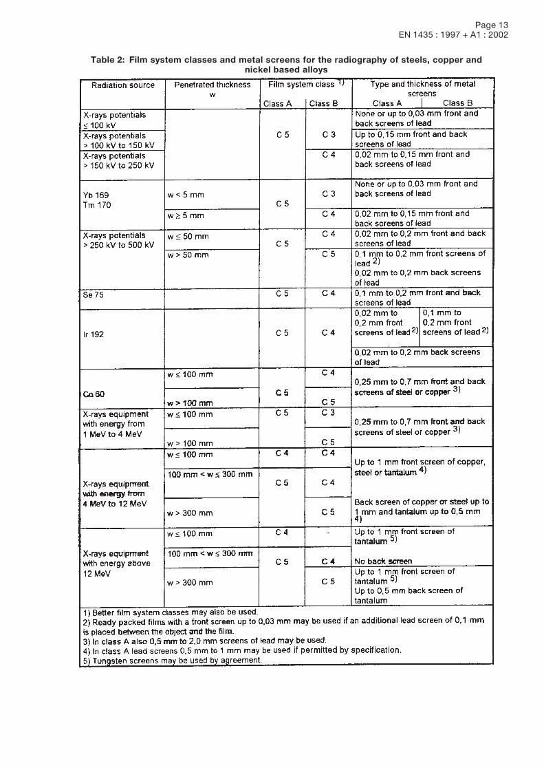
6.3 Film systems and screensFor radiographic testing, film system classes shall be used in accordance with EN 584-1.For different radiation sources, the minimum film system classes are given in tables 2 and 3.When using metal screens, a proper contact between films and screens is required. This may be achieved eitherby using vacuum-packed films or by applying pressure.For different radiation sources, tables 2 and 3 show the recommended screens materials and thickness.Other screen thicknesses may be specified provided the required image quality is achieved.
Page 13EN 1435 : 1997 + A1 : 2002
Table 2: Film system classes and metal screens for the radiography of steels, copper andnickel based alloys
Page 14EN 1435 : 1997 + A1 : 2002
6.4 Alignment of beamThe radiation beam shall be directed to the centre of the area being examined and should be perpendicular tothe object surface at that point, except where it can be demonstrated that certain imperfections are bestrevealed by a different alignment of the beam. In this case, an appropriate alignment of the beam can bepermitted.Other ways of radiographing may be specified.
6.5 Reduction of scattered radiation6.5.1 Filters and collimatorsIn order to reduce the effect of back-scattered radiation, direct radiation shall be collimated as much as possibleto the section under test.With Ir 192 and Co 60 radiation sources or in case of edge scatter a sheet of lead can be used as a filter of lowenergy scattered radiation between the object and the cassette. The thickness of this sheet is 0,5 mm to 2 mmin accordance with the penetrated thickness.
6.5.2 Interception of back-scattered radiationIf necessary, the film shall be shielded from back scattered radiation by an adequate thickness of lead at least1 mm, or of tin at least 1,5 mm, placed behind the film-screen combination.The presence of back-scattered radiation shall be checked for each new test arrangement by a lead letter B(with a height of minimum 10 mm and a thickness of minimum 1,5 mm) placed immediately behind eachcassette. If the image of this symbol records as a lighter image on the radiograph, it shall be rejected. If thesymbol is darker or invisible, the radiograph is acceptable and demonstrates good protection against scatteredradiation.
6.6 Source-to-object distanceThe minimum source-to-object distance, fmin, is a function of the source size d and on the object-to-filmdistance, b.The distance, f, shall, where practicable, be chosen so that the ratio of this distance to the source size, d, i.e.f/d, is not below the values given by the following equations:
b 2/3For class A: f/d ö 7,5 ëŒ › (1) mm
b
2/3For class B: f/d ö 15 ëŒ › (2) mm
b is given in millimeter (mm).
Radiation sourceFilm system class 1)
Type and thickness ofintensifying screens
Class A Class B
X-ray potentials up to 150 kVNone or up to 0,03 mm front and upto 0,15 mm back screens of lead
X-ray potentials above 150 kV 0,02 mm to 0,15 mm front and backup to 250 kV screens of lead
X-ray potentials above 250 kV 0,1 mm to 0,2 mm front and backup to 500 kV screens of lead
Yb 169 0,02 mm to 0,15 mm front and backscreens of lead
Se 75 0,2 mm front 2) and 0,1 mm to 0,2 mmback screens of lead
1) Better film system classes may also be used.2) Instead of 0,2 mm lead, a 0,1 mm screen with an additional 0,1 mm filter may be used.
Table 3: Film system classes and metal screens for aluminium and titanium
C 5 C 3
Page 15EN 1435 : 1997 + A1 : 2002
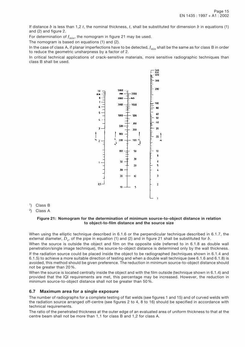
If distance b is less than 1,2 t, the nominal thickness, t, shall be substituted for dimension b in equations (1)and (2) and figure 2.For determination of fmin, the nomogram in figure 21 may be used.The nomogram is based on equations (1) and (2).In the case of class A, if planar imperfections have to be detected, fmin shall be the same as for class B in orderto reduce the geometric unsharpness by a factor of 2.In critical technical applications of crack-sensitive materials, more sensitive radiographic techniques thanclass B shall be used.
1) Class B2) Class A
Figure 21: Nomogram for the determination of minimum source-to-object distance in relationto object-to-film distance and the source size
When using the elliptic technique described in 6.1.6 or the perpendicular technique described in 6.1.7, theexternal diameter, De, of the pipe in equation (1) and (2) and in figure 21 shall be substituted for b.When the source is outside the object and film on the opposite side (referred to in 6.1.8 as double wallpenetration/single image technique), the source-to-object distance is determined only by the wall thickness.If the radiation source could be placed inside the object to be radiographed (techniques shown in 6.1.4 and6.1.5) to achieve a more suitable direction of testing and when a double wall technique (see 6.1.6 and 6.1.8) isavoided, this method should be given preference. The reduction in minimum source-to-object distance shouldnot be greater than 20 %.When the source is located centrally inside the object and with the film outside (technique shown in 6.1.4) andprovided that the IQI requirements are met, this percentage may be increased. However, the reduction inminimum source-to-object distance shall not be greater than 50 %.
6.7 Maximum area for a single exposureThe number of radiographs for a complete testing of flat welds (see figures 1 and 15) and of curved welds withthe radiation source arranged off-centre (see figures 2 to 4, 8 to 16) should be specified in accordance withtechnical requirements.The ratio of the penetrated thickness at the outer edge of an evaluated area of uniform thickness to that at thecentre beam shall not be more than 1,1 for class B and 1,2 for class A.
Page 16EN 1435 : 1997 + A1 : 2002
The densities resulting from any variation of penetrated thickness should not be lower than those indicated in6.8 and not higher than those allowed by the available illuminator, provided suitable masking is possible.The size of the area to be examined includes the weld and the heat affected zones. In general, about 10 mmof parent metal shall be examined on each side of the weld.A recommendation for the number of radiographs is indicated in annex A which gives an acceptable testing ofa circumferential butt weld.
6.8 Density of radiographExposure conditions should be such that the minimum optical density of the radiograph in the area under testis greater than or equal to those given in table 4.
Table 4: Optical density of radiographs
Class Minimum optical density 1)
A 2,0 2)
B 2,3 3)
1) A measuring tolerance of t 0,1 is permitted.2) May be reduced to 1,5 if permitted by specification.3) May be reduced to 2,0 if permitted by specification.
It may be advantageous to use high optical densities where the viewing light is sufficiently bright (cf. 6.10).In order to avoid unduly high fog densities arising from film ageing, development or temperature, the fog densityshall be checked periodically on a non-exposed sample taken from the films being used, and handled andprocessed under the same conditions as the actual radiograph. The fog density shall not exceed 0,3 (fog densitybeing defined as the total density (emulsion and base) of a processed, unexposed film.When using a multi-film technique with interpretation of single films, the optical density of each film shall bein accordance with table 4.If double film viewing is requested, the optical density of one single film shall not be lower than 1,3.
6.9 ProcessingFilms are processed in accordance with the conditions recommended by the film and chemical manufacturerto obtain the selected film system class. Particular attention should be paid to temperature, developing timeand washing time. The film processing shall be controlled regularly in accordance with EN 584-2. The radio-graphs should be free from defects due to processing or other causes which would interfere with interpretation.
6.10 Film viewing conditionsThe radiographs should be examined in a darkened room on an area of the viewing screen with an adjustableluminance in accordance with EN 25580. The viewing screen should be masked to the area of interest.
7 Test reportFor each exposure, or set of exposures, a test report shall be made giving information on the radiographictechnique used, and on any other special circumstances which would allow a better understanding of theresults.The test report shall include at least the following information:
a) name of test body;b) object under test;c) material;d) heat treatment;e) weld geometry;f) material thickness;g) welding process;h) specification of testing including requirements for acceptance;i) radiographic technique and class, required IQI sensitivity in accordance with this standard;j) test arrangement, in accordance with 6.1;k) system of marking used;l) film position plan;
Page 17EN 1435 : 1997 + A1 : 2002
m) radiation source, type and size of focal spot and identification of equipment used;n) film, screens and filters used;o) tube voltage and current or source activity used;p) time of exposure and source-to-film distance;q) processing technique (manual/automatic);r) type and position of image quality indicators;s) results of testing, including data on film density, reading of IQI;t) any deviation from this standard (subject to special agreement);u) name, reference to certificate and signature of the responsible person(s);v) date(s) of exposure and test report.
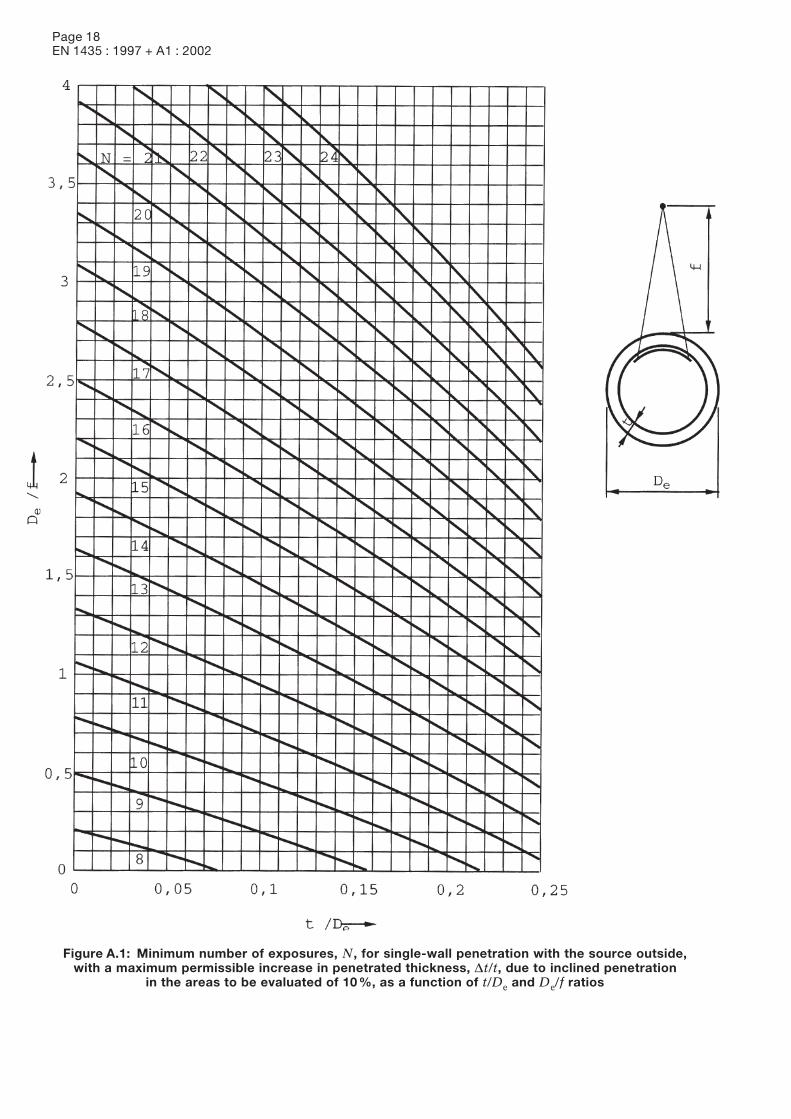
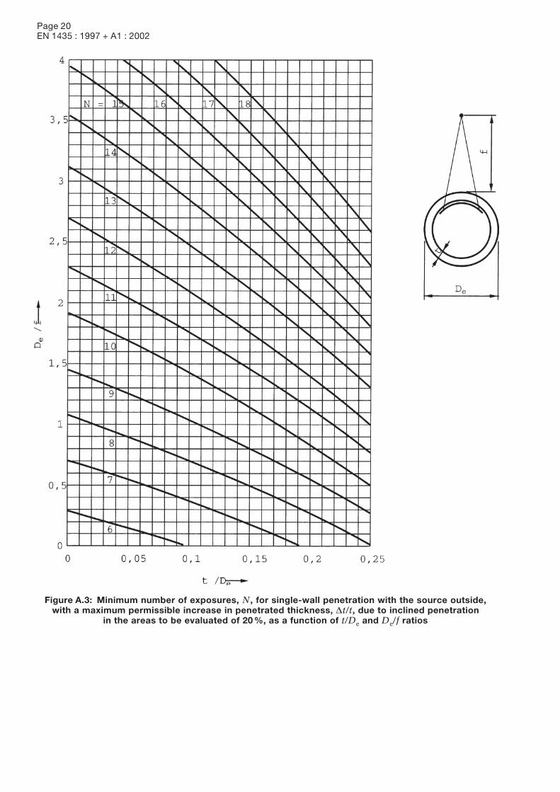
Annex A (normative)Recommended number of exposures which give an acceptable test of a circumferential buttweldThe minimum number of exposures required is presented in figures A.1 to A.4, which are valid for pipes withan outside diameter exceeding 100 mm.Where the deviation of the wall thickness of the joint to be examined, Dt/t, when using a single exposure, doesnot exceed 20 %, figures A.3 and A.4 are to be used. This technique is recommended only when the possibilityof having transverse cracks is minor or the weld is examined for such imperfections by other non-destructivetest methods.Where Dt/t is less than or equal to 10 %, figures A.1 and A.2 are to be used. In this case, it is likely that transversecracks also will be detected.If the object is examined for single transverse cracks, the required minimum number of radiographs will increaseas compared with the values given in figures A.1 to A.4.
Page 18EN 1435 : 1997 + A1 : 2002
Figure A.1: Minimum number of exposures, N, for single-wall penetration with the source outside,with a maximum permissible increase in penetrated thickness, Dt/t, due to inclined penetration
in the areas to be evaluated of 10 %, as a function of t/De and De/f ratios
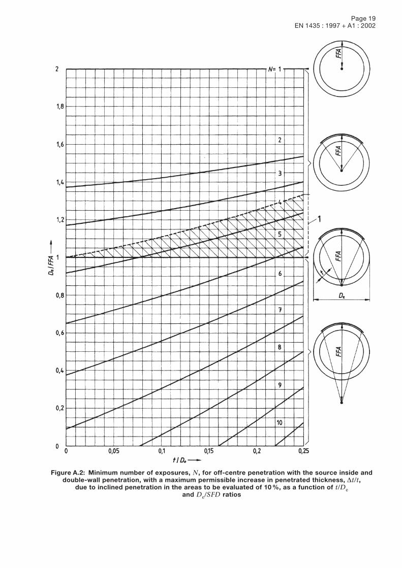
Page 19EN 1435 : 1997 + A1 : 2002
Figure A.2: Minimum number of exposures, N, for off-centre penetration with the source inside anddouble-wall penetration, with a maximum permissible increase in penetrated thickness, Dt/t,
due to inclined penetration in the areas to be evaluated of 10 %, as a function of t/Deand De/SFD ratios
Page 20EN 1435 : 1997 + A1 : 2002
Figure A.3: Minimum number of exposures, N, for single-wall penetration with the source outside,with a maximum permissible increase in penetrated thickness, Dt/t, due to inclined penetration
in the areas to be evaluated of 20 %, as a function of t/De and De/f ratios
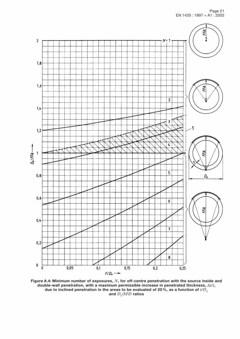
Page 21EN 1435 : 1997 + A1 : 2002
Figure A.4: Minimum number of exposures, N, for off-centre penetration with the source inside anddouble-wall penetration, with a maximum permissible increase in penetrated thickness, Dt/t,
due to inclined penetration in the areas to be evaluated of 20 %, as a function of t/Deand De/SFD ratios
Page 22EN 1435 : 1997 + A1 : 2002
Table B.1: Wire IQI
Image quality class A
Nominal thickness, t, in mm IQI value 1)
Up to 1,2 W 18Above 1,2 up to 2,0 W 17Above 2,0 up to 3,5 W 16Above 3,5 up to 5,0 W 15Above 5,0 up to 7 W 14Above 7 up to 10 W 13Above 10 up to 15 W 12Above 15 up to 25 W 11Above 25 up to 32 W 10Above 32 up to 40 W 9Above 40 up to 55 W 8Above 55 up to 85 W 7Above 85 up to 150 W 6Above 150 up to 250 W 5Above 250 W 4
1) When using lr 192 sources, IQI values lowerthan listed values can be accepted asfollows:10 mm to 24 mm: up to 2 valuesabove 24 mm up to 30 mm: up to 1 value.
Annex B (normative)Minimum image quality values
Single-wall technique; IQI on source side
Table B.2: Step/hole IQI
Image quality class A
Nominal thickness, t, in mm IQI value 1)
Up to 2,0 H 3Above 2,0 up to 3,5 H 4Above 3,5 up to 6 H 5Above 6 up to 10 H 6Above 10 up to 15 H 7Above 15 up to 24 H 8Above 24 up to 30 H 9Above 30 up to 40 H 10Above 40 up to 60 H 11Above 60 up to 100 H 12Above 100 up to 150 H 13Above 150 up to 200 H 14Above 200 up to 250 H 15Above 250 up to 320 H 16Above 320 up to 400 H 17Above 400 H 18
1) When using lr 192 sources, IQI values lowerthan listed values can be accepted asfollows:10 mm to 24 mm: up to 2 valuesabove 24 mm up to 30 mm: up to 1 value.
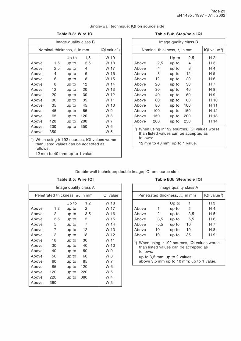
Page 23EN 1435 : 1997 + A1 : 2002
Single-wall technique; IQI on source side
Table B.3: Wire IQI
Image quality class B
Nominal thickness, t, in mm IQI value 1)
Up to 1,5 W 19Above 1,5 up to 2,5 W 18Above 2,5 up to 4 W 17Above 4 up to 6 W 16Above 6 up to 8 W 15Above 8 up to 12 W 14Above 12 up to 20 W 13Above 20 up to 30 W 12Above 30 up to 35 W 11Above 35 up to 45 W 10Above 45 up to 65 W 9Above 65 up to 120 W 8Above 120 up to 200 W 7Above 200 up to 350 W 6Above 350 W 5
1) When using lr 192 sources, IQI values worsethan listed values can be accepted asfollows:12 mm to 40 mm: up to 1 value.
Table B.4: Step/hole IQI
Image quality class B
Nominal thickness, t, in mm IQI value 1)
Up to 2,5 H 2Above 2,5 up to 4 H 3Above 4 up to 8 H 4Above 8 up to 12 H 5Above 12 up to 20 H 6Above 20 up to 30 H 7Above 30 up to 40 H 8Above 40 up to 60 H 9Above 60 up to 80 H 10Above 80 up to 100 H 11Above 100 up to 150 H 12Above 150 up to 200 H 13Above 200 up to 250 H 14
1) When using lr 192 sources, IQI values worsethan listed values can be accepted asfollows:12 mm to 40 mm: up to 1 value.
Double-wall technique; double image; lQI on source side
Table B.5: Wire IQI
Image quality class A
Penetrated thickness, w, in mm IQI value
Up to 1,2 W 18Above 1,2 up to 2 W 17Above 2 up to 3,5 W 16Above 3,5 up to 5 W 15Above 5 up to 7 W 14Above 7 up to 12 W 13Above 12 up to 18 W 12Above 18 up to 30 W 11Above 30 up to 40 W 10Above 40 up to 50 W 9Above 50 up to 60 W 8Above 60 up to 85 W 7Above 85 up to 120 W 6Above 120 up to 220 W 5Above 220 up to 380 W 4Above 380 W 3
Table B.6: Step/hole IQI
Image quality class A
Penetrated thickness, w, in mm IQI value 1)
Up to 1 H 3Above 1 up to 2 H 4Above 2 up to 3,5 H 5Above 3,5 up to 5,5 H 6Above 5,5 up to 10 H 7Above 10 up to 19 H 8Above 19 up to 35 H 9
1) When using lr 192 sources, IQI values worsethan listed values can be accepted asfollows:up to 3,5 mm: up to 2 valuesabove 3,5 mm up to 10 mm: up to 1 value.
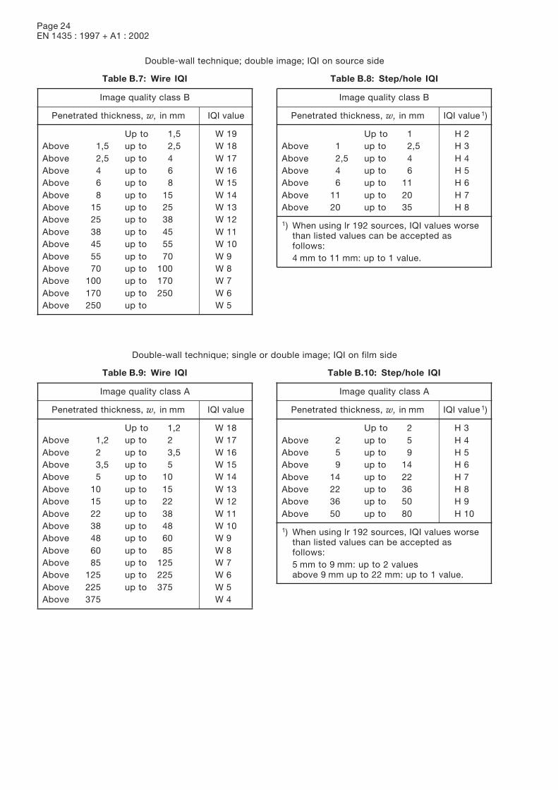
Page 24EN 1435 : 1997 + A1 : 2002
Double-wall technique; double image; IQI on source side
Table B.7: Wire IQI
Image quality class B
Penetrated thickness, w, in mm IQI value
Up to 1,5 W 19Above 1,5 up to 2,5 W 18Above 2,5 up to 4 W 17Above 4 up to 6 W 16Above 6 up to 8 W 15Above 8 up to 15 W 14Above 15 up to 25 W 13Above 25 up to 38 W 12Above 38 up to 45 W 11Above 45 up to 55 W 10Above 55 up to 70 W 9Above 70 up to 100 W 8Above 100 up to 170 W 7Above 170 up to 250 W 6Above 250 up to W 5
Table B.8: Step/hole IQI
Image quality class B
Penetrated thickness, w, in mm IQI value 1)
Up to 1 H 2Above 1 up to 2,5 H 3Above 2,5 up to 4 H 4Above 4 up to 6 H 5Above 6 up to 11 H 6Above 11 up to 20 H 7Above 20 up to 35 H 8
1) When using lr 192 sources, IQI values worsethan listed values can be accepted asfollows:4 mm to 11 mm: up to 1 value.
Double-wall technique; single or double image; IQI on film side
Table B.9: Wire IQI
Image quality class A
Penetrated thickness, w, in mm IQI value
Up to 1,2 W 18Above 1,2 up to 2 W 17Above 2 up to 3,5 W 16Above 3,5 up to 5 W 15Above 5 up to 10 W 14Above 10 up to 15 W 13Above 15 up to 22 W 12Above 22 up to 38 W 11Above 38 up to 48 W 10Above 48 up to 60 W 9Above 60 up to 85 W 8Above 85 up to 125 W 7Above 125 up to 225 W 6Above 225 up to 375 W 5Above 375 W 4
Table B.10: Step/hole IQI
Image quality class A
Penetrated thickness, w, in mm IQI value 1)
Up to 2 H 3Above 2 up to 5 H 4Above 5 up to 9 H 5Above 9 up to 14 H 6Above 14 up to 22 H 7Above 22 up to 36 H 8Above 36 up to 50 H 9Above 50 up to 80 H 10
1) When using lr 192 sources, IQI values worsethan listed values can be accepted asfollows:5 mm to 9 mm: up to 2 valuesabove 9 mm up to 22 mm: up to 1 value.
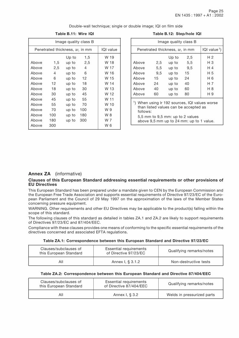
Page 25EN 1435 : 1997 + A1 : 2002
Double-wall technique; single or double image; IQI on film side
Table B.11: Wire IQI
Image quality class B
Penetrated thickness, w, in mm IQI value
Up to 1,5 W 19Above 1,5 up to 2,5 W 18Above 2,5 up to 4 W 17Above 4 up to 6 W 16Above 6 up to 12 W 15Above 12 up to 18 W 14Above 18 up to 30 W 13Above 30 up to 45 W 12Above 45 up to 55 W 11Above 55 up to 70 W 10Above 70 up to 100 W 9Above 100 up to 180 W 8Above 180 up to 300 W 7Above 300 W 6
Table B.12: Step/hole IQI
Image quality class B
Penetrated thickness, w, in mm IQI value 1)
Up to 2,5 H 2Above 2,5 up to 5,5 H 3Above 5,5 up to 9,5 H 4Above 9,5 up to 15 H 5Above 15 up to 24 H 6Above 24 up to 40 H 7Above 40 up to 60 H 8Above 60 up to 80 H 9
1) When using lr 192 sources, IQI values worsethan listed values can be accepted asfollows:5,5 mm to 9,5 mm: up to 2 valuesabove 9,5 mm up to 24 mm: up to 1 value.
Annex ZA (informative)Clauses of this European Standard addressing essential requirements or other provisions ofEU DirectivesThis European Standard has been prepared under a mandate given to CEN by the European Commission andthe European Free Trade Association and supports essential requirements of Directive 97/23/EC of the Euro-pean Parliament and the Council of 29 May 1997 on the approximation of the laws of the Member Statesconcerning pressure equipment.WARNING. Other requirements and other EU Directives may be applicable to the product(s) falling within thescope of this standard.The following clauses of this standard as detailed in tables ZA.1 and ZA.2 are likely to support requirementsof Directives 97/23/EC and 87/404/EEC.Compliance with these clauses provides one means of conforming to the specific essential requirements of thedirectives concerned and associated EFTA regulations.
Table ZA.1: Correspondence between this European Standard and Directive 97/23/EC
Clauses/subclauses of Essential requirementsthis European Standard of Directive 97/23/EC
Qualifying remarks/notes
All Annex I, § 3.1.2 Non-destructive tests
Table ZA.2: Correspondence between this European Standard and Directive 87/404/EEC
Clauses/subclauses of Essential requirementsthis European Standard of Directive 87/404/EEC
Qualifying remarks/notes
All Annex I, § 3.2 Welds in pressurized parts


![Literaturverzeichnis3A978-3-662-07107-6%2F1.pdf · [58] Hobbacher, A. (Hrsg.): Fatigue Design of Welded Joints and Components. Abington Pub lishing, Cambridge 1996 [59] Maddox, S](https://img.pdfslide.org/doc/110x75/5e7d596b2920055b832dca4d/literaturverzeichnis-3a978-3-662-07107-62f1pdf-58-hobbacher-a-hrsg-fatigue.jpg)