Embed Size (px)
Citation preview
NovoPort® IV
WN 903012-21-6-50 09-2018

2 NovoPort® IV
DE Copyright und Haftungsausschluss© 2018 TORMATIC®
Die vollständige oder auszugsweise Vervielfältigung, Weitergabe oder Verwertung dieses Dokumentes, sei es in elektronischer oder mechanischer Form, einschließlich Fotokopie und Aufzeichnung, bedarf unabhängig vom damit verfolgten Zweck der vorherigen schriftlichen Genehmigung durch TORMATIC.
GB Copyright and disclaimer© 2018 TORMATIC®
No part of this document may be reproduced, distributed, or transmitted in any form or by any means, electronically or mechanically, including photocopying and recording for any purpose, without the express written authorization of TORMATIC.

Inhalt
DE
Inhalt1 Zu diesem Handbuch ................................................................................... 5
1.1 Inhalt und Zielgruppe............................................................................ 51.1.1 Darstellungen in Abbildungen ............................................... 5
1.2 Piktogramme und Signalwörter ............................................................ 51.2.1 Gefahrensymbole.................................................................. 61.2.2 Hinweis- und Infosymbol ....................................................... 6
2 Sicherheit ...................................................................................................... 72.1 Bestimmungsgemäßer Gebrauch ........................................................ 72.2 Vorhersehbare Fehlanwendung ........................................................... 82.3 Personalqualifikation ............................................................................ 82.4 Gefahren, die vom Produkt ausgehen können ..................................... 9
3 Produktbeschreibung ................................................................................ 103.1 Allgemeine Produktübersicht.............................................................. 103.2 Technische Daten .............................................................................. 103.3 Typenschild ........................................................................................ 113.4 Bedienelemente ................................................................................. 113.5 Funktionsweise der integrierten Sicherheitseinrichtung ..................... 11
4 Installation und Montage ........................................................................... 124.1 Sicherheitshinweise für die Installation und Montage ........................ 124.2 Antriebe und Zubehör......................................................................... 124.3 Lieferumfang ...................................................................................... 124.4 Vorbereitung der Montage.................................................................. 134.5 Montage des Garagentorantriebs....................................................... 13
4.5.1 Motorkopf entriegeln ........................................................... 154.6 Garagentorantrieb verkabeln - Netzanschluss und Steuerung .......... 16
4.6.1 Übersicht Anschlussplan..................................................... 174.6.2 Impulsgeber und externe Sicherheitseinrichtungen ............ 18
4.7 Antennenverlegung ............................................................................ 194.8 Schlupftürschalter............................................................................... 194.9 Antriebskopf programmieren .............................................................. 20
4.9.1 Vorbereitung........................................................................ 204.9.2 Menü 1: Startfunktion für den Handsender
programmieren.................................................................... 214.9.3 Menü 2: Lichtfunktion für den Handsender
programmieren.................................................................... 214.9.4 Löschen aller am Antrieb programmierten Handsender ..... 224.9.5 Menü 3 + Menü 4: Einstellung der Endpositionen .............. 224.9.6 Kraftlernfahrt ....................................................................... 234.9.7 Prüfung der Kraftbegrenzung.............................................. 24
NovoPort® IV 1

Inhalt
DE
4.10 Sondereinstellungen........................................................................... 254.10.1 Menü "Sondereinstellungen" öffnen.................................... 254.10.2 Menü 5 + Menü 6: Kraftbegrenzung für Auf- und Zufahrt ... 254.10.3 Menü 7: Lichtzeiten einstellen............................................. 254.10.4 Menü 8: Toranpassungen ................................................... 264.10.5 Menü 9: Einstellungen weitere Betriebsarten...................... 264.10.6 Menü H: Einstellungen STOPP-A ....................................... 27
4.11 TTZ Richtlinie - Einbruchhemmung für Garagentore ......................... 274.11.1 Einbruchhemmung herstellen ............................................. 274.11.2 Einbruchhemmung rückgängig machen.............................. 28
4.12 Installation abschließen ...................................................................... 284.13 Warnaufkleber anbringen ................................................................... 28
5 Betrieb ......................................................................................................... 295.1 Sicherheitshinweise für den Betrieb ................................................... 295.2 Garagentor öffnen und schließen (im Normalbetrieb) ........................ 295.3 Garagentor von Hand öffnen und schließen ...................................... 295.4 Garagentor öffnen und schließen (weitere Betriebsarten) ................. 30
6 Fehlersuche ................................................................................................ 31
7 Diagnoseanzeige ........................................................................................ 327.1 Werkseinstellungen wiederherstellen ................................................. 337.2 Zyklenzähler ....................................................................................... 33
8 Inspektions- und Prüfprotokoll ................................................................. 348.1 Garagentorantrieb testen ................................................................... 35
9 Prüflisten ..................................................................................................... 369.1 Prüfliste der Toranlage ....................................................................... 369.2 Prüfungs- und Wartungsnachweis der Toranlage .............................. 37
10 Wartung / Überprüfung .............................................................................. 38
11 Reinigung / Pflege ...................................................................................... 38
12 Demontage / Entsorgung........................................................................... 3912.1 Demontage ......................................................................................... 3912.2 Entsorgung ......................................................................................... 39
13 Garantiebestimmungen ............................................................................. 39
14 Konformitäts- und Einbauerklärung ......................................................... 4014.1 Einbauerklärung nach EG-Richtlinie Maschinen 2006/42/EG............ 4014.2 Konformitätserklärung nach Richtlinie 2014/53/EU............................ 40
2 NovoPort® IV
Zu diesem Handbuch
1 Zu diesem Handbuch1.1 Inhalt und Zielgruppe
Dieses Handbuch beschreibt den Garagentorantrieb der Modulreihe NovoPort® IV (im Folgenden als "Produkt" bezeichnet). Dieses Handbuch richtet sich sowohl an technisches Personal, welches mit Montage- und Wartungsarbeiten beauftragt wird, als auch an die Endverbraucher des Produkts.Im vorliegenden Handbuch wird nur die Steuerung per Handsender beschrieben. Andere Steuergeräte arbeiten analog.
1.1.1 Darstellungen in Abbildungen
Die Abbildungen in diesem Handbuch dienen Ihnen zum besseren Verständnis von Sachverhalten und Handlungsabläufen. Die Darstellungen in den Abbildungen sind beispielhaft und können geringfügig vom tatsächlichen Aussehen Ihres Produktes abweichen.
1.2 Piktogramme und Signalwörter
Wichtige Informationen in diesem Handbuch sind mit folgenden Piktogrammen versehen.
GEFAHR... weist auf eine Gefährdung hin, die, wenn sie nicht gemieden wird, den Tod oder eine schwere Verletzung zur Folge hat.
WARNUNG... weist auf eine Gefährdung hin, die, wenn sie nicht gemieden wird, den Tod oder eine schwere Verletzung zur Folge haben könnte.
VORSICHT... weist auf eine Gefährdung hin, die, wenn sie nicht gemieden wird, eine geringfügige oder mäßige Verletzung zur Folge haben könnte.
NovoPort® IV 3
Zu diesem Handbuch
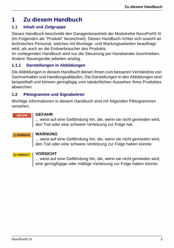
1.2.1 Gefahrensymbole
1.2.2 Hinweis- und Infosymbol
Gefahr! Dieses Zeichen weist Sie auf eine unmittelbare Gefahr für das Leben und die Gesundheit von Personen hin, bis hin zu lebensgefährlichen Verletzungen oder Tod.
Gefahr!Gefahr durch elektrischen Strom!Dieses Zeichen weist Sie auf Gefahren durch elektrischen Strom hin.
Warnung!Gefahr durch Quetschen!Dieses Zeichen weist Sie auf gefährliche Situationen mit Quetschgefahr für Gliedmaßen hin.
Warnung!Gefahr durch Quetschen!Die mit diesem Symbol gekennzeichneten Textpassagen informieren Sie über gefährliche Situationen mit Quetschgefahr für den ganzen Körper.
HINWEIS... weist auf wichtige Informationen (z. B. auf Sachschäden), aber nicht auf Gefährdungen hin.
Information
Tipps und Informationen sind durch das Handsymbol mit dem ausgestrecktem Zeigefinger und das Wort "Information" in Fettdruck gekennzeichnet.
4 NovoPort® IV

Sicherheit
2 SicherheitBeachten Sie grundsätzlich folgende Sicherheitshinweise:
• Beachten Sie alle in diesem Handbuch enthaltenen Hinweise zum bestimmungsgemäßen Gebrauch.
• Bewahren Sie alle Sicherheitshinweise und Anweisungen für die Zukunft auf.• Die Installation darf nur durch qualifiziertes technisches Personal erfolgen.• Veränderungen am Produkt dürfen nur mit ausdrücklicher Genehmigung durch
den Hersteller vorgenommen werden.• Verwenden Sie ausschließlich die Original-Ersatzteile des Herstellers. Falsche
oder fehlerhafte Ersatzteile können zu Beschädigungen, Fehlfunktionen oder Totalausfall des Produktes führen.
• Das Gerät kann von Kindern ab 8 Jahren sowie von Personen mit reduzierten physischen, sensorischen oder mentalen Fähigkeiten oder Mangel an Erfahrung und / oder Wissen benutzt werden, wenn sie beaufsichtigt oder bezüglich des sicheren Gebrauchs des Gerätes unterwiesen wurden und die daraus resultierenden Gefahren verstanden haben.
• Kinder dürfen nicht mit dem Gerät spielen. Reinigung und Benutzer-Wartung dürfen nicht durch Kinder ohne Beaufsichtigung durchgeführt werden.
• Bei Nichteinhaltung der angegebenen Sicherheitshinweise und Anweisungen in diesem Handbuch sowie der für den Einsatzbereich geltenden Unfallverhütungsvorschriften und allgemeinen Sicherheitsbestimmungen sind jegliche Haftpflicht- und Schadenersatzansprüche gegen den Hersteller oder seinen Beauftragten ausgeschlossen.
2.1 Bestimmungsgemäßer Gebrauch
• Das Produkt ist ausschließlich zum Öffnen und Schließen gewichts- oder federausgeglichener Garagentore konzipiert. Ein Einsatz an Toren ohne Gewichts- oder Federausgleichsmechanismus ist nicht zulässig.
• Das Produkt ist ausschließlich mit Produkten von Novoferm kompatibel.
Verletzungsgefahr durch Missachtung der Sicherheitshinweise und Anweisungen!Versäumnisse bei der Einhaltung der Sicherheitshinweise und Anweisungen können elektrischen Schlag, Brand und / oder schwere Verletzungen verursachen.• Durch Befolgen der angegebenen Sicherheitshinweise und
Anweisungen in diesem Handbuch können Personen- und Sachschäden während der Arbeit mit und an dem Produkt vermieden werden.
• Lesen und befolgen Sie alle Sicherheitshinweise und Anweisungen.
NovoPort® IV 5

Sicherheit
• Veränderungen am Produkt dürfen nur mit ausdrücklicher Genehmigung durch den Hersteller vorgenommen werden.
• Das Produkt ist ausschließlich für den Hausgebrauch geeignet.
2.2 Vorhersehbare Fehlanwendung
Eine andere Verwendung als die im Kapitel 2.1 beschriebene gilt als vernünftigerweise vorhersehbare Fehlanwendung, dazu gehören z. B.:• die Verwendung als Antrieb für Schiebetürkonstruktionen• der Einsatz an Toren ohne Gewichts- oder Federausgleichsmechanismus Für Sach- und / oder Personenschäden, die durch vernünftigerweise vorhersehbare Fehlanwendung und aus der Nichtbeachtung dieses Handbuchs resultieren, übernimmt der Hersteller keinerlei Haftung.
2.3 Personalqualifikation
Nur Personal, welches dieses Handbuch kennt und sich der Gefahren im Umgang mit diesem Produkt bewusst ist, darf das Produkt nutzen.Die einzelnen Tätigkeiten erfordern unterschiedliche Personalqualifikationen, die in Tabelle 2-1 aufgelistet sind.
Tab. 2-1 Übersicht der mindestens erforderlichen Personalqualifikation
Tätigkeiten Bediener Fachkräfte mit einschlägiger Ausbildung z. B. Industriemechanikera
a. Als Fachkraft gilt, wer aufgrund seiner fachlichen Ausbildung, Kenntnisse und Erfahrungen sowie Kenntnis der einschlägigen Bestimmungen die ihm übertragenen Arbeiten beurtei-len und mögliche Gefahren erkennen kann.
Elektrofach-kraftb
b. Ausgebildete Elektrofachkräfte müssen Elektro-Schaltpläne lesen und verstehen, elektrische Maschinen in Betrieb nehmen, warten und instand halten, Schalt- und Steuerschränke verdrahten, die Funktionstauglichkeit von elektrischen Komponenten gewährleisten und mögliche Gefahren im Umgang mit elektrischen und elektronischen Systemen erkennen können.
Aufbau, Montage, Inbetriebnahme x x
Elektrische Installation x
Betrieb x
Reinigung x
Wartung x x x
Arbeiten an der Elektrik (Störungsbeseitigung, Reparatur & Deinstallation)
x
Arbeiten an der Mechanik (Störungsbeseitigung & Reparatur)
x
Entsorgung x x x
6 NovoPort® IV
Sicherheit
2.4 Gefahren, die vom Produkt ausgehen können
Das Produkt wurde einer Risikobeurteilung unterzogen. Die darauf aufbauende Konstruktion und Ausführung des Produktes entspricht dem heutigen Stand der Technik. Das Produkt ist bei bestimmungsgemäßer Verwendung betriebssicher. Dennoch bleibt ein Restrisiko bestehen.
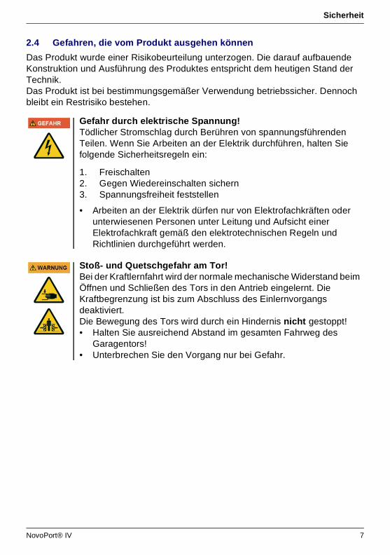
Gefahr durch elektrische Spannung!Tödlicher Stromschlag durch Berühren von spannungsführenden Teilen. Wenn Sie Arbeiten an der Elektrik durchführen, halten Sie folgende Sicherheitsregeln ein:
1. Freischalten2. Gegen Wiedereinschalten sichern3. Spannungsfreiheit feststellen
• Arbeiten an der Elektrik dürfen nur von Elektrofachkräften oder unterwiesenen Personen unter Leitung und Aufsicht einer Elektrofachkraft gemäß den elektrotechnischen Regeln und Richtlinien durchgeführt werden.
Stoß- und Quetschgefahr am Tor!Bei der Kraftlernfahrt wird der normale mechanische Widerstand beim Öffnen und Schließen des Tors in den Antrieb eingelernt. Die Kraftbegrenzung ist bis zum Abschluss des Einlernvorgangs deaktiviert. Die Bewegung des Tors wird durch ein Hindernis nicht gestoppt! • Halten Sie ausreichend Abstand im gesamten Fahrweg des
Garagentors!• Unterbrechen Sie den Vorgang nur bei Gefahr.
NovoPort® IV 7

Produktbeschreibung
3 Produktbeschreibung3.1 Allgemeine Produktübersicht
Abb. 3-1 Produktübersicht
3.2 Technische Daten
1. Steuergerät 4. Hebelarm 28. Spiralkabel
2. Antriebskopf 5. Torkonsole 29. Netzanschlusskabel
Max. Torgröße: 18 m2 Beleuchtungs-LED: 1,6 W
Max. Gewicht: 200 kg Sicherheit gem. EN 13849-1:
Modellspezifikationen Eingang STOPP A: Kat. 2 / PL = C
Steuerung: NovoPort® IV Eingang STOPP B: Kat. 2 / PL = C
Betriebsart: Impulsbetrieb, ferngesteuert
Antriebstyp: NovoPort® IV Temperaturbereich:
IP20, nur für trockene Räume
Nennbelastbarkeit: 165 N
Max. Belastbarkeit: 550 N
Anschlusswerte: 230 V / 50 Hz
Leistungsaufnahme:Schutzklasse:
Standby: 0,5 W Lautstärke: < 70 dBA
Max. Betrieb: 200 W Hersteller: Novoferm tormatic GmbHEisenhüttenweg 644145 DortmundDeutschlandwww.tormatic.de
Zyklen / Stunde: 3
Max. Zyklen / Tag: 10
Max. Zyklen Gesamt: 25000
2
28 1
4
29
5
-20 °C
+40 °C
8 NovoPort® IV
Produktbeschreibung
3.3 Typenschild
Das Typenschild befindet sich unter der Abdeckung des Steuergerätes, siehe Abb. 4-4, Seite 14.Die angegebenen Anschlusswerte sind zu beachten.
3.4 Bedienelemente
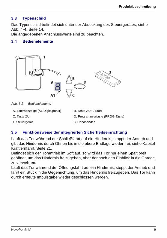
Abb. 3-2 Bedienelemente
3.5 Funktionsweise der integrierten Sicherheitseinrichtung
Läuft das Tor während der Schließfahrt auf ein Hindernis, stoppt der Antrieb und gibt das Hindernis durch Öffnen bis in die obere Endlage wieder frei, siehe Kapitel Kraftlernfahrt, Seite 21.Befindet sich der Torantrieb im Softlauf, so wird das Tor nur einen Spalt breit geöffnet, um das Hindernis freizugeben, aber dennoch den Einblick in die Garage zu verwehren.Läuft das Tor während der Öffnungsfahrt auf ein Hindernis, stoppt der Antrieb und fährt ein Stück in die Gegenrichtung, um das Hindernis freizugeben. Das Tor kann durch erneute Impulsgabe wieder geschlossen werden.
A. Ziffernanzeige (A1 Digitalpunkt) B. Taste AUF / Start
C. Taste ZU D. Programmiertaste (PROG-Taste)
1. Steuergerät 3. Handsender
A
C
B
A1
D
3
1
NovoPort® IV 9

Installation und Montage
4 Installation und Montage4.1 Sicherheitshinweise für die Installation und Montage
• Die Installation darf nur durch qualifiziertes technisches Personal erfolgen.• Machen Sie sich vor Beginn der Produktinstallation mit allen
Installationsanweisungen vertraut.
4.2 Antriebe und Zubehör
Abb. 4-1 Antriebe und Zubehör
4.3 Lieferumfang
Abb. 4-2 Lieferumfang
2xAWG 22
2xAWG 22
2xAWG 22
1500
mm
2xAWG 22
2xAWG 22
Y-OB2 x 1,0
9
1x
1 2 31x1x
1x1x4 6
1x
8
1x
7
1x
5
WARNUNG: Automatisches Tor - Nicht im Bewegungsbereich des
Tores aufhalten, da sich das Tor unerwartet in Bewegung setzen kann!
WARNING: Automatic door - The door may operate unexpectedly,
therefore do not allow anything/anyone to stay in the path of the door!
Automatic Door
1. Steuergerät2. Antriebskopf3. Handsender (modellabhängig)4. Hebelarm5. Torkonsole6. Bolzen7. Schraubenbeutel8. Zahnriemen9. Warnschild
10 NovoPort® IV

Installation und Montage
4.4 Vorbereitung der Montage
• Für den Netzanschluss muss eine Steckdose bauseits installiert sein. Das mitgelieferte Netzanschlusskabel ist ca. 1 m lang.
• Überprüfen Sie die Stabilität des Tors, ziehen Sie Schrauben und Muttern am Tor nach.
• Überprüfen Sie das Tor auf einwandfreien Lauf, schmieren Sie Wellen und Lager. Die Federvorspannung sollte ebenfalls überprüft und ggf. korrigiert werden.
• Demontieren Sie vorhandene Torverriegelungen (Riegelblech und Schnapper).• Bei Garagen ohne zweiten Eingang ist eine Notentriegelung (Zubehör)
erforderlich. • Bei Garagen mit Schlupftür ist zunächst der Schlupftürkontakt zu installieren.
4.5 Montage des Garagentorantriebs
Folgen Sie den Abbildungen auf dem A3-Montageposter.
HINWEISÜberprüfen Sie, ob die gelieferten Schrauben und Halterungen für die Montage vor Ort unter Berücksichtigung der baulichen Voraussetzungen geeignet sind.
Gefahr durch Stoßen oder Umfallen!Personen können durch das Tor gestoßen oder umgestoßen werden.• Stellen Sie sicher, dass das Tor nicht in öffentliche Fußwege oder
Straßen hineinragt.
Gefahr durch Quetschen!Quetsch- und Schergefahr an den Verriegelungsmechanismen des Garagentors. • Entfernen Sie, falls nötig gefährliche Bauteile vor der Montage.
Schritt Installation
Wahl der Einbauseite
1 Wählen Sie die Einbauseite entsprechend den baulichen Gegebenheiten. Standardeinbauseite ist von innen gesehen rechts. Sondereinbaufälle siehe 11 und 12. Sprühen Sie die Laufschiene für optimale Laufeigenschaften mit Silikonspray ein (keine ölhaltigen Mittel verwenden).
Einbau des Zahnriemens
2a Nutzen Sie die obere Laufschiene des Tors für den Einbau der Antriebseinheit. Legen Sie den Zahnriemen in die Laufschiene (Zahnriemenrücken nach oben).Stecken Sie torseitig das Zahnriemenende in das Formendstück.
2b Ziehen Sie zum Entriegeln des Antriebsrades die Zugglocke.
2c Führen Sie den Zahnriemen wie dargestellt durch die Antriebsräder des Motorkopfes.
2d Setzen Sie den Antrieb mit den Antriebsrädern in die obere Laufschiene ein.
NovoPort® IV 11

Installation und Montage
2e Schieben Sie den Zahnriemenprofilanschlag unter den Zahnriemen.
2f Positionieren Sie den Zahnriemenprofilanschlag so, dass dieser ca. 5 cm Abstand zum Antriebskopf in der Endposition AUF einhält.
Hintere Zahnriemenbefestigung montieren
3a Führen Sie den Zahnriemen durch den Eckverbindungswinkel durch und halten Sie ihn gespannt.
3b Stecken Sie die Hülsenhälften wie dargestellt auf den Zahnriemen auf.
3c Bringen Sie die Rändelmutter auf und spannen Sie den Zahnriemen durch Drehen der Rändelmutter handfest. Verhinden Sie dabei ein Verdrehen des Zahnriemens.
3d Überstehender Zahnriemen kann gekürzt werden.
Obere Laufrolle einsetzen
4a + 4b Entfernen Sie den Erweiterungsring der Laufrolle.
4c + 4d Setzen Sie die Laufrolle in die Laufschiene ein, stellen Sie sie entsprechend der Abbildung ein und schrauben Sie sie an.
Torkonsole befestigen
5 Setzen Sie die Torkonsole auf die vorgesehenen Bohrungen der oberen Torblattsektion und verschrauben Sie sie mit 3 Blechschrauben 6,3 x 16.
6 Hebelarm einsetzen
6a Stecken Sie den Hebelarm auf den Bolzen des Motorkopfs und sichern Sie ihn mit einem Clip.
6b Halten Sie die andere Seite des Hebelarms zwischen die Torkonsole und wählen Sie die Locheinstellung (Einstellung VL nur für Baujahre vor 2006). Stecken Sie den Bolzen durch die Torkonsole und den Hebelarm und sichern Sie ihn mit einem Clip.
Gleitstück
7 Stecken Sie das Gleitstück auf das Laufschienenprofil, schieben Sie es in die hintere Öffnung am Motorkopf und schrauben Sie es mit einer Schraube 4,2 x 13 fest.
Anschluss Spiralkabel
8a Auf der Rückseite des Steuergerätes ist eine Kabelklemme für die beiden einzelnen Adern vorgesehen. Stecken Sie die rote Ader links (1) und die grüne Ader rechts (2) in die Klemme ein.
8b Stecken Sie den Stecker (3) in die dafür vorgesehene Buchse ein und lassen Sie ihn verrasten.
8c Führen Sie anschließend das Kabel durch das Labyrinth und fixieren Sie das Kabel mit einer Kabelhalteklemme.
8d Fixieren Sie das Netzkabel des Steuergerätes ebenfalls mit einer Kabelhalteklemme.
Befestigen des Steuergerätes
9a Um das Steuergerät an die seitliche Wand zu montieren, setzen Sie im Abstand von ca. 1 m zum Tor und 1,50 m vom Fußboden die Markierung für das erste Dübelloch. Bohren Sie ein Loch mit einem Steinbohrer (Ø 6 mm), setzen Sie den Dübel ein und drehen Sie die Schraube nicht ganz ein.
9b Setzen Sie das Steuergerät mit dem Schlüsselloch auf den hervorstehenden Schraubenkopf.
9c + 9d Richten Sie das Gerät aus und zeichnen Sie die weiteren Befestigungsbohrungen. Bohren Sie die Löcher, setzen Sie die Dübel ein und verschrauben Sie das Gerät mit Schrauben 4,2 x 32.
Schritt Installation
12 NovoPort® IV

Installation und Montage
4.5.1 Motorkopf entriegeln
Im Verlauf der Montage kann es notwendig sein, den Antrieb am Motorkopf zu entriegeln und wieder zu verriegeln. Eine Demontage des Hebelarms ist hierzu nicht erforderlich.
1. Ziehen Sie an der Zugglocke, um das Garagentor von Hand zu bewegen (siehe Abb. A). Der Antrieb ist jetzt dauerhaft entriegelt (der Wert "8" erscheint auf der Anzeige, wenn der Antrieb eingeschaltet und eine Strecke eingelernt ist).Der Motorkopf lässt sich an jeder beliebigen Stelle wieder einrasten.
2. Drücken Sie den Hebel am Motorkopf nach unten, um den Antrieb wieder zu verriegeln (siehe Abb. B).
Abb. 4-3 Antrieb entriegeln und verriegeln
Wandschelle
10 Halten Sie das Spiralkabel senkrecht hoch. Die max. Dehnung des horizontal geführten Kabels darf nicht mehr als das 3-fache der ursprünglichen Länge betragen. Klemmen Sie die Wandschelle am Knickpunkt auf. Halten Sie die Schelle an die Wand an und setzen Sie die Markierung. Bohren Sie das Loch, setzen Sie den Dübel ein und verschrauben Sie das Gerät mit einer Schraube 4,2 x 45.
Einbau linke Torseite
11a Wenn bauliche Gegebenheiten dafür sprechen, kann der Antrieb auch linksseitig montiert werden.
11b Lösen Sie den Bolzen am Motorkopf mit einem Schraubenschlüssel (SW 10 17 mm).
11c Schrauben Sie ihn an der anderen Seite wieder an. Verfahren Sie anschließend wie bei der rechten Montage.
Steuergerät abgesetzt
12a Kann das Steuergerät nicht direkt unterhalb der Laufschiene platziert werden,
12b dann kann das Spiralkabel mit der beiliegenden zweiten Kabelschelle und dem Lochband zum Motorkopf geführt werden.
12c Das Spiralkabel darf im beweglichen Teil um max. Faktor 3 gedehnt werden und im fest verlegten Teil um Faktor 7. Falls das Spiralkabel nicht lang genug ist, ist das Verlängerungsset (Zubehör) einzusetzen.
HINWEISDie Zugglocke muss mindestens 1,80 m über dem Boden hängen.
Schritt Installation
A B
NovoPort® IV 13
Installation und Montage
4.6 Garagentorantrieb verkabeln - Netzanschluss und Steuerung
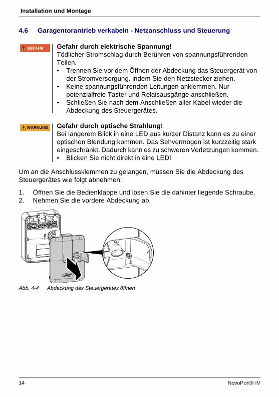
Um an die Anschlussklemmen zu gelangen, müssen Sie die Abdeckung des Steuergerätes wie folgt abnehmen:
1. Öffnen Sie die Bedienklappe und lösen Sie die dahinter liegende Schraube.2. Nehmen Sie die vordere Abdeckung ab.
Abb. 4-4 Abdeckung des Steuergerätes öffnen
Gefahr durch elektrische Spannung!Tödlicher Stromschlag durch Berühren von spannungsführenden Teilen. • Trennen Sie vor dem Öffnen der Abdeckung das Steuergerät von
der Stromversorgung, indem Sie den Netzstecker ziehen.• Keine spannungsführenden Leitungen anklemmen. Nur
potenzialfreie Taster und Relaisausgänge anschließen.• Schließen Sie nach dem Anschließen aller Kabel wieder die
Abdeckung des Steuergerätes.
Gefahr durch optische Strahlung!Bei längerem Blick in eine LED aus kurzer Distanz kann es zu einer optischen Blendung kommen. Das Sehvermögen ist kurzzeitig stark eingeschränkt. Dadurch kann es zu schweren Verletzungen kommen.• Blicken Sie nicht direkt in eine LED!
14 NovoPort® IV

Installation und Montage
4.6.1 Übersicht Anschlussplan
RELLS 4
1 2 3 4 5
LS 4
1 2
I H G F E
8k2
I H G F E
4
180R
I H G F E
3
8k28k2
I H G F E
2
6
LS 2LS 2
1 2 1 2
5
I H G F E
8k2
I H G F E
24V-
7
8k2
K
230V~
8I H G F E
REL
24V
-
E43U
9
8k2
10
8k2
I H G F EJ
P
K
1
P
NovoPort® IV 15

Installation und Montage
4.6.2 Impulsgeber und externe Sicherheitseinrichtungen
Nr. Klemme Beschreibung
1 Übersicht der Anschlussbelegung am Steuergerät
1 J Stecksockel für Funkempfänger
2 E Anschluss für Antenne. Bei Verwendung einer externen Antenne muss die Abschirmung auf die links daneben liegende Klemme (F) gelegt werden.
3 F Anschluss für externen Impulsgeber (Zubehör, z. B. Schlüsseltaster oder Codetaster)
4 G Anschluss für Schlupftürkontakt (Zubehör) oder NotstoppÜber diesen Eingang wird der Antrieb gestoppt bzw. der Anlauf unterdrückt.(siehe Menü H)
5 G / H Anschluss Lichtschranke LS2 (bei Verwendung einer anderen Lichtschranke entnehmen Sie bitte die Anklemmpositionen aus der Anleitung der Lichtschranke)
6 I / H Anschluss 4-Draht Lichtschranke (z. B. LS5)Über diesen Eingang wird die automatische Richtungsumkehr des Antriebs während des Schließens aktiviert.
7 I Anschluss für z. B. 24V-Signalleuchte (Zubehör)Spannungsversorgung 24 V DC, max. 100 mA (geschaltet)
8 K Anschluss für externe, schutzisolierte Beleuchtung oder Signallampe (Schutzklasse II, max. 500W) (Zubehör)
9 F / I Spannungsversorgung 24 V DC max. 100 mA (permanent)
10 P Anschluss für Mobility Modul (Zubehör)
Information
Bei erhöhten Anforderungen an den Personenschutz empfehlen wir zusätzlich zur internen Kraftbegrenzung des Antriebs die Installation einer 2-Draht-Lichtschranke. Die Installation einer 4-Draht-Lichtschranke dient dem reinen Sachschutz. Weitere Informationen zum Zubehör entnehmen Sie bitte unseren Unterlagen oder fragen Sie Ihren Fachhändler.
HINWEISVor der Erstinbetriebnahme muss der Antrieb auf einwandfreie und sichere Funktion geprüft werden (siehe Kapitel Wartung / Überprüfung, Seite 36).
16 NovoPort® IV
Installation und Montage
4.7 Antennenverlegung
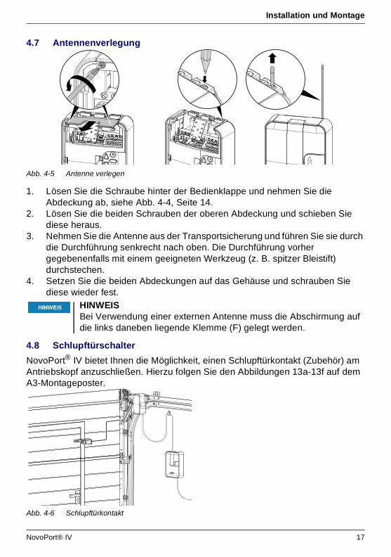
Abb. 4-5 Antenne verlegen
1. Lösen Sie die Schraube hinter der Bedienklappe und nehmen Sie die Abdeckung ab, siehe Abb. 4-4, Seite 14.
2. Lösen Sie die beiden Schrauben der oberen Abdeckung und schieben Sie diese heraus.
3. Nehmen Sie die Antenne aus der Transportsicherung und führen Sie sie durch die Durchführung senkrecht nach oben. Die Durchführung vorher gegebenenfalls mit einem geeigneten Werkzeug (z. B. spitzer Bleistift) durchstechen.
4. Setzen Sie die beiden Abdeckungen auf das Gehäuse und schrauben Sie diese wieder fest.
4.8 Schlupftürschalter
NovoPort® IV bietet Ihnen die Möglichkeit, einen Schlupftürkontakt (Zubehör) am Antriebskopf anzuschließen. Hierzu folgen Sie den Abbildungen 13a-13f auf dem A3-Montageposter.
Abb. 4-6 Schlupftürkontakt
HINWEISBei Verwendung einer externen Antenne muss die Abschirmung auf die links daneben liegende Klemme (F) gelegt werden.
NovoPort® IV 17

Installation und Montage
4.9 Antriebskopf programmieren
In diesem Abschnitt wird die Basisprogrammierung des Antriebs im Rahmen der Installation beschrieben. Das Programmieren der Steuerung ist menügeführt. • Durch Drücken der Taste (D) wird die Menüführung aufgerufen. Die Ziffern der
Anzeige (A) zeigen den Menüschritt an. • Nach ca. 2 Sekunden blinkt die Anzeige (A) und die Einstellung kann durch die
Tasten (B) und (C) verändert werden. • Mit der Taste (D) wird der eingestellte Wert gespeichert und das Programm
springt automatisch in den nächsten Menüschritt. Durch mehrmaliges Betätigen der Taste (D) können Menüschritte übersprungen werden.
• Zur Beendigung des Menüs so oft die Taste (D) betätigen, bis wieder die Ziffer 0 angezeigt wird oder erlischt.
• Außerhalb des Menüs kann mit Taste (B) ein Startimpuls gegeben werden.
Informationen zu weitere und/oder speziellen Einstellungen finden Sie im Kapitel Sondereinstellungen, Seite 23.
4.9.1 Vorbereitung
1. Stellen Sie sicher, dass das Garagentor sicher mit dem Motorkopf verbunden ist.
Gefahr durch elektrische Spannung!Tödlicher Stromschlag durch Berühren von spannungsführenden Teilen. • Trennen Sie vor dem Öffnen der Abdeckung das Steuergerät von
der Stromversorgung, indem Sie den Netzstecker ziehen.
Schritt Installation
Schlupftürschalter
13b Lösen Sie die Schrauben der Abdeckung und nehmen Sie die Abdeckung ab.
13c Brechen Sie mit einer Zange die Blindlasche seitlich am Gehäuse des Antriebskopfes aus.
13d Verlegen Sie das Anschlusskabel entlang des Hebelarms und befestigen Sie es mit Kabelbindern. Achten Sie auf genügend Bewegungsfreiheit des Kabels.
13e Schließen Sie das Kabel des Türschlupfkontaktes an die zweite und dritte Position des Klemmblocks an.
13f Setzen Sie die Abdeckung wieder auf das Gehäuse und verschrauben Sie sie. (8k2-Widerstand von Klemme G im Steuergerät entfernen)
Prüfung Öffnen Sie die Schlupftür.• Das Display am Steuergerät zeigt den Wert "1" an, wenn der
Antrieb eingeschaltet ist.
18 NovoPort® IV
Installation und Montage
2. Stellen Sie sicher, dass die Antenne korrekt positioniert ist (Abb. 4-5, Seite 17).
3. Stellen Sie sicher, dass Sie alle Handsender, die Sie für dieses Garagentor einlernen möchten, zur Hand haben.
4. Öffnen Sie die Bedienklappe am Steuergerät.5. Verbinden Sie das Netzkabel des Steuergerätes mit einer Netzsteckdose. Die
Punktanzeige (A1) leuchtet auf.
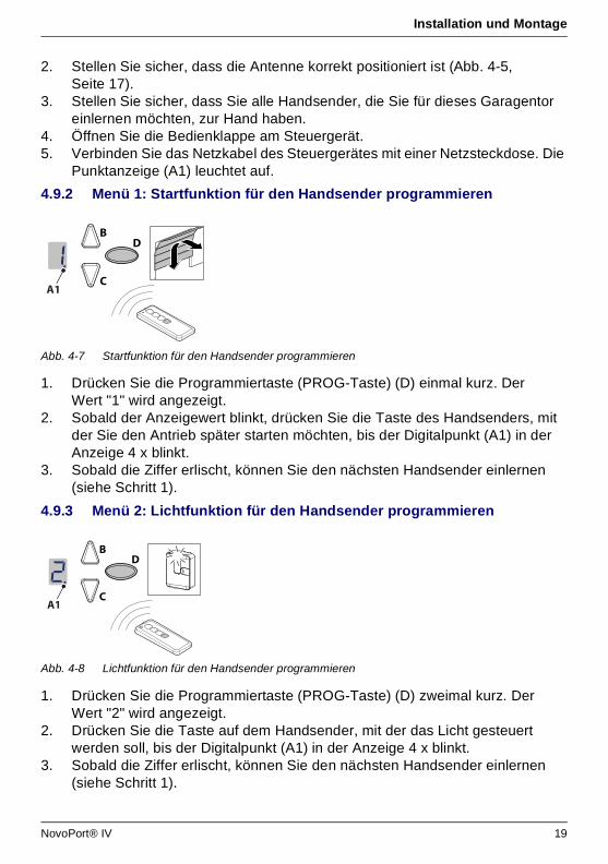
4.9.2 Menü 1: Startfunktion für den Handsender programmieren
Abb. 4-7 Startfunktion für den Handsender programmieren
1. Drücken Sie die Programmiertaste (PROG-Taste) (D) einmal kurz. Der Wert "1" wird angezeigt.
2. Sobald der Anzeigewert blinkt, drücken Sie die Taste des Handsenders, mit der Sie den Antrieb später starten möchten, bis der Digitalpunkt (A1) in der Anzeige 4 x blinkt.
3. Sobald die Ziffer erlischt, können Sie den nächsten Handsender einlernen (siehe Schritt 1).
4.9.3 Menü 2: Lichtfunktion für den Handsender programmieren
Abb. 4-8 Lichtfunktion für den Handsender programmieren
1. Drücken Sie die Programmiertaste (PROG-Taste) (D) zweimal kurz. Der Wert "2" wird angezeigt.
2. Drücken Sie die Taste auf dem Handsender, mit der das Licht gesteuert werden soll, bis der Digitalpunkt (A1) in der Anzeige 4 x blinkt.
3. Sobald die Ziffer erlischt, können Sie den nächsten Handsender einlernen (siehe Schritt 1).
C
BD
A1
C
BD
A1
NovoPort® IV 19
Installation und Montage
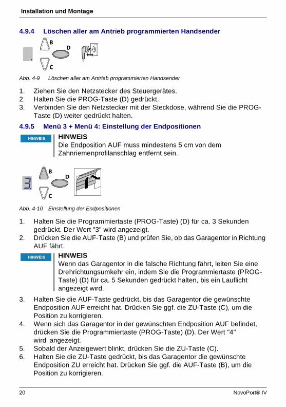
4.9.4 Löschen aller am Antrieb programmierten Handsender
Abb. 4-9 Löschen aller am Antrieb programmierten Handsender
1. Ziehen Sie den Netzstecker des Steuergerätes.2. Halten Sie die PROG-Taste (D) gedrückt.3. Verbinden Sie den Netzstecker mit der Steckdose, während Sie die PROG-
Taste (D) weiter gedrückt halten.
4.9.5 Menü 3 + Menü 4: Einstellung der Endpositionen
Abb. 4-10 Einstellung der Endpositionen
1. Halten Sie die Programmiertaste (PROG-Taste) (D) für ca. 3 Sekunden gedrückt. Der Wert "3" wird angezeigt.
2. Drücken Sie die AUF-Taste (B) und prüfen Sie, ob das Garagentor in Richtung AUF fährt.
3. Halten Sie die AUF-Taste gedrückt, bis das Garagentor die gewünschte Endposition AUF erreicht hat. Drücken Sie ggf. die ZU-Taste (C), um die Position zu korrigieren.
4. Wenn sich das Garagentor in der gewünschten Endposition AUF befindet, drücken Sie die Programmiertaste (PROG-Taste) (D). Der Wert "4" wird angezeigt.
5. Sobald der Anzeigewert blinkt, drücken Sie die ZU-Taste (C).6. Halten Sie die ZU-Taste gedrückt, bis das Garagentor die gewünschte
Endposition ZU erreicht hat. Drücken Sie ggf. die AUF-Taste (B), um die Position zu korrigieren.
HINWEISDie Endposition AUF muss mindestens 5 cm von dem Zahnriemenprofilanschlag entfernt sein.
HINWEISWenn das Garagentor in die falsche Richtung fährt, leiten Sie eine Drehrichtungsumkehr ein, indem Sie die Programmiertaste (PROG-Taste) (D) für ca. 5 Sekunden gedrückt halten, bis ein Lauflicht angezeigt wird.
C
BD
C
BD
20 NovoPort® IV
Installation und Montage
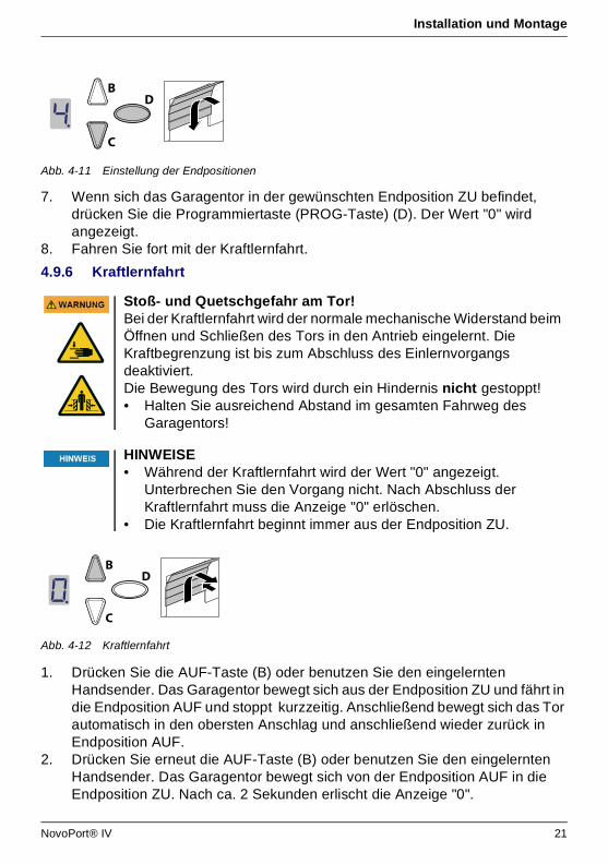
Abb. 4-11 Einstellung der Endpositionen
7. Wenn sich das Garagentor in der gewünschten Endposition ZU befindet, drücken Sie die Programmiertaste (PROG-Taste) (D). Der Wert "0" wird angezeigt.
8. Fahren Sie fort mit der Kraftlernfahrt.
4.9.6 Kraftlernfahrt
Abb. 4-12 Kraftlernfahrt
1. Drücken Sie die AUF-Taste (B) oder benutzen Sie den eingelernten Handsender. Das Garagentor bewegt sich aus der Endposition ZU und fährt in die Endposition AUF und stoppt kurzzeitig. Anschließend bewegt sich das Tor automatisch in den obersten Anschlag und anschließend wieder zurück in Endposition AUF.
2. Drücken Sie erneut die AUF-Taste (B) oder benutzen Sie den eingelernten Handsender. Das Garagentor bewegt sich von der Endposition AUF in die Endposition ZU. Nach ca. 2 Sekunden erlischt die Anzeige "0".
Stoß- und Quetschgefahr am Tor!Bei der Kraftlernfahrt wird der normale mechanische Widerstand beim Öffnen und Schließen des Tors in den Antrieb eingelernt. Die Kraftbegrenzung ist bis zum Abschluss des Einlernvorgangs deaktiviert. Die Bewegung des Tors wird durch ein Hindernis nicht gestoppt! • Halten Sie ausreichend Abstand im gesamten Fahrweg des
Garagentors!
HINWEISE• Während der Kraftlernfahrt wird der Wert "0" angezeigt.
Unterbrechen Sie den Vorgang nicht. Nach Abschluss der Kraftlernfahrt muss die Anzeige "0" erlöschen.
• Die Kraftlernfahrt beginnt immer aus der Endposition ZU.
C
BD
C
BD
NovoPort® IV 21
Installation und Montage
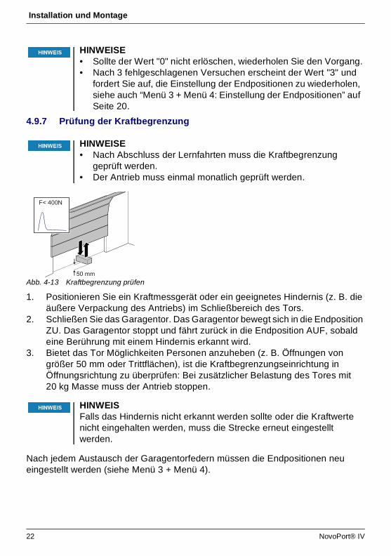
4.9.7 Prüfung der Kraftbegrenzung
Abb. 4-13 Kraftbegrenzung prüfen
1. Positionieren Sie ein Kraftmessgerät oder ein geeignetes Hindernis (z. B. die äußere Verpackung des Antriebs) im Schließbereich des Tors.
2. Schließen Sie das Garagentor. Das Garagentor bewegt sich in die Endposition ZU. Das Garagentor stoppt und fährt zurück in die Endposition AUF, sobald eine Berührung mit einem Hindernis erkannt wird.
3. Bietet das Tor Möglichkeiten Personen anzuheben (z. B. Öffnungen von größer 50 mm oder Trittflächen), ist die Kraftbegrenzungseinrichtung in Öffnungsrichtung zu überprüfen: Bei zusätzlicher Belastung des Tores mit 20 kg Masse muss der Antrieb stoppen.
Nach jedem Austausch der Garagentorfedern müssen die Endpositionen neu eingestellt werden (siehe Menü 3 + Menü 4).
HINWEISE• Sollte der Wert "0" nicht erlöschen, wiederholen Sie den Vorgang.• Nach 3 fehlgeschlagenen Versuchen erscheint der Wert "3" und
fordert Sie auf, die Einstellung der Endpositionen zu wiederholen, siehe auch “Menü 3 + Menü 4: Einstellung der Endpositionen” auf Seite 20.
HINWEISE• Nach Abschluss der Lernfahrten muss die Kraftbegrenzung
geprüft werden.• Der Antrieb muss einmal monatlich geprüft werden.
HINWEISFalls das Hindernis nicht erkannt werden sollte oder die Kraftwerte nicht eingehalten werden, muss die Strecke erneut eingestellt werden.
F< 400N
50 mm
22 NovoPort® IV

Installation und Montage
4.10 Sondereinstellungen
4.10.1 Menü "Sondereinstellungen" öffnen
1. Um in die Menüs für Sondereinstellungen zu gelangen, halten Sie die Programmiertaste (PROG-Taste) (D) für ca. 3 Sekunden gedrückt. Der Wert "3" wird angezeigt.
2. Drücken Sie erneut die Programmiertaste (PROG-Taste) (D). Der Wert "4" wird angezeigt.
3. Halten Sie die Programmiertaste (PROG-Taste) (D) erneut für ca. 3 Sekunden gedrückt. Der Wert "5" wird angezeigt.
4.10.2 Menü 5 + Menü 6: Kraftbegrenzung für Auf- und Zufahrt
1. Wählen Sie Menüpunkt "5". Nach ca. 2 Sekunden blinkt die Anzeige und der eingestellte Wert der Kraftbegrenzung für die Auffahrt erscheint.
2. Passen Sie die Einstellung ggf. mithilfe der AUF- (B) und ZU- (C) Tasten an.3. Drücken Sie die Programmiertaste (PROG-Taste) (D). Der Wert "6" wird
angezeigt. Nach ca. 2 Sekunden blinkt die Anzeige und der eingestellte Wert für die Kraftbegrenzung für die Zufahrt erscheint.
4. Passen Sie die Einstellung ggf. mithilfe der AUF- (B) und ZU- (C) Tasten an.5. Drücken Sie die Programmiertaste (PROG-Taste) (D).
Der Wert "7" wird angezeigt.
4.10.3 Menü 7: Lichtzeiten einstellen
1. Wählen Sie Menüpunkt "7". Nach ca. 2 Sekunden blinkt die Anzeige und der eingestellte Wert für die Lichtzeit erscheint. Im Auslieferungszustand ist der Wert "0" eingestellt.
2. Passen Sie die Einstellung ggf. mithilfe der AUF- (B) und ZU- (C) Tasten an.
Quetschgefahr am Tor!Bei einer zu hohen Einstellung der Kraftbegrenzung besteht Verletzungsgefahr für Personen.Im Auslieferungszustand ist der eingestellte Wert beim Öffnen "6" und beim Schließen "4".• Die Kraft an der Hauptschließkante darf 400 N / 750 ms nicht
übersteigen!
Wert Lichtzeit Vorwarnzeit 24V
0 60 s 0 s 60 s
1 120 s 0 s 120 s
2 240 s 0 s 240 s
3 0 s 0 s 0 s
4 0 s 3 s 0 s
5 60 s 3 s 0 s
6 120 s 3 s 0 s
NovoPort® IV 23
Installation und Montage
3. Drücken Sie die Programmiertaste (PROG-Taste) (D). Der Wert "8" wird angezeigt.
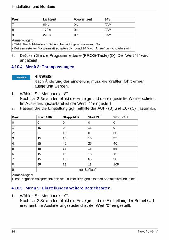
4.10.4 Menü 8: Toranpassungen
1. Wählen Sie Menüpunkt "8". Nach ca. 2 Sekunden blinkt die Anzeige und der eingestellte Wert erscheint. Im Auslieferungszustand ist der Wert "4" eingestellt.
2. Passen Sie die Einstellung ggf. mithilfe der AUF- (B) und ZU- (C) Tasten an.
4.10.5 Menü 9: Einstellungen weitere Betriebsarten
1. Wählen Sie Menüpunkt "9". Nach ca. 2 Sekunden blinkt die Anzeige und die Einstellung der Betriebsart erscheint. Im Auslieferungszustand ist der Wert "0" eingestellt.
7 60 s 0 s TAM
8 120 s 0 s TAM
9 240 s 0 s TAM
Anmerkungen:- TAM (Tor-Auf-Meldung): 24 Volt bei nicht geschlossenem Tor.- Bei eingestellter Vorwarnzeit schalten Licht und 24 V vor Anlauf des Antriebes ein.
HINWEISNach Änderung der Einstellung muss die Kraftlernfahrt erneut ausgeführt werden.
Wert Start AUF Stopp AUF Start ZU Stopp ZU
0 0 0 0 0
1 15 0 15 0
2 0 15 0 60
3 15 15 15 35
4 25 40 25 40
5 15 15 15 55
6 15 15 15 15
7 15 15 65 50
8 55 15 15 105
9 nur Softlauf
Anmerkungen:Diese Angaben entsprechen den am Laufschlitten gemessenen Softlaufstrecken in cm.
Wert Lichtzeit Vorwarnzeit 24V
24 NovoPort® IV
Installation und Montage
2. Passen Sie die Einstellung ggf. mithilfe der AUF- (B) und ZU- (C) Tasten an.
4.10.6 Menü H: Einstellungen STOPP-A
1. Wählen Sie Menüpunkt “H”. Nach ca. 2 Sekunden blinkt die Anzeige und die Einstellung der Betriebsart erscheint. Im Auslieferungszustand ist der Wert “0” eingestellt.
2. Passen Sie die Einstellung ggf. mithilfe der AUF- (B) und ZU- (C) Tasten an.
4.11 TTZ Richtlinie - Einbruchhemmung für Garagentore
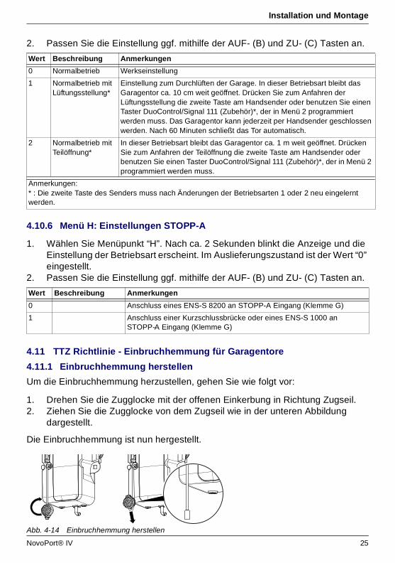
4.11.1 Einbruchhemmung herstellen
Um die Einbruchhemmung herzustellen, gehen Sie wie folgt vor:
1. Drehen Sie die Zugglocke mit der offenen Einkerbung in Richtung Zugseil.2. Ziehen Sie die Zugglocke von dem Zugseil wie in der unteren Abbildung
dargestellt.
Die Einbruchhemmung ist nun hergestellt.
Abb. 4-14 Einbruchhemmung herstellen
Wert Beschreibung Anmerkungen
0 Normalbetrieb Werkseinstellung
1 Normalbetrieb mit Lüftungsstellung*
Einstellung zum Durchlüften der Garage. In dieser Betriebsart bleibt das Garagentor ca. 10 cm weit geöffnet. Drücken Sie zum Anfahren der Lüftungsstellung die zweite Taste am Handsender oder benutzen Sie einen Taster DuoControl/Signal 111 (Zubehör)*, der in Menü 2 programmiert werden muss. Das Garagentor kann jederzeit per Handsender geschlossen werden. Nach 60 Minuten schließt das Tor automatisch.
2 Normalbetrieb mit Teilöffnung*
In dieser Betriebsart bleibt das Garagentor ca. 1 m weit geöffnet. Drücken Sie zum Anfahren der Teilöffnung die zweite Taste am Handsender oder benutzen Sie einen Taster DuoControl/Signal 111 (Zubehör)*, der in Menü 2 programmiert werden muss.
Anmerkungen:* : Die zweite Taste des Senders muss nach Änderungen der Betriebsarten 1 oder 2 neu eingelernt werden.
Wert Beschreibung Anmerkungen
0 Anschluss eines ENS-S 8200 an STOPP-A Eingang (Klemme G)
1 Anschluss einer Kurzschlussbrücke oder eines ENS-S 1000 an STOPP-A Eingang (Klemme G)
NovoPort® IV 25
Installation und Montage
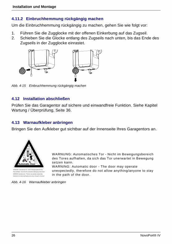
4.11.2 Einbruchhemmung rückgängig machen
Um die Einbruchhemmung rückgängig zu machen, gehen Sie wie folgt vor:
1. Führen Sie die Zugglocke mit der offenen Einkerbung auf das Zugseil.2. Schieben Sie die Glocke entlang des Zugseils nach unten, bis das Ende des
Zugseils in der Zugglocke einrastet.
Abb. 4-15 Einbruchhemmung rückgängig machen
4.12 Installation abschließen
Prüfen Sie das Garagentor auf sichere und einwandfreie Funktion. Siehe Kapitel Wartung / Überprüfung, Seite 36.
4.13 Warnaufkleber anbringen
Bringen Sie den Aufkleber gut sichtbar auf der Innenseite Ihres Garagentors an.
Abb. 4-16 Warnaufkleber anbringen
WARNUNG: Automatisches Tor - Nicht im Bewegungsbereich des
Tores aufhalten, da sich das Tor unerwartet in Bewegung setzen kann!
WARNING: Automatic door - The door may operate unexpectedly,
therefore do not allow anything/anyone to stay in the path of the door!
Automatic Door
WARNUNG: Automatisches Tor - Nicht im Bewegungsbereich des Tores aufhalten, da sich das Tor unerwartet in Bewegung setzen kann.WARNING: Automatic door - The door may operate unexpectedly, therefore do not allow anything/anyone to stay in the path of the door.
26 NovoPort® IV

Betrieb
5 Betrieb5.1 Sicherheitshinweise für den Betrieb
Beachten Sie für den Betrieb folgende Sicherheitshinweise:• Benutzung nur durch unterwiesene Personen. • Alle Benutzer müssen mit den anwendbaren Sicherheitsvorschriften vertraut
sein.• Halten Sie die für den Einsatzbereich geltenden örtlichen
Unfallverhütungsvorschriften und allgemeinen Sicherheitsbestimmungen ein.• Bewahren Sie Handsender außerhalb der Reichweite von Kindern auf.
5.2 Garagentor öffnen und schließen (im Normalbetrieb)
Das Garagentor kann mit verschiedenen Steuergeräten bedient werden (Handsender, Schlüsselschalter, etc.). Im vorliegenden Handbuch wird nur die Steuerung per Handsender beschrieben. Andere Steuergeräte arbeiten analog.
1. Drücken Sie die Taste am Handsender einmal kurz. Abhängig von der aktuellen Position fährt das Garagentor anschließend in die AUF- oder ZU-Position.
2. Drücken Sie ggf. erneut die Taste am Handsender, um das Garagentor wieder zu stoppen.
3. Drücken Sie ggf. erneut die Taste am Handsender, um das Garagentor zurück in die Ausgangsposition zu verfahren.
5.3 Garagentor von Hand öffnen und schließen
Stoß- und Quetschgefahr durch die Bewegung des Tors!Bei Betätigung des Antriebes müssen die Öffnungs- und Schließvorgänge überwacht werden.• Das Garagentor muss vom Ort der Bedienung aus einsehbar sein. • Achten Sie darauf, dass sich keine Personen oder Gegenstände
im Bewegungsbereich des Garagentors befinden.
Information
Eine Taste am Handsender kann mit der Funktion "4-Minuten-Licht" belegt werden. Über den Handsender kann das Licht dann unabhängig vom Antrieb eingeschaltet werden. Nach 4 Minuten wird das Licht automatisch abgeschaltet.
Stoß- und Quetschgefahr durch unkontrollierte Bewegung des Tors!Beim Einsatz der Schnellentriegelung kann sich das Garagentor unkontrolliert bewegen. Das Garagentor ist möglicherweise nicht mehr korrekt ausbalanciert oder die Federn sind beschädigt oder besitzen nicht mehr die notwendige Spannkraft. • Setzen Sie sich mit dem zuständigen Lieferanten / Hersteller in
Verbindung.
NovoPort® IV 27
Betrieb
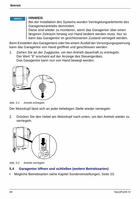
Beim Einstellen des Garagentors oder bei einem Ausfall der Versorgungsspannung kann das Garagentor von Hand geöffnet und geschlossen werden.
1. Ziehen Sie an der Zugglocke, um den Antrieb dauerhaft zu entriegeln.Der Wert "8" erscheint auf der Anzeige des Steuergerätes.Das Garagentor kann nun von Hand bewegt werden.
Abb. 5-1 Antrieb entriegeln
Der Motorkopf lässt sich an jeder beliebigen Stelle wieder verriegeln.
2. Drücken Sie den Hebel am Motorkopf nach unten, um den Antrieb wieder zu verriegeln.
Abb. 5-2 Antrieb verriegeln
5.4 Garagentor öffnen und schließen (weitere Betriebsarten)
• Mögliche Betriebsarten siehe Kapitel Sondereinstellungen, Seite 23.
HINWEISBei der Installation des Systems wurden Verriegelungselemente des Garagentorantriebs demontiert. Diese sind wieder zu montieren, wenn das Garagentor über einen längeren Zeitraum hinweg von Hand bedient werden muss. Nur so kann das Garagentor im geschlossenen Zustand verriegelt werden.
28 NovoPort® IV

Fehlersuche
NovoPort® IV 29
6 Fehlersuche
Gefahr durch elektrischen Strom!• Bei Arbeiten am Antrieb ist unbedingt vorher der Netzstecker zu
ziehen!
Störung Mögliche Ursachen Abhilfe
Tor schließt / öffnet nicht vollständig. Tormechanik hat sich verändert. Schließ-/Öffnungskraft zu schwach eingestellt. Endposition nicht richtig eingestellt.
Tor überprüfen lassen. Krafteinstellung durchführen lassen (Menüschritte 5 und 6, Seite 23). Endposition neu einstellen lassen.
Nach dem Schließen öffnet sich das Tor wieder einen Spalt breit.
Tor blockiert kurz vor Zuposition. Endposition nicht richtig eingestellt.
Hindernis entfernen. Endposition ZU neu einstellen lassen.
Antrieb fährt nicht, obwohl der Motor läuft.
Der Antrieb ist entriegelt. Antrieb wieder verriegeln, siehe Abb. 5-2, Seite 28.
Tor reagiert nicht auf Impulsgabe des Handsenders - jedoch auf Betätigung durch Drucktaster oder andere Impulsgeber.
Batterie im Handsender leer. Antenne nicht vorhanden oder nicht ausgerichtet. Kein Handsender programmiert.
Batterie im Handsender erneuern. Antenne einstecken / ausrichten. Handsender programmieren (Menüschritt 1, Seite 19).
Tor reagiert weder auf Impulsgabe des Handsenders noch auf andere Impulsgeber.
Siehe Diagnoseanzeige. Siehe Diagnoseanzeige.
Zu geringe Reichweite des Handsenders.
Batterie im Handsender leer. Antenne nicht vorhanden oder nicht ausgerichtet. Bauseitige Abschirmung des Empfangssignals.
Batterie im Handsender erneuern. Antenne einstecken / ausrichten. Externe Antenne anschließen (Zubehör).
Zahnriemen oder Antrieb macht Geräusche.
Zahnriemen ist verschmutzt oder Zahnriemen ist zu stark gespannt.
Zahnriemen reinigen. Mit Silikonspray einsprühen (keine ölhaltigen Mittel verwenden). Zahnriemen entspannen.
Diagnoseanzeige
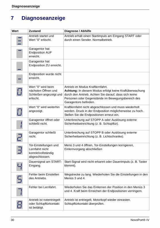
7 Diagnoseanzeige
Wert Zustand Diagnose / Abhilfe
Antrieb startet und Wert "0" erlischt.
Antrieb erhält einen Startimpuls am Eingang START oder durch einen Sender. Normalbetrieb.
Garagentor hat Endposition AUF erreicht.
Garagentor hat Endposition ZU erreicht.
Endposition wurde nicht erreicht.
Wert "0" wird beim nächsten Öffnen und Schließen angezeigt und erlischt.
Antrieb im Modus Kraftlernfahrt.Achtung: In diesem Modus erfolgt keine Kraftüberwachung durch den Antrieb. Achten Sie darauf, dass sich keine Personen oder Gegenstände im Bewegungsbereich des Garagentors befinden.
Wert "0" wird weiterhin angezeigt.
Kraftlernfahrt nicht abgeschlossen und muss wiederholt werden. Druck in der Endposition möglicherweise zu hoch. Stellen Sie die Endpositionen erneut ein.
Garagentor öffnet oder schließt nicht.
Unterbrechung auf STOPP A oder Auslösung externe Sicherheitseinrichtung (z. B. Schlupftür).
Garagentor schließt nicht.
Unterbrechung auf STOPP B oder Auslösung externe Sicherheitseinrichtung (z. B. Lichtschranke).
Tor-Einstellungen und Lernfahrt nicht korrekt/vollständig abgeschlossen.
Menü 3 und 4 öffnen, Tor-Einstellungen korrigieren, Einlernvorgang abschließen
Dauersignal am START-Eingang.
Start-Signal wird nicht erkannt oder Dauerimpuls (z. B. Taster klemmt).
Fehler beim Einstellen des Antriebs.
Wegstrecke zu lang. Wiederholen Sie die Einstellungen in den Menüs 3 und 4.
Fehler bei Lernfahrt. Wiederholen Sie das Einlernen der Position in den Menüs 3 und 4. Kraft beim Erreichen der Endpositionen verringern.
Antrieb ist notentriegelt oder Schlupftürkontakt ist betätigt.
Antrieb ist entriegelt, Motorkopf wieder einrasten. Schlupftürkontakt überprüfen.
30 NovoPort® IV
Diagnoseanzeige
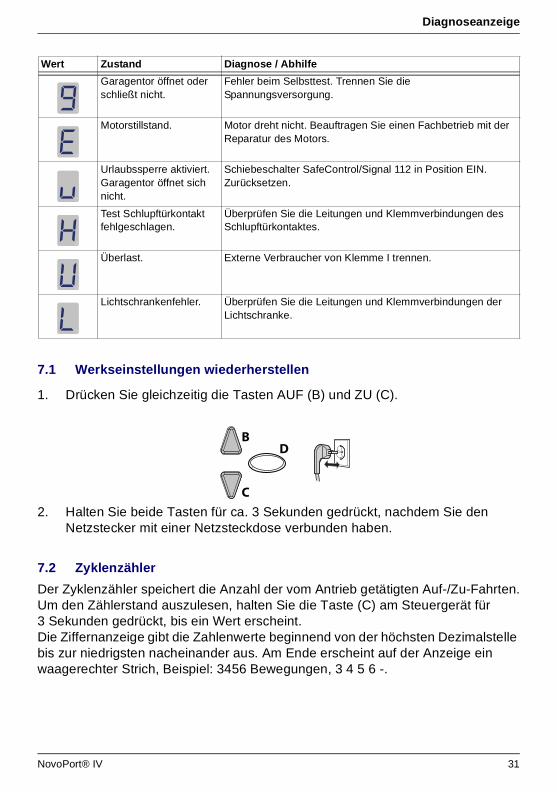
7.1 Werkseinstellungen wiederherstellen
1. Drücken Sie gleichzeitig die Tasten AUF (B) und ZU (C).
2. Halten Sie beide Tasten für ca. 3 Sekunden gedrückt, nachdem Sie den Netzstecker mit einer Netzsteckdose verbunden haben.
7.2 Zyklenzähler
Der Zyklenzähler speichert die Anzahl der vom Antrieb getätigten Auf-/Zu-Fahrten.Um den Zählerstand auszulesen, halten Sie die Taste (C) am Steuergerät für 3 Sekunden gedrückt, bis ein Wert erscheint.Die Ziffernanzeige gibt die Zahlenwerte beginnend von der höchsten Dezimalstelle bis zur niedrigsten nacheinander aus. Am Ende erscheint auf der Anzeige ein waagerechter Strich, Beispiel: 3456 Bewegungen, 3 4 5 6 -.
Garagentor öffnet oder schließt nicht.
Fehler beim Selbsttest. Trennen Sie die Spannungsversorgung.
Motorstillstand. Motor dreht nicht. Beauftragen Sie einen Fachbetrieb mit der Reparatur des Motors.
Urlaubssperre aktiviert.Garagentor öffnet sich nicht.
Schiebeschalter SafeControl/Signal 112 in Position EIN.Zurücksetzen.
Test Schlupftürkontakt fehlgeschlagen.
Überprüfen Sie die Leitungen und Klemmverbindungen des Schlupftürkontaktes.
Überlast. Externe Verbraucher von Klemme I trennen.
Lichtschrankenfehler. Überprüfen Sie die Leitungen und Klemmverbindungen der Lichtschranke.
Wert Zustand Diagnose / Abhilfe
C
BD
NovoPort® IV 31
Inspektions- und Prüfprotokoll
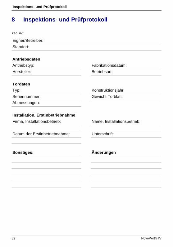
8 Inspektions- und Prüfprotokoll
Tab. 8-1
Eigner/Betreiber:
Standort:
Antriebsdaten
Antriebstyp: Fabrikationsdatum:
Hersteller: Betriebsart:
Tordaten
Typ: Konstruktionsjahr:
Seriennummer: Gewicht Torblatt:
Abmessungen:
Installation, Erstinbetriebnahme
Firma, Installationsbetrieb: Name, Installationsbetrieb:
Datum der Erstinbetriebnahme: Unterschrift:
Sonstiges: Änderungen
32 NovoPort® IV

Inspektions- und Prüfprotokoll
8.1 Garagentorantrieb testen
• Antriebsbetriebene Garagentore sind in regelmäßigen Abständen durch qualifiziertes und einschlägig geschultes und erfahrenes Personal zu inspizieren und zu warten.
• Die vom Hersteller angegebenen Inspektions- und Wartungsintervalle sind einzuhalten.
• Beachten Sie alle anwendbaren nationalen Vorschriften (ASR 1.7 "Technische Regeln für Arbeitsstätten - Türen und Tore").
• Sämtliche Inspektions- und Wartungstätigkeiten sind im beiliegenden Inspektions- und Prüfprotokoll zu dokumentieren.
• Der Betreiber/Eigner ist verpflichtet, das Inspektions- und Prüfprotokoll zusammen mit der Dokumentation zum Garagentorantrieb über die komplette Lebensdauer der Anlage sicher aufzubewahren.
• Der Installationsbetrieb ist verpflichtet, das Inspektions- und Prüfprotokoll vor Inbetriebnahme der Anlage vollständig ausgefüllt an den Betreiber/Eigner zu übergeben. Dies gilt auch für manuell betätigte Tore.
• Sämtlichen Vorschriften und Hinweisen der Dokumentation zum Garagentorantrieb (Installation, Betrieb und Wartung, etc.) ist strikt Folge zu leisten.
• Im Falle unsachgemäßer Ausführung der vorgeschriebenen Inspektions- und Wartungstätigkeiten erlischt jegliche Herstellergarantie.
• Genehmigte Änderungen am Garagentorantrieb sind zu dokumentieren.
HINWEISEine Inspektion ersetzt nicht die erforderlichen Wartungstätigkeiten! Nach jeder Inspektion sind festgestellte Mängel umgehend zu beseitigen.
NovoPort® IV 33
Prüflisten
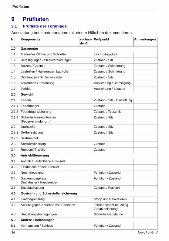
9 Prüflisten9.1 Prüfliste der Toranlage
Ausstattung bei Inbetriebnahme mit einem Häkchen dokumentieren.
Nr. Komponente vorhan-den?
Prüfpunkt Anmerkungen
1.0 Garagentor
1.1 Manuelles Öffnen und Schließen Leichtgängigkeit
1.2 Befestigungen / Steckverbindungen Zustand / Sitz
1.3 Bolzen / Gelenke Zustand / Schmierung
1.4 Laufrollen / Halterungen Laufrollen Zustand / Schmierung
1.5 Dichtungen / Schleifkontakte Zustand / Sitz
1.6 Torrahmen / Torführung Ausrichtung / Befestigung
1.7 Torblatt Ausrichtung / Zustand
2.0 Gewicht
2.1 Federn Zustand / Sitz / Einstellung
2.1.1 Federbänder Zustand
2.1.2 Federbruchsicherung Zustand / Typschild
2.1.3 Sicherheitseinrichtungen (Federverbindung,…)
Zustand / Sitz
2.2 Drahtseile Zustand / Sitz
2.2.1 Seilbefestigung Zustand / Sitz
2.2.2 Seiltrommel
2.3 Absturzsicherung Zustand
2.4 Rundlauf T-Welle Zustand
3.0 Antrieb/Steuerung
3.1 Antrieb / Laufschiene / Konsole
3.2 Elektrische Kabel / Stecker
3.3 Notentriegelung Funktion / Zustand
3.4 Steuerungsgeräte, Drucktaster / Handsender
Funktion / Zustand
3.5 Endabschaltung Zustand / Position
4.0 Quetsch- und Scherstellensicherung
4.1 Kraftbegrenzung Stopp und Reversieren
4.2 Schutz gegen Anheben von Personen Torblatt stoppt bei 20 kg Zusatzbelastung
4.3 Umgebungsbedingungen Sicherheitsabstände
5.0 Andere Einrichtungen
5.1 Verriegelung / Schloss Funktion / Zustand
34 NovoPort® IV

Prüflisten
9.2 Prüfungs- und Wartungsnachweis der Toranlage
5.2 Schlupftür Funktion / Zustand
5.2.1 Schlupftürkontakt Funktion / Zustand
5.2.2 Torschließer Funktion / Zustand
5.3 Ampelsteuerung Funktion / Zustand
5.4 Lichtschranken Funktion / Zustand
5.5 Schließkantensicherung Funktion / Zustand
6.0 Dokumentation Betreiber / Eigner
6.1 Typschild / CE-Kennzeichen vollständig / lesbar
6.2 Konformitätserklärung Toranlage vollständig / lesbar
6.3 Installation, Betrieb und Wartung vollständig / lesbar
Datum Durchgeführte Arbeiten / erforderliche Maßnahmen
Prüfung durchgeführt
Mängel beseitigt
Unterschrift / Adresse Firma
Unterschrift / Adresse Firma
Nr. Komponente vorhan-den?
Prüfpunkt Anmerkungen
NovoPort® IV 35

Wartung / Überprüfung
36 NovoPort® IV
10 Wartung / Überprüfung
Überwachung der Kraftbegrenzung
Die Antriebssteuerung verfügt über ein 2-Prozessor-Sicherheitssystem zur Überwachung der Kraftbegrenzung. In einer Endposition oder bei Wiedereinschalten wird die integrierte Kraftabschaltung automatisch getestet. Bei der monatlichen Überprüfung der Toranlage muss die Kraftbegrenzung geprüft werden!
Prüfen Sie die Kraftbegrenzung wie in Kapitel “Menü 5 + Menü 6: Kraftbegrenzung für Auf- und Zufahrt” auf Seite 23 beschrieben.
11 Reinigung / Pflege
Reiben Sie den Antrieb bei Bedarf mit einem trockenen Lappen ab.
HINWEISZu Ihrer Sicherheit muss die Toranlage vor der ersten Inbetriebnahme und nach Bedarf – jedoch mindestens einmal monatlich – geprüft werden. Wir empfehlen, einen Fachbetrieb hinzuzuziehen.
Quetschgefahr am Tor!Bei einer zu hohen Einstellung der Kraftbegrenzung besteht Verletzungsgefahr für Personen.Im Auslieferungszustand ist der eingestellte Wert beim Öffnen "6" und beim Schließen "4".• Die Kraft an der Hauptschließkante darf 400 N / 750 ms nicht
übersteigen!
Gefahr durch elektrische Spannung!Bei Kontakt des Antriebs mit Wasser besteht die Gefahr, einen elektrischen Schlag zu bekommen!• Ziehen Sie vor Arbeiten am Tor oder am Antrieb immer den
Netzstecker!

Demontage / Entsorgung
NovoPort® IV 37
12 Demontage / Entsorgung12.1 Demontage
Die Demontage erfolgt in umgekehrter Reihenfolge der Montageanleitung (Kapitel Installation und Montage, Seite 10).
12.2 Entsorgung
Zur Entsorgung demontieren Sie die Toranlage und zerlegen Sie diese in die einzelnen Materialgruppen:• Kunststoffe• Nichteisenmetalle (z. B. Kupferschrott)• Elektroschrott (Motoren)• StahlEntsorgen Sie die Materialien entsprechend der landesüblichen Gesetzgebung!
Entsorgen Sie Verpackungsmaterialien stets umweltgerecht und nach den geltenden örtlichen Entsorgungsvorschriften.
13 GarantiebestimmungenBitte beachten Sie, dass sich der Geltungsbereich ausschließlich auf die private Nutzung der Anlage erstreckt. Unter privater Nutzung verstehen wir max. 10 Zyklen (AUF/ZU) pro Tag.Der vollständige Text der Garantiebestimmung ist unter der folgenden Internetadresse verfügbar: https://www.novoferm.de/garantiebestimmungen
Das Symbol des durchgestrichenen Mülleimers auf einem Elektro- oder Elektronik-Altgerät besagt, dass dieses am Ende seiner Lebensdauer nicht im Hausmüll entsorgt werden darf. Zur kostenfreien Rückgabe stehen in Ihrer Nähe Sammelstellen für Elektro- und Elektronik-Altgeräte zur Verfügung. Die Adressen erhalten Sie von Ihrer Stadt- bzw. Kommunalverwaltung. Durch die getrennte Sammlung von Elektro- und Elektronik-Altgeräten soll die Wiederverwendung, die stoffliche Verwertung bzw. andere Formen der Verwertung von Altgeräten ermöglicht sowie negative Folgen bei der Entsorgung der in den Geräten möglicherweise enthaltenen gefährlichen Stoffe auf die Umwelt und die menschliche Gesundheit vermieden werden.
Batterien und Akkus gehören nicht in den Hausmüll, sondern müssen in der Europäischen Union – gemäß Richtlinie 2006/66/ EG DES EUROPÄISCHEN PARLAMENTS UND DES RATES vom 06. September 2006 über Batterien und Akkumulatoren – einer fachgerechten Entsorgung zugeführt werden. Bitte entsorgen Sie Batterien und Akkus entsprechend den geltenden gesetzlichen Bestimmungen.
Li-Ion

Konformitäts- und Einbauerklärung
38 NovoPort® IV
14 Konformitäts- und Einbauerklärung14.1 Einbauerklärung nach EG-Richtlinie Maschinen 2006/42/EG
Einbauerklärung des Herstellers (Original)für den Einbau einer unvollständigen Maschine
im Sinne der EG-Richtlinie Maschinen 2006/42/EG, Anhang II Teil 1 Abschnitt BHiermit erklären wir, dass die nachfolgend bezeichnete unvollständige Maschine – soweit es vom Lieferumfang möglich ist – den grundlegenden Anforderungen der EG-Maschinenrichtlinie entspricht. Die unvollständige Maschine ist nur zum Einbau in eine Toranlage bestimmt, um somit eine vollständige Maschine im Sinne der EG-Maschinenrichtlinie zu bilden. Die Toranlage darf erst in Betrieb genommen werden, wenn festgestellt wurde, dass die gesamte Anlage den Bestimmungen der EG-Maschinenrichtlinie entspricht und die EG-Konformitätserklärung gemäß Anhang II A vorliegt. Ferner erklären wir, dass die speziellen technischen Unterlagen für diese unvollständige Maschine nach Anhang VII Teil B erstellt wurden und verpflichten uns, diese auf begründetes Verlangen den zuständigen einzelstaatlichen Stellen über unsere Dokumentationsabteilung zu übermitteln.
14.2 Konformitätserklärung nach Richtlinie 2014/53/EU
Maschinentyp: Garagenantrieb
Maschinenbezeichnung: NovoPort® IV
Baujahr: ab 2018
Einschlägige EG-/EU-Richtlinien:
• Richtlinie 2014/30/EU über die elektromagnetische Verträglichkeit in der Fassung vom 29.03.2014
• Richtlinie 2011/65/EU zur Beschränkung der Verwendung bestimmter gefährlicher Stoffe in Elektro- und Elektronikgeräten in der Fassung vom 01.07.2011
Eingehaltene Anforderungen der MRL 2006/42/EG, Anhang I Teil 1:
1.1.2, 1.1.3, 1.1.5, 1.2.1, 1.2.2, 1.2.3, 1.2.4, 1.2.5, 1.2.6, 1.3.1, 1.3.2, 1.3.4, 1.3.7, 1.5.1, 1.5.4, 1.5.6, 1.5.14, 1.6.1, 1.6.2, 1.6.3, 1.7.1, 1.7.3, 1.7.4
Angewandte harmonisierte Normen:
EN ISO 12100:2010; EN ISO 13849-1:2015, PL „C“ Cat. 2EN 60335-1:2012 (soweit anwendbar), EN 61000-6-3:2007 / A1:2011 EN 61000-6-2:2005 / AC:2005, EN ISO 13850:2008; EN 60204-1:2006/AC:2010; EN 617:2001+A1:2010; EN 618:2002+A1:2010
Sonstige angewandte technische Normen und Spezifikationen:
EN 300220-1:2017-05, EN 300220-2:2017-05EN 301489-1:2017, EN 12453:2017 EN 60335-2-95:2015-01 / A1:2015-06
Hersteller und Name des Bevollmächtigten der technischen Unterlagen:
Novoferm tormatic GmbHEisenhüttenweg 644145 Dortmund
Dortmund, den 05.06.2018
Ort, Datum Dirk Gößling, Geschäftsführer
Das integrierte Funksystem entspricht der Richtlinie 2014/53/EU.Der vollständige Text der Konformitätserklärung ist unter der folgenden Internetadresse verfügbar:https://www.tormatic.de/dokumentation/

Contents
GB
Contents1 About this manual ...................................................................................... 43
1.1 Contents and intended audience........................................................ 431.1.1 Illustrations .......................................................................... 43
1.2 Pictograms and signal words ............................................................. 431.2.1 Hazard symbols .................................................................. 441.2.2 Notice and information symbol............................................ 44
2 Safety........................................................................................................... 452.1 Intended use....................................................................................... 452.2 Foreseeable misuse ........................................................................... 462.3 Personnel qualification ....................................................................... 462.4 Potential hazards associated with the product ................................... 47
3 Product description.................................................................................... 483.1 General product overview .................................................................. 483.2 Technical data .................................................................................... 483.3 Rating plate ........................................................................................ 493.4 Control elements ................................................................................ 493.5 Functioning of the integrated safety unit ............................................ 49
4 Installation and assembly.......................................................................... 504.1 Safety instructions for installation and assembly................................ 504.2 Drive and accessories ........................................................................ 504.3 Scope of delivery ................................................................................ 504.4 Preparing for installation..................................................................... 514.5 Mounting the garage door operator .................................................... 51
4.5.1 Disengaging the motor head ............................................... 534.6 Connecting the garage door operator to electrical power
and controls ........................................................................................ 544.6.1 Connection diagram overview............................................. 554.6.2 Pulse generator and external safety devices ...................... 56
4.7 Routing the antenna ........................................................................... 574.8 Wicket door switch ............................................................................. 574.9 Programming the drive head .............................................................. 58
4.9.1 Preparation.......................................................................... 584.9.2 Menu 1: Programming the start function
for the hand transmitter ....................................................... 594.9.3 Menu 2: Programming the light function
for the hand transmitter ....................................................... 594.9.4 Deleting all hand transmitters programmed
for the operator.................................................................... 604.9.5 Menu 3 + Menu 4: Setting the end positions....................... 604.9.6 Force learning cycle ............................................................ 61
NovoPort® IV 39
Contents
GB
4.9.7 Checking the force limits ..................................................... 624.10 Special settings .................................................................................. 62
4.10.1 Opening the special settings menu ..................................... 624.10.2 Menu 5 + Menu 6: Force limits for opening and closing ..... 634.10.3 Menu 7: Adjusting the light phases ..................................... 634.10.4 Menu 8: Door adjustments .................................................. 644.10.5 Menu 9: Setting other operating modes .............................. 644.10.6 Menu H: STOP-A settings................................................... 65
4.11 TTZ guideline - Burglar resistance for garage doors .......................... 654.11.1 Enabling burglar resistance................................................. 654.11.2 Disabling burglar resistance................................................ 66
4.12 Completing the installation procedure ................................................ 664.13 Attaching the warning sticker ............................................................. 66
5 Operation..................................................................................................... 675.1 Safety instructions for operation ......................................................... 675.2 Opening or closing the garage door (in normal operation mode) ....... 675.3 Manually opening or closing the garage door .................................... 675.4 Opening or closing the garage door (other operation modes)............ 68
6 Troubleshooting ......................................................................................... 69
7 Diagnostic display...................................................................................... 707.1 Restoring the factory settings ............................................................. 717.2 Cycle counter ..................................................................................... 71
8 Inspection and test report ......................................................................... 728.1 Testing of the garage door operator ................................................... 73
9 Checklists.................................................................................................... 749.1 Checklist for door system ................................................................... 749.2 Proof of inspection and maintenance of the door system .................. 75
10 Maintenance / Checks ................................................................................ 76
11 Cleaning / Care ........................................................................................... 76
12 Disassembly / disposal .............................................................................. 7712.1 Disassembly ....................................................................................... 7712.2 Disposal.............................................................................................. 77
13 Warranty terms ........................................................................................... 77
14 Declaration of Conformity and Incorporation.......................................... 7814.1 Declaration of Incorporation in accordance
with the EC Machinery Directive 2006/42/EC .................................... 7814.2 Declaration of Conformity according to Directive 2014/53/EU ........... 78
40 NovoPort® IV
About this manual
1 About this manual1.1 Contents and intended audience
This manual gives information about the NovoPort® IV series garage door operator (hereinafter referred to as ‘the product’). The manual is intended for technicians that install and maintain the product, and for consumers that use the product on a daily base.This description only mentions the hand transmitter. Other devices work in the same way.
1.1.1 Illustrations
The illustrations in this manual help you to better understand the descriptions and procedures. The illustrations only serve as examples and may deviate slightly from your product's actual appearance.
1.2 Pictograms and signal words
Important information in this manual is marked with the following pictograms.
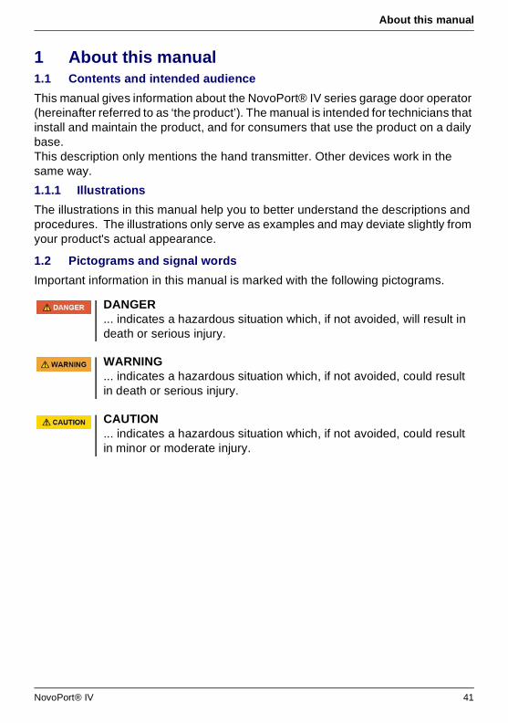
DANGER... indicates a hazardous situation which, if not avoided, will result in death or serious injury.
WARNING... indicates a hazardous situation which, if not avoided, could result in death or serious injury.
CAUTION... indicates a hazardous situation which, if not avoided, could result in minor or moderate injury.
NovoPort® IV 41
About this manual
1.2.1 Hazard symbols
1.2.2 Notice and information symbol
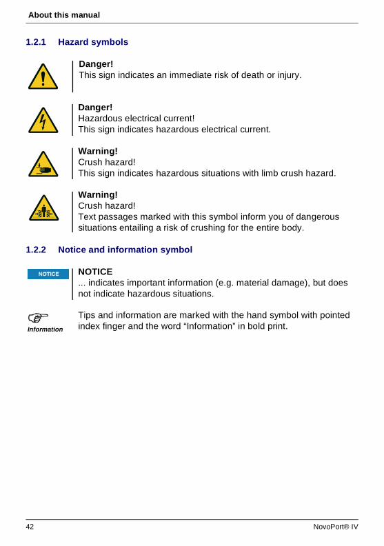
Danger! This sign indicates an immediate risk of death or injury.
Danger!Hazardous electrical current!This sign indicates hazardous electrical current.
Warning!Crush hazard!This sign indicates hazardous situations with limb crush hazard.
Warning!Crush hazard!Text passages marked with this symbol inform you of dangerous situations entailing a risk of crushing for the entire body.
NOTICE... indicates important information (e.g. material damage), but does not indicate hazardous situations.
Information
Tips and information are marked with the hand symbol with pointed index finger and the word “Information” in bold print.
42 NovoPort® IV

Safety
2 SafetyObserve the following safety information:
• Only use the product for the intended use as mentioned in this manual. • Keep all safety information and instructions for future reference.• Installation must only be carried out by qualified technicians.• Never make any modifications or changes to the product that have not been
expressly approved by the manufacturer.• Only use genuine spare parts of the manufacturer. Wrong or faulty spare parts
can cause damage, malfunctions or even a total failure of the product.• This appliance can be used by children aged from 8 years and above and
persons with reduced physical, sensory or mental capabilities or lack of experience and knowledge if they have been given supervision or instruction concerning use of the appliance in a safe way and understand the hazards involved.
• Children shall not play with the appliance. Cleaning and user maintenance shall not be made by children without supervision.
• Failure to comply with the safety information and instructions given in this manual or with the accident prevention regulations and general safety regulations relevant to the field of application shall exempt the manufacturer or its representative from all liability and shall render any damage claims null and void.
2.1 Intended use
• The product is designed exclusively for opening and closing spring-balanced or weight-balanced garage doors. It may not be used for garage doors without spring-balancing or weight-balancing mechanisms.
• The product is compatible with Novoferm products only.• Never make any modifications or changes to the product that have not been
expressly approved by the manufacturer.• The product is suitable for domestic use only.
Risk of injury when disregarding the safety information and instructions!Failure to observe the safety information and instructions can cause electric shock, fire and / or severe injuries.• Following the safety information and instructions given in this
manual helps to avoid personal injuries and material damage while working on and with the product.
• Read and comply with all safety information and instructions.
NovoPort® IV 43
Safety
2.2 Foreseeable misuse
Any use other than described in chapter 2.1 is regarded as reasonably foreseeable misuse. This includes but is not limited to:• using the product as an operator for sliding door constructions• using the product for garage doors without spring-balancing or weight-balancing
mechanisms Any damage or injury as a result of reasonably foreseeable misuse or of not following the instructions in this manual will render the manufacturer’s liability null and void.
2.3 Personnel qualification
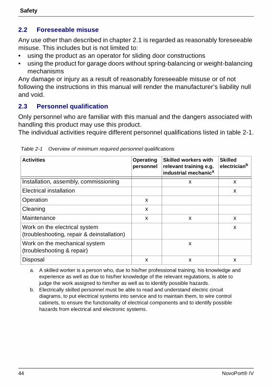
Only personnel who are familiar with this manual and the dangers associated with handling this product may use this product.The individual activities require different personnel qualifications listed in table 2-1.
Table 2-1 Overview of minimum required personnel qualifications
Activities Operating personnel
Skilled workers with relevant training e.g. industrial mechanica
a. A skilled worker is a person who, due to his/her professional training, his knowledge and experience as well as due to his/her knowledge of the relevant regulations, is able to judge the work assigned to him/her as well as to identify possible hazards.
Skilled electricianb
b. Electrically skilled personnel must be able to read and understand electric circuit diagrams, to put electrical systems into service and to maintain them, to wire control cabinets, to ensure the functionality of electrical components and to identify possible hazards from electrical and electronic systems.
Installation, assembly, commissioning x x
Electrical installation x
Operation x
Cleaning x
Maintenance x x x
Work on the electrical system (troubleshooting, repair & deinstallation)
x
Work on the mechanical system (troubleshooting & repair)
x
Disposal x x x
44 NovoPort® IV

Safety
2.4 Potential hazards associated with the product
The product has undergone a risk assessment. The product's design and construction, which are based on this risk assessment, correspond to the current state-of-the-art. The product is safe to operate when used as intended. Nevertheless, residual risks remain.
Hazardous voltage!Fatal electric shock when touching live parts. Observe the following safety rules when working on the electrical system:
1. Disconnect from the mains.2. Secure against inadvertent switch-on.3. Verify de-energised state.
• Work on the electrical system may only be performed by skilled electricians or instructed persons working under the direction and supervision of a skilled electrician in accordance with the electrotechnical rules and directives.
Crush and impact hazard at the garage door!During the force learning cycle, the operator automatically learns the normal mechanical force required to open and close the garage door. Force limits are deactivated until the conclusion of the learning cycle. The door movement will not be stopped by an obstruction! • Keep a sufficient distance from the entire path of motion of the
garage door!• Only interrupt the procedure in case of danger.
NovoPort® IV 45
Product description
3 Product description3.1 General product overview
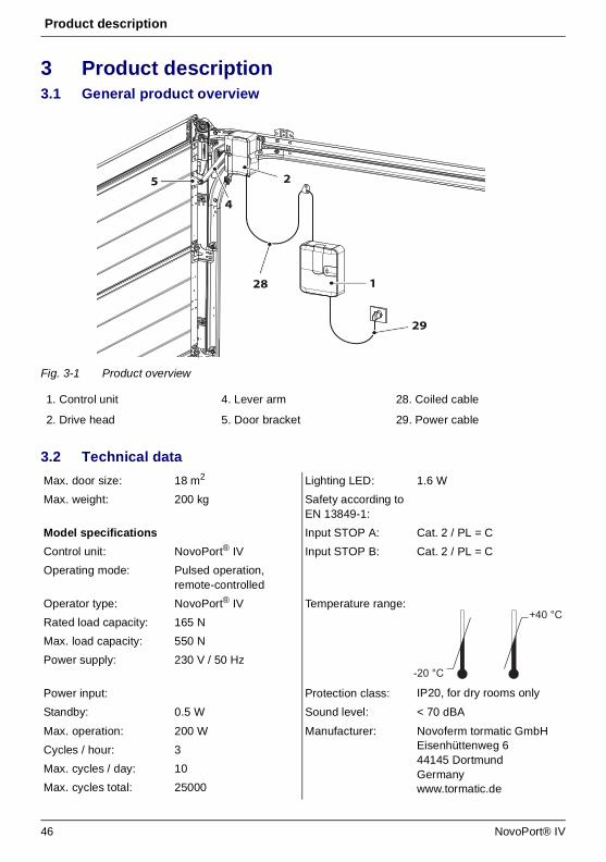
Fig. 3-1 Product overview
3.2 Technical data
1. Control unit 4. Lever arm 28. Coiled cable
2. Drive head 5. Door bracket 29. Power cable
Max. door size: 18 m2 Lighting LED: 1.6 W
Max. weight: 200 kg Safety according to EN 13849-1:
Model specifications Input STOP A: Cat. 2 / PL = C
Control unit: NovoPort® IV Input STOP B: Cat. 2 / PL = C
Operating mode: Pulsed operation, remote-controlled
Operator type: NovoPort® IV Temperature range:
IP20, for dry rooms only
Rated load capacity: 165 N
Max. load capacity: 550 N
Power supply: 230 V / 50 Hz
Power input: Protection class:
Standby: 0.5 W Sound level: < 70 dBA
Max. operation: 200 W Manufacturer: Novoferm tormatic GmbHEisenhüttenweg 644145 DortmundGermanywww.tormatic.de
Cycles / hour: 3
Max. cycles / day: 10
Max. cycles total: 25000
2
28 1
4
29
5
-20 °C
+40 °C
46 NovoPort® IV
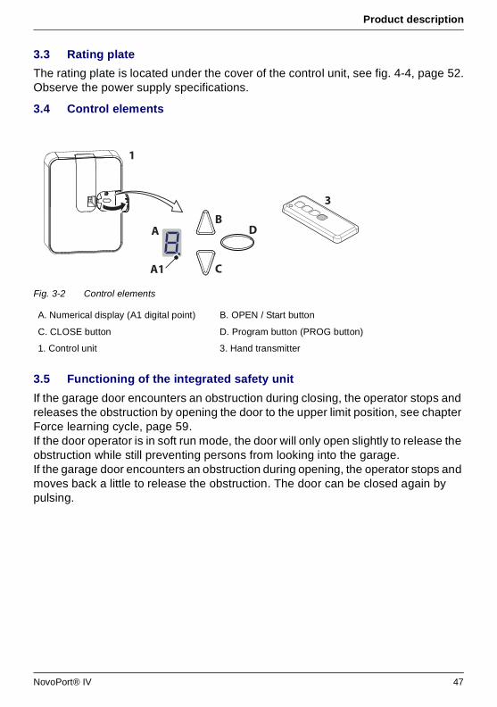
Product description
3.3 Rating plate
The rating plate is located under the cover of the control unit, see fig. 4-4, page 52.Observe the power supply specifications.
3.4 Control elements
Fig. 3-2 Control elements
3.5 Functioning of the integrated safety unit
If the garage door encounters an obstruction during closing, the operator stops and releases the obstruction by opening the door to the upper limit position, see chapter Force learning cycle, page 59.If the door operator is in soft run mode, the door will only open slightly to release the obstruction while still preventing persons from looking into the garage.If the garage door encounters an obstruction during opening, the operator stops and moves back a little to release the obstruction. The door can be closed again by pulsing.
A. Numerical display (A1 digital point) B. OPEN / Start button
C. CLOSE button D. Program button (PROG button)
1. Control unit 3. Hand transmitter
A
C
B
A1
D
3
1
NovoPort® IV 47
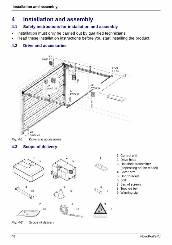
Installation and assembly
4 Installation and assembly4.1 Safety instructions for installation and assembly
• Installation must only be carried out by qualified technicians.• Read these installation instructions before you start installing the product.
4.2 Drive and accessories
Fig. 4-1 Drive and accessories
4.3 Scope of delivery
Fig. 4-2 Scope of delivery
2xAWG 22
2xAWG 22
2xAWG 22
1500
mm
2xAWG 22
2xAWG 22
Y-OB2 x 1,0
9
1x
1 2 31x1x
1x1x4 6
1x
8
1x
7
1x
5
WARNUNG: Automatisches Tor - Nicht im Bewegungsbereich des
Tores aufhalten, da sich das Tor unerwartet in Bewegung setzen kann!
WARNING: Automatic door - The door may operate unexpectedly,
therefore do not allow anything/anyone to stay in the path of the door!
Automatic Door
1. Control unit2. Drive head3. Handheld transmitter
(depending on the model)4. Lever arm5. Door bracket6. Bolt7. Bag of screws8. Toothed belt9. Warning sign
48 NovoPort® IV
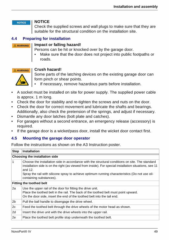
Installation and assembly
4.4 Preparing for installation
• A socket must be installed on site for power supply. The supplied power cable is approx. 1 m long.
• Check the door for stability and re-tighten the screws and nuts on the door.• Check the door for correct movement and lubricate the shafts and bearings.
Additionally, also check the pretension of the springs, and adjust if necessary.• Dismantle any door latches (bolt plate and catches).• For garages without a second entrance, an emergency release (accessory) is
required. • If the garage door is a wicket/pass door, install the wicket door contact first.
4.5 Mounting the garage door operator
Follow the instructions as shown on the A3 Instruction poster.
NOTICECheck the supplied screws and wall plugs to make sure that they are suitable for the structural condition on the installation site.
Impact or falling hazard!Persons can be hit or knocked over by the garage door.• Make sure that the door does not project into public footpaths or
roads.
Crush hazard!Some parts of the latching devices on the existing garage door can form pinch or shear points. • If necessary, remove hazardous parts before installation.
Step Installation
Choosing the installation side
1 Choose the installation side in accordance with the structural conditions on site. The standard installation side is on the right (as viewed from inside). For special installation situations, see 11 and 12. Spray the rail with silicone spray to achieve optimum running characteristics (Do not use oil-containing substances).
Fitting the toothed belt
2a Use the upper rail of the door for fitting the drive unit. Place the toothed belt in the rail. The back of the toothed belt must point upward.On the door side, insert the end of the toothed belt into the tail end.
2b Pull the ball handle to disengage the drive wheel.
2c Feed the toothed belt through the drive wheels of the motor head as shown.
2d Insert the drive unit with the drive wheels into the upper rail.
2e Place the toothed belt profile stop underneath the toothed belt.
NovoPort® IV 49
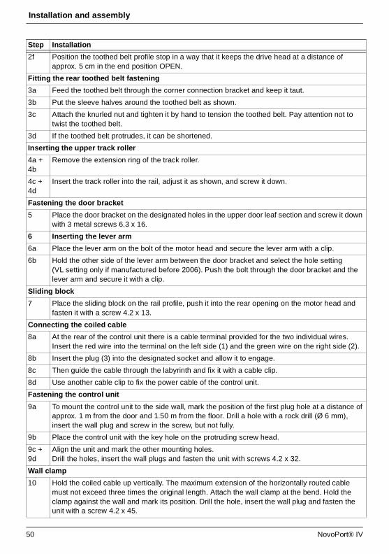
Installation and assembly
2f Position the toothed belt profile stop in a way that it keeps the drive head at a distance of approx. 5 cm in the end position OPEN.
Fitting the rear toothed belt fastening
3a Feed the toothed belt through the corner connection bracket and keep it taut.
3b Put the sleeve halves around the toothed belt as shown.
3c Attach the knurled nut and tighten it by hand to tension the toothed belt. Pay attention not to twist the toothed belt.
3d If the toothed belt protrudes, it can be shortened.
Inserting the upper track roller
4a + 4b
Remove the extension ring of the track roller.
4c + 4d
Insert the track roller into the rail, adjust it as shown, and screw it down.
Fastening the door bracket
5 Place the door bracket on the designated holes in the upper door leaf section and screw it down with 3 metal screws 6.3 x 16.
6 Inserting the lever arm
6a Place the lever arm on the bolt of the motor head and secure the lever arm with a clip.
6b Hold the other side of the lever arm between the door bracket and select the hole setting (VL setting only if manufactured before 2006). Push the bolt through the door bracket and the lever arm and secure it with a clip.
Sliding block
7 Place the sliding block on the rail profile, push it into the rear opening on the motor head and fasten it with a screw 4.2 x 13.
Connecting the coiled cable
8a At the rear of the control unit there is a cable terminal provided for the two individual wires. Insert the red wire into the terminal on the left side (1) and the green wire on the right side (2).
8b Insert the plug (3) into the designated socket and allow it to engage.
8c Then guide the cable through the labyrinth and fix it with a cable clip.
8d Use another cable clip to fix the power cable of the control unit.
Fastening the control unit
9a To mount the control unit to the side wall, mark the position of the first plug hole at a distance of approx. 1 m from the door and 1.50 m from the floor. Drill a hole with a rock drill (Ø 6 mm), insert the wall plug and screw in the screw, but not fully.
9b Place the control unit with the key hole on the protruding screw head.
9c + 9d
Align the unit and mark the other mounting holes. Drill the holes, insert the wall plugs and fasten the unit with screws 4.2 x 32.
Wall clamp
10 Hold the coiled cable up vertically. The maximum extension of the horizontally routed cable must not exceed three times the original length. Attach the wall clamp at the bend. Hold the clamp against the wall and mark its position. Drill the hole, insert the wall plug and fasten the unit with a screw 4.2 x 45.
Step Installation
50 NovoPort® IV
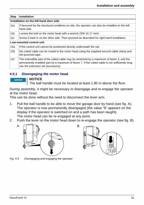
Installation and assembly
4.5.1 Disengaging the motor head
During assembly, it might be necessary to disengage and re-engage the operator at the motor head. This can be done without the need to disconnect the lever arm.
1. Pull the ball handle to be able to move the garage door by hand (see fig. A). The operator is now permanently disengaged (the value “8” appears on the display if the operator is switched on and a path has been taught).The motor head can be re-engaged at any point.
2. Push the lever on the motor head down to re-engage the operator (see fig. B).
Fig. 4-3 Disengaging and engaging the operator
Installation on the left-hand door side
11a If favoured by the structural conditions on site, the operator can also be installed on the left-hand side.
11b Loosen the bolt on the motor head with a wrench (SW 10 17 mm).
11c Screw it back in on the other side. Then proceed as described for right-hand installation.
Low-mounted control unit
12a If the control unit cannot be positioned directly underneath the rail,
12b the coiled cable can be routed to the motor head using the supplied second cable clamp and the punched tape.
12c The extendible part of the coiled cable may be stretched by a maximum of factor 3, and the permanently installed part by a maximum of factor 7. If the coiled cable is not sufficiently long, use the extension set (accessory).
NOTICEThe ball handle must be located at least 1.80 m above the floor.
Step Installation
A B
NovoPort® IV 51
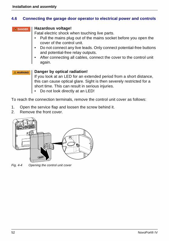
Installation and assembly
4.6 Connecting the garage door operator to electrical power and controls
To reach the connection terminals, remove the control unit cover as follows:
1. Open the service flap and loosen the screw behind it.2. Remove the front cover.
Fig. 4-4 Opening the control unit cover
Hazardous voltage!Fatal electric shock when touching live parts. • Pull the mains plug out of the mains socket before you open the
cover of the control unit.• Do not connect any live leads. Only connect potential-free buttons
and potential-free relay outputs.• After connecting all cables, connect the cover to the control unit
again.
Danger by optical radiation!If you look at an LED for an extended period from a short distance, this can cause optical glare. Sight is then severely restricted for a short time. This can result in serious injuries.• Do not look directly at an LED!
52 NovoPort® IV

Installation and assembly
4.6.1 Connection diagram overview
RELLS 4
1 2 3 4 5
LS 4
1 2
I H G F E
8k2
I H G F E
4
180R
I H G F E
3
8k28k2
I H G F E
2
6
LS 2LS 2
1 2 1 2
5
I H G F E
8k2
I H G F E
24V-
7
8k2
K
230V~
8I H G F E
REL
24V
-
E43U
9
8k2
10
8k2
I H G F EJ
P
K
1
P
NovoPort® IV 53

Installation and assembly
4.6.2 Pulse generator and external safety devices
No. Terminal Description
1 Overview of terminal assignment at the control unit
1 J Plug base for radio receiver
2 E Connector for antenna. When using an external antenna, the shield must be placed on the left adjacent terminal (F).
3 F Connector for external pulse generator (accessories, e.g. key switch or code keypad)
4 G Connection for wicket door contact (accessory) or emergency stopThe drive is stopped or the start-up is suppressed via this input.(see menu H)
5 G / H Connection for photoelectric sensor LS2 (please refer to the connection points of the photoelectric sensor manual for use of other photoelectric sensors)
6 I / H Connection for 4-wire photoelectric sensor (e.g. LS5)This input activates the automatic reversal of the drive during closing.
7 I Connection for e.g. 24 V signal light (accessory)Power supply 24 V DC, max. 100 mA (switched)
8 K Connection for external, protectively insulated lighting or signal lamp (protection class II, max. 500 W) (accessory)
9 F / I Power supply 24 V DC max. 100 mA (permanent)
10 P Connection for Mobility Module (accessory)
Information
In situations of increased requirements in terms of personal protection, we recommend, in addition to the internal power limitation of the drive, the installation of a 2-wire photoelectric sensor. The installation of a 4-wire photoelectric sensor serves purely for the protection of property. For further information on our range of accessories, please refer to our sales literature or consult your specialist dealer.
NOTICEBefore using the operator for the first time, it must be tested to make sure that it is working properly and safely (see chapter Maintenance / Checks, page 74).
54 NovoPort® IV
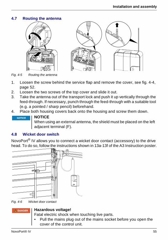
Installation and assembly
4.7 Routing the antenna
Fig. 4-5 Routing the antenna
1. Loosen the screw behind the service flap and remove the cover, see fig. 4-4, page 52.
2. Loosen the two screws of the top cover and slide it out.3. Take the antenna out of the transport lock and push it up vertically through the
feed-through. If necessary, punch through the feed-through with a suitable tool (e.g. a pointed / sharp pencil) beforehand.
4. Place both housing covers back onto the housing and screw them down.
4.8 Wicket door switch
NovoPort® IV allows you to connect a wicket door contact (accessory) to the drive head. To do so, follow the instructions shown in 13a-13f of the A3 Instruction poster.
Fig. 4-6 Wicket door contact
NOTICEWhen using an external antenna, the shield must be placed on the left adjacent terminal (F).
Hazardous voltage!Fatal electric shock when touching live parts. • Pull the mains plug out of the mains socket before you open the
cover of the control unit.
NovoPort® IV 55

Installation and assembly
4.9 Programming the drive head
This section describes the normal programming of the drive head during installation. Programming the control unit is menu-driven. • Pressing button (D) opens the menu. The digit on the display (A) indicates the
menu step. • After approx. 2 seconds, the display (A) starts flashing and the setting can be
changed using buttons (B) and (C). • Press button (D) to save the setting. The programme automatically moves on to
the next menu step. By pressing button (D) repeatedly, you can skip menu steps.
• To quit the menu, press button (D) repeatedly until “0” is displayed again or until the display goes out.
• Outside the menu, button (B) can be used to generate a start pulse.
Information on further and/or special settings can be found in the chapter Special settings, page 60.
4.9.1 Preparation
1. Make sure that the garage door is securely connected to the motor head.2. Make sure that the antenna is correctly positioned (fig. 4-5, page 55).3. Make sure that you have all hand transmitters for this garage door at hand.4. Open the service flap at the control unit.5. Connect the power cable of the control unit to a mains socket. The point
display (A1) lights up.
Step Installation
Wicket door switch
13b Loosen the screws of the cover and remove the cover.
13c Break out the tab on the side of the drive head housing with a pair of pliers.
13d Route the connection cable along the lever arm and attach it with cable ties. Make sure that the cable has sufficient freedom of movement.
13e Connect the cable of the wicket door contact to the second and third position on the terminal block.
13f Put the cover back on the housing and screw it down. (Remove 8k2 resistor from terminal G in the control unit)
Checking Open the wicket door.• The display at the control unit shows “1” if the operator is switched
on.
56 NovoPort® IV
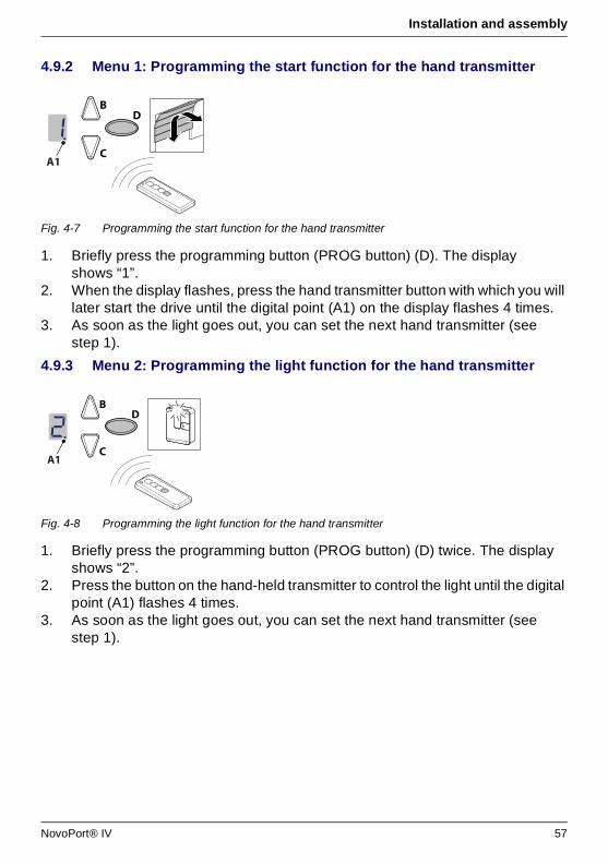
Installation and assembly
4.9.2 Menu 1: Programming the start function for the hand transmitter
Fig. 4-7 Programming the start function for the hand transmitter
1. Briefly press the programming button (PROG button) (D). The display shows “1”.
2. When the display flashes, press the hand transmitter button with which you will later start the drive until the digital point (A1) on the display flashes 4 times.
3. As soon as the light goes out, you can set the next hand transmitter (see step 1).
4.9.3 Menu 2: Programming the light function for the hand transmitter
Fig. 4-8 Programming the light function for the hand transmitter
1. Briefly press the programming button (PROG button) (D) twice. The display shows “2”.
2. Press the button on the hand-held transmitter to control the light until the digital point (A1) flashes 4 times.
3. As soon as the light goes out, you can set the next hand transmitter (see step 1).
C
BD
A1
C
BD
A1
NovoPort® IV 57
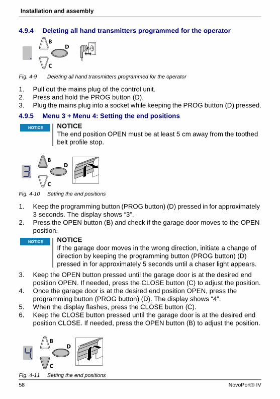
Installation and assembly
4.9.4 Deleting all hand transmitters programmed for the operator
Fig. 4-9 Deleting all hand transmitters programmed for the operator
1. Pull out the mains plug of the control unit.2. Press and hold the PROG button (D).3. Plug the mains plug into a socket while keeping the PROG button (D) pressed.
4.9.5 Menu 3 + Menu 4: Setting the end positions
Fig. 4-10 Setting the end positions
1. Keep the programming button (PROG button) (D) pressed in for approximately 3 seconds. The display shows “3”.
2. Press the OPEN button (B) and check if the garage door moves to the OPEN position.
3. Keep the OPEN button pressed until the garage door is at the desired end position OPEN. If needed, press the CLOSE button (C) to adjust the position.
4. Once the garage door is at the desired end position OPEN, press the programming button (PROG button) (D). The display shows “4”.
5. When the display flashes, press the CLOSE button (C).6. Keep the CLOSE button pressed until the garage door is at the desired end
position CLOSE. If needed, press the OPEN button (B) to adjust the position.
Fig. 4-11 Setting the end positions
NOTICEThe end position OPEN must be at least 5 cm away from the toothed belt profile stop.
NOTICEIf the garage door moves in the wrong direction, initiate a change of direction by keeping the programming button (PROG button) (D) pressed in for approximately 5 seconds until a chaser light appears.
C
BD
C
BD
C
BD
58 NovoPort® IV
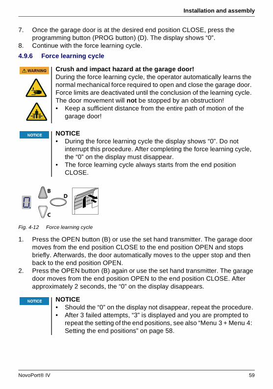
Installation and assembly
7. Once the garage door is at the desired end position CLOSE, press the programming button (PROG button) (D). The display shows “0”.
8. Continue with the force learning cycle.
4.9.6 Force learning cycle
Fig. 4-12 Force learning cycle
1. Press the OPEN button (B) or use the set hand transmitter. The garage door moves from the end position CLOSE to the end position OPEN and stops briefly. Afterwards, the door automatically moves to the upper stop and then back to the end position OPEN.
2. Press the OPEN button (B) again or use the set hand transmitter. The garage door moves from the end position OPEN to the end position CLOSE. After approximately 2 seconds, the “0” on the display disappears.
Crush and impact hazard at the garage door!During the force learning cycle, the operator automatically learns the normal mechanical force required to open and close the garage door. Force limits are deactivated until the conclusion of the learning cycle. The door movement will not be stopped by an obstruction! • Keep a sufficient distance from the entire path of motion of the
garage door!
NOTICE• During the force learning cycle the display shows “0”. Do not
interrupt this procedure. After completing the force learning cycle, the “0” on the display must disappear.
• The force learning cycle always starts from the end position CLOSE.
NOTICE• Should the “0” on the display not disappear, repeat the procedure.• After 3 failed attempts, “3” is displayed and you are prompted to
repeat the setting of the end positions, see also “Menu 3 + Menu 4: Setting the end positions” on page 58.
C
BD
NovoPort® IV 59
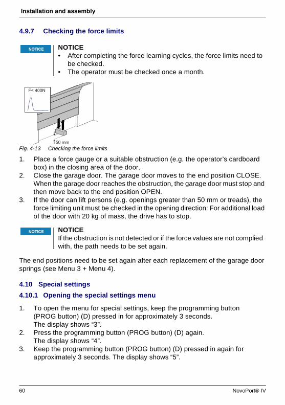
Installation and assembly
4.9.7 Checking the force limits
Fig. 4-13 Checking the force limits
1. Place a force gauge or a suitable obstruction (e.g. the operator’s cardboard box) in the closing area of the door.
2. Close the garage door. The garage door moves to the end position CLOSE. When the garage door reaches the obstruction, the garage door must stop and then move back to the end position OPEN.
3. If the door can lift persons (e.g. openings greater than 50 mm or treads), the force limiting unit must be checked in the opening direction: For additional load of the door with 20 kg of mass, the drive has to stop.
The end positions need to be set again after each replacement of the garage door springs (see Menu 3 + Menu 4).
4.10 Special settings
4.10.1 Opening the special settings menu
1. To open the menu for special settings, keep the programming button (PROG button) (D) pressed in for approximately 3 seconds. The display shows “3”.
2. Press the programming button (PROG button) (D) again. The display shows “4”.
3. Keep the programming button (PROG button) (D) pressed in again for approximately 3 seconds. The display shows “5”.
NOTICE• After completing the force learning cycles, the force limits need to
be checked.• The operator must be checked once a month.
NOTICEIf the obstruction is not detected or if the force values are not complied with, the path needs to be set again.
F< 400N
50 mm
60 NovoPort® IV
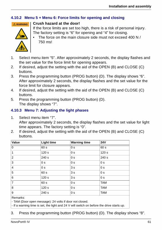
Installation and assembly
4.10.2 Menu 5 + Menu 6: Force limits for opening and closing
1. Select menu item “5”. After approximately 2 seconds, the display flashes and the set value for the force limit for opening appears.
2. If desired, adjust the setting with the aid of the OPEN (B) and CLOSE (C) buttons.
3. Press the programming button (PROG button) (D). The display shows “6”. After approximately 2 seconds, the display flashes and the set value for the force limit for closure appears.
4. If desired, adjust the setting with the aid of the OPEN (B) and CLOSE (C) buttons.
5. Press the programming button (PROG button) (D). The display shows “7”.
4.10.3 Menu 7: Adjusting the light phases
1. Select menu item “7”. After approximately 2 seconds, the display flashes and the set value for light time appears. The factory setting is “0”.
2. If desired, adjust the setting with the aid of the OPEN (B) and CLOSE (C) buttons.
3. Press the programming button (PROG button) (D). The display shows “8”.
Crush hazard at the door!If the force limits are set too high, there is a risk of personal injury.The factory setting is “6” for opening and “4” for closing.• The force on the main closure side must not exceed 400 N /
750 ms!
Value Light time Warning time 24V
0 60 s 0 s 60 s
1 120 s 0 s 120 s
2 240 s 0 s 240 s
3 0 s 0 s 0 s
4 0 s 3 s 0 s
5 60 s 3 s 0 s
6 120 s 3 s 0 s
7 60 s 0 s TAM
8 120 s 0 s TAM
9 240 s 0 s TAM
Remarks:- TAM (Door open message): 24 volts if door not closed.- If a warning time is set, the light and 24 V will switch on before the drive starts up.
NovoPort® IV 61
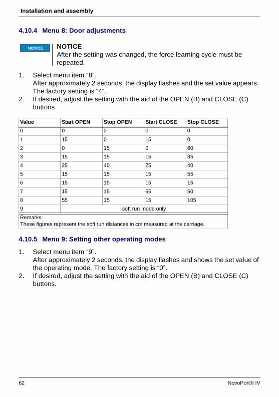
Installation and assembly
4.10.4 Menu 8: Door adjustments
1. Select menu item “8”. After approximately 2 seconds, the display flashes and the set value appears. The factory setting is “4”.
2. If desired, adjust the setting with the aid of the OPEN (B) and CLOSE (C) buttons.
4.10.5 Menu 9: Setting other operating modes
1. Select menu item “9”. After approximately 2 seconds, the display flashes and shows the set value of the operating mode. The factory setting is “0”.
2. If desired, adjust the setting with the aid of the OPEN (B) and CLOSE (C) buttons.
NOTICEAfter the setting was changed, the force learning cycle must be repeated.
Value Start OPEN Stop OPEN Start CLOSE Stop CLOSE
0 0 0 0 0
1 15 0 15 0
2 0 15 0 60
3 15 15 15 35
4 25 40 25 40
5 15 15 15 55
6 15 15 15 15
7 15 15 65 50
8 55 15 15 105
9 soft run mode only
Remarks:These figures represent the soft run distances in cm measured at the carriage.
62 NovoPort® IV

Installation and assembly
4.10.6 Menu H: STOP-A settings
1. Select menu item “H”. After approximately 2 seconds, the display flashes and shows the set value of the operating mode. The factory setting is “0”.
2. If desired, adjust the setting with the aid of the OPEN (B) and CLOSE (C) buttons.
4.11 TTZ guideline - Burglar resistance for garage doors
4.11.1 Enabling burglar resistance
To enable burglar resistance, proceed as follows:
1. Turn the ball handle so that the pull cord sits in the ball handle's groove.2. Pull the ball handle off the pull cord as shown below.
Burglar resistance is now enabled.
Fig. 4-14 Enabling burglar resistance
Value Description Remarks
0 Normal operation Factory settings
1 Normal operation with ventilation settings*
Allows the ventilation of the garage. In this mode, the garage door is approximately 10 cm wide open. To start up the ventilation setting, press the second button on the hand transmitter or use a DuoControl/Signal 111 (accessories) setting* that must be programmed in Menu 2. The garage door can be closed at any time using the hand transmitter. The garage door closes automatically after 60 minutes.
2 Normal operation with partial opening*
In this mode, the garage door is approximately 1 m wide open. To start up the partial opening, press the second button on the hand transmitter or use a DuoControl/Signal 111 (accessories) setting* that must be programmed in Menu 2.
Remarks:* : The second button of the transmitter must be reset after changes in operating modes 1 or 2.
Value Description Remarks
0 ENS-S 8200 connected to STOP-A input (terminal G)
1 Jumper or ENS-S 1000 connected to STOP-A input (terminal G)
NovoPort® IV 63

Installation and assembly
4.11.2 Disabling burglar resistance
To disable burglar resistance, proceed as follows:
1. Place the ball handle on the pull cord so that the pull cords sits in the groove.2. Slide the ball handle down along the pull cord until the end of the pull cord locks
into place in the ball handle.
Fig. 4-15 Disabling burglar resistance
4.12 Completing the installation procedure
Check if the garage door operates properly and safely. See chapter Maintenance / Checks, page 74.
4.13 Attaching the warning sticker
Place the sticker clearly visible on the inner surface of the garage door.
Fig. 4-16 Attaching the warning sticker
WARNUNG: Automatisches Tor - Nicht im Bewegungsbereich des
Tores aufhalten, da sich das Tor unerwartet in Bewegung setzen kann!
WARNING: Automatic door - The door may operate unexpectedly,
therefore do not allow anything/anyone to stay in the path of the door!
Automatic Door
WARNUNG: Automatisches Tor - Nicht im Bewegungsbereich des Tores aufhalten, da sich das Tor unerwartet in Bewegung setzen kann.WARNING: Automatic door - The door may operate unexpectedly, therefore do not allow anything/anyone to stay in the path of the door.
64 NovoPort® IV
Operation
5 Operation5.1 Safety instructions for operation
Observe the following safety instructions for operation:• Use only by trained persons. • All users must be familiar with the applicable safety regulations.• Comply with the accident prevention regulations and general safety regulations
relevant to the field of application.• Keep hand transmitters out of reach of children.
5.2 Opening or closing the garage door (in normal operation mode)
The garage door can be operated by different devices (hand transmitter, key switch etc.). This description only mentions the hand transmitter. Other devices work in the same way.
1. Briefly press the button on the hand transmitter. Depending on the current position, the garage door then moves to the OPEN or CLOSE position.
2. If needed, briefly press the button on the hand transmitter to stop the movement of the garage door.
3. If needed, press the button on the hand transmitter once again to make the garage door move in the other direction.
5.3 Manually opening or closing the garage door
Impact and crush hazard due to the door movement!When the drive is actuated, the opening and closing processes must be monitored.• The garage door must be visible from the place of operation. • Make sure that no persons or objects are in the travel path of the
garage door.
Information
A button on the hand transmitter can be set with the function “4-minute light”. By using the hand transmitter the light will be turned on, independently from the drive unit. After 4 minutes the light will be turned off.
Impact and crush hazard due to uncontrolled door movement!By using the quick release uncontrolled movements of the garage door are possible. The garage door may be out of balance or the springs might be broken or worn. • Please consult your dealer or manufacturer.
NovoPort® IV 65
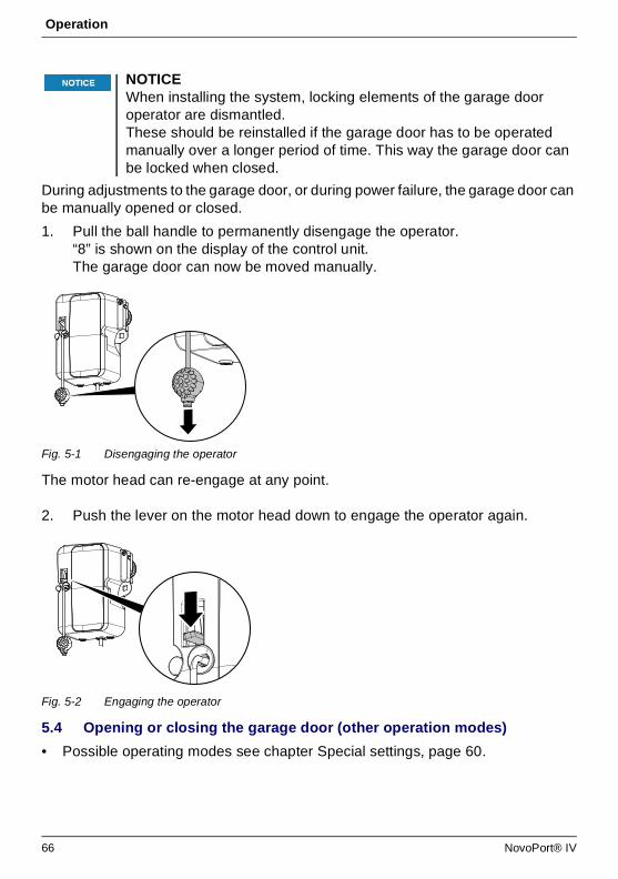
Operation
During adjustments to the garage door, or during power failure, the garage door can be manually opened or closed.
1. Pull the ball handle to permanently disengage the operator.“8” is shown on the display of the control unit.The garage door can now be moved manually.
Fig. 5-1 Disengaging the operator
The motor head can re-engage at any point.
2. Push the lever on the motor head down to engage the operator again.
Fig. 5-2 Engaging the operator
5.4 Opening or closing the garage door (other operation modes)
• Possible operating modes see chapter Special settings, page 60.
NOTICEWhen installing the system, locking elements of the garage door operator are dismantled. These should be reinstalled if the garage door has to be operated manually over a longer period of time. This way the garage door can be locked when closed.
66 NovoPort® IV
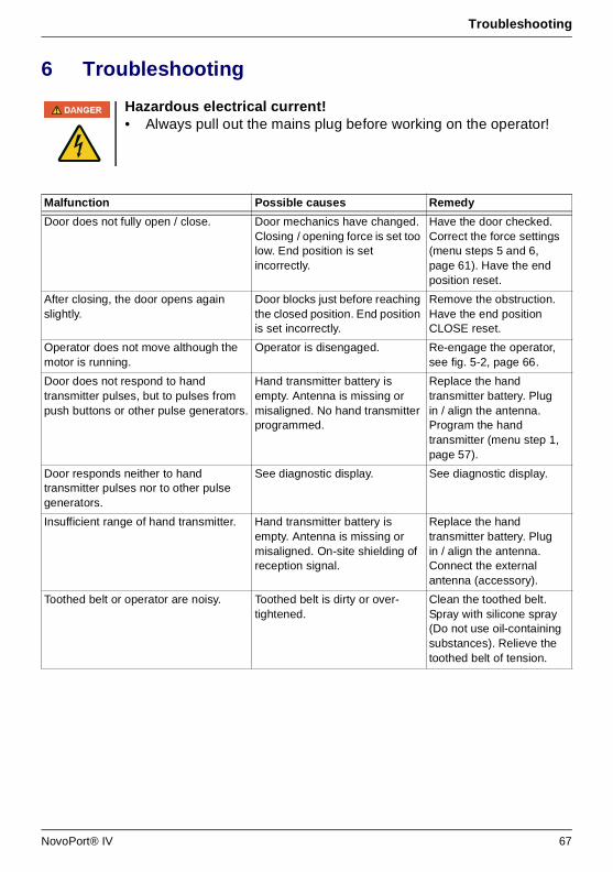
Troubleshooting
NovoPort® IV 67
6 Troubleshooting
Hazardous electrical current!• Always pull out the mains plug before working on the operator!
Malfunction Possible causes Remedy
Door does not fully open / close. Door mechanics have changed. Closing / opening force is set too low. End position is set incorrectly.
Have the door checked. Correct the force settings (menu steps 5 and 6, page 61). Have the end position reset.
After closing, the door opens again slightly.
Door blocks just before reaching the closed position. End position is set incorrectly.
Remove the obstruction. Have the end position CLOSE reset.
Operator does not move although the motor is running.
Operator is disengaged. Re-engage the operator, see fig. 5-2, page 66.
Door does not respond to hand transmitter pulses, but to pulses from push buttons or other pulse generators.
Hand transmitter battery is empty. Antenna is missing or misaligned. No hand transmitter programmed.
Replace the hand transmitter battery. Plug in / align the antenna. Program the hand transmitter (menu step 1, page 57).
Door responds neither to hand transmitter pulses nor to other pulse generators.
See diagnostic display. See diagnostic display.
Insufficient range of hand transmitter. Hand transmitter battery is empty. Antenna is missing or misaligned. On-site shielding of reception signal.
Replace the hand transmitter battery. Plug in / align the antenna. Connect the external antenna (accessory).
Toothed belt or operator are noisy. Toothed belt is dirty or over-tightened.
Clean the toothed belt. Spray with silicone spray (Do not use oil-containing substances). Relieve the toothed belt of tension.
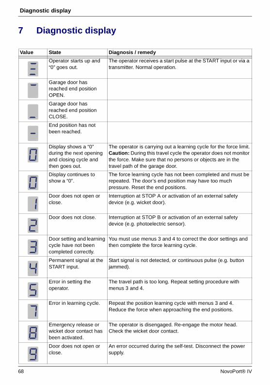
Diagnostic display
7 Diagnostic display
Value State Diagnosis / remedy
Operator starts up and “0” goes out.
The operator receives a start pulse at the START input or via a transmitter. Normal operation.
Garage door has reached end position OPEN.
Garage door has reached end position CLOSE.
End position has not been reached.
Display shows a “0” during the next opening and closing cycle and then goes out.
The operator is carrying out a learning cycle for the force limit.Caution: During this travel cycle the operator does not monitor the force. Make sure that no persons or objects are in the travel path of the garage door.
Display continues to show a “0”.
The force learning cycle has not been completed and must be repeated. The door’s end position may have too much pressure. Reset the end positions.
Door does not open or close.
Interruption at STOP A or activation of an external safety device (e.g. wicket door).
Door does not close. Interruption at STOP B or activation of an external safety device (e.g. photoelectric sensor).
Door setting and learning cycle have not been completed correctly.
You must use menus 3 and 4 to correct the door settings and then complete the force learning cycle.
Permanent signal at the START input.
Start signal is not detected, or continuous pulse (e.g. button jammed).
Error in setting the operator.
The travel path is too long. Repeat setting procedure with menus 3 and 4.
Error in learning cycle. Repeat the position learning cycle with menus 3 and 4. Reduce the force when approaching the end positions.
Emergency release or wicket door contact has been activated.
The operator is disengaged. Re-engage the motor head. Check the wicket door contact.
Door does not open or close.
An error occurred during the self-test. Disconnect the power supply.
68 NovoPort® IV
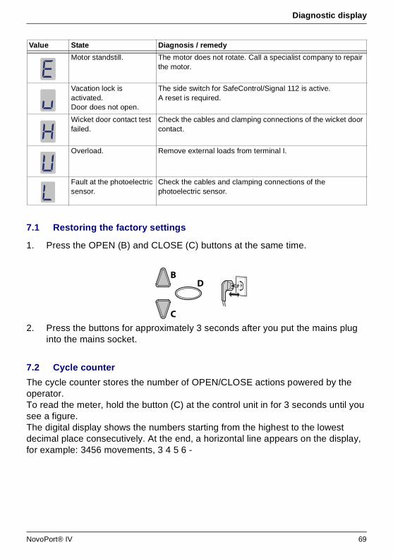
Diagnostic display
7.1 Restoring the factory settings
1. Press the OPEN (B) and CLOSE (C) buttons at the same time.
2. Press the buttons for approximately 3 seconds after you put the mains plug into the mains socket.
7.2 Cycle counter
The cycle counter stores the number of OPEN/CLOSE actions powered by the operator.To read the meter, hold the button (C) at the control unit in for 3 seconds until you see a figure.The digital display shows the numbers starting from the highest to the lowest decimal place consecutively. At the end, a horizontal line appears on the display, for example: 3456 movements, 3 4 5 6 -
Motor standstill. The motor does not rotate. Call a specialist company to repair the motor.
Vacation lock is activated.Door does not open.
The side switch for SafeControl/Signal 112 is active.A reset is required.
Wicket door contact test failed.
Check the cables and clamping connections of the wicket door contact.
Overload. Remove external loads from terminal I.
Fault at the photoelectric sensor.
Check the cables and clamping connections of the photoelectric sensor.
Value State Diagnosis / remedy
C
BD
NovoPort® IV 69
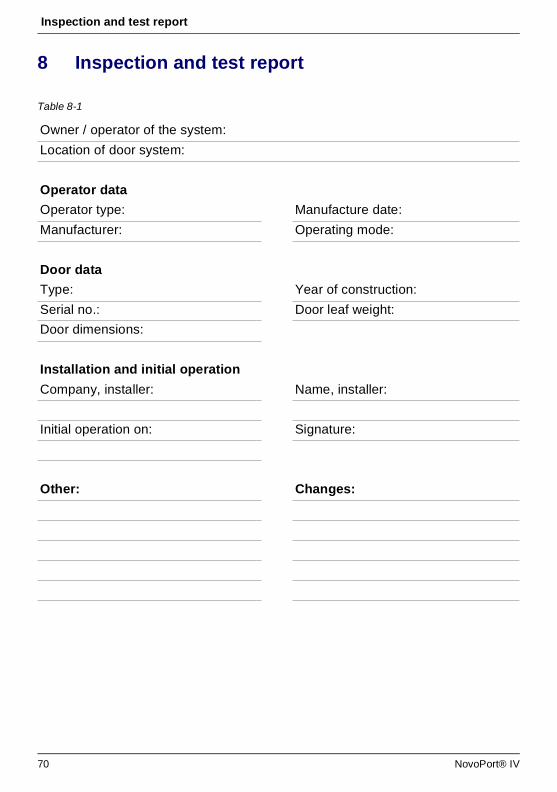
Inspection and test report
8 Inspection and test report
Table 8-1
Owner / operator of the system:
Location of door system:
Operator data
Operator type: Manufacture date:
Manufacturer: Operating mode:
Door data
Type: Year of construction:
Serial no.: Door leaf weight:
Door dimensions:
Installation and initial operation
Company, installer: Name, installer:
Initial operation on: Signature:
Other: Changes:
70 NovoPort® IV

Inspection and test report
8.1 Testing of the garage door operator
• Drive-controlled garage doors are to be inspected and maintained periodically by qualified, trained and experienced personnel.
• The manufacturer's specified inspection and maintenance intervals must be observed.
• Observe all applicable national regulations (ASR 1.7 ‘Technical Regulations for Workplaces - doors and gates’).
• All inspection and maintenance work must be documented in the enclosed inspection and test report.
• The operator/owner is obliged to store the inspection and test report together with the documentation for the garage door operator for the entire service life of the system.
• The installer must fill out the log book completely and give it to the operator/owner before the operator/owner puts the system into service. This recommendation includes manually operated doors.
• All guidelines and instructions for the garage door operator (installation, operation and maintenance, etc.) must be strictly followed.
• The manufacturer’s guarantee becomes null and void in the event that inspection/maintenance has not been carried out.
• Alterations to the garage door operator (in as far as permitted) must also be documented.
NOTICEAn inspection is not the same as maintenance! After an inspection, the user must do any necessary maintenance.
NovoPort® IV 71

Checklists
9 Checklists9.1 Checklist for door system
Confirm features at start-up with a check mark.
No. Equipment Present? Features to be tested Remarks
1.0 Garage door
1.1 Manual opening and closing Smooth running
1.2 Fastenings / connections State / seat
1.3 Pivots / joints State / lubrication
1.4 Track rollers / track roller holders State / lubrication
1.5 Seals / sliding contact strips State / seat
1.6 Door frame / door guide Alignment / fastening
1.7 Door leaf Alignment / state
2.0 Weight
2.1 Springs State / seat / setting
2.1.1 Spring strips State
2.1.2 Spring break device State / rating plate
2.1.3 Safety elements (spring connector,…) State / seat
2.2 Wire cables State / seat
2.2.1 Mounting State / seat
2.2.2 Cable drum
2.3 Fall protection State
2.4 Concentricity of T-shaft State
3.0 Operator / controls
3.1 Operator / rail / bracket
3.2 Electrical cables / connections
3.3 Emergency release Function / state
3.4 Control devices, push buttons / hand transmitters
Function / state
3.5 Limit stop State / position
4.0 Safeguarding of crush and shearing zones
4.1 Force limit Stops and reverses
4.2 Protection against lifting of persons Door leaf stops at 20 kg
4.3 Site conditions Safely distances
5.0 Other equipment
5.1 Latching / lock Function / state
5.2 Wicket door Function / state
72 NovoPort® IV
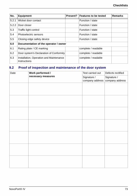
Checklists
9.2 Proof of inspection and maintenance of the door system
5.2.1 Wicket door contact Function / state
5.2.2 Door closer Function / state
5.3 Traffic light control Function / state
5.4 Photoelectric sensors Function / state
5.5 Closing edge safety device Function / state
6.0 Documentation of the operator / owner
6.1 Rating plate / CE marking complete / readable
6.2 Door system’s Declaration of Conformity complete / readable
6.3 Installation, Operation and Maintenance Instructions
complete / readable
Date Work performed / necessary measures
Test carried out Defects rectified
Signature / company address
Signature / company address
No. Equipment Present? Features to be tested Remarks
NovoPort® IV 73
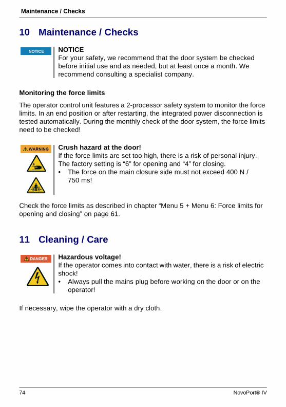
Maintenance / Checks
74 NovoPort® IV
10 Maintenance / Checks
Monitoring the force limits
The operator control unit features a 2-processor safety system to monitor the force limits. In an end position or after restarting, the integrated power disconnection is tested automatically. During the monthly check of the door system, the force limits need to be checked!
Check the force limits as described in chapter “Menu 5 + Menu 6: Force limits for opening and closing” on page 61.
11 Cleaning / Care
If necessary, wipe the operator with a dry cloth.
NOTICEFor your safety, we recommend that the door system be checked before initial use and as needed, but at least once a month. We recommend consulting a specialist company.
Crush hazard at the door!If the force limits are set too high, there is a risk of personal injury.The factory setting is “6” for opening and “4” for closing.• The force on the main closure side must not exceed 400 N /
750 ms!
Hazardous voltage!If the operator comes into contact with water, there is a risk of electric shock!• Always pull the mains plug before working on the door or on the
operator!

Disassembly / disposal
NovoPort® IV 75
12 Disassembly / disposal12.1 Disassembly
Disassembly is carried out in reverse order of the assembly instructions (chapter Installation and assembly, page 48).
12.2 Disposal
For disposal, disassemble the door system and separate it into its individual material groups:• plastics• non-ferrous metals (e.g. copper scrap)• electric scrap (motors)• steelDispose of all materials according to the national legislation!
Dispose of packaging material in an environmentally friendly way and according to the applicable local disposal regulations.
13 Warranty termsPlease note that the scope of the warranty is restricted to private use of the system. We define private use as a maximum of 10 cycles (OPEN/CLOSE) per day.The full text of the warranty terms can be found at: https://www.novoferm.de/garantiebestimmungen
The icon with the crossed-out waste bin on waste electrical or electronic equipment stipulates that this equipment must not be disposed of with the household waste at the end of its life. You will find collection points for free return of waste electrical and electronic equipment in your vicinity. The addresses can be obtained from your municipality or local administration. The separate collection of waste electrical and electronic equipment aims to enable the re-use, recycling and other forms of recovery of waste equipment as well as to prevent negative effects for the environment and human health caused by the disposal of hazardous substances potentially contained in the equipment.
In the European Union, batteries and accumulators must not be treated as domestic waste, but must be disposed of professionally in accordance with Directive 2006/66/EC of the European Parliament and of the Council of 6 September 2006 on batteries and accumulators. Please dispose of batteries and accumulators according to the relevant legal requirements.
Li-Ion
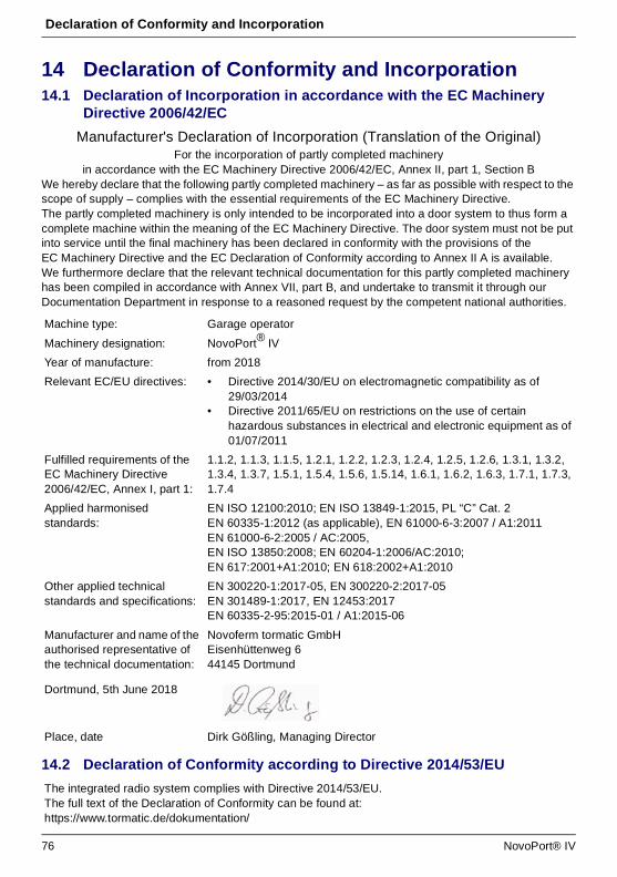
Declaration of Conformity and Incorporation
76 NovoPort® IV
14 Declaration of Conformity and Incorporation14.1 Declaration of Incorporation in accordance with the EC Machinery
Directive 2006/42/EC
Manufacturer's Declaration of Incorporation (Translation of the Original)For the incorporation of partly completed machinery
in accordance with the EC Machinery Directive 2006/42/EC, Annex II, part 1, Section BWe hereby declare that the following partly completed machinery – as far as possible with respect to the scope of supply – complies with the essential requirements of the EC Machinery Directive. The partly completed machinery is only intended to be incorporated into a door system to thus form a complete machine within the meaning of the EC Machinery Directive. The door system must not be put into service until the final machinery has been declared in conformity with the provisions of the EC Machinery Directive and the EC Declaration of Conformity according to Annex II A is available. We furthermore declare that the relevant technical documentation for this partly completed machinery has been compiled in accordance with Annex VII, part B, and undertake to transmit it through our Documentation Department in response to a reasoned request by the competent national authorities.
14.2 Declaration of Conformity according to Directive 2014/53/EU
Machine type: Garage operator
Machinery designation: NovoPort® IV
Year of manufacture: from 2018
Relevant EC/EU directives: • Directive 2014/30/EU on electromagnetic compatibility as of 29/03/2014
• Directive 2011/65/EU on restrictions on the use of certain hazardous substances in electrical and electronic equipment as of 01/07/2011
Fulfilled requirements of the EC Machinery Directive 2006/42/EC, Annex I, part 1:
1.1.2, 1.1.3, 1.1.5, 1.2.1, 1.2.2, 1.2.3, 1.2.4, 1.2.5, 1.2.6, 1.3.1, 1.3.2, 1.3.4, 1.3.7, 1.5.1, 1.5.4, 1.5.6, 1.5.14, 1.6.1, 1.6.2, 1.6.3, 1.7.1, 1.7.3, 1.7.4
Applied harmonised standards:
EN ISO 12100:2010; EN ISO 13849-1:2015, PL “C” Cat. 2EN 60335-1:2012 (as applicable), EN 61000-6-3:2007 / A1:2011 EN 61000-6-2:2005 / AC:2005, EN ISO 13850:2008; EN 60204-1:2006/AC:2010; EN 617:2001+A1:2010; EN 618:2002+A1:2010
Other applied technical standards and specifications:
EN 300220-1:2017-05, EN 300220-2:2017-05EN 301489-1:2017, EN 12453:2017 EN 60335-2-95:2015-01 / A1:2015-06
Manufacturer and name of the authorised representative of the technical documentation:
Novoferm tormatic GmbHEisenhüttenweg 644145 Dortmund
Dortmund, 5th June 2018
Place, date Dirk Gößling, Managing Director
The integrated radio system complies with Directive 2014/53/EU.The full text of the Declaration of Conformity can be found at:https://www.tormatic.de/dokumentation/


![springer.com Fehlzeiten-Report 2018 Sinn erleben - Arbeit ... · CHF und die mit [2] gekennzeichneten Preise für elektronische Produkte sind unverbindliche Preisempfehlungen und](https://img.pdfslide.org/doc/110x75/5d48207b88c99349508b5bb9/fehlzeiten-report-2018-sinn-erleben-arbeit-chf-und-die-mit-2-gekennzeichneten.jpg)