Embed Size (px)
Citation preview
ESPOO 2008 VTT WORKING PAPERS 94
NPP Safety Automation Systems Analysis
State of the Art
Janne Valkonen & Ilkka Karanta VTT Technical Research Centre of Finland
Matti Koskimies, Keijo Heljanko & Ilkka Niemelä Helsinki University of Technology TKK
Dan Sheridan & Robin E. Bloomfield Adelard LLP
ISBN 978-951-38-7158-1 (URL: http://www.vtt.fi/publications/index.jsp) ISSN 1459-7683 (URL: http://www.vtt.fi/publications/index.jsp) Copyright © VTT 2008
JULKAISIJA � UTGIVARE � PUBLISHER
VTT, Vuorimiehentie 3, PL 1000, 02044 VTT puh. vaihde 020 722 111, faksi 020 722 4374
VTT, Bergsmansvägen 3, PB 1000, 02044 VTT tel. växel 020 722 111, fax 020 722 4374
VTT Technical Research Centre of Finland, Vuorimiehentie 5, P.O. Box 1000, FI-02044 VTT, Finland phone internat. +358 20 722 111, fax +358 20 722 4374
VTT, Vuorimiehentie 3, PL 1000, 02044 VTT puh. vaihde 020 722 111, faksi 020 722 6027
VTT, Bergsmansvägen 3, PB 1000, 02044 VTT tel. växel 020 722 111, fax 020 722 6027
VTT Technical Research Centre of Finland, Vuorimiehentie 5, P.O. Box 1000, FI-02044 VTT, Finland phone internat. +358 20 722 111, fax +358 20 722 6027
Series title, number and report code of publication
VTT Working Papers 94 VTT–WORK–94
Author(s) Valkonen, Janne, Karanta, Ilkka, Koskimies, Matti, Heljanko, Keijo, Niemelä, Ilkka, Sheridan, Dan & Bloomfield, Robin E. Title
NPP Safety Automation Systems Analysis State of the Art Abstract This report describes the state of the art of formal methods and models applied in safety evaluation of nuclear and other industrial safety systems. Special attention is drawn to a technique called model checking that is a set of methods for analysing whether a model of a system fulfils its specifications by examining all of its possible behaviours. The report describes the scope and requirements for safety evaluation and introduces typical safety assessment approaches. The Safety Case concept is also described and discussed how it could be combined with model checking.
ISBN 978-951-38-7158-1 (URL: http://www.vtt.fi/publications/index.jsp)
Series title and ISSN Project number VTT Working Papers 1459-7683 (URL: http://www.vtt.fi/publications/index.jsp)
23743
Date Language Pages April 2008 English 62 p.
Name of project Commissioned by MODSAFE
Keywords Publisher model checking, safety automation, safety case, formal verification, programmable logic controller, SAFIR2010
VTT Technical Research Centre of Finland P.O. Box 1000, FI-02044 VTT, Finland Phone internat. +358 20 722 4520 Fax +358 20 722 4374

5
Preface
This report has been prepared under the research project Model-based safety evaluation of automation systems (MODSAFE) which is part of the Finnish Research Programme on Nuclear Power Plant Safety 2007�2010 (SAFIR2010). The aims of the project are to develop methods for model-based safety evaluation, apply the methods in real-istic case studies, evaluate the suitability of formal model checking methods for NPP automation analysis, and to develop recommenda-tions for the practical application of the methods.
The report describes the state of the art of formal methods and models applied in safety evaluation of industrial and nuclear safety systems. The methods are evaluated with respect to their applicability in the analysis of NPP safety automation systems.
Espoo, March 2008,
Authors
Contents
List of Acronyms 8
1 Introduction 101.1 Scope of the Report . . . . . . . . . . . . . . . . . . . . . . . 101.2 NPP Automation Systems . . . . . . . . . . . . . . . . . . . . 101.3 Special Characteristics of the Nuclear Field . . . . . . . . . . 111.4 Structure of the Report . . . . . . . . . . . . . . . . . . . . . 12
2 Safety Assessment Approaches 132.1 Scope and Requirements for Analysis . . . . . . . . . . . . . . 132.2 Reliability analysis . . . . . . . . . . . . . . . . . . . . . . . . 152.3 Failure analysis . . . . . . . . . . . . . . . . . . . . . . . . . . 162.4 Safety Cases . . . . . . . . . . . . . . . . . . . . . . . . . . . . 18
2.4.1 Goal-based safety cases . . . . . . . . . . . . . . . . . 202.4.2 Notation . . . . . . . . . . . . . . . . . . . . . . . . . . 21
2.4.2.1 Claims-Argument-Evidence (CAE) . . . . . . 222.4.2.2 Goal-Structuring Notation (GSN) . . . . . . 22
2.4.3 Safety case formalisms . . . . . . . . . . . . . . . . . . 232.4.3.1 Govier support patterns . . . . . . . . . . . . 232.4.3.2 The Cemsis approach . . . . . . . . . . . . . 242.4.3.3 The Fog approach . . . . . . . . . . . . . . . 25
2.5 Regulatory Perspective . . . . . . . . . . . . . . . . . . . . . . 25
3 Formal Methods for Digital Automation Systems Analysis 283.1 Computer Aided Verification Methods . . . . . . . . . . . . . 28
3.1.1 Model Checking . . . . . . . . . . . . . . . . . . . . . 283.1.2 Deductive Verification . . . . . . . . . . . . . . . . . . 293.1.3 Model-based Testing . . . . . . . . . . . . . . . . . . . 30
3.2 Formal methods for Digital Automation systems . . . . . . . 303.2.1 Classification Criteria for PLC Models . . . . . . . . . 31
3.3 Survey of Studies on Model Checking PLCs . . . . . . . . . . 333.3.1 Previous surveys . . . . . . . . . . . . . . . . . . . . . 333.3.2 Modelling PLC applications . . . . . . . . . . . . . . . 343.3.3 Methods for synthesising PLC programs from models 35
3.4 Overall Status of the Research on Model Checking PLCs . . . 373.5 Previous Approaches to Software and Automation Analysis
(in NPPs) . . . . . . . . . . . . . . . . . . . . . . . . . . . . . 373.5.1 Computer Aided Analysis of Korean and Canadian
NPP Automation Systems . . . . . . . . . . . . . . . . 373.5.2 French approaches . . . . . . . . . . . . . . . . . . . . 38
3.5.2.1 SCADE . . . . . . . . . . . . . . . . . . . . . 383.5.2.2 Caveat . . . . . . . . . . . . . . . . . . . . . 38
6
Preface 5
Contents
3.5.3 BE-SECBS Project . . . . . . . . . . . . . . . . . . . . 393.5.3.1 IRSN’s Methods . . . . . . . . . . . . . . . . 393.5.3.2 ISTec’s Methods . . . . . . . . . . . . . . . . 403.5.3.3 VTT/STUK’s Methods . . . . . . . . . . . . 41
3.5.4 Model Checking Operator Procedures . . . . . . . . . 423.5.5 Adelard’s Methods and Approaches . . . . . . . . . . 43
3.5.5.1 Use of Formalisation of Safety Case Arguments 433.5.5.2 Use of Formalisation in Safety Case Claims . 44
4 Model Checking in Safety Cases 49
5 Conclusions 51
References 52
7
List of Acronyms
ALARP As Low As Reasonably Practicable
ASCAD Adelard Safety Case Development Manual
BMC Bounded Model Checking
CAE Claims-Argument-Evidence
COTS Commercial Off-The-Shelf
DCS Distributed Control System
FBD Function Block Diagram
FMEA Failure Mode and Effects Analysis
GSN Goal-Structuring Notation
HAZOP Hazard and Operability Analysis
HMI Human-Machine Interface
I&C Instrumentation and Control
IFE Institute for Energy Technology (Norway)
IL Instruction List
IRSN Institute for Radiological Protection and Nuclear Safety (France)
ISTec Institute for Safety Technology (Germany)
LD Ladder Diagram
MTTF Mean Time To Failure
NPP Nuclear Power Plant
(O)BDD (Ordered) Binary Decision Diagram
OTS Off-The-Shelf
PLC Programmable Logic Controller
PSA Probabilistic Safety Analysis
QA QA Technology Company, Inc.
QAC C compiler by QA company
RETRANS REverse TRAnsformation of Normed Source code
8

SAT Propositional Satisfiability
SCA Software Criticality Analysis
SFC Sequential Function Chart
SMV Simple Model Verifier
ST Structured Text
STUK The Finnish Radiation and Nuclear Safety Authority
VTT Technical Research Centre of Finland
9
1 Introduction
1.1 Scope of the Report
This report is part of yearly reporting in the MODSAFE (Model-based safetyevaluation of automation systems) project which belongs to the Finnish Na-tional Research Programme on NPP Safety 2007–2010. The report describesthe state of the art of formal methods and models applied in safety evaluationof industrial and nuclear safety systems. The methods are evaluated withrespect to their applicability in the analysis of NPP safety automation sys-tems. Special attention is drawn to a technique called model checking [40],which is a set of methods for analysing whether a model of a system fulfilsits specification by examining all of its possible behaviours. The compati-bility of the methods with the practices and models used in different phasesof NPP safety automation design is also an important issue.
The basic objective of licensing safety critical systems is to assess if theyare adequately safe and if not, what are the reasons for that and what canbe done to achieve the required level of safety. Licencing process includescollecting evidence supporting the safety claims of the system under con-sideration, and based on this evidence assessing the achieved safety of thesystem. That is why safety cases and the role of model checking in the NPPautomation safety case creation are discussed in the report. The report aimsat giving an introduction to the research area with a large number of ref-erences to be used in more detailed investigation of the topics introducedhere.
1.2 NPP Automation Systems
Instrumentation and Control (I&C) systems play a crucial role in the opera-tion of a nuclear power plant. The most important tasks of I&C systems areto control and supervise processes inside the power plant and the interfaceswith the operators. The control and supervising tasks are performed withhuman interactions or automatically according to predetermined rules.
The main objectives of I&C systems in nuclear power plants are to ensuresafety, availability and performance of the plant. The following definitionsare based mostly on [65]. Nuclear safety means the achievement of properoperating conditions, prevention of accidents or mitigation of accident con-sequences, resulting in protection of workers in the plant, the public and theenvironment from undue radiation hazards. Availability is the fraction oftime for which a system is capable of fulfilling its intended purpose. Reli-ability represents essentially the same information, but in a different form:reliability is the probability that a system or a component will meet its min-imum performance requirements when called upon to do so. Performancemeans the accomplishment of a task in accordance with a set standard ofcompleteness and accuracy.
10
The requirements for I&C systems are derived from the main objectives(listed above) and they are presented as functional and technical require-ments. As [116] describes, functional requirements are implemented by theI&C systems. The protection functions prevent systems and process com-ponents from damages, the interlocking functions prevent unwanted opera-tional conditions of process, the closed loop controls keep process parameterswithin predefined limits, and the automatic start and shutdown processesand the measurement functions acquire process values and present them inthe control room. Technical requirements influence mostly on the selection,design and implementation of equipment.
I&C systems need lots of information from the process itself and alsofrom control commands. This information is provided by different kindsof measurements or measuring systems. The HMI (Human-Machine Inter-action) is realised through different types of indicators, push buttons andcomputer workstations in control rooms.
1.3 Special Characteristics of the Nuclear Field
There are many characteristics making the nuclear field different from othersafety critical industries. [112] lists several of them. The most important oneis the fact that it is not enough to have a safe nuclear installation, but it alsohas to be proved to the licensing authorities that the installation really issafe and meets all the necessary requirements. One special characteristic inthe nuclear field is the concept of defence in depth. Defence in depth meansseveral levels of protection, ensuring that if a failure were to occur, it wouldbe detected and the release of radioactive material to the environment wouldbe prevented. The concept has been described in several nuclear relateddocuments (e.g., [64]) and it is applied to all safety activities: organisational,behavioural and design related. Defence in depth helps to preserve the threebasic safety functions (controlling the power, cooling the fuel and confiningthe radioactive material), and ensures that radioactive materials do notreach people or the environment. Defence in depth helps to achieve higherreliability with unreliable components. In a more concrete level, it relies onredundancy, separation and diversity, which aim to ensure that no singlefailure will pose a threat to safety.
Guide YVL 5.5 “Instrumentation systems and components at nuclear fa-cilities” [102] says that “With the testing and analyses it shall also be ensuredthat there are no unintentional functions in the system or its equipment thatcould be detrimental for safety.” The principle of defence in depth shouldbe used to provide sufficient proofs that I&C will follow YVL 5.5, meaningthat the system provides all intended and no unintended functions. How-ever, the hardware and software platforms used for I&C are complex, andproving the absence of unintended functions is almost impossible because itis always possible to argue that design errors in the hardware and software
11
platforms may cause simultaneous failures of several critical functions [112].In this context an unintentional function is one that is unnecessary for theactual functioning of a system or piece of equipment. Functions not requiredfor accomplishing a task, but whose safety significance has been analysedand considered in system design, are not unintentional [102].
The I&C systems of the first generation NPPs were based on analoguetechnology. Now the trend is to start using digital I&C systems with pro-grammable logic controllers. The increasing shortage of suitable spare partsfor analogue systems is also accelerating the transfer towards digitalisedsystems.
One important characteristic differentiating nuclear power plants fromconventional industry is their very long life-cycles. Nuclear power plantswere typically designed to operate forty years and nowadays it is commonto apply for a lifetime extension of twenty years or so. This usually in-cludes renewals and upgrades of some systems. As information technologyand computers are developing rapidly, the lifetime of a typical computeror software is usually less than five years, sometimes even less than threeyears. Comparing the huge difference between the lifetimes of the plant anda typical computer brings up the fact that the computer systems in NPPshave to be upgraded a several times during the lifetime of a plant.
1.4 Structure of the Report
Section 2 introduces some safety assessment approaches and explains theessentials of safety cases. The scope of making safety evaluations is alsodiscussed along with sketching the different system levels which can be thetarget of evaluation. Section 3 describes formal methods for digital automa-tion systems analysis. Some previous approaches and experiences from bothresearch and regulatory perspectives are introduced as well. Section 5 sumsup the report with conclusions and discussions.
12
2 Safety Assessment Approaches
2.1 Scope and Requirements for Analysis
Safety analysis is difficult, labour- and knowledge-intensive work that canbenefit from computerised support tools in several ways, such as reducingthe time and effort involved in the analysis and keeping track of the sys-tem’s analysed parts and their relationships. Following [56], the evidencedemonstrating the acceptability of any safety related system can be dividedinto a) evidence addressing the quality of the development process and b)evidence addressing the quality of the product.
The quality of the system development process, testing, and analysisof products are typical parts of system safety assessment. [94] suggeststhat the safety assessment rests on a tripod made up of testing, analysis,and a certification of the personnel and the production process. In everycase, the use of several methods in safety assessment is a significant andpositive aspect, and will naturally lead to a more realistic safety estimatethan putting one’s faith on a single method [56].
One type of analysis is testing, which can show the presence of bugs.However, testing is not practical for showing that software is free from de-sign errors. In the design phase of system or software development, sim-ulation can be used to show presence of desired behaviour, but simulationdoes not cover all situations and possible behaviours. Instead, a techniquecalled model checking can provide convincing evidence that the system de-sign under inspection has or has not certain behaviour (model checking isintroduced in Section 3.1.1).
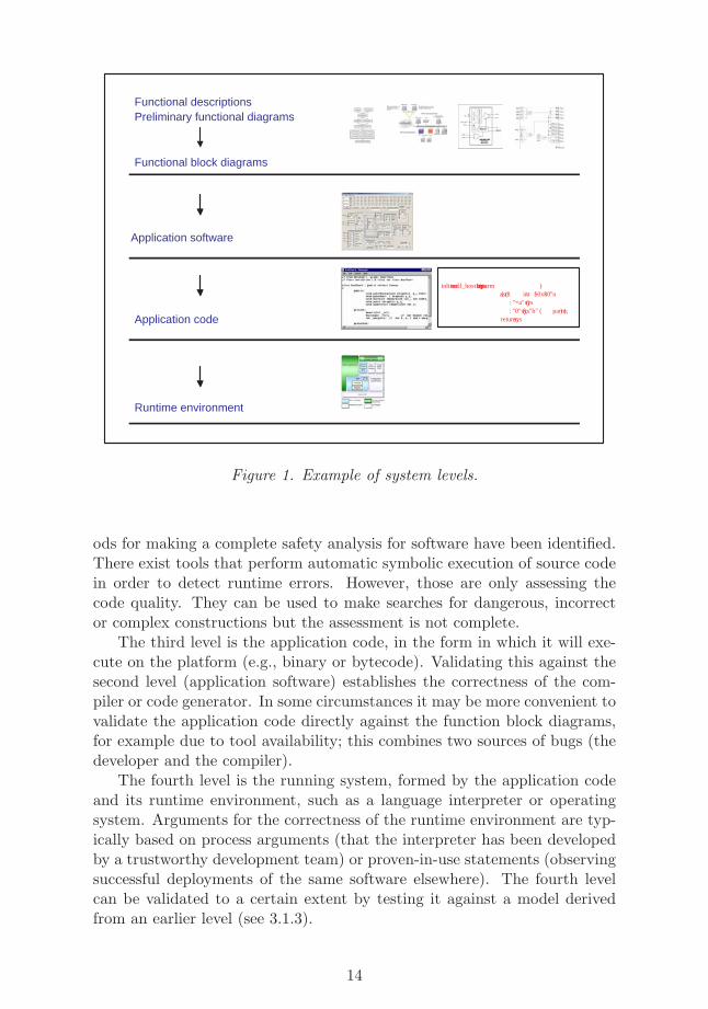
Figure 1 below presents an example of possible “levels” at which a systemcan be analysed, and at which a safety assessment of I&C systems canbe performed. On the first level, the system specifications, starting fromfunctional descriptions and diagrams acting as requirements, are developedinto more detailed specifications and designs. This results in production offunction block diagrams – a more rigorous way of specifying the behaviour.The increasingly growing complexity in design may be achieved by startingwith the main functions of the system and adding more specific details,redundant channels, voting units etc. little by little. One target of earlyphase safety analysis is the validation of function block diagram descriptionsbefore the development gets to the implementation level.
The second level of the system is the application software, in the formin which it is developed (e.g., source code). This may be validated for-mally against the function block diagrams or informally against the originalrequirements. This validation exercise determines whether the developerhas correctly transformed the requirements into the software design, im-plementing all of the required functionality without introducing unintendedbehaviours. This is a very challenging task, and so far no suitable meth-
13
Functional descriptions Preliminary functional diagrams
Functional block diagrams
Application code
Runtime environment
Application software
inline int call_host1( int sys , int parm ) { asm (" int \ $0x80 \ n ”
: "=a" ( sys ) : "0" ( sys ), "b" ( parm ) );
return sys ;
Figure 1. Example of system levels.
ods for making a complete safety analysis for software have been identified.There exist tools that perform automatic symbolic execution of source codein order to detect runtime errors. However, those are only assessing thecode quality. They can be used to make searches for dangerous, incorrector complex constructions but the assessment is not complete.
The third level is the application code, in the form in which it will exe-cute on the platform (e.g., binary or bytecode). Validating this against thesecond level (application software) establishes the correctness of the com-piler or code generator. In some circumstances it may be more convenient tovalidate the application code directly against the function block diagrams,for example due to tool availability; this combines two sources of bugs (thedeveloper and the compiler).
The fourth level is the running system, formed by the application codeand its runtime environment, such as a language interpreter or operatingsystem. Arguments for the correctness of the runtime environment are typ-ically based on process arguments (that the interpreter has been developedby a trustworthy development team) or proven-in-use statements (observingsuccessful deployments of the same software elsewhere). The fourth levelcan be validated to a certain extent by testing it against a model derivedfrom an earlier level (see 3.1.3).
14
2.2 Reliability analysis
Reliability can be defined as:The ability of an item to perform a required function, under given environ-mental and operational conditions and for a stated period of time [68].
Reliability has been the subject of scientific study since 1930’s. Struc-tural reliability analysis concentrates on structural elements such as beamsand bridges using the methods of mechanics and strength of materials, andwill not be considered further here. In the actuarial approach [10] to reli-ability analysis, all information about the object system is included in theprobability distribution function F (t) of the time to failure T (the time in-terval from the present to the next failure of the system); the aim of theanalysis is to obtain a good estimate of this function. When the systemunder consideration consists of several components, the analysis is calledsystem reliability analysis.
Any complex technological system consists of three main types of com-ponents:
• Hardware: this has long been the main subject of study in reliabilitytheory.
• Software: this has several distinguishing characteristics that renderreliability methods developed for hardware components meaningless.For example, the reliability of a software component does not deteri-orate with age, but rather stays the same once the software has beenupdated; the uniqueness of each piece of software makes the reliabilitydata of earlier versions mostly meaningless in considering the relia-bility of a piece of software; software errors manifest themselves onlyunder particular conditions.
• Human: in particular, considering the effects of limited rationality andperception; considering the effects of stress and fatigue; etc.
In addition to the above three types, environmental conditions and re-liability of structures (weather, earthquakes, buildings, dams, etc.) have tobe taken into account. This report will not consider either human reliabilityanalysis or the environmental conditions.
The reliability of complex systems is often analysed with the help of afault tree or an event tree. A fault tree is a presentation of the various faultsin the system and how they (may) lead to system failure when combined.An event tree is a presentation of sequences of events that lead to a failure.A branching in the tree corresponds to points where events can take morethan one course.
15
Some active research areas in the field are common cause failures (whereone event, e.g. a fire, can cause several faults, e.g. burning of electric ca-bles and leakage of pipes); restricting the number of events in event treesto avoid combinatorial explosion; human reliability; reliability of digital sys-tems; elicitation and incorporation of expert opinions to the analyses; andthe use of reliability analyses in decision making.
In the following, a commonly used method for risk-based decision making– failure modes and effects analysis (section 2.3) – is briefly described. Thereare other methods such as:
• Pareto analysis: this is a prioritisation technique that identifies themost significant items among many.
• Checklist analysis: here, the risks related to a system or operation areevaluated in the light of a preconstructed checklist.
• Change analysis: it looks systematically for possible risk impacts andappropriate risk management strategies in situations where a change isoccurring. This includes situations in which system configurations arealtered, operating practices or policies are changed, new or differentactivities will be performed, etc.
• What-if analysis: it is a brainstorming approach that uses broad,loosely structured questioning to postulate potential upsets that mayresult in accidents or system performance problems, and ensure thatappropriate safeguards against those problems are in place.
• HAZOP: a systematic qualitative process in which a multi-disciplineteam performs a systematic study of a process using guide words todiscover how deviations from the design intent can occur in equipment,actions, or materials, and whether the consequences of these deviationscan result in a hazard. It focuses on identifying single failures that canresult in accidents of interest. It is most commonly used to identifysafety hazards and operability problems of continuous processes.
2.3 Failure analysis
Failure modes and effects analysis (FMEA) is a qualitative analysis that isoften carried out before probabilistic risk analysis. Failure mode refers tothe way a failure might occur, e.g. the failure of a valve to prevent flowor a leak of the valve. Failure effect is the consequence of failure from thesystem’s (or customer’s) point of view, e.g., lack of flow in a pipe.
FMEA is often carried out early in the development life cycle to findways of mitigating failures and thereby enhancing reliability through design;in this case, coarse probability estimates for the failure causes and effectsare usually derived. However, for the purposes of this report, FMEA is
16
considered as part of reliability and risk analysis, and in that context it is apurely qualitative technique. FMEA consists of the following tasks:
• Potential failure modes are identified. It is not possible to anticipateevery mode that a component etc. might fail, but as many modes aspossible are identified.
• Their effects on the operation of the system are determined.
• Actions to mitigate the failures are identified.
FMEA’s may be carried out from many perspectives, the following beingthe most common:
• System: the focus is on global system functions.
• Design: the focus is on components and subsystems.
• Process: the focus is on manufacturing and assembly.
• Service: the focus is on service and maintenance.
• Software: the focus is on the software subsystem functions.
FMEA can be used for different purposes depending on the phase of thedevelopment life cycle:
• Development and evaluation of requirements from reliability point ofview.
• Identification of design characteristics that contribute to failures, thusaiding design.
• Help to develop useful tests to assess reliability.
• Ensure that potential failures will not injure or seriously impact peo-ple.
FMEA consists of the following steps:
• Describe the system (product, process or other) and its function. Thiscovers also the uses of the system, both intentional and unintentional.
• Create a block diagram of the system. This shows the components orsubprocesses of the system as nodes connected by lines that indicatehow the nodes are related logically to each other.
17
• Create a table that lists components of subprocesses, and the failuremodes and effects associated with each. A numerical ranking is as-signed to each failure effect. Also the potential causes of each failuremode should be listed. Also the mechanisms that identify the failureor prevent it from causing system failure should be listed. The ta-ble should also contain a header that identifies the system considered,persons responsible etc.
• The table should be updated on a regular basis during FMEA, bearingin mind that a failure mode in one component may induce a failure inanother.
• Compute risk priority numbers that are the product of failure severity,failure probability and failure detection likelihood (the probability thatthe failure will be detected, given that one has occurred). This andthe following step are not carried out when using FMEA as part ofprobabilistic risk analysis.
• Determine potential actions for failures that have a high risk prioritynumber.
An IEC standard exists for the conduct of FMEA [67].A traditional FMEA uses potential equipment failures as the basis of
analysis. Therefore, human errors and especially those that do not pro-duce equipment failure are often overlooked in FMEA. In FMEA, equipmentfailures are analysed one by one, and therefore important combinations ofequipment failures might be overlooked. Environmental conditions, externalimpacts and other such factors are analysed in FMEA only to the extentthat they produce equipment failures; external influences that do not pro-duce equipment failures (but may still produce system failure) are oftenoverlooked. A single FMEA typically accounts for an equipment failure inone mode of operation (e.g. use, maintenance), and therefore more than oneFMEA may be necessary to obtain a full picture of hazards.
2.4 Safety Cases
Safety cases are a way of presenting a clear, defensible argument that a sys-tem is adequately safe. A safety case document contains all of the necessaryinformation for justifying the safety of a system together with an argu-ment that explains how the available evidence supports the safety claim.The structure can take a number of forms. Historically, safety cases werestructured so as to show compliance with the relevant safety standards.Vulnerability-based arguments are based on demonstrations that vulnera-bilities within a system do not constitute a problem—this is essentially a“bottom-up” approach. Goal-based approaches (see Section 2.4.1) are the
18
converse “top-down” approach, in which a general claim is supported by lay-ers of increasingly detailed argument. These approaches are not mutuallyexclusive, and a combination of these approaches can be used to support asafety justification, especially where the system consists of both off-the-shelfand application-specific elements.
Although safety case documents are mandated in many sectors (e.g.,railways, off-shore), in the nuclear sector there is no single defining pieceof legislation. The requirement for a safety case arises from several LicenceConditions. Importantly, a safety case must demonstrate, by one or othermeans, the achievement of ALARP1. Other Licence Conditions, e.g. theestablishment of Operating Rules, in the satisfaction of their requirementsdraw upon the contents of the safety case. In the UK Health and SafetyCommission’s submission to the Government’s ‘Nuclear Review’2 a SafetyCase is defined as “a suite of documents providing a written demonstrationthat risks have been reduced as low as reasonably practicable”. It is intendedto be a living dossier which underpins every safety-related decision made bythe licensee.
The core of a nuclear system safety case is
• a deterministic analysis of the hazards and faults which could ariseand cause injury, disability or loss of life from the plant either on oroff the site, and
• a demonstration of the sufficiency and adequacy of the provisions forensuring that the combined frequencies of such events will be accept-ably low.
Risk-reducing provisions include safety systems, so the safety case willinclude arguments of compliance with appropriate standards and probabilis-tic analyses of reliability. Other techniques that may provide inputs to thesafety case include fault and event tree analysis, failure mode and effectsanalysis (FMEA) and hazard and operability studies (HAZOP).
The safety case traditionally contains diverse arguments (or “legs”) thatsupport its claims based on different evidence. Just as there is defence indepth in employing diversity at the system architecture level, there is ananalogous approach within the safety case itself. Independent assessment isalso an important part of the safety case process. The objective of indepen-dent assessment is to ensure that more than one person or team sees theevidence, to overcome possible conflicts of interest and blinkered views thatmay arise from a single assessment. The existence of an independent asses-sor can also motivate the assessed organisation. The relationship between
1The ALARP principle mandates a demonstration that risks are As Low As Reasonably
Practicable, and is usually assessed by comparing the cost of further risk reductions withthe postulated “cost” of a fatality or injury.
2The review of the future of nuclear power in the UK’s electricity supply industry.
19
independent assessments and legs can, however, be complex. ProbabilisticSafety Analysis (PSA) is now an accepted means of demonstrating safety.The PSA is based on the overall plant design and operation and covers allinitiating events that are in the design bases. It is performed using best-estimate methods and data to demonstrate the acceptability of the plantrisk. The PSA provides a comprehensive logical analysis of the plant andthe roles played by the design for safety, the engineered safety systems andthe operating procedures. The PSA also demonstrates that a balanced de-sign has been achieved: no particular class of accidents of the plant makesa disproportionate contribution to the overall risk. The PSA provides in-formation on the reliability, maintenance and testing requirements for thesafety and safety-related systems. There are various techniques used forsafety analysis with fault trees, event trees and FMEA being the dominantmethods, and HAZOP being used in fuel reprocessing applications.
In Finland, the concept of Safety Case is not yet widely used. Instead, theFinnish nuclear sector uses the term Final Safety Analysis Report (FSAR)which defines the principles of functioning and testing of safety related sys-tems and equipment. FSAR presents design principles, tasks, and param-eters that have an effect on safety. In addition, it summarises the tests ofsystems and equipment and it should be updated regularly after mainte-nance and update activities (just like Safety Cases).
2.4.1 Goal-based safety cases
Goal-based approaches are flexible, in that they focus directly on the safetyrequirements for the system, for example, requirements on functional be-haviour, accuracy or fail-safe behaviour. This research has been adopted byseveral industries and goal-based cases are routinely developed in some sec-tors (e.g., civil aviation [33] and UK defence industries [109]), although theyare still a departure from current licensing practices in the nuclear industry.
The flexibility of the goal-based approaches and the focus on safety prop-erties makes them applicable when a standards compliance case cannot bemade. This is often the case for off-the-shelf components, where typically,development follows industrial good practice and does not necessarily con-form to a recognised safety lifecycle (e.g., IEC 61508). Alternative evidencecan be presented to justify the safety properties depending on the charac-teristics of the device being justified and the process followed. Evidence canalso be related to a range of different safety standards by identifying howthe standards’ requirements support the various claims.
One of the difficulties with safety cases is in ensuring their validity: doesthe safety case accurately show that the safety requirements are met? Thisdifficulty is not linked to the specific approach taken to argue safety—itis applicable regardless of the approach being prescriptive or goal-based.For example, if a prescriptive approach is followed, where a given failure
20
integrity is argued based on compliance with a safety process (as in the caseof IEC 61508), we must consider how one can ensure that
• following the prescribed process guarantees that the integrity targethas been achieved, and
• the deployed process is an adequate interpretation of the prescribedprocess.
A similar difficulty arises when a goal-based approach is applied. Ina goal-based approach, top-level claims are decomposed into more specificclaims and further decomposed until evidence can be supplied to supportthe claims. However, there is currently no systematic way of evaluating thevalidity and completeness of this decomposition. Similarly, no guidance iscurrently available on how to achieve an adequate decomposition of top-levelclaims. How can one ensure that the claim decomposition is appropriate andthat we have confidence that the evidence presented supports the claims?Obviously, the validity of the safety case strongly depends on the sub-claimsbeing adequate and sufficient to form an argument in support of a higher-level claim - that is, that the decomposition is valid.
2.4.2 Notation
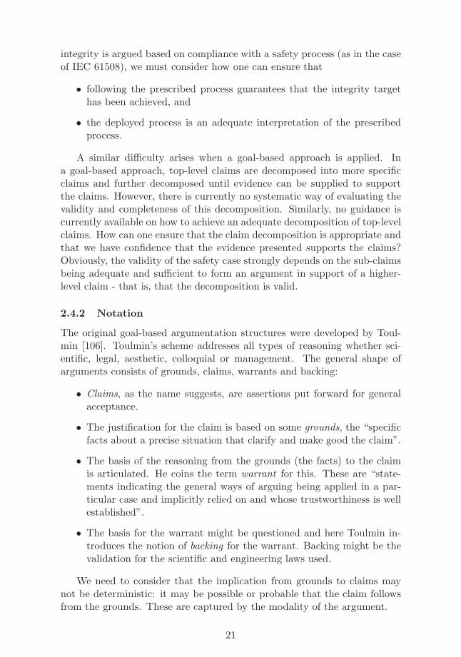
The original goal-based argumentation structures were developed by Toul-min [106]. Toulmin’s scheme addresses all types of reasoning whether sci-entific, legal, aesthetic, colloquial or management. The general shape ofarguments consists of grounds, claims, warrants and backing:
• Claims, as the name suggests, are assertions put forward for generalacceptance.
• The justification for the claim is based on some grounds, the “specificfacts about a precise situation that clarify and make good the claim”.
• The basis of the reasoning from the grounds (the facts) to the claimis articulated. He coins the term warrant for this. These are “state-ments indicating the general ways of arguing being applied in a par-ticular case and implicitly relied on and whose trustworthiness is wellestablished”.
• The basis for the warrant might be questioned and here Toulmin in-troduces the notion of backing for the warrant. Backing might be thevalidation for the scientific and engineering laws used.
We need to consider that the implication from grounds to claims maynot be deterministic: it may be possible or probable that the claim followsfrom the grounds. These are captured by the modality of the argument.
21
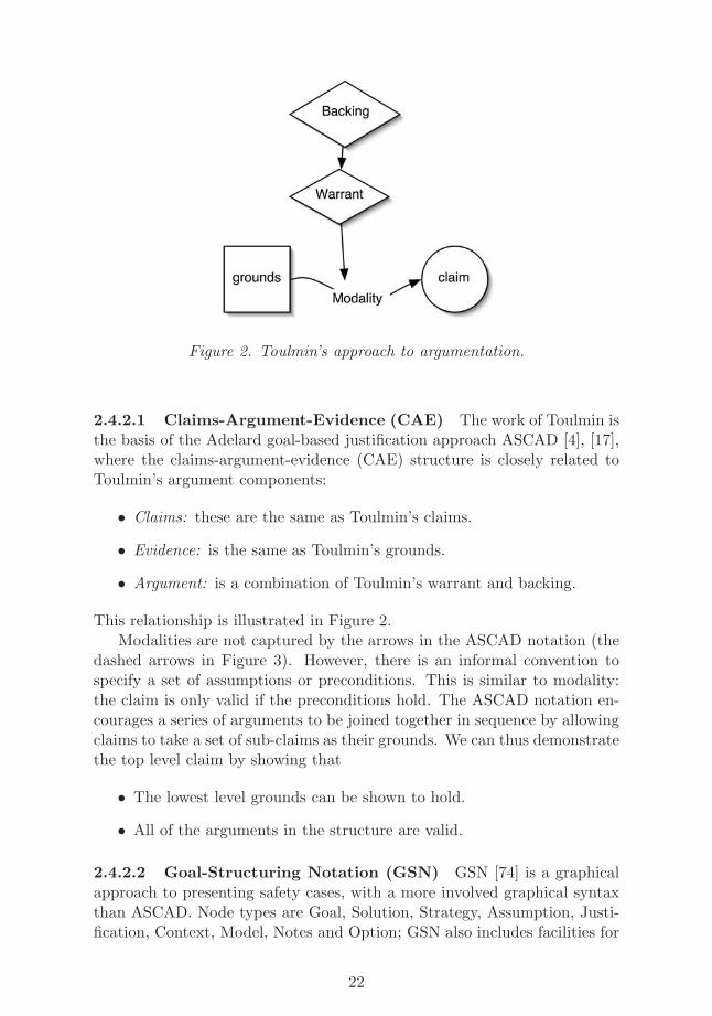
Figure 2. Toulmin’s approach to argumentation.
2.4.2.1 Claims-Argument-Evidence (CAE) The work of Toulmin isthe basis of the Adelard goal-based justification approach ASCAD [4], [17],where the claims-argument-evidence (CAE) structure is closely related toToulmin’s argument components:
• Claims: these are the same as Toulmin’s claims.
• Evidence: is the same as Toulmin’s grounds.
• Argument: is a combination of Toulmin’s warrant and backing.
This relationship is illustrated in Figure 2.Modalities are not captured by the arrows in the ASCAD notation (the
dashed arrows in Figure 3). However, there is an informal convention tospecify a set of assumptions or preconditions. This is similar to modality:the claim is only valid if the preconditions hold. The ASCAD notation en-courages a series of arguments to be joined together in sequence by allowingclaims to take a set of sub-claims as their grounds. We can thus demonstratethe top level claim by showing that
• The lowest level grounds can be shown to hold.
• All of the arguments in the structure are valid.
2.4.2.2 Goal-Structuring Notation (GSN) GSN [74] is a graphicalapproach to presenting safety cases, with a more involved graphical syntaxthan ASCAD. Node types are Goal, Solution, Strategy, Assumption, Justi-fication, Context, Model, Notes and Option; GSN also includes facilities for
22
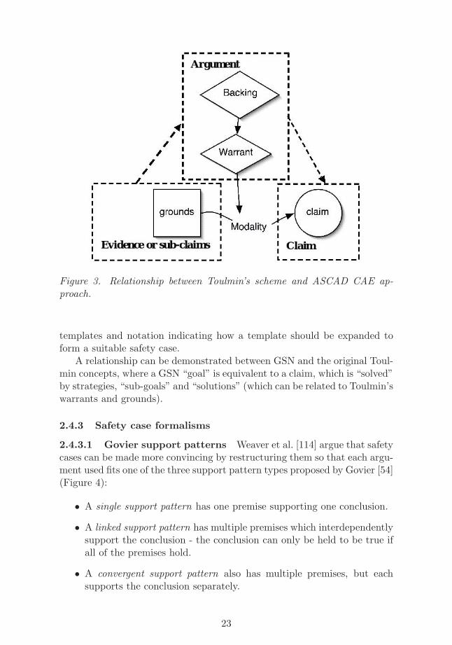
Figure 3. Relationship between Toulmin’s scheme and ASCAD CAE ap-proach.
templates and notation indicating how a template should be expanded toform a suitable safety case.
A relationship can be demonstrated between GSN and the original Toul-min concepts, where a GSN “goal” is equivalent to a claim, which is “solved”by strategies, “sub-goals” and “solutions” (which can be related to Toulmin’swarrants and grounds).
2.4.3 Safety case formalisms
2.4.3.1 Govier support patterns Weaver et al. [114] argue that safetycases can be made more convincing by restructuring them so that each argu-ment used fits one of the three support pattern types proposed by Govier [54](Figure 4):
• A single support pattern has one premise supporting one conclusion.
• A linked support pattern has multiple premises which interdependentlysupport the conclusion - the conclusion can only be held to be true ifall of the premises hold.
• A convergent support pattern also has multiple premises, but eachsupports the conclusion separately.
23
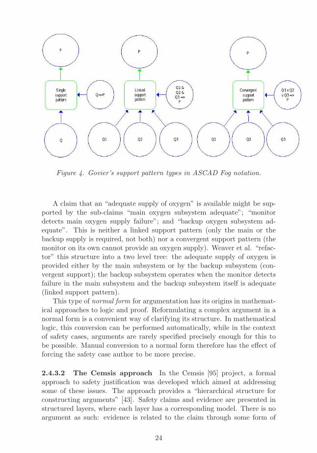
Figure 4. Govier’s support pattern types in ASCAD Fog notation.
A claim that an “adequate supply of oxygen” is available might be sup-ported by the sub-claims “main oxygen subsystem adequate”; “monitordetects main oxygen supply failure”; and “backup oxygen subsystem ad-equate”. This is neither a linked support pattern (only the main or thebackup supply is required, not both) nor a convergent support pattern (themonitor on its own cannot provide an oxygen supply). Weaver et al. “refac-tor” this structure into a two level tree: the adequate supply of oxygen isprovided either by the main subsystem or by the backup subsystem (con-vergent support); the backup subsystem operates when the monitor detectsfailure in the main subsystem and the backup subsystem itself is adequate(linked support pattern).
This type of normal form for argumentation has its origins in mathemat-ical approaches to logic and proof. Reformulating a complex argument in anormal form is a convenient way of clarifying its structure. In mathematicallogic, this conversion can be performed automatically, while in the contextof safety cases, arguments are rarely specified precisely enough for this tobe possible. Manual conversion to a normal form therefore has the effect offorcing the safety case author to be more precise.
2.4.3.2 The Cemsis approach In the Cemsis [95] project, a formalapproach to safety justification was developed which aimed at addressingsome of these issues. The approach provides a “hierarchical structure forconstructing arguments” [43]. Safety claims and evidence are presented instructured layers, where each layer has a corresponding model. There is noargument as such: evidence is related to the claim through some form of
24
model and a set of agreed assumptions, i.e. the argument is self-evidentgiven the evidence, the model and the sub-claims. Claims are made at thefollowing levels:
0. Top level (the plant).
1. Plant / safety system interface.
2. Safety systems architecture.
3. Safety system design.
4. Operational environment.
Initial claims are made at Level 0, and can be expanded into sub-claimsat lower levels. A claim at a given level can be satisfied by evidence at thatlevel or by sub-claims at subsequent levels.
The same structure can be used for generic components, where Level 1 isa claim about the component interfaces, and subsequent claims are relatedto different levels of detail of the component. Claims about components canbe used within larger system justifications.
2.4.3.3 The Fog approach The Fog project is partly concerned withensuring that only valid arguments are used in the construction of the claimtree. The ASCAD notation represents the warrant and backing throughthe use of informal arguments in the narrative. To allow us to increasethe formality of the claim structure, we draw the key parts of the warrantand backing out into side-claims (Figure 5). These may have their owndecompositions, giving support and evidence for the argument itself.
Side-claims tell us how to combine the grounds together, and under whatcircumstances the argument is valid. In this way, for example, the varioussupport patterns of Govier are representable. In each case, the side claims(to the right of the argument node) explain the relationship between the sub-claims or grounds (Q, Q1, Q2, Q3) and the conclusion claim P . For example,the single support pattern is used when a single sub-claim Q supports a singleconclusion claim P . A side-claim is required to explain why Q ⇒ P holds.
2.5 Regulatory Perspective
From the nuclear regulator’s viewpoint, the problem with the current safetyassessment methods is that they often do not address the behaviour of thesystem but try and infer this from indirect evidence such as compliance withstandards or good development processes. Safety assessment methods whichare feasible, repeatable and can be performed within reasonable amount ofresources and time and directly address the behaviour of the system haveclear advantages.
25
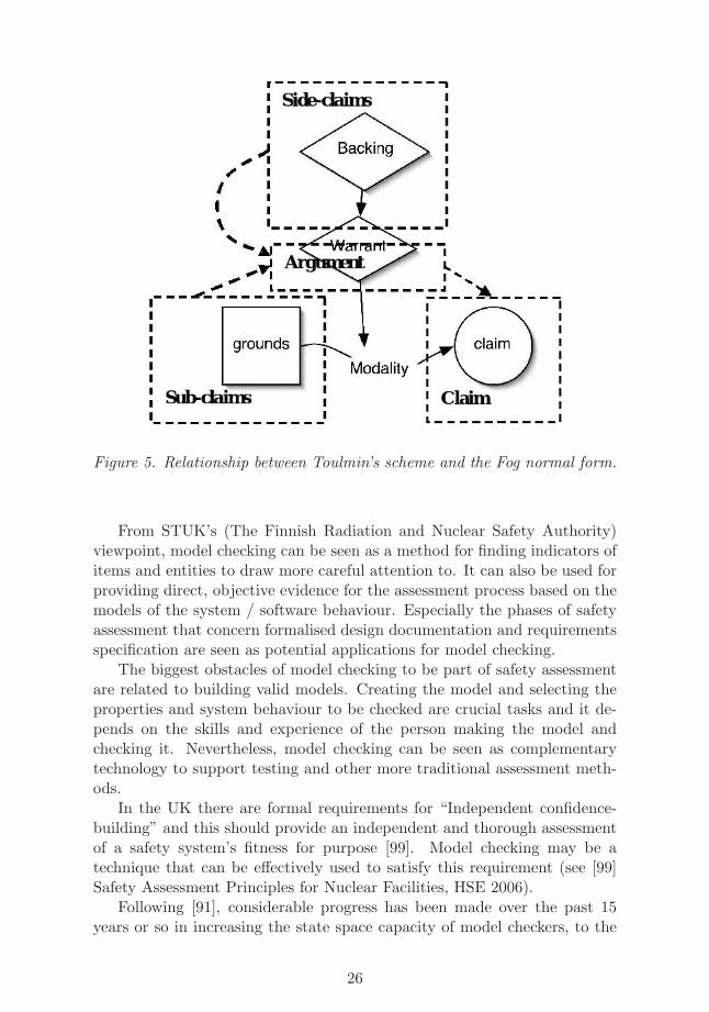
Figure 5. Relationship between Toulmin’s scheme and the Fog normal form.
From STUK’s (The Finnish Radiation and Nuclear Safety Authority)viewpoint, model checking can be seen as a method for finding indicators ofitems and entities to draw more careful attention to. It can also be used forproviding direct, objective evidence for the assessment process based on themodels of the system / software behaviour. Especially the phases of safetyassessment that concern formalised design documentation and requirementsspecification are seen as potential applications for model checking.
The biggest obstacles of model checking to be part of safety assessmentare related to building valid models. Creating the model and selecting theproperties and system behaviour to be checked are crucial tasks and it de-pends on the skills and experience of the person making the model andchecking it. Nevertheless, model checking can be seen as complementarytechnology to support testing and other more traditional assessment meth-ods.
In the UK there are formal requirements for “Independent confidence-building” and this should provide an independent and thorough assessmentof a safety system’s fitness for purpose [99]. Model checking may be atechnique that can be effectively used to satisfy this requirement (see [99]Safety Assessment Principles for Nuclear Facilities, HSE 2006).
Following [91], considerable progress has been made over the past 15years or so in increasing the state space capacity of model checkers, to the
26

point where specifications containing hundreds of state variables can oftenbe verified automatically in a few hours. However, realistic designs oftencontain thousands or millions of state variables, far exceeding the reach ofcurrent model checking algorithms. Another class of verification tools calledtheorem provers can be used to overcome the capacity limitations of modelchecking. A theorem prover does not search the state space of a specificationdirectly, but instead searches through the space of correctness proofs thata specification satisfies for a given correctness property. In general, modelchecking and theorem proving are complementary technologies and shouldbe integrated to successfully tackle realistic system designs.
27
3 Formal Methods for Digital Automation Sys-tems Analysis
3.1 Computer Aided Verification Methods
The traditional way of ensuring the reliability of distributed systems has re-lied on the two main techniques of manual testing using human- or machine-generated test cases and simulation. However, when the systems containparallel and distributed components, the effectiveness of these techniquesdoes not scale at the rate of the system size growth. The use of computeraided verification has been suggested as an aid to supplement these methods.
3.1.1 Model Checking
Model checking [40] is a set of methods for analysing whether a model ofa system fulfils its specification by examining all of its possible behaviours.Model checking was introduced in the early 1980s simultaneously by two dif-ferent groups [97, 41]. Good introductory books to the topic are [40, 12, 96].In model checking, at least in principle, the analysis can be made fully auto-matic with computer aided tools. The specification is expressed in a suitablespecification language, temporal logics being a prime example, describing theallowed behaviours of a system. Given a model and a specification as input,a model checking algorithm decides whether the system violates its speci-fication or not. If none of the behaviours of the system violate the givenspecification, the (model of the) system is correct. Otherwise the modelchecker will automatically give a counterexample execution of the systemdemonstrating why the property is violated.
In symbolic model checking the main idea is to represent the behaviourof the system in a symbolic form rather than explicitly. There are severalvariations to symbolic methods. The most well-known is the use of datastructure called ordered binary decision diagrams (OBDDs), which are acanonical representation of Boolean functions [30, 32, 31, 87]. The boundedmodel checking method [14] was introduced to further improve the scalabilityof symbolic model checking by replacing OBDDs with methods based onpropositional satisfiability (SAT) checking. The main idea in bounded modelchecking is to look for counterexamples that are shorter than some fixedlength n for a given property. If a counterexample can be found which is atmost of length n, the property does not hold for the system. It seems that thebounded model checking procedures can currently challenge OBDD basedmethods on digital hardware designs both in terms of memory and timerequired to find counterexamples [15, 24, 42]. A weakness of bounded modelchecking is that if no counterexample can be found using a bound, usingthe basic method the result is in general inconclusive. However, the basicmethod can be extended to a complete model checking method for safety
28
properties by employing temporal induction [100, 49]. The Laboratory forTheoretical Computer Science at Helsinki University of Technology and staffat Adelard have contributed to the development of the NuSMV symbolicmodel checker [38, 76, 77, 59, 60, 39, 69, 16].
The area of model checking of real source code has recently become aprominent field of research. A large part of the interest has been triggered bythe success of the SLAM project [7] at Microsoft. SLAM is a model checkerfor sequential C programs aimed at the verification of the use of lockingprimitives of Windows device drivers. As a matter of fact, the SLAM systemhas been transferred from Microsoft research into the Windows group andhas been integrated in a beta version of the Windows driver developmentkit [6], and is thus in production use. The success of the SLAM projecthas raised interest in using model checking methods also for analysing Csource code. Similar approaches could be used to e.g., analyse the embeddedsoftware of smart sensors and other small devices with embedded softwarewritten in C. The academic tools in this area are, however, less mature thanmodel checkers for hardware systems such as NuSMV.
For concurrent programs such as data communications protocols theanalysis techniques have so far mostly concentrated on modelling the con-current program in the input language of a traditional explicit state modelchecker. These tools use simpler models of concurrency and include toolssuch as Spin [61] or Murϕ [48]. The Laboratory for Theoretical ComputerScience at Helsinki University of Technology has significantly contributed tothe research on model checkers by creating tools such as PROD [111] andMaria [85].
For systems with real-time constraints model checking approaches basedon analysing models with real time valued clocks such as timed automatais natural, and can be sometimes much more efficient than modelling theclocks with counters updated at discrete time intervals. One of the mostprominent model checking tools in this area is Uppaal [11].
3.1.2 Deductive Verification
Deductive verification is a set of methods for determining whether a programfulfils its specification by analysing its formal semantics. The specificationdefines a relationship between the state of the computer when the programbegins (the precondition) and the state of the computer when the programterminates (the postcondition). The way that each program statement inturn transforms the state is analysed either manually (e.g., as describedby Kaldewaij [73]) or using a theorem provers or proof assistants (e.g., theCaduceus and Krakatoa tools [51]), in order to determine whether the spec-ification is met.
Deductive verification has been successfully applied in safety applica-tions [86, 27] but it remains a relatively expensive technique. Both manual
29
proof and conventional theorem provers require a degree of understandingof the underlying semantic model and proof approaches as well as the NPPdomain at hand. Although this requirement for skilled application of themethod makes deductive verification unsuitable for MODSAFE at least fromNPP I&C systems developer perspective. However, some techniques usedin the field may still be quite relevant. For example, the approach could beused in verification efforts done by third parties with sufficient knowledge ofboth deductive verification methods as well as NPP domain expertise.
3.1.3 Model-based Testing
Testing is one of the most time consuming parts in the development ofcomplex systems. Reports from the telecommunications industry tell usthat the number of man hours devoted to testing is in many cases morethan half of the effort spent in a typical development project. However, inmany cases the testing is very ad-hoc and not based on a solid theoreticalfoundation. Thus there is a lot of room for improvement to be gained froma model-based approach to testing.
A promising way to use formal methods in connection with testing wasproposed in [107, 45, 28]. The main idea is to test a black-box implemen-tation with test cases and test verdicts automatically generated from anassumed to be correct “golden design” abstract system model, which is inthis context called the specification. How this could be further applied inautomation setting is an open research question.
The first commercial model-based testing tools are available for UMLmodels [62] and for Simulink/Stateflow models [103]. However, the academictools available for model-based testing are currently less well developed thanacademic model checking tools.
3.2 Formal methods for Digital Automation systems
In this section we review existing work on applying formal methods to theanalysis of digital automation systems. However, as the subject area isvery wide, we have restricted our focus on the key areas of interest in theview of the MODSAFE project. Therefore we discuss only studies concern-ing automation systems based on programmable logic controllers (hereafterPLCs). Consequently we have mostly excluded systems which are based e.g.,on softPLCs (PLCs based on standard PCs) and distributed control systems(DCSs). This restriction seems reasonable, since the conclusions made onPLCs can be extended to cover also softPLCs. On the other hand, coveringalso the subject of DCS would have required a survey of much larger scale.However, the PLC domain can be seen as a logical stepping stone towardsanalysing of DCS based automation systems. On the method side we arefocusing mainly on applying model checking methods to PLC applications.
30
The analysis of PLC based systems with formal methods can be doneon different levels. In the most comprehensive approach the validity of thePLC program is verified against the specification of the entire system whichconsists of the combined specification of the controller and its environment.Another option is to restrict only on verifying the correctness of the con-troller. In this case the specification of the system as a whole is dividedinto the specifications of the environment and the controller part, and theprogram of the controller is analysed with respect to the specification of thecontroller.
Another classification of approaches on applying formal methods to PLCapplications can be made based on the initial objective of the process. Thatis, the goal might be to analyse an existing application or to design a com-pletely new one. In the first approach an existing PLC program is firsttransformed into some formal modelling language and then, based on themodel, the validation of properties is carried out with a model checker. Thisapproach is often referred to as modelling or formalising existing PLC pro-grams [80]. The related studies are often—but not always—restricted to onlyvalidating the controller against its specification. In the second approach asystem is designed from the beginning by using a formal modelling method.After the model (which in this case often consists of both, the model of thecontroller and the environment) is finished, it can be used, alongside of val-idating properties, to derive a PLC program automatically. This approachis usually referred to as model based design or program synthesis [53].
In this report we review studies on both approaches, the modelling ofexisting PLC programs and the model based design. We start by listingsome earlier surveys made on the subject. From these we found especiallythe papers [80, 63] as a good starting point for our own review. After thelist of existing surveys we proceed to present references to the most relevantstudies in the view of MODSAFE project. However, before going into theactual survey we describe in the following section some classification criteriafor models of PLC programs which were originally presented in [80]. We usethis terminology to describe the references that we list in this paper, butnot all the referred studies are classified according to all these criteria.
3.2.1 Classification Criteria for PLC Models
Here we describe the three orthogonal criteria for classifying PLC modelsoriginally presented by Mader in [80]. The discussion is intentionally keptbrief and an interested reader is advised to turn to [80] for more in-depthcoverage on the issue.
31
Modelling of the cyclic operation mode
The most fundamental characteristic of PLCs is their cyclic operation mode.Therefore the first logical choice in classifying PLC models can be made onthe basis of how the scan cycle of the PLC is modelled. There are threepossible choices:
• Explicit modelling of the scan cycle.
• Implicit modelling of the scan cycle.
• Abstracting from the scan cycle.
In the explicit modelling of the scan cycle the exact duration of thecycle in actual time units is modelled. Instead, in the implicit modellingthe existence of the cycle itself is modelled, but the actual duration of it isnot measured in time units, and moreover, it is considered to be constant.The third option is to abstract from the scan cycle entirely so that the timemodel of the PLC is considered to be continuous instead of discrete.
Modelling of timers
The use of timers is a fundamental characteristic of PLC programs. However,not all of the PLC applications need timers and in many cases the use ofthem can be avoided, either by modelling techniques or by altering thesystem design. Therefore, it is justifiable that there are studies concernedwith modelling of timers as well as those which abstract them out.
The language fragment considered
By the language fragment criteria a choice is made on which parts of thePLC programming language are considered in the modelling process. Thefirst obvious question is that which of the five languages defined in theIEC 61131-3 standard is considered. The options are:
• Instruction List (IL).
• Structured Text (ST).
• Ladder Diagrams (LDs).
• Function Block Diagrams (FBDs).
• Sequential Function Charts (SFCs).
Moreover, usually only a restricted part of the features of the chosen tar-get language is considered. This is because the IEC 61131-3 standard lacks
32
definition of formal semantics on the languages of the standard. There-fore, from the viewpoint of academic research, it simply is not reasonable toconsider all possible semantic interpretations of all parts of the languages.
Finally, the language fragment considered can also be restricted on thepossible data types, i.e., which of the data types of booleans, integers andreal numbers are allowed.
3.3 Survey of Studies on Model Checking PLCs
In this section the survey of studies on applying model checking to PLCsis presented. The section is organised as follows. In Subsection 3.3.1 a listof already existing surveys is given, after which approaches to modelling ofPLC programs are listed in Subsection 3.3.2, and finally in Subsection 3.3.3the studies on model based design are reviewed.
3.3.1 Previous surveys
• The paper [80] by Angelika Mader presents a classification of differentPLC models. It first classifies an orthogonal set of criteria on whichPLC models can be classified on. The paper also introduces an ex-tensive list of publications which are classified against the presentedcriteria. The dissertation [63] by Ralf Huuck presents quite a similarsurvey which also includes more recent studies and an extended list ofthe classification criteria.
• The paper [84] also by Mader discusses the application of formal meth-ods to PLC applications in general. It presents a schema on the struc-ture of a general PLC application and based on this framework anal-yses the possibilities for applying different formal methods on PLCs.
• The paper [120] by Frey introduces four criteria on which studies con-sidering formalisation of existing PLC programs can be categorised.It also presents references to studies falling in each of these categories.The study is by no means as thorough as the survey presented inthe papers [80, 63] but contains some additional references and showsanother way of classifying the existing research.
• The paper [53] by Frey presents a general framework on the differ-ent phases of verification and validation and discusses what formalmethods can be used in these different phases. Therefore, it not onlyfocusses on transforming existing PLC programs to models, but it alsodiscusses other formal methods in addition to model checking.
33
3.3.2 Modelling PLC applications
In the following a list of studies considering the modelling of PLC applica-tions is given. The references are organised according to the PLC program-ming language.
Research on modelling SFC programs
• The Doctoral Thesis of Ralf Huuck [63] shows how SFC programscan be given formal semantics, including a translation of the untimedsemantics of PLCs to the Cadence SMV model checker input language.In the paper [9] this research is extended by giving formal semanticsalso for timed SFCs and in the paper [8] it is shown how timed SFCscan be translated into timed automata. The latter study illustratesin both, timed and untimed cases, the complete verification procedurefrom model transformation to identifying errors with model checkingtools UPPAAL and Cadence SMV.
The research papers described here seem to take the closest approachto that originally sketched in the MODSAFE research proposal.
Research on modelling IL programs
• The widely referred paper [82] by Mader and Wupper shows how a frag-ment of IL programs can be translated into timed automaton. Basedon this study a tool is presented in the paper [115] by Willems whichtranslates IL programs automatically into timed automaton format ac-cepted by UPPAAL model checking tool. This tool chain allows modelchecking of real time properties with explicit modelling of the scan cy-cle. The Willems’s tool also allows IL programs to contain boundedinteger variables. Moreover, UPPAAL tool can be used to model theenvironment of the PLC as well. In an unpublished paper [83] Maderpresents two examples on modelling IL programs and performing theirverification with the UPPAAL tool.
• In the paper [58] it is shown how IL programs can be transformed intoPetri nets. The method allows usage of data structures up to lengthof 8-bits and it takes into account all standard instructions excludingcommands from libraries. However, the real-time aspects cannot bemodelled.
• In the paper [66] it is shown how IL programs can be transformedinto Timed Net Condition/Event systems. The scan cycle is modelledexplicitly and timers are taken into account at some level. However,the possible data structures are restricted to boolean values and onlyload, store, and, and or instructions are considered.
34
• The paper [34] deals with the same fragment of IL programs as thepaper [66] described above. In addition, the loop operations are consid-ered. However, [34] is concerned with translating IL programs directlyto the input language of the SMV model checker tool. As SMV can-not directly handle real-time issues, these aspects of the IL programcannot be analysed.
• The paper [78] uses BDD and BMC based symbolic model checkers tomodel check two small PLC based automation systems written in IL.
Research on modelling LD programs
• In paper [90] LD programs are modelled with SMV tool without tak-ing timing aspects into account. Based on this study there exists aresearch paper [108] presenting two comprehensive case studies on ex-isting chemical processing systems. In these case studies the model ofthe environment is also presented. The verification process revealednumerous faults and the results could be used to improve the designs.
• In the paper [98] a large fragment of LD programs are modelled withthe SMV model checker. The scan cycle is modelled implicitly and itis shown how a particular type of timers can be modelled in non-realtime manner so that certain liveness and safety properties can still beverified.
Research on modelling ST programs
• The paper [71] by Jimnez-Fraustro and Rutten considers of modelling afragment of the ST language with the synchronous language SIGNAL.The fragment includes at least assignments, conditionals and boundedloops. Scan cycles are modelled implicitly and real-time behaviouris not considered. The follow up study [72] considers also the FBDlanguage. Unfortunately, there does not seem to exist any relatedstudies on actual model checking based on the SIGNAL model.
3.3.3 Methods for synthesising PLC programs from models
In the following a list of studies considering the synthesis of PLC programsfrom models is given.
• In the paper [47] Henning Dierks presents a new modelling formalismnamed PLC-automata especially designed for modelling PLC appli-cations. PLC-automata allows explicit modelling of the scan cyclebut it is possible to model only particular type of timers in which an
35
input signal is ignored for a certain time. Dierks shows also how PLC-automata models can be transformed automatically into language ofStructured Text.
In the paper [46] it is shown how PLC-automata models can be trans-formed into timed automata models which makes it possible to performmodel checking with a real-time model checker such as KRONOS orUPPAAL. Moreover, in the paper [104] a tool MOBY/PLC is pre-sented which can be used to model PLC-automata, validation, andcode generation.
• As a continuation for the research based on PLC-automata formalismOlderog presents in paper [92] an approach for designing valid PLCapplications. His method is based on formulating design specificationswith PLC-automata and specifying requirements in Constraint Dia-grams. Olderog also presents a case study from industry for which heapplies his approach. In the paper [93] Dierks and Olderog present atool Moby/RT which is based on the design approach of [92].
• The Doctoral Thesis of Georg Frey [52] tries to formalise PLC controlalgorithms and their verification through the use of a Petri net basedformalism.
• A quite interesting research project from the view of MODSAFE projectis reported in the papers [81, 29] by Mader, Brinksma et al. In [81] asystematic design and validation of a PLC control program for a batchplant by using formal methods is reported. This plant was selectedas a case study for the EC project on Verification of Hybrid Systems(VHS). In the follow up paper [29] it is reported how the Spin modelchecker was used for both the verification of a process control programand the derivation of optimal control schedules.
• The paper [117] discusses the use of formal methods in designing PLCcontrollers to be employed in Korean nuclear power plants. The ap-proach is based on first modelling the required control using a com-bined timed automata and tabular notation like model (NuSCR), andthen mapping the design through automated tools to a PLC imple-mentation based on the IEC 61131-3 Function Block Diagram FBDnotation. In the actual implementation the FBD design is furtherhand optimised by domain experts to minimise time needed for thePLC cycle. The authors claim that they can employ model checkingon the initial timed automaton model as well as verify the soundnessof the hand optimisations used. However, actually performing thismodel checking is not reported in the paper.
• The paper [119] gives details of the NuSCR specification approachdiscussed above together with further references.
36
• The paper [37] gives the tool support used by the Korean NuSCR spec-ification formalism. It also includes an SMV backend that supportsthe model checking of NuSCR specifications. The paper contains asmall case study utilising model checking.
• The paper [118] describes the synthesis approach for NuSCR describedabove in slightly more detail.
• The paper [70] describes the methods used to test PLC programs inFBD format for Korean nuclear power plants.
• The paper [101] shows how the SMV model checker can be used tomodel check a Korean safety critical system for a nuclear power plant.
3.4 Overall Status of the Research on Model Checking PLCs
On the study field of modelling PLC programs most research papers seemto be available on the language of Instruction Lists. On Ladder Diagramprograms there is also quite a lot of research but in this area there seems tobe many gaps to be filled, especially on covering timers and real time issues.Instead, in the case of the SFC programs the situation is the opposite: therehasn’t been that many research projects, but the coverage of existing onesis quite extensive.
Considering the last two languages of the IEC 61131-3 standard, i.e., onStructured Text and Function Block Diagrams, there seems to exist onlyvery few studies. We presume that the reason for this in the case of the STlanguage might be that the relevant problems on the modelling issues arepresent also in the IL language which, in its brevity, better suits academicresearch. Instead, in the case of the FBD language, the similar but moreevolved SFC language provides features not existing in FBD, and therefore,might be more appealing for research.
For the synthesising approach there has also clearly been a lot of researchactivity. The usefulness of this approach has especially been shown in theKorean research project described above. As this particular research projectis very close to the scope of the MODSAFE project, it is further describedin Section 3.5.1.
3.5 Previous Approaches to Software and Automation Anal-ysis (in NPPs)
3.5.1 Computer Aided Analysis of Korean and Canadian NPPAutomation Systems
As already mentioned in Section 3.3.3, the Korean approach to NPP au-tomation systems analysis is based on using a finite state machine model ofthe PLC control given formally in a tabular notation called NuSCR [117].
37
The idea is that first this finite state machine model is proved correct us-ing, e.g., model checking methods [101]. After the model is known to becorrect, it can be mapped into an implementation using an automatic trans-lation [118]. It is not known to us whether any control systems designedin this manner are in production use at Korean NPPs. The drawback ofthis approach is that it requires the design approach of the control systemsto be modified to accommodate for computer aided analysis unlike in theMODSAFE project where no such design process changes are needed.
A similar approach to the one employed in Korea has been used to designreal reactor shutdown systems of Canadian NPPs of Ontario Hydro usinga tabular notation software design documents and proving the design docu-ments correct using a theorem prover. A very nice overview of the approachtaken in Canada can be found from [113].
3.5.2 French approaches
The French approach to reliability determination is basically deterministicand supplemented by PSAs. PSAs are not requested before licensing: theyare used only to gain a global overview of the plant safety and to determinepossible weaknesses. Besides, the PSAs do not cover software.
3.5.2.1 SCADE The SCADE tool [13, 105], based on the synchronoushigh-level LUSTRE language [36], is an industrial tool developed by Es-terel. It has been used in nuclear software development by Merlin-Gerinand Schneider-Electric for software development. Two facilities provided bySCADE are of interest:
• Validation facilities: Design verification supporting formal analysisand simulation.
• Automatic Code Generation: SCADE produces some code (C) au-tomatically. Originally problems in the tool were found by checkingagainst the code; these problems have been corrected and Merlin-Gerinnow argue that their feedback of two years experience with non-nuclearsystems has stabilised the tool.
3.5.2.2 Caveat Caveat [1] is a C static analysis tool aimed at controlsystems code—code which may be long but is typically not very complex.It is a combination of an interactive theorem prover and code analysis tool,covering:
• Code navigation (code structure, call graphs and data-flow graphs).
• Support for formal proof of properties in first-order logic.
38
• Calculation of the subroutine outputs as a function of their inputs,and the calculation of weakest preconditions.
• Test case generation.
• Dead code detection.
• Software execution metrics (worst-case execution time, stack depth).
3.5.3 BE-SECBS Project
A FP5 project called “Benchmark Exercise of Safety Evaluation of ComputerBased Systems BE-SECBS” aimed at making a comparative evaluation ofexisting methodologies in safety critical computer based systems assessmentamong regulators and technical support organisations in some EU MemberStates. The project had three assessor teams: Institute for RadiologicalProtection and Nuclear Safety (IRSN, France), Institute for Safety Tech-nology (ISTec, Germany), and a Finnish consortium Technical ResearchCentre of Finland / Radiation and Nuclear Safety Authority (VTT/STUK)which assessed a reference study case provided by Framatome. The projectwas coordinated by Joint Research Centre—Institute for Energy (JRC-IE).The following three sections describe the methods used in the BE-SECBSproject [75].
3.5.3.1 IRSN’s Methods IRSN’s method of safety critical softwareevaluation consists of five major steps:
1. Development process and associated documentation analysis. The firststep of the evaluation consists in understanding the development pro-cess and assessing its conformance to the principles and requirementsof national regulation (French basic safety rules RFS IV.1.a, IV.2.b andV.2.d) and international standards (IAEA safety guides, IEC 61226,IEC 61513, IEC 60880). The crucial part of this examination focuseson the evaluation of the consistency, completeness and correctness ofthe software specifications against user requirements and system de-sign requirements.
2. Source code analysis. IRSN uses QAC and McCabe tools to assessthe code quality. They can be used to make searches for dangerous,incorrect or complex constructs. Polyspace Verifier tool automaticallyperforms symbolic execution of a source code in order to detect run-time errors such as array out of bounds violations using static analysistechniques.
3. Determination of critical software components. Failure Modes andEffects Analysis (FMEA) adopted to software systems is used at this
39
assessment step. An index of relative importance is established foreach function by taking into account the number and severity of theconsequences of the failures and categorising them. Once the potentialfailures that could lead to dangerous malfunctions are identified, it ischecked that there are no errors in the software that could lead to thesefailures. This is done by verifying that there is at least one validationtest performed that would have covered this postulated failure mode.
4. Dynamic analysis. In order to perform dynamic analysis, IRSN hasdeveloped a set of tools, called Claire simulation tool [35], which cansimulate operation by execution of a binary program without recourseto equipment used on site. The goal is to perform non-intrusive testand observation of the actual binary codes of a multi processor system.Next, a consistency study is used to verify the output values from thechannels (e.g. controlling a reactor trip) when the input values areselected by the analyst from the nominal operating range of the system.This study verifies the most significant aspects of the behaviour of thebinary program that is actually operational on site. Eventually, arobustness study aims at judging the behaviour of the programs of therepresentative set subjected to series of tests. These tests are definedin advance. They represent abnormal situations for the system or itsenvironment. The series of tests are focused on the critical or sensitivecomponents detected during the previous steps.
5. Development of test cases and choice of testing strategy. For the test-ing analysis purposes, IRSN has developed the tool Gatel. Test cases(input/output sequences) are generated, covering a specification work-ing together with its environment. These test cases exhaustively covera given test objective, derived by the assessor from the safety require-ments of the system. Gatel produces “abstract tests”, correspondingto a functional view of the software, so they must be “concretised” tothe binary code level in order to be run by Claire. This translationis made by Claire and requires additional knowledge about the binarycode under test.
3.5.3.2 ISTec’s Methods Institute for Safety Technology (ISTec) par-ticipated in BE-SECBS project as well. The safety assessment performed atISTec was based on IEC 60880 and German national rule KTA 3503 (“TypeTesting of Electrical Modules for the Reactor Protection System”). To ver-ify the automatically generated code within a reasonable amount of time,a methodology was developed by ISTec within the framework of a researchprogram from 1994 to 1997. This methodology is based on a tool supportedstatic analysis of the generated code which is independent from the gener-ation rules of the code generator. The tool is called RETRANS (REverse
40
TRAnsformation of Normed Source code). The methodology is restrictedto the configuration part of software systems, where the configuration partconsists of normed source code. RETRANS transforms the normed sourcecode into analysis items. These analysis items should have a correspondentitem in the original specification data set and vice-versa (consistency andcompleteness). In the case of an error-free run RETRANS
• demonstrates the functional equivalence of the specification data setwith the source code,
• demonstrates the existence of consistent data in the specification dataset,
• demonstrates the existence of consistent data in the generated normedsource code,
• carries out a plausibility check: analyses items’ comparison betweenredundancies and highlights differences.
In general, ISTec applied a two-phase qualification approach consistingof generic and plant-specific elements and made use of the fact that theexample case was type-tested according to the mentioned German nationalrule KTA 3503, which is a generic qualification of hardware and softwarecomponents. Within BE-SECBS, ISTec performed the corresponding plant-specific system qualification phase. Since 1993, type testing of softwarecomponents has been applied by ISTec according to KTA 3503 with theobjective to qualify and assess the developed software modules on the basisof the mentioned phase model and to demonstrate compliance of the typetested software components with their software requirements specification.The plant-specific system qualification is performed within the respectivelicensing process of the individual plant with emphasis on the system ar-chitecture, V&V measures, functional tests, and application code analysis.Besides functional testing, the analysis of the application code is a necessaryverification step in the whole qualification procedure. It grants the compli-ance with requirements of generally accepted standards like IEC 60880 forthe automatically generated application software. During the plant specificsoftware assessment it is not necessary to evaluate the type tested softwaremodules again; it only needs to verify that the correct versions of the typetested software modules are used and that they are used in an appropriateway.
3.5.3.3 VTT/STUK’s Methods The VTT/STUK safety evaluationmethod is based on the Finnish regulatory guide YVL-5.5 which describesthe principles for licensing automation systems for NPPs. The basic prin-ciple of the methodology is the critical review of the evidence and analyses
41
provided by the system vendor or the power utility applying for the license.The VTT/STUK method aims at evaluating the quality of evidence (i.e.evaluation of the target product and its design and implementation pro-cess with respect to standards, authority requirements etc.). YVL-5.5 re-quires also quantitative reliability analyses. In the VTT/STUK method, thequantitative reliability estimates are produced by using a Bayesian networkmodel.
The qualitative analysis of a programmable automation system has thefollowing major tasks or phases: overall analysis of the evidence/materialprovided; analysis of the requirements specification; FMEA of safety func-tions; analysis of test coverage, operating experience, application code; anal-ysis of the platform development process and application development pro-cess. Each of the above mentioned items is evaluated and an assessment ismade on the level of quality. This analysis yields a map of safety evidenceor safety arguments.
The results of the above tasks are used in the quantitative reliabilityanalysis. There are no well-established and generally accepted methods forquantitative reliability analysis of programmable systems. However, whenperforming a PSA study, also these systems have to be taken into accountand probability values that programmables do not perform their task prop-erly when demanded, have to be evaluated. The direct estimation of suchprobabilities on the basis of operating experience is not possible due to lim-ited statistical information. However, the information developed in differentphases during licensing process reflects the reliability of the system and itshould be utilised. One approach to take this information into account isthe use of Bayesian networks with the following modelling phases:
1. Development of the map of evidence,
2. Definition of the structure of the Bayesian network model (variables,metrics, probabilistic relationships and dependencies),
3. Quantification of the model,
4. Interpretation of the results (sensitivity and importance analysis).
3.5.4 Model Checking Operator Procedures
Some very interesting work has also been done on model checking operatorsprocedures in the avionics context. NASA has been using model checkingto check for mode confusion errors [88, 44, 79]. The idea is to look forpotential cases where the operator might lose his/her situation awareness(be confused about the mode the system is in) by using a formal modellingof the user interface of the operator and the system being controlled. Sothis is an interesting piece of work using formal methods to analyse humancomputer interaction factors of operators.
42
In the NPP area operator procedures have been formally checked byInstitute for Energy Technology (IFE) which has been using model checkingin its research for the OECD Halden Reactor Project in Halden Norway.The research has considered designing and verifying operator procedureswhich are documents telling operators what to do in various situations.They are widely used in nuclear power industry and in process industries.The correctness of such procedures is of great importance to assure safeexecutions of the procedures.
The paper [121] describes how model checking can be used to detect po-tential errors and to verify properties of such procedures. Types of correct-ness specifications, types of errors that can be detected by model checkingand basic techniques for modelling operator procedures and for detectingerrors are discussed.
The paper [122] presents verification approaches based on different modelchecking techniques and tools for the formalisation and verification of op-erating procedures. Possible problems and relative merits of the differentapproaches are discussed. The paper [122] also presents a case study of oneof the approaches to show the practical application of formal verification.Application of formal verification in the traditional procedure design processcan reduce the human resources involved in reviews and simulations, andhence reduce the cost of verification and validation.
3.5.5 Adelard’s Methods and Approaches
A safety case is a type of logical argument in which a claim about the safetyof a system is argued by decomposing it into sub-claims about simpler prop-erties and simpler subsystems. Model checking and other formal approachesare therefore applicable in two ways: as evidence that a subsystem has cer-tain properties, and as evidence that a safety case forms a valid argument.
3.5.5.1 Use of Formalisation of Safety Case Arguments Adelard’sFog project (see Section 2.4.3.3) is concerned with developing a formal ar-gument structure for safety cases. By restricting safety cases to a simplelogical argument in a normal form, it becomes possible to use automatedtools to prove the validity (or otherwise) of the argument represented. Theapproach taken in Fog is to produce safety case “building blocks” whichhave been shown in a theorem prover to be valid; these building blocks canthen be composed into a safety case. Provided the evidence at the lowestlevel is established, knowing the validity of the safety case argument allowsus to deduce the top level claim.
43
3.5.5.2 Use of Formalisation in Safety Case Claims
Software Reliability Modelling The expected reliability of software canbe modelled as a function of the faults detected through testing. That is, byextrapolating future reliability from past failures. Using relatively standardassumptions it can be shown [22] that the expected worst-case value of thefailure rate after a usage time t is bounded by:
λt ≤N
et
where N is the initial number of faults and e is the exponential constant.Less pessimistic results can be obtained if additional assumptions are madeabout the distribution of failure rates over the N faults. These predictionsturn out to be relatively insensitive to assumption violations over the longerterm. The theory offers the potential for making long term software relia-bility growth predictions based solely on prior estimates of the number ofresidual faults (e.g. using the program size and other software developmentmetrics).
Given a fixed amount of testing, this formula can be rearranged to de-termine the maximum number of faults permitted for a target MTTF3:
N ≤et
MTTF
This is, of course, a worst case bound model, and better results wouldbe obtained with more accurate models. For example, a worst case boundmodel that assumes a log normal distribution is described in [23].
Software Process Modelling Having related the system reliability tothe number of faults, the ability of the development process to detect faultsor avoid creating them becomes of interest. A “barrier model” of the devel-opment process may be used [26], where in each development phase faultsare created or detected. This model is parameterised by the rates of faultcreation and detection at each phase of the software lifecycle. It can thenbe used to estimate the number of residual faults (i.e. those that escape thelast barrier).
In [26], an analysis of fault creation and detection estimates for a numberof projects was carried out, in order to calibrate the statistical models fora given development process. Figure 6 shows a probability distributionfor a particular development process. The bar graph marked “Judgement”indicates the predicted probabilities of producing a product with a givennumber of faults; gamma and log-normal best-fit curves are also shown.
3Mean Time To Failure (MTTF), the time before the next system failure occurs, is thereciprocal of reliability—which is the expected number of failures in a given time period.
44
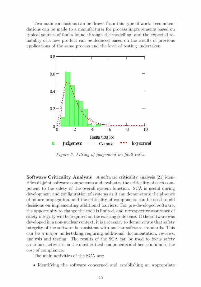
Two main conclusions can be drawn from this type of work: recommen-dations can be made to a manufacturer for process improvements based ontypical sources of faults found through the modelling; and the expected re-liability of a new product can be deduced based on the results of previousapplications of the same process and the level of testing undertaken.
Figure 6. Fitting of judgement on fault rates.
Software Criticality Analysis A software criticality analysis [21] iden-tifies disjoint software components and evaluates the criticality of each com-ponent to the safety of the overall system function. SCA is useful duringdevelopment and configuration of systems as it can demonstrate the absenceof failure propagation, and the criticality of components can be used to aiddecisions on implementing additional barriers. For pre-developed software,the opportunity to change the code is limited, and retrospective assurance ofsafety integrity will be required on the existing code base. If the software wasdeveloped in a non-nuclear context, it is necessary to demonstrate that safetyintegrity of the software is consistent with nuclear software standards. Thiscan be a major undertaking requiring additional documentation, reviews,analysis and testing. The results of the SCA can be used to focus safetyassurance activities on the most critical components and hence minimise thecost of compliance.
The main activities of the SCA are:
• Identifying the software concerned and establishing an appropriate
45
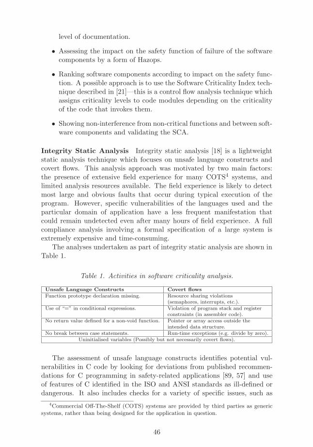
level of documentation.
• Assessing the impact on the safety function of failure of the softwarecomponents by a form of Hazops.
• Ranking software components according to impact on the safety func-tion. A possible approach is to use the Software Criticality Index tech-nique described in [21]—this is a control flow analysis technique whichassigns criticality levels to code modules depending on the criticalityof the code that invokes them.
• Showing non-interference from non-critical functions and between soft-ware components and validating the SCA.
Integrity Static Analysis Integrity static analysis [18] is a lightweightstatic analysis technique which focuses on unsafe language constructs andcovert flows. This analysis approach was motivated by two main factors:the presence of extensive field experience for many COTS4 systems, andlimited analysis resources available. The field experience is likely to detectmost large and obvious faults that occur during typical execution of theprogram. However, specific vulnerabilities of the languages used and theparticular domain of application have a less frequent manifestation thatcould remain undetected even after many hours of field experience. A fullcompliance analysis involving a formal specification of a large system isextremely expensive and time-consuming.
The analyses undertaken as part of integrity static analysis are shown inTable 1.
Table 1. Activities in software criticality analysis.
Unsafe Language Constructs Covert flows
Function prototype declaration missing. Resource sharing violations(semaphores, interrupts, etc.).
Use of “=” in conditional expressions. Violation of program stack and registerconstraints (in assembler code).
No return value defined for a non-void function. Pointer or array access outside theintended data structure.
No break between case statements. Run-time exceptions (e.g. divide by zero).Uninitialised variables (Possibly but not necessarily covert flows).
The assessment of unsafe language constructs identifies potential vul-nerabilities in C code by looking for deviations from published recommen-dations for C programming in safety-related applications [89, 57] and useof features of C identified in the ISO and ANSI standards as ill-defined ordangerous. It also includes checks for a variety of specific issues, such as
4Commercial Off-The-Shelf (COTS) systems are provided by third parties as genericsystems, rather than being designed for the application in question.
46
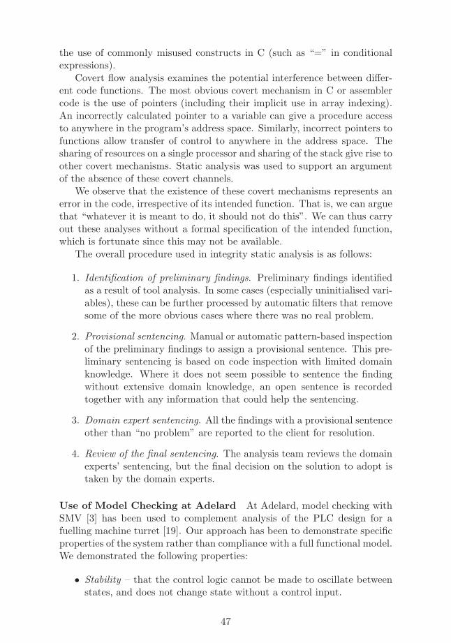
the use of commonly misused constructs in C (such as “=” in conditionalexpressions).
Covert flow analysis examines the potential interference between differ-ent code functions. The most obvious covert mechanism in C or assemblercode is the use of pointers (including their implicit use in array indexing).An incorrectly calculated pointer to a variable can give a procedure accessto anywhere in the program’s address space. Similarly, incorrect pointers tofunctions allow transfer of control to anywhere in the address space. Thesharing of resources on a single processor and sharing of the stack give rise toother covert mechanisms. Static analysis was used to support an argumentof the absence of these covert channels.
We observe that the existence of these covert mechanisms represents anerror in the code, irrespective of its intended function. That is, we can arguethat “whatever it is meant to do, it should not do this”. We can thus carryout these analyses without a formal specification of the intended function,which is fortunate since this may not be available.
The overall procedure used in integrity static analysis is as follows:
1. Identification of preliminary findings. Preliminary findings identifiedas a result of tool analysis. In some cases (especially uninitialised vari-ables), these can be further processed by automatic filters that removesome of the more obvious cases where there was no real problem.
2. Provisional sentencing. Manual or automatic pattern-based inspectionof the preliminary findings to assign a provisional sentence. This pre-liminary sentencing is based on code inspection with limited domainknowledge. Where it does not seem possible to sentence the findingwithout extensive domain knowledge, an open sentence is recordedtogether with any information that could help the sentencing.
3. Domain expert sentencing. All the findings with a provisional sentenceother than “no problem” are reported to the client for resolution.
4. Review of the final sentencing. The analysis team reviews the domainexperts’ sentencing, but the final decision on the solution to adopt istaken by the domain experts.
Use of Model Checking at Adelard At Adelard, model checking withSMV [3] has been used to complement analysis of the PLC design for afuelling machine turret [19]. Our approach has been to demonstrate specificproperties of the system rather than compliance with a full functional model.We demonstrated the following properties:
• Stability – that the control logic cannot be made to oscillate betweenstates, and does not change state without a control input.
47
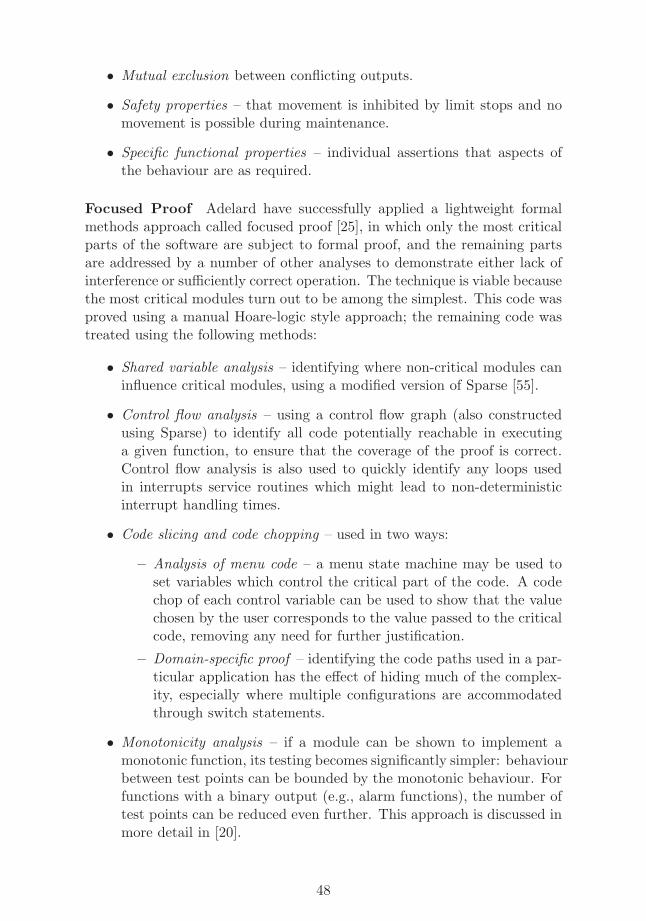
• Mutual exclusion between conflicting outputs.
• Safety properties – that movement is inhibited by limit stops and nomovement is possible during maintenance.
• Specific functional properties – individual assertions that aspects ofthe behaviour are as required.
Focused Proof Adelard have successfully applied a lightweight formalmethods approach called focused proof [25], in which only the most criticalparts of the software are subject to formal proof, and the remaining partsare addressed by a number of other analyses to demonstrate either lack ofinterference or sufficiently correct operation. The technique is viable becausethe most critical modules turn out to be among the simplest. This code wasproved using a manual Hoare-logic style approach; the remaining code wastreated using the following methods:
• Shared variable analysis – identifying where non-critical modules caninfluence critical modules, using a modified version of Sparse [55].
• Control flow analysis – using a control flow graph (also constructedusing Sparse) to identify all code potentially reachable in executinga given function, to ensure that the coverage of the proof is correct.Control flow analysis is also used to quickly identify any loops usedin interrupts service routines which might lead to non-deterministicinterrupt handling times.
• Code slicing and code chopping – used in two ways:
– Analysis of menu code – a menu state machine may be used toset variables which control the critical part of the code. A codechop of each control variable can be used to show that the valuechosen by the user corresponds to the value passed to the criticalcode, removing any need for further justification.
– Domain-specific proof – identifying the code paths used in a par-ticular application has the effect of hiding much of the complex-ity, especially where multiple configurations are accommodatedthrough switch statements.
• Monotonicity analysis – if a module can be shown to implement amonotonic function, its testing becomes significantly simpler: behaviourbetween test points can be bounded by the monotonic behaviour. Forfunctions with a binary output (e.g., alarm functions), the number oftest points can be reduced even further. This approach is discussed inmore detail in [20].
48
4 Model Checking in Safety Cases
One way of structuring a software safety case is to break down the safetyargument by attribute, as shown below (these are derived from [5]).
Attributes of the service that are provided when the component functionscorrectly
• Functional properties : The primary functional behaviour of the com-ponent.
• Timing properties: The time allowed for the software to respond togiven inputs or to periodic events, and/or the performance of the soft-ware in terms of transactions or messages handled per unit time.
• Accuracy: The required precision of the computed results.
Attributes dealing with the overall likelihood of malfunction
• Reliability: continuity of correct service. The probability that thesoftware will perform to a specified requirement for a specified periodof time under specified conditions.
• Availability: fraction of time for which a system is capable of fulfillingits intended purpose.
Attributes dealing with recovery from failure and changes
• Maintainability: ability to undergo modifications and repairs.
Behaviour with respect to certain classes of fault
• Robustness: The behaviour of the component in the event of exter-nal events: spurious (unexpected) inputs, hardware faults and powersupply interruptions, either in the component itself or in connecteddevices.
• Failure integrity: The probability that an internal failure can be de-tected externally.
• Usability: Avoidance of error and delay when the component interfaceswith a human operator.
Consequences of behaviour, different types of loss
• Security: Prevention of loss of component confidentiality, availabilityand integrity due to external attack.
• Non-interference: The absence of interference with other systems froman operational component.
49
Of these attributes, some are more appropriate than others to addressthrough model checking. Conventional model checking approaches can dealwith functional properties, and approaches based on timed automata maybe able to handle timing properties sufficiently provided a strong enoughmodel of the execution environment can be created. It may be possible tohandle accuracy using infinite-state or SMT5 - based techniques.
Maintainability, as a meta-property, may be better handled by analysis ofthe safety case itself. Does the safety case demonstrate that every attributecontinues to meet its requirements over the lifetime of the system? A semi-formal approach to structuring a safety case using an inductive argumentover system changes due to age or damage was presented in the ASDESproject [20].
Reliability and availability are not immediately amenable to model-checking style approaches, although discovery and elimination of other bugswill improve the worst case bounds generated by reliability modelling tech-niques [22, 23]. Robustness and failure integrity may be handled by tech-niques which deliberately perturb the inputs or the internal logic (failuremode injection) and measure the resulting faults; one such technique isFSAP/NuSMV-SA, based on the NuSMV model checker [2].
The remaining attributes (usability, security, and non-interference) aretoo application-specific to be immediately considered, although certain as-pects of each will be amenable to modelling (e.g., absence of certain inter-fering behaviours).
5Satisfiability Modulo Theorems (SMT) is an extension of Satisfiability (SAT) solvertechnology to handle propositional formulae in which some symbols are defined by asser-tions in some other theory, typically linear inequalities.
50
5 Conclusions
This report covers the state of the art in using formal methods in connectionwith NPP I&C systems and other safety critical systems. We have coveredtopics on safety assessment, formal methods in analysis of safety criticalsystems, as well as previous approaches to software and automation analysisin NPPs.
The main focus of the MODSAFE project has been to evaluate theapplicability of model checking methods to the analysis of safety critical NPPI&C systems. The two case studies done in 2007 have demonstrated that theapproach is feasible for the design validation of the two systems concerned:the arc protection system, and the emergency cooling system [110]. In bothcase studies the controller was modelled using the NuSMV model checker,and placed in an environment model modelling an abstraction of the processbeing controlled. The models were then model checked, and proved to workaccording to their specifications formalised in temporal logic from the designdocuments used. For the systems considered, the scalability of the modelchecker to analyse the system on all relevant input sequence combinationswas sufficient. On the NPP I&C systems analysis side the approach closestto the one applied in the MODSAFE case studies is [117], where modelchecking is used as a design aid for developing the control system in the firstplace, instead of analysing its design after the development.
The range of software based systems used in NPP I&C systems is verylarge, from PLCs and small smart devices with small embedded programsto larger software systems like UPSs and automation systems (DCS) witha large platform software component. We have so far focused on smallsafety critical control systems where model checking seems to be fairly wellapplicable, at least with the kinds of systems that have only limited processfeedback like emergency shutdown systems. Scaling up to larger systemsis an interesting challenge, and requires more research. For example, moreadvanced methods for dealing with real-time aspects of systems as well asmethods for comparing a system at different levels of abstraction are calledfor. It may be also the case that model checking should be applied inconjunction with other formal safety critical systems analysis techniques toscale up to larger systems.
51
References
[1] Caveat, http://www-list.cea.fr/labos/gb/LSL/caveat/.
[2] FSAP/NuSMV-SA. Available from http://sra.itc.it/tools/
fsap.
[3] The SMV system. http://www.cs.cmu.edu/∼modelcheck/smv.html.
[4] ASCAD – Adelard Safety Case Development Manual, 1998. ISBN 09533771 0 5.
[5] Avizienis, A., Laprie, J.-C., Randell, B., and Landwehr, C. Basicconcepts and taxonomy of dependable and secure computing. IEEETransactions on Dependable and Secure Computing, 1(1):11–33, 2004.
[6] Ball, T., Cook, B., Levin, V., and Rajamani, S. K. SLAM and staticdriver verifier: Technology transfer of formal methods inside Microsoft.In Proceedings of the 4th International Conference on Integrated For-mal Methods (IFM 2004), volume 2999 of Lecture Notes in ComputerScience, pages 1–20. Springer-Verlag, 2004.
[7] Ball, T. and Rajamani, S. K. The SLAM project: debugging sys-tem software via static analysis. In Conference Record of the 29thACM SIGPLAN-SIGACT Symposium on Principles of ProgrammingLanguages (POPL 2002), pages 1–3. Association for Computing Ma-chinery, 2002.
[8] Bauer, N., Engell, S., Huuck, R., Lohmann, S., Lukoschus, B.,Remelhe, M., and Stursberg, O. Verification of PLC programs givenas sequential function charts. In Ehrig et al. [50], pages 517–540.
[9] Bauer, N., Huuck, R., Lukoschus, B., and Engell, S. A unifying seman-tics for sequential function charts. In Ehrig et al. [50], pages 400–418.
[10] Bedford, T. and Cooke, R. Probabilistic risk analysis – foundationsand methods. Cambridge University Press, 2001.
[11] Behrmann, G., David, A., Larsen, K. G., Hakansson, J., Pettersson,P., Yi, W., and Hendriks, M. UPPAAL 4.0. In QEST, pages 125–126.IEEE Computer Society, 2006.
[12] Berard, B., Bidoit, M., Finkel, A., Laroussinie, F., Petit, A., Petrucci,L., and Schnoebelen, P. Systems and Software Verification. Model-Checking Techniques and Tools. Springer, 2001.
52
[13] Bergerand, J. L. and Pilaud, E. Design and qualification of softwarefor protection and control systems: the use of SAGA. In SFEN In-ternational Conference on Operability of Nuclear Systems in Normaland Adverse Environments, Lyon, 1989.
[14] Biere, A., Cimatti, A., Clarke, E., and Zhu, Y. Symbolic model check-ing without BDDs. In TACAS’99, volume 1579 of LNCS, pages 193–207. Springer, 1999.
[15] Biere, A., Clarke, E., Raimi, R., and Zhu, Y. Verifying safety proper-ties of a Power PC microprocessor using symbolic model checking with-out BDDs. In CAV’99, volume 1633 of LNCS, pages 60–71. Springer,1999.
[16] Biere, A., Heljanko, K., Junttila, T., Latvala, T., and Schuppan, V.Linear encodings of bounded LTL model checking. Logical Methods inComputer Science, 2(5:5), 2006. (doi: 10.2168/LMCS-2(5:5)2006).
[17] Bishop, P. G. and Bloomfield, R. E. A methodology for safety casedevelopment. In Safety-Critical Systems Symposium (SSS ’98), Birm-ingham, UK, February 1998.
[18] Bishop, P. G., Bloomfield, R. E., Clement, T. P., Guerra, A. S. L., andJones, C. Integrity static analysis of COTS/SOUP. In Proceedings ofSAFECOMP 2003, pages 63–76, Edinburgh, UK, September 2003.Springer-Verlag.
[19] Bishop, P. G., Bloomfield, R. E., and Guerra, A. S. D. L. Quantifica-tion of safety system failure probability – task a: Reliability assessmentof the siarls example. Technical Report D/189/4306/2, Adelard, June2001.
[20] Bishop, P. G., Bloomfield, R. E., Guerra, A. S. L., Sheridan, D. J.,and Tourlas, K. Asdes: Assessment of smart devices. Technical ReportD/352/10502/1, Adelard, December 2006.
[21] Bishop, P., Bloomfield, R., Clement, T., and Guerra, S. Softwarecriticality analysis of COTS/SOUP. In Proceedings of SAFECOMP2002, pages 198–211, Catania, Italy, September 2002. Springer-Verlag.
[22] Bishop, P. and Bloomfield, R. A conservative theory for long-termreliability growth prediction. IEEE Trans. Reliability, 45(4):550–560,1996. ISSN 0018-9529.
[23] Bishop, P. and Bloomfield, R. Using a log-normal failure rate distribu-tion for worst case bound reliability prediction. In ISSRE 2003, pages237–245, Denver, Colorado, USA, November 2003.
53
[24] Bjesse, P., Leonard, T., and Mokkedem, A. Finding bugs in an Alphamicroprocessor using satisfiability solvers. In Proceedings of 13th In-ternational Conference on Computer Aided Verification, (CAV’2001),pages 454–464. Springer-Verlag, 2001. LNCS 2102.
[25] Bloomfield, R. and Sheridan, D. Applying formal methods at allSILs. In INUCE Control and Instrumentation conference, Manchester,September 2007.
[26] Bloomfield, R. E. and Guerra, S. Process modelling to support de-pendability arguments. In 2002 International Conference on Depend-able Systems and Networks (DSN 2002), pages 113–122, Washington,DC, USA, June 2002.
[27] Bradley, A. R. and Manna, Z. The Calculus of Computation: DecisionProcedures with Applications to Verification. Springer, 2007.
[28] Brinksma, E. and Tretmans, J. Testing Transition Systems: An An-notated Bibliography. In Summer School MOVEP’2k – Modelling andVerification of Parallel Processes, pages 44–50, Nantes, July 2000.
[29] Brinksma, H. and Mader, A. H. Verification and optimization of a PLCcontrol schedule. In Havelund, K., Penix, J., and Visser, W., editors,7th Int. SPIN Workshop on Model Checking of Software, StanfordUniv., California, volume LNCS 1885, pages 73–92, Berlin, August2000. Springer-Verlag.
[30] Bryant, R. E. Symbolic Boolean manipulation with ordered binarydecision diagrams. ACM Computing surveys, 24(3):293–318, 1992.
[31] Burch, J., Clarke, E., McMillan, K., Dill, D., and Hwang, L. Symbolicmodel checking: 1020 states and beyond. Information and Computa-tion, 98:142–170, 1992.
[32] Burch, J. R., Clarke, E. M., McMillan, K. L., Dill, D. L., and Hwang,L. J. Symbolic model checking: 1020 states and beyond. Informationand Computation, 98(2):142–170, 1992.
[33] CAA Safety Regulation Group. CAP 670—ATS Safety Requirements,1998.
[34] Canet, G., Couffin, S., Lesage, J.-J., Petit, A., and Schnoebelen, Ph.Towards the automatic verification of PLC programs written in In-struction List. In Proceedings of the IEEE International Conferenceon Systems, Man and Cybernetics (SMC 2000), pages 2449–2454,Nashville, Tennessee, USA, October 2000. Argos Press.
54
[35] Carloganu, A. and Raguideau, J. Claire: An event-driven simulationtool for test and validation of software programs. In InternationalConference on Dependable Systems and Networks (DSN’02), page 538.IEEE, June 2002.
[36] Caspi, P., Pilaud, D., Halbwachs, N., and Plaice, J. Lustre: A declara-tive language for programming synchronous systems. In POPL, pages178–188, 1987.
[37] Cho, J., Yoo, J., and Cha, S. D. NuEditor - A tool suite for spec-ification and verification of NuSCR. In Dosch, W., Lee, R. Y., andWu, C., editors, SERA, volume 3647 of Lecture Notes in ComputerScience, pages 19–28. Springer, 2004.
[38] Cimatti, A., Clarke, E., Giunchiglia, E., Giunchiglia, F., Pistore, M.,Roveri, M., Sebastiani, R., and Tacchella, A. NuSMV 2: An open-source tool for symbolic model checking. In CAV’02, volume 2404 ofLNCS, pages 359–364. Springer, 2002.
[39] Cimatti, A., Roveri, M., and Sheridan, D. Bounded verification ofpast LTL. In Hu, A. J. and Martin, A. K., editors, Formal Methods inComputer-Aided Design; 5th International Conference, FMCAD 2004,Austin, TX, USA, November 2004. Springer.
[40] Clarke, E. M., Grumberg, O., and Peled, D. A. Model Checking. TheMIT Press, 1999.
[41] Clarke, E. and Emerson, E. Design and synthesis of synchronization ofskeletons using branching time temporal logic. In Proceedings of theIBM Workshop on Logics of Programs, volume 131 of LNCS, pages52–71. Springer, 1981.
[42] Copty, F., Fix, L., Fraer, R., Giunchiglia, E., Kamhi, G., Tacchella,A., and Vardi, M. Y. Benefits of bounded model checking at an in-dustrial setting. In Proceedings of 13th International Conference onComputer Aided Verification, (CAV’2001), pages 436–453. Springer-Verlag, 2001. LNCS 2102.
[43] Courtois, P.-J. A dependability justification framework for NPP dig-ital instrumentation and control systems. Technical report, CemsisProject, March 2004.
[44] Crow, J., Javaux, D., and Rushby, J. Models and mechanized meth-ods that integrate human factors into automation design. In Abbott,K., Speyer, J.-J., and Boy, G., editors, HCI-AERO 2000: Interna-tional Conference on Human-Computer Interaction in Aeronautics,pages 163–168, Toulouse, France, sep 2000.
55
[45] de Vries, R. G. and Tretmans, J. On-the-fly conformance testing us-ing SPIN. International Journal on Software Tools for TechnologyTransfer (STTT), 2(4):382–393, 2000.
[46] Dierks, H., Fehnker, A., Mader, A. H., and Vaandrager, F. W. Oper-ational and logical semantics for polling real-time systems. In Anders,P. R. and Rischel, H., editors, 7th Int. Symp. on Formal Techniques inReal-Time and Fault Tolerant Systems (FTRTFT), Lyngby, Denmark,volume LNCS 1486, pages 29–40, Berlin, September 1998. Springer-Verlag.
[47] Dierks, H. PLC-Automata: A new class of implementable real-timeautomata. In Bertran, M. and Rus, T., editors, ARTS, volume 1231of Lecture Notes in Computer Science, pages 111–125. Springer, 1997.
[48] Dill, D. L. The Murϕ verification system. In Proceedings of the 8th In-ternational Conference on Computer Aided Verification (CAV 1996),volume 1102 of Lecture Notes in Computer Science, pages 390–393.Springer-Verlag, 1996.
[49] Een, N. and Sorensson, N. Temporal induction by incremental SATsolving. In Strichman, O. and Biere, A., editors, Electronic Notes inTheoretical Computer Science, volume 89(4). Elsevier, July 2003.
[50] Ehrig, H., Damm, W., Desel, J., Große-Rhode, M., Reif, W.,Schnieder, E., and Westkamper, E., editors. Integration of SoftwareSpecification Techniques for Applications in Engineering, Priority Pro-gram SoftSpez of the German Research Foundation (DFG), Final Re-port, volume 3147 of Lecture Notes in Computer Science. Springer,2004.
[51] Filliatre, J.-C. and Marche, C. The why/krakatoa/caduceus platformfor deductive program verification. In Damm, W. and Hermanns, H.,editors, CAV, volume 4590 of Lecture Notes in Computer Science,pages 173–177. Springer, 2007.
[52] Frey, G. Design and formal Analysis of Petri Net based Logic ControlAlgorithms. PhD thesis, Universitat Kaiserslautern, 2002.
[53] Frey, G. and Litz, L. Formal methods in PLC programming. In IEEEInternational Conference on Systems, Man and Cybernetics (SMC2000), pages 2431–2436, Nashville (TN), USA, October 2000.
[54] Govier, T. A Practical Study of Argument. Wadsworth, 1988.
[55] Group, L. K. Sparse—a semantic parser for C. http://www.kernel.org/pub/linux/kernel/people/josh/sparse/.
56
[56] Haapanen, P., Korhonen, J., and Pulkkinen, U. Licensing process forsafety-critical software-based systems. Technical Report STUK-YTO-TR 171, STUK, Helsinki, 2000.
[57] Hatton, L. Safer C. McGraw-Hill, 1994.
[58] Heiner, M. and Menzel, T. A Petri net semantics for thePLC language Instruction List; IEEE Workshop on Discrete EventSystems, 1998. Available from http://citeseer.ist.psu.edu/
heiner98petri.html.
[59] Heljanko, K., Junttila, T., and Latvala, T. Incremental and completebounded model checking for full PLTL. In CAV’05, volume 3576 ofLNCS, pages 98–111. Springer-Verlag, July 2005.
[60] Heljanko, K., Junttila, T. A., Keinanen, M., Lange, M., and Latvala,T. Bounded model checking for weak alternating buchi automata. InBall, T. and Jones, R. B., editors, CAV, volume 4144 of Lecture Notesin Computer Science, pages 95–108. Springer, 2006.
[61] Holzmann, G. J. The model checker Spin. IEEE Transactions onSoftware Engineering, 23(5):279–295, 1997.
[62] Huima, A. Implementing Conformiq Qtronic. In Petrenko, A., Veanes,M., Tretmans, J., and Grieskamp, W., editors, TestCom/FATES, vol-ume 4581 of Lecture Notes in Computer Science, pages 1–12. Springer,2007.
[63] Huuck, R. Software Verification for Programmable Logic Controllers.PhD thesis, Christian-Albrechts-Universitat zu Kiel, Germany, 2003.
[64] IAEA (International Atomic Energy Agency, Vienna. Safety of Nu-clear power plants: Design—Requirements, 2000. NS-R-1.
[65] IAEA (International Atomic Energy Agency, Vienna. IAEA SafetyGlossary: Terminology Used in Nuclear Safety and Radiation Protec-tion, 2007.
[66] Modelling of PLC behaviour by means of timed net Condition/Eventsystems, 1997.
[67] International Electrotechnical Commission. IEC 60812 Analysis tech-niques for system reliability—procedure for failure mode and effectsanalysis (FMEA), 2 edition, January 2001.
[68] International Standards Organization. ISO 8402. Quality vocabulary,1986.
57
[69] Jackson, P. and Sheridan, D. Clause form conversions for booleancircuits. In Seventh International Conference on Theory and Applica-tions of Satisfiability Testing (SAT 2004). Springer-Verlag, December2004.
[70] Jee, E., Yoo, J., and Cha, S. D. Control and data flow testing onfunction block diagrams. In Winther, R., Gran, B. A., and Dahll,G., editors, SAFECOMP, volume 3688 of Lecture Notes in ComputerScience, pages 67–80. Springer, 2005.
[71] Jimnez-Fraustro, F. and Rutten, E. A synchronous model of the PLCprogramming language ST. Available from citeseer.ist.psu.edu/
393006.html.
[72] Jimnez-Fraustro, F. and ric Rutten. A synchronous model of IEC61131 PLC languages in signal. In ECRTS, pages 135–142. IEEEComputer Society, 2001.
[73] Kaldewaij, A. Programming: the derivation of algorithms. Prentice-Hall, Inc., Upper Saddle River, NJ, USA, 1990.
[74] Kelly, T. P. and McDermid, J. A. Safety case construction and reuseusing patterns. In Daniel, P., editor, SAFECOMP97: the 16th In-ternational Conference on Computer Safety, Reliability and SecurityYork, UK, 7-10 September 1997, pages 55–69. Springer, 1997.
[75] Kopustinskas, V., Kirchsteiger, C., Soubies, B., Daumas, F., Gassino,J., Pron, J., Rgnier, P., Martz, J., Baleanu, M., Miedl, H., Kersken,M., Pulkkinen, U., Koskela, M., Haapanen, P., Jarvinen, M., Bock, H.,and Dreves, W. Benchmark exercise of safety evaluation of computerbased systems (BE-SECBS). In FISA-2003 / EU Research in ReactorSafety, Luxembourg, November 2003.
[76] Latvala, T., Biere, A., Heljanko, K., and Junttila, T. Simple boundedLTL model checking. In Proceedings of the 5th International Confer-ence on Formal Methods in Computer-Aided Design (FMCAD 2004),volume 3312 of Lecture Notes in Computer Science, pages 186–200.Springer-Verlag, 2004.
[77] Latvala, T., Biere, A., Heljanko, K., and Junttila, T. Simple is better:Efficient bounded model checking for past LTL. In Proceedings ofthe 6th International Conference on Verification, Model Checking andAbstract Interpretation (VMCAI 2005), volume 3385 of Lecture Notesin Computer Science, pages 380–395. Springer-Verlag, 2005.
[78] Loeis, K., Bani Younis, M., and Frey, G. Application of symbolicand bounded model checking to the verification of logic control sys-
58
tems. In 10th IEEE International Conference on Emerging Technolo-gies and Factory Automation (ETFA 2005), pages 247–250, Catania,Italy, September 2005.
[79] Luttgen, G. and Carreno, V. Analyzing mode confusion via modelchecking. In Dams, D., Gerth, R., Leue, S., and Massink, M., editors,Theoretical and Practical Aspects of SPIN Model Checking (SPIN ’99),volume 1680 of Lecture Notes in Computer Science, pages 120–135,Toulouse, France, September 1999. Springer-Verlag.
[80] Mader, A. H. A classification of PLC models and applications. In Boel,R. and Stremersch, G., editors, 5th Int. Workshop on Discrete EventSystems (WODES) – Discrete Event Systems, Analysis and Control,Ghent, Belgium, pages 239–247, Boston, Massachusetts, August 2000.Kluwer Academic Publishers.
[81] Mader, A. H., Brinksma, H., Wupper, H., and Bauer, N. Design of aPLC control program for a batch plant - VHS Case Study 1. EuropeanJournal of Control, 7(4):416–439, 2001.
[82] Mader, A. H. and Wupper, H. Timed automaton models for simpleprogrammable logic controllers. In 11th Euromicro Conf. on Real-Time Systems, York, UK, pages 114–122, Los Alamitos, California,June 1999. IEEE Computer Society.
[83] Mader, A. Precise timing analysis of PLC applications two small ex-amples. Unpublished manuscript. Available from http://citeseer.
ist.psu.edu/mader00precise.html.
[84] Mader, A. and Wupper, H. What is the formal method for PLC appli-cations? In Proceedings ADPM 2000: 4th International Conference onAutomation of Mixed Processes: Hybrid Dynamic Systems, September18-19, 2000, Dortmund, Germany, 2000.
[85] Makela, M. Maria: Modular reachability analyser for algebraic systemnets. In Proceedings of the 23rd International Conference on Applica-tion and Theory of Petri Nets (ICATPN 2002), volume 2360 of LectureNotes in Computer Science, pages 434–444. Springer-Verlag, 2002.
[86] Manna, Z. and Pnueli, A. Temporal Verification of Reactive Systems:Safety. Springer, 1995.
[87] McMillan, K. L. Symbolic Model Checking. Kluwer Academic Pub-lishers, 1993.
[88] Miller, S. P., Barber, S., Carlson, T., Lempia, D., and Tribble, A.A methodology for improving mode awareness in flight guidance de-
59
sign. In Proceedings of the 21st Digital Avionics Systems Conference(DASC’02), Irvine, CA, 2002.
[89] MISRA. Guidelines for the use of the C language in vehicle basedsoftware, 1998.
[90] Moon, I. Modeling programmable logic controllers for logic verifica-tion, 1994.
[91] Oak Ridge National Laboratory. Emerging Technologies in Instrumen-tation and Controls: An Update, January 2006.
[92] Olderog, E.-R. Correct Real-Time Software for Programmable LogicControllers. In Correct System Design - Recent Insights and Advances,volume 1710 of Lecture Notes in Computer Science, pages 342–362.Springer, 1999.
[93] Olderog, E.-R. and Dierks, H. Moby/RT: A Tool for Specification andVerification of Real-Time Systems. Journal of Universal ComputerScience, 9(2):88–105, February 2003.
[94] Parnas, D., van Schouwen, A., and Kwan, P. Evaluation of safety-critical software. Communications of the ACM, 33(6):636–648, 1990.
[95] Pavey, D. J. Final public synthesis report. Technical report, CEMSIS(Cost Effective Modernisation of Systems Important to Safety), 2004.http://www.cemsis.org/.
[96] Peled, D. A. Software Reliability Methods. Springer, 2001.
[97] Quielle, J. and Sifakis, J. Specification and verification of concurrentsystems in CESAR. In Proceedings of the 5th International Symposiumon Programming, pages 337–350, 1981.
[98] Rossi, O. and Schnoebelen, Ph. Formal modeling of timed functionblocks for the automatic verification of Ladder Diagram programs. InEngell, S., Kowalewski, S., and Zaytoon, J., editors, Proceedings ofthe 4th International Conference on Automation of Mixed Processes:Hybrid Dynamic Systems (ADPM 2000), pages 177–182, Dortmund,Germany, September 2000. Shaker Verlag.
[99] Safety Assessment Principles for Nuclear Facilities, 2006 Edition.Available from http://www.hse.gov.uk/nuclear/saps/saps2006.
pdf.
[100] Sheeran, M., Singh, S., and Stalmarck, G. Checking safety propertiesusing induction and a SAT-solver. In Jr., W. A. H. and Johnson, S. D.,editors, Proceedings of the 3rd International Conference on Formal
60
Methods in Computer-Aided Design (FMCAD ’2000), volume 1954 ofLecture Notes in Computer Science, pages 108–125, Austin, Texas,USA, November 2000. Springer.
[101] Song, M. J., Koo, S. R., and Seong, P.-H. Development of a verificationmethod for timed function blocks using ESDT and SMV. In HASE,pages 285–286. IEEE Computer Society, 2004.
[102] STUK. Radiation and Nuclear Safety Authority Finland, Instrumen-tation systems and components at nuclear facilities, 2002. Availableon-line: http://www.stuk.fi/saannosto/YVL5-5e.html.
[103] Systems, R. Model-based testing and validation with Reactis. Techni-cal whitepaper, available from http://www.reactive-systems.com/
papers/bcsf.pdf.
[104] Tapken, J. and Dierks, H. MOBY/PLC - graphical development ofPLC-Automata. In Ravn, A. P. and Rischel, H., editors, FTRTFT,volume 1486 of Lecture Notes in Computer Science, pages 311–314.Springer, 1998.
[105] Technologies, E. SCADE tool. http://www.esterel-technologies.com.
[106] Toulmin, S. E. The Uses of Argument. Cambridge University Press,1958.
[107] Tretmans, J. A Formal Approach to Conformance Testing. PhD thesis,University of Twente, Enschede, The Netherlands, 1992.
[108] Turk, A. L., Probst, S. T., and Powers, G. J. Verification of real timechemical processing systems. In Maler, O., editor, HART, volume 1201of Lecture Notes in Computer Science, pages 259–272. Springer, 1997.
[109] UK Ministry of Defence. Def Stan 00-56—Safety Management Re-quirements for Defence Systems, 3 edition, December 2004.
[110] Valkonen, J., Pettersson, V., Bjorkman, K., Holmberg, J.-E.,Koskimies, M., Heljanko, K., and Niemela, I. Model-Based Analysisof an Arc Protection and an Emergency Cooling System – MODSAFE2007 Work Report. VTT Working Papers 93, 2008.
[111] Varpaaniemi, K., Heljanko, K., and Lilius, J. PROD 3.2 - An ad-vanced tool for efficient reachability analysis. In Proceedings of the9th International Conference on Computer Aided Verification (CAV1997), volume 1254 of Lecture Notes in Computer Science, pages 472–475. Springer-Verlag, 1997.
61
[112] Wahlstrom, B., Venta, O., and Valkonen, J. Proving absence of CCFs;a case for open source. In Technical Meeting on Common-Cause Fail-ures in Digital Instrumentation and Control Systems of Nuclear PowerPlants, Bethesda, Maryland, USA, June 2007.
[113] Wassyng, A. and Lawford, M. Lessons learned from a successful im-plementation of formal methods in an industrial project. In Araki, K.,Gnesi, S., and Mandrioli, D., editors, FME, volume 2805 of LectureNotes in Computer Science, pages 133–153. Springer, 2003.
[114] Weaver, R., Fenn, J., and Kelly, T. A pragmatic approach to reasoningabout the assurance of safety arguments. In Proceedings of the 8thAustralian workshop on Safety critical systems and software, pages57–67, Canberra, Australia, October 2003.
[115] Willems, H. X. Compact timed automata for PLC programs. Tech-nical report, CiteSeer [http://cs1.ist.psu.edu/cgi-bin/oai.cgi](United States), 1999.
[116] Winter, M. Instrumentation and control system, yk1 - basic profes-sional training course on nuclear safety finland, part iv, lecture 11,2003.
[117] Yoo, J., Cha, S., Son, H. S., Kim, C. H., and Lee, J.-S. PLC-Basedsafety critical software development for nuclear power plants. In Heisel,M., Liggesmeyer, P., and Wittmann, S., editors, SAFECOMP, volume3219 of Lecture Notes in Computer Science, pages 155–165. Springer,2004.
[118] Yoo, J., Cha, S., Kim, C. H., and Song, D. Y. Synthesis of FBD-basedPLC design from NuSCR formal specification. Reliability Engineeringand System Safety, 87(2):287–294, 2005.
[119] Yoo, J., Kim, T., Cha, S. D., Lee, J.-S., and Son, H. S. A formalsoftware requirements specification method for digital nuclear plantprotection systems. Journal of Systems and Software, 74(1):73–83,2005.
[120] Younis, M. B. and Frey, G. Formalization of existing PLC programs: Asurvey. In Proceedings of CESA 2003, pages Paper No.S2–R–00–0239,Lille, France, July 2003.
[121] Zhang, W. Verification of operator procedures by model checking.Technical Report HWR-582, OECD Halden Reactor Project, April1999.
[122] Zhang, W. Model checking as an aid to procedure design. TechnicalReport HWR-648, OECD Halden Reactor Project, January 2001.
62

ISBN 978-951-38-7158-1 (URL: http://www.vtt.fi/publications/index.jsp) ISSN 1459-7683 (URL: http://www.vtt.fi/publications/index.jsp)