Embed Size (px)
Citation preview

Simple, intuitive and compact.
Liquid Handling StationOperators manual
F I R S T C L A S S · B R A N D
English

ii
BRAND GMBH + CO KG · [email protected] · www.brand.de
EG-Konformitätserklärung EC-Conformity Declaration
Das bezeichnete Gerät entspricht den einschlägigen Anforderungen der aufgeführten EG-Richtlinien und Normen. Die alleinige Verantwortung für die Ausstellung dieser Konformitätserklärung trägt der Hersteller. Bei einer nicht mit uns abgestimmten Änderung des Gerätes verliert die Erklärung ihre Gültigkeit.
The device named below fulfills the relevant fundamental requirements of the EC directives and standards listed. This declaration of conformity is issued under the sole responsibility of the
manufacturer. In case of unauthorized modifications to the device, the declaration becomes invalid.
Gerätebezeichnung / Device name: Liquid Handling Station inkl. Liquid Ends Liquid Handling Station incl. Liquid Ends
Gerätetyp / Device type: Pipettiersystem Pipette system
Hersteller / Manufacturer: BRAND GMBH + CO KG
Adresse / Address: Otto-Schott-Str. 25 97877 Wertheim · Germany
Der oben beschriebene Gegenstand der Erklärung erfüllt die einschlägigen Harmonisierungsrechtsvorschriften der Union: The object of the declaration described above is in conformity with the relevant Union harmonisation legislation:
Harmonisierte Normen: Harmonized standards:
RoHS II 2011/65/EU: 2011/06 EN 50581: 2012
Weitere berücksichtige Richtlinien: Other considered directives:
Harmonisierte Normen: Harmonized standards:
EMV EMC
2014/30/EU: 2014/02 EN 61326-1:2013; FCC 47 CFR Part 15B; ICES-003
Niederspannung LVD
2014/35/EU: 2014/02
EN 60320-1:2001+A1:2007
IEC 61010-1:2010 (3rd Ed.), IEC 61010-2-081:2015 (2nd Ed.)
Volumen//Volume - EN ISO 8655 -1/ -2 / -6 Wertheim, 01. September 2016 / September 01, 2016 # 11.01.01.02
Peter Mahler i.A. Josef Pfohl Technischer Geschäftsführer Qualitätsmanagement Managing Director Quality Management
Diese Erklärung bescheinigt die Übereinstimmung mit den genannten Harmonisierungsvorschriften,
beinhaltet jedoch keine Zusicherung von Eigenschaften. This document declares the accordance with the named harmonized regulations, but does NOT assure specific properties.

2
Table of Contents
1 User Instructions 5
1.1 Using this manual . . . . . . . . . . . . . . . . . . . . . . . . . . . . . . . . . 5
1.2 Information about this document . . . . . . . . . . . . . . . . . . . . . . . . . 5
1.3 Symbols . . . . . . . . . . . . . . . . . . . . . . . . . . . . . . . . . . . . . . 6
1.4 Glossary . . . . . . . . . . . . . . . . . . . . . . . . . . . . . . . . . . . . . . 7
1.5 Liability . . . . . . . . . . . . . . . . . . . . . . . . . . . . . . . . . . . . . . 10
2 Safety 11
2.1 Intended use . . . . . . . . . . . . . . . . . . . . . . . . . . . . . . . . . . . . 11
2.2 Safety instructions . . . . . . . . . . . . . . . . . . . . . . . . . . . . . . . . . 12
2.3 Transport and storage . . . . . . . . . . . . . . . . . . . . . . . . . . . . . . . 16
3 Liquid Handling Station 17
3.1 Overview . . . . . . . . . . . . . . . . . . . . . . . . . . . . . . . . . . . . . . 17
3.2 Included in delivery . . . . . . . . . . . . . . . . . . . . . . . . . . . . . . . . 18
3.3 Technical data . . . . . . . . . . . . . . . . . . . . . . . . . . . . . . . . . . . 18
4 Start-up 20
4.1 Setting up . . . . . . . . . . . . . . . . . . . . . . . . . . . . . . . . . . . . . 20
4.2 Connection . . . . . . . . . . . . . . . . . . . . . . . . . . . . . . . . . . . . . 21
4.3 Operation . . . . . . . . . . . . . . . . . . . . . . . . . . . . . . . . . . . . . 22
5 Replacing the Liquid End 23
6 Maintenance/Cleaning 24
6.1 Instrument . . . . . . . . . . . . . . . . . . . . . . . . . . . . . . . . . . . . . 24
6.2 Single-channel Liquid Ends . . . . . . . . . . . . . . . . . . . . . . . . . . . . 26
6.3 8-channel Liquid Ends . . . . . . . . . . . . . . . . . . . . . . . . . . . . . . . 27
7 Ordering Information 29
7.1 Liquid Handling Station and Accessories . . . . . . . . . . . . . . . . . . . . . 29
7.2 Spare parts . . . . . . . . . . . . . . . . . . . . . . . . . . . . . . . . . . . . . 32
3

4
1 User Instructions1.1 Using this manual
It is essential to read and follow this operating manual to work safely and correctly with theLiquid Handling Station.
Important!Read this operating manual carefully before using the Liquid Handling Station andkeep it in a location easily accessible to all users for later reference.
Use the Liquid Handling Station only for the intended use described in this manual.In case of doubt, contact the manufacturer of this product.
1.2 Information about this document
Manufacturer BRAND GMBH + CO KGOtto-Schott Strasse 2597877 WertheimGermany
Tel.: +49 9342 808-0Fax: +49 9342 808-98000E-mail: [email protected]: www.brand.de
Service BRAND GMBH + CO KGOtto-Schott Strasse 2597877 WertheimGermany
Tel.: +49 9342 808-1990Fax: +49 9342 808-91290E-mail: [email protected]
Document Manufacturer’s original operating manualLast updated: 06. September 2016
The latest version of the operating manual can be requested from the manufacturer in eitherPDF or HTML format.All rights reserved. This document and parts thereof may not be reproduced or stored on anelectronic storage system without the written approval of BRAND GMBH + CO KG.Any service marks used in this document are the property of their owners.
5
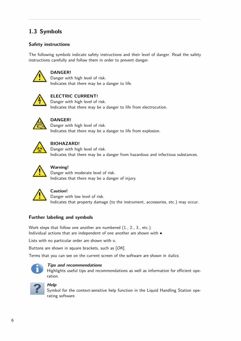
1.3 Symbols
Safety instructions
The following symbols indicate safety instructions and their level of danger. Read the safetyinstructions carefully and follow them in order to prevent danger.
DANGER!Danger with high level of risk.Indicates that there may be a danger to life.
ELECTRIC CURRENT!Danger with high level of risk.Indicates that there may be a danger to life from electrocution.
DANGER!Danger with high level of risk.Indicates that there may be a danger to life from explosion.
BIOHAZARD!Danger with high level of risk.Indicates that there may be a danger from hazardous and infectious substances.
Warning!Danger with moderate level of risk.Indicates that there may be a danger of injury.
Caution!Danger with low level of risk.Indicates that property damage (to the instrument, accessories, etc.) may occur.
Further labeling and symbols
Work steps that follow one another are numbered (1., 2., 3., etc.).Individual actions that are independent of one another are shown with •.Lists with no particular order are shown with o.Buttons are shown in square brackets, such as [OK].Terms that you can see on the current screen of the software are shown in italics.
Tips and recommendationsHighlights useful tips and recommendations as well as information for efficient ope-ration.
HelpSymbol for the context-sensitive help function in the Liquid Handling Station ope-rating software.
6
1.4 Glossary
AAdapters
Adapters are used to compensate for height differences between the positions equippedwith different types of labware. This achieves shorter distances and faster execution ofthe method. There can be height adapters, tip adapters, microtube, or PCR racks. Anoverview of all the adapters available can be found in the section ”Ordering data” under”Accessories”.
CCommand
Indicates a single sequence step in the program sequence of a method. In the operatingsoftware, there are four different commands available: Transfer, Wait, Mix, and Breakcommands.
DDestination
Labware or destination container into which the liquid is transferred from another con-tainer (the source).
Destination wellIndividual well in a labware that has been defined as the destination.
FFilling volume
Maximum volume available in a labware or an individual well for filling with liquid.GGraphical view
Area in the software that graphically represents the Work Table (with selected labware,filling, etc.).
LLabware
Collective term for microplates, PCR plates, deep-well plates, inserts, tube racks, tubes,tips and the waste box that can all be used with the Liquid Handling Station.
Liquid EndSingle- or 8-channel pipetting module that is connected to the motor control unit tocarry out liquid transfers with the Liquid Handling Station.
MMethod
Sequence consisting of naming the file, equipping of the Work Table, definition of thecommand and execution of the method. A more detailed explanation of the term ”Me-thod” can be found in the chapter ”Structure of methods”.
Minimum immersion depthDistance from the lower end of the tip to the surface of the liquid. This distance ensurescorrect aspiration of liquid and avoids problems such as the accidental aspiration of air.
7
Minimum bottom distanceDenotes the smallest permitted distance between the labware bottom and the lower endof the tip that will be approached when moving into the labware. This distance is usedto avoid crashes and ensure the correct aspiration of liquids.
PPipetting step
Aspiration of a predefined volume from a source well and dispense of that volume (entirelyor in partial steps) in a destination well.
PositionIndividual recess on the Work Table onto which the labware can be positioned. TheWork Table of the Liquid Handling Station has eight positions. Seven of them can beequipped freely, but one position is predefined for the waste box.
RRemaining Volume
Volume that must remain in the labware to permit defined, reliable liquid aspiration. Theremaining volume is reliant on the minimum immersion depth and the minimum bottomdistance.
SSettings
Configurations for the labware on the individual positions, as well as the individualcommands.
SourceLabware from which liquid is taken to transfer it into another labware (the destination).
Source WellIndividual well in a piece of labware defined as the source.
TTab Denotes individual tabs on a menu tab. Example: Method tab on the main menu.Transfer
A single transfer includes all the pipetting steps carried out between one or more sourcesand one or more destinations in a Transfer command.
Transfer volumeThe volume of liquid transferred from the source into the destination, or into the indi-vidual wells of the destination.
V(Distribution) Pattern
Specification of the position of aspiration in a source (source wells) and the position ofdispensing of a destination (destination wells).
WWell Content
General: Contents of one or more wells.In the operating software: Settings such as liquid volume, name, liquid type that applyto the contents of a fillable labware.
8
Work TableWorkspace of the Liquid Handling Station, whose eight positions can be virtually equip-ped using the software. After definition of the commands, the physical loading of theWork Table then takes place.
ZZ-tracking
Downward movement during liquid aspiration and upward movement while dispensing.The starting point of aspirating and dispensing can be set user-defined.
9
1.5 Liability
All specifications and instructions in this manual were compiled in consideration of the app-licable standards and regulations, the state of the art, and the many years of experience of themanufacturer.The manufacturer of this product cannot accept any liability for damages resulting from:
◦ Failure to follow this operating manual◦ Use of the instrument for anything but its intended use◦ Use by untrained personnel◦ Unauthorized modifiacation of the instrument◦ Unauthorized repair of the instrument◦ The use of third-party or unapproved spare parts◦ Normal wear, in particular of wearing parts such as pistons, seals, valves, etc.
The warranty terms for damages that can occur despite proper use can be found in themanufacturer’s General Terms of Business.Subject to technical changes, error, and printing errors.
10
2 Safety2.1 Intended use
The BRAND Liquid Handling Station is an automated pipetting system for use in routinelaboratories with small to medium sample throughput in research, development, or productionparticularly in such application fields as PCR, qPCR, ELISA, enzyme assays, etc.Typically, aqueous media such as buffer solutions (phosphate buffer, Tris-HCL buffer, etc.),protein solutions (BSA solutions, enzyme solutions, PCR master mix) and samples are pipetted.The instrument is used for the automatic, precision transfer of liquids. For the liquid transfer,there are autoclavable single-channel and 8-channel pipette modules (Liquid Ends) available,which are replaced manually. 7 SLAS-formatted working positions (P2-P8) can be loaded ontothe Work Table and freely assigned. One additional predefined position (P1) must be occupiedby the waste container.Limits and restrictions for use
◦ Operating temperature: + 15 °C to + 35 °C (instrument and reagents)◦ Vapor pressure: up to 500 mbar◦ Viscosity: 260 mPa s
Viscous and highly adhesive liquids may impair volumetric accuracy. Volumetric accuracy mayalso be impaired when pipetting liquids that differ from ambient temperature by more than+/- 5 °C.
Caution!Risk of corrosion◦ Do not use the instrument with liquids that attack polypropylene, PMMA (sideand front panels), POM or aluminum (labware adapters).
◦ Avoid aggressive vapors.◦ Avoid strong acids and bases.◦ Protect the instrument from penetration by liquids. Do not place containers ofliquid on, in, or next to the instrument.
This instrument can be used in combination with hazardous materials, operations and equip-ment. However, the Operating Manual cannot identify all of the safety risks that can occurfrom working with the instrument. It is the user’s responsibility to comply with the relevantsafety and health regulations and to determine the applicability prior to use.In case of doubt, contact the manufacturer!The safety instructions listed in the next chapter must always be followed. If damages shouldoccur due to use other than the intended use, no claims of any kind can be accepted.
11
2.2 Safety instructions
1. Danger due to electrical current
DANGER!Danger to life from electrical voltage
Life-threatening electrical voltages exist within the instrument.Contact with live components may result in a danger to life by electrocution.
◦ Commissioning may only take place if the instrument has been properly installed orrepaired.
◦ Immediately disconnect the device from the mains voltage in the event of any danger:pull the plug or disconnect the cables.
◦ Always be sure that the housing and covers are intact and closed.◦ Only connect the instrument to properly grounded power outlets.◦ Before connecting, check that the supply voltage matches the permitted operating vol-tage. An incorrect supply voltage can cause major damage to the instrument.
◦ Before turning on, be sure that the power cable and connections are undamaged.◦ The covers of the instrument must only be removed by technicians authorized by themanufacturer to do so. Turn off the instrument and pull the power plug before disas-sembly.
◦ Keep moisture away from live components to avoid short circuits.
2. Personnel requirements
WARNING!Qualification of personnel
Unqualified personnel are prohibited from working with the instrument.◦ The instrument may only be operated by experts, i.e. users who have been trained bythe manufacturer or specialized suppliers.
◦ To avoid injuries and property damage, keep unauthorized personnel away from the workarea of the instrument.
◦ Each user must read and understand the contents of the operating manual before usingthe instrument.
Caution!Repair and service
Repair and service may only be carried out by trained technical personnel.◦ Repairs to and service work on the instrument may only be carried out by experts, i.e.technicians who are authorized by the manufacturer to do so.
◦ Only original spare parts should be used.◦ Do not make any technical modifications to the instrument.
12
3. Danger due to failure to observe the intended use, or improper handling
WARNING!Follow the limitations on use
Do not use the instrument for anything but its intended use.◦ The instrument must only be used for its intended purpose. Explosive and flammable
substances must not be used◦ The manufacturer cannot assume any liability for any consequential damage , including
personal injury, loss of productivity of samples, and/or property damage that results fromfailure to observe the intended use.
◦ When in doubt, contact the manufacturer.
WARNING!Improper handling
Handle the instrument according to the safety instructions and the operating manual.◦ Do not use excessive force.◦ Improper handling (short circuit, mechanical damage, overheating, etc.) may lead to fire
or explosion of the instrument.◦ No liability can be assumed for damages due to improper handling.
4. Locally applicable safety instructions
WARNING!Compliance with locally applicable regulations
In addition to the safety regulations for the use of the instrument, locally applicable regu-lations must also be observed.
◦ This particularly applies to workplace safety and accident prevention (e.g. safety clothing,safety gloves, and eye protection) as well as hygiene regulations.
◦ Your own laboratory’s safety guidelines for handling any potentially hazardous substan-ces.
13
5. Danger due to hazardous substances
DANGER!Use of hazardous substances or infectious liquids
When handling infectious, aqueous fluids, national regulations and biosafety level of labo-ratories should be observed.The Liquid Handling Station is suitable for dealing with germs and biological material of riskclass I. The most current requirements stated in the ”Laboratory Biosafety Manual”(WorldHealth Organization) apply when dealing with germs of higher risk groups.The operator bears all responsibility for selecting the substances used and for their safe hand-ling.
◦ This applies particularly to radioactive, infectious, poisonous, aggressive, flammable, orotherwise dangerous substances.
◦ When working with infectious or hazardous samples, standard laboratory procedures andprecautions must be followed.
◦ Observe the material safety data sheets (MSDS) and the manufacturer’s applicationnotes.
◦ Dispose of the contents of the waste container in accordance with applicable regulati-ons. Particular caution is recommended when using inflammable, reactive, or infectiousliquids.
◦ If the instrument has been contaminated with hazardous substances, it must be cleanedand decontaminated.
The unit itself will not emit any potentially toxic or harmful gases or substances.
6. Danger of explosion
DANGER!Danger of explosion
In case of contact with explosive substances, there is a danger of explosion.◦ The instrument should not be operated in a potentially explosive atmosphere.◦ Do not use explosive or highly reactive substances with the instrument.◦ Do not store explosive substances near the instrument.◦ Do not use any flammable liquids, especially carbon disulfide.
14
7. Danger of crushing
Caution!Crushing danger - Watch your fingers and hands!
Only reach into the work area when the machinery is at a standstill!◦ If the front panel is opened while a program is in progress, the running process will be
interrupted after the current work step has finished.◦ Wait until the machinery has stopped before reaching into the work area!
8. Visual inspection before starting work
Caution!Inspection before starting work
Before starting work, inspect the instrument to verify that it is in proper condition.◦ If damage can be observed that would endanger safe operation, do not work with the
instrument, until appropriate repairs are performed.◦ If the instrument is contaminated with liquids or dirt, clean it up before starting work.
9. Malfunctions
Caution!Handling malfunctions
If malfunctions occur during the work process, correct them immediately.◦ Follow the instructions on the screen.◦ If the program does not display error messages and instructions, stop the procedure by
actuating the on/off switch. When in doubt, contact the manufacturer.◦ An ”emergency stop” can be carried out by pulling the power plug. Please note that in
this case data may be lost.
15
2.3 Transport and storage
WARNING!Risk of injury or property damage during transport◦ Always have at least two people to lift and carry the instrument.◦ When carrying the instrument, only grip it under the sides.◦ Only transport the instrument in a vertical orientation and do not tip it.
Before transport, remove all loose parts (adapters, containers, labware, etc.).Do not leave hazardous substances in the instrument. If necessary, clean and decontaminatethe instrument before transport.Environmental conditions for transport and storage:
◦ Temperature range: - 20 °C to + 65 °C◦ Humidity: max. 95 %
For optimum protection, the instrument must be transported in special packaging. To retainthat protection during storage as well, only remove the packaging shortly before installati-on.
Always use the original packaging for transportation! Please do not damage thepackaging or dispose of packaging. Unpack and repack machinery in accordancewith the included instructions!
16
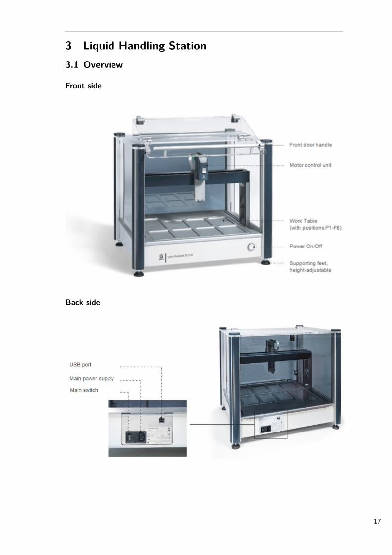
3 Liquid Handling Station3.1 Overview
Front side
Back side
17
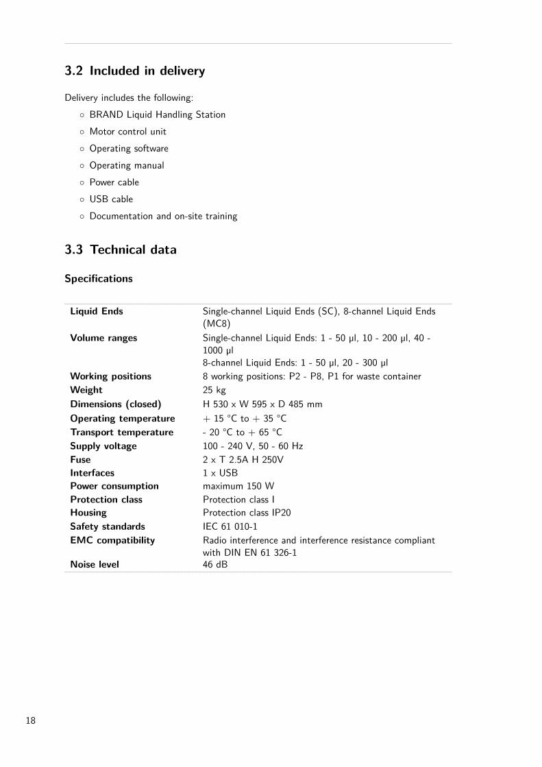
3.2 Included in delivery
Delivery includes the following:◦ BRAND Liquid Handling Station◦ Motor control unit◦ Operating software◦ Operating manual◦ Power cable◦ USB cable◦ Documentation and on-site training
3.3 Technical data
Specifications
Liquid Ends Single-channel Liquid Ends (SC), 8-channel Liquid Ends(MC8)
Volume ranges Single-channel Liquid Ends: 1 - 50 µl, 10 - 200 µl, 40 -1000 µl8-channel Liquid Ends: 1 - 50 µl, 20 - 300 µl
Working positions 8 working positions: P2 - P8, P1 for waste containerWeight 25 kgDimensions (closed) H 530 x W 595 x D 485 mmOperating temperature + 15 °C to + 35 °CTransport temperature - 20 °C to + 65 °CSupply voltage 100 - 240 V, 50 - 60 HzFuse 2 x T 2.5A H 250VInterfaces 1 x USBPower consumption maximum 150 WProtection class Protection class IHousing Protection class IP20Safety standards IEC 61 010-1EMC compatibility Radio interference and interference resistance compliant
with DIN EN 61 326-1Noise level 46 dB
18
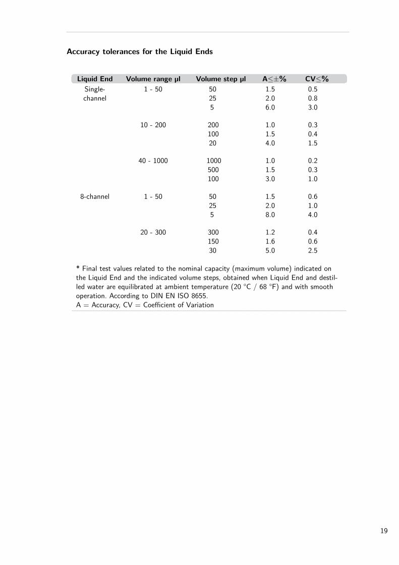
Accuracy tolerances for the Liquid Ends
Liquid End Volume range µl Volume step µl A≤±% CV≤%Single-channel
1 - 50 50255
1.52.06.0
0.50.83.0
10 - 200 20010020
1.01.54.0
0.30.41.5
40 - 1000 1000500100
1.01.53.0
0.20.31.0
8-channel 1 - 50 50255
1.52.08.0
0.61.04.0
20 - 300 30015030
1.21.65.0
0.40.62.5
* Final test values related to the nominal capacity (maximum volume) indicated onthe Liquid End and the indicated volume steps, obtained when Liquid End and destil-led water are equilibrated at ambient temperature (20 °C / 68 °F) and with smoothoperation. According to DIN EN ISO 8655.A = Accuracy, CV = Coefficient of Variation
19
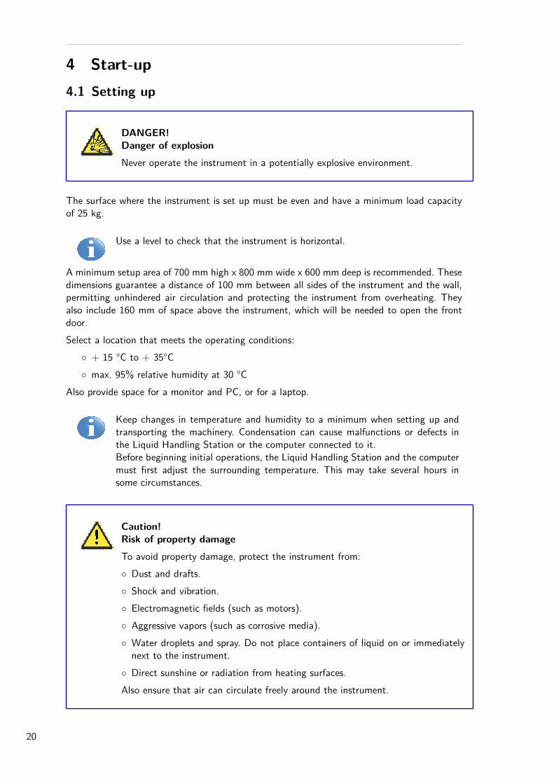
4 Start-up4.1 Setting up
DANGER!Danger of explosionNever operate the instrument in a potentially explosive environment.
The surface where the instrument is set up must be even and have a minimum load capacityof 25 kg.
Use a level to check that the instrument is horizontal.
A minimum setup area of 700 mm high x 800 mm wide x 600 mm deep is recommended. Thesedimensions guarantee a distance of 100 mm between all sides of the instrument and the wall,permitting unhindered air circulation and protecting the instrument from overheating. Theyalso include 160 mm of space above the instrument, which will be needed to open the frontdoor.Select a location that meets the operating conditions:
◦ + 15 °C to + 35°C◦ max. 95% relative humidity at 30 °C
Also provide space for a monitor and PC, or for a laptop.
Keep changes in temperature and humidity to a minimum when setting up andtransporting the machinery. Condensation can cause malfunctions or defects inthe Liquid Handling Station or the computer connected to it.Before beginning initial operations, the Liquid Handling Station and the computermust first adjust the surrounding temperature. This may take several hours insome circumstances.
Caution!Risk of property damageTo avoid property damage, protect the instrument from:◦ Dust and drafts.◦ Shock and vibration.◦ Electromagnetic fields (such as motors).◦ Aggressive vapors (such as corrosive media).◦ Water droplets and spray. Do not place containers of liquid on or immediatelynext to the instrument.
◦ Direct sunshine or radiation from heating surfaces.Also ensure that air can circulate freely around the instrument.
20
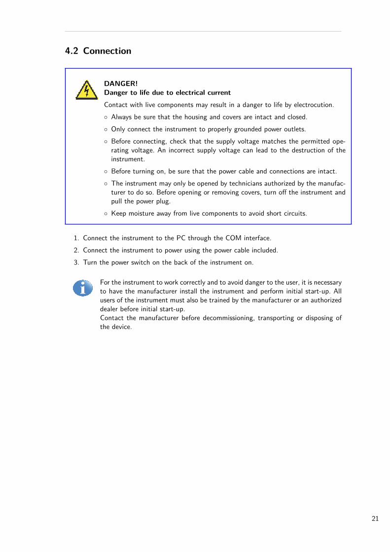
4.2 Connection
DANGER!Danger to life due to electrical currentContact with live components may result in a danger to life by electrocution.◦ Always be sure that the housing and covers are intact and closed.◦ Only connect the instrument to properly grounded power outlets.◦ Before connecting, check that the supply voltage matches the permitted ope-rating voltage. An incorrect supply voltage can lead to the destruction of theinstrument.
◦ Before turning on, be sure that the power cable and connections are intact.◦ The instrument may only be opened by technicians authorized by the manufac-turer to do so. Before opening or removing covers, turn off the instrument andpull the power plug.
◦ Keep moisture away from live components to avoid short circuits.
1. Connect the instrument to the PC through the COM interface.2. Connect the instrument to power using the power cable included.3. Turn the power switch on the back of the instrument on.
For the instrument to work correctly and to avoid danger to the user, it is necessaryto have the manufacturer install the instrument and perform initial start-up. Allusers of the instrument must also be trained by the manufacturer or an authorizeddealer before initial start-up.Contact the manufacturer before decommissioning, transporting or disposing ofthe device.
21
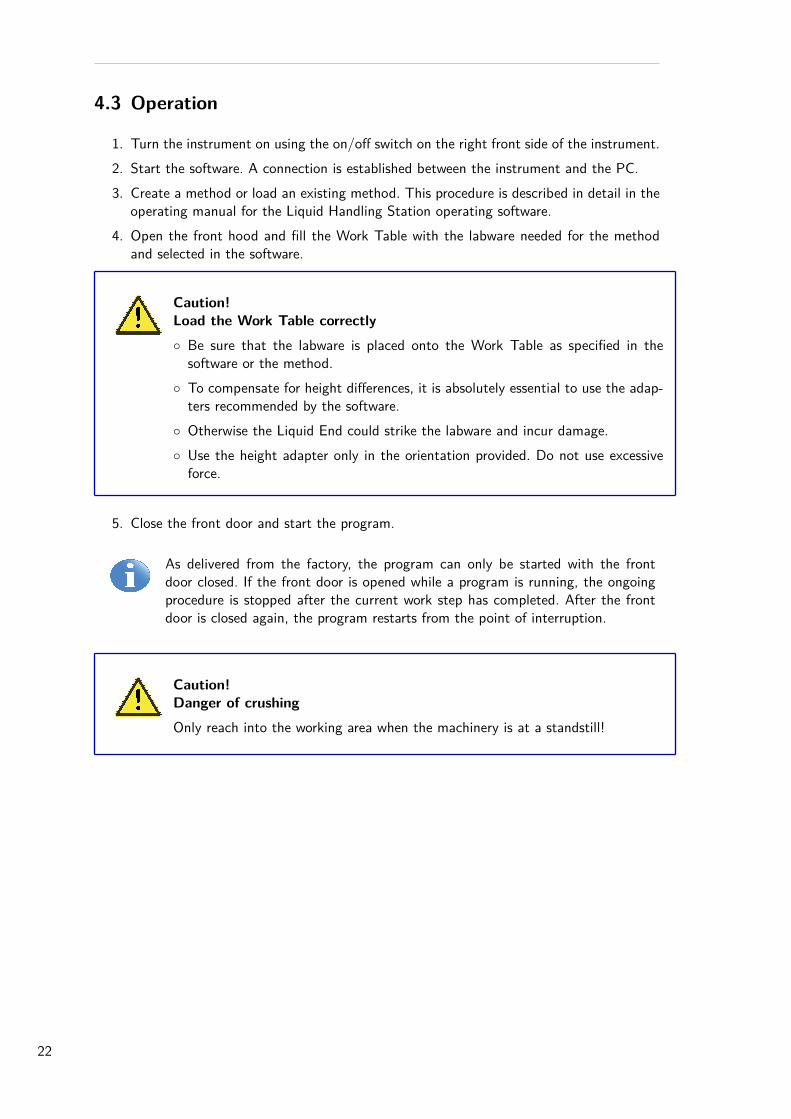
4.3 Operation
1. Turn the instrument on using the on/off switch on the right front side of the instrument.2. Start the software. A connection is established between the instrument and the PC.3. Create a method or load an existing method. This procedure is described in detail in the
operating manual for the Liquid Handling Station operating software.4. Open the front hood and fill the Work Table with the labware needed for the method
and selected in the software.
Caution!Load the Work Table correctly◦ Be sure that the labware is placed onto the Work Table as specified in thesoftware or the method.
◦ To compensate for height differences, it is absolutely essential to use the adap-ters recommended by the software.
◦ Otherwise the Liquid End could strike the labware and incur damage.◦ Use the height adapter only in the orientation provided. Do not use excessiveforce.
5. Close the front door and start the program.
As delivered from the factory, the program can only be started with the frontdoor closed. If the front door is opened while a program is running, the ongoingprocedure is stopped after the current work step has completed. After the frontdoor is closed again, the program restarts from the point of interruption.
Caution!Danger of crushingOnly reach into the working area when the machinery is at a standstill!
22
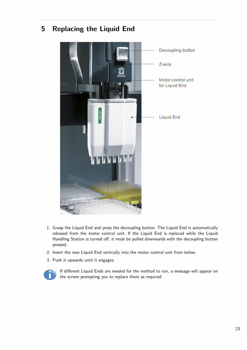
5 Replacing the Liquid End
1. Grasp the Liquid End and press the decoupling button. The Liquid End is automaticallyreleased from the motor control unit. If the Liquid End is replaced while the LiquidHandling Station is turned off, it must be pulled downwards with the decoupling buttonpressed.
2. Insert the new Liquid End vertically into the motor control unit from below.3. Push it upwards until it engages.
If different Liquid Ends are needed for the method to run, a message will appear onthe screen prompting you to replace them as required.
23
6 Maintenance/Cleaning6.1 Instrument
Spray, drips, or large amounts of spilled liquids must be wiped off immediately with an absorbentcloth.Remove contamination (such as dirt, dust) with a soft, clean cloth.If necessary, use a neutral detergent.Liquid Ends can be autoclaved at 121 °C for 20 minutes.Labware adapters are not autoclavable! They can be cleaned as needed with ethanol or disin-fectant.
Decontamination
Caution!Turn off the Liquid Handling Station and isolate it from the mains before cleaning,decontaminating or carrying out any maintenance work!
Wipe off the instrument and working surface with a lint-free cloth.We recommend using 70 % (v/v) ethanol, 3 % - 4 % sodium hypochloride or an alcohol-basedsurface disinfectant, e.g. Pursept® -A Xpress disinfectant spray for disinfection or decontami-nation.
Caution!Please be sure that during spraying◦ the motor control unit does not come into contact with cleaning agents or otherliquids
◦ and that no detergents can enter the guide slots.Should any liquid get into the device, isolate the unit immediately from the mainsand contact the BRAND service.
UV decontamination of the Liquid Ends and the adapters is possible.
If a procedure or detergent other than those listed here is used, please clarify with the manu-facturer whether it will be harmless to the instrument.
WARNING!Cleaning in medical laboratories◦ Particular care is required when handling infectious material (see Safety instruc-tions - 5. Danger due to hazardous substances).
◦ Please follow the corresponding safety regulations.
24
Sending the instrument in for service or repair
If the instrument has to be sent to the manufacturer, decontamination must first be carriedout and documented. For safety reasons, only decontaminated instruments can be serviced andrepaired.Hereto complete the ”Declaration on Absence of Health Hazards” and send the instrument tothe manufacturer. Ask your manufacturer for the form or download it on www.brand.de.Before sending, request the special packaging from the manufacturer and pack the LiquidHandling Station properly in order to prevent damage during transport.
Transporting hazardous materials without a permit is a violation of federal law.
25
6.2 Single-channel Liquid Ends
To ensure proper function, the Liquid Ends should be serviced on a regular basis and cleanedwhen needed.
Maintenance1. Detach Liquid End: Press the decoupling button with one hand
while simultaneously removing the Liquid End with the otherhand.
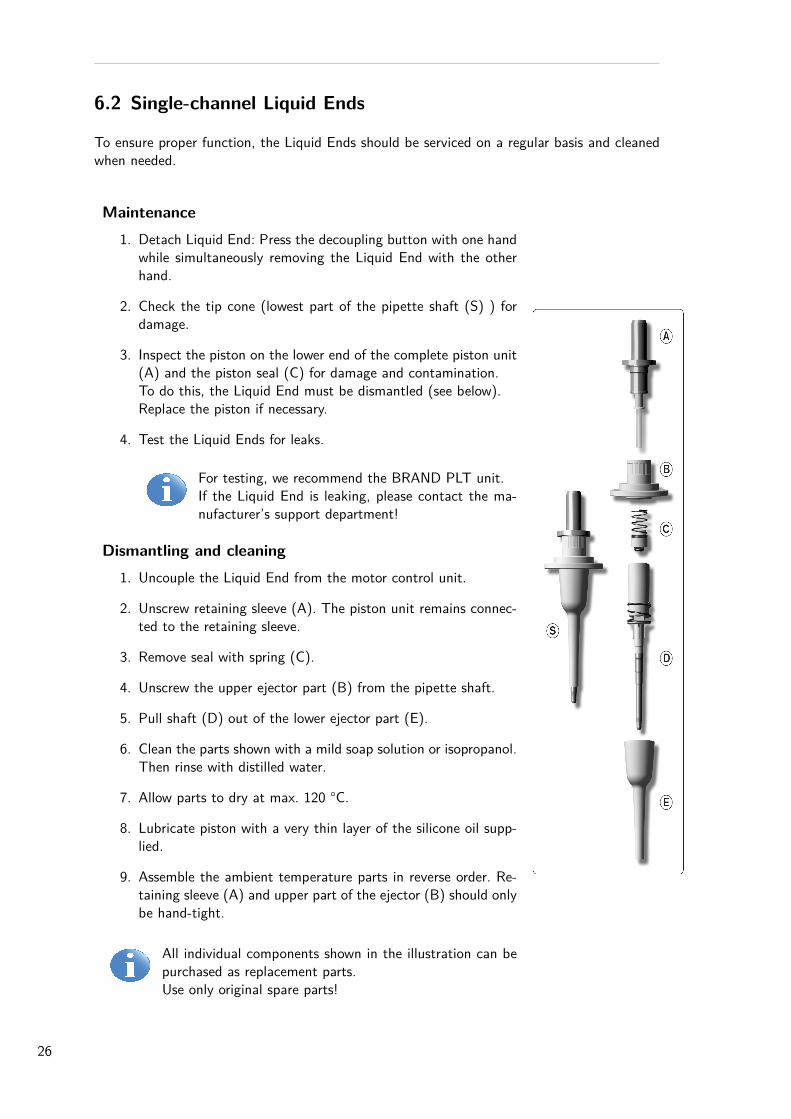
2. Check the tip cone (lowest part of the pipette shaft (S) ) fordamage.
3. Inspect the piston on the lower end of the complete piston unit(A) and the piston seal (C) for damage and contamination.To do this, the Liquid End must be dismantled (see below).Replace the piston if necessary.
4. Test the Liquid Ends for leaks.
For testing, we recommend the BRAND PLT unit.If the Liquid End is leaking, please contact the ma-nufacturer’s support department!
Dismantling and cleaning1. Uncouple the Liquid End from the motor control unit.
2. Unscrew retaining sleeve (A). The piston unit remains connec-ted to the retaining sleeve.
3. Remove seal with spring (C).
4. Unscrew the upper ejector part (B) from the pipette shaft.
5. Pull shaft (D) out of the lower ejector part (E).
6. Clean the parts shown with a mild soap solution or isopropanol.Then rinse with distilled water.
7. Allow parts to dry at max. 120 °C.
8. Lubricate piston with a very thin layer of the silicone oil supp-lied.
9. Assemble the ambient temperature parts in reverse order. Re-taining sleeve (A) and upper part of the ejector (B) should onlybe hand-tight.
All individual components shown in the illustration can bepurchased as replacement parts.Use only original spare parts!
26
6.3 8-channel Liquid Ends
To ensure proper function, the Liquid Ends should be serviced on a regular basis and cleanedwhen needed.
Maintenance
1. Detach Liquid End.2. Check nose cones, pistons and seals for damage and contamination.3. Test the Liquid Ends for leaks.
For testing, we recommend the BRAND PLT unit. Use only original spareparts!
Dismantling and cleaning
Cleaning instructions
1. Clean single nose cones, piston and nose cone support bar (these components only)with a mild soap solution or isopropanol. Then rinse with distilled water.
2. Allow parts to dry at max. 120 °C and cool down completely. Residual moisture in thenose cones may result in a loss of accuracy.
3. Lubricate pistons with a very thin coating of the silicone grease supplied. For the centralguide rod only use the recommended flourstatic grease!
Removing nose cones and seals for cleaning and replacement
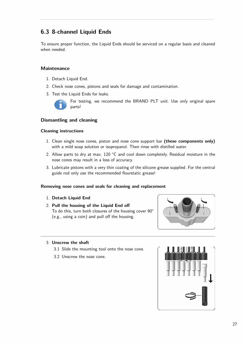
1. Detach Liquid End2. Pull the housing of the Liquid End off
To do this, turn both closures of the housing cover 90°(e.g., using a coin) and pull off the housing.
3. Unscrew the shaft3.1 Slide the mounting tool onto the nose cone.3.2 Unscrew the nose cone.
27
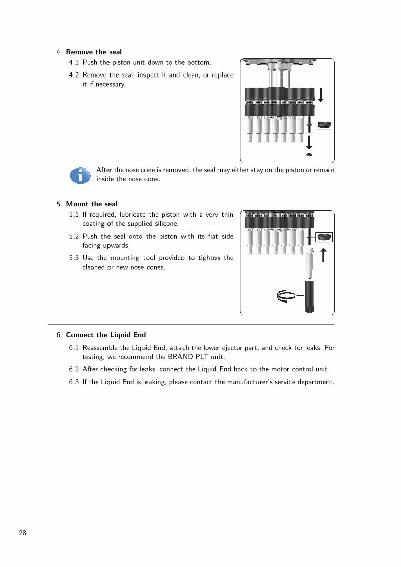
4. Remove the seal4.1 Push the piston unit down to the bottom.4.2 Remove the seal, inspect it and clean, or replace
it if necessary.
After the nose cone is removed, the seal may either stay on the piston or remaininside the nose cone.
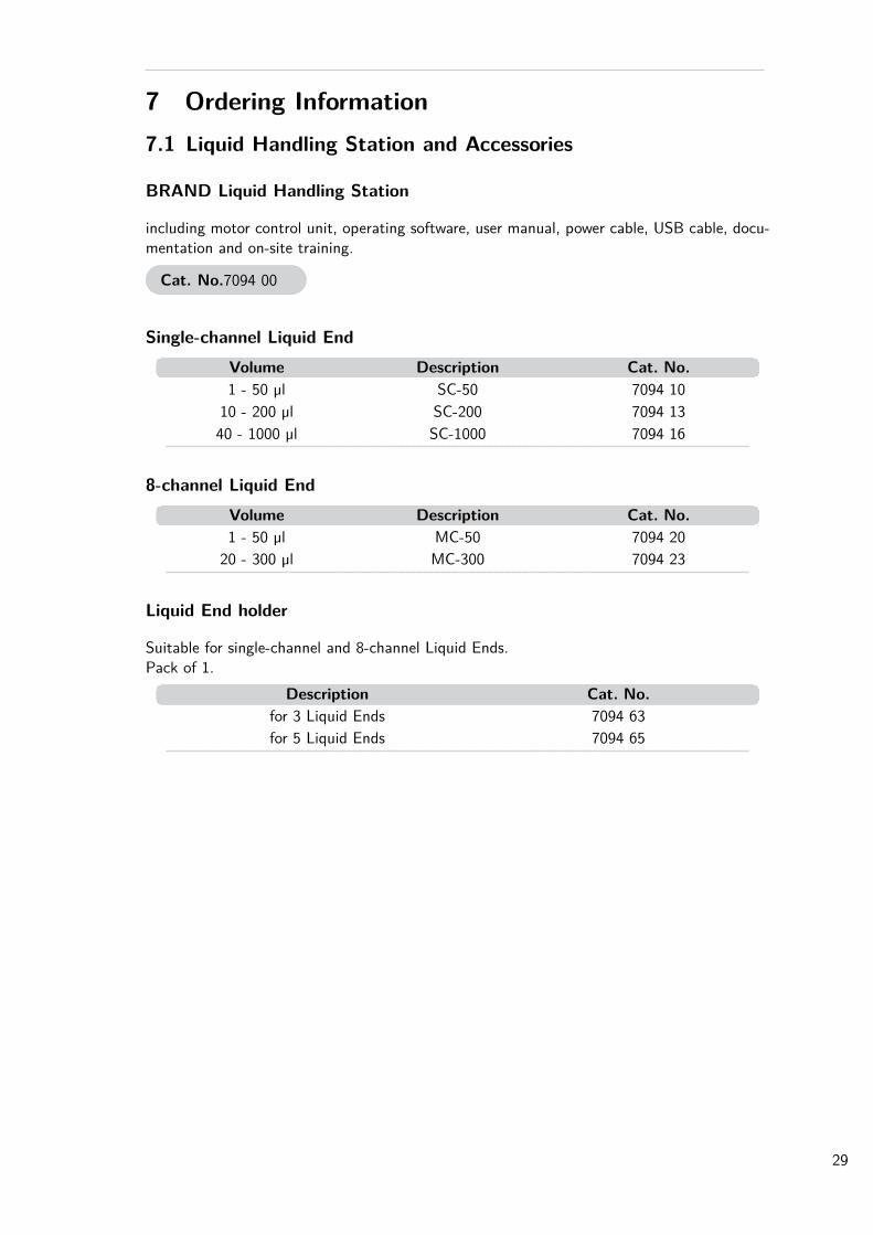
5. Mount the seal5.1 If required, lubricate the piston with a very thin
coating of the supplied silicone.5.2 Push the seal onto the piston with its flat side
facing upwards.5.3 Use the mounting tool provided to tighten the
cleaned or new nose cones.
6. Connect the Liquid End6.1 Reassemble the Liquid End, attach the lower ejector part, and check for leaks. For
testing, we recommend the BRAND PLT unit.6.2 After checking for leaks, connect the Liquid End back to the motor control unit.6.3 If the Liquid End is leaking, please contact the manufacturer’s service department.
28
7 Ordering Information7.1 Liquid Handling Station and Accessories
BRAND Liquid Handling Station
including motor control unit, operating software, user manual, power cable, USB cable, docu-mentation and on-site training.
Cat. No.7094 00
Single-channel Liquid EndVolume Description Cat. No.1 - 50 µl SC-50 7094 10
10 - 200 µl SC-200 7094 1340 - 1000 µl SC-1000 7094 16
8-channel Liquid EndVolume Description Cat. No.1 - 50 µl MC-50 7094 20
20 - 300 µl MC-300 7094 23
Liquid End holder
Suitable for single-channel and 8-channel Liquid Ends.Pack of 1.
Description Cat. No.for 3 Liquid Ends 7094 63for 5 Liquid Ends 7094 65
29
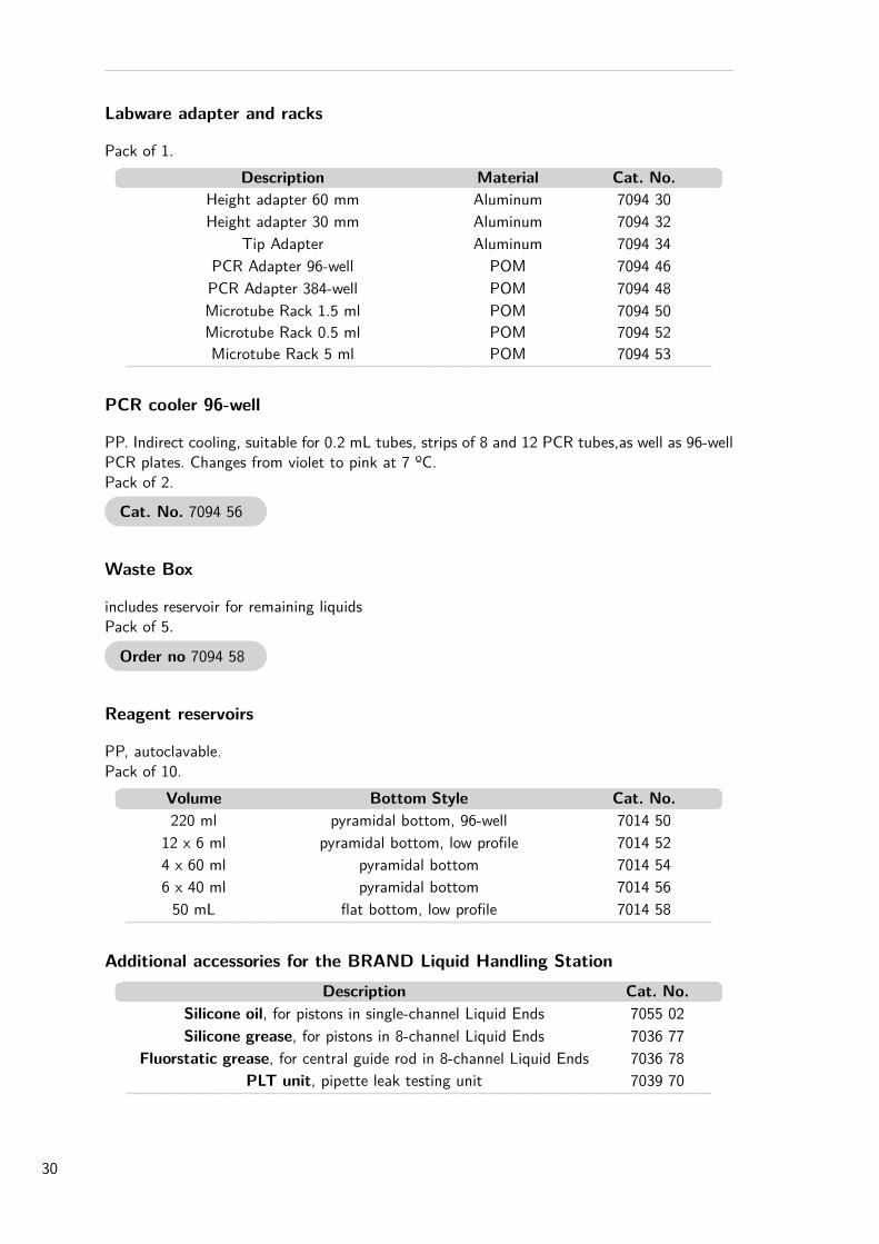
Labware adapter and racks
Pack of 1.Description Material Cat. No.
Height adapter 60 mm Aluminum 7094 30Height adapter 30 mm Aluminum 7094 32
Tip Adapter Aluminum 7094 34PCR Adapter 96-well POM 7094 46PCR Adapter 384-well POM 7094 48Microtube Rack 1.5 ml POM 7094 50Microtube Rack 0.5 ml POM 7094 52Microtube Rack 5 ml POM 7094 53
PCR cooler 96-well
PP. Indirect cooling, suitable for 0.2 mL tubes, strips of 8 and 12 PCR tubes,as well as 96-wellPCR plates. Changes from violet to pink at 7 ºC.Pack of 2.
Cat. No. 7094 56
Waste Box
includes reservoir for remaining liquidsPack of 5.
Order no 7094 58
Reagent reservoirs
PP, autoclavable.Pack of 10.
Volume Bottom Style Cat. No.220 ml pyramidal bottom, 96-well 7014 50
12 x 6 ml pyramidal bottom, low profile 7014 524 x 60 ml pyramidal bottom 7014 546 x 40 ml pyramidal bottom 7014 5650 mL flat bottom, low profile 7014 58
Additional accessories for the BRAND Liquid Handling StationDescription Cat. No.
Silicone oil, for pistons in single-channel Liquid Ends 7055 02Silicone grease, for pistons in 8-channel Liquid Ends 7036 77
Fluorstatic grease, for central guide rod in 8-channel Liquid Ends 7036 78PLT unit, pipette leak testing unit 7039 70
30
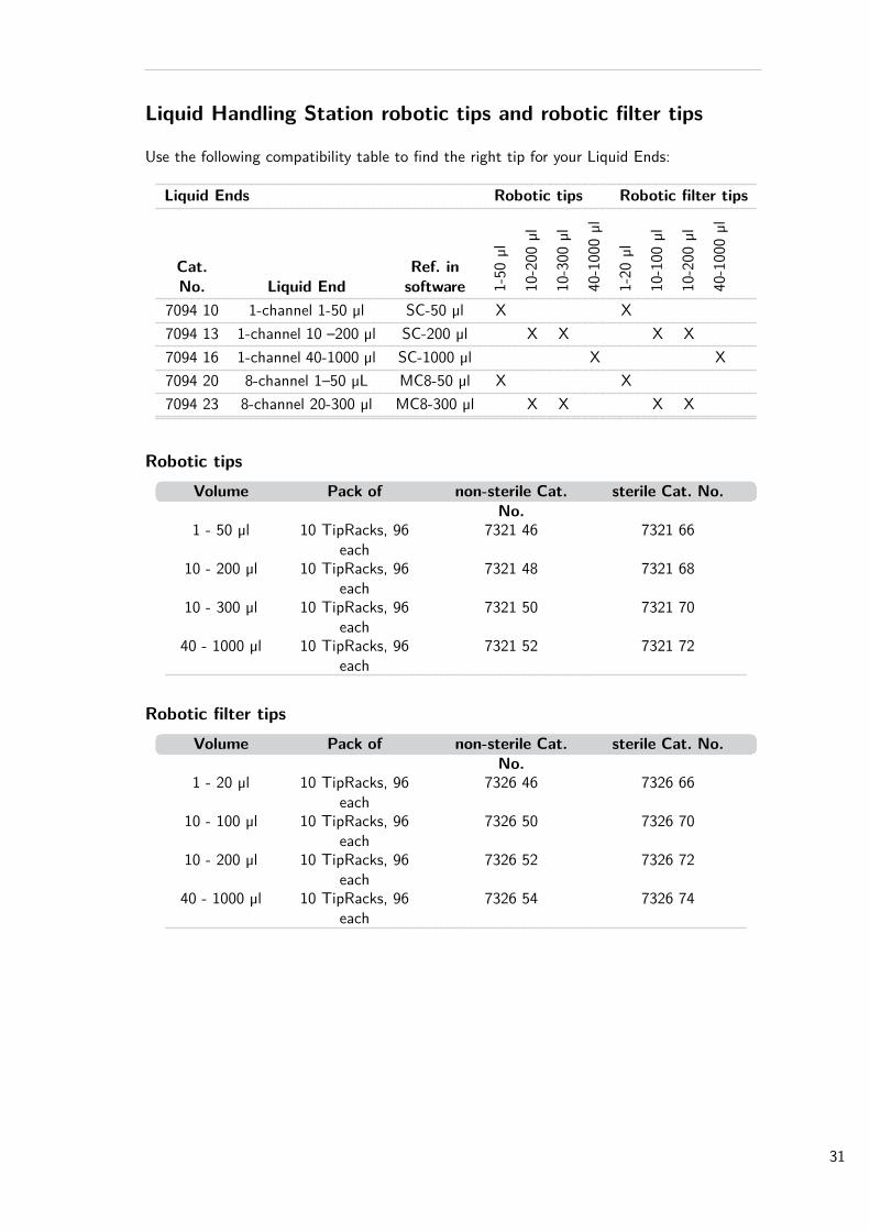
Liquid Handling Station robotic tips and robotic filter tips
Use the following compatibility table to find the right tip for your Liquid Ends:
Liquid Ends Robotic tips Robotic filter tips
Cat.No. Liquid End
Ref. insoftware 1-
50µl
10-200
µl
10-300
µl
40-100
0µl
1-20
µl
10-100
µl
10-200
µl
40-100
0µl
7094 10 1-channel 1-50 µl SC-50 µl X X7094 13 1-channel 10 –200 µl SC-200 µl X X X X7094 16 1-channel 40-1000 µl SC-1000 µl X X7094 20 8-channel 1–50 µL MC8-50 µl X X7094 23 8-channel 20-300 µl MC8-300 µl X X X X
Robotic tipsVolume Pack of non-sterile Cat.
No.sterile Cat. No.
1 - 50 µl 10 TipRacks, 96each
7321 46 7321 66
10 - 200 µl 10 TipRacks, 96each
7321 48 7321 68
10 - 300 µl 10 TipRacks, 96each
7321 50 7321 70
40 - 1000 µl 10 TipRacks, 96each
7321 52 7321 72
Robotic filter tipsVolume Pack of non-sterile Cat.
No.sterile Cat. No.
1 - 20 µl 10 TipRacks, 96each
7326 46 7326 66
10 - 100 µl 10 TipRacks, 96each
7326 50 7326 70
10 - 200 µl 10 TipRacks, 96each
7326 52 7326 72
40 - 1000 µl 10 TipRacks, 96each
7326 54 7326 74
31
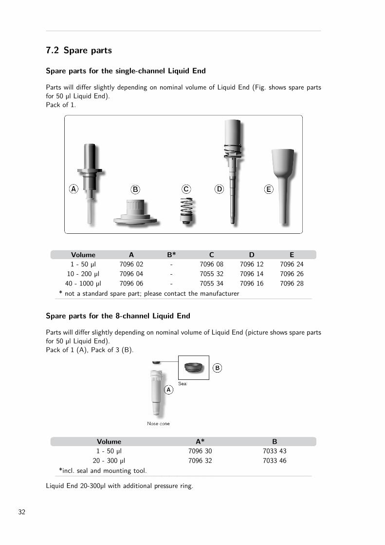
7.2 Spare parts
Spare parts for the single-channel Liquid End
Parts will differ slightly depending on nominal volume of Liquid End (Fig. shows spare partsfor 50 µl Liquid End).Pack of 1.
Volume A B* C D E1 - 50 µl 7096 02 - 7096 08 7096 12 7096 24
10 - 200 µl 7096 04 - 7055 32 7096 14 7096 2640 - 1000 µl 7096 06 - 7055 34 7096 16 7096 28
* not a standard spare part; please contact the manufacturer
Spare parts for the 8-channel Liquid End
Parts will differ slightly depending on nominal volume of Liquid End (picture shows spare partsfor 50 µl Liquid End).Pack of 1 (A), Pack of 3 (B).
Volume A* B1 - 50 µl 7096 30 7033 4320 - 300 µl 7096 32 7033 46
*incl. seal and mounting tool.
Liquid End 20-300µl with additional pressure ring.
32

2

4

2

4
2
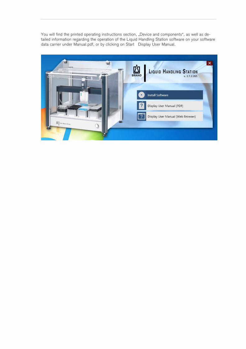
You will find the printed operating instructions section, „Device and components“, as well as de-tailed information regarding the operation of the Liquid Handling Station software on your software data carrier under Manual.pdf, or by clicking on Start Display User Manual.

9974 96 · Printed in Germany · 1016