Embed Size (px)
DESCRIPTION
Â
Citation preview
Passiv-Infrarot-Bewegungsmelder
Passive Infrared MotionDetector
Détecteur de mouvementpassif à infrarouge
Rivelatore di movimentopassivo a raggi infrarossi
Detector de movimientopasivo por infrarrojo
Das Gerät darf nur an Schutz-kleinspannung mit sichererelektrischer Trennung betrie-ben werden.Eingriffe und Reparaturen nurdurch Ihren Lieferanten vor-nehmen lassen!
L’appareil ne doit être raccordéqu’à une basse tension deprotection possédant unisolement électrique sûr.Les interventions etréparations ne doivent êtreeffectuées que par votrefournisseur.
The device must only beoperated at a protective lowvoltage with safe electricalisolation.Interventions and repair workmust only be performed byyour supplier!
1. Sicherheitshinweise 1. Safety instructions 1.Consignes de sécurité de en fr 1. Avvisi di sicurezza 1. Indicac. de seguridadit es
2. Struttura / Panoram. 2. Estructura / Sinopsisit es
1 Pot.1-Empfindlichkeit2 Drehbügel3 Blende4 Umschalter aktiv/passiv5 LED, Funktionsanzeige
rot Sensor aktivgrün Sensor nicht aktiv
6 Deckel/Fresnellinse7 Zoomskala8 Zoomschraube
1 Pot. 1 sensibilité2 Etrier orientable3 Plaque obturatrice4 Commutateur actif/passif5 LED, indicateur de fonction
rouge détecteur actifvert détecteur non actif
6 Couvercle/Lentille deFresnel
7 Echelle zoom8 Vis zoom
1 Pot.1 Sensitivity2 Swivel bracket3 Diaphragm4 Switch active/passive5 LED, function indicator
red sensor activatedgreen sensor not activated
6 Cover/Fresnel lens7 Zoom scale8 Zoom screw
22. Aufbau / Übersicht 2. Design / Overview 2. Structure / Vue d’ens.de en fr
L’apparecchio deve essereallacciato solo ad una tensioneinferiore a 42 V conseparazione elettrica sicura.Interventi e riparazioni devonoessere effettuati solo dal vostrofornitore.
El aparato sólo debe serconectado a una tensión bajade protección con unaseparación eléctrica segura.¡Las intervenciones yreparaciones deben serefectuadas únicamente por suproveedor!
1 Potenz.1 sensibilità2 Staffa girevole3 Piastra otturatrice4 Commutatore attivo/passivo5 LED, indicatore di funzione
rosso sensore attivoverde sensore inattivo
6 Coperchio/Lente di Fresnel7 Scala zoom8 Vite zoom
1 Potmtro.1 sensibilidad2 Soporte orientable3 Placa obturadora4 Conmutador activo/pasivo5 LED, indicador de funcionam.
rojo sensor activoverde sensor no activo
6 Tapa/Lente concéntrica deFresnel
7 Escala para zoom8 Tornillo para zoom
4
8
1
5
7
3
6
2
3. Montaggio 3. Montajeit es3. Montage 3. Mounting 3. Montagede en fr
3a 3b
Fig. 3a MontagewinkelFig. 3b DrehbügelFig. 3c Anschlussklemme
lösen
Fig. 3a Mounting bracketFig. 3b Swivel bracketFig. 3c Release connection
terminal
Fig. 3a Angle de montageFig. 3b Etrier orientableFig. 3c Desserrer la borne de
connexion
Fig. 3a Squadretta di montagg.Fig. 3b Staffa girevoleFig. 3c Sbloccare il morsetto
Fig. 3a Escuadra de montajeFig. 3b Soporte basculanteFig. 3c Soltar borne de
conexión
3c
Quality international level
EN ISO9001
PIR 20 BetriebsanleitungOperating instructionsInstructions d’utilisationIstruzioni per l’usoInstrucciones de servicio
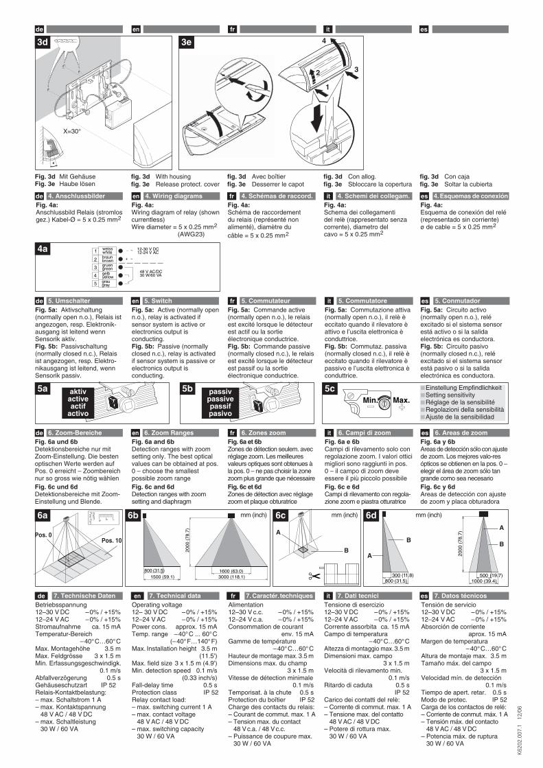
Fig. 6a und 6bDetektionsbereiche nur mitZoom-Einstellung. Die bestenoptischen Werte werden aufPos. 0 erreicht – Zoombereichnur so gross wie nötig wählenFig. 6c und 6dDetektionsbereiche mit Zoom-Einstellung und Blende.
Fig. 6a and 6bDetection ranges with zoomsetting only. The best opticalvalues can be obtained at pos.0 – choose the smallestpossible zoom rangeFig. 6c and 6dDetection ranges with zoomsetting and diaphragm
6. Zoom-Bereiche 6. Zoom Ranges 6. Zones zoomde en frFig. 6a et 6bZones de détection seulem. avecréglage zoom. Les meilleuresvaleurs optiques sont obtenues àla pos. 0 – ne pas choisir la zonezoom plus grande que nécessaireFig. 6c et 6dZones de détection avec réglagezoom et plaque obturatrice
Fig. 6a e 6bCampi di rilevamento solo conregolazione zoom. I valori otticimigliori sono raggiunti in pos.0 – il campo di zoom deveessere il più piccolo possibileFig. 6c e 6dCampi di rilevamento con regola-zione zoom e piastra otturatrice
Fig. 6a y 6bAreas de detección sólo con ajustede zoom. Los mejores valo-resópticos se obtienen en la pos. 0 –elegir el área de zoom sólo tangrande como sea necesarioFig. 6c y 6dAreas de detección con ajustede zoom y placa obturadora
6. Campi di zoom 6. Areas de zoomit es
5a 5baktivactiveactif
activo
passivpassivepassifpasivo
Fig. 5a: Aktivschaltung(normally open n.o.), Relais istangezogen, resp. Elektronik-ausgang ist leitend wennSensorik aktiv.Fig. 5b: Passivschaltung(normally closed n.c.), Relaisist angezogen, resp. Elektro-nikausgang ist leitend, wennSensorik passiv.
Fig. 5a: Active (normally openn.o.), relay is activated ifsensor system is active orelectronics output isconducting.Fig. 5b: Passive (normallyclosed n.c.), relay is activatedif sensor system is passive orelectronics output isconducting.
5. Umschalter 5. Switch 5. Commutateurde en frFig. 5a: Commande active(normally open n.o.), le relaisest excité lorsque le détecteurest actif ou la sortieélectronique conductrice.Fig. 5b: Commande passive(normally closed n.c.), le relaisest excité lorsque le détecteurest passif ou la sortieélectronique conductrice.
Fig. 5a: Commutazione attiva(normally open n.o.), il relè èeccitato quando il rilevatore èattivo e l’uscita elettronica èconduttrice.Fig. 5b: Commutaz. passiva(normally closed n.c.), il relè èeccitato quando il rilevatore èpassivo e l’uscita elettronica èconduttrice.
Fig. 5a: Circuito activo(normally open n.o.), reléexcitado si el sistema sensorestá activo o si la salidaelectrónica es conductora.Fig. 5b: Circuito pasivo(normally closed n.c.), reléexcitado si el sistema sensorestá pasivo o si la salidaelectrónica es conductora.
5. Commutatore 5. Conmutadorit es
Betriebsspannung12–30 V DC –0% / +15%12–24 V AC –0% / +15%Stromaufnahme ca. 15 mATemperatur-Bereich
–40°C…60°CMax. Montagehöhe 3.5 mMax. Feldgrösse 3 x 1.5 mMin. Erfassungsgeschwindigk.
0.1 m/sAbfallverzögerung 0.5 sGehäuseschutzart IP 52Relais-Kontaktbelastung:– max. Schaltstrom 1 A– max. Kontaktspannung
48 V AC / 48 V DC– max. Schaltleistung
30 W / 60 VA
Operating voltage 12– 30 V DC –0% / +15%12–24 V AC –0% / +15%Power cons. approx. 15 mATemp. range –40°C ... 60°C
(–40°F…140°F) Max. Installation height 3.5 m
(11.5')Max. field size 3 x 1.5 m (4.9')Min. detection speed 0.1 m/s
(0.33 inch/s)Fall-delay time 0.5 sProtection class IP 52Relay contact load:– max. switching current 1 A– max. contact voltage
48 V AC / 48 V DC– max. switching capacity
30 W / 60 VA
Alimentation 12–30 V c.c. –0% / +15%12–24 V c.a. –0% / +15%Consommation de courant
env. 15 mAGamme de température
–40°C…60°CHauteur de montage max. 3.5 mDimensions max. du champ
3 x 1.5 mVitesse de détection minimale
0.1 m/sTemporisat. à la chute 0.5 sProtection du boîtier IP 52Charge des contacts du relais:– Courant de commut. max. 1 A– Tension max. du contact
48 Vc.a. / 48 Vc.c.– Puissance de coupure max.
30 W / 60 VA
Tensione di esercizio12–30 V DC –0% / +15%12–24 V AC –0% / +15%Corrente assorbita ca. 15 mACampo di temperatura
–40°C…60°CAltezza di montaggio max.3.5 mDimensioni max. campo
3 x 1.5 mVelocità di rilevamento min.
0.1 m/sRitardo di caduta 0.5 s
IP 52Carico dei contatti del relè:– Corrente di commut. max. 1 A– Tensione max. del contatto
48 V AC / 48 V DC– Potere di rottura max.
30 W / 60 VA
Tensión de servicio12–30 V DC –0% / +15%12–24 V AC –0% / +15%Absorción de corriente
aprox. 15 mAMargen de temperatura
–40°C…60°CAltura de montaje max. 3.5 mTamaño máx. del campo
3 x 1.5 mVelocidad mín. de detección
0.1 m/sTiempo de apert. retar. 0.5 sModo de protec. IP 52Carga de los contactos de relé:– Corriente de conmut. máx. 1 A– Tensión máx. del contacto
48 V AC / 48 V DC– Potencia máx. de ruptura
30 W / 60 VA
7. Technische Daten 7. Technical data 7. Caractér.techniquesde en fr 7. Dati tecnici 7. Datos técnicosit es
it esde en fr
3d 3e
Fig. 3d Mit GehäuseFig. 3e Haube lösen
fig. 3d With housingfig. 3e Release protect. cover
fig. 3d Avec boîtierfig. 3e Desserrer le capot
fig. 3d Con allog. fig. 3e Sbloccare la copertura
fig. 3d Con caja fig. 3e Soltar la cubierta
x
X=30°
1
2
4
3
6a
800 (31.5)1500 (59.1)
1600 (63.0)3000 (118.1)
2000
(78
.7)
6b
Pos. 0Pos. 10
✂
6c
1000 (39.4)500 (19.7)
2000
(78
.7)
300 (11.8)800 (31.5)
6d
A
BA
BB
A
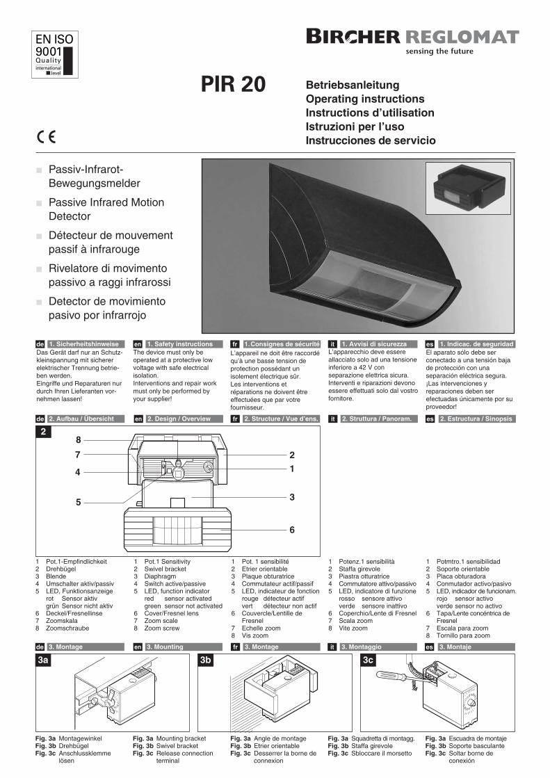
Fig. 4a:Schéma de raccordement du relais (représenté nonalimenté), diamètre du câble = 5 x 0.25 mm2
Fig. 4a:Schema dei collegamenti del relè (rappresentato senzacorrente), diametro del cavo = 5 x 0.25 mm2
Fig. 4a:Esquema de conexión del relé(representado sin corriente)ø de cable = 5 x 0.25 mm2
Fig. 4a:Wiring diagram of relay (showncurrentless) Wire diameter = 5 x 0.25 mm2
(AWG23)
4. Anschlussbilder 4. Wiring diagrams 4. Schémas de raccord.de en fr
1
2
3
4
5
weisswhitebraunbrowngruengreengelbyellowgraugray
12-30 V DC
+
48 V AC/DC30 W/60 VA
12-24 V AC~
~
4a
4. Schemi dei collegam. 4.Esquemas de conexiónit es
K62
02.0
07.1
12
/06
Min. Max.5c Einstellung Empfindlichkeit
Setting sensitivityRéglage de la sensibilitéRegolazioni della sensibilitàAjuste de la sensibilidad
Fig. 4a:Anschlussbild Relais (stromlosgez.) Kabel-Ø = 5 x 0.25 mm2
mm (inch) mm (inch) mm (inch)