Embed Size (px)
Citation preview

DEEN
DEEN
DEEN
DEEN
DEEN
DEEN
BetriebsanleitungOperating instructions Additional languages www.stahl-ex.com
DE EN
DEEN
DEEN
DE
Potentiometer für Schalttafeleinbau
Potentiometer for panel mounting
8455


DEDEDEDEDEDEDEDEDEDEDEDEDEDEDEDEDE
BetriebsanleitungAdditional languages www.stahl-ex.com
DE
DEDEDEDEDEDEDEDE
Potentiometer für Schalttafeleinbau
8455
Allgemeine AngabenDEDEDEDEDEDEDEDEDEDEDEDEDEDEDEDEDEDEDEDEDEDEDEDEDE
r
Inhaltsverzeichnis1 Allgemeine Angaben ...........................................................................................21.1 Hersteller .............................................................................................................21.2 Angaben zur Betriebsanleitung ...........................................................................21.3 Symbole ..............................................................................................................22 Sicherheitshinweise ............................................................................................33 Normenkonformität .............................................................................................34 Funktion ..............................................................................................................45 Technische Daten ...............................................................................................46 Anordnung und Montage ....................................................................................57 Installation ...........................................................................................................57.1 Inbetriebnahme ...................................................................................................68 Instandhaltung ....................................................................................................68.1 Wartung ..............................................................................................................68.2 Zubehör und Ersatzteile ......................................................................................69 Transport und Lagerung .....................................................................................610 Entsorgung ..........................................................................................................6
1 Allgemeine Angaben
1.1 HerstellerR. STAHL Schaltgeräte GmbHAm Bahnhof 3074638 Waldenburg Germany
Tel.: +49 7942 943-0Fax: +49 7942 943-4333Internet: www.stahl-ex.comE-Mail: [email protected]
1.2 Angaben zur BetriebsanleitungID-Nr.: 145210 / 8455603300Publikationsnummer: 2016-04-19·BA00·III·de·04
Technische Änderungen vorbehalten.
1.3 Symbole
Achtung!Diese Grafik kennzeichnet Hinweise, bei deren Nichtbeachtung Ihre Gesundheit odedie Funktionsfähigkeit des Gerätes bzw. der Komponente gefährdet ist.
HinweisDiese Grafik kennzeichnet wichtige Zusatzinformationen, Tipps und Empfehlungen.
2 145210 / 84556033002016-04-19·BA00·III·de·04
Potentiometer für Schalttafeleinbau8455
SicherheitshinweiseDEDEDEDEDEDEDEDEDEDEDEDEDEDEDEDEDEDEDEDEDEDEDEDEDE
r, e“
n
2
2 SicherheitshinweiseIn diesem Kapitel sind die wichtigsten Sicherheitsmaßnahmen zusammengefasst. Es ergänzt die entsprechenden Vorschriften, zu deren Studium das verantwortliche Personal verpflichtet ist.Bei Arbeiten in explosionsgefährdeten Bereichen hängt die Sicherheit von Personen und Anlagen von der Einhaltung aller relevanten Sicherheitsvorschriften ab. Das Montage- und Wartungspersonal trägt deshalb eine besondere Verantwortung. Voraussetzung ist die genaue Kenntnis der geltenden Vorschriften und Bestimmungen.
Verwenden Sie die Geräte bzw. Komponenten bestimmungsgemäß, nur für den zugelassenen Einsatzzweck (siehe “Funktion” auf Seite 4). Fehlerhafter und unzulässiger Einsatz sowie das Nichtbeachten der Hinweise dieser Betriebsanleitung schließen eine Gewährleistung unsererseits aus. Umbauten und Veränderungen an den Geräten und Komponenten, die den Explosionsschutz betreffen, sind nicht gestattet. Die Geräte und Komponenten dürfen nur in unbeschädigtem, trockenem und sauberem Zustand eingebaut werden.
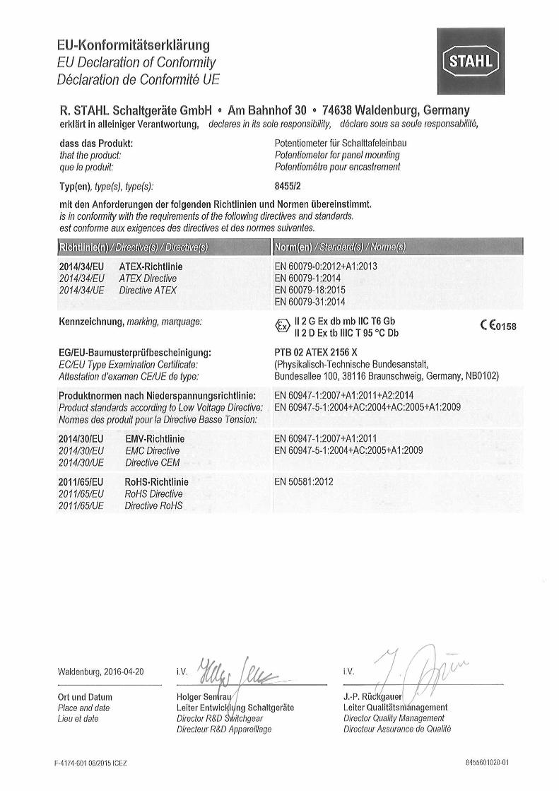
3 NormenkonformitätDie Geräte entsprechen den folgenden Normen bzw. Richtlinien:Typ 8455/2:- Richtlinie 2014/34/EU- IEC/EN 60079-0, IEC/EN 60079-1, IEC/EN 60079-18, IEC/EN 61241-0,
IEC/EN 61241-1
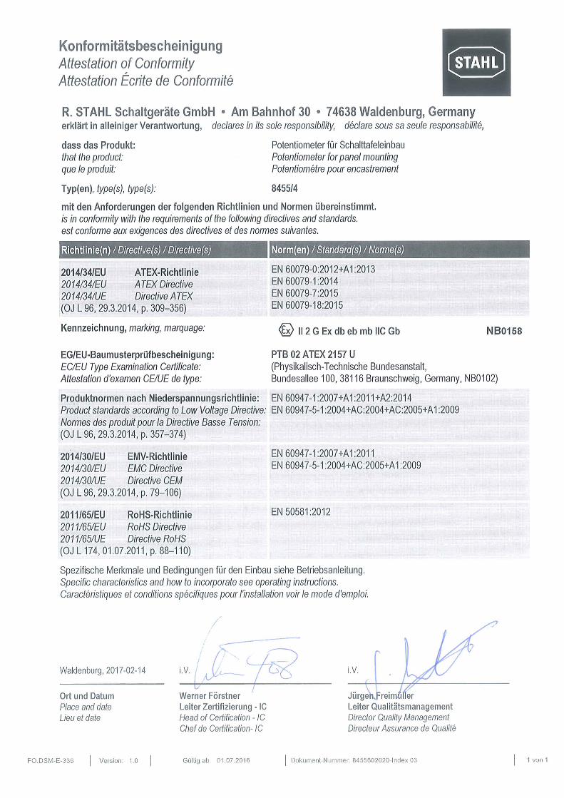
Typ 8455/4:- Richtlinie 2014/34/EU- IEC/EN 60079-0, IEC/EN 60079-1, IEC/EN 60079-7, IEC/EN 60079-18
Beachten Sie als Anwender: die nationalen Sicherheits- und Unfallverhütungsvorschriften, die nationalen Montage- und Errichtungsvorschriften (z.B. IEC/EN 60079-14), die allgemein anerkannten Regeln der Technik, die Sicherheitshinweise und Angaben dieser Betriebsanleitung, die Kennwerte und Bemessungsbetriebsbedingungen der Typ- und Datenschilde dass beim Einbau des Gerätes in Gehäuse der Zündschutzart „Erhöhte Sicherheit
die Bedingungen nach IEC/EN 60079-0 und IEC/EN 60079-7 zu berücksichtigen sind.
dass die Rückseite des Gerätes bzw. der Komponente gegen mechanische Beschädigung geschützt werden muss,
dass Beschädigungen des Gerätes bzw. der Komponente den Ex-Schutz aufhebekönnen.
Die Geräte sind für den Einsatz in explosionsgefährdeten Bereichen der Zonen 1, 2, 21 und 22 zugelassen.
Die Geräte sind für den Einsatz in explosionsgefährdeten Bereichen der Zonen 1 undzugelassen.
145210 / 84556033002016-04-19·BA00·III·de·04
3Potentiometer für Schalttafeleinbau8455
FunktionDEDEDEDEDEDEDEDEDEDEDEDEDEDEDEDEDEDEDEDEDEDEDEDEDE
4 FunktionDas Potentiometer für Schalttafeleinbau Typ 8455/2 ist ein explosionsgeschütztes elektrisches Betriebsmittel mit Anschlussleitung. Es eignet sich zum Einbau in Gehäusewände und -deckel elektrischer Betriebsmittel bzw. in Schalttafeln oder Steuerschränke.Das Potentiometer für Schalttafeleinbau Typ 8455/4 ist eine elektrische Komponente. Der Leitungsanschluss erfolgt über integrierte Anschlüsse in der Zündschutzart „Erhöhte Sicherheit e“. Es ist zum Einbau in Gehäusewände und -deckel elektrischer Betriebsmittel bzw. in Schalttafeln oder Steuerschränke z.B. der Zündschutzart „Erhöhte Sicherheit e“ nach IEC/EN 60079-7 vorgesehen.
5 Technische Daten
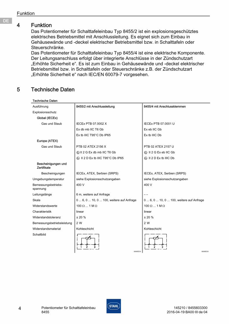
Technische Daten
Ausführung 8455/2 mit Anschlussleitung 8455/4 mit Anschlussklemmen
Explosionsschutz
Global (IECEx)
Gas und Staub IECEx PTB 07.0002 X IECEx PTB 07.0001 U
Ex db mb IIC T6 Gb Ex eb IIC Gb
Ex tb IIIC T95°C Db IP65 Ex tb IIIC Db
Europa (ATEX)
Gas und Staub PTB 02 ATEX 2156 X PTB 02 ATEX 2157 U
EII 2 G Ex db mb IIC T6 Gb E II 2 G Ex eb IIC Gb
E II 2 D Ex tb IIIC T95°C Db IP65 E II 2 D Ex tb IIIC Db
Bescheinigungen und Zertifikate
Bescheinigungen IECEx, ATEX, Serbien (SRPS) IECEx, ATEX, Serbien (SRPS)
Umgebungstemperatur siehe Explosionsschutzangaben siehe Explosionsschutzangaben
Bemessungsbetriebs- spannung
400 V 400 V
Leitungslänge 6 m, weitere auf Anfrage – –
Skala 0 ... 6, 0 ... 10, 0 ... 100, weitere auf Anfrage 0 ... 6, 0 ... 10, 0 ... 100, weitere auf Anfrage
Widerstandswerte 100 Ω ... 1 M Ω 100 Ω ... 1 M Ω
Charakteristik linear linear
Widerstandstoleranz ± 20 % ± 20 %
Bemessungsbetriebsleistung 2 W 2 W
Widerstandsmaterial Kohleschicht Kohleschicht
Schaltbild
06065E00 06065E00
4 145210 / 84556033002016-04-19·BA00·III·de·04
Potentiometer für Schalttafeleinbau8455
Anordnung und Montage DEDEDEDEDEDEDEDEDEDEDEDEDEDEDEDEDEDEDEDEDEDEDEDEDE
en!
ie
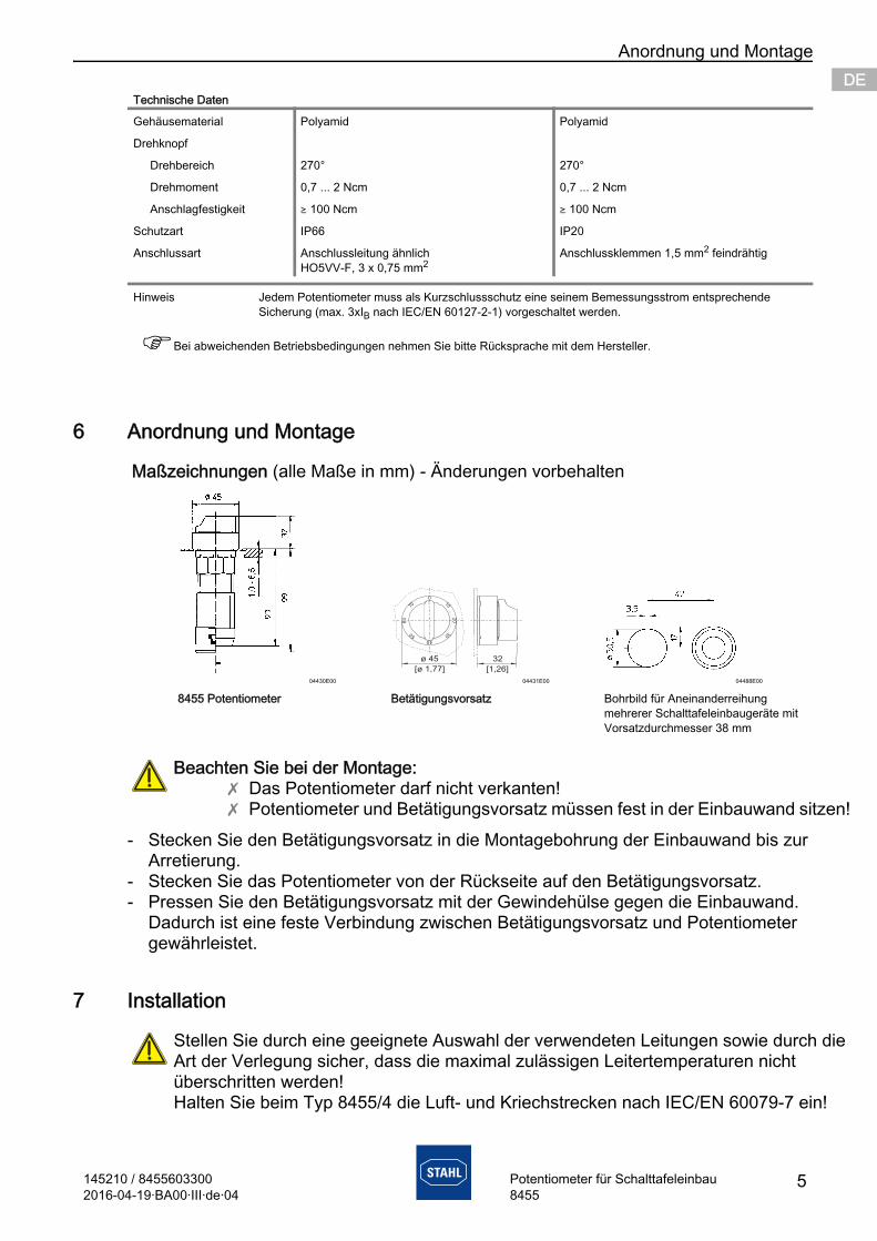
6 Anordnung und Montage
- Stecken Sie den Betätigungsvorsatz in die Montagebohrung der Einbauwand bis zur Arretierung.
- Stecken Sie das Potentiometer von der Rückseite auf den Betätigungsvorsatz.- Pressen Sie den Betätigungsvorsatz mit der Gewindehülse gegen die Einbauwand.
Dadurch ist eine feste Verbindung zwischen Betätigungsvorsatz und Potentiometer gewährleistet.
7 Installation
Gehäusematerial Polyamid Polyamid
Drehknopf
Drehbereich 270° 270°
Drehmoment 0,7 ... 2 Ncm 0,7 ... 2 Ncm
Anschlagfestigkeit ) 100 Ncm ) 100 Ncm
Schutzart IP66 IP20
Anschlussart Anschlussleitung ähnlich HO5VV-F, 3 x 0,75 mm2
Anschlussklemmen 1,5 mm2 feindrähtig
Hinweis Jedem Potentiometer muss als Kurzschlussschutz eine seinem Bemessungsstrom entsprechende Sicherung (max. 3xIB nach IEC/EN 60127-2-1) vorgeschaltet werden.
Bei abweichenden Betriebsbedingungen nehmen Sie bitte Rücksprache mit dem Hersteller.
Maßzeichnungen (alle Maße in mm) - Änderungen vorbehalten
04430E00 04431E00 04488E00
8455 Potentiometer Betätigungsvorsatz Bohrbild für Aneinanderreihung mehrerer Schalttafeleinbaugeräte mit Vorsatzdurchmesser 38 mm
Beachten Sie bei der Montage:X Das Potentiometer darf nicht verkanten!X Potentiometer und Betätigungsvorsatz müssen fest in der Einbauwand sitz
Stellen Sie durch eine geeignete Auswahl der verwendeten Leitungen sowie durch dArt der Verlegung sicher, dass die maximal zulässigen Leitertemperaturen nicht überschritten werden!Halten Sie beim Typ 8455/4 die Luft- und Kriechstrecken nach IEC/EN 60079-7 ein!
Technische Daten
ø 45
[ 1, ]ø 77
32
[1, ]26
010
20
30
4050
60
70
145210 / 84556033002016-04-19·BA00·III·de·04
5Potentiometer für Schalttafeleinbau8455
InstandhaltungDEDEDEDEDEDEDEDEDEDEDEDEDEDEDEDEDEDEDEDEDEDEDEDEDE
7.1 InbetriebnahmeStellen Sie vor der Inbetriebnahme sicher, dass- der Anschluss ordnungsgemäß ausgeführt und- das Potentiometer vorschriftsmäßig installiert wurde,- das Potentiometer nicht beschädigt ist.
8 Instandhaltung
8.1 Wartung
Überprüfen Sie im Rahmen der Wartung:- die Leitung auf festen Sitz,- das Kunststoffgehäuse auf Rissbildung,- die Dichtung der Leitungseinführung auf Beschädigung,- die bestimmungsgemäße Funktion.
8.2 Zubehör und Ersatzteile
9 Transport und LagerungTransport und Lagerung sind nur in Originalverpackung gestattet.
10 Entsorgung
Wartungsarbeiten an den Geräten dürfen nur von dazu befugtem und entsprechendgeschultem Personal durchgeführt werden.Schalten Sie vor Beginn der Wartungsarbeiten die Geräte spannungsfrei.
Beachten Sie auch die geltenden nationalen Bestimmungen im Einsatzland!
Verwenden Sie nur Original-Zubehör sowie Original-Ersatzteile der Firma R. STAHL Schaltgeräte GmbH. Bei Verwendung von Zubehör und Ersatzteilen von Fremdherstellern erlischt die Garantie der Firma R. STAHL Schaltgeräte GmbH.
Beachten Sie die nationalen Abfallbeseitigungsvorschriften.
6 145210 / 84556033002016-04-19·BA00·III·de·04
Potentiometer für Schalttafeleinbau8455
ENENENENENENENENENENENENENENENENEN
Operating instructions Additional languages www.stahl-ex.com
EN
ENENENENENENENEN
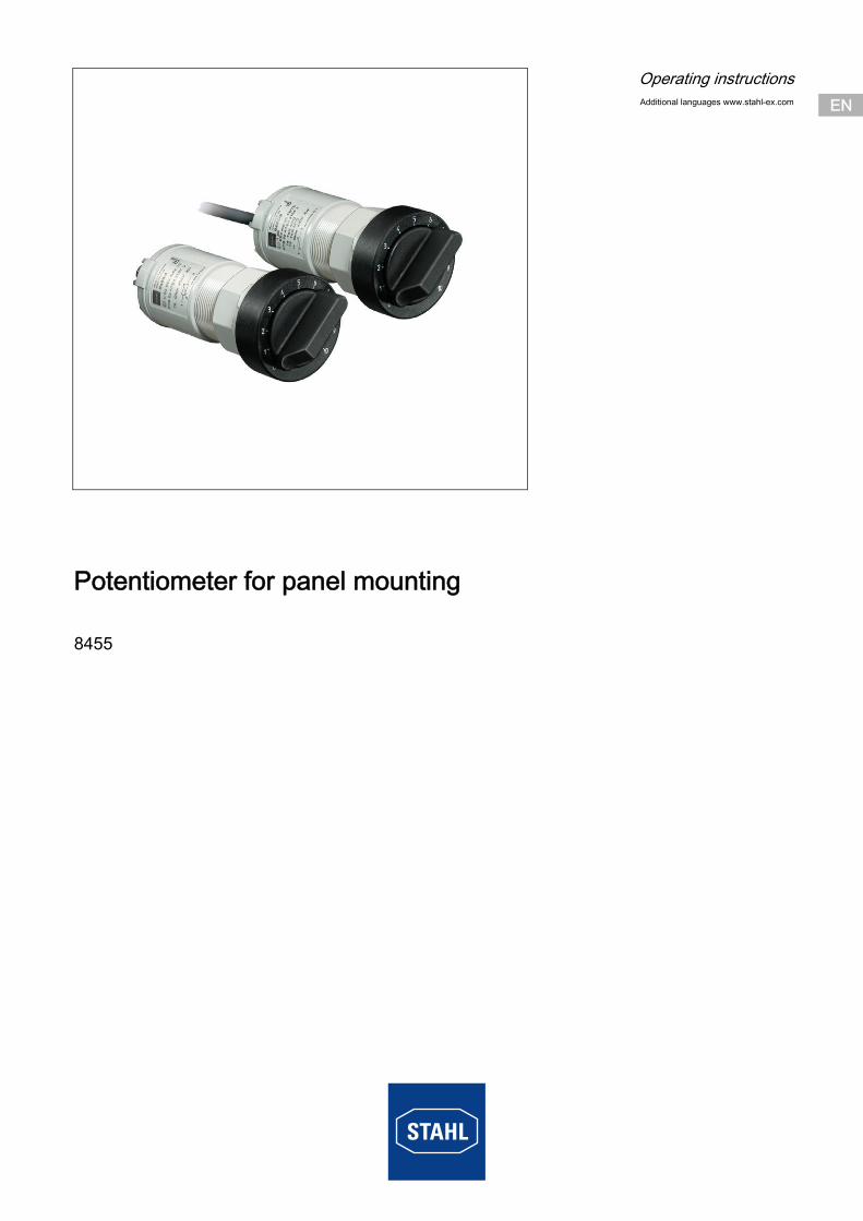
Potentiometer for panel mounting
8455
General InformationENENENENENENENENENENENENENENENENENENENENENENENENEN
Contents1 General Information ............................................................................................21.1 Manufacturer .......................................................................................................21.2 Information regarding the operating instructions .................................................21.3 Symbols ..............................................................................................................22 Safety notes ........................................................................................................33 Conformity to Standards .....................................................................................34 Function ..............................................................................................................45 Technical Data ....................................................................................................46 Arrangement and Assembly ................................................................................57 Installation ...........................................................................................................67.1 Commissioning ...................................................................................................68 Maintenance .......................................................................................................68.1 Maintenance .......................................................................................................68.2 Accessories and Spare Parts ..............................................................................69 Transport and Storage ........................................................................................610 Disposal ..............................................................................................................6
1 General Information
1.1 ManufacturerR. STAHL Schaltgeräte GmbHAm Bahnhof 3074638 Waldenburg Germany
Phone: +49 7942 943-0Fax: +49 7942 943-4333Internet: www.stahl-ex.comE-Mail: [email protected]
1.2 Information regarding the operating instructionsID-No.: 145210 / 8455603300Publication Code: 2016-04-19·BA00·III·en·04
Subject to alterations.
1.3 Symbols
Caution!This symbol marks notes whose non-observance will endanger your health or the functioning of the device.
NoteThis symbol marks important additional information, tips and recommendations.
2 145210 / 84556033002016-04-19·BA00·III·en·04
Potentiometer for panel mounting8455
Safety notes ENENENENENENENENENENENENENENENENENENENENENENENENEN
,ty d.
d
2 Safety notesThe most important safety instructions are summarised in this section. They supplement the corresponding regulations which the personnel in charge must study.When working in areas subject to explosion hazards, the safety of personnel and plant depends on complying with all relevant safety regulations. Assembly and maintenance staff working on installations therefore have a particular responsibility. A precise knowledge of the applicable standards and regulations is required.
Use the devices or components in accordance with their designated use and for their intended purpose only (see "Function" on page 4). Incorrect and impermissible use or non-compliance with these operating instructions invalidates our warranty provision. No modifications or alterations to the devices or components, impairing their explosion protection, are permitted. The devices and components may only be fitted if they are undamaged, dry and clean.
3 Conformity to StandardsThe devices comply with the following standards and directives:Type 8455/2:- Directive 2014/34/EU- IEC/EN 60079-0, IEC/EN 60079-1, IEC/EN 60079-18, IEC/EN 61241-0,
IEC/EN 61241-1
Type 8455/4:- Directive 2014/34/EU- IEC/EN 60079-0, IEC/EN 60079-1, IEC/EN 60079-7, IEC/EN 60079-18
As the user, please note: national safety and accident prevention regulations, national assembly and installation regulations (e.g. IEC/EN 60079-14), generally recognised technical regulations, safety instructions and information in these operating instructions, characteristic values and rated operating conditions on the rating and data plates that when fitting the device into enclosures with type of protection “Increased Safe
e“, the conditions given in IEC/EN 60079-0 and IEC/EN 60079-7 must be observe that the backs of the device or component must be protected against mechanical
damage, that any damage of the device or component may render the Ex protection null an
void.
The devices are approved for use in hazardous areas zones 1, 2, 21 and 22.
The devices are approved for use in hazardous areas zones 1 and 2.
145210 / 84556033002016-04-19·BA00·III·en·04
3Potentiometer for panel mounting8455
FunctionENENENENENENENENENENENENENENENENENENENENENENENENEN
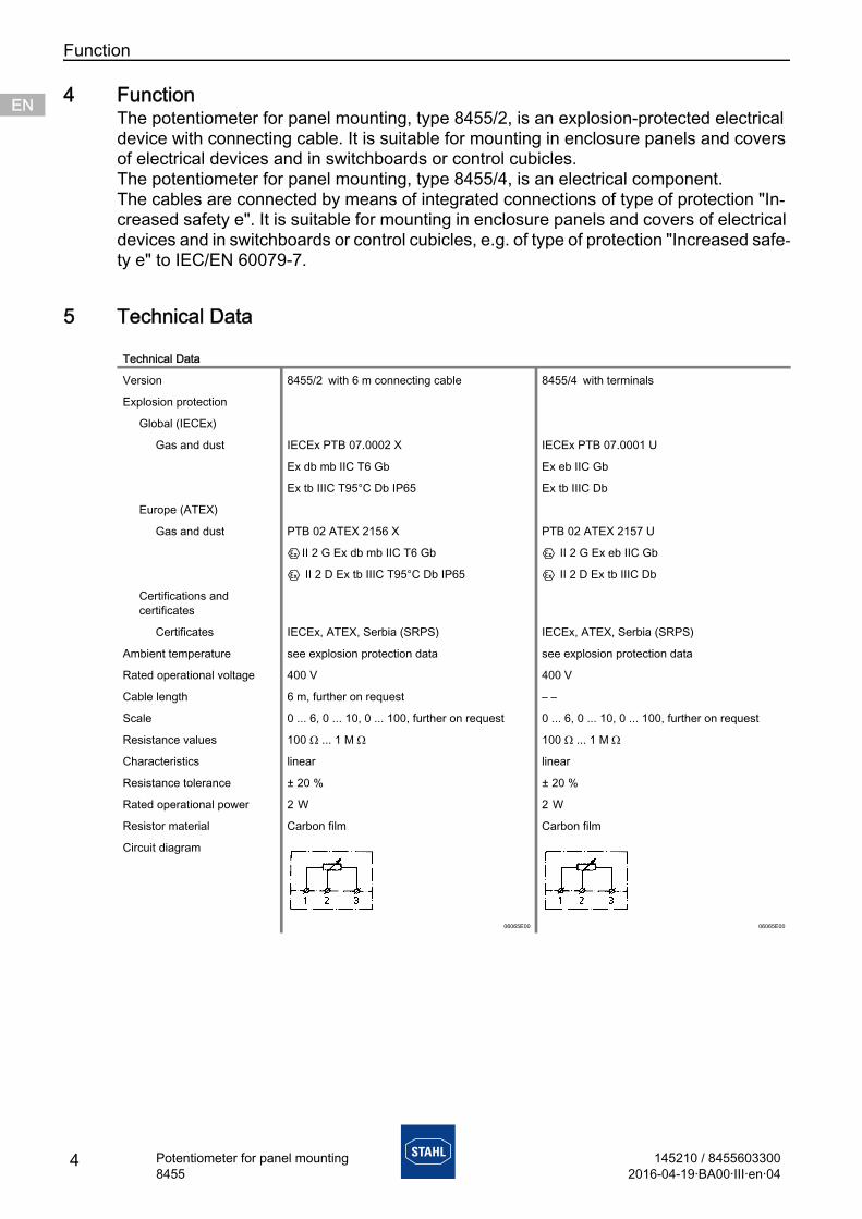
4 FunctionThe potentiometer for panel mounting, type 8455/2, is an explosion-protected electrical device with connecting cable. It is suitable for mounting in enclosure panels and covers of electrical devices and in switchboards or control cubicles.The potentiometer for panel mounting, type 8455/4, is an electrical component. The cables are connected by means of integrated connections of type of protection "In-creased safety e". It is suitable for mounting in enclosure panels and covers of electrical devices and in switchboards or control cubicles, e.g. of type of protection "Increased safe-ty e" to IEC/EN 60079-7.
5 Technical Data
Technical Data
Version 8455/2 with 6 m connecting cable 8455/4 with terminals
Explosion protection
Global (IECEx)
Gas and dust IECEx PTB 07.0002 X IECEx PTB 07.0001 U
Ex db mb IIC T6 Gb Ex eb IIC Gb
Ex tb IIIC T95°C Db IP65 Ex tb IIIC Db
Europe (ATEX)
Gas and dust PTB 02 ATEX 2156 X PTB 02 ATEX 2157 U
EII 2 G Ex db mb IIC T6 Gb E II 2 G Ex eb IIC Gb
E II 2 D Ex tb IIIC T95°C Db IP65 E II 2 D Ex tb IIIC Db
Certifications and certificates
Certificates IECEx, ATEX, Serbia (SRPS) IECEx, ATEX, Serbia (SRPS)
Ambient temperature see explosion protection data see explosion protection data
Rated operational voltage 400 V 400 V
Cable length 6 m, further on request – –
Scale 0 ... 6, 0 ... 10, 0 ... 100, further on request 0 ... 6, 0 ... 10, 0 ... 100, further on request
Resistance values 100 Ω ... 1 M Ω 100 Ω ... 1 M Ω
Characteristics linear linear
Resistance tolerance ± 20 % ± 20 %
Rated operational power 2 W 2 W
Resistor material Carbon film Carbon film
Circuit diagram
06065E00 06065E00
4 145210 / 84556033002016-04-19·BA00·III·en·04
Potentiometer for panel mounting8455
Arrangement and Assembly ENENENENENENENENENENENENENENENENENENENENENENENENEN
el!
6 Arrangement and Assembly
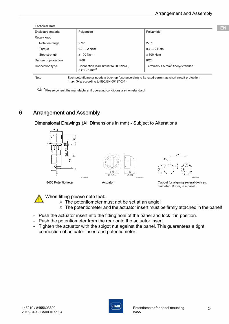
- Push the actuator insert into the fitting hole of the panel and lock it in position.- Push the potentiometer from the rear onto the actuator insert.- Tighten the actuator with the spigot nut against the panel. This guarantees a tight
connection of actuator insert and potentiometer.
Enclosure material Polyamide Polyamide
Rotary knob
Rotation range 270° 270°
Torque 0.7 ... 2 Ncm 0.7 ... 2 Ncm
Stop strength ) 100 Ncm ) 100 Ncm
Degree of protection IP66 IP20
Connection type Connection lead similar to HO5VV-F, 3 x 0.75 mm2
Terminals 1.5 mm2 finely-stranded
Note Each potentiometer needs a back-up fuse according to its rated current as short circuit protection (max. 3xIB according to IEC/EN 60127-2-1).
Please consult the manufacturer if operating conditions are non-standard.
Dimensional Drawings (All Dimensions in mm) - Subject to Alterations
04430E00 04431E00 04488E00
8455 Potentiometer Actuator Cut-out for aligning several devices, diameter 38 mm, in a panel
When fitting please note that:X The potentiometer must not be set at an angle!X The potentiometer and the actuator insert must be firmly attached in the pan
Technical Data
ø 45
[ 1, ]ø 77
32
[1, ]26
010
20
30
4050
60
70
145210 / 84556033002016-04-19·BA00·III·en·04
5Potentiometer for panel mounting8455
InstallationENENENENENENENENENENENENENENENENENENENENENENENENEN
d
7 Installation
7.1 CommissioningBefore commissioning, ensure that- the connections have been correctly made,- the potentiometer has been correctly installed,- the potentiometer is not damaged.
8 Maintenance
8.1 Maintenance
The following must be checked during maintenance:- that the cable is securely seated,- plastic enclosure for the formation of cracks,- the cable entry seal for damage,- the function according to its designated use.
8.2 Accessories and Spare Parts
9 Transport and StorageTransport and storage are only permitted in the original packing.
10 Disposal
Ensure that the maximum permissible conductor temperatures are not exceeded by suitable selection of cables and means of running them!Observe the clearance and creepage distances to IEC/EN 60079-7 for type 8455/4!
Maintenance work on the devices may only be carried out by appropriately authoriseand trained personnel.Before any work commences, the devices must be disconnected from the supply.
Observe the relevant national regulations in the country of use!
Use only original accessories and spare parts from R. STAHL Schaltgeräte GmbH. Use of another company´s accessories and spare parts invalidates the warranty of R. STAHL Schaltgeräte GmbH.
Observe the national standard for refuse disposal.
6 145210 / 84556033002016-04-19·BA00·III·en·04
Potentiometer for panel mounting8455