Embed Size (px)
Citation preview
Programmer &
ExperimentalboardsManual / Handbuch
Batronix programmer and experimental board manual – © 1998 - 2006 by Batronix, www.Batronix.com
This document is protected by German and international copyright laws.
Dieses Werk ist durch das deutsche und internationale Urheberrecht geschützt.
2 Batronix programmer and experimental board manual
INHALTSVERZEICHNIS
INHALTSVERZEICHNIS .............................................................................................................. 2
USB DEVICE INSTALLATION / USB GERÄTEINSTALLATION ..................................................... 4
BX32 BATUPO AND BX32P BARLINO ...................................................................................... 7
INSTALLATION AND OPERATION / INSTALLATION UND BENUTZUNG: .............................7
CONNECTIONS / ANSCHLÜSSE:............................................................................................7
CORRECT PLACEMENT OF CHIPS / KORREKTES EINSETZEN VON CHIPS: .......................7
USB CHIP PROGRAMMER ........................................................................................................ 8
INSTALLATION AND OPERATION / INSTALLATION UND BENUTZUNG: .............................8
CONNECTIONS / ANSCHLÜSSE:............................................................................................8
CORRECT PLACEMENT OF CHIPS / KORREKTES EINSETZEN VON CHIPS: .......................8
EPROM PROGRAMMER 3.X-4 / EPROM BRENNER 3.X-4....................................................... 9
CONSTRUCTION OF A BUILDING KIT / AUFBAU EINES BAUSATZES: .................................9
INSTALLATION AND OPERATION / INSTALLATION UND BENUTZUNG: ...........................12
CONNECTIONS / ANSCHLÜSSE:..........................................................................................12
CORRECT PLACEMENT OF CHIPS / KORREKTES EINSETZEN VON CHIPS: .....................13
FLASH MC PROGRAMMER I / FLASH MC BRENNER I........................................................... 14
CONSTRUCTION OF A BUILDING KIT / AUFBAU EINES BAUSATZES: ...............................14
INSTALLATION AND OPERATION / INSTALLATION UND BENUTZUNG: ...........................17
CONNECTIONS / ANSCHLÜSSE:..........................................................................................17
CORRECT PLACEMENT OF CHIPS / KORREKTES EINSETZEN VON CHIPS: .....................18
FLASH MC PROGRAMMER II / FLASH MC BRENNER II......................................................... 19
CONSTRUCTION OF A BUILDING KIT / AUFBAU EINES BAUSATZES: ...............................19
INSTALLATION AND OPERATION / INSTALLATION UND BENUTZUNG: ...........................22
CONNECTIONS / ANSCHLÜSSE:..........................................................................................22
CORRECT PLACEMENT OF CHIPS / KORREKTES EINSETZEN VON CHIPS: .....................23
FLASH EXP.BOARD I / FLASH EXP.BOARD I .......................................................................... 24
CONSTRUCTION OF A BUILDING KIT / AUFBAU EINES BAUSATZES: ...............................24
CONNECTIONS / ANSCHLÜSSE:..........................................................................................27
CORRECT PLACEMENT OF CHIPS / KORREKTES EINSETZEN VON CHIPS: .....................27
DIP SWITCH / DIP SCHALTER:...............................................................................................28

Batronix programmer and experimental board manual – © 1998 - 2006 by Batronix, www.Batronix.com
This document is protected by German and international copyright laws.
Dieses Werk ist durch das deutsche und internationale Urheberrecht geschützt.
3Batronix programmer and experimental board manual
FLASH EXP.BOARD II / FLASH EXP.BOARD II ........................................................................ 29
CONSTRUCTION OF A BUILDING KIT / AUFBAU EINES BAUSATZES: ...............................29
CONNECTIONS / ANSCHLÜSSE:..........................................................................................32
CORRECT PLACEMENT OF CHIPS / KORREKTES EINSETZEN VON CHIPS: .....................32
DIP SWITCH / DIP SCHALTER:...............................................................................................33
Batronix programmer and experimental board manual – © 1998 - 2006 by Batronix, www.Batronix.com
This document is protected by German and international copyright laws.
Dieses Werk ist durch das deutsche und internationale Urheberrecht geschützt.
4 Batronix programmer and experimental board manual
USB DEVICE INSTALLATION / USB GERÄTEINSTALLATION
First, please install the Prog-Express
software. Details on installation and using
this software are in the belonging
manual.
You can find the software on the supplied
CD or at www.batronix.com in the
download area.
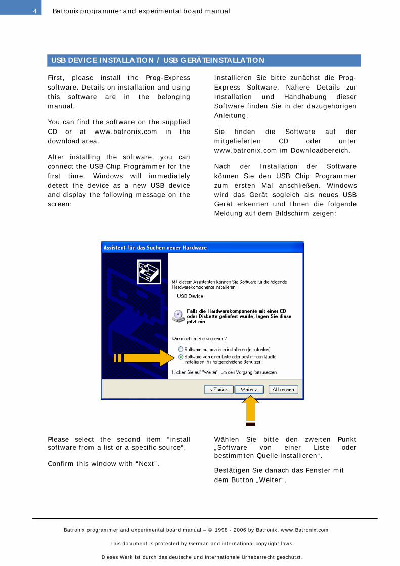
After installing the software, you can
connect the USB Chip Programmer for the
first time. Windows will immediately
detect the device as a new USB device
and display the following message on the
screen:
Installieren Sie bitte zunächst die Prog-
Express Software. Nähere Details zur
Installation und Handhabung dieser
Software finden Sie in der dazugehörigen
Anleitung.
Sie finden die Software auf der
mitgelieferten CD oder unter
www.batronix.com im Downloadbereich.
Nach der Installation der Software
können Sie den USB Chip Programmer
zum ersten Mal anschließen. Windows
wird das Gerät sogleich als neues USB
Gerät erkennen und Ihnen die folgende
Meldung auf dem Bildschirm zeigen:
Please select the second item “install
software from a list or a specific source“.
Confirm this window with “Next”.
Wählen Sie bitte den zweiten Punkt
„Software von einer Liste oder
bestimmten Quelle installieren“.
Bestätigen Sie danach das Fenster mit
dem Button „Weiter“.
Batronix programmer and experimental board manual – © 1998 - 2006 by Batronix, www.Batronix.com
This document is protected by German and international copyright laws.
Dieses Werk ist durch das deutsche und internationale Urheberrecht geschützt.
5Batronix programmer and experimental board manual
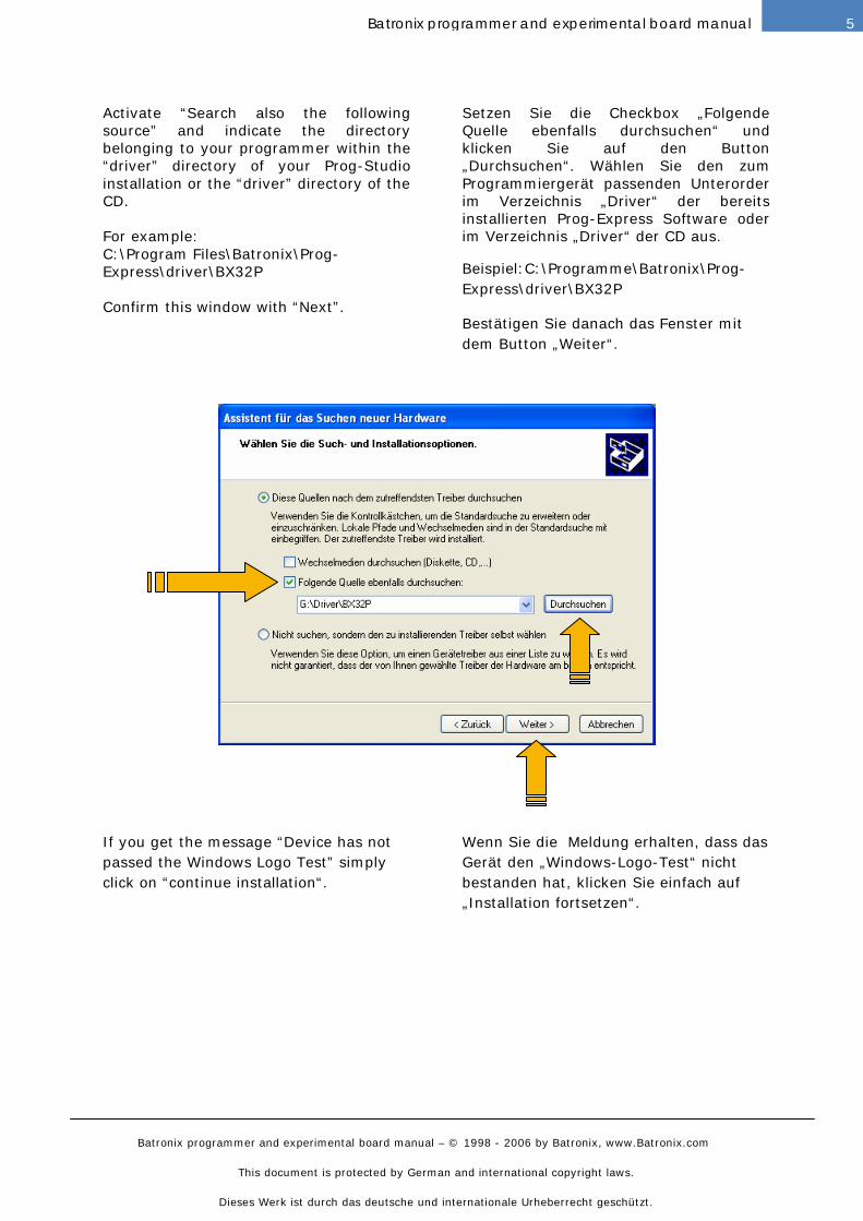
Activate “Search also the following
source” and indicate the directory
belonging to your programmer within the
“driver” directory of your Prog-Studio
installation or the “driver” directory of the
CD.
For example:
C:\Program Files\Batronix\Prog-
Express\driver\BX32P
Confirm this window with “Next”.
Setzen Sie die Checkbox „Folgende
Quelle ebenfalls durchsuchen“ und
klicken Sie auf den Button
„Durchsuchen“. Wählen Sie den zum
Programmiergerät passenden Unterorder
im Verzeichnis „Driver“ der bereits
installierten Prog-Express Software oder
im Verzeichnis „Driver“ der CD aus.
Beispiel:C:\Programme\Batronix\Prog-
Express\driver\BX32P
Bestätigen Sie danach das Fenster mit
dem Button „Weiter“.
If you get the message “Device has not
passed the Windows Logo Test” simply
click on “continue installation“.
Wenn Sie die Meldung erhalten, dass das
Gerät den „Windows-Logo-Test“ nicht
bestanden hat, klicken Sie einfach auf
„Installation fortsetzen“.
Batronix programmer and experimental board manual – © 1998 - 2006 by Batronix, www.Batronix.com
This document is protected by German and international copyright laws.
Dieses Werk ist durch das deutsche und internationale Urheberrecht geschützt.
6 Batronix programmer and experimental board manual
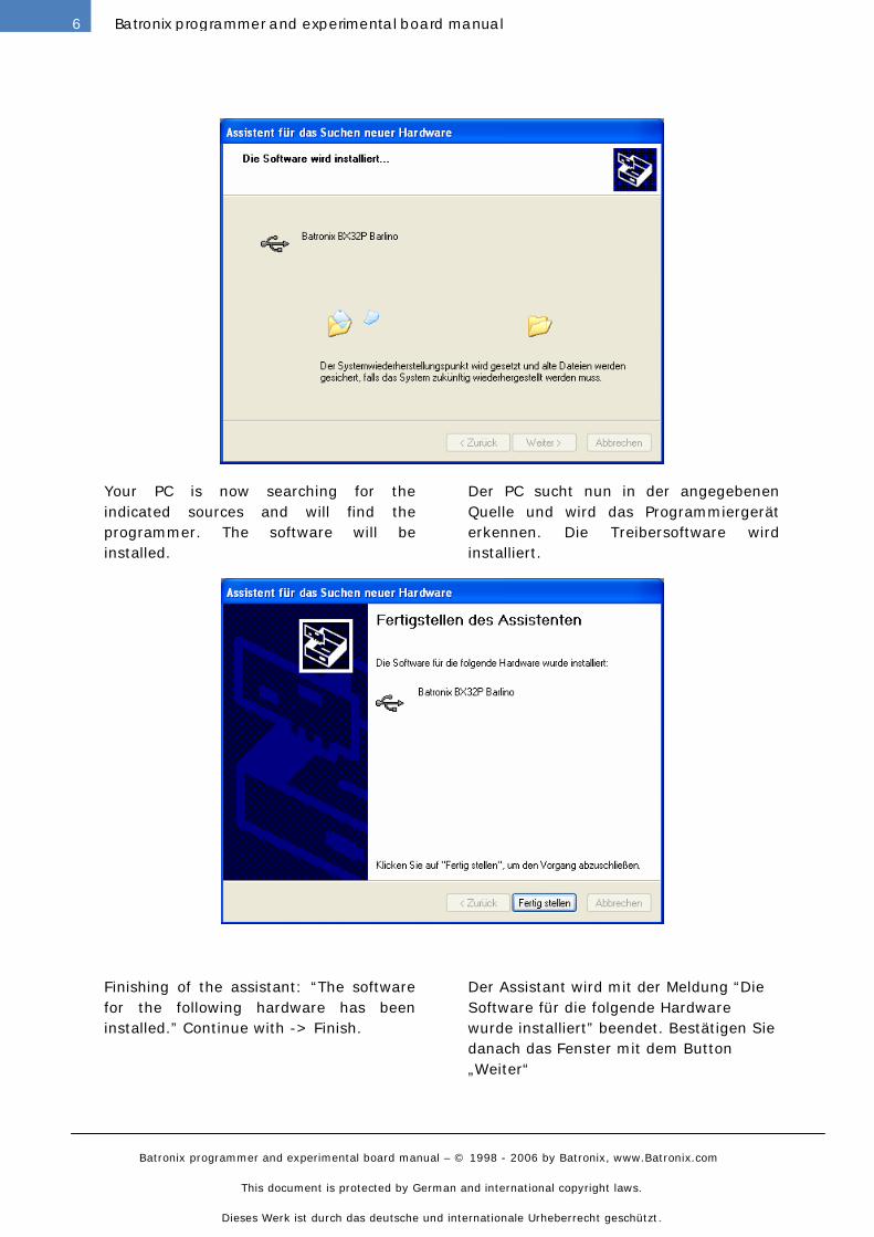
Your PC is now searching for the
indicated sources and will find the
programmer. The software will be
installed.
Der PC sucht nun in der angegebenen
Quelle und wird das Programmiergerät
erkennen. Die Treibersoftware wird
installiert.
Finishing of the assistant: “The software
for the following hardware has been
installed.” Continue with -> Finish.
Der Assistant wird mit der Meldung “Die
Software für die folgende Hardware
wurde installiert” beendet. Bestätigen Sie
danach das Fenster mit dem Button
„Weiter“
Batronix programmer and experimental board manual – © 1998 - 2006 by Batronix, www.Batronix.com
This document is protected by German and international copyright laws.
Dieses Werk ist durch das deutsche und internationale Urheberrecht geschützt.
7Batronix programmer and experimental board manual
BX32 BATUPO AND BX32P BARLINO
INSTALLATION AND OPERATION / INSTALLATION UND BENUTZUNG:
The installation steps are equal for all
USB devices. This part is descripted in
the capter “USB Device Installation”
above.
The BX32 and BX32P programmers are
completely operated by the Prog-Express
software. Please read the Prog-Express
manual to learn how the programmers
are used.
Die Installationsschritte sind für alle USB
Geräte identisch. Dieser Teil wird weiter
oben in dem Kapitel „USB
Geräteinstallation„ beschrieben.
Die BX32 und BX32P Programmiergeräte
werden mittels der Prog-Express
Software angesteuert. Bitte lesen Sie die
Prog-Express Anleitung um zu erfahren,
wie die Programmiergeräte verwendet
werden.
CONNECTIONS / ANSCHLÜSSE:
The USB connection is made using the
supplied cable. A power adapter or
batteries are not required, since all
programming voltages between 3 and 25
volts are provided internally by a voltage
generator from the USB supply voltage.
Der USB Anschluss erfolgt mit dem
mitgelieferten Kabel. Ein Netzteil oder
Batterien werden nicht benötigt, alle
Programmierspannungen zwischen 3 und
25 Volt werden intern aus der USB
Spannung über Ladungspumpen
generiert.
CORRECT PLACEMENT OF CHIPS / KORREKTES EINSETZEN VON CHIPS:
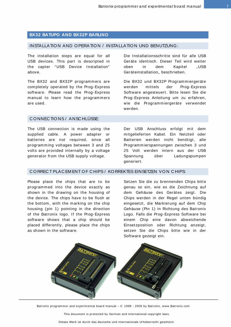
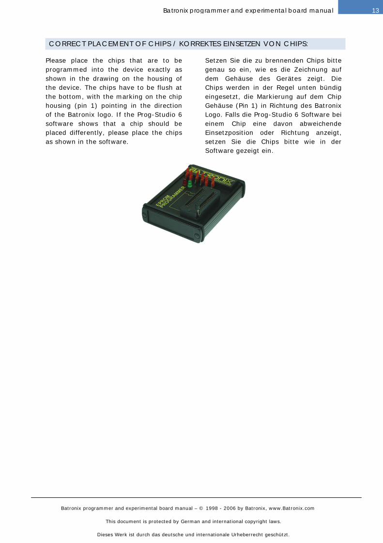
Please place the chips that are to be
programmed into the device exactly as
shown in the drawing on the housing of
the device. The chips have to be flush at
the bottom, with the marking on the chip
housing (pin 1) pointing in the direction
of the Batronix logo. If the Prog-Express
software shows that a chip should be
placed differently, please place the chips
as shown in the software.
Setzen Sie die zu brennenden Chips bitte
genau so ein, wie es die Zeichnung auf
dem Gehäuse des Gerätes zeigt. Die
Chips werden in der Regel unten bündig
eingesetzt, die Markierung auf dem Chip
Gehäuse (Pin 1) in Richtung des Batronix
Logo. Falls die Prog-Express Software bei
einem Chip eine davon abweichende
Einsetzposition oder Richtung anzeigt,
setzen Sie die Chips bitte wie in der
Software gezeigt ein.
Batronix programmer and experimental board manual – © 1998 - 2006 by Batronix, www.Batronix.com
This document is protected by German and international copyright laws.
Dieses Werk ist durch das deutsche und internationale Urheberrecht geschützt.
8 Batronix programmer and experimental board manual
USB CHIP PROGRAMMER
INSTALLATION AND OPERATION / INSTALLATION UND BENUTZUNG:
The installation steps are equal for all
USB devices. This part is descripted in
the capter “USB Device Installation”
above.
The USB Chip Programmers are
completely operated by the Prog-Express
software. Please read the Prog-Express
manual to learn how the programmers
are used.
Die Installationsschritte sind für alle USB
Geräte identisch. Dieser Teil wird weiter
oben in dem Kapitel „USB
Geräteinstallation„ beschrieben.
Die USB Chip Programmer werden mittels
der Prog-Express Software angesteuert.
Bitte lesen Sie die Prog-Express Anleitung
um zu erfahren, wie die
Programmiergeräte verwendet werden.
CONNECTIONS / ANSCHLÜSSE:
The USB connection is made using the
supplied cable. The network connection
that is built in is no longer needed, but is
fully operational. If a network adapter
with 9 to 12 volts DC (plug center
positive, outside ground) is connected, it
will take over the power supply to the
device (this can save battery power at
notebooks for example).
Der USB Anschluss erfolgt mit dem
mitgelieferten Kabel. Der vorgesehene
Netzteil Anschluss wird in der Regel nicht
weiter benötigt, ist aber voll
funktionsfähig. Sobald ein Netzteil mit 9
bis 12 Volt DC (mittlerer Stecker positiv,
außen Masse) angeschlossen wird,
übernimmt dieses die Stromversorgung
des Gerätes (z.B. um einen Laptop- Akku
zu schonen).
CORRECT PLACEMENT OF CHIPS / KORREKTES EINSETZEN VON CHIPS:
Please place the chips that are to be
programmed into the device exactly as
shown in the drawing on the housing of
the USB Chip Programmer. The chips
have to be flush at the bottom, with the
marking on the chip housing (pin 1)
pointing in the direction of the LED’s. If
the Prog-Express software shows that a
chip should be placed differently, please
place the chips as shown in the software.
Setzen Sie die zu brennenden Chips bitte
genau so ein, wie es die Zeichnung auf
dem Gehäuse des USB Chip Programmers
zeigt. Die Chips werden unten bündig
eingesetzt, die Markierung auf dem Chip
Gehäuse (Pin 1) in Richtung der LEDs.
Falls die Prog-Express Software bei einem
Chip eine davon abweichende
Einsetzposition oder Richtung anzeigt,
setzen Sie die Chips bitte wie in der
Software gezeigt ein.
Batronix programmer and experimental board manual – © 1998 - 2006 by Batronix, www.Batronix.com
This document is protected by German and international copyright laws.
Dieses Werk ist durch das deutsche und internationale Urheberrecht geschützt.
9Batronix programmer and experimental board manual
EPROM PROGRAMMER 3.X-4 / EPROM BRENNER 3.X-4
CONSTRUCTION OF A BUILDING KIT / AUFBAU EINES BAUSATZES:
You should first mount the smaller parts,
such as resistors and diodes. Then mount
the IC sockets, and only then the
remaining components. When mounting
the diodes, electrolyte and tantalum
condensers, transistors and IC's, please
take care that they are placed in the right
direction. We also highly recommend
placing all IC's on sockets; the necessary
sockets are included with all building kits.
You should mount the parallel port
connection last. This component is a 25
pole SUB-D plug (male). Therefore the
device can be connected with a simple
printer extension cable.
With the LED, you should pay particular
attention to the direction in which it is
mounted. In the drawings, you can
recognize the cathode (-) as the flattened
side of the LED housing. The following
markings can generally be used with
LED's to differentiate between the anode
and the cathode:
Anode (+) = the longer connection pin
Cathode (-) = the flattened side of the
housing, the larger metal surface in the
LED
Please take the time before construction
to assign the parts supplied in the
package to the items on the package list.
This can help to avoid unnecessary
confusion and resultant problems.
Als erstes sollten sie die kleineren
Bauteile wie Widerstände und Dioden
bestücken. Danach sollten sie die IC
Fassungen und erst dann die restlichen
Teile bestücken. Achten sie bitte bei den
Dioden, Elektrolyt- und
Tantalkondensatoren, Transistoren und
IC's auf den polungsrichtigen Einbau.
Zudem empfehlen wir alle IC's zu
sockeln, die nötigen Sockel liegen allen
Bausätzen bei.
Den Parallelportanschluss sollten sie
zuletzt bestücken. Bei diesem Bauteil
handelt es sich um einen 25 poligen SUB-
D Stecker (männlich). Das Gerät lässt
sich also mit einem einfachen Drucker-
Verlängerungskabel anschließen.
Bei der LED sollten Sie besonders auf die
Einbaurichtung achten. In den
Zeichnungen erkennen Sie die Kathode(-)
als die abgeflachte Seite vom LED
Gehäuse. Folgende Merkmale können
i.d.R. bei den LED's zur Unterscheidung
zwischen Anode und Kathode
herangezogen werden:
Anode(+) = Der längere Anschlusspin
Kathode(-) = Die abgeflachte Seite vom
Gehäuse, die größere Metallfläche in der
LED
Bitte nehmen Sie sich die Zeit und ordnen
Sie die gelieferten Bauteile vor dem
Aufbau der Stückliste zu. Damit können
unnötige Verwechslungen und damit
verbundene Probleme vermieden werden.
Batronix programmer and experimental board manual – © 1998 - 2006 by Batronix, www.Batronix.com
This document is protected by German and international copyright laws.
Dieses Werk ist durch das deutsche und internationale Urheberrecht geschützt.
10 Batronix programmer and experimental board manual
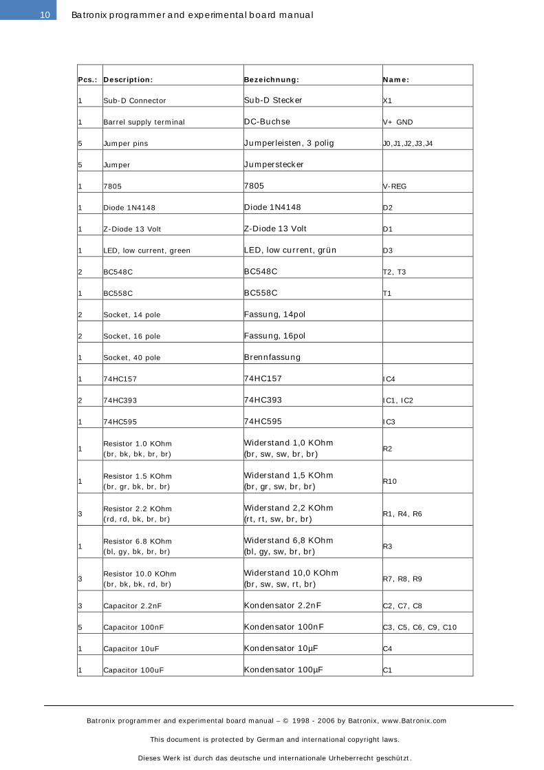
Pcs.: Description: Bezeichnung: Name:
1 Sub-D Connector Sub-D Stecker X1
1 Barrel supply terminal DC-Buchse V+ GND
5 Jumper pins Jumperleisten, 3 polig J0,J1,J2,J3,J4
5 Jumper Jumperstecker
1 7805 7805 V-REG
1 Diode 1N4148 Diode 1N4148 D2
1 Z-Diode 13 Volt Z-Diode 13 Volt D1
1 LED, low current, green LED, low current, grün D3
2 BC548C BC548C T2, T3
1 BC558C BC558C T1
2 Socket, 14 pole Fassung, 14pol
2 Socket, 16 pole Fassung, 16pol
1 Socket, 40 pole Brennfassung
1 74HC157 74HC157 IC4
2 74HC393 74HC393 IC1, IC2
1 74HC595 74HC595 IC3
1
Resistor 1.0 KOhm
(br, bk, bk, br, br)
Widerstand 1,0 KOhm
(br, sw, sw, br, br)
R2
1
Resistor 1.5 KOhm
(br, gr, bk, br, br)
Widerstand 1,5 KOhm
(br, gr, sw, br, br)
R10
3
Resistor 2.2 KOhm
(rd, rd, bk, br, br)
Widerstand 2,2 KOhm
(rt, rt, sw, br, br)
R1, R4, R6
1
Resistor 6.8 KOhm
(bl, gy, bk, br, br)
Widerstand 6,8 KOhm
(bl, gy, sw, br, br)
R3
3
Resistor 10.0 KOhm
(br, bk, bk, rd, br)
Widerstand 10,0 KOhm
(br, sw, sw, rt, br)
R7, R8, R9
3 Capacitor 2.2nF Kondensator 2.2nF C2, C7, C8
5 Capacitor 100nF Kondensator 100nF C3, C5, C6, C9, C10
1 Capacitor 10uF Kondensator 10µF C4
1 Capacitor 100uF Kondensator 100µF C1
Batronix programmer and experimental board manual – © 1998 - 2006 by Batronix, www.Batronix.com
This document is protected by German and international copyright laws.
Dieses Werk ist durch das deutsche und internationale Urheberrecht geschützt.
11Batronix programmer and experimental board manual
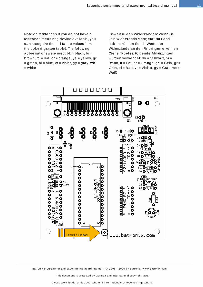
Note on resistances: If you do not have a resistance measuring device available, you can recognize the resistance values from the color rings (see table). The following abbreviations were used: bk = black, br = brown, rd = red, or = orange, ye = yellow, gr = green, bl = blue, vt = violet, gy = gray, wh= white
Hinweis zu den Widerständen: Wenn Sie kein Widerstands-Messgerät zur Hand haben, können Sie die Werte der Widerstände an den Farbringen erkennen (Siehe Tabelle). Folgende Abkürzungen wurden verwendet: sw = Schwarz, br = Braun, rt = Rot, or = Orange, ge = Gelb, gr = Grün, bl = Blau, vt = Violett, gy = Grau, ws = Weiß
Level / Hebel
Batronix programmer and experimental board manual – © 1998 - 2006 by Batronix, www.Batronix.com
This document is protected by German and international copyright laws.
Dieses Werk ist durch das deutsche und internationale Urheberrecht geschützt.
12 Batronix programmer and experimental board manual
INSTALLATION AND OPERATION / INSTALLATION UND BENUTZUNG:
The Eprom Programmer 3.x/4 are
completely operated by the Prog-Studio 6
software. Please read the Prog-Studio 6
manual to learn how the programmers
are used.
Die Eprom Brenner 3.x/4 werden mittels
der Prog-Studio 6 Software angesteuert.
Bitte lesen Sie die Prog-Studio 6
Anleitung um zu erfahren, wie die
Programmiergeräte verwendet werden.
CONNECTIONS / ANSCHLÜSSE:
The power supply must have a DC
voltage between 14 and 20 volts. The
maximum required power will be not over
150 mA. In the devices with the DC
barrel connectors, the inner connection of
the plug must be positive (standard).
Prior to connecting to the parallel port for
the first time with construction kits you
have put together yourself, you should
check the power takeup (without a chip in
place, this should be clearly below 50
mA). To operate the programming
devices, a fully connected (1:1) and
shielded parallel port cable is required
(do not use flat ribbon cable!). The cable
is a simple printer extension cable. One
end of the cable has a 25 pole SUB-D
plug and the other end has a 25 pole
SUB-D female connector.
In rare cases, the address of the parallel
port must be adapted to your PC. The
address 378(h) is to be entered as the
initial setting. This applies to most PCs.
In Windows, you can find the address in
the system guidance under System ->
Device manager -> Connections -> LPT -
> Resources. The entry E/A sector 378-
37F means that the basic address of the
port is 378(h). You can set up the parallel
port address that you find in the Prog-
Studio software options (menu „Process“
-> „Options“).
Die Versorgungsspannung muss eine
Gleichspannung zwischen 14 und 20 Volt
sein. Der max. benötigte Strom beträgt
150 mA. Der innere Kontakt des Steckers
muss die positive Spannung beinhalten,
der äußere Masse.
Vor dem ersten Anschließen an den
Parallelport sollten Sie bei selbst
aufgebauten Bausätzen die
Stromaufnahme kontrollieren. Diese
sollte ohne eingesetzten Chip deutlich
kleiner als 50mA sein. Zum Betrieb des
Programmiergerätes ist ein voll
verbundenes (1:1) und geschirmtes
Parallelportkabel nötig. An einem Ende
des Kabels ist ein 25 poliger SUB-D
Stecker und an dem anderen Ende des
Kabels ist eine 25 polige SUB-D Buchse
angebracht.
In seltenen Fällen muss die Adresse des
Parallelports noch an Ihren PC angepasst
werden. Als Voreinstellung ist die Adresse
378(h) eingetragen, die bei den meisten
PCs zutrifft. Bei Windows findet Sie die
Angabe der Adresse in der
Systemsteuerung unter System ->
Gerätemanager -> Anschlüsse -> LPT ->
Ressourcen. Der Eintrag E/A-Bereich 378-
37F bedeutet, dass die Basisadresse des
Ports 378(h) ist. Die gefundene
Parallelportadresse können Sie dann in
den Prog-Studio Software Optionen
einstellen (Menü „Bearbeiten“ ->
„Optionen“).
Batronix programmer and experimental board manual – © 1998 - 2006 by Batronix, www.Batronix.com
This document is protected by German and international copyright laws.
Dieses Werk ist durch das deutsche und internationale Urheberrecht geschützt.
13Batronix programmer and experimental board manual
CORRECT PLACEMENT OF CHIPS / KORREKTES EINSETZEN VON CHIPS:
Please place the chips that are to be
programmed into the device exactly as
shown in the drawing on the housing of
the device. The chips have to be flush at
the bottom, with the marking on the chip
housing (pin 1) pointing in the direction
of the Batronix logo. If the Prog-Studio 6
software shows that a chip should be
placed differently, please place the chips
as shown in the software.
Setzen Sie die zu brennenden Chips bitte
genau so ein, wie es die Zeichnung auf
dem Gehäuse des Gerätes zeigt. Die
Chips werden in der Regel unten bündig
eingesetzt, die Markierung auf dem Chip
Gehäuse (Pin 1) in Richtung des Batronix
Logo. Falls die Prog-Studio 6 Software bei
einem Chip eine davon abweichende
Einsetzposition oder Richtung anzeigt,
setzen Sie die Chips bitte wie in der
Software gezeigt ein.
Batronix programmer and experimental board manual – © 1998 - 2006 by Batronix, www.Batronix.com
This document is protected by German and international copyright laws.
Dieses Werk ist durch das deutsche und internationale Urheberrecht geschützt.
14 Batronix programmer and experimental board manual
FLASH MC PROGRAMMER I / FLASH MC BRENNER I
CONSTRUCTION OF A BUILDING KIT / AUFBAU EINES BAUSATZES:
You should first mount the smaller parts,
such as resistors and diodes. Then mount
the IC sockets, and only then the
remaining components. When mounting
the diodes, electrolyte and tantalum
condensers, transistors and IC's, please
take care that they are placed in the right
direction. We also highly recommend
placing all IC's on sockets; the necessary
sockets are included with all building kits.
You should mount the parallel port
connection last. This component is a 25
pole SUB-D plug (male). Therefore the
device can be connected with a simple
printer extension cable.
With the LED, you should pay particular
attention to the direction in which it is
mounted. In the drawings, you can
recognize the cathode (-) as the flattened
side of the LED housing. The following
markings can generally be used with
LED's to differentiate between the anode
and the cathode:
Anode (+) = the longer connection pin
Cathode (-) = the flattened side of the
housing, the larger metal surface in the
LED
Please take the time before construction
to assign the parts supplied in the
package to the items on the package list.
This can help to avoid unnecessary
confusion and resultant problems.
Als erstes sollten sie die kleineren
Bauteile wie Widerstände und Dioden
bestücken. Danach sollten sie die IC
Fassungen und erst dann die restlichen
Teile bestücken. Achten sie bitte bei den
Dioden, Elektrolyt- und
Tantalkondensatoren, Transistoren und
IC's auf den polungsrichtigen Einbau.
Zudem empfehlen wir alle IC's zu
sockeln, die nötigen Sockel liegen allen
Bausätzen bei.
Den Parallelportanschluss sollten sie
zuletzt bestücken. Bei diesem Bauteil
handelt es sich um einen 25 poligen SUB-
D Stecker (männlich). Das Gerät lässt
sich also mit einem einfachen Drucker-
Verlängerungskabel anschließen.
Bei der LED sollten Sie besonders auf die
Einbaurichtung achten. In den
Zeichnungen erkennen Sie die Kathode(-)
als die abgeflachte Seite vom LED
Gehäuse. Folgende Merkmale können
i.d.R. bei den LED's zur Unterscheidung
zwischen Anode und Kathode
herangezogen werden:
Anode(+) = Der längere Anschlusspin
Kathode(-) = Die abgeflachte Seite vom
Gehäuse, die größere Metallfläche in der
LED
Bitte nehmen Sie sich die Zeit und ordnen
Sie die gelieferten Bauteile vor dem
Aufbau der Stückliste zu. Damit können
unnötige Verwechslungen und damit
verbundene Probleme vermieden werden.
Batronix programmer and experimental board manual – © 1998 - 2006 by Batronix, www.Batronix.com
This document is protected by German and international copyright laws.
Dieses Werk ist durch das deutsche und internationale Urheberrecht geschützt.
15Batronix programmer and experimental board manual
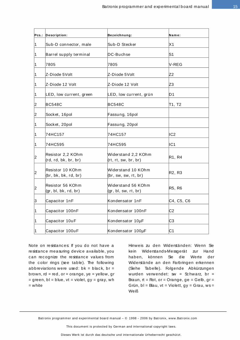
Pcs.: Description: Bezeichnung: Name:
1 Sub-D connector, male Sub-D Stecker X1
1 Barrel supply terminal DC-Buchse S1
1 7805 7805 V-REG
1 Z-Diode 5Volt Z-Diode 5Volt Z2
1 Z-Diode 12 Volt Z-Diode 12 Volt Z3
1 LED, low current, green LED, low current, grün D1
2 BC548C BC548C T1, T2
2 Socket, 16pol Fassung, 16pol
1 Socket, 20pol Fassung, 20pol
1 74HC157 74HC157 IC2
1 74HC595 74HC595 IC1
2
Resistor 2,2 KOhm
(rd, rd, bk, br, br)
Widerstand 2,2 KOhm
(rt, rt, sw, br, br)
R1, R4
2
Resistor 10 KOhm
(br, bk, bk, rd, br)
Widerstand 10 KOhm
(br, sw, sw, rt, br)
R2, R3
2
Resistor 56 KOhm
(gr, bl, bk, rd, br)
Widerstand 56 KOhm
(gr, bl, sw, rt, br)
R5, R6
3 Capacitor 1nF Kondensator 1nF C4, C5, C6
1 Capacitor 100nF Kondensator 100nF C2
1 Capacitor 10uF Kondensator 10µF C3
1 Capacitor 100uF Kondensator 100µF C1
Note on resistances: If you do not have a resistance measuring device available, you can recognize the resistance values from the color rings (see table). The following abbreviations were used: bk = black, br = brown, rd = red, or = orange, ye = yellow, gr = green, bl = blue, vt = violet, gy = gray, wh= white
Hinweis zu den Widerständen: Wenn Sie kein Widerstands-Messgerät zur Hand haben, können Sie die Werte der Widerstände an den Farbringen erkennen (Siehe Tabelle). Folgende Abkürzungen wurden verwendet: sw = Schwarz, br = Braun, rt = Rot, or = Orange, ge = Gelb, gr = Grün, bl = Blau, vt = Violett, gy = Grau, ws = Weiß
Batronix programmer and experimental board manual – © 1998 - 2006 by Batronix, www.Batronix.com
This document is protected by German and international copyright laws.
Dieses Werk ist durch das deutsche und internationale Urheberrecht geschützt.
16 Batronix programmer and experimental board manual
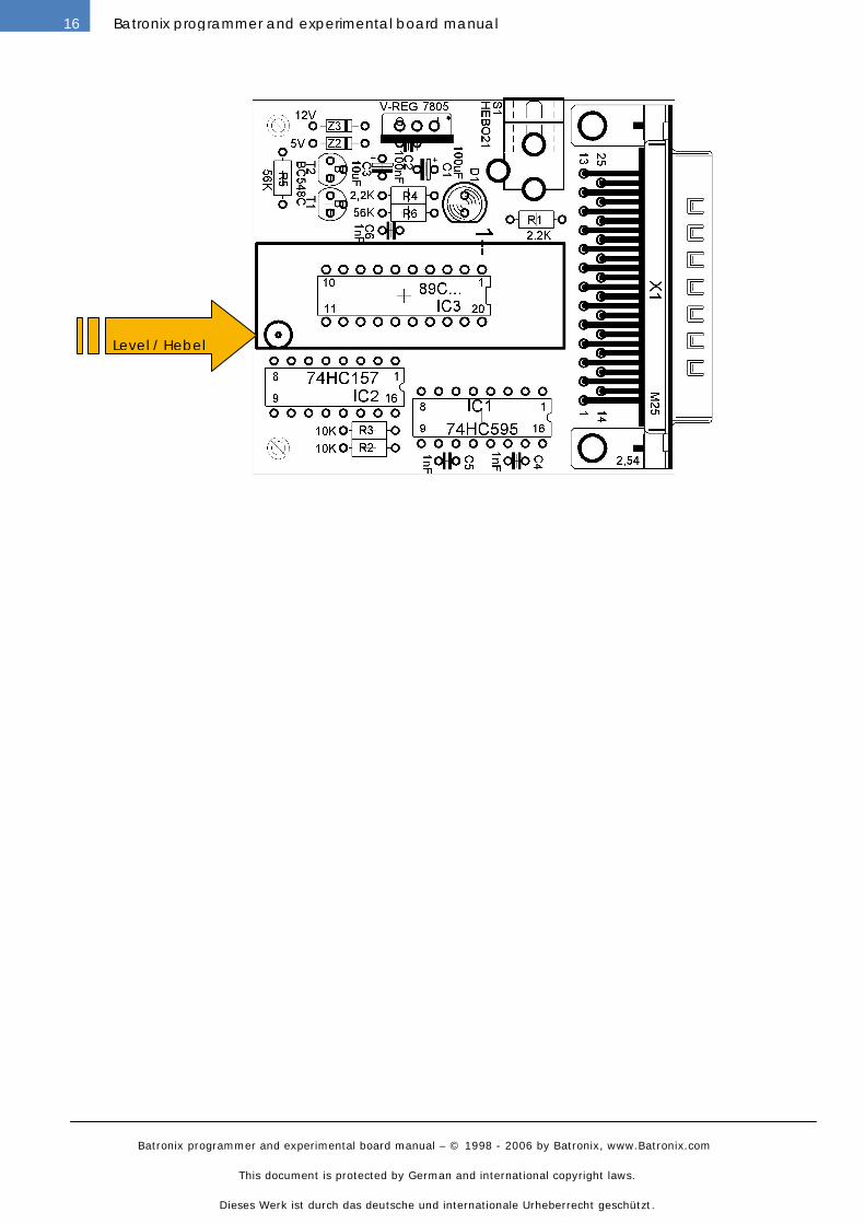
Level / Hebel
Batronix programmer and experimental board manual – © 1998 - 2006 by Batronix, www.Batronix.com
This document is protected by German and international copyright laws.
Dieses Werk ist durch das deutsche und internationale Urheberrecht geschützt.
17Batronix programmer and experimental board manual
INSTALLATION AND OPERATION / INSTALLATION UND BENUTZUNG:
The Flash MC Programmer I are
completely operated by the Prog-Studio 6
software. Please read the Prog-Studio 6
manual to learn how the programmers
are used.
Die Flash MC Brenner I werden mittels
der Prog-Studio 6 Software angesteuert.
Bitte lesen Sie die Prog-Studio 6
Anleitung um zu erfahren, wie die
Programmiergeräte verwendet werden.
CONNECTIONS / ANSCHLÜSSE:
The power supply must have a DC
voltage between 12 and 24 volts. The
maximum required power will be not over
100 mA. In the devices with the DC
barrel connectors, the inner connection of
the plug must be positive (standard).
Prior to connecting to the parallel port for
the first time with construction kits you
have put together yourself, you should
check the power takeup (without a chip in
place, this should be clearly below 50
mA). To operate the programming
devices, a fully connected (1:1) and
shielded parallel port cable is required
(do not use flat ribbon cable!). The cable
is a simple printer extension cable. One
end of the cable has a 25 pole SUB-D
plug and the other end has a 25 pole
SUB-D female connector.
In rare cases, the address of the parallel
port must be adapted to your PC. The
address 378(h) is to be entered as the
initial setting. This applies to most PCs.
In Windows, you can find the address in
the system guidance under System ->
Device manager -> Connections -> LPT -
> Resources. The entry E/A sector 378-
37F means that the basic address of the
port is 378(h). You can set up the parallel
port address that you find in the Prog-
Studio software options (menu „Process“
-> „Options“).
Die Versorgungsspannung muss eine
Gleichspannung zwischen 12 und 24 Volt
sein. Der max. benötigte Strom beträgt
100 mA. Der innere Kontakt des Steckers
muss die positive Spannung beinhalten,
der äußere Masse.
Vor dem ersten Anschließen an den
Parallelport sollten Sie bei selbst
aufgebauten Bausätzen die
Stromaufnahme kontrollieren. Diese
sollte ohne eingesetzten Chip deutlich
kleiner als 50mA sein. Zum Betrieb des
Programmiergerätes ist ein voll
verbundenes (1:1) und geschirmtes
Parallelportkabel nötig. An einem Ende
des Kabels ist ein 25 poliger SUB-D
Stecker und an dem anderen Ende des
Kabels ist eine 25 polige SUB-D Buchse
angebracht.
In seltenen Fällen muss die Adresse des
Parallelports noch an Ihren PC angepasst
werden. Als Voreinstellung ist die Adresse
378(h) eingetragen, die bei den meisten
PCs zutrifft. Bei Windows findet Sie die
Angabe der Adresse in der
Systemsteuerung unter System ->
Gerätemanager -> Anschlüsse -> LPT ->
Ressourcen. Der Eintrag E/A-Bereich 378-
37F bedeutet, dass die Basisadresse des
Ports 378(h) ist. Die gefundene
Parallelportadresse können Sie dann in
den Prog-Studio Software Optionen
einstellen (Menü „Bearbeiten“ ->
„Optionen“).
Batronix programmer and experimental board manual – © 1998 - 2006 by Batronix, www.Batronix.com
This document is protected by German and international copyright laws.
Dieses Werk ist durch das deutsche und internationale Urheberrecht geschützt.
18 Batronix programmer and experimental board manual
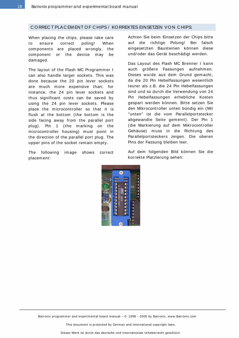
CORRECT PLACEMENT OF CHIPS / KORREKTES EINSETZEN VON CHIPS:
When placing the chips, please take care
to ensure correct poling! When
components are placed wrongly, the
component or the device may be
damaged.
The layout of the Flash MC Programmer I
can also handle larger sockets. This was
done because the 20 pin lever sockets
are much more expensive than; for
instance, the 24 pin lever sockets and
thus significant costs can be saved by
using the 24 pin lever sockets. Please
place the microcontroller so that it is
flush at the bottom (the bottom is the
side facing away from the parallel port
plug). Pin 1 (the marking on the
microcontroller housing) must point in
the direction of the parallel port plug. The
upper pins of the socket remain empty.
The following image shows correct
placement:
Achten Sie beim Einsetzen der Chips bitte
auf die richtige Polung! Bei falsch
eingesetzten Bausteinen können diese
und/oder das Gerät beschädigt werden.
Das Layout des Flash MC Brenner I kann
auch größere Fassungen aufnehmen.
Dieses wurde aus dem Grund gemacht,
da die 20 Pin Hebelfassungen wesentlich
teurer als z.B. die 24 Pin Hebelfassungen
sind und so durch die Verwendung von 24
Pin Hebelfassungen erhebliche Kosten
gespart werden können. Bitte setzen Sie
den Mikrocontroller unten bündig ein (Mit
"unten" ist die vom Parallelportstecker
abgewandte Seite gemeint). Der Pin 1
(die Markierung auf dem Mikrocontroller
Gehäuse) muss in die Richtung des
Parallelportsteckers zeigen. Die oberen
Pins der Fassung bleiben leer.
Auf dem folgenden Bild können Sie die
korrekte Platzierung sehen:
Batronix programmer and experimental board manual – © 1998 - 2006 by Batronix, www.Batronix.com
This document is protected by German and international copyright laws.
Dieses Werk ist durch das deutsche und internationale Urheberrecht geschützt.
19Batronix programmer and experimental board manual
FLASH MC PROGRAMMER II / FLASH MC BRENNER II
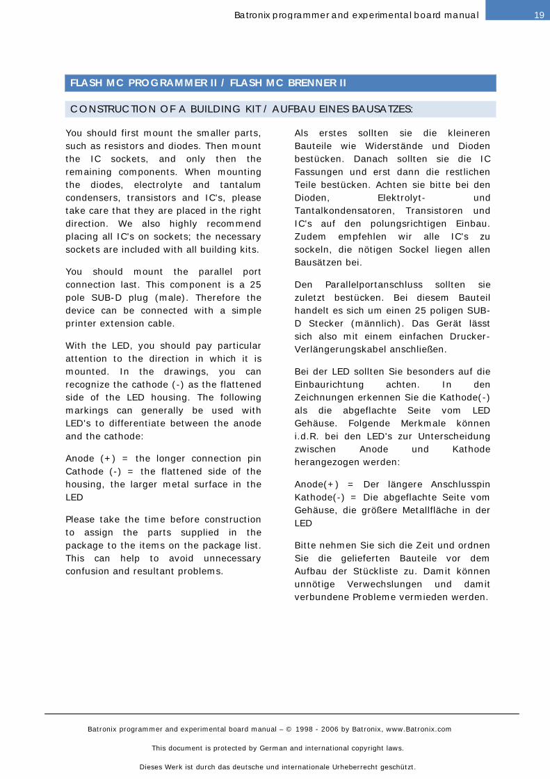
CONSTRUCTION OF A BUILDING KIT / AUFBAU EINES BAUSATZES:
You should first mount the smaller parts,
such as resistors and diodes. Then mount
the IC sockets, and only then the
remaining components. When mounting
the diodes, electrolyte and tantalum
condensers, transistors and IC's, please
take care that they are placed in the right
direction. We also highly recommend
placing all IC's on sockets; the necessary
sockets are included with all building kits.
You should mount the parallel port
connection last. This component is a 25
pole SUB-D plug (male). Therefore the
device can be connected with a simple
printer extension cable.
With the LED, you should pay particular
attention to the direction in which it is
mounted. In the drawings, you can
recognize the cathode (-) as the flattened
side of the LED housing. The following
markings can generally be used with
LED's to differentiate between the anode
and the cathode:
Anode (+) = the longer connection pin
Cathode (-) = the flattened side of the
housing, the larger metal surface in the
LED
Please take the time before construction
to assign the parts supplied in the
package to the items on the package list.
This can help to avoid unnecessary
confusion and resultant problems.
Als erstes sollten sie die kleineren
Bauteile wie Widerstände und Dioden
bestücken. Danach sollten sie die IC
Fassungen und erst dann die restlichen
Teile bestücken. Achten sie bitte bei den
Dioden, Elektrolyt- und
Tantalkondensatoren, Transistoren und
IC's auf den polungsrichtigen Einbau.
Zudem empfehlen wir alle IC's zu
sockeln, die nötigen Sockel liegen allen
Bausätzen bei.
Den Parallelportanschluss sollten sie
zuletzt bestücken. Bei diesem Bauteil
handelt es sich um einen 25 poligen SUB-
D Stecker (männlich). Das Gerät lässt
sich also mit einem einfachen Drucker-
Verlängerungskabel anschließen.
Bei der LED sollten Sie besonders auf die
Einbaurichtung achten. In den
Zeichnungen erkennen Sie die Kathode(-)
als die abgeflachte Seite vom LED
Gehäuse. Folgende Merkmale können
i.d.R. bei den LED's zur Unterscheidung
zwischen Anode und Kathode
herangezogen werden:
Anode(+) = Der längere Anschlusspin
Kathode(-) = Die abgeflachte Seite vom
Gehäuse, die größere Metallfläche in der
LED
Bitte nehmen Sie sich die Zeit und ordnen
Sie die gelieferten Bauteile vor dem
Aufbau der Stückliste zu. Damit können
unnötige Verwechslungen und damit
verbundene Probleme vermieden werden.
Batronix programmer and experimental board manual – © 1998 - 2006 by Batronix, www.Batronix.com
This document is protected by German and international copyright laws.
Dieses Werk ist durch das deutsche und internationale Urheberrecht geschützt.
20 Batronix programmer and experimental board manual
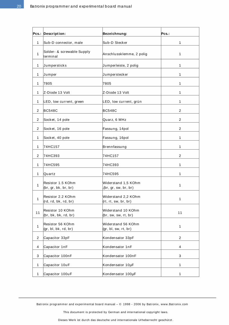
Pcs.: Description: Bezeichnung: Pcs.:
1 Sub-D connector, male Sub-D Stecker 1
1
Solder- & screwable Supply
terminal
Anschlussklemme, 2 polig 1
1 Jumpersticks Jumperleiste, 2 polig 1
1 Jumper Jumperstecker 1
1 7805 7805 1
1 Z-Diode 13 Volt Z-Diode 13 Volt 1
1 LED, low current, green LED, low current, grün 1
2 BC548C BC548C 2
2 Socket, 14 pole Quarz, 6 MHz 2
2 Socket, 16 pole Fassung, 14pol 2
1 Socket, 40 pole Fassung, 16pol 1
1 74HC157 Brennfassung 1
2 74HC393 74HC157 2
1 74HC595 74HC393 1
1 Quartz 74HC595 1
1
Resistor 1.5 KOhm
(br, gr, bk, br, br)
Widerstand 1,5 KOhm
‚(br, gr, sw, br, br)
1
1
Resistor 2.2 KOhm
(rd, rd, bk, rd, br)
Widerstand 2,2 KOhm
(rt, rt, sw, br, br)
1
11
Resistor 10 KOhm
(br, bk, bk, rd, br)
Widerstand 10 KOhm
(br, sw, sw, rt, br)
11
1
Resistor 56 KOhm
(gr, bl, bk, rd, br)
Widerstand 56 KOhm
(gr, bl, sw, rt, br)
1
2 Capacitor 33pF Kondensator 33pF 2
4 Capacitor 1nF Kondensator 1nF 4
3 Capacitor 100nF Kondensator 100nF 3
1 Capacitor 10uF Kondensator 10µF 1
1 Capacitor 100uF Kondensator 100µF 1
Batronix programmer and experimental board manual – © 1998 - 2006 by Batronix, www.Batronix.com
This document is protected by German and international copyright laws.
Dieses Werk ist durch das deutsche und internationale Urheberrecht geschützt.
21Batronix programmer and experimental board manual
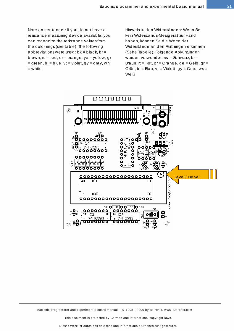
Note on resistances: If you do not have a resistance measuring device available, you can recognize the resistance values from the color rings (see table). The following abbreviations were used: bk = black, br = brown, rd = red, or = orange, ye = yellow, gr = green, bl = blue, vt = violet, gy = gray, wh= white
Hinweis zu den Widerständen: Wenn Sie kein Widerstands-Messgerät zur Hand haben, können Sie die Werte der Widerstände an den Farbringen erkennen (Siehe Tabelle). Folgende Abkürzungen wurden verwendet: sw = Schwarz, br = Braun, rt = Rot, or = Orange, ge = Gelb, gr = Grün, bl = Blau, vt = Violett, gy = Grau, ws = Weiß
Level / Hebel
Batronix programmer and experimental board manual – © 1998 - 2006 by Batronix, www.Batronix.com
This document is protected by German and international copyright laws.
Dieses Werk ist durch das deutsche und internationale Urheberrecht geschützt.
22 Batronix programmer and experimental board manual
INSTALLATION AND OPERATION / INSTALLATION UND BENUTZUNG:
The Flash MC Programmer II are
completely operated by the Prog-Studio 6
software. Please read the Prog-Studio 6
manual to learn how the programmers
are used.
Die Flash MC Brenner II werden mittels
der Prog-Studio 6 Software angesteuert.
Bitte lesen Sie die Prog-Studio 6
Anleitung um zu erfahren, wie die
Programmiergeräte verwendet werden.
CONNECTIONS / ANSCHLÜSSE:
The power supply must have a DC
voltage between 12 and 24 volts. The
maximum required power will be not over
100 mA. In the devices with the DC
barrel connectors, the inner connection of
the plug must be positive (standard).
Prior to connecting to the parallel port for
the first time with construction kits you
have put together yourself, you should
check the power takeup (without a chip in
place, this should be clearly below 50
mA). To operate the programming
devices, a fully connected (1:1) and
shielded parallel port cable is required
(do not use flat ribbon cable!). The cable
is a simple printer extension cable. One
end of the cable has a 25 pole SUB-D
plug and the other end has a 25 pole
SUB-D female connector.
In rare cases, the address of the parallel
port must be adapted to your PC. The
address 378(h) is to be entered as the
initial setting. This applies to most PCs.
In Windows, you can find the address in
the system guidance under System ->
Device manager -> Connections -> LPT -
> Resources. The entry E/A sector 378-
37F means that the basic address of the
port is 378(h). You can set up the parallel
port address that you find in the Prog-
Studio software options (menu „Process“
-> „Options“).
Die Versorgungsspannung muss eine
Gleichspannung zwischen 12 und 24 Volt
sein. Der max. benötigte Strom beträgt
100 mA. Der innere Kontakt des Steckers
muss die positive Spannung beinhalten,
der äußere Masse.
Vor dem ersten Anschließen an den
Parallelport sollten Sie bei selbst
aufgebauten Bausätzen die
Stromaufnahme kontrollieren. Diese
sollte ohne eingesetzten Chip deutlich
kleiner als 50mA sein. Zum Betrieb des
Programmiergerätes ist ein voll
verbundenes (1:1) und geschirmtes
Parallelportkabel nötig. An einem Ende
des Kabels ist ein 25 poliger SUB-D
Stecker und an dem anderen Ende des
Kabels ist eine 25 polige SUB-D Buchse
angebracht.
In seltenen Fällen muss die Adresse des
Parallelports noch an Ihren PC angepasst
werden. Als Voreinstellung ist die Adresse
378(h) eingetragen, die bei den meisten
PCs zutrifft. Bei Windows findet Sie die
Angabe der Adresse in der
Systemsteuerung unter System ->
Gerätemanager -> Anschlüsse -> LPT ->
Ressourcen. Der Eintrag E/A-Bereich 378-
37F bedeutet, dass die Basisadresse des
Ports 378(h) ist. Die gefundene
Parallelportadresse können Sie dann in
den Prog-Studio Software Optionen
einstellen (Menü „Bearbeiten“ ->
„Optionen“).
Batronix programmer and experimental board manual – © 1998 - 2006 by Batronix, www.Batronix.com
This document is protected by German and international copyright laws.
Dieses Werk ist durch das deutsche und internationale Urheberrecht geschützt.
23Batronix programmer and experimental board manual
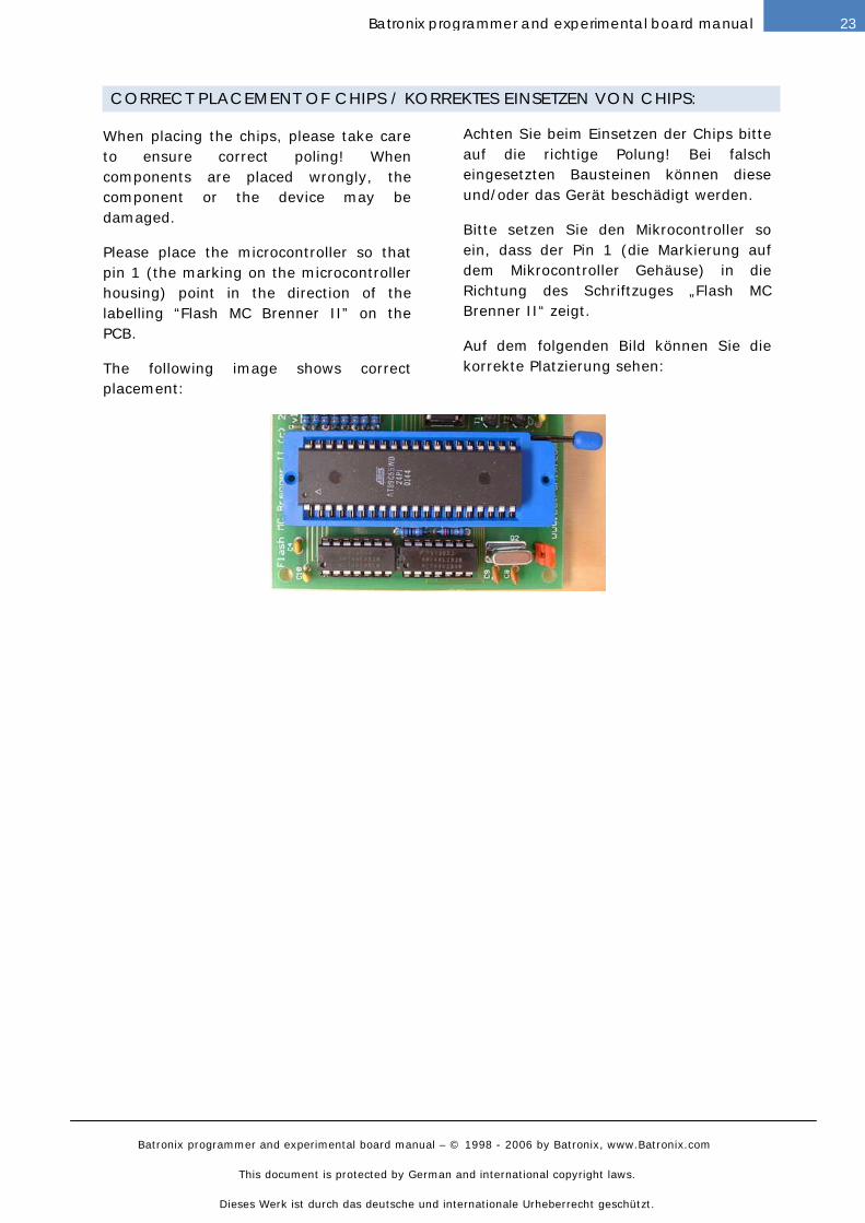
CORRECT PLACEMENT OF CHIPS / KORREKTES EINSETZEN VON CHIPS:
When placing the chips, please take care
to ensure correct poling! When
components are placed wrongly, the
component or the device may be
damaged.
Please place the microcontroller so that
pin 1 (the marking on the microcontroller
housing) point in the direction of the
labelling “Flash MC Brenner II” on the
PCB.
The following image shows correct
placement:
Achten Sie beim Einsetzen der Chips bitte
auf die richtige Polung! Bei falsch
eingesetzten Bausteinen können diese
und/oder das Gerät beschädigt werden.
Bitte setzen Sie den Mikrocontroller so
ein, dass der Pin 1 (die Markierung auf
dem Mikrocontroller Gehäuse) in die
Richtung des Schriftzuges „Flash MC
Brenner II“ zeigt.
Auf dem folgenden Bild können Sie die
korrekte Platzierung sehen:
Batronix programmer and experimental board manual – © 1998 - 2006 by Batronix, www.Batronix.com
This document is protected by German and international copyright laws.
Dieses Werk ist durch das deutsche und internationale Urheberrecht geschützt.
24 Batronix programmer and experimental board manual
FLASH EXP.BOARD I / FLASH EXP.BOARD I
CONSTRUCTION OF A BUILDING KIT / AUFBAU EINES BAUSATZES:
You should first mount the smaller parts,
such as resistors and diodes. Then mount
the IC sockets, and only then the
remaining components. When mounting
the diodes, electrolyte and tantalum
condensers, transistors and IC's, please
take care that they are placed in the right
direction. We also highly recommend
placing all IC's on sockets; the necessary
sockets are included with all building kits.
IMPORTANT: Please mount the cooling
body to the voltage regulator, using the
included screw and nut, prior to soldering
it into place. Otherwise its pins may be
soldered in too deeply and the cooling
body can no longer be mounted to the
voltage regulator without difficulty.
With the LED, you should pay particular
attention to the direction in which it is
mounted. In the drawings, you can
recognize the cathode (-) as the flattened
side of the LED housing. The following
markings can generally be used with
LED's to differentiate between the anode
and the cathode:
Anode (+) = the longer connection pin
Cathode (-) = the flattened side of the
housing, the larger metal surface in the
LED
Please take the time before construction
to assign the parts supplied in the
package to the items on the package list.
This can help to avoid unnecessary
confusion and resultant problems.
Als erstes sollten sie die kleineren
Bauteile wie Widerstände und Dioden
bestücken. Danach sollten sie die IC
Fassungen und erst dann die restlichen
Teile bestücken. Achten sie bitte bei den
Dioden, Elektrolyt- und
Tantalkondensatoren, Transistoren und
IC's auf den polungsrichtigen Einbau.
Zudem empfehlen wir alle IC's zu
sockeln, die nötigen Sockel liegen allen
Bausätzen bei.
WICHTIG: Bitte montieren Sie erst den
Kühlkörper mit der beigelegten Schraube
samt Mutter an den Spannungsregler,
bevor Sie diesen einlöten. Ansonsten
kann es passieren, dass dieser mit seinen
Pins "zu tief" eingelötet wird und sich
damit der Kühlkörper nicht mehr
problemlos an dem Spannungsregler
montieren lässt.
Bei der LED sollten Sie besonders auf die
Einbaurichtung achten. In den
Zeichnungen erkennen Sie die Kathode(-)
als die abgeflachte Seite vom LED
Gehäuse. Folgende Merkmale können
i.d.R. bei den LED's zur Unterscheidung
zwischen Anode und Kathode
herangezogen werden:
Anode(+) = Der längere Anschlusspin
Kathode(-) = Die abgeflachte Seite vom
Gehäuse, die größere Metallfläche in der
LED
Bitte nehmen Sie sich die Zeit und ordnen
Sie die gelieferten Bauteile vor dem
Aufbau der Stückliste zu. Damit können
unnötige Verwechslungen und damit
verbundene Probleme vermieden werden.
Batronix programmer and experimental board manual – © 1998 - 2006 by Batronix, www.Batronix.com
This document is protected by German and international copyright laws.
Dieses Werk ist durch das deutsche und internationale Urheberrecht geschützt.
25Batronix programmer and experimental board manual
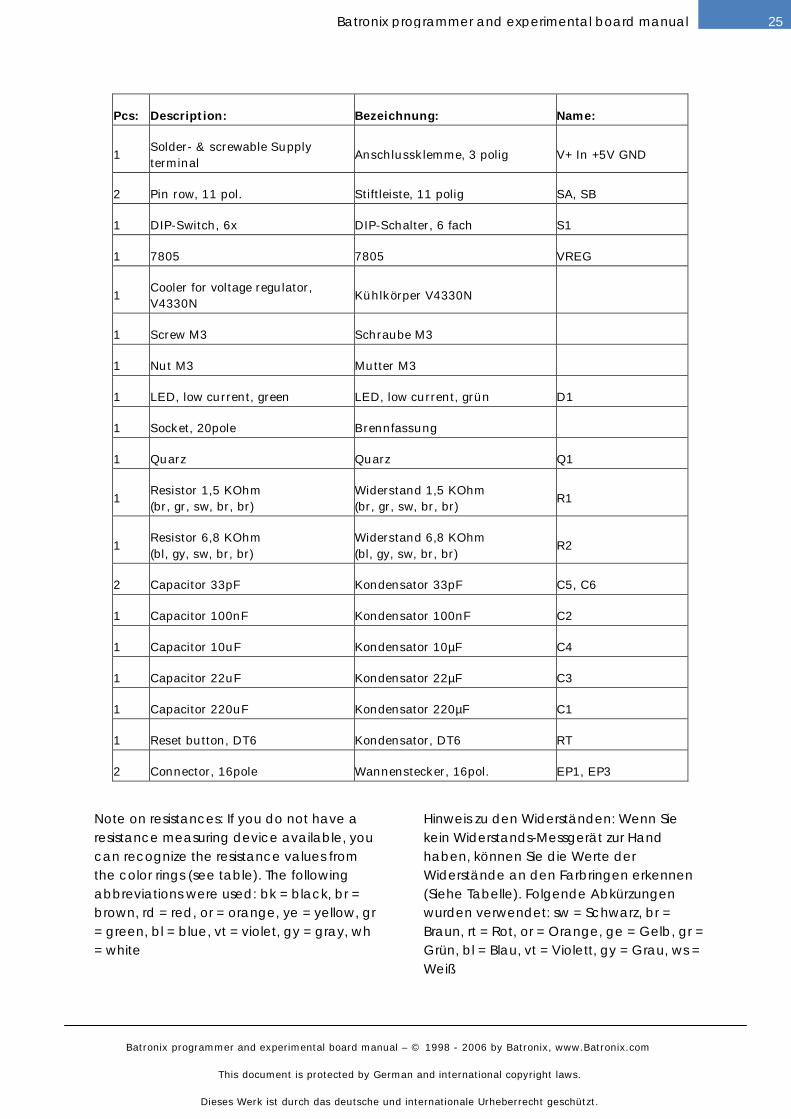
Pcs: Description: Bezeichnung: Name:
1
Solder- & screwable Supply
terminal
Anschlussklemme, 3 polig V+ In +5V GND
2 Pin row, 11 pol. Stiftleiste, 11 polig SA, SB
1 DIP-Switch, 6x DIP-Schalter, 6 fach S1
1 7805 7805 VREG
1
Cooler for voltage regulator,
V4330N
Kühlkörper V4330N
1 Screw M3 Schraube M3
1 Nut M3 Mutter M3
1 LED, low current, green LED, low current, grün D1
1 Socket, 20pole Brennfassung
1 Quarz Quarz Q1
1
Resistor 1,5 KOhm
(br, gr, sw, br, br)
Widerstand 1,5 KOhm
(br, gr, sw, br, br)
R1
1
Resistor 6,8 KOhm
(bl, gy, sw, br, br)
Widerstand 6,8 KOhm
(bl, gy, sw, br, br)
R2
2 Capacitor 33pF Kondensator 33pF C5, C6
1 Capacitor 100nF Kondensator 100nF C2
1 Capacitor 10uF Kondensator 10µF C4
1 Capacitor 22uF Kondensator 22µF C3
1 Capacitor 220uF Kondensator 220µF C1
1 Reset button, DT6 Kondensator, DT6 RT
2 Connector, 16pole Wannenstecker, 16pol. EP1, EP3
Note on resistances: If you do not have a resistance measuring device available, you can recognize the resistance values from the color rings (see table). The following abbreviations were used: bk = black, br = brown, rd = red, or = orange, ye = yellow, gr = green, bl = blue, vt = violet, gy = gray, wh= white
Hinweis zu den Widerständen: Wenn Sie kein Widerstands-Messgerät zur Hand haben, können Sie die Werte der Widerstände an den Farbringen erkennen (Siehe Tabelle). Folgende Abkürzungen wurden verwendet: sw = Schwarz, br = Braun, rt = Rot, or = Orange, ge = Gelb, gr = Grün, bl = Blau, vt = Violett, gy = Grau, ws = Weiß
Batronix programmer and experimental board manual – © 1998 - 2006 by Batronix, www.Batronix.com
This document is protected by German and international copyright laws.
Dieses Werk ist durch das deutsche und internationale Urheberrecht geschützt.
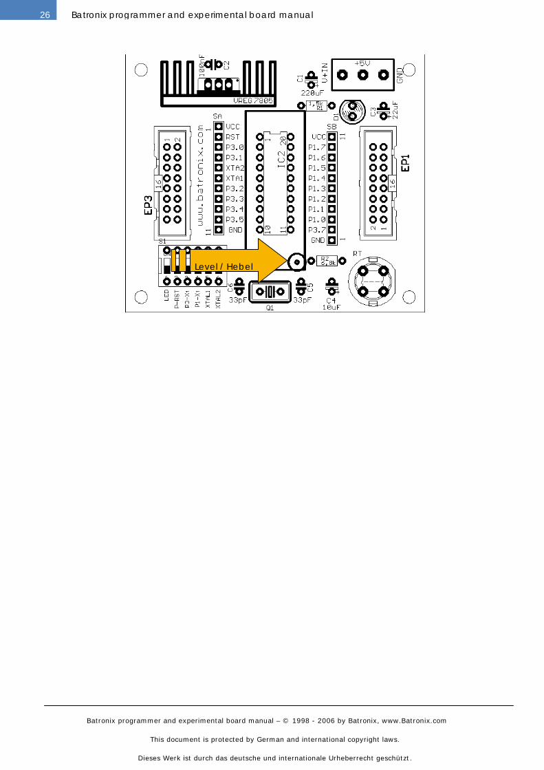
26 Batronix programmer and experimental board manual
Level / Hebel
Batronix programmer and experimental board manual – © 1998 - 2006 by Batronix, www.Batronix.com
This document is protected by German and international copyright laws.
Dieses Werk ist durch das deutsche und internationale Urheberrecht geschützt.
27Batronix programmer and experimental board manual
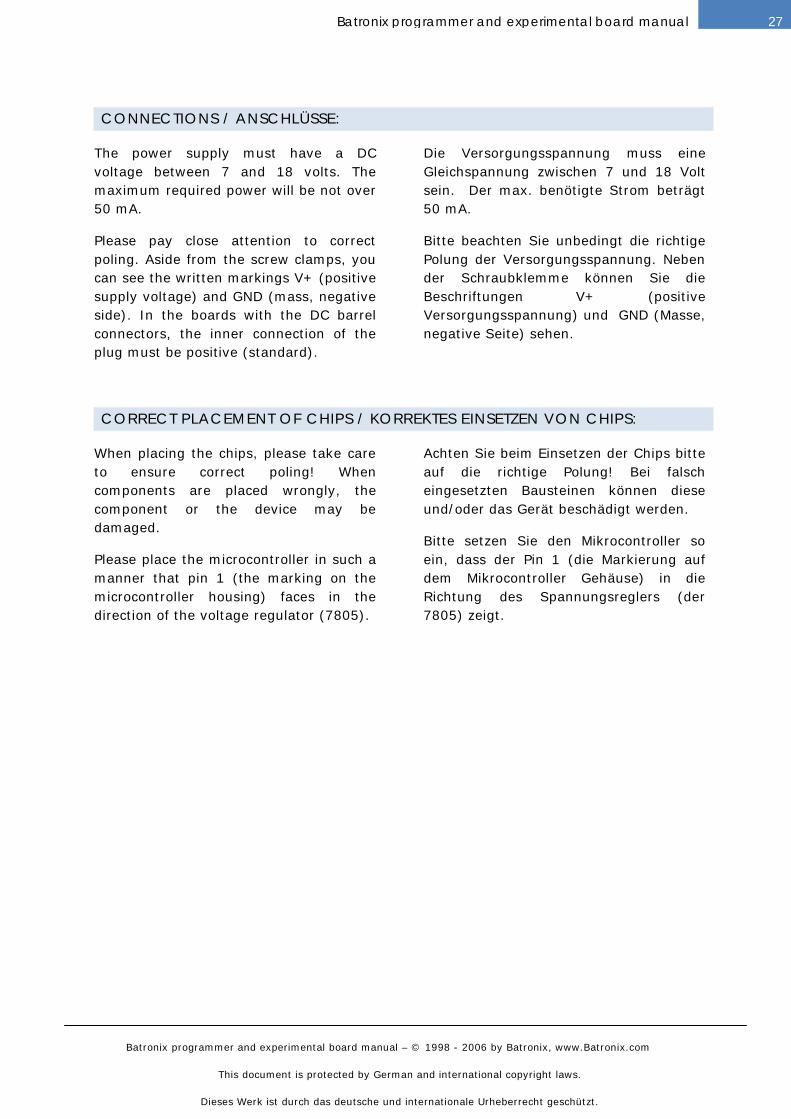
CONNECTIONS / ANSCHLÜSSE:
The power supply must have a DC
voltage between 7 and 18 volts. The
maximum required power will be not over
50 mA.
Please pay close attention to correct
poling. Aside from the screw clamps, you
can see the written markings V+ (positive
supply voltage) and GND (mass, negative
side). In the boards with the DC barrel
connectors, the inner connection of the
plug must be positive (standard).
Die Versorgungsspannung muss eine
Gleichspannung zwischen 7 und 18 Volt
sein. Der max. benötigte Strom beträgt
50 mA.
Bitte beachten Sie unbedingt die richtige
Polung der Versorgungsspannung. Neben
der Schraubklemme können Sie die
Beschriftungen V+ (positive
Versorgungsspannung) und GND (Masse,
negative Seite) sehen.
CORRECT PLACEMENT OF CHIPS / KORREKTES EINSETZEN VON CHIPS:
When placing the chips, please take care
to ensure correct poling! When
components are placed wrongly, the
component or the device may be
damaged.
Please place the microcontroller in such a
manner that pin 1 (the marking on the
microcontroller housing) faces in the
direction of the voltage regulator (7805).
Achten Sie beim Einsetzen der Chips bitte
auf die richtige Polung! Bei falsch
eingesetzten Bausteinen können diese
und/oder das Gerät beschädigt werden.
Bitte setzen Sie den Mikrocontroller so
ein, dass der Pin 1 (die Markierung auf
dem Mikrocontroller Gehäuse) in die
Richtung des Spannungsreglers (der
7805) zeigt.
Batronix programmer and experimental board manual – © 1998 - 2006 by Batronix, www.Batronix.com
This document is protected by German and international copyright laws.
Dieses Werk ist durch das deutsche und internationale Urheberrecht geschützt.
28 Batronix programmer and experimental board manual
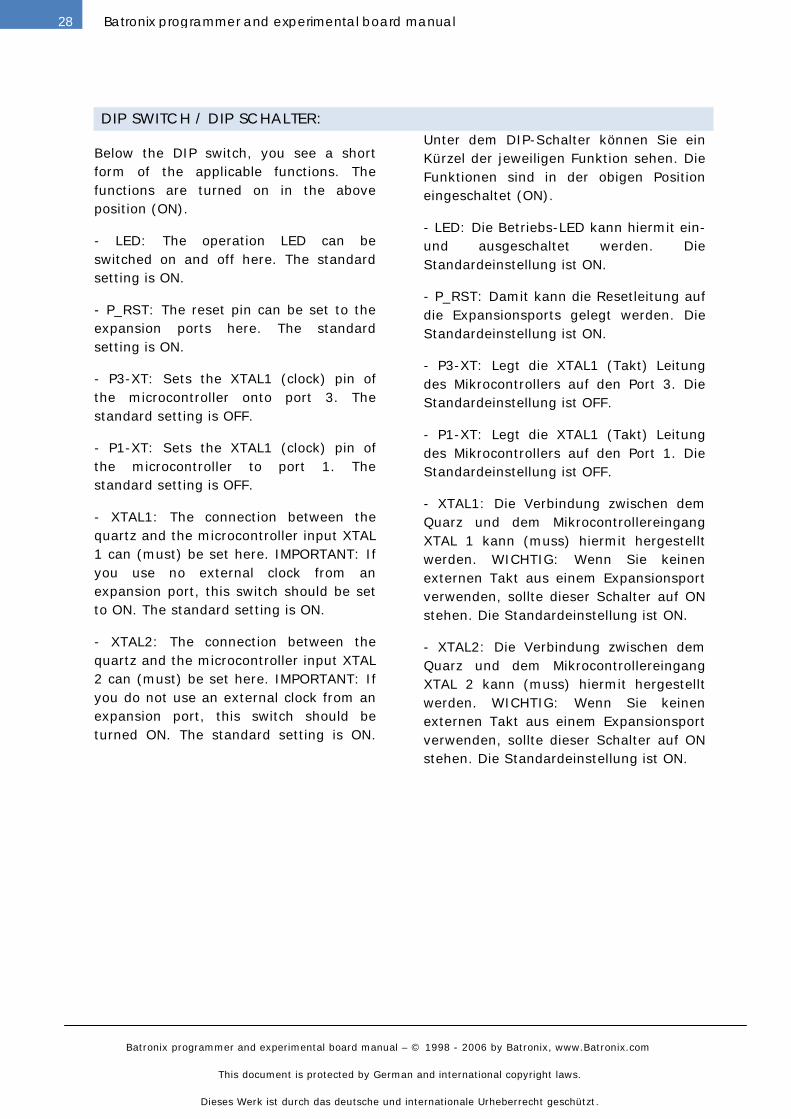
DIP SWITCH / DIP SCHALTER:
Below the DIP switch, you see a short
form of the applicable functions. The
functions are turned on in the above
position (ON).
- LED: The operation LED can be
switched on and off here. The standard
setting is ON.
- P_RST: The reset pin can be set to the
expansion ports here. The standard
setting is ON.
- P3-XT: Sets the XTAL1 (clock) pin of
the microcontroller onto port 3. The
standard setting is OFF.
- P1-XT: Sets the XTAL1 (clock) pin of
the microcontroller to port 1. The
standard setting is OFF.
- XTAL1: The connection between the
quartz and the microcontroller input XTAL
1 can (must) be set here. IMPORTANT: If
you use no external clock from an
expansion port, this switch should be set
to ON. The standard setting is ON.
- XTAL2: The connection between the
quartz and the microcontroller input XTAL
2 can (must) be set here. IMPORTANT: If
you do not use an external clock from an
expansion port, this switch should be
turned ON. The standard setting is ON.
Unter dem DIP-Schalter können Sie ein
Kürzel der jeweiligen Funktion sehen. Die
Funktionen sind in der obigen Position
eingeschaltet (ON).
- LED: Die Betriebs-LED kann hiermit ein-
und ausgeschaltet werden. Die
Standardeinstellung ist ON.
- P_RST: Damit kann die Resetleitung auf
die Expansionsports gelegt werden. Die
Standardeinstellung ist ON.
- P3-XT: Legt die XTAL1 (Takt) Leitung
des Mikrocontrollers auf den Port 3. Die
Standardeinstellung ist OFF.
- P1-XT: Legt die XTAL1 (Takt) Leitung
des Mikrocontrollers auf den Port 1. Die
Standardeinstellung ist OFF.
- XTAL1: Die Verbindung zwischen dem
Quarz und dem Mikrocontrollereingang
XTAL 1 kann (muss) hiermit hergestellt
werden. WICHTIG: Wenn Sie keinen
externen Takt aus einem Expansionsport
verwenden, sollte dieser Schalter auf ON
stehen. Die Standardeinstellung ist ON.
- XTAL2: Die Verbindung zwischen dem
Quarz und dem Mikrocontrollereingang
XTAL 2 kann (muss) hiermit hergestellt
werden. WICHTIG: Wenn Sie keinen
externen Takt aus einem Expansionsport
verwenden, sollte dieser Schalter auf ON
stehen. Die Standardeinstellung ist ON.
Batronix programmer and experimental board manual – © 1998 - 2006 by Batronix, www.Batronix.com
This document is protected by German and international copyright laws.
Dieses Werk ist durch das deutsche und internationale Urheberrecht geschützt.
29Batronix programmer and experimental board manual
FLASH EXP.BOARD II / FLASH EXP.BOARD II
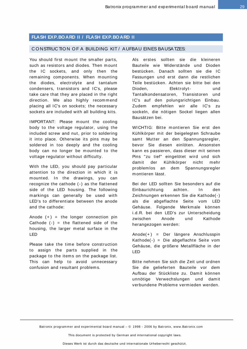
CONSTRUCTION OF A BUILDING KIT / AUFBAU EINES BAUSATZES:
You should first mount the smaller parts,
such as resistors and diodes. Then mount
the IC sockets, and only then the
remaining components. When mounting
the diodes, electrolyte and tantalum
condensers, transistors and IC's, please
take care that they are placed in the right
direction. We also highly recommend
placing all IC's on sockets; the necessary
sockets are included with all building kits.
IMPORTANT: Please mount the cooling
body to the voltage regulator, using the
included screw and nut, prior to soldering
it into place. Otherwise its pins may be
soldered in too deeply and the cooling
body can no longer be mounted to the
voltage regulator without difficulty.
With the LED, you should pay particular
attention to the direction in which it is
mounted. In the drawings, you can
recognize the cathode (-) as the flattened
side of the LED housing. The following
markings can generally be used with
LED's to differentiate between the anode
and the cathode:
Anode (+) = the longer connection pin
Cathode (-) = the flattened side of the
housing, the larger metal surface in the
LED
Please take the time before construction
to assign the parts supplied in the
package to the items on the package list.
This can help to avoid unnecessary
confusion and resultant problems.
Als erstes sollten sie die kleineren
Bauteile wie Widerstände und Dioden
bestücken. Danach sollten sie die IC
Fassungen und erst dann die restlichen
Teile bestücken. Achten sie bitte bei den
Dioden, Elektrolyt- und
Tantalkondensatoren, Transistoren und
IC's auf den polungsrichtigen Einbau.
Zudem empfehlen wir alle IC's zu
sockeln, die nötigen Sockel liegen allen
Bausätzen bei.
WICHTIG: Bitte montieren Sie erst den
Kühlkörper mit der beigelegten Schraube
samt Mutter an den Spannungsregler,
bevor Sie diesen einlöten. Ansonsten
kann es passieren, dass dieser mit seinen
Pins "zu tief" eingelötet wird und sich
damit der Kühlkörper nicht mehr
problemlos an dem Spannungsregler
montieren lässt.
Bei der LED sollten Sie besonders auf die
Einbaurichtung achten. In den
Zeichnungen erkennen Sie die Kathode(-)
als die abgeflachte Seite vom LED
Gehäuse. Folgende Merkmale können
i.d.R. bei den LED's zur Unterscheidung
zwischen Anode und Kathode
herangezogen werden:
Anode(+) = Der längere Anschlusspin
Kathode(-) = Die abgeflachte Seite vom
Gehäuse, die größere Metallfläche in der
LED
Bitte nehmen Sie sich die Zeit und ordnen
Sie die gelieferten Bauteile vor dem
Aufbau der Stückliste zu. Damit können
unnötige Verwechslungen und damit
verbundene Probleme vermieden werden.
Batronix programmer and experimental board manual – © 1998 - 2006 by Batronix, www.Batronix.com
This document is protected by German and international copyright laws.
Dieses Werk ist durch das deutsche und internationale Urheberrecht geschützt.
30 Batronix programmer and experimental board manual
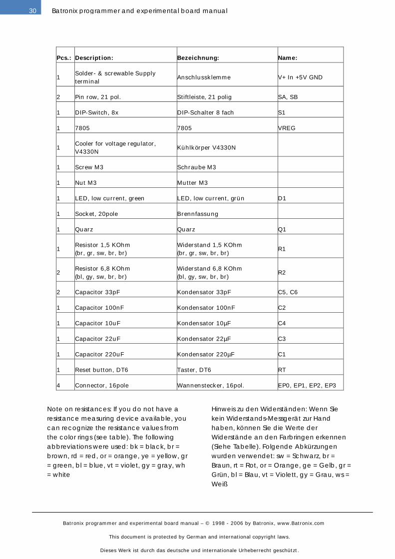
Pcs.: Description: Bezeichnung: Name:
1
Solder- & screwable Supply
terminal
Anschlussklemme V+ In +5V GND
2 Pin row, 21 pol. Stiftleiste, 21 polig SA, SB
1 DIP-Switch, 8x DIP-Schalter 8 fach S1
1 7805 7805 VREG
1
Cooler for voltage regulator,
V4330N
Kühlkörper V4330N
1 Screw M3 Schraube M3
1 Nut M3 Mutter M3
1 LED, low current, green LED, low current, grün D1
1 Socket, 20pole Brennfassung
1 Quarz Quarz Q1
1
Resistor 1,5 KOhm
(br, gr, sw, br, br)
Widerstand 1,5 KOhm
(br, gr, sw, br, br)
R1
2
Resistor 6,8 KOhm
(bl, gy, sw, br, br)
Widerstand 6,8 KOhm
(bl, gy, sw, br, br)
R2
2 Capacitor 33pF Kondensator 33pF C5, C6
1 Capacitor 100nF Kondensator 100nF C2
1 Capacitor 10uF Kondensator 10µF C4
1 Capacitor 22uF Kondensator 22µF C3
1 Capacitor 220uF Kondensator 220µF C1
1 Reset button, DT6 Taster, DT6 RT
4 Connector, 16pole Wannenstecker, 16pol. EP0, EP1, EP2, EP3
Note on resistances: If you do not have a resistance measuring device available, you can recognize the resistance values from the color rings (see table). The following abbreviations were used: bk = black, br = brown, rd = red, or = orange, ye = yellow, gr = green, bl = blue, vt = violet, gy = gray, wh= white
Hinweis zu den Widerständen: Wenn Sie kein Widerstands-Messgerät zur Hand haben, können Sie die Werte der Widerstände an den Farbringen erkennen (Siehe Tabelle). Folgende Abkürzungen wurden verwendet: sw = Schwarz, br = Braun, rt = Rot, or = Orange, ge = Gelb, gr = Grün, bl = Blau, vt = Violett, gy = Grau, ws = Weiß
Batronix programmer and experimental board manual – © 1998 - 2006 by Batronix, www.Batronix.com
This document is protected by German and international copyright laws.
Dieses Werk ist durch das deutsche und internationale Urheberrecht geschützt.
31Batronix programmer and experimental board manual
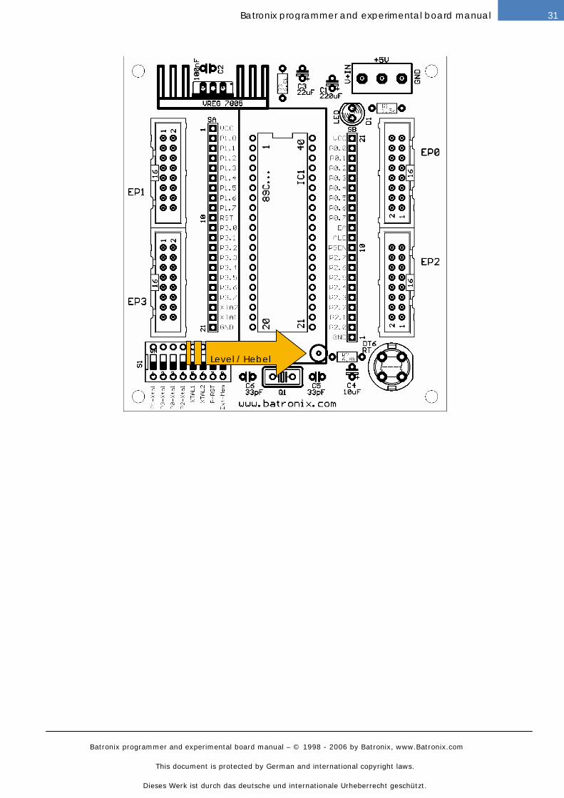
Level / Hebel
Batronix programmer and experimental board manual – © 1998 - 2006 by Batronix, www.Batronix.com
This document is protected by German and international copyright laws.
Dieses Werk ist durch das deutsche und internationale Urheberrecht geschützt.
32 Batronix programmer and experimental board manual
CONNECTIONS / ANSCHLÜSSE:
The power supply must have a DC
voltage between 7 and 18 volts. The
maximum required power will be not over
50 mA.
Please pay close attention to correct
poling. Aside from the screw clamps, you
can see the written markings V+ (positive
supply voltage) and GND (mass, negative
side). In the boards with the DC barrel
connectors, the inner connection of the
plug must be positive (standard).
Die Versorgungsspannung muss eine
Gleichspannung zwischen 7 und 18 Volt
sein. Der max. benötigte Strom beträgt
50 mA.
Bitte beachten Sie unbedingt die richtige
Polung der Versorgungsspannung. Neben
der Schraubklemme können Sie die
Beschriftungen V+ (positive
Versorgungsspannung) und GND (Masse,
negative Seite) sehen.
CORRECT PLACEMENT OF CHIPS / KORREKTES EINSETZEN VON CHIPS:
When placing the chips, please take care
to ensure correct poling! When
components are placed wrongly, the
component or the device may be
damaged.
Please place the microcontroller in such a
manner that pin 1 (the marking on the
microcontroller housing) faces in the
direction of the voltage regulator (7805).
Achten Sie beim Einsetzen der Chips bitte
auf die richtige Polung! Bei falsch
eingesetzten Bausteinen können diese
und/oder das Gerät beschädigt werden.
Bitte setzen Sie den Mikrocontroller so
ein, dass der Pin 1 (die Markierung auf
dem Mikrocontroller Gehäuse) in die
Richtung des Spannungsreglers (der
7805) zeigt.
Batronix programmer and experimental board manual – © 1998 - 2006 by Batronix, www.Batronix.com
This document is protected by German and international copyright laws.
Dieses Werk ist durch das deutsche und internationale Urheberrecht geschützt.
33Batronix programmer and experimental board manual
DIP SWITCH / DIP SCHALTER:
Below the DIP switch, you see a short
form of the applicable functions. The
functions are turned on in the above
position (ON).
- P0-XT up to P3-XT: Sets the XTAL1
(clock) pin of the microcontroller onto
port 0-3. The standard setting is OFF.
- LED: The operation LED can be
switched on and off here. The standard
setting is ON.
- XTAL1: The connection between the
quartz and the microcontroller input XTAL
1 can (must) be set here. IMPORTANT: If
you use no external clock from an
expansion port, this switch should be set
to ON. The standard setting is ON.
- XTAL2: The connection between the
quartz and the microcontroller input XTAL
2 can (must) be set here. IMPORTANT: If
you do not use an external clock from an
expansion port, this switch should be
turned ON. The standard setting is ON.
- P_RST: The reset pin can be set to the
expansion ports here. The standard
setting is ON.
- Ext-Mem: This switch can be used to
toggle back and forth between operations
with the internal Flash and an external
memory as the program memory.
IMPORTANT: If no external memory is
connected as a program memory, this
switch should be turned OFF. The
standard setting is OFF
Unter dem DIP-Schalter können Sie ein
Kürzel der jeweiligen Funktion sehen. Die
Funktionen sind in der obigen Position
eingeschaltet (ON).
- P0-XT bis P3-XT: Legt die XTAL1 (Takt)
Leitung des Mikrocontrollers auf den Port
0-3. Die Standardeinstellung ist OFF.
- XTAL1: Die Verbindung zwischen dem
Quarz und dem Mikrocontrollereingang
XTAL 1 kann (muss) hiermit hergestellt
werden. WICHTIG: Wenn Sie keinen
externen Takt aus einem Expansionsport
verwenden, sollte dieser Schalter auf ON
stehen. Die Standardeinstellung ist ON.
- XTAL2: Die Verbindung zwischen dem
Quarz und dem Mikrocontrollereingang
XTAL 2 kann (muss) hiermit hergestellt
werden. WICHTIG: Wenn Sie keinen
externen Takt aus einem Expansionsport
verwenden, sollte dieser Schalter auf ON
stehen. Die Standardeinstellung ist ON.
- P_RST: Damit kann die Resetleitung auf
die Expansionsports gelegt werden. Die
Standardeinstellung ist ON.
- Ext-Mem: Mit diesen Schalter kann
zwischen dem Betrieb mit dem internen
Flash und einem externen Speicher als
Programmspeicher umgeschaltet werden.
WICHTIG: Wenn Sie keinen externen
Speicher als Programmspeicher
angeschlossen haben, sollte dieser
Schalter auf OFF stehen. Die
Standardeinstellung ist OFF.