Embed Size (px)
Citation preview
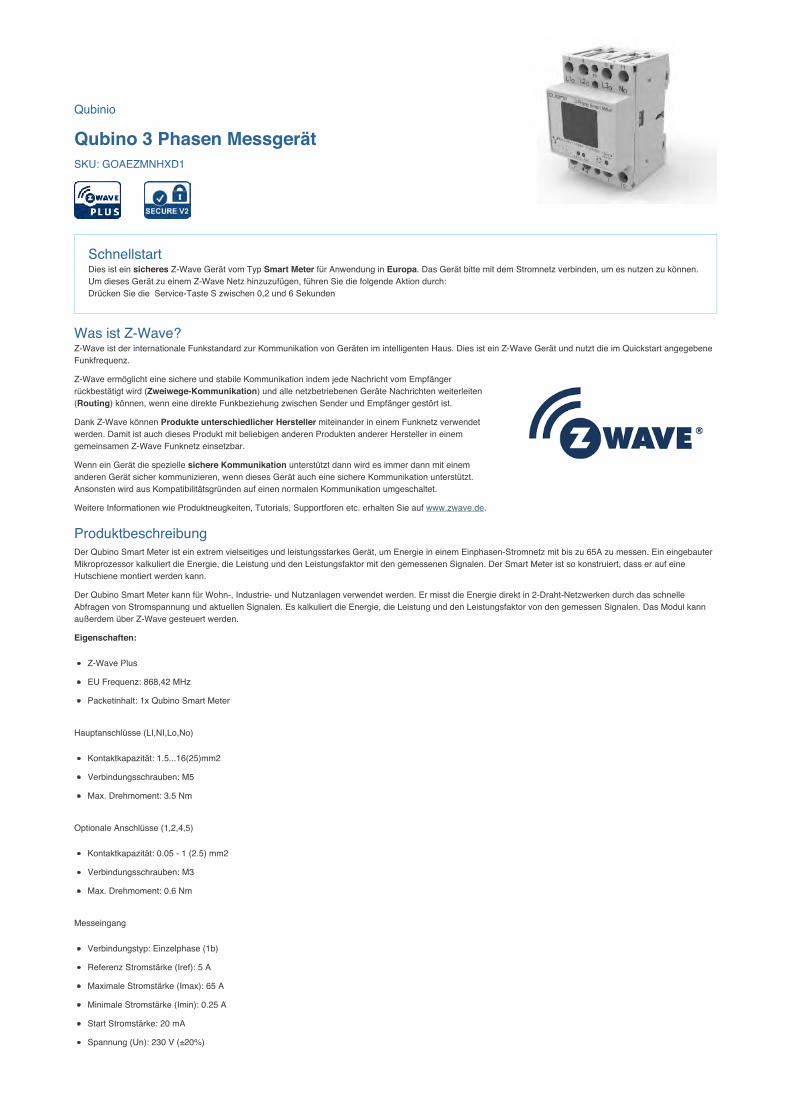
Qubinio
Qubino 3 Phasen MessgerätSKU: GOAEZMNHXD1
SchnellstartDies ist ein sicheres Z-Wave Gerät vom Typ Smart Meter für Anwendung in Europa. Das Gerät bitte mit dem Stromnetz verbinden, um es nutzen zu können.Um dieses Gerät zu einem Z-Wave Netz hinzuzufügen, führen Sie die folgende Aktion durch: Drücken Sie die Service-Taste S zwischen 0,2 und 6 Sekunden
Was ist Z-Wave?Z-Wave ist der internationale Funkstandard zur Kommunikation von Geräten im intelligenten Haus. Dies ist ein Z-Wave Gerät und nutzt die im Quickstart angegebeneFunkfrequenz.
Z-Wave ermöglicht eine sichere und stabile Kommunikation indem jede Nachricht vom Empfängerrückbestätigt wird (Zweiwege-Kommunikation) und alle netzbetriebenen Geräte Nachrichten weiterleiten(Routing) können, wenn eine direkte Funkbeziehung zwischen Sender und Empfänger gestört ist.
Dank Z-Wave können Produkte unterschiedlicher Hersteller miteinander in einem Funknetz verwendetwerden. Damit ist auch dieses Produkt mit beliebigen anderen Produkten anderer Hersteller in einemgemeinsamen Z-Wave Funknetz einsetzbar.
Wenn ein Gerät die spezielle sichere Kommunikation unterstützt dann wird es immer dann mit einemanderen Gerät sicher kommunizieren, wenn dieses Gerät auch eine sichere Kommunikation unterstützt.Ansonsten wird aus Kompatibilitätsgründen auf einen normalen Kommunikation umgeschaltet.
Weitere Informationen wie Produktneugkeiten, Tutorials, Supportforen etc. erhalten Sie auf www.zwave.de.
ProduktbeschreibungDer Qubino Smart Meter ist ein extrem vielseitiges und leistungsstarkes Gerät, um Energie in einem Einphasen-Stromnetz mit bis zu 65A zu messen. Ein eingebauterMikroprozessor kalkuliert die Energie, die Leistung und den Leistungsfaktor mit den gemessenen Signalen. Der Smart Meter ist so konstruiert, dass er auf eineHutschiene montiert werden kann.
Der Qubino Smart Meter kann für Wohn-, Industrie- und Nutzanlagen verwendet werden. Er misst die Energie direkt in 2-Draht-Netzwerken durch das schnelleAbfragen von Stromspannung und aktuellen Signalen. Es kalkuliert die Energie, die Leistung und den Leistungsfaktor von den gemessen Signalen. Das Modul kannaußerdem über Z-Wave gesteuert werden.
Eigenschaften:
Z-Wave Plus
EU Frequenz: 868,42 MHz
Packetinhalt: 1x Qubino Smart Meter
Hauptanschlüsse (LI,NI,Lo,No)
Kontaktkapazität: 1.5...16(25)mm2
Verbindungsschrauben: M5
Max. Drehmoment: 3.5 Nm
Optionale Anschlüsse (1,2,4,5)
Kontaktkapazität: 0.05 - 1 (2.5) mm2
Verbindungsschrauben: M3
Max. Drehmoment: 0.6 Nm
Messeingang
Verbindungstyp: Einzelphase (1b)
Referenz Stromstärke (Iref): 5 A
Maximale Stromstärke (Imax): 65 A
Minimale Stromstärke (Imin): 0.25 A
Start Stromstärke: 20 mA
Spannung (Un): 230 V (±20%)
Stromverbrauch Un: < 2 W
Nominale Frequenz (fn): 50 and 60 Hz
Zubehör
IKA232-20/230 V (GOAEIKA23220)
BICOM432-40-WM1 (GOAEBICOM432)
Vorbereitung auf die Installation des GerätesBitte lesen Sie die Benutzeranleitung bevor Sie das Gerät in Betrieb nehmen.
Damit ein Z-Wave zu einem neuen Netz hinzugefügt werden kann muss es sich im Auslieferungs- oder Reset-Zustand befinden. Im Zweifel ist es sinnvoll, eineExklusion durchzuführen, um das Gerät ganz sicher in diesem Zustand zu bringen. Diese Exklusion kann von jedem beliebigen Z-Wave Controller durchgeführtwerden.
Zurücksetzen in den AuslieferungszustandDieses Gerät kann auch ohne Hilfe eines Controller in den Reset-Zustand zurückgeführt werden. Dies sollte jedoch nur dann gemacht werden wenn derPrimärcontroller des Z-Wave-Netzes nicht mehr verfügbar oder defekt ist.
Halten Sie die Service-Taste S zwischen 6 Sekunden und 20 Sekunden gedrückt.
Sicherheitswarnung für netzbetriebene GeräteAchtung: Je nach nationalen Sicherheitsnormen kann es nur autorisierten und/oder ausgebildeten Techniker erlaubt sein, elektrische Installationen am Spannungsnetzvorzunehmen. Bitte informieren Sie sich vor der Installation über die Rechtslage.
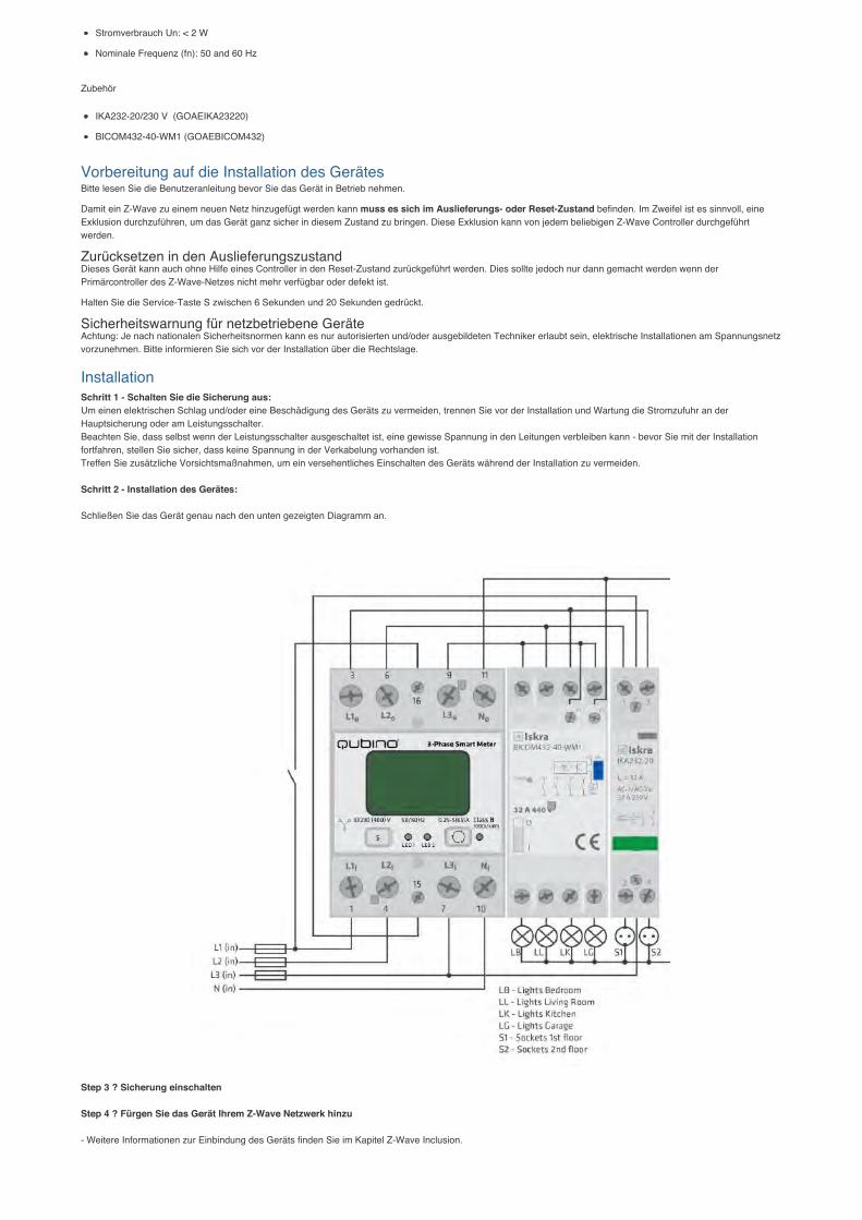
InstallationSchritt 1 - Schalten Sie die Sicherung aus:Um einen elektrischen Schlag und/oder eine Beschädigung des Geräts zu vermeiden, trennen Sie vor der Installation und Wartung die Stromzufuhr an derHauptsicherung oder am Leistungsschalter.Beachten Sie, dass selbst wenn der Leistungsschalter ausgeschaltet ist, eine gewisse Spannung in den Leitungen verbleiben kann - bevor Sie mit der Installationfortfahren, stellen Sie sicher, dass keine Spannung in der Verkabelung vorhanden ist.Treffen Sie zusätzliche Vorsichtsmaßnahmen, um ein versehentliches Einschalten des Geräts während der Installation zu vermeiden. Schritt 2 - Installation des Gerätes: Schließen Sie das Gerät genau nach den unten gezeigten Diagramm an.
Step 3 ? Sicherung einschalten Step 4 ? Fürgen Sie das Gerät Ihrem Z-Wave Netzwerk hinzu
- Weitere Informationen zur Einbindung des Geräts finden Sie im Kapitel Z-Wave Inclusion.
Step 5 ? Die Installation ist nun abgeschlossen. Es ist Zeit, Ihr Leben mit Hilfe des Qubino 3-Phasen Smart Meter komfortabler zu gestalten.
EXTERNE RELAIS:Es ist möglich, zwei externe Relais an ein 3-Phasen-Smart Meter-Gerät anzuschließen. Eine wird über den eingebauten optischen (IR) Kommunikationsanschluss ander Seite gesteuert, die andere über den Ausgang an Klemme 15. *IKA und BICOM sind separat erhältlich - weitere Informationen finden Sie im Qubino-Katalog. Produkt-Bestellnummern (Modellnummern): IKA232-20/230V: 030 046833 000; BICOM432-40-WM1: 30.074.038
Hinzufügen/Entfernen des Gerätes (Inklusion/Exclusion)Im Auslieferungszustand ist das Gerät mit keinem Z-Wave-Netz verbunden. Damit es mit anderen Z-Wave Geräten kommunizieren kann, muss es in ein bestehendesZ-Wave Netz eingebunden werden. Dieser Prozess wird bei Z-Wave Inklusion genannt. Geräte können Netzwerke auch wieder verlassen. Dieser Prozess heißt bei Z-Wave Exklusion. Beide Prozesse werden von einem Controller gestartet, der dazu in einen Inklusion- bzw. Exklusion-Modus geschaltet werden muss. Das Handbuchdes Controllers enthält Informationen, wie er in diese Modi zu schalten ist. Erst wenn der Controller des Z-Wave Netzes im Inclusion-Modus ist, können Gerätehinzugefügt werden. Das Verlassen des Netzes durch Exklusion führt zum Rücksetzen dieses Gerätes in den Auslieferungszustand.
InklusionDrücken Sie die Service-Taste S zwischen 0,2 und 6 Sekunden
ExklusionDrücken Sie die Service-Taste
Auto-ExklusionNeben der normalen Inklusion unterstützt dieses Gerät sie so genannte Auto-inklusion. Dabei befindet sich das Gerät - sofern im Reset-Zustand - direkt nach demEinschalten (Einlegen der Batterie oder Verbindung zum Stromnetz) im Inklusionmodus und kann von einem Controller einem Netz hinzugefügt werden. Dieser Moduswird nach einiger Zeit automatisch beendet.
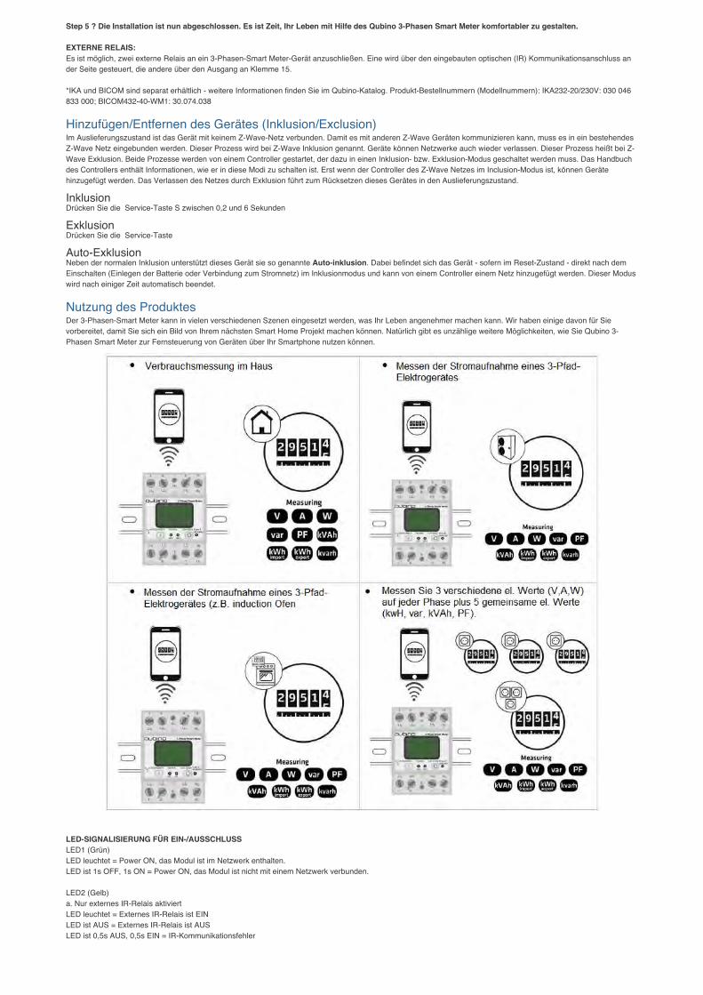
Nutzung des ProduktesDer 3-Phasen-Smart Meter kann in vielen verschiedenen Szenen eingesetzt werden, was Ihr Leben angenehmer machen kann. Wir haben einige davon für Sievorbereitet, damit Sie sich ein Bild von Ihrem nächsten Smart Home Projekt machen können. Natürlich gibt es unzählige weitere Möglichkeiten, wie Sie Qubino 3-Phasen Smart Meter zur Fernsteuerung von Geräten über Ihr Smartphone nutzen können.
LED-SIGNALISIERUNG FÜR EIN-/AUSSCHLUSSLED1 (Grün)LED leuchtet = Power ON, das Modul ist im Netzwerk enthalten.LED ist 1s OFF, 1s ON = Power ON, das Modul ist nicht mit einem Netzwerk verbunden. LED2 (Gelb)a. Nur externes IR-Relais aktiviertLED leuchtet = Externes IR-Relais ist EINLED ist AUS = Externes IR-Relais ist AUSLED ist 0,5s AUS, 0,5s EIN = IR-Kommunikationsfehler
b. Nur externes TRIAC-Relais aktiviertLED leuchtet = Externes IR-Relais ist EINLED ist AUS = Externes IR-Relais ist AUSc. Sowohl TRIAC als auch IR-fähigLED leuchtet = Externes IR-Relais ist EINLED ist AUS = Externes IR-Relais ist AUSLED ist 0,5s AUS, 0,5s EIN = IR-Kommunikationsfehlerd. Externes IR-Relais deaktiviertLED leuchtet = Modbus-Paket wird gesendetLED ist AUS = Modbus-Paket wird empfangen
Einige Hinweise bei ProblemenDie folgenden kleinen Hinweise können bei Problemen im Z-Wave Netz helfen.
1. Stellen Sie sicher, daß sich das neue Gerät im Auslieferungszustand befindet. Im Zweifel lieber noch mals eine Exclusion ausführen.2. Wenn ein Gerät keine Verbindung aufbaut, prüfen Sie , ob Controller und neues Gerät auf der gleichen Funkfrequenz (Länderkennung) arbeiten.3. Entfernen Sie nicht mehr vorhandene Geräte als allen Assoziationsgruppen. Ansonsten werden Sie erhebliche Verzögerungen bei der Kommandoausführung
spüren.4. Nutzer Sie niemals schlafende Batteriegeräte ohne Zentralsteuerung.5. FLIRS-Geräte dürfen nicht gepollt werden.6. Stellen Sie sicher, daß Sie genügend netzbetriebene Geräte haben, um die Vorteile der Funkvermaschung zu nutzen.
Assoziation - Geräte steuern sich untereinanderZ-Wave Geräte können andere Geräte direkt steuern. Diese direkte Steuerung heißt in Z-Wave Assoziation. In den steuernden Geräten muss dazu die Geräte-ID deszu steuernden Gerätes hinterlegt werden. Dies erfolgt in sogenannten Assoziationsgruppen. Eine Assoziationsgruppe ist immer an ein Ereignis im steuernden Gerätgebunden (Tastendruck oder Auslösen eines Sensors). Bei Eintritt dieses Ereignisses wird an alle in einer Assoziationsgruppe hinterlegten Geräte einSteuerkommando - meist ein BASIC SET - gesendet.
Assoziationsgruppen:Gruppen-Nummer Max. Anzahl Geräte Beschreibung
1 1 Lifeline
Configuration ParametersZ-Wave Produkte können direkt nach der Inklusion im Netz verwendet werden. Durch Konfigurationseinstellungen kann das Verhalten des Gerätes jedoch nochbesser an die Anforderungen der Anwendung angepasst und zusätzliche Funktionen aktiviert werden.
WICHTIG: Manche Steuerungen erlauben nur die Konfiguration von vorzeichenbehafteten Werten zwischen -128 und 127. Um erforderliche Werte zwischen 128 und255 zu programmieren, muss der gewünschte Wert minus 256 eingegeben werden. Beispiel: um einen Parameter auf einen Wert von 200 zu setzen, müsste der Wert200-256 = -56 eingegeben werden, wenn nur positive Werte bis 128 akzeptiert werden. Bei Werten von 2 Byte Länge wird die gleiche Logik angewandt: Werte über32768 werden als negative Werte angegeben.
Parameter 7: Funktionsauswahl des SchaltereingangsVerfügbare Konfigurationsparameter für Eingangsschalter I1 Grösse: 1 Byte, Voreingestellt: 0
Wert Beschreibung
0 Deaktiviert
2 IR externe Relaissteuerung - Taster
3 IR externe Relaissteuerung - Schalter
4 Steuerung externes Relais - Taster
5 Steuerung externes Relais - Schalter
Parameter 40: Bereicht StromänderungDieser Parameter gilt für Wirkleistung gesamt, Wirkleistung Phase1, Wirkleistung Phase2 und Wirkleistung Phase3.HINWEIS: Wenn die Leistungsänderung wenigerals 5 W beträgt, wird der Bericht nicht gesendet (gedrückt) HINWEIS: Das Gerät misst auch einige Störungen, selbst wenn am Ausgang keine Last anliegt. Um Störungen zu vermeiden:- Wenn die gemessene Wirkleistung (W) unter z.B. 5W-> liegt, ist der gemeldete Wert in diesem Fall 0W Grösse: 1 Byte, Voreingestellt: 50
Wert Beschreibung
0 Bericht deaktiviert
1 - 100 1% - 100% Bericht aktiviert. Der Leistungsbericht wird nur gesendet, wenn die tatsächliche Leistung in Watt (inEchtzeit ändert sich die Leistung um mehr als den eingestellten Prozentsatz im Vergleich zur vorherigenWirkleistung, Schritt ist 1%.
Parameter 42: Berichterstattung nach ZeitintervallDieser Parameter gilt derzeit nur für Wirkenergie Gesamt Import/Export (kWh), Blindenergie Gesamt (kvarh), Gesamtenergie (kVAh).Hinweis: Das Gerät meldet nur,wenn es eine Änderung von 0.1 gemessen wird.Hinweis: In Zukunft wird es möglich sein, auch Wirkenergie an PH1, PH2 und PH3 zu messen und zu melden. Grösse: 2 Byte, Voreingestellt: 600
Wert Beschreibung
0 Bericht deaktiviert
600 - 65536 Der Bericht wird mit dem durch den eingegebenen Wert festgelegten Zeitintervall gesendet. Sekunden
Parameter 43: Andere Werte - Berichterstattung nach ZeitintervallDieser Parameter gilt nur für Spannung (V von ph1, ph2, ph3), Strom (A von ph1, ph2, ph3), Gesamtleistungsfaktor, Gesamtblindleistung (var).Hinweis: Das Gerätmeldet nur, wenn es eine Änderung gab. Grösse: 2 Byte, Voreingestellt: 600
Wert Beschreibung
0 Bericht deaktiviert
600 - 65536 Der Bericht wird mit dem durch den eingegebenen Wert festgelegten Zeitintervall gesendet. Sekunden
Parameter 100: Aktivieren / Deaktivieren des externen IR-Relais (BICOM)HINWEIS 1: Nach der Parameteränderung wird zuerst das Modul ausgeschlossen (ohne die Parameter auf den Standardwert zu setzen) und dann das Modul neueingebunden.HINWEIS 2: Wenn Sie kein IR-BICOM-Relaismodul montiert haben und die IR-Kommunikation aktivieren (Parameter 100 ist 1 oder 2), wird kein gültiger IR-Relaiszustand gemeldet. Es wird ein IR-KOMMUNIKATIONSFEHLER gemeldet und LED2 blinkt. Grösse: 1 Byte, Voreingestellt: 0
Wert Beschreibung
0 Externen IR Relais deaktiviert
1 Externes IR-Relais aktiviert und an alle 3 Phasen angeschlossen
2 Externes IR-Relais aktiviert und an eine Phase 1 angeschlossen
Parameter 101: Aktivieren / Deaktivieren Externes Relais (IKA)Nach einer Parameteränderung exkludieren Sie zuerst das Modul (ohne die Parameter auf den Standardwert zu setzen) und inkludieren dann das Modul erneut. Grösse: 1 Byte, Voreingestellt: 0
Wert Beschreibung
0 Externes Relais deaktiviert
1 Externes Relais aktiviert und an Phase 2 angeschlossen
Parameter 106: Einstellung der Leistungsschwelle des externen IR-Relais (BICOM) - maximale Leistung allerPhasen gemeinsamDieser Parameter definiert eine Schwelle, wenn das externe IR-Relais ausgeschaltet wird. (Wenn Parameter Nr. 100 auf den Wert 1 oder 2 gesetzt ist)HINWEIS: DasMessgerät kann max. 3x65A messen! Grösse: 2 Byte, Voreingestellt: 0
Wert Beschreibung
0 keine Funktion
10 - 60000 Watt
Parameter 107: Einstellung der Leistungsschwelle des externen Relais (IKA) - maximale Leistung an Phase L2Dieser Parameter definiert eine Schwelle, wenn das externe Relais ausgeschaltet wird (wenn der Parameter Nr. 100 auf den Wert 1 oder 2 eingestellt ist).HINWEIS:Das Messgerät ist in der Lage, max. 65A zu messen. Grösse: 2 Byte, Voreingestellt: 0
Wert Beschreibung
0 keine Funktion
10 - 20000 Watt
Parameter 112: Leistungsschwelle - Verzögerung vor dem EinschaltenExternes IR-Relais/ Externes Relais wird bei erkannter Überlast abgeschaltet (wie in Parameter 106 & 107 eingestellt) und bleibt für eine in diesem Parameterdefinierte Zeit ausgeschaltet. Danach schaltet sich der Ausgang ein, um zu prüfen, ob die Überlast noch vorhanden ist.HINWEIS: Die Verzögerungszeit kann um mehrals 10s der durch den Parameter eingestellten Zeit verlängert werden. Grösse: 2 Byte, Voreingestellt: 0
Wert Beschreibung
0 Externes IR-Relais/ Externes Relais schaltet nicht wieder ein
30 - 32535 Sekunden
Technische DatenAbmessung 53,6 x 84 x 65 mm
Gewicht 221 gr
Z-Wave Hardware Platform ZM5101
EAN 3830062070683
IP Klasse IP 20
Betriebsspannung 3x 230 V/400V
Schaltbare Last 65 A
Gerätetyp Smart Meter
Firmware Version 01.00
Z-Wave Version 04.3d
Z-Wave Produkt Id 0x0159.0x0007.0x0054
Unterstützte KommandoklassenBasic
Switch Binary
Meter
Crc 16 Encap
Association Grp Info
Device Reset Locally
Zwaveplus Info
Multi Channel
Supervision
Configuration
Manufacturer Specific
Powerlevel
Firmware Update Md
Association
Version
Multi Channel Association
Security
Transport Service
Security 2
Gesteuerte KommandoklassenTransport Service
Security 2
Erklärung einiger Z-Wave-BegriffeController... ist ein Z-Wave-Gerät mit erweiterten Fähigkeiten zur Verwaltung eines Netzes. Dies sind in der Regel Gateways oder Fernbedienungen.Batteriegespeiste Wandschalter können auch Controller sein.
Slave... ist ein Z-Wave-Gerät mit erweiterten Fähigkeiten zur Verwaltung eines Netzes. Es gibt Sensoren, Aktoren und auch Fernbedienungen als Slaves.
Primärcontroller (engl. Primary Controller)... ist der zentrale Netzverwalter des Z-Wave-Netzes.
Inklusion (eng. Inclusion)... ist der Prozess des Einbindens eines neuen Gerätes ins Z-Wave-Netz.
Exklusion (engl. Exclusion)... ist der Prozess des Entfernens eines Gerätes aus dem Z-Wave-Netz.
Assoziation (engl. Association)... ist eine Steuerbeziehung zwischen einem steuernden und einem gesteuerten Gerät. Die Information dazu wird imsteuernden Gerät in einer Assoziationsgruppe hinterlegt.
Wakeup Notifikation (engl. Wakeup Notification) ... ist eine spezielle Funknachricht, mit der ein batteriegespeistes Gerät bekanntmacht, daß es imAufwachstatus ist und Z-Wave-Nachrichten empfangen kann.
Node Information Frame... ist eine spezielle Funknachricht, mit der ein Z-Wave-Gerät seine Geräteeigenschaften bekanntgibt.
(c) 2019 Z-Wave Europe GmbH, Antonstr. 3, 09337 Hohenstein-Ernstthal, Germany, All rights reserved, www.zwave.eu. Dieses Template wird bearbeitet vom Z-WaveEurope GmbH. Der Produktinhalt wird bearbeitet von Z-Wave Europe GmbH , Supportteam, [email protected]. LetzteAktualisierung des Produktes: 2018-07-23

USER MANUAL EN.
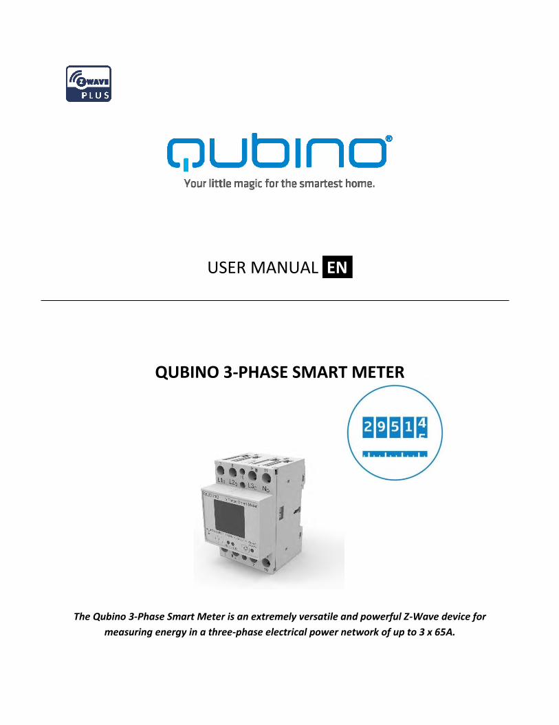
QUBINO 3-PHASE SMART METER
The Qubino 3-Phase Smart Meter is an extremely versatile and powerful Z-Wave device for
measuring energy in a three-phase electrical power network of up to 3 x 65A.
EN.
2
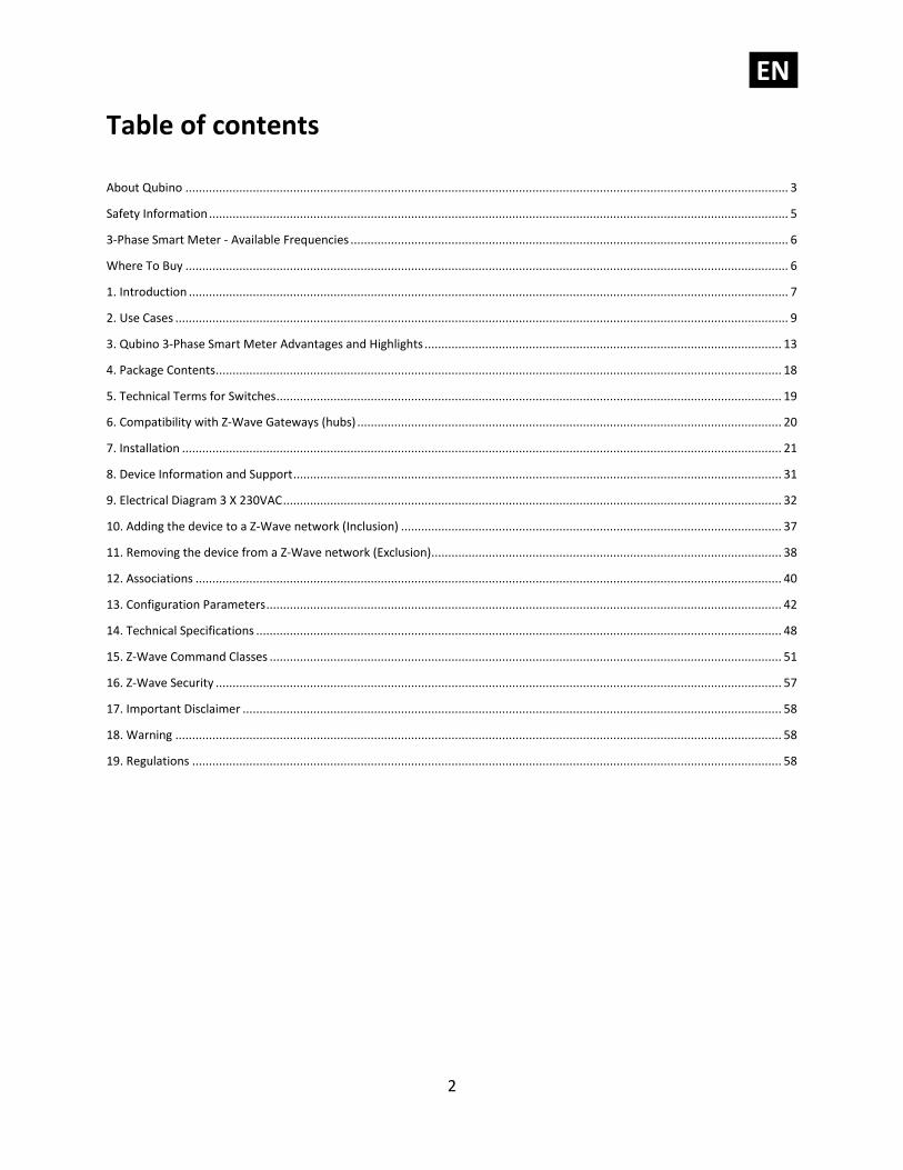
Table of contents
About Qubino ................................................................................................................................................................................... 3
Safety Information ............................................................................................................................................................................ 5
3-Phase Smart Meter - Available Frequencies .................................................................................................................................. 6
Where To Buy ................................................................................................................................................................................... 6
1. Introduction .................................................................................................................................................................................. 7
2. Use Cases ...................................................................................................................................................................................... 9
3. Qubino 3-Phase Smart Meter Advantages and Highlights .......................................................................................................... 13
4. Package Contents ........................................................................................................................................................................ 18
5. Technical Terms for Switches ...................................................................................................................................................... 19
6. Compatibility with Z-Wave Gateways (hubs) .............................................................................................................................. 20
7. Installation .................................................................................................................................................................................. 21
8. Device Information and Support ................................................................................................................................................. 31
9. Electrical Diagram 3 X 230VAC .................................................................................................................................................... 32
10. Adding the device to a Z-Wave network (Inclusion) ................................................................................................................. 37
11. Removing the device from a Z-Wave network (Exclusion)........................................................................................................ 38
12. Associations .............................................................................................................................................................................. 40
13. Configuration Parameters ......................................................................................................................................................... 42
14. Technical Specifications ............................................................................................................................................................ 48
15. Z-Wave Command Classes ........................................................................................................................................................ 51
16. Z-Wave Security ........................................................................................................................................................................ 57
17. Important Disclaimer ................................................................................................................................................................ 58
18. Warning .................................................................................................................................................................................... 58
19. Regulations ............................................................................................................................................................................... 58
EN.
3
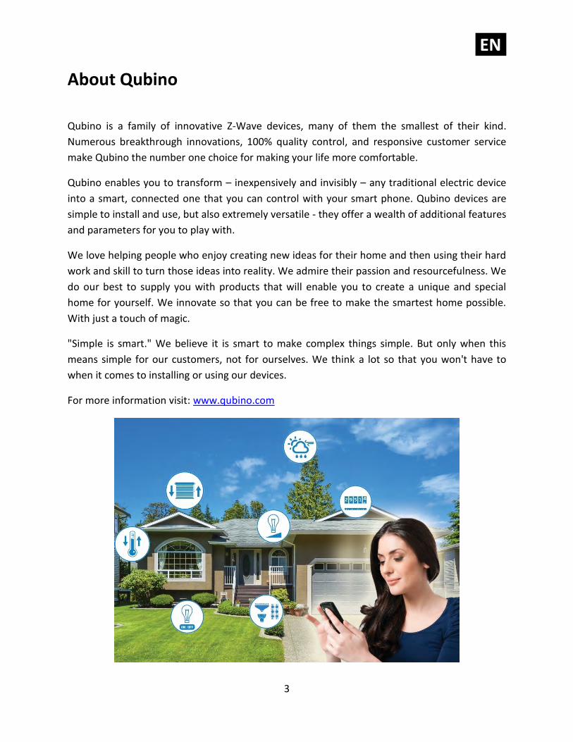
About Qubino
Qubino is a family of innovative Z-Wave devices, many of them the smallest of their kind.
Numerous breakthrough innovations, 100% quality control, and responsive customer service
make Qubino the number one choice for making your life more comfortable.
Qubino enables you to transform – inexpensively and invisibly – any traditional electric device
into a smart, connected one that you can control with your smart phone. Qubino devices are
simple to install and use, but also extremely versatile - they offer a wealth of additional features
and parameters for you to play with.
We love helping people who enjoy creating new ideas for their home and then using their hard
work and skill to turn those ideas into reality. We admire their passion and resourcefulness. We
do our best to supply you with products that will enable you to create a unique and special
home for yourself. We innovate so that you can be free to make the smartest home possible.
With just a touch of magic.
"Simple is smart." We believe it is smart to make complex things simple. But only when this
means simple for our customers, not for ourselves. We think a lot so that you won't have to
when it comes to installing or using our devices.
For more information visit: www.qubino.com

EN.
4
About Z-Wave:
The Z-Wave protocol is an interoperable, wireless, RF-based communications technology
designed specifically for control, monitoring, and status reading applications in residential and
light commercial environments. Mature, proven, and broadly deployed (with over 50 million
products sold worldwide), Z-Wave is by far the world market leader in wireless control, bringing
affordable, reliable, and easy-to-use 'smart' products to millions of people in every aspect of
daily life.
Source: www.z-wavealliance.org
EN.
5
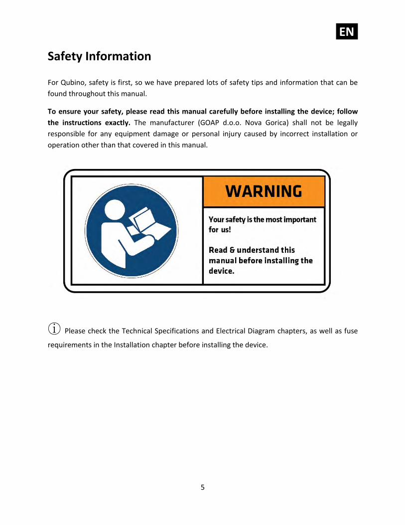
Safety Information
For Qubino, safety is first, so we have prepared lots of safety tips and information that can be
found throughout this manual.
To ensure your safety, please read this manual carefully before installing the device; follow
the instructions exactly. The manufacturer (GOAP d.o.o. Nova Gorica) shall not be legally
responsible for any equipment damage or personal injury caused by incorrect installation or
operation other than that covered in this manual.
ⓘ Please check the Technical Specifications and Electrical Diagram chapters, as well as fuse
requirements in the Installation chapter before installing the device.
EN.
6
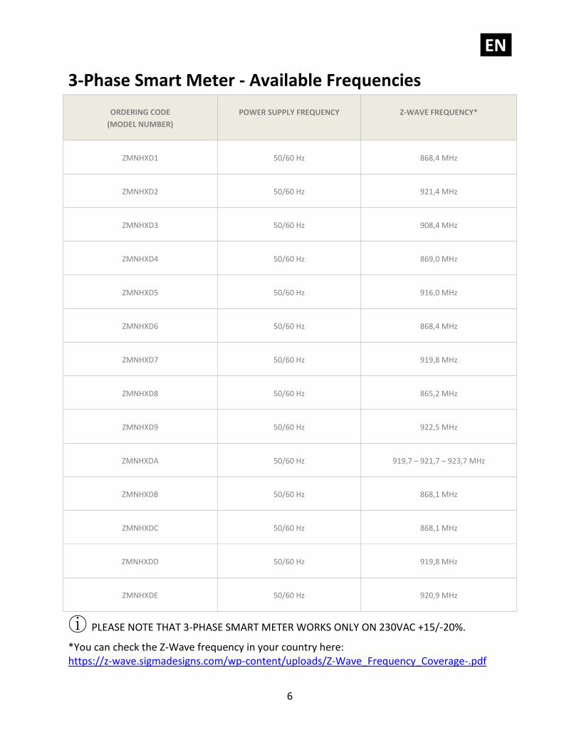
3-Phase Smart Meter - Available Frequencies
ORDERING CODE
(MODEL NUMBER)
POWER SUPPLY FREQUENCY
Z-WAVE FREQUENCY*
ZMNHXD1
50/60 Hz
868,4 MHz
ZMNHXD2
50/60 Hz
921,4 MHz
ZMNHXD3
50/60 Hz
908,4 MHz
ZMNHXD4
50/60 Hz
869,0 MHz
ZMNHXD5
50/60 Hz
916,0 MHz
ZMNHXD6
50/60 Hz
868,4 MHz
ZMNHXD7
50/60 Hz
919,8 MHz
ZMNHXD8
50/60 Hz
865,2 MHz
ZMNHXD9
50/60 Hz
922,5 MHz
ZMNHXDA
50/60 Hz
919,7 – 921,7 – 923,7 MHz
ZMNHXDB
50/60 Hz
868,1 MHz
ZMNHXDC
50/60 Hz
868,1 MHz
ZMNHXDD
50/60 Hz
919,8 MHz
ZMNHXDE
50/60 Hz
920,9 MHz
ⓘ PLEASE NOTE THAT 3-PHASE SMART METER WORKS ONLY ON 230VAC +15/-20%.
*You can check the Z-Wave frequency in your country here: https://z-wave.sigmadesigns.com/wp-content/uploads/Z-Wave_Frequency_Coverage-.pdf
EN.
7
Where To Buy
To find your nearest Qubino dealer visit: http://qubino.com/where-to-buy/
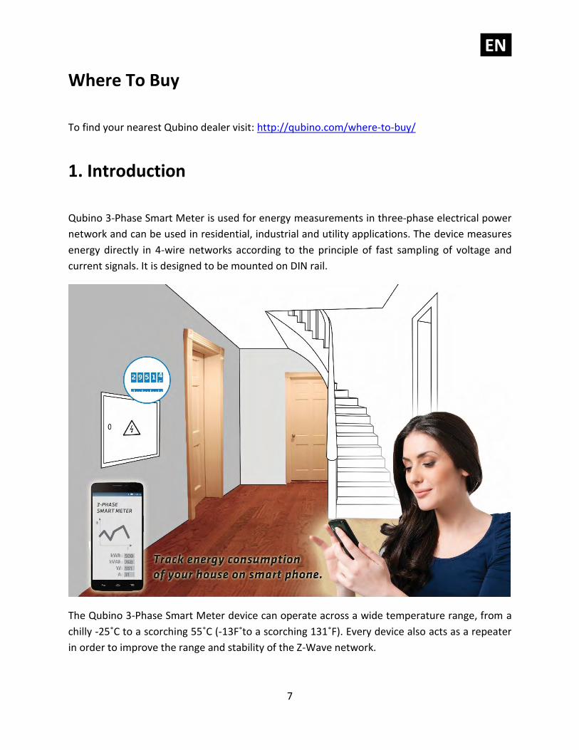
1. Introduction
Qubino 3-Phase Smart Meter is used for energy measurements in three-phase electrical power
network and can be used in residential, industrial and utility applications. The device measures
energy directly in 4-wire networks according to the principle of fast sampling of voltage and
current signals. It is designed to be mounted on DIN rail.
The Qubino 3-Phase Smart Meter device can operate across a wide temperature range, from a
chilly -25˚C to a scorching 55˚C (-13F˚to a scorching 131˚F). Every device also acts as a repeater
in order to improve the range and stability of the Z-Wave network.
EN.
8
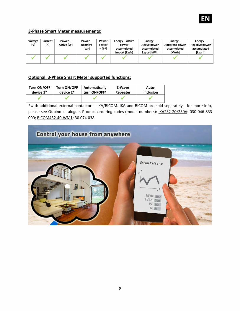
3-Phase Smart Meter measurements:
Voltage [V]
Current [A]
Power – Active [W]
Power – Reactive
[var]
Power Factor – [PF]
Energy – Active power
accumulated Import [kWh]
Energy – Active power accumulated Export[kWh]
Energy – Apparent power
accumulated [kVAh]
Energy – Reactive power
accumulated [kvarh]
✓ ✓ ✓ ✓ ✓ ✓ ✓ ✓ ✓
Optional: 3-Phase Smart Meter supported functions:
Turn ON/OFF device 1*
Turn ON/OFF device 2*
Automatically turn ON/OFF*
Z-Wave Repeater
Auto-inclusion
✓ ✓ ✓ ✓ ✓ *with additional external contactors - IKA/BICOM. IKA and BICOM are sold separately - for more info,
please see Qubino catalogue. Product ordering codes (model numbers): IKA232-20/230V: 030 046 833
000; BICOM432-40-WM1: 30.074.038
EN.
9
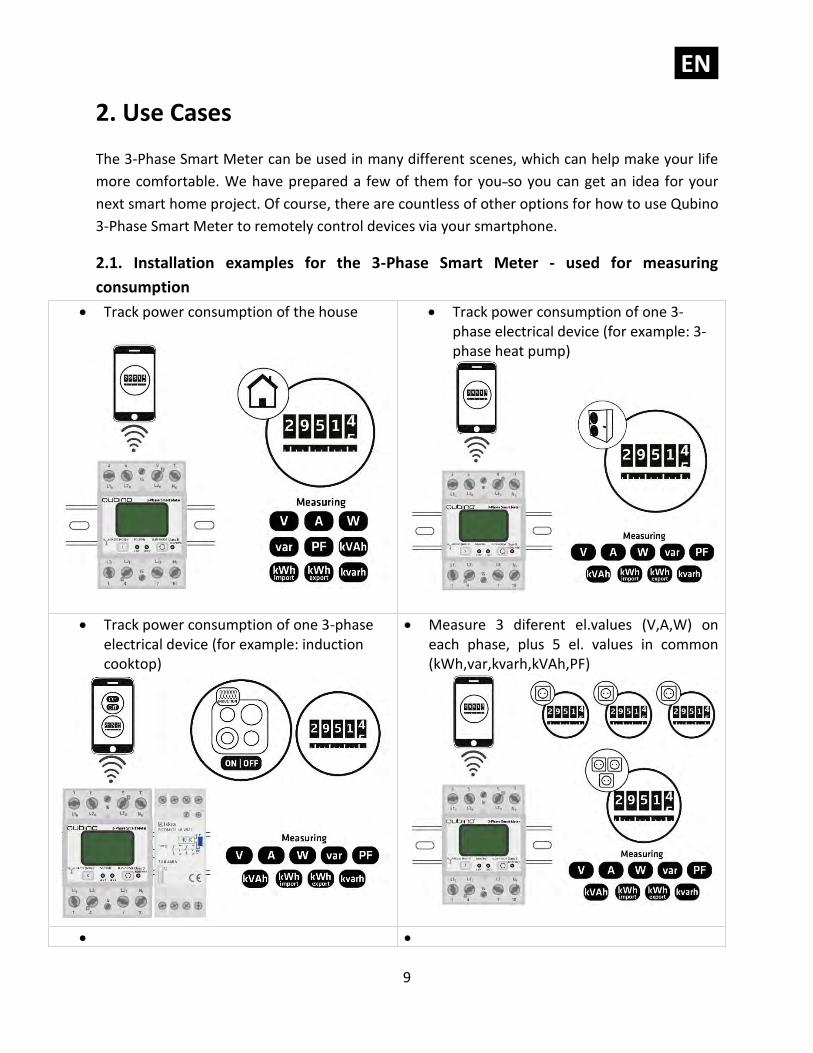
2. Use Cases
The 3-Phase Smart Meter can be used in many different scenes, which can help make your life
more comfortable. We have prepared a few of them for you so you can get an idea for your
next smart home project. Of course, there are countless of other options for how to use Qubino
3-Phase Smart Meter to remotely control devices via your smartphone.
2.1. Installation examples for the 3-Phase Smart Meter - used for measuring
consumption
• Track power consumption of the house
• Track power consumption of one 3-phase electrical device (for example: 3-phase heat pump)
• Track power consumption of one 3-phase electrical device (for example: induction cooktop)
• Measure 3 diferent el.values (V,A,W) on each phase, plus 5 el. values in common (kWh,var,kvarh,kVAh,PF)
• •
EN.
10
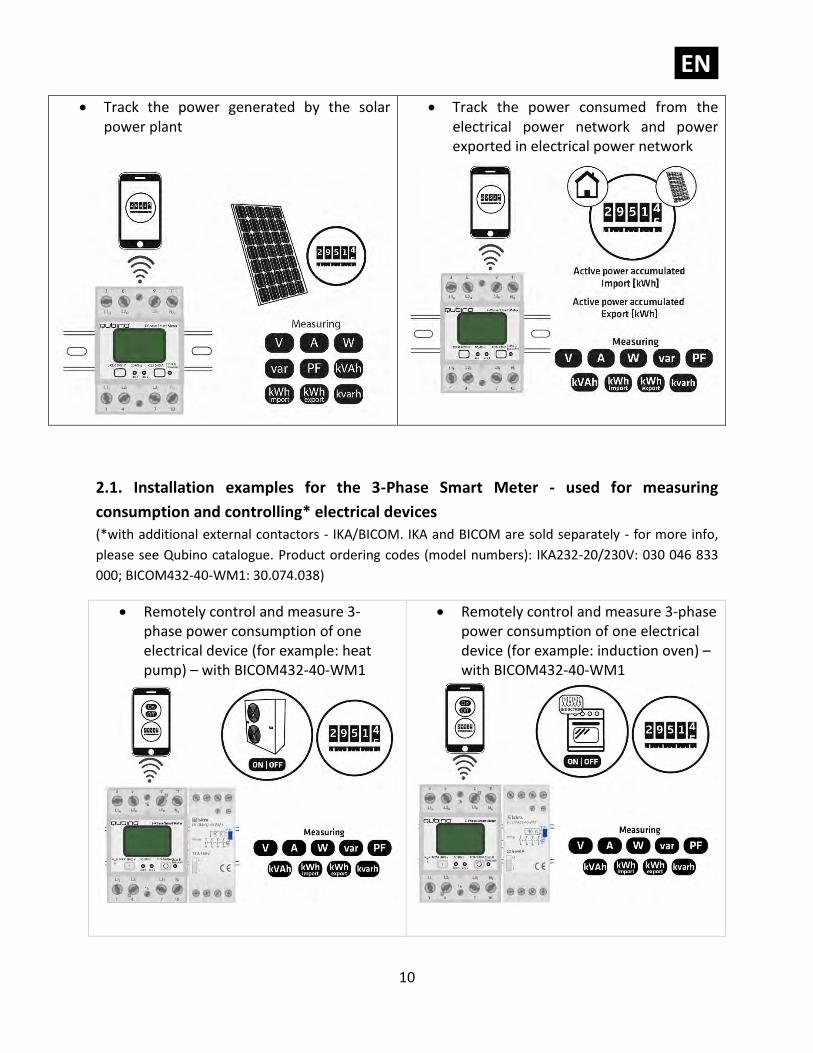
• Track the power generated by the solar power plant
• Track the power consumed from the electrical power network and power exported in electrical power network
2.1. Installation examples for the 3-Phase Smart Meter - used for measuring
consumption and controlling* electrical devices
(*with additional external contactors - IKA/BICOM. IKA and BICOM are sold separately - for more info,
please see Qubino catalogue. Product ordering codes (model numbers): IKA232-20/230V: 030 046 833
000; BICOM432-40-WM1: 30.074.038)
• Remotely control and measure 3-phase power consumption of one electrical device (for example: heat pump) – with BICOM432-40-WM1
• Remotely control and measure 3-phase power consumption of one electrical device (for example: induction oven) – with BICOM432-40-WM1
EN.
11
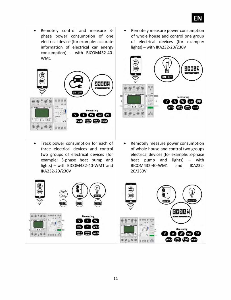
• Remotely control and measure 3-phase power consumption of one electrical device (for example: accurate information of electrical car energy consumption) – with BICOM432-40-WM1
• Remotely measure power consumption of whole house and control one group of electrical devices (for example: lights) – with IKA232-20/230V
• Track power consumption for each of three electrical devices and control two groups of electrical devices (for example: 3-phase heat pump and lights) – with BICOM432-40-WM1 and IKA232-20/230V
• Remotely measure power consumption of whole house and control two groups electrical devices (for example: 3-phase heat pump and lights) – with BICOM432-40-WM1 and IKA232-20/230V
EN.
12
2.2. Additional features of 3-Phase Smart Meter which can make your life easier
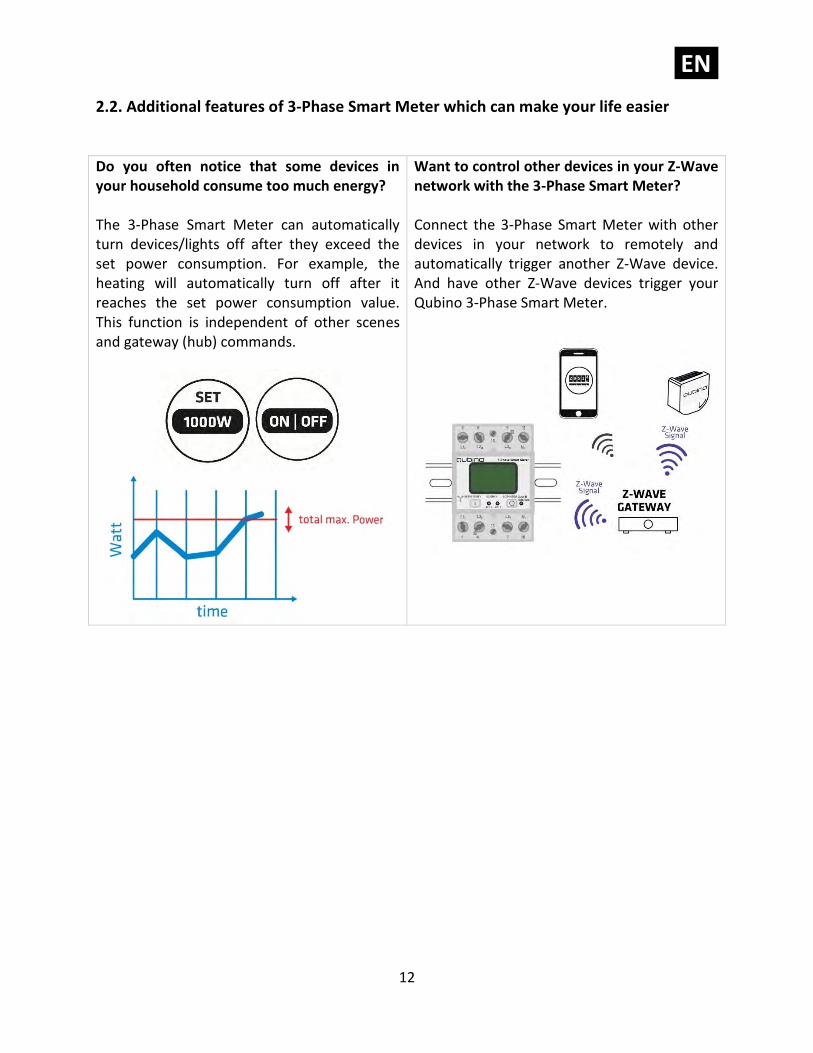
Do you often notice that some devices in your household consume too much energy? The 3-Phase Smart Meter can automatically turn devices/lights off after they exceed the set power consumption. For example, the heating will automatically turn off after it reaches the set power consumption value. This function is independent of other scenes and gateway (hub) commands.
Want to control other devices in your Z-Wave network with the 3-Phase Smart Meter?
Connect the 3-Phase Smart Meter with other devices in your network to remotely and automatically trigger another Z-Wave device. And have other Z-Wave devices trigger your Qubino 3-Phase Smart Meter.
EN.
13
3. Qubino 3-Phase Smart Meter Advantages and
Highlights
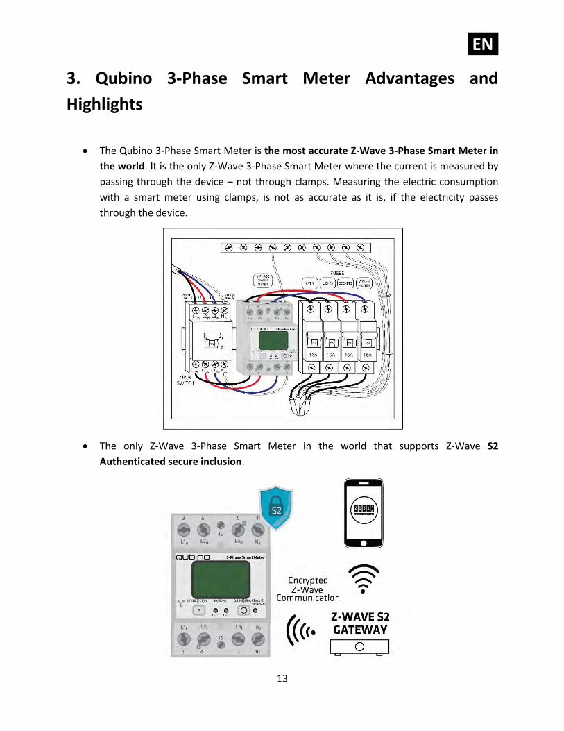
• The Qubino 3-Phase Smart Meter is the most accurate Z-Wave 3-Phase Smart Meter in
the world. It is the only Z-Wave 3-Phase Smart Meter where the current is measured by
passing through the device – not through clamps. Measuring the electric consumption
with a smart meter using clamps, is not as accurate as it is, if the electricity passes
through the device.
• The only Z-Wave 3-Phase Smart Meter in the world that supports Z-Wave S2
Authenticated secure inclusion.
EN.
14
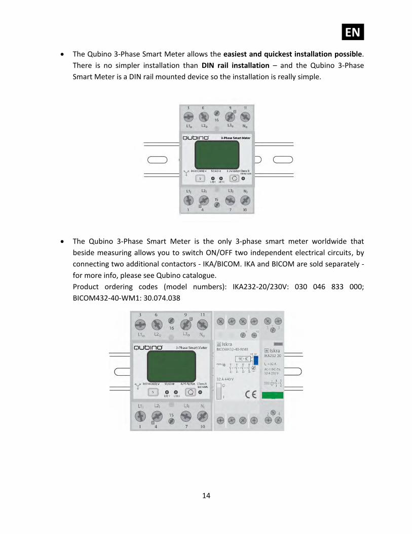
• The Qubino 3-Phase Smart Meter allows the easiest and quickest installation possible.
There is no simpler installation than DIN rail installation – and the Qubino 3-Phase
Smart Meter is a DIN rail mounted device so the installation is really simple.
• The Qubino 3-Phase Smart Meter is the only 3-phase smart meter worldwide that
beside measuring allows you to switch ON/OFF two independent electrical circuits, by
connecting two additional contactors - IKA/BICOM. IKA and BICOM are sold separately -
for more info, please see Qubino catalogue.
Product ordering codes (model numbers): IKA232-20/230V: 030 046 833 000;
BICOM432-40-WM1: 30.074.038
EN.
15
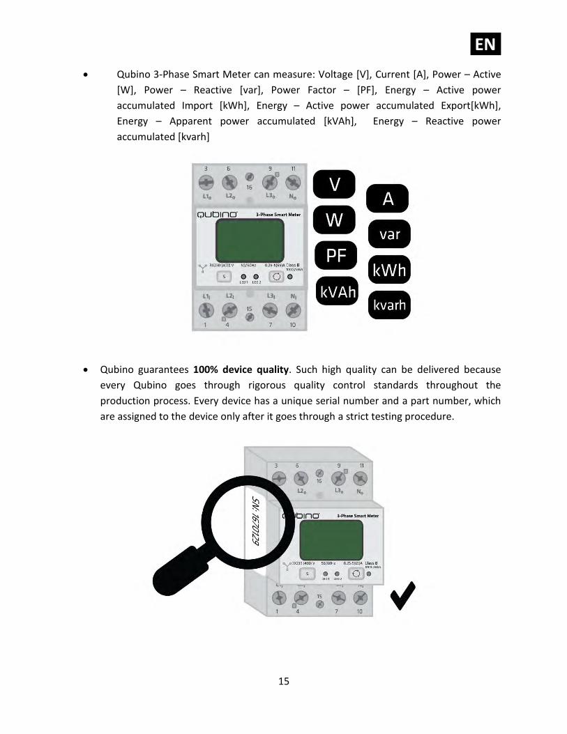
• Qubino 3-Phase Smart Meter can measure: Voltage [V], Current [A], Power – Active
[W], Power – Reactive [var], Power Factor – [PF], Energy – Active power
accumulated Import [kWh], Energy – Active power accumulated Export[kWh],
Energy – Apparent power accumulated [kVAh], Energy – Reactive power
accumulated [kvarh]
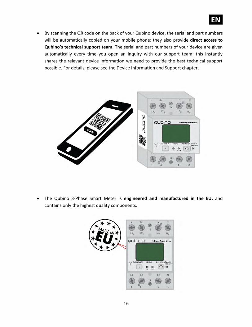
• Qubino guarantees 100% device quality. Such high quality can be delivered because
every Qubino goes through rigorous quality control standards throughout the
production process. Every device has a unique serial number and a part number, which
are assigned to the device only after it goes through a strict testing procedure.
EN.
16
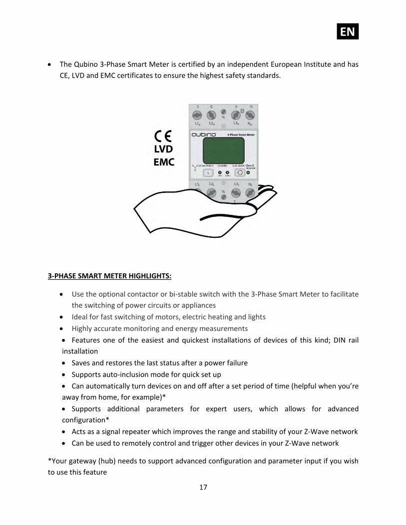
• By scanning the QR code on the back of your Qubino device, the serial and part numbers
will be automatically copied on your mobile phone; they also provide direct access to
Qubino’s technical support team. The serial and part numbers of your device are given
automatically every time you open an inquiry with our support team: this instantly
shares the relevant device information we need to provide the best technical support
possible. For details, please see the Device Information and Support chapter.
• The Qubino 3-Phase Smart Meter is engineered and manufactured in the EU, and
contains only the highest quality components.
EN.
17
• The Qubino 3-Phase Smart Meter is certified by an independent European Institute and has
CE, LVD and EMC certificates to ensure the highest safety standards.
3-PHASE SMART METER HIGHLIGHTS:
• Use the optional contactor or bi-stable switch with the 3-Phase Smart Meter to facilitate
the switching of power circuits or appliances
• Ideal for fast switching of motors, electric heating and lights
• Highly accurate monitoring and energy measurements
• Features one of the easiest and quickest installations of devices of this kind; DIN rail
installation
• Saves and restores the last status after a power failure
• Supports auto-inclusion mode for quick set up
• Can automatically turn devices on and off after a set period of time (helpful when you’re
away from home, for example)*
• Supports additional parameters for expert users, which allows for advanced
configuration*
• Acts as a signal repeater which improves the range and stability of your Z-Wave network
• Can be used to remotely control and trigger other devices in your Z-Wave network
*Your gateway (hub) needs to support advanced configuration and parameter input if you wish
to use this feature

EN.
18
4. Package Contents
• 3-Phase Smart Meter Device
• Installation Manual
• S2 packaging label
EN.
19
5. Technical Terms for Switches
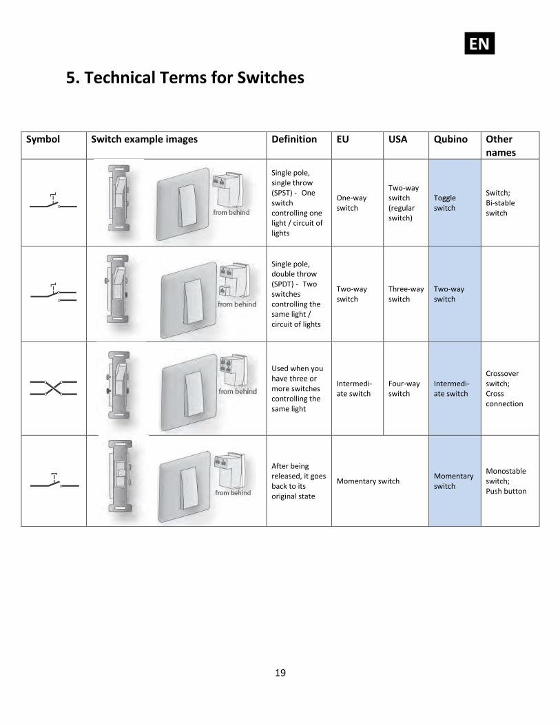
Symbol Switch example images Definition EU USA Qubino Other names
Single pole, single throw (SPST) - One switch controlling one light / circuit of lights
One-way switch
Two-way switch (regular switch)
Toggle switch
Switch; Bi-stable switch
Single pole, double throw (SPDT) - Two switches controlling the same light / circuit of lights
Two-way switch
Three-way switch
Two-way switch
Used when you have three or more switches controlling the same light
Intermedi-ate switch
Four-way switch
Intermedi-ate switch
Crossover switch; Cross connection
After being released, it goes back to its original state
Momentary switch Momentary switch
Monostable switch; Push button
EN.
20
6. Compatibility with Z-Wave Gateways (hubs)
Please check compatibility with your Z-Wave gateway (hub) before you purchase this device.
The compatibility table is available online.
https://qubino.com/products/3-phase-smart-meter/smart-meter-3phase-compatibility/
EN.
21
7. Installation
Before installing the device, please read the following carefully and follow the instructions
exactly:
ⓘ Danger of electrocution!
Installation of this device requires a great degree of skill and may be performed only by a
licensed and qualified electrician. Please keep in mind that even when the device is turned off,
voltage may still be present in the device’s terminals.
ⓘ Note!
Do not connect the device to loads exceeding the recommended values. Connect the device
exactly as shown in the provided diagrams. Improper wiring may be dangerous and result in
equipment damage.
Electrical installation must be protected by directly associated overcurrent protection fuse
with rated current up to 65A, it must be used according to wiring diagram to achieve
appropriate overload protection of the device.
EN.
22
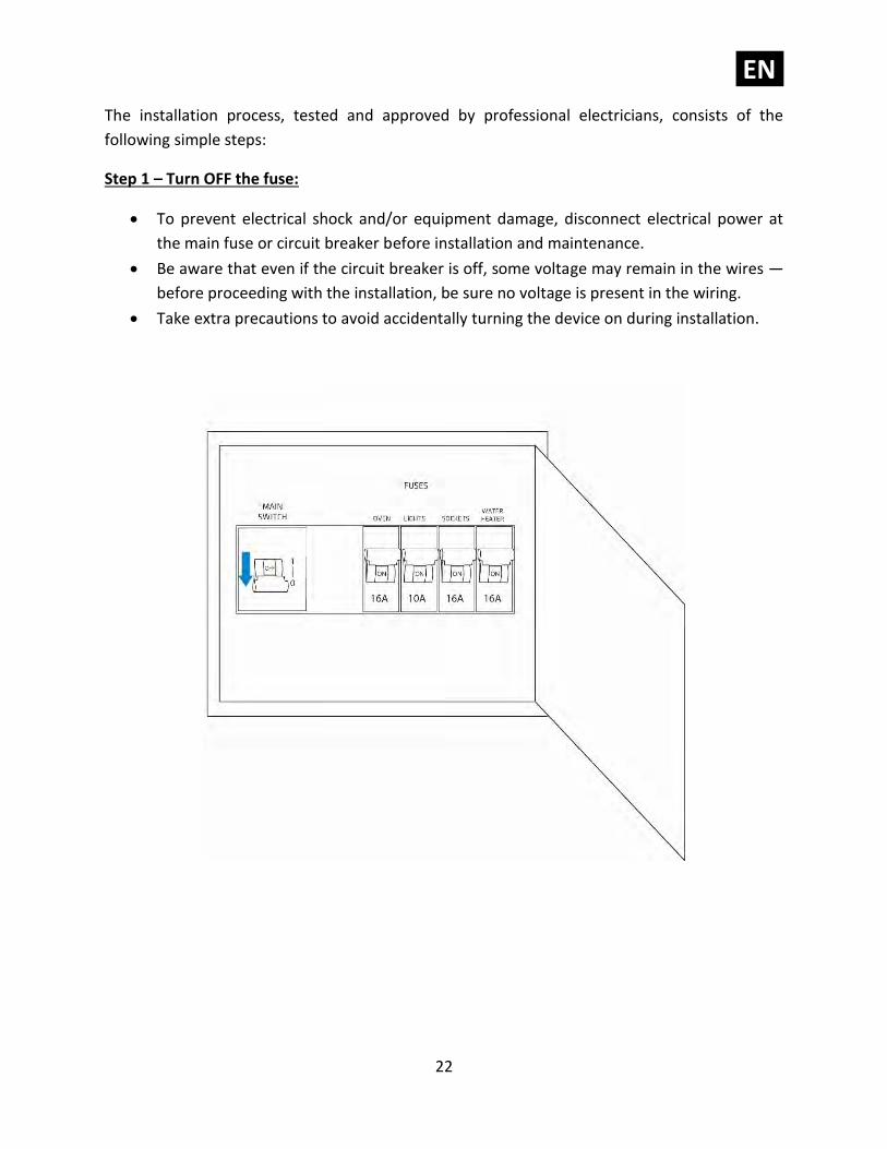
The installation process, tested and approved by professional electricians, consists of the
following simple steps:
Step 1 – Turn OFF the fuse:
• To prevent electrical shock and/or equipment damage, disconnect electrical power at
the main fuse or circuit breaker before installation and maintenance.
• Be aware that even if the circuit breaker is off, some voltage may remain in the wires —
before proceeding with the installation, be sure no voltage is present in the wiring.
• Take extra precautions to avoid accidentally turning the device on during installation.
EN.
23
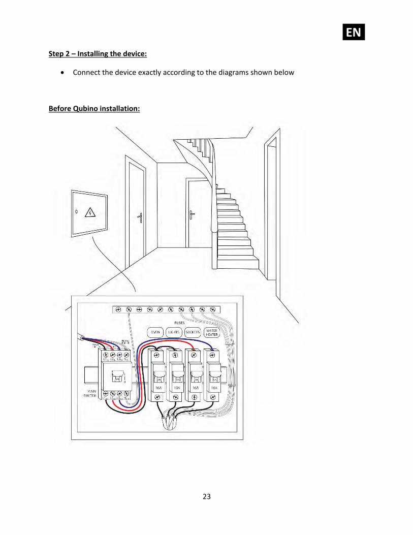
Step 2 – Installing the device:
• Connect the device exactly according to the diagrams shown below
Before Qubino installation:
EN.
24
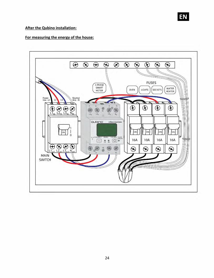
After the Qubino installation:
For measuring the energy of the house:
EN.
25
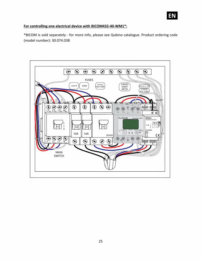
For controlling one electrical device with BICOM432-40-WM1*:
*BICOM is sold separately - for more info, please see Qubino catalogue. Product ordering code
(model number): 30.074.038
EN.
26
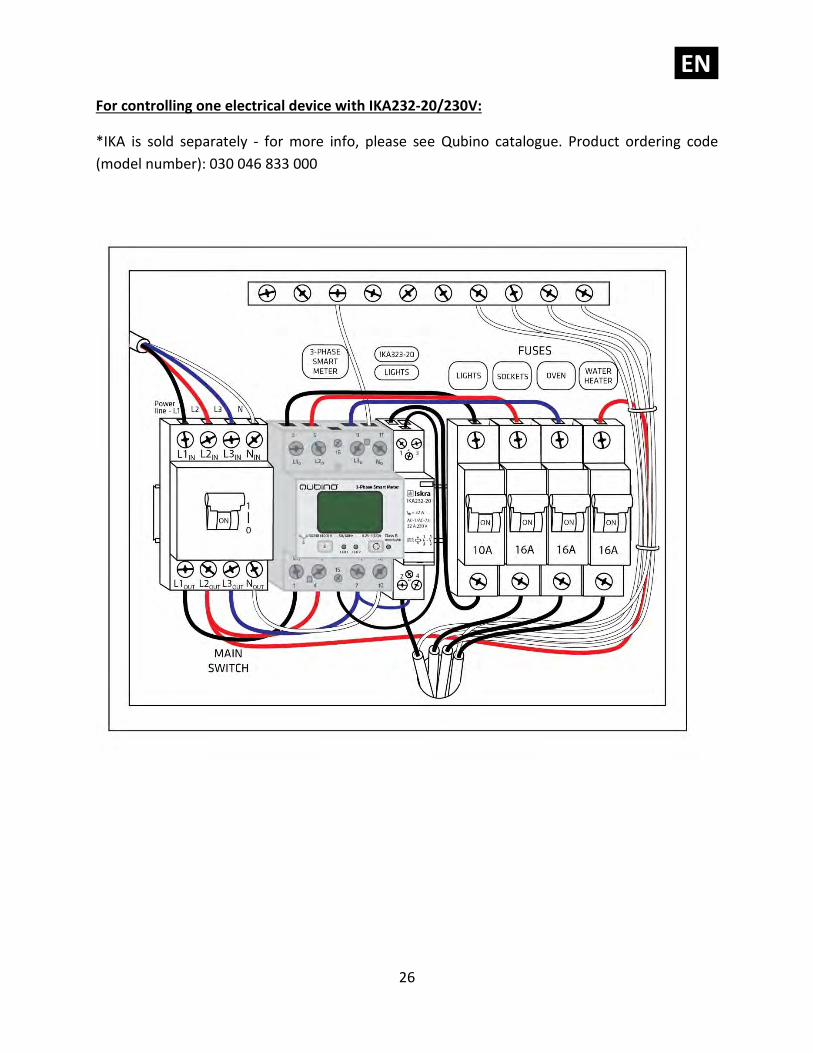
For controlling one electrical device with IKA232-20/230V:
*IKA is sold separately - for more info, please see Qubino catalogue. Product ordering code
(model number): 030 046 833 000
EN.
27
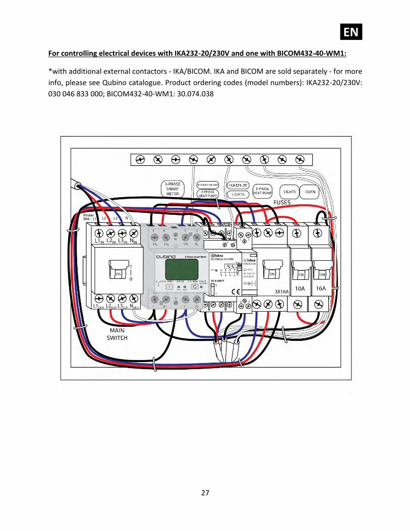
For controlling electrical devices with IKA232-20/230V and one with BICOM432-40-WM1:
*with additional external contactors - IKA/BICOM. IKA and BICOM are sold separately - for more
info, please see Qubino catalogue. Product ordering codes (model numbers): IKA232-20/230V:
030 046 833 000; BICOM432-40-WM1: 30.074.038
EN.
28
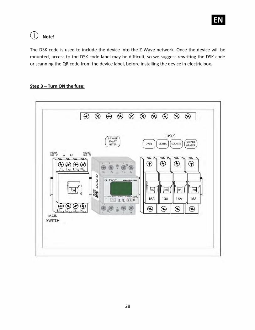
ⓘ Note!
The DSK code is used to include the device into the Z-Wave network. Once the device will be
mounted, access to the DSK code label may be difficult, so we suggest rewriting the DSK code
or scanning the QR code from the device label, before installing the device in electric box.
Step 3 – Turn ON the fuse:
EN.
29
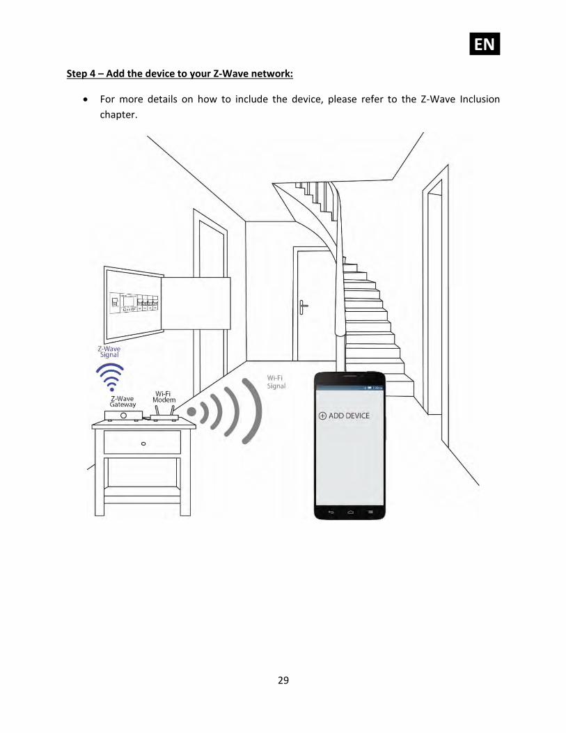
Step 4 – Add the device to your Z-Wave network:
• For more details on how to include the device, please refer to the Z-Wave Inclusion
chapter.
EN.
30
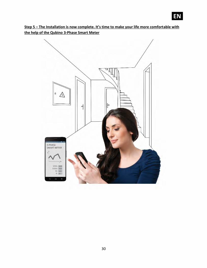
Step 5 – The Installation is now complete. It’s time to make your life more comfortable with
the help of the Qubino 3-Phase Smart Meter
EN.
31
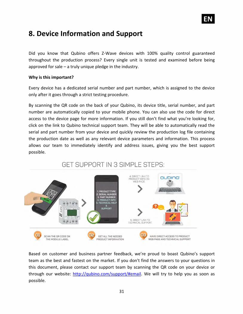
8. Device Information and Support
Did you know that Qubino offers Z-Wave devices with 100% quality control guaranteed
throughout the production process? Every single unit is tested and examined before being
approved for sale – a truly unique pledge in the industry.
Why is this important?
Every device has a dedicated serial number and part number, which is assigned to the device
only after it goes through a strict testing procedure.
By scanning the QR code on the back of your Qubino, its device title, serial number, and part
number are automatically copied to your mobile phone. You can also use the code for direct
access to the device page for more information. If you still don’t find what you’re looking for,
click on the link to Qubino technical support team. They will be able to automatically read the
serial and part number from your device and quickly review the production log file containing
the production date as well as any relevant device parameters and information. This process
allows our team to immediately identify and address issues, giving you the best support
possible.
Based on customer and business partner feedback, we’re proud to boast Qubino’s support
team as the best and fastest on the market. If you don't find the answers to your questions in
this document, please contact our support team by scanning the QR code on your device or
through our website: http://qubino.com/support/#email. We will try to help you as soon as
possible.
EN.
32
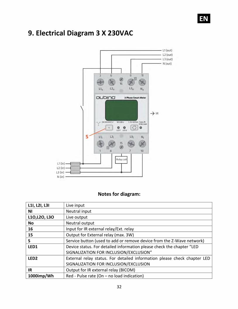
9. Electrical Diagram 3 X 230VAC
Notes for diagram:
L1I, L2I, L3I Live input
NI Neutral input
L1O,L2O, L3O Live output
No Neutral output
16 Input for IR external relay/Ext. relay
15 Output for External relay (max. 3W)
S Service button (used to add or remove device from the Z-Wave network)
LED1 Device status. For detailed information please check the chapter “LED SIGNALIZATION FOR INCLUSION/EXCLUSION”
LED2 External relay status. For detailed information please check chapter LED SIGNALIZATION FOR INCLUSION/EXCLUSION
IR Output for IR external relay (BICOM)
1000imp/Wh Red - Pulse rate (On – no load indication)
EN.
33
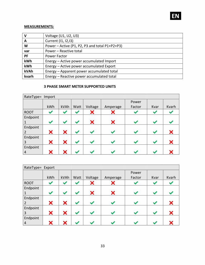
MEASUREMENTS:
V Voltage (U1, U2, U3)
A Current (I1, I2,I3)
W Power – Active (P1, P2, P3 and total P1+P2+P3)
var Power – Reactive total
PF Power Factor
kWh Energy – Active power accumulated Import
kWh Energy – Active power accumulated Export
kVAh Energy – Apparent power accumulated total
kvarh Energy – Reactive power accumulated total
3 PHASE SMART METER SUPPORTED UNITS
RateType= Import
kWh kVAh Watt Voltage Amperage Power Factor Kvar Kvarh
ROOT ✔ ✔ ✔ ✖ ✖ ✔ ✔ ✔
Endpoint 1 ✔ ✔ ✔ ✖ ✖ ✔ ✔ ✔
Endpoint 2 ✖ ✖ ✔ ✔ ✔ ✔ ✔ ✖
Endpoint 3 ✖ ✖ ✔ ✔ ✔ ✔ ✔ ✖
Endpoint 4 ✖ ✖ ✔ ✔ ✔ ✔ ✔ ✖
RateType= Export
kWh kVAh Watt Voltage Amperage Power Factor Kvar Kvarh
ROOT ✔ ✔ ✔ ✖ ✖ ✔ ✔ ✔
Endpoint 1 ✔ ✔ ✔ ✖ ✖ ✔ ✔ ✔
Endpoint 2 ✖ ✖ ✔ ✔ ✔ ✔ ✔ ✖
Endpoint 3 ✖ ✖ ✔ ✔ ✔ ✔ ✔ ✖
Endpoint 4 ✖ ✖ ✔ ✔ ✔ ✔ ✔ ✖
EN.
34
NOTE: there could be a meter measurement update delay for some scales up to 10 minutes.
Therefore the first real measured values could be reported with the same delay.
Watchdog To protect the Smart Meter against getting stuck in an undesired state, the watchdog timer is
enabled.
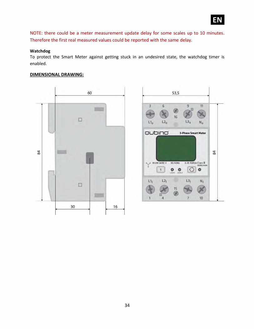
DIMENSIONAL DRAWING:
EN.
35
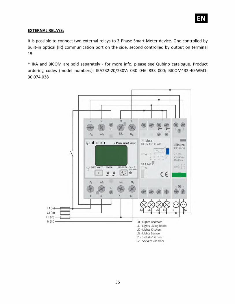
EXTERNAL RELAYS:
It is possible to connect two external relays to 3-Phase Smart Meter device. One controlled by
built-in optical (IR) communication port on the side, second controlled by output on terminal
15.
* IKA and BICOM are sold separately - for more info, please see Qubino catalogue. Product
ordering codes (model numbers): IKA232-20/230V: 030 046 833 000; BICOM432-40-WM1:
30.074.038
EN.
36
BICOM432-40-WM1 (IR) RELAY
BICOM432-40-WM1 is a bistable switch with modbus communication over IR connection.
Bistable switch is a switching device with two stable states for switching on and off all kinds of
electrical loads. When the switch is not electrically, manually or over a IR communication path,
remains stable in its operating position and will change its operating position on initiation or
actuation. initiated Switch is controllable over a IR communication interface always in a slave
communication position. BICOM432-40-WM1 has built-in electro-mechanical check of the
position status. BICOM432-40-WM1 is available as standalone unit, being also powered from
own power source over an internal power supply. By default, endpoint 3, which corresponds to
this relay, is hidden and can be enabled by changing the value of the configuration parameter
100.
For more information, please consult the official manual, which can be obtained on the
following address: http://qubino.com/download/1107/
IKA232-20/230V
IKA232-20 is a bistable switch, which can be controlled, in contrast to the IR relay, using a
digital output (on the 3-Phase Smart Meter). A bistable switch is a switching device with two
stable states for switching on and off all kinds of electrical loads. It can can be used for remote
control of various AC devices (fast switching of motors, electric heating, lights and lightning, all
kinds of electrical and electronic equipment, which can be found in residential, hospitals,
hotels, and business premises). IKA232-20/230V is available as standalone unit, being also
powered from own power source over an internal power supply. By default, endpoint 2, which
corresponds to this relay, is hidden and can be enabled by changing the value of the
configuration parameter 101.
For more information, please consult the official manual, which can be obtained on the
following address: http://qubino.com/download/1099/
Both relays can be controlled using the supported actuation commands: BASIC_SET,
SWITCH_BINARY_SET
EN.
37
10. Adding the device to a Z-Wave network (Inclusion)
AUTOMATICALLY ADDING THE DEVICE TO A Z-WAVE NETWORK (AUTO INCLUSION)
1. Enable add/remove mode on your Z-Wave gateway (hub)
2. Automatic selection of secure/unsecure inclusion
3. The device can be automatically added to a Z-Wave network during the first 2 minutes
4. Connect the device to the power supply
5. Auto-inclusion will be initiated within 5 seconds of connection to the power supply and the
device will be automatically added to your network (when the device is excluded and
re-connected to the power supply it automatically enters the LEARN MODE state.)
ⓘ NOTE: For S2 inclusion please check chapter – »16. Z-Wave Security«.
MANUALLY ADDING THE DEVICE TO A Z-WAVE NETWORK (MANUAL INCLUSION)
1. Connect the device to the power supply
2. Enable add/remove mode on your Z-Wave gateway (hub)
2. Toggle the Service button S between 0.2 and 3 seconds
3. A new multi-channel device will appear on your dashboard
EN.
38
11. Removing the device from a Z-Wave network
(Exclusion)
REMOVAL FROM A ZWAVE NETWORK (Z-WAVE EXCLUSION)
1. Connect the device to the power supply
2. Make sure the device is within direct range of your Z-Wave gateway (hub) or use a hand-
held Z-Wave remote to perform exclusion
3. Enable add/remove mode on your Z-Wave gateway (hub)
4. Press and hold the S service button between 0.2 and 3 seconds
5. The device will be removed from your network but custom configuration parameters will not
be erased. Wait at least 30 seconds before adding the device back to a network.
FACTORY RESET
1. Connect the device to the power supply
2. Press and hold the S service button between 6 seconds and 20 seconds
3. Device will be removed from you network and the green LED starts blinking
ⓘ By resetting the device, all custom parameters previously set on the device will return to
their default values, and the owner ID will be deleted. Use this reset procedure only when the
main gateway (hub) is missing or otherwise inoperable.
EN.
39
LED SIGNALIZATION FOR INCLUSION/EXCLUSION
LED1 (Green)
• LED is ON = Power ON, module is included
• LED is 1s OFF, 1s ON = Power ON, module is excluded
LED2 (Yellow)
a. External IR relay enabled only
• LED is ON = External IR relay is turned ON
• LED is OFF = External IR relay is turned OFF
• LED is 0.5s OFF, 0.5s ON = IR communication error
b. External TRIAC relay enabled only
• LED is ON = External IR relay is turned ON
• LED is OFF = External IR relay is turned OFF
c. Both TRIAC an IR enabled
• LED is ON = External IR relay is turned ON
• LED is OFF = External IR relay is turned OFF
• LED is 0.5s OFF, 0.5s ON = IR communication error
d. External IR relay disabled
• LED is ON = modbus packet is sent
• LED is OFF = modbus packet is received
EN.
40
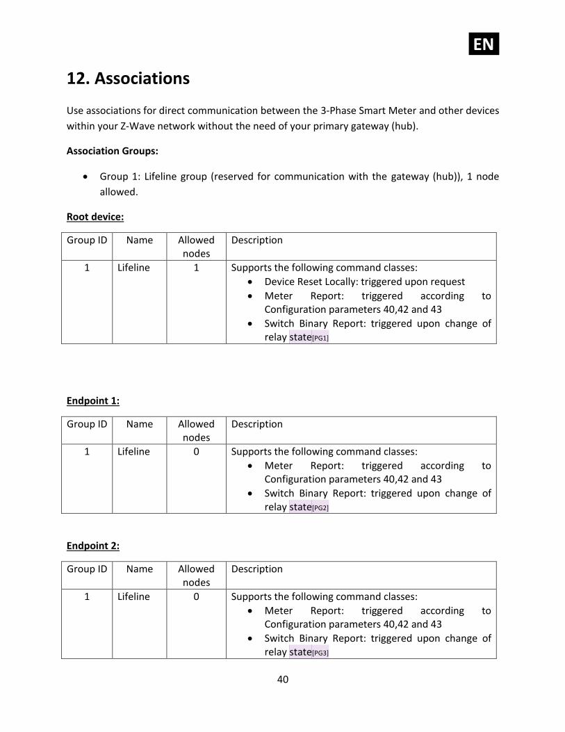
12. Associations
Use associations for direct communication between the 3-Phase Smart Meter and other devices
within your Z-Wave network without the need of your primary gateway (hub).
Association Groups:
• Group 1: Lifeline group (reserved for communication with the gateway (hub)), 1 node
allowed.
Root device:
Group ID Name Allowed nodes
Description
1 Lifeline 1 Supports the following command classes:
• Device Reset Locally: triggered upon request
• Meter Report: triggered according to Configuration parameters 40,42 and 43
• Switch Binary Report: triggered upon change of relay state[PG1]
Endpoint 1:
Group ID Name Allowed nodes
Description
1 Lifeline 0 Supports the following command classes:
• Meter Report: triggered according to Configuration parameters 40,42 and 43
• Switch Binary Report: triggered upon change of relay state[PG2]
Endpoint 2:
Group ID Name Allowed nodes
Description
1 Lifeline 0 Supports the following command classes:
• Meter Report: triggered according to Configuration parameters 40,42 and 43
• Switch Binary Report: triggered upon change of relay state[PG3]
EN.
41
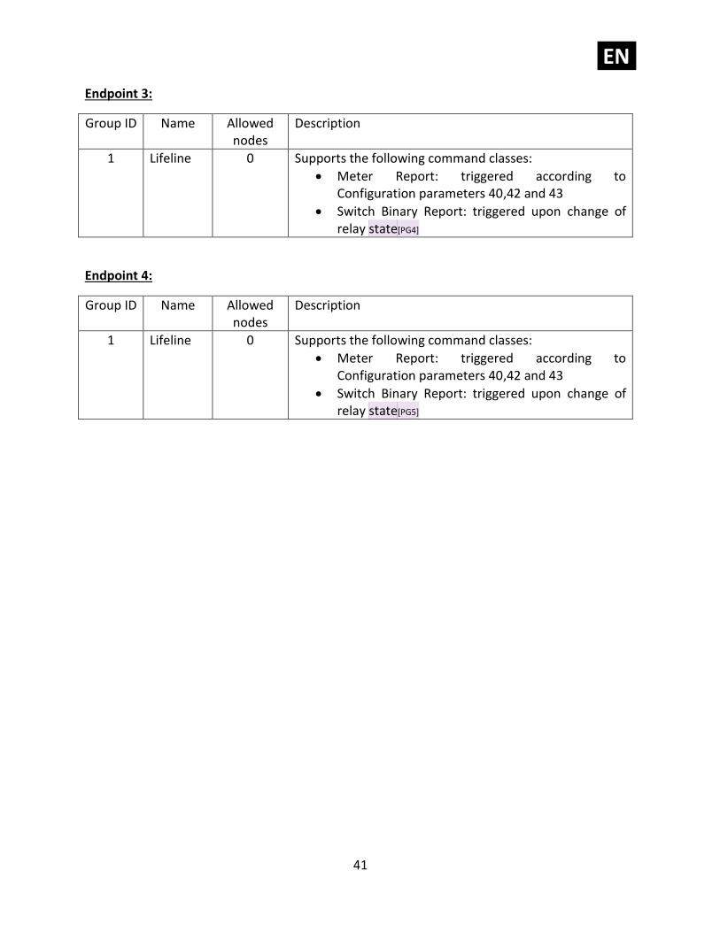
Endpoint 3:
Group ID Name Allowed nodes
Description
1 Lifeline 0 Supports the following command classes:
• Meter Report: triggered according to Configuration parameters 40,42 and 43
• Switch Binary Report: triggered upon change of relay state[PG4]
Endpoint 4:
Group ID Name Allowed nodes
Description
1 Lifeline 0 Supports the following command classes:
• Meter Report: triggered according to Configuration parameters 40,42 and 43
• Switch Binary Report: triggered upon change of relay state[PG5]
EN.
42
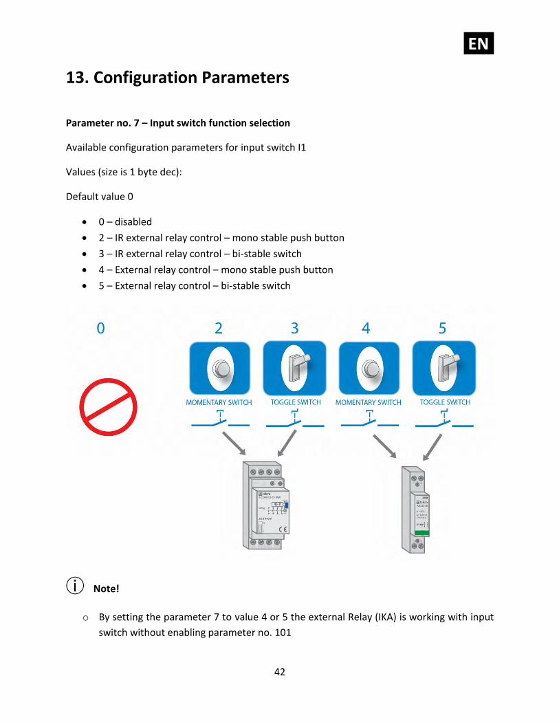
13. Configuration Parameters
Parameter no. 7 – Input switch function selection
Available configuration parameters for input switch I1
Values (size is 1 byte dec):
Default value 0
• 0 – disabled
• 2 – IR external relay control – mono stable push button
• 3 – IR external relay control – bi-stable switch
• 4 – External relay control – mono stable push button
• 5 – External relay control – bi-stable switch
ⓘ Note!
o By setting the parameter 7 to value 4 or 5 the external Relay (IKA) is working with input
switch without enabling parameter no. 101
EN.
43
o To make the IR Relay (BICOM) responsive to the digital input, in addition to the setting
of the configuration parameter 7, parameter 100 must also be set to value 1 or 2.
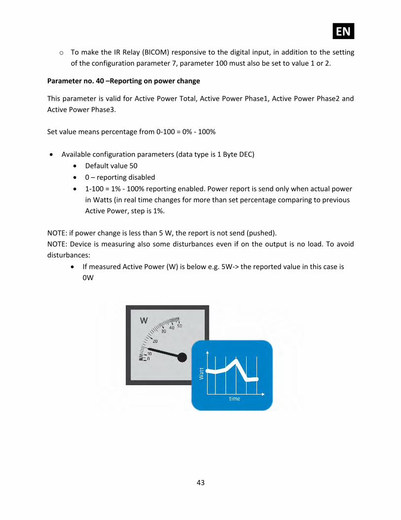
Parameter no. 40 –Reporting on power change
This parameter is valid for Active Power Total, Active Power Phase1, Active Power Phase2 and
Active Power Phase3.
Set value means percentage from 0-100 = 0% - 100%
• Available configuration parameters (data type is 1 Byte DEC)
• Default value 50
• 0 – reporting disabled
• 1-100 = 1% - 100% reporting enabled. Power report is send only when actual power
in Watts (in real time changes for more than set percentage comparing to previous
Active Power, step is 1%.
NOTE: if power change is less than 5 W, the report is not send (pushed).
NOTE: Device is measuring also some disturbances even if on the output is no load. To avoid
disturbances:
• If measured Active Power (W) is below e.g. 5W-> the reported value in this case is
0W
EN.
44
Parameter no. 42 – Reporting on time interval
This parameter is currently valid only for Active Energy Total Import/Export (kWh), Reactive
Energy Total (kvarh), Total Energy (kVAh)
• Available configuration parameters (data type is 2 Byte DEC)
• Default value 600 (600 seconds - 10 minutes)
• 0 – reporting disabled
• 600-32535 = 600 (600 seconds – 32535 seconds). Reporting enabled. Report is send
with the time interval set by entered value.
Note: Device is reporting only if there was a change of 0.1 in Energy
Note: In the future will be possible to measure and report also Active Energy on PH1, PH2 and
PH3.
Parameter no. 43 – Other Values - Reporting on time interval
This parameter is valid only for Voltage (V of ph1, ph2, ph3), Current (A of ph1, ph2, ph3), Total
Power Factor, Total Reactive Power (var)
Available configuration parameters (data type is 2 Byte DEC)
• Default value 600 (600 seconds - 10 minutes)
• 0 – reporting disabled
• 600-32535 = 600 (600 seconds – 32535 seconds). Reporting enabled. Report is send
with the time interval set by entered value.
• Note: Device is reporting only if there was a change
EN.
45
Parameter no. 100 – Enable / Disable External IR relay (BICOM)
Available configuration parameters (data type is 1 Byte DEC):
• default value 0
• 0 – External IR relay disabled
• 1 – External IR relay enabled and connected to all 3 Phases
• 2 – External IR relay enabled and connected to a Phase 1
NOTE1: After parameter change, first exclude module (without setting parameters to default
value) and then re include the module.
NOTE 2: If you don't have IR BICOM relay module mounted and you enable IR communication
(parameter 100 is 1 or 2) there will be no valid IR relay state reported. It will be reported IR
COMMUNICATION ERROR and LED2 will BLINK.
Parameter no. 101 – Enable / Disable External relay (IKA)
Available configuration parameters (data type is 1 Byte DEC):
• default value 0
• 0 – External relay disabled
• 1 – External relay enabled and connected to Phase 2
NOTE1: After parameter change, first exclude module (without setting parameters to default
value) and then re include the module.
EN.
46
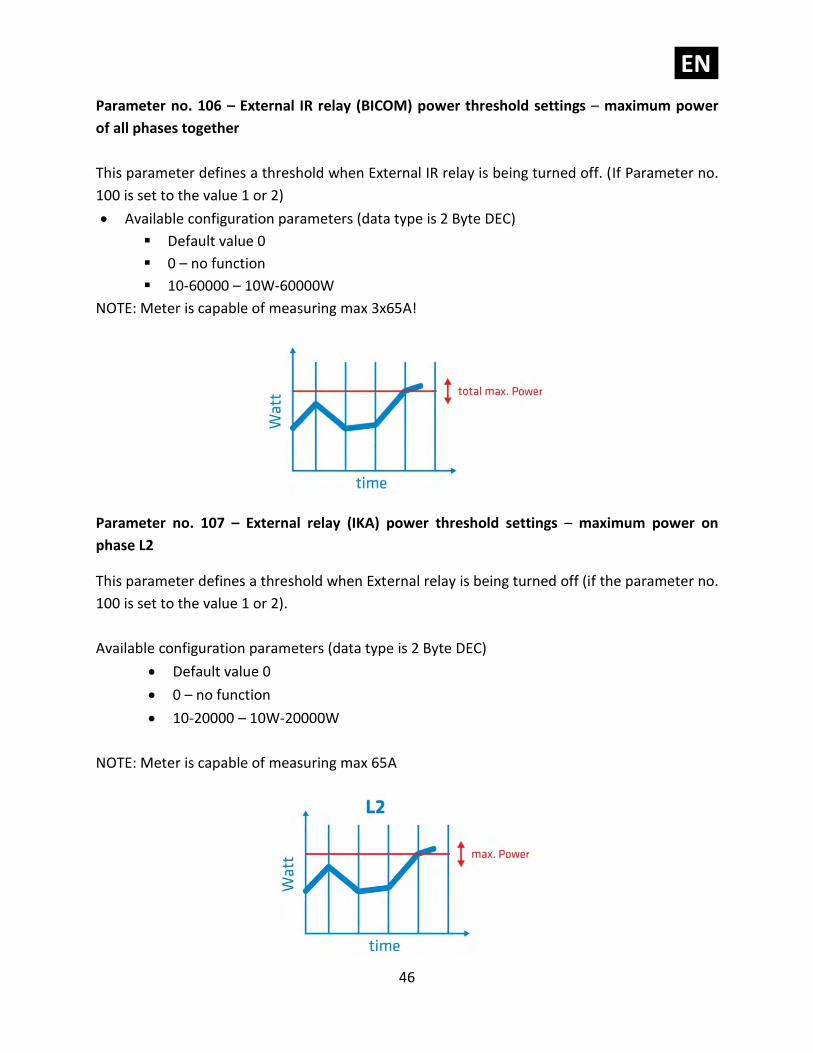
Parameter no. 106 – External IR relay (BICOM) power threshold settings – maximum power
of all phases together
This parameter defines a threshold when External IR relay is being turned off. (If Parameter no.
100 is set to the value 1 or 2)
• Available configuration parameters (data type is 2 Byte DEC)
▪ Default value 0
▪ 0 – no function
▪ 10-60000 – 10W-60000W
NOTE: Meter is capable of measuring max 3x65A!
Parameter no. 107 – External relay (IKA) power threshold settings – maximum power on
phase L2
This parameter defines a threshold when External relay is being turned off (if the parameter no.
100 is set to the value 1 or 2).
Available configuration parameters (data type is 2 Byte DEC)
• Default value 0
• 0 – no function
• 10-20000 – 10W-20000W
NOTE: Meter is capable of measuring max 65A
EN.
47
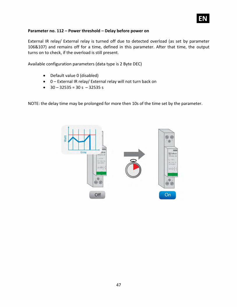
Parameter no. 112 – Power threshold – Delay before power on
External IR relay/ External relay is turned off due to detected overload (as set by parameter 106&107) and remains off for a time, defined in this parameter. After that time, the output turns on to check, if the overload is still present. Available configuration parameters (data type is 2 Byte DEC)
• Default value 0 (disabled)
• 0 – External IR relay/ External relay will not turn back on
• 30 – 32535 = 30 s – 32535 s
NOTE: the delay time may be prolonged for more then 10s of the time set by the parameter.
EN.
48
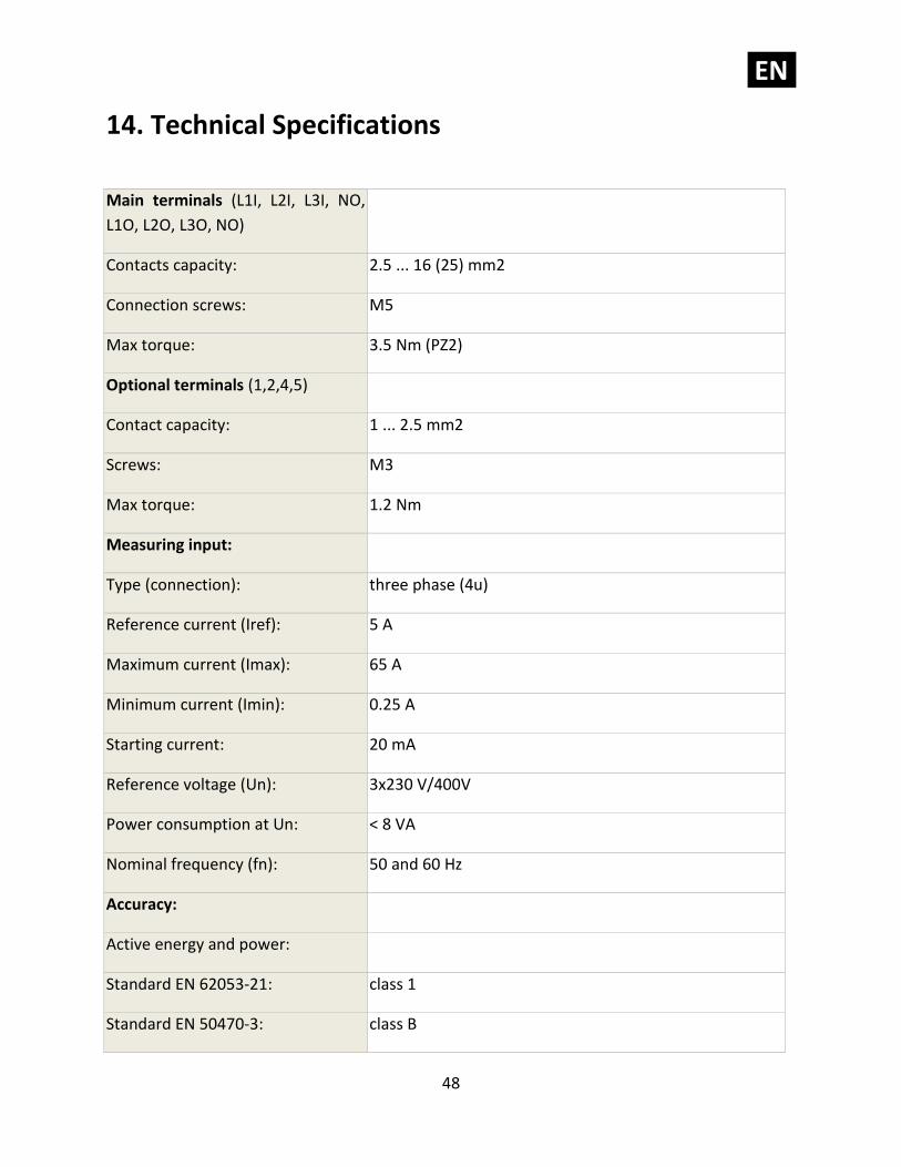
14. Technical Specifications
Main terminals (L1I, L2I, L3I, NO,
L1O, L2O, L3O, NO)
Contacts capacity: 2.5 ... 16 (25) mm2
Connection screws: M5
Max torque: 3.5 Nm (PZ2)
Optional terminals (1,2,4,5)
Contact capacity: 1 ... 2.5 mm2
Screws: M3
Max torque: 1.2 Nm
Measuring input:
Type (connection): three phase (4u)
Reference current (Iref): 5 A
Maximum current (Imax): 65 A
Minimum current (Imin): 0.25 A
Starting current: 20 mA
Reference voltage (Un): 3x230 V/400V
Power consumption at Un: < 8 VA
Nominal frequency (fn): 50 and 60 Hz
Accuracy:
Active energy and power:
Standard EN 62053-21: class 1
Standard EN 50470-3: class B
EN.
49
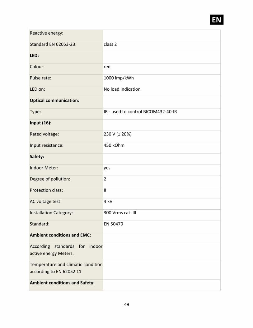
Reactive energy:
Standard EN 62053-23: class 2
LED:
Colour: red
Pulse rate: 1000 imp/kWh
LED on: No load indication
Optical communication:
Type: IR - used to control BICOM432-40-IR
Input (16):
Rated voltage: 230 V (± 20%)
Input resistance: 450 kOhm
Safety:
Indoor Meter: yes
Degree of pollution: 2
Protection class: II
AC voltage test: 4 kV
Installation Category: 300 Vrms cat. III
Standard: EN 50470
Ambient conditions and EMC:
According standards for indoor
active energy Meters.
Temperature and climatic condition
according to EN 62052 11
Ambient conditions and Safety:
EN.
50
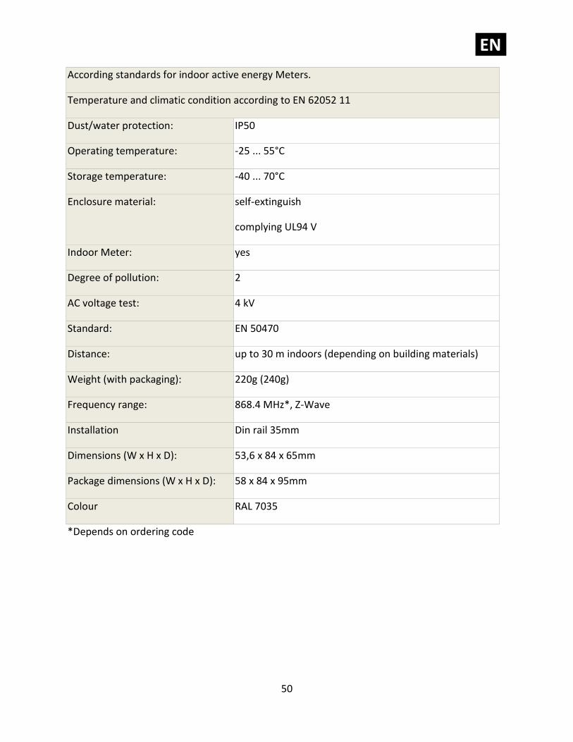
According standards for indoor active energy Meters.
Temperature and climatic condition according to EN 62052 11
Dust/water protection: IP50
Operating temperature: -25 ... 55°C
Storage temperature: -40 ... 70°C
Enclosure material: self-extinguish
complying UL94 V
Indoor Meter: yes
Degree of pollution: 2
AC voltage test: 4 kV
Standard: EN 50470
Distance: up to 30 m indoors (depending on building materials)
Weight (with packaging): 220g (240g)
Frequency range: 868.4 MHz*, Z-Wave
Installation Din rail 35mm
Dimensions (W x H x D): 53,6 x 84 x 65mm
Package dimensions (W x H x D): 58 x 84 x 95mm
Colour RAL 7035
*Depends on ordering code
EN.
51
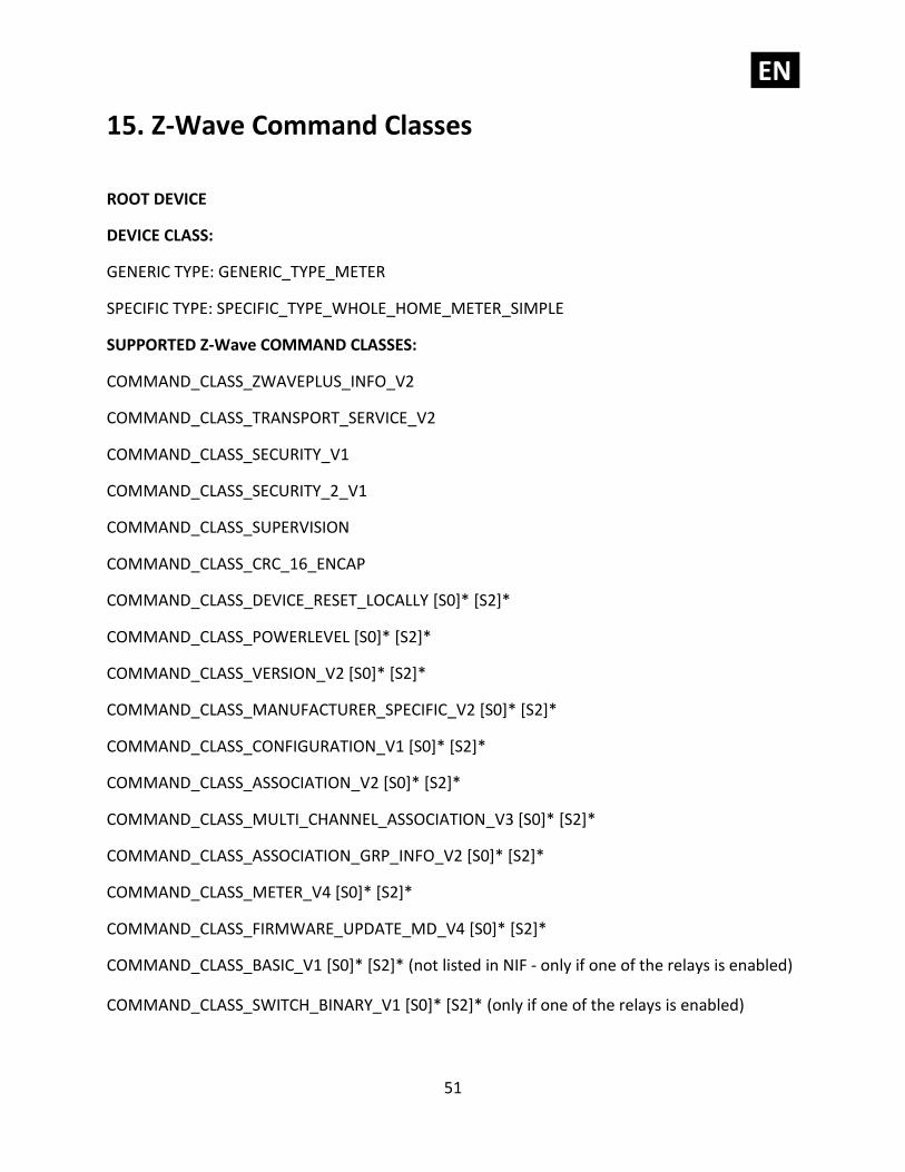
15. Z-Wave Command Classes
ROOT DEVICE
DEVICE CLASS:
GENERIC TYPE: GENERIC_TYPE_METER
SPECIFIC TYPE: SPECIFIC_TYPE_WHOLE_HOME_METER_SIMPLE
SUPPORTED Z-Wave COMMAND CLASSES:
COMMAND_CLASS_ZWAVEPLUS_INFO_V2
COMMAND_CLASS_TRANSPORT_SERVICE_V2
COMMAND_CLASS_SECURITY_V1
COMMAND_CLASS_SECURITY_2_V1
COMMAND_CLASS_SUPERVISION
COMMAND_CLASS_CRC_16_ENCAP
COMMAND_CLASS_DEVICE_RESET_LOCALLY [S0]* [S2]*
COMMAND_CLASS_POWERLEVEL [S0]* [S2]*
COMMAND_CLASS_VERSION_V2 [S0]* [S2]*
COMMAND_CLASS_MANUFACTURER_SPECIFIC_V2 [S0]* [S2]*
COMMAND_CLASS_CONFIGURATION_V1 [S0]* [S2]*
COMMAND_CLASS_ASSOCIATION_V2 [S0]* [S2]*
COMMAND_CLASS_MULTI_CHANNEL_ASSOCIATION_V3 [S0]* [S2]*
COMMAND_CLASS_ASSOCIATION_GRP_INFO_V2 [S0]* [S2]*
COMMAND_CLASS_METER_V4 [S0]* [S2]*
COMMAND_CLASS_FIRMWARE_UPDATE_MD_V4 [S0]* [S2]*
COMMAND_CLASS_BASIC_V1 [S0]* [S2]* (not listed in NIF - only if one of the relays is enabled)
COMMAND_CLASS_SWITCH_BINARY_V1 [S0]* [S2]* (only if one of the relays is enabled)
EN.
52
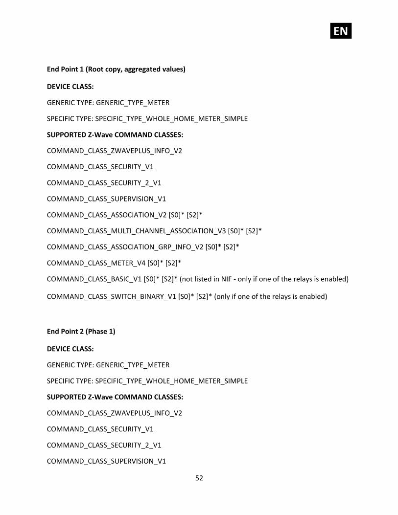
End Point 1 (Root copy, aggregated values)
DEVICE CLASS:
GENERIC TYPE: GENERIC_TYPE_METER
SPECIFIC TYPE: SPECIFIC_TYPE_WHOLE_HOME_METER_SIMPLE
SUPPORTED Z-Wave COMMAND CLASSES:
COMMAND_CLASS_ZWAVEPLUS_INFO_V2
COMMAND_CLASS_SECURITY_V1
COMMAND_CLASS_SECURITY_2_V1
COMMAND_CLASS_SUPERVISION_V1
COMMAND_CLASS_ASSOCIATION_V2 [S0]* [S2]*
COMMAND_CLASS_MULTI_CHANNEL_ASSOCIATION_V3 [S0]* [S2]*
COMMAND_CLASS_ASSOCIATION_GRP_INFO_V2 [S0]* [S2]*
COMMAND_CLASS_METER_V4 [S0]* [S2]*
COMMAND_CLASS_BASIC_V1 [S0]* [S2]* (not listed in NIF - only if one of the relays is enabled)
COMMAND_CLASS_SWITCH_BINARY_V1 [S0]* [S2]* (only if one of the relays is enabled)
End Point 2 (Phase 1)
DEVICE CLASS:
GENERIC TYPE: GENERIC_TYPE_METER
SPECIFIC TYPE: SPECIFIC_TYPE_WHOLE_HOME_METER_SIMPLE
SUPPORTED Z-Wave COMMAND CLASSES:
COMMAND_CLASS_ZWAVEPLUS_INFO_V2
COMMAND_CLASS_SECURITY_V1
COMMAND_CLASS_SECURITY_2_V1
COMMAND_CLASS_SUPERVISION_V1
EN.
53
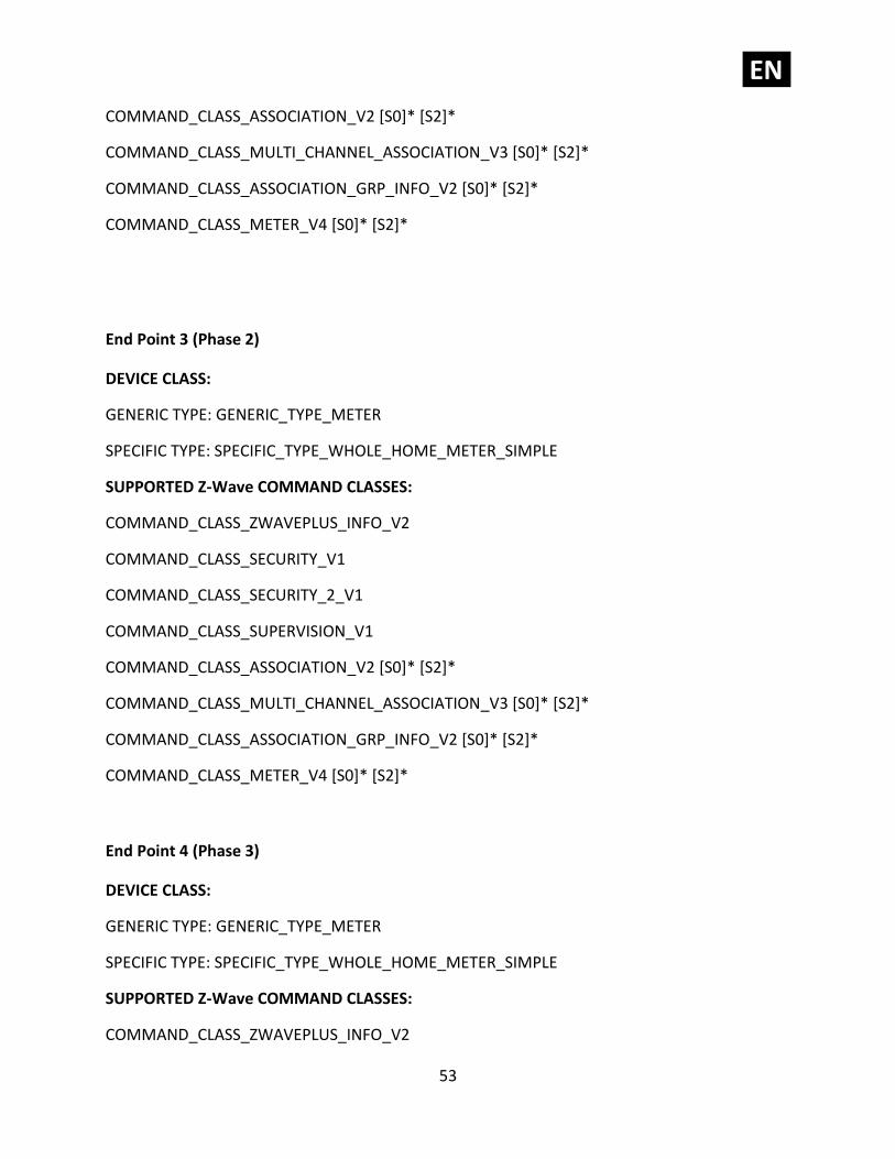
COMMAND_CLASS_ASSOCIATION_V2 [S0]* [S2]*
COMMAND_CLASS_MULTI_CHANNEL_ASSOCIATION_V3 [S0]* [S2]*
COMMAND_CLASS_ASSOCIATION_GRP_INFO_V2 [S0]* [S2]*
COMMAND_CLASS_METER_V4 [S0]* [S2]*
End Point 3 (Phase 2)
DEVICE CLASS:
GENERIC TYPE: GENERIC_TYPE_METER
SPECIFIC TYPE: SPECIFIC_TYPE_WHOLE_HOME_METER_SIMPLE
SUPPORTED Z-Wave COMMAND CLASSES:
COMMAND_CLASS_ZWAVEPLUS_INFO_V2
COMMAND_CLASS_SECURITY_V1
COMMAND_CLASS_SECURITY_2_V1
COMMAND_CLASS_SUPERVISION_V1
COMMAND_CLASS_ASSOCIATION_V2 [S0]* [S2]*
COMMAND_CLASS_MULTI_CHANNEL_ASSOCIATION_V3 [S0]* [S2]*
COMMAND_CLASS_ASSOCIATION_GRP_INFO_V2 [S0]* [S2]*
COMMAND_CLASS_METER_V4 [S0]* [S2]*
End Point 4 (Phase 3)
DEVICE CLASS:
GENERIC TYPE: GENERIC_TYPE_METER
SPECIFIC TYPE: SPECIFIC_TYPE_WHOLE_HOME_METER_SIMPLE
SUPPORTED Z-Wave COMMAND CLASSES:
COMMAND_CLASS_ZWAVEPLUS_INFO_V2
EN.
54
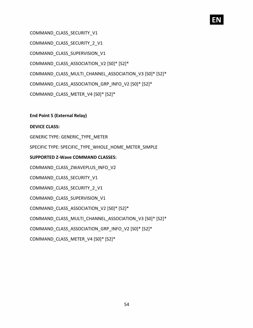
COMMAND_CLASS_SECURITY_V1
COMMAND_CLASS_SECURITY_2_V1
COMMAND_CLASS_SUPERVISION_V1
COMMAND_CLASS_ASSOCIATION_V2 [S0]* [S2]*
COMMAND_CLASS_MULTI_CHANNEL_ASSOCIATION_V3 [S0]* [S2]*
COMMAND_CLASS_ASSOCIATION_GRP_INFO_V2 [S0]* [S2]*
COMMAND_CLASS_METER_V4 [S0]* [S2]*
End Point 5 (External Relay)
DEVICE CLASS:
GENERIC TYPE: GENERIC_TYPE_METER
SPECIFIC TYPE: SPECIFIC_TYPE_WHOLE_HOME_METER_SIMPLE
SUPPORTED Z-Wave COMMAND CLASSES:
COMMAND_CLASS_ZWAVEPLUS_INFO_V2
COMMAND_CLASS_SECURITY_V1
COMMAND_CLASS_SECURITY_2_V1
COMMAND_CLASS_SUPERVISION_V1
COMMAND_CLASS_ASSOCIATION_V2 [S0]* [S2]*
COMMAND_CLASS_MULTI_CHANNEL_ASSOCIATION_V3 [S0]* [S2]*
COMMAND_CLASS_ASSOCIATION_GRP_INFO_V2 [S0]* [S2]*
COMMAND_CLASS_METER_V4 [S0]* [S2]*
EN.
55
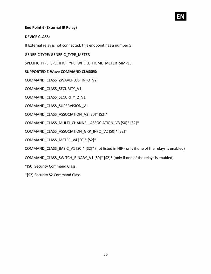
End Point 6 (External IR Relay)
DEVICE CLASS:
If External relay is not connected, this endpoint has a number 5
GENERIC TYPE: GENERIC_TYPE_METER
SPECIFIC TYPE: SPECIFIC_TYPE_WHOLE_HOME_METER_SIMPLE
SUPPORTED Z-Wave COMMAND CLASSES:
COMMAND_CLASS_ZWAVEPLUS_INFO_V2
COMMAND_CLASS_SECURITY_V1
COMMAND_CLASS_SECURITY_2_V1
COMMAND_CLASS_SUPERVISION_V1
COMMAND_CLASS_ASSOCIATION_V2 [S0]* [S2]*
COMMAND_CLASS_MULTI_CHANNEL_ASSOCIATION_V3 [S0]* [S2]*
COMMAND_CLASS_ASSOCIATION_GRP_INFO_V2 [S0]* [S2]*
COMMAND_CLASS_METER_V4 [S0]* [S2]*
COMMAND_CLASS_BASIC_V1 [S0]* [S2]* (not listed in NIF - only if one of the relays is enabled)
COMMAND_CLASS_SWITCH_BINARY_V1 [S0]* [S2]* (only if one of the relays is enabled)
*[S0] Security Command Class
*[S2] Security S2 Command Class
EN.
56
NOTE:
* Command classes on endpoints are supported securely only if the device is added to a Z-Wave network as secure.
NOTE:
• Endpoints are shown/hidden by Parameter No. 100
• The relays will be turned ON or OFF after receiving the BASIC_SET command.
• To be turned ON: [Command Class Basic, Basic Set, Basic Value = 0x01~0x63; FF]
• To be turned OFF: [Command Class Basic, Basic Set, Basic Value = 0x00]
• BASIC SET/GET on root device is mapped to basic set/get of both endpoints.
COMMAND_CLASS_METER_V1
• Default values: o Rate Type = 1 (Import) o Scale = 0 (W)
This Security Enabled Z-Wave Plus Product can be included and operated in any Z-Wave network with other Z-Wave certified devices from any other manufacturers and product categories. All constantly powered nodes in the same network will act as repeaters regardless of the vendor in order to increase reliability of the network.
EN.
57
16. Z-Wave Security
Qubino Smart Meter supports the latest Security 2 feature. Security S2 is handled by the Strong AES 128 Encryption protocol, which means that the S2 makes Z-Wave the most secure IoT (Internet of Things) security platform out there. In order to fully utilize the product and its SECURITY 2 feature, a Security Enabled Z-Wave gateway (hub) must be used. Authenticated Control
• Out-Of-Band Device Specific Key for inclusion
• May be used by most implementations Also supports: Security S2 Unauthenticated, Security S0 and Unsecure inclusion. IMPORTANT: When adding the Smart Meter to a Z-Wave network with a controller supporting
Security 2 (S2), the Z-Wave Device Specific Key (DSK) is required. The unique DSK code is
printed on the side label of the product and a copy is inserted in the packaging, which must not
be lost. Do not remove the DSK from the product. As a backup measure, please use the label in
the packaging to record the location where the product has been installed.
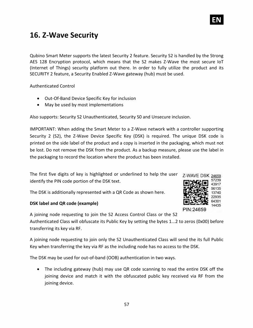
The first five digits of key is highlighted or underlined to help the user
identify the PIN code portion of the DSK text.
The DSK is additionally represented with a QR Code as shown here.
DSK label and QR code (example)
A joining node requesting to join the S2 Access Control Class or the S2
Authenticated Class will obfuscate its Public Key by setting the bytes 1...2 to zeros (0x00) before
transferring its key via RF.
A joining node requesting to join only the S2 Unauthenticated Class will send the its full Public
Key when transferring the key via RF as the including node has no access to the DSK.
The DSK may be used for out-of-band (OOB) authentication in two ways.
• The including gateway (hub) may use QR code scanning to read the entire DSK off the
joining device and match it with the obfuscated public key received via RF from the
joining device.
EN.
58
• Else the including gateway (hub) will ask the user to enter a 5 digits PIN code (the 5 first
digits of the DSK label) in order to substitute the obfuscated bytes of the joining node’s
Public Key. The including gateway (hub) may additionally ask the user to visually validate
that the rest of the DSK with the Public Key received via RF.
17. Important Disclaimer
Z-Wave wireless communication is not always 100% reliable. This device should not be used in situations in which life and/or valuables are solely dependent on its functioning. If the device is not recognized by your gateway (hub) or shows up incorrectly, you may need to change the device type manually and make sure your gateway (hub) supports multi-channel devices. Contact us for help before returning the device: http://qubino.com/support/#email
18. Warning
Do not dispose of electrical appliances as unsorted municipal waste, use separate collection facilities. Contact your local government for information regarding the collection systems available. If electrical appliances are disposed of in landfills or dumps, hazardous substances can leak into the groundwater and get into the food chain, damaging your health and well-being. When replacing old appliances with new ones, the retailer is legally obligated to take back your old appliance for disposal free of charge.
19. Regulations
Legal Notice
This user manual is subject to change and improvement without notice. GOAP d.o.o. Nova Gorica reserves all rights to revise and update all documentation without any obligation to notify any individual or entity.
Declaration of Conformity
Qubino 3-Phase Smart Meter device is in compliance with the essential requirements and other relevant provisions of the Low voltage (LVD) Directive (2014/35/EU), Electromagnetic Compatibility (EMC) Directive (2014/30/EU), Radio Equipment Directive (2014/53/EU), Directive RoHS 2 (2011/65/EU) and Directive ErP (2009/125/EC).
EN.
59
WEEE
According to the WEEE (Waste electrical and electronic equipment) Directive, do not dispose of this product as household waste or commercial waste. Waste electrical and electronic equipment should be appropriately collected and recycled as required by practices established for your country. For information on recycling of this product, please contact your local authorities, your household waste disposal service or the shop where you purchased the product.
NOTE: User manual is valid for device with the S1 (SW version is part of P/N)!
Example: P/N: ZMNHXDx H1S1P2
GOAP d.o.o. Nova Gorica
Ulica Klementa Juga 007, 5250 Solkan, Slovenia
E-mail: [email protected]
Tel: +386 5 335 95 00
Web: www.qubino.com
Date: 19.04.2019; V 3.4
DON’T MISS OTHER INVENTIONS FROM QUBINO– CLICK HERE AND CHECK OUT QUBINO’S
COMPLETE PORTFOLIO