Embed Size (px)
Citation preview
Montageanleitung
Mounting Instructions
Instructions de montage
Instrucciones para el montaje
Istruzioni per il montaggio
EDK94AYAB..øn
Ä..ønä
9400
E94AYAB - SM100
Sicherheitsmodul
Safety moduleModule de sécurité
Módulo de seguridadModulo di sicurezza
L-force Drives
read_GG_DE-S100 B Pos
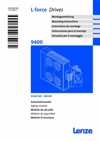
Lesen Sie zuerst diese Anleitung und die Dokumentation zum Grundgerät,bevor Sie mit den Arbeiten beginnen!Beachten Sie die enthaltenen Sicherheitshinweise.
Please read these instructions and the documentation of the standarddevice before you start working!Observe the safety instructions given therein!
Lire le présent fascicule et la documentation relative à l’appareil de baseavant toute manipulation de l’équipement !Respecter les consignes de sécurité fournies.
Lea estas instrucciones y la documentación del equipo básico antes deempezar a trabajar.Observe las instrucciones de seguridad indicadas.
Prima di usare l’apparecchiatura, leggere le istruzioni contenute in questomanuale e la documentazione del modulo asse.Osservare le note di sicurezza.
read_GG_DE-S100 B Pos
SSP94SM112
EDK94AYAB DE/EN/FR/ES/IT 2.04
M5Lieferumfang-DUMMY_NUM_Reset
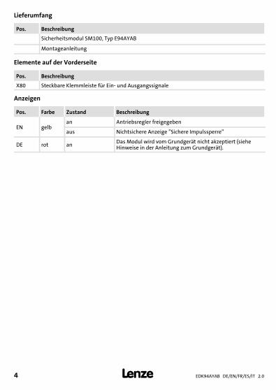
Lieferumfang
Pos. Beschreibung
Sicherheitsmodul SM100, Typ E94AYAB
Montageanleitung
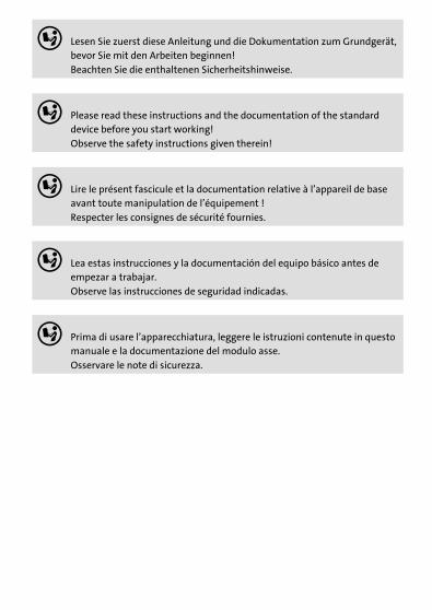
Elemente auf der Vorderseite
Pos. Beschreibung
X80 Steckbare Klemmleiste für Ein- und Ausgangssignale
Anzeigen
Pos. Farbe Zustand Beschreibung
EN gelban Antriebsregler freigegeben
aus Nichtsichere Anzeige ”Sichere Impulssperre”
DE rot an Das Modul wird vom Grundgerät nicht akzeptiert (sieheHinweise in der Anleitung zum Grundgerät).
EDK94AYAB DE/EN/FR/ES/IT 2.0 5
M5Lieferumfang-DUMMY_NUM_Reset
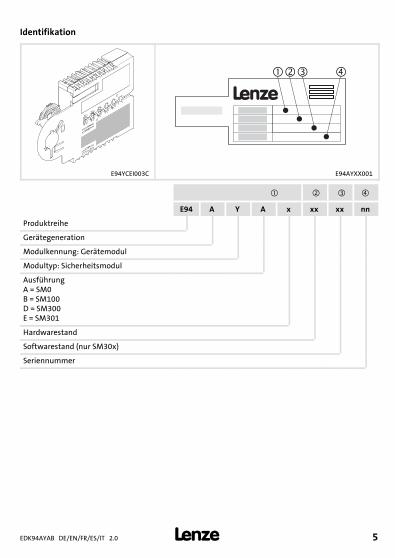
Identifikation
�
L
�� �
E94YCEI003C E94AYXX001
E94 A Y A x xx xx nn
Produktreihe
Gerätegeneration
Modulkennung: Gerätemodul
Modultyp: Sicherheitsmodul
AusführungA = SM0B = SM100D = SM300E = SM301
Hardwarestand
Softwarestand (nur SM30x)
Seriennummer
EDK94AYAB DE/EN/FR/ES/IT 2.06
M5Lieferumfang-DUMMY_NUM_Reset
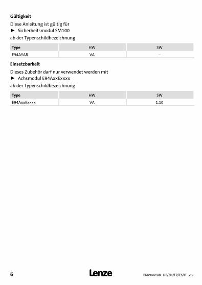
Gültigkeit
Diese Anleitung ist gültig fürƒ Sicherheitsmodul SM100
ab der Typenschildbezeichnung
Type HW SW
E94AYAB VA –
Einsetzbarkeit
Dieses Zubehör darf nur verwendet werden mitƒ Achsmodul E94AxxExxxx
ab der Typenschildbezeichnung
Type HW SW
E94AxxExxxx VA 1.100Abb. 0Tab. 0
SicherheitshinweiseDefinition der verwendeten Hinweise
1
EDK94AYAB DE/EN/FR/ES/IT 2.0 7
H1sic_DE-UL-Warn_Module_Temp_Fuse
1 Sicherheitshinweise
Definition der verwendeten Hinweise
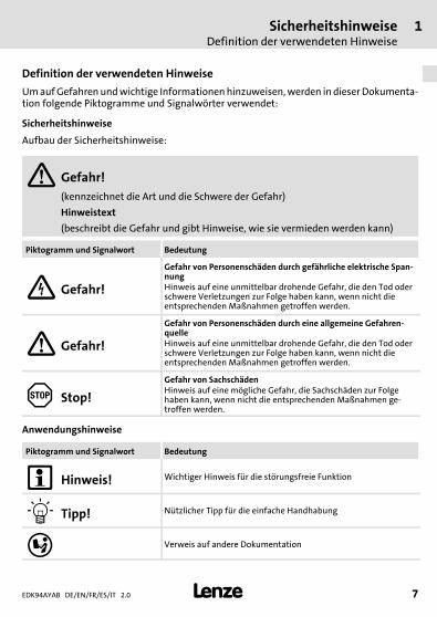
UmaufGefahrenundwichtige Informationenhinzuweisen,werden in dieser Dokumenta-tion folgende Piktogramme und Signalwörter verwendet:
Sicherheitshinweise
Aufbau der Sicherheitshinweise:
Gefahr!(kennzeichnet die Art und die Schwere der Gefahr)
Hinweistext
(beschreibt die Gefahr und gibt Hinweise, wie sie vermieden werden kann)
Piktogramm und Signalwort Bedeutung
Gefahr!
Gefahr von Personenschäden durch gefährliche elektrische Span-nungHinweis auf eine unmittelbar drohende Gefahr, die den Tod oderschwere Verletzungen zur Folge haben kann, wenn nicht dieentsprechenden Maßnahmen getroffen werden.
Gefahr!
Gefahr von Personenschäden durch eine allgemeine Gefahren-quelleHinweis auf eine unmittelbar drohende Gefahr, die den Tod oderschwere Verletzungen zur Folge haben kann, wenn nicht dieentsprechenden Maßnahmen getroffen werden.
Stop!
Gefahr von SachschädenHinweis auf eine mögliche Gefahr, die Sachschäden zur Folgehaben kann, wenn nicht die entsprechenden Maßnahmen ge-troffen werden.
Anwendungshinweise
Piktogramm und Signalwort Bedeutung
Hinweis! Wichtiger Hinweis für die störungsfreie Funktion
Tipp! Nützlicher Tipp für die einfache Handhabung
Verweis auf andere Dokumentation
1 SicherheitshinweiseDefinition der verwendeten Hinweise
EDK94AYAB DE/EN/FR/ES/IT 2.08
H1sic_DE-UL-Warn_Module_Temp_Fuse
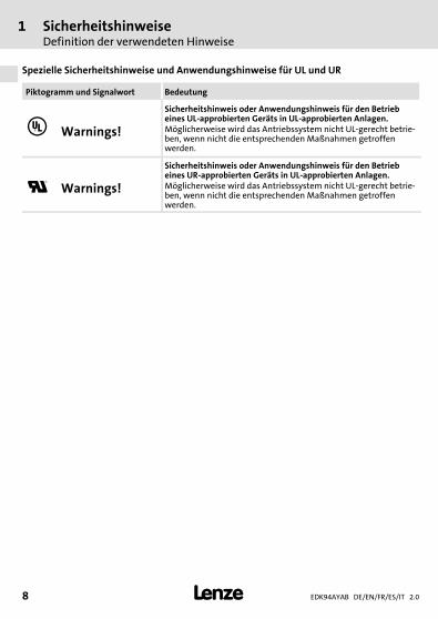
Spezielle Sicherheitshinweise und Anwendungshinweise für UL und UR
Piktogramm und Signalwort Bedeutung
Warnings!
Sicherheitshinweis oder Anwendungshinweis für den Betriebeines UL-approbierten Geräts in UL-approbierten Anlagen.Möglicherweise wird das Antriebssystem nicht UL-gerecht betrie-ben, wenn nicht die entsprechenden Maßnahmen getroffenwerden.
Warnings!
Sicherheitshinweis oder Anwendungshinweis für den Betriebeines UR-approbierten Geräts in UL-approbierten Anlagen.Möglicherweise wird das Antriebssystem nicht UL-gerecht betrie-ben, wenn nicht die entsprechenden Maßnahmen getroffenwerden.
SicherheitshinweiseAllgemeine Sicherheitshinweise
1
EDK94AYAB DE/EN/FR/ES/IT 2.0 9
H1sic_DE-UL-Warn_Module_Temp_Fuse
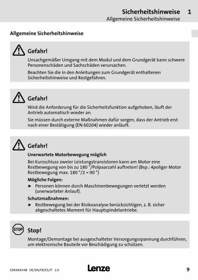
Allgemeine Sicherheitshinweise
Gefahr!Unsachgemäßer Umgang mit demModul und dem Grundgerät kann schwerePersonenschäden und Sachschäden verursachen.
Beachten Sie die in den Anleitungen zum Grundgerät enthaltenenSicherheitshinweise und Restgefahren.
Gefahr!Wird die Anforderung für die Sicherheitsfunktion aufgehoben, läuft derAntrieb automatisch wieder an.
Sie müssen durch externe Maßnahmen dafür sorgen, dass der Antrieb erstnach einer Bestätigung (EN 60204) wieder anläuft.
Gefahr!Unerwartete Motorbewegung möglich
Bei Kurzschluss zweier Leistungstransistoren kann amMotor eineRestbewegung von bis zu 180 °/Polpaarzahl auftreten! (Bsp.: 4poliger Motor Restbewegung max. 180 °/2 = 90 °)
Mögliche Folgen:ƒ Personen können durch Maschinenbewegungen verletzt werden
(unerwarteter Anlauf).
Schutzmaßnahmen:ƒ Restbewegung bei der Risikoanalyse berücksichtigen, z. B. sicher
abgeschaltetes Moment für Hauptspindelantriebe.
Stop!Montage/Demontage bei ausgeschalteter Versorgungsspannung durchführen,um elektronische Bauteile vor Beschädigung zu schützen.
1 SicherheitshinweiseSicherheitshinweise für die Installation nach UL oder UR
EDK94AYAB DE/EN/FR/ES/IT 2.010
H1sic_DE-UL-Warn_Module_Temp_Fuse
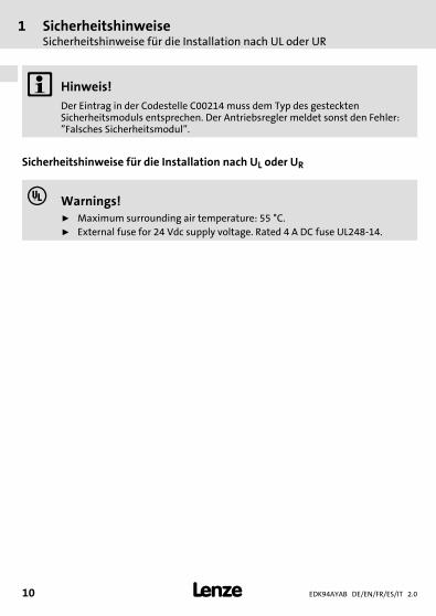
Hinweis!Der Eintrag in der Codestelle C00214 muss dem Typ des gestecktenSicherheitsmoduls entsprechen. Der Antriebsregler meldet sonst den Fehler:”Falsches Sicherheitsmodul”.
Sicherheitshinweise für die Installation nach UL oder UR
Warnings!ƒ Maximum surrounding air temperature: 55 °C.ƒ External fuse for 24 Vdc supply voltage. Rated 4 A DC fuse UL248-14.
Technische Daten 2
EDK94AYAB DE/EN/FR/ES/IT 2.0 11
H1_Daten-BemDat-SM100
2 Technische Daten
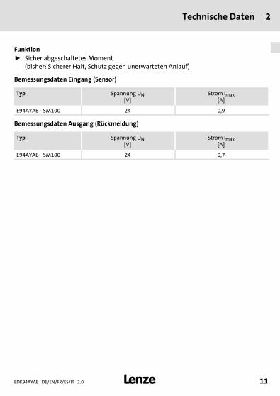
Funktionƒ Sicher abgeschaltetes Moment
(bisher: Sicherer Halt, Schutz gegen unerwarteten Anlauf)
Bemessungsdaten Eingang (Sensor)
Typ Spannung UN[V]
Strom Imax[A]
E94AYAB - SM100 24 0,9
Bemessungsdaten Ausgang (Rückmeldung)
Typ Spannung UN[V]
Strom Imax[A]
E94AYAB - SM100 24 0,7
3 Mechanische InstallationMontage
EDK94AYAB DE/EN/FR/ES/IT 2.012
H1_MechINS-KommModul Demontage
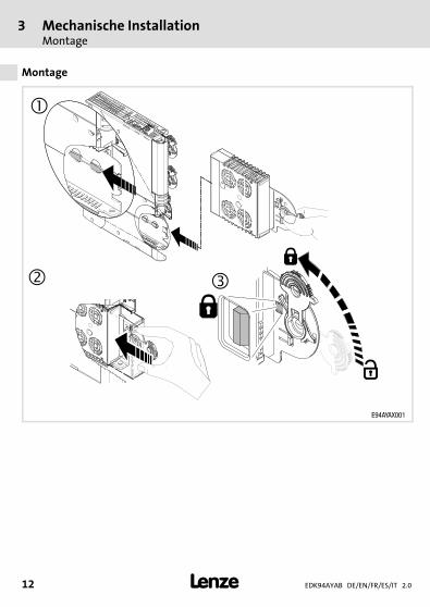
3 Mechanische Installation
Montage
E94AYAX001

Mechanische InstallationDemontage
3
EDK94AYAB DE/EN/FR/ES/IT 2.0 13
H1_MechINS-KommModul Demontage
Demontage
E94AYCXX001H
4 Elektrische InstallationBlockschaltbild
EDK94AYAB DE/EN/FR/ES/IT 2.014
H1_E_INST----(DUMMYSEITEVOR)---
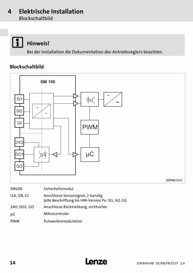
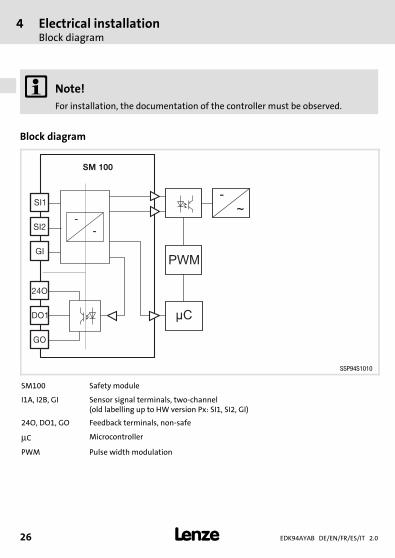
4 Elektrische Installation
Hinweis!Bei der Installation die Dokumentation des Antriebsreglers beachten.
Blockschaltbild
SM 100
SI1
SI2
GI
24O
DO1
GO
PWM
µC
-
~-
-
SSP94S1010
SM100 Sicherheitsmodul
I1A, I2B, GI Anschlüsse Sensorsignal, 2-kanalig(alte Beschriftung bis HW-Version Px: SI1, SI2, GI)
24O, DO1, GO Anschlüsse Rückmeldung, nichtsicher
μC Mikrocontroler
PWM Pulsweitenmodulation
Elektrische InstallationAnschlussdaten
4
EDK94AYAB DE/EN/FR/ES/IT 2.0 15
H1_E_INST----(DUMMYSEITEVOR)---
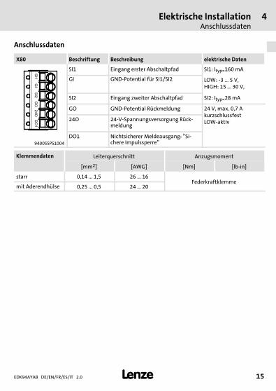
Anschlussdaten
X80 Beschriftung Beschreibung elektrische Daten
SI1 Eingang erster Abschaltpfad SI1: Ityp=160 mA
GI GND-Potential für SI1/SI2 LOW: -3 ... 5 V,HIGH: 15 ... 30 V,
SI2 Eingang zweiter Abschaltpfad SI2: Ityp=28 mA
GO GND-Potential Rückmeldung 24 V, max. 0,7 AkurzschlussfestLOW-aktiv24O 24-V-Spannungsversorgung Rück-
meldung
9400SSPS1004
DO1 Nichtsicherer Meldeausgang: ”Si-chere Impulssperre”
Klemmendaten Leiterquerschnitt Anzugsmoment
[mm2] [AWG] [Nm] [lb-in]
starr 0,14 ... 1,5 26 ... 16Federkraftklemme
mit Aderendhülse 0,25 ... 0,5 24 ... 20
EDK94AYAB DE/EN/FR/ES/IT 2.016
M5Lieferumfang-DUMMY_NUM_Reset
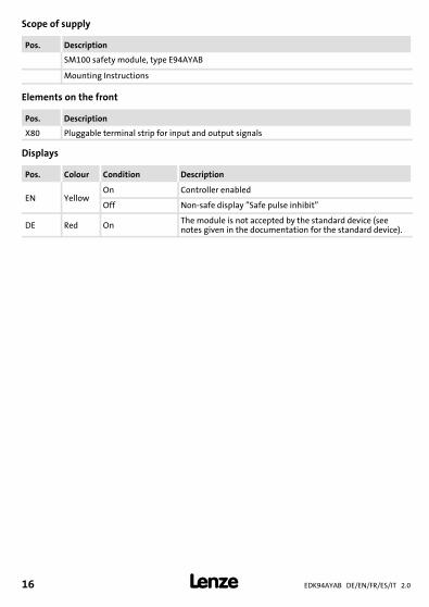
Scope of supply
Pos. Description
SM100 safety module, type E94AYAB
Mounting Instructions
Elements on the front
Pos. Description
X80 Pluggable terminal strip for input and output signals
Displays
Pos. Colour Condition Description
EN YellowOn Controller enabled
Off Non-safe display ”Safe pulse inhibit”
DE Red On The module is not accepted by the standard device (seenotes given in the documentation for the standard device).
EDK94AYAB DE/EN/FR/ES/IT 2.0 17
M5Lieferumfang-DUMMY_NUM_Reset
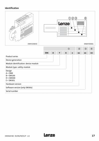
Identification
�
L
�� �
E94YCEI003C E94AYXX001
E94 A Y A x xx xx nn
Product series
Device generation
Module identification: device module
Module type: safety module
DesignA = SM0B = SM100D = SM300E = SM301
Hardware version
Software version (only SM30x)
Serial number
EDK94AYAB DE/EN/FR/ES/IT 2.018
M5Lieferumfang-DUMMY_NUM_Reset
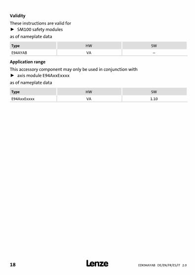
Validity
These instructions are valid forƒ SM100 safety modules
as of nameplate data
Type HW SW
E94AYAB VA –
Application range
This accessory component may only be used in conjunction withƒ axis module E94AxxExxxx
as of nameplate data
Type HW SW
E94AxxExxxx VA 1.100Fig. 0Tab. 0
Safety instructionsDefinition of notes used
1
EDK94AYAB DE/EN/FR/ES/IT 2.0 19
H1sic_EN-UL-Warn_Module_Temp_Fuse
1 Safety instructions
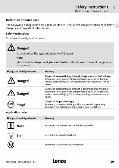
Definition of notes used
The following pictographs and signal words are used in this documentation to indicatedangers and important information:
Safety instructions
Structure of safety instructions:
Danger!(characterises the type and severity of danger)
Note
(describes the danger and gives information about how to prevent dangeroussituations)
Pictograph and signal word Meaning
Danger!Danger of personal injury through dangerous electrical voltage.Reference to an imminent danger that may result in death orserious personal injury if the corresponding measures are nottaken.
Danger!Danger of personal injury through a general source of danger.Reference to an imminent danger that may result in death orserious personal injury if the corresponding measures are nottaken.
Stop!Danger of property damage.Reference to a possible danger that may result in propertydamage if the corresponding measures are not taken.
Application notes
Pictograph and signal word Meaning
Note! Important note to ensure troublefree operation
Tip! Useful tip for simple handling
Reference to another documentation
1 Safety instructionsDefinition of notes used
EDK94AYAB DE/EN/FR/ES/IT 2.020
H1sic_EN-UL-Warn_Module_Temp_Fuse
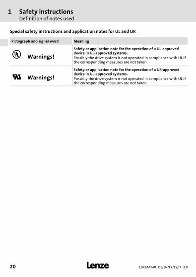
Special safety instructions and application notes for UL and UR
Pictograph and signal word Meaning
Warnings!Safety or application note for the operation of a UL-approveddevice in UL-approved systems.Possibly the drive system is not operated in compliance with UL ifthe corresponding measures are not taken.
Warnings!Safety or application note for the operation of a UR-approveddevice in UL-approved systems.Possibly the drive system is not operated in compliance with UL ifthe corresponding measures are not taken.
Safety instructionsGeneral safety information
1
EDK94AYAB DE/EN/FR/ES/IT 2.0 21
H1sic_EN-UL-Warn_Module_Temp_Fuse
General safety information
Danger!Improper use of the module and the standard device may cause serious injuryand property damage.
Observe the chapters ”Safety instructions” and ”Residual hazards” containedin the instructions for the standard device.
Danger!If the request for the safety function is cancelled, the drive will restartautomatically.
You must provide external measures which ensure that the drive only restartsafter a confirmation (EN 60204).
Danger!Unexpected motor rotation possible
In the event of a short-circuit between two power transistors, a residualmovement of the motor of up to 180 °/number of pole pairs may occur!(Example.: 4-pole motor residual movement max. 180 °/2 = 90 °)
Possible consequences:ƒ People may be injured by the machine movements (unexpected start-up).
Protective measures:ƒ The residual movement must be considered in the risk analysis, e.g. safe
torque off for main spindle drives.
Stop!Before mounting/dismounting, switch off the supply voltage to preventelectronic modules from damage.
1 Safety instructionsSafety instructions for the installation according to UL or UR
EDK94AYAB DE/EN/FR/ES/IT 2.022
H1sic_EN-UL-Warn_Module_Temp_Fuse
Note!The entry under code C00214 must correspond to the type of the safetymodule plugged on. Otherwise, the controller signals the error: ”Wrong safetymodule”.
Safety instructions for the installation according to UL or UR
Warnings!ƒ Maximum surrounding air temperature: 55 °C.ƒ External fuse for 24 Vdc supply voltage. Rated 4 A DC fuse UL248-14.
Technical data 2
EDK94AYAB DE/EN/FR/ES/IT 2.0 23
H1_Daten-BemDat-SM100
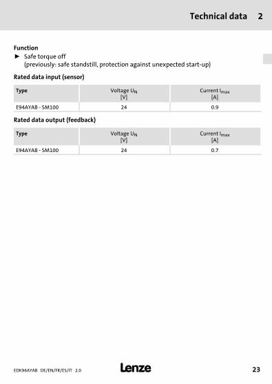
2 Technical data
Functionƒ Safe torque off
(previously: safe standstill, protection against unexpected start-up)
Rated data input (sensor)
Type Voltage UN[V]
Current Imax[A]
E94AYAB - SM100 24 0.9
Rated data output (feedback)
Type Voltage UN[V]
Current Imax[A]
E94AYAB - SM100 24 0.7

3 Mechanical installationMounting
EDK94AYAB DE/EN/FR/ES/IT 2.024
H1_MechINS-KommModul Demontage
3 Mechanical installation
Mounting
E94AYAX001
Mechanical installationDismounting
3
EDK94AYAB DE/EN/FR/ES/IT 2.0 25
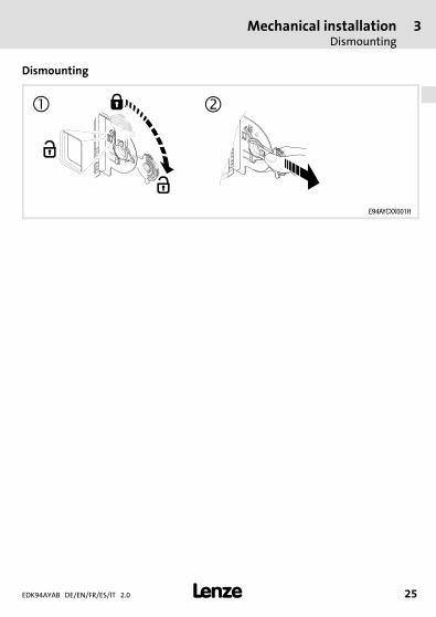
H1_MechINS-KommModul Demontage
Dismounting
E94AYCXX001H
4 Electrical installationBlock diagram
EDK94AYAB DE/EN/FR/ES/IT 2.026
H1_E_INST----(DUMMYSEITEVOR)---
4 Electrical installation
Note!For installation, the documentation of the controller must be observed.
Block diagram
SM 100
SI1
SI2
GI
24O
DO1
GO
PWM
µC
-
~-
-
SSP94S1010
SM100 Safety module
I1A, I2B, GI Sensor signal terminals, two-channel(old labelling up to HW version Px: SI1, SI2, GI)
24O, DO1, GO Feedback terminals, non-safe
μC Microcontroller
PWM Pulse width modulation
Electrical installationConnection data
4
EDK94AYAB DE/EN/FR/ES/IT 2.0 27
H1_E_INST----(DUMMYSEITEVOR)---
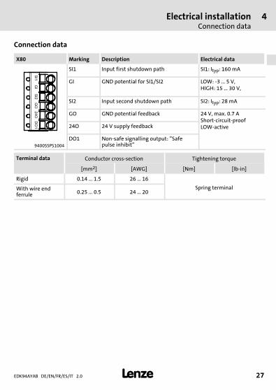
Connection data
X80 Marking Description Electrical data
SI1 Input first shutdown path SI1: Ityp: 160 mA
GI GND potential for SI1/SI2 LOW: -3 ... 5 V,HIGH: 15 ... 30 V,
SI2 Input second shutdown path SI2: Ityp: 28 mA
GO GND potential feedback 24 V, max. 0.7 AShort-circuit-proofLOW-active24O 24 V supply feedback
9400SSPS1004
DO1 Non-safe signalling output: ”Safepulse inhibit”
Terminal data Conductor cross-section Tightening torque
[mm2] [AWG] [Nm] [lb-in]
Rigid 0.14 ... 1.5 26 ... 16
Spring terminalWith wire endferrule 0.25 ... 0.5 24 ... 20
EDK94AYAB DE/EN/FR/ES/IT 2.028
M5Lieferumfang-DUMMY_NUM_Reset
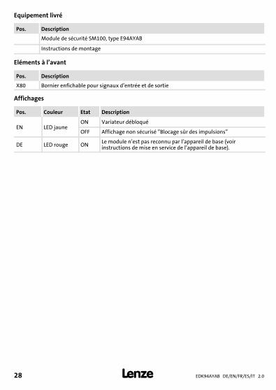
Equipement livré
Pos. Description
Module de sécurité SM100, type E94AYAB
Instructions de montage
Eléments à l’avant
Pos. Description
X80 Bornier enfichable pour signaux d’entrée et de sortie
Affichages
Pos. Couleur Etat Description
EN LED jauneON Variateur débloqué
OFF Affichage non sécurisé ”Blocage sûr des impulsions”
DE LED rouge ON Le module n’est pas reconnu par l’appareil de base (voirinstructions de mise en service de l’appareil de base).
EDK94AYAB DE/EN/FR/ES/IT 2.0 29
M5Lieferumfang-DUMMY_NUM_Reset
Identification
�
L
�� �
E94YCEI003C E94AYXX001
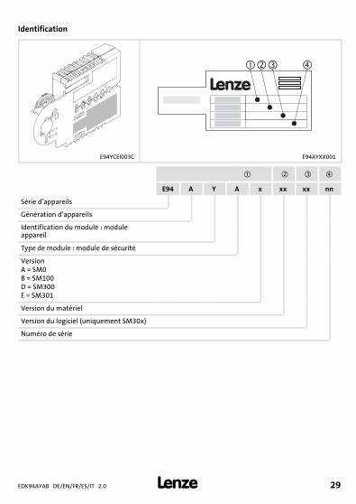
E94 A Y A x xx xx nn
Série d’appareils
Génération d’appareils
Identification du module : moduleappareil
Type de module : module de sécurité
VersionA = SM0B = SM100D = SM300E = SM301
Version du matériel
Version du logiciel (uniquement SM30x)
Numéro de série
EDK94AYAB DE/EN/FR/ES/IT 2.030
M5Lieferumfang-DUMMY_NUM_Reset
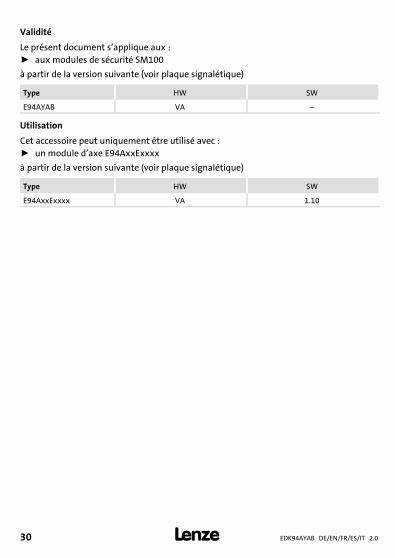
Validité
Le présent document s’applique aux :ƒ aux modules de sécurité SM100
à partir de la version suivante (voir plaque signalétique)
Type HW SW
E94AYAB VA –
Utilisation
Cet accessoire peut uniquement être utilisé avec :ƒ unmodule d’axe E94AxxExxxx
à partir de la version suivante (voir plaque signalétique)
Type HW SW
E94AxxExxxx VA 1.100Fig. 0Tab. 0
Consignes de sécuritéDéfinition des conventions utilisées
1
EDK94AYAB DE/EN/FR/ES/IT 2.0 31
H1sic_FR-UL-Warn_Module_Temp_Fuse
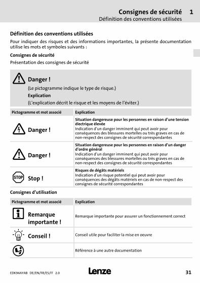
1 Consignes de sécurité
Définition des conventions utiliséesPour indiquer des risques et des informations importantes, la présente documentationutilise les mots et symboles suivants :
Consignes de sécurité
Présentation des consignes de sécurité
Danger !(Le pictogramme indique le type de risque.)
Explication
(L’explication décrit le risque et les moyens de l’éviter.)
Pictogramme et mot associé Explication
Danger !
Situation dangereuse pour les personnes en raison d’une tensionélectrique élevéeIndication d’un danger imminent qui peut avoir pourconséquences des blessures mortelles ou très graves en cas denon-respect des consignes de sécurité correspondantes
Danger !
Situation dangereuse pour les personnes en raison d’un dangerd’ordre généralIndication d’un danger imminent qui peut avoir pourconséquences des blessures mortelles ou très graves en cas denon-respect des consignes de sécurité correspondantes
Stop !Risques de dégâts matérielsIndication d’un risque potentiel qui peut avoir pourconséquences des dégâts matériels en cas de non-respect desconsignes de sécurité correspondantes
Consignes d’utilisation
Pictogramme et mot associé Explication
Remarqueimportante !
Remarque importante pour assurer un fonctionnement correct
Conseil ! Conseil utile pour faciliter la mise en oeuvre
Référence à une autre documentation
1 Consignes de sécuritéDéfinition des conventions utilisées
EDK94AYAB DE/EN/FR/ES/IT 2.032
H1sic_FR-UL-Warn_Module_Temp_Fuse
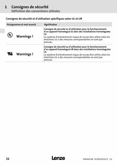
Consignes de sécurité et d’utilisation spécifiques selon UL et UR
Pictogramme et mot associé Signification
Warnings !
Consigne de sécurité ou d’utilisation pour le fonctionnementd’un appareil homologué UL dans des installations homologuéesULLe système d’entraînement risque de ne pas être utilisé selon lesdirectives UL si des mesures correspondantes ne sont pasprévues.
Warnings !
Consigne de sécurité ou d’utilisation pour le fonctionnementd’un appareil homologué UR dans des installations homologuéesULLe système d’entraînement risque de ne pas être utilisé selon lesdirectives UL si des mesures correspondantes ne sont pasprévues.
Consignes de sécuritéConsignes générales
1
EDK94AYAB DE/EN/FR/ES/IT 2.0 33
H1sic_FR-UL-Warn_Module_Temp_Fuse
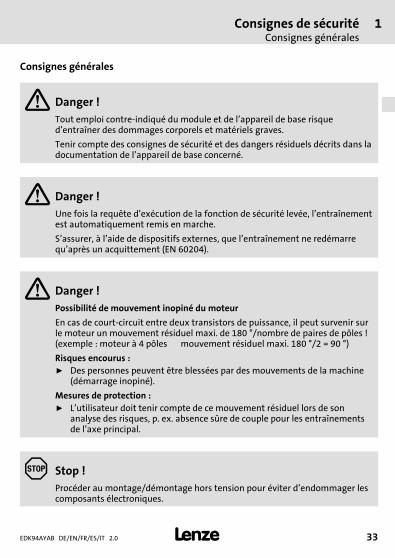
Consignes générales
Danger !Tout emploi contre-indiqué du module et de l’appareil de base risqued’entraîner des dommages corporels et matériels graves.
Tenir compte des consignes de sécurité et des dangers résiduels décrits dans ladocumentation de l’appareil de base concerné.
Danger !Une fois la requête d’exécution de la fonction de sécurité levée, l’entraînementest automatiquement remis en marche.
S’assurer, à l’aide de dispositifs externes, que l’entraînement ne redémarrequ’après un acquittement (EN 60204).
Danger !Possibilité de mouvement inopiné du moteur
En cas de court-circuit entre deux transistors de puissance, il peut survenir surle moteur un mouvement résiduel maxi. de 180 °/nombre de paires de pôles !(exemple : moteur à 4 pôles mouvement résiduel maxi. 180 °/2 = 90 °)
Risques encourus :ƒ Des personnes peuvent être blessées par des mouvements de la machine
(démarrage inopiné).
Mesures de protection :ƒ L’utilisateur doit tenir compte de ce mouvement résiduel lors de son
analyse des risques, p. ex. absence sûre de couple pour les entraînementsde l’axe principal.
Stop !Procéder au montage/démontage hors tension pour éviter d’endommager lescomposants électroniques.
1 Consignes de sécuritéConsignes de sécurité pour l’installation selon UL ou UR
EDK94AYAB DE/EN/FR/ES/IT 2.034
H1sic_FR-UL-Warn_Module_Temp_Fuse
Remarque importante !La saisie en C00214 doit correspondre au type de module de sécurité enfiché,faute de quoi le variateur de vitesse renvoie l’erreur suivante : ”Module desécurité erroné”.
Consignes de sécurité pour l’installation selon UL ou UR
Warnings !ƒ Maximum surrounding air temperature: 55 °C.ƒ External fuse for 24 Vdc supply voltage. Rated 4 A DC fuse UL248-14.
Spécifications techniques 2
EDK94AYAB DE/EN/FR/ES/IT 2.0 35
H1_Daten-BemDat-SM100
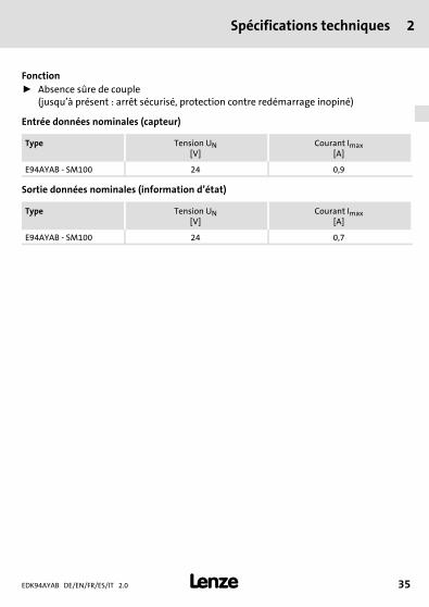
2 Spécifications techniques
Fonctionƒ Absence sûre de couple
(jusqu’à présent : arrêt sécurisé, protection contre redémarrage inopiné)
Entrée données nominales (capteur)
Type Tension UN[V]
Courant Imax[A]
E94AYAB - SM100 24 0,9
Sortie données nominales (information d’état)
Type Tension UN[V]
Courant Imax[A]
E94AYAB - SM100 24 0,7

3 Installation mécaniqueMontage
EDK94AYAB DE/EN/FR/ES/IT 2.036
H1_MechINS-KommModul Demontage
3 Installation mécanique
Montage
E94AYAX001

Installation mécaniqueDémontage
3
EDK94AYAB DE/EN/FR/ES/IT 2.0 37
H1_MechINS-KommModul Demontage
Démontage
E94AYCXX001H
4 Installation électriqueSchéma bloc
EDK94AYAB DE/EN/FR/ES/IT 2.038
H1_E_INST----(DUMMYSEITEVOR)---
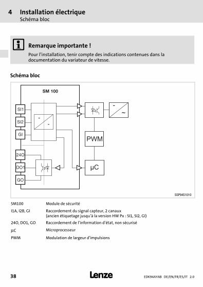
4 Installation électrique
Remarque importante !Pour l’installation, tenir compte des indications contenues dans ladocumentation du variateur de vitesse.
Schéma bloc
SM 100
SI1
SI2
GI
24O
DO1
GO
PWM
µC
-
~-
-
SSP94S1010
SM100 Module de sécurité
I1A, I2B, GI Raccordement du signal capteur, 2 canaux(ancien étiquetage jusqu’à la version HW Px : SI1, SI2, GI)
24O, DO1, GO Raccordement de l’information d’état, non sécurisé
μC Microprocesseur
PWM Modulation de largeur d’impulsions
Installation électriqueSpécifications de raccordement
4
EDK94AYAB DE/EN/FR/ES/IT 2.0 39
H1_E_INST----(DUMMYSEITEVOR)---
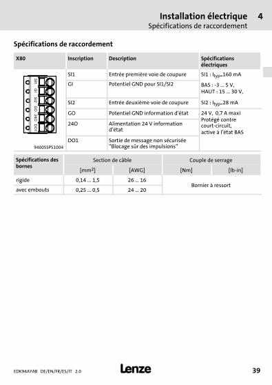
Spécifications de raccordement
X80 Inscription Description Spécificationsélectriques
SI1 Entrée première voie de coupure SI1 : Ityp=160 mA
GI Potentiel GND pour SI1/SI2 BAS : -3 ... 5 V,HAUT : 15 ... 30 V,
SI2 Entrée deuxième voie de coupure SI2 : Ityp=28 mA
GO Potentiel GND information d’état 24 V, 0,7 A maxiProtégé contrecourt-circuit,active à l’état BAS
24O Alimentation 24 V informationd’état
9400SSPS1004
DO1 Sortie de message non sécurisée”Blocage sûr des impulsions”
Spécifications desbornes
Section de câble Couple de serrage
[mm2] [AWG] [Nm] [lb-in]
rigide 0,14 ... 1,5 26 ... 16Bornier à ressort
avec embouts 0,25 ... 0,5 24 ... 20
EDK94AYAB DE/EN/FR/ES/IT 2.040
M5Lieferumfang-DUMMY_NUM_Reset
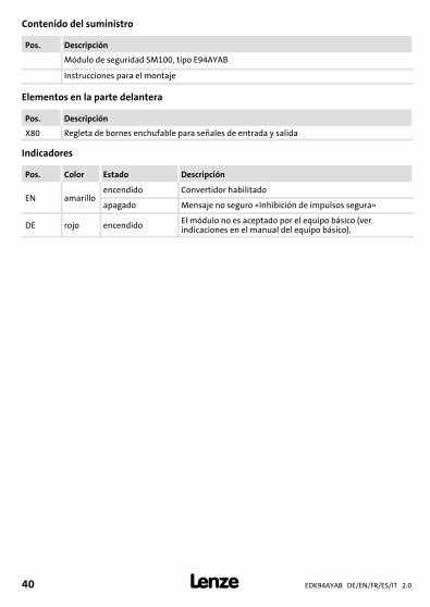
Contenido del suministro
Pos. Descripción
Módulo de seguridad SM100, tipo E94AYAB
Instrucciones para el montaje
Elementos en la parte delantera
Pos. Descripción
X80 Regleta de bornes enchufable para señales de entrada y salida
Indicadores
Pos. Color Estado Descripción
EN amarilloencendido Convertidor habilitado
apagado Mensaje no seguro «Inhibición de impulsos segura»
DE rojo encendido El módulo no es aceptado por el equipo básico (verindicaciones en el manual del equipo básico).

EDK94AYAB DE/EN/FR/ES/IT 2.0 41
M5Lieferumfang-DUMMY_NUM_Reset
Identificación
�
L
�� �
E94YCEI003C E94AYXX001
E94 A Y A x xx xx nn
Serie de producto
Versión del equipo
Identificación del módulo: Módulo deequipo
Tipo de módulo: Módulo de seguridad
EjecuciónA = SM0B = SM100D = SM300E = SM301
Versión de hardware
Versión de software (sólo SM30x)
Número de serie
EDK94AYAB DE/EN/FR/ES/IT 2.042
M5Lieferumfang-DUMMY_NUM_Reset
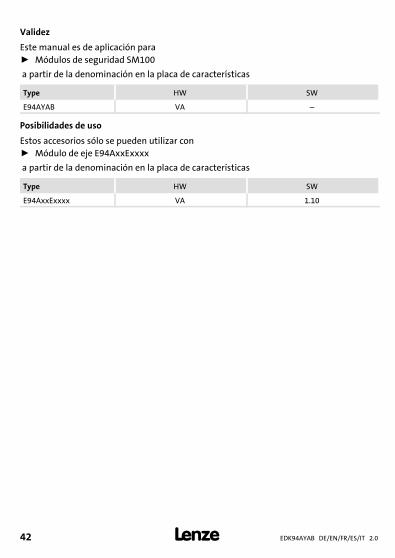
Validez
Este manual es de aplicación paraƒ Módulos de seguridad SM100
a partir de la denominación en la placa de características
Type HW SW
E94AYAB VA –
Posibilidades de uso
Estos accesorios sólo se pueden utilizar conƒ Módulo de eje E94AxxExxxx
a partir de la denominación en la placa de características
Type HW SW
E94AxxExxxx VA 1.100Fig. 0Tab. 0
Instrucciones de seguridadDefinición de las instrucciones utilizadas
1
EDK94AYAB DE/EN/FR/ES/IT 2.0 43
H1sic_ES-UL-Warn_Module_Temp_Fuse
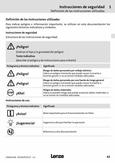
1 Instrucciones de seguridad
Definición de las instrucciones utilizadas
Para indicar peligros e información importante, se utilizan en esta documentación lossiguientes términos indicativos y símbolos:
Instrucciones de seguridad
Estructura de las instrucciones de seguridad:
¡Peligro!(indican el tipo y la gravedad del peligro)
Texto indicativo
(describe el peligro y da instrucciones para evitarlo)
Pictograma y término indicativo Significado
¡Peligro!Riesgo de daños personales por voltaje eléctricoIndica un peligro inminente que puede causar la muerte olesiones graves si no se tomanmedidas adecuadas.
¡Peligro!Riesgo de daños personales por una fuente de riesgo generalIndica un peligro inminente que puede causar la muerte olesiones graves si no se tomanmedidas adecuadas.
¡Alto!Peligro de dañosmaterialesIndica un posible riesgo que puede ocasionar daños materiales sino se toman las medidas adecuadas.
Instrucciones de uso
Pictograma y término indicativo Significado
¡Aviso! Nota importante para el funcionamiento sin fallos
¡Sugerencia! Sugerencia útil para facilitar la operación
Referencia a otra documentación
1 Instrucciones de seguridadDefinición de las instrucciones utilizadas
EDK94AYAB DE/EN/FR/ES/IT 2.044
H1sic_ES-UL-Warn_Module_Temp_Fuse
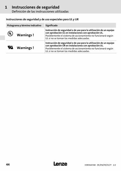
Instrucciones de seguridad y de uso especiales para UL y UR
Pictograma y término indicativo Significado
Warnings !
Instrucción de seguridad o de uso para la utilización de un equipocon aprobación UL en instalaciones con aprobación UL.Posiblemente el sistema de accionamiento no funcionará segúnUL si no se toman las medidas adecuadas.
Warnings !
Instrucción de seguridad o de uso para la utilización de un equipocon aprobación UR en instalaciones con aprobación UL.Posiblemente el sistema de accionamiento no funcionará segúnUL si no se toman las medidas adecuadas.
Instrucciones de seguridadInstrucciones generales de seguridad
1
EDK94AYAB DE/EN/FR/ES/IT 2.0 45
H1sic_ES-UL-Warn_Module_Temp_Fuse
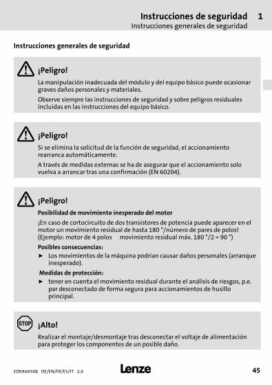
Instrucciones generales de seguridad
¡Peligro!La manipulación inadecuada del módulo y del equipo básico puede ocasionargraves daños personales y materiales.
Observe siempre las instrucciones de seguridad y sobre peligros residualesincluidas en las instrucciones del equipo básico.
¡Peligro!Si se elimina la solicitud de la función de seguridad, el accionamientorearranca automáticamente.
A través de medidas externas se ha de asegurar que el accionamiento solovuelva a arrancar tras una confirmación (EN 60204).
¡Peligro!Posibilidad de movimiento inesperado del motor
¡En caso de cortocircuito de dos transistores de potencia puede aparecer en elmotor un movimiento residual de hasta 180 °/número de pares de polos!(Ejemplo: motor de 4 polos movimiento residual máx. 180 °/2 = 90 °)
Posibles consecuencias:ƒ Losmovimientos de la máquina podrían causar daños personales (arranque
inesperado).
Medidas de protección:ƒ tener en cuenta el movimiento residual durante el análisis de riesgos, p.e.
par desconectado de forma segura para accionamientos de husilloprincipal.
¡Alto!Realizar el montaje/desmontaje tras desconectar el voltaje de alimentaciónpara proteger los componentes de un posible daño.
1 Instrucciones de seguridadInstrucciones de seguridad para la instalación según UL o UR
EDK94AYAB DE/EN/FR/ES/IT 2.046
H1sic_ES-UL-Warn_Module_Temp_Fuse
¡Aviso!La entrada en el código C00214 debe corresponder al tipo del módulo deseguridad conectado. En caso contrario el convertidor emitirá el error: ”Módulode seguridad equivocado”.
Instrucciones de seguridad para la instalación según UL o UR
Warnings !ƒ Maximum surrounding air temperature: 55 °C.ƒ External fuse for 24 Vdc supply voltage. Rated 4 A DC fuse UL248-14.
Datos técnicos 2
EDK94AYAB DE/EN/FR/ES/IT 2.0 47
H1_Daten-BemDat-SM100
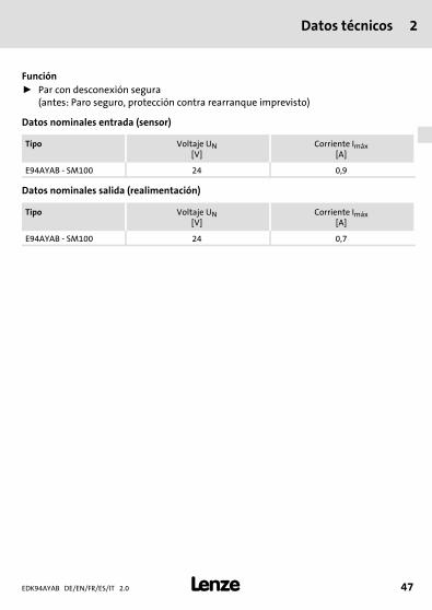
2 Datos técnicos
Funciónƒ Par con desconexión segura
(antes: Paro seguro, protección contra rearranque imprevisto)
Datos nominales entrada (sensor)
Tipo Voltaje UN[V]
Corriente Imáx[A]
E94AYAB - SM100 24 0,9
Datos nominales salida (realimentación)
Tipo Voltaje UN[V]
Corriente Imáx[A]
E94AYAB - SM100 24 0,7

3 Instalación mecánicaMontaje
EDK94AYAB DE/EN/FR/ES/IT 2.048
H1_MechINS-KommModul Demontage
3 Instalación mecánica
Montaje
E94AYAX001
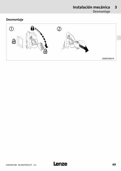
Instalación mecánicaDesmontaje
3
EDK94AYAB DE/EN/FR/ES/IT 2.0 49
H1_MechINS-KommModul Demontage
Desmontaje
E94AYCXX001H
4 Instalación eléctricaDiagrama en bloque
EDK94AYAB DE/EN/FR/ES/IT 2.050
H1_E_INST----(DUMMYSEITEVOR)---
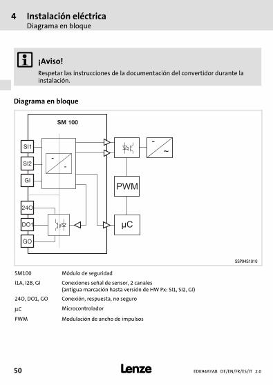
4 Instalación eléctrica
¡Aviso!Respetar las instrucciones de la documentación del convertidor durante lainstalación.
Diagrama en bloque
SM 100
SI1
SI2
GI
24O
DO1
GO
PWM
µC
-
~-
-
SSP94S1010
SM100 Módulo de seguridad
I1A, I2B, GI Conexiones señal de sensor, 2 canales(antigua marcación hasta versión de HW Px: SI1, SI2, GI)
24O, DO1, GO Conexión, respuesta, no seguro
μC Microcontrolador
PWM Modulación de ancho de impulsos
Instalación eléctricaDatos de conexión
4
EDK94AYAB DE/EN/FR/ES/IT 2.0 51
H1_E_INST----(DUMMYSEITEVOR)---
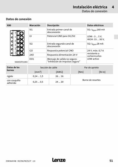
Datos de conexión
X80 Marcación Descripción Datos eléctricos
SI1 Entrada primer canal dedesconexión
SI1: Itipo=160 mA
GI Potencial GND para SI1/SI2 LOW: -3 ... 5 V,HIGH: 15 ... 30 V,
SI2 Entrada segundo canal dedesconexión
SI2: Itipo=28 mA
GO Respuesta potencial GND 24 V, máx. 0,7 Aresistente acortocircuitosLOW activo
24O Respuesta alimentación 24-V
9400SSPS1004
DO1 Mensaje de salida no seguro:”Inhibición de impulsos segura”
Datos de losbornes
Sección de cable Par de apriete
[mm2] [AWG] [Nm] [lb-in]
rígido 0,14 ... 1,5 26 ... 16
Borne de resortescon casquilloadherido 0,25 ... 0,5 24 ... 20
EDK94AYAB DE/EN/FR/ES/IT 2.052
M5Lieferumfang-DUMMY_NUM_Reset
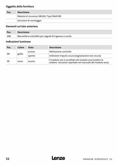
Oggetto della fornitura
Pos. Descrizione
Modulo di sicurezza SM100, Tipo E94AYAB
Istruzioni di montaggio
Elementi sul lato anteriore
Pos. Descrizione
X80 Morsettiera estraibile per segnali di ingresso e uscita
Indicazioni luminose
Pos. Colore Stato Descrizione
EN gialloacceso Abilitazione controllo
spento Inibizione impulsi sicura (segnalazione non sicura)
DE rosso acceso Il modulo non è accettato dal modulo asse (vedere lerelative istruzioni riportate nel manuale del modulo asse).
EDK94AYAB DE/EN/FR/ES/IT 2.0 53
M5Lieferumfang-DUMMY_NUM_Reset
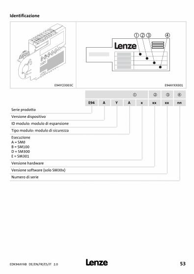
Identificazione
�
L
�� �
E94YCEI003C E94AYXX001
E94 A Y A x xx xx nn
Serie prodotto
Versione dispositivo
ID modulo: modulo di espansione
Tipo modulo: modulo di sicurezza
EsecuzioneA = SM0B = SM100D = SM300E = SM301
Versione hardware
Versione software (solo SM30x)
Numero di serie
EDK94AYAB DE/EN/FR/ES/IT 2.054
M5Lieferumfang-DUMMY_NUM_Reset
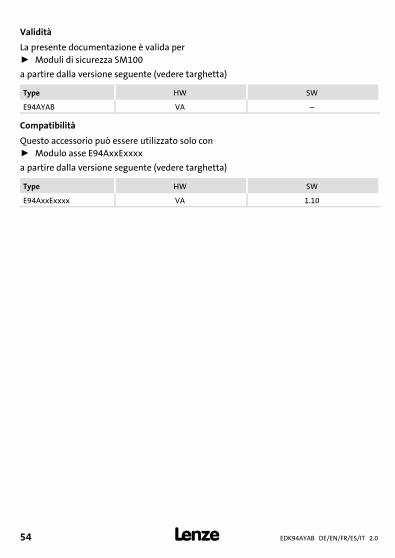
Validità
La presente documentazione è valida perƒ Moduli di sicurezza SM100
a partire dalla versione seguente (vedere targhetta)
Type HW SW
E94AYAB VA –
Compatibilità
Questo accessorio può essere utilizzato solo conƒ Modulo asse E94AxxExxxx
a partire dalla versione seguente (vedere targhetta)
Type HW SW
E94AxxExxxx VA 1.100Fig. 0Tab. 0
Informazioni sulla sicurezzaSimbologia delle note e avvertenze utilizzate
1
EDK94AYAB DE/EN/FR/ES/IT 2.0 55
H1sic_IT-UL-Warn_Module_Temp_Fuse
1 Informazioni sulla sicurezza
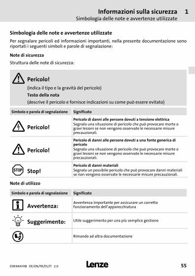
Simbologia delle note e avvertenze utilizzate
Per segnalare pericoli ed informazioni importanti, nella presente documentazione sonoriportati i seguenti simboli e parole di segnalazione:
Note di sicurezza
Struttura delle note di sicurezza:
Pericolo!(indica il tipo e la gravità del pericolo)
Testo della nota
(descrive il pericolo e fornisce indicazioni su come può essere evitato)
Simbolo e parola di segnalazione Significato
Pericolo!Pericolo di danni alle persone dovuti a tensione elettricaSegnala una situazione di pericolo che può provocare morte ogravi lesioni se non vengono osservate le necessarie misureprecauzionali.
Pericolo!
Pericolo di danni alle persone dovuti a una fonte generica dipericoloSegnala una situazione di pericolo che può provocare morte ogravi lesioni se non vengono osservate le necessarie misureprecauzionali.
Stop!Pericolo di danni materialiSegnala un possibile pericolo che può provocare danni materialise non vengono osservate le necessarie misure precauzionali.
Note di utilizzo
Simbolo e parola di segnalazione Significato
Avvertenza:Avvertenza importante per assicurare un correttofunzionamento dell’apparecchiatura
Suggerimento: Utile suggerimento per una più semplice gestione
Rimando ad altra documentazione
1 Informazioni sulla sicurezzaSimbologia delle note e avvertenze utilizzate
EDK94AYAB DE/EN/FR/ES/IT 2.056
H1sic_IT-UL-Warn_Module_Temp_Fuse
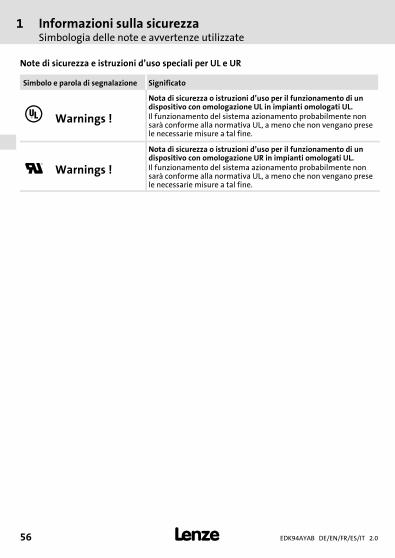
Note di sicurezza e istruzioni d’uso speciali per UL e UR
Simbolo e parola di segnalazione Significato
Warnings !
Nota di sicurezza o istruzioni d’uso per il funzionamento di undispositivo con omologazione UL in impianti omologati UL.Il funzionamento del sistema azionamento probabilmente nonsarà conforme alla normativa UL, a meno che non vengano presele necessarie misure a tal fine.
Warnings !
Nota di sicurezza o istruzioni d’uso per il funzionamento di undispositivo con omologazione UR in impianti omologati UL.Il funzionamento del sistema azionamento probabilmente nonsarà conforme alla normativa UL, a meno che non vengano presele necessarie misure a tal fine.
Informazioni sulla sicurezzaNote generali di sicurezza
1
EDK94AYAB DE/EN/FR/ES/IT 2.0 57
H1sic_IT-UL-Warn_Module_Temp_Fuse
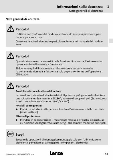
Note generali di sicurezza
Pericolo!L’utilizzo non conforme del modulo e del modulo asse può provocare gravidanni a persone e cose.
Osservare le note di sicurezza e pericolo contenute nel manuale del moduloasse.
Pericolo!Quando viene meno la necessità della funzione di sicurezza, l’azionamentoriprende automaticamente a funzionare.
Si dovranno quindi intraprendere misure esterne per assicurare chel’azionamento riprenda a funzionare solo dopo la conferma dell’operatore(EN 60204).
Pericolo!Possibile rotazione inattesa del motore
In caso di cortocircuito di due transistori di potenza, può generarsi sul motoreuna rotazione residua massima di 180 °/numero di coppie di poli (Es.: motore a4 poli rotazione residua max. 180 °/2 = 90 °)
Possibili conseguenze:ƒ Rischio di infortunio alle persone dovuto all’azionamento delle macchine
(avvio inatteso).
Misure di protezione:ƒ Prendere in considerazione il movimento residuo nell’analisi dei rischi, ad
es. funzione Scollegamento sicuro per gli azionamenti mandrino principali.
Stop!Eseguire le operazioni di montaggio/smontaggio solo con l’alimentazionedisinserita, per evitare di danneggiare i componenti elettronici.
1 Informazioni sulla sicurezzaInformazionisullasicurezzaper l’installazionesecondolanormativaULoUR
EDK94AYAB DE/EN/FR/ES/IT 2.058
H1sic_IT-UL-Warn_Module_Temp_Fuse
Avvertenza:L’impostazione del codice C00214 deve corrispondere al tipo di modulo disicurezza collegato. In caso contrario viene segnalato un errore di modulo disicurezza non valido.
Informazioni sulla sicurezza per l’installazione secondo la normativa UL o UR
Warnings !ƒ Maximum surrounding air temperature: 55 °C.ƒ External fuse for 24 Vdc supply voltage. Rated 4 A DC fuse UL248-14.
Dati tecnici 2
EDK94AYAB DE/EN/FR/ES/IT 2.0 59
H1_Daten-BemDat-SM100
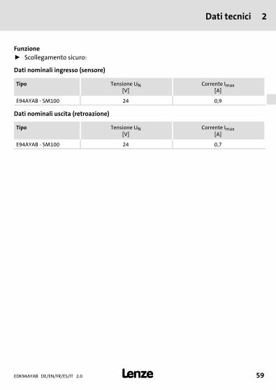
2 Dati tecnici
Funzioneƒ Scollegamento sicuro:
Dati nominali ingresso (sensore)
Tipo Tensione UN[V]
Corrente Imax[A]
E94AYAB - SM100 24 0,9
Dati nominali uscita (retroazione)
Tipo Tensione UN[V]
Corrente Imax[A]
E94AYAB - SM100 24 0,7

3 Installazione meccanicaMontaggio
EDK94AYAB DE/EN/FR/ES/IT 2.060
H1_MechINS-KommModul Demontage
3 Installazione meccanica
Montaggio
E94AYAX001
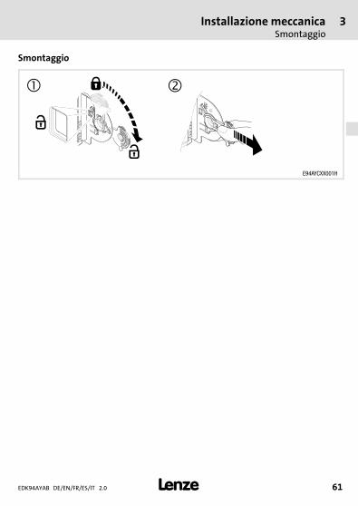
Installazione meccanicaSmontaggio
3
EDK94AYAB DE/EN/FR/ES/IT 2.0 61
H1_MechINS-KommModul Demontage
Smontaggio
E94AYCXX001H

4 Installazione elettricaSchema a blocchi
EDK94AYAB DE/EN/FR/ES/IT 2.062
H1_E_INST----(DUMMYSEITEVOR)---
4 Installazione elettrica
Avvertenza:Durante l’installazione, consultare la documentazione dell’unità di controllo.
Schema a blocchi
SM 100
SI1
SI2
GI
24O
DO1
GO
PWM
µC
-
~-
-
SSP94S1010
SM100 Modulo di sicurezza
I1A, I2B, GI Collegamenti segnale sensore, a 2 canali(precedente siglatura fino alla versione HW Px: SI1, SI2, GI)
24O, DO1, GO Collegamenti retroazione, non sicuri
μC Microprocessore
PWM Modulazione ad ampiezza d’impulsi PWM (Pulse Width Modulation)
Installazione elettricaSpecifiche dei collegamenti
4
EDK94AYAB DE/EN/FR/ES/IT 2.0 63
H1_E_INST----(DUMMYSEITEVOR)---
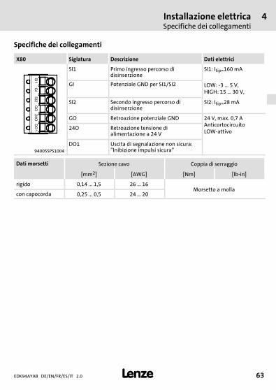
Specifiche dei collegamenti
X80 Siglatura Descrizione Dati elettrici
SI1 Primo ingresso percorso didisinserzione
SI1: Itip=160 mA
GI Potenziale GND per SI1/SI2 LOW: -3 ... 5 V,HIGH: 15 ... 30 V,
SI2 Secondo ingresso percorso didisinserzione
SI2: Itip=28 mA
GO Retroazione potenziale GND 24 V, max. 0,7 AAnticortocircuitoLOW-attivo
24O Retroazione tensione dialimentazione a 24 V
9400SSPS1004
DO1 Uscita di segnalazione non sicura:”Inibizione impulsi sicura”
Dati morsetti Sezione cavo Coppia di serraggio
[mm2] [AWG] [Nm] [lb-in]
rigido 0,14 ... 1,5 26 ... 16Morsetto a molla
con capocorda 0,25 ... 0,5 24 ... 20
backside
Lenze Drive Systems GmbHHans-Lenze-Straße 1D-31855 AerzenGermany
EDK94AYABDE/EN/FR/ES/IT 2.0
© 04/2007TD29
+49 (0) 51 54 82-0
Service 00 80 00 24 4 68 77 (24 h helpline)
Service +49 (0) 51 54 82-1112
E-Mail [email protected]
Internet www.Lenze.com10 9 8 7 6 5 4 3 2 1

![powerpoint to print.ppt [Read-Only] - 123seminarsonly.com · 2011. 12. 17. · Title: Microsoft PowerPoint - powerpoint_to_print.ppt [Read-Only] [Compatibility Mode] Created Date:](https://img.pdfslide.org/doc/110x75/610f466cedc48522fd6dd953/powerpoint-to-printppt-read-only-2011-12-17-title-microsoft-powerpoint.jpg)


![iekšējie motivatori.pptx [Read-Only]](https://img.pdfslide.org/doc/110x75/6259a780cf5a9149b14e59fd/iekejie-read-only.jpg)
![Apres1 FUMEGA 16Dez.pptx [Read-Only]](https://img.pdfslide.org/doc/110x75/626168aeb223b035a565919d/apres1-fumega-16dezpptx-read-only.jpg)
![G gnaegi Datenzyklus.ppt [Read-Only]](https://img.pdfslide.org/doc/110x75/629c7eba4627e8020972a294/g-gnaegi-read-only.jpg)

![Aracus advanced esp.pptx [Read-Only] - membrapure.de](https://img.pdfslide.org/doc/110x75/62c4eac6cefe741ecd2ee142/aracus-advanced-esppptx-read-only-.jpg)