Embed Size (px)
Citation preview
© ZBT GmbH – Reformer concepts for 50%-plus efficiencies of SOFC systems – F-Cell 2012 1
Zentrum für BrennstoffzellenTechnik GmbH
Reformer concepts for high efficient SOFC systems
Dr. Christian Spitta
Session B1, F-Cell 2012, Stuttgart
ZBT GmbHCarl-Benz-Straße 20147057 DuisburgGermany
Telefon: +49-203-7598-4277Telefax: +49-203-7598 [email protected]
© ZBT GmbH – Reformer concepts for 50%-plus efficiencies of SOFC systems – F-Cell 2012 2
mCHP Reformer technology at ZBT
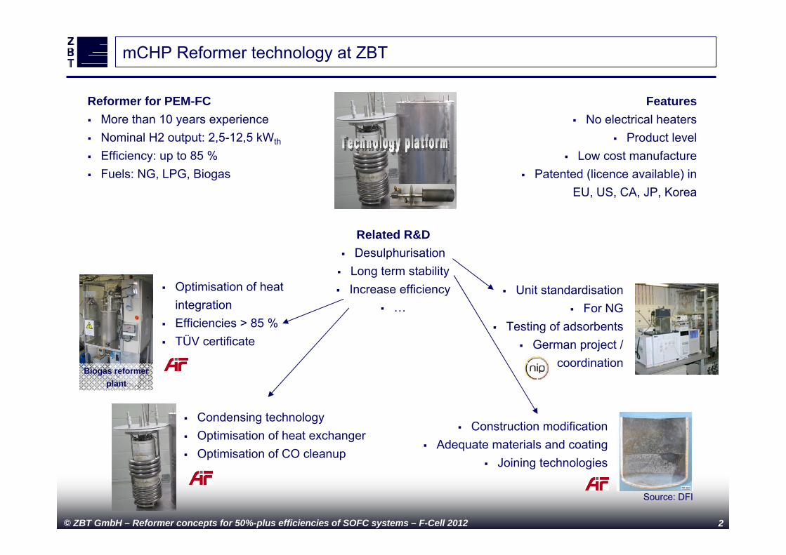
Reformer for PEM-FC More than 10 years experience Nominal H2 output: 2,5-12,5 kWth
Efficiency: up to 85 % Fuels: NG, LPG, Biogas
Related R&D Desulphurisation Long term stability Increase efficiency
…
Features No electrical heaters
Product level Low cost manufacture
Patented (licence available) in EU, US, CA, JP, Korea
Unit standardisation For NG
Testing of adsorbents German project /
coordination
Construction modification Adequate materials and coating
Joining technologies
Optimisation of heat integration
Efficiencies > 85 % TÜV certificate
Condensing technology Optimisation of heat exchanger Optimisation of CO cleanup
Biogas reformer plant
Source: DFI
© ZBT GmbH – Reformer concepts for 50%-plus efficiencies of SOFC systems – F-Cell 2012 3
Introduction
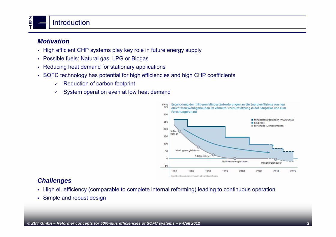
Motivation High efficient CHP systems play key role in future energy supply Possible fuels: Natural gas, LPG or Biogas Reducing heat demand for stationary applications SOFC technology has potential for high efficiencies and high CHP coefficients
Reduction of carbon footprint System operation even at low heat demand
Challenges High el. efficiency (comparable to complete internal reforming) leading to continuous operation Simple and robust design
© ZBT GmbH – Reformer concepts for 50%-plus efficiencies of SOFC systems – F-Cell 2012 4
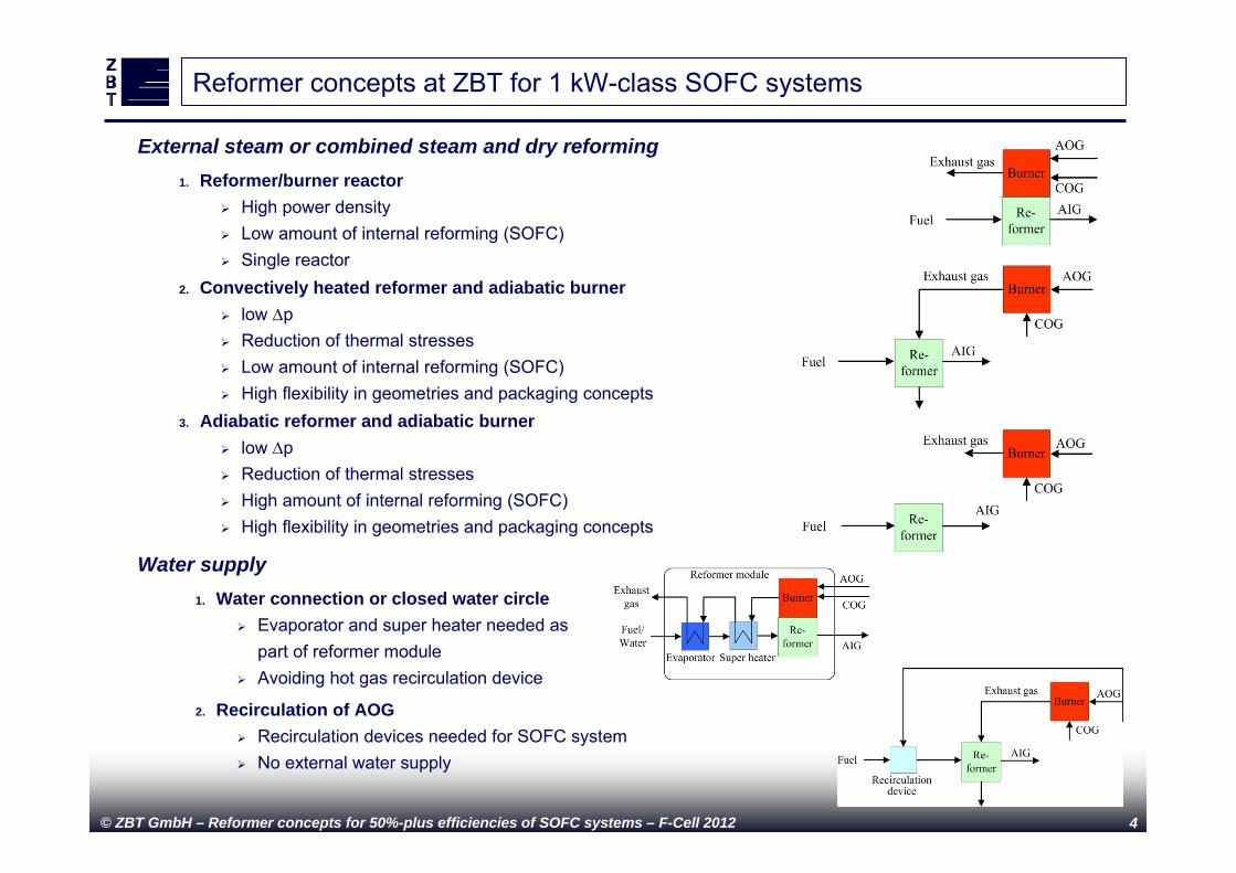
1. Reformer/burner reactor High power density Low amount of internal reforming (SOFC) Single reactor
External steam or combined steam and dry reforming
Reformer concepts at ZBT for 1 kW-class SOFC systems
2. Convectively heated reformer and adiabatic burner low p Reduction of thermal stresses Low amount of internal reforming (SOFC) High flexibility in geometries and packaging concepts
3. Adiabatic reformer and adiabatic burner low p Reduction of thermal stresses High amount of internal reforming (SOFC) High flexibility in geometries and packaging concepts
2. Recirculation of AOG Recirculation devices needed for SOFC system No external water supply
1. Water connection or closed water circle Evaporator and super heater needed as
part of reformer module Avoiding hot gas recirculation device
Water supply
© ZBT GmbH – Reformer concepts for 50%-plus efficiencies of SOFC systems – F-Cell 2012 5
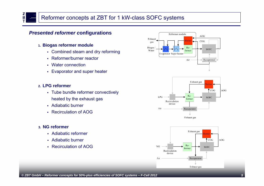
Presented reformer configurations
Reformer concepts at ZBT for 1 kW-class SOFC systems
2. LPG reformer Tube bundle reformer convectively
heated by the exhaust gas Adiabatic burner Recirculation of AOG
1. Biogas reformer module Combined steam and dry reforming Reformer/burner reactor Water connection Evaporator and super heater
3. NG reformer Adiabatic reformer Adiabatic burner Recirculation of AOG
© ZBT GmbH – Reformer concepts for 50%-plus efficiencies of SOFC systems – F-Cell 2012 6
1. Biogas reformer module
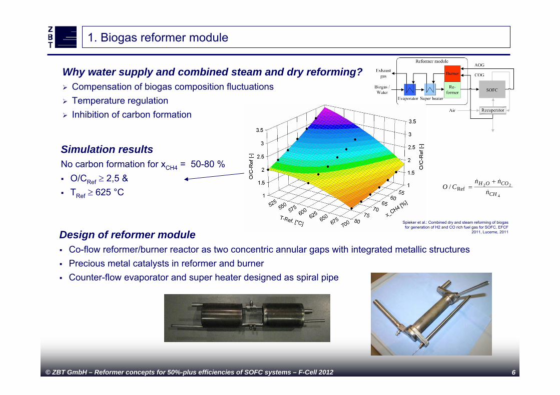
Why water supply and combined steam and dry reforming? Compensation of biogas composition fluctuations Temperature regulation Inhibition of carbon formation
Simulation resultsNo carbon formation for xCH4 = 50-80 % O/CRef 2,5 & TRef 625 °C
Design of reformer module Co-flow reformer/burner reactor as two concentric annular gaps with integrated metallic structures Precious metal catalysts in reformer and burner Counter-flow evaporator and super heater designed as spiral pipe
Spieker et al.: Combined dry and steam reforming of biogas for generation of H2 and CO rich fuel gas for SOFC, EFCF
2011, Lucerne, 2011
4
22/ RefCH
COOH
nnn
CO
© ZBT GmbH – Reformer concepts for 50%-plus efficiencies of SOFC systems – F-Cell 2012 7
1. Biogas reformer module
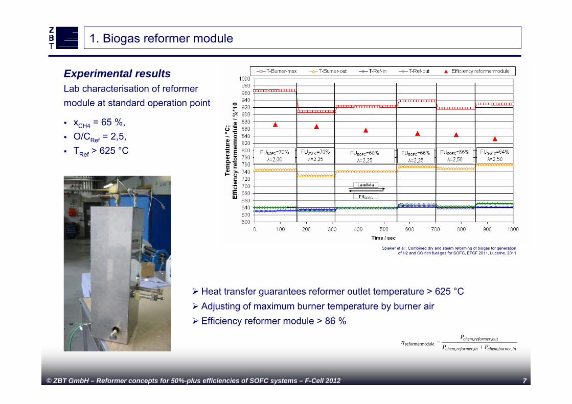
Experimental resultsLab characterisation of reformer module at standard operation point
Spieker et al.: Combined dry and steam reforming of biogas for generationof H2 and CO rich fuel gas for SOFC, EFCF 2011, Lucerne, 2011
xCH4 = 65 %, O/CRef = 2,5, TRef > 625 °C
Heat transfer guarantees reformer outlet temperature > 625 °C Adjusting of maximum burner temperature by burner air Efficiency reformer module > 86 %
inburnercheminreformerchem
outreformerchem
PPP
,,,,
,,dulereformermo
© ZBT GmbH – Reformer concepts for 50%-plus efficiencies of SOFC systems – F-Cell 2012 8
1. Biogas reformer module
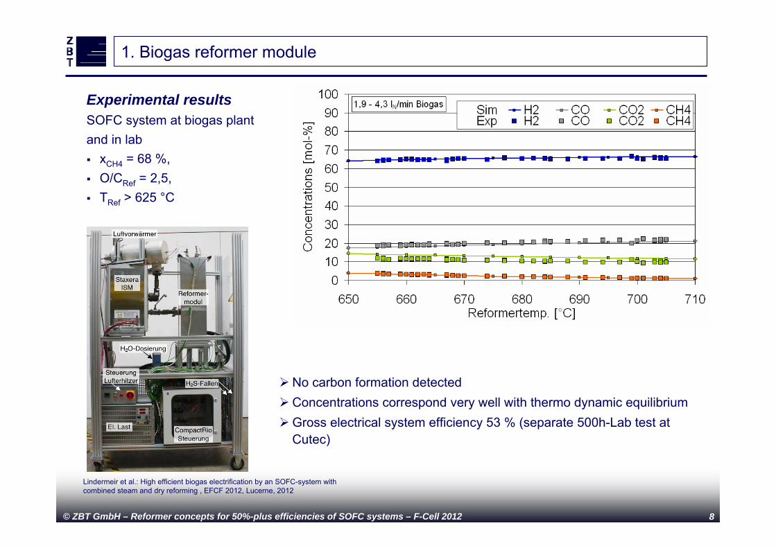
Experimental resultsSOFC system at biogas plant and in lab xCH4 = 68 %, O/CRef = 2,5, TRef > 625 °C
No carbon formation detectedConcentrations correspond very well with thermo dynamic equilibriumGross electrical system efficiency 53 % (separate 500h-Lab test at
Cutec)
Lindermeir et al.: High efficient biogas electrification by an SOFC-system with combined steam and dry reforming , EFCF 2012, Lucerne, 2012
© ZBT GmbH – Reformer concepts for 50%-plus efficiencies of SOFC systems – F-Cell 2012 9
2. Tube bundle LPG reformer
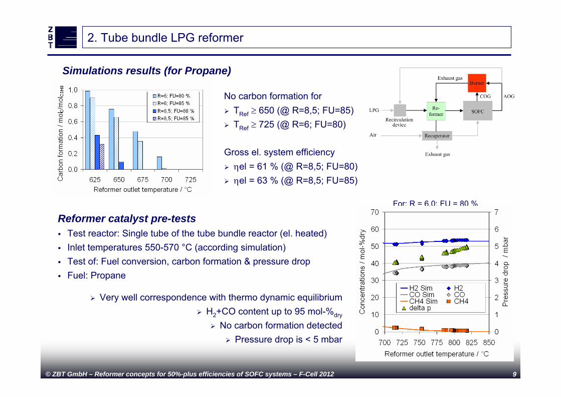
Simulations results (for Propane)
No carbon formation for TRef 650 (@ R=8,5; FU=85) TRef 725 (@ R=6; FU=80)
Gross el. system efficiency el = 61 % (@ R=8,5; FU=80) el = 63 % (@ R=8,5; FU=85)
Reformer catalyst pre-tests Test reactor: Single tube of the tube bundle reactor (el. heated) Inlet temperatures 550-570 °C (according simulation) Test of: Fuel conversion, carbon formation & pressure drop Fuel: Propane
Very well correspondence with thermo dynamic equilibrium H2+CO content up to 95 mol-%dry
No carbon formation detected Pressure drop is < 5 mbar
For: R = 6,0; FU = 80 %
© ZBT GmbH – Reformer concepts for 50%-plus efficiencies of SOFC systems – F-Cell 2012 10
2. Tube bundle LPG reformer
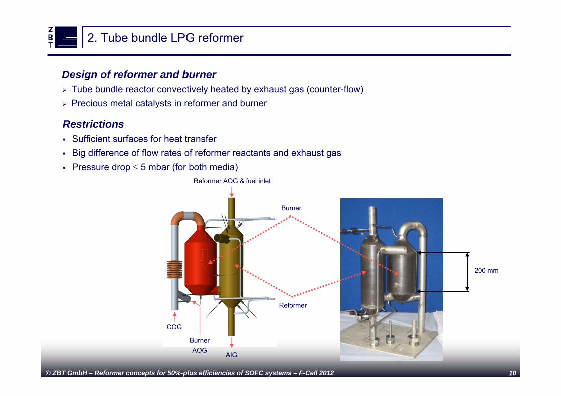
Design of reformer and burner Tube bundle reactor convectively heated by exhaust gas (counter-flow) Precious metal catalysts in reformer and burner
Restrictions Sufficient surfaces for heat transfer Big difference of flow rates of reformer reactants and exhaust gas Pressure drop 5 mbar (for both media)
200 mm
Burner
AIG
Reformer AOG & fuel inlet
COG
Burner AOG
Reformer
© ZBT GmbH – Reformer concepts for 50%-plus efficiencies of SOFC systems – F-Cell 2012 11
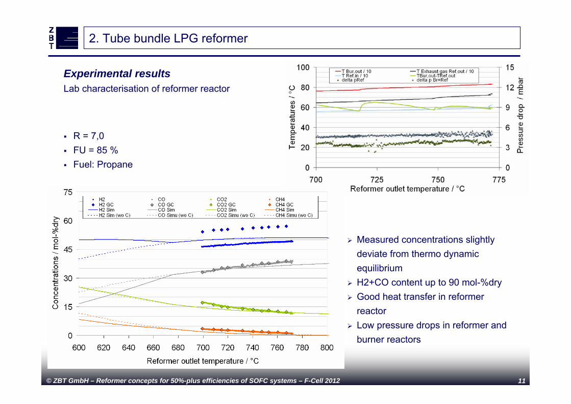
2. Tube bundle LPG reformer
Measured concentrations slightly deviate from thermo dynamic equilibrium
H2+CO content up to 90 mol-%dry Good heat transfer in reformer
reactor Low pressure drops in reformer and
burner reactors
Experimental resultsLab characterisation of reformer reactor
R = 7,0 FU = 85 % Fuel: Propane
© ZBT GmbH – Reformer concepts for 50%-plus efficiencies of SOFC systems – F-Cell 2012 12
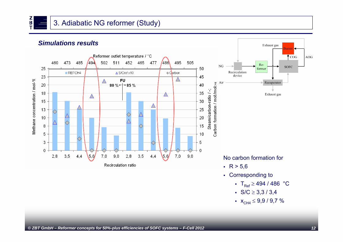
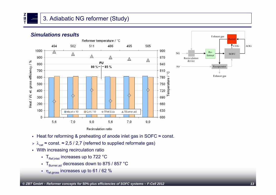
Thermo dynamical simulations (with Aspen Plus®)
No carbon formation for R > 5,6 Corresponding to
TRef 494 / 486 °C S/C 3,3 / 3,4 xCH4 9,9 / 9,7 %
3. Adiabatic NG reformer (Study)
Simulations results
© ZBT GmbH – Reformer concepts for 50%-plus efficiencies of SOFC systems – F-Cell 2012 13
Thermo dynamical simulations (with Aspen Plus®)3. Adiabatic NG reformer (Study)
Heat for reforming & preheating of anode inlet gas in SOFC ≈ const. cat ≈ const. ≈ 2,5 / 2,7 (referred to supplied reformate gas) With increasing recirculation ratio
TRef,inlet increases up to 722 °C TBurner,ad decreases down to 875 / 857 °C el,gross increases up to 61 / 62 %
Simulations results
© ZBT GmbH – Reformer concepts for 50%-plus efficiencies of SOFC systems – F-Cell 2012 14
Conclusion and outlook
Conclusion Presentation of 3 reformer and water supply configurations for 1 kW-class SOFC system Simulation for all configurations showed
Gross electrical system efficiencies > 50 % Tests of biogas reformer module demonstrated
Biogas composition fluctuations could be compensated by steam and dry reforming Concentrations correspond very well with thermo dynamic equilibrium High reformer and system efficiencies in Lab and at biogas plant
Tests of tube bundle LPG reformer showed Good heat transfer from exhaust gas to reformer Low pressure drop in reformer and burner H2+CO content up to 90 mol-%dry
Outlook Further proves of concept of biogas SOFC system reformer module at other biogas plants Test results on system level with the tube bundle LPG reformer Combinations of reformer and water supply concepts Scale-up of tube bundle reformer
© ZBT GmbH – Reformer concepts for 50%-plus efficiencies of SOFC systems – F-Cell 2012 15
Thanks to the team members at ZBT for their high effort leading to the presented results.
Thanks to the colleagues from project partner Cutec for the collaboration and contribution in these projects. Furthermore thanks to Staxera GmbH and Nordzucker AG for their support during the projects.
Part of the work was financed with funds of the German “Federal Ministry of Economics and Technology” (BMWi) and is gratefully acknowledged (IGF-projects no. 16126 N and 16638 N).
Acknowledgements
© ZBT GmbH – Reformer concepts for 50%-plus efficiencies of SOFC systems – F-Cell 2012 16
Thank you for your attention!
ZBT – Reformer concepts for high efficient SOFC systems
Contact:Dr. Christian [email protected]+49 (0)203/7598-4277www.zbt-duisburg.de