Embed Size (px)
Citation preview
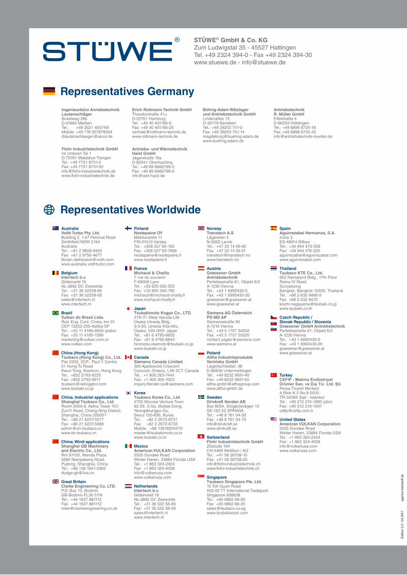
STÜWE® GmbH & Co. KGZum Ludwigstal 35 - 45527 HattingenTel. +49 2324 394-0 - Fax +49 2324 394-30www.stuewe.de - [email protected]
Antriebs- und WärmetechnikHaist GmbHJägerstraße 16aD-82041 OberhachingTel.: +49 89 6666799-0Fax: +49 89 [email protected]
Edi
tion
2.0
/ 04.
2017
Representatives Germany
Representatives Worldwide
Australia Voith Turbo Pty. Ltd. Building 2, 1-47 Percival Road Smithfield NSW 2164 Australia Tel.: +61 2 9609-9400 Fax: +61 2 9756-4677 [email protected] www.australia.voithturbo.com
Belgium Intertech b.v. Gildenveld 19 NL-3892 DC Zeewolde Tel.: +31 36 52258-85 Fax: +31 36 52258-06 [email protected] www.intertech.nl
Brazil Vulkan do Brasil Ltda. Rod. Eng. Cont. Cintra, km 91 CEP 13252-200-Itatiba-SP Tel.: +55 11 4166-6600 (pabx) Fax: +55 11 4195-1569 [email protected] www.vulkan.com
China (Hong Kong) Tsubaco (Hong Kong) Co., Ltd. Flat 2202, 22/F., Paul Y. Centre 51 Hung To Road Kwun Tong, Kowloon, Hong Kong Tel.: +852 2793-9220 Fax: +852 2793-9917 [email protected] www.tsubaki.co.jp
China, Industrial applications Shanghai Tsubaco Co., Ltd Room 2005-6, Aetna Tower 107, ZunYi Road, Chang Ning District, Shanghai, China 200051 Tel.: +86 21 6237-5577 Fax: +86 21 6237-5688 [email protected] www.sh-tsubaco.cn
China, Wind applications Shanghai GB Machinery and Electric Co., Ltd. Rm B1102, Wanda Plaza 528# Nianjiabang Road, Pudong, Shanghai, China Tel.: +86 138 1841-3363 [email protected]
Great Britain Clarke Engineering Co. LTD. P.O. Box 13, Bodmin GB-Bodmin PL30 5YN Tel.: +44 1637 881112 Fax: +44 1637 881112 [email protected]
Finland Nestepaine OY Mäkituvantie 11 FIN-01510 Vantaa Tel.: +358 207 65-165 Fax: +358 207 65-7666 [email protected] www.nestepaine.fi
France Michaud & Chailly 7 rue du souvenir F-69009 Lyon Tel.: +33 825 002-555 Fax: +33 825 340-785 [email protected] www.michaud-chailly.fr
Japan Tsubakimoto Kogyo Co., LTD. 27th Fl.-Meiji Yasuda-Life Osaka Umeda Bldg. 3-3-20, Umeda Kita-kKu, Osaka, 530-0001 Japan Tel.: +81 6 4795-8835 Fax: +81 6 4795-8843 [email protected] www.tsubaki.co.jp
Canada Siemens Canada Limited 300 Applewood Crescent Concord, Ontario, L4K 5C7, Canada Tel.: +1 800 263-7444 Fax: +1 905 305-1023 [email protected]
Korea Tsubaco Korea Co., Ltd. #705 Wooree Venture Town 82-29, 3-Ga, Mullae-Dong, Yeongdeungpo-Gu, Seoul 150-836, Korea Tel.: +82 2 2672-8731 Fax: +82 2 2672-8733 Mobile: +86 13918204470 [email protected] www.tsubaki.co.kr
Mexico American VULKAN Corporation 2525 Dundee Road Winter Haven, 33884 Florida USA Tel.: +1 863 324-2424 Fax: +1 863 324-4008 [email protected] www.vulkanusa.com
Netherlands Intertech b.v. Gildenveld 19 NL-3892 DC Zeewolde Tel.: +31 36 522 58-85 Fax: +31 36 522 58-06 [email protected] www.intertech.nl
Spain Aguirrezabal Hermanos, S.A. Iruña 3 ES-48014 Bilbao Tel.: +34 944 473-358 Fax: +34 944 476-320 [email protected] www.aguirrezabal.com
Thailand Tsubaco KTE Co., Ltd. 952 Ramaland Bldg., 17th Floor Rama IV Road Suriyawong Bangrak, Bangkok 10500, Thailand Tel.: +66 2 632 9466-9 Fax: +66 2 632 9470 [email protected] www.tsubaki.co.th
Czech Republic / Slovak Republic / Slovenia Graessner GmbH Antriebstechnik
Perfektastraße 61, Objekt 6/2 A-1230 Vienna Tel.: +43 1 6992430-0 Fax: +43 1 6992430-20 [email protected] www.graessner.at
Turkey CEFIP - Makina Endüstriyel ÜrünlerSan.veDışTic.Ltd.Şti. Perpa Ticaret Merkezi A Blok K.2 No:9-0033 TR-34384 Şişli - Istanbul Tel.: +90 212 210-1890 (pbx) Fax: +90 212 210-1597 [email protected]
United States American VULKAN Corporation 2525 Dundee Road Winter Haven, 33884 Florida USA Tel.: +1 863 324-2424 Fax: +1 863 324-4008 [email protected] www.vulkanusa.com
Norway Transtech A.S Lågaveien 5 N-3262 Larvik Tel.: +47 33 14 06-00 Fax: +47 33 14 06-01 [email protected] www.transtech.no
Austria Graessner GmbH Antriebstechnik Perfektastraße 61, Objekt 6/2 A-1230 Vienna Tel.: +43 1 6992430-0 Fax: +43 1 6992430-20 [email protected] www.graessner.at Siemens AG Österreich PD MD AP Siemensstraße 90 A-1210 Vienna Tel.: +43 5 1707 34252 Fax: +43 5 1707 55020 [email protected] www.siemens.at
Poland Altha Industrieprodukte Vertriebs GmbH Lagerlechfeldstr. 38 D-86836 Untermeitingen Tel.: +49 8232 9691-40 Fax: +49 8232 9691-55 [email protected] www.altha-gmbh.de
Sweden Drivkraft Norden AB Box 8034, Sörgårdsvägen 13 SE-163 52 SPÅNGA Tel.: +46 8 761 04-30 Fax: +46 8 761 04-75 [email protected] www.drivkraft.se
Switzerland Flohr Industrietechnik GmbH Zilistude 164 CH-5465 Mellikon / AG Tel.: +41 56 26708-10 Fax: +41 56 26708-25 [email protected] www.flohr-industrietechnik.ch
Singapore Tsubaco Singapore Pte. Ltd. 10 Toh Guan Road #02-02 TT International Tradepark Singapore 608838 Tel.: +65 6862 68-00 Fax: +65 6862 68-20 [email protected] www.tsubakisosin.com
Ingenieurbüro Anriebstechnik LautenschlägerBoselweg 28bD-01665 MeißenTel.: +49 3521 4057-69Mobile: +49 176 [email protected]
AntriebstechnikR. Müller GmbHEifelstraße 4D-66333 VölklingenTel.: +49 6898 8705-18Fax: +49 6898 [email protected]
Erich Rottmann Technik GmbHTheodorstraße 41uD-22761 HamburgTel.: +49 40 401766-0Fax: +49 40 [email protected] www.rottmann-technik.de
Bührig-Adam Wälzlager und Antriebstechnik GmbHLindenallee 13D-39179 BarlebenTel.: +49 39203 751-0Fax: +49 39203 [email protected]
Flohr Industrietechnik GmbHIm Unteren Tal 1D-79761 Waldshut-TiengenTel.: +49 7751 8731-0Fax: +49 7751 8731-50info@flohr-industrietechnik.dewww.flohr-industrietechnik.de
agen
tur-
trei
bsto
ff.de

Frictional Connections C
atalog
ue

Frictional Connections Catalogue
Certified in accordance with DIN ISO 9001:2008
MADE IN GERMAN
YM
AD
E IN GERMANY

FRICTIONAL CONNECTIONS TECHNOLOGY THAT CONNECTS

FRICTIONAL CONNECTIONS TECHNOLOGY THAT CONNECTS
03
Dear business partner,
STÜWE® GmbH & Co. KG offers the best possible connections – in the third generation of ownership. We and our products have stood for skilled work and quality for more than 60 years. In addition to our longstanding supply range which includes shrink discs, locking units, shaft couplings and cardan shaft couplings, we also develop individual customised solutions for any particular application use you may have.
Some possible solutions for this can be found here in our cata-logue. We are happy at all times to assist you, together with our staff, and to reliably support you in all possible matters.
Rena Stüwe, Jan StüweManaging Directors
Made in Germany
With 60 years of expertise and 120 employees, STÜWE® develops highly specialised frictional connections for particularly demanding applications. Since the introduction of its first shrink disc in 1967 STÜWE® has been producing exclusively in Germany and has retained its company headquarters in Hattingen. We select our suppliers based on the highest of quality standards and check these regularly through audits.
Regular customers have placed their trust in our high standards of skills and quality for many years, in particular for large transmission systems under difficult conditions. As is the case, for example, in wind turbines and ships.
Company History
Friedhelm Stüwe founded the company Maschinenfabrik STÜWE® in 1948 with an original specialisation on the production of cranes and steel products.
In 1967 the first shrink disc was launched onto the market. It enables a simple mechanical external join between a shaft and a hub. The ground-breaking technology can even be found as an entry in the technical literature as the “STÜWE® disc”. After the three-piece SD shrink disc, STÜWE® also launched the two-piece HSD and hydraulically tensioned connections. Increasing sales and new models require constant extensions to capacity.
A CONNECTION AT A HIGH LEVEL

05
A CONNECTION AT A HIGH LEVEL
High Performance
Secure transmission at torques of up to over 11 000 000 Nm
Suitable for shaft diameters of 8 mm to over 1 000 mm
Quick and easy, space-saving installation and non-destructive removal
No fretting corrosion
Compact design
Normal surface finish qualities of shafts & hubs
Can be used as an assembly for a specific application
Can be tightened using bolts or hydraulically
The Benefits
STÜWE® frictional connections can be easily and non-destructively installed and removed – differently to thermal or friction connections which are joined in other ways. The clearance fit between a shaft and a hub and between a hub and a “STÜWE® disc” enables easy installation and removal. Renowned companies throughout the world appreciate the benefits of our products.
Certified Quality
Not only our highly qualified employees, but also the latest production technology and the consistent optimisation of operational processes guarantee you the top-class nature of our services.
As an ISO 9001 certified company we monitor all steps from the good-in-wards inspection of our materials to the final inspection of our precision products. The latest test methods, and not least the great care we take, guarantee you a consistent high level of quality, safety and service life for each individual frictional connection. On request, all STÜWE® products may be supplied with acceptance from a classification company.

CONTENTS
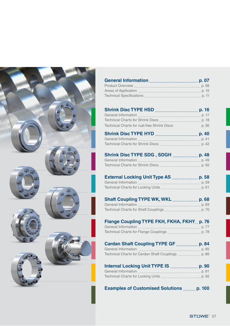
CONTENTS
07
General Information p. 07Product Overview p. 08Areas of Application p. 10Technical Specifications p. 11
Shrink Disc TYPE HSD p. 16General Information p. 17Technical Charts for Shrink Discs p. 18
Technical Charts for rust-free Shrink Discs p. 36
Shrink Disc TYPE HYD p. 40General Information p. 41Technical Charts for Shrink Discs p. 42
Shrink Disc TYPE SDG , SDGH p. 48General Information p. 49Technical Charts for Shrink Discs p. 50
External Locking Unit Type AS p. 58General Information p. 59Technical Charts for Locking Units p. 61
Shaft Coupling TYPE WK, WKL p. 68General Information p. 69Technical Charts for Shaft Couplings p. 70
Flange Coupling TYPE FKH, FKHA, FKHY p. 76General Information p. 77Technical Charts for Flange Couplings p. 78
Cardan Shaft Coupling TYPE GF p. 84General Information p. 85Technical Charts for Cardan Shaft Couplings p. 86
Internal Locking Unit TYPE IS p. 90General Information p. 91Technical Charts for Locking Units p. 92
Examples of Customised Solutions p. 100
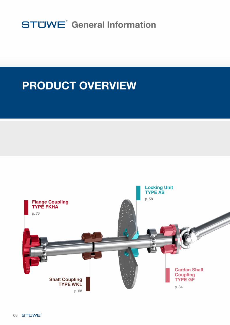
Locking Unit TYPE AS
Shaft Coupling TYPE WKL
Cardan Shaft Coupling TYPE GF
Flange Coupling TYPE FKHAp. 76
p. 58
p. 68p. 84
General Information
08
PRODUCT OVERVIEW
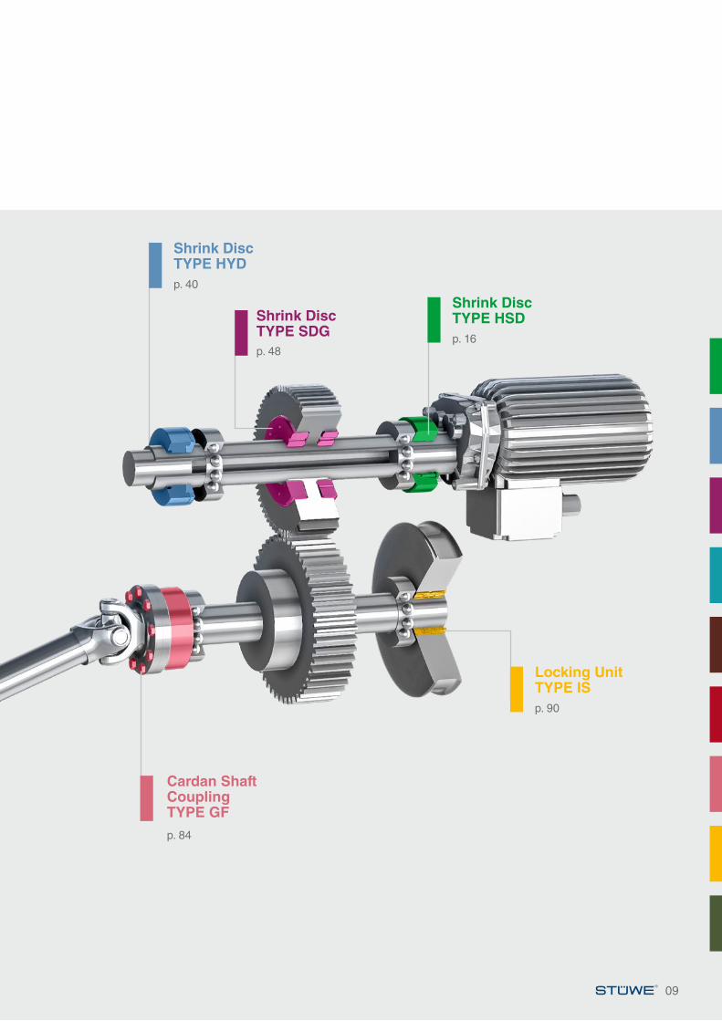
Shrink Disc TYPE HSD
Locking Unit TYPE IS
Shrink Disc TYPE HYD
Cardan Shaft Coupling TYPE GF
Cardan Shaft Coupling TYPE GF
Shrink Disc TYPE SDG p. 16
p. 90
p. 40
p. 84
p. 84
p. 48
09
General Information
10
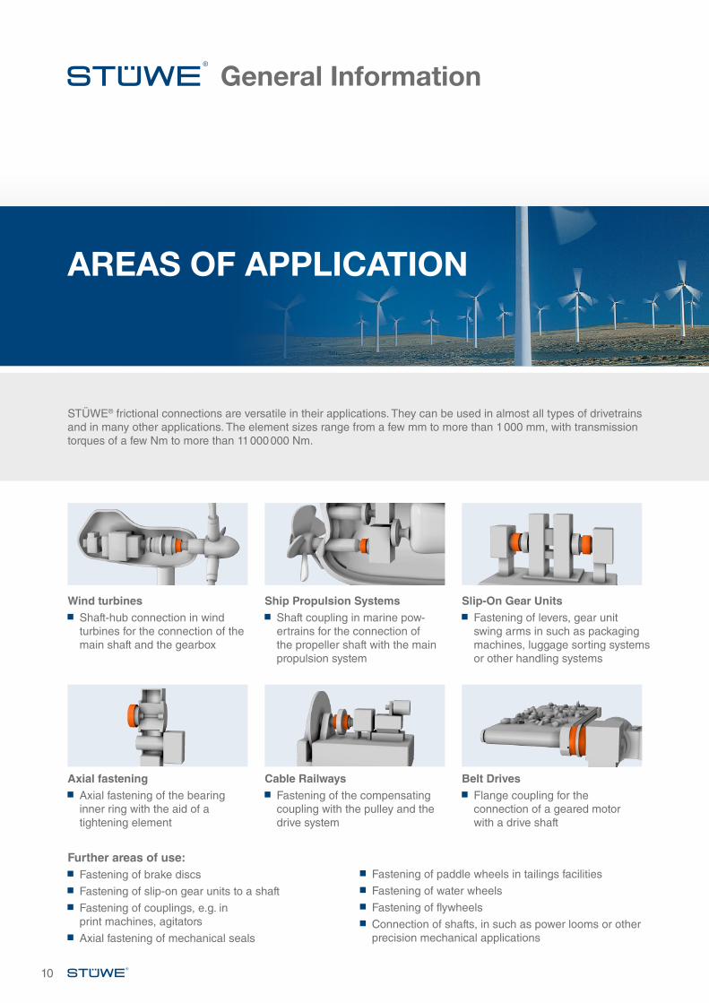
Wind turbines Shaft-hub connection in wind turbines for the connection of the main shaft and the gearbox
Axial fastening Axial fastening of the bearing inner ring with the aid of a tightening element
Ship Propulsion Systems Shaft coupling in marine pow-ertrains for the connection of the propeller shaft with the main propulsion system
Cable Railways Fastening of the compensating coupling with the pulley and the drive system
Slip-On Gear Units Fastening of levers, gear unit swing arms in such as packaging machines, luggage sorting systems or other handling systems
Belt Drives Flange coupling for the connection of a geared motor with a drive shaft
Wind turbines
STÜWE® frictional connections are versatile in their applications. They can be used in almost all types of drivetrains and in many other applications. The element sizes range from a few mm to more than 1 000 mm, with transmission torques of a few Nm to more than 11 000 000 Nm.
Further areas of use: Fastening of brake discs
Fastening of slip-on gear units to a shaft
Fastening of couplings, e.g. in print machines, agitators
Axial fastening of mechanical seals
Fastening of paddle wheels in tailings facilities
Fastening of water wheels
Fastening of flywheels
Connection of shafts, in such as power looms or other precision mechanical applications
AREAS OF APPLICATION
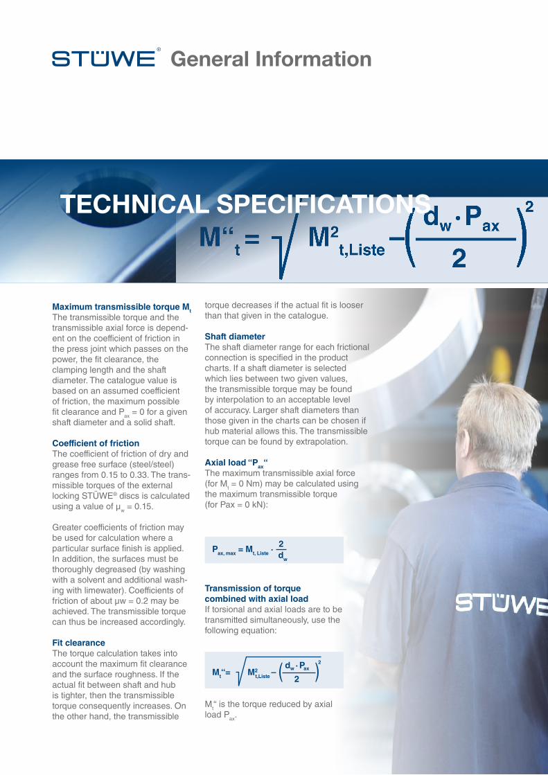
M“t = M2t,Liste –
dw · Pax
2
2
General Information
TECHNICAL SPECIFICATIONS
Maximum transmissible torque Mt The transmissible torque and the transmissible axial force is depend-ent on the coefficient of friction in the press joint which passes on the power, the fit clearance, the clamping length and the shaft diameter. The catalogue value is based on an assumed coefficient of friction, the maximum possible fit clearance and Pax = 0 for a given shaft diameter and a solid shaft.
Coefficient of frictionThe coefficient of friction of dry and grease free surface (steel/steel) ranges from 0.15 to 0.33. The trans-missible torques of the external locking STÜWE® discs is calculated using a value of μw = 0.15.
Greater coefficients of friction may be used for calculation where a particular surface finish is applied. In addition, the surfaces must be thoroughly degreased (by washing with a solvent and additional wash-ing with limewater). Coefficients of friction of about µw = 0.2 may be achieved. The transmissible torque can thus be increased accordingly.
Fit clearanceThe torque calculation takes into account the maximum fit clearance and the surface roughness. If the actual fit between shaft and hub is tighter, then the transmissible torque consequently increases. On the other hand, the transmissible
Transmission of torquecombined with axial loadIf torsional and axial loads are to be transmitted simultaneously, use the following equation:
Mt“ is the torque reduced by axial load Pax.
torque decreases if the actual fit is looser than that given in the catalogue.
Shaft diameterThe shaft diameter range for each frictional connection is specified in the product charts. If a shaft diameter is selected which lies between two given values, the transmissible torque may be found by interpolation to an acceptable level of accuracy. Larger shaft diameters than those given in the charts can be chosen if hub material allows this. The transmissible torque can be found by extrapolation.
Axial load “Pax“The maximum transmissible axial force (for Mt = 0 Nm) may be calculated using the maximum transmissible torque (for Pax = 0 kN):
Mt “= M2t,Liste –
dw · Pax
2
2
Pax, max = Mt, Liste ·2dw
General InformationGeneral Information
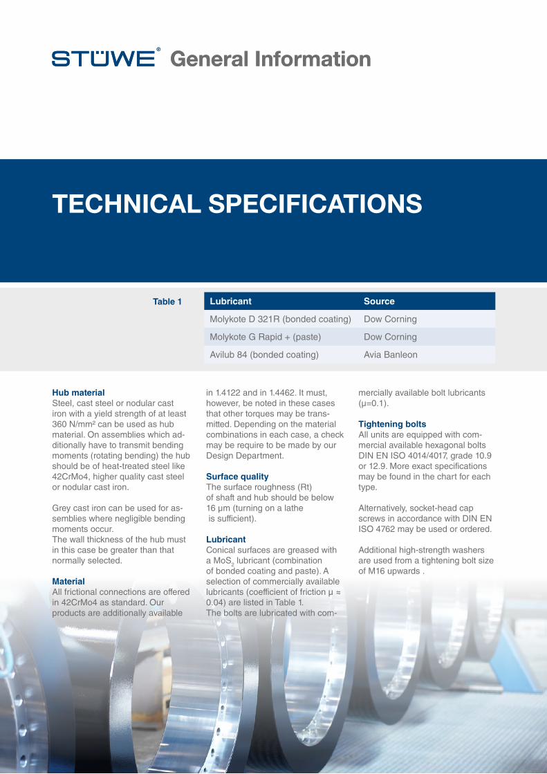
Table 1 Lubricant Source
Molykote D 321R (bonded coating) Dow Corning
Molykote G Rapid + (paste) Dow Corning
Avilub 84 (bonded coating) Avia Banleon
TECHNICAL SPECIFICATIONS
in 1.4122 and in 1.4462. It must, however, be noted in these cases that other torques may be trans-mitted. Depending on the material combinations in each case, a check may be require to be made by our Design Department.
Surface qualityThe surface roughness (Rt) of shaft and hub should be below 16 μm (turning on a lathe is sufficient).
LubricantConical surfaces are greased with a MoS2 lubricant (combination of bonded coating and paste). A selection of commercially available lubricants (coefficient of friction µ ≈ 0.04) are listed in Table 1. The bolts are lubricated with com-
Hub materialSteel, cast steel or nodular cast iron with a yield strength of at least 360 N/mm² can be used as hub material. On assemblies which ad-ditionally have to transmit bending moments (rotating bending) the hub should be of heat-treated steel like 42CrMo4, higher quality cast steel or nodular cast iron.
Grey cast iron can be used for as-semblies where negligible bending moments occur. The wall thickness of the hub must in this case be greater than that normally selected.
MaterialAll frictional connections are offered in 42CrMo4 as standard. Our products are additionally available
mercially available bolt lubricants (μ=0.1).
Tightening boltsAll units are equipped with com-mercial available hexagonal bolts DIN EN ISO 4014/4017, grade 10.9 or 12.9. More exact specifications may be found in the chart for each type. Alternatively, socket-head cap screws in accordance with DIN EN ISO 4762 may be used or ordered.
Additional high-strength washers are used from a tightening bolt size of M16 upwards .
M“t = M2t,Liste –
dw · Pax
2
2
13
General InformationGeneral Information
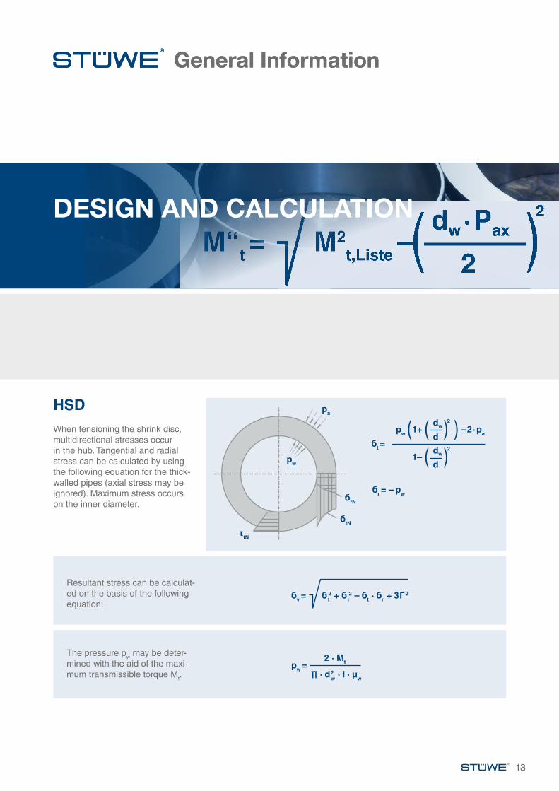
Resultant stress can be calculat-ed on the basis of the following equation:
The pressure pw may be deter-mined with the aid of the maxi-mum transmissible torque Mt.
HSDWhen tensioning the shrink disc, multidirectional stresses occur in the hub. Tangential and radial stress can be calculated by using the following equation for the thick-walled pipes (axial stress may be ignored). Maximum stress occurs on the inner diameter.
13
DESIGN AND CALCULATION
бv = бt2 + бr
2 – бt · бr
+ 3Г2
pw =2 · Mt
∏ · d2w · l · μw
pa
pw
бtN
бrN
tN
бr = – pw
бt =
pw 1+
1–
–2·pa
dw
dw
d
d
2
2
M“t = M2t,Liste –
dw · Pax
2
2
General InformationGeneral Information
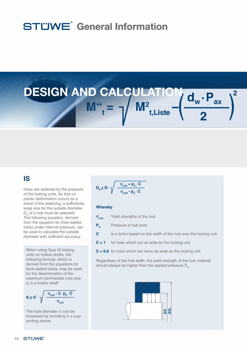
When using Type IS locking units on hollow shafts, the following formula, which is derived from the equations for thick-walled tubes, may be used for the determination of the maximum permissible hole size di in a hollow shaft:
The hole diameter di can be increased by shrinking in a sup-porting sleeve.
ISHubs are widened by the pressure of the locking units. So that no plastic deformation occurs as a result of the widening, a sufficiently large size for the outside diameter DN of a hub must be selected. The following equation, derived from the equation for thick-walled tubes under internal pressure, can be used to calculate the outside diameter with sufficient accuracy.
DESIGN AND CALCULATION
Whereby
σ0.2N Yield strengths of the hub
PN Pressure in hub bore
C is a factor based on the width of the hub over the locking unit
C = 1 for hubs which are as wide as the locking unit
C = 0.6 for hubs which are twice as wide as the locking unit Regardless of the hub width, the yield strength of the hub material should always be higher than the applied pressure PN.
14
DN ≥ D·σ0,2N + pN ∙ C
σ0,2N - pN ∙ C
di ≤ d ∙ σ0,2S - 2 ∙ pS ∙ C
σ0,2S
ØD
ØD
N

1515
SHRINK DISC TYPE HSD
Series Shaft diameter Transmissible torque Feature
HSD 20 20 - 250 mm 0.15 - 18.3 kNm Low torques
HSD 21 110 - 730 mm 16 - 4033 kNm Medium-sized torques
HSD 22 9 - 1050 mm 0.02 - 16493 kNm High torques
HSD 23 100 - 1050 mm 26 - 19684 kNm Very high torques
HSD 81 38 - 1050 mm 1.5 - 19958 kNm Identical to series 22 but 20 - 30 % higher torques
HSD 83 100 - 1050 mm 30 - 23811 kNm Identical to series 23 but 20 - 30 % higher torques
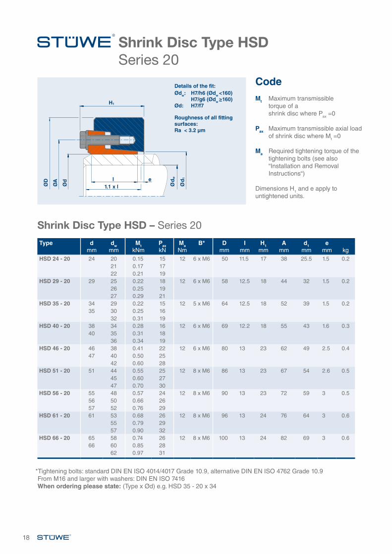
SHRINK DISC TYPE HSD – GENERAL INFORMATION
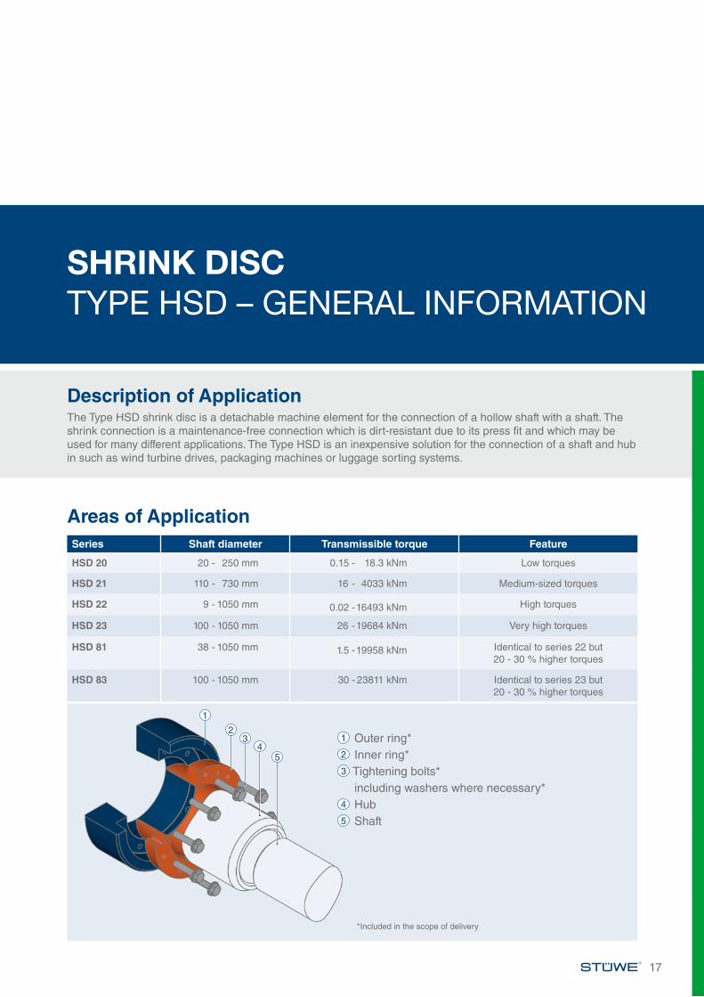
Description of ApplicationThe Type HSD shrink disc is a detachable machine element for the connection of a hollow shaft with a shaft. The shrink connection is a maintenance-free connection which is dirt-resistant due to its press fit and which may be used for many different applications. The Type HSD is an inexpensive solution for the connection of a shaft and hub in such as wind turbine drives, packaging machines or luggage sorting systems.
Areas of Application
17
1
23
45
1 Outer ring*2 Inner ring*3 Tightening bolts* including washers where necessary*4 Hub5 Shaft
*Included in the scope of delivery
ØD
ØA
Ød
H1
l1.1 x l
e
Details of the fit:Ødw: H7/h6 (Ødw <160) H7/g6 (Ødw ≥160)Ød: H7/f7
Roughness of all fitting surfaces:Ra < 3.2 µm
CodeMt Maximum transmissible
torque of a shrink disc where Pax =0
Pax Maximum transmissible axial load of shrink disc where Mt =0
Ma Required tightening torque of the tightening bolts (see also “Installation and Removal Instructions“)
Dimensions H1 and e apply to untightened units.
18
Shrink Disc Type HSD – Series 20
*Tightening bolts: standard DIN EN ISO 4014/4017 Grade 10.9, alternative DIN EN ISO 4762 Grade 10.9From M16 and larger with washers: DIN EN ISO 7416When ordering please state: (Type x Ød) e.g. HSD 35 - 20 x 34
Shrink Disc Type HSDSeries 20
Type dmm
dwmm
MtkNm
PaxkN
MaNm
B* Dmm
Imm
H1mm
Amm
d1mm
emm kg
HSD 24 - 20 24 20 0.15 15 12 6 x M6 50 11.5 17 38 25.5 1.5 0.221 0.17 1722 0.21 19
HSD 29 - 20 29 25 0.22 18 12 6 x M6 58 12.5 18 44 32 1.5 0.226 0.25 1927 0.29 21
HSD 35 - 20 34 29 0.22 15 12 5 x M6 64 12.5 18 52 39 1.5 0.235 30 0.25 16
32 0.31 19HSD 40 - 20 38 34 0.28 16 12 6 x M6 69 12.2 18 55 43 1.6 0.3
40 35 0.31 1836 0.34 19
HSD 46 - 20 46 38 0.41 22 12 6 x M6 80 13 23 62 49 2.5 0.447 40 0.50 25
42 0.60 28HSD 51 - 20 51 44 0.55 25 12 8 x M6 86 13 23 67 54 2.6 0.5
45 0.60 2747 0.70 30
HSD 56 - 20 55 48 0.57 24 12 8 x M6 90 13 23 72 59 3 0.556 50 0.66 2657 52 0.76 29
HSD 61 - 20 61 53 0.68 26 12 8 x M6 96 13 24 76 64 3 0.655 0.79 2957 0.90 32
HSD 66 - 20 65 58 0.74 26 12 8 x M6 100 13 24 82 69 3 0.666 60 0.85 28
62 0.97 31
Ød w
Ød 1
19
Shrink Disc Type HSD – Series 20
*Tightening bolts: standard DIN EN ISO 4014/4017 Grade 10.9, alternative DIN EN ISO 4762 Grade 10.9From M16 and larger with washers: DIN EN ISO 7416When ordering please state: (Type x Ød) e.g. HSD 108 - 20 x 106
Type dmm
dwmm
MtkNm
PaxkN
MaNm
B* Dmm
Imm
H1mm
Amm
d1mm
emm kg
HSD 73 - 20 70 63 0.94 30 29 9 x M8 115 18 30 94 77 3 1.272 65 1.07 3373 68 1.29 38
HSD 78 - 20 76 68 1.21 36 29 9 x M8 120 18 30 100 82 3 1.278 70 1.36 39
72 1.52 42HSD 83 - 20 81 73 1.24 34 29 9 x M8 125 18 30 104 87 3 1.3
83 75 1.38 3777 1.54 40
HSD 88 - 20 86 78 1.47 38 29 9 x M8 130 18 30 110 92 3 1.488 80 1.62 40
82 1.78 43HSD 93 - 20 93 83 1.63 39 29 9 x M8 135 18 31 114 97 3 1.4
94 85 1.80 4287 1.97 45
HSD 98 - 20 96 88 1.72 39 29 9 x M8 140 18 31 120 102 3 1.598 90 1.89 42
92 2.07 45HSD 103 - 20 103 93 2.13 46 29 10 x M8 145 18 31 124 107 3.5 1.5
95 2.31 4997 2.50 52
HSD 108 - 20 106 98 2.16 44 29 10 x M8 150 18 31 128 112 3.5 1.6108 100 2.34 47
102 2.53 50HSD 115 - 20 112 103 2.34 45 29 10 x M8 160 22 35 134 118 3.5 2.1
115 105 2.54 48108 2.86 53
HSD 120 - 20 118 108 2.82 52 29 10 x M8 164 22 35 140 124 3.5 2.1120 110 3.03 55
113 3.37 60HSD 125 - 20 125 113 2.94 52 29 12 x M8 169 22 35 144 129 3.5 2.2
115 3.16 55118 3.49 59
HSD 130 - 20 130 118 3.15 53 29 12 x M8 174 22 35 150 134 3.5 2.2120 3.37 56123 3.71 60
HSD 135 - 20 135 123 3.57 58 29 12 x M8 179 22 35 154 139 3.5 2.3125 3.81 61128 4.19 66
HSD 140 - 20 138 128 3.93 61 29 12 x M8 184 22 36 160 144 4 2.4140 130 4.18 64
132 4.44 67HSD 145 - 20 145 133 4.39 66 29 12 x M8 189 22 36 164 149 4 2.5
135 4.65 69137 4.92 72
HSD 150 - 20 150 138 4.89 71 29 12 x M8 194 22 36 170 154 4 2.5140 5.16 74142 5.44 77
HSD 160 - 20 160 146 4.86 67 29 12 x M8 204 22 35 180 164 4 2.6150 5.39 72152 5.67 75
HSD 170 - 20 166 156 5.20 67 29 12 x M8 214 22 35 190 174 4 3.0170 160 5.73 72
162 6.01 74
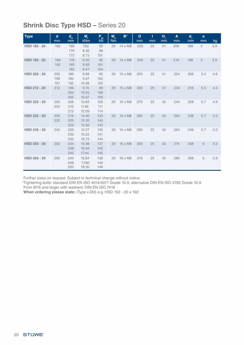
20
Type dmm
dwmm
MtkNm
PaxkN
MaNm
B* Dmm
Imm
H1mm
Amm
d1mm
emm kg
HSD 182 - 20 182 166 7.62 92 29 14 x M8 230 25 41 206 188 5 3.9170 8.35 98172 8.73 101
HSD 192 - 20 189 176 8.35 95 29 14 x M8 240 25 41 216 198 5 3.9192 180 9.09 101
182 9.47 104HSD 202 - 20 202 186 8.88 95 29 15 x M8 250 25 41 224 208 5.5 4.6
198 190 9.67 102197 192 10.08 105
HSD 212 - 20 212 196 9.74 99 29 15 x M8 260 25 41 234 218 5.5 4.4200 10.55 106202 10.97 109
HSD 222 - 20 220 206 10.83 105 29 16 x M8 270 25 42 244 228 5.7 4.9222 210 11.66 111
212 12.09 114HSD 232 - 20 230 216 14.40 133 29 16 x M8 280 25 42 254 238 5.7 5.0
232 220 15.35 140222 15.83 143
HSD 242 - 20 242 226 15.27 135 29 16 x M8 290 25 42 264 248 5.7 5.0230 16.22 141232 16.72 144
HSD 252 - 20 252 234 15.98 137 29 16 x M8 300 25 42 274 258 6 5.2238 16.94 142240 17.44 145
HSD 262 - 20 262 244 16.84 138 29 18 x M8 310 25 42 286 268 6 5.6248 17.80 144250 18.30 146
Further sizes on request. Subject to technical change without notice.*Tightening bolts: standard DIN EN ISO 4014/4017 Grade 10.9, alternative DIN EN ISO 4762 Grade 10.9From M16 and larger with washers: DIN EN ISO 7416When ordering please state: (Type x Ød) e.g. HSD 192 - 20 x 192
Shrink Disc Type HSD – Series 20
ØD
ØA
Ød
Ød
w
Ød
1
H1
l1,1 x l
e
Details of the fit:Ødw: H7/h6 (Ødw <160) H7/g6 (Ødw ≥160)Ød: H7/f7
Roughness of all fitting surfaces:Ra < 3.2 µm
CodeMt Maximum transmissible
torque of a shrink disc where Pax =0
Pax Maximum transmissible axial load of shrink disc where Mt =0
Ma Required tightening torque of the tightening bolts (see also “Installation and Removal Instructions“)
Dimensions H1 and e apply to untightened units.
21
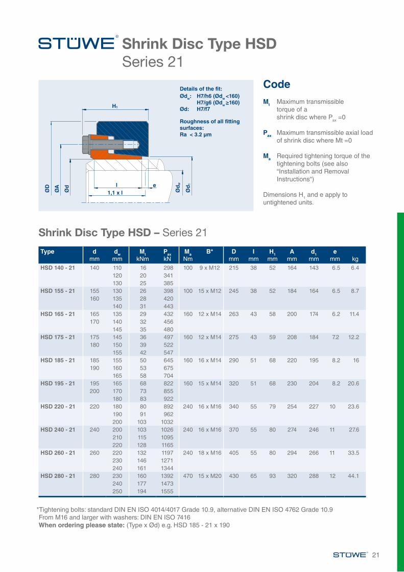
Shrink Disc Type HSDSeries 21
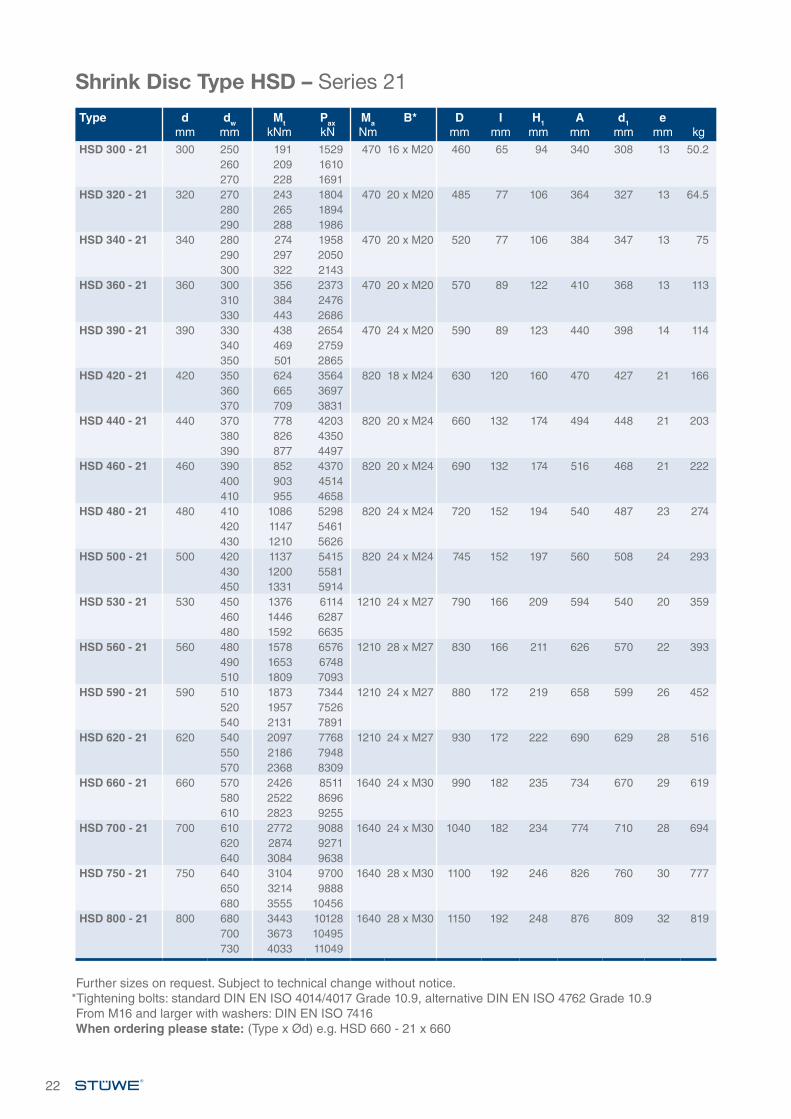
Shrink Disc Type HSD – Series 21
*Tightening bolts: standard DIN EN ISO 4014/4017 Grade 10.9, alternative DIN EN ISO 4762 Grade 10.9From M16 and larger with washers: DIN EN ISO 7416When ordering please state: (Type x Ød) e.g. HSD 185 - 21 x 190
Type dmm
dwmm
MtkNm
PaxkN
MaNm
B* Dmm
Imm
H1mm
Amm
d1mm
emm kg
HSD 140 - 21 140 110 16 298 100 9 x M12 215 38 52 164 143 6.5 6.4120 20 341130 25 385
HSD 155 - 21 155 130 26 398 100 15 x M12 245 38 52 184 164 6.5 8.7160 135 28 420
140 31 443HSD 165 - 21 165 135 29 432 160 12 x M14 263 43 58 200 174 6.2 11.4
170 140 32 456145 35 480
HSD 175 - 21 175 145 36 497 160 12 x M14 275 43 59 208 184 7.2 12.2180 150 39 522
155 42 547HSD 185 - 21 185 155 50 645 160 16 x M14 290 51 68 220 195 8.2 16
190 160 53 675165 58 704
HSD 195 - 21 195 165 68 822 160 15 x M14 320 51 68 230 204 8.2 20.6200 170 73 855
180 83 922HSD 220 - 21 220 180 80 892 240 16 x M16 340 55 79 254 227 10 23.6
190 91 962200 103 1032
HSD 240 - 21 240 200 103 1026 240 16 x M16 370 55 80 274 246 11 27.6210 115 1095220 128 1165
HSD 260 - 21 260 220 132 1197 240 18 x M16 405 55 80 294 266 11 33.5230 146 1271240 161 1344
HSD 280 - 21 280 230 160 1392 470 15 x M20 430 65 93 320 288 12 44.1240 177 1473250 194 1555
Further sizes on request. Subject to technical change without notice.*Tightening bolts: standard DIN EN ISO 4014/4017 Grade 10.9, alternative DIN EN ISO 4762 Grade 10.9From M16 and larger with washers: DIN EN ISO 7416When ordering please state: (Type x Ød) e.g. HSD 660 - 21 x 660
Shrink Disc Type HSD – Series 21
22
Type dmm
dwmm
MtkNm
PaxkN
MaNm
B* Dmm
Imm
H1mm
Amm
d1mm
emm kg
HSD 300 - 21 300 250 191 1529 470 16 x M20 460 65 94 340 308 13 50.2260 209 1610270 228 1691
HSD 320 - 21 320 270 243 1804 470 20 x M20 485 77 106 364 327 13 64.5280 265 1894290 288 1986
HSD 340 - 21 340 280 274 1958 470 20 x M20 520 77 106 384 347 13 75290 297 2050300 322 2143
HSD 360 - 21 360 300 356 2373 470 20 x M20 570 89 122 410 368 13 113310 384 2476330 443 2686
HSD 390 - 21 390 330 438 2654 470 24 x M20 590 89 123 440 398 14 114340 469 2759350 501 2865
HSD 420 - 21 420 350 624 3564 820 18 x M24 630 120 160 470 427 21 166360 665 3697370 709 3831
HSD 440 - 21 440 370 778 4203 820 20 x M24 660 132 174 494 448 21 203380 826 4350390 877 4497
HSD 460 - 21 460 390 852 4370 820 20 x M24 690 132 174 516 468 21 222400 903 4514410 955 4658
HSD 480 - 21 480 410 1086 5298 820 24 x M24 720 152 194 540 487 23 274420 1147 5461430 1210 5626
HSD 500 - 21 500 420 1137 5415 820 24 x M24 745 152 197 560 508 24 293430 1200 5581450 1331 5914
HSD 530 - 21 530 450 1376 6114 1210 24 x M27 790 166 209 594 540 20 359460 1446 6287480 1592 6635
HSD 560 - 21 560 480 1578 6576 1210 28 x M27 830 166 211 626 570 22 393490 1653 6748510 1809 7093
HSD 590 - 21 590 510 1873 7344 1210 24 x M27 880 172 219 658 599 26 452520 1957 7526540 2131 7891
HSD 620 - 21 620 540 2097 7768 1210 24 x M27 930 172 222 690 629 28 516550 2186 7948570 2368 8309
HSD 660 - 21 660 570 2426 8511 1640 24 x M30 990 182 235 734 670 29 619580 2522 8696610 2823 9255
HSD 700 - 21 700 610 2772 9088 1640 24 x M30 1040 182 234 774 710 28 694620 2874 9271640 3084 9638
HSD 750 - 21 750 640 3104 9700 1640 28 x M30 1100 192 246 826 760 30 777650 3214 9888680 3555 10456
HSD 800 - 21 800 680 3443 10128 1640 28 x M30 1150 192 248 876 809 32 819700 3673 10495730 4033 11049
23
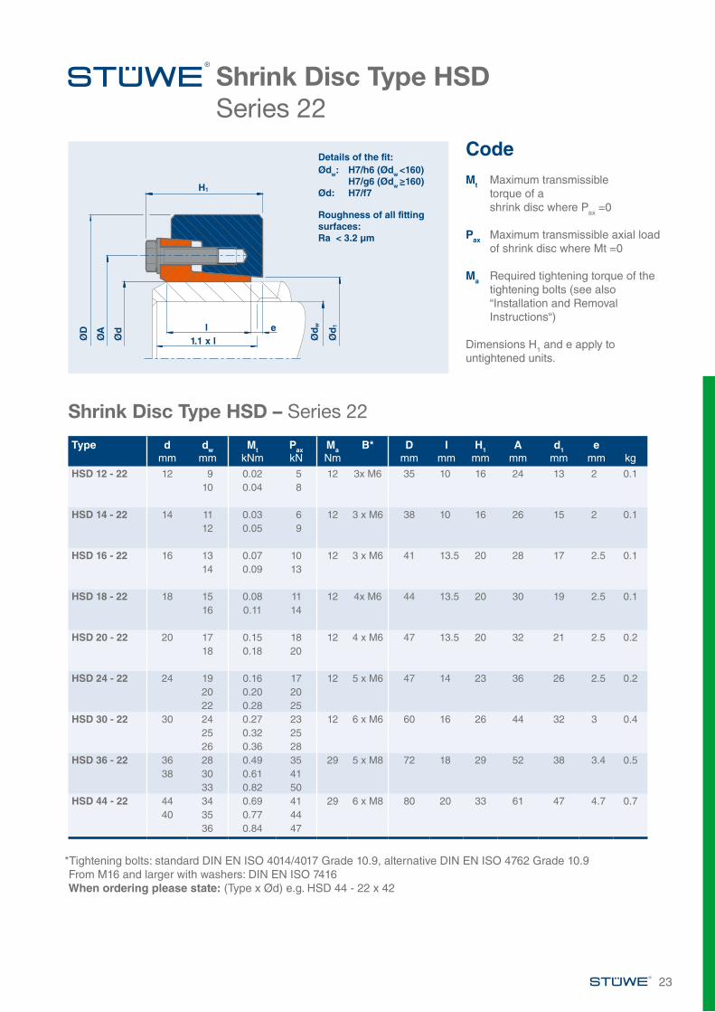
Shrink Disc Type HSDSeries 22
Shrink Disc Type HSD – Series 22
*Tightening bolts: standard DIN EN ISO 4014/4017 Grade 10.9, alternative DIN EN ISO 4762 Grade 10.9From M16 and larger with washers: DIN EN ISO 7416When ordering please state: (Type x Ød) e.g. HSD 44 - 22 x 42
CodeMt Maximum transmissible
torque of a shrink disc where Pax =0
Pax Maximum transmissible axial load of shrink disc where Mt =0
Ma Required tightening torque of the tightening bolts (see also “Installation and Removal Instructions“)
Dimensions H1 and e apply to untightened units.
ØD
ØA
Ød
Ød
w
Ød
1
H1
l1.1 x l
e
Details of the fit:Ødw: H7/h6 (Ødw <160) H7/g6 (Ødw ≥160)Ød: H7/f7
Roughness of all fitting surfaces:Ra < 3.2 µm
Type dmm
dwmm
MtkNm
PaxkN
MaNm
B* Dmm
Imm
H1mm
Amm
d1mm
emm kg
HSD 12 - 22 12 9 0.02 5 12 3x M6 35 10 16 24 13 2 0.110 0.04 8
HSD 14 - 22 14 11 0.03 6 12 3 x M6 38 10 16 26 15 2 0.112 0.05 9
HSD 16 - 22 16 13 0.07 10 12 3 x M6 41 13.5 20 28 17 2.5 0.114 0.09 13
HSD 18 - 22 18 15 0.08 11 12 4x M6 44 13.5 20 30 19 2.5 0.116 0.11 14
HSD 20 - 22 20 17 0.15 18 12 4 x M6 47 13.5 20 32 21 2.5 0.218 0.18 20
HSD 24 - 22 24 19 0.16 17 12 5 x M6 47 14 23 36 26 2.5 0.220 0.20 2022 0.28 25
HSD 30 - 22 30 24 0.27 23 12 6 x M6 60 16 26 44 32 3 0.425 0.32 2526 0.36 28
HSD 36 - 22 36 28 0.49 35 29 5 x M8 72 18 29 52 38 3.4 0.538 30 0.61 41
33 0.82 50HSD 44 - 22 44 34 0.69 41 29 6 x M8 80 20 33 61 47 4.7 0.7
40 35 0.77 4436 0.84 47
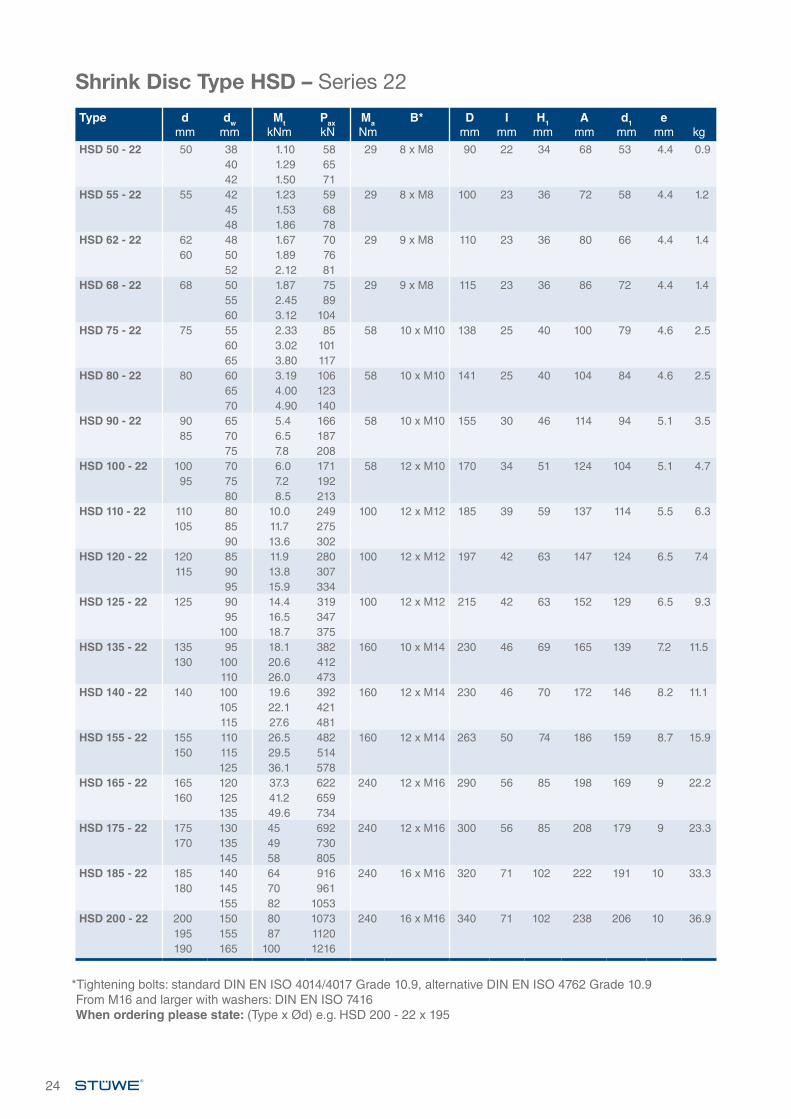
*Tightening bolts: standard DIN EN ISO 4014/4017 Grade 10.9, alternative DIN EN ISO 4762 Grade 10.9From M16 and larger with washers: DIN EN ISO 7416When ordering please state: (Type x Ød) e.g. HSD 200 - 22 x 195
24
Shrink Disc Type HSD – Series 22
Type dmm
dwmm
MtkNm
PaxkN
MaNm
B* Dmm
Imm
H1mm
Amm
d1mm
emm kg
HSD 50 - 22 50 38 1.10 58 29 8 x M8 90 22 34 68 53 4.4 0.940 1.29 6542 1.50 71
HSD 55 - 22 55 42 1.23 59 29 8 x M8 100 23 36 72 58 4.4 1.245 1.53 6848 1.86 78
HSD 62 - 22 62 48 1.67 70 29 9 x M8 110 23 36 80 66 4.4 1.460 50 1.89 76
52 2.12 81HSD 68 - 22 68 50 1.87 75 29 9 x M8 115 23 36 86 72 4.4 1.4
55 2.45 8960 3.12 104
HSD 75 - 22 75 55 2.33 85 58 10 x M10 138 25 40 100 79 4.6 2.560 3.02 10165 3.80 117
HSD 80 - 22 80 60 3.19 106 58 10 x M10 141 25 40 104 84 4.6 2.565 4.00 12370 4.90 140
HSD 90 - 22 90 65 5.4 166 58 10 x M10 155 30 46 114 94 5.1 3.585 70 6.5 187
75 7.8 208HSD 100 - 22 100 70 6.0 171 58 12 x M10 170 34 51 124 104 5.1 4.7
95 75 7.2 19280 8.5 213
HSD 110 - 22 110 80 10.0 249 100 12 x M12 185 39 59 137 114 5.5 6.3105 85 11.7 275
90 13.6 302HSD 120 - 22 120 85 11.9 280 100 12 x M12 197 42 63 147 124 6.5 7.4
115 90 13.8 30795 15.9 334
HSD 125 - 22 125 90 14.4 319 100 12 x M12 215 42 63 152 129 6.5 9.395 16.5 347
100 18.7 375HSD 135 - 22 135 95 18.1 382 160 10 x M14 230 46 69 165 139 7.2 11.5
130 100 20.6 412110 26.0 473
HSD 140 - 22 140 100 19.6 392 160 12 x M14 230 46 70 172 146 8.2 11.1105 22.1 421115 27.6 481
HSD 155 - 22 155 110 26.5 482 160 12 x M14 263 50 74 186 159 8.7 15.9150 115 29.5 514
125 36.1 578HSD 165 - 22 165 120 37.3 622 240 12 x M16 290 56 85 198 169 9 22.2
160 125 41.2 659135 49.6 734
HSD 175 - 22 175 130 45 692 240 12 x M16 300 56 85 208 179 9 23.3170 135 49 730
145 58 805HSD 185 - 22 185 140 64 916 240 16 x M16 320 71 102 222 191 10 33.3
180 145 70 961155 82 1053
HSD 200 - 22 200 150 80 1073 240 16 x M16 340 71 102 238 206 10 36.9195 155 87 1120190 165 100 1216
25
Shrink Disc Type HSD – Series 22
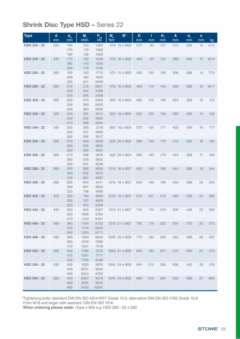
*Tightening bolts: standard DIN EN ISO 4014/4017 Grade 10.9, alternative DIN EN ISO 4762 Grade 10.9From M16 and larger with washers: DIN EN ISO 7416When ordering please state: (Type x Ød) e.g. HSD 280 - 22 x 280
Type dmm
dwmm
MtkNm
PaxkN
MaNm
B* Dmm
Imm
H1mm
Amm
d1mm
emm kg
HSD 220 - 22 220 160 103 1283 470 15 x M20 370 93 121 270 230 12 51.5170 119 1395180 136 1509
HSD 240 - 22 240 170 122 1439 470 16 x M20 405 95 124 288 248 12 63.9180 140 1555200 179 1790
HSD 260 - 22 260 190 163 1715 470 15 x M20 430 105 136 306 268 14 77.5200 184 1842220 231 2099
HSD 280 - 22 280 210 215 2051 470 16 x M20 460 114 146 328 288 16 94.7220 240 2186240 295 2458
HSD 300 - 22 300 220 270 2456 820 16 x M24 485 123 158 354 309 16 112230 300 2605250 363 2906
HSD 320 - 22 320 240 301 2511 820 18 x M24 520 125 159 380 328 14 133250 332 2655270 398 2945
HSD 340 - 22 340 250 390 3118 820 18 x M24 570 134 171 402 349 16 177260 427 3283280 506 3617
HSD 350 - 22 350 270 493 3649 820 20 x M24 580 140 178 414 365 16 190280 535 3825290 580 4001
HSD 360 - 22 360 270 496 3676 820 20 x M24 590 140 179 424 369 17 194280 539 3852300 631 4206
HSD 380 - 22 380 290 585 4034 1210 18 x M27 640 146 188 444 388 19 244300 632 4215310 681 4397
HSD 390 - 22 390 290 640 4411 1210 18 x M27 645 146 189 454 398 20 243300 691 4605320 799 4996
HSD 420 - 22 420 320 742 4640 1210 18 x M27 670 167 210 490 428 20 286330 797 4829350 912 5209
HSD 440 - 22 440 340 945 5557 1210 21 x M27 710 174 219 506 448 22 339350 1009 5764370 1143 6181
HSD 460 - 22 460 360 1104 6133 1210 21 x M27 745 174 222 534 470 25 375370 1174 6345390 1320 6771
HSD 480 - 22 480 380 1300 6843 1640 20 x M30 770 192 239 552 488 22 437390 1378 7066410 1541 7516
HSD 500 - 22 500 400 1496 7478 1640 21 x M30 800 192 241 572 509 24 470410 1581 7711430 1759 8180
HSD 530 - 22 530 430 1930 8976 1640 24 x M30 845 213 266 606 540 29 576440 2031 9234460 2243 9752
HSD 560 - 22 560 450 2097 9318 1640 24 x M30 900 213 264 632 568 27 660460 2201 9572480 2420 10081
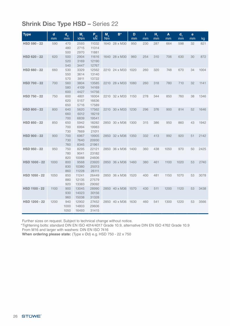
Shrink Disc Type HSD – Series 22
Further sizes on request. Subject to technical change without notice.*Tightening bolts: standard DIN EN ISO 4014/4017 Grade 10.9, alternative DIN EN ISO 4762 Grade 10.9From M16 and larger with washers: DIN EN ISO 7416When ordering please state: (Type x Ød) e.g. HSD 750 - 22 x 750
26
Type dmm
dwmm
MtkNm
PaxkN
MaNm
B* Dmm
Imm
H1mm
Amm
d1mm
emm kg
HSD 590 - 22 590 470 2593 11032 1640 28 x M30 950 230 287 664 598 32 821480 2715 11314500 2970 11881
HSD 620 - 22 620 500 2904 11616 1640 28 x M30 960 254 310 706 630 30 872520 3169 12190540 3447 12767
HSD 660 - 22 660 530 3329 12562 2210 24 x M33 1020 260 320 748 670 34 1004550 3614 13140570 3911 13722
HSD 700 - 22 700 560 3804 13585 2210 28 x M33 1080 260 318 780 710 32 1141580 4109 14169600 4427 14756
HSD 750 - 22 750 600 4801 16004 2210 32 x M33 1150 278 344 850 760 38 1346620 5157 16636650 5716 17589
HSD 800 - 22 800 640 5620 17562 2210 30 x M33 1230 296 376 900 814 52 1646660 6012 18219700 6839 19541
HSD 850 - 22 850 650 5942 18282 2850 30 x M36 1300 315 386 950 860 43 1942700 6994 19983730 7669 21011
HSD 900 - 22 900 700 6967 19905 2850 32 x M36 1350 332 413 992 920 51 2142730 7640 20930760 8345 21961
HSD 950 - 22 950 750 8295 22121 2850 36 x M36 1400 360 438 1050 970 50 2425780 9041 23182820 10088 24606
HSD 1000 - 22 1000 800 9568 23920 2850 36 x M36 1460 380 461 1100 1020 53 2740830 10380 25013860 11228 26111
HSD 1050 - 22 1050 850 11241 26449 2850 36 x M36 1520 400 481 1150 1070 53 3078880 12135 27579920 13383 29092
HSD 1100 - 22 1100 900 13045 28990 2850 40 x M36 1570 430 511 1200 1120 53 3438930 14023 30156960 15038 31328
HSD 1200 - 22 1200 940 12902 27452 2850 40 x M36 1630 460 541 1300 1220 53 35661000 14803 296061050 16493 31415
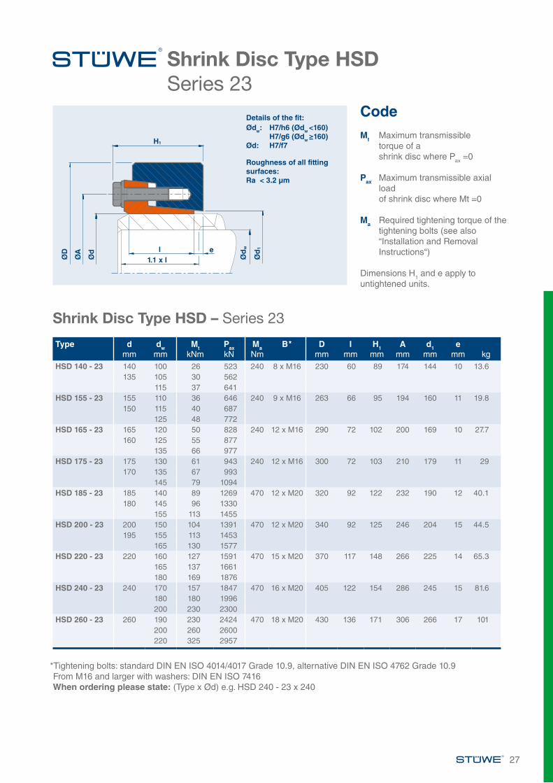
Shrink Disc Type HSDSeries 23
Shrink Disc Type HSD – Series 23
*Tightening bolts: standard DIN EN ISO 4014/4017 Grade 10.9, alternative DIN EN ISO 4762 Grade 10.9From M16 and larger with washers: DIN EN ISO 7416When ordering please state: (Type x Ød) e.g. HSD 240 - 23 x 240
27
CodeMt Maximum transmissible
torque of a shrink disc where Pax =0
Pax Maximum transmissible axial load of shrink disc where Mt =0
Ma Required tightening torque of the tightening bolts (see also “Installation and Removal Instructions“)
Dimensions H1 and e apply to untightened units.
ØD
ØA
Ød
Ød
w
Ød
1
H1
l1.1 x l
e
Details of the fit:Ødw: H7/h6 (Ødw <160) H7/g6 (Ødw ≥160)Ød: H7/f7
Roughness of all fitting surfaces:Ra < 3.2 µm
Type dmm
dwmm
MtkNm
PaxkN
MaNm
B* Dmm
Imm
H1mm
Amm
d1mm
emm kg
HSD 140 - 23 140 100 26 523 240 8 x M16 230 60 89 174 144 10 13.6135 105 30 562
115 37 641HSD 155 - 23 155 110 36 646 240 9 x M16 263 66 95 194 160 11 19.8
150 115 40 687125 48 772
HSD 165 - 23 165 120 50 828 240 12 x M16 290 72 102 200 169 10 27.7160 125 55 877
135 66 977HSD 175 - 23 175 130 61 943 240 12 x M16 300 72 103 210 179 11 29
170 135 67 993145 79 1094
HSD 185 - 23 185 140 89 1269 470 12 x M20 320 92 122 232 190 12 40.1180 145 96 1330
155 113 1455HSD 200 - 23 200 150 104 1391 470 12 x M20 340 92 125 246 204 15 44.5
195 155 113 1453165 130 1577
HSD 220 - 23 220 160 127 1591 470 15 x M20 370 117 148 266 225 14 65.3165 137 1661180 169 1876
HSD 240 - 23 240 170 157 1847 470 16 x M20 405 122 154 286 245 15 81.6180 180 1996200 230 2300
HSD 260 - 23 260 190 230 2424 470 18 x M20 430 136 171 306 266 17 101200 260 2600220 325 2957
Further sizes on request. Subject to technical change without notice.*Tightening bolts: standard DIN EN ISO 4014/4017 Grade 10.9, alternative DIN EN ISO 4762 Grade 10.9From M16 and larger with washers: DIN EN ISO 7416When ordering please state: (Type x Ød) e.g. HSD 420 - 23 x 420
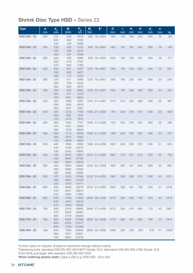
Shrink Disc Type HSD – Series 23
28
Type dmm
dwmm
MtkNm
PaxkN
MaNm
B* Dmm
Imm
H1mm
Amm
d1mm
emm kg
HSD 280 - 23 280 210 306 2918 820 16 x M24 460 148 185 334 286 16 126220 342 3105240 418 3485
HSD 300 - 23 300 230 360 3132 820 16 x M24 485 152 191 354 306 18 140240 398 3314250 437 3498
HSD 320 - 23 320 240 430 3580 820 18 x M24 520 160 199 374 325 18 171250 473 3781270 565 4186
HSD 340 - 23 340 250 551 4407 1210 18 x M27 560 176 219 404 346 19 221260 603 4637280 714 5100
HSD 360 - 23 360 270 671 4969 1210 18 x M27 590 180 224 424 366 20 249280 729 5204300 852 5679
HSD 390 - 23 390 290 850 5860 1210 20 x M27 650 190 238 456 399 24 324300 917 6116320 1061 6633
HSD 420 - 23 420 320 1008 6301 1210 21 x M27 670 214 264 486 428 26 367330 1082 6555350 1237 7067
HSD 440 - 23 440 340 1218 7166 1640 21 x M30 740 229 279 514 448 25 508350 1301 7433370 1475 7972
HSD 460 - 23 460 360 1402 7791 1640 21 x M30 750 226 278 534 469 28 485370 1491 8062390 1678 8606
HSD 480 - 23 480 380 1712 9008 1640 21 x M30 760 246 305 552 488 33 537390 1814 9302410 2028 9893
HSD 500 - 23 500 400 1993 9963 1640 24 x M30 800 246 303 572 508 31 604410 2106 10273430 2342 10895
HSD 530 - 23 530 430 2549 11857 2210 21 x M33 860 276 341 616 539 36 794440 2683 12196460 2962 12878
HSD 560 - 23 560 450 2849 12660 2210 24 x M33 900 280 341 646 568 34 867460 2990 13002480 3285 13689
HSD 590 - 23 590 470 3310 14084 2210 24 x M33 960 296 366 672 598 40 1071480 3467 14446500 3793 15171
HSD 620 - 23 620 500 4069 16276 2210 27 x M33 1000 330 401 706 630 41 1279510 4251 16672540 4824 17866
HSD 660 - 23 660 530 4746 17909 2850 28 x M36 1070 334 402 750 670 40 1475540 4944 18313570 5566 19530
HSD 700 - 23 700 560 5316 18985 2850 27 x M36 1070 334 413 800 710 45 1387570 5525 19387600 6179 20596
HSD 750 - 23 750 600 6326 21086 2850 32 x M36 1170 360 431 850 760 44 1810620 6794 21917650 7530 23169
HSD 800 - 23 800 640 7358 22993 2850 32 x M36 1280 360 439 900 810 51 2290660 7871 23851700 8952 25576
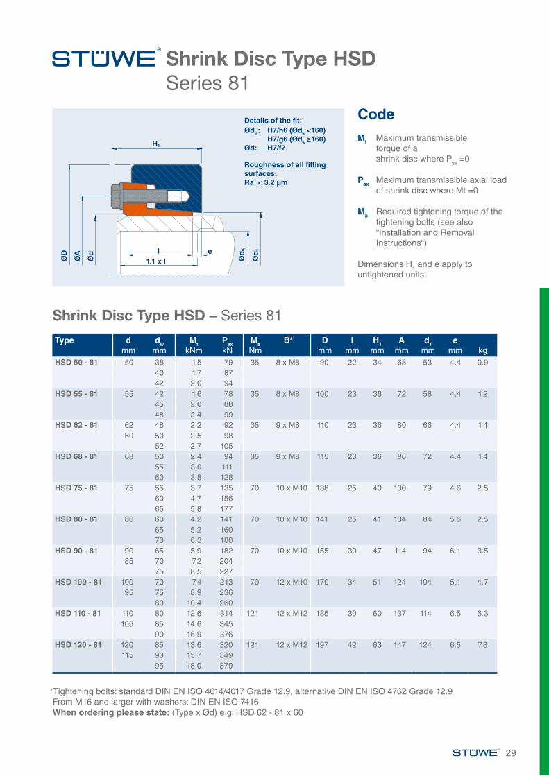
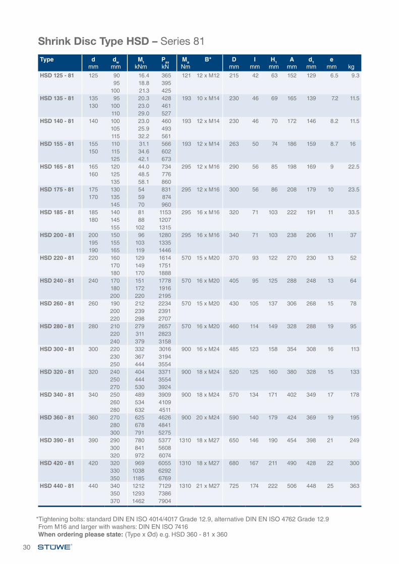
Shrink Disc Type HSDSeries 81
Shrink Disc Type HSD – Series 81
*Tightening bolts: standard DIN EN ISO 4014/4017 Grade 12.9, alternative DIN EN ISO 4762 Grade 12.9From M16 and larger with washers: DIN EN ISO 7416When ordering please state: (Type x Ød) e.g. HSD 62 - 81 x 60
CodeMt Maximum transmissible
torque of a shrink disc where Pax =0
Pax Maximum transmissible axial load of shrink disc where Mt =0
Ma Required tightening torque of the tightening bolts (see also “Installation and Removal Instructions“)
Dimensions H1 and e apply to untightened units.
ØD
ØA
Ød
Ød
w
Ød
1
H1
l1.1 x l
e
Details of the fit:Ødw: H7/h6 (Ødw <160) H7/g6 (Ødw ≥160)Ød: H7/f7
Roughness of all fitting surfaces:Ra < 3.2 µm
Type dmm
dwmm
MtkNm
PaxkN
MaNm
B* Dmm
Imm
H1mm
Amm
d1mm
emm kg
HSD 50 - 81 50 38 1.5 79 35 8 x M8 90 22 34 68 53 4.4 0.940 1.7 8742 2.0 94
HSD 55 - 81 55 42 1.6 78 35 8 x M8 100 23 36 72 58 4.4 1.245 2.0 8848 2.4 99
HSD 62 - 81 62 48 2.2 92 35 9 x M8 110 23 36 80 66 4.4 1.460 50 2.5 98
52 2.7 105HSD 68 - 81 68 50 2.4 94 35 9 x M8 115 23 36 86 72 4.4 1.4
55 3.0 11160 3.8 128
HSD 75 - 81 75 55 3.7 135 70 10 x M10 138 25 40 100 79 4.6 2.560 4.7 15665 5.8 177
HSD 80 - 81 80 60 4.2 141 70 10 x M10 141 25 41 104 84 5.6 2.565 5.2 16070 6.3 180
HSD 90 - 81 90 65 5.9 182 70 10 x M10 155 30 47 114 94 6.1 3.585 70 7.2 204
75 8.5 227HSD 100 - 81 100 70 7.4 213 70 12 x M10 170 34 51 124 104 5.1 4.7
95 75 8.9 23680 10.4 260
HSD 110 - 81 110 80 12.6 314 121 12 x M12 185 39 60 137 114 6.5 6.3105 85 14.6 345
90 16.9 376HSD 120 - 81 120 85 13.6 320 121 12 x M12 197 42 63 147 124 6.5 7.8
115 90 15.7 34995 18.0 379
29
Shrink Disc Type HSD – Series 81
*Tightening bolts: standard DIN EN ISO 4014/4017 Grade 12.9, alternative DIN EN ISO 4762 Grade 12.9From M16 and larger with washers: DIN EN ISO 7416When ordering please state: (Type x Ød) e.g. HSD 360 - 81 x 360
30
Type dmm
dwmm
MtkNm
PaxkN
MaNm
B* Dmm
Imm
H1mm
Amm
d1mm
emm kg
HSD 125 - 81 125 90 16.4 365 121 12 x M12 215 42 63 152 129 6.5 9.395 18.8 395
100 21.3 425HSD 135 - 81 135 95 20.3 428 193 10 x M14 230 46 69 165 139 7.2 11.5
130 100 23.0 461110 29.0 527
HSD 140 - 81 140 100 23.0 460 193 12 x M14 230 46 70 172 146 8.2 11.5105 25.9 493115 32.2 561
HSD 155 - 81 155 110 31.1 566 193 12 x M14 263 50 74 186 159 8.7 16150 115 34.6 602
125 42.1 673HSD 165 - 81 165 120 44.0 734 295 12 x M16 290 56 85 198 169 9 22.5
160 125 48.5 776135 58.1 860
HSD 175 - 81 175 130 54 831 295 12 x M16 300 56 86 208 179 10 23.5170 135 59 874
145 70 960HSD 185 - 81 185 140 81 1153 295 16 x M16 320 71 103 222 191 11 33.5
180 145 88 1207155 102 1315
HSD 200 - 81 200 150 96 1280 295 16 x M16 340 71 103 238 206 11 37195 155 103 1335190 165 119 1446
HSD 220 - 81 220 160 129 1614 570 15 x M20 370 93 122 270 230 13 52170 149 1751180 170 1888
HSD 240 - 81 240 170 151 1778 570 16 x M20 405 95 125 288 248 13 64180 172 1916200 220 2195
HSD 260 - 81 260 190 212 2234 570 15 x M20 430 105 137 306 268 15 78200 239 2391220 298 2707
HSD 280 - 81 280 210 279 2657 570 16 x M20 460 114 149 328 288 19 95220 311 2823240 379 3158
HSD 300 - 81 300 220 332 3016 900 16 x M24 485 123 158 354 308 16 113230 367 3194250 444 3554
HSD 320 - 81 320 240 404 3371 900 18 x M24 520 125 160 380 328 15 133250 444 3554270 530 3924
HSD 340 - 81 340 250 489 3909 900 18 x M24 570 134 171 402 349 17 178260 534 4109280 632 4511
HSD 360 - 81 360 270 625 4626 900 20 x M24 590 140 179 424 369 19 195280 678 4841300 791 5275
HSD 390 - 81 390 290 780 5377 1310 18 x M27 650 146 190 454 398 21 249300 841 5608320 972 6074
HSD 420 - 81 420 320 969 6055 1310 18 x M27 680 167 211 490 428 22 300330 1038 6292350 1185 6769
HSD 440 - 81 440 340 1212 7129 1310 21 x M27 725 174 222 506 448 25 363350 1293 7386370 1462 7904
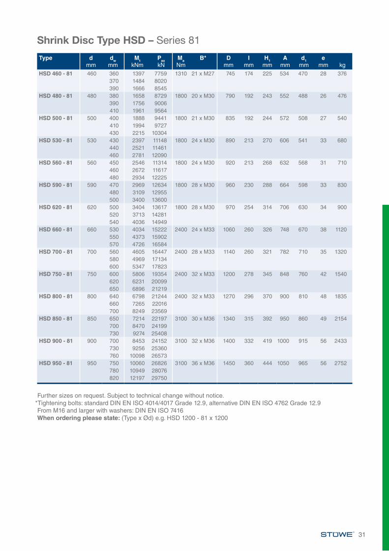
Further sizes on request. Subject to technical change without notice.*Tightening bolts: standard DIN EN ISO 4014/4017 Grade 12.9, alternative DIN EN ISO 4762 Grade 12.9 From M16 and larger with washers: DIN EN ISO 7416When ordering please state: (Type x Ød) e.g. HSD 1200 - 81 x 1200
Shrink Disc Type HSD – Series 81
Type dmm
dwmm
MtkNm
PaxkN
MaNm
B* Dmm
Imm
H1mm
Amm
d1mm
emm kg
HSD 460 - 81 460 360 1397 7759 1310 21 x M27 745 174 225 534 470 28 376370 1484 8020390 1666 8545
HSD 480 - 81 480 380 1658 8729 1800 20 x M30 790 192 243 552 488 26 476390 1756 9006410 1961 9564
HSD 500 - 81 500 400 1888 9441 1800 21 x M30 835 192 244 572 508 27 540410 1994 9727430 2215 10304
HSD 530 - 81 530 430 2397 11148 1800 24 x M30 890 213 270 606 541 33 680440 2521 11461460 2781 12090
HSD 560 - 81 560 450 2546 11314 1800 24 x M30 920 213 268 632 568 31 710460 2672 11617480 2934 12225
HSD 590 - 81 590 470 2969 12634 1800 28 x M30 960 230 288 664 598 33 830480 3109 12955500 3400 13600
HSD 620 - 81 620 500 3404 13617 1800 28 x M30 970 254 314 706 630 34 900520 3713 14281540 4036 14949
HSD 660 - 81 660 530 4034 15222 2400 24 x M33 1060 260 326 748 670 38 1120550 4373 15902570 4726 16584
HSD 700 - 81 700 560 4605 16447 2400 28 x M33 1140 260 321 782 710 35 1320580 4969 17134600 5347 17823
HSD 750 - 81 750 600 5806 19354 2400 32 x M33 1200 278 345 848 760 42 1540620 6231 20099650 6896 21219
HSD 800 - 81 800 640 6798 21244 2400 32 x M33 1270 296 370 900 810 48 1835660 7265 22016700 8249 23569
HSD 850 - 81 850 650 7214 22197 3100 30 x M36 1340 315 392 950 860 49 2154700 8470 24199730 9274 25408
HSD 900 - 81 900 700 8453 24152 3100 32 x M36 1400 332 419 1000 915 56 2433730 9256 25360760 10098 26573
HSD 950 - 81 950 750 10060 26826 3100 36 x M36 1450 360 444 1050 965 56 2752780 10949 28076820 12197 29750
31
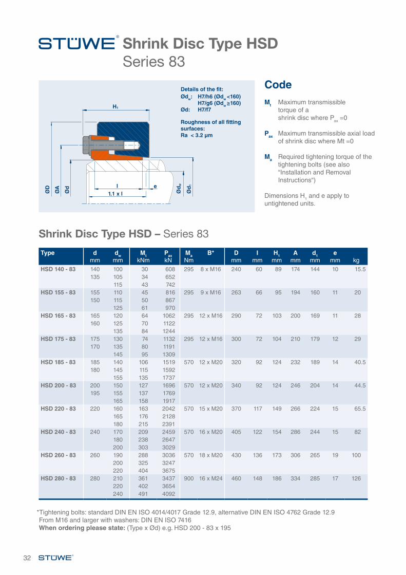
Shrink Disc Type HSDSeries 83
Shrink Disc Type HSD – Series 83
*Tightening bolts: standard DIN EN ISO 4014/4017 Grade 12.9, alternative DIN EN ISO 4762 Grade 12.9From M16 and larger with washers: DIN EN ISO 7416When ordering please state: (Type x Ød) e.g. HSD 200 - 83 x 195
CodeMt Maximum transmissible
torque of a shrink disc where Pax =0
Pax Maximum transmissible axial load of shrink disc where Mt =0
Ma Required tightening torque of the tightening bolts (see also “Installation and Removal Instructions“)
Dimensions H1 and e apply to untightened units.
ØD
ØA
Ød
Ød
w
Ød
1
H1
l1.1 x l
e
Details of the fit:Ødw: H7/h6 (Ødw <160) H7/g6 (Ødw ≥160)Ød: H7/f7
Roughness of all fitting surfaces:Ra < 3.2 µm
32
Type dmm
dwmm
MtkNm
PaxkN
MaNm
B* Dmm
Imm
H1mm
Amm
d1mm
emm kg
HSD 140 - 83 140 100 30 608 295 8 x M16 240 60 89 174 144 10 15.5135 105 34 652
115 43 742HSD 155 - 83 155 110 45 816 295 9 x M16 263 66 95 194 160 11 20
150 115 50 867125 61 970
HSD 165 - 83 165 120 64 1062 295 12 x M16 290 72 103 200 169 11 28160 125 70 1122
135 84 1244HSD 175 - 83 175 130 74 1132 295 12 x M16 300 72 104 210 179 12 29
170 135 80 1191145 95 1309
HSD 185 - 83 185 140 106 1519 570 12 x M20 320 92 124 232 189 14 40.5180 145 115 1592
155 135 1737HSD 200 - 83 200 150 127 1696 570 12 x M20 340 92 124 246 204 14 44.5
195 155 137 1769165 158 1917
HSD 220 - 83 220 160 163 2042 570 15 x M20 370 117 149 266 224 15 65.5165 176 2128180 215 2391
HSD 240 - 83 240 170 209 2459 570 16 x M20 405 122 154 286 244 15 82180 238 2647200 303 3029
HSD 260 - 83 260 190 288 3036 570 18 x M20 430 136 173 306 265 19 100200 325 3247220 404 3675
HSD 280 - 83 280 210 361 3437 900 16 x M24 460 148 186 334 285 17 126220 402 3654240 491 4092
Further sizes on request. Subject to technical change without notice.*Tightening bolts: standard DIN EN ISO 4014/4017 Grade 12.9, alternative DIN EN ISO 4762 Grade 12.9 From M16 and larger with washers: DIN EN ISO 7416, When ordering please state: (Type x Ød) e.g. HSD 420 - 83 x 420
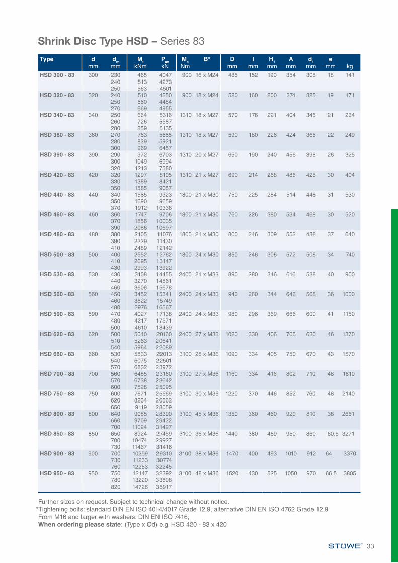
Shrink Disc Type HSD – Series 83
33
Type dmm
dwmm
MtkNm
PaxkN
MaNm
B* Dmm
Imm
H1mm
Amm
d1mm
emm kg
HSD 300 - 83 300 230 465 4047 900 16 x M24 485 152 190 354 305 18 141240 513 4273250 563 4501
HSD 320 - 83 320 240 510 4250 900 18 x M24 520 160 200 374 325 19 171250 560 4484270 669 4955
HSD 340 - 83 340 250 664 5316 1310 18 x M27 570 176 221 404 345 21 234260 726 5587280 859 6135
HSD 360 - 83 360 270 763 5655 1310 18 x M27 590 180 226 424 365 22 249280 829 5921300 969 6457
HSD 390 - 83 390 290 972 6703 1310 20 x M27 650 190 240 456 398 26 325300 1049 6994320 1213 7580
HSD 420 - 83 420 320 1297 8105 1310 21 x M27 690 214 268 486 428 30 404330 1389 8421350 1585 9057
HSD 440 - 83 440 340 1585 9323 1800 21 x M30 750 225 284 514 448 31 530350 1690 9659370 1912 10336
HSD 460 - 83 460 360 1747 9706 1800 21 x M30 760 226 280 534 468 30 520370 1856 10035390 2086 10697
HSD 480 - 83 480 380 2105 11076 1800 21 x M30 800 246 309 552 488 37 640390 2229 11430410 2489 12142
HSD 500 - 83 500 400 2552 12762 1800 24 x M30 850 246 306 572 508 34 740410 2695 13147430 2993 13922
HSD 530 - 83 530 430 3108 14455 2400 21 x M33 890 280 346 616 538 40 900440 3270 14861460 3606 15678
HSD 560 - 83 560 450 3452 15341 2400 24 x M33 940 280 344 646 568 36 1000460 3622 15749480 3976 16567
HSD 590 - 83 590 470 4027 17138 2400 24 x M33 980 296 369 666 600 41 1150480 4217 17571500 4610 18439
HSD 620 - 83 620 500 5040 20160 2400 27 x M33 1020 330 406 706 630 46 1370510 5263 20641540 5964 22089
HSD 660 - 83 660 530 5833 22013 3100 28 x M36 1090 334 405 750 670 43 1570540 6075 22501570 6832 23972
HSD 700 - 83 700 560 6485 23160 3100 27 x M36 1160 334 416 802 710 48 1810570 6738 23642600 7528 25095
HSD 750 - 83 750 600 7671 25569 3100 30 x M36 1220 370 446 852 760 48 2140620 8234 26562650 9119 28059
HSD 800 - 83 800 640 9085 28390 3100 45 x M36 1350 360 460 920 810 38 2651660 9709 29422700 11024 31497
HSD 850 - 83 850 650 8924 27459 3100 36 x M36 1440 380 469 950 860 60.5 3271700 10474 29927730 11467 31416
HSD 900 - 83 900 700 10259 29310 3100 38 x M36 1470 400 493 1010 912 64 3370730 11233 30774760 12253 32245
HSD 950 - 83 950 750 12147 32392 3100 48 x M36 1520 430 525 1050 970 66.5 3805780 13220 33898820 14726 35917

34
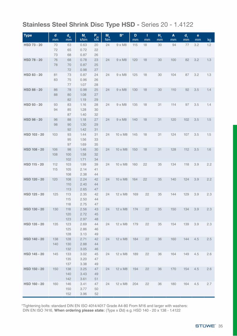
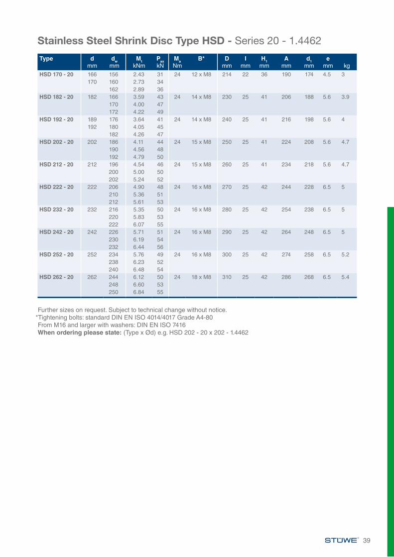
Stainless Steel Shrink Disc Type HSD Series 20 - 1.4122
CodeMt Maximum transmissible
torque of a shrink disc where Pax =0
Pax Maximum transmissible axial load of shrink disc where Mt =0
Ma Required tightening torque of the tightening bolts (see also “Installation and Removal Instructions“)
Dimensions H1 and e apply to untightened units.
µw The transmissible loads are calculated using a coefficient of friction µw = 0.1 for stainless steel materials
ØD
ØA
Ød
Ød
w
Ød
1
H1
l1.1 x l
e
Details of the fit:Ødw: H7/h6 (Ødw <160) H7/g6 (Ødw ≥160)Ød: H7/f7
Roughness of all fitting surfaces:Ra < 3.2 µm
Stainless Steel Shrink Disc Type HSD - Series 20 - 1.4122
*Tightening bolts: standard DIN EN ISO 4014/4017 Grade A4-80 From M16 and larger with washers: DIN EN ISO 7416, When ordering please state: (Type x Ød) e.g. HSD 61 - 20 x 61 - 1.4122
Type dmm
dwmm
MtkNm
PaxkN
MaNm
B* Dmm
Imm
H1mm
Amm
d1mm
emm kg
HSD 24 - 20 24 20 0.08 8 10 6 x M6 50 11.5 18 38 25 1.8 0.221 0.10 1022 0.12 11
HSD 29 - 20 29 25 0.13 10 10 6 x M6 58 12.5 18 44 31 1.8 0.226 0.15 1127 0.17 13
HSD 35 - 20 34 29 0.15 10 10 5 x M6 64 12.5 18 52 38 1.8 0.2535 30 0.17 11
32 0.21 13HSD 40 - 20 38 34 0.19 11 10 6 x M6 69 12.2 18 55 43 2.5 0.3
40 35 0.21 1236 0.23 13
HSD 46 - 20 46 38 0.24 13 10 6 x M6 80 13 23 62 50 2.5 0.547 40 0.30 15
42 0.36 17HSD 51 - 20 51 44 0.35 16 10 8 x M6 86 13 23 67 54 2.5 0.5
45 0.38 1747 0.45 19
HSD 56 - 20 55 48 0.37 15 10 8 x M6 90 13 23 72 59 2.9 0.656 50 0.43 1757 52 0.49 19
HSD 61 - 20 61 53 0.47 18 10 8 x M6 96 13 24 76 63 2.9 0.755 0.55 2057 0.63 22
HSD 66 - 20 65 58 0.51 18 10 8 x M6 100 13 24 82 68 2.9 0.766 60 0.58 19
62 0.66 21
35
Stainless Steel Shrink Disc Type HSD - Series 20 - 1.4122
*Tightening bolts: standard DIN EN ISO 4014/4017 Grade A4-80 From M16 and larger with washers: DIN EN ISO 7416, When ordering please state: (Type x Ød) e.g. HSD 140 - 20 x 138 - 1.4122
Type dmm
dwmm
MtkNm
PaxkN
MaNm
B* Dmm
Imm
H1mm
Amm
d1mm
emm kg
HSD 73 - 20 70 63 0.63 20 24 9 x M8 115 18 30 94 77 3.2 1.2
72 65 0.72 22
73 68 0.87 26
HSD 78 - 20 76 68 0.78 23 24 9 x M8 120 18 30 100 82 3.2 1.3
78 70 0.87 25
72 0.98 27
HSD 83 - 20 81 73 0.87 24 24 9 x M8 125 18 30 104 87 3.2 1.3
83 75 0.96 26
77 1.07 28
HSD 88 - 20 86 78 0.98 25 24 9 x M8 130 18 30 110 92 3.5 1.4
88 80 1.08 27
82 1.19 29
HSD 93 - 20 93 83 1.16 28 24 9 x M8 135 18 31 114 97 3.5 1.4
94 85 1.28 30
87 1.40 32
HSD 98 - 20 96 88 1.18 27 24 9 x M8 140 18 31 120 102 3.5 1.5
98 90 1.30 29
92 1.42 31
HSD 103 - 20 103 93 1.44 31 24 10 x M8 145 18 31 124 107 3.5 1.5
95 1.56 33
97 1.69 35
HSD 108 - 20 106 98 1.46 30 24 10 x M8 150 18 31 128 112 3.5 1.6
108 100 1.58 32
102 1.71 34
HSD 115 - 20 112 103 1.99 39 24 10 x M8 160 22 35 134 118 3.9 2.2
115 105 2.14 41
108 2.38 44
HSD 120 - 20 120 108 2.24 42 24 10 x M8 164 22 35 140 124 3.9 2.2
110 2.40 44
113 2.65 47
HSD 125 - 20 125 113 2.35 42 24 12 x M8 169 22 35 144 129 3.9 2.3
115 2.50 44
118 2.75 47
HSD 130 - 20 130 118 2.56 43 24 12 x M8 174 22 35 150 134 3.9 2.3
120 2.72 45
123 2.97 48
HSD 135 - 20 135 123 2.69 44 24 12 x M8 179 22 35 154 139 3.9 2.3
125 2.86 46
128 3.13 49
HSD 140 - 20 138 128 2.71 42 24 12 x M8 184 22 36 160 144 4.5 2.5
140 130 2.88 44
132 3.05 46
HSD 145 - 20 145 133 3.02 45 24 12 x M8 189 22 36 164 149 4.5 2.6
135 3.20 47
137 3.38 49
HSD 150 - 20 150 138 3.25 47 24 12 x M8 194 22 36 170 154 4.5 2.6
140 3.43 49
142 3.61 51
HSD 160 - 20 160 146 3.41 47 24 12 x M8 204 22 36 180 164 4.5 2.7
150 3.77 50
152 3.96 52
Stainless Steel Shrink Disc Type HSD - Series 20 - 1.4122
36
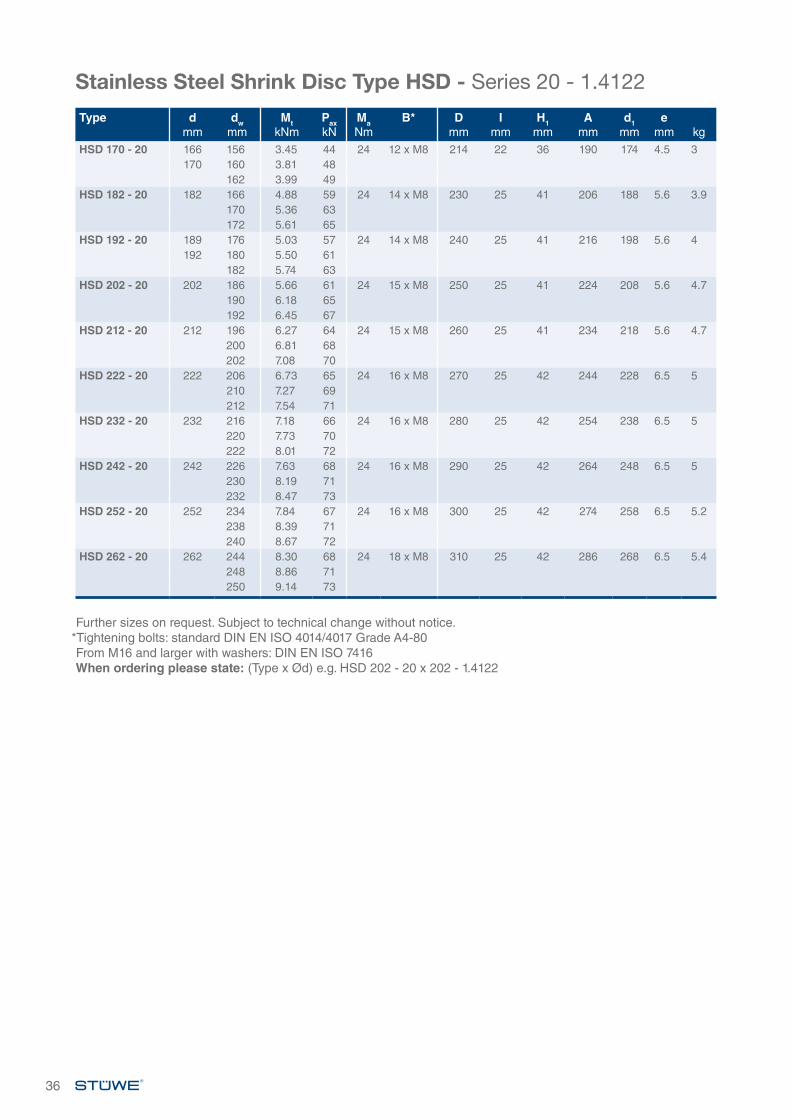
Further sizes on request. Subject to technical change without notice.*Tightening bolts: standard DIN EN ISO 4014/4017 Grade A4-80 From M16 and larger with washers: DIN EN ISO 7416When ordering please state: (Type x Ød) e.g. HSD 202 - 20 x 202 - 1.4122
Type dmm
dwmm
MtkNm
PaxkN
MaNm
B* Dmm
Imm
H1mm
Amm
d1mm
emm kg
HSD 170 - 20 166 156 3.45 44 24 12 x M8 214 22 36 190 174 4.5 3170 160 3.81 48
162 3.99 49HSD 182 - 20 182 166 4.88 59 24 14 x M8 230 25 41 206 188 5.6 3.9
170 5.36 63172 5.61 65
HSD 192 - 20 189 176 5.03 57 24 14 x M8 240 25 41 216 198 5.6 4192 180 5.50 61
182 5.74 63HSD 202 - 20 202 186 5.66 61 24 15 x M8 250 25 41 224 208 5.6 4.7
190 6.18 65192 6.45 67
HSD 212 - 20 212 196 6.27 64 24 15 x M8 260 25 41 234 218 5.6 4.7200 6.81 68202 7.08 70
HSD 222 - 20 222 206 6.73 65 24 16 x M8 270 25 42 244 228 6.5 5210 7.27 69212 7.54 71
HSD 232 - 20 232 216 7.18 66 24 16 x M8 280 25 42 254 238 6.5 5220 7.73 70222 8.01 72
HSD 242 - 20 242 226 7.63 68 24 16 x M8 290 25 42 264 248 6.5 5230 8.19 71232 8.47 73
HSD 252 - 20 252 234 7.84 67 24 16 x M8 300 25 42 274 258 6.5 5.2238 8.39 71240 8.67 72
HSD 262 - 20 262 244 8.30 68 24 18 x M8 310 25 42 286 268 6.5 5.4248 8.86 71250 9.14 73
Stainless Steel Shrink Disc Type HSD Series 20 - 1.4462
CodeMt Maximum transmissible
torque of a shrink disc where Pax =0
Pax Maximum transmissible axial load of shrink disc where Mt =0
Ma Required tightening torque of the tightening bolts (see also “Installation and Removal Instructions“)
Dimensions H1 and e apply to untightened units.
µw The transmissible loads are calculated using a coefficient of friction µw = 0.1 for rust-free materials
ØD
ØA
Ød
Ød
w
Ød
1
H1
l1.1 x l
e
Details of the fit:Ødw: H7/h6 (Ødw <160) H7/g6 (Ødw ≥160)Ød: H7/f7
Roughness of all fitting surfaces:Ra < 3.2 µm
Stainless Steel Shrink Disc Type HSD - Series 20 - 1.4462
*Tightening bolts: standard DIN EN ISO 4014/4017 Grade A4-80 From M16 and larger with washers: DIN EN ISO 7416When ordering please state: (Type x Ød) e.g. HSD 61 - 20 x 61 - 61 - 1.4462
37
Type dmm
dwmm
MtkNm
PaxkN
MaNm
B* Dmm
Imm
H1mm
Amm
d1mm
emm kg
HSD 24 - 20 24 20 0.06 6 10 6 x M6 50 11.5 18 38 25 1.8 0.221 0.07 722 0.09 8
HSD 29 - 20 29 25 0.09 8 10 6 x M6 58 12.5 18 44 31 1.8 0.226 0.11 927 0.13 10
HSD 35 - 20 34 29 0.11 8 10 6 x M6 64 12.5 18 52 38 1.8 0.2535 30 0.13 8
32 0.16 10HSD 40 - 20 38 34 0.14 8 10 6 x M6 69 12.2 18 55 43 2.5 0.3
40 35 0.16 936 0.18 10
HSD 46 - 20 46 38 0.16 8 10 6 x M6 80 13 23 62 50 2.5 0.547 40 0.20 10
42 0.25 12HSD 51 - 20 51 44 0.24 11 10 8 x M6 86 13 23 67 54 2.5 0.5
45 0.26 1247 0.32 14
HSD 56 - 20 55 48 0.24 10 10 8 x M6 90 13 23 72 59 2.9 0.656 50 0.29 1257 52 0.35 13
HSD 61 - 20 61 53 0.32 12 10 8 x M6 96 13 24 76 63 2.9 0.755 0.38 1457 0.45 16
HSD 66 - 20 65 58 0.34 12 10 8 x M6 100 13 24 82 68 2.9 0.766 60 0.40 13
62 0.46 15
38
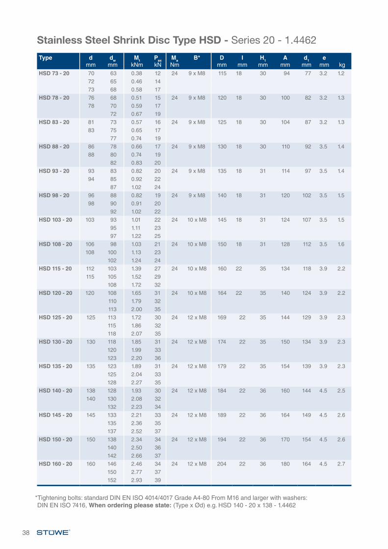
Stainless Steel Shrink Disc Type HSD - Series 20 - 1.4462
*Tightening bolts: standard DIN EN ISO 4014/4017 Grade A4-80 From M16 and larger with washers: DIN EN ISO 7416, When ordering please state: (Type x Ød) e.g. HSD 140 - 20 x 138 - 1.4462
Type dmm
dwmm
MtkNm
PaxkN
MaNm
B* Dmm
Imm
H1mm
Amm
d1mm
emm kg
HSD 73 - 20 70 63 0.38 12 24 9 x M8 115 18 30 94 77 3.2 1.2
72 65 0.46 14
73 68 0.58 17
HSD 78 - 20 76 68 0.51 15 24 9 x M8 120 18 30 100 82 3.2 1.3
78 70 0.59 17
72 0.67 19
HSD 83 - 20 81 73 0.57 16 24 9 x M8 125 18 30 104 87 3.2 1.3
83 75 0.65 17
77 0.74 19
HSD 88 - 20 86 78 0.66 17 24 9 x M8 130 18 30 110 92 3.5 1.4
88 80 0.74 19
82 0.83 20
HSD 93 - 20 93 83 0.82 20 24 9 x M8 135 18 31 114 97 3.5 1.4
94 85 0.92 22
87 1.02 24
HSD 98 - 20 96 88 0.82 19 24 9 x M8 140 18 31 120 102 3.5 1.5
98 90 0.91 20
92 1.02 22
HSD 103 - 20 103 93 1.01 22 24 10 x M8 145 18 31 124 107 3.5 1.5
95 1.11 23
97 1.22 25
HSD 108 - 20 106 98 1.03 21 24 10 x M8 150 18 31 128 112 3.5 1.6
108 100 1.13 23
102 1.24 24
HSD 115 - 20 112 103 1.39 27 24 10 x M8 160 22 35 134 118 3.9 2.2
115 105 1.52 29
108 1.72 32
HSD 120 - 20 120 108 1.65 31 24 10 x M8 164 22 35 140 124 3.9 2.2
110 1.79 32
113 2.00 35
HSD 125 - 20 125 113 1.72 30 24 12 x M8 169 22 35 144 129 3.9 2.3
115 1.86 32
118 2.07 35
HSD 130 - 20 130 118 1.85 31 24 12 x M8 174 22 35 150 134 3.9 2.3
120 1.99 33
123 2.20 36
HSD 135 - 20 135 123 1.89 31 24 12 x M8 179 22 35 154 139 3.9 2.3
125 2.04 33
128 2.27 35
HSD 140 - 20 138 128 1.93 30 24 12 x M8 184 22 36 160 144 4.5 2.5
140 130 2.08 32
132 2.23 34
HSD 145 - 20 145 133 2.21 33 24 12 x M8 189 22 36 164 149 4.5 2.6
135 2.36 35
137 2.52 37
HSD 150 - 20 150 138 2.34 34 24 12 x M8 194 22 36 170 154 4.5 2.6
140 2.50 36
142 2.66 37
HSD 160 - 20 160 146 2.46 34 24 12 x M8 204 22 36 180 164 4.5 2.7
150 2.77 37
152 2.93 39
Stainless Steel Shrink Disc Type HSD - Series 20 - 1.4462
Further sizes on request. Subject to technical change without notice.*Tightening bolts: standard DIN EN ISO 4014/4017 Grade A4-80 From M16 and larger with washers: DIN EN ISO 7416When ordering please state: (Type x Ød) e.g. HSD 202 - 20 x 202 - 1.4462
39
Type dmm
dwmm
MtkNm
PaxkN
MaNm
B* Dmm
Imm
H1mm
Amm
d1mm
emm kg
HSD 170 - 20 166 156 2.43 31 24 12 x M8 214 22 36 190 174 4.5 3170 160 2.73 34
162 2.89 36HSD 182 - 20 182 166 3.59 43 24 14 x M8 230 25 41 206 188 5.6 3.9
170 4.00 47172 4.22 49
HSD 192 - 20 189 176 3.64 41 24 14 x M8 240 25 41 216 198 5.6 4192 180 4.05 45
182 4.26 47HSD 202 - 20 202 186 4.11 44 24 15 x M8 250 25 41 224 208 5.6 4.7
190 4.56 48192 4.79 50
HSD 212 - 20 212 196 4.54 46 24 15 x M8 260 25 41 234 218 5.6 4.7200 5.00 50202 5.24 52
HSD 222 - 20 222 206 4.90 48 24 16 x M8 270 25 42 244 228 6.5 5210 5.36 51212 5.61 53
HSD 232 - 20 232 216 5.35 50 24 16 x M8 280 25 42 254 238 6.5 5220 5.83 53222 6.07 55
HSD 242 - 20 242 226 5.71 51 24 16 x M8 290 25 42 264 248 6.5 5230 6.19 54232 6.44 56
HSD 252 - 20 252 234 5.76 49 24 16 x M8 300 25 42 274 258 6.5 5.2238 6.23 52240 6.48 54
HSD 262 - 20 262 244 6.12 50 24 18 x M8 310 25 42 286 268 6.5 5.4248 6.60 53250 6.84 55
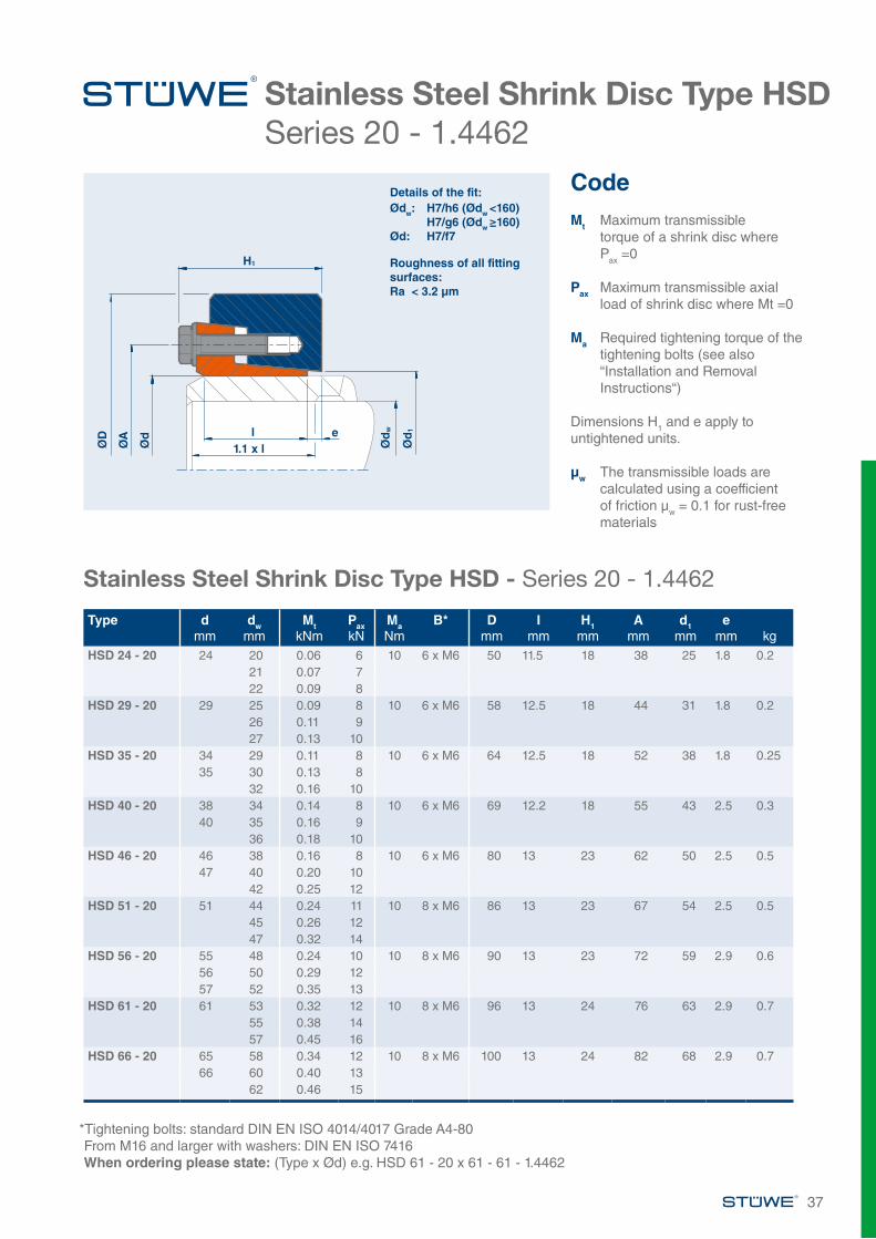
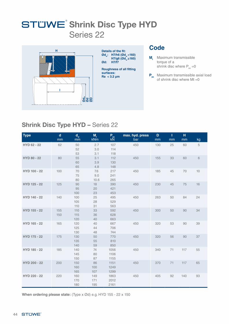
SHRINK DISC TYPE HYD
SHRINK DISC TYPE HYD
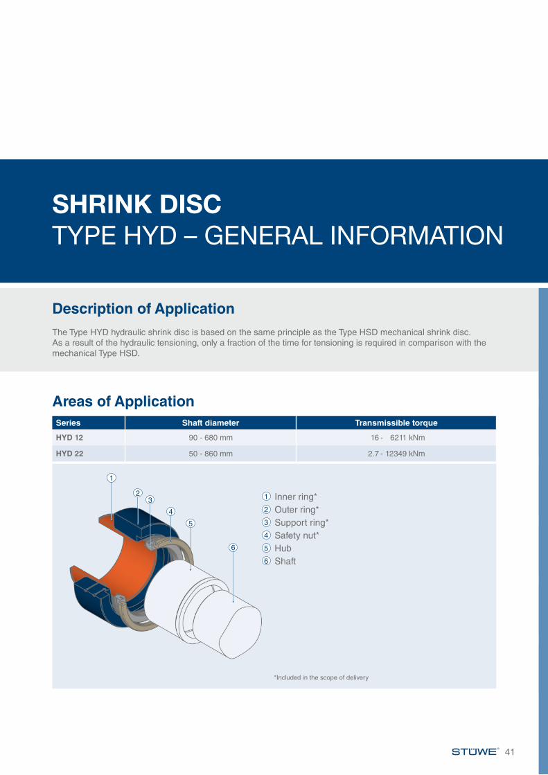
SHRINK DISC TYPE HYD – GENERAL INFORMATION
Description of ApplicationThe Type HYD hydraulic shrink disc is based on the same principle as the Type HSD mechanical shrink disc. As a result of the hydraulic tensioning, only a fraction of the time for tensioning is required in comparison with the mechanical Type HSD.
Areas of ApplicationSeries Shaft diameter Transmissible torque
HYD 12 90 - 680 mm 16 - 6211 kNm
HYD 22 50 - 860 mm 2.7 - 12349 kNm
41
1
23
4
5
6
1 Inner ring*2 Outer ring*3 Support ring*4 Safety nut*5 Hub6 Shaft
*Included in the scope of delivery

42
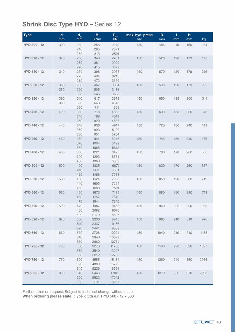
Shrink Disc Type HYDSeries 12
Shrink Disc Type HYD – Series 12
Type dmm
dwmm
MtkNm
PaxkN
max. hyd. pressbar
Dmm
Imm
Hmm kg
HYD 125 - 12 125 90 16 348 450 215 42 75 1395 18 377
100 20 406HYD 140 - 12 140 100 19 374 450 245 46 84 20
105 21 401110 24 429
HYD 155 - 12 155 110 27 488 450 263 50 90 23115 30 520120 33 551
HYD 165 - 12 165 120 36 592 450 290 56 90 29125 39 628130 43 663
HYD 175 - 12 175 130 50 776 450 300 71 90 31135 55 818140 60 861
HYD 185 - 12 185 140 62 881 450 320 71 117 46145 67 924150 73 968
HYD 200 - 12 200 150 73 976 450 340 71 117 51160 85 1064165 91 1108
HYD 220 - 12 220 160 96 1194 450 370 80 130 66170 110 1297180 126 1401
HYD 240 - 12 240 180 140 1560 450 430 86 150 110190 159 1677200 180 1796
HYD 260 - 12 260 200 180 1795 450 430 95 145 98210 201 1916220 224 2038
HYD 280 - 12 280 220 228 2073 450 460 100 150 115230 253 2198240 279 2323
When ordering please state: (Type x Ød) e.g. HYD 155 - 12 x 155
CodeMt Maximum transmissible
torque of a shrink disc where Pax =0
Pax Maximum transmissible axial load of shrink disc where Mt =0
Details of the fit:Ødw: H7/h6 (Ødw <160) H7/g6 (Ødw ≥160)Ød: H7/f7
Roughness of all fitting surfaces:Ra < 3.2 µm
l
H
Ød
w
Ød
ØD
43
Shrink Disc Type HYD – Series 12
Further sizes on request. Subject to technical change without notice.When ordering please state: (Type x Ød) e.g. HYD 560 - 12 x 560
Type dmm
dwmm
MtkNm
PaxkN
max. hyd. pressbar
Dmm
Imm
Hmm kg
HYD 300 - 12 300 230 258 2242 450 485 110 160 134240 285 2371250 313 2501
HYD 320 - 12 320 250 348 2781 450 520 120 179 173260 381 2929270 415 3077
HYD 340 - 12 340 260 398 3063 450 570 120 179 216270 434 3215280 472 3369
HYD 360 - 12 360 280 467 3334 450 590 120 179 225350 290 505 3486
300 546 3638HYD 390 - 12 390 310 617 3978 450 650 135 200 311
380 320 663 4143330 711 4308
HYD 420 - 12 420 330 718 4353 450 690 135 200 345340 768 4519350 820 4686
HYD 440 - 12 440 340 836 4917 450 720 160 240 449350 893 5100360 951 5284
HYD 460 - 12 460 360 944 5246 450 745 160 240 475370 1004 5429380 1066 5612
HYD 480 - 12 480 380 1221 6425 450 780 170 260 566390 1293 6631400 1368 6839
HYD 500 - 12 500 400 1335 6674 450 830 170 260 657410 1411 6881420 1488 7088
HYD 530 - 12 530 430 1524 7088 450 850 190 280 712440 1605 7294450 1688 7501
HYD 560 - 12 560 450 1673 7435 450 880 190 280 743460 1757 7640470 1844 7846
HYD 590 - 12 590 470 1987 8456 450 940 200 300 925480 2082 8676490 2179 8896
HYD 620 - 12 620 500 2236 8945 450 965 210 310 976510 2337 9166520 2441 9389
HYD 660 - 12 660 530 2728 10294 450 1040 210 310 1153540 2843 10529550 2960 10764
HYD 700 - 12 700 560 3278 11708 450 1100 220 320 1327580 3540 12207600 3812 12708
HYD 750 - 12 750 600 4555 15184 450 1260 240 350 2066620 4889 15772640 5236 16361
HYD 800 - 12 800 640 5446 17019 450 1310 260 370 2293660 5822 17642680 6211 18267
44
Shrink Disc Type HYDSeries 22
Shrink Disc Type HYD – Series 22
Type dmm
dwmm
MtkNm
PaxkN
max. hyd. pressbar
Dmm
Imm
Hmm kg
HYD 62 - 22 62 50 2.7 107 450 130 25 60 552 3.0 11453 3.1 118
HYD 80 - 22 80 55 3.1 112 450 155 33 60 660 3.9 13065 4.8 148
HYD 100 - 22 100 70 7.6 217 450 185 45 70 1075 9.0 24180 10.6 265
HYD 125 - 22 125 90 18 390 450 230 45 75 1695 20 421
100 23 453HYD 140 - 22 140 100 25 495 450 263 50 84 24
105 28 529110 31 563
HYD 155 - 22 155 110 33 592 450 300 50 90 34150 115 36 628
120 40 663HYD 165 - 22 165 120 40 667 450 320 53 90 39
125 44 706130 48 744
HYD 175 - 22 175 130 50 770 450 320 56 90 37135 55 810140 59 850
HYD 185 - 22 185 140 74 1056 450 340 71 117 55145 80 1106150 87 1155
HYD 200 - 22 200 150 86 1151 450 370 71 117 65160 100 1249165 107 1299
HYD 220 - 22 220 160 149 1863 450 405 92 140 93170 171 2012180 195 2161
When ordering please state: (Type x Ød) e.g. HYD 155 - 22 x 150
l
H Details of the fit:Ødw: H7/h6 (Ødw <160) H7/g6 (Ødw ≥160)Ød: H7/f7
Roughness of all fitting surfaces:Ra < 3.2 µm
Ød
w
Ød
ØD
CodeMt Maximum transmissible
torque of a shrink disc where Pax =0
Pax Maximum transmissible axial load of shrink disc where Mt =0
45
Shrink Disc Type HYD – Series 22
Type dmm
dwmm
MtkNm
PaxkN
max. hyd. pressbar
Dmm
Imm
Hmm kg
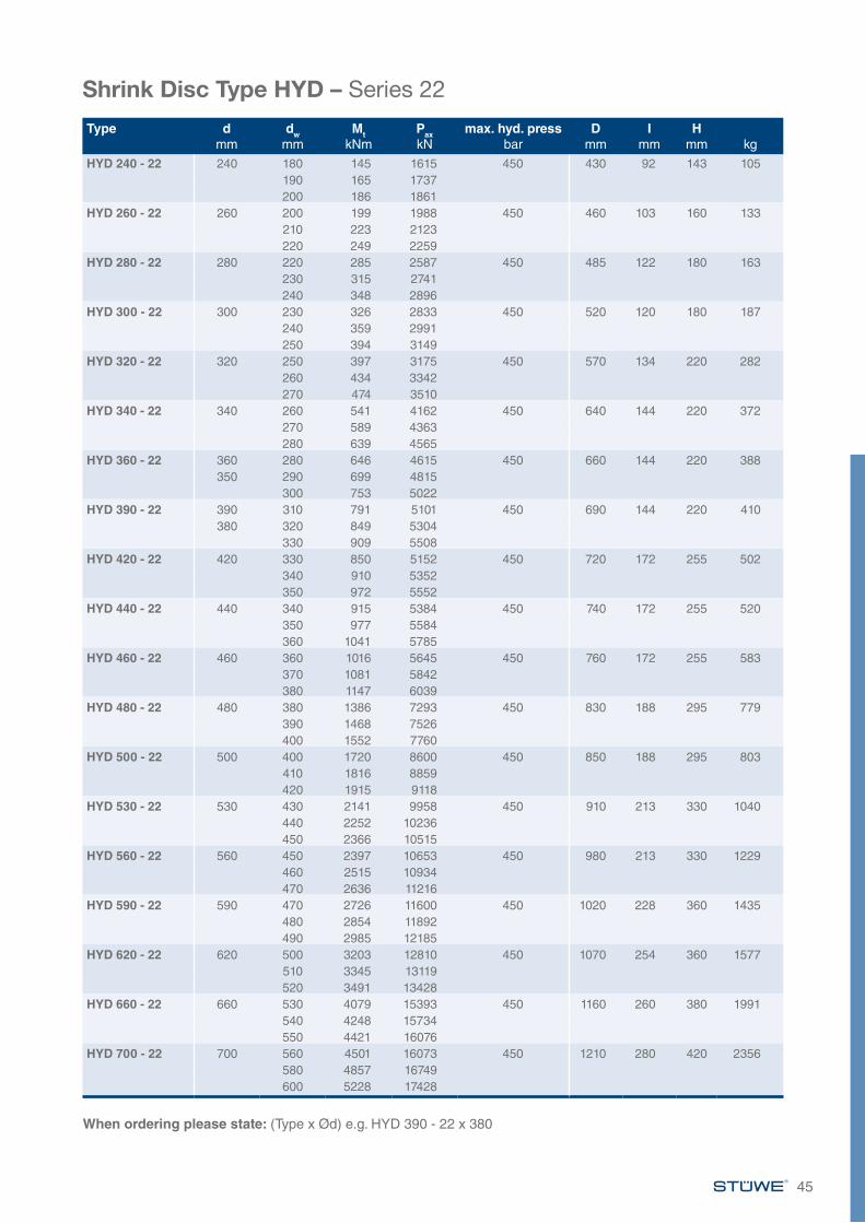
HYD 240 - 22 240 180 145 1615 450 430 92 143 105190 165 1737200 186 1861
HYD 260 - 22 260 200 199 1988 450 460 103 160 133210 223 2123220 249 2259
HYD 280 - 22 280 220 285 2587 450 485 122 180 163230 315 2741240 348 2896
HYD 300 - 22 300 230 326 2833 450 520 120 180 187240 359 2991250 394 3149
HYD 320 - 22 320 250 397 3175 450 570 134 220 282260 434 3342270 474 3510
HYD 340 - 22 340 260 541 4162 450 640 144 220 372270 589 4363280 639 4565
HYD 360 - 22 360 280 646 4615 450 660 144 220 388350 290 699 4815
300 753 5022HYD 390 - 22 390 310 791 5101 450 690 144 220 410
380 320 849 5304330 909 5508
HYD 420 - 22 420 330 850 5152 450 720 172 255 502340 910 5352350 972 5552
HYD 440 - 22 440 340 915 5384 450 740 172 255 520350 977 5584360 1041 5785
HYD 460 - 22 460 360 1016 5645 450 760 172 255 583370 1081 5842380 1147 6039
HYD 480 - 22 480 380 1386 7293 450 830 188 295 779390 1468 7526400 1552 7760
HYD 500 - 22 500 400 1720 8600 450 850 188 295 803410 1816 8859420 1915 9118
HYD 530 - 22 530 430 2141 9958 450 910 213 330 1040440 2252 10236450 2366 10515
HYD 560 - 22 560 450 2397 10653 450 980 213 330 1229460 2515 10934470 2636 11216
HYD 590 - 22 590 470 2726 11600 450 1020 228 360 1435480 2854 11892490 2985 12185
HYD 620 - 22 620 500 3203 12810 450 1070 254 360 1577510 3345 13119520 3491 13428
HYD 660 - 22 660 530 4079 15393 450 1160 260 380 1991540 4248 15734550 4421 16076
HYD 700 - 22 700 560 4501 16073 450 1210 280 420 2356580 4857 16749600 5228 17428
When ordering please state: (Type x Ød) e.g. HYD 390 - 22 x 380
46
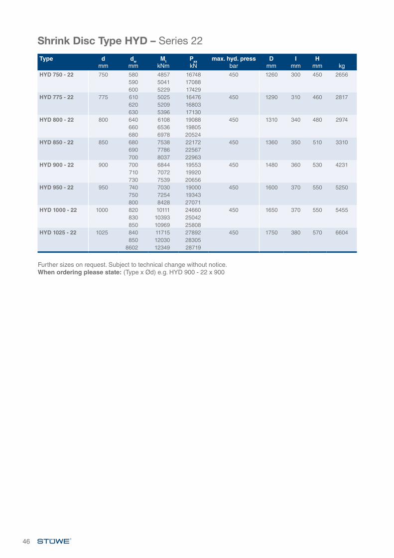
Further sizes on request. Subject to technical change without notice.When ordering please state: (Type x Ød) e.g. HYD 900 - 22 x 900
Shrink Disc Type HYD – Series 22
Type dmm
dwmm
MtkNm
PaxkN
max. hyd. pressbar
Dmm
Imm
Hmm kg
HYD 750 - 22 750 580 4857 16748 450 1260 300 450 2656590 5041 17088600 5229 17429
HYD 775 - 22 775 610 5025 16476 450 1290 310 460 2817620 5209 16803630 5396 17130
HYD 800 - 22 800 640 6108 19088 450 1310 340 480 2974660 6536 19805680 6978 20524
HYD 850 - 22 850 680 7538 22172 450 1360 350 510 3310690 7786 22567700 8037 22963
HYD 900 - 22 900 700 6844 19553 450 1480 360 530 4231710 7072 19920730 7539 20656
HYD 950 - 22 950 740 7030 19000 450 1600 370 550 5250750 7254 19343800 8428 27071
HYD 1000 - 22 1000 820 10111 24660 450 1650 370 550 5455830 10393 25042850 10969 25808
HYD 1025 - 22 1025 840 11715 27892 450 1750 380 570 6604850 12030 28305
8602 12349 28719
SHRINK DISC TYPE SDG AND SDGH
SHRINK DISC TYPE SDG AND SDGH
SHRINK DISC TYPE SDG AND SDGH – GENERAL INFORMATION
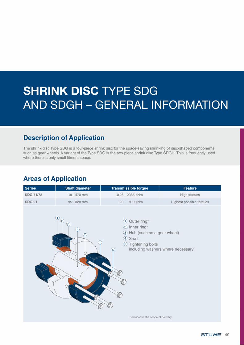
Description of ApplicationThe shrink disc Type SDG is a four-piece shrink disc for the space-saving shrinking of disc-shaped components such as gear wheels. A variant of the Type SDG is the two-piece shrink disc Type SDGH. This is frequently used where there is only small fitment space.
Areas of Application
49
Series Shaft diameter Transmissible torque Feature
SDG 71/72 19 - 470 mm 0,26 - 2386 kNm High torques
SDG 91 95 - 320 mm 23 - 919 kNm Highest possible torques
1 Outer ring*2 Inner ring*3 Hub (such as a gear-wheel)4 Shaft5 Tightening bolts including washers where necessary
12
3
24
1
5
*Included in the scope of delivery
50
Shrink Disc Type SDGSeries 71 | 72
Shrink Disc Type SDG – Series 71 | 72
Type dmm
dwmm
MtkNm
PaxkN
MaNm
tightening bolts*
Dmm
I/2mm
hmm
H1mm
Amm
d1mm
emm
fmm kg
SDG 24 - 72 24 19 0.26 28 5 6 x M5 50 9 7.8 16 36 25.5 4 1.5 0.220 0.31 3121 0.36 34
SDG 30 - 72 30 24 0.34 28 5 6 x M5 60 10 8.5 17 44 32 4 1.5 0.325 0.39 3126 0.44 34
SDG 36 - 72 36 28 0.61 44 12 5 x M6 70 11 10 19 52 38 4 2 0.530 0.76 5033 1.00 60
SDG 44 - 72 44 34 0.83 49 12 6 x M6 80 12 10.5 20 61 46.5 4 2 0.635 0.91 5236 1.00 55
SDG 50 - 72 50 38 1.4 72 12 8 x M6 90 13 11.5 20 75 52.5 3 2.5 0.840 1.6 7942 1.8 87
SDG 55 - 72 55 42 1.5 71 12 8 x M6 100 14 12.5 23 75 57.5 5 2.5 1.145 1.8 8148 2.2 92
SDG 62 - 72 62 48 2.0 85 12 9 x M6 110 14 12.5 23 86 65 5 2.5 1.350 2.3 9252 2.6 98
SDG 68 - 72 68 50 2.0 79 12 9 x M6 115 14 12.5 23 86 71 5 2.5 1.455 2.6 9460 3.3 110
*Tightening bolts: standard DIN EN ISO 4014/4017 Grade 10.9, alternative DIN EN ISO 4762 Grade 10.9From M16 and larger with washers: DIN EN ISO 7416When ordering please state: (Type x Ød) Dimension X, e.g. SDG 62 - 72 x 62 X=15 mm
CodeMt Maximum transmissible
torque of a shrink disc where Pax =0
Pax Maximum transmissible axial load of shrink disc where Mt =0
Ma Required tightening torque of the tightening bolts (see also “Installation and Removal Instructions“)
Dimensions H1 and e apply to untightened units.
e
l/2
H1
h
fx45°
Ød
Ød
1
Details of the fit:Ød: H7/f7Ødw: H7/h6 (Ødw <160) H7/g6 (Ødw ≥160)
Roughness of all fitting surfaces:Ra < 3.2 µm
ØD
ØA
Ød
w
x
51
Shrink Disc Type SDG – Series 71 | 72
Type dmm
dwmm
MtkNm
PaxkN
MaNm
tighteningbolts*
Dmm
I/2mm
hmm
H1mm
Amm
d1mm
emm
fmm kg
SDG 80 - 72 80 60 3.8 128 29 7 x M8 138 17 13 27 100 83.5 5 4 2.575 65 4.8 147
70 5.8 165SDG 90 - 72 90 65 5.8 178 29 10 x M8 155 20 16.5 31 114 96 6 5 3.7
85 70 7.0 20075 8.4 223
SDG 100 - 72 100 70 7.3 209 29 12 x M8 168 24.3 19 32 124 104 2 5 4.995 75 8.7 233
80 10.3 257SDG 110 - 72 110 80 10.5 261 58 9 x M10 185 24 21.5 37 136 115 7 5 6.2
105 85 12.2 28890 14.2 315
SDG 125 - 72 125 90 15.0 333 58 12 x M10 215 26 23 39 160 134 7 5 9.3120 95 17.1 361130 100 19.5 389
SDG 140 - 71 140 95 19.3 407 100 10 x M12 230 28 25 43 176 146 8 5 12135 105 24.6 469
110 27.6 501SDG 155 - 71 155 110 28.0 510 100 12 x M12 263 30 26 45 192 165 8 5 16
150 115 31.2 542160 120 34.5 575
SDG 165 - 71 160 120 40 669 240 8 x M16 290 33 29 54 210 174 7 5 22165 125 44 707170 130 49 747
SDG 175 - 71 175 130 45 695 240 8 x M16 300 33 29 54 220 185 7 5 23180 135 49 732
140 54 770SDG 185 - 71 185 140 62 885 240 10 x M16 320 40 36 63 236 195 9 5 32
190 145 67 929150 73 973
SDG 200 - 71 200 150 82 1088 240 12 x M16 340 40 37 63 246 206 9 5 39195 155 88 1136
160 95 1184SDG 220 - 71 220 160 102 1276 240 15 x M16 370 52 45 77 276 230 11 8 54
165 110 1332170 118 1388
SDG 240 - 71 240 170 125 1474 470 12 x M20 405 54 49 81 295 248 11 8 67180 143 1591190 162 1710
SDG 260 - 71 260 190 173 1824 470 12 x M20 430 59 53 84 321 268 9 8 81200 196 1957210 219 2090
SDG 280 - 71 280 210 228 2168 470 15 x M20 460 67 58 95 346 288 12 10 104220 254 2308230 282 2449
SDG 300 - 71 300 220 247 2250 470 16 x M20 485 71 60 97 364 308 10 10 120230 275 2389240 304 2529
SDG 320 - 71 320 240 316 2631 470 18 x M20 520 71 60 97 386 328 10 10 139250 347 2779260 381 2928
*Tightening bolts: standard DIN EN ISO 4014/4017 Grade 10.9, alternative DIN EN ISO 4762 Grade 10.9From M16 and larger with washers: DIN EN ISO 7416When ordering please state: (Type x Ød) Dimension X, e.g. SDG 200 - 71 x 200 X=40 mm
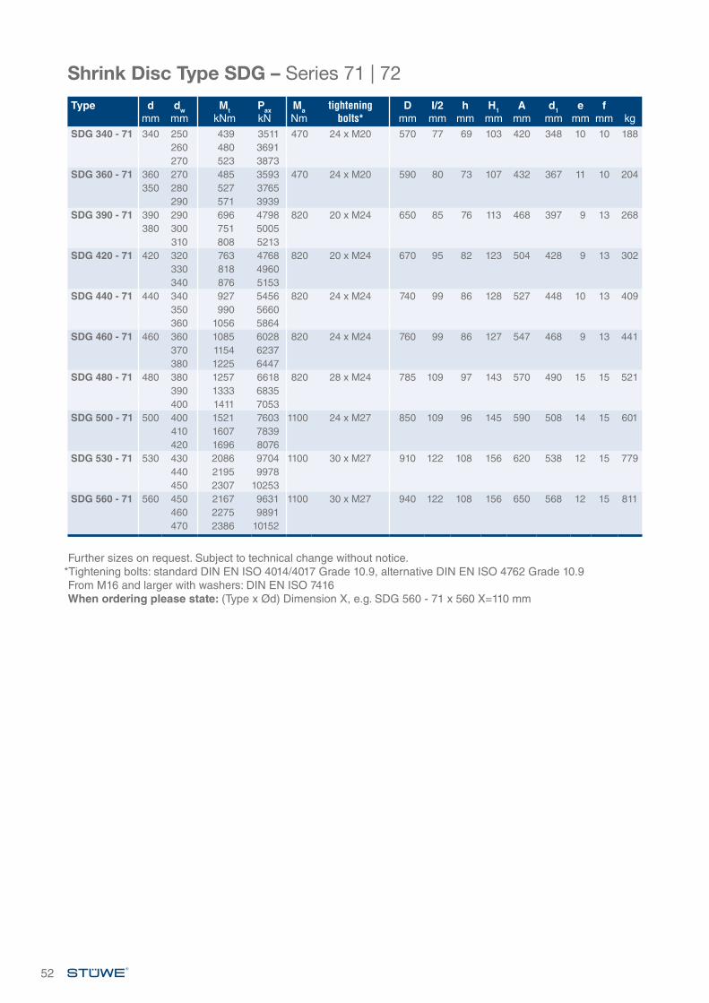
Type dmm
dwmm
MtkNm
PaxkN
MaNm
tighteningbolts*
Dmm
I/2mm
hmm
H1mm
Amm
d1mm
emm
fmm kg
SDG 340 - 71 340 250 439 3511 470 24 x M20 570 77 69 103 420 348 10 10 188260 480 3691270 523 3873
SDG 360 - 71 360 270 485 3593 470 24 x M20 590 80 73 107 432 367 11 10 204350 280 527 3765
290 571 3939SDG 390 - 71 390 290 696 4798 820 20 x M24 650 85 76 113 468 397 9 13 268
380 300 751 5005310 808 5213
SDG 420 - 71 420 320 763 4768 820 20 x M24 670 95 82 123 504 428 9 13 302330 818 4960340 876 5153
SDG 440 - 71 440 340 927 5456 820 24 x M24 740 99 86 128 527 448 10 13 409350 990 5660360 1056 5864
SDG 460 - 71 460 360 1085 6028 820 24 x M24 760 99 86 127 547 468 9 13 441370 1154 6237380 1225 6447
SDG 480 - 71 480 380 1257 6618 820 28 x M24 785 109 97 143 570 490 15 15 521390 1333 6835400 1411 7053
SDG 500 - 71 500 400 1521 7603 1100 24 x M27 850 109 96 145 590 508 14 15 601410 1607 7839420 1696 8076
SDG 530 - 71 530 430 2086 9704 1100 30 x M27 910 122 108 156 620 538 12 15 779440 2195 9978450 2307 10253
SDG 560 - 71 560 450 2167 9631 1100 30 x M27 940 122 108 156 650 568 12 15 811460 2275 9891470 2386 10152
Shrink Disc Type SDG – Series 71 | 72
Further sizes on request. Subject to technical change without notice.*Tightening bolts: standard DIN EN ISO 4014/4017 Grade 10.9, alternative DIN EN ISO 4762 Grade 10.9From M16 and larger with washers: DIN EN ISO 7416When ordering please state: (Type x Ød) Dimension X, e.g. SDG 560 - 71 x 560 X=110 mm
52

*Tightening bolts: standard DIN EN ISO 4014/4017 Grade 10.9, alternative DIN EN ISO 4762 Grade 10.9From M16 and larger with washers: DIN EN ISO 7416When ordering please state: (Type x Ød) Dimension X, e.g. SDG 260 - 91 x 260 X=70 mm
53
Shrink Disc Type SDGSeries 91
Shrink Disc Type SDG – Series 91
Type dmm
dwmm
MtkNm
PaxkN
MaNm
tighteningbolts*
Dmm
I/2mm
hmm
H1mm
Amm
d1mm
emm
fmm kg
SDG 140 - 91 140 95 23 476 100 12 x M12 230 35 32 51 175 145 9 5 14100 26 514110 32 591
SDG 155 - 91 155 110 34 618 100 15 x M12 263 38 35 54 198 165 9 5 20160 115 38 659
120 42 699SDG 165 - 91 165 120 49 818 240 10 x M16 290 41 38 64 210 176 9 5 27
170 125 54 866130 59 915
SDG 175 - 91 175 130 55 852 240 10 x M16 300 41 38 65 220 186 10 5 28180 135 61 898
140 66 944SDG 185 - 91 185 140 93 1329 240 15 x M16 320 50 50 76 236 189 12 5 41
145 101 1392150 109 1456
SDG 200 - 91 200 150 105 1393 240 15 x M16 340 51 50 76 246 205 11 5 45195 155 113 1455
160 121 1517SDG 220 - 91 220 160 140 1744 240 20 x M16 370 65 57 90 270 225 11 8 67
165 150 1820170 161 1895
SDG 240 - 91 240 170 172 2025 470 15 x M20 405 68 65 98 295 245 14 8 84180 197 2184190 223 2345
SDG 260 - 91 260 190 205 2162 470 16 x M20 430 75.5 72 105 321 266 13 8 104200 232 2323210 261 2486
CodeMt Maximum transmissible
torque of a shrink disc where Pax =0
Pax Maximum transmissible axial load of shrink disc where Mt =0
Ma Required tightening torque of the tightening bolts (see also “Installation and Removal Instructions“)
Dimensions H1 and e apply to untightened units.
e
l/2
H1
h
fx45°
Ød
Ød
1
Details of the fit:Ød: H7/f7Ødw: H7/h6 (Ødw <160) H7/g6 (Ødw ≥160)
Roughness of all fitting surfaces:Ra < 3.2 µm
ØD
ØA
Ød
w
x
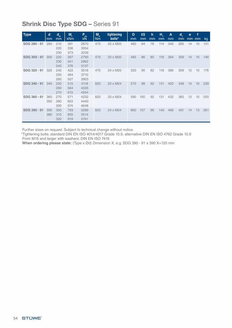
Shrink Disc Type SDG – Series 91
54
Further sizes on request. Subject to technical change without notice.*Tightening bolts: standard DIN EN ISO 4014/4017 Grade 10.9, alternative DIN EN ISO 4762 Grade 10.9From M16 and larger with washers: DIN EN ISO 7416When ordering please state: (Type x Ød) Dimension X, e.g. SDG 390 - 91 x 390 X=120 mm
Type dmm
dwmm
MtkNm
PaxkN
MaNm
tighteningbolts*
Dmm
I/2mm
hmm
H1mm
Amm
d1mm
emm
fmm kg
SDG 280 - 91 280 210 301 2870 470 20 x M20 460 84 78 114 340 285 14 10 131220 336 3054230 373 3239
SDG 300 - 91 300 220 307 2790 470 20 x M20 485 86 80 116 364 309 14 10 146230 341 2962240 376 3137
SDG 320 - 91 320 240 422 3518 470 24 x M20 520 90 82 118 386 309 12 10 176250 464 3710260 507 3903
SDG 340 - 91 340 250 515 4118 820 20 x M24 570 98 92 131 420 348 14 10 239260 564 4335270 615 4554
SDG 360 - 91 360 270 571 4232 820 20 x M24 590 100 92 131 432 365 12 10 255350 280 622 4440
290 674 4648SDG 390 - 91 390 300 793 5289 820 24 x M24 660 107 96 140 468 401 14 13 361
380 310 855 5514320 919 5741
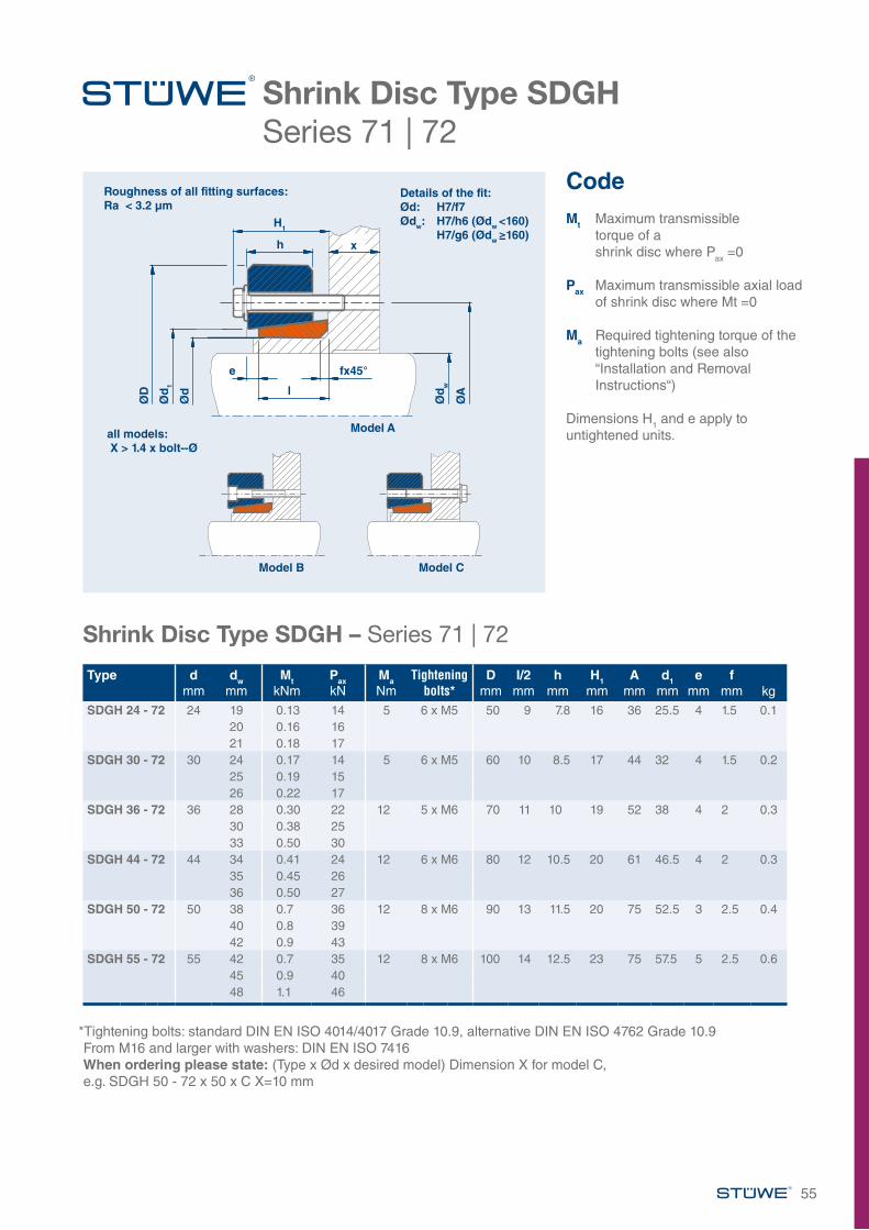
55
*Tightening bolts: standard DIN EN ISO 4014/4017 Grade 10.9, alternative DIN EN ISO 4762 Grade 10.9From M16 and larger with washers: DIN EN ISO 7416When ordering please state: (Type x Ød x desired model) Dimension X for model C, e.g. SDGH 50 - 72 x 50 x C X=10 mm
Shrink Disc Type SDGHSeries 71 | 72
Shrink Disc Type SDGH – Series 71 | 72
Type d mm
dw mm
Mt kNm
Pax kN
Ma Nm
Tightening bolts*
D mm
I/2 mm
hmm
H1mm
A mm
d1 mm
e mm
f mm kg
SDGH 24 - 72 24 19 0.13 14 5 6 x M5 50 9 7.8 16 36 25.5 4 1.5 0.120 0.16 1621 0.18 17
SDGH 30 - 72 30 24 0.17 14 5 6 x M5 60 10 8.5 17 44 32 4 1.5 0.225 0.19 1526 0.22 17
SDGH 36 - 72 36 28 0.30 22 12 5 x M6 70 11 10 19 52 38 4 2 0.330 0.38 2533 0.50 30
SDGH 44 - 72 44 34 0.41 24 12 6 x M6 80 12 10.5 20 61 46.5 4 2 0.335 0.45 2636 0.50 27
SDGH 50 - 72 50 38 0.7 36 12 8 x M6 90 13 11.5 20 75 52.5 3 2.5 0.440 0.8 3942 0.9 43
SDGH 55 - 72 55 42 0.7 35 12 8 x M6 100 14 12.5 23 75 57.5 5 2.5 0.645 0.9 4048 1.1 46
CodeMt Maximum transmissible
torque of a shrink disc where Pax =0
Pax Maximum transmissible axial load of shrink disc where Mt =0
Ma Required tightening torque of the tightening bolts (see also “Installation and Removal Instructions“)
Dimensions H1 and e apply to untightened units.
Details of the fit:Ød: H7/f7Ødw: H7/h6 (Ødw <160) H7/g6 (Ødw ≥160)
all models: X > 1.4 x bolt--Ø
Roughness of all fitting surfaces:Ra < 3.2 µm
Model A
Model B Model C
H1
h
ØD
Ød
1
Ød
e fx45°
Ød
w
ØAl
x
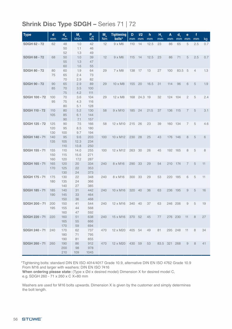
Type d mm
dw mm
Mt kNm
Pax kN
Ma Nm
Tightening bolts*
D mm
I/2 mm
hmm
H1mm
A mm
d1 mm
e mm
f mm kg
SDGH 62 - 72 62 48 1.0 42 12 9 x M6 110 14 12.5 23 86 65 5 2.5 0.750 1.1 4652 1.3 49
SDGH 68 - 72 68 50 1.0 39 12 9 x M6 115 14 12.5 23 86 71 5 2.5 0.755 1.3 4760 1.6 55
SDGH 80 - 72 80 60 1.9 64 29 7 x M8 138 17 13 27 100 83.5 5 4 1.375 65 2.4 73
70 2.9 82SDGH 90 - 72 90 65 2.9 89 29 10 x M8 155 20 16.5 31 114 96 6 5 1.9
85 70 3.5 10075 4.2 111
SDGH 100 - 72 100 70 3.6 104 29 12 x M8 168 24.3 19 32 124 104 2 5 2.495 75 4.3 116
80 5.1 128SDGH 110 - 72 110 80 5.2 130 58 9 x M10 185 24 21.5 37 136 115 7 5 3.1
105 85 6.1 14490 7.1 157
SDGH 125 - 72 125 90 7.5 166 58 12 x M10 215 26 23 39 160 134 7 5 4.6120 95 8.5 180130 100 9.7 194
SDGH 140 - 71 140 95 9.6 203 100 10 x M12 230 28 25 43 176 146 8 5 6135 105 12.3 234
110 13.8 250SDGH 155 - 71 155 110 14.0 255 100 12 x M12 263 30 26 45 192 165 8 5 8
150 115 15.6 271160 120 17.2 287
SDGH 165 - 71 165 120 20 334 240 8 x M16 290 33 29 54 210 174 7 5 11170 125 22 353
130 24 373SDGH 175 - 71 175 130 22 348 240 8 x M16 300 33 29 53 220 185 6 5 11
180 135 24 366140 27 385
SDGH 185 - 71 185 140 31 442 240 10 x M16 320 40 36 63 236 195 9 5 16190 145 33 464
150 36 468SDGH 200 - 71 200 150 41 544 240 12 x M16 340 40 37 63 246 206 9 5 19
195 155 44 568160 47 592
SDGH 220 - 71 220 160 51 638 240 15 x M16 370 52 45 77 276 230 11 8 27165 55 666170 59 694
SDGH 240 - 71 240 170 62 737 470 12 x M20 405 54 49 81 295 248 11 8 34180 71 795190 81 855
SDGH 260 - 71 260 190 86 912 470 12 x M20 430 59 53 83.5 321 268 9 8 41200 98 978210 109 1045
Shrink Disc Type SDGH – Series 71 | 72
*Tightening bolts: standard DIN EN ISO 4014/4017 Grade 10.9, alternative DIN EN ISO 4762 Grade 10.9From M16 and larger with washers: DIN EN ISO 7416When ordering please state: (Type x Ød x desired model) Dimension X for desired model C, e.g. SDGH 260 - 71 x 260 x C X=80 mm
Washers are used for M16 bolts upwards. Dimension X is given by the customer and simply determines the bolt length.
56
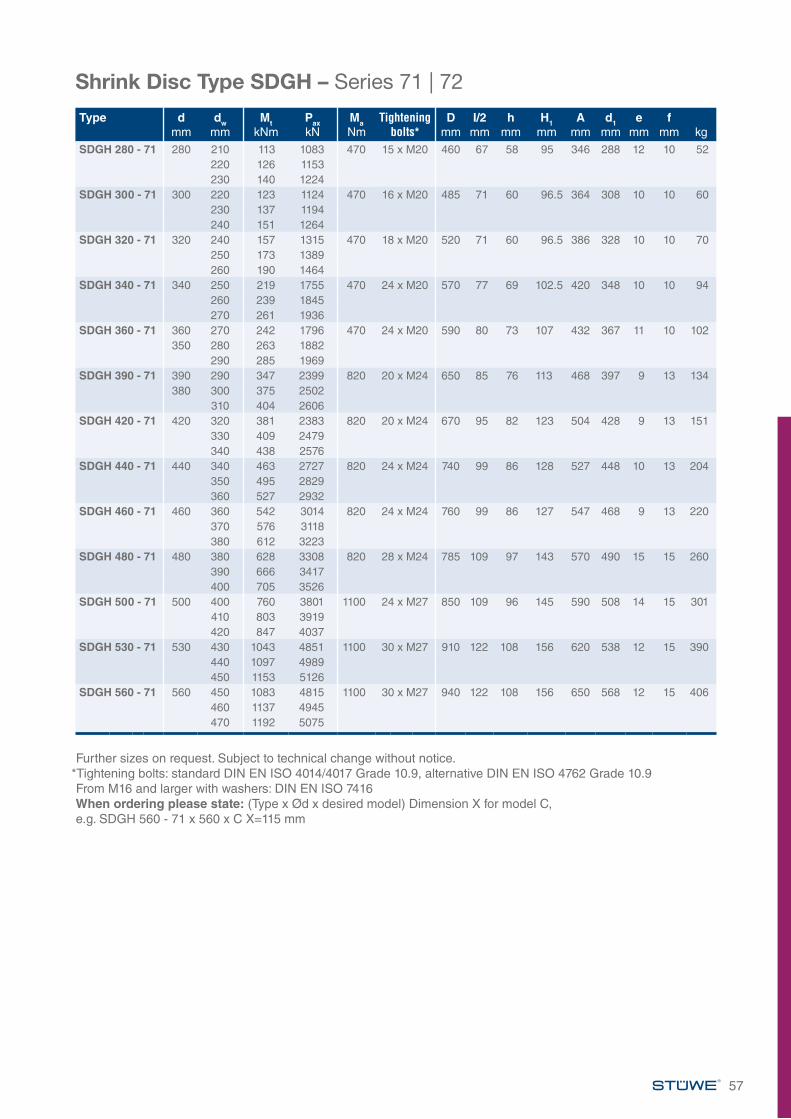
Shrink Disc Type SDGH – Series 71 | 72
Type d mm
dw mm
Mt kNm
Pax kN
Ma Nm
Tightening bolts*
D mm
I/2 mm
hmm
H1mm
A mm
d1 mm
e mm
f mm kg
SDGH 280 - 71 280 210 113 1083 470 15 x M20 460 67 58 95 346 288 12 10 52220 126 1153230 140 1224
SDGH 300 - 71 300 220 123 1124 470 16 x M20 485 71 60 96.5 364 308 10 10 60230 137 1194240 151 1264
SDGH 320 - 71 320 240 157 1315 470 18 x M20 520 71 60 96.5 386 328 10 10 70250 173 1389260 190 1464
SDGH 340 - 71 340 250 219 1755 470 24 x M20 570 77 69 102.5 420 348 10 10 94260 239 1845270 261 1936
SDGH 360 - 71 360 270 242 1796 470 24 x M20 590 80 73 107 432 367 11 10 102350 280 263 1882
290 285 1969SDGH 390 - 71 390 290 347 2399 820 20 x M24 650 85 76 113 468 397 9 13 134
380 300 375 2502310 404 2606
SDGH 420 - 71 420 320 381 2383 820 20 x M24 670 95 82 123 504 428 9 13 151330 409 2479340 438 2576
SDGH 440 - 71 440 340 463 2727 820 24 x M24 740 99 86 128 527 448 10 13 204350 495 2829360 527 2932
SDGH 460 - 71 460 360 542 3014 820 24 x M24 760 99 86 127 547 468 9 13 220370 576 3118380 612 3223
SDGH 480 - 71 480 380 628 3308 820 28 x M24 785 109 97 143 570 490 15 15 260390 666 3417400 705 3526
SDGH 500 - 71 500 400 760 3801 1100 24 x M27 850 109 96 145 590 508 14 15 301410 803 3919420 847 4037
SDGH 530 - 71 530 430 1043 4851 1100 30 x M27 910 122 108 156 620 538 12 15 390440 1097 4989450 1153 5126
SDGH 560 - 71 560 450 1083 4815 1100 30 x M27 940 122 108 156 650 568 12 15 406460 1137 4945470 1192 5075
Further sizes on request. Subject to technical change without notice.*Tightening bolts: standard DIN EN ISO 4014/4017 Grade 10.9, alternative DIN EN ISO 4762 Grade 10.9From M16 and larger with washers: DIN EN ISO 7416When ordering please state: (Type x Ød x desired model) Dimension X for model C, e.g. SDGH 560 - 71 x 560 x C X=115 mm
57
EXTERNAL LOCKING UNIT TYPE AS
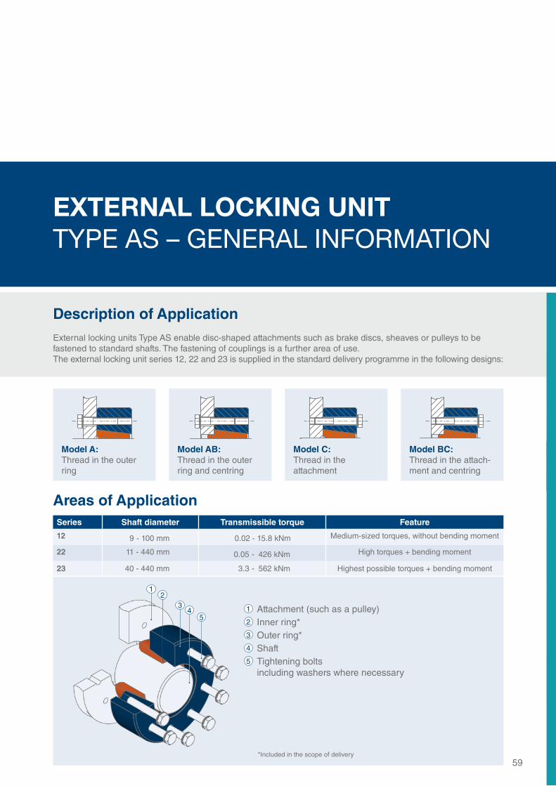
EXTERNAL LOCKING UNIT TYPE AS
EXTERNAL LOCKING UNIT TYPE AS – GENERAL INFORMATION
Description of ApplicationExternal locking units Type AS enable disc-shaped attachments such as brake discs, sheaves or pulleys to be fastened to standard shafts. The fastening of couplings is a further area of use. The external locking unit series 12, 22 and 23 is supplied in the standard delivery programme in the following designs:
59
Areas of ApplicationSeries Shaft diameter Transmissible torque Feature
12 9 - 100 mm 0.02 - 15.8 kNm Medium-sized torques, without bending moment
22 11 - 440 mm 0.05 - 426 kNm High torques + bending moment
23 40 - 440 mm 3.3 - 562 kNm Highest possible torques + bending moment
1 Attachment (such as a pulley)2 Inner ring*3 Outer ring*4 Shaft5 Tightening bolts including washers where necessary
Model A:Thread in the outer ring
Model AB:Thread in the outer ring and centring
Model C:Thread in the attachment
Model BC:Thread in the attach-ment and centring
12
3
54
*Included in the scope of delivery
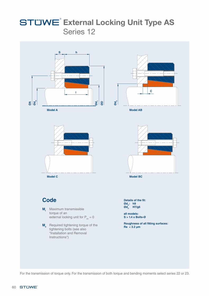
60
External Locking Unit Type AS Series 12
Details of the fit:Ødw: h9Ød2: H7/g6
all models: S > 1.4 x Bolts-Ø
Roughness of all fitting surfaces:Ra < 3.2 µm
For the transmission of torque only. For the transmission of both torque and bending moments select series 22 or 23.
Ød
2
Model AB
C
ØA
S h
l
Ød
w
Ød
1
ØD
Model A
Model C Model BC
CodeMt Maximum transmissible
torque of an external locking unit for Pax = 0
Ma Required tightening torque of the tightening bolts (see also “Installation and Removal Instructions“)
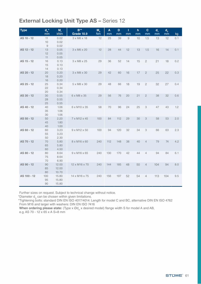
61
External Locking Unit Type AS – Series 12
Type dw*mm
MtkNm
B**Grade 10.9
MaNm
Amm
Dmm
Imm
hmm
Cmm
d1mm
d2mm kg
AS 10 - 12 11 0.02 3 x M6 x 18 12 25 39 9 10 1.5 13 12 0.110 0.029 0.02
AS 12 - 12 13 0.05 3 x M6 x 20 12 28 44 12 13 1.5 16 14 0.112 0.0511 0.05
AS 15 - 12 16 0.13 3 x M8 x 25 29 36 52 14 15 2 21 18 0.215 0.1314 0.13
AS 20 - 12 20 0.20 3 x M8 x 30 29 42 60 16 17 2 25 22 0.318 0.2016 0.20
AS 25 - 12 25 0.34 5 x M8 x 30 29 48 66 18 19 2 32 27 0.422 0.3420 0.34
AS 30 - 12 30 0.55 6 x M8 x 35 29 56 76 20 21 2 38 32 0.628 0.5525 0.55
AS 40 - 12 40 1.06 6 x M10 x 35 58 70 96 24 25 3 47 43 1.235 1.0630 1.06
AS 50 - 12 50 2.20 7 x M12 x 45 100 84 112 29 30 3 58 53 2.045 1.8040 1.00
AS 60 - 12 60 3.23 9 x M12 x 50 100 94 120 32 34 3 66 63 2.355 3.2350 2.30
AS 70 - 12 70 5.80 8 x M16 x 60 240 112 148 38 40 4 79 74 4.265 5.8060 4.50
AS 80 - 12 80 8.64 9 x M16 x 65 240 130 170 42 44 4 94 84 6.175 8.6470 6.90
AS 90 - 12 90 12.00 12 x M16 x 70 240 144 185 48 50 4 104 94 8.085 12.0080 10.70
AS 100 - 12 100 15.80 14 x M16 x 75 240 156 197 52 54 4 113 104 9.595 15.8090 15.80
Further sizes on request. Subject to technical change without notice.*Diameter dw can be chosen within given limitations. *Tightening bolts: standard DIN EN ISO 4017/4014: Length for model C and BC, alternative DIN EN ISO 4762From M16 and larger with washers: DIN EN ISO 7416When ordering please state: (Type x Ødw x desired model) flange width S for model A and AB, e.g. AS 70 - 12 x 65 x A S=8 mm
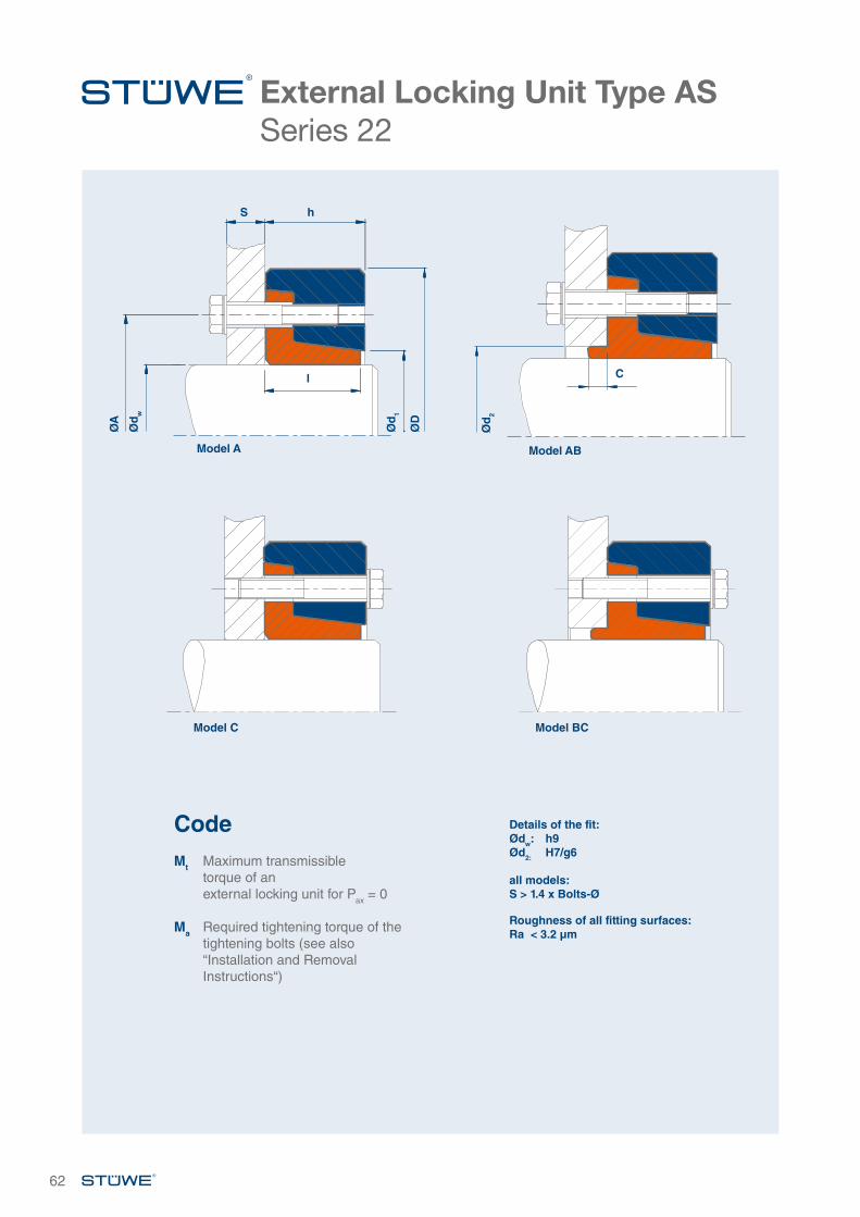
62
External Locking Unit Type ASSeries 22
Ød
2
Model AB
C
ØA
S h
l
Ød
w
Ød
1
ØD
Model A
CodeMt Maximum transmissible
torque of an external locking unit for Pax = 0
Ma Required tightening torque of the tightening bolts (see also “Installation and Removal Instructions“)
Details of the fit:Ødw: h9Ød2: H7/g6
all models: S > 1.4 x Bolts-Ø
Roughness of all fitting surfaces:Ra < 3.2 µm
Model BCModel C
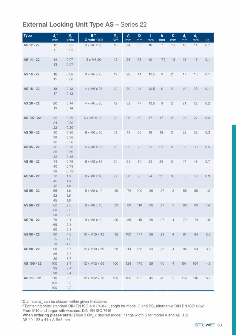
63
External Locking Unit Type AS – Series 22
Type dw*mm
MtkNm
B**Grade 10.9
MaNm
Amm
Dmm
Imm
hmm
Cmm
d1mm
d2mm kg
AS 12 - 22 12 0.05 3 x M6 x 20 12 24 35 10 7 1.5 13 14 0.111 0.05
AS 14 - 22 14 0.07 3 x M6 20 12 26 38 10 7.3 1.5 15 16 0.113 0.07
AS 16 - 22 16 0.08 3 x M6 x 25 12 28 41 13.5 9 2 17 18 0.115 0.08
AS 18 - 22 18 0.13 4 x M6 x 25 12 30 44 13.5 9 2 19 20 0.117 0.13
AS 20 - 22 20 0.14 4 x M6 x 25 12 32 47 13.5 9 2 21 22 0.219 0.14
AS- 25 - 22 25 0.20 5 x M6 x 30 12 36 50 17 17 2 26 27 0.224 0.2022 0.20
AS 30 - 22 30 0.30 6 x M6 x 30 12 44 60 18 19 3 32 32 0.328 0.3026 0.30
AS 35 - 22 36 0.50 5 x M8 x 35 29 52 72 20 21 3 38 38 0.535 0.5032 0.45
AS 40 - 22 44 0.75 6 x M8 x 35 29 61 80 22 23 3 47 46 0.740 0.7538 0.72
AS 50 - 22 50 1.3 8 x M8 x 40 29 68 90 24 25 3 53 53 0.945 1.342 1.0
AS 55 - 22 55 1.6 8 x M8 x 40 29 72 100 26 27 3 58 58 1.252 1.645 1.6
AS 60 - 22 62 2.0 9 x M8 x 40 29 80 110 26 27 3 66 63 1.460 2.050 2.0
AS 70 - 22 70 2.1 9 x M8 x 40 29 86 115 26 27 4 72 74 1.565 2.160 2.1
AS 80 - 22 80 4.0 10 x M10 x 45 58 100 141 28 29 4 84 84 2.575 4.070 4.0
AS 90 - 22 90 5.7 12 x M10 x 50 58 114 155 34 35 4 94 94 3.685 5.780 5.7
AS 100 - 22 100 8.4 12 x M12 x 60 100 124 170 39 40 4 104 104 4.695 8.490 8.4
AS 110 - 22 110 9.2 12 x M12 x 70 100 136 185 45 46 5 114 116 6.2105 9.2100 9.2
*Diameter dw can be chosen within given limitations. **Tightening bolts: standard DIN EN ISO 4017/4014: Length for model C and BC, alternative DIN EN ISO 4762From M16 and larger with washers: DIN EN ISO 7416When ordering please state: (Type x Ødw x desired model) flange width S for model A and AB, e.g.AS 40 - 22 x 44 x A S=8 mm
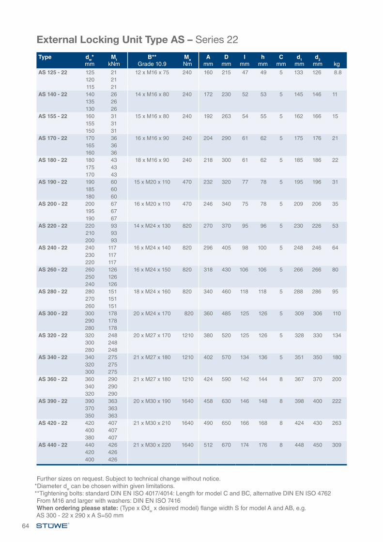
64
Type dw*mm
MtkNm
B**Grade 10.9
MaNm
Amm
Dmm
Imm
hmm
Cmm
d1mm
d2mm kg
AS 125 - 22 125 21 12 x M16 x 75 240 160 215 47 49 5 133 126 8.8120 21115 21
AS 140 - 22 140 26 14 x M16 x 80 240 172 230 52 53 5 145 146 11135 26130 26
AS 155 - 22 160 31 15 x M16 x 80 240 192 263 54 55 5 162 166 15155 31150 31
AS 170 - 22 170 36 16 x M16 x 90 240 204 290 61 62 5 175 176 21165 36160 36
AS 180 - 22 180 43 18 x M16 x 90 240 218 300 61 62 5 185 186 22175 43170 43
AS 190 - 22 190 60 15 x M20 x 110 470 232 320 77 78 5 195 196 31185 60180 60
AS 200 - 22 200 67 16 x M20 x 110 470 246 340 75 78 5 209 206 35195 67190 67
AS 220 - 22 220 93 14 x M24 x 130 820 270 370 95 96 5 230 226 53210 93200 93
AS 240 - 22 240 117 16 x M24 x 140 820 296 405 98 100 5 248 246 64230 117220 117
AS 260 - 22 260 126 16 x M24 x 150 820 318 430 106 106 5 266 266 80250 126240 126
AS 280 - 22 280 151 18 x M24 x 160 820 340 460 118 118 5 288 286 95270 151260 151
AS 300 - 22 300 178 20 x M24 x 170 820 360 485 125 126 5 309 306 110290 178280 178
AS 320 - 22 320 248 20 x M27 x 170 1210 380 520 125 126 5 328 330 134300 248280 248
AS 340 - 22 340 275 21 x M27 x 180 1210 402 570 134 136 5 351 350 180320 275300 275
AS 360 - 22 360 290 21 x M27 x 180 1210 424 590 142 144 8 367 370 200340 290320 290
AS 390 - 22 390 363 20 x M30 x 190 1640 458 630 146 148 8 398 400 222370 363350 363
AS 420 - 22 420 407 21 x M30 x 210 1640 490 650 166 168 8 424 430 263400 407380 407
AS 440 - 22 440 426 21 x M30 x 220 1640 512 670 174 176 8 448 450 309420 426400 426
Further sizes on request. Subject to technical change without notice.*Diameter dw can be chosen within given limitations.**Tightening bolts: standard DIN EN ISO 4017/4014: Length for model C and BC, alternative DIN EN ISO 4762From M16 and larger with washers: DIN EN ISO 7416When ordering please state: (Type x Ødw x desired model) flange width S for model A and AB, e.g.AS 300 - 22 x 290 x A S=50 mm
External Locking Unit Type AS – Series 22
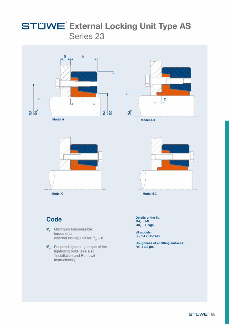
65
External Locking Unit Type ASSeries 23
Ød
2
Model AB
C
ØA
S h
l
Ød
w
Ød
1
ØD
Model A
CodeMt Maximum transmissible
torque of an external locking unit for Pax = 0
Ma Required tightening torque of the tightening bolts (see also “Installation and Removal Instructions“)
Details of the fit:Ødw: h9Ød2: H7/g6
all models: S > 1.4 x Bolts-Ø
Roughness of all fitting surfaces:Ra < 3.2 µm
Model BCModel C
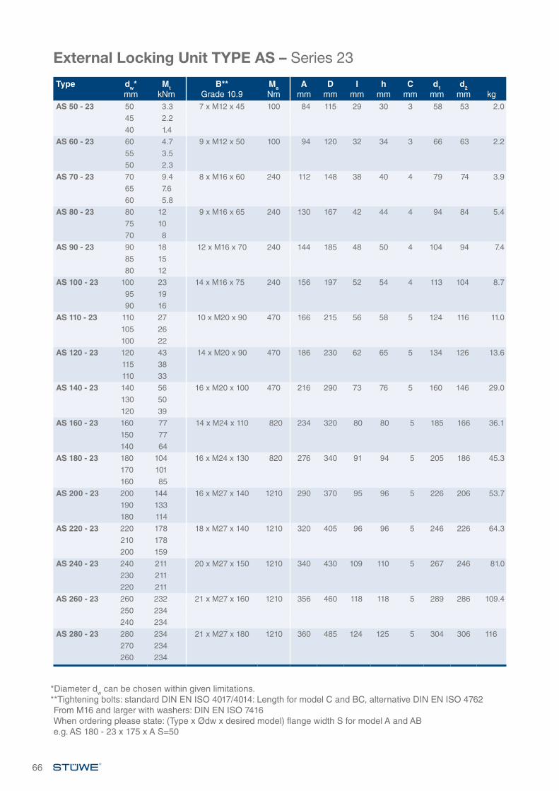
66
External Locking Unit TYPE AS – Series 23
Type dw*mm
MtkNm
B**Grade 10.9
MaNm
Amm
Dmm
Imm
hmm
Cmm
d1mm
d2mm kg
AS 50 - 23 50 3.3 7 x M12 x 45 100 84 115 29 30 3 58 53 2.0
45 2.2
40 1.4
AS 60 - 23 60 4.7 9 x M12 x 50 100 94 120 32 34 3 66 63 2.2
55 3.5
50 2.3
AS 70 - 23 70 9.4 8 x M16 x 60 240 112 148 38 40 4 79 74 3.9
65 7.6
60 5.8
AS 80 - 23 80 12 9 x M16 x 65 240 130 167 42 44 4 94 84 5.4
75 10
70 8
AS 90 - 23 90 18 12 x M16 x 70 240 144 185 48 50 4 104 94 7.4
85 15
80 12
AS 100 - 23 100 23 14 x M16 x 75 240 156 197 52 54 4 113 104 8.7
95 19
90 16
AS 110 - 23 110 27 10 x M20 x 90 470 166 215 56 58 5 124 116 11.0
105 26
100 22
AS 120 - 23 120 43 14 x M20 x 90 470 186 230 62 65 5 134 126 13.6
115 38
110 33
AS 140 - 23 140 56 16 x M20 x 100 470 216 290 73 76 5 160 146 29.0
130 50
120 39
AS 160 - 23 160 77 14 x M24 x 110 820 234 320 80 80 5 185 166 36.1
150 77
140 64
AS 180 - 23 180 104 16 x M24 x 130 820 276 340 91 94 5 205 186 45.3
170 101
160 85
AS 200 - 23 200 144 16 x M27 x 140 1210 290 370 95 96 5 226 206 53.7
190 133
180 114
AS 220 - 23 220 178 18 x M27 x 140 1210 320 405 96 96 5 246 226 64.3
210 178
200 159
AS 240 - 23 240 211 20 x M27 x 150 1210 340 430 109 110 5 267 246 81.0
230 211
220 211
AS 260 - 23 260 232 21 x M27 x 160 1210 356 460 118 118 5 289 286 109.4
250 234
240 234
AS 280 - 23 280 234 21 x M27 x 180 1210 360 485 124 125 5 304 306 116
270 234
260 234
*Diameter dw can be chosen within given limitations.**Tightening bolts: standard DIN EN ISO 4017/4014: Length for model C and BC, alternative DIN EN ISO 4762From M16 and larger with washers: DIN EN ISO 7416When ordering please state: (Type x Ødw x desired model) flange width S for model A and AB e.g. AS 180 - 23 x 175 x A S=50
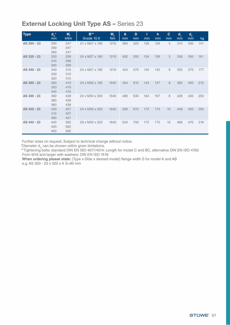
67
External Locking Unit Type AS – Series 23
Type dw*mm
MtkNm
B**Grade 10.9
MaNm
Amm
Dmm
Imm
hmm
Cmm
d1mm
d2mm kg
AS 300 - 23 300 247 21 x M27 x 180 1210 380 520 128 126 5 315 330 141290 247280 247
AS 320 - 23 320 299 24 x M27 x 180 1210 402 550 134 136 5 336 350 161310 299300 299
AS 340 - 23 340 315 24 x M27 x 180 1210 424 570 140 142 8 355 370 177330 315320 315
AS 360 - 23 360 410 24 x M30 x 190 1640 454 610 144 147 8 383 400 210350 410340 410
AS 390 - 23 390 439 24 x M30 x 200 1640 486 630 164 167 8 428 430 250380 439360 439
AS 420 - 23 420 457 24 x M30 x 220 1640 506 670 172 175 10 448 450 292410 457390 457
AS 440 - 23 440 562 28 x M30 x 220 1640 534 700 172 175 10 468 470 318420 562400 562
Further sizes on request. Subject to technical change without notice.*Diameter dw can be chosen within given limitations.**Tightening bolts: standard DIN EN ISO 4017/4014: Length for model C and BC, alternative DIN EN ISO 4762From M16 and larger with washers: DIN EN ISO 7416When ordering please state: (Type x Ødw x desired model) flange width S for model A and AB e.g. AS 320 - 23 x 320 x A S=90 mm
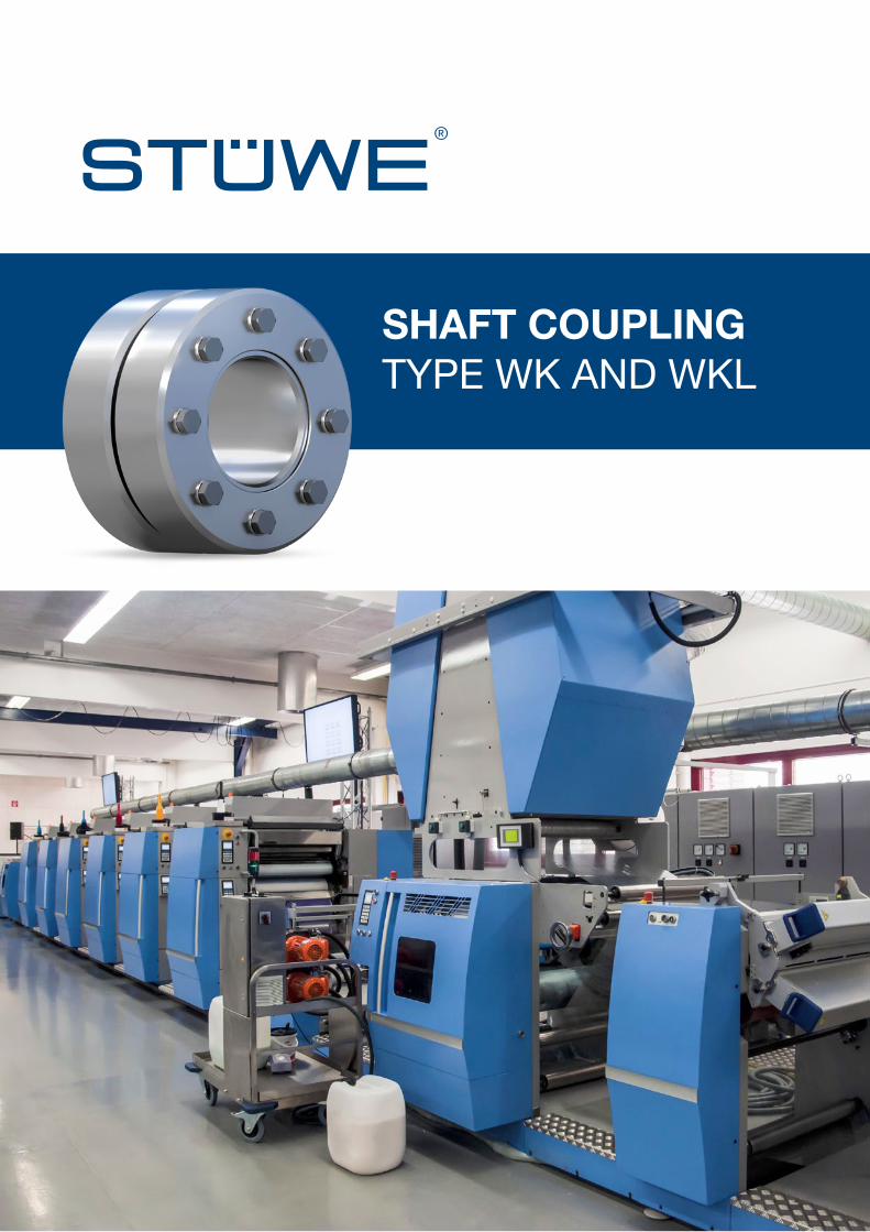
SHAFT COUPLING TYPE WK AND WKL
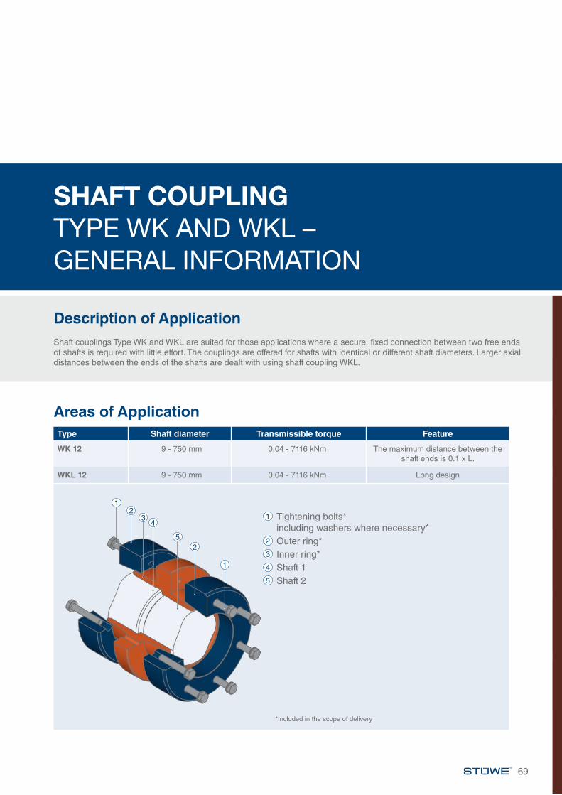
SHAFT COUPLING TYPE WK AND WKL – GENERAL INFORMATION
Description of ApplicationShaft couplings Type WK and WKL are suited for those applications where a secure, fixed connection between two free ends of shafts is required with little effort. The couplings are offered for shafts with identical or different shaft diameters. Larger axial distances between the ends of the shafts are dealt with using shaft coupling WKL.
69
Areas of ApplicationType Shaft diameter Transmissible torque Feature
WK 12 9 - 750 mm 0.04 - 7116 kNm The maximum distance between the shaft ends is 0.1 x L.
WKL 12 9 - 750 mm 0.04 - 7116 kNm Long design
1 Tightening bolts* including washers where necessary*2 Outer ring*3 Inner ring*4 Shaft 15 Shaft 2
*Included in the scope of delivery
23
4
52
1
1
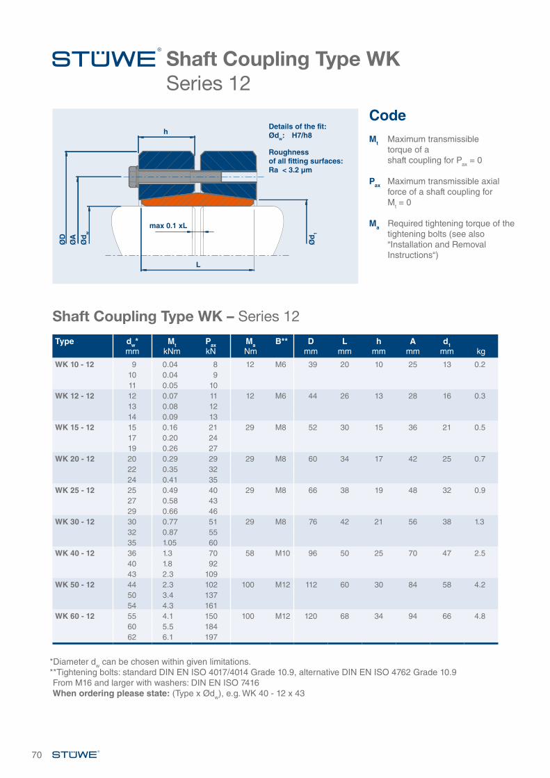
70
Shaft Coupling Type WKSeries 12
Shaft Coupling Type WK – Series 12
Type dw*mm
MtkNm
PaxkN
MaNm
B** Dmm
Lmm
hmm
Amm
d1mm kg
WK 10 - 12 9 0.04 8 12 M6 39 20 10 25 13 0.210 0.04 911 0.05 10
WK 12 - 12 12 0.07 11 12 M6 44 26 13 28 16 0.313 0.08 1214 0.09 13
WK 15 - 12 15 0.16 21 29 M8 52 30 15 36 21 0.517 0.20 2419 0.26 27
WK 20 - 12 20 0.29 29 29 M8 60 34 17 42 25 0.722 0.35 3224 0.41 35
WK 25 - 12 25 0.49 40 29 M8 66 38 19 48 32 0.927 0.58 4329 0.66 46
WK 30 - 12 30 0.77 51 29 M8 76 42 21 56 38 1.332 0.87 5535 1.05 60
WK 40 - 12 36 1.3 70 58 M10 96 50 25 70 47 2.540 1.8 9243 2.3 109
WK 50 - 12 44 2.3 102 100 M12 112 60 30 84 58 4.250 3.4 13754 4.3 161
WK 60 - 12 55 4.1 150 100 M12 120 68 34 94 66 4.860 5.5 18462 6.1 197
*Diameter dw can be chosen within given limitations.**Tightening bolts: standard DIN EN ISO 4017/4014 Grade 10.9, alternative DIN EN ISO 4762 Grade 10.9From M16 and larger with washers: DIN EN ISO 7416When ordering please state: (Type x Ødw), e.g. WK 40 - 12 x 43
CodeMt Maximum transmissible
torque of a shaft coupling for Pax = 0
Pax Maximum transmissible axial force of a shaft coupling for
Mt = 0
Ma Required tightening torque of the tightening bolts (see also “Installation and Removal Instructions“)
ØD
Ød
1
ØA
Ød
w
max 0.1 xL
L
hDetails of the fit:Ødw: H7/h8
Roughness of all fitting surfaces:Ra < 3.2 µm
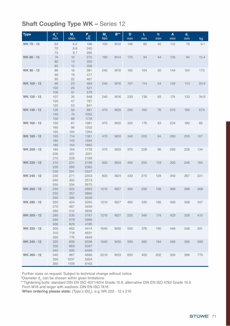
71
Shaft Coupling Type WK – Series 12
Further sizes on request. Subject to technical change without notice.*Diameter dw can be chosen within given limitations.**Tightening bolts: standard DIN EN ISO 4017/4014 Grade 10.9, alternative DIN EN ISO 4762 Grade 10.9From M16 and larger with washers: DIN EN ISO 7416When ordering please state: (Type x Ødw), e.g. WK 220 - 12 x 210
Type dw*mm
MtkNm
PaxkN
MaNm
B** Dmm
Lmm
hmm
Amm
d1mm kg
WK 70 - 12 63 6.2 196 100 M12 148 80 40 112 79 9.170 8.6 24573 9.7 266
WK 80 - 12 74 10 275 160 M14 170 94 44 130 94 13.480 13 32085 15 358
WK 90 - 12 86 16 381 240 M16 185 104 50 144 104 17.590 19 41795 22 461
WK 100 - 12 96 23 483 240 M16 197 114 54 156 113 20.9100 26 521106 31 578
WK 120 - 12 107 35 648 240 M16 230 138 65 174 133 34.6120 47 787125 53 841
WK 140 - 12 126 56 881 470 M20 290 160 76 216 160 67.5140 74 1052150 88 1178
WK 160 - 12 150 81 1081 470 M20 320 176 83 234 180 85160 96 1202165 104 1264
WK 180 - 12 165 114 1381 470 M20 340 200 94 260 205 107180 143 1594185 154 1665
WK 200 - 12 185 164 1778 470 M20 370 228 96 290 226 134200 201 2011210 228 2169
WK 220 - 12 210 231 2199 820 M24 405 250 118 320 246 184220 260 2362230 291 2527
WK 240 - 12 230 271 2353 820 M24 430 270 128 340 267 221240 302 2513250 334 2675
WK 260 - 12 240 322 2683 1210 M27 460 290 138 366 288 268250 357 2860260 395 3039
WK 280 - 12 260 424 3265 1210 M27 485 330 166 400 308 347270 467 3459280 512 3656
WK 300 - 12 280 530 3787 1210 M27 520 346 174 420 328 415290 579 3990300 629 4195
WK 320 - 12 300 662 4414 1640 M30 550 376 190 446 348 501310 718 4631320 776 4849
WK 340 - 12 320 806 5038 1640 M30 590 380 194 466 368 589330 869 5267340 935 5499
WK 360 - 12 340 967 5686 2210 M33 650 400 202 500 398 770350 1037 5924360 1109 6163
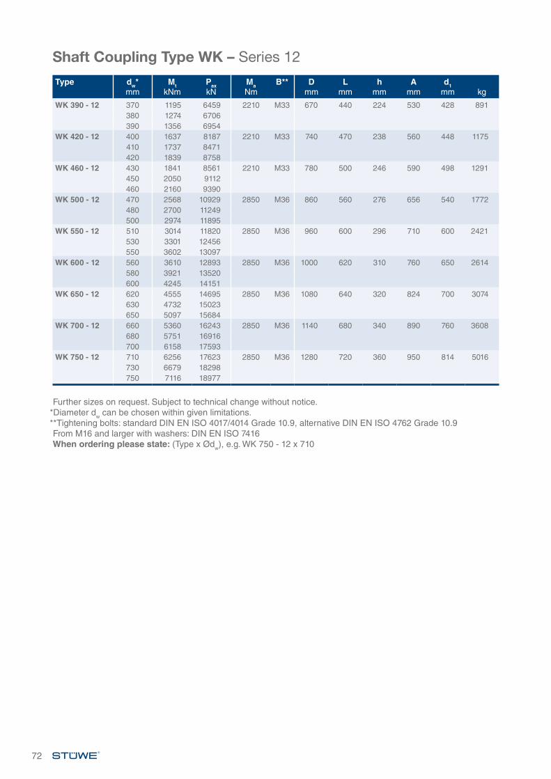
72
Shaft Coupling Type WK – Series 12
Further sizes on request. Subject to technical change without notice.*Diameter dw can be chosen within given limitations.**Tightening bolts: standard DIN EN ISO 4017/4014 Grade 10.9, alternative DIN EN ISO 4762 Grade 10.9From M16 and larger with washers: DIN EN ISO 7416When ordering please state: (Type x Ødw), e.g. WK 750 - 12 x 710
Type dw*mm
MtkNm
PaxkN
MaNm
B** Dmm
Lmm
hmm
Amm
d1mm kg
WK 390 - 12 370 1195 6459 2210 M33 670 440 224 530 428 891380 1274 6706390 1356 6954
WK 420 - 12 400 1637 8187 2210 M33 740 470 238 560 448 1175410 1737 8471420 1839 8758
WK 460 - 12 430 1841 8561 2210 M33 780 500 246 590 498 1291450 2050 9112460 2160 9390
WK 500 - 12 470 2568 10929 2850 M36 860 560 276 656 540 1772480 2700 11249500 2974 11895
WK 550 - 12 510 3014 11820 2850 M36 960 600 296 710 600 2421530 3301 12456550 3602 13097
WK 600 - 12 560 3610 12893 2850 M36 1000 620 310 760 650 2614580 3921 13520600 4245 14151
WK 650 - 12 620 4555 14695 2850 M36 1080 640 320 824 700 3074630 4732 15023650 5097 15684
WK 700 - 12 660 5360 16243 2850 M36 1140 680 340 890 760 3608680 5751 16916700 6158 17593
WK 750 - 12 710 6256 17623 2850 M36 1280 720 360 950 814 5016730 6679 18298750 7116 18977
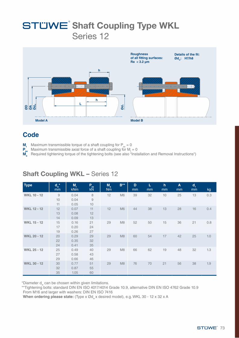
73
Shaft Coupling Type WKL Series 12
Shaft Coupling WKL – Series 12
Type dw*mm
MtkNm
PaxkN
MaNm
B** Dmm
Lmm
hmm
Amm
d1mm kg
WKL 10 - 12 9 0.04 8 12 M6 39 32 10 25 13 0.310 0.04 911 0.05 10
WKL 12 - 12 12 0.07 11 12 M6 44 38 13 28 16 0.413 0.08 1214 0.09 13
WKL 15 - 12 15 0.16 21 29 M8 52 50 15 36 21 0.817 0.20 2419 0.26 27
WKL 20 - 12 20 0.29 29 29 M8 60 54 17 42 25 1.022 0.35 3224 0.41 35
WKL 25 - 12 25 0.49 40 29 M8 66 62 19 48 32 1.327 0.58 4329 0.66 46
WKL 30 - 12 30 0.77 51 29 M8 76 70 21 56 38 1.932 0.87 5535 1.05 60
*Diameter dw can be chosen within given limitations.**Tightening bolts: standard DIN EN ISO 4017/4014 Grade 10.9, alternative DIN EN ISO 4762 Grade 10.9From M16 and larger with washers: DIN EN ISO 7416When ordering please state: (Type x Ødw x desired model), e.g. WKL 30 - 12 x 32 x A
ØD
ØA
Ød
w
Ød
1Lh
h
Model A Model B
Details of the fit:Ødw: H7/h8
Roughness of all fitting surfaces:Ra < 3.2 µm
Code Mt Maximum transmissible torque of a shaft coupling for Pax = 0Pax Maximum transmissible axial force of a shaft coupling for Mt = 0Ma Required tightening torque of the tightening bolts (see also “Installation and Removal Instructions“)
74
Shaft Coupling Type WKL – Series 12
*Diameter dw can be chosen within given limitations.**Tightening bolts: standard DIN EN ISO 4017/4014 Grade 10.9, alternative DIN EN ISO 4762 Grade 10.9From M16 and larger with washers: DIN EN ISO 7416When ordering please state: (Type x Ødw x desired model), e.g. WKL 240 - 12 x 230 x B
Type dw*mm
MtkNm
PaxkN
MaNm
B** Dmm
Lmm
hmm
Amm
d1mm kg
WKL 40 - 12 36 1.3 70 58 M10 96 80 25 70 47 3.540 1.8 9243 2.3 109
WKL 50 - 12 44 2.3 102 100 M12 112 90 30 84 58 5.550 3.4 13754 4.3 161
WKL 60 - 12 55 4.1 150 100 M12 120 120 34 94 66 7.960 5.5 18362 6.1 197
WKL 70 - 12 63 6.2 196 100 M12 148 140 40 112 79 13.770 8.6 24573 9.7 266
WKL 80 - 12 74 10 282 160 M14 170 170 44 130 94 21.480 13 32685 15 364
WKL 90 - 12 86 17 387 240 M16 185 200 50 144 104 29.590 19 42195 22 466
WKL 100 - 12 96 23 487 240 M16 197 210 54 148 114 33.0100 26 523106 31 579
WKL 120 - 12 107 35 659 240 M16 230 230 65 174 134 54.2120 48 796125 53 850
WKL 140 - 12 126 56 895 470 M20 290 250 76 206 160 95.4140 74 1064150 89 1188
WKL 160 - 12 150 82 1096 470 M20 320 280 83 234 180 115160 97 1216165 105 1277
WKL 180 - 12 165 116 1404 470 M20 340 310 94 260 205 152180 145 1613185 156 1684
WKL 200 - 12 185 167 1805 470 M20 370 350 96 266 226 192200 203 2034210 230 2190
WKL 220 - 12 210 234 2224 820 M24 405 390 118 320 246 252220 262 2385230 293 2548
WKL 240 - 12 230 273 2377 820 M24 430 430 128 340 267 302240 304 2536250 337 2696
WKL 260 - 12 240 325 2712 1210 M27 460 450 138 366 288 376250 361 2888260 398 3065
WKL 280 - 12 260 431 3312 1210 M27 485 470 154 400 308 443270 473 3504280 518 3698
WKL 300 - 12 280 537 3834 1210 M27 520 470 162 420 328 502290 585 4035300 636 4237
Shaft Coupling Type WKL – Series 12
Further sizes on request. Subject to technical change without notice.*Diameter dw can be chosen within given limitations.**Tightening bolts: standard DIN EN ISO 4017/4014 Grade 10.9, alternative DIN EN ISO 4762 Grade 10.9From M16 and larger with washers: DIN EN ISO 7416When ordering please state: (Type x Ødw x desired model), e.g. WKL 750 - 12 x 710 x B
75
Type dw*mm
MtkNm
PaxkN
MaNm
B** Dmm
Lmm
hmm
Amm
d1mm kg
WKL 320 - 12 300 667 4450 1640 M30 550 510 180 446 348 609310 723 4664320 781 4881
WKL 340 - 12 320 811 5066 1640 M30 590 510 184 466 368 694330 874 5294340 939 5525
WKL 360 - 12 340 973 5725 2210 M33 650 530 192 490 398 881350 1043 5961360 1116 6199
WKL 390 - 12 370 1199 6479 2210 M33 670 580 216 526 428 1004380 1278 6725390 1360 6972
WKL 420 - 12 400 1647 8234 2210 M33 740 600 226 550 448 1257410 1746 8517420 1848 8801
WKL 460 - 12 430 1841 8561 2210 M33 780 640 246 590 498 1483450 2050 9112460 2160 9390
WKL 500 - 12 470 2568 10929 2850 M36 860 690 276 648 540 1989480 2700 11249500 2974 11895
WKL 550 - 12 510 3014 11820 2850 M36 960 760 296 710 600 2739530 3301 12456550 3602 13097
WKL 600 - 12 560 3610 12893 2850 M36 1000 780 310 760 650 2957580 3921 13520600 4245 14151
WKL 650 - 12 620 4555 14695 2850 M36 1080 820 320 824 700 3501630 4732 15023650 5097 15684
WKL 700 - 12 660 5360 16243 2850 M36 1140 840 340 890 760 4056680 5751 16916700 6158 17593
WKL 750 - 12 710 6256 17623 2850 M36 1280 880 360 950 814 5511730 6679 18298750 7116 18977
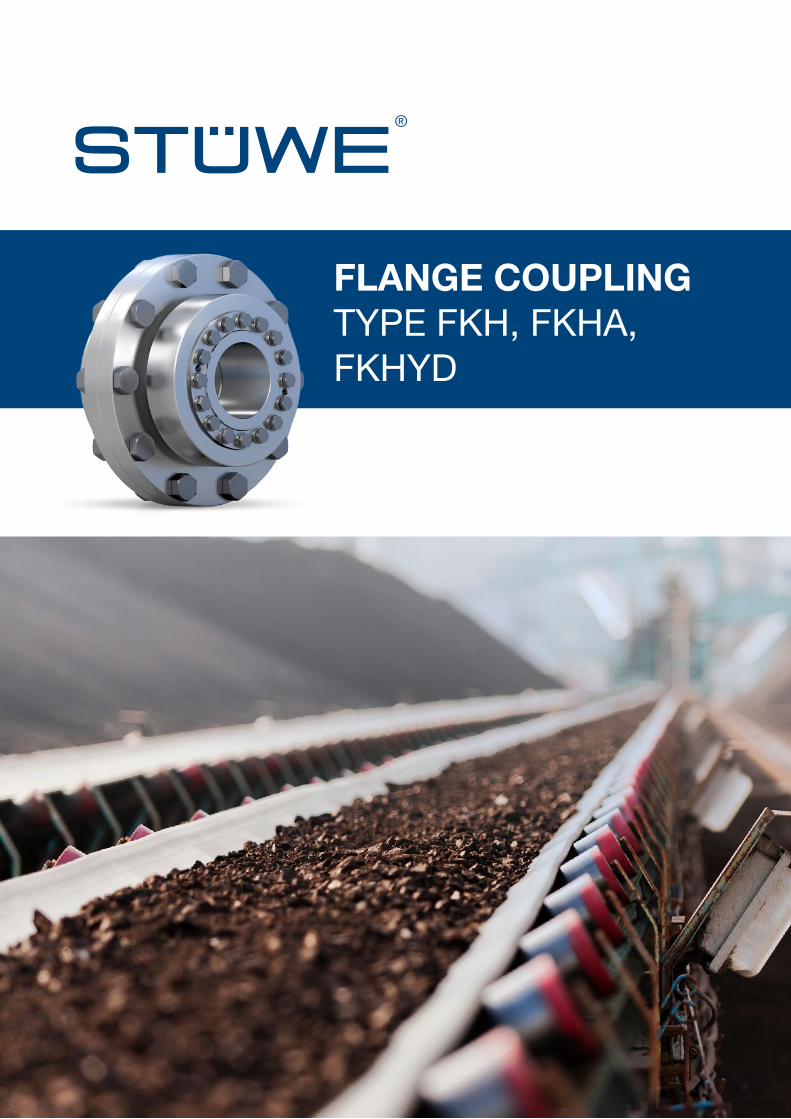
FLANGE COUPLING TYPE FKH, FKHA, FKHYD
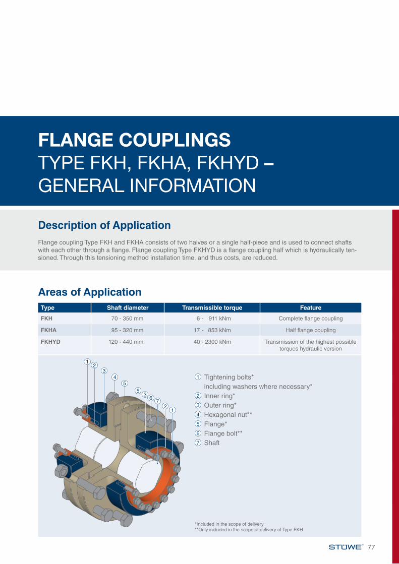
FLANGE COUPLINGS TYPE FKH, FKHA, FKHYD – GENERAL INFORMATION
Description of ApplicationFlange coupling Type FKH and FKHA consists of two halves or a single half-piece and is used to connect shafts with each other through a flange. Flange coupling Type FKHYD is a flange coupling half which is hydraulically ten-sioned. Through this tensioning method installation time, and thus costs, are reduced.
77
Areas of ApplicationType Shaft diameter Transmissible torque Feature
FKH 70 - 350 mm 6 - 911 kNm Complete flange coupling
FKHA 95 - 320 mm 17 - 853 kNm Half flange coupling
FKHYD 120 - 440 mm 40 - 2300 kNm Transmission of the highest possible torques hydraulic version
1 Tightening bolts* including washers where necessary*2 Inner ring*3 Outer ring*4 Hexagonal nut**5 Flange*6 Flange bolt**7 Shaft
1
1
2
2
43
3
55
67
*Included in the scope of delivery **Only included in the scope of delivery of Type FKH
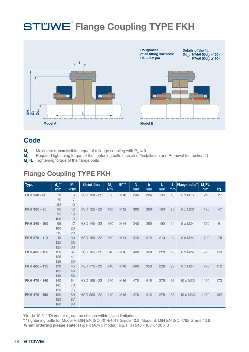
78
Flange Coupling TYPE FKH
Flange Coupling TYPE FKH
Type dw**mm
MtkNm
Shrink Disc MaNm
B*** Nmm
bmm
Lmm
fmm
Flange bolts* MaFLNm kg
FKH 240 - 80 70 6 HSD 100 - 22 58 M10 240 206 136 18 6 x M16 210 2775 784 10
FKH 300 - 90 85 12 HSD 125 - 22 100 M12 300 260 160 20 6 x M20 420 4795 16
100 19FKH 340 - 100 95 17 HSD 140 - 22 160 M14 340 280 190 24 5 x M24 720 61
100 20115 28
FKH 370 - 110 115 30 HSD 155 - 22 160 M14 370 310 210 24 8 x M24 720 78120 33125 36
FKH 400 - 120 120 37 HSD 165 - 22 240 M16 400 350 228 28 8 x M24 720 110125 41135 50
FKH 400 - 130 130 45 HSD 175 - 22 240 M16 400 350 228 28 8 x M24 720 112135 49145 58
FKH 470 - 140 140 64 HSD 185 - 22 240 M16 470 416 278 36 10 x M30 1450 173145 70150 76
FKH 470 - 150 150 80 HSD 200 - 22 240 M16 470 416 278 36 10 x M30 1450 182155 87160 93
*Grade 10.9 **Diameter dw can be chosen within given limitations. ***Tightening bolts for Model A: DIN EN ISO 4014/4017 Grade 10.9, Model B: DIN EN ISO 4762 Grade 10.9When ordering please state: (Type x Ødw x model), e.g. FKH 340 - 100 x 100 x B
ØN
Øb
Ød
w
L
Model A Model B
f
Details of the fit:Ødw: H7/h6 (Ødw: <160) H7/g6 (Ødw: ≥160)
Roughness of all fitting surfaces:Ra < 3.2 µm
Code Mt Maximum transmissible torque of a flange coupling with Pax = 0Ma Required tightening torque of the tightening bolts (see also “Installation and Removal Instructions“)MaFL Tightening torque of the flange bolts
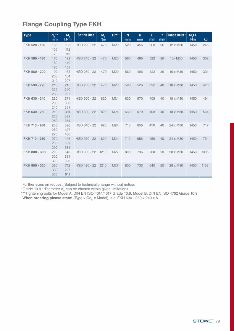
79
Flange Coupling Type FKH
Further sizes on request. Subject to technical change without notice.*Grade 10.9 **Diameter dw can be chosen within given limitations. ***Tightening bolts for Model A: DIN EN ISO 4014/4017 Grade 10.9, Model B: DIN EN ISO 4762 Grade 10.9When ordering please state: (Type x Ødw x Model), e.g. FKH 630 - 250 x 240 x A
Type dw**mm
MtkNm
Shrink Disc MaNm
B*** Nmm
bmm
Lmm
fmm
Flange bolts* MaFLNm kg
FKH 520 - 160 160 103 HSD 220 - 22 470 M20 520 456 300 36 12 x M30 1450 245165 112170 119
FKH 560 - 180 170 122 HSD 240 - 22 470 M20 560 496 322 36 16x M30 1450 302180 140190 159
FKH 560 - 200 190 163 HSD 260 - 22 470 M20 560 496 322 36 16 x M30 1450 334200 184210 207
FKH 590 - 220 210 215 HSD 280 - 22 470 M20 590 526 392 40 18 x M30 1450 420220 240230 267
FKH 630 - 240 220 271 HSD 300 - 22 820 M24 630 570 408 40 18 x M30 1450 494230 300240 331
FKH 630 - 250 240 301 HSD 320 - 22 820 M24 630 570 408 40 18 x M30 1450 534250 332260 364
FKH 710 - 260 250 390 HSD 340 - 22 820 M24 710 656 450 40 24 x M30 1450 717260 427270 466
FKH 710 - 280 270 496 HSD 360 - 22 820 M24 710 656 450 40 24 x M30 1450 754280 539290 584
FKH 800 - 300 290 640 HSD 390 - 22 1210 M27 800 736 500 50 28 x M30 1450 1006300 691320 800
FKH 800 - 330 320 742 HSD 420 - 22 1210 M27 800 736 540 50 28 x M30 1450 1158330 797350 911
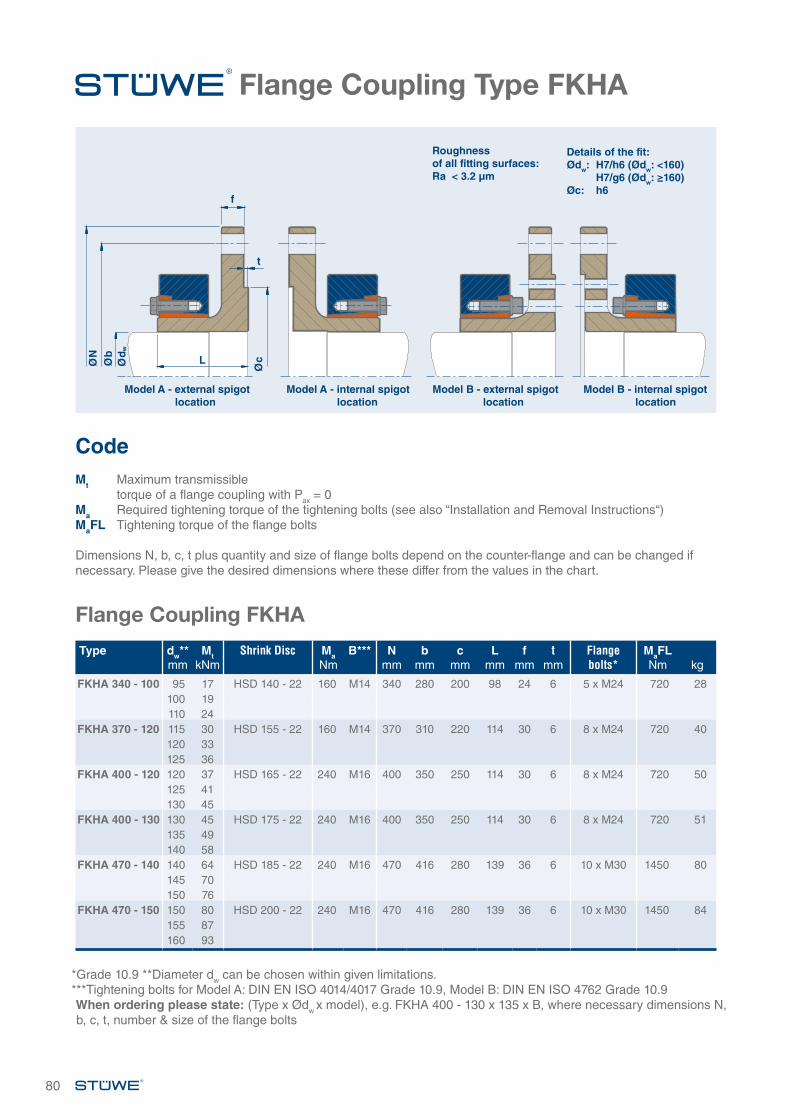
80
Flange Coupling Type FKHA
*Grade 10.9 **Diameter dw can be chosen within given limitations.***Tightening bolts for Model A: DIN EN ISO 4014/4017 Grade 10.9, Model B: DIN EN ISO 4762 Grade 10.9When ordering please state: (Type x Ødw x model), e.g. FKHA 400 - 130 x 135 x B, where necessary dimensions N, b, c, t, number & size of the flange bolts
Details of the fit:Ødw: H7/h6 (Ødw: <160) H7/g6 (Ødw: ≥160)Øc: h6
Roughness of all fitting surfaces:Ra < 3.2 µm
Flange Coupling FKHA
Model A - external spigot location
Model A - internal spigot location
Model B - external spigot location
Model B - internal spigot location
Code Mt Maximum transmissible
torque of a flange coupling with Pax = 0Ma Required tightening torque of the tightening bolts (see also “Installation and Removal Instructions“)MaFL Tightening torque of the flange bolts
Dimensions N, b, c, t plus quantity and size of flange bolts depend on the counter-flange and can be changed if necessary. Please give the desired dimensions where these differ from the values in the chart.
Type dw**mm
MtkNm
Shrink Disc MaNm
B*** Nmm
bmm
cmm
Lmm
fmm
tmm
Flange bolts*
MaFLNm kg
FKHA 340 - 100 95 17 HSD 140 - 22 160 M14 340 280 200 98 24 6 5 x M24 720 28100 19110 24
FKHA 370 - 120 115 30 HSD 155 - 22 160 M14 370 310 220 114 30 6 8 x M24 720 40120 33125 36
FKHA 400 - 120 120 37 HSD 165 - 22 240 M16 400 350 250 114 30 6 8 x M24 720 50125 41130 45
FKHA 400 - 130 130 45 HSD 175 - 22 240 M16 400 350 250 114 30 6 8 x M24 720 51135 49140 58
FKHA 470 - 140 140 64 HSD 185 - 22 240 M16 470 416 280 139 36 6 10 x M30 1450 80145 70150 76
FKHA 470 - 150 150 80 HSD 200 - 22 240 M16 470 416 280 139 36 6 10 x M30 1450 84155 87160 93
ØN
Øb
Ød w
Øc
f
t
L
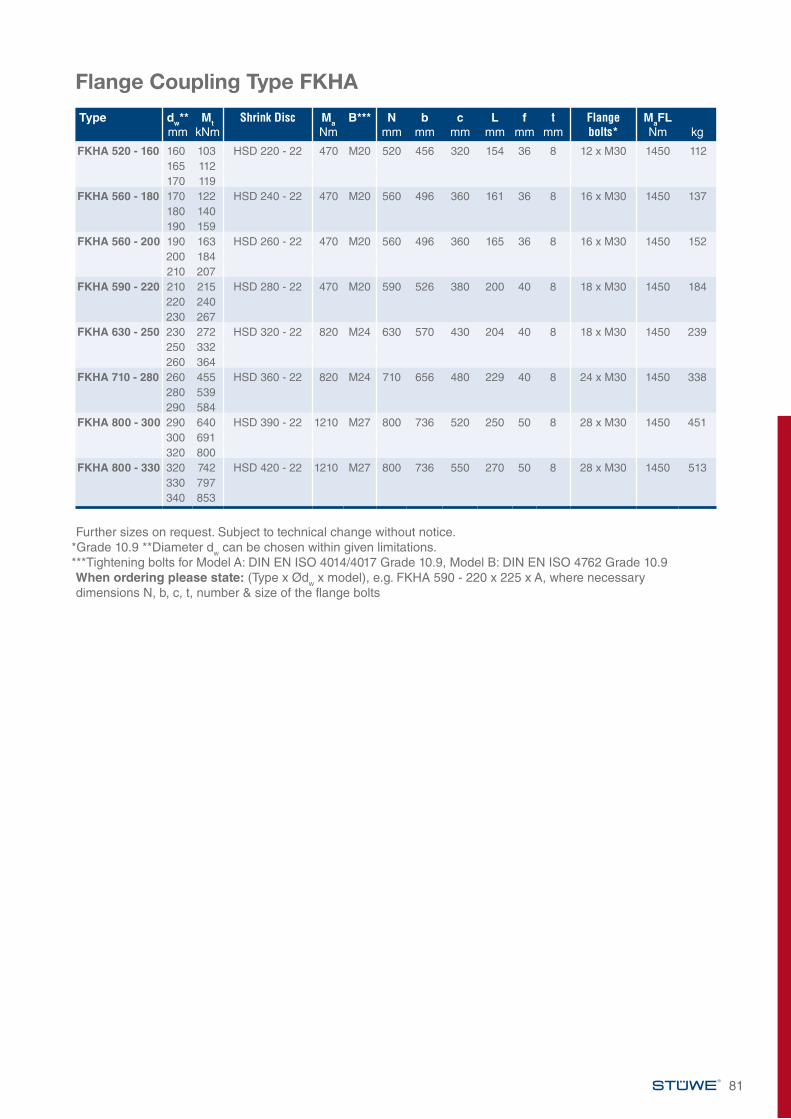
81
Further sizes on request. Subject to technical change without notice.*Grade 10.9 **Diameter dw can be chosen within given limitations. ***Tightening bolts for Model A: DIN EN ISO 4014/4017 Grade 10.9, Model B: DIN EN ISO 4762 Grade 10.9When ordering please state: (Type x Ødw x model), e.g. FKHA 590 - 220 x 225 x A, where necessary dimensions N, b, c, t, number & size of the flange bolts
Type dw**mm
MtkNm
Shrink Disc MaNm
B*** Nmm
bmm
cmm
Lmm
fmm
tmm
Flange bolts*
MaFLNm kg
FKHA 520 - 160 160 103 HSD 220 - 22 470 M20 520 456 320 154 36 8 12 x M30 1450 112165 112170 119
FKHA 560 - 180 170 122 HSD 240 - 22 470 M20 560 496 360 161 36 8 16 x M30 1450 137180 140190 159
FKHA 560 - 200 190 163 HSD 260 - 22 470 M20 560 496 360 165 36 8 16 x M30 1450 152200 184210 207
FKHA 590 - 220 210 215 HSD 280 - 22 470 M20 590 526 380 200 40 8 18 x M30 1450 184220 240230 267
FKHA 630 - 250 230 272 HSD 320 - 22 820 M24 630 570 430 204 40 8 18 x M30 1450 239250 332260 364
FKHA 710 - 280 260 455 HSD 360 - 22 820 M24 710 656 480 229 40 8 24 x M30 1450 338280 539290 584
FKHA 800 - 300 290 640 HSD 390 - 22 1210 M27 800 736 520 250 50 8 28 x M30 1450 451300 691320 800
FKHA 800 - 330 320 742 HSD 420 - 22 1210 M27 800 736 550 270 50 8 28 x M30 1450 513330 797340 853
Flange Coupling Type FKHA
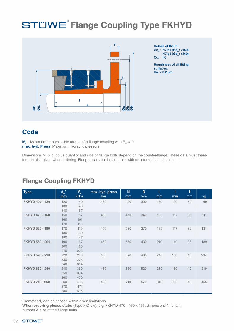
82
Flange Coupling Type FKHYD
Flange Coupling FKHYD
Type dw*mm
MtkNm
max. hyd. pressbar
Nmm
Dmm
Lmm
Imm
fmm kg
FKHYD 400 - 120 120 40 450 400 300 150 90 30 69130 48140 57
FKHYD 470 - 160 150 87 450 470 340 185 117 36 111160 101170 115
FKHYD 520 - 180 170 115 450 520 370 185 117 36 131180 130190 147
FKHYD 560 - 200 190 167 450 560 430 210 140 36 189200 186210 208
FKHYD 590 - 220 220 248 450 590 460 240 160 40 234230 275240 304
FKHYD 630 - 240 240 360 450 630 520 260 180 40 319250 394260 430
FKHYD 710 - 260 260 435 450 710 570 310 220 40 455270 474280 515
Details of the fit:Ødw: H7/h6 (Ødw: <160) H7/g6 (Ødw: ≥160)Øc: h6
Roughness of all fitting surfaces:Ra < 3.2 µm
Code Mt Maximum transmissible torque of a flange coupling with Pax = 0max. hyd. Press Maximum hydraulic pressure Dimensions N, b, c, t plus quantity and size of flange bolts depend on the counter-flange. These data must there-fore be also given when ordering. Flanges can also be supplied with an internal spigot location.
*Diameter dw can be chosen within given limitations. When ordering please state: (Type x Ø dw), e.g. FKHYD 470 - 160 x 155, dimensions N, b, c, t, number & size of the flange bolts
ØD
Øc
Øb
ØN
Ød w
l
t
f
L
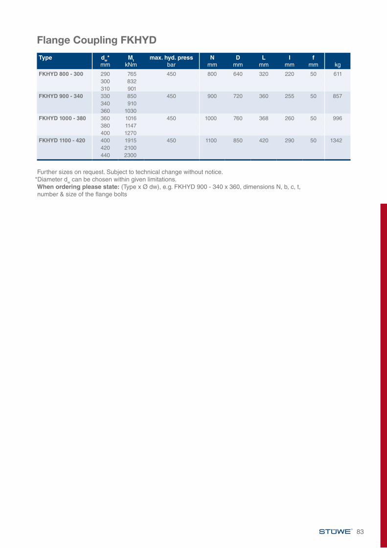
83
Flange Coupling FKHYD
Further sizes on request. Subject to technical change without notice.*Diameter dw can be chosen within given limitations. When ordering please state: (Type x Ø dw), e.g. FKHYD 900 - 340 x 360, dimensions N, b, c, t, number & size of the flange bolts
Type dw*mm
MtkNm
max. hyd. pressbar
Nmm
Dmm
Lmm
Imm
fmm kg
FKHYD 800 - 300 290 765 450 800 640 320 220 50 611300 832310 901
FKHYD 900 - 340 330 850 450 900 720 360 255 50 857340 910360 1030
FKHYD 1000 - 380 360 1016 450 1000 760 368 260 50 996380 1147400 1270
FKHYD 1100 - 420 400 1915 450 1100 850 420 290 50 1342420 2100440 2300
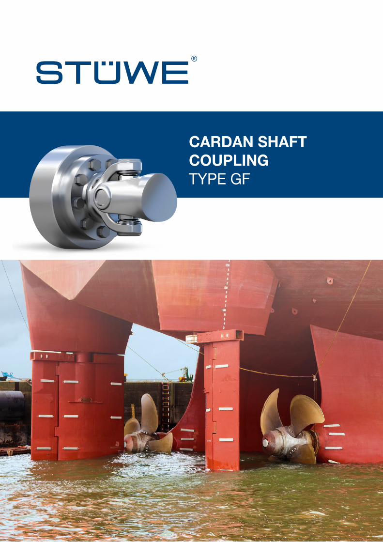
CARDAN SHAFT
COUPLINGTYPE GF

CARDAN SHAFTCOUPLING TYPE GF – GENERAL INFORMATION
Description of ApplicationCardan shaft flange Type GF is suited for the connection of standard cardan shafts. The following characteristics distinguish the flanges: Perfect power transmission, quick and easy installation, secure connection of cardan shafts with varying shaft ends.
Series Shaft diameter Transmissible torque Feature
21 20 - 85 mm 0.12 - 9.52 kNm Flange bolts are also used for tensioning
22 65 - 220 mm 7 - 229 kNm Primarily for the connection of smallshaft diameters with large cardan shaft flanges
23 90 - 300 mm 13 - 507 kNm Primarily for the connection of large shaft diameters
Areas of Application
Model A Model A
Model A
Model B Model B
Model B
Series 21 Series 22 Series 23
Cardan Shaft Cardan Shaft Cardan ShaftCardan Shaft
Cardan Shaft
1 Shaft2 Outer ring*3 Inner ring*4 Tightening bolts* including washers where necessary*5 Cardan Shaft6 Flange bolts
23
45
6
1
*Included in the scope of delivery
Cardan Shaft
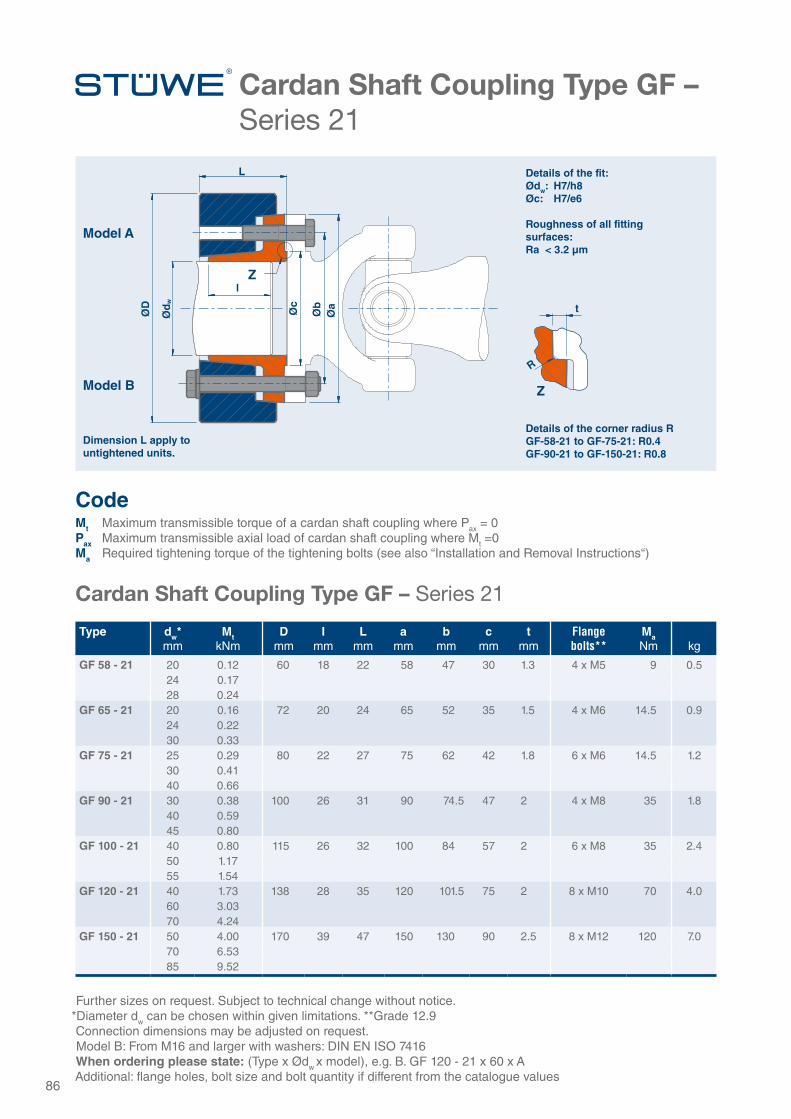
Cardan Shaft Coupling Type GF – Series 21
Cardan Shaft Coupling Type GF – Series 21
Type dw*mm
MtkNm
Dmm
Imm
Lmm
amm
bmm
cmm
tmm
Flangebolts**
MaNm kg
GF 58 - 21 20 0.12 60 18 22 58 47 30 1.3 4 x M5 9 0.524 0.1728 0.24
GF 65 - 21 20 0.16 72 20 24 65 52 35 1.5 4 x M6 14.5 0.924 0.2230 0.33
GF 75 - 21 25 0.29 80 22 27 75 62 42 1.8 6 x M6 14.5 1.230 0.4140 0.66
GF 90 - 21 30 0.38 100 26 31 90 74.5 47 2 4 x M8 35 1.840 0.5945 0.80
GF 100 - 21 40 0.80 115 26 32 100 84 57 2 6 x M8 35 2.450 1.1755 1.54
GF 120 - 21 40 1.73 138 28 35 120 101.5 75 2 8 x M10 70 4.060 3.0370 4.24
GF 150 - 21 50 4.00 170 39 47 150 130 90 2.5 8 x M12 120 7.070 6.5385 9.52
Further sizes on request. Subject to technical change without notice.*Diameter dw can be chosen within given limitations. **Grade 12.9 Connection dimensions may be adjusted on request.Model B: From M16 and larger with washers: DIN EN ISO 7416When ordering please state: (Type x Ødw x model), e.g. B. GF 120 - 21 x 60 x AAdditional: flange holes, bolt size and bolt quantity if different from the catalogue values
*
Z
Model A
Model B
t
Z
R
ØD
Øc
Øb
Øa
Ød
wL
l
Dimension L apply to untightened units.
Details of the corner radius RGF-58-21 to GF-75-21: R0.4GF-90-21 to GF-150-21: R0.8
86
CodeMt Maximum transmissible torque of a cardan shaft coupling where Pax = 0Pax Maximum transmissible axial load of cardan shaft coupling where Mt =0Ma Required tightening torque of the tightening bolts (see also “Installation and Removal Instructions“)
Details of the fit:Ødw: H7/h8Øc: H7/e6
Roughness of all fitting surfaces:Ra < 3.2 µm
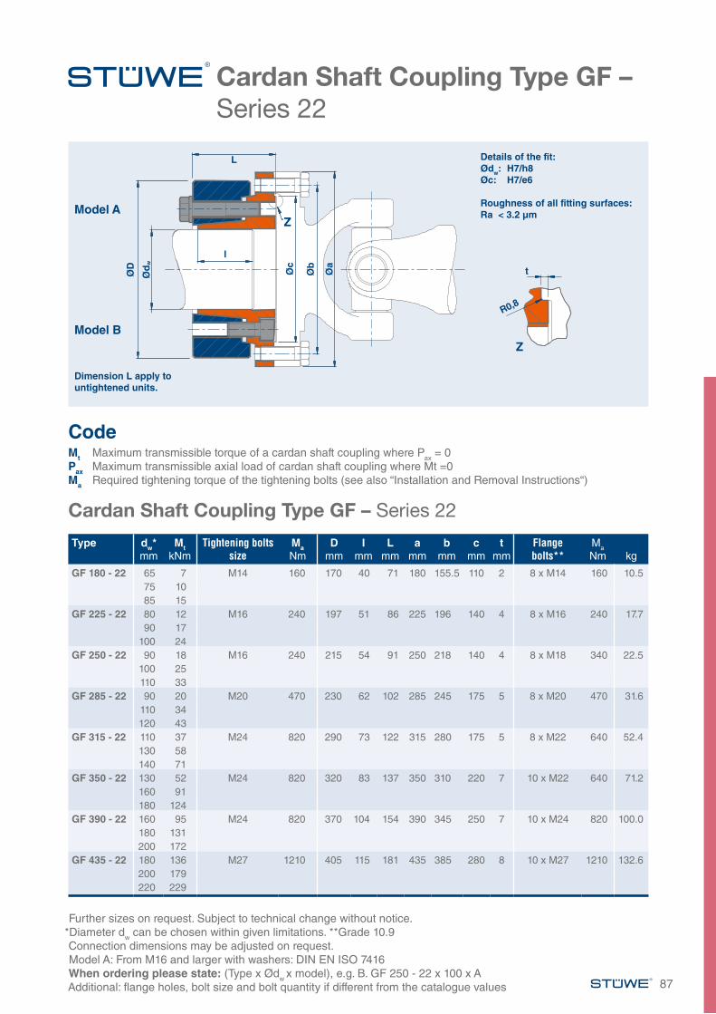
Cardan Shaft Coupling Type GF – Series 22
Cardan Shaft Coupling Type GF – Series 22
Type dw*mm
MtkNm
Tightening bolts size
MaNm
Dmm
Imm
Lmm
amm
bmm
cmm
tmm
Flangebolts**
Ma
Nm kg
GF 180 - 22 65 7 M14 160 170 40 71 180 155.5 110 2 8 x M14 160 10.575 1085 15
GF 225 - 22 80 12 M16 240 197 51 86 225 196 140 4 8 x M16 240 17.790 17
100 24GF 250 - 22 90 18 M16 240 215 54 91 250 218 140 4 8 x M18 340 22.5
100 25110 33
GF 285 - 22 90 20 M20 470 230 62 102 285 245 175 5 8 x M20 470 31.6110 34120 43
GF 315 - 22 110 37 M24 820 290 73 122 315 280 175 5 8 x M22 640 52.4130 58140 71
GF 350 - 22 130 52 M24 820 320 83 137 350 310 220 7 10 x M22 640 71.2160 91180 124
GF 390 - 22 160 95 M24 820 370 104 154 390 345 250 7 10 x M24 820 100.0180 131200 172
GF 435 - 22 180 136 M27 1210 405 115 181 435 385 280 8 10 x M27 1210 132.6200 179220 229
Further sizes on request. Subject to technical change without notice.*Diameter dw can be chosen within given limitations. **Grade 10.9 Connection dimensions may be adjusted on request.Model A: From M16 and larger with washers: DIN EN ISO 7416When ordering please state: (Type x Ødw x model), e.g. B. GF 250 - 22 x 100 x AAdditional: flange holes, bolt size and bolt quantity if different from the catalogue values
*
Details of the fit:Ødw: H7/h8Øc: H7/e6
Roughness of all fitting surfaces:Ra < 3.2 µm
ZModel A
Model B
t
Z
ØD
Øc
Øb
Øa
Ød
w
L
Dimension L apply to untightened units.
l
87
CodeMt Maximum transmissible torque of a cardan shaft coupling where Pax = 0Pax Maximum transmissible axial load of cardan shaft coupling where Mt =0Ma Required tightening torque of the tightening bolts (see also “Installation and Removal Instructions“)
R0,8
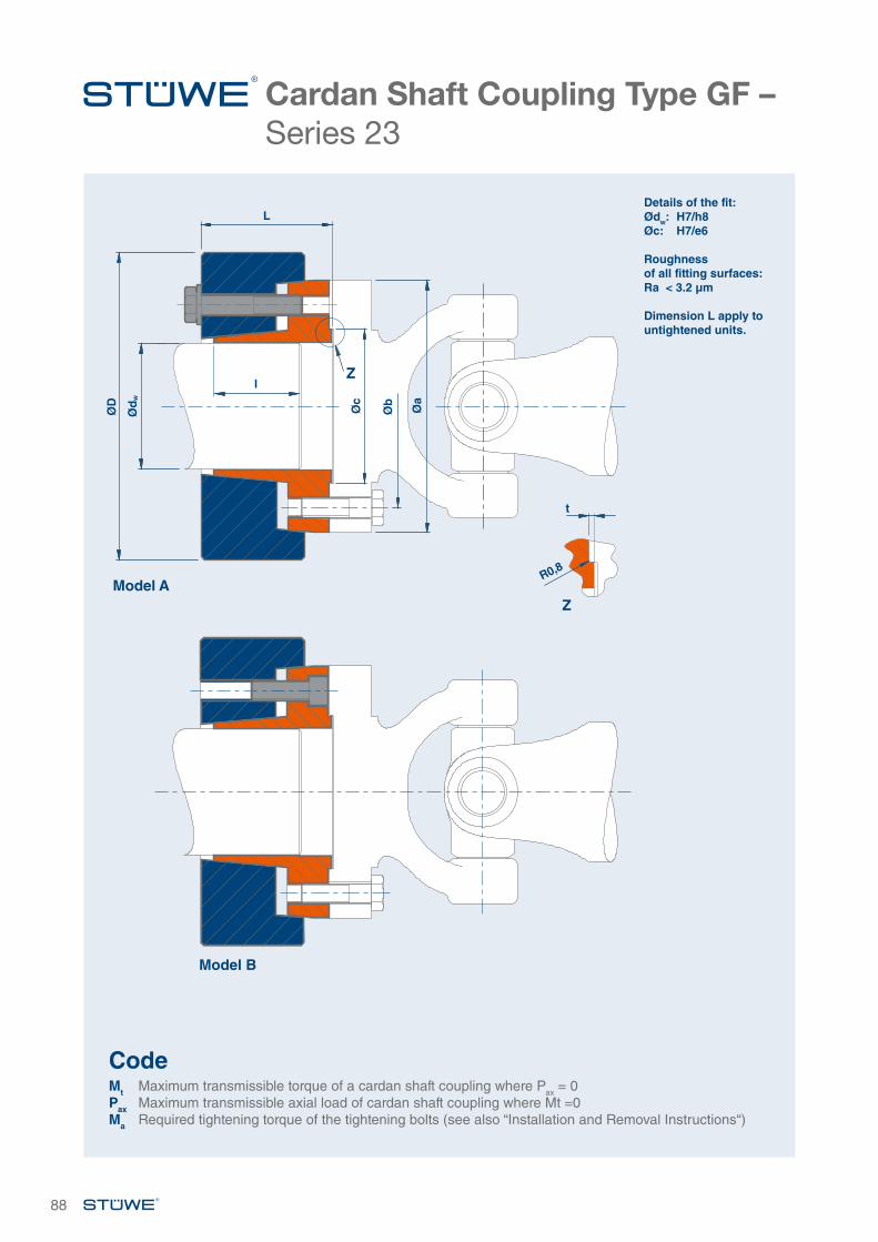
Cardan Shaft Coupling Type GF – Series 23
88
Model B
Model A
Z
ØD
Øc
Øb
Øa
Ød
w
L
l
t
Z
Details of the fit:Ødw: H7/h8Øc: H7/e6
Roughness of all fitting surfaces:Ra < 3.2 µm
Dimension L apply to untightened units.
CodeMt Maximum transmissible torque of a cardan shaft coupling where Pax = 0Pax Maximum transmissible axial load of cardan shaft coupling where Mt =0Ma Required tightening torque of the tightening bolts (see also “Installation and Removal Instructions“)
R0,8
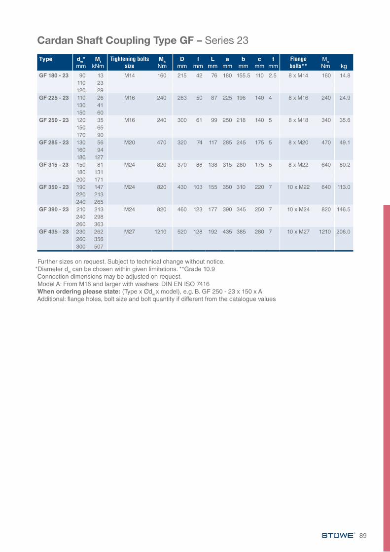
Cardan Shaft Coupling Type GF – Series 23
Type dw*mm
MtkNm
Tightening bolts size
MaNm
Dmm
Imm
Lmm
amm
bmm
cmm
tmm
Flange bolts**
Ma
Nm kg
GF 180 - 23 90 13 M14 160 215 42 76 180 155.5 110 2.5 8 x M14 160 14.8110 23120 29
GF 225 - 23 110 26 M16 240 263 50 87 225 196 140 4 8 x M16 240 24.9130 41150 60
GF 250 - 23 120 35 M16 240 300 61 99 250 218 140 5 8 x M18 340 35.6150 65170 90
GF 285 - 23 130 56 M20 470 320 74 117 285 245 175 5 8 x M20 470 49.1160 94180 127
GF 315 - 23 150 81 M24 820 370 88 138 315 280 175 5 8 x M22 640 80.2180 131200 171
GF 350 - 23 190 147 M24 820 430 103 155 350 310 220 7 10 x M22 640 113.0220 213240 265
GF 390 - 23 210 213 M24 820 460 123 177 390 345 250 7 10 x M24 820 146.5240 298260 363
GF 435 - 23 230 262 M27 1210 520 128 192 435 385 280 7 10 x M27 1210 206.0260 356300 507
Further sizes on request. Subject to technical change without notice.*Diameter dw can be chosen within given limitations. **Grade 10.9Connection dimensions may be adjusted on request.Model A: From M16 and larger with washers: DIN EN ISO 7416When ordering please state: (Type x Ødw x model), e.g. B. GF 250 - 23 x 150 x AAdditional: flange holes, bolt size and bolt quantity if different from the catalogue values
89
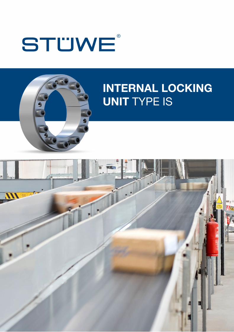
INTERNAL LOCKING UNIT TYPE IS
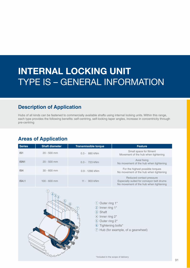
INTERNAL LOCKING UNIT TYPE IS – GENERAL INFORMATION
Description of ApplicationHubs of all kinds can be fastened to commercially available shafts using internal locking units. Within this range, each type provides the following benefits: self-centring, self-locking taper angles, increase in concentricity through pre-centring
91
Series Shaft diameter Transmissible torque Feature
IS1 20 - 500 mm 0.3 - 880 kNm Small space for fitment
Movement of the hub when tightening
ISN1 20 - 500 mm 0.3 - 723 kNm Axial fixing
No movement of the hub when tightening
IS4 30 - 600 mm 0.9 - 1266 kNm For the highest possible torques
No movement of the hub when tightening
IS4.1 100 - 600 mm 11 - 903 kNm Reduced contact pressure
Especially suited for conveyor belt drumsNo movement of the hub when tightening
Areas of Application
1 Outer ring 1*2 Inner ring 1*3 Shaft4 Inner ring 2*5 Outer ring 2*6 Tightening bolts* 7 Hub (for example, of a gearwheel)
12
34
56
7
*Included in the scope of delivery
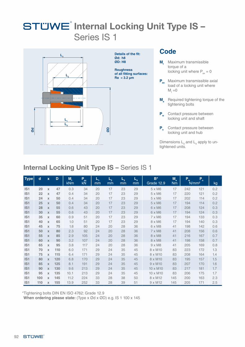
Internal Locking Unit Type IS – Series IS 1
Internal Locking Unit Type IS – Series IS 1
Type d x D MtkNm
PaxkN
L1mm
L2mm
L3mm
L4mm
B*Grade 12.9
MaNm
Pw PnN/mm² kg
IS1 20 x 47 0.3 34 20 17 23 29 5 x M6 17 242 121 0.2IS1 22 x 47 0.4 34 20 17 23 29 5 x M6 17 220 121 0.2IS1 24 x 50 0.4 34 20 17 23 29 5 x M6 17 202 114 0.2IS1 25 x 50 0.4 34 20 17 23 29 5 x M6 17 194 114 0.2IS1 28 x 55 0.6 43 20 17 23 29 6 x M6 17 208 124 0.3IS1 30 x 55 0.6 43 20 17 23 29 6 x M6 17 194 124 0.3IS1 35 x 60 0.9 51 20 17 23 29 7 x M6 17 194 133 0.3IS1 40 x 65 1.0 51 20 17 23 29 8 x M6 17 194 140 0.3IS1 45 x 75 1.8 80 24 20 28 36 6 x M8 41 198 142 0.6IS1 50 x 80 2.3 92 24 20 28 36 7 x M8 41 208 156 0.6IS1 55 x 85 2.9 105 24 20 28 36 8 x M8 41 216 167 0.7IS1 60 x 90 3.2 107 24 20 28 36 8 x M8 41 198 158 0.7IS1 65 x 95 3.8 117 24 20 28 36 9 x M8 41 205 169 0.8IS1 70 x 110 6.0 171 29 24 35 45 8 x M10 83 223 172 1.3IS1 75 x 115 6.4 171 29 24 35 45 8 x M10 83 208 164 1.4IS1 80 x 120 6.8 170 29 24 35 45 8 x M10 83 195 157 1.5IS1 85 x 125 8.1 191 29 24 35 45 9 x M10 83 207 170 1.6IS1 90 x 130 9.6 213 29 24 35 45 10 x M10 83 217 181 1.7IS1 95 x 135 10.1 213 29 24 35 45 10 x M10 83 206 175 1.7IS1 100 x 145 11.2 224 33 28 38 50 8 x M12 145 200 163 2.3IS1 110 x 155 13.9 252 33 28 39 51 9 x M12 145 205 171 2.5
*Tightening bolts DIN EN ISO 4762: Grade 12.9When ordering please state: (Type x Ød x ØD) e.g. IS 1 100 x 145
CodeMt Maximum transmissible
torque of a locking unit where Pax = 0
Pax Maximum transmissible axial load of a locking unit where
Mt =0
Ma Required tightening torque of the tightening bolts
Pw Contact pressure between locking unit and shaft
Pn Contact pressure between locking unit and hub Dimensions L3 and L4 apply to un-tightened units.
Details of the fit:Ød: h8ØD: H8
Roughness of all fitting surfaces:Ra < 3.2 µm
Ød
ØD
L4
L2
L1
L3
92
Internal Locking Unit Type IS – Series IS 1
Type d x D MtkNm
PaxkN
L1mm
L2mm
L3mm
L4mm
B*Grade 12.9
MaNm
Pw PnN/mm² kg
IS1 120 x 165 16.8 280 33 28 39 51 10 x M12 145 209 179 2.8IS1 130 x 180 23.1 355 38 33 43 55 12 x M12 145 201 167 4.0IS1 140 x 190 23.5 336 38 33 43 55 12 x M12 145 186 158 4.1IS1 150 x 200 30.4 406 38 33 43 55 14 x M12 145 203 175 4.2IS1 160 x 210 34.8 435 38 33 43 55 15 x M12 145 204 179 4.5IS1 170 x 225 41.5 488 43 38 49 63 12 x M14 230 186 159 6.0IS1 180 x 235 51.2 569 43 38 50 64 14 x M14 230 205 178 6.3IS1 190 x 250 61.1 643 51 46 58 72 16 x M14 230 187 158 8.5IS1 200 x 260 71.6 716 51 46 57 71 18 x M14 230 200 171 9.3IS1 220 x 285 99.5 905 55 50 62 78 16 x M16 355 207 175 12IS1 240 x 305 108.0 900 55 50 62 78 16 x M16 355 189 164 13IS1 260 x 325 129.5 996 55 50 62 78 18 x M16 355 197 173 15IS1 280 x 355 169.7 1212 65 60 73 91 18 x M18 485 188 161 20IS1 300 x 375 199.8 1332 65 60 73 91 20 x M18 485 195 169 22IS1 320 x 405 274.5 1716 77 72 86 106 18 x M20 690 198 167 31IS1 340 x 425 289.8 1705 77 72 88 108 20 x M20 690 187 160 33IS1 360 x 455 384.7 2137 89 84 100 122 20 x M22 930 190 159 44IS1 380 x 475 430.0 2263 89 84 99 121 21 x M22 930 189 160 46IS1 400 x 495 449.7 2249 89 84 99 121 21 x M22 930 180 154 48IS1 420 x 515 545.5 2597 89 84 100 122 24 x M22 930 196 169 51IS1 440 x 545 659.9 3000 101 96 114 138 24 x M24 1200 190 161 66IS1 460 x 565 689.9 3000 101 96 113 137 24 x M24 1200 182 156 69IS1 480 x 585 719.9 3000 101 96 114 138 24 x M24 1200 174 150 71IS1 500 x 605 880.4 3522 101 96 113 137 28 x M24 1200 195 170 75
93
Further sizes on request. Subject to technical change without notice.*Tightening bolts DIN EN ISO 4762: Grade 12.9When ordering please state: (Type x Ød x ØD) e.g. IS 1 200 x 260
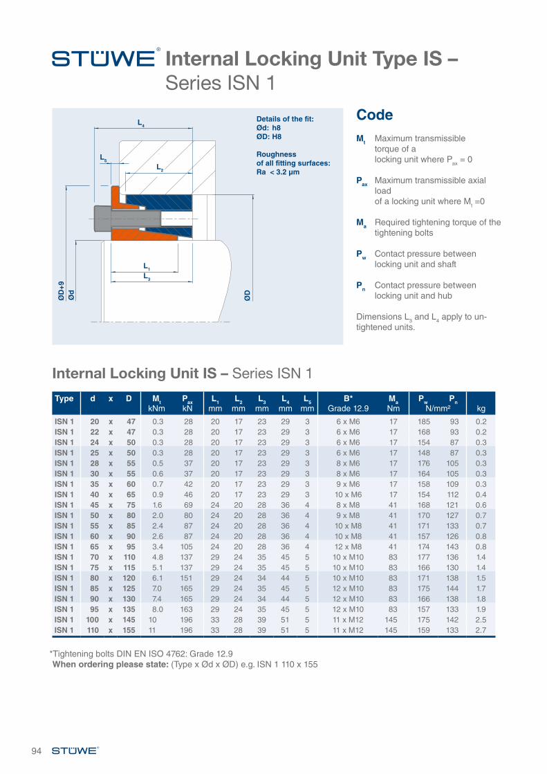
Internal Locking Unit Type IS – Series ISN 1
Internal Locking Unit IS – Series ISN 1
*Tightening bolts DIN EN ISO 4762: Grade 12.9When ordering please state: (Type x Ød x ØD) e.g. ISN 1 110 x 155
94
CodeMt Maximum transmissible
torque of a locking unit where Pax = 0
Pax Maximum transmissible axial load of a locking unit where Mt =0
Ma Required tightening torque of the tightening bolts
Pw Contact pressure between locking unit and shaft
Pn Contact pressure between locking unit and hub Dimensions L3 and L4 apply to un-tightened units.
Type d x D MtkNm
PaxkN
L1mm
L2mm
L3mm
L4mm
L5mm
B* Grade 12.9
MaNm
Pw PnN/mm² kg
ISN 1 20 x 47 0.3 28 20 17 23 29 3 6 x M6 17 185 93 0.2ISN 1 22 x 47 0.3 28 20 17 23 29 3 6 x M6 17 168 93 0.2ISN 1 24 x 50 0.3 28 20 17 23 29 3 6 x M6 17 154 87 0.3ISN 1 25 x 50 0.3 28 20 17 23 29 3 6 x M6 17 148 87 0.3ISN 1 28 x 55 0.5 37 20 17 23 29 3 8 x M6 17 176 105 0.3ISN 1 30 x 55 0.6 37 20 17 23 29 3 8 x M6 17 164 105 0.3ISN 1 35 x 60 0.7 42 20 17 23 29 3 9 x M6 17 158 109 0.3ISN 1 40 x 65 0.9 46 20 17 23 29 3 10 x M6 17 154 112 0.4ISN 1 45 x 75 1.6 69 24 20 28 36 4 8 x M8 41 168 121 0.6ISN 1 50 x 80 2.0 80 24 20 28 36 4 9 x M8 41 170 127 0.7ISN 1 55 x 85 2.4 87 24 20 28 36 4 10 x M8 41 171 133 0.7ISN 1 60 x 90 2.6 87 24 20 28 36 4 10 x M8 41 157 126 0.8ISN 1 65 x 95 3.4 105 24 20 28 36 4 12 x M8 41 174 143 0.8ISN 1 70 x 110 4.8 137 29 24 35 45 5 10 x M10 83 177 136 1.4ISN 1 75 x 115 5.1 137 29 24 35 45 5 10 x M10 83 166 130 1.4ISN 1 80 x 120 6.1 151 29 24 34 44 5 10 x M10 83 171 138 1.5ISN 1 85 x 125 7.0 165 29 24 35 45 5 12 x M10 83 175 144 1.7ISN 1 90 x 130 7.4 165 29 24 34 44 5 12 x M10 83 166 138 1.8ISN 1 95 x 135 8.0 163 29 24 35 45 5 12 x M10 83 157 133 1.9ISN 1 100 x 145 10 196 33 28 39 51 5 11 x M12 145 175 142 2.5ISN 1 110 x 155 11 196 33 28 39 51 5 11 x M12 145 159 133 2.7
Details of the fit:Ød: h8ØD: H8
Roughness of all fitting surfaces:Ra < 3.2 µm
Ød
ØD
+9
ØD
L5
L4
L2
L1
L3
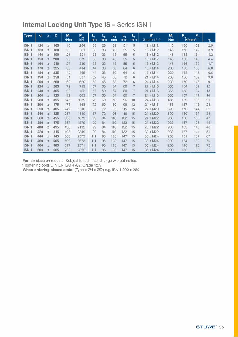
Internal Locking Unit Type IS – Series ISN 1
Internal Locking Unit Type IS – Series ISN 1
Further sizes on request. Subject to technical change without notice.*Tightening bolts DIN EN ISO 4762: Grade 12.9When ordering please state: (Type x Ød x ØD) e.g. ISN 1 200 x 260
95
Type d x D MtkNm
PaxkN
L1mm
L2mm
L3mm
L4mm
L5mm
B* Grade 12.9
MaNm
Pw PnN/mm² kg
ISN 1 120 x 165 16 264 33 28 39 51 5 12 x M12 145 186 159 2.9ISN 1 130 x 180 20 301 38 33 43 55 5 16 x M12 145 170 142 3.9ISN 1 140 x 190 21 301 38 33 43 55 5 16 x M12 145 158 134 4.2ISN 1 150 x 200 25 332 38 33 43 55 5 18 x M12 145 166 143 4.4ISN 1 160 x 210 27 339 38 33 43 55 5 18 x M12 145 156 137 4.7ISN 1 170 x 225 35 414 44 38 50 64 6 16 x M14 230 158 135 6.0ISN 1 180 x 235 42 465 44 38 50 64 6 18 x M14 230 168 145 6.6ISN 1 190 x 250 51 537 52 46 58 72 6 21 x M14 230 156 132 9.0ISN 1 200 x 260 62 620 52 46 58 72 6 24 x M14 230 170 145 9.1ISN 1 220 x 285 79 719 57 50 64 80 7 21 x M16 355 164 139 12ISN 1 240 x 305 92 763 57 50 64 80 7 21 x M16 355 158 137 13ISN 1 260 x 325 112 863 57 50 64 80 7 24 x M16 355 167 147 14ISN 1 280 x 355 145 1039 70 60 78 96 10 24 x M18 485 159 136 21ISN 1 300 x 375 175 1168 72 60 80 98 12 24 x M18 485 167 145 23ISN 1 320 x 405 242 1510 87 72 95 115 15 24 x M20 690 170 144 32ISN 1 340 x 425 257 1510 87 72 96 116 15 24 x M20 690 160 137 35ISN 1 360 x 455 338 1879 99 84 110 132 15 24 x M22 930 156 130 47ISN 1 380 x 475 357 1879 99 84 110 132 15 24 x M22 930 147 125 46ISN 1 400 x 495 438 2192 99 84 110 132 15 28 x M22 930 163 140 48ISN 1 420 x 515 493 2349 99 84 110 132 15 30 x M22 930 167 144 51ISN 1 440 x 545 566 2573 111 96 123 147 15 30 x M24 1200 161 137 67ISN 1 460 x 565 592 2573 111 96 123 147 15 33 x M24 1200 154 132 70ISN 1 480 x 585 617 2571 111 96 123 147 15 33 x M24 1200 148 128 73ISN 1 500 x 605 723 2892 111 96 123 147 15 36 x M24 1200 160 139 80
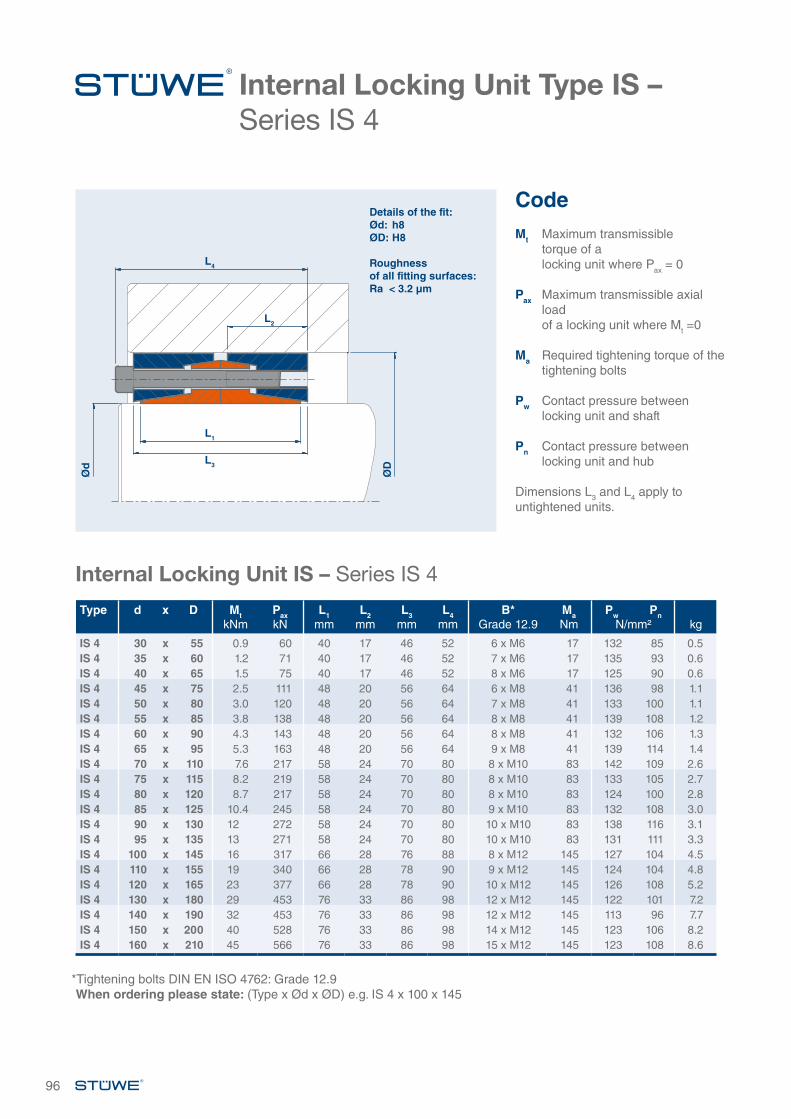
Internal Locking Unit Type IS – Series IS 4
Internal Locking Unit IS – Series IS 4
96
CodeMt Maximum transmissible
torque of a locking unit where Pax = 0
Pax Maximum transmissible axial load of a locking unit where Mt =0
Ma Required tightening torque of the tightening bolts
Pw Contact pressure between locking unit and shaft
Pn Contact pressure between locking unit and hub Dimensions L3 and L4 apply to untightened units.
Details of the fit:Ød: h8ØD: H8
Roughness of all fitting surfaces:Ra < 3.2 µm
L4
L2
L1
L3
Type d x D MtkNm
PaxkN
L1mm
L2mm
L3mm
L4mm
B*Grade 12.9
MaNm
Pw PnN/mm² kg
IS 4 30 x 55 0.9 60 40 17 46 52 6 x M6 17 132 85 0.5IS 4 35 x 60 1.2 71 40 17 46 52 7 x M6 17 135 93 0.6IS 4 40 x 65 1.5 75 40 17 46 52 8 x M6 17 125 90 0.6IS 4 45 x 75 2.5 111 48 20 56 64 6 x M8 41 136 98 1.1IS 4 50 x 80 3.0 120 48 20 56 64 7 x M8 41 133 100 1.1IS 4 55 x 85 3.8 138 48 20 56 64 8 x M8 41 139 108 1.2IS 4 60 x 90 4.3 143 48 20 56 64 8 x M8 41 132 106 1.3IS 4 65 x 95 5.3 163 48 20 56 64 9 x M8 41 139 114 1.4IS 4 70 x 110 7.6 217 58 24 70 80 8 x M10 83 142 109 2.6IS 4 75 x 115 8.2 219 58 24 70 80 8 x M10 83 133 105 2.7IS 4 80 x 120 8.7 217 58 24 70 80 8 x M10 83 124 100 2.8IS 4 85 x 125 10.4 245 58 24 70 80 9 x M10 83 132 108 3.0IS 4 90 x 130 12 272 58 24 70 80 10 x M10 83 138 116 3.1IS 4 95 x 135 13 271 58 24 70 80 10 x M10 83 131 111 3.3IS 4 100 x 145 16 317 66 28 76 88 8 x M12 145 127 104 4.5IS 4 110 x 155 19 340 66 28 78 90 9 x M12 145 124 104 4.8IS 4 120 x 165 23 377 66 28 78 90 10 x M12 145 126 108 5.2IS 4 130 x 180 29 453 76 33 86 98 12 x M12 145 122 101 7.2IS 4 140 x 190 32 453 76 33 86 98 12 x M12 145 113 96 7.7IS 4 150 x 200 40 528 76 33 86 98 14 x M12 145 123 106 8.2IS 4 160 x 210 45 566 76 33 86 98 15 x M12 145 123 108 8.6
*Tightening bolts DIN EN ISO 4762: Grade 12.9When ordering please state: (Type x Ød x ØD) e.g. IS 4 x 100 x 145
Ød
ØD
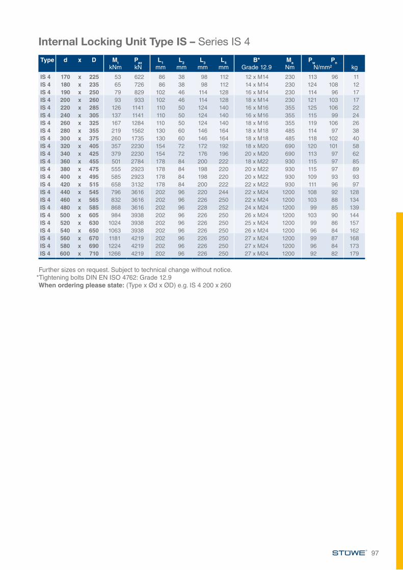
Internal Locking Unit Type IS – Series IS 4
Internal Locking Unit Type IS – Series IS 4
Further sizes on request. Subject to technical change without notice.*Tightening bolts DIN EN ISO 4762: Grade 12.9When ordering please state: (Type x Ød x ØD) e.g. IS 4 200 x 260
97
Type d x D MtkNm
PaxkN
L1mm
L2mm
L3mm
L4mm
B*Grade 12.9
MaNm
Pw PnN/mm² kg
IS 4 170 x 225 53 622 86 38 98 112 12 x M14 230 113 96 11IS 4 180 x 235 65 726 86 38 98 112 14 x M14 230 124 108 12IS 4 190 x 250 79 829 102 46 114 128 16 x M14 230 114 96 17IS 4 200 x 260 93 933 102 46 114 128 18 x M14 230 121 103 17IS 4 220 x 285 126 1141 110 50 124 140 16 x M16 355 125 106 22IS 4 240 x 305 137 1141 110 50 124 140 16 x M16 355 115 99 24IS 4 260 x 325 167 1284 110 50 124 140 18 x M16 355 119 106 26IS 4 280 x 355 219 1562 130 60 146 164 18 x M18 485 114 97 38IS 4 300 x 375 260 1735 130 60 146 164 18 x M18 485 118 102 40IS 4 320 x 405 357 2230 154 72 172 192 18 x M20 690 120 101 58IS 4 340 x 425 379 2230 154 72 176 196 20 x M20 690 113 97 62IS 4 360 x 455 501 2784 178 84 200 222 18 x M22 930 115 97 85IS 4 380 x 475 555 2923 178 84 198 220 20 x M22 930 115 97 89IS 4 400 x 495 585 2923 178 84 198 220 20 x M22 930 109 93 93IS 4 420 x 515 658 3132 178 84 200 222 22 x M22 930 111 96 97IS 4 440 x 545 796 3616 202 96 220 244 22 x M24 1200 108 92 128IS 4 460 x 565 832 3616 202 96 226 250 22 x M24 1200 103 88 134IS 4 480 x 585 868 3616 202 96 228 252 24 x M24 1200 99 85 139IS 4 500 x 605 984 3938 202 96 226 250 26 x M24 1200 103 90 144IS 4 520 x 630 1024 3938 202 96 226 250 25 x M24 1200 99 86 157IS 4 540 x 650 1063 3938 202 96 226 250 26 x M24 1200 96 84 162IS 4 560 x 670 1181 4219 202 96 226 250 27 x M24 1200 99 87 168IS 4 580 x 690 1224 4219 202 96 226 250 27 x M24 1200 96 84 173IS 4 600 x 710 1266 4219 202 96 226 250 27 x M24 1200 92 82 179
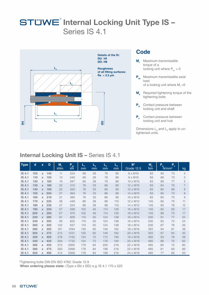
Internal Locking Unit Type IS – Series IS 4.1
98
CodeMt Maximum transmissible
torque of a locking unit where Pax = 0
Pax Maximum transmissible axial load of a locking unit where Mt =0
Ma Required tightening torque of the tightening bolts
Pw Contact pressure between locking unit and shaft
Pn Contact pressure between locking unit and hub Dimensions L3 and L4 apply to un-tightened units.
Details of the fit:Ød: h8ØD: H8
Roughness of all fitting surfaces:Ra < 3.2 µm
L4
L2
L1
L3
Ød
ØD
Internal Locking Unit IS – Series IS 4.1
Type d x D MtkNm
PaxkN
L1mm
L2mm
L3mm
L4mm
B*Grade 12.9
MaNm
Pw PnN/mm² kg
IS 4.1 100 x 145 11 224 66 28 76 86 8 x M10 83 90 73 4IS 4.1 110 x 155 13 240 66 28 78 88 9 x M10 83 88 73 5IS 4.1 120 x 165 16 267 66 28 78 88 10 x M10 83 89 77 5IS 4.1 130 x 180 20 312 76 33 86 96 12 x M10 83 84 70 7IS 4.1 140 x 190 22 320 76 33 86 96 12 x M10 83 80 68 8IS 4.1 150 x 200 27 364 76 33 86 96 14 x M10 83 85 73 8IS 4.1 160 x 210 31 390 76 33 86 96 15 x M10 83 85 75 9IS 4.1 170 x 225 38 449 86 38 98 110 12 x M12 145 82 70 11IS 4.1 180 x 235 47 524 86 38 98 110 14 x M12 145 90 78 12IS 4.1 190 x 250 57 599 102 46 114 126 16 x M12 145 82 69 17IS 4.1 200 x 260 67 674 102 46 114 126 18 x M12 145 88 75 17IS 4.1 220 x 285 91 828 110 50 124 138 16 x M14 230 91 77 22IS 4.1 240 x 305 99 822 110 50 124 138 16 x M14 230 83 72 24IS 4.1 260 x 325 122 937 110 50 124 138 18 x M14 230 87 76 26IS 4.1 280 x 355 181 1294 130 60 146 162 18 x M16 355 94 81 38IS 4.1 300 x 375 215 1431 130 60 146 162 20 x M16 355 97 84 40IS 4.1 320 x 405 276 1725 154 72 172 190 18 x M18 485 93 78 58IS 4.1 340 x 425 294 1732 154 72 176 194 20 x M18 485 88 75 62IS 4.1 360 x 455 372 2065 178 84 200 218 22 x M18 485 85 72 85IS 4.1 380 x 475 393 2068 178 84 198 216 22 x M18 485 81 69 89IS 4.1 400 x 495 414 2068 178 84 198 216 24 x M18 485 77 66 93
*Tightening bolts DIN EN ISO 4762: Grade 12.9When ordering please state: (Type x Ød x ØD) e.g. IS 4.1 170 x 225
Internal Locking Unit Type IS – Series IS 4.1
99
Internal Locking Unit IS – Series IS 4.1
Further sizes on request. Subject to technical change without notice.*Tightening bolts DIN EN ISO 4762: Grade 12.9When ordering please state: (Type x Ød x ØD) e.g. IS 4.1 420 x 515
Type d x D MtkNm
PaxkN
L1mm
L2mm
L3mm
L4mm
B*Grade 12.9
MaNm
Pw PnN/mm² kg
IS 4.1 420 x 515 507 2412 178 84 200 218 26 x M18 485 86 74 97IS 4.1 440 x 545 530 2409 202 96 228 248 24 x M20 690 72 61 128IS 4.1 460 x 565 554 2409 202 96 226 246 22 x M20 690 69 59 134IS 4.1 480 x 585 578 2409 202 96 228 248 24 x M20 690 66 57 139IS 4.1 500 x 605 703 2811 202 96 226 246 26 x M20 690 74 64 144IS 4.1 520 x 630 731 2811 202 96 226 246 26 x M20 690 71 62 157IS 4.1 540 x 650 759 2811 202 96 226 246 26 x M20 690 68 60 162IS 4.1 560 x 670 843 3012 202 96 226 246 30 x M20 690 71 62 168IS 4.1 580 x 690 873 3012 202 96 226 246 30 x M20 690 68 60 173IS 4.1 600 x 710 903 3012 202 96 226 246 30 x M20 690 66 59 179

CUSTOMISED SOLUTIONS

CUSTOMISED SOLUTIONS CUSTOMISED SOLUTIONSEXAMPLES
Description of ApplicationWe offer an extensive selection of customised solutions in addition to our standard delivery program.
101
With around 50 years of expertise, STÜWE® is today still among the world’s leading manufacturers and a leader in technology in the field of frictional connections.
With our highly modern design methods we ensure that our standard solutions are consistently developed and design customised solutions which are tailored to solve your problem area. This means that, should the perfect solution to your individual application be unable to
be found within our extensive product range of frictional connections, both our specialist engineers and our representatives will be pleased to help you at all times.
Our experienced design team will skilfully and efficiently implement your technical and financial de-mands while taking into account quality characteristics und any pos-sible requirements from certifying authorities. Through our great depth
of in-house manufacture, our extensive machinery and our extensive network of suppliers we are able to react rapidly and flexibly to your enquiries.
Through the examples shown on the following pages you can gain an impression of our possibilites.
Solving tasks with Customised Versions
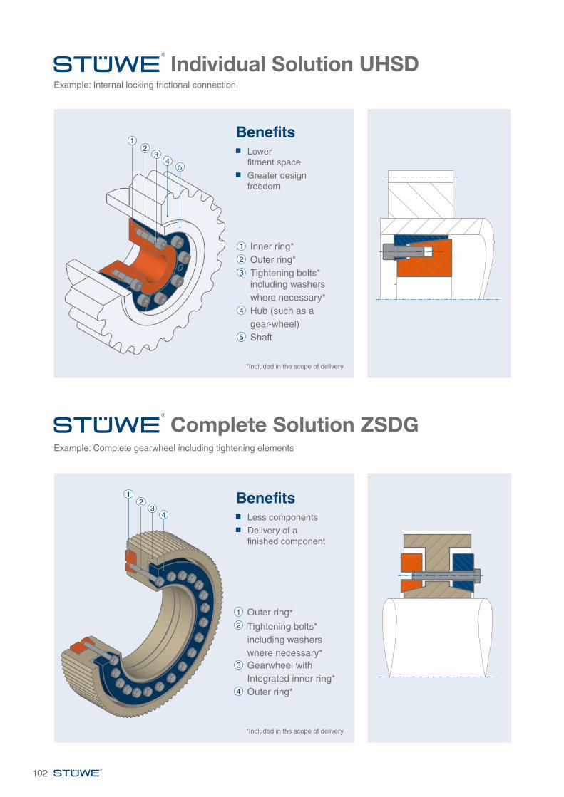
Complete Solution ZSDGExample: Complete gearwheel including tightening elements
Example: Internal locking frictional connection
Individual Solution UHSD
Benefits Lower
fitment space
Greater design freedom
Benefits Less components
Delivery of a finished component
1 Inner ring*2 Outer ring*3 Tightening bolts* including washers where necessary*4 Hub (such as a gear-wheel)5 Shaft
45
12
3
4
12
3
*Included in the scope of delivery
*Included in the scope of delivery
1 Outer ring*2 Tightening bolts* including washers where necessary*3 Gearwheel with Integrated inner ring*4 Outer ring*
102
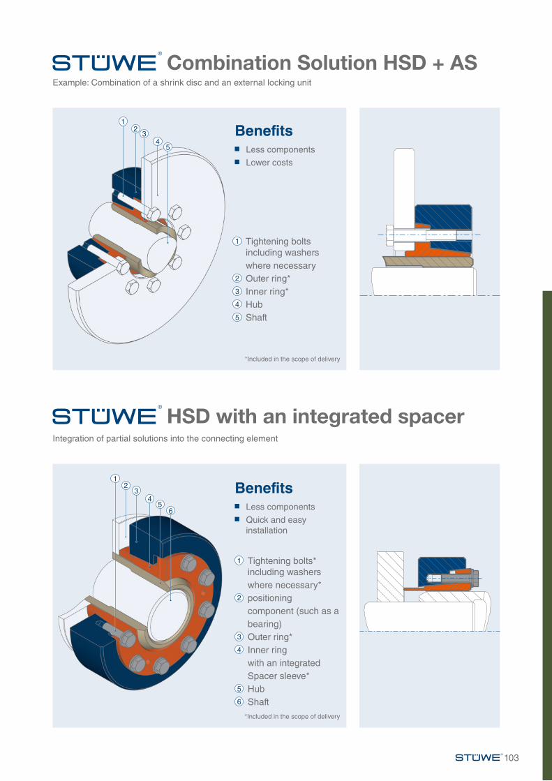
HSD with an integrated spacerIntegration of partial solutions into the connecting element
Combination Solution HSD + ASExample: Combination of a shrink disc and an external locking unit
Benefits Less components
Lower costs
Benefits Less components
Quick and easy installation
1 Tightening bolts including washers where necessary2 Outer ring*3 Inner ring*4 Hub5 Shaft
*Included in the scope of delivery
*Included in the scope of delivery
4
4
5
56
1
1
2
2
3
3
1 Tightening bolts* including washers where necessary*2 positioning
component (such as a bearing)
3 Outer ring*4 Inner ring with an integrated Spacer sleeve*5 Hub6 Shaft
103
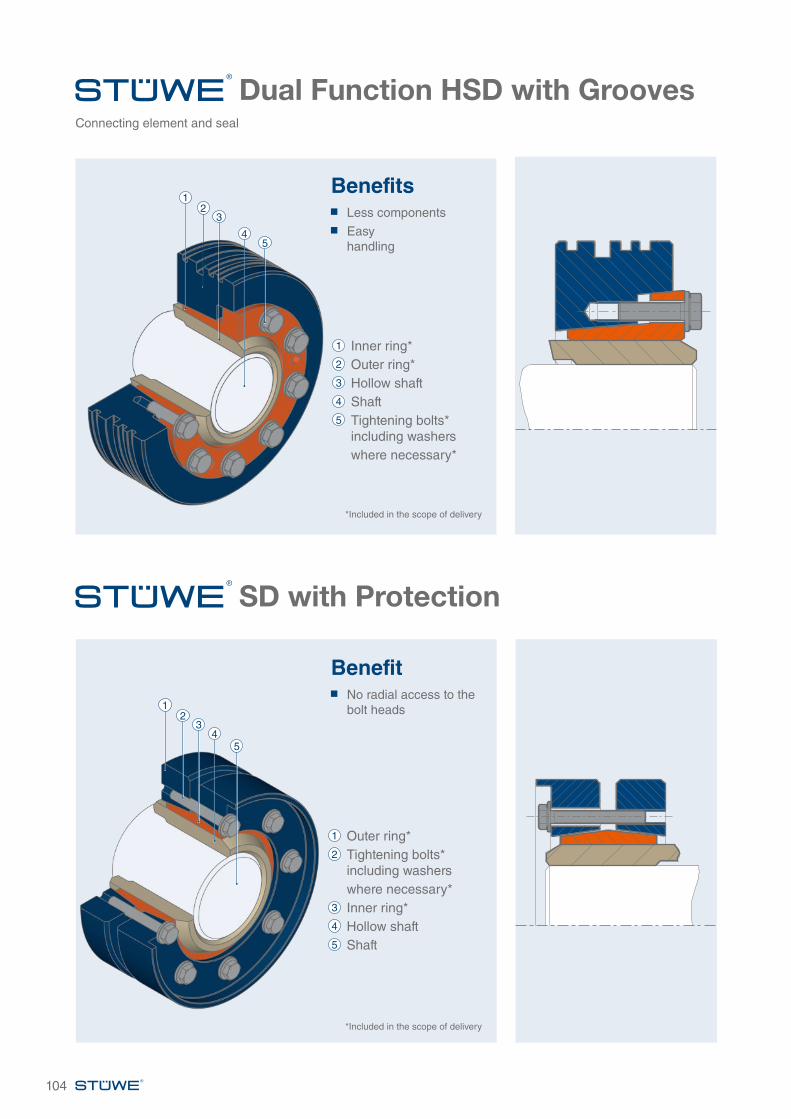
SD with Protection
Dual Function HSD with GroovesConnecting element and seal
Benefits Less components
Easy handling
Benefit No radial access to the
bolt heads
1 Inner ring*2 Outer ring*3 Hollow shaft4 Shaft5 Tightening bolts* including washers where necessary*
45
12
3
*Included in the scope of delivery
1 Outer ring*2 Tightening bolts* including washers where necessary*3 Inner ring*4 Hollow shaft5 Shaft
45
12
3
104
*Included in the scope of delivery