Embed Size (px)
Citation preview
Schrumpfscheiben,Smart-Lock & Wellenkupplungen
Shrink Discs, Smart-Lock & Shaft Couplings
D|GB12|2008
Partner for Performancewww.ringfeder.com

Wir sind für Sie da
A Global Presence For You
Die heutige RINGFEDER POWER TRANSMISSION GMBH wurde 1922 in Krefeld / Deutschland als Patentverwertungsgesellschaft für Reibungsfedern gegründet. Heute sind wir ein weltweiter Anbieter für Spitzenprodukte der Antriebs und Dämpfungstechnik. Innovatives Denken in die Grenzbereiche des Möglichen zeichnet uns aus und hilft uns, mit progressiven und günstigen Lösungen den technischen Fortschritt unserer Kunden zu unterstützen.
The RINGFEDER POWER TRANSMISSION GMBH was founded in 1922 in Krefeld, Germany to fabricate and promote Friction Spring technol-ogy. Today we have expanded our offerings to top power transmission and damping products. In-novative thinking sets us apart and allows us to develop progressive and economical solutions to support our customers.
2

Besondere Anforderungen erfordern beson-dere Anstrengungen
Wir stehen Ihnen mit langjähriger Erfahrung und produktivem Engineering zur Verfügung ob mit Standardprodukten oder auf individuelle Anfrage. Wir verste hen Dinge wie außer gewöhnlich hohe Belastbarkeit oder Montage, Demontagefreundlichkeit von Bauteilen, aber auch die Senkung von Fertigungskosten als „Dienst am Kunden“ und ent
wickeln effiziente und technisch ausgereifte Lösungen.
Special applications require special solutions
Our extensive range of R INGFEDER POWER TRANSMISSION products can be applied to solve most
applications. We don´t just sell, but by understanding the individual requirements of our customers (e.g. loads on the components, easy installation/re-moval capability and reduction of production costs) assist you in every step with innovative engineering to plan efficient and technically mature solutions.
3

Inhalt
InhaltAll technical details and information is non-binding and cannot be used as a basis for legal claims. The user is obligated to determine whether the represented products meet his requirements. We reserve the right at all times to carry out modifications in the interests of technical progress. Upon the issue of this catalogue all previous bro-chures and questionnaires on the products displayed are no longer valid.
Alle technischen Daten und Hin weise sind unverbindlich, Rechts ansprüche können daraus nicht abgeleitet werden. Der Anwender ist grundsätzlich verpflichtet zu prü-fen, ob die dargestellten Produkte seinen Anforderungen genügen. Änderungen, die dem technischen Fortschritt dienen, behalten wir uns jederzeit vor. Mit Erscheinen dieses Kataloges werden alle älteren Prospekte und Fragebögen zu den gezeigten Produkten ungültig.
Content
Inhalt
Content
Eigenschaften / Characteristics ............................ Seite / Page 8
RINGFEDER® RfN 4012 ............................................... Seite / Page 10
RINGFEDER® RfN 4023 ............................................... Seite / Page 12
RINGFEDER® RfN 4051 ............................................... Seite / Page 16
RINGFEDER® RfN 4061 ............................................... Seite / Page 24
RINGFEDER® RfN 4071 ............................................... Seite / Page 32
RINGFEDER® RfN 4073 ............................................... Seite / Page 36
RINGFEDER® RfN 4091 ............................................... Seite / Page 40
RINGFEDER® RfN 4161 ............................................... Seite / Page 48
RINGFEDER® RfN 4171 ............................................... Seite / Page 52
RINGFEDER® RfN 4181 ............................................... Seite / Page 54
RINGFEDER® RfN 4071 rostfrei/stainless ............................................................ Seite / Page 61
SchrumpfscheibenShrink Discs
4

Inhalt
Content
Content
Inhalt
ContentSmart-Lock
WellenkupplungenShaft Couplings
Eigenschaften / Characteristics ............................ Seite / Page 69
RINGFEDER® RfN 4001 ............................................... Seite / Page 70
Smart-Lock Einzelteile / Parts ................................ Seite / Page 74
Eigenschaften / Characteristics ............................ Seite / Page 78
RINGFEDER® WK 5071 ............................................... Seite / Page 80
RINGFEDER® WK 5091 ............................................... Seite / Page 84
Montage-/DemontageanweisungenInstallation and removal instructions
Schrumpfscheiben / Shrink Discs .......................... Seite / Page 88
Schrumpfscheiben / Shrink Discs Rostfrei / stainless ........................................................ Seite / Page 92
5
RINGFEDER® Schrumpfscheiben · Shrink Discs
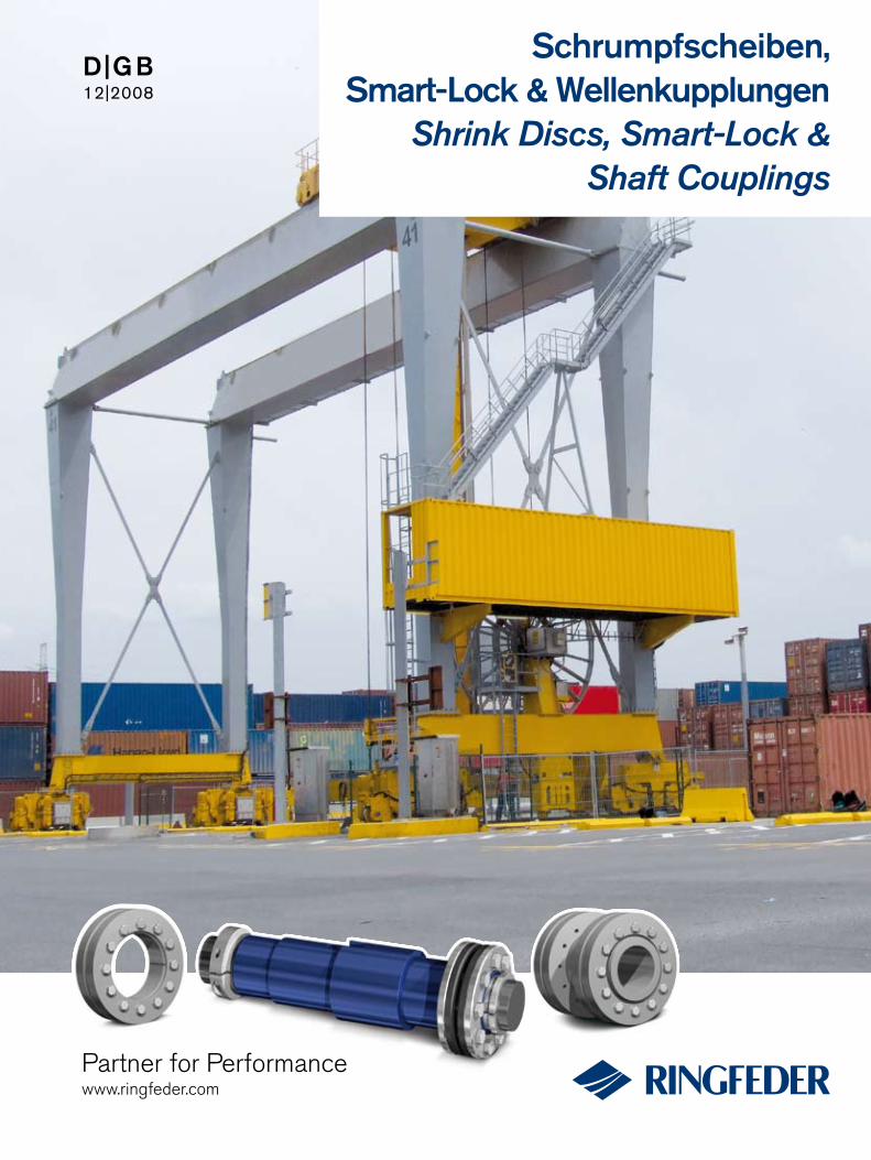
RfN 4071Standard ReiheStandard Series
RfN 4073Mini ReiheMini Series
RfN 4091Schwere Reihe
Heavy Duty Series
RfN 4181Schwere Reihe
Heavy Duty Series
RfN 4023Leichte Reihe
Light Duty Series
RfN 4051Leichte Reihe
Light Duty Series
RfN 4051Leichte Reihe,
geteiltLight Duty Series,
split
RfN 4061Standard Reihe,
geteiltStandard Series,
split
RfN 4061Standard ReiheStandard Series
RfN 4071Standard Reihe,
geteiltStandard Series,
split
RfN 4091Schwere Reihe, geteilt
Heavy Duty Series, split
RfN 4161Standard ReiheStandard Series
RfN 4171StandardReiheStandard Series
RfN 4012Leichte Reihe
Light Duty Series
6

7
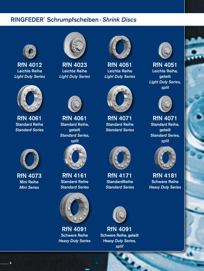
Schrumpfscheiben sind die modernsten Spannverbindungen. Sie bestehen grundsätzlich, je nach Bauform, aus einem oder zwei konischen Druckringen und einem Innenring. Mittels Spannschrauben werden diese axial gegeneinander verspannt. Der wesentliche Unterschied zu den Innenspannverbindungen besteht darin, dass die Pressung von außen auf die Nabe aufgebracht wird. Die Schrumpfscheibe liegt somit nicht im Kraftfluss, sondern das Drehmoment wird an der Füge fläche zwischen Welle und Nabe ohne Zwischenelement kraftschlüssig übertragen. Dadurch wird mit der Schrumpfscheibe auf einfache und kostengünstige Weise ein Presssitz (Schrumpfsitz) für hochbeanspruchte WelleNabeVerbindungen erzeugt. Bisher mussten Presssitze durch umständliche Berechnung, engste Fertigungstoleranzen und erheblichem Aufwand bei Montage und Demontage hergestellt werden. Zusätzlich treten Probleme bei evtl. notwendig werdenden Reparaturen (Austauschbarkeit, Einstellung bzw. Zentrierung usw.) auf. Keine andere WelleNabeVerbindungsart hat auch nur annähernd so gute Eigenschaften bezüglich der Dauerdrehwechselfestigkeit aufzuweisen und besitzt einen so hervorragenden Rundlauf.
Unbeschränkte Einsatzmöglichkeiten – Schrumpfscheiben RINGFEDER® eignen sich zur Befestigung von Nabenkörpern aller Art auf Wellen und Achsen. Ein satzmöglichkeiten bieten sich überall dort, wo bisher Schrumpfsitze, Keil, Passfeder und PolygonVerbindungen, Vielkeilwellen usw. zur Anwendung gelangten. So werden Zahn und Kettenräder, Hebel, Nocken, Kurven, Riemen oder Bremsscheiben , Schwungräder, Kupplungen, Aufsteck getriebe, Flansche, Seilscheiben, Laufräder absolut zuverlässig befestigt.
The Shrink Disc is the modern method for creating a mechanical shrink fit. The Shrink Disc consists of either one or two thrust rings with tapered bores and a mating tapered inner ring. By tightening locking screws the thrust rings are drawn together compressing the inner ring and applying pressure to the outside of the hub clamping it to the shaft. Being positioned around the hub there is only one in-terface transmitting the loads giving the shrink disc method distinct advantages such as offering the possibility of very concentric and well balanced connections that are suited to high speed applica-tions. Traditional shrink fits require complicated calculations, close machining tolerances and fine surface finishes, they also need con-siderable effort with mounting and removal. The Shrink Disc con-nection has none of these disadvantages and is better than any of the other usual connection methods with regard to fatigue strength under alternating torsional stress.
Unlimited range of applications – RINGFEDER® Shrink Disc connections are suitable for securing all types of hubs onto shafts and axles. Replacing traditional shrink fits, keys and polygon con-nections, splined shafts etc.
Eigenschaften · Characteristics
dw ISO
max.
über bis Fügespiel S/clearance S
above up to mm
6 10 0,011
10 18 H6/j6 0,014
18 30 0,017
30 50 H6/h6 0,032
50 80 H6/g6 0,048
80 120 0,069
120 180 0,079
180 250 H7/g6 0,090
250 315 0,101
315 400 0,111
400 500 0,123
Für die Berechnung der Funktionswerte berücksichtigte Passungen:Clearances considered for the calculation of the function values:
Es können auch beliebige andere Passungen gewählt werden. Solange dabei das angegebene max. Fügespiel nicht überschritten wird, ergeben sich keine Funktionswertänderungen.
Any other tolerances can be chosen. As long as the stated max. clearance is not exceeded, there will be no variations of the functional characteristics.
RINGFEDER® Schrumpfscheiben · Shrink Discs
8

Erläuterungen zu Tabellen Explanations to tables
d, D, L, l, L1, L2, d1 = Basic dimensions
dW = solid shaft diameter (provided by the customer)
T = transmissible torque
Fax = transmissible axial force
p = approx. surface pressure on the hub extension (diameter d)
TA = required tightening torque per screw (Screws greased with molykote!)
n = quantity of screws
S = clearance between shaft and hub bore
Tmax = maximum theoretical transmissible torque
sv = calculated combined stress in the hub extension (d/dw) under consideration of the tangential, radial and torsional stresses following the equation:
Additional loads, e.g. tension, thrust or bending have to be taken into consideration accordingly.
Function values The functional characteristics are valid with the screw tighte-ning torque listed in the tables and the following assumed conditions:The locking screws are lubricated using MoS2 (µtot= 0,1).The tapered cones are lubricated using MoS2 (µ = 0,05). The contact surfaces (dw) are in lightly oiled condition with coefficient of friction µ = 0,12. The hub and shaft materials have a modulus of elasticity of 210,000 N/mm2. (Lower values result in increased values for T and Fax with reduced tangential stress.)The maximum clearance S is being fully utilized. The shaft being used is solid, for hollow shaft applications the functional values will change.In cases where the assumed conditions do not apply then contact our Technical Department where we will be happy to assist you with your application.
d, D, L, l, L1, L2, d1 = Grundabmessungen, Schrumpfscheiben ungespannt
dW = Vollwellendurchmesser (kundenseitig)
T = übertragbares Drehmoment
Fax = übertragbare Axialkraft
p = Flächenpressung auf dem Nabenansatz (Durchmesser d) TA = erforderliches Anzieh dreh moment pro Spann - schraube (Schrauben molykotiert!)
n = Anzahl der Spannschrauben S = Fügespiel zwischen Welle und Nabenbohrung
Tmax = maximal theoretisch übertragbares Drehmoment
σv = rechnerische Vergleichsspannung im Nabenansatz (d/dw) unter Berücksichtigung der Tangential-, Radial- und Torsions span nung nach folgender Beziehung:
Zusätzliche Spannungen, z.B. Zug, Druck, Biegung, sind ent-sprechend zu berücksichtigen.
FunktionswerteDie Funktionswerte sind in Abhängigkeit der jeweils angege-benen Anzieh drehmomente TA bestimmt. Die Spannschrauben sind mit Schmiermitteln, die MoS2 ent-halten, geschmiert (µges = 0,1).Die Konen sind ebenfalls molykotiert (µ = 0,05).Für die Fuge, Durchmesser dw, wurde der für geölte Montage-verhältnisse übliche Reibwert µ = 0,12 angesetzt. Als E-Modul für Welle und Hohlwelle wurde der Wert 210.000 N/mm2 berücksichtigt. (Niedrigere Werte führen zu einer Erhöhung von T und Fax und einer Reduzierung der höchsten Einzelspannung, der Tangential span nung.)Für die Berechnung der Funktionswerte wurde das max. Fügespiel S berücksichtigt, siehe nebenstehende Tabelle.Die Funktionswerte gelten nur bei Verwendung einer Voll-welle.Bei der Anwendung einer Außenverspannung auf Hohlwellen ändern sich die Funktionswerte. Bitte mit unseren Spezia-listen Rück sprache nehmen.
9
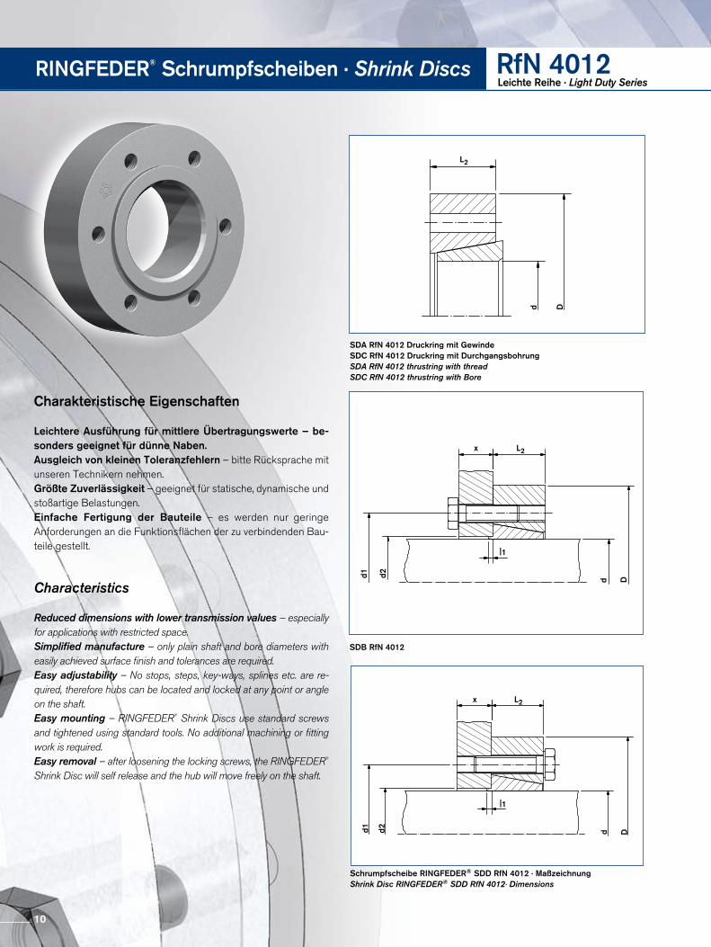
SDA RfN 4012 Druckring mit Gewinde SDC RfN 4012 Druckring mit DurchgangsbohrungSDA RfN 4012 thrustring with thread SDC RfN 4012 thrustring with Bore
Schrumpfscheibe RINGFEDER® SDD RfN 4012 · MaßzeichnungShrink Disc RINGFEDER® SDD RfN 4012· Dimensions
L2
d D
d1 d2
x L2
|1
d D
SDB RfN 4012
d1 d2
x L2
|1
d D
RINGFEDER® Schrumpfscheiben · Shrink Discs RfN 4012Leichte Reihe · Light Duty Series
Charakteristische Eigenschaften
Leichtere Ausführung für mittlere Übertragungswerte – be-sonders geeignet für dünne Naben.Ausgleich von kleinen Toleranzfehlern – bitte Rücksprache mit unseren Technikern nehmen.Größte Zuverlässigkeit – geeignet für statische, dynamische und stoßartige Belastungen.Einfache Fertigung der Bauteile – es werden nur geringe Anforde rungen an die Funktionsflächen der zu verbindenden Bauteile gestellt.
Characteristics
Reduced dimensions with lower transmission values – especially for applications with restricted space.Simplified manufacture – only plain shaft and bore diameters with easily achieved surface finish and tolerances are required.Easy adjustability – No stops, steps, key-ways, splines etc. are re-quired, therefore hubs can be located and locked at any point or angle on the shaft.Easy mounting – RINGFEDER® Shrink Discs use standard screws and tightened using standard tools. No additional machining or fitting work is required.Easy removal – after loosening the locking screws, the RINGFEDER® Shrink Disc will self release and the hub will move freely on the shaft.
10
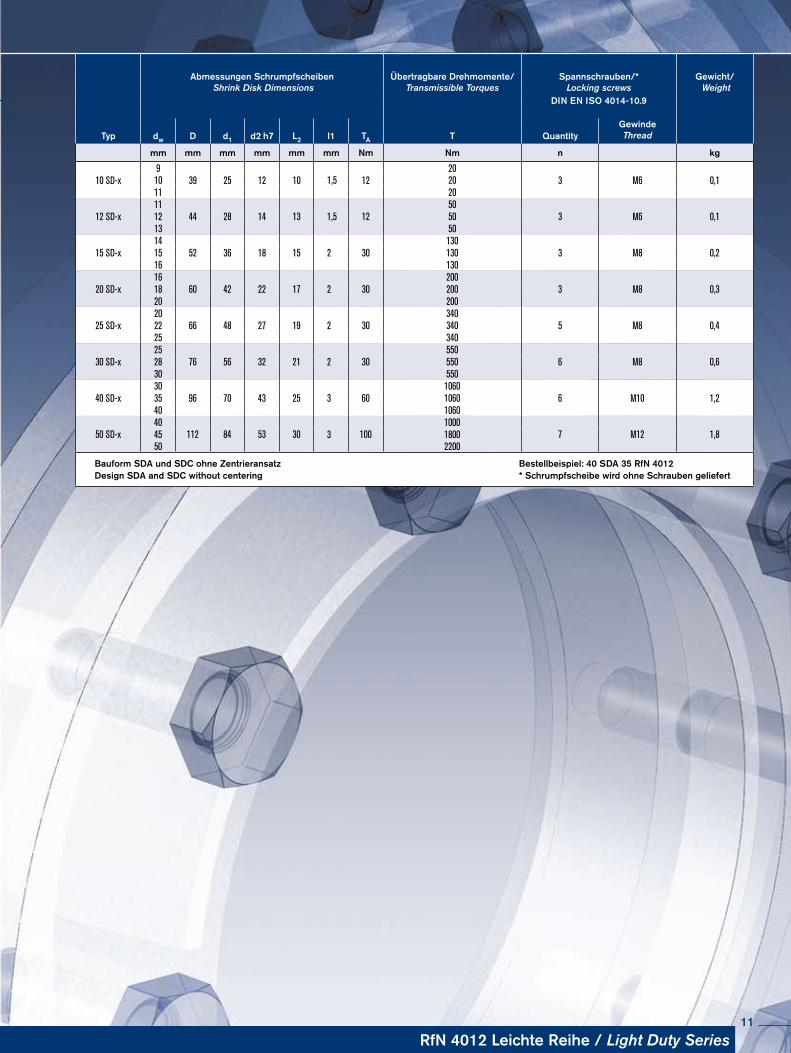
Abmessungen Schrumpfscheiben Shrink Disk Dimensions
Übertragbare Drehmomente/Transmissible Torques
Spannschrauben/*Locking screws
Gewicht/ Weight
DIN EN ISO 4014-10.9
GewindeThreadTyp dw D d1 d2 h7 L2 l1 TA T Quantity
mm mm mm mm mm mm Nm Nm n kg
10 SD-x9
39 25 12 10 1220
3 M6 0,110 1,5 2011 20
12 SD-x11
44 28 14 13 1250
3 M6 0,112 1,5 5013 50
15 SD-x14
52 36 18 15 30130
3 M8 0,215 2 13016 130
20 SD-x16
60 42 22 17 30200
3 M8 0,318 2 20020 200
25 SD-x20
66 48 27 19 30340
5 M8 0,422 2 34025 340
30 SD-x25
76 56 32 21 30550
6 M8 0,628 2 55030 550
40 SD-x30
96 70 43 25 601060
6 M10 1,235 3 106040 1060
50 SD-x40
112 84 53 30 1001000
7 M12 1,845 3 180050 2200
Bauform SDA und SDC ohne Zentrieransatz Bestellbeispiel: 40 SDA 35 RfN 4012Design SDA and SDC without centering * Schrumpfscheibe wird ohne Schrauben geliefert
RfN 4012 Leichte Reihe / Light Duty Series11
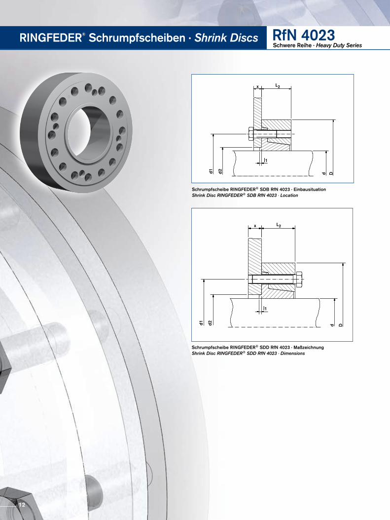
Schrumpfscheibe RINGFEDER® SDB RfN 4023 · EinbausituationShrink Disc RINGFEDER® SDB RfN 4023 · Location
x L2
d1 d2
|1
d D
Schrumpfscheibe RINGFEDER® SDD RfN 4023 · MaßzeichnungShrink Disc RINGFEDER® SDD RfN 4023 · Dimensions
x L2
d1 d2
|1
d D
RINGFEDER® Schrumpfscheiben · Shrink Discs RfN 4023Schwere Reihe · Heavy Duty Series
12
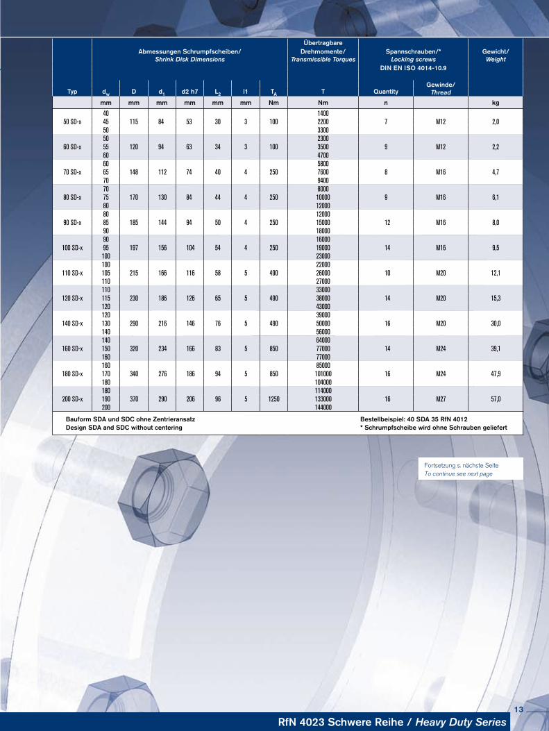
ÜbertragbareAbmessungen Schrumpfscheiben/
Shrink Disk DimensionsDrehmomente/
Transmissible TorquesSpannschrauben/*
Locking screwsGewicht/Weight
DIN EN ISO 4014-10.9
Gewinde/ThreadTyp dw D d1 d2 h7 L2 l1 TA T Quantity
mm mm mm mm mm mm Nm Nm n kg
40 140050 SD-x 45 115 84 53 30 3 100 2200 7 M12 2,0
50 330050 2300
60 SD-x 55 120 94 63 34 3 100 3500 9 M12 2,260 470060 5800
70 SD-x 65 148 112 74 40 4 250 7600 8 M16 4,770 940070 8000
80 SD-x 75 170 130 84 44 4 250 10000 9 M16 6,180 1200080 12000
90 SD-x 85 185 144 94 50 4 250 15000 12 M16 8,090 1800090 16000
100 SD-x 95 197 156 104 54 4 250 19000 14 M16 9,5100 23000100 22000
110 SD-x 105 215 166 116 58 5 490 26000 10 M20 12,1110 27000110 33000
120 SD-x 115 230 186 126 65 5 490 38000 14 M20 15,3120 43000120 39000
140 SD-x 130 290 216 146 76 5 490 50000 16 M20 30,0140 56000140 64000
160 SD-x 150 320 234 166 83 5 850 77000 14 M24 39,1160 77000160 85000
180 SD-x 170 340 276 186 94 5 850 101000 16 M24 47,9180 104000180 114000
200 SD-x 190 370 290 206 96 5 1250 133000 16 M27 57,0200 144000
Bauform SDA und SDC ohne Zentrieransatz Bestellbeispiel: 40 SDA 35 RfN 4012Design SDA and SDC without centering * Schrumpfscheibe wird ohne Schrauben geliefert
Fortsetzung s. nächste Seite To continue see next page
RfN 4023 Schwere Reihe / Heavy Duty Series13
RINGFEDER® Schrumpfscheiben · Shrink Discs RfN 4023Schwere Reihe · Heavy Duty Series
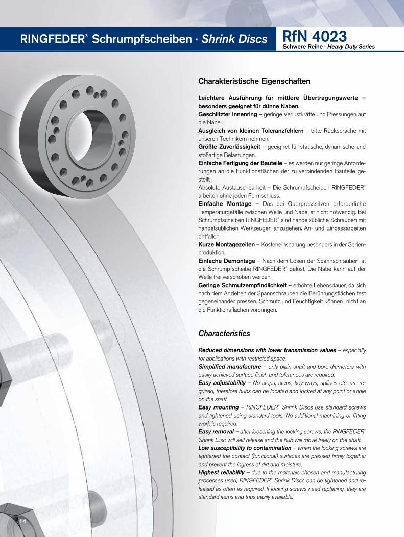
Charakteristische Eigenschaften
Leichtere Ausführung für mittlere Übertragungswerte – besonders geeignet für dünne Naben.Geschlitzter Innenring – geringe Verlustkräfte und Pressungen auf die Nabe.Ausgleich von kleinen Toleranzfehlern – bitte Rücksprache mit unseren Technikern nehmen.Größte Zuverlässigkeit – geeignet für statische, dynamische und stoßartige Belastungen.Einfache Fertigung der Bauteile – es werden nur geringe Anforderungen an die Funktionsflächen der zu verbindenden Bauteile gestellt.Absolute Austauschbarkeit – Die Schrumpfscheiben RINGFEDER® arbeiten ohne jeden Formschluss. Einfache Montage – Das bei Querpresssitzen erforderliche Tempera turgefälle zwischen Welle und Nabe ist nicht notwendig. Bei Schrumpf scheiben RINGFEDER® sind handelsübliche Schrauben mit handelsüblichen Werkzeugen anzuziehen. An und Einpassarbeiten entfallen.Kurze Montagezeiten – Kosteneinsparung besonders in der Serienproduktion.Einfache Demontage – Nach dem Lösen der Spannschrauben ist die Schrumpfscheibe RINGFEDER® gelöst. Die Nabe kann auf der Welle frei verschoben werden. Geringe Schmutzempfindlichkeit – erhöhte Lebensdauer, da sich nach dem Anziehen der Spannschrauben die Berührungsflächen fest gegeneinander pressen. Schmutz und Feuchtigkeit können nicht an die Funktionsflächen vordringen.
Characteristics
Reduced dimensions with lower transmission values – especially for applications with restricted space.Simplified manufacture – only plain shaft and bore diameters with easily achieved surface finish and tolerances are required.Easy adjustability – No stops, steps, key-ways, splines etc. are re-quired, therefore hubs can be located and locked at any point or angle on the shaft.Easy mounting – RINGFEDER® Shrink Discs use standard screws and tightened using standard tools. No additional machining or fitting work is required.Easy removal – after loosening the locking screws, the RINGFEDER® Shrink Disc will self release and the hub will move freely on the shaft.Low susceptibility to contamination – when the locking screws are tightened the contact (functional) surfaces are pressed firmly together and prevent the ingress of dirt and moisture.Highest reliability – due to the materials chosen and manufacturing processes used, RINGFEDER® Shrink Discs can be tightened and re-leased as often as required. If locking screws need replacing, they are standard items and thus easily available.
14
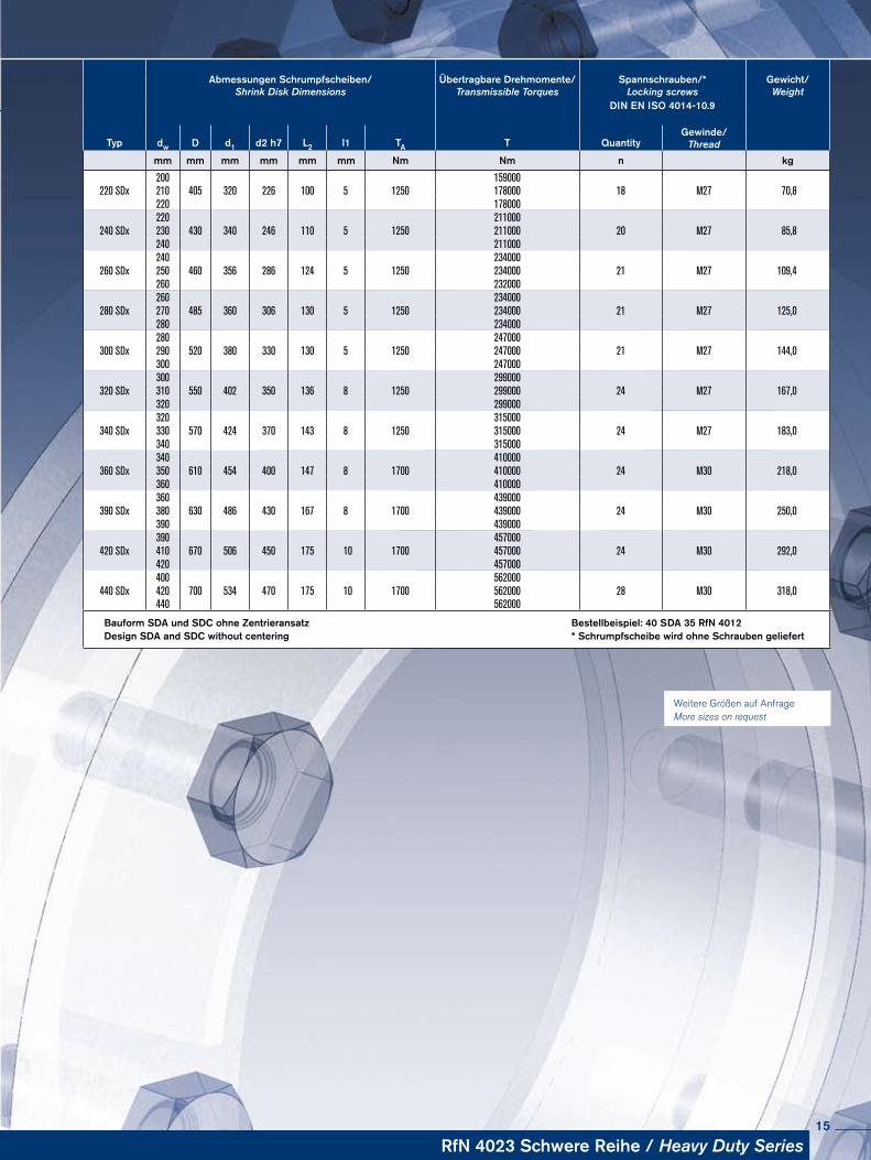
Abmessungen Schrumpfscheiben/Shrink Disk Dimensions
Übertragbare Drehmomente/Transmissible Torques
Spannschrauben/*Locking screws
Gewicht/Weight
DIN EN ISO 4014-10.9
Gewinde/ThreadTyp dw D d1 d2 h7 L2 l1 TA T Quantity
mm mm mm mm mm mm Nm Nm n kg
200 159000220 SDx 210 405 320 226 100 5 1250 178000 18 M27 70,8
220 178000220 211000
240 SDx 230 430 340 246 110 5 1250 211000 20 M27 85,8240 211000240 234000
260 SDx 250 460 356 286 124 5 1250 234000 21 M27 109,4260 232000260 234000
280 SDx 270 485 360 306 130 5 1250 234000 21 M27 125,0280 234000280 247000
300 SDx 290 520 380 330 130 5 1250 247000 21 M27 144,0300 247000300 299000
320 SDx 310 550 402 350 136 8 1250 299000 24 M27 167,0320 299000320 315000
340 SDx 330 570 424 370 143 8 1250 315000 24 M27 183,0340 315000340 410000
360 SDx 350 610 454 400 147 8 1700 410000 24 M30 218,0360 410000360 439000
390 SDx 380 630 486 430 167 8 1700 439000 24 M30 250,0390 439000390 457000
420 SDx 410 670 506 450 175 10 1700 457000 24 M30 292,0420 457000400 562000
440 SDx 420 700 534 470 175 10 1700 562000 28 M30 318,0440 562000
Bauform SDA und SDC ohne Zentrieransatz Bestellbeispiel: 40 SDA 35 RfN 4012Design SDA and SDC without centering * Schrumpfscheibe wird ohne Schrauben geliefert
Weitere Größen auf Anfrage More sizes on request
RfN 4023 Schwere Reihe / Heavy Duty Series15
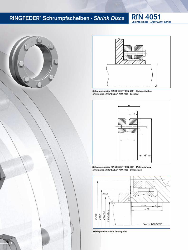
Schrumpfscheibe RINGFEDER® RfN 4051 · EinbausituationShrink Disc RINGFEDER® RfN 4051 · Location
Axiallagerteller · Axial bearing disc
Schrumpfscheibe RINGFEDER® RfN 4051 · MaßzeichnungShrink Disc RINGFEDER® RfN 4051 · Dimensions
RINGFEDER® Schrumpfscheiben · Shrink Discs RfN 4051Leichte Reihe · Light Duty Series
16
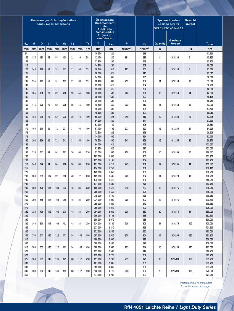
Abmessungen Schrumpfscheiben ÜbertragbareDrehmomente
oderAxialkräfte
Spannschrauben Ge wichtShrink Discs dimensions Locking screws Weight
DIN EN ISO 4014-10.9Transmissible
torques oraxial forces
dw d D L1 L d1 L2 I TA P σv Quantity Gewinde
TmaxT Fax Thread
mm mm mm mm mm mm mm mm Nm Nm kN N/mm2 N/mm2 n kg Nm
95 10.550 220 278 13.200100 125 185 58 51 158 22 39 59 12.100 240 191 280 8 M10x40 6 15.125105 13.800 260 288 17.250110 14.800 265 268 18.500120 140 220 58 51 175 22 39 59 18.640 310 192 281 9 M10x40 8 23.300125 20.500 325 315 25.625130 24.000 365 293 30.000135 155 245 58 51 192 22 39 59 26.400 390 212 306 11 M10x40 10 33.000140 29.000 410 334 36.250135 32.000 475 298 40.000140 165 260 70 62 210 26 46 100 35.200 500 224 308 10 M12x50 14 44.000145 38.500 530 327 48.125145 39.000 535 302 48.750150 175 275 70 62 220 26 46 100 42.400 560 232 313 11 M12x50 16 53.000155 46.000 590 334 57.500155 46.600 600 307 58.250160 185 295 70 62 225 26 46 100 50.300 625 240 319 12 M12x50 20 62.875165 54.000 650 341 67.500165 63.000 760 306 78.750170 195 315 80 72 237 31 56 100 67.700 795 233 323 15 M12x55 27 84.625175 72.500 825 355 90.625175 74.000 850 334 92.500180 200 330 80 72 242 31 56 100 79.500 890 243 368 16 M12x55 30 99.375185 84.500 915 440 105.625180 82.800 920 277 103.500190 220 345 94 84 265 36 66 250 93.500 980 220 306 10 M16x65 35 116.875200 105.000 1.055 367 131.250200 113.000 1.135 304 141.250210 240 370 94 84 290 36 66 250 127.500 1.210 243 330 12 M16x65 44 159.375215 134.500 1.250 356 168.125220 149.000 1.350 303 186.250230 260 395 102 92 310 40 72 250 165.000 1.435 240 334 14 M16x70 48 206.250235 173.000 1.475 364 216.250230 171.000 1.485 270 213.750240 280 425 114 104 333 46 84 250 189.000 1.570 218 287 16 M16x75 60 236.250250 208.000 1.660 324 260.000250 215.000 1.720 279 268.750260 300 460 114 104 358 46 84 250 234.000 1.800 229 303 18 M16x75 75 292.500270 255.000 1.890 342 318.750270 260.000 1.940 293 325.000280 320 495 116 106 378 48 84 250 284.000 2.030 239 313 20 M16x75 84 355.000290 306.000 2.125 355 382.500290 300.000 2.070 288 375.000300 340 535 116 106 402 48 84 250 324.000 2.160 236 309 21 M16x75 100 405.000305 337.000 2.210 326 421.250300 372.000 2.485 292 465.000305 350 545 135 122 413 54 100 490 385.000 2.540 230 304 16 M20x90 120 481.250310 400.000 2.590 320 500.000300 360.000 2.400 270 450.000310 360 555 135 122 423 54 100 490 388.000 2.500 223 284 16 M20x90 125 485.000320 415.000 2.590 314 518.750320 435.000 2.720 268 543.750325 380 585 149 136 442 60 112 490 451.000 2.780 213 275 18 M20x100 150 563.750330 467.000 2.835 285 583.750330 505.000 3.060 285 631.250340 390 595 149 136 452 60 112 490 540.000 3.175 230 304 20 M20x100 156 675.000350 577.000 3.295 337 721.250
Fortsetzung s. nächste Seite To continue see next page
RfN 4051 Leichte Reihe / Light Duty Series17
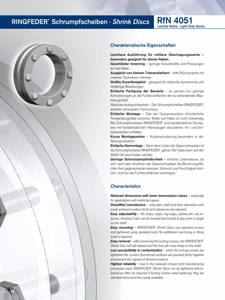
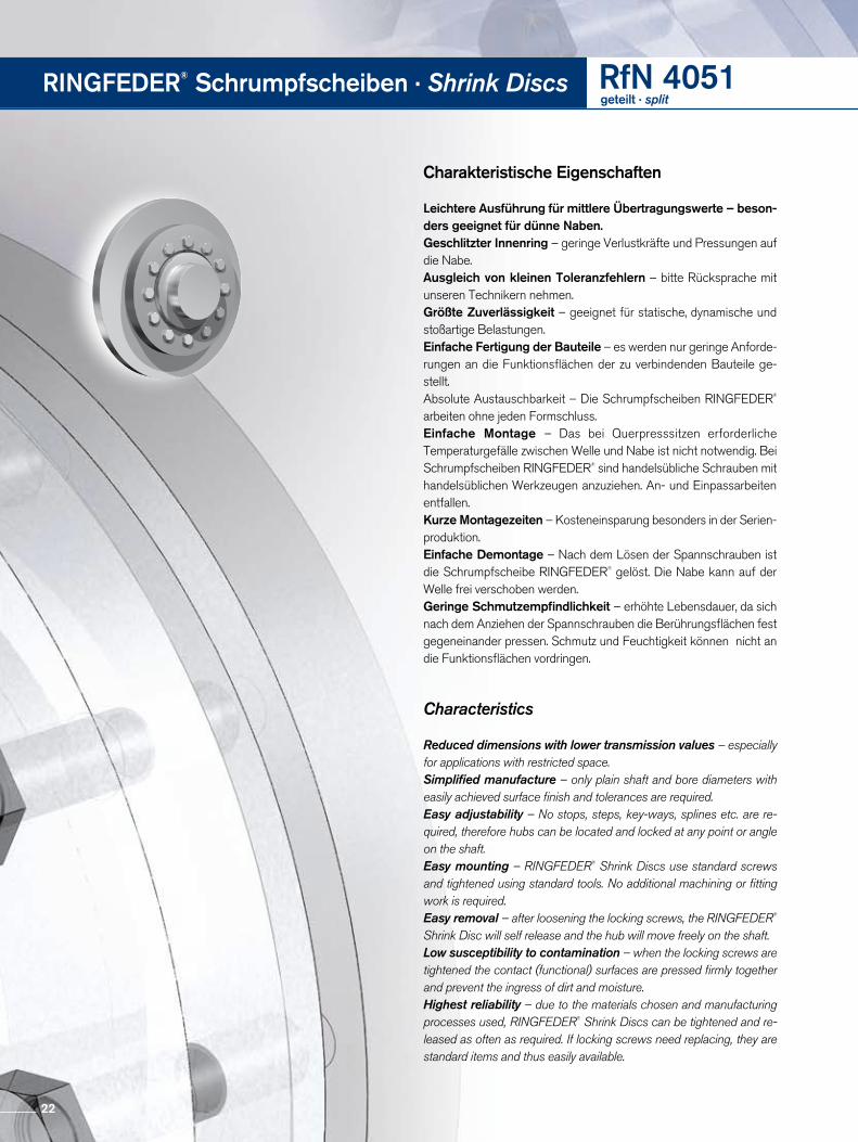
Charakteristische Eigenschaften
Leichtere Ausführung für mittlere Übertragungswerte – besonders geeignet für dünne Naben.Geschlitzter Innenring – geringe Verlustkräfte und Pressungen auf die Nabe.Ausgleich von kleinen Toleranzfehlern – bitte Rücksprache mit unseren Technikern nehmen.Größte Zuverlässigkeit – geeignet für statische, dynamische und stoßartige Belastungen.Einfache Fertigung der Bauteile – es werden nur geringe Anforde rungen an die Funktionsflächen der zu verbindenden Bauteile gestellt.Absolute Austauschbarkeit – Die Schrumpfscheiben RINGFEDER® arbeiten ohne jeden Formschluss. Einfache Montage – Das bei Querpresssitzen erforderliche Tempera turgefälle zwischen Welle und Nabe ist nicht notwendig. Bei Schrumpf scheiben RINGFEDER® sind handelsübliche Schrauben mit handelsüblichen Werkzeugen anzuziehen. An und Einpassarbeiten entfallen.Kurze Montagezeiten – Kosteneinsparung besonders in der Serien produktion.Einfache Demontage – Nach dem Lösen der Spannschrauben ist die Schrumpfscheibe RINGFEDER® gelöst. Die Nabe kann auf der Welle frei verschoben werden. Geringe Schmutzempfindlichkeit – erhöhte Lebensdauer, da sich nach dem Anziehen der Spannschrauben die Berührungsflächen fest gegeneinander pressen. Schmutz und Feuchtigkeit können nicht an die Funktionsflächen vordringen.
Characteristics
Reduced dimensions with lower transmission values – especially for applications with restricted space.Simplified manufacture – only plain shaft and bore diameters with easily achieved surface finish and tolerances are required.Easy adjustability – No stops, steps, key-ways, splines etc. are re-quired, therefore hubs can be located and locked at any point or angle on the shaft.Easy mounting – RINGFEDER® Shrink Discs use standard screws and tightened using standard tools. No additional machining or fitting work is required.Easy removal – after loosening the locking screws, the RINGFEDER® Shrink Disc will self release and the hub will move freely on the shaft.Low susceptibility to contamination – when the locking screws are tightened the contact (functional) surfaces are pressed firmly together and prevent the ingress of dirt and moisture.Highest reliability – due to the materials chosen and manufacturing processes used, RINGFEDER® Shrink Discs can be tightened and re-leased as often as required. If locking screws need replacing, they are standard items and thus easily available.
RINGFEDER® Schrumpfscheiben · Shrink Discs RfN 4051Leichte Reihe · Light Duty Series
18
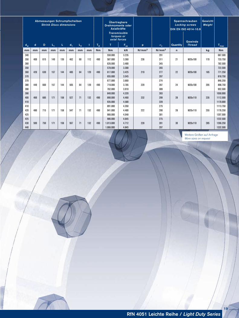
Abmessungen Schrumpfscheiben ÜbertragbareDrehmomente oder
Axialkräfte
Spannschrauben Ge wichtShrink Discs dimensions Locking screws Weight
DIN EN ISO 4014-10.9Transmissible
torques oraxial forces
GewindeThreaddw d D L1 L d1 L2 I TA T Fax p σv Quantity Tmax
mm mm mm mm mm mm mm mm Nm Nm kN N/mm2 N/mm2 n kg Nm
340 550.000 3.235 291 687.500
350 400 615 149 136 462 60 112 490 587.000 3.360 236 311 21 M20x100 170 733.750
360 626.000 3.480 345 782.500
350 578.000 3.300 265 722.500
360 420 630 157 144 485 64 120 490 617.000 3.425 219 277 22 M20x100 185 771.250
370 655.000 3.545 297 818.750
370 677.000 3.660 274 846.250
380 440 660 157 144 505 64 120 490 719.000 3.785 229 287 24 M20x100 205 898.750
390 762.000 3.910 309 952.500
390 840.000 4.320 283 1050.000
400 460 685 171 158 527 71 132 490 890.000 4.460 232 299 28 M20x110 235 1112.500
410 935.000 4.580 328 1170.000
410 891.000 4.350 275 1113.750
420 480 715 171 158 547 71 132 490 941.000 4.480 222 290 28 M20x110 255 1176.250
425 966.000 4.548 301 1207.500
425 986.000 4.645 275 1232.500
430 500 750 171 158 567 71 132 490 1.013.000 4.712 228 281 30 M20x110 285 1266.250
440 1.066.000 4.845 297 1332.500
Weitere Größen auf Anfrage More sizes on request
RfN 4051 Leichte Reihe / Light Duty Series19
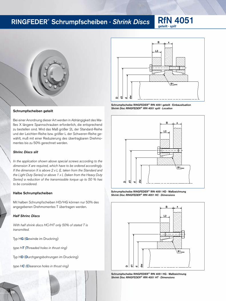
Schrumpfscheibe RINGFEDER® RfN 4051 geteilt · EinbausituationShrink Disc RINGFEDER® RfN 4051 split · Location
Schrumpfscheibe RINGFEDER® RfN 4051 HG · MaßzeichnungShrink Disc RINGFEDER® RfN 4051 HT · Dimensions
Schrumpfscheibe RINGFEDER® RfN 4051 HD · MaßzeichnungShrink Disc RINGFEDER® RfN 4051 HC · Dimensions
RINGFEDER® Schrumpfscheiben · Shrink Discs RfN 4051geteilt · split
D d1 d dw
R1max
L2
B x
D d1 d dw
R1max
L2
B x
D d1 d dw
R1max
L2
B x
Schrumpfscheiben geteilt
Bei einer Anordnung dieser Art werden in Abhängigkeit des Maßes X längere Spannschrauben erforderlich, die entsprechend zu bestellen sind. Wird das Maß größer 2L der StandardReihe und der LeichtenReihe bzw. größer L der SchwerenReihe gewählt, muß mit einer Reduzierung des übertragbaren Drehmomentes bis zu 50% gerechnet werden.
Shrinc Discs slit
In the application shown above special screws according to the dimension X are required, which have to be ordered accordingly. If the dimension X is above 2 x L (L taken from the Standard and the Light Duty Series) or above 1 x L (taken from the Heavy Duty Series) a reduction of the transmissible torque up to 50 % has to be considered.
Halbe Schrumpfscheiben
Mit halben Schrumpfscheiben HD/HG können nur 50% des angegebenen Drehmomentes T übertragen werden.
Half Shrinc Discs
With half shrink discs HC/HT only 50% of stated T is transmitted.
Typ HG (Gewinde im Druckring)
type HT (Threaded holes in thrust ring)
Typ HD (Durchgangsbohrungen im Druckring)
type HC (Clearance holes in thrust ring)
20
RfN 4051 geteilt / split
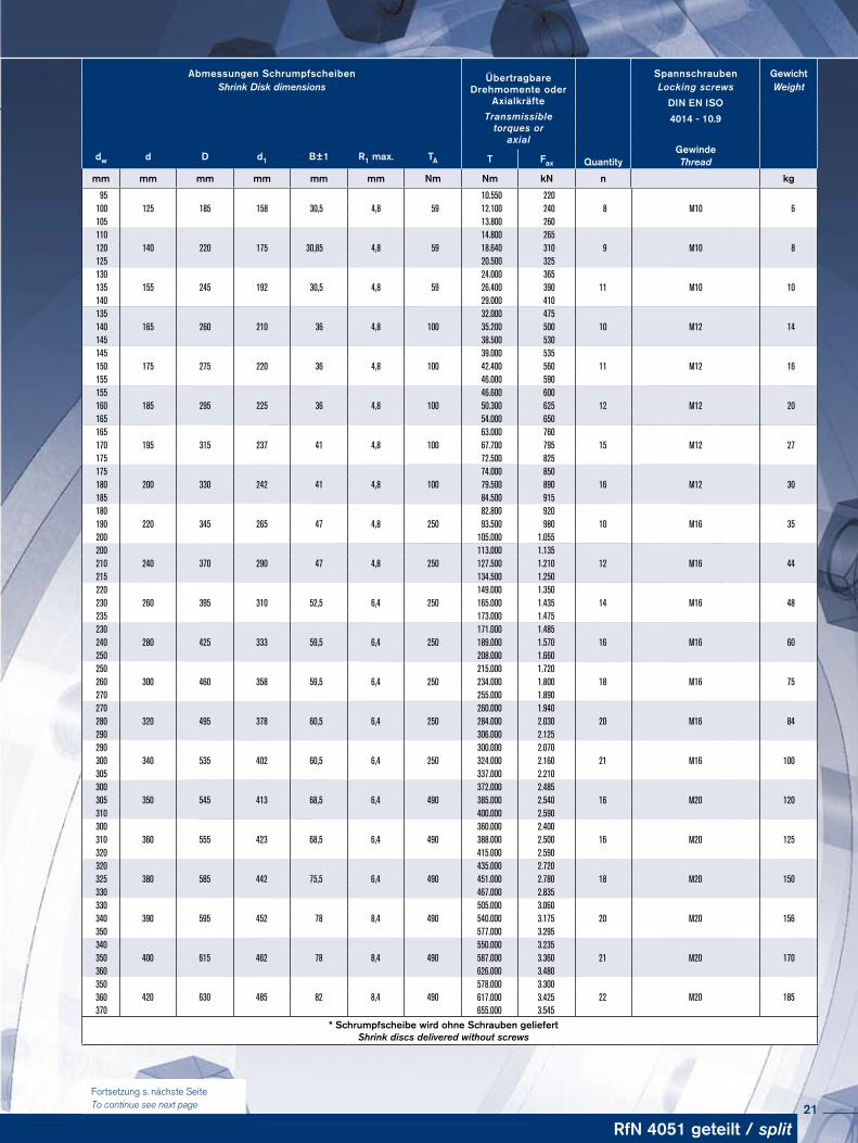
Abmessungen Schrumpfscheiben ÜbertragbareDrehmomente oder
Axialkräfte
Spannschrauben GewichtShrink Disk dimensions Locking screws Weight
DIN EN ISOTransmissible
torques oraxial
4014 - 10.9
dw d D d1 B±1 R1 max. TAGewinde
T Fax Quantity Thread
mm mm mm mm mm mm Nm Nm kN n kg
95125 185 158 30,5 4,8 59
10.550 2208 M10 6100 12.100 240
105 13.800 260110
140 220 175 30,85 4,8 5914.800 265
9 M10 8120 18.640 310125 20.500 325130
155 245 192 30,5 4,8 5924.000 365
11 M10 10135 26.400 390140 29.000 410135
165 260 210 36 4,8 10032.000 475
10 M12 14140 35.200 500145 38.500 530145
175 275 220 36 4,8 10039.000 535
11 M12 16150 42.400 560155 46.000 590155
185 295 225 36 4,8 10046.600 600
12 M12 20160 50.300 625165 54.000 650165
195 315 237 41 4,8 10063.000 760
15 M12 27170 67.700 795175 72.500 825175
200 330 242 41 4,8 10074.000 850
16 M12 30180 79.500 890185 84.500 915180
220 345 265 47 4,8 25082.800 920
10 M16 35190 93.500 980200 105.000 1.055200
240 370 290 47 4,8 250113.000 1.135
12 M16 44210 127.500 1.210215 134.500 1.250220
260 395 310 52,5 6,4 250149.000 1.350
14 M16 48230 165.000 1.435235 173.000 1.475230
280 425 333 59,5 6,4 250171.000 1.485
16 M16 60240 189.000 1.570250 208.000 1.660250
300 460 358 59,5 6,4 250215.000 1.720
18 M16 75260 234.000 1.800270 255.000 1.890270
320 495 378 60,5 6,4 250260.000 1.940
20 M16 84280 284.000 2.030290 306.000 2.125290
340 535 402 60,5 6,4 250300.000 2.070
21 M16 100300 324.000 2.160305 337.000 2.210300
350 545 413 68,5 6,4 490372.000 2.485
16 M20 120305 385.000 2.540310 400.000 2.590300
360 555 423 68,5 6,4 490360.000 2.400
16 M20 125310 388.000 2.500320 415.000 2.590320
380 585 442 75,5 6,4 490435.000 2.720
18 M20 150325 451.000 2.780330 467.000 2.835330
390 595 452 78 8,4 490505.000 3.060
20 M20 156340 540.000 3.175350 577.000 3.295340
400 615 462 78 8,4 490550.000 3.235
21 M20 170350 587.000 3.360360 626.000 3.480350
420 630 485 82 8,4 490578.000 3.300
22 M20 185360 617.000 3.425370 655.000 3.545
* Schrumpfscheibe wird ohne Schrauben geliefert Shrink discs delivered without screws
Fortsetzung s. nächste Seite To continue see next page 21
RINGFEDER® Schrumpfscheiben · Shrink Discs RfN 4051geteilt · split
Charakteristische Eigenschaften
Leichtere Ausführung für mittlere Übertragungswerte – beson-ders geeignet für dünne Naben.Geschlitzter Innenring – geringe Verlustkräfte und Pressungen auf die Nabe.Ausgleich von kleinen Toleranzfehlern – bitte Rücksprache mit unseren Technikern nehmen.Größte Zuverlässigkeit – geeignet für statische, dynamische und stoßartige Belastungen.Einfache Fertigung der Bauteile – es werden nur geringe Anforderungen an die Funktionsflächen der zu verbindenden Bauteile gestellt.Absolute Austauschbarkeit – Die Schrumpfscheiben RINGFEDER® arbeiten ohne jeden Formschluss. Einfache Montage – Das bei Querpresssitzen erforderliche Tempera turgefälle zwischen Welle und Nabe ist nicht notwendig. Bei Schrumpf scheiben RINGFEDER® sind handelsübliche Schrauben mit handelsüblichen Werkzeugen anzuziehen. An und Einpassarbeiten entfallen.Kurze Montagezeiten – Kosteneinsparung besonders in der Serienproduktion.Einfache Demontage – Nach dem Lösen der Spannschrauben ist die Schrumpfscheibe RINGFEDER® gelöst. Die Nabe kann auf der Welle frei verschoben werden. Geringe Schmutzempfindlichkeit – erhöhte Lebensdauer, da sich nach dem Anziehen der Spannschrauben die Berührungsflächen fest gegeneinander pressen. Schmutz und Feuchtigkeit können nicht an die Funktionsflächen vordringen.
Characteristics
Reduced dimensions with lower transmission values – especially for applications with restricted space.Simplified manufacture – only plain shaft and bore diameters with easily achieved surface finish and tolerances are required.Easy adjustability – No stops, steps, key-ways, splines etc. are re-quired, therefore hubs can be located and locked at any point or angle on the shaft.Easy mounting – RINGFEDER® Shrink Discs use standard screws and tightened using standard tools. No additional machining or fitting work is required.Easy removal – after loosening the locking screws, the RINGFEDER® Shrink Disc will self release and the hub will move freely on the shaft.Low susceptibility to contamination – when the locking screws are tightened the contact (functional) surfaces are pressed firmly together and prevent the ingress of dirt and moisture.Highest reliability – due to the materials chosen and manufacturing processes used, RINGFEDER® Shrink Discs can be tightened and re-leased as often as required. If locking screws need replacing, they are standard items and thus easily available.
22
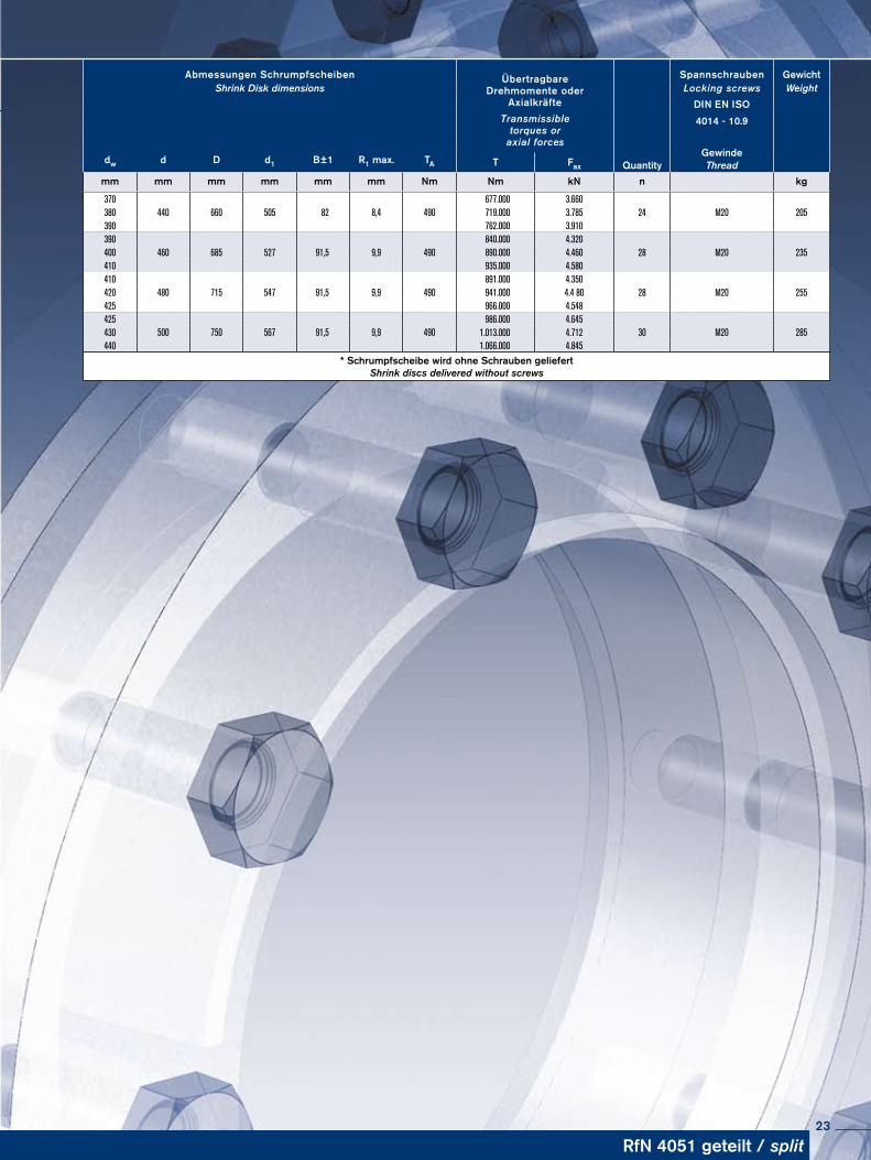
Abmessungen Schrumpfscheiben ÜbertragbareDrehmomente oder
Axialkräfte
Spannschrauben GewichtShrink Disk dimensions Locking screws Weight
DIN EN ISOTransmissible
torques oraxial forces
4014 - 10.9
dw d D d1 B±1 R1 max. TAGewinde
T Fax Quantity Thread
mm mm mm mm mm mm Nm Nm kN n kg
370440 660 505 82 8,4 490
677.000 3.66024 M20 205380 719.000 3.785
390 762.000 3.910390
460 685 527 91,5 9,9 490840.000 4.320
28 M20 235400 890.000 4.460410 935.000 4.580410
480 715 547 91,5 9,9 490891.000 4.350
28 M20 255420 941.000 4.4 80425 966.000 4.548425
500 750 567 91,5 9,9 490986.000 4.645
30 M20 285430 1.013.000 4.712440 1.066.000 4.845
* Schrumpfscheibe wird ohne Schrauben geliefert Shrink discs delivered without screws
RfN 4051 geteilt / split23
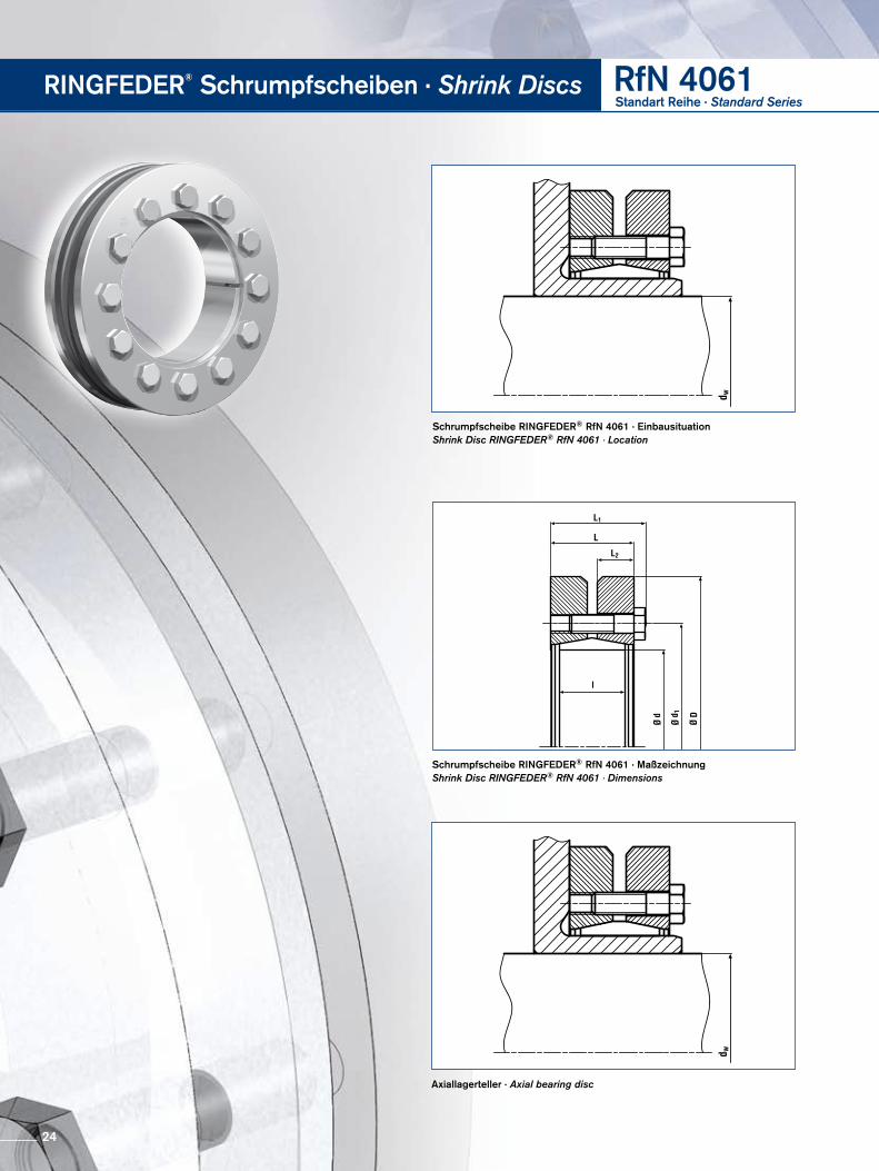
Schrumpfscheibe RINGFEDER® RfN 4061 · EinbausituationShrink Disc RINGFEDER® RfN 4061 · Location
Axiallagerteller · Axial bearing disc
Schrumpfscheibe RINGFEDER® RfN 4061 · MaßzeichnungShrink Disc RINGFEDER® RfN 4061 · Dimensions
RINGFEDER® Schrumpfscheiben · Shrink Discs RfN 4061Standart Reihe · Standard Series
24
RfN 4061 Standart Reihe / Standard Series
Abmessungen Schrumpfscheiben ÜbertragbareDrehmomente
oderAxialkräfte
Spannschrauben Ge wichtShrink Discs dimensions Locking screws Weight
DIN EN ISO 4014-10.9Transmissible
torques oraxial forces
dw d D L1 L d1 L2 I TA P σv QuantityGewinde
TmaxT Fax Thread
mm mm mm mm mm mm mm mm Nm Nm kN N/mm2 n kg Nm
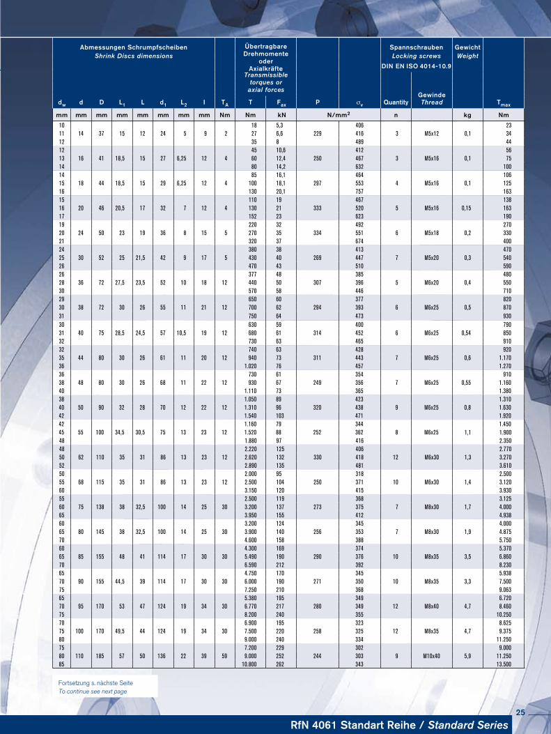
10 18 5,3 406 2311 14 37 15 12 24 5 9 2 27 6,6 229 416 3 M5x12 0,1 3412 35 8 489 4412 45 10,6 412 5613 16 41 18,5 15 27 6,25 12 4 60 12,4 250 467 3 M5x16 0,1 7514 80 14,2 632 10014 85 16,1 464 10615 18 44 18,5 15 29 6,25 12 4 100 18,1 297 553 4 M5x16 0,1 12516 130 20,1 757 16315 110 19 467 13816 20 46 20,5 17 32 7 12 4 130 21 333 520 5 M5x16 0,15 16317 152 23 623 19019 220 32 492 27020 24 50 23 19 36 8 15 5 270 35 334 551 6 M5x18 0,2 33021 320 37 674 40024 380 38 413 47025 30 52 25 21,5 42 9 17 5 430 40 269 447 7 M5x20 0,3 54026 470 43 510 59026 377 48 385 48028 36 72 27,5 23,5 52 10 18 12 440 50 307 396 5 M6x20 0,4 55030 570 58 446 71029 650 60 377 82030 38 72 30 26 55 11 21 12 700 62 294 393 6 M6x25 0,5 87031 750 64 473 93030 630 59 400 79031 40 75 28,5 24,5 57 10,5 19 12 680 61 314 452 6 M6x25 0,54 85032 730 63 465 91032 740 63 428 92035 44 80 30 26 61 11 20 12 940 73 311 443 7 M6x25 0,6 1.17036 1.020 76 457 1.27036 730 61 354 91038 48 80 30 26 68 11 22 12 930 67 249 356 7 M6x25 0,55 1.16040 1.110 73 365 1.38038 1.050 89 423 1.31040 50 90 32 28 70 12 22 12 1.310 96 320 438 9 M6x25 0,8 1.63042 1.540 103 471 1.92042 1.160 79 344 1.45045 55 100 34,5 30,5 75 13 23 12 1.520 88 252 362 8 M6x25 1,1 1.90048 1.880 97 416 2.35048 2.220 125 406 2.77050 62 110 35 31 86 13 23 12 2.620 132 330 418 12 M6x30 1,3 3.27052 2.890 135 481 3.61050 2.000 95 318 2.50055 68 115 35 31 86 13 23 12 2.500 104 250 371 10 M6x30 1,4 3.12060 3.150 120 415 3.93055 2.500 119 368 3.12560 75 138 38 32,5 100 14 25 30 3.200 137 273 375 7 M8x30 1,7 4.00065 3.950 155 412 4.93860 3.200 124 345 4.00065 80 145 38 32,5 100 14 25 30 3.900 140 256 353 7 M8x30 1,9 4.87570 4.600 158 388 5.75060 4.300 169 374 5.37065 85 155 48 41 114 17 30 30 5.490 190 290 376 10 M8x35 3,5 6.86070 6.590 212 392 8.23065 4.750 170 345 5.93870 90 155 44,5 39 114 17 30 30 6.000 190 271 350 10 M8x35 3,3 7.50075 7.250 210 368 9.06365 5.380 195 349 6.72070 95 170 53 47 124 19 34 30 6.770 217 280 349 12 M8x40 4,7 8.46075 8.200 240 355 10.25070 6.900 195 323 8.62575 100 170 49,5 44 124 19 34 30 7.500 220 258 325 12 M8x35 4,7 9.37580 9.000 240 334 11.25075 7.200 229 302 9.00080 110 185 57 50 136 22 39 59 9.000 252 244 303 9 M10x40 5,9 11.25085 10.800 262 343 13.500
Fortsetzung s. nächste Seite To continue see next page
25
RINGFEDER® Schrumpfscheiben · Shrink Discs RfN 4061Standart Reihe · Standard Series
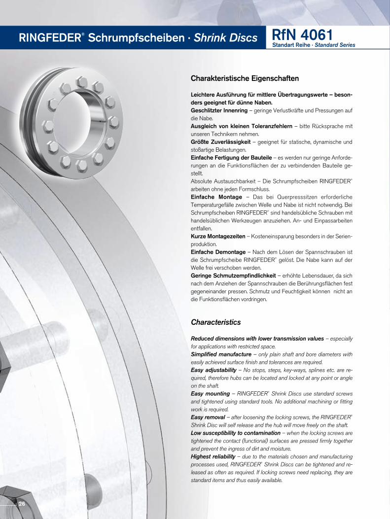
Charakteristische Eigenschaften
Leichtere Ausführung für mittlere Übertragungswerte – beson-ders geeignet für dünne Naben.Geschlitzter Innenring – geringe Verlustkräfte und Pressungen auf die Nabe.Ausgleich von kleinen Toleranzfehlern – bitte Rücksprache mit unseren Technikern nehmen.Größte Zuverlässigkeit – geeignet für statische, dynamische und stoßartige Belastungen.Einfache Fertigung der Bauteile – es werden nur geringe Anforderungen an die Funktionsflächen der zu verbindenden Bauteile gestellt.Absolute Austauschbarkeit – Die Schrumpfscheiben RINGFEDER® arbeiten ohne jeden Formschluss. Einfache Montage – Das bei Querpresssitzen erforderliche Tempera turgefälle zwischen Welle und Nabe ist nicht notwendig. Bei Schrumpf scheiben RINGFEDER® sind handelsübliche Schrauben mit handelsüblichen Werkzeugen anzuziehen. An und Einpassarbeiten entfallen.Kurze Montagezeiten – Kosteneinsparung besonders in der Serienproduktion.Einfache Demontage – Nach dem Lösen der Spannschrauben ist die Schrumpfscheibe RINGFEDER® gelöst. Die Nabe kann auf der Welle frei verschoben werden. Geringe Schmutzempfindlichkeit – erhöhte Lebensdauer, da sich nach dem Anziehen der Spannschrauben die Berührungsflächen fest gegeneinander pressen. Schmutz und Feuchtigkeit können nicht an die Funktionsflächen vordringen.
Characteristics
Reduced dimensions with lower transmission values – especially for applications with restricted space.Simplified manufacture – only plain shaft and bore diameters with easily achieved surface finish and tolerances are required.Easy adjustability – No stops, steps, key-ways, splines etc. are re-quired, therefore hubs can be located and locked at any point or angle on the shaft.Easy mounting – RINGFEDER® Shrink Discs use standard screws and tightened using standard tools. No additional machining or fitting work is required.Easy removal – after loosening the locking screws, the RINGFEDER® Shrink Disc will self release and the hub will move freely on the shaft.Low susceptibility to contamination – when the locking screws are tightened the contact (functional) surfaces are pressed firmly together and prevent the ingress of dirt and moisture.Highest reliability – due to the materials chosen and manufacturing processes used, RINGFEDER® Shrink Discs can be tightened and re-leased as often as required. If locking screws need replacing, they are standard items and thus easily available.
26
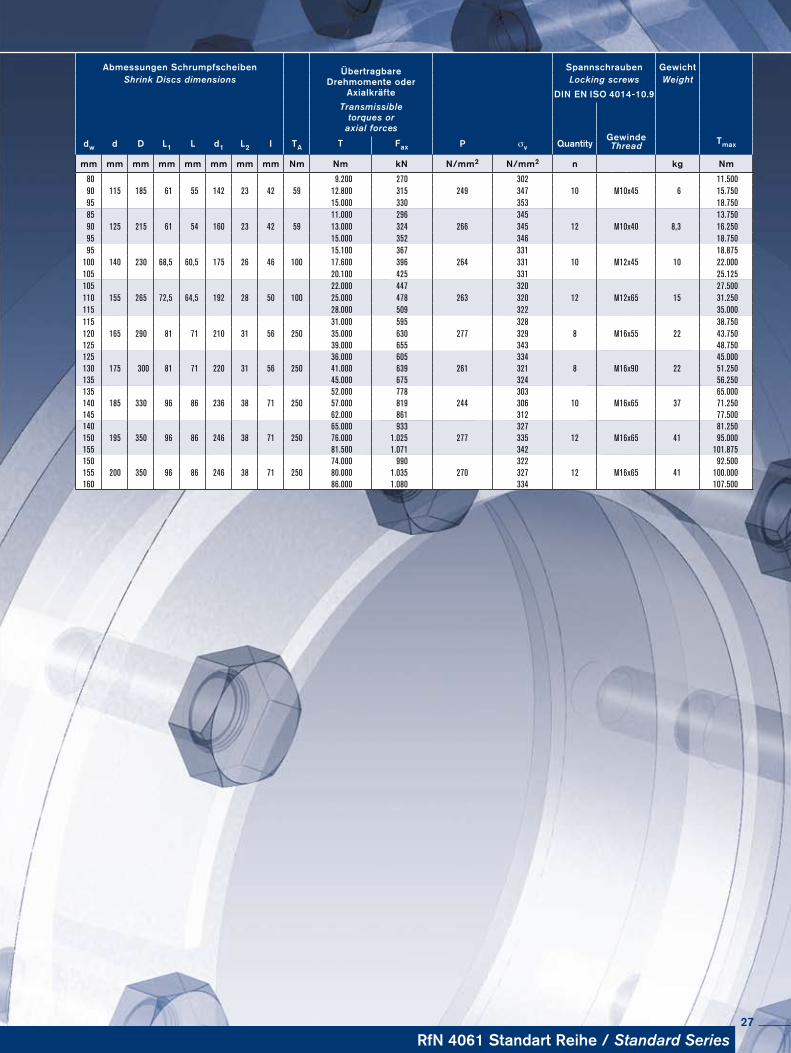
Abmessungen Schrumpfscheiben ÜbertragbareDrehmomente oder
Axialkräfte
Spannschrauben Ge wichtShrink Discs dimensions Locking screws Weight
DIN EN ISO 4014-10.9Transmissible
torques oraxial forces
dw d D L1 L d1 L2 I TA P σv QuantityGewinde TmaxT Fax Thread
mm mm mm mm mm mm mm mm Nm Nm kN N/mm2 N/mm2 n kg Nm
80 9.200 270 302 11.50090 115 185 61 55 142 23 42 59 12.800 315 249 347 10 M10x45 6 15.75095 15.000 330 353 18.75085 11.000 296 345 13.75090 125 215 61 54 160 23 42 59 13.000 324 266 345 12 M10x40 8,3 16.25095 15.000 352 346 18.75095 15.100 367 331 18.875
100 140 230 68,5 60,5 175 26 46 100 17.600 396 264 331 10 M12x45 10 22.000105 20.100 425 331 25.125105 22.000 447 320 27.500110 155 265 72,5 64,5 192 28 50 100 25.000 478 263 320 12 M12x65 15 31.250115 28.000 509 322 35.000115 31.000 595 328 38.750120 165 290 81 71 210 31 56 250 35.000 630 277 329 8 M16x55 22 43.750125 39.000 655 343 48.750125 36.000 605 334 45.000130 175 300 81 71 220 31 56 250 41.000 639 261 321 8 M16x90 22 51.250135 45.000 675 324 56.250135 52.000 778 303 65.000140 185 330 96 86 236 38 71 250 57.000 819 244 306 10 M16x65 37 71.250145 62.000 861 312 77.500140 65.000 933 327 81.250150 195 350 96 86 246 38 71 250 76.000 1.025 277 335 12 M16x65 41 95.000155 81.500 1.071 342 101.875150 74.000 990 322 92.500155 200 350 96 86 246 38 71 250 80.000 1.035 270 327 12 M16x65 41 100.000160 86.000 1.080 334 107.500
RfN 4061 Standart Reihe / Standard Series27

Schrumpfscheibe RINGFEDER® RfN 4061 geteilt · EinbausituationShrink Disc RINGFEDER® RfN 4061 split · Location
D d1 d dw
R1max
L2
B x
Schrumpfscheibe RINGFEDER® RfN 4061 HD · MaßzeichnungShrink Disc RINGFEDER® RfN 4061 HC · Dimensions
D d1 d dw
R1max
L2
B x
D d1 d dw
R1max
L2
B x
Schrumpfscheibe RINGFEDER® RfN 4061 HG versionShrink Disc RINGFEDER® RfN 4061 HT version
RINGFEDER® Schrumpfscheiben · Shrink Discs RfN 4061geteilt · split
Schrumpfscheiben geteilt
Bei einer Anordnung dieser Art werden in Abhängigkeit des Maßes X längere Spannschrauben erforderlich, die entsprechend zu bestellen sind. Wird das Maß größer 2L der StandardReihe und der LeichtenReihe bzw. größer L der SchwerenReihe gewählt, muß mit einer Reduzierung des übertragbaren Drehmomentes bis zu 50% gerechnet werden.
Shrinc Discs slit
In the application shown above special screws according to the dimension X are required, which have to be ordered accordingly. If the dimension X is above 2 x L (L taken from the Standard and the Light Duty Series) or above 1 x L (taken from the Heavy Duty Series) a reduction of the transmissible torque up to 50 % has to be considered.
Halbe Schrumpfscheiben
Mit halben Schrumpfscheiben HD/HG können nur 50% des angegebenen Drehmomentes T übertragen werden.
Half Shrinc Discs
With half shrink discs HC/HT only 50% of stated T is transmitted.
Typ HG (Gewinde im Druckring)
type HT (Threaded holes in thrust ring)
Typ HD (Durchgangsbohrungen im Druckring)
type HC (Clearance holes in thrust ring)
28
RfN 4061 geteilt / split
1520 46 32 11,5 1,3 4
110 195 M5 0,15
12116 5 130 21 14317 152 23 167,219
24 50 36 11,75 1,3 5220 32
6 M5 0,2242
20 6,25 270 35 29721 320 37 35224
30 52 42 12,75 1,3 5380 38
7 M5 0,3418
25 6,25 430 40 47326 470 43 51726
36 72 52 13,75 1,3 12377 48
5 M6 0,4414,7
28 7 440 50 48430 570 58 62729
38 72 55 15,25 1,3 12650 60
6 M6 0,5715
30 8 700 62 77031 750 64 82530
40 75 57 14,75 1,3 12630 59
6 M6 0,54693
31 9 680 61 74832 730 63 80332
44 80 61 15,25 2,8 12740 63
M6 0,6814
35 10 940 73 7 103436 1.020 76 112236
48 80 68 15,25 2,8 12730 61
7 M6 0,55803
38 11 930 67 102340 1.110 73 122138
50 90 70 16,25 2,8 121.050 89
9 M6 0,81155
40 10,5 1.310 96 144142 1.540 103 169442
55 100 75 17,75 2,8 121.160 79
8 M6 1,11276
45 11 1.520 88 167248 1.880 97 206848
62 110 86 17,75 2,8 122.220 125
12 M6 1,32442
50 11 2.620 132 288252 2.890 135 317950
68 115 86 17,75 2,8 122.000 95
10 M6 1,42200
55 12 2.500 104 275060 3.150 120 346555
75 138 100 19,75 2,8 302.500 119
7 M8 1,72750
60 13 3.200 137 352065 3.950 155 434560
80 145 100 19,75 2,8 303.200 124
7 M8 1,93520
65 13 3.900 140 429070 4.600 158 506060
85 155 114 23 3,3 304.300 169
10 M8 3,54730
65 13 5.490 190 603970 6.590 212 724965
90 155 114 23 3,3 304.750 170
10 M8 3,35225
70 14 6.000 190 660075 7.250 210 797565
95 170 124 23,5 3,3 305.380 195
12 M8 4,75918
70 14 6.770 217 744775 8.200 240 902070
100 170 124 25,5 3,3 306.900 195
12 M8 4,77590
75 17 7.500 220 825080 9.000 240 990075
110 185 136 28,5 4,8 597.200 229
9 M10 5,97920
80 17 9.000 252 990085 10.800 262 1188080
115 185 142 32 4,8 599.200 270
10 M10 610120
90 19 12.800 315 1408095 15.000 330 1650085
125 215 160 32 4,8 5911.000 345
12 M10 8,312100
90 19 13.000 345 1430095 15.000 346 1650095
140 230 175 35,5 4,8 10015.100 33
10 M12 1016610
100 22 17.600 331 19360105 20.100 331 22110105
155 265 92 37,25 4,8 10022.000 320
12 M12 1524200
110 28 25.000 320 27500115 28.000 322 30800
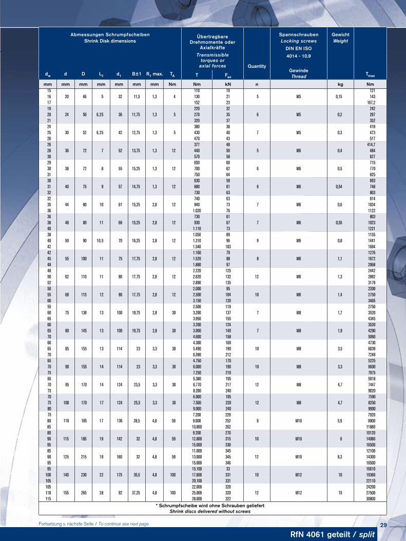
* Schrumpfscheibe wird ohne Schrauben geliefert Shrink discs delivered without screws
Abmessungen Schrumpfscheiben ÜbertragbareDrehmomente oder
Axialkräfte
Spannschrauben GewichtShrink Disk dimensions Locking screws Weight
DIN EN ISOTransmissible
torques oraxial forces
4014 - 10.9
Quantity
dw d D L2 d1 B±1 R1 max. TAGewinde
TmaxT Fax Thread
mm mm mm mm mm mm mm Nm Nm kN n kg Nm
Fortsetzung s. nächste Seite / To continue see next page 29
RINGFEDER® Schrumpfscheiben · Shrink Discs RfN 4061geteilt · split
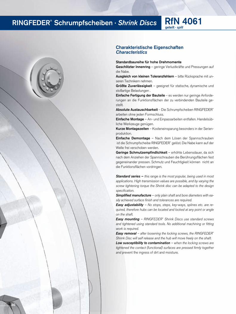
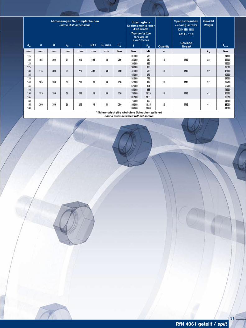
Charakteristische Eigenschaften Characteristics
Standardbaureihe für hohe DrehmomenteGeschlitzter Innenring – geringe Verlustkräfte und Pressungen auf die Nabe.Ausgleich von kleinen Toleranzfehlern – bitte Rücksprache mit unseren Technikern nehmen.Größte Zuverlässigkeit – geeignet für statische, dynamische und stoßartige Belastungen .Einfache Fertigung der Bauteile – es werden nur geringe Anforderungen an die Funktionsflächen der zu verbindenden Bauteile gestellt.Absolute Austauschbarkeit – Die Schrumpfscheiben RINGFEDER® arbeiten ohne jeden Formschluss. Einfache Montage – An und Einpassarbeiten entfallen. Handelsübliche Werkzeuge genügen. Kurze Montagezeiten – Kosteneinsparung besonders in der Serienproduktion.Einfache Demontage – Nach dem Lösen der Spannschrauben ist die Schrumpfscheibe RINGFEDER® gelöst. Die Nabe kann auf der Welle frei verschoben werden. Geringe Schmutzempfindlichkeit – erhöhte Lebensdauer, da sich nach dem Anziehen der Spannschrauben die Berührungsflächen fest gegeneinander pressen. Schmutz und Feuchtigkeit können nicht an die Funktions flächen vordringen.
Standard series – this range is the most popular, being used in most applications. High transmission values are possible, and by varying the screw tightening torque the Shrink disc can be adapted to the design specification.Simplified manufacture – only plain shaft and bore diameters with ea-sily achieved surface finish and tolerances are required.Easy adjustability – No stops, steps, key-ways, splines etc. are re-quired, therefore hubs can be located and locked at any point or angle on the shaft.Easy mounting – RINGFEDER® Shrink Discs use standard screws and tightened using standard tools. No additional machining or fitting work is required.Easy removal – after loosening the locking screws, the RINGFEDER® Shrink Disc will self release and the hub will move freely on the shaft.Low susceptibility to contamination – when the locking screws are tightened the contact (functional) surfaces are pressed firmly together and prevent the ingress of dirt and moisture.
30
115165 290 210 40,5 4,8 250
31.000 5958 M16 22
34100120 31 35.000 630 38500125 39.000 655 42900125
175 300 220 40,5 4,8 25036.000 605
8 M16 2239600
130 31 41.000 639 45100135 45.000 675 49500135
185 330 236 48 4,8 25052.000 778
10 M16 3757200
140 38 57.000 819 62700145 62.000 861 68200140
195 350 246 48 4,8 25065.000 933
12 M16 4171500
150 38 76.000 1025 83600155 81.500 1071 89650150
200 350 246 48 4,8 25074.000 990
12 M16 4181400
155 38 80.000 1035 88000160 86.000 1080 94600
* Schrumpfscheibe wird ohne Schrauben geliefert Shrink discs delivered without screws
Abmessungen Schrumpfscheiben ÜbertragbareDrehmomente oder
Axialkräfte
Spannschrauben GewichtShrink Disk dimensions Locking screws Weight
DIN EN ISOTransmissible
torques oraxial forces
4014 - 10.9
dw d D L2 d1 B±1 R1 max. TAGewinde
TmaxT Fax Quantity Thread
mm mm mm mm mm mm mm Nm Nm kN n kg Nm
RfN 4061 geteilt / split31
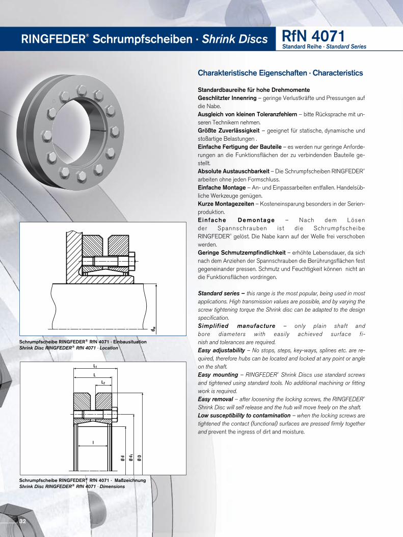
RINGFEDER® Schrumpfscheiben · Shrink Discs RfN 4071Standard Reihe · Standard Series
Charakteristische Eigenschaften · Characteristics
Standardbaureihe für hohe DrehmomenteGeschlitzter Innenring – geringe Verlustkräfte und Pressungen auf die Nabe.Ausgleich von kleinen Toleranzfehlern – bitte Rücksprache mit unseren Technikern nehmen.Größte Zuverlässigkeit – geeignet für statische, dynamische und stoßartige Belastungen .Einfache Fertigung der Bauteile – es werden nur geringe Anforderungen an die Funktionsflächen der zu verbindenden Bauteile gestellt.Absolute Austauschbarkeit – Die Schrumpfscheiben RINGFEDER® arbeiten ohne jeden Formschluss. Einfache Montage – An und Einpassarbeiten entfallen. Handelsübliche Werkzeuge genügen. Kurze Montagezeiten – Kosteneinsparung besonders in der Serienproduktion.Einfache Demontage – Nach dem Lösen der Spannschrauben ist d ie Schrumpfscheibe RINGFEDER® gelöst. Die Nabe kann auf der Welle frei verschoben werden. Geringe Schmutzempfindlichkeit – erhöhte Lebensdauer, da sich nach dem Anziehen der Spannschrauben die Berührungsflächen fest gegeneinander pressen. Schmutz und Feuchtigkeit können nicht an die Funktions flächen vordringen.
Standard series – this range is the most popular, being used in most applications. High transmission values are possible, and by varying the screw tightening torque the Shrink disc can be adapted to the design specification.Simplified manufacture – only plain shaft and bore diameters with easily achieved surface fi- nish and tolerances are required.Easy adjustability – No stops, steps, key-ways, splines etc. are re-quired, therefore hubs can be located and locked at any point or angle on the shaft.Easy mounting – RINGFEDER® Shrink Discs use standard screws and tightened using standard tools. No additional machining or fitting work is required.Easy removal – after loosening the locking screws, the RINGFEDER® Shrink Disc will self release and the hub will move freely on the shaft.Low susceptibility to contamination – when the locking screws are tightened the contact (functional) surfaces are pressed firmly together and prevent the ingress of dirt and moisture.
Schrumpfscheibe RINGFEDER® RfN 4071 · EinbausituationShrink Disc RINGFEDER® RfN 4071 · Location
Schrumpfscheibe RINGFEDER® RfN 4071 · MaßzeichnungShrink Disc RINGFEDER® RfN 4071 · Dimensions
32
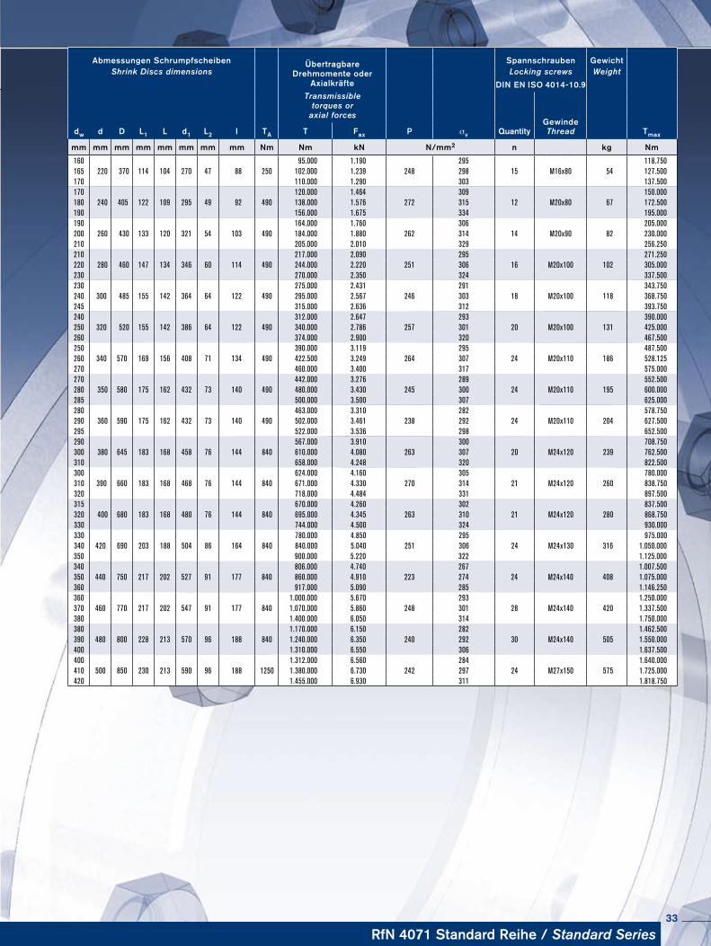
RfN 4071 Standard Reihe / Standard Series
Abmessungen Schrumpfscheiben ÜbertragbareDrehmomente oder
Axialkräfte
Spannschrauben Ge wichtShrink Discs dimensions Locking screws Weight
DIN EN ISO 4014-10.9Transmissible
torques oraxial forces
dw d D L1 L d1 L2 I TA P σv Quantity Gewinde
Tmax T Fax Thread
mm mm mm mm mm mm mm mm Nm Nm kN N/mm2 n kg Nm
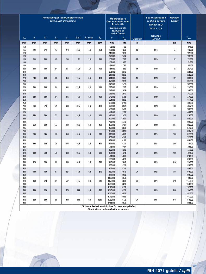
160 95.000 1.190 295 118.750165 220 370 114 104 270 47 88 250 102.000 1.239 248 298 15 M16x80 54 127.500170 110.000 1.290 303 137.500170 120.000 1.464 309 150.000180 240 405 122 109 295 49 92 490 138.000 1.576 272 315 12 M20x80 67 172.500190 156.000 1.675 334 195.000190 164.000 1.760 306 205.000200 260 430 133 120 321 54 103 490 184.000 1.880 262 314 14 M20x90 82 230.000210 205.000 2.010 329 256.250210 217.000 2.090 295 271.250220 280 460 147 134 346 60 114 490 244.000 2.220 251 306 16 M20x100 102 305.000230 270.000 2.350 324 337.500230 275.000 2.431 291 343.750240 300 485 155 142 364 64 122 490 295.000 2.567 246 303 18 M20x100 118 368.750245 315.000 2.636 312 393.750240 312.000 2.647 293 390.000250 320 520 155 142 386 64 122 490 340.000 2.786 257 301 20 M20x100 131 425.000260 374.000 2.900 320 467.500250 390.000 3.119 295 487.500260 340 570 169 156 408 71 134 490 422.500 3.249 264 307 24 M20x110 186 528.125270 460.000 3.400 317 575.000270 442.000 3.276 289 552.500280 350 580 175 162 432 73 140 490 480.000 3.430 245 300 24 M20x110 195 600.000285 500.000 3.500 307 625.000280 463.000 3.310 282 578.750290 360 590 175 162 432 73 140 490 502.000 3.461 238 292 24 M20x110 204 627.500295 522.000 3.536 298 652.500290 567.000 3.910 300 708.750300 380 645 183 168 458 76 144 840 610.000 4.080 263 307 20 M24x120 239 762.500310 658.000 4.248 320 822.500300 624.000 4.160 305 780.000310 390 660 183 168 468 76 144 840 671.000 4.330 270 314 21 M24x120 260 838.750320 718.000 4.484 331 897.500315 670.000 4.260 302 837.500320 400 680 183 168 480 76 144 840 695.000 4.345 263 310 21 M24x120 280 868.750330 744.000 4.500 324 930.000330 780.000 4.850 295 975.000340 420 690 203 188 504 86 164 840 840.000 5.040 251 306 24 M24x130 316 1.050.000350 900.000 5.220 322 1.125.000340 806.000 4.740 267 1.007.500350 440 750 217 202 527 91 177 840 860.000 4.910 223 274 24 M24x140 408 1.075.000360 917.000 5.090 285 1.146.250360 1.000.000 5.670 293 1.250.000370 460 770 217 202 547 91 177 840 1.070.000 5.860 248 301 28 M24x140 420 1.337.500380 1.400.000 6.050 314 1.750.000380 1.170.000 6.150 282 1.462.500390 480 800 228 213 570 96 188 840 1.240.000 6.350 240 292 30 M24x140 505 1.550.000400 1.310.000 6.550 306 1.637.500400 1.312.000 6.560 284 1.640.000410 500 850 230 213 590 96 188 1250 1.380.000 6.730 242 297 24 M27x150 575 1.725.000420 1.455.000 6.930 311 1.818.750
33
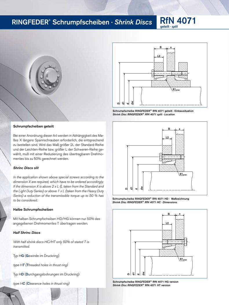
RINGFEDER® Schrumpfscheiben · Shrink Discs RfN 4071geteilt · split
Schrumpfscheiben geteilt
Bei einer Anordnung dieser Art werden in Abhängigkeit des Maßes X längere Spannschrauben erforderlich, die entsprechend zu bestellen sind. Wird das Maß größer 2L der StandardReihe und der LeichtenReihe bzw. größer L der SchwerenReihe gewählt, muß mit einer Reduzierung des übertragbaren Drehmomentes bis zu 50% gerechnet werden.
Shrinc Discs slit
In the application shown above special screws according to the dimension X are required, which have to be ordered accordingly. If the dimension X is above 2 x L (L taken from the Standard and the Light Duty Series) or above 1 x L (taken from the Heavy Duty Series) a reduction of the transmissible torque up to 50 % has to be considered.
Halbe Schrumpfscheiben
Mit halben Schrumpfscheiben HD/HG können nur 50% des angegebenen Drehmomentes T übertragen werden.
Half Shrinc Discs
With half shrink discs HC/HT only 50% of stated T is transmitted.
Typ HG (Gewinde im Druckring)
type HT (Threaded holes in thrust ring)
Typ HD (Durchgangsbohrungen im Druckring)
type HC (Clearance holes in thrust ring)
Schrumpfscheibe RINGFEDER® RfN 4071 geteilt · EinbausituationShrink Disc RINGFEDER® RfN 4071 split · Location
D d1 d dw
R1max
L2
B x
Schrumpfscheibe RINGFEDER® RfN 4071 HD · MaßzeichnungShrink Disc RINGFEDER® RfN 4071 HC · Dimensions
D d1 d dw
R1max
L2
B x
D d1 d dw
R1max
L2
B x
Schrumpfscheibe RINGFEDER® RfN 4071 HG versionShrink Disc RINGFEDER® RfN 4071 HT version
34
160220 370 270 59,5 7,4 250
95.000 119015 M16 54
104500165 47 102.000 1239 112200170 110.000 1290 121000170
240 405 295 62 7,4 490120.000 1464
12 M20 67132000
180 49 138.000 1576 151800190 156.000 1675 171600190
260 430 321 67,5 7,4 490164.000 1760
14 M20 82180400
200 54 184.000 1880 202400210 205.000 2010 225500210
280 460 346 76,5 8,4 490217.000 2090
16 M20 102238700
220 60 244.000 2220 268400230 270.000 2350 297000230
300 485 364 79,5 8,4 490275.000 2431
18 M20 118302500
240 64 295.000 2567 324500245 315.000 2636 346500240
320 520 386 79,5 8,4 490312.000 2647
20 M20 131343200
250 64 340.000 2786 374000260 374.000 2900 411400250
340 570 408 86,5 8,4 490390.000 3119
24 M20 186429000
260 71 422.500 3249 464750270 460.000 3400 506000270
350 580 432 89,5 8,4 490442.000 3276
24 M20 195486200
280 73 480.000 3430 528000285 500.000 3500 550000280
360 590 432 89,5 8,4 490463.000 3310
24 M20 204509300
290 73 502.000 3461 552200295 522.000 3536 574200290
380 645 458 92,5 8,4 840567.000 3910
20 M24 239623700
300 76 610.000 4080 671000310 658.000 4248 723800300
390 660 468 92,5 8,4 840624.000 4160
21 M24 260686400
310 76 671.000 4330 738100320 718.000 4484 789800315
400 680 480 92,5 8,4 840670.000 4260
21 M24 280737000
320 76 695.000 4345 764500330 744.000 4500 818400330
420 690 504 106,5 9,9 840780.000 4850
24 M24 316858000
340 86 840.000 5040 924000350 900.000 5220 990000340
440 750 527 113,5 9,9 840806.000 4740
24 M24 408886600
350 91 860.000 4910 946000360 917.000 5090 1008700360
460 770 547 113,5 9,9 8401.000.000 5670
28 M24 4201100000
370 91 1.070.000 5860 1177000380 1.400.000 6050 1540000380
480 800 570 119 9,9 8401.170.000 6150
30 M24 5051287000
390 96 1.240.000 6350 1364000400 1.310.000 6550 1441000400
500 850 590 119 9,9 12501.312.000 6560
24 M27 5751443200
410 96 1.380.000 6730 1518000420 1.455.000 6930 1600500
* Schrumpfscheibe wird ohne Schrauben geliefert Shrink discs delivered without screws
Abmessungen Schrumpfscheiben ÜbertragbareDrehmomente oder
Axialkräfte
Spannschrauben GewichtShrink Disk dimensions Locking screws Weight
DIN EN ISOTransmissible
torques oraxial forces
4014 - 10.9
dw d D L2 d1 B±1 R1 max. TAGewinde
TmaxT Fax Quantity Thread
mm mm mm mm mm mm mm Nm Nm kN n kg Nm
RfN 4071 geteilt / split35
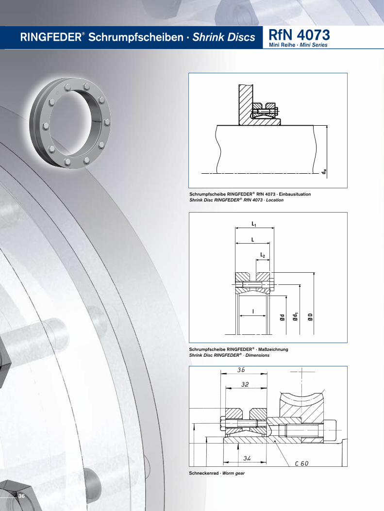
Schrumpfscheibe RINGFEDER® RfN 4073 · EinbausituationShrink Disc RINGFEDER® RfN 4073 · Location
Schneckenrad · Worm gear
Schrumpfscheibe RINGFEDER® · MaßzeichnungShrink Disc RINGFEDER® · Dimensions
RINGFEDER® Schrumpfscheiben · Shrink Discs RfN 4073Mini Reihe · Mini Series
36
Fortsetzung s. nächste Seite To continue see next page
Abmessungen Schrumpfscheiben ÜbertragbareDrehmomente
oderAxialkräfte
Spannschrauben Ge wichtShrink Discs dimensions Locking screws Weight
DIN EN ISO 4014-10.9Transmissible
torques oraxial forces
dw d D L1 L d1 L2 I TA P σv Quantity GewindeThread TmaxT Fax
mm mm mm mm mm mm mm mm Nm Nm kN N/mm2 n kg Nm
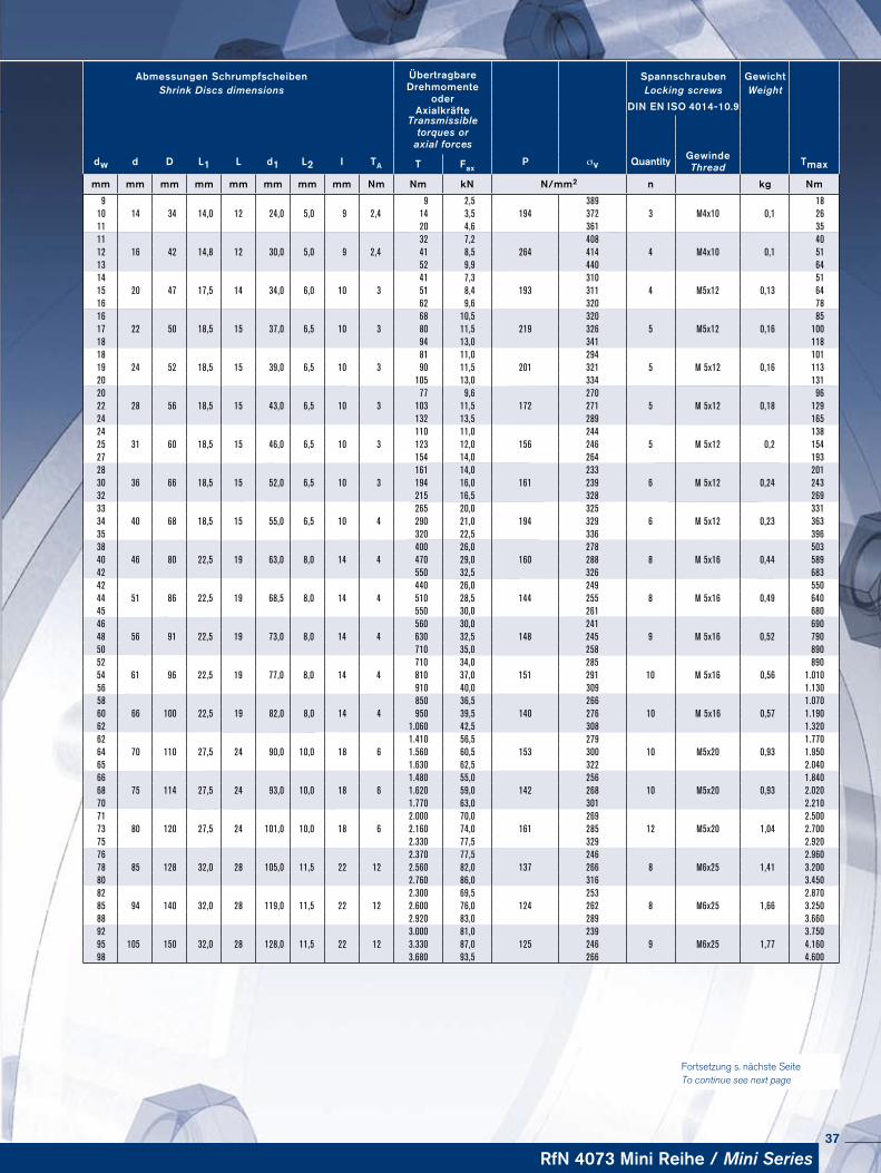
9 9 2,5 389 1810 14 34 14,0 12 24,0 5,0 9 2,4 14 3,5 194 372 3 M4x10 0,1 2611 20 4,6 361 3511 32 7,2 408 4012 16 42 14,8 12 30,0 5,0 9 2,4 41 8,5 264 414 4 M4x10 0,1 5113 52 9,9 440 6414 41 7,3 310 5115 20 47 17,5 14 34,0 6,0 10 3 51 8,4 193 311 4 M5x12 0,13 6416 62 9,6 320 7816 68 10,5 320 8517 22 50 18,5 15 37,0 6,5 10 3 80 11,5 219 326 5 M5x12 0,16 10018 94 13,0 341 11818 81 11,0 294 10119 24 52 18,5 15 39,0 6,5 10 3 90 11,5 201 321 5 M 5x12 0,16 11320 105 13,0 334 13120 77 9,6 270 9622 28 56 18,5 15 43,0 6,5 10 3 103 11,5 172 271 5 M 5x12 0,18 12924 132 13,5 289 16524 110 11,0 244 13825 31 60 18,5 15 46,0 6,5 10 3 123 12,0 156 246 5 M 5x12 0,2 15427 154 14,0 264 19328 161 14,0 233 20130 36 66 18,5 15 52,0 6,5 10 3 194 16,0 161 239 6 M 5x12 0,24 24332 215 16,5 328 26933 265 20,0 325 33134 40 68 18,5 15 55,0 6,5 10 4 290 21,0 194 329 6 M 5x12 0,23 36335 320 22,5 336 39638 400 26,0 278 50340 46 80 22,5 19 63,0 8,0 14 4 470 29,0 160 288 8 M 5x16 0,44 58942 550 32,5 326 68342 440 26,0 249 55044 51 86 22,5 19 68,5 8,0 14 4 510 28,5 144 255 8 M 5x16 0,49 64045 550 30,0 261 68046 560 30,0 241 69048 56 91 22,5 19 73,0 8,0 14 4 630 32,5 148 245 9 M 5x16 0,52 79050 710 35,0 258 89052 710 34,0 285 89054 61 96 22,5 19 77,0 8,0 14 4 810 37,0 151 291 10 M 5x16 0,56 1.01056 910 40,0 309 1.13058 850 36,5 266 1.07060 66 100 22,5 19 82,0 8,0 14 4 950 39,5 140 276 10 M 5x16 0,57 1.19062 1.060 42,5 308 1.32062 1.410 56,5 279 1.77064 70 110 27,5 24 90,0 10,0 18 6 1.560 60,5 153 300 10 M5x20 0,93 1.95065 1.630 62,5 322 2.04066 1.480 55,0 256 1.84068 75 114 27,5 24 93,0 10,0 18 6 1.620 59,0 142 268 10 M5x20 0,93 2.02070 1.770 63,0 301 2.21071 2.000 70,0 269 2.50073 80 120 27,5 24 101,0 10,0 18 6 2.160 74,0 161 285 12 M5x20 1,04 2.70075 2.330 77,5 329 2.92076 2.370 77,5 246 2.96078 85 128 32,0 28 105,0 11,5 22 12 2.560 82,0 137 266 8 M6x25 1,41 3.20080 2.760 86,0 316 3.45082 2.300 69,5 253 2.87085 94 140 32,0 28 119,0 11,5 22 12 2.600 76,0 124 262 8 M6x25 1,66 3.25088 2.920 83,0 289 3.66092 3.000 81,0 239 3.75095 105 150 32,0 28 128,0 11,5 22 12 3.330 87,0 125 246 9 M6x25 1,77 4.16098 3.680 93,5 266 4.600
RfN 4073 Mini Reihe / Mini Series37
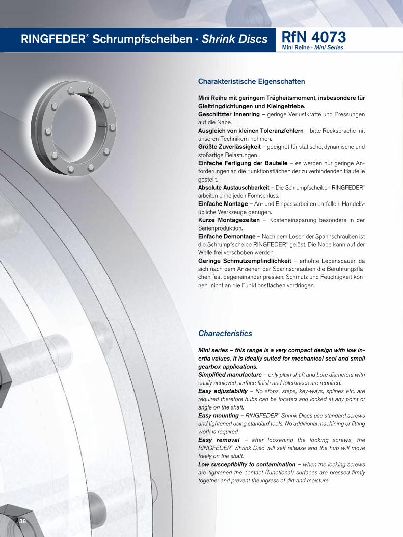
Charakteristische Eigenschaften
Mini Reihe mit geringem Trägheitsmoment, insbesondere für Gleit ring dichtungen und Kleingetriebe.Geschlitzter Innenring – geringe Verlustkräfte und Pressungen auf die Nabe.Ausgleich von kleinen Toleranzfehlern – bitte Rücksprache mit unseren Technikern nehmen.Größte Zuverlässigkeit – geeignet für statische, dynamische und stoßartige Belastungen .Einfache Fertigung der Bauteile – es werden nur geringe Anforderungen an die Funktionsflächen der zu verbindenden Bauteile gestellt.Absolute Austauschbarkeit – Die Schrumpfscheiben RINGFEDER® arbeiten ohne jeden Formschluss. Einfache Montage – An und Einpassarbeiten entfallen. Handelsübliche Werkzeuge genügen. Kurze Montagezeiten – Kosteneinsparung besonders in der Serien produktion.Einfache Demontage – Nach dem Lösen der Spannschrauben ist die Schrumpfscheibe RINGFEDER® gelöst. Die Nabe kann auf der Welle frei verschoben werden. Geringe Schmutzempfindlichkeit – erhöhte Lebensdauer, da sich nach dem Anziehen der Spannschrauben die Berührungsflächen fest gegeneinander pressen. Schmutz und Feuchtigkeit können nicht an die Funktionsflächen vordringen.
Characteristics
Mini series – this range is a very compact design with low in-ertia values. It is ideally suited for mechanical seal and small gearbox applications.Simplified manufacture – only plain shaft and bore diameters with easily achieved surface finish and tolerances are required.Easy adjustability – No stops, steps, key-ways, splines etc. are required therefore hubs can be located and locked at any point or angle on the shaft.Easy mounting – RINGFEDER® Shrink Discs use standard screws and tightened using standard tools. No additional machining or fitting work is required.Easy removal – after loosening the locking screws, the RINGFEDER® Shrink Disc will self release and the hub will move freely on the shaft.Low susceptibility to contamination – when the locking screws are tightened the contact (functional) surfaces are pressed firmly together and prevent the ingress of dirt and moisture.
RINGFEDER® Schrumpfscheiben · Shrink Discs RfN 4073Mini Reihe · Mini Series
38
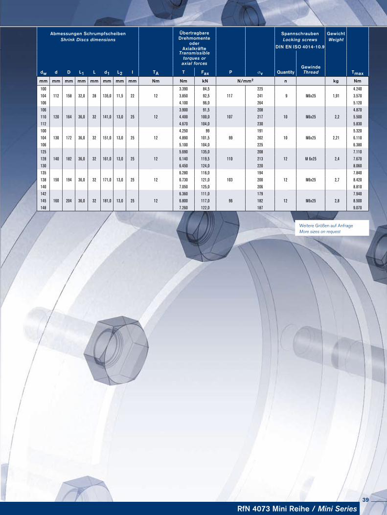
Weitere Größen auf Anfrage More sizes on request
Abmessungen Schrumpfscheiben ÜbertragbareDrehmomente
oderAxialkräfte
Spannschrauben Ge wichtShrink Discs dimensions Locking screws Weight
DIN EN ISO 4014-10.9Transmissible
torques oraxial forces
dw d D L1 L d1 L2 I TA P σv QuantityGewinde
TmaxT Fax Thread
mm mm mm mm mm mm mm mm Nm Nm kN N/mm2 n kg Nm
100 3.390 84,5 225 4.240
104 112 158 32,0 28 135,0 11,5 22 12 3.850 92,5 117 241 9 M6x25 1,91 3.570
106 4.100 96,0 264 5.120
106 3.900 91,5 208 4.870
110 120 164 36,0 32 141,0 13,0 25 12 4.400 100,0 107 217 10 M6x25 2,2 5.500
112 4.670 104,0 230 5.830
100 4.250 99 191 5.320
104 130 172 36,0 32 151,0 13,0 25 12 4.890 101,5 99 202 10 M6x25 2,21 6.110
106 5.100 104,0 225 6.380
125 5.690 135,0 208 7.110
128 140 182 36,0 32 161,0 13,0 25 12 6.140 119,5 110 213 12 M 6x25 2,4 7.670
130 6.450 124,0 220 8.060
135 6.280 116,0 194 7.840
138 150 194 36,0 32 171,0 13,0 25 12 6.730 121,0 103 200 12 M6x25 2,7 8.420
140 7.050 125,0 206 8.810
142 6.360 111,0 179 7.940
145 160 204 36,0 32 181,0 13,0 25 12 6.800 117,0 96 182 12 M6x25 2,8 8.500
148 7.260 122,0 187 9.070
RfN 4073 Mini Reihe / Mini Series39
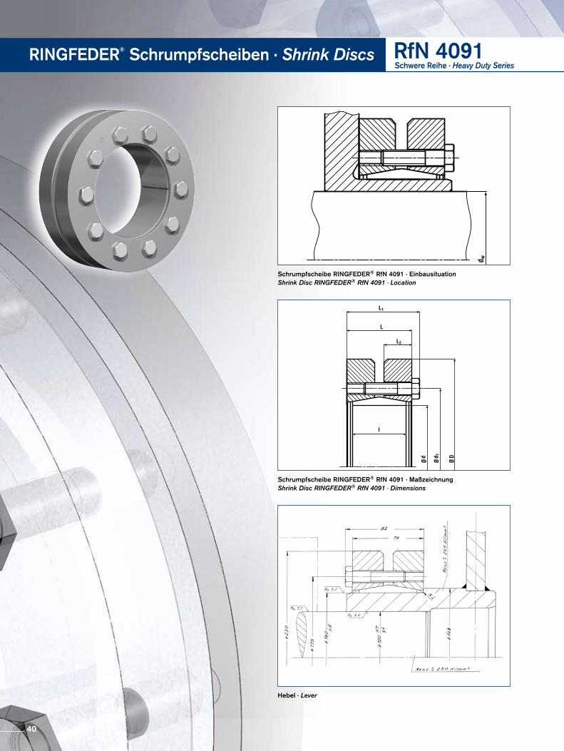
Schrumpfscheibe RINGFEDER® RfN 4091 · Einbausituation Shrink Disc RINGFEDER® RfN 4091 · Location
Hebel · Lever
Schrumpfscheibe RINGFEDER® RfN 4091 · MaßzeichnungShrink Disc RINGFEDER® RfN 4091 · Dimensions
RINGFEDER® Schrumpfscheiben · Shrink Discs RfN 4091Schwere Reihe · Heavy Duty Series
40
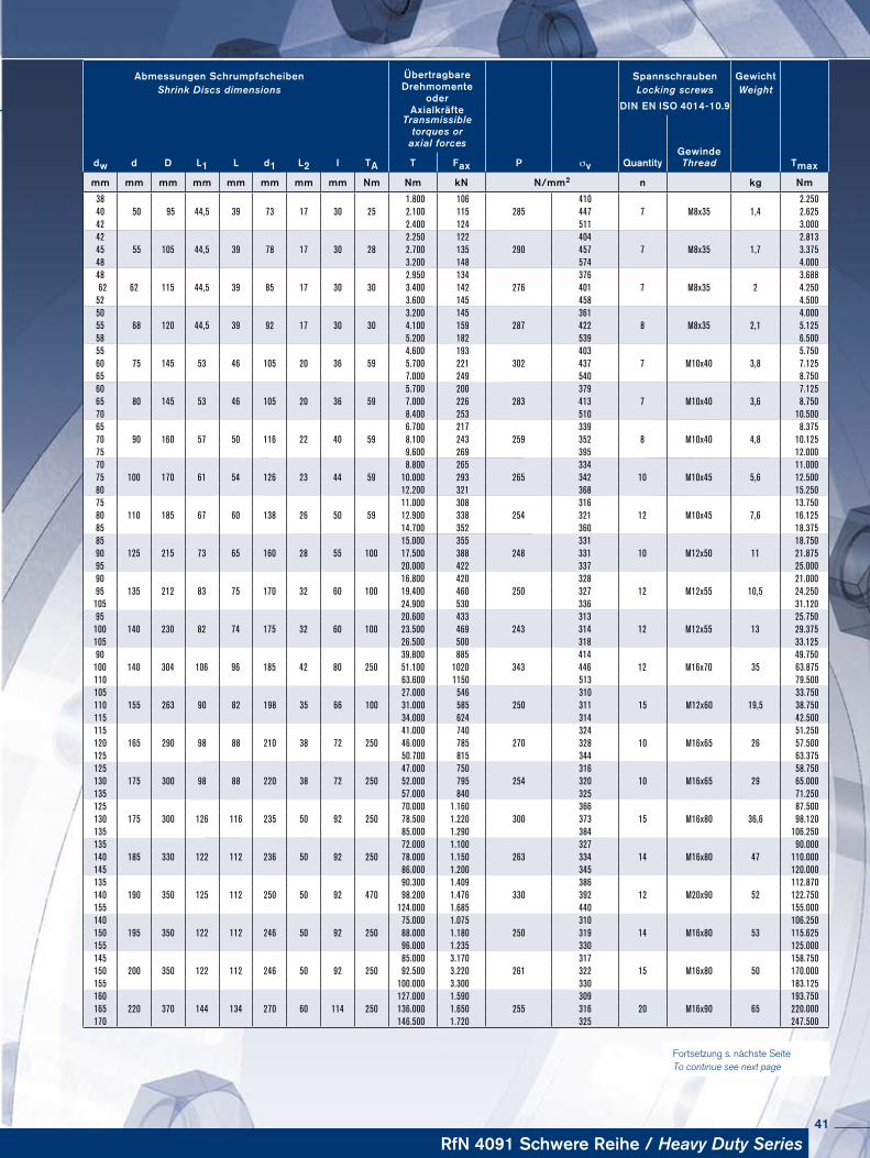
Fortsetzung s. nächste Seite To continue see next page
Abmessungen Schrumpfscheiben ÜbertragbareDrehmomente
oderAxialkräfte
Spannschrauben Ge wichtShrink Discs dimensions Locking screws Weight
DIN EN ISO 4014-10.9Transmissible
torques oraxial forces
dw d D L1 L d1 L2 I TA P σv QuantityGewinde
TmaxT Fax Thread
mm mm mm mm mm mm mm mm Nm Nm kN N/mm2 n kg Nm
38 1.800 106 410 2.25040 50 95 44,5 39 73 17 30 25 2.100 115 285 447 7 M8x35 1,4 2.62542 2.400 124 511 3.00042 2.250 122 404 2.81345 55 105 44,5 39 78 17 30 28 2.700 135 290 457 7 M8x35 1,7 3.37548 3.200 148 574 4.00048 2.950 134 376 3.688
62 62 115 44,5 39 85 17 30 30 3.400 142 276 401 7 M8x35 2 4.25052 3.600 145 458 4.50050 3.200 145 361 4.00055 68 120 44,5 39 92 17 30 30 4.100 159 287 422 8 M8x35 2,1 5.12558 5.200 182 539 6.50055 4.600 193 403 5.75060 75 145 53 46 105 20 36 59 5.700 221 302 437 7 M10x40 3,8 7.12565 7.000 249 540 8.75060 5.700 200 379 7.12565 80 145 53 46 105 20 36 59 7.000 226 283 413 7 M10x40 3,6 8.75070 8.400 253 510 10.50065 6.700 217 339 8.37570 90 160 57 50 116 22 40 59 8.100 243 259 352 8 M10x40 4,8 10.12575 9.600 269 395 12.00070 8.800 265 334 11.00075 100 170 61 54 126 23 44 59 10.000 293 265 342 10 M10x45 5,6 12.50080 12.200 321 368 15.25075 11.000 308 316 13.75080 110 185 67 60 138 26 50 59 12.900 338 254 321 12 M10x45 7,6 16.12585 14.700 352 360 18.37585 15.000 355 331 18.75090 125 215 73 65 160 28 55 100 17.500 388 248 331 10 M12x50 11 21.87595 20.000 422 337 25.00090 16.800 420 328 21.00095 135 212 83 75 170 32 60 100 19.400 460 250 327 12 M12x55 10,5 24.250105 24.900 530 336 31.12095 20.600 433 313 25.750
100 140 230 82 74 175 32 60 100 23.500 469 243 314 12 M12x55 13 29.375105 26.500 500 318 33.12590 39.800 885 414 49.750
100 140 304 106 96 185 42 80 250 51.100 1020 343 446 12 M16x70 35 63.875110 63.600 1150 513 79.500105 27.000 546 310 33.750110 155 263 90 82 198 35 66 100 31.000 585 250 311 15 M12x60 19,5 38.750115 34.000 624 314 42.500115 41.000 740 324 51.250120 165 290 98 88 210 38 72 250 46.000 785 270 328 10 M16x65 26 57.500125 50.700 815 344 63.375125 47.000 750 316 58.750130 175 300 98 88 220 38 72 250 52.000 795 254 320 10 M16x65 29 65.000135 57.000 840 325 71.250125 70.000 1.160 366 87.500130 175 300 126 116 235 50 92 250 78.500 1.220 300 373 15 M16x80 36,6 98.120135 85.000 1.290 384 106.250135 72.000 1.100 327 90.000140 185 330 122 112 236 50 92 250 78.000 1.150 263 334 14 M16x80 47 110.000145 86.000 1.200 345 120.000135 90.300 1.409 386 112.870140 190 350 125 112 250 50 92 470 98.200 1.476 330 392 12 M20x90 52 122.750155 124.000 1.685 440 155.000140 75.000 1.075 310 106.250150 195 350 122 112 246 50 92 250 88.000 1.180 250 319 14 M16x80 53 115.625155 96.000 1.235 330 125.000145 85.000 3.170 317 158.750150 200 350 122 112 246 50 92 250 92.500 3.220 261 322 15 M16x80 50 170.000155 100.000 3.300 330 183.125160 127.000 1.590 309 193.750165 220 370 144 134 270 60 114 250 136.000 1.650 255 316 20 M16x90 65 220.000170 146.500 1.720 325 247.500
RfN 4091 Schwere Reihe / Heavy Duty Series41
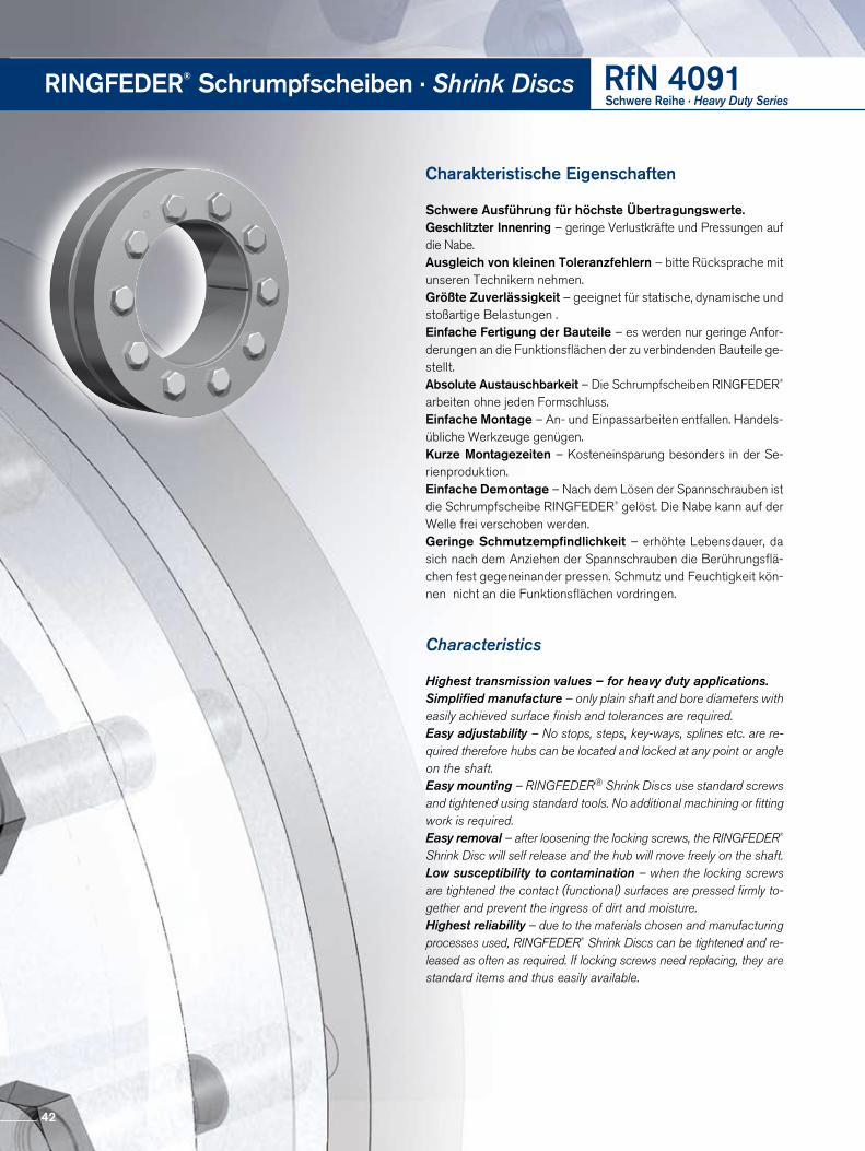
Charakteristische Eigenschaften
Schwere Ausführung für höchste Übertragungswerte.Geschlitzter Innenring – geringe Verlustkräfte und Pressungen auf die Nabe.Ausgleich von kleinen Toleranzfehlern – bitte Rücksprache mit unseren Technikern nehmen.Größte Zuverlässigkeit – geeignet für statische, dynamische und stoßartige Belastungen .Einfache Fertigung der Bauteile – es werden nur geringe Anforderungen an die Funktionsflächen der zu verbindenden Bauteile ge stellt.Absolute Austauschbarkeit – Die Schrumpfscheiben RINGFEDER® arbeiten ohne jeden Formschluss. Einfache Montage – An und Einpassarbeiten entfallen. Handelsübliche Werkzeuge genügen. Kurze Montagezeiten – Kosteneinsparung besonders in der Se rien produktion.Einfache Demontage – Nach dem Lösen der Spannschrauben ist die Schrumpfscheibe RINGFEDER® gelöst. Die Nabe kann auf der Welle frei verschoben werden. Geringe Schmutzempfindlichkeit – erhöhte Lebensdauer, da sich nach dem Anziehen der Spannschrauben die Berührungsflächen fest gegeneinander pressen. Schmutz und Feuchtigkeit können nicht an die Funktionsflächen vordringen.
Characteristics
Highest transmission values – for heavy duty applications.Simplified manufacture – only plain shaft and bore diameters with easily achieved surface finish and tolerances are required.Easy adjustability – No stops, steps, key-ways, splines etc. are re-quired therefore hubs can be located and locked at any point or angle on the shaft.Easy mounting – RINGFEDER® Shrink Discs use standard screws and tightened using standard tools. No additional machining or fitting work is required.Easy removal – after loosening the locking screws, the RINGFEDER® Shrink Disc will self release and the hub will move freely on the shaft.Low susceptibility to contamination – when the locking screws are tightened the contact (functional) surfaces are pressed firmly to-gether and prevent the ingress of dirt and moisture.Highest reliability – due to the materials chosen and manufacturing processes used, RINGFEDER® Shrink Discs can be tightened and re-leased as often as required. If locking screws need replacing, they are standard items and thus easily available.
RINGFEDER® Schrumpfscheiben · Shrink Discs RfN 4091Schwere Reihe · Heavy Duty Series
42
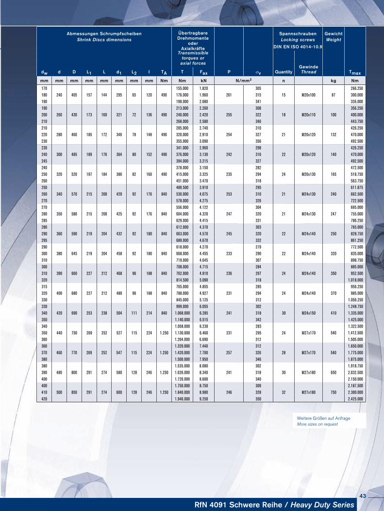
Weitere Größen auf Anfrage More sizes on request
Abmessungen Schrumpfscheiben ÜbertragbareDrehmomente
oderAxialkräfte
Spannschrauben Ge wichtShrink Discs dimensions Locking screws Weight
DIN EN ISO 4014-10.9Transmissible
torques oraxial forces
dw d D L1 L d1 L2 I TA P σv QuantityGewinde
TmaxT Fax Thread
mm mm mm mm mm mm mm mm Nm Nm kN N/mm2 n kg Nm
170 155.000 1.820 305 266.250
180 240 405 157 144 295 65 120 490 176.000 1.960 261 315 15 M20x100 87 300.000
190 198.000 2.080 341 335.000
190 213.000 2.260 308 356.250
200 260 430 173 160 321 72 136 490 240.000 2.420 255 322 18 M20x110 100 400.000
210 268.000 2.580 346 443.750
210 285.000 2.740 310 426.250
220 280 460 185 172 346 78 148 490 320.000 2.910 254 327 21 M20x120 132 470.000
230 355.000 3.090 356 492.500
230 341.000 2.960 298 426.250
240 300 485 189 176 364 80 152 490 376.000 3.130 242 316 22 M20x120 140 470.000
245 394.000 3.215 327 492.500
240 378.000 3.150 282 472.500
250 320 520 197 184 386 82 160 490 415.000 3.325 235 294 24 M20x130 165 518.750
260 451.000 3.470 318 563.750
250 489.500 3.910 295 611.875
260 340 570 215 200 420 92 176 840 530.000 4.075 253 310 21 M24x130 240 662.500
270 578.000 4.275 326 722.500
270 556.000 4.122 304 695.000
280 350 580 215 200 425 92 176 840 604.000 4.320 247 320 21 M24x130 247 755.000
285 629.000 4.415 331 786.250
280 612.000 4.370 303 765.000
290 360 590 219 204 432 92 180 840 663.000 4.570 245 320 22 M24x140 250 828.750
295 689.000 4.670 332 861.250
290 618.000 4.270 279 772.500
300 380 645 219 204 458 92 180 840 668.000 4.455 233 290 22 M24x140 320 835.000
310 719.000 4.645 307 898.750
300 708.000 4.715 284 885.000
310 390 660 227 212 468 96 188 840 762.000 4.910 236 297 24 M24x140 350 952.500
320 814.500 5.090 318 1.018.000
315 765.000 4.855 285 956.250
320 400 680 227 212 480 96 188 840 788.000 4.927 231 294 24 M24x140 370 985.000
330 845.000 5.125 312 1.056.250
330 999.000 6.055 302 1.248.750
340 420 690 253 238 504 111 214 840 1.068.000 6.285 241 318 30 M24x150 410 1.335.000
350 1.140.000 6.515 342 1.425.000
340 1.058.000 6.230 283 1.322.500
350 440 750 269 252 527 115 224 1.250 1.130.000 6.460 231 295 24 M27x170 540 1.412.500
360 1.204.000 6.690 312 1.505.000
360 1.320.000 7.440 312 1.650.000
370 460 770 269 252 547 115 224 1.250 1.420.000 7.700 257 326 28 M27x170 540 1.775.000
380 1.500.000 7.950 346 1.875.000
380 1.535.000 8.080 302 1.918.750
390 480 800 291 274 580 128 246 1.250 1.626.000 8.340 241 318 30 M27x180 650 2.032.500
400 1.720.000 8.600 340 2.150.000
400 1.750.000 8.750 309 2.187.500
410 500 850 291 274 600 128 246 1.250 1.840.000 8.980 246 328 32 M27x180 750 2.300.000
420 1.940.000 9.250 350 2.425.000
RfN 4091 Schwere Reihe / Heavy Duty Series43
Schrumpfscheibe RINGFEDER® RfN 4091 · Einbausituation Shrink Disc RINGFEDER® RfN 4091 · Location
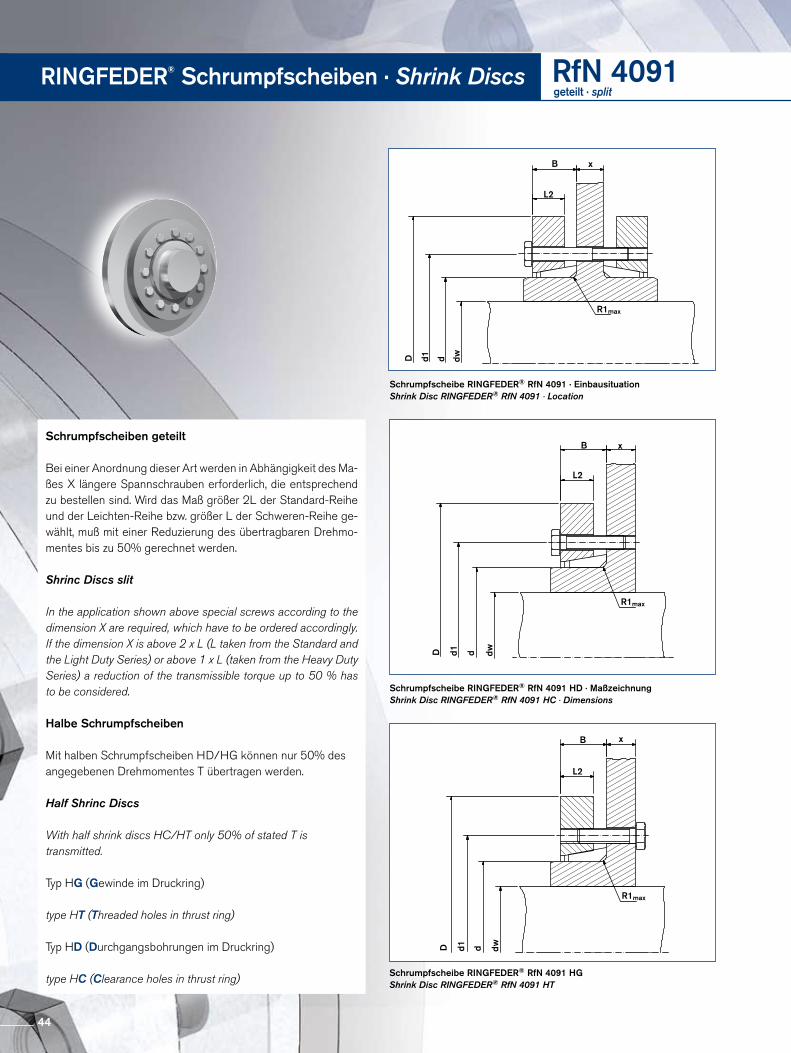
Schrumpfscheibe RINGFEDER® RfN 4091 HGShrink Disc RINGFEDER® RfN 4091 HT
Schrumpfscheibe RINGFEDER® RfN 4091 HD · MaßzeichnungShrink Disc RINGFEDER® RfN 4091 HC · Dimensions
RINGFEDER® Schrumpfscheiben · Shrink Discs RfN 4091geteilt · split
D d1 d dw
R1max
L2
B x
D d1 d dw
R1max
L2
B x
D d1 d dw
R1max
L2
B x
Schrumpfscheiben geteilt
Bei einer Anordnung dieser Art werden in Abhängigkeit des Maßes X längere Spannschrauben erforderlich, die entsprechend zu bestellen sind. Wird das Maß größer 2L der StandardReihe und der LeichtenReihe bzw. größer L der SchwerenReihe gewählt, muß mit einer Reduzierung des übertragbaren Drehmomentes bis zu 50% gerechnet werden.
Shrinc Discs slit
In the application shown above special screws according to the dimension X are required, which have to be ordered accordingly. If the dimension X is above 2 x L (L taken from the Standard and the Light Duty Series) or above 1 x L (taken from the Heavy Duty Series) a reduction of the transmissible torque up to 50 % has to be considered.
Halbe Schrumpfscheiben
Mit halben Schrumpfscheiben HD/HG können nur 50% des angegebenen Drehmomentes T übertragen werden.
Half Shrinc Discs
With half shrink discs HC/HT only 50% of stated T is transmitted.
Typ HG (Gewinde im Druckring)
type HT (Threaded holes in thrust ring)
Typ HD (Durchgangsbohrungen im Druckring)
type HC (Clearance holes in thrust ring)
44
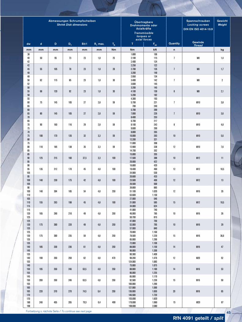
Abmessungen Schrumpfscheiben ÜbertragbareDrehmomente oder
Axialkräfte
Spannschrauben GewichtShrink Disk dimensions Locking screws Weight
DIN EN ISO 4014-10.9Transmissible
torques oraxial forces
Quantitydw d D D1 B±1 R1 max. TAGewinde T Fax Thread
mm mm mm mm mm mm Nm Nm kN n kg
RfN 4091 geteilt / split
3850 95 73 23 1,8 25
1.800 1067 M8 1,440 2.100 115
42 2.400 12442
55 105 78 23 1,8 282.250 122
7 M8 1,745 2.700 13548 3.200 14848
62 115 85 23 1,8 302.950 134
7 M8 250 3.400 14252 3.600 14550
68 120 92 23 1,8 303.200 145
8 M8 2,155 4.100 15958 5.200 18255
75 145 105 27 2,8 594.300 193
7 M10 3,860 5.700 22165 700 24960
80 145 105 27 2,8 595.700 200
7 M10 3,665 7.000 22670 8.400 25365
90 160 116 29 2,8 596.700 217
8 M10 4,870 8.100 24375 9.600 26970
100 170 126 32 3,3 598.800 265
10 M10 5,675 10.000 29380 12.200 32175
110 185 138 35 3,3 5911.000 308
12 M10 7,680 12.900 33885 14.700 35285
125 215 160 37,5 3,3 10015.000 355
10 M12 1190 17.500 38895 20.000 42290
135 212 170 45 4,8 10016.800 420
12 M12 10,595 19.400 460105 24.900 53095
140 230 175 42 4,8 10020.600 433
12 M12 13100 23.500 469105 26.500 50090
140 304 185 54 4,8 25039.800 885
12 M16 35100 51.100 1.020110 63.600 1.150105
155 263 198 45 4,8 10027.000 546
15 M12 19,5110 31.000 585115 34.000 624115
165 290 210 49 4,8 25041.000 740
10 M16 26120 46.000 785125 50.700 815125
175 300 220 49 4,8 25047.000 750
10 M16 29130 52.000 795135 57.000 840125
175 300 235 59 4,8 25070.000 1.160
15 M16 36,6130 78.500 1.220135 85.000 1.290135
185 330 236 61 4,8 25072.000 1.100
14 M16 47140 88.000 1.150145 96.000 1.200135
190 350 250 62 4,8 47090.300 1.409
12 M20 52140 98.200 1.476155 124.000 1.685140
195 350 246 63,5 4,8 25075.000 1.075
14 M16 53150 88.000 1.180155 96.000 1.235145
200 350 246 63,5 4,8 25085.000 1.170
15 M16 50150 92.500 1.230155 100.000 1.290160
220 370 270 74,5 6,4 250127.000 1.590
20 M16 65165 136.000 1.650170 146.500 1.720170
240 405 295 79,5 6,4 490155.000 1.820
15 M20 87180 176.000 1.960190 198.000 2.080
Fortsetzung s. nächste Seite / To continue see next page 45
RINGFEDER® Schrumpfscheiben · Shrink Discs RfN 4091geteilt · split
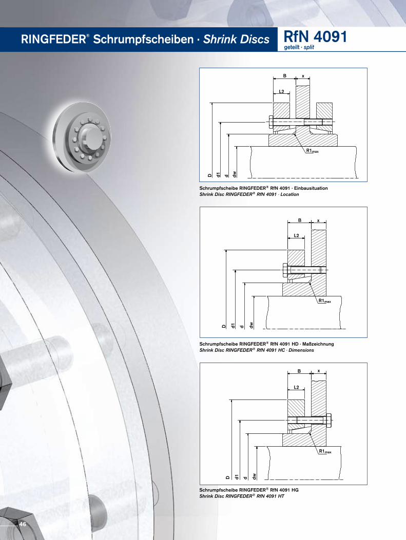
D d1 d dw
R1max
L2
B x
D d1 d dw
R1max
L2
B x
D d1 d dw
R1max
L2
B x
Schrumpfscheibe RINGFEDER® RfN 4091 · Einbausituation Shrink Disc RINGFEDER® RfN 4091 · Location
Schrumpfscheibe RINGFEDER® RfN 4091 HGShrink Disc RINGFEDER® RfN 4091 HT
Schrumpfscheibe RINGFEDER® RfN 4091 HD · MaßzeichnungShrink Disc RINGFEDER® RfN 4091 HC · Dimensions
46
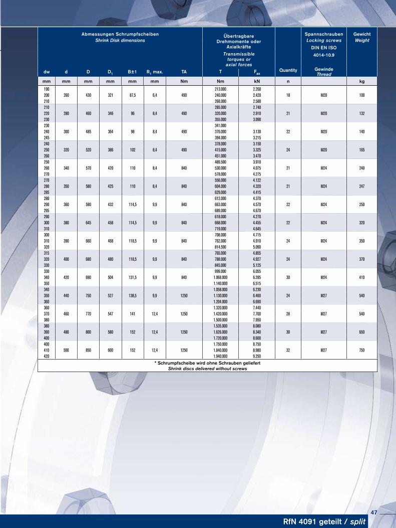
Abmessungen Schrumpfscheiben ÜbertragbareDrehmomente oder
Axialkräfte
Spannschrauben GewichtShrink Disk dimensions Locking screws Weight
DIN EN ISOTransmissible
torques oraxial forces
4014-10.9
Quantitydw d D D1 B±1 R1 max. TA Gewinde T Fax Thread
mm mm mm mm mm mm Nm Nm kN n kg
190260 430 321 87,5 6,4 490
213.000 2.26018 M20 100200 240.000 2.420
210 268.000 2.580210
280 460 346 96 8,4 490285.000 2.740
21 M20 132220 320.000 2.910230 355.000 3.090230
300 485 364 98 8,4 490341.000
22 M20 140240 376.000 3.130245 394.000 3.215240
320 520 386 102 8,4 490378.000 3.150
24 M20 165250 415.000 3.325260 451.000 3.470250
340 570 420 110 8,4 840489.500 3.910
21 M24 240260 530.000 4.075270 578.000 4.275270
350 580 425 110 8,4 840556.000 4.122
21 M24 247280 604.000 4.320285 629.000 4.415280
360 590 432 114,5 9,9 840612.000 4.370
22 M24 250290 663.000 4.570295 689.000 4.670290
380 645 458 114,5 9,9 840618.000 4.270
22 M24 320300 668.000 4.455310 719.000 4.645300
390 660 468 118,5 9,9 840708.000 4.715
24 M24 350310 762.000 4.910320 814.500 5.090315
400 680 480 118,5 9,9 840765.000 4.855
24 M24 370320 788.000 4.927330 845.000 5.125330
420 690 504 131,5 9,9 840999.000 6.055
30 M24 410340 1.068.000 6.285350 1.140.000 6.515340
440 750 527 138,5 9,9 12501.058.000 6.230
24 M27 540350 1.130.000 6.460360 1.204.000 6.690360
460 770 547 141 12,4 12501.320.000 7.440
28 M27 540370 1.420.000 7.700380 1.500.000 7.950380
480 800 580 152 12,4 12501.535.000 8.080
30 M27 650390 1.626.000 8.340400 1.720.000 8.600400
500 850 600 152 12,4 12501.750.000 8.750
32 M27 750410 1.840.000 8.980420 1.940.000 9.250
* Schrumpfscheibe wird ohne Schrauben geliefert Shrink discs delivered without screws
RfN 4091 geteilt / split47
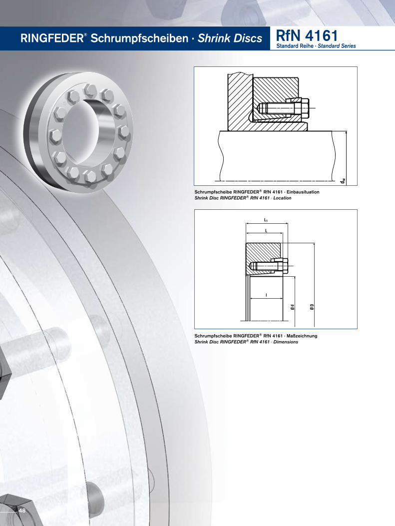
Schrumpfscheibe RINGFEDER® RfN 4161 · Einbausituation Shrink Disc RINGFEDER® RfN 4161 · Location
Schrumpfscheibe RINGFEDER® RfN 4161 · MaßzeichnungShrink Disc RINGFEDER® RfN 4161 · Dimensions
RINGFEDER® Schrumpfscheiben · Shrink Discs RfN 4161Standard Reihe · Standard Series
48
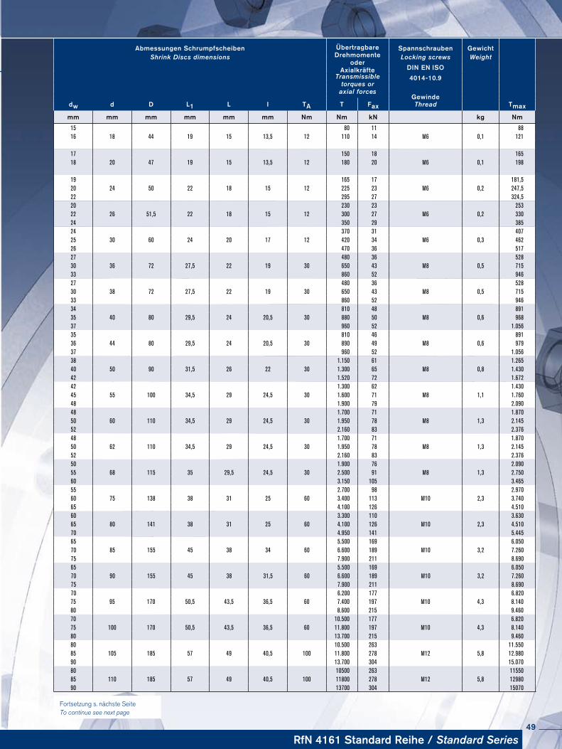
Abmessungen Schrumpfscheiben ÜbertragbareDrehmomente
oderAxialkräfte
Spannschrauben Ge wichtShrink Discs dimensions Locking screws Weight
DIN EN ISOTransmissible
torques oraxial forces
4014-10.9
dw d D L1 L I TAGewinde
TmaxT Fax Thread
mm mm mm mm mm mm Nm Nm kN kg Nm
15 80 11 8816 18 44 19 15 13,5 12 110 14 M6 0,1 121
17 150 18 16518 20 47 19 15 13,5 12 180 20 M6 0,1 198
19 165 17 181,520 24 50 22 18 15 12 225 23 M6 0,2 247,522 295 27 324,520 230 23 25322 26 51,5 22 18 15 12 300 27 M6 0,2 33024 350 29 38524 370 31 40725 30 60 24 20 17 12 420 34 M6 0,3 46226 470 36 51727 480 36 528 30 36 72 27,5 22 19 30 650 43 M8 0,5 71533 860 52 94627 480 36 52830 38 72 27,5 22 19 30 650 43 M8 0,5 71533 860 52 94634 810 48 89135 40 80 29,5 24 20,5 30 880 50 M8 0,6 96837 960 52 1.05635 810 46 89136 44 80 29,5 24 20,5 30 890 49 M8 0,6 97937 960 52 1.05638 1.150 61 1.26540 50 90 31,5 26 22 30 1.300 65 M8 0,8 1.43042 1.520 72 1.67242 1.300 62 1.43045 55 100 34,5 29 24,5 30 1.600 71 M8 1,1 1.76048 1.900 79 2.09048 1.700 71 1.87050 60 110 34,5 29 24,5 30 1.950 78 M8 1,3 2.14552 2.160 83 2.37648 1.700 71 1.87050 62 110 34,5 29 24,5 30 1.950 78 M8 1,3 2.14552 2.160 83 2.37650 1.900 76 2.09055 68 115 35 29,5 24,5 30 2.500 91 M8 1,3 2.75060 3.150 105 3.46555 2.700 98 2.97060 75 138 38 31 25 60 3.400 113 M10 2,3 3.74065 4.100 126 4.51060 3.300 110 3.63065 80 141 38 31 25 60 4.100 126 M10 2,3 4.51070 4.950 141 5.44565 5.500 169 6.05070 85 155 45 38 34 60 6.600 189 M10 3,2 7.26075 7.900 211 8.69065 5.500 169 6.05070 90 155 45 38 31,5 60 6.600 189 M10 3,2 7.26075 7.900 211 8.69070 6.200 177 6.82075 95 170 50,5 43,5 36,5 60 7.400 197 M10 4,3 8.14080 8.600 215 9.46070 10.500 177 6.82075 100 170 50,5 43,5 36,5 60 11.800 197 M10 4,3 8.14080 13.700 215 9.46080 10.500 263 11.55085 105 185 57 49 40,5 100 11.800 278 M12 5,8 12.98090 13.700 304 15.07080 10500 263 1155085 110 185 57 49 40,5 100 11800 278 M12 5,8 1298090 13700 304 15070
RfN 4161 Standard Reihe / Standard Series
Fortsetzung s. nächste Seite To continue see next page
49
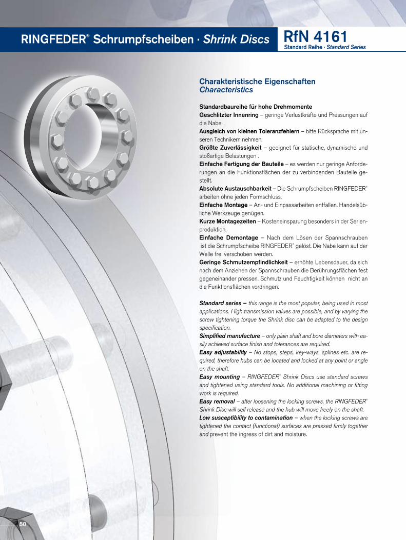
RINGFEDER® Schrumpfscheiben · Shrink Discs RfN 4161Standard Reihe · Standard Series
Charakteristische Eigenschaften Characteristics
Standardbaureihe für hohe DrehmomenteGeschlitzter Innenring – geringe Verlustkräfte und Pressungen auf die Nabe.Ausgleich von kleinen Toleranzfehlern – bitte Rücksprache mit unseren Technikern nehmen.Größte Zuverlässigkeit – geeignet für statische, dynamische und stoßartige Belastungen .Einfache Fertigung der Bauteile – es werden nur geringe Anforderungen an die Funktionsflächen der zu verbindenden Bauteile gestellt.Absolute Austauschbarkeit – Die Schrumpfscheiben RINGFEDER® arbeiten ohne jeden Formschluss. Einfache Montage – An und Einpassarbeiten entfallen. Handelsübliche Werkzeuge genügen. Kurze Montagezeiten – Kosteneinsparung besonders in der Serienproduktion.Einfache Demontage – Nach dem Lösen der Spannschrauben ist die Schrumpfscheibe RINGFEDER® gelöst. Die Nabe kann auf der Welle frei verschoben werden. Geringe Schmutzempfindlichkeit – erhöhte Lebensdauer, da sich nach dem Anziehen der Spannschrauben die Berührungsflächen fest gegeneinander pressen. Schmutz und Feuchtigkeit können nicht an die Funktions flächen vordringen.
Standard series – this range is the most popular, being used in most applications. High transmission values are possible, and by varying the screw tightening torque the Shrink disc can be adapted to the design specification.Simplified manufacture – only plain shaft and bore diameters with ea-sily achieved surface finish and tolerances are required.Easy adjustability – No stops, steps, key-ways, splines etc. are re-quired, therefore hubs can be located and locked at any point or angle on the shaft.Easy mounting – RINGFEDER® Shrink Discs use standard screws and tightened using standard tools. No additional machining or fitting work is required.Easy removal – after loosening the locking screws, the RINGFEDER® Shrink Disc will self release and the hub will move freely on the shaft.Low susceptibility to contamination – when the locking screws are tightened the contact (functional) surfaces are pressed firmly together and prevent the ingress of dirt and moisture.
50
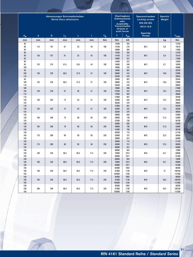
Abmessungen Schrumpfscheiben ÜbertragbareDrehmomente
oderAxialkräfte
Spannschrauben Ge wichtShrink Discs dimensions Locking screws Weight
DIN EN ISOTransmissible
torques oraxial forces
4014-10.9
dw d D L1 L I TAGewinde
TmaxT Fax Thread
mm mm mm mm mm mm Nm Nm kN kg Nm
85 12500 263 1375090 115 197 61 53 45 100 14100 278 M12 6,9 1551095 16000 304 1760085 12500 294 1375090 120 197 61 53 45 100 14100 313 M12 6,9 1551095 16000 337 1760090 14500 322 1595095 125 215 61,5 53,5 45 100 16600 349 M12 8,7 18260
100 18800 376 2068095 18400 387 20240
100 130 230 66,5 57,5 47 160 20800 416 M14 10,8 22880110 26200 476 2882095 18400 387 20240
100 135 230 66,5 57,5 47 160 20800 416 M14 10,8 22880110 26200 476 28820100 19900 398 21890105 140 230 67 58 47 160 22200 423 M14 10,3 24420115 27800 483 30580110 27000 491 29700120 150 263 72 63 51 160 32000 533 M14 15,2 35200125 36200 579 39820110 27000 491 29700120 155 263 72 63 51 160 32000 533 M14 15,2 35200125 36200 579 39820120 39000 650 42900130 160 290 79 68 56 250 48000 738 M16 21,5 52800135 51000 756 56100120 39000 650 42900130 165 290 79 68 56 250 48000 738 M16 21,5 52800135 51000 756 56100130 46500 715 51150140 170 300 80 69 56 250 53000 757 M16 22,5 58300145 59000 814 64900130 46500 715 51150140 175 300 80 69 56 250 53000 757 M16 22,5 58300145 59000 814 64900140 66000 943 72600150 180 320 96,5 85,5 71,5 250 76000 1013 M16 32,7 83600155 83000 1071 91300140 66000 943 72600150 185 320 96,5 85,5 71,5 250 76000 1013 M16 32,7 83600155 83000 1071 91300150 82000 1093 90200160 190 340 96,5 85,5 71,5 250 91000 1138 M16 37 100100165 102000 1236 112200150 82000 1093 90200160 195 340 96,5 85,5 71,5 250 91000 1138 M16 36,3 100100165 102000 1236 112200150 82000 1093 90200160 200 340 96,5 85,5 71,5 250 91000 1138 M16 36,3 100100165 102000 1236 112200
RfN 4161 Standard Reihe / Standard Series51
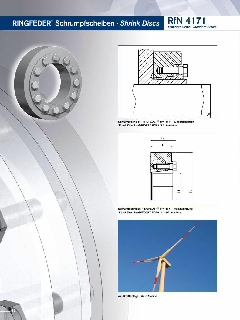
Schrumpfscheibe RINGFEDER® RfN 4171 · EinbausituationShrink Disc RINGFEDER® RfN 4171 · Location
Schrumpfscheibe RINGFEDER® RfN 4171 · MaßzeichnungShrink Disc RINGFEDER® RfN 4171 · Dimensions
RINGFEDER® Schrumpfscheiben · Shrink Discs RfN 4171Standard Reihe · Standard Series
Windkraftanlage · Wind turbine
52
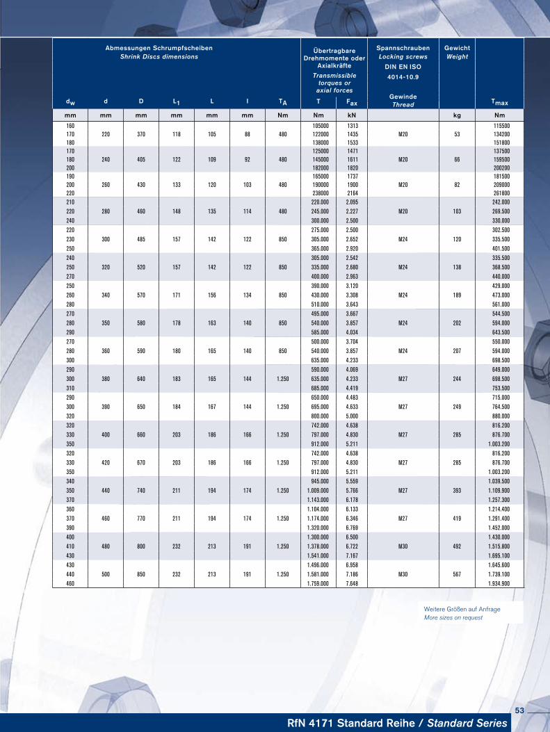
Weitere Größen auf Anfrage More sizes on request
Abmessungen Schrumpfscheiben ÜbertragbareDrehmomente oder
Axialkräfte
Spannschrauben Ge wichtShrink Discs dimensions Locking screws Weight
DIN EN ISOTransmissible
torques oraxial forces
4014-10.9
dw d D L1 L I TAGewinde
TmaxT Fax Thread
mm mm mm mm mm mm Nm Nm kN kg Nm
160 105000 1313 115500 170 220 370 118 105 88 480 122000 1435 M20 53 134200180 138000 1533 151800170 125000 1471 137500180 240 405 122 109 92 480 145000 1611 M20 66 159500200 182000 1820 200200190 165000 1737 181500200 260 430 133 120 103 480 190000 1900 M20 82 209000220 238000 2164 261800210 220.000 2.095 242.000220 280 460 148 135 114 480 245.000 2.227 M20 103 269.500240 300.000 2.500 330.000220 275.000 2.500 302.500230 300 485 157 142 122 850 305.000 2.652 M24 120 335.500250 365.000 2.920 401.500240 305.000 2.542 335.500250 320 520 157 142 122 850 335.000 2.680 M24 138 368.500270 400.000 2.963 440.000250 390.000 3.120 429.000260 340 570 171 156 134 850 430.000 3.308 M24 189 473.000280 510.000 3.643 561.000270 495.000 3.667 544.500280 350 580 178 163 140 850 540.000 3.857 M24 202 594.000290 585.000 4.034 643.500270 500.000 3.704 550.000280 360 590 180 165 140 850 540.000 3.857 M24 207 594.000300 635.000 4.233 698.500290 590.000 4.069 649.000300 380 640 183 165 144 1.250 635.000 4.233 M27 244 698.500310 685.000 4.419 753.500290 650.000 4.483 715.000300 390 650 184 167 144 1.250 695.000 4.633 M27 249 764.500320 800.000 5.000 880.000320 742.000 4.638 816.200330 400 660 203 186 166 1.250 797.000 4.830 M27 285 876.700350 912.000 5.211 1.003.200320 742.000 4.638 816.200330 420 670 203 186 166 1.250 797.000 4.830 M27 285 876.700350 912.000 5.211 1.003.200340 945.000 5.559 1.039.500350 440 740 211 194 174 1.250 1.009.000 5.766 M27 393 1.109.900370 1.143.000 6.178 1.257.300360 1.104.000 6.133 1.214.400370 460 770 211 194 174 1.250 1.174.000 6.346 M27 419 1.291.400390 1.320.000 6.769 1.452.000400 1.300.000 6.500 1.430.000410 480 800 232 213 191 1.250 1.378.000 6.722 M30 492 1.515.800430 1.541.000 7.167 1.695.100430 1.496.000 6.958 1.645.600440 500 850 232 213 191 1.250 1.581.000 7.186 M30 567 1.739.100460 1.759.000 7.648 1.934.900
RfN 4171 Standard Reihe / Standard Series53
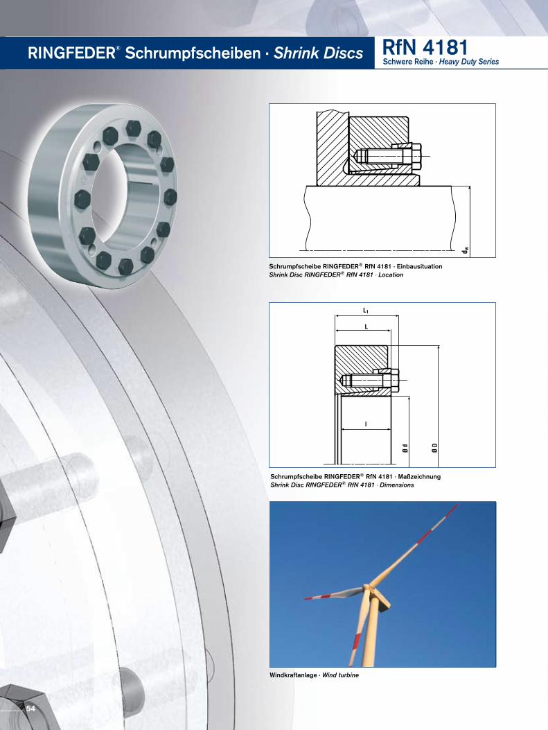
RINGFEDER® Schrumpfscheiben · Shrink Discs RfN 4181Schwere Reihe · Heavy Duty Series
Schrumpfscheibe RINGFEDER® RfN 4181 · EinbausituationShrink Disc RINGFEDER® RfN 4181 · Location
Windkraftanlage · Wind turbine
Schrumpfscheibe RINGFEDER® RfN 4181 · MaßzeichnungShrink Disc RINGFEDER® RfN 4181 · Dimensions
54
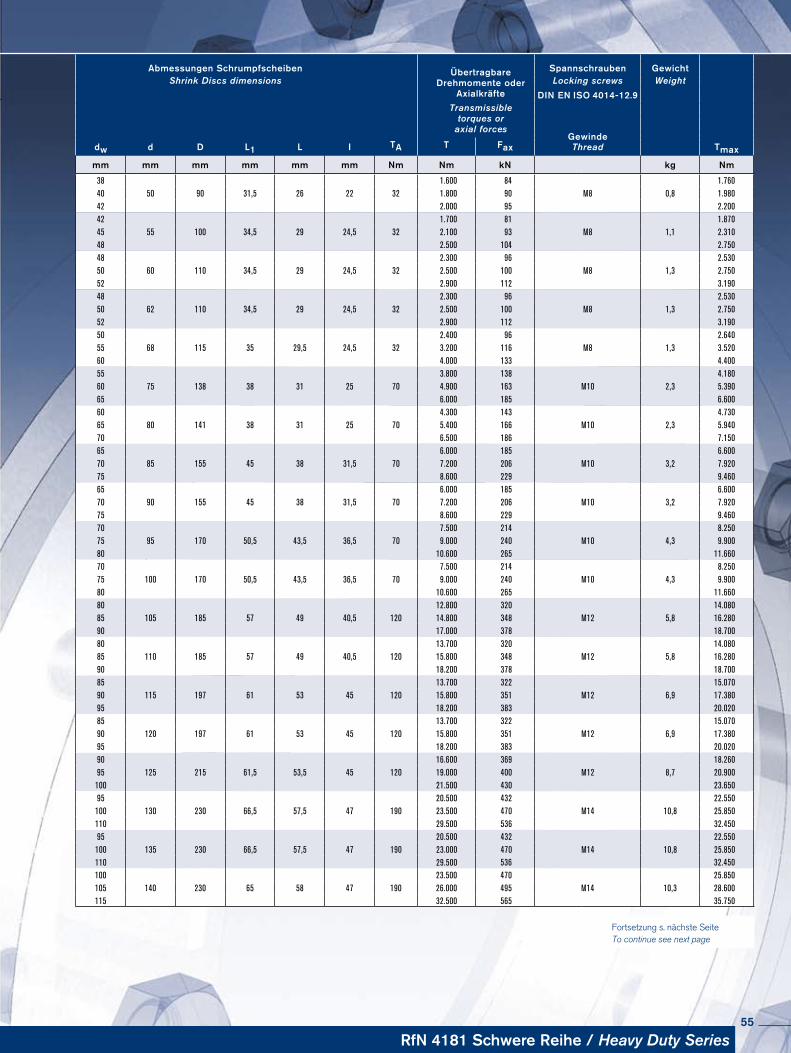
Fortsetzung s. nächste Seite To continue see next page
Abmessungen Schrumpfscheiben ÜbertragbareDrehmomente oder
Axialkräfte
Spannschrauben Ge wichtShrink Discs dimensions Locking screws Weight
DIN EN ISO 4014-12.9Transmissible
torques oraxial forces
dw d D L1 L I TAGewinde
T Fax Thread Tmax
mm mm mm mm mm mm Nm Nm kN kg Nm
38 1.600 84 1.76040 50 90 31,5 26 22 32 1.800 90 M8 0,8 1.98042 2.000 95 2.20042 1.700 81 1.87045 55 100 34,5 29 24,5 32 2.100 93 M8 1,1 2.31048 2.500 104 2.75048 2.300 96 2.53050 60 110 34,5 29 24,5 32 2.500 100 M8 1,3 2.75052 2.900 112 3.19048 2.300 96 2.53050 62 110 34,5 29 24,5 32 2.500 100 M8 1,3 2.75052 2.900 112 3.19050 2.400 96 2.64055 68 115 35 29,5 24,5 32 3.200 116 M8 1,3 3.52060 4.000 133 4.40055 3.800 138 4.18060 75 138 38 31 25 70 4.900 163 M10 2,3 5.39065 6.000 185 6.60060 4.300 143 4.73065 80 141 38 31 25 70 5.400 166 M10 2,3 5.94070 6.500 186 7.15065 6.000 185 6.60070 85 155 45 38 31,5 70 7.200 206 M10 3,2 7.92075 8.600 229 9.46065 6.000 185 6.60070 90 155 45 38 31,5 70 7.200 206 M10 3,2 7.92075 8.600 229 9.46070 7.500 214 8.25075 95 170 50,5 43,5 36,5 70 9.000 240 M10 4,3 9.90080 10.600 265 11.66070 7.500 214 8.25075 100 170 50,5 43,5 36,5 70 9.000 240 M10 4,3 9.90080 10.600 265 11.66080 12.800 320 14.08085 105 185 57 49 40,5 120 14.800 348 M12 5,8 16.28090 17.000 378 18.70080 13.700 320 14.08085 110 185 57 49 40,5 120 15.800 348 M12 5,8 16.28090 18.200 378 18.70085 13.700 322 15.07090 115 197 61 53 45 120 15.800 351 M12 6,9 17.38095 18.200 383 20.02085 13.700 322 15.07090 120 197 61 53 45 120 15.800 351 M12 6,9 17.38095 18.200 383 20.02090 16.600 369 18.26095 125 215 61,5 53,5 45 120 19.000 400 M12 8,7 20.900100 21.500 430 23.65095 20.500 432 22.550100 130 230 66,5 57,5 47 190 23.500 470 M14 10,8 25.850110 29.500 536 32.45095 20.500 432 22.550100 135 230 66,5 57,5 47 190 23.000 470 M14 10,8 25.850110 29.500 536 32.450100 23.500 470 25.850105 140 230 65 58 47 190 26.000 495 M14 10,3 28.600115 32.500 565 35.750
RfN 4181 Schwere Reihe / Heavy Duty Series55
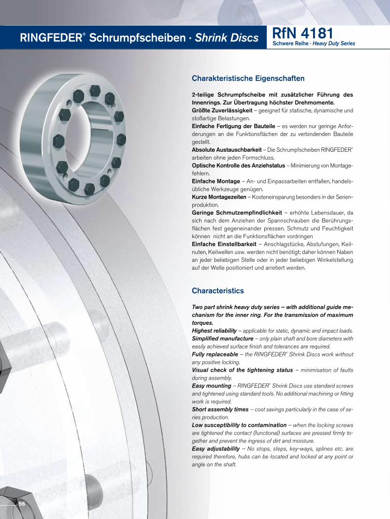
Charakteristische Eigenschaften
2-teilige Schrumpfscheibe mit zusätzlicher Führung des Innen rings. Zur Übertragung höchster Drehmomente.Größte Zuverlässigkeit – geeignet für statische, dynamische und stoßartige Belastungen.Einfache Fertigung der Bauteile – es werden nur geringe Anforderungen an die Funktionsflächen der zu verbindenden Bauteile gestellt.Absolute Austauschbarkeit – Die Schrumpfscheiben RINGFEDER® arbeiten ohne jeden Formschluss. Optische Kontrolle des Anziehstatus – Minimierung von Montagefehlern.Einfache Montage – An und Einpassarbeiten entfallen, handelsübliche Werkzeuge genügen. Kurze Montagezeiten – Kosteneinsparung besonders in der Serienproduktion.Geringe Schmutzempfindlichkeit – erhöhte Lebensdauer, da sich nach dem Anziehen der Spannschrauben die Berührungsflächen fest gegeneinander pressen. Schmutz und Feuchtigkeit können nicht an die Funktionsflächen vordringenEinfache Einstellbarkeit – Anschlagstücke, Abstufungen, Keil nuten, Keilwellen usw. werden nicht benötigt; daher können Naben an jeder beliebigen Stelle oder in jeder beliebigen Winkelstellung auf der Welle positioniert und arretiert werden.
Characteristics
Two part shrink heavy duty series – with additional guide me- chanism for the inner ring. For the transmission of maximum torques.Highest reliability – applicable for static, dynamic and impact loads.Simplified manufacture – only plain shaft and bore diameters with easily achieved surface finish and tolerances are required.Fully replaceable – the RINGFEDER® Shrink Discs work without any positive locking.Visual check of the tightening status – minimisation of faults during assembly.Easy mounting – RINGFEDER® Shrink Discs use standard screws and tightened using standard tools. No additional machining or fitting work is required.Short assembly times – cost savings particularly in the case of se- ries production.Low susceptibility to contamination – when the locking screws are tightened the contact (functional) surfaces are pressed firmly to-gether and prevent the ingress of dirt and moisture.Easy adjustability – No stops, steps, key-ways, splines etc. are required therefore, hubs can be located and locked at any point or angle on the shaft.
RINGFEDER® Schrumpfscheiben · Shrink Discs RfN 4181Schwere Reihe · Heavy Duty Series
56
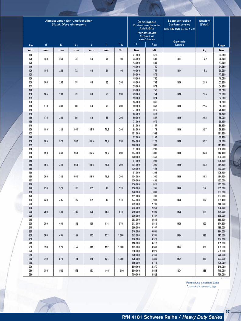
Abmessungen Schrumpfscheiben ÜbertragbareDrehmomente oder
Axialkräfte
Spannschrauben Ge wichtShrink Discs dimensions Locking screws Weight
DIN EN ISO 4014-12.9Transmissible
torques oraxial forces
dw d D L1 L I TAGewinde
TmaxT Fax Thread
mm mm mm mm mm mm Nm Nm kN kg Nm
110 31.500 573 34.650120 150 263 72 63 51 190 35.000 583 M14 15,2 38.500125 43.000 688 47.300110 45.000 750 34.650120 155 263 72 63 51 190 49.000 754 M14 15,2 38.500125 59.000 874 47.300120 45.000 750 49.500130 160 290 79 68 56 290 49.000 754 M16 21,5 53.900135 59.000 874 64.900120 45.000 750 49.500130 165 290 79 68 56 290 49.000 754 M16 21,5 53.900135 59.000 874 64.900130 55.000 846 60.500140 170 300 80 69 56 290 60.000 857 M16 22,5 66.000145 71.000 979 78.100140 55.000 846 60.500150 175 300 80 69 56 290 60.000 857 M16 22,5 66.000155 71.000 979 78.100140 81.000 1.157 89.100150 180 320 96,5 85,5 71,5 290 88.000 1.173 M16 32,7 96.800155 101.000 1.303 111.100140 97.000 1.157 89.100150 185 320 96,5 85,5 71,5 290 104.000 1.173 M16 32,7 96.800155 120.000 1.303 111.100150 97.000 1.293 106.700160 190 340 96,5 85,5 71,5 290 104.000 1.300 M16 36,3 114.400165 120.000 1.455 132.000150 97.000 1.293 106.700160 195 340 96,5 85,5 71,5 290 104.000 1.300 M16 36,3 114.400165 120.000 1.455 132.000150 97.000 1.293 106.700160 200 340 96,5 85,5 71,5 290 104.000 1.300 M16 36,3 114.400165 120.000 1.455 132.000160 130.000 1.625 143.000170 220 370 118 105 88 570 150.000 1.765 M20 53 165.000180 170.000 1.889 187.000170 152.000 1.788 167.200180 240 405 122 109 92 570 174.000 1.933 M20 66 191.400200 219.000 2.190 240.900190 215.000 2.263 236.500200 260 430 133 120 103 570 240.000 2.400 M20 82 264.000220 300.000 2.727 330.000210 282.000 2.686 310.200220 280 460 148 135 114 570 313.000 2.845 M20 103 344.300240 380.000 3.167 418.000220 340.000 3.091 374.000230 300 485 157 142 122 1.000 375.000 3.261 M24 120 412.500250 440.000 3.520 484.000240 410.000 3.417 451.000250 320 520 157 142 122 1.000 445.000 3.560 M24 138 489.500270 530.000 3.926 583.000250 520.000 4.160 572.000260 340 570 171 156 134 1.000 570.000 4.385 M24 189 627.000280 660.000 4.714 726.000270 590.000 4.370 649.000280 350 580 178 163 140 1.000 650.000 4.643 M24 189 715.000290 700.000 4.828 770.000
Fortsetzung s. nächste Seite To continue see next page
RfN 4181 Schwere Reihe / Heavy Duty Series57

Schrumpfscheibe RINGFEDER® RfN 4181 · EinbausituationShrink Disc RINGFEDER® RfN 4181 · Location
Schrumpfscheibe RINGFEDER® RfN 4181 · MaßzeichnungShrink Disc RINGFEDER® RfN 4181 · Dimensions
RINGFEDER® Schrumpfscheiben · Shrink Discs RfN 4181Schwere Reihe · Heavy Duty Series
Windkraftanlage · Wind turbine
58
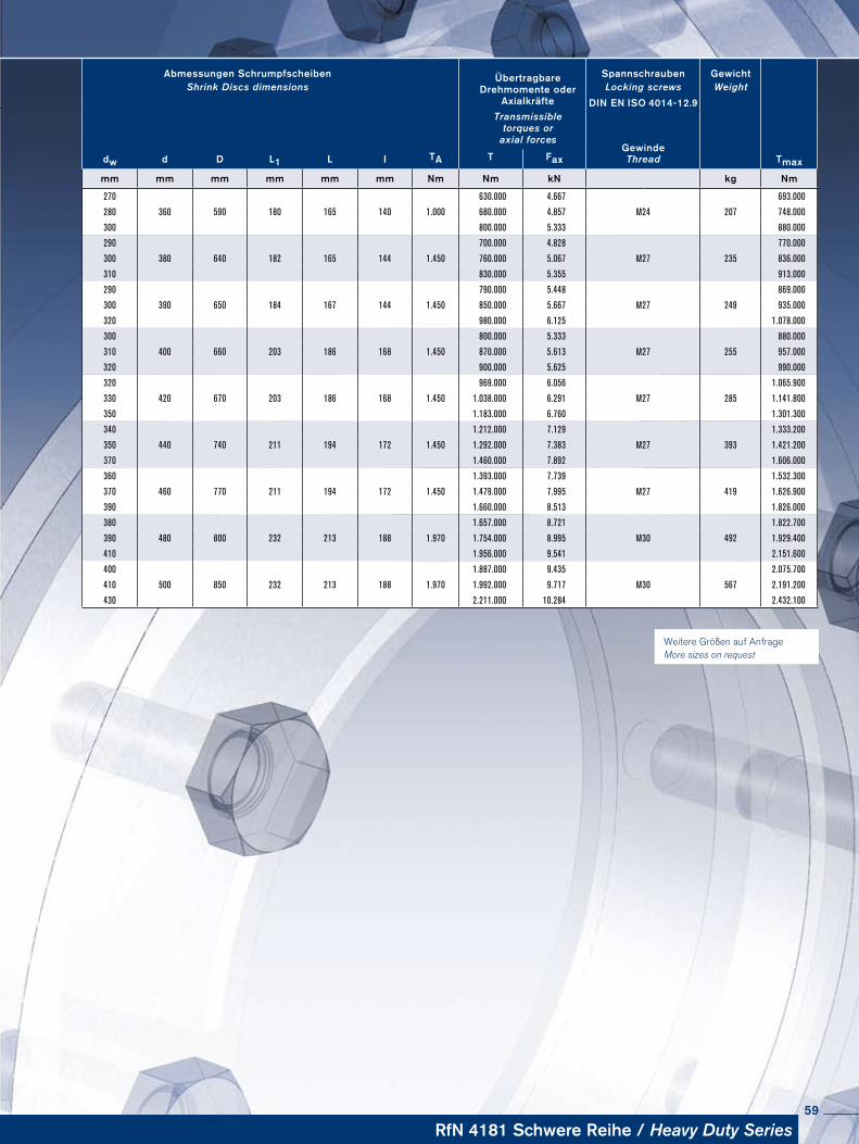
Weitere Größen auf Anfrage More sizes on request
Abmessungen Schrumpfscheiben ÜbertragbareDrehmomente oder
Axialkräfte
Spannschrauben Ge wichtShrink Discs dimensions Locking screws Weight
DIN EN ISO 4014-12.9Transmissible
torques oraxial forces
dw d D L1 L I TAGewinde
T Fax Thread Tmax
mm mm mm mm mm mm Nm Nm kN kg Nm
270 630.000 4.667 693.000
280 360 590 180 165 140 1.000 680.000 4.857 M24 207 748.000
300 800.000 5.333 880.000
290 700.000 4.828 770.000
300 380 640 182 165 144 1.450 760.000 5.067 M27 235 836.000
310 830.000 5.355 913.000
290 790.000 5.448 869.000
300 390 650 184 167 144 1.450 850.000 5.667 M27 249 935.000
320 980.000 6.125 1.078.000
300 800.000 5.333 880.000
310 400 660 203 186 168 1.450 870.000 5.613 M27 255 957.000
320 900.000 5.625 990.000
320 969.000 6.056 1.065.900
330 420 670 203 186 168 1.450 1.038.000 6.291 M27 285 1.141.800
350 1.183.000 6.760 1.301.300
340 1.212.000 7.129 1.333.200
350 440 740 211 194 172 1.450 1.292.000 7.383 M27 393 1.421.200
370 1.460.000 7.892 1.606.000
360 1.393.000 7.739 1.532.300
370 460 770 211 194 172 1.450 1.479.000 7.995 M27 419 1.626.900
390 1.660.000 8.513 1.826.000
380 1.657.000 8.721 1.822.700
390 480 800 232 213 188 1.970 1.754.000 8.995 M30 492 1.929.400
410 1.956.000 9.541 2.151.600
400 1.887.000 9.435 2.075.700
410 500 850 232 213 188 1.970 1.992.000 9.717 M30 567 2.191.200
430 2.211.000 10.284 2.432.100
RfN 4181 Schwere Reihe / Heavy Duty Series59

RINGFEDER®
rostfreie Produkte · stainless Poducts
60
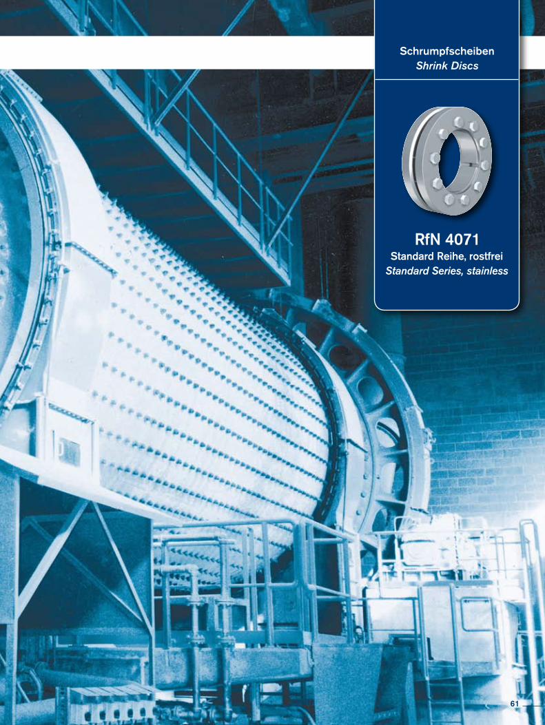
SchrumpfscheibenShrink Discs
Standard Reihe, rostfreiStandard Series, stainless
RfN 4071
61
Charakteristische EigenschaftenKostengünstige Fertigung – Große mögliche Toleranzen und einfache Drehbearbeitung garantieren kostengünstige Fertigung.
Einfache Montage – Es sind nur wenige Schrauben anzuziehen, Ausrichtung zwischen Nabe und Welle winkelgenau in jeder Position möglich, Einpassarbeiten entfallen ganz.
Einfache Demontage – Spannsätze RINGFEDER® verfügen über Abdrückgewinde, daher keine zusätzlichen Hilfsmittel erforderlich, Baureihe RfN 7012 ist sogar selbstlösend (keine Abdrückgewinde).
Große Dauerdrehwechselfestigkeit – Welle und Nabe sind ungenutet, dadurch keine Schwächung dieser Bauteile. Welle und Nabe können deutlich kleiner ausgeführt werden (leichte, kosten und platzsparende Konstruktion möglich).
Keine Gefahr des Ausschlagens – Spannsätze RINGFEDER® sind absolut spielfrei.
Wirkung wie Überlastsicherung – Nach dem Überschreiten des eingestellten Kraftschlusses rutschen die Spannsätze durch. Wertvolle Maschinenteile werden geschützt. Die Spannsätze unterliegen hierbei aber den gleichen Gesetzen, wie jede andere Reibschlussverbindung auch als Rutschkupplung nicht geeignet.
Absolut wartungsfrei – Keine Folgekosten.
Characteristics
Inexpensive manufacture – The large tolerances that are possible and the simple turning process guarantee inexpensive manufacture.
Simple installation – Only a few screws need to be tightened, alignment to precise angles between the hub and shaft is possible in any position, no fitting work is required.
Simple dismantling – Locking Assemblies RINGFEDER® are fitted with threaded ex-traction holes, so that no additional auxiliary equipment is necessary, series RfN 7012 is self-releasing.
Large constant reverse-torsion fatigue strength – shaft and hub are ungrooved, so that there is no weakening of these components. Shaft and hub can be designed to be consi-derably smaller (light, cost and space-saving design possible).
No danger of deflection – Locking Assemblies RINGFEDER® are absolutely backlash free.
Effect similar to overload protection – After the set frictional connection force has been exceeded the Locking Assemblies simply slide. Valuable machine parts are protected. The Locking Assemblies are subject to the same laws as any other connection with force trans-mission by friction - not suitable as sliding clutch.
Completely maintenance-free – no follow-up costs.
RINGFEDER®
rostfreie Produkte · stainless Poducts
62

Erläuterungen zu Tabellen Explanations to tables
d, D, L, l, L1, L2, d1 = Basic dimensions
dW = solid shaft diameter (provided by the customer)
T = transmissible torque
Fax = transmissible axial force
p = approx. surface pressure on the hub extension (diameter d)
TA = required tightening torque per screw (Screws greased with molykote!)
n = quantity of screws
S = clearance between shaft and hub bore
Tmax = maximum theoretical transmissible torque
σv = calculated combined stress in the hub extension (d/dw) under consideration of the tangential, radial and torsional stresses following the equation:
Additional loads, e.g. tension, thrust or bending have to be taken into consideration accordingly.
Function values The functional characteristics are valid with the screw tighte-ning torque listed in the tables and the following assumed conditions:The locking screws are lubricated using MoS2 (µtot= 0,1).The tapered cones are lubricated using MoS2 (µ = 0,05). The contact surfaces (dw) are in lightly oiled condition with coefficient of friction µ = 0,12. The hub and shaft materials have a modulus of elasticity of 210,000 N/mm2. (Lower values result in increased values for T and Fax with reduced tangential stress.)The maximum clearance S is being fully utilized. The shaft being used is solid, for hollow shaft applications the functional values will change.In cases where the assumed conditions do not apply then contact our Technical Department where we will be happy to assist you with your application.
d, D, L, l, L1, L2, d1 = Grundabmessungen, Schrumpfscheiben ungespannt
dW = Vollwellendurchmesser (kundenseitig)
T = übertragbares Drehmoment
Fax = übertragbare Axialkraft
p = Flächenpressung auf dem Nabenansatz (Durchmesser d) TA = erforderliches Anzieh dreh moment pro Spann - schraube (Schrauben molykotiert!)
n = Anzahl der Spannschrauben S = Fügespiel zwischen Welle und Nabenbohrung
Tmax = maximal theoretisch übertragbares Drehmoment
σv = rechnerische Vergleichsspannung im Nabenansatz (d/dw) unter Berücksichtigung der Tangential-, Radial- und Torsions span nung nach folgender Beziehung:
Zusätzliche Spannungen, z.B. Zug, Druck, Biegung, sind ent-sprechend zu berücksichtigen.
FunktionswerteDie Funktionswerte sind in Abhängigkeit der jeweils angege-benen Anzieh drehmomente TA bestimmt. Die Spannschrauben sind mit Schmiermitteln, die MoS2 ent-halten, geschmiert (µges = 0,1).Die Konen sind ebenfalls molykotiert (µ = 0,05).Für die Fuge, Durchmesser dw, wurde der für geölte Montage-verhältnisse übliche Reibwert µ = 0,12 angesetzt. Als E-Modul für Welle und Hohlwelle wurde der Wert 210.000 N/mm2 berücksichtigt. (Niedrigere Werte führen zu einer Erhöhung von T und Fax und einer Reduzierung der höchsten Einzelspannung, der Tangential span nung.)Für die Berechnung der Funktionswerte wurde das max. Fü-gespiel S berücksichtigt, s. nebenstehende Tabelle.Die Funktionswerte gelten nur bei Verwendung einer Voll-welle.Bei der Anwendung einer Außenverspannung auf Hohlwellen ändern sich die Funktionswerte. Bitte mit unseren Spezia-listen Rück sprache nehmen.
63
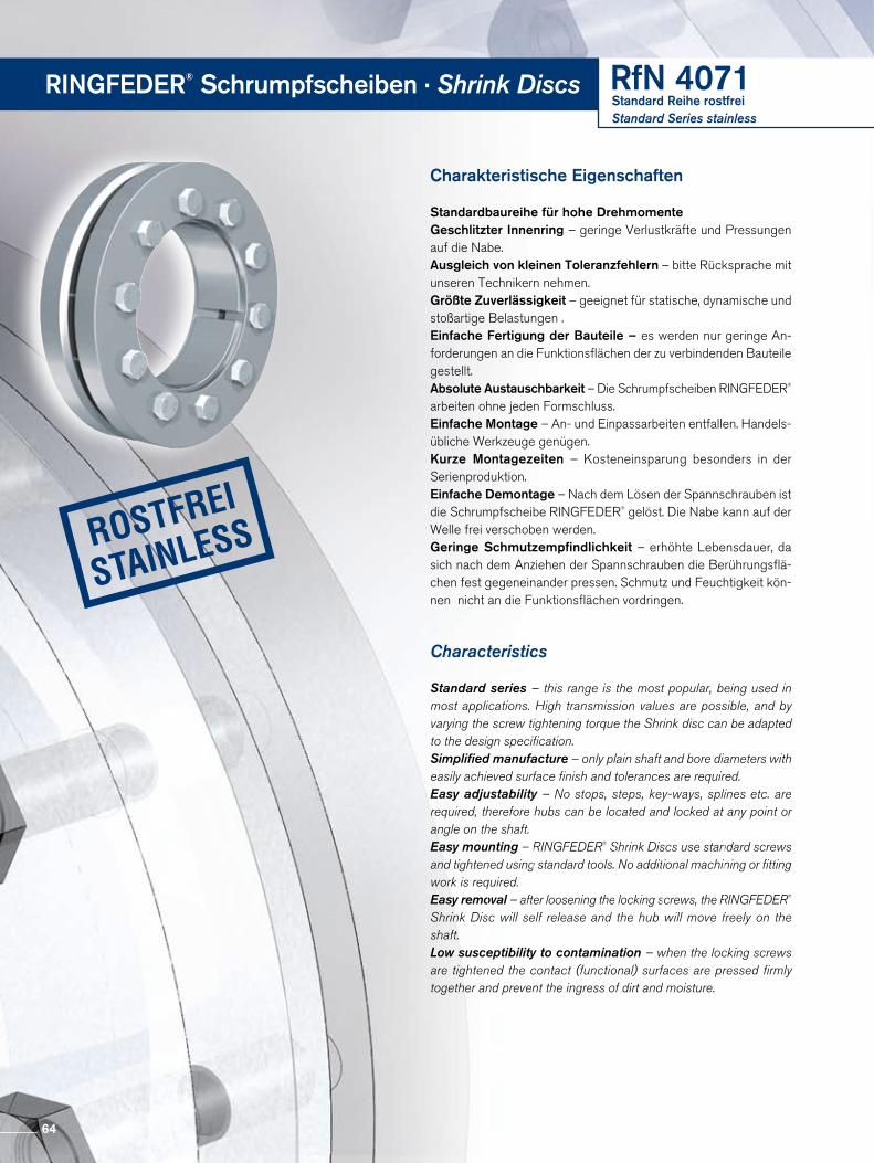
Charakteristische Eigenschaften
Standardbaureihe für hohe DrehmomenteGeschlitzter Innenring – geringe Verlustkräfte und Pressungen auf die Nabe.Ausgleich von kleinen Toleranzfehlern – bitte Rücksprache mit unseren Technikern nehmen.Größte Zuverlässigkeit – geeignet für statische, dynamische und stoßartige Belastungen .Einfache Fertigung der Bauteile – es werden nur geringe Anforderungen an die Funktionsflächen der zu verbindenden Bauteile gestellt.Absolute Austauschbarkeit – Die Schrumpfscheiben RINGFEDER® arbeiten ohne jeden Formschluss. Einfache Montage – An und Einpassarbeiten entfallen. Handelsübliche Werkzeuge genügen. Kurze Montagezeiten – Kosteneinsparung besonders in der Serien produktion.Einfache Demontage – Nach dem Lösen der Spannschrauben ist die Schrumpfscheibe RINGFEDER® gelöst. Die Nabe kann auf der Welle frei verschoben werden. Geringe Schmutzempfindlichkeit – erhöhte Lebensdauer, da sich nach dem Anziehen der Spannschrauben die Berührungsflächen fest gegeneinander pressen. Schmutz und Feuchtigkeit können nicht an die Funktionsflächen vordringen.
Characteristics
Standard series – this range is the most popular, being used in most applications. High transmission values are possible, and by varying the screw tightening torque the Shrink disc can be adapted to the design specification.Simplified manufacture – only plain shaft and bore diameters with easily achieved surface finish and tolerances are required.Easy adjustability – No stops, steps, key-ways, splines etc. are required, therefore hubs can be located and locked at any point or angle on the shaft.Easy mounting – RINGFEDER® Shrink Discs use standard screws and tightened using standard tools. No additional machining or fitting work is required.Easy removal – after loosening the locking screws, the RINGFEDER® Shrink Disc will self release and the hub will move freely on the shaft.Low susceptibility to contamination – when the locking screws are tightened the contact (functional) surfaces are pressed firmly together and prevent the ingress of dirt and moisture.
RINGFEDER® Schrumpfscheiben · Shrink Discs RfN 4071Standard Reihe rostfreiStandard Series stainless
64
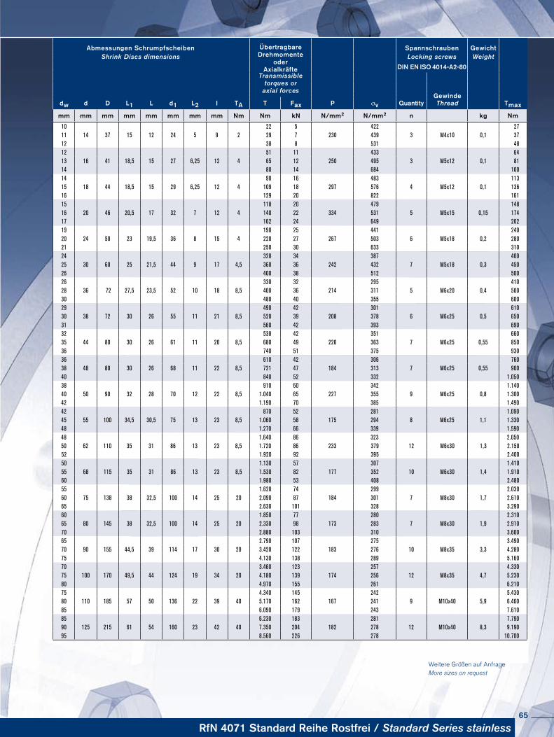
Weitere Größen auf Anfrage More sizes on request
Abmessungen Schrumpfscheiben ÜbertragbareDrehmomente
oderAxialkräfte
Spannschrauben Ge wichtShrink Discs dimensions Locking screws Weight
DIN EN ISO 4014-A2-80Transmissible
torques oraxial forces
dw d D L1 L d1 L2 I TA P σv QuantityGewinde
TmaxT Fax Thread
mm mm mm mm mm mm mm mm Nm Nm kN N/mm2 N/mm2 n kg Nm
10 22 5 422 2711 14 37 15 12 24 5 9 2 29 7 230 439 3 M4x10 0,1 3712 38 8 531 4812 51 11 433 6413 16 41 18,5 15 27 6,25 12 4 65 12 250 495 3 M5x12 0,1 8114 80 14 684 10014 90 16 483 11315 18 44 18,5 15 29 6,25 12 4 109 18 297 576 4 M5x12 0,1 13616 129 20 822 16115 118 20 479 14816 20 46 20,5 17 32 7 12 4 140 22 334 531 5 M5x15 0,15 17417 162 24 649 20219 190 25 441 24020 24 50 23 19,5 36 8 15 4 220 27 267 503 6 M5x18 0,2 28021 250 30 633 31024 320 34 387 40025 30 60 25 21,5 44 9 17 4,5 360 36 242 432 7 M5x18 0,3 45026 400 38 512 50026 330 32 295 41028 36 72 27,5 23,5 52 10 18 8,5 400 36 214 311 5 M6x20 0,4 50030 480 40 355 60029 490 42 301 61030 38 72 30 26 55 11 21 8,5 520 39 208 378 6 M6x25 0,5 65031 560 42 393 69032 530 42 351 66035 44 80 30 26 61 11 20 8,5 680 49 220 363 7 M6x25 0,55 85036 740 51 375 93036 610 42 306 76038 48 80 30 26 68 11 22 8,5 721 47 184 313 7 M6x25 0,55 90040 840 52 332 1.05038 910 60 342 1.14040 50 90 32 28 70 12 22 8,5 1.040 65 227 355 9 M6x25 0,8 1.30042 1.190 70 385 1.49042 870 52 281 1.09045 55 100 34,5 30,5 75 13 23 8,5 1.060 58 175 294 8 M6x25 1,1 1.33048 1.270 66 339 1.59048 1.640 86 323 2.05050 62 110 35 31 86 13 23 8,5 1.720 86 233 379 12 M6x30 1,3 2.15052 1.920 92 395 2.40050 1.130 57 307 1.41055 68 115 35 31 86 13 23 8,5 1.530 82 177 352 10 M6x30 1,4 1.91060 1.980 53 408 2.48055 1.620 74 299 2.03060 75 138 38 32,5 100 14 25 20 2.090 87 184 301 7 M8x30 1,7 2.61065 2.630 101 328 3.29060 1.850 77 280 2.31065 80 145 38 32,5 100 14 25 20 2.330 98 173 283 7 M8x30 1,9 2.91070 2.880 103 310 3.60065 2.790 107 275 3.49070 90 155 44,5 39 114 17 30 20 3.420 122 183 276 10 M8x35 3,3 4.28075 4.130 138 289 5.16070 3.460 123 257 4.33075 100 170 49,5 44 124 19 34 20 4.180 139 174 256 12 M8x35 4,7 5.23080 4.970 155 261 6.21075 4.340 145 242 5.43080 110 185 57 50 136 22 39 40 5.170 162 167 241 9 M10x40 5,9 6.46085 6.090 179 243 7.61085 6.230 183 281 7.79090 125 215 61 54 160 23 42 40 7.350 204 182 278 12 M10x40 8,3 9.19095 8.560 226 278 10.700
RfN 4071 Standard Reihe Rostfrei / Standard Series stainless65

RINGFEDER® Smart-Lock
66

Smart-Lock-Set RfN 4001
67
Smart-Lock-Set: the connection of the future
For the perfect hollow shaft connection, the solid shaft is always manufactured to a high degree of precision, normally with a dimensional tolerance of h6/H6. This close tolerance, high-finish shaft is inserted into the equally close tolerance hollow bore of the gearbox and secured in place by the com-pressive force of the Shrink Disc. Only by maintaining the strict dimensional tolerances the full torque capacity can be reliability achieved. Smart-Lock puts an end to all the precision machining invol-ved and guarantees an optimum connection even with clea-rances up to 0.2 mm/0.007 in..The flexibility offered by using interchangeable bushings between the solid shaft and the hollow shaft of the gearbox makes the Smart-Lock-Set an invaluable aid to the market-place. Thanks to the availability of shaft adapter bushings with various inside diameters. One gearbox can be used with a range of shaft sizes without a change out to the shaft or Shrink Disc. The ease of selecting and using the Smart-Lock-Set is child´s play. The Smart-Lock-Set is an efficient design that makes eco-nomic sense to the user. Not only can it compensate larger dimensional tolerances (up to 0.2 mm/0.007 in.), it also offers significant cost savings by requiring a minimal number of spare parts needed in inventory. Furthermore, inexpensive, cold drawn, commercial available shafting up to quality grade h11 can be utilized without additional machining. The export market also benefits from using Smart-Lock-Set; adapter bushings in inch size standards are readily available from local inventories for countries that don´t use metric measu-rements. Expensive specials and large spare part inventories are a thing of the past.
Smart-Lock-Set: Verbindung der Zukunft
Eine perfekte Hohlwellenverbindung erfordert, dass die Voll-welle mit höchster Präzision, in der Regel h6/H6-Toleranz, hergestellt wird. Die Welle wird dabei in die Hohlwelle des Getriebes eingeführt und mit Hilfe einer Schrumpfscheibe kraftschlüssig verspannt. Aber nur, wenn in diesem Szenario die Toleranzen ganz genau stimmen, wird das Drehmoment sicher übertragen. Smart-Lock-Set macht jetzt Schluss mit dem Bangen und garantiert optimale Verbindungen bis zu einem Fügespiel von 0,1-0,2 mm. Der flexible Einsatz von zylindrischen Adapterbuchsen zwi-schen Welle und Getriebehohlwelle macht das Smart-Lock-Set zu einem unverzichtbaren Hilfsmittel am Markt. Durch unterschiedliche Innendurchmesser der Buchsen kann das System an verschiedenste Hohlwellendurchmesser angepasst werden trotz Einsatz der gleichen Smart-Lock-Schrumpfscheibe und Getriebehohlwelle. So lassen sich beispielsweise unterschiedliche Wellendurchmesser mit ein und demselben Getriebe verbinden. Für jeden Anwendungs-fall gibt es fertige Buchsen, die eine individuelle Anpassung zum Kinderspiel machen. Das Smart-Lock-Set sorgt für mehr Effizienz. Es kann nicht nur grobe Toleranzen bis zu einem Fügespiel von 0,2 mm ausgleichen, sondern bietet sogar darüber hinaus noch weiteres Potenzial zur Kosteneinsparung. Im Ersatzteilela-ger muss nur noch ein Minimum an Material bereitgehalten werden, um alle Maschinen und Bänder der Produktion im Notfall unkompliziert wieder in Betrieb nehmen zu können. Außerdem kann jetzt gezogenes, unbearbeitetes Material bis zur Qualitätsstufe h11 als Kundenwelle eingesetzt werden. Beim Export kann das Smart-Lock-Set noch einen weiteren Vorteil ausspielen: Für Länder ohne metrisches Maß gibt es die Adapterbuchsen in Zollabmessungen aus lokalen Lager-stätten. Teuere Sonderanfertigungen und Ersatzteile gehö-ren damit der Vergangenheit an.
RINGFEDER® Smart-Lock
68

Flexibel, kostengünstig, wartungsfreundlich: SmartLockSet ist die neue HohlwellenVerbindung von. Zylindrische Buchsen ermöglichen die Verbindung von Getriebehohlwellen und anderen Hohlwellenverbindungen mit unterschiedlichen metrischen und zölligen Wellen.
• Qualitätsbewusst:Spannungsoptimierte, unzerstörbare Schrumpfscheiben ge
währleisten höchste Sicherheit.
• Kompromisslos:Zylindrische Buchsen für jeden Wellendurchmesser sorgen
für perfekte Verbindungen.
• Sparsam:SmartLockSet steht für minimalen Arbeitsaufwand und bis zu
70% weniger Kosten im Ersatzteilelager.
Technische Details des Smart-Lock-Set
Für Getriebehersteller: • Der Hohlwellenbereich ist in acht Stufen mit Außendurchmesser von 4490 mm aufgeteilt. • Die Kundenwellen können stufenlos von 2570 Durchmesser eingesetzt werden. • Der Drehmomentbereich reicht von 5805600 Nm
Für Anwender von Getrieben: • Auswahlkriterium für den Wellendurchmesser ist das zu über tragende Drehmoment. • Das ausgewählte Getriebe kann in Verbindung mit verschie denen VollwellenDurchmessern eingesetzt werden. Dadurch ist eine Standardisierung auf denselben Getriebetypen möglich. • Verminderte Ersatzteilehaltung und Variantenvielfalt erlauben eine erhebliche Kostenreduzierung!
Eigenschaften
Flexible, cost-saving, easy to maintain: Smart-Lock-Set is the new Shaft/Hollow Shaft connection from. Cylindrical Bushings allow the attachment of hollow shaft gear reducers and other hollow shaft con-nections to any metric and inch size solid shaft diameter.
• Reliable:Tension-optimized and virtually indestructible Shrink Discs gua-
rantee the highest possible degree of safety
• Uncompromising:Cylindrical Bushings for a wide range of shaft diameters pro-
vide the perfect connection.
• Economical: The Smart-Lock-Set requires minimal labor at installation and reduces spare part inventory costs up to 70 %.
Technical details of the Smart-Lock-Set
For Gearbox manufacturers: • Eight standard sizes of adaptor buhings are available for hollow shaft outside diameters from 44 to 90 mm.
• The inside diameters are variable and accommodate the most common metric and inch size shaft sizes. • Commercially available solid shafting without any machining can be used. Diameters from 25 to 70 mm are possible.
For users of Gearboxes: • The torque to be transmitted is the criterion used to select the shaft diameter. • The optimum shaft size for an individual gearbox can be used in connection with the Smart-Lock-Set.
• It is possible to standardize on a certain gearbox size for a range of shaft diameters. The results are lower costs for maintenance and spare parts.
Characteristics
69
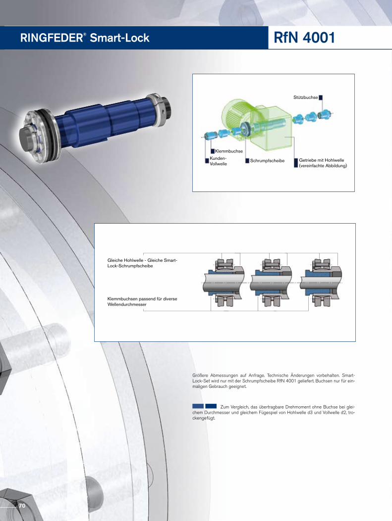
RINGFEDER® Smart-Lock RfN 4001
Klemmbuchse
Kunden- Vollwelle
Schrumpfscheibe Getriebe mit Hohlwelle (vereinfachte Abbildung)
Stützbuchse
Gleiche Hohlwelle - Gleiche Smart-Lock-Schrumpfscheibe
Klemmbuchsen passend für diverse Wellendurchmesser
Größere Abmessungen auf Anfrage. Technische Änderungen vorbehalten. SmartLockSet wird nur mit der Schrumpfscheibe RfN 4001 geliefert. Buchsen nur für einmaligen Gebrauch geeignet.
Zum Vergleich, das übertragbare Drehmoment ohne Buchse bei gleichem Durchmesser und gleichem Fügespiel von Hohlwelle d3 und Vollwelle d2, trockengefügt.
70
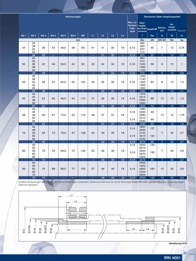
Abmessungen
Max. zu-lässiges Füge-spiel
Technische Daten Vergütungsstahl
Über-tragba-
res Dreh-moment
An-zungs-
momentAxialkraftSchrau-
ben Gewicht
Ød 1 Ød 2 Ød 3 Ød 4 Ød 5 Ød 6 ØD L1 L2 L3 L4 T Fax G TA m
mm Nm kN DIN 931 Nm kg
44
25
36 43 49,5 38 80 41 31 30 18 0,13
580
45 7 12 0,7528 65030 67032 71036 36 -- -- -- -- -- 31 30 -- 0,13 400 20 7 12 0,6
50
30
42 49 59,5 44 90 45 34 34 18 0,16
860
58 9 12 132 91035 100038 109040 115048 48 -- -- -- -- -- 34 34 18 0,16 720 34 9 12 0,8
55
35
48 54 64,5 50 100 46 35 35 18 0,16
1050
60 8 12 1,338 114040 120042 126045 135048 48 -- -- -- -- -- 35 35 18 0,16 1080 45 8 12 1,1
62
40
52 60 69,5 54 110 47 36 36 18 0,16
1970
98 12 12 1,545 221048 236050 246052 52 -- -- -- -- -- 36 36 18 0,19 1920 74 12 12 1,3
68
40
60 67 74,5 62 115 48 37 37 180,16
198099
10 12 1,7545 223048 238050 0,19 2210 8955 243060 60 -- -- -- -- -- 37 37 18 0,19 1990 66 10 12 1,4
75
45
65 73 79,5 67 138 50 39 39 18
0,16 2860 127
7 30 2,748 305050
0,193100
12455 341060 372065 65 -- -- -- -- -- 39 39 18 0,19 3470 99 7 30 2,7
80
45
70 78 84,5 72 145 50 39 39 18
0,16 3050 135
7 30 2,950
0,19
3310
13355 364060 397065 430070 70 -- -- -- -- -- 39 39 18 0,19 3470 99 7 30 2,7
90
50
75 88 89,5 77 155 57 46 46 18
4000
160 10 30 3,955 440060 0,19 480065 520070 560075 75 -- -- -- -- -- 46 46 18 0,19 4500 120 10 30 3,3
Ø D
Ø d
1h8
Ø d
4
Ø d
6
Ø d
3H7
Ø d
2
Ø d
2
Ø d
3H7
Ø d
6
Ø d
5
L1
L2
L3 L4
Größere Abmessungen auf Anfrage. Technische Änderungen vorbehalten. SmartLockSet wird nur mit der Schrumpfscheibe RfN 4061 geliefert. Buchsen nur für einmaligen Gebrauch geeignet.
Abmessung S.74
RfN 400171
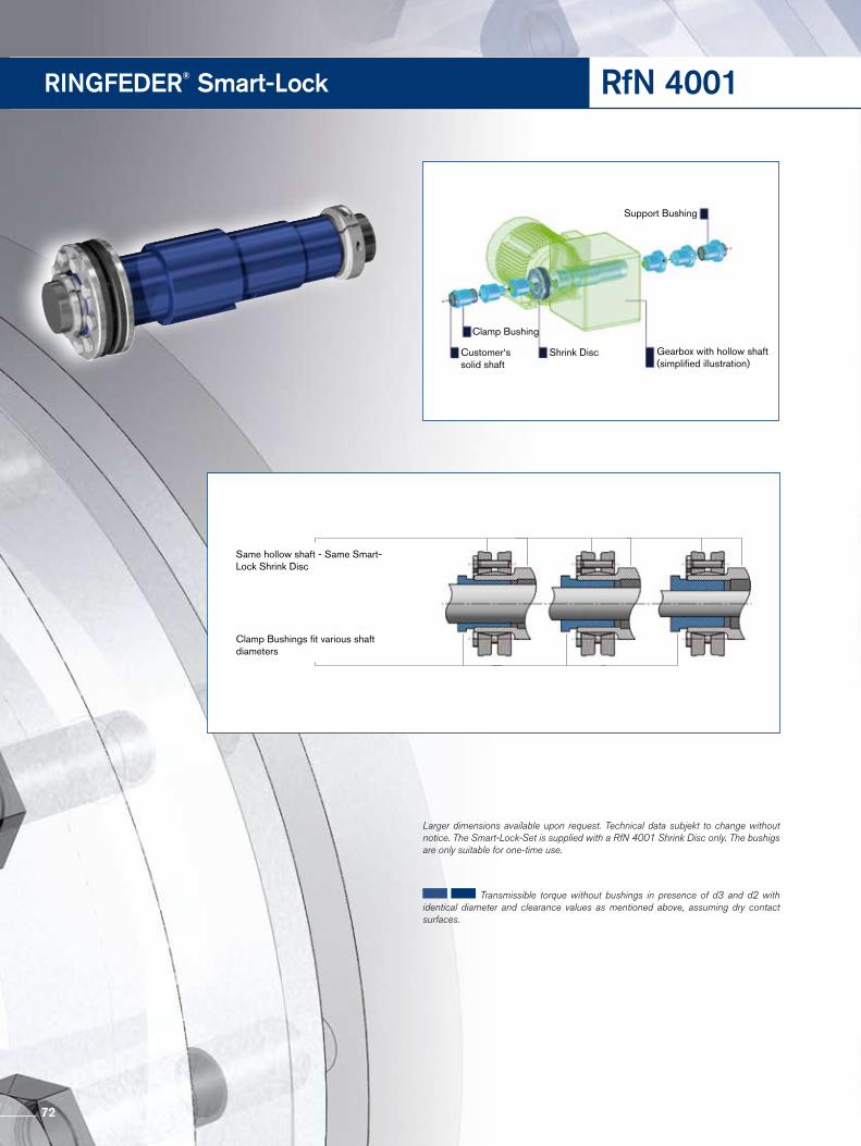
RINGFEDER® Smart-Lock RfN 4001
Clamp Bushing
Customer‘s solid shaft
Shrink Disc Gearbox with hollow shaft (simplified illustration)
Support Bushing
Same hollow shaft - Same Smart-Lock Shrink Disc
Clamp Bushings fit various shaft diameters
Larger dimensions available upon request. Technical data subjekt to change without notice. The Smart-Lock-Set is supplied with a RfN 4001 Shrink Disc only. The bushigs are only suitable for one-time use.
Transmissible torque without bushings in presence of d3 and d2 with identical diameter and clearance values as mentioned above, assuming dry contact surfaces.
72
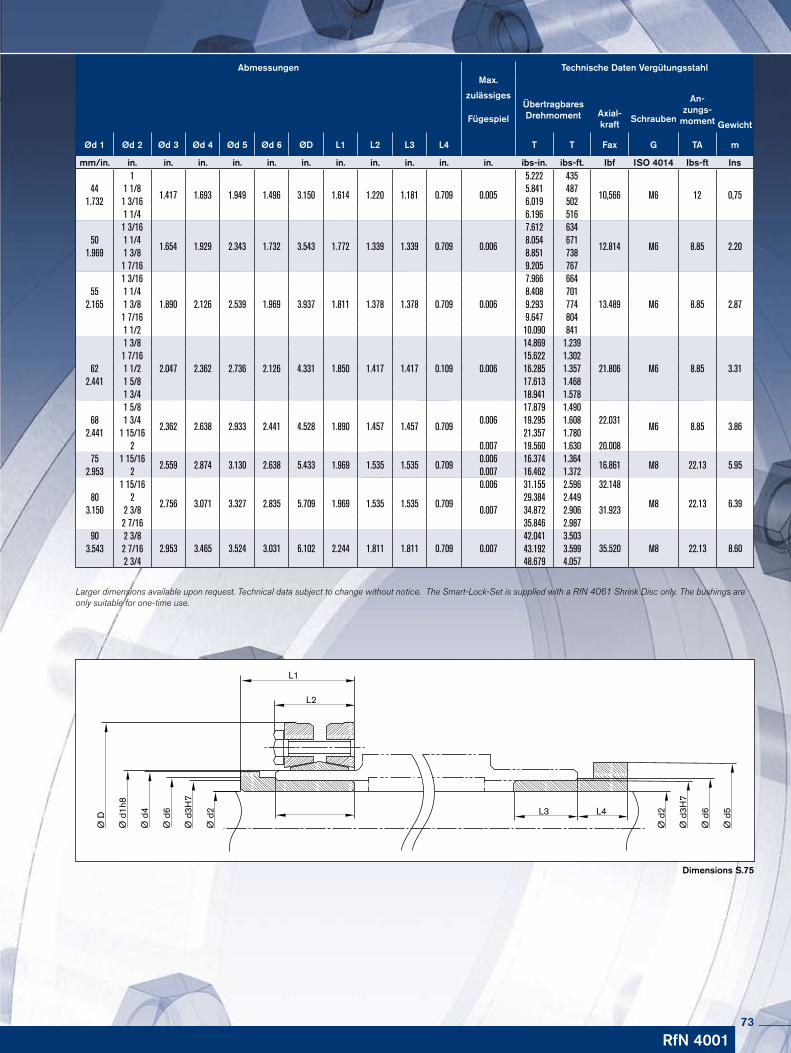
Abmessungen Technische Daten VergütungsstahlMax.
zulässigesÜbertragbares Drehmoment
An-zungs-
momentFügespielAxial-kraft
SchraubenGewicht
Ød 1 Ød 2 Ød 3 Ød 4 Ød 5 Ød 6 ØD L1 L2 L3 L4 T T Fax G TA m
mm/in. in. in. in. in. in. in. in. in. in. in. in. ibs-in. ibs-ft. Ibf ISO 4014 Ibs-ft Ins1
1.417 1.693 1.949 1.496 3.150 1.614 1.220 1.181 0.709 0.005
5.222 435
10,566 M6 12 0,7544 1 1/8 5.841 487
1.732 1 3/16 6.019 5021 1/4 6.196 5161 3/16
1.654 1.929 2.343 1.732 3.543 1.772 1.339 1.339 0.709 0.006
7.612 634
12.814 M6 8.85 2.2050 1 1/4 8.054 671
1.969 1 3/8 8.851 7381 7/16 9.205 7671 3/16
1.890 2.126 2.539 1.969 3.937 1.811 1.378 1.378 0.709 0.006
7.966 664
13.489 M6 8.85 2.8755 1 1/4 8.408 701
2.165 1 3/8 9.293 7741 7/16 9.647 8041 1/2 10.090 8411 3/8
2.047 2.362 2.736 2.126 4.331 1.850 1.417 1.417 0.109 0.006
14.869 1.239
21.806 M6 8.85 3.311 7/16 15.622 1.302
62 1 1/2 16.285 1.3572.441 1 5/8 17.613 1.468
1 3/4 18.941 1.5781 5/8
2.362 2.638 2.933 2.441 4.528 1.890 1.457 1.457 0.7090.006
17.879 1.49022.031
M6 8.85 3.8668 1 3/4 19.295 1.608
2.441 1 15/16 21.357 1.7802 0.007 19.560 1.630 20.008
75 1 15/162.559 2.874 3.130 2.638 5.433 1.969 1.535 1.535 0.709
0.006 16.374 1.36416.861 M8 22.13 5.95
2.953 2 0.007 16.462 1.3721 15/16
2.756 3.071 3.327 2.835 5.709 1.969 1.535 1.535 0.709
0.006 31.155 2.596 32.148
M8 22.13 6.3980 2
0.00729.384 2.449
31.9233.150 2 3/8 34.872 2.9062 7/16 35.846 2.987
90 2 3/82.953 3.465 3.524 3.031 6.102 2.244 1.811 1.811 0.709 0.007
42.041 3.50335.520 M8 22.13 8.603.543 2 7/16 43.192 3.599
2 3/4 48.679 4.057
Ø D
Ø d
1h8
Ø d
4
Ø d
6
Ø d
3H7
Ø d
2
Ø d
2
Ø d
3H7
Ø d
6
Ø d
5
L1
L2
L3 L4
Larger dimensions available upon request. Technical data subject to change without notice. The Smart-Lock-Set is supplied with a RfN 4061 Shrink Disc only. The bushings are only suitable for one-time use.
RfN 4001
Dimensions S.75
73
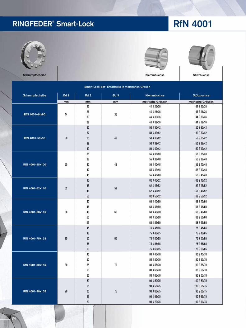
RINGFEDER® Smart-Lock
Smart-Lock-Set- Ersatzteile in metrischen Größen
Schrumpfscheibe Ød 1 Ød 2 Ød 3 Klemmbuchse Stützbuchse
mm mm mm metrische Grössen metrische Grössen
RfN 4001-44x80 44
25
36
44 K 25/36 44 S 25/36
28 44 K 28/36 44 S 28/36
30 44 K 30/36 44 S 30/36
32 44 K 32/36 44 S 32/36
RfN 4001-50x90 50
30
42
50 K 30/42 50 S 30/42
32 50 K 32/42 50 S 32/42
35 50 K 35/42 50 S 35/42
38 50 K 38/42 50 S 38/42
40 50 K 40/42 50 S 40/42
RfN 4001-55x100 55
35
48
55 K 35/48 55 S 35/48
38 55 K 38/48 55 S 38/48
40 55 K 40/48 55 S 40/48
42 55 K 42/48 55 S 42/48
45 55 K 45/48 55 S 45/48
RfN 4001-62x110 62
40
52
62 K 40/52 62 S 40/52
45 62 K 45/52 62 S 45/52
48 62 K 48/52 62 S 48/52
50 62 K 50/52 62 S 50/52
RfN 4001-68x115 68
40
60
68 K 40/60 68 S 40/60
45 68 K 45/60 68 S 45/60
48 68 K 48/60 68 S 48/60
50 68 K 50/60 68 S 50/60
55 68 K 55/60 68 S 55/60
RfN 4001-75x138 75
45
65
75 K 45/65 75 S 45/65
48 75 K 48/65 75 S 48/65
50 75 K 50/65 75 S 50/65
55 75 K 55/65 75 S 55/65
60 75 K 60/65 75 S 60/65
RfN 4001-80x145 80
45
70
80 K 45/70 80 S 45/70
50 80 K 50/70 80 S 50/70
55 80 K 55/70 80 S 55/70
60 80 K 60/70 80 S 60/70
65 80 K 65/70 80 S 65/70
RfN 4001-90x155 90
50
75
90 K 50/75 90 S 50/75
55 90 K 55/75 90 S 55/75
60 90 K 60/75 90 S 60/75
65 90 K 65/75 90 S 65/75
70 90 K 70/75 90 S 70/75
Schrumpfscheibe Klemmbuchse Stützbuchse
RfN 4001
74
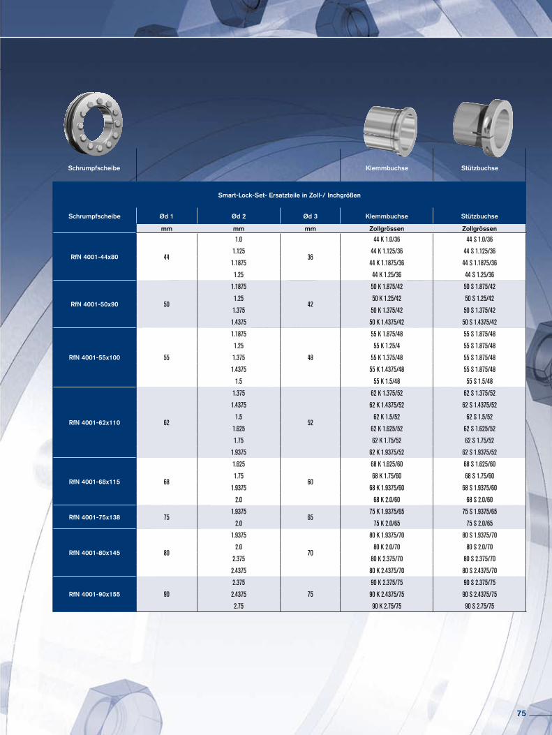
Smart-Lock-Set- Ersatzteile in Zoll-/ Inchgrößen
Schrumpfscheibe Ød 1 Ød 2 Ød 3 Klemmbuchse Stützbuchse
mm mm mm Zollgrössen Zollgrössen
RfN 4001-44x80 44
1.0
36
44 K 1.0/36 44 S 1.0/36
1.125 44 K 1.125/36 44 S 1.125/36
1.1875 44 K 1.1875/36 44 S 1.1875/36
1.25 44 K 1.25/36 44 S 1.25/36
RfN 4001-50x90 50
1.1875
42
50 K 1.875/42 50 S 1.875/42
1.25 50 K 1.25/42 50 S 1.25/42
1.375 50 K 1.375/42 50 S 1.375/42
1.4375 50 K 1.4375/42 50 S 1.4375/42
RfN 4001-55x100 55
1.1875
48
55 K 1.875/48 55 S 1.875/48
1.25 55 K 1.25/4 55 S 1.875/48
1.375 55 K 1.375/48 55 S 1.875/48
1.4375 55 K 1.4375/48 55 S 1.875/48
1.5 55 K 1.5/48 55 S 1.5/48
RfN 4001-62x110 62
1.375
52
62 K 1.375/52 62 S 1.375/52
1.4375 62 K 1.4375/52 62 S 1.4375/52
1.5 62 K 1.5/52 62 S 1.5/52
1.625 62 K 1.625/52 62 S 1.625/52
1.75 62 K 1.75/52 62 S 1.75/52
1.9375 62 K 1.9375/52 62 S 1.9375/52
RfN 4001-68x115 68
1.625
60
68 K 1.625/60 68 S 1.625/60
1.75 68 K 1.75/60 68 S 1.75/60
1.9375 68 K 1.9375/60 68 S 1.9375/60
2.0 68 K 2.0/60 68 S 2.0/60
RfN 4001-75x138 751.9375
6575 K 1.9375/65 75 S 1.9375/65
2.0 75 K 2.0/65 75 S 2.0/65
RfN 4001-80x145 80
1.9375
70
80 K 1.9375/70 80 S 1.9375/70
2.0 80 K 2.0/70 80 S 2.0/70
2.375 80 K 2.375/70 80 S 2.375/70
2.4375 80 K 2.4375/70 80 S 2.4375/70
RfN 4001-90x155 90
2.375
75
90 K 2.375/75 90 S 2.375/75
2.4375 90 K 2.4375/75 90 S 2.4375/75
2.75 90 K 2.75/75 90 S 2.75/75
Schrumpfscheibe Klemmbuchse Stützbuchse
75

RINGFEDER®
Wellenkupplungen · Shaft Couplings
76
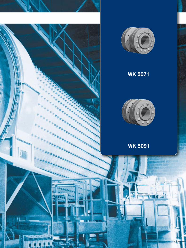
WK 5071
WK 5091
77
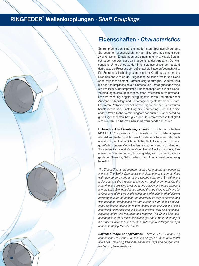
Schrumpfscheiben sind die modernsten Spannverbindungen. Sie bestehen grundsätzlich, je nach Bauform, aus einem oder zwei konischen Druckringen und einem Innenring. Mittels Spannschrauben werden diese axial gegeneinander verspannt. Der wesentliche Unterschied zu den Innenspannverbindungen besteht darin, dass die Pressung von außen auf die Nabe aufgebracht wird. Die Schrumpfscheibe liegt somit nicht im Kraftfluss, sondern das Drehmoment wird an der Füge fläche zwischen Welle und Nabe ohne Zwischenelement kraftschlüssig übertragen. Dadurch wird mit der Schrumpfscheibe auf einfache und kostengünstige Weise ein Presssitz (Schrumpfsitz) für hochbeanspruchte WelleNabeVerbindungen erzeugt. Bisher mussten Presssitze durch umständliche Berechnung, engste Fertigungstoleranzen und erheblichem Aufwand bei Montage und Demontage hergestellt werden. Zusätzlich treten Probleme bei evtl. notwendig werdenden Reparaturen (Austauschbarkeit, Einstellung bzw. Zentrierung usw.) auf. Keine andere WelleNabeVerbindungsart hat auch nur annähernd so gute Eigenschaften bezüglich der Dauerdrehwechselfestigkeit aufzuweisen und besitzt einen so hervorragenden Rundlauf.
Unbeschränkte Einsatzmöglichkeiten – Schrumpfscheiben RINGFEDER® eignen sich zur Befestigung von Nabenkörpern aller Art auf Wellen und Achsen. Ein satzmöglichkeiten bieten sich überall dort, wo bisher Schrumpfsitze, Keil, Passfeder und PolygonVerbindungen, Vielkeilwellen usw. zur Anwendung gelangten. So werden Zahn und Kettenräder, Hebel, Nocken, Kurven, Riemen oder Bremsscheiben , Schwungräder, Kupplungen, Aufsteckgetriebe, Flansche, Seilscheiben, Laufräder absolut zuverlässig befestigt.
The Shrink Disc is the modern method for creating a mechanical shrink fit. The Shrink Disc consists of either one or two thrust rings with tapered bores and a mating tapered inner ring. By tightening locking screws the thrust rings are drawn together compressing the inner ring and applying pressure to the outside of the hub clamping it to the shaft. Being positioned around the hub there is only one in-terface transmitting the loads giving the shrink disc method distinct advantages such as offering the possibility of very concentric and well balanced connections that are suited to high speed applica-tions. Traditional shrink fits require complicated calculations, close machining tolerances and fine surface finishes, they also need con-siderable effort with mounting and removal. The Shrink Disc con-nection has none of these disadvantages and is better than any of the other usual connection methods with regard to fatigue strength under alternating torsional stress.
Unlimited range of applications – RINGFEDER® Shrink Disc connections are suitable for securing all types of hubs onto shafts and axles. Replacing traditional shrink fits, keys and polygon con-nections, splined shafts etc.
Eigenschaften · Characteristics
RINGFEDER®
Wellenkupplungen · Shaft Couplings
78

Erläuterungen zu Tabellen Explanations to tables
d, D, L, l, L1, L2, d1 = Basic dimensions
dW = solid shaft diameter (provided by the customer)
T = transmissible torque
Fax = transmissible axial force
p = approx. surface pressure on the hub extension (diameter d)
TA = required tightening torque per screw (Screws greased with molykote!)
n = quantity of screws
S = clearance between shaft and hub bore
Tmax = maximum theoretical transmissible torque
σv = calculated combined stress in the hub extension (d/dw) under consideration of the tangential, radial and torsional stresses following the equation:
Additional loads, e.g. tension, thrust or bending have to be taken into consideration accordingly.
Function values The functional characteristics are valid with the screw tighte-ning torque listed in the tables and the following assumed conditions:The locking screws are lubricated using MoS2 (µtot= 0,1).The tapered cones are lubricated using MoS2 (µ = 0,05). The contact surfaces (dw) are in lightly oiled condition with coefficient of friction µ = 0,12. The hub and shaft materials have a modulus of elasticity of 210,000 N/mm2. (Lower values result in increased values for T and Fax with reduced tangential stress.)The maximum clearance S is being fully utilized. The shaft being used is solid, for hollow shaft applications the functional values will change.In cases where the assumed conditions do not apply then contact our Technical Department where we will be happy to assist you with your application.
d, D, L, l, L1, L2, d1 = Grundabmessungen, Schrumpfscheiben ungespannt
dW = Vollwellendurchmesser (kundenseitig)
T = übertragbares Drehmoment
Fax = übertragbare Axialkraft
p = Flächenpressung auf dem Nabenansatz (Durchmesser d) TA = erforderliches Anzieh dreh moment pro Spann - schraube (Schrauben molykotiert!)
n = Anzahl der Spannschrauben S = Fügespiel zwischen Welle und Nabenbohrung
Tmax = maximal theoretisch übertragbares Drehmoment
σv = rechnerische Vergleichsspannung im Nabenansatz (d/dw) unter Berücksichtigung der Tangential-, Radial- und Torsions span nung nach folgender Beziehung:
Zusätzliche Spannungen, z.B. Zug, Druck, Biegung, sind ent-sprechend zu berücksichtigen.
FunktionswerteDie Funktionswerte sind in Abhängigkeit der jeweils angege-benen Anzieh drehmomente TA bestimmt. Die Spannschrauben sind mit Schmiermitteln, die MoS2 ent-halten, geschmiert (µges = 0,1).Die Konen sind ebenfalls molykotiert (µ = 0,05).Für die Fuge, Durchmesser dw, wurde der für geölte Montage-verhältnisse übliche Reibwert µ = 0,12 angesetzt. Als E-Modul für Welle und Hohlwelle wurde der Wert 210.000 N/mm2 berücksichtigt. (Niedrigere Werte führen zu einer Erhöhung von T und Fax und einer Reduzierung der höchsten Einzelspannung, der Tangential span nung.)Für die Berechnung der Funktionswerte wurde das max. Fü-gespiel S berücksichtigt, s. nebenstehende Tabelle.Die Funktionswerte gelten nur bei Verwendung einer Voll-welle.Bei der Anwendung einer Außenverspannung auf Hohlwellen ändern sich die Funktionswerte. Bitte mit unseren Spezia-listen Rück sprache nehmen.
79
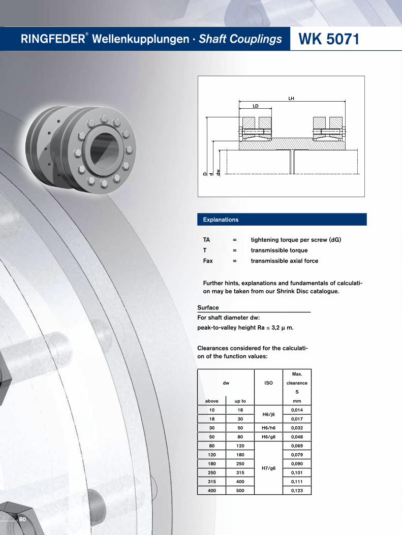
WK 5071
D d dw
LD
LH
RINGFEDER®
Wellenkupplungen · Shaft Couplings
Explanations
TA = tightening torque per screw (dG)
T = transmissible torque
Fax = transmissible axial force
Further hints, explanations and fundamentals of calculati-on may be taken from our Shrink Disc catalogue.
dw ISO
Max.
clearance
S
above up to mm
10 18H6/j6
0,014
18 30 0,017
30 50 H6/h6 0,032
50 80 H6/g6 0,048
80 120
H7/g6
0,069
120 180 0,079
180 250 0,090
250 315 0,101
315 400 0,111
400 500 0,123
Surface
For shaft diameter dw:
peak-to-valley height Ra ≤ 3,2 µ m.
Clearances considered for the calculati-on of the function values:
80
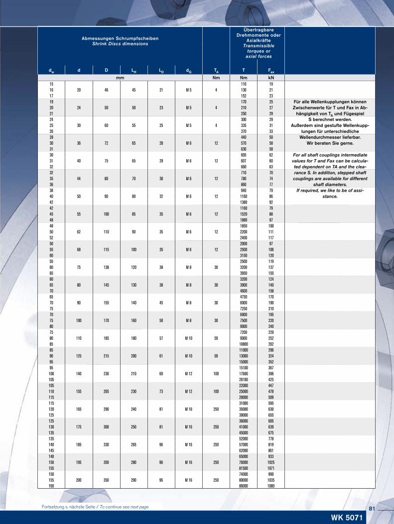
ÜbertragbareDrehmomente oder
Axialkräfte Transmissible
torques oraxial forces
Abmessungen Schrumpfscheiben Shrink Discs dimensions
dw d D LH LD dG TA T Fax
mm Nm Nm kN15 110 1916 20 46 45 21 M 5 4 130 2117 152 2319 170 25 Für alle Wellenkupplungen können
Zwischenwerte für T und Fax in Ab-hängigkeit von TA und Fügespiel
20 24 50 50 23 M 5 4 210 2721 250 2924 300 29 S berechnet werden.
Außerdem sind gestufte Wellenkupp-lungen für unterschiedliche
25 30 60 55 25 M 5 4 335 3126 370 3328 440 50 Wellendurchmesser lieferbar.30 36 72 65 28 M 6 12 570 58 Wir beraten Sie gerne.31 630 5830 605 62 For all shaft couplings intermediate31 40 75 65 29 M 6 12 607 60 values for T and Fax can be calcula-32 660 63 ted dependent on TA and the clea-32 710 70 rance S. In addition, stepped shaft35 44 80 70 30 M 6 12 780 74 couplings are available for different36 860 77 shaft diameters. 38 940 79 If required, we like to be of assi-40 50 90 80 32 M 6 12 1160 86 stance.42 1380 9242 1160 7945 55 100 85 35 M 6 12 1520 8848 1880 9748 1850 10050 62 110 90 35 M 6 12 2200 11152 2400 11750 2000 9755 68 115 100 35 M 6 12 2500 10660 3150 12055 2500 11960 75 138 120 38 M 8 30 3200 13765 3950 15560 3200 12465 80 145 130 38 M 8 30 3900 14070 4600 15865 4750 17070 90 155 140 45 M 8 30 6000 19075 7250 21070 6900 19575 100 170 160 50 M 8 30 7500 22080 9000 24075 7200 22980 110 185 180 57 M 10 59 9000 25285 10800 26285 11000 29690 125 215 200 61 M 10 59 13000 32495 15000 35295 15100 367100 140 230 210 69 M 12 100 17600 396105 20100 425105 22000 447110 155 265 230 73 M 12 100 25000 478115 28000 509115 31000 595120 165 290 240 81 M 16 250 35000 630125 39000 655125 36000 605130 175 300 250 81 M 16 250 41000 639135 45000 675135 52000 778140 185 330 265 96 M 16 250 57000 819145 62000 861140 65000 933150 195 350 280 96 M 16 250 76000 1025155 81500 1071150 74000 990155 200 350 290 96 M 16 250 80000 1035160 86000 1080
Fortsetzung s. nächste Seite / To continue see next page
WK 507181
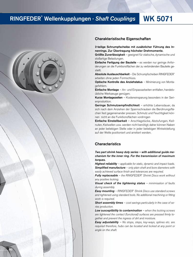
WK 5071RINGFEDER®
Wellenkupplungen · Shaft Couplings
Charakteristische Eigenschaften
2-teilige Schrumpfscheibe mit zusätzlicher Führung des In- nen rings. Zur Übertragung höchster Drehmomente.Größte Zuverlässigkeit – geeignet für statische, dynamische und stoßartige Belastungen.Einfache Fertigung der Bauteile – es werden nur geringe Anforderungen an die Funktionsflächen der zu verbindenden Bauteile gestellt.Absolute Austauschbarkeit – Die Schrumpfscheiben RINGFEDER® arbeiten ohne jeden Formschluss. Optische Kontrolle des Anziehstatus – Minimierung von Montagefehlern.Einfache Montage – An und Einpassarbeiten entfallen, handelsübliche Werkzeuge genügen. Kurze Montagezeiten – Kosteneinsparung besonders in der Seri enproduktion.Geringe Schmutzempfindlichkeit – erhöhte Lebensdauer, da sich nach dem Anziehen der Spannschrauben die Berührungsflächen fest gegeneinander pressen. Schmutz und Feuchtigkeit können nicht an die Funktionsflächen vordringenEinfache Einstellbarkeit – Anschlagstücke, Abstufungen, Keil nuten, Keilwellen usw. werden nicht benötigt; daher können Naben an jeder beliebigen Stelle oder in jeder beliebigen Winkelstellung auf der Welle positioniert und arretiert werden.
Characteristics
Two part shrink heavy duty series – with additional guide me- chanism for the inner ring. For the transmission of maximum torques.Highest reliability – applicable for static, dynamic and impact loads.Simplified manufacture – only plain shaft and bore diameters with easily achieved surface finish and tolerances are required.Fully replaceable – the RINGFEDER® Shrink Discs work without any positive locking.Visual check of the tightening status – minimisation of faults during assembly.Easy mounting – RINGFEDER® Shrink Discs use standard screws and tightened using standard tools. No additional machining or fitting work is required.Short assembly times – cost savings particularly in the case of se- ries production.Low susceptibility to contamination – when the locking screws are tightened the contact (functional) surfaces are pressed firmly to-gether and prevent the ingress of dirt and moisture.Easy adjustability – No stops, steps, key-ways, splines etc. are required therefore, hubs can be located and locked at any point or angle on the shaft.
82
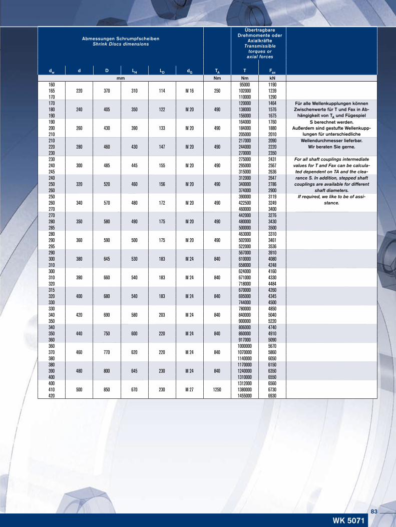
160 95000 1190165 220 370 310 114 M 16 250 102000 1239170 110000 1290170 120000 1464 Für alle Wellenkupplungen können
Zwischenwerte für T und Fax in Ab-hängigkeit von TA und Fügespiel
180 240 405 350 122 M 20 490 138000 1576190 156000 1675190 164000 1760 S berechnet werden.
Außerdem sind gestufte Wellenkupp-lungen für unterschiedliche
200 260 430 390 133 M 20 490 184000 1880210 205000 2010210 217000 2090 Wellendurchmesser lieferbar.220 280 460 430 147 M 20 490 244000 2220 Wir beraten Sie gerne.230 270000 2350230 275000 2431 For all shaft couplings intermediate240 300 485 445 155 M 20 490 295000 2567 values for T and Fax can be calcula-245 315000 2636 ted dependent on TA and the clea-240 312000 2647 rance S. In addition, stepped shaft250 320 520 460 156 M 20 490 340000 2786 couplings are available for different260 374000 2900 shaft diameters. 250 390000 3119 If required, we like to be of assi-260 340 570 480 172 M 20 490 422500 3249 stance.270 460000 3400270 442000 3276280 350 580 490 175 M 20 490 480000 3430285 500000 3500280 463000 3310290 360 590 500 175 M 20 490 502000 3461295 522000 3536290 567000 3910300 380 645 530 183 M 24 840 610000 4080310 658000 4248300 624000 4160310 390 660 540 183 M 24 840 671000 4330320 718000 4484315 670000 4260320 400 680 540 183 M 24 840 695000 4345330 744000 4500330 780000 4850340 420 690 580 203 M 24 840 840000 5040350 900000 5220340 806000 4740350 440 750 600 220 M 24 840 860000 4910360 917000 5090360 1000000 5670370 460 770 620 220 M 24 840 1070000 5860380 1140000 6050380 1170000 6150390 480 800 645 230 M 24 840 1240000 6350400 1310000 6550400 1312000 6560410 500 850 670 230 M 27 1250 1380000 6730420 1455000 6930
ÜbertragbareDrehmomente oder
Axialkräfte Transmissible
torques oraxial forces
Abmessungen Schrumpfscheiben Shrink Discs dimensions
dw d D LH LD dG TA T Fax
mm Nm Nm kN
WK 507183
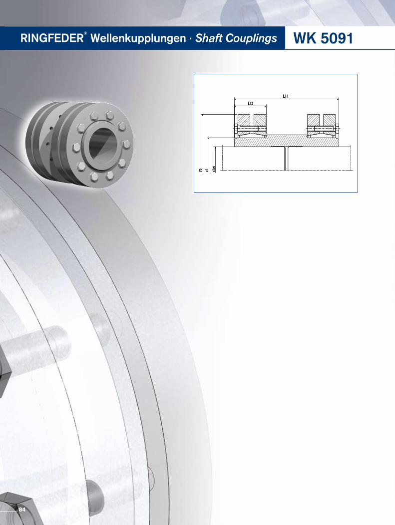
WK 5091RINGFEDER®
Wellenkupplungen · Shaft Couplings
D d dw
LD
LH
84
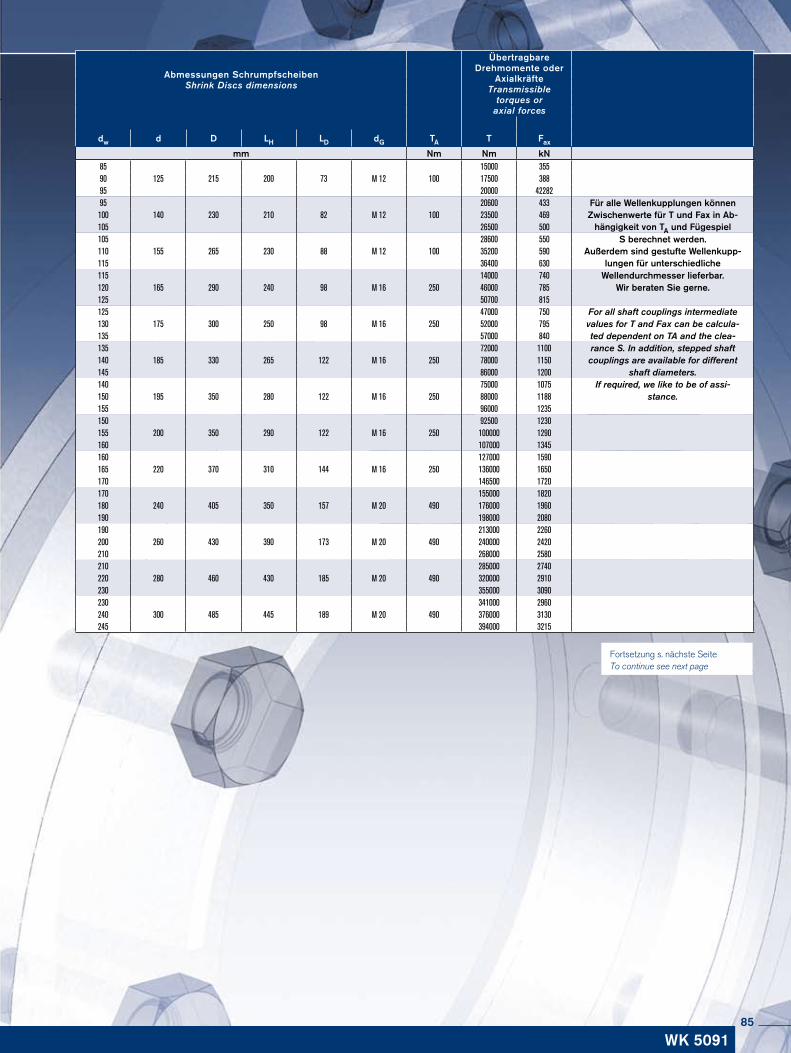
ÜbertragbareDrehmomente oder
Axialkräfte Transmissible
torques oraxial forces
Abmessungen Schrumpfscheiben Shrink Discs dimensions
dw d D LH LD dG TA T Fax
mm Nm Nm kN85 15000 35590 125 215 200 73 M 12 100 17500 38895 20000 4228295 20600 433 Für alle Wellenkupplungen können
Zwischenwerte für T und Fax in Ab-hängigkeit von TA und Fügespiel
100 140 230 210 82 M 12 100 23500 469105 26500 500105 28600 550 S berechnet werden.
Außerdem sind gestufte Wellenkupp-lungen für unterschiedliche
110 155 265 230 88 M 12 100 35200 590115 36400 630115 14000 740 Wellendurchmesser lieferbar.120 165 290 240 98 M 16 250 46000 785 Wir beraten Sie gerne.125 50700 815125 47000 750 For all shaft couplings intermediate130 175 300 250 98 M 16 250 52000 795 values for T and Fax can be calcula-135 57000 840 ted dependent on TA and the clea-135 72000 1100 rance S. In addition, stepped shaft140 185 330 265 122 M 16 250 78000 1150 couplings are available for different145 86000 1200 shaft diameters. 140 75000 1075 If required, we like to be of assi-150 195 350 280 122 M 16 250 88000 1188 stance.155 96000 1235150 92500 1230155 200 350 290 122 M 16 250 100000 1290160 107000 1345160 127000 1590165 220 370 310 144 M 16 250 136000 1650170 146500 1720170 155000 1820180 240 405 350 157 M 20 490 176000 1960190 198000 2080190 213000 2260200 260 430 390 173 M 20 490 240000 2420210 268000 2580210 285000 2740220 280 460 430 185 M 20 490 320000 2910230 355000 3090230 341000 2960240 300 485 445 189 M 20 490 376000 3130245 394000 3215
WK 5091
Fortsetzung s. nächste Seite To continue see next page
85
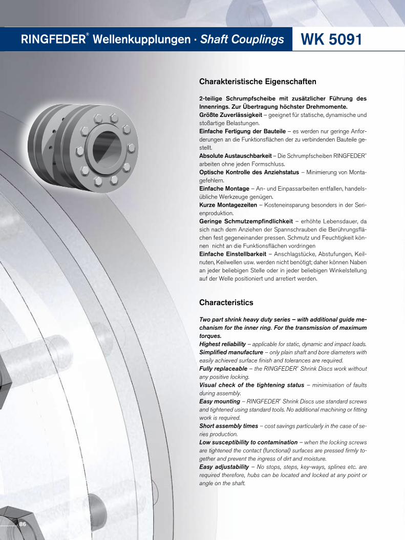
WK 5091RINGFEDER®
Wellenkupplungen · Shaft Couplings
Charakteristische Eigenschaften
2-teilige Schrumpfscheibe mit zusätzlicher Führung des Innen rings. Zur Übertragung höchster Drehmomente.Größte Zuverlässigkeit – geeignet für statische, dynamische und stoßartige Belastungen.Einfache Fertigung der Bauteile – es werden nur geringe Anforderungen an die Funktionsflächen der zu verbindenden Bauteile gestellt.Absolute Austauschbarkeit – Die Schrumpfscheiben RINGFEDER® arbeiten ohne jeden Formschluss. Optische Kontrolle des Anziehstatus – Minimierung von Montagefehlern.Einfache Montage – An und Einpassarbeiten entfallen, handelsübliche Werkzeuge genügen. Kurze Montagezeiten – Kosteneinsparung besonders in der Seri enproduktion.Geringe Schmutzempfindlichkeit – erhöhte Lebensdauer, da sich nach dem Anziehen der Spannschrauben die Berührungsflächen fest gegeneinander pressen. Schmutz und Feuchtigkeit können nicht an die Funktionsflächen vordringenEinfache Einstellbarkeit – Anschlagstücke, Abstufungen, Keil nuten, Keilwellen usw. werden nicht benötigt; daher können Naben an jeder beliebigen Stelle oder in jeder beliebigen Winkelstellung auf der Welle positioniert und arretiert werden.
Characteristics
Two part shrink heavy duty series – with additional guide me- chanism for the inner ring. For the transmission of maximum torques.Highest reliability – applicable for static, dynamic and impact loads.Simplified manufacture – only plain shaft and bore diameters with easily achieved surface finish and tolerances are required.Fully replaceable – the RINGFEDER® Shrink Discs work without any positive locking.Visual check of the tightening status – minimisation of faults during assembly.Easy mounting – RINGFEDER® Shrink Discs use standard screws and tightened using standard tools. No additional machining or fitting work is required.Short assembly times – cost savings particularly in the case of se- ries production.Low susceptibility to contamination – when the locking screws are tightened the contact (functional) surfaces are pressed firmly to-gether and prevent the ingress of dirt and moisture.Easy adjustability – No stops, steps, key-ways, splines etc. are required therefore, hubs can be located and locked at any point or angle on the shaft.
86
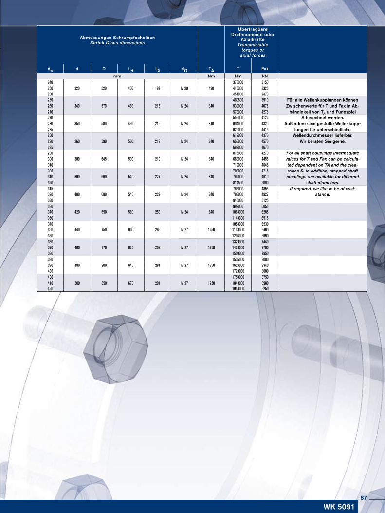
ÜbertragbareDrehmomente oder
Axialkräfte Transmissible
torques oraxial forces
Abmessungen Schrumpfscheiben Shrink Discs dimensions
dw d D LH LD dG TA T Fax
mm Nm Nm kN240 378000 3150250 320 520 460 197 M 20 490 415000 3325260 451000 3470250 489500 3910 Für alle Wellenkupplungen können
Zwischenwerte für T und Fax in Ab-hängigkeit von TA und Fügespiel
260 340 570 480 215 M 24 840 530000 4075270 578000 4275270 556000 4122 S berechnet werden.
Außerdem sind gestufte Wellenkupp-lungen für unterschiedliche
280 350 580 490 215 M 24 840 604000 4320285 629000 4415280 612000 4370 Wellendurchmesser lieferbar.290 360 590 500 219 M 24 840 663000 4570 Wir beraten Sie gerne.295 689000 4670290 618000 4270 For all shaft couplings intermediate300 380 645 530 219 M 24 840 668000 4455 values for T and Fax can be calcula-310 719000 4645 ted dependent on TA and the clea-300 708000 4715 rance S. In addition, stepped shaft310 390 660 540 227 M 24 840 762000 4910 couplings are available for different320 814500 5090 shaft diameters. 315 765000 4855 If required, we like to be of assi-320 400 680 540 227 M 24 840 788000 4927 stance.330 845000 5125330 999000 6055340 420 690 580 253 M 24 840 1068000 6285350 1140000 6515340 1058000 6230350 440 750 600 269 M 27 1250 1130000 6460360 1204000 6690360 1320000 7440370 460 770 620 269 M 27 1250 1420000 7700380 1500000 7950380 1535000 8080390 480 800 645 291 M 27 1250 1626000 8340400 1720000 8600400 1750000 8750410 500 850 670 291 M 27 1250 1840000 8980420 1940000 9250
WK 509187
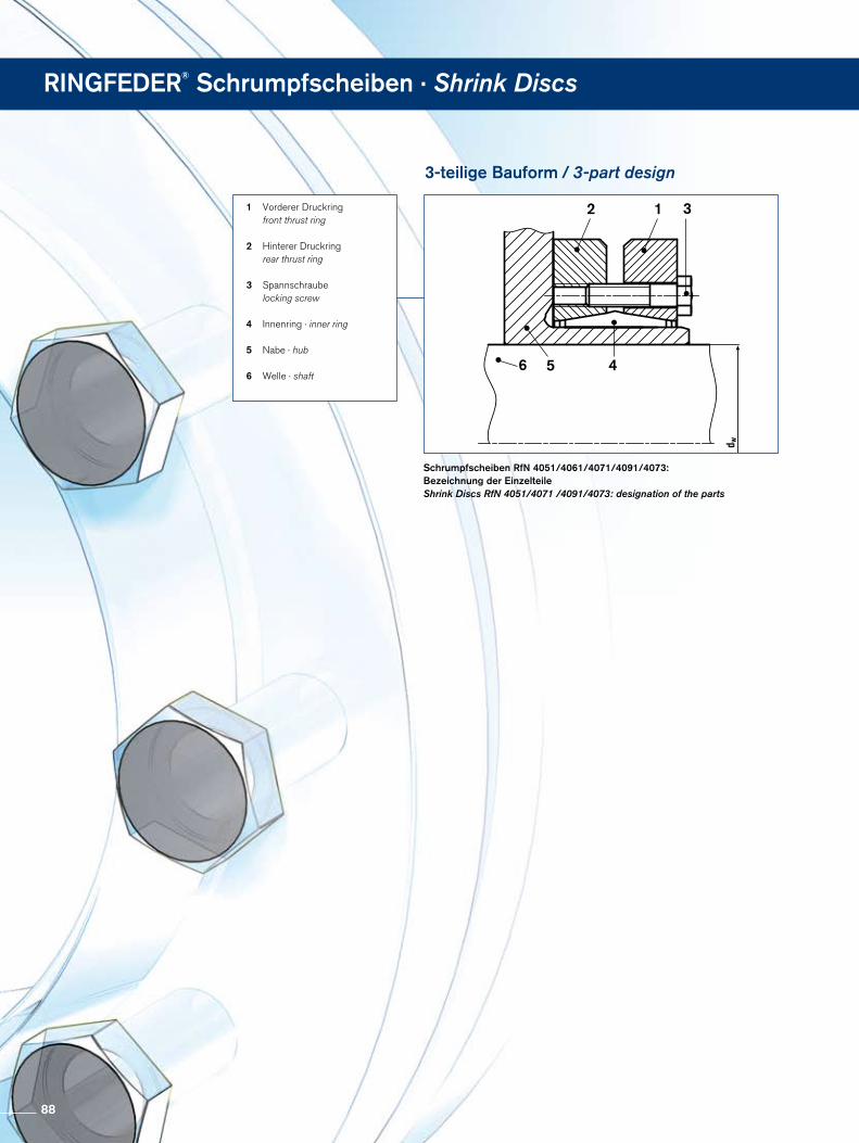
RINGFEDER® Schrumpfscheiben · Shrink Discs
Schrumpfscheiben RfN 4051/4061/4071/4091/4073: Bezeichnung der Einzelteile Shrink Discs RfN 4051/4071 /4091/4073: designation of the parts
1 Vorderer Druckring front thrust ring
2 Hinterer Druckring rear thrust ring
3 Spannschraube locking screw
4 Innenring · inner ring
5 Nabe · hub
6 Welle · shaft6
2 1 3
5 4
3-teilige Bauform / 3-part design
88

Schrumpfscheiben RfN 4051, 4061, 4071, 4091, 4073
Montage
1. Sitzstelle der Schrumpfscheibe auf dem Nabenteil säu-bern und ggf. zur einfacheren Montage leicht ölen.
2. Entfernen der aus Transportgründen eventuell vorhandenen Distanzstücke zwischen den Spannscheiben.
3. Aufschieben der Schrumpfscheibe auf die Nabe. Achtung: Nicht mit den Verspannen beginnen, bevor die
Welle in der Nabenbohrung sitzt, sonst tritt bleibende Ver-formung ein.
4. Nabe auf die Welle schieben und in die geforderte Position bringen. Die Nabenbohrung und die Welle können mit einem dünnflüssigen Öl leicht eingeölt werden um die Montage zu erleichtern.
Achtung: Kein Schmierstoff mit MOS2 verwenden.
5. Verspannen durch gleichmäßiges Anziehen der Schrau-ben, in mehreren Umläufen, mit jeweils ansteigendem Schraubenanzugsdrehmoment. Anziehen der Schrauben der Reihe nach (nicht „überkreuz“), mithilfe eines Drehmo-mentschlüssels. Vor Beginn der Verspannung ist auf eine planparallle Ausrichtung der Spannscheiben zu achten.
6. Kontrolle des Anziehdrehmomentes der Schrauben in der Reihenfolge ihrer Anordnung. Erst wenn alle Schrauben das angegebene Anziehmoment TA erreicht haben, ist die Montage beendet.
Demontage
1. Lösen der Spannschrauben gleichmäßig und der Reihe nach, wieder in mehreren Umläufen um ein Verkanten der Schei-ben auf dem Innenring zu vermeiden. Spannschrauben unter keinen Umständen ganz aus ihren Gewindelöchern entfernen, hierdurch besteht Unfallgefahr.
2. Ausbau der Welle bzw. Abziehen der Nabe von der Welle. Vorher eventuellen Rostansatz auf der Welle und der Nabe entfernen.
3. Abziehen der Schrumpfscheibe von der Nabe.
Installation and removal instructions
Shrink Discs RfN 4051, 4061, 4071, 4091, 4073
Installation
1. Clean the area on the hub where the shrink disc will be seated and oil to ease assembly, if necessary.
2. Removing spacers which may be present between the tensioning discs for transport purposes.
3. Sliding the shrink disc onto the hub. Attention: Do not start tensioning before the shaft is in the
bore of the hub, this may cause permanent deformation.
4. Slide the hub onto the shaft and position as required. Use a thin oil to lightly lubricate the hub bore and shaft to faci-litate assembly.
Attention: Do not use lubricants containing MOS2.
5. Tighten by uniformly tensioning the screws in circular se-quence, increasing the applied torque stepwise after each sequence. Tension the bolts in sequence (not cross-wise), using a torque wrench. Before starting to tension, make sure that the tensioning discs are aligned plane-parallel.
6. Re-check tightening torque by applying it to all screws all the way around. If all screw`s have reached the max. tig-htening torque TA, the assembly is completed.
Removal
1. Loosen the tensioning bolts evenly and in sequence, again in several circular sequences, to avoid jamming of the discs on the inner ring. Never completely remove the tensioning bolts from their threaded holes,
this creates a risk of accidents.
2. Sliding the shrink disc and its attachment part from the shaft. First remove possible traces of rust from the shaft.
3. Releasing the attachment part from the shrink disc.
Montage- und Demontageanweisungen
89
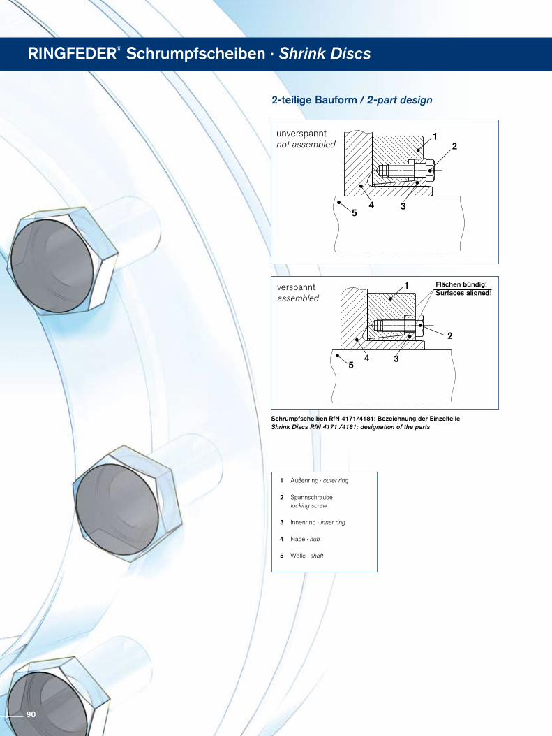
RINGFEDER® Schrumpfscheiben · Shrink Discs
Schrumpfscheiben RfN 4171/4181: Bezeichnung der Einzelteile Shrink Discs RfN 4171 /4181: designation of the parts
1 Außenring · outer ring
2 Spannschraube locking screw
3 Innenring · inner ring
4 Nabe · hub
5 Welle · shaft
5
1
2
4 3
2-teilige Bauform / 2-part design
Flächen bündig! Surfaces aligned!
unverspannt not assembled
verspannt assembled
54 3
2
2
1
90
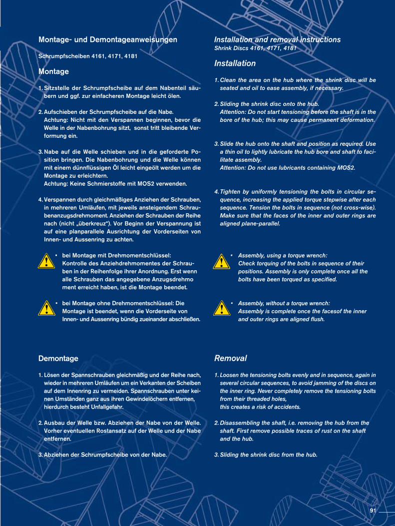
Schrumpfscheiben 4161, 4171, 4181
Montage
1. Sitzstelle der Schrumpfscheibe auf dem Nabenteil säu-bern und ggf. zur einfacheren Montage leicht ölen.
2. Aufschieben der Schrumpfscheibe auf die Nabe. Achtung: Nicht mit den Verspannen beginnen, bevor die
Welle in der Nabenbohrung sitzt, sonst tritt bleibende Ver-formung ein.
3. Nabe auf die Welle schieben und in die geforderte Po-sition bringen. Die Nabenbohrung und die Welle können mit einem dünnflüssigen Öl leicht eingeölt werden um die Montage zu erleichtern.
Achtung: Keine Schmierstoffe mit MOS2 verwenden.
4. Verspannen durch gleichmäßiges Anziehen der Schrauben, in mehreren Umläufen, mit jeweils ansteigendem Schrau-benanzugsdrehmoment. Anziehen der Schrauben der Reihe nach (nicht „überkreuz“). Vor Beginn der Verspannung ist auf eine planparallele Ausrichtung der Vorderseiten von Innen- und Aussenring zu achten.
• bei Montage mit Drehmomentschlüssel: Kontrolle des Anziehdrehmomentes der Schrau- ben in der Reihenfolge ihrer Anordnung. Erst wenn
alle Schrauben das angegebene Anzugsdrehmo ment erreicht haben, ist die Montage beendet.
• bei Montage ohne Drehmomentschlüssel: Die Montage ist beendet, wenn die Vorderseite von Innen- und Aussenring bündig zueinander abschließen.
Demontage
1. Lösen der Spannschrauben gleichmäßig und der Reihe nach, wieder in mehreren Umläufen um ein Verkanten der Scheiben auf dem Innenring zu vermeiden. Spannschrauben unter kei-nen Umständen ganz aus ihren Gewindelöchern entfernen,
hierdurch besteht Unfallgefahr.
2. Ausbau der Welle bzw. Abziehen der Nabe von der Welle. Vorher eventuellen Rostansatz auf der Welle und der Nabe entfernen.
3. Abziehen der Schrumpfscheibe von der Nabe.
Installation and removal instructionsShrink Discs 4161, 4171, 4181
Installation
1. Clean the area on the hub where the shrink disc will be seated and oil to ease assembly, if necessary.
2. Sliding the shrink disc onto the hub. Attention: Do not start tensioning before the shaft is in the
bore of the hub; this may cause permanent deformation.
3. Slide the hub onto the shaft and position as required. Use a thin oil to lightly lubricate the hub bore and shaft to faci-litate assembly.
Attention: Do not use lubricants containing MOS2.
4. Tighten by uniformly tensioning the bolts in circular se-quence, increasing the applied torque stepwise after each sequence. Tension the bolts in sequence (not cross-wise). Make sure that the faces of the inner and outer rings are aligned plane-parallel.
• Assembly, using a torque wrench: Check torquing of the bolts in sequence of their positions. Assembly is only complete once all the
bolts have been torqued as specified.
• Assembly, without a torque wrench: Assembly is complete once the facesof the inner and outer rings are aligned flush.
Removal
1. Loosen the tensioning bolts evenly and in sequence, again in several circular sequences, to avoid jamming of the discs on the inner ring. Never completely remove the tensioning bolts from their threaded holes,
this creates a risk of accidents.
2. Disassembling the shaft, i.e. removing the hub from the shaft. First remove possible traces of rust on the shaft and the hub.
3. Sliding the shrink disc from the hub.
Montage- und Demontageanweisungen
91
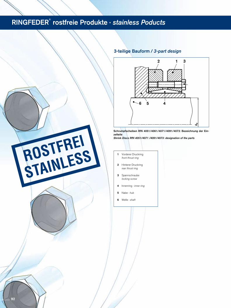
RINGFEDER®
rostfreie Produkte · stainless Poducts
Schrumpfscheiben RfN 4051/4061/4071/4091/4073: Bezeichnung der Ein-zelteile Shrink Discs RfN 4051/4071 /4091/4073: designation of the parts
1 Vorderer Druckring front thrust ring
2 Hinterer Druckring rear thrust ring
3 Spannschraube locking screw
4 Innenring · inner ring
5 Nabe · hub
6 Welle · shaft
6
2 1 3
5 4
3-teilige Bauform / 3-part design
92

Schrumpfscheiben RfN 4071 Rostfrei
Montage
1. Sitzstelle der Schrumpfscheibe auf der Welle säubern und ggf. zur einfacheren Montage leicht ölen.
2. Anbauteil mit der Schrumpfscheibe verbinden. ACHTUNG: Schrauben nur leicht eindrehen.
3. Aufschieben der Schrumpfscheibe auf die Welle.
4. Verspannen durch gleichmäßiges Anziehen der Schrauben, in mehreren Umläufen, mit jeweils ansteigendem Schrauben-anzugsdrehmoment. Anziehen der Schrauben der Reihe nach (nicht „überkreuz“), mithilfe eines Drehmomentschlüssels.
5. Kontrolle des Anziehdrehmomentes der Schrauben in der Reihenfolge ihrer Anordnung. Erst wenn alle Schrauben das angegebene Anziehmoment TA erreicht haben, ist die Montage beendet.
Demontage
1. Lösen der Spannschrauben gleichmäßig und der Reihe nach, wieder in mehreren Umläufen um ein Verkanten der Scheiben auf dem Innenring zu vermeiden. Spannschrauben unter kei-nen Umständen ganz aus ihren Gewindelöchern entfernen,
hierdurch besteht Unfallgefahr.
2. Abziehen der Schrumpfscheibe mit dem Anbauteil von der Welle. Vorher eventuellen Rostansatz auf der Welle entfernen.
3. Lösen des Anbauteiles von der Schrumpfscheibe.
Installation and removal instructions
Shrink Discs RfN 4071 Stainless
Installation
1. Clean the area on the shaft where the shrink disc will be seated and oil lightly to ease assembly, if necessary.
Attention: Do not use lubricants containing MOS2.
2. Fasten the attachment part to the shrink disc. ATTENTION: Tighten the bolts lightly.
3. Sliding the shrink disc onto the shaft.
4. Tighten by uniformly tensioning the bolts in circular se-quence, increasing the applied torque stepwise after each sequence. Tension the bolts in sequence (not cross-wise), using a torque wrench.
5. Re-check tightening torque by applying it to all screws all the way around. If all screw`s have reached the max. tig-htening torque TA, the assembly is completed.
Removal
1. Loosen the tensioning bolts evenly and in sequence, again in several circular sequences, to avoid jamming of the discs on the inner ring. Never completely remove the tensioning bolts from their threaded holes,
this creates a risk of accidents.
2. Sliding the shrink disc and its attachment part from the shaft. First remove possible traces of rust from the shaft.
3. Releasing the attachment part from the shrink disc.
Montage- und Demontageanweisungen
93
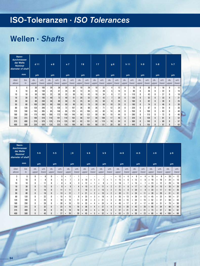
3 6 - 30 - 105 - 20 - 38 - 20 - 32 - 10 - 28 - 10 - 22 - 4 - 12 0 - 75 0 - 30 0 - 18 0 - 12 6 10 - 40 - 130 - 25 - 47 - 25 - 40 - 13 - 35 - 13 - 28 - 5 - 14 0 - 90 0 - 36 0 - 22 0 - 15 10 18 - 50 - 160 - 32 - 59 - 32 - 50 - 16 - 43 - 16 - 34 - 6 - 17 0 - 110 0 - 43 0 - 27 0 - 18 18 30 - 65 - 195 - 40 - 73 - 40 - 61 - 20 - 53 - 20 - 42 - 7 - 20 0 - 130 0 - 52 0 - 33 0 - 21 30 50 - 80 - 240 - 50 - 89 - 50 - 75 - 25 - 64 - 25 - 50 - 9 - 25 0 - 160 0 - 62 0 - 39 0 - 25 50 80 - 100 - 290 - 60 - 106 - 60 - 90 - 30 - 76 - 30 - 60 - 10 - 29 0 - 190 0 - 74 0 - 46 0 - 30 80 120 - 120 - 340 - 72 - 126 - 72 - 107 - 36 - 90 - 36 - 71 - 12 - 34 0 - 220 0 - 87 0 - 54 0 - 35 120 180 - 145 - 395 - 85 - 148 - 85 - 125 - 43 - 106 - 43 - 83 - 14 - 39 0 - 250 0 - 100 0 - 63 0 - 40 180 250 - 170 - 460 - 100 - 172 - 100 - 146 - 50 - 122 - 50 - 96 - 15 - 44 0 - 290 0 - 115 0 - 72 0 - 46 250 315 - 190 - 510 - 110 - 191 - 110 - 162 - 56 - 137 - 56 - 108 - 17 - 49 0 - 320 0 - 130 0 - 81 0 - 52 315 400 - 210 - 570 - 125 - 214 - 125 - 182 - 62 - 151 - 62 - 119 - 18 - 54 0 - 360 0 - 140 0 - 89 0 - 57 400 500 - 230 - 630 - 135 - 232 - 135 - 198 - 68 - 165 - 68 - 131 - 20 - 60 0 - 440 0 - 155 0 - 97 0 - 63
über bis ob. unt. ob. unt. ob. unt. ob. unt. ob. unt. ob. unt. ob. unt. ob. unt. ob. unt. ob. unt. above to upper lower upper lower upper lower upper lower upper lower upper lower upper lower upper lower upper lower upper lower
mm
d 11 e 8 e 7 f 8 f 7 g 6 h 11 h 9 h 8 h 7
µm µm µm µm µm µm µm µm µm µm
Nenn-durchmesser
der WelleNominal
diameter of shaft
3 6 0 - 8 0 - 5 + 7 - 1 – – – – + 12 + 4 + 9 + 4 + 16 + 8 + 20 + 12 6 10 0 - 9 0 - 6 + 7 - 2 + 10 + 1 + 7 + 1 + 15 + 6 + 12 + 6 + 19 + 10 + 24 + 15 10 18 0 - 11 0 - 8 + 8 - 3 + 12 + 1 + 9 + 1 + 18 + 7 + 15 + 7 + 23 + 12 + 29 + 18 18 30 0 - 13 0 - 9 + 9 - 4 + 15 + 2 + 11 + 2 + 21 + 8 + 17 + 8 + 28 + 15 + 35 + 26 30 50 0 - 16 0 - 11 + 11 - 5 - 18 + 2 + 13 + 2 + 25 + 9 + 20 + 9 + 33 + 17 + 42 + 26 50 80 0 - 19 0 - 13 + 12 - 7 + 21 + 2 + 15 + 2 + 30 + 11 + 24 + 11 + 39 + 20 + 51 + 32 80 120 0 - 22 0 - 15 + 13 - 9 + 25 + 3 + 18 + 3 + 35 + 13 + 28 + 13 + 45 + 23 + 59 + 37 120 180 0 - 25 0 - 18 + 14 - 11 + 28 + 3 + 21 + 3 + 40 + 15 + 33 + 15 + 52 + 27 + 68 + 43 180 250 0 - 29 0 - 20 + 16 - 13 + 33 + 4 + 24 + 4 + 46 + 17 + 37 + 17 + 60 + 31 + 79 + 50 250 315 0 - 32 0 - 23 + 16 - 16 + 36 + 4 + 27 + 4 + 53 + 20 + 43 + 20 + 66 + 34 + 88 + 56 315 400 0 - 36 0 - 25 + 18 - 18 + 40 + 4 + 29 + 4 + 57 + 21 + 46 + 21 + 73 + 37 + 98 + 62 400 500 0 - 40 0 - 27 + 20 - 20 + 45 + 5 + 32 + 5 + 63 + 23 + 50 + 23 + 80 + 40 + 108 + 68
über bis ob. unt. ob. unt. ob. unt. ob. unt. ob. unt. ob. unt. ob. unt. ob. unt. ob. unt. above to upper lower upper lower upper lower upper lower upper lower upper lower upper lower upper lower upper lower
mm
h 6 h 5 j 6 k 6 k 5 m 6 m 5 n 6 p 6
µm µm µm µm µm µm µm µm µm
Nenn-durchmesser
der WelleNominal
diameter of shaft
Wellen · Shafts
ISO-Toleranzen · ISO Tolerances
94
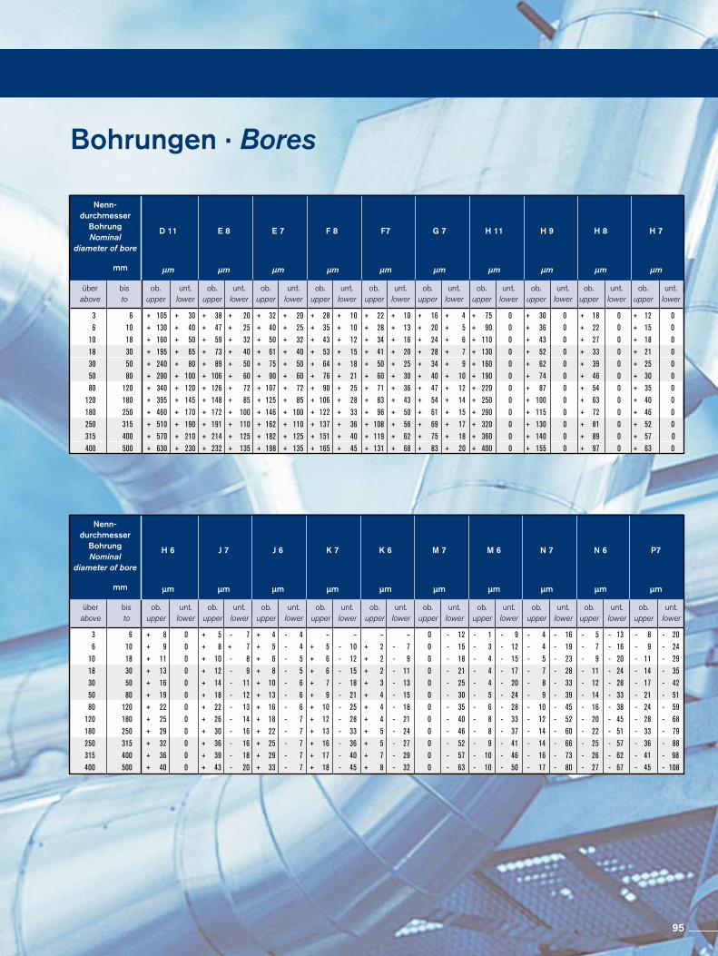
3 6 + 105 + 30 + 38 + 20 + 32 + 20 + 28 + 10 + 22 + 10 + 16 + 4 + 75 0 + 30 0 + 18 0 + 12 0 6 10 + 130 + 40 + 47 + 25 + 40 + 25 + 35 + 10 + 28 + 13 + 20 + 5 + 90 0 + 36 0 + 22 0 + 15 0 10 18 + 160 + 50 + 59 + 32 + 50 + 32 + 43 + 12 + 34 + 16 + 24 + 6 + 110 0 + 43 0 + 27 0 + 18 0 18 30 + 195 + 65 + 73 + 40 + 61 + 40 + 53 + 15 + 41 + 20 + 28 + 7 + 130 0 + 52 0 + 33 0 + 21 0 30 50 + 240 + 80 + 89 + 50 + 75 + 50 + 64 + 18 + 50 + 25 + 34 + 9 + 160 0 + 62 0 + 39 0 + 25 0 50 80 + 290 + 100 + 106 + 60 + 90 + 60 + 76 + 21 + 60 + 30 + 40 + 10 + 190 0 + 74 0 + 46 0 + 30 0 80 120 + 340 + 120 + 126 + 72 + 107 + 72 + 90 + 25 + 71 + 36 + 47 + 12 + 220 0 + 87 0 + 54 0 + 35 0 120 180 + 395 + 145 + 148 + 85 + 125 + 85 + 106 + 28 + 83 + 43 + 54 + 14 + 250 0 + 100 0 + 63 0 + 40 0 180 250 + 460 + 170 + 172 + 100 + 146 + 100 + 122 + 33 + 96 + 50 + 61 + 15 + 290 0 + 115 0 + 72 0 + 46 0 250 315 + 510 + 190 + 191 + 110 + 162 + 110 + 137 + 36 + 108 + 56 + 69 + 17 + 320 0 + 130 0 + 81 0 + 52 0 315 400 + 570 + 210 + 214 + 125 + 182 + 125 + 151 + 40 + 119 + 62 + 75 + 18 + 360 0 + 140 0 + 89 0 + 57 0 400 500 + 630 + 230 + 232 + 135 + 198 + 135 + 165 + 45 + 131 + 68 + 83 + 20 + 400 0 + 155 0 + 97 0 + 63 0
über bis ob. unt. ob. unt. ob. unt. ob. unt. ob. unt. ob. unt. ob. unt. ob. unt. ob. unt. ob. unt. above to upper lower upper lower upper lower upper lower upper lower upper lower upper lower upper lower upper lower upper lower
mm
D 11 E 8 E 7 F 8 F7 G 7 H 11 H 9 H 8 H 7
µm µm µm µm µm µm µm µm µm µm
Nenn-durchmesser
BohrungNominal
diameter of bore
3 6 + 8 0 + 5 - 7 + 4 - 4 – – – – 0 - 12 - 1 - 9 - 4 - 16 - 5 - 13 - 8 - 20 6 10 + 9 0 + 8 + 7 + 5 - 4 + 5 - 10 + 2 - 7 0 - 15 - 3 - 12 - 4 - 19 - 7 - 16 - 9 - 24 10 18 + 11 0 + 10 - 8 + 6 - 5 + 6 - 12 + 2 - 9 0 - 18 - 4 - 15 - 5 - 23 - 9 - 20 - 11 - 29 18 30 + 13 0 + 12 - 9 + 8 - 5 + 6 - 15 + 2 - 11 0 - 21 - 4 - 17 - 7 - 28 - 11 - 24 - 14 - 35 30 50 + 16 0 + 14 - 11 + 10 - 6 + 7 - 18 + 3 - 13 0 - 25 - 4 - 20 - 8 - 33 - 12 - 28 - 17 - 42 50 80 + 19 0 + 18 - 12 + 13 - 6 + 9 - 21 + 4 - 15 0 - 30 - 5 - 24 - 9 - 39 - 14 - 33 - 21 - 51 80 120 + 22 0 + 22 - 13 + 16 - 6 + 10 - 25 + 4 - 18 0 - 35 - 6 - 28 - 10 - 45 - 16 - 38 - 24 - 59 120 180 + 25 0 + 26 - 14 + 18 - 7 + 12 - 28 + 4 - 21 0 - 40 - 8 - 33 - 12 - 52 - 20 - 45 - 28 - 68 180 250 + 29 0 + 30 - 16 + 22 - 7 + 13 - 33 + 5 - 24 0 - 46 - 8 - 37 - 14 - 60 - 22 - 51 - 33 - 79 250 315 + 32 0 + 36 - 16 + 25 - 7 + 16 - 36 + 5 - 27 0 - 52 - 9 - 41 - 14 - 66 - 25 - 57 - 36 - 88 315 400 + 36 0 + 39 - 18 + 29 - 7 + 17 - 40 + 7 - 29 0 - 57 - 10 - 46 - 16 - 73 - 26 - 62 - 41 - 98 400 500 + 40 0 + 43 - 20 + 33 - 7 + 18 - 45 + 8 - 32 0 - 63 - 10 - 50 - 17 - 80 - 27 - 67 - 45 - 108
über bis ob. unt. ob. unt. ob. unt. ob. unt. ob. unt. ob. unt. ob. unt. ob. unt. ob. unt. ob. unt. above to upper lower upper lower upper lower upper lower upper lower upper lower upper lower upper lower upper lower upper lower
mm
H 6 J 7 J 6 K 7 K 6 M 7 M 6 N 7 N 6 P7
µm µm µm µm µm µm µm µm µm µm
Nenn-durchmesser
BohrungNominal
diameter of bore
Bohrungen · Bores
95

Notizen · Notes
96

Notizen · Notes
97

RINGFEDER PT GMBH · Oberschlesienstr. 15 · D47807 Krefeld · Postfach / P.O. Box 130619 · D47758 KrefeldTel. / Phone +49 (0) 2151835232 · Fax +49 (0) 215183519232 · http://www.ringfeder.com
email: [email protected]
Um unseren Mitarbeitern die Beratung Ihres Problems zu erleichtern und Irrtümern bzw. Fehlern vorzubeugen, sollte Ihre Anfrage die nachfolgenden Angaben enthalten / To take it easier for our technical staff and to avoid errors or mistakes your enquiry should include the following information:
Angaben für den Beratungs-Service / Information for technical service
Maximal auftretende Belastungen / Expected maximum loads:
Max. Drehmoment / Max. torque T max. = NmMax. Biegemoment / Max. bending moment M max. = NmMax. Axiallast / Max. axial load F max. = kNMax. Radiallast / Max. radial load Fr max. = kN
Dimensionen, Werkstoffe / Dimensions, materials:
Durchmesser der Welle / shaft diameter dw = mmBei Hohlwelle, Innendurchmesserin case of hollow shaft, internal diameter dB = mmDrehzahl der Welle / Speed/revolutions n = 1/minAußendurchmesser Nabe / Hub outside diameter DN = mmNabenbreite / Hub width B = mmNabenmaterial bzw. Streckgrenze / Hub material/yield strength Rp0,2N = N/mm2
Wellenmaterial bzw. Streckgrenze / Shaft material/yield strength Rp0,2W = N/mm2
Betriebstemperatur der Verbindung / Temperature of the connection Temp. = °C
Sonstige Angaben / Additional informations:
Bitte fügen Sie Ihrer Anfrage eine Zeichnung oder Skizze bei!Please send a drawing or sketch together with your enquiry!
Für die Auslegung von RINGFEDER® Welle-Nabe-VerbindungTo get a design proposal for RINGFEDER® shaft-hub-connection
RINGFEDER POWER TRANSMISSION GMBH, 47807 Krefeld
Fax 0 21 51 / 8 35 - 19 232 Absender/Adresser
Firma / Company
z. Hd. / attn. Abt. / Dept.
Adresse / Adress
Tel. / Phone Fax
Wir bitten um ein Beratungsgespräch, bitte rufen sie uns unter /We ask for a consulting discussion. Please call us under zurück / back
Fax-Anfrage / Fax Inquiry
98

Delivery ProgrammeLieferprogramm · Delivery Program
Locking Devices
SpannsätzeLocking Assemblies
SpannelementeLocking Elements
SchrumpfscheibenShrink Discs
Damping Technology
ReibungsfedernFriction Springs
DEFORM plus®
DEFORM plus® RHydro Elastische DämpferFluid Elastomeric Damper
Special Solutions
CouplingsMagnetkupplungenMagnetic Couplings
ElastomerkupplungenServo-Insert Couplings
SicherheitskupplungenSafety Couplings
RINGflex® – torsionssteife Lamellenkupplungen / torsionallyrigid Disc Couplings
SpannsätzeLocking Assemblies
FlanschkupplungenFlange Couplings
ZwischenwellenLine Shafts
SmartLock
WellenkupplungenShaft Couplings
MetallbalgkupplungenMetal Bellow Couplings
99

www.ringfeder.com · www.gerwah.com
RINGFEDER POWER TRANSMISSION GMBH · Oberschlesienstr. 15, D47807 Krefeld, Germany · Phone: +49 (0) 2151 835232 Fax: +49 (0) 2151 83519232 · Email: [email protected]
GERWAH GmbH · Lützeltaler Str. 5a, D63868 Großwallstadt, Germany · Phone: +49 (0) 6022 22040 · Fax: +49 (0) 6022 220411 Email: [email protected]
RINGFEDER POWER TRANSMISSION INDIA PRIVATE LIMITED · Plot No. 4, Door No. 220, Mount Poonamallee High Road, Kattupakkam, Chennai – 600 056, India · Phone: +91 44 26496411 · Fax: +91 44 26496422 · Email: [email protected]mail: [email protected]
RINGFEDER Corporation · 165 Carver Avenue, P.O. Box 691 Westwood, NJ 07675, USA · Toll Free: +1 888 7464333Phone: +1 201 666 3320 · Fax: +1 201 664 6053 · Email: [email protected] · Email: [email protected]