Embed Size (px)
Citation preview
SCR- und Partikel-Abgasnachbehandlungssysteme für Heavy Duty EU VI und NRMM Stufe IV; Die Zukunft auf dem Prüfstand
SCR and Particle Exhaust Gas Aftertreatment Systems for Heavy-Duty EU VI and NRMM Stage IV; The Future is being scrutinized
Dipl. Ing. Wolfgang Maus, Dipl. Ing. Rolf Brück, Dipl. Ing. Peter Hirth,
Emitec GmbH, Lohmar
1
SCR and Particle Exhaust Gas Aftertreatment Systems for Heavy-Duty EU VI and NRMM Stage IV; The Future is being scrutinized
Abstract Due to the high proportion of NOx emissions generated by road traffic [1], current and future legislation on NOx limits has a major impact on the automotive industry. In Europe this includes not only the increasingly tighter annual average NO2 emission limits for urban areas, but also the proposed NOx limits of 80 mg/km for EU6 passenger cars and 400 mg/kWh for heavy-duty commercial vehicles. The US has passed similar legislation in the form of US BIN 5 for passenger cars and US 2010 for heavy-duty trucks.
There is no doubt that there is a need for exhaust aftertreatment systems that can meet these limits by reducing NOx. However, the technical details of the catalysts capable of fulfilling these requirements are still unclear, especially because the necessary systems have to combine the conflicting demands of cost, efficiency, space requirement, and fuel consumption/CO2 emissions.
Against this background, this paper deals primarily with the SCRi® system for NOx reduction, which consists of a catalyst system with integrated particulate reduction and a urea dosing unit. It also tries to establish which catalyst design and structure provide the best solution with respect to installation space, pressure loss and effectiveness. The catalyst performance coefficient (CPC) and the SCRi® system were defined on the basis of tests carried out with a synthetic gas reactor and on the engine bench.
2
SCR and Particle Exhaust Gas Aftertreatment Systems for Heavy-Duty EU VI and NRMM Stage IV; The Future is being scrutinized
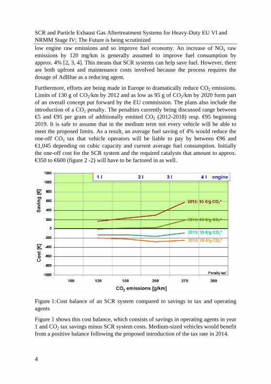
1. Introduction In addition to gaseous emissions and particle mass, EU 6 legislation for passenger cars and EU VI legislation for commercial vehicles for the first time also limit particle numbers. Attention is focused mainly on the reduction of nanoparticles (10-100 nm), which are considered harmful to health. Table 1 lists the limits for EU 6 passenger cars and EU VI heavy-duty vehicles. The limits for particle numbers are currently still under discussion.
Cars Heavy duty (ETC)
Limit PM
[mg/km]
PN
[#/km]
NOx
[g/km]
PM
[g/kWh]
PN
[#/kWh]
NOx
[g/kWh]
EU 5 / V 5.0 - 0.18 0.03 - 2.0
EU 6 / VI
4.5 6 x 10**11
0.08 0.01 6 x 10**11
0.4
Table 1: EU V/VI limits for heavy-duty vehicles and EU 5/6 limits for cars
The development of new engines, platforms and aftertreatment systems that meet these legal requirements is subject to numerous demands. Alongside performance and torque, fuel consumption and engine raw emissions are also relevant because they determine the requirements for catalyst technology. Platform developments must take particular account of installation space for correspondingly dimensioned close-coupled catalysts and filters. Compact, multi-functional catalyst systems are gaining in importance because aerodynamics substantially reduces the amount of available space and engine package and crash safety take priority.
This is particularly true because new European exhaust legislation (for passenger cars and commercial vehicles) leads to gradually higher requirements for catalyst effectiveness and long-term stability. To meet these requirements the volume-specific effectiveness of the catalysts needs to be increased without raising exhaust gas backpressure, if possible. These developments are also intended to help minimise costs.
The primary aim of engine developers is to meet emission limits solely through engine-based measures. This approach generally leads to higher fuel consumption, especially when it comes to lowering NOx emissions. The application of SCR (selective catalytic reduction) aftertreatment makes it possible not further to priorize
3
SCR and Particle Exhaust Gas Aftertreatment Systems for Heavy-Duty EU VI and NRMM Stage IV; The Future is being scrutinized low engine raw emissions and so improve fuel economy. An increase of NOx raw emissions by 120 mg/km is generally assumed to improve fuel consumption by approx. 4% [2, 3, 4]. This means that SCR systems can help save fuel. However, there are both upfront and maintenance costs involved because the process requires the dosage of AdBlue as a reducing agent.
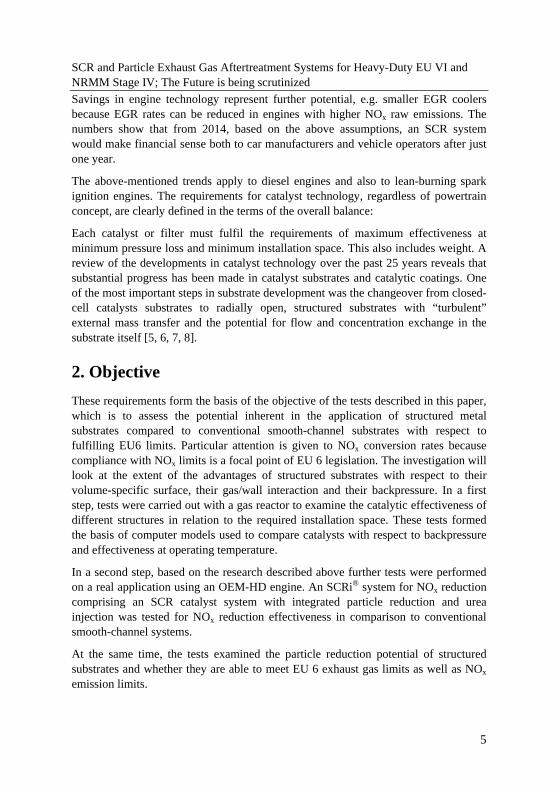
Furthermore, efforts are being made in Europe to dramatically reduce CO2 emissions. Limits of 130 g of CO2/km by 2012 and as low as 95 g of CO2/km by 2020 form part of an overall concept put forward by the EU commission. The plans also include the introduction of a CO2 penalty. The penalties currently being discussed range between €5 and €95 per gram of additionally emitted CO2 (2012-2018) resp. €95 beginning 2019. It is safe to assume that in the medium term not every vehicle will be able to meet the proposed limits. As a result, an average fuel saving of 4% would reduce the one-off CO2 tax that vehicle operators will be liable to pay by between €96 and €1,045 depending on cubic capacity and current average fuel consumption. Initially the one-off cost for the SCR system and the required catalysts that amount to approx. €350 to €600 (figure 2 -2) will have to be factored in as well.
Figure 1: Cost balance of an SCR system compared to savings in tax and operating agents
Figure 1 shows this cost balance, which consists of savings in operating agents in year 1 and CO2 tax savings minus SCR system costs. Medium-sized vehicles would benefit from a positive balance following the proposed introduction of the tax rate in 2014.
4
SCR and Particle Exhaust Gas Aftertreatment Systems for Heavy-Duty EU VI and NRMM Stage IV; The Future is being scrutinized Savings in engine technology represent further potential, e.g. smaller EGR coolers because EGR rates can be reduced in engines with higher NOx raw emissions. The numbers show that from 2014, based on the above assumptions, an SCR system would make financial sense both to car manufacturers and vehicle operators after just one year.
The above-mentioned trends apply to diesel engines and also to lean-burning spark ignition engines. The requirements for catalyst technology, regardless of powertrain concept, are clearly defined in the terms of the overall balance:
Each catalyst or filter must fulfil the requirements of maximum effectiveness at minimum pressure loss and minimum installation space. This also includes weight. A review of the developments in catalyst technology over the past 25 years reveals that substantial progress has been made in catalyst substrates and catalytic coatings. One of the most important steps in substrate development was the changeover from closed-cell catalysts substrates to radially open, structured substrates with “turbulent” external mass transfer and the potential for flow and concentration exchange in the substrate itself [5, 6, 7, 8].
2. Objective These requirements form the basis of the objective of the tests described in this paper, which is to assess the potential inherent in the application of structured metal substrates compared to conventional smooth-channel substrates with respect to fulfilling EU6 limits. Particular attention is given to NOx conversion rates because compliance with NOx limits is a focal point of EU 6 legislation. The investigation will look at the extent of the advantages of structured substrates with respect to their volume-specific surface, their gas/wall interaction and their backpressure. In a first step, tests were carried out with a gas reactor to examine the catalytic effectiveness of different structures in relation to the required installation space. These tests formed the basis of computer models used to compare catalysts with respect to backpressure and effectiveness at operating temperature.
In a second step, based on the research described above further tests were performed on a real application using an OEM-HD engine. An SCRi® system for NOx reduction comprising an SCR catalyst system with integrated particle reduction and urea injection was tested for NOx reduction effectiveness in comparison to conventional smooth-channel systems.
At the same time, the tests examined the particle reduction potential of structured substrates and whether they are able to meet EU 6 exhaust gas limits as well as NOx emission limits.
5
SCR and Particle Exhaust Gas Aftertreatment Systems for Heavy-Duty EU VI and NRMM Stage IV; The Future is being scrutinized
3. Potential analysis of structured substrates on the gas test bench It is a well known fact that catalyst effectiveness in warmed-up condition is influenced by substrate properties, i.e. by increasing the specific surface and improving contact between gas and wall, regardless of the type of catalytic reaction that is to take place. The key parameter that describes the transport properties is the mass transfer coefficient β, which is the analogue of the heat transfer coefficient α. Under mass transfer limited conditions catalyst effectiveness is linked to the coefficient β on the basis of the following correlation (formula 1):
Formula (1):
⎥⎥⎥
⎦
⎤
⎢⎢⎢
⎣
⎡−−=−=
VGSA
cc
Uein
aus.exp11 β
The coefficient β can be expressed according to
hdDSh 12=βFormula (2):
as a function of the Sherwood number, which itself depends primarily on key catalyst parameters, such as substrate length, hydraulic channel diameter and key flow parameters, such as the Reynolds number and the Sc number:
Formula (3): ),,,Re( Kath LdScfSh =
The mass transfer coefficient describing the flux from the gas to the channel wall is known to depend very much on the shape and fluid dynamic design of the channel (i.e. the channel or catalyst structure). Typical options for the design of the channel shape include the introduction of guide blades (LS structure) [5, 9] or holes in the channel wall [7]. These types of structures, including the LS or PE designs, have already been discussed in a number of previous papers.
It is of central importance that these structures are able to produce high values for the emission-relevant product β x GSA under suitable operating conditions, as these values make it possible to design very compact substrates. Some of these structures
6
SCR and Particle Exhaust Gas Aftertreatment Systems for Heavy-Duty EU VI and NRMM Stage IV; The Future is being scrutinized also generate low backpressure, which in conjunction with high catalytic efficiency enables them to make an excellent contribution to solving the problems described in the introduction.
The above-mentioned computer models were defined on the basis of the following processes:
• Measuring the conversion rate under variation of design and process parameters and evaluation of the characteristic Sherwood numbers for standard, PE and LS structures and for a ceramic substrate using propene oxidation on the gas test bench. Propene oxidation was chosen because mass transfer controlled regime begins here at fairly low temperatures (>350°C).
• From this basis correlations for Sherwood number as a function of Re, dh and L was derived, as were the pressure loss models for each of the four structures by matching the measured data to typical equations that included all the above-mentioned parameters.
• In a next step, these equations were used to demonstrate the potentials of the individual structures with respect to the ratio between effectiveness and pressure loss on a comparative basis to select particularly advantageous structures.
• Finally, the results of this comparison were taken into account while designing an SCRi® system for NOx aftertreatment. This was subsequently tested on the engine test bench and the results were compared to those of a standard SCR system without structured channels. This test also examined whether structured substrates were able to meet EU 6 requirements.
7
SCR and Particle Exhaust Gas Aftertreatment Systems for Heavy-Duty EU VI and NRMM Stage IV; The Future is being scrutinized
3.1 Evaluation of characteristic Sherwood numbers for various substrate structures
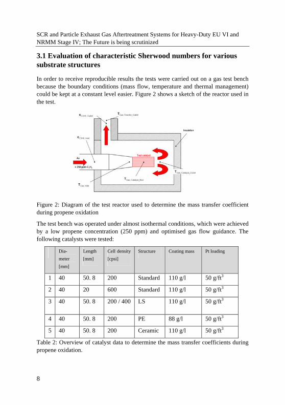
In order to receive reproducible results the tests were carried out on a gas test bench because the boundary conditions (mass flow, temperature and thermal management) could be kept at a constant level easier. Figure 2 shows a sketch of the reactor used in the test.
Figure 2: Diagram of the test reactor used to determine the mass transfer coefficient during propene oxidation
The test bench was operated under almost isothermal conditions, which were achieved by a low propene concentration (250 ppm) and optimised gas flow guidance. The following catalysts were tested:
Dia-meter [mm]
Length [mm]
Cell density [cpsi]
Structure Coating mass Pt loading
1 40 50. 8 200 Standard 110 g/l 50 g/ft3
2 40 20 600 Standard 110 g/l 50 g/ft3
3 40 50. 8 200 / 400 LS 110 g/l 50 g/ft3
4 40 50. 8 200 PE 88 g/l 50 g/ft3
5 40 50. 8 200 Ceramic 110 g/l 50 g/ft3
Table 2: Overview of catalyst data to determine the mass transfer coefficients during propene oxidation.
8
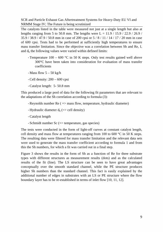
SCR and Particle Exhaust Gas Aftertreatment Systems for Heavy-Duty EU VI and NRMM Stage IV; The Future is being scrutinized The catalysts listed in the table were measured not just at a single length but also at lengths ranging from 5 to 50.8 mm. The lengths were L = 11.9 / 15.9 / 22.9 / 26.9 / 35.9 / 38.9 / 47.9 / 50.8 mm in case of 200 cpsi or 5 / 8 / 11 / 14 / 17 / 20 mm in case of 600 cpsi. Tests had to be performed at sufficiently high temperatures to ensure mass transfer limitation. Since the objective was a correlation between Sh and Re, L and dh the following values were varied within defined limits:
- Temperature 100 – 600 °C in 50 K steps. Only test results gained well above 300°C have been taken into consideration for evaluation of mass transfer coefficients
- Mass flow 5 – 50 kg/h
- Cell density: 200 – 600 cpsi
- Catalyst length: 5- 50.8 mm
This produced a large pool of data for the following fit parameters that are relevant to the adaptations of the Sh correlation according to formula (3):
- Reynolds number Re ( => mass flow, temperature, hydraulic diameter)
- Hydraulic diameter dh (=> cell density)
- Catalyst length
- Schmidt number Sc (=> temperature, gas species)
The tests were conducted in the form of light-off curves at constant catalyst length, cell density and mass flow at temperatures ranging from 100 to 600 °C in 50 K steps. The resulting data were filtered for mass transfer limitation and the relevant data sets were used to generate the mass transfer coefficient according to formula 1 and from this the Sh numbers, for which a fit was carried out in a final step.
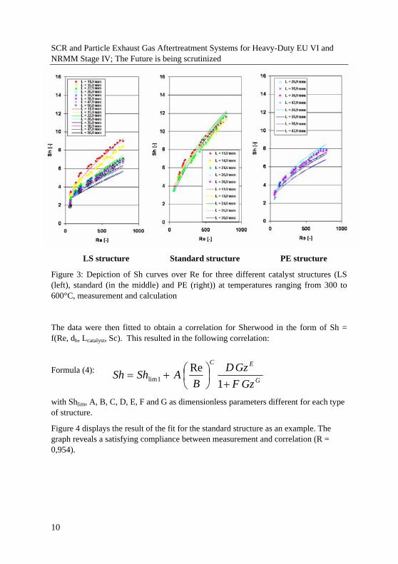
Figure 3 shows the results in the form of Sh as a function of Re for three substrate types with different structures as measurement results (dots) and as the calculated results of the fit (line). The LS structure can be seen to have great advantages conceptually over the smooth standard channel, while the PE structure produces higher Sh numbers than the standard channel. This fact is easily explained by the additional number of edges in substrates with an LS or PE structure where the flow boundary layer has to be re-established in terms of inlet flow [10, 11, 12].
9
SCR and Particle Exhaust Gas Aftertreatment Systems for Heavy-Duty EU VI and NRMM Stage IV; The Future is being scrutinized
LS structure Standard structure PE structure
Figure 3: Depiction of Sh curves over Re for three different catalyst structures (LS (left), standard (in the middle) and PE (right)) at temperatures ranging from 300 to 600°C, measurement and calculation
The data were then fitted to obtain a correlation for Sherwood in the form of Sh = f(Re, dh, Lcatalyst, Sc). This resulted in the following correlation:
G
EC
GzFGzD
BAShSh
+⎟⎠⎞
⎜⎝⎛+=
1Re
1limFormula (4):
with Shlim, A, B, C, D, E, F and G as dimensionless parameters different for each type of structure.
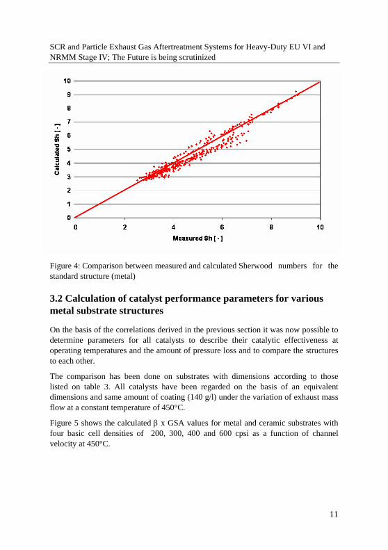
Figure 4 displays the result of the fit for the standard structure as an example. The graph reveals a satisfying compliance between measurement and correlation (R = 0,954).
10
SCR and Particle Exhaust Gas Aftertreatment Systems for Heavy-Duty EU VI and NRMM Stage IV; The Future is being scrutinized .
Figure 4: Comparison between measured and calculated Sherwood numbers for the standard structure (metal)
3.2 Calculation of catalyst performance parameters for various metal substrate structures
On the basis of the correlations derived in the previous section it was now possible to determine parameters for all catalysts to describe their catalytic effectiveness at operating temperatures and the amount of pressure loss and to compare the structures to each other.
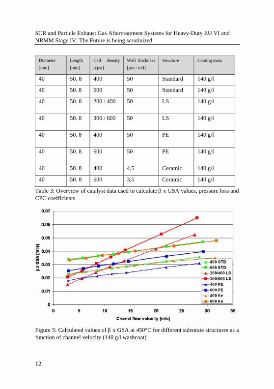
The comparison has been done on substrates with dimensions according to those listed on table 3. All catalysts have been regarded on the basis of an equivalent dimensions and same amount of coating (140 g/l) under the variation of exhaust mass flow at a constant temperature of 450°C.
Figure 5 shows the calculated β x GSA values for metal and ceramic substrates with four basic cell densities of 200, 300, 400 and 600 cpsi as a function of channel velocity at 450°C.
11
SCR and Particle Exhaust Gas Aftertreatment Systems for Heavy-Duty EU VI and NRMM Stage IV; The Future is being scrutinized
Diameter [mm]
Length [mm]
Cell density [cpsi]
Wall thickness [µm / mil]
Structure Coating mass
40 50. 8 400 50 Standard 140 g/l
40 50. 8 600 50 Standard 140 g/l
40 50. 8 200 / 400 50 LS 140 g/l
40 50. 8 300 / 600 50 LS 140 g/l
40 50. 8 400 50 PE 140 g/l
40 50. 8 600 50 PE 140 g/l
40 50. 8 400 4,5 Ceramic 140 g/l
40 50. 8 600 3,5 Ceramic 140 g/l
Table 3: Overview of catalyst data used to calculate β x GSA values, pressure loss and CPC coefficients
Figure 5: Calculated values of β x GSA at 450°C for different substrate structures as a function of channel velocity (140 g/l washcoat)
12
SCR and Particle Exhaust Gas Aftertreatment Systems for Heavy-Duty EU VI and NRMM Stage IV; The Future is being scrutinized The following phenomena can be derived from the data:
• Both LS structures are substantially more affected by channel velocity than any other type
• This means that there is a typical channel velocity for each type above which it can be replaced by an LS structure with lower basic cell density (for example: LS 200/400 replaces 400 STD at a velocity above approx. 10 m/s)
• On the other hand, PE structures behave similarly to standard channels, although compared to the STD substrates the β x GSA value for PE is not reduced to the extent expected due to the GSA loss. This results from a gain in β of PE relative to the standard structure
• The values for (standard) metal and ceramic structures are almost identical at comparable cell densities.
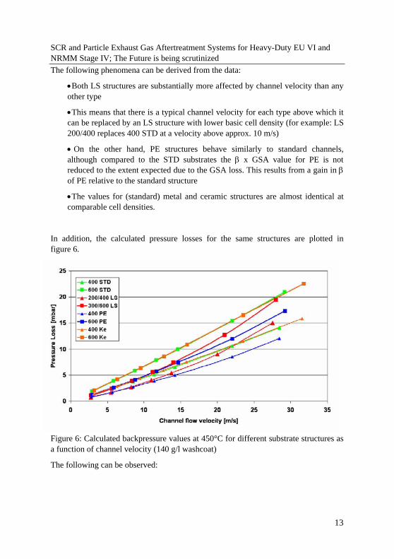
In addition, the calculated pressure losses for the same structures are plotted in figure 6.
Figure 6: Calculated backpressure values at 450°C for different substrate structures as a function of channel velocity (140 g/l washcoat)
The following can be observed:
13
SCR and Particle Exhaust Gas Aftertreatment Systems for Heavy-Duty EU VI and NRMM Stage IV; The Future is being scrutinized
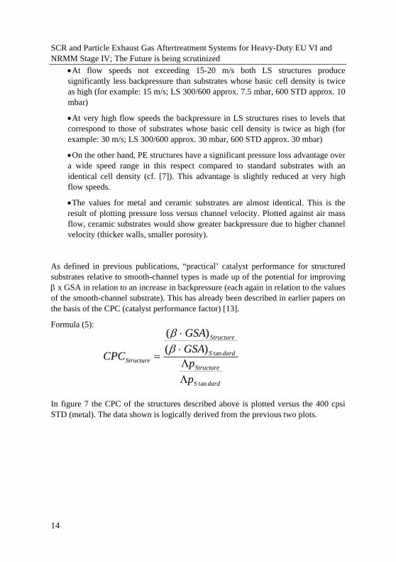
• At flow speeds not exceeding 15-20 m/s both LS structures produce significantly less backpressure than substrates whose basic cell density is twice as high (for example: 15 m/s; LS 300/600 approx. 7.5 mbar, 600 STD approx. 10 mbar)
• At very high flow speeds the backpressure in LS structures rises to levels that correspond to those of substrates whose basic cell density is twice as high (for example: 30 m/s; LS 300/600 approx. 30 mbar, 600 STD approx. 30 mbar)
• On the other hand, PE structures have a significant pressure loss advantage over a wide speed range in this respect compared to standard substrates with an identical cell density (cf. [7]). This advantage is slightly reduced at very high flow speeds.
• The values for metal and ceramic substrates are almost identical. This is the result of plotting pressure loss versus channel velocity. Plotted against air mass flow, ceramic substrates would show greater backpressure due to higher channel velocity (thicker walls, smaller porosity).
As defined in previous publications, “practical’ catalyst performance for structured substrates relative to smooth-channel types is made up of the potential for improving β x GSA in relation to an increase in backpressure (each again in relation to the values of the smooth-channel substrate). This has already been described in earlier papers on the basis of the CPC (catalyst performance factor) [13].
Formula (5):
dardS
Structure
dardS
Structure
Structure
pp
GSAGSA
CPC
tan
tan)()(
ΛΛ⋅⋅
=ββ
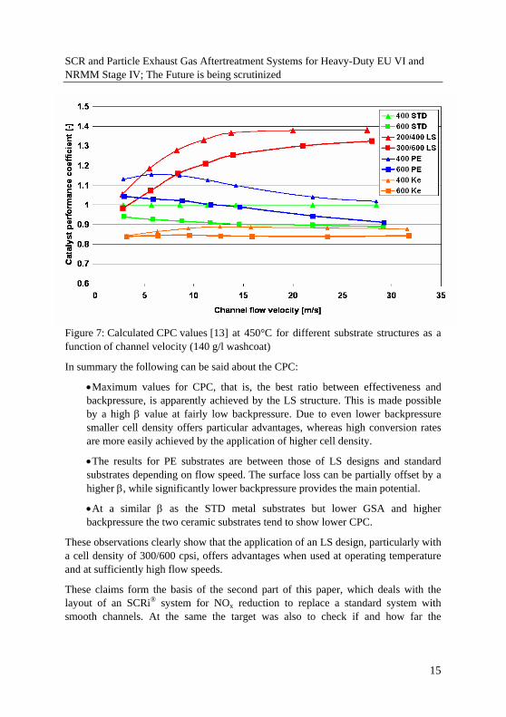
In figure 7 the CPC of the structures described above is plotted versus the 400 cpsi STD (metal). The data shown is logically derived from the previous two plots.
14
SCR and Particle Exhaust Gas Aftertreatment Systems for Heavy-Duty EU VI and NRMM Stage IV; The Future is being scrutinized
Figure 7: Calculated CPC values [13] at 450°C for different substrate structures as a function of channel velocity (140 g/l washcoat)
In summary the following can be said about the CPC:
• Maximum values for CPC, that is, the best ratio between effectiveness and backpressure, is apparently achieved by the LS structure. This is made possible by a high β value at fairly low backpressure. Due to even lower backpressure smaller cell density offers particular advantages, whereas high conversion rates are more easily achieved by the application of higher cell density.
• The results for PE substrates are between those of LS designs and standard substrates depending on flow speed. The surface loss can be partially offset by a higher β, while significantly lower backpressure provides the main potential.
• At a similar β as the STD metal substrates but lower GSA and higher backpressure the two ceramic substrates tend to show lower CPC.
These observations clearly show that the application of an LS design, particularly with a cell density of 300/600 cpsi, offers advantages when used at operating temperature and at sufficiently high flow speeds.
These claims form the basis of the second part of this paper, which deals with the layout of an SCRi® system for NOx reduction to replace a standard system with smooth channels. At the same the target was also to check if and how far the
15
SCR and Particle Exhaust Gas Aftertreatment Systems for Heavy-Duty EU VI and NRMM Stage IV; The Future is being scrutinized regularities derived from tests on oxidation catalysts can be applied on SCR catalyst systems.
The following section describes the various steps of the research.
4. The SCRi® system on the engine test bench Based on the findings from the previous section an SCRi system was configured with the aim of replacing a conventional smooth channel catalyst system. The SCRi system was to be compared to a standard system with respect to NOx conversion rates and ultimately also analysed to see whether it had sufficient potential to meet EU 6 limits.
The necessary work was carried out on the engine test bench using an HD engine, as described below. In addition, the effectiveness of a particle reduction system integrated in the SCRi® system was also assessed.
A concept was investigated, which – in first step without changing engine parameters - would demonstrate that appropriate exhaust aftertreatment was able to meet the EU VI limits currently under discussion.
4.1 Catalyst system
Table 4 lists the dimensions, technical data and the properties of the catalytic coating of the catalysts of the two systems to be compared.
HC/CO/NO oxidation Hydrolysis and PM reduction NOx reduction
Substrate Coating Substrate Coating Substrate Coating
Ceramic system (EU V)
none none none none 2 x 241.3 x (190 + 190) mm / 400 cpsi / 5 mil, V = 34.8 l
SCR, 220 g/l + NH3 slip catalyst zone coated
Metal system (EU VI)
Ø 342 x 120 mm / 200/400 LS, V = 11.0 l
DOC, 40 g Pt / ft³
2 x 251.4 x (174 + 174) mm / 200 cpsi PMM, V = 17.3 l
174 mm with 25 g/l hydrolysis / 174 mm without
2 x 251.4 x (174 + 90) mm / 300/600 LS, V = 26.2 l
SCR, 220 g/l
Table 4: Overview of catalyst data for both SCR systems
16
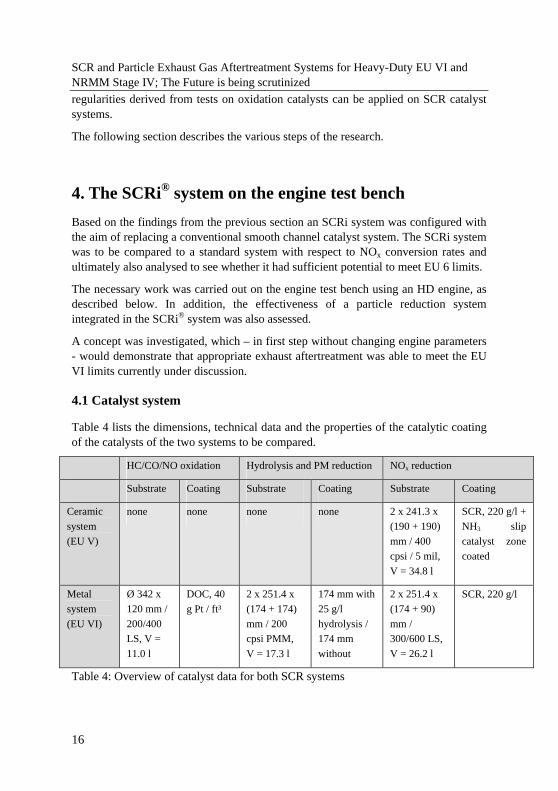
SCR and Particle Exhaust Gas Aftertreatment Systems for Heavy-Duty EU VI and NRMM Stage IV; The Future is being scrutinized In the metal substrate-based combination of particle reduction and NOx reduction AdBlue was injected upstream in front of the partial flow filter. In view of future test procedures involving cold starts and low loads, the metal system included an oxidation catalyst fitted upstream from the actual SCRi® system, resulting in the overall systems described in table 4 and figure 8. Oxidation catalyst and hydrolysis catalyst were absent in the EU V system, but are needed for EU VI. The metal substrate system, which has in regard to NOx conversion a smaller volume than the ceramic system, is therefore operated at significantly higher space velocities in line with the volume ratios.
Figure 8: Diagram of the catalyst test setup. Top: original EU V SCR system; bottom: modified metal version for EU VI
4.2 Test setup / test engine
The test was performed on a 400 kW commercial vehicle engine with an EU V configuration and SCR technology based on ceramic substrates as currently supplied by an OEM as standard.
The engine was operated on a test bench equipped with a high-performance brake, which makes it possible to run all currently applicable test cycles. Figure 9 shows the configuration of the engine with the exhaust aftertreatment system and the specified measuring points to record the measured variables.
17
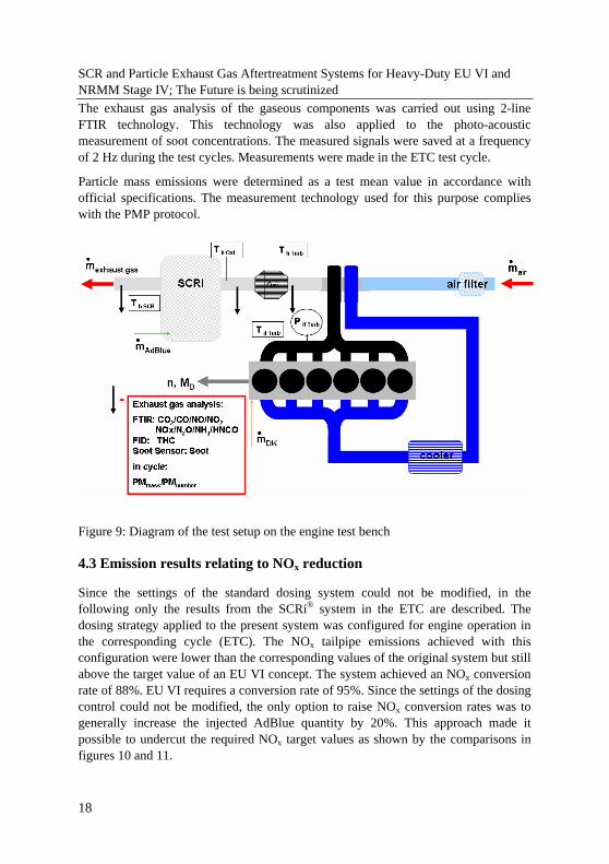
SCR and Particle Exhaust Gas Aftertreatment Systems for Heavy-Duty EU VI and NRMM Stage IV; The Future is being scrutinized The exhaust gas analysis of the gaseous components was carried out using 2-line FTIR technology. This technology was also applied to the photo-acoustic measurement of soot concentrations. The measured signals were saved at a frequency of 2 Hz during the test cycles. Measurements were made in the ETC test cycle.
Particle mass emissions were determined as a test mean value in accordance with official specifications. The measurement technology used for this purpose complies with the PMP protocol.
Figure 9: Diagram of the test setup on the engine test bench
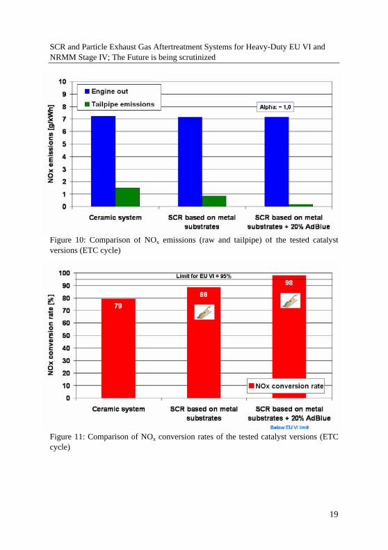
4.3 Emission results relating to NOx reduction
Since the settings of the standard dosing system could not be modified, in the following only the results from the SCRi® system in the ETC are described. The dosing strategy applied to the present system was configured for engine operation in the corresponding cycle (ETC). The NOx tailpipe emissions achieved with this configuration were lower than the corresponding values of the original system but still above the target value of an EU VI concept. The system achieved an NOx conversion rate of 88%. EU VI requires a conversion rate of 95%. Since the settings of the dosing control could not be modified, the only option to raise NOx conversion rates was to generally increase the injected AdBlue quantity by 20%. This approach made it possible to undercut the required NOx target values as shown by the comparisons in figures 10 and 11.
18
SCR and Particle Exhaust Gas Aftertreatment Systems for Heavy-Duty EU VI and NRMM Stage IV; The Future is being scrutinized
Figure 10: Comparison of NOx emissions (raw and tailpipe) of the tested catalyst versions (ETC cycle)
Figure 11: Comparison of NOx conversion rates of the tested catalyst versions (ETC cycle)
19
SCR and Particle Exhaust Gas Aftertreatment Systems for Heavy-Duty EU VI and NRMM Stage IV; The Future is being scrutinized The increased injected AdBlue quantity made it possible to achieve NOx emissions of approx. 0.1 g/kWh, which corresponds to a 98% conversion rate and significantly exceeds the requirements of the EU VI limit.
Taking up the considerations based on the observations in the first part of this paper, which established significant advantages for the use of an LS concept compared to smooth channels, especially with a cell density of 300/600 cpsi LS, it can now be said that the validity of these claims could also be found on SCR catalyst systems. The advantage of higher GSA in connection with better mass transfer allows a significant volume reduction with even better emission results, when operated under suitable operating conditions.
However, as a result of this uncontrolled additional injection (+20%) of AdBlue, the NH3 concentrations measured at the same time rose to levels that significantly exceeded the proposed limit. The detected NH3 slip suggests that this ammonia reserve should be used for further NOx reduction by increasing the reduction volume. However, the NH3 slip that occurs with this amount of injected AdBlue can be reliably prevented by the additional installation of NH3 slip catalysts. In this case the values measured in the ETC cycle were even lower than those of the original system, which already included zone coating to prevent NH3 slip.
Compliance with CO and HC limits generally poses no difficulty to state-of-the-art commercial vehicle engines. HC and CO emissions were oxidised by between 97% and 99% because the SCRi® system included an oxidation catalyst to achieve NOx targets. Therefore this paper will not expand further on the components CO and HC.
20
SCR and Particle Exhaust Gas Aftertreatment Systems for Heavy-Duty EU VI and NRMM Stage IV; The Future is being scrutinized
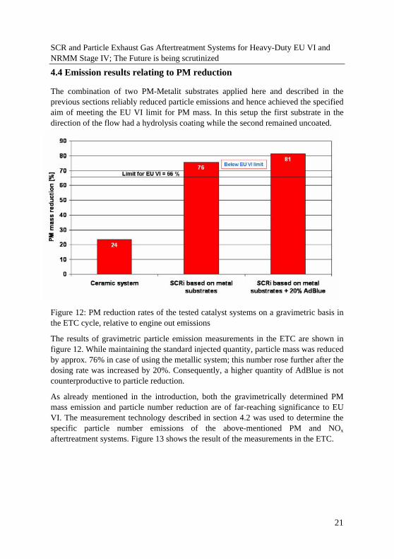
4.4 Emission results relating to PM reduction
The combination of two PM-Metalit substrates applied here and described in the previous sections reliably reduced particle emissions and hence achieved the specified aim of meeting the EU VI limit for PM mass. In this setup the first substrate in the direction of the flow had a hydrolysis coating while the second remained uncoated.
Figure 12: PM reduction rates of the tested catalyst systems on a gravimetric basis in the ETC cycle, relative to engine out emissions
The results of gravimetric particle emission measurements in the ETC are shown in figure 12. While maintaining the standard injected quantity, particle mass was reduced by approx. 76% in case of using the metallic system; this number rose further after the dosing rate was increased by 20%. Consequently, a higher quantity of AdBlue is not counterproductive to particle reduction.
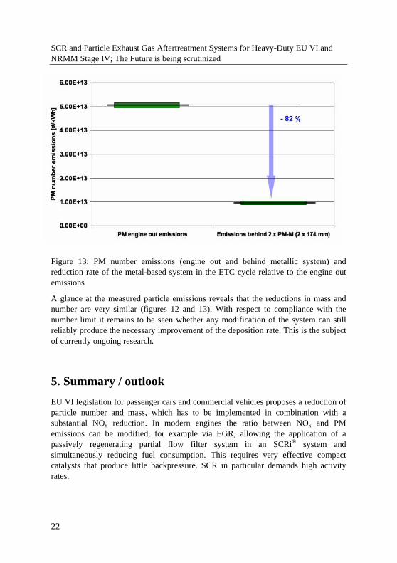
As already mentioned in the introduction, both the gravimetrically determined PM mass emission and particle number reduction are of far-reaching significance to EU VI. The measurement technology described in section 4.2 was used to determine the specific particle number emissions of the above-mentioned PM and NOx aftertreatment systems. Figure 13 shows the result of the measurements in the ETC.
21
SCR and Particle Exhaust Gas Aftertreatment Systems for Heavy-Duty EU VI and NRMM Stage IV; The Future is being scrutinized
Figure 13: PM number emissions (engine out and behind metallic system) and reduction rate of the metal-based system in the ETC cycle relative to the engine out emissions
A glance at the measured particle emissions reveals that the reductions in mass and number are very similar (figures 12 and 13). With respect to compliance with the number limit it remains to be seen whether any modification of the system can still reliably produce the necessary improvement of the deposition rate. This is the subject of currently ongoing research.
5. Summary / outlook EU VI legislation for passenger cars and commercial vehicles proposes a reduction of particle number and mass, which has to be implemented in combination with a substantial NOx reduction. In modern engines the ratio between NOx and PM emissions can be modified, for example via EGR, allowing the application of a passively regenerating partial flow filter system in an SCRi® system and simultaneously reducing fuel consumption. This requires very effective compact catalysts that produce little backpressure. SCR in particular demands high activity rates.
22
SCR and Particle Exhaust Gas Aftertreatment Systems for Heavy-Duty EU VI and NRMM Stage IV; The Future is being scrutinized This paper systematically examined the effectiveness and backpressure potential of substrates with different structures at operating temperatures and established clear advantages for structured substrates:
• LS structures show a significantly better mass transfer compared to standard substrates. They are more affected by channel flow speeds than any other type.
• At not too high flow speeds LS structures produce significantly lower backpressure than standard substrates whose basic cell density is twice as high.
• Maximum CPC, that is, the best ratio between effectiveness and backpressure, is achieved by the LS structures. This is made possible by a high β value at fairly low backpressure. Due to even lower backpressure smaller cell density offers particular advantages, whereas high conversion rates are more easily achieved by the application of higher cell density.
The validity of these claims was checked and could be confirmed on an engine test bench using the SCR application. The SCRi® system had a smaller volume than standard ceramic systems. Using this system, which comprises passively regenerating PM-Metalit substrates of approx. 260% of the engine capacity for soot aftertreatment and SCR catalysts of 200% of the engine capacity for NOx aftertreatment, it was possible to demonstrate that EU IV limits could be met reliably. The dosing system was – regardless the 20% increased dosage volume - not modified during the tests.
It would certainly have been possible to significantly increase the efficiency of NOx reduction again if the dosing strategy could have been adapted to given conditions. A system that primarily is operated on an engine that is subject to low loads should have a correspondingly adapted dosing strategy.
23
SCR and Particle Exhaust Gas Aftertreatment Systems for Heavy-Duty EU VI and NRMM Stage IV; The Future is being scrutinized
6. Symbol register
U conversion rate [-]
outc concentration at reactor outlet [mol/l]
einc concentration at reactor inlet [mol/l]
β mass transfer coefficient [m/s]
GSA geometric surface area [m²] •
V volumetric flow [m³/s]
Sh Sherwood number [-]
12D binary diffusion coefficient [m²/s]
hd hydraulic diameter [m]
KatL catalyst length [m]
Sc Schmitt number [-]
Re Reynolds number [-]
limSh limiting Sherwood number [-]
Gz Graetz number [-]
FEDCBA ,,,,, dimensionless parameters [-]
CPC Catalyst Performance Coefficient [-]
24
SCR and Particle Exhaust Gas Aftertreatment Systems for Heavy-Duty EU VI and NRMM Stage IV; The Future is being scrutinized
7. Bibliography [1] U. Lambrecht, F. Dünnebeil; IFEU-Institut; “High Levels of nitrogen dioxide on urban street – the role of emissions from diesel vehicles”; MinNOx IAV-Conference; Berlin; 2008
[2] W. Müller; Daimler AG; Stuttgart: “Emission Strategy for Commercial Vehicle Diesel Engines”; 5th International CTI Forum; Nürtingen; 2007
[3] Scania-Presse-Info: “Technologischer Durchbruch für Scania: Euro V und EEV für hohen Komfort beim Handling”; P07X02DE / Per-Erik Nordström; 18. Oktober 2007
[4] Fachzeitschrift Commercial Motor: 1000 Miles Test; Reed Business Information Ltd; Dezember 2006
[5] W. Maus, R. Brück; Emitec GmbH; “Die Zukunft der heterogenen Katalyse im Automobil; Turbulente Katalysatoren für Otto- und Dieselanwendungen”; 26. Internationales Motorensymposium, Wien, 27.04.2005
[6] J. Dahlgren, M. Laurell, N. Vollmer; Volvo Car Corp.; R. Brück, P. Hirth, W. Maus; Emitec GmbH; “Der Lambdasondenkatalysator; ein neues Konzept für kompakte Hochleistungs-Katalysatorsysteme”; 14. Aachener Kolloquium “Fahrzeug- und Motorentechnik”; 2005
[7] C. Iotti, V. Rossi, L. Poggio; Ferrari S.p.A.; M. Holzinger; ArvinMeritor; L. Pace, M. Presti; Emitec GmbH; “Backpressure Optimized Close Coupled PE-Catalyst - First Application on a Maserati Powertrain”; SAE-Paper 2005-01-1105
[8] M. Ganz, S. Hackmayer; quattro GmbH; C. Kruse, A. Reck, Emitec GmbH; “Innovatives Katalysatorsystem für den Audi RS6, 8 Zyl, 4,2ltr, 331 KW mit LEV Zertifizierung”; 25. Internationales Motorensymposium, Wien, 29.04.2004
[9] O. Deutschmann, N. Mladenov; TU Karlsruhe; W. Maus, R. Brück, P. Hirth; Emitec GmbH; “Turbulent schlägt laminar ”; 27. Internationales Motorensymposium, Wien, 2006
[10] W. Bohl; “Technische Strömungslehre”; Vogel-Verlag
[11] VDI-Wärmealtlas
[12] H.-D. Baehr, K. Stephan; “Wärme- und Stoffübertragung”; Springer-Verlag
[13] J. Liebl; BMW Group; W. Maus, R. Brück; Emitec GmbH; “Strengere Abgas-Emissionsgesetze - Niedrigste CO2- und Schadstoff-Emissionen, ein lösbarer Zielkonflikt?”; ATZ / MTZ-Konferenz – Energie; München; 2006
25