Embed Size (px)
Citation preview
© Fraunhofer ISE
Battery management and energy management
Simon Schwunk, Matthias Vetter, Nils Armbruster
Fraunhofer Institute forSolar Energy Systems ISE
FVEE-Workshop
Ulm, 20. Januar 2010
© Fraunhofer ISE
Agenda
Stationary applicationsBattery management
ArchitectureState determination for lead-acid batteriesResults
Energy managementArchitectureResults
Automotive applicationsArchitectureState determination for lithium–ion batteries
Photo: INES
© Fraunhofer ISE
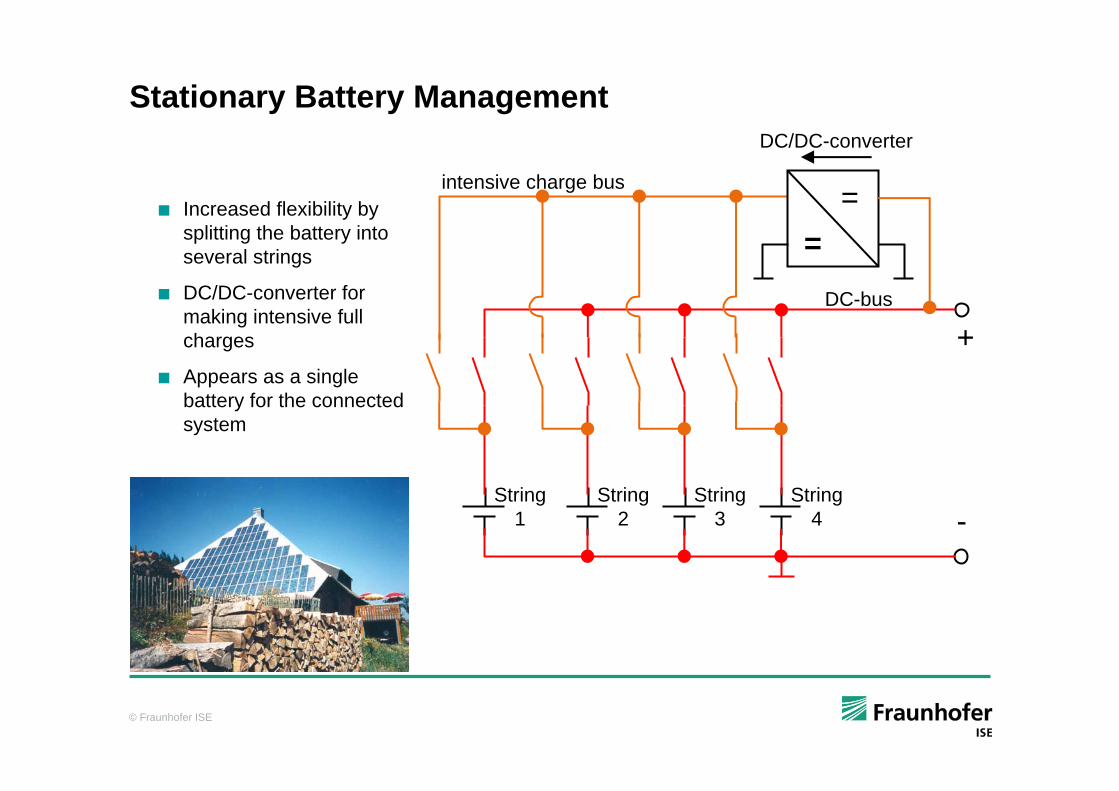
Stationary Battery Management
Increased flexibility bysplitting the battery intoseveral strings
DC/DC-converter formaking intensive fullcharges
Appears as a singlebattery for the connectedsystem
String 1
+
-String
2String
3String
4
DC-bus
DC/DC-converter
==intensive charge bus
© Fraunhofer ISE
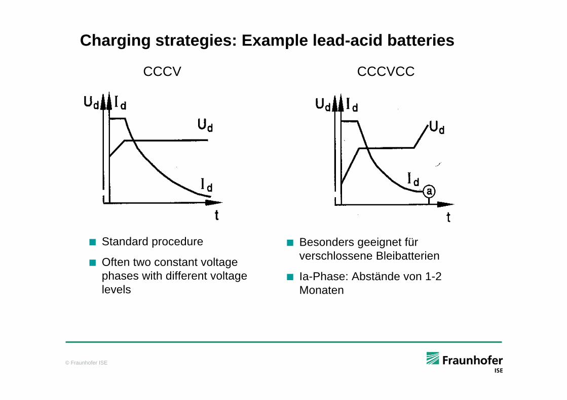
Charging strategies: Example lead-acid batteries
Besonders geeignet für verschlossene Bleibatterien
Ia-Phase: Abstände von 1-2 Monaten
CCCV CCCVCC
Standard procedure
Often two constant voltagephases with different voltagelevels
© Fraunhofer ISE
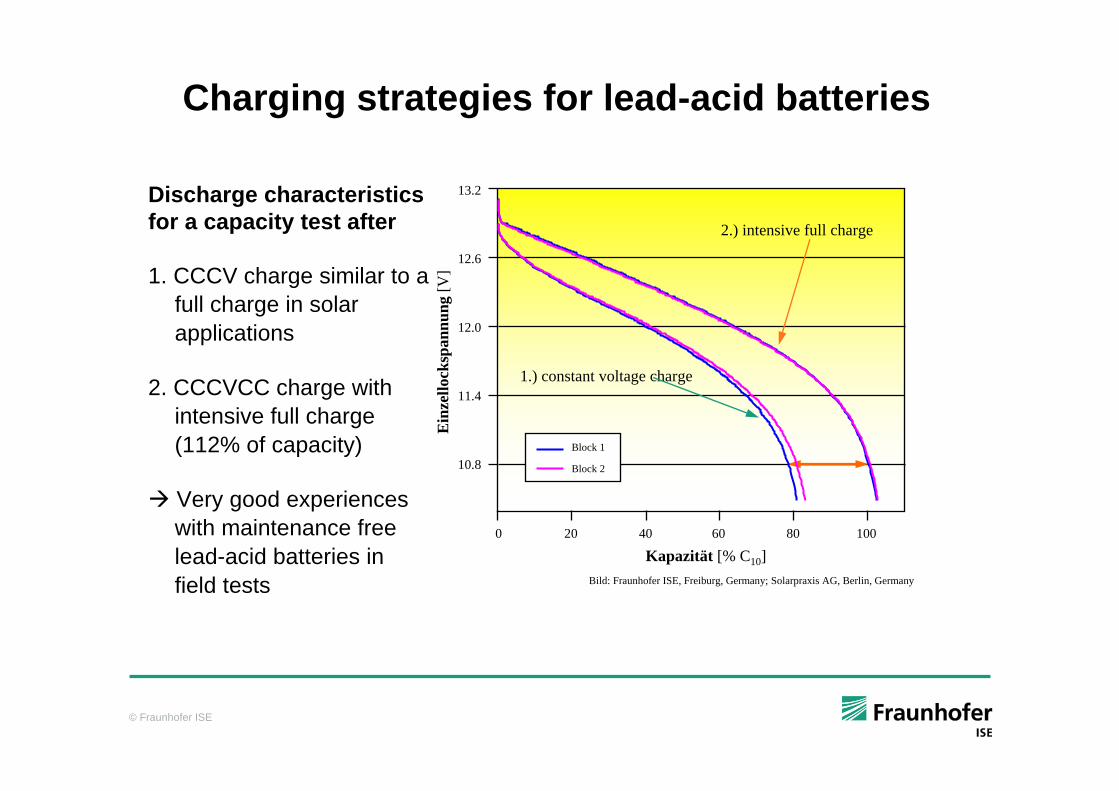
Charging strategies for lead-acid batteries
Discharge characteristics for a capacity test after
1. CCCV charge similar to afull charge in solar applications
2. CCCVCC charge with intensive full charge (112% of capacity)
Very good experiences with maintenance free lead-acid batteries in field tests
Ein
zello
cksp
annu
ng[V
]
Kapazität [% C10]0 20 40 60 80 100
13.2
12.6
12.0
11.4
10.8
2.) intensive full charge
1.) constant voltage charge
Block 1
Block 2
Bild: Fraunhofer ISE, Freiburg, Germany; Solarpraxis AG, Berlin, Germany
© Fraunhofer ISE
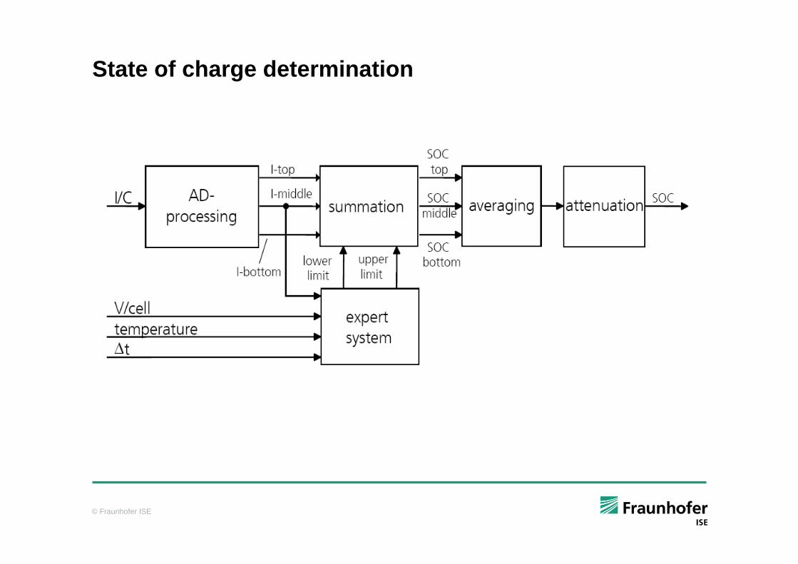
State of charge determination
© Fraunhofer ISE
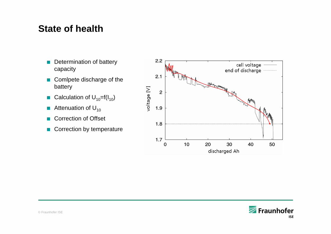
State of health
Determination of batterycapacity
Comlpete discharge of thebattery
Calculation of U10=f(I10)
Attenuation of U10
Correction of Offset
Correction by temperature
© Fraunhofer ISE
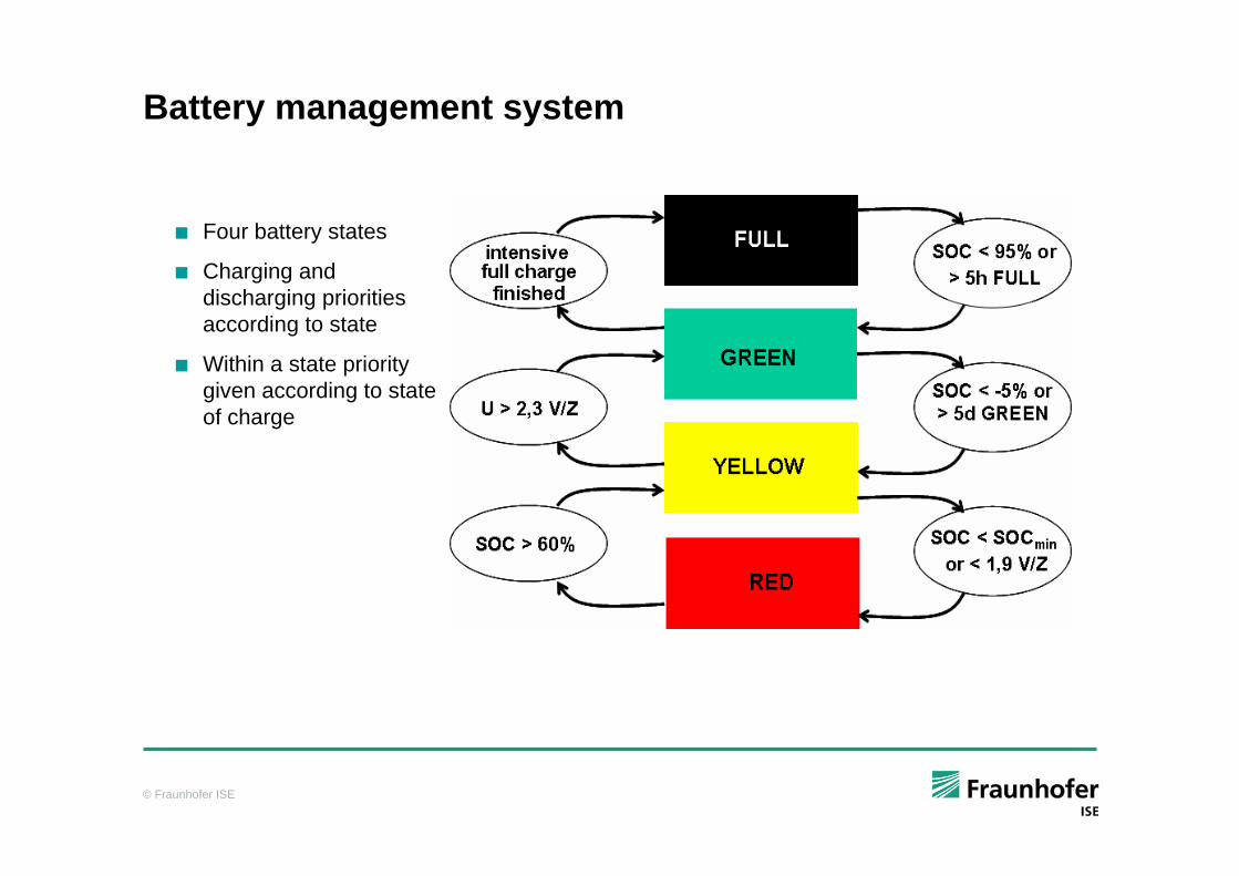
Battery management system
Four battery states
Charging and discharging prioritiesaccording to state
Within a state prioritygiven according to stateof charge
© Fraunhofer ISE
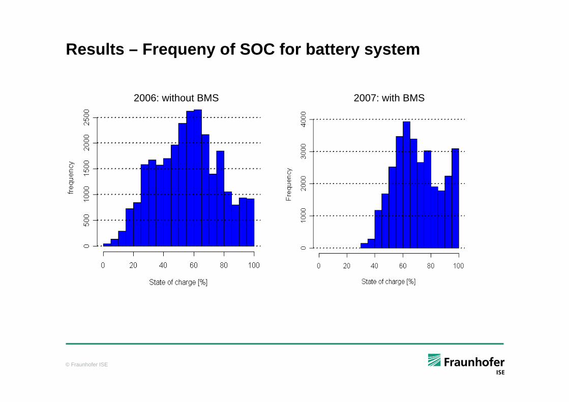
Results – Frequeny of SOC for battery system
2006: without BMS 2007: with BMS
© Fraunhofer ISE
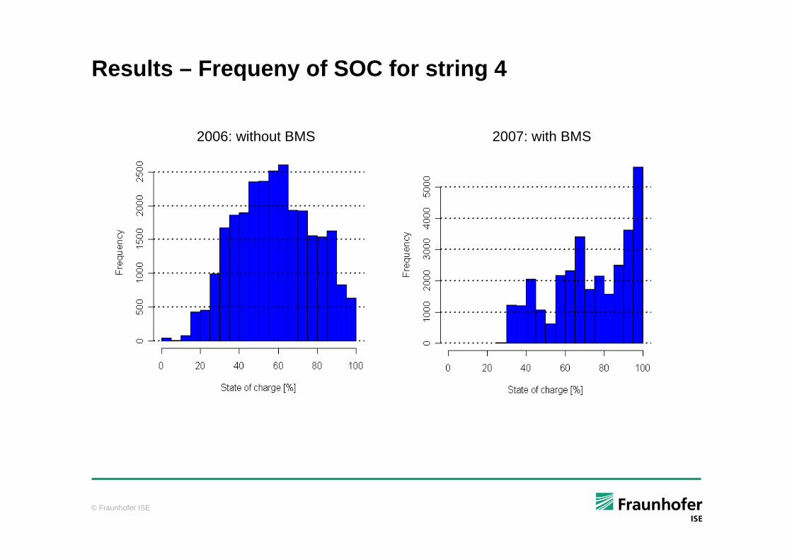
Results – Frequeny of SOC for string 4
2006: without BMS 2007: with BMS
© Fraunhofer ISE
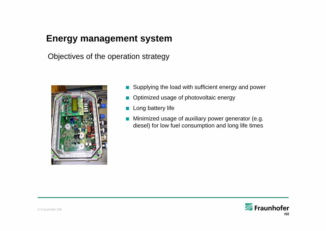
Energy management system
Objectives of the operation strategy
Supplying the load with sufficient energy and power
Optimized usage of photovoltaic energy
Long battery life
Minimized usage of auxiliary power generator (e.g. diesel) for low fuel consumption and long life times
© Fraunhofer ISE
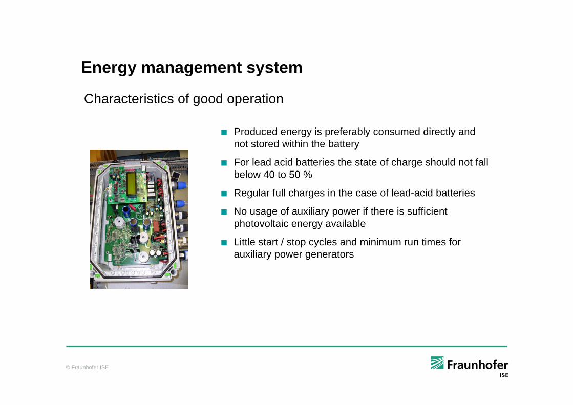
Energy management system
Characteristics of good operation
Produced energy is preferably consumed directly and not stored within the battery
For lead acid batteries the state of charge should not fall below 40 to 50 %
Regular full charges in the case of lead-acid batteries
No usage of auxiliary power if there is sufficient photovoltaic energy available
Little start / stop cycles and minimum run times for auxiliary power generators
© Fraunhofer ISE
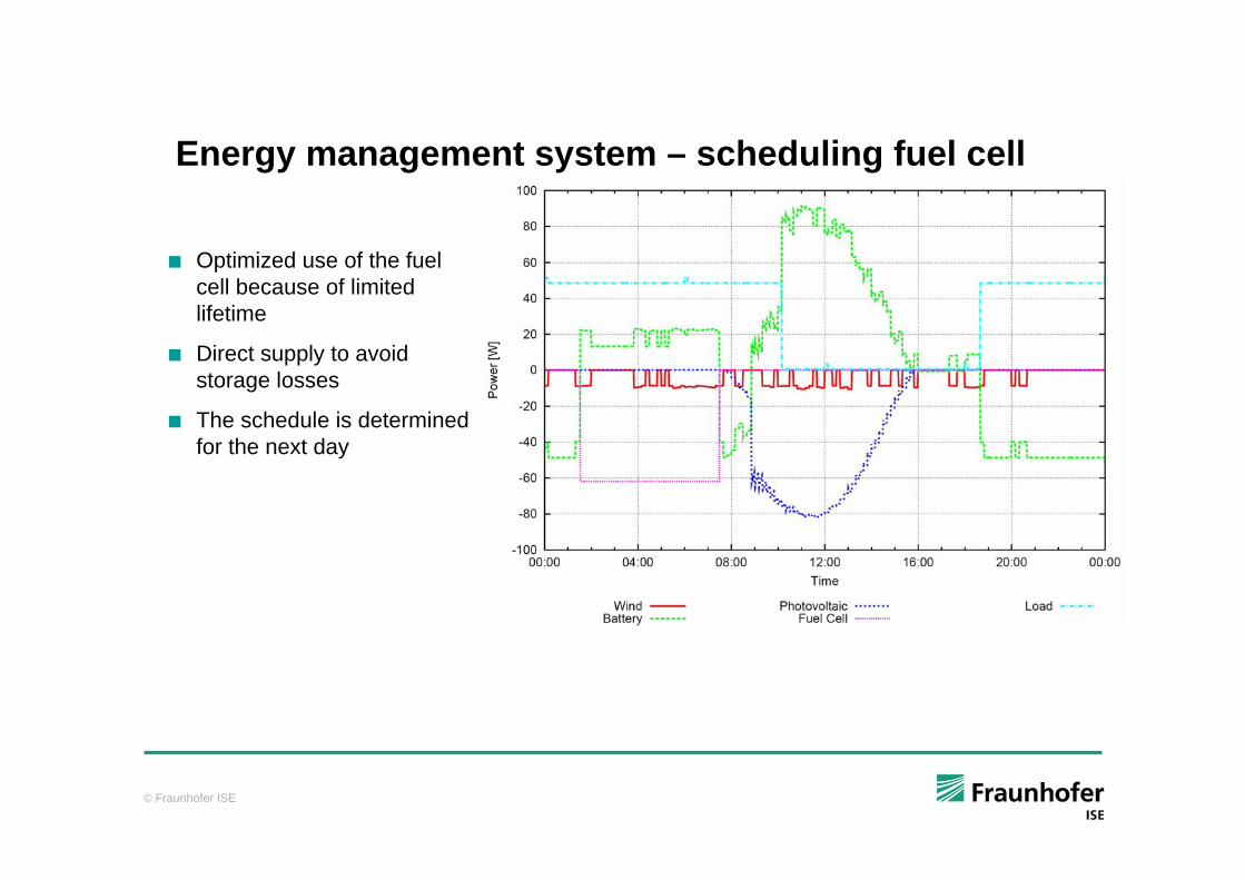
Energy management system – scheduling fuel cell
Optimized use of the fuel cell because of limited lifetime
Direct supply to avoid storage losses
The schedule is determined for the next day
© Fraunhofer ISE
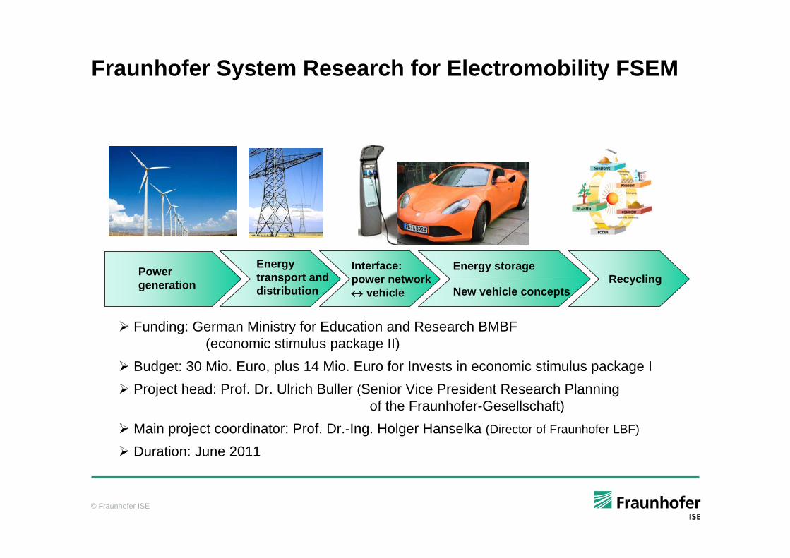
Fraunhofer System Research for Electromobility FSEM
Funding: German Ministry for Education and Research BMBF (economic stimulus package II)
Budget: 30 Mio. Euro, plus 14 Mio. Euro for Invests in economic stimulus package IProject head: Prof. Dr. Ulrich Buller (Senior Vice President Research Planning
of the Fraunhofer-Gesellschaft)Main project coordinator: Prof. Dr.-Ing. Holger Hanselka (Director of Fraunhofer LBF)
Duration: June 2011
Powergeneration
Energy transport and distribution
Interface:power network↔ vehicle
Energy storage
New vehicle conceptsRecycling
© Fraunhofer ISE
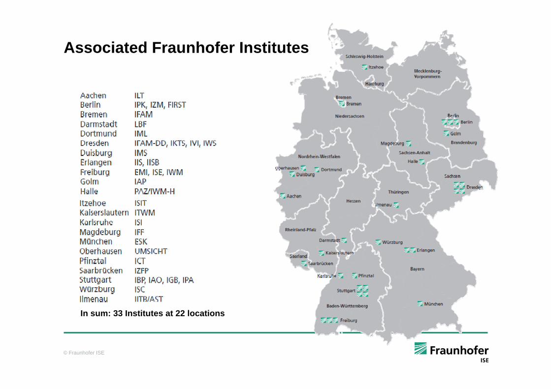
Associated Fraunhofer Institutes
In sum: 33 Institutes at 22 locations
© Fraunhofer ISE
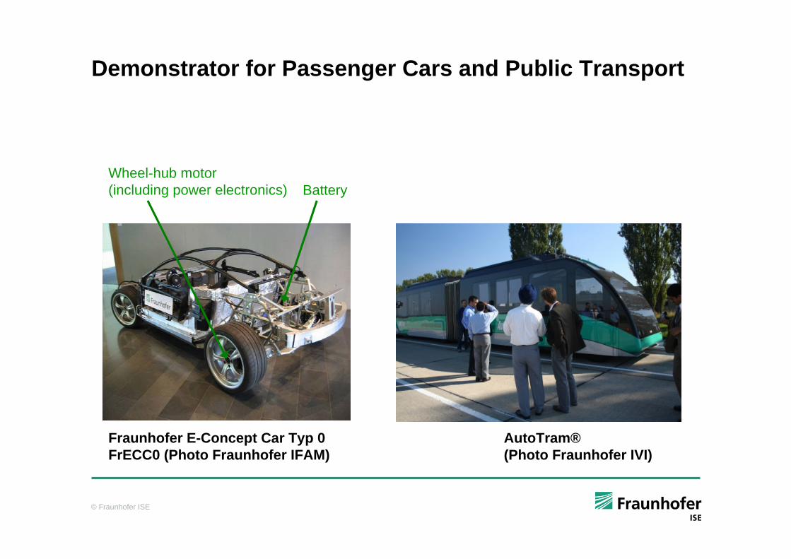
Demonstrator for Passenger Cars and Public Transport
BatteryWheel-hub motor (including power electronics)
AutoTram®(Photo Fraunhofer IVI)
Fraunhofer E-Concept Car Typ 0 FrECC0 (Photo Fraunhofer IFAM)
© Fraunhofer ISE
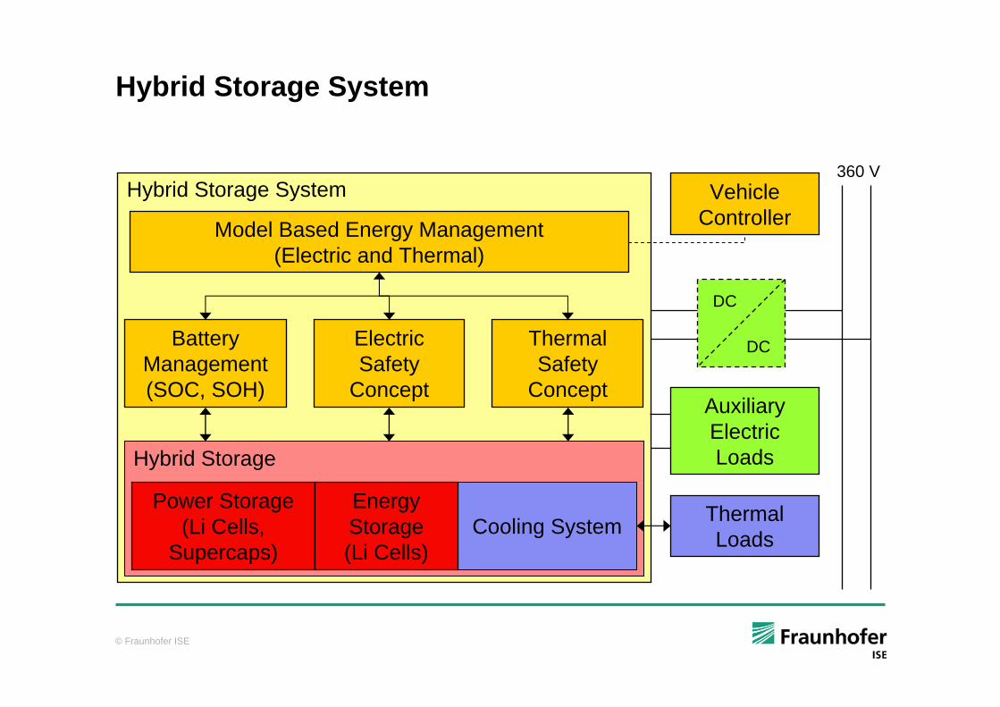
Hybrid Storage System
Battery Management(SOC, SOH)
Electric Safety
Concept
Thermal Safety
Concept
Power Storage (Li Cells,
Supercaps)
360 VVehicle
Controller
Thermal Loads
Auxiliary Electric Loads
Cooling System
Hybrid Storage System
Energy Storage (Li Cells)
Hybrid Storage
DC
DC
Model Based Energy Management (Electric and Thermal)
© Fraunhofer ISE
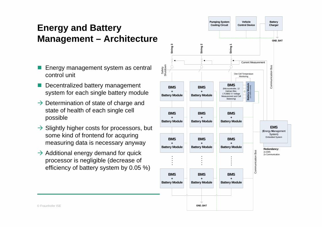
Energy and Battery Management – Architecture
Energy management system as central control unit
Decentralized battery management system for each single battery module
Determination of state of charge and state of health of each single cell possible
Slightly higher costs for processors, but some kind of frontend for acquringmeasuring data is necessary anyway
Additional energy demand for quick processor is negligible (decrease of efficiency of battery system by 0.05 %)
BMS(Microcontroller, 12
Kalman filter,LTC6802 Voltage
Measurement and Cell Balancing) B
atte
ry M
odul
e(1
2 C
ells
in s
erie
s)
...
EMS(Energy Management
System)Embedded System
BMS+
Battery Module
BMS+
Battery Module
BMS+
Battery Module
. . .
. .
BMS+
Battery Module
BMS+
Battery Module
BMS+
Battery Module
BMS+
Battery Module
. . .
. .
BMS+
Battery Module
BMS+
Battery Module
BMS+
Battery Module
BMS+
Battery Module
. . .
. .
One Cell Temperature Monitoring
Strin
g 1
Strin
g 2
Strin
g 3
VehicleControl Device
Battery Charger
Com
mun
icat
ion
Bus
Saf
ety
Shu
tdow
n
Pumping System Cooling Circuit
Com
mun
icat
ion
Bus
Redundancy:2x EMS2x Communication
GND_BAT
GND_BAT
Current Measurement
© Fraunhofer ISE
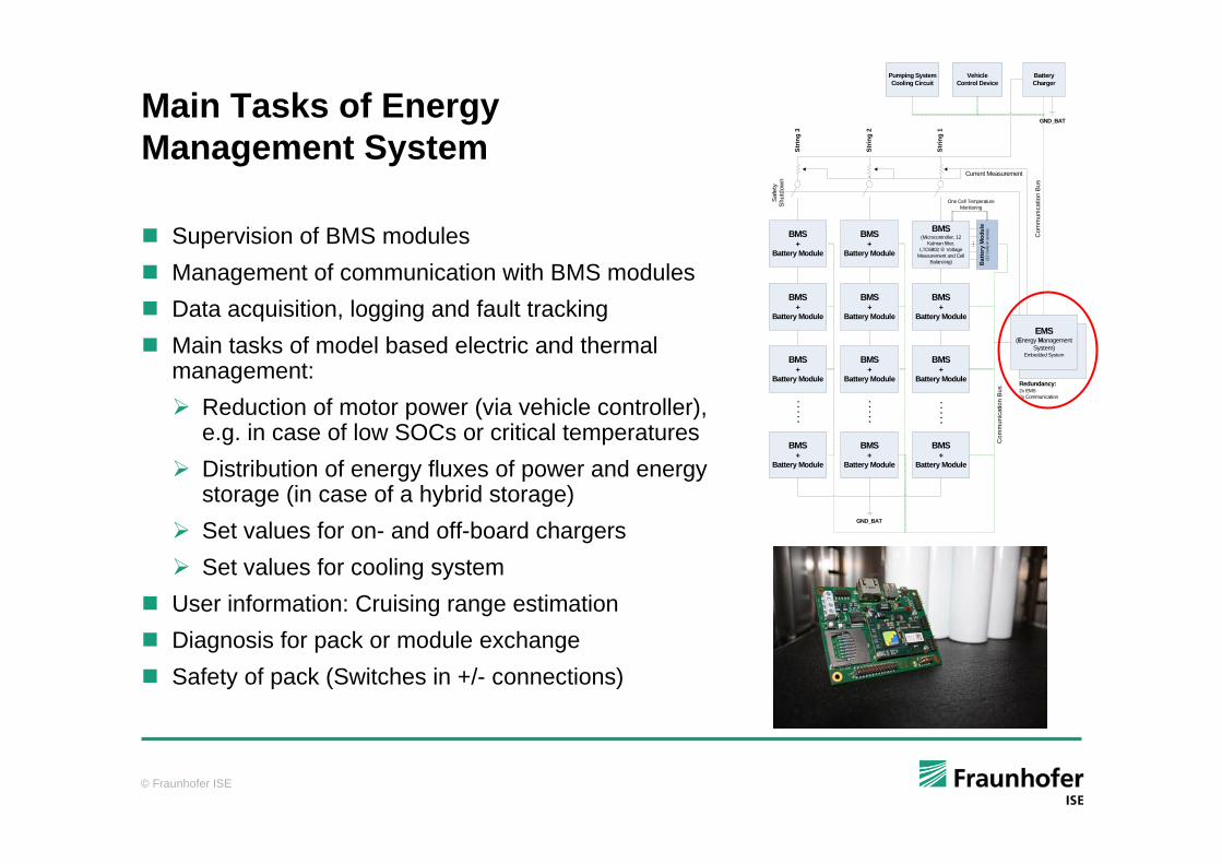
Main Tasks of Energy Management System
Supervision of BMS modulesManagement of communication with BMS modulesData acquisition, logging and fault trackingMain tasks of model based electric and thermal management:
Reduction of motor power (via vehicle controller), e.g. in case of low SOCs or critical temperaturesDistribution of energy fluxes of power and energy storage (in case of a hybrid storage)Set values for on- and off-board chargersSet values for cooling system
User information: Cruising range estimationDiagnosis for pack or module exchangeSafety of pack (Switches in +/- connections)
BMS(Microcontroller, 12
Kalman filter,LTC6802 Voltage
Measurement and Cell Balancing) B
atte
ry M
odul
e(1
2 C
ells
in s
erie
s)
...
EMS(Energy Management
System)Embedded System
BMS+
Battery Module
BMS+
Battery Module
BMS+
Battery Module
. . .
. .
BMS+
Battery Module
BMS+
Battery Module
BMS+
Battery Module
BMS+
Battery Module
. . .
. .
BMS+
Battery Module
BMS+
Battery Module
BMS+
Battery Module
BMS+
Battery Module
. . .
. .
One Cell Temperature Monitoring
Strin
g 1
Strin
g 2
Strin
g 3
VehicleControl Device
Battery Charger
Com
mun
icat
ion
Bus
Saf
ety
Shu
tdow
n
Pumping System Cooling Circuit
Com
mun
icat
ion
Bus
Redundancy:2x EMS2x Communication
GND_BAT
GND_BAT
Current Measurement
© Fraunhofer ISE
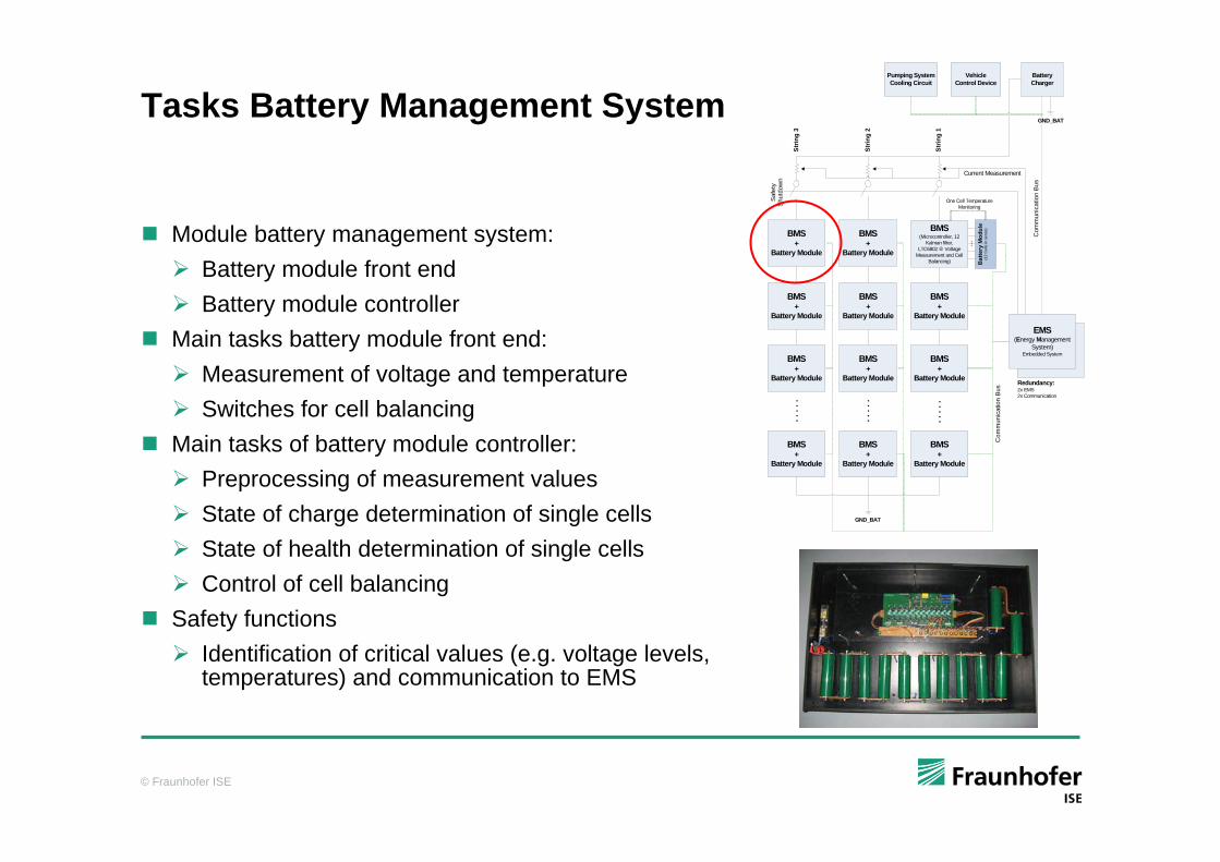
Tasks Battery Management System
Module battery management system:Battery module front endBattery module controller
Main tasks battery module front end:Measurement of voltage and temperatureSwitches for cell balancing
Main tasks of battery module controller:Preprocessing of measurement valuesState of charge determination of single cellsState of health determination of single cellsControl of cell balancing
Safety functionsIdentification of critical values (e.g. voltage levels, temperatures) and communication to EMS
BMS(Microcontroller, 12
Kalman filter,LTC6802 Voltage
Measurement and Cell Balancing) B
atte
ry M
odul
e(1
2 C
ells
in s
erie
s)
...
EMS(Energy Management
System)Embedded System
BMS+
Battery Module
BMS+
Battery Module
BMS+
Battery Module
. . .
. .
BMS+
Battery Module
BMS+
Battery Module
BMS+
Battery Module
BMS+
Battery Module
. . .
. .
BMS+
Battery Module
BMS+
Battery Module
BMS+
Battery Module
BMS+
Battery Module
. . .
. .
One Cell Temperature Monitoring
Strin
g 1
Strin
g 2
Strin
g 3
VehicleControl Device
Battery Charger
Com
mun
icat
ion
Bus
Saf
ety
Shu
tdow
n
Pumping System Cooling Circuit
Com
mun
icat
ion
Bus
Redundancy:2x EMS2x Communication
GND_BAT
GND_BAT
Current Measurement
© Fraunhofer ISE
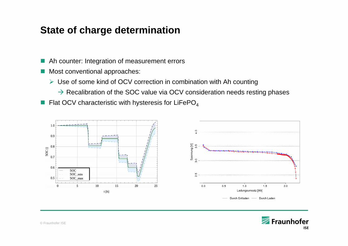
State of charge determination
Ah counter: Integration of measurement errors Most conventional approaches:
Use of some kind of OCV correction in combination with Ah countingRecalibration of the SOC value via OCV consideration needs resting phases
Flat OCV characteristic with hysteresis for LiFePO4
© Fraunhofer ISE
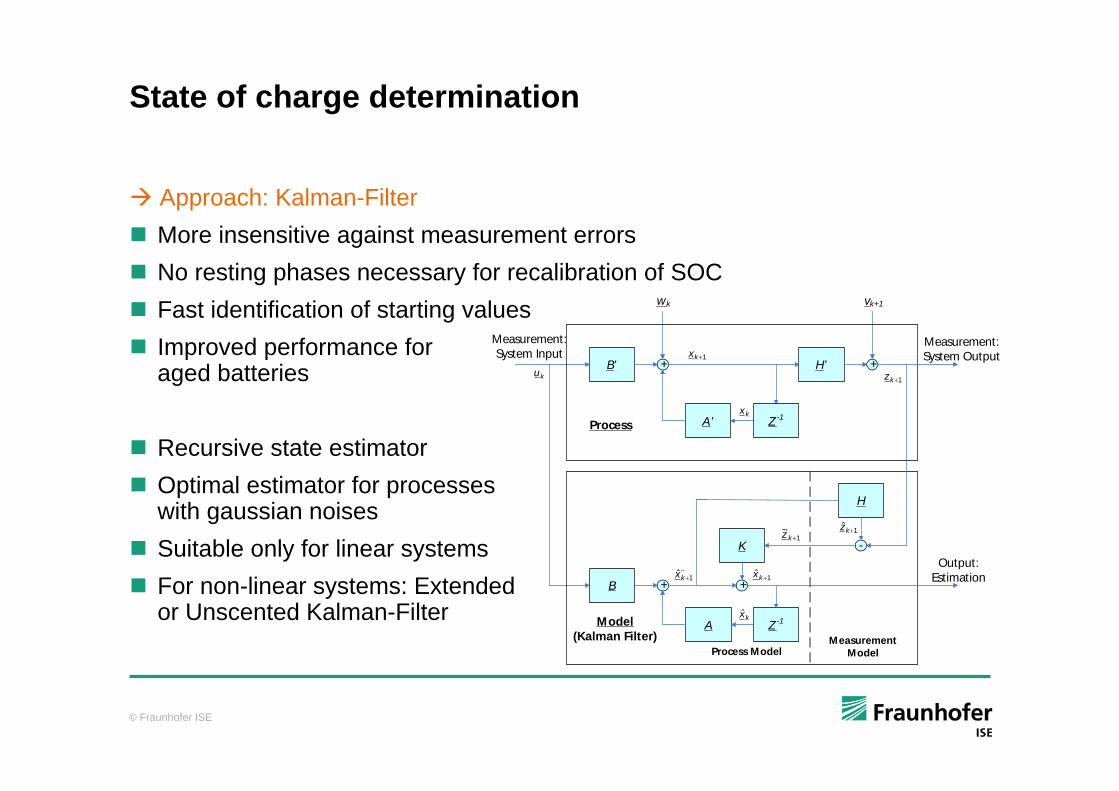
State of charge determination
Approach: Kalman-FilterMore insensitive against measurement errorsNo resting phases necessary for recalibration of SOCFast identification of starting values Improved performance for aged batteries
Recursive state estimatorOptimal estimator for processes with gaussian noisesSuitable only for linear systemsFor non-linear systems: Extended or Unscented Kalman-Filter
B’ H’
A’
+ +
wk vk+1
B
H
A
+
-K
Process
Model(Kalman Filter)
Output:Estimation
Measurement:System Output
Measurement:System Input
Z-1
Measurement ModelProcess Model
1ˆ +kx−+1ˆkx
1~
+kz
kx̂
1ˆ +kz
1+kx
kx
1+kzku
+
Z-1
© Fraunhofer ISE
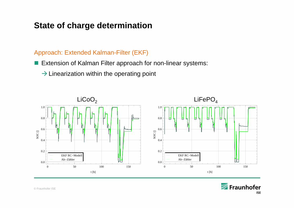
State of charge determination
Approach: Extended Kalman-Filter (EKF)
Extension of Kalman Filter approach for non-linear systems:
Linearization within the operating point
0 50 100 150
0.0
0.2
0.4
0.6
0.8
1.0
t �h�
SOC��
Ah�ZählerEKF RC�Modell
0 50 100 150
0.0
0.2
0.4
0.6
0.8
1.0
t �h�
SOC��
Ah�ZählerEKF RC�Modell
LiCoO2 LiFePO4
© Fraunhofer ISE
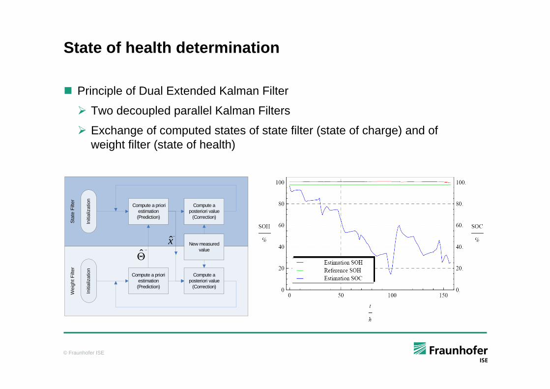
State of health determination
Principle of Dual Extended Kalman Filter
Two decoupled parallel Kalman Filters
Exchange of computed states of state filter (state of charge) and of weight filter (state of health)
Compute a priori estimation (Prediction)
Compute a posteriori value
(Correction)
Stat
e Fi
lter
Initi
aliz
atio
n
Compute a priori estimation (Prediction)
Compute a posteriori value
(Correction)
Wei
ght F
ilter
Initi
aliz
atio
n
New measured value
Θ−ˆ
x̂−
© Fraunhofer ISE
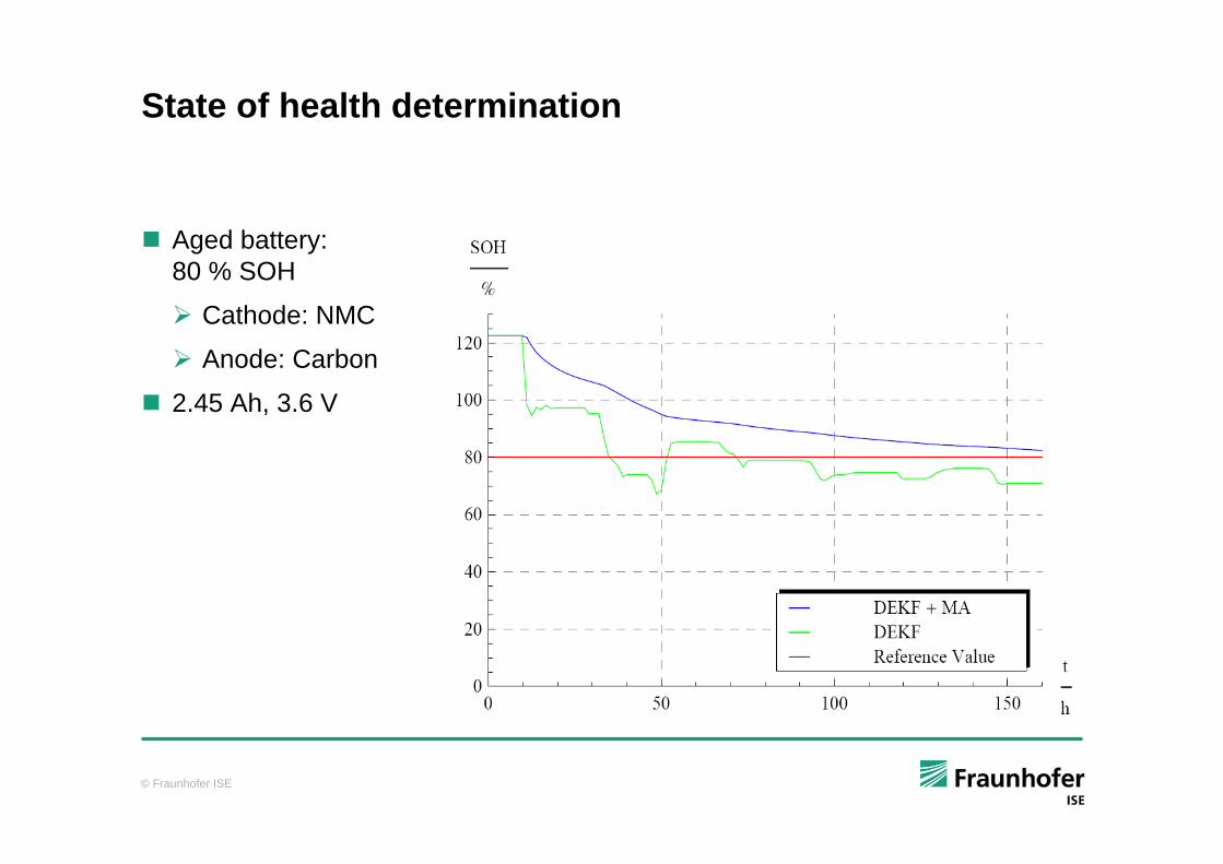
State of health determination
Aged battery: 80 % SOH
Cathode: NMC
Anode: Carbon
2.45 Ah, 3.6 V
© Fraunhofer ISE
Conclusions
Battery systems for electric vehicles
Energy and battery management systems are similar both in stationary and automotive applications in principal
But specific boundary conditions must be taken into account:
Very specific properties of batteries in automotive applications make e.g. approaches for state determination based on rules difficult to implement model based approaches are more straight forward to adapt to different battery types
Centralized BMS in stationary applications easier to handle since there are less dynamics and safety can be more easily assured module BMS in automotive applications ensures safety, reliable state determination and long life times
Thermal management is more important in automotive applications than in stationary applications
In automotive applications there are not multiple power generators available at the same time