Embed Size (px)
Citation preview
© Ingenieurbüro Huß & Feickert, 2016 14. LS-DYNA Forum 2016, Bamberg 1
Stefan Hennig1, Prof. Dr.-Ing. Armin Huß2, Heiko Honermeier1, Marcel Jagic1, Manuel Schönborn
1 Ingenieurbüro Huß & Feickert GbR, Liederbach, Germany 2 Frankfurt University of Applied Sciences, Frankfurt, Germany
Simulation of containment-tests at a generic
model of a large-scale turbocharger with LS-
DYNA
© Ingenieurbüro Huß & Feickert, 2016 14. LS-DYNA Forum 2016, Bamberg
Overview
2
Introduction
o Company Profile
o Why simulate Containment-Tests
Motivation
Containment Simulation today
Generic Model
Studies
o different approaches of modeling bursting scenario of compressor flywheel
o effect of lode-angle-parameter on the damage and failure behavior of the housing
structures
Summary
© Ingenieurbüro Huß & Feickert, 2016 14. LS-DYNA Forum 2016, Bamberg
Introduction - Company Profile
3
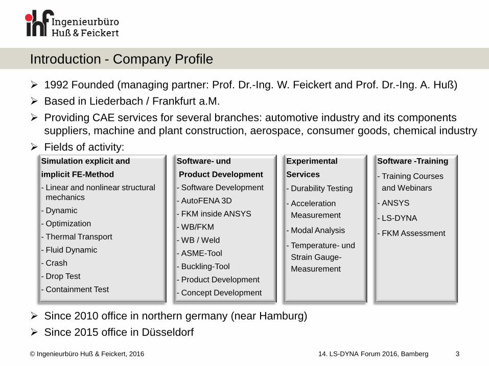
1992 Founded (managing partner: Prof. Dr.-Ing. W. Feickert and Prof. Dr.-Ing. A. Huß)
Based in Liederbach / Frankfurt a.M.
Providing CAE services for several branches: automotive industry and its components
suppliers, machine and plant construction, aerospace, consumer goods, chemical industry
Fields of activity:
Since 2010 office in northern germany (near Hamburg)
Since 2015 office in Düsseldorf
Software- und
Product Development
- Software Development
- AutoFENA 3D
- FKM inside ANSYS
- WB/FKM
- WB / Weld
- ASME-Tool
- Buckling-Tool
- Product Development
- Concept Development
Experimental
Services
- Durability Testing
- Acceleration
Measurement
- Modal Analysis
- Temperature- und
Strain Gauge-
Measurement
Software -Training
- Training Courses
and Webinars
- ANSYS
- LS-DYNA
- FKM Assessment
Simulation explicit and
implicit FE-Method
- Linear and nonlinear structural
mechanics
- Dynamic
- Optimization
- Thermal Transport
- Fluid Dynamic
- Crash
- Drop Test
- Containment Test
© Ingenieurbüro Huß & Feickert, 2016 14. LS-DYNA Forum 2016, Bamberg
Introduction – Why simulate Containment-Tests
4
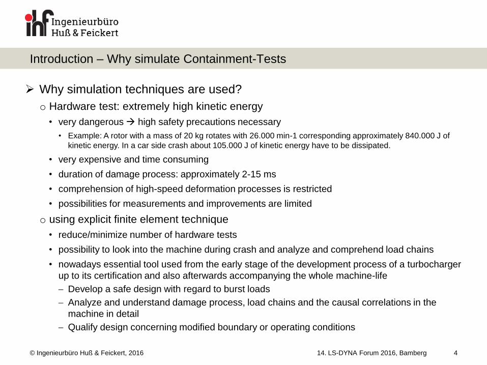
Why simulation techniques are used?
o Hardware test: extremely high kinetic energy
• very dangerous high safety precautions necessary
• Example: A rotor with a mass of 20 kg rotates with 26.000 min-1 corresponding approximately 840.000 J of
kinetic energy. In a car side crash about 105.000 J of kinetic energy have to be dissipated.
• very expensive and time consuming
• duration of damage process: approximately 2-15 ms
• comprehension of high-speed deformation processes is restricted
• possibilities for measurements and improvements are limited
o using explicit finite element technique
• reduce/minimize number of hardware tests
• possibility to look into the machine during crash and analyze and comprehend load chains
• nowadays essential tool used from the early stage of the development process of a turbocharger
up to its certification and also afterwards accompanying the whole machine-life
Develop a safe design with regard to burst loads
Analyze and understand damage process, load chains and the causal correlations in the
machine in detail
Qualify design concerning modified boundary or operating conditions
© Ingenieurbüro Huß & Feickert, 2016
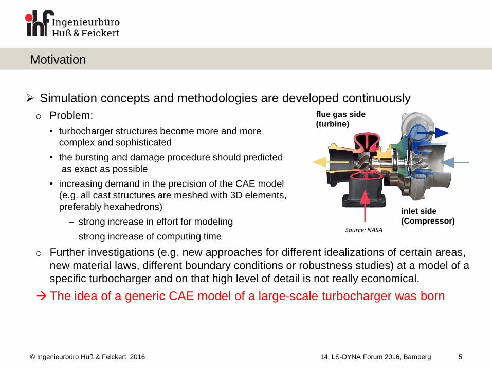
Simulation concepts and methodologies are developed continuously
o Problem:
• turbocharger structures become more and more
complex and sophisticated
• the bursting and damage procedure should predicted
as exact as possible
• increasing demand in the precision of the CAE model
(e.g. all cast structures are meshed with 3D elements,
preferably hexahedrons)
strong increase in effort for modeling
strong increase of computing time
o Further investigations (e.g. new approaches for different idealizations of certain areas,
new material laws, different boundary conditions or robustness studies) at a model of a
specific turbocharger and on that high level of detail is not really economical.
The idea of a generic CAE model of a large-scale turbocharger was born
14. LS-DYNA Forum 2016, Bamberg
Motivation
5
Source: NASA
inlet side
(Compressor)
flue gas side
(turbine)
© Ingenieurbüro Huß & Feickert, 2016 14. LS-DYNA Forum 2016, Bamberg
Containment-Simulation Today
6
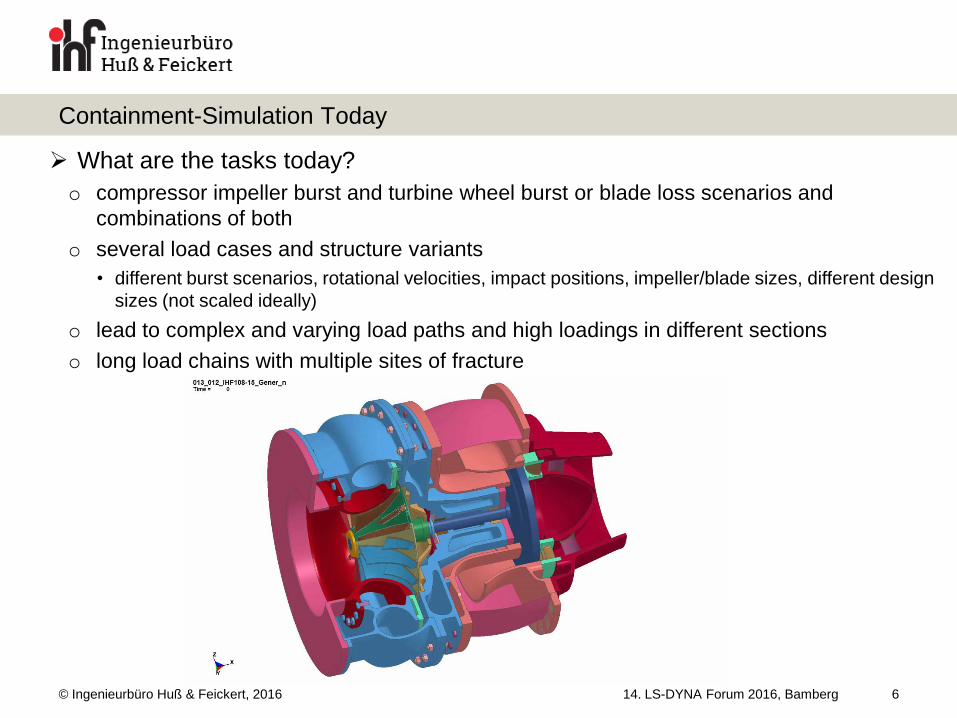
What are the tasks today?
o compressor impeller burst and turbine wheel burst or blade loss scenarios and
combinations of both
o several load cases and structure variants
• different burst scenarios, rotational velocities, impact positions, impeller/blade sizes, different design
sizes (not scaled ideally)
o lead to complex and varying load paths and high loadings in different sections
o long load chains with multiple sites of fracture
© Ingenieurbüro Huß & Feickert, 2016 14. LS-DYNA Forum 2016, Bamberg
Containment-Simulation Today
7
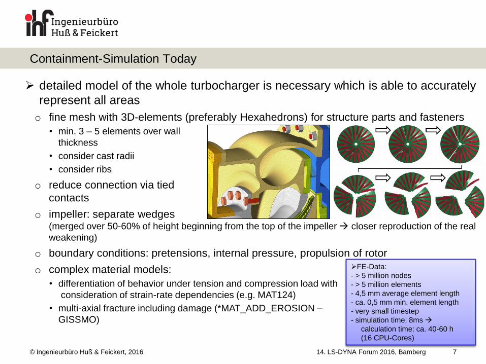
detailed model of the whole turbocharger is necessary which is able to accurately
represent all areas
o fine mesh with 3D-elements (preferably Hexahedrons) for structure parts and fasteners
• min. 3 – 5 elements over wall
thickness
• consider cast radii
• consider ribs
o reduce connection via tied
contacts
o impeller: separate wedges (merged over 50-60% of height beginning from the top of the impeller closer reproduction of the real
weakening)
o boundary conditions: pretensions, internal pressure, propulsion of rotor
o complex material models:
• differentiation of behavior under tension and compression load with
consideration of strain-rate dependencies (e.g. MAT124)
• multi-axial fracture including damage (*MAT_ADD_EROSION –
GISSMO)
FE-Data:
- > 5 million nodes
- > 5 million elements
- 4,5 mm average element length
- ca. 0,5 mm min. element length
- very small timestep
- simulation time: 8ms
calculation time: ca. 40-60 h
(16 CPU-Cores)
© Ingenieurbüro Huß & Feickert, 2016 14. LS-DYNA Forum 2016, Bamberg
Containment-Simulation Today
8
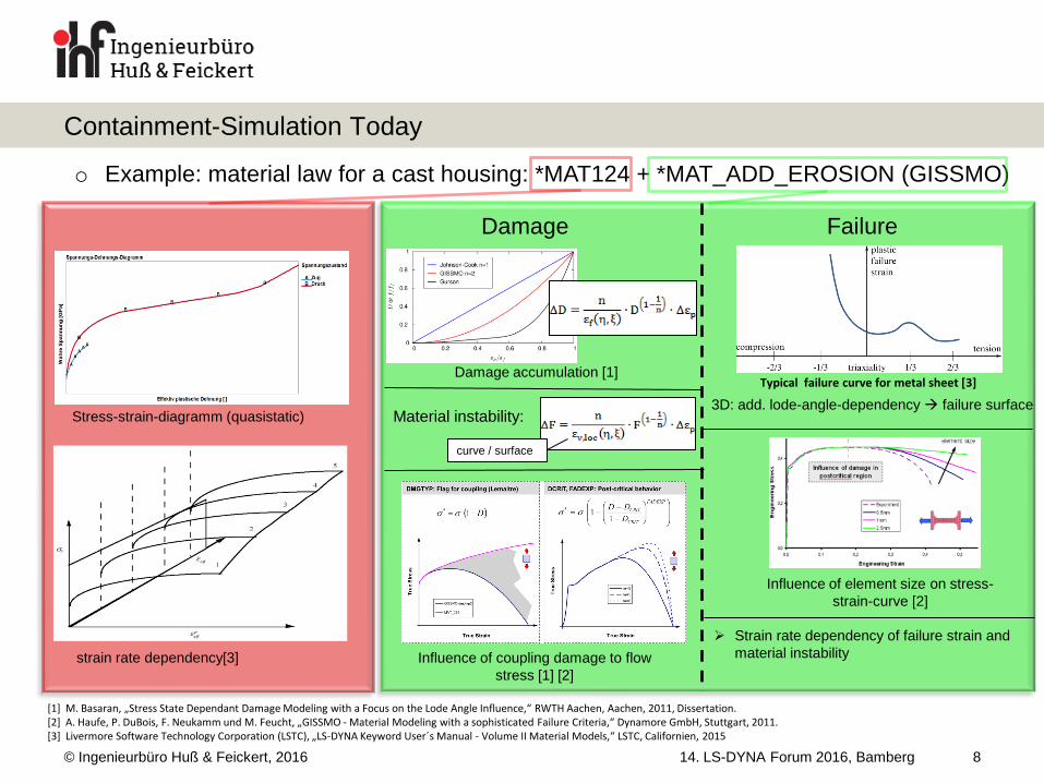
o Example: material law for a cast housing: *MAT124 + *MAT_ADD_EROSION (GISSMO)
Stress-strain-diagramm (quasistatic)
strain rate dependency[3] Influence of coupling damage to flow
stress [1] [2]
Damage accumulation [1]
Damage
Material instability:
curve / surface
Typical failure curve for metal sheet [3]
Influence of element size on stress-
strain-curve [2]
Failure
Strain rate dependency of failure strain and
material instability
3D: add. lode-angle-dependency failure surface
[1] M. Basaran, „Stress State Dependant Damage Modeling with a Focus on the Lode Angle Influence,“ RWTH Aachen, Aachen, 2011, Dissertation. [2] A. Haufe, P. DuBois, F. Neukamm und M. Feucht, „GISSMO - Material Modeling with a sophisticated Failure Criteria,“ Dynamore GmbH, Stuttgart, 2011. [3] Livermore Software Technology Corporation (LSTC), „LS-DYNA Keyword User´s Manual - Volume II Material Models,“ LSTC, Californien, 2015
© Ingenieurbüro Huß & Feickert, 2016
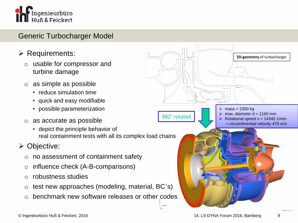
2D-geometry of turbocharger Requirements:
o usable for compressor and
turbine damage
o as simple as possible
• reduce simulation time
• quick and easy modifiable
• possible parameterization
o as accurate as possible
• depict the principle behavior of
real containment tests with all its complex load chains
Objective:
o no assessment of containment safety
o influence check (A-B-comparisons)
o robustness studies
o test new approaches (modeling, material, BC´s)
o benchmark new software releases or other codes
14. LS-DYNA Forum 2016, Bamberg
Generic Turbocharger Model
9
360° rotated
mass = 2300 kg
max. diameter d = 1160 mm
Rotational speed n = 14340 1/min
= circumferential velocity 475 m/s
© Ingenieurbüro Huß & Feickert, 2016 14. LS-DYNA Forum 2016, Bamberg
Generic Turbocharger Model
10
Turbocharger is build up modular: 3 sections and rotor:
o Compressor
o Bearing
o Turbine
o Rotor
rotational symmetric structure
o no inlet and outlet openings
no base / foot structure
o mounting via BC´s at lower area of circumference of turbine casing
silencer heavy idealized
o back plane/flange + lumped masses
o retention mass inertia
2 versions of each (coarse and fine - differentiation of
compressor and turbine containment)
© Ingenieurbüro Huß & Feickert, 2016 14. LS-DYNA Forum 2016, Bamberg
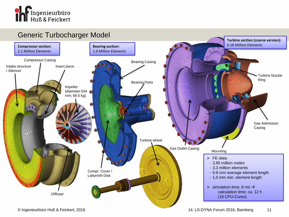
Generic Turbocharger Model
11
Compressor Casing
Intake structure
/ Silencer
Insert piece
Diffuser
Bearing Casing
Bearing Parts
Compr. Cover /
Labyrinth Disk
Gas Outlet Casing
Gas Admission
Casing
Turbine Nozzle
Ring
Mounting
Compressor section: 2.1 Million Elements
Bearing section: 1.0 Million Elements
Turbine section (coarse version): 0.18 Million Elements
FE-data:
- 3,85 million nodes
- 3,3 million elements
- 5-6 mm average element length
- 1,0 mm min. element length
simulation time: 8 ms
calculation time: ca. 12 h
(16 CPU-Cores)
Impeller
(diameter 634
mm; 68.5 kg)
Turbine wheel
© Ingenieurbüro Huß & Feickert, 2016 14. LS-DYNA Forum 2016, Bamberg
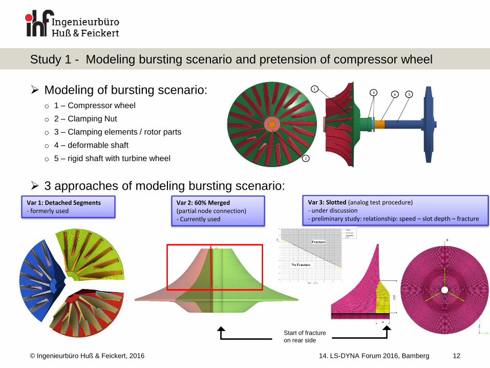
Study 1 - Modeling bursting scenario and pretension of compressor wheel
12
Modeling of bursting scenario: o 1 – Compressor wheel
o 2 – Clamping Nut
o 3 – Clamping elements / rotor parts
o 4 – deformable shaft
o 5 – rigid shaft with turbine wheel
3 approaches of modeling bursting scenario:
Var 1: Detached Segments - formerly used
Var 2: 60% Merged (partial node connection) - Currently used
Var 3: Slotted (analog test procedure) - under discussion - preliminary study: relationship: speed – slot depth – fracture
Start of fracture
on rear side
© Ingenieurbüro Huß & Feickert, 2016 14. LS-DYNA Forum 2016, Bamberg
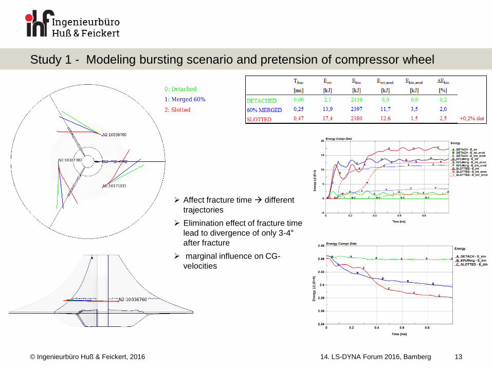
Study 1 - Modeling bursting scenario and pretension of compressor wheel
13
Affect fracture time different
trajectories
Elimination effect of fracture time
lead to divergence of only 3-4°
after fracture
marginal influence on CG-
velocities
© Ingenieurbüro Huß & Feickert, 2016 14. LS-DYNA Forum 2016, Bamberg
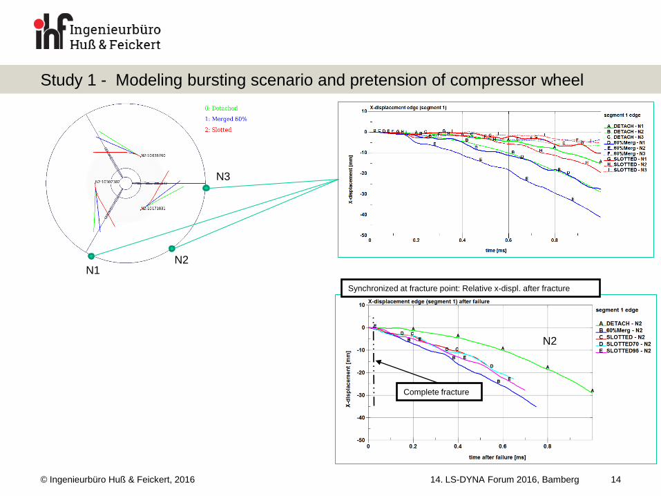
Study 1 - Modeling bursting scenario and pretension of compressor wheel
14
N1 N2
N3
Complete fracture
Synchronized at fracture point: Relative x-displ. after fracture
N2
© Ingenieurbüro Huß & Feickert, 2016 14. LS-DYNA Forum 2016, Bamberg
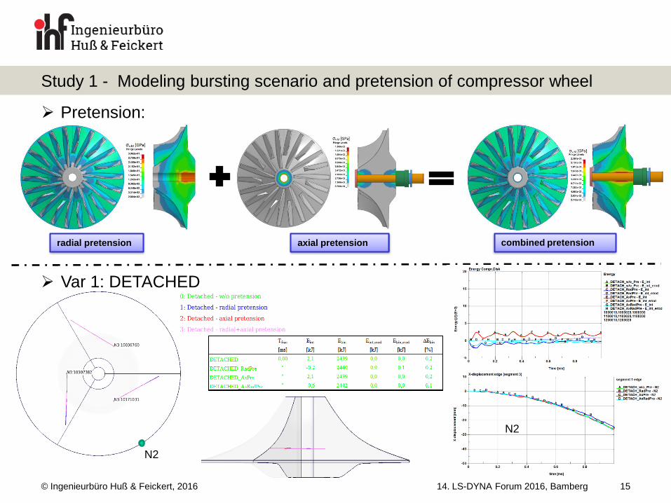
Study 1 - Modeling bursting scenario and pretension of compressor wheel
15
Pretension:
Var 1: DETACHED
axial pretension radial pretension combined pretension
N2
N2
© Ingenieurbüro Huß & Feickert, 2016 14. LS-DYNA Forum 2016, Bamberg
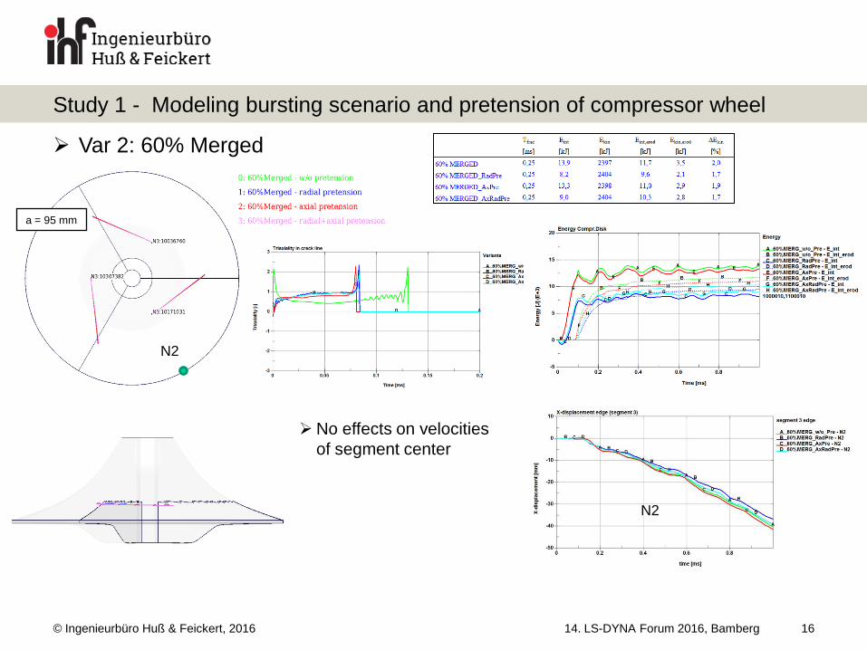
Study 1 - Modeling bursting scenario and pretension of compressor wheel
16
Var 2: 60% Merged
a = 95 mm
N2
N2
No effects on velocities
of segment center
© Ingenieurbüro Huß & Feickert, 2016 14. LS-DYNA Forum 2016, Bamberg
Study 1 - Modeling bursting scenario and pretension of compressor wheel
17
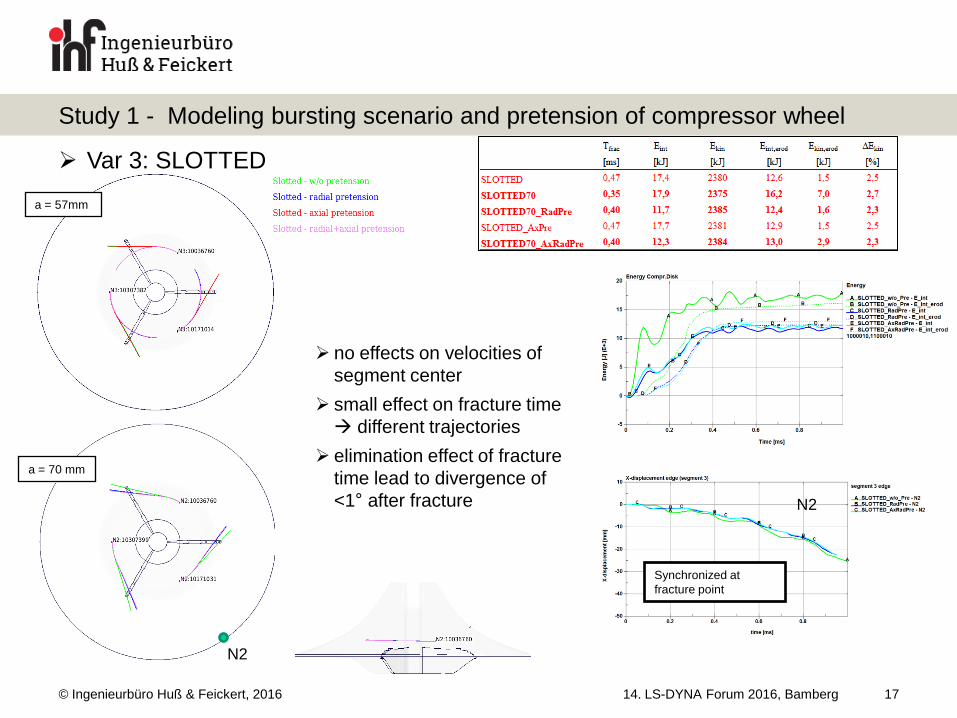
Var 3: SLOTTED
a = 57mm
a = 70 mm
N2
N2
Synchronized at
fracture point
no effects on velocities of
segment center
small effect on fracture time
different trajectories
elimination effect of fracture
time lead to divergence of
<1° after fracture
© Ingenieurbüro Huß & Feickert, 2016 14. LS-DYNA Forum 2016, Bamberg
Study 1 - Modeling bursting scenario and pretension of compressor wheel
18
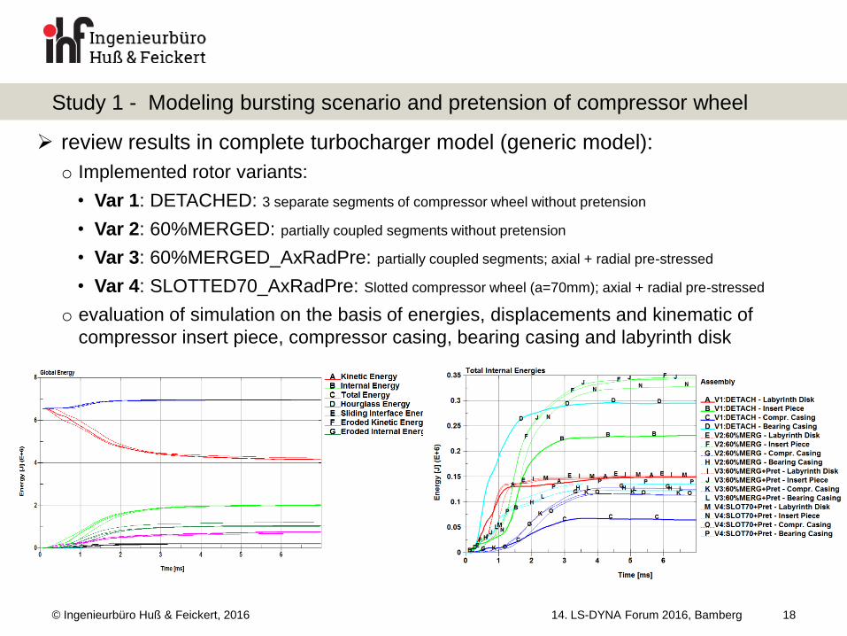
review results in complete turbocharger model (generic model):
o Implemented rotor variants:
• Var 1: DETACHED: 3 separate segments of compressor wheel without pretension
• Var 2: 60%MERGED: partially coupled segments without pretension
• Var 3: 60%MERGED_AxRadPre: partially coupled segments; axial + radial pre-stressed
• Var 4: SLOTTED70_AxRadPre: Slotted compressor wheel (a=70mm); axial + radial pre-stressed
o evaluation of simulation on the basis of energies, displacements and kinematic of
compressor insert piece, compressor casing, bearing casing and labyrinth disk
© Ingenieurbüro Huß & Feickert, 2016 14. LS-DYNA Forum 2016, Bamberg
Study 1 - Modeling bursting scenario and pretension of compressor wheel
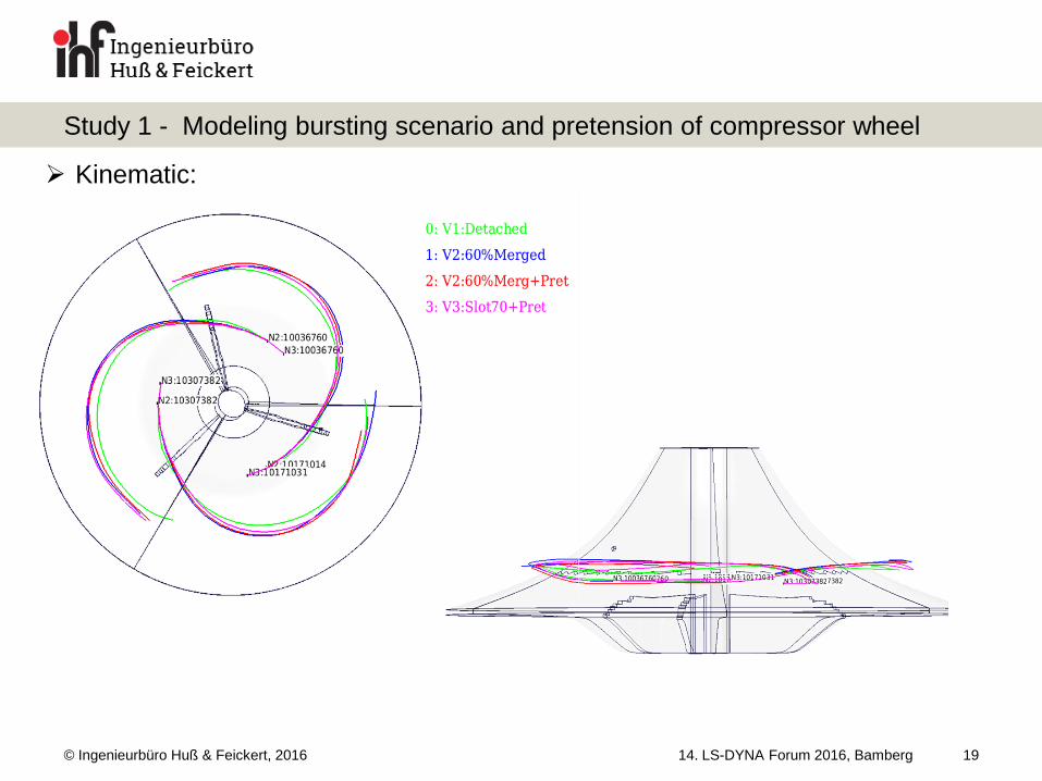
19
Kinematic:
© Ingenieurbüro Huß & Feickert, 2016 14. LS-DYNA Forum 2016, Bamberg
Study 1 - Modeling bursting scenario and pretension of compressor wheel
20
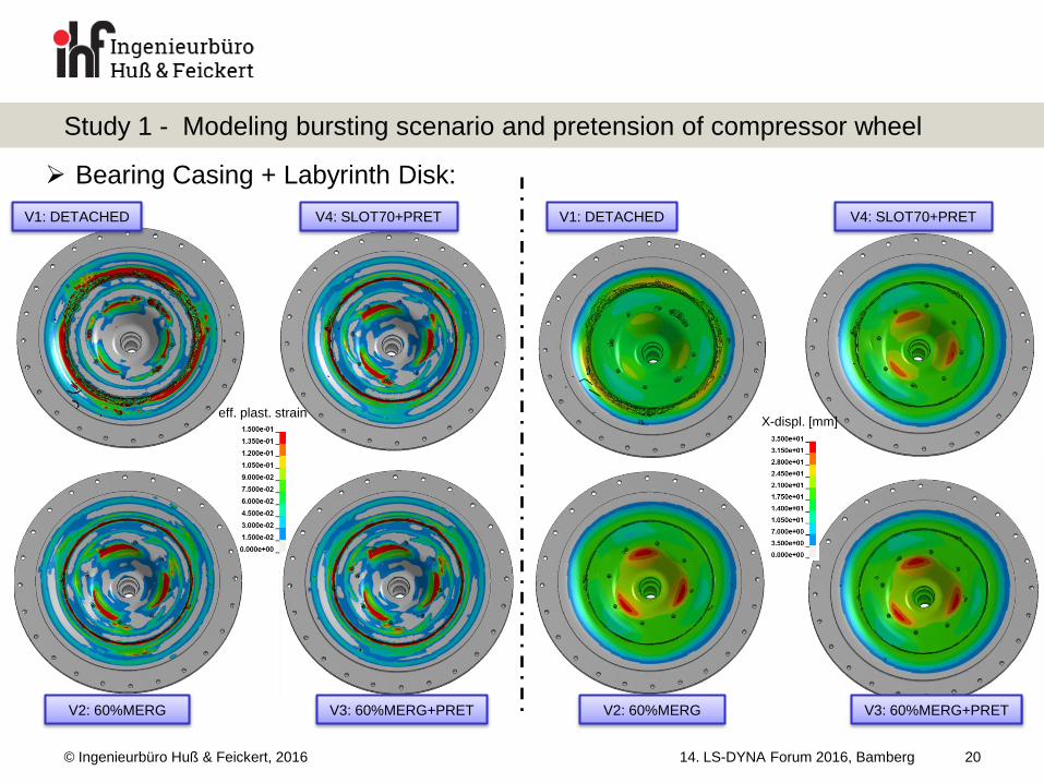
Bearing Casing + Labyrinth Disk:
eff. plast. strain
V1: DETACHED V4: SLOT70+PRET
V3: 60%MERG+PRET V2: 60%MERG
V1: DETACHED V4: SLOT70+PRET
V3: 60%MERG+PRET V2: 60%MERG
X-displ. [mm]
© Ingenieurbüro Huß & Feickert, 2016 14. LS-DYNA Forum 2016, Bamberg
Study 1 - Modeling bursting scenario and pretension of compressor wheel
21
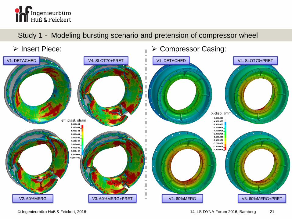
Insert Piece:
eff. plast. strain
V1: DETACHED V4: SLOT70+PRET
V3: 60%MERG+PRET V2: 60%MERG
V1: DETACHED V4: SLOT70+PRET
V3: 60%MERG+PRET V2: 60%MERG
X-displ. [mm]
Compressor Casing:
© Ingenieurbüro Huß & Feickert, 2016 14. LS-DYNA Forum 2016, Bamberg
Study 1 - Modeling bursting scenario and pretension of compressor wheel
22
implementation of bursting scenario:
o small influences on energy balance (red. 2-3%)
o difference in time till fracture (depending on slot depth) variance of segment kinematic
• small divergence in radial and tangential movement and segment rotation : trajectories differ < 4°
• obvious influence on axial movement / overturning (in particular Var1)
axial pretension no significant influences
radial pretension reduced Einternal for fracture + reduced loss of Ekinetic
o no influence on degree of damage of compressor wheel
o small influence on time till fracture small variance of segment kinematic (overturning)
pretension eliminates peak in triaxiality at the beginning
© Ingenieurbüro Huß & Feickert, 2016 14. LS-DYNA Forum 2016, Bamberg
Study 1 - Modeling bursting scenario and pretension of compressor wheel
23
influences in complete turbocharger model (generic model):
o small differences in global energies + partially heavy differences in energies of main
assemblies
o different impact loads on surrounding parts: differences in plastic strain, axial
displacements and damage
o different kinematic of compressor wheel
• in particular Var1 (DETACHED) differ from the rest significantly
• marginal divergences between Var2 and Var3 (60%MERGED with and without Pretension)
• small divergences between Var3 (60%MERGED+PRET) and Var4 (SLOTTED70+PRET)
o initial splitted or only slotted impeller make the great difference; the kind of modeling the slot is
secondary
o axial pretension no influence; radial pretension small influence
• compressor bursting: prefer variant with partially merged segments (coupling over ca.
60% of height beginning from the top of the impeller) without pretension
(good kinematic + heaviest loads on surrounding structure + no slot-modeling and implicit analysis
needed)
© Ingenieurbüro Huß & Feickert, 2016 14. LS-DYNA Forum 2016, Bamberg
Study 2 – Effect of lode-angle-parameter on the failure behavior in a CT-Simulation
24
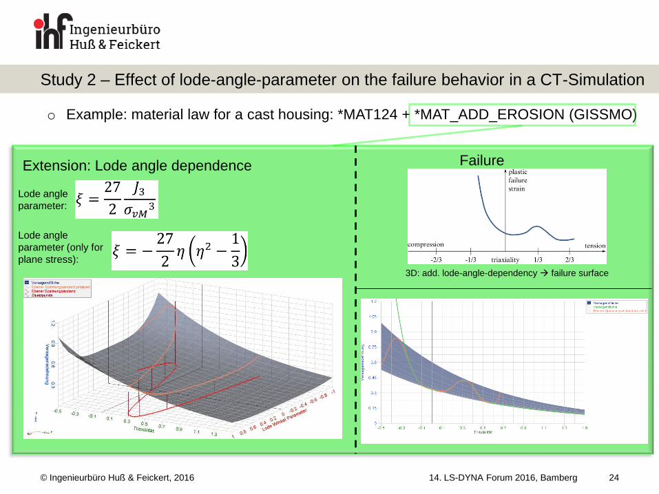
o Example: material law for a cast housing: *MAT124 + *MAT_ADD_EROSION (GISSMO)
Extension: Lode angle dependence Failure
3D: add. lode-angle-dependency failure surface
Lode angle
parameter:
Lode angle
parameter (only for
plane stress):
© Ingenieurbüro Huß & Feickert, 2016
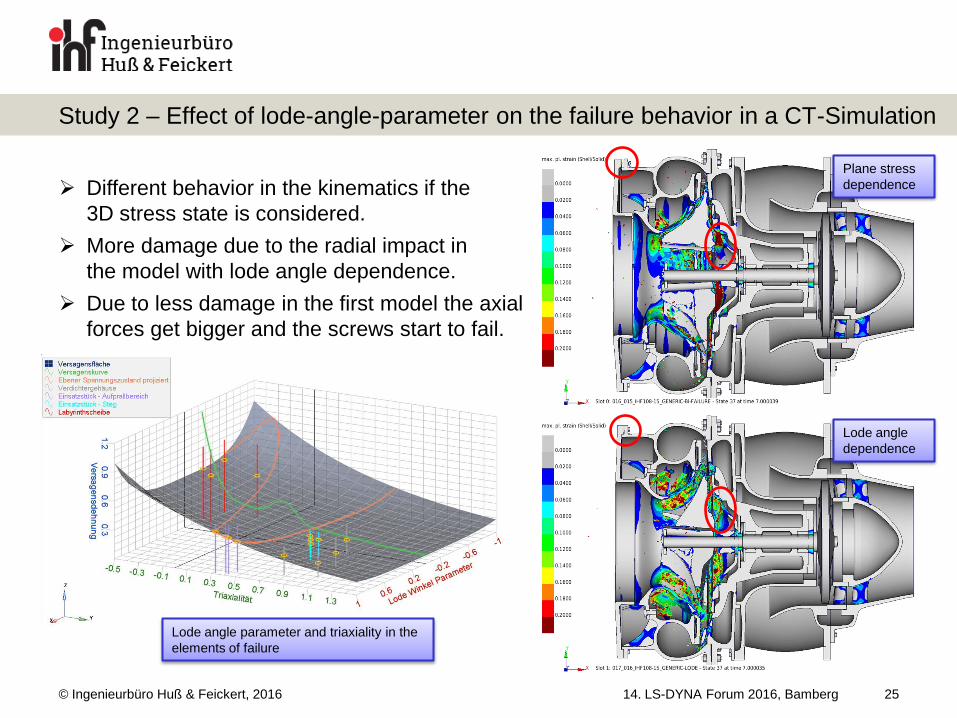
Different behavior in the kinematics if the
3D stress state is considered.
More damage due to the radial impact in
the model with lode angle dependence.
Due to less damage in the first model the axial
forces get bigger and the screws start to fail.
14. LS-DYNA Forum 2016, Bamberg
Study 2 – Effect of lode-angle-parameter on the failure behavior in a CT-Simulation
25
Plane stress
dependence
Lode angle
dependence
Lode angle parameter and triaxiality in the
elements of failure
© Ingenieurbüro Huß & Feickert, 2016
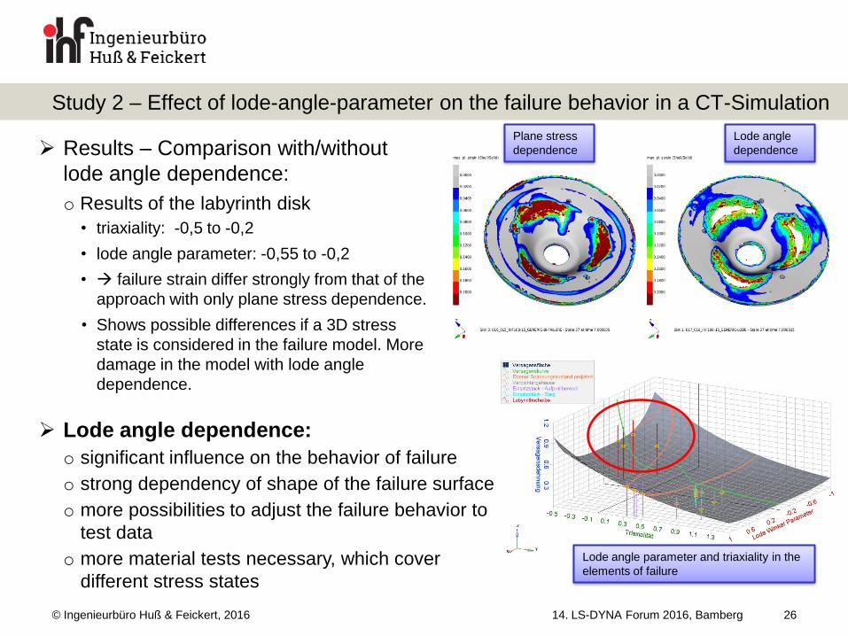
Results – Comparison with/without
lode angle dependence:
o Results of the labyrinth disk
• triaxiality: -0,5 to -0,2
• lode angle parameter: -0,55 to -0,2
• failure strain differ strongly from that of the
approach with only plane stress dependence.
• Shows possible differences if a 3D stress
state is considered in the failure model. More
damage in the model with lode angle
dependence.
14. LS-DYNA Forum 2016, Bamberg
Study 2 – Effect of lode-angle-parameter on the failure behavior in a CT-Simulation
26
Plane stress
dependence
Lode angle
dependence
Lode angle parameter and triaxiality in the
elements of failure
Lode angle dependence:
o significant influence on the behavior of failure
o strong dependency of shape of the failure surface
o more possibilities to adjust the failure behavior to
test data
o more material tests necessary, which cover
different stress states
© Ingenieurbüro Huß & Feickert, 2016 14. LS-DYNA Forum 2016, Bamberg
Summary
27
models become more and more complex high effort for meshing + long
calculation time cost driver o studies of modifications and improvements (e.g. in material laws, meshing, geometry, boundary
conditions, simulation methodology) are very expensive and long-lasting
the developed generic model has proved itself a very helpful instrument o depicts the principle behavior of real containment tests with all its complex load chains
o enables studies, sensitivity and robustness analyses in a fast and efficient way
o improvements, new features and simulation approaches can be tested and assessed comprehensively
before considering them in a detailed containment simulation
kind of implementation of bursting scenario can affect simulation results
significantly o Currently used approach is very good and efficient
Lode angle dependence is a very important point o can have strong influence depending on shape of the failure surface and the existing stress state
o more effort for validation needed
© Ingenieurbüro Huß & Feickert, 2016 14. LS-DYNA Forum 2016, Bamberg 28
Ingenieurbüro Huß & Feickert GbR
Im Kohlruß 1-3
65835 Liederbach
Telefon: +49 (0)6196 / 67071 – 0
Fax: +49 (0)6196 / 67071 – 28
Mail: [email protected]
www.ihf-ffm.de
Managing Partner: Prof. Dr.-Ing. Wolfgang Feickert, Prof. Dr.-Ing. Armin Huß