Embed Size (px)
Citation preview
05.03.2015, pF www.pccl.at
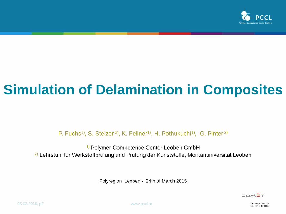
P. Fuchs1), S. Stelzer 2), K. Fellner1), H. Pothukuchi1), G. Pinter 2)
1) Polymer Competence Center Leoben GmbH
2) Lehrstuhl für Werkstoffprüfung und Prüfung der Kunststoffe, Montanuniversität Leoben
Polyregion Leoben - 24th of March 2015
Simulation of Delamination in Composites
05.03.2015, pF www.pccl.at 2
- Introduction and Motivation
- Methods Simulation of Delamination
Cohesive Zone Model
Mixed Mode
Implementation in FEM
- Determination Model Parameters State of the Art
Fracture Tests
Numerical Optimization
- Application Examples Joining
Printed Circuit Boards
Cyclic Delamination
- Summary
Outline
05.03.2015, pF www.pccl.at
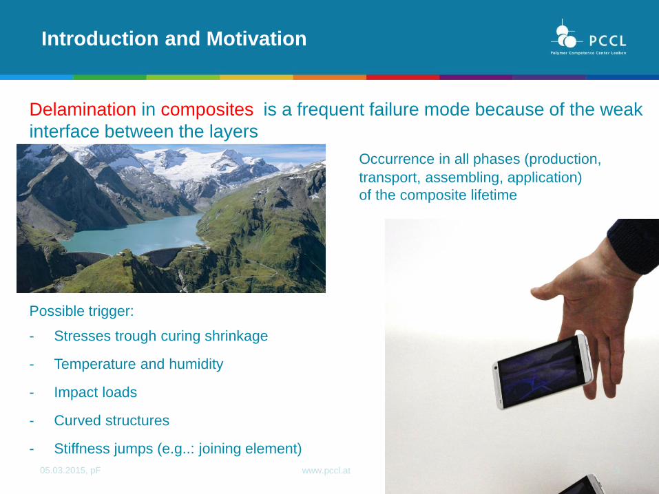
Delamination in composites is a frequent failure mode because of the weak
interface between the layers
Occurrence in all phases (production,
transport, assembling, application)
of the composite lifetime
Possible trigger:
- Stresses trough curing shrinkage
- Temperature and humidity
- Impact loads
- Curved structures
- Stiffness jumps (e.g..: joining element)
3
Introduction and Motivation

05.03.2015, pF www.pccl.at
4
Introduction and Motivation
Albert Turon Travesa, “Simulation of delamination in composites under quasi-static
and fatigue loading using cohesive zone models”.
Surface Internal
fracture mode
Impact
critical loads (Examples)
constraint transversal strain
Curved structures
Lehrstuhl für Kontinuumsmechanik und
Materialtheorie, Prof. W.H. Müller,
Technische Universität Berlin
Damage

05.03.2015, pF www.pccl.at 5
Fracture Mechanis Damage Mechanics
Methods
Simulation of Delamination
‘Virtual Crack Closure Technique’ (VCCT)
Qelle : Schwalbe K H, Scheider I, Cornec A; SIAM CM 09 – The SIAM method for applying cohesvie models to damgae behaviour of engineering materials and structures, GKSS
Cohesive Zone Model
Albert Turon Travesa, “Simulation of delamination in composites under quasi-static and fatigue
loading using cohesive zone models”.
Anderson, T.L. (2005), Fracture mechanics: Fundamentals and applications, 3rd ed., Taylor &
Francis, Boca Raton, FL.

05.03.2015, pF www.pccl.at
Simulation Schädigung
Methods
Cohesive Zone Model
𝛿𝑚0
𝑇
𝛿𝑚𝑓
𝐺𝑐
𝑡 𝑡 + 𝛿𝑚0 𝑡 + 𝛿𝑚𝑓
𝐷𝑎𝑚𝑎𝑔𝑒 𝑖𝑛𝑖𝑡𝑎𝑡𝑖𝑜𝑛 𝑎𝑛𝑑 𝑒𝑣𝑜𝑙𝑢𝑡𝑖𝑜𝑛
𝑇𝑟𝑎𝑐𝑡𝑖𝑜𝑛
𝑠𝑒𝑝𝑒𝑟𝑎𝑡𝑖𝑜𝑛
modeling possibilities
05.03.2015, pF www.pccl.at 7
effective displacement unified potential
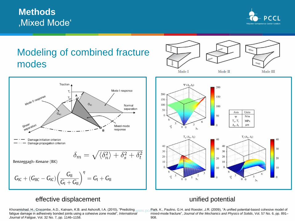
Methods
‚Mixed Mode‘
Khoramishad, H., Crocombe, A.D., Katnam, K.B. and Ashcroft, I.A. (2010), “Predicting
fatigue damage in adhesively bonded joints using a cohesive zone model”, International
Journal of Fatigue, Vol. 32 No. 7, pp. 1146–1158.
Park, K., Paulino, G.H. and Roesler, J.R. (2009), “A unified potential-based cohesive model of
mixed-mode fracture”, Journal of the Mechanics and Physics of Solids, Vol. 57 No. 6, pp. 891–
908.
Modeling of combined fracture
modes
05.03.2015, pF www.pccl.at 8
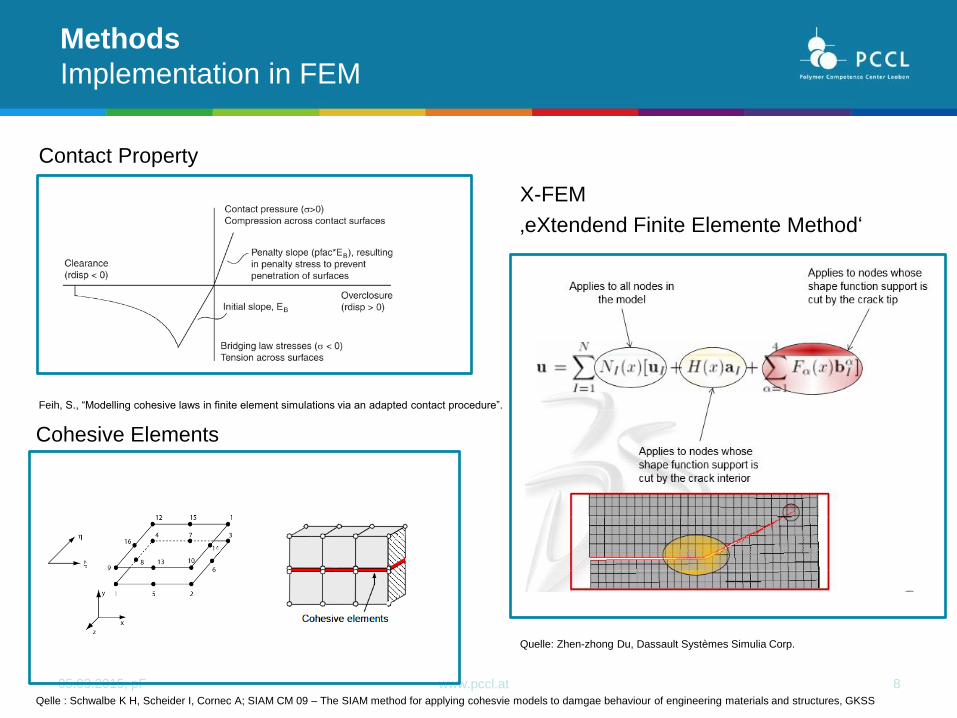
Contact Property
Methods
Implementation in FEM
Quelle: Zhen-zhong Du, Dassault Systèmes Simulia Corp.
Cohesive Elements
X-FEM
‚eXtendend Finite Elemente Method‘
Feih, S., “Modelling cohesive laws in finite element simulations via an adapted contact procedure”.
Qelle : Schwalbe K H, Scheider I, Cornec A; SIAM CM 09 – The SIAM method for applying cohesvie models to damgae behaviour of engineering materials and structures, GKSS
05.03.2015, pF www.pccl.at
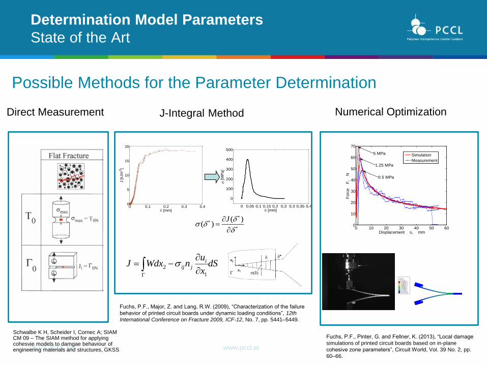
Possible Methods for the Parameter Determination
Determination Model Parameters
State of the Art
Schwalbe K H, Scheider I, Cornec A; SIAM CM 09 – The SIAM method for applying cohesvie models to damgae behaviour of engineering materials and structures, GKSS
0 0.1 0.2 0.3 0.40
5
10
15
20
[mm]
J [
kJm
-2]
0 0,05 0,1 0,15 0,2 0,3 0,3 0,35 0,4
0
100
200
300
400
500
[mm]
[
MP
a]
)()(
J
dSx
unWdxJ i
jij
1
2
Direct Measurement J-Integral Method Numerical Optimization
Fuchs, P.F., Major, Z. and Lang, R.W. (2009), “Characterization of the failure
behavior of printed circuit boards under dynamic loading conditions”, 12th
International Conference on Fracture 2009, ICF-12, No. 7, pp. 5441–5449.
0 10 20 30 40 50 600
10
20
30
40
50
60
70
Displacement s, mm
Fo
rce
F
, N
Simulation
Measurement
0.5 MPa
1.25 MPa
5 MPa
Fuchs, P.F., Pinter, G. and Fellner, K. (2013), “Local damage
simulations of printed circuit boards based on in-plane
cohesive zone parameters”, Circuit World, Vol. 39 No. 2, pp.
60–66.
05.03.2015, pF www.pccl.at 10
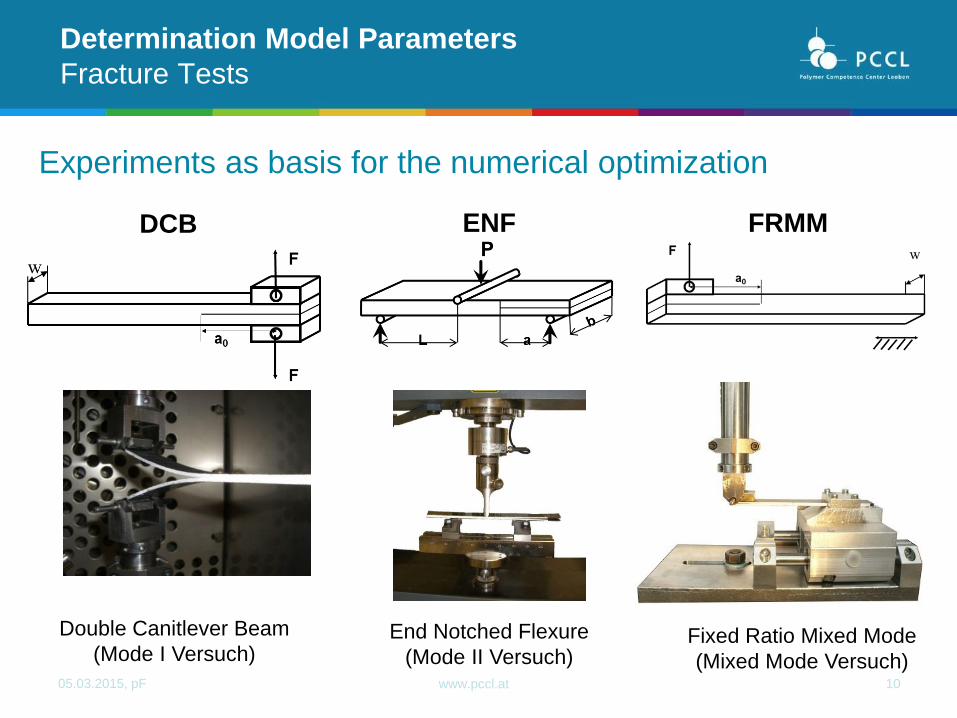
Experiments as basis for the numerical optimization
Determination Model Parameters
Fracture Tests
DCB ENF FRMM
Double Canitlever Beam
(Mode I Versuch) End Notched Flexure
(Mode II Versuch) Fixed Ratio Mixed Mode
(Mixed Mode Versuch)

05.03.2015, pF www.pccl.at
‚Double Cantilever Beam‘
Mode I Versuch
Determination Model Parameters
Numerical Optimization
DCB
Albert Turon Travesa, “Simulation of delamination in composites under quasi-static and fatigue
loading using cohesive zone models”.
parameters:
• stiffness
• critical energy release rate
• definition damage initiation (e.g. stress or
displacement)
• damage evolution (e.g.: linear, bilinear or
exponential)
• element size

05.03.2015, pF www.pccl.at
parameters:
• stiffness
• critical energy release rate
• definition damage initiation (e.g. stress or
displacement)
• damage evolution (e.g.: linear, bilinear or
exponential)
• element size
• time step
• friction interface
• friction bearings
‚End Notched Flexure‘
Mode II Test
Determination Model Parameters
Numerical Optimization
ENF

05.03.2015, pF www.pccl.at
Motivation
Application Examples
Joining Techniques
Cold metal transfer (CMT) welding head attached to three axes moving portal
Mould with fixed metall inserts
CMT-pins for reinforcing CFRP to CFRP joints (stainless steel or titanium)
Specimen Preperation
‚Single Lap Shear Test‘
Optimized experimental methods for the description of the delamination and failure behavior of
high performance composites and joints, 2014
05.03.2015, pF www.pccl.at
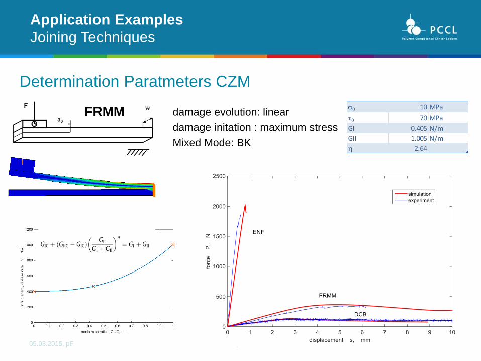
Determination Paratmeters CZM
Application Examples
Joining Techniques
FRMM 0 10 MPa
t0 70 MPa
GI 0.405 N/m
GII 1.005 N/m
h 2.64
damage evolution: linear
damage initation : maximum stress
Mixed Mode: BK

05.03.2015, pF www.pccl.at
Single Lap Shear Simulation
Application Examples
Joining Techniques
• Damage evolution
• Influende fracuture
modes
1
2 3
1 2
3

05.03.2015, pF www.pccl.at
Results
Application Examples
Joining Techniques
pin array 1
pin array 2
pin array 3

05.03.2015, pF www.pccl.at 17
Multilayer built-ups
Interaction of materials with significantly different thermo mechanical behavior
Wide field of applications – various loading conditions
Temperature Vibrations Impact
Fatigue
Application Examples
Printed Circuit Boards
Motivation

05.03.2015, pF www.pccl.at 18
Application Examples
Printed Circuit Boards
Fuchs, P. and Major, Z. (2011), “Cyclic bend tests for the reliability evaluation of printed
circuit boards under dynamic loads”, Frattura ed Integrità Strutturale No. 15, pp. 64–73.
Fuchs, P.F., Pinter, G. and Krivec, T., “Design independent lifetime assessment method for
PCBs under low cycle fatigue loading conditions”, EuroSimE, Vol. 2014.
Loading and Failure Modes

05.03.2015, pF www.pccl.at 19 Quelle: Schürmann H, Konstruieren mit Faser-Kunststoff-Verbunden, Springer, 2007
Materials
fibreglass reinforced epoxy laminates
glas fibre fabric with differences in
warp and weft direction
very thin (50-200 mm)
orthotropic material behaviour
Application Examples
Printed Circuit Boards
05.03.2015, pF www.pccl.at 20
Application Examples
Printed Circuit Boards
E11,E22,(E33)
n12, (n13, n23)
G12,(G13,G23)
Engineering Constants
Determination of the in plane engineering constants 1122122224522114
22114512
EEEEEE
EEEG
n
0 0.02 0.040
50
100
150
200
250
strain , -
str
ess
, M
Pa
0°
90°
45°
0 1 2 3 4
0
5
10
x 10-3
time t, -str
ain
,
-
transversal strain
longitudinal strain

05.03.2015, pF www.pccl.at 21
Application Examples
Printed Circuit Boards
0 10 20 30 40 50 600
10
20
30
40
50
60
70
Displacement s, mm
Fo
rce
F
, N
Simulation
Measurement
0.5 MPa
1.25 MPa
5 MPa
Adaption cohesive stress
Determination of the damage initiation
Fuchs, P. and Major, Z. (2011), “Cyclic bend tests for the reliability evaluation of printed circuit boards under
dynamic loads”, Frattura ed Integrità Strutturale No. 15, pp. 64–73.

05.03.2015, pF www.pccl.at 22
Application Examples
Printed Circuit Boards
0 50 100 150 2000
10
20
30
40
50
60
Displacement s, mm
Fo
rce
F
, N
Simulation
Measurement
2 mm Probe
5 mm Probe
0.7 mm Probe
Evaluation of the cohesive zone model
Determination of the damage initiation

05.03.2015, pF www.pccl.at
23
Application Examples
Printed Circuit Boards
Model
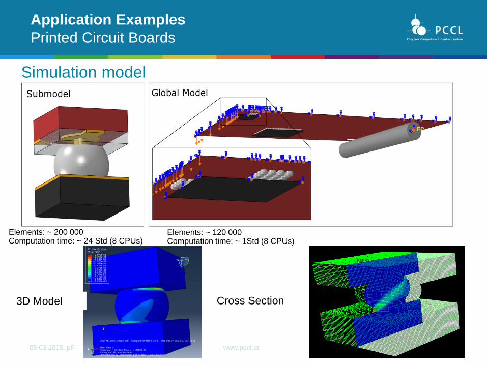
05.03.2015, pF www.pccl.at 24
Sub Model
Cross Section 3D Model
Simulation model
Application Examples
Printed Circuit Boards
Elements: ~ 120 000 Computation time: ~ 1Std (8 CPUs)
Elements: ~ 200 000 Computation time: ~ 24 Std (8 CPUs)
05.03.2015, pF www.pccl.at
Application Examples
Printed Circuit Boards
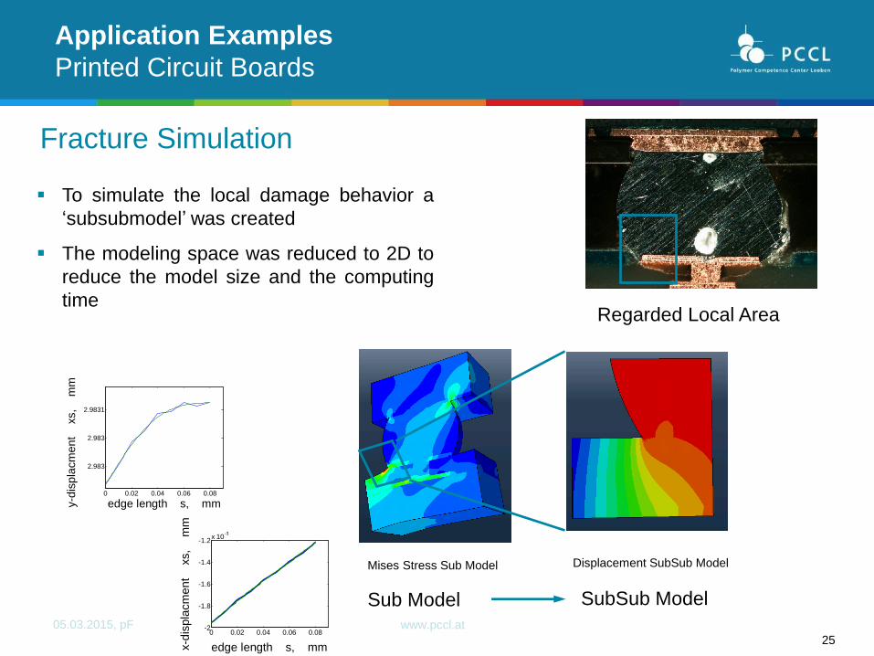
Sub Model SubSub Model
Displacement SubSub Model
Regarded Local Area
Mises Stress Sub Model
Fracture Simulation
25
To simulate the local damage behavior a
‘subsubmodel’ was created
The modeling space was reduced to 2D to
reduce the model size and the computing
time
0 0.02 0.04 0.06 0.08-2
-1.8
-1.6
-1.4
-1.2x 10
-3
edge length s, mmx-d
ispla
cm
en
t
xs,
mm
0 0.02 0.04 0.06 0.08
2.983
2.983
2.9831
edge length s, mmy-d
ispla
cm
en
t
xs,
mm

05.03.2015, pF www.pccl.at 26
Application Examples
Printed Circuit Boards
X-FEM Simulation
Failure Mode experiment
Fracture simulation

05.03.2015, pF www.pccl.at
Summary
Delamination is critical in a load of composite applications because e of
the weak interface between the layers
Possible simulation methods based on fracture and damage mechanics
The phenomenological cohesive Zone Model is advantageous with
respect to the application in a FEM simulation
Challenging Determination of the Cohesive Zone Model Parameters
Useful to understand and interpret delamination in order to optimize the
component design

05.03.2015, pF www.pccl.at 28
Acknowledgement
Die vorliegende Forschungsarbeit wurde an der Polymer Competence Center Leoben GmbH
im Rahmen des Kompetenzzentren-Programms COMET des Bundesministeriums für
Verkehr, Innovation und Technologie und des Bundesministeriums für Wirtschaft, Familie
und Jugend unter Beteiligung der Montanuniversität Leoben, der Austria Technologie &
Systemtechnik AG, AT&S und der Andritz Hydro AG durchgeführt und mit Mitteln des Bundes und
der Länder Steiermark, Niederösterreich und Oberösterreich gefördert.
Teile der Forschungsarbeit wurden weiters durch das FFG TAKE OFF Projekt
Composite+composite Joints with Enhanced damage toleranCe (CoJEC) gefördert.