Embed Size (px)
Citation preview

1
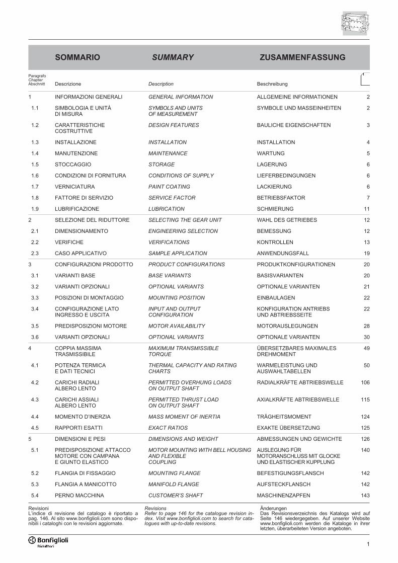
SOMMARIO
Descrizione Description Beschreibung
1 INFORMAZIONI GENERALI GENERAL INFORMATION ALLGEMEINE INFORMATIONEN 2
1.1 SIMBOLOGIA E UNITÀDI MISURA
SYMBOLS AND UNITSOF MEASUREMENT
SYMBOLE UND MASSEINHEITEN 2
1.2 CARATTERISTICHECOSTRUTTIVE
DESIGN FEATURES BAULICHE EIGENSCHAFTEN 3
1.3 INSTALLAZIONE INSTALLATION INSTALLATION 4
1.4 MANUTENZIONE MAINTENANCE WARTUNG 5
1.5 STOCCAGGIO STORAGE LAGERUNG 6
1.6 CONDIZIONI DI FORNITURA CONDITIONS OF SUPPLY LIEFERBEDINGUNGEN 6
1.7 VERNICIATURA PAINT COATING LACKIERUNG 6
1.8 FATTORE DI SERVIZIO SERVICE FACTOR BETRIEBSFAKTOR 7
1.9 LUBRIFICAZIONE LUBRICATION SCHMIERUNG 11
2 SELEZIONE DEL RIDUTTORE SELECTING THE GEAR UNIT WAHL DES GETRIEBES 12
2.1 DIMENSIONAMENTO ENGINEERING SELECTION BEMESSUNG 12
2.2 VERIFICHE VERIFICATIONS KONTROLLEN 13
2.3 CASO APPLICATIVO SAMPLE APPLICATION ANWENDUNGSFALL 19
3 CONFIGURAZIONI PRODOTTO PRODUCT CONFIGURATIONS PRODUKTKONFIGURATIONEN 20
3.1 VARIANTI BASE BASE VARIANTS BASISVARIANTEN 20
3.2 VARIANTI OPZIONALI OPTIONAL VARIANTS OPTIONALE VARIANTEN 21
3.3 POSIZIONI DI MONTAGGIO MOUNTING POSITION EINBAULAGEN 22
3.4 CONFIGURAZIONE LATOINGRESSO E USCITA
INPUT AND OUTPUTCONFIGURATION
KONFIGURATION ANTRIEBSUND ABTRIEBSSEITE
22
3.5 PREDISPOSIZIONI MOTORE MOTOR AVAILABILITY MOTORAUSLEGUNGEN 28
3.6 VARIANTI OPZIONALI OPTIONAL VARIANTS OPTIONALE VARIANTEN 30
4 COPPIA MASSIMATRASMISSIBILE
MAXIMUM TRANSMISSIBLETORQUE
ÜBERSETZBARES MAXIMALESDREHMOMENT
49
4.1 POTENZA TERMICAE DATI TECNICI
THERMAL CAPACITY AND RATINGCHARTS
WARMELEISTUNG UNDAUSWAHLTABELLEN
50
4.2 CARICHI RADIALIALBERO LENTO
PERMITTED OVERHUNG LOADSON OUTPUT SHAFT
RADIALKRÄFTE ABTRIEBSWELLE 106
4.3 CARICHI ASSIALIALBERO LENTO
PERMITTED THRUST LOADON OUTPUT SHAFT
AXIALKRÄFTE ABTRIEBSWELLE 115
4.4 MOMENTO D’INERZIA MASS MOMENT OF INERTIA TRÄGHEITSMOMENT 124
4.5 RAPPORTI ESATTI EXACT RATIOS EXAKTE ÜBERSETZUNG 125
5 DIMENSIONI E PESI DIMENSIONS AND WEIGHT ABMESSUNGEN UND GEWICHTE 126
5.1 PREDISPOSIZIONE ATTACCOMOTORE CON CAMPANAE GIUNTO ELASTICO
MOTOR MOUNTING WITH BELL HOUSINGAND FLEXIBLECOUPLING
AUSLEGUNG FÜRMOTORANSCHLUSS MIT GLOCKEUND ELASTISCHER KUPPLUNG
140
5.2 FLANGIA DI FISSAGGIO MOUNTING FLANGE BEFESTIGUNGSFLANSCH 142
5.3 FLANGIA A MANICOTTO MANIFOLD FLANGE AUFSTECKFLANSCH 142
5.4 PERNO MACCHINA CUSTOMER’S SHAFT MASCHINENZAPFEN 143
ParagrafoChapterAbschnitt
SUMMARY ZUSAMMENFASSUNG
RevisionsRefer to page 146 for the catalogue revision in-dex. Visit www.bonfiglioli.com to search for cata-logues with up-to-date revisions.
ÄnderungenDas Revisionsverzeichnis des Katalogs wird aufSeite 146 wiedergegeben. Auf unserer Websitewww.bonfiglioli.com werden die Kataloge in ihrerletzten, überarbeiteten Version angeboten.
RevisioniL’indice di revisione del catalogo è riportato apag. 146. Al sito www.bonfiglioli.com sono dispo-nibili i cataloghi con le revisioni aggiornate.
2
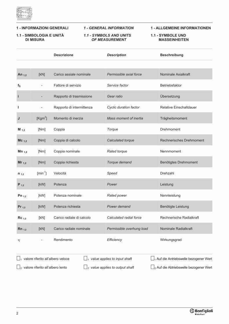
Descrizione Description Beschreibung
An 1,2 [kN] Carico assiale nominale Permissible axial force Nominale Axialkraft
fS - Fattore di servizio Service factor Betriebsfaktor
i - Rapporto di trasmissione Gear ratio Übersetzung
I - Rapporto di intermittenza Cyclic duration factor Relative Einschaltdauer
J [Kgm2] Momento di inerzia Mass moment of inertia Trägheitsmoment
M 1,2 [Nm] Coppia Torque Drehmoment
Mc 1,2 [Nm] Coppia di calcolo Calculated torque Rechnerisches Drehmoment
Mn 1,2 [Nm] Coppia nominale Rated torque Nennmoment
Mr 1,2 [Nm] Coppia richiesta Torque demand Benötigtes Drehmoment
n 1,2 [min-1] Velocità Speed Drehzahl
P 1,2 [kW] Potenza Power Leistung
Pn 1,2 [kW] Potenza nominale Rated power Nennleistung
Pr 1,2 [kW] Potenza richiesta Power demand Benötigte Leistung
Rc 1,2 [kN] Carico radiale di calcolo Calculated radial force Rechnerische Radialkraft
Rn 1,2 [kN] Carico radiale nominale Permissible overhung load Nominale Radialkraft
� - Rendimento Efficiency Wirkungsgrad
1 - INFORMAZIONI GENERALI
1.1 - SIMBOLOGIA E UNITÀ
DI MISURA
1 - GENERAL INFORMATION
1.1 - SYMBOLS AND UNITS
OF MEASUREMENT
1 - ALLGEMEINE INFORMATIONEN
1.1 - SYMBOLE UND
MASSEINHEITEN
�1 valore riferito all’albero veloce
�2 valore riferito all’albero lento
�1 value applies to input shaft
�2 value applies to output shaft
�1 Auf die Antriebswelle bezogener Wert
�2 Auf die Abtriebswelle bezogener Wert
3
1.2 - CARATTERISTICHE
COSTRUTTIVE
I riduttori della serie HDO sfruttano tec-niche progettuali all’avanguardia ed of-frono pertanto:
• Elevate coppie specifiche.
• Rendimenti superiori.
• Vibrazione e rumorosità ridotte.
• Robustezza e affidabilità assolute.
• Calcoli di vita secondo le Norme ISOe AGMA applicabili.
• Ampia personalizzazione tramite lavasta gamma di opzioni offerte a ca-talogo.
Le principali caratteristiche costruttivedella serie di riduttori ad assi ortogonaliHDO sono:
• 7 grandezze: HDO 100, 110, 120,130, 140, 150 e 160 a 2, 3 e 4 stadidi riduzione.
• Valori di coppia nominale con distri-buzione favorevole su tutto l’arco deirapporti.
• Rapporti di trasmissione con progres-sione costante del 12%.
• HDO 100, 110 e 120: Cassa monobloc-co in ghisa sferoidale, rigida, resistentee precisa, verniciata internamente edesternamente. Design moderno e privodi recessi a garanzia di una pulizia faci-litata. Fissaggio universale grazie allenumerose superfici lavorate e forate.Forme e spessori ottimizzati mediantel’analisi FEM garantiscono elevata rigi-dezza strutturale e ridotte emissioniacustiche con un peso contenuto.
• HDO 130, 140, 150 e 160: Cassa inghisa sferoidale realizzata in due se-migusci, con piano di separazionecomplanare agli assi. L’architetturaconsente di realizzare interventi dimanutenzione in maniera efficace edeconomica. Forme e spessori ottimiz-zati mediante l’analisi FEM garanti-scono elevata rigidezza strutturale eridotte emissioni acustiche con unpeso contenuto.
• Ingranaggi conici e cilindrici in acciaiolegato, cementati, temprati e rettifica-ti, con correzione dei profili per:- ridurre la rumorosità e favorire la
regolarità della trasmissione degliingranaggi veloci
- massimizzare la coppia trasmissibi-le delle riduzioni finali
• Alberi veloci generalmente cementatie rettificati e alberi lenti in acciaio dabonifica di elevata rigidezza.
1.2 - DESIGN FEATURES
The HDO range of gearboxes features
advanced design techniques that offer:
• High specific torque values.
• Superior performance.
• Silent, vibration-free operation.
• Total ruggedness and reliability.
• Lifetime calculations according to appli-
cable ISO and AGMA standards.
• Extensive customisation through a wide
range of catalogue options.
The main design features of the HDO
bevel helical range are:
• 7 frame sizes: HDO 100, 110, 120
130, 140, 150 and 160, with 2, 3, and
4 reduction stages.
• Excellent distribution of rated torque
values across the entire ratio range.
• Gear ratios with constant 12%
escalation.
• HDO 100, 110 and 120: monobloc cas-
ing in rigid, strong and precision ma-
chined spheroidal graphite cast iron,
with internal and external paint finish.
Modern recess-free design for easy
cleaning. Universal mounting thanks to
large number of machined and drilled
surfaces. Casing shapes and thick-
nesses optimised by FEM analysis for
superior structural rigidity, low acoustic
emissions and reduced weight.
• HDO 130, 140, 150 and 160: spheroi-
dal graphite cast iron body made up of
two half-casings, split along the same
plane as the shafts. This design makes
maintenance operations quick and
economical. Casing shapes and thick-
nesses optimised by FEM analysis for
superior structural rigidity, low acous-
tic emissions and reduced weight.
• Case hardened, tempered and ground
finished alloyed steel bevel and helical
gears, with corrected profiles for:
- more silent operation and smoother
running of input gears
- maximum transmissible torque from
final reduction stages
• Casehardened and ground finished
input shafts; output shafts in ex-
tremely rigid hardened and tempered
steel.
• Input shaft configurations:
Solid input shaft on same plane as or
orthogonal to gear shafts, even simul-
taneously.
1.2 - BAULICHE
EIGENSCHAFTEN
Die Getriebe der Serie HDO nutzen mo-dernste Entwicklungstechniken und bie-ten daher:
• Hohe spezifische Drehmomente.
• Höhere Wirkungsgrade.
• Reduzierte Vibrationen und Geräusch-entwicklung.
• Robuste Bauweise und absolute Zu-verlässigkeit.
• Lebensdauerberechnung gemäß deneinschlägigen ISO-und AGMA-Normen.
• Weitest gehende Personalisierungdurch das breit gefächerte Optionsan-gebot im Katalog.
Die hauptsächlichen baulichen Merkma-le der Kegelstirnradgetriebe HDO sind:
• 7 Größen: HDO 100, 110, 120, 130,140, 150 und 160 mit 2, 3 und 4 Unter-setzungsstufen.
• Nennmomentwerte mit optimaler Vertei-lung im gesamten Übersetzungsbereich.
• Übersetzungen mit konstantem Stu-fensprung von 12%.
• HDO 100, 110 und 120: Starres, wider-standsfähiges und präzises Monobloc-kgehäuse aus Sphäroguss, innen undaußen lackiert. Modernes Design ohneEinbuchtungen für eine einfache Reini-gung. Universalbefestigung durch diezahlreichen bearbeiteten und geloch-ten Oberflächen. Mittels FEM- Analy-sen optimierte Formen und Stärkengarantieren hohe Struktursteifheit undreduzierte Schallemissionen bei gleich-zeitig geringem Gewicht.
• HDO 130, 140, 150 und 160: 2 Ge-häuseschalen aus Sphäroguss mitTeilfuge in Wellenebene Diese Kon-struktion gestattet wirksame und wirt-schaftliche Serviceeingriffe. MittelsFEM- Analysen optimierte Formen undStärken garantieren hohe Struktursteif-heit und reduzierte Schallemissionenbei gleichzeitig geringem Gewicht.
• Einsatzgehärtete und geschliffene Ke-gel- und Stirnzahnräder aus legiertemStahl mit Profilkorrektur, um:- die Geräuschentwicklung zu verrin-
gern und die gleichförmige An-triebsleistung der schnelllaufendenZahnräder zu garantieren
- das von den Enduntersetzungenübertragbare Drehmoment zu maxi-mieren
• Die Antriebswellen sind in der Regeleinsatzgehärtet und geschliffen, dieAbtriebswellen aus Vergütungsstahlhoher Steifigkeit.
4
• Configurazioni albero veloce:Albero cilindrico con disposizionecomplanare agli assi oppure ortogo-nale, anche contemporaneamente.Estremità d’albero secondo UNI/ISO775-88 (serie lunga). Predisposizionemotore mediante campana di collega-mento e giunto elastico.
• Configurazioni albero lento:- albero cilindrico integrale, a singola o
doppia sporgenza, con estremità se-condo UNI/ISO 775-88 (serie lunga)
- albero cavo con sede per linguetta- albero cavo con calettatore
• Cuscinetti delle primarie marche deltipo a rulli conici, oppure orientabili arulli, largamente dimensionati e idonei asopportare elevati carichi esterni.
• Numerose possibilità di personalizza-zione del riduttore tramite le opzioni arichiesta, fra le quali:- dispositivi termici ausiliari di raffred-
damento/riscaldamento- sistemi di lubrificazione forzata- dispositivo antiretro- flangie di fissaggio, o a manicotto- tenute e guarnizioni di diverso tipo
e materiale- sensori- dispositivo dry-well per installazioni
con albero verticale- organi di fissaggio
1.3 - INSTALLAZIONE
È molto importante, per l’installazione delriduttore, attenersi alle seguenti norme:
• Assicurarsi che il fissaggio del ridut-tore sia stabile onde evitare qualsiasivibrazione. Installare (se si prevedo-no urti, sovraccarichi prolungati opossibili bloccaggi) giunti idraulici, fri-zioni, limitatori di coppia, ecc.
• Prima della eventuale verniciatura sidovranno proteggere i piani lavorati eil bordo esterno degli anelli di tenutaper evitare che la vernice ne essichila gomma, pregiudicando la tenutadel paraolio stesso.
• Si consiglia di lavorare gli organi chevanno calettati sugli alberi di uscita delriduttore con tolleranza ISO H7 perevitare accoppiamenti troppo bloccatiche in fase di montaggio potrebberodanneggiare irreparabilmente il ridutto-re stesso. Inoltre, per il montaggio e losmontaggio di tali organi si consiglial’uso di adeguati tiranti ed estrattori uti-lizzando il foro filettato posto in testaalle estremità degli alberi.
1.3 - INSTALLATION
The following installation instructions
must be observed:
• Make sure that the gearbox is cor-
rectly secured to avoid vibrations.
If shocks or overloads are expected,
install hydraulic couplings, clutches,
torque limiters, etc.
• Before being painted, the machined
surfaces and the outer face of the
oilseals must be protected to prevent
paint drying out the rubber and jeop-
ardising the oil-seal function.
• Components to be keyed on to the
gearbox output shafts should be ma-
chined to ISO H7 tolerances to pre-
vent mating surfaces jamming and
causing irreparable damage to the
gearbox during installation. Suitable
pullers and extractors should also be
used to fit and remove such compo-
nents. These should be properly se-
cured to the threaded hole at the end
of the shafts.
1.3 - INSTALLATION
Beim Einbau des Getriebes sind folgendeVorschriften strikt zu befolgen:
• Um Vibration zu vermeiden sicherstel-len, dass die Getriebe korrekt befes-tigt sind. Wenn Stöße, anhaltendeÜberlasten oder mögliche Blockierun-gen erwartet werden, Strömungskupp-lungen, Kupplungen, Drehmomentbe-grenzer usw. installieren.
• Während der Lackierung müssen diebearbeiteten Flächen und die Außen-kante der Dichtringe geschützt wer-den, damit der Lack nicht das Gummiaustrocknet, und somit die Funktiondes Dichtrings.
• Die Komponenten, die auf die Abtriebs-wellen des Getriebes aufgezogen wer-den, sollten die Toleranz ISO H7 aufwei-sen, damit zu fest sitzende Verbindungenvermieden werden, durch die das Getrie-be bei der Montage irreparabel beschä-digt werden könnte. Für den Ein- undAusbau dieser Elemente wird außerdemdie Verwendung geeigneter Zugstrebenoder Abzieher empfohlen, die an der Ge-
Shaft end according to UNI/ISO 775-88
standards (long series).
Provision for motor mounting with
coupling bell and flexible joint.
• Output shaft configurations:
- solid, single or double-extension output
shaft with ends conforming to UNI/ISO
775-88 standards (long series)
- hollow shaft with keyway
- hollow shaft with shrink disc
• Large, leading brand taper roller or
self aligning roller bearings capable of
withstanding high external loads.
• A wide range of gearbox customisa-
tion options available upon request,
including:
- auxiliary cooling/heating devices
- forced lubrication systems
- backstop device
- mounting flanges or sleeves
- seals and gaskets in various types
and materials
- sensors
- dry-well device for vertical shaft in-
stallations
- fixing elements
• Konfiguration der Antriebswelle:Zylindrische Welle auch mit gleichzeiti-ger komplanarer oder orthogonalerWellenanordnung. Wellenende gemäßUNI/ISO 775-88 (lange Serie). Vorrü-stung für Motoranschluss mit Verbin-dungsglocke und elastischer Kupplung.
• Konfiguration der Abtriebswelle:- Zylindrische Vollwelle mit ein- oder
zweifachem Wellenstummel und Wel-lenende gemäß UNI/ISO 775-88 (lan-ge Serie)
- Hohlwelle mit Aussparung für Pass-feder
- Hohlwelle mit Schrumpfscheiben-verbindung
• Großzügig bemessene Kegel- bzw.Pendelrollenlager führender Marken,für hohe Außenbelastungen ausgelegt.
• Zahlreiche Personalisierungsmöglichkei-ten des Getriebes mit den auf Anfrageerhältlichen Optionen, unter anderen:- thermische Vorrichtungen zur Küh-
lung/Wärmung- Systeme zur Zwangsschmierung- Rücklaufsperre- Befestigungsflansche oder -muffe- Dichtungen und Dichtmanschetten
verschiedener Art und Werkstoffe- Sensoren- Drywell Vorrichtung für Einbau mit
senkrechter Welle- Befestigungselemente

5
• Le superfici di contatto dovranno esserepulite e trattate con adeguati protettiviprima del montaggio, onde evitare l’ossi-dazione e il conseguente bloccaggiodelle parti.
• Prima della messa in servizo del ridutto-re accertarsi che la macchina che lo in-corpora sia in regola con le disposizionidella Direttiva Macchine 2006/42/CE esuccessivi aggiornamenti.
• Prima della messa in funzione dellamacchina, accertarsi che la posizionedel livello del lubrificante sia conformealla posizione di montaggio del riduttoree che la viscosità sia adeguata al tipo diapplicazione.
• Nel caso di istallazione all’aperto preve-dere adeguate protezioni e/o carteratureallo scopo di evitare l’esposizione diret-ta agli agenti atmosferici e alla radiazio-ne solare.
windebohrung an der Stirnseite am Wel-lenende angesetzt werden.
• Die Kontaktflächen müssen vor derMontage gesäubert und mit geeignetenSchutzprodukten behandelt werden,um eine Oxidation und folglich die Blo-ckierung der Teile, zu verhindern.
• Vor Inbetriebnahme des Getriebes si-cherstellen, dass die Maschine, in diees eingebaut wird, die Vorschriftender Maschinenrichtlinie 2006/42/CE ingültiger Fassung erfüllt.
• Vor Inbetriebnahme der Maschinemuss sichergestellt werden, dass derSchmiermittelstand der Einbaulage desGetriebes entspricht und die Viskositätfür die Art der Applikation geeignet ist.
• Bei Installation im Freien müssen ge-eignete Schutzvorrichtungen und/oderSchutzgehäuse vorgesehen werden,um die Getriebe vor direkten Witte-rungseinflüssen und Sonneneinstrah-lung zu schützen.
• Mating surfaces must be cleaned and
treated with suitable protective prod-
ucts before mounting to avoid oxida-
tion and, as a result, seizure of parts.
• Prior to putting the gear unit into oper-
ation make sure that the equipment
that incorporates the same complies
with the current revision of the Ma-
chines Directive 2006/42/CE.
• Before starting up the machine, make
sure that oil level conforms to the
mounting position specified for the
gear unit and viscosity is suitable for
the specific application.
• For outdoor installation provide ade-
quate guards in order to protect the
drive from rainfalls as well as direct
sun radiation.
1.4 - MANUTENZIONE
Si consiglia di effettuare una prima sosti-tuzione del lubrificante dopo circa 300ore di funzionamento, provvedendo adun accurato lavaggio interno del gruppocon adeguati detergenti.Evitare di miscelare oli di tipo e/o marcadifferente.Controllare periodicamente il livello dellubrificante effettuando la sostituzioneindicativamente agli intervalli riportatinella tabella.
1.4 - MAINTENANCE
It is advisable to change the lubricant af-
ter the initial 300 hours of operation and
thoroughly clean the interior of the unit
with a suitable detergent.
Do not mix different types and/or brands
of oil.
Periodically check the oil level, and re-
place at the intervals given in the chart.
1.4 - WARTUNG
Es wird empfohlen, das Schmiermittelerstmalig nach 300 Betriebsstunden zuersetzen, und den Getriebeinnenraummit einem angemessenen Reinigungs-mittel sorgfältig zu säubern.Schmieröle unterschiedlicher Art und/oder Marke nicht mischen.Regelmäßig den Schmiermittelstand kon-trollieren und nach den Angaben dernachfolgenden Tabelle wechseln.
Temperatura olio / Oil temperature
Öltemperatur
Intervallo di lubrificazione / Oil change interval
Schmierintervall
[h]
[°C]
olio minerale / mineral oil
Mineralöl
olio sintetic / synthetic oil
Synthetiköl
t < 65 8000 25000
65 < t < 80 4000 15000
80 < t < 95 2000 12500

6
1.6 - CONDIZIONI DI FORNITURA
I riduttori vengono forniti come segue:
• già predisposti per essere installatinella posizione di montaggio comedefinito in fase di ordine;
• collaudati secondo specifiche interne;
• superfici di accoppiamento non verni-ciate
• provvisti di bulloneria per la flangiatu-ra del motore (se la predisposizione astandard IEC è specificata).
1.6 - CONDITIONS OF SUPPLY
Gear units are supplied as follows:
• configured for installation in the
mounting position specified when or-
dering;
• tested to manufacturer specifications;
• mating machined surfaces come un-
painted;
• nuts and bolts for mounting motors
are provided if a flanged motor input
is specified.
1.6 - LIEFERBEDINGUNGEN
Die Getriebe werden wie folgt geliefert:
• ausgelegt für die Installation in der beiAuftragserteilung angegebenen Ein-baulage;
• abgenommen gemäß den firmeninter-nen Spezifikationen;
• die Kontaktflächen sind nicht lackiert;
• Schrauben und Muttern für das An-flanschen des Motors beiliegend (fallsdie Auslegung nach IEC-Standardspezifiziert ist).
1.7 - VERNICIATURA
I gruppi HDO sono verniciati a spruzzocon mano di primer epossidico sia inter-namente che esternamente, seguita dauna verniciatura esterna a riduttore finito- colore grigio RAL 7042, spessore com-plessivo all'esterno 130-180 µm. Spes-sore complessivo all’interno 80-100 µm.
1.7 - PAINT COATING
HDO gearboxes are internally and exter-
nally spray painted with an epoxy primer,
and then finished with an epoxy top coat-
ing for a total thickness of 130-180 µm.
The colour is RAL 7042 grey.
Total thickness of internal coating is
80-100 µm.
1.7 - LACKIERUNG
Die HDO Getriebe sind innen und außenmit Epoxydharzgrundierung spritzbe-schichtet und nachträglich, nach derMontage von Getrieben, mit Epoxyd-harzanstrich überlackiert. Gesamtstärkeder Außenschicht 130–180 µm. FarbeGrau RAL 7042. Gesamtstärke der In-nenschicht 80–100 µm.
1.5 - STOCCAGGIO
Il corretto stoccaggio dei prodotti richie-de l’esecuzione delle seguenti attività:
• Escludere aree all’aperto, zone espo-ste alle intemperie o con eccessivaumidità.
• Interporre sempre tra il pavimento ed iprodotti pianali lignei, o di altra natura,atti ad impedire il diretto contatto colsuolo.
• Per periodi di stoccaggio e soste pro-lungate le superfici interessate agli ac-coppiamenti quali flange, alberi e giuntidevono essere protette con idoneoprodotto antiossidante (Tectile 506 EHo equivalente).In questo caso i riduttori dovranno es-sere posizionati con il tappo di sfiatonella posizione più alta e riempiti inte-ramente d’olio.Prima della loro messa in servizio neiriduttori dovrà essere ripristinata la cor-retta quantità, e il tipo di lubrificante.
1.5 - STORAGE
Observe the following instructions to en-
sure correct storage of the products:
• Do not store outdoors, in areas ex-
posed to weather or with excessive
humidity.
• Always place boards, wooden or other
material between the products and
the floor. The gearboxes should not
have direct contact with the floor.
• In case of long-term storage all ma-
chined surfaces such as flanges,
shafts and couplings must be coated
with a suitable rust inhibiting product
(Tectile 506 EH or equivalent). Fur-
thermore gear units must be placed
with the fill plug in the highest position
and filled up with oil. Before putting
the units into operation the appropri-
ate quantity, and type, of oil must be
restored.
1.5 - LAGERUNG
Befolgen Sie die nachstehenden Punkteum eine korrekte Lagerung der Produktesicherzustellen:
• Die Getriebe dürfen nicht im Freiensowie an Orten mit hoher Luftfeuchtig-keit gelagert werden.
• Die Produkte nicht direkt auf den Bo-den, sondern auf Paletten aus Holzoder sonstigem Material stellen.
• Im Falle einer längeren Lagerung bzw.bei längerem Stillstand müssen dieKontaktflächen wie Flansche, Wellenund Kupplungen mit Antioxidationsmit-tel (Tectile 506 EH oder gleichwertig)geschützt werden. In diesem Fall müs-sen die Getriebe so aufgestellt werden,dass die Entlüftungsschraube an derhöchsten Position ist. Anschließendmuss das Getriebe vollständig mit Ölbefüllt werden. Vor Inbetriebnahmemüssen die Getriebe wieder mit derrichtigen Schmiermittelmenge und -artbefüllt werden.
7
1.8 - FATTORE DI SERVIZIO
I fattori di servizio elencati qui di seguitosono valori empirici basati su specificheemesse dalle Norme ISO e AGMA e dal-la conoscenza maturata dal costruttorein lunghi anni di attività nell’industria.Essi sono applicabili per macchine pro-gettate e realizzate secondo lo stato del-l’arte e operanti in condizioni di funzio-namento normali.
1.8 - SERVICE FACTOR
Service factors listed here under are
empirical values based on AGMA and
ISO specifications as well as our experi-
ence for use in common applications.
They apply for state of the art-designed
driven machines and normal operating
conditions.
1.8 - BETRIEBSFAKTOR
Die nachstehend aufgeführten Betriebs-faktoren sind empirische Werte, die aufSpezifikationen der ISO- und AGMA-Nor-men und auf der langjährigen Erfahrungdes Herstellers in der Industrie beruhen.Sie gelten für Maschinen, die nach demStand der Technik konzipiert wurden undunter normalen Betriebsbedingungen ar-beiten.
Applicazione Application Applikation
� 10 > 10ore/giornohours/day
Std./Tag
ore/giornohours/day
Std./Tag
AGITATORI, MESCOLATORI AGITATORS, MIXERS RÜHRWERKE, MISCHER
Liquidi a densità costante Pure liquids Flüssigkeiten mit konstanter Dichte 1.25 1.50
Liquidi con solidi in sospensione Liquids and solids Flüssigkeiten mit Schwebstoffen 1.25 1.50
Liquidi a densità variabile Liquids - variable density Flüssigkeiten mit variabler Dichte 1.50 1.75
SOFFIANTI BLOWERS GEBLÄSE
Centrifughe Centrifugal Zentrifugalgebläse 1.00 1.25
A lobi Lobe Drehkolbengebläse 1.25 1.50
A palette Vane Drehschiebergebläse 1.25 1.50
CHIARIFICATORI CLARIFIERS KLÄRBECKEN 1.00 1.25
MACCHINE PER LAVORAZIONE
DELL'ARGILLA
CLAY WORKING MACHINERY MASCHINEN FÜR DIE TONBEARBEITUNG
Presse per laterizi Brick press Ziegelpressen 1.75 2.00
Presse per formatura piastrelle Briquette machine Fliesenpressen 1.75 2.00
Impastatrici Pug mill Knetmaschinen 1.25 1.50
COMPATTATORI COMPACTORS KOMPAKTOREN 2.00 2.00
COMPRESSORI COMPRESSORS VERDICHTER
Centrifughi Centrifugal Zentrifugalverdichter 1.25 1.50
A lobi Lobe Drehkolbenverdichter 1.25 1.50
Alternativi, pluricilindrici Reciprocating, multi-cylinder Mehrzylinder-Hubkolbenverdichter 1.50 1.75
Alternativi, monocilindrici Reciprocating, single-cylinder Einzelzylinder-Hubkolbenverdichter 1.75 2.00
TRASPORTATORI - USO GENERALE CONVEYORS - GENERAL PURPOSE FÖRDERER - ALLGEMEINE VERWENDUNG
Carico uniformemente distribuito Uniformly loaded or fed Gleichmäßig verteilte Last 1.15 1.25
- Servizio pesante - Heavy duty - Schwerer Betrieb
Carico non uniformemente distribuito Not uniformly fed Ungleichmäßig verteilte Last 1.25 1.50
- Alternativi o a scosse - Reciprocating or shaker - Schwing- oder Rüttelförderer 1.75 2.00
GRU (*) CRANES (*) KRANE (*)
Bacino di carenaggio Dry dock Reparaturdock
Paranco principale Main hoist Hauptrollenzug 2.50 2.50
Paranco ausiliario Auxiliary hoist Hilfsrollenzug 2.50 3.00
Paranco a braccio Boom hoist Armrollenzug 2.50 3.00
Azionamento rotazione Slewing Drive Drehantrieb 2.50 3.00
Azionamento traslazione Traction Drive Fahrantrieb 3.00 3.00
Carrello Trolley Drive Wagen
Traslazione portale Gantry Drive Fahrantrieb Kranportal 3.00 3.00
Azionamento traslazione Traction Drive Fahrantrieb 2.00 2.00
Impiego industriale Industrial duty Industrieller Einsatz
Paranco principale Main hoist Hauptrollenzug 2.50 3.00
Paranco ausiliario Auxiliary hoist Hilfsrollenzug 2.50 3.00
Ponte e Bridge and Brückenkran 3.00 3.00
Traslazione carrello Trolley travel Fahrantrieb Kranwagen 3.00 3.00
FRANTUMATORI CRUSHER BRECHER
Pietre o minerali Stone or ore Steine oder Minerale 2.00 2.00
(*) - L’indicazione del fattore di servizio in fun-zione della classificazione FEM è disponibilesu richiesta. Consultare il Servizio TecnicoBonfiglioli.- Argani per sollevamento di persone: i valoriin tabella non sono applicabili. Consultareil Servizio Tecnico Bonfiglioli.
(*) - Indication of service factor based on FEM
1.001 classification available upon request.
Consult factory.
- Hoists for passengers lift: charted values
not applicable. Consult factory.
(*) - Die Angabe des Betriebsfaktors in Abhän-gigkeit von der FEM-Einstufung ist auf Anfra-ge verfügbar. Bitte wenden Sie sich an dentechnischen Kundendienst von Bonfiglioli.- Aufzugswinden für Personenaufzüge: DieTabellenwerte sind nicht anwendbar bei
Aufzugswinden von Personenaufzügen. Bittewenden Sie sich an den technischen Kun-dendienst von Bonfiglioli.

8
Applicazione Application Applikation
� 10 > 10
ore/giornohours/day
Std./Tag
ore/giornohours/day
Std./Tag
DRAGHE DREDGES SCHWIMMBAGGER
Trasportatori Conveyors Förderer 1.25 1.50
Azionamenti teste portafrese Cutter head drives Antriebe Fräsköpfe 2.00 2.00
Vagli Screen drives Siebe 1.75 2.00
Accatastatori Stackers Stapler 1.25 1.50
Argani Winches Aufzugswinden 1.25 1.50
ELEVATORI ELEVATORS ELEVATOREN
A tazze Bucket Becherwerke 1.25 1.50
A scarico centrifugo Centrifugal discharge Mit Zentrifugalentleerung 1.15 1.25
Scale mobili Escalators Rolltreppen 1.15 1.25
Carico Freight Beladung 1.25 1.50
Scarico per gravità Gravity discharge Schwerkraftentleerung 1.15 1.25
ESTRUSORI EXTRUDERS STRANGPRESSEN
Generalità General Allgemein 1.50 1.50
Plastica Plastics Kunststoff
Funzionamento a velocità variabile Variable speed drive Betrieb bei variabler Drehzahl 1.50 1.50
Funzionamento a velocità fissa Fixed speed drive Betrieb bei unveränderlicher Drehzahl 1.75 1.75
Gomma Rubber Gummi
Funzionamento vite continuo Continuous screw operation Dauer-Schneckenbetrieb 1.75 1.75
Funzionamento vite intermittente Intermittent screw operation Aussetzender Schneckenbetrieb 1.75 1.75
VENTILATORI FANS VENTILATOREN
A centrifuga Centrifugal Zentrifugalventilatoren 1.00 1.25
Torri di raffreddamento Cooling towers Kühltürme 2.00 2.00
Tiraggio forzato Forced draft Druckbelüftet 1.25 1.25
Tiraggio indotto Induced draft Saugzug-Gegenstrom 1.50 1.50
Industriali e ad uso minerario Industrial and mine Industriell und Verwendung Untertage 1.50 1.50
ALIMENTATORI FEEDERS BESCHICKER
A piastre Apron Plattenbandbeschicker 1.25 1.50
A cinghia Belt Gurtbeschicker 1.15 1.50
A tavola Disc Tischbeschicker 1.00 1.25
Alternativi Reciprocating Schwenkbeschicker 1.75 2.00
A vite Screw Schneckenbeschicker 1.25 1.50
INDUSTRIA ALIMENTARE FOOD INDUSTRY NAHRUNGSMITTELINDUSTRIE
Impastatrici Dough mixer Knetmaschinen 1.25 1.50
Tritacarne Meat grinders Fleischwölfe 1.25 1.50
Affettatrici Slicers Aufschnittmaschinen 1.25 1.50
GENERATORI DI CORRENTE GENERATORS AND EXCITERS STROMERZEUGER 1.00 1.25
MOLINI A MARTELLO HAMMER MILLS HAMMERMÜHLEN 1.75 2.00
ARGANI (*) HOISTS (*) AUFZUGSWINDEN (*)
Servizio pesante Heavy duty Schwerer Betrieb 1.75 2.00
Servizio medio Medium duty Mittlerer Betrieb 1.25 1.50
Argani a cassetta Skip hoist Schrägaufzüge 1.25 1.50
INDUSTRIA DEL LEGNO LUMBER INDUSTRY HOLZINDUSTRIE
Scortecciatrici - avanzamento del mandrino Barkers - spindle feed Entrindungsmaschinen - Spindelvorschub 1.25 1.50
Azionamento principale Main drive Hauptantrieb 1.75 1.75
Trasportatori - bruciatori Conveyors - burner Förderer - Brenner 1.25 1.50
Servizio principale o pesante Main or heavy duty Haupt- oder schwerer Betrieb 1.50 1.50
Tronco principale Main log Hauptstamm 1.75 2.00
Risegatura, giostra Re-saw, merry-go-round Sägearbeiten, Karussell 1.25 1.50
Trasportatori Conveyors Förderer
Lastra Slab Platte 1.75 2.00
Trasferimento Transfer Transfer 1.25 1.50
Catene Chains Ketten
Pavimento Floor Boden 1.50 1.50
Non stagionato Green Grünes Holz 1.50 1.75
(*) - L’indicazione del fattore di servizio in fun-zione della classificazione FEM è disponibilesu richiesta. Consultare il Servizio TecnicoBonfiglioli.- Argani per sollevamento di persone: i valoriin tabella non sono applicabili. Consultareil Servizio Tecnico Bonfiglioli.
(*) - Indication of service factor based on FEM
1.001 classification available upon request.
Consult factory.
- Hoists for passengers lift: charted values
not applicable. Consult factory.
(*) - Die Angabe des Betriebsfaktors in Abhän-gigkeit von der FEM-Einstufung ist auf Anfra-ge verfügbar. Bitte wenden Sie sich an dentechnischen Kundendienst von Bonfiglioli.- Aufzugswinden für Personenaufzüge: DieTabellenwerte sind nicht anwendbar bei
Aufzugswinden von Personenaufzügen. Bittewenden Sie sich an den technischen Kun-dendienst von Bonfiglioli.

9
Applicazione Application Applikation
� 10 > 10ore/giornohours/day
Std./Tag
ore/giornohours/day
Std./Tag
Segatrici Cut-off saws Handsägen
Catena Chain Kette 1.50 1.75
Trascinamento Drag Mitnehmer 1.50 1.75
Cilindri di scortecciatura Debarking drums Schälzylinder 1.75 2.00
Avanzamenti Feeds Vorschübe
Rifilatrice Edger Beschneidemaschine 1.25 1.50
Lame multiple Gang Mehrfachklingen 1.75 1.75
Taglierina Trimmer Cutter 1.25 1.50
Tronchi in pila Log deck Gestapelte Stämme 1.75 1.75
Convogliatori di tronchi - rampa - a ruote Log hauls - incline - weel type Stammförderer - Rampe - mit Rädern 1.75 1.75
Dispositivi ribaltamento tronchi Log turning devices Stamm-Kippvorrichtungen 1.75 1.75
Avanzamento piallatrice Planer feed Vorschub Hobelmaschine 1.25 1.50
Paranchi ribaltamento tronchi Planer tilting hoists Stamm-Kipprollenzüge 1.50 1.50
A rulli Rolls - live-off brg. - roll cases Mit Rollen 1.75 1.75
Tavola di selezione Sorting table Selektiertisch 1.25 1.50
Paranco con piano ribaltabile Tipple hoist Rollenzug mit Kipptisch 1.25 1.50
Trasbordatori Transfers Verschiebebühnen
Catena Chain Kette 1.50 1.75
Vie di corsa Craneways Laufbahnen 1.50 1.75
Azionamento vassoi Tray drives Tablettantrieb 1.25 1.50
Azionamento torni piallacci Veneer lathe drives Antrieb Furnierdrehmaschinen 1.25 1.50
STABILIMENTI METALLURGICI METAL MILLS METALLURGISCHE WERKE
Spintori lastre Slab pushers Plattenschieber 1.50 1.50
Trance Shears Scheren 2.00 2.00
Trafilatura Wire drawing Drahtziehmaschinen 1.25 1.50
Bobinatrice Wire winding machine Spulmaschine 1.50 1.50
MULINI, TIPO ROTANTE MILLS, ROTARY TYPE DREHMÜHLEN
Palla e barra Ball and rod Kugel- und Stabmühlen 2.00 2.00
Corona dentata cilindrica Spur ring gear Zylindrischer Zahnkranz 2.00 2.00
Corona dentata elicoidale Helical ring gear Schrauben-Zahnkranz 1.50 1.50
Collegamento diretto Direct connected Direktverbindung 2.00 2.00
Forni da cemento Cement kilns Zementöfen 1.50 1.50
Essiccatori e refrigeratori Dryers and coolers Trockner und Kühler 1.50 1.50
MESCOLATORI MIXERS MISCHER
Calcestruzzo Concrete Beton 1.50 1.75
CARTIERE PAPER MILLS PAPIERFABRIKEN
Agitatore (impastatore) Agitator (mixer) Rührwerk (Kneter) 1.50 1.50
Agitatore per liscivia pura Agitator for pure liquors Rührwerk für reine Lauge 1.25 1.25
Cilindri di scortecciatura Barking drums Schälzylinder 2.00 2.00
Scortecciatrici - meccaniche Barkers - mechanical Entrindungsmaschinen - mechanisch 2.00 2.00
Raffinatore Beater Refiner 1.50 1.50
Sfilacciatore Breaker stack Reißwolf 1.25 1.25
Calandra Calendar Kalander 1.25 1.25
Sminuzzatrice Chipper Shredder 2.00 2.00
Alimentatore trucioli Chip feeder Spänebeschicker 1.50 1.50
Cilindri di patinatura Coating rolls Patinierzylinder 1.25 1.25
Trasportatori Conveyors Förderer
Truciolo, corteccia, sostanze chimiche Chip, bark, chemical Späne, Rinde, Chemikalien 1.25 1.25
Tronco (tavola inclusa) Log (including slab) Stamm (einschl, Tafel) 2.00 2.00
Presse manicotto Couch rolls Muffenpressen 1.25 1.25
Fresa Cutter Fräse 2.00 2.00
Stampi cilindrici Cylinder molds Zylindrische Werkzeuge 1.25 1.25
Essiccatori Dryers Trockner
Macchina continua Paper machine Papiermaschine 1.25 1.25
Tipo a convogliatori Conveyors type Mit Förderern 1.25 1.25
Goffratrice Embosser Gaufriermaschine 1.25 1.25
Estrusore Extruder Strangpresse 1.50 1.50
Macchina per raffinare la polpa Jordan Halbstoff-Refiner 1.50 1.50
Azionamento forno Kiln drive Ofenantrieb 1.50 1.50
Rotoli di carta Paper rolls Papierrollen 1.25 1.25
Piatto Platter Teller 1.50 1.50
Presse - feltro e aspirazione Presses - felt and suction Pressen - Filz und Absaugung 1.25 1.25
Impastatrici Pulper Knetmaschinen 2.00 2.00
Pompe - a vuoto Pumps - vacuum Vakuumpumpen 1.50 1.50
10
Applicazione Application Applikation
� 10 > 10ore/giornohours/day
Std./Tag
ore/giornohours/day
Std./Tag
Bobina (tipo superficiale) Reel (surface type) Flächenspule 1.25 1.25
Setacci Screens Siebe
Trucioli Chip Späne 1.50 1.50
Rotanti Rotary Drehsiebe 1.50 1.50
Vibranti Vibrating Rüttelsiebe 2.00 2.00
Pressa a misura Size press Leimpresse 1.25 1.25
Supercalandra Super calendar Superkalander 1.25 1.25
Addensatore (motore CA) Thickener (AC motor) Eindicker (AC-Motor) 1.50 1.50
Addensatore (motore CC) Thickener (DC motor) Eindicker (DC-Motor) 1.25 1.25
Lavatrice (motore CA) Washer (AC motor) Waschmaschine (AC-Motor) 1.50 1.50
Lavatrice (motore CC) Washer (DC motor) Waschmaschine (DC-Motor) 1.25 1.25
Supporto di avvolgimento e svolgimento Wind and unwind stand Auf- und Abwickelhalter 1.25 1.50
Incannatoi (tipo superficiale) Winders (surface type) Flächenspulmaschinen 1.25 1.25
Essiccatoi Yankee Yankee dryers Yankee-Trockner 1.25 1.25
INDUSTRIA DELLA PLASTICA PLASTICS INDUSTRY KUNSTSTOFFINDUSTRIE
Impastatori lotti Batch mixers Chargenkneter 1.75 1.75
Miscelatori continui Continuous mixers Dauermischer 1.50 1.50
Impianto di mescolatura Compounding mill Mischanlagen 1.25 1.25
Calandre Calendars Kalander 1.50 1.50
Lavorazione secondaria Secondary processing Sekundärbearbeitung
Impianti di soffiatura Blow molders Gebläseanlagen 1.50 1.50
Rivestimento Coating Beschichtung 1.25 1.25
Pellicola Film Folien 1.25 1.25
Pre-masticatori Pre-plasticizers Vor-Zerkleinerer 1.50 1.50
Barre Rods Stäbe 1.25 1.25
Lastra Sheet Platten 1.25 1.25
Tubi Tubing Rohre 1.25 1.50
POMPE PUMPS PUMPEN
Centrifughe Centrifugal Kreiselpumpen 1.15 1.25
A moto alternativo Reciprocating Hubkolbenpumpen
A effetto semplice, tre o più cilindri Single acting, three or more cylinders Einfachwirkend, drei oder mehr Zylinder 1.25 1.50
A doppio effetto, due o più cilindri Double acting, two or more cylinders Doppeltwirkend, zwei oder mehr Zylinder 1.25 1.50
Rotanti Rotary Drehpumpen
Tipo a ingranaggi Gear type Zahnradpumpen 1.15 1.25
A lobi Lobe Drehkolbenpumpen 1.15 1.25
A pale Vane Flügelpumpen 1.15 1.25
INDUSTRIA DELLA GOMMA RUBBER INDUSTRY GUMMIINDUSTRIE
Impastatori interni intensivi Intensive internal mixer Interne Intensivkneter
Impastatori lotti Batch mixers Chargenkneter 1.75 1.75
Miscelatori continui Continuous mixers Dauermischer 1.50 1.50
Raffinatore - due cilindri Refiner - two rolls Refiner - zwei Zylinder 1.50 1.50
Calandre Calendars Kalander 1.50 1.50
MOLAZZA PER SABBIA SAND MULLER MAHLGANG FÜR SAND 1.25 1.50
DISPOSITIVI SMALTIMENTO LIQUAMI SEWAGE DISPOSAL EQUIPMENT VORRICHTUNGEN FÜR DIE
ABWASSERENTSORGUNG
Aeratori Aerators Belüfter 2.00 2.00
Alimentatori sostanze chimiche Chemical feeders Beschicker von chemischen Substanzen 1.25 1.25
Vagli di disidratazione Dewatering screens Dehydratisierungssiebe 1.50 1.50
Frangi scorie Scum breakers Schlackenbrecher 1.50 1.50
Mescolatori lenti o rapidi Slow or rapid mixers Langsame oder schnelle Mischer 1.50 1.50
Collettori di fanghi Sludge collectors Schlammsammler 1.25 1.25
Addensatori Thickeners Schlammverdichter 1.50 1.50
Filtri a vuoto Vacuum filters Vakuumfilter 1.50 1.50
SETACCI SCREENS SIEBE
Lavaggio aria Air washing Luftwäsche 1.00 1.25
Rotanti - pietra o ghiaia Rotary - stone or gravel Drehsiebe - Stein oder Kies 1.25 1.50
Mobili entrata acqua Travelling water intake Mobile Siebe Wassereintritt 1.00 1.25
INDUSTRIA DELLO ZUCCHERO SUGAR INDUSTRY ZUCKERINDUSTRIE
Pelabarbabietole Beet slicer Rübenschälmaschinen 2.00 2.00
Lame per canne Cane knives Zuckerrohrmesser 1.50 1.50
Frantoi Crushers Ölmühlen 1.50 1.50
Mulini (estremità a bassa velocità) Mills (low speed end) Mühlen (mit niedriger Geschwindigkeit) 1.75 1.75
MACCHINARIO TESSILE TEXTILE MACHINERY TEXTILMASCHINEN 1.25 1.50
11
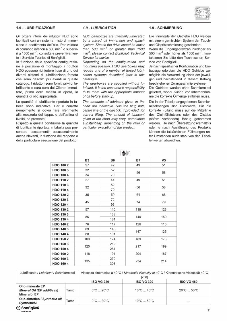
1.9 - LUBRIFICAZIONE
Gli organi interni dei riduttori HDO sonolubrificati con un sistema misto di immer-sione e sbattimento dell’olio. Per velocitàdi comando inferiori a 500 min-1 o superio-ri a 1500 min-1, consultare preventivamen-te il Servizio Tecnico di Bonfiglioli.In funzione della specifica configurazio-ne e posizione di montaggio, i riduttoriHDO possono richiedere l’uso di uno deidiversi sistemi di lubrificazione forzatache sono descritti più avanti in questocatalogo. I riduttori sono forniti privi di lu-brificante e sarà cura del Cliente immet-tere, prima della messa in opera, laquantità di olio appropriata.
Le quantità di lubrificante riportate in ta-bella sono indicative. Per il correttoriempimento si dovrà fare riferimentoalla mezzeria del tappo, o dell’astina dilivello, se presente.Rispetto a questa condizione la quantitàdi lubrificante riportata in tabella può pre-sentare scostamenti, occasionalmenteanche rilevanti, in funzione del rapporto odella particolare esecuzione del prodotto.
1.9 - LUBRICATION
HDO gearboxes are internally lubricated
by a mixed oil immersion and splash
system. Should the drive speed be lower
than 500 min-1
or greater than 1500
min-1
, please contact Bonfiglioli Technical
Service for advise.
Depending on the configuration and
mounting position, HDO gearboxes may
require one of a number of forced lubri-
cation systems described later in this
catalogue.
The gearboxes are supplied without lu-
bricant. It is the customer’s responsibility
to fill them with the appropriate amount
of oil before start-up.
The amounts of lubricant given in the
chart are indicative. Use the plug hole
centre line or the dipstick, if provided, for
correct filling. The amount of lubricant
given in the chart may vary, sometimes
substantially, depending on the ratio or
particular execution of the product.
1.9 - SCHMIERUNG
Die Innenteile der Getriebe HDO werdenmit einem gemischten System der Tauch-und Ölspritzschmierung geschmiert.Wenn die Eingangsdrehzahl niedriger als500 min-1 oder höher als 1500 min-1, kon-taktieren Sie bitte den Technischen Ser-vice von Bonfiglioli.Je nach spezifischer Konfiguration und Ein-baulage erfordern die HDO Getriebe wo-möglich die Verwendung eines der jeweili-gen und nachstehend in diesem Katalogbeschriebenen Zwangsschmiersysteme.Die Getriebe werden ohne Schmiermittelgeliefert, wobei Kunde vor Inbetriebnah-me die korrekte Ölmenge einfüllen muss.
Die in der Tabelle angegebenen Schmier-mittelmengen sind Richtwerte. Für diekorrekte Füllung muss auf die Mittelliniedes Öleinfüllstutzens oder des Ölstabs(sofern vorhanden) Bezug genommenwerden. Je nach Übersetzungsverhältnisoder je nach Ausführung des Produktskönnen die tatsächlichen Füllmengen un-ter Umständen auch stark von den Tabel-lenwerten abweichen.
B3 B6 B7 V5
HDO 100 2 27 42 49 51
HDO 100 3 32 5256 58
HDO 100 4 34 70
HDO 110 2 27 44 49 51
HDO 110 332
5256 58
HDO 110 4 70
HDO 120 2 35 59 64 68
HDO 120 345
7274 79
HDO 120 4 96
HDO 130 2 57 110 119 128
HDO 130 386
138140 150
HDO 130 4 181
HDO 140 2 76 117 126 115
HDO 140 3 89 146147 135
HDO 140 4 88 191
HDO 150 2 109 174 189 173
HDO 150 3125
212217 199
HDO 150 4 281
HDO 160 2 118 191 204 187
HDO 160 3135
230234 214
HDO 160 4 303
oil [l]
Lubrificante / Lubricant / Schmiermittel Viscosità cinematica a 40°C / Kinematic viscosity at 40°C / Kinematische Viskosität 40°C[cSt]
ISO VG 220 ISO VG 320 ISO VG 460
Olio minerale EP
Mineral Oil (EP additives)
Mineralöl EP
Tamb 0°C ... 20°C 10°C ... 40°C 20°C ... 50°C
Olio sintetico / Synthetic oil
SynthetikölTamb 0°C ... 30°C 10°C ... 50°C —
12
• funzionamento a temperature inferioria 0°C
• avviamento di riduttori lubrificati adimmersione e sbattimento qualora latemperatura ambiente minima non siasuperiore di almeno 10°C al punto discorrimento dell’olio
• avviamento di riduttori con dispositivi dilubrificazione forzata (varianti OP1,OP2, MOP), quando la viscosità dell’olioè superiore a 1800 cst. In funzione dellubrificante utilizzato questo valore si ri-scontra indicativamente a temperatureambiente comprese fra 10°C e 20°C.
• operation at ambient temperatures
lower than 0°C
• operation of gear units lubricated by
oil immersion and splashing when the
minimum ambient temperature ex-
ceeds the pour point of lubricant by
less than 10°C
• upon starting up gear units with forced
lubrication systems (options OP1,
OP2 or MOP) if the oil viscosity ex-
ceeds 1800 cst. Depending of the
type of lubricant used, this value may
be produced with ambient tempera-
tures between 10°C and 20°C approx.
• Betrieb bei Temperaturen unter 0°C
• Anfahren von Getrieben mit Tauch- undÖlspritzschmierung, wenn die niedrigsteUmgebungstemperatur mehr als 10°unter dem Fließpunkt des Öls liegt
• Anfahren von Getrieben mit Zwangs-schmierung (Varianten OP1, OP2,MOP), wenn die Viskosität des Ölsüber 1800 cSt liegt. Je nach verwen-detem Schmiermittel tritt dieser Wertungefähr bei Umgebungstemperatu-ren zwischen 10°C und 20°C auf.
Nei seguenti casi è necessario prevede-re il pre-riscaldamento dell’olio attraver-so un’opportuna resistenza elettrica (va-riante opzionale HE):
Lubricant must be pre-heated through
the appropriate electric resistance (HE
option) in the following cases:
In folgenden Fällen muss das Öl mit ei-nem geeigneten elektrischen Heizwider-stand (optionale Variante HE) vorge-wärmt werden:
2 - SELEZIONE DEL RIDUTTORE
La selezione ottimale della trasmissionepuò essere condotta solo previa la pienaconoscenza delle condizioni applicative,sia di natura funzionale, che ambientale.
A garanzia di un corretto dimensionamentodel prodotto, è vivamente consigliato ricor-rere all'esperienza e alla specifica cono-scenza del Servizio Tecnico di Bonfiglioli.
2.1 - DIMENSIONAMENTO
1. Determinare il rapporto di trasmissione:
2. Calcolare la potenza richiesta Pr1 al-l’albero veloce del riduttore:
3. Determinare il fattore di servizio fs ap-plicabile e il fattore correttivo dipen-dente dal tipo di organo motore fm:
2 - SELECTING THE GEAR UNIT
The selection of the drive unit can only
be optimized upon knowing both the en-
gineering and the environmental condi-
tions the gearbox will operate into.
For a safe selection it is strongly recom-
mended to rely on the long time experi-
ence of the Bonfiglioli Technical Service
Dept.
2.1 - ENGINEERING SELECTION
1. First determine the gear ratio:
2. Calculate the power Pr1 required at
the input shaft:
3. Determine the applicable service fac-
tor fs and the adjusting factor fm de-
pending on prime mover:
2 - WAHL DES GETRIEBES
Eine optimale Wahl der Uebertragungkann durch eine vollständige Bekannt-schaft von allen Anwendungsbedingungensowohl die zweckmäßige als auch dieUmweltbedingungen ausgeführt werden.
Um eine richtige Bemessung zu gewähren,empfehlen wir Sie, an die Dienstleistungs-service von der Bonfiglioli zu wenden.
2.1 - BEMESSUNG
1. Die Übersetzung ermitteln:
2. Benötigte Leistung Pr1 an der An-triebswelle des Getriebes berechnen:
3. Bestimmen Sie den geeigneten Betriebs-faktor fs und den Korrekturfaktor fm in Ab-hängigkeit von der Antriebsmaschine:
i nn
� 1
2
P M x n9550 xr1
r2 2��
�
2x 0.96
3x 0.94
4x 0.92
fm
Motore elettrico / Motore idraulico / Turbina Electric motor / Hydraulic motor / Turbine Elektromotor / Hydraulikmotor / Turbine 1.00
Motore a combustione interna pluricilindrico Multi-cylinder internal combustion engine Mehrzylinder-Verbrennungsmotor 1.25
Motore a combustione interna monocilindrico Single cylinder internal combustion engine Einzelzylinder-Verbrennungsmotor 1.50

13
Pn1 � Pr1 � fs � fm
2.2 - VERIFICHE
2.2.1 - CARICHI IMPULSIVI
In presenza di cicli di lavoro intermittenti,o caratterizzati da urti, avviamenti a pie-no carico o elevati carichi inerziali, per ilvalore di coppia istantanea Mp sviluppa-ta nel ciclo di funzionamento si deve ve-rificare la seguente condizione:
2.2 - VERIFICATIONS
2.2.1 - SHOCK LOADING
For intermittent duty, impact/shock load-
ing applications or start-ups under full
load or with high inertial loads, make
sure the following condition is satisfied
for momentary peak torque Mp gener-
ated during the operating cycle:
2.2 - KONTROLLEN
2.2.1 - STOSSBELASTUNG
Stellen Sie sicher, dass im Fall von aus-setzenden Arbeitszyklen, oder bei Ar-beitszyklen die durch Stöße, Anlaufenunter Volllast oder durch hohe Träg-heitskräfte gekennzeichnet sind, folgen-de Bedingung, für kurzzeitige Spitzen-momente Mp die während des Betriebserzeugt werden, eingehalten wird:
Mp � Mn2 � fp
4. Dalle tabelle dati tecnici selezionare ilriduttore con rapporto di trasmissionepiù prossimo a quello calcolato e ca-ratterizzato da una potenza nominalePn1, tale che:
4. Use the rating charts to select the
gear unit with the gear ratio nearest
to that calculated, and with a rated
power Pn1, so that:
4. Aus den technischen Datentabellenein Getriebe aussuchen, dessenÜbersetzungsverhältnis dem berech-neten am nächsten kommt, und des-sen Nennleistung Pn1, die folgendeBedingung ermöglicht:
Picchi/ora / Peaks/hour
Spitzenwerte/Stundefp
1 2 ... 10 11 ... 50 51 ... 100 > 100
Tipo di motoDriveBewegungsart
Direzione costanteConstant directionKonstante Richtung
2.0 1.6 1.3 1.1 1.0
Inversioni di motoReversalsReversierbetrieb
1.4 1.1 0.9 0.8 0.7
Se la condizione suddetta non fosse ve-rificata prevedere l’installazione di un di-spositivo limitatore di coppia, oppureconsiderare la selezione di un riduttoredi taglia superiore.
If the above condition is not satisfied, con-
sider installing a torque limiter or selecting
a gear unit of the next size up.
Wenn die oben genannte Bedingungnicht erfüllt wird, muss ein Drehmoment-begrenzer installiert oder ein größeresGetriebe gewählt werden.
2.2.2 - ABBINAMENTO MOTORE
Per il riduttore selezionato verificare ladisponibilità della relativa flangia di ac-coppiamento nella sezione 3.5.La normalizzazione tipica dei motorielettrici può portare a selezionare unmotore caratterizzato da potenza di tar-
2.2.2 - MOTOR MOUNTING
Verify that the appropriate motor adapter
is available for the selected gear unit.
See section 3.5.
Because of standardisation, the rated
power of the electric motor selected
might be greater than power Pr1 actually
2.2.2 - MOTORZUSAMMENSTELLUNG
Für das gewählte Getriebe im Abschnitt3.5 die Verfügbarkeit des entsprechen-den Kupplungsflansches überprüfen.Aufgrund der Normierung von Elektro-motoren kann es dazu kommen, dassein Motor gewählt wird, dessen Nennlei-
Picchi/ora / Peaks/hour
Spitzenwerte/Stundefp
1 ... 50 51 ... 100 > 100
Tipo di motoDriveBewegungsart
Direzione costanteConstant directionKonstante Richtung
1.3 1.1 1.0
Inversioni di motoReversalsReversierbetrieb
0.9 0.8 0.7
Per la configurazione S (albero lentocon calettatore) eseguire la verifica con-siderando i seguenti valori:
For configuration S (output shaft with
shrink disc), use the following values to
verify applicability:
Für die Konfiguration S (Abtriebswellemit Schrumpfverbindung) die Überprü-fung unter Berücksichtigung folgenderWerte ausführen:
14
2.2.3 - DISPOSITIVO ANTI-RITORNO
Se il riduttore è specificato con dispositi-vo anti-ritorno, verificare la capacità dicarico di quest’ultimo nella relativa se-zione 3.6.3 di questo catalogo e assicu-rarsi che il valore di coppia massimaM1MAX non sia mai trasmesso al riduttoredurante il suo funzionamento.
2.2.3 - BACKSTOP DEVICE
If the gear unit is specified with a back-
stop, verify the load capacity of the de-
vice at section 3.6.3 of this catalogue
and make sure the torque M1MAX is
never exceeded in operation.
2.2.3 - RÜCKLAUFSPERRE
Wird das Getriebe mit Rücklaufsperrebestellt, muss deren Belastbarkeit imentsprechenden Abschnitt 3.6.3 diesesKatalogs überprüft werden; zudem ist si-cherzustellen, dass der Wert des maxi-malen Drehmoments M1MAX währenddes Betriebs niemals auf das Getriebeübertragen wird.
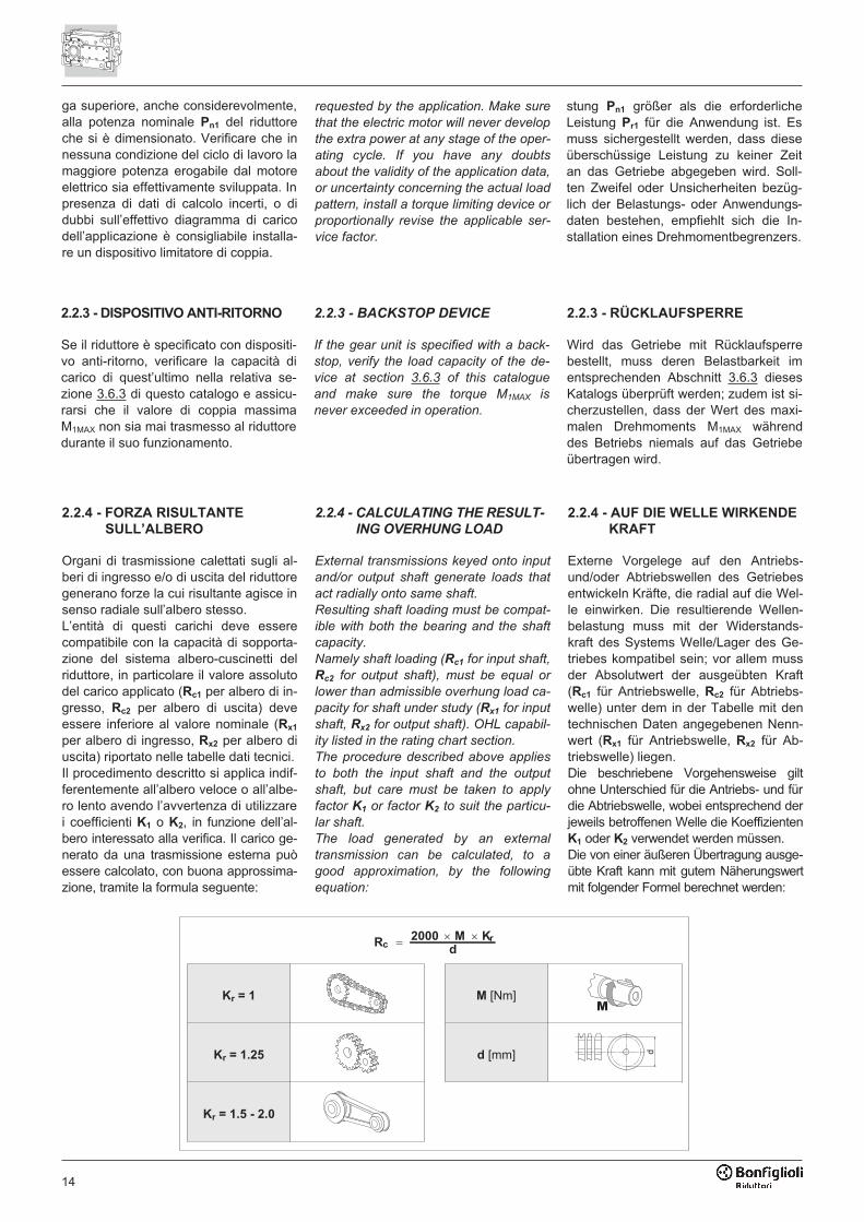
2.2.4 - FORZA RISULTANTE
SULL’ALBERO
Organi di trasmissione calettati sugli al-beri di ingresso e/o di uscita del riduttoregenerano forze la cui risultante agisce insenso radiale sull’albero stesso.L’entità di questi carichi deve esserecompatibile con la capacità di sopporta-zione del sistema albero-cuscinetti delriduttore, in particolare il valore assolutodel carico applicato (Rc1 per albero di in-gresso, Rc2 per albero di uscita) deveessere inferiore al valore nominale (Rx1
per albero di ingresso, Rx2 per albero diuscita) riportato nelle tabelle dati tecnici.Il procedimento descritto si applica indif-ferentemente all’albero veloce o all’albe-ro lento avendo l’avvertenza di utilizzarei coefficienti K1 o K2, in funzione dell’al-bero interessato alla verifica. Il carico ge-nerato da una trasmissione esterna puòessere calcolato, con buona approssima-zione, tramite la formula seguente:
2.2.4 - CALCULATING THE RESULT-
ING OVERHUNG LOAD
External transmissions keyed onto input
and/or output shaft generate loads that
act radially onto same shaft.
Resulting shaft loading must be compat-
ible with both the bearing and the shaft
capacity.
Namely shaft loading (Rc1 for input shaft,
Rc2 for output shaft), must be equal or
lower than admissible overhung load ca-
pacity for shaft under study (Rx1 for input
shaft, Rx2 for output shaft). OHL capabil-
ity listed in the rating chart section.
The procedure described above applies
to both the input shaft and the output
shaft, but care must be taken to apply
factor K1 or factor K2 to suit the particu-
lar shaft.
The load generated by an external
transmission can be calculated, to a
good approximation, by the following
equation:
2.2.4 - AUF DIE WELLE WIRKENDE
KRAFT
Externe Vorgelege auf den Antriebs-und/oder Abtriebswellen des Getriebesentwickeln Kräfte, die radial auf die Wel-le einwirken. Die resultierende Wellen-belastung muss mit der Widerstands-kraft des Systems Welle/Lager des Ge-triebes kompatibel sein; vor allem mussder Absolutwert der ausgeübten Kraft(Rc1 für Antriebswelle, Rc2 für Abtriebs-welle) unter dem in der Tabelle mit dentechnischen Daten angegebenen Nenn-wert (Rx1 für Antriebswelle, Rx2 für Ab-triebswelle) liegen.Die beschriebene Vorgehensweise giltohne Unterschied für die Antriebs- und fürdie Abtriebswelle, wobei entsprechend derjeweils betroffenen Welle die KoeffizientenK1 oder K2 verwendet werden müssen.Die von einer äußeren Übertragung ausge-übte Kraft kann mit gutem Näherungswertmit folgender Formel berechnet werden:
ga superiore, anche considerevolmente,alla potenza nominale Pn1 del riduttoreche si è dimensionato. Verificare che innessuna condizione del ciclo di lavoro lamaggiore potenza erogabile dal motoreelettrico sia effettivamente sviluppata. Inpresenza di dati di calcolo incerti, o didubbi sull’effettivo diagramma di caricodell’applicazione è consigliabile installa-re un dispositivo limitatore di coppia.
requested by the application. Make sure
that the electric motor will never develop
the extra power at any stage of the oper-
ating cycle. If you have any doubts
about the validity of the application data,
or uncertainty concerning the actual load
pattern, install a torque limiting device or
proportionally revise the applicable ser-
vice factor.
stung Pn1 größer als die erforderlicheLeistung Pr1 für die Anwendung ist. Esmuss sichergestellt werden, dass dieseüberschüssige Leistung zu keiner Zeitan das Getriebe abgegeben wird. Soll-ten Zweifel oder Unsicherheiten bezüg-lich der Belastungs- oder Anwendungs-daten bestehen, empfiehlt sich die In-stallation eines Drehmomentbegrenzers.
R2000 M K
dc
r�� �
Kr = 1 M [Nm]
Kr = 1.25 d [mm]
Kr = 1.5 - 2.0
�
�
15
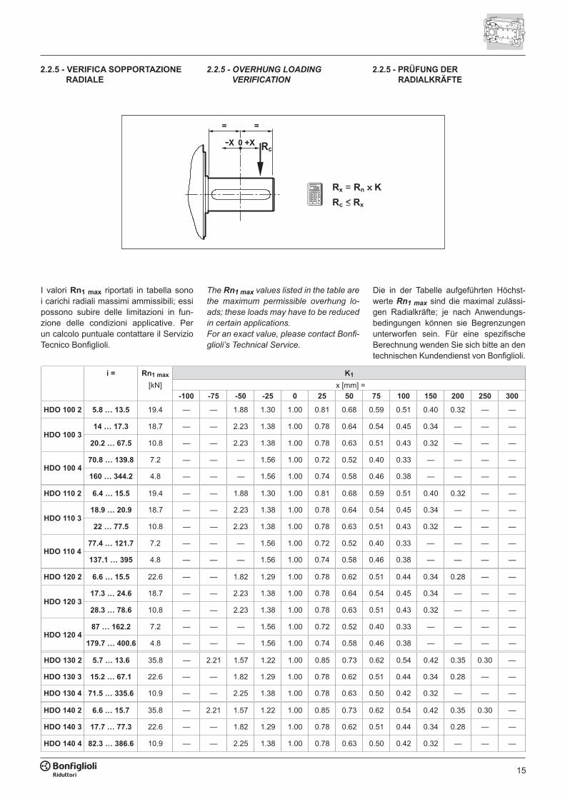
i = Rn1 max K1
[kN] x [mm] =-100 -75 -50 -25 0 25 50 75 100 150 200 250 300
HDO 100 2 5.8 … 13.5 19.4 — — 1.88 1.30 1.00 0.81 0.68 0.59 0.51 0.40 0.32 — —
HDO 100 314 … 17.3 18.7 — — 2.23 1.38 1.00 0.78 0.64 0.54 0.45 0.34 — — —
20.2 … 67.5 10.8 — — 2.23 1.38 1.00 0.78 0.63 0.51 0.43 0.32 — — —
HDO 100 470.8 … 139.8 7.2 — — — 1.56 1.00 0.72 0.52 0.40 0.33 — — — —
160 … 344.2 4.8 — — — 1.56 1.00 0.74 0.58 0.46 0.38 — — — —
HDO 110 2 6.4 … 15.5 19.4 — — 1.88 1.30 1.00 0.81 0.68 0.59 0.51 0.40 0.32 — —
HDO 110 318.9 … 20.9 18.7 — — 2.23 1.38 1.00 0.78 0.64 0.54 0.45 0.34 — — —
22 … 77.5 10.8 — — 2.23 1.38 1.00 0.78 0.63 0.51 0.43 0.32 — — —
HDO 110 477.4 … 121.7 7.2 — — — 1.56 1.00 0.72 0.52 0.40 0.33 — — — —
137.1 … 395 4.8 — — — 1.56 1.00 0.74 0.58 0.46 0.38 — — — —
HDO 120 2 6.6 … 15.5 22.6 — — 1.82 1.29 1.00 0.78 0.62 0.51 0.44 0.34 0.28 — —
HDO 120 317.3 … 24.6 18.7 — — 2.23 1.38 1.00 0.78 0.64 0.54 0.45 0.34 — — —
28.3 … 78.6 10.8 — — 2.23 1.38 1.00 0.78 0.63 0.51 0.43 0.32 — — —
HDO 120 487 … 162.2 7.2 — — — 1.56 1.00 0.72 0.52 0.40 0.33 — — — —
179.7 … 400.6 4.8 — — — 1.56 1.00 0.74 0.58 0.46 0.38 — — — —
HDO 130 2 5.7 … 13.6 35.8 — 2.21 1.57 1.22 1.00 0.85 0.73 0.62 0.54 0.42 0.35 0.30 —
HDO 130 3 15.2 … 67.1 22.6 — — 1.82 1.29 1.00 0.78 0.62 0.51 0.44 0.34 0.28 — —
HDO 130 4 71.5 … 335.6 10.9 — — 2.25 1.38 1.00 0.78 0.63 0.50 0.42 0.32 — — —
HDO 140 2 6.6 … 15.7 35.8 — 2.21 1.57 1.22 1.00 0.85 0.73 0.62 0.54 0.42 0.35 0.30 —
HDO 140 3 17.7 … 77.3 22.6 — — 1.82 1.29 1.00 0.78 0.62 0.51 0.44 0.34 0.28 — —
HDO 140 4 82.3 … 386.6 10.9 — — 2.25 1.38 1.00 0.78 0.63 0.50 0.42 0.32 — — —
Rx = Rn KRc Rx
I valori Rn1 max riportati in tabella sono i carichi radiali massimi ammissibili; essi possono subire delle limitazioni in fun-zione delle condizioni applicative. Per un calcolo puntuale contattare il Servizio Tecnico Bonfiglioli.
The Rn1 max values listed in the table are the maximum permissible overhung lo-ads; these loads may have to be reduced in certain applications.For an exact value, please contact Bonfi-glioli’s Technical Service.
Die in der Tabelle aufgeführten Höchst-werte Rn1 max sind die maximal zulässi-gen Radialkräfte; je nach Anwendungs-bedingungen können sie Begrenzungen unterworfen sein. Für eine spezifische Berechnung wenden Sie sich bitte an den technischen Kundendienst von Bonfiglioli.
2.2.5 - VERIFICA SOPPORTAZIONE RADIALE
2.2.5 - OVERHUNG LOADING VERIFICATION
2.2.5 - PRÜFUNG DER RADIALKRÄFTE

16
2.2.6 - CARICHI AGENTI SUGLI ALBERI
1. Carichi radiali albero lentoRiferirsi alla sezione 4.2 e verificare che, per la configurazione di prodot-to selezionata, e per le condizioni di carico radiale e assiale applicate agli alberi, le forze agenti esternamente non superino quelle ammissibili per il riduttore.Per verificare la sopportazione ra-diale riferirsi allo schema illustrato al paragrafo 2.2.5 e confrontare la forza radiale Rc gravante sull’albero con il carico ammissibile Rx corrispondente alla distanza di applicazione della for-
2.2.6 - SHAFT LOADING
1. Overhung loads on output shaftRefer to section 4.2, and verify that both the radial and the axial force act-ing onto output shaft do not exceed the maximum permitted for the selected product configuration.When checking the overhung load capacity refer to scheme shown at paragraph 2.2.5. Calculate the admis-sible overhung load Rx that is relevant to the distance the force applies from shaft midpoint and compare this with the force Rc that acts onto the shaft.Multiply the nominal radial load Rn2,
2.2.6 - WELLENBELASTUNG
1. Radialkräfte auf der AbtriebswelleAuf den Abschnitt 4.2 Bezug nehmen und sicherstellen, dass weder die au-ßen einwirkenden Radial- noch die Axialkräfte die für das Getriebe zuläs-sigen Kräfte übersteigen.Um die zulässige radiale Belastung zu überprüfen, beziehen Sie sich auf das in Abschnitt 2.2.5 dargestellte Sche-ma. Berechnen Sie die zulässige Radi-allast Rx in Abhängigkeit vom Abstand zum Mittelpunkt der Welle und ver-gleichen Sie diese mit der Radialkraft Rc. Die zulässige Last Rx2 für die Ab-
i = Rn1 max K1
[kN] x [mm] =-100 -75 -50 -25 0 25 50 75 100 150 200 250 300
HDO 150 25.5 … 7.0 54.0 2.75 1.91 1.47 1.19 1.00 0.86 0.76 0.67 0.59 0.47 0.40 0.34 0.30
8.1 … 13.7 41.6 2.75 1.91 1.47 1.19 1.00 0.86 0.76 0.66 0.58 0.46 0.39 0.33 0.29
HDO 150 3 15.6 … 60.8 35.8 — 2.21 1.57 1.22 1.00 0.85 0.73 0.62 0.54 0.42 0.35 0.30 —
HDO 150 466.9 … 92.9 18.7 — — 2.23 1.38 1.00 0.78 0.64 0.54 0.45 0.34 — — —
101.8 … 238.8 10.9 — — 2.25 1.38 1.00 0.78 0.63 0.50 0.42 0.32 — — —
HDO 160 27.3 … 7.9 54.0 2.75 1.91 1.47 1.19 1.00 0.86 0.76 0.67 0.59 0.47 0.40 0.34 0.30
8.9 … 15.4 41.6 2.75 1.91 1.47 1.19 1.00 0.86 0.76 0.66 0.58 0.46 0.39 0.33 0.29
HDO 160 3 17.7 … 68.6 35.8 — 2.21 1.57 1.22 1.00 0.85 0.73 0.62 0.54 0.42 0.35 0.30 —
HDO 160 475.9 … 96.3 18.7 — — 2.23 1.38 1.00 0.78 0.64 0.54 0.45 0.34 — — —
115.2 … 269.7 10.9 — — 2.25 1.38 1.00 0.78 0.63 0.50 0.42 0.32 — — —
Rn2 max K2 An2 max
[kN] x [mm] = [kN]-100 -75 -50 -25 0 25 50 75 100 150 200 250 300 350 400 450 500
HDO 100 80.0 1.28 1.20 1.12 1.06 1.00 0.81 0.68 0.58 0.51 0.41 0.34 0.30 0.26 — — — — 40.0
HDO 110 86.0 1.27 1.19 1.12 1.06 1.00 0.83 0.71 0.63 0.56 0.45 0.38 0.33 0.29 0.26 0.24 — — 43.0
HDO 120 107.0 1.25 1.18 1.11 1.05 1.00 0.83 0.71 0.63 0.56 0.45 0.38 0.33 0.29 0.26 0.24 — — 53.5
HDO 130 160.0 1.20 1.14 1.09 1.04 1.00 0.86 0.75 0.67 0.60 0.50 0.43 0.38 0.33 0.30 0.27 0.25 — 80.0
HDO 140 190.0 1.20 1.14 1.09 1.04 1.00 0.86 0.75 0.67 0.60 0.50 0.43 0.38 0.33 0.30 0.27 0.25 — 95.0
HDO 150 200.0 1.15 1.11 1.07 1.03 1.00 0.92 0.85 0.80 0.75 0.66 0.60 0.54 0.49 0.45 0.41 0.38 0.35 100.0
HDO 160 220.0 1.15 1.11 1.07 1.03 1.00 0.92 0.85 0.80 0.75 0.66 0.60 0.54 0.49 0.45 0.41 0.38 0.35 110.0
I valori dei carichi radiali ed assiali sono quelli massimi ammissibili.Per confrontare i valori di Rn2 e An2 alle diverse condizioni applicative vedere i ca-pitoli 4.2 e 4.3.
The values for overhung and thrust loads are the maximum permissible values.To verify Rn2 and An2 values for different applications, see sections 4.2 and 4.3.
Bei den angegebenen Radial- und Axial-kräften handelt es sich um die maximal zulässigen Werte. Zum Vergleich der Wer-te von Rn2 und An2 unter den verschie-denen Anwendungsbedingungen sind die Kapitel 4.2 und 4.3 einzusehen.
17
za stessa dalla mezzeria dell’albero. Il carico ammissibile Rx2 per l’albero lento si ricava moltiplicando il valore nominale Rn2, reperibile nelle tabelle dati tecnici, per il coefficiente di spo-stamento K2. I carichi radiali nominali Rn sono relativi alle condizioni di cal-colo più sfavorevoli in quanto a verso di rotazione e angolo di applicazione della forza, e rappresentano pertanto un valore conservativo. Per un calcolo puntuale consultare il Servizio Tecnico di Bonfiglioli Riduttori. Congiuntamen-te al carico radiale è applicabile un ca-rico assiale An2 ≤ 0.2 x Rn2.
2. Carichi assiali albero lentoRiferirsi alla sezione 4.3 e verificare che, per la configurazione di prodot-to selezionata, e per la combinazione verso di rotazione albero / verso di ap-plicazione della forza, il carico appli-cato all’abero sia inferiore o uguale a quello ammissibile riportato in tabella. I valori di carico assiale ammissibile riportati in tabella si riferiscono all’ap-plicazione di forze puramente assiali.In caso di configurazione S (albero lento con calettatore), forze agenti eccentricamente rispetto all’asse o in presenza di componenti radiali, con-sultare il Servizio Tecnico di Bonfiglioli Riduttori.
3. Carichi radiali e assiali albero velocePer verificare la sopportazione ra-diale riferirsi allo schema illustrato al paragrafo 2.2.5 e confrontare la forza radiale Rc gravante sull’albero con il carico ammissibile Rx corrispondente alla distanza di applicazione della for-za stessa dalla mezzeria dell’albero. Il carico ammissibile Rx1 per l’albero veloce si ricava moltiplicando il valore nominale Rn1, reperibile nelle tabelle dati tecnici, per il coefficiente di spo-stamento K1.I carichi radiali nominali Rn sono re-lativi alle condizioni di calcolo più sfa-vorevoli in quanto a verso di rotazione e angolo di applicazione della forza, e rappresentano pertanto un valore conservativo. Per un calcolo puntuale consultare il Servizio Tecnico di Bon-figlioli Riduttori. Congiuntamente al carico radiale è applicabile un carico assiale An1 ≤ 0.2 x Rn1.
as listed in the technical data section, for the load location factor K2 to get the permissible overhung load Rx2 for the output shaft. Rated overhung loads Rn are calculated for the most unfavourable condition as far as direc-tion of rotation and the angle the force applies onto the shaft.Catalogue values are therefore con-servative, for an in-depth calculation contact the Technical Service of Bon-figlioli Riduttori. When a radial force applies a thrust load An2 ≤ 0.2 x Rn2 is also permitted.
2. Thrust loads on output shaftRefer to section 4.3 and verify that thrust force on the shaft does not ex-ceed that specified in the chart for the selected product configuration and combination of direction of shaft rota-tion / direction of force.Permissible thrust loads refer exclu-sively to forces applying axially on the shaft. Please contact Bonfiglioli Riduttori’s Technical Service for information on configuration S gearboxes (output shaft with shrink disc) and for applica-tions involving forces that act eccentri-cally with respect to the shaft or involv-ing overhung loads.
3. Overhung and thrust loads on input shaftWhen checking the overhung load capacity refer to scheme shown at paragraph 2.2.5. Calculate the admis-sible overhung load Rx that is relevant to the distance the force applies from shaft midpoint and compare this with the force Rc that acts onto the shaft. Multiply the nominal radial load Rn1, as listed in the technical data section, for the load location factor K1 to get the permissible overhung load Rx1 for the output shaft.Rated overhung loads Rn are calcu-lated for the most unfavourable condi-tion as far as direction of rotation and the angle the force applies onto the shaft. Catalogue values are therefore conservative, for an in-depth calcula-tion contact the Technical Service of Bonfiglioli Riduttori.When a radial force applies a thrust load An1 ≤ 0.2 x Rn1 is also permitted.
triebswelle wird errechnet, indem der Nennwert Rn2, der den Tabellen mit den technischen Daten entnommen werden kann, mit dem Verschiebungs-koeffizienten K2 multipliziert wird.Die Nenn-Radialkräfte Rn beziehen sich auf die ungünstigsten Berech-nungsbedingungen hinsichtlich Dreh-richtung und Anwendungswinkel der Kraft, und stellen daher einen konser-vativen Wert dar. Für eine spezifische Berechnung wenden Sie sich bitte an den technischen Kundendienst von Bonfiglioli Riduttori.Zusammen mit der Radialkraft ist eine Axialkraft von An2 ≤ 0.2 x Rn2 an-wendbar.
2. Axialkräfte auf der AbtriebswelleAuf den Abschnitt 4.3 Bezug nehmen und prüfen, ob die auf die Welle ange-wandte Last für die gewählte Produkt-konfiguration und für die Kombination Drehrichtung der Welle / Richtung der Kraftanwendung kleiner oder gleich der in der Tabelle angegebenen zulässigen Last ist. Die in der Tabelle angegebe-nen zulässigen Axialkraftwerte bezie-hen sich auf reine Axialkräfte. Im Fall der Konfiguration S (Abtriebswelle mit Schrumpfverbindung) ist bei exzent-risch zur Achse wirkenden Kräften oder beim Vorhandensein radialer Kompo-nenten der technische Kundendienst von Bonfiglioli Riduttori zu kontaktieren.
3. Radial- und Axialkräfte auf der AntriebswelleUm die zulässige radiale Belastung zu überprüfen, beziehen Sie sich auf das in Abschnitt 2.2.5 dargestellte Schema. Berechnen Sie die zulässige Radiallast Rx in Abhängigkeit vom Ab-stand zum Mittelpunkt der Welle und vergleichen Sie diese mit der Radial-kraft Rc.Die zulässige Last Rx1 für die An-triebswelle wird errechnet, indem der Nennwert Rn1, der den Tabellen mit den technischen Daten entnommen werden kann, mit dem Verschiebungs-koeffizienten K1 multipliziert wird.Die Nenn-Radialkräfte Rn beziehen sich auf die ungünstigsten Berech-nungsbedingungen hinsichtlich Dreh-richtung und Anwendungswinkel der Kraft, und stellen daher einen konser-vativen Wert dar. Für eine spezifische Berechnung wenden Sie sich bitte an den technischen Kundendienst von Bonfiglioli Riduttori. Zusammen mit der Radialkraft ist eine Axialkraft von An1 ≤ 0.2 x Rn1 anwendbar.
18
2.2.7 - POTENZA TERMICA
La potenza termica PT è il valore mas-simo di potenza che può essere tra-smessa meccanicamente dal riduttore, in funzionamento continuo, senza che si produca al suo interno un aumento di temperatura tale da provocare il danneg-giamento degli organi principali.
Nelle seguenti condizioni operative:- posizione di montaggio B3- funzionamento continuo- installazione in ampi spazi (velocità aria > 1.4 m/s)- altitudine max 1000 mi valori di potenza termica complessiva e i valori di potenza termica comprensiva del contributo fornito dagli eventuali di-spositivi di ausilio termico, sono riportati nel capitolo 4.1.Per condizioni diverse contattare il Servi-zio Tecnico Bonfiglioli.
Il valore così determinato deve essere maggiore del valore di potenza Pr1 ri-chiesto all’albero veloce del riduttore, la seguente espressione deve essere per-tanto verificata:
2.2.7 - THERMAL CAPACITY
Thermal power PT is the maximum power that the gearbox can transmit me-chanically, under continuous operation, without the internal temperature rising to a value that could damage the gearbox components.
Under the following operating conditions:- mounting position B3- continuous functioning- installation in large areas (air speed > 1.4 m/s)- max. installation altitude 1000 mtotal thermal capacity values and ther-mal capacity values inclusive of contri-butions from auxiliary cooling units are listed in section 4.1.For other conditions contact Bonfiglioli’s Technical Service.
The figure determined must be greater than the Pr1 power value for the gearbox input shaft. It is therefore important to verify the following formula:
2.2.7 - WARMELEISTUNG
Die Wärmeleistung PT ist der maximale Leistungswert, der bei Dauerbetrieb me-chanisch vom Getriebe übertragen wer-den kann, ohne dass im Innenbereich des Getriebes ein Temperaturanstieg zu ver-zeichnen wäre, der die Schädigung der wesentlichen Teile verursachen würde.
Unter folgenden Betriebsbedingungen:- Einbaulage B3- Dauerbetrieb- Installation in großen Räumen
(Luftgeschwindigkeit > 1.4 m/s)- max. 1000 m ü NNDie Werte der Gesamtwärmeleistung und die Werte der Wärmeleistung ein-schließlich des Beitrags durch eventuel-le thermische Hilfsvorrichtungen sind in Kapitel 4.1 aufgeführt.Für andere Bedingungen Kontakt tech-nischen Kundendienst von Bonfiglioli Riduttori.
Der Wert bestimmt so muss über dem Leistungswert Pr1 liegen, der an der An-triebswelle des Getriebes gefordert ist; folgende Bedingung muss deshalb über-prüft werden:
PT... Pr1
19
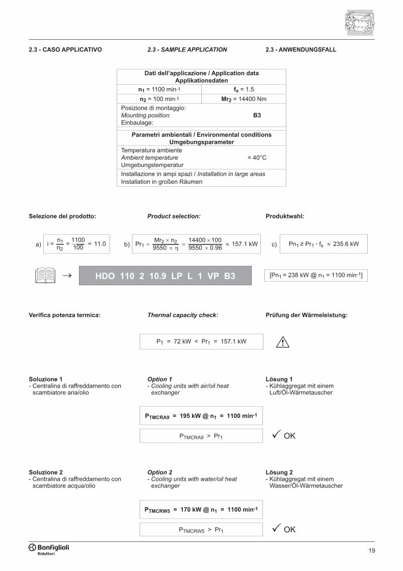
Soluzione 2- Centralina di raffreddamento con
scambiatore acqua/olio
Option 2- Cooling units with water/oil heat
exchanger
Lösung 2- Kühlaggregat mit einem
Wasser/Öl-Wärmetauscher
PTMCRW5 = 170 kW @ n1 = 1100 min-1
PTMCRW5 > Pr1 OK
Soluzione 1- Centralina di raffreddamento con
scambiatore aria/olio
Option 1- Cooling units with air/oil heat
exchanger
Lösung 1- Kühlaggregat mit einem
Luft/Öl-Wärmetauscher
PTMCRA9 = 195 kW @ n1 = 1100 min-1
PTMCRA9 > Pr1 OK
Verifica potenza termica: Thermal capacity check: Prüfung der Wärmeleistung:
PT = 72 kW < Pr1 = 157.1 kW
Selezione del prodotto: Product selection: Produktwahl:
HDO 110 2 10.9 LP L 1 VP B3 [Pn1 = 238 kW @ n1 = 1100 min-1]
235.6 kWPn1 ≥ Pr1 · fsc)a) i = 11.0n1n2
= =1100100 Pr1 9550 9550 0.96 157.1 kWMr2 n2 14400 100
b)
2.3 - CASO APPLICATIVO 2.3 - SAMPLE APPLICATION 2.3 - ANWENDUNGSFALL
Dati dell’applicazione / Application dataApplikationsdaten
n1 = 1100 min-1 fs = 1.5n2 = 100 min-1 Mr2 = 14400 Nm
Posizione di montaggio:Mounting position:Einbaulage:
B3
Parametri ambientali / Environmental conditionsUmgebungsparameter
Temperatura ambienteAmbient temperatureUmgebungstemperatur
= 40°C
Installazione in ampi spazi / Installation in large areasInstallation in großen Räumen
20
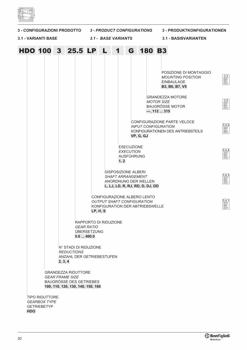
3 - CONFIGURAZIONI PRODOTTO
3.1 - VARIANTI BASE
3 - PRODUCT CONFIGURATIONS
3.1 - BASE VARIANTS
3 - PRODUKTKONFIGURATIONEN
3.1 - BASISVARIANTEN
POSIZIONE DI MONTAGGIOMOUNTING POSITION
EINBAULAGEB3, B6, B7, V5
GRANDEZZA MOTOREMOTOR SIZE
BAUGRÖSSE MOTOR—, 112 ... 315
CONFIGURAZIONE PARTE VELOCEINPUT CONFIGURATION
KONFIGURATIONEN DES ANTRIEBSTEILSVP, G, GJ
DISPOSIZIONE ALBERISHAFT ARRANGEMENT
ANORDNUNG DER WELLENL, LJ, LD, R, RJ, RD, D, DJ, DD
CONFIGURAZIONE ALBERO LENTOOUTPUT SHAFT CONFIGURATION
KONFIGURATION DER ABTRIEBSWELLELP, H, S
RAPPORTO DI RIDUZIONEGEAR RATIO
ÜBERSETZUNG5.6 ... 400.0
N° STADI DI RIDUZIONEREDUCTIONS
ANZAHL DER GETRIEBESTUFEN2, 3, 4
GRANDEZZA RIDUTTOREGEAR FRAME SIZE
BAUGRÖSSE DES GETRIEBES100, 110, 120, 130, 140, 150, 160
TIPO RIDUTTOREGEARBOX TYPE
GETRIEBETYPHDO
3.3
3.5
3.4.2
3.4.4
3.4.3
ESECUZIONEEXECUTION
AUSFÜHRUNG1, 2
3.4.1
HDO 100 3 25.5 LP L G 180 B31

21
3.2 - VARIANTI OPZIONALI 3.2 - OPTIONAL VARIANTS 3.2 - OPTIONALE VARIANTEN
PROVE DOCUMENTALICERTIFICATES
NACHWEISE—, AC, CC, CT
ORGANI DI FISSAGGIOMOUNTING DEVICES
BEFESTIGUNGSORGANE—, TA
DRYWELL—, DW
SENSORISENSORS
SENSOREN—, TG, OLG
TENUTE E GUARNIZIONIOIL SEALING
DICHTUNGEN UND DICHTMANSCHETTEN—, TK, VS, DS, DVS
FLANGIA DI FISSAGGIO / MOUNTING FLANGE
BEFESTIGUNGSFLANSCH— F660L, F800L,
F660R, F800R, FM
ROTAZIONE ALBERO LENTOOUTPUT SHAFT ROTATION
DREHUNG DER ABTRIEBSWELLE—, CW, CCW
ANTIRETROANTI-RUN BACK DEVICE
RÜCKLAUFSPERRE—, A
LUBRIFICAZIONE FORZATAFORCED LUBRICATION
ZWANGSSCHMIERUNG—, OP, OP1, OP2, MOP
DISPOSITIVI DI AUSILIO TERMICOAUXILIARY THERMAL DEVICES
THERMISCHE HILFSVORRICHTUNGEN—, FAN, FANJ,
MCRW5, MCRW9, MCRW21, MCRW34, MCRW51
MCRA5, MCRA9, MCRA21, MCRA34, MCRA51
SR, HE
NOTA: La selezione combinata di alcu-ne varianti può comportare conflitti dinatura tecnica o dimensionale.Consultare la fabbrica per una verificapuntuale.
REMARK: The multiple selection of
some of the variants may be subject to
technical or dimensional constraints.
Consult with the factory to have your se-
lection approved.
HINWEIS: Die Kombination einiger Va-rianten kann Konflikte technischer oderdimensionaler Art verursachen.Für eine spezifische Überprüfung bitteRücksprache mit dem Werk halten.
3.6.8
3.6.7
3.6.6
3.6.4
3.6.3
3.6.2
3.6.1
3.6.5
5.2
22
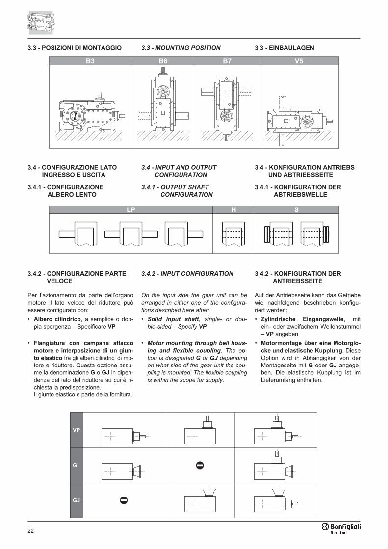
3.3 - POSIZIONI DI MONTAGGIO 3.3 - MOUNTING POSITION 3.3 - EINBAULAGEN
�� �� �� ��
3.4 - CONFIGURAZIONE LATO
INGRESSO E USCITA
3.4.1 - CONFIGURAZIONE
ALBERO LENTO
3.4 - INPUT AND OUTPUT
CONFIGURATION
3.4.1 - OUTPUT SHAFT
CONFIGURATION
3.4 - KONFIGURATION ANTRIEBS
UND ABTRIEBSSEITE
3.4.1 - KONFIGURATION DER
ABTRIEBSWELLE
��
3.4.2 - CONFIGURAZIONE PARTE
VELOCE
Per l’azionamento da parte dell’organomotore il lato veloce del riduttore puòessere configurato con:
• Albero cilindrico, a semplice o dop-pia sporgenza – Specificare VP
• Flangiatura con campana attacco
motore e interposizione di un giun-
to elastico fra gli alberi cilindrici di mo-tore e riduttore. Questa opzione assu-me la denominazione G o GJ in dipen-denza del lato del riduttore su cui è ri-chiesta la predisposizione.Il giunto elastico è parte della fornitura.
3.4.2 - INPUT CONFIGURATION
On the input side the gear unit can be
arranged in either one of the configura-
tions described here after:
• Solid input shaft, single- or dou-
ble-sided – Specify VP
• Motor mounting through bell hous-
ing and flexible coupling. The op-
tion is designated G or GJ depending
on what side of the gear unit the cou-
pling is mounted. The flexible coupling
is within the scope for supply.
3.4.2 - KONFIGURATION DER
ANTRIEBSSEITE
Auf der Antriebsseite kann das Getriebewie nachfolgend beschrieben konfigu-riert werden:
• Zylindrische Eingangswelle, mitein- oder zweifachem Wellenstummel– VP angeben
• Motormontage über eine Motorglo-
cke und elastische Kupplung. DieseOption wird in Abhängigkeit von derMontageseite mit G oder GJ angege-ben. Die elastische Kupplung ist imLieferumfang enthalten.
��
�
��
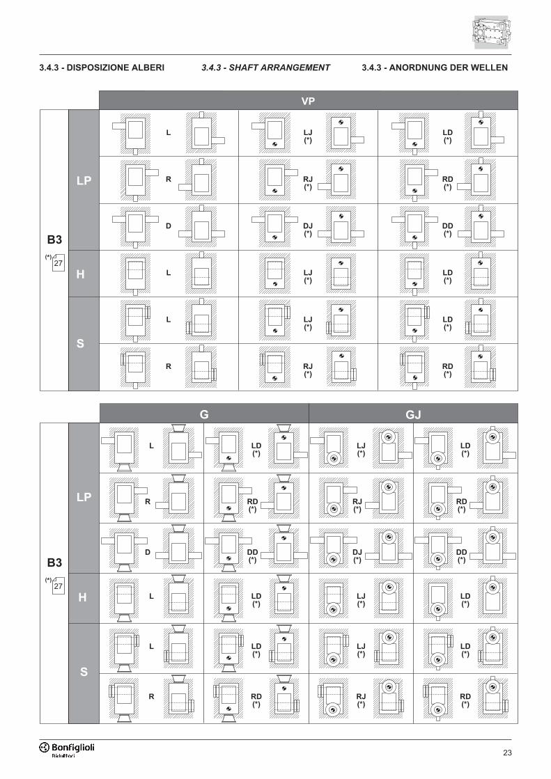
23
3.4.3 - DISPOSIZIONE ALBERI 3.4.3 - SHAFT ARRANGEMENT 3.4.3 - ANORDNUNG DER WELLEN
��
��
�
�
�
�
�
�����
����
�����
�����
�����
�����
� ���
� ���
���
� ���
� ���
� ���
�����
��
��
� ��
� ���
� � ���
�����
� ���
� � ���
�����
���
���
����
� ���
� � ���
�����
� ���
� � ���
�����
� � ���
� ���
�����
�����
��

24
�����
��
��
��
��
� ��
�
�
�
�
�
�����
����
�����
�����
�����
�����
� ���
� ���
���
� ���
� ���
� ���
�����
��
� ���
�����
� ���
�
� ���
�����
� ���
�
���
����
���
� ���
�����
� ���
�
� ���
�����
� ���
�
� ���
�����
� ���
�
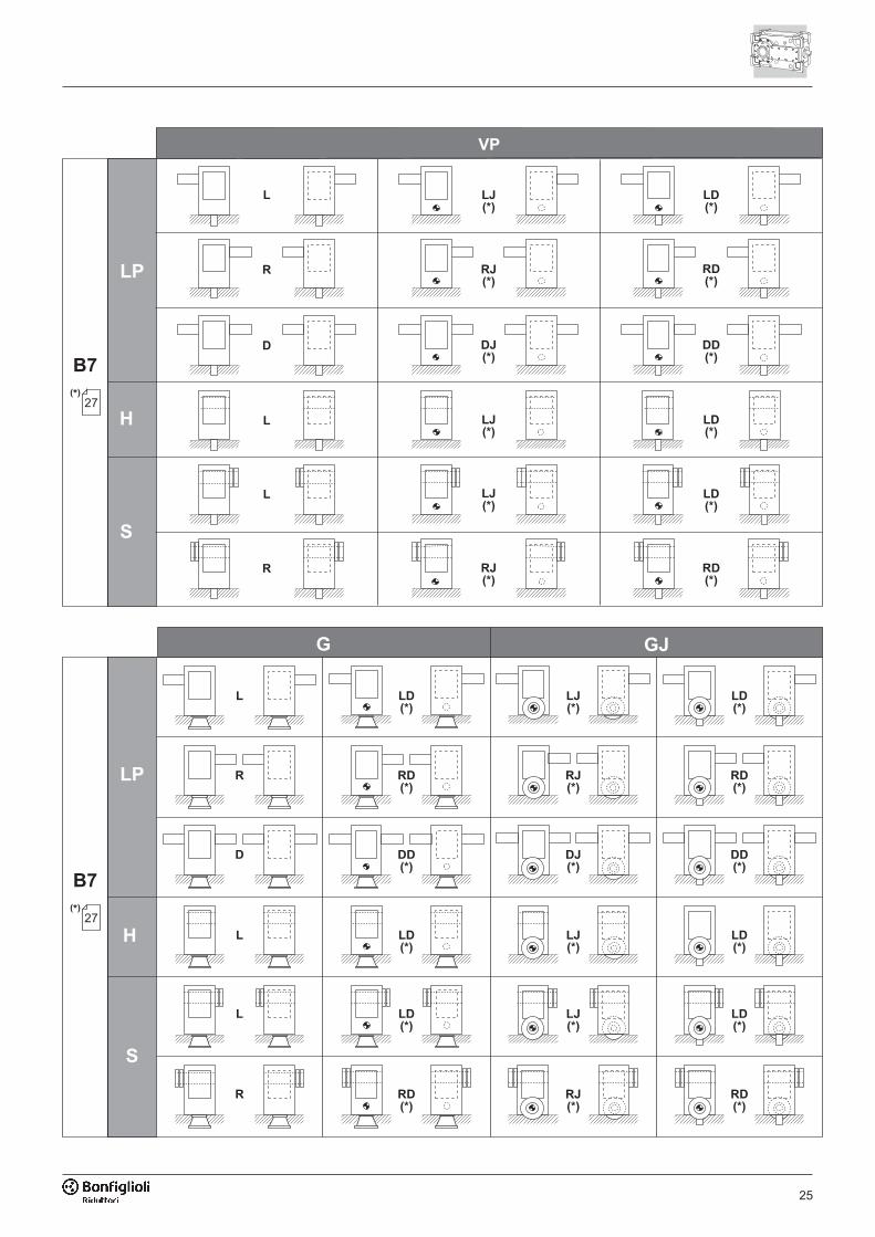
25
�����
��
��
��
��
� ��
�
�
�
�
�
�����
����
�����
�����
�����
�����
� ���
� ���
���
� ���
� ���
� ���
�����
��
� � ���
�����
� ���
� � ���
�����
� ���
���
����
���
� � ���
�����
� ���
� � ���
�����
� ���
� � ���
�����
� ���
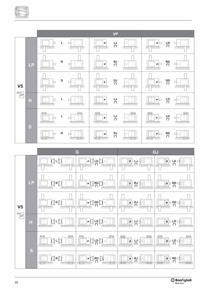
26
�����
��
��
��
��
� ��
�����
��
� �����
� ���
� �����
� ���
����
���
� �����
� ���
� �����
� ���
� �����
� ���
� �����
� ���
� �����
� ���
� �����
� ���
����
���
� �����
� ���
�
� ���
� ���
� ���
���
� ���
� ���
�����
� ���
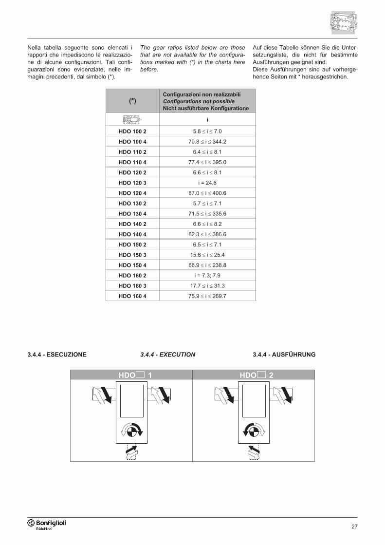
27
3.4.4 - EXECUTION 3.4.4 - AUSFÜHRUNG3.4.4 - ESECUZIONE
�������� ��������
Nella tabella seguente sono elencati irapporti che impediscono la realizzazio-ne di alcune configurazioni. Tali confi-guarazioni sono evidenziate, nelle im-magini precedenti, dal simbolo (*).
The gear ratios listed below are those
that are not available for the configura-
tions marked with (*) in the charts here
before.
Auf diese Tabelle können Sie die Unter-setzungsliste, die nicht für bestimmteAusführungen geeignet sind.Diese Ausführungen sind auf vorherge-hende Seiten mit * herausgestrichen.
(*)
Configurazioni non realizzabili
Configurations not possible
Nicht ausführbare Konfiguratione
i
HDO 100 2 5.8 � i � 7.0
HDO 100 4 70.8 � i � 344.2
HDO 110 2 6.4 � i � 8.1
HDO 110 4 77.4 � i � 395.0
HDO 120 2 6.6 � i � 8.1
HDO 120 3 i = 24.6
HDO 120 4 87.0 � i � 400.6
HDO 130 2 5.7 � i � 7.1
HDO 130 4 71.5 � i � 335.6
HDO 140 2 6.6 � i � 8.2
HDO 140 4 82.3 � i � 386.6
HDO 150 2 6.5 � i � 7.1
HDO 150 3 15.6 � i � 25.4
HDO 150 4 66.9 � i � 238.8
HDO 160 2 i = 7.3; 7.9
HDO 160 3 17.7 � i � 31.3
HDO 160 4 75.9 � i � 269.7
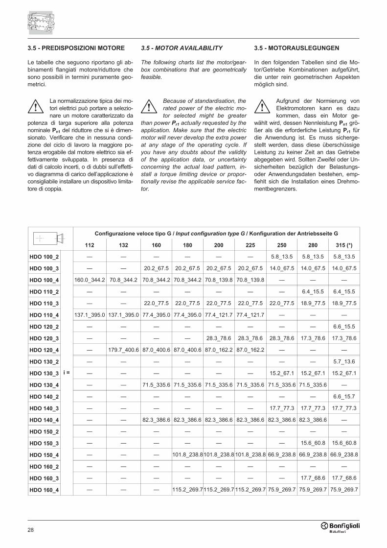
28
3.5 - PREDISPOSIZIONI MOTORE
Le tabelle che seguono riportano gli ab-binamenti flangiati motore/riduttore chesono possibili in termini puramente geo-metrici.
La normalizzazione tipica dei mo-tori elettrici può portare a selezio-nare un motore caratterizzato da
potenza di targa superiore alla potenzanominale Pn1 del riduttore che si è dimen-sionato. Verificare che in nessuna condi-zione del ciclo di lavoro la maggiore po-tenza erogabile dal motore elettrico sia ef-fettivamente sviluppata. In presenza didati di calcolo incerti, o di dubbi sull’effetti-vo diagramma di carico dell’applicazione èconsigliabile installare un dispositivo limita-tore di coppia.
3.5 - MOTOR AVAILABILITY
The following charts list the motor/gear-
box combinations that are geometrically
feasible.
Because of standardisation, the
rated power of the electric mo-
tor selected might be greater
than power Pr1 actually requested by the
application. Make sure that the electric
motor will never develop the extra power
at any stage of the operating cycle. If
you have any doubts about the validity
of the application data, or uncertainty
concerning the actual load pattern, in-
stall a torque limiting device or propor-
tionally revise the applicable service fac-
tor.
3.5 - MOTORAUSLEGUNGEN
In den folgenden Tabellen sind die Mo-tor/Getriebe Kombinationen aufgeführt,die unter rein geometrischen Aspektenmöglich sind.
Aufgrund der Normierung vonElektromotoren kann es dazukommen, dass ein Motor ge-
wählt wird, dessen Nennleistung Pn1 grö-ßer als die erforderliche Leistung Pr1 fürdie Anwendung ist. Es muss sicherge-stellt werden, dass diese überschüssigeLeistung zu keiner Zeit an das Getriebeabgegeben wird. Sollten Zweifel oder Un-sicherheiten bezüglich der Belastungs-oder Anwendungsdaten bestehen, emp-fiehlt sich die Installation eines Drehmo-mentbegrenzers.
Configurazione veloce tipo G / Input configuration type G / Konfiguration der Antriebsseite G
112 132 160 180 200 225 250 280 315 (*)
HDO 100_2
i =
— — — — — — 5.8_13.5 5.8_13.5 5.8_13.5
HDO 100_3 — — 20.2_67.5 20.2_67.5 20.2_67.5 20.2_67.5 14.0_67.5 14.0_67.5 14.0_67.5
HDO 100_4 160.0_344.2 70.8_344.2 70.8_344.2 70.8_344.2 70.8_139.8 70.8_139.8 — — —
HDO 110_2 — — — — — — — 6.4_15.5 6.4_15.5
HDO 110_3 — — 22.0_77.5 22.0_77.5 22.0_77.5 22.0_77.5 22.0_77.5 18.9_77.5 18.9_77.5
HDO 110_4 137.1_395.0 137.1_395.0 77.4_395.0 77.4_395.0 77.4_121.7 77.4_121.7 — — —
HDO 120_2 — — — — — — — — 6.6_15.5
HDO 120_3 — — — — 28.3_78.6 28.3_78.6 28.3_78.6 17.3_78.6 17.3_78.6
HDO 120_4 — 179.7_400.6 87.0_400.6 87.0_400.6 87.0_162.2 87.0_162.2 — — —
HDO 130_2 — — — — — — — — 5.7_13.6
HDO 130_3 — — — — — — 15.2_67.1 15.2_67.1 15.2_67.1
HDO 130_4 — — 71.5_335.6 71.5_335.6 71.5_335.6 71.5_335.6 71.5_335.6 71.5_335.6 —
HDO 140_2 — — — — — — — — 6.6_15.7
HDO 140_3 — — — — — — 17.7_77.3 17.7_77.3 17.7_77.3
HDO 140_4 — — 82.3_386.6 82.3_386.6 82.3_386.6 82.3_386.6 82.3_386.6 82.3_386.6 —
HDO 150_2 — — — — — — — — —
HDO 150_3 — — — — — — — 15.6_60.8 15.6_60.8
HDO 150_4 — — — 101.8_238.8101.8_238.8 101.8_238.8 66.9_238.8 66.9_238.8 66.9_238.8
HDO 160_2 — — — — — — — — —
HDO 160_3 — — — — — — — 17.7_68.6 17.7_68.6
HDO 160_4 — — — 115.2_269.7115.2_269.7 115.2_269.7 75.9_269.7 75.9_269.7 75.9_269.7
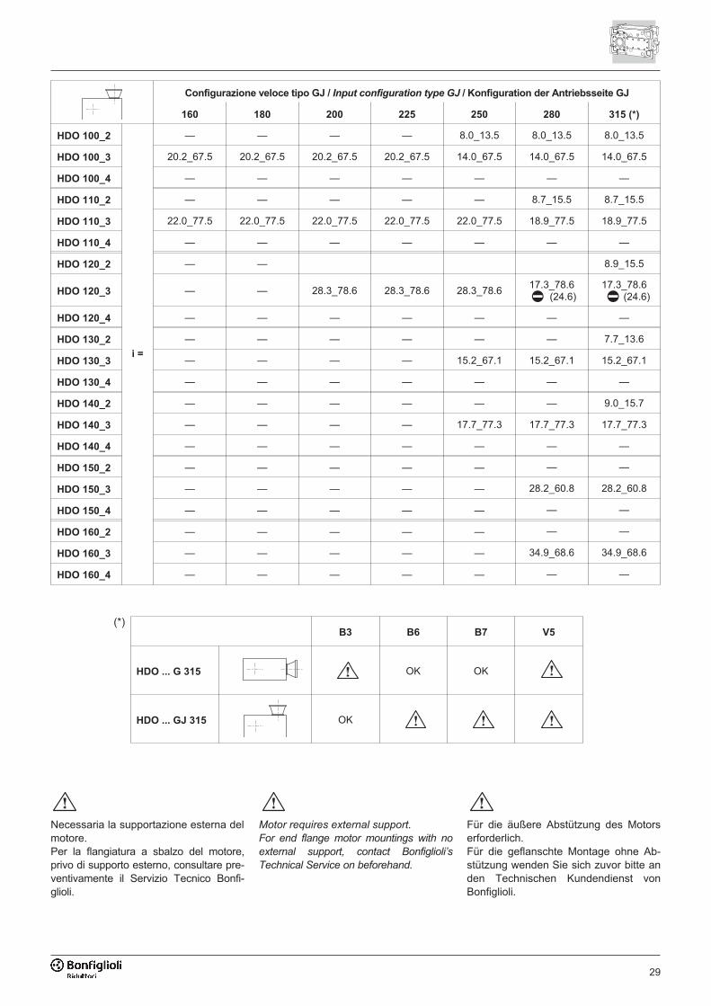
29
Configurazione veloce tipo GJ / Input configuration type GJ / Konfiguration der Antriebsseite GJ
160 180 200 225 250 280 315 (*)
HDO 100_2
i =
— — — — 8.0_13.5 8.0_13.5 8.0_13.5
HDO 100_3 20.2_67.5 20.2_67.5 20.2_67.5 20.2_67.5 14.0_67.5 14.0_67.5 14.0_67.5
HDO 100_4 — — — — — — —
HDO 110_2 — — — — — 8.7_15.5 8.7_15.5
HDO 110_3 22.0_77.5 22.0_77.5 22.0_77.5 22.0_77.5 22.0_77.5 18.9_77.5 18.9_77.5
HDO 110_4 — — — — — — —
HDO 120_2 — — 8.9_15.5
HDO 120_3 — — 28.3_78.6 28.3_78.6 28.3_78.617.3_78.6
(24.6)17.3_78.6
(24.6)
HDO 120_4 — — — — — — —
HDO 130_2 — — — — — — 7.7_13.6
HDO 130_3 — — — — 15.2_67.1 15.2_67.1 15.2_67.1
HDO 130_4 — — — — — — —
HDO 140_2 — — — — — — 9.0_15.7
HDO 140_3 — — — — 17.7_77.3 17.7_77.3 17.7_77.3
HDO 140_4 — — — — — — —
HDO 150_2 — — — — — — —
HDO 150_3 — — — — — 28.2_60.8 28.2_60.8
HDO 150_4 — — — — — — —
HDO 160_2 — — — — — — —
HDO 160_3 — — — — — 34.9_68.6 34.9_68.6
HDO 160_4 — — — — — — —
B3 B6 B7 V5
HDO ... G 315 OK OK
HDO ... GJ 315 OK
(*)
Necessaria la supportazione esterna delmotore.Per la flangiatura a sbalzo del motore,privo di supporto esterno, consultare pre-ventivamente il Servizio Tecnico Bonfi-glioli.
Motor requires external support.
For end flange motor mountings with no
external support, contact Bonfiglioli’s
Technical Service on beforehand.
Für die äußere Abstützung des Motorserforderlich.Für die geflanschte Montage ohne Ab-stützung wenden Sie sich zuvor bitte anden Technischen Kundendienst vonBonfiglioli.
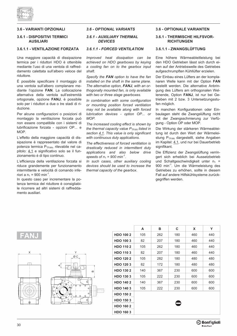
30
3.6 - VARIANTI OPZIONALI
3.6.1 - DISPOSITIVI TERMICI
AUSILIARI
3.6.1.1 - VENTILAZIONE FORZATA
Una maggiore capacità di dissipazionetermica per i riduttori HDO è ottenibilemediante l’uso di una ventola di raffred-damento calettata sull’albero veloce delriduttore.
È possibile specificare il montaggio diuna ventola sull’albero complanare me-diante l’opzione FAN. La collocazionealternativa della ventola sull’estremitàortogonale, opzione FANJ, è possibilesolo per i riduttori a due o tre stadi di ri-duzione.
Per alcune configurazioni o posizioni dimontaggio la ventilazione forzata puònon essere compatibile con i sistemi dilubrificazione forzata - opzioni OP... eMOP.
L’effetto della maggiore capacità di dis-sipazione è rappresentato dal valore dipotenza termica PTFAN, rilevabile nel ca-pitolo: 4.1 e significativo solo se il fun-zionamento è di tipo continuo.
L’efficienza della ventilazione forzata siriduce grandemente per funzionamentointermittente e velocità di comando infe-riori a n1 = 900 min-1.In questo caso per incrementare la po-tenza termica del riduttore è consigliabi-le ricorrere ad altri sistemi di raffredda-mento ausiliari.
3.6 - OPTIONAL VARIANTS
3.6.1 - AUXILIARY THERMAL
DEVICES
3.6.1.1 - FORCED VENTILATION
Improved heat dissipation can be
achieved on HDO gearboxes by keying
a cooling fan on to the gearbox input
shaft.
Specify the FAN option to have the fan
installed on the shaft in the same plane.
The alternative option, FANJ, with an or-
thogonally mounted fan, is only available
with two or three stage gearboxes.
In combination with some configuration
or mounting position forced ventilation
may not be available along with forced
lubrication devices - option OP... or
MOP.
The increased cooling effect is shown by
the thermal capacity value PTFAN listed in
section 4.1. This value is only significant
with continuous duty applications.
The effectiveness of forced ventilation is
drastically reduced in intermittent duty
applications and also below drive
speeds of n1 = 900 min-1
.
In such cases, other auxiliary cooling
devices should be used to increase the
thermal capacity of the gearbox.
3.6 - OPTIONALE VARIANTEN
3.6.1 - THERMISCHE HILFSVOR-
RICHTUNGEN
3.6.1.1 - ZWANGSLÜFTUNG
Eine höhere Wärmeableitleistung beiden HDO Getrieben lässt sich durch ei-nen auf der Antriebswelle des Getriebesaufgeschrumpften Kühllüfter erzielen.
Der Einbau eines Lüfters an der kompla-naren Welle kann mit der Option FAN
bestellt werden. Die alternative Anbrin-gung des Lüfters am orthogonalen Wel-lenende, Option FANJ, ist nur bei Ge-trieben mit 2 bzw. 3 Untersetzungsstu-fen möglich.
In manchen Konfigurationen oder Ein-baulagen steht die Zwangslüftung nichtmit der Zwangsschmierung zur Verfü-gung - Option OP oder MOP.
Die Wirkung der stärkeren Wärmeablei-tung ist durch den Wert der Wärmelei-stung PTFAN dargestellt, siehe Angabenim Kapitel: 4.1, und nur bei Dauerbetriebsignifikant.
Die Effizienz der Zwangslüftung verrin-gert sich erheblich bei Aussetzbetriebund Schaltgeschwindigkeit unter n1 =900 min-1. Um die Wärmeleistung desGetriebes zu erhöhen, sollte in diesemFall auf andere Hilfskühlsysteme zurück-gegriffen werden.
���
�
�
��
A B C X Y
HDO 100 2 105 262 180 460 440
HDO 100 3 82 207 180 460 440
HDO 110 2 105 262 180 460 440
HDO 110 3 82 207 180 460 440
HDO 120 2 105 282 180 480 480
HDO 120 3 82 172 180 480 480
HDO 130 2 140 367 230 600 600
HDO 130 3 105 222 230 600 600
HDO 140 2 140 367 230 600 600
HDO 140 3 105 222 230 600 600
HDO 150 2
HDO 150 3
HDO 160 2
HDO 160 3
FANJ
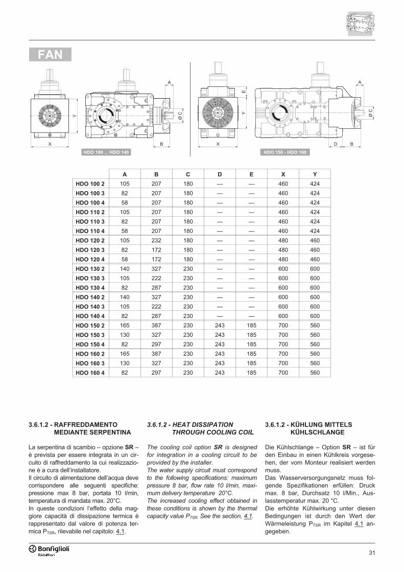
31
���
�
��
�
� � �
�
���
�
������������������� ���������������
A B C D E X Y
HDO 100 2 105 207 180 — — 460 424
HDO 100 3 82 207 180 — — 460 424
HDO 100 4 58 207 180 — — 460 424
HDO 110 2 105 207 180 — — 460 424
HDO 110 3 82 207 180 — — 460 424
HDO 110 4 58 207 180 — — 460 424
HDO 120 2 105 232 180 — — 480 460
HDO 120 3 82 172 180 — — 480 460
HDO 120 4 58 172 180 — — 480 460
HDO 130 2 140 327 230 — — 600 600
HDO 130 3 105 222 230 — — 600 600
HDO 130 4 82 287 230 — — 600 600
HDO 140 2 140 327 230 — — 600 600
HDO 140 3 105 222 230 — — 600 600
HDO 140 4 82 287 230 — — 600 600
HDO 150 2 165 387 230 243 185 700 560
HDO 150 3 130 327 230 243 185 700 560
HDO 150 4 82 297 230 243 185 700 560
HDO 160 2 165 387 230 243 185 700 560
HDO 160 3 130 327 230 243 185 700 560
HDO 160 4 82 297 230 243 185 700 560
FAN
3.6.1.2 - RAFFREDDAMENTO
MEDIANTE SERPENTINA
La serpentina di scambio – opzione SR –è prevista per essere integrata in un cir-cuito di raffreddamento la cui realizzazio-ne è a cura dell’installatore.Il circuito di alimentazione dell’acqua devecorrispondere alle seguenti specifiche:pressione max 8 bar, portata 10 l/min,temperatura di mandata max. 20°C.In queste condizioni l’effetto della mag-giore capacità di dissipazione termica èrappresentato dal valore di potenza ter-mica PTSR, rilevabile nel capitolo: 4.1.
3.6.1.2 - HEAT DISSIPATION
THROUGH COOLING COIL
The cooling coil option SR is designed
for integration in a cooling circuit to be
provided by the installer.
The water supply circuit must correspond
to the following specifications: maximum
pressure 8 bar, flow rate 10 l/min, maxi-
mum delivery temperature 20°C.
The increased cooling effect obtained in
these conditions is shown by the thermal
capacity value PTSR. See the section, 4.1.
3.6.1.2 - KÜHLUNG MITTELS
KÜHLSCHLANGE
Die Kühlschlange – Option SR – ist fürden Einbau in einen Kühlkreis vorgese-hen, der vom Monteur realisiert werdenmuss.Das Wasserversorgungsnetz muss fol-gende Spezifikationen erfüllen: Druckmax. 8 bar, Durchsatz 10 l/Min., Aus-lasstemperatur max. 20 °C.Die erhöhte Kühlwirkung unter diesenBedingungen ist durch den Wert derWärmeleistung PTSR im Kapitel 4.1 an-gegeben.
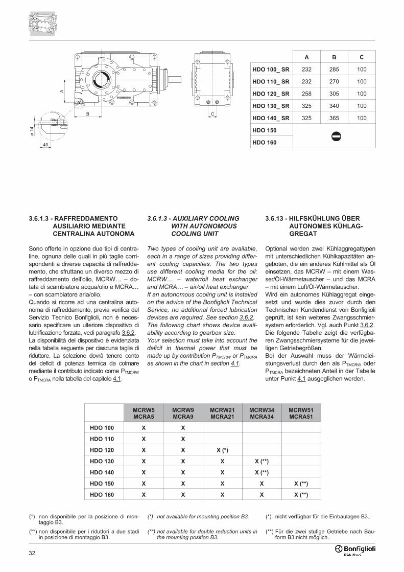
32
�
�
��
�
�
�
A B C
HDO 100_ SR 232 285 100
HDO 110_ SR 232 270 100
HDO 120_ SR 258 305 100
HDO 130_ SR 325 340 100
HDO 140_ SR 325 365 100
HDO 150
HDO 160
3.6.1.3 - RAFFREDDAMENTO
AUSILIARIO MEDIANTE
CENTRALINA AUTONOMA
Sono offerte in opzione due tipi di centra-line, ognuna delle quali in più taglie corri-spondenti a diverse capacità di raffredda-mento, che sfruttano un diverso mezzo diraffreddamento dell’olio, MCRW… – do-tata di scambiatore acqua/olio e MCRA…– con scambiatore aria/olio.Quando si ricorre ad una centralina auto-noma di raffreddamento, previa verifica delServizio Tecnico Bonfiglioli, non è neces-sario specificare un ulteriore dispositivo dilubrificazione forzata, vedi paragrafo 3.6.2.La disponibilità del dispositivo è evidenziatanella tabella seguente per ciascuna taglia diriduttore. La selezione dovrà tenere contodel deficit di potenza termica da colmaremediante il contributo indicato come PTMCRW
o PTMCRA nella tabella del capitolo 4.1.
3.6.1.3 - AUXILIARY COOLING
WITH AUTONOMOUS
COOLING UNIT
Two types of cooling unit are available,
each in a range of sizes providing differ-
ent cooling capacities. The two types
use different cooling media for the oil:
MCRW… – water/oil heat exchanger
and MCRA… – air/oil heat exchanger.
If an autonomous cooling unit is installed
on the advice of the Bonfiglioli Technical
Service, no additional forced lubrication
devices are required. See section 3.6.2.
The following chart shows device avail-
ability according to gearbox size.
Your selection must take into account the
deficit in thermal power that must be
made up by contribution PTMCRW or PTMCRA
as shown in the chart in section 4.1.
3.6.13 - HILFSKÜHLUNG ÜBER
AUTONOMES KÜHLAG-
GREGAT
Optional werden zwei Kühlaggregattypenmit unterschiedlichen Kühlkapazitäten an-geboten, die ein anderes Kühlmittel als Öleinsetzen, das MCRW – mit einem Was-ser/Öl-Wärmetauscher – und das MCRA– mit einem Luft/Öl-Wärmetauscher.Wird ein autonomes Kühlaggregat einge-setzt und wurde dies zuvor durch denTechnischen Kundendienst von Bonfiglioligeprüft, ist kein weiteres Zwangsschmier-system erforderlich. Vgl. auch Punkt 3.6.2.Die folgende Tabelle zeigt die verfügba-ren Zwangsschmiersysteme für die jewei-ligen Getriebegrößen.Bei der Auswahl muss der Wärmelei-stungsverlust durch den als PTMCRW oderPTMCRA bezeichneten Anteil in der Tabelleunter Punkt 4.1 ausgeglichen werden.
MCRW5
MCRA5
MCRW9
MCRA9
MCRW21
MCRA21
MCRW34
MCRA34
MCRW51
MCRA51
HDO 100 X X
HDO 110 X X
HDO 120 X X X (*)
HDO 130 X X X X (**)
HDO 140 X X X X (**)
HDO 150 X X X X X (**)
HDO 160 X X X X X (**)
(*) non disponibile per la posizione di mon-taggio B3.
(*) not available for mounting position B3. (*) nicht verfügbar für die Einbaulagen B3.
(**) non disponibile per i riduttori a due stadiin posizione di montaggio B3.
(**) not available for double reduction units inthe mounting position B3.
(**) Für die zwei stufige Getriebe nach Bau-form B3 nicht möglich.
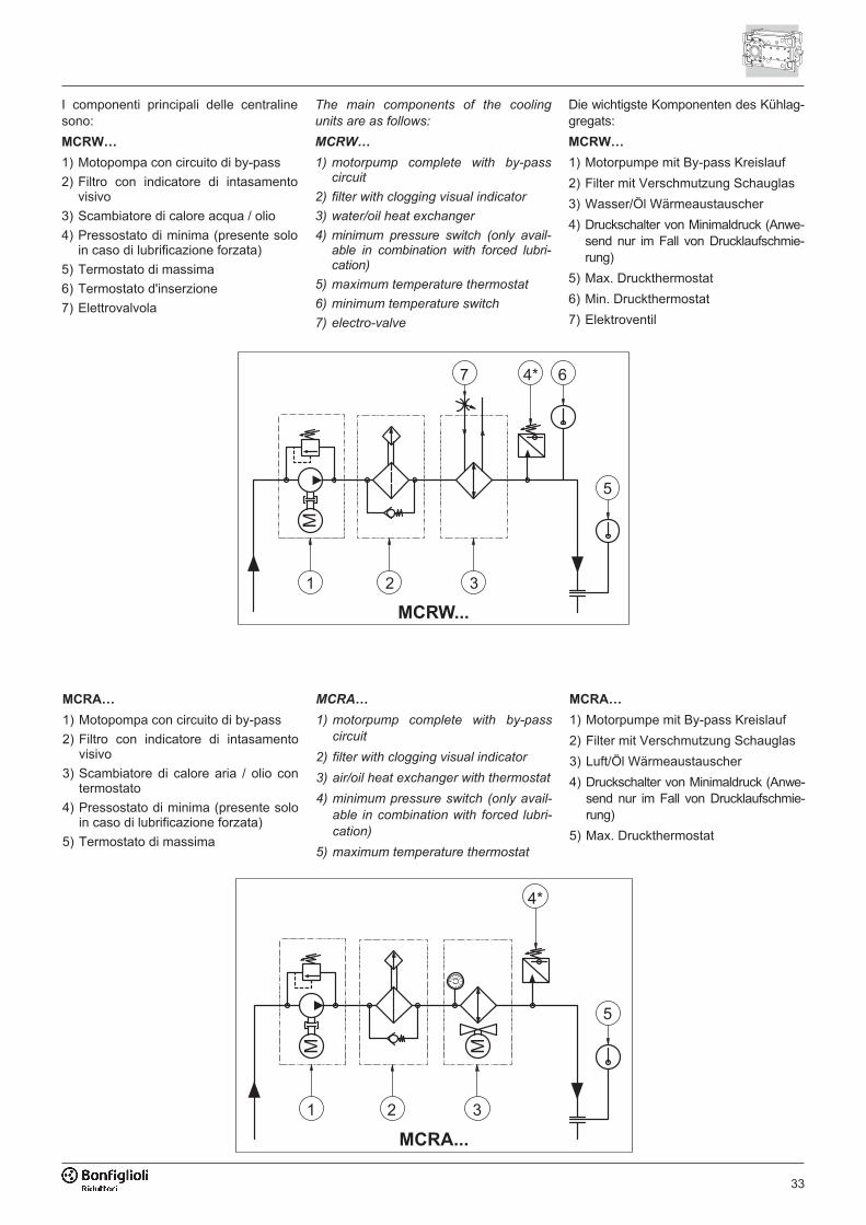
33
� �����
�
� � �
��
�
��
The main components of the cooling
units are as follows:
MCRW…
1) motorpump complete with by-passcircuit
2) filter with clogging visual indicator
3) water/oil heat exchanger
4) minimum pressure switch (only avail-able in combination with forced lubri-cation)
5) maximum temperature thermostat
6) minimum temperature switch
7) electro-valve
Die wichtigste Komponenten des Kühlag-gregats:
MCRW…
1) Motorpumpe mit By-pass Kreislauf
2) Filter mit Verschmutzung Schauglas
3) Wasser/Öl Wärmeaustauscher
4) Druckschalter von Minimaldruck (Anwe-send nur im Fall von Drucklaufschmie-rung)
5) Max. Druckthermostat
6) Min. Druckthermostat
7) Elektroventil
I componenti principali delle centralinesono:
MCRW…
1) Motopompa con circuito di by-pass
2) Filtro con indicatore di intasamentovisivo
3) Scambiatore di calore acqua / olio
4) Pressostato di minima (presente soloin caso di lubrificazione forzata)
5) Termostato di massima
6) Termostato d'inserzione
7) Elettrovalvola
� �����
�
�
� � �
��
�
MCRA…
1) motorpump complete with by-pass
circuit
2) filter with clogging visual indicator
3) air/oil heat exchanger with thermostat
4) minimum pressure switch (only avail-
able in combination with forced lubri-
cation)
5) maximum temperature thermostat
MCRA…
1) Motorpumpe mit By-pass Kreislauf
2) Filter mit Verschmutzung Schauglas
3) Luft/Öl Wärmeaustauscher
4) Druckschalter von Minimaldruck (Anwe-send nur im Fall von Drucklaufschmie-rung)
5) Max. Druckthermostat
MCRA…
1) Motopompa con circuito di by-pass
2) Filtro con indicatore di intasamentovisivo
3) Scambiatore di calore aria / olio contermostato
4) Pressostato di minima (presente soloin caso di lubrificazione forzata)
5) Termostato di massima
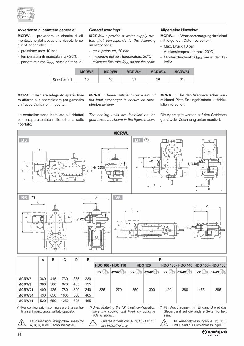
34
Avvertenze di carattere generale:
MCRW... : prevedere un circuito di ali-mentazione dell’acqua che rispetti le se-guenti specifiche:
- pressione max 10 bar
- temperatura di mandata max 20°C
- portata minima QH2O come da tabella:
General warnings:
MCRW... : provide a water supply sys-
tem that corresponds to the following
specifications:
- max. pressure, 10 bar
- maximum delivery temperature, 20°C
- minimum flow rate QH2O as per the chart:
Allgemeine Hinweise:
MCRW... : Wasserversorgungskreislaufmit folgenden Daten vorsehen:
- Max. Druck 10 bar
- Auslasstemperatur max. 20°C
- Mindestdurchsatz QH2O wie in der Ta-belle:
MCRA... : lasciare adeguato spazio libe-ro attorno allo scambiatore per garantireun flusso d’aria non impedito.
Le centraline sono installate sui riduttoricome rappresentato nello schema sottoriportato.
MCRA... : leave sufficient space around
the heat exchanger to ensure an unre-
stricted air flow.
The cooling units are installed on the
gearboxes as shown in the figure below.
MCRA... : Um den Wärmetauscher aus-reichend Platz für ungehinderte Luftzirku-lation vorsehen.
Die Aggregate werden auf den Getriebengemäß der Zeichnung unten montiert.
���
�
�
��
�
���
�
�
�
�
�
�
�
���
��
���
�
�
��
���
����� ��
�� �
� �����
A B C D E F
HDO 100 - HDO 110 HDO 120 HDO 130 - HDO 140 HDO 150 - HDO 160
2x 3x/4x 2x 3x/4x 2x 3x/4x 2x 3x/4x
MCRW5 360 415 730 365 230
325 270 350 300 420 380 475 395
MCRW9 360 380 870 435 195
MCRW21 400 425 780 390 240
MCRW34 430 650 1000 500 465
MCRW51 520 650 1250 625 465
Le dimensioni d'ingombro massimoA, B, C, D ed E sono indicative.
MCRW5 MCRW9 MCRW21 MCRW34 MCRW51
QH2O [l/min] 10 18 31 56 81
Overall dimensions A, B, C, D and E
are indicative only
(*) Per configurazioni con ingresso J la centra-lina sarà posizionata sul lato opposto.
(*) Units featuring the "J" input configuration
have the cooling unit fitted on opposite
side as shown.
(*) Für Ausführungen mit Eingang J wird dasSteuergerät auf die andere Seite montiertsein.
Die Außenabmessungen A; B; C; Dund E sind nur Richtabmessungen.
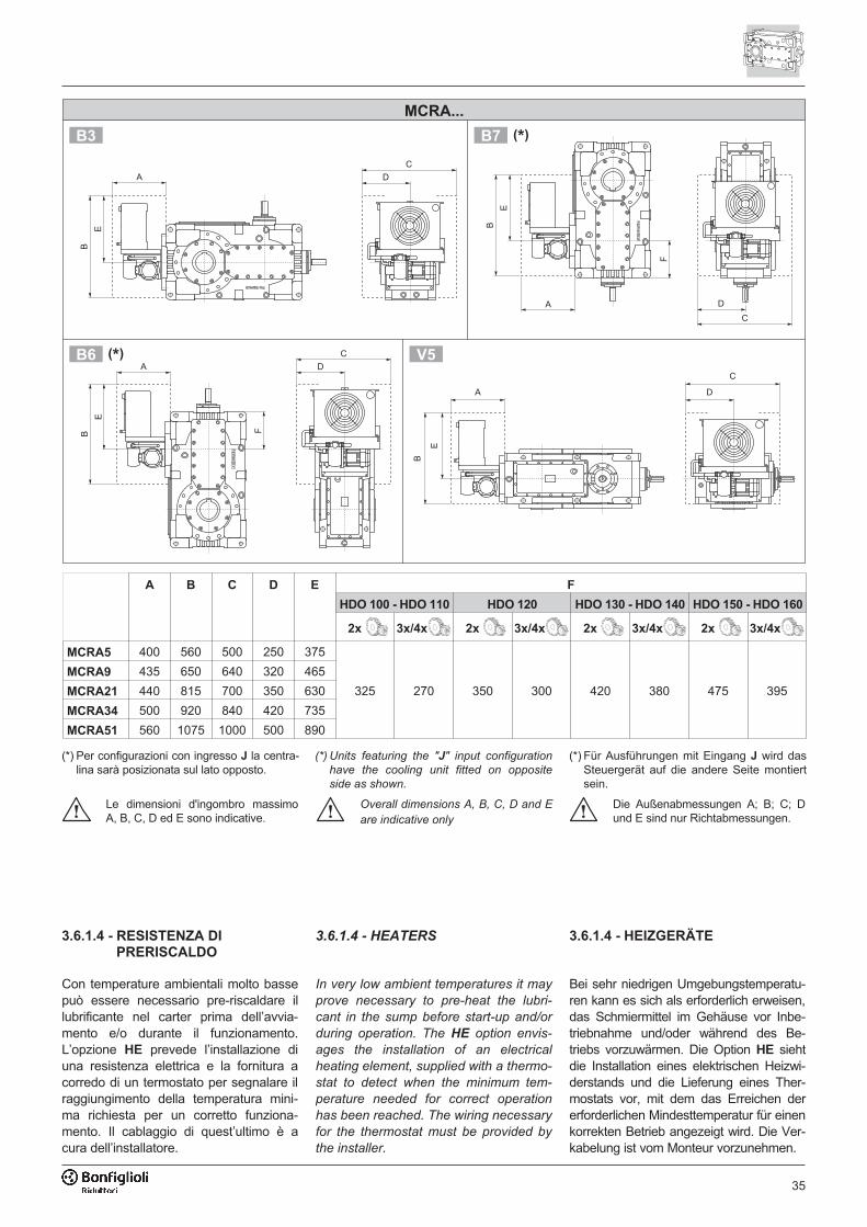
35
A B C D E F
HDO 100 - HDO 110 HDO 120 HDO 130 - HDO 140 HDO 150 - HDO 160
2x 3x/4x 2x 3x/4x 2x 3x/4x 2x 3x/4x
MCRA5 400 560 500 250 375
325 270 350 300 420 380 475 395
MCRA9 435 650 640 320 465
MCRA21 440 815 700 350 630
MCRA34 500 920 840 420 735
MCRA51 560 1075 1000 500 890
�
�
�
��
�
�
�
�
�
�
�
�
�
�
� �
��
�� ��
���
���
�� �
� �����
3.6.1.4 - RESISTENZA DI
PRERISCALDO
Con temperature ambientali molto bassepuò essere necessario pre-riscaldare illubrificante nel carter prima dell’avvia-mento e/o durante il funzionamento.L’opzione HE prevede l’installazione diuna resistenza elettrica e la fornitura acorredo di un termostato per segnalare ilraggiungimento della temperatura mini-ma richiesta per un corretto funziona-mento. Il cablaggio di quest’ultimo è acura dell’installatore.
3.6.1.4 - HEATERS
In very low ambient temperatures it may
prove necessary to pre-heat the lubri-
cant in the sump before start-up and/or
during operation. The HE option envis-
ages the installation of an electrical
heating element, supplied with a thermo-
stat to detect when the minimum tem-
perature needed for correct operation
has been reached. The wiring necessary
for the thermostat must be provided by
the installer.
3.6.1.4 - HEIZGERÄTE
Bei sehr niedrigen Umgebungstemperatu-ren kann es sich als erforderlich erweisen,das Schmiermittel im Gehäuse vor Inbe-triebnahme und/oder während des Be-triebs vorzuwärmen. Die Option HE siehtdie Installation eines elektrischen Heizwi-derstands und die Lieferung eines Ther-mostats vor, mit dem das Erreichen dererforderlichen Mindesttemperatur für einenkorrekten Betrieb angezeigt wird. Die Ver-kabelung ist vom Monteur vorzunehmen.
Le dimensioni d'ingombro massimoA, B, C, D ed E sono indicative.
Die Außenabmessungen A; B; C; Dund E sind nur Richtabmessungen.
Overall dimensions A, B, C, D and E
are indicative only
(*) Per configurazioni con ingresso J la centra-lina sarà posizionata sul lato opposto.
(*) Units featuring the "J" input configuration
have the cooling unit fitted on opposite
side as shown.
(*) Für Ausführungen mit Eingang J wird dasSteuergerät auf die andere Seite montiertsein.
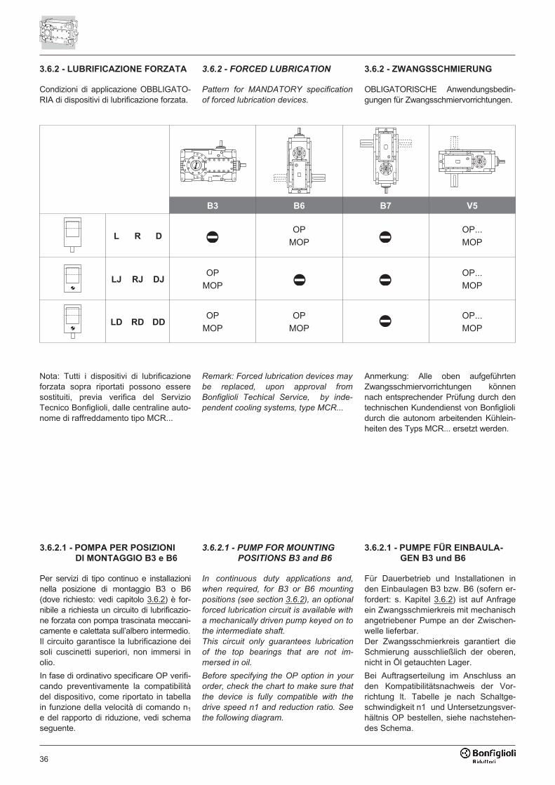
36
3.6.2 - LUBRIFICAZIONE FORZATA
Condizioni di applicazione OBBLIGATO-RIA di dispositivi di lubrificazione forzata.
Nota: Tutti i dispositivi di lubrificazioneforzata sopra riportati possono esseresostituiti, previa verifica del ServizioTecnico Bonfiglioli, dalle centraline auto-nome di raffreddamento tipo MCR...
3.6.2 - FORCED LUBRICATION
Pattern for MANDATORY specification
of forced lubrication devices.
Remark: Forced lubrication devices may
be replaced, upon approval from
Bonfiglioli Techical Service, by inde-
pendent cooling systems, type MCR...
3.6.2 - ZWANGSSCHMIERUNG
OBLIGATORISCHE Anwendungsbedin-gungen für Zwangsschmiervorrichtungen.
Anmerkung: Alle oben aufgeführtenZwangsschmiervorrichtungen könnennach entsprechender Prüfung durch dentechnischen Kundendienst von Bonfigliolidurch die autonom arbeitenden Kühlein-heiten des Typs MCR... ersetzt werden.
B3 B6 B7 V5
L R DOP
MOP
OP...
MOP
LJ RJ DJOP
MOP
OP...
MOP
LD RD DDOP
MOP
OP
MOP
OP...
MOP
3.6.2.1 - POMPA PER POSIZIONI
DI MONTAGGIO B3 e B6
Per servizi di tipo continuo e installazioninella posizione di montaggio B3 o B6(dove richiesto: vedi capitolo 3.6.2) è for-nibile a richiesta un circuito di lubrificazio-ne forzata con pompa trascinata meccani-camente e calettata sull’albero intermedio.Il circuito garantisce la lubrificazione deisoli cuscinetti superiori, non immersi inolio.
In fase di ordinativo specificare OP verifi-cando preventivamente la compatibilitàdel dispositivo, come riportato in tabellain funzione della velocità di comando n1
e del rapporto di riduzione, vedi schemaseguente.
3.6.2.1 - PUMP FOR MOUNTING
POSITIONS B3 and B6
In continuous duty applications and,
when required, for B3 or B6 mounting
positions (see section 3.6.2), an optional
forced lubrication circuit is available with
a mechanically driven pump keyed on to
the intermediate shaft.
This circuit only guarantees lubrication
of the top bearings that are not im-
mersed in oil.
Before specifying the OP option in your
order, check the chart to make sure that
the device is fully compatible with the
drive speed n1 and reduction ratio. See
the following diagram.
3.6.2.1 - PUMPE FÜR EINBAULA-
GEN B3 und B6
Für Dauerbetrieb und Installationen inden Einbaulagen B3 bzw. B6 (sofern er-fordert: s. Kapitel 3.6.2) ist auf Anfrageein Zwangsschmierkreis mit mechanischangetriebener Pumpe an der Zwischen-welle lieferbar.Der Zwangsschmierkreis garantiert dieSchmierung ausschließlich der oberen,nicht in Öl getauchten Lager.
Bei Auftragserteilung im Anschluss anden Kompatibilitätsnachweis der Vor-richtung lt. Tabelle je nach Schaltge-schwindigkeit n1 und Untersetzungsver-hältnis OP bestellen, siehe nachstehen-des Schema.
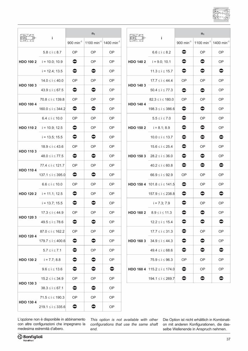
37
L’opzione non è disponibile in abbinamentocon altre configurazioni che impegnano lamedesima estremità d’albero.
This option is not available with other
configurations that use the same shaft
end.
Die Option ist nicht erhältlich in Kombinati-on mit anderen Konfigurationen, die das-selbe Wellenende in Anspruch nehmen.
i
n1
i
n1
900 min-1 1100 min-1 1400 min-1 900 min-1 1100 min-1 1400 min-1
HDO 100 2
5.8 � i � 8.7 OP OP OP
HDO 140 2
6.6 � i � 8.2 OP OP
i = 10.0; 10.9 OP OP i = 9.0; 10.1 OP
i = 12.4; 13.5 OP 11.3 � i � 15.7
HDO 100 3
14.0 � i � 40.0 OP OP OPHDO 140 3
17.7 � i � 44.4 OP OP OP
43.9 � i � 67.5 OP 50.4 � i � 77.3 OP
HDO 100 4
70.8 � i � 139.8 OP OP OPHDO 140 4
82.3 � i � 180.0 OP OP OP
160.0 � i � 344.2 OP 198.3 � i � 386.6 OP
HDO 110 2
6.4 � i � 10.0 OP OP OP
HDO 150 2
5.5 � i � 7.0 OP OP
i = 10.9; 12.5 OP OP i = 8.1; 8.9 OP
i = 13.5; 15.5 OP 10.0 � i � 13.7
HDO 110 3
18.9 � i � 43.6 OP OP OP
HDO 150 3
15.6 � i � 25.4 OP OP
48.0 � i � 77.5 OP 28.2 � i � 36.0 OP
HDO 110 4
77.4 � i � 121.7 OP OP OP 40.2 � i � 60.8
137.1 � i � 395.0 OP
HDO 150 4
66.9 � i � 92.9 OP OP OP
HDO 120 2
6.6 � i � 10.0 OP OP OP 101.8 � i � 141.5 OP OP
i = 11.1; 12.5 OP OP 157.9 � i � 238.8
i = 13.7; 15.5 OP
HDO 160 2
i = 7.3; 7.9 OP OP
HDO 120 3
17.3 � i � 44.9 OP OP OP 8.9 � i � 11.3 OP
49.5 � i � 78.6 OP 12.2 � i � 15.4
HDO 120 4
87.0 � i � 162.2 OP OP OP
HDO 160 3
17.7 � i � 31.3 OP OP
179.7 � i � 400.6 OP 34.9 � i � 44.3 OP
HDO 130 2
5.7 � i � 7.1 OP OP 49.4 � i � 68.6
i = 7.7; 8.8 OP
HDO 160 4
75.9 � i � 96.3 OP OP OP
9.6 � i � 13.6 115.2 � i � 174.0 OP OP
HDO 130 3
15.2 � i � 34.9 OP OP OP 194.1 � i � 269.7
38.3 � i � 67.1 OP
HDO 130 4
71.5 � i � 190.3 OP OP OP
219.1 � i � 335.6 OP
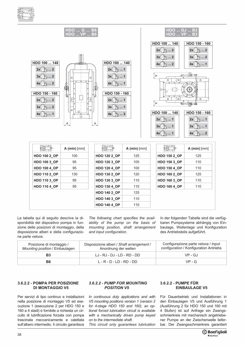
38
���������������������������������
����������������������������������
��
����������������
����������������
����������������
�����������
����������������
����������������
����������������
���������������
����������������
����������������
����������������
���������������
����������������
����������������
����������������
�����������
� �
����������������
����������������
����������������
���������������
����������������
����������������
����������������
�����������
����������������
����������������
����������������
���������������
����������������
����������������
����������������
�����������
La tabella qui di seguito descrive la di-sponibilità del dispositivo pompa in fun-zione delle posizioni di montaggio, delladisposizione alberi e della configurazio-ne parte veloce.
In der folgenden Tabelle sind die verfüg-baren Pumpsysteme abhängig von Ein-baulage, Wellenlage und Konfigurationdes Antriebsteils aufgeführt.
Posizione di montaggio /Mounting position / Einbaulagen
Disposizione alberi / Shaft arrangement /Anordnung der wellen
Configurazione parte veloce / Inputconfiguration / Konfiguration Antriebs
B3 LJ - RJ - DJ - LD - RD - DD VP - GJ
B6 L - R - D - LD - RD - DD VP - G
The following chart specifies the avail-
ability of the pump on the basis of
mounting position, shaft arrangement
and input configuration.
A (min) [mm] A (min) [mm] A (min) [mm]
HDO 100 2_OP 100 HDO 120 2_OP 125 HDO 150 2_OP 125
HDO 100 3_OP 95 HDO 120 3_OP 105 HDO 150 3_OP 110
HDO 100 4_OP 95 HDO 120 4_OP 100 HDO 150 4_OP 110
HDO 110 2_OP 130 HDO 130 2_OP 120 HDO 160 2_OP 125
HDO 110 3_OP 95 HDO 130 3_OP 110 HDO 160 3_OP 110
HDO 110 4_OP 95 HDO 130 4_OP 110 HDO 160 4_OP 110
HDO 140 2_OP 125
HDO 140 3_OP 110
HDO 140 4_OP 110
3.6.2.2 - POMPA PER POSIZIONE
DI MONTAGGIO V5
Per servizi di tipo continuo e installazioninella posizione di montaggio V5 ed ese-cuzione 1 (esecuzione 2 per HDO 150 e160 a 4 stadi) è fornibile a richiesta un cir-cuito di lubrificazione forzata con pompatrascinata meccanicamente e calettatasull’albero intermedio. Il circuito garantisce
3.6.2.2 - PUMP FOR MOUNTING
POSITION V5
In continuous duty applications and with
V5 mounting positions version 1 (version 2
for 4-stage HDO 150 and 160), an op-
tional forced lubrication circuit is available
with a mechanically driven pump keyed
on to the intermediate shaft.
This circuit only guarantees lubrication
3.6.2.2 - PUMPE FÜR
EINBAULAGE V5
Für Dauerbetrieb und Installationen inden Einbaulagen V5 und Ausführung 1(Ausführung 2 für HDO 150 und 160 mit4 Stufen) ist auf Anfrage ein Zwangs-schmierkreis mit mechanisch angetriebe-ner Pumpe an der Zwischenwelle liefer-bar. Der Zwangsschmierkreis garantiert
39
la lubrificazione dei soli cuscinetti superio-ri, non immersi in olio.Se il dispositivo è richiesto congiunta-mente al dispositivo di Drywell consulta-re il Servizio Tecnico Bonfiglioli.In fase di ordinativo specificare OP1 oOP2 verificando preventivamente lacompatibilità del dispositivo, come ripor-tato in tabella in funzione della velocitàdi comando n1 e del rapporto di riduzio-ne, vedi schema seguente.
of the top bearings that are not im-
mersed in oil.
If this device is required in conjunction
with the Drywell device, consult the
Bonfiglioli Technical Service.
When ordering, specify the OP1 or OP2
option in your order after first checking
the chart to make sure that the device is
fully compatible with drive speed n1 and
the reduction ratio. See the following di-
agram.
ausschließlich die Schmierung der obe-ren, nicht im Ölbad laufenden Lager.Wird die Zwangsschmierung zusammenmit der „Drywell“-Vorrichtung gewünscht,wenden Sie sich bitte an den TechnischenKundendienst von Bonfiglioli.Bei Auftragserteilung bitte die Kompatibili-tät der Vorrichtung lt. Tabelle im nachste-henden Schema je nach Schaltgeschwin-digkeit n1 und Untersetzungsverhältnisprüfen und OP1 oder OP2 angeben.
i
n1
in1
900 min-1 1100 min-1 1400 min-1 900 min-1 1100 min-1 1400 min-1
HDO 100 2
5.8 � i � 7.0 OP1 OP1 OP1
HDO 140 2
6.6 � i � 8.2 OP2 OP2 OP1
i = 8.0; 8.7 OP1 OP1 i = 9.0; 10.1 OP2 OP2
i = 10.0; 10.9 OP1 i = 11.3; 12.6 OP2
i = 12.4; 13.5 i = 14.0; 15.7
HDO 100 3
14.0 � i � 17.3 OP2 OP1 OP1
HDO 140 3
17.7 � i � 23.3 OP2 OP2 OP1
20.2 � i � 40.0 OP2 OP1 26.0 � i � 44.4 OP2 OP2
43.9 � i � 67.5 50.4 � i � 77.3
HDO 100 470.8 � i � 139.8 OP2 OP1
HDO 140 482.3 � i � 180.0 OP2 OP1
160.0 � i � 344.2 198.3 � i � 386.6
HDO 110 2
6.4 � i � 8.1 OP2 OP2 OP1
HDO 150 2
5.5 � i � 7.0 OP2 OP2 OP1
i = 8.7; 10.0 OP2 OP2 i = 8.1; 8.9 OP2 OP2
i = 10.9; 12.5 OP2 10.0 � i � 10.9 OP2
i = 13.5; 15.5 12.6 � i � 13.7
HDO 110 3
i = 18.9; 20.9 OP2 OP1 OP1
HDO 150 3
15.6 � i � 25.4 OP2 OP2 OP1
22.0 � i � 43.6 OP2 OP1 28.2 � i � 36.0 OP2 OP2
48.0 � i � 77.5 40.2 � i � 60.8
HDO 110 477.4 � i � 121.7 OP2 OP2
HDO 150 4
66.9 � i � 92.9 OP2 OP2 OP1
137.1 � i � 395.0 101.8 � i � 141.5 OP2 OP2
HDO 120 2
6.6 � i � 8.1 OP2 OP2 OP1 157.9 � i � 238.8
i = 8.9; 10.0 OP2 OP2
HDO 160 2
i = 7.3; 7.9 OP2 OP2 OP1
i = 11.1; 12.5 OP2 8.9 � i � 11.3 OP2
i = 13.7; 15.5 12.2 � i � 15.4
HDO 120 3
17.3 � i � 28.3 OP2 OP2 OP1
HDO 160 3
17.7 � i � 31.3 OP2 OP2 OP1
32.0 � i � 44.9 OP2 OP2 34.9 � i � 44.3 OP2 OP2
49.5 � i � 78.6 49.4 � i � 68.6
HDO 120 487.0 � i � 162.2 OP2 OP2
HDO 160 4
75.9 � i � 96.3 OP2 OP2 OP1
179.0 � i � 400.6 115.2 � i � 174.0 OP2 OP2
HDO 130 2
5.7 � i � 7.1 OP2 OP1 OP1 194.1 � i � 269.7
i = 7.7; 8.8 OP2 OP1
i = 9.6; 11.0 OP2
i = 12.0; 13.6
HDO 130 3
15.2 � i � 19.9 OP2 OP2 OP1
22.6 � i � 34.9 OP2 OP2
38.3 � i � 67.1
HDO 130 471.5 � i � 190.3 OP2 OP1
219.1 � i � 335.6

40
L’opzione non è disponibile in abbina-mento con altre configurazioni che impe-gnano la medesima estremità d’albero.
This option is not available with other
configurations that use the same shaft
end.
Die Option ist nicht in Verbindung mitanderen Konfigurationen verfügbar, diedasselbe Wellenende in Anspruch neh-men.
1 - Pompa2 - Filtro3 - Pressostato di minima
1 - Pump
2 - Filter
3 - Minimum pressure switch
1 - Pumpe2 - Filter3 - Mindestdruckwächter
Per le dimensioni di ingombro contattareil Servizio Tecnico Bonfiglioli.
Contact the Bonfiglioli Technical Service
for overall dimensions.
Für die Aufstellmaße wenden Sie sichbitte an den Technischen Kundendienstvon Bonfiglioli.
3.6.2.3 - MOTOPOMPA
PER POSIZIONI DI
MONTAGGIO B3 e B6
Per servizi di tipo intermittente e/o qua-lora le velocità non siano compatibili conl’utilizzo della pompa OP, nella posizio-ne di montaggio B3 e B6 (dove richiesto:vedi capitolo 3.6.2) è fornibile a richie-sta un circuito di lubrificazione forzatacon motopompa alimentata autonoma-mente - opzione MOP. Il circuito garanti-sce una portata costante di olio in corri-spondenza dei cuscinetti superiori.
3.6.2.3 - ELECTRIC PUMP FOR
MOUNTING POSITIONS B3
and B6
In intermittent duty applications, if
speeds are incompatible with the use of
the OP pump option, and when required
for B3 and B6 mounting positions (see
section 3.6.2), the MOP optional forced
lubrication circuit is available with an in-
dependently powered electric pump.
This system ensures a constant flow of
oil to the top bearings.
3.6.2.3 - MOTORPUMPE FÜR
EINBAULAGEN B3
und B6
Für Aussetzbetrieb bzw. bei nicht für denEinsatz der Pumpe OP geeigneten Dreh-zahlen ist in den Einbaulagen B3 bzw. B6(sofern erfordert: s. Kapitel 3.6.2) auf An-frage ein Zwangsschmierkreis mit unab-hängig versorgter Motorpumpe - OptionMOP - lieferbar.Der Zwangsschmierkreis garantiert ei-nen konstanten Schmieröldurchsatz anden oberen Lagern.
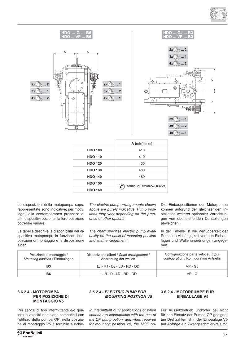
41
���������������������������������
����������������������������������
��
����������������
����������������
����������������
����������������
����������������
����������������
��
����������������
����������������
����������������
����������������
����������������
����������������
A (min) [mm]
HDO 100 410
HDO 110 410
HDO 120 430
HDO 130 480
HDO 140 480
HDO 150
HDO 160
Le disposizioni della motopompa soprarappresentate sono indicative, per motivilegati alla contemporanea presenza dialtri dispositivi opzionali la loro posizionepotrebbe variare.
The electric pump arrangements shown
above are purely indicative. Pump posi-
tions may vary depending on the pres-
ence of other options
Die Einbaupositionen der Motorpumpekönnen aufgrund der gleichzeitigen In-stallation weiterer optionaler Vorrichtun-gen von obenstehenden Darstellungenabweichen.
La tabella descrive la disponibilità del di-spositivo motopompa in funzione delleposizioni di montaggio e la disposizionealberi.
The chart specifies electric pump avail-
ability on the basis of mounting position
and shaft arrangement.
In der Tabelle ist die Verfügbarkeit derPumpe in Abhängigkeit von den Einbau-lagen und Wellenanordnungen angege-ben.
Posizione di montaggio /Mounting position / Einbaulagen
Disposizione alberi / Shaft arrangement /Anordnung der wellen
Configurazione parte veloce / Input
configuration / Konfiguration Antriebs
B3 LJ - RJ - DJ - LD - RD - DD VP - GJ
B6 L - R - D - LD - RD - DD VP - G
3.6.2.4 - MOTOPOMPA
PER POSIZIONE DI
MONTAGGIO V5
Per servizi di tipo intermittente e/o qua-lora le velocità non siano compatibili conl’utilizzo della pompa OP, nella posizio-ne di montaggio V5 è fornibile a richie-
3.6.2.4 - ELECTRIC PUMP FOR
MOUNTING POSITION V5
In intermittent duty applications or when
speeds are incompatible with the use of
the OP pump option, and when required
for mounting position V5, the MOP op-
3.6.2.4 - MOTORPUMPE FÜR
EINBAULAGE V5
Für Aussetzbetrieb und/oder bei nichtfür den Einsatz der Pumpe OP geeigne-ten Drehzahlen ist in der Einbaulage V5auf Anfrage ein Zwangsschmierkreis mit
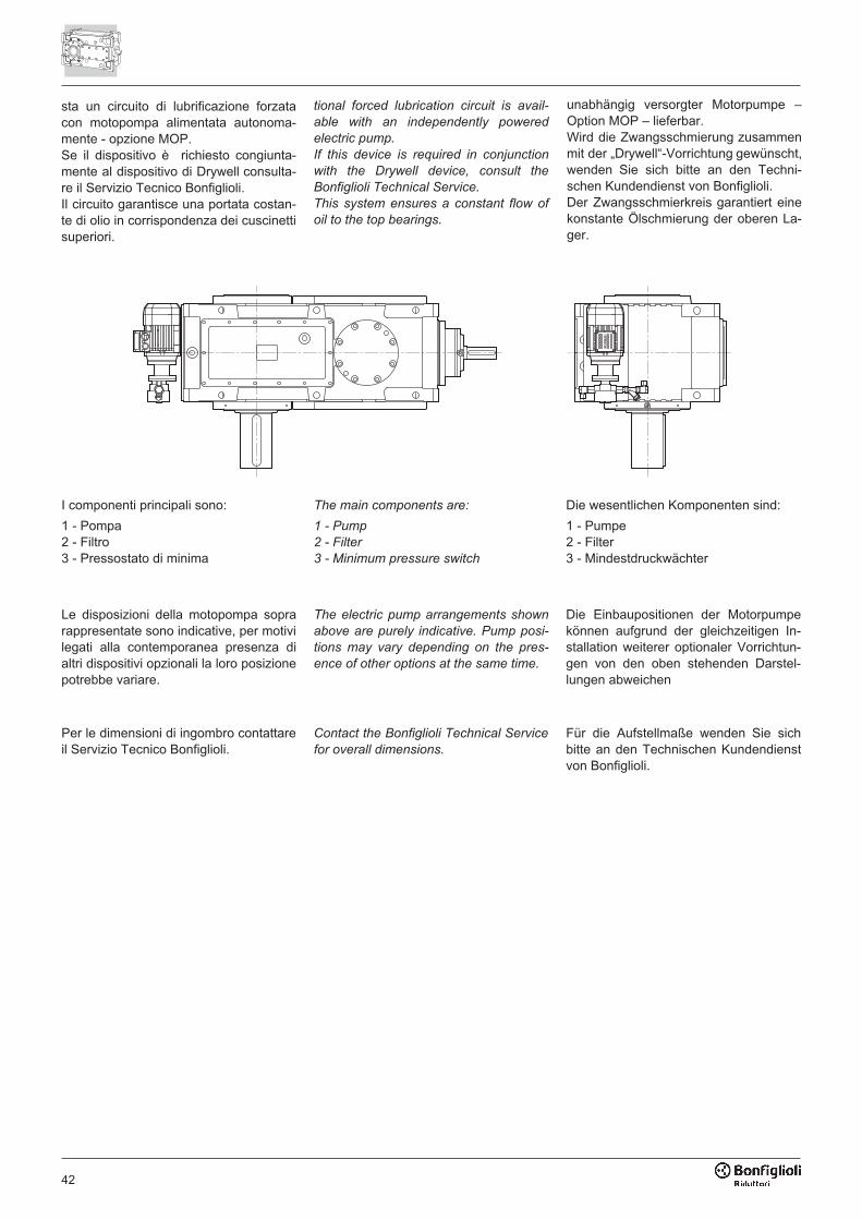
42
I componenti principali sono:
1 - Pompa2 - Filtro3 - Pressostato di minima
The main components are:
1 - Pump
2 - Filter
3 - Minimum pressure switch
Die wesentlichen Komponenten sind:
1 - Pumpe2 - Filter3 - Mindestdruckwächter
Per le dimensioni di ingombro contattareil Servizio Tecnico Bonfiglioli.
Contact the Bonfiglioli Technical Service
for overall dimensions.
Für die Aufstellmaße wenden Sie sichbitte an den Technischen Kundendienstvon Bonfiglioli.
Le disposizioni della motopompa soprarappresentate sono indicative, per motivilegati alla contemporanea presenza dialtri dispositivi opzionali la loro posizionepotrebbe variare.
The electric pump arrangements shown
above are purely indicative. Pump posi-
tions may vary depending on the pres-
ence of other options at the same time.
Die Einbaupositionen der Motorpumpekönnen aufgrund der gleichzeitigen In-stallation weiterer optionaler Vorrichtun-gen von den oben stehenden Darstel-lungen abweichen
sta un circuito di lubrificazione forzatacon motopompa alimentata autonoma-mente - opzione MOP.Se il dispositivo è richiesto congiunta-mente al dispositivo di Drywell consulta-re il Servizio Tecnico Bonfiglioli.Il circuito garantisce una portata costan-te di olio in corrispondenza dei cuscinettisuperiori.
tional forced lubrication circuit is avail-
able with an independently powered
electric pump.
If this device is required in conjunction
with the Drywell device, consult the
Bonfiglioli Technical Service.
This system ensures a constant flow of
oil to the top bearings.
unabhängig versorgter Motorpumpe –Option MOP – lieferbar.Wird die Zwangsschmierung zusammenmit der „Drywell“-Vorrichtung gewünscht,wenden Sie sich bitte an den Techni-schen Kundendienst von Bonfiglioli.Der Zwangsschmierkreis garantiert einekonstante Ölschmierung der oberen La-ger.
43
3.6.3 - DISPOSITIVO ANTIRETRO
Il dispositivo antiretro garantisce il fun-
zionamento unidirezionale del riduttore e
previene il moto retrogrado per effetto
del carico collegato all’albero lento. Oltre
ad effettuare la verifica ai carichi impulsi-
vi riportati al paragrafo 2.2.1, è necessa-
rio accertarsi che la coppia richiesta al
dispositivo antiretro M1 = M2 / (i x �) sia
inferiore al momento torcente M1max ri-
portato in tabella.
La specifica della relativa opzione, desi-
gnata A, deve essere necessariamente
completata dall’indicazione del verso di
rotazione libera dell’albero lento (CW
oppure CCW).
Se particolari condizioni d’uso lo richie-
dono, il verso di rotazione del dispositi-
vo anti-ritorno può essere variato dall’u-
tente accedendo all’alloggiamento che
lo contiene, e invertendo il verso di
montaggio della ruota libera. Qualora
sia richiesto un intervento di questo tipo
contattare il Servizio Tecnico Bonfiglioli
per le relative istruzioni.
Il particolare tipo di anti-ritorno, costitui-
to da corpi di contatto a distacco centri-
fugo, non richiede alcun tipo di manu-
tenzione periodica.
L’opzione non è disponibile in abbina-
mento con altre configurazioni che impe-
gnano la medesima estremità d’albero.
3.6.3 - BACKSTOP DEVICE
The backstop device ensures that only
one direction of rotation is allowed, and
prevents the gearbox to be backdriven by
the load connected to the output shaft.
In addition to verifying the shock loads
shown in section 2.2.1, also make sure
that the torque transmitted to the back-
stop M1 = M2 / (i x �) is less than the ad-
missible torque M1max listed in the chart
below.
Along with the specification of the back-
stop device, option A, the direction of free
rotation for the output shaft (CW or CCW)
must also be specified in the order.
If special operating conditions require it,
the user can reverse the direction of ro-
tation of the backstop device by open-
ing the backstop compartment and re-
versing the direction of the freewheel. If
you need to perform this operation, con-
tact Bonfiglioli’s Technical Service for
the necessary instructions.
The type of backstop device used, based
on centrifugally released shoes, does not
require any regular maintenance.
This option is not available with other
configurations that use the same shaft
end.
3.6.3 - RÜCKLAUFSPERRE
Die Rücklaufsperre stellt sicher, dass nur
eine Drehrichtung des Getriebes möglich
ist und verhindert die Rückwärtsbewe-
gung durch die mit der Abtriebswelle ver-
bundene Last. Zusätzlich zur Überprü-
fung der im Abschnitt 2.2.1 aufgeführten
Stoßbelastung muss sichergestellt werden,
dass das von der Rücklaufsperre übertra-
gene Moment M1 = M2 / (i x �) unter dem
in der Tabelle angegebenen max. erlaub-
ten Torsionsmoment M1max liegt.
Bei Bestellung der entsprechenden Option
mit der Bezeichnung A muss obligato-
risch auch die freie Drehrichtung der Ab-
triebswelle angegeben werden (CW oder
CCW). Die Option ist nicht in Kombinati-
on mit anderen Konfigurationen erhältlich,
die dasselbe Wellenende in Anspruch
nehmen. Sollten bestimmte Betriebsbedin-
gungen dies erfordern, kann die Drehrich-
tung der Rücklaufsperre vom Benutzer ge-
ändert werden, indem in der Aufnahme der
Rücklaufsperre die Montagerichtung des frei
drehenden Rads umgekehrt wird. Ist ein
Eingriff dieser Art notwendig, kann die jewei-
lige Anleitung beim technischen Kunden-
dienst von Bonfiglioli angefordert werden.
Die besondere Ausführung der Rücklauf-
sperre, bestehend aus Kontaktkörpern,
die sich bei Einwirkung der Zentrifugal-
kraft ablösen, erfordert keine regelmäßi-
gen Wartungseingriffe.
Die Option ist nicht erhältlich in Kombinati-
on mit anderen Konfigurationen, die das-
selbe Wellenende in Anspruch nehmen.
In funzionamento permanente si
consiglia di mantenere una velo-
cità di rotazione in folle (sopra-
vanzo) n1min superiore a quella indicata
in tabella, al fine di garantire il distacco
centrifugo di tutti i corpi preservandoli da
fenomeni di usura.
Per ulteriori informazioni contattare Servi-
zio Tecnico Bonfiglioli.
Under continuous operating
conditions, it is advisable to
maintain a neutral rotation
speed n1min greater than that specified in
the chart in order to ensure the effective
centrifugal release of all the shoes and
avoid unnecessary wear. For further de-
tails, contact the Bonfiglioli Technical
Service.
Bei Dauerbetrieb empfiehlt sich
die Einhaltung einer Leerlaufdreh-
zahl (Überschuss) n1min oberhalb
des in der Tabelle angegebenen Werts,
um die Ablösung aller Kontaktkörper bei
Einwirkung der Zentrifugalkraft zu gewähr-
leisten und somit Verschleißerscheinun-
gen der Kontaktkörper vorzubeugen. Bei
weiterem Informationsbedarf wenden Sie
sich bitte an den technischen Kunden-
dienst von Bonfiglioli.
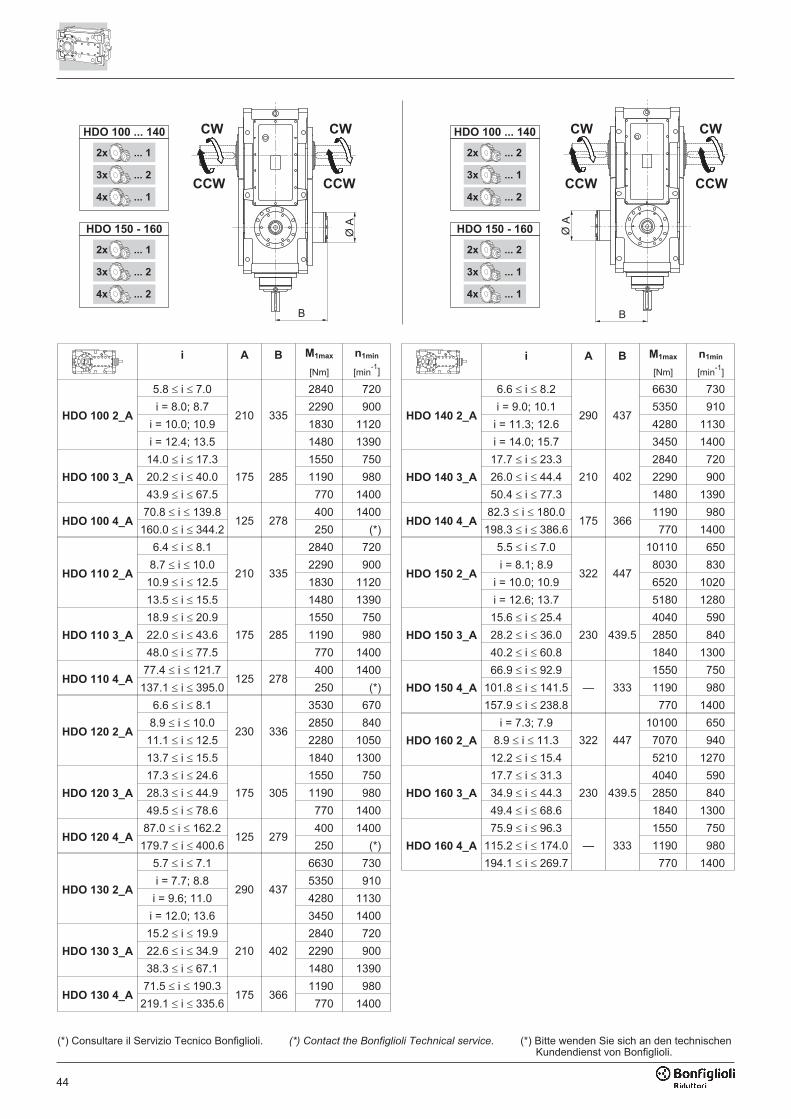
44
����������������
����������������
����������������
���������������
����������������
����������������
����������������
�����������
����������������
����������������
����������������
���������������
����������������
����������������
����������������
�����������
(*) Consultare il Servizio Tecnico Bonfiglioli. (*) Contact the Bonfiglioli Technical service. (*) Bitte wenden Sie sich an den technischenKundendienst von Bonfiglioli.
i A B M1max
[Nm]
n1min
[min-1
]
i A B M1max
[Nm]
n1min
[min-1
]
HDO 100 2_A
5.8 � i � 7.0
210 335
2840 720
HDO 140 2_A
6.6 � i � 8.2
290 437
6630 730
i = 8.0; 8.7 2290 900 i = 9.0; 10.1 5350 910
i = 10.0; 10.9 1830 1120 i = 11.3; 12.6 4280 1130
i = 12.4; 13.5 1480 1390 i = 14.0; 15.7 3450 1400
HDO 100 3_A
14.0 � i � 17.3
175 285
1550 750
HDO 140 3_A
17.7 � i � 23.3
210 402
2840 720
20.2 � i � 40.0 1190 980 26.0 � i � 44.4 2290 900
43.9 � i � 67.5 770 1400 50.4 � i � 77.3 1480 1390
HDO 100 4_A70.8 � i � 139.8
125 278400 1400
HDO 140 4_A82.3 � i � 180.0
175 3661190 980
160.0 � i � 344.2 250 (*) 198.3 � i � 386.6 770 1400
HDO 110 2_A
6.4 � i � 8.1
210 335
2840 720
HDO 150 2_A
5.5 � i � 7.0
322 447
10110 650
8.7 � i � 10.0 2290 900 i = 8.1; 8.9 8030 830
10.9 � i � 12.5 1830 1120 i = 10.0; 10.9 6520 1020
13.5 � i � 15.5 1480 1390 i = 12.6; 13.7 5180 1280
HDO 110 3_A
18.9 � i � 20.9
175 285
1550 750
HDO 150 3_A
15.6 � i � 25.4
230 439.5
4040 590
22.0 � i � 43.6 1190 980 28.2 � i � 36.0 2850 840
48.0 � i � 77.5 770 1400 40.2 � i � 60.8 1840 1300
HDO 110 4_A77.4 � i � 121.7
125 278400 1400
HDO 150 4_A
66.9 � i � 92.9
— 333
1550 750
137.1 � i � 395.0 250 (*) 101.8 � i � 141.5 1190 980
HDO 120 2_A
6.6 � i � 8.1
230 336
3530 670 157.9 � i � 238.8 770 1400
8.9 � i � 10.0 2850 840
HDO 160 2_A
i = 7.3; 7.9
322 447
10100 650
11.1 � i � 12.5 2280 1050 8.9 � i � 11.3 7070 940
13.7 � i � 15.5 1840 1300 12.2 � i � 15.4 5210 1270
HDO 120 3_A
17.3 � i � 24.6
175 305
1550 750
HDO 160 3_A
17.7 � i � 31.3
230 439.5
4040 590
28.3 � i � 44.9 1190 980 34.9 � i � 44.3 2850 840
49.5 � i � 78.6 770 1400 49.4 � i � 68.6 1840 1300
HDO 120 4_A87.0 � i � 162.2
125 279400 1400
HDO 160 4_A
75.9 � i � 96.3
— 333
1550 750
179.7 � i � 400.6 250 (*) 115.2 � i � 174.0 1190 980
HDO 130 2_A
5.7 � i � 7.1
290 437
6630 730 194.1 � i � 269.7 770 1400
i = 7.7; 8.8 5350 910
i = 9.6; 11.0 4280 1130
i = 12.0; 13.6 3450 1400
HDO 130 3_A
15.2 � i � 19.9
210 402
2840 720
22.6 � i � 34.9 2290 900
38.3 � i � 67.1 1480 1390
HDO 130 4_A71.5 � i � 190.3
175 3661190 980
219.1 � i � 335.6 770 1400

45
3.6.4 - TENUTE E GUARNIZIONI
A richiesta, i riduttori possono esseredotati di sistemi di tenuta diversi, e inparticolare:
TK – In ambienti caratterizzati da pre-senza di polveri abrasive sono consiglia-te tenute tipo Taconite costituite da unacombinazione di anelli di tenuta, labirintie camera a grasso.La presenza del grasso deve essere ga-rantita attraverso operazioni di manuten-zione periodica.
VS – Dotazione di anelli di tenuta conmescola in Viton®.
DS – Dotazione di doppio anello di tenu-ta su ogni estremità d’albero.
DVS – Dotazione di doppio anello di te-nuta con mescola in Viton® su ogniestremità d’albero.
3.6.4 - SEALS AND GASKETS
On request, gearboxes can be
equipped with different oil sealing sys-
tems. These are:
TK – Taconite seals are recommended
for environments characterised by the
presence of abrasive dust or powders.
Taconite seals incorporate a combina-
tion of sealing rings, labyrinths and a
grease chamber. Greasing must be en-
sured as part of the scheduled mainte-
nance programme.
VS – Viton®
compound seal rings.
DS – Dual set of seal rings at each
shaft end.
DVS – Dual set of Viton®
compound
seal rings at each shaft end.
3.6.4 - DICHTUNGEN UND DICHT-
MANSCHETTEN
Auf Anfrage können die Getriebe mit un-terschiedlichen Dichtsystemen ausge-stattet werden, und zwar:
TK – In Umgebungen mit hoher Präsenzabrasiver Stäube werden Taconite-Dich-tungen empfohlen. Diese bestehen auseiner Kombination von Dichtringen, La-byrinthdichtungen und Fettkammern.Das Fett muss durch regelmäßige War-tung geprüft werden.
VS – Ausstattung mit Wellendichtringenaus Viton®.
DS – Ausstattung mit doppeltem Wellen-dichtring an jedem Wellenende.
DVS – Ausstattung mit doppeltem Wel-lendichtring aus Viton® an jedem Wel-lenende.
3.6.5 - SENSORI
Termostato bimetallico – Su specificadell’opzione TG è fornita una sonda bi-metallica termostatica per rilevarequando la temperatura dell’olio supera ilvalore di 90°C ± 5°C. Il dispositivo è for-nito a corredo e l’installazione e il relati-vo cablaggio elettrico sono a cura del-l’installatore.
Controllo livello olio – Su specificadell’opzione OLG in fase di ordinativo èinstallata una sonda per il controllo re-moto del livello del lubrificante. Il dispo-sitivo è funzionante in condizioni di inat-tività del riduttore. Durante il funziona-mento dello stesso, il dispositivo deveessere bypassato. Il cablaggio è a curadell’installatore.Il dispositivo può non essere compatibi-le con altri accessori e/o alcune configu-razioni, contattare il Servizio TecnicoBonfiglioli.
3.6.5 - SENSORS
Bimetal thermostat – If the TG option
is specified, a bimetallic thermostat de-
tects when the oil temperature exceeds
90°C ± 5°C.
The device is supplied with the gear
unit, but installation and wiring are the
responsibility of the installer.
Oil level indicator – If the OLG option
is specified in the order, the gearbox is
supplied with a device permitting the re-
mote checking of the oil level. The de-
vice best operates when the gearbox is
idle and should be bypassed when the
gearbox is operating. Wiring is the re-
sponsibility of the installer.
The device may not be available in
combination with other accessories
and/or particular product configurations.
Please contact Bonfiglioli Technical
Service for advise.
3.6.5 - SENSOREN
Bimetallthermostat – Bei Bestellungder Option TG ist ein Bimetalltempera-turfühler verfügbar, der dazu dient, dieÜberschreitung des Werts 90°C ± 5°Cder Öltemperatur zu erfassen. Die Vor-richtung wird im Zubehör mitgeliefert;die Installation und die entsprechendeelektrische Verkabelung müssen vomMonteur durchgeführt werden.
Ölstandkontrolle – Wird bei Auftrags-erteilung die Option OLG bestellt, er-folgt die Installation eines Fühlers fürdie Fernkontrolle des Ölstands. Die Vor-richtung funktioniert bei Stillstand desGetriebes. Während des Betriebs desGetriebes muss die Vorrichtung über-brückt werden. Die Verkabelung ist vomMonteur vorzunehmen.Diese Ausführung könnte nicht mit wei-teren Zubehören und/oder Ausführungenmöglich sein. Kontaktieren Sie bitte denTechnischen Service von Bonfiglioli.
46
3.6.7 - BEFESTIGUNGSORGANE
Für die Aufsteckbefestigungen der HDOGetriebe ist eine Schraube aus vergüte-tem Stahl mit entsprechender Form lie-ferbar, um das Getriebe an der Träger-struktur zu verankern.
Der Bausatz enthält außerdem die Tel-lerfedern zur Schwingungsdämpfung,die bei der Installation durch den Kun-den nach dem in folgender Tabelle an-gegebenen Maß G vorgespannt werdenmüssen.
Die Reaktionsschraube ist an der Ge-triebeseite neben der anzutreibendenMaschine anzubringen und in der Boh-rung mehr entfernt von Abtriebswelle(sehen Sie die Masse F auf folgenderZeichnung).
Die Montage auf der Deckelseite ist un-möglich. In diesem Fall kontaktieren Siebitte den Technischen Service von Bonfi-glioli.
3.6.7 - FIXING ELEMENTS
For shaft mounted HDO gearboxes, a
specially shaped hardened steel bolt is
available to secure the unit to the sup-
porting structure.
Vibration damping cup springs are also
supplied in the kit. The customer must
adjust the preload of these springs dur-
ing installation, respecting the value G
given in the following chart.
The reaction bolt must be fitted on the
side of the gearbox next to the driven
machine and in the farthest hole from
output shaft centre (see dimension F in
the following figure).
Fitting the bolt on same side as the in-
spection cover is not possible. In this
case please contact Bonfiglioli Technical
Service for advise.
3.6.7 - ORGANI DI FISSAGGIO
Per i fissaggi di tipo pendolare dei ridut-tori HDO è fornibile un bullone in accia-io bonificato e opportunamente sago-mato per vincolare il riduttore alla strut-tura di supporto.
Fanno parte del kit anche le molle a taz-za con funzione di smorzamento delle vi-brazioni il cui precarico dovrà essere re-golato dal Cliente al momento dell’instal-lazione rispettando la quota G indicatanella tabella seguente.
Il bullone di reazione dovrà essere collo-cato sul lato del riduttore adiacente allamacchina che deve essere azionata enel foro lontano dall'asse lento del ridut-tore (vedi quota F indicata nella figuraseguente).
Il montaggio dal lato coperchio non èpossibile, consultare il Servizio TecnicoBonfiglioli.
3.6.6 - DRYWELL
Il dispositivo “Drywell”, opzione DW, è unparticolare dispositivo di tenuta dell'albe-ro lento ed è unicamente applicabile ai ri-duttori nella posizione di montaggio verti-cale V5.Quando specificato, richiede necessaria-mente l’adozione contestuale di un siste-ma di lubrificazione forzata, selezionatofra quelli disponibili per l’unità e illustratinel relativo capitolo di questo catalogo.Periodicamente, è opportuno verificare/ri-pristinare la carica di grasso nella came-ra ricavata sotto al cuscinetto inferioredell’albero lento.
L’opzione Drywell può avere limitazioniin concomitanza con altre varianti delprodotto.Consultare preventivamente il ServizioTecnico Bonfiglioli.
3.6.6 - DRYWELL
The "drywell" - option DW - is a device
providing output shaft sealing for units
with output shaft laying vertically in the
V5 position.
When specified, it necessarily requires
the installation of a forced lubrication
system, selected from those available
for the gearbox, as illustrated in the rele-
vant section of this catalogue.
At scheduled intervals, check and refill
the grease in the vane underneath the
output shaft’s bottom bearing.
Availability of the Drywell may be sub-
ject to limitations, depending on the con-
temporary specification of other devices.
Please consult with Bonfiglioli Technical
Service.
3.6.6 - DRYWELL
Die „Drywell“-Vorrichtung – Option DW –garantiert die Dichtung der Abtriebswelleund kann nur bei Getrieben nach Einbau-lagen V5 verwendet.Wenn diese Option bestellt wird, mussobligatorisch gleichzeitig ein Zwangs-schmiersystem vorgesehen werden, dasunter den für die Einheit verfügbaren, imentsprechenden Kapitel dieses Katalogsillustrierten Systemen auszuwählen ist.Die Schmierfettfüllung in der Kammer un-ter dem unteren Lager der Abtriebswelleist regelmäßig zu kontrollieren/nachzufül-len. Die Verfügbarkeit der Option Drywellkann durch gleichzeitige Auswahl weite-rer Optionen eingeschränkt sein.Bitte wenden Sie sich dann an unserentechnischen Service.
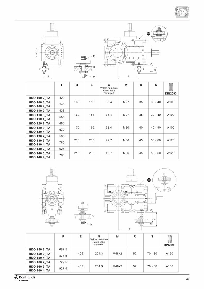
47
�
�
�
�
��
�
F B E G
Valore nominaleRated valueNennwert
M R S
DIN2093
HDO 100 2_TA 420
160 153 33.4 M27 35 30 - 40 A100HDO 100 3_TA
HDO 100 4_TA540
HDO 110 2_TA 435
160 153 33.4 M27 35 30 - 40 A100HDO 110 3_TA
HDO 110 4_TA555
HDO 120 2_TA 480
170 166 33.4 M30 40 40 - 50 A100HDO 120 3_TA
HDO 120 4_TA630
HDO 130 2_TA 585
216 205 42.7 M36 45 50 - 60 A125HDO 130 3_TA
HDO 130 4_TA780
HDO 140 2_TA 625
216 205 42.7 M36 45 50 - 60 A125HDO 140 3_TA
HDO 140 4_TA790
�
�
�
��
F E G
Valore nominaleRated valueNennwert
M R S
DIN2093
HDO 150 2_TA 687.5
405 204.3 M48x2 52 70 - 80 A160HDO 150 3_TA
HDO 150 4_TA877.5
HDO 160 2_TA 727.5
405 204.3 M48x2 52 70 - 80 A160HDO 160 3_TA
HDO 160 4_TA927.5
48
3.6.8 - PROVE DOCUMENTALI
AC - Attestato di conformità
Documento il cui rilascio attesta la con-formità del prodotto all’ordinativo e la co-struzione dello stesso in conformità alleprocedure standard di processo e dicontrollo previste dal sistema di QualitàBonfiglioli Riduttori.
CC - Certificato di collaudo
La specifica comporta la conduzione diverifiche di conformità all’ordine, controllivisivi generali e verifiche strumentali del-le dimensioni di accoppiamento. Sonoinoltre condotti controlli generali di fun-zionamento a vuoto e verifiche della fun-zionalità delle guarnizioni di tenuta inmodalità statica e in funzionamento. Ilcollaudo si applica ad un campione stati-stico del lotto di spedizione.
CT - Certificato di tipo
Oltre alle attività competenti al Certifica-to di collaudo si aggiungono controllifunzionali specifici relativi a:
• controllo rumorosità
• temperatura superficiale a regime
• verifica della coppia di serraggio vite-ria esterna
• funzionalità eventuali organi accessori
Tutte le attività sono condotte con fun-zionamento a vuoto del riduttore. Il colla-udo si applica ad un campione statisticodel lotto di spedizione.
3.6.8 - CERTIFICATES
AC - Certificate of compliance
The document certifies the compliance
of the product with the purchase order
and the construction in conformity with
the applicable procedures of the
Bonfiglioli Quality System.
CC - Inspection certificate
The document entails checking on order
compliance, the visual inspection of ex-
ternal conditions and of mating dimen-
sions. Checking on main functional pa-
rameters in unloaded conditions is also
performed along with oil seal proofing,
both in static and in running conditions.
Units inspected are sampled within the
shipping batch and marked individually.
CT - Type certificate
Further to the activities relevant to the In-
spection certificate the following checks
are also conducted:
• noise
• surface temperature
• tightness of external hardware
• functionality of ancillary devices, if fit-
ted
All checks are conducted with the gear
unit running unloaded. Units inspected
are sampled within the shipping batch
and marked individually.
3.6.8 - NACHWEISE
AC - Konformitätsbescheinigung
Dokument
mit dessen Ausstellung die Konformitätdes Produkts mit dem Auftrag, und des-sen Konstruktion in Konformität mit denvom Qualitätsmanagementsystem vonBonfiglioli Riduttori vorgesehenen Stan-dardfertigungs- und -kontrollverfahrenbescheinigt wird.
CC - Prüfzeugnis
Die Bestellung führt zur Durchführungvon Kontrollen der Konformität mit demAuftrag, allgemeinen Sichtkontrollen undinstrumentalen Prüfungen der Passma-ße. Des Weiteren werden allgemeineBetriebskontrollen bei Leerlauf sowiePrüfungen der Funktionalität der Dich-tungen bei Stillstand und während desBetriebs durchgeführt. Die Prüfung wirdanhand einer Stichprobe des Versandlo-ses durchgeführt.
CT - Baumusterzeugnis
Zu den Tätigkeiten, die unter das Prüf-zeugnis fallen, kommen spezifische Funk-tionskontrollen in Bezug auf:
• Geräuschentwicklung
• Oberflächentemperatur bei Betriebs-drehzahl
• Prüfung des Anzugsmoments der äu-ßeren Schrauben
• Funktionalität eventueller zusätzlicherOrgane
Alle Vorgänge werden bei Leerlauf desGetriebes durchgeführt. Die Prüfungwird anhand einer Stichprobe des Ver-sandloses durchgeführt.
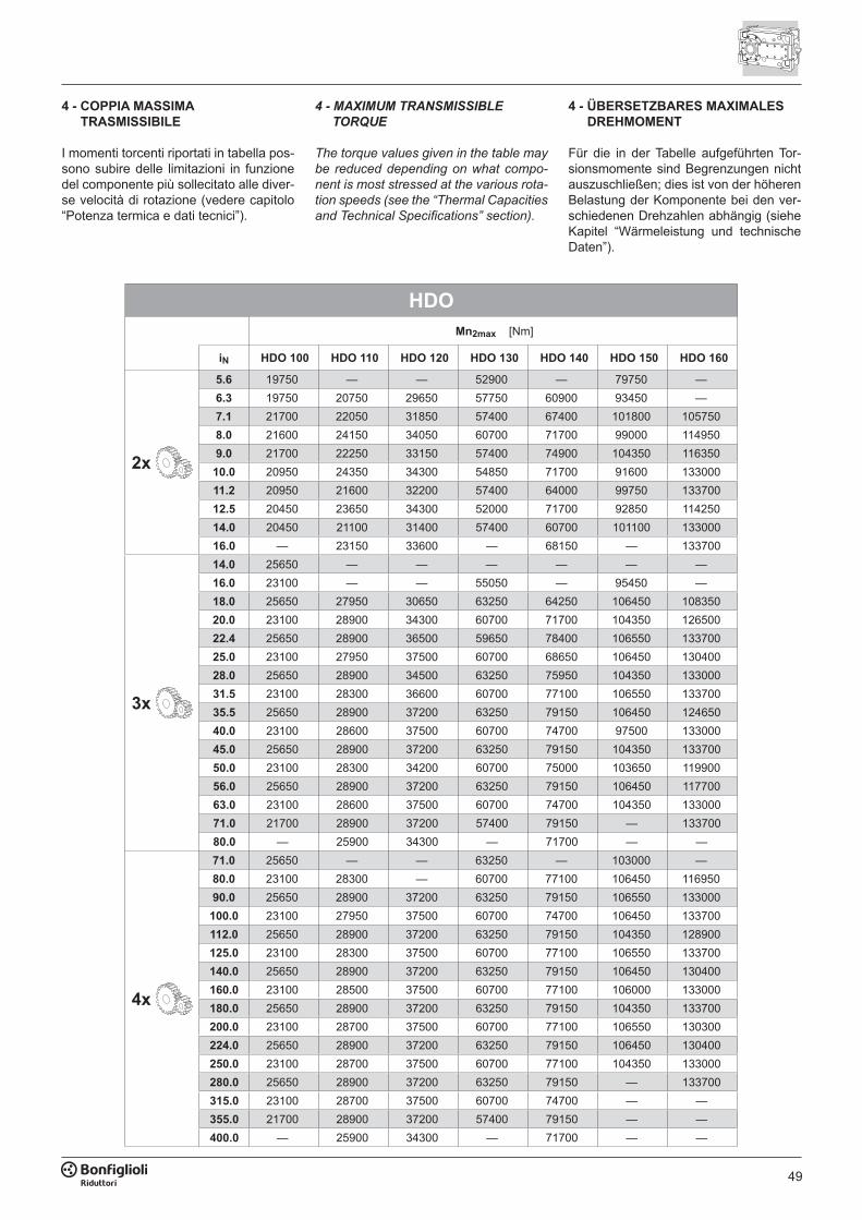
49
HDOMn2max [Nm]
iN HDO 100 HDO 110 HDO 120 HDO 130 HDO 140 HDO 150 HDO 160
2x
5.6 19750 — — 52900 — 79750 —6.3 19750 20750 29650 57750 60900 93450 —7.1 21700 22050 31850 57400 67400 101800 1057508.0 21600 24150 34050 60700 71700 99000 1149509.0 21700 22250 33150 57400 74900 104350 11635010.0 20950 24350 34300 54850 71700 91600 13300011.2 20950 21600 32200 57400 64000 99750 13370012.5 20450 23650 34300 52000 71700 92850 11425014.0 20450 21100 31400 57400 60700 101100 13300016.0 — 23150 33600 — 68150 — 133700
3x
14.0 25650 — — — — — —16.0 23100 — — 55050 — 95450 —18.0 25650 27950 30650 63250 64250 106450 10835020.0 23100 28900 34300 60700 71700 104350 12650022.4 25650 28900 36500 59650 78400 106550 13370025.0 23100 27950 37500 60700 68650 106450 13040028.0 25650 28900 34500 63250 75950 104350 13300031.5 23100 28300 36600 60700 77100 106550 13370035.5 25650 28900 37200 63250 79150 106450 12465040.0 23100 28600 37500 60700 74700 97500 13300045.0 25650 28900 37200 63250 79150 104350 13370050.0 23100 28300 34200 60700 75000 103650 11990056.0 25650 28900 37200 63250 79150 106450 11770063.0 23100 28600 37500 60700 74700 104350 13300071.0 21700 28900 37200 57400 79150 — 13370080.0 — 25900 34300 — 71700 — —
4x
71.0 25650 — — 63250 — 103000 —80.0 23100 28300 — 60700 77100 106450 11695090.0 25650 28900 37200 63250 79150 106550 133000100.0 23100 27950 37500 60700 74700 106450 133700112.0 25650 28900 37200 63250 79150 104350 128900125.0 23100 28300 37500 60700 77100 106550 133700140.0 25650 28900 37200 63250 79150 106450 130400160.0 23100 28500 37500 60700 77100 106000 133000180.0 25650 28900 37200 63250 79150 104350 133700200.0 23100 28700 37500 60700 77100 106550 130300224.0 25650 28900 37200 63250 79150 106450 130400250.0 23100 28700 37500 60700 77100 104350 133000280.0 25650 28900 37200 63250 79150 — 133700315.0 23100 28700 37500 60700 74700 — —355.0 21700 28900 37200 57400 79150 — —400.0 — 25900 34300 — 71700 — —
4 - COPPIA MASSIMA TRASMISSIBILE
I momenti torcenti riportati in tabella pos-sono subire delle limitazioni in funzione del componente più sollecitato alle diver-se velocità di rotazione (vedere capitolo “Potenza termica e dati tecnici”).
4 - MAXIMUM TRANSMISSIBLE TORQUE
The torque values given in the table may be reduced depending on what compo-nent is most stressed at the various rota-tion speeds (see the “Thermal Capacities and Technical Specifications” section).
4 - ÜBERSETZBARES MAXIMALES DREHMOMENT
Für die in der Tabelle aufgeführten Tor-sionsmomente sind Begrenzungen nicht auszuschließen; dies ist von der höheren Belastung der Komponente bei den ver-schiedenen Drehzahlen abhängig (siehe Kapitel “Wärmeleistung und technische Daten”).
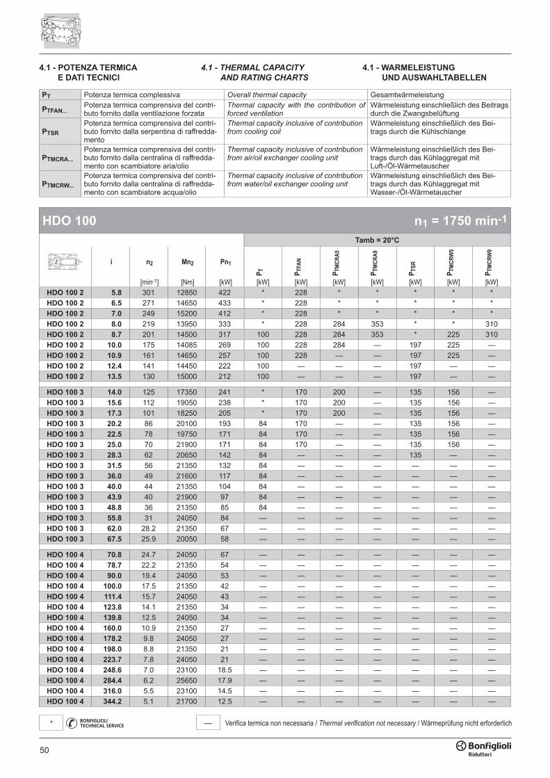
50
— Verifica termica non necessaria / Thermal verification not necessary / Wärmeprüfung nicht erforderlich*
HDO 100 n1 = 1750 min-1
Tamb = 20°C
i n2 Mn2 Pn1P T P T
FAN
P TM
CRA5
P TM
CRA9
P TSR
P TM
CRW
5
P TM
CRW
9
[min-1] [Nm] [kW] [kW] [kW] [kW] [kW] [kW] [kW] [kW]HDO 100 2 5.8 301 12850 422 * 228 * * * * *HDO 100 2 6.5 271 14650 433 * 228 * * * * *HDO 100 2 7.0 249 15200 412 * 228 * * * * *HDO 100 2 8.0 219 13950 333 * 228 284 353 * * 310HDO 100 2 8.7 201 14500 317 100 228 284 353 * 225 310HDO 100 2 10.0 175 14085 269 100 228 284 — 197 225 —HDO 100 2 10.9 161 14650 257 100 228 — — 197 225 —HDO 100 2 12.4 141 14450 222 100 — — — 197 — —HDO 100 2 13.5 130 15000 212 100 — — — 197 — —
HDO 100 3 14.0 125 17350 241 * 170 200 — 135 156 —HDO 100 3 15.6 112 19050 238 * 170 200 — 135 156 —HDO 100 3 17.3 101 18250 205 * 170 200 — 135 156 —HDO 100 3 20.2 86 20100 193 84 170 — — 135 156 —HDO 100 3 22.5 78 19750 171 84 170 — — 135 156 —HDO 100 3 25.0 70 21900 171 84 170 — — 135 156 —HDO 100 3 28.3 62 20650 142 84 — — — 135 — —HDO 100 3 31.5 56 21350 132 84 — — — — — —HDO 100 3 36.0 49 21600 117 84 — — — — — —HDO 100 3 40.0 44 21350 104 84 — — — — — —HDO 100 3 43.9 40 21900 97 84 — — — — — —HDO 100 3 48.8 36 21350 85 84 — — — — — —HDO 100 3 55.8 31 24050 84 — — — — — — —HDO 100 3 62.0 28.2 21350 67 — — — — — — —HDO 100 3 67.5 25.9 20050 58 — — — — — — —
HDO 100 4 70.8 24.7 24050 67 — — — — — — —HDO 100 4 78.7 22.2 21350 54 — — — — — — —HDO 100 4 90.0 19.4 24050 53 — — — — — — —HDO 100 4 100.0 17.5 21350 42 — — — — — — —HDO 100 4 111.4 15.7 24050 43 — — — — — — —HDO 100 4 123.8 14.1 21350 34 — — — — — — —HDO 100 4 139.8 12.5 24050 34 — — — — — — —HDO 100 4 160.0 10.9 21350 27 — — — — — — —HDO 100 4 178.2 9.8 24050 27 — — — — — — —HDO 100 4 198.0 8.8 21350 21 — — — — — — —HDO 100 4 223.7 7.8 24050 21 — — — — — — —HDO 100 4 248.6 7.0 23100 18.5 — — — — — — —HDO 100 4 284.4 6.2 25650 17.9 — — — — — — —HDO 100 4 316.0 5.5 23100 14.5 — — — — — — —HDO 100 4 344.2 5.1 21700 12.5 — — — — — — —
4.1 - POTENZA TERMICA E DATI TECNICI
4.1 - THERMAL CAPACITY AND RATING CHARTS
4.1 - WARMELEISTUNG UND AUSWAHLTABELLEN
PT Potenza termica complessiva Overall thermal capacity Gesamtwärmeleistung
PTFAN...Potenza termica comprensiva del contri-buto fornito dalla ventilazione forzata
Thermal capacity with the contribution of forced ventilation
Wärmeleistung einschließlich des Beitrags durch die Zwangsbelüftung
PTSRPotenza termica comprensiva del contri-buto fornito dalla serpentina di raffredda-mento
Thermal capacity inclusive of contribution from cooling coil
Wärmeleistung einschließlich des Bei-trags durch die Kühlschlange
PTMCRA...Potenza termica comprensiva del contri-buto fornito dalla centralina di raffredda-mento con scambiatore aria/olio
Thermal capacity inclusive of contribution from air/oil exchanger cooling unit
Wärmeleistung einschließlich des Bei-trags durch das Kühlaggregat mitLuft-/Öl-Wärmetauscher
PTMCRW...Potenza termica comprensiva del contri-buto fornito dalla centralina di raffredda-mento con scambiatore acqua/olio
Thermal capacity inclusive of contribution from water/oil exchanger cooling unit
Wärmeleistung einschließlich des Bei-trags durch das Kühlaggregat mitWasser-/Öl-Wärmetauscher
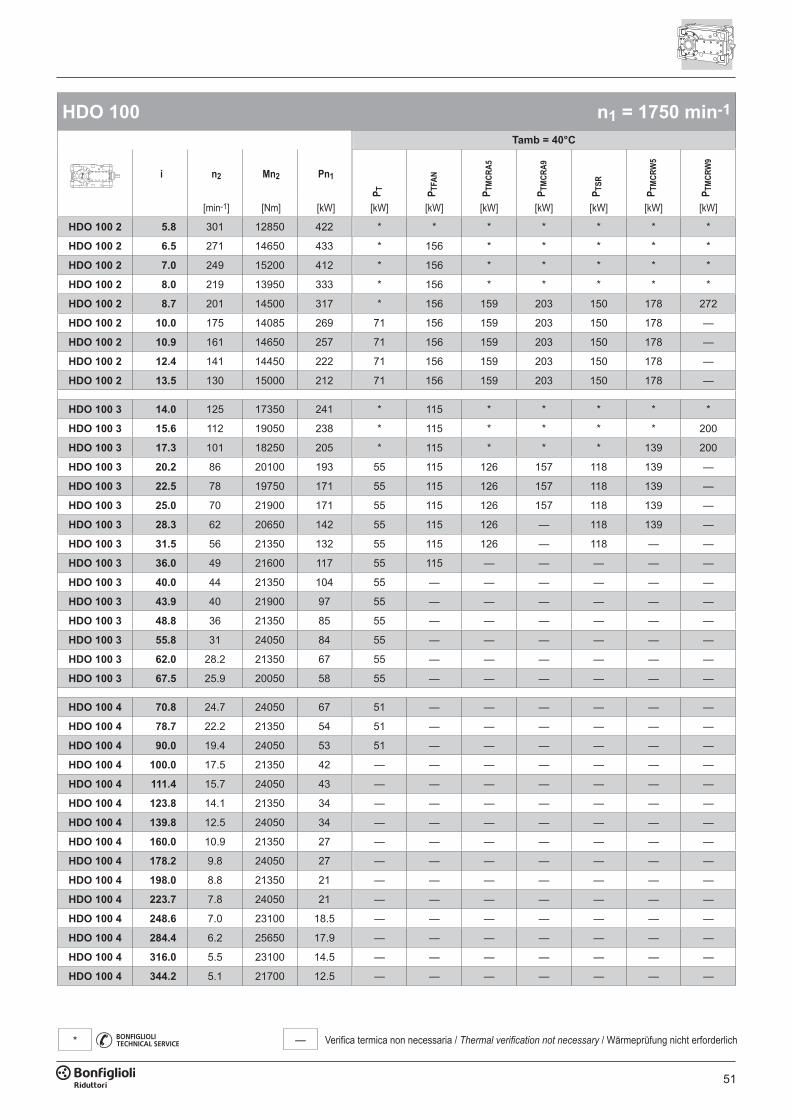
51
— Verifica termica non necessaria / Thermal verification not necessary / Wärmeprüfung nicht erforderlich*
HDO 100 n1 = 1750 min-1
Tamb = 40°C
i n2 Mn2 Pn1
P T P TFA
N
P TM
CRA5
P TM
CRA9
P TSR
P TM
CRW
5
P TM
CRW
9
[min-1] [Nm] [kW] [kW] [kW] [kW] [kW] [kW] [kW] [kW]
HDO 100 2 5.8 301 12850 422 * * * * * * *
HDO 100 2 6.5 271 14650 433 * 156 * * * * *
HDO 100 2 7.0 249 15200 412 * 156 * * * * *
HDO 100 2 8.0 219 13950 333 * 156 * * * * *
HDO 100 2 8.7 201 14500 317 * 156 159 203 150 178 272
HDO 100 2 10.0 175 14085 269 71 156 159 203 150 178 —
HDO 100 2 10.9 161 14650 257 71 156 159 203 150 178 —
HDO 100 2 12.4 141 14450 222 71 156 159 203 150 178 —
HDO 100 2 13.5 130 15000 212 71 156 159 203 150 178 —
HDO 100 3 14.0 125 17350 241 * 115 * * * * *
HDO 100 3 15.6 112 19050 238 * 115 * * * * 200
HDO 100 3 17.3 101 18250 205 * 115 * * * 139 200
HDO 100 3 20.2 86 20100 193 55 115 126 157 118 139 —
HDO 100 3 22.5 78 19750 171 55 115 126 157 118 139 —
HDO 100 3 25.0 70 21900 171 55 115 126 157 118 139 —
HDO 100 3 28.3 62 20650 142 55 115 126 — 118 139 —
HDO 100 3 31.5 56 21350 132 55 115 126 — 118 — —
HDO 100 3 36.0 49 21600 117 55 115 — — — — —
HDO 100 3 40.0 44 21350 104 55 — — — — — —
HDO 100 3 43.9 40 21900 97 55 — — — — — —
HDO 100 3 48.8 36 21350 85 55 — — — — — —
HDO 100 3 55.8 31 24050 84 55 — — — — — —
HDO 100 3 62.0 28.2 21350 67 55 — — — — — —
HDO 100 3 67.5 25.9 20050 58 55 — — — — — —
HDO 100 4 70.8 24.7 24050 67 51 — — — — — —
HDO 100 4 78.7 22.2 21350 54 51 — — — — — —
HDO 100 4 90.0 19.4 24050 53 51 — — — — — —
HDO 100 4 100.0 17.5 21350 42 — — — — — — —
HDO 100 4 111.4 15.7 24050 43 — — — — — — —
HDO 100 4 123.8 14.1 21350 34 — — — — — — —
HDO 100 4 139.8 12.5 24050 34 — — — — — — —
HDO 100 4 160.0 10.9 21350 27 — — — — — — —
HDO 100 4 178.2 9.8 24050 27 — — — — — — —
HDO 100 4 198.0 8.8 21350 21 — — — — — — —
HDO 100 4 223.7 7.8 24050 21 — — — — — — —
HDO 100 4 248.6 7.0 23100 18.5 — — — — — — —
HDO 100 4 284.4 6.2 25650 17.9 — — — — — — —
HDO 100 4 316.0 5.5 23100 14.5 — — — — — — —
HDO 100 4 344.2 5.1 21700 12.5 — — — — — — —
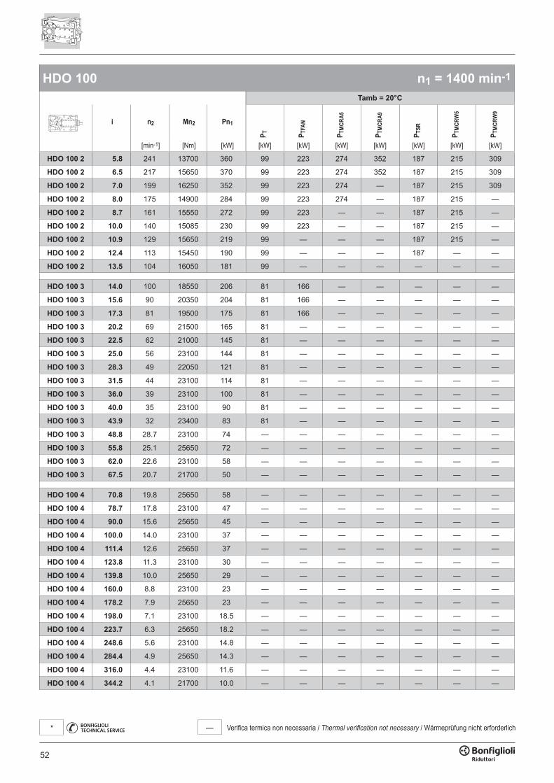
52
— Verifica termica non necessaria / Thermal verification not necessary / Wärmeprüfung nicht erforderlich*
HDO 100 n1 = 1400 min-1
Tamb = 20°C
i n2 Mn2 Pn1
P T P TFA
N
P TM
CRA5
P TM
CRA9
P TSR
P TM
CRW
5
P TM
CRW
9
[min-1] [Nm] [kW] [kW] [kW] [kW] [kW] [kW] [kW] [kW]
HDO 100 2 5.8 241 13700 360 99 223 274 352 187 215 309
HDO 100 2 6.5 217 15650 370 99 223 274 352 187 215 309
HDO 100 2 7.0 199 16250 352 99 223 274 — 187 215 309
HDO 100 2 8.0 175 14900 284 99 223 274 — 187 215 —
HDO 100 2 8.7 161 15550 272 99 223 — — 187 215 —
HDO 100 2 10.0 140 15085 230 99 223 — — 187 215 —
HDO 100 2 10.9 129 15650 219 99 — — — 187 215 —
HDO 100 2 12.4 113 15450 190 99 — — — 187 — —
HDO 100 2 13.5 104 16050 181 99 — — — — — —
HDO 100 3 14.0 100 18550 206 81 166 — — — — —
HDO 100 3 15.6 90 20350 204 81 166 — — — — —
HDO 100 3 17.3 81 19500 175 81 166 — — — — —
HDO 100 3 20.2 69 21500 165 81 — — — — — —
HDO 100 3 22.5 62 21000 145 81 — — — — — —
HDO 100 3 25.0 56 23100 144 81 — — — — — —
HDO 100 3 28.3 49 22050 121 81 — — — — — —
HDO 100 3 31.5 44 23100 114 81 — — — — — —
HDO 100 3 36.0 39 23100 100 81 — — — — — —
HDO 100 3 40.0 35 23100 90 81 — — — — — —
HDO 100 3 43.9 32 23400 83 81 — — — — — —
HDO 100 3 48.8 28.7 23100 74 — — — — — — —
HDO 100 3 55.8 25.1 25650 72 — — — — — — —
HDO 100 3 62.0 22.6 23100 58 — — — — — — —
HDO 100 3 67.5 20.7 21700 50 — — — — — — —
HDO 100 4 70.8 19.8 25650 58 — — — — — — —
HDO 100 4 78.7 17.8 23100 47 — — — — — — —
HDO 100 4 90.0 15.6 25650 45 — — — — — — —
HDO 100 4 100.0 14.0 23100 37 — — — — — — —
HDO 100 4 111.4 12.6 25650 37 — — — — — — —
HDO 100 4 123.8 11.3 23100 30 — — — — — — —
HDO 100 4 139.8 10.0 25650 29 — — — — — — —
HDO 100 4 160.0 8.8 23100 23 — — — — — — —
HDO 100 4 178.2 7.9 25650 23 — — — — — — —
HDO 100 4 198.0 7.1 23100 18.5 — — — — — — —
HDO 100 4 223.7 6.3 25650 18.2 — — — — — — —
HDO 100 4 248.6 5.6 23100 14.8 — — — — — — —
HDO 100 4 284.4 4.9 25650 14.3 — — — — — — —
HDO 100 4 316.0 4.4 23100 11.6 — — — — — — —
HDO 100 4 344.2 4.1 21700 10.0 — — — — — — —

53
— Verifica termica non necessaria / Thermal verification not necessary / Wärmeprüfung nicht erforderlich*
HDO 100 n1 = 1400 min-1
Tamb = 40°C
i n2 Mn2 Pn1
P T P TFA
N
P TM
CRA5
P TM
CRA9
P TSR
P TM
CRW
5
P TM
CRW
9
[min-1] [Nm] [kW] [kW] [kW] [kW] [kW] [kW] [kW] [kW]
HDO 100 2 5.8 241 13700 360 * 152 158 202 149 177 271
HDO 100 2 6.5 217 15650 370 * 152 158 202 149 177 271
HDO 100 2 7.0 199 16250 352 * 152 158 202 149 177 271
HDO 100 2 8.0 175 14900 284 70 152 158 202 149 177 271
HDO 100 2 8.7 161 15550 272 70 152 158 202 149 177 271
HDO 100 2 10.0 140 15085 230 70 152 158 202 149 177 —
HDO 100 2 10.9 129 15650 219 70 152 158 202 149 177 —
HDO 100 2 12.4 113 15450 190 70 152 158 — 149 177 —
HDO 100 2 13.5 104 16050 181 70 152 158 — 149 177 —
HDO 100 3 14.0 100 18550 206 52 114 123 — 115 136 —
HDO 100 3 15.6 90 20350 204 52 114 123 — 115 136 —
HDO 100 3 17.3 81 19500 175 52 114 123 — 115 136 —
HDO 100 3 20.2 69 21500 165 52 114 123 — 115 136 —
HDO 100 3 22.5 62 21000 145 52 114 123 — 115 136 —
HDO 100 3 25.0 56 23100 144 52 114 123 — 115 136 —
HDO 100 3 28.3 49 22050 121 52 114 — — 115 — —
HDO 100 3 31.5 44 23100 114 52 — — — — — —
HDO 100 3 36.0 39 23100 100 52 — — — — — —
HDO 100 3 40.0 35 23100 90 52 — — — — — —
HDO 100 3 43.9 32 23400 83 52 — — — — — —
HDO 100 3 48.8 28.7 23100 74 52 — — — — — —
HDO 100 3 55.8 25.1 25650 72 52 — — — — — —
HDO 100 3 62.0 22.6 23100 58 52 — — — — — —
HDO 100 3 67.5 20.7 21700 50 — — — — — — —
HDO 100 4 70.8 19.8 25650 58 53 — — — — — —
HDO 100 4 78.7 17.8 23100 47 — — — — — — —
HDO 100 4 90.0 15.6 25650 45 — — — — — — —
HDO 100 4 100.0 14.0 23100 37 — — — — — — —
HDO 100 4 111.4 12.6 25650 37 — — — — — — —
HDO 100 4 123.8 11.3 23100 30 — — — — — — —
HDO 100 4 139.8 10.0 25650 29 — — — — — — —
HDO 100 4 160.0 8.8 23100 23 — — — — — — —
HDO 100 4 178.2 7.9 25650 23 — — — — — — —
HDO 100 4 198.0 7.1 23100 18.5 — — — — — — —
HDO 100 4 223.7 6.3 25650 18.2 — — — — — — —
HDO 100 4 248.6 5.6 23100 14.8 — — — — — — —
HDO 100 4 284.4 4.9 25650 14.3 — — — — — — —
HDO 100 4 316.0 4.4 23100 11.6 — — — — — — —
HDO 100 4 344.2 4.1 21700 10.0 — — — — — — —
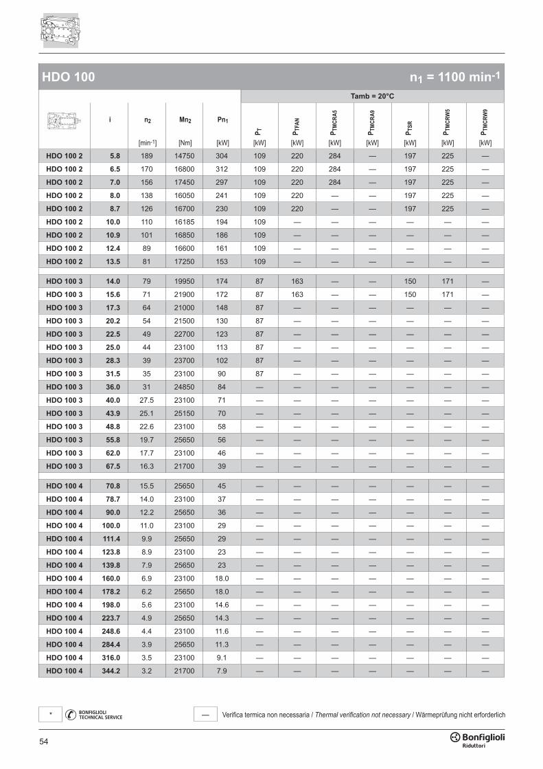
54
— Verifica termica non necessaria / Thermal verification not necessary / Wärmeprüfung nicht erforderlich*
HDO 100 n1 = 1100 min-1
Tamb = 20°C
i n2 Mn2 Pn1
P T P TFA
N
P TM
CRA5
P TM
CRA9
P TSR
P TM
CRW
5
P TM
CRW
9
[min-1] [Nm] [kW] [kW] [kW] [kW] [kW] [kW] [kW] [kW]
HDO 100 2 5.8 189 14750 304 109 220 284 — 197 225 —
HDO 100 2 6.5 170 16800 312 109 220 284 — 197 225 —
HDO 100 2 7.0 156 17450 297 109 220 284 — 197 225 —
HDO 100 2 8.0 138 16050 241 109 220 — — 197 225 —
HDO 100 2 8.7 126 16700 230 109 220 — — 197 225 —
HDO 100 2 10.0 110 16185 194 109 — — — — — —
HDO 100 2 10.9 101 16850 186 109 — — — — — —
HDO 100 2 12.4 89 16600 161 109 — — — — — —
HDO 100 2 13.5 81 17250 153 109 — — — — — —
HDO 100 3 14.0 79 19950 174 87 163 — — 150 171 —
HDO 100 3 15.6 71 21900 172 87 163 — — 150 171 —
HDO 100 3 17.3 64 21000 148 87 — — — — — —
HDO 100 3 20.2 54 21500 130 87 — — — — — —
HDO 100 3 22.5 49 22700 123 87 — — — — — —
HDO 100 3 25.0 44 23100 113 87 — — — — — —
HDO 100 3 28.3 39 23700 102 87 — — — — — —
HDO 100 3 31.5 35 23100 90 87 — — — — — —
HDO 100 3 36.0 31 24850 84 — — — — — — —
HDO 100 3 40.0 27.5 23100 71 — — — — — — —
HDO 100 3 43.9 25.1 25150 70 — — — — — — —
HDO 100 3 48.8 22.6 23100 58 — — — — — — —
HDO 100 3 55.8 19.7 25650 56 — — — — — — —
HDO 100 3 62.0 17.7 23100 46 — — — — — — —
HDO 100 3 67.5 16.3 21700 39 — — — — — — —
HDO 100 4 70.8 15.5 25650 45 — — — — — — —
HDO 100 4 78.7 14.0 23100 37 — — — — — — —
HDO 100 4 90.0 12.2 25650 36 — — — — — — —
HDO 100 4 100.0 11.0 23100 29 — — — — — — —
HDO 100 4 111.4 9.9 25650 29 — — — — — — —
HDO 100 4 123.8 8.9 23100 23 — — — — — — —
HDO 100 4 139.8 7.9 25650 23 — — — — — — —
HDO 100 4 160.0 6.9 23100 18.0 — — — — — — —
HDO 100 4 178.2 6.2 25650 18.0 — — — — — — —
HDO 100 4 198.0 5.6 23100 14.6 — — — — — — —
HDO 100 4 223.7 4.9 25650 14.3 — — — — — — —
HDO 100 4 248.6 4.4 23100 11.6 — — — — — — —
HDO 100 4 284.4 3.9 25650 11.3 — — — — — — —
HDO 100 4 316.0 3.5 23100 9.1 — — — — — — —
HDO 100 4 344.2 3.2 21700 7.9 — — — — — — —
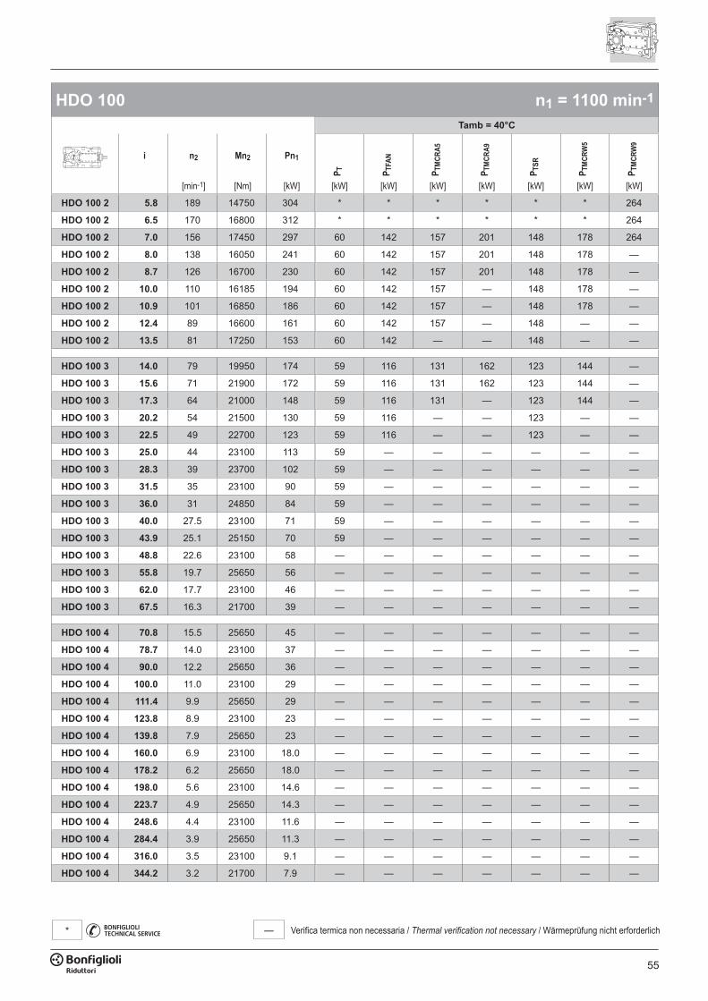
55
— Verifica termica non necessaria / Thermal verification not necessary / Wärmeprüfung nicht erforderlich*
HDO 100 n1 = 1100 min-1
Tamb = 40°C
i n2 Mn2 Pn1
P T P TFA
N
P TM
CRA5
P TM
CRA9
P TSR
P TM
CRW
5
P TM
CRW
9
[min-1] [Nm] [kW] [kW] [kW] [kW] [kW] [kW] [kW] [kW]
HDO 100 2 5.8 189 14750 304 * * * * * * 264
HDO 100 2 6.5 170 16800 312 * * * * * * 264
HDO 100 2 7.0 156 17450 297 60 142 157 201 148 178 264
HDO 100 2 8.0 138 16050 241 60 142 157 201 148 178 —
HDO 100 2 8.7 126 16700 230 60 142 157 201 148 178 —
HDO 100 2 10.0 110 16185 194 60 142 157 — 148 178 —
HDO 100 2 10.9 101 16850 186 60 142 157 — 148 178 —
HDO 100 2 12.4 89 16600 161 60 142 157 — 148 — —
HDO 100 2 13.5 81 17250 153 60 142 — — 148 — —
HDO 100 3 14.0 79 19950 174 59 116 131 162 123 144 —
HDO 100 3 15.6 71 21900 172 59 116 131 162 123 144 —
HDO 100 3 17.3 64 21000 148 59 116 131 — 123 144 —
HDO 100 3 20.2 54 21500 130 59 116 — — 123 — —
HDO 100 3 22.5 49 22700 123 59 116 — — 123 — —
HDO 100 3 25.0 44 23100 113 59 — — — — — —
HDO 100 3 28.3 39 23700 102 59 — — — — — —
HDO 100 3 31.5 35 23100 90 59 — — — — — —
HDO 100 3 36.0 31 24850 84 59 — — — — — —
HDO 100 3 40.0 27.5 23100 71 59 — — — — — —
HDO 100 3 43.9 25.1 25150 70 59 — — — — — —
HDO 100 3 48.8 22.6 23100 58 — — — — — — —
HDO 100 3 55.8 19.7 25650 56 — — — — — — —
HDO 100 3 62.0 17.7 23100 46 — — — — — — —
HDO 100 3 67.5 16.3 21700 39 — — — — — — —
HDO 100 4 70.8 15.5 25650 45 — — — — — — —
HDO 100 4 78.7 14.0 23100 37 — — — — — — —
HDO 100 4 90.0 12.2 25650 36 — — — — — — —
HDO 100 4 100.0 11.0 23100 29 — — — — — — —
HDO 100 4 111.4 9.9 25650 29 — — — — — — —
HDO 100 4 123.8 8.9 23100 23 — — — — — — —
HDO 100 4 139.8 7.9 25650 23 — — — — — — —
HDO 100 4 160.0 6.9 23100 18.0 — — — — — — —
HDO 100 4 178.2 6.2 25650 18.0 — — — — — — —
HDO 100 4 198.0 5.6 23100 14.6 — — — — — — —
HDO 100 4 223.7 4.9 25650 14.3 — — — — — — —
HDO 100 4 248.6 4.4 23100 11.6 — — — — — — —
HDO 100 4 284.4 3.9 25650 11.3 — — — — — — —
HDO 100 4 316.0 3.5 23100 9.1 — — — — — — —
HDO 100 4 344.2 3.2 21700 7.9 — — — — — — —
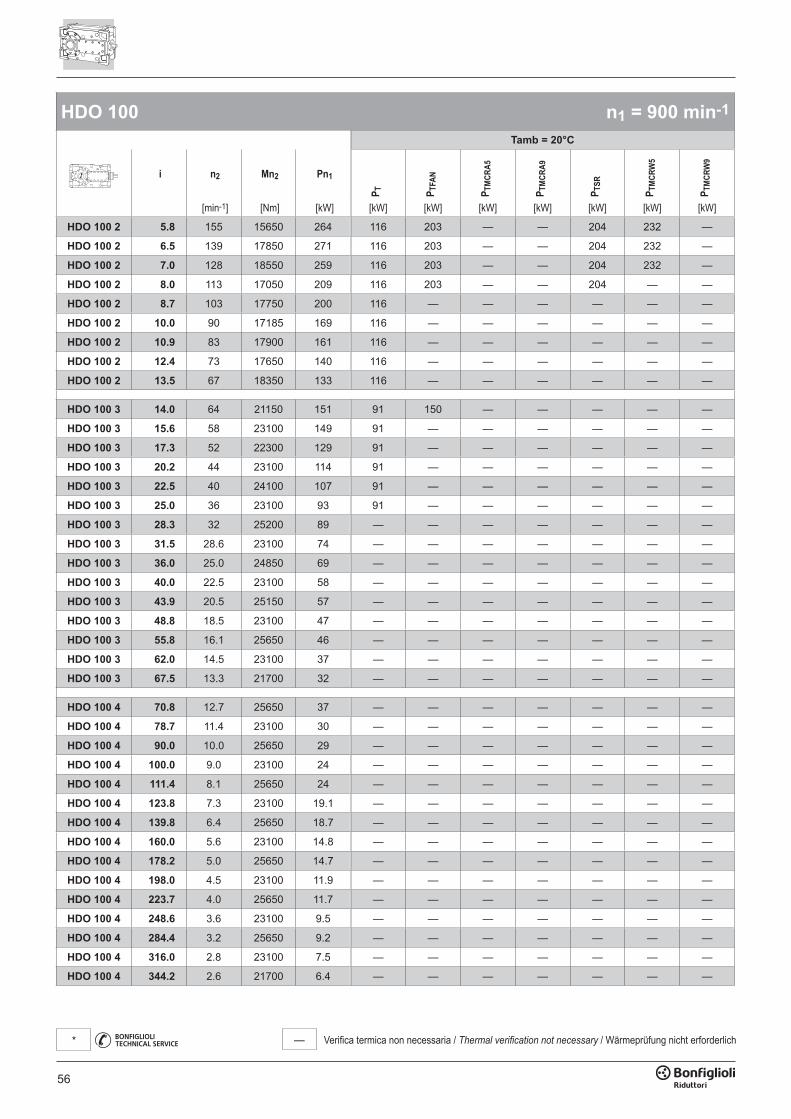
56
— Verifica termica non necessaria / Thermal verification not necessary / Wärmeprüfung nicht erforderlich*
HDO 100 n1 = 900 min-1
Tamb = 20°C
i n2 Mn2 Pn1
P T P TFA
N
P TM
CRA5
P TM
CRA9
P TSR
P TM
CRW
5
P TM
CRW
9
[min-1] [Nm] [kW] [kW] [kW] [kW] [kW] [kW] [kW] [kW]
HDO 100 2 5.8 155 15650 264 116 203 — — 204 232 —
HDO 100 2 6.5 139 17850 271 116 203 — — 204 232 —
HDO 100 2 7.0 128 18550 259 116 203 — — 204 232 —
HDO 100 2 8.0 113 17050 209 116 203 — — 204 — —
HDO 100 2 8.7 103 17750 200 116 — — — — — —
HDO 100 2 10.0 90 17185 169 116 — — — — — —
HDO 100 2 10.9 83 17900 161 116 — — — — — —
HDO 100 2 12.4 73 17650 140 116 — — — — — —
HDO 100 2 13.5 67 18350 133 116 — — — — — —
HDO 100 3 14.0 64 21150 151 91 150 — — — — —
HDO 100 3 15.6 58 23100 149 91 — — — — — —
HDO 100 3 17.3 52 22300 129 91 — — — — — —
HDO 100 3 20.2 44 23100 114 91 — — — — — —
HDO 100 3 22.5 40 24100 107 91 — — — — — —
HDO 100 3 25.0 36 23100 93 91 — — — — — —
HDO 100 3 28.3 32 25200 89 — — — — — — —
HDO 100 3 31.5 28.6 23100 74 — — — — — — —
HDO 100 3 36.0 25.0 24850 69 — — — — — — —
HDO 100 3 40.0 22.5 23100 58 — — — — — — —
HDO 100 3 43.9 20.5 25150 57 — — — — — — —
HDO 100 3 48.8 18.5 23100 47 — — — — — — —
HDO 100 3 55.8 16.1 25650 46 — — — — — — —
HDO 100 3 62.0 14.5 23100 37 — — — — — — —
HDO 100 3 67.5 13.3 21700 32 — — — — — — —
HDO 100 4 70.8 12.7 25650 37 — — — — — — —
HDO 100 4 78.7 11.4 23100 30 — — — — — — —
HDO 100 4 90.0 10.0 25650 29 — — — — — — —
HDO 100 4 100.0 9.0 23100 24 — — — — — — —
HDO 100 4 111.4 8.1 25650 24 — — — — — — —
HDO 100 4 123.8 7.3 23100 19.1 — — — — — — —
HDO 100 4 139.8 6.4 25650 18.7 — — — — — — —
HDO 100 4 160.0 5.6 23100 14.8 — — — — — — —
HDO 100 4 178.2 5.0 25650 14.7 — — — — — — —
HDO 100 4 198.0 4.5 23100 11.9 — — — — — — —
HDO 100 4 223.7 4.0 25650 11.7 — — — — — — —
HDO 100 4 248.6 3.6 23100 9.5 — — — — — — —
HDO 100 4 284.4 3.2 25650 9.2 — — — — — — —
HDO 100 4 316.0 2.8 23100 7.5 — — — — — — —
HDO 100 4 344.2 2.6 21700 6.4 — — — — — — —

57
— Verifica termica non necessaria / Thermal verification not necessary / Wärmeprüfung nicht erforderlich*
HDO 100 n1 = 900 min-1
Tamb = 40°C
i n2 Mn2 Pn1
P T P TFA
N
P TM
CRA5
P TM
CRA9
P TSR
P TM
CRW
5
P TM
CRW
9
[min-1] [Nm] [kW] [kW] [kW] [kW] [kW] [kW] [kW] [kW]
HDO 100 2 5.8 155 15650 264 78 142 175 219 166 194 —
HDO 100 2 6.5 139 17850 271 78 142 175 219 166 194 —
HDO 100 2 7.0 128 18550 259 78 142 175 219 166 194 —
HDO 100 2 8.0 113 17050 209 78 142 175 — 166 194 —
HDO 100 2 8.7 103 17750 200 78 142 175 — 166 194 —
HDO 100 2 10.0 90 17185 169 78 142 — — 166 — —
HDO 100 2 10.9 83 17900 161 78 142 — — — — —
HDO 100 2 12.4 73 17650 140 78 — — — — — —
HDO 100 2 13.5 67 18350 133 78 — — — — — —
HDO 100 3 14.0 64 21150 151 62 106 133 — 125 146 —
HDO 100 3 15.6 58 23100 149 62 106 133 — 125 146 —
HDO 100 3 17.3 52 22300 129 62 106 — — 125 — —
HDO 100 3 20.2 44 23100 114 62 106 — — — — —
HDO 100 3 22.5 40 24100 107 62 106 — — — — —
HDO 100 3 25.0 36 23100 93 62 — — — — — —
HDO 100 3 28.3 32 25200 89 62 — — — — — —
HDO 100 3 31.5 28.6 23100 74 62 — — — — — —
HDO 100 3 36.0 25.0 24850 69 62 — — — — — —
HDO 100 3 40.0 22.5 23100 58 — — — — — — —
HDO 100 3 43.9 20.5 25150 57 — — — — — — —
HDO 100 3 48.8 18.5 23100 47 — — — — — — —
HDO 100 3 55.8 16.1 25650 46 — — — — — — —
HDO 100 3 62.0 14.5 23100 37 — — — — — — —
HDO 100 3 67.5 13.3 21700 32 — — — — — — —
HDO 100 4 70.8 12.7 25650 37 — — — — — — —
HDO 100 4 78.7 11.4 23100 30 — — — — — — —
HDO 100 4 90.0 10.0 25650 29 — — — — — — —
HDO 100 4 100.0 9.0 23100 24 — — — — — — —
HDO 100 4 111.4 8.1 25650 24 — — — — — — —
HDO 100 4 123.8 7.3 23100 19.1 — — — — — — —
HDO 100 4 139.8 6.4 25650 18.7 — — — — — — —
HDO 100 4 160.0 5.6 23100 14.8 — — — — — — —
HDO 100 4 178.2 5.0 25650 14.7 — — — — — — —
HDO 100 4 198.0 4.5 23100 11.9 — — — — — — —
HDO 100 4 223.7 4.0 25650 11.7 — — — — — — —
HDO 100 4 248.6 3.6 23100 9.5 — — — — — — —
HDO 100 4 284.4 3.2 25650 9.2 — — — — — — —
HDO 100 4 316.0 2.8 23100 7.5 — — — — — — —
HDO 100 4 344.2 2.6 21700 6.4 — — — — — — —
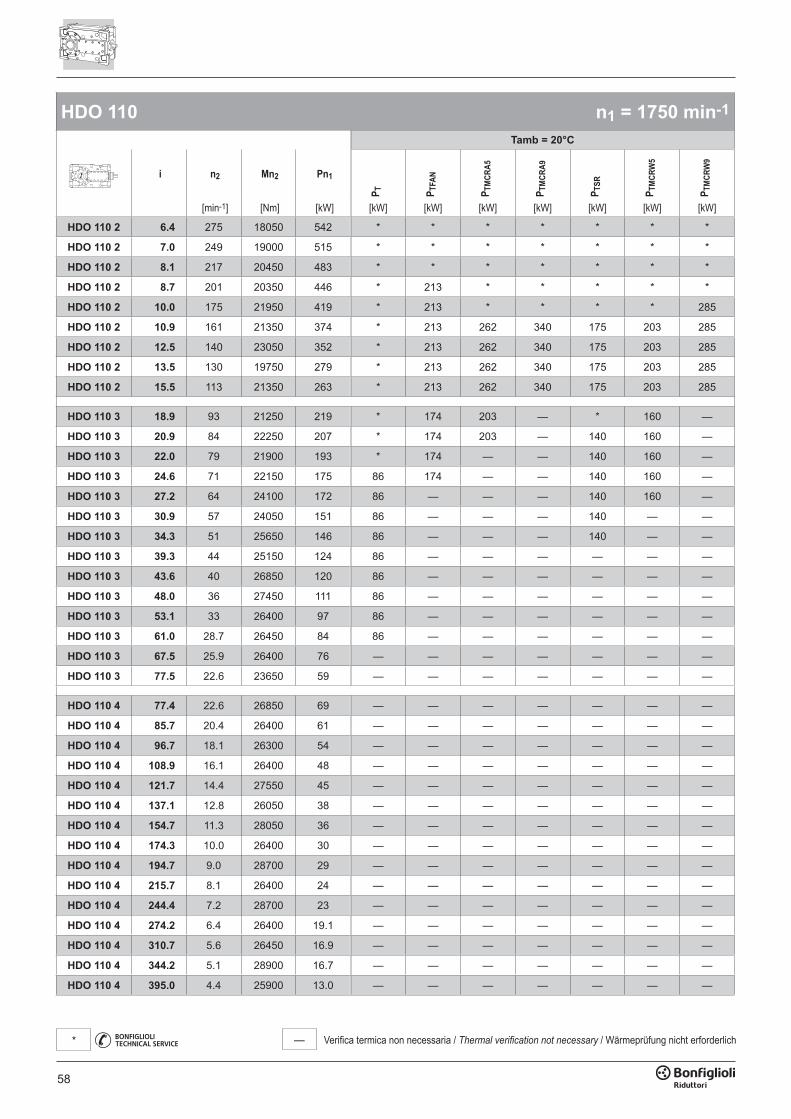
58
— Verifica termica non necessaria / Thermal verification not necessary / Wärmeprüfung nicht erforderlich*
HDO 110 n1 = 1750 min-1
Tamb = 20°C
i n2 Mn2 Pn1
P T P TFA
N
P TM
CRA5
P TM
CRA9
P TSR
P TM
CRW
5
P TM
CRW
9
[min-1] [Nm] [kW] [kW] [kW] [kW] [kW] [kW] [kW] [kW]
HDO 110 2 6.4 275 18050 542 * * * * * * *
HDO 110 2 7.0 249 19000 515 * * * * * * *
HDO 110 2 8.1 217 20450 483 * * * * * * *
HDO 110 2 8.7 201 20350 446 * 213 * * * * *
HDO 110 2 10.0 175 21950 419 * 213 * * * * 285
HDO 110 2 10.9 161 21350 374 * 213 262 340 175 203 285
HDO 110 2 12.5 140 23050 352 * 213 262 340 175 203 285
HDO 110 2 13.5 130 19750 279 * 213 262 340 175 203 285
HDO 110 2 15.5 113 21350 263 * 213 262 340 175 203 285
HDO 110 3 18.9 93 21250 219 * 174 203 — * 160 —
HDO 110 3 20.9 84 22250 207 * 174 203 — 140 160 —
HDO 110 3 22.0 79 21900 193 * 174 — — 140 160 —
HDO 110 3 24.6 71 22150 175 86 174 — — 140 160 —
HDO 110 3 27.2 64 24100 172 86 — — — 140 160 —
HDO 110 3 30.9 57 24050 151 86 — — — 140 — —
HDO 110 3 34.3 51 25650 146 86 — — — 140 — —
HDO 110 3 39.3 44 25150 124 86 — — — — — —
HDO 110 3 43.6 40 26850 120 86 — — — — — —
HDO 110 3 48.0 36 27450 111 86 — — — — — —
HDO 110 3 53.1 33 26400 97 86 — — — — — —
HDO 110 3 61.0 28.7 26450 84 86 — — — — — —
HDO 110 3 67.5 25.9 26400 76 — — — — — — —
HDO 110 3 77.5 22.6 23650 59 — — — — — — —
HDO 110 4 77.4 22.6 26850 69 — — — — — — —
HDO 110 4 85.7 20.4 26400 61 — — — — — — —
HDO 110 4 96.7 18.1 26300 54 — — — — — — —
HDO 110 4 108.9 16.1 26400 48 — — — — — — —
HDO 110 4 121.7 14.4 27550 45 — — — — — — —
HDO 110 4 137.1 12.8 26050 38 — — — — — — —
HDO 110 4 154.7 11.3 28050 36 — — — — — — —
HDO 110 4 174.3 10.0 26400 30 — — — — — — —
HDO 110 4 194.7 9.0 28700 29 — — — — — — —
HDO 110 4 215.7 8.1 26400 24 — — — — — — —
HDO 110 4 244.4 7.2 28700 23 — — — — — — —
HDO 110 4 274.2 6.4 26400 19.1 — — — — — — —
HDO 110 4 310.7 5.6 26450 16.9 — — — — — — —
HDO 110 4 344.2 5.1 28900 16.7 — — — — — — —
HDO 110 4 395.0 4.4 25900 13.0 — — — — — — —

59
— Verifica termica non necessaria / Thermal verification not necessary / Wärmeprüfung nicht erforderlich*
HDO 110 n1 = 1750 min-1
Tamb = 40°C
i n2 Mn2 Pn1
P T P TFA
N
P TM
CRA5
P TM
CRA9
P TSR
P TM
CRW
5
P TM
CRW
9
[min-1] [Nm] [kW] [kW] [kW] [kW] [kW] [kW] [kW] [kW]
HDO 110 2 6.4 275 18050 542 * * * * * * *
HDO 110 2 7.0 249 19000 515 * * * * * * *
HDO 110 2 8.1 217 20450 483 * * * * * * *
HDO 110 2 8.7 201 20350 446 * * * * * * *
HDO 110 2 10.0 175 21950 419 * 141 * * * * *
HDO 110 2 10.9 161 21350 374 * 141 * 190 * * 259
HDO 110 2 12.5 140 23050 352 * 141 * 190 * 168 259
HDO 110 2 13.5 130 19750 279 * 141 158 190 * 168 259
HDO 110 2 15.5 113 21350 263 * 141 158 190 * 168 259
HDO 110 3 18.9 93 21250 219 * 119 * * * 131 199
HDO 110 3 20.9 84 22250 207 * 119 * * * 131 199
HDO 110 3 22.0 79 21900 193 * 119 125 159 * 131 —
HDO 110 3 24.6 71 22150 175 57 119 125 159 120 131 —
HDO 110 3 27.2 64 24100 172 57 119 125 159 120 131 —
HDO 110 3 30.9 57 24050 151 57 119 125 — 120 131 —
HDO 110 3 34.3 51 25650 146 57 119 125 — 120 131 —
HDO 110 3 39.3 44 25150 124 57 119 — — 120 — —
HDO 110 3 43.6 40 26850 120 57 119 — — — — —
HDO 110 3 48.0 36 27450 111 57 — — — — — —
HDO 110 3 53.1 33 26400 97 57 — — — — — —
HDO 110 3 61.0 28.7 26450 84 57 — — — — — —
HDO 110 3 67.5 25.9 26400 76 57 — — — — — —
HDO 110 3 77.5 22.6 23650 59 57 — — — — — —
HDO 110 4 77.4 22.6 26850 69 50 — — — — — —
HDO 110 4 85.7 20.4 26400 61 50 — — — — — —
HDO 110 4 96.7 18.1 26300 54 50 — — — — — —
HDO 110 4 108.9 16.1 26400 48 — — — — — — —
HDO 110 4 121.7 14.4 27550 45 — — — — — — —
HDO 110 4 137.1 12.8 26050 38 — — — — — — —
HDO 110 4 154.7 11.3 28050 36 — — — — — — —
HDO 110 4 174.3 10.0 26400 30 — — — — — — —
HDO 110 4 194.7 9.0 28700 29 — — — — — — —
HDO 110 4 215.7 8.1 26400 24 — — — — — — —
HDO 110 4 244.4 7.2 28700 23 — — — — — — —
HDO 110 4 274.2 6.4 26400 19.1 — — — — — — —
HDO 110 4 310.7 5.6 26450 16.9 — — — — — — —
HDO 110 4 344.2 5.1 28900 16.7 — — — — — — —
HDO 110 4 395.0 4.4 25900 13.0 — — — — — — —
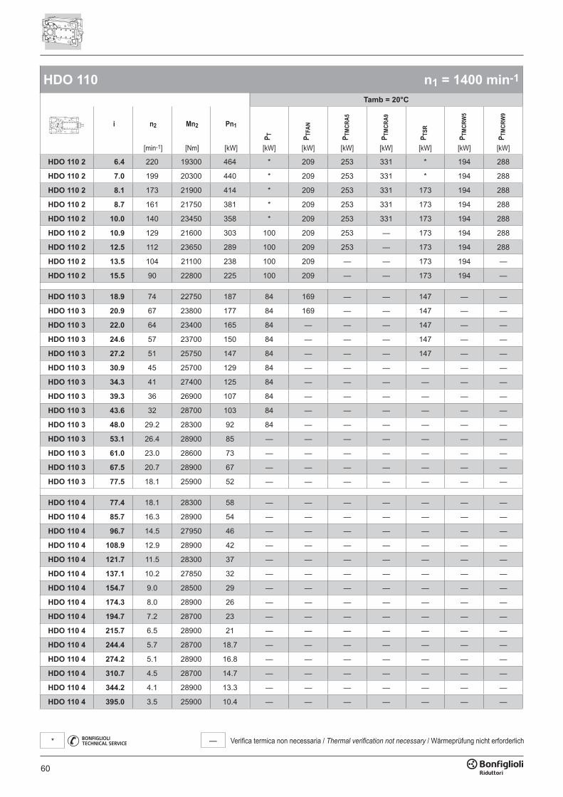
60
— Verifica termica non necessaria / Thermal verification not necessary / Wärmeprüfung nicht erforderlich*
HDO 110 n1 = 1400 min-1
Tamb = 20°C
i n2 Mn2 Pn1
P T P TFA
N
P TM
CRA5
P TM
CRA9
P TSR
P TM
CRW
5
P TM
CRW
9
[min-1] [Nm] [kW] [kW] [kW] [kW] [kW] [kW] [kW] [kW]
HDO 110 2 6.4 220 19300 464 * 209 253 331 * 194 288
HDO 110 2 7.0 199 20300 440 * 209 253 331 * 194 288
HDO 110 2 8.1 173 21900 414 * 209 253 331 173 194 288
HDO 110 2 8.7 161 21750 381 * 209 253 331 173 194 288
HDO 110 2 10.0 140 23450 358 * 209 253 331 173 194 288
HDO 110 2 10.9 129 21600 303 100 209 253 — 173 194 288
HDO 110 2 12.5 112 23650 289 100 209 253 — 173 194 288
HDO 110 2 13.5 104 21100 238 100 209 — — 173 194 —
HDO 110 2 15.5 90 22800 225 100 209 — — 173 194 —
HDO 110 3 18.9 74 22750 187 84 169 — — 147 — —
HDO 110 3 20.9 67 23800 177 84 169 — — 147 — —
HDO 110 3 22.0 64 23400 165 84 — — — 147 — —
HDO 110 3 24.6 57 23700 150 84 — — — 147 — —
HDO 110 3 27.2 51 25750 147 84 — — — 147 — —
HDO 110 3 30.9 45 25700 129 84 — — — — — —
HDO 110 3 34.3 41 27400 125 84 — — — — — —
HDO 110 3 39.3 36 26900 107 84 — — — — — —
HDO 110 3 43.6 32 28700 103 84 — — — — — —
HDO 110 3 48.0 29.2 28300 92 84 — — — — — —
HDO 110 3 53.1 26.4 28900 85 — — — — — — —
HDO 110 3 61.0 23.0 28600 73 — — — — — — —
HDO 110 3 67.5 20.7 28900 67 — — — — — — —
HDO 110 3 77.5 18.1 25900 52 — — — — — — —
HDO 110 4 77.4 18.1 28300 58 — — — — — — —
HDO 110 4 85.7 16.3 28900 54 — — — — — — —
HDO 110 4 96.7 14.5 27950 46 — — — — — — —
HDO 110 4 108.9 12.9 28900 42 — — — — — — —
HDO 110 4 121.7 11.5 28300 37 — — — — — — —
HDO 110 4 137.1 10.2 27850 32 — — — — — — —
HDO 110 4 154.7 9.0 28500 29 — — — — — — —
HDO 110 4 174.3 8.0 28900 26 — — — — — — —
HDO 110 4 194.7 7.2 28700 23 — — — — — — —
HDO 110 4 215.7 6.5 28900 21 — — — — — — —
HDO 110 4 244.4 5.7 28700 18.7 — — — — — — —
HDO 110 4 274.2 5.1 28900 16.8 — — — — — — —
HDO 110 4 310.7 4.5 28700 14.7 — — — — — — —
HDO 110 4 344.2 4.1 28900 13.3 — — — — — — —
HDO 110 4 395.0 3.5 25900 10.4 — — — — — — —
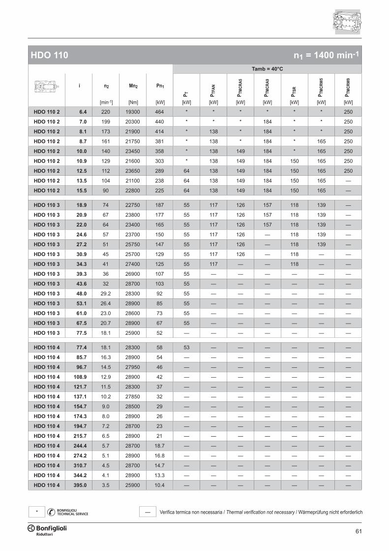
61
— Verifica termica non necessaria / Thermal verification not necessary / Wärmeprüfung nicht erforderlich*
HDO 110 n1 = 1400 min-1
Tamb = 40°C
i n2 Mn2 Pn1
P T P TFA
N
P TM
CRA5
P TM
CRA9
P TSR
P TM
CRW
5
P TM
CRW
9
[min-1] [Nm] [kW] [kW] [kW] [kW] [kW] [kW] [kW] [kW]
HDO 110 2 6.4 220 19300 464 * * * * * * 250
HDO 110 2 7.0 199 20300 440 * * * 184 * * 250
HDO 110 2 8.1 173 21900 414 * 138 * 184 * * 250
HDO 110 2 8.7 161 21750 381 * 138 * 184 * 165 250
HDO 110 2 10.0 140 23450 358 * 138 149 184 * 165 250
HDO 110 2 10.9 129 21600 303 * 138 149 184 150 165 250
HDO 110 2 12.5 112 23650 289 64 138 149 184 150 165 250
HDO 110 2 13.5 104 21100 238 64 138 149 184 150 165 —
HDO 110 2 15.5 90 22800 225 64 138 149 184 150 165 —
HDO 110 3 18.9 74 22750 187 55 117 126 157 118 139 —
HDO 110 3 20.9 67 23800 177 55 117 126 157 118 139 —
HDO 110 3 22.0 64 23400 165 55 117 126 157 118 139 —
HDO 110 3 24.6 57 23700 150 55 117 126 — 118 139 —
HDO 110 3 27.2 51 25750 147 55 117 126 — 118 139 —
HDO 110 3 30.9 45 25700 129 55 117 126 — 118 — —
HDO 110 3 34.3 41 27400 125 55 117 — — 118 — —
HDO 110 3 39.3 36 26900 107 55 — — — — — —
HDO 110 3 43.6 32 28700 103 55 — — — — — —
HDO 110 3 48.0 29.2 28300 92 55 — — — — — —
HDO 110 3 53.1 26.4 28900 85 55 — — — — — —
HDO 110 3 61.0 23.0 28600 73 55 — — — — — —
HDO 110 3 67.5 20.7 28900 67 55 — — — — — —
HDO 110 3 77.5 18.1 25900 52 — — — — — — —
HDO 110 4 77.4 18.1 28300 58 53 — — — — — —
HDO 110 4 85.7 16.3 28900 54 — — — — — — —
HDO 110 4 96.7 14.5 27950 46 — — — — — — —
HDO 110 4 108.9 12.9 28900 42 — — — — — — —
HDO 110 4 121.7 11.5 28300 37 — — — — — — —
HDO 110 4 137.1 10.2 27850 32 — — — — — — —
HDO 110 4 154.7 9.0 28500 29 — — — — — — —
HDO 110 4 174.3 8.0 28900 26 — — — — — — —
HDO 110 4 194.7 7.2 28700 23 — — — — — — —
HDO 110 4 215.7 6.5 28900 21 — — — — — — —
HDO 110 4 244.4 5.7 28700 18.7 — — — — — — —
HDO 110 4 274.2 5.1 28900 16.8 — — — — — — —
HDO 110 4 310.7 4.5 28700 14.7 — — — — — — —
HDO 110 4 344.2 4.1 28900 13.3 — — — — — — —
HDO 110 4 395.0 3.5 25900 10.4 — — — — — — —
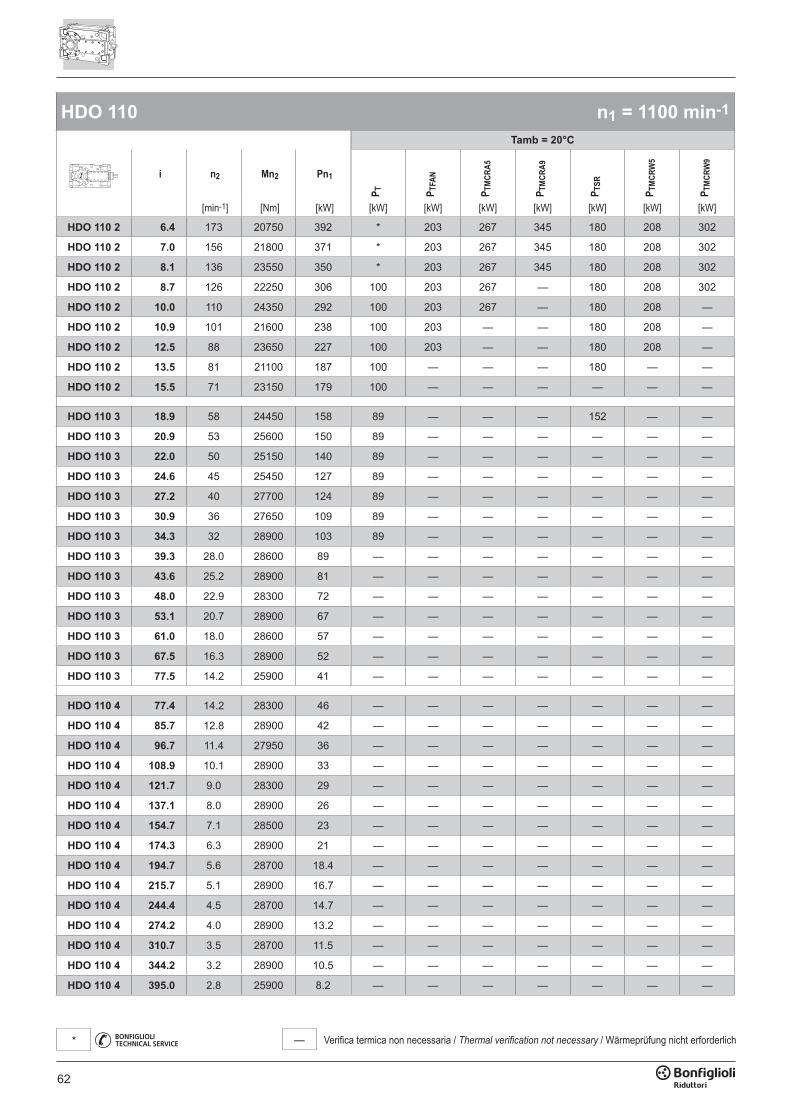
62
— Verifica termica non necessaria / Thermal verification not necessary / Wärmeprüfung nicht erforderlich*
HDO 110 n1 = 1100 min-1
Tamb = 20°C
i n2 Mn2 Pn1
P T P TFA
N
P TM
CRA5
P TM
CRA9
P TSR
P TM
CRW
5
P TM
CRW
9
[min-1] [Nm] [kW] [kW] [kW] [kW] [kW] [kW] [kW] [kW]
HDO 110 2 6.4 173 20750 392 * 203 267 345 180 208 302
HDO 110 2 7.0 156 21800 371 * 203 267 345 180 208 302
HDO 110 2 8.1 136 23550 350 * 203 267 345 180 208 302
HDO 110 2 8.7 126 22250 306 100 203 267 — 180 208 302
HDO 110 2 10.0 110 24350 292 100 203 267 — 180 208 —
HDO 110 2 10.9 101 21600 238 100 203 — — 180 208 —
HDO 110 2 12.5 88 23650 227 100 203 — — 180 208 —
HDO 110 2 13.5 81 21100 187 100 — — — 180 — —
HDO 110 2 15.5 71 23150 179 100 — — — — — —
HDO 110 3 18.9 58 24450 158 89 — — — 152 — —
HDO 110 3 20.9 53 25600 150 89 — — — — — —
HDO 110 3 22.0 50 25150 140 89 — — — — — —
HDO 110 3 24.6 45 25450 127 89 — — — — — —
HDO 110 3 27.2 40 27700 124 89 — — — — — —
HDO 110 3 30.9 36 27650 109 89 — — — — — —
HDO 110 3 34.3 32 28900 103 89 — — — — — —
HDO 110 3 39.3 28.0 28600 89 — — — — — — —
HDO 110 3 43.6 25.2 28900 81 — — — — — — —
HDO 110 3 48.0 22.9 28300 72 — — — — — — —
HDO 110 3 53.1 20.7 28900 67 — — — — — — —
HDO 110 3 61.0 18.0 28600 57 — — — — — — —
HDO 110 3 67.5 16.3 28900 52 — — — — — — —
HDO 110 3 77.5 14.2 25900 41 — — — — — — —
HDO 110 4 77.4 14.2 28300 46 — — — — — — —
HDO 110 4 85.7 12.8 28900 42 — — — — — — —
HDO 110 4 96.7 11.4 27950 36 — — — — — — —
HDO 110 4 108.9 10.1 28900 33 — — — — — — —
HDO 110 4 121.7 9.0 28300 29 — — — — — — —
HDO 110 4 137.1 8.0 28900 26 — — — — — — —
HDO 110 4 154.7 7.1 28500 23 — — — — — — —
HDO 110 4 174.3 6.3 28900 21 — — — — — — —
HDO 110 4 194.7 5.6 28700 18.4 — — — — — — —
HDO 110 4 215.7 5.1 28900 16.7 — — — — — — —
HDO 110 4 244.4 4.5 28700 14.7 — — — — — — —
HDO 110 4 274.2 4.0 28900 13.2 — — — — — — —
HDO 110 4 310.7 3.5 28700 11.5 — — — — — — —
HDO 110 4 344.2 3.2 28900 10.5 — — — — — — —
HDO 110 4 395.0 2.8 25900 8.2 — — — — — — —
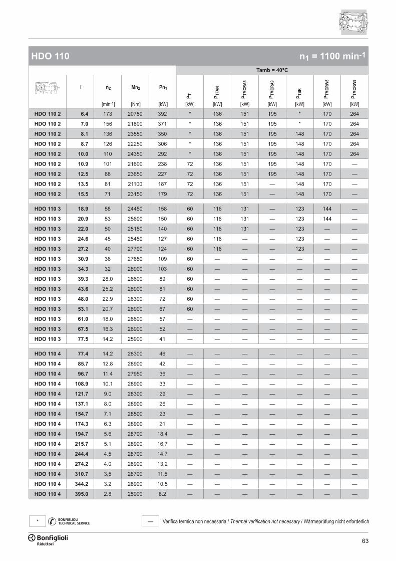
63
— Verifica termica non necessaria / Thermal verification not necessary / Wärmeprüfung nicht erforderlich*
HDO 110 n1 = 1100 min-1
Tamb = 40°C
i n2 Mn2 Pn1
P T P TFA
N
P TM
CRA5
P TM
CRA9
P TSR
P TM
CRW
5
P TM
CRW
9
[min-1] [Nm] [kW] [kW] [kW] [kW] [kW] [kW] [kW] [kW]
HDO 110 2 6.4 173 20750 392 * 136 151 195 * 170 264
HDO 110 2 7.0 156 21800 371 * 136 151 195 * 170 264
HDO 110 2 8.1 136 23550 350 * 136 151 195 148 170 264
HDO 110 2 8.7 126 22250 306 * 136 151 195 148 170 264
HDO 110 2 10.0 110 24350 292 * 136 151 195 148 170 264
HDO 110 2 10.9 101 21600 238 72 136 151 195 148 170 —
HDO 110 2 12.5 88 23650 227 72 136 151 195 148 170 —
HDO 110 2 13.5 81 21100 187 72 136 151 — 148 170 —
HDO 110 2 15.5 71 23150 179 72 136 151 — 148 170 —
HDO 110 3 18.9 58 24450 158 60 116 131 — 123 144 —
HDO 110 3 20.9 53 25600 150 60 116 131 — 123 144 —
HDO 110 3 22.0 50 25150 140 60 116 131 — 123 — —
HDO 110 3 24.6 45 25450 127 60 116 — — 123 — —
HDO 110 3 27.2 40 27700 124 60 116 — — 123 — —
HDO 110 3 30.9 36 27650 109 60 — — — — — —
HDO 110 3 34.3 32 28900 103 60 — — — — — —
HDO 110 3 39.3 28.0 28600 89 60 — — — — — —
HDO 110 3 43.6 25.2 28900 81 60 — — — — — —
HDO 110 3 48.0 22.9 28300 72 60 — — — — — —
HDO 110 3 53.1 20.7 28900 67 60 — — — — — —
HDO 110 3 61.0 18.0 28600 57 — — — — — — —
HDO 110 3 67.5 16.3 28900 52 — — — — — — —
HDO 110 3 77.5 14.2 25900 41 — — — — — — —
HDO 110 4 77.4 14.2 28300 46 — — — — — — —
HDO 110 4 85.7 12.8 28900 42 — — — — — — —
HDO 110 4 96.7 11.4 27950 36 — — — — — — —
HDO 110 4 108.9 10.1 28900 33 — — — — — — —
HDO 110 4 121.7 9.0 28300 29 — — — — — — —
HDO 110 4 137.1 8.0 28900 26 — — — — — — —
HDO 110 4 154.7 7.1 28500 23 — — — — — — —
HDO 110 4 174.3 6.3 28900 21 — — — — — — —
HDO 110 4 194.7 5.6 28700 18.4 — — — — — — —
HDO 110 4 215.7 5.1 28900 16.7 — — — — — — —
HDO 110 4 244.4 4.5 28700 14.7 — — — — — — —
HDO 110 4 274.2 4.0 28900 13.2 — — — — — — —
HDO 110 4 310.7 3.5 28700 11.5 — — — — — — —
HDO 110 4 344.2 3.2 28900 10.5 — — — — — — —
HDO 110 4 395.0 2.8 25900 8.2 — — — — — — —
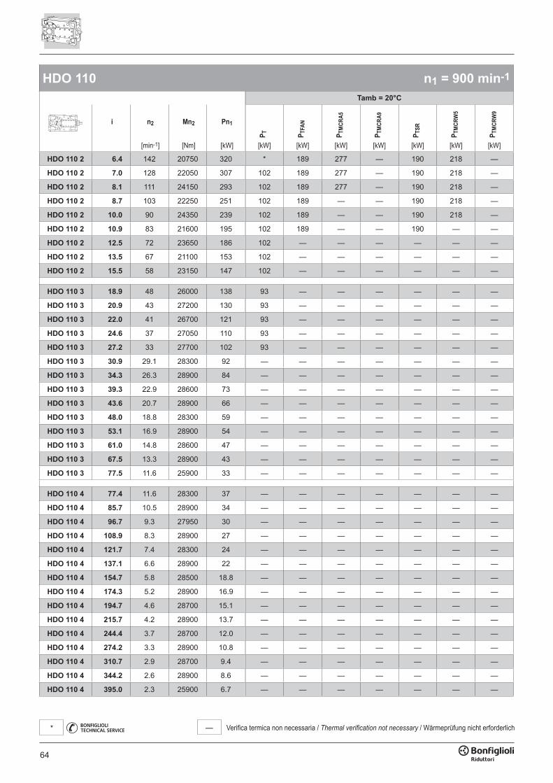
64
— Verifica termica non necessaria / Thermal verification not necessary / Wärmeprüfung nicht erforderlich*
HDO 110 n1 = 900 min-1
Tamb = 20°C
i n2 Mn2 Pn1
P T P TFA
N
P TM
CRA5
P TM
CRA9
P TSR
P TM
CRW
5
P TM
CRW
9
[min-1] [Nm] [kW] [kW] [kW] [kW] [kW] [kW] [kW] [kW]
HDO 110 2 6.4 142 20750 320 * 189 277 — 190 218 —
HDO 110 2 7.0 128 22050 307 102 189 277 — 190 218 —
HDO 110 2 8.1 111 24150 293 102 189 277 — 190 218 —
HDO 110 2 8.7 103 22250 251 102 189 — — 190 218 —
HDO 110 2 10.0 90 24350 239 102 189 — — 190 218 —
HDO 110 2 10.9 83 21600 195 102 189 — — 190 — —
HDO 110 2 12.5 72 23650 186 102 — — — — — —
HDO 110 2 13.5 67 21100 153 102 — — — — — —
HDO 110 2 15.5 58 23150 147 102 — — — — — —
HDO 110 3 18.9 48 26000 138 93 — — — — — —
HDO 110 3 20.9 43 27200 130 93 — — — — — —
HDO 110 3 22.0 41 26700 121 93 — — — — — —
HDO 110 3 24.6 37 27050 110 93 — — — — — —
HDO 110 3 27.2 33 27700 102 93 — — — — — —
HDO 110 3 30.9 29.1 28300 92 — — — — — — —
HDO 110 3 34.3 26.3 28900 84 — — — — — — —
HDO 110 3 39.3 22.9 28600 73 — — — — — — —
HDO 110 3 43.6 20.7 28900 66 — — — — — — —
HDO 110 3 48.0 18.8 28300 59 — — — — — — —
HDO 110 3 53.1 16.9 28900 54 — — — — — — —
HDO 110 3 61.0 14.8 28600 47 — — — — — — —
HDO 110 3 67.5 13.3 28900 43 — — — — — — —
HDO 110 3 77.5 11.6 25900 33 — — — — — — —
HDO 110 4 77.4 11.6 28300 37 — — — — — — —
HDO 110 4 85.7 10.5 28900 34 — — — — — — —
HDO 110 4 96.7 9.3 27950 30 — — — — — — —
HDO 110 4 108.9 8.3 28900 27 — — — — — — —
HDO 110 4 121.7 7.4 28300 24 — — — — — — —
HDO 110 4 137.1 6.6 28900 22 — — — — — — —
HDO 110 4 154.7 5.8 28500 18.8 — — — — — — —
HDO 110 4 174.3 5.2 28900 16.9 — — — — — — —
HDO 110 4 194.7 4.6 28700 15.1 — — — — — — —
HDO 110 4 215.7 4.2 28900 13.7 — — — — — — —
HDO 110 4 244.4 3.7 28700 12.0 — — — — — — —
HDO 110 4 274.2 3.3 28900 10.8 — — — — — — —
HDO 110 4 310.7 2.9 28700 9.4 — — — — — — —
HDO 110 4 344.2 2.6 28900 8.6 — — — — — — —
HDO 110 4 395.0 2.3 25900 6.7 — — — — — — —
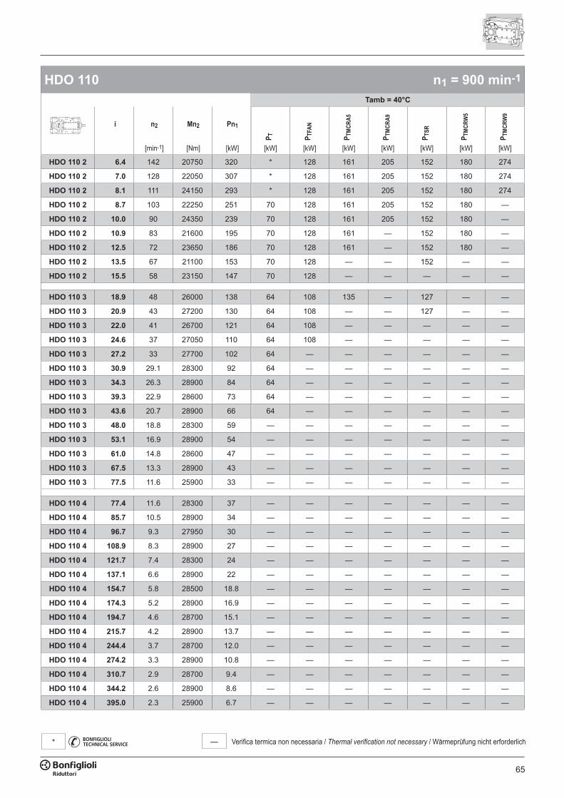
65
— Verifica termica non necessaria / Thermal verification not necessary / Wärmeprüfung nicht erforderlich*
HDO 110 n1 = 900 min-1
Tamb = 40°C
i n2 Mn2 Pn1
P T P TFA
N
P TM
CRA5
P TM
CRA9
P TSR
P TM
CRW
5
P TM
CRW
9
[min-1] [Nm] [kW] [kW] [kW] [kW] [kW] [kW] [kW] [kW]
HDO 110 2 6.4 142 20750 320 * 128 161 205 152 180 274
HDO 110 2 7.0 128 22050 307 * 128 161 205 152 180 274
HDO 110 2 8.1 111 24150 293 * 128 161 205 152 180 274
HDO 110 2 8.7 103 22250 251 70 128 161 205 152 180 —
HDO 110 2 10.0 90 24350 239 70 128 161 205 152 180 —
HDO 110 2 10.9 83 21600 195 70 128 161 — 152 180 —
HDO 110 2 12.5 72 23650 186 70 128 161 — 152 180 —
HDO 110 2 13.5 67 21100 153 70 128 — — 152 — —
HDO 110 2 15.5 58 23150 147 70 128 — — — — —
HDO 110 3 18.9 48 26000 138 64 108 135 — 127 — —
HDO 110 3 20.9 43 27200 130 64 108 — — 127 — —
HDO 110 3 22.0 41 26700 121 64 108 — — — — —
HDO 110 3 24.6 37 27050 110 64 108 — — — — —
HDO 110 3 27.2 33 27700 102 64 — — — — — —
HDO 110 3 30.9 29.1 28300 92 64 — — — — — —
HDO 110 3 34.3 26.3 28900 84 64 — — — — — —
HDO 110 3 39.3 22.9 28600 73 64 — — — — — —
HDO 110 3 43.6 20.7 28900 66 64 — — — — — —
HDO 110 3 48.0 18.8 28300 59 — — — — — — —
HDO 110 3 53.1 16.9 28900 54 — — — — — — —
HDO 110 3 61.0 14.8 28600 47 — — — — — — —
HDO 110 3 67.5 13.3 28900 43 — — — — — — —
HDO 110 3 77.5 11.6 25900 33 — — — — — — —
HDO 110 4 77.4 11.6 28300 37 — — — — — — —
HDO 110 4 85.7 10.5 28900 34 — — — — — — —
HDO 110 4 96.7 9.3 27950 30 — — — — — — —
HDO 110 4 108.9 8.3 28900 27 — — — — — — —
HDO 110 4 121.7 7.4 28300 24 — — — — — — —
HDO 110 4 137.1 6.6 28900 22 — — — — — — —
HDO 110 4 154.7 5.8 28500 18.8 — — — — — — —
HDO 110 4 174.3 5.2 28900 16.9 — — — — — — —
HDO 110 4 194.7 4.6 28700 15.1 — — — — — — —
HDO 110 4 215.7 4.2 28900 13.7 — — — — — — —
HDO 110 4 244.4 3.7 28700 12.0 — — — — — — —
HDO 110 4 274.2 3.3 28900 10.8 — — — — — — —
HDO 110 4 310.7 2.9 28700 9.4 — — — — — — —
HDO 110 4 344.2 2.6 28900 8.6 — — — — — — —
HDO 110 4 395.0 2.3 25900 6.7 — — — — — — —
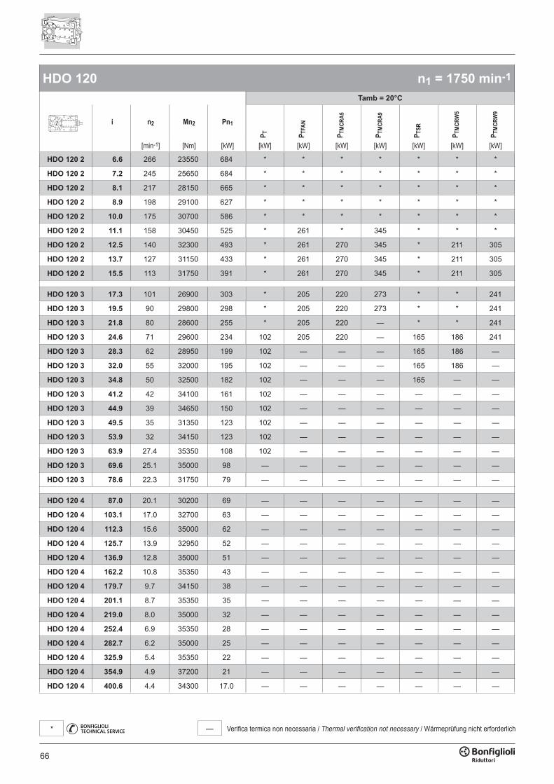
66
— Verifica termica non necessaria / Thermal verification not necessary / Wärmeprüfung nicht erforderlich*
HDO 120 n1 = 1750 min-1
Tamb = 20°C
i n2 Mn2 Pn1
P T P TFA
N
P TM
CRA5
P TM
CRA9
P TSR
P TM
CRW
5
P TM
CRW
9
[min-1] [Nm] [kW] [kW] [kW] [kW] [kW] [kW] [kW] [kW]
HDO 120 2 6.6 266 23550 684 * * * * * * *
HDO 120 2 7.2 245 25650 684 * * * * * * *
HDO 120 2 8.1 217 28150 665 * * * * * * *
HDO 120 2 8.9 198 29100 627 * * * * * * *
HDO 120 2 10.0 175 30700 586 * * * * * * *
HDO 120 2 11.1 158 30450 525 * 261 * 345 * * *
HDO 120 2 12.5 140 32300 493 * 261 270 345 * 211 305
HDO 120 2 13.7 127 31150 433 * 261 270 345 * 211 305
HDO 120 2 15.5 113 31750 391 * 261 270 345 * 211 305
HDO 120 3 17.3 101 26900 303 * 205 220 273 * * 241
HDO 120 3 19.5 90 29800 298 * 205 220 273 * * 241
HDO 120 3 21.8 80 28600 255 * 205 220 — * * 241
HDO 120 3 24.6 71 29600 234 102 205 220 — 165 186 241
HDO 120 3 28.3 62 28950 199 102 — — — 165 186 —
HDO 120 3 32.0 55 32000 195 102 — — — 165 186 —
HDO 120 3 34.8 50 32500 182 102 — — — 165 — —
HDO 120 3 41.2 42 34100 161 102 — — — — — —
HDO 120 3 44.9 39 34650 150 102 — — — — — —
HDO 120 3 49.5 35 31350 123 102 — — — — — —
HDO 120 3 53.9 32 34150 123 102 — — — — — —
HDO 120 3 63.9 27.4 35350 108 102 — — — — — —
HDO 120 3 69.6 25.1 35000 98 — — — — — — —
HDO 120 3 78.6 22.3 31750 79 — — — — — — —
HDO 120 4 87.0 20.1 30200 69 — — — — — — —
HDO 120 4 103.1 17.0 32700 63 — — — — — — —
HDO 120 4 112.3 15.6 35000 62 — — — — — — —
HDO 120 4 125.7 13.9 32950 52 — — — — — — —
HDO 120 4 136.9 12.8 35000 51 — — — — — — —
HDO 120 4 162.2 10.8 35350 43 — — — — — — —
HDO 120 4 179.7 9.7 34150 38 — — — — — — —
HDO 120 4 201.1 8.7 35350 35 — — — — — — —
HDO 120 4 219.0 8.0 35000 32 — — — — — — —
HDO 120 4 252.4 6.9 35350 28 — — — — — — —
HDO 120 4 282.7 6.2 35000 25 — — — — — — —
HDO 120 4 325.9 5.4 35350 22 — — — — — — —
HDO 120 4 354.9 4.9 37200 21 — — — — — — —
HDO 120 4 400.6 4.4 34300 17.0 — — — — — — —
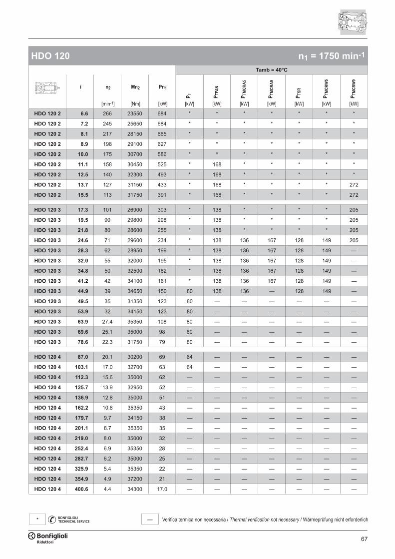
67
— Verifica termica non necessaria / Thermal verification not necessary / Wärmeprüfung nicht erforderlich*
HDO 120 n1 = 1750 min-1
Tamb = 40°C
i n2 Mn2 Pn1
P T P TFA
N
P TM
CRA5
P TM
CRA9
P TSR
P TM
CRW
5
P TM
CRW
9
[min-1] [Nm] [kW] [kW] [kW] [kW] [kW] [kW] [kW] [kW]
HDO 120 2 6.6 266 23550 684 * * * * * * *
HDO 120 2 7.2 245 25650 684 * * * * * * *
HDO 120 2 8.1 217 28150 665 * * * * * * *
HDO 120 2 8.9 198 29100 627 * * * * * * *
HDO 120 2 10.0 175 30700 586 * * * * * * *
HDO 120 2 11.1 158 30450 525 * 168 * * * * *
HDO 120 2 12.5 140 32300 493 * 168 * * * * *
HDO 120 2 13.7 127 31150 433 * 168 * * * * 272
HDO 120 2 15.5 113 31750 391 * 168 * * * * 272
HDO 120 3 17.3 101 26900 303 * 138 * * * * 205
HDO 120 3 19.5 90 29800 298 * 138 * * * * 205
HDO 120 3 21.8 80 28600 255 * 138 * * * * 205
HDO 120 3 24.6 71 29600 234 * 138 136 167 128 149 205
HDO 120 3 28.3 62 28950 199 * 138 136 167 128 149 —
HDO 120 3 32.0 55 32000 195 * 138 136 167 128 149 —
HDO 120 3 34.8 50 32500 182 * 138 136 167 128 149 —
HDO 120 3 41.2 42 34100 161 * 138 136 167 128 149 —
HDO 120 3 44.9 39 34650 150 80 138 136 — 128 149 —
HDO 120 3 49.5 35 31350 123 80 — — — — — —
HDO 120 3 53.9 32 34150 123 80 — — — — — —
HDO 120 3 63.9 27.4 35350 108 80 — — — — — —
HDO 120 3 69.6 25.1 35000 98 80 — — — — — —
HDO 120 3 78.6 22.3 31750 79 80 — — — — — —
HDO 120 4 87.0 20.1 30200 69 64 — — — — — —
HDO 120 4 103.1 17.0 32700 63 64 — — — — — —
HDO 120 4 112.3 15.6 35000 62 — — — — — — —
HDO 120 4 125.7 13.9 32950 52 — — — — — — —
HDO 120 4 136.9 12.8 35000 51 — — — — — — —
HDO 120 4 162.2 10.8 35350 43 — — — — — — —
HDO 120 4 179.7 9.7 34150 38 — — — — — — —
HDO 120 4 201.1 8.7 35350 35 — — — — — — —
HDO 120 4 219.0 8.0 35000 32 — — — — — — —
HDO 120 4 252.4 6.9 35350 28 — — — — — — —
HDO 120 4 282.7 6.2 35000 25 — — — — — — —
HDO 120 4 325.9 5.4 35350 22 — — — — — — —
HDO 120 4 354.9 4.9 37200 21 — — — — — — —
HDO 120 4 400.6 4.4 34300 17.0 — — — — — — —
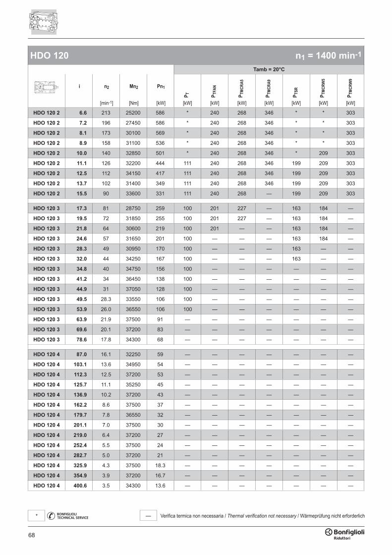
68
— Verifica termica non necessaria / Thermal verification not necessary / Wärmeprüfung nicht erforderlich*
HDO 120 n1 = 1400 min-1
Tamb = 20°C
i n2 Mn2 Pn1
P T P TFA
N
P TM
CRA5
P TM
CRA9
P TSR
P TM
CRW
5
P TM
CRW
9
[min-1] [Nm] [kW] [kW] [kW] [kW] [kW] [kW] [kW] [kW]
HDO 120 2 6.6 213 25200 586 * 240 268 346 * * 303
HDO 120 2 7.2 196 27450 586 * 240 268 346 * * 303
HDO 120 2 8.1 173 30100 569 * 240 268 346 * * 303
HDO 120 2 8.9 158 31100 536 * 240 268 346 * * 303
HDO 120 2 10.0 140 32850 501 * 240 268 346 * 209 303
HDO 120 2 11.1 126 32200 444 111 240 268 346 199 209 303
HDO 120 2 12.5 112 34150 417 111 240 268 346 199 209 303
HDO 120 2 13.7 102 31400 349 111 240 268 346 199 209 303
HDO 120 2 15.5 90 33600 331 111 240 268 — 199 209 303
HDO 120 3 17.3 81 28750 259 100 201 227 — 163 184 —
HDO 120 3 19.5 72 31850 255 100 201 227 — 163 184 —
HDO 120 3 21.8 64 30600 219 100 201 — — 163 184 —
HDO 120 3 24.6 57 31650 201 100 — — — 163 184 —
HDO 120 3 28.3 49 30950 170 100 — — — 163 — —
HDO 120 3 32.0 44 34250 167 100 — — — 163 — —
HDO 120 3 34.8 40 34750 156 100 — — — — — —
HDO 120 3 41.2 34 36450 138 100 — — — — — —
HDO 120 3 44.9 31 37050 128 100 — — — — — —
HDO 120 3 49.5 28.3 33550 106 100 — — — — — —
HDO 120 3 53.9 26.0 36550 106 100 — — — — — —
HDO 120 3 63.9 21.9 37500 91 — — — — — — —
HDO 120 3 69.6 20.1 37200 83 — — — — — — —
HDO 120 3 78.6 17.8 34300 68 — — — — — — —
HDO 120 4 87.0 16.1 32250 59 — — — — — — —
HDO 120 4 103.1 13.6 34950 54 — — — — — — —
HDO 120 4 112.3 12.5 37200 53 — — — — — — —
HDO 120 4 125.7 11.1 35250 45 — — — — — — —
HDO 120 4 136.9 10.2 37200 43 — — — — — — —
HDO 120 4 162.2 8.6 37500 37 — — — — — — —
HDO 120 4 179.7 7.8 36550 32 — — — — — — —
HDO 120 4 201.1 7.0 37500 30 — — — — — — —
HDO 120 4 219.0 6.4 37200 27 — — — — — — —
HDO 120 4 252.4 5.5 37500 24 — — — — — — —
HDO 120 4 282.7 5.0 37200 21 — — — — — — —
HDO 120 4 325.9 4.3 37500 18.3 — — — — — — —
HDO 120 4 354.9 3.9 37200 16.7 — — — — — — —
HDO 120 4 400.6 3.5 34300 13.6 — — — — — — —
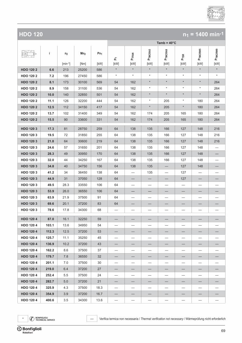
69
— Verifica termica non necessaria / Thermal verification not necessary / Wärmeprüfung nicht erforderlich*
HDO 120 n1 = 1400 min-1
Tamb = 40°C
i n2 Mn2 Pn1
P T P TFA
N
P TM
CRA5
P TM
CRA9
P TSR
P TM
CRW
5
P TM
CRW
9
[min-1] [Nm] [kW] [kW] [kW] [kW] [kW] [kW] [kW] [kW]
HDO 120 2 6.6 213 25200 586 * * * * * * *
HDO 120 2 7.2 196 27450 586 * * * * * * *
HDO 120 2 8.1 173 30100 569 54 162 * * * * 264
HDO 120 2 8.9 158 31100 536 54 162 * * * * 264
HDO 120 2 10.0 140 32850 501 54 162 * * * * 264
HDO 120 2 11.1 126 32200 444 54 162 * 205 * 180 264
HDO 120 2 12.5 112 34150 417 54 162 * 205 * 180 264
HDO 120 2 13.7 102 31400 349 54 162 174 205 165 180 264
HDO 120 2 15.5 90 33600 331 54 162 174 205 165 180 264
HDO 120 3 17.3 81 28750 259 64 138 135 166 127 148 216
HDO 120 3 19.5 72 31850 255 64 138 135 166 127 148 216
HDO 120 3 21.8 64 30600 219 64 138 135 166 127 148 216
HDO 120 3 24.6 57 31650 201 64 138 135 166 127 148 —
HDO 120 3 28.3 49 30950 170 64 138 135 166 127 148 —
HDO 120 3 32.0 44 34250 167 64 138 135 166 127 148 —
HDO 120 3 34.8 40 34750 156 64 138 135 — 127 148 —
HDO 120 3 41.2 34 36450 138 64 — 135 — 127 — —
HDO 120 3 44.9 31 37050 128 64 — — — 127 — —
HDO 120 3 49.5 28.3 33550 106 64 — — — — — —
HDO 120 3 53.9 26.0 36550 106 64 — — — — — —
HDO 120 3 63.9 21.9 37500 91 64 — — — — — —
HDO 120 3 69.6 20.1 37200 83 64 — — — — — —
HDO 120 3 78.6 17.8 34300 68 — — — — — — —
HDO 120 4 87.0 16.1 32250 59 — — — — — — —
HDO 120 4 103.1 13.6 34950 54 — — — — — — —
HDO 120 4 112.3 12.5 37200 53 — — — — — — —
HDO 120 4 125.7 11.1 35250 45 — — — — — — —
HDO 120 4 136.9 10.2 37200 43 — — — — — — —
HDO 120 4 162.2 8.6 37500 37 — — — — — — —
HDO 120 4 179.7 7.8 36550 32 — — — — — — —
HDO 120 4 201.1 7.0 37500 30 — — — — — — —
HDO 120 4 219.0 6.4 37200 27 — — — — — — —
HDO 120 4 252.4 5.5 37500 24 — — — — — — —
HDO 120 4 282.7 5.0 37200 21 — — — — — — —
HDO 120 4 325.9 4.3 37500 18.3 — — — — — — —
HDO 120 4 354.9 3.9 37200 16.7 — — — — — — —
HDO 120 4 400.6 3.5 34300 13.6 — — — — — — —

70
— Verifica termica non necessaria / Thermal verification not necessary / Wärmeprüfung nicht erforderlich*
HDO 120 n1 = 1100 min-1
Tamb = 20°C
i n2 Mn2 Pn1
P T P TFA
N
P TM
CRA5
P TM
CRA9
P TSR
P TM
CRW
5
P TM
CRW
9
[min-1] [Nm] [kW] [kW] [kW] [kW] [kW] [kW] [kW] [kW]
HDO 120 2 6.6 167 27100 495 * 243 286 364 199 227 321
HDO 120 2 7.2 154 29500 495 * 243 286 364 199 227 321
HDO 120 2 8.1 136 32350 480 * 243 286 364 199 227 321
HDO 120 2 8.9 124 33150 449 109 243 286 364 199 227 321
HDO 120 2 10.0 110 32850 394 109 243 286 364 199 227 321
HDO 120 2 11.1 99 32200 349 109 243 286 — 199 227 321
HDO 120 2 12.5 88 34300 329 109 243 286 — 199 227 321
HDO 120 2 13.7 80 31400 274 109 243 — — 199 227 —
HDO 120 2 15.5 71 33600 260 109 243 — — 199 227 —
HDO 120 3 17.3 64 30650 217 108 199 — — 171 192 —
HDO 120 3 19.5 56 34250 215 108 199 — — 171 192 —
HDO 120 3 21.8 50 32900 185 108 — — — 171 — —
HDO 120 3 24.6 45 34000 169 108 — — — — — —
HDO 120 3 28.3 39 33300 144 108 — — — — — —
HDO 120 3 32.0 34 36600 140 108 — — — — — —
HDO 120 3 34.8 32 37200 131 108 — — — — — —
HDO 120 3 41.2 26.7 37500 111 108 — — — — — —
HDO 120 3 44.9 24.5 37200 101 — — — — — — —
HDO 120 3 49.5 22.2 34200 85 — — — — — — —
HDO 120 3 53.9 20.4 37200 84 — — — — — — —
HDO 120 3 63.9 17.2 37500 72 — — — — — — —
HDO 120 3 69.6 15.8 37200 65 — — — — — — —
HDO 120 3 78.6 14.0 34300 53 — — — — — — —
HDO 120 4 87.0 12.6 34700 50 — — — — — — —
HDO 120 4 103.1 10.7 35400 43 — — — — — — —
HDO 120 4 112.3 9.8 35200 39 — — — — — — —
HDO 120 4 125.7 8.8 37250 37 — — — — — — —
HDO 120 4 136.9 8.0 37200 34 — — — — — — —
HDO 120 4 162.2 6.8 37500 29 — — — — — — —
HDO 120 4 179.7 6.1 36550 25 — — — — — — —
HDO 120 4 201.1 5.5 37500 23 — — — — — — —
HDO 120 4 219.0 5.0 37200 21 — — — — — — —
HDO 120 4 252.4 4.4 37500 18.6 — — — — — — —
HDO 120 4 282.7 3.9 37200 16.4 — — — — — — —
HDO 120 4 325.9 3.4 37500 14.4 — — — — — — —
HDO 120 4 354.9 3.1 37200 13.1 — — — — — — —
HDO 120 4 400.6 2.7 34300 10.7 — — — — — — —
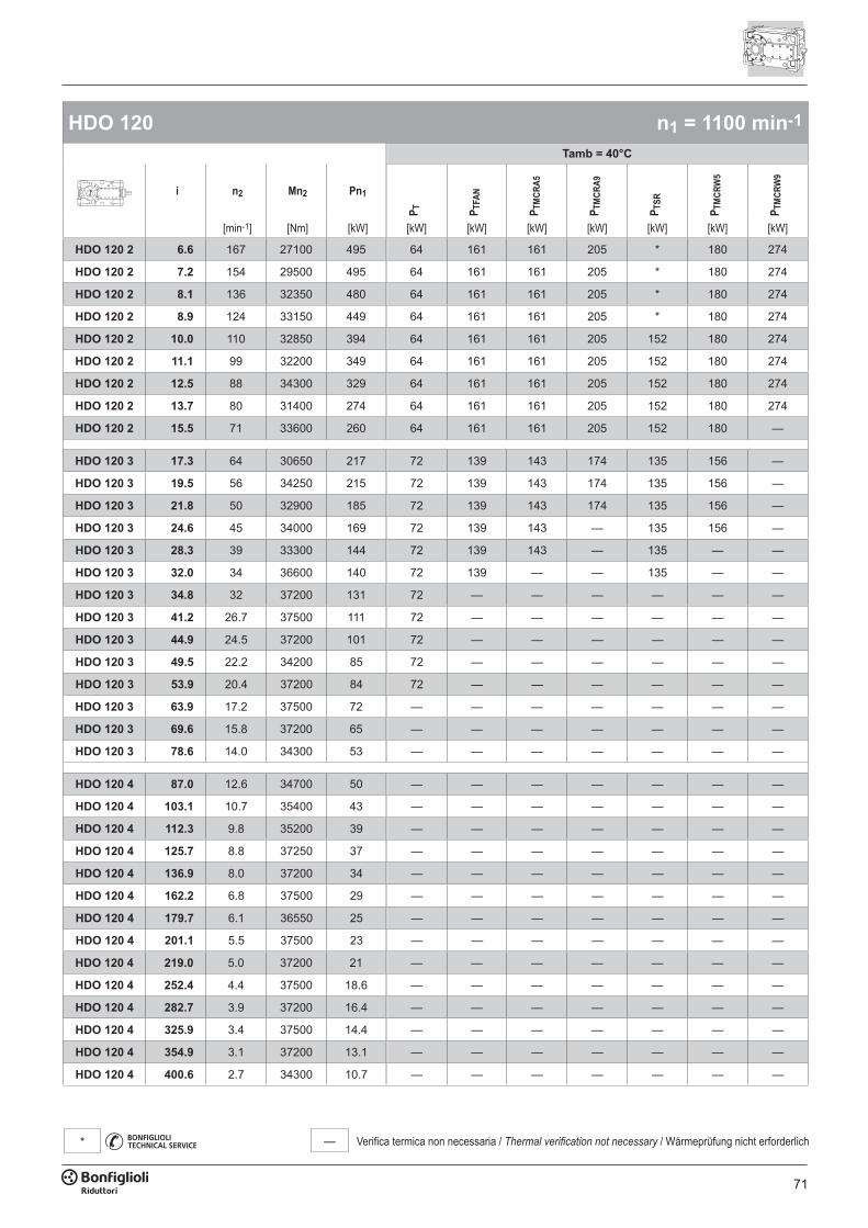
71
— Verifica termica non necessaria / Thermal verification not necessary / Wärmeprüfung nicht erforderlich*
HDO 120 n1 = 1100 min-1
Tamb = 40°C
i n2 Mn2 Pn1
P T P TFA
N
P TM
CRA5
P TM
CRA9
P TSR
P TM
CRW
5
P TM
CRW
9
[min-1] [Nm] [kW] [kW] [kW] [kW] [kW] [kW] [kW] [kW]
HDO 120 2 6.6 167 27100 495 64 161 161 205 * 180 274
HDO 120 2 7.2 154 29500 495 64 161 161 205 * 180 274
HDO 120 2 8.1 136 32350 480 64 161 161 205 * 180 274
HDO 120 2 8.9 124 33150 449 64 161 161 205 * 180 274
HDO 120 2 10.0 110 32850 394 64 161 161 205 152 180 274
HDO 120 2 11.1 99 32200 349 64 161 161 205 152 180 274
HDO 120 2 12.5 88 34300 329 64 161 161 205 152 180 274
HDO 120 2 13.7 80 31400 274 64 161 161 205 152 180 274
HDO 120 2 15.5 71 33600 260 64 161 161 205 152 180 —
HDO 120 3 17.3 64 30650 217 72 139 143 174 135 156 —
HDO 120 3 19.5 56 34250 215 72 139 143 174 135 156 —
HDO 120 3 21.8 50 32900 185 72 139 143 174 135 156 —
HDO 120 3 24.6 45 34000 169 72 139 143 — 135 156 —
HDO 120 3 28.3 39 33300 144 72 139 143 — 135 — —
HDO 120 3 32.0 34 36600 140 72 139 — — 135 — —
HDO 120 3 34.8 32 37200 131 72 — — — — — —
HDO 120 3 41.2 26.7 37500 111 72 — — — — — —
HDO 120 3 44.9 24.5 37200 101 72 — — — — — —
HDO 120 3 49.5 22.2 34200 85 72 — — — — — —
HDO 120 3 53.9 20.4 37200 84 72 — — — — — —
HDO 120 3 63.9 17.2 37500 72 — — — — — — —
HDO 120 3 69.6 15.8 37200 65 — — — — — — —
HDO 120 3 78.6 14.0 34300 53 — — — — — — —
HDO 120 4 87.0 12.6 34700 50 — — — — — — —
HDO 120 4 103.1 10.7 35400 43 — — — — — — —
HDO 120 4 112.3 9.8 35200 39 — — — — — — —
HDO 120 4 125.7 8.8 37250 37 — — — — — — —
HDO 120 4 136.9 8.0 37200 34 — — — — — — —
HDO 120 4 162.2 6.8 37500 29 — — — — — — —
HDO 120 4 179.7 6.1 36550 25 — — — — — — —
HDO 120 4 201.1 5.5 37500 23 — — — — — — —
HDO 120 4 219.0 5.0 37200 21 — — — — — — —
HDO 120 4 252.4 4.4 37500 18.6 — — — — — — —
HDO 120 4 282.7 3.9 37200 16.4 — — — — — — —
HDO 120 4 325.9 3.4 37500 14.4 — — — — — — —
HDO 120 4 354.9 3.1 37200 13.1 — — — — — — —
HDO 120 4 400.6 2.7 34300 10.7 — — — — — — —
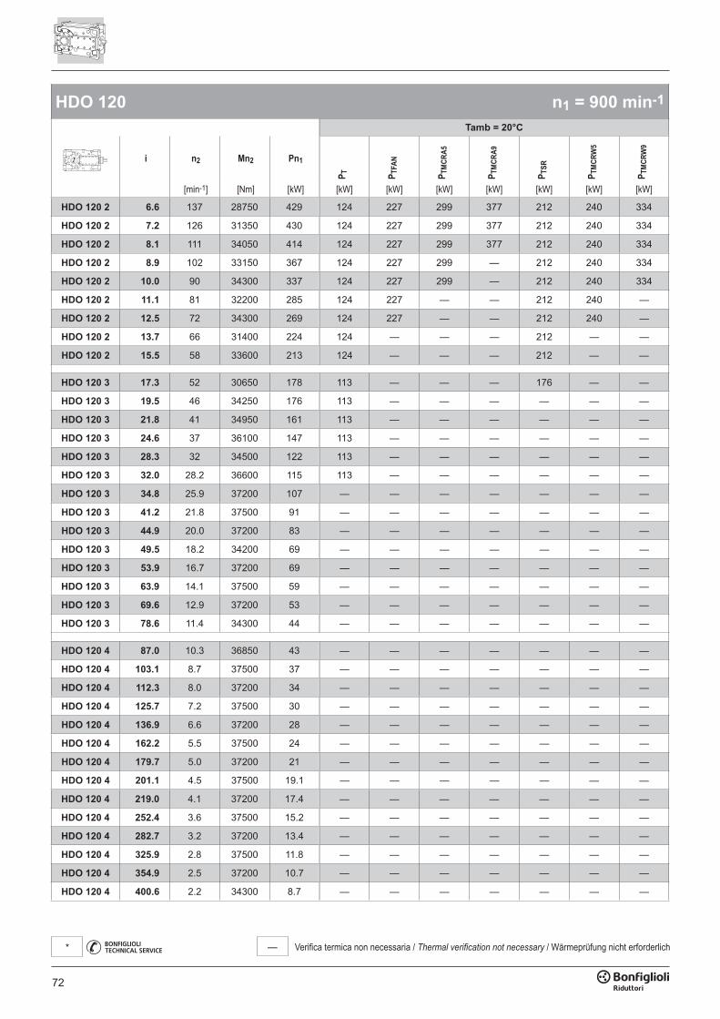
72
— Verifica termica non necessaria / Thermal verification not necessary / Wärmeprüfung nicht erforderlich*
HDO 120 n1 = 900 min-1
Tamb = 20°C
i n2 Mn2 Pn1
P T P TFA
N
P TM
CRA5
P TM
CRA9
P TSR
P TM
CRW
5
P TM
CRW
9
[min-1] [Nm] [kW] [kW] [kW] [kW] [kW] [kW] [kW] [kW]
HDO 120 2 6.6 137 28750 429 124 227 299 377 212 240 334
HDO 120 2 7.2 126 31350 430 124 227 299 377 212 240 334
HDO 120 2 8.1 111 34050 414 124 227 299 377 212 240 334
HDO 120 2 8.9 102 33150 367 124 227 299 — 212 240 334
HDO 120 2 10.0 90 34300 337 124 227 299 — 212 240 334
HDO 120 2 11.1 81 32200 285 124 227 — — 212 240 —
HDO 120 2 12.5 72 34300 269 124 227 — — 212 240 —
HDO 120 2 13.7 66 31400 224 124 — — — 212 — —
HDO 120 2 15.5 58 33600 213 124 — — — 212 — —
HDO 120 3 17.3 52 30650 178 113 — — — 176 — —
HDO 120 3 19.5 46 34250 176 113 — — — — — —
HDO 120 3 21.8 41 34950 161 113 — — — — — —
HDO 120 3 24.6 37 36100 147 113 — — — — — —
HDO 120 3 28.3 32 34500 122 113 — — — — — —
HDO 120 3 32.0 28.2 36600 115 113 — — — — — —
HDO 120 3 34.8 25.9 37200 107 — — — — — — —
HDO 120 3 41.2 21.8 37500 91 — — — — — — —
HDO 120 3 44.9 20.0 37200 83 — — — — — — —
HDO 120 3 49.5 18.2 34200 69 — — — — — — —
HDO 120 3 53.9 16.7 37200 69 — — — — — — —
HDO 120 3 63.9 14.1 37500 59 — — — — — — —
HDO 120 3 69.6 12.9 37200 53 — — — — — — —
HDO 120 3 78.6 11.4 34300 44 — — — — — — —
HDO 120 4 87.0 10.3 36850 43 — — — — — — —
HDO 120 4 103.1 8.7 37500 37 — — — — — — —
HDO 120 4 112.3 8.0 37200 34 — — — — — — —
HDO 120 4 125.7 7.2 37500 30 — — — — — — —
HDO 120 4 136.9 6.6 37200 28 — — — — — — —
HDO 120 4 162.2 5.5 37500 24 — — — — — — —
HDO 120 4 179.7 5.0 37200 21 — — — — — — —
HDO 120 4 201.1 4.5 37500 19.1 — — — — — — —
HDO 120 4 219.0 4.1 37200 17.4 — — — — — — —
HDO 120 4 252.4 3.6 37500 15.2 — — — — — — —
HDO 120 4 282.7 3.2 37200 13.4 — — — — — — —
HDO 120 4 325.9 2.8 37500 11.8 — — — — — — —
HDO 120 4 354.9 2.5 37200 10.7 — — — — — — —
HDO 120 4 400.6 2.2 34300 8.7 — — — — — — —
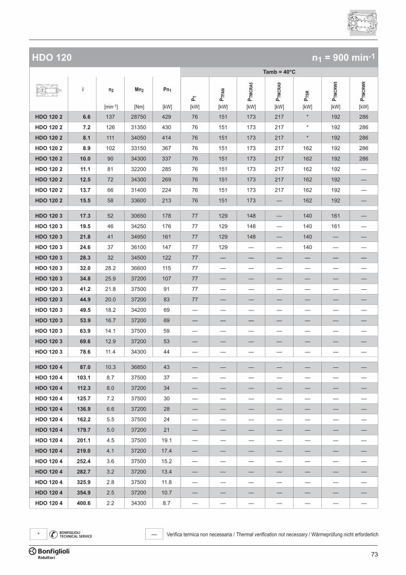
73
— Verifica termica non necessaria / Thermal verification not necessary / Wärmeprüfung nicht erforderlich*
HDO 120 n1 = 900 min-1
Tamb = 40°C
i n2 Mn2 Pn1
P T P TFA
N
P TM
CRA5
P TM
CRA9
P TSR
P TM
CRW
5
P TM
CRW
9
[min-1] [Nm] [kW] [kW] [kW] [kW] [kW] [kW] [kW] [kW]
HDO 120 2 6.6 137 28750 429 76 151 173 217 * 192 286
HDO 120 2 7.2 126 31350 430 76 151 173 217 * 192 286
HDO 120 2 8.1 111 34050 414 76 151 173 217 * 192 286
HDO 120 2 8.9 102 33150 367 76 151 173 217 162 192 286
HDO 120 2 10.0 90 34300 337 76 151 173 217 162 192 286
HDO 120 2 11.1 81 32200 285 76 151 173 217 162 192 —
HDO 120 2 12.5 72 34300 269 76 151 173 217 162 192 —
HDO 120 2 13.7 66 31400 224 76 151 173 217 162 192 —
HDO 120 2 15.5 58 33600 213 76 151 173 — 162 192 —
HDO 120 3 17.3 52 30650 178 77 129 148 — 140 161 —
HDO 120 3 19.5 46 34250 176 77 129 148 — 140 161 —
HDO 120 3 21.8 41 34950 161 77 129 148 — 140 — —
HDO 120 3 24.6 37 36100 147 77 129 — — 140 — —
HDO 120 3 28.3 32 34500 122 77 — — — — — —
HDO 120 3 32.0 28.2 36600 115 77 — — — — — —
HDO 120 3 34.8 25.9 37200 107 77 — — — — — —
HDO 120 3 41.2 21.8 37500 91 77 — — — — — —
HDO 120 3 44.9 20.0 37200 83 77 — — — — — —
HDO 120 3 49.5 18.2 34200 69 — — — — — — —
HDO 120 3 53.9 16.7 37200 69 — — — — — — —
HDO 120 3 63.9 14.1 37500 59 — — — — — — —
HDO 120 3 69.6 12.9 37200 53 — — — — — — —
HDO 120 3 78.6 11.4 34300 44 — — — — — — —
HDO 120 4 87.0 10.3 36850 43 — — — — — — —
HDO 120 4 103.1 8.7 37500 37 — — — — — — —
HDO 120 4 112.3 8.0 37200 34 — — — — — — —
HDO 120 4 125.7 7.2 37500 30 — — — — — — —
HDO 120 4 136.9 6.6 37200 28 — — — — — — —
HDO 120 4 162.2 5.5 37500 24 — — — — — — —
HDO 120 4 179.7 5.0 37200 21 — — — — — — —
HDO 120 4 201.1 4.5 37500 19.1 — — — — — — —
HDO 120 4 219.0 4.1 37200 17.4 — — — — — — —
HDO 120 4 252.4 3.6 37500 15.2 — — — — — — —
HDO 120 4 282.7 3.2 37200 13.4 — — — — — — —
HDO 120 4 325.9 2.8 37500 11.8 — — — — — — —
HDO 120 4 354.9 2.5 37200 10.7 — — — — — — —
HDO 120 4 400.6 2.2 34300 8.7 — — — — — — —
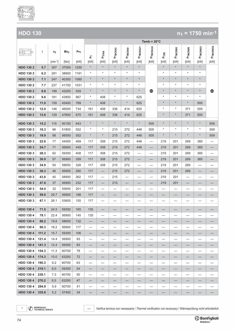
74
— Verifica termica non necessaria / Thermal verification not necessary / Wärmeprüfung nicht erforderlich*
HDO 130 n1 = 1750 min-1
Tamb = 20°C
i n2 Mn2 Pn1
P T P TFA
N
P TM
CRA5
P TM
CRA9
P TM
CRA2
1
P TM
CRA3
4
P TSR
P TM
CRW
5
P TM
CRW
9
P TM
CRW
21
P TM
CRW
34
[min-1] [Nm] [kW] [kW] [kW] [kW] [kW] [kW] [kW] [kW] [kW] [kW] [kW] [kW]
HDO 130 2 5.7 307 37550 1255 * * * * * * * * *
HDO 130 2 6.2 281 38900 1191 * * * * * * * * *
HDO 130 2 7.1 247 40300 1085 * * * * * * * * *
HDO 130 2 7.7 227 41700 1031 * * * * * * * * *
HDO 130 2 8.8 199 43200 939 * * * * * * * * *
HDO 130 2 9.6 181 43800 867 * 408 * * 625 * * * *
HDO 130 2 11.0 159 45400 789 * 408 * * 625 * * * 505
HDO 130 2 12.0 146 46000 734 161 408 336 414 625 * * 371 505
HDO 130 2 13.6 129 47800 670 161 408 336 414 625 * * 371 505
HDO 130 3 15.2 115 50150 643 * * * * * 505 * * * * 509
HDO 130 3 18.3 96 51800 552 * * 215 272 448 505 * * * * 509
HDO 130 3 19.9 88 56550 552 * * 215 272 448 505 * * * * 509
HDO 130 3 22.6 77 54500 469 117 308 215 272 448 — 219 201 269 385 —
HDO 130 3 24.7 71 56900 449 117 308 215 272 448 — 219 201 269 385 —
HDO 130 3 28.3 62 59300 408 117 308 215 272 — — 219 201 269 385 —
HDO 130 3 30.9 57 56900 359 117 308 215 272 — — 219 201 269 385 —
HDO 130 3 34.9 50 58650 328 117 308 215 272 — — 219 201 269 — —
HDO 130 3 38.3 46 56900 290 117 — 215 272 — — 219 201 269 — —
HDO 130 3 43.8 40 58900 262 117 — 215 — — — 219 201 — — —
HDO 130 3 47.8 37 56900 232 117 — 215 — — — 219 201 — — —
HDO 130 3 54.0 32 55650 201 117 — — — — — — — — — —
HDO 130 3 59.0 29.7 56900 188 117 — — — — — — — — — —
HDO 130 3 67.1 26.1 53600 155 117 — — — — — — — — — —
HDO 130 4 71.5 24.5 59300 165 135 — — — — — — — — — —
HDO 130 4 78.1 22.4 56900 145 135 — — — — — — — — — —
HDO 130 4 88.2 19.8 58650 132 — — — — — — — — — — —
HDO 130 4 96.3 18.2 56900 117 — — — — — — — — — — —
HDO 130 4 111.2 15.7 59300 106 — — — — — — — — — — —
HDO 130 4 121.4 14.4 56900 93 — — — — — — — — — — —
HDO 130 4 141.3 12.4 59300 83 — — — — — — — — — — —
HDO 130 4 154.3 11.3 60700 78 — — — — — — — — — — —
HDO 130 4 174.3 10.0 63250 72 — — — — — — — — — — —
HDO 130 4 190.3 9.2 60700 63 — — — — — — — — — — —
HDO 130 4 219.1 8.0 59300 54 — — — — — — — — — — —
HDO 130 4 239.1 7.3 60700 50 — — — — — — — — — — —
HDO 130 4 270.2 6.5 63250 47 — — — — — — — — — — —
HDO 130 4 294.9 5.9 60700 41 — — — — — — — — — — —
HDO 130 4 335.6 5.2 57400 34 — — — — — — — — — — —
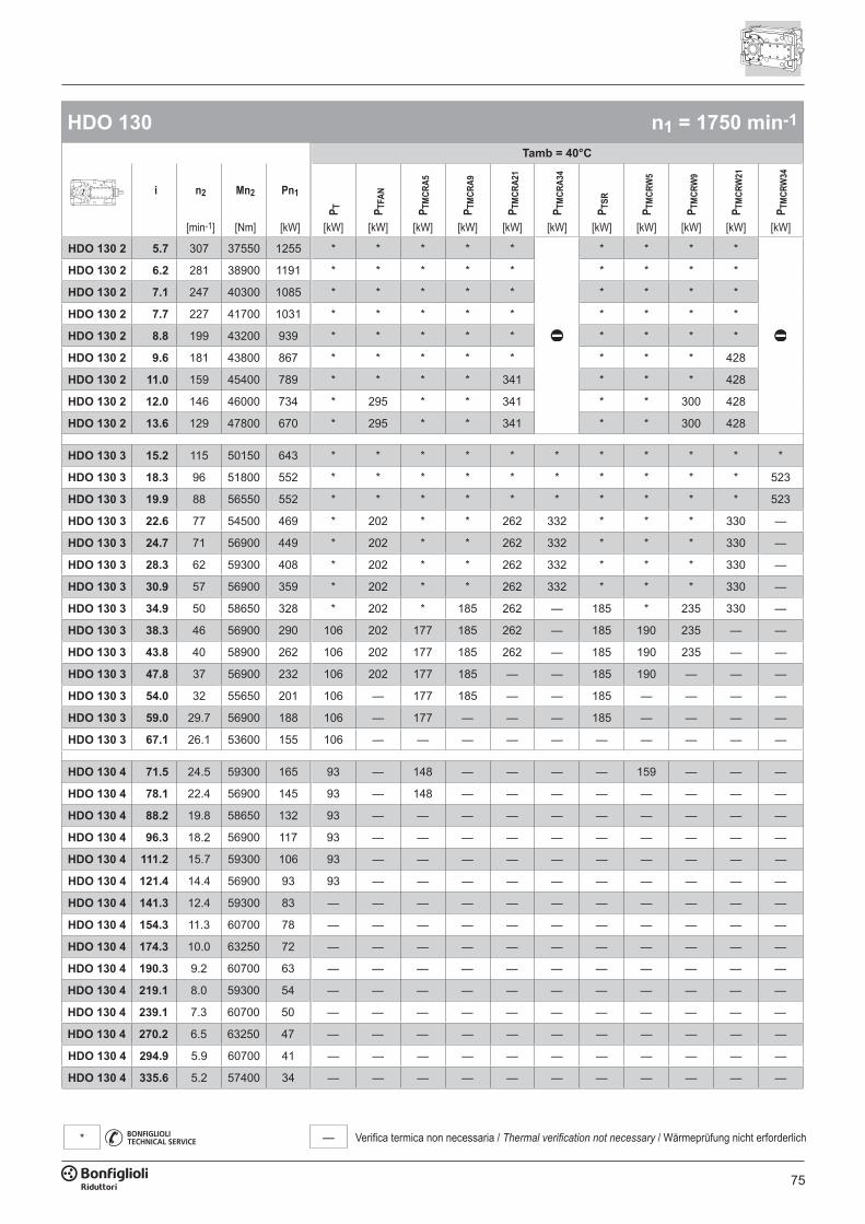
75
— Verifica termica non necessaria / Thermal verification not necessary / Wärmeprüfung nicht erforderlich*
HDO 130 n1 = 1750 min-1
Tamb = 40°C
i n2 Mn2 Pn1
P T P TFA
N
P TM
CRA5
P TM
CRA9
P TM
CRA2
1
P TM
CRA3
4
P TSR
P TM
CRW
5
P TM
CRW
9
P TM
CRW
21
P TM
CRW
34
[min-1] [Nm] [kW] [kW] [kW] [kW] [kW] [kW] [kW] [kW] [kW] [kW] [kW] [kW]
HDO 130 2 5.7 307 37550 1255 * * * * * * * * *
HDO 130 2 6.2 281 38900 1191 * * * * * * * * *
HDO 130 2 7.1 247 40300 1085 * * * * * * * * *
HDO 130 2 7.7 227 41700 1031 * * * * * * * * *
HDO 130 2 8.8 199 43200 939 * * * * * * * * *
HDO 130 2 9.6 181 43800 867 * * * * * * * * 428
HDO 130 2 11.0 159 45400 789 * * * * 341 * * * 428
HDO 130 2 12.0 146 46000 734 * 295 * * 341 * * 300 428
HDO 130 2 13.6 129 47800 670 * 295 * * 341 * * 300 428
HDO 130 3 15.2 115 50150 643 * * * * * * * * * * *
HDO 130 3 18.3 96 51800 552 * * * * * * * * * * 523
HDO 130 3 19.9 88 56550 552 * * * * * * * * * * 523
HDO 130 3 22.6 77 54500 469 * 202 * * 262 332 * * * 330 —
HDO 130 3 24.7 71 56900 449 * 202 * * 262 332 * * * 330 —
HDO 130 3 28.3 62 59300 408 * 202 * * 262 332 * * * 330 —
HDO 130 3 30.9 57 56900 359 * 202 * * 262 332 * * * 330 —
HDO 130 3 34.9 50 58650 328 * 202 * 185 262 — 185 * 235 330 —
HDO 130 3 38.3 46 56900 290 106 202 177 185 262 — 185 190 235 — —
HDO 130 3 43.8 40 58900 262 106 202 177 185 262 — 185 190 235 — —
HDO 130 3 47.8 37 56900 232 106 202 177 185 — — 185 190 — — —
HDO 130 3 54.0 32 55650 201 106 — 177 185 — — 185 — — — —
HDO 130 3 59.0 29.7 56900 188 106 — 177 — — — 185 — — — —
HDO 130 3 67.1 26.1 53600 155 106 — — — — — — — — — —
HDO 130 4 71.5 24.5 59300 165 93 — 148 — — — — 159 — — —
HDO 130 4 78.1 22.4 56900 145 93 — 148 — — — — — — — —
HDO 130 4 88.2 19.8 58650 132 93 — — — — — — — — — —
HDO 130 4 96.3 18.2 56900 117 93 — — — — — — — — — —
HDO 130 4 111.2 15.7 59300 106 93 — — — — — — — — — —
HDO 130 4 121.4 14.4 56900 93 93 — — — — — — — — — —
HDO 130 4 141.3 12.4 59300 83 — — — — — — — — — — —
HDO 130 4 154.3 11.3 60700 78 — — — — — — — — — — —
HDO 130 4 174.3 10.0 63250 72 — — — — — — — — — — —
HDO 130 4 190.3 9.2 60700 63 — — — — — — — — — — —
HDO 130 4 219.1 8.0 59300 54 — — — — — — — — — — —
HDO 130 4 239.1 7.3 60700 50 — — — — — — — — — — —
HDO 130 4 270.2 6.5 63250 47 — — — — — — — — — — —
HDO 130 4 294.9 5.9 60700 41 — — — — — — — — — — —
HDO 130 4 335.6 5.2 57400 34 — — — — — — — — — — —

76
— Verifica termica non necessaria / Thermal verification not necessary / Wärmeprüfung nicht erforderlich*
HDO 130 n1 = 1400 min-1
Tamb = 20°C
i n2 Mn2 Pn1
P T P TFA
N
P TM
CRA5
P TM
CRA9
P TM
CRA2
1
P TM
CRA3
4
P TSR
P TM
CRW
5
P TM
CRW
9
P TM
CRW
21
P TM
CRW
34
[min-1] [Nm] [kW] [kW] [kW] [kW] [kW] [kW] [kW] [kW] [kW] [kW] [kW] [kW]
HDO 130 2 5.7 245 40150 1074 * 354 * * * * * * *
HDO 130 2 6.2 225 41600 1019 * 354 * * * * * * *
HDO 130 2 7.1 197 43100 928 * 354 * * * * * * *
HDO 130 2 7.7 181 44600 882 * 354 * * 620 * * * *
HDO 130 2 8.8 159 46200 803 * 354 * * 620 * * * 501
HDO 130 2 9.6 145 46800 741 160 354 335 413 620 * * 370 501
HDO 130 2 11.0 128 48550 675 160 354 335 413 620 * 282 370 501
HDO 130 2 12.0 117 49200 628 160 354 335 413 620 292 282 370 501
HDO 130 2 13.6 103 51100 573 160 354 335 413 — 292 282 370 501
HDO 130 3 15.2 92 53600 550 * * 189 246 422 548 * * * * —
HDO 130 3 18.3 77 55400 472 115 281 189 246 422 — 217 199 267 383 —
HDO 130 3 19.9 70 60500 473 115 281 189 246 422 — 217 199 267 383 —
HDO 130 3 22.6 62 58300 402 115 281 189 246 — — 217 199 267 383 —
HDO 130 3 24.7 57 60700 383 115 281 189 246 — — 217 199 267 — —
HDO 130 3 28.3 50 63250 349 115 281 189 246 — — 217 199 267 — —
HDO 130 3 30.9 45 60700 306 115 281 189 246 — — 217 199 267 — —
HDO 130 3 34.9 40 63250 283 115 — 189 246 — — 217 199 267 — —
HDO 130 3 38.3 37 60700 247 115 — 189 246 — — 217 199 — — —
HDO 130 3 43.8 32 62950 224 115 — 189 — — — 217 199 — — —
HDO 130 3 47.8 29.3 60700 198 115 — 189 — — — — — — — —
HDO 130 3 54.0 25.9 59500 172 115 — — — — — — — — — —
HDO 130 3 59.0 23.7 60700 160 115 — — — — — — — — — —
HDO 130 3 67.1 20.9 57400 133 115 — — — — — — — — — —
HDO 130 4 71.5 19.6 63250 141 — — — — — — — — — — —
HDO 130 4 78.1 17.9 60700 124 — — — — — — — — — — —
HDO 130 4 88.2 15.9 63250 114 — — — — — — — — — — —
HDO 130 4 96.3 14.5 60700 100 — — — — — — — — — — —
HDO 130 4 111.2 12.6 63250 90 — — — — — — — — — — —
HDO 130 4 121.4 11.5 60700 79 — — — — — — — — — — —
HDO 130 4 141.3 9.9 63250 71 — — — — — — — — — — —
HDO 130 4 154.3 9.1 60700 63 — — — — — — — — — — —
HDO 130 4 174.3 8.0 63250 58 — — — — — — — — — — —
HDO 130 4 190.3 7.4 60700 51 — — — — — — — — — — —
HDO 130 4 219.1 6.4 63250 46 — — — — — — — — — — —
HDO 130 4 239.1 5.9 60700 40 — — — — — — — — — — —
HDO 130 4 270.2 5.2 63250 37 — — — — — — — — — — —
HDO 130 4 294.9 4.7 60700 33 — — — — — — — — — — —
HDO 130 4 335.6 4.2 57400 27 — — — — — — — — — — —
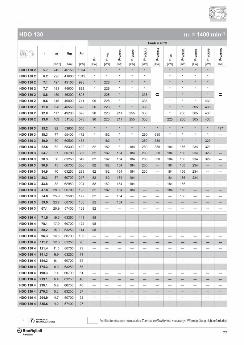
77
— Verifica termica non necessaria / Thermal verification not necessary / Wärmeprüfung nicht erforderlich*
HDO 130 n1 = 1400 min-1
Tamb = 40°C
i n2 Mn2 Pn1
P T P TFA
N
P TM
CRA5
P TM
CRA9
P TM
CRA2
1
P TM
CRA3
4
P TSR
P TM
CRW
5
P TM
CRW
9
P TM
CRW
21
P TM
CRW
34
[min-1] [Nm] [kW] [kW] [kW] [kW] [kW] [kW] [kW] [kW] [kW] [kW] [kW] [kW]
HDO 130 2 5.7 245 40150 1074 * * * * * * * * *
HDO 130 2 6.2 225 41600 1019 * * * * * * * * *
HDO 130 2 7.1 197 43100 928 * 228 * * * * * * *
HDO 130 2 7.7 181 44600 882 * 228 * * * * * * *
HDO 130 2 8.8 159 46200 803 * 228 * * 336 * * * *
HDO 130 2 9.6 145 46800 741 90 228 * * 336 * * * 430
HDO 130 2 11.0 128 48550 675 90 228 * * 336 * * 305 430
HDO 130 2 12.0 117 49200 628 90 228 211 255 336 * 230 305 430
HDO 130 2 13.6 103 51100 573 90 228 211 255 336 225 230 305 430
HDO 130 3 15.2 92 53600 550 * * * * * * * * * * 497
HDO 130 3 18.3 77 55400 472 * 182 * * 260 330 * * * * —
HDO 130 3 19.9 70 60500 473 * 182 * * 260 330 * * * 329 —
HDO 130 3 22.6 62 58300 402 82 182 * 184 260 330 184 166 234 329 —
HDO 130 3 24.7 57 60700 383 82 182 154 184 260 330 184 166 234 329 —
HDO 130 3 28.3 50 63250 349 82 182 154 184 260 330 184 166 234 329 —
HDO 130 3 30.9 45 60700 306 82 182 154 184 260 — 184 166 234 — —
HDO 130 3 34.9 40 63250 283 82 182 154 184 260 — 184 166 234 — —
HDO 130 3 38.3 37 60700 247 82 182 154 184 — — 184 166 234 — —
HDO 130 3 43.8 32 62950 224 82 182 154 184 — — 184 166 — — —
HDO 130 3 47.8 29.3 60700 198 82 182 154 184 — — 184 166 — — —
HDO 130 3 54.0 25.9 59500 172 82 — 154 — — — — 166 — — —
HDO 130 3 59.0 23.7 60700 160 82 — 154 — — — — — — — —
HDO 130 3 67.1 20.9 57400 133 82 — — — — — — — — — —
HDO 130 4 71.5 19.6 63250 141 98 — — — — — — — — — —
HDO 130 4 78.1 17.9 60700 124 98 — — — — — — — — — —
HDO 130 4 88.2 15.9 63250 114 98 — — — — — — — — — —
HDO 130 4 96.3 14.5 60700 100 — — — — — — — — — — —
HDO 130 4 111.2 12.6 63250 90 — — — — — — — — — — —
HDO 130 4 121.4 11.5 60700 79 — — — — — — — — — — —
HDO 130 4 141.3 9.9 63250 71 — — — — — — — — — — —
HDO 130 4 154.3 9.1 60700 63 — — — — — — — — — — —
HDO 130 4 174.3 8.0 63250 58 — — — — — — — — — — —
HDO 130 4 190.3 7.4 60700 51 — — — — — — — — — — —
HDO 130 4 219.1 6.4 63250 46 — — — — — — — — — — —
HDO 130 4 239.1 5.9 60700 40 — — — — — — — — — — —
HDO 130 4 270.2 5.2 63250 37 — — — — — — — — — — —
HDO 130 4 294.9 4.7 60700 33 — — — — — — — — — — —
HDO 130 4 335.6 4.2 57400 27 — — — — — — — — — — —

78
— Verifica termica non necessaria / Thermal verification not necessary / Wärmeprüfung nicht erforderlich*
HDO 130 n1 = 1100 min-1
Tamb = 20°C
i n2 Mn2 Pn1
P T P TFA
N
P TM
CRA5
P TM
CRA9
P TM
CRA2
1
P TM
CRA3
4
P TSR
P TM
CRW
5
P TM
CRW
9
P TM
CRW
21
P TM
CRW
34
[min-1] [Nm] [kW] [kW] [kW] [kW] [kW] [kW] [kW] [kW] [kW] [kW] [kW] [kW]
HDO 130 2 5.7 193 43200 908 * 359 316 394 637 * * * 511
HDO 130 2 6.2 177 44750 861 * 359 316 394 637 * * * 511
HDO 130 2 7.1 155 46350 784 * 359 316 394 637 * * 363 511
HDO 130 2 7.7 143 47950 745 156 359 316 394 637 * 272 363 511
HDO 130 2 8.8 125 49650 678 156 359 316 394 637 * 272 363 511
HDO 130 2 9.6 114 50350 626 156 359 316 394 — 291 272 363 511
HDO 130 2 11.0 100 52200 571 156 359 316 394 — 291 272 363 511
HDO 130 2 12.0 92 52000 522 156 359 316 394 — 291 272 363 511
HDO 130 2 13.6 81 54950 484 156 359 316 394 — 291 272 363 —
HDO 130 3 15.2 72 55050 444 * 245 222 279 — — * * * — —
HDO 130 3 18.3 60 59550 399 136 245 222 279 — — 238 220 288 — —
HDO 130 3 19.9 55 60700 373 136 245 222 279 — — 238 220 288 — —
HDO 130 3 22.6 49 59650 323 136 245 222 279 — — 238 220 288 — —
HDO 130 3 24.7 45 60700 301 136 245 222 279 — — 238 220 288 — —
HDO 130 3 28.3 39 63250 274 136 245 222 — — — 238 220 — — —
HDO 130 3 30.9 36 60700 241 136 — 222 — — — 238 220 — — —
HDO 130 3 34.9 32 63250 222 136 — 222 — — — — 220 — — —
HDO 130 3 38.3 28.7 60700 194 136 — — — — — — — — — —
HDO 130 3 43.8 25.1 63250 177 136 — — — — — — — — — —
HDO 130 3 47.8 23.0 60700 155 136 — — — — — — — — — —
HDO 130 3 54.0 20.4 63250 143 136 — — — — — — — — — —
HDO 130 3 59.0 18.6 60700 126 — — — — — — — — — — —
HDO 130 3 67.1 16.4 57400 105 — — — — — — — — — — —
HDO 130 4 71.5 15.4 63250 110 — — — — — — — — — — —
HDO 130 4 78.1 14.1 60700 97 — — — — — — — — — — —
HDO 130 4 88.2 12.5 63250 90 — — — — — — — — — — —
HDO 130 4 96.3 11.4 60700 79 — — — — — — — — — — —
HDO 130 4 111.2 9.9 63250 71 — — — — — — — — — — —
HDO 130 4 121.4 9.1 60700 62 — — — — — — — — — — —
HDO 130 4 141.3 7.8 63250 56 — — — — — — — — — — —
HDO 130 4 154.3 7.1 60700 49 — — — — — — — — — — —
HDO 130 4 174.3 6.3 63250 45 — — — — — — — — — — —
HDO 130 4 190.3 5.8 60700 40 — — — — — — — — — — —
HDO 130 4 219.1 5.0 63250 36 — — — — — — — — — — —
HDO 130 4 239.1 4.6 60700 32 — — — — — — — — — — —
HDO 130 4 270.2 4.1 63250 29 — — — — — — — — — — —
HDO 130 4 294.9 3.7 60700 26 — — — — — — — — — — —
HDO 130 4 335.6 3.3 57400 21 — — — — — — — — — — —
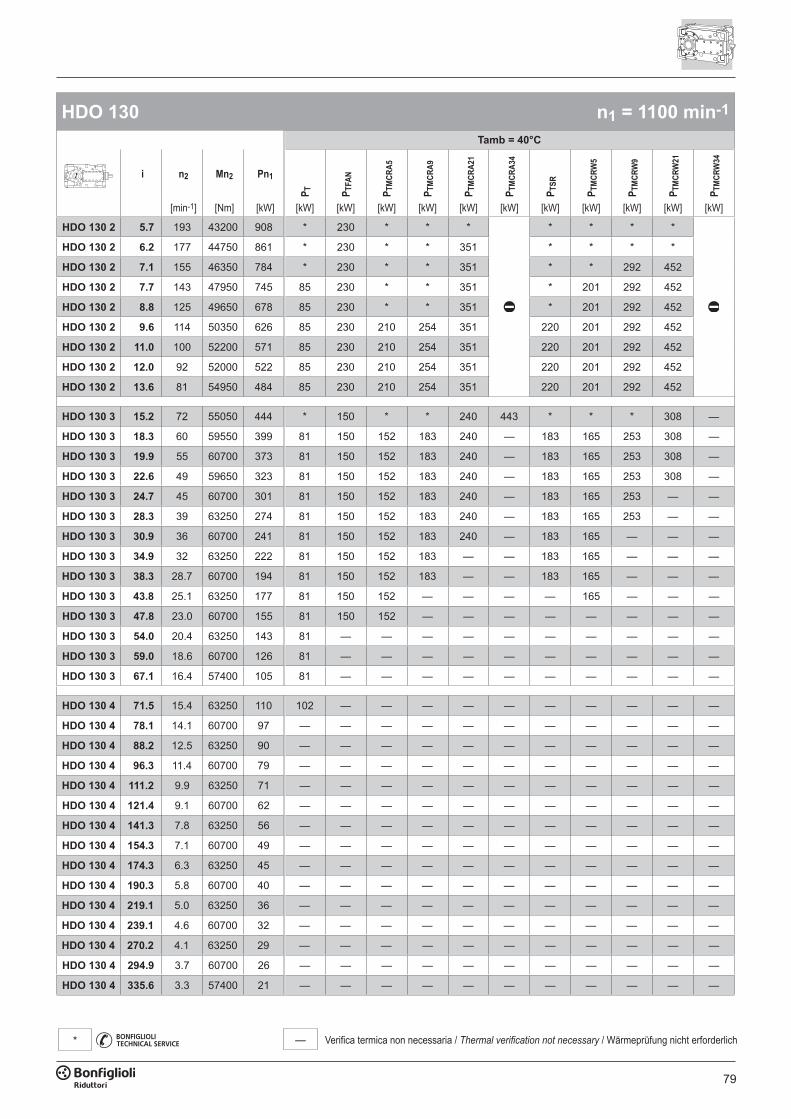
79
— Verifica termica non necessaria / Thermal verification not necessary / Wärmeprüfung nicht erforderlich*
HDO 130 n1 = 1100 min-1
Tamb = 40°C
i n2 Mn2 Pn1
P T P TFA
N
P TM
CRA5
P TM
CRA9
P TM
CRA2
1
P TM
CRA3
4
P TSR
P TM
CRW
5
P TM
CRW
9
P TM
CRW
21
P TM
CRW
34
[min-1] [Nm] [kW] [kW] [kW] [kW] [kW] [kW] [kW] [kW] [kW] [kW] [kW] [kW]
HDO 130 2 5.7 193 43200 908 * 230 * * * * * * *
HDO 130 2 6.2 177 44750 861 * 230 * * 351 * * * *
HDO 130 2 7.1 155 46350 784 * 230 * * 351 * * 292 452
HDO 130 2 7.7 143 47950 745 85 230 * * 351 * 201 292 452
HDO 130 2 8.8 125 49650 678 85 230 * * 351 * 201 292 452
HDO 130 2 9.6 114 50350 626 85 230 210 254 351 220 201 292 452
HDO 130 2 11.0 100 52200 571 85 230 210 254 351 220 201 292 452
HDO 130 2 12.0 92 52000 522 85 230 210 254 351 220 201 292 452
HDO 130 2 13.6 81 54950 484 85 230 210 254 351 220 201 292 452
HDO 130 3 15.2 72 55050 444 * 150 * * 240 443 * * * 308 —
HDO 130 3 18.3 60 59550 399 81 150 152 183 240 — 183 165 253 308 —
HDO 130 3 19.9 55 60700 373 81 150 152 183 240 — 183 165 253 308 —
HDO 130 3 22.6 49 59650 323 81 150 152 183 240 — 183 165 253 308 —
HDO 130 3 24.7 45 60700 301 81 150 152 183 240 — 183 165 253 — —
HDO 130 3 28.3 39 63250 274 81 150 152 183 240 — 183 165 253 — —
HDO 130 3 30.9 36 60700 241 81 150 152 183 240 — 183 165 — — —
HDO 130 3 34.9 32 63250 222 81 150 152 183 — — 183 165 — — —
HDO 130 3 38.3 28.7 60700 194 81 150 152 183 — — 183 165 — — —
HDO 130 3 43.8 25.1 63250 177 81 150 152 — — — — 165 — — —
HDO 130 3 47.8 23.0 60700 155 81 150 152 — — — — — — — —
HDO 130 3 54.0 20.4 63250 143 81 — — — — — — — — — —
HDO 130 3 59.0 18.6 60700 126 81 — — — — — — — — — —
HDO 130 3 67.1 16.4 57400 105 81 — — — — — — — — — —
HDO 130 4 71.5 15.4 63250 110 102 — — — — — — — — — —
HDO 130 4 78.1 14.1 60700 97 — — — — — — — — — — —
HDO 130 4 88.2 12.5 63250 90 — — — — — — — — — — —
HDO 130 4 96.3 11.4 60700 79 — — — — — — — — — — —
HDO 130 4 111.2 9.9 63250 71 — — — — — — — — — — —
HDO 130 4 121.4 9.1 60700 62 — — — — — — — — — — —
HDO 130 4 141.3 7.8 63250 56 — — — — — — — — — — —
HDO 130 4 154.3 7.1 60700 49 — — — — — — — — — — —
HDO 130 4 174.3 6.3 63250 45 — — — — — — — — — — —
HDO 130 4 190.3 5.8 60700 40 — — — — — — — — — — —
HDO 130 4 219.1 5.0 63250 36 — — — — — — — — — — —
HDO 130 4 239.1 4.6 60700 32 — — — — — — — — — — —
HDO 130 4 270.2 4.1 63250 29 — — — — — — — — — — —
HDO 130 4 294.9 3.7 60700 26 — — — — — — — — — — —
HDO 130 4 335.6 3.3 57400 21 — — — — — — — — — — —

80
— Verifica termica non necessaria / Thermal verification not necessary / Wärmeprüfung nicht erforderlich*
HDO 130 n1 = 900 min-1
Tamb = 20°C
i n2 Mn2 Pn1
P T P TFA
N
P TM
CRA5
P TM
CRA9
P TM
CRA2
1
P TM
CRA3
4
P TSR
P TM
CRW
5
P TM
CRW
9
P TM
CRW
21
P TM
CRW
34
[min-1] [Nm] [kW] [kW] [kW] [kW] [kW] [kW] [kW] [kW] [kW] [kW] [kW] [kW]
HDO 130 2 5.7 158 45850 788 165 335 340 418 661 272 281 375 535
HDO 130 2 6.2 144 47500 748 165 335 340 418 661 272 281 375 535
HDO 130 2 7.1 127 49200 681 165 335 340 418 661 272 281 375 535
HDO 130 2 7.7 117 50950 648 165 335 340 418 — 272 281 375 535
HDO 130 2 8.8 103 52750 590 165 335 340 418 — 272 281 375 535
HDO 130 2 9.6 93 53450 544 165 335 340 418 — 272 281 375 535
HDO 130 2 11.0 82 55450 496 165 335 340 418 — 272 281 375 —
HDO 130 2 12.0 75 52000 427 165 335 340 418 — 272 281 375 —
HDO 130 2 13.6 66 57400 414 165 335 340 — — 272 281 375 —
HDO 130 3 15.2 59 55050 363 * 232 243 300 — — 218 200 268 — —
HDO 130 3 18.3 49 63250 347 149 232 243 300 — — 218 200 268 — —
HDO 130 3 19.9 45 60700 305 149 232 243 300 — — 218 200 268 — —
HDO 130 3 22.6 40 59650 264 149 232 243 — — — 218 200 — — —
HDO 130 3 24.7 36 60700 246 149 232 243 — — — 218 200 — — —
HDO 130 3 28.3 32 63250 224 149 — — — — — 218 200 — — —
HDO 130 3 30.9 29.2 60700 197 149 — — — — — — — — — —
HDO 130 3 34.9 25.8 63250 182 149 — — — — — — — — — —
HDO 130 3 38.3 23.5 60700 159 149 — — — — — — — — — —
HDO 130 3 43.8 20.5 63250 145 — — — — — — — — — — —
HDO 130 3 47.8 18.8 60700 127 — — — — — — — — — — —
HDO 130 3 54.0 16.7 63250 117 — — — — — — — — — — —
HDO 130 3 59.0 15.3 60700 103 — — — — — — — — — — —
HDO 130 3 67.1 13.4 57400 86 — — — — — — — — — — —
HDO 130 4 71.5 12.6 63250 90 — — — — — — — — — — —
HDO 130 4 78.1 11.5 60700 79 — — — — — — — — — — —
HDO 130 4 88.2 10.2 63250 73 — — — — — — — — — — —
HDO 130 4 96.3 9.3 60700 64 — — — — — — — — — — —
HDO 130 4 111.2 8.1 63250 58 — — — — — — — — — — —
HDO 130 4 121.4 7.4 60700 51 — — — — — — — — — — —
HDO 130 4 141.3 6.4 63250 46 — — — — — — — — — — —
HDO 130 4 154.3 5.8 60700 40 — — — — — — — — — — —
HDO 130 4 174.3 5.2 63250 37 — — — — — — — — — — —
HDO 130 4 190.3 4.7 60700 33 — — — — — — — — — — —
HDO 130 4 219.1 4.1 63250 29 — — — — — — — — — — —
HDO 130 4 239.1 3.8 60700 26 — — — — — — — — — — —
HDO 130 4 270.2 3.3 63250 24 — — — — — — — — — — —
HDO 130 4 294.9 3.1 60700 21 — — — — — — — — — — —
HDO 130 4 335.6 2.7 57400 17.5 — — — — — — — — — — —
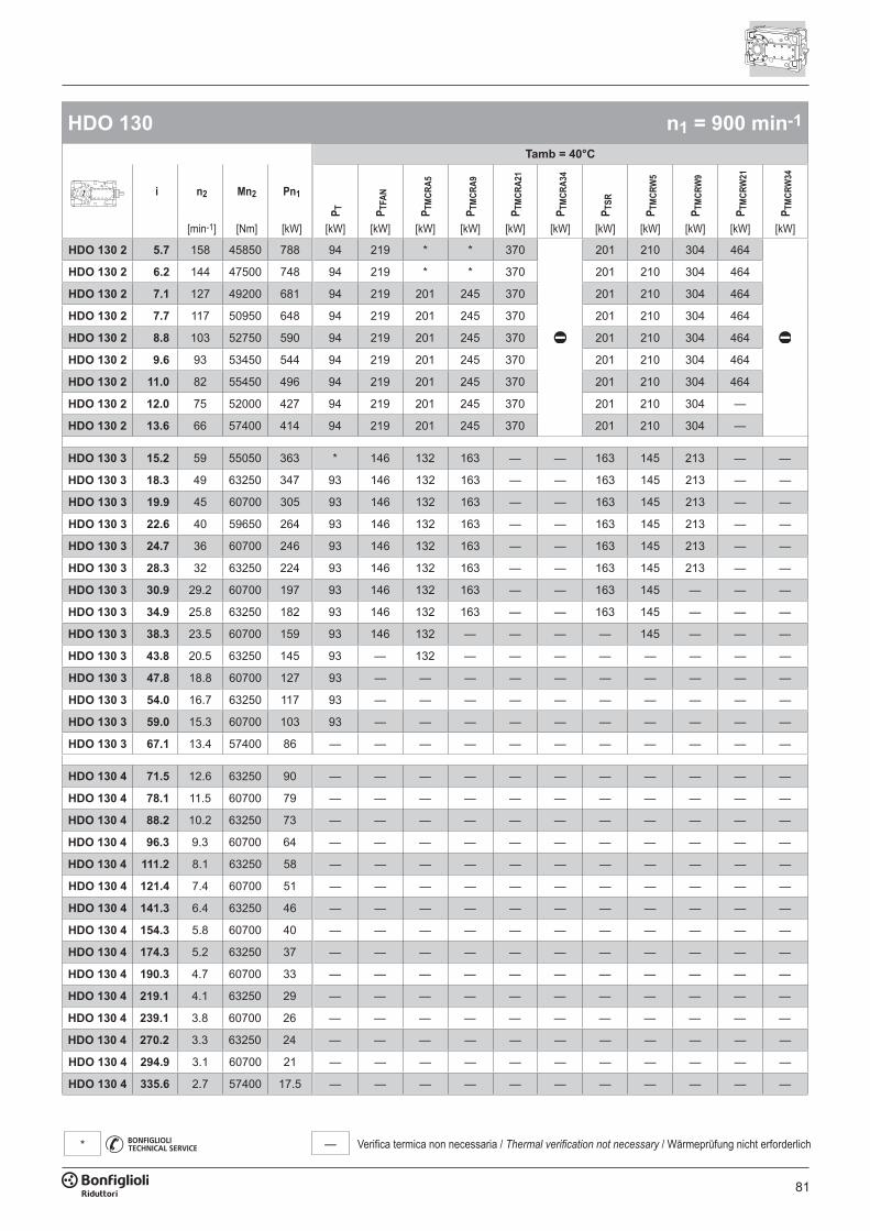
81
— Verifica termica non necessaria / Thermal verification not necessary / Wärmeprüfung nicht erforderlich*
HDO 130 n1 = 900 min-1
Tamb = 40°C
i n2 Mn2 Pn1
P T P TFA
N
P TM
CRA5
P TM
CRA9
P TM
CRA2
1
P TM
CRA3
4
P TSR
P TM
CRW
5
P TM
CRW
9
P TM
CRW
21
P TM
CRW
34
[min-1] [Nm] [kW] [kW] [kW] [kW] [kW] [kW] [kW] [kW] [kW] [kW] [kW] [kW]
HDO 130 2 5.7 158 45850 788 94 219 * * 370 201 210 304 464
HDO 130 2 6.2 144 47500 748 94 219 * * 370 201 210 304 464
HDO 130 2 7.1 127 49200 681 94 219 201 245 370 201 210 304 464
HDO 130 2 7.7 117 50950 648 94 219 201 245 370 201 210 304 464
HDO 130 2 8.8 103 52750 590 94 219 201 245 370 201 210 304 464
HDO 130 2 9.6 93 53450 544 94 219 201 245 370 201 210 304 464
HDO 130 2 11.0 82 55450 496 94 219 201 245 370 201 210 304 464
HDO 130 2 12.0 75 52000 427 94 219 201 245 370 201 210 304 —
HDO 130 2 13.6 66 57400 414 94 219 201 245 370 201 210 304 —
HDO 130 3 15.2 59 55050 363 * 146 132 163 — — 163 145 213 — —
HDO 130 3 18.3 49 63250 347 93 146 132 163 — — 163 145 213 — —
HDO 130 3 19.9 45 60700 305 93 146 132 163 — — 163 145 213 — —
HDO 130 3 22.6 40 59650 264 93 146 132 163 — — 163 145 213 — —
HDO 130 3 24.7 36 60700 246 93 146 132 163 — — 163 145 213 — —
HDO 130 3 28.3 32 63250 224 93 146 132 163 — — 163 145 213 — —
HDO 130 3 30.9 29.2 60700 197 93 146 132 163 — — 163 145 — — —
HDO 130 3 34.9 25.8 63250 182 93 146 132 163 — — 163 145 — — —
HDO 130 3 38.3 23.5 60700 159 93 146 132 — — — — 145 — — —
HDO 130 3 43.8 20.5 63250 145 93 — 132 — — — — — — — —
HDO 130 3 47.8 18.8 60700 127 93 — — — — — — — — — —
HDO 130 3 54.0 16.7 63250 117 93 — — — — — — — — — —
HDO 130 3 59.0 15.3 60700 103 93 — — — — — — — — — —
HDO 130 3 67.1 13.4 57400 86 — — — — — — — — — — —
HDO 130 4 71.5 12.6 63250 90 — — — — — — — — — — —
HDO 130 4 78.1 11.5 60700 79 — — — — — — — — — — —
HDO 130 4 88.2 10.2 63250 73 — — — — — — — — — — —
HDO 130 4 96.3 9.3 60700 64 — — — — — — — — — — —
HDO 130 4 111.2 8.1 63250 58 — — — — — — — — — — —
HDO 130 4 121.4 7.4 60700 51 — — — — — — — — — — —
HDO 130 4 141.3 6.4 63250 46 — — — — — — — — — — —
HDO 130 4 154.3 5.8 60700 40 — — — — — — — — — — —
HDO 130 4 174.3 5.2 63250 37 — — — — — — — — — — —
HDO 130 4 190.3 4.7 60700 33 — — — — — — — — — — —
HDO 130 4 219.1 4.1 63250 29 — — — — — — — — — — —
HDO 130 4 239.1 3.8 60700 26 — — — — — — — — — — —
HDO 130 4 270.2 3.3 63250 24 — — — — — — — — — — —
HDO 130 4 294.9 3.1 60700 21 — — — — — — — — — — —
HDO 130 4 335.6 2.7 57400 17.5 — — — — — — — — — — —
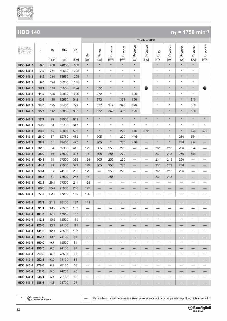
82
— Verifica termica non necessaria / Thermal verification not necessary / Wärmeprüfung nicht erforderlich*
HDO 140 n1 = 1750 min-1
Tamb = 20°C
i n2 Mn2 Pn1
P T P TFA
N
P TM
CRA5
P TM
CRA9
P TM
CRA2
1
P TM
CRA3
4
P TSR
P TM
CRW
5
P TM
CRW
9
P TM
CRW
21
P TM
CRW
34
[min-1] [Nm] [kW] [kW] [kW] [kW] [kW] [kW] [kW] [kW] [kW] [kW] [kW] [kW]
HDO 140 2 6.6 266 44850 1303 * * * * * * * * *
HDO 140 2 7.3 241 49650 1303 * * * * * * * * *
HDO 140 2 8.2 214 55550 1298 * * * * * * * * *
HDO 140 2 9.0 194 58250 1235 * * * * * * * * *
HDO 140 2 10.1 173 59550 1124 * 372 * * * * * * *
HDO 140 2 11.3 156 58950 1000 * 372 * * 629 * * * *
HDO 140 2 12.6 138 62550 944 * 372 * 393 629 * * * 510
HDO 140 2 14.0 125 58400 799 * 372 342 393 629 * * * 510
HDO 140 2 15.7 112 65850 802 * 372 342 393 629 * * * 510
HDO 140 3 17.7 99 58500 643 * * * * * * * * * * *
HDO 140 3 19.9 88 65700 643 * * * * * * * * * * *
HDO 140 3 23.3 75 66000 552 * * * 270 446 572 * * * 354 576
HDO 140 3 26.0 67 62750 469 * 305 * 270 446 — * * 266 354 —
HDO 140 3 28.8 61 69450 470 * 305 * 270 446 — * * 266 354 —
HDO 140 3 32.5 54 69350 415 129 305 256 270 — — 231 213 266 354 —
HDO 140 3 36.0 49 73500 398 129 305 256 270 — — 231 213 266 354 —
HDO 140 3 40.1 44 67550 328 129 305 256 270 — — 231 213 266 — —
HDO 140 3 44.4 39 73500 322 129 305 256 270 — — 231 213 266 — —
HDO 140 3 50.4 35 74100 286 129 — 256 270 — — 231 213 266 — —
HDO 140 3 55.8 31 73500 256 129 — 256 — — — 231 213 — — —
HDO 140 3 62.2 28.1 67550 211 129 — — — — — — — — — —
HDO 140 3 68.8 25.4 73500 208 129 — — — — — — — — — —
HDO 140 3 77.3 22.6 67200 169 129 — — — — — — — — — —
HDO 140 4 82.3 21.3 69100 167 141 — — — — — — — — — —
HDO 140 4 91.1 19.2 73500 160 — — — — — — — — — — —
HDO 140 4 101.5 17.2 67550 132 — — — — — — — — — — —
HDO 140 4 112.3 15.6 73500 130 — — — — — — — — — — —
HDO 140 4 128.0 13.7 74100 115 — — — — — — — — — — —
HDO 140 4 141.6 12.4 73500 103 — — — — — — — — — — —
HDO 140 4 162.7 10.8 74100 91 — — — — — — — — — — —
HDO 140 4 180.0 9.7 73500 81 — — — — — — — — — — —
HDO 140 4 198.3 8.8 74100 74 — — — — — — — — — — —
HDO 140 4 219.5 8.0 73500 67 — — — — — — — — — — —
HDO 140 4 252.1 6.9 74100 58 — — — — — — — — — — —
HDO 140 4 279.0 6.3 79150 56 — — — — — — — — — — —
HDO 140 4 311.0 5.6 74700 48 — — — — — — — — — — —
HDO 140 4 344.1 5.1 79150 46 — — — — — — — — — — —
HDO 140 4 386.6 4.5 71700 37 — — — — — — — — — — —
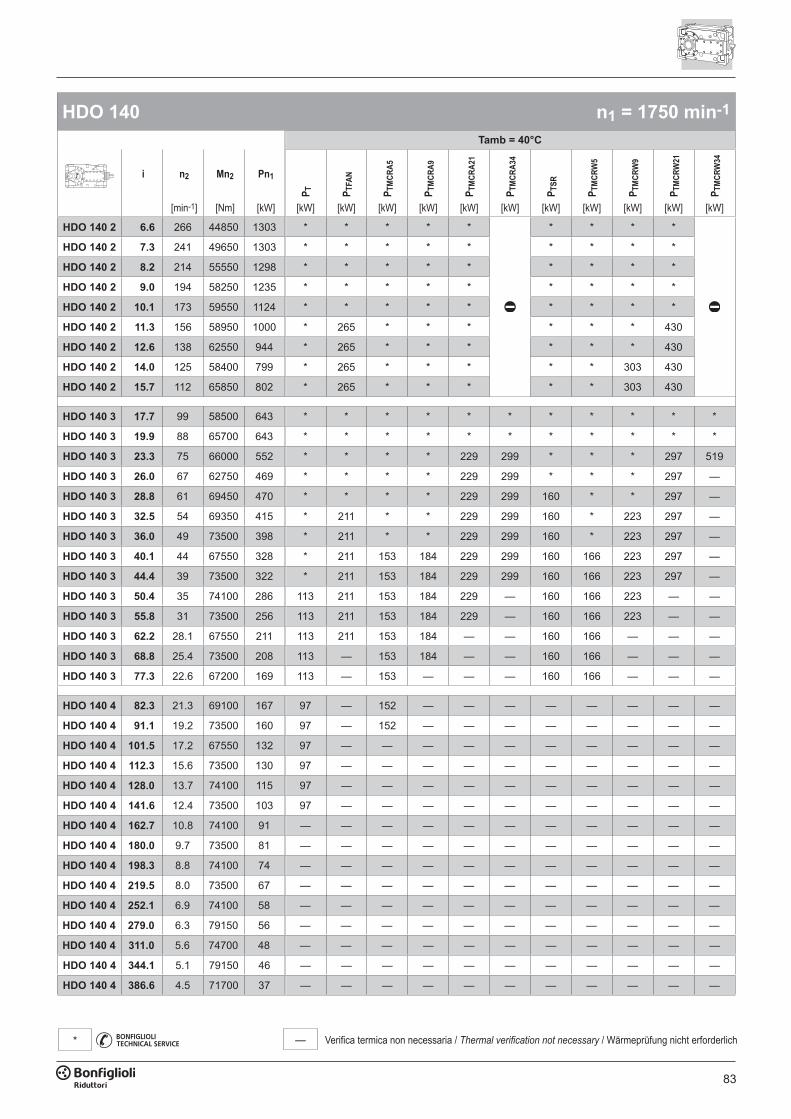
83
— Verifica termica non necessaria / Thermal verification not necessary / Wärmeprüfung nicht erforderlich*
HDO 140 n1 = 1750 min-1
Tamb = 40°C
i n2 Mn2 Pn1
P T P TFA
N
P TM
CRA5
P TM
CRA9
P TM
CRA2
1
P TM
CRA3
4
P TSR
P TM
CRW
5
P TM
CRW
9
P TM
CRW
21
P TM
CRW
34
[min-1] [Nm] [kW] [kW] [kW] [kW] [kW] [kW] [kW] [kW] [kW] [kW] [kW] [kW]
HDO 140 2 6.6 266 44850 1303 * * * * * * * * *
HDO 140 2 7.3 241 49650 1303 * * * * * * * * *
HDO 140 2 8.2 214 55550 1298 * * * * * * * * *
HDO 140 2 9.0 194 58250 1235 * * * * * * * * *
HDO 140 2 10.1 173 59550 1124 * * * * * * * * *
HDO 140 2 11.3 156 58950 1000 * 265 * * * * * * 430
HDO 140 2 12.6 138 62550 944 * 265 * * * * * * 430
HDO 140 2 14.0 125 58400 799 * 265 * * * * * 303 430
HDO 140 2 15.7 112 65850 802 * 265 * * * * * 303 430
HDO 140 3 17.7 99 58500 643 * * * * * * * * * * *
HDO 140 3 19.9 88 65700 643 * * * * * * * * * * *
HDO 140 3 23.3 75 66000 552 * * * * 229 299 * * * 297 519
HDO 140 3 26.0 67 62750 469 * * * * 229 299 * * * 297 —
HDO 140 3 28.8 61 69450 470 * * * * 229 299 160 * * 297 —
HDO 140 3 32.5 54 69350 415 * 211 * * 229 299 160 * 223 297 —
HDO 140 3 36.0 49 73500 398 * 211 * * 229 299 160 * 223 297 —
HDO 140 3 40.1 44 67550 328 * 211 153 184 229 299 160 166 223 297 —
HDO 140 3 44.4 39 73500 322 * 211 153 184 229 299 160 166 223 297 —
HDO 140 3 50.4 35 74100 286 113 211 153 184 229 — 160 166 223 — —
HDO 140 3 55.8 31 73500 256 113 211 153 184 229 — 160 166 223 — —
HDO 140 3 62.2 28.1 67550 211 113 211 153 184 — — 160 166 — — —
HDO 140 3 68.8 25.4 73500 208 113 — 153 184 — — 160 166 — — —
HDO 140 3 77.3 22.6 67200 169 113 — 153 — — — 160 166 — — —
HDO 140 4 82.3 21.3 69100 167 97 — 152 — — — — — — — —
HDO 140 4 91.1 19.2 73500 160 97 — 152 — — — — — — — —
HDO 140 4 101.5 17.2 67550 132 97 — — — — — — — — — —
HDO 140 4 112.3 15.6 73500 130 97 — — — — — — — — — —
HDO 140 4 128.0 13.7 74100 115 97 — — — — — — — — — —
HDO 140 4 141.6 12.4 73500 103 97 — — — — — — — — — —
HDO 140 4 162.7 10.8 74100 91 — — — — — — — — — — —
HDO 140 4 180.0 9.7 73500 81 — — — — — — — — — — —
HDO 140 4 198.3 8.8 74100 74 — — — — — — — — — — —
HDO 140 4 219.5 8.0 73500 67 — — — — — — — — — — —
HDO 140 4 252.1 6.9 74100 58 — — — — — — — — — — —
HDO 140 4 279.0 6.3 79150 56 — — — — — — — — — — —
HDO 140 4 311.0 5.6 74700 48 — — — — — — — — — — —
HDO 140 4 344.1 5.1 79150 46 — — — — — — — — — — —
HDO 140 4 386.6 4.5 71700 37 — — — — — — — — — — —
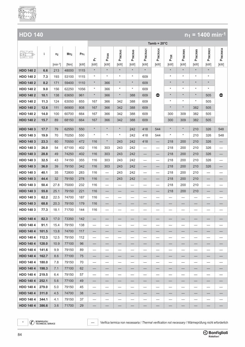
84
— Verifica termica non necessaria / Thermal verification not necessary / Wärmeprüfung nicht erforderlich*
HDO 140 n1 = 1400 min-1
Tamb = 20°C
i n2 Mn2 Pn1
P T P TFA
N
P TM
CRA5
P TM
CRA9
P TM
CRA2
1
P TM
CRA3
4
P TSR
P TM
CRW
5
P TM
CRW
9
P TM
CRW
21
P TM
CRW
34
[min-1] [Nm] [kW] [kW] [kW] [kW] [kW] [kW] [kW] [kW] [kW] [kW] [kW] [kW]
HDO 140 2 6.6 213 48000 1115 * * * * * * * * *
HDO 140 2 7.3 193 53100 1115 * * * * 609 * * * *
HDO 140 2 8.2 171 59400 1110 * 366 * * 609 * * * *
HDO 140 2 9.0 156 62250 1056 * 366 * * 609 * * * *
HDO 140 2 10.1 138 63650 961 * 366 * 388 609 * * * 505
HDO 140 2 11.3 124 63050 855 167 366 342 388 609 * * * 505
HDO 140 2 12.6 111 66900 808 167 366 342 388 609 * * 382 505
HDO 140 2 14.0 100 60700 664 167 366 342 388 609 300 309 382 505
HDO 140 2 15.7 89 68150 664 167 366 342 388 609 300 309 382 505
HDO 140 3 17.7 79 62550 550 * * * 242 418 544 * * 210 326 548
HDO 140 3 19.9 70 70250 550 * * * 242 418 544 * * 210 326 548
HDO 140 3 23.3 60 70550 472 116 * 243 242 418 — 218 200 210 326 —
HDO 140 3 26.0 54 67100 402 116 303 243 242 — — 218 200 210 326 —
HDO 140 3 28.8 49 74250 402 116 303 243 242 — — 218 200 210 326 —
HDO 140 3 32.5 43 74150 355 116 303 243 242 — — 218 200 210 326 —
HDO 140 3 36.0 39 79150 342 116 303 243 242 — — 218 200 210 326 —
HDO 140 3 40.1 35 72800 283 116 — 243 242 — — 218 200 210 — —
HDO 140 3 44.4 32 79150 278 116 — 243 242 — — 218 200 210 — —
HDO 140 3 50.4 27.8 75000 232 116 — — — — — 218 200 210 — —
HDO 140 3 55.8 25.1 79150 221 116 — — — — — 218 200 210 — —
HDO 140 3 62.2 22.5 74700 187 116 — — — — — — — — — —
HDO 140 3 68.8 20.3 79150 179 116 — — — — — — — — — —
HDO 140 3 77.3 18.1 71700 144 116 — — — — — — — — — —
HDO 140 4 82.3 17.0 73350 142 — — — — — — — — — — —
HDO 140 4 91.1 15.4 79150 138 — — — — — — — — — — —
HDO 140 4 101.5 13.8 74700 117 — — — — — — — — — — —
HDO 140 4 112.3 12.5 79150 112 — — — — — — — — — — —
HDO 140 4 128.0 10.9 77100 96 — — — — — — — — — — —
HDO 140 4 141.6 9.9 79150 89 — — — — — — — — — — —
HDO 140 4 162.7 8.6 77100 75 — — — — — — — — — — —
HDO 140 4 180.0 7.8 79150 70 — — — — — — — — — — —
HDO 140 4 198.3 7.1 77100 62 — — — — — — — — — — —
HDO 140 4 219.5 6.4 79150 57 — — — — — — — — — — —
HDO 140 4 252.1 5.6 77100 49 — — — — — — — — — — —
HDO 140 4 279.0 5.0 79150 45 — — — — — — — — — — —
HDO 140 4 311.0 4.5 74700 38 — — — — — — — — — — —
HDO 140 4 344.1 4.1 79150 37 — — — — — — — — — — —
HDO 140 4 386.6 3.6 71700 29 — — — — — — — — — — —
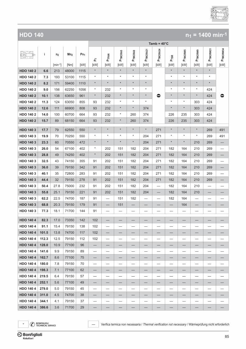
85
— Verifica termica non necessaria / Thermal verification not necessary / Wärmeprüfung nicht erforderlich*
HDO 140 n1 = 1400 min-1
Tamb = 40°C
i n2 Mn2 Pn1
P T P TFA
N
P TM
CRA5
P TM
CRA9
P TM
CRA2
1
P TM
CRA3
4
P TSR
P TM
CRW
5
P TM
CRW
9
P TM
CRW
21
P TM
CRW
34
[min-1] [Nm] [kW] [kW] [kW] [kW] [kW] [kW] [kW] [kW] [kW] [kW] [kW] [kW]
HDO 140 2 6.6 213 48000 1115 * * * * * * * * *
HDO 140 2 7.3 193 53100 1115 * * * * * * * * *
HDO 140 2 8.2 171 59400 1110 * * * * * * * * *
HDO 140 2 9.0 156 62250 1056 * 232 * * * * * * 424
HDO 140 2 10.1 138 63650 961 * 232 * * * * * * 424
HDO 140 2 11.3 124 63050 855 93 232 * * * * * 303 424
HDO 140 2 12.6 111 66900 808 93 232 * * 374 * * 303 424
HDO 140 2 14.0 100 60700 664 93 232 * 260 374 226 235 303 424
HDO 140 2 15.7 89 68150 664 93 232 * 260 374 226 235 303 424
HDO 140 3 17.7 79 62550 550 * * * * * 271 * * * 269 491
HDO 140 3 19.9 70 70250 550 * * * * 204 271 * * * 269 491
HDO 140 3 23.3 60 70550 472 * * * * 204 271 * * 210 269 —
HDO 140 3 26.0 54 67100 402 * 202 151 182 204 271 182 164 210 269 —
HDO 140 3 28.8 49 74250 402 * 202 151 182 204 271 182 164 210 269 —
HDO 140 3 32.5 43 74150 355 91 202 151 182 204 271 182 164 210 269 —
HDO 140 3 36.0 39 79150 342 91 202 151 182 204 271 182 164 210 269 —
HDO 140 3 40.1 35 72800 283 91 202 151 182 204 271 182 164 210 269 —
HDO 140 3 44.4 32 79150 278 91 202 151 182 204 271 182 164 210 269 —
HDO 140 3 50.4 27.8 75000 232 91 202 151 182 204 — 182 164 210 — —
HDO 140 3 55.8 25.1 79150 221 91 202 151 182 204 — 182 164 210 — —
HDO 140 3 62.2 22.5 74700 187 91 — 151 182 — — 182 164 — — —
HDO 140 3 68.8 20.3 79150 179 91 — 151 — — — — 164 — — —
HDO 140 3 77.3 18.1 71700 144 91 — — — — — — — — — —
HDO 140 4 82.3 17.0 73350 142 102 — — — — — — — — — —
HDO 140 4 91.1 15.4 79150 138 102 — — — — — — — — — —
HDO 140 4 101.5 13.8 74700 117 102 — — — — — — — — — —
HDO 140 4 112.3 12.5 79150 112 102 — — — — — — — — — —
HDO 140 4 128.0 10.9 77100 96 — — — — — — — — — — —
HDO 140 4 141.6 9.9 79150 89 — — — — — — — — — — —
HDO 140 4 162.7 8.6 77100 75 — — — — — — — — — — —
HDO 140 4 180.0 7.8 79150 70 — — — — — — — — — — —
HDO 140 4 198.3 7.1 77100 62 — — — — — — — — — — —
HDO 140 4 219.5 6.4 79150 57 — — — — — — — — — — —
HDO 140 4 252.1 5.6 77100 49 — — — — — — — — — — —
HDO 140 4 279.0 5.0 79150 45 — — — — — — — — — — —
HDO 140 4 311.0 4.5 74700 38 — — — — — — — — — — —
HDO 140 4 344.1 4.1 79150 37 — — — — — — — — — — —
HDO 140 4 386.6 3.6 71700 29 — — — — — — — — — — —
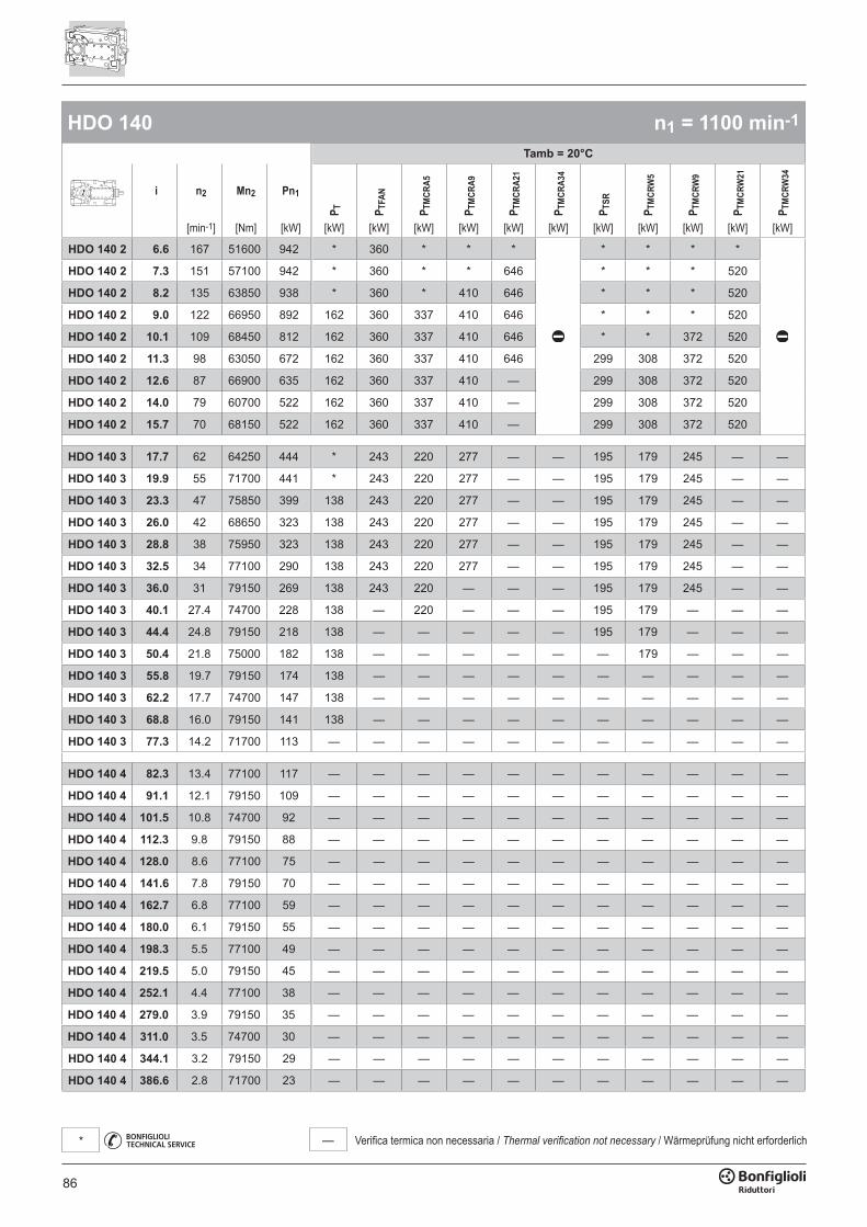
86
— Verifica termica non necessaria / Thermal verification not necessary / Wärmeprüfung nicht erforderlich*
HDO 140 n1 = 1100 min-1
Tamb = 20°C
i n2 Mn2 Pn1
P T P TFA
N
P TM
CRA5
P TM
CRA9
P TM
CRA2
1
P TM
CRA3
4
P TSR
P TM
CRW
5
P TM
CRW
9
P TM
CRW
21
P TM
CRW
34
[min-1] [Nm] [kW] [kW] [kW] [kW] [kW] [kW] [kW] [kW] [kW] [kW] [kW] [kW]
HDO 140 2 6.6 167 51600 942 * 360 * * * * * * *
HDO 140 2 7.3 151 57100 942 * 360 * * 646 * * * 520
HDO 140 2 8.2 135 63850 938 * 360 * 410 646 * * * 520
HDO 140 2 9.0 122 66950 892 162 360 337 410 646 * * * 520
HDO 140 2 10.1 109 68450 812 162 360 337 410 646 * * 372 520
HDO 140 2 11.3 98 63050 672 162 360 337 410 646 299 308 372 520
HDO 140 2 12.6 87 66900 635 162 360 337 410 — 299 308 372 520
HDO 140 2 14.0 79 60700 522 162 360 337 410 — 299 308 372 520
HDO 140 2 15.7 70 68150 522 162 360 337 410 — 299 308 372 520
HDO 140 3 17.7 62 64250 444 * 243 220 277 — — 195 179 245 — —
HDO 140 3 19.9 55 71700 441 * 243 220 277 — — 195 179 245 — —
HDO 140 3 23.3 47 75850 399 138 243 220 277 — — 195 179 245 — —
HDO 140 3 26.0 42 68650 323 138 243 220 277 — — 195 179 245 — —
HDO 140 3 28.8 38 75950 323 138 243 220 277 — — 195 179 245 — —
HDO 140 3 32.5 34 77100 290 138 243 220 277 — — 195 179 245 — —
HDO 140 3 36.0 31 79150 269 138 243 220 — — — 195 179 245 — —
HDO 140 3 40.1 27.4 74700 228 138 — 220 — — — 195 179 — — —
HDO 140 3 44.4 24.8 79150 218 138 — — — — — 195 179 — — —
HDO 140 3 50.4 21.8 75000 182 138 — — — — — — 179 — — —
HDO 140 3 55.8 19.7 79150 174 138 — — — — — — — — — —
HDO 140 3 62.2 17.7 74700 147 138 — — — — — — — — — —
HDO 140 3 68.8 16.0 79150 141 138 — — — — — — — — — —
HDO 140 3 77.3 14.2 71700 113 — — — — — — — — — — —
HDO 140 4 82.3 13.4 77100 117 — — — — — — — — — — —
HDO 140 4 91.1 12.1 79150 109 — — — — — — — — — — —
HDO 140 4 101.5 10.8 74700 92 — — — — — — — — — — —
HDO 140 4 112.3 9.8 79150 88 — — — — — — — — — — —
HDO 140 4 128.0 8.6 77100 75 — — — — — — — — — — —
HDO 140 4 141.6 7.8 79150 70 — — — — — — — — — — —
HDO 140 4 162.7 6.8 77100 59 — — — — — — — — — — —
HDO 140 4 180.0 6.1 79150 55 — — — — — — — — — — —
HDO 140 4 198.3 5.5 77100 49 — — — — — — — — — — —
HDO 140 4 219.5 5.0 79150 45 — — — — — — — — — — —
HDO 140 4 252.1 4.4 77100 38 — — — — — — — — — — —
HDO 140 4 279.0 3.9 79150 35 — — — — — — — — — — —
HDO 140 4 311.0 3.5 74700 30 — — — — — — — — — — —
HDO 140 4 344.1 3.2 79150 29 — — — — — — — — — — —
HDO 140 4 386.6 2.8 71700 23 — — — — — — — — — — —
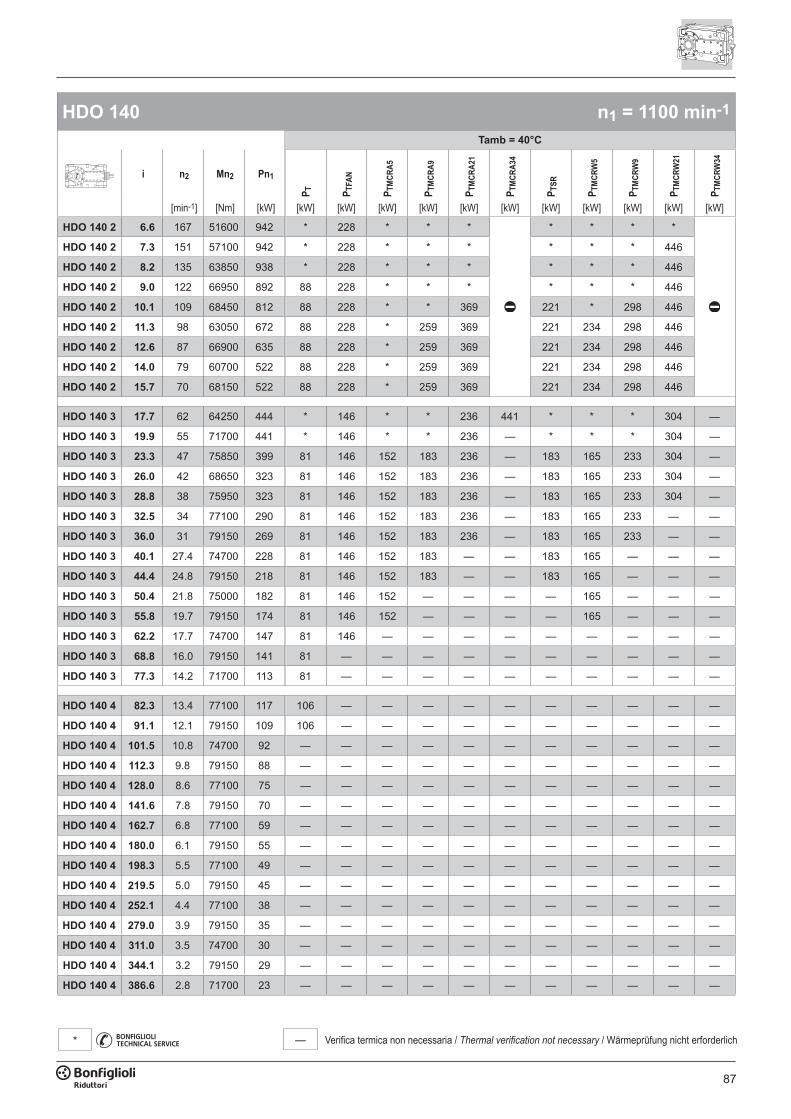
87
— Verifica termica non necessaria / Thermal verification not necessary / Wärmeprüfung nicht erforderlich*
HDO 140 n1 = 1100 min-1
Tamb = 40°C
i n2 Mn2 Pn1
P T P TFA
N
P TM
CRA5
P TM
CRA9
P TM
CRA2
1
P TM
CRA3
4
P TSR
P TM
CRW
5
P TM
CRW
9
P TM
CRW
21
P TM
CRW
34
[min-1] [Nm] [kW] [kW] [kW] [kW] [kW] [kW] [kW] [kW] [kW] [kW] [kW] [kW]
HDO 140 2 6.6 167 51600 942 * 228 * * * * * * *
HDO 140 2 7.3 151 57100 942 * 228 * * * * * * 446
HDO 140 2 8.2 135 63850 938 * 228 * * * * * * 446
HDO 140 2 9.0 122 66950 892 88 228 * * * * * * 446
HDO 140 2 10.1 109 68450 812 88 228 * * 369 221 * 298 446
HDO 140 2 11.3 98 63050 672 88 228 * 259 369 221 234 298 446
HDO 140 2 12.6 87 66900 635 88 228 * 259 369 221 234 298 446
HDO 140 2 14.0 79 60700 522 88 228 * 259 369 221 234 298 446
HDO 140 2 15.7 70 68150 522 88 228 * 259 369 221 234 298 446
HDO 140 3 17.7 62 64250 444 * 146 * * 236 441 * * * 304 —
HDO 140 3 19.9 55 71700 441 * 146 * * 236 — * * * 304 —
HDO 140 3 23.3 47 75850 399 81 146 152 183 236 — 183 165 233 304 —
HDO 140 3 26.0 42 68650 323 81 146 152 183 236 — 183 165 233 304 —
HDO 140 3 28.8 38 75950 323 81 146 152 183 236 — 183 165 233 304 —
HDO 140 3 32.5 34 77100 290 81 146 152 183 236 — 183 165 233 — —
HDO 140 3 36.0 31 79150 269 81 146 152 183 236 — 183 165 233 — —
HDO 140 3 40.1 27.4 74700 228 81 146 152 183 — — 183 165 — — —
HDO 140 3 44.4 24.8 79150 218 81 146 152 183 — — 183 165 — — —
HDO 140 3 50.4 21.8 75000 182 81 146 152 — — — — 165 — — —
HDO 140 3 55.8 19.7 79150 174 81 146 152 — — — — 165 — — —
HDO 140 3 62.2 17.7 74700 147 81 146 — — — — — — — — —
HDO 140 3 68.8 16.0 79150 141 81 — — — — — — — — — —
HDO 140 3 77.3 14.2 71700 113 81 — — — — — — — — — —
HDO 140 4 82.3 13.4 77100 117 106 — — — — — — — — — —
HDO 140 4 91.1 12.1 79150 109 106 — — — — — — — — — —
HDO 140 4 101.5 10.8 74700 92 — — — — — — — — — — —
HDO 140 4 112.3 9.8 79150 88 — — — — — — — — — — —
HDO 140 4 128.0 8.6 77100 75 — — — — — — — — — — —
HDO 140 4 141.6 7.8 79150 70 — — — — — — — — — — —
HDO 140 4 162.7 6.8 77100 59 — — — — — — — — — — —
HDO 140 4 180.0 6.1 79150 55 — — — — — — — — — — —
HDO 140 4 198.3 5.5 77100 49 — — — — — — — — — — —
HDO 140 4 219.5 5.0 79150 45 — — — — — — — — — — —
HDO 140 4 252.1 4.4 77100 38 — — — — — — — — — — —
HDO 140 4 279.0 3.9 79150 35 — — — — — — — — — — —
HDO 140 4 311.0 3.5 74700 30 — — — — — — — — — — —
HDO 140 4 344.1 3.2 79150 29 — — — — — — — — — — —
HDO 140 4 386.6 2.8 71700 23 — — — — — — — — — — —

88
— Verifica termica non necessaria / Thermal verification not necessary / Wärmeprüfung nicht erforderlich*
HDO 140 n1 = 900 min-1
Tamb = 20°C
i n2 Mn2 Pn1
P T P TFA
N
P TM
CRA5
P TM
CRA9
P TM
CRA2
1
P TM
CRA3
4
P TSR
P TM
CRW
5
P TM
CRW
9
P TM
CRW
21
P TM
CRW
34
[min-1] [Nm] [kW] [kW] [kW] [kW] [kW] [kW] [kW] [kW] [kW] [kW] [kW] [kW]
HDO 140 2 6.6 137 54800 819 168 338 343 421 664 275 * 378 538
HDO 140 2 7.3 124 60600 818 168 338 343 421 664 275 * 378 538
HDO 140 2 8.2 110 67800 815 168 338 343 421 664 275 * 378 538
HDO 140 2 9.0 100 71100 775 168 338 343 421 664 275 * 378 538
HDO 140 2 10.1 89 71600 695 168 338 343 421 664 275 300 378 538
HDO 140 2 11.3 80 64000 558 168 338 343 421 — 275 300 378 538
HDO 140 2 12.6 71 71700 557 168 338 343 421 — 275 300 378 538
HDO 140 2 14.0 65 60700 427 168 338 343 421 — 275 300 378 —
HDO 140 2 15.7 57 68150 427 168 338 343 421 — 275 300 378 —
HDO 140 3 17.7 51 64250 363 116 232 243 300 — — 218 200 268 — —
HDO 140 3 19.9 45 71700 361 116 232 243 300 — — 218 200 268 — —
HDO 140 3 23.3 39 78400 337 116 232 243 300 — — 218 200 268 — —
HDO 140 3 26.0 35 68650 264 116 232 243 — — — 218 200 — — —
HDO 140 3 28.8 31 75950 264 116 232 243 — — — 218 200 — — —
HDO 140 3 32.5 27.7 77100 237 116 232 — — — — 218 200 — — —
HDO 140 3 36.0 25.0 79150 220 116 — — — — — 218 200 — — —
HDO 140 3 40.1 22.4 74700 186 116 — — — — — — — — — —
HDO 140 3 44.4 20.3 79150 178 116 — — — — — — — — — —
HDO 140 3 50.4 17.8 75000 149 116 — — — — — — — — — —
HDO 140 3 55.8 16.1 79150 142 116 — — — — — — — — — —
HDO 140 3 62.2 14.5 74700 120 116 — — — — — — — — — —
HDO 140 3 68.8 13.1 79150 115 — — — — — — — — — — —
HDO 140 3 77.3 11.6 71700 93 — — — — — — — — — — —
HDO 140 4 82.3 10.9 77100 96 — — — — — — — — — — —
HDO 140 4 91.1 9.9 79150 89 — — — — — — — — — — —
HDO 140 4 101.5 8.9 74700 75 — — — — — — — — — — —
HDO 140 4 112.3 8.0 79150 72 — — — — — — — — — — —
HDO 140 4 128.0 7.0 77100 62 — — — — — — — — — — —
HDO 140 4 141.6 6.4 79150 57 — — — — — — — — — — —
HDO 140 4 162.7 5.5 77100 48 — — — — — — — — — — —
HDO 140 4 180.0 5.0 79150 45 — — — — — — — — — — —
HDO 140 4 198.3 4.5 77100 40 — — — — — — — — — — —
HDO 140 4 219.5 4.1 79150 37 — — — — — — — — — — —
HDO 140 4 252.1 3.6 77100 31 — — — — — — — — — — —
HDO 140 4 279.0 3.2 79150 29 — — — — — — — — — — —
HDO 140 4 311.0 2.9 74700 25 — — — — — — — — — — —
HDO 140 4 344.1 2.6 79150 24 — — — — — — — — — — —
HDO 140 4 386.6 2.3 71700 19.0 — — — — — — — — — — —
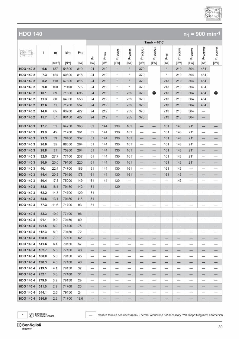
89
— Verifica termica non necessaria / Thermal verification not necessary / Wärmeprüfung nicht erforderlich*
HDO 140 n1 = 900 min-1
Tamb = 40°C
i n2 Mn2 Pn1
P T P TFA
N
P TM
CRA5
P TM
CRA9
P TM
CRA2
1
P TM
CRA3
4
P TSR
P TM
CRW
5
P TM
CRW
9
P TM
CRW
21
P TM
CRW
34
[min-1] [Nm] [kW] [kW] [kW] [kW] [kW] [kW] [kW] [kW] [kW] [kW] [kW] [kW]
HDO 140 2 6.6 137 54800 819 94 219 * * 370 * 210 304 464
HDO 140 2 7.3 124 60600 818 94 219 * * 370 * 210 304 464
HDO 140 2 8.2 110 67800 815 94 219 * * 370 213 210 304 464
HDO 140 2 9.0 100 71100 775 94 219 * * 370 213 210 304 464
HDO 140 2 10.1 89 71600 695 94 219 * 255 370 213 210 304 464
HDO 140 2 11.3 80 64000 558 94 219 * 255 370 213 210 304 464
HDO 140 2 12.6 71 71700 557 94 219 * 255 370 213 210 304 464
HDO 140 2 14.0 65 60700 427 94 219 * 255 370 213 210 304 —
HDO 140 2 15.7 57 68150 427 94 219 * 255 370 213 210 304 —
HDO 140 3 17.7 51 64250 363 61 144 130 161 — — 161 143 211 — —
HDO 140 3 19.9 45 71700 361 61 144 130 161 — — 161 143 211 — —
HDO 140 3 23.3 39 78400 337 61 144 130 161 — — 161 143 211 — —
HDO 140 3 26.0 35 68650 264 61 144 130 161 — — 161 143 211 — —
HDO 140 3 28.8 31 75950 264 61 144 130 161 — — 161 143 211 — —
HDO 140 3 32.5 27.7 77100 237 61 144 130 161 — — 161 143 211 — —
HDO 140 3 36.0 25.0 79150 220 61 144 130 161 — — 161 143 211 — —
HDO 140 3 40.1 22.4 74700 186 61 144 130 161 — — 161 143 — — —
HDO 140 3 44.4 20.3 79150 178 61 144 130 161 — — 161 143 — — —
HDO 140 3 50.4 17.8 75000 149 61 144 130 — — — — 143 — — —
HDO 140 3 55.8 16.1 79150 142 61 — 130 — — — — — — — —
HDO 140 3 62.2 14.5 74700 120 61 — — — — — — — — — —
HDO 140 3 68.8 13.1 79150 115 61 — — — — — — — — — —
HDO 140 3 77.3 11.6 71700 93 61 — — — — — — — — — —
HDO 140 4 82.3 10.9 77100 96 — — — — — — — — — — —
HDO 140 4 91.1 9.9 79150 89 — — — — — — — — — — —
HDO 140 4 101.5 8.9 74700 75 — — — — — — — — — — —
HDO 140 4 112.3 8.0 79150 72 — — — — — — — — — — —
HDO 140 4 128.0 7.0 77100 62 — — — — — — — — — — —
HDO 140 4 141.6 6.4 79150 57 — — — — — — — — — — —
HDO 140 4 162.7 5.5 77100 48 — — — — — — — — — — —
HDO 140 4 180.0 5.0 79150 45 — — — — — — — — — — —
HDO 140 4 198.3 4.5 77100 40 — — — — — — — — — — —
HDO 140 4 219.5 4.1 79150 37 — — — — — — — — — — —
HDO 140 4 252.1 3.6 77100 31 — — — — — — — — — — —
HDO 140 4 279.0 3.2 79150 29 — — — — — — — — — — —
HDO 140 4 311.0 2.9 74700 25 — — — — — — — — — — —
HDO 140 4 344.1 2.6 79150 24 — — — — — — — — — — —
HDO 140 4 386.6 2.3 71700 19.0 — — — — — — — — — — —
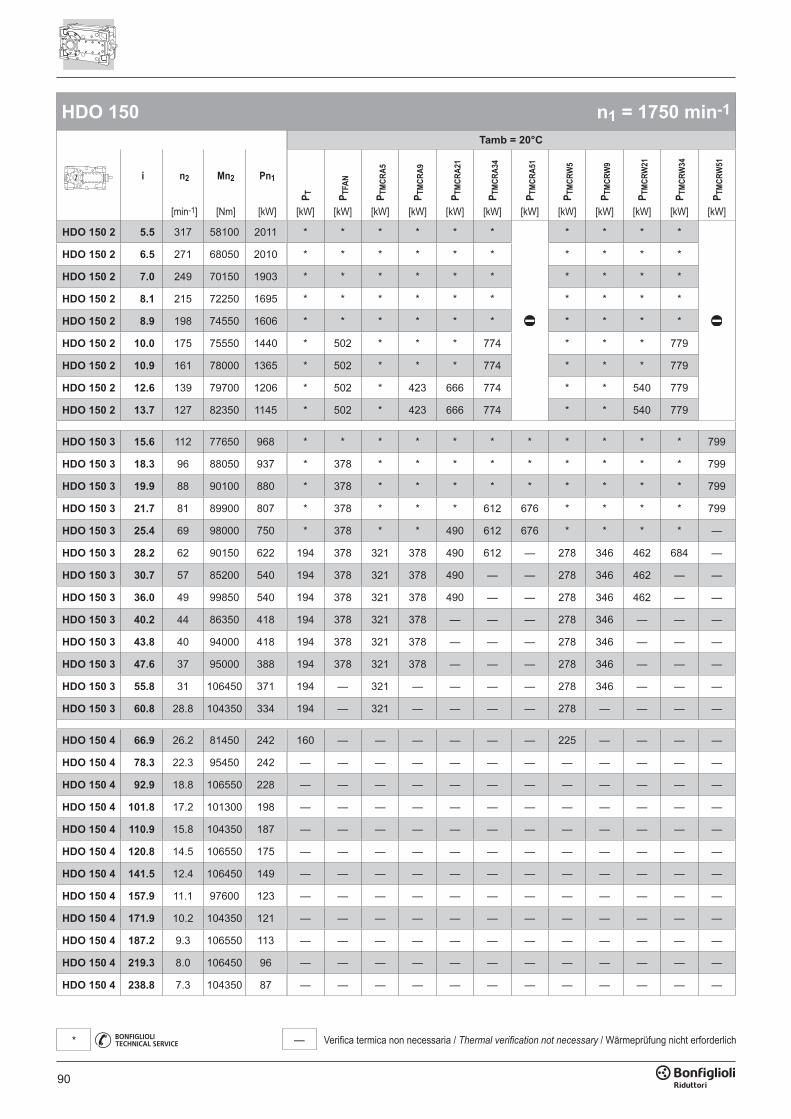
90
— Verifica termica non necessaria / Thermal verification not necessary / Wärmeprüfung nicht erforderlich*
HDO 150 n1 = 1750 min-1
Tamb = 20°C
i n2 Mn2 Pn1
P T P TFA
N
P TM
CRA5
P TM
CRA9
P TM
CRA2
1
P TM
CRA3
4
P TM
CRA5
1
P TM
CRW
5
P TM
CRW
9
P TM
CRW
21
P TM
CRW
34
P TM
CRW
51
[min-1] [Nm] [kW] [kW] [kW] [kW] [kW] [kW] [kW] [kW] [kW] [kW] [kW] [kW] [kW]
HDO 150 2 5.5 317 58100 2011 * * * * * * * * * *
HDO 150 2 6.5 271 68050 2010 * * * * * * * * * *
HDO 150 2 7.0 249 70150 1903 * * * * * * * * * *
HDO 150 2 8.1 215 72250 1695 * * * * * * * * * *
HDO 150 2 8.9 198 74550 1606 * * * * * * * * * *
HDO 150 2 10.0 175 75550 1440 * 502 * * * 774 * * * 779
HDO 150 2 10.9 161 78000 1365 * 502 * * * 774 * * * 779
HDO 150 2 12.6 139 79700 1206 * 502 * 423 666 774 * * 540 779
HDO 150 2 13.7 127 82350 1145 * 502 * 423 666 774 * * 540 779
HDO 150 3 15.6 112 77650 968 * * * * * * * * * * * 799
HDO 150 3 18.3 96 88050 937 * 378 * * * * * * * * * 799
HDO 150 3 19.9 88 90100 880 * 378 * * * * * * * * * 799
HDO 150 3 21.7 81 89900 807 * 378 * * * 612 676 * * * * 799
HDO 150 3 25.4 69 98000 750 * 378 * * 490 612 676 * * * * —
HDO 150 3 28.2 62 90150 622 194 378 321 378 490 612 — 278 346 462 684 —
HDO 150 3 30.7 57 85200 540 194 378 321 378 490 — — 278 346 462 — —
HDO 150 3 36.0 49 99850 540 194 378 321 378 490 — — 278 346 462 — —
HDO 150 3 40.2 44 86350 418 194 378 321 378 — — — 278 346 — — —
HDO 150 3 43.8 40 94000 418 194 378 321 378 — — — 278 346 — — —
HDO 150 3 47.6 37 95000 388 194 378 321 378 — — — 278 346 — — —
HDO 150 3 55.8 31 106450 371 194 — 321 — — — — 278 346 — — —
HDO 150 3 60.8 28.8 104350 334 194 — 321 — — — — 278 — — — —
HDO 150 4 66.9 26.2 81450 242 160 — — — — — — 225 — — — —
HDO 150 4 78.3 22.3 95450 242 — — — — — — — — — — — —
HDO 150 4 92.9 18.8 106550 228 — — — — — — — — — — — —
HDO 150 4 101.8 17.2 101300 198 — — — — — — — — — — — —
HDO 150 4 110.9 15.8 104350 187 — — — — — — — — — — — —
HDO 150 4 120.8 14.5 106550 175 — — — — — — — — — — — —
HDO 150 4 141.5 12.4 106450 149 — — — — — — — — — — — —
HDO 150 4 157.9 11.1 97600 123 — — — — — — — — — — — —
HDO 150 4 171.9 10.2 104350 121 — — — — — — — — — — — —
HDO 150 4 187.2 9.3 106550 113 — — — — — — — — — — — —
HDO 150 4 219.3 8.0 106450 96 — — — — — — — — — — — —
HDO 150 4 238.8 7.3 104350 87 — — — — — — — — — — — —
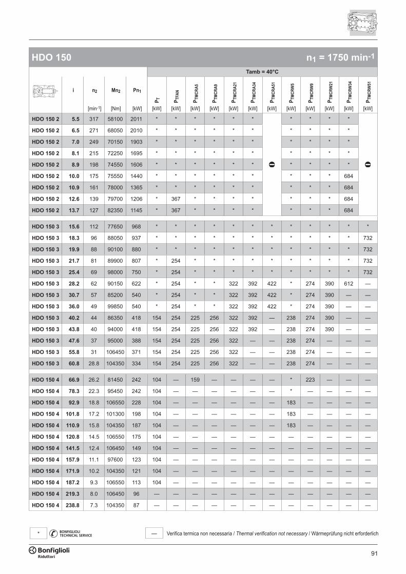
91
— Verifica termica non necessaria / Thermal verification not necessary / Wärmeprüfung nicht erforderlich*
HDO 150 n1 = 1750 min-1
Tamb = 40°C
i n2 Mn2 Pn1
P T P TFA
N
P TM
CRA5
P TM
CRA9
P TM
CRA2
1
P TM
CRA3
4
P TM
CRA5
1
P TM
CRW
5
P TM
CRW
9
P TM
CRW
21
P TM
CRW
34
P TM
CRW
51
[min-1] [Nm] [kW] [kW] [kW] [kW] [kW] [kW] [kW] [kW] [kW] [kW] [kW] [kW] [kW]
HDO 150 2 5.5 317 58100 2011 * * * * * * * * * *
HDO 150 2 6.5 271 68050 2010 * * * * * * * * * *
HDO 150 2 7.0 249 70150 1903 * * * * * * * * * *
HDO 150 2 8.1 215 72250 1695 * * * * * * * * * *
HDO 150 2 8.9 198 74550 1606 * * * * * * * * * *
HDO 150 2 10.0 175 75550 1440 * * * * * * * * * 684
HDO 150 2 10.9 161 78000 1365 * * * * * * * * * 684
HDO 150 2 12.6 139 79700 1206 * 367 * * * * * * * 684
HDO 150 2 13.7 127 82350 1145 * 367 * * * * * * * 684
HDO 150 3 15.6 112 77650 968 * * * * * * * * * * * *
HDO 150 3 18.3 96 88050 937 * * * * * * * * * * * 732
HDO 150 3 19.9 88 90100 880 * * * * * * * * * * * 732
HDO 150 3 21.7 81 89900 807 * 254 * * * * * * * * * 732
HDO 150 3 25.4 69 98000 750 * 254 * * * * * * * * * 732
HDO 150 3 28.2 62 90150 622 * 254 * * 322 392 422 * 274 390 612 —
HDO 150 3 30.7 57 85200 540 * 254 * * 322 392 422 * 274 390 — —
HDO 150 3 36.0 49 99850 540 * 254 * * 322 392 422 * 274 390 — —
HDO 150 3 40.2 44 86350 418 154 254 225 256 322 392 — 238 274 390 — —
HDO 150 3 43.8 40 94000 418 154 254 225 256 322 392 — 238 274 390 — —
HDO 150 3 47.6 37 95000 388 154 254 225 256 322 — — 238 274 — — —
HDO 150 3 55.8 31 106450 371 154 254 225 256 322 — — 238 274 — — —
HDO 150 3 60.8 28.8 104350 334 154 254 225 256 322 — — 238 274 — — —
HDO 150 4 66.9 26.2 81450 242 104 — 159 — — — — * 223 — — —
HDO 150 4 78.3 22.3 95450 242 104 — — — — — — * — — — —
HDO 150 4 92.9 18.8 106550 228 104 — — — — — — 183 — — — —
HDO 150 4 101.8 17.2 101300 198 104 — — — — — — 183 — — — —
HDO 150 4 110.9 15.8 104350 187 104 — — — — — — 183 — — — —
HDO 150 4 120.8 14.5 106550 175 104 — — — — — — — — — — —
HDO 150 4 141.5 12.4 106450 149 104 — — — — — — — — — — —
HDO 150 4 157.9 11.1 97600 123 104 — — — — — — — — — — —
HDO 150 4 171.9 10.2 104350 121 104 — — — — — — — — — — —
HDO 150 4 187.2 9.3 106550 113 104 — — — — — — — — — — —
HDO 150 4 219.3 8.0 106450 96 — — — — — — — — — — — —
HDO 150 4 238.8 7.3 104350 87 — — — — — — — — — — — —
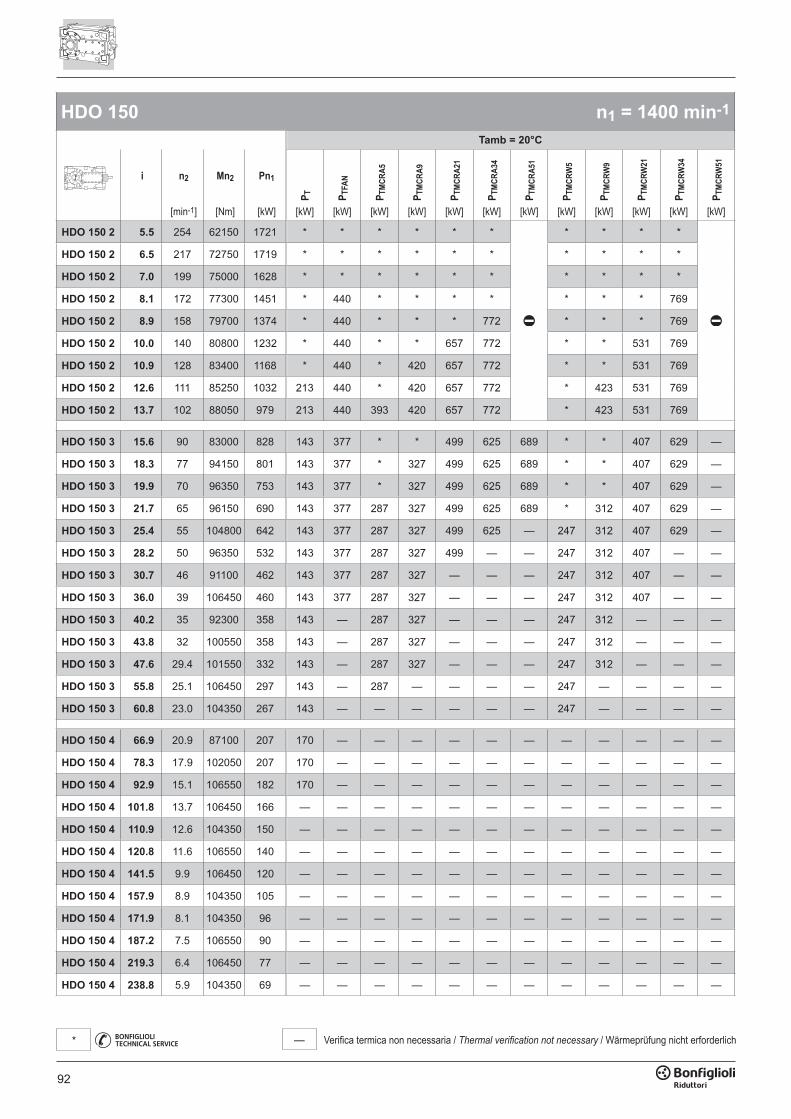
92
— Verifica termica non necessaria / Thermal verification not necessary / Wärmeprüfung nicht erforderlich*
HDO 150 n1 = 1400 min-1
Tamb = 20°C
i n2 Mn2 Pn1
P T P TFA
N
P TM
CRA5
P TM
CRA9
P TM
CRA2
1
P TM
CRA3
4
P TM
CRA5
1
P TM
CRW
5
P TM
CRW
9
P TM
CRW
21
P TM
CRW
34
P TM
CRW
51
[min-1] [Nm] [kW] [kW] [kW] [kW] [kW] [kW] [kW] [kW] [kW] [kW] [kW] [kW] [kW]
HDO 150 2 5.5 254 62150 1721 * * * * * * * * * *
HDO 150 2 6.5 217 72750 1719 * * * * * * * * * *
HDO 150 2 7.0 199 75000 1628 * * * * * * * * * *
HDO 150 2 8.1 172 77300 1451 * 440 * * * * * * * 769
HDO 150 2 8.9 158 79700 1374 * 440 * * * 772 * * * 769
HDO 150 2 10.0 140 80800 1232 * 440 * * 657 772 * * 531 769
HDO 150 2 10.9 128 83400 1168 * 440 * 420 657 772 * * 531 769
HDO 150 2 12.6 111 85250 1032 213 440 * 420 657 772 * 423 531 769
HDO 150 2 13.7 102 88050 979 213 440 393 420 657 772 * 423 531 769
HDO 150 3 15.6 90 83000 828 143 377 * * 499 625 689 * * 407 629 —
HDO 150 3 18.3 77 94150 801 143 377 * 327 499 625 689 * * 407 629 —
HDO 150 3 19.9 70 96350 753 143 377 * 327 499 625 689 * * 407 629 —
HDO 150 3 21.7 65 96150 690 143 377 287 327 499 625 689 * 312 407 629 —
HDO 150 3 25.4 55 104800 642 143 377 287 327 499 625 — 247 312 407 629 —
HDO 150 3 28.2 50 96350 532 143 377 287 327 499 — — 247 312 407 — —
HDO 150 3 30.7 46 91100 462 143 377 287 327 — — — 247 312 407 — —
HDO 150 3 36.0 39 106450 460 143 377 287 327 — — — 247 312 407 — —
HDO 150 3 40.2 35 92300 358 143 — 287 327 — — — 247 312 — — —
HDO 150 3 43.8 32 100550 358 143 — 287 327 — — — 247 312 — — —
HDO 150 3 47.6 29.4 101550 332 143 — 287 327 — — — 247 312 — — —
HDO 150 3 55.8 25.1 106450 297 143 — 287 — — — — 247 — — — —
HDO 150 3 60.8 23.0 104350 267 143 — — — — — — 247 — — — —
HDO 150 4 66.9 20.9 87100 207 170 — — — — — — — — — — —
HDO 150 4 78.3 17.9 102050 207 170 — — — — — — — — — — —
HDO 150 4 92.9 15.1 106550 182 170 — — — — — — — — — — —
HDO 150 4 101.8 13.7 106450 166 — — — — — — — — — — — —
HDO 150 4 110.9 12.6 104350 150 — — — — — — — — — — — —
HDO 150 4 120.8 11.6 106550 140 — — — — — — — — — — — —
HDO 150 4 141.5 9.9 106450 120 — — — — — — — — — — — —
HDO 150 4 157.9 8.9 104350 105 — — — — — — — — — — — —
HDO 150 4 171.9 8.1 104350 96 — — — — — — — — — — — —
HDO 150 4 187.2 7.5 106550 90 — — — — — — — — — — — —
HDO 150 4 219.3 6.4 106450 77 — — — — — — — — — — — —
HDO 150 4 238.8 5.9 104350 69 — — — — — — — — — — — —

93
— Verifica termica non necessaria / Thermal verification not necessary / Wärmeprüfung nicht erforderlich*
HDO 150 n1 = 1400 min-1
Tamb = 40°C
i n2 Mn2 Pn1
P T P TFA
N
P TM
CRA5
P TM
CRA9
P TM
CRA2
1
P TM
CRA3
4
P TM
CRA5
1
P TM
CRW
5
P TM
CRW
9
P TM
CRW
21
P TM
CRW
34
P TM
CRW
51
[min-1] [Nm] [kW] [kW] [kW] [kW] [kW] [kW] [kW] [kW] [kW] [kW] [kW] [kW] [kW]
HDO 150 2 5.5 254 62150 1721 * * * * * * * * * *
HDO 150 2 6.5 217 72750 1719 * * * * * * * * * *
HDO 150 2 7.0 199 75000 1628 * * * * * * * * * *
HDO 150 2 8.1 172 77300 1451 * * * * * * * * * 674
HDO 150 2 8.9 158 79700 1374 * * * * * * * * * 674
HDO 150 2 10.0 140 80800 1232 * 320 * * * * * * * 674
HDO 150 2 10.9 128 83400 1168 * 320 * * * * * * * 674
HDO 150 2 12.6 111 85250 1032 118 320 * * 394 491 * * 488 674
HDO 150 2 13.7 102 88050 979 118 320 * * 394 491 * * 488 674
HDO 150 3 15.6 90 83000 828 * 241 * * * * * * * * * 767
HDO 150 3 18.3 77 94150 801 * 241 * * * 341 371 * * * 561 767
HDO 150 3 19.9 70 96350 753 * 241 * * * 341 371 * * 341 561 —
HDO 150 3 21.7 65 96150 690 * 241 * * 287 341 371 * * 341 561 —
HDO 150 3 25.4 55 104800 642 * 241 * * 287 341 371 * 242 341 561 —
HDO 150 3 28.2 50 96350 532 140 241 211 242 287 341 371 224 242 341 — —
HDO 150 3 30.7 46 91100 462 140 241 211 242 287 341 371 224 242 341 — —
HDO 150 3 36.0 39 106450 460 140 241 211 242 287 341 371 224 242 341 — —
HDO 150 3 40.2 35 92300 358 140 241 211 242 287 341 — 224 242 341 — —
HDO 150 3 43.8 32 100550 358 140 241 211 242 287 341 — 224 242 341 — —
HDO 150 3 47.6 29.4 101550 332 140 241 211 242 287 — — 224 242 — — —
HDO 150 3 55.8 25.1 106450 297 140 241 211 242 287 — — 224 242 — — —
HDO 150 3 60.8 23.0 104350 267 140 241 211 242 — — — 224 242 — — —
HDO 150 4 66.9 20.9 87100 207 115 — 170 195 — — — 181 — — — —
HDO 150 4 78.3 17.9 102050 207 115 — 170 195 — — — 181 — — — —
HDO 150 4 92.9 15.1 106550 182 115 — 170 — — — — 181 — — — —
HDO 150 4 101.8 13.7 106450 166 115 — — — — — — — — — — —
HDO 150 4 110.9 12.6 104350 150 115 — — — — — — — — — — —
HDO 150 4 120.8 11.6 106550 140 115 — — — — — — — — — — —
HDO 150 4 141.5 9.9 106450 120 — — — — — — — — — — — —
HDO 150 4 157.9 8.9 104350 105 — — — — — — — — — — — —
HDO 150 4 171.9 8.1 104350 96 — — — — — — — — — — — —
HDO 150 4 187.2 7.5 106550 90 — — — — — — — — — — — —
HDO 150 4 219.3 6.4 106450 77 — — — — — — — — — — — —
HDO 150 4 238.8 5.9 104350 69 — — — — — — — — — — — —
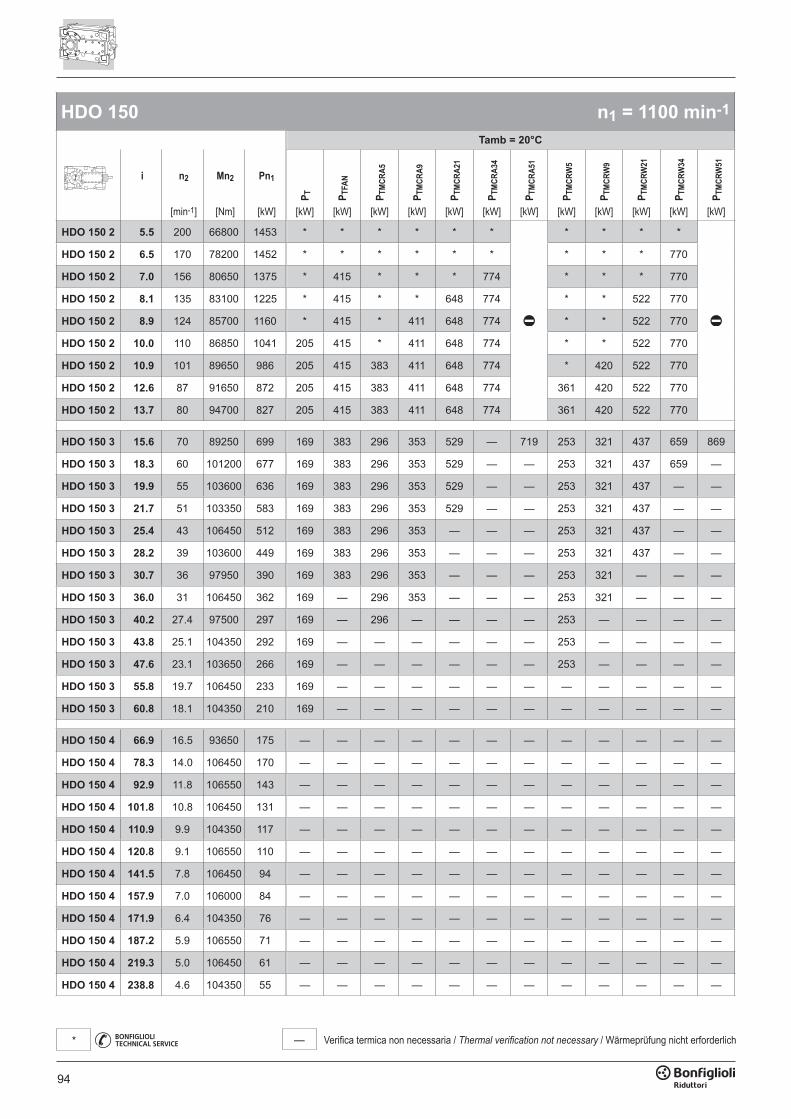
94
— Verifica termica non necessaria / Thermal verification not necessary / Wärmeprüfung nicht erforderlich*
HDO 150 n1 = 1100 min-1
Tamb = 20°C
i n2 Mn2 Pn1
P T P TFA
N
P TM
CRA5
P TM
CRA9
P TM
CRA2
1
P TM
CRA3
4
P TM
CRA5
1
P TM
CRW
5
P TM
CRW
9
P TM
CRW
21
P TM
CRW
34
P TM
CRW
51
[min-1] [Nm] [kW] [kW] [kW] [kW] [kW] [kW] [kW] [kW] [kW] [kW] [kW] [kW] [kW]
HDO 150 2 5.5 200 66800 1453 * * * * * * * * * *
HDO 150 2 6.5 170 78200 1452 * * * * * * * * * 770
HDO 150 2 7.0 156 80650 1375 * 415 * * * 774 * * * 770
HDO 150 2 8.1 135 83100 1225 * 415 * * 648 774 * * 522 770
HDO 150 2 8.9 124 85700 1160 * 415 * 411 648 774 * * 522 770
HDO 150 2 10.0 110 86850 1041 205 415 * 411 648 774 * * 522 770
HDO 150 2 10.9 101 89650 986 205 415 383 411 648 774 * 420 522 770
HDO 150 2 12.6 87 91650 872 205 415 383 411 648 774 361 420 522 770
HDO 150 2 13.7 80 94700 827 205 415 383 411 648 774 361 420 522 770
HDO 150 3 15.6 70 89250 699 169 383 296 353 529 — 719 253 321 437 659 869
HDO 150 3 18.3 60 101200 677 169 383 296 353 529 — — 253 321 437 659 —
HDO 150 3 19.9 55 103600 636 169 383 296 353 529 — — 253 321 437 — —
HDO 150 3 21.7 51 103350 583 169 383 296 353 529 — — 253 321 437 — —
HDO 150 3 25.4 43 106450 512 169 383 296 353 — — — 253 321 437 — —
HDO 150 3 28.2 39 103600 449 169 383 296 353 — — — 253 321 437 — —
HDO 150 3 30.7 36 97950 390 169 383 296 353 — — — 253 321 — — —
HDO 150 3 36.0 31 106450 362 169 — 296 353 — — — 253 321 — — —
HDO 150 3 40.2 27.4 97500 297 169 — 296 — — — — 253 — — — —
HDO 150 3 43.8 25.1 104350 292 169 — — — — — — 253 — — — —
HDO 150 3 47.6 23.1 103650 266 169 — — — — — — 253 — — — —
HDO 150 3 55.8 19.7 106450 233 169 — — — — — — — — — — —
HDO 150 3 60.8 18.1 104350 210 169 — — — — — — — — — — —
HDO 150 4 66.9 16.5 93650 175 — — — — — — — — — — — —
HDO 150 4 78.3 14.0 106450 170 — — — — — — — — — — — —
HDO 150 4 92.9 11.8 106550 143 — — — — — — — — — — — —
HDO 150 4 101.8 10.8 106450 131 — — — — — — — — — — — —
HDO 150 4 110.9 9.9 104350 117 — — — — — — — — — — — —
HDO 150 4 120.8 9.1 106550 110 — — — — — — — — — — — —
HDO 150 4 141.5 7.8 106450 94 — — — — — — — — — — — —
HDO 150 4 157.9 7.0 106000 84 — — — — — — — — — — — —
HDO 150 4 171.9 6.4 104350 76 — — — — — — — — — — — —
HDO 150 4 187.2 5.9 106550 71 — — — — — — — — — — — —
HDO 150 4 219.3 5.0 106450 61 — — — — — — — — — — — —
HDO 150 4 238.8 4.6 104350 55 — — — — — — — — — — — —
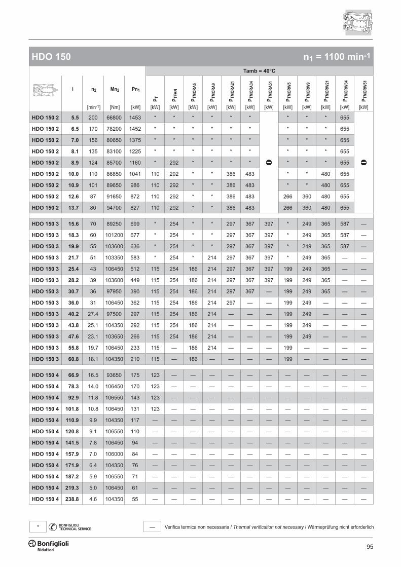
95
— Verifica termica non necessaria / Thermal verification not necessary / Wärmeprüfung nicht erforderlich*
HDO 150 n1 = 1100 min-1
Tamb = 40°C
i n2 Mn2 Pn1
P T P TFA
N
P TM
CRA5
P TM
CRA9
P TM
CRA2
1
P TM
CRA3
4
P TM
CRA5
1
P TM
CRW
5
P TM
CRW
9
P TM
CRW
21
P TM
CRW
34
P TM
CRW
51
[min-1] [Nm] [kW] [kW] [kW] [kW] [kW] [kW] [kW] [kW] [kW] [kW] [kW] [kW] [kW]
HDO 150 2 5.5 200 66800 1453 * * * * * * * * * 655
HDO 150 2 6.5 170 78200 1452 * * * * * * * * * 655
HDO 150 2 7.0 156 80650 1375 * * * * * * * * * 655
HDO 150 2 8.1 135 83100 1225 * * * * * * * * * 655
HDO 150 2 8.9 124 85700 1160 * 292 * * * * * * * 655
HDO 150 2 10.0 110 86850 1041 110 292 * * 386 483 * * 480 655
HDO 150 2 10.9 101 89650 986 110 292 * * 386 483 * * 480 655
HDO 150 2 12.6 87 91650 872 110 292 * * 386 483 266 360 480 655
HDO 150 2 13.7 80 94700 827 110 292 * * 386 483 266 360 480 655
HDO 150 3 15.6 70 89250 699 * 254 * * 297 367 397 * 249 365 587 —
HDO 150 3 18.3 60 101200 677 * 254 * * 297 367 397 * 249 365 587 —
HDO 150 3 19.9 55 103600 636 * 254 * * 297 367 397 * 249 365 587 —
HDO 150 3 21.7 51 103350 583 * 254 * 214 297 367 397 * 249 365 — —
HDO 150 3 25.4 43 106450 512 115 254 186 214 297 367 397 199 249 365 — —
HDO 150 3 28.2 39 103600 449 115 254 186 214 297 367 397 199 249 365 — —
HDO 150 3 30.7 36 97950 390 115 254 186 214 297 367 — 199 249 365 — —
HDO 150 3 36.0 31 106450 362 115 254 186 214 297 — — 199 249 — — —
HDO 150 3 40.2 27.4 97500 297 115 254 186 214 — — — 199 249 — — —
HDO 150 3 43.8 25.1 104350 292 115 254 186 214 — — — 199 249 — — —
HDO 150 3 47.6 23.1 103650 266 115 254 186 214 — — — 199 249 — — —
HDO 150 3 55.8 19.7 106450 233 115 — 186 214 — — — 199 — — — —
HDO 150 3 60.8 18.1 104350 210 115 — 186 — — — — 199 — — — —
HDO 150 4 66.9 16.5 93650 175 123 — — — — — — — — — — —
HDO 150 4 78.3 14.0 106450 170 123 — — — — — — — — — — —
HDO 150 4 92.9 11.8 106550 143 123 — — — — — — — — — — —
HDO 150 4 101.8 10.8 106450 131 123 — — — — — — — — — — —
HDO 150 4 110.9 9.9 104350 117 — — — — — — — — — — — —
HDO 150 4 120.8 9.1 106550 110 — — — — — — — — — — — —
HDO 150 4 141.5 7.8 106450 94 — — — — — — — — — — — —
HDO 150 4 157.9 7.0 106000 84 — — — — — — — — — — — —
HDO 150 4 171.9 6.4 104350 76 — — — — — — — — — — — —
HDO 150 4 187.2 5.9 106550 71 — — — — — — — — — — — —
HDO 150 4 219.3 5.0 106450 61 — — — — — — — — — — — —
HDO 150 4 238.8 4.6 104350 55 — — — — — — — — — — — —
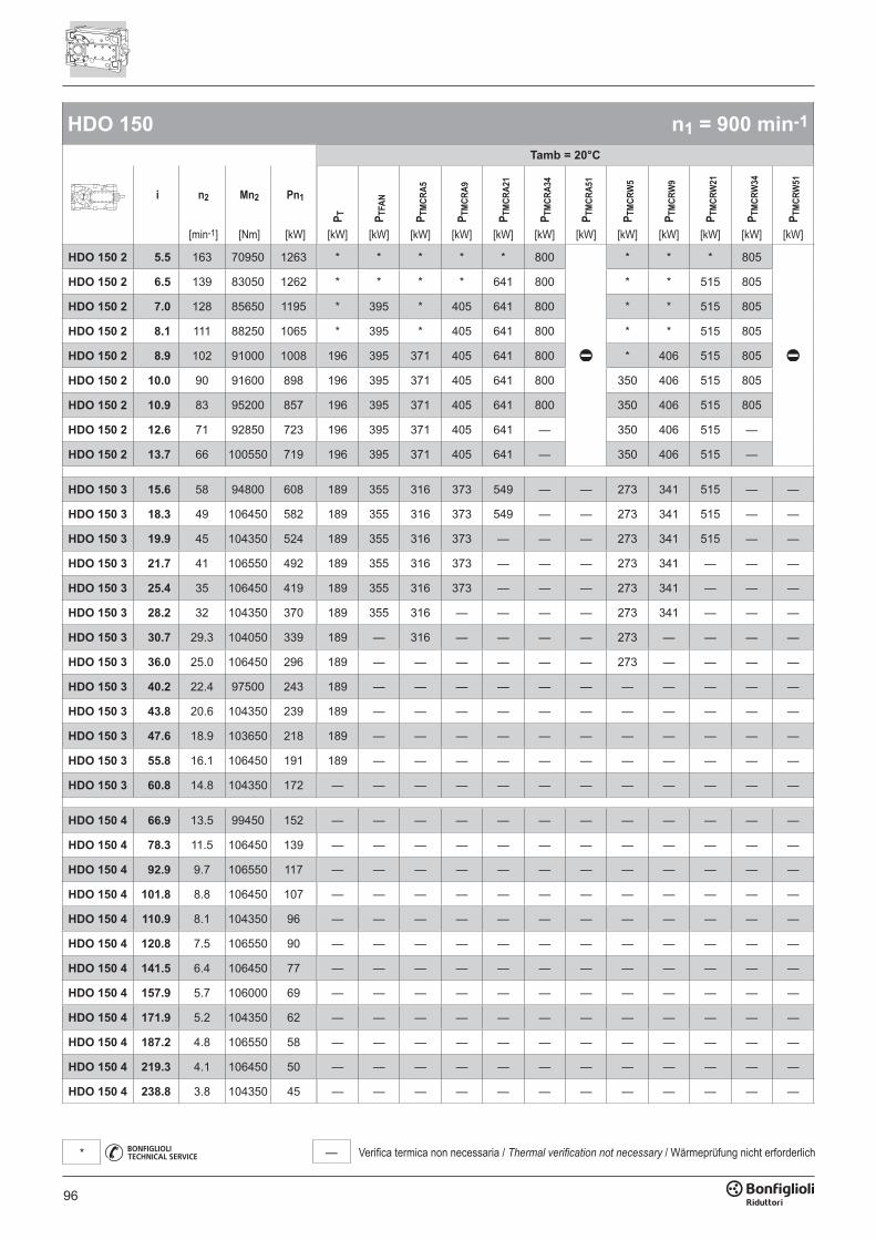
96
— Verifica termica non necessaria / Thermal verification not necessary / Wärmeprüfung nicht erforderlich*
HDO 150 n1 = 900 min-1
Tamb = 20°C
i n2 Mn2 Pn1
P T P TFA
N
P TM
CRA5
P TM
CRA9
P TM
CRA2
1
P TM
CRA3
4
P TM
CRA5
1
P TM
CRW
5
P TM
CRW
9
P TM
CRW
21
P TM
CRW
34
P TM
CRW
51
[min-1] [Nm] [kW] [kW] [kW] [kW] [kW] [kW] [kW] [kW] [kW] [kW] [kW] [kW] [kW]
HDO 150 2 5.5 163 70950 1263 * * * * * 800 * * * 805
HDO 150 2 6.5 139 83050 1262 * * * * 641 800 * * 515 805
HDO 150 2 7.0 128 85650 1195 * 395 * 405 641 800 * * 515 805
HDO 150 2 8.1 111 88250 1065 * 395 * 405 641 800 * * 515 805
HDO 150 2 8.9 102 91000 1008 196 395 371 405 641 800 * 406 515 805
HDO 150 2 10.0 90 91600 898 196 395 371 405 641 800 350 406 515 805
HDO 150 2 10.9 83 95200 857 196 395 371 405 641 800 350 406 515 805
HDO 150 2 12.6 71 92850 723 196 395 371 405 641 — 350 406 515 —
HDO 150 2 13.7 66 100550 719 196 395 371 405 641 — 350 406 515 —
HDO 150 3 15.6 58 94800 608 189 355 316 373 549 — — 273 341 515 — —
HDO 150 3 18.3 49 106450 582 189 355 316 373 549 — — 273 341 515 — —
HDO 150 3 19.9 45 104350 524 189 355 316 373 — — — 273 341 515 — —
HDO 150 3 21.7 41 106550 492 189 355 316 373 — — — 273 341 — — —
HDO 150 3 25.4 35 106450 419 189 355 316 373 — — — 273 341 — — —
HDO 150 3 28.2 32 104350 370 189 355 316 — — — — 273 341 — — —
HDO 150 3 30.7 29.3 104050 339 189 — 316 — — — — 273 — — — —
HDO 150 3 36.0 25.0 106450 296 189 — — — — — — 273 — — — —
HDO 150 3 40.2 22.4 97500 243 189 — — — — — — — — — — —
HDO 150 3 43.8 20.6 104350 239 189 — — — — — — — — — — —
HDO 150 3 47.6 18.9 103650 218 189 — — — — — — — — — — —
HDO 150 3 55.8 16.1 106450 191 189 — — — — — — — — — — —
HDO 150 3 60.8 14.8 104350 172 — — — — — — — — — — — —
HDO 150 4 66.9 13.5 99450 152 — — — — — — — — — — — —
HDO 150 4 78.3 11.5 106450 139 — — — — — — — — — — — —
HDO 150 4 92.9 9.7 106550 117 — — — — — — — — — — — —
HDO 150 4 101.8 8.8 106450 107 — — — — — — — — — — — —
HDO 150 4 110.9 8.1 104350 96 — — — — — — — — — — — —
HDO 150 4 120.8 7.5 106550 90 — — — — — — — — — — — —
HDO 150 4 141.5 6.4 106450 77 — — — — — — — — — — — —
HDO 150 4 157.9 5.7 106000 69 — — — — — — — — — — — —
HDO 150 4 171.9 5.2 104350 62 — — — — — — — — — — — —
HDO 150 4 187.2 4.8 106550 58 — — — — — — — — — — — —
HDO 150 4 219.3 4.1 106450 50 — — — — — — — — — — — —
HDO 150 4 238.8 3.8 104350 45 — — — — — — — — — — — —
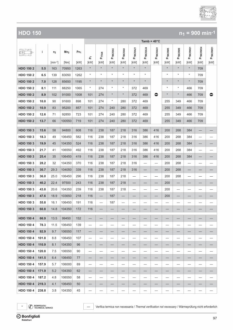
97
— Verifica termica non necessaria / Thermal verification not necessary / Wärmeprüfung nicht erforderlich*
HDO 150 n1 = 900 min-1
Tamb = 40°C
i n2 Mn2 Pn1
P T P TFA
N
P TM
CRA5
P TM
CRA9
P TM
CRA2
1
P TM
CRA3
4
P TM
CRA5
1
P TM
CRW
5
P TM
CRW
9
P TM
CRW
21
P TM
CRW
34
P TM
CRW
51
[min-1] [Nm] [kW] [kW] [kW] [kW] [kW] [kW] [kW] [kW] [kW] [kW] [kW] [kW] [kW]
HDO 150 2 5.5 163 70950 1263 * * * * * * * * * 709
HDO 150 2 6.5 139 83050 1262 * * * * * * * * * 709
HDO 150 2 7.0 128 85650 1195 * * * * * * * * * 709
HDO 150 2 8.1 111 88250 1065 * 274 * * 372 469 * * 466 709
HDO 150 2 8.9 102 91000 1008 101 274 * * 372 469 * * 466 709
HDO 150 2 10.0 90 91600 898 101 274 * 280 372 469 255 349 466 709
HDO 150 2 10.9 83 95200 857 101 274 240 280 372 469 255 349 466 709
HDO 150 2 12.6 71 92850 723 101 274 240 280 372 469 255 349 466 709
HDO 150 2 13.7 66 100550 719 101 274 240 280 372 469 255 349 466 709
HDO 150 3 15.6 58 94800 608 116 238 187 218 316 386 416 200 268 384 — —
HDO 150 3 18.3 49 106450 582 116 238 187 218 316 386 416 200 268 384 — —
HDO 150 3 19.9 45 104350 524 116 238 187 218 316 386 416 200 268 384 — —
HDO 150 3 21.7 41 106550 492 116 238 187 218 316 386 416 200 268 384 — —
HDO 150 3 25.4 35 106450 419 116 238 187 218 316 386 416 200 268 384 — —
HDO 150 3 28.2 32 104350 370 116 238 187 218 316 — — 200 268 — — —
HDO 150 3 30.7 29.3 104050 339 116 238 187 218 316 — — 200 268 — — —
HDO 150 3 36.0 25.0 106450 296 116 238 187 218 — — — 200 268 — — —
HDO 150 3 40.2 22.4 97500 243 116 238 187 218 — — — 200 — — — —
HDO 150 3 43.8 20.6 104350 239 116 238 187 218 — — — 200 — — — —
HDO 150 3 47.6 18.9 103650 218 116 — 187 — — — — 200 — — — —
HDO 150 3 55.8 16.1 106450 191 116 — 187 — — — — — — — — —
HDO 150 3 60.8 14.8 104350 172 116 — — — — — — — — — — —
HDO 150 4 66.9 13.5 99450 152 — — — — — — — — — — — —
HDO 150 4 78.3 11.5 106450 139 — — — — — — — — — — — —
HDO 150 4 92.9 9.7 106550 117 — — — — — — — — — — — —
HDO 150 4 101.8 8.8 106450 107 — — — — — — — — — — — —
HDO 150 4 110.9 8.1 104350 96 — — — — — — — — — — — —
HDO 150 4 120.8 7.5 106550 90 — — — — — — — — — — — —
HDO 150 4 141.5 6.4 106450 77 — — — — — — — — — — — —
HDO 150 4 157.9 5.7 106000 69 — — — — — — — — — — — —
HDO 150 4 171.9 5.2 104350 62 — — — — — — — — — — — —
HDO 150 4 187.2 4.8 106550 58 — — — — — — — — — — — —
HDO 150 4 219.3 4.1 106450 50 — — — — — — — — — — — —
HDO 150 4 238.8 3.8 104350 45 — — — — — — — — — — — —

98
— Verifica termica non necessaria / Thermal verification not necessary / Wärmeprüfung nicht erforderlich*
HDO 160 n1 = 1750 min-1
Tamb = 20°C
i n2 Mn2 Pn1
P T P TFA
N
P TM
CRA5
P TM
CRA9
P TM
CRA2
1
P TM
CRA3
4
P TM
CRA5
1
P TM
CRW
5
P TM
CRW
9
P TM
CRW
21
P TM
CRW
34
P TM
CRW
51
[min-1] [Nm] [kW] [kW] [kW] [kW] [kW] [kW] [kW] [kW] [kW] [kW] [kW] [kW] [kW]
HDO 160 2 7.3 240 77050 2012 * * * * * * * * * *
HDO 160 2 7.9 220 81300 1953 * * * * * * * * * *
HDO 160 2 8.9 196 82150 1755 * * * * * * * * * *
HDO 160 2 10.4 168 88700 1623 * * * * * * * * * *
HDO 160 2 11.3 154 91300 1537 * * * * * * * * * *
HDO 160 2 12.2 144 84200 1322 * * * * * 755 * * * 760
HDO 160 2 14.2 123 95100 1279 * 500 * * * 755 * * * 760
HDO 160 2 15.4 114 98000 1213 * 500 * * * 755 * * * 760
HDO 160 3 17.7 99 88200 968 * 382 * * * * 659 * * * * 809
HDO 160 3 20.7 85 102900 968 * 382 * * * * 659 * * * * 809
HDO 160 3 22.5 78 111850 968 * 382 * * * * 659 * * * * 809
HDO 160 3 24.6 71 102100 807 * 382 * * * 623 659 * * * * —
HDO 160 3 28.8 61 119200 807 * 382 * * * 623 659 * * * * —
HDO 160 3 31.3 56 126150 786 * 382 * * * 623 659 * * * * —
HDO 160 3 34.9 50 100800 562 219 382 346 403 579 — — 303 371 487 709 —
HDO 160 3 40.7 43 117650 562 219 382 346 403 — — — 303 371 487 — —
HDO 160 3 44.3 40 122300 538 219 382 346 403 — — — 303 371 487 — —
HDO 160 3 49.4 35 106150 418 219 382 346 403 — — — 303 371 — — —
HDO 160 3 54.1 32 107850 388 219 382 346 — — — — 303 371 — — —
HDO 160 3 63.2 27.7 125900 388 219 382 346 — — — — 303 371 — — —
HDO 160 3 68.6 25.5 133700 379 219 — 346 — — — — 303 371 — — —
HDO 160 4 75.9 23.0 92500 242 170 — — — — — — 236 — — — —
HDO 160 4 88.6 19.7 107950 242 170 — — — — — — 236 — — — —
HDO 160 4 96.3 18.2 117350 242 170 — — — — — — 236 — — — —
HDO 160 4 115.2 15.2 114600 198 170 — — — — — — — — — — —
HDO 160 4 125.2 14.0 124550 198 170 — — — — — — — — — — —
HDO 160 4 137.1 12.8 130400 189 170 — — — — — — — — — — —
HDO 160 4 160.1 10.9 133000 165 — — — — — — — — — — — —
HDO 160 4 174.0 10.1 133700 153 — — — — — — — — — — — —
HDO 160 4 194.1 9.0 120000 123 — — — — — — — — — — — —
HDO 160 4 212.6 8.2 130400 122 — — — — — — — — — — — —
HDO 160 4 248.1 7.1 133000 107 — — — — — — — — — — — —
HDO 160 4 269.7 6.5 133700 98 — — — — — — — — — — — —

99
— Verifica termica non necessaria / Thermal verification not necessary / Wärmeprüfung nicht erforderlich*
HDO 160 n1 = 1750 min-1
Tamb = 40°C
i n2 Mn2 Pn1
P T P TFA
N
P TM
CRA5
P TM
CRA9
P TM
CRA2
1
P TM
CRA3
4
P TM
CRA5
1
P TM
CRW
5
P TM
CRW
9
P TM
CRW
21
P TM
CRW
34
P TM
CRW
51
[min-1] [Nm] [kW] [kW] [kW] [kW] [kW] [kW] [kW] [kW] [kW] [kW] [kW] [kW] [kW]
HDO 160 2 7.3 240 77050 2012 * * * * * * * * * *
HDO 160 2 7.9 220 81300 1953 * * * * * * * * * *
HDO 160 2 8.9 196 82150 1755 * * * * * * * * * *
HDO 160 2 10.4 168 88700 1623 * * * * * * * * * *
HDO 160 2 11.3 154 91300 1537 * * * * * * * * * *
HDO 160 2 12.2 144 84200 1322 * * * * * * * * * 659
HDO 160 2 14.2 123 95100 1279 * * * * * * * * * 659
HDO 160 2 15.4 114 98000 1213 * * * * * * * * * 659
HDO 160 3 17.7 99 88200 968 * * * * * * * * * * * *
HDO 160 3 20.7 85 102900 968 * * * * * * * * * * * *
HDO 160 3 22.5 78 111850 968 * * * * * * * * * * * *
HDO 160 3 24.6 71 102100 807 * 261 * * * * * * * * * 760
HDO 160 3 28.8 61 119200 807 * 261 * * * * * * * * * 760
HDO 160 3 31.3 56 126150 786 * 261 * * * * * * * * 632 760
HDO 160 3 34.9 50 100800 562 * 261 * * 342 412 442 * 294 410 — —
HDO 160 3 40.7 43 117650 562 * 261 * * 342 412 442 * 294 410 — —
HDO 160 3 44.3 40 122300 538 * 261 * * 342 412 442 * 294 410 — —
HDO 160 3 49.4 35 106150 418 165 261 236 267 342 412 — 249 294 410 — —
HDO 160 3 54.1 32 107850 388 165 261 236 267 342 — — 249 294 — — —
HDO 160 3 63.2 27.7 125900 388 165 261 236 267 342 — — 249 294 — — —
HDO 160 3 68.6 25.5 133700 379 165 261 236 267 342 — — 249 294 — — —
HDO 160 4 75.9 23.0 92500 242 * — * * — — — * — — — —
HDO 160 4 88.6 19.7 107950 242 * — * * — — — * — — — —
HDO 160 4 96.3 18.2 117350 242 * — * * — — — * — — — —
HDO 160 4 115.2 15.2 114600 198 126 — 181 206 — — — 192 — — — —
HDO 160 4 125.2 14.0 124550 198 126 — 181 — — — — 192 — — — —
HDO 160 4 137.1 12.8 130400 189 126 — 181 — — — — — — — — —
HDO 160 4 160.1 10.9 133000 165 126 — — — — — — — — — — —
HDO 160 4 174.0 10.1 133700 153 126 — — — — — — — — — — —
HDO 160 4 194.1 9.0 120000 123 — — — — — — — — — — — —
HDO 160 4 212.6 8.2 130400 122 — — — — — — — — — — — —
HDO 160 4 248.1 7.1 133000 107 — — — — — — — — — — — —
HDO 160 4 269.7 6.5 133700 98 — — — — — — — — — — — —
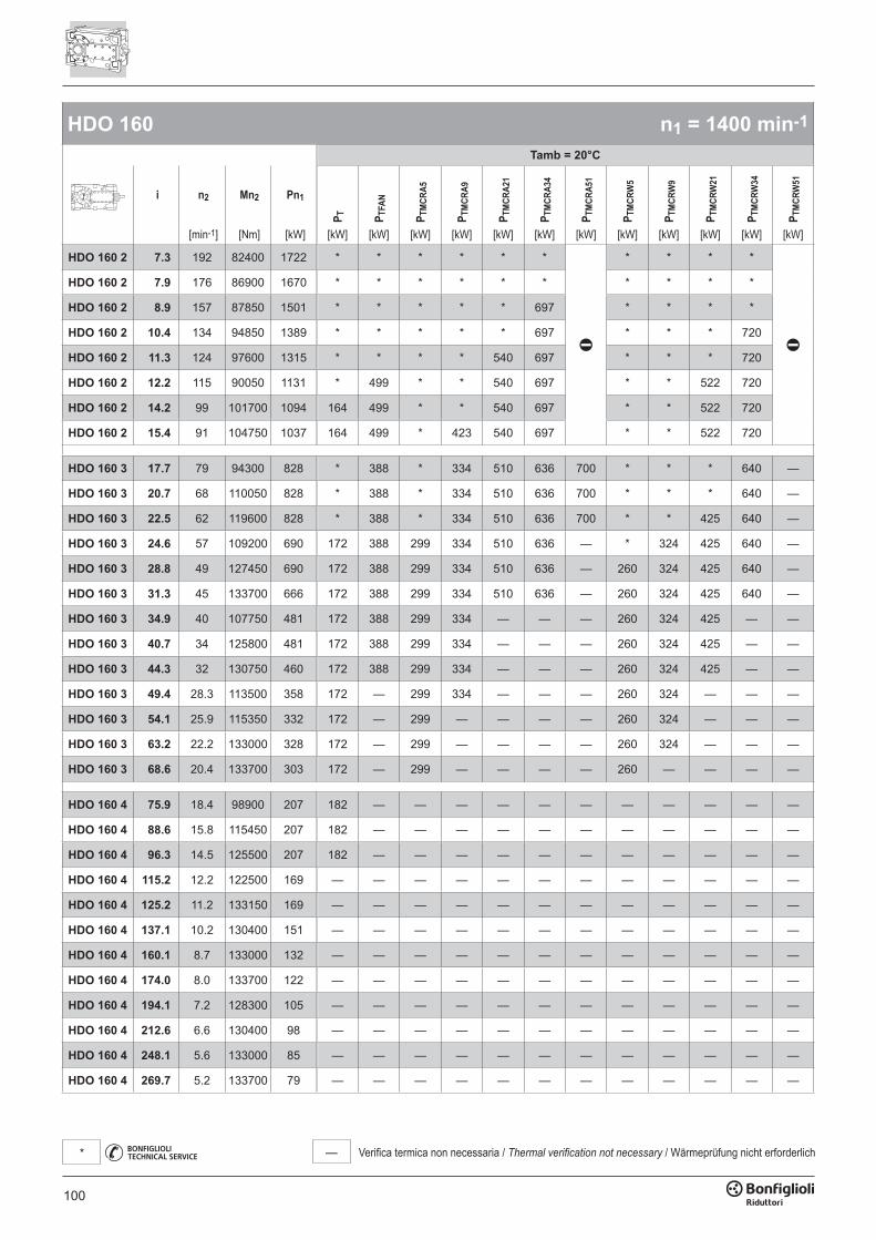
100
— Verifica termica non necessaria / Thermal verification not necessary / Wärmeprüfung nicht erforderlich*
HDO 160 n1 = 1400 min-1
Tamb = 20°C
i n2 Mn2 Pn1
P T P TFA
N
P TM
CRA5
P TM
CRA9
P TM
CRA2
1
P TM
CRA3
4
P TM
CRA5
1
P TM
CRW
5
P TM
CRW
9
P TM
CRW
21
P TM
CRW
34
P TM
CRW
51
[min-1] [Nm] [kW] [kW] [kW] [kW] [kW] [kW] [kW] [kW] [kW] [kW] [kW] [kW] [kW]
HDO 160 2 7.3 192 82400 1722 * * * * * * * * * *
HDO 160 2 7.9 176 86900 1670 * * * * * * * * * *
HDO 160 2 8.9 157 87850 1501 * * * * * 697 * * * *
HDO 160 2 10.4 134 94850 1389 * * * * * 697 * * * 720
HDO 160 2 11.3 124 97600 1315 * * * * 540 697 * * * 720
HDO 160 2 12.2 115 90050 1131 * 499 * * 540 697 * * 522 720
HDO 160 2 14.2 99 101700 1094 164 499 * * 540 697 * * 522 720
HDO 160 2 15.4 91 104750 1037 164 499 * 423 540 697 * * 522 720
HDO 160 3 17.7 79 94300 828 * 388 * 334 510 636 700 * * * 640 —
HDO 160 3 20.7 68 110050 828 * 388 * 334 510 636 700 * * * 640 —
HDO 160 3 22.5 62 119600 828 * 388 * 334 510 636 700 * * 425 640 —
HDO 160 3 24.6 57 109200 690 172 388 299 334 510 636 — * 324 425 640 —
HDO 160 3 28.8 49 127450 690 172 388 299 334 510 636 — 260 324 425 640 —
HDO 160 3 31.3 45 133700 666 172 388 299 334 510 636 — 260 324 425 640 —
HDO 160 3 34.9 40 107750 481 172 388 299 334 — — — 260 324 425 — —
HDO 160 3 40.7 34 125800 481 172 388 299 334 — — — 260 324 425 — —
HDO 160 3 44.3 32 130750 460 172 388 299 334 — — — 260 324 425 — —
HDO 160 3 49.4 28.3 113500 358 172 — 299 334 — — — 260 324 — — —
HDO 160 3 54.1 25.9 115350 332 172 — 299 — — — — 260 324 — — —
HDO 160 3 63.2 22.2 133000 328 172 — 299 — — — — 260 324 — — —
HDO 160 3 68.6 20.4 133700 303 172 — 299 — — — — 260 — — — —
HDO 160 4 75.9 18.4 98900 207 182 — — — — — — — — — — —
HDO 160 4 88.6 15.8 115450 207 182 — — — — — — — — — — —
HDO 160 4 96.3 14.5 125500 207 182 — — — — — — — — — — —
HDO 160 4 115.2 12.2 122500 169 — — — — — — — — — — — —
HDO 160 4 125.2 11.2 133150 169 — — — — — — — — — — — —
HDO 160 4 137.1 10.2 130400 151 — — — — — — — — — — — —
HDO 160 4 160.1 8.7 133000 132 — — — — — — — — — — — —
HDO 160 4 174.0 8.0 133700 122 — — — — — — — — — — — —
HDO 160 4 194.1 7.2 128300 105 — — — — — — — — — — — —
HDO 160 4 212.6 6.6 130400 98 — — — — — — — — — — — —
HDO 160 4 248.1 5.6 133000 85 — — — — — — — — — — — —
HDO 160 4 269.7 5.2 133700 79 — — — — — — — — — — — —
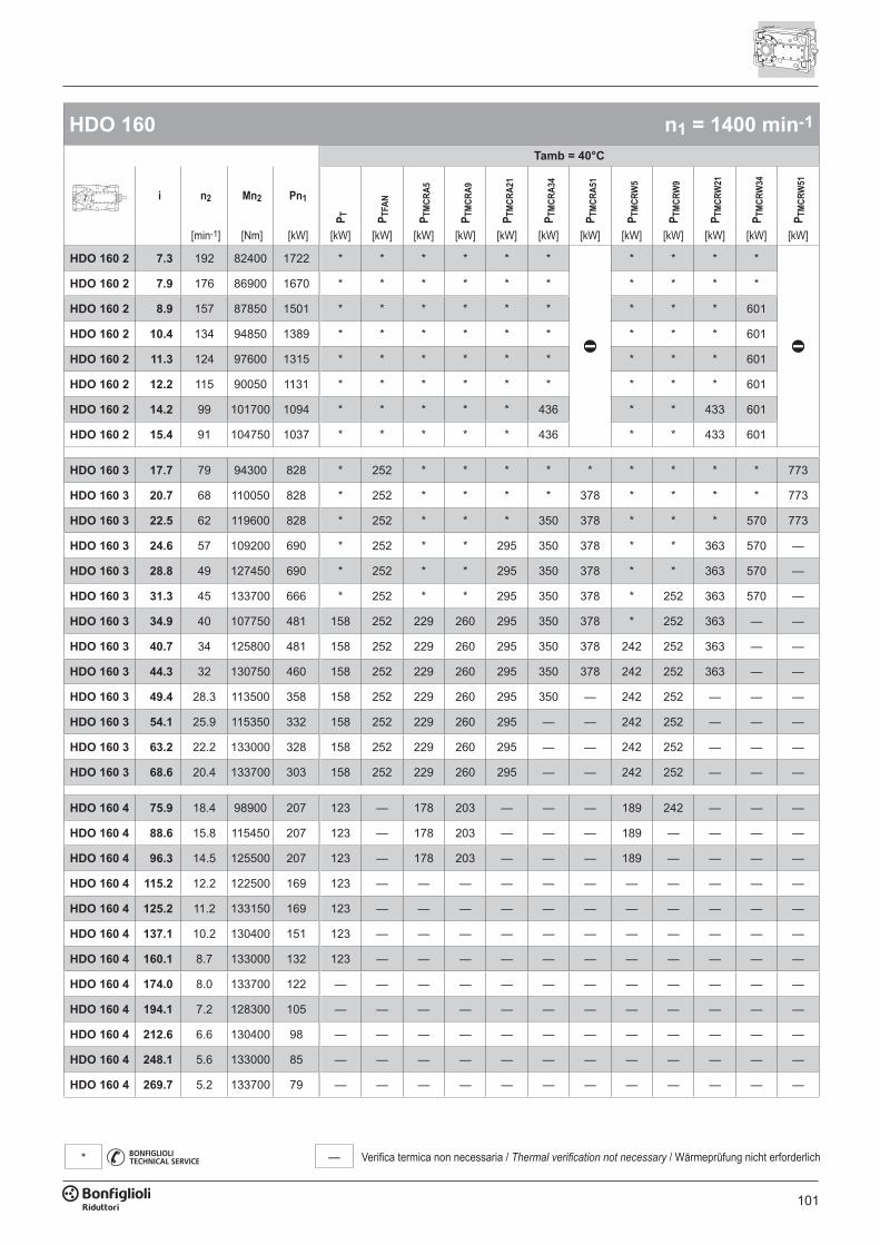
101
— Verifica termica non necessaria / Thermal verification not necessary / Wärmeprüfung nicht erforderlich*
HDO 160 n1 = 1400 min-1
Tamb = 40°C
i n2 Mn2 Pn1
P T P TFA
N
P TM
CRA5
P TM
CRA9
P TM
CRA2
1
P TM
CRA3
4
P TM
CRA5
1
P TM
CRW
5
P TM
CRW
9
P TM
CRW
21
P TM
CRW
34
P TM
CRW
51
[min-1] [Nm] [kW] [kW] [kW] [kW] [kW] [kW] [kW] [kW] [kW] [kW] [kW] [kW] [kW]
HDO 160 2 7.3 192 82400 1722 * * * * * * * * * *
HDO 160 2 7.9 176 86900 1670 * * * * * * * * * *
HDO 160 2 8.9 157 87850 1501 * * * * * * * * * 601
HDO 160 2 10.4 134 94850 1389 * * * * * * * * * 601
HDO 160 2 11.3 124 97600 1315 * * * * * * * * * 601
HDO 160 2 12.2 115 90050 1131 * * * * * * * * * 601
HDO 160 2 14.2 99 101700 1094 * * * * * 436 * * 433 601
HDO 160 2 15.4 91 104750 1037 * * * * * 436 * * 433 601
HDO 160 3 17.7 79 94300 828 * 252 * * * * * * * * * 773
HDO 160 3 20.7 68 110050 828 * 252 * * * * 378 * * * * 773
HDO 160 3 22.5 62 119600 828 * 252 * * * 350 378 * * * 570 773
HDO 160 3 24.6 57 109200 690 * 252 * * 295 350 378 * * 363 570 —
HDO 160 3 28.8 49 127450 690 * 252 * * 295 350 378 * * 363 570 —
HDO 160 3 31.3 45 133700 666 * 252 * * 295 350 378 * 252 363 570 —
HDO 160 3 34.9 40 107750 481 158 252 229 260 295 350 378 * 252 363 — —
HDO 160 3 40.7 34 125800 481 158 252 229 260 295 350 378 242 252 363 — —
HDO 160 3 44.3 32 130750 460 158 252 229 260 295 350 378 242 252 363 — —
HDO 160 3 49.4 28.3 113500 358 158 252 229 260 295 350 — 242 252 — — —
HDO 160 3 54.1 25.9 115350 332 158 252 229 260 295 — — 242 252 — — —
HDO 160 3 63.2 22.2 133000 328 158 252 229 260 295 — — 242 252 — — —
HDO 160 3 68.6 20.4 133700 303 158 252 229 260 295 — — 242 252 — — —
HDO 160 4 75.9 18.4 98900 207 123 — 178 203 — — — 189 242 — — —
HDO 160 4 88.6 15.8 115450 207 123 — 178 203 — — — 189 — — — —
HDO 160 4 96.3 14.5 125500 207 123 — 178 203 — — — 189 — — — —
HDO 160 4 115.2 12.2 122500 169 123 — — — — — — — — — — —
HDO 160 4 125.2 11.2 133150 169 123 — — — — — — — — — — —
HDO 160 4 137.1 10.2 130400 151 123 — — — — — — — — — — —
HDO 160 4 160.1 8.7 133000 132 123 — — — — — — — — — — —
HDO 160 4 174.0 8.0 133700 122 — — — — — — — — — — — —
HDO 160 4 194.1 7.2 128300 105 — — — — — — — — — — — —
HDO 160 4 212.6 6.6 130400 98 — — — — — — — — — — — —
HDO 160 4 248.1 5.6 133000 85 — — — — — — — — — — — —
HDO 160 4 269.7 5.2 133700 79 — — — — — — — — — — — —
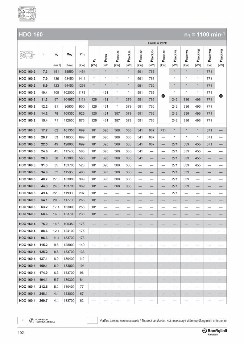
102
— Verifica termica non necessaria / Thermal verification not necessary / Wärmeprüfung nicht erforderlich*
HDO 160 n1 = 1100 min-1
Tamb = 20°C
i n2 Mn2 Pn1
P T P TFA
N
P TM
CRA5
P TM
CRA9
P TM
CRA2
1
P TM
CRA3
4
P TM
CRA5
1
P TM
CRW
5
P TM
CRW
9
P TM
CRW
21
P TM
CRW
34
P TM
CRW
51
[min-1] [Nm] [kW] [kW] [kW] [kW] [kW] [kW] [kW] [kW] [kW] [kW] [kW] [kW] [kW]
HDO 160 2 7.3 151 88550 1454 * * * * 591 766 * * * 771
HDO 160 2 7.9 139 93450 1411 * * * * 591 766 * * * 771
HDO 160 2 8.9 123 94450 1268 * * * * 591 766 * * * 771
HDO 160 2 10.4 105 102000 1173 * 431 * * 591 766 * * * 771
HDO 160 2 11.3 97 104950 1111 126 431 * 379 591 766 242 336 496 771
HDO 160 2 12.2 91 96800 955 126 431 * 379 591 766 242 336 496 771
HDO 160 2 14.2 78 109350 925 126 431 387 379 591 766 242 336 496 771
HDO 160 2 15.4 71 112650 876 126 431 387 379 591 766 242 336 496 771
HDO 160 3 17.7 62 101350 699 181 395 308 365 541 667 731 * * * 671 —
HDO 160 3 20.7 53 118300 699 181 395 308 365 541 667 — * * * 671 —
HDO 160 3 22.5 49 128600 699 181 395 308 365 541 667 — 271 339 455 671 —
HDO 160 3 24.6 45 117400 583 181 395 308 365 541 — — 271 339 455 — —
HDO 160 3 28.8 38 133000 566 181 395 308 365 541 — — 271 339 455 — —
HDO 160 3 31.3 35 133700 523 181 395 308 365 — — — 271 339 455 — —
HDO 160 3 34.9 32 115850 406 181 395 308 365 — — — 271 339 — — —
HDO 160 3 40.7 27.0 133000 399 181 395 308 365 — — — 271 339 — — —
HDO 160 3 44.3 24.8 133700 369 181 — 308 365 — — — 271 339 — — —
HDO 160 3 49.4 22.3 119900 297 181 — — — — — — 271 — — — —
HDO 160 3 54.1 20.3 117700 266 181 — — — — — — — — — — —
HDO 160 3 63.2 17.4 133000 258 181 — — — — — — — — — — —
HDO 160 3 68.6 16.0 133700 238 181 — — — — — — — — — — —
HDO 160 4 75.9 14.5 106350 175 — — — — — — — — — — — —
HDO 160 4 88.6 12.4 124100 175 — — — — — — — — — — — —
HDO 160 4 96.3 11.4 133700 173 — — — — — — — — — — — —
HDO 160 4 115.2 9.5 128900 140 — — — — — — — — — — — —
HDO 160 4 125.2 8.8 133700 133 — — — — — — — — — — — —
HDO 160 4 137.1 8.0 130400 119 — — — — — — — — — — — —
HDO 160 4 160.1 6.9 133000 104 — — — — — — — — — — — —
HDO 160 4 174.0 6.3 133700 96 — — — — — — — — — — — —
HDO 160 4 194.1 5.7 130300 84 — — — — — — — — — — — —
HDO 160 4 212.6 5.2 130400 77 — — — — — — — — — — — —
HDO 160 4 248.1 4.4 133000 67 — — — — — — — — — — — —
HDO 160 4 269.7 4.1 133700 62 — — — — — — — — — — — —
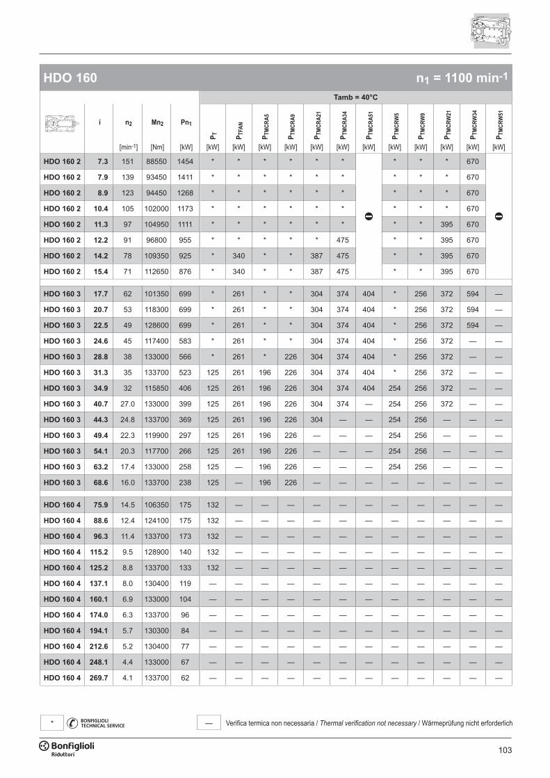
103
— Verifica termica non necessaria / Thermal verification not necessary / Wärmeprüfung nicht erforderlich*
HDO 160 n1 = 1100 min-1
Tamb = 40°C
i n2 Mn2 Pn1
P T P TFA
N
P TM
CRA5
P TM
CRA9
P TM
CRA2
1
P TM
CRA3
4
P TM
CRA5
1
P TM
CRW
5
P TM
CRW
9
P TM
CRW
21
P TM
CRW
34
P TM
CRW
51
[min-1] [Nm] [kW] [kW] [kW] [kW] [kW] [kW] [kW] [kW] [kW] [kW] [kW] [kW] [kW]
HDO 160 2 7.3 151 88550 1454 * * * * * * * * * 670
HDO 160 2 7.9 139 93450 1411 * * * * * * * * * 670
HDO 160 2 8.9 123 94450 1268 * * * * * * * * * 670
HDO 160 2 10.4 105 102000 1173 * * * * * * * * * 670
HDO 160 2 11.3 97 104950 1111 * * * * * * * * 395 670
HDO 160 2 12.2 91 96800 955 * * * * * 475 * * 395 670
HDO 160 2 14.2 78 109350 925 * 340 * * 387 475 * * 395 670
HDO 160 2 15.4 71 112650 876 * 340 * * 387 475 * * 395 670
HDO 160 3 17.7 62 101350 699 * 261 * * 304 374 404 * 256 372 594 —
HDO 160 3 20.7 53 118300 699 * 261 * * 304 374 404 * 256 372 594 —
HDO 160 3 22.5 49 128600 699 * 261 * * 304 374 404 * 256 372 594 —
HDO 160 3 24.6 45 117400 583 * 261 * * 304 374 404 * 256 372 — —
HDO 160 3 28.8 38 133000 566 * 261 * 226 304 374 404 * 256 372 — —
HDO 160 3 31.3 35 133700 523 125 261 196 226 304 374 404 * 256 372 — —
HDO 160 3 34.9 32 115850 406 125 261 196 226 304 374 404 254 256 372 — —
HDO 160 3 40.7 27.0 133000 399 125 261 196 226 304 374 — 254 256 372 — —
HDO 160 3 44.3 24.8 133700 369 125 261 196 226 304 — — 254 256 — — —
HDO 160 3 49.4 22.3 119900 297 125 261 196 226 — — — 254 256 — — —
HDO 160 3 54.1 20.3 117700 266 125 261 196 226 — — — 254 256 — — —
HDO 160 3 63.2 17.4 133000 258 125 — 196 226 — — — 254 256 — — —
HDO 160 3 68.6 16.0 133700 238 125 — 196 226 — — — — — — — —
HDO 160 4 75.9 14.5 106350 175 132 — — — — — — — — — — —
HDO 160 4 88.6 12.4 124100 175 132 — — — — — — — — — — —
HDO 160 4 96.3 11.4 133700 173 132 — — — — — — — — — — —
HDO 160 4 115.2 9.5 128900 140 132 — — — — — — — — — — —
HDO 160 4 125.2 8.8 133700 133 132 — — — — — — — — — — —
HDO 160 4 137.1 8.0 130400 119 — — — — — — — — — — — —
HDO 160 4 160.1 6.9 133000 104 — — — — — — — — — — — —
HDO 160 4 174.0 6.3 133700 96 — — — — — — — — — — — —
HDO 160 4 194.1 5.7 130300 84 — — — — — — — — — — — —
HDO 160 4 212.6 5.2 130400 77 — — — — — — — — — — — —
HDO 160 4 248.1 4.4 133000 67 — — — — — — — — — — — —
HDO 160 4 269.7 4.1 133700 62 — — — — — — — — — — — —
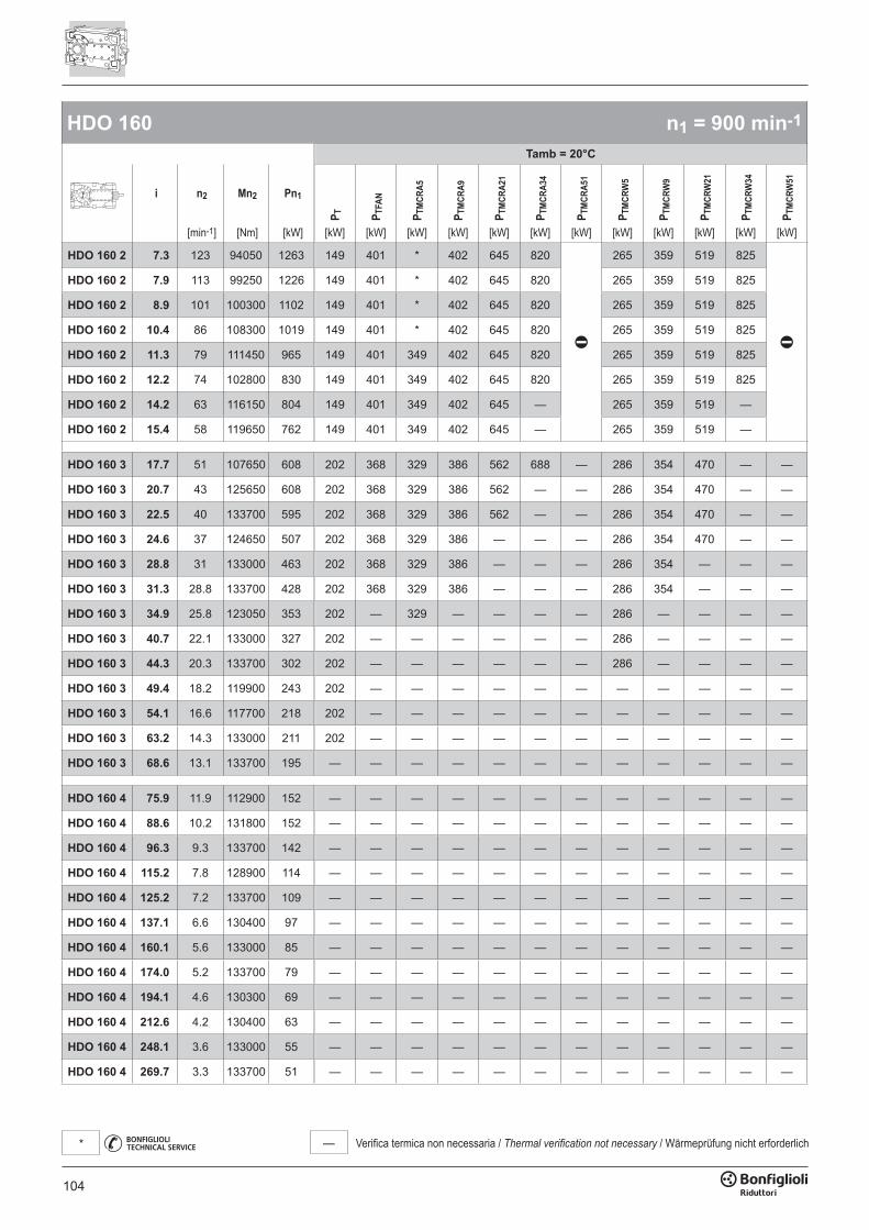
104
— Verifica termica non necessaria / Thermal verification not necessary / Wärmeprüfung nicht erforderlich*
HDO 160 n1 = 900 min-1
Tamb = 20°C
i n2 Mn2 Pn1
P T P TFA
N
P TM
CRA5
P TM
CRA9
P TM
CRA2
1
P TM
CRA3
4
P TM
CRA5
1
P TM
CRW
5
P TM
CRW
9
P TM
CRW
21
P TM
CRW
34
P TM
CRW
51
[min-1] [Nm] [kW] [kW] [kW] [kW] [kW] [kW] [kW] [kW] [kW] [kW] [kW] [kW] [kW]
HDO 160 2 7.3 123 94050 1263 149 401 * 402 645 820 265 359 519 825
HDO 160 2 7.9 113 99250 1226 149 401 * 402 645 820 265 359 519 825
HDO 160 2 8.9 101 100300 1102 149 401 * 402 645 820 265 359 519 825
HDO 160 2 10.4 86 108300 1019 149 401 * 402 645 820 265 359 519 825
HDO 160 2 11.3 79 111450 965 149 401 349 402 645 820 265 359 519 825
HDO 160 2 12.2 74 102800 830 149 401 349 402 645 820 265 359 519 825
HDO 160 2 14.2 63 116150 804 149 401 349 402 645 — 265 359 519 —
HDO 160 2 15.4 58 119650 762 149 401 349 402 645 — 265 359 519 —
HDO 160 3 17.7 51 107650 608 202 368 329 386 562 688 — 286 354 470 — —
HDO 160 3 20.7 43 125650 608 202 368 329 386 562 — — 286 354 470 — —
HDO 160 3 22.5 40 133700 595 202 368 329 386 562 — — 286 354 470 — —
HDO 160 3 24.6 37 124650 507 202 368 329 386 — — — 286 354 470 — —
HDO 160 3 28.8 31 133000 463 202 368 329 386 — — — 286 354 — — —
HDO 160 3 31.3 28.8 133700 428 202 368 329 386 — — — 286 354 — — —
HDO 160 3 34.9 25.8 123050 353 202 — 329 — — — — 286 — — — —
HDO 160 3 40.7 22.1 133000 327 202 — — — — — — 286 — — — —
HDO 160 3 44.3 20.3 133700 302 202 — — — — — — 286 — — — —
HDO 160 3 49.4 18.2 119900 243 202 — — — — — — — — — — —
HDO 160 3 54.1 16.6 117700 218 202 — — — — — — — — — — —
HDO 160 3 63.2 14.3 133000 211 202 — — — — — — — — — — —
HDO 160 3 68.6 13.1 133700 195 — — — — — — — — — — — —
HDO 160 4 75.9 11.9 112900 152 — — — — — — — — — — — —
HDO 160 4 88.6 10.2 131800 152 — — — — — — — — — — — —
HDO 160 4 96.3 9.3 133700 142 — — — — — — — — — — — —
HDO 160 4 115.2 7.8 128900 114 — — — — — — — — — — — —
HDO 160 4 125.2 7.2 133700 109 — — — — — — — — — — — —
HDO 160 4 137.1 6.6 130400 97 — — — — — — — — — — — —
HDO 160 4 160.1 5.6 133000 85 — — — — — — — — — — — —
HDO 160 4 174.0 5.2 133700 79 — — — — — — — — — — — —
HDO 160 4 194.1 4.6 130300 69 — — — — — — — — — — — —
HDO 160 4 212.6 4.2 130400 63 — — — — — — — — — — — —
HDO 160 4 248.1 3.6 133000 55 — — — — — — — — — — — —
HDO 160 4 269.7 3.3 133700 51 — — — — — — — — — — — —

105
— Verifica termica non necessaria / Thermal verification not necessary / Wärmeprüfung nicht erforderlich*
HDO 160 n1 = 900 min-1
Tamb = 40°C
i n2 Mn2 Pn1
P T P TFA
N
P TM
CRA5
P TM
CRA9
P TM
CRA2
1
P TM
CRA3
4
P TM
CRA5
1
P TM
CRW
5
P TM
CRW
9
P TM
CRW
21
P TM
CRW
34
P TM
CRW
51
[min-1] [Nm] [kW] [kW] [kW] [kW] [kW] [kW] [kW] [kW] [kW] [kW] [kW] [kW] [kW]
HDO 160 2 7.3 123 94050 1263 * * * * * * * * * 724
HDO 160 2 7.9 113 99250 1226 * * * * * * * * * 724
HDO 160 2 8.9 101 100300 1102 * * * * * 429 * * 426 724
HDO 160 2 10.4 86 108300 1019 * * * * * 429 * * 426 724
HDO 160 2 11.3 79 111450 965 * * * * 349 429 * * 426 724
HDO 160 2 12.2 74 102800 830 * 314 * * 349 429 * * 426 724
HDO 160 2 14.2 63 116150 804 * 314 * * 349 429 * 353 426 724
HDO 160 2 15.4 58 119650 762 * 314 * * 349 429 * 353 426 724
HDO 160 3 17.7 51 107650 608 125 247 196 227 325 395 425 209 277 393 — —
HDO 160 3 20.7 43 125650 608 125 247 196 227 325 395 425 209 277 393 — —
HDO 160 3 22.5 40 133700 595 125 247 196 227 325 395 425 209 277 393 — —
HDO 160 3 24.6 37 124650 507 125 247 196 227 325 395 425 209 277 393 — —
HDO 160 3 28.8 31 133000 463 125 247 196 227 325 395 425 209 277 393 — —
HDO 160 3 31.3 28.8 133700 428 125 247 196 227 325 395 425 209 277 393 — —
HDO 160 3 34.9 25.8 123050 353 125 247 196 227 325 — — 209 277 — — —
HDO 160 3 40.7 22.1 133000 327 125 247 196 227 325 — — 209 277 — — —
HDO 160 3 44.3 20.3 133700 302 125 247 196 227 — — — 209 277 — — —
HDO 160 3 49.4 18.2 119900 243 125 — 196 227 — — — 209 — — — —
HDO 160 3 54.1 16.6 117700 218 125 — 196 — — — — 209 — — — —
HDO 160 3 63.2 14.3 133000 211 125 — 196 — — — — 209 — — — —
HDO 160 3 68.6 13.1 133700 195 125 — — — — — — — — — — —
HDO 160 4 75.9 11.9 112900 152 — — — — — — — — — — — —
HDO 160 4 88.6 10.2 131800 152 — — — — — — — — — — — —
HDO 160 4 96.3 9.3 133700 142 — — — — — — — — — — — —
HDO 160 4 115.2 7.8 128900 114 — — — — — — — — — — — —
HDO 160 4 125.2 7.2 133700 109 — — — — — — — — — — — —
HDO 160 4 137.1 6.6 130400 97 — — — — — — — — — — — —
HDO 160 4 160.1 5.6 133000 85 — — — — — — — — — — — —
HDO 160 4 174.0 5.2 133700 79 — — — — — — — — — — — —
HDO 160 4 194.1 4.6 130300 69 — — — — — — — — — — — —
HDO 160 4 212.6 4.2 130400 63 — — — — — — — — — — — —
HDO 160 4 248.1 3.6 133000 55 — — — — — — — — — — — —
HDO 160 4 269.7 3.3 133700 51 — — — — — — — — — — — —
106
HDO 100
Rn2 [kN]
n2 x h M2 = 20000 Nm M2 = 16000 Nm M2 = 13300 Nm M2 = 10000 Nm
250 00052.0 62.5 69.5 78.161.9 70.4 76.0 80.0
500 00032.4 42.8 49.9 58.542.3 50.8 56.5 63.5
750 00022.7 33.2 40.2 48.832.6 41.1 46.8 53.8
1 000 00016.4 26.9 34.0 42.626.4 34.9 40.6 47.6
1 250 000— 22.5 29.5 38.222.0 30.4 36.1 43.1
2 500 000— — 17.4 26.1— 18.3 24.1 31.1
3 750 000— — — 20.1— — 18.1 25.1
5 000 000— — — 16.4— — — 21.2
HDO 100
Rn2 [kN]
n2 x h M2 = 20000 Nm M2 = 16000 Nm M2 = 13300 Nm M2 = 10000 Nm
250 00076.3 80.0 80.0 80.079.1 80.0 80.0 80.0
500 00056.7 62.3 66.1 70.753.4 69.8 72.0 75.3
750 00043.5 52.6 56.4 61.040.1 57.9 59.8 65.6
1 000 00033.6 46.4 50.2 54.831.1 49.7 51.9 59.4
1 250 00025.9 41.5 45.7 50.324.5 43.8 46.1 55.0
2 500 000— 22.2 32.6 38.3— 22.6 30.0 39.7
3 750 000— — 23.4 32.3— — 21.4 31.9
5 000 000— — 16.7 28.5— — — 26.9
����
����
����
����
���
���
����
����
����
����
���
���
4.2 - CARICHI RADIALI ALBERO
LENTO
4.2 - PERMITTED OVERHUNG
LOADS ON OUTPUT SHAFT
4.2 - RADIALKRÄFTE
ABTRIEBSWELLE
����
����
����
����
����
��������
���� ���
���
���
���
Albero al quale sono riferiti i carichi radialiammissibili. Per gli alberi bisporgenti il cari-co può essere applicato solo sull’estremitàcosì evidenziata. In caso diverso consultareil Servizio Tecnico Bonfiglioli.
Welle, auf die sich die zulässigen Radialkräftebeziehen. Für die Wellen mit zwei Wellen-stummeln kann die Kraft nur auf das so ge-kennzeichnete Wellenende ausgeübt werden.Andernfalls mit dem technischen Kundendienstvon Bonfiglioli Rücksprache halten.
h: durata in ore riferita al cuscinetto dell'alberolento.
h: expected lifetime [hours] for bearing of the
output shaft.
h: Lebensdauer in Stunden für des Lagers derAbtriebswelle.
Shaft the rated overhung load is applicable to.For double extended shaft the load is only ap-plicable to the extension highlighted Shouldthis not be the case consult Bonfiglioli’s Tec-hnical Service.
(—) Consultare il Servizio Tecnico Bonfiglioli (—) Contact the Bonfiglioli Technical Service. (—) Bitte wenden Sie sich an den technischenKundendienst von Bonfiglioli.
SH
SH
LP
LP
107
HDO 110
Rn2 [kN]
n2 x h M2 = 23650 Nm M2 = 18900 Nm M2 = 15750 Nm M2 = 11800 Nm
250 00064.4 75.1 81.7 86.074.0 82.5 86.0 86.0
500 00042.6 53.0 59.9 68.352.1 60.6 66.3 73.2
750 00031.7 42.2 49.1 57.641.3 49.8 55.4 62.5
1 000 00024.8 35.2 42.2 50.934.4 42.9 48.5 55.6
1 250 00019.8 30.3 37.2 45.829.5 37.9 43.6 50.7
2 500 000— — 23.7 32.4— 24.5 30.1 37.2
3 750 000— — — 25.7— 17.8 23.4 30.5
5 000 000— — — 21.4— — 19.2 26.2
HDO 110
Rn2 [kN]
n2 x h M2 = 23650 Nm M2 = 18900 Nm M2 = 15750 Nm M2 = 11800 Nm
250 00086.0 86.0 86.0 86.086.0 86.0 86.0 86.0
500 00065.5 71.3 75.1 80.068.7 78.6 81.2 84.4
750 00054.6 60.5 64.3 69.354.5 65.4 70.4 73.7
1 000 00047.7 53.5 57.4 62.245.1 56.5 63.3 66.8
1 250 00041.0 48.6 52.4 57.138.1 50.0 57.1 62.0
2 500 00017.8 34.2 39.0 43.8— 31.8 39.7 48.4
3 750 000— 23.4 32.3 37.1— 20.6 30.8 40.0
5 000 000— — 26.6 32.8— — 24.9 34.5
����
����
����
����
����
��������
���� ���
���
���
���
����
����
����
����
���
���
����
����
����
����
���
���
Albero al quale sono riferiti i carichi radialiammissibili. Per gli alberi bisporgenti il cari-co può essere applicato solo sull’estremitàcosì evidenziata. In caso diverso consultareil Servizio Tecnico Bonfiglioli.
Welle, auf die sich die zulässigen Radialkräftebeziehen. Für die Wellen mit zwei Wellen-stummeln kann die Kraft nur auf das so ge-kennzeichnete Wellenende ausgeübt werden.Andernfalls mit dem technischen Kundendienstvon Bonfiglioli Rücksprache halten.
h: durata in ore riferita al cuscinetto dell'alberolento.
h: expected lifetime [hours] for bearing of the
output shaft.
h: Lebensdauer in Stunden für des Lagers derAbtriebswelle.
Shaft the rated overhung load is applicable to.For double extended shaft the load is only ap-plicable to the extension highlighted Shouldthis not be the case consult Bonfiglioli’s Tec-hnical Service.
(—) Consultare il Servizio Tecnico Bonfiglioli (—) Contact the Bonfiglioli Technical Service. (—) Bitte wenden Sie sich an den technischenKundendienst von Bonfiglioli.
SH
SH
LP
LP
108
HDO 120
Rn2 [kN]
n2 x h M2 = 31750 Nm M2 = 25400 Nm M2 = 21150 Nm M2 = 15850 Nm
250 00088.9 101.5 107.0 107.0
100.7 107.0 107.0 107.0
500 00060.3 73.0 81.4 91.972.2 82.5 89.3 97.9
750 00046.1 58.8 67.3 77.858.0 68.3 75.2 83.7
1 000 00037.0 49.7 58.2 68.848.9 59.3 66.2 74.7
1 250 00030.5 43.2 51.7 62.342.4 52.8 59.6 68.2
2 500 000— 25.5 34.0 44.6— 35.1 42.0 50.6
3 750 000— — 25.3 35.9— 26.3 33.2 41.8
5 000 000— — — 30.3— — 27.7 36.2
HDO 120
Rn2 [kN]
n2 x h M2 = 31750 Nm M2 = 25400 Nm M2 = 21150 Nm M2 = 15850 Nm
250 000107.0 107.0 107.0 107.0107.0 107.0 107.0 107.0
500 00088.0 95.1 99.9 105.888.1 101.5 107.0 107.0
750 00073.9 81.0 85.7 91.669.6 83.8 92.5 97.1
1 000 00062.5 71.9 76.6 82.657.6 72.4 81.3 88.1
1 250 00052.8 65.4 70.2 76.148.8 64.0 73.3 81.5
2 500 00023.7 43.9 52.5 58.523.0 40.6 50.8 62.2
3 750 000— 30.4 42.6 49.7— 28.1 39.2 51.4
5 000 000— — 34.2 44.2— — 31.7 44.3
����
����
����
����
����
��������
���� ���
���
���
���
����
����
����
����
���
���
����
����
����
����
���
���
Albero al quale sono riferiti i carichi radialiammissibili. Per gli alberi bisporgenti il cari-co può essere applicato solo sull’estremitàcosì evidenziata. In caso diverso consultareil Servizio Tecnico Bonfiglioli.
Welle, auf die sich die zulässigen Radialkräftebeziehen. Für die Wellen mit zwei Wellen-stummeln kann die Kraft nur auf das so ge-kennzeichnete Wellenende ausgeübt werden.Andernfalls mit dem technischen Kundendienstvon Bonfiglioli Rücksprache halten.
h: durata in ore riferita al cuscinetto dell'alberolento.
h: expected lifetime [hours] for bearing of the
output shaft.
h: Lebensdauer in Stunden für des Lagers derAbtriebswelle.
Shaft the rated overhung load is applicable to.For double extended shaft the load is only ap-plicable to the extension highlighted Shouldthis not be the case consult Bonfiglioli’s Tec-hnical Service.
(—) Consultare il Servizio Tecnico Bonfiglioli (—) Contact the Bonfiglioli Technical Service. (—) Bitte wenden Sie sich an den technischenKundendienst von Bonfiglioli.
SH
SH
LP
LP
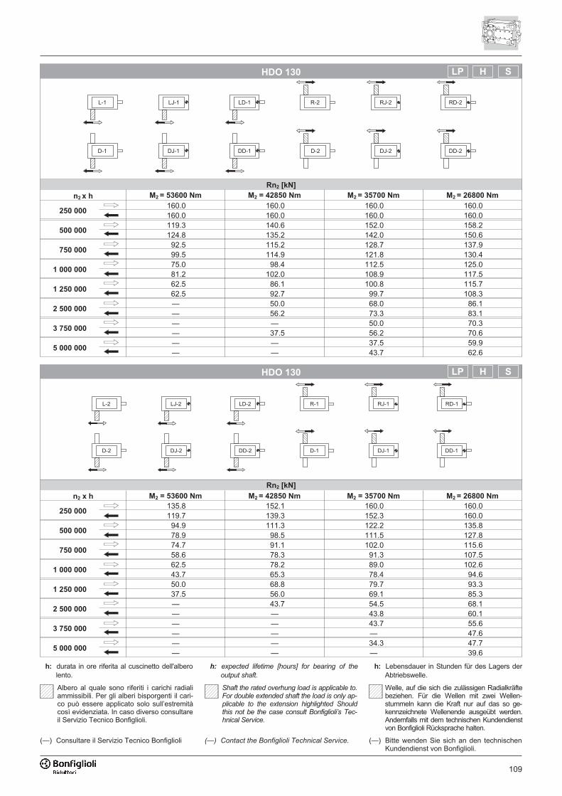
109
HDO 130
Rn2 [kN]
n2 x h M2 = 53600 Nm M2 = 42850 Nm M2 = 35700 Nm M2 = 26800 Nm
250 000160.0 160.0 160.0 160.0160.0 160.0 160.0 160.0
500 000119.3 140.6 152.0 158.2124.8 135.2 142.0 150.6
750 00092.5 115.2 128.7 137.999.5 114.9 121.8 130.4
1 000 00075.0 98.4 112.5 125.081.2 102.0 108.9 117.5
1 250 00062.5 86.1 100.8 115.762.5 92.7 99.7 108.3
2 500 000— 50.0 68.0 86.1— 56.2 73.3 83.1
3 750 000— — 50.0 70.3— 37.5 56.2 70.6
5 000 000— — 37.5 59.9— — 43.7 62.6
HDO 130
Rn2 [kN]
n2 x h M2 = 53600 Nm M2 = 42850 Nm M2 = 35700 Nm M2 = 26800 Nm
250 000135.8 152.1 160.0 160.0119.7 139.3 152.3 160.0
500 00094.9 111.3 122.2 135.878.9 98.5 111.5 127.8
750 00074.7 91.1 102.0 115.658.6 78.3 91.3 107.5
1 000 00062.5 78.2 89.0 102.643.7 65.3 78.4 94.6
1 250 00050.0 68.8 79.7 93.337.5 56.0 69.1 85.3
2 500 000— 43.7 54.5 68.1— — 43.8 60.1
3 750 000— — 43.7 55.6— — — 47.6
5 000 000— — 34.3 47.7— — — 39.6
����
����
����
����
����
��������
���� ���
���
���
���
����
����
����
����
���
���
����
����
����
����
���
���
Albero al quale sono riferiti i carichi radialiammissibili. Per gli alberi bisporgenti il cari-co può essere applicato solo sull’estremitàcosì evidenziata. In caso diverso consultareil Servizio Tecnico Bonfiglioli.
Welle, auf die sich die zulässigen Radialkräftebeziehen. Für die Wellen mit zwei Wellen-stummeln kann die Kraft nur auf das so ge-kennzeichnete Wellenende ausgeübt werden.Andernfalls mit dem technischen Kundendienstvon Bonfiglioli Rücksprache halten.
h: durata in ore riferita al cuscinetto dell'alberolento.
h: expected lifetime [hours] for bearing of the
output shaft.
h: Lebensdauer in Stunden für des Lagers derAbtriebswelle.
Shaft the rated overhung load is applicable to.For double extended shaft the load is only ap-plicable to the extension highlighted Shouldthis not be the case consult Bonfiglioli’s Tec-hnical Service.
(—) Consultare il Servizio Tecnico Bonfiglioli (—) Contact the Bonfiglioli Technical Service. (—) Bitte wenden Sie sich an den technischenKundendienst von Bonfiglioli.
SH
SH
LP
LP
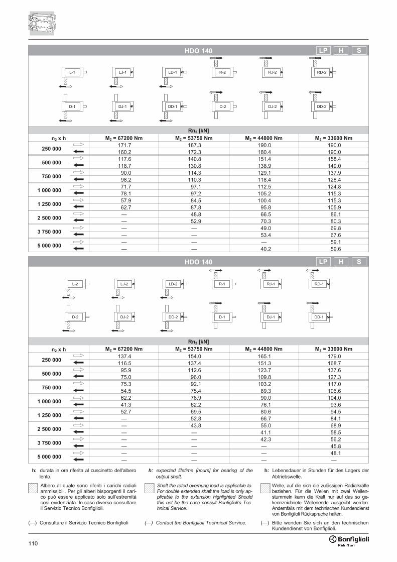
110
HDO 140
Rn2 [kN]
n2 x h M2 = 67200 Nm M2 = 53750 Nm M2 = 44800 Nm M2 = 33600 Nm
250 000171.7 187.3 190.0 190.0160.2 172.3 180.4 190.0
500 000117.6 140.8 151.4 158.4118.7 130.8 138.9 149.0
750 00090.0 114.3 129.1 137.998.2 110.3 118.4 128.4
1 000 00071.7 97.1 112.5 124.878.1 97.2 105.2 115.3
1 250 00057.9 84.5 100.4 115.362.7 87.8 95.8 105.9
2 500 000— 48.8 66.5 86.1— 52.9 70.3 80.3
3 750 000— — 49.0 69.8— — 53.4 67.6
5 000 000— — — 59.1— — 40.2 59.6
HDO 140
Rn2 [kN]
n2 x h M2 = 67200 Nm M2 = 53750 Nm M2 = 44800 Nm M2 = 33600 Nm
250 000137.4 154.0 165.1 179.0116.5 137.4 151.3 168.7
500 00095.9 112.6 123.7 137.675.0 96.0 109.8 127.3
750 00075.3 92.1 103.2 117.054.5 75.4 89.3 106.6
1 000 00062.2 78.9 90.0 104.041.3 62.2 76.1 93.6
1 250 00052.7 69.5 80.6 94.5— 52.8 66.7 84.1
2 500 000— 43.8 55.0 68.9— — 41.1 58.5
3 750 000— — 42.3 56.2— — — 45.8
5 000 000— — — 48.1— — — —
����
����
����
����
����
��������
���� ���
���
���
���
����
����
����
����
���
���
����
����
����
����
���
���
Albero al quale sono riferiti i carichi radialiammissibili. Per gli alberi bisporgenti il cari-co può essere applicato solo sull’estremitàcosì evidenziata. In caso diverso consultareil Servizio Tecnico Bonfiglioli.
Welle, auf die sich die zulässigen Radialkräftebeziehen. Für die Wellen mit zwei Wellen-stummeln kann die Kraft nur auf das so ge-kennzeichnete Wellenende ausgeübt werden.Andernfalls mit dem technischen Kundendienstvon Bonfiglioli Rücksprache halten.
h: durata in ore riferita al cuscinetto dell'alberolento.
h: expected lifetime [hours] for bearing of the
output shaft.
h: Lebensdauer in Stunden für des Lagers derAbtriebswelle.
Shaft the rated overhung load is applicable to.For double extended shaft the load is only ap-plicable to the extension highlighted Shouldthis not be the case consult Bonfiglioli’s Tec-hnical Service.
(—) Consultare il Servizio Tecnico Bonfiglioli (—) Contact the Bonfiglioli Technical Service. (—) Bitte wenden Sie sich an den technischenKundendienst von Bonfiglioli.
SH
SH
LP
LP
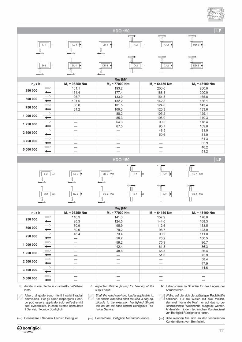
111
HDO 150
Rn2 [kN]
n2 x h M2 = 96250 Nm M2 = 77000 Nm M2 = 64150 Nm M2 = 48100 Nm
250 000161.1 193.2 200.0 200.0161.4 177.4 188.1 200.0
500 00095.7 133.0 154.5 165.8
101.5 132.2 142.8 156.1
750 00060.0 101.5 124.6 143.461.2 109.3 120.3 133.6
1 000 000— 80.2 105.2 129.1— 85.3 106.0 119.3
1 250 000— 64.3 90.5 118.4— 67.5 95.7 109.0
2 500 000— — 48.5 81.0— — 50.6 81.0
3 750 000— — — 61.3— — — 65.9
5 000 000— — — 48.2— — — 51.2
HDO 150
Rn2 [kN]
n2 x h M2 = 96250 Nm M2 = 77000 Nm M2 = 64150 Nm M2 = 48100 Nm
250 000116.3 141.3 157.9 178.8
95.3 124.5 144.0 168.3
500 00070.9 95.9 112.6 133.550.0 79.2 98.7 123.0
750 00048.4 73.4 90.2 111.0— 56.7 76.2 100.5
1 000 000— 59.2 75.9 96.7— 42.4 61.8 86.3
1 250 000— 48.8 65.5 86.4— — 51.6 75.9
2 500 000— — — 58.4— — — 47.9
3 750 000— — — 44.6— — — —
5 000 000— — — —— — — —
����
����
����
����
����
��������
���� ���
���
���
���
����
����
����
����
���
���
����
����
����
����
���
���
Albero al quale sono riferiti i carichi radialiammissibili. Per gli alberi bisporgenti il cari-co può essere applicato solo sull’estremitàcosì evidenziata. In caso diverso consultareil Servizio Tecnico Bonfiglioli.
Welle, auf die sich die zulässigen Radialkräftebeziehen. Für die Wellen mit zwei Wellen-stummeln kann die Kraft nur auf das so ge-kennzeichnete Wellenende ausgeübt werden.Andernfalls mit dem technischen Kundendienstvon Bonfiglioli Rücksprache halten.
h: durata in ore riferita al cuscinetto dell'alberolento.
h: expected lifetime [hours] for bearing of the
output shaft.
h: Lebensdauer in Stunden für des Lagers derAbtriebswelle.
Shaft the rated overhung load is applicable to.For double extended shaft the load is only ap-plicable to the extension highlighted Shouldthis not be the case consult Bonfiglioli’s Tec-hnical Service.
(—) Consultare il Servizio Tecnico Bonfiglioli (—) Contact the Bonfiglioli Technical Service. (—) Bitte wenden Sie sich an den technischenKundendienst von Bonfiglioli.
LP
LP
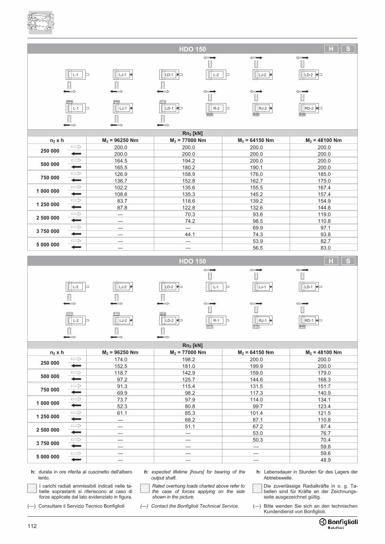
112
HDO 150
Rn2 [kN]
n2 x h M2 = 96250 Nm M2 = 77000 Nm M2 = 64150 Nm M2 = 48100 Nm
250 000200.0 200.0 200.0 200.0200.0 200.0 200.0 200.0
500 000164.5 194.2 200.0 200.0165.5 180.2 190.1 200.0
750 000126.9 158.9 176.0 185.0136.7 152.8 162.7 175.0
1 000 000102.2 135.6 155.5 167.4108.6 135.3 145.2 157.4
1 250 00083.7 118.6 139.2 154.987.8 122.8 132.6 144.8
2 500 000— 70.3 93.6 119.0— 74.2 98.5 110.8
3 750 000— — 69.9 97.1— 44.1 74.3 93.8
5 000 000— — 53.9 82.7— — 56.5 83.0
HDO 150
Rn2 [kN]
n2 x h M2 = 96250 Nm M2 = 77000 Nm M2 = 64150 Nm M2 = 48100 Nm
250 000174.0 198.2 200.0 200.0152.5 181.0 199.9 200.0
500 000118.7 142.9 159.0 179.0
97.2 125.7 144.6 168.3
750 00091.3 115.4 131.5 151.769.9 98.2 117.3 140.9
1 000 00073.7 97.9 114.0 134.152.3 80.8 99.7 123.4
1 250 00061.1 85.3 101.4 121.5— 68.2 87.1 110.8
2 500 000— 51.1 67.2 87.4— — 53.0 76.7
3 750 000— — 50.3 70.4— — — 59.8
5 000 000— — — 59.6— — — 48.9
��� ���� ���� ��� ���� ����
���� ������� ���� �������
��� ���� ���� ��� ���� ����
���� ������� ���� �������
I carichi radiali ammissibili indicati nelle ta-belle soprastanti si riferiscono al caso diforze applicate dal lato evidenziato in figura.
Die zuverlässige Radialkräfte in o. g. Ta-bellen sind für Kräfte an der Zeichnungs-seite ausgezeichnet gültig.
h: durata in ore riferita al cuscinetto dell'alberolento.
h: expected lifetime [hours] for bearing of the
output shaft.
h: Lebensdauer in Stunden für des Lagers derAbtriebswelle.
Rated overhung loads charted above refer tothe case of forces applying on the sideshown in the picture.
(—) Consultare il Servizio Tecnico Bonfiglioli (—) Contact the Bonfiglioli Technical Service. (—) Bitte wenden Sie sich an den technischenKundendienst von Bonfiglioli.
SH
SH

113
HDO 160
Rn2 [kN]
n2 x h M2 = 123200 Nm M2 = 98550 Nm M2 = 82100 Nm M2 = 61600 Nm
250 000135.0 175.2 192.8 204.9143.7 163.3 176.2 192.5
500 00065.4 112.3 139.4 159.668.1 118.0 130.9 147.2
750 000— 78.9 108.1 137.2— 84.7 108.5 124.7
1 000 000— 56.6 87.6 120.7— 58.5 94.2 110.4
1 250 000— — 72.5 107.0— — 77.8 100.0
2 500 000— — — 67.8— — — 72.2
3 750 000— — — 47.1— — — 50.5
5 000 000— — — —— — — —
HDO 160
Rn2 [kN]
n2 x h M2 = 123200 Nm M2 = 98550 Nm M2 = 82100 Nm M2 = 61600 Nm
250 000106.2 133.3 151.3 173.8
79.7 112.0 133.7 160.5
500 00057.3 87.8 106.0 128.5— 66.4 88.2 115.2
750 000— 65.4 83.5 106.0— 44.2 65.8 92.7
1 000 000— 50.1 69.2 91.6— — 51.5 78.3
1 250 000— — 58.8 81.4— — — 68.1
2 500 000— — — 53.4— — — —
3 750 000— — — —— — — —
5 000 000— — — —— — — —
����
����
����
����
����
��������
���� ���
���
���
���
����
����
����
����
���
���
����
����
����
����
���
���
Albero al quale sono riferiti i carichi radialiammissibili. Per gli alberi bisporgenti il cari-co può essere applicato solo sull’estremitàcosì evidenziata. In caso diverso consultareil Servizio Tecnico Bonfiglioli.
Welle, auf die sich die zulässigen Radialkräftebeziehen. Für die Wellen mit zwei Wellen-stummeln kann die Kraft nur auf das so ge-kennzeichnete Wellenende ausgeübt werden.Andernfalls mit dem technischen Kundendienstvon Bonfiglioli Rücksprache halten.
h: durata in ore riferita al cuscinetto dell'alberolento.
h: expected lifetime [hours] for bearing of the
output shaft.
h: Lebensdauer in Stunden für des Lagers derAbtriebswelle.
Shaft the rated overhung load is applicable to.For double extended shaft the load is only ap-plicable to the extension highlighted Shouldthis not be the case consult Bonfiglioli’s Tec-hnical Service.
(—) Consultare il Servizio Tecnico Bonfiglioli (—) Contact the Bonfiglioli Technical Service. (—) Bitte wenden Sie sich an den technischenKundendienst von Bonfiglioli.
LP
LP
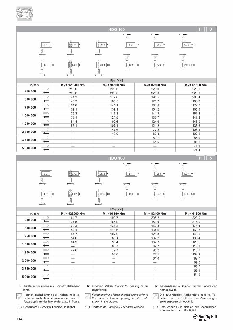
114
HDO 160
Rn2 [kN]
n2 x h M2 = 123200 Nm M2 = 98550 Nm M2 = 82100 Nm M2 = 61600 Nm
250 000216.0 220.0 220.0 220.0203.6 220.0 220.0 220.0
500 000141.3 177.6 195.5 206.4148.3 166.5 178.7 193.8
750 000101.6 141.1 164.4 179.0109.1 139.1 151.2 166.3
1 000 00075.3 117.1 141.3 161.479.1 121.5 133.7 148.9
1 250 00054.4 99.6 124.6 148.956.1 107.4 121.2 136.3
2 500 000— 47.6 77.2 108.5— 49.0 83.3 102.1
3 750 000— — 51.7 85.9— — 54.6 85.2
5 000 000— — — 71.1— — — 74.4
HDO 160
Rn2 [kN]
n2 x h M2 = 123200 Nm M2 = 98550 Nm M2 = 82100 Nm M2 = 61600 Nm
250 000164.7 190.7 208.2 220.0137.5 168.9 189.9 216.0
500 000109.3 135.3 152.8 174.4
82.1 113.6 134.6 160.8
750 00081.7 107.9 125.3 146.954.6 86.1 107.2 133.4
1 000 00064.2 90.4 107.7 129.5— 68.7 89.7 115.8
1 250 00047.6 77.7 95.2 116.9— 56.0 77.1 103.2
2 500 000— — 61.0 82.7— — — 69.0
3 750 000— — — 65.7— — — 52.1
5 000 000— — — 54.9— — — —
��� ���� ���� ��� ���� ����
���� ������� ���� �������
��� ���� ���� ��� ���� ����
���� ������� ���� �������
I carichi radiali ammissibili indicati nelle ta-belle soprastanti si riferiscono al caso diforze applicate dal lato evidenziato in figura.
Die zuverlässige Radialkräfte in o. g. Ta-bellen sind für Kräfte an der Zeichnungs-seite ausgezeichnet gültig.
h: durata in ore riferita al cuscinetto dell'alberolento.
h: expected lifetime [hours] for bearing of the
output shaft.
h: Lebensdauer in Stunden für des Lagers derAbtriebswelle.
Rated overhung loads charted above refer tothe case of forces applying on the sideshown in the picture.
(—) Consultare il Servizio Tecnico Bonfiglioli (—) Contact the Bonfiglioli Technical Service. (—) Bitte wenden Sie sich an den technischenKundendienst von Bonfiglioli.
SH
SH
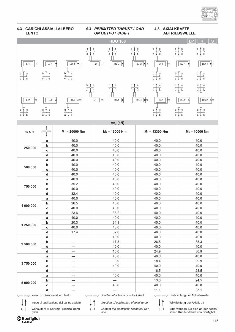
115
HDO 100
An2 [kN]
n2 x h M2 = 20000 Nm M2 = 16000 Nm M2 = 13300 Nm M2 = 10000 Nm
250 000
a 40.0 40.0 40.0 40.0
b 40.0 40.0 40.0 40.0
c 40.0 40.0 40.0 40.0
d 40.0 40.0 40.0 40.0
500 000
a 40.0 40.0 40.0 40.0
b 40.0 40.0 40.0 40.0
c 40.0 40.0 40.0 40.0
d 40.0 40.0 40.0 40.0
750 000
a 40.0 40.0 40.0 40.0
b 35.2 40.0 40.0 40.0
c 40.0 40.0 40.0 40.0
d 32.4 40.0 40.0 40.0
1 000 000
a 40.0 40.0 40.0 40.0
b 26.5 40.0 40.0 40.0
c 40.0 40.0 40.0 40.0
d 23.6 38.2 40.0 40.0
1 250 000
a 40.0 40.0 40.0 40.0
b 20.3 34.3 40.0 40.0
c 40.0 40.0 40.0 40.0
d 17.4 32.0 40.0 40.0
2 500 000
a — 40.0 40.0 40.0
b — 17.3 26.8 38.3
c — 40.0 40.0 40.0
d — 15.0 24.9 36.9
3 750 000
a — 40.0 40.0 40.0
b — 8.9 18.4 29.9
c — 40.0 40.0 40.0
d — — 16.5 28.5
5 000 000
a — 40.0 40.0 40.0
b — — 13.0 24.5
c — 40.0 40.0 40.0
d — — 11.1 23.1
���
��� ����
����
����
���� ���
���
����
���� ����
����
���
���
����
���� ����
����
4.3 - CARICHI ASSIALI ALBERO
LENTO
4.3 - PERMITTED THRUST LOAD
ON OUTPUT SHAFT
4.3 - AXIALKRÄFTE
ABTRIEBSWELLE
verso di rotazione albero lento
verso di applicazione del carico assiale
direction of rotation of output shaft
direction of application of axial force
Drehrichtung der Abtriebswelle
Wirkrichtung der Axialkraft
(—) Consultare il Servizio Tecnico Bonfi-glioli
(—) Contact the Bonfiglioli Technical Ser-vice.
(—) Bitte wenden Sie sich an den techni-schen Kundendienst von Bonfiglioli.
SHLP
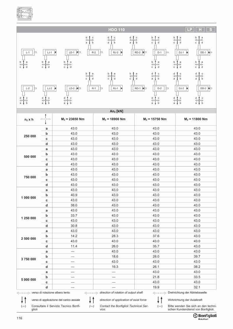
116
HDO 110
An2 [kN]
n2 x h M2 = 23650 Nm M2 = 18900 Nm M2 = 15750 Nm M2 = 11800 Nm
250 000
a 43.0 43.0 43.0 43.0
b 43.0 43.0 43.0 43.0
c 43.0 43.0 43.0 43.0
d 43.0 43.0 43.0 43.0
500 000
a 43.0 43.0 43.0 43.0
b 43.0 43.0 43.0 43.0
c 43.0 43.0 43.0 43.0
d 43.0 43.0 43.0 43.0
750 000
a 43.0 43.0 43.0 43.0
b 43.0 43.0 43.0 43.0
c 43.0 43.0 43.0 43.0
d 43.0 43.0 43.0 43.0
1 000 000
a 43.0 43.0 43.0 43.0
b 40.9 43.0 43.0 43.0
c 43.0 43.0 43.0 43.0
d 38.0 43.0 43.0 43.0
1 250 000
a 43.0 43.0 43.0 43.0
b 33.7 43.0 43.0 43.0
c 43.0 43.0 43.0 43.0
d 30.8 43.0 43.0 43.0
2 500 000
a 43.0 43.0 43.0 43.0
b 14.2 28.3 37.6 43.0
c 43.0 43.0 43.0 43.0
d 11.4 26.0 35.7 43.0
3 750 000
a — 43.0 43.0 43.0
b — 18.6 28.0 39.7
c — 43.0 43.0 43.0
d — 16.3 26.1 38.2
5 000 000
a — — 43.0 43.0
b — — 21.8 33.5
c — — 43.0 43.0
d — — 19.9 32.1
���
��� ����
����
����
���� ���
���
����
���� ����
����
���
���
����
���� ����
����
verso di rotazione albero lento
verso di applicazione del carico assiale
direction of rotation of output shaft
direction of application of axial force
Drehrichtung der Abtriebswelle
Wirkrichtung der Axialkraft
(—) Consultare il Servizio Tecnico Bonfi-glioli
(—) Contact the Bonfiglioli Technical Ser-vice.
(—) Bitte wenden Sie sich an den techni-schen Kundendienst von Bonfiglioli.
SHLP
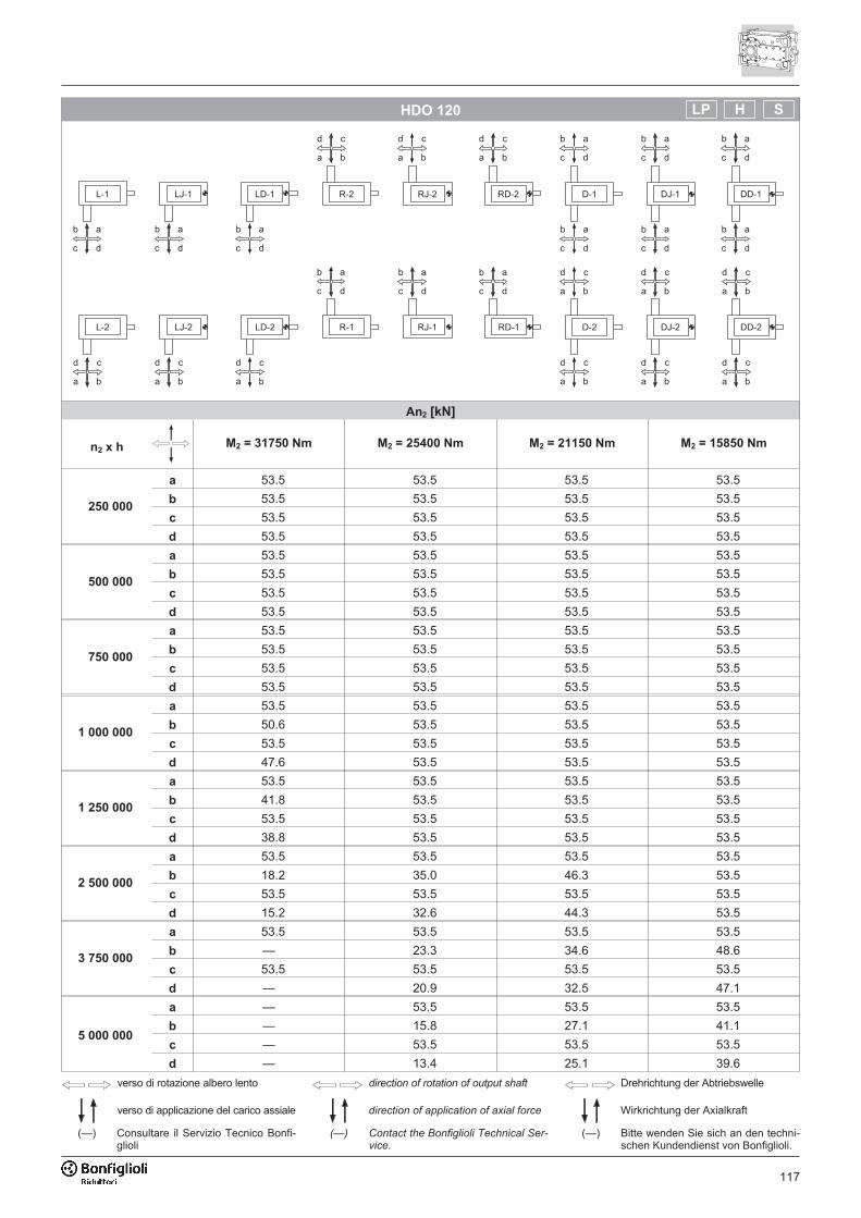
117
HDO 120
An2 [kN]
n2 x h M2 = 31750 Nm M2 = 25400 Nm M2 = 21150 Nm M2 = 15850 Nm
250 000
a 53.5 53.5 53.5 53.5
b 53.5 53.5 53.5 53.5
c 53.5 53.5 53.5 53.5
d 53.5 53.5 53.5 53.5
500 000
a 53.5 53.5 53.5 53.5
b 53.5 53.5 53.5 53.5
c 53.5 53.5 53.5 53.5
d 53.5 53.5 53.5 53.5
750 000
a 53.5 53.5 53.5 53.5
b 53.5 53.5 53.5 53.5
c 53.5 53.5 53.5 53.5
d 53.5 53.5 53.5 53.5
1 000 000
a 53.5 53.5 53.5 53.5
b 50.6 53.5 53.5 53.5
c 53.5 53.5 53.5 53.5
d 47.6 53.5 53.5 53.5
1 250 000
a 53.5 53.5 53.5 53.5
b 41.8 53.5 53.5 53.5
c 53.5 53.5 53.5 53.5
d 38.8 53.5 53.5 53.5
2 500 000
a 53.5 53.5 53.5 53.5
b 18.2 35.0 46.3 53.5
c 53.5 53.5 53.5 53.5
d 15.2 32.6 44.3 53.5
3 750 000
a 53.5 53.5 53.5 53.5
b — 23.3 34.6 48.6
c 53.5 53.5 53.5 53.5
d — 20.9 32.5 47.1
5 000 000
a — 53.5 53.5 53.5
b — 15.8 27.1 41.1
c — 53.5 53.5 53.5
d — 13.4 25.1 39.6
���
��� ����
����
����
���� ���
���
����
���� ����
����
���
���
����
���� ����
����
verso di rotazione albero lento
verso di applicazione del carico assiale
direction of rotation of output shaft
direction of application of axial force
Drehrichtung der Abtriebswelle
Wirkrichtung der Axialkraft
(—) Consultare il Servizio Tecnico Bonfi-glioli
(—) Contact the Bonfiglioli Technical Ser-vice.
(—) Bitte wenden Sie sich an den techni-schen Kundendienst von Bonfiglioli.
SHLP
118
HDO 130
An2 [kN]
n2 x h M2 = 53600 Nm M2 = 42850 Nm M2 = 35700 Nm M2 = 26800 Nm
250 000
a 80.0 80.0 80.0 80.0
b 80.0 80.0 80.0 80.0
c 80.0 80.0 80.0 80.0
d 80.0 80.0 80.0 80.0
500 000
a 80.0 80.0 80.0 80.0
b 80.0 80.0 80.0 80.0
c 80.0 80.0 80.0 80.0
d 80.0 80.0 80.0 80.0
750 000
a 78.5 80.0 80.0 80.0
b 80.0 80.0 80.0 80.0
c 73.3 80.0 80.0 80.0
d 80.0 80.0 80.0 80.0
1 000 000
a 61.6 80.0 80.0 80.0
b 80.0 80.0 80.0 80.0
c 56.4 80.0 80.0 80.0
d 80.0 80.0 80.0 80.0
1 250 000
a 49.5 74.7 80.0 80.0
b 80.0 80.0 80.0 80.0
c 44.3 70.6 80.0 80.0
d 80.0 80.0 80.0 80.0
2 500 000
a 16.5 41.7 58.5 79.4
b 80.0 80.0 80.0 80.0
c — 37.6 55.1 76.9
d 80.0 80.0 80.0 80.0
3 750 000
a — 25.4 42.2 63.1
b — 80.0 80.0 80.0
c — 21.3 38.8 60.6
d — 80.0 80.0 80.0
5 000 000
a — — 31.8 52.7
b — 80.0 80.0 80.0
c — — 28.4 50.1
d — 78.7 80.0 80.0
���
��� ����
����
����
���� ���
���
����
���� ����
����
���
���
����
���� ����
����
verso di rotazione albero lento
verso di applicazione del carico assiale
direction of rotation of output shaft
direction of application of axial force
Drehrichtung der Abtriebswelle
Wirkrichtung der Axialkraft
(—) Consultare il Servizio Tecnico Bonfi-glioli
(—) Contact the Bonfiglioli Technical Ser-vice.
(—) Bitte wenden Sie sich an den techni-schen Kundendienst von Bonfiglioli.
SHLP
119
HDO 140
An2 [kN]
n2 x h M2 = 67200 Nm M2 = 53750 Nm M2 = 44800 Nm M2 = 33600 Nm
250 000
a 95.0 95.0 95.0 95.0
b 95.0 95.0 95.0 95.0
c 95.0 95.0 95.0 95.0
d 95.0 95.0 95.0 95.0
500 000
a 83.9 95.0 95.0 95.0
b 95.0 95.0 95.0 95.0
c 79.1 95.0 95.0 95.0
d 95.0 95.0 95.0 95.0
750 000
a 83.9 95.0 95.0 95.0
b 95.0 95.0 95.0 95.0
c 79.1 95.0 95.0 95.0
d 95.0 95.0 95.0 95.0
1 000 000
a 64.9 94.1 95.0 95.0
b 95.0 95.0 95.0 95.0
c 60.0 90.2 95.0 95.0
d 95.0 95.0 95.0 95.0
1 250 000
a 51.3 80.4 95.0 95.0
b 95.0 95.0 95.0 95.0
c 46.3 76.5 95.0 95.0
d 95.0 95.0 95.0 95.0
2 500 000
a — 43.5 62.8 87.1
b 95.0 95.0 95.0 95.0
c — 39.5 59.6 84.7
d 95.0 95.0 95.0 95.0
3 750 000
a — 25.2 44.5 68.8
b — 95.0 95.0 95.0
c — 21.2 41.2 66.4
d — 95.0 95.0 95.0
5 000 000
a — — 32.8 57.1
b — 89.2 95.0 95.0
c — — 29.6 54.6
d — 83.8 91.4 95.0
���
��� ����
����
����
���� ���
���
����
���� ����
����
���
���
����
���� ����
����
verso di rotazione albero lento
verso di applicazione del carico assiale
direction of rotation of output shaft
direction of application of axial force
Drehrichtung der Abtriebswelle
Wirkrichtung der Axialkraft
(—) Consultare il Servizio Tecnico Bonfi-glioli
(—) Contact the Bonfiglioli Technical Ser-vice.
(—) Bitte wenden Sie sich an den techni-schen Kundendienst von Bonfiglioli.
SHLP
120
HDO 150
An2 [kN]
n2 x h M2 = 96250 Nm M2 = 77000 Nm M2 = 64150 Nm M2 = 48100 Nm
250 000
a 100.0 100.0 100.0 100.0
b 100.0 100.0 100.0 100.0
c 100.0 100.0 100.0 100.0
d 100.0 100.0 100.0 100.0
500 000
a 74.4 100.0 100.0 100.0
b 100.0 100.0 100.0 100.0
c 66.4 100.0 100.0 100.0
d 100.0 100.0 100.0 100.0
750 000
a 44.7 81.7 100.0 100.0
b 100.0 100.0 100.0 100.0
c 36.7 75.3 100.0 100.0
d 100.0 100.0 100.0 100.0
1 000 000
a 25.7 62.7 87.4 100.0
b 100.0 100.0 100.0 100.0
c — 56.2 82.0 100.0
d 100.0 100.0 100.0 100.0
1 250 000
a — 49.0 73.7 100.0
b 100.0 100.0 100.0 100.0
c — 42.7 68.4 100.0
d 100.0 100.0 100.0 100.0
2 500 000
a — — 36.8 67.6
b — 100.0 100.0 100.0
c — — 31.4 63.5
d — 100.0 100.0 100.0
3 750 000
a — — — 49.3
b — — 100.0 100.0
c — — — 45.2
d — — 99.1 100.0
5 000 000
a — — — 37.5
b — — 93.4 100.0
c — — — 33.5
d — — 87.4 98.0
���
��� ����
����
����
���� ���
���
����
���� ����
����
���
���
����
���� ����
����
verso di rotazione albero lento
verso di applicazione del carico assiale
direction of rotation of output shaft
direction of application of axial force
Drehrichtung der Abtriebswelle
Wirkrichtung der Axialkraft
(—) Consultare il Servizio Tecnico Bonfi-glioli
(—) Contact the Bonfiglioli Technical Ser-vice.
(—) Bitte wenden Sie sich an den techni-schen Kundendienst von Bonfiglioli.
LP
121
HDO 150
An2 [kN]
n2 x h M2 = 96250 Nm M2 = 77000 Nm M2 = 64150 Nm M2 = 48100 Nm
250 000
a 100.0 100.0 100.0 100.0
b 100.0 100.0 100.0 100.0
c 100.0 100.0 100.0 100.0
d 100.0 100.0 100.0 100.0
500 000
a 100.0 100.0 100.0 100.0
b 100.0 100.0 100.0 100.0
c 100.0 100.0 100.0 100.0
d 100.0 100.0 100.0 100.0
750 000
a 100.0 100.0 100.0 100.0
b 100.0 100.0 100.0 100.0
c 100.0 100.0 100.0 100.0
d 100.0 100.0 100.0 100.0
1 000 000
a 87.1 100.0 100.0 100.0
b 100.0 100.0 100.0 100.0
c 78.6 100.0 100.0 100.0
d 100.0 100.0 100.0 100.0
1 250 000
a 69.4 100.0 100.0 100.0
b 100.0 100.0 100.0 100.0
c 61.0 99.7 100.0 100.0
d 100.0 100.0 100.0 100.0
2 500 000
a 21.6 58.7 83.4 100.0
b 100.0 100.0 100.0 100.0
c — 51.8 77.7 100.0
d 100.0 100.0 100.0 100.0
3 750 000
a — 35.0 59.7 90.6
b — 100.0 100.0 100.0
c — 28.1 54.0 86.4
d — 100.0 100.0 100.0
5 000 000
a — — 44.5 75.5
b — 100.0 100.0 100.0
c — — 38.9 71.2
d — 100.0 100.0 100.0
verso di rotazione albero lento
verso di applicazione del carico assiale
direction of rotation of output shaft
direction of application of axial force
Drehrichtung der Abtriebswelle
Wirkrichtung der Axialkraft
(—) Consultare il Servizio Tecnico Bonfi-glioli
(—) Contact the Bonfiglioli Technical Ser-vice.
(—) Bitte wenden Sie sich an den techni-schen Kundendienst von Bonfiglioli.
SH
����������� ����������������������
���������������������������������
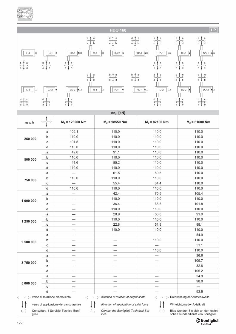
122
HDO 160
An2 [kN]
n2 x h M2 = 123200 Nm M2 = 98550 Nm M2 = 82100 Nm M2 = 61600 Nm
250 000
a 109.1 110.0 110.0 110.0
b 110.0 110.0 110.0 110.0
c 101.5 110.0 110.0 110.0
d 110.0 110.0 110.0 110.0
500 000
a 49.0 91.1 110.0 110.0
b 110.0 110.0 110.0 110.0
c 41.6 85.2 110.0 110.0
d 110.0 110.0 110.0 110.0
750 000
a — 61.5 89.5 110.0
b 110.0 110.0 110.0 110.0
c — 55.4 84.4 110.0
d 110.0 110.0 110.0 110.0
1 000 000
a — 42.4 70.5 105.4
b — 110.0 110.0 110.0
c — 36.4 65.5 101.8
d — 110.0 110.0 110.0
1 250 000
a — 28.9 56.8 91.9
b — 110.0 110.0 110.0
c — 22.8 51.8 88.1
d — 110.0 110.0 110.0
2 500 000
a — — — 54.9
b — — 110.0 110.0
c — — — 51.1
d — — 110.0 110.0
3 750 000
a — — — 36.6
b — — — 109.7
c — — — 32.8
d — — — 105.2
5 000 000
a — — — 24.9
b — — — 98.0
c — — — —
d — — — 93.5
���
��� ����
����
����
���� ���
���
����
���� ����
����
���
���
����
���� ����
����
verso di rotazione albero lento
verso di applicazione del carico assiale
direction of rotation of output shaft
direction of application of axial force
Drehrichtung der Abtriebswelle
Wirkrichtung der Axialkraft
(—) Consultare il Servizio Tecnico Bonfi-glioli
(—) Contact the Bonfiglioli Technical Ser-vice.
(—) Bitte wenden Sie sich an den techni-schen Kundendienst von Bonfiglioli.
LP
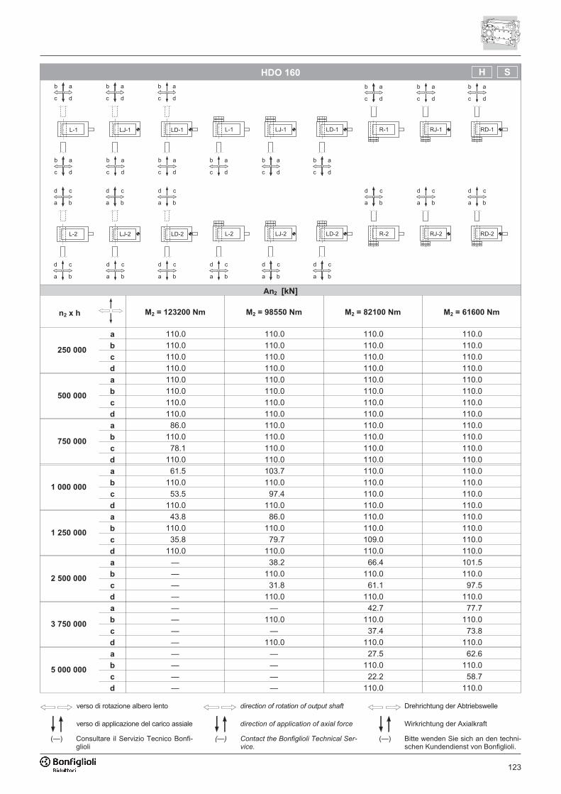
123
HDO 160
An2 [kN]
n2 x h M2 = 123200 Nm M2 = 98550 Nm M2 = 82100 Nm M2 = 61600 Nm
250 000
a 110.0 110.0 110.0 110.0
b 110.0 110.0 110.0 110.0
c 110.0 110.0 110.0 110.0
d 110.0 110.0 110.0 110.0
500 000
a 110.0 110.0 110.0 110.0
b 110.0 110.0 110.0 110.0
c 110.0 110.0 110.0 110.0
d 110.0 110.0 110.0 110.0
750 000
a 86.0 110.0 110.0 110.0
b 110.0 110.0 110.0 110.0
c 78.1 110.0 110.0 110.0
d 110.0 110.0 110.0 110.0
1 000 000
a 61.5 103.7 110.0 110.0
b 110.0 110.0 110.0 110.0
c 53.5 97.4 110.0 110.0
d 110.0 110.0 110.0 110.0
1 250 000
a 43.8 86.0 110.0 110.0
b 110.0 110.0 110.0 110.0
c 35.8 79.7 109.0 110.0
d 110.0 110.0 110.0 110.0
2 500 000
a — 38.2 66.4 101.5
b — 110.0 110.0 110.0
c — 31.8 61.1 97.5
d — 110.0 110.0 110.0
3 750 000
a — — 42.7 77.7
b — 110.0 110.0 110.0
c — — 37.4 73.8
d — 110.0 110.0 110.0
5 000 000
a — — 27.5 62.6
b — — 110.0 110.0
c — — 22.2 58.7
d — — 110.0 110.0
verso di rotazione albero lento
verso di applicazione del carico assiale
direction of rotation of output shaft
direction of application of axial force
Drehrichtung der Abtriebswelle
Wirkrichtung der Axialkraft
(—) Consultare il Servizio Tecnico Bonfi-glioli
(—) Contact the Bonfiglioli Technical Ser-vice.
(—) Bitte wenden Sie sich an den techni-schen Kundendienst von Bonfiglioli.
����������� ����������������������
���������������������������������
SH
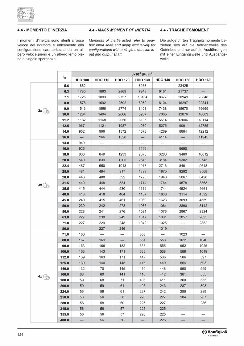
124
4.4 - MOMENTO D'INERZIA 4.4 - MASS MOMENT OF INERTIA 4.4 - TRÄGHEITSMOMENT
iNJ�10
-4 [Kg m2]
HDO 100 HDO 110 HDO 120 HDO 130 HDO 140 HDO 150 HDO 160
2x
5.6 1862 — — 8268 — 23425 —
6.3 1780 1893 2869 7943 9161 21737 —
7.1 1725 1803 2757 10164 8677 20949 23848
8.0 1578 1692 2592 6959 8104 16297 22841
9.0 1543 1566 2774 8408 7438 15670 19669
10.0 1204 1494 2666 5207 7065 12076 18609
11.2 1182 1168 2056 6135 5514 12006 18114
12.5 967 1121 1987 4070 5275 9091 12785
14.0 952 996 1572 4673 4269 8884 12212
16.0 — 966 1528 — 4114 — 11945
3x
14.0 940 — — — — — —
16.0 926 — — 3156 — 9690 —
18.0 836 849 1233 2675 3280 9480 10012
20.0 540 839 1205 2643 3184 9382 9743
22.4 487 550 1013 1913 2716 8401 9618
25.0 481 494 917 1893 1970 8292 8568
28.0 443 488 592 1728 1940 5067 8428
31.5 440 448 534 1714 1764 4578 8363
35.5 415 444 530 1612 1744 4524 4661
40.0 413 418 464 1137 1636 3114 4592
45.0 240 415 461 1069 1623 3093 4559
50.0 239 242 278 1063 1084 2890 3142
56.0 228 241 276 1021 1076 2867 2924
63.0 227 230 249 1017 1031 2857 2895
71.0 227 229 248 1042 1025 — 2882
80.0 — 227 246 — 1019 — —
4x
71.0 168 — — 553 — 1023 —
80.0 167 169 — 551 558 1011 1040
90.0 163 168 182 535 555 952 1025
100.0 163 143 171 533 538 589 1019
112.0 139 163 171 447 536 586 597
125.0 139 140 145 446 449 554 593
140.0 132 70 145 410 448 550 559
160.0 68 60 141 410 412 301 555
180.0 59 68 71 406 411 300 553
200.0 59 59 61 405 243 287 303
224.0 56 59 61 227 242 285 289
250.0 56 56 58 226 227 284 287
280.0 56 58 60 225 227 — 286
315.0 56 56 57 225 225 — —
355.0 56 56 57 226 225 — —
400.0 — 56 56 — 225 — —
I momenti d’inerzia sono riferiti all’asseveloce del riduttore e unicamente allaconfigurazione caratterizzata da un al-bero veloce pieno e un albero lento pie-no a singola sporgenza.
Moments of inertia listed refer to gear-
box input shaft and apply exclusively for
configurations with a single extension in-
put and output shaft.
Die aufgeführten Trägheitsmomente be-ziehen sich auf die Antriebswelle desGetriebes und nur auf die Ausführungenmit einer Eingangswelle und Ausgangs-welle.

125
4.5 - RAPPORTI ESATTI 4.5 - EXACT RATIOS 4.5 - EXAKTE ÜBERSETZUNG
iNi
HDO 100 HDO 110 HDO 120 HDO 130 HDO 140 HDO 150 HDO 160
2x
5.6 5.815 — — 5.708 — 5.512 —
6.3 6.462 6.354 6.569 6.231 6.569 6.459 —
7.1 7.038 7.038 7.154 7.090 7.269 7.034 7.306
8.0 8.000 8.077 8.077 7.714 8.167 8.133 7.941
9.0 8.714 8.714 8.857 8.778 9.000 8.857 8.933
10.0 10.000 10.000 10.000 9.643 10.111 10.010 10.427
11.2 10.893 10.893 11.071 10.972 11.250 10.901 11.333
12.5 12.400 12.500 12.500 11.957 12.639 12.607 12.152
14.0 13.507 13.507 13.729 13.606 13.950 13.729 14.183
16.0 — 15.500 15.500 — 15.672 — 15.417
3x
14.0 14.009 — — — — — —
16.0 15.566 — — 15.188 — 15.618 —
18.0 17.308 18.910 17.260 18.265 17.719 18.300 17.735
20.0 20.235 20.948 19.487 19.938 19.906 19.929 20.700
22.4 22.500 22.042 21.802 22.613 23.262 21.698 22.500
25.0 25.000 24.583 24.579 24.686 26.027 25.425 24.641
28.0 28.320 27.232 28.343 28.267 28.800 28.232 28.760
31.5 31.467 30.942 31.952 30.857 32.533 30.739 31.261
35.5 36.000 34.276 34.796 34.862 36.000 36.019 34.908
40.0 40.000 39.333 41.248 38.263 40.124 40.184 40.743
45.0 43.896 43.571 44.918 43.813 44.400 43.760 44.286
50.0 48.773 47.960 49.526 47.829 50.427 47.646 49.406
56.0 55.800 53.128 53.934 54.036 55.800 55.830 54.107
63.0 62.000 60.967 63.934 58.989 62.193 60.798 63.151
71.0 67.536 67.536 69.623 67.121 68.820 — 68.643
80.0 — 77.500 78.607 — 77.316 — —
4x
71.0 70.800 — — 71.498 — 66.861 —
80.0 78.667 77.356 — 78.050 82.290 78.345 75.927
90.0 90.000 85.690 86.990 88.181 91.059 92.894 88.620
100.0 100.000 96.694 103.119 96.262 101.491 101.848 96.326
112.0 111.392 108.929 112.296 111.182 112.306 110.912 115.205
125.0 123.769 121.706 125.679 121.371 127.964 120.762 125.223
140.0 139.830 137.105 136.864 141.333 141.600 141.503 137.137
160.0 160.000 154.711 162.241 154.286 162.667 157.865 160.061
180.0 178.227 174.286 179.673 174.311 180.000 171.914 173.980
200.0 198.030 194.730 201.087 190.286 198.345 187.182 194.096
225.0 223.728 215.711 218.982 219.067 219.480 219.330 212.562
250.0 248.587 244.444 252.424 239.143 252.133 238.849 248.095
280.0 284.400 274.210 282.686 270.182 279.000 — 269.668
315.0 316.000 310.733 325.856 294.943 310.964 — —
355.0 344.214 344.214 354.855 335.604 344.100 — —
400.0 — 395.000 400.643 — 386.581 — —
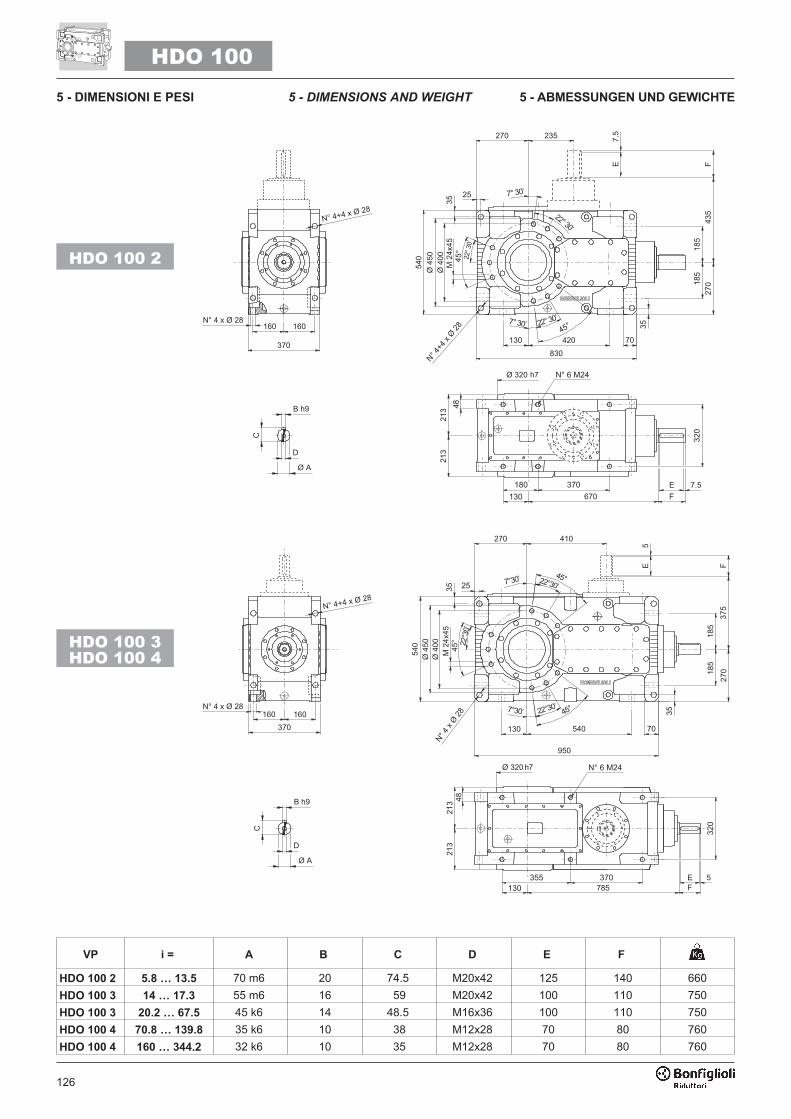
126
VP i = A B C D E F
HDO 100 2 5.8 … 13.5 70 m6 20 74.5 M20x42 125 140 660
HDO 100 3 14 … 17.3 55 m6 16 59 M20x42 100 110 750
HDO 100 3 20.2 … 67.5 45 k6 14 48.5 M16x36 100 110 750
HDO 100 4 70.8 … 139.8 35 k6 10 38 M12x28 70 80 760
HDO 100 4 160 … 344.2 32 k6 10 35 M12x28 70 80 760
HDO 100
��
�������
����
��
�
�������
�� ��
��
�
HDO 100 2
HDO 100 3
HDO 100 4
5 - DIMENSIONS AND WEIGHT5 - DIMENSIONI E PESI 5 - ABMESSUNGEN UND GEWICHTE

127
HDO 100
�
�
�
��
���
���
��
���
���
����
��
��������
�� �����
�����
� � ��� ��� � �
�� ���
��� ��
��
�
�� � ��
�� �����
����
���
���
�� ��
LP
H
S
* Per un corretto utilizzo riferirsi al "MANUALEUSO E MANUTENZIONE".
* For correct use, refer to the "OPERATION
AND MAINTENANCE MANUAL".
* Zur Gewährleistung eines korrekten Ge-brauchs die "BETRIEBS- UND WAR-TUNGSANLEITUNG" konsultieren.

128
HDO 110
VP i = A B C D E F
HDO 110 2 6.4 … 15.5 70 m6 20 74.5 M20x42 125 140 715
HDO 110 3 18.9 … 20.9 55 m6 16 59 M20x42 100 110 800
HDO 110 3 22 … 77.5 45 k6 14 48.5 M16x36 100 110 800
HDO 110 4 77.4 … 121.7 35 k6 10 38 M12x28 70 80 790
HDO 110 4 137.1 … 395 32 k6 10 35 M12x28 70 80 790
��
�������
����
��
�
�������
�� ��
��
�
HDO 110 2
HDO 110 3
HDO 110 4
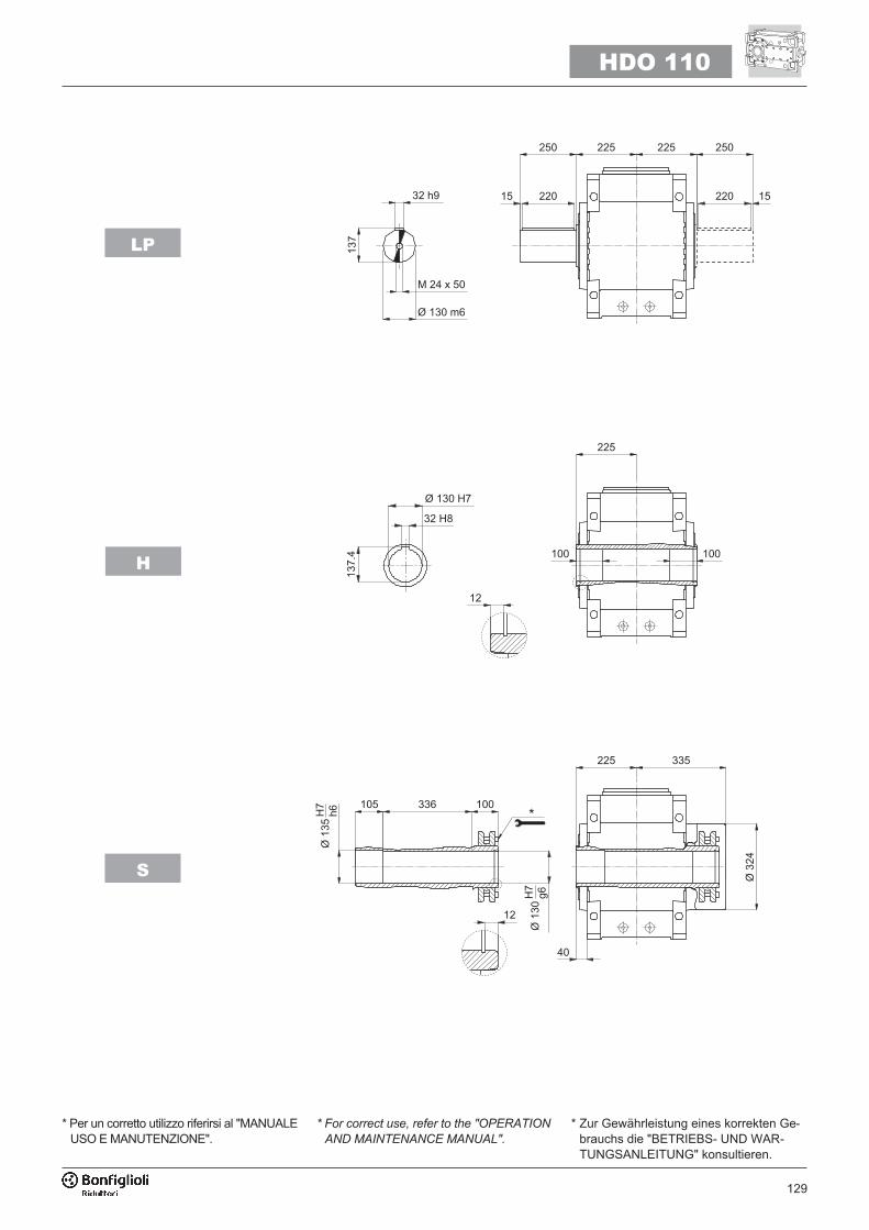
129
HDO 110
�
�
��
��
���
�
��
��
���
��� ��
��
�
�� � ��
�� ����
����
��
���
�� ��
����
�
��������
�� ����
��� �
��� ��� ��� ���
��� �
LP
H
S
* Per un corretto utilizzo riferirsi al "MANUALEUSO E MANUTENZIONE".
* For correct use, refer to the "OPERATION
AND MAINTENANCE MANUAL".
* Zur Gewährleistung eines korrekten Ge-brauchs die "BETRIEBS- UND WAR-TUNGSANLEITUNG" konsultieren.
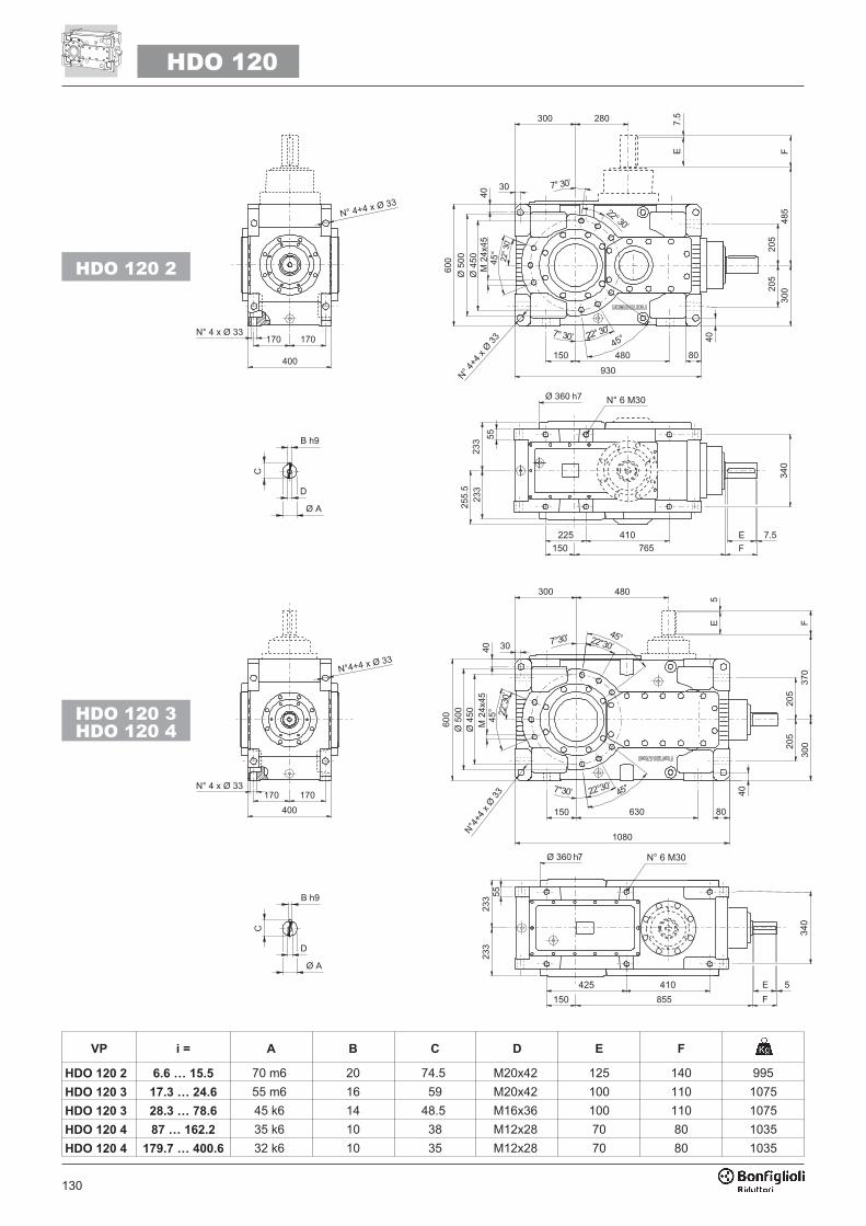
130
HDO 120
VP i = A B C D E F
HDO 120 2 6.6 … 15.5 70 m6 20 74.5 M20x42 125 140 995
HDO 120 3 17.3 … 24.6 55 m6 16 59 M20x42 100 110 1075
HDO 120 3 28.3 … 78.6 45 k6 14 48.5 M16x36 100 110 1075
HDO 120 4 87 … 162.2 35 k6 10 38 M12x28 70 80 1035
HDO 120 4 179.7 … 400.6 32 k6 10 35 M12x28 70 80 1035
�� �������
����
�
��
�������
���
�
��
HDO 120 2
HDO 120 3
HDO 120 4

131
HDO 120
�
��
�
�
��
��
�
��
��
���
�� ���
��
�
�� �� �
����
�
��������
�� ����
��� �
��� �� �� ���
��� �
�� ����
����
��
��
� �
LP
H
S
* Per un corretto utilizzo riferirsi al "MANUALEUSO E MANUTENZIONE".
* For correct use, refer to the "OPERATION
AND MAINTENANCE MANUAL".
* Zur Gewährleistung eines korrekten Ge-brauchs die "BETRIEBS- UND WAR-TUNGSANLEITUNG" konsultieren.
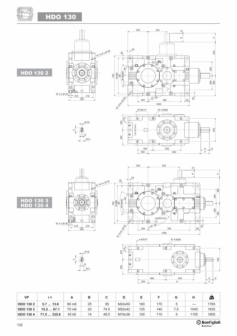
132
HDO 130
VP i = A B C D E F G H
HDO 130 2 5.7 … 13.6 90 m6 25 95 M24x50 160 170 5 — 1765
HDO 130 3 15.2 … 67.1 70 m6 20 74.5 M20x42 125 140 7.5 1040 1835
HDO 130 4 71.5 … 335.6 45 k6 14 48.5 M16x36 100 110 5 1105 1805
HDO 130 2
HDO 130 3
HDO 130 4
��
�������
����
�
���
�������
�����
�
���
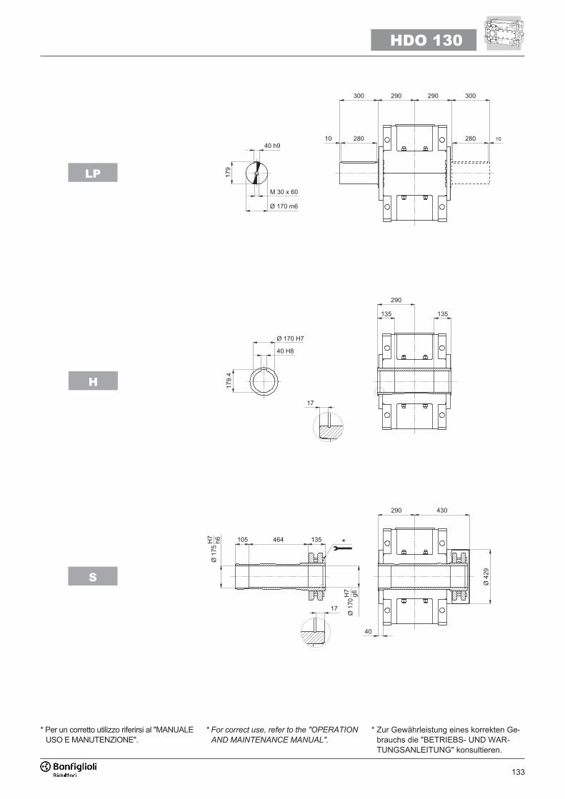
133
HDO 130
�
��
���
���
�
��
���
���
�
��� �
��
��
�
�� � �
�� �����
����
���
� �
���
����
��������
�� �����
��
��� �
�� ��� ��� ��
����
LP
H
S
* Per un corretto utilizzo riferirsi al "MANUALEUSO E MANUTENZIONE".
* For correct use, refer to the "OPERATION
AND MAINTENANCE MANUAL".
* Zur Gewährleistung eines korrekten Ge-brauchs die "BETRIEBS- UND WAR-TUNGSANLEITUNG" konsultieren.
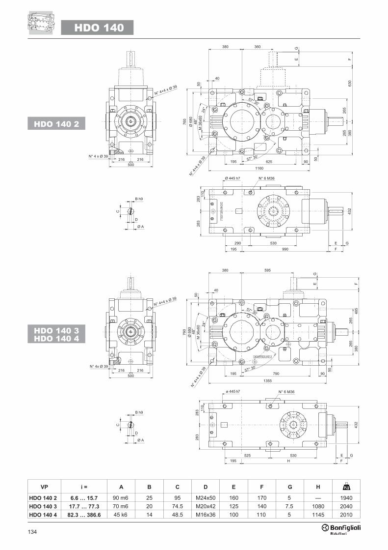
134
VP i = A B C D E F G H
HDO 140 2 6.6 … 15.7 90 m6 25 95 M24x50 160 170 5 — 1940
HDO 140 3 17.7 … 77.3 70 m6 20 74.5 M20x42 125 140 7.5 1080 2040
HDO 140 4 82.3 … 386.6 45 k6 14 48.5 M16x36 100 110 5 1145 2010
HDO 140
��
�����
�������
�
�
�������
����� ��
HDO 140 2
HDO 140 3
HDO 140 4

135
HDO 140
�
�
�
��
���
���
��� �
��
�
�
�� �� �
��
���
���
�� �����
����
���
� �
���
����
��������
�� �����
��
��� �
�� ��� ��� ��
����
LP
H
S
* Per un corretto utilizzo riferirsi al "MANUALEUSO E MANUTENZIONE".
* For correct use, refer to the "OPERATION
AND MAINTENANCE MANUAL".
* Zur Gewährleistung eines korrekten Ge-brauchs die "BETRIEBS- UND WAR-TUNGSANLEITUNG" konsultieren.
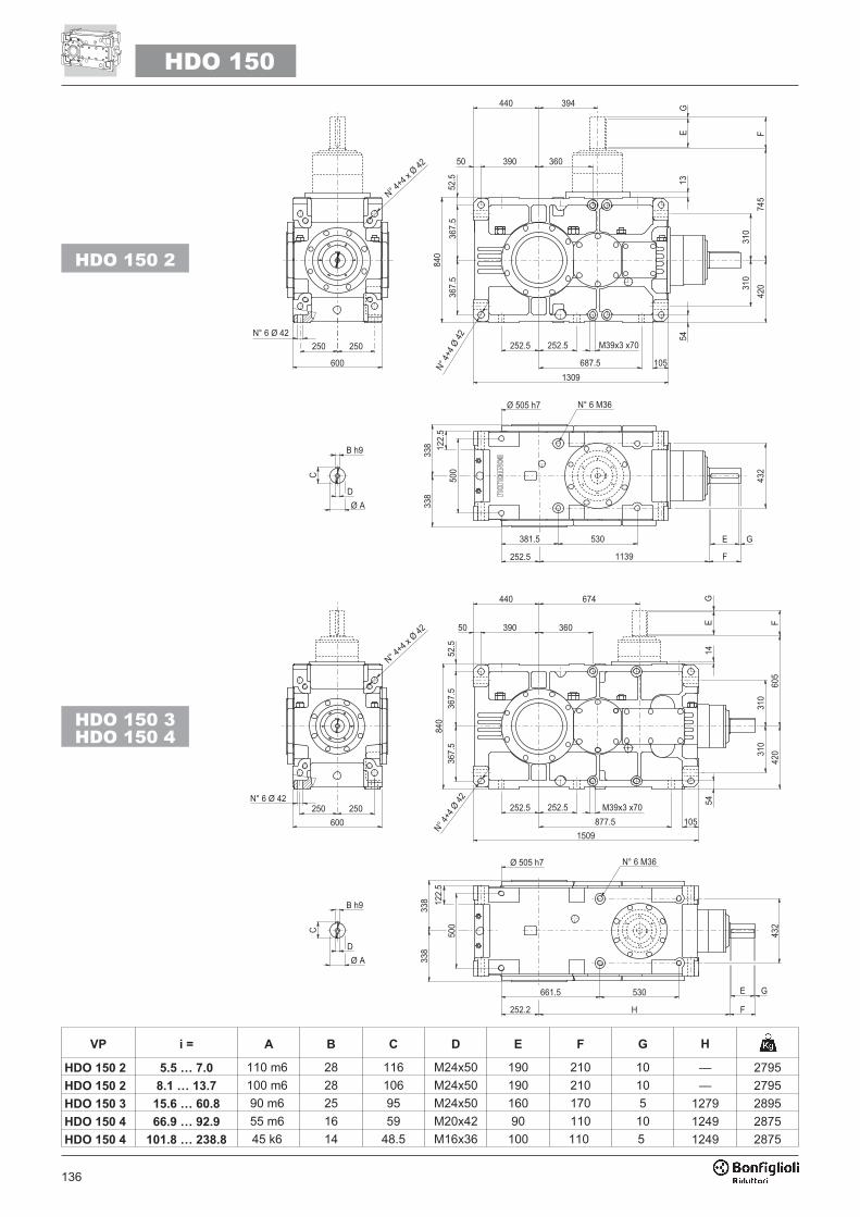
136
VP i = A B C D E F G H
HDO 150 2 5.5 … 7.0 110 m6 28 116 M24x50 190 210 10 — 2795
HDO 150 2 8.1 … 13.7 100 m6 28 106 M24x50 190 210 10 — 2795
HDO 150 3 15.6 … 60.8 90 m6 25 95 M24x50 160 170 5 1279 2895
HDO 150 4 66.9 … 92.9 55 m6 16 59 M20x42 90 110 10 1249 2875
HDO 150 4 101.8 … 238.8 45 k6 14 48.5 M16x36 100 110 5 1249 2875
HDO 150
����������� ��
�
�������
�����
��
���
� �
���
����
� � �
�� ��
��
���
���
�
�
�
����
���
���
� �
�����
����� ����� � �� ���
��
��
����
�
�
���
�
�
����
��
����
�����
�
�� � �
� �
� �
������� ������ �
�������
�����
����������� ��
�
�� ���
�� �
����
���
� �
���
��
�����
�����
�����
���
����� ��
����� � �� ���
��
�
��
�
��
���
��
�
�
�
����
�
�������
�����
�����
�
� �
� �
� �
������ �
����
�
�
���
HDO 150 2
HDO 150 3
HDO 150 4
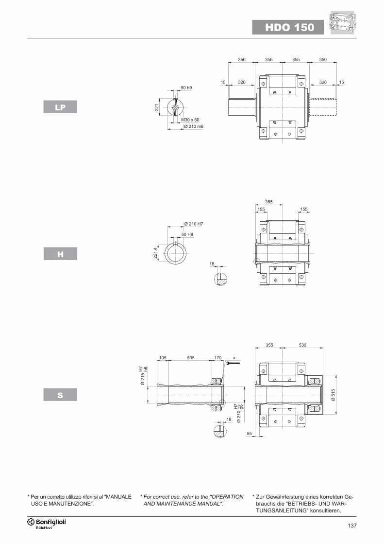
137
HDO 150
�����
��
�������
��� ����
� ��
�� �� �� ��
�� �
��� ����
�����
�� �
�
��
�� ��
���� ��
���
��
���
��
���
��
���
�
��
�� ��
���
�
LP
H
S
* Per un corretto utilizzo riferirsi al "MANUALEUSO E MANUTENZIONE".
* For correct use, refer to the "OPERATION
AND MAINTENANCE MANUAL".
* Zur Gewährleistung eines korrekten Ge-brauchs die "BETRIEBS- UND WAR-TUNGSANLEITUNG" konsultieren.
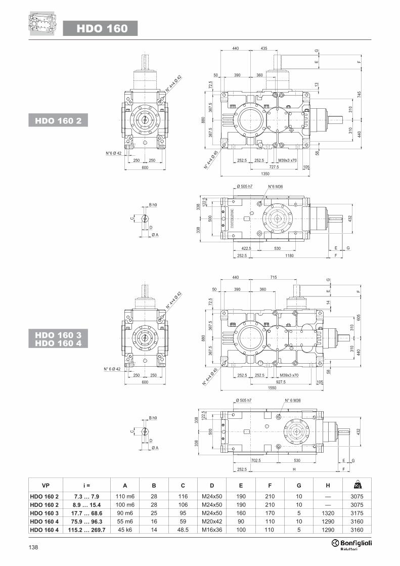
138
VP i = A B C D E F G H
HDO 160 2 7.3 … 7.9 110 m6 28 116 M24x50 190 210 10 — 3075
HDO 160 2 8.9 … 15.4 100 m6 28 106 M24x50 190 210 10 — 3075
HDO 160 3 17.7 … 68.6 90 m6 25 95 M24x50 160 170 5 1320 3175
HDO 160 4 75.9 … 96.3 55 m6 16 59 M20x42 90 110 10 1290 3160
HDO 160 4 115.2 … 269.7 45 k6 14 48.5 M16x36 100 110 5 1290 3160
HDO 160
��������
�� ��
�����
���
���
�� ���
� �� ��
���
��
�� �
���
��
����
���
���
���
�����
� �� ��
������� �����
��
��
��
��
��
���
��
����
�
�
���
���
���
����
��
������
�����
����� ���
��
���
�������
�����
�����
����������� ��
�
�� ��
� �� ��
���
��
�� �
���
��
�����
�����
�����
�� �� ��
����� �������
��
��
��
��
��
���
���
���
��� ��
���
�
�����
��� ��
� �
� �
���
������ ��������
��
�
��
����
�
�
���
HDO 160 2
HDO 160 3
HDO 160 4
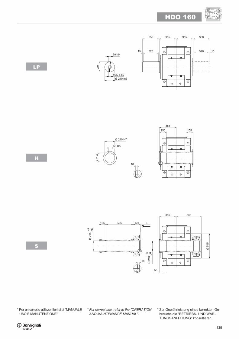
139
HDO 160
LP
H
S
�����
��
���������� ����
� ��
�� �� �� ��
�� �
��� ����
�����
�� �
�
��
�� ��
���� ��
���
��
���
��
���
��
���
�
��
�� ��
���
�
* Per un corretto utilizzo riferirsi al "MANUALEUSO E MANUTENZIONE".
* For correct use, refer to the "OPERATION
AND MAINTENANCE MANUAL".
* Zur Gewährleistung eines korrekten Ge-brauchs die "BETRIEBS- UND WAR-TUNGSANLEITUNG" konsultieren.

140
5.1 - PREDISPOSIZIONE ATTACCO
MOTORE CON CAMPANA
E GIUNTO ELASTICO
5.1 - MOTOR MOUNTING WITH
BELL HOUSING AND
FLEXIBLE COUPLING
5.1 - AUSLEGUNG FÜR MOTORAN-
SCHLUSS MIT GLOCKE UND
ELASTISCHER KUPPLUNG
�
��
M M1 M2 N N1 N2 N3 N4 X P PJ
HDO 100 2_250 65 69.4 18 550 500 450 30 18 6 420.5 475.5
HDO 100 2_280 75 79.9 20 550 500 450 30 18 6 420.5 475.5
HDO 100 2_315 80 85.4 22 660 600 550 22 22 10 457 512
HDO 100 3_160 42 45.3 12 350 300 250 23 18 6 351 351
HDO 100 3_180 48 51.8 14 350 300 250 23 18 6 351 351
HDO 100 3_200 55 59.3 16 400 350 300 — M16x23 7 376 376
HDO 100 3_225 60 64.4 18 450 400 350 26 18 7 383 383
HDO 100 3_250 65 69.4 18 550 500 450 30 18 6 413 413
HDO 100 3_280 75 79.9 20 550 500 450 30 18 6 413 413
HDO 100 3_315 80 85.4 22 660 600 550 22 22 10 449.5 449.5
HDO 100 4_112 28 31.3 8 250 215 180 15 14 5 265 —
HDO 100 4_132 38 41.3 10 300 265 230 — M12x20 6 285 —
HDO 100 4_160 42 45.3 12 350 300 250 23 18 6 351 —
HDO 100 4_180 48 51.8 14 350 300 250 23 18 6 351 —
HDO 100 4_200 55 59.3 16 400 350 300 — M16x23 7 376 —
HDO 100 4_225 60 64.4 18 450 400 350 26 18 7 383 —
HDO 110 2_280 75 79.9 20 550 500 450 30 18 6 420.5 475.5
HDO 110 2_315 80 85.4 22 660 600 550 22 22 10 457 512
HDO 110 3_160 42 45.3 12 350 300 250 23 18 6 351 351
HDO 110 3_180 48 51.8 14 350 300 250 23 18 6 351 351
HDO 110 3_200 55 59.3 16 400 350 300 — M16x23 7 376 376
HDO 110 3_225 60 64.4 18 450 400 350 26 18 7 383 383
HDO 110 3_250 65 69.4 18 550 500 450 30 18 6 413 413
HDO 110 3_280 75 79.9 20 550 500 450 30 18 6 413 413
HDO 110 3_315 80 85.4 22 660 600 550 22 22 10 449.5 449.5
HDO 110 4_112 28 31.3 8 250 215 180 15 14 5 265 —
HDO 110 4_132 38 41.3 10 300 265 230 — M12x20 6 285 —
HDO 110 4_160 42 45.3 12 350 300 250 23 18 6 351 —
HDO 110 4_180 48 51.8 14 350 300 250 23 18 6 351 —
HDO 110 4_200 55 59.3 16 400 350 300 — M16x23 7 376 —
HDO 110 4_225 60 64.4 18 450 400 350 26 18 7 383 —
HDO 120 2_315 80 85.4 22 660 600 550 22 22 10 482 532
HDO 120 3_200 55 59.3 16 400 350 300 — M16x23 7 346 346
HDO 120 3_225 60 64.4 18 450 400 350 26 18 7 353 353
HDO 120 3_250 65 69.4 18 550 500 450 30 18 6 383 383
HDO 120 3_280 75 79.9 20 550 500 450 30 18 6 383 383
HDO 120 3_315 80 85.4 22 660 600 550 22 22 10 419.5 419.5
HDO 120 4_132 38 41.3 10 300 265 230 — M12x40 6 255 —
HDO 120 4_160 42 45.3 12 350 300 250 23 18 6 321 —
HDO 120 4_180 48 51.8 14 350 300 250 23 18 6 321 —
HDO 120 4_200 55 59.3 16 400 350 300 — M16x23 7 346 —
HDO 120 4_225 60 64.4 18 450 400 350 26 18 7 353 —
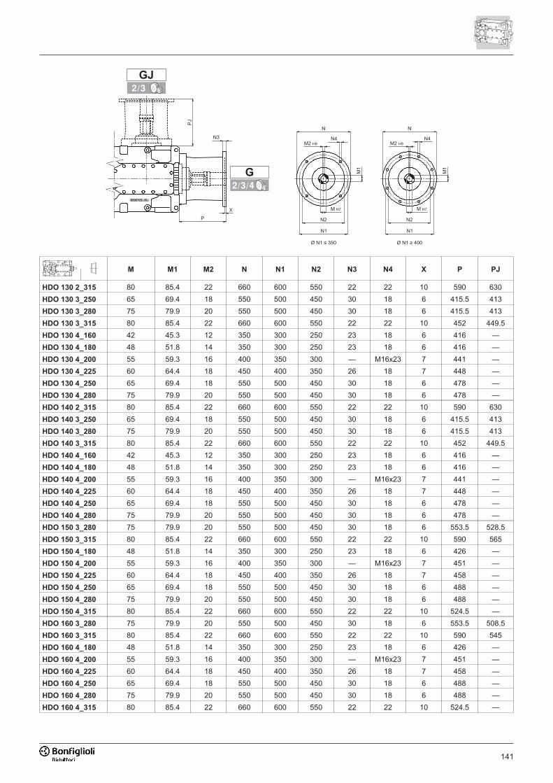
141
M M1 M2 N N1 N2 N3 N4 X P PJ
HDO 130 2_315 80 85.4 22 660 600 550 22 22 10 590 630
HDO 130 3_250 65 69.4 18 550 500 450 30 18 6 415.5 413
HDO 130 3_280 75 79.9 20 550 500 450 30 18 6 415.5 413
HDO 130 3_315 80 85.4 22 660 600 550 22 22 10 452 449.5
HDO 130 4_160 42 45.3 12 350 300 250 23 18 6 416 —
HDO 130 4_180 48 51.8 14 350 300 250 23 18 6 416 —
HDO 130 4_200 55 59.3 16 400 350 300 — M16x23 7 441 —
HDO 130 4_225 60 64.4 18 450 400 350 26 18 7 448 —
HDO 130 4_250 65 69.4 18 550 500 450 30 18 6 478 —
HDO 130 4_280 75 79.9 20 550 500 450 30 18 6 478 —
HDO 140 2_315 80 85.4 22 660 600 550 22 22 10 590 630
HDO 140 3_250 65 69.4 18 550 500 450 30 18 6 415.5 413
HDO 140 3_280 75 79.9 20 550 500 450 30 18 6 415.5 413
HDO 140 3_315 80 85.4 22 660 600 550 22 22 10 452 449.5
HDO 140 4_160 42 45.3 12 350 300 250 23 18 6 416 —
HDO 140 4_180 48 51.8 14 350 300 250 23 18 6 416 —
HDO 140 4_200 55 59.3 16 400 350 300 — M16x23 7 441 —
HDO 140 4_225 60 64.4 18 450 400 350 26 18 7 448 —
HDO 140 4_250 65 69.4 18 550 500 450 30 18 6 478 —
HDO 140 4_280 75 79.9 20 550 500 450 30 18 6 478 —
HDO 150 3_280 75 79.9 20 550 500 450 30 18 6 553.5 528.5
HDO 150 3_315 80 85.4 22 660 600 550 22 22 10 590 565
HDO 150 4_180 48 51.8 14 350 300 250 23 18 6 426 —
HDO 150 4_200 55 59.3 16 400 350 300 — M16x23 7 451 —
HDO 150 4_225 60 64.4 18 450 400 350 26 18 7 458 —
HDO 150 4_250 65 69.4 18 550 500 450 30 18 6 488 —
HDO 150 4_280 75 79.9 20 550 500 450 30 18 6 488 —
HDO 150 4_315 80 85.4 22 660 600 550 22 22 10 524.5 —
HDO 160 3_280 75 79.9 20 550 500 450 30 18 6 553.5 508.5
HDO 160 3_315 80 85.4 22 660 600 550 22 22 10 590 545
HDO 160 4_180 48 51.8 14 350 300 250 23 18 6 426 —
HDO 160 4_200 55 59.3 16 400 350 300 — M16x23 7 451 —
HDO 160 4_225 60 64.4 18 450 400 350 26 18 7 458 —
HDO 160 4_250 65 69.4 18 550 500 450 30 18 6 488 —
HDO 160 4_280 75 79.9 20 550 500 450 30 18 6 488 —
HDO 160 4_315 80 85.4 22 660 600 550 22 22 10 524.5 —
�
��
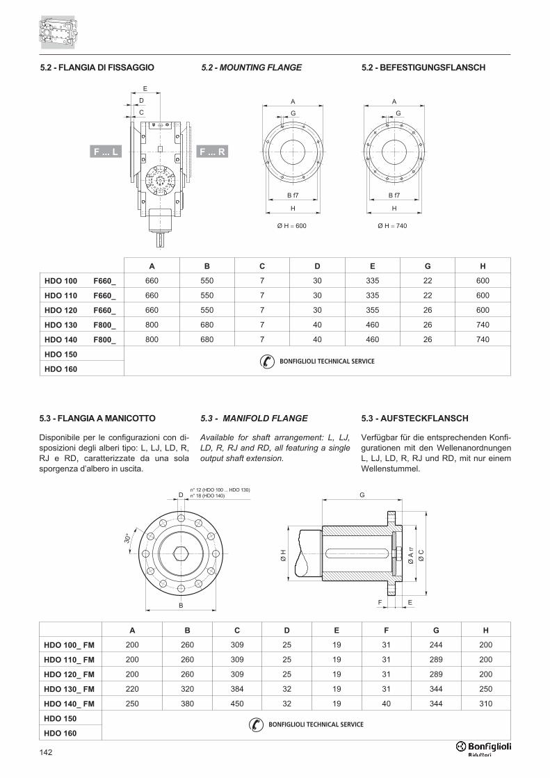
142
A B C D E G H
HDO 100 F660_ 660 550 7 30 335 22 600
HDO 110 F660_ 660 550 7 30 335 22 600
HDO 120 F660_ 660 550 7 30 355 26 600
HDO 130 F800_ 800 680 7 40 460 26 740
HDO 140 F800_ 800 680 7 40 460 26 740
HDO 150
HDO 160
5.2 - FLANGIA DI FISSAGGIO
����
�
�
�
������
����
�
�
�
��������
�
�
5.2 - MOUNTING FLANGE 5.2 - BEFESTIGUNGSFLANSCH
F ... L F ... R
5.3 - FLANGIA A MANICOTTO 5.3 - MANIFOLD FLANGE 5.3 - AUFSTECKFLANSCH
Disponibile per le configurazioni con di-sposizioni degli alberi tipo: L, LJ, LD, R,RJ e RD, caratterizzate da una solasporgenza d’albero in uscita.
Available for shaft arrangement: L, LJ,
LD, R, RJ and RD, all featuring a single
output shaft extension.
Verfügbar für die entsprechenden Konfi-gurationen mit den WellenanordnungenL, LJ, LD, R, RJ und RD, mit nur einemWellenstummel.
�
�������� ��������� ������������� �����
��
�
���
���
���
� �
���
A B C D E F G H
HDO 100_ FM 200 260 309 25 19 31 244 200
HDO 110_ FM 200 260 309 25 19 31 289 200
HDO 120_ FM 200 260 309 25 19 31 289 200
HDO 130_ FM 220 320 384 32 19 31 344 250
HDO 140_ FM 250 380 450 32 19 40 344 310
HDO 150
HDO 160

143
5.4 - PERNO MACCHINA 5.4 - CUSTOMER’S SHAFT 5.4 - MASCHINENZAPFEN
H
A1 A2 A3 B B1 B2 C D E F R SUNI6604
HDO 100 � 133 120 h6 119.5 420 100 250 360 30 32 h9 127 3 2.5 32x18x360A
HDO 110 � 143 130 h6 129.5 420 100 250 360 30 32 h9 137 3 2.5 32x18x360A
HDO 120 � 153 140 h6 139.5 444 110 260 400 40 36 h9 148 3 2.5 36x20x400A
HDO 130 � 183 170 h6 169.5 540 135 310 400 80 40 h9 179 3 2.5 40x22x400A
HDO 140 � 193 180 h6 179.5 540 135 310 400 80 45 h9 190 3 2.5 45x25x400A
HDO 150 � 223 210 h6 209.5 667 155 400 500 100 50 h9 221 3 3 50x28x450B
HDO 160 � 223 210 h6 209.5 667 155 400 500 100 50 h9 221 3 3 50x28x450B
Escluso dalla fornitura / out of scope for supply / Nicht im Lieferumfang enthalten
UNI7437 G G1 G2 G3 G4 H H1 UNI5739
HDO 100 120x4 120 d9 96 64 26 M16 24 12 M24x70
HDO 110 130x4 130 d9 105 69 26 M20 24 12 M24x70
HDO 120 140x4 140 d9 115 79 26 M20 30 15 M24x80
HDO 130 170x4 170 d9 142 102 33 M24 34 17 M30x90
HDO 140 180x4 180 d9 150 110 33 M24 34 17 M30x90
HDO 150 210x5 210 d9 178 140 33 M24 36 18 M30x100
HDO 160 210x5 210 d9 178 140 33 M24 36 18 M30x100
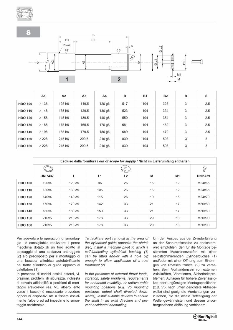
144
S
A1 A2 A3 A4 B B1 B2 R S
HDO 100 � 138 125 h6 119.5 120 g6 517 104 328 3 2.5
HDO 110 � 148 135 h6 129.5 130 g6 523 104 334 3 2.5
HDO 120 � 158 145 h6 139.5 140 g6 550 104 354 3 2.5
HDO 130 � 188 175 h6 169.5 170 g6 681 104 462 3 2.5
HDO 140 � 198 185 h6 179.5 180 g6 689 104 470 3 2.5
HDO 150 � 228 215 h6 209.5 210 g6 839 104 593 3 3
HDO 160 � 228 215 h6 209.5 210 g6 839 104 593 3 3
Escluso dalla fornitura / out of scope for supply / Nicht im Lieferumfang enthalten
UNI7437 L L1 L2 M M1 UNI5739
HDO 100 120x4 120 d9 96 26 16 12 M24x65
HDO 110 130x4 130 d9 105 26 16 12 M24x65
HDO 120 140x4 140 d9 115 26 19 15 M24x70
HDO 130 170x4 170 d9 142 33 21 17 M30x80
HDO 140 180x4 180 d9 150 33 21 17 M30x80
HDO 150 210x5 210 d9 178 33 29 18 M30x90
HDO 160 210x5 210 d9 178 33 29 18 M30x90
Per agevolare le operazioni di smontag-gio è consigliabile realizzare il pernomacchina dotato di un foro adatto alpassaggio di una sostanza antiruggine(2) e/o predisposto per il montaggio diuna boccola cilindrica autolubrificantenel tratto cilindrico di guida opposto alcalettatore (1).In presenza di carichi assiali esterni, vi-brazioni, problemi di sicurezza, richiestadi elevata affidabilità o posizioni di mon-taggio sfavorevoli (es. V5, albero lentoverso il basso) è necessario prevedereopportuni dispositivi atti a fissare assial-mente l’albero ed ad impedirne lo smon-taggio accidentale.
To facilitate part removal in the area of
the cylindrical guide opposite the shrink
disc, install a machine pivot to which a
self-lubricating cylindrical bushing (1)
can be fitted and/or with a hole big
enough to allow application of a rust
treatment (2).
In the presence of external thrust loads,
vibration, safety problems, requirements
for enhanced reliability, or unfavourable
mounting positions (e.g. V5 mounting
positions, output shaft directed down-
wards), install suitable devices to secure
the shaft in an axial direction and pre-
vent accidental decoupling.
Um den Ausbau aus der Zylinderführungan der Schrumpfscheibe zu erleichtern,wird empfohlen, den für die Montage be-stimmten Maschinenzapfen mit einerselbstschmierenden Zylinderbuchse (1)und/oder mit einer Öffnung zum Einbrin-gen von Rostschutzmittel (2) zu verse-hen. Beim Vorhandensein von externenAxialkräften, Vibrationen, Sicherheitspro-blemen, Auflagen für höhere Zuverlässig-keit oder ungünstigen Montagepositionen(z.B. V5, nach unten gerichtete Abtriebs-welle) sind geeignete Vorrichtungen vor-zusehen, die die axiale Befestigung derWelle gewährleisten und dessen unvor-hergesehene Ablösung verhindern.
1 2

145
146 COD. 1930 R3
INDICE DI REVISIONE (R) INDEX OF REVISIONS (R) LISTE DER ÄNDERUNGEN (R)
Questa pubblicazione annulla e sostituisceogni precedente edizione o revisione. Ci ri-serviamo il diritto di apportare modifiche sen-za preavviso. È vietata la produzione ancheparziale senza autorizzazione.
This publication supersedes and replaces any
previous edition and revision. We reserve the
right to implement modifications without no-
tice. This catalogue cannot be reproduced,
even partially, without prior consent.
Diese Veröffentlichung annuliert und ersetztjeder hergehende Edition oder Revision.BONFIGLIOLI behält sich das Recht vor,Änderungen ohne vorherige Informationendurchzuführen.
R3
Descrizione Description Beschereibung
11
05
25