Embed Size (px)
Citation preview
Fachhochschul-DiplomstudiengangBioinformatik
4232 Hagenberg, Austria
Digital Lab Book, a web-based modulefor experiment management within the
Scientific Microscopy Lab Environment project
Diplomarbeit
zur Erlangung des akademischen GradsDiplom-Ingenieur (Fachhochschule)
eingereicht von
Maria Fischer
Betreuer: DI Gernot Stocker, TU GrazBegutachter: DI (FH) Peter Kulczycki
September 2006
Eidesstattliche Erklärung
Ich erkläre hiermit an Eides statt, dass ich die vorliegende Arbeit selbstständig ver-fasst, keine anderen als die angegebenen Quellen und Hilfsmittel verwendet, michauch sonst keiner unerlaubten Hilfe bedient, und diese Arbeit weder im Inland nochim Ausland in irgendeiner Form als Prüfungsarbeit vorgelegt habe.
ORT, DATUM MARIA FISCHER
Abstract
Microscopy techniques reveal new possibilities for studying biological processes andproduce a huge amount of data. Besides high resolution images, data from literatureresearch, experimental design, image quantification, analysis as well as comparisonof the results is generated by microscopy experiments. The project Scientific Mi-croscopy Lab Environment (SMILE) addresses the organization and management ofinformation gained by these experiments.
The objective of this thesis was to design and implement a module within SMILEwhich handles the management of data acquisition in a project-oriented way. Thisincludes experiment design, processing of experiment series, as well as storing ofacquired experiment data. It allows the definition of experiments which follow spe-cific protocols. Additionally these protocols can be stored as standard protocols inorder to be reused and modified in other experiments.
The digital lab book was realized using a three tier J2EE architecture providing aweb-based user interface. A model driven development approach with novel tech-nologies like the Spring Application Framework as business backend and Tapestryfor the web frontend were used.
This work resulted in a platform independent web application which covers theworkflow of data acquisition during a microscopy experiment in an intuitive wayand will be used in productive laboratory environment.
Keywords: microscopy experiment, SMILE, MDA, J2EE
Kurzfassung
Die stetige technologische Weiterentwicklung der Mikroskopie ermöglicht neue We-ge biologische Prozesse zu erforschen. Die daraus gewonnenen Informationen be-stehen - neben hochauflösenden Bildern - vor allem aus Daten, welche aus Literatur-recherchen, Experimentdesign, Bildanalysen sowie Vergleich und Analyse von Er-gebnissen gewonnen werden. Das Projekt »Scientific Microscopy Lab Environment(SMILE)« versucht aus Mikroskopie-Experimente gewonnene Informationen orga-nisiert und strukturiert zu verwalten.
Das Ziel dieser Diplomarbeit war, ein Modul innerhalb des Projekts SMILE zu ent-wickeln, welches Daten in einer Projekt-orientierten Weise erfasst. Dies schließt so-wohl Experimentdesign, als auch die Durchführung von Experimentreihen sowiedie Speicherung der gewonnen Experimentdaten mit ein. Die resultierende Softwareermöglicht die Definition von Experimenten, welche definierten Protokollen folgen.Zusätzlich können oftens wiederverwendete Protokolle als sogenannte Standard-protokolle im System gespeichert werden.
Basierend auf einer dreischichtigen J2EE Plattform wurde das Modul »Digital LabBook« mit Hilfe der Model-Driven-Architecture (MDA) entwickelt. Neue Techno-logien wie das »Spring Application Framework« und »Tapestry« wurden für dieImplementierung der Businesslogik und des Webfrontends verwendet.
Diese Arbeit resultierte in eine plattformunabhängige Web Applikation, welche dieDatenerfassung während eines Mikroskopie-Experimentes in einer intuitiven Weiseerledigt und bei der Laborarbeit verwendet werden wird.
Schlüsselwörter: Mikroskopie-Experiment, SMILE, MDA, J2EE

Acknowledgments
I want to thank DI Gernot Stocker for the great support during my internship and forthe many helpful comments and suggestions on the thesis.
Special thanks to to Prof. Zlatko Trajanoski for giving me the opportunity to do mydiploma thesis at the Institute for Genomics and Bioinformatics - TU Graz.
In addition I would like to thank my supervisor DI (FH) Peter Kulczycki from the Up-per Austria University of Applied Sciences in Hagenberg for his advises and supporton writing this paper.
Last, but not least, I want to thank my parents for their support during my studies.
Maria Fischer
Contents
1 Introduction 11.1 SMILE - Scientific Microscopy Lab Environment . . . . . . . . . . . . . 11.2 Digital Lab Book . . . . . . . . . . . . . . . . . . . . . . . . . . . . . . 3
1.2.1 Objectives . . . . . . . . . . . . . . . . . . . . . . . . . . . . . . 4
2 Methods 62.1 Used Standards . . . . . . . . . . . . . . . . . . . . . . . . . . . . . . 6
2.1.1 Model Driven Architecture . . . . . . . . . . . . . . . . . . . . . 62.1.2 Unified Modeling Language (UML) . . . . . . . . . . . . . . . . 82.1.3 XML Metadata Interchange (XMI) . . . . . . . . . . . . . . . . 8
2.2 Java 2 Enterprise Edition . . . . . . . . . . . . . . . . . . . . . . . . . 92.2.1 Distributed Multi-tiered Application Models . . . . . . . . . . . . 92.2.2 Enterprise Information System (EIS) Tier . . . . . . . . . . . . 102.2.3 Middle Tier . . . . . . . . . . . . . . . . . . . . . . . . . . . . . 10
2.2.3.1 Enterprise Java Beans . . . . . . . . . . . . . . . . . 112.2.3.2 Web Tier . . . . . . . . . . . . . . . . . . . . . . . . . 12
2.2.4 Client Tier . . . . . . . . . . . . . . . . . . . . . . . . . . . . . . 132.2.5 J2EE Patterns . . . . . . . . . . . . . . . . . . . . . . . . . . . 13
2.3 Chosen Technologies . . . . . . . . . . . . . . . . . . . . . . . . . . . 142.3.1 Hibernate . . . . . . . . . . . . . . . . . . . . . . . . . . . . . . 14
2.3.1.1 Possible solutions for the impedance mismatch . . . . 152.3.2 Spring Application Framework . . . . . . . . . . . . . . . . . . 17
2.3.2.1 Inversion of Control . . . . . . . . . . . . . . . . . . . 192.3.2.2 Aspect Oriented Programming . . . . . . . . . . . . . 202.3.2.3 Data Access . . . . . . . . . . . . . . . . . . . . . . . 22
2.3.3 Acegi Security System for Spring . . . . . . . . . . . . . . . . . 222.3.3.1 Authentication . . . . . . . . . . . . . . . . . . . . . . 232.3.3.2 Authorization . . . . . . . . . . . . . . . . . . . . . . . 23
CONTENTS vii
2.3.4 Tapestry . . . . . . . . . . . . . . . . . . . . . . . . . . . . . . . 242.3.4.1 Standard Components . . . . . . . . . . . . . . . . . 252.3.4.2 Custom Components . . . . . . . . . . . . . . . . . . 27
2.4 Code Generation . . . . . . . . . . . . . . . . . . . . . . . . . . . . . . 282.4.1 AndroMDA . . . . . . . . . . . . . . . . . . . . . . . . . . . . . 28
2.4.1.1 Cartridges . . . . . . . . . . . . . . . . . . . . . . . . 292.4.1.2 Velocity Templates . . . . . . . . . . . . . . . . . . . . 32
2.5 JUnit Testing . . . . . . . . . . . . . . . . . . . . . . . . . . . . . . . . 332.6 Tools . . . . . . . . . . . . . . . . . . . . . . . . . . . . . . . . . . . . . 33
2.6.1 Maven . . . . . . . . . . . . . . . . . . . . . . . . . . . . . . . . 332.6.2 MagicDraw . . . . . . . . . . . . . . . . . . . . . . . . . . . . . 342.6.3 MyEclipse Enterprise Workbench . . . . . . . . . . . . . . . . . 34
2.7 Usermanagement . . . . . . . . . . . . . . . . . . . . . . . . . . . . . 352.7.1 SimpleUsermanagement . . . . . . . . . . . . . . . . . . . . . 352.7.2 GenomeUsermanagement . . . . . . . . . . . . . . . . . . . . 36
3 Design 373.1 Workflow . . . . . . . . . . . . . . . . . . . . . . . . . . . . . . . . . . 37
3.1.1 Experiment oriented Workflow . . . . . . . . . . . . . . . . . . 373.1.2 Standard Protocol oriented Workflow . . . . . . . . . . . . . . . 39
3.2 UML Diagram . . . . . . . . . . . . . . . . . . . . . . . . . . . . . . . . 393.2.1 Entity Diagram . . . . . . . . . . . . . . . . . . . . . . . . . . . 403.2.2 Value Object Diagram . . . . . . . . . . . . . . . . . . . . . . . 423.2.3 Service Diagram . . . . . . . . . . . . . . . . . . . . . . . . . . 43
4 Implementation 464.1 Project Management . . . . . . . . . . . . . . . . . . . . . . . . . . . . 47
4.1.1 Creation of a new Project . . . . . . . . . . . . . . . . . . . . . 474.1.2 Project Overview . . . . . . . . . . . . . . . . . . . . . . . . . . 484.1.3 Subprojects . . . . . . . . . . . . . . . . . . . . . . . . . . . . . 494.1.4 Structural Components . . . . . . . . . . . . . . . . . . . . . . 49
4.2 Experiment Management . . . . . . . . . . . . . . . . . . . . . . . . . 504.2.1 Creation of a new Experiment . . . . . . . . . . . . . . . . . . . 504.2.2 Experiment Overview . . . . . . . . . . . . . . . . . . . . . . . 51
4.3 Current Working Protocol Management . . . . . . . . . . . . . . . . . 524.3.1 Creation of a new CWP Step . . . . . . . . . . . . . . . . . . . 524.3.2 Protocol Overview . . . . . . . . . . . . . . . . . . . . . . . . . 544.3.3 Deletion of a CWP Step . . . . . . . . . . . . . . . . . . . . . . 56
CONTENTS viii
4.3.4 CWP Step Overview . . . . . . . . . . . . . . . . . . . . . . . . 574.4 Standard Protocol Management . . . . . . . . . . . . . . . . . . . . . 59
4.4.1 Versioning Standard Protocols . . . . . . . . . . . . . . . . . . 594.5 Parameter Management . . . . . . . . . . . . . . . . . . . . . . . . . . 60
4.5.1 Creation of a new Parameter . . . . . . . . . . . . . . . . . . . 614.5.2 Parameter Overview . . . . . . . . . . . . . . . . . . . . . . . . 62
4.6 General Implementations . . . . . . . . . . . . . . . . . . . . . . . . . 624.6.1 Tapestry Components . . . . . . . . . . . . . . . . . . . . . . . 63
4.6.1.1 Layout Component . . . . . . . . . . . . . . . . . . . 634.6.1.2 TabPanel Component . . . . . . . . . . . . . . . . . . 65
4.6.2 Extensions to the AndroMDA Cartridges . . . . . . . . . . . . . 67
5 Discussion 695.1 Usability Testing . . . . . . . . . . . . . . . . . . . . . . . . . . . . . . 695.2 Further Development . . . . . . . . . . . . . . . . . . . . . . . . . . . . 71
5.2.1 Acquisition Wizard . . . . . . . . . . . . . . . . . . . . . . . . . 715.2.2 Device Management . . . . . . . . . . . . . . . . . . . . . . . . 735.2.3 Enumerations . . . . . . . . . . . . . . . . . . . . . . . . . . . . 74
A User Requirements Document 76A.1 Abstract . . . . . . . . . . . . . . . . . . . . . . . . . . . . . . . . . . . 76A.2 Basic units . . . . . . . . . . . . . . . . . . . . . . . . . . . . . . . . . 76
A.2.1 Project . . . . . . . . . . . . . . . . . . . . . . . . . . . . . . . . 76A.2.2 Experiment . . . . . . . . . . . . . . . . . . . . . . . . . . . . . 78A.2.3 Current Working Protocol (CWP) . . . . . . . . . . . . . . . . . 79A.2.4 Acquisition Wizard . . . . . . . . . . . . . . . . . . . . . . . . . 82A.2.5 Notes . . . . . . . . . . . . . . . . . . . . . . . . . . . . . . . . 83
A.3 Management Tools . . . . . . . . . . . . . . . . . . . . . . . . . . . . . 83A.3.1 Standard Protocol Management . . . . . . . . . . . . . . . . . 83A.3.2 Device Management . . . . . . . . . . . . . . . . . . . . . . . . 85
B Usability Testing 87B.1 Task list and test scores . . . . . . . . . . . . . . . . . . . . . . . . . . 87B.2 Overall Questionnaire . . . . . . . . . . . . . . . . . . . . . . . . . . . 89
Figures 90
Bibliography 94
Chapter 1
Introduction
Microscopy experiments involve huge amounts of data including high resolutionimages. Also data from literature research, experimental design, image acquisition,quantification, analysis as well as comparison of the results is generated. Organizingand managing all this information is an important and critical task.
Microscopists are responsible for the management of their experiment-related dataindividually. As a result digital data is spread upon different servers, local harddisks, and other storages whereas observations made during the experiment are usu-ally manually written in laboratory books. This calls for digital systems like SMILEwhich manage all data and information acquired in the daily lab work in a central-ized way.
1.1 SMILE - Scientific Microscopy Lab Environment
The Scientific Microscopy Lab Environment (SMILE) is a project of the Institute forGenomics and Bioinformatics (IGB) in cooperation with the National Cancer Insti-tute (NCI/NIH). It addresses the management of microscopy experiment data ina centralized way and is designed to assist in the daily lab work. SMILE organizesdata in a chronological and project-oriented way—if the system is used continuouslyit will be able to keep track of data evolution during experimental work.
CHAPTER 1. INTRODUCTION 2
Since all steps of the daily lab work should be covered by the system, SMILE dividesthe lab work into five main activities:
Project Definition Starting with a biological question, biologists carry out lit-erature research to find answers. If there are insufficient documents about thissubject new projects can emerge. In order to identify different projects, rele-vant data, such as name and description, can be stored in the system. Sinceliterature research can involve valuable hints, the accordant documents areattachable to the project.
Data Acquisition This activity manages issues dealing with experiments in-cluding experiment design, processing of experiment series, and storing ofacquired experiment data.
Before an experiment, all steps and their sequence order are specified by ex-periment design. The system refers to this step sequence as current workingprotocol (CWP). In order to reuse well established protocols, so-called stan-dard protocols can be defined in the system. Standard protocols are handledindependently from experiments as well as projects.
During the experiment, a wizard should act as a guide through the CWP. Itprovides possibilities to alter the predefined CWP as well as to store step-specific data to the accordant steps.
For data acquisition the system supports organization and management offiles acquired from different devices. In order to guarantee that all relevantdata is stored in the system, SMILE also stores information about devices usedin the lab. Another important subject are observations made during an exper-iment. They can include useful hints as well as document irregularities of ex-periments. For this SMILE introduces notes which can be attached to projects,experiments, and protocols.
Data Analysis and Processing After collecting data the system should inte-grate analytical methods to provide possibilities to further process the data.These analysis steps should extract useful information and combine it in astatistically meaningful manner.
Since analytical methods can be conducted by third-party software products,SMILE supports two types of analysis: automatically processed server-sideanalysis, which is managed by the system and requires minimal user inter-action, and analysis which is done outside the system using third-party soft-ware.
To be able to keep track of data development, SMILE describes and stores allexternal analysis steps so that the resultant information can be assigned to theoriginal data files.
CHAPTER 1. INTRODUCTION 3
Data Comparison This category addresses the comparison of experiment re-sults. SMILE keeps track of all compared data by associating the comparedfiles and supporting ways to attach notes to each comparison. Since datacomparison can lead to conclusions, this information can be stored in SMILEas well. In order to facilitate searching through the data, conclusions can bedescribed by some keywords offered by the system.
Data Retrieval After all the data is stored and managed in SMILE, biologistsmay want to search through the previously acquired data. Therefore the sys-tem provides an easy to use search interface which searches through all thedifferent types of notes—including observation and comparison notes. Sincea simple textual search can lead to high number of results, SMILE providesnot only a text search but also the possibility to search for keywords.
1.2 Digital Lab Book
The Digital Lab Book is a module within SMILE and addresses the first two activitiesof lab work: project definition and data acquisition. It represents a digital form oflaboratory books and provides ways to keep track of experiment data development.The Digital Lab Book does not handle all subjects of data acquisition. Outsourcedfunctions are the attachment of notes as well as file imports. Since data analysis,processing, and comparison also include notes and files, these functions are not onlynecessary for data acquisition and can be seen as separate modules. The followinglist describes the Digital Lab Book’s responsibilities in more detail:
Project Management handles creation, modification, and deletion of projects.Since SMILE organizes its data in a project-oriented way, projects representthe main organizational unit of the Digital Lab Book. In order to enhance aproject’s structure, it is possible to further divide projects into subprojects.
Experiment Management addresses the organization of experiment relateddata. This includes adding an experiment to a particular project as well asthe modification and deletion of an experiment.
Current Working Protocol Management is responsible for organizing an ex-periment’s working step sequence which includes the creation, modification,and—if possible—deletion of CWP steps and their parameters. Since an ex-periment’s structure can be quite complex, the CWP management supportsgrouping step sequences to higher level units and defining step sequenceswhich should be processed simultaneously. Such parallel step sequences canoccur if probes have to be treated differently, for example cells which aretreated with different drugs in order to study their influence on the cells.
CHAPTER 1. INTRODUCTION 4
Standard Protocol Management is similar to the CWP management and han-dles similar tasks. The main differences between these two protocol manage-ments are: a standard protocol exists on its own without being dependenton projects or experiments and since standard protocols can be loaded intoexperiments, the standard protocol management must provide methods forversioning.
Acquisition Wizard guides through the experiment and provides methods tonavigate through the CWP. Besides navigation it is possible to fill in parametervalues and to attach files or notes to a CWP step. CWP steps which are notalready processed can be modified in the wizard as well. This feature is notimplemented within the scope of this thesis. Its description can be found inChapter 5.2.1 on page 71.
Device Management supports organization of devices used in the lab. Thisincludes creation, modification, and deletion of devices as well as specify-ing device parameters and attaching device-specific files, such as user man-uals. Since this is also not implemented within the scope of this thesis, adetailed description of the device management tool is given in Chapter 5.2.2on page 73.
1.2.1 Objectives
Besides the realization of the above mentioned responsibilities the following objec-tives were determined:
Transformation in class diagrams Before the beginning of this thesis, a so-called entity-relationship (ER) diagram1 which represented the SMILE datamodel already existed. Since the Digital Lab Book is a module within SMILE,this ER diagram also included the structure of the Digital Lab Book. In orderto enhance documentation and the project’s further development the existentER diagram should be remodeled and—if necessary—adapted in UML classdiagrams (see Chapter 2.1.2 on page 8).
Integration into SMILE The Digital Lab Book is part of the project SMILE.Therefore its integration into SMILE must be guaranteed. To facilitate projectorganization, a clear separation of concerns must be preserved. Although thewhole SMILE system is documented in a set of UML models, these models aredivided into several modules which handle the Digital Lab Book or SMILE-specific content.
1An entity-relationship diagram is used to represent a system’s entities and their relationships in agraphical way. Usually it is used to model and design database schemas.

CHAPTER 1. INTRODUCTION 5
Web-based Because biologists at the IGB work on different operating systemsSMILE and therefore the Digital Lab Book should be platform independent.Another requirement is that the system should be available for their users atdifferent workstations without the need to install the whole system. Web-based applications satisfy these needs because they can be accessed from ev-ery computer having a connection to the local network or internet.
Three tier architecture To ensure a clean application structure the applicationshould be realized as a three tier architecture with a database backend, a webserver, and a web front-end.
Chapter 2
Methods
This chapter will give a brief introduction into the technologies and tools used dur-ing the thesis.
2.1 Used Standards
All standards described below were specified by the Object Management Group(OMG). OMG is an open membership, non-profit consortium [OMG, 2006c] whichwas founded 1989 by eleven companies (amongst others Hewlett-Packard Company,IBM, and Apple Computer). Its original goals were to define standards for dis-tributed object systems which led to focusing on modeling and creating model-basedstandards.
2.1.1 Model Driven Architecture
For large applications it is important to spend time doing design work because gooddesigns can expose possible problems at an early stage, enhance development, in-tegration and maintainability. Besides these advantages, modeling can also enableauto-generation of fundamental components.
But for large business applications designing only one model would create hugemodels with too much information. The complexity of large applications is nearlyimpossible to handle. To overcome this problem, OMG introduced Model Driven Ar-chitecture (MDA). MDA relies on four OMG standards: Meta Objects Facility (MOF)1,
1MOF is closely related to UML and enables metadata management and modeling language definition.
CHAPTER 2. METHODS 7
Unified Modeling Language (UML) (see Chapter 2.1.2 on the next page), Common Ware-house Metamodel (CWM)2, and XML Metadata Interchange (XMI) [Chapter 2.1.3 on thefollowing page]. MDA’s basic idea is to separate business and application logic fromunderlying platform technology [OMG, 2002]. Therefore MDA separates the »clas-sical« UML model into the following four models (OMG calls this »separation ofconcerns«):
Computation Independent Model (CIM) also referred to as domain model orbusiness model, focuses on the requirements of the system and on the situa-tions in which the system will be used. It does not show the details of thestructure of systems.
Platform Independent Model (PIM) documents on the one side business be-havior and functionality and on the other side hides the details necessary fora particular platform. It only shows the part of the specification which doesnot change between platforms. Thus the separation of technology specificsand general business functionality is gained.
Platform Specific Model (PSM) Whereas the PIM ignores all platform-specificdetails the PSM concentrates on this particular issue. It combines the view ofthe PIM with all the details that realize the use of a certain platform.
Code Model represents the platform-specific implementation and is often gen-erated by a code generator.
Via the introduction of CIM and PIM, MDA can provide platform-, language-, andsystem independence. MDA’s most important goals portability, interoperability, andreusability are gained through this separation. [Miller and Mukerji, 2003]
As mentioned at the beginning, models can enhance automation of a component’sconstruction. This can be referred to as transformation of models. MDA distin-guishes between two types:
Model Transformation describes transformation of one model into anothermodel.
Code Transformation describes transformation of the model into code. Thisis done by so-called code generators.
2CWM is a specification for data repository integration.
CHAPTER 2. METHODS 8
2.1.2 Unified Modeling Language (UML)
In order to control complexity and therefore assure functionality and robustness ofapplications software engineers design systems before coding. By modeling, anoverview as well as a detailed view of applications can be provided and differentaspects can be regarded according to their importance. The Unified Modeling Lan-guage (UML) is OMG’s most used specification and was specified to standardizemodeling in software development. It helps in the specifying, visualizing, and doc-umenting models of software systems, including their structure and design. [OMG,2006b]
UML’s current version (UML 2.0) consists of the four main parts:
UML Superstructure defines UML’s thirteen standard diagram types and theelements that comprise them. The standard diagram types can be furtherdivided into three subcategories.
� Structure Diagrams show the static structure of a system and includeClass Diagram, Object Diagram, Component Diagram, Composite Struc-ture Diagram, Package Diagram, and Deployment Diagram.
� Behavior Diagrams specify what the system does and contain Use CaseDiagram, Activity Diagram, and State Machine Diagram.
� Interaction Diagrams are a subset of Behavior Diagrams and character-ize control and data flow in a system. Sequence Diagram, Communica-tion Diagram, Timing Diagram, and Interaction Overview Diagram arecomprised in this category.
UML Infrastructure builds the core foundation of UML by defining its baseclasses.
UML Object Constraint Language (OCL) allows a textual description of pre-and post conditions, invariants, initial values, and other conditions.
UML Diagram Interchange provides graph-oriented information and there-fore defines the diagram layout. UML tools can now interchange both UMLmodels and graphical information such as position and size of model ele-ments.
2.1.3 XML Metadata Interchange (XMI)
The objective of XMI is to allow technology and middleware neutral exchange ofobjects from the OMG’s Object Analysis and Design Facility, commonly described
CHAPTER 2. METHODS 9
as Unified Modeling Language and Meta Objects Facility (MOF). So to say XMI isthe OMG standard for exchanging data and metadata between tools, repositoriesand applications via Extensible Markup Language (XML). It is based on existingindustry standards UML, MOF and XML. [OMG, 2006a]
2.2 Java 2 Enterprise Edition
The Java 2 Enterprise Edition (J2EE) is an environment which provides a component-based approach for the design, development, assembly, and deployment of enter-prise applications. The J2EE platform consists of a set of services, application pro-gramming interfaces (APIs), and protocols that provide the functionality for devel-oping multi-tiered applications. [Bodoff et al., 2005]
2.2.1 Distributed Multi-tiered Application Models
J2EE provides good support for implementing distributed architectures. This is oneof the most important reasons why many enterprise applications are based on so-called distributed multi-tiered application models. These models divide applicationlogic according to its function. The resultant components are classified depending onthe corresponding tier and can be split across multiple Java Virtual Machines (JVMs)running on different locations. [Johnson, 2002] [Bodoff et al., 2005]
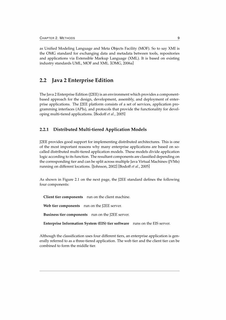
As shown in Figure 2.1 on the next page, the J2EE standard defines the followingfour components:
Client tier components run on the client machine.
Web tier components run on the J2EE server.
Business tier components run on the J2EE server.
Enterprise Information System (EIS) tier software runs on the EIS server.
Although the classification uses four different tiers, an enterprise application is gen-erally referred to as a three-tiered application. The web tier and the client tier can becombined to form the middle tier.
CHAPTER 2. METHODS 10
Figure 2.1: Illustration of a J2EE multi-tiered application (taken from [Bodoff et al., 2005])
2.2.2 Enterprise Information System (EIS) Tier
As described in [Johnson, 2002] the EIS tier handles the enterprise resources that aJ2EE application has to access. It includes database management systems, enter-prise resource planning (ERP) systems and other legacy mainframe applications.Although the J2EE server manages transactions and connection pooling in a stan-dard way, the EIS tier is outside of the control of the J2EE server. Several APIs suchas Java Database Connectivity (JDBC), Java Naming and Directory Interface (JNDI),and Java Connector Architecture (JCA) guarantee access to the EIS tier.
2.2.3 Middle Tier
This tier encapsulates business logic and mediates between EIS tier and client tier.Furthermore it provides system-level services such as transaction management, con-nection pooling, and security. If Enterprise Java Beans (EJB) are used, this tier is splitinto two: the business tier (also referred to as EJB tier) and the web tier. The use ofremote EJBs will guarantee the possibility of separating the middle tier logically andphysically on two different servers. For EJBs and web tier components two separate
CHAPTER 2. METHODS 11
JVMs can be used. However this split is not necessary to ensure a clean middle tier.[Johnson, 2002]
2.2.3.1 Enterprise Java Beans
Enterprise Java Beans implement the Enterprise Java Beans specification which isone of the J2EE APIs. These server-side components encapsulate the business logicof an application and they must be run in an EJB container. EJBs can be classifiedinto three different categories.
Session Beans represent single clients inside the application server and man-age processes or task flows. Session beans can not be shared and are notpersistent (which means that a session bean’s data is not saved to a database).One can distinguish between stateless and stateful session beans. Stateless ses-sion beans do not maintain a conversational state3 for the client. Except dur-ing method invocation, all instances of a stateless session bean are equivalent,allowing the concurrent access to the bean. Thus one bean can serve morethan one client and therefore enhances scalability. Stateful session beans keeptheir conversational state across method calls. The state is retained as longas the bean is not removed or terminated, and is lost when the conversationends.
Entity Beans represent objects which exist in a persistent storage such as adatabase or legacy system. In contrast to session beans the entity bean’s stateexist beyond the lifetime of the application. If the client terminates or if theserver shuts down, the underlying services ensure that the entity bean data issaved.
Message Driven Beans also process tasks by accessing entity beans as wellas session beans. The most important difference between session and mes-sage driven beans is the way of communication. Whereas session and entitybeans receive and send messages synchronously, message driven beans listento messages and after receiving one message, they process it asynchronously.This helps to avoid tying up server resources.
Often EJB technology is thought to be the core of J2EE. In fact, using EJBs in enter-prise applications is just one choice J2EE offers. EJBs provide great support for dis-tributed applications and complex transaction management. However EJBs involvean increase in complexity and other drawbacks such as complication of applicationtesting and application deployment. Johnson states that using EJB with remote in-terfaces may hamper practical OO design. According to [Johnson, 2002] four of the
3The state of an object consists of the values of its instance variables.
CHAPTER 2. METHODS 12
six »EJB layer architectural patterns« described in [Marinescu, 2002] are not true pat-terns, but workarounds for problems that are introduced by using EJB with remoteinterfaces. Details can be found in Chapter 2.2.5 on the following page.
Some of the problems mentioned above are caused by EJB’s specification-driven ori-gins. This means that the EJB standard did not evolve but was created by a commit-tee. However there are alternatives to EJB. Instead of using entity beans to accesspersistent data object/relational mapping frameworks such as Hibernate (described inChapter 2.3.1 on page 14) and TopLink can handle this problem in a more sophisti-cated way. The Spring Application Framework (see Chapter 2.3.2 on page 17) pro-vides good alternatives for session and message driven beans by using Plain OldJava Objects (POJOs) and message driven POJOs.
2.2.3.2 Web Tier
The web tier provides access to the application’s business logic on the world wideweb by processing Hypertext Transfer Protocol (HTTP) requests. It manages theinteraction between web clients and business logic. Mostly the web tier producesHypertext Markup Language (HTML) or XML content, although any content typecould be created.
[Singh et al., 2002] lists the following functions which the typical web tier performsin a J2EE application:
Web-enabling of business logic Interaction between web clients and applica-tion business logic is managed by the web tier.
Dynamic content generation Content, which can be stored in entirely arbi-trary data formats, including HTML, images, sound, and video, is generateddynamically by web tier components.
Data presentation and input collection Web tier components translate HTTPPUT and GET actions into a form that the business logic understands. Fur-thermore results are presented as web content.
Screen flow control The web tier usually determines which »screen« (that is,which page) to display next. This is done because screen flow tends to bespecific to client capabilities.
Maintaining state A simple, flexible mechanism for accumulating data, whichis used for transactions and for interaction context over the lifetime of a usersession, is provided by the web tier.
CHAPTER 2. METHODS 13
Multiple and future client type support Through describing web contents byextensible MIME types a web client can support any current and future typeof data content.
J2EE web components are either servlets or pages created using JavaServer Pages(JSP) technology. Servlets are Java classes which dynamically produce content andrun within a web container. They interact with web applications by using HTTPrequests and responses. By implementing so-called service methods servlets provideservices for web clients. JSP technology is very similar to Java servlet technology. Infact JSP are an extension to servlets and are translated into servlets at runtime. Thedifference between servlets and JSP is that JSP page does not contain pure Java code.A JSP page is a text document which contains static and dynamic data. Static datacan be expressed by any text-based format such as HTML whereas dynamic data isgenerated by so-called JSP elements. As JSP technology was not used during thisthesis the JSP technology is not described any further. For additional informationread section on JavaServer Pages Technology in [Bodoff et al., 2005].
2.2.4 Client Tier
J2EE supports many types of clients. [Bodoff et al., 2005] roughly classifies clients inweb-based and non-web-based. Non-web-based clients are also referred to as appli-cation clients and run on the client machine. Typically they provide a graphical userinterface. In contrast to application clients, web clients display content generatedby the web tier. The necessary information is usually retrieved by an applicationserver—this type of clients does not execute heavyweight operations such as query-ing databases. Therefore web clients are also called thin clients. Nevertheless thinclients can also handle many responsibilities such as validating user input or man-aging conversational state.
2.2.5 J2EE Patterns
Design patterns describe reusable solutions for frequently occurring problems insoftware development. They do not provide a concrete design or implementationfor a problem; they give an abstract description of a template solving a particularproblem. For this reason design patterns can be adopted to different situations andrequirements. In [Gamma et al., 1994] pattern name, problem characterization, solutiondescription, and the resultant consequences are mentioned to be the essential elementsof a design pattern.
CHAPTER 2. METHODS 14
J2EE patterns include design patterns especially created for J2EE-specific problems.The following list briefly describes some of the typical J2EE patterns. For detailedinformation about J2EE patterns see [Marinescu, 2002].
Session Facade This pattern can be used for different problems. In contextwith J2EE and EJB the Session Facade pattern can handle the following prob-lem: Complex tasks need multiple EJBs in order to process them. This leadsinto an increase of network traffic and latency. The Session Facade patternsolves this problem by specifying another session bean which contains andcentralizes the interactions between lower-level EJBs. The Session Facade isone of the patterns which the author of [Johnson, 2002] considers not to betrue patterns, but workarounds for problems introduced by using EJBs.
Data Access Object (DAO) acts as an adapter between components and a datasource by abstracting and encapsulating all access to it. This includes man-aging the connection with the data source to obtain and store data. By pro-viding an interface the DAO’s implementation can change without affectingother components.
Data Transfer Object This pattern (also referred to as Value Object pattern)addresses the problem of receiving related attributes which are mostly ac-cessed together. Accessing these attributes by Value Objects—instead of get-ting each attribute separately from an enterprise bean—increases performance.This is caused by the decrease of the number of necessary remote calls andtheir according overhead.
2.3 Chosen Technologies
The general concepts of J2EE technology were introduced in the previous section.EJBs were presented as a possible technology for implementing the middle tier andthe implicated problems were described. This section presents the chosen alterna-tives for EJBs: Hibernate and Spring Application Framework. Later the open sourceframework Tapestry is introduced. Tapestry is designed for creating web applica-tions in Java and is the chosen technology for the presentation tier implemented inthis thesis.
2.3.1 Hibernate
Data which should outlive an application’s termination is commonly stored in adatabase. Nowadays one of the most frequently used database types are relational
CHAPTER 2. METHODS 15
databases4 which organize data in form of related tables. When programming lan-guages which follow the object oriented paradigm maintain their persistent datain relational databases the problem of mapping dataobjects to data stored in tablesarise. The fundamentally different data representation in relational and object ori-ented systems has led to the so-called object/relational paradigm mismatch—also re-ferred to as impedance mismatch. Examples of impedance mismatch include prob-lems of type mapping, transformation of associations, and realizing inheritance.
2.3.1.1 Possible solutions for the impedance mismatch
Manually coded Java classes
One way to overcome the object/relational paradigm mismatch is by using man-ually implemented Java classes which realize all data access using JDBC and SQL5.The DAO pattern (described in Chapter 2.2.5 on page 13) shows a suitable way to im-plement these classes. Nevertheless the implicated development effort for each classis extensive and underlying database schema modifications are difficult to maintain.
Entity Beans
Entity beans provide another approach for persisting data. But according to [Bauerand King, 2004] entity beans with container managed persistence (CMP) does notrepresent a sophisticated solution to the object/relational mismatch. Bauer and Kinglisted the following reasons to confirm this opinion:
� CMP beans are too fine grained to realize the stated goal of EJB: the definitionof reusable software components. A reusable component should be a verycoarse grained object, with an external interface that is stable in the face ofsmall changes to the database schema.
� Although EJBs take advantage of implementation inheritance, entity beans donot support polymorphic associations and queries, one of the defining featuresof »true« object/relational mapping.
� Entity beans, despite the stated goal of the EJB specification, aren’t portable inpractice. Capabilities of CMP engines vary widely between vendors, and themapping metadata is highly vendor-specific.
4Object Oriented Database Management Systems (OODBMS) represent another type of database. Incontrast to relational databanks OODBMS store data as objects and support the modeling and creation ofdata as objects.
5SQL stands for Structured Query Language and is a standardized data sublanguage capable of creat-ing, editing, and controlling relational databases.
CHAPTER 2. METHODS 16
� Entity beans aren’t serializable. Additional DTOs (see Chapter 2.2.5 on page 13)must be defined in order to transport data to a remote client tier.
[Bauer and King, 2004] was written before the EJB specification version 3.0 was re-leased. The points listed above refer to EJB version 2. Some problems are solvedby EJB3: Entity beans which are implemented using EJB3 are serializable and theEJB3 Java Persistence API supports basic object oriented concepts like inheritanceand polymorphism with EJB3 entities. Nevertheless portability between vendorsand CMP bean granularity remain unsolved.
Object/relational mapping
Automated solutions to the object/relational paradigm mismatch can be referred toas object/relational mappings (ORMs). In general ORMs transform data from an objectmodel to a relational data model and vice versa by using SQL-based schemas. Inorder to create the necessary SQL statements ORM uses metadata that describes themapping between the objects and the database. According to [Bauer and King, 2004]an ORM solution must include an API for performing basic CRUD6 operations, alanguage or API for specifying queries, a facility for specifying mapping metadata,and a technique for the ORM implementation to interact with transactional objects toperform dirty checking, lazy association fetching, and other optimization functions.
Hibernate is an open source project which follows the ORM approach and providesan ORM tool for the Java language. It takes care of mapping persistent classes todatabase tables and addresses the problem of mapping Java types to SQL data typesespecially regarding the vendor-specific SQL dialect.
Applications using Hibernate usually implement persistent classes as so-called PlainOld Java Objects (POJOs). By defining mapping metadata Hibernate can relate theclasses and their properties to database tables and columns. This object/relationalmapping metadata is usually defined in an XML document. The DTD which isspecified for Hibernate mapping files handles object identity, inheritance, and as-sociations. These mapping files can be created manually or by code generators likeAndroMDA. For a detailed description of the XML attributes see [Hibernate, 2006].
In order to retrieve persistent objects from a database Hibernate provides several op-tions like using the databank’s native SQL or the Hibernate Query Language (HQL).In [Bauer and King, 2004] a detailed description of all strategies is given. If na-tive SQL is part of an application, changes in the underlying database may implydifferent SQL dialects. Therefore the usage of native SQL can cause bigger efforts.Hibernate comes with its own query language which looks very much like SQL butis fully object oriented and capable of inheritance, polymorphism and associations.
6CRUD is an acronym for create, retrieve, update, and delete and refers to the basic functions of adatabase.
CHAPTER 2. METHODS 17
In contrast to SQL which is able to define all CRUD operations, HQL only supportsdata retrieval. Nevertheless HQL is effective and provides the possibility to orderquery results, outer joins, subqueries, and the aggregation with group by, having,and aggregate functions.
2.3.2 Spring Application Framework
The Spring Application Framework (shortly referred to as Spring) is an open sourcelayered Java/J2EE application framework which is based on the ideas publishedin Expert One-on-One J2EE Design and Development (see [Johnson, 2002]). This bookdescribes the basic architectural concepts relying on Johnson’s experience in devel-oping J2EE applications.
Spring’s main goals are to promote good programming practice, to make J2EE eas-ier to use, and therefore reduce development efforts and costs. It realizes this byenabling a POJO-based programming model that is applicable in a wide range ofenvironments and by improving test coverage and quality. J2EE applications imple-mented with EJB are hard to unit test. By not needing JNDI lookups in order to get acomponent’s dependencies Spring facilitates testing. [Johnson, 2005] [Johnson et al.,2006]
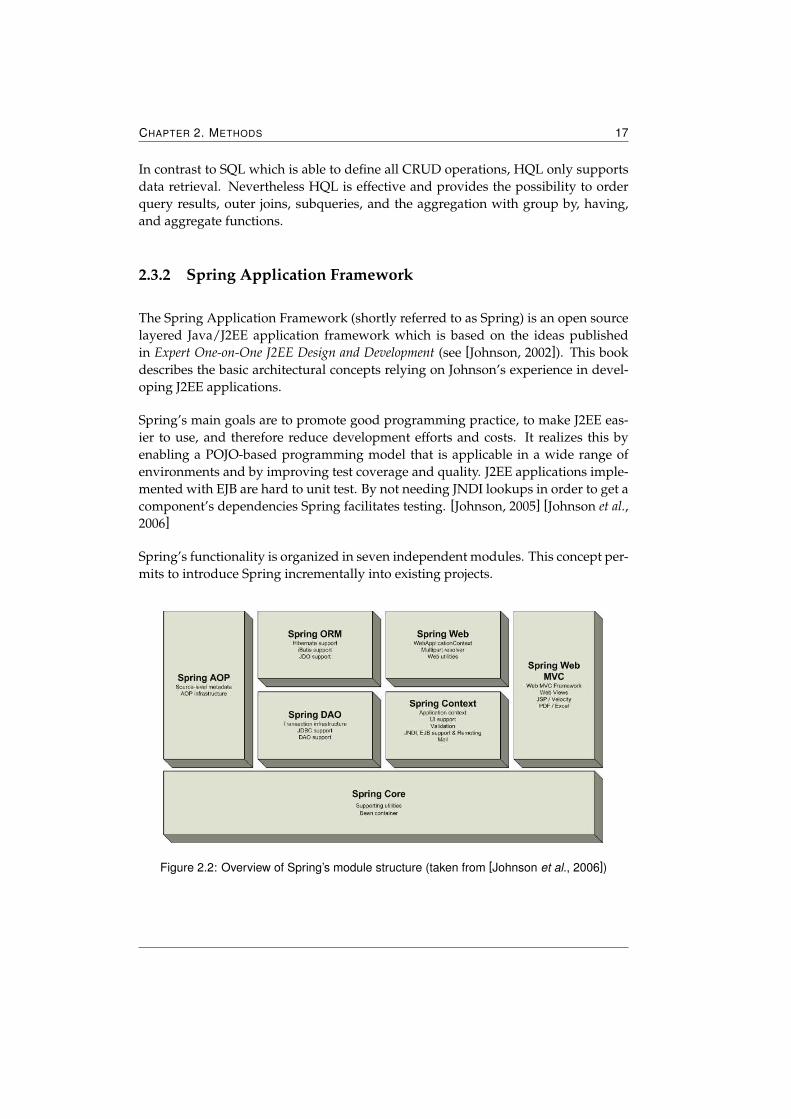
Spring’s functionality is organized in seven independent modules. This concept per-mits to introduce Spring incrementally into existing projects.
Figure 2.2: Overview of Spring’s module structure (taken from [Johnson et al., 2006])
CHAPTER 2. METHODS 18
Spring Core contains the fundamental functionality of Spring and provides incombination with the Spring Context module the basis for Inversion of Controlfeatures (further described in Chapter 2.3.2.1 on the next page). The mod-ule’s basic component is the BeanFactory which follows the factory pattern(described in [Gamma et al., 1994]). According to [Johnson et al., 2006] theBeanFactory is the actual container which instantiates, configures, and man-ages a number of beans using an XML configuration file. By using the Bean-Factory the configuration and specification of dependencies caused by beanscollaborating with each other can be separated from the application code it-self. This makes exchange of implementations really easy because a goodencapsulation of responsibilities is forced by the framework.
Spring Context builds on top of the Spring Core module by basing on the Ap-plicationContext interface. This interface derives from Spring Core’s Bean-Factory interface and therefore is capable of all the functions the BeanFactoryprovides. Furthermore the ApplicationContext interface enhances the Bean-Factory’s capabilities by supporting the access to beans in a more framework-oriented style. Except for situations where memory consumption is critical itis recommended that ApplicationContext be used because it is an enhancedversion of the FactoryBean.
Spring DAO provides an abstraction layer that ensures the possibility to workwith different data access technologies in a standardized way. Therefore thismodule handles vendor-specific exceptions by translating them to its own ex-ception hierarchy. Spring guarantees by wrapping the original exceptions thatno valuable information is lost. Furthermore Spring’s DAO support providesprogrammatic and declarative transaction management for all POJOs.
Spring ORM Spring does not implement its own object/relational mappinglayer because excellent solutions such as Hibernate or TopLink already exist.Instead Spring supports these ORM mapping APIs by providing integrationlayers in Spring’s ORM module.
Spring AOP integrates Aspect Oriented Programming (AOP) (described inChapter 2.3.2.2 on page 20) into Spring. Transaction management, logging,and various other features are fully integrated. According to [Johnson andHoeller, 2004] the main use of the Spring AOP framework is to provide declar-ative enterprise services for POJOs.
Spring Web provides features for web-based applications such as initializa-tion of application contexts.
CHAPTER 2. METHODS 19
Spring Web MVC provides a Model-View-Controller (MVC) implementationfor web applications. It ensures a clean separation between domain modelcode and web forms and supports various web technologies such as JSP andVelocity.
2.3.2.1 Inversion of Control
Most of an application’s business objects have dependencies—either in form of otherbusiness objects, data access objects or resources. In order to manage these depen-dencies an application needs an infrastructural backbone which is often providedby containers7. Inversion of Control (IoC) delegates the responsibility for resolvinga business object’s dependencies to the container. This means that a business objectdoes not look up its own dependencies, it relies on the container to invoke the accor-dant methods. This principle is often described as the »Hollywood Principle—Don’tcall us, we’ll call you.«
Spring supports a special flavor of IoC called Dependency Injection. Furthermore, italso provides possibilities for Dependency Lookup which is a contrary approach to IoCfor accessing dependencies. EJBs and other J2EE APIs provide Dependency Lookup.
If containers provide callback methods which objects must call to resolve their de-pendencies this form of accessing dependencies is called Dependency Lookup. Itusually involves container-specific code. If possible Dependency Lookups shouldbe avoided in order to minimize dependencies on a specific framework. On theother hand to access Spring from external technologies Dependency Lookups arenecessary.
Dependency Injection is the main paradigm of Spring and removes explicit depen-dence on container APIs. Meaning that the container recognizes which dependenciesare needed by a component and provides these dependencies to the component atruntime. For this to function components must provide a way for containers to in-ject the dependencies. This can be realized by Setter Injection or Constructor Injection.When business objects provide getter and setter methods for resolving dependen-cies this form of Dependency Injection is called Setter Injection. Whereas expressingdependencies via constructor arguments is referred to as Constructor Injection.
For keeping flexibility high it’s necessary to avoid introducing dependencies by us-ing a certain container. By following the principles of IoC, especially by implement-ing Dependency Injection, containers can minimize an application’s dependency onthemselves. [Johnson and Hoeller, 2004] [Johnson, 2005]
7Containers can be described as frameworks in which application code runs.
CHAPTER 2. METHODS 20
2.3.2.2 Aspect Oriented Programming
Aspect Oriented Programming was introduced by Kiczales et al. on the ECOOP8
in 1997. It evolved because some problems exist which can not be appropriatelyseparated according to their concerns—neither by the Object Oriented Programming(OOP) approach nor by the procedural approach.
Separation of concerns is one of the key principles in software engineering. It isbased on the fact that problems usually involve different kinds of concerns. In or-der to reduce the problem’s complexity the problem can be decomposed into easiersubproblems (in this case also referred to as concerns). By following separation ofconcerns a program’s robustness, adaptability, and maintainability can be enhanced.OOP and Procedural Oriented Programming (POP) both follow separation of con-cerns.
As mentioned above there exist some problems which OOP and POP can not decom-pose appropriately. An example for such problems is logging. In a typical applica-tion logging is not only done in one class, log outputs are written in several methodsof different classes. This results in code duplication and in code which is hard tomaintain.
AOP can handle this problem by introducing another way of thinking about appli-cation structure. It does this by separating the system into aspects or concerns, ratherthan objects. This provides a way of modularization of concerns which otherwisecut across applications. AOP is not thought to compete with OOP. It is designed tocomplete OOP. [Kiczales et al., 1997] [Johnson and Hoeller, 2004] [Johnson et al., 2006]
This list describes some of the core concepts of AOP more detailed:
Concern is a piece of interest for an application or a goal which an applica-tion must meet. Typical examples for concerns are transaction management,logging, security checks, performance monitoring, as well as an application’smain functionality which is captured by its business logic.
Core concern describes one of the main goals/functionalities of an applica-tion. The business logic handles all core concerns of an application. Usuallyother concerns which ensure proper execution such as transaction manage-ment or security checks are not referred to as core concerns.
Cross-cutting concern is a concern which does not only affect one class hier-archy. It cuts across the applications functionality and therefore is hard tocapture by OOP. Most examples mentioned in point Concern are cross-cuttingconcerns.
8ECOOP stands for European Conference on Object-Oriented Programming.
CHAPTER 2. METHODS 21
Aspect is the modularization of a cross-cutting concern. By using aspects thescattering of code is prevented.
Join point is a point in a program’s flow. At a join point the »main« programand the aspect meet. There exist different possible locations for join points.Method invocation, field access, and throwing an exception are some examples.Method invocation can also include the invocation of class constructors andis the only supported join point in Spring. So all join points realized in Springare always method invocations. Field access describes points where instancevariables are read or written.
Advice is an action executed by the framework at a particular join point. Onecan distinguish between three different types of advice: before (also referredto as pre), after (also referred to as post), and around.
Before advices describe advices which are called before the entering of a joinpoint’s method. Whereas after advices are being executed after invokinga join point. Spring further classifies after advices in after returning advicesand throws advices. If an advice is fired after the successful execution of ajoin point’s method this type of advice is called after returning advice. Be-sides others this type of advice has read access to the method’s return value.Throws advice identifies advices which are invoked after the join point hasthrown a particular exception or a subclass of it.
The around advice is Spring’s most fundamental advice type. Here the adviceis responsible for invoking the join point and should provide access to the joinpoint’s return value. A typical example for an around advice is transactionmanagement. Before invoking the join point a transaction is opened, after thejoin point’s execution the transaction is closed by the advice.
Pointcut is a set of join points used to define which join points initiate theexecution of which advices. In order to specify a pointcut’s join points regularexpressions as well as other wildcard syntax are used.
In this thesis transaction management, some security checks, and logging are im-plemented according to the AOP approach. So-called transaction proxies representan advice. They open an accordant transaction before invoking a business method(which is the join point). After the business method’s termination the transactionproxies handle the transaction closing. Security checks concerning user data are alsorealized by AOP. Methods provided by the in-house developed usermanagementcheck a user’s identity and authorization before returning the accordant user data.
CHAPTER 2. METHODS 22
2.3.2.3 Data Access
With the DAO and ORM module Spring provides well-structured options to accessdata in a standardized way. Spring supports both types of data access: direct relationalaccess and ORM. Direct relational data access is realized by Spring’s DAO modulewhich provides JDBC support whereas the ORM module handles integration withORM tools.
For standardizing data access Spring provides the following functions:
� To facilitate exception handling and to reduce dependency on selected data ac-cess technologies, Spring translates technology-specific exceptions to its ownexception hierarchy. All mapped exceptions derive from Spring’s root excep-tion class DataAccessException. Spring wraps proprietary, checked exceptionsto abstracted runtime exceptions.
� Spring provides various abstract DAO classes which implement the DAO pat-tern (described in Chapter 2.2.5 on page 13) to ensure consistent usage of dif-ferent data access technologies. These abstract classes can be extended and de-rived from the generic base class DaoSupport which defines template methodsfor DAO initialization. The abstract subclasses provide methods for setting thedata source and all necessary configurations dependent on the chosen technol-ogy. Some provided classes are JDBCDaoSupport, JDODaoSupport, TopLink-DaoSupport, and HibernateDaoSupport. Spring supports two HibernateDao-Support classes: one coping with Hibernate version 2 technology and the otherone handling Hibernate version 3.
� In order to simplify data access code, Spring implements so-called templateclasses. They all handle translation into Spring’s exception hierarchy and con-nection management. Other functions vary by the chosen technology. Al-though these template classes are optional, it is recommended to use them ifpossible to abstract data access. Changes of underlying data access technolo-gies are easier to maintain if template classes are used.
2.3.3 Acegi Security System for Spring
Security is one of the most important concerns in enterprise applications. Multi-user systems must verify a user’s identity and check if a specific user has the ac-cordant authorization to access a particular resource. The Acegi Security System forSpring (from here on referred to as Acegi Security) addresses these issues by pro-viding authentication and authorization services. Acegi Security is an open sourcesecurity framework designed for enterprise applications developed with Spring. Its
CHAPTER 2. METHODS 23
provided services can be integrated in applications without implementing securitycode in business logic objects by using AOP. Acegi Security provides web-based ac-cess control lists (ACLs) based on URL schemes, Java class and method security us-ing AOP, and Yale’s Central Authentication Service for single sign-on. [Porter, 2006][Hardwick, 2006]
2.3.3.1 Authentication
Authentication describes an application’s process to verify a user’s, a device’s oranother system’s identity. The resultant assigned identity is referred to as principalwhich is often represented by a username. Normally an authentication is performedby checking the principal’s credentials9 which are usually realized by passwords.
Acegi Security supports different types of authentication models; ranging from thirdparty models over standard bodies to Acegi Security’s own authentication features.Amongst others10 Acegi Security provides authentication with the following tech-nologies:
� Internet Engineering Task Force standards
� Anonymous authentication
� Java Authentication and Authorization Service (JAAS)
� Container integration with JBoss, Jetty, Resin, and Tomcat
� Lightweight Directory Access Protocol (LDAP)
2.3.3.2 Authorization
Checking a principal’s right to access a resource in a system is characterized as au-thorization. Usually before a user’s authorization can be determined the user mustbe authenticated. In order to distinguish between rights of different principals, J2EEapplications define so-called roles and groups. Roles specify which resources are ac-cessible for principals associated with a certain role. Groups are related to one ormore roles and organize different principals to groups. Principals belonging to aparticular group have access to all resources defined in the group’s roles and to re-sources accessible by—for this principal—additionally defined roles. Acegi Secu-rity provides capabilities of authorization, especially for authorizing web requests,method invocation, and access to individual domain object instances. [Alex, 2006]
9[Bodoff et al., 2005] describes credentials as the information describing the security attributes of prin-cipal.
10For a detailed list of all technologies see [Alex, 2006].
CHAPTER 2. METHODS 24
2.3.4 Tapestry
Tapestry is a component-based open source framework designed for the develop-ment of web applications with Java. Tapestry builds on the standard Java ServletAPI. Therefore, web applications developed with Tapestry are still servlet applica-tions and can be run in any application server or servlet container, such as ApacheTomcat, Jetty, or WebSphere.
Acting as a layer between a Java servlet container and a web application, Tapestryhandles non-application-specific concerns like encoding URLs, generating requestsand responses, or managing server-side state. Using the Model-View-Controller(MVC) pattern, Tapestry emphasizes separation of concerns. This pattern dividesan application into the tree categories Model, View, and Controller. The Model rep-resents data objects which may be manipulated and are presented to the user. TheView is responsible for representing data obtained from the Model. The Controlleracts as a bridge between Model and View by reading data from the Model and pro-viding it to the View as well as by reacting to user input by manipulating the Model.
As Tapestry bases on the standard Java Servlet API, Tapestry web applications donot need to implement the Servlet API in order to interact with a backend system.The application’s Java classes can derive from Tapestry base classes which alreadyimplement the Servlet API. To define application-specific behavior, these Java classesimplement so-called listener methods.
Tapestry introduces its own way of organizing web applications. It divides webapplications into a number of pages whereas these pages are constructed from com-ponents which may contain other components. A page has its own unique name andconsists of a template, a Java object, and an XML file also referred to as page specificationfile. This structure ensures a clean separation between Java and template code. Of-ten a page’s template is an HTML file but Tapestry supports other markup languagessuch as WML11 and XHTML12 as well. A template usually contains ordinary HTMLtags whereas some of them are used as placeholders for components. To indicate thatan HTML tag acts as a placeholder, the tag contains a special attribute called jwcidwhich stands for Java Web Component ID. At runtime Tapestry replaces such tagscompletely by HTML output which is generated by the specified component. Thepage’s Java object is responsible for the page’s generation within the application.Tapestry provides with its BasePage class a base class for HTML pages. By default,all templates are represented by this class. If the page’s Java object must provideadditional properties and methods, a Java class deriving from BasePage can be asso-ciated with the page by its page specification. Besides associating a page’s template
11WML stands for Wireless Markup Language and bases on XML.12XHTML is an acronym for Extensible HyperText Markup Language and provides the same expressive
possibilities as HTML but demands a stricter syntax.
CHAPTER 2. METHODS 25
with its according Java class, page specifications may also include information aboutthe page’s components. [Tong, 2005] [Lewis Ship, 2004]
Tapestry’s main goal is to ensure robust, scalable, and maintainable applications byproviding the accordant options and by enhancing right design choices. To attainthis goal, Tapestry’s philosophy consists of simplicity, consistency, efficiency, and feed-back (described in [Lewis Ship, 2004]):
Simplicity Web applications developed with Tapestry do not need to extractand interpret query parameters from a request or manage data stored as ses-sion attributes. These issues are handled by Tapestry. The framework alsobuilds and formats URLs with the accordant query parameters. These fea-tures avoid the need to implement non-application-specific code and enhancessimplicity by focusing on application-specific logic.
Consistency Tapestry enhances consistency in web applications by providinga component-based approach. Functions which are frequently needed in webapplications can be encapsulated in so-called components (further describedin Chapter 2.3.4.1 and Chapter 2.3.4.2 on page 27). These components can bereused and avoid code duplication as well as inconsistencies.
Efficiency Web applications based on Tapestry are scalable. By using objectpools and caches Tapestry can reuse file contents and therefore minimize therequired processing during a request. Once a template or a template’s spec-ification file is read, its context is stored into an object pool and is reused ifnecessary.
Feedback Most web application frameworks represent exceptions by display-ing the stack trace in the web browser. Usually this approach leads into acumbersome search of the error’s source and often involves debugging. To fa-cilitate an error’s localization, Tapestry provides multiple layers of exceptioncatching and reporting. This architecture ensures that as much information aspossible is collected regarding an error. This information is displayed eitherin the web browser or in the server’s console.
2.3.4.1 Standard Components
In order to enhance consistency Tapestry provides a set of reusable components forfunctionalities which are frequently needed in web applications. The frameworksupports low-level components such as conditional tags as well as more advancedcomponents like some form components basing on JavaScript. The following listdescribes some of the provided components in more detail. A complete list of all
CHAPTER 2. METHODS 26
components and their parameters can be found at Tapestry’s official homepage (Ac-cessible through the Web at »http://tapestry.apache.org/tapestry4/«).
If Elements enclosed by this component are rendered only when the specifiedcondition is met.
Else can only be used in combination with an If component. Elements en-closed by an Else component are only rendered if the condition specified inthe previous If component is not met.
For loops over a specified collection of source values and renders its body mul-tiple times.
Image generates an HTML <img> tag and thereby displays an image whosesource URL is given by the component’s image parameter.
Insert is used for the insertion of text which should be formatted in a specificway.
Body generates a page’s <body> element and organizes client-side JavaScripton the page into a single <script> block. Tapestry components which useJavaScript expect to be enclosed by a Body component. If no Body componentis wrapped around these components an exception with an accordant hintwill be thrown.
Form handles the rendering of an HTML form and the processing when a formis submitted. The Form component generates HTTP query parameters andassigns unique IDs for its containing form control elements.
TextField is a simple form element component which renders an HTML - <in-put> element. By setting the component’s hidden attribute true, the browsermasks the text input. This is used to realize password inputs.
TextArea is another Tapestry form control component rendering an HTML -<textarea> element accepting text input larger than a single line.
PropertySelection realizes a drop-down list allowing single selection of itsproperties. If multiple selection is required, Select and Option components(further described in [Lewis Ship, 2004]) must be used. In order to specify thedrop-down list’s options, a Java class implementing the IPropertySelec-tionModel interface must be bound to the PropertySelection component.PropertySelection is another form element component and must be enclosedby a Form component.
CHAPTER 2. METHODS 27
DatePicker is one of Tapestry’s more advanced form control components im-plicating that this component must be enclosed by Tapestry’s Form compo-nent. The DatePicker component provides two ways of selecting dates: eitherby writing the date directly into the component’s HTML text field or by us-ing the pop-up window which can be activated by a button beside the HTMLtext field. Since the pop-up calendar is created via JavaScript, this componentrequires the usage of the Body component.
Submit creates an HTML form submission element <input type="submit">.If a form has more than one submit button, the application must distinguishwhich button was clicked. Tapestry provides two types of differentiation: bysetting submit properties (tag and select) to some unique values, or byspecifying different listeners which are notified when the form is submitted.The Submit component must be wrapped by a Form component as well.
DirectLink creates an HTML <a> element which causes—when clicked—thetriggering of server-side behavior. In this case server-side behavior is realizedby the execution of the component’s specified listener method. The generatedlink can include additional information which is passed to the triggered lis-tener. Besides form submission this component introduces the second maintype of user interaction in Tapestry.
PageLink Like a DirectLink component a PageLink component generates anHTML <a> hyperlink element. The difference between these components isthat the PageLink component directly references another page within the ap-plication without executing a pre-defined listener method.
2.3.4.2 Custom Components
Besides supplying standard components, Tapestry provides possibilities to imple-ment custom components. A component’s structure is similar to a page’s structurebecause strictly speaking, Tapestry realizes pages as specialized kinds of compo-nents. This includes specified properties and listener methods.
Components consist of a component specification, a Java class, and an optional com-ponent template13. The component specification is an XML configuration file whichdefines the component’s Java class as well as additionally required or optional pa-rameters. The Java class must implement the IComponent interface which defines anobject which may be used to provide dynamic content. Tapestry provides two baseclasses which implement the IComponent interface: AbstractComponent and BaseC-omponent. AbstractComponent ensures basic functionality for components whichrender its output in Java code. Components inherited from AbstractComponent
13Components not specifying a template are called abstract components.
CHAPTER 2. METHODS 28
must implement the renderComponent method in order to define their outputs. There-fore, such abstract components do not need a template. Contrarily BaseComponentprovides a base implementation for most components that use an HTML templateand derives from AbstractComponent. If no additional functionality is needed com-ponents with HTML templates will use the BaseComponent class.
In order to reuse already designed components, a set of components can be packedinto a library and exported into other applications. There exist a couple of goodthird-party component libraries such as the Tapestry contrib library 14 and the Tacoslibrary project15.
2.4 Code Generation
The development of enterprise applications often involves creation of several con-figuration files, development of code skeletons implementing standard operations,and other time-consuming and monotonous jobs. Code generation introduces theautomation of software production by generating code with the help of programs.This technique speeds up software development, reduces typing errors as well asmaintenance costs.
Code generators can range from small helper scripts to large sophisticated programs.UML Based Code Generators represent one category of code generators. They read oneor more UML models and generate platform-specific code. AndroMDA (describedin the section below) represents such a type of code generator and is used in thisthesis to generate persistence and business tier configuration and code skeletons.
2.4.1 AndroMDA
AndroMDA is an open source code generation framework that follows the MDAparadigm (see Chapter 2.1.1 on page 6). As a UML Based Code Generator An-droMDA reads one or more UML models, which are stored in XMI format, andgenerates fully deployable applications and other components by using AndroMDAplug-ins. As the framework supports customizing and developing code templates,AndroMDA is not limited to any programming language. [AndroMDA, 2005e]
The framework relies on two main components: The AndroMDA code generation en-gine and Apache’s Maven project builder and management system (shortly referred to as
14Accessible through the Web at »tapestry.apache.org/tapestry4/tapestry-contrib/index.html«
15Accessible through the Web at »tacos.sourceforge.net/«
CHAPTER 2. METHODS 29
Maven). The code generation engine handles the necessary generation tasks and actsas a platform for code modules16. These modules are responsible for code genera-tion. Maven handles the tasks required to call the AndroMDA engine, but its usageis optional. Alternatives to Maven are starting the engine directly from commandline, from within an Integrated Development Environment (IDE), or from a buildscript using Ant. Most AndroMDA tools come with a Maven plug-in, therefore itsusage is recommended. For example the plug-in andromdapp:generate initializes anew J2EE project from scratch including creation of the required directory structure,providing a pre-configured UML model, and generation of configuration files. [An-droMDA, 2005a]
AndroMDA’s code generation bases on a Mental Model (MM) from which a PlatformIndependent Model (PIM) is created. This PIM represents the MM in a more formallanguage such as UML. Afterwards cartridges transform the PIM into a PlatformSpecific Model (PSM). Based on that, AndroMDA produces code by using templates.
Code generation involves many advantages. Since AndroMDA bases on UML de-signed PIMs, applications built with AndroMDA are well documented and theirmodels always reflect the generated code. Changes of system requirements or ap-plication architecture are easier to maintain. Developers just remodel the PIM andregenerate the code. Pre-defined templates ensure a consistent programming style.Classes which are generated by the same cartridge have the same structure. An-droMDA’s community driven development provides quick support and up-to-datedocumentation.
2.4.1.1 Cartridges
Cartridges can be interpreted as AndroMDA’s rules for code generation. They de-fine the transformation from the PIM to the implementation code. Since AndroMDAis mostly used for code generation which follows the J2EE approach, nearly all car-tridges generate Java code. A cartridge consists of a collection of source code tem-plate files (see Chapter 2.4.1.2 on page 32), Java helper classes (called Metafacades),and a special descriptor file named andromdacartridge.xml which are all packagedinto a .JAR file. [AndroMDA, 2005a]
AndroMDA provides the possibility to remodel and regenerate code. Since eachcode regeneration would cause the loss of manually altered code, all cartridges fol-low a certain structure in which the separation of manually editable and pure gen-erated code is realized. AndroMDA therefore creates two different file locations:target and source, whereas code stored in the target folder will be overwritten by thecartridges.
16AndroMDA calls these modules cartridges and are further described in Chapter 2.4.1.1.
CHAPTER 2. METHODS 30
Currently AndroMDA provides ten different cartridges, such as BPM4Struts, EJB,Hibernate, Spring, and Java. The Java cartridge is responsible for the generation ofbasic Java objects. Below the Hibernate and Spring cartridge are further described,since they are the cartridges used in this thesis. For a detailed description of allcartridges refer to [AndroMDA, 2005b].
Hibernate Cartridge
This cartridge is responsible for the generation of a persistence tier which uses Hiber-nate as its ORM tool. Besides Java classes and Hibernate mapping files, the creationof vendor-specific SQL scripts for database schema creation and deletion is handledby this cartridge. A namespace attribute specifies the type of relational database andis used to distinguish between the different SQL dialects. In that way, the underlyingrelational database system can be exchanged with small effort.
The created persistence tier can be hidden by a service layer implemented with ses-sion EJBs or by Spring POJOs. The integration with session EJBs or Spring is notnecessary to run this cartridge. It can be used without interaction with any othercartridge. According to [AndroMDA, 2005c] the Hibernate cartridge uses the fol-lowing stereotypes:
Entity is applied to UML class model elements and implicates that a class rep-resents a Hibernate POJO. UML classes assigned with this stereotype causethe cartridge to generate an accordant Hibernate mapping file as well as itscorresponding Java class.
Relationships between entity classes can be modeled via associations and areconsidered by the cartridge as well. It is important to set the correct multi-plicities on the association ends to ensure that proper mappings, code, anddatabase tables are created.
Enumeration instruct the generation of a type-safe enumeration class. Suchclasses are modeled as any other regular class, only all attributes defined inthe enumeration class must provide a default value. Since these enumerationsare persisted by the Hibernate framework, entities can reference them in theirattributes as well.
Service implicates that a class represents a session EJB which acts as a facadefor a set of entities.
Identifier can only be applied to attributes of entity classes and defines theaccordant attribute as the classes’ primary key. If no identifier stereotype isapplied to an entity the system will create a default primary key.
CHAPTER 2. METHODS 31
Besides stereotypes, the Hibernate cartridge supports various tagged values, suchas @andromda.hibernate.generator.class and @andromda.hibernate.query. They areused to add information to the model. @andromda.hibernate.generator.class definesthe Hibernate generator class for the creation of primary keys. Increment, sequence,and foreign are some of its possible allowed values. @andromda.hibernate.queryimplicates that an entity’s method handles SQL or HQL query expressions whichare defined by their tagged values. It is recommended to avoid this type of findermethods because it can introduce vendor-specific SQL and HQL to the PIM andportability could be lost.
Spring Cartridge
The Spring cartridge generates code based on the Spring Framework. It providescode generation only for persistence and business tier objects. Code which realizesthe Tapestry presentation tier is not created by this cartridge. It is capable of generat-ing both—stand-alone Spring POJOs, which can run without an EJB container in anordinary web container, and Spring POJOs wrapped with an EJB session bean whichrequires its deployment in an EJB container. AndroMDA provides some namespaceproperties to distinguish which Spring POJO type should be created.
Since the Spring cartridge realizes its object/relational mapping by integrating Hi-bernate, it can only be used in conjunction with the Hibernate cartridge. Therefore,all stereotypes and tagged values provided by the Hibernate cartridge can be usedas well. Spring POJOs can reference enumerations and entities without any furthermodeling required. Among the files generated by the Hibernate cartridge, the entitystereotype causes the Spring cartridge to create additional DAO objects. This in-cludes a *Dao, *DaoBase, and *DaoImpl class17. *Dao specifies a Java interface whichprovides CRUD operations. *DaoBase implements the *Dao interface and inheritsHibernateDaoSupport—one of Spring’s abstract DAO classes (see Chapter 2.3.2.3 onpage 22). The *DaoImpl class is only generated once because it is intended to containmanually written code. Entity methods which are declared as static methods (haveclassifier scope) will be handled in the *Dao classes whereas instance scoped meth-ods will be handled in the entity’s class. The modeling of so-called finder methodsis realized in AndroMDA by static methods. Finder methods can be modeled by us-ing tagged values (described in the section handling the Hibernate cartridge) or byusing OCL. Unlike the tagged value method OCL can ensure portability over differ-ent technologies since it causes query generation. When the Spring and Hibernatecartridge are used the OCL query language is translated into HQL.
Besides entity the following stereotypes can be used with the Spring cartridge:
Service generates classes which handle an application’s business tier. Depen-dent on the session-ejbs outlet of the cartridge’s namespace, classes which are
17* is used as a wildcard for any entity’s name.
CHAPTER 2. METHODS 32
assigned with this stereotype cause creation of session EJBs or stand-aloneSpring POJOs. By default an exception for each service is generated as well.
Modeling dependencies between service and entity objects causes the car-tridge to add accessors for the entity’s Dao in the service class. At runtime,the accordant Dao objects are invoked by Spring’s Dependency Injection.
ValueObject Although the Java class representing the value object is gener-ated by another cartridge, it can cause additional code in Spring’s entity *Dao,*DaoBase, and *DaoImpl classes. When a dependency from an entity to avalue object is modeled, the Spring cartridge creates a transformation methodin the accordant *Dao classes.
ApplicationException and UnexpectedException are used to specify particu-lar exceptions for entity or service classes. Dependencies from these classesto an exception will cause that each method of the accordant class will throwthis exception. In order to generate the stereotype UnexpectedException theSpring cartridge must cooperate with the Java cartridge.
Since AndroMDA supports Acegi declarative role-based security for Spring services,the Spring cartridge provides modeling of application roles. In the model, these rolesare represented by actors. By adding dependencies from actors to Spring services orto single Spring service methods, role access is defined. When generating code theaccordant configuration file and Acegi Security classes are generated. [AndroMDA,2005d]
2.4.1.2 Velocity Templates
Apache Software Foundation’s Velocity (from here on referred to as Velocity) is aJava-based template engine. It permits a template language to reference objects de-fined in Java code. Besides code generation Velocity is used to create HTML pagesin web applications, to generate automatic emails, and to transform XML. [Velocity,2005b] [Velocity, 2005a]
AndroMDA supports different template engines, but by default the Velocity tem-plate engine is used for code generation. In the code generation process a cartridgemaps its stereotypes to Velocity template files. These mappings are specified in thecartridge’s descriptor file. Then, Velocity generates content according to the associ-ated template file. Since Velocity template files are modifiable, custom-specific ad-justments of a cartridge are possible.
CHAPTER 2. METHODS 33
2.5 JUnit Testing
Testing plays an important role in software development. It checks an application’sfunctionality and can indicate and expose errors in applications.
JUnit is an open-source unit test framework for Java and provides mechanisms forcreating and running sets of automated tests. Unit testing evolved with Test DrivenDevelopment (TDD) usually validates the functions of basic building blocks of anapplication. TDD is a software development technique which is based on first writ-ing test cases and then implementing only the code which is needed to fulfill thetest’s requirements. If the implemented code passes the unit tests the test cases willbe extended and the development cycle starts over again. By incrementally extend-ing the tests, the system evolves and is able to handle more complex tasks. Further-more the previous defined test sets ensure that code changes will not effect alreadyexisting functions. This thesis does not follow the TDD approach but is influencedby it. Therefore unit test exists to test several different functionalities but they weredeveloped during—not before the implementation.
2.6 Tools
This chapter introduces development tools used during this thesis. It describes thetools MyEclipse as well as the Maven and MagicDraw which are needed for theAndroMDA generation process.
2.6.1 Maven
Maven is one of the Apache Projects and is used as a software project managementtool. Based on a central piece of information Maven manages the building, reportingand documentation of a project. Its main goal is to allow developers to comprehendthe complete state of a development effort in the shortest period of time. [Maven,2006a]
Maven tries to address the following concerns [Maven, 2006b]:
� Making the build process easy
� Providing a uniform build system
� Providing quality project information
CHAPTER 2. METHODS 34
� Providing guidelines for best practices development
� Allowing transparent migration to new features
Maven supports downloading dependencies from remote repositories. It stores andmanages project dependencies in a local repository. If dependencies, which are notalready in the local repository, are declared by a project Maven will try to downloadthem from a remote repository.
2.6.2 MagicDraw
MagicDraw is a cross-platform compatible visual UML modeling and CASE18 toolwith teamwork support. By providing database schema modeling, Data Defini-tion Language (DDL) generation, reverse engineering facilities, and a code gener-ation mechanism, MagicDraw facilitates analysis and design of OO systems anddatabases. [No Magic Inc., 2006]
MagicDraw is available in six different editions—amongst others MagicDraw Reader,MagicDraw Community edition, and MagicDraw Standard edition whereas Mag-icDraw Reader and MagicDraw Community edition are free of charge. Since thisthesis handles just a part of a bigger system, separation of models according to theirresponsibilities is necessary. MagicDraw Standard edition is one of MagicDraw’scommercial products and supports possibilities for dividing models into modules.
The newest release of MagicDraw is MagicDraw version 11.5 and fully supportsUML 2. Since AndroMDA does not support UML 2.0 (caused by major problemswith open source repository support of MOF 2 and UML 2.0), AndroMDA recom-mends the usage of MagicDraw version 9.5 which works with UML version 1.4.
2.6.3 MyEclipse Enterprise Workbench
MyEclipse Enterprise Workbench (from here on referred to as MyEclipse) is a com-mercial J2EE IDE extension which is based on open-industry standards and theEclipse platform. The used Eclipse Software Development Kit is an open sourceproject focused on providing an extensible development platform and applicationframework for building software. Combined with MyEclipse it can be used as amature development environment in the J2EE field.
[Genuitec, 2006] describes MyEclipse as a full-featured, Enterprise-class platformand tool suite for developing software applications and systems supporting the full
18CASE is an acronym for Computer-Aided Software Engineering.
CHAPTER 2. METHODS 35
life-cycle of application development. It provides a complete application develop-ment environment for J2EE WEB, XML, UML, and databases. Integration with ap-plication server connectors is supported by MyEclipse as well.
MyEclipse features include [Genuitec, 2006]:
� Java EE development (JSP, JSF, Struts, JSTL, XML, XSD, Servlets, EJB, app-server deployment/debug)
� POJO development (Spring, EJB, Hibernate, web services, XDoclet, ...)
� Database development (ERD, Database Explorer, SQL, DDL, Data editing, Or-acle triggers, procedures, packages, ...)
� UML development (round-trip support, class, sequence, collaboration, deploy-ment, state, activity)
2.7 Usermanagement
For handling user authentication and authorization this thesis integrates UserMan-agementUtils which is an in-house Java project developed by Gernot Stocker. At thebeginning its purpose was to provide an alternative file-based lightweight userman-agement for the in-house GenomeUsermanagement. Since SMILE bases on AcegiSecurity, the UserManagmentUtils were enlarged by Java classes which integrateAcegi Security and build the glue code between Usermanagement Implementationsand Acegi Security.
As mentioned above, UserManagementUtils supports two types of usermanage-ment which can be distinguished in a host-specific configuration file. These differentusermanagements are referred to as SimpleUsermanagement and GenomeUsermanage-ment.
2.7.1 SimpleUsermanagement
The SimpleUsermanagement bases on an XML file named users.xml which containsinformation about a user’s username, description, password (in encrypted form),userid, organizations, and roles. The roles define which applications the user canaccess and their accordant rights.
The SimpleUsermanagement can be thought of a lightweight version of Genome-Usermanagement and can handle most of the GenomeUsermanagement’s important
CHAPTER 2. METHODS 36
authentication and authorization features. Solely single sign on is not supported bythe SimpleUsermanagement. On the other hand the GenomeUsermanagement canexport the AAS-data into an XML file which can be read by the SimpleUsermanage-ment. Thereby synchronization of systems can be implemented.
2.7.2 GenomeUsermanagement
The GenomeUsermanagement is a Java-based usermanagement system for molecu-lar biology database systems originally developed by Dieter Zeller. It is a centralizedadministration system for assigning users a single account for web applications, Mi-crosoft Windows domains, and Unix/Linux servers. [Zeller, 2003]
By providing a web front end, administrators can manage user, user groups, organi-zations, resources, and access control lists (ACLs). Among authentication and autho-rization functionality, the system is capable of sharing resources between users andorganization-wide sharing. Furthermore the GenomeUsermanagement also pro-vides single sign on. Therefore users which are logged in once can access all theirsubscribed applications without any additional login procedure.
Chapter 3
Design
Design is an important task in software development. It specifies how an applica-tion’s functionality is achieved and enhances transparency of later implementations.This chapter describes the overall design created for this thesis. Since design requiresa detailed description of an application’s functionality, this chapter also provides amore detailed view on the Digital Lab Book workflow.
3.1 Workflow
The Digtial Lab Book supports the independent management of experiments andstandard protocols. Therefore, two separate workflows for each task are created.Figure 3.1 on the following page and Figure 3.2 on page 39 visualize both workflows.
3.1.1 Experiment oriented Workflow
This section describes the definition of an experiment and its accordant step se-quence.
Create Project Projects are top-level domains and are one of the basic organi-zational units. They act as a container for subprojects and experiments. Sub-projects can be used to further divide projects to separate a problem in morefine-grained subjects. Thereby possibilities to structure projects are provided.
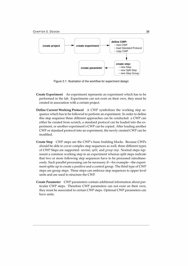
CHAPTER 3. DESIGN 38
create step:
− new Split Step− new Step Group
− new Stepcreate parameter
define CWP:
create project create experiment − new CWP− load Standard Protocol− copy CWP
Figure 3.1: Illustration of the workflow for experiment design
Create Experiment An experiment represents an experiment which has to beperformed in the lab. Experiments can not exist on their own, they must becreated in association with a certain project.
Define Current Working Protocol A CWP symbolizes the working step se-quence which has to be followed to perform an experiment. In order to definethis step sequence three different approaches can be conducted: a CWP caneither be created from scratch, a standard protocol can be loaded into the ex-periment, or another experiment’s CWP can be copied. After loading anotherCWP or standard protocol into an experiment, the newly created CWP can bemodified.
Create Step CWP steps are the CWP’s basic building blocks. Because CWPsshould be able to cover complex step sequences as well, three different typesof CWP Steps are supported: normal, split, and group step. Normal steps rep-resent a common working step in an experiment whereas split steps indicatethat two or more following step sequences have to be processed simultane-ously. Such parallel processing can be necessary if—for example—the experi-ment splits up to create a positive and a control group. The third type of CWPsteps are group steps. These steps can embrace step sequences to upper levelunits and are used to structure the CWP.
Create Parameter CWP parameters contain additional information about par-ticular CWP steps. Therefore CWP parameters can not exist on their own,they must be associated to certain CWP steps. Optional CWP parameters canhave units.
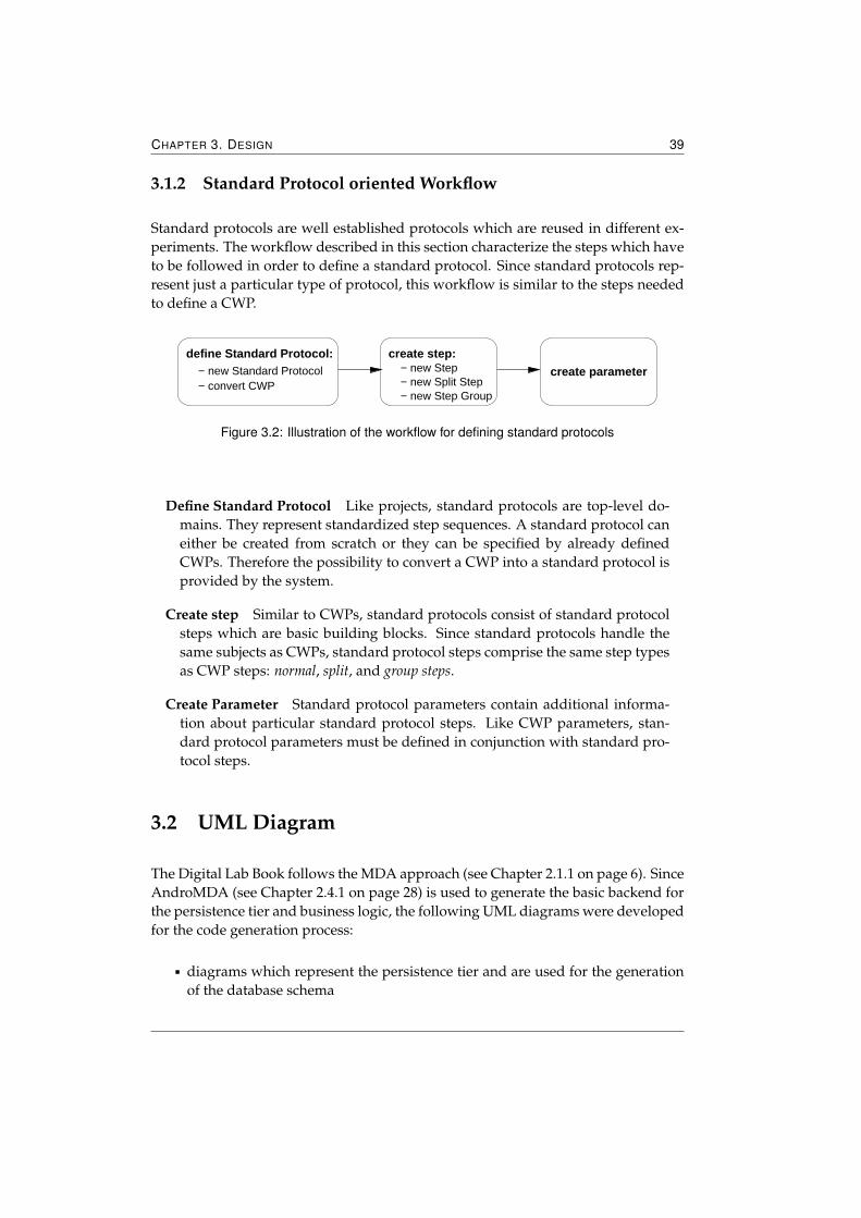
CHAPTER 3. DESIGN 39
3.1.2 Standard Protocol oriented Workflow
Standard protocols are well established protocols which are reused in different ex-periments. The workflow described in this section characterize the steps which haveto be followed in order to define a standard protocol. Since standard protocols rep-resent just a particular type of protocol, this workflow is similar to the steps neededto define a CWP.
create step:
− new Split Step− new Step Group
− new Step create parameter
define Standard Protocol:− new Standard Protocol− convert CWP
Figure 3.2: Illustration of the workflow for defining standard protocols
Define Standard Protocol Like projects, standard protocols are top-level do-mains. They represent standardized step sequences. A standard protocol caneither be created from scratch or they can be specified by already definedCWPs. Therefore the possibility to convert a CWP into a standard protocol isprovided by the system.
Create step Similar to CWPs, standard protocols consist of standard protocolsteps which are basic building blocks. Since standard protocols handle thesame subjects as CWPs, standard protocol steps comprise the same step typesas CWP steps: normal, split, and group steps.
Create Parameter Standard protocol parameters contain additional informa-tion about particular standard protocol steps. Like CWP parameters, stan-dard protocol parameters must be defined in conjunction with standard pro-tocol steps.
3.2 UML Diagram
The Digital Lab Book follows the MDA approach (see Chapter 2.1.1 on page 6). SinceAndroMDA (see Chapter 2.4.1 on page 28) is used to generate the basic backend forthe persistence tier and business logic, the following UML diagrams were developedfor the code generation process:
� diagrams which represent the persistence tier and are used for the generationof the database schema
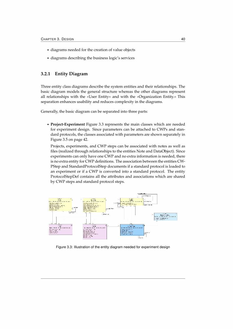
CHAPTER 3. DESIGN 40
� diagrams needed for the creation of value objects
� diagrams describing the business logic’s services
3.2.1 Entity Diagram
Three entity class diagrams describe the system entities and their relationships. Thebasic diagram models the general structure whereas the other diagrams representall relationships with the »User Entity« and with the »Organization Entity.« Thisseparation enhances usability and reduces complexity in the diagrams.
Generally, the basic diagram can be separated into three parts:
� Project-Experiment Figure 3.3 represents the main classes which are neededfor experiment design. Since parameters can be attached to CWPs and stan-dard protocols, the classes associated with parameters are shown separately inFigure 3.5 on page 42.
Projects, experiments, and CWP steps can be associated with notes as well asfiles (realized through relationships to the entities Note and DataObject). Sinceexperiments can only have one CWP and no extra information is needed, thereis no extra entity for CWP definitions. The association between the entities CW-PStep and StandardProtocolStep documents if a standard protocol is loaded toan experiment or if a CWP is converted into a standard protocol. The entityProtocolStepDef contains all the attributes and associations which are sharedby CWP steps and standard protocol steps.
Figure 3.3: Illustration of the entity diagram needed for experiment design
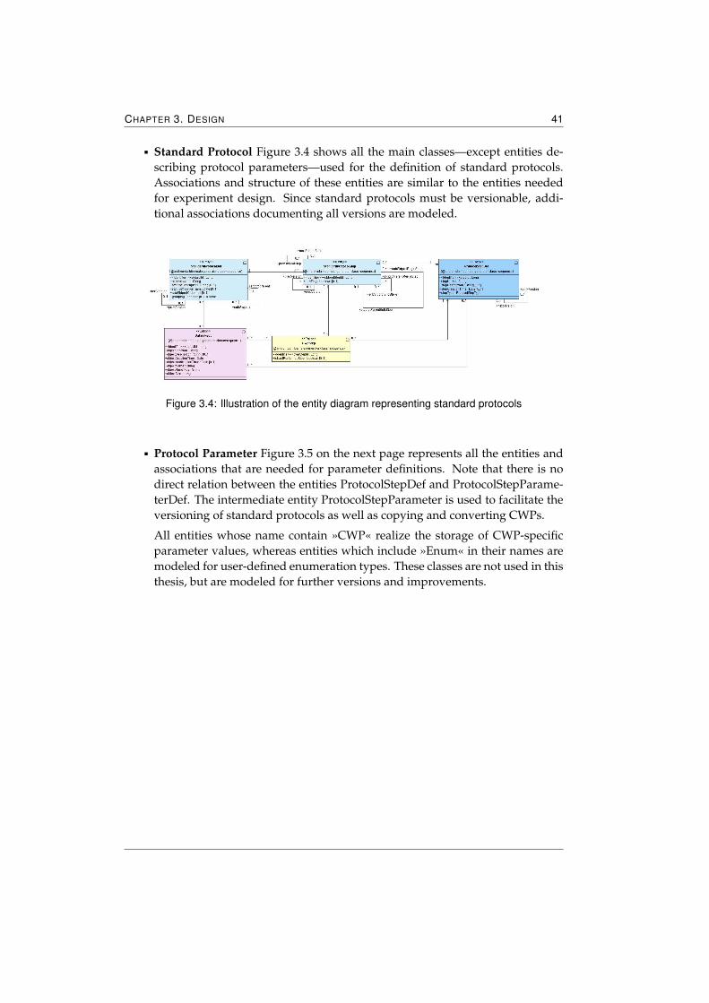
CHAPTER 3. DESIGN 41
� Standard Protocol Figure 3.4 shows all the main classes—except entities de-scribing protocol parameters—used for the definition of standard protocols.Associations and structure of these entities are similar to the entities neededfor experiment design. Since standard protocols must be versionable, addi-tional associations documenting all versions are modeled.
Figure 3.4: Illustration of the entity diagram representing standard protocols
� Protocol Parameter Figure 3.5 on the next page represents all the entities andassociations that are needed for parameter definitions. Note that there is nodirect relation between the entities ProtocolStepDef and ProtocolStepParame-terDef. The intermediate entity ProtocolStepParameter is used to facilitate theversioning of standard protocols as well as copying and converting CWPs.
All entities whose name contain »CWP« realize the storage of CWP-specificparameter values, whereas entities which include »Enum« in their names aremodeled for user-defined enumeration types. These classes are not used in thisthesis, but are modeled for further versions and improvements.
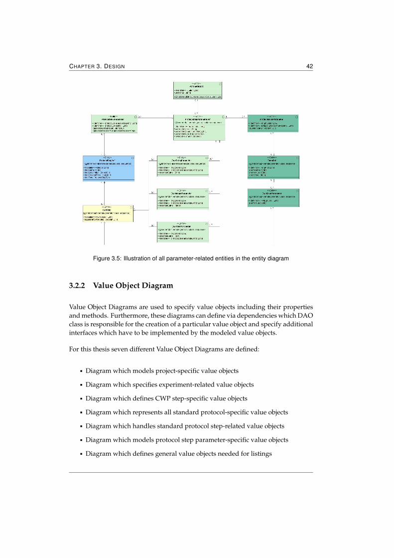
CHAPTER 3. DESIGN 42
Figure 3.5: Illustration of all parameter-related entities in the entity diagram
3.2.2 Value Object Diagram
Value Object Diagrams are used to specify value objects including their propertiesand methods. Furthermore, these diagrams can define via dependencies which DAOclass is responsible for the creation of a particular value object and specify additionalinterfaces which have to be implemented by the modeled value objects.
For this thesis seven different Value Object Diagrams are defined:
� Diagram which models project-specific value objects
� Diagram which specifies experiment-related value objects
� Diagram which defines CWP step-specific value objects
� Diagram which represents all standard protocol-specific value objects
� Diagram which handles standard protocol step-related value objects
� Diagram which models protocol step parameter-specific value objects
� Diagram which defines general value objects needed for listings
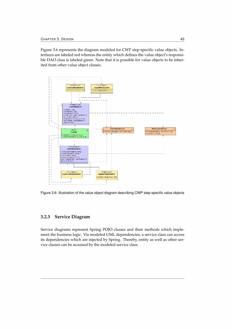
CHAPTER 3. DESIGN 43
Figure 3.6 represents the diagram modeled for CWP step-specific value objects. In-terfaces are labeled red whereas the entity which defines the value object’s responsi-ble DAO class is labeled green. Note that it is possible for value objects to be inher-ited from other value object classes.
Figure 3.6: Illustration of the value object diagram describing CWP step-specific value objects
3.2.3 Service Diagram
Service diagrams represent Spring POJO classes and their methods which imple-ment the business logic. Via modeled UML dependencies, a service class can accessits dependencies which are injected by Spring. Thereby, entity as well as other ser-vice classes can be accessed by the modeled service class.
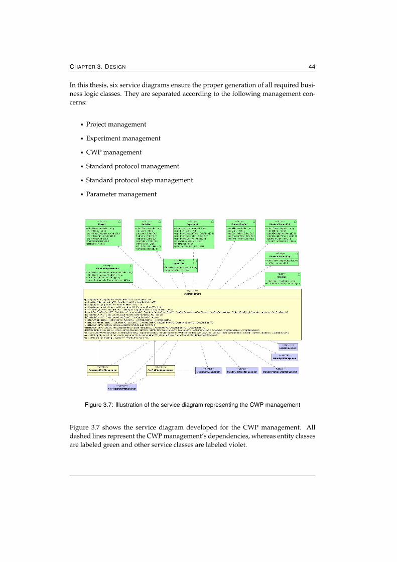
CHAPTER 3. DESIGN 44
In this thesis, six service diagrams ensure the proper generation of all required busi-ness logic classes. They are separated according to the following management con-cerns:
� Project management
� Experiment management
� CWP management
� Standard protocol management
� Standard protocol step management
� Parameter management
Figure 3.7: Illustration of the service diagram representing the CWP management
Figure 3.7 shows the service diagram developed for the CWP management. Alldashed lines represent the CWP management’s dependencies, whereas entity classesare labeled green and other service classes are labeled violet.

CHAPTER 3. DESIGN 45
Since the CWP management handles normal and split steps separately, three serviceclasses were defined. The first one specifies all methods, whereas the two otherclasses inherit from the first class and handle the previously defined methods. Thismodel was chosen to ensure on the one hand a clean separation between the differentsteps and to guarantee on the other hand a universal usage.
Chapter 4
Implementation
Based on a J2EE framework, the application is designed and implemented as a threetier architecture and is web-based. As described in Chapter 2.3 on page 14 Spring,Hibernate, Acegi Security, and Tapestry are the chosen technologies for the imple-mentation. The open source, relational database PostgreSQL is used as databasesystem. Since the application does not contain any EJBs, the deployment on an appli-cation server is not necessary—the usage of a servlet container is sufficient. ApacheTomcat is the chosen servlet container on which the application is deployed.
The realization is divided into two Java projects—one handling the persistence tierand business logic, the other one containing all files which are relevant for the pre-sentation tier. This separation emerged because of the usage of AndroMDA. An-droMDA provides cartridges for the generation of a persistence tier and businesslogic using the Spring and Hibernate technology. Since the number of Java classesand configuration files which are generated by AndroMDA is relatively high andthe directory structure1 created is complex, the disjunction of the presentation tier,whose configuration files, Java classes, and HTML files are all implemented manu-ally, arose. By splitting into the two Java projects, a certain clearness is assured.
In this chapter, the implementation’s description is not partitioned according to thedifferent tiers of the three tier architecture—conceptually related domains are builtand described.
1AndroMDA creates projects from scratch and thereby defines a certain directory structure.
CHAPTER 4. IMPLEMENTATION 47
4.1 Project Management
The project management handles basic CRUD operations for projects. By support-ing the creation of subprojects, this management is capable of structuring projects. Toenhance usability and facilitate the navigation through projects, the project manage-ment further provides components which give an overview of a project’s structure.Each component, whose creation is generally dependent on the project management,contains blue elements. Headlines, links, arrows, and the border of required inputfields are common elements which are colored in a domain-specific color. The usageof different colors representing different conceptually related domains enhances us-ability. The following list describes the conceptual domains and their correspondingcolor:
� Project—labeled blue
� Experiment—labeled green
� Standard Protocol—labeled red
4.1.1 Creation of a new Project
The application provides a mask which implies the creation of a new root project.These projects are top level units and independent from other projects. Generally, aproject is characterized by the following data:
� Project name
� Short description of the strategy
� Further project description
� Definition of the project aims
� Owner
� Submitter
� Date of creation
� Parent project
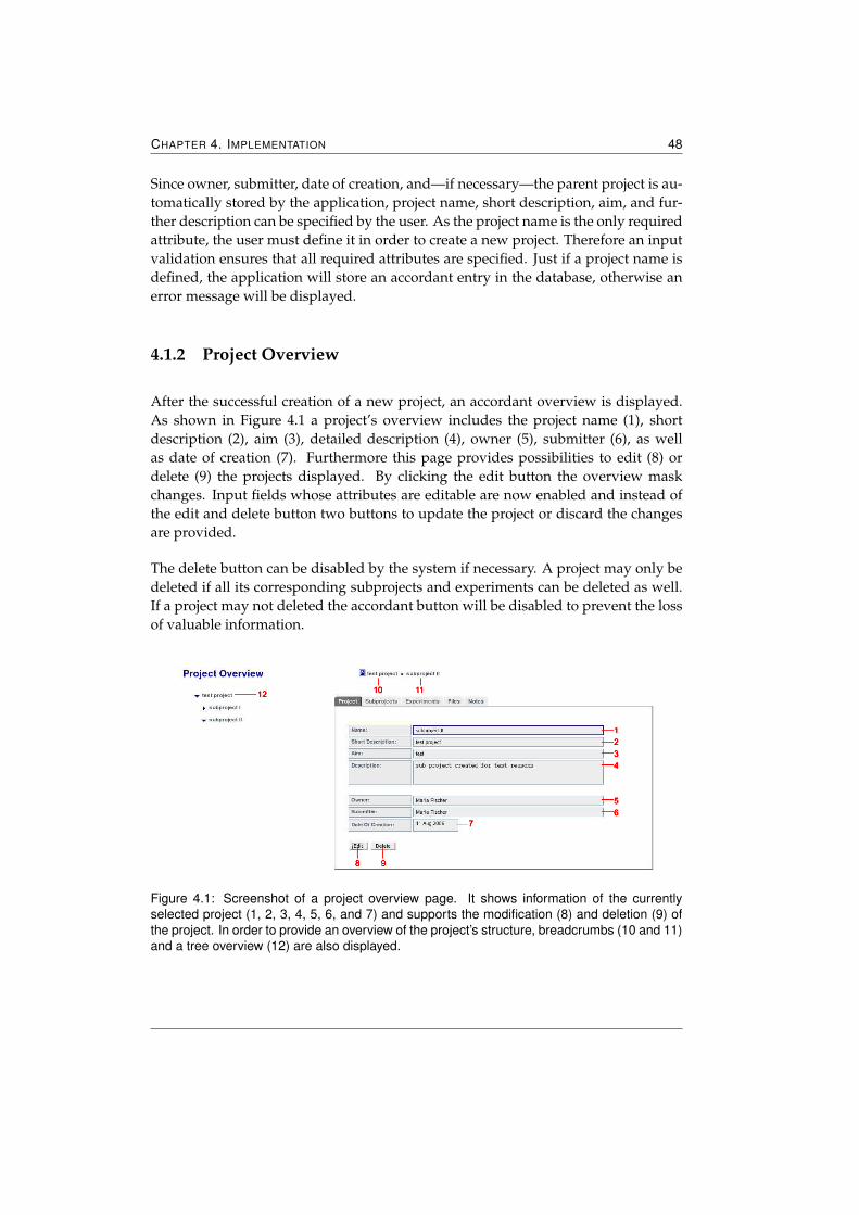
CHAPTER 4. IMPLEMENTATION 48
Since owner, submitter, date of creation, and—if necessary—the parent project is au-tomatically stored by the application, project name, short description, aim, and fur-ther description can be specified by the user. As the project name is the only requiredattribute, the user must define it in order to create a new project. Therefore an inputvalidation ensures that all required attributes are specified. Just if a project name isdefined, the application will store an accordant entry in the database, otherwise anerror message will be displayed.
4.1.2 Project Overview
After the successful creation of a new project, an accordant overview is displayed.As shown in Figure 4.1 a project’s overview includes the project name (1), shortdescription (2), aim (3), detailed description (4), owner (5), submitter (6), as wellas date of creation (7). Furthermore this page provides possibilities to edit (8) ordelete (9) the projects displayed. By clicking the edit button the overview maskchanges. Input fields whose attributes are editable are now enabled and instead ofthe edit and delete button two buttons to update the project or discard the changesare provided.
The delete button can be disabled by the system if necessary. A project may only bedeleted if all its corresponding subprojects and experiments can be deleted as well.If a project may not deleted the accordant button will be disabled to prevent the lossof valuable information.
Figure 4.1: Screenshot of a project overview page. It shows information of the currentlyselected project (1, 2, 3, 4, 5, 6, and 7) and supports the modification (8) and deletion (9) ofthe project. In order to provide an overview of the project’s structure, breadcrumbs (10 and 11)and a tree overview (12) are also displayed.
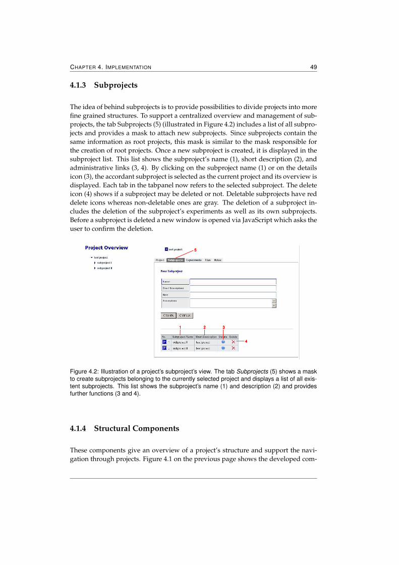
CHAPTER 4. IMPLEMENTATION 49
4.1.3 Subprojects
The idea of behind subprojects is to provide possibilities to divide projects into morefine grained structures. To support a centralized overview and management of sub-projects, the tab Subprojects (5) (illustrated in Figure 4.2) includes a list of all subpro-jects and provides a mask to attach new subprojects. Since subprojects contain thesame information as root projects, this mask is similar to the mask responsible forthe creation of root projects. Once a new subproject is created, it is displayed in thesubproject list. This list shows the subproject’s name (1), short description (2), andadministrative links (3, 4). By clicking on the subproject name (1) or on the detailsicon (3), the accordant subproject is selected as the current project and its overview isdisplayed. Each tab in the tabpanel now refers to the selected subproject. The deleteicon (4) shows if a subproject may be deleted or not. Deletable subprojects have reddelete icons whereas non-deletable ones are gray. The deletion of a subproject in-cludes the deletion of the subproject’s experiments as well as its own subprojects.Before a subproject is deleted a new window is opened via JavaScript which asks theuser to confirm the deletion.
Figure 4.2: Illustration of a project’s subproject’s view. The tab Subprojects (5) shows a maskto create subprojects belonging to the currently selected project and displays a list of all exis-tent subprojects. This list shows the subproject’s name (1) and description (2) and providesfurther functions (3 and 4).
4.1.4 Structural Components
These components give an overview of a project’s structure and support the navi-gation through projects. Figure 4.1 on the previous page shows the developed com-
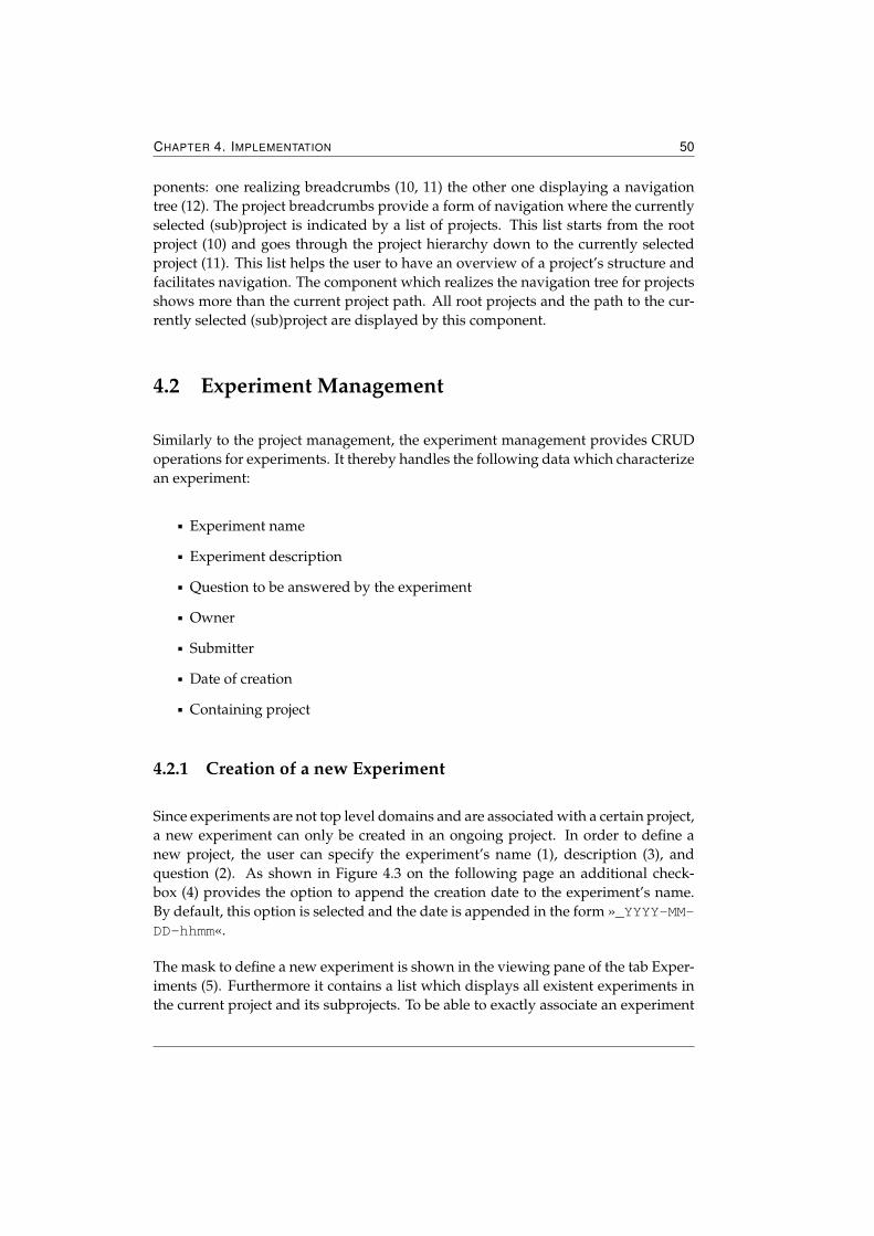
CHAPTER 4. IMPLEMENTATION 50
ponents: one realizing breadcrumbs (10, 11) the other one displaying a navigationtree (12). The project breadcrumbs provide a form of navigation where the currentlyselected (sub)project is indicated by a list of projects. This list starts from the rootproject (10) and goes through the project hierarchy down to the currently selectedproject (11). This list helps the user to have an overview of a project’s structure andfacilitates navigation. The component which realizes the navigation tree for projectsshows more than the current project path. All root projects and the path to the cur-rently selected (sub)project are displayed by this component.
4.2 Experiment Management
Similarly to the project management, the experiment management provides CRUDoperations for experiments. It thereby handles the following data which characterizean experiment:
� Experiment name
� Experiment description
� Question to be answered by the experiment
� Owner
� Submitter
� Date of creation
� Containing project
4.2.1 Creation of a new Experiment
Since experiments are not top level domains and are associated with a certain project,a new experiment can only be created in an ongoing project. In order to define anew project, the user can specify the experiment’s name (1), description (3), andquestion (2). As shown in Figure 4.3 on the following page an additional check-box (4) provides the option to append the creation date to the experiment’s name.By default, this option is selected and the date is appended in the form »_YYYY-MM-DD-hhmm«.
The mask to define a new experiment is shown in the viewing pane of the tab Exper-iments (5). Furthermore it contains a list which displays all existent experiments inthe current project and its subprojects. To be able to exactly associate an experiment
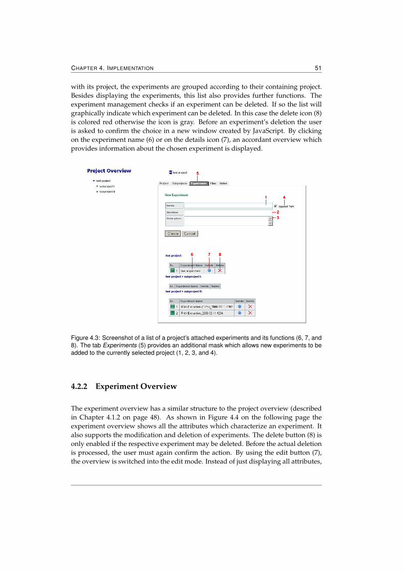
CHAPTER 4. IMPLEMENTATION 51
with its project, the experiments are grouped according to their containing project.Besides displaying the experiments, this list also provides further functions. Theexperiment management checks if an experiment can be deleted. If so the list willgraphically indicate which experiment can be deleted. In this case the delete icon (8)is colored red otherwise the icon is gray. Before an experiment’s deletion the useris asked to confirm the choice in a new window created by JavaScript. By clickingon the experiment name (6) or on the details icon (7), an accordant overview whichprovides information about the chosen experiment is displayed.
Figure 4.3: Screenshot of a list of a project’s attached experiments and its functions (6, 7, and8). The tab Experiments (5) provides an additional mask which allows new experiments to beadded to the currently selected project (1, 2, 3, and 4).
4.2.2 Experiment Overview
The experiment overview has a similar structure to the project overview (describedin Chapter 4.1.2 on page 48). As shown in Figure 4.4 on the following page theexperiment overview shows all the attributes which characterize an experiment. Italso supports the modification and deletion of experiments. The delete button (8) isonly enabled if the respective experiment may be deleted. Before the actual deletionis processed, the user must again confirm the action. By using the edit button (7),the overview is switched into the edit mode. Instead of just displaying all attributes,
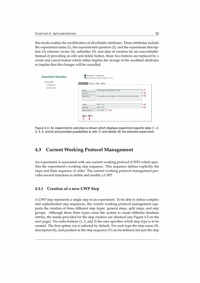
CHAPTER 4. IMPLEMENTATION 52
this mode enables the modification of all editable attributes. These attributes includethe experiment name (1), the experimental question (2), and the experiment descrip-tion (3) whereas owner (4), submitter (5), and date of creation (6) are non-editable.Instead of providing an edit and delete button, these two buttons are replaced by acreate and cancel button which either implies the storage of the modified attributesor implies that the changes will be cancelled.
Figure 4.4: An experiment’s overview is shown which displays experiment-specific data (1, 2,3, 4, 5, and 6) and provides possibilities to edit (7) and delete (8) the selected experiment.
4.3 Current Working Protocol Management
An experiment is associated with one current working protocol (CWP) which spec-ifies the experiment’s working step sequence. This sequence defines explicitly thesteps and their sequence of order. The current working protocol management pro-vides several functions to define and modify a CWP.
4.3.1 Creation of a new CWP Step
A CWP step represents a single step in an experiment. To be able to define complexand sophisticated step sequences, the current working protocol management sup-ports the creation of three different step types: general steps, split steps, and stepgroups. Although these three types cause the system to create different databaseentries, the masks provided for the step creation are identical (see Figure 4.5 on thenext page). Via radio buttons (1, 2, and 3) the user specifies which step type is to becreated. The first option step is selected by default. For each type the step name (5),description (6), and position in the step sequence (7) can be defined, but just the step
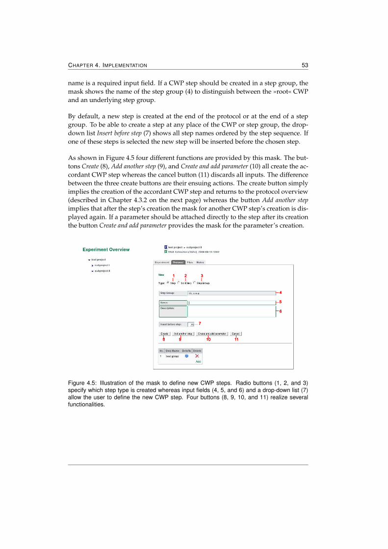
CHAPTER 4. IMPLEMENTATION 53
name is a required input field. If a CWP step should be created in a step group, themask shows the name of the step group (4) to distinguish between the »root« CWPand an underlying step group.
By default, a new step is created at the end of the protocol or at the end of a stepgroup. To be able to create a step at any place of the CWP or step group, the drop-down list Insert before step (7) shows all step names ordered by the step sequence. Ifone of these steps is selected the new step will be inserted before the chosen step.
As shown in Figure 4.5 four different functions are provided by this mask. The but-tons Create (8), Add another step (9), and Create and add parameter (10) all create the ac-cordant CWP step whereas the cancel button (11) discards all inputs. The differencebetween the three create buttons are their ensuing actions. The create button simplyimplies the creation of the accordant CWP step and returns to the protocol overview(described in Chapter 4.3.2 on the next page) whereas the button Add another stepimplies that after the step’s creation the mask for another CWP step’s creation is dis-played again. If a parameter should be attached directly to the step after its creationthe button Create and add parameter provides the mask for the parameter’s creation.
Figure 4.5: Illustration of the mask to define new CWP steps. Radio buttons (1, 2, and 3)specify which step type is created whereas input fields (4, 5, and 6) and a drop-down list (7)allow the user to define the new CWP step. Four buttons (8, 9, 10, and 11) realize severalfunctionalities.
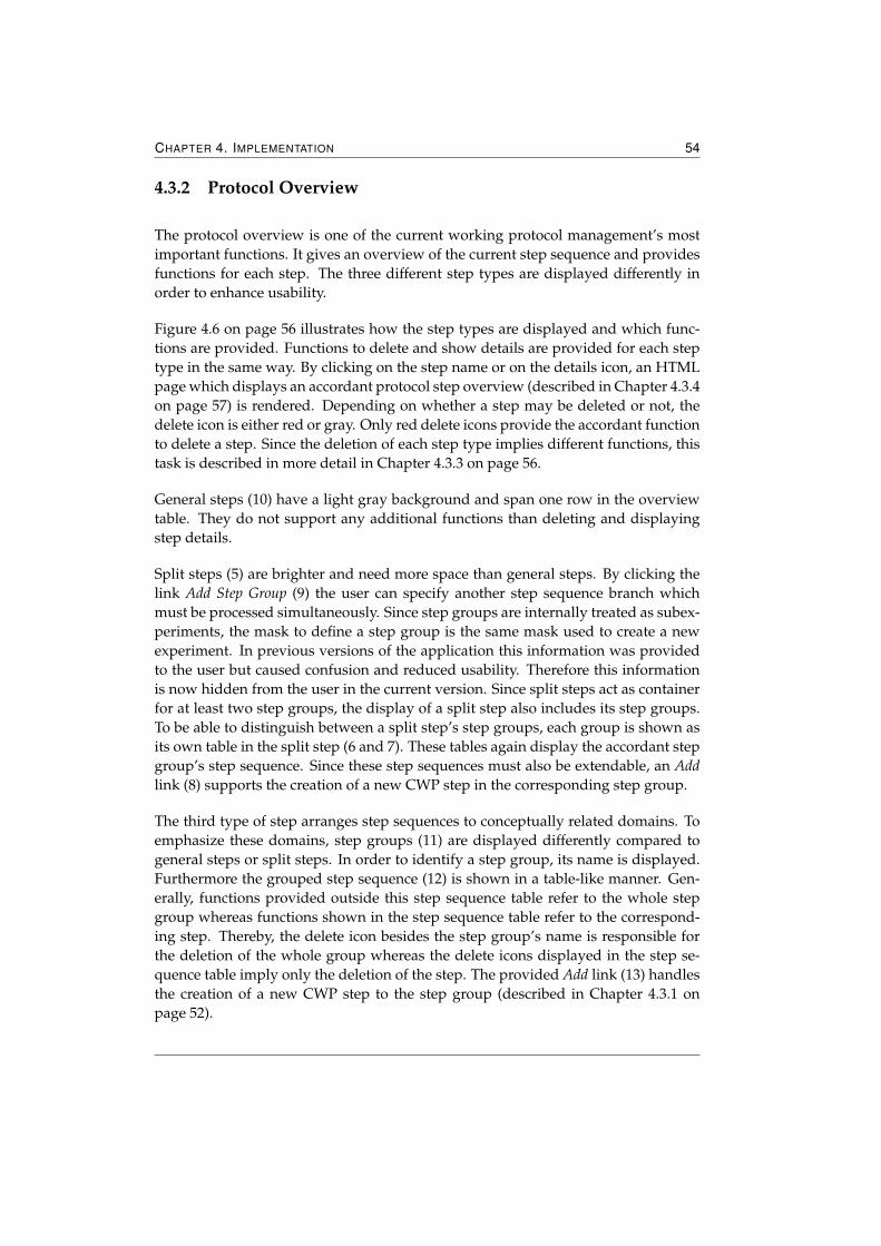
CHAPTER 4. IMPLEMENTATION 54
4.3.2 Protocol Overview
The protocol overview is one of the current working protocol management’s mostimportant functions. It gives an overview of the current step sequence and providesfunctions for each step. The three different step types are displayed differently inorder to enhance usability.
Figure 4.6 on page 56 illustrates how the step types are displayed and which func-tions are provided. Functions to delete and show details are provided for each steptype in the same way. By clicking on the step name or on the details icon, an HTMLpage which displays an accordant protocol step overview (described in Chapter 4.3.4on page 57) is rendered. Depending on whether a step may be deleted or not, thedelete icon is either red or gray. Only red delete icons provide the accordant functionto delete a step. Since the deletion of each step type implies different functions, thistask is described in more detail in Chapter 4.3.3 on page 56.
General steps (10) have a light gray background and span one row in the overviewtable. They do not support any additional functions than deleting and displayingstep details.
Split steps (5) are brighter and need more space than general steps. By clicking thelink Add Step Group (9) the user can specify another step sequence branch whichmust be processed simultaneously. Since step groups are internally treated as subex-periments, the mask to define a step group is the same mask used to create a newexperiment. In previous versions of the application this information was providedto the user but caused confusion and reduced usability. Therefore this informationis now hidden from the user in the current version. Since split steps act as containerfor at least two step groups, the display of a split step also includes its step groups.To be able to distinguish between a split step’s step groups, each group is shown asits own table in the split step (6 and 7). These tables again display the accordant stepgroup’s step sequence. Since these step sequences must also be extendable, an Addlink (8) supports the creation of a new CWP step in the corresponding step group.
The third type of step arranges step sequences to conceptually related domains. Toemphasize these domains, step groups (11) are displayed differently compared togeneral steps or split steps. In order to identify a step group, its name is displayed.Furthermore the grouped step sequence (12) is shown in a table-like manner. Gen-erally, functions provided outside this step sequence table refer to the whole stepgroup whereas functions shown in the step sequence table refer to the correspond-ing step. Thereby, the delete icon besides the step group’s name is responsible forthe deletion of the whole group whereas the delete icons displayed in the step se-quence table imply only the deletion of the step. The provided Add link (13) handlesthe creation of a new CWP step to the step group (described in Chapter 4.3.1 onpage 52).
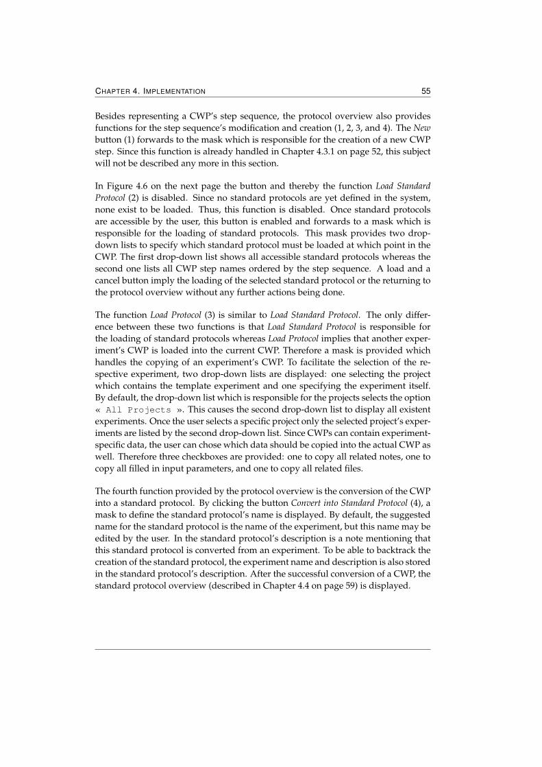
CHAPTER 4. IMPLEMENTATION 55
Besides representing a CWP’s step sequence, the protocol overview also providesfunctions for the step sequence’s modification and creation (1, 2, 3, and 4). The Newbutton (1) forwards to the mask which is responsible for the creation of a new CWPstep. Since this function is already handled in Chapter 4.3.1 on page 52, this subjectwill not be described any more in this section.
In Figure 4.6 on the next page the button and thereby the function Load StandardProtocol (2) is disabled. Since no standard protocols are yet defined in the system,none exist to be loaded. Thus, this function is disabled. Once standard protocolsare accessible by the user, this button is enabled and forwards to a mask which isresponsible for the loading of standard protocols. This mask provides two drop-down lists to specify which standard protocol must be loaded at which point in theCWP. The first drop-down list shows all accessible standard protocols whereas thesecond one lists all CWP step names ordered by the step sequence. A load and acancel button imply the loading of the selected standard protocol or the returning tothe protocol overview without any further actions being done.
The function Load Protocol (3) is similar to Load Standard Protocol. The only differ-ence between these two functions is that Load Standard Protocol is responsible forthe loading of standard protocols whereas Load Protocol implies that another exper-iment’s CWP is loaded into the current CWP. Therefore a mask is provided whichhandles the copying of an experiment’s CWP. To facilitate the selection of the re-spective experiment, two drop-down lists are displayed: one selecting the projectwhich contains the template experiment and one specifying the experiment itself.By default, the drop-down list which is responsible for the projects selects the option« All Projects ». This causes the second drop-down list to display all existentexperiments. Once the user selects a specific project only the selected project’s exper-iments are listed by the second drop-down list. Since CWPs can contain experiment-specific data, the user can chose which data should be copied into the actual CWP aswell. Therefore three checkboxes are provided: one to copy all related notes, one tocopy all filled in input parameters, and one to copy all related files.
The fourth function provided by the protocol overview is the conversion of the CWPinto a standard protocol. By clicking the button Convert into Standard Protocol (4), amask to define the standard protocol’s name is displayed. By default, the suggestedname for the standard protocol is the name of the experiment, but this name may beedited by the user. In the standard protocol’s description is a note mentioning thatthis standard protocol is converted from an experiment. To be able to backtrack thecreation of the standard protocol, the experiment name and description is also storedin the standard protocol’s description. After the successful conversion of a CWP, thestandard protocol overview (described in Chapter 4.4 on page 59) is displayed.
CHAPTER 4. IMPLEMENTATION 56
Figure 4.6: Illustration of a CWP step sequence with its provided functions (1, 2, 3, and 4).This overview lists a CWP’s steps according to their step sequence (5, 10, and 11). Furtherdisplayed are all split step’s containing step groups (6 and 7) and all steps enclosed by stepgroups (12). In order to add step groups to split steps and accordingly to add steps to stepgroups, links to this options (9 and 13) are provided as well.
4.3.3 Deletion of a CWP Step
Since the deletion of a CWP step differs from one step type to another, the actionsprocessed to delete a CWP step are dependent on the step type. But some activitiesare necessary for all step types: Each deletion must be confirmed by the user beforethe accordant step is removed and after the deletion, the removed step’s predecessorand successor are directly linked.
If a general step is deleted no further processes than the ones described above areneeded whereas the deletion of a split step or step group requires more activities.Usually, if these step types are to be deleted more than one step must be removed:The underlying or grouped steps are deleted before their containing step is removedas well. This exactly describes the procedure which is followed if a step group isdeleted. If a split step is deleted one more user input will be necessary before thesplit step can be removed. Since the application provides the possibility to includethe step sequence of one of the split step’s underlying step groups, a mask in whichthe user can specify which step group should be maintained is displayed. By default,no step group is chosen. This causes the application to remove the complete split
CHAPTER 4. IMPLEMENTATION 57
step from the step sequence. If one of the split step’s underlying step groups ischosen, each step of this step group is inserted at the split step’s position. Figure 4.7shows the step sequence of Figure 4.6 on the preceding page after the deletion of thesplit step Tissue sample preparation whereas the step group Cells grown in suspensionwas chosen as the step group which should be included in the current step sequence.
Figure 4.7: Screenshot of the same CWP step sequence as in Figure 4.6 on the precedingpage after the deletion of the first CWP step.
4.3.4 CWP Step Overview
The CWP step overview provides a detailed view of a CWP step. The headline (1)of the step overview indicates which step type is described. Since each step typestores step name (2), step description (3), and parameters (5), these attributes aredisplayed no matter which step type is described. Like the project and experimentoverview, the CWP step overview also supports the modification (8) and deletion (9)of its displayed elements in which step name and step description are editable. Fur-thermore, buttons (10, 11, and 12) to navigate through the CWP are provided. TheBack button (10) forwards to the protocol overview whereas the Prev Step (11) andNext Step (12) buttons link to the overview of the step’s predecessor and successor.If the displayed step has no previous or next step (that is if a step is at the beginningor the end of the protocol/step group) the accordant button is disabled.
In order to modify the parameters which are attached to a step, this overview pro-vides buttons and links to add, delete, and display detailed information about pa-rameters. The Add button (4) shown in the Parameters field causes the rendering of amask2 responsible for adding a new parameter to the shown step. If there are already
2This mask is further described in Ch. 4.5.1 on page 61
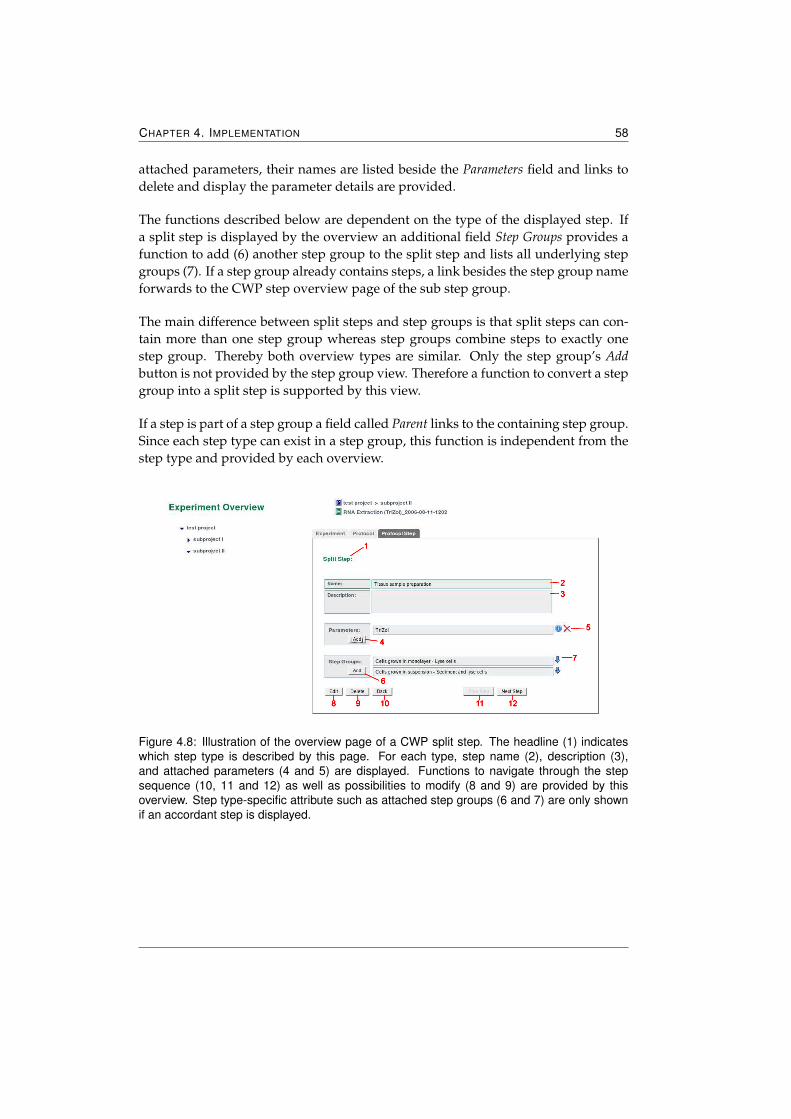
CHAPTER 4. IMPLEMENTATION 58
attached parameters, their names are listed beside the Parameters field and links todelete and display the parameter details are provided.
The functions described below are dependent on the type of the displayed step. Ifa split step is displayed by the overview an additional field Step Groups provides afunction to add (6) another step group to the split step and lists all underlying stepgroups (7). If a step group already contains steps, a link besides the step group nameforwards to the CWP step overview page of the sub step group.
The main difference between split steps and step groups is that split steps can con-tain more than one step group whereas step groups combine steps to exactly onestep group. Thereby both overview types are similar. Only the step group’s Addbutton is not provided by the step group view. Therefore a function to convert a stepgroup into a split step is supported by this view.
If a step is part of a step group a field called Parent links to the containing step group.Since each step type can exist in a step group, this function is independent from thestep type and provided by each overview.
Figure 4.8: Illustration of the overview page of a CWP split step. The headline (1) indicateswhich step type is described by this page. For each type, step name (2), description (3),and attached parameters (4 and 5) are displayed. Functions to navigate through the stepsequence (10, 11 and 12) as well as possibilities to modify (8 and 9) are provided by thisoverview. Step type-specific attribute such as attached step groups (6 and 7) are only shownif an accordant step is displayed.
CHAPTER 4. IMPLEMENTATION 59
4.4 Standard Protocol Management
Standard protocols represent well established protocols which are reused in severalexperiments. Since standard protocols are equally structured as current workingprotocols, most functions provided by the current working protocol managementare also supported by the standard protocol management. In more detail, this man-agement provides the same mechanisms and masks for the creation of a new step,a step’s deletion, and a step’s overview. Even the display of the standard proto-col’s step sequence is identical to the CWP overview (described in Chapter 4.3.2 onpage 54). The only difference between these two overviews is that the overview of astandard protocol’s step sequence does not provide the functions to load a standardprotocol, to load another protocol, and to convert the protocol into a standard proto-col. Only the creation of new standard protocol Steps is supported by this overview.
Standard protocols can exist without projects and experiments whereas CWPs aredependent on these two elements. Therefore standard protocols build their own toplevel units and the standard protocol management provides components to navigatethrough these units. Figure 4.9 on the next page illustrates this. On the left side, atree view (1) of all accessible standard protocols is given. If a selected standard pro-tocol contains Step groups, these groups (2) are shown below the standard protocol.The second component (3) shows the currently selected standard protocol. By click-ing on the standard protocol’s name, an accordant overview of the standard protocol(which is also shown in Figure 4.9 on the following page) is displayed. The standardprotocol overview illustrates the attributes which characterize a standard protocol:standard protocol name (4), description (5), owner (6), and date of creation (7). Sim-ilar to the project overview, the standard protocol overview provides functionalitiesto edit and delete standard protocols whereas their modifiable attributes are the stan-dard protocol name and description.
4.4.1 Versioning Standard Protocols
If a CWP contains standard protocols in its step sequence the CWP will internally ac-cesses some entities of the standard protocols. Therefore standard protocols can noteasily be modified in each case—the necessity to version a whole standard protocolor certain parts of it arise.
To save storage space, not each modification of a standard protocol causes a version-ing. Only standard protocols which are at least loaded into one CWP are versioned.Therfore the application checks before each manipulation of a standard protocol, if aversioning is necessary. Usually, modifications of a standard protocol do not addressall standard protocol steps. If a simple manipulation of one standard protocol step
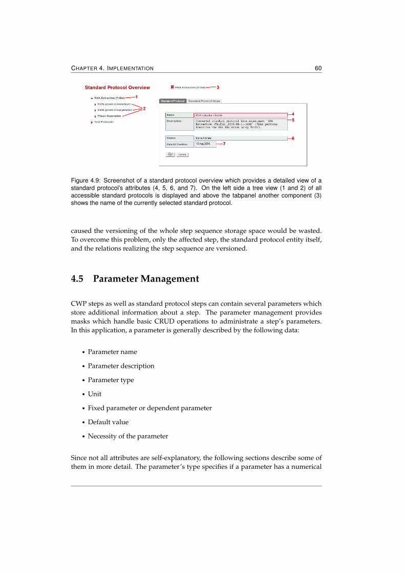
CHAPTER 4. IMPLEMENTATION 60
Figure 4.9: Screenshot of a standard protocol overview which provides a detailed view of astandard protocol’s attributes (4, 5, 6, and 7). On the left side a tree view (1 and 2) of allaccessible standard protocols is displayed and above the tabpanel another component (3)shows the name of the currently selected standard protocol.
caused the versioning of the whole step sequence storage space would be wasted.To overcome this problem, only the affected step, the standard protocol entity itself,and the relations realizing the step sequence are versioned.
4.5 Parameter Management
CWP steps as well as standard protocol steps can contain several parameters whichstore additional information about a step. The parameter management providesmasks which handle basic CRUD operations to administrate a step’s parameters.In this application, a parameter is generally described by the following data:
� Parameter name
� Parameter description
� Parameter type
� Unit
� Fixed parameter or dependent parameter
� Default value
� Necessity of the parameter
Since not all attributes are self-explanatory, the following sections describe some ofthem in more detail. The parameter’s type specifies if a parameter has a numerical
CHAPTER 4. IMPLEMENTATION 61
or non-numerical value. Currently, this application can handle three different pa-rameter types: float, integer, and string. In later versions user-defined enumerationsshould be supported as well.
This application distinguishes between fixed and dependent parameters. Fixed pa-rameters represent parameters whose amounts can be specified before the actualexecution of an experiment because they are independent from any previously per-formed steps. In contrast to fixed parameters, dependent parameters can be influ-enced by previously processed steps and their amounts are not explicitly definablebefore the execution of the experiment. An example is the pellet mass after a liquid’scentrifugation.
A parameter’s necessity is important for later versions of this application. In theapplication’s next version, a wizard guides the user through the experiment andrequired parameters must be specified in order to process a CWP Step. Therefore thisapplication distinguishes between optional and required parameters. By default,parameters are assumed to be optional.
4.5.1 Creation of a new Parameter
In order to attach parameters to an already existing CWP step or standard protocolstep, the parameter management provides a mask (displayed in Figure 4.10 on thenext page) which handles the creation of parameters. Besides parameter name (1),the attributes type (3), fixed/dependent parameter (6), and necessity (8) are requiredin order to add a new parameter. These three attributes can be defined by severaldrop-down lists. By default, parameters are float, fixed and optional parameters.Since the attributes parameter description (2), unit (4 and 5), as well as default valueare optional, the user is not forced to specify them in order to successfully createa parameter. To define a parameter’s unit, a drop-down list (4) contains a view offrequently used units. If a unit is not included in this list the user can specify theaccordant unit in a field (5) which is displayed next to the drop-down list. After thesuccessful creation, the newly defined unit is stored in the database and is added tothe drop-down list. To prevent this list from containing too many elements, unitsspecified by other users are not shown in the list—only units which belong to theuser are displayed in this mask.
Via buttons the user can either create (9 and 10) a new parameter or discard (11)all entries. To facilitate the creation of several parameters, the button Add anotherparameter creates first the defined parameter and then cleans all entries so that anempty mask is displayed again.
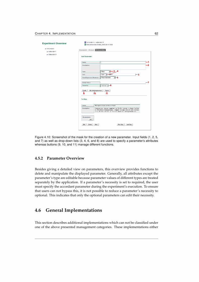
CHAPTER 4. IMPLEMENTATION 62
Figure 4.10: Screenshot of the mask for the creation of a new parameter. Input fields (1, 2, 5,and 7) as well as drop-down lists (3, 4, 6, and 8) are used to specify a parameter’s attributeswhereas buttons (9, 10, and 11) manage different functions.
4.5.2 Parameter Overview
Besides giving a detailed view on parameters, this overview provides functions todelete and manipulate the displayed parameter. Generally, all attributes except theparameter’s type are editable because parameter values of different types are treatedseparately by the application. If a parameter’s necessity is set to required, the usermust specify the accordant parameter during the experiment’s execution. To ensurethat users can not bypass this, it is not possible to reduce a parameter’s necessity tooptional. This indicates that only the optional parameters can edit their necessity.
4.6 General Implementations
This section describes additional implementations which can not be classified underone of the above presented management categories. These implementations either
CHAPTER 4. IMPLEMENTATION 63
influence the AndroMDA code generation process or are general Tapestry compo-nents which are used in several web pages.
4.6.1 Tapestry Components
As described in Chapter 2.3.4.2 on page 27, Tapestry components encapsulate codewhich is frequently needed in web pages. For this thesis, two main components weredeveloped to guarantee a consistent design: Layout and TabPanel.
4.6.1.1 Layout Component
Web applications at the IGB follow a certain design which is usually realized byHTML - <frameset> and HTML - <frame> tags. Since the usage of frames in combi-nation with Tapestry can imply problems, it is recommended to implement the de-sign by using HTML tables. Furthermore, by avoiding HTML frames even browserswhich are not able to represent frames can display the application.
Therefore, the Layout component was developed. It realizes the IGB-typical appli-cation look and feel without any HTML frames. HTML tables in combination withHTML - <div> tags and Cascading Style Sheets (CSS) substitute all HTML framesetsand frames. The Layout component does not require any additional properties andis designed as a component which allows a body. All content in the component’sbody will be rendered by the component at a specific place. The code displayed be-low shows how to integrate the Layout component in an HTML page. In a commonHTML - <span> tag the jwcid3 attribute Layout specifies that the Layout compo-nent must be rendered. All page-specific content which is enclosed by the HTMLspan is in turn rendered by the Layout component.
<span jwcid="layout@Layout">
page-specific content...
</span>
3See Chapter 2.3.4 on page 24
CHAPTER 4. IMPLEMENTATION 64
Besides the visual design, the Layout component also handles general functionalitywhich must be provided by each HTML page:
Switch between different design modes The Layout component provides threeicons (1, 2, and 3) which allows the user to switch between different designmodes. By default, the design mode shown in Figure 4.11 on the follow-ing page is displayed. It’s screen width is 1024 pixels which ensures that allscreens with a resolution of at least 1024x768 can display the application con-veniently. It is the only mode which shows the bar containing the logo of theTechnical University of Graz and the image bar (4). Icon (2) causes the pre-viously mentioned logo and image bar (4) to disappear and thereby createsmore space for displaying page-specific content. This design mode is referredto as »stretched« mode and also has a screen width of 1024 pixels. The iconon the right (3) implies the rendering of the third design mode which is alsoreferred to as »fullscreen« mode. Like with the stretched mode, the header (4)is not displayed, but the design’s width is enlarged to the current width of thebrowser window.
Distinguish if a user is logged in or not By having access to an internal uservalue object, the Layout component can distinguish if a user is logged in ornot. It can therefore render different or additional contents depending to thelogin state of a user.
Providing links for login and logout Depending on whether a user is alreadylogged in or not, the general navigation bar, which contains the three naviga-tion links and generally accessible links, provides either a login or a logoutlink (5). The login link redirects the user to the login page whereas the logoutlink first logs the user out from the Usermanagement, destroys the user valueobject and then also redirects to the application’s login page.
If a user is already logged in the Layout component provides further functionali-ties:
Displaying an additional navigation bar Beside the general navigation bar, afurther navigation bar (6) containing links to functionalities which are onlyaccessible for registered users is displayed.
Showing user details To distinguish which user is currently logged in, theLayout component also displays username and the user’s first - and surname(7).
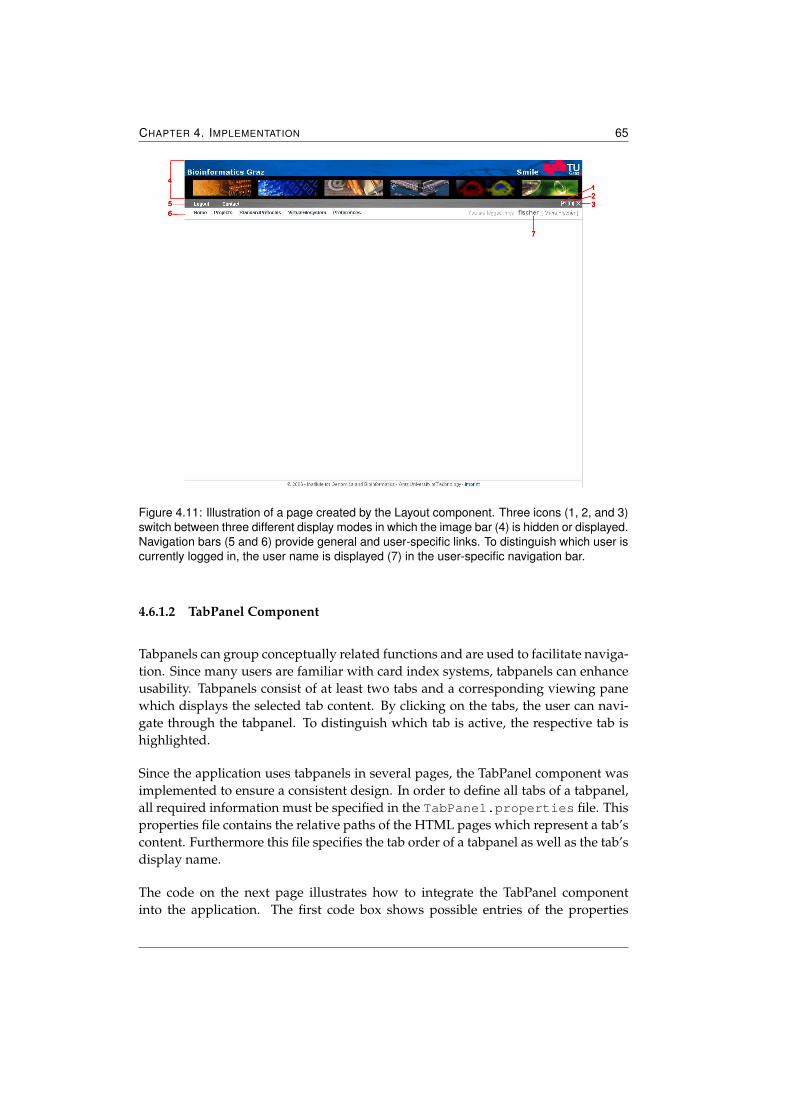
CHAPTER 4. IMPLEMENTATION 65
Figure 4.11: Illustration of a page created by the Layout component. Three icons (1, 2, and 3)switch between three different display modes in which the image bar (4) is hidden or displayed.Navigation bars (5 and 6) provide general and user-specific links. To distinguish which user iscurrently logged in, the user name is displayed (7) in the user-specific navigation bar.
4.6.1.2 TabPanel Component
Tabpanels can group conceptually related functions and are used to facilitate naviga-tion. Since many users are familiar with card index systems, tabpanels can enhanceusability. Tabpanels consist of at least two tabs and a corresponding viewing panewhich displays the selected tab content. By clicking on the tabs, the user can navi-gate through the tabpanel. To distinguish which tab is active, the respective tab ishighlighted.
Since the application uses tabpanels in several pages, the TabPanel component wasimplemented to ensure a consistent design. In order to define all tabs of a tabpanel,all required information must be specified in the TabPanel.properties file. Thisproperties file contains the relative paths of the HTML pages which represent a tab’scontent. Furthermore this file specifies the tab order of a tabpanel as well as the tab’sdisplay name.
The code on the next page illustrates how to integrate the TabPanel componentinto the application. The first code box shows possible entries of the properties
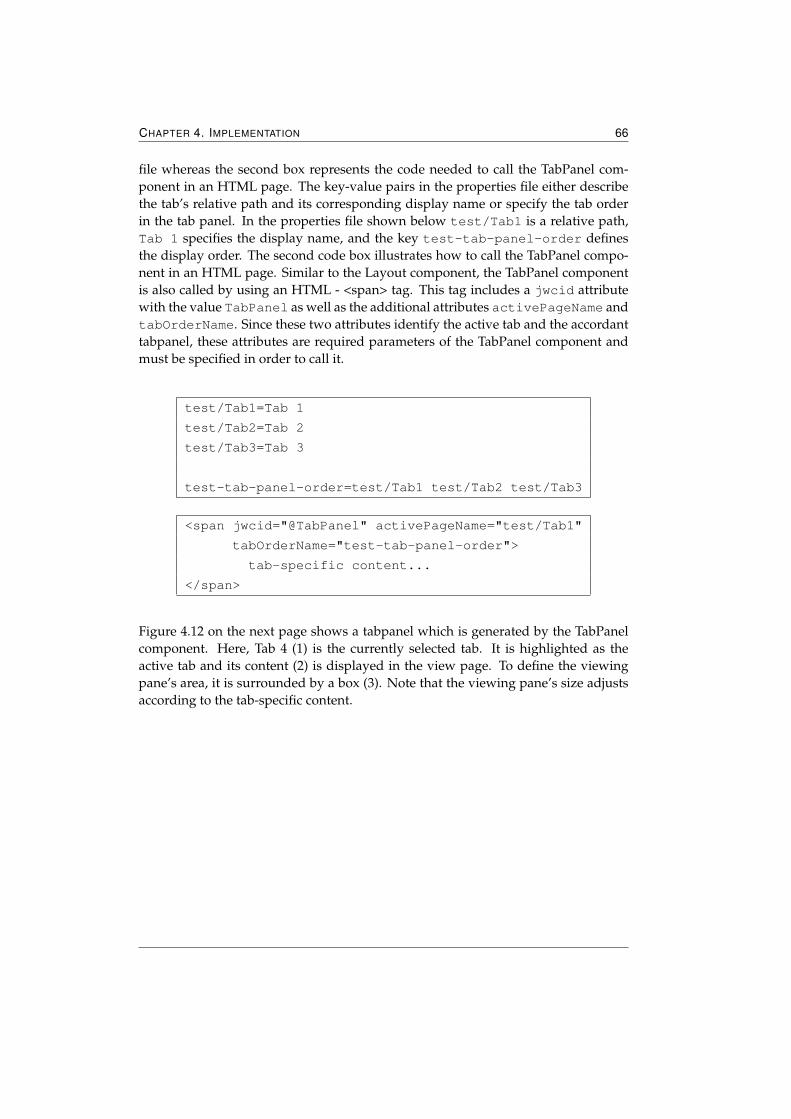
CHAPTER 4. IMPLEMENTATION 66
file whereas the second box represents the code needed to call the TabPanel com-ponent in an HTML page. The key-value pairs in the properties file either describethe tab’s relative path and its corresponding display name or specify the tab orderin the tab panel. In the properties file shown below test/Tab1 is a relative path,Tab 1 specifies the display name, and the key test-tab-panel-order definesthe display order. The second code box illustrates how to call the TabPanel compo-nent in an HTML page. Similar to the Layout component, the TabPanel componentis also called by using an HTML - <span> tag. This tag includes a jwcid attributewith the value TabPanel as well as the additional attributes activePageName andtabOrderName. Since these two attributes identify the active tab and the accordanttabpanel, these attributes are required parameters of the TabPanel component andmust be specified in order to call it.
test/Tab1=Tab 1
test/Tab2=Tab 2
test/Tab3=Tab 3
test-tab-panel-order=test/Tab1 test/Tab2 test/Tab3
<span jwcid="@TabPanel" activePageName="test/Tab1"
tabOrderName="test-tab-panel-order">
tab-specific content...
</span>
Figure 4.12 on the next page shows a tabpanel which is generated by the TabPanelcomponent. Here, Tab 4 (1) is the currently selected tab. It is highlighted as theactive tab and its content (2) is displayed in the view page. To define the viewingpane’s area, it is surrounded by a box (3). Note that the viewing pane’s size adjustsaccording to the tab-specific content.
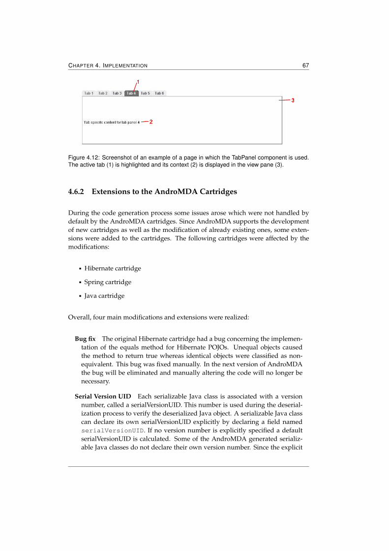
CHAPTER 4. IMPLEMENTATION 67
Figure 4.12: Screenshot of an example of a page in which the TabPanel component is used.The active tab (1) is highlighted and its context (2) is displayed in the view pane (3).
4.6.2 Extensions to the AndroMDA Cartridges
During the code generation process some issues arose which were not handled bydefault by the AndroMDA cartridges. Since AndroMDA supports the developmentof new cartridges as well as the modification of already existing ones, some exten-sions were added to the cartridges. The following cartridges were affected by themodifications:
� Hibernate cartridge
� Spring cartridge
� Java cartridge
Overall, four main modifications and extensions were realized:
Bug fix The original Hibernate cartridge had a bug concerning the implemen-tation of the equals method for Hibernate POJOs. Unequal objects causedthe method to return true whereas identical objects were classified as non-equivalent. This bug was fixed manually. In the next version of AndroMDAthe bug will be eliminated and manually altering the code will no longer benecessary.
Serial Version UID Each serializable Java class is associated with a versionnumber, called a serialVersionUID. This number is used during the deserial-ization process to verify the deserialized Java object. A serializable Java classcan declare its own serialVersionUID explicitly by declaring a field namedserialVersionUID. If no version number is explicitly specified a defaultserialVersionUID is calculated. Some of the AndroMDA generated serializ-able Java classes do not declare their own version number. Since the explicit
CHAPTER 4. IMPLEMENTATION 68
definition of serialVersionUIDs is highly recommended and the absence ofthe serialVersionUID field causes a warning in the MyEclipse IDE, a defaultserialVersionUID was added to each serializable Java class.
Value Objects implementing interfaces The generation of value objects capa-ble of implementing one or more interfaces was not supported by the originalJava cartridge. Since the design of the implementation demanded to specifyinterfaces which are implemented by value objects (see Figure 3.6 on page 43),the Java cartridge was extended for this function.
If a value object should realize an interface an additional link from the valueobject’s class to the corresponding interface must be modeled in the UML di-agram. During the code generation process, AndroMDA creates the originalJava class which represents the modeled value object for all value objects. Ifa value object also specifies interfaces to be implemented an additional Javaclass is created as well. This class inherits from the original value object classand specifies all modeled interfaces in its class declaration. Since these inter-faces must be implemented, all interfaces’s method declarations are generatedin the newly created value object class as well. This class is only generatedonce to ensure that the code which implements the interfaces is not lost.
Composite IDs The AndroMDA version 3.1 does not support the generationof composite IDs4. As it was necessary for the handling of protocol step pa-rameters to model primary keys which consist of more than one attribute, theHibernate and Spring cartridge were modified and extended to support com-posite IDs. This function was needed to realize many-to-many associationswhich include additional association-specific attributes. Since the Spring Car-tridge is responsible for the generation of DAO objects which implement basicCRUD operations (see Chapter 2.4.1.1 on page 29), the integration of compos-ite IDs also affected the Spring cartridge.
By using this extension, AndroMDA reacts differently to Entities with oneidentifier and Entities specifying at least two identifiers. The modeling ofcomposite IDs (see Figure 3.5 on page 42) causes the generation of an addi-tional Java class which represents and realizes the composite primary key.The Hibernate mapping file is also adapted to the different primary key typeas well as the Spring’s DAO class.
4Composite IDs describe primary keys of database entities which consist of at least two attributes ofthe entity.
Chapter 5
Discussion
This chapter discusses the implemented application by presenting results gainedfrom a usability test and by giving an outlook on further developments.
5.1 Usability Testing
Usability Testing is a method to measure how well people can use a software prod-uct for its intended purpose. Therefore, testers participate in a controlled experi-ment. While the testers try to solve certain tasks they are watched by observers whodocument the whole scenario including errors, difficulties, and misunderstandings.To detect relevant errors and areas of improvement it is important to design a real-istic and authentic situation. Since biased testers can influence the test results, it isessential to select testers who have never have used the system before.
To collect as much information and feedback as possible, the testers were encouragedto think aloud during the test. The thinking aloud method required that the users wereasked to describe
� What were they trying to do?
� Which things did they read?
� Which questions arose in their mind?
� Which things were confusing?
� What decisions did they make?
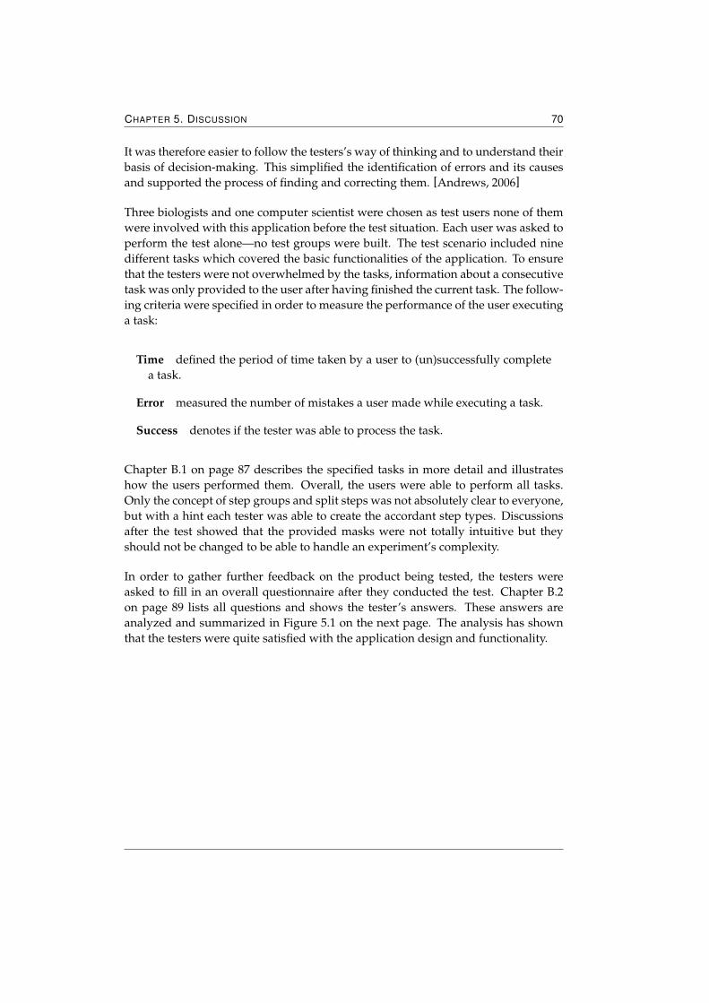
CHAPTER 5. DISCUSSION 70
It was therefore easier to follow the testers’s way of thinking and to understand theirbasis of decision-making. This simplified the identification of errors and its causesand supported the process of finding and correcting them. [Andrews, 2006]
Three biologists and one computer scientist were chosen as test users none of themwere involved with this application before the test situation. Each user was asked toperform the test alone—no test groups were built. The test scenario included ninedifferent tasks which covered the basic functionalities of the application. To ensurethat the testers were not overwhelmed by the tasks, information about a consecutivetask was only provided to the user after having finished the current task. The follow-ing criteria were specified in order to measure the performance of the user executinga task:
Time defined the period of time taken by a user to (un)successfully completea task.
Error measured the number of mistakes a user made while executing a task.
Success denotes if the tester was able to process the task.
Chapter B.1 on page 87 describes the specified tasks in more detail and illustrateshow the users performed them. Overall, the users were able to perform all tasks.Only the concept of step groups and split steps was not absolutely clear to everyone,but with a hint each tester was able to create the accordant step types. Discussionsafter the test showed that the provided masks were not totally intuitive but theyshould not be changed to be able to handle an experiment’s complexity.
In order to gather further feedback on the product being tested, the testers wereasked to fill in an overall questionnaire after they conducted the test. Chapter B.2on page 89 lists all questions and shows the tester’s answers. These answers areanalyzed and summarized in Figure 5.1 on the next page. The analysis has shownthat the testers were quite satisfied with the application design and functionality.
CHAPTER 5. DISCUSSION 71
Figure 5.1: Displayed is the analysis of the overall questionnaire answered by the user afterthe execution of the test. The aspects are rated from 1 to 5, where 1 is the best mark.
5.2 Further Development
This version of the Digital Lab Book covers the creation and management of exper-iments and their related steps. As shown in the usability test, this version is a goodstarting point for further developments which primarily include functions for dataacquisition and refinements of the methods provided for experiment design.
5.2.1 Acquisition Wizard
After the definition of an experiment, the user can perform it by following the speci-fied CWP. Therefore, an acquisition wizard should guide through an experiment byproviding methods to navigate through an experiment’s CWP. To do that, the wizardshould display one CWP step after another, starting from the first step of the CWP.To show the user which step of the CWP is currently displayed, the wizard shouldgive a general overview of the CWP step sequence and highlight the accordant CWPstep.
For each step all relevant information should be displayed in the wizard which in-cludes step name and step description. Furthermore, the wizard should provide ad-ditional information dependent on the step type of the currently shown CWP step.
CHAPTER 5. DISCUSSION 72
General steps do not need any further information, whereas the wizard must ensurethat split steps as well as step groups are presented differently to each other. Atthe beginning of a step group, the wizard should report this and in each underlyingstep the name of the step group should be displayed. Since split steps usually con-tain more than one step group which must be processed simultaneously, the wizardshould point out that the user must now choose which step group should be fol-lowed. Therefore, the splitting should be reported and to support further decisions,an overview of all containing step groups should be given.
Besides giving instructions on how to process a step, the wizard also provides thepossibility to attach and store additional information in terms of attaching notes ordocuments and in the form of defining parameter values. Therefore, masks handlingthe storage of notes, documents, and parameter values must be provided by thewizard. It is important that the mask managing parameter values considers defaultvalues. If a parameter has a default value, the mask should display this value andprovide an accordant function to store the default value as the actual value. If notesor documents were already stored to a step during its creation the wizard shouldgive an overview of all attached notes and documents such that the user can accessthem.
Steps which are not already processed should be editable by the wizard. To check ifa step is processed or not, the application must check if a step’s required parametervalues are already defined or not. If no data is stored, the step is not yet performedand thereby editable. The user can edit the step’s name, description, attach addi-tional parameters, and change a parameter’s necessity from optional to required.Once a step is performed, the step definition should no longer be modifiable to pre-vent complications which may occur.
To navigate through the CWP, the wizard should provide the following functions:
Next displays the next step in the CWP’s step sequence. If the next step is asplit step, the user must choose which of the split step’s step groups shouldbe processed first. To support this decision the wizard should provide anoverview of all underlying step groups. After reaching the end of one stepgroup, the system must check which step should be displayed next. If all stepgroups of a split step are performed the experiment merges to one experimentand the step defined after the split step will be displayed. If a split step con-tains further step groups which are not already processed it will not be pos-sible to merge the experiment but the user can start to execute another splitstep’s step group. To define which group is now processed again an overviewof all non-performed step groups should be displayed by the wizard.
CHAPTER 5. DISCUSSION 73
It is always possible to go to the next step—even if the currently displayedstep is not fully processed. This function is enabled to allow the user to get anoverview of the CWP. To distinguish between performed and non-performedsteps, the wizard checks if all required parameter values are specified. If astep whose previous step is not yet processed is displayed the user can notspecify any parameters or attach any notes and documents but the user canmodify the step. Only if a step’s predecessors are already performed, the userhas write access to all parameter values.
Back shows the previous step in the CWP’s step sequence. Since the first stephas no predecessor, this function is disabled at the beginning of the CWP.If the previous step is a Step Group or a Split Step, the wizard must reactdifferently. If the predecessor is a Step Group, the wizard should displaythe last step of the Step Group and should report that the shown step is partof a Step Group. Split Steps are more complex to display. Therefore, thewizard should declare that the previous step is a Split Step and should displayan overview of the Split Step’s Step Groups. If the user chooses one of theunderlying Step Groups, the last step of this group will be displayed.
Begin jumps to the first step of the CWP and displays its information.
End jumps to the last step of the CWP and displays its information.
Show last performed step It is possible to close the wizard before the last stepof the CWP is reached. To comfortably continue with an already started butinterrupted data acquisition, this function displays the last performed stepof the CWP. If this step is a part of a split step’s underlying step group, thesplit step will be displayed because multiple step groups could be processedsimultaneously.
5.2.2 Device Management
Every device which is used for data acquisition in the lab should be documentedby the application. Since devices can act as a data source for stored documents, itshould be possible for the user to define the document’s origin. Therefore, the appli-cation should provide a device management Tool which is capable of the followingfunctions:
Create new Devices The device management should provide a mask which isresponsible for the creation of a new device. With this, users with the appro-priate rights can specify the data which defines a device: device name anddevice description.
CHAPTER 5. DISCUSSION 74
Device Overview After the successful creation of a new device, an accordantoverview should be given. This overview shows all the relevant data andprovides possibilities to edit and delete the displayed device.
Edit Devices Users with an appropriate authorization should be able to edita device name and description. As mentioned above this function should beprovided by the device overview.
Delete Devices Generally, devices can be deleted unless the accordant deviceis already defined as a document data source. To prevent the loss of valuableinformation, the device management must check if a device can be deleted ornot before providing this function.
Add Document Documents—above all—user manuals can provide additionalinformation about a device. Therefore, the possibility to attach device-specificdocuments should be provided.
Define Parameters Some devices used in the lab require settings and param-eters to calibrate the device. Consequently, the storage of this informationin form of parameters should be provided by the device management. Sim-ilar to the parameter management which is implemented for the handling ofprotocol-specific parameters, the device management should provide func-tions to define optional and required parameters to devices.
Integration into the Acquisition Wizard While performing an experiment, theuser may define additional data in form of documents. The acquisition wiz-ard should then display a list in which all defined devices of a laboratory areshown. The user can thereby easily define the document’s data source.
5.2.3 Enumerations
Float, integer, and string parameters are the currently supported parameter types.To enlarge the possible parameter types, the next version of the application shouldbe able to handle user-defined enumerations. Therefore, the following modificationsshould be realized:
Create new Enumerations A mask which is responsible for the creation of allparameter-specific attributes (see Chapter 4.5.1 on page 61) and further man-ages the definition of possible enumeration values should be developed forthe next version.
CHAPTER 5. DISCUSSION 75
Provide an Overview To support the manipulation of already defined enu-meration types, an accordant overview should be provided. This overviewdisplays all parameter-relevant data and lists all specified enumeration val-ues. The system should support the manipulation of these enumeration val-ues and handle the definition of further enumeration values. Besides this, thefollowing functions should be handled:
� Edit Similar to the parameter overview, this overview should supportthe manipulation of an enumeration’s editable attributes.
� Delete If possible, the deletion of enumerations should be handled bythe application. An enumeration can only be deleted if no CWP step orstandard protocol step defined the accordant enumeration as its param-eter type.
Integration into the existent Parameter Management Enumeration types aredefined to enlarge the supported parameter types. Therefore, the parametermanagement must integrate this type into its masks. For instance the maskwhich is responsible for the definition of a new parameter to a protocol stepmust provide in its type drop-down list the possibility to choose an enumer-ation.
Appendix A
User Requirements Document
A.1 Abstract
SMILE: Digital Lab Book is a subunit of the software SMILE: Scientific Microscopy LabEnvironment. The Digital Lab Book deals with parts of the first two main topics inthe lab work:
� project definition
� data acquisition
Additionally it covers the management of standard protocols and devices. The otheraspects of SMILE will not be described in this document. In order to get further infor-mation about SMILE please read the user requirements document SMILE: scientificMicroscopy Lab Environment.
A.2 Basic units
A.2.1 Project
Projects are the main organizational unit in the Digital Lab Book. All laboratory ac-tivities have to be associated with a certain project. In order to characterize a projectthe following data is required:
CHAPTER A. USER REQUIREMENTS DOCUMENT 77
� project name
� short description of the strategy
� further project description
� definition of the expected goals
� creator
� submitter
� date of creation
� parent project
The Digital Lab Book provides the possibilities to create a new project, show theuser all his/her accessible projects in an overview, get detailed information about aspecific project, edit and delete an existing project and link to appendant subprojects.
New ProjectIn order to create a new project the user must specify the project name. Short descrip-tion, further project description and definition of the expected goals are optional.Creator, submitter and date of creation will be stored automatically.
Project OverviewOnce the user logged in an overview of all his/her accessible projects will be dis-played. The overview contains project name, corresponding short description andthe project’s date of creation. It is possible to display the overview sorted byproject name or by date of creation.
Project DetailsProject details can be reached via selecting the appropriate project. In addition toproject name, short description and date of creation, a detailed project descriptionand expected goals will be displayed. Due to the fact that groups can share projectsthe names of the creator and submitter are also shown. If there are already linkedsubprojects or created experiments the according overview is given.
Edit ProjectOngoing projects can be edited by users who have the correspondent authorization.Project name, short and detailed description and definition of the expected goals canbe changed. Whereas date of creation, creator and submitter are not editable.
Delete ProjectOnly the creator of a project or the administrator is able to delete an ongoing project.Other group members who have access to the project do not have the authorization.Projects with associated data can not be deleted at all.
CHAPTER A. USER REQUIREMENTS DOCUMENT 78
SubprojectA project can be divided into several subprojects. Therefore a project can act as acontainer for further projects. The user can attach a subproject by adding a newproject to an existing project. The same data as described above in section NewProject is required. Additionally the link to the parent project is stored automatically.
Attach additional InformationAdditional information can be stored via documents or notes. The possibility to up-load various documents is adumbrated but not implemented in this version. Notesare stored as project notes.
A.2.2 Experiment
Several experiments can be performed during a project. Therefore the Digital LabBook provides functions to add an experiment to a certain project, show all associ-ated experiments of a project, edit experiments and attach additional data to experi-ments. An experiment is characterized by the following data:
� experiment name
� experiment description
� question to be answered
� creator
� submitter
� date/time of creation
� parent experiment
New ExperimentExperiments are associated with a certain project. Thus a new experiment can onlybe created in an ongoing project. The experiment name is required whereas ex-periment description and experiment question are optional. Creator, submitter anddate/time of creation will be stored automatically.
Experiment OverviewAs mentioned in section Project Details an overview of all related experiments to aproject is given in the project details. Only the experiment name will be shown.
CHAPTER A. USER REQUIREMENTS DOCUMENT 79
Experiment DetailsFor further information about an experiment the Digital Lab Book provides a de-tailed view of all experiment related data. Additionally to the experiment name, ex-periment description, experiment question, date/time of creation, creator and sub-mitter are displayed. If the experiment contains further subexperiments a shortoverview of the subexperiments is also given.
Edit ExperimentIt is possible to edit experiment name, description and question. The relation to aproject as well as date/time of creation is fixed and can not be changed.
Experiment NoteAdditional information to experiments can be stored by attaching experiment notesto an experiment.
SubexperimentAfter some working steps, most experiments split up into several subexperiments.After some steps which are processed separately, the subexperiments can be mergedinto the original experiment. Therefore an experiment can act as a container for fur-ther experiments. Experiment name and an optional short description of the subex-periment are required. Due to the fact that an experiment can be split up and re-united several times, the order of separation is stored automatically.
A.2.3 Current Working Protocol (CWP)
After defining the initial experiment data users perform an experiment by followinga sequence of working steps (also called current working protocol). In general thework follows one or more well established standard working protocols which mustbe defined by the standard protocol management.
Current Working Protocol StepThe CWP is a sequence of so-called CWP steps. A CWP step describes a single stepin the experiment. It is characterized by:
� step name
� step description
� creator
� date/time of creation
� step parent, to trace the step evolution
CHAPTER A. USER REQUIREMENTS DOCUMENT 80
Additional (required or optional) CWP step parameters can further specify a CWPstep.
Current Working Protocol Step ParameterA CWP parameter contains the following data:
� parameter name
� parameter description
� necessity
� default value
� parameter value
� parameter type for type checking
� parameter type for differentiation between input and output parameter
Splitting StepA splitting step in the CWP signals the dividing of an experiment into two subex-periments. The subexperiments can now be performed separately.
Merge StepAfter some different working steps both subexperiments can follow again the samestandard protocol. To enhance generalization the merging of two subexperiments ispossible.
Final StepEvery experiment ends with a final step. It consists of a short textual descriptionof the results and improvements for future experiments. The entered information isstored as an experiment note.
Load Standard ProtocolBefore performing an experiment a CWP must be defined. For each experiment onlyone CWP is stored. To declare more than one CWP is not viable. One option to de-clare a CWP is via loading one or more standard protocols into the experiment. Withthe Digital Lab Book users can create the CWP out of all their accessible standardprotocols.
Create a new CWPAnother possibility to declare a CWP is to create a new CWP manually. For that rea-son the user must specify the required data protocol name and description. Creator,date/time of creation and version is generated by the software.
CHAPTER A. USER REQUIREMENTS DOCUMENT 81
Add CWP StepFor flexibility and reusability standard protocols can be modified. One possibility isto add (or insert) an additional step into the step sequence. Therefore the user canadd CWP steps while conducting an experiment. In order to insert a new step thename and description is required. Creator and date/time of definition is insertedautomatically. Related parameters can be declared via creating new parameters orusing already existing parameters which are provided by the standard protocol man-agement. Furthermore the user has to specify where the step should be inserted. Tofacilitate this task the step sequence is displayed and the user can easily define wherethe step should be inserted.
Edit CWP StepSeveral CWP steps can be edited manually. CWP step data can be changed whiledefining the CWP or during processing an experiment in the acquisition wizard. Inthis version the altering of parameter settings of an CWP step is not provided.
Delete CWP StepSingle CWP steps can be deleted from the CWP. Therefore the user can select theaccordant CWP steps from a list. The list will be rearranged automatically.
Copy a CWPThe possibility to copy a CWP directly into another experiment should be possible.The user can chose which CWP related data is copied as well:
� copy CWP with all related notes
� copy CWP with all filled in input parameters
� copy CWP with all related files
Since only one CWP can be stored to an experiment a warning will be displayed if aCWP should be copied to an experiment with an existing CWP. The user can decidewhether the previous CWP should be replaced or not.
Convert CWP into a Standard ProtocolIn order to enhance reusability a CWP can also be converted into a standard protocol.The user with the accordant authorization can define a CWP as a standard protocol.
CWP OverviewFor user support the Digital Lab Book provides an overview of the CWP. Com-mon CWP steps are displayed sequentially whereas splitting and merging steps arepointed out. CWP steps of following subexperiments are also shown. Additionallyusers can export the given overview with all related CWP notes and parameters intoa pdf document.
CHAPTER A. USER REQUIREMENTS DOCUMENT 82
Attach additional InformationAdditional information to CWP or CWP steps can be acquired via notes or docu-ments. The possibility to upload documents is adumbrated but not implemented inthis version.
A.2.4 Acquisition Wizard
To process an experiment the CWP—as mentioned above—has to be followed. Inorder to facilitate the process the Digital Lab Book provides an acquisition wizardwhich guides through the CWP. The user has the possibility to navigate through theCWP.
Show CWP StepFor each CWP step the wizard displays step name, short description and all requiredand optional parameters. The wizard shows all given parameter values. If there arealready attached documents an overview will be given.
Show last performed StepThe wizard offers the possibility to go to the last performed step to continue alreadystarted but interrupted data acquisition.
Begin ProcessOnce the user starts or continues an experiment the acquisition wizard will be dis-played. If there are already performed steps the wizard will automatically go to thelast performed step. Otherwise the first CWP step will be shown.
Navigation—NextTo get a certain overview the user has always the possibility to go to the next CWPstep. If the previous step is not finished the user will have read-only access to thenext CWP steps. In order to finish a step and get write access to the following CWPstep all values of the required parameters of the current step must be specified. Theuser can either insert the default value via the wizard or define the value manually.Before finishing the step all given parameter values are type checked.
Splitting and merging steps are treated differently. If a splitting point is reached onemust either follow the one or the other sub experiment. The splitting is reported bythe wizard and as decision support an overview of both sub experiments is given.In case of merging two sub experiments both experiments must be finished in orderto continue the joint CWP. After finishing a sub experiment the other has to be pro-cessed. It is impossible to skip the second experiment if subexperiments are mergedagain.
CHAPTER A. USER REQUIREMENTS DOCUMENT 83
Navigation—BackIt is always possible to go to the previous step. The appropriate data will be shownby the wizard.
Navigation—BeginVia begin the user can go to the beginning of the CWP.
Navigation—EndVia end the last step of the CWP is displayed.
Attach InformationVia input and output parameters one can store important information about a CWPstep. Additionally the user can attach further notes to each CWP step. Both—parameters and notes—are inserted via the acquisition wizard. The possibility toattach several result files is shown but not implemented in this version.
A.2.5 Notes
Via notes the user can store further information and observations. At several stagesthe Digital Lab Book offers the possibility to attach notes. A note is generally spec-ified by the note name and the note content. The software stores automatically thecreator of each note.
A.3 Management Tools
A.3.1 Standard Protocol Management
To preform an experiment a CWP must be defined. One way to accomplish thatis via loading one or more standard protocols into the experiment. Users with theaccordant authorization can create new standard protocols as well as modify anddelete them.
Standard ProtocolA standard protocol represents a well established sequence of working steps. Thatis why a standard protocol can contain several standard protocol steps. For furtherdescription of the standard protocol the following data are also stored:
� protocol name
� protocol description
CHAPTER A. USER REQUIREMENTS DOCUMENT 84
� creator
� time of creation
Standard Protocol StepAs mentioned above the content of a standard protocol consists of a sequence ofstandard protocol steps which represent a single step in an experiment. Standardprotocol steps are characterized by the given data:
� step name
� step description
� creator
� date/time of creation
� step parent, to trace the step evolution
For the purpose of gathering further information about a step, parameters which areacquired during the experiment are stored as well.
Standard Protocol Step ParametersParameters further specify a protocol step and are described by the following data:
� parameter name
� parameter description
� parameter default value
� necessity
� parameter type
In this version integer, string, float and predefined enumeration parameters are sup-ported. For succeeding versions the implementation of user-defined enumerationtypes is intended.
New Standard ProtocolUsers who have the accordant authorization can create new standard protocols. Forthis purpose all required data and a sequence of standard protocol Steps must bedefined. Protocol name and description must be defined by the user while creator,date/time of creation and version are handled automatically. The user can eithercreate new or load existing standard protocol steps.

CHAPTER A. USER REQUIREMENTS DOCUMENT 85
New Standard Protocol StepIn case of creating a new protocol step, most data described above has to be declaredby the user. Whereas creator and date/time of creation are stored automatically.Each way—adding existing parameters and creating new ones—is covered by theDigital Lab Book.
New Standard Protocol Step ParameterIn order to specify a new parameter all parameter related data—except the parame-ter’s default value—must be given by the user. Concerning the parameter typeone can choose between integer, float, string and pre-defined enumeration types.
Delete Standard ProtocolOnly not used standard protocols can be deleted by the authorized users. Protocolswhich are already declared as working protocols in an experiment can not be deletedat all.
Edit Standard ProtocolFor the purpose of modifying/improve standard protocols the Digital Lab Book pro-vides the function to edit a standard protocol. The user can edit the protocol nameand description without interrupting with the system. In case of altering the stepsequence, problems with the system could occur. If the current standard protocol isalready used as a CWP the acquisition wizard will need the original standard pro-tocol. To overcome this problem the standard protocol is copied and a new versionnumber is stored automatically. Now the user can edit the standard protocol withoutinterrupting the existing system.
A.3.2 Device Management
Devices for data acquisition are used during an experiment. With the intention ofstoring acquired data the user must be able to select the providing device from alist. In order to administrate all devices the Digital Lab Book offers a device manage-ment tool. Users with an accordant authorization are able to add, delete and modifydevices.
Add DeviceA device is characterized by a device name and a description. Both have to be de-clared by the user. The option to include additional documents like manuals is ad-umbrated but not implemented. Similar to the standard protocol management, thedevice management offers the possibility to add required and optional parametersto a device. The user can either reuse already defined device parameters or createnew ones.
CHAPTER A. USER REQUIREMENTS DOCUMENT 86
New Device ParameterMandatory and optional parameters are described by their name, description, ne-cessity and their default value. All data must be defined in order to create a newparameter.
Delete DeviceA device can only be deleted if no data is related to the device.
Edit DeviceAll data of a device can be modified without limitation if no related data exists.In the case of already stored data only the device description can be altered andsupplementary documents can be added.
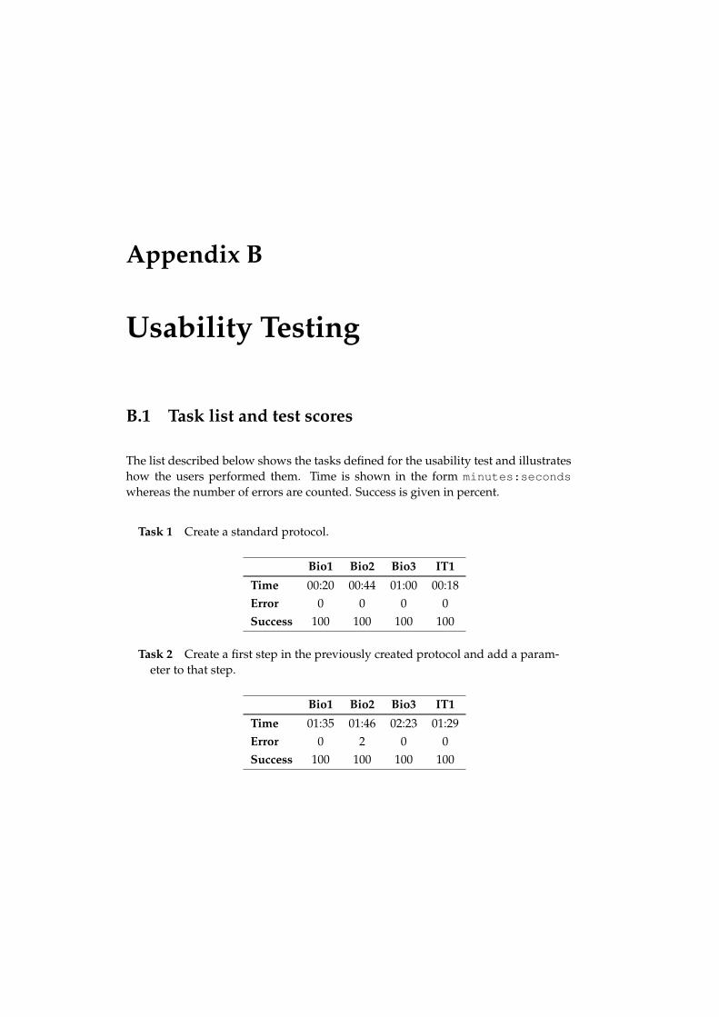
Appendix B
Usability Testing
B.1 Task list and test scores
The list described below shows the tasks defined for the usability test and illustrateshow the users performed them. Time is shown in the form minutes:secondswhereas the number of errors are counted. Success is given in percent.
Task 1 Create a standard protocol.
Bio1 Bio2 Bio3 IT1
Time 00:20 00:44 01:00 00:18Error 0 0 0 0Success 100 100 100 100
Task 2 Create a first step in the previously created protocol and add a param-eter to that step.
Bio1 Bio2 Bio3 IT1
Time 01:35 01:46 02:23 01:29Error 0 2 0 0Success 100 100 100 100
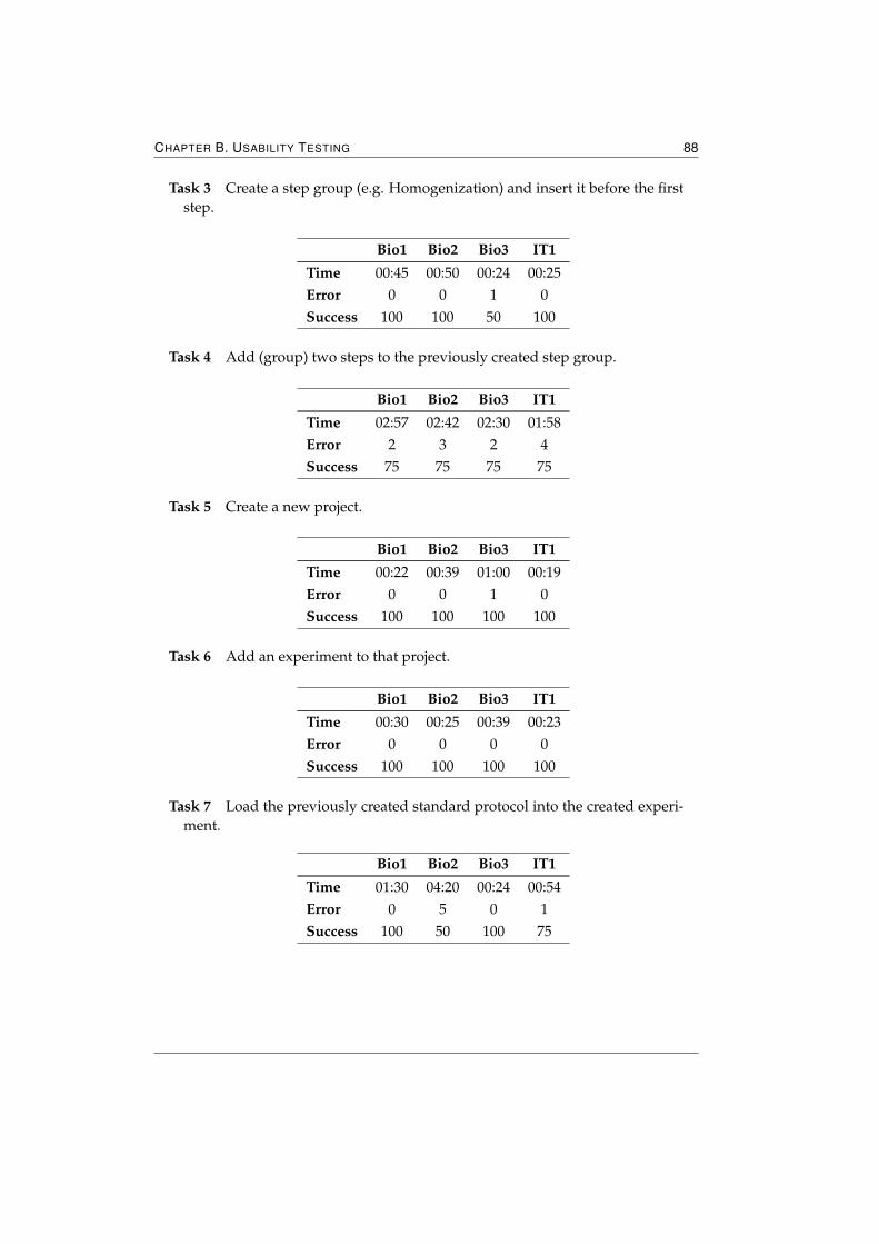
CHAPTER B. USABILITY TESTING 88
Task 3 Create a step group (e.g. Homogenization) and insert it before the firststep.
Bio1 Bio2 Bio3 IT1
Time 00:45 00:50 00:24 00:25Error 0 0 1 0Success 100 100 50 100
Task 4 Add (group) two steps to the previously created step group.
Bio1 Bio2 Bio3 IT1
Time 02:57 02:42 02:30 01:58Error 2 3 2 4Success 75 75 75 75
Task 5 Create a new project.
Bio1 Bio2 Bio3 IT1
Time 00:22 00:39 01:00 00:19Error 0 0 1 0Success 100 100 100 100
Task 6 Add an experiment to that project.
Bio1 Bio2 Bio3 IT1
Time 00:30 00:25 00:39 00:23Error 0 0 0 0Success 100 100 100 100
Task 7 Load the previously created standard protocol into the created experi-ment.
Bio1 Bio2 Bio3 IT1
Time 01:30 04:20 00:24 00:54Error 0 5 0 1Success 100 50 100 75
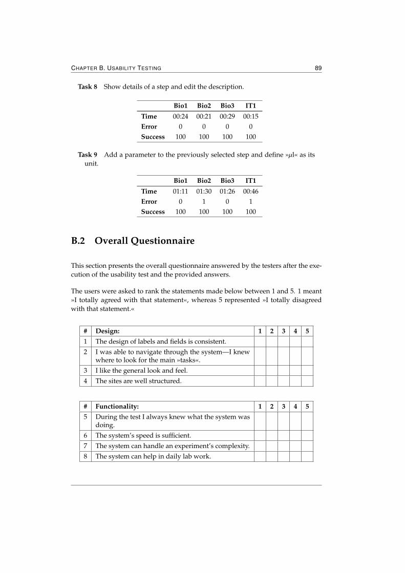
CHAPTER B. USABILITY TESTING 89
Task 8 Show details of a step and edit the description.
Bio1 Bio2 Bio3 IT1
Time 00:24 00:21 00:29 00:15Error 0 0 0 0Success 100 100 100 100
Task 9 Add a parameter to the previously selected step and define »µl« as itsunit.
Bio1 Bio2 Bio3 IT1
Time 01:11 01:30 01:26 00:46Error 0 1 0 1Success 100 100 100 100
B.2 Overall Questionnaire
This section presents the overall questionnaire answered by the testers after the exe-cution of the usability test and the provided answers.
The users were asked to rank the statements made below between 1 and 5. 1 meant»I totally agreed with that statement«, whereas 5 represented »I totally disagreedwith that statement.«
# Design: 1 2 3 4 51 The design of labels and fields is consistent.
2 I was able to navigate through the system—I knewwhere to look for the main »tasks«.
3 I like the general look and feel.
4 The sites are well structured.
# Functionality: 1 2 3 4 55 During the test I always knew what the system was
doing.
6 The system’s speed is sufficient.
7 The system can handle an experiment’s complexity.
8 The system can help in daily lab work.
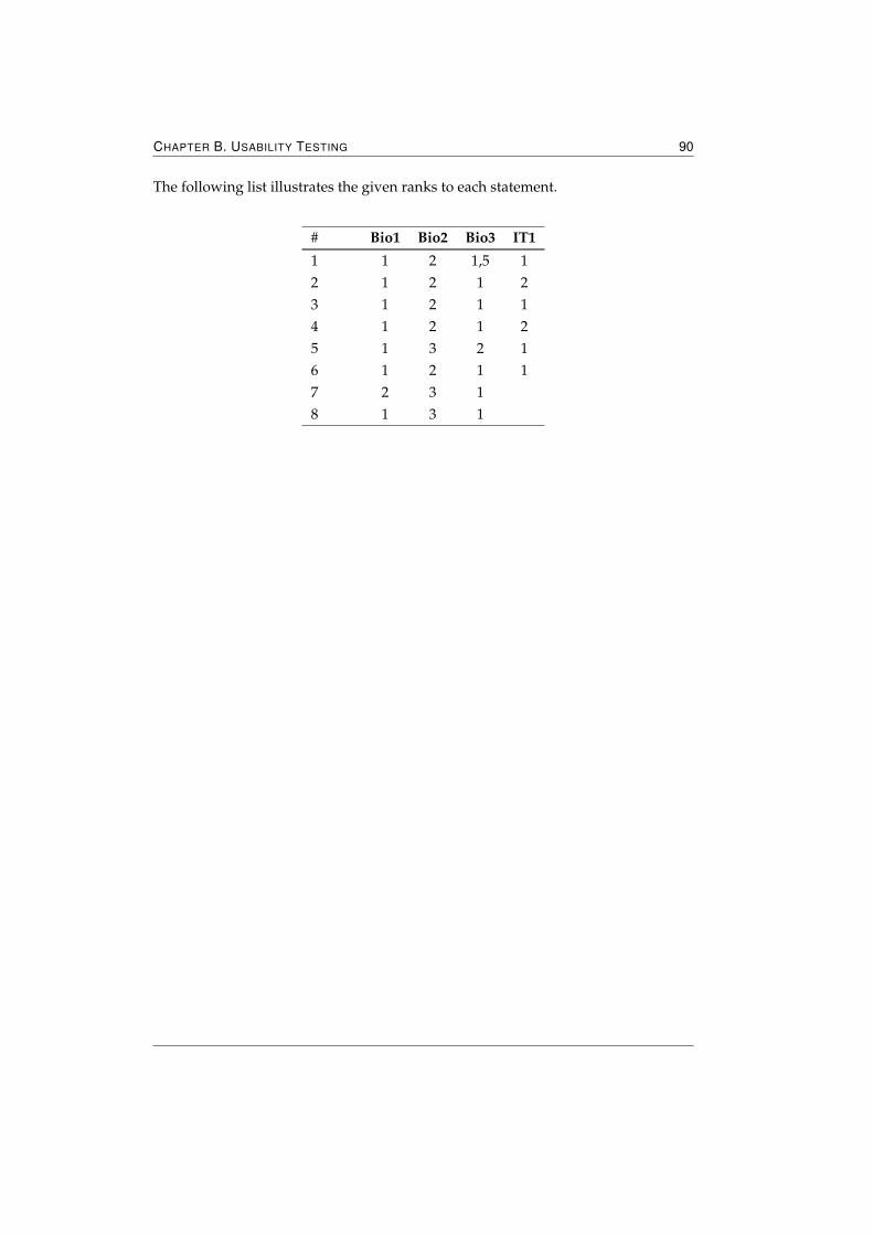
CHAPTER B. USABILITY TESTING 90
The following list illustrates the given ranks to each statement.
# Bio1 Bio2 Bio3 IT1
1 1 2 1,5 12 1 2 1 23 1 2 1 14 1 2 1 25 1 3 2 16 1 2 1 17 2 3 18 1 3 1
Figures
2.1 Illustration of a J2EE multi-tiered application . . . . . . . . . . . . . . . 102.2 Illustration of the Spring module structure . . . . . . . . . . . . . . . . 17
3.1 Workflow—experiment design . . . . . . . . . . . . . . . . . . . . . . . 383.2 Workflow—standard protocol . . . . . . . . . . . . . . . . . . . . . . . 393.3 Entity Diagram—experiment design . . . . . . . . . . . . . . . . . . . 403.4 Entity Diagram—Standard Protocol . . . . . . . . . . . . . . . . . . . . 413.5 Entity Diagram—Protocol Step Parameter . . . . . . . . . . . . . . . . 423.6 Value Object Diagram—example . . . . . . . . . . . . . . . . . . . . . 433.7 Service Diagram—example . . . . . . . . . . . . . . . . . . . . . . . . 44
4.1 Screenshot—Project Overview . . . . . . . . . . . . . . . . . . . . . . 484.2 Screenshot—Subprojects . . . . . . . . . . . . . . . . . . . . . . . . . 494.3 Screenshot—Experiments . . . . . . . . . . . . . . . . . . . . . . . . . 514.4 Screenshot—Experiment Overview . . . . . . . . . . . . . . . . . . . . 524.5 Screenshot—New CWP Step . . . . . . . . . . . . . . . . . . . . . . . 534.6 Screenshot—CWP step sequence . . . . . . . . . . . . . . . . . . . . 564.7 Screenshot—CWP step sequence after deletion of a CWP step . . . . 574.8 Screenshot—CWP Step Overview . . . . . . . . . . . . . . . . . . . . 584.9 Screenshot—Standard Protocol Overview . . . . . . . . . . . . . . . . 604.10 Screenshot—New Parameter . . . . . . . . . . . . . . . . . . . . . . . 624.11 Screenshot—Layout Component . . . . . . . . . . . . . . . . . . . . . 654.12 Screenshot—TabPanel Component . . . . . . . . . . . . . . . . . . . . 67
5.1 Usability Testing—Analysis of overall questionnaire . . . . . . . . . . . 71
Bibliography
[Alex, 2006] Ben Alex. Acegi Security, Reference Documentation, 2006. Accessible through theWeb at »http://acegisecurity.org/docbook/acegi.pdf«.
[Andrews, 2006] Keith Andrews. Human-Computer Interaction, March 2006. Accessiblethrough the Web at »http://www.eclipse.org/« (last visited on August 20, 2006).
[AndroMDA, 2005a] AndroMDA. A Bird’s Eye view of AndroMDA, November 2005. Ac-cessible through the Web at »http://galaxy.andromda.org/docs-3.1/contrib/birds-eye-view.html« (last visited on July 16, 2006).
[AndroMDA, 2005b] AndroMDA. AndroMDA Cartridges, November 2005. Ac-cessible through the Web at »http://galaxy.andromda.org/docs-3.1/andromda-cartridges/index.html« (last visited on July 17, 2006).
[AndroMDA, 2005c] AndroMDA. AndroMDA Hibernate Cartridge Profile, November2005. Accessible through the Web at »http://galaxy.andromda.org/docs-3.1/andromda-hibernate-cartridge/profile.html« (last visited on July 16, 2006).
[AndroMDA, 2005d] AndroMDA. Declarative Security with Acegi, November 2005.Accessible through the Web at »http://galaxy.andromda.org/docs-3.1/andromda-spring-cartridge/howto8.html« (last visited on July 17, 2006).
[AndroMDA, 2005e] AndroMDA. What is AndroMDA?, November 2005. Accessible throughthe Web at »http://galaxy.andromda.org/docs-3.1/whatisit.html« (last visit-ed on July 15, 2006).
[Bauer and King, 2004] Christian Bauer and Gavin King. Hibernate in Action. In Action Series.Manning Publications Co., August 2004. ISBN 1-9323-9415-X.
[Bodoff et al., 2005] Stephanie Bodoff, Eric Armstrong, Jennifer Ball, Debbie Bode Carson, IanEvans, Dale Green, Kim Haase, and Eric Jendrock. The J2EE(TM) 1.4 Tutorial, Decem-ber 2005. Accessible through the Web at »http://java.sun.com/j2ee/1.4/docs/tutorial/doc/J2EETutorial.pdf« (last visited on May 24, 2006).
[Gamma et al., 1994] Erich Gamma, Richard Helm, Ralph Johnson, and John Vlissides. DesignPatterns: Elements of Reusable Object-Oriented Software. Addison-Wesley, October 1994. ISBN0-201-63361-2.
[Genuitec, 2006] Genuitec. About MyEclipse, 2006. Accessible through the Web at »http://www.eclipse.org/« (last visited on July 20, 2006).
[Hardwick, 2006] David Hardwick. Introduction to Acegi, Mastering the security framework,February 2006. Accessible through the Web at »http://java.sys-con.com/read/171482_1.htm« (last visited on July 13, 2006).
BIBLIOGRAPHY 93
[Hibernate, 2006] Hibernate. Hibernate Reference Documentation, 2006. Accessiblethrough the Web at »http://www.hibernate.org/hib_docs/v3/reference/en/pdf/hibernate_reference.pdf« (last visited on June 27, 2006).
[Johnson et al., 2006] Rod Johnson, Juergen Hoeller, Alef Arendsen, Colin Sampaleanu, RobHarrop, Thomas Risberg, Darren Davison, Dmitriy Kopylenko, Mark Pollack, Thierry Tem-plier, and Erwin Vervaet. Spring - Java/J2EE Application Framework, Reference Documenta-tion, 2006. Accessible through the Web at »http://static.springframework.org/spring/docs/1.2.x/spring-reference.pdf« (last visited on July 1, 2006).
[Johnson and Hoeller, 2004] Rod Johnson and Juerger Hoeller. Expert One-on-One J2EE Devel-opment without EJB. Wiley, John & Sons, Incorporated, June 2004. ISBN 0-7645-5831-5.
[Johnson, 2002] Rod Johnson. Expert One-on-One J2EE Design and Development. Wiley, John &Sons, Incorporated, October 2002. ISBN 0-7645-4385-7.
[Johnson, 2005] Rod Johnson. Introduction to the Spring Framework, May 2005. Accessiblethrough the Web at »http://www.theserverside.com/tt/articles/article.tss?l=SpringFramework« (last visited on July 1, 2006).
[Kiczales et al., 1997] Gregor Kiczales, John Lamping, Anurag Mendhekar, Chris Maeda,Cristina Videira Lopes, Jean-Marc Loingtier, and John Irwin. Aspect-Oriented Programming,June 1997. Accessible through the Web at »http://www.parc.com/research/csl/projects/aspectj/downloads/ECOOP1997-AOP.pdf«.
[Lewis Ship, 2004] Howard M. Lewis Ship. Tapestry in Action. In Action Series. ManningPublications Co., March 2004. ISBN 1-932394-11-7.
[Marinescu, 2002] Floyd Marinescu. EJB Design Patterns. Advanced Patterns, Pro-cesses, and Idioms. Wiley, John & Sons, Incorporated, April 2002. Accessi-ble through the Web at »http://www.theserverside.com/tt/books/wiley/EJBDesignPatterns/index.tss«. ISBN 0-471-20831-0.
[Maven, 2006a] Maven. Welcome to Maven, 2006. Accessible through the Web at »http://maven.apache.org/« (last visited on July 18, 2006).
[Maven, 2006b] Maven. What is Maven?, 2006. Accessible through the Web at »http://maven.apache.org/what-is-maven.html« (last visited on July 18, 2006).
[Miller and Mukerji, 2003] Joaquin Miller and Jishnu Mukerji. MDA Guide Version 1.0.1, June2003. Accessible through the Web at »http://www.omg.org/docs/omg/03-06-01.pdf« (last visited on May 17, 2006).
[No Magic Inc., 2006] No Magic Inc. Introducing MagicDraw, 2006. Accessible through theWeb at »http://www.magicdraw.com« (last visited on July 19, 2006).
[OMG, 2002] ObjectManagement Group OMG. OMG Model Driven Architecture, March 2002.Accessible through the Web at »http://www.omg.org/mda/« (last visited on May 17,2006).
[OMG, 2006a] ObjectManagement Group OMG. An Overview to the XMI - XML Metadata In-terchange Specification, January 2006. Accessible through the Web at »http://www.omg.org/news/pr99/xmi_overview.html« (last visited on May 17, 2006).
[OMG, 2006b] ObjectManagement Group OMG. Introduction to OMG’s Unified ModelingLanguage(TM), May 2006. Accessible through the Web at »http://www.omg.org/gettingstarted/what_is_uml.htm« (last visited on May 16, 2006).
[OMG, 2006c] ObjectManagement Group OMG. The Object Management Group (OMG), May2006. Accessible through the Web at »http://www.omg.org/« (last visited on May 18,2006).
BIBLIOGRAPHY 94
[Porter, 2006] Matthew Porter. Securing Your Java Applications - Acegi Security Style,2006. Accessible through the Web at »http://www.javalobby.org/articles/acegisecurity/part1.jsp« (last visited on July 13, 2006).
[Singh et al., 2002] Inderjeet Singh, Beth Stearns, Mark Johnson, and the Enterprise Team.Designing Enterprise Applications with the J2EE Platform, Second Edition. The Java Series.Addison-Wesley, March 2002. Accessible through the Web at »http://java.sun.com/blueprints/guidelines/designing_enterprise_applications_2e/«. ISBN0-201-78790-3.
[Tong, 2005] Ka Iok Tong. Enjoying Web Development with Tapestry. TipTec Development, 2nd E-dition, 2005. ISBN 1-4116-4913-3.
[Velocity, 2005a] Velocity. Velocity Overview, 2005. Accessible through the Web at »http://jakarta.apache.org/velocity/overview.html« (last visited on July 18, 2006).
[Velocity, 2005b] Velocity. What is Velocity?, 2005. Accessible through the Web at »http://jakarta.apache.org/velocity/index.html« (last visited on July 18, 2006).
[Zeller, 2003] Dieter Zeller. Design and development of a user management system for molecularbiology database systems, October 2003.