Embed Size (px)
Citation preview

The Half-Edge Data Structure
Computational Geometry, WS 2006/07Lecture 9, Part I
Prof. Dr. Thomas OttmannKhaireel A. Mohamed
Algorithmen & Datenstrukturen, Institut für InformatikFakultät für Angewandte WissenschaftenAlbert-Ludwigs-Universität Freiburg

Computational Geometry, WS 2006/07Prof. Dr. Thomas Ottmann 2
Overview
• Planar subdivision representation• Adjacency relationships and queries• Boundary representation structure• Baumgart’s winged-edge data structure• Doubly-connected-edge-list (DCEL)• Overlaying planar subdivisions• Analyses

Computational Geometry, WS 2006/07Prof. Dr. Thomas Ottmann 3
Representing a Polygon Mesh
• We require a convenient and efficient way to represent a planar subdivision.
• Components in the planar subdivision:– A list of vertices
– A list of edges
– A list of faces storing pointers for its vertices
• Must preserve adjacency relationships between components.

Computational Geometry, WS 2006/07Prof. Dr. Thomas Ottmann 4
Possible Adjacency Queries
Point anywhere on the polygon mesh and ask:• Which faces use this vertex?• Which edges use this vertex?• Which faces border this edge?• Which edges border this face?• Which faces are adjacent to this face?
Planar subdivisionEuler’s formular: v – e + f = 2

Computational Geometry, WS 2006/07Prof. Dr. Thomas Ottmann 5
Boundary Representation Structures
• To represent such queries efficiently, we use the boundary representation (B-rep) structure.
• B-rep explicitly model the edges, vertices, and faces of the planar subdivision PLUS additional adjacency information stored inside.
• Two most common examples of B-rep:– Baumgart’s winged-edge data structure
– Doubly-connect-edge-list (DCEL)

Computational Geometry, WS 2006/07Prof. Dr. Thomas Ottmann 6
Baumgart’s Winged-Edge DS
• The Edge DS is augmented with pointers to:– the two vertices it touches (v1, v2),
– the two faces it borders (f1, f2), and
– pointers to four of the edges which emanate from each end point (e_v1[4], v2[4]).
• We can determine which faces or vertices border a given edge in constant time.
• Other types of queries can require more expensive processing.
e
v1
v2
f2
f1
e_v1[4]
e_v2[4]

Computational Geometry, WS 2006/07Prof. Dr. Thomas Ottmann 7
The Doubly-Connected-Edge-List (DCEL)
• DCEL is a directed half-edge B-rep data structure.
• Allows all adjacency queries in constant time (per piece of information gathered). That is, for example;– When querying all edges adjacent to a vertex, the operation will be
linear in the number of edges adjacent to the vertex, but constant time per edge.
• The DCEL is excellent in representing manifold surfaces:– Every edge is bordered by exactly two faces.
– Cross junctions and internal polygons are not allowed.

Computational Geometry, WS 2006/07Prof. Dr. Thomas Ottmann 8
DCEL Component – Half-edge
• The half-edges in the DCEL that border a face form a circular linked-list around its perimeter (anti-clockwise); i.e. each half-edge in the loop stores a pointer to the face it borders (incident).
• Each half-edge is directed and can be described in C as follows:
struct HE_edge { HE_vert *v_orig; HE_edge *e_twin; HE_face *f; HE_edge *e_next; HE_edge *e_prev;}; HE_edge
f e_next
e_prev
v_orig e_twin

Computational Geometry, WS 2006/07Prof. Dr. Thomas Ottmann 9
DCEL Component - Vertex
• Vertices in the DCEL stores:– their actual point location, and
– a pointer to exactly ONE of the HE_edge, which uses the vertex as its origin.
• There may be several HE_edge whose origins start at the same vertex. We need only one, and it does not matter which one.
struct HE_vert { Gdiplus::PointF p; HE_edge *edge;};
HE_vert
edge
p=(x,y)

Computational Geometry, WS 2006/07Prof. Dr. Thomas Ottmann 10
• The “bare-bones” version of the face component needs only to store a single pointer to one of the half-edges it borders.
• In the implementation by de Berg et al. (2000), edge is the pointer to the circular loop of the OuterComponent (or the outer-most boundary) of the incident face.
• For the unbounded face, this pointer is NULL.
DCEL Component – Face I
struct HE_face_barebone { HE_edge *edge;};
HE_face_barebone
edge
Computational Geometry, WS 2006/07Prof. Dr. Thomas Ottmann 11
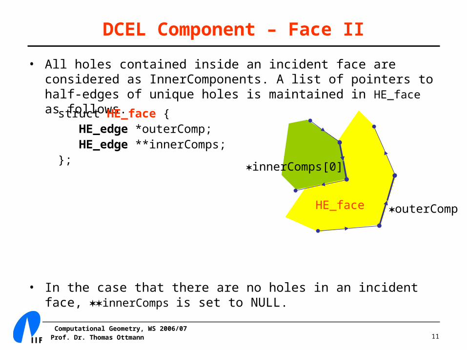
• All holes contained inside an incident face are considered as InnerComponents. A list of pointers to half-edges of unique holes is maintained in HE_face as follows.
• In the case that there are no holes in an incident face, innerComps is set to NULL.
DCEL Component – Face II
struct HE_face { HE_edge *outerComp; HE_edge **innerComps;};
HE_face outerComp
innerComps[0]
Computational Geometry, WS 2006/07Prof. Dr. Thomas Ottmann 12
Adjacency Queries
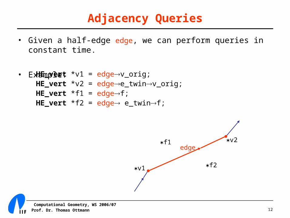
• Given a half-edge edge, we can perform queries in constant time.
• Example:HE_vert *v1 = edgev_orig;HE_vert *v2 = edgee_twinv_orig;HE_vert *f1 = edgef;HE_vert *f2 = edge e_twinf;
edgef1 v2
v1 f2

Computational Geometry, WS 2006/07Prof. Dr. Thomas Ottmann 13
DCEL Example
Examplevertex v1 = { (1, 2), h_edge(12) }
face f1 = {h_edge(15), [h_edge(67)] }
h_edge(54) = { v5, h_edge(45), f1, h_edge(43), h_edge(15) }
HE_vert v1;v1p = new Point(1,2);v1egde = e_12;
HE_face f1;f1outerComp = e_15;f1innerComp[0] = e_67;
HE_edge e_54;e_54v_orig = v5;e_54e_twin = e_45;e_54f = f1;e_54e_next = e_43; e_54e_prev = e_15;
In terms of the structure definitions:

Computational Geometry, WS 2006/07Prof. Dr. Thomas Ottmann 14
Iterated Adjacency Queries
• Iterating over the half-edges adjacent to a given face.
• Iterating over the half-edges that are adjacent to a given vertex.
HE_edge *edge = faceouterComp;do { // Do something with edge. edge = edgenext;} while (edge != faceouterComp);
HE_edge *edge = vertexedge;do { // Do something with edge, edgee_twin, etc. edge = edgee_twinnext;} while (edge != vertexedge);
Computational Geometry, WS 2006/07Prof. Dr. Thomas Ottmann 15
Face Records
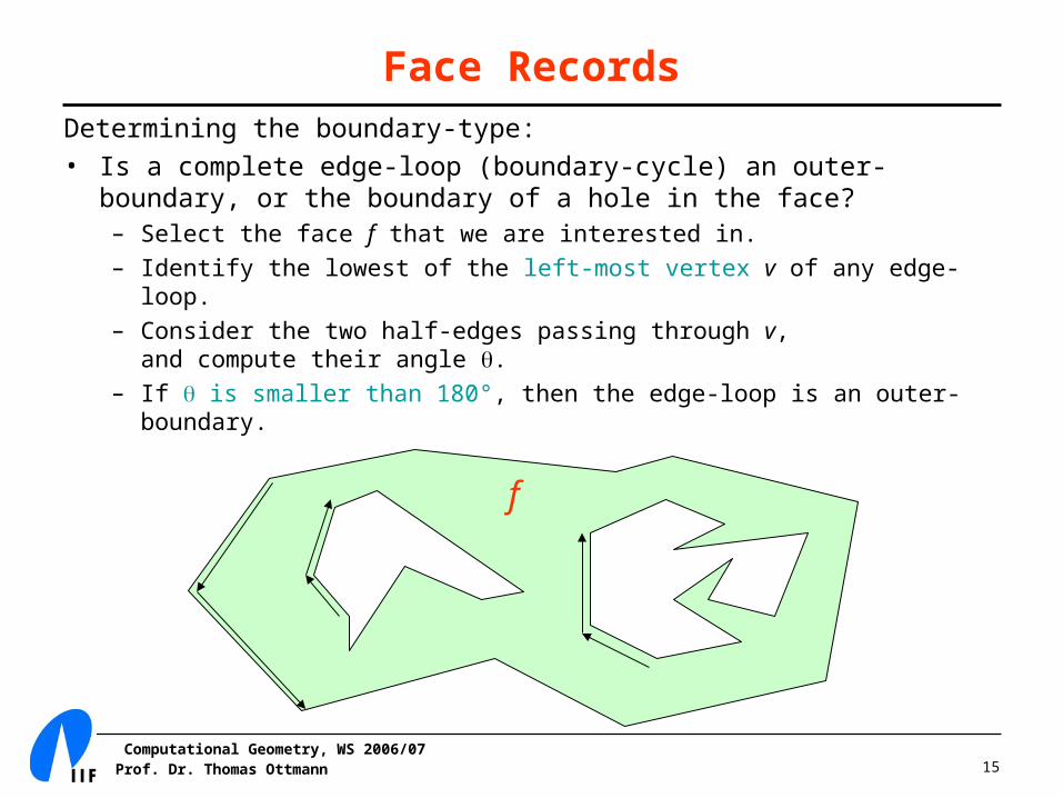
Determining the boundary-type:• Is a complete edge-loop (boundary-cycle) an outer-boundary, or the
boundary of a hole in the face?– Select the face f that we are interested in.
– Identify the lowest of the left-most vertex v of any edge-loop.
– Consider the two half-edges passing through v, and compute their angle .
– If is smaller than 180°, then the edge-loop is an outer-boundary.
f

Computational Geometry, WS 2006/07Prof. Dr. Thomas Ottmann 16
Top Level DCEL Representation
Construct a graph G to representy boundary-cycles.• For every boundary-cycle, there is a node in G (+ imaginary bound).• An arc joins two cycles iff one is a boundary of a hole and the other
has a half-edge immediately to the left of the left-most vertex of that hole.
c6
c7c3
c5c1c2
c4c8 c1
c6
c3
c2c5
c8
c4
c7
Outside
Holes
Computational Geometry, WS 2006/07Prof. Dr. Thomas Ottmann 17
Splitting an Edge
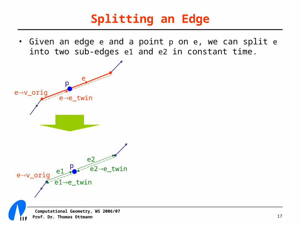
• Given an edge e and a point p on e, we can split e into two sub-edges e1 and e2 in constant time.
ep
p
ee_twinev_orig
ev_orig e1
e2e2e_twin
e1e_twin
Computational Geometry, WS 2006/07Prof. Dr. Thomas Ottmann 18
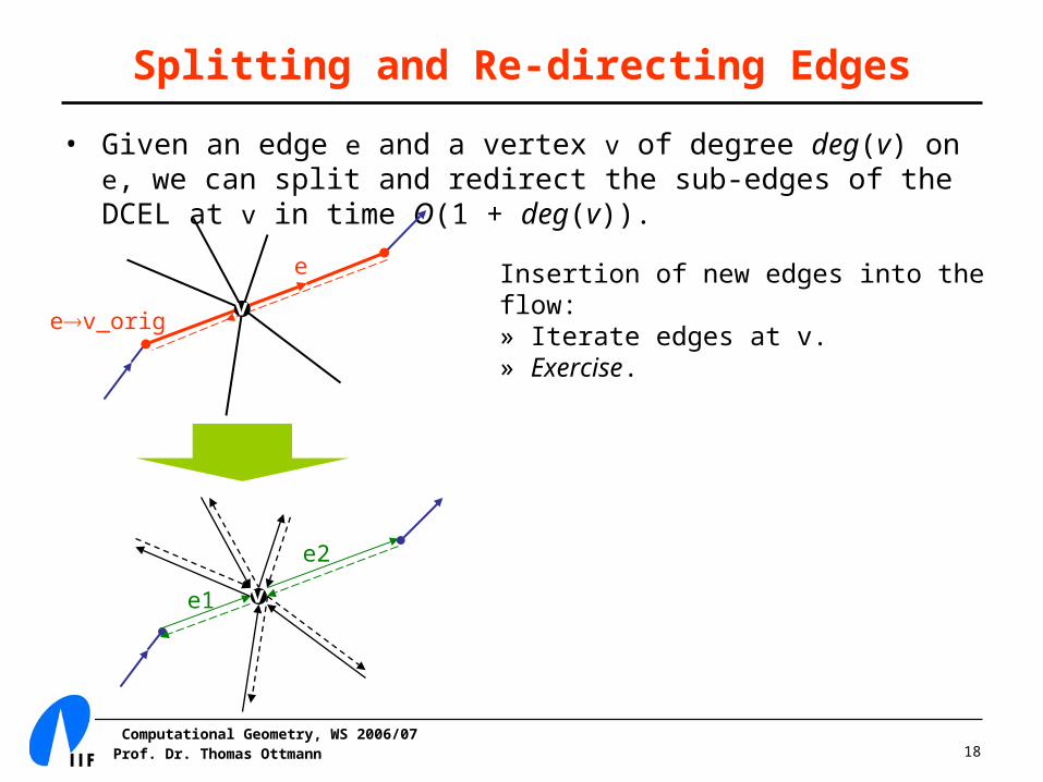
Splitting and Re-directing Edges
• Given an edge e and a vertex v of degree deg(v) on e, we can split and redirect the sub-edges of the DCEL at v in time O(1 + deg(v)).
e
e1
e2
ev_orig
v
vInsertion of new edges into the flow:» Iterate edges at v.» Exercise.
Computational Geometry, WS 2006/07Prof. Dr. Thomas Ottmann 19
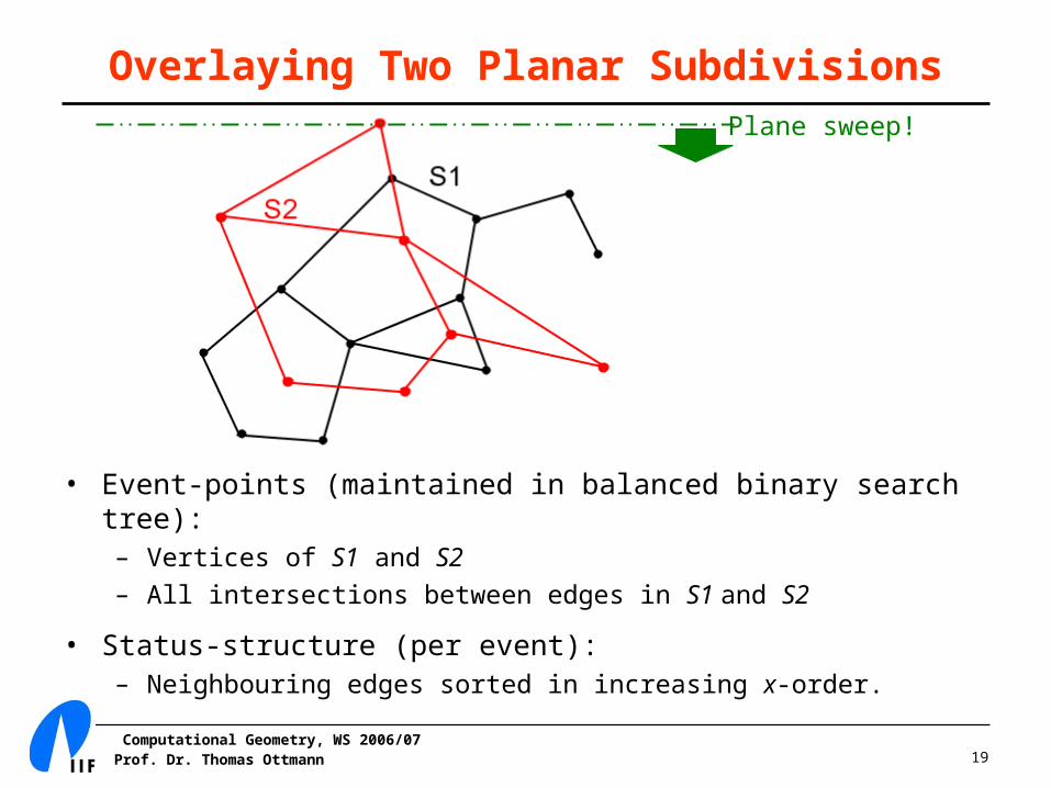
Overlaying Two Planar SubdivisionsPlane sweep!
• Event-points (maintained in balanced binary search tree): – Vertices of S1 and S2
– All intersections between edges in S1 and S2
• Status-structure (per event):– Neighbouring edges sorted in increasing x-order.

Computational Geometry, WS 2006/07Prof. Dr. Thomas Ottmann 20
Handling Intersections
• Additional handling of ‘intersection’ event points:– Split and re-direct edges.
– Check new nearest-neighbours for intersections.
• Recall (from Lecture 3): 2
13
7
7 3
12 8
U(P)
C(P)
C(P)
3
8
4
5
7
1
3
2
1
• PL

Computational Geometry, WS 2006/07Prof. Dr. Thomas Ottmann 21
Analysis
For a total of n vertices in both S1 and S2:• Sorting of n vertices: O(n log n) time• Runtime per ‘intersection’-vertex: O(1 + deg(v))• Time to retrieve neighbouring edges per ‘interection’-vertex: O(log
n)• Total ‘intersection’-vertices: k
• Total runtime: O(n log n + k log n)