Embed Size (px)
Citation preview
georg neumann gmbh · leipziger str. 112 · 10117 berlin · germanytel +49 (0)30 / 41 77 24-0 · fax -50 · [email protected] · www.neumann.com
TLM 102
Bedienungsanleitung 2
Operating Manual 6
2D
1. Einleitung
In dieser Anleitung fi nden Sie alle wichtigen In-formationen für den Betrieb und die Pfl ege des von Ihnen erworbenen Produktes. Lesen Sie diese Anleitung sorgfältig und vollständig, bevor Sie das Gerät benutzen. Bewahren Sie sie so auf, dass sie für alle momentanen und späteren Nutzer je-derzeit zugänglich ist.
Weitergehende Informationen, insbesondere auch zu den verfügbaren Zubehörteilen und den Neumann-Servicepartnern, fi nden Sie jederzeit auf unserer Website www.neumann.com. Die Servicepartner können Sie auch telefonisch unter +49 (0) 30 / 41 77 24 - 0 erfragen.
Auf unserer Website www.neumann.com fi nden Sie in der Rubrik Downloads ergänzend folgende PDF-Dateien:
• Betrieb an unsymmetrischen oder mittengeer-deten Eingängen
• Hinweise zur Pfl ege des Mikrofons
Zum weltweiten Erfahrungsaustausch unter Neu-mann-Anwendern bieten wir auf unserer Website das Neumann Online-Forum an, das sich durch die integrierte Archivfunktion zu einem umfang-reichen Know-How-Pool entwickelt hat.
2. Sicherheitshinweise
Der bestimmungsgemäße Gebrauch dieses Mikro-fons ist die Wandlung akustischer in elektrische Signale.
Schließen Sie das Mikrofon nur an Mikrofon-eingänge und Speisegeräte an, die eine 48 V-Phantomspeisung nach IEC 61938 liefern.
Reparatur- und Servicearbeiten dürfen nur von erfahrenem und autorisiertem Fachpersonal durchgeführt werden. Wenn Sie das Gerät eigen-mächtig öff nen oder umbauen, erlischt die Ge-währleistung.
Verwenden Sie das Gerät nur unter den in den technischen Daten angegebenen Betriebsbedin-gungen.
Lassen Sie das Gerät auf Raumtemperatur akkli-matisieren, bevor Sie es einschalten.
Nehmen Sie das Gerät nicht in Betrieb, wenn es beim Transport beschädigt wurde.
Verlegen Sie Kabel stets so, dass niemand darüber stolpern kann.
Halten Sie Flüssigkeiten und elektrisch leitfähige Gegenstände, die nicht betriebsbedingt notwen-dig sind, vom Gerät und dessen Anschlüssen fern.
Verwenden Sie zum Reinigen keine Lösungsmittel oder aggressiven Reinigungsmittel.
Entsorgen Sie das Gerät nach den Bestimmungen Ihres Landes.
3. Kurzbeschreibung
Das TLM 102 ist ein Kondensator-Studiomikrofon in transformatorloser Schaltungstechnik (TLM) mit der Richtcharakteristik Niere.
Mit seinem transformatorlosen Konzept ermögli-cht das TLM 102 eine besonders saubere, verfär-bungsfreie Klangübertragung und höchste Aus-steuerbarkeit bei geringem Eigenrauschen.
Das TLM 102 ist mit einer Großmembrankapsel ausgerüstet. Diese hat einen bis ca. 6 kHz ebenen Frequenzgang, darüber eine breite, fl ache Präsen-zanhebung.
4. Lieferumfang
TLM 102 (bk):
• Mikrofon TLM 102 (bk)
• Stativgelenk SG 2
• Bedienungsanleitung
TLM 102 (bk) Studio-Set:
• Mikrofon TLM 102 (bk),
• Elastische Aufh ängung EA 4,
• Bedienungsanleitung
bk = schwarz
5. Inbetriebnahme
Mikrofon einrichtenBefestigen Sie das Mikrofon auf einem ausrei-chend stabilen und standfesten Stativ. Verwenden Sie ggf. eine elastische Aufh ängung, um die Über-tragung von Körperschallgeräuschen mechanisch zu unterdrücken. Setzen Sie dafür das Mikrofon von oben in den Innenkorb ein und schrauben Sie es mit der Rändelmutter am Innenkorb fest. Zur Dämpfung von Wind- oder Popgeräuschen verwenden Sie bei Bedarf einen Wind- oder Pop-schutz aus unserem Zubehörprogramm.
3
Mikrofon anschließen
Vorsicht: Eine falsche Versorgungsspannung kann das Mikrofon beschädigen!
Schließen Sie das Mikrofon ausschließlich an ein Netzgerät, einen Mikrofon-Vorverstärker, ein Mischpult o.Ä. mit 48 V-Phantomspeisung nach IEC 61938 an. Sie können alle P48-Speisegeräte verwenden, die mindestens 3,5 mA je Kanal ab-geben.
Vorsicht: Sehr laute Geräusche können Ihr Gehör oder Ihre Lautsprecher schädigen!
Minimieren Sie an den angeschlossenen Wieder-gabe- und Aufnahmegeräten die Lautstärke, be-vor Sie das Mikrofon anschließen.
Verbinden Sie das Mikrofon über ein geeignetes Kabel mit dem Mikrofoneingang Ihres weiterver-arbeitenden Audiogerätes bzw. mit dem vorgese-henen P48-Speisegerät. Hinweise zur Anschluss-belegung fi nden Sie im Kapitel Technische Daten.
Kabellängen bis ca. 300 m zwischen Mikrofon und nachfolgendem Verstärkereingang haben kei-nen Einfl uss auf den Frequenzgang des Mikrofons.
Achten Sie beim Anschließen von Kabeln auf die korrekte Verriegelung der Steckverbinder. Verle-gen Sie die Kabel so, dass sie keine Stolpergefahr darstellen.
Besprechen Sie das Mikrofon von der Seite aus, auf der sich das Neumann-Logo befi ndet.
Erhöhen Sie an den weiterverarbeitenden Geräten schrittweise den Lautstärkepegel.
Stellen Sie die Vorverstärkung (Gain) Ihres wei-terverarbeitenden Gerätes so ein, dass bei höchs-tem Pegel keine Verzerrungen auft reten.
StörschallunterdrückungDer Übertragungsbereich des TLM 102 reicht bis unter 20 Hz. Entsprechend empfi ndlich ist das Mi-krofon natürlich auch für tieff requente Störungen wie Körperschall oder Wind- und Popgeräusche. Daher empfi ehlt sich ggf. die Verwendung einer elastischen Aufh ängung, eines Windschutzes und/oder eines Popschirmes.
TontestSprechen Sie das Mikrofon einfach nur an. An-pusten oder „Anploppen“ führt zu gefährlichen Schalldruckpegeln.
6. Außerbetriebnahme und Aufbewahrung
Verringern Sie vor der Außerbetriebnahme und dem Abziehen von Kabeln den Lautstärkepegel Ihres weiterverarbeitenden Gerätes.
Schalten Sie erst dann die Phantomspeisung aus.
Trennen Sie die Kabelverbindungen.
Ziehen Sie beim Lösen von Kabeln stets nur an den Steckverbindern und nicht am Kabel.
Mikrofone, die nicht im Einsatz sind, sollte man nicht auf dem Stativ einstauben lassen. Wird ein Mikrofon längere Zeit nicht verwendet, sollte es bei normalem Umgebungsklima staubgeschützt aufb ewahrt werden. Verwenden Sie hierfür einen nicht fusselnden, luft durchlässigen Staubschutz-beutel oder die Originalverpackung des Mikro-fons.
D
4D
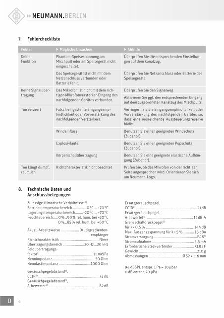
8. Technische Daten und Anschlussbelegungen
Zulässige klimatische Verhältnisse:1) Betriebstemperaturbereich ...............0 °C … +70 °CLagerungstemperaturbereich........–20 °C … +70 °CFeuchtebereich ..... 0 %…90 % rel. hum. bei +20 °C
0 %…85 % rel. hum. bei +60 °C
Akust. Arbeitsweise ................... Druckgradienten-empfänger
Richtcharakteristik .........................................NiereÜbertragungsbereich ......................20 Hz...20 kHzFeldübertragungs-faktor2) ...................................................... 11 mV/PaNennimpedanz ............................................ 50 OhmNennlastimpedanz .................................1000 Ohm
Geräuschpegelabstand3), CCIR4) ...............................................................73 dBGeräuschpegelabstand3),A-bewertet4) ....................................................82 dB
Ersatzgeräuschpegel,CCIR4) ...............................................................21 dBErsatzgeräuschpegel,A-bewertet4) ................................................ 12 dB-AGrenzschalldruckpegel5) für k < 0,5 % ................................................. 144 dBMax. Ausgangsspannung für k < 5 % ............ 13 dBuStromversorgung .............................................P486)
Stromaufnahme ............................................ 3,5 mAErforderliche Steckverbinder ...................... XLR 3 FGewicht ............................................................210 gAbmessungen ...................................Ø 52 x 116 mm
94 dBSPL entspr. 1 Pa = 10 μbar0 dB entspr. 20 μPa
7. Fehlercheckliste
Fehler ▶ Mögliche Ursachen ▶ Abhilfe
Keine Funktion
Phantom-Speisespannung am Mischpult oder am Speisegerät nicht eingeschaltet.
Überprüfen Sie die entsprechenden Einstellun-gen auf dem Kanalzug.
Das Speisegerät ist nicht mit dem Netzanschluss verbunden oder Batterie fehlt.
Überprüfen Sie Netzanschluss oder Batterie des Speisegeräts.
Keine Signalüber-tragung
Das Mikrofon ist nicht mit dem rich-tigen Mikrofonverstärker-Eingang des nachfolgenden Gerätes verbunden.
Überprüfen Sie den Signalweg
Aktivieren Sie ggf. den entsprechenden Eingang auf dem zugeordneten Kanalzug des Mischpults.
Ton verzerrt Falsch eingestellte Eingangsemp-fi ndlichkeit oder Vorverstärkung des nachfolgenden Verstärkers.
Verringern Sie die Eingangsempfi ndlichkeit oder Vorverstärkung des nachfolgenden Gerätes so, dass eine ausreichende Aussteuerungsreserve bleibt.
Windeinfl uss Benutzen Sie einen geeigneten Windschutz (Zubehör).
Explosivlaute Benutzen Sie einen geeigneten Popschutz (Zubehör).
Körperschallübertragung Benutzen Sie eine geeignete elastische Aufh än-gung (Zubehör).
Ton klingt dumpf, räumlich
Richtcharakteristik nicht beachtet Prüfen Sie, ob das Mikrofon von der richtigen Seite angesprochen wird. Orientieren Sie sich am Neumann-Logo.
5 D
Das Mikrofon besitzt einen symmetrischen, über-tragerlosen Ausgang. Der 3-polige XLR-Steck-verbinder weist folgende normgerechte Belegung auf:
Pin 1: 0 V/Masse
Pin 2: Modulation (+Phase)
Pin 3: Modulation (–Phase)
1) Alle Werte für nicht-kondensierende Feuchtigkeit.
Die Werte gelten für saubere, gepfl egte Mikrofone bzw.
Mikrofonkapseln. Schmutzablagerungen jeglicher Art auf
Kapseln oder Membranen können die genannten Werte
einschränken.2) bei 1 kHz an 1 kOhm Nennlastimpedanz3) bezogen auf 94 dB SPL4) nach IEC 60268-1;
CCIR-Bewertung nach CCIR 468-3, Quasi-Spitzenwert;
A-Bewertung nach IEC 61672-1, Eff ektivwert5) Klirrfaktor des Mikrofonverstärkers bei einer Eingangs-
spannung, die der von der Kapsel beim entsprechenden
Schalldruck abgegebenen Spannung entspricht.6) nach IEC 61938
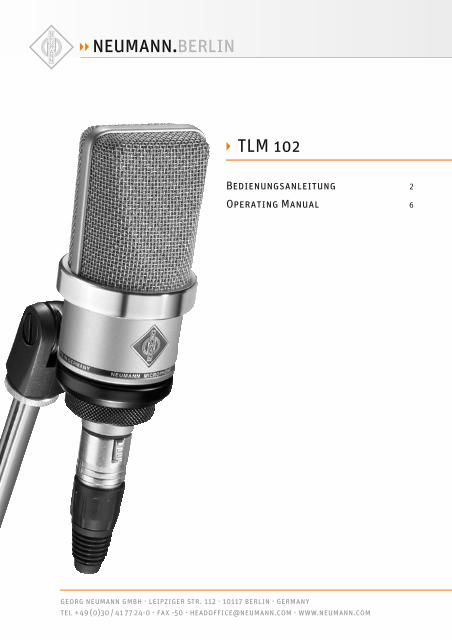
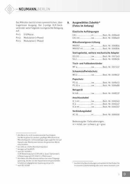
9. Ausgewähltes Zubehör* (Fotos im Anhang)
Elastische AufhängungenEA 1 ..........................ni ................ Best.-Nr. 008449EA 1 mt .....................sw ............... Best.-Nr. 008450
MikrofonneigevorrichtungMNV 87 ....................ni ................ Best.-Nr. 006804MNV 87 mt ...............sw ............... Best.-Nr. 006806
Stativgelenke, weitere mechanische AdapterDS 120 .....................sw ............... Best.-Nr. 007343SG 2 ..........................sw ............... Best.-Nr. 008636
Tisch- und FußbodenständerMF 4 .........................sw ............... Best.-Nr. 007337
Schaumstoff windschutzWS 2 .........................sw ............... Best.-Nr. 008637
PopschutzPS 15 .......................sw ............... Best.-Nr. 008472PS 20 a ...................sw ............... Best.-Nr. 008488
NetzgerätN 248 .......................sw ............... Best.-Nr. 008537
AnschlusskabelIC 3 mt .....................sw ............... Best.-Nr. 006543IC 4 ..........................ni ................ Best.-Nr. 006547IC 4 mt .....................sw ............... Best.-Nr. 006557
VerbindungskabelAC 25 .......................ni ................ Best.-Nr. 006600
Bedeutung der Farbcodierungen:ni = nickel, sw = schwarz, gr = grau
* Ausführliche Beschreibungen und weitere Artikel fi nden Sie
in unserem Zubehörkatalog oder unter www.neumann.com
66EN
1. Introduction
This manual contains essential information for the operation and care of the product you have pur-chased. Please read the instructions carefully and completely before using the equipment. Please keep this manual where it will be accessible at all times to all current and future users.
Additional information, in particular concern-ing available accessories and Neumann service partners, can always be found on our website: www.neumann.com. Information about service partners can also be obtained by telephone: +49 (0) 30 / 41 77 24 - 0.
The following related fi les are available in PDF format in the Downloads section of our website www.neumann.com:
• Operation with Unbalanced or Center Tap Grounded Inputs
• Some Remarks on Microphone Maintenance
The Neumann online forum on our website en-ables Neumann users worldwide to share their experiences. Through its integrated archive func-tion, the forum has developed into an extensive knowledge pool.
2. Safety instructions
The microphone has the intended purpose of con-verting acoustic signals into electrical signals.
Connect the microphone only to microphone inputs and devices which supply 48 V of phan-tom power in accordance with IEC 61938.
Repairs and servicing are to be carried out only by experienced, authorized service personnel. Unauthorized opening or modifi cation of the equipment shall void the warranty.
Use the equipment only under the conditions specifi ed in the “Technical data” section.
Allow the equipment to adjust to the ambient tem-perature before switching it on.
Do not operate the equipment if it has been dam-aged during transport.
Always run cables in such a way that there is no risk of tripping over them.
Unless required for operation, ensure that liquids and electrically conductive objects are kept at a safe distance from the equipment and its connec-tions.
Do not use solvents or aggressive cleansers for cleaning purposes.
Dispose of the equipment in accordance with the regulations applicable to the respective country.
3. Brief description
The TLM 102 is a condenser studio microphone with transformerless (TLM) circuit technology and a cardioid directional characteristic.
The transformerless design of the TLM 102 per-mits exceptionally clean sound transmission with no coloration, as well as a maximum dynamic range with low self-noise.
The microphone houses a large diaphragm cap-sule. It has a linear frequency response up to ap-proximately 6 kHz, above which there is a broad, fl at presence boost.
4. Scope of delivery
TLM 102 (bk):
• TLM 102 (bk) microphone
• SG 2 stand mount
• Operating manual
• Wooden box
TLM 102 (bk) Studio set:
• TLM 102 (bk), microphone
• EA 4 elastic suspension
• Operating manual
bk = black
5. Setup
Mounting the microphoneAttach the microphone to a stable, sturdy stand. Use an elastic suspension, if necessary, for the mechanical suppression of structure-borne noise. For this purpose set the microphone into the inner cage from above, and secure it to the inner cage with the threaded nut. If required, use a wind-screen or popscreen from our range of accesso-ries in order to suppress wind or pop noise.
77 EN
Connecting the microphone
Caution: An incorrect supply voltage can dam-age the microphone!
Attach the microphone only to a power supply unit, a microphone preamplifi er, a mixing console or other equipment which has phantom power with 48 V (P48), in accordance with IEC 61938. Any P48 power supply equipment can be used which supplies at least 3.5 mA per channel.
Caution: Very loud noise can damage loud-speakers or your hearing!
Minimize the volume of connected playback and recording equipment before connecting the mi-crophone.
Using a suitable cable, connect the microphone to the microphone input of the audio equipment to be used for subsequent processing, or to the designated P48 power supply equipment. Infor-mation concerning connector assignment can be found in the “Technical data” section.
Cable lengths of up to approximately 300 m be-tween the microphone and the subsequent am-plifi er input have no eff ect on the frequency re-sponse of the microphone.
When connecting the cables, ensure that the con-nectors are locked correctly. Run the cables in such a way that there is no risk of tripping over them.
Address the microphone from the side on which the Neumann logo is located.
Gradually increase the volume of the connected equipment
Set the gain of the connected equipment so that no distortion occurs at the highest sound pres-sure level.
Suppressing noise interferenceThe frequency response of the TLM 102 extends below 20 Hz. The microphone is of course corre-spondingly sensitive to low-frequency interfer-ence such as structure-borne noise and wind or pop noise. Depending upon the situation, the use of an elastic suspension, a windscreen and/or a popscreen is therefore recommended.
Sound testSimply speak into the microphone. Do not blow into the microphone or subject it to pop noise, since this can easily result in hazardous sound pressure levels.
6. Shutdown and storage
Before switching off the microphone or discon-necting the cables, reduce the volume of con-nected equipment.
Only then should the phantom power be switched off .
Disconnect the cables.
When disconnecting a cable, always pull only on the connector and not on the cable itself.
Microphones which are not in use should not be allowed to remain on the stand gathering dust. A microphone which is unused for a prolonged pe-riod should be stored under normal atmospheric conditions, and should be protected from dust. For this purpose, use a lint-free, air-permeable dust cover or the original packaging of the micro-phone.
88EN
7. Troubleshooting
Problem ▶ Possible causes ▶ Solution
Microphone not operating
The phantom power supply voltage is not switched on at the mixing console or at the power supply equipment
Check the corresponding channel settings
The power supply equipment is not connected to the power supply line or there is no battery
Check the connection to the power supply line or check the battery of the power supply equipment
No signal transmission
The microphone is not connected to the correct microphone amplifi er input of the subsequent equipment
Check the signal path
If necessary, activate the appropriate input on the corresponding channel of the mixing console
Distorted sound Incorrect input sensitivity or gain setting of subsequent amplifi er
Decrease the input sensitivity or gain of the subsequent amplifi er so as to provide suffi cient headroom
Wind eff ects Use an appropriate windscreen (accessory)
Plosives Use an appropriate popscreen (accessory)
Transmission of structure-borne noise
Use a suitable elastic suspension (accessory)
Sound is muffl ed and reverberant
Incorrect directional characteristic Check to ensure that the microphone is being addressed from the correct side, as designated by the Neumann logo.
8. Technical data and connector assignments
Permissible atmospheric conditions1) Operating temperature range ...........0 °C to +70 °CStorage temperature range ...........–20 °C to +70 °CHumidity range .....................0 % to 90 % at +20 °C
0 % … 85 % at +60 °C
Acoustical op. principle .............Pressure gradient transducer
Directional pattern .......................................................Cardioid/Frequency range ............................ 20 Hz to 20 kHzSensitivity2) .............................................. 11 mV/PaRated impedance ....................................... 50 ohmsRated load impedance ......................... 1000 ohms
Signal-to-noise ratio3), CCIR4) ...............................................................73 dBSignal-to-noise ratio3), A-weighted4) ....................................................82 dB
Equivalent noise level, CCIR4) ...............................................................21 dBEquivalent noise level, A-weighted4) ................................................ 12 dB-AMax. SPL5)
for THD < 0.5 % ........................................... 144 dBMax. output voltage for THD > 5 % ............... 13 dBuPower Supply ...................................................P486)
Current consumption ................................... 3.5 mARequired connectors ................................... XLR 3 FWeight ..............................................................210 gDimensions ......................................Ø 52 x 116 mm
94 dBSPL equiv. to 1 Pa = 10 μbar0 dB equiv. to 20 μPa

99 EN
The microphone has a balanced, transformerless output. The 3-pin XLR connector has the following standard pin assignments:
Pin 1: 0 V/Ground
Pin 2: Modulation (+phase)
Pin 3: Modulation (–phase)
1) All values are for non-condensing humidity.
The values are valid for clean and well-looked-aft er
microphones or microphone capsules, respectively. Any
kind of pollution of capsules and membranes may restrict
the said values.2) at 1 kHz into 1 kohm rated load impedance.3) re 94 dB SPL4) according to IEC 60268-1;
CCIR-weighting acccording to CCIR 468-3, quasi peak;
A-weighting according to IEC 61672-1, RMS5) THD of microphone amplifi er at an input voltage equivalent
to the capsule output at the specifi ed SPL. 6) according to IEC 61938
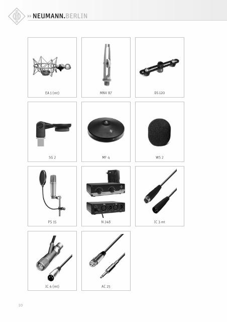
9. Selected Accessories* (see photos in appendix)
Elastic SuspensionsEA 1 ..........................ni ..................Cat. No. 008449EA 1 mt .....................blk ................Cat. No. 008450
Auditorium HangerMNV 87 ....................ni ..................Cat. No. 006804MNV 87 mt ...............blk ................Cat. No. 006806
Stand Mounts, Misc. Mechanical AdaptersDS 120 .....................blk ................Cat. No. 007343SG 2..........................blk ................Cat. No. 008636
Table and Floor StandsMF 4 .........................blk ................Cat. No. 007337
Foam WindscreensWS 2 .........................blk ................Cat. No. 008637
PopscreenPS 15 .......................blk ................Cat. No. 008472
Power SupplyN 248 .......................blk ................Cat. No. 008537
Connecting CablesIC 3 mt ....................blk ................Cat. No. 006543IC 4 ...........................ni ..................Cat. No. 006547IC 4 mt .....................blk ................Cat. No. 006557
Adapter CablesAC 25 .............................................Cat. No. 006600
Meaning of color codes:ni = nickel, blk = black, gry = grey
* Detailed descriptions and additional articles can be found
in our accessories catalog or at: www.neumann.com
10
N 248 IC 3 mt
EA 1 (mt) DS 120MNV 87
SG 2 MF 4
AC 25
WS 2
PS 15
IC 4 (mt)
1111
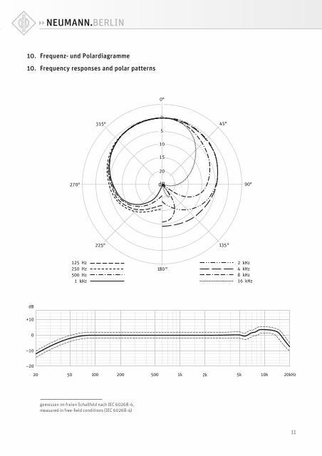
10. Frequenz- und Polardiagramme
10. Frequency responses and polar patterns
gemessen im freien Schallfeld nach IEC 60268-4,
measured in free-fi eld conditions (IEC 60268-4)
Irrtümer und technische Änderungen vorbehalten • Errors excepted, subject to changes
Printed in Germany • Publ. 09/15 535661/A01
HaftungsausschlussDie Georg Neumann GmbH übernimmt keinerlei Haft ung für Folgen eines unsachgemäßen Gebrauchs des Produkts, d.h. die Folgen eines Gebrauchs, der von den in der Bedienungsanleitung genannten technischen Vorausset-zungen abweicht (z.B. Bedienungsfehler, mechanische Beschädigungen, falsche Spannung, Abweichung von empfohlenen Korrespondenzgeräten). Jegliche Haft ung der Georg Neumann GmbH für Schäden und Folgeschä-den, die dem Benutzer aufgrund eines solchen abweichenden Gebrauchs entstehen sollten, wird ausgeschlossen. Ausgenommen von diesem Haf-tungsausschluss sind Ansprüche aufgrund zwingender gesetzlicher Haf-tung, wie z.B. nach Produkthaft ungsgesetz.
Limitation of LiabilityGeorg Neumann GmbH shall not be liable for consequences of an inappro-priate use of the product not being in compliance with the technical allow-ance in the user manual such as handling errors, mechanical spoiling, false voltage and using other than the recommended correspondence devices. Any liability of Georg Neumann GmbH for any damages including indirect, consequential, special, incidental and punitive damages based on the user’s non-compliance with the user manual or unreasonable utilization of the product is hereby excluded as to the extent permitted by law. This limitation of liability on damages is not applicable for the liability under European product liability codes or for users in a state or country where such damages cannot be limited.
KonformitätserklärungDie Georg Neumann GmbH erklärt, dass dieses Gerät die anwendbaren CE-Normen und -Vorschrift en erfüllt.
® Neumann ist in zahlreichen Ländern eine eingetragene Marke der Georg Neumann GmbH.
Declaration of ConformityGeorg Neumann GmbH hereby declares that this device conforms to the applicable CE standards and regulations.
® Neumann is a registered trademark of the Georg Neumann GmbH in cer-tain countries.