Embed Size (px)
Citation preview

de
deu
tschen
english
frfran
çaisKA 190O/98/a3/02.02 52010808
Vibracon Mini LVL-A1Füllstandgrenzschalter für Flüssigkeiten
� universell einsetzbar� wartungsfrei
Betriebsanleitung
Level limit switch for fluids� universally applicable� maintenance-free
Operation Manual
Détecteur de niveau pour liquides� utilisation universelle� sans maintenance
Mise en service
Abbildung in OriginalgrößeFigure in original sizeFigure en dimension réelle
2
Inhalt
Was der Vibracon Mini kann 3Hier finden Sie Informationen zu:
• Einsatzbereiche• Vorteile und Funktionsweise• Einbaubeispiele und Verwendungshinweise• Einsatzarten für Varianten AC und DC-
PNP• Produktvarianten und Bestell-Code• Zertifikate und Zubehör
Technische Daten 7Hier finden Sie die Anschlusswerte, Einsatz-bedingungen und Abmessungen.
Sicherheit 9Lesen Sie unbedingt diesen Abschnitt vor Montage und Anschluss des LVL-A1.
Montage und Anschluss 10Hier finden Sie die Anleitung zum Einbau und zur Ausrichtung des LVL-A1, zum elektrischen Anschluss und zum Test mit dem Testmagnet.
Lichtsignale und Störungen 14Hier finden Sie eine Übersicht zur eingebauten Leuchtanzeige des LVL-A1 und Informationen zur Behebung eventuell auftretender Störun-gen.
Reinigung und Entsorgung 15Hier lesen Sie, was Sie beim Reinigen und Entsorgen des LVL-A1 beachten müssen.
de
3
Was der Vibracon Mini kann
EinsatzbereicheDer Vibracon Mini LVL-A1 ist ein Füllstandgrenz-schalter für Flüssigkeiten aller Art und kommt in Tanks, Behältern und Rohrleitungen zum Einsatz. Er wird z.B. in Reinigungs- und Filteranlagen so-wie in Kühl- und Schmiermittelbehältern als Über-füllsicherung oder als Pumpenschutz verwendet.
Der LVL-A1 ist ideal für Anwendungen, in denen bisher Schwimmerschalter, konduktive, kapazitive und optische Sensoren verwendet wurden.
Er funktioniert aber auch in Bereichen, in denen diese Messprinzipien wegen Leitfähigkeit, Ablage-rungen, Turbulenzen, Strömungen oder Luftbla-sen nicht geeignet sind.
Der LVL-A1 ist nicht geeignet für explosionsge-fährdete Bereiche, Hygienebereiche und Bereiche mit Messstofftemperaturen über 100 °C.
Vorteile• Betriebssicherheit, Zuverlässigkeit und univer-
selle Einsetzbarkeit durch das Messprinzip der Schwinggabel
• Testmöglichkeit von außen durch Testmagnet• Funktionskontrolle vor Ort möglich durch
Leuchtanzeigen außen• Einfacher Einbau auch an schwer zugäng-
lichen Stellen durch kompakte Bauform• Robustes Edelstahlgehäuse (316L)• Servicefreundliche Steckanschlüsse
FunktionsweiseDie Schwinggabel des LVL-A1 wird durch einen piezoelektrischen Antrieb auf ihre Resonanzfre-quenz angeregt.
Wird die Schwinggabel von Flüssigkeit bedeckt, ändert sich dadurch diese Frequenz.
Die Elektronik des LVL-A1 überwacht die Reso-nanzfrequenz und zeigt an, ob die Schwinggabel frei schwingt oder von Flüssigkeit bedeckt ist.
Was d
er Vib
racon
Min
i kann
4
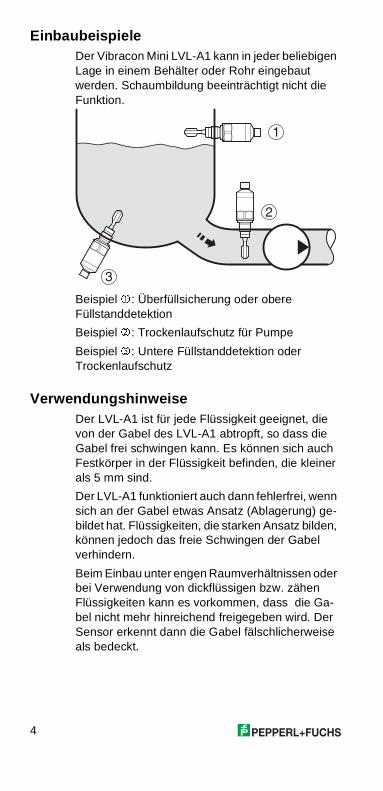
EinbaubeispieleDer Vibracon Mini LVL-A1 kann in jeder beliebigen Lage in einem Behälter oder Rohr eingebaut werden. Schaumbildung beeinträchtigt nicht die Funktion.
Beispiel �: Überfüllsicherung oder obere Füllstanddetektion
Beispiel �: Trockenlaufschutz für Pumpe
Beispiel �: Untere Füllstanddetektion oder Trockenlaufschutz
VerwendungshinweiseDer LVL-A1 ist für jede Flüssigkeit geeignet, die von der Gabel des LVL-A1 abtropft, so dass die Gabel frei schwingen kann. Es können sich auch Festkörper in der Flüssigkeit befinden, die kleiner als 5 mm sind.
Der LVL-A1 funktioniert auch dann fehlerfrei, wenn sich an der Gabel etwas Ansatz (Ablagerung) ge-bildet hat. Flüssigkeiten, die starken Ansatz bilden, können jedoch das freie Schwingen der Gabel verhindern.
Beim Einbau unter engen Raumverhältnissen oder bei Verwendung von dickflüssigen bzw. zähen Flüssigkeiten kann es vorkommen, dass die Ga-bel nicht mehr hinreichend freigegeben wird. Der Sensor erkennt dann die Gabel fälschlicherweise als bedeckt.
�
�
�
de
5
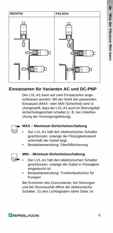
Einsatzarten für Varianten AC und DC-PNPDer LVL-A1 kann auf zwei Einsatzarten ange-schlossen werden. Mit der Wahl der passenden Einsatzart (MAX- oder MIN-Sicherheit) wird si-chergestellt, dass der LVL-A1 auch im Störungsfall sicherheitsgerichtet schaltet (z. B. bei Unterbre-chung der Versorgungsleitung).
MAX – Maximum-Sicherheitsschaltung
• Der LVL-A1 hält den elektronischen Schalter geschlossen, solange der Flüssigkeitsstand unterhalb der Gabel liegt.
• Beispielanwendung: Überfüllsicherung
MIN – Minimum-Sicherheitsschaltung
• Der LVL-A1 hält den elektronischen Schalter geschlossen, solange die Gabel in Flüssigkeit eingetaucht ist.
• Beispielanwendung: Trockenlaufschutz für Pumpen
Bei Erreichen des Grenzstands, bei Störungen und bei Stromausfall öffnet der elektronische Schalter. Zu den Lichtsignalen siehe Seite 14.
RICHTIG FALSCH Was d
er Vib
racon
Min
i kann
6
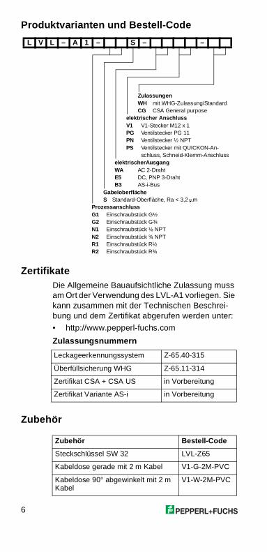
Produktvarianten und Bestell-Code
ZertifikateDie Allgemeine Bauaufsichtliche Zulassung muss am Ort der Verwendung des LVL-A1 vorliegen. Sie kann zusammen mit der Technischen Beschrei-bung und dem Zertifikat abgerufen werden unter:
• http://www.pepperl-fuchs.com
Zulassungsnummern
Zubehör
L V L – A 1 – S – –
ZulassungenWH mit WHG-Zulassung/StandardCG CSA General purpose
elektrischer AnschlussV1 V1-Stecker M12 x 1PG Ventilstecker PG 11PN Ventilstecker ½ NPTPS Ventilstecker mit QUICKON-An-
schluss, Schneid-Klemm-Anschluss elektrischerAusgangWA AC 2-DrahtE5 DC, PNP 3-DrahtB3 AS-i-Bus
GabeloberflächeS Standard-Oberfläche, Ra < 3,2 �m
ProzessanschlussG1 Einschraubstück G½G2 Einschraubstück G¾N1 Einschraubstück ½ NPTN2 Einschraubstück ¾ NPTR1 Einschraubstück R½R2 Einschraubstück R¾
Leckageerkennungssystem Z-65.40-315
Überfüllsicherung WHG Z-65.11-314
Zertifikat CSA + CSA US in Vorbereitung
Zertifikat Variante AS-i in Vorbereitung
Zubehör Bestell-Code
Steckschlüssel SW 32 LVL-Z65
Kabeldose gerade mit 2 m Kabel V1-G-2M-PVC
Kabeldose 90° abgewinkelt mit 2 m Kabel
V1-W-2M-PVC
de
7
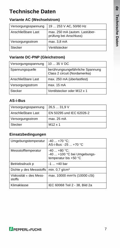
Technische DatenVariante AC (Wechselstrom)
Variante DC-PNP (Gleichstrom)
AS-i-Bus
Einsatzbedingungen
Versorgungsspannung 19 ... 253 V AC, 50/60 Hz
Anschließbare Last max. 250 mA (autom. Lastüber-prüfung bei Anschluss)
Versorgungsstrom max. 3,8 mA
Stecker Ventilstecker
Versorgungsspannung 10 ... 35 V DC
Spannungsquelle berührungsungefährliche SpannungClass 2 circuit (Nordamerika)
Anschließbare Last max. 250 mA (überlastfest)
Versorgungsstrom max. 15 mA
Stecker Ventilstecker oder M12 x 1
Versorgungsspannung 26,5 ... 31,9 V
Anschließbare Last EN 50295 und IEC 62026-2
Versorgungsstrom max. 25 mA
Stecker M12 x 1
Umgebungstemperatur -40 ... +70 °C; AS-i-Bus: -25 ... +70 °C
Messstofftemperatur -40 ... +80 °C; -40 ... +100 °C bei Umgebungs-temperatur bis +50 °C
Betriebsdruck p -1 ... +40 bar
Dichte � des Messstoffs min. 0,7 g/cm³
Viskosität � des Mess-stoffs
max. 10000 mm²/s (10000 cSt)
Klimaklasse IEC 60068 Teil 2 - 38, Bild 2a
Tech
nisch
e Daten
8
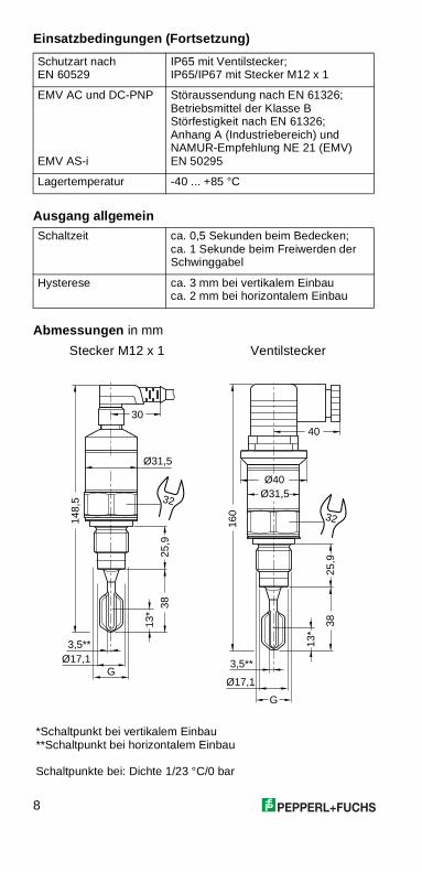
Einsatzbedingungen (Fortsetzung)
Ausgang allgemein
Abmessungen in mm
Schutzart nach EN 60529
IP65 mit Ventilstecker;IP65/IP67 mit Stecker M12 x 1
EMV AC und DC-PNP
EMV AS-i
Störaussendung nach EN 61326; Betriebsmittel der Klasse B Störfestigkeit nach EN 61326; Anhang A (Industriebereich) und NAMUR-Empfehlung NE 21 (EMV)EN 50295
Lagertemperatur -40 ... +85 °C
Schaltzeit ca. 0,5 Sekunden beim Bedecken;ca. 1 Sekunde beim Freiwerden der Schwinggabel
Hysterese ca. 3 mm bei vertikalem Einbauca. 2 mm bei horizontalem Einbau
Stecker M12 x 1 Ventilstecker
*Schaltpunkt bei vertikalem Einbau**Schaltpunkt bei horizontalem Einbau
Schaltpunkte bei: Dichte 1/23 °C/0 bar
148,
5
Ø31,5
Ø17,1
25,9
38
G
30
32
13*
3,5**
160
25,9
38
Ø31,5
G
Ø17,1
Ø40
40
32
13*
3,5**
de
9
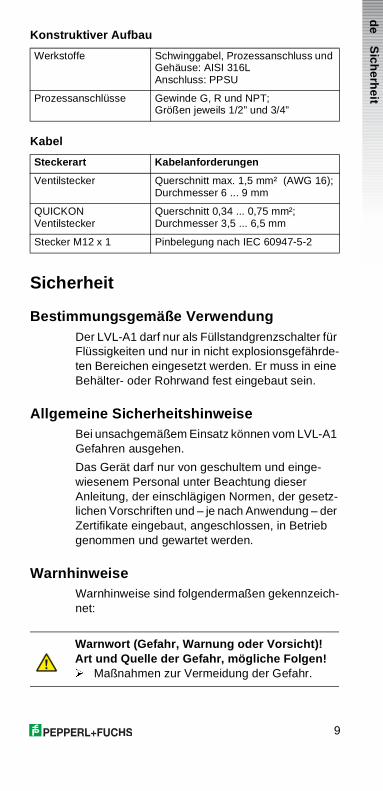
Konstruktiver Aufbau
Kabel
Sicherheit
Bestimmungsgemäße VerwendungDer LVL-A1 darf nur als Füllstandgrenzschalter für Flüssigkeiten und nur in nicht explosionsgefährde-ten Bereichen eingesetzt werden. Er muss in eine Behälter- oder Rohrwand fest eingebaut sein.
Allgemeine SicherheitshinweiseBei unsachgemäßem Einsatz können vom LVL-A1 Gefahren ausgehen.
Das Gerät darf nur von geschultem und einge-wiesenem Personal unter Beachtung dieser Anleitung, der einschlägigen Normen, der gesetz-lichen Vorschriften und – je nach Anwendung – der Zertifikate eingebaut, angeschlossen, in Betrieb genommen und gewartet werden.
WarnhinweiseWarnhinweise sind folgendermaßen gekennzeich-net:
Werkstoffe Schwinggabel, Prozessanschluss und Gehäuse: AISI 316LAnschluss: PPSU
Prozessanschlüsse Gewinde G, R und NPT; Größen jeweils 1/2” und 3/4”
Steckerart Kabelanforderungen
Ventilstecker Querschnitt max. 1,5 mm² (AWG 16);Durchmesser 6 ... 9 mm
QUICKON Ventilstecker
Querschnitt 0,34 ... 0,75 mm²;Durchmesser 3,5 ... 6,5 mm
Stecker M12 x 1 Pinbelegung nach IEC 60947-5-2
Warnwort (Gefahr, Warnung oder Vorsicht)!Art und Quelle der Gefahr, mögliche Folgen!� Maßnahmen zur Vermeidung der Gefahr.
Sich
erheit
10
Montage und Anschluss
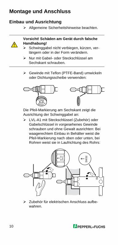
Einbau und Ausrichtung� Allgemeine Sicherheitshinweise beachten.
� Gewinde mit Teflon (PTFE-Band) umwickeln oder Dichtungsscheibe verwenden:
Die Pfeil-Markierung am Sechskant zeigt die Ausrichtung der Schwinggabel an:
� LVL-A1 mit Steckschlüssel (Zubehör) oder Gabelschlüssel in vorgesehenes Gewinde schrauben und ohne Gewalt ausrichten: Bei waagerechtem Einbau in Behälter weist die Pfeil-Markierung nach oben oder unten, bei Rohren weist sie in Laufrichtung des Rohrs:
� Zubehör für elektrischen Anschluss aufbe-wahren.
Vorsicht! Schäden am Gerät durch falsche Handhabung!� Schwinggabel nicht verbiegen, kürzen, ver-
längern oder in der Form verändern.
� Nur mit Gabel- oder Steckschlüssel am Sechskant schrauben.
��
��
��
���
���
��
de
11
Elektrischer AnschlussVoraussetzung: Einsatzart (MIN oder MAX) ist festgelegt (siehe Seite 5).
� Sicherheitshinweise beachten (siehe Seite 9).
� Kabelspezifikation zum vorliegenden Stecker beachten (siehe Seite 9).
� Anhand des Typenschilds feststellen, welche Variante des LVL-A1 vorliegt: Variante DC-PNP, Variante AC oder AS-i-Bus.
� Anschlusswerte beachten.
Ventilstecker sind getrennt verpackt und zerlegt:
� Ventilstecker (auch QUICKON) gemäß Anleitung auf der Steckerverpackung zusam-mensetzen und montieren.
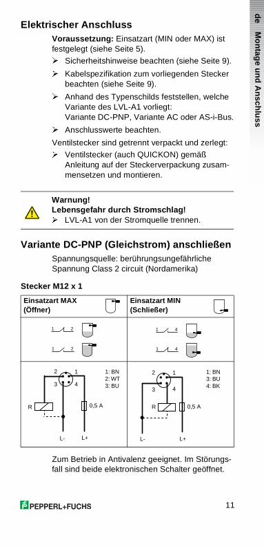
Variante DC-PNP (Gleichstrom) anschließenSpannungsquelle: berührungsungefährliche Spannung Class 2 circuit (Nordamerika)
Stecker M12 x 1
Zum Betrieb in Antivalenz geeignet. Im Störungs-fall sind beide elektronischen Schalter geöffnet.
Warnung!Lebensgefahr durch Stromschlag!� LVL-A1 von der Stromquelle trennen.
Einsatzart MAX(Öffner)
Einsatzart MIN(Schließer)
1 2
1 2
1 4
1 4
0,5 A
L+
R
L-
2
3
1
4
1: BN2: WT3: BU
0,5 A
L+
R
L-
2
3
1
4
1: BN3: BU4: BK
Mo
ntag
e un
d A
nsch
luss
12
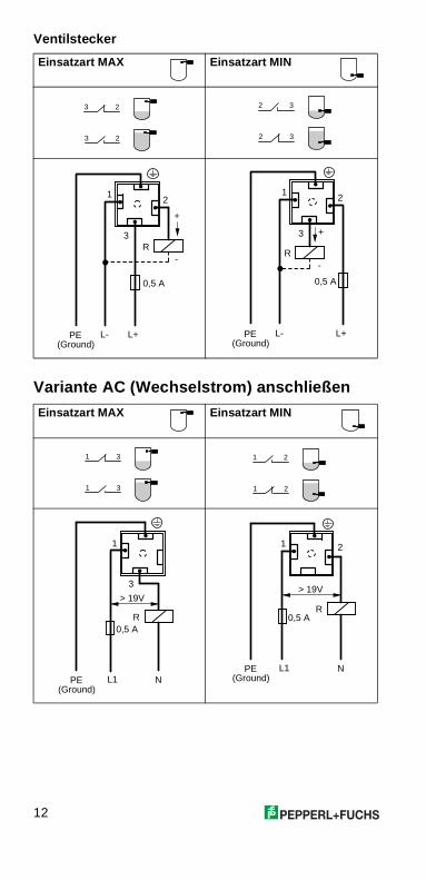
Ventilstecker
Variante AC (Wechselstrom) anschließen
Einsatzart MAX Einsatzart MIN
Einsatzart MAX Einsatzart MIN
3 2
3 2
2 3
2 3
(Ground)
1
3
0,5 A
L+PE
R
L-
2
+
-
1
3
0,5 A
L+PE(Ground)
R
L-
2
+
-
1 3
1 3
1 2
1 2
(Ground)
1
3
R0,5 A
L1 NPE
> 19V
(Ground)
1 2
R0,5 A
L1 NPE
> 19V
de
13
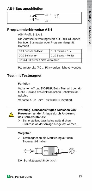
AS-i-Bus anschließen
Programmierhinweise AS-iAS-i-Profil: S-1.A.E
Die Adresse ist voreingestellt auf 0 (HEX), änder-bar über Busmaster oder Programmiergerät. Datenbit:
Parameterbits (P0 ... P3) werden nicht verwendet.
Test mit Testmagnet
Funktion
Varianten AC und DC-PNP: Beim Test wird der ak-tuelle Zustand des elektronischen Schalters um-gekehrt.
Variante AS-i: Beim Test wird D0 invertiert.
Vorgehen
� Testmagnet an die Markierung auf dem Typenschild halten:
Der Schaltzustand ändert sich.
AS-i +
AS-i -
2
3
1
4
1: BN3: BU
D0:1 Sensor bedeckt D1:1 Status = o. k.
D0:0 Sensor frei D1:0 Status = Fehler
D2 und D3 werden nicht verwendet.
Warnung! Unbeabsichtigtes Auslösen von Prozessen an der Anlage durch Änderung des Schaltzustands!� Sicherstellen, dass keine gefährlichen
Prozesse an der Anlage ausgelöst werden.
Mo
ntag
e un
d A
nsch
luss
14
Lichtsignale und Störungen
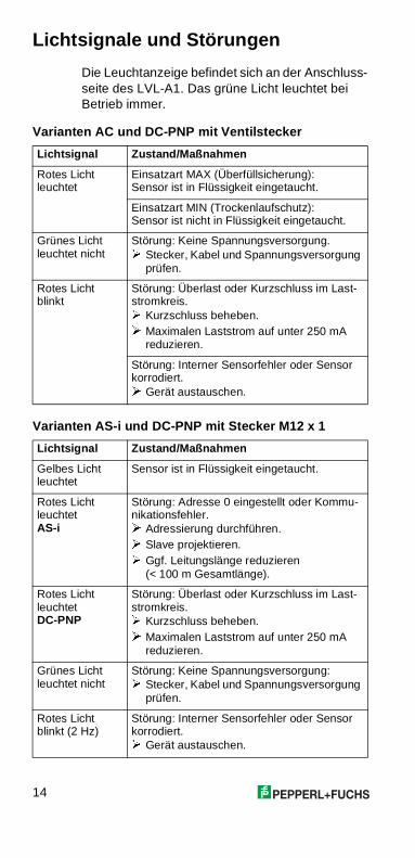
Die Leuchtanzeige befindet sich an der Anschluss-seite des LVL-A1. Das grüne Licht leuchtet bei Betrieb immer.
Varianten AC und DC-PNP mit Ventilstecker
Varianten AS-i und DC-PNP mit Stecker M12 x 1
Lichtsignal Zustand/Maßnahmen
Rotes Licht leuchtet
Einsatzart MAX (Überfüllsicherung):Sensor ist in Flüssigkeit eingetaucht.
Einsatzart MIN (Trockenlaufschutz):Sensor ist nicht in Flüssigkeit eingetaucht.
Grünes Licht leuchtet nicht
Störung: Keine Spannungsversorgung.� Stecker, Kabel und Spannungsversorgung
prüfen.
Rotes Licht blinkt
Störung: Überlast oder Kurzschluss im Last-stromkreis.� Kurzschluss beheben.� Maximalen Laststrom auf unter 250 mA
reduzieren.
Störung: Interner Sensorfehler oder Sensor korrodiert.� Gerät austauschen.
Lichtsignal Zustand/Maßnahmen
Gelbes Licht leuchtet
Sensor ist in Flüssigkeit eingetaucht.
Rotes Licht leuchtetAS-i
Störung: Adresse 0 eingestellt oder Kommu-nikationsfehler.� Adressierung durchführen.� Slave projektieren.� Ggf. Leitungslänge reduzieren
(< 100 m Gesamtlänge).
Rotes Licht leuchtetDC-PNP
Störung: Überlast oder Kurzschluss im Last-stromkreis.� Kurzschluss beheben.� Maximalen Laststrom auf unter 250 mA
reduzieren.
Grünes Licht leuchtet nicht
Störung: Keine Spannungsversorgung:� Stecker, Kabel und Spannungsversorgung
prüfen.
Rotes Licht blinkt (2 Hz)
Störung: Interner Sensorfehler oder Sensor korrodiert.� Gerät austauschen.
de
15
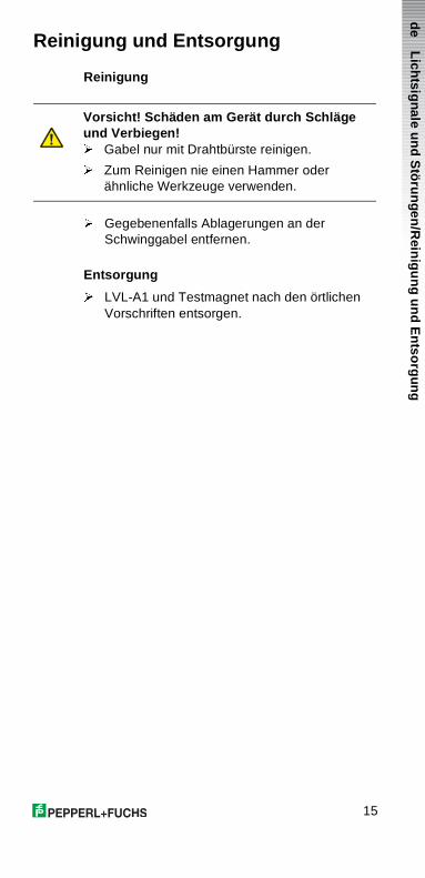
Reinigung und Entsorgung
Reinigung
� Gegebenenfalls Ablagerungen an der Schwinggabel entfernen.
Entsorgung
� LVL-A1 und Testmagnet nach den örtlichen Vorschriften entsorgen.
Vorsicht! Schäden am Gerät durch Schläge und Verbiegen!� Gabel nur mit Drahtbürste reinigen.
� Zum Reinigen nie einen Hammer oderähnliche Werkzeuge verwenden.
Lich
tsignale u
nd S
töru
ngen
/Rein
igu
ng
un
d E
ntso
rgun
g
16
Contents
What the Vibracon Mini can do 17Here you can find information on:
• Applications• Benefits and functional description• Installation examples and application
instructions• Operating modes for variants AC and DC-
PNP• Product variants and ordering code• Certificates and accessories
Technical data 21Here you will find connection data, operating conditions and dimensions.
Safety 23Make sure you read this section before you start installing and connecting the LVL-A1.
Installation and connection 24Here you will find instructions on how to mount and adjust the LVL-A1, making the electrical connections and test using the test magnet.
Light signals and faults 28Here you will find an overview of the LED display integrated on the LVL-A1 and information on how to remedy any faults that may occur.
Cleaning and disposal 29This contains instructions on what to do when cleaning and disposing of the LVL-A1.
17
en
What the Vibracon Mini can do
ApplicationsThe Vibracon Mini LVL-A1 is a level limit switch for all kinds of fluids and is used in tanks, containers and pipelines.
It is used in cleaning and filtering systems and coolant and lubricant tanks as an overspill protection or as a pump protector.
The LVL-A1 is ideal for applications which previously used float switches and conductive, capacitive and optical sensors.
It also works in applications which are unsuitable for these measuring methods due to conductivity, build-ups, turbulence, flows or air bubbles.
The LVL-A1 is not suitable for hazardous areas, hygiene areas and areas where the liquid temperature is over 100 °C.
Benefits• Operational safety, reliability and universal
applicability through use of the tuning fork measuring principle
• External test option using test magnet• On-site control using external LED display• Easy to install even at points difficult to access
due to compact construction• Rugged stainless steel housing (316L)• Service-friendly plug-in connections
Functional descriptionThe tuning fork of the LVL-A1 is excited to its resonance frequency by means of a piezoelectric drive.
This frequency changes if the tuning fork is covered by fluid.
The LVL-A1 electronics monitor the resonance frequency and indicate whether the tuning fork is oscillating freely or whether fluid is covering it.
Wh
at the V
ibraco
n M
ini can
do
18
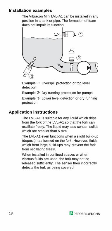
Installation examplesThe Vibracon Mini LVL-A1 can be installed in any position in a tank or pipe. The formation of foam does not impair its function.
Example �: Overspill protection or top level detection
Example �: Dry running protection for pumps
Example �: Lower level detection or dry running protection
Application instructionsThe LVL-A1 is suitable for any liquid which drips from the fork of the LVL-A1 so that the fork can oscillate freely. The liquid may also contain solids which are smaller than 5 mm.
The LVL-A1 even functions when a slight build-up (deposit) has formed on the fork. However, fluids which form large build-ups may prevent the fork from oscillating freely.
When installed in confined spaces or when viscous fluids are used, the fork may not be released sufficiently. The sensor then incorrectly detects the fork as being covered.
�
�
�
19
en
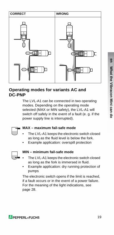
Operating modes for variants AC and DC-PNP
The LVL-A1 can be connected in two operating modes. Depending on the operating mode selected (MAX or MIN safety), the LVL-A1 will switch off safely in the event of a fault (e. g. if the power supply line is interrupted).
MAX – maximum fail-safe mode
• The LVL-A1 keeps the electronic switch closed as long as the fluid level is below the fork.
• Example application: overspill protection
MIN – minimum fail-safe mode
• The LVL-A1 keeps the electronic switch closed as long as the fork is immersed in fluid.
• Example application: dry running protection of pumps
The electronic switch opens if the limit is reached, if a fault occurs or in the event of a power failure. For the meaning of the light indications, see page 28.
CORRECT WRONG
Wh
at the V
ibraco
n M
ini can
do
20
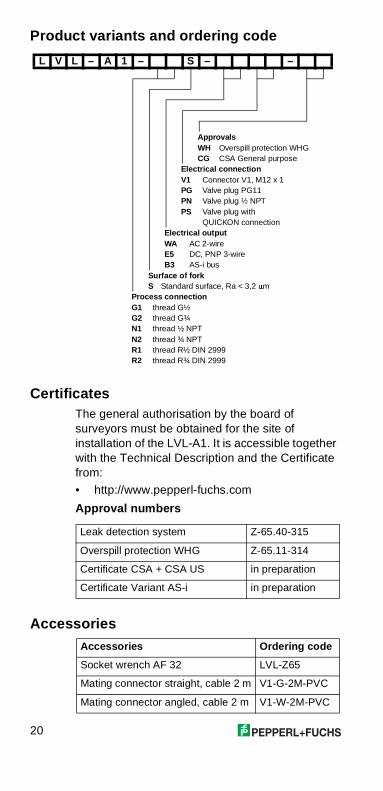
Product variants and ordering code
CertificatesThe general authorisation by the board of surveyors must be obtained for the site of installation of the LVL-A1. It is accessible together with the Technical Description and the Certificate from:
• http://www.pepperl-fuchs.com
Approval numbers
Accessories
L V L – A 1 – S – –
ApprovalsWH Overspill protection WHGCG CSA General purpose
Electrical connectionV1 Connector V1, M12 x 1PG Valve plug PG11PN Valve plug ½ NPTPS Valve plug with
QUICKON connectionElectrical outputWA AC 2-wireE5 DC, PNP 3-wireB3 AS-i bus
Surface of forkS Standard surface, Ra < 3,2 �m
Process connectionG1 thread G½G2 thread G¾N1 thread ½ NPTN2 thread ¾ NPTR1 thread R½ DIN 2999R2 thread R¾ DIN 2999
Leak detection system Z-65.40-315
Overspill protection WHG Z-65.11-314
Certificate CSA + CSA US in preparation
Certificate Variant AS-i in preparation
Accessories Ordering code
Socket wrench AF 32 LVL-Z65
Mating connector straight, cable 2 m V1-G-2M-PVC
Mating connector angled, cable 2 m V1-W-2M-PVC
21
en
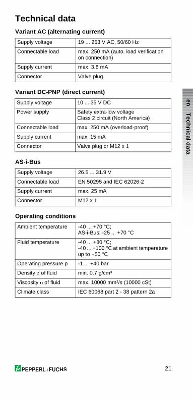
Technical dataVariant AC (alternating current)
Variant DC-PNP (direct current)
AS-i-Bus
Operating conditions
Supply voltage 19 ... 253 V AC, 50/60 Hz
Connectable load max. 250 mA (auto. load verification on connection)
Supply current max. 3.8 mA
Connector Valve plug
Supply voltage 10 ... 35 V DC
Power supply Safety extra-low voltage Class 2 circuit (North America)
Connectable load max. 250 mA (overload-proof)
Supply current max. 15 mA
Connector Valve plug or M12 x 1
Supply voltage 26.5 ... 31.9 V
Connectable load EN 50295 and IEC 62026-2
Supply current max. 25 mA
Connector M12 x 1
Ambient temperature -40 ... +70 °C; AS-i-Bus: -25 ... +70 °C
Fluid temperature -40 ... +80 °C; -40 ... +100 °C at ambient temperature up to +50 °C
Operating pressure p -1 ... +40 bar
Density � of fluid min. 0.7 g/cm³
Viscosity � of fluid max. 10000 mm²/s (10000 cSt)
Climate class IEC 60068 part 2 - 38 pattern 2a
Techn
ical data
22
Operating conditions (continued)
Output, general
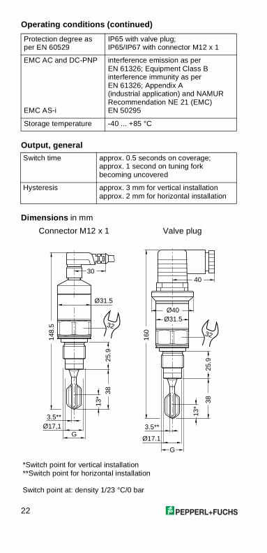
Dimensions in mm
Protection degree as per EN 60529
IP65 with valve plug;IP65/IP67 with connector M12 x 1
EMC AC and DC-PNP
EMC AS-i
interference emission as per EN 61326; Equipment Class B interference immunity as per EN 61326; Appendix A (industrial application) and NAMURRecommendation NE 21 (EMC)EN 50295
Storage temperature -40 ... +85 °C
Switch time approx. 0.5 seconds on coverage;approx. 1 second on tuning fork becoming uncovered
Hysteresis approx. 3 mm for vertical installationapprox. 2 mm for horizontal installation
Connector M12 x 1 Valve plug
*Switch point for vertical installation**Switch point for horizontal installation
Switch point at: density 1/23 °C/0 bar
148.
5
Ø31.5
Ø17,1
25.9
38
G
30
32
13*
3.5**
160
25.9
38
Ø31.5
G
Ø17.1
Ø40
40
32
13*
3.5**
23
en
Mechanical data
Cable
Safety
Intended applicationThe LVL-A1 may only be used as a level limit switch for fluids and only in non-hazardous areas. It must be installed in a fixed position in a tank or pipe wall.
General safety instructionsImproper use may cause dangerous situations to emanate from the LVL-A1.
The device may only be installed, connected up, put into operation and maintained by trained and instructed personnel taking into consideration these instructions, the prevailing standards, statutory regulations and – depending on the application – certificates.
WarningsWarnings are identified as follows:
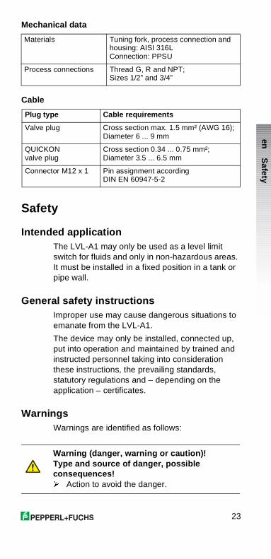
Materials Tuning fork, process connection and housing: AISI 316LConnection: PPSU
Process connections Thread G, R and NPT; Sizes 1/2” and 3/4”
Plug type Cable requirements
Valve plug Cross section max. 1.5 mm² (AWG 16);Diameter 6 ... 9 mm
QUICKON valve plug
Cross section 0.34 ... 0.75 mm²;Diameter 3.5 ... 6.5 mm
Connector M12 x 1 Pin assignment according DIN EN 60947-5-2
Warning (danger, warning or caution)!Type and source of danger, possible consequences!� Action to avoid the danger.
Safety
24
Installation and connection
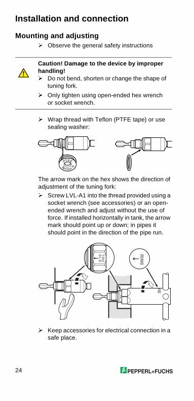
Mounting and adjusting� Observe the general safety instructions
� Wrap thread with Teflon (PTFE tape) or use sealing washer:
The arrow mark on the hex shows the direction of adjustment of the tuning fork:
� Screw LVL-A1 into the thread provided using a socket wrench (see accessories) or an open-ended wrench and adjust without the use of force. If installed horizontally in tank, the arrow mark should point up or down; in pipes it should point in the direction of the pipe run.
� Keep accessories for electrical connection in a safe place.
Caution! Damage to the device by improper handling!� Do not bend, shorten or change the shape of
tuning fork.
� Only tighten using open-ended hex wrench or socket wrench.
��
��
��
���
���
��
25
en
Electrical connectionRequirements: Operating mode (MIN or MAX) is defined (see page 19).
� Comply with the safety instructions (see page 23).
� Comply with cable specifications for the present connector (see page 23).
� Read the nameplate to determine what variant the LVL-A1 is: variant DC-PNP, variant AC or AS-i-Bus.
� Note the connection data.
Valve plugs are placed separately and disassembled:
� Assemble and install valve plugs (also QUICKON) acc. to instructions on the plug packaging.
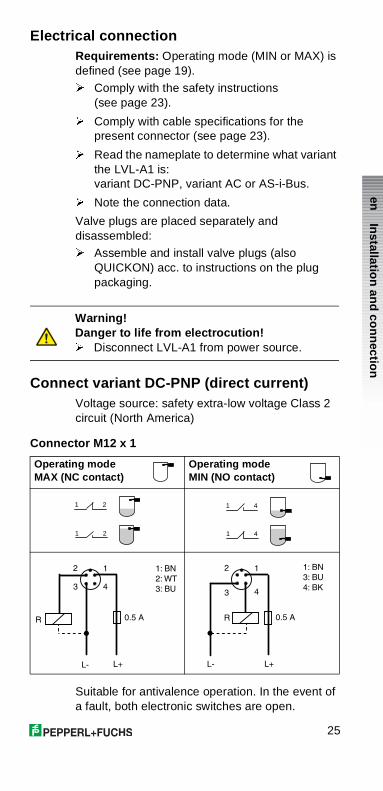
Connect variant DC-PNP (direct current)Voltage source: safety extra-low voltage Class 2 circuit (North America)
Connector M12 x 1
Suitable for antivalence operation. In the event of a fault, both electronic switches are open.
Warning!Danger to life from electrocution!� Disconnect LVL-A1 from power source.
Operating mode MAX (NC contact)
Operating modeMIN (NO contact)
1 2
1 2
1 4
1 4
0.5 A
L+
R
L-
2
3
1
4
1: BN
2:WT
3: BU
0.5 A
L+
R
L-
2
3
1
4
1: BN
3: BU
4: BK
Installatio
n an
d co
nn
ection
26
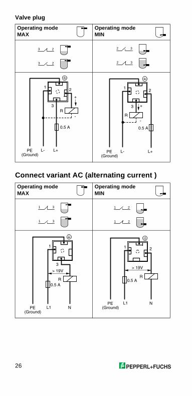
Valve plug
Connect variant AC (alternating current )
Operating mode MAX
Operating modeMIN
Operating mode MAX
Operating modeMIN
3 2
3 2
2 3
2 3
(Ground)
1
3
0.5 A
L+PE
R
L-
2
+
-
1
3
0.5 A
L+PE(Ground)
R
L-
2
+
-
1 3
1 3
1 2
1 2
(Ground)
1
3
R
0.5 A
L1 NPE
> 19V
(Ground)
1 2
R0.5 A
L1 NPE
> 19V
27
en
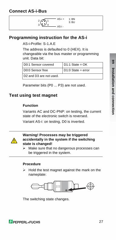
Connect AS-i-Bus
Programming instruction for the AS-iAS-i-Profile: S-1.A.E
The address is defaulted to 0 (HEX). It is changeable via the bus master or programming unit. Data bit:
Parameter bits (P0 ... P3) are not used.
Test using test magnet
Function
Variants AC and DC-PNP: on testing, the current state of the electronic switch is reversed.
Variant AS-i: on testing, D0 is inverted.
Procedure
� Hold the test magnet against the mark on the nameplate:
The switching state changes.
AS-i +
AS-i -
2
3
1
4
1: BN3: BU
D0:1 Sensor covered D1:1 State = OK
D0:0 Sensor free D1:0 State = error
D2 and D3 are not used.
Warning! Processes may be triggered accidentally in the system if the switching state is changed!� Make sure that no dangerous processes can
be triggered in the system.
Installatio
n an
d co
nn
ection
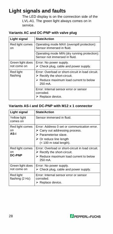
28
Light signals and faultsThe LED display is on the connection side of the LVL-A1. The green light always comes on inservice.
Variants AC and DC-PNP with valve plug
Variants AS-i and DC-PNP with M12 x 1 connector
Light signal State/Action
Red light comes on
Operating mode MAX (overspill protection):Sensor immersed in fluid.
Operating mode MIN (dry running protection):Sensor not immersed in fluid.
Green light does not come on
Error: No power supply.� Check plug, cable and power supply.
Red light flashing
Error: Overload or short-circuit in load circuit.� Rectify the short-circuit.� Reduce maximum load current to below
250 mA.
Error: Internal sensor error or sensor corroded.� Replace device.
Light signal State/Action
Yellow light comes on
Sensor immersed in fluid.
Red light comes onAS-i
Error: Address 0 set or communication error.� Carry out addressing process.� Parameterise slave.� Or reduce line length
(< 100 m total length).
Red light comes onDC-PNP
Error: Overload or short-circuit in load circuit.� Rectify the short-circuit.� Reduce maximum load current to below
250 mA.
Green light does not come on
Error: No power supply.� Check plug, cable and power supply.
Red light flashing (2 Hz)
Error: Internal sensor error or sensor corroded.� Replace device.

29
en
Cleaning and disposal
Cleaning
� Remove any build-ups on tuning fork.
Disposal
� Dispose of LVL-A1 and test magnet according to local regulations.
Caution! Do not damage device by knocks and bending!� Only clean fork with wire brush.
� Never use hammer or similar tools for cleaning.
Lig
ht sig
nals an
d fau
lts/Clean
ing
and
disp
osal
30
Sommaire
Domaines d’application Vibracon Mini 31Vous trouverez ici des informations suivantes :
• Domaines d’utilisation• Avantages et Principe de fonctionnement• Exemples de montage et Conseils
d’utilisation• Raccordement des variantes AC et DC-
PNP• Variantes produits/structure de
commande• Certificats et Accessoires
Caractéristiques techniques 35Vous trouverez ici les valeurs de raccordement, les conditions d’utilisation et dimensions.
Sécurité 37Lire impérativement cette section avant le montage et le raccordement du LVL-A1.
Montage et raccordement 38Vous trouverez ici les directives de montage et d’orientation du LVL-A1, de raccordement électrique et de test avec l’aimant test.
Signaux lumineux et défauts 42Vous trouverez ici une vue d’ensemble des signaux lumineux du LVL-A1 et des informations sur la suppression d’éventuels défauts.
Nettoyage et mise au rebut 43Vous trouverez ici des conseils pour le nettoyage et la mise au rebut du LVL-A1.
31
fr
Domaines d’application Vibracon Mini
Domaines d’utilisationLe Vibracon Mini LVL-A1 est un détecteur de niveau pour liquides de toutes natures utilisé dans les cuves, réservoirs et conduites.
Il est employé dans les installations de nettoyage et de filtration, les réservoirs de réfrigérants et de lubrifiants comme sécurité anti-débordement ou protection contre la marche à vide de pompes.
Le LVL-A1 est idéal pour les applications sur lesquelles on employait jusqu’à présent des flotteurs ou des sondes conductives, capacitives ou optiques.
Il fonctionne également dans les domaines où ces principes échouent en raison de la conductivité, des dépôts, turbulences, courants ou bulles d’air.
Le LVL-A1 n’est pas conçu pour les zones explosibles, ni les domaines aseptiques ou les produits dont la température dépasse 100 °C.
Avantages• Sécurité de fonctionnement, fiabilité et
universalité grâce au principe de mesure des lames vibrantes
• Possibilité de test de l’extérieur avec l’aimant test
• Contrôle du fonctionnement sur site grâce à l’affichage lumineux externe
• Forme compacte facilitant le montage, également en des endroits difficiles d’accès
• Boitier inox robuste (316L)• Raccords embrochables
Principe de fonctionnementLa fourche du LVL-A1 est amenée à sa fréquence de résonance par actionnement piézoélectrique. Cette fréquence se modifie lorsque la fourche est recouverte de liquide.
L’électronique du LVL-A1 surveille la fréquence de résonance et indique si la fourche oscille librement ou si elle est recouverte de liquide.
Do
main
es d’ap
plicatio
n V
ibracon
Min
i
32
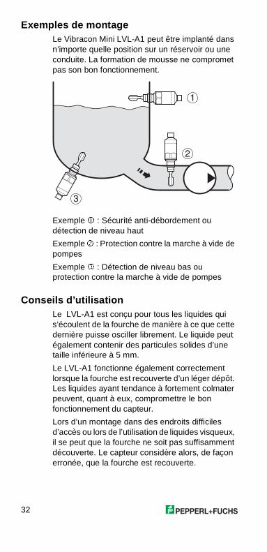
Exemples de montageLe Vibracon Mini LVL-A1 peut être implanté dans n’importe quelle position sur un réservoir ou une conduite. La formation de mousse ne compromet pas son bon fonctionnement.
Exemple � : Sécurité anti-débordement ou détection de niveau haut
Exemple � : Protection contre la marche à vide de pompes
Exemple � : Détection de niveau bas ou protection contre la marche à vide de pompes
Conseils d’utilisationLe LVL-A1 est conçu pour tous les liquides qui s’écoulent de la fourche de manière à ce que cette dernière puisse osciller librement. Le liquide peut également contenir des particules solides d’une taille inférieure à 5 mm.
Le LVL-A1 fonctionne également correctement lorsque la fourche est recouverte d’un léger dépôt. Les liquides ayant tendance à fortement colmater peuvent, quant à eux, compromettre le bon fonctionnement du capteur.
Lors d’un montage dans des endroits difficiles d’accès ou lors de l’utilisation de liquides visqueux, il se peut que la fourche ne soit pas suffisamment découverte. Le capteur considère alors, de façon erronée, que la fourche est recouverte.
�
�
�
33
fr
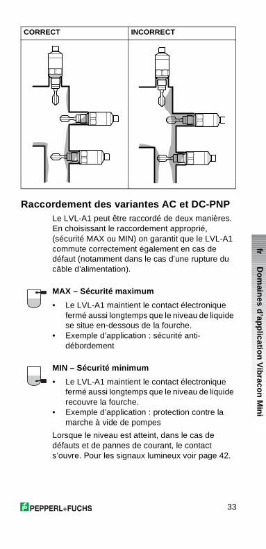
Raccordement des variantes AC et DC-PNPLe LVL-A1 peut être raccordé de deux manières. En choisissant le raccordement approprié, (sécurité MAX ou MIN) on garantit que le LVL-A1 commute correctement également en cas de défaut (notamment dans le cas d’une rupture du câble d’alimentation).
MAX – Sécurité maximum
• Le LVL-A1 maintient le contact électronique fermé aussi longtemps que le niveau de liquide se situe en-dessous de la fourche.
• Exemple d’application : sécurité anti-débordement
MIN – Sécurité minimum
• Le LVL-A1 maintient le contact électronique fermé aussi longtemps que le niveau de liquide recouvre la fourche.
• Exemple d’application : protection contre la marche à vide de pompes
Lorsque le niveau est atteint, dans le cas de défauts et de pannes de courant, le contact s’ouvre. Pour les signaux lumineux voir page 42.
CORRECT INCORRECT
Do
main
es d’ap
plicatio
n V
ibracon
Min
i
34
Variantes produits/structure de commande
CertificatsLe Certificat d’homologation général doit être disponible au lieu d’utilisation du LVL-A1. Il peut être obtenu avec la description technique et le certificat sous :
• http://www.pepperl-fuchs.com
Numéros d’agréments
Accessoires
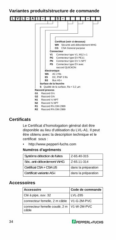
L V L – A 1 – S – –
Certificat (voir ci-dessous)WH Sécurité anti-débordement WHGCG CSA General purpose
ConnecteurV1 Connecteur type V1, M12 x 1PG Connecteur type EV PE11PN Connecteur type EV ½ NPTPS Connecteur type EV avec
raccord QUICKONElectroniqueWA AC 2 filsE5 DC, PNP 3 filsB3 Bus AS-i
Surface de la fourcheS Qualité de la surface, Ra < 3,2 �m
Raccord processG1 Raccord G½G2 Raccord G¾N1 Raccord ½ NPTN2 Raccord ¾ NPTR1 Raccord R½ DIN 2999R2 Raccord R¾ DIN 2999
Système détection de fuites Z-65.40-315
Séc. anti-débordement WHG Z-65.11-314
Certificat CSA+CSAUS dans la préparation
Certificat variante AS-i dans la préparation
Accessoire Code de commande
Clé à pipe, ouv. 32 LVL-Z65
connecteur femelle, 2 m câble V1-G-2M-PVC
connecteur femelle coudé, 2 m câble
V1-W-2M-PVC
35
fr
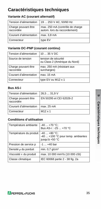
Caractéristiques techniquesVariante AC (courant alternatif)
Variante DC-PNP (courant continu)
Bus AS-i
Conditions d’utilisation
Tension d’alimentation 19 ... 253 V AC, 50/60 Hz
Charge pouvant être raccordée
max. 250 mA (contrôle de charge autom. lors du raccordement)
Courant d’alimentation max. 3,8 mA
Connecteur type EV
Tension d’alimentation 10 ... 35 V DC
Source de tension tension de sécurité ou Class 2 (Amérique du Nord)
Charge pouvant être raccordée
max. 250 mA (résistant aux surcharges)
Courant d’alimentation max. 15 mA
Connecteur type EV ou M12 x 1
Tension d’alimentation 26,5 ... 31,9 V
Charge pouvant être raccordée
EN 50295 et CEI 62026-2
Courant d’alimentation max. 25 mA
Connecteur M12 x 1
Température ambiante -40 ... +70 °C; Bus AS-i : -25 ... +70 °C
Température du produit -40 ... +80 °C; -40 ... +100 °C pour temp. ambiantes jusqu’à +50 °C
Pression de service p -1 ... +40 bar
Densité � du porduit min. 0,7 g/cm³
Viscosité � du produit max. 10 000 mm²/s (10 000 cSt)
Classe climatique IEC 60068 partie 2 - 38 fig. 2a
Caractéristiq
ues tech
niq
ues
36
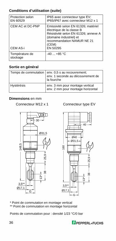
Conditions d’utilisation (suite)
Sortie en général
Dimensions en mm
Protection selon EN 60529
IP65 avec connecteur type EV;IP65/IP67 avec connecteur M12 x 1
CEM AC et DC-PNP
CEM AS-i
Emissivité selon EN 61326; matériel électrique de la classe BRésistivité selon EN 61326; annexe A (domaine industriel) et recommandation NAMUR NE 21 (CEM)EN 50295
Température de stockage
-40 ... +85 °C
Temps de commutation env. 0,5 s au recouvrement;env. 1 seconde au découvrement de la fourche
Hystérésis env. 3 mm pour montage verticalenv. 2 mm pour montage horizontal
Connecteur M12 x 1 Connecteur type EV
* Point de commutation en montage vertical** Point de commutation en montage horizontal
Points de commutation pour : densité 1/23 °C/0 bar
148,
5
Ø31,5
Ø17,1
25,9
38
G
30
32
13*
3,5**
160
25,9
38
Ø31,5
G
Ø17,1
Ø40
40
32
13*
3,5**
37
fr
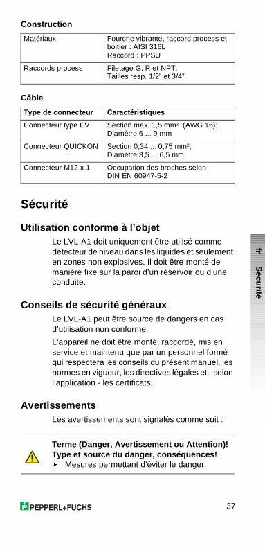
Construction
Câble
Sécurité
Utilisation conforme à l’objetLe LVL-A1 doit uniquement être utilisé comme détecteur de niveau dans les liquides et seulement en zones non explosives. Il doit être monté de manière fixe sur la paroi d’un réservoir ou d’une conduite.
Conseils de sécurité générauxLe LVL-A1 peut être source de dangers en cas d’utilisation non conforme.
L’appareil ne doit être monté, raccordé, mis en service et maintenu que par un personnel formé qui respectera les conseils du présent manuel, les normes en vigueur, les directives légales et - selon l’application - les certificats.
AvertissementsLes avertissements sont signalés comme suit :
Matériaux Fourche vibrante, raccord process et boitier : AISI 316LRaccord : PPSU
Raccords process Filetage G, R et NPT; Tailles resp. 1/2” et 3/4”
Type de connecteur Caractéristiques
Connecteur type EV Section max. 1,5 mm² (AWG 16);Diamètre 6 ... 9 mm
Connecteur QUICKON Section 0,34 ... 0,75 mm²;Diamètre 3,5 ... 6,5 mm
Connecteur M12 x 1 Occupation des broches selon DIN EN 60947-5-2
Terme (Danger, Avertissement ou Attention)!Type et source du danger, conséquences!� Mesures permettant d’éviter le danger.
Sécu
rité
38
Montage et raccordement
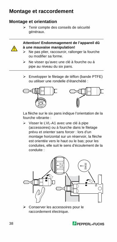
Montage et orientation� Tenir compte des conseils de sécurité
généraux.
� Envelopper le filetage de téflon (bande PTFE) ou utiliser une rondelle d’étanchéité :
La flèche sur le six pans indique l’orientation de la fourche vibrante :
� Visser le LVL-A1 avec une clé à pipe (accessoires) ou à fourche dans le filetage prévu et orienter sans forcer : lors d’un montage horizontal sur un réservoir, la flèche est orientée vers le haut ou le bas; pour les conduites, elle suit le sens d’écoulement de la conduite :
� Conserver les accessoires pour le raccordement électrique.
Attention! Endommagement de l’appareil dû à une mauvaise manipulation!� Ne pas plier, raccourcir, rallonger la fourche
ou modifier sa forme.
� Ne visser qu’avec une clé à fourche ou à pipe au niveau du six pans.
��
��
��
���
���
��
39
fr
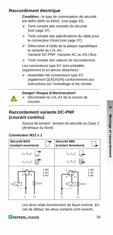
Raccordement électriqueCondition : le type de commutation de sécurité est défini (MIN ou MAX) (voir page 33).
� Tenir compte des conseils de sécurité (voir page 37).
� Tenir compte des spécifications du câble pour le connecteur choisi (voir page 37).
� Déterminer à l’aide de la plaque signalétique la variante du LVL-A1 : Variante DC-PNP, Variante AC ou AS-i-Bus.
� Tenir compte des valeurs de raccordement.
Les connecteurs type EV sont emballés séparément et en pièces détachées :
� Assembler les connecteurs type EV (également QUICKON) conformément aux instructions sur l’emballage et les monter.
Raccordement variante DC-PNP (courant continu)
Source de tension : tension de sécurité ou Class 2 (Amérique du Nord)
Connecteur M12 x 1
Les deux relais fonctionnent de façon inverse. En cas de défaut, les deux contacts sont ouverts.
Danger! Risque d’électrocution!� Déconneter le LVL-A1 de la source de
courant.
Sécurité MAX(contact ouverture)
Sécurité MIN(contact fermeture)
1 2
1 2
1 4
1 4
0,5 A
L+
R
L-
2
3
1
4
1: BN2: WT3: BU
0,5 A
L+
R
L-
2
3
1
4
1: BN3: BU4: BK
Mo
ntage et racco
rdem
ent
40
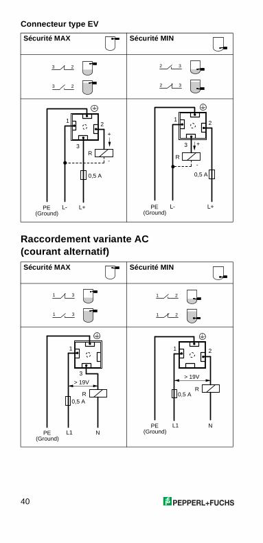
Connecteur type EV
Raccordement variante AC (courant alternatif)
Sécurité MAX Sécurité MIN
Sécurité MAX Sécurité MIN
3 2
3 2
2 3
2 3
(Ground)
1
3
0,5 A
L+PE
R
L-
2
+
-
1
3
0,5 A
L+PE(Ground)
R
L-
2
+
-
1 3
1 3
1 2
1 2
(Ground)
1
3
R0,5 A
L1 NPE
> 19V
(Ground)
1 2
R0,5 A
L1 NPE
> 19V
41
fr
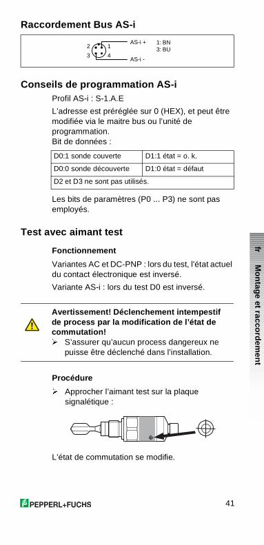
Raccordement Bus AS-i
Conseils de programmation AS-iProfil AS-i : S-1.A.E
L’adresse est préréglée sur 0 (HEX), et peut être modifiée via le maitre bus ou l’unité de programmation. Bit de données :
Les bits de paramètres (P0 ... P3) ne sont pas employés.
Test avec aimant test
Fonctionnement
Variantes AC et DC-PNP : lors du test, l’état actuel du contact électronique est inversé.
Variante AS-i : lors du test D0 est inversé.
Procédure
� Approcher l’aimant test sur la plaque signalétique :
L’état de commutation se modifie.
AS-i +
AS-i -
2
3
1
4
1: BN3: BU
D0:1 sonde couverte D1:1 état = o. k.
D0:0 sonde découverte D1:0 état = défaut
D2 et D3 ne sont pas utilisés.
Avertissement! Déclenchement intempestif de process par la modification de l’état de commutation!� S’assurer qu’aucun process dangereux ne
puisse être déclenché dans l’installation.
Mo
ntage et racco
rdem
ent
42
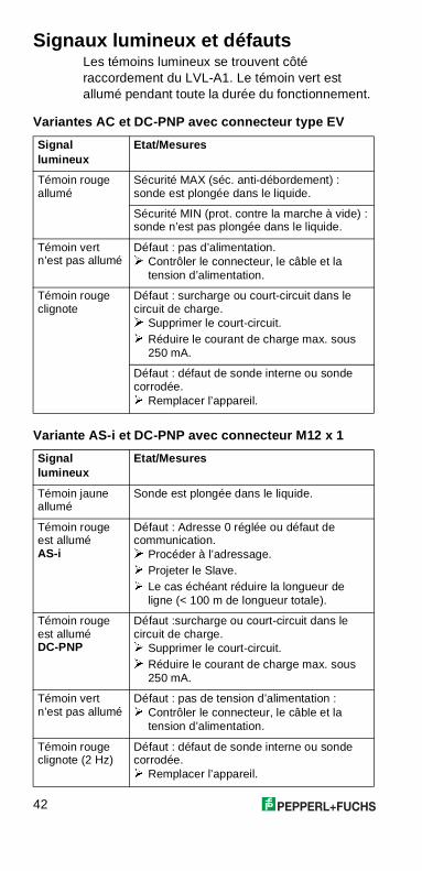
Signaux lumineux et défautsLes témoins lumineux se trouvent côté raccordement du LVL-A1. Le témoin vert est allumé pendant toute la durée du fonctionnement.
Variantes AC et DC-PNP avec connecteur type EV
Variante AS-i et DC-PNP avec connecteur M12 x 1
Signallumineux
Etat/Mesures
Témoin rouge allumé
Sécurité MAX (séc. anti-débordement) :sonde est plongée dans le liquide.
Sécurité MIN (prot. contre la marche à vide) :sonde n’est pas plongée dans le liquide.
Témoin vert n’est pas allumé
Défaut : pas d’alimentation.� Contrôler le connecteur, le câble et la
tension d’alimentation.
Témoin rouge clignote
Défaut : surcharge ou court-circuit dans le circuit de charge.� Supprimer le court-circuit.� Réduire le courant de charge max. sous
250 mA.
Défaut : défaut de sonde interne ou sonde corrodée.� Remplacer l’appareil.
Signallumineux
Etat/Mesures
Témoin jaune allumé
Sonde est plongée dans le liquide.
Témoin rouge est alluméAS-i
Défaut : Adresse 0 réglée ou défaut de communication.� Procéder à l’adressage.� Projeter le Slave.� Le cas échéant réduire la longueur de
ligne (< 100 m de longueur totale).
Témoin rouge est alluméDC-PNP
Défaut :surcharge ou court-circuit dans le circuit de charge.� Supprimer le court-circuit.� Réduire le courant de charge max. sous
250 mA.
Témoin vert n’est pas allumé
Défaut : pas de tension d’alimentation :� Contrôler le connecteur, le câble et la
tension d’alimentation.
Témoin rouge clignote (2 Hz)
Défaut : défaut de sonde interne ou sonde corrodée.� Remplacer l’appareil.
43
fr
Nettoyage et mise au rebut
Nettoyage
� Le cas échéant, supprimer les dépôts sur la fourche.
Mise au rebut
� Mettre le LVL-A1 et l’aimant test au rebut conformément aux directives locales.
Attention! Endomagement de l’appareil par des chocs ou torsions!� Nettoyer la fourche uniquement avec une
brosse métallique.
� Ne jamais utiliser de marteau ou d’outil similaire pour le nettoyage.
Sig
naux lu
min
eux et d
éfauts/N
ettoyag
e et mise au
rebu
t

KA 190O/98/a3/02.0252010808 CCS/FM6
116408 02/02 01
de Bestellung� Geben Sie bei Pepperl+Fuchs Ihren Bestellcode
an (siehe Seite 6).
en Ordering� Specify your ordering code to the
Pepperl+Fuchs (see page 20).
fr Commande� Indiquer le code de commande à votre
Pepperl+Fuchs (voir page 34).
L V L – A 1 – – –
Zentrale weltweit Pepperl+Fuchs GmbH � K�nigsberger Allee 87 68307 Mannheim � Deutschland Tel. (06 21) 7 76-0 � Fax (06 21) 7 76-10 00E-Mail: [email protected]
Zentrale AsienPepperl+Fuchs Pte Ltd. � P+F Building18 Ayer Rajah Crescent � Singapore 139942Tel. (65) 7 79 90 91 � Fax (65) 8 73 16 37E-Mail: [email protected]
Zentrale USA Pepperl+Fuchs Inc. � 1600 Enterprise ParkwayTwinsburg, Ohio 44087 � USATel. (330) 4 25 35 55 � Fax (330) 4 25 46 07E-Mail: [email protected]
Zumutbare �nderungen aufgrund technischer Verbesserungen vorbehalten � Copyright PEPPERL+FUCHS � Printed in Germany Subject to reasonable modifications due to technical advances � Copyright PEPPERL+FUCHS � Printed in GermanySous rØserve de modifications en raison d�amØliorations techniques � Copyright PEPPERL+FUCHS � Printed in Germany
service line process automation
Tel. (0621) 776-22 22 � Fax (0621) 776-27-22 22 � E-Mail: [email protected]