Embed Size (px)
Citation preview
Wagon Plough THSRT
Instruction Manual“Original Instructions”
ENEdition:170413
EF-overensstemmelseserklæring/ EG-Konformitätserklärung/ EC Declaration of Conformity/ Déclaration CE de conformité/ Dichiarazione CE di conformita/ EG Verklaring van Overeenstemming/ EG-försäkran om överensstämmelse/ EY-vaatimustenmukaisuusvakuutus/ Declaración de conformidad CE/ Deklaracja Zgodności WE./ Декларация за съответствие EO/ EK Megfelelőségi Nyilatkozat /ES Prohlášení o shodě/ EB Atitikties deklaracija/ ES prehlásenie o zhode/ Declaraţia de conformitate CE/ Vastavuse Deklaratsioon EÜ /ES Izjava o skladnosti/ Δήλωση πιστότητας EK/ Declaração de fidelidade CE/ Dikjarazzjoni ta’ Konformità tal-KE/ EK Atbilstības deklarācija/
Fabrikant/ Hersteller/ Manufacturer/ Fabricant/ Produttore/ Fabrikant/ Fabrikant/ Valmistaja/ Fabricante/ Producent/ Производител/ Gyártó/ Výrobce/ Gamintojas/ Výrobca/ Producător/ Tootja/ Proizvajalec/ Κατασκευαστής/ Fabricante/ Fabbrikant/ Ražotājs
CNH INDUSTRIAL SWEDEN AB.Bruksgatan 4, 59096 Överum, SWEDEN
Repræsenteret af Antoon Vermeulen, Leon Claeysstraat 3A, B8210 Zedelgem (Belgien), som også har tilladelse til at indsamle teknisk dokumentation / vertreten durch Antoon Vermeulen, Leon Claeysstraat 3A, B8210 Zedelgem (Belgium), der auch autorisiert ist, die technische Akte zu erarbeiten / represented by Antoon Vermeulen, Leon Claeysstraat 3A, B8210 Zedelgem (Belgium), who is also authorised to compile the Technical File / Répresentés par Antoon Vermeulen, Leon Claeysstraat 3A, B8210 Zedelgem (Belgique), également autorisé à constituer le dossier technique / rappresentati da Antoon Vermeulen, Leon Claeysstraat 3A, B8210 Zedelgem (Belgio), autorizzato a compilare il File tecnico / vertegenwoordigd door Antoon Vermeulen, Leon Claeysstraat 3A, B8210 Zedelgem (Belgium), die tevens is gemachtigd om het Technisch Bestand samen te stellen / representerade av Antoon Vermeulen, Leon Claeysstraat 3A, B8210 Zedelgem (Belgien), som också har behörighet att sammanställa den tekniska dokumentationen / edustajamme Antoon Vermeulenin, osoite Leon Claeysstraat 3A, B8210 Zedelgem (Belgium) välityksellä, jolla on myös oikeus laatia tekninen tiedosto / representados por Antoon Vermeulen, Leon Claeysstraat 3A, B8210 Zedelgem (Bélgica), quien además está autorizado para recopilar el documento técnico / której przedstawicielem jest Antoon Vermeulen, Leon Claeysstraat 3A, B8210 Zedelgem (Belgia), który jest również upoważniony do sporządzania dokumentacji technicznej / представлявани от Антоон Вермьолен, Leon Claeysstraat 3A, B8210 Zedelgem (Белгия), с упълномощение също да състави Техническото досие / akiket képvisel: Antoon Vermeulen, Leon Claeysstraat 3A, B8210 Zedelgem (Belgium), aki szintén jogosult a műszaki dokumentumok összeállítására / v zastoupení Antoon Vermeulen, Leon Claeysstraat 3A, B8210 Zedelgem (Belgium), s autorizací k tvorbě technického souboru / atstovaujami Antoon Vermeulen, Leon Claeysstraat 3A, B8210 Zedelgem (Belgija), taip pat turintis teisę sudaryti technines bylas / v zastúpení Antoonom Vermeulenom, Leon Claeysstraat 3A, B8210 Zedelgem (Belgicko), ktorý je oprávnený zostavovať technickú dokumentáciu / reprezentaţi de Antoon Vermeulen, Leon Claeysstraat 3A, B8210 Zedelgem (Belgia), care este, de asemenea, autorizat să compileze dosarul ethnic / esindajatega Antoon Vermeulen, Leon Claeysstraat 3A, B8210 Zedelgem (Belgia), kellel on samuti luba tehnilise faili koostamiseks / ki nas zastopa Antoon Vermeulen, Leon Claeysstraat 3A, B8210 Zedelgem (Belgija), ki je pooblaščen tudi za sestavo tehnične dokumentacije / εκπροσωπούμενοι από τον Antoon Vermeulen, Leon Claeysstraat 3A, B8210 Zedelgem (Βέλγιο), με εξουσιοδότηση και για τη σύνταξη του Τεχνικού φακέλου / representados por Antoon Vermeulen, Leon Claeysstraat 3A, B8210 Zedelgem (Bélgica), que também tem autorização para compilar o Ficheiro Técnico / irrappreżentata minn Antoon Vermeulen

Leon Claeysstraat 3a, B8210 Zedelgem (Belġju), min huwa wkoll awtorizzat li tiġbor l-Fajl Tekniku / Antoon Vermeulen, Leon Claeysstraat 3A, B8210, Zedelgem (Belgium), pārstāvēti, kas ir pilnvarots arī sastādīt tehnisko reģistru
Erklærer hermed, at/ Erklären hiermit, daß/ Hereby declare that/ Déclare par la présente que/ Dichiara che/ Verklaren hierbij dat/ Försäkrar härmed, att/ Vakuuttaa täten, että tuote/ Por el presente declara que/ Niniejszym deklaruje, że/ Декларирам, че/ Az alábbiakban kijelentem, hogy/ Tímto prohlašuje, že/ Deklaruoja, kad/ Týmto prehlasujeme, že/ Prin prezenta declar că/ Alljärgnevaga deklareerib, et/ Izjavljamo, da je/ Με το παρόν δηλώνω ότι/ Abaixo declara que / Jiddikjaraw li / Apstiprinu, ka
- er i overensstemmelse med Maskindirektivets bestemmelser (Direktiv 2006/42/EF) og hvis relevant også bestemmelserne i EMC-direktivet 2014/30/EU.- In übereinstimmung mit den Bestimmungen der Maschinen-Richtlinie 2006/42/EG und wenn erforderlich auch mit der EMC-Richtlinie 2014/30/EU hergestellt wurde.- is in conformity with the provisions of the Machinery Directive 2006/42/EC and if relevant also the provisions of the EMC Directive 2014/30/EU.- est conforme aux dispositions de la Directive relatives aux machines 2006/42/CE et également aux dispositions de la Directive sur la Directive EMC 2014/30/UE.- é in conformita’ con la Direttiva Macchine 2006/42/CE e, se pertinente, anche alla Direttiva alla Direttiva EMC 2014/30/UE.- in overeenstemming is met de bepalingen van de Machine richtlijn 2006/42/EG en wanneer relevant ook met de bepalingen van de EMC richtlijn 2014/30/EU.- är i överensstämmelse med Maskindirektivets bestämmelser (Direktiv 2006/42/EG) och om relevant också bestämmelserna i EMC-direktivet 2014/30/EU.- täyttää Konedirektiivin (Direktiivi 2006/42/EY) määräykset ja oleellisilta osin myös EMC-direktiivin 2014/30/EU.- es conforme a la Directiva de Maquinaria 2006/42/CE y, si aplica, es conforme también a la Directiva EMC 2014/30/EU.- pozostaje w zgodzie z warunkami Dyrektywy Maszynowej 2006/42/WE i jeżeli ma to zastosowanie również z warunkami Dyrektywy dot. kompatybilności elektro magnetycznej EMC 2014/30/UE.- отговаря на изискванията на Директивата за Машините 2006/42/EО и ако има приложение на изискванията на Директивата за електромагнитна съвместимост 2014/30/EC.- Megfelel a 2006/42/EK Gépi Eszközökre vonatkozó előírásoknak és amennyiben felhasználásra kerül, a 2014/30/EU Elektromágneses kompatibilitás Irányelv feltételeinek.- odpovídá základním požadavkům Strojní směrnice 2006/42/ES a jestliže to její uplatnění vyžaduje i s podmínkami Směrnice 2014/30/EU týkající se elektromagnetické kompatibility.- atitinka Mašinų direktyvos Nr. 2006/42/EB ir, jeigu taikoma, Elektromagnetinio suderinamumo direktyvos Nr. 2014/30/ES reikalavimus.
THSRTTillage300000-320000

- je v súlade s podmienkami Smernice 2006/42/ES o strojných zariadeniach a pokiaľ si to jeho uplatnenie vyžaduje aj s podmienkami Smernice 2014/30/EÚ o elektromagnetickej kompatibilite.- îndeplineşte prevederilor Directivei de Maşini 2006/42/CE şi dacă este utilizată de asemenea cu prevederile Directivei referitoare la compatibilitatea electro-magnetică EMC 2014/30/UE.- on vastavuses Masinate Direktiivi tingimustega 2006/42/EÜ ning sammuti juhul, kui on tegemist sammuti on vastavuses Elektromagnetilise kokkusobivuse Direktiivitingimustega EMC 2014/30/EL.- z določili Direktive o strojih 2006/42/ES ter, če je to relevantno, tudi z določili EMC Direktive 2014/30/EU.- παραμένει σύμφωνη με τους όρους της Οδηγίας περί Μηχανών 2006/42/ΕΚ και σε περίπτωση που αυτό εφαρμόζεται και με τους όρους της Οδηγίας περί ηλεκτροµαγνητικής συµβατότητας (ΗΜΣ) 2014/30/EE.- Está de acordo com exigências das Directivas das Maquínarias 2006/42/CE e no caso em que tiver igualmente aplicação com as exigências das Directivas referentes a compatibilidade electromagnética EMC 2014/30/UE.- tikkonforma mad-dispożizzjonijiet tad-Direttiva dwar il-Makkinarju 2006/42/KE u jekk rilevanti wkoll mad-dispożizzjonijiet tad d-Direttiva EMC 2014/30/EU.- atbilst mašīnu direktīvai 2006/42/EK, kā arī nepieciešamības gadījumā elektromagnētiskās saderības direktīvai EMC 2014/30/ES.
ZedelgemAntoon Vermeulen

1
FOREWORD
DEAR CUSTOMER!Please read these instructions carefully. If you follow the instructions given, you can expect good results along with a good economic return from your choice of plough.
If carefully operated, adjusted and maintained, the plough will meet all reasonable demands made on it and will give you reliable service in years to come. Should you need further instructions, which are not included in this manual, or require the help of experienced service personnel, we advise you to contact one of our local representatives, which also will have spare parts in stock.
It has always been the ambition of Kongskilde to constantly improve its products. Consequently, in the interest of product improvement, no specification is final or binding and we reserve the right to alter the design of new machine series and equipment without previous notice.
CNH Industrial Sweden ABBruksgatan 4S-59096 ÖverumSweden
Tel.: +45 33 68 35 00E-mail: [email protected]
2THSRT KK EN 170413Wagon Plough THSRT
CONTENTSFOREWORD ............................................................................................................11. INTRODUCTION ..................................................................................................3
Description of function .................................................................................3Identification of plough .................................................................................4Safety Regulations .......................................................................................5
2. TECHNICAL DESCRIPTION ................................................................................9Checking the tractor prior to ploughing ........................................................9Preparation of the plough ..........................................................................11Mounting the plough onto the tractor ......................................................... 11Checking the plough ..................................................................................13Turn-Over Mechanism ...............................................................................13Ploughing / Hydraulic .................................................................................15Transport driving ........................................................................................17Parking .......................................................................................................17
3. BASIC SETTINGS ..............................................................................................18Basic settings of the plough .......................................................................18Disc coulters ..............................................................................................21Adjustment / Setting of skimming devices .................................................22Troubleshooting - Ploughing ......................................................................24Adjustment of working width ......................................................................25
4. STONE TRIP SYSTEM ......................................................................................28Hydraulic stone trip system ........................................................................28Adjustment of operating pressure ..............................................................29Checking the accumulator .........................................................................30
5. DRIVING A REVERSIBLE PLOUGH .................................................................31Useful operational points ...........................................................................32
6. MAINTENANCE .................................................................................................33Replacement of wearing parts ...................................................................33Parallelism and G-measurement of the mouldboards ...............................34Tightening the bolts ...................................................................................35Greasing of the beam hinge points ............................................................35Tyre pressure .............................................................................................36Winter storage ...........................................................................................36Lubrication chart ........................................................................................37
7. USEFUL ADVICE ...............................................................................................388. LIFTING POINTS ...............................................................................................399. TECHNICAL DATA .............................................................................................40
3
1. INTRODUCTION
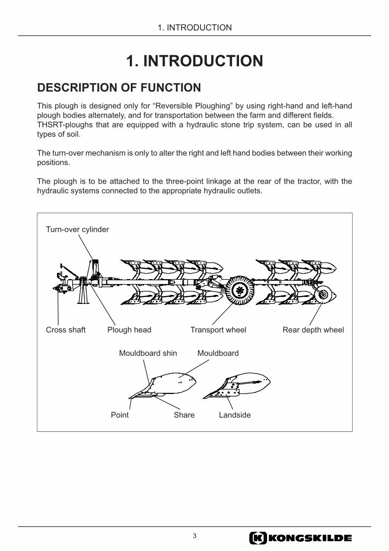
1. INTRODUCTIONDESCRIPTION OF FUNCTIONThis plough is designed only for “Reversible Ploughing” by using right-hand and left-hand plough bodies alternately, and for transportation between the farm and different fields. THSRT-ploughs that are equipped with a hydraulic stone trip system, can be used in all types of soil. The turn-over mechanism is only to alter the right and left hand bodies between their working positions.
The plough is to be attached to the three-point linkage at the rear of the tractor, with the hydraulic systems connected to the appropriate hydraulic outlets.
Turn-over cylinder
Cross shaft Plough head Transport wheel Rear depth wheel
LandsidePoint Share
MouldboardMouldboard shin

4THSRT KK EN 170413Wagon Plough THSRT
1. INTRODUCTION
IDENTIFICATION OF PLOUGHType designationTHSRT 71080 THSRT 81080 THSRT 91080 THSRT 101080
Beam height 80 cm
Plough body spacing 10=100 cm
Number of plough body pairs
Machin type
Complete the sign below with the Machine type and Serial number of Your plough.
THSRT 81080 17 300001
Year of manufacturing
Serial number
Tillage Designation
Max plough weightAxle load
Drawbar load

5
1. INTRODUCTION
SAFETY REGULATIONSREAD THE INSTRUCTION MANUAL. SAFETY IS YOUR RESPONSIBILITY.
You should read the instruction manual before you change any settings or start using the plough. The plough is designed and manufactured with as many safety features as possible, but we cannot foresee all possible circumstances that can involve safety hazards with this machine.
Your responsibilities as owner or operator are to ensure the safety of any personnel in connection with: the operation, transport, maintenance or storage of the machine. If you have questions not answered in this manual, please contact your dealer or distributor.
Be aware of your responsibilities. The most important safety device is a safety conscious operator, whose training and experience must include:
• Operator competence, the operator must be able to carry out a correct and complete adjustment of settings and to ensure safe and reliable operation. Training in safety issues is to be reviewed or repeated annually.
• Being aware of their environment to the extent that unforeseen safety issues that may arise are dealt with to ensure the safety of all personnel (including operators, maintenance personnel and bystanders).
This symbol means: SAFETY ALERT! The safety decals in the instruction manual are used to highlight given
instructions that involve safety of all personnel. Failure to comply with a given instruction could result in severe injury or death.
SAFETY ALERT decals Note! The decals on the machine can differ from the decals in this instruction manual.
GENERAL SAFETY INSTRUCTIONS
Keep a safe distanceDo not stand under, on or close to the plough when it is in operation or when it is connected to the tractor.
Support the PloughDo not stand under, on or close to the plough if the plough is not properly supported.
Lower the ploughThe plough should be lowered to the ground when standing still.
Front ballast weightsThe front of the tractor should be fitted with balance weights as required to maintain optimal traction and directional stability. Ensure that at least 20% of the tractor’s weight is carried by the front wheels.
6THSRT KK EN 170413Wagon Plough THSRT
1. INTRODUCTION
Be alertEnsure that no person is on, underneath or in the hazardous area of the plough during transport, ploughing or when maneuvering the plough. Never work under a lifted plough! Use the support legAlways use the support leg when the plough is parked. Park the plough on level firm surface.
Do not allow passengersDo not allow anyone to ride on the implement when it is being transported or while in operation.
SAFETY WHEN CONNECTING AND DISCONNECTING THE PLOUGH
Risk for personal damageAn unintentional manoeuvre with the tractor may cause serious injury. Always make sure that nobody is standing between the tractor and the machine during connection and disconnection.
Make sure that the plough is locked with sufficient locking pins. During operation, negative forces can occur that push one side of the cross shaft and the lower link of the quick coupling upwards. There is a risk that the hook can release. Therefore, the quick coupling on the lower links should be secured with a bolt.Make sure the tractors gear is in neutral before starting the engine.
Make sure that there is no pressure in the hydraulic hosesBefore the tractor engine has stopped, make sure that there is no pressure in the hydraulic hoses by activating the tractor spool valves to floating position.
Check the length of the hydraulic hosesCheck the length of the hydraulic hoses when the plough is lowered to working position. Check that they are not too tense.
Check connection of hydraulic hoses Make sure that the hydraulic hoses are connected to the correct hydraulic outlets on the tractor. If connected incorrectly, the plough can move in an unforeseen way.
MAINTENANCE SAFETY
Avoid contact with oil and greaseTo avoid oil and grease contact with your skin, wear protective gloves.
High oil pressureThe plough must be connected to the tractorBe careful when the plough is examined for oil leaks or damaged fittings. Hydraulic oil under pressure can penetrate the skin and cause serious damage. Always release the pressure in the hydraulic system prior to maintenance work on the hydraulic system and make sure that all components are correctly tightened before the system is set under pressure. Always wear gloves and eye protection.Never tamper with the gas filling valve on the accumulator!
7
1. INTRODUCTION
Do the maintenance regularlyDo the maintenance work regularly as it is described in this manual, section 6 MAINTENANCE. Replace wearing parts as described. There is a risk of poor performance if the machine not is maintained properly.
Retighten all nuts and bolts Always remember to retighten all nuts and bolts after about 3 hours of use. Make sure that bolts and nuts are tight at all times. Tightening torques are shown in section 6 MAINTENANCE.
Use protection gloves Always use gloves when working with parts on the machine as they can have sharp edges.
TRANSPORT SAFETY
Beware of the length of the ploughThe plough is long and does not completely follow the tractor in sharp turns. Avoid that the plough’s rear end hits an obstacle. The tractors braking pedals must be locked together during transport driving.
The stabilizers of the lower links The stabilizers of the lower links should be locked when the plough is in transport position, so that the plough is fixed sideways.
Comply with the relevant traffic regulationsThe operators have to observe relevant statutory or other national regulations dealing with road safety and labor safety issues.
Drive safe, max 25km/hBe a safe and courteous driver, yield to oncoming traffic. In all situations, do not exceed 25 km/h.

8THSRT KK EN 170413Wagon Plough THSRT
1. INTRODUCTION
WARNING DECALS
Explanations
4165 99101 00 Read the manual!Carefully read the instructions and observe all safety instructions before you connect the machine to the tractor.
4165 98301 00 Warning hazardous area!It is not allowed to be within the hazardous area, on, under or close to the machine during transport driving, operation or when the plough is reversed. Never work under a lifted plough. Always make sure that nobody is standing between the tractor and the machine.
4165 98300 00 High oil pressure!Be careful when oil leaks or damaged fittings are examined. Hydraulic oil under pressure can be dangerous. Always release the pressure in the hydraulic system prior to maintenance work on the hydraulic system and make sure that all components are correct tightened before the system is set under pressure. Always wear gloves and eye protection.
4165 99102 00 Support legDo not stand close to the plough if not properly supported. When parking the plough always use the support leg.
4165 34375 00 Transport lockThe plough can swing down against the vertical stop when the transport lock is released.Be alert!
4165 25073 00 Warning! Risk of crushingRisk of crushing injuries. Be careful!
9
2. TECHNICAL DESCRIPTION
2. TECHNICAL DESCRIPTIONCHECKING THE TRACTOR PRIOR TO PLOUGHING
TRACTOR SIZE
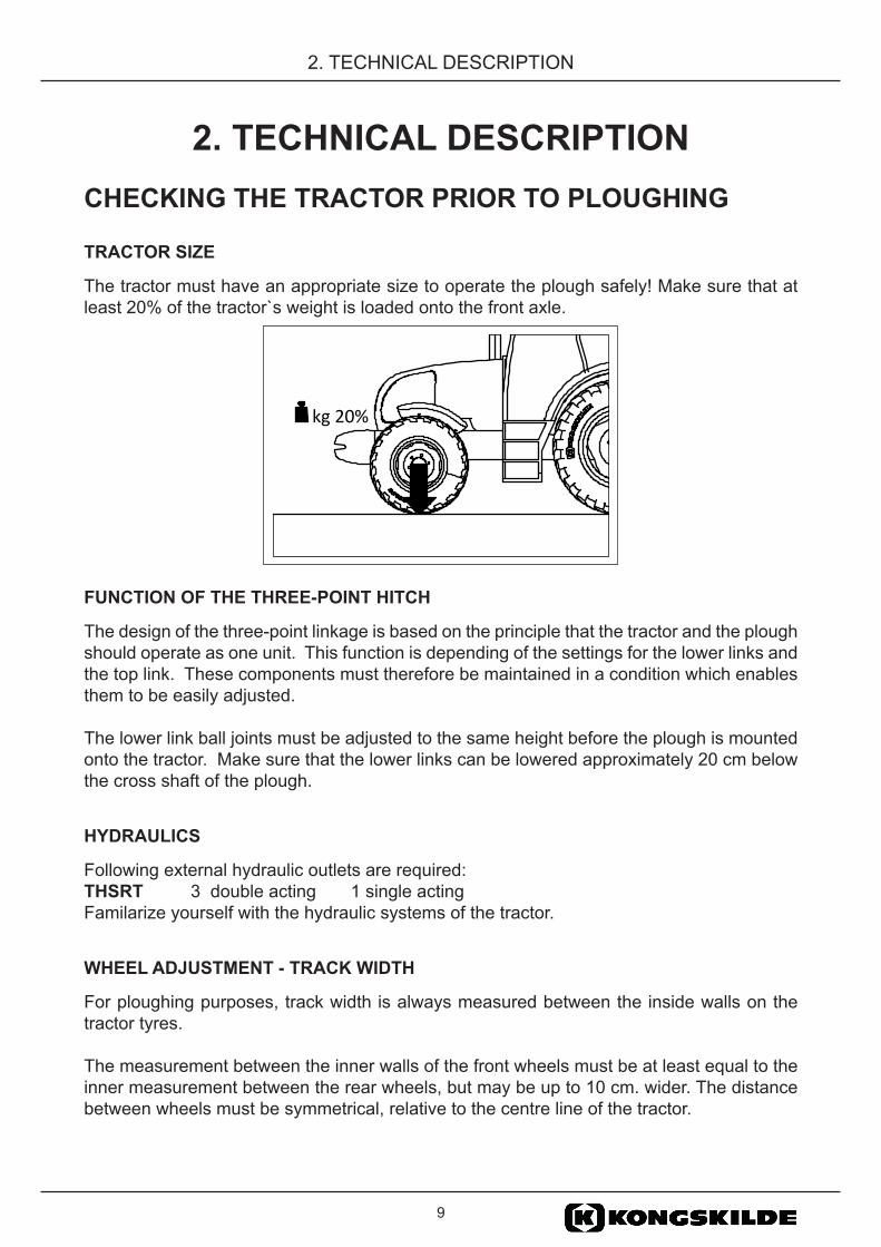
The tractor must have an appropriate size to operate the plough safely! Make sure that at least 20% of the tractor`s weight is loaded onto the front axle.
FUNCTION OF THE THREE-POINT HITCH
The design of the three-point linkage is based on the principle that the tractor and the plough should operate as one unit. This function is depending of the settings for the lower links and the top link. These components must therefore be maintained in a condition which enables them to be easily adjusted.
The lower link ball joints must be adjusted to the same height before the plough is mounted onto the tractor. Make sure that the lower links can be lowered approximately 20 cm below the cross shaft of the plough.
HYDRAULICS
Following external hydraulic outlets are required: THSRT 3 double acting 1 single acting Familarize yourself with the hydraulic systems of the tractor.
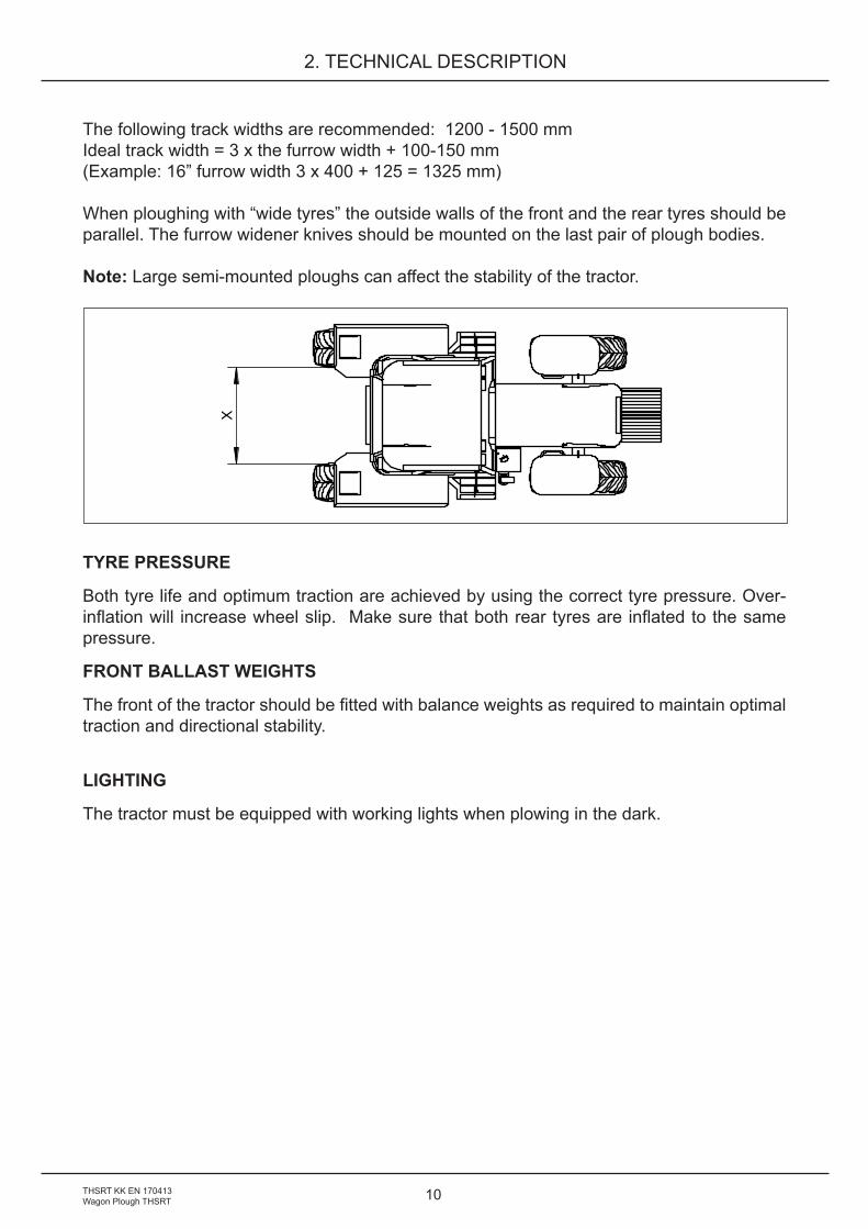
WHEEL ADJUSTMENT - TRACK WIDTH
For ploughing purposes, track width is always measured between the inside walls on the tractor tyres.
The measurement between the inner walls of the front wheels must be at least equal to the inner measurement between the rear wheels, but may be up to 10 cm. wider. The distance between wheels must be symmetrical, relative to the centre line of the tractor.
kg 20%
10THSRT KK EN 170413Wagon Plough THSRT
2. TECHNICAL DESCRIPTION
The following track widths are recommended: 1200 - 1500 mmIdeal track width = 3 x the furrow width + 100-150 mm(Example: 16” furrow width 3 x 400 + 125 = 1325 mm)
When ploughing with “wide tyres” the outside walls of the front and the rear tyres should be parallel. The furrow widener knives should be mounted on the last pair of plough bodies.
Note: Large semi-mounted ploughs can affect the stability of the tractor.
TYRE PRESSURE
Both tyre life and optimum traction are achieved by using the correct tyre pressure. Over-inflation will increase wheel slip. Make sure that both rear tyres are inflated to the same pressure.
FRONT BALLAST WEIGHTS
The front of the tractor should be fitted with balance weights as required to maintain optimal traction and directional stability.
LIGHTING
The tractor must be equipped with working lights when plowing in the dark.
x
11
2. TECHNICAL DESCRIPTION
PREPARATION OF THE PLOUGHCheck that the quick-couplings on the hydraulic hoses are the same type as the quick-couplings on the tractor, if required fit the correct quick-couplings to suit your tractor.
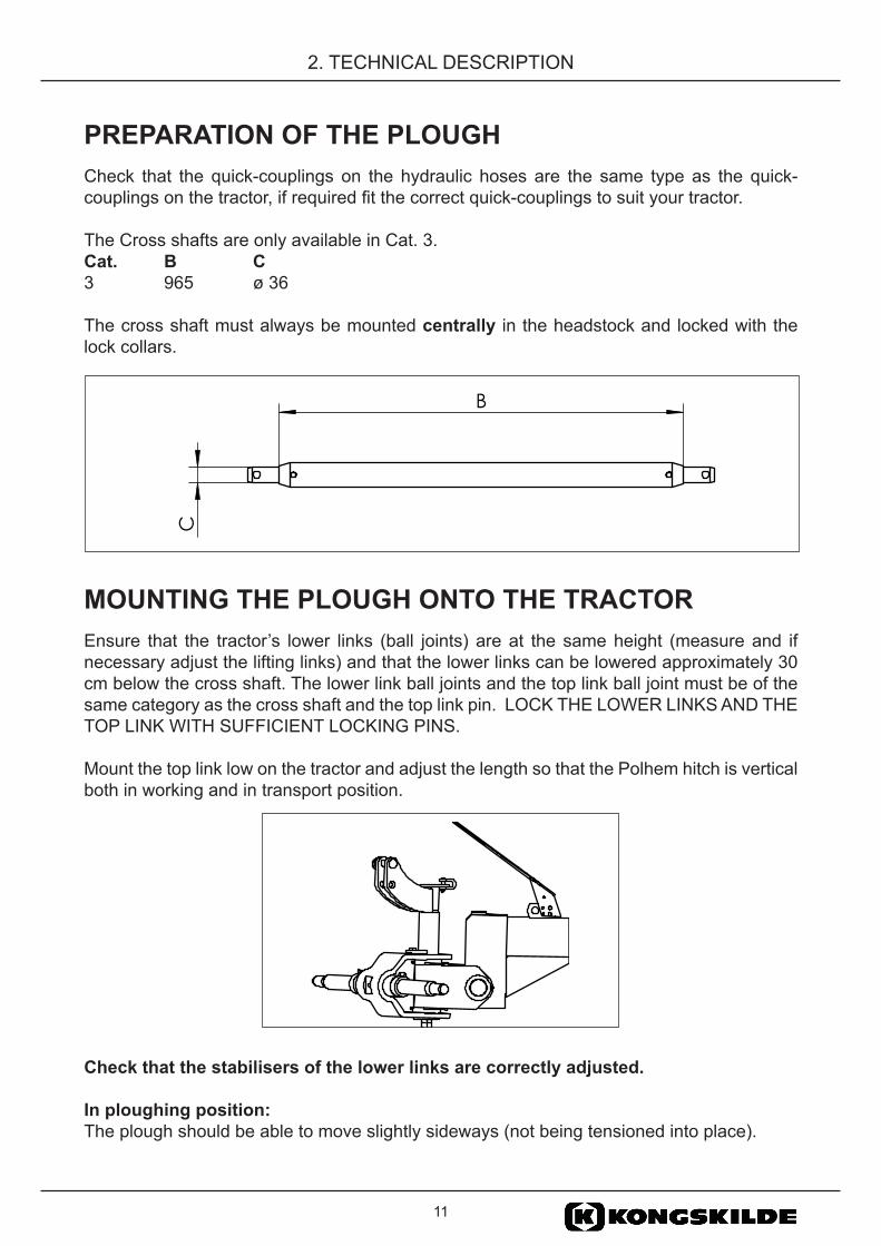
The Cross shafts are only available in Cat. 3.Cat. B C 3 965 ø 36 The cross shaft must always be mounted centrally in the headstock and locked with the lock collars.
MOUNTING THE PLOUGH ONTO THE TRACTOREnsure that the tractor’s lower links (ball joints) are at the same height (measure and if necessary adjust the lifting links) and that the lower links can be lowered approximately 30 cm below the cross shaft. The lower link ball joints and the top link ball joint must be of the same category as the cross shaft and the top link pin. LOCK THE LOWER LINKS AND THE TOP LINK WITH SUFFICIENT LOCKING PINS.
Mount the top link low on the tractor and adjust the length so that the Polhem hitch is vertical both in working and in transport position.
Check that the stabilisers of the lower links are correctly adjusted.
In ploughing position: The plough should be able to move slightly sideways (not being tensioned into place).
B
C
12THSRT KK EN 170413Wagon Plough THSRT
2. TECHNICAL DESCRIPTION
In transport position: The plough should not be lable to swing out and collide with the tractor wheels or fender.
Make sure that the plough is locked with sufficient locking pins. During operation, negative forces can occur that push one side of the cross shaft and the lower link of the quick coupling upwards. There is a risk that the hook can release. Therefore, the quick coupling on the lower links should be secured with a bolt.
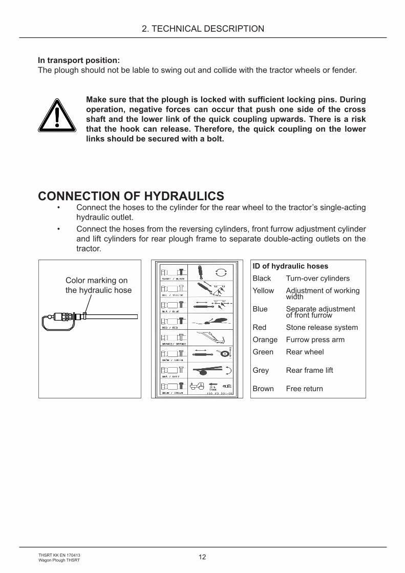
CONNECTION OF HYDRAULICS• Connect the hoses to the cylinder for the rear wheel to the tractor’s single-acting
hydraulic outlet. • Connect the hoses from the reversing cylinders, front furrow adjustment cylinder
and lift cylinders for rear plough frame to separate double-acting outlets on the tractor.
ID of hydraulic hosesBlack Turn-over cylindersYellow Adjustment of working widthBlue Separate adjustment of front furrowRed Stone release systemOrange Furrow press armGreen Rear wheel
Grey Rear frame lift
Brown Free return
Color marking on the hydraulic hose

13
2. TECHNICAL DESCRIPTION
CHECKING THE PLOUGH• Check the tightness of all bolts and nuts• Grease all lubrication points• Check the tyre pressure and adjust as necessary. See chapter 6. Maintenance,
Tyre pressure.• Mouldboards: In order to make it easy starting up a new plough, the frontside
of the mouldboards, skim coulters and coverboards are protected with wax. The wax do not have to be removed before the plough is used for the first time.
• Check the disc coulter, the skim coulter settings and adjust so that the settings are identical.
• Raise the plough, fold up the support legs.• Always remember to re-tighten all nuts and bolts after about 3 hours of
use, apart from that you should make sure that bolts and nuts are tight at all times.
STONE TRIP SYSTEM
Check the working pressure by reading the pressure gauge. For suitable working pressure, see section: 4. STONE TRIP SYSTEM, ADJUSTMENT OF OPERATING PRESSURE.
TURN-OVER MECHANISM
FUNCTION
The turn-over mechanism consists of three single acting cylinders connected to a double acting valve on the tractor.
NOTE ! Always raise the plough fully before the turn-over action is started. Do not turn-over the plough before it is made sure that the turn-over cylinders are filled with oil. (If the cylinder has not been filled with oil, the plough falls down against the adjustment screws without any restriction, which can cause damage to the plough).
FILL THE REVERSING CYLINDERS WITH OIL
Pressurise the cylinder starting the turn-over action. Stop the turn-over before reaching the intermediate position. Pressurise the other cylinder and let the plough frame down to the starting position. Repeat this a few times before a complete turn-over is made.
14THSRT KK EN 170413Wagon Plough THSRT
2. TECHNICAL DESCRIPTION
FUNCTION
The turn-over action is achieved by the turn-over cylinders that press the plough frame over the intermediate position. The plough is pushed down to the vertical adjustment screws by the third turn-over cylinder.
KEEP THE LEVER IN POSITION WHILE TURNING OVER.
At the next turn-over, the lever is pushed in the opposite direction. The two cylinders are equipped with adjustable restriction valves, controlling the speed of the second half of the turn-over.
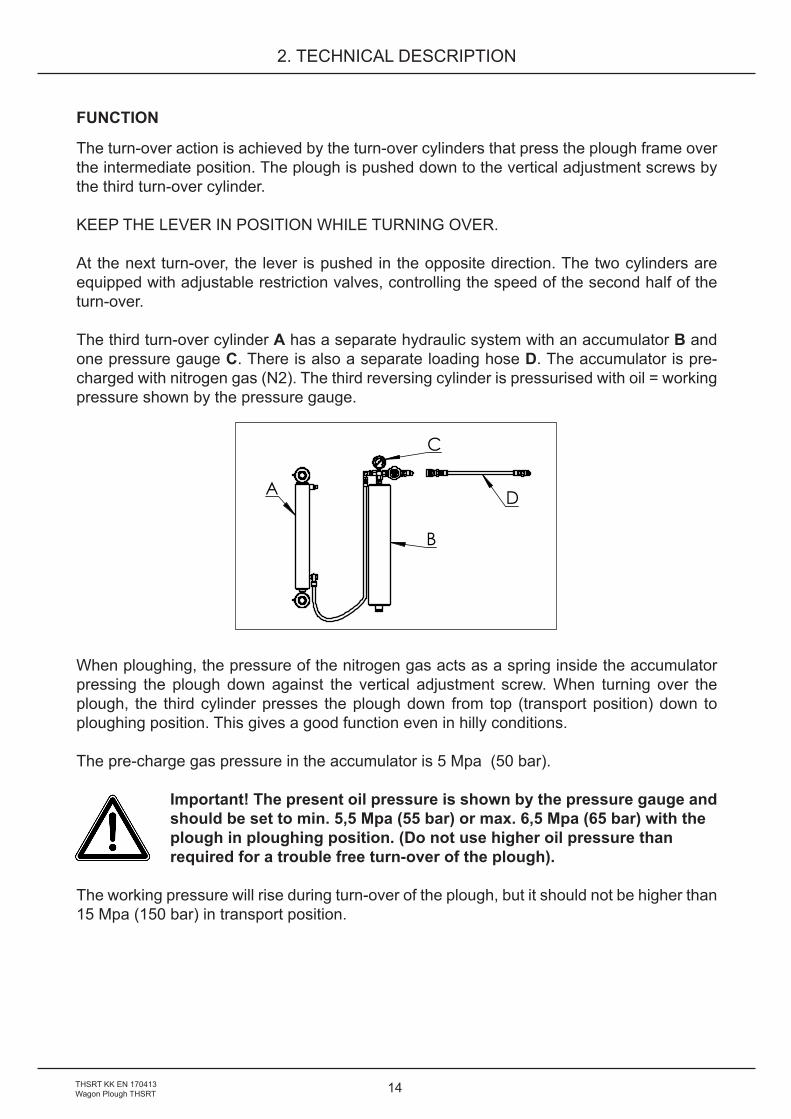
The third turn-over cylinder A has a separate hydraulic system with an accumulator B and one pressure gauge C. There is also a separate loading hose D. The accumulator is pre-charged with nitrogen gas (N2). The third reversing cylinder is pressurised with oil = working pressure shown by the pressure gauge.
When ploughing, the pressure of the nitrogen gas acts as a spring inside the accumulator pressing the plough down against the vertical adjustment screw. When turning over the plough, the third cylinder presses the plough down from top (transport position) down to ploughing position. This gives a good function even in hilly conditions.
The pre-charge gas pressure in the accumulator is 5 Mpa (50 bar).
Important! The present oil pressure is shown by the pressure gauge andshould be set to min. 5,5 Mpa (55 bar) or max. 6,5 Mpa (65 bar) with theplough in ploughing position. (Do not use higher oil pressure thanrequired for a trouble free turn-over of the plough).
The working pressure will rise during turn-over of the plough, but it should not be higher than 15 Mpa (150 bar) in transport position.
A
B
C
D
15
2. TECHNICAL DESCRIPTION
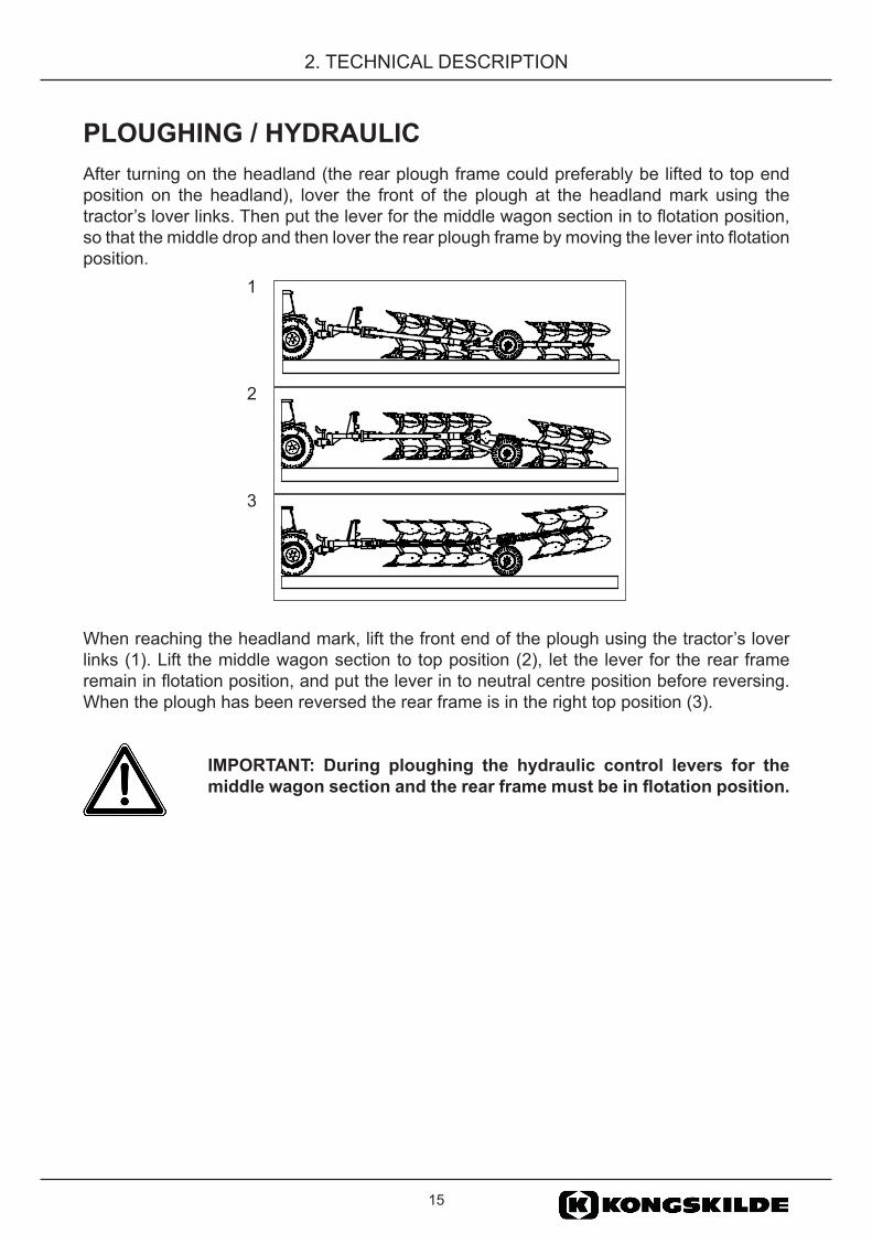
PLOUGHING / HYDRAULICAfter turning on the headland (the rear plough frame could preferably be lifted to top end position on the headland), lover the front of the plough at the headland mark using the tractor’s lover links. Then put the lever for the middle wagon section in to flotation position, so that the middle drop and then lover the rear plough frame by moving the lever into flotation position.
When reaching the headland mark, lift the front end of the plough using the tractor’s lover links (1). Lift the middle wagon section to top position (2), let the lever for the rear frame remain in flotation position, and put the lever in to neutral centre position before reversing. When the plough has been reversed the rear frame is in the right top position (3).
IMPORTANT: During ploughing the hydraulic control levers for the middle wagon section and the rear frame must be in flotation position.
1
2
3
16THSRT KK EN 170413Wagon Plough THSRT
2. TECHNICAL DESCRIPTION
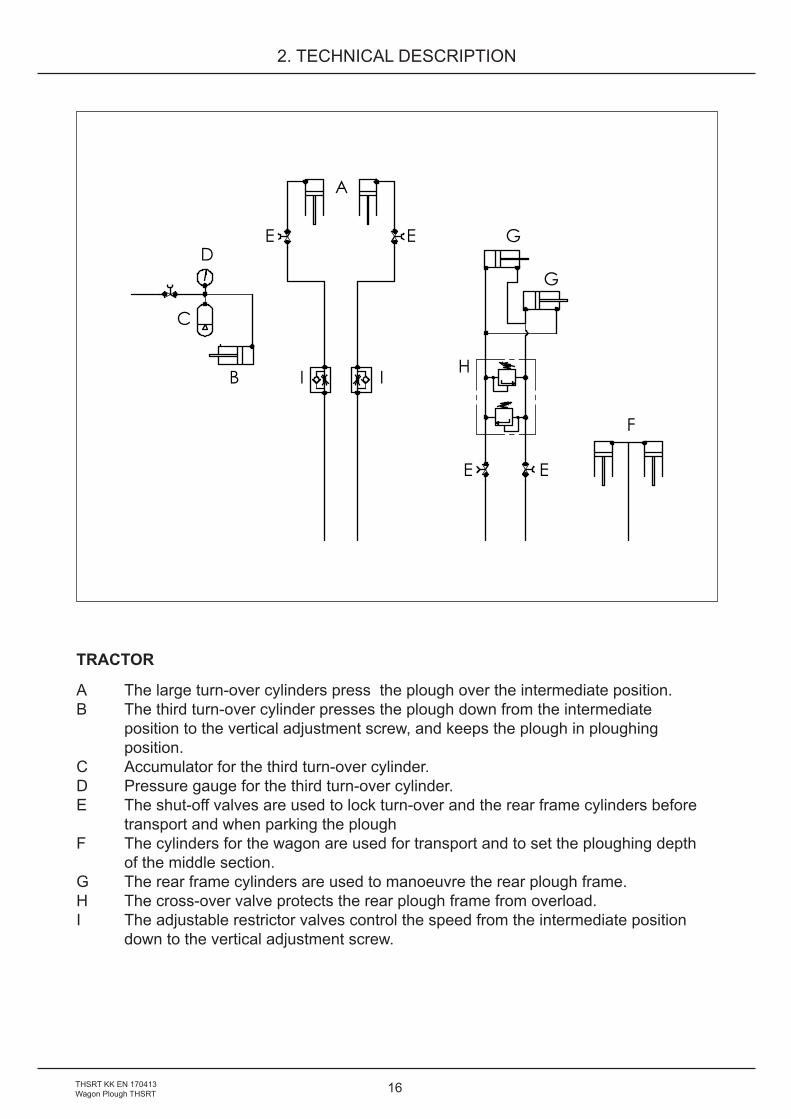
TRACTOR
A The large turn-over cylinders press the plough over the intermediate position.B The third turn-over cylinder presses the plough down from the intermediate position to the vertical adjustment screw, and keeps the plough in ploughing position.C Accumulator for the third turn-over cylinder.D Pressure gauge for the third turn-over cylinder.E The shut-off valves are used to lock turn-over and the rear frame cylinders before transport and when parking the plough F The cylinders for the wagon are used for transport and to set the ploughing depth of the middle section. G The rear frame cylinders are used to manoeuvre the rear plough frame. H The cross-over valve protects the rear plough frame from overload.I The adjustable restrictor valves control the speed from the intermediate position down to the vertical adjustment screw.
D
C
B
E E G
G
H
E E
F
A
I I
17
2. TECHNICAL DESCRIPTION
Shut off valve
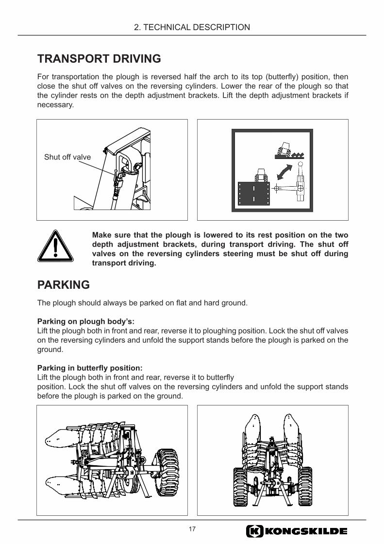
TRANSPORT DRIVINGFor transportation the plough is reversed half the arch to its top (butterfly) position, then close the shut off valves on the reversing cylinders. Lower the rear of the plough so that the cylinder rests on the depth adjustment brackets. Lift the depth adjustment brackets if necessary.
Make sure that the plough is lowered to its rest position on the two depth adjustment brackets, during transport driving. The shut off valves on the reversing cylinders steering must be shut off during transport driving.
PARKINGThe plough should always be parked on flat and hard ground.
Parking on plough body’s: Lift the plough both in front and rear, reverse it to ploughing position. Lock the shut off valves on the reversing cylinders and unfold the support stands before the plough is parked on the ground.
Parking in butterfly position: Lift the plough both in front and rear, reverse it to butterflyposition. Lock the shut off valves on the reversing cylinders and unfold the support stands before the plough is parked on the ground.
18THSRT KK EN 170413Wagon Plough THSRT
3. BASIC SETTINGS
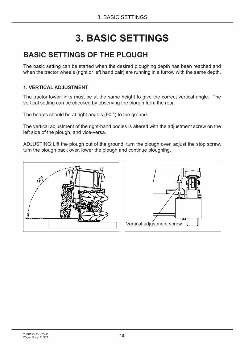
3. BASIC SETTINGSBASIC SETTINGS OF THE PLOUGHThe basic setting can be started when the desired ploughing depth has been reached and when the tractor wheels (right or left hand pair) are running in a furrow with the same depth.
1. VERTICAL ADJUSTMENT
The tractor lower links must be at the same height to give the correct vertical angle. The vertical setting can be checked by observing the plough from the rear.
The beams should be at right angles (90 °) to the ground.
The vertical adjustment of the right-hand bodies is altered with the adjustment screw on the left side of the plough, and vice-versa.
ADJUSTING: Lift the plough out of the ground, turn the plough over, adjust the stop screw, turn the plough back over, lower the plough and continue ploughing.
90°
Vertical adjustment screw
19
3. BASIC SETTINGS
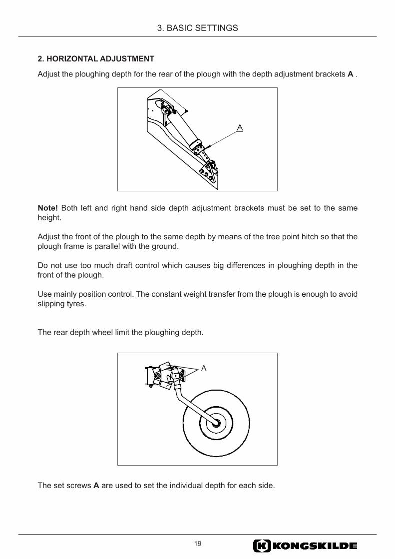
2. HORIZONTAL ADJUSTMENT
Adjust the ploughing depth for the rear of the plough with the depth adjustment brackets A .
Note! Both left and right hand side depth adjustment brackets must be set to the same height.
Adjust the front of the plough to the same depth by means of the tree point hitch so that the plough frame is parallel with the ground.
Do not use too much draft control which causes big differences in ploughing depth in the front of the plough.
Use mainly position control. The constant weight transfer from the plough is enough to avoid slipping tyres.
The rear depth wheel limit the ploughing depth.
The set screws A are used to set the individual depth for each side.
A
A
20THSRT KK EN 170413Wagon Plough THSRT
3. BASIC SETTINGS
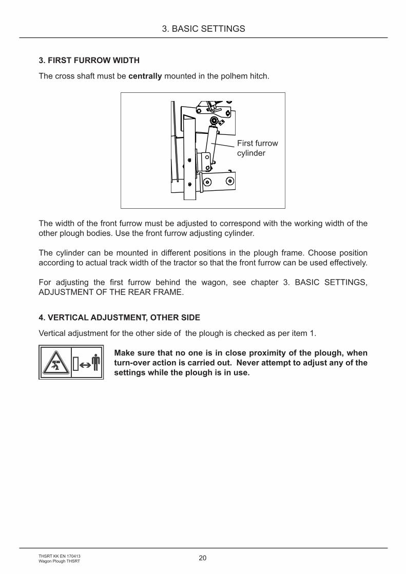
3. FIRST FURROW WIDTH
The cross shaft must be centrally mounted in the polhem hitch.
The width of the front furrow must be adjusted to correspond with the working width of the other plough bodies. Use the front furrow adjusting cylinder.
The cylinder can be mounted in different positions in the plough frame. Choose position according to actual track width of the tractor so that the front furrow can be used effectively.
For adjusting the first furrow behind the wagon, see chapter 3. BASIC SETTINGS, ADJUSTMENT OF THE REAR FRAME.
4. VERTICAL ADJUSTMENT, OTHER SIDE
Vertical adjustment for the other side of the plough is checked as per item 1.
Make sure that no one is in close proximity of the plough, when turn-over action is carried out. Never attempt to adjust any of the settings while the plough is in use.
First furrowcylinder

21
3. BASIC SETTINGS
DISC COULTERSThe purpose of the disc coulters is to make a vertical cut, separating the furrow slices. There are two types of disc coulters, fixed and spring loaded. When ploughing in stony or very heavy soils, the spring-loaded type of disc coulter should be used. This is to protect the coulters and to ensure that they do not act like a support wheel, carrying the plough, which would prevent it from maintaining a correct ploughing depth.
Side adjustment of disc coultersThe coulters should be set to produce a clean cut. Under normal conditions, the cut should be made 10 - 20 mm outside the landside, depending on type and condition of soil. The left and right hand coulters are set individually by loosening the nut on bracket A and turning the coulter shank sideways.
Depth adjustment of disc coultersTo maintain a favourable cutting angle towards the surface, the disc coulters should never be set deeper in the ground than 1/3 of their diameter.
Depth adjustment is carried out by fitting the coulter arm to different positions, B. This applies for both fixed and spring loaded disc coulters.
Make sure that all disc coulters on the plough are set to the same depth and are on an equal distance from the landsides on both left and right hand sides.
ATTENTION! Be alert, there is always a risk for injuries while adjusting disc coulters and skimmers.
10-20 mm
B
A
B
A
22THSRT KK EN 170413Wagon Plough THSRT
3. BASIC SETTINGS
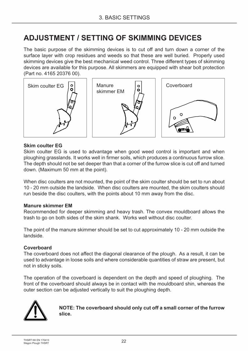
ADJUSTMENT / SETTING OF SKIMMING DEVICESThe basic purpose of the skimming devices is to cut off and turn down a corner of the surface layer with crop residues and weeds so that these are well buried. Properly used skimming devices give the best mechanical weed control. Three different types of skimming devices are available for this purpose. All skimmers are equipped with shear bolt protection (Part no. 4165 20376 00).
Skim coulter EGSkim coulter EG is used to advantage when good weed control is important and when ploughing grasslands. It works well in firmer soils, which produces a continuous furrow slice. The depth should not be set deeper than that a corner of the furrow slice is cut off and turned down. (Maximum 50 mm at the point).
When disc coulters are not mounted, the point of the skim coulter should be set to run about 10 - 20 mm outside the landside. When disc coulters are mounted, the skim coulters should run beside the disc coulters, with the points about 10 mm away from the disc.
Manure skimmer EMRecommended for deeper skimming and heavy trash. The convex mouldboard allows the trash to go on both sides of the skim shank. Works well without disc coulter.
The point of the manure skimmer should be set to cut approximately 10 - 20 mm outside the landside.
Coverboard The coverboard does not affect the diagonal clearance of the plough. As a result, it can be used to advantage in loose soils and where considerable quantities of straw are present, but not in sticky soils. The operation of the coverboard is dependent on the depth and speed of ploughing. The front of the coverboard should always be in contact with the mouldboard shin, whereas the outer section can be adjusted vertically to suit the ploughing depth.
NOTE: The coverboard should only cut off a small corner of the furrow slice.
Skim coulter EG Manureskimmer EM
Coverboard

23
3. BASIC SETTINGS
BASIC SETTING OF SKIMMERS (for 20 cm plough depth)
The mounting position of the skimmer bracket on the beam is the same if the plough is equipped with fin coulters or disc coulters.
The skimmer bracket is mounted in the rear hole as standard.
The distance V is measured between the beam and the skimmer share point and should be adjusted as follows:
Underbeam clearance 75 cm V = 540Underbeam clearance 80 cm V = 620(Valid for all types of skimmers EG and EM)
The skimmer share points should be set to cut approximately 10-20 mm outside the fin coulter or landside if disc coulters are mounted.
When the skimmers are adjusted all the skimmer share points should be in a straight line.
ATTENTION! Be alert, there is always a risk for injuries when adjusting disc coulters and skimmers.
V
Hydraulic stone trip

24THSRT KK EN 170413Wagon Plough THSRT
3. BASIC SETTINGS
TROUBLESHOOTING - PLOUGHINGThe following common faults produce poor ploughing results, giving higher running costs and causing unnecessary wear on both the tractor and plough.
Problem Reason ChecklistTractor pulls to one side and must be steered to counteract this
Plough incorrectly adjusted Correct the plough adjustments, see basic settings:Check front and rear track widths. Check that the tractor’s stabilisers are not tensioned.
Front end of tractor tends to lift
The front is too light. NOTE: The tractor must never be allowed to run on the back wheels (rear up)
Fit front weights or fill front tires with fluid
The first plough body cuts different furrow widths in left and right hand ploughing
The cross-shaft is not mounted centrally
Move the cross-shaft to the centre
Incorrect vertical adjustment Adjust the vertical adjustment
The plough frame is leaving the set screw for vertical setting during ploughing
Disc coulter too deep Reduce depth of disc coulterWorn points Change pointsStone release pressure too low
Increase working pressure
First furrow slice too high or low
Incorrect basic setting Adjust as per basic settings: Front furrow width.
The furrows are stepped
Incorrect basic setting Adjust as per basic settings: Horizontal and vertical settings
Furrow slices remain standing or are not fully turned
Skimming devices set too low
Adjust the skimmers to reduce skimming action.
Soil resistance causes plough to trip
Increase the working pressure
Plough leans excessively toward unploughed side
Adjust the vertical setting
Furrow width too narrow in relation to depth
Increase the furrow width
Furrow height alters within the same run
Lateral setting of disc coulters incorrect
Adjust the coulters
Skim coulters set to different depths or have incorrect side adjustment
Adjust the skimmers

25
3. BASIC SETTINGS
ADJUSTMENT OF WORKING WIDTHThe plough is equipped with adjustable working width: 16”/400, 18”/450 and 20”/500.
1. Alternating the beam housing positionEach plough body pair can swivel around the front bolt in the beam housing by removing the rear bolt. By placing rear bolt in one of the three different positions A, B or C you will alter the working (furrow) width. The table below shows you what working (furrow) widths you can achieve for the plough. When bolt has been mounted in the desired hole, tighten it up with a torque of 310 Nm (32 kpm).
Working (furrow) widths A B C16”/400 18”/450 20”/500
NOTE! Remember to retighten the bolts after approx. 3 hours
ABC
26THSRT KK EN 170413Wagon Plough THSRT
3. BASIC SETTINGS
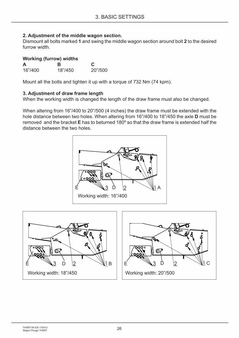
2. Adjustment of the middle wagon section. Dismount all bolts marked 1 and swing the middle wagon section around bolt 2 to the desired furrow width. Working (furrow) widths A B C16”/400 18”/450 20”/500 Mount all the bolts and tighten it up with a torque of 732 Nm (74 kpm).
3. Adjustment of draw frame lengthWhen the working width is changed the length of the draw frame must also be changed.
When altering from 16”/400 to 20”/500 (4 inches) the draw frame must be extended with the hole distance between two holes. When altering from 16”/400 to 18”/450 the axle D must be removed and the bracket E has to beturned 180º so that the draw frame is extended half thedistance between the two holes.
123
123 123
Working width: 16”/400
Working width: 18”/450 Working width: 20”/500
A
B C
D
DD
E
EE

27
3. BASIC SETTINGS
4. Adjustment of the rear frameBelow are the basic setting for the A and B measurement at different furrow widths.
Basic setting16”/400 A = 475 mm B = 480 mm 18”/450 A = 450 mm B = 465 mm 20”/500 A = 425 B = 450 mm
After that the basic setting is done, check that the land sides are parallel with the land sides in front of the middle wagon section.
Drive forwards and check the furrow width on the furrow behind the wheels.
Adjust the furrow width with set screw B.
A
B
28THSRT KK EN 170413Wagon Plough THSRT
4. STONE TRIP SYSTEM
4. STONE TRIP SYSTEMTo protect the plough and tractor, all ploughs are equipped with a stone trip system.
HYDRAULIC STONE TRIP SYSTEMThe tripping mechanism consists of a trip cylinder for each pair of plough bodies. The cylinder is connected to a gas/oil accumulator. The accumulator is precharged with nitrogen gas (N2).
The trip cylinders, pressure hoses and the accumulator are pressurized with oil = working pressure, as shown by the pressure gauge.
When ploughing, the pressure of the nitrogen gas acts as a spring inside the accumulator giving the plough bodies fully automatic and individual tripping and resetting actions.
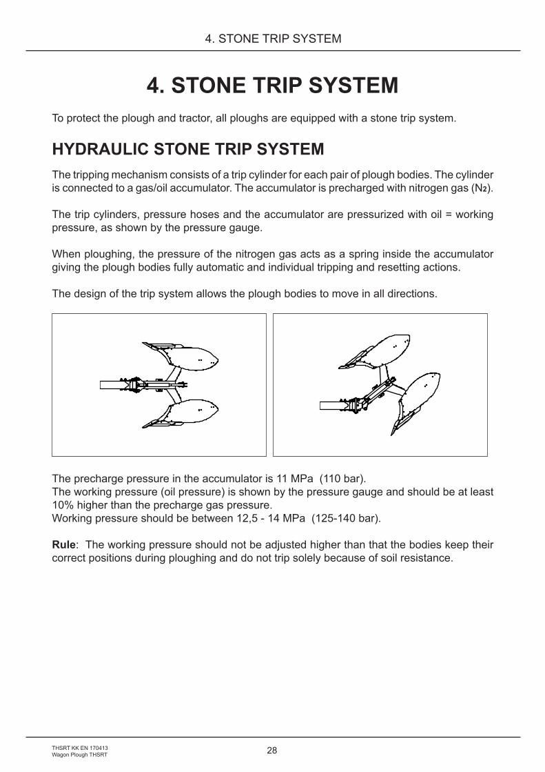
The design of the trip system allows the plough bodies to move in all directions.
The precharge pressure in the accumulator is 11 MPa (110 bar). The working pressure (oil pressure) is shown by the pressure gauge and should be at least 10% higher than the precharge gas pressure.Working pressure should be between 12,5 - 14 MPa (125-140 bar).
Rule: The working pressure should not be adjusted higher than that the bodies keep their correct positions during ploughing and do not trip solely because of soil resistance.
29
4. STONE TRIP SYSTEM
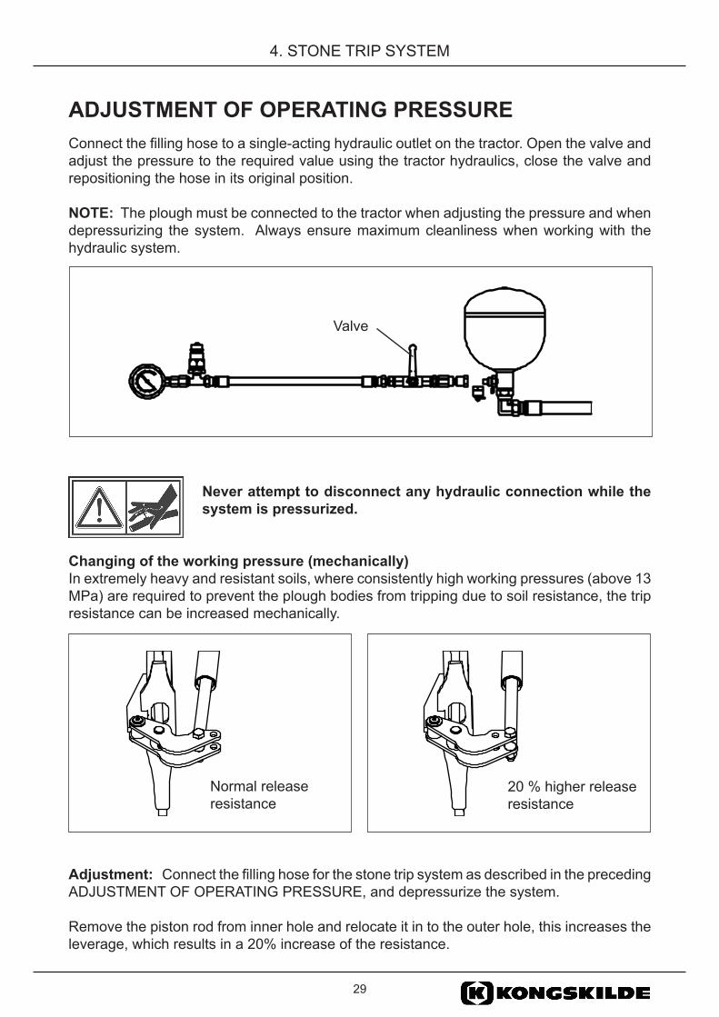
ADJUSTMENT OF OPERATING PRESSUREConnect the filling hose to a single-acting hydraulic outlet on the tractor. Open the valve and adjust the pressure to the required value using the tractor hydraulics, close the valve and repositioning the hose in its original position.
NOTE: The plough must be connected to the tractor when adjusting the pressure and when depressurizing the system. Always ensure maximum cleanliness when working with the hydraulic system.
Never attempt to disconnect any hydraulic connection while the system is pressurized.
Changing of the working pressure (mechanically)In extremely heavy and resistant soils, where consistently high working pressures (above 13 MPa) are required to prevent the plough bodies from tripping due to soil resistance, the trip resistance can be increased mechanically.
Adjustment: Connect the filling hose for the stone trip system as described in the preceding ADJUSTMENT OF OPERATING PRESSURE, and depressurize the system.
Remove the piston rod from inner hole and relocate it in to the outer hole, this increases the leverage, which results in a 20% increase of the resistance.
20 % higher release resistance
Normal release resistance
Valve

30THSRT KK EN 170413Wagon Plough THSRT
4. STONE TRIP SYSTEM
CHECKING THE ACCUMULATORThe plough must be connected to the tractor!
The accumulator precharge pressure should be checked at regular intervals (yearly) with the help of the pressure gauge.
Connect the filling hose as described in “ADJUSTMENT OF WORKING PRESSURE”, set the control lever on the tractor to the open return position and open the shut-off valve slightly. The working pressure will now drop slowly to a specific value and then fall rapidly to zero.
The pressure shown by the gauge at which the rapid drop occurs is the accumulator precharge pressure.
In a similar manner, the precharge pressure can be checked when filling. In this case, the reading will rise rapidly from 0 to a specific value, after which it will increase slowly. The pressure gauge reading at the end of the rapid rise in pressure is the accumulator precharge pressure.SUMMARY: The pressure at which the gauge reading drops quickly when emptying the system and at which the reading stops rising quickly when filling the system, is the accumulator precharge pressure.
Should the pressure fall by more than 2 MPa (20 bar) below the precharge pressure specified on the accumulator, contact your local Kongskilde dealer for advice.
Never tamper with the gas filling valve. Never attempt to disconnect a hydraulic conntection while the system is pressurized.The plough must be connected to the tractor!
31
5. DRIVING A REVERSIBLE PLOUGH
5. DRIVING A REVERSIBLE PLOUGHRoad transport: Make sure that the plough is lowered all the way down on the rear
wheel cylinder bracket (the single acting hydraulic lining should have open return) . Make sure that the Polhem hitch is vertical and that the shut off valves on the reversing are closed.
Driving speeds, Adapt driving speed to the road conditions so that the plough does not transport: bounce behind the tractor this could alter the plough settings and
impose abnormal stresses on it. Maximum transport speed 25 km/h (16 mph).
Ploughing: Adapt ploughing speed to the prevailing ground conditions and presence of stones.
NOTE: Excessively high speed costs money in terms of wear and damage to equipment.
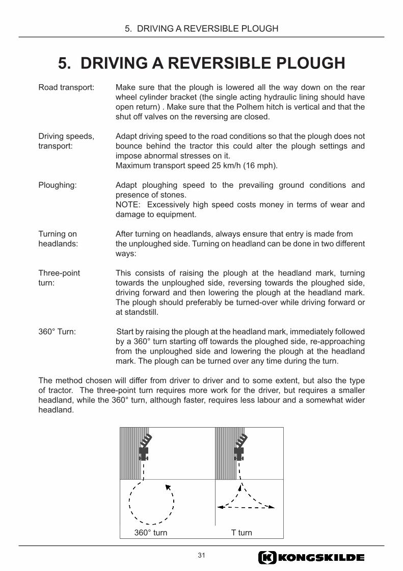
Turning on After turning on headlands, always ensure that entry is made from headlands: the unploughed side. Turning on headland can be done in two different
ways:
Three-point This consists of raising the plough at the headland mark, turning turn: towards the unploughed side, reversing towards the ploughed side,
driving forward and then lowering the plough at the headland mark. The plough should preferably be turned-over while driving forward or at standstill.
360° Turn: Start by raising the plough at the headland mark, immediately followed by a 360° turn starting off towards the ploughed side, re-approaching from the unploughed side and lowering the plough at the headland mark. The plough can be turned over any time during the turn.
The method chosen will differ from driver to driver and to some extent, but also the type of tractor. The three-point turn requires more work for the driver, but requires a smaller headland, while the 360° turn, although faster, requires less labour and a somewhat wider headland.
360° turn T turn
32THSRT KK EN 170413Wagon Plough THSRT
5. DRIVING A REVERSIBLE PLOUGH
USEFUL OPERATIONAL POINTSMarking of headlandsAlways mark the headlands, working inward, towards the field with the rear body, (i.e. with an extended top-link and the front end of the plough raised).
In good regular fields, headland marking is only necessary at the short sides. In irregular fields or fields surrounded by ditches, hedges or other obstacles, the headlands should be marked out all around the field.
Headland widthHeadlands should always be of an adequate width to permit the plough to be fully raised out of the ground before starting to turn the tractor. Depending on the size of the tractor and plough, and the method of turning on the headland (reversing or making a 360° turn), the headland width should be between 15 - 25 meters.
PloughingWhen starting ploughing at the edge of the field or at the side headland (if marked out all around), the first furrow slice should be laid inwards using the same plough setting as when marking the headlands. Ploughing begins with the second run in which the first furrow slice is returned. All the soil will by this be ploughed through completely. On the third run, the tractor will be running in a furrow at the correct depth and the basic settings should be adjusted.
LOWERING AND RAISING OF THE PLOUGH SHOULD BE CARRIED OUT AT THE HEADLAND MARKS.
An even edge at the headland marking will make it easier to plough the headlands and eliminate double ploughing.
Drive Straight! Crooked furrows impose high stress on both tractor and plough, and contribute to an unsatisfactory result due to poor matching. Consequently, the furrows should be straightened as quickly as possible.
Always use the plough bodies alternately to equalise the wear on both right and left hand sides, otherwise, it will be impossible to produce uniform furrow slices on both sides.
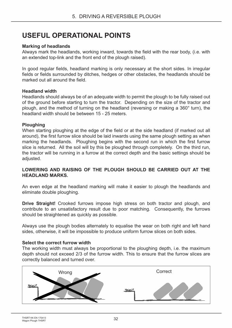
Select the correct furrow widthThe working width must always be proportional to the ploughing depth, i.e. the maximum depth should not exceed 2/3 of the furrow width. This to ensure that the furrow slices are correctly balanced and turned over.
Wrong Correct

33
6. MAINTENANCE
6. MAINTENANCETo ensure the plough a long life and to avoid unnecessary wear, observe the following instructions.
The plough comes with three wrenches. The wrenches are used for re-tightening the bolts and for replacing the wear parts.
REPLACEMENT OF WEARING PARTSAll wearing parts should be replaced in good time in order to protect more vital parts, which will save you money. Always use original spare parts, which will ensure that you get wearing parts with good quality and which fit the plough. This is also a condition for validity of the warranty.
Point and SharesThe points and shares must be replaced before it has been worn down so far that the frog is damaged.
MouldboardsWhen replacing mouldboards, ensure that the bolts are CROSS-TIGHTENED in order to avoid tension being built into the mouldboard, which may cause it to crack.
Mouldboard shinWhen replacing the mouldboard shin, ensure that the bolts are CROSS-TIGHTENED in order to avoid tension being built into the mouldboard shin, which may cause it to crack.
LandsidesIf the landsides are severely worn, the plough will break out towards the unploughed soil which gives a poorer turning of the furrow slice and the plough will pull heavier.
Disc coulter bladesIf a good cutting function should be maintained, the coulter blade should be replaced when 1/3 of the original diameter is worn off.
• The plough must be connected to the tractor!• Never carry out adjustment or replacing wearing parts unless
the tractor engine is stopped and the plough is louvered to level ground.
• Never work under a raised plough without securing it with a stand or similar, to avoid accidental lowering of the plough.
• Never rely solely on the tractor hydraulic system.• Always wear gloves and protective goggles when handling
worn implement parts with sharp edges.

34THSRT KK EN 170413Wagon Plough THSRT
6. MAINTENANCE
PARALLELISM AND G-MEASUREMENT OF THE MOULDBOARDS
• Check the working angle of the mouldboard. The normal position is measured on the rear plough body between the extended inside line of the landside, horizontally out against the outermost hole in the mouldboard, see measurement G. Adjust the mouldboard stay if necessary.
AX Mouldboard normal measurement G = 580 mm XLD Mouldboard normal measurement G = 670 mm AH Mouldboard normal measurement G = 625 mm FC Measurement to the outer end of the bottom slat = 635 mm AS Measurement to the outer end of the top slat = 505 mm
• Repeat the same procedure for the rear body on the opposite side.• Measure from the now adjusted rear, two bodies forward and adjust the mouldboard
stays if necessary, to the interbody space 1000 mm A= B.
A
B
G

35
6. MAINTENANCE
TIGHTENING THE BOLTSBolts of quality 8.8, 10.9 and 12.9 are used on the ploughs. When replacing these bolts, ensure that the same quality bolts and nuts are used. It is easier to tighten bolts and nuts to correct tightening torque, if they are lubricated with oil.
The following tightening torque should be used for the different bolts:Tightening torque’s Quality Size Torque Dry bolts Bolts and nuts and nuts lubricated with oil 8,8 M12 81 Nm 70 Nm 8,8 M16 197 Nm 170 Nm 8,8 M18 275 Nm 236 Nm 8,8 M20 385 Nm 330 Nm 8,8 M24 665 Nm 572 Nm 8,8 M30 1310 Nm 1127 Nm 10,9 M12 114 Nm 98 Nm 10,9 M16 277 Nm 238 Nm 10,9 M20 541 Nm 465 Nm 10,9 M24 935 Nm 804 Nm 10,9 M30 1840 Nm 1582 Nm 12,9 M16* 333 Nm 286 Nm 12,9 M20 649 Nm 558 Nm 12,9 M24 1120 Nm 963 Nm
* The M16 screws that are mounted through the link plates but outside the main frame should be tightened to 200 Nm
GREASING OF THE BEAM HINGE POINTSPosition the plough with the bodies approx. 15 cm above the ground, depressurise the system as described in, see section 4. STONE TRIP SYSTEM, CHECKING THE ACCUMULATOR.
The hinge points will now expose as the beams drop down. Grease all the upper hinge points(MoS2 grease is recomended). Also grease all other lubricating points in the stone trip linkage while depressurized. Now pressurize the system, make sure that the beams return to their correct positions. Turn the plough over to the other side, and repeat the procedure. Charge the system up to the correct operating pressure, close the valve and return the supply hose to its original position.
NOTE! Make sure that all beams return to their correct positions.

36THSRT KK EN 170413Wagon Plough THSRT
6. MAINTENANCE
TYRE PRESSURETyre Recommended pressure10.0/80-12 300 kPa 3,0 bar400/60-26,5 250 kPa 2,5 bar
WINTER STORAGE• Clean the plough properly.• Ensure that all wearing parts are in good condition, replace if necessary (so that
the plough is ready for the next season).• Tighten all bolts and nuts.• Check the pre-charge pressure in the accumulator.• Lubricate all lubrication points with grease and oil.• Protect the mouldboards and all the shiny details by lubricating them with either
oil, under coat protection or acid-free grease.• The stone trip system should be stored in a pressurised condition so that all trip
cylinders are fully extended and filled with oil.• Check the hydraulic hoses on the stone trip system and replace any damaged
parts.
Always use original spare parts.
Lubricate every 40 hours of work
Lubricate every 40 hours of work
37
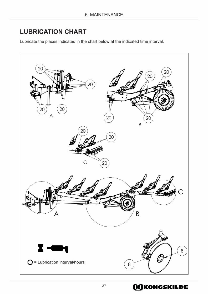
6. MAINTENANCE
LUBRICATION CHARTLubricate the places indicated in the chart below at the indicated time interval.
8
8
= Lubrication interval/hours=SmörjintervallTimmar
A B
C
A20
20
20
20
B 20 20
2020
C
2020
20

38THSRT KK EN 170413Wagon Plough THSRT
7. USEFUL ADVICE
7. USEFUL ADVICEWhen you have completed a careful and accurate adjustment of your plough so that it works well and gives a good result, make a note of the following important measurements:
Length of the lift rods _____________________________________________
Length of top link _____________________________________________
Left vertical adjustment screw _____________________________________________
Right vertical adjustment screw _____________________________________________
Adjustment sleeves ondepth wheel _____________________________________________
These measurements and similar notes will make the adjustments easier next time you start ploughing.

39
8. LIFTING POINTS
8. LIFTING POINTS
NOTE! It is not allowed to lift the plough! For transportation the plough most be mounted to a tractor!

40THSRT KK EN 170413Wagon Plough THSRT
9. TECHNICAL DATA
9. TECHNICAL DATA
* Equipment: One pair of disc coulters, other knife coulters
Model THSRT
Distance between plough bodies pairs (cm)
Under beam clearance(cm)
No. of plough body pairs
Work width(cm)
Recom-mended tractor size (hp)
Machine weight*(kg)
71080 100 80 7 280-350 150-250 440081080 100 80 8 320-400 160-280 480091080 100 80 9 360-450 180-320 5100
101080 100 80 10 400-500 200-350 5400

41
9. TECHNICAL DATA

42THSRT KK EN 170413Wagon Plough THSRT
9. TECHNICAL DATA

43
9. TECHNICAL DATA

4165 68008 13 THSRT KK ENYou can always find the latest version of the manuals at www.kongskilde.com