Raytheon Anschütz GmbHPostfach 1166D -- 24100 KielGermanyTel +49--4 31--30 19--0Fax +49--4 31--30 19--501Email [email protected]
3648/130--613.DOC010102 Edition: October 23, 2009
Operator Unit
Type 130 --613
1 Description2 Operation3 Maintenance and repairs

Weitergabe sowie Vervielfältigung dieser Unterlage, Verwertung undMitteilung ihres Inhaltes nicht gestattet, soweit nicht ausdrücklichzugestanden. Zuwiderhandlungen verpflichten zu Schadenersatz.
Copying of this document, and giving it to others and the use orcommunication of the contents thereof, are forbidden without expressauthority. Offenders are liable to the payment of damages.
Toute communication ou reproduction de ce document, touteexploitation ou communication de son contenu sont interdites, saufautorisation expresse. Tout manquement à cette règle est illicite etexpose son auteur au versement de dommages et intérêts.
Sin nuestra expresa autorización, queda terminantemente prohibida lareproducción total o parcial de este documento, así como su usoindebido y/o su exhibición o comunicación a terceros. De los infractoresse exigirá el correspondiente resarcimiento de daños y perjuicios.
Operator Unit
Operator Unit130--613
I 3648/130--613.DOC010102Edition: Oct. 23, 2009
TABLE OF CONTENTS Page
Declaration of Conformity
List of abbreviations
1 General Information 1. . . . . . . . . . . . . . . . . . . . . . . . . . . . . . . . . . . . . . . . . . . . . . . . . . . .
1.1 The Construction of the Operator Unit 2. . . . . . . . . . . . . . . . . . . . . . . . . . . . . . . . . . . .
1.1.1 Principle of Operation 3. . . . . . . . . . . . . . . . . . . . . . . . . . . . . . . . . . . . . . . . . . . . . . . . . .
1.1.2 CAN-Bus 5. . . . . . . . . . . . . . . . . . . . . . . . . . . . . . . . . . . . . . . . . . . . . . . . . . . . . . . . . . . . .
1.2 Technical data 6. . . . . . . . . . . . . . . . . . . . . . . . . . . . . . . . . . . . . . . . . . . . . . . . . . . . . . . . .
1.2.1 Mechanical data 6. . . . . . . . . . . . . . . . . . . . . . . . . . . . . . . . . . . . . . . . . . . . . . . . . . . . . . .
1.2.2 Electrical data 6. . . . . . . . . . . . . . . . . . . . . . . . . . . . . . . . . . . . . . . . . . . . . . . . . . . . . . . . .
2 Operation 7. . . . . . . . . . . . . . . . . . . . . . . . . . . . . . . . . . . . . . . . . . . . . . . . . . . . . . . . . . . . .
2.1 Controls and Indicators on the Operator Unit 7. . . . . . . . . . . . . . . . . . . . . . . . . . . . . .
2.2 Setting into Operation 8. . . . . . . . . . . . . . . . . . . . . . . . . . . . . . . . . . . . . . . . . . . . . . . . . .
2.2.1 General Information regarding the Operation of the Operator Unit 9. . . . . . . . . . . .
2.2.1.1 Overview of display information (compass) 10. . . . . . . . . . . . . . . . . . . . . . . . . . . . . . . .
2.2.1.2 Changing the Default Settings 12. . . . . . . . . . . . . . . . . . . . . . . . . . . . . . . . . . . . . . . . . . .
2.2.1.3 Adjusting Brightness and Contrast 13. . . . . . . . . . . . . . . . . . . . . . . . . . . . . . . . . . . . . . .
2.2.1.4 Changing the Current Sensor 14. . . . . . . . . . . . . . . . . . . . . . . . . . . . . . . . . . . . . . . . . . . .
2.2.1.5 Menu selection 15. . . . . . . . . . . . . . . . . . . . . . . . . . . . . . . . . . . . . . . . . . . . . . . . . . . . . . . .
2.2.1.6 Lamp test 16. . . . . . . . . . . . . . . . . . . . . . . . . . . . . . . . . . . . . . . . . . . . . . . . . . . . . . . . . . . . .
2.2.2 Alarm and Fault Handling 17. . . . . . . . . . . . . . . . . . . . . . . . . . . . . . . . . . . . . . . . . . . . . . .
2.2.2.1 Alarm handling 17. . . . . . . . . . . . . . . . . . . . . . . . . . . . . . . . . . . . . . . . . . . . . . . . . . . . . . . .
2.2.2.2 Status and alarm messages (an overview) 19. . . . . . . . . . . . . . . . . . . . . . . . . . . . . . . .
2.2.2.3 General Error Messages 22. . . . . . . . . . . . . . . . . . . . . . . . . . . . . . . . . . . . . . . . . . . . . . . .
2.2.2.4 Warnings 25. . . . . . . . . . . . . . . . . . . . . . . . . . . . . . . . . . . . . . . . . . . . . . . . . . . . . . . . . . . . .
3 Gyrocompass Operation 27. . . . . . . . . . . . . . . . . . . . . . . . . . . . . . . . . . . . . . . . . . . . . . . .
3.1 Selecting the Sensor 27. . . . . . . . . . . . . . . . . . . . . . . . . . . . . . . . . . . . . . . . . . . . . . . . . . .
3.1.1 The HEADING display 28. . . . . . . . . . . . . . . . . . . . . . . . . . . . . . . . . . . . . . . . . . . . . . . . . .
3.1.1.1 Heading indication from gyro system after switching on
(Heating stage and settling stage) 29. . . . . . . . . . . . . . . . . . . . . . . . . . . . . . . . . . . . . . . .
3.2 Selecting Man Speed / Aut Speed / Individual Speed 31. . . . . . . . . . . . . . . . . . . . . . .
3.3 Selecting Man Lat / Auto Lat / Individual Lat 35. . . . . . . . . . . . . . . . . . . . . . . . . . . . . . .
3.4 Activation of the Quick Settling function 38. . . . . . . . . . . . . . . . . . . . . . . . . . . . . . . . . . .
3.4.1 Quick Settling activation of selected gyro 39. . . . . . . . . . . . . . . . . . . . . . . . . . . . . . . . . .
3.4.2 Quick Settling activation of not selected gyro 42. . . . . . . . . . . . . . . . . . . . . . . . . . . . . .
4 Magnetic Compass Operation 44. . . . . . . . . . . . . . . . . . . . . . . . . . . . . . . . . . . . . . . . . . .
4.1 Display/amend alarm threshold for Gyro/Magnet 45. . . . . . . . . . . . . . . . . . . . . . . . . . .
4.1.1 Display and alter Variation/Deviation 47. . . . . . . . . . . . . . . . . . . . . . . . . . . . . . . . . . . . . .
4.1.1.1 Single value input 48. . . . . . . . . . . . . . . . . . . . . . . . . . . . . . . . . . . . . . . . . . . . . . . . . . . . . .
Operator Unit130--613
II Edition: Oct. 23, 20093648/130--613.DOC010102
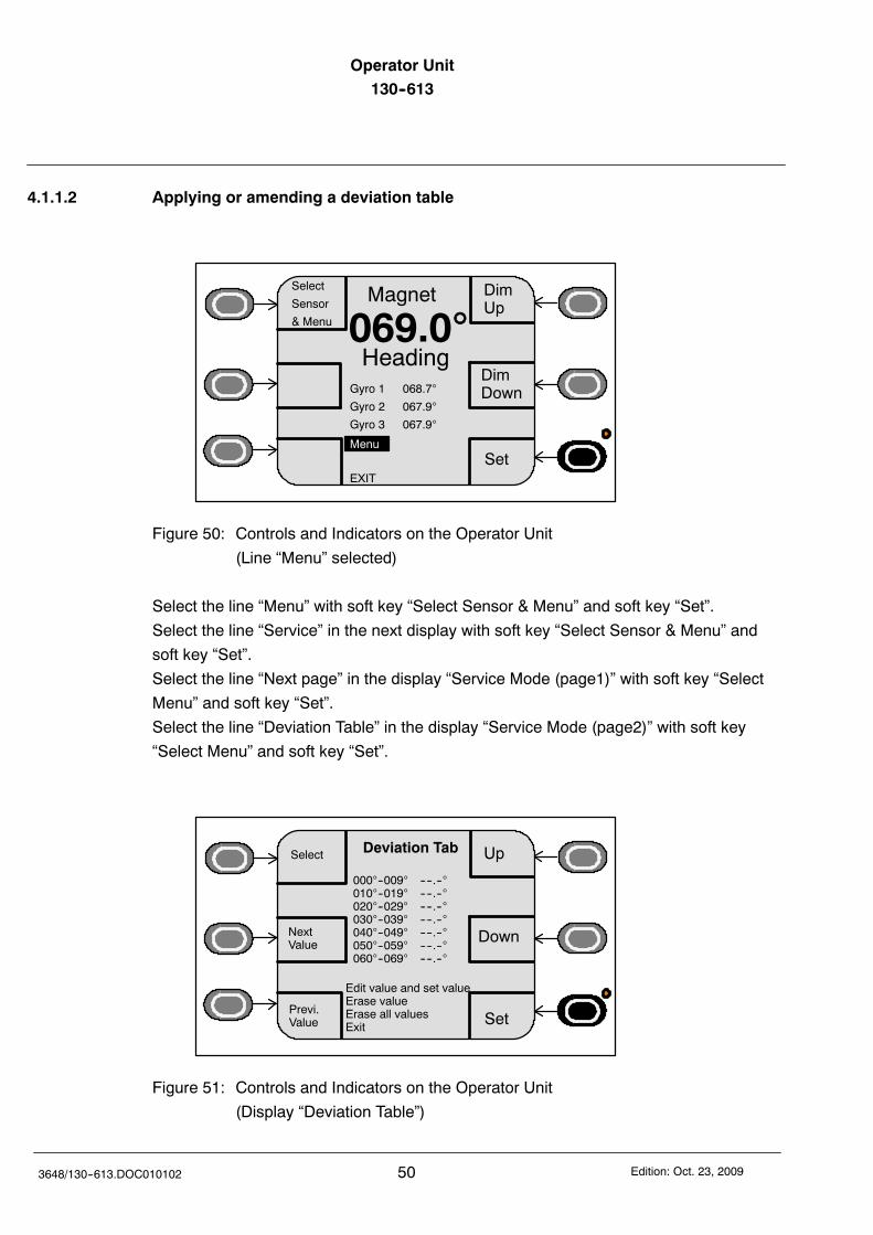
4.1.1.2 Applying or amending a deviation table 50. . . . . . . . . . . . . . . . . . . . . . . . . . . . . . . . . . .
5 Operation of Satellite Compass STD 21 (GPS) 52. . . . . . . . . . . . . . . . . . . . . . . . . . . . .
6 Adjustment of additional operation modes with the service menu 53. . . . . . . . . . . . .
6.1 Difference Alarm 53. . . . . . . . . . . . . . . . . . . . . . . . . . . . . . . . . . . . . . . . . . . . . . . . . . . . . . .
6.1.1 G1/G2/G3 or GPS difference alarm 56. . . . . . . . . . . . . . . . . . . . . . . . . . . . . . . . . . . . . . .
6.2 Panel Setup Software version 58. . . . . . . . . . . . . . . . . . . . . . . . . . . . . . . . . . . . . . . . . . .
6.3 Service Mode 60. . . . . . . . . . . . . . . . . . . . . . . . . . . . . . . . . . . . . . . . . . . . . . . . . . . . . . . . .
6.3.1 Service Mode Page 1 61. . . . . . . . . . . . . . . . . . . . . . . . . . . . . . . . . . . . . . . . . . . . . . . . . . .
6.3.1.1 CAN--Bus Addressees 62. . . . . . . . . . . . . . . . . . . . . . . . . . . . . . . . . . . . . . . . . . . . . . . . . .
6.3.1.2 Heading without correction values 64. . . . . . . . . . . . . . . . . . . . . . . . . . . . . . . . . . . . . . . .
6.3.1.3 Damping of the Rate of Turn 65. . . . . . . . . . . . . . . . . . . . . . . . . . . . . . . . . . . . . . . . . . . . .
6.3.1.4 Speed Source 67. . . . . . . . . . . . . . . . . . . . . . . . . . . . . . . . . . . . . . . . . . . . . . . . . . . . . . . . .
6.3.1.5 GPS Setup 68. . . . . . . . . . . . . . . . . . . . . . . . . . . . . . . . . . . . . . . . . . . . . . . . . . . . . . . . . . . .
6.3.2 Service Mode Page 2 70. . . . . . . . . . . . . . . . . . . . . . . . . . . . . . . . . . . . . . . . . . . . . . . . . . .
6.3.2.1 DV--bus application 71. . . . . . . . . . . . . . . . . . . . . . . . . . . . . . . . . . . . . . . . . . . . . . . . . . . .
6.3.2.2 Auto Heading Switch--over 73. . . . . . . . . . . . . . . . . . . . . . . . . . . . . . . . . . . . . . . . . . . . . .
6.3.2.3 Deviation Table 76. . . . . . . . . . . . . . . . . . . . . . . . . . . . . . . . . . . . . . . . . . . . . . . . . . . . . . . .
6.3.2.4 Gyro Data 77. . . . . . . . . . . . . . . . . . . . . . . . . . . . . . . . . . . . . . . . . . . . . . . . . . . . . . . . . . . . .
6.3.2.5 Software Versions 79. . . . . . . . . . . . . . . . . . . . . . . . . . . . . . . . . . . . . . . . . . . . . . . . . . . . . .
6.3.2.6 Individual Speed Error Correction (SEC) (E11) 81. . . . . . . . . . . . . . . . . . . . . . . . . . . . .
6.4 Power OFF--ON Procedures 84. . . . . . . . . . . . . . . . . . . . . . . . . . . . . . . . . . . . . . . . . . . . .
6.4.1 Flashing new Software 84. . . . . . . . . . . . . . . . . . . . . . . . . . . . . . . . . . . . . . . . . . . . . . . . .
6.4.2 Changing configuration of system components or connecting of
other/new system components 85. . . . . . . . . . . . . . . . . . . . . . . . . . . . . . . . . . . . . . . . . . .
6.5 Switching Off the Operator Unit 86. . . . . . . . . . . . . . . . . . . . . . . . . . . . . . . . . . . . . . . . . .
7 Operator Unit maintenance and repair 87. . . . . . . . . . . . . . . . . . . . . . . . . . . . . . . . . . . .
8 Installation 88. . . . . . . . . . . . . . . . . . . . . . . . . . . . . . . . . . . . . . . . . . . . . . . . . . . . . . . . . . . .
8.1 Assembly 88. . . . . . . . . . . . . . . . . . . . . . . . . . . . . . . . . . . . . . . . . . . . . . . . . . . . . . . . . . . . .
8.2 Overview of switches, jumpers and plugs 88. . . . . . . . . . . . . . . . . . . . . . . . . . . . . . . . .
8.3 Setting the device address 89. . . . . . . . . . . . . . . . . . . . . . . . . . . . . . . . . . . . . . . . . . . . . .
8.4 Making the cable connections 91. . . . . . . . . . . . . . . . . . . . . . . . . . . . . . . . . . . . . . . . . . .
8.4.1 General information about establishing on-board wiring 91. . . . . . . . . . . . . . . . . . . . .
8.4.1.1 Connections to the plug connections 93. . . . . . . . . . . . . . . . . . . . . . . . . . . . . . . . . . . . .
8.4.1.2 Plugging in the jumpers 95. . . . . . . . . . . . . . . . . . . . . . . . . . . . . . . . . . . . . . . . . . . . . . . . .
Appendix:
Operator Unit Dimensional Drawing 130 D 613 HP005
Operator Unit
Operator Unit130--613
III 3648/130--613.DOC010102Edition: Oct. 23, 2009
Functional enhancements and/or additional features upfrom development status E11 are designated with E11 inthis manual (up from status E06 labelled at the housing).
For operating in combination with a Satellite CompassSTD 21 GPS see respective manual no.: 3717
Only for GGMR application!All manually set values have to be set for bothDistribution Units.
Fluxgate compasses are operated as magneticcompasses (but without CAN bus addressees).
E11
Alarms from external heading devices (non Raytheondevices, connected to the Distribution Unit) are notoutput via the Operator Unit.
If there are more than one Operator Unit in an ap-plication, than all settings and configurations have tobe performed for each Operator Unit.
After configuration changes the Distribution Unit andthe Operator Unit must be reset, see section 6.4.Changes must be made for all Distribution Units andOperator Units in a compass system.
Operator Unit130--613
IV Edition: Oct. 23, 20093648/130--613.DOC010102
List of used Abbreviations
CAN Controller Area Network
Diff Difference
GND Ground
GPS Global Positioning System
ESC Escape
IP Internal Protection
kn Knots
Lat Latitude
LCD Liquid Crystal Display
LED Light Emitting Diode
Mag Magnetic
Man Manual
MINS Marine Inertial Navigation System
NMEA National Marine Electronic Association
PCB Printed Circuit Board
Pos Position
RoT Rate of Turn
RS Recommended Standard
Spd Speed
VHW Velocity Heading through Water
VTB Velocity below Water
VTG Velocity through Ground
Operator Unit130--613 Operator Unit
1Edition: Oct. 23, 2009 3648/130--613.DOC010102
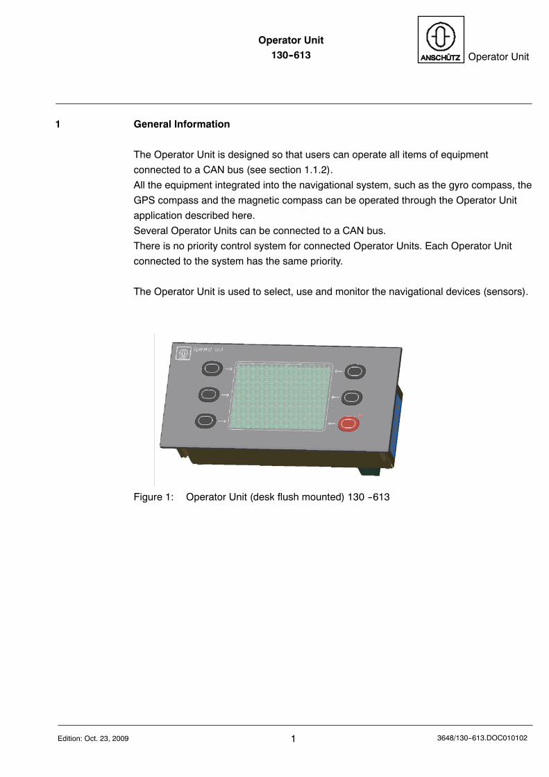
1 General Information
The Operator Unit is designed so that users can operate all items of equipment
connected to a CAN bus (see section 1.1.2).
All the equipment integrated into the navigational system, such as the gyro compass, the
GPS compass and the magnetic compass can be operated through the Operator Unit
application described here.
Several Operator Units can be connected to a CAN bus.
There is no priority control system for connected Operator Units. Each Operator Unit
connected to the system has the same priority.
The Operator Unit is used to select, use and monitor the navigational devices (sensors).
Figure 1: Operator Unit (desk flush mounted) 130 --613
Operator Unit130--613
23648/130--613.DOC010102 Edition: Oct. 23, 2009
1.1 The Construction of the Operator Unit
The Operator Unit is available in two versions -- desk-flush mounted, and with
angled fixing bracket.
The Operator Unit consists of a casing with a front panel.
All the electronics components required are accommodated inside the casing on
2 PCBs.
The front panel contains the display, 6 sealed membrane keys and a two-colour LED.
The PCBs are connected to the display unit via an optical fibre.
An alarm transmitter is mounted behind the front panel to transmit audible alarms.
The Operator Unit is designed for two redundancy CAN (CAN1 and CAN2) busses.
The Operator Unit is equipped with a PTC in the supply voltage line.
In the event of a fault (short circuit in the Operator Unit) this PTC reduces the current,
thus preventing further damage to the equipment.
There is no voltage fuse protection.
Operator Unit130--613 Operator Unit
3Edition: Oct. 23, 2009 3648/130--613.DOC010102
1.1.1 Principle of Operation
Once a voltage supply is present, the Operator Unit is able to detect every connected
item of navigational equipment (sensors) and indicate them on the display unit.
Depending on the status of the device, heading information is also now displayed.
Any gyro compasses connected will deliver a usable heading only after the heating and
settling stages.
If several sensors are connected, in principle the heading data supplied by the gyro
compass designated GYRO will be displayed (provided it is enabled and usable); if
several gyro compasses are in use, the one designated GYRO 1 will be displayed.
A membrane key (Select Sensor & Menu) can be used to select a different sensor or
sub-menu (see also Figure 3 and section 2.2.1.4).
Dimup
Dimdown
GYRO 1
068.7HEADING
Aut Spd: 08.5Kts
Aut Lat.: 5005‘
Gyro 2 067.9
Gyro 3 068.0
Magnet 069.0
SelectSpeed
Select
Sensor
& Menu
SelectLat.
Contrast
LampTest
Figure 2: Example of a display after it was put into operation
Explanation of the controls and indicators:
The Operator Unit display is divided into the display section and 6 soft keys.
The upper section of the display area indicates the sensor that is selected, and the
heading data it is indicating. Additional information about the selected sensor is
displayed underneath.
The lower section lists all the sensors connected to the CAN bus.
The display and the softkey designations (the fields on the display) alter depending on
which sensor is currently selected, to enable you to make settings relevant to the sensor
in question.
A membrane key is assigned to each soft key. The soft keys are operated by pressing
this membrane key.
Operator Unit130--613
43648/130--613.DOC010102 Edition: Oct. 23, 2009
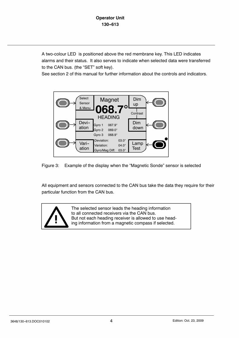
A two-colour LED is positioned above the red membrane key. This LED indicates
alarms and their status. It also serves to indicate when selected data were transferred
to the CAN bus. (the “SET” soft key).
See section 2 of this manual for further information about the controls and indicators.
Dimup
Dimdown
Magnet
068.7HEADING
Gyro 1 067.9
Gyro 2 069.0
Gyro 3 068.9
Contrast
Vari--ation
Select
Sensor
& Menu
Devi--ation
Deviation: 03.0
Variation: 04.0
Gyro/Mag Diff: 03.0
LampTest
Figure 3: Example of the display when the “Magnetic Sonde” sensor is selected
All equipment and sensors connected to the CAN bus take the data they require for their
particular function from the CAN bus.
The selected sensor leads the heading informationto all connected receivers via the CAN bus.But not each heading receiver is allowed to use head-ing information from a magnetic compass if selected.
Operator Unit130--613 Operator Unit
5Edition: Oct. 23, 2009 3648/130--613.DOC010102
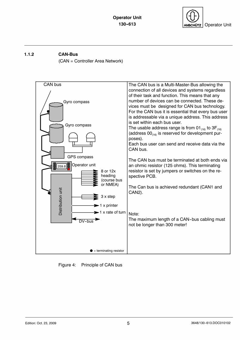
1.1.2 CAN-Bus
(CAN = Controller Area Network)
259.8
Gyro compass
Gyro compass
GPS compass
Operator unit
Distributionunit
8 or 12xheading(course busor NMEA)
3 x step
1 x rate of turn
1 x printer
= terminating resistor
DV--bus
CAN bus The CAN bus is a Multi-Master-Bus allowing theconnection of all devices and systems regardlessof their task and function. This means that anynumber of devices can be connected. These de-vices must be designed for CAN bus technology.For the CAN bus it is essential that every bus useris addressable via a unique address. This addressis set within each bus user.The usable address range is from 01(16) to 3F(16)
(address 00(16) is reserved for development pur-poses).Each bus user can send and receive data via theCAN bus.
The CAN bus must be terminated at both ends viaan ohmic resistor (125 ohms). This terminatingresistor is set by jumpers or switches on the re-spective PCB.
The Can bus is achieved redundant (CAN1 andCAN2).
Note:The maximum length of a CAN--bus cabling mustnot be longer than 300 meter!
Figure 4: Principle of CAN bus
Operator Unit130--613
63648/130--613.DOC010102 Edition: Oct. 23, 2009
1.2 Technical data
1.2.1 Mechanical data
Dimensions and weight: see appended Dimensional Drawing 130--613.HP005
Type of enclosure: IP23
(higher rating with special casing)
1.2.2 Electrical data
Supply voltage: 24 V DC (18 .. 36 V d.c.)
Power consumption: 6W
Interfaces: 2 x CAN bus
(optional RS422)
Operator Unit130--613 Operator Unit
7Edition: Oct. 23, 2009 3648/130--613.DOC010102
2 Operation
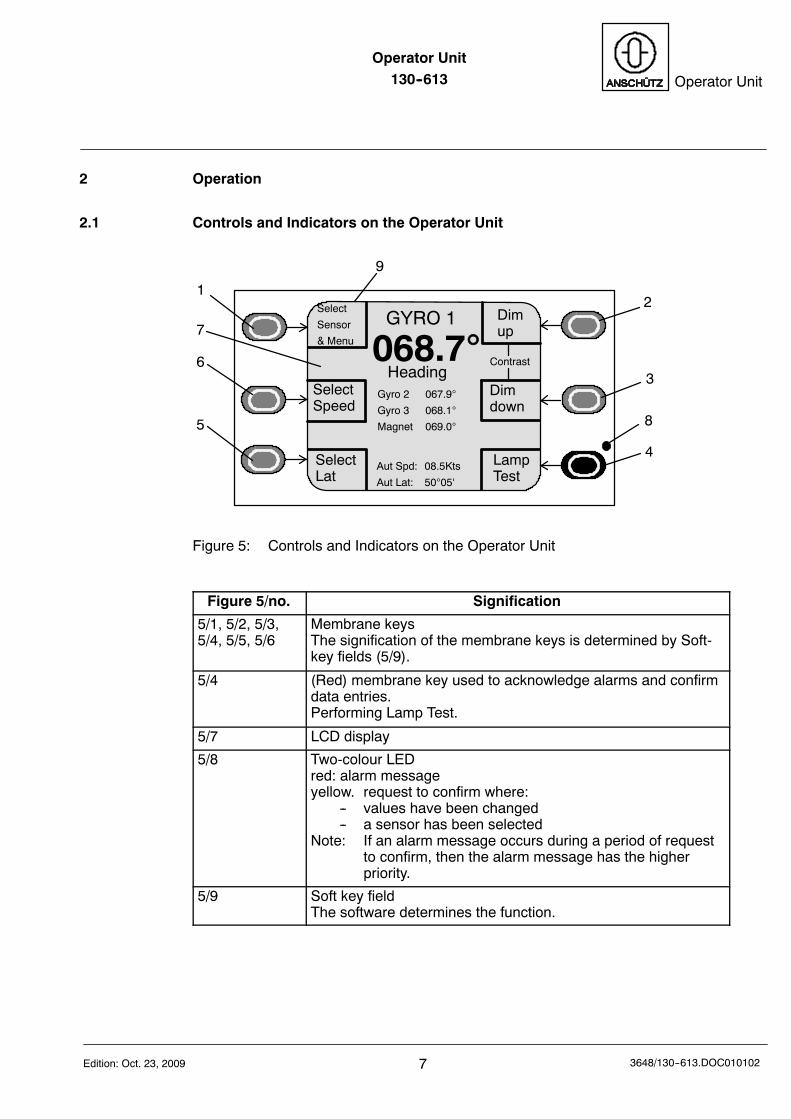
2.1 Controls and Indicators on the Operator Unit
12
3
4
5
6
7
8
9
Dimup
Dimdown
GYRO 1
068.7Heading
Aut Spd: 08.5Kts
Aut Lat: 5005‘
Gyro 2 067.9
Gyro 3 068.1
Magnet 069.0
SelectSpeed
SelectLat
Contrast
Select
Sensor
& Menu
LampTest
Figure 5: Controls and Indicators on the Operator Unit
Figure 5/no. Signification
5/1, 5/2, 5/3,5/4, 5/5, 5/6
Membrane keysThe signification of the membrane keys is determined by Soft-key fields (5/9).
5/4 (Red) membrane key used to acknowledge alarms and confirmdata entries.Performing Lamp Test.
5/7 LCD display
5/8 Two-colour LEDred: alarm messageyellow. request to confirm where:
-- values have been changed-- a sensor has been selected
Note: If an alarm message occurs during a period of requestto confirm, then the alarm message has the higherpriority.
5/9 Soft key fieldThe software determines the function.
Operator Unit130--613
83648/130--613.DOC010102 Edition: Oct. 23, 2009
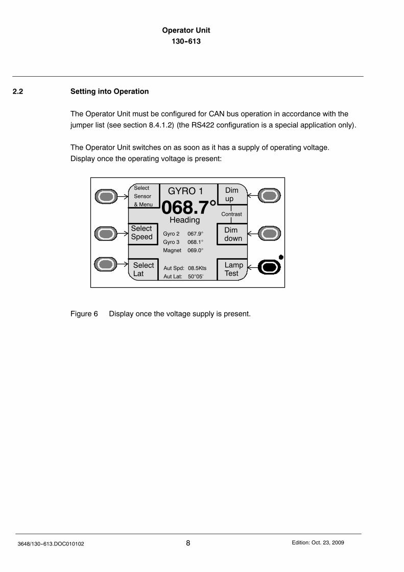
2.2 Setting into Operation
The Operator Unit must be configured for CAN bus operation in accordance with the
jumper list (see section 8.4.1.2) (the RS422 configuration is a special application only).
The Operator Unit switches on as soon as it has a supply of operating voltage.
Display once the operating voltage is present:
Dimup
Dimdown
GYRO 1
068.7Heading
Aut Spd: 08.5Kts
Aut Lat: 5005‘
Gyro 2 067.9
Gyro 3 068.1
Magnet 069.0
SelectSpeed
SelectLat
Contrast
Select
Sensor
& Menu
LampTest
Figure 6 Display once the voltage supply is present.
Operator Unit130--613 Operator Unit
9Edition: Oct. 23, 2009 3648/130--613.DOC010102
2.2.1 General Information regarding the Operation of the Operator Unit
The principle of operation is explained on the figure illustrating the display for Gyro1.
The meaning and function of each soft key depends on the sensor concerned, and these
are explained in more detail in the section referring to the sensor in question.
Operator Unit130--613
103648/130--613.DOC010102 Edition: Oct. 23, 2009
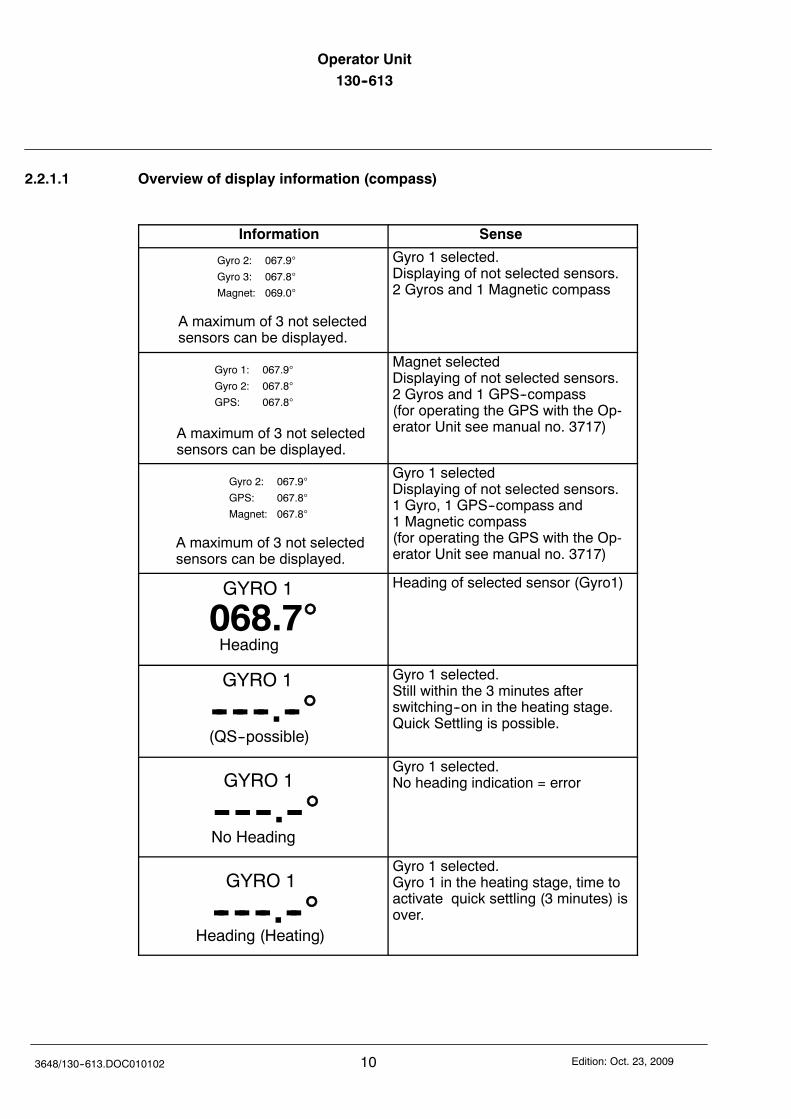
2.2.1.1 Overview of display information (compass)
Information Sense
Gyro 2: 067.9
Gyro 3: 067.8
Magnet: 069.0
A maximum of 3 not selectedsensors can be displayed.
Gyro 1 selected.Displaying of not selected sensors.2 Gyros and 1 Magnetic compass
Gyro 1: 067.9
Gyro 2: 067.8
GPS: 067.8
A maximum of 3 not selectedsensors can be displayed.
Magnet selectedDisplaying of not selected sensors.2 Gyros and 1 GPS--compass(for operating the GPS with the Op-erator Unit see manual no. 3717)
Gyro 2: 067.9
GPS: 067.8
Magnet: 067.8
A maximum of 3 not selectedsensors can be displayed.
Gyro 1 selectedDisplaying of not selected sensors.1 Gyro, 1 GPS--compass and1 Magnetic compass(for operating the GPS with the Op-erator Unit see manual no. 3717)
GYRO 1
068.7Heading
Heading of selected sensor (Gyro1)
GYRO 1
-- -- --.--(QS--possible)
Gyro 1 selected.Still within the 3 minutes afterswitching--on in the heating stage.Quick Settling is possible.
GYRO 1
-- -- --.--No Heading
Gyro 1 selected.No heading indication = error
GYRO 1
-- -- --.--Heading (Heating)
Gyro 1 selected.Gyro 1 in the heating stage, time toactivate quick settling (3 minutes) isover.
Operator Unit130--613 Operator Unit
11Edition: Oct. 23, 2009 3648/130--613.DOC010102
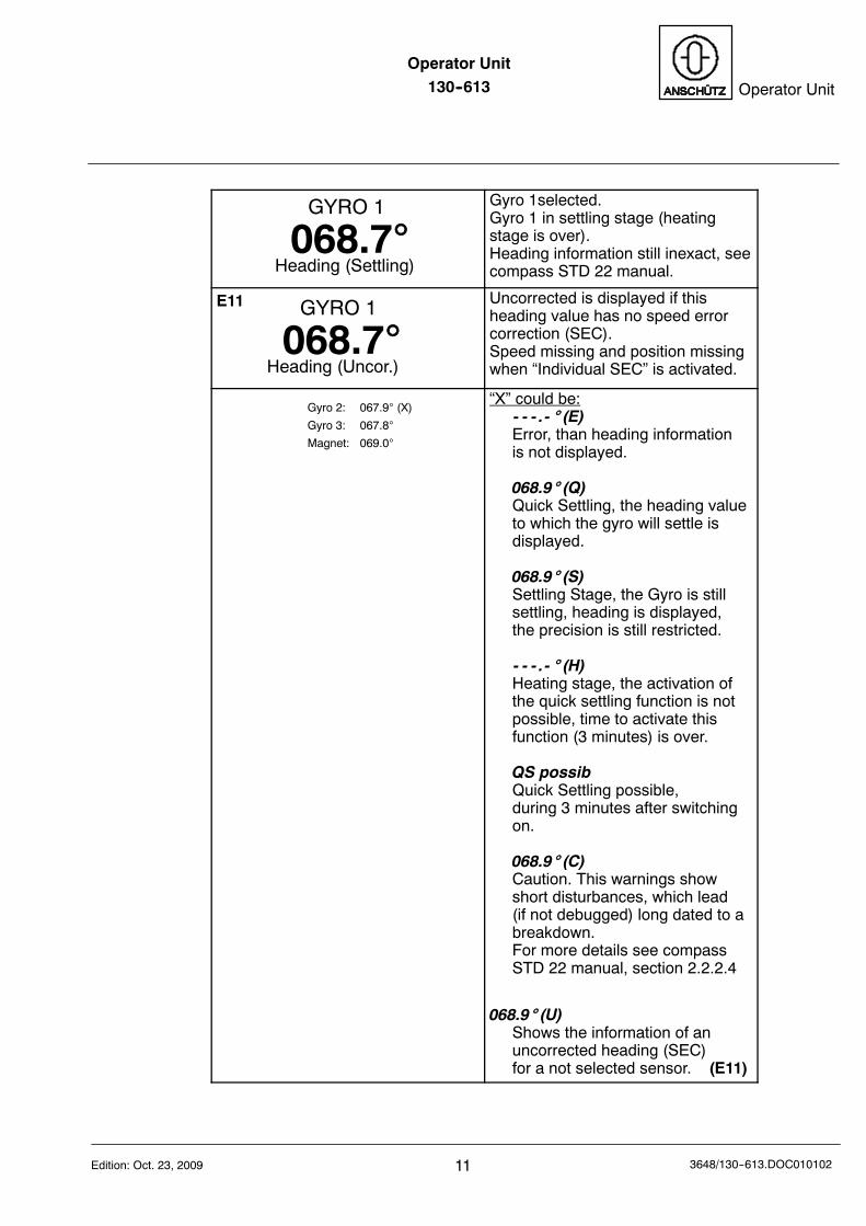
GYRO 1
068.7Heading (Settling)
Gyro 1selected.Gyro 1 in settling stage (heatingstage is over).Heading information still inexact, seecompass STD 22 manual.
GYRO 1
068.7Heading (Uncor.)
E11 Uncorrected is displayed if thisheading value has no speed errorcorrection (SEC).Speed missing and position missingwhen “Individual SEC” is activated.
Gyro 2: 067.9 (X)
Gyro 3: 067.8
Magnet: 069.0
“X” could be:- - - .- (E)Error, than heading informationis not displayed.
068.9 (Q)Quick Settling, the heading valueto which the gyro will settle isdisplayed.
068.9 (S)Settling Stage, the Gyro is stillsettling, heading is displayed,the precision is still restricted.
- - - .- (H)Heating stage, the activation ofthe quick settling function is notpossible, time to activate thisfunction (3 minutes) is over.
QS possibQuick Settling possible,during 3 minutes after switchingon.
068.9 (C)Caution. This warnings showshort disturbances, which lead(if not debugged) long dated to abreakdown.For more details see compassSTD 22 manual, section 2.2.2.4
068.9 (U)Shows the information of anuncorrected heading (SEC)for a not selected sensor. (E11)
Operator Unit130--613
123648/130--613.DOC010102 Edition: Oct. 23, 2009
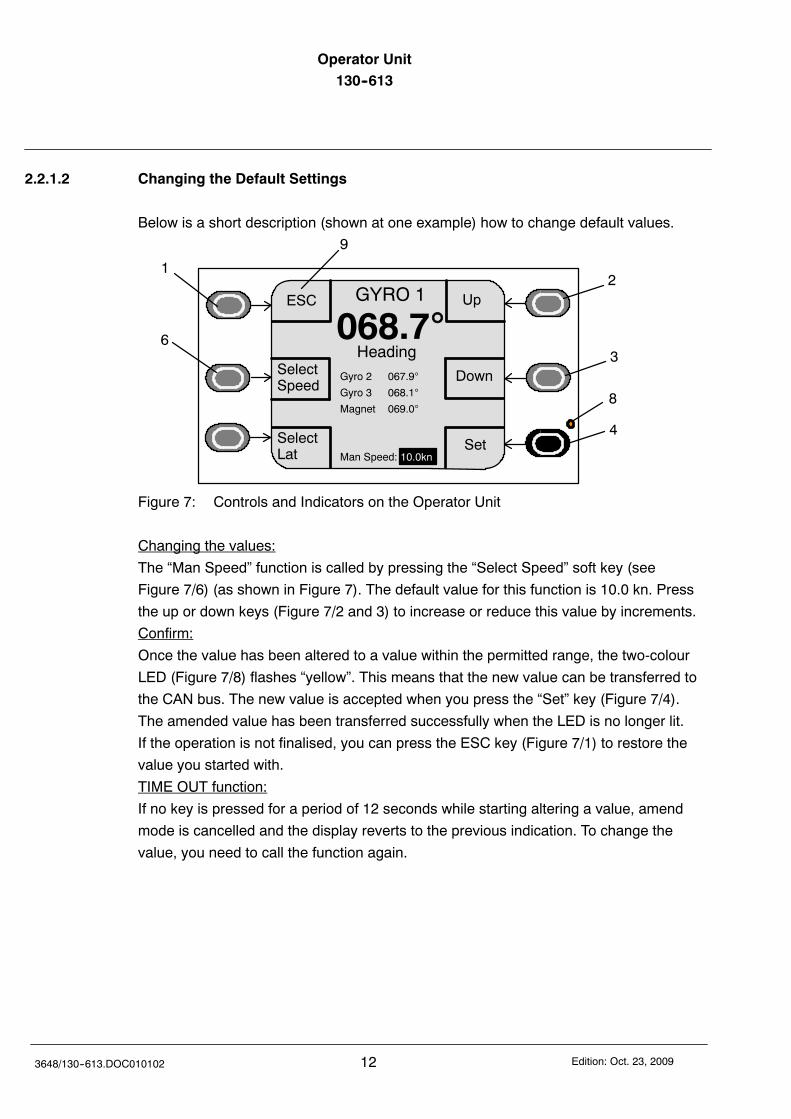
2.2.1.2 Changing the Default Settings
Below is a short description (shown at one example) how to change default values.
12
3
4
6
8
9
Up
Down
GYRO 1
068.7Heading
Gyro 2 067.9
Gyro 3 068.1
Magnet 069.0
Man Speed:SetSelect
Lat 10.0kn
SelectSpeed
ESC
Figure 7: Controls and Indicators on the Operator Unit
Changing the values:
The “Man Speed” function is called by pressing the “Select Speed” soft key (see
Figure 7/6) (as shown in Figure 7). The default value for this function is 10.0 kn. Press
the up or down keys (Figure 7/2 and 3) to increase or reduce this value by increments.
Confirm:
Once the value has been altered to a value within the permitted range, the two-colour
LED (Figure 7/8) flashes “yellow”. This means that the new value can be transferred to
the CAN bus. The new value is accepted when you press the “Set” key (Figure 7/4).
The amended value has been transferred successfully when the LED is no longer lit.
If the operation is not finalised, you can press the ESC key (Figure 7/1) to restore the
value you started with.
TIME OUT function:
If no key is pressed for a period of 12 seconds while starting altering a value, amend
mode is cancelled and the display reverts to the previous indication. To change the
value, you need to call the function again.
Operator Unit130--613 Operator Unit
13Edition: Oct. 23, 2009 3648/130--613.DOC010102
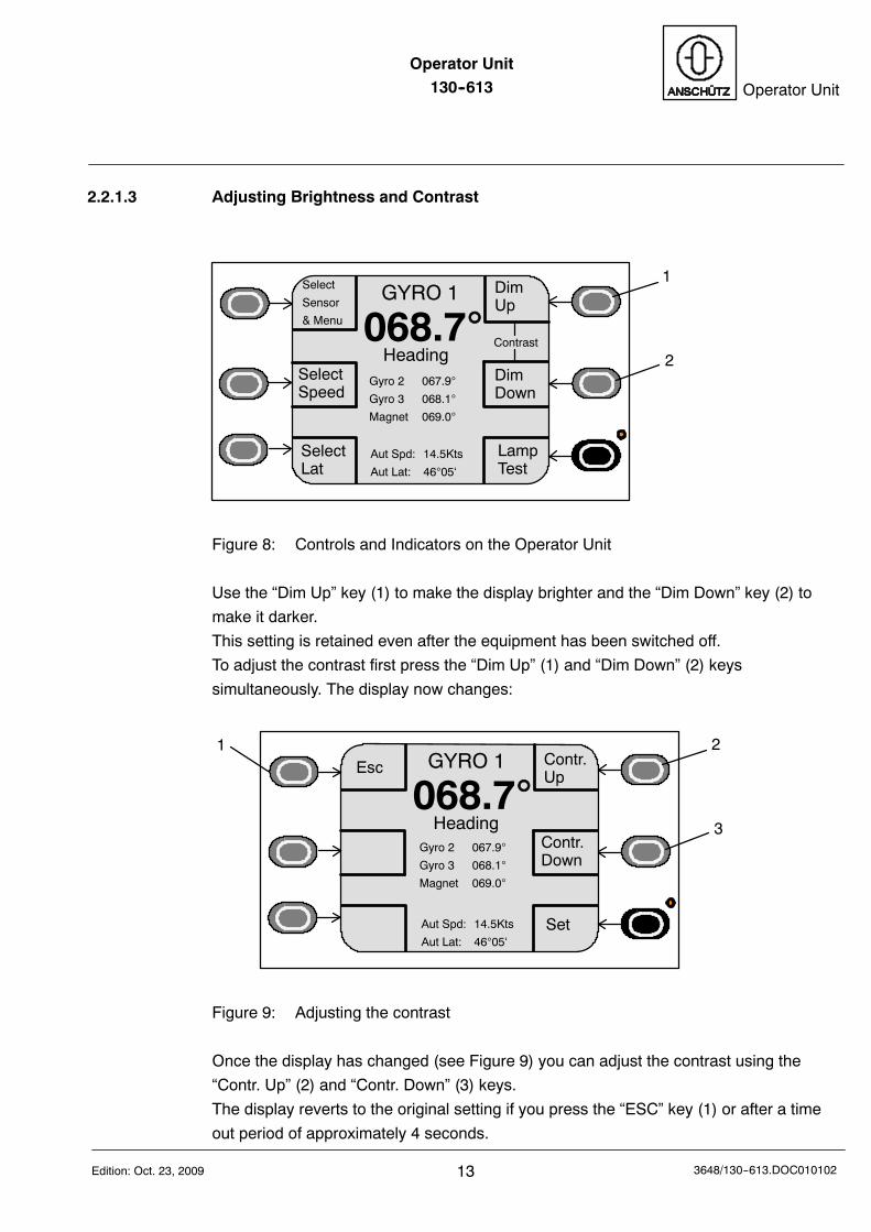
2.2.1.3 Adjusting Brightness and Contrast
1
2
DimUp
DimDown
GYRO 1
068.7Heading
Gyro 2 067.9
Gyro 3 068.1
Magnet 069.0
SelectLat
SelectSpeed
Contrast
Select
Sensor
& Menu
Aut Spd: 14.5Kts
Aut Lat: 4605‘
LampTest
Figure 8: Controls and Indicators on the Operator Unit
Use the “Dim Up” key (1) to make the display brighter and the “Dim Down” key (2) to
make it darker.
This setting is retained even after the equipment has been switched off.
To adjust the contrast first press the “Dim Up” (1) and “Dim Down” (2) keys
simultaneously. The display now changes:
2
3
Contr.Up
Contr.Down
GYRO 1
068.7Heading
Gyro 2 067.9
Gyro 3 068.1
Magnet 069.0
Esc1
Aut Spd: 14.5Kts
Aut Lat: 4605‘Set
Figure 9: Adjusting the contrast
Once the display has changed (see Figure 9) you can adjust the contrast using the
“Contr. Up” (2) and “Contr. Down” (3) keys.
The display reverts to the original setting if you press the “ESC” key (1) or after a time
out period of approximately 4 seconds.
Operator Unit130--613
143648/130--613.DOC010102 Edition: Oct. 23, 2009
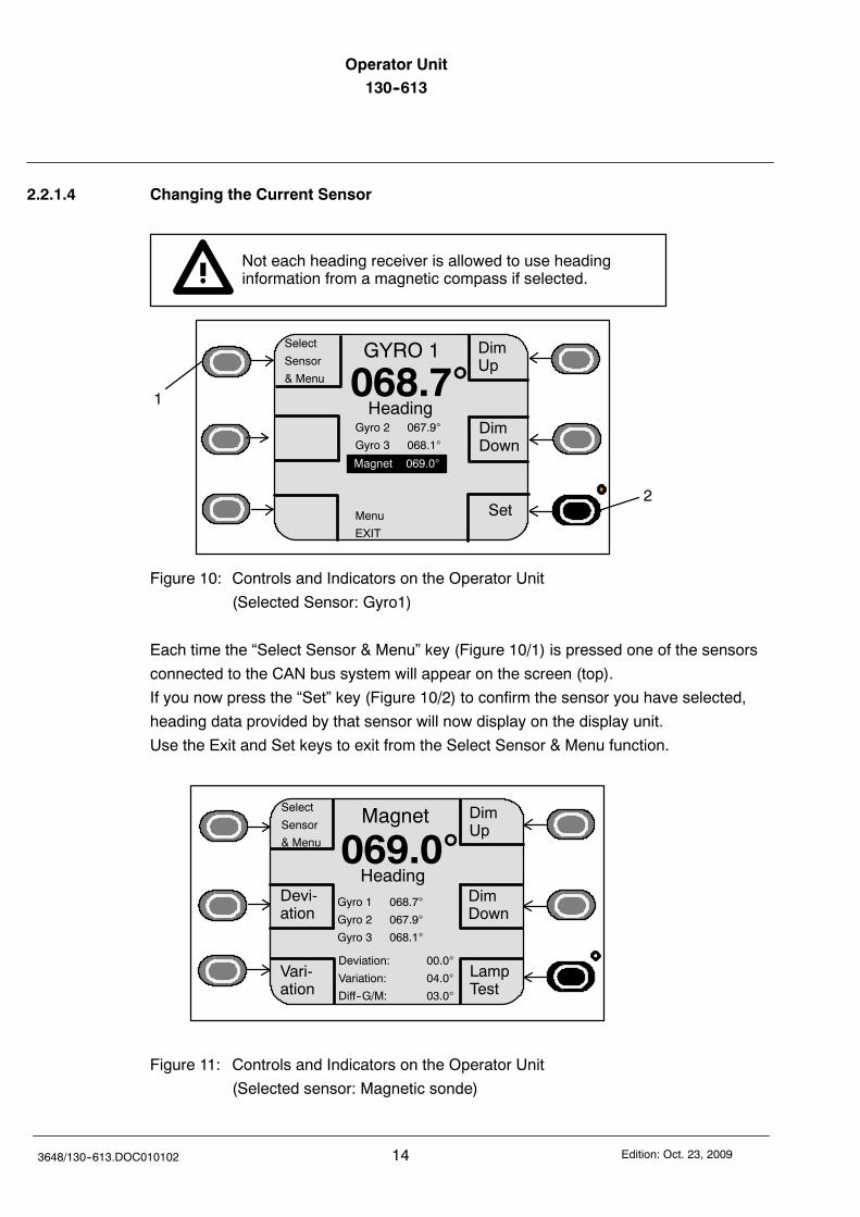
2.2.1.4 Changing the Current Sensor
Not each heading receiver is allowed to use headinginformation from a magnetic compass if selected.
2
1
DimUp
DimDown
GYRO 1
068.7Heading
Gyro 2 067.9
Gyro 3 068.1
Menu
EXIT
Set
Select
Sensor
& Menu
Magnet 069.0
Figure 10: Controls and Indicators on the Operator Unit
(Selected Sensor: Gyro1)
Each time the “Select Sensor & Menu” key (Figure 10/1) is pressed one of the sensors
connected to the CAN bus system will appear on the screen (top).
If you now press the “Set” key (Figure 10/2) to confirm the sensor you have selected,
heading data provided by that sensor will now display on the display unit.
Use the Exit and Set keys to exit from the Select Sensor & Menu function.
Magnet
069.0Gyro 1 068.7
Gyro 2 067.9
Gyro 3 068.1
DimUp
DimDown
Heading
Vari-ation
Select
Sensor
& Menu
Devi-ation
Deviation: 00.0
Variation: 04.0
Diff--G/M: 03.0
LampTest
Figure 11: Controls and Indicators on the Operator Unit
(Selected sensor: Magnetic sonde)
Operator Unit130--613 Operator Unit
15Edition: Oct. 23, 2009 3648/130--613.DOC010102
2.2.1.5 Menu selection
Use the “Select Sensor & Menu” soft key to select a sub-menu.
This sub-menu is used to make settings that require updating relatively rarely, but which
are provided for servicing purposes.
Sub-menu
-- Diff.Alarm (see section 6.1.1 for Gyros and 4.1 for Magnetic compass)
The monitoring threshold setting between Gyro1, Gyro2 and Gyro3
GPS (if used) is identical to a Gyro.
(Default: Gyro/Gyro Diff = 03.0)
The monitoring threshold settings between selected Gyro and Magnetic compass
(Default: Gyro/Mag Diff = 05.0)
-- Panel Set Up (see section 6.2)
In this sub--menu the volume of the alarm horn may be adjusted and the actual
software status is displayed.
-- Service (see section 6.3)
There are two pages which may be selected. The pages contain:
---- Displaying of CAN bus addresses and heading without correction values
(as there are speed error correction and alignment error)
---- Adjustment of damping of the Rate of Turn
---- Displaying and selection of speed source
---- Activation of DV--bus and adjustment of DV--bus address for the distribution unit
---- Automatic switch--over if a Gyro fails.
---- Applying and changing of a deviation table
---- Performing GPS configuration
---- Displaying operational data of all Gyros
---- Displaying of software versions of all Gyro and Distribution Unit memories
-- Quick Settling (see section 3.4)
In this submenu the quick settling function can be activated for each gyro.
This submenu is shown only, if there is a possibility for Quick settling.
Operator Unit130--613
163648/130--613.DOC010102 Edition: Oct. 23, 2009
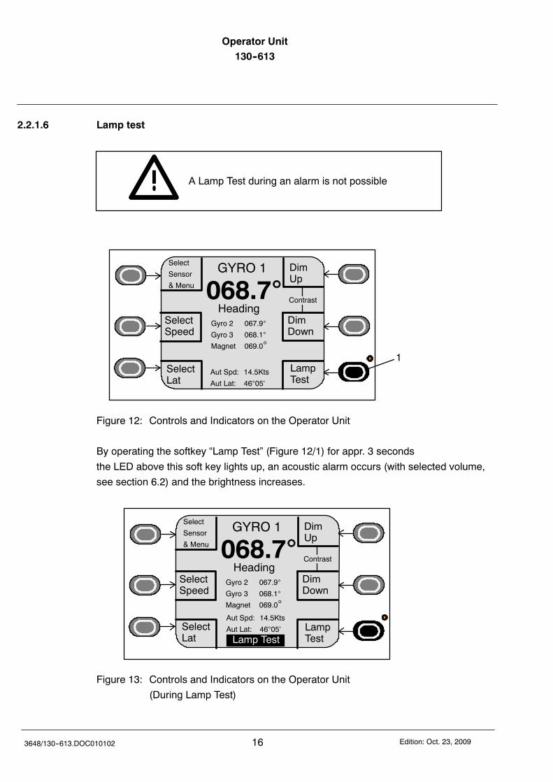
2.2.1.6 Lamp test
A Lamp Test during an alarm is not possible
DimUp
DimDown
GYRO 1
068.7Heading
Gyro 2 067.9
Gyro 3 068.1
Magnet 069.0
SelectLat
SelectSpeed
Contrast
Select
Sensor
& Menu
Aut Spd: 14.5Kts
Aut Lat: 4605‘
LampTest
1
Figure 12: Controls and Indicators on the Operator Unit
By operating the softkey “Lamp Test” (Figure 12/1) for appr. 3 seconds
the LED above this soft key lights up, an acoustic alarm occurs (with selected volume,
see section 6.2) and the brightness increases.
DimUp
DimDown
GYRO 1
068.7Heading
Gyro 2 067.9
Gyro 3 068.1
Magnet 069.0
SelectLat
SelectSpeed
Contrast
Select
Sensor
& Menu
Aut Spd: 14.5Kts
Aut Lat: 4605‘ LampTestLamp Test
Figure 13: Controls and Indicators on the Operator Unit
(During Lamp Test)
Operator Unit130--613 Operator Unit
17Edition: Oct. 23, 2009 3648/130--613.DOC010102
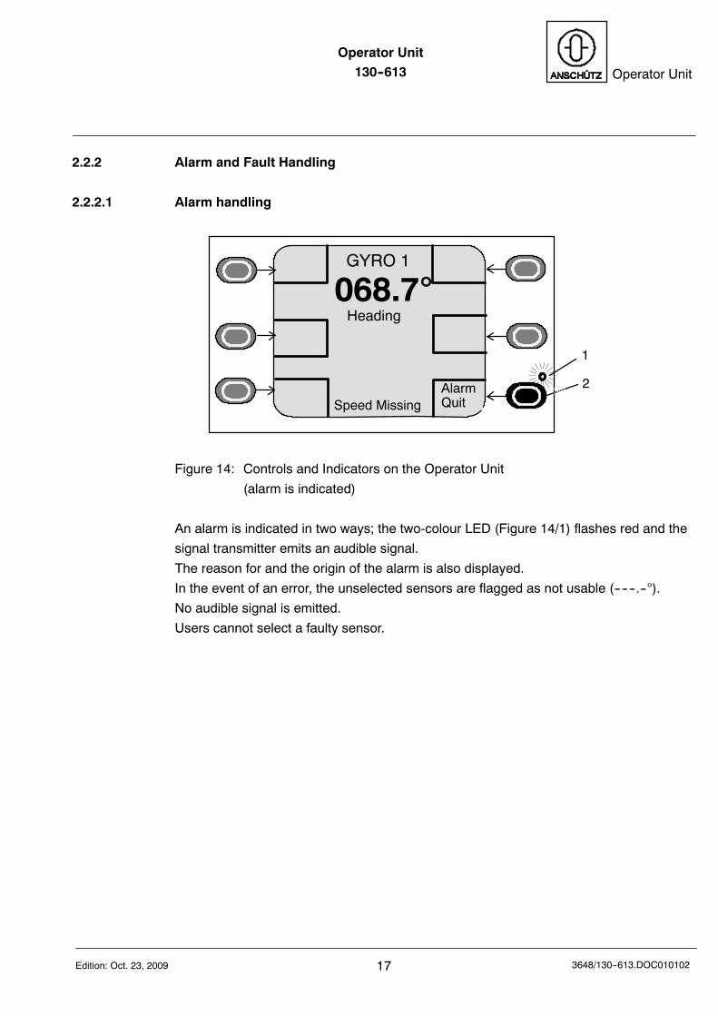
2.2.2 Alarm and Fault Handling
2.2.2.1 Alarm handling
2
1
GYRO 1
068.7Heading
Set
Speed MissingAlarmQuit
Figure 14: Controls and Indicators on the Operator Unit
(alarm is indicated)
An alarm is indicated in two ways; the two-colour LED (Figure 14/1) flashes red and the
signal transmitter emits an audible signal.
The reason for and the origin of the alarm is also displayed.
In the event of an error, the unselected sensors are flagged as not usable (------.--).
No audible signal is emitted.
Users cannot select a faulty sensor.
Operator Unit130--613
183648/130--613.DOC010102 Edition: Oct. 23, 2009
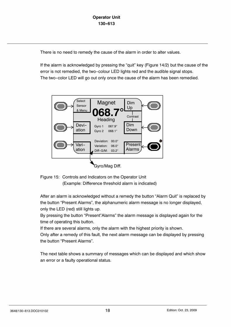
There is no need to remedy the cause of the alarm in order to alter values.
If the alarm is acknowledged by pressing the “quit” key (Figure 14/2) but the cause of the
error is not remedied, the two--colour LED lights red and the audible signal stops.
The two--color LED will go out only once the cause of the alarm has been remedied.
DimUp
DimDown
Magnet
068.7Heading
Gyro 1 067.9
Gyro 2 068.1
Vari--ation
Devi--ation
Contrast
Select
Sensor
& Menu
Deviation: 00.0
Variation: 06.0
Diff--G/M: 03.2
PresentAlarms
Gyro/Mag Diff.
Figure 15: Controls and Indicators on the Operator Unit
(Example: Difference threshold alarm is indicated)
After an alarm is acknowledged without a remedy the button “Alarm Quit” is replaced by
the button “Present Alarms”, the alphanumeric alarm message is no longer displayed,
only the LED (red) still lights up.
By pressing the button “Present”Alarms” the alarm message is displayed again for the
time of operating this button.
If there are several alarms, only the alarm with the highest priority is shown.
Only after a remedy of this fault, the next alarm message can be displayed by pressing
the button “Present Alarms”.
The next table shows a summary of messages which can be displayed and which show
an error or a faulty operational status.
Operator Unit130--613 Operator Unit
19Edition: Oct. 23, 2009 3648/130--613.DOC010102
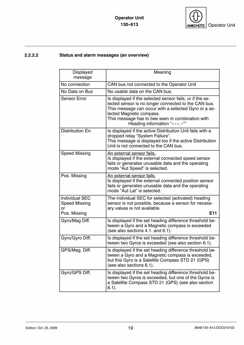
2.2.2.2 Status and alarm messages (an overview)
Displayedmessage
Meaning
No connection CAN bus not connected to the Operator Unit
No Data on Bus No usable data on the CAN bus.
Sensor Error Is displayed if the selected sensor fails, or if the se-lected sensor is no longer connected to the CAN bus.This message can occur with a selected Gyro or a se-lected Magnetic compass.This message has to bee seen in combination with
Heading information “------.--”
Distribution Err. Is displayed if the active Distribution Unit fails with adropped relay “System Failure”.This message is displayed too if the active DistributionUnit is not connected to the CAN bus.
Speed Missing An external sensor fails.Is displayed if the external connected speed sensorfails or generates unusable data and the operatingmode “Aut Speed” is selected.
Pos. Missing An external sensor fails.Is displayed if the external connected position sensorfails or generates unusable data and the operatingmode “Aut Lat” is selected.
Individual SECSpeed MissingorPos. Missing
The individual SEC for selected (activated) headingsensor is not possible, because a sensor for necess-ary values is not available.
E11
Gyro/Mag Diff. Is displayed if the set heading difference threshold be-tween a Gyro and a Magnetic compass is exceeded(see also sections 4.1. and 6.1).
Gyro/Gyro Diff. Is displayed if the set heading difference threshold be-tween two Gyros is exceeded (see also section 6.1).
GPS/Mag. Diff. Is displayed if the set heading difference threshold be-tween a Gyro and a Magnetic compass is exceeded,but this Gyro is a Satellite Compass STD 21 (GPS)(see also sections 6.1).
Gyro/GPS Diff. Is displayed if the set heading difference threshold be-tween two Gyros is exceeded, but one of the Gyros isa Satellite Compass STD 21 (GPS) (see also section6.1).
Operator Unit130--613
203648/130--613.DOC010102 Edition: Oct. 23, 2009
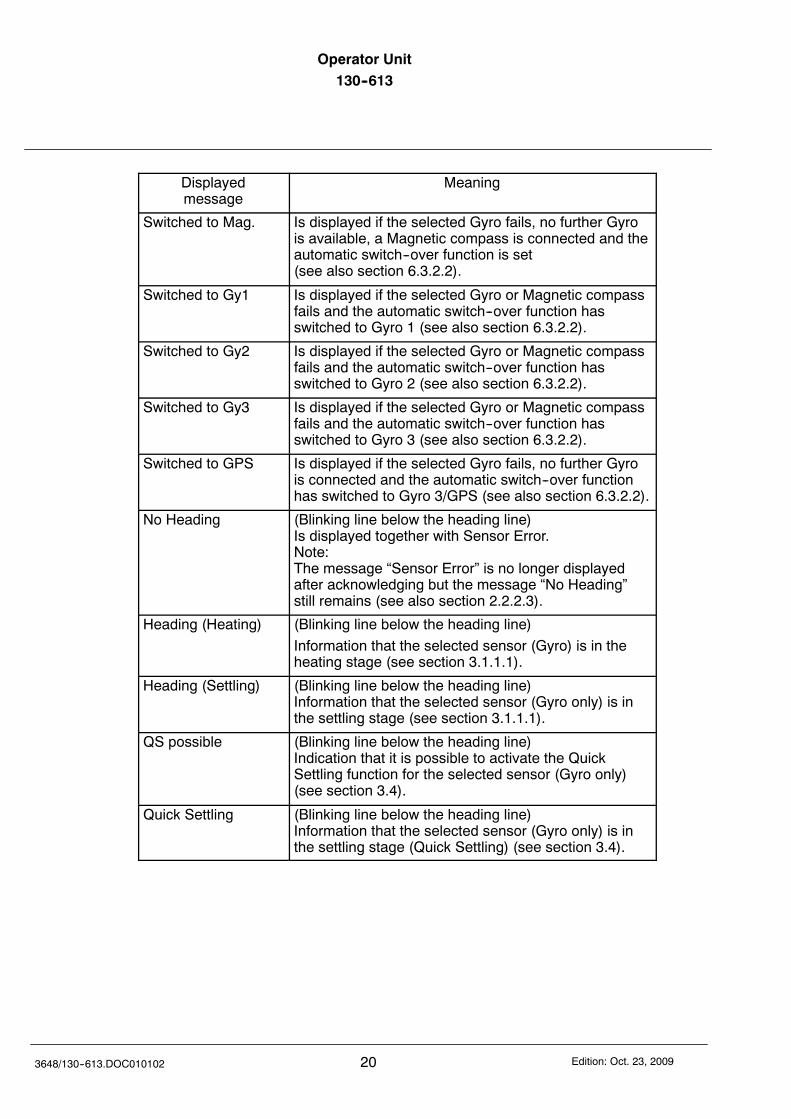
Displayedmessage
Meaning
Switched to Mag. Is displayed if the selected Gyro fails, no further Gyrois available, a Magnetic compass is connected and theautomatic switch--over function is set(see also section 6.3.2.2).
Switched to Gy1 Is displayed if the selected Gyro or Magnetic compassfails and the automatic switch--over function hasswitched to Gyro 1 (see also section 6.3.2.2).
Switched to Gy2 Is displayed if the selected Gyro or Magnetic compassfails and the automatic switch--over function hasswitched to Gyro 2 (see also section 6.3.2.2).
Switched to Gy3 Is displayed if the selected Gyro or Magnetic compassfails and the automatic switch--over function hasswitched to Gyro 3 (see also section 6.3.2.2).
Switched to GPS Is displayed if the selected Gyro fails, no further Gyrois connected and the automatic switch--over functionhas switched to Gyro 3/GPS (see also section 6.3.2.2).
No Heading (Blinking line below the heading line)Is displayed together with Sensor Error.Note:The message “Sensor Error” is no longer displayedafter acknowledging but the message “No Heading”still remains (see also section 2.2.2.3).
Heading (Heating) (Blinking line below the heading line)
Information that the selected sensor (Gyro) is in theheating stage (see section 3.1.1.1).
Heading (Settling) (Blinking line below the heading line)Information that the selected sensor (Gyro only) is inthe settling stage (see section 3.1.1.1).
QS possible (Blinking line below the heading line)Indication that it is possible to activate the QuickSettling function for the selected sensor (Gyro only)(see section 3.4).
Quick Settling (Blinking line below the heading line)Information that the selected sensor (Gyro only) is inthe settling stage (Quick Settling) (see section 3.4).
Operator Unit130--613 Operator Unit
21Edition: Oct. 23, 2009 3648/130--613.DOC010102
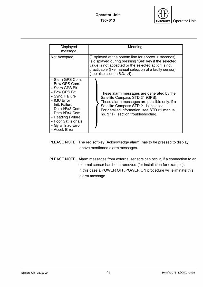
Displayedmessage
Meaning
Not Accepted (Displayed at the bottom line for approx. 2 seconds).Is displayed during pressing “Set” key if the selectedvalue is not accepted or the selected action is notpracticable (like manual selection of a faulty sensor)(see also section 6.3.1.4).
-- Stern GPS Com.-- Bow GPS Com.-- Stern GPS Bit-- Bow GPS Bit-- Sync. Failure-- IMU Error-- Init. Failure-- Data I/F#3 Com.-- Data I/F#4 Com.-- Heading Failure-- Poor Sat. signals-- Gyro Triad Error-- Accel. Error
These alarm messages are generated by theSatellite Compass STD 21 (GPS).These alarm messages are possible only, if aSatellite Compass STD 21 is installed.For detailed information, see STD 21 manualno. 3717, section troubleshooting.
PLEASE NOTE: The red softkey (Acknowledge alarm) has to be pressed to display
above mentioned alarm messages.
PLEASE NOTE: Alarm messages from external sensors can occur, if a connection to an
external sensor has been removed (for installation for example).
In this case a POWER OFF/POWER ON procedure will eliminate this
alarm message.
Operator Unit130--613
223648/130--613.DOC010102 Edition: Oct. 23, 2009
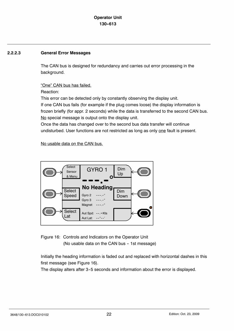
2.2.2.3 General Error Messages
The CAN bus is designed for redundancy and carries out error processing in the
background.
“One” CAN bus has failed.
Reaction:
This error can be detected only by constantly observing the display unit.
If one CAN bus fails (for example if the plug comes loose) the display information is
frozen briefly (for appr. 2 seconds) while the data is transferred to the second CAN bus.
No special message is output onto the display unit.
Once the data has changed over to the second bus data transfer will continue
undisturbed. User functions are not restricted as long as only one fault is present.
No usable data on the CAN bus.
DimUp
DimDown
GYRO 1
No HeadingGyro 2 ------.--
Gyro 3 ------.--
Magnet ------.--
-- -- --.--SelectSpeed
SelectLat
Select
Sensor
& Menu
Aut Spd: ----.--KtsAut Lat: --------‘
Figure 16: Controls and Indicators on the Operator Unit
(No usable data on the CAN bus -- 1st message)
Initially the heading information is faded out and replaced with horizontal dashes in this
first message (see Figure 16).
The display alters after 3--5 seconds and information about the error is displayed.
Operator Unit130--613 Operator Unit
23Edition: Oct. 23, 2009 3648/130--613.DOC010102
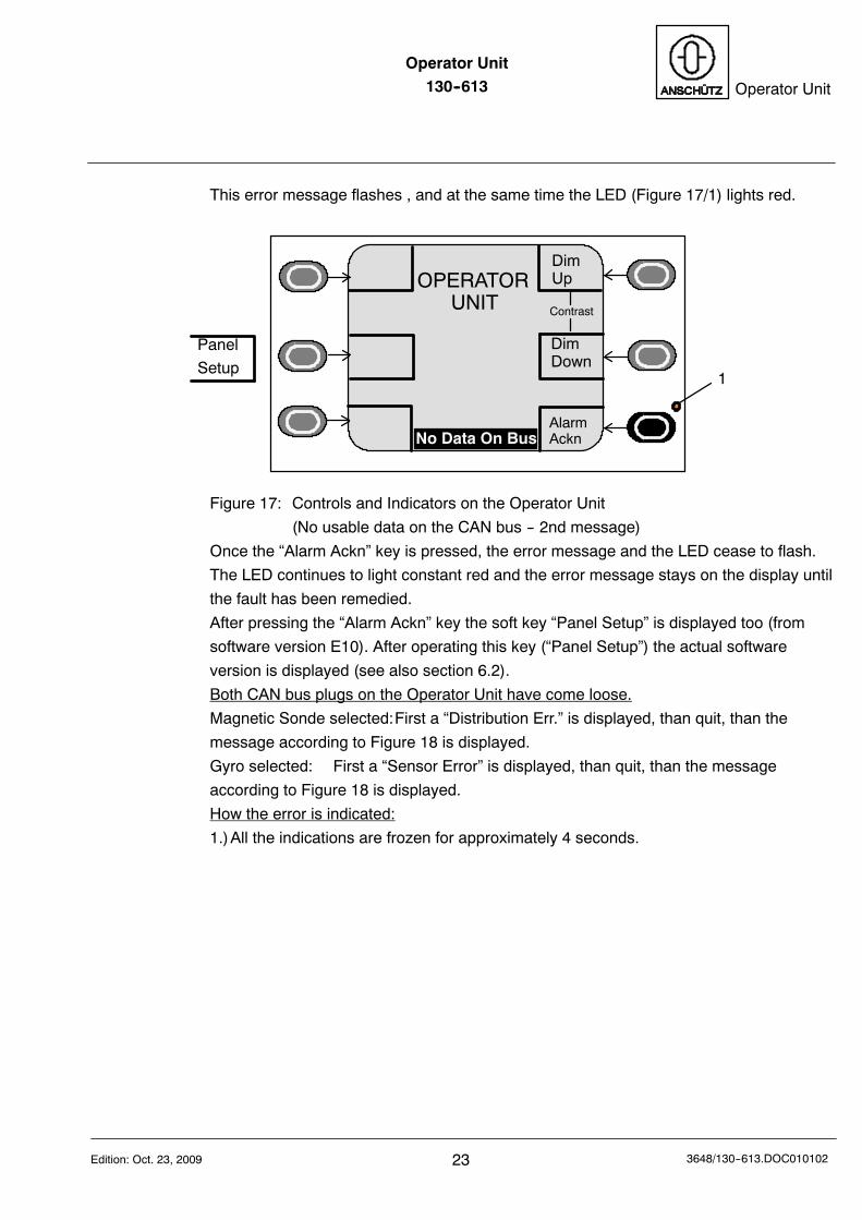
This error message flashes , and at the same time the LED (Figure 17/1) lights red.
1
DimUp
DimDown
AlarmAcknNo Data On Bus
Contrast
OPERATORUNIT
Panel
Setup
Figure 17: Controls and Indicators on the Operator Unit
(No usable data on the CAN bus -- 2nd message)
Once the “Alarm Ackn” key is pressed, the error message and the LED cease to flash.
The LED continues to light constant red and the error message stays on the display until
the fault has been remedied.
After pressing the “Alarm Ackn” key the soft key “Panel Setup” is displayed too (from
software version E10). After operating this key (“Panel Setup”) the actual software
version is displayed (see also section 6.2).
Both CAN bus plugs on the Operator Unit have come loose.
Magnetic Sonde selected:First a “Distribution Err.” is displayed, than quit, than the
message according to Figure 18 is displayed.
Gyro selected: First a “Sensor Error” is displayed, than quit, than the message
according to Figure 18 is displayed.
How the error is indicated:
1.)All the indications are frozen for approximately 4 seconds.
Operator Unit130--613
243648/130--613.DOC010102 Edition: Oct. 23, 2009
Up
Down
GYRO 1
No Heading
Gyro 2 ------.--
Gyro 3 ------.--
Magnet ------.--
ESC
-- -- --.--
Aut Spd: ----.--Kts
Aut Lat: --------‘
LampTest
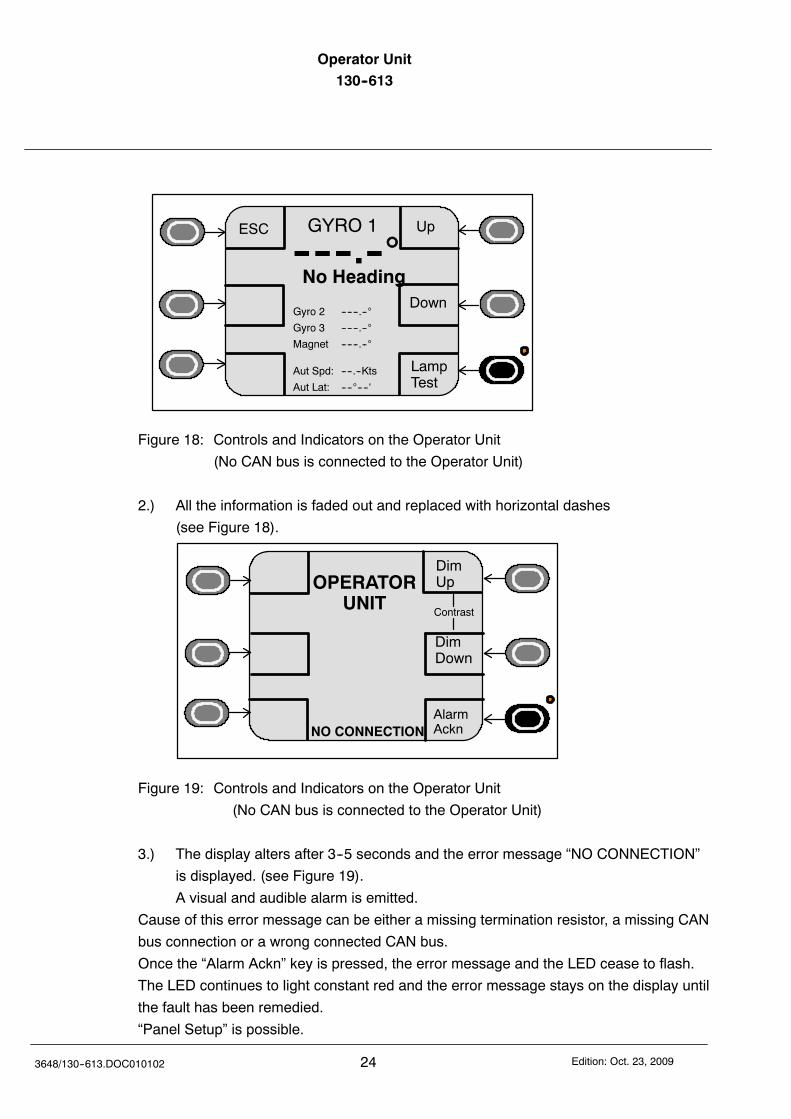
Figure 18: Controls and Indicators on the Operator Unit
(No CAN bus is connected to the Operator Unit)
2.) All the information is faded out and replaced with horizontal dashes
(see Figure 18).
DimUp
DimDown
AlarmAcknNO CONNECTION
OPERATORUNIT
Contrast
Figure 19: Controls and Indicators on the Operator Unit
(No CAN bus is connected to the Operator Unit)
3.) The display alters after 3--5 seconds and the error message “NO CONNECTION”
is displayed. (see Figure 19).
A visual and audible alarm is emitted.
Cause of this error message can be either a missing termination resistor, a missing CAN
bus connection or a wrong connected CAN bus.
Once the “Alarm Ackn” key is pressed, the error message and the LED cease to flash.
The LED continues to light constant red and the error message stays on the display until
the fault has been remedied.
“Panel Setup” is possible.
Operator Unit130--613 Operator Unit
25Edition: Oct. 23, 2009 3648/130--613.DOC010102
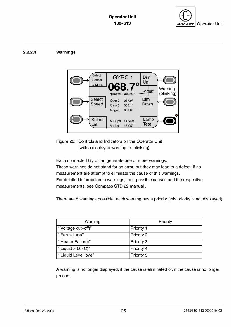
2.2.2.4 Warnings
DimUp
DimDown
GYRO 1
068.7“(Heater Failure)”
Gyro 2 067.9
Gyro 3 068.1
Magnet 069.0
SelectLat
SelectSpeed
Contrast
Select
Sensor
& Menu
Aut Spd: 14.5Kts
Aut Lat: 4605‘
LampTest
Warning(blinking)
Figure 20: Controls and Indicators on the Operator Unit
(with a displayed warning --> blinking)
Each connected Gyro can generate one or more warnings.
These warnings do not stand for an error, but they may lead to a defect, if no
measurement are attempt to eliminate the cause of this warnings.
For detailed information to warnings, their possible causes and the respective
measurements, see Compass STD 22 manual .
There are 5 warnings possible, each warning has a priority (this priority is not displayed):
Warning Priority
“(Voltage cut--off)” Priority 1
“(Fan failure)” Priority 2
“(Heater Failure)” Priority 3
“(Liquid > 60C)” Priority 4
“(Liquid Level low)” Priority 5
A warning is no longer displayed, if the cause is eliminated or, if the cause is no longer
present.
Operator Unit130--613
263648/130--613.DOC010102 Edition: Oct. 23, 2009
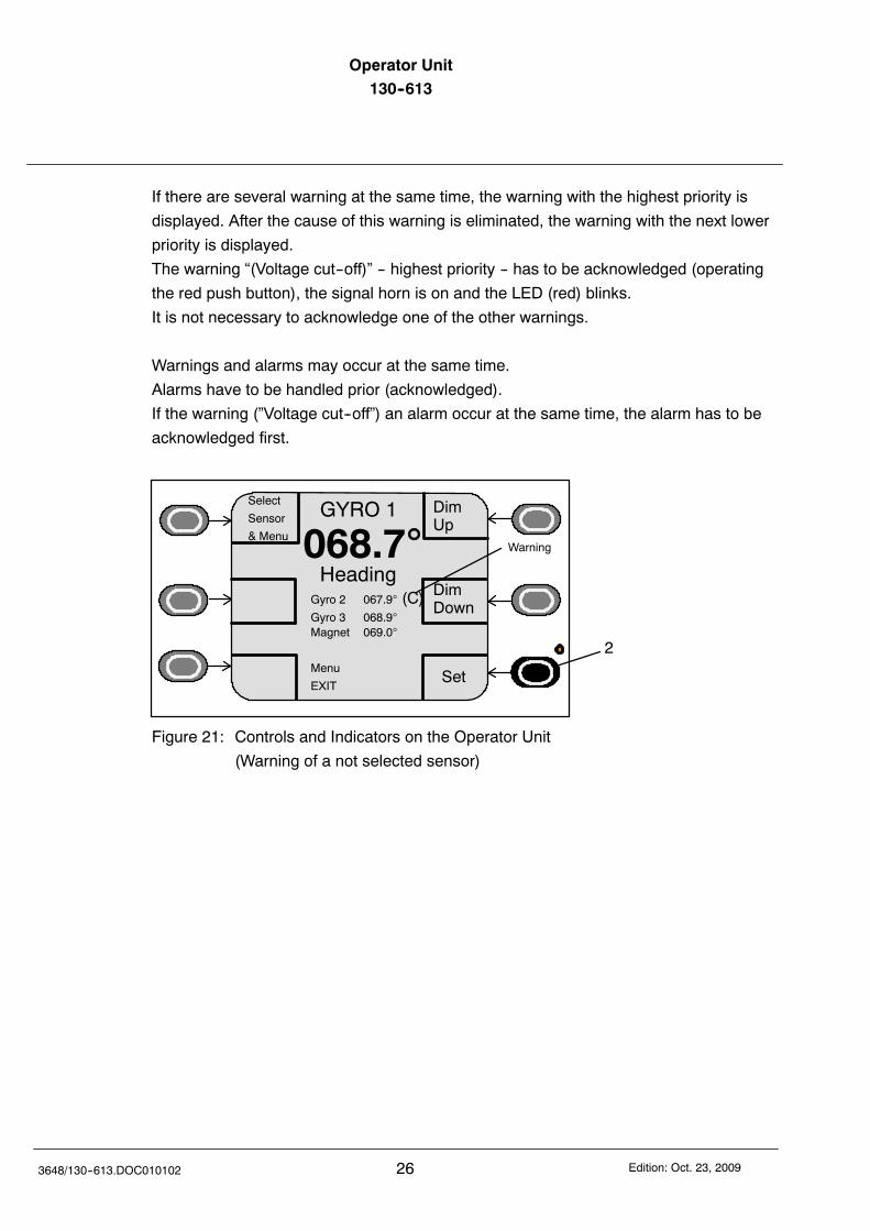
If there are several warning at the same time, the warning with the highest priority is
displayed. After the cause of this warning is eliminated, the warning with the next lower
priority is displayed.
The warning “(Voltage cut--off)” -- highest priority -- has to be acknowledged (operating
the red push button), the signal horn is on and the LED (red) blinks.
It is not necessary to acknowledge one of the other warnings.
Warnings and alarms may occur at the same time.
Alarms have to be handled prior (acknowledged).
If the warning (”Voltage cut--off”) an alarm occur at the same time, the alarm has to be
acknowledged first.
DimUp
DimDown
GYRO 1
068.7Heading
Magnet 069.0
Menu
EXIT
2
Set
Gyro 2 067.9 (C)Gyro 3 068.9
Select
Sensor
& MenuWarning
Figure 21: Controls and Indicators on the Operator Unit
(Warning of a not selected sensor)
Operator Unit130--613 Operator Unit
27Edition: Oct. 23, 2009 3648/130--613.DOC010102
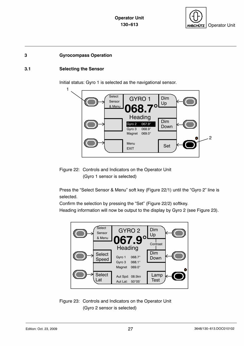
3 Gyrocompass Operation
3.1 Selecting the Sensor
Initial status: Gyro 1 is selected as the navigational sensor.
DimUp
DimDown
GYRO 1
068.7Heading
Magnet 069.0
Menu
EXIT
1
2
Set
Gyro 2 067.9
Gyro 3 068.9
Select
Sensor
& Menu
Figure 22: Controls and Indicators on the Operator Unit
(Gyro 1 sensor is selected)
Press the “Select Sensor & Menu” soft key (Figure 22/1) until the “Gyro 2” line is
selected.
Confirm the selection by pressing the “Set” (Figure 22/2) softkey.
Heading information will now be output to the display by Gyro 2 (see Figure 23).
DimUp
DimDown
GYRO 2
067.9Heading
Gyro 1 068.7
Gyro 3 068.1
Magnet 069.0
Contrast
Select
Sensor
& Menu
SelectSpeed
SelectLat
Aut Spd: 08.5kn
Aut Lat: 5005‘
LampTest
Figure 23: Controls and Indicators on the Operator Unit
(Gyro 2 sensor is selected)
Operator Unit130--613
283648/130--613.DOC010102 Edition: Oct. 23, 2009
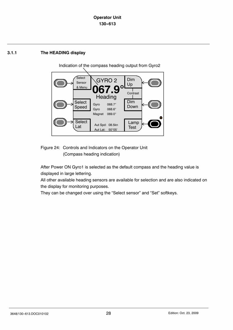
3.1.1 The HEADING display
DimUp
DimDown
GYRO 2
067.9Heading
Gyro 068.7
Gyro 068.6
Magnet 069.0
Contrast
SelectSpeed
SelectLat
Indication of the compass heading output from Gyro2
Select
Sensor
& Menu
LampTest
Aut Spd: 08.5kn
Aut Lat: 5005‘
Figure 24: Controls and Indicators on the Operator Unit
(Compass heading indication)
After Power ON Gyro1 is selected as the default compass and the heading value is
displayed in large lettering.
All other available heading sensors are available for selection and are also indicated on
the display for monitoring purposes.
They can be changed over using the “Select sensor” and “Set” softkeys.
Operator Unit130--613 Operator Unit
29Edition: Oct. 23, 2009 3648/130--613.DOC010102
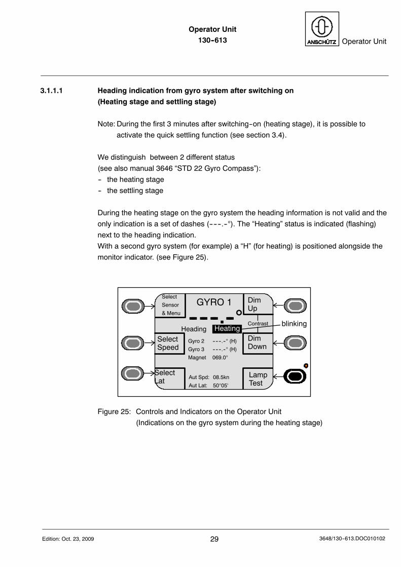
3.1.1.1 Heading indication from gyro system after switching on
(Heating stage and settling stage)
Note: During the first 3 minutes after switching--on (heating stage), it is possible to
activate the quick settling function (see section 3.4).
We distinguish between 2 different status
(see also manual 3646 “STD 22 Gyro Compass”):
-- the heating stage
-- the settling stage
During the heating stage on the gyro system the heading information is not valid and the
only indication is a set of dashes (------.--). The “Heating” status is indicated (flashing)
next to the heading indication.
With a second gyro system (for example) a “H” (for heating) is positioned alongside the
monitor indicator. (see Figure 25).
DimUp
DimDown
GYRO 1
-- -- --.--
Aut Spd: 08.5kn
Aut Lat: 5005‘
Gyro 2 ------.-- (H)
Gyro 3 ------.-- (H)
Magnet 069.0
Contrast
SelectSpeed
SelectLat
Heading Heating
Select
Sensor
& Menu
LampTest
blinking
Figure 25: Controls and Indicators on the Operator Unit
(Indications on the gyro system during the heating stage)
Operator Unit130--613
303648/130--613.DOC010102 Edition: Oct. 23, 2009
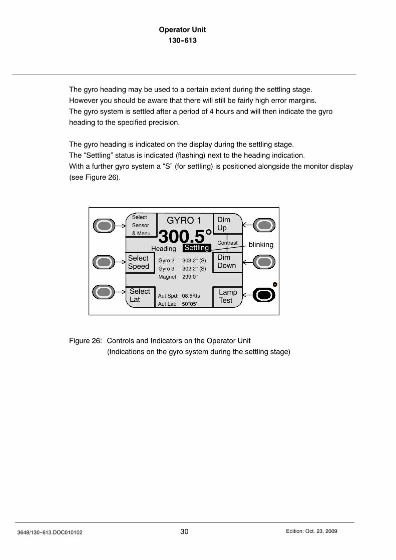
The gyro heading may be used to a certain extent during the settling stage.
However you should be aware that there will still be fairly high error margins.
The gyro system is settled after a period of 4 hours and will then indicate the gyro
heading to the specified precision.
The gyro heading is indicated on the display during the settling stage.
The “Settling” status is indicated (flashing) next to the heading indication.
With a further gyro system a “S” (for settling) is positioned alongside the monitor display
(see Figure 26).
DimUp
DimDown
GYRO 1
300.5
Aut Spd: 08.5Kts
Aut Lat: 5005‘
Contrast
SelectSpeed
SelectLat
Heading Settling
Select
Sensor
& Menu
Gyro 2 303.2 (S)
Gyro 3 302.2 (S)
Magnet 299.0
LampTest
blinking
Figure 26: Controls and Indicators on the Operator Unit
(Indications on the gyro system during the settling stage)
Operator Unit130--613 Operator Unit
31Edition: Oct. 23, 2009 3648/130--613.DOC010102
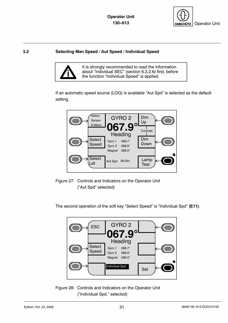
3.2 Selecting Man Speed / Aut Speed / Individual Speed
It is strongly recommended to read the informationabout “Individual SEC” (section 6.3.2.6) first, beforethe function “Individual Speed” is applied.
If an automatic speed source (LOG) is available “Aut Spd” is selected as the default
setting.
DimUp
DimDown
GYRO 2
067.9Heading
Contrast
SelectSpeed
SelectLat
Select
Sensor
& Menu
Aut Spd 08.5kn
Gyro 1 068.7
Gyro 3 068.9
Magnet 069.0
LampTest
Figure 27: Controls and Indicators on the Operator Unit
(”Aut Spd” selected)
The second operation of the soft key “Select Speed” is “Individual Spd” (E11).
GYRO 2
067.9Heading
SelectSpeed
ESC
Gyro 1 068.7
Gyro 3 068.9
Magnet 069.0
SetIndividual Spd.
Figure 28: Controls and Indicators on the Operator Unit
(”Individual Spd.” selected)
Operator Unit130--613
323648/130--613.DOC010102 Edition: Oct. 23, 2009
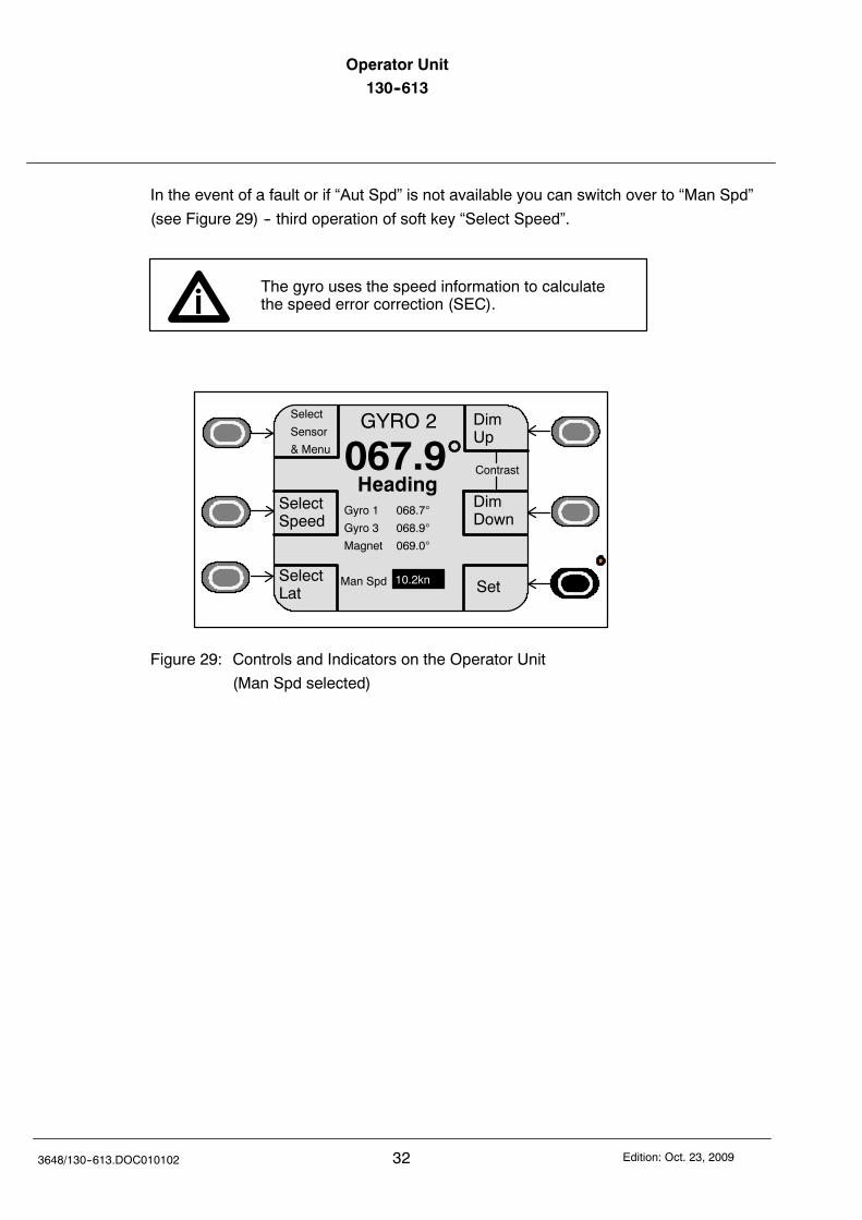
In the event of a fault or if “Aut Spd” is not available you can switch over to “Man Spd”
(see Figure 29) -- third operation of soft key “Select Speed”.
The gyro uses the speed information to calculatethe speed error correction (SEC).
DimUp
DimDown
GYRO 2
067.9Heading
Contrast
SelectSpeed
SelectLat
Select
Sensor
& Menu
Man Spd 10.2kn
Gyro 1 068.7
Gyro 3 068.9
Magnet 069.0
Set
Figure 29: Controls and Indicators on the Operator Unit
(Man Spd selected)
Operator Unit130--613 Operator Unit
33Edition: Oct. 23, 2009 3648/130--613.DOC010102
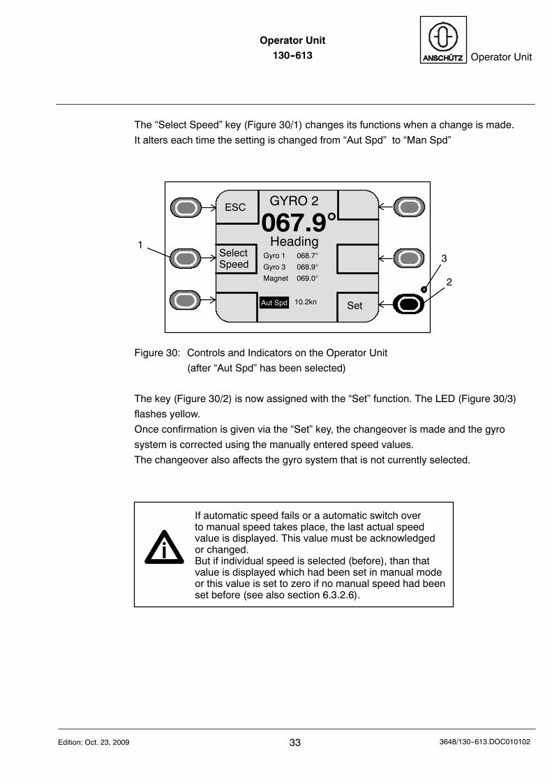
The “Select Speed” key (Figure 30/1) changes its functions when a change is made.
It alters each time the setting is changed from “Aut Spd” to “Man Spd”
GYRO 2
067.9Heading
SelectSpeed
Set
1
2
3
Aut Spd
Gyro 1 068.7
Gyro 3 068.9
Magnet 069.0
10.2kn
ESC
Figure 30: Controls and Indicators on the Operator Unit
(after “Aut Spd” has been selected)
The key (Figure 30/2) is now assigned with the “Set” function. The LED (Figure 30/3)
flashes yellow.
Once confirmation is given via the “Set” key, the changeover is made and the gyro
system is corrected using the manually entered speed values.
The changeover also affects the gyro system that is not currently selected.
If automatic speed fails or a automatic switch overto manual speed takes place, the last actual speedvalue is displayed. This value must be acknowledgedor changed.But if individual speed is selected (before), than thatvalue is displayed which had been set in manual modeor this value is set to zero if no manual speed had beenset before (see also section 6.3.2.6).
Operator Unit130--613
343648/130--613.DOC010102 Edition: Oct. 23, 2009
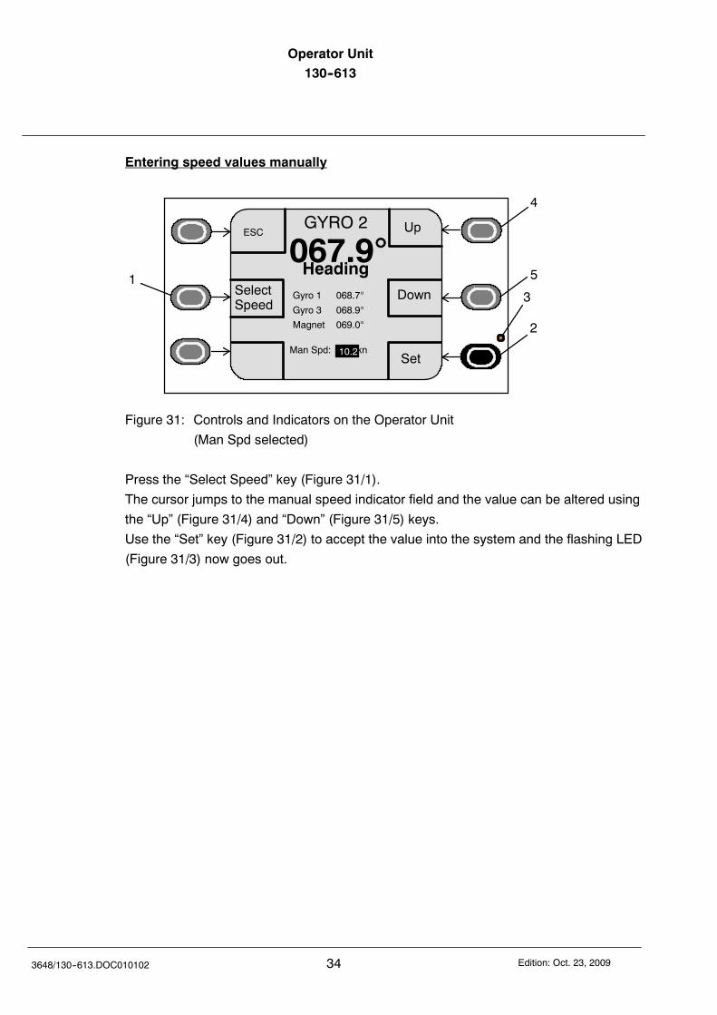
Entering speed values manually
Up
Down
GYRO 2
067.9Heading
SelectSpeed
Set
1
2
3
4
5
ESC
Man Spd: kn10.2
Gyro 1 068.7
Gyro 3 068.9
Magnet 069.0
Figure 31: Controls and Indicators on the Operator Unit
(Man Spd selected)
Press the “Select Speed” key (Figure 31/1).
The cursor jumps to the manual speed indicator field and the value can be altered using
the “Up” (Figure 31/4) and “Down” (Figure 31/5) keys.
Use the “Set” key (Figure 31/2) to accept the value into the system and the flashing LED
(Figure 31/3) now goes out.
Operator Unit130--613 Operator Unit
35Edition: Oct. 23, 2009 3648/130--613.DOC010102
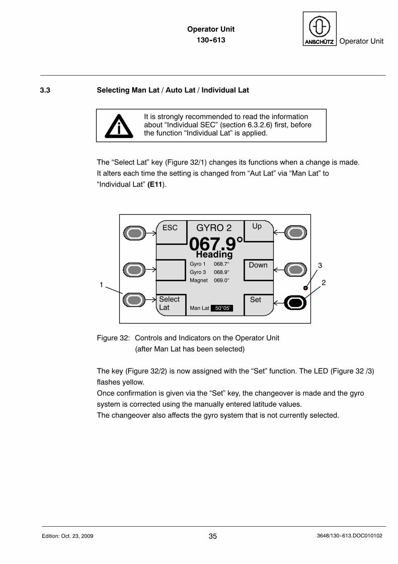
3.3 Selecting Man Lat / Auto Lat / Individual Lat
It is strongly recommended to read the informationabout “Individual SEC” (section 6.3.2.6) first, beforethe function “Individual Lat” is applied.
The “Select Lat” key (Figure 32/1) changes its functions when a change is made.
It alters each time the setting is changed from “Aut Lat” via “Man Lat” to
“Individual Lat” (E11).
GYRO 2
067.9Heading
SelectLat
Set
1 2
3
Man Lat
Gyro 1 068.7
Gyro 3 068.9
Magnet 069.0
ESC Up
Down
5005‘
Figure 32: Controls and Indicators on the Operator Unit
(after Man Lat has been selected)
The key (Figure 32/2) is now assigned with the “Set” function. The LED (Figure 32 /3)
flashes yellow.
Once confirmation is given via the “Set” key, the changeover is made and the gyro
system is corrected using the manually entered latitude values.
The changeover also affects the gyro system that is not currently selected.
Operator Unit130--613
363648/130--613.DOC010102 Edition: Oct. 23, 2009
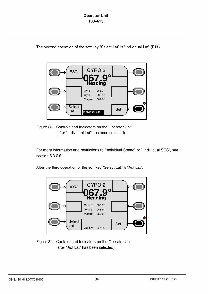
The second operation of the soft key “Select Lat” is “Individual Lat” (E11).
GYRO 2
067.9Heading
SelectLat Set
Gyro 1 068.7
Gyro 3 068.9
Magnet 069.0
ESC
Individual Lat
Figure 33: Controls and Indicators on the Operator Unit
(after “Individual Lat” has been selected)
For more information and restrictions to “Individual Speed” or “ Individual SEC”, see
section 6.3.2.6.
After the third operation of the soft key “Select Lat” is “Aut Lat”:
GYRO 2
067.9Heading
4905‘
SelectLat Set
Aut Lat
Gyro 1 068.7
Gyro 3 068.9
Magnet 069.0
ESC
Figure 34: Controls and Indicators on the Operator Unit
(after “Aut Lat” has been selected)
Operator Unit130--613 Operator Unit
37Edition: Oct. 23, 2009 3648/130--613.DOC010102
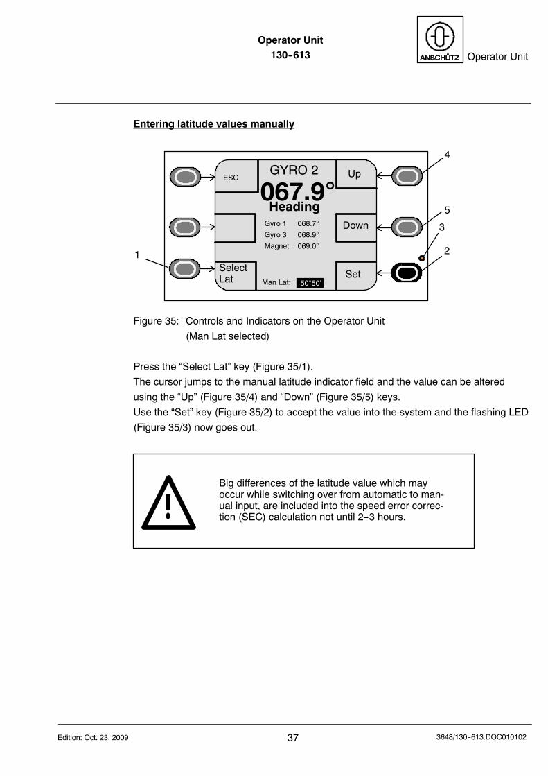
Entering latitude values manually
Up
Down
GYRO 2
067.9Heading
Man Lat:
SelectLat Set
1 2
3
4
5
5050‘
ESC
Gyro 1 068.7
Gyro 3 068.9
Magnet 069.0
Figure 35: Controls and Indicators on the Operator Unit
(Man Lat selected)
Press the “Select Lat” key (Figure 35/1).
The cursor jumps to the manual latitude indicator field and the value can be altered
using the “Up” (Figure 35/4) and “Down” (Figure 35/5) keys.
Use the “Set” key (Figure 35/2) to accept the value into the system and the flashing LED
(Figure 35/3) now goes out.
Big differences of the latitude value which mayoccur while switching over from automatic to man-ual input, are included into the speed error correc-tion (SEC) calculation not until 2--3 hours.
Operator Unit130--613
383648/130--613.DOC010102 Edition: Oct. 23, 2009
3.4 Activation of the Quick Settling function
The “Quick Settling” function reduces the time the compass requires to settle from
approximately 4 hours to approximately one hour
The most recent heading is stored when the gyro compass is switch off. When it is
switched on the compass uses that value to make a default setting so that the settling
time is reduced.
The Quick Settling function can only be used if the ship‘sheading has not been changed between switching off andswitching back on.The Quick Settling function can not be used:
-- During the first setting up (installation).-- If the ship‘s position was changed between
switching off and on again of the compass.-- If the temperature of the gyro supporting liquid is
more than 30C.
Immediately after switching on of the compass it is possible to activate the Quick Settling
function at the Operator Unit.
By this the heating stage and the settling stage are reduced to (in total) one hour.
After this time an usable heading information is displayed (for the accuracy of the
heading information see compass manual).
Time to activate this function is only for 3 minutes afterswitching on
At the end of this 3 minutes (without activating this function) the heating stage and the
settling stage runs in the sequence according to the compass manual.
NOTE: To activate this function is possible only during the first three minutes after
switching on.
If there should be activated several (max. 3 gyro compasses) with the Quick
Settling function it is recommended to switch on these compasses one after the
other (if possible) in order not to exceed this three minutes.
Operator Unit130--613 Operator Unit
39Edition: Oct. 23, 2009 3648/130--613.DOC010102
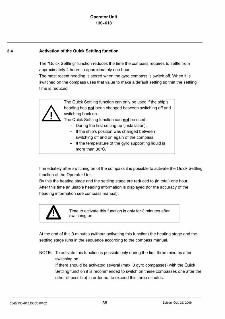
3.4.1 Quick Settling activation of selected gyro
After switching on of the selected compass the possibility to activate the Quick Settling
function is displayed. (Figure 36).
DimUp
DimDown
GYRO 1
-- -- --.--
Magnet 069.0
Menu
EXIT
Gyro 2 ------.-- (H)
Gyro 3 ------.-- (H)
Contrast
SelectSpeed
SelectLat
(QS--possible)
Select
Sensor
& Menu
LampTest
Heating stage,no possibility forQuick Settling(3 minutes are over)
Figure 36: Controls and Indicators on the Operator Unit
(Heating stage of the selected gyro 1,
Quick Settling is possible during a time of 3 minutes)
During this 3 minutes the menu line “Menu” has to be selected
(softkey “Select Sensor &Menu).
DimUp
DimDown
GYRO 1
-- -- --.--
Magnet 069.0
EXIT
Gyro 2 ------.-- (H)
Gyro 3 ------.-- (H)
Contrast
SelectSpeed
SelectLat
(QS--possible)
Select
Sensor
& Menu
LampTest
Menu
Figure 37: Controls and Indicators on the Operator Unit
(Heating stage of the selected gyro 1,
Quick Settling is possible during a time of 3 minutes,
menu line “Menu” selected)
Operator Unit130--613
403648/130--613.DOC010102 Edition: Oct. 23, 2009
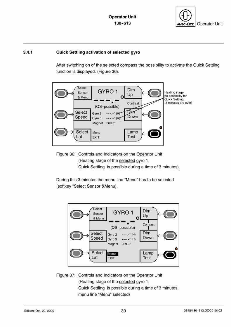
Basic Menu ----> Selected line: “Menu” ----> Display “Menu”
DimUp
DimDown
Gyro 1
-- -- --.--
Set
Select
Menu
Panel set up
Service
EXIT
Diff--Alarm
(QS--possible)
Quick--Settling
Figure 38: Controls and Indicators on the Operator Unit
(Heating stage of the selected gyro 1,
Quick Settling is possible during a time of 3 minutes,
menu line “Quick Settling” selected)
Basic Menu ----> : Selected line “Menu” ----> Display “Menu” ----> Selected:
“Quick--Settling”.
DimUp
DimDown
Quick Settling
Set
Select
EXIT
Gyro 1
Note: Gyro 2 and gyro 3 not displayed because aQuick Settling is no longer possible.(Indication of “H” = Heating stage means alsoQuick Settling no longer possible, 3 minutesare over).
QS SET
SET oper-ated
Figure 39: Controls and Indicators on the Operator Unit
(Heating stage of the selected gyro 1,
Quick Settling is possible during a time of 3 minutes,
menu “Quick Settling”, gyro 1 is selected)
Operator Unit130--613 Operator Unit
41Edition: Oct. 23, 2009 3648/130--613.DOC010102
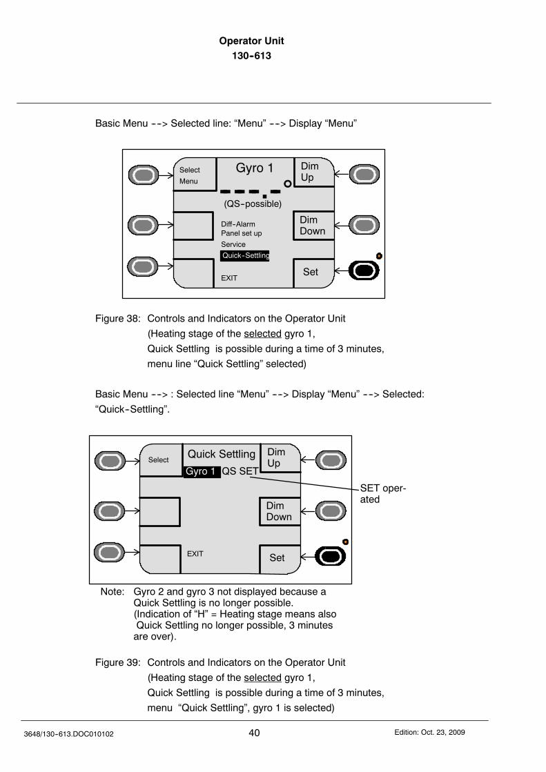
After confirming by “SET” the activated Quick Settling function for the selected gyro is
displayed by “Gyro 1 QS Set” (Figure 39).
After selection of “Exit” the basic menu is displayed (Figure 40).
DimUp
DimDown
GYRO 1
068.7
Magnet 069.0
Menu
EXIT
Gyro 2 ------.-- (H)
Gyro 3 ------.-- (H)
Contrast
SelectSpeed
SelectLat
(Qick Settling)
Select
Sensor
& Menu
LampTest
blinking
Figure 40: Controls and Indicators on the Operator Unit
(Function Quick Settling activated for gyro 1)
This menu “Quick Settling” is displayed only if this functionis possible.
Operator Unit130--613
423648/130--613.DOC010102 Edition: Oct. 23, 2009
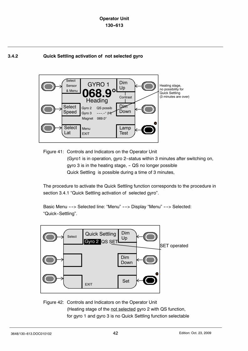
3.4.2 Quick Settling activation of not selected gyro
DimUp
DimDown
GYRO 1
068.9
Magnet 069.0
Menu
EXIT
Gyro 2 QS possib
Gyro 3 ------.-- (H)
Contrast
SelectSpeed
SelectLat
Heading
Select
Sensor
& Menu
LampTest
Heating stage,no possibility forQuick Settling(3 minutes are over)
Figure 41: Controls and Indicators on the Operator Unit
(Gyro1 is in operation, gyro 2--status within 3 minutes after switching on,
gyro 3 is in the heating stage, -- QS no longer possible
Quick Settling is possible during a time of 3 minutes,
The procedure to activate the Quick Settling function corresponds to the procedure in
section 3.4.1 “Quick Settling activation of selected gyro”.
Basic Menu ----> Selected line: “Menu” ----> Display “Menu” ----> Selected:
“Quick--Settling”.
DimUp
DimDown
Quick Settling
Set
Select
EXIT
SET operatedGyro 2 QS SET
Figure 42: Controls and Indicators on the Operator Unit
(Heating stage of the not selected gyro 2 with QS function,
for gyro 1 and gyro 3 is no Quick Settling function selectable
Operator Unit130--613 Operator Unit
43Edition: Oct. 23, 2009 3648/130--613.DOC010102
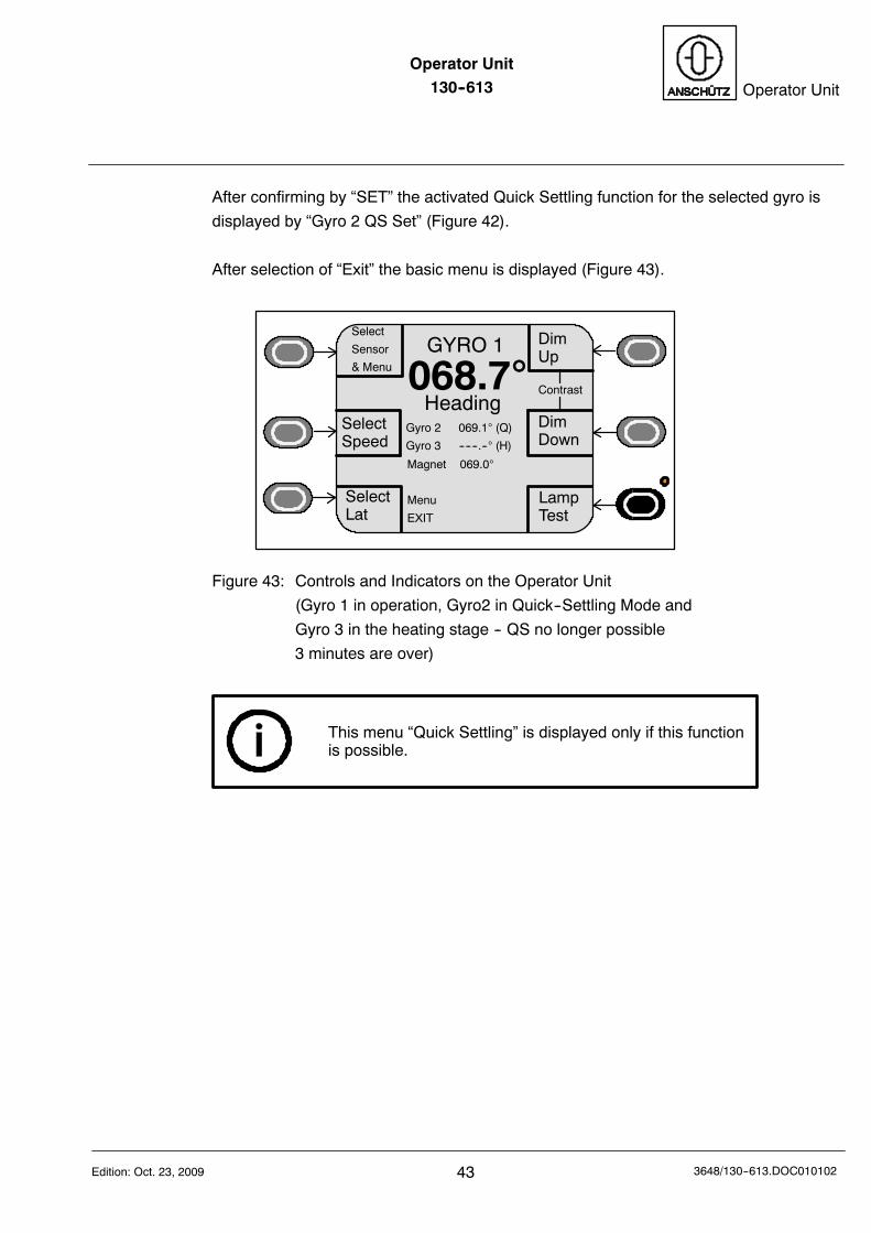
After confirming by “SET” the activated Quick Settling function for the selected gyro is
displayed by “Gyro 2 QS Set” (Figure 42).
After selection of “Exit” the basic menu is displayed (Figure 43).
DimUp
DimDown
GYRO 1
068.7
Magnet 069.0
Menu
EXIT
Gyro 2 069.1 (Q)
Gyro 3 ------.-- (H)
Contrast
SelectSpeed
SelectLat
Heading
Select
Sensor
& Menu
LampTest
Figure 43: Controls and Indicators on the Operator Unit
(Gyro 1 in operation, Gyro2 in Quick--Settling Mode and
Gyro 3 in the heating stage -- QS no longer possible
3 minutes are over)
This menu “Quick Settling” is displayed only if this functionis possible.
Operator Unit130--613
443648/130--613.DOC010102 Edition: Oct. 23, 2009
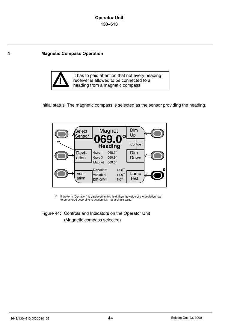
4 Magnetic Compass Operation
It has to paid attention that not every headingreceiver is allowed to be connected to aheading from a magnetic compass.
Initial status: The magnetic compass is selected as the sensor providing the heading.
Vari--ation
Devi--ation
Magnet
069.0
Deviation: +4.5Variation: +5.0Diff--G/M: 3.0
DimUp
DimDown
SelectSensor
Heading Contrast
Gyro 1 068.7
Gyro 3 068.9
Magnet 069.0
LampTest
**
** if the term “Deviation” is displayed in this field, then the value of the deviation hasto be entered according to section 4.1.1 as a single value.
Figure 44: Controls and Indicators on the Operator Unit
(Magnetic compass selected)
Operator Unit130--613 Operator Unit
45Edition: Oct. 23, 2009 3648/130--613.DOC010102
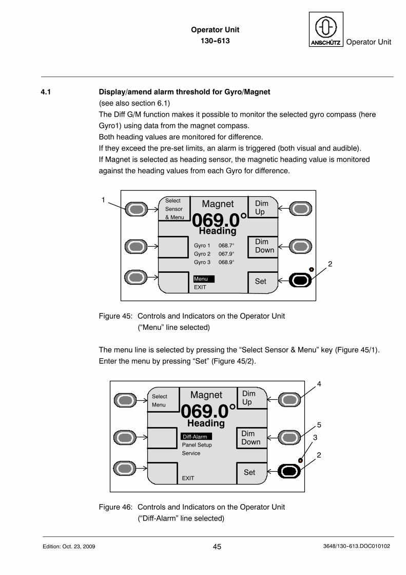
4.1 Display/amend alarm threshold for Gyro/Magnet
(see also section 6.1)
The Diff G/M function makes it possible to monitor the selected gyro compass (here
Gyro1) using data from the magnet compass.
Both heading values are monitored for difference.
If they exceed the pre-set limits, an alarm is triggered (both visual and audible).
If Magnet is selected as heading sensor, the magnetic heading value is monitored
against the heading values from each Gyro for difference.
DimUp
DimDown
Magnet
069.0Heading
Set
1
2
Select
Sensor
& Menu
Gyro 1 068.7
Gyro 2 067.9
Gyro 3 068.9
Menu
EXIT
Figure 45: Controls and Indicators on the Operator Unit
(“Menu” line selected)
The menu line is selected by pressing the “Select Sensor & Menu” key (Figure 45/1).
Enter the menu by pressing “Set” (Figure 45/2).
DimUp
DimDown
Magnet
069.0Heading
Set
2
3
4
5
Select
Menu
Panel Setup
Service
EXIT
Diff-Alarm
Figure 46: Controls and Indicators on the Operator Unit
(“Diff-Alarm” line selected)
Operator Unit130--613
463648/130--613.DOC010102 Edition: Oct. 23, 2009
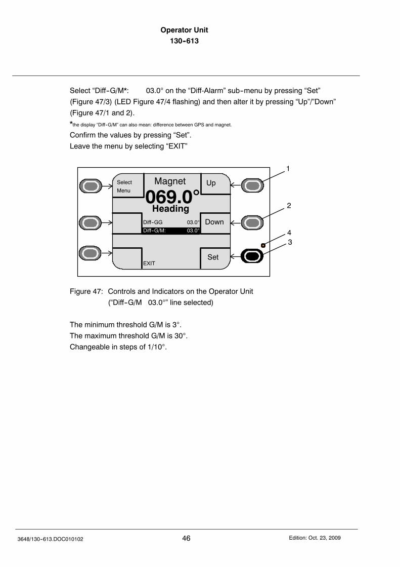
Select “Diff--G/M*: 03.0 on the “Diff-Alarm” sub--menu by pressing “Set”
(Figure 47/3) (LED Figure 47/4 flashing) and then alter it by pressing “Up”/”Down”
(Figure 47/1 and 2).
*the display “Diff--G/M” can also mean: difference between GPS and magnet.
Confirm the values by pressing “Set”.
Leave the menu by selecting “EXIT”
Up
Down
Magnet
069.0Heading
Set
Select
Menu
Diff--GG 03.0
Diff--G/M: 03.0
EXIT
1
2
34
Figure 47: Controls and Indicators on the Operator Unit
(“Diff--G/M 03.0” line selected)
The minimum threshold G/M is 3.
The maximum threshold G/M is 30.
Changeable in steps of 1/10.
Operator Unit130--613 Operator Unit
47Edition: Oct. 23, 2009 3648/130--613.DOC010102
4.1.1 Display and alter Variation/Deviation
Deviation
A heading display from a magnetic compass may be affected by permanent magnetic
parts of steel, lines with direct current flow or magnetic soft iron parts in that manner,
that the heading information is faulty.
With correction values (deviation values) this fault can be corrected.
This correction value is entered via the Operation Unit to the Distribution Unit and is
used to correct the magnetic heading information.
An indication if it is possible to apply or to amend a deviationtable is the soft key field “Deviation”.If there is no therm “Deviation “ in this field, than the function of adeviation table is available (this function reflects a higher devel-opment status. At Distribution Units with a lower developmentstatus the field has the therm “Deviation”. In this case singlecorrection value to each heading have to be entered according tosection 4.1.1.1).For Distribution Units with the function of a deviation table, seesection 4.1.1.2.
In general:If a variation or declination value is displayed, than it is possibleto change this value.If such a value is not displayed (for example Fluxgate compasseswith complete NMEA sentences), than the correction value is partof the respective input information (NMEA sentence).Than there is no need to change this value.
Variation
Because of the magnetic north pole is not identical to the geographic pole, there is a
declination, this declination is designated with variation.
This variation varying and it is possible to take out this alteration out of a sea chart
(depending location).
This value has to be entered as a single value. It is stored in the Distribution Unit and
used to correct the magnetic heading information.
Operator Unit130--613
483648/130--613.DOC010102 Edition: Oct. 23, 2009
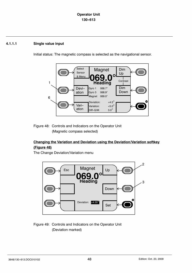
4.1.1.1 Single value input
Initial status: The magnetic compass is selected as the navigational sensor.
Vari--ation
Devi--ation
Magnet
069.0DimUp
DimDown
Heading
6
Contrast
Select
Sensor
& Menu
Deviation: +4.5Variation: +5.0Diff--G/M: 3.0
1
Gyro 1 068.7
Gyro 3 068.9
Magnet 069.0
Figure 48: Controls and Indicators on the Operator Unit
(Magnetic compass selected)
Changing the Variation and Deviation using the Deviation/Variation softkey
(Figure 48)
The Change Deviation/Variation menu
Magnet
069.0Heading
2
Esc Up
Down
3
SetDeviation: +4.55
Figure 49: Controls and Indicators on the Operator Unit
(Deviation marked)
Operator Unit130--613 Operator Unit
49Edition: Oct. 23, 2009 3648/130--613.DOC010102
Deviation (deviation in relation to the ship)
Select the deviation input field by pressing the “Deviation” key (Figure 48/1)
Alter the values (deviation) by pressing the “Up” or “Down” keys.
(Figure 49/2 or 3).
Once you have confirmed (using the “Set” key) these values are accepted, stored into
an internal table and the magnet compass heading is corrected accordingly by
interpolation of the set (stored) values.
The menu reverts back to its initial status.
Variation (deviation in relation to location)
Select the variation input field by pressing the “Variation” key (Figure 48/6).
Change the value and finalise the alteration procedure as described under “Changing
the Deviation”.
Operator Unit130--613
503648/130--613.DOC010102 Edition: Oct. 23, 2009
4.1.1.2 Applying or amending a deviation table
DimUp
DimDown
Magnet
069.0Heading
Set
Select
Sensor
& Menu
Gyro 1 068.7
Gyro 2 067.9
Gyro 3 067.9
EXIT
Menu
Figure 50: Controls and Indicators on the Operator Unit
(Line “Menu” selected)
Select the line “Menu” with soft key “Select Sensor & Menu” and soft key “Set”.
Select the line “Service” in the next display with soft key “Select Sensor & Menu” and
soft key “Set”.
Select the line “Next page” in the display “Service Mode (page1)” with soft key “Select
Menu” and soft key “Set”.
Select the line “Deviation Table” in the display “Service Mode (page2)” with soft key
“Select Menu” and soft key “Set”.
Up
Down
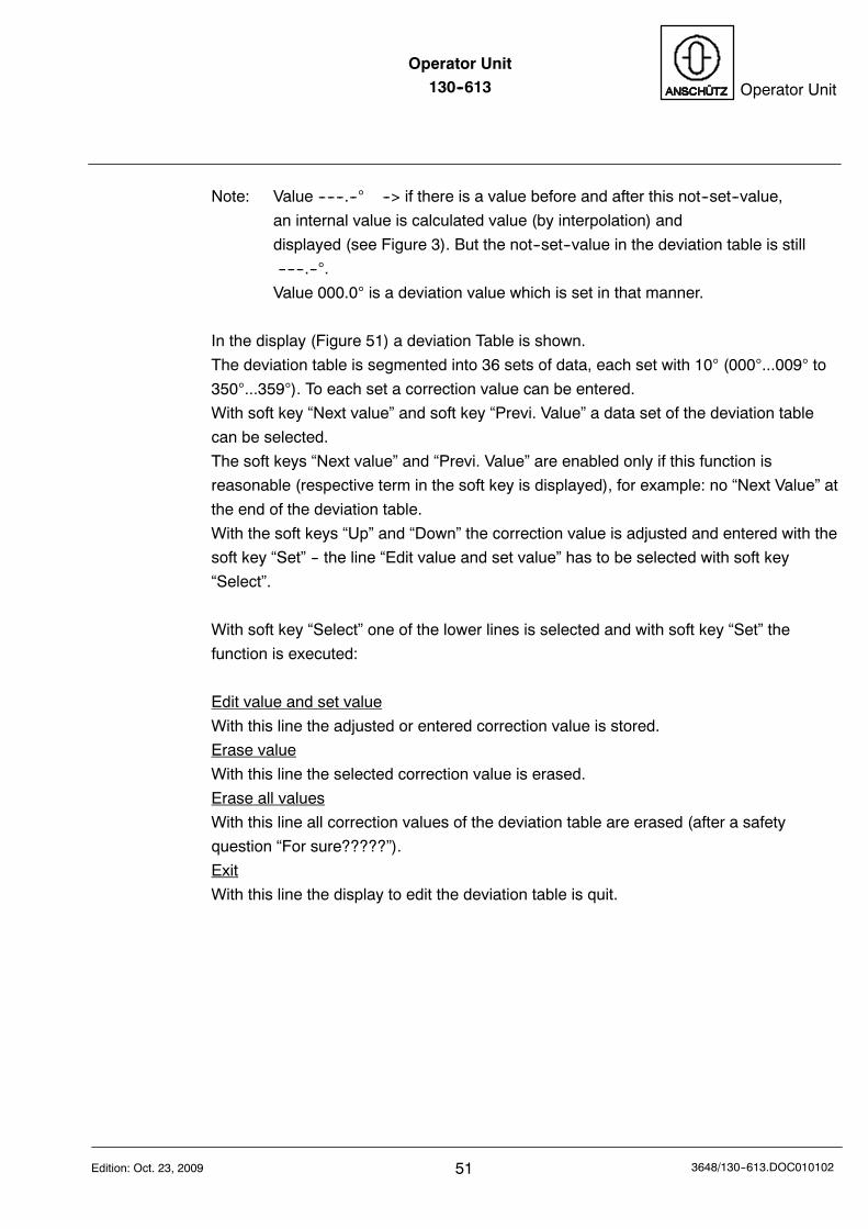
Deviation Tab
Set
Select
NextValue
Previ.Value
000--009 ----.--010--019 ----.--020--029 ----.--030--039 ----.--040--049 ----.--050--059 ----.--060--069 ----.--
Edit value and set valueErase valueErase all valuesExit
Figure 51: Controls and Indicators on the Operator Unit
(Display “Deviation Table”)
Operator Unit130--613 Operator Unit
51Edition: Oct. 23, 2009 3648/130--613.DOC010102
Note: Value ------.-- --> if there is a value before and after this not--set--value,
an internal value is calculated value (by interpolation) and
displayed (see Figure 3). But the not--set--value in the deviation table is still
------.--.
Value 000.0 is a deviation value which is set in that manner.
In the display (Figure 51) a deviation Table is shown.
The deviation table is segmented into 36 sets of data, each set with 10 (000...009 to
350...359). To each set a correction value can be entered.
With soft key “Next value” and soft key “Previ. Value” a data set of the deviation table
can be selected.
The soft keys “Next value” and “Previ. Value” are enabled only if this function is
reasonable (respective term in the soft key is displayed), for example: no “Next Value” at
the end of the deviation table.
With the soft keys “Up” and “Down” the correction value is adjusted and entered with the
soft key “Set” -- the line “Edit value and set value” has to be selected with soft key
“Select”.
With soft key “Select” one of the lower lines is selected and with soft key “Set” the
function is executed:
Edit value and set value
With this line the adjusted or entered correction value is stored.
Erase value
With this line the selected correction value is erased.
Erase all values
With this line all correction values of the deviation table are erased (after a safety
question “For sure?????”).
Exit
With this line the display to edit the deviation table is quit.
Operator Unit130--613
523648/130--613.DOC010102 Edition: Oct. 23, 2009
5 Operation of Satellite Compass STD 21 (GPS)
Within a navigation system, which is based on a Gyro compass STD 22, it can connect
except a magnetic compass a Satellite Compass STD 21 (GPS) too.
This compass is displayed as GPS.
The organisational integration of a GPS is identical to a Gyro compass.
Dimup
Dimdown
GYRO 1
068.7Heading
Aut Spd: 08.5kn
Aut Lat: 5005‘
Gyro 2 067.9
GPS 068.8
Magnet 069.0
SelectSpeed
SelectLat
Contrast
Select
Sensor
& Menu
LampTest
Figure 52: Controls and Indicators on the Operator Unit
(Display with a GPS in the application)
Dimup
Dimdown
GPS
068.7Heading
Gyro 1 067.9
Gyro 2 068.8
Magnet 069.0
GPSConfig.
GPSHdg.
Contrast
Select
Sensor
& Menu
LampTest
Lat: 054 21.712‘NLon: 010 08.434‘E
Figure 53: Controls and Indicators on the Operator Unit
(Display with GPS as selected heading sensor)
For all adjustments, configurations and operation functions see Satellite Compass
STD21 manual (no. 3717).
Operator Unit130--613 Operator Unit
53Edition: Oct. 23, 2009 3648/130--613.DOC010102
6 Adjustment of additional operation modes with the service menu
After selection of the menu line “Menu” below mentioned submenus are displayed to
select other operational modes:
-- Diff--Alarm (Difference Alarm) (see section 6.1)
-- Panel Setup (see section 6.2)
-- Service (see section 6.3)
-- Quick Settling (see section 3.4)
6.1 Difference Alarm
In such a compass system all connected heading sensors are compared together
constantly. If there is a deviation more than the adjusted threshold than there will be a
difference alarm displayed and output.
A conclusion about which of the connected sensors deviates is not possible.
Each connected sensor has to be checked depending his function.
All adjustments necessary for a difference alarm are shown in the table below.
Parameter G*/M G/G*
Minimum threshold 3 1
Maximum threshold 89,9 89,9
Increment 1/10 1/10
* “G” can be Gyro or GPS. A GPS is dealt as a Gyro.
In case of a reduced availability of the GPS (STD21)a difference alarm may occur.For reasons of a reduced availability see manual3717, section “Principles of Operation”.
The following table shows the connectable sensors referring to their comparison
procedures.
Operator Unit130--613
543648/130--613.DOC010102 Edition: Oct. 23, 2009
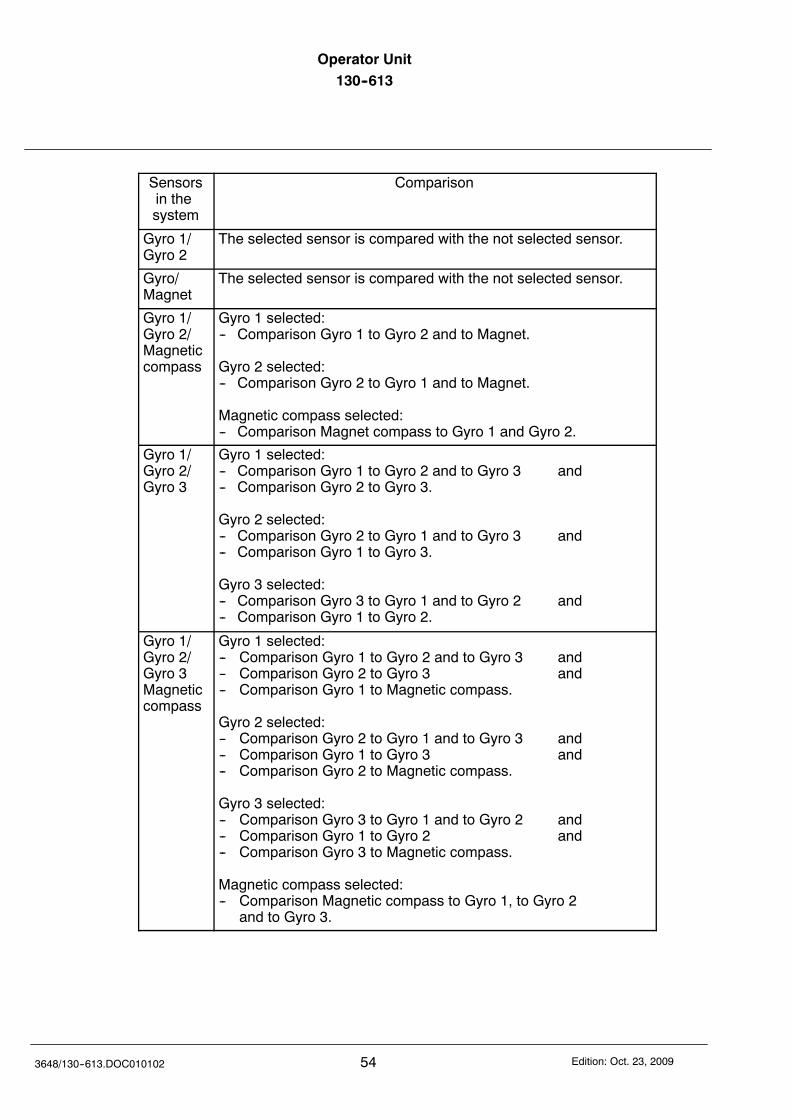
Sensorsin thesystem
Comparison
Gyro 1/Gyro 2
The selected sensor is compared with the not selected sensor.
Gyro/Magnet
The selected sensor is compared with the not selected sensor.
Gyro 1/Gyro 2/Magneticcompass
Gyro 1 selected:-- Comparison Gyro 1 to Gyro 2 and to Magnet.
Gyro 2 selected:-- Comparison Gyro 2 to Gyro 1 and to Magnet.
Magnetic compass selected:-- Comparison Magnet compass to Gyro 1 and Gyro 2.
Gyro 1/Gyro 2/Gyro 3
Gyro 1 selected:-- Comparison Gyro 1 to Gyro 2 and to Gyro 3 and-- Comparison Gyro 2 to Gyro 3.
Gyro 2 selected:-- Comparison Gyro 2 to Gyro 1 and to Gyro 3 and-- Comparison Gyro 1 to Gyro 3.
Gyro 3 selected:-- Comparison Gyro 3 to Gyro 1 and to Gyro 2 and-- Comparison Gyro 1 to Gyro 2.
Gyro 1/Gyro 2/Gyro 3Magneticcompass
Gyro 1 selected:-- Comparison Gyro 1 to Gyro 2 and to Gyro 3 and-- Comparison Gyro 2 to Gyro 3 and-- Comparison Gyro 1 to Magnetic compass.
Gyro 2 selected:-- Comparison Gyro 2 to Gyro 1 and to Gyro 3 and-- Comparison Gyro 1 to Gyro 3 and-- Comparison Gyro 2 to Magnetic compass.
Gyro 3 selected:-- Comparison Gyro 3 to Gyro 1 and to Gyro 2 and-- Comparison Gyro 1 to Gyro 2 and-- Comparison Gyro 3 to Magnetic compass.
Magnetic compass selected:-- Comparison Magnetic compass to Gyro 1, to Gyro 2
and to Gyro 3.
Operator Unit130--613 Operator Unit
55Edition: Oct. 23, 2009 3648/130--613.DOC010102
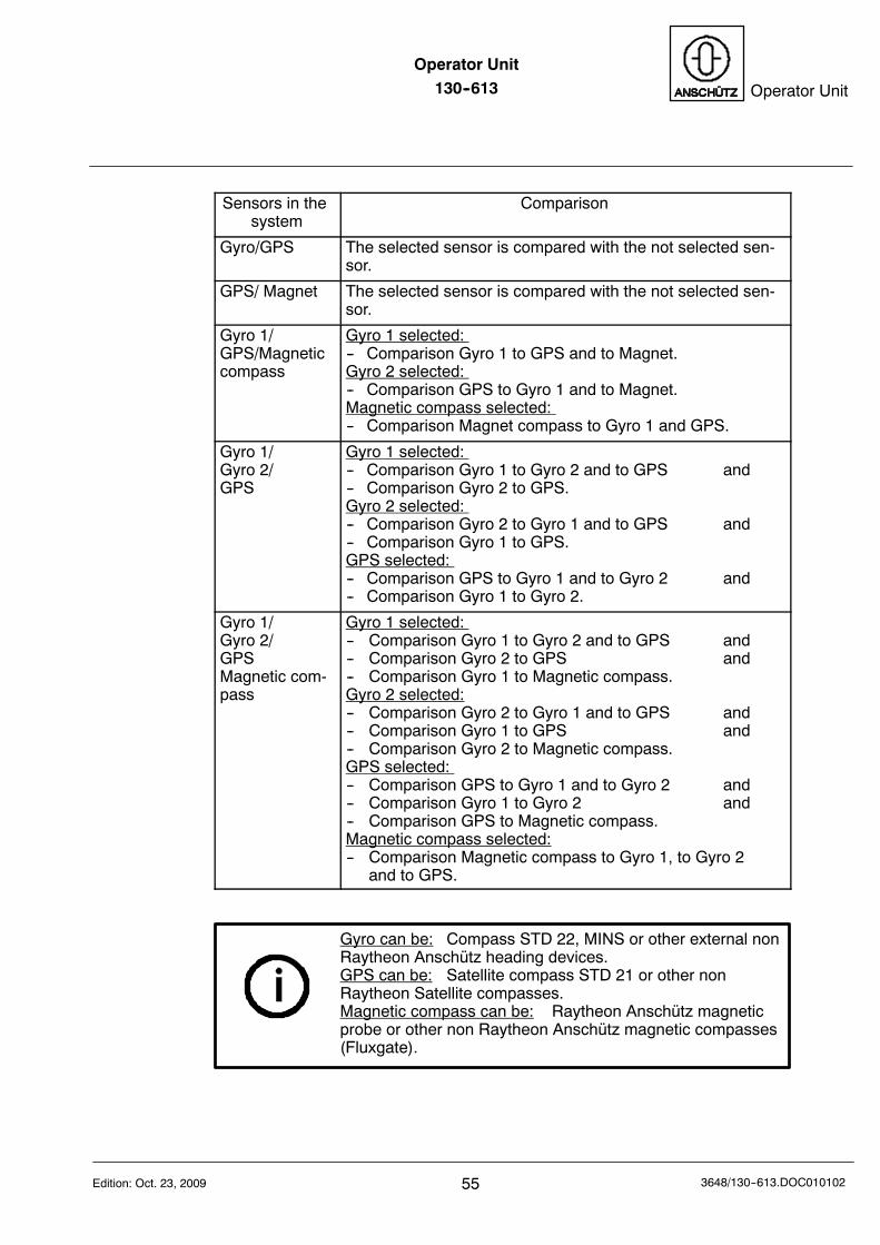
Sensors in thesystem
Comparison
Gyro/GPS The selected sensor is compared with the not selected sen-sor.
GPS/ Magnet The selected sensor is compared with the not selected sen-sor.
Gyro 1/GPS/Magneticcompass
Gyro 1 selected:-- Comparison Gyro 1 to GPS and to Magnet.Gyro 2 selected:-- Comparison GPS to Gyro 1 and to Magnet.Magnetic compass selected:-- Comparison Magnet compass to Gyro 1 and GPS.
Gyro 1/Gyro 2/GPS
Gyro 1 selected:-- Comparison Gyro 1 to Gyro 2 and to GPS and-- Comparison Gyro 2 to GPS.Gyro 2 selected:-- Comparison Gyro 2 to Gyro 1 and to GPS and-- Comparison Gyro 1 to GPS.GPS selected:-- Comparison GPS to Gyro 1 and to Gyro 2 and-- Comparison Gyro 1 to Gyro 2.
Gyro 1/Gyro 2/GPSMagnetic com-pass
Gyro 1 selected:-- Comparison Gyro 1 to Gyro 2 and to GPS and-- Comparison Gyro 2 to GPS and-- Comparison Gyro 1 to Magnetic compass.Gyro 2 selected:-- Comparison Gyro 2 to Gyro 1 and to GPS and-- Comparison Gyro 1 to GPS and-- Comparison Gyro 2 to Magnetic compass.GPS selected:-- Comparison GPS to Gyro 1 and to Gyro 2 and-- Comparison Gyro 1 to Gyro 2 and-- Comparison GPS to Magnetic compass.Magnetic compass selected:-- Comparison Magnetic compass to Gyro 1, to Gyro 2
and to GPS.
Gyro can be: Compass STD 22, MINS or other external nonRaytheon Anschütz heading devices.GPS can be: Satellite compass STD 21 or other nonRaytheon Satellite compasses.Magnetic compass can be: Raytheon Anschütz magneticprobe or other non Raytheon Anschütz magnetic compasses(Fluxgate).
Operator Unit130--613
563648/130--613.DOC010102 Edition: Oct. 23, 2009
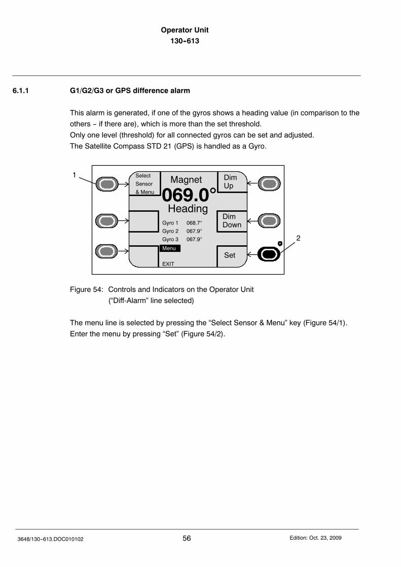
6.1.1 G1/G2/G3 or GPS difference alarm
This alarm is generated, if one of the gyros shows a heading value (in comparison to the
others -- if there are), which is more than the set threshold.
Only one level (threshold) for all connected gyros can be set and adjusted.
The Satellite Compass STD 21 (GPS) is handled as a Gyro.
DimUp
DimDown
Magnet
069.0Heading
Set
1
2
Select
Sensor
& Menu
Gyro 1 068.7
Gyro 2 067.9
Gyro 3 067.9
EXIT
Menu
Figure 54: Controls and Indicators on the Operator Unit
(“Diff-Alarm” line selected)
The menu line is selected by pressing the “Select Sensor & Menu” key (Figure 54/1).
Enter the menu by pressing “Set” (Figure 54/2).
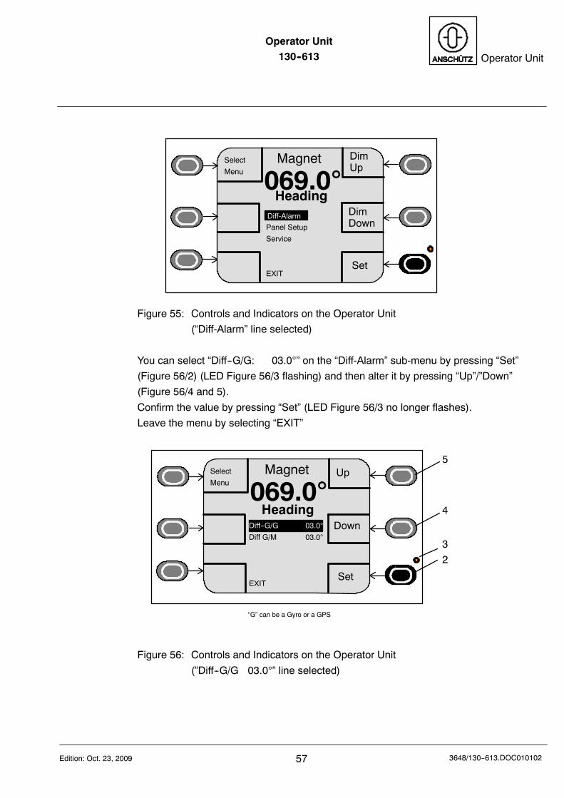
Operator Unit130--613 Operator Unit
57Edition: Oct. 23, 2009 3648/130--613.DOC010102
DimUp
DimDown
Magnet
069.0Heading
Set
Select
Menu
Panel Setup
Service
EXIT
Diff-Alarm
Figure 55: Controls and Indicators on the Operator Unit
(“Diff-Alarm” line selected)
You can select “Diff--G/G: 03.0” on the “Diff-Alarm” sub-menu by pressing “Set”
(Figure 56/2) (LED Figure 56/3 flashing) and then alter it by pressing “Up”/”Down”
(Figure 56/4 and 5).
Confirm the value by pressing “Set” (LED Figure 56/3 no longer flashes).
Leave the menu by selecting “EXIT”
Up
Down
Magnet
069.0Heading
Set
Select
Menu
Diff--G/G 03.0
Diff G/M 03.0
EXIT
2
3
4
5
“G” can be a Gyro or a GPS
Figure 56: Controls and Indicators on the Operator Unit
(”Diff--G/G 03.0” line selected)
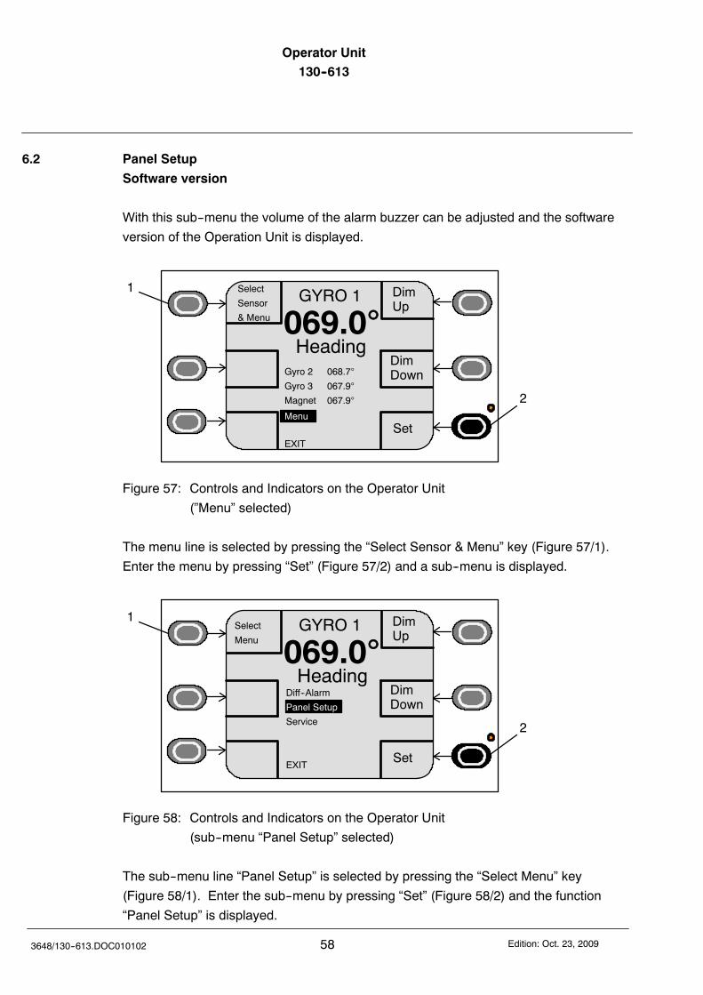
Operator Unit130--613
583648/130--613.DOC010102 Edition: Oct. 23, 2009
6.2 Panel Setup
Software version
With this sub--menu the volume of the alarm buzzer can be adjusted and the software
version of the Operation Unit is displayed.
DimUp
DimDown
GYRO 1
069.0Heading
Set
1
2
Select
Sensor
& Menu
Gyro 2 068.7
Gyro 3 067.9
Magnet 067.9
EXIT
Menu
Figure 57: Controls and Indicators on the Operator Unit
(”Menu” selected)
The menu line is selected by pressing the “Select Sensor & Menu” key (Figure 57/1).
Enter the menu by pressing “Set” (Figure 57/2) and a sub--menu is displayed.
DimUp
DimDown
GYRO 1
069.0Heading
Set
1
2
Select
Menu
Diff--Alarm
Panel Setup
Service
EXIT
Figure 58: Controls and Indicators on the Operator Unit
(sub--menu “Panel Setup” selected)
The sub--menu line “Panel Setup” is selected by pressing the “Select Menu” key
(Figure 58/1). Enter the sub--menu by pressing “Set” (Figure 58/2) and the function
“Panel Setup” is displayed.
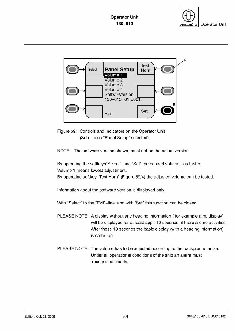
Operator Unit130--613 Operator Unit
59Edition: Oct. 23, 2009 3648/130--613.DOC010102
TestHornPanel Setup
Set
4
Select
Volume 1Volume 2Volume 3Volume 4Softw.--Version:130--613P01.E001.
Exit
Figure 59: Controls and Indicators on the Operator Unit
(Sub--menu “Panel Setup” selected)
NOTE: The software version shown, must not be the actual version.
By operating the softkeys“Select” and “Set” the desired volume is adjusted.
Volume 1 means lowest adjustment.
By operating softkey “Test Horn” (Figure 59/4) the adjusted volume can be tested.
Information about the software version is displayed only.
With “Select” to the “Exit”--line and with “Set” this function can be closed.
PLEASE NOTE: A display without any heading information ( for example a.m. display)
will be displayed for at least appr. 10 seconds, if there are no activities.
After these 10 seconds the basic display (with a heading information)
is called up.
PLEASE NOTE: The volume has to be adjusted according to the background noise.
Under all operational conditions of the ship an alarm must
recognized clearly.
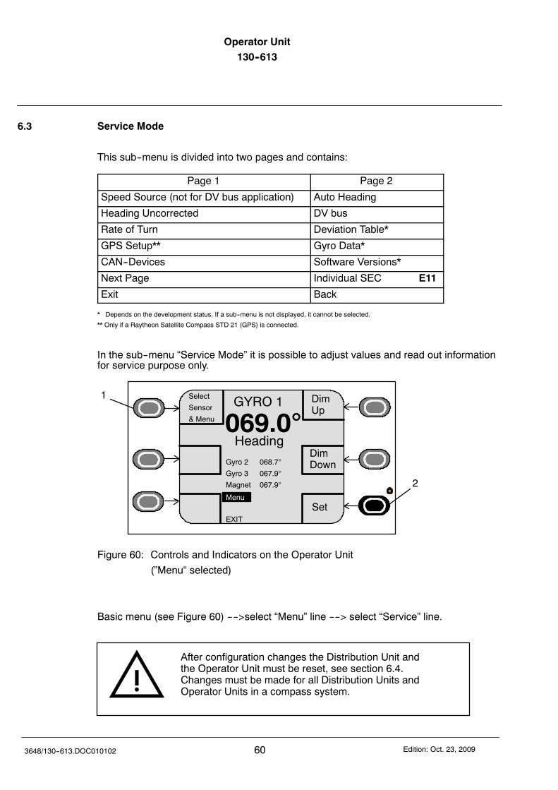
Operator Unit130--613
603648/130--613.DOC010102 Edition: Oct. 23, 2009
6.3 Service Mode
This sub--menu is divided into two pages and contains:
Page 1 Page 2
Speed Source (not for DV bus application) Auto Heading
Heading Uncorrected DV bus
Rate of Turn Deviation Table*
GPS Setup** Gyro Data*
CAN--Devices Software Versions*
Next Page Individual SEC E11
Exit Back
* Depends on the development status. If a sub--menu is not displayed, it cannot be selected.
** Only if a Raytheon Satellite Compass STD 21 (GPS) is connected.
In the sub--menu “Service Mode” it is possible to adjust values and read out informationfor service purpose only.
DimUp
DimDown
GYRO 1
069.0Heading
Set
1
2
Select
Sensor
& Menu
Gyro 2 068.7
Gyro 3 067.9
Magnet 067.9
EXIT
Menu
Figure 60: Controls and Indicators on the Operator Unit
(”Menu“ selected)
Basic menu (see Figure 60) ---->select “Menu” line ----> select “Service” line.
After configuration changes the Distribution Unit andthe Operator Unit must be reset, see section 6.4.Changes must be made for all Distribution Units andOperator Units in a compass system.
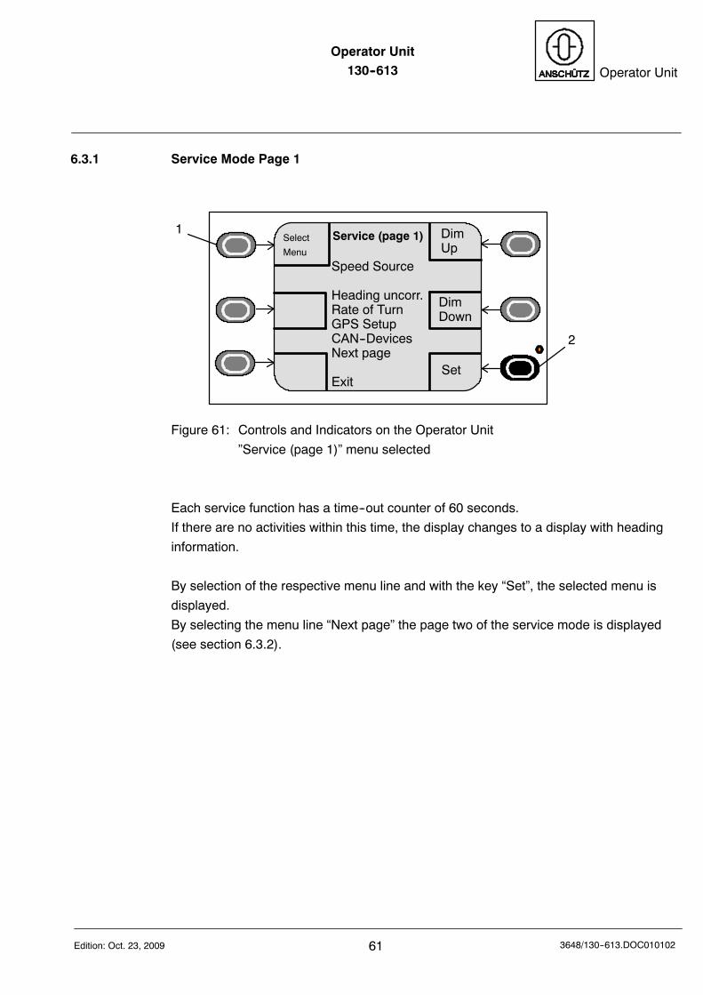
Operator Unit130--613 Operator Unit
61Edition: Oct. 23, 2009 3648/130--613.DOC010102
6.3.1 Service Mode Page 1
DimUp
DimDown
Set
1
2
Select
Menu
Speed Source
Heading uncorr.Rate of TurnGPS SetupCAN--DevicesNext page
Exit
Service (page 1)
Figure 61: Controls and Indicators on the Operator Unit
”Service (page 1)” menu selected
Each service function has a time--out counter of 60 seconds.
If there are no activities within this time, the display changes to a display with heading
information.
By selection of the respective menu line and with the key “Set”, the selected menu is
displayed.
By selecting the menu line “Next page” the page two of the service mode is displayed
(see section 6.3.2).
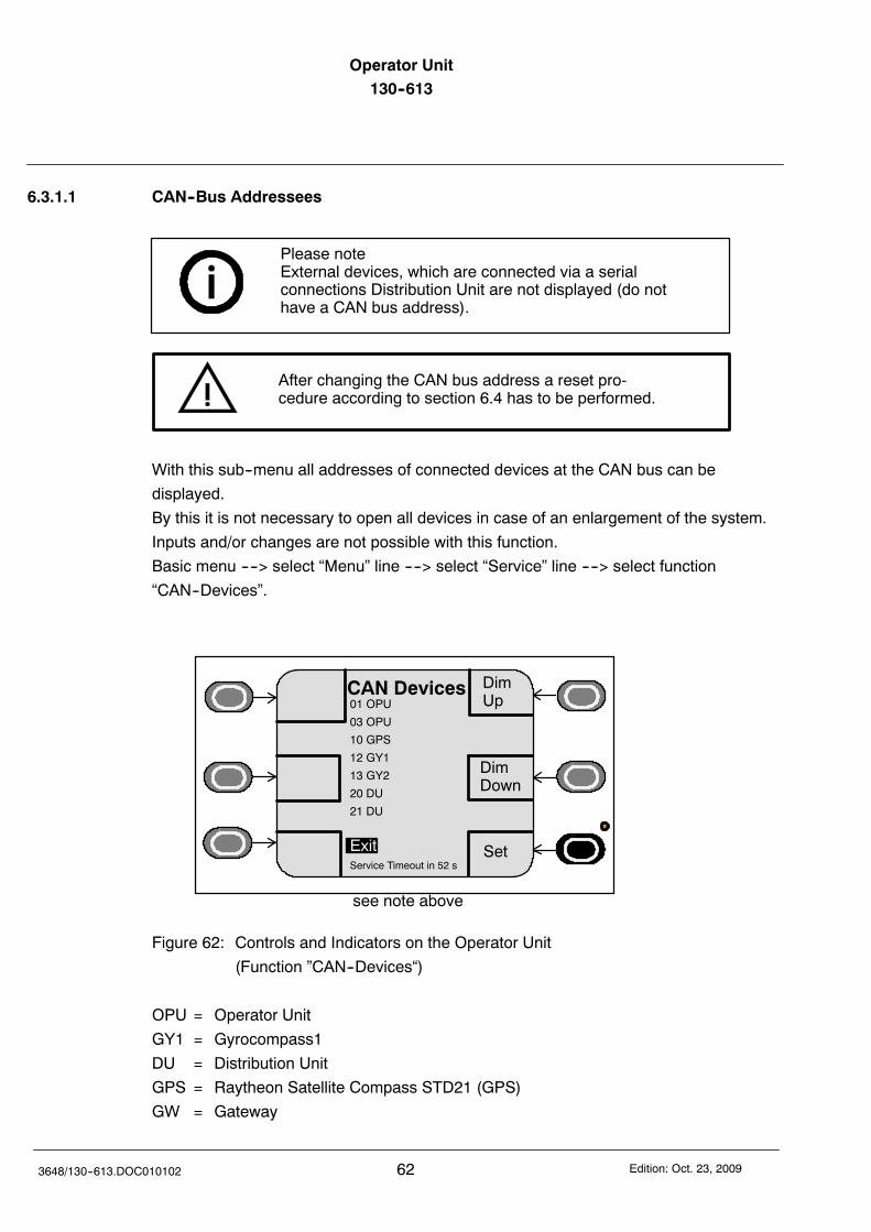
Operator Unit130--613
623648/130--613.DOC010102 Edition: Oct. 23, 2009
6.3.1.1 CAN--Bus Addressees
Please noteExternal devices, which are connected via a serialconnections Distribution Unit are not displayed (do nothave a CAN bus address).
After changing the CAN bus address a reset pro-cedure according to section 6.4 has to be performed.
With this sub--menu all addresses of connected devices at the CAN bus can be
displayed.
By this it is not necessary to open all devices in case of an enlargement of the system.
Inputs and/or changes are not possible with this function.
Basic menu ----> select “Menu” line ----> select “Service” line ----> select function
“CAN--Devices”.
DimUp
DimDown
CAN Devices
Set
01 OPU
03 OPU
10 GPS
12 GY1
13 GY2
20 DU
21 DU
ExitService Timeout in 52 s
see note above
Figure 62: Controls and Indicators on the Operator Unit
(Function ”CAN--Devices“)
OPU = Operator Unit
GY1 = Gyrocompass1
DU = Distribution Unit
GPS = Raytheon Satellite Compass STD21 (GPS)
GW = Gateway

Operator Unit130--613 Operator Unit
63Edition: Oct. 23, 2009 3648/130--613.DOC010102
With this function all addressees within the CAN--bus system are displayed decimal.
With “Select” to the “Exit”--line and with “Set” this function can be closed.
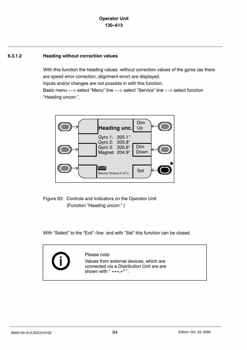
Operator Unit130--613
643648/130--613.DOC010102 Edition: Oct. 23, 2009
6.3.1.2 Heading without correction values
With this function the heading values without correction values of the gyros (as there
are speed error correction, alignment error) are displayed.
Inputs and/or changes are not possible in with this function.
Basic menu ----> select “Menu” line ----> select “Service” line ----> select function
“Heading uncorr.”.
DimUp
DimDown
Heading unc.
Set
Gyro 1: 205.1Gyro 2: 205.8Gyro 3: 205.6Magnet: 204.9
ExitService Timeout in 57 s
Figure 63: Controls and Indicators on the Operator Unit
(Function ”Heading uncorr.“ )
With “Select” to the “Exit”--line and with “Set” this function can be closed.
Please note:Values from external devices, which areconnected via a Distribution Unit are areshown with “ -- -- --.-- ”.
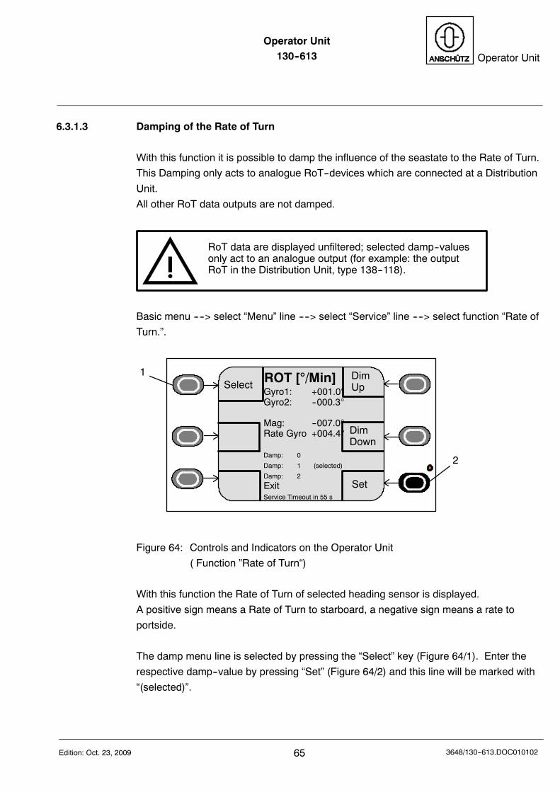
Operator Unit130--613 Operator Unit
65Edition: Oct. 23, 2009 3648/130--613.DOC010102
6.3.1.3 Damping of the Rate of Turn
With this function it is possible to damp the influence of the seastate to the Rate of Turn.
This Damping only acts to analogue RoT--devices which are connected at a Distribution
Unit.
All other RoT data outputs are not damped.
RoT data are displayed unfiltered; selected damp--valuesonly act to an analogue output (for example: the outputRoT in the Distribution Unit, type 138--118).
Basic menu ----> select “Menu” line ----> select “Service” line ----> select function “Rate of
Turn.”.
DimUp
DimDown
ROT [/Min]
Set
1
2
Gyro1: +001.0Gyro2: --000.3
Mag: --007.0Rate Gyro +004.4
Damp: 0
Damp: 1 (selected)
Damp: 2
ExitService Timeout in 55 s
Select
Figure 64: Controls and Indicators on the Operator Unit
( Function ”Rate of Turn“)
With this function the Rate of Turn of selected heading sensor is displayed.
A positive sign means a Rate of Turn to starboard, a negative sign means a rate to
portside.
The damp menu line is selected by pressing the “Select” key (Figure 64/1). Enter the
respective damp--value by pressing “Set” (Figure 64/2) and this line will be marked with
“(selected)”.
Operator Unit130--613
663648/130--613.DOC010102 Edition: Oct. 23, 2009
The Rate of Turn can not be adjusted, displayed only.
The scaling of the Rate of Turn has to be carried out in the Distribution Unit
The line “Rate Gyro” displays the Rate of Turn of an external Rate of Turn sensor
connected at the Distribution Unit.
This line is not shown if there is no Rate of Turn sensor connected.
“Damp 0” means small damping.
“Damp 1” means middle damping.
“Damp 2” means strong damping.
With “Select” to the “Exit”--line and with “Set” this function can be closed.
If there is no Rate of Turn indicator connected inthe respective application, the rate of turn forconnected heading sensors is a tendency indica-tion only.Exception: DV--bus application shows a rate ofturn for magnetic compasses (if selected).For more information about RoT applications,see manual of respective Distribution Unit.
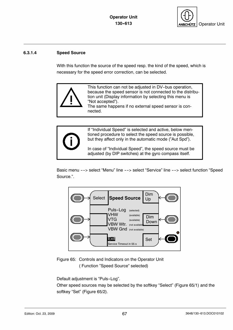
Operator Unit130--613 Operator Unit
67Edition: Oct. 23, 2009 3648/130--613.DOC010102
6.3.1.4 Speed Source
With this function the source of the speed resp. the kind of the speed, which is
necessary for the speed error correction, can be selected.
This function can not be adjusted in DV--bus operation,because the speed sensor is not connected to the distribu-tion unit (Display information by selecting this menu is“Not accepted”).The same happens if no external speed sensor is con-nected.
If “Individual Speed” is selected and active, below men-tioned procedure to select the speed source is possible,but they affect only in the automatic mode (”Aut Spd”).
In case of “Individual Speed”, the speed source must beadjusted (by DIP switches) at the gyro compass itself.
Basic menu ----> select “Menu” line ----> select “Service” line ----> select function “Speed
Source.”.
DimUp
DimDown
Speed Source
Set
Puls--Log (selected)
VHW (available)
VTG (available)
VBW Wtr. (not available)
VBW Gnd (not available)
ExitService Timeout in 55 s
Select
Figure 65: Controls and Indicators on the Operator Unit
( Function ”Speed Source“ selected)
Default adjustment is “Puls--Log”.
Other speed sources may be selected by the softkey “Select” (Figure 65/1) and the
softkey “Set” (Figure 65/2).
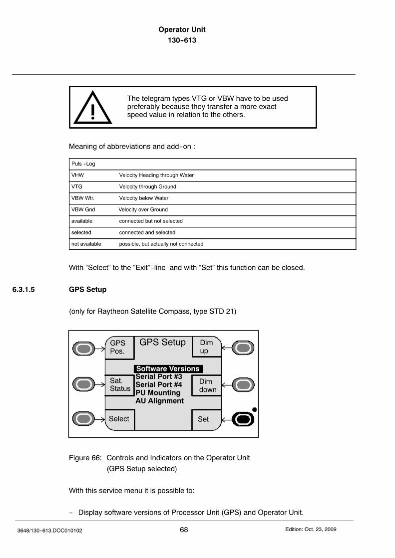
Operator Unit130--613
683648/130--613.DOC010102 Edition: Oct. 23, 2009
The telegram types VTG or VBW have to be usedpreferably because they transfer a more exactspeed value in relation to the others.
Meaning of abbreviations and add--on :
Puls --Log
VHW Velocity Heading through Water
VTG Velocity through Ground
VBW Wtr. Velocity below Water
VBW Gnd Velocity over Ground
available connected but not selected
selected connected and selected
not available possible, but actually not connected
With “Select” to the “Exit”--line and with “Set” this function can be closed.
6.3.1.5 GPS Setup
(only for Raytheon Satellite Compass, type STD 21)
Dimup
Dimdown
GPS Setup
Serial Port #3Serial Port #4PU MountingAU Alignment
GPSPos.
Select Set
Sat.Status
Software Versions
Figure 66: Controls and Indicators on the Operator Unit
(GPS Setup selected)
With this service menu it is possible to:
-- Display software versions of Processor Unit (GPS) and Operator Unit.

Operator Unit130--613 Operator Unit
69Edition: Oct. 23, 2009 3648/130--613.DOC010102
-- Adjust the data format for the serial outputs (#3 and #4).
-- Adjust position and location of the installed Processor Unit (GPS)
(this is necessary to define the position of the built in accelerometers in the
Processor Unit (GPS).
-- Enter the difference of the Antenna Unit (AU) from the ship‘s baseline.
For detailed information, see Satellite Compass STD 21 manual (manual no. 3717).
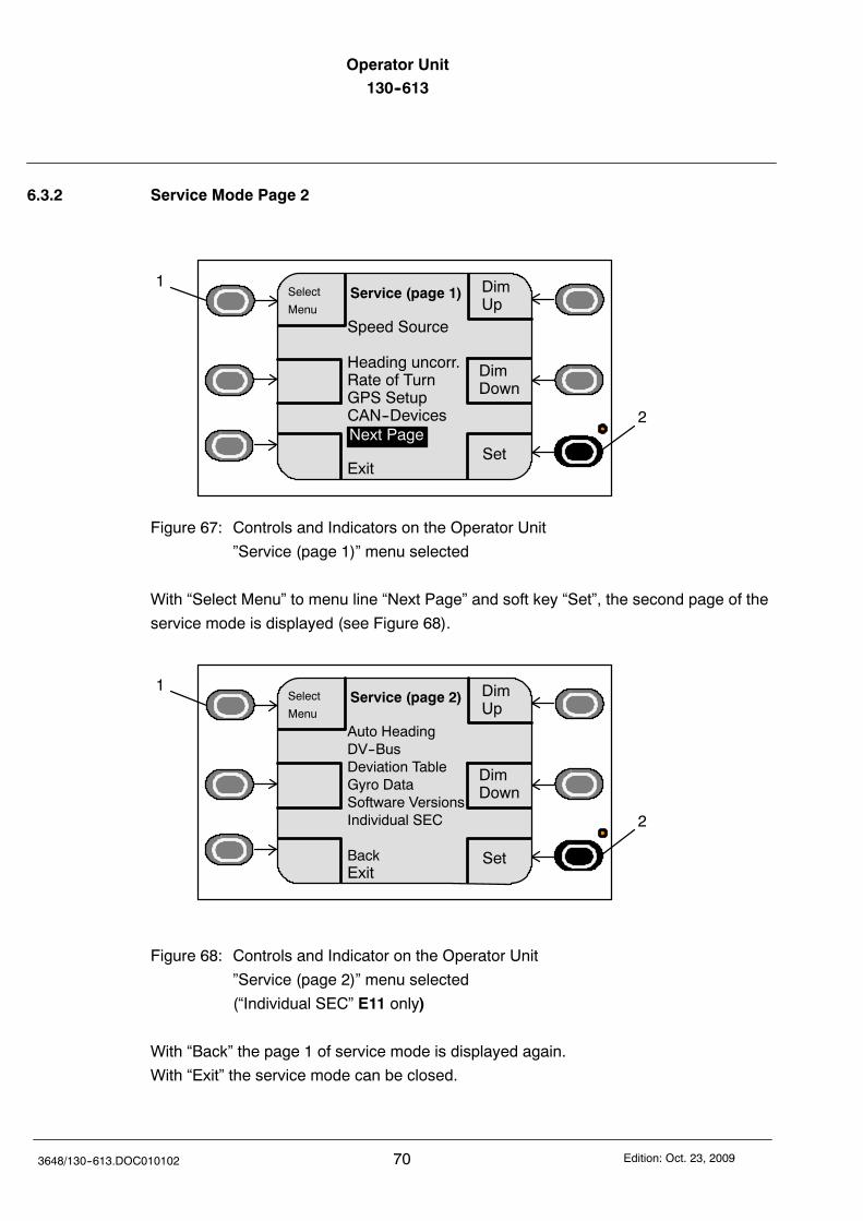
Operator Unit130--613
703648/130--613.DOC010102 Edition: Oct. 23, 2009
6.3.2 Service Mode Page 2
DimUp
DimDown
Service (page 1)
Set
1
2
Select
Menu
Speed Source
Heading uncorr.Rate of TurnGPS SetupCAN--Devices
Exit
Next Page
Figure 67: Controls and Indicators on the Operator Unit
”Service (page 1)” menu selected
With “Select Menu” to menu line “Next Page” and soft key “Set”, the second page of the
service mode is displayed (see Figure 68).
DimUp
DimDown
Service (page 2)
Set
1
2
Select
Menu
Auto HeadingDV--BusDeviation TableGyro DataSoftware VersionsIndividual SEC
BackExit
Figure 68: Controls and Indicator on the Operator Unit
”Service (page 2)” menu selected
(“Individual SEC” E11 only)
With “Back” the page 1 of service mode is displayed again.
With “Exit” the service mode can be closed.
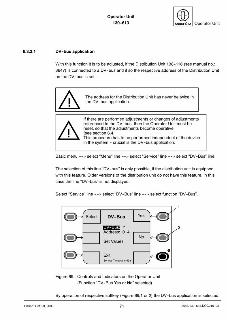
Operator Unit130--613 Operator Unit
71Edition: Oct. 23, 2009 3648/130--613.DOC010102
6.3.2.1 DV--bus application
With this function it is to be adjusted, if the Distribution Unit 138--118 (see manual no.:
3647) is connected to a DV--bus and if so the respective address of the Distribution Unit
on the DV--bus is set.
The address for the Distribution Unit has never be twice inthe DV--bus application.
If there are performed adjustments or changes of adjustmentsreferenced to the DV--bus, then the Operator Unit must bereset, so that the adjustments become operative(see section 6.4.This procedure has to be performed independent of the devicein the system -- crucial is the DV--bus application.
Basic menu ----> select “Menu” line ----> select “Service” line ----> select “DV--Bus” line.
The selection of this line “DV--bus” is only possible, if the distribution unit is equipped
with this feature. Older versions of the distribution unit do not have this feature, in this
case the line “DV--bus” is not displayed.
Select “Service” line ----> select “DV--Bus” line ----> select function “DV--Bus”.
Yes
No
DV--Bus
DV--Bus: YAddress: 014
Set Values
ExitService Timeout in 55 s
Select
1
2
Figure 69: Controls and Indicators on the Operator Unit
(Function “DV--Bus Yes or No” selected)
By operation of respective softkey (Figure 69/1 or 2) the DV--bus application is selected.
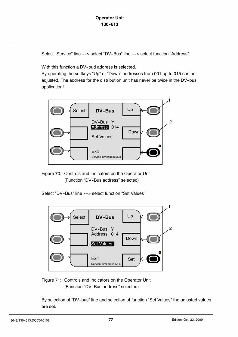
Operator Unit130--613
723648/130--613.DOC010102 Edition: Oct. 23, 2009
Select “Service” line ----> select “DV--Bus” line ----> select function “Address”.
With this function a DV--bud address is selected.
By operating the softkeys “Up” or “Down” addresses from 001 up to 015 can be
adjusted. The address for the distribution unit has never be twice in the DV--bus
application!
Up
Down
DV--Bus
DV--Bus: YAddress: 014
Set Values
ExitService Timeout in 55 s
Select
1
2
Figure 70: Controls and Indicators on the Operator Unit
(Function “DV--Bus address” selected)
Select “DV--Bus” line ----> select function “Set Values”.
Up
Down
DV--Bus
DV--Bus: YAddress: 014
Set Values
ExitService Timeout in 55 s
Select
1
2
Set
Figure 71: Controls and Indicators on the Operator Unit
(Function “DV--Bus address” selected)
By selection of “DV--bus” line and selection of function “Set Values” the adjusted values
are set.
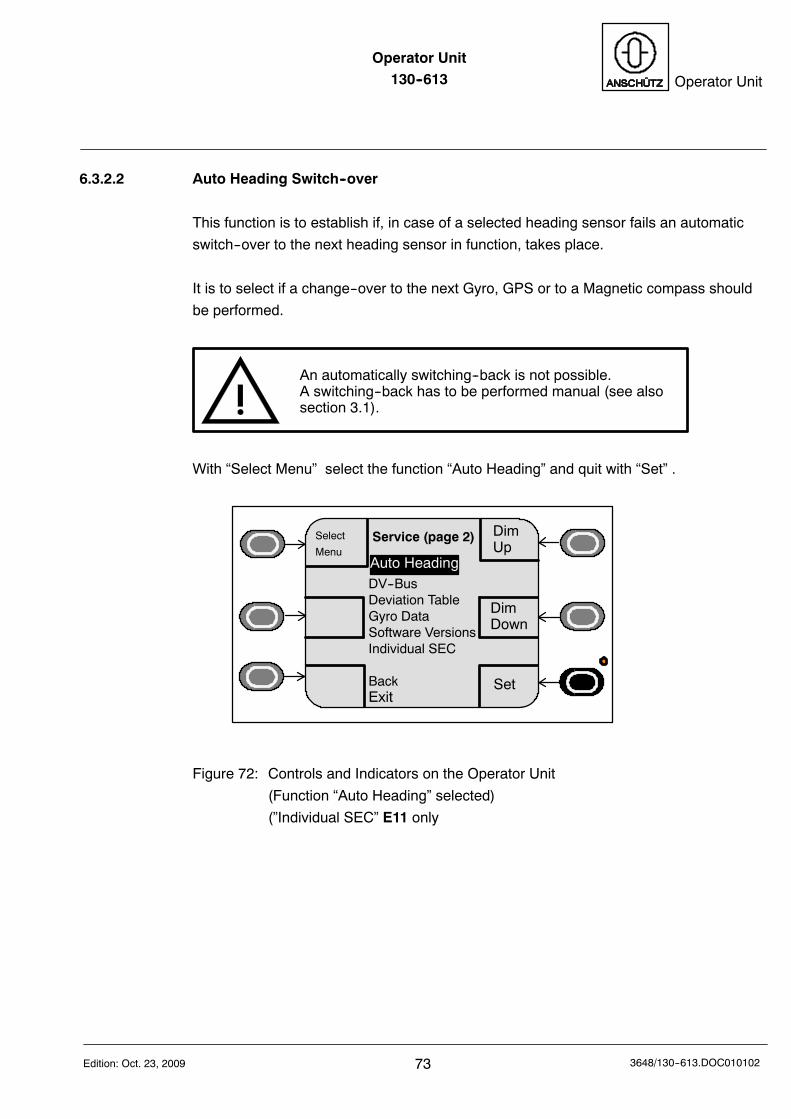
Operator Unit130--613 Operator Unit
73Edition: Oct. 23, 2009 3648/130--613.DOC010102
6.3.2.2 Auto Heading Switch--over
This function is to establish if, in case of a selected heading sensor fails an automatic
switch--over to the next heading sensor in function, takes place.
It is to select if a change--over to the next Gyro, GPS or to a Magnetic compass should
be performed.
An automatically switching--back is not possible.A switching--back has to be performed manual (see alsosection 3.1).
With “Select Menu” select the function “Auto Heading” and quit with “Set” .
DimUp
DimDown
Service (page 2)
Set
Select
MenuAuto HeadingDV--BusDeviation TableGyro DataSoftware VersionsIndividual SEC
BackExit
Figure 72: Controls and Indicators on the Operator Unit
(Function “Auto Heading” selected)
(”Individual SEC” E11 only
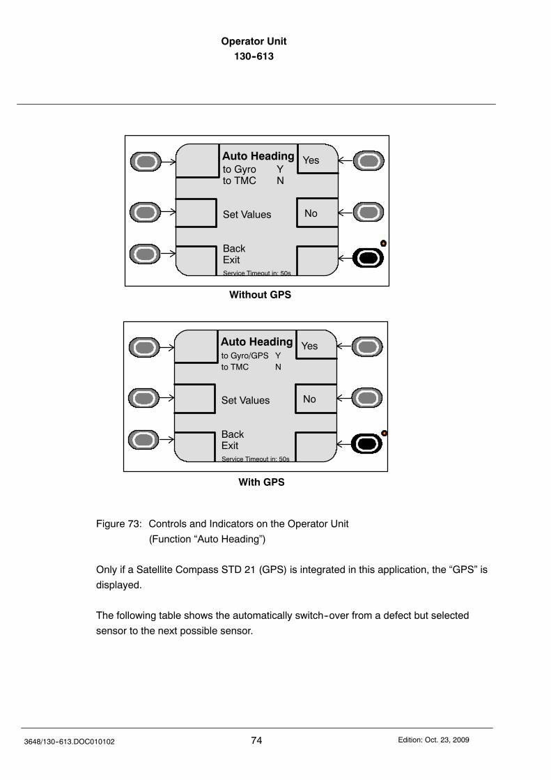
Operator Unit130--613
743648/130--613.DOC010102 Edition: Oct. 23, 2009
Yes
No
Auto Headingto Gyro Yto TMC N
Set Values
BackExitService Timeout in: 50s
Yes
No
Auto Headingto Gyro/GPS Yto TMC N
Set Values
BackExitService Timeout in: 50s
Without GPS
With GPS
Figure 73: Controls and Indicators on the Operator Unit
(Function “Auto Heading”)
Only if a Satellite Compass STD 21 (GPS) is integrated in this application, the “GPS” is
displayed.
The following table shows the automatically switch--over from a defect but selected
sensor to the next possible sensor.
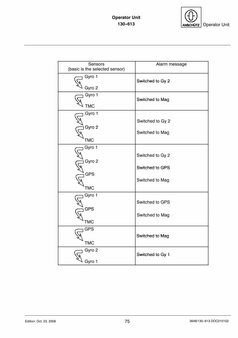
Operator Unit130--613 Operator Unit
75Edition: Oct. 23, 2009 3648/130--613.DOC010102
Sensors(basic is the selected sensor)
Alarm message
Gyro 1Switched to Gy 2
Gyro 2
Switched to Gy 2
Gyro 1Switched to Mag
TMC
Switched to Mag
Gyro 1
Gyro 2Switched to Gy 2
Gyro 2
TMC
Switched to Mag
Gyro 1
Gyro 2Switched to Gy 2
Switched to GPS
GPS
TMC
Switched to GPS
Switched to Mag
Gyro 1
GPS
Switched to GPS
GPS
TMC
Switched to Mag
GPS
Switched to Mag
TMC
Switched to Mag
Gyro 2Switched to Gy 1
Gyro 1
Switched to Gy 1
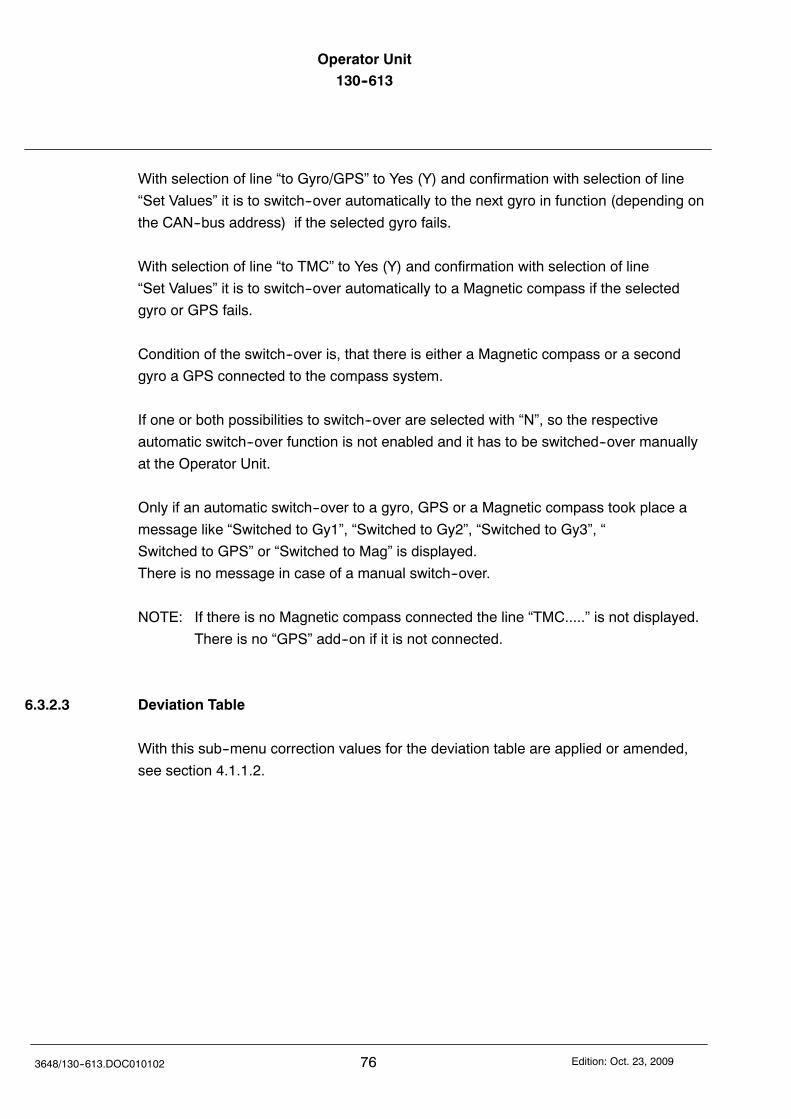
Operator Unit130--613
763648/130--613.DOC010102 Edition: Oct. 23, 2009
With selection of line “to Gyro/GPS” to Yes (Y) and confirmation with selection of line
“Set Values” it is to switch--over automatically to the next gyro in function (depending on
the CAN--bus address) if the selected gyro fails.
With selection of line “to TMC” to Yes (Y) and confirmation with selection of line
“Set Values” it is to switch--over automatically to a Magnetic compass if the selected
gyro or GPS fails.
Condition of the switch--over is, that there is either a Magnetic compass or a second
gyro a GPS connected to the compass system.
If one or both possibilities to switch--over are selected with “N”, so the respective
automatic switch--over function is not enabled and it has to be switched--over manually
at the Operator Unit.
Only if an automatic switch--over to a gyro, GPS or a Magnetic compass took place a
message like “Switched to Gy1”, “Switched to Gy2”, “Switched to Gy3”, “
Switched to GPS” or “Switched to Mag” is displayed.
There is no message in case of a manual switch--over.
NOTE: If there is no Magnetic compass connected the line “TMC.....” is not displayed.
There is no “GPS” add--on if it is not connected.
6.3.2.3 Deviation Table
With this sub--menu correction values for the deviation table are applied or amended,
see section 4.1.1.2.
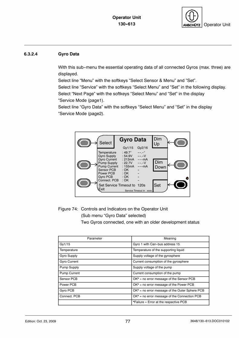
Operator Unit130--613 Operator Unit
77Edition: Oct. 23, 2009 3648/130--613.DOC010102
6.3.2.4 Gyro Data
With this sub--menu the essential operating data of all connected Gyros (max. three) are
displayed.
Select line “Menu” with the softkeys “Select Sensor & Menu” and ”Set”.
Select line “Service” with the softkeys “Select Menu” and “Set” in the following display.
Select “Next Page” with the softkeys “Select Menu” and “Set” in the display
“Service Mode (page1).
Select line “Gyro Data” with the softkeys “Select Menu” and “Set” in the display
“Service Mode (page2).
DimUp
DimDown
Gyro Data
Set
SelectGy1/15 Gy2/16
Temperature : 49.7 ----.--Gyro Supply : 54.9V ----.--VGyro Current : 213mA ------mAPump Supply : 22.7V ----.--VPump Current : 155mA ------mASensor PCB : OK --Power PCB : OK --Gyro PCB : OK --Connect. PCB : OK --
Set Service Timeout to 120sExit Service Timeout in xxxs
Figure 74: Controls and Indicators on the Operator Unit
(Sub menu “Gyro Data” selected)
Two Gyros connected, one with an older development status
Parameter Meaning
Gy1/15 Gyro 1 with Can--bus address 15
Temperature Temperature of the supporting liquid
Gyro Supply Supply voltage of the gyrosphere
Gyro Current Current consumption of the gyrosphere
Pump Supply Supply voltage of the pump
Pump Current Current consumption of the pump
Sensor PCB OK* = no error message of the Sensor PCB
Power PCB OK* = no error message of the Power PCB
Gyro PCB OK* = no error message of the Outer Sphere PCB
Connect. PCB OK* = no error message of the Connection PCB
*Failure = Error at the respective PCB

Operator Unit130--613
783648/130--613.DOC010102 Edition: Oct. 23, 2009
With softkey “Select” one of the lines “Set Service Timeout to 120s” or “Exit” can be
selected.
By operating the softkey “Set” and selected line “Set Service Time out to 120s” the
internal counter is set to 120 seconds again.
The standard menu (Figure 2) is displayed, if this internal counter counts to zero.
By operating softkey “Set” and selected line “Exit”, the display “Service mode (page1) is
displayed again .
Operator Unit130--613 Operator Unit
79Edition: Oct. 23, 2009 3648/130--613.DOC010102
6.3.2.5 Software Versions
With this submenu the software status of all processor program--memories of PCB of the
connected Gyros (max. three) and of the Distribution unit are displayed.
DimUp
DimDown
SW Versions
Set
Select
Gy1/15 Gy2/16110--233.P01.E10.00 P00.E00.00110--233.P02.E10.00110--233.P03.E10.00110--233.P04.E10.00
DU /20138--118.P01.E10.00138--118.P02.E10.00138--118.P03.E10.00
Set Service Timeout to 120sExit Service Timeout in xxxs
Note: There is no display for PCB‘s with an older development status
Figure 75: Controls and Indicators on the Operator Unit
( Submenu “SW Versions” displayed)
One Gyro and one Distribution Unit connected.
Display Meaning
Gy1/15 Gyro 1 with CAN--bus address 15
110--233.P01.E11.00 110--233 = Compass STD 22P01 = Program at the Sensor PCBP02 = Program at the Power PCBP03 = Program for MC 1 at the Outer Sphere PCBP04 = Program for MC 1 at the Outer Sphere PCBE11.00 = Software version
DU /20 Distribution Unit with CAN--bus address 20
138--118.P01 138--118 = Distribution UnitP05 = Program of the CAN--bus Processor + DV--bus
at the Interface PCBP06 = Program of the I/O PCB ProcessorP07 = Program at the I/O PCB
Gy2/16 Gyro 2 with CAN--bus address 16
P00.E00.00 older development status
Above mentioned displays and meanings are examples only.
Please note:Software Versions are not displayed for MINS and nonexternal (non Raytheon) devices.
Operator Unit130--613
803648/130--613.DOC010102 Edition: Oct. 23, 2009
With softkey “Select” one of the lines “Set Service Timeout to 120s” or “Exit” can be
selected.
By operating the softkey “Set” and selected line “Set Service Time out to 120s” the
internal counter is set to 120 seconds again.
The standard menu (Figure 2) is displayed, if this internal counter counts to zero.
By operating softkey “Set” and selected line “Exit”, the display “Service mode (page1) is
displayed again .
Operator Unit130--613 Operator Unit
81Edition: Oct. 23, 2009 3648/130--613.DOC010102
6.3.2.6 Individual Speed Error Correction (SEC) (E11)
Comments regarding Speed Error Correction
Speed error is a physical deviation from the steering heading indicated on the gyro
compass (compass heading) from the true heading (chart heading).
The speed error depends on the speed of the ship, the heading it is steering and the
latitude. A speed-error table takes these items into consideration (see Operator Manual
of the Gyro Compass STD 22) .
The ship’s acceleration also affects the gyro system. Since this is a non linear error the
speed-error table cannot take it into consideration.
The correction values are calculated within the gyro system and added or subtracted to
the compass heading.
So, in the event that the speed error correction function is activated by manually entering
speed and latitude, dynamic speed error correction will also be carried out.
This can lead to unexpected results because accelerationis produced by a simulated speed change (as opposed tothe ship’s speed) and this can lead to inaccurate correctionvalues.The result of the correction will only be correct if the manualentries (speed/latitude) align with the current ship’sdynamics.
Individual Speed Error Correction
This application is intended to provide gyro compasses with an own (individual) Speed
Error Correction. For this it is necessary to supply each compass with its own speed and
position (Latitude) values from different sources.
By this feature a speed or position jump leads to an appropriately adjusted heading
difference alarm at the Operator Unit.
If there is no Individual Speed Error Correction, then all gyro compasses will show the
same heading value, because the speed and position is distributed to them from one
source (Distribution Unit).
Individual Speed Error Correction is preferable forDP system (Dynamic Positioning Systems).
Operator Unit130--613
823648/130--613.DOC010102 Edition: Oct. 23, 2009
Conditions for “Individual Speed Error Correction:
All Gyro Compasses must be type 110--233 NG002andthe Distribution Unit must be type 138--118 NG002 or NG003andbelow mentioned adjustments must be performedandthe Operator Unit type 130--613 must have a software statushigher than E11.
Very first steps:
-- Speed and GPS position must be connected and configured at the
Gyro Compass STD 22.
-- “Individual SEC” must be set to “Y”, see Figure 76 and Figure 77.
-- Speed source must be set to “Individual Spd”, see section 3.2.
-- Latitude must be set to “Individual Lat”, see section 3.3.
There is no need to switch over Speed source to“Individual Spd” and Latitude to “Individual Lat”.Only one of the settings must be switched over -- the otheris switched over automatically.
After selection of “Individual SEC” to “Y” the procedure to select between
“Aut Spd”, “Man Spd” and “Individual Spd” has changed.
-- Individual speed is already selected
-- “Man Spd xx.x kts” is displayed
-- “Man Spd xx.x kts” must be acknowledged with “SET” (after “Select Speed”)
or changed with “UP”/”DOWN” and acknowledged with “SET”
-- “Individual Spd” is displayed and can be selected (”Select Speed”)
Summary: “Man Spd” has to be selected and acknowledged (independent the speed
value) with “SET” before “Aut Spd” is displayed and selectable at all again.
Above mentioned procedure had been performed once before it is possible to select
“Aut Spd” after each selection of “Individual SEC” with “Yes”.
The same procedure must be performed analogous for the latitude modes “Aut Lat”,
“Man Lat” and “Individual Lat”.
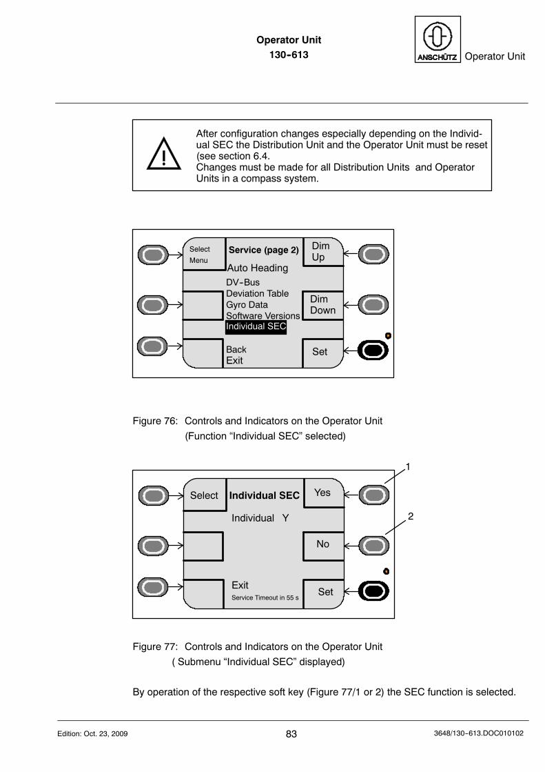
Operator Unit130--613 Operator Unit
83Edition: Oct. 23, 2009 3648/130--613.DOC010102
After configuration changes especially depending on the Individ-ual SEC the Distribution Unit and the Operator Unit must be reset(see section 6.4.Changes must be made for all Distribution Units and OperatorUnits in a compass system.
DimUp
DimDown
Service (page 2)
Set
Select
MenuAuto HeadingDV--BusDeviation TableGyro DataSoftware Versions
BackExit
Individual SEC
Figure 76: Controls and Indicators on the Operator Unit
(Function “Individual SEC” selected)
Yes
No
Individual SEC
Individual Y
ExitService Timeout in 55 s
Select
1
2
Set
Figure 77: Controls and Indicators on the Operator Unit
( Submenu “Individual SEC” displayed)
By operation of the respective soft key (Figure 77/1 or 2) the SEC function is selected.
Operator Unit130--613
843648/130--613.DOC010102 Edition: Oct. 23, 2009
6.4 Power OFF--ON Procedures
Caution!
Power OFF--ON procedures and/or configuration changes
must be permormed by trained an qualified personnel only.
Below mentioned procedures are necessary after flashing a new software and/orafter a configuration of system components (configuration changes or newdevices/components).
6.4.1 Flashing new Software
Caution!
A Power OFF--ON procedure for the compass should last
not longer than 1 second. Otherwise the compass settling
procedure is performed (4 hours settling stage, Quick
settling is not possible).
After flashing a new software it is recommended to reset the respective deviceby a power OFF--ON procedure, but a RESET (with respective push button ifavailable) is absolutely necessary.A power OFF--ON procedure can be performed either by switching of the supplyvoltage at a main supply distribution or by removing respective power cables(there are no separate power switches -- neither at the compass nor atdistribution units or operator units).
Operator Unit130--613 Operator Unit
85Edition: Oct. 23, 2009 3648/130--613.DOC010102
6.4.2 Changing configuration of system components or connecting of
other/new system components
Please note:It is not necessary to switch OFF and ON a device/compo-nent after configuration changes or after connecting other/new system components.Instead of a power OFF -- ON a RESET procedure can beapplied (as below mentioned).
A RESET procedure must be performed for below mentioned applications:
-- DV--Bus is changed-- Individual Speed is changed-- CAN bus addressees are changed-- External sensors are changed or added-- Type of Distribution Unit is changed-- Magnetic compass connection is changed
This RESET procedure must be performed at the connected Distribution Unit bypressing the RESET push buttons on both PC Boards and for the Operator Unitby switching OFF the supply voltage.A RESET or a power OFF for the compass is not necessary.
Please note:For this procedure it is necessary that the DistributionUnits and the Operator Unit are not switched OFF.
-- Open the frontcover of the Distribution Unit.-- Press both RESET buttons, (located at each PC Board) if possiblesimultaneously.Button B6 at the Interface PCB and button B42 at the I/O PCB of theDistribution Unit (see respective manual of the Distribution Unit).
-- Disconnect the Operator Unit from the terminal board L1 in the DistributionUnit for approx. 5 seconds and connect it again.
-- Close the frontcover of the Distribution Unit and fix it with the screws.
Operator Unit130--613
863648/130--613.DOC010102 Edition: Oct. 23, 2009
6.5 Switching Off the Operator Unit
The equipment is switched off when the voltage supply to the operator unit is switched
off.
Even if the equipment in question is installed as the “end device” on a CAN bus
application, the operation of the other connected devices will not be affected.
Operator Unit130--613 Operator Unit
87Edition: Oct. 23, 2009 3648/130--613.DOC010102
7 Operator Unit maintenance and repair
The Operator Unit is maintenance-free.
If necessary wipe the display unit clean with a dry cloth.
Repair:
In case of malfunction, the Operator Unit has to be replaced complete .
Operation during a replacement can only be performedwhen the CAN--bus is terminated.It is absolute necessary that the CAN--bus is terminatedcorrectly on both ends.If there is no terminator by jumpers or switches within therespective devices, than each CAN--bus (CAN1 and CAN2)has to be terminated by, in total 2 resistors (each 120Ohm)from CAN--low to CAN--high
PLEASE NOTE: There are no changes respective to settings or adjustments,
while flashing a new software version.
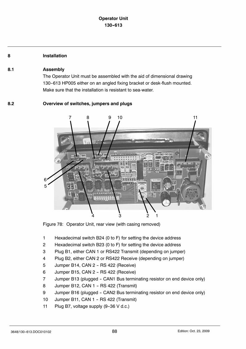
Operator Unit130--613
883648/130--613.DOC010102 Edition: Oct. 23, 2009
8 Installation
8.1 Assembly
The Operator Unit must be assembled with the aid of dimensional drawing
130--613 HP005 either on an angled fixing bracket or desk-flush mounted.
Make sure that the installation is resistant to sea-water.
8.2 Overview of switches, jumpers and plugs
1234
56
7 8 9 10 11
Figure 78: Operator Unit, rear view (with casing removed)
1 Hexadecimal switch B24 (0 to F) for setting the device address
2 Hexadecimal switch B23 (0 to F) for setting the device address
3 Plug B1, either CAN 1 or RS422 Transmit (depending on jumper)
4 Plug B2, either CAN 2 or RS422 Receive (depending on jumper)
5 Jumper B14, CAN 2 -- RS 422 (Receive)
6 Jumper B15, CAN 2 -- RS 422 (Receive)
7 Jumper B13 (plugged -- CAN1 Bus terminating resistor on end device only)
8 Jumper B12, CAN 1 -- RS 422 (Transmit)
9 Jumper B16 (plugged -- CAN2 Bus terminating resistor on end device only)
10 Jumper B11, CAN 1 -- RS 422 (Transmit)
11 Plug B7, voltage supply (9--36 V d.c.)
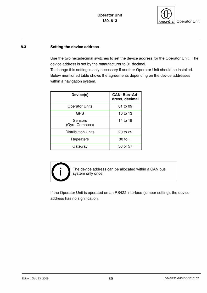
Operator Unit130--613 Operator Unit
89Edition: Oct. 23, 2009 3648/130--613.DOC010102
8.3 Setting the device address
Use the two hexadecimal switches to set the device address for the Operator Unit. The
device address is set by the manufacturer to 01 decimal.
To change this setting is only necessary if another Operator Unit should be installed.
Below mentioned table shows the agreements depending on the device addresses
within a navigation system.
Device(s) CAN--Bus--Ad-dress, decimal
Operator Units 01 to 09
GPS 10 to 13
Sensors(Gyro Compass)
14 to 19
Distribution Units 20 to 29
Repeaters 30 to ...
Gateway 56 or 57
The device address can be allocated within a CAN bussystem only once!
If the Operator Unit is operated on an RS422 interface (jumper setting), the device
address has no signification.
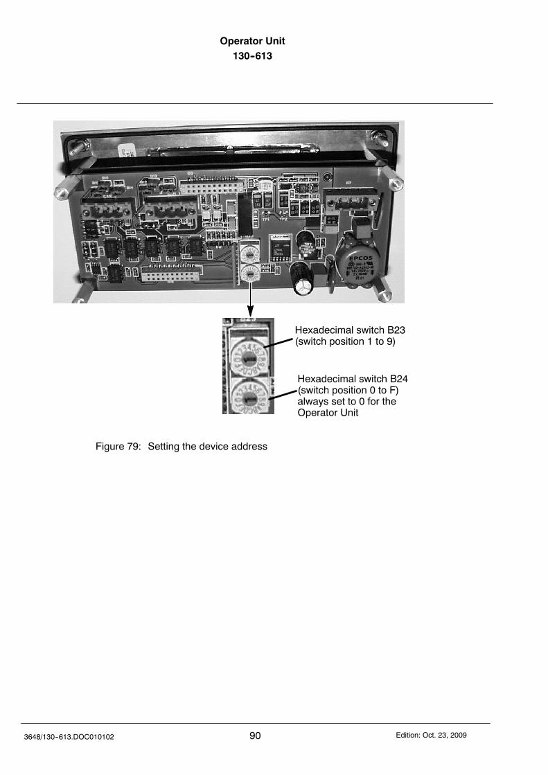
Operator Unit130--613
903648/130--613.DOC010102 Edition: Oct. 23, 2009
Hexadecimal switch B24(switch position 0 to F)always set to 0 for theOperator Unit
Hexadecimal switch B23(switch position 1 to 9)
Figure 79: Setting the device address
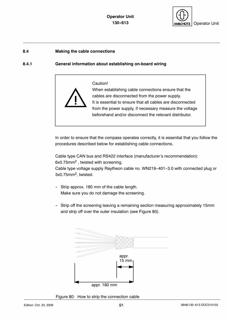
Operator Unit130--613 Operator Unit
91Edition: Oct. 23, 2009 3648/130--613.DOC010102
8.4 Making the cable connections
8.4.1 General information about establishing on-board wiring
Caution!
When establishing cable connections ensure that the
cables are disconnected from the power supply.
It is essential to ensure that all cables are disconnected
from the power supply, if necessary measure the voltage
beforehand and/or disconnect the relevant distributor.
In order to ensure that the compass operates correctly, it is essential that you follow the
procedures described below for establishing cable connections.
Cable type CAN bus and RS422 interface (manufacturer’s recommendation):
6x0.75mm2 , twisted with screening.
Cable type voltage supply Raytheon cable no. WN219--401--3.0 with connected plug or
3x0.75mm2, twisted.
-- Strip approx. 180 mm of the cable length.
Make sure you do not damage the screening.
-- Strip off the screening leaving a remaining section measuring approximately 15mm
and strip off over the outer insulation (see Figure 80).
appr. 180 mm
appr.15 mm
Figure 80: How to strip the connection cable
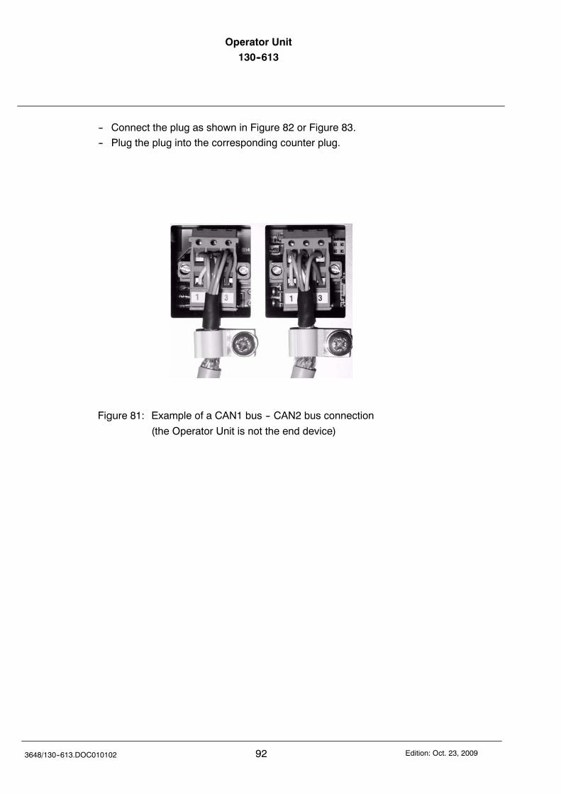
Operator Unit130--613
923648/130--613.DOC010102 Edition: Oct. 23, 2009
-- Connect the plug as shown in Figure 82 or Figure 83.
-- Plug the plug into the corresponding counter plug.
Figure 81: Example of a CAN1 bus -- CAN2 bus connection
(the Operator Unit is not the end device)
Operator Unit130--613 Operator Unit
93Edition: Oct. 23, 2009 3648/130--613.DOC010102
8.4.1.1 Connections to the plug connections
Plug B7Voltage supply
Pin: 3 2 1Pin: 1 2 3Pin: 1 2 3
Plug B1CAN 1
Plug B2CAN 2
1 +9 to 36V DC2 0V3 Casing
1 CAN low2 CAN high3 GND
1 CAN low2 CAN high3 GND
Connection to supply voltageCable no.: WN219--401--3.0
CAN1 or CAN 2 connection to the plug,Operator Unit CAN--Bus connectionwith terminating resistorJumper B13 and Jumper B16 (see section 8.4.1.2)
CAN1high
CAN1low
Connector pin assignment:White +9V to 36V DC.Brown 0VBlack Screen
B1 B2
GND CAN2high
CAN2low
GND
Figure 82: Making the connections to the plugs for supply voltage and CAN-Bus
Operator Unit130--613
943648/130--613.DOC010102 Edition: Oct. 23, 2009
Pin: 1 2 3Pin: 1 2 3
Plug B1RS422Transmit
Plug B2RS422Receive
1 TX--2 TX+3 GND
1 RX--2 RX+3 GND
RS422 connectionPlug B1 = TransmitPlug B2 = Receive
GND
RS 422 TX--RS 422 TX+
GND
RS 422 RX--RS 422 RX+
OPTION (currently not used)
Figure 83: Making the connections to the plugs for RS422 interface (TX and RX)
Operator Unit130--613 Operator Unit
95Edition: Oct. 23, 2009 3648/130--613.DOC010102
8.4.1.2 Plugging in the jumpers
Jumper B15 B16 B14 B12 B13 B11
Figure 84: Plugging in the jumpers
Jumper Pin1--2--3
Default Function
B11Default Plug B1 -- CAN 1
Plug B1 -- RS422
B12Default Plug B1 -- CAN 1
Plug B1 -- RS422
B13CAN bus terminating re-sistor plugged in --on end device only
B14Default Plug B1 -- CAN 2
Plug B1 -- RS422
B15Default Plug B1 -- CAN 2
Plug B1 -- RS422
B16CAN bus terminatingresistor plugged in --on end device only

Operator Unit130--613
963648/130--613.DOC010102 Edition: Oct. 23, 2009
Intentionally left blank
Recommended