Embed Size (px)
Citation preview
The 5GNOW Project Consortium groups the following organizations:
Partner Name Short name Country
FRAUNHOFER-GESELLSCHAFT ZUR FOERDERUNG DER ANGEWANDTEN FORSCHUNG E.V. HHI Germany
ALCATEL LUCENT DEUTSCHLAND AG ALUD Germany
COMMISSARIAT A L ENERGIE ATOMIQUE ET AUX ENERGIES ALTERNATIVES CEA France
IS-WIRELESS ISW Poland
NATIONAL INSTRUMENTS NI Hungary
TECHNISCHE UNIVERSITÄT DRESDEN TUD Germany
Abstract: The screening process of T3.1 will generate a candidate list of waveforms and signal formats, described in this IR3.1.
White Paper
D1.6
‘5GNOW_D1.6_v1.0.docx’
Version: 1.0
Last Update: 13/12/2016
Distribution Level: PU
Distribution level PU = Public, RE = Restricted to a group of the specified Consortium, PP = Restricted to other program participants (including Commission Services), CO= Confidential, only for members of the 5GNOW Consortium (including the Commission Services)

D1.6
5GNOW FP7 – ICT– GA 318555
Page: 2 of 55
The 5GNOW Project Consortium groups the following organizations:
Partner Name Short name Country
FRAUNHOFER-GESELLSCHAFT ZUR FOERDERUNG DER ANGEWANDTEN FORSCHUNG E.V. HHI Germany
ALCATEL LUCENT DEUTSCHLAND AG ALUD Germany
COMMISSARIAT À L’ENERGIE ATOMIQUE ET AUX ENERGIES ALTERNATIVES CEA France
IS-WIRELESS ISW Poland
NATIONAL INSTRUMENTS NI Hungary
TECHNISCHE UNIVERSITÄT DRESDEN TUD Germany
Abstract: This white paper reports transceiver and frame structure concepts and corresponding results from the European FP7 research project 5GNOW. The core is the unified frame structure concept which supports an integrated 5G air interface, capable of dealing both with broadband data services and small packet services within the same band. It is essential for this concept to introduce waveforms which are more robust than OFDM, e.g., with respect to time-frequency misalignment. Encouraging candidate waveform technologies are presented and discussed with respective results. This goes along with the corresponding multiple access technologies using multi-layered signals and advanced multi-user receivers. In addition we introduce new (compressive) random access strategies to enable “one shot transmission” with greatly reduced control signaling particularly for sporadic traffic by orders of magnitude. Finally, we comment on the respective results on the 5GNOW networking interface. The final results of 5GNOW lay the ground for the standardization path towards a new 5G air interface beyond LTE-A.
D1.6
5GNOW FP7 – ICT– GA 318555
Page: 3 of 55
“The research leading to these results has received funding from the European Community's Seventh Framework Programme (FP7/2007-2013) under grant agreement n° 318555”
D1.6
5GNOW FP7 – ICT– GA 318555
Page: 4 of 55
Document Identity
Title: White Paper WP: WP1 WP Leader Priv.-Doz. Dr. Gerhard Wunder Main Editor Priv.-Doz. Dr. Gerhard Wunder Number: D1.6 File name: 5GNOW_D1.6_v1.0 Last Update: Tuesday, December 13, 2016
Revision History
No. Version Edition Author(s) Date
1 0.1 Gerhard Wunder (HHI) 31.03.15
Comments: Template edition and insertion of initial content and input all
2 1.0 All 08.04.15
Comments: Input partners
3 Gerhard Wunder, Martin Kasparick(HHI) 15.04.15
Comments: Final polishing
4 Gerhard Wunder, all 10.05.15
Comments: KPI Boxes
5
Comments:
6
Comments:
7
Comments:
8
Comments:
9
Comments:
10
Comments:
11
Comments:
12
Comments:
13
Comments:
14
Comments:
15
Comments:
D1.6
5GNOW FP7 – ICT– GA 318555
Page: 5 of 55
Table of Contents
1 WHAT DRIVES 5G? ............................................................................................................................................. 6
1.1 5G APPLICATION REQUIREMENTS ............................................................................................................................. 6 1.2 WHY DO WE NEED NEW WAVEFORMS? ..................................................................................................................... 7
1.2.1 Sporadic traffic ............................................................................................................................................ 7 1.2.2 Spectral and temporal fragmentation ........................................................................................................ 8 1.2.3 Real-time constraints .................................................................................................................................. 8
1.3 5GNOW KEY PERFORMANCE INDICATORS ................................................................................................................. 9
2 5GNOW ARCHITECTURE CORE ELEMENTS.........................................................................................................13
2.1 WAVEFORMS ..................................................................................................................................................... 13 2.1.1 Gabor signalling ........................................................................................................................................ 13 2.1.2 5GNOW waveforms .................................................................................................................................. 14
2.2 UNIFIED FRAME STRUCTURE, ONE SHOT TRANSMISSION AND AUTONOMOUS TIMING ADVANCE ........................................... 15 2.3 TEMPORAL AND SPECTRAL FRAGMENTATION ............................................................................................................ 17 2.4 NETWORKING INTERFACE – ROBUSTNESS FRAMEWORK .............................................................................................. 18
2.4.1 Robust CoMP with relaxed time and frequency synchronization .............................................................. 18 2.4.2 Robust cellular iterative interference alignment ...................................................................................... 19
2.5 LOW LATENCY .................................................................................................................................................... 19
3 5GNOW REFERENCE SCENARIOS .......................................................................................................................21
3.1 PRACH SCENARIO .............................................................................................................................................. 21 3.1.1 Performance evaluation ............................................................................................................................ 22
3.2 RELAXED SYNCHRONIZATION AND LOW LATENCY USING GFDM ................................................................................... 27 3.2.1 Performance evaluation for relaxed synchronization ............................................................................... 27 3.2.2 Performance evaluation for low latency ................................................................................................... 30
3.3 UPLINK COMP WITH JOINT RECEPTION ................................................................................................................... 31 3.3.1 Performance evaluation ............................................................................................................................ 32
3.4 MULTIUSER UPLINK ON FRAGMENTED SPECTRUM WITH FBMC .................................................................................... 34 3.4.1 Performance evaluation ............................................................................................................................ 35
3.5 DOWNLINK COMP WITH FBMC ........................................................................................................................... 41 3.5.1 Performance evaluation ............................................................................................................................ 43
4 DEMONSTRATION ............................................................................................................................................47
5 5GNOW IMPACT ON STANDARDIZATION AND EXPLOITATION .........................................................................49
D1.6
5GNOW FP7 – ICT– GA 318555
Page: 6 of 55
1 What drives 5G?
Bigger, faster, higher? The appetite for broadband has clearly fuelled the development of mobile cellular networks. On the other hand, the successful deployment of killer applications in the past 20 years has had a major impact on the markets as well: First and foremost the need for un-tethered telephony and therefore wireless real-time voice communication has dominated the success of cordless phones, followed by first generation (1G) of cellular communications. Soon, incorporated in the second generation (2G), two-way paging implemented by short message service (SMS) text messaging became the second killer application. With the success of wireless local area network (WLAN) technology (i.e. IEEE 802.11), Internet browsing, and the widespread market adoption of laptop computers, Internet data connectivity became interesting for anyone, opening up the opportunity for creating a market for the third killer application in third generation (3G): wireless data connectivity. The logical next step has been the shrinkage of the laptop, merging it with the cellular telephone into today’s smartphones, and offering high bandwidth access to wireless users with the world’s information at their fingertips everywhere and every time. This is the scenario of the current fourth generation (4G), so called Long Term Evolution – Advanced (LTE-A). Smartphones are, undoubtedly, in the focus of service architectures for future mobile access. Now, is there a killer application for 5G on the horizon?
1.1 5G application requirements
Fundamental research for 5G is well under way. The main drivers are: * Internet of Things (IoT): The IoT will certainly play a key role but business models have not started off yet. The main challenge is the scalability problem with more than, say, 100k machine-type communication (MTC) nodes in a cell under the premises of low cost (below 10$ per radio module) and life time (greater than 10 years). The IoT could change the way we see the Internet as a human-to-human interface towards a more general machine-to-machine platform. * Gigabit Wireless Connectivity: For example, users might request quick downloads (e.g. from a wireless data kiosk) of 3D streaming content with data rates in the order of ~100 Mbit/s. Thereby, download times are expected to be 100 times faster, thus, in the order of ~ 10Gbit/s. Gigabit wireless connectivity is also expected in large crowd gatherings with possibly interactively connected devices (smartphones, tablets, etc.). * Tactile Internet: It comprises a vast amount of real-time applications with extremely low latency requirements. Motivated by the tactile sense of the human body which can distinguish latencies of the order of 1ms accuracy, 5G can then be applied for steering and control scenarios implying a disruptive change from today’s content driven communications; popular ideas range from virtual overlay of context information on a display, through robotics and health care to vehicle safety and smart city applications. A 1ms roundtrip time for a typical tactile interaction requires a time budget of maximum 100µs on the physical (PHY) layer. This is far shorter than current wireless cellular systems allow for, missing the target by nearly two orders of magnitude. … and probably many more. From a technical perspective it seems to be utmost challenging to provide uniform service experience to users under the premises of heterogeneous networking or future small cell scenarios. Not only must the network operators be well prepared to take on the challenge of a much higher per-user rate and increasing overall required bandwidth but also to realize service differentiation with very different (virtually contradicting) application requirements. Consequently, the radio access has to be flexible, scalable, content

D1.6
5GNOW FP7 – ICT– GA 318555
Page: 7 of 55
aware, robust, reliable and efficient in terms of energy and spectrum. Actually, with the limitations of current 4G system, this will put further pressure on the common value chains on which the operators rely in order to compensate for investment costs for future user services. Hence, there is a clear motivation for an innovative and in part disruptive re-design of the PHY layer. Before we discuss in the following section why LTE-A OFDM waveforms fall short in view of 5G requirements let us briefly comment on the architectural view (which is not the focus here). Densification of cellular systems as well as a deployment of light base stations together with resource pooling and data aggregation (cloud computing) will take place in the future. It is important to note that 5G application requirements and cloud-based architectural elements are not fully independent. For example, the Tactile Internet with its extremely low latency requirements requires the baseband processing unit(s) relatively near to the terminals with its real-time app. This means for such application the cloud cannot be in a remote area but must be within certain radius of the application (hence, by speed of light and 1ms real-time constraint within 30km radius).
1.2 Why do we need new waveforms?
The main hypothesis of this article is that, specifically, the underlying design principles –synchronism and orthogonality– of the PHY layer of today’s LTE-A radio access network constitute a major obstacle for the envisioned service architecture. Orthogonality means that in case of perfect synchronized transmission no crosstalk occurs. Moreover, synchronicity means that the senders operate with a common clock for their processing. OFDM modulation keeps the subcarrier waveforms orthogonal even after the channel, provided the DFT window can be properly adjusted by suitable synchronization mechanism, which is then near optimal processing in a single cell. However, as soon as the orthogonality is destroyed, e.g. by random access or multi-cell operation, the distortion accumulates without bounds in OFDM. This is due to the so-called reproducing Dirichlet kernel sin(Nx)/sin(x) of OFDM which quickly approaches the sin(x)/x kernel for large N where N is the number of subcarriers. Hence, we believe it is better to abandon orthogonality altogether and control the impairments instead. Let us discuss several intriguing examples:
1.2.1 Sporadic traffic
Sporadic traffic generating devices (e.g. MTC devices in the IoT) should not be forced to be integrated into the bulky synchronization procedure of LTE-A PHY layer random access, which has been deliberately designed to meet orthogonal constraints. Instead, they optimally should be able to awake only occasionally and transmit their message right away only coarsely synchronized. By doing so MTC traffic would be removed from standard uplink data pipes with drastically reduced signalling overhead. Therefore, alleviating the synchronism requirements can significantly improve operational capabilities and network performance as well as user experience and life time of autonomous MTC nodes. Interestingly, sporadic access poses another significant challenge to mobile access networks due to an operation known as fast dormancy. Fast dormancy is used by smartphone manufacturers to save battery power by using the feature that a mobile can break ties to the network individually and as soon as a data piece is delivered the smartphone changes from active into idle state. Consequently, when the mobile has to deliver more pieces of data it will always go through the complete synchronization procedure again. Actually, this can happen several hundred times a day resulting in significant control signalling growth and network congestion threat. A rough estimation yields that 2k control resource elements (i.e. a subcarrier) are necessary to deliver one data resource element.
D1.6
5GNOW FP7 – ICT– GA 318555
Page: 8 of 55
We conclude that sporadic traffic must be carried by non-orthogonal waveforms for asynchronous signalling in the uplink and specifically in an uplink random access channel (RACH). We will outline in Section 3.1 a suitable sparse signal processing concept together with the new waveforms to efficiently deal with the sporadic traffic and control signalling problem. In fact the ratio of control and data can be actually reversed by such concept to approach a value below 5% within 1ms sub-frame.
1.2.2 Spectral and temporal fragmentation
Due to fragmentation, spectrum is scarce and expensive but also underutilized: this is commonly referred to as the spectrum paradox. Therefore, carrier aggregation will be implemented to achieve much higher rates by variably aggregating non-contiguous frequency bands [2]. Carrier aggregation implies the use of separate RF front ends accessing different channels thereby reinforcing the attraction of isolated frequency bands such as the L-Band. Actually, the search for new spectrum is very active in Europe and in the USA in order to provide mobile broadband expansion. It includes the opportunistic use of spectrum, which has been an interesting research area in wireless communications in the past decade. Moreover, techniques to detect and assess channel vacancy using cognitive radio could well make new business models possible in the future. The first real implementation will start with the exploration of TV white spaces in the USA. Combined with the preparation of the on-going regulatory framework in Europe, opportunistic use of spectrum can address a 5G market if it overcomes, with spectrum agility, the rigorous implementation requirements of low out of band radiation for protection of legacy systems [2]. LTE-A waveform imposes generous guard bands to other legacy networks to satisfy spectral mask requirements which either severely deteriorate spectral efficiency or even prevent band usage at all, which is again an artefact of strict orthogonality and synchronism constraints within the PHY layer. Moreover, in a scenario with uncoordinated interference from Pico- or Femto-cells and highly overlapping coverage, it seems illusive to provide the degree of coordination to maintain synchronism and orthogonality in the network calling for new waveforms as well. In addition to spectral fragmentation, temporal fragmentation is another key issue, e.g. due to sporadic access e.g. in the asynchronous uplink RACH. Notably, asynchronous signaling matters also in the downlink in the context of cooperative multipoint (CoMP). In conclusion, such 5G scenarios where multiple users are allocated a pool of frequencies with relaxed (or even no) synchronization in time must be addressed by new waveforms. Such waveforms must implement sharp frequency notches and tight spectral masks in order not to interfere with other legacy systems, must be robust to asynchronous signalling and handle un-coordinated interference. Traditional OFDM schemes are not suited due to the inflexible handling of cyclic prefixes (CPs), cyclic suffixes (CS) and guard intervals (GI) as well as poor spectral localization. In Section 2.4.1 we discuss waveforms achieving 100x better localization (e.g. 35 dB side lobe with LTE-A OFDM compared to 55dB side lobe with Filter Bank Multi-Carrier (FBMC) [8]) which makes then a real difference for CoMP transmissions.
1.2.3 Real-time constraints
4G systems offer latencies of multiple 10ms between terminal and base station which originate from resource scheduling, frame processing, re-transmission procedures, etc. However, future application scenarios such as the Tactile Internet scenario require extremely low latency matched with the human tactile sense. In such an environment, a massive number of distributed sensors and actuators will be connected to enable real-time tactile interaction in an augmented way. Sharing the medium becomes an additional challenge and imposes short wake up cycles on the nodes and the use of burst transmission. Instead of consuming spectrum and power resources by introducing sophisticated algorithms to reach synchronism, an asynchronous approach appears promising. In order to achieve ultra-low latency, each and every element of the communication and control chain must be optimized. Focusing on the PHY layer, LTE-A system supports different granularity of scheduling
D1.6
5GNOW FP7 – ICT– GA 318555
Page: 9 of 55
resources in a fixed transmission time interval (TTI) of 1ms. TTI represents an inherent lower bound of the LTE-A system’s PHY latency. Clearly, as the time budget on PHY layer in the Tactile Internet scenario is 100 s maximum, frame duration must be reduced and LTE-A with its OFDM symbol duration of 67 s is not an option. In order to discuss possible alternatives assume 20µs symbol duration. This means that the frame composed of five symbols, allowing for an appropriated frame structure for random channel access. Considering e.g. a 1km cell range, the expected delay spread is around 3µs, and, thus, 4µs CP is required to ensure an inter-symbol interference (ISI) free scenario. Hence, use of conventional OFDM entails 20% loss in spectral efficiency. A non-orthogonal waveform which allows for transmitting multiples symbols with a single CP relaxes such strict time domain requirements. Another major drawback caused by short frames is the fixed bandwidth increment required to keep a given throughput. A flexible non-orthogonal multicarrier waveform allowing also for inter-carrier interference (ICI) can use non-proportional sub-carrier spacing to accommodate the necessary bandwidth. Alternatively, non-contiguous spectrum can be aggregated again enabled by the low out-of-band emissions of the non-orthogonal waveform. Short frames have also positive impact on mobility support or operational frequencies. LTE-A has been designed to support Doppler spread of 100Hz caused by 50km/h mobility. By reducing the frame duration it is possible to support either higher mobility or to operate in higher frequencies range. Finally, a short frame brings benefits to higher layers: Although the low latency requirements of real-time applications demands for a robust PHY layer to avoid retransmissions of the frame, applications may desire acknowledged signaling. A short frame will enable the implementation of less time-consuming retransmissions algorithms. Summarizing, although OFDM could be tuned to address different granularity of scheduling resources, there is no mode in current LTE-A standard that can adapt to the latency requirements of real-time services running on top. If symbol duration is reduced to achieve very short roundtrip delays, the CPs, CSs, and GIs cannot be scaled accordingly without severely compromising spectral efficiency or the cell size. Required flexibility can only be achieved with new waveforms as we show in Section 2.5.
1.3 5GNOW key performance indicators
LTE-A is used in 5GNOW project as a benchmark. Obtained results are compared to the performance of a 3GPP LTE-A system. The project focus is to improve characteristics of current system in six main areas which are gathered in Table 1.3.1, namely:
Capacity (downlink),
Signalling overhead (downlink),
MTC signalling overhead (uplink),
Out-of-band radiation,
Local oscillator accuracy requirement. Detailed description of KPIs can be found in following section. Table 1.3.1 contains description of the performance of current system used as a benchmark (LTE-A) and expected improvement in relation to this benchmark. The performance of the approaches will be compared to a standard LTE-A air interface using the indicators summarized in the KPI table below.
D1.6
5GNOW FP7 – ICT– GA 318555
Page: 10 of 55
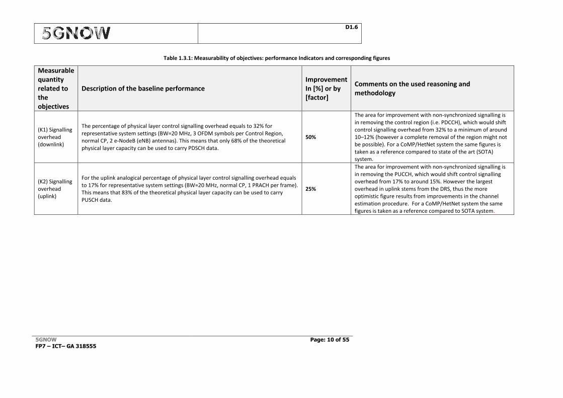
Table 1.3.1: Measurability of objectives: performance Indicators and corresponding figures
Measurable quantity related to the objectives
Description of the baseline performance Improvement In [%] or by [factor]
Comments on the used reasoning and methodology
(K1) Signalling overhead (downlink)
The percentage of physical layer control signalling overhead equals to 32% for representative system settings (BW=20 MHz, 3 OFDM symbols per Control Region, normal CP, 2 e-NodeB (eNB) antennas). This means that only 68% of the theoretical physical layer capacity can be used to carry PDSCH data.
50%
The area for improvement with non-synchronized signalling is in removing the control region (i.e. PDCCH), which would shift control signalling overhead from 32% to a minimum of around 10–12% (however a complete removal of the region might not be possible). For a CoMP/HetNet system the same figures is taken as a reference compared to state of the art (SOTA) system.
(K2) Signalling overhead (uplink)
For the uplink analogical percentage of physical layer control signalling overhead equals to 17% for representative system settings (BW=20 MHz, normal CP, 1 PRACH per frame). This means that 83% of the theoretical physical layer capacity can be used to carry PUSCH data.
25%
The area for improvement with non-synchronized signalling is in removing the PUCCH, which would shift control signalling overhead from 17% to around 15%. However the largest overhead in uplink stems from the DRS, thus the more optimistic figure results from improvements in the channel estimation procedure. For a CoMP/HetNet system the same figures is taken as a reference compared to SOTA system.
D1.6
5GNOW FP7 – ICT– GA 318555
Page: 11 of 55
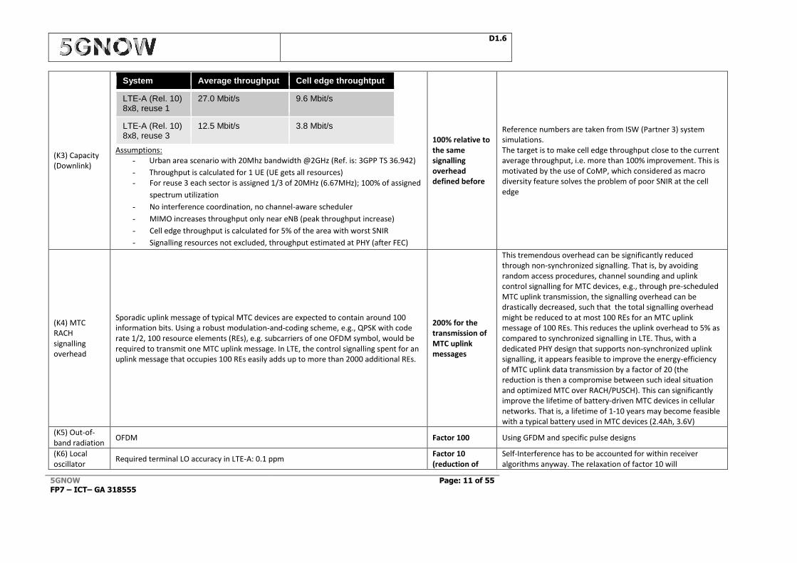
(K3) Capacity (Downlink)
System Average throughput Cell edge throughtput
LTE-A (Rel. 10) 8x8, reuse 1
27.0 Mbit/s 9.6 Mbit/s
LTE-A (Rel. 10) 8x8, reuse 3
12.5 Mbit/s 3.8 Mbit/s
Assumptions: - Urban area scenario with 20Mhz bandwidth @2GHz (Ref. is: 3GPP TS 36.942)
- Throughput is calculated for 1 UE (UE gets all resources) - For reuse 3 each sector is assigned 1/3 of 20MHz (6.67MHz); 100% of assigned
spectrum utilization
- No interference coordination, no channel-aware scheduler
- MIMO increases throughput only near eNB (peak throughput increase)
- Cell edge throughput is calculated for 5% of the area with worst SNIR
- Signalling resources not excluded, throughput estimated at PHY (after FEC)
100% relative to the same signalling overhead defined before
Reference numbers are taken from ISW (Partner 3) system simulations. The target is to make cell edge throughput close to the current average throughput, i.e. more than 100% improvement. This is motivated by the use of CoMP, which considered as macro diversity feature solves the problem of poor SNIR at the cell edge
(K4) MTC RACH signalling overhead
Sporadic uplink message of typical MTC devices are expected to contain around 100 information bits. Using a robust modulation-and-coding scheme, e.g., QPSK with code rate 1/2, 100 resource elements (REs), e.g. subcarriers of one OFDM symbol, would be required to transmit one MTC uplink message. In LTE, the control signalling spent for an uplink message that occupies 100 REs easily adds up to more than 2000 additional REs.
200% for the transmission of MTC uplink messages
This tremendous overhead can be significantly reduced through non-synchronized signalling. That is, by avoiding random access procedures, channel sounding and uplink control signalling for MTC devices, e.g., through pre-scheduled MTC uplink transmission, the signalling overhead can be drastically decreased, such that the total signalling overhead might be reduced to at most 100 REs for an MTC uplink message of 100 REs. This reduces the uplink overhead to 5% as compared to synchronized signalling in LTE. Thus, with a dedicated PHY design that supports non-synchronized uplink signalling, it appears feasible to improve the energy-efficiency of MTC uplink data transmission by a factor of 20 (the reduction is then a compromise between such ideal situation and optimized MTC over RACH/PUSCH). This can significantly improve the lifetime of battery-driven MTC devices in cellular networks. That is, a lifetime of 1-10 years may become feasible with a typical battery used in MTC devices (2.4Ah, 3.6V)
(K5) Out-of-band radiation
OFDM Factor 100 Using GFDM and specific pulse designs
(K6) Local oscillator
Required terminal LO accuracy in LTE-A: 0.1 ppm Factor 10 (reduction of
Self-Interference has to be accounted for within receiver algorithms anyway. The relaxation of factor 10 will
D1.6
5GNOW FP7 – ICT– GA 318555
Page: 12 of 55
accuracy the required terminal LO accuracy)
approximately cause the same interference as it is inherent in GFDM
D1.6
5GNOW FP7 – ICT– GA 318555
Page: 13 of 55
2 5GNOW Architecture Core Elements
2.1 Waveforms
2.1.1 Gabor signalling
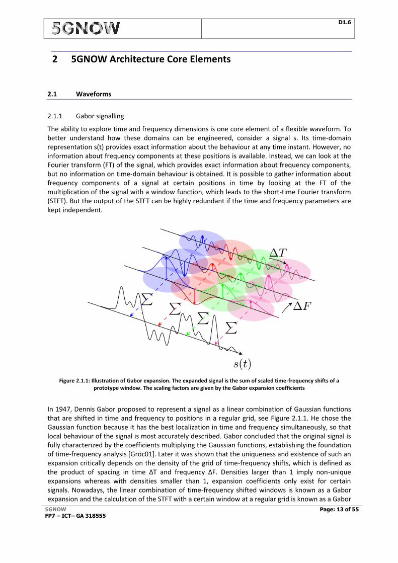
The ability to explore time and frequency dimensions is one core element of a flexible waveform. To better understand how these domains can be engineered, consider a signal s. Its time-domain representation s(t) provides exact information about the behaviour at any time instant. However, no information about frequency components at these positions is available. Instead, we can look at the Fourier transform (FT) of the signal, which provides exact information about frequency components, but no information on time-domain behaviour is obtained. It is possible to gather information about frequency components of a signal at certain positions in time by looking at the FT of the multiplication of the signal with a window function, which leads to the short-time Fourier transform (STFT). But the output of the STFT can be highly redundant if the time and frequency parameters are kept independent.
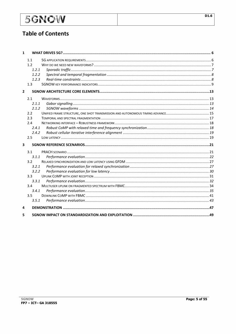
Figure 2.1.1: Illustration of Gabor expansion. The expanded signal is the sum of scaled time-frequency shifts of a prototype window. The scaling factors are given by the Gabor expansion coefficients
In 1947, Dennis Gabor proposed to represent a signal as a linear combination of Gaussian functions that are shifted in time and frequency to positions in a regular grid, see Figure 2.1.1. He chose the Gaussian function because it has the best localization in time and frequency simultaneously, so that local behaviour of the signal is most accurately described. Gabor concluded that the original signal is fully characterized by the coefficients multiplying the Gaussian functions, establishing the foundation of time-frequency analysis [Gröc01]. Later it was shown that the uniqueness and existence of such an expansion critically depends on the density of the grid of time-frequency shifts, which is defined as the product of spacing in time ∆T and frequency ∆F. Densities larger than 1 imply non-unique expansions whereas with densities smaller than 1, expansion coefficients only exist for certain signals. Nowadays, the linear combination of time-frequency shifted windows is known as a Gabor expansion and the calculation of the STFT with a certain window at a regular grid is known as a Gabor

D1.6
5GNOW FP7 – ICT– GA 318555
Page: 14 of 55
transform [BHW98]. Expansion and transform windows are in a dual relation, i.e. the coefficients which are used to expand to a certain signal with a given window are provided by the Gabor transform of that signal with the dual window. In case the window and its dual are equal, the window is said to be orthogonal and expansion and transform reduce to well-known orthogonal expansion series. A prominent example is OFDM, which performs a Gabor expansion using a finite discrete set of rectangular window functions with length T S in time and shifts of 1/T S in the frequency grid. In discrete Gabor expansion and transform, which in the OFDM case is the discrete Fourier transform (DFT), all signals are assumed to be periodic in time and frequency. However, non-periodic time-continuous scenarios can be approximated by choosing long frames and appropriate sampling frequencies.
2.1.2 5GNOW waveforms
In 5GNOW several waveform approaches have been developed [WJK+14][5GNOWD3.1] [5GNOWD3.2] [5GNOWD3.3]. Altogether 5GNOW proposes a multicarrier Gabor-like structure for 5G coming in different variants to be operated possibly in parallel in the unified frame structure and optimized parameter settings. We have the following findings:
In UFMC [VWS+13], a pulse shaping filter is applied to a group of conventional OFDM subcarriers. This approach can be also represented in the context of the Gabor frame. UFMC is very close to OFDM in its design with (quasi-)orthogonal reception, which allows to directly apply all OFDM know-how from MIMO, channel estimation etc. Its key difference to the other waveform candidates is, instead of applying a per-subcarrier filtering, entire groups of subcarriers are filtered. The motivation is that ICI occurs between groups of subcarriers. This allows to shortening the filter for efficiency and latency reasons.
GFDM [MMG+14] can be seen as a more generic block oriented filtered multicarrier system that follows the Gabor principles. Basically, the parameterization of the waveform directly influences i) transmitter window; ii) time-frequency grid structure; as well as iii) transform length and can hence provide means to emulate a multitude of conventional multi-carrier systems. GFDM allows a flexible parametrization. In its default parameter set it is non-orthogonal and aims at very short frame durations for low latency support. 5GNOW has extended the theoretical basis for such systems allowing for transmission at “critical density” even if the (continuous-time) Balian-Low theorem is violated. The reason is the block cyclic structure (similar to the BFDM concept) which makes it possible to “exploit” discrete artefacts in the concept. Notably, the non-orthogonality requires possibly advanced receivers for removing self-interference.
FBMC-OQAM [Farh11][DBC+14] belongs to the family of filterbank based waveforms. The principles revolve around filtering the subcarriers in the system while retaining orthogonality. As the name suggests, the essence of this candidate waveform is offset modulation, which allows avoiding interference between real and imaginary signal components. FBMC in its default parameter setting has the strongest spectral localization of the waveform candidates. This comes along with long filter durations and usage of offset-QAM for efficiency reasons. FBMC makes use of a very advanced theory of Wilson bases allowing orthogonal transmission even for systems operating at the critical density.
BFDM [KWJ+14][WKJ15a][WKJ15b][WGS15] directly relates to the theory of Gabor frames. Signal generation can be considered a Gabor expansion while the bi-orthogonal receive filter constitutes a Gabor transform. BFDM has a pulse design which is optimized for sparsity-aware detection techniques, making it appealing for advanced receivers for D-PRACH. BFDM allows for “quasi-OFDM” like operation with bi-orthogonal pulses (thereby giving up transmit
D1.6
5GNOW FP7 – ICT– GA 318555
Page: 15 of 55
orthogonality) so that many OFDM concepts can be transferred but sensitivity to temporal and spectral asynchronisms is dramatically improved particularly in the context of ATA.
These waveforms have been thoroughly investigated within 5GNOW, each particularly related to certain scenarios as described in detail in the next section.
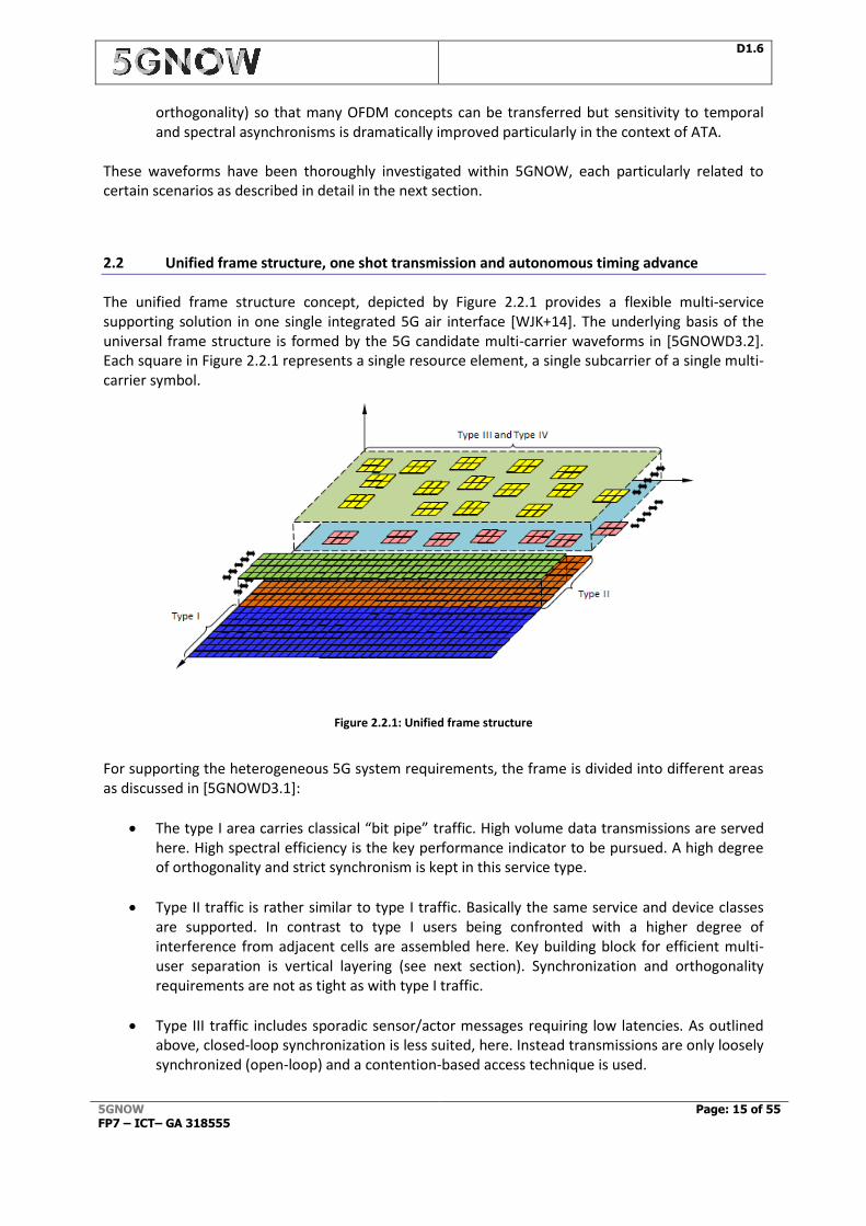
2.2 Unified frame structure, one shot transmission and autonomous timing advance
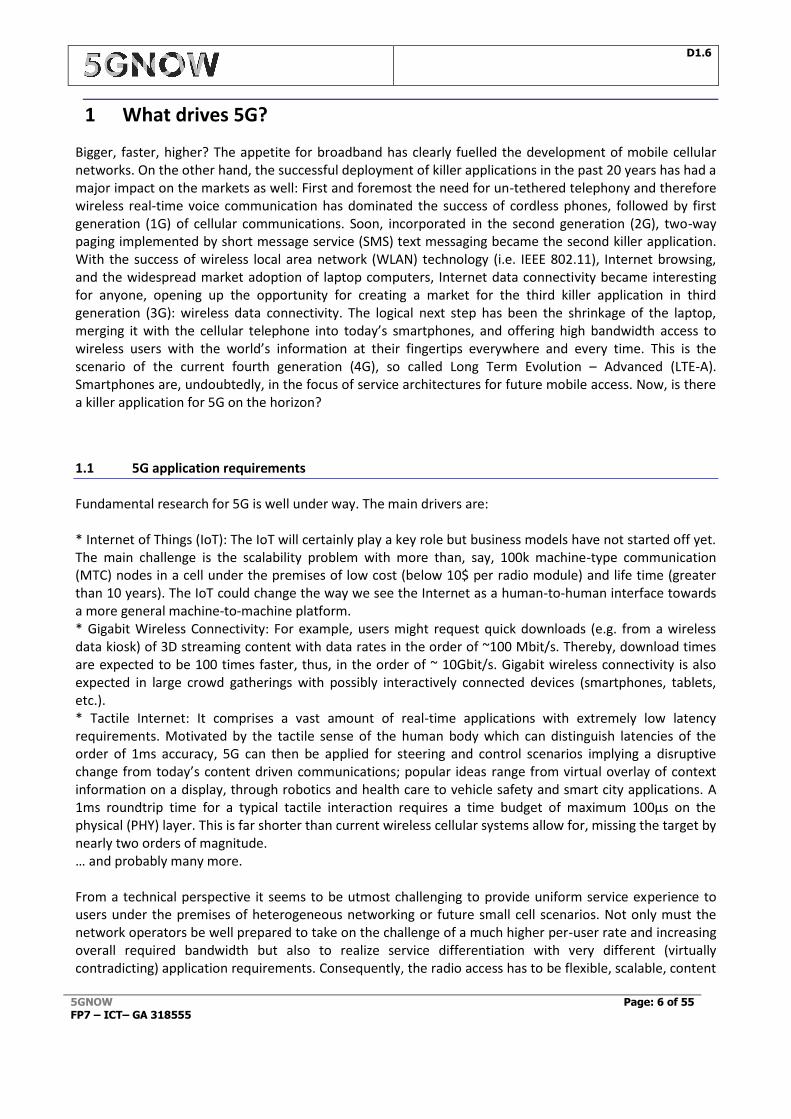
The unified frame structure concept, depicted by Figure 2.2.1 provides a flexible multi-service supporting solution in one single integrated 5G air interface [WJK+14]. The underlying basis of the universal frame structure is formed by the 5G candidate multi-carrier waveforms in [5GNOWD3.2]. Each square in Figure 2.2.1 represents a single resource element, a single subcarrier of a single multi-carrier symbol.
Figure 2.2.1: Unified frame structure
For supporting the heterogeneous 5G system requirements, the frame is divided into different areas as discussed in [5GNOWD3.1]:
The type I area carries classical “bit pipe” traffic. High volume data transmissions are served here. High spectral efficiency is the key performance indicator to be pursued. A high degree of orthogonality and strict synchronism is kept in this service type.
Type II traffic is rather similar to type I traffic. Basically the same service and device classes are supported. In contrast to type I users being confronted with a higher degree of interference from adjacent cells are assembled here. Key building block for efficient multi-user separation is vertical layering (see next section). Synchronization and orthogonality requirements are not as tight as with type I traffic.
Type III traffic includes sporadic sensor/actor messages requiring low latencies. As outlined above, closed-loop synchronization is less suited, here. Instead transmissions are only loosely synchronized (open-loop) and a contention-based access technique is used.
D1.6
5GNOW FP7 – ICT– GA 318555
Page: 16 of 55
Type IV traffic includes sporadic sensor/actor messages tolerating high latencies. Multiple signal layers are used, either using spreading or IDMA [PLK06][CSW14].
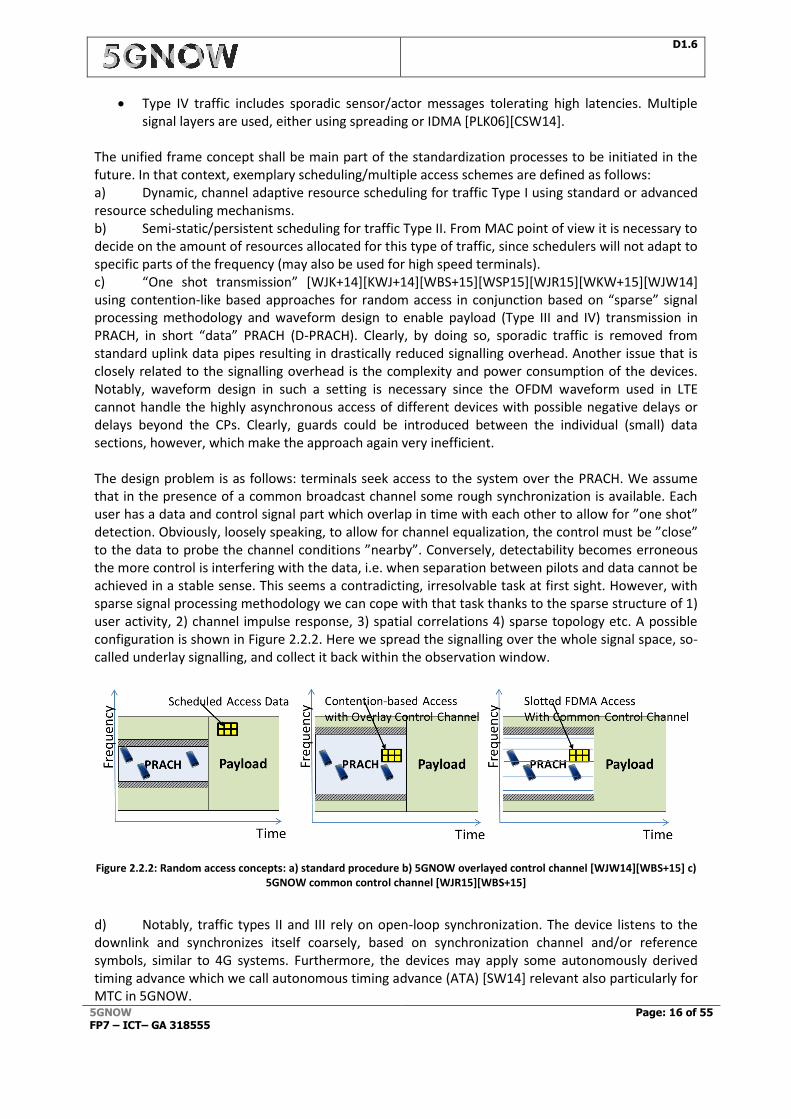
The unified frame concept shall be main part of the standardization processes to be initiated in the future. In that context, exemplary scheduling/multiple access schemes are defined as follows: a) Dynamic, channel adaptive resource scheduling for traffic Type I using standard or advanced resource scheduling mechanisms. b) Semi-static/persistent scheduling for traffic Type II. From MAC point of view it is necessary to decide on the amount of resources allocated for this type of traffic, since schedulers will not adapt to specific parts of the frequency (may also be used for high speed terminals). c) “One shot transmission” [WJK+14][KWJ+14][WBS+15][WSP15][WJR15][WKW+15][WJW14] using contention-like based approaches for random access in conjunction based on “sparse” signal processing methodology and waveform design to enable payload (Type III and IV) transmission in PRACH, in short “data” PRACH (D-PRACH). Clearly, by doing so, sporadic traffic is removed from standard uplink data pipes resulting in drastically reduced signalling overhead. Another issue that is closely related to the signalling overhead is the complexity and power consumption of the devices. Notably, waveform design in such a setting is necessary since the OFDM waveform used in LTE cannot handle the highly asynchronous access of different devices with possible negative delays or delays beyond the CPs. Clearly, guards could be introduced between the individual (small) data sections, however, which make the approach again very inefficient. The design problem is as follows: terminals seek access to the system over the PRACH. We assume that in the presence of a common broadcast channel some rough synchronization is available. Each user has a data and control signal part which overlap in time with each other to allow for ”one shot” detection. Obviously, loosely speaking, to allow for channel equalization, the control must be ”close” to the data to probe the channel conditions ”nearby”. Conversely, detectability becomes erroneous the more control is interfering with the data, i.e. when separation between pilots and data cannot be achieved in a stable sense. This seems a contradicting, irresolvable task at first sight. However, with sparse signal processing methodology we can cope with that task thanks to the sparse structure of 1) user activity, 2) channel impulse response, 3) spatial correlations 4) sparse topology etc. A possible configuration is shown in Figure 2.2.2. Here we spread the signalling over the whole signal space, so-called underlay signalling, and collect it back within the observation window.
Figure 2.2.2: Random access concepts: a) standard procedure b) 5GNOW overlayed control channel [WJW14][WBS+15] c) 5GNOW common control channel [WJR15][WBS+15]
d) Notably, traffic types II and III rely on open-loop synchronization. The device listens to the downlink and synchronizes itself coarsely, based on synchronization channel and/or reference symbols, similar to 4G systems. Furthermore, the devices may apply some autonomously derived timing advance which we call autonomous timing advance (ATA) [SW14] relevant also particularly for MTC in 5GNOW.
D1.6
5GNOW FP7 – ICT– GA 318555
Page: 17 of 55
2.3 Temporal and spectral fragmentation
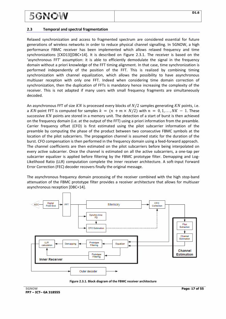
Relaxed synchronization and access to fragmented spectrum are considered essential for future generations of wireless networks in order to reduce physical channel signalling. In 5GNOW, a high performance FBMC receiver has been implemented which allows relaxed frequency and time synchronizations [CKD13][DBC+14]. It is described on Figure 2.3.1. The receiver is based on the ‘asynchronous FFT’ assumption: it is able to efficiently demodulate the signal in the frequency domain without a priori knowledge of the FFT timing alignment. In that case, time synchronization is performed independently of the position of the FFT. This is realized by combining timing synchronization with channel equalization, which allows the possibility to have asynchronous multiuser reception with only one FFT. Indeed when considering time domain correction of synchronization, then the duplication of FFTs is mandatory hence increasing the complexity of the receiver. This is not adapted if many users with small frequency fragments are simultaneously decoded. An asynchronous FFT of size 𝐾𝑁 is processed every blocks of 𝑁/2 samples generating 𝐾𝑁 points, i.e. a 𝐾𝑁-point FFT is computed for samples 𝑘 = (𝑛 + 𝑚 × 𝑁/2) with 𝑛 = 0, 1, . . . , 𝑁𝐾 − 1. These successive 𝐾𝑁 points are stored in a memory unit. The detection of a start of burst is then achieved on the frequency domain (i.e. at the output of the FFT) using a priori information from the preamble. Carrier frequency offset (CFO) is first estimated using the pilot subcarrier information of the preamble by computing the phase of the product between two consecutive FBMC symbols at the location of the pilot subcarriers. The propagation channel is assumed static for the duration of the burst. CFO compensation is then performed in the frequency domain using a feed-forward approach. The channel coefficients are then estimated on the pilot subcarriers before being interpolated on every active subcarrier. Once the channel is estimated on all the active subcarriers, a one-tap per subcarrier equalizer is applied before filtering by the FBMC prototype filter. Demapping and Log-Likelihood Ratio (LLR) computation complete the inner receiver architecture. A soft-input Forward Error Correction (FEC) decoder recovers finally the original message. The asynchronous frequency domain processing of the receiver combined with the high stop-band attenuation of the FBMC prototype filter provides a receiver architecture that allows for multiuser asynchronous reception [DBC+14].
Figure 2.3.1. Block diagram of the FBMC receiver architecture

D1.6
5GNOW FP7 – ICT– GA 318555
Page: 18 of 55
It should be mentioned that the complexity of this receiver is increased compared to the classical FBMC receiver based on time domain PPN (PolyPhase Network) [Bel10]. The FFT processor works on KN points while 𝑁 points are required for PPN+FFT architecture. As the sampling frequency is small compared to current circuit clock processing the complexity of a 𝐾𝑁-point FFT is close to a 𝑁-point FFT. However, the memory resources required are 𝐾 times more important for the proposed architecture.
2.4 Networking interface – Robustness framework
2.4.1 Robust CoMP with relaxed time and frequency synchronization
Cooperation between cells in the DL (i.e. CoMP) aims at improving the QoS of users at cell edges. Fourth generation of cellular systems can benefit from the presence of the OFDM Guard Interval (GI) to deal with different times of arrival of eNBs’ signals at the UE. Nevertheless, the further the eNBs are from the UE, the longer must be the GI, reducing the system capacity dramatically. For the next generation of cellular systems, non-orthogonal waveforms are strong candidates. FBMC is one of these waveforms. In addition to the excellent frequency localization of its prototype filter, it does not require the use of a GI. The system capacity is thus increased (for long enough frames). However, for CoMP, a robust design of a receiver against time delays between eNBs’ signals becomes crucial. A receiver with robust algorithms, for both time and frequency synchronizations, have therefore been proposed for DL CoMP with FBMC. The chronology of the synchronization process is illustrated on Figure 2.4.1 (bottom) and the system on Figure 2.4.1 (top). Here 𝛿Δf is the Carrier Frequency Offset between the BSs and the UE; 𝜏 is the delay at the UE of eNB2 compared to eNB1 and 𝜑𝑖 is the initial phase of eNBi.
Figure 2.4.1 (Top) DL CoMP system. (Bottom) Chronology of the proposed time and frequency synchronization process
Delays up to 120 samples, i.e. 7.8 µs (2340 meters with the LTE parameters) can be tolerated at the UE without any estimation or correction, with the proposed pilot scheme [CKD13] [CKW+14]. Delays higher than 7.8 µs are unlikely to occur in most of cooperative systems. Nevertheless, in order to decrease the effects of phase rotations of the channel due to high delays, an algorithm was proposed to estimate the delay. The algorithm was demonstrated to be very robust to non-detections and false alarms with very limited feedback information. Frequency synchronization (estimation and compensation of the CFO) with FBMC can be entirely realized at the UE in the frequency domain. Thanks to the very good frequency localization of FBMC carriers, the most part of the CFO can be easily and accurately estimated thanks to a simple energy
D1.6
5GNOW FP7 – ICT– GA 318555
Page: 19 of 55
detection algorithm on the preamble carriers. The residual part of the CFO after this estimation is lower than 100/(2𝐾)% of carrier spacing (with 𝐾 the FBMC overlapping factor) [CKD13]. The same method applied to OFDM would lead to a much higher residual CFO of 50 % at maximum. The proposed algorithm for estimation of the residual part was shown to have good performance with reduced complexity. The correction of the CFO requires no feedback from the UE to the BSs.
2.4.2 Robust cellular iterative interference alignment
The major limiting factor in 4G CoMP (OFDM) systems is properly sharing channel state information (CSI) and other overhead among cells. This so-called limited feedback problem has been greatly analysed for multiuser MIMO [CJK+10], as well as for joint transmission [KG12] in terms of the rate distance Δ𝑟𝑚 of node 𝑚 to capacity subject to some offset independent of SNR. Hence, these results essentially provide a systems' degrees-of-freedom (DoF) analysis assuming infinite SNR regime. It is now highly relevant how the overall throughput scales with the feedback overhead for both practical systems in more relevant regimes. Classical analyses in literature reveals a scaling of the throughput degradation in the number of
feedback bits in the order of 2−𝑏(𝑝)/(𝑁𝑇−1) where 𝑁𝑇 denotes the number of transmit antennas while 𝑝 and 𝑏 = 𝑏(𝑝) denote the SNR and feedback budget per user and resource block (in bits/channel use) as a function of SNR, respectively. 5GNOW studies [SWJ14][SWJ13][WRS+13][WSJ12] [SW12a][SW12b][SW12c][SW11a][SW11b][SW10][WSJ+10a][WSJ+10b][SJW09] indicate that these results are fragile and that, in fact, the trade-offs actually behave very differently in more practical regimes. Classical analysis of the scaling of per-node capacity in the number of feedback bits falls short due to several reasons: (i) it assumes an infinite SNR regime where achieving DoF is optimal. In this operational regime, interference mitigation instead of signal enhancement is the primary goal; (ii) it asserts that the transmitter can optimally allocate rates while, in practice, the transmitter allocates rates according to the available CSI and corresponding scheduler decisions (real versus ideal link adaption); (iii) the optimal scheduling decision is known a priori, which is unrealistic since limited feedback not only affects the choice of spatial precoding but also user selection and resource allocation. In [SWJ13][SWJ14] it is shown that for any finite SNR point 𝑝 and for any scaling in 𝑏 the per-node
capacity degradation is actually in the order of 2−𝑏/(2(𝑁𝑇−1)) , which actually doubles the required number of bits. In addition, in [SWJ13, SWJ14] a scheme termed robust cellular iterative interference alignment generalizing the algorithms in [SW11, SW12a/b] which actually achieves this scaling has been developed.
2.5 Low latency
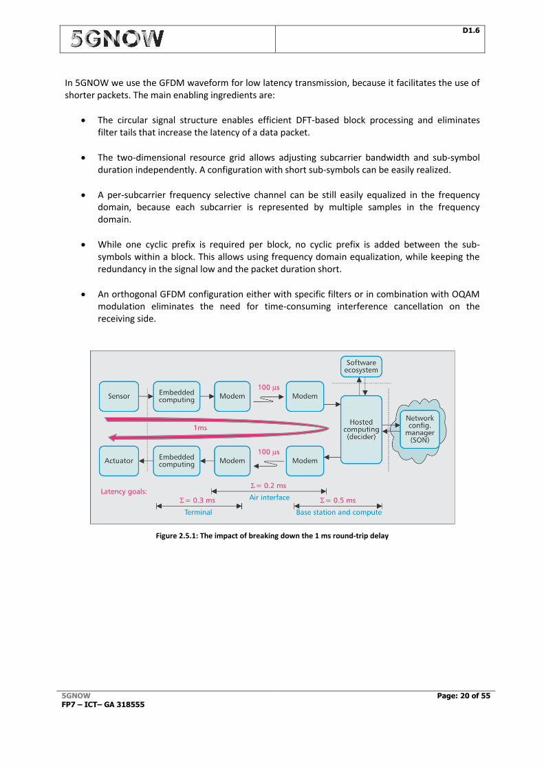
Real time is a highly subjective term and depends on the use case. We define a service to be real time when the communication response time is faster than the time constants of the application. While today all major applications are hosted and run in the cloud, users want to maintain the responsiveness of locally executed software. Current wireless cellular systems miss this target by nearly two orders of magnitude. Figure 2.5.1 shows one possible latency budget over a communications chain, taking into account the latencies from the sensor through the operating system, the wireless/cellular protocol stack, the physical layer of terminal and base station, the base station’s protocol stack, the trunk line to the compute server, the operating system of the server, the network within the server to the processor, the computation, and back through the equivalent chain to the actuator.
D1.6
5GNOW FP7 – ICT– GA 318555
Page: 20 of 55
In 5GNOW we use the GFDM waveform for low latency transmission, because it facilitates the use of shorter packets. The main enabling ingredients are:
The circular signal structure enables efficient DFT-based block processing and eliminates filter tails that increase the latency of a data packet.
The two-dimensional resource grid allows adjusting subcarrier bandwidth and sub-symbol duration independently. A configuration with short sub-symbols can be easily realized.
A per-subcarrier frequency selective channel can be still easily equalized in the frequency domain, because each subcarrier is represented by multiple samples in the frequency domain.
While one cyclic prefix is required per block, no cyclic prefix is added between the sub-symbols within a block. This allows using frequency domain equalization, while keeping the redundancy in the signal low and the packet duration short.
An orthogonal GFDM configuration either with specific filters or in combination with OQAM modulation eliminates the need for time-consuming interference cancellation on the receiving side.
Figure 2.5.1: The impact of breaking down the 1 ms round-trip delay
D1.6
5GNOW FP7 – ICT– GA 318555
Page: 21 of 55
3 5GNOW Reference Scenarios
3.1 PRACH scenario
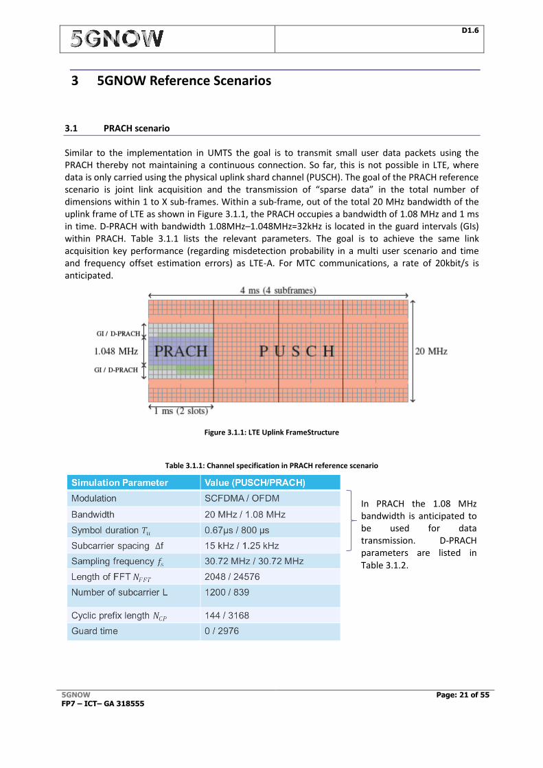
Similar to the implementation in UMTS the goal is to transmit small user data packets using the PRACH thereby not maintaining a continuous connection. So far, this is not possible in LTE, where data is only carried using the physical uplink shard channel (PUSCH). The goal of the PRACH reference scenario is joint link acquisition and the transmission of “sparse data” in the total number of dimensions within 1 to X sub-frames. Within a sub-frame, out of the total 20 MHz bandwidth of the uplink frame of LTE as shown in Figure 3.1.1, the PRACH occupies a bandwidth of 1.08 MHz and 1 ms in time. D-PRACH with bandwidth 1.08MHz–1.048MHz=32kHz is located in the guard intervals (GIs) within PRACH. Table 3.1.1 lists the relevant parameters. The goal is to achieve the same link acquisition key performance (regarding misdetection probability in a multi user scenario and time and frequency offset estimation errors) as LTE-A. For MTC communications, a rate of 20kbit/s is anticipated.
Figure 3.1.1: LTE Uplink FrameStructure
Table 3.1.1: Channel specification in PRACH reference scenario
In PRACH the 1.08 MHz bandwidth is anticipated to be used for data transmission. D-PRACH parameters are listed in Table 3.1.2.
D1.6
5GNOW FP7 – ICT– GA 318555
Page: 22 of 55
3.1.1 Performance evaluation
3.1.1.1 D-PRACH Performance
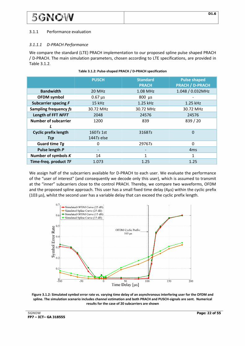
We compare the standard (LTE) PRACH implementation to our proposed spline pulse shaped PRACH / D-PRACH. The main simulation parameters, chosen according to LTE specifications, are provided in Table 3.1.2.
Table 3.1.2: Pulse-shaped PRACH / D-PRACH specification
We assign half of the subcarriers available for D-PRACH to each user. We evaluate the performance of the “user of interest" (and consequently we decode only this user), which is assumed to transmit at the “inner” subcarriers close to the control PRACH. Thereby, we compare two waveforms, OFDM and the proposed spline approach. This user has a small fixed time delay (4µs) within the cyclic prefix (103 µs), whilst the second user has a variable delay that can exceed the cyclic prefix length.
Figure 3.1.2: Simulated symbol error rate vs. varying time delay of an asynchronous interfering user for the OFDM and spline. The simulation scenario includes channel estimation and both PRACH and PUSCH-signals are sent. Numerical
results for the case of 20 subcarriers are shown
PUSCH Standard PRACH
Pulse shaped PRACH / D-PRACH
Bandwidth 20 MHz 1.08 MHz 1.048 / 0.032MHz
OFDM symbol 0.67 µs 800 µs -
Subcarrier spacing F 15 kHz 1.25 kHz 1.25 kHz
Sampling frequency fs 30.72 MHz 30.72 MHz 30.72 MHz
Length of FFT NFFT 2048 24576 24576
Number of subcarrier L
1200 839 839 / 20
Cyclic prefix length Tcp
160Ts 1st 144Ts else
3168Ts 0
Guard time Tg 0 2976Ts 0
Pulse length P - - 4ms
Number of symbols K 14 1 1
Time-freq. product TF 1.073 1.25 1.25
D1.6
5GNOW FP7 – ICT– GA 318555
Page: 23 of 55
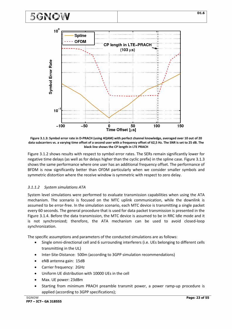
Figure 3.1.3: Symbol error rate in D-PRACH (using 4QAM) with perfect channel knowledge, averaged over 10 out of 20 data subcarriers vs. a varying time offset of a second user with a frequency offset of 62,5 Hz. The SNR is set to 25 dB. The
black line shows the CP length in LTE PRACH
Figure 3.1.2 shows results with respect to symbol error rates. The SERs remain significantly lower for negative time delays (as well as for delays higher than the cyclic prefix) in the spline case. Figure 3.1.3 shows the same performance where one user has an additional frequency offset. The performance of BFDM is now significantly better than OFDM particularly when we consider smaller symbols and symmetric distortion where the receive window is symmetric with respect to zero delay.
3.1.1.2 System simulations ATA
System level simulations were performed to evaluate transmission capabilities when using the ATA mechanism. The scenario is focused on the MTC uplink communication, while the downlink is assumed to be error-free. In the simulation scenario, each MTC device is transmitting a single packet every 60 seconds. The general procedure that is used for data packet transmission is presented in the Figure 3.1.4. Before the data transmission, the MTC device is assumed to be in RRC Idle mode and it is not synchronized; therefore, the ATA mechanism can be used to avoid closed-loop synchronization. The specific assumptions and parameters of the conducted simulations are as follows:
Single omni-directional cell and 6 surrounding interferers (i.e. UEs belonging to different cells
transmitting in the UL)
Inter-Site-Distance: 500m (according to 3GPP simulation recommendations)
eNB antenna gain: 15dB
Carrier frequency: 2GHz
Uniform UE distribution with 10000 UEs in the cell
Max. UE power: 23dBm
Starting from minimum PRACH preamble transmit power, a power ramp-up procedure is
applied (according to 3GPP specifications);
D1.6
5GNOW FP7 – ICT– GA 318555
Page: 24 of 55
3GPP pathloss model
2 PRACH opportunities per frame
5MHz (according to 3GPP recommendations for MTC evaluation)
Stationary or low mobility UEs (3km/h)
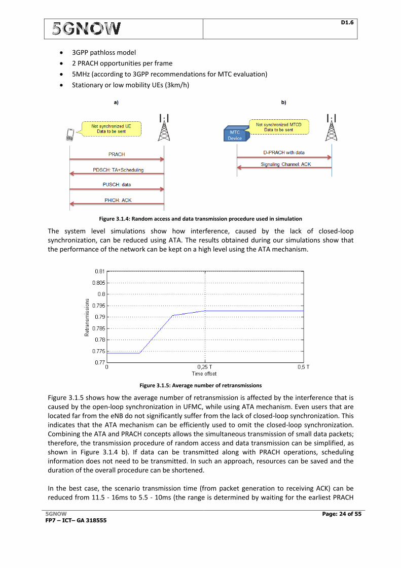
Figure 3.1.4: Random access and data transmission procedure used in simulation
The system level simulations show how interference, caused by the lack of closed-loop synchronization, can be reduced using ATA. The results obtained during our simulations show that the performance of the network can be kept on a high level using the ATA mechanism.
Figure 3.1.5: Average number of retransmissions
Figure 3.1.5 shows how the average number of retransmission is affected by the interference that is caused by the open-loop synchronization in UFMC, while using ATA mechanism. Even users that are located far from the eNB do not significantly suffer from the lack of closed-loop synchronization. This indicates that the ATA mechanism can be efficiently used to omit the closed-loop synchronization. Combining the ATA and PRACH concepts allows the simultaneous transmission of small data packets; therefore, the transmission procedure of random access and data transmission can be simplified, as shown in Figure 3.1.4 b). If data can be transmitted along with PRACH operations, scheduling information does not need to be transmitted. In such an approach, resources can be saved and the duration of the overall procedure can be shortened. In the best case, the scenario transmission time (from packet generation to receiving ACK) can be reduced from 11.5 - 16ms to 5.5 - 10ms (the range is determined by waiting for the earliest PRACH
D1.6
5GNOW FP7 – ICT– GA 318555
Page: 25 of 55
slot). The number of resource elements used to complete the data transmission is reduced from 2076 to 1404.
3.1.1.3 Compressive Random Access
Table 3.1.3: Compressive Random Access Parameters
Parameter Setting
Active nodes 10
Maximum nodes 100
FFT size 24576
Observation window 839
Detection threshold 0.1
Pilot coefficients 3213
Pilot nulling 87%
Data symbols/active node (before nulling) 1000
Data symbols/active node (after nulling) 900
Data nulling 10%
To explain the overall idea we start by considering first a generic single–user system model. Let 𝑝 ∈ℂ𝑛 be a pilot (preamble) sequence which is unknown but from a given set 𝒫 ⊂ ℂ𝑛 and 𝑥 ∈ ℂ𝑛 be an unknown (coded) data vector. Both are transmitted simultaneously and use potentially the same
resource. We set 𝔼1
𝑛‖𝑝‖𝑙2
2 = 𝛼, and 𝔼1
𝑛‖𝑥‖𝑙2
2 = 1 − 𝛼. Hence, the control signalling fraction of the
power is 𝛼 and, due to the random nature of x we have 𝔼1
𝑛‖𝑝 + 𝑥‖𝑙2
2 = 1, i.e. the total transmit
power is unity. Note that in typical systems n is large, say n=24576 as in LTE/LTE-A with 20 Mhz bandwidth and 𝒫 represents the Frank-Zadoff-Chu sequence set and no data is transmitted. The primary goal at the receiver is to estimate the data vector x from the observations y whereby also the vector h of channel coefficients is unknown. A possible strategy is to estimate separately first the
channel coefficients ℎ̃ = 𝑄ℎ(𝑦|𝑥 ∈ 𝑋), under certain assumptions on the data x. A simple approach
here is for example to treat the data as noise. In a second phase then the data �̃� = 𝑄𝑥(𝑦|ℎ̃)
conditioned onto ℎ̃ has to be estimated. Obviously, this procedure can then be iterated with or without data decoding. While for a classical receiver this procedure results in a huge interference for the channel estimation, a non-standard receiver can make use of the reduced dimensionality of the problem beyond the classical Shannon setting: 1) The communication in random access is sporadic so that out of the total set only an unknown small subset of users are actually active. Alternatively, we can assert certain probabilities to each node. 2) We assume to have a–priori support knowledge on h, i.e. supp(ℎ) ⊆ Τ with T denotes, e.g., a subset of [0, … , 𝑇𝑐𝑝] where 𝑇𝑐𝑝 represents the cyclic prefix
of LTE-A (i.e. 𝑇𝑐𝑝=8192). Moreover, we assume “sparsity” of channel profile with only six relevant
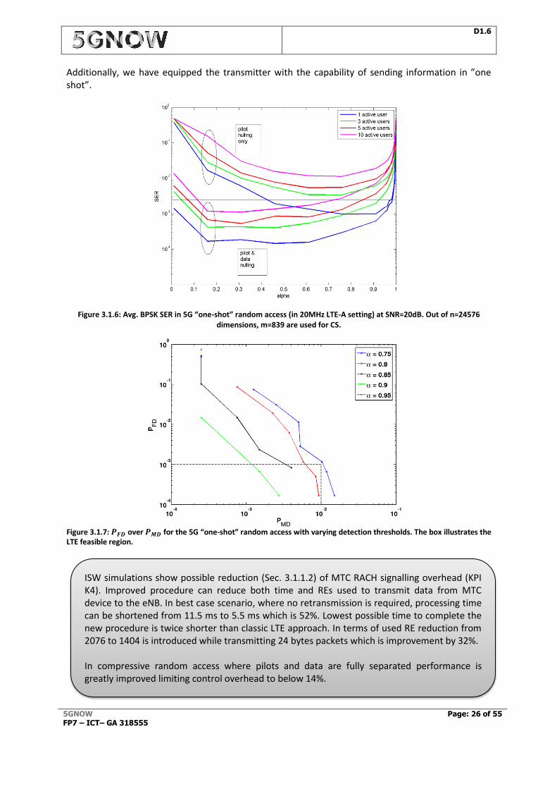
paths and supp(h) < 300 (corresponding to a 1.5 km cell). The values are listed in Table 3.1.3. Performance results are depicted in Figure 3.1.6, where we show symbol error rates (SER) over the pilot-to-data power ratio 𝛼. Recall the extremely challenging scenario of only 839 subcarriers in the measurement window versus almost 24k data payload subcarriers. Moreover, in Figure 3.1.7, we show the false detection probability 𝑃𝐹𝐷 over the missed detection probability 𝑃𝑀𝐷. We observe that, although the algorithms do not yet capture the full potential of the idea, reasonable data detection performance can be achieved by varying 𝛼, cf. [WJW14][WBS+15]. In the 4G LTE-A standard a minimum 𝑃𝐹𝐷 = 10−3 is required for any number of receive antennas, for all frame structures and for any channel bandwidth. For certain SNRs a minimum 𝑃𝑀𝐷 = 10−2 is required. It can be observed from the simulations that the requirements can be achieved. Actually, compared to LTE-A where the control signalling can be up to 2000% [WJK+14] of a single resource element the control overhead is in the CS setting down to 13% (let alone the huge increase in latency)!
D1.6
5GNOW FP7 – ICT– GA 318555
Page: 26 of 55
Additionally, we have equipped the transmitter with the capability of sending information in ”one shot”.
Figure 3.1.6: Avg. BPSK SER in 5G “one-shot” random access (in 20MHz LTE-A setting) at SNR=20dB. Out of n=24576
dimensions, m=839 are used for CS.
Figure 3.1.7: 𝑷𝑭𝑫 over 𝑷𝑴𝑫 for the 5G “one-shot” random access with varying detection thresholds. The box illustrates the LTE feasible region.
ISW simulations show possible reduction (Sec. 3.1.1.2) of MTC RACH signalling overhead (KPI K4). Improved procedure can reduce both time and REs used to transmit data from MTC device to the eNB. In best case scenario, where no retransmission is required, processing time can be shortened from 11.5 ms to 5.5 ms which is 52%. Lowest possible time to complete the new procedure is twice shorter than classic LTE approach. In terms of used RE reduction from 2076 to 1404 is introduced while transmitting 24 bytes packets which is improvement by 32%. In compressive random access where pilots and data are fully separated performance is greatly improved limiting control overhead to below 14%.
D1.6
5GNOW FP7 – ICT– GA 318555
Page: 27 of 55
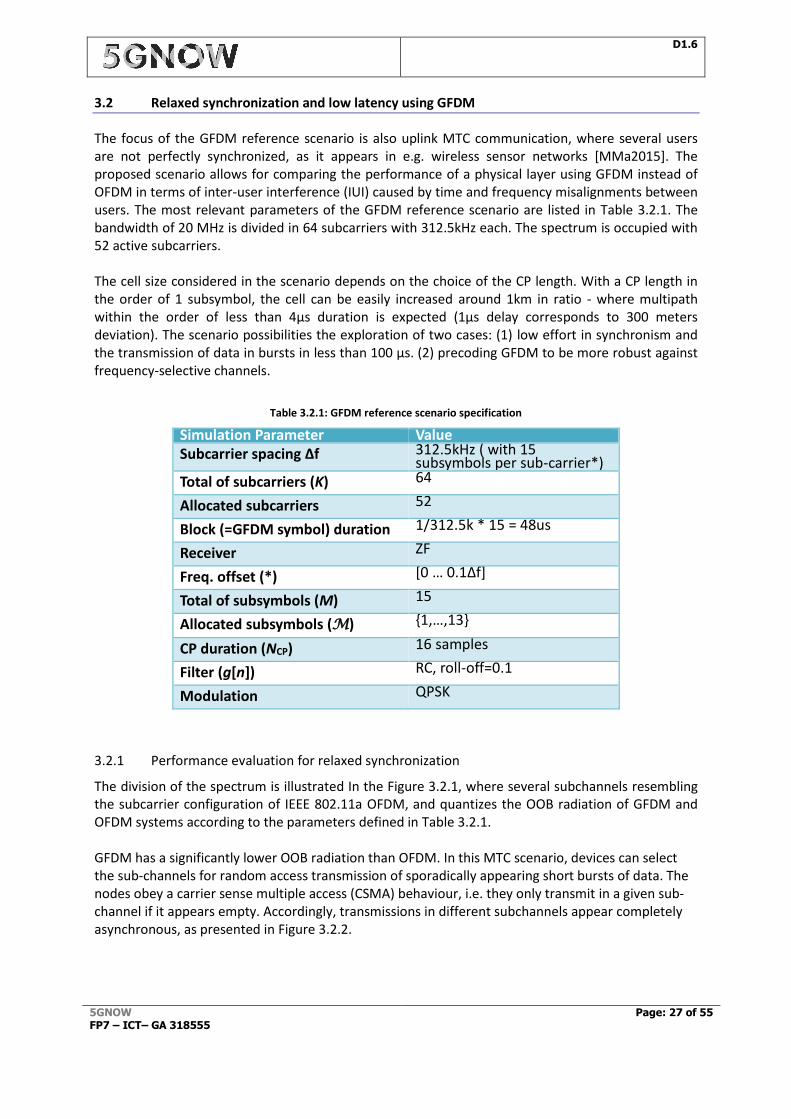
3.2 Relaxed synchronization and low latency using GFDM
The focus of the GFDM reference scenario is also uplink MTC communication, where several users are not perfectly synchronized, as it appears in e.g. wireless sensor networks [MMa2015]. The proposed scenario allows for comparing the performance of a physical layer using GFDM instead of OFDM in terms of inter-user interference (IUI) caused by time and frequency misalignments between users. The most relevant parameters of the GFDM reference scenario are listed in Table 3.2.1. The bandwidth of 20 MHz is divided in 64 subcarriers with 312.5kHz each. The spectrum is occupied with 52 active subcarriers. The cell size considered in the scenario depends on the choice of the CP length. With a CP length in the order of 1 subsymbol, the cell can be easily increased around 1km in ratio - where multipath within the order of less than 4µs duration is expected (1µs delay corresponds to 300 meters deviation). The scenario possibilities the exploration of two cases: (1) low effort in synchronism and the transmission of data in bursts in less than 100 µs. (2) precoding GFDM to be more robust against frequency-selective channels.
Table 3.2.1: GFDM reference scenario specification
Simulation Parameter Value Subcarrier spacing Δf 312.5kHz ( with 15
subsymbols per sub-carrier*) Total of subcarriers (K) 64
Allocated subcarriers 52
Block (=GFDM symbol) duration 1/312.5k * 15 = 48us
Receiver ZF
Freq. offset (*) [0 … 0.1Δf]
Total of subsymbols (M) 15
Allocated subsymbols (M) {1,…,13}
CP duration (NCP) 16 samples
Filter (g[n]) RC, roll-off=0.1
Modulation QPSK
3.2.1 Performance evaluation for relaxed synchronization
The division of the spectrum is illustrated In the Figure 3.2.1, where several subchannels resembling the subcarrier configuration of IEEE 802.11a OFDM, and quantizes the OOB radiation of GFDM and OFDM systems according to the parameters defined in Table 3.2.1. GFDM has a significantly lower OOB radiation than OFDM. In this MTC scenario, devices can select the sub-channels for random access transmission of sporadically appearing short bursts of data. The nodes obey a carrier sense multiple access (CSMA) behaviour, i.e. they only transmit in a given sub-channel if it appears empty. Accordingly, transmissions in different subchannels appear completely asynchronous, as presented in Figure 3.2.2.

D1.6
5GNOW FP7 – ICT– GA 318555
Page: 28 of 55
Figure 3.2.1: Arrangement of subchannels with GFDM and OFDM modulation
Figure 3.2.2: Illustration of a node (user 1) to be demodulated and other nodes (users 2,3,4) have different time offsets
Figure 3.2.3: Constellation MSE for different offsets of user 2 with a noise level of -40 dB
D1.6
5GNOW FP7 – ICT– GA 318555
Page: 29 of 55
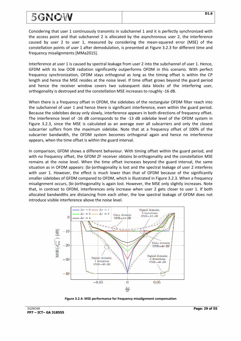
Considering that user 1 continuously transmits in subchannel 1 and it is perfectly synchronized with the access point and that subchannel 2 is allocated by the asynchronous user 2, the interference caused by user 2 to user 1, measured by considering the mean-squared error (MSE) of the constellation points of user 1 after demodulation, is presented at Figure 3.2.3 for different time and frequency misalignments [MMa2015]. Interference at user 1 is caused by spectral leakage from user 2 into the subchannel of user 1. Hence, GFDM with its low OOB radiation significantly outperforms OFDM in this scenario. With perfect frequency synchronization, OFDM stays orthogonal as long as the timing offset is within the CP length and hence the MSE resides at the noise level. If time offset grows beyond the guard period and hence the receiver window covers two subsequent data blocks of the interfering user, orthogonality is destroyed and the constellation MSE increases to roughly -16 dB. When there is a frequency offset in OFDM, the sidelobes of the rectangular OFDM filter reach into the subchannel of user 1 and hence there is significant interference, even within the guard period. Because the sidelobes decay only slowly, interference appears in both directions of frequency offset. The interference level of -16 dB corresponds to the -13 dB sidelobe level of the OFDM system in Figure 3.2.3, since the MSE is calculated as an average over all subcarriers and only the closest subcarrier suffers from the maximum sidelobe. Note that at a frequency offset of 100% of the subcarrier bandwidth, the OFDM system becomes orthogonal again and hence no interference appears, when the time offset is within the guard interval. In comparison, GFDM shows a different behaviour. With timing offset within the guard period, and with no frequency offset, the GFDM ZF receiver obtains bi-orthogonality and the constellation MSE remains at the noise level. When the time offset increases beyond the guard interval, the same situation as in OFDM appears: (bi-)orthogonality is lost and the spectral leakage of user 2 interferes with user 1. However, the effect is much lower than that of OFDM because of the significantly smaller sidelobes of GFDM compared to OFDM, which is illustrated in Figure 3.2.3. When a frequency misalignment occurs, (bi-)orthogonality is again lost. However, the MSE only slightly increases. Note that, in contrast to OFDM, interferences only increase when user 2 gets closer to user 1. If both allocated bandwidths are distancing from each other, the low spectral leakage of GFDM does not introduce visible interference above the noise level.
Figure 3.2.4: MSE performance for frequency misalignment compensation
D1.6
5GNOW FP7 – ICT– GA 318555
Page: 30 of 55
3.2.2 Performance evaluation for low latency
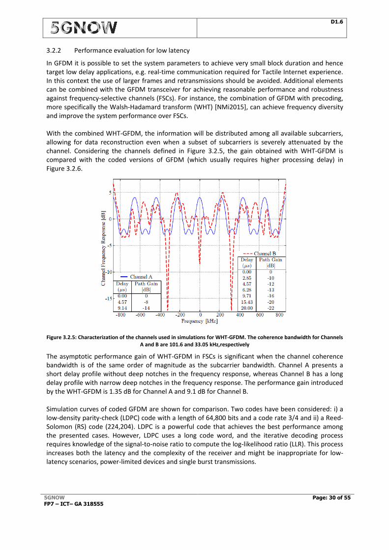
In GFDM it is possible to set the system parameters to achieve very small block duration and hence target low delay applications, e.g. real-time communication required for Tactile Internet experience. In this context the use of larger frames and retransmissions should be avoided. Additional elements can be combined with the GFDM transceiver for achieving reasonable performance and robustness against frequency-selective channels (FSCs). For instance, the combination of GFDM with precoding, more specifically the Walsh-Hadamard transform (WHT) [NMi2015], can achieve frequency diversity and improve the system performance over FSCs. With the combined WHT-GFDM, the information will be distributed among all available subcarriers, allowing for data reconstruction even when a subset of subcarriers is severely attenuated by the channel. Considering the channels defined in Figure 3.2.5, the gain obtained with WHT-GFDM is compared with the coded versions of GFDM (which usually requires higher processing delay) in Figure 3.2.6.
Figure 3.2.5: Characterization of the channels used in simulations for WHT-GFDM. The coherence bandwidth for Channels A and B are 101.6 and 33.05 kHz,respectively
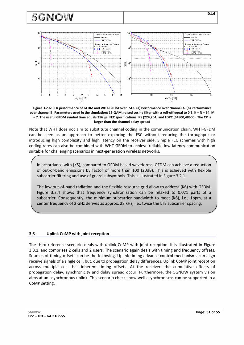
The asymptotic performance gain of WHT-GFDM in FSCs is significant when the channel coherence bandwidth is of the same order of magnitude as the subcarrier bandwidth. Channel A presents a short delay profile without deep notches in the frequency response, whereas Channel B has a long delay profile with narrow deep notches in the frequency response. The performance gain introduced by the WHT-GFDM is 1.35 dB for Channel A and 9.1 dB for Channel B. Simulation curves of coded GFDM are shown for comparison. Two codes have been considered: i) a low-density parity-check (LDPC) code with a length of 64,800 bits and a code rate 3/4 and ii) a Reed-Solomon (RS) code (224,204). LDPC is a powerful code that achieves the best performance among the presented cases. However, LDPC uses a long code word, and the iterative decoding process requires knowledge of the signal-to-noise ratio to compute the log-likelihood ratio (LLR). This process increases both the latency and the complexity of the receiver and might be inappropriate for low-latency scenarios, power-limited devices and single burst transmissions.
D1.6
5GNOW FP7 – ICT– GA 318555
Page: 31 of 55
Figure 3.2.6: SER performance of GFDM and WHT-GFDM over FSCs. (a) Performance over channel A. (b) Performance over channel B. Parameters used in the simulation: 16-QAM, raised cosine filter with a roll-off equal to 0.1, K = N = 64. M
= 7. The useful GFDM symbol time equals 256 s. FEC specifications: RS (224,204) and LDPC (64800,48600). The CP is larger than the channel delay spread
Note that WHT does not aim to substitute channel coding in the communication chain. WHT-GFDM can be seen as an approach to better exploring the FSC without reducing the throughput or introducing high complexity and high latency on the receiver side. Simple FEC schemes with high coding rates can also be combined with WHT-GFDM to achieve reliable low-latency communication suitable for challenging scenarios in next-generation wireless networks.
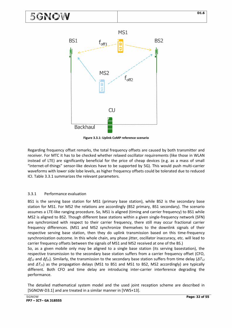
3.3 Uplink CoMP with joint reception
The third reference scenario deals with uplink CoMP with joint reception. It is illustrated in Figure 3.3.1, and comprises 2 cells and 2 users. The scenario again deals with timing and frequency offsets. Sources of timing offsets can be the following. Uplink timing advance control mechanisms can align receive signals of a single cell, but, due to propagation delay differences, Uplink CoMP joint reception across multiple cells has inherent timing offsets. At the receiver, the cumulative effects of propagation delay, synchronicity and delay spread occur. Furthermore, the 5GNOW system vision aims at an asynchronous uplink. This scenario checks how well asynchronisms can be supported in a CoMP setting.
In accordance with (K5), compared to OFDM based waveforms, GFDM can achieve a reduction of out-of-band emissions by factor of more than 100 (20dB). This is achieved with flexible subcarrier filtering and use of guard subsymbols. This is illustrated in Figure 3.2.1. The low out-of-band radiation and the flexible resource grid allow to address (K6) with GFDM. Figure 3.2.4 shows that frequency synchronization can be relaxed to 0.071 parts of a subcarrier. Consequently, the minimum subcarrier bandwidth to meet (K6), i.e., 1ppm, at a center frequency of 2 GHz derives as approx. 28 kHz, i.e., twice the LTE subcarrier spacing.
D1.6
5GNOW FP7 – ICT– GA 318555
Page: 32 of 55
Figure 3.3.1: Uplink CoMP reference scenario
Regarding frequency offset remarks, the total frequency offsets are caused by both transmitter and receiver. For MTC it has to be checked whether relaxed oscillator requirements (like those in WLAN instead of LTE) are significantly beneficial for the price of cheap devices (e.g. as a mass of small “internet-of-things” sensor-like devices have to be supported by 5G). This would push multi-carrier waveforms with lower side lobe levels, as higher frequency offsets could be tolerated due to reduced ICI. Table 3.3.1 summarizes the relevant parameters.
3.3.1 Performance evaluation
BS1 is the serving base station for MS1 (primary base station), while BS2 is the secondary base station for MS1. For MS2 the relations are accordingly (BS2 primary, BS1 secondary). The scenario assumes a LTE-like ranging procedure. So, MS1 is aligned (timing and carrier frequency) to BS1 while MS2 is aligned to BS2. Though different base stations within a given single-frequency network (SFN) are synchronized with respect to their carrier frequency, there still may occur fractional carrier frequency differences. (MS1 and MS2 synchronize themselves to the downlink signals of their respective serving base station, then they do uplink transmission based on this time-frequency synchronization outcome. In this whole chain, any phase jitter, oscillator inaccuracy, etc. will lead to carrier frequency offsets between the signals of MS1 and MS2 received at one of the BS.) So, as a given mobile only may be aligned to a single base station (its serving basestation), the respective transmission to the secondary base station suffers from a carrier frequency offset (CFO, Δf12 and Δf21). Similarly, the transmission to the secondary base station suffers from time delay (ΔT12 and ΔT21) as the propagation delays (MS1 to BS1 and MS1 to BS2, MS2 accordingly) are typically different. Both CFO and time delay are introducing inter-carrier interference degrading the performance. The detailed mathematical system model and the used joint reception scheme are described in [5GNOW-D3.1] and are treated in a similar manner in [VWS+13].

D1.6
5GNOW FP7 – ICT– GA 318555
Page: 33 of 55
The transmissions between BSi (i = [1, 2]) and the CU via fronthaul is assumed to be ideal (error free and with sufficient resolution, so that any quantization effects are negligible; e.g. using a CPRI interface). Ultimate target of this reference scenario is to compare the capabilities of different waveforms to harvest on the gains UL CoMP is promising under realistic synchronization assumptions. Simulations have been carried out in order to assess the performance gains of UFMC over OFDM. For now, the considered timing offsets are still ΔT12 = ΔT21=0, so, only the impact of frequency offsets on the cross-links are considered, yet. The simulation settings are depicted in Table 3.3.1. The receiver is assumed to have perfect channel state information. The simulation results are depicted in Figure 3.3.2. Depending on the SNR operation point, performance gains of several dBs for UFMC over OFDM can be observed, because of better inter-carrier interference suppression by the reduced side-lobe levels of the waveform. This demonstrates that UFMC is a powerful candidate 5G waveform in the CoMP scenario in case of synchronization mismatch. This allows that synchronization requirements can be relaxed and in the case of MTC devices transmitting in CoMP joint reception systems, a better support of low-end devices with relaxed oscillator requirements can be provided by the help of UFMC.
Figure 3.3.2: SER vs Eb/N0 – comparison between UFMC and OFDM for absence of carrier frequency offset (no CFO), perfectly known and compensated carrier frequency (per. CFO comp) and a CFO compensation with a residual mismatch
of 10% of the total CFO
12 14 16 18 20 22 24 2610
-4
10-3
10-2
10-1
Eb/N0
QP
SK
SE
R
UFMC no CFO
UFMC perf. CFO comp
UFMC CFO comp w/ err
OFDM no CFO
OFDM perf. CFO comp.
OFDM CFO comp. w/ err
This directly addresses the KPI target (K6) from Table 3.3.1: The chosen frequency offset of 0.1 Δf is 1.5kHz for the selected subcarrier spacing. 5GNOW target is 1 ppm LO accuracy, corresponding to a carrier frequency of 1.5 GHz. Furthermore, KPI target “(K5) Out-of-band radiation” with a factor 100 improvement is easily fulfilled by the UFMC waveform – see spectrum plot in D3.3.
D1.6
5GNOW FP7 – ICT– GA 318555
Page: 34 of 55
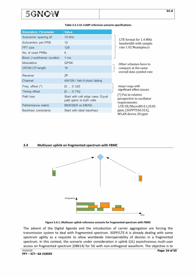
Table 3.3.1:UL CoMP reference scenario specifications
3.4 Multiuser uplink on fragmented spectrum with FBMC
Figure 3.4.1: Multiuser uplink reference scenario for fragmented spectrum with FBMC
The advent of the Digital Agenda and the introduction of carrier aggregation are forcing the transmission system to deal with fragmented spectrum. 3GPP/LTE-A is already dealing with some spectrum agility as a requisite to allow worldwide interoperability of devices in a fragmented spectrum. In this context, the scenario under consideration is uplink (UL) asynchronous multi-user access on fragmented spectrum [DBK14] for 5G with non-orthogonal waveform. The objective is to
LTE format for 1.4 MHz bandwidth with sample rate 1.92 Msamples/s
Other schemes have to compare at the same overall data symbol rate
Adapt range until significant effect occurs
(*) Put in relative perspective to oscillator requirements: LTE UE/MacroBS 0.1/0.05 ppm, [3GPPTS36.521], WLAN device 20 ppm
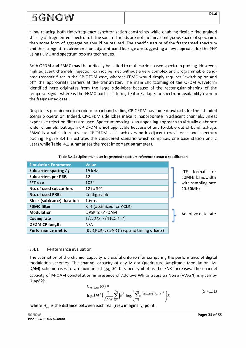
D1.6
5GNOW FP7 – ICT– GA 318555
Page: 35 of 55
allow relaxing both time/frequency synchronization constraints while enabling flexible fine-grained sharing of fragmented spectrum. If the spectral needs are not met in a contiguous space of spectrum, then some form of aggregation should be realized. The specific nature of the fragmented spectrum and the stringent requirements on adjacent band leakage are suggesting a new approach for the PHY using FBMC and spectrum pooling techniques.
Both OFDM and FBMC may theoretically be suited to multicarrier-based spectrum pooling. However, high adjacent channels’ rejection cannot be met without a very complex and programmable band-pass transmit filter in the CP-OFDM case, whereas FBMC would simply requires “switching on and off” the appropriate carriers at the transmitter. The main shortcoming of the OFDM waveform identified here originates from the large side-lobes because of the rectangular shaping of the temporal signal whereas the FBMC built-in filtering feature adapts to spectrum availability even in the fragmented case.
Despite its prominence in modern broadband radios, CP-OFDM has some drawbacks for the intended scenario operation. Indeed, CP-OFDM side lobes make it inappropriate in adjacent channels, unless expensive rejection filters are used. Spectrum pooling is an appealing approach to virtually elaborate wider channels, but again CP-OFDM is not applicable because of unaffordable out-of-band leakage. FBMC is a valid alternative to CP-OFDM, as it achieves both adjacent coexistence and spectrum pooling. Figure 3.4.1 illustrates the considered scenario which comprises one base station and 2 users while Table .4.1 summarizes the most important parameters.
Table 3.4.1: Uplink multiuser fragmented spectrum reference scenario specification
Simulation Parameter Value
Subcarrier spacing ∆𝒇 15 kHz
Subcarriers per PRB 12
FFT size 1024
No. of used subcarriers 12 to 501
No. of used PRBs Configurable
Block (subframe) duration 1.6ms
FBMC filter K=4 (optimized for ACLR)
Modulation QPSK to 64-QAM
Coding rate 1/2, 2/3, 3/4 (CC K=7)
OFDM CP-length N/A
Performance metric (BER,PER) vs SNR (freq. and timing offsets)
3.4.1 Performance evaluation
The estimation of the channel capacity is a useful criterion for comparing the performance of digital modulation schemes. The channel capacity of any M-ary Quadrature Amplitude Modulation (M-QAM) scheme rises to a maximum of Mlog
2 bits per symbol as the SNR increases. The channel
capacity of M-QAM constellation in presence of Additive White Gaussian Noise (AWGN) is given by [Ung82]:
dtee
MM
C
mid
mitd
M
i
tM
m
QAMM
2)()(2
1=
2
2
1=
2
2 log2
log
=)(
(5.4.1.1)
where mid is the distance between each real (resp imaginary) point:
LTE format for 10MHz bandwidth with sampling rate 15.36MHz
Adaptive data rate
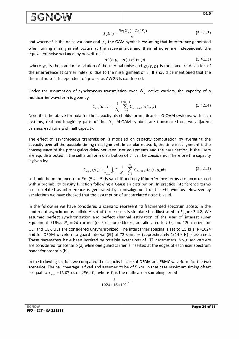
D1.6
5GNOW FP7 – ICT– GA 318555
Page: 36 of 55
)()(
=)( immi
XReXRed
(5.4.1.2)
and where 2 is the noise variance and iX the QAM symbols.Assuming that interference generated
when timing misalignment occurs at the receiver side and thermal noise are independent, the equivalent noise variance my be written as:
),(=),( 222 pp in (5.4.1.3)
where n is the standard deviation of the thermal noise and ),( pi is the standard deviation of
the interference at carrier index p due to the misalignment of . It should be mentioned that the
thermal noise is independent of p or as AWGN is considered.
Under the assumption of synchronous transmission over aN active carriers, the capacity of a
multicarrier waveform is given by:
)),((1
=),(
1=
0=
pCN
C QAMM
aNp
pa
nMC
(5.4.1.4)
Note that the above formula for the capacity also holds for multicarrier O-QAM systems: with such
systems, real and imaginary parts of the aN M-QAM symbols are transmitted on two adjacent
carriers, each one with half capacity. The effect of asynchronous transmission is modeled on capacity computation by averaging the capacity over all the possible timing misalignment. In cellular network, the time misalignment is the consequence of the propagation delay between user equipments and the base station. If the users are equidistributed in the cell a uniform distribution of can be considered. Therefore the capacity is given by:
dpCN
C QAMM
aNp
pa
max
max
nasync )),((11
=)(
1=
0=0
(5.4.1.5)
It should be mentioned that Eq. (5.4.1.5) is valid, if and only if interference terms are uncorrelated with a probability density function following a Gaussian distribution. In practice interference terms are correlated as interference is generated by a misalignment of the FFT window. However by simulations we have checked that the assumption of uncorrelated noise is valid.
In the following we have considered a scenario representing fragmented spectrum access in the context of asynchronous uplink. A set of three users is simulated as illustrated in Figure 3.4.2. We assumed perfect synchronization and perfect channel estimation of the user of interest (User Equipment 0 UE0). 24=aN carriers (or 2 resource blocks) are allocated to UE0, and 120 carriers for
UE1 and UE2. UEs are considered unsynchronized. The intercarrier spacing is set to 15 kHz, N=1024 and for OFDM waveform a guard interval (GI) of 72 samples (approximately 1/14 x N) is assumed. These parameters have been inspired by possible extensions of LTE parameters. No guard carriers are considered for scenario (a) while one guard carrier is inserted at the edges of each user spectrum bands for scenario (b). In the following section, we compared the capacity in case of OFDM and FBMC waveform for the two scenarios. The cell coverage is fixed and assumed to be of 5 km. In that case maximum timing offset is equal to 16.67=max us or
sT256 , where sT is the multicarrier sampling period
s310151024
1
.
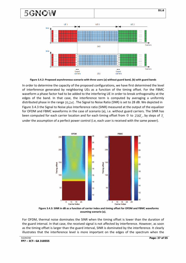
D1.6
5GNOW FP7 – ICT– GA 318555
Page: 37 of 55
Figure 3.4.2: Proposed asynchronous scenario with three users (a) without guard band, (b) with guard bands
In order to determine the capacity of the proposed configurations, we have first determined the level of interference generated by neighboring UEs as a function of the timing offset. For the FBMC waveform a phase factor had to be added to the interfering UE in order to break orthogonality at the edges of the band. In that case, the interference term is computed by averaging a uniformly distributed phase in the range [[0,2 . The Signal to Noise Ratio (SNR) is set to 28 dB. We depicted in
Figure 3.4.3 the Signal to Noise plus Interference ratio (SINR) measured at the output of the equalizer for OFDM and FBMC waveforms in the case of scenario (a), i.e. without guard carriers. The SINR has been computed for each carrier location and for each timing offset from 0 to
sT256 , by steps of sT
under the assumption of a perfect power control (i.e, each user is received with the same power).
Figure 3.4.3: SINR in dB as a function of carrier index and timing offset for OFDM and FBMC waveforms
assuming scenario (a).
For OFDM, thermal noise dominates the SINR when the timing offset is lower than the duration of the guard interval. In that case, the received signal is not affected by interference. However, as soon as the timing offset is larger than the guard interval, SINR is dominated by the interference. It clearly illustrates that the interference level is more important on the edges of the spectrum when the
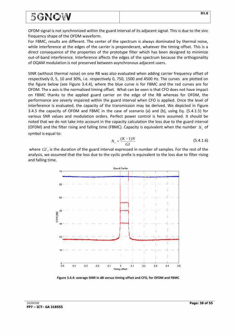
D1.6
5GNOW FP7 – ICT– GA 318555
Page: 38 of 55
OFDM signal is not synchronized within the guard interval of its adjacent signal. This is due to the sinc frequency shape of the OFDM waveform. For FBMC, results are different. The center of the spectrum is always dominated by thermal noise, while interference at the edges of the carrier is preponderant, whatever the timing offset. This is a direct consequence of the properties of the prototype filter which has been designed to minimize out-of-band interference. Interference affects the edges of the spectrum because the orthogonality of OQAM modulation is not preserved between asynchronous adjacent users. SINR (without thermal noise) on one RB was also evaluated when adding carrier frequency offset of respectively 0, 5, 10 and 30%, i.e. respectively 0, 750, 1500 and 4500 Hz. The curves are plotted on the figure below (see Figure 3.4.4), where the blue curve is for FBMC and the red curves are for OFDM. The x axis is the normalized timing offset. What can be seen is that CFO does not have impact on FBMC thanks to the applied guard carrier on the edge of the RB whereas for OFDM, the performance are severly impaired within the guard interval when CFO is applied. Once the level of interference is evaluated, the capacity of the transmission may be derived. We depicted in Figure 3.4.5 the capacity of OFDM and FBMC in the case of scenario (a) and (b), using Eq. (5.4.1.5) for various SNR values and modulation orders. Perfect power control is here assumed. It should be noted that we do not take into account in the capacity calculation the loss due to the guard interval (OFDM) and the filter rising and falling time (FBMC). Capacity is equivalent when the number
sN of
symbol is equal to:
GI
NKN s
1)(=
(5.4.1.6)
where GI , is the duration of the guard interval expressed in number of samples. For the rest of the analysis, we assumed that the loss due to the cyclic prefix is equivalent to the loss due to filter rising and falling time.
Figure 3.4.4: average SINR in dB versus timing offset and CFO, for OFDM and FBMC
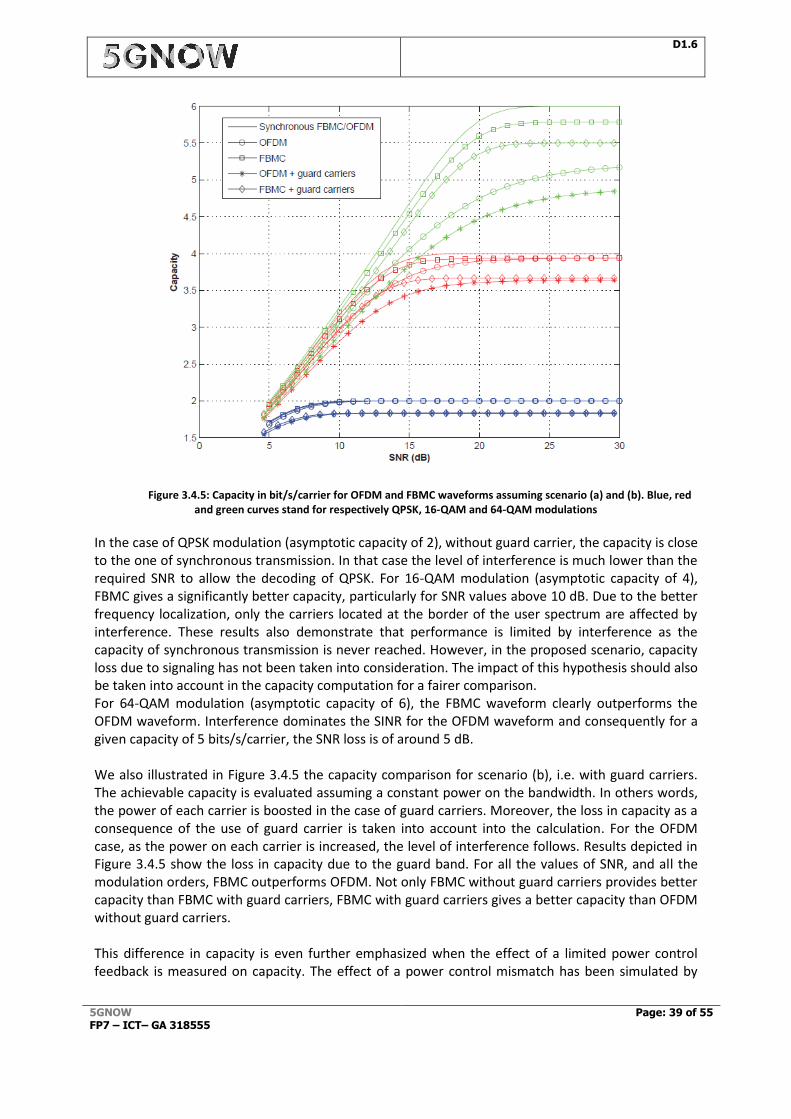
D1.6
5GNOW FP7 – ICT– GA 318555
Page: 39 of 55
Figure 3.4.5: Capacity in bit/s/carrier for OFDM and FBMC waveforms assuming scenario (a) and (b). Blue, red and green curves stand for respectively QPSK, 16-QAM and 64-QAM modulations
In the case of QPSK modulation (asymptotic capacity of 2), without guard carrier, the capacity is close to the one of synchronous transmission. In that case the level of interference is much lower than the required SNR to allow the decoding of QPSK. For 16-QAM modulation (asymptotic capacity of 4), FBMC gives a significantly better capacity, particularly for SNR values above 10 dB. Due to the better frequency localization, only the carriers located at the border of the user spectrum are affected by interference. These results also demonstrate that performance is limited by interference as the capacity of synchronous transmission is never reached. However, in the proposed scenario, capacity loss due to signaling has not been taken into consideration. The impact of this hypothesis should also be taken into account in the capacity computation for a fairer comparison. For 64-QAM modulation (asymptotic capacity of 6), the FBMC waveform clearly outperforms the OFDM waveform. Interference dominates the SINR for the OFDM waveform and consequently for a given capacity of 5 bits/s/carrier, the SNR loss is of around 5 dB. We also illustrated in Figure 3.4.5 the capacity comparison for scenario (b), i.e. with guard carriers. The achievable capacity is evaluated assuming a constant power on the bandwidth. In others words, the power of each carrier is boosted in the case of guard carriers. Moreover, the loss in capacity as a consequence of the use of guard carrier is taken into account into the calculation. For the OFDM case, as the power on each carrier is increased, the level of interference follows. Results depicted in Figure 3.4.5 show the loss in capacity due to the guard band. For all the values of SNR, and all the modulation orders, FBMC outperforms OFDM. Not only FBMC without guard carriers provides better capacity than FBMC with guard carriers, FBMC with guard carriers gives a better capacity than OFDM without guard carriers. This difference in capacity is even further emphasized when the effect of a limited power control feedback is measured on capacity. The effect of a power control mismatch has been simulated by

D1.6
5GNOW FP7 – ICT– GA 318555
Page: 40 of 55
increasing the power of the asynchronous adjacent user. We depicted in Figure 3.4.6 the impact of the power control on capacity.
Figure 3.4.6: Capacity in bit/s/carrier for OFDM and FBMC waveforms when power control feedback is limited
(assuming scenario (a)). Blue, red and green curves stand for respectively QPSK, 16-QAM and 64-QAM modulations.
As previously mentioned, when QPSK modulation is considered the capacity is limited by thermal noise level. Therefore even if the power of the adjacent user is increased by 3dB, the capacity achieved with QPSK modulation is equal to the capacity in presence of perfect power control. The impact of power control on capacity is more important for 16-QAM and 64-QAM modulation. For FBMC, the impact of the adjacent user power is almost negligible. This is because only the carriers located at the edges of the spectrum are affected by the interference. However for the case of OFDM, the capacity is significantly reduced when the power of the adjacent user is increased. As the interference level varies linearly with the power of the adjacent user, capacity decreases. These results underline the benefit of the FBMC waveform in case of limited feedback for both time misalignment and power control. We demonstrated the benefits of the FBMC waveform compared

D1.6
5GNOW FP7 – ICT– GA 318555
Page: 41 of 55
to the OFDM waveform, particularly for high order modulations. Due to the fair frequency localization, only the carriers located at the edges of the active spectrum are affected by interference, while for OFDM interference is spread over all the active carriers. In case of fragmented spectrum the impact of interference is further amplified for the case of OFDM. Moreover FBMC waveforms permit a simple way of sharing resources between cell-edge users without strict synchronization between users, especially in near unity frequency reuse. It is a direct consequence of the low level of uplink interference generated by the built-in waveform filter.
3.5 Downlink CoMP with FBMC
The reference scenario for FBMC deals with downlink CoMP with joint reception, its objective: is to demonstrate the feasibility of downlink CoMP for 5G with non-orthogonal waveforms. As illustrated in Figure 3.5.1, 2 cells and 2 users are included. Timing and frequency offsets are again considered, the sources of the offsets can be characterized as follows: Received signals from multiple cells may not be aligned in time at the receiver due to propagation delay differences and due to possible time de-synchronization between cooperating BSs. This offset causes pilots rotations at the receiver that make the estimation of the channel difficult. Thus high time delays will be studied. Clocks at the BSs and at the UE side may not be perfectly synchronized in frequency, causing Carrier Frequency Offset (CFO) at the receiver, therefore, the impact of the CFO will be studied. The reference scenario investigates the level of tolerance to asynchronism in the downlink CoMP scenario using the FBMC waveform.
The scenario under investigation (MU UL on fragmented spectrum) underlines the benefits of the FBMC waveform in case of limited feedback for both time misalignment and power control. It is shown that the receiver can cope with any timing offset without degradation when 1 guard carrier is applied to separate the users in the frequency domain. This means that we can remove the timing advance procedure and thus the related signalling both for the DL and the UL (see control overhead KPI in Table 1.3.1). Same conclusion holds for the UL power control procedure, allowing also to reduce the related signalling both for the DL and the UL (see control overhead KPI in Table 1.3.1). Moreover, FBMC has been proven to be more efficient than OFDM for the estimation and the correction of very high CFOs (larger than the carrier spacing) after FFT. This means that the required terminal oscillator accuracy can be relaxed at least from a factor of 10 (see the related local oscillator KPI in table 1.3.1). Last but not least it has been shown that FBMC achieves 100x better localization (e.g. 35 dB sidelobe with LTE-A OFDM compared to 55dB side lobe with FBMC, which fulfils the related KPI (out-band radiation) in table 1.3.1.
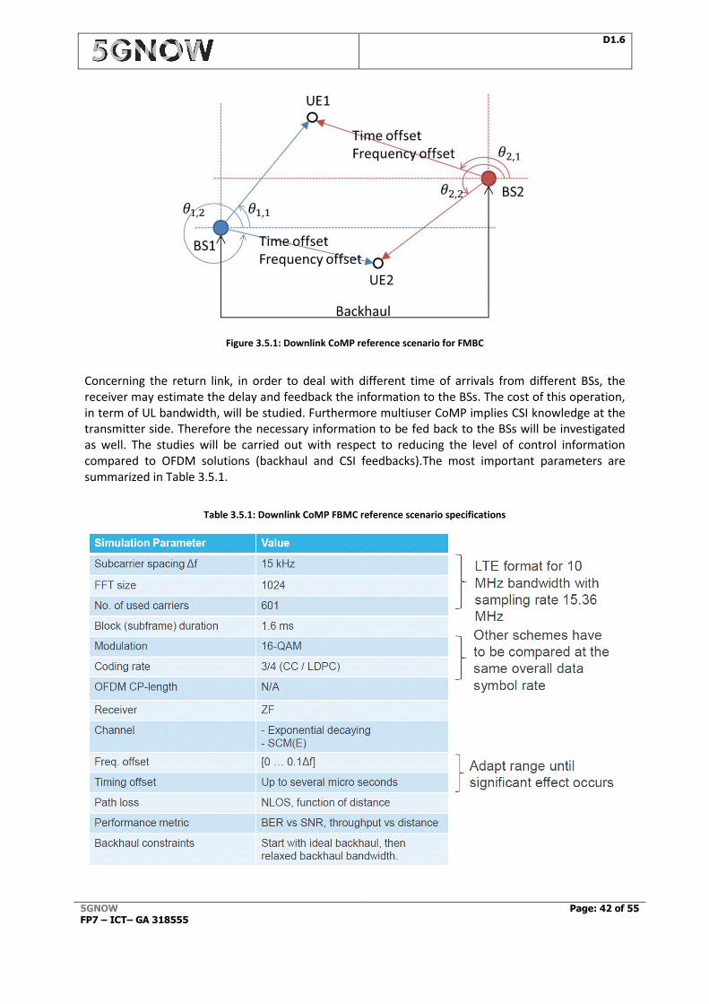
D1.6
5GNOW FP7 – ICT– GA 318555
Page: 42 of 55
Figure 3.5.1: Downlink CoMP reference scenario for FMBC
Concerning the return link, in order to deal with different time of arrivals from different BSs, the receiver may estimate the delay and feedback the information to the BSs. The cost of this operation, in term of UL bandwidth, will be studied. Furthermore multiuser CoMP implies CSI knowledge at the transmitter side. Therefore the necessary information to be fed back to the BSs will be investigated as well. The studies will be carried out with respect to reducing the level of control information compared to OFDM solutions (backhaul and CSI feedbacks).The most important parameters are summarized in Table 3.5.1.
Table 3.5.1: Downlink CoMP FBMC reference scenario specifications
D1.6
5GNOW FP7 – ICT– GA 318555
Page: 43 of 55
3.5.1 Performance evaluation
It was previously demonstrated in this project that the UE can robustly estimate very large delays and arbitrary high carrier frequency offsets. The correction of the delays required only a few bits of feedback when the compensation of the offset can be realized at the UE side. The aim here is to go one step further by investigating the robustness of FBMC in DL CoMP scenarios with respect to the feedback link and MAC related asynchronisms such as outdated CSI, as investigated in [CKW+14]. The parameters can be found in Table 3.5.1 and Table 3.5.3. In order to avoid having to carry out actual signal processing, in system level simulations usually a link-to-system (L2S) interface comprising a suitable PHY layer abstraction is used. The goal of this PHY layer abstraction is essentially to obtain a block error rate (BLER) for a transport block (given particular subcarrier channel realizations) without having to carry out real signal processing. This is usually implemented in form of a look-up table where packet or block error rates are given for a certain effective quality measure, often the SINR, taking into account modulation and coding, power control, resource allocation, HARQ, etc. However, the SINR measure, which is usually applied in the evaluation of OFDMA systems, cannot capture the mutual dependencies between subcarriers of non-orthogonal multicarrier schemes. To cope with this issue, we used the Signal to Noise plus Interference and Distortion Ratio (SNIDR) model, as proposed in [OIG+13], where the “D” stands for the residual distortion. The SNIDR on subcarrier k is defined as:
Thereby Ps, Pi, and Pn denote the signal power, interference power, and noise power, respectively. Pd denotes the residual distortion power. In simulations presented above, the CSI feedback and the throughput computation is done on a RB basis. The following steps are then realized to assess the users’ throughputs:
Computation by each user of the preferred precoder(s) depending on the channel at the current time t0.
Reporting by each user of the preferred precoder(s).
Measurement by link level simulations of the SNIDR of each user on each carrier of the RB at time t0+τ. τ is a parameter modelling the time between feedback at the UE and the reception of the signal. The SNIDR takes into account inter-user interference due to MU-MIMO, residual distortion power and SNR. It is computed with the channel at time t0+ τ.
Computation of the mean SNIDR on the RB. The choice to use the mean SNIDR instead of the ESM mechanism is justified by the high coherence bandwidth of the channel.
Choice of the PER corresponding to the MCS and the mean SNIDR in LUT. The MCS must maximize the throughput while ensuring PER<10-1.
Assessment of the throughput as R(1-PER) with R the rate of the MCS. LUT are presented on Figure 3.5.2. As stated in [WKB+13], the gain in FBMC from abandoning the cyclic prefix can be clearly observed in these LUTs. Figure 3.5.3 shows the distribution of the throughputs of UEs for FBMC and OFDM (OFDM with dashed lines, FBMC with continuous lines), for a feedback of the two preferred precoders. Two-antenna BSs are used for the figure. On each figure and for each modulation, three curves are plotted, corresponding to τ={0,∆(t),2∆(t)} ms. The correspondence between ∆(t) and the speed of the UEs is given in Table 3.5.2.
D1.6
5GNOW FP7 – ICT– GA 318555
Page: 44 of 55
Figure 3.5.2. BLER vs SNR in AWGN Channel
The red curves are for an instantaneous feedback. The blue curves are for τ=∆(t) and the grey curves are for τ=2∆(t), whatever the speed of the UE. For example for a UE moving at 3km/h (resp. 20km/h) the blue curves are for τ=90ms (resp. τ=13.5ms) and the grey curves for τ=180ms (resp. τ=27ms). Two observations can be made from this figure. First, FBMC outperforms OFDM whatever the feedback delay τ. These gains from FBMC to OFDM are primarily caused by the removal of the cyclic prefix. Second, the degradation of the throughput when τ=∆(t) compared to τ=0 is significant. At 20km/h (∆(t) = 13.5ms), the precoders must therefore be updated frequently.
Table 3.5.2: Error over velocity
velocity [km/h] ∆(𝒕) [ms]
1 270
3 90
10 27
20 13.5
D1.6
5GNOW FP7 – ICT– GA 318555
Page: 45 of 55
Figure 3.5.3. CDF of the throughput of UEs. (OFDM: dashed lines, FBMC: continuous lines)
The total throughput of the UEs vs. the feedback rate per UE was plotted in Figure 3.5.4 for the same configuration. The feedback per RB per codebook is NT bits for the preferred weight and four bits for the MCS. As two preferred precoders are fed back, the feedback is 2(NT+4) bits per RB per UE. Two UEs are scheduled on each RB and fifty RBs are available.
Figure 3.5.4. Total throughput as a function of the feedback rate. (OFDM: dashed lines, FBMC: continuous lines)
It must be noted that FBMC once again outperforms OFDM, for example:
Regarding “Signalling overhead” Key Performance Indicator, to reach the same throughput of 22Mbps, FBMC requires 3 (resp. 10, 30 and 55) kbps lower feedback rates than OFDM for a speed of 1 (resp. 3, 10 and 20) km/h.
Regarding “Capacity” Key Performance Indicator, with a feedback rate of 20 kbps, FBMC UEs moving at 1 km/h allow a throughput of 24,7Mbps whereas OFDM UEs only allow 23.6Mbps.
D1.6
5GNOW FP7 – ICT– GA 318555
Page: 46 of 55
As intuitively expected, the speed of the UEs has a significant impact on the necessary amount of feedback: to ensure a throughput of 24.7 Mbps, 60 kbps are necessary at 3 km/h and more than 100 kbps at 10 km/h. Further, it can be observed, that the FBMC curves have a slope similar to the slope of the corresponding OFDM curves. Thus, FBMC shows a comparable robustness against limited feedback.
Table 3.5.3: Downlink CoMP FBMC reference scenario specifications
Simulation Parameter Value
Subcarrier spacing 15kHz
FFT size 1024
Number of transmit antennas 2
Number of receive antennas 1
Codebook LTE
N° of used carriers 600
N° of RBs 50
Modulation From QPSK to 64QAM
Number of users Two per RB
Coding rate From 1/3 to 3/4
Channel SCM(E)
Feedback delay Up to 540ms
Path LOS NLOS
Performance metrics PER vs SNR Throughput vs feedback delay
Backhaul constraints Non instantaneous
In the context of Rel-11 DL CoMP, UE performance requirements are defined by assuming a typical timing offset in the range of [-0.5, 2] µs. In [5GNOWD4.1] it was shown that FBMC, with real channel estimation, can cope with delays of up to 120 times samples (7.8µs) without any need for correction, which relaxes the need for time synchronization between the base stations. FBMC modulation is indeed very resistant to time propagation differences between signals from the two BSs, due to its overlapping structure. Furthermore it is shown in this section that the signaling overhead related to the choice of the MCS and the precoder per RB and per user is reduced by 50% (see signaling overhead KPI in the uplink, table 1.3.1) while at the same time the DL capacity is increased by 5% (see capacity KPI in table 1.3.1). Moreover, FBMC has been proven to be more efficient than OFDM for the estimation and the correction of very high CFOs (larger than the carrier spacing) after FFT. This means that the required terminal oscillator accuracy can be relaxed at least from a factor of 10 (see the related local oscillator KPI in table 1.3.1).

D1.6
5GNOW FP7 – ICT– GA 318555
Page: 47 of 55
4 Demonstration
5GNOW proof-of-concept work package (WP5) concentrate efforts in developing demonstrations to highlight specific aspects of new PHY proposals. In this deliverable FBMC and GFDM prototypes developed by CEA and TUD are presented in details, their demonstrators exhibited at VTC Spring 2013, FUNEMS 2013 and EuCNC’14 (Figure 4.1) have shown that more localized spectrum can be flexibly obtained through the use of filtered multicarrier approach at an affordable hardware complexity. The idea is to explore the new PHY properties together with more flexible MAC layer concepts, addressing distinct types of traffic, from high data rate bit pipe to sporadic and asynchronous low rate access.
Figure 4.1: VTC Spring 2013 and FUNEMS 2013 5GNOW booths (top); EuCNC’14 5GNOW booth (bottom)
Moreover, as part of the IEEE Globecom conference in Austin, 2014, 5GNOW organized the “First International 5G Air Interface Workshop”, see Figure 4.2, including the first ever Globecom Demo Night.
D1.6
5GNOW FP7 – ICT– GA 318555
Page: 48 of 55
Figure 4.2: First International 5G Air Interface Workshop at the IEEE Globecom conference 2014.
Eventually, the main dissemination event for the 5GNOW project was the Barcelona Mobile World Congress (MWC 2015), see Figure 4.3.
o
Figure 4.3: MWC 2015: 5GNOW Coordinator PD Dr. Gerhard Wunder presented the 5GNOW Mission to EU Commissioner Günther Oettinger, EC Vice-President Andrus Ansip and DG Connect Director Mario Campolargo

D1.6
5GNOW FP7 – ICT– GA 318555
Page: 49 of 55
5 5GNOW Impact on Standardization and Exploitation
The original 5GNOW dissemination plan to impact the scientific community, industry and standardization is shown in Figure. It clearly shows that 5GNOW has followed the path outlined in the proposal.
LTE and its evolution LTE-A are standardized via the 3rd generation partnership project (3GPP) [23]. The foreseen diversification of the service and device-class mix of future telecommunications and the related expansion of the requirement space [WJK+14] require a revolutionary step. This step from 4G to 5G, anticipated in the 5GNOW project goals, implies a backward compatibility drop. 5GNOW new waveforms and the usage of the 5GNOW unified frame structure with a mixture of synchronous and asynchronous traffic are a major building block for supporting those goals. Starting from the main drivers of 5G, sporadic traffic, spectral and temporal fragmentation and real-time constraints together with the vision of supporting a single unified air interface, D3.3 presents such building blocks. General waveform considerations are discussed in the light of the Gabor theory. Then the four 5GNOW waveform candidate technologies GFDM, UFMC, FBMC and BFDM are described in detail, summarizing the available results. These waveforms are supporting and enabling the unified frame structure. The unified frame structure concept is the heart of the 5GNOW frame design, designed for supporting various heterogeneous traffic and device types in parallel. We argue that each multicarrier waveform has properties which makes it advantageous in specific scenarios and shall be operated in parallel with others by proper re-parameterization. Performance results for the candidate transceiver approaches are provided, including optimized and/or reasonable waveform parameters. Those new signal formats require standardization, as they need to be known on both ends of the link. The 5GNOW project assesses the advantages gained when using the new 5GNOW technologies and thus will generate technical findings which guide the decisions on this generation change. 5GNOW has provided a powerful waveform and frame structure “toolbox” for the standardization process, coming along with optimized/reasonable parameter settings and performance results. The further system design steps taken in future 5GPP projects can built upon this vast number of available 5GNOW technologies and results for waveforms and frame structure of a new 5G air interface, paving the way for 5G standardization. The wireless industry as a whole has to build up consensus on the technology candidates for 5G standardization. For this purpose, 5GNOW is in close contact to the European METIS research project
VTC booth and special
session June `13
Globecom
Dec`14 MWC
‘15
Figure 5.1: 5GNOW dissemination plan
D1.6
5GNOW FP7 – ICT– GA 318555
Page: 50 of 55
[24], in order to spread 5GNOW outcomes on a broad basis into the industry and research community. The encouraging results, 5GNOW and METIS have achieved so far, lay the ground for the arising 5G infrastructure PPP projects [25]. Those projects, based on generated 5GNOW know-how, guided by METIS system concepts, will then be able to directly work towards pre-standardization. 3GPP release 14, starting in 2016 could be a first platform for creating a study item focused on a new air interface. Finally, we have discussed that the 5G services will be very much different with different requirements. One alternative for fulfilling 5G targets is to introduce separate specialized air interfaces on dedicated bands. The potential drawbacks are that the spectrum will be inefficiently used (e.g. due to lack of multiplexing gain) and multiple parallel implementations need to be supported and maintained at network elements and devices (increasing cost). A second option is to aim for a “Golden Air Interface”. This means a single air interface with modular design, which is adaptable and reconfigurable and can be used efficiently for the different services. The role of the waveform in this Golden Air Interface is to support the flexibility and modular design. 5GNOW waveforms, due to better spectral properties than OFDM, thus have the potential to enable the support of very heterogeneous requirements on parallel subbands, as they provide a better spectral separation of heterogeneous multi-carrier parameter sets and different accuracy levels of time-frequency synchronization, which would cause inter-carrier interference in OFDM. This next step in the investigation will be carried out in the European 5GPPP project “FANTASTIC-5G”.

D1.6
5GNOW FP7 – ICT– GA 318555
Page: 51 of 55
Abbreviations:
3GPP 1G 2G 3G
3rd Generation Partnership Project First Generation Second Generation Third Generation
4G Fourth Generation 5G Fifth Generation 5GNOW 5th Generation Non-orthogonal Waveforms for Asynchronous
Signalling BS BW
Base Station Bandwidth
CoMP CFO CP CQI CSI DFT DL DRS eNB
Coordinated Multipoint Carrier Frequency Offset Cyclic Prefix Channel Quality Information Channel State Information Discrete Fourier Transform Downlink Demodulation Reference Signal e-NodeB
EXALTED Expanding LTE for Devices FBMC FEC
Filter Bank Multi-Carrier Forward Error Correction
FP7 7th Framework Programme GFDM GPS
Generalized Frequency Division Multiplexing Global Positioning System
GSM Global System for Mobile Communications H2H HetNet
Human-to-Human Heterogeneous Networking
ICI (I)FFT ISI
Inter-Carrier Interference (Inverse) Fast Fourier Transform Inter-Symbol Interference
KPI Key Performance Indicator LTE Long Term Evolution LTE-A M2M
Long Term Evolution Advanced Machine-to-Machine
MAC MIMO MTC OFDM OFDMA PDCCH PDSCH PHY
Medium Access (layer) Multiple Input Multiple Output Machine Type Communication Orthogonal Frequency-Division Multiplexing Orthogonal Frequency-Division Multiple Access Physical Downlink Control Channel Physical Downlink Shared Channel Physical (layer)
PRACH PUCCH PUSCH
Physical Random Access Channel Physical Uplink Control Channel Physical Uplink Shared Channel
D1.6
5GNOW FP7 – ICT– GA 318555
Page: 52 of 55
QAM QPSK RACH RE RF SMS SNIR SOTA TDOA TVWS UE UL UMTS WLAN
Quadrature Amplitude Modulation Quadrature Phase-Shift Keying Random Access Channel Resource Element Radio Frequency Short Message Service Signal to Noise and Interference Ratio State Of The Art Time Difference Of Arrival TV White Spaces User Equipment Uplink Universal Mobile Telecommunications System Wireless Local Area Network
D1.6
5GNOW FP7 – ICT– GA 318555
Page: 53 of 55
References:
[5GNOWD3.1] 5GNOW, “5G Waveform Candidate Selection”, Deliverable 3.1, September 2013 [5GNOWD3.2] 5GNOW, “5G Waveform Candidate Selection”, Deliverable 3.2, March 2014 [5GNOWD3.3] 5GNOW, “Final 5GNOW Transceiver and frame structure concept”, Deliverable 3.3,
March 2015 [Bel10] M.Bellanger, et al. “FBMC physical layer: a primer,” http://www.ict-phydyas.org,
2010 [BHW98] J. J. Benedetto, C. Heil, and D. F. Walnut, “Gabor Systems and the Balian-Low
Theorem,” in Gabor Analysis and Algorithms, H. G. Feichtinger and T. Strohmer, Eds. Birkhäuser, 1998, ch. 2, pp. 85–122.
[CJK+10] G. Caire, N. Jindal, and M. Kobayashi, and N. Ravindran, Multiuser MIMO Achievable Rates with Downlink Training and Channel State Feedback, IEEE Trans. on Information Theory, vol. 56, no. 6, pp. 2845–2866, June 2010
[CKD13] N. Cassiau, D. Kténas and J-B. Doré, “Time and Frequency Synchronization for Downlink CoMP with FBMC”, ISCWCS (International Conference on Wireless Communication Systems), 28th August 2013, Ilmenau, Germany
[CKW+14] N. Cassiau, D. Kténas, G. Wunder and M. Kasparick, “Feedback scaling for Downlink CoMP with orthogonal and non-orthogonal waveforms”, in proceedings of European Conference on Networks and Communications (EuCNC'14), Bologna, 23.6. - 26.6.2014
[CSW14] Y. Chen, F. Schaich, T. Wild, “Multiple Access and Waveforms for 5G: IDMA and Universal Filtered Multi-Carrier”, IEEE VTCs’14, Seoul, Korea, May 2014
[DBC+14] J-B. Doré, V. Berg, N. Cassiau and D. Kténas, “FBMC receiver for multi-user asynchronous transmission on fragmented spectrum”, EURASIP Journal on Advances in Signal Processing 2014, 2014:41
[DBK14] J-B. Doré, V. Berg and D. Kténas, “Performance of FBMC Multiple Access for Relaxed Synchronization Cellular”, 10th IEEE BWA Workshop, IEEE Globecom 2014, 9-12 December 2014, Austin, Texas, USA.
[Farh11] B. Farhang-Boroujeny, "OFDM versus filter bank multicarrier," IEEE Signal Processing Magazine, April 2011, pp. 92-112.
[FDM+11] G. P. Fettweis, F. Denzin, N. Michailov, K. Schlöder, D,. Seul, I. Wolff, E. Zimmermann, Wireless M2M – Wireless Machine-to-Machine Communications, VDE Position Paper
[Gröc01] K. Gröchenig, Foundations of Time-Frequency Analysis. Birkhäuser,2001 [KWJ+14] Kasparick, Martin; Wunder, Gerhard; Jung, Peter; Maryopi, Dick, "Bi-orthogonal
Waveforms for 5G Random Access with Short Message Support," European Wireless 2014; 20th European Wireless Conference; Proceedings of , vol., no., pp.1,6, 14-16 May 2014
[MMa2015] M. Matthé and others “Asynchronous Multi-User Uplink Transmission with Generalized Frequency Division Multiplexing”, accepted for publication, IEEE International Conference on Communications (ICC'15), London, 2015
[MMG+14] Michailow, N.; Matthe, M.; Gaspar, I.S.; Caldevilla, A.N.; Mendes, L.L.; Festag, A.; Fettweis, G., "Generalized Frequency Division Multiplexing for 5th Generation Cellular Networks," Communications, IEEE Transactions on , vol.62, no.9, pp.3045,3061, Sept. 2014
[NMi2015] N. Michailow and others „Robust WHT-GFDM for the Next Generation of Wireless Networks in Communication Letters (CommL), 99(PP), November 2014
[PLK06] Ping, Li; Liu, Lihai; Wu, Keying; Leung, W.K.; “Interleave-Division Multiple-Access,” IEEE Trans. Wireless Commun., Vol. 5, No. 4, pp. 938–947, Apr. 2006.
D1.6
5GNOW FP7 – ICT– GA 318555
Page: 54 of 55
[SW11a] J. Schreck and G. Wunder, Distributed Interference Alignment in Cellular Systems: Analysis and Algorithms, Proc IEEE European Wireless, pp. 1-8, April 2011
[SW11b] J. Schreck and G. Wunder, Iterative Interference Alignment in Cellular Systems, ITG/IEEE Workshop on Smart Antennas (WSA’11), Aachen, Germany, February 2011
[SW10] G. Wunder and J. Schreck, A Robust and Efficient Transmission Technique for the LTE Downlink, Proc. of 44th Annual Asilomar Conference on Signals, Systems, and Computers, Monterey, USA, November 2010
[WSJ+10a] G. Wunder, J. Schreck, P. Jung, H. Huang, and R. Valenzuela, A new Robust Transmission Technique for the Multiuser MIMO Downlink, IEEE International Symposium on Information Theory (ISIT’10), Austin, USA, June 2010
[WSJ+10b] G. Wunder, J. Schreck, P. Jung, H. Huang, and R. Valenzuela, Rate Approximation: A new Paradigm for Multiuser MIMO Downlink Communications, IEEE International Communications Conference (ICC’10), Capetown, South Africa, May 2010
[SJW09] J. Schreck, P. Jung, and G. Wunder, Limited Feedback in Multiuser MIMO OFDM Systems Based on Rate Approximation, IEEE Global Communications Conference (GLOBECOM’09), Honolulu, USA, September 2009
[SW12a] J. Schreck and G. Wunder, Iterative Interference Alignment for Cellular Systems with User Selection, to appear in IEEE 37th International Conference on Acoustics, Speech, and Signal Processing (ICASSP), pp. 1-4, March 2012
[SW12b] J. Schreck and G. Wunder, Interference Alignment Over Limited Dimensions for Cellular Networks: Feasibility and Algorithms, IEEE ITG Workshop on Smart Antennas, Dresden, March 2012
[SW12c] J. Schreck and G. Wunder, Multiuser MIMO systems using codebook tailored limited feedback protocol, ITG/IEEE Workshop on Smart Antennas (WSA’12), Dresden, Germany, February 2012
[WRS+13] G. Wunder, S. Raghuprakash, J. Schreck and P. Jung, Multi-User MIMO Multi-Cell Systems: Finite SNR Rate Loss Gap Analysis, ITG/IEEE Workshop on Smart Antennas (WSA'13), Stuttgart, Germany, March 2013
[SW14] F. Schaich and T. Wild, "Relaxed Synchronization Support of Universal Filtered Multi-Carrier including Autonomous Timing Advance," ISWCS Workshop on Advanced Multi-Carrier Techniques for Next Generation Commercial and Professional Mobile Systems, Aug. 26-29, 2014, Barcelona, Spain
[SWJ13] G. Wunder, J. Schreck, and P. Jung, “Distributed Interference Alignment with Limited Feedback for Cellular Networks”, International Workshop on Emerging Technologies for LTE-Advanced and Beyond-4G, IEEE Globecom'13, Atlanta, GA, USA, Dec. 2013
[SWJ14] J. Schreck, G. Wunder, and P. Jung, “Robust Iterative Interference Alignment for Cellular Networks with Limited Feedback”, IEEE Transactions on Wireless Communications, to appear 2015, available at http://arxiv.org/abs/1308.6750
[WSJ12] G. Wunder, J. Schreck, and P. Jung, Nearly Doubling the Throughput of Multiuser MIMO Systems Using Codebook Tailored Limited Feedback Protocol, IEEE Transactions on Wireless Communications, November 2012, vol. 11, no. 11, pp. 3921-3931
[THE+10] G. Taubock, F. Hlawatsch, D. Eiwen, and H Rauhut, Compressive Estimation of Doubly Selective Channels in Multicarrier Systems: Leakage Effects and Sparsity-Enhancing Processing, IEEE Journal of Selected Topics in Signal Processing, vol. 4, no. 2, pp. 255-271
[Ung82] G. Ungerboeck, “Channel coding with mullti-level/phases signals”, Information Theory”, IEEE Trans. on, vol. 28, no. 1, pp. 55-67, Jan. 1982.
[VWS+13] V. Vakilian, T. Wild, F. Schaich, S.t. Brink, J.-F. Frigon, "Universal-Filtered Multi-Carrier Technique for Wireless Systems Beyond LTE", 9th International Workshop on Broadband Wireless Access (BWA) @ IEEE Globecom'13, Atlanta, GA, USA, Dec. 2013.
D1.6
5GNOW FP7 – ICT– GA 318555
Page: 55 of 55
[WBS+15] Wunder, G.; Boche, H.; Strohmer, T.; Jung, P., "Sparse Signal Processing Concepts for Efficient 5G System Design," IEEE Access, vol.3, no., pp.195,208, 2015
[WSP15] G. Wunder, C. Stefanovic, P. Popovski, Compressive Coded Random Access for Massive MTC Traffic in 5G Systems, 49th Annual Asilomar Conf. on Signals, Systems, Pacific Grove, USA, November 2015, invited paper
[WGS15] G. Wunder, S. A. Gorgani, S. Sid-Ahmed, “Waveform Optimization Using Trapezoidal Pulses for 5G Random Access with Short Message Support,“ submitted to 16th IEEE International Workshop on Signal Processing Advances in Wireless Communications (SPAWC), 2015
[WJR15] G. Wunder, P. Jung, and M. Ramadan, “Compressive Random Access Using a Common Overloaded Control Channel,” IEEE Globecom 2015, San Diego, USA, Dec. 2015
[WJW14] G. Wunder, P. Jung, C. Wang, „Compressive Random Access for Post-LTE Systems“, IEEE ICC Workshop on Massive Uncoordinated Access Protocols, Sydney, Australia, June 10-14, 2014
[WJK+14] Wunder, G.; Jung, P.; Kasparick, M.; Wild, T.; Schaich, F.; Chen, Y.; Brink, S.T.; Gaspar,I.; Michailow, N.; Festag, A.; Mendes, L.; Cassiau, N.; Ktenas, D.; Dryjanski, M.; Pietrzyk, S.; Eged, B.; Vago, P.; Wiedmann, F., “5GNOW: non-orthogonal, asynchronous waveforms for future mobile applications,” Communications Magazine, IEEE , vol.52, no.2, pp.97,105, February 2014
[WKJ15a] G. Wunder, M. Kasparick, P. Jung, “Spline Waveforms and Interference Analyis for 5G Random Access with Short Message Support,” Arxiv e-prints, Jan. 2015
[WKJ15b] G. Wunder, M. Kasparick, P. Jung, “Interference Analysis for 5G Random Access with Short Message Support,” Proc. 21st European Wireless Conference (2015), 20-22 May 2015, Budapest, Hungary
[WKW+15] Gerhard Wunder et al, “New physical layer waveforms for 5G” , book chapter, in “Towards 5G: Applications, Requirements and Candidate Technologies”, Wiley, 2015
--- End of Document ---