Embed Size (px)
Citation preview

United States Patent [191 Traweek
[11] 4,155,342 [451 May 22, 1979
[54] LASSO GUN [76] Inventor: Lowell E. Traweek, 8392 Snowbird '
Dr., Huntington Beach, Calif. 92646
[21] Appl. No.: 847,705 [22] Filed: . Nov. 2, 1977
[51] Int. Cl.2 .............................................. .. F4113 7/00 [52] US. Cl. ...................................... .. 124/27; 124/36;
124/41 A; 119/153 [58] Field of Search ............. .. 124/1, 16, 35, 36, 41K;
' 43/8; 119/153
[56] References Cited U.S. PATENT DOCUMENTS
2,732,647 l/ 1956 Byars .............. ....................... .. 43/8
2,891,342 6/1959 Grablc et al. .. 124/16 X 3,160,977 12/1964 Kickliter l24/36X 3,949,514 4/1976 Ramsey .......................... .. 119/153 X
Primary Examiner-Richard C. Pinkham Assistant Examiner—William R. Browne Attorney, Agent, or Firm-K. H. Boswell
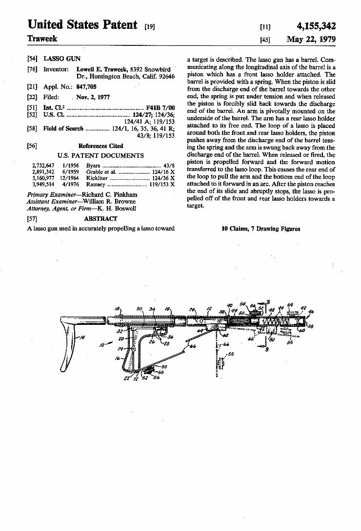
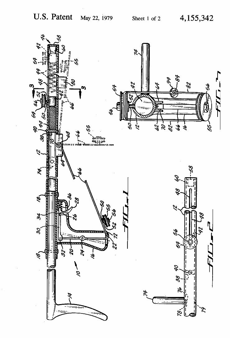
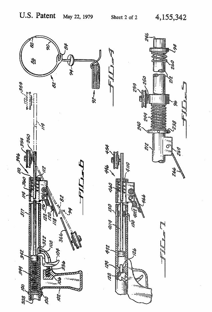
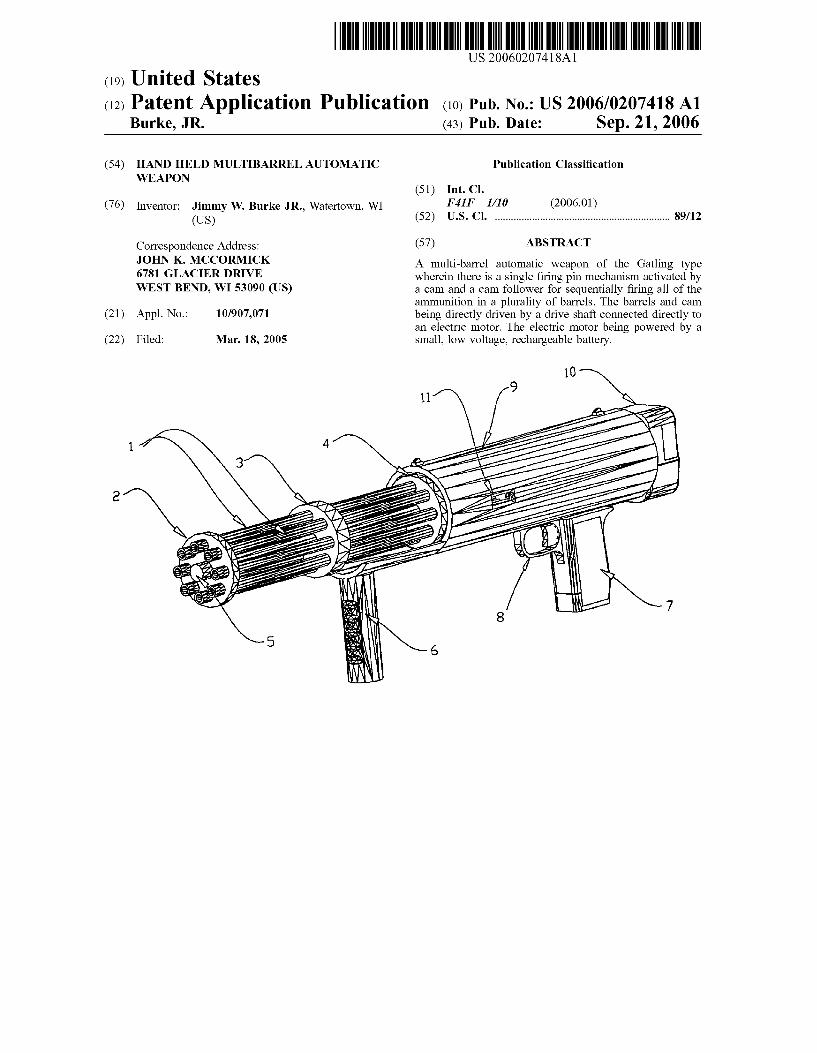
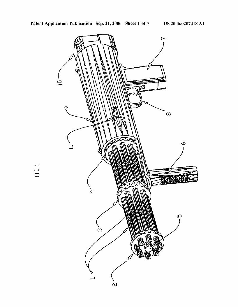
[57,] ABSTRACT A lasso gun used in accurately propelling a lasso toward
a target is described. The lasso gun has a barrel. Com municating along the longitudinal axis of the barrel is a piston which has a front lasso holder attached. The barrel is provided with a spring. When the piston is slid from the discharge end of the barrel towards the other end, the spring ‘is put under tension and when released .the piston is forcibly slid back towards the discharge end of the barrel. An arm is pivotally mounted on the underside of the barrel. The arm has a rear lasso holder attached to its free end. The loop of a lasso is placed around both the front and rear lasso holders, the piston pushes away from the discharge end of the barrel tens ing the spring and ‘the arm is swung back away from the discharge end of the barrel. When released or fired, the piston is propelled forward and the forward motion transferred to the lasso loop. This causes the rear end of the loop to pull the arm and the bottom end of the loop attached to it forward in an arc. After the piston reaches the end of its slide and abruptly stops, the lasso is pro pelled off of the front and rear lasso holders towards a target.
10 Claims, 7 Drawing Figures
77121111111115
US. Patent May 22, 1979 Sheet 1 of2 4,155,342
N .leu?lh Qm. um NR NW
mm “m A
US. Patent May 22, 1979 Sheet 2 of2 4,155,342
Note: Within nine months of the publication of the mention of the grant of the European patent in the European PatentBulletin, any person may give notice to the European Patent Office of opposition to that patent, in accordance with theImplementing Regulations. Notice of opposition shall not be deemed to have been filed until the opposition fee has beenpaid. (Art. 99(1) European Patent Convention).
Printed by Jouve, 75001 PARIS (FR)
(19)E
P2
208
959
B1
TEPZZ Z8959B_T(11) EP 2 208 959 B1
(12) EUROPEAN PATENT SPECIFICATION
(45) Date of publication and mention of the grant of the patent: 13.03.2013 Bulletin 2013/11
(21) Application number: 10150722.6
(22) Date of filing: 14.01.2010
(51) Int Cl.:F41B 11/646 (2013.01) F41B 11/89 (2013.01)
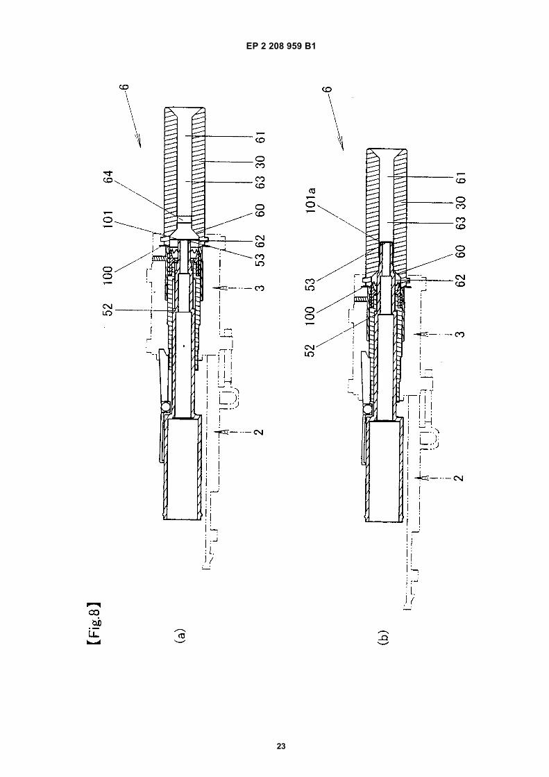
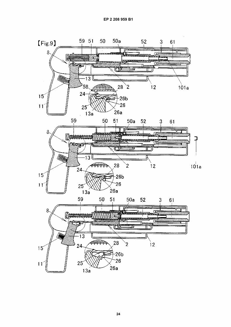
(54) Paper bullet firing pistol toy
Papiergeschosse abfeuernde Spielzeugpistole
Jouet de pistolet tirant des balles de papier
(84) Designated Contracting States: AT BE BG CH CY CZ DE DK EE ES FI FR GB GR HR HU IE IS IT LI LT LU LV MC MK MT NL NO PL PT RO SE SI SK SM TR
(30) Priority: 20.01.2009 JP 2009009584
(43) Date of publication of application: 21.07.2010 Bulletin 2010/29
(73) Proprietor: Agatsuma Co., Ltd.Tokyo (JP)
(72) Inventor: Funaki, ShotaroTokyo (JP)
(74) Representative: Skone James, Robert EdmundGill Jennings & Every LLP The Broadgate Tower 20 Primrose StreetLondon EC2A 2ES (GB)
(56) References cited: FR-A- 918 278 FR-A- 991 950US-A- 2 490 991 US-B2- 6 669 530
EP 2 208 959 B1
16
EP 2 208 959 B1
17
EP 2 208 959 B1
18

EP 2 208 959 B1
19

EP 2 208 959 B1
20
EP 2 208 959 B1
21
EP 2 208 959 B1
22
EP 2 208 959 B1
23
EP 2 208 959 B1
24
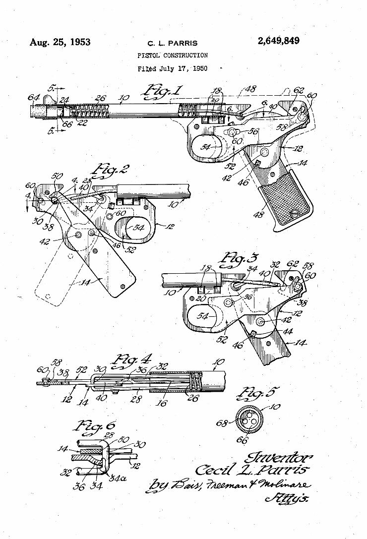
Aug. 25, 1953 c. L. PARRIS 2,649,849 I - ' PISTOL CONSTRUCTION
Filéd July 17,1950 -
@cz/L Farris"
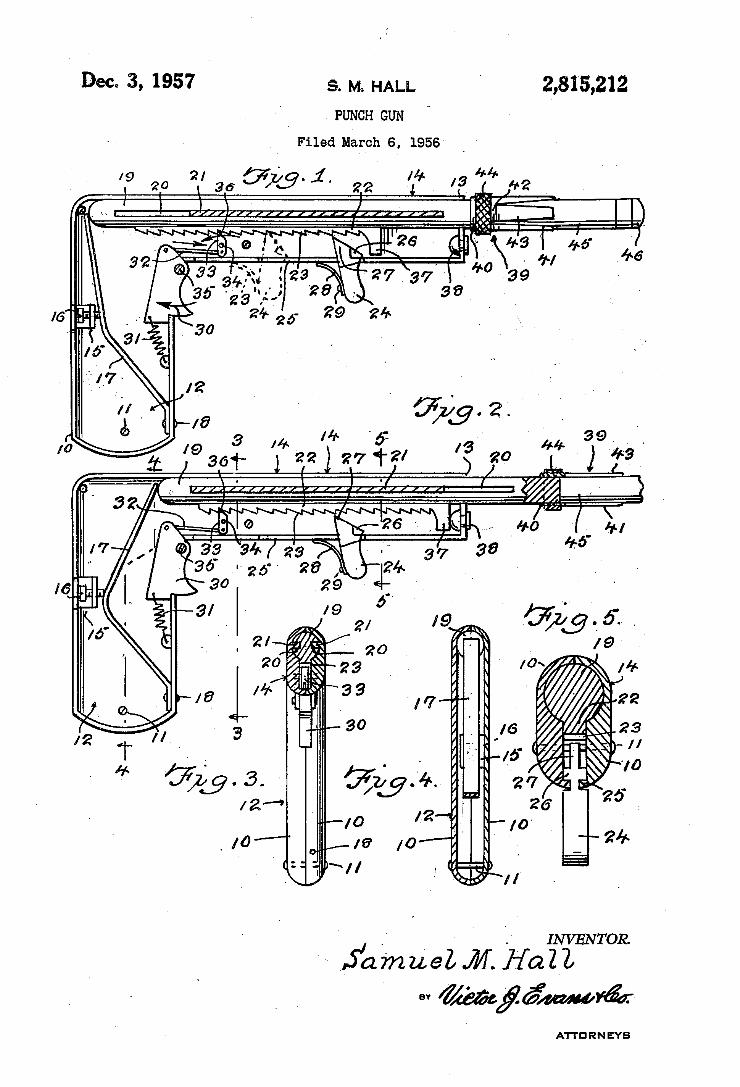
Dec. 3, 1957 s. M HALL ’ 2,815,212
l PUNCH GUN
Filed March 6, 1956
INV EN TOR.
ATTE RN EYB
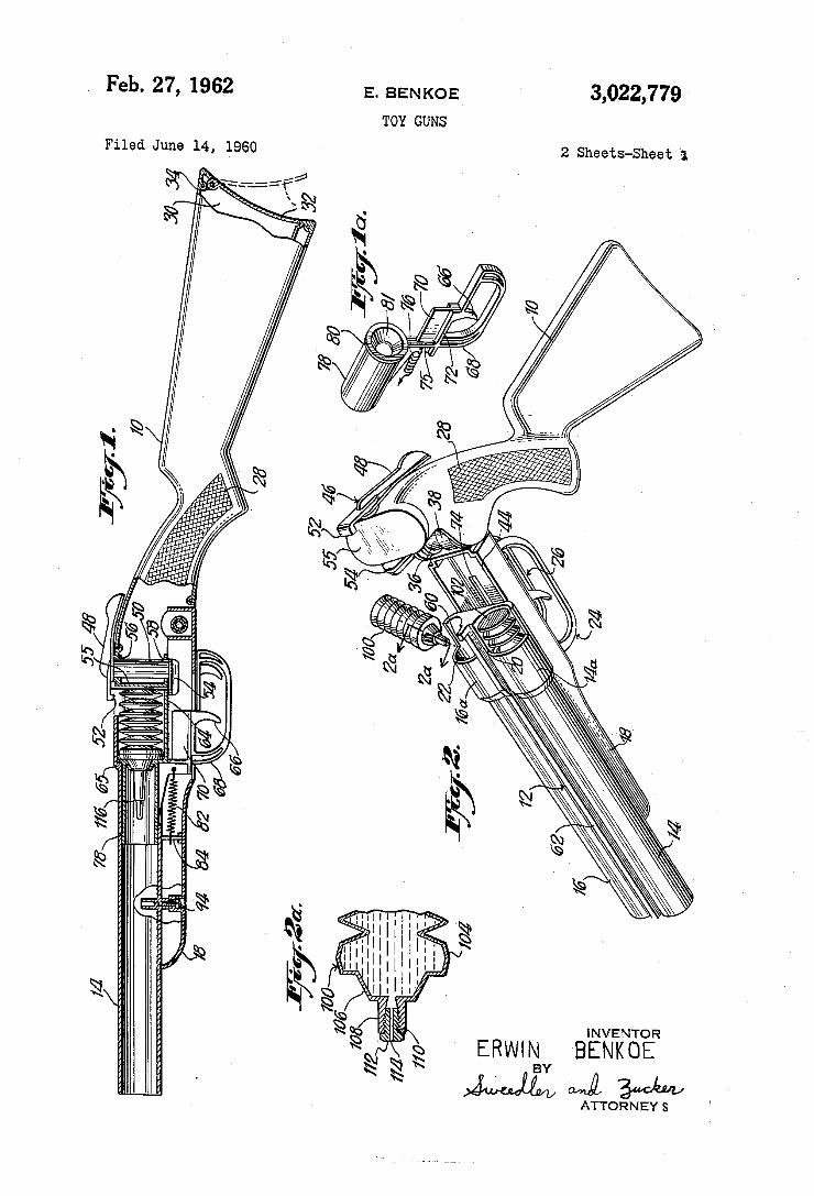
Feb. 27, 1962 E. BENKOE 3,022,779 TOY GUNS
Filed June 14, 1960 2 Sheets-Sheet 1
R
Ea .1. / Z5
Q ‘Q
Q [Q
g
{Q
§
E
\. INVENTOR
‘ ERWIN BENKOE @w . BY
\ AMA/Mil 3w” ATTORNEY S
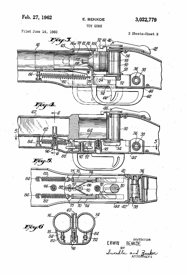
Feb. 27', 1962
Filed June 14, 1960
E. BEN KOE
TOY GUNS
, 3,022,779
2 Sheets-Sheet 2
127/4
III/IIIII'II'"
INVENTOR ERWW .BENKDE
BY
QTGZgOéNEYS
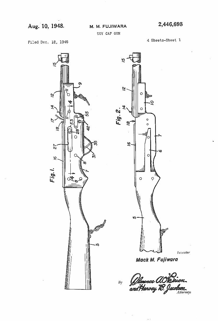
2,446,698 Aug. 10, 1948. M. M. FUJIWARA TOY CAP GUN
4 Sheets-Sheet 1 Filed Dec. 18, 1946
I11 renter
M. Fujiwara
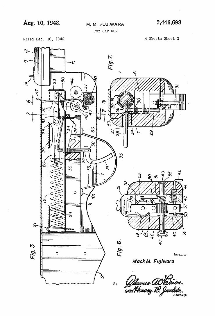
2,446,698 Aug- 10, 1948- M. M. FUJIWARA TOY CAP GUN
4 Sheets-Sheet 2 Filed Dec. 18, 1946
41 11:13:: 1-0
v Inventor
ack . Fujiwara
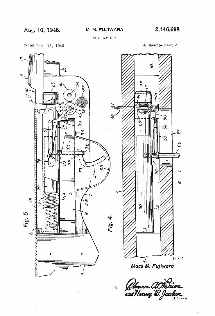
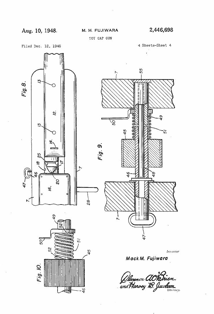
Aug. 10, 1948. M. M. FUJIWARA 2,446,698 TOY CAP GUN
Filed Dec. 18, 1946 4 Sheets-Sheet 4
lulu/im
/ Mack M. Fujiwara 45
Fig. I0.
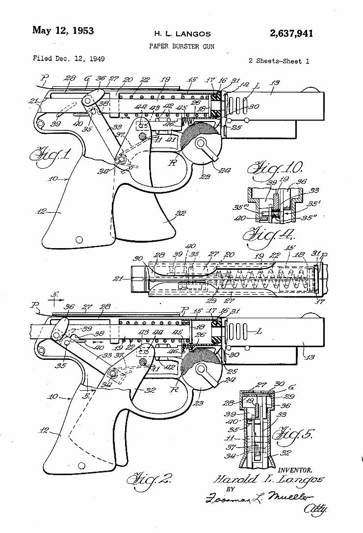
May 12, 1953 H. L. LANGOS 2,637,941 ‘ ' PAPER BURSTER GUN
Filed Dec. 12,v 1949 2 Sheets-Sheet l
1N V EN TOR.
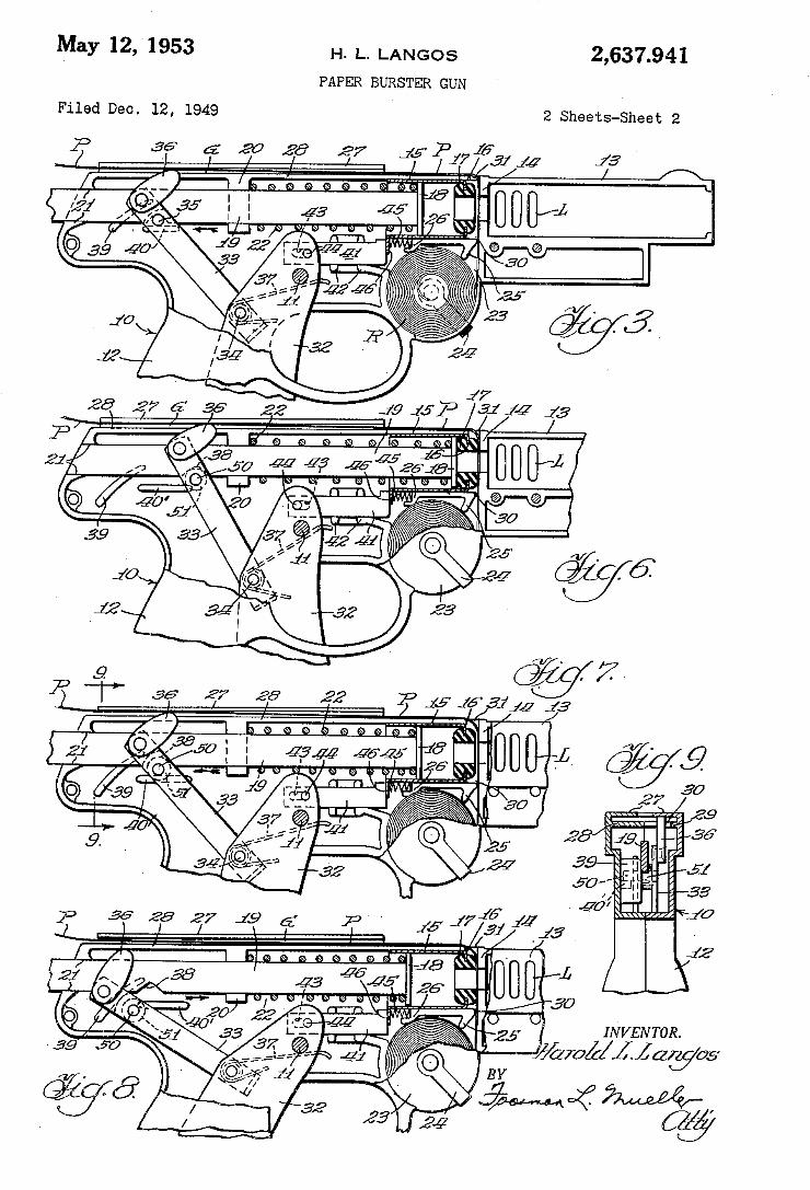
May l2, 1953 H. L. LANGOS
PAPER BURSTER GUN
2,637.941
Filed Deo. l2, 1949 2 Sheets-Sheet 2
. 7
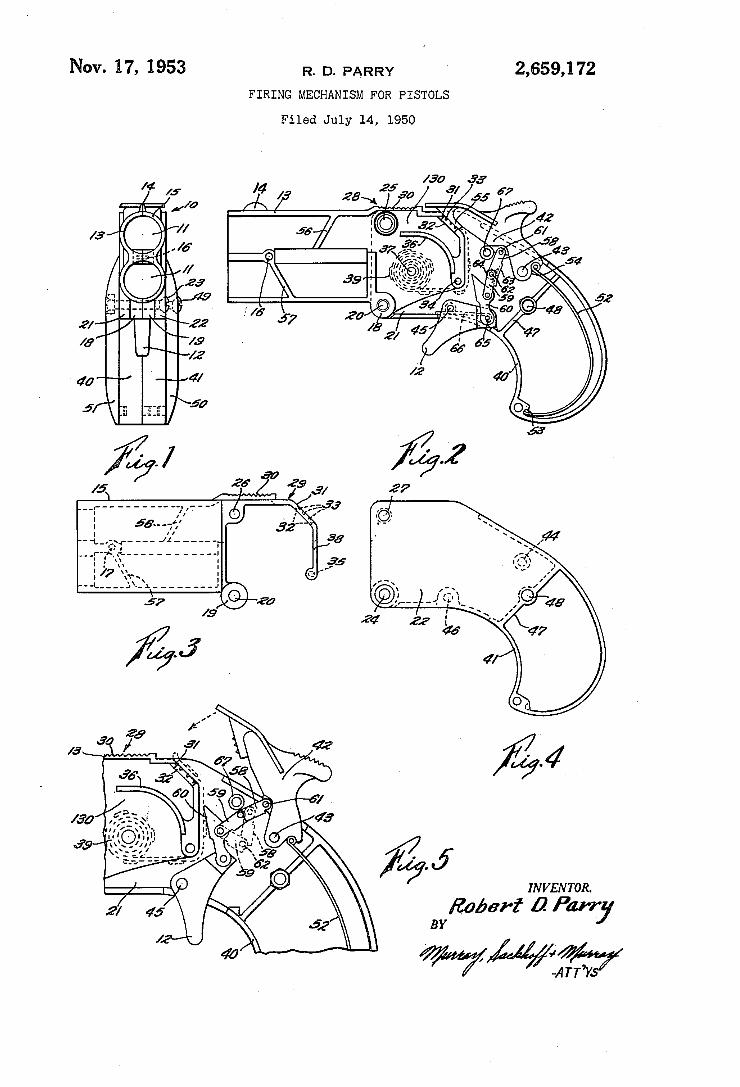
Nov. 17, 1953 R. D. PARRY ` 2,659,172
FIRING MECHANISM FOR PIsToLs
Filed July 14, 195o
Ä log. j IN V EN TOR
?ZaberÍ ä Parr] BY
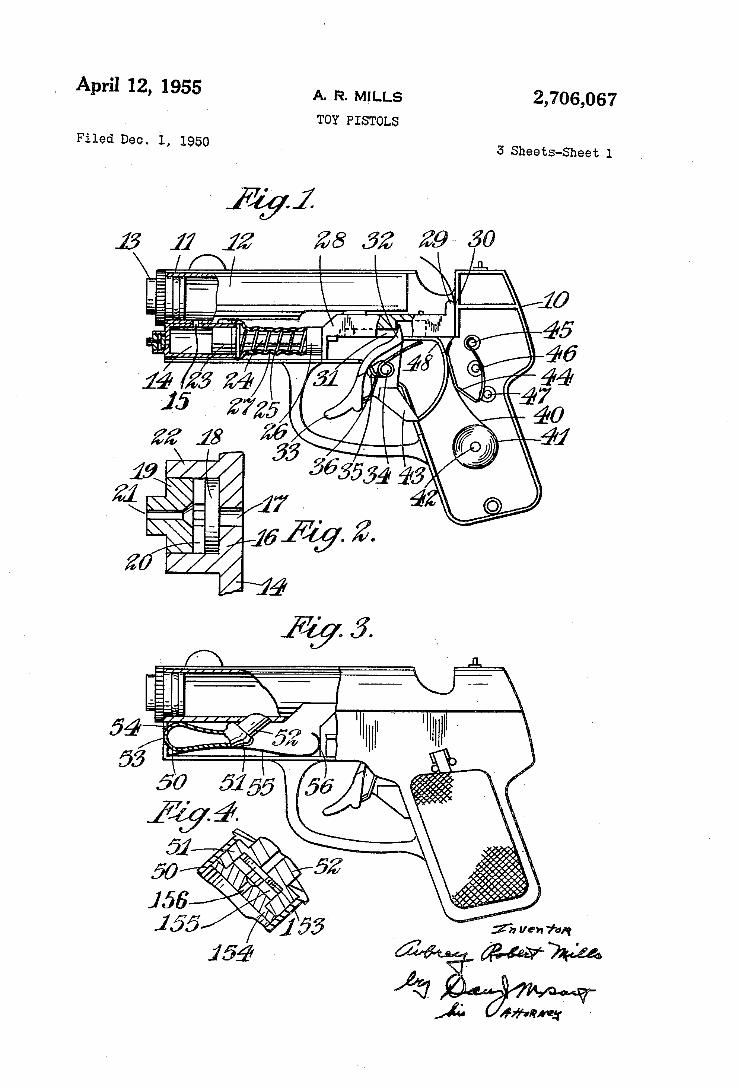
y April 12, 1955 A. R. MILLS 2,706,067 Toy PIsToLs
Filed Dec. l, 195o s sheets-sheet 1
HHH
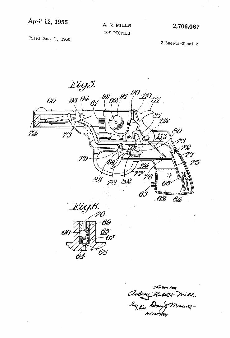
Apri] 12, 1955 A. R. MILLS 2,706,067 TOY PIsToLs
Filed Dec. l, 1950 3 Sheets-Sheet 2
// |l ß 619 @5
6% » a@
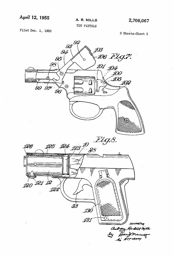
2,706,067 A. R. MILLS
TOY PISTOLS
April 12, 1955
5 sheéts-sheet 3 Filed Dec. l, 1950
ump' W.
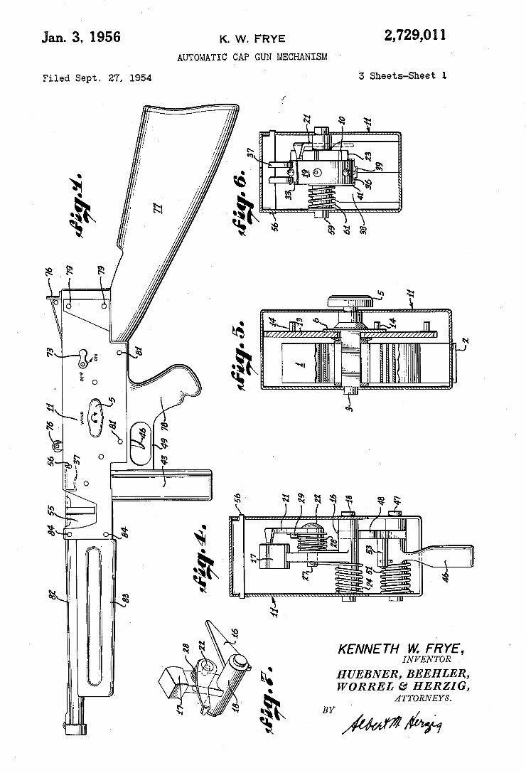
Jan. 3, 1956 K. w. FRYE 2,729,011 AUTOMATIC CAP GUN MECHANISM
Filed Sept. 27. 1954 5 Sheets-Sheet 1
KENNETH W. FRYE, INVENTOR
H UEBNER, BEEHLER, WORREL £9‘ HERZIG,
ATTORNEYS.
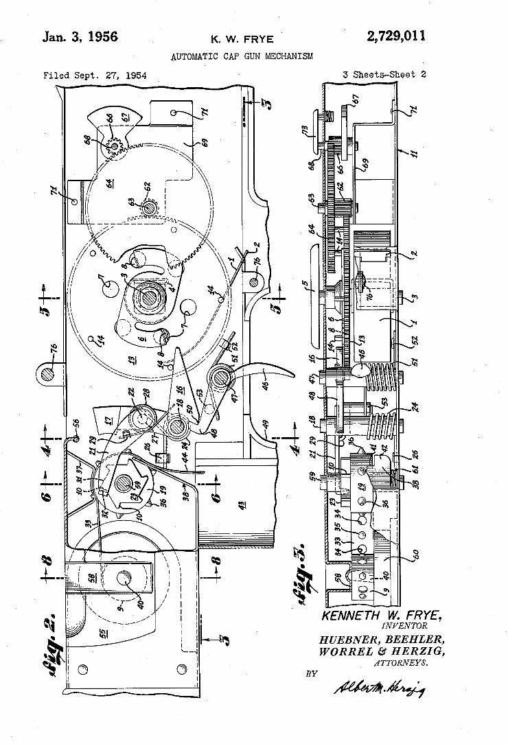
2,729,011 Jan. 3, 1956 K. w. FRYE '
AUTOMATIC CAP GUN MECHANISM
Filed Sept. 27, 1954 I5 Sheets-Sheet 2
E, R6, YRwus. a mmHRH \ m EEM {JUN [WV EH 0 _ 8. “l .. 3.. Q m BEN
Ill __..||_L H R1 4a ____,__ _ T EL v. _®__ E N BM QKR mm; % cN._ W0
K HW
BY
51
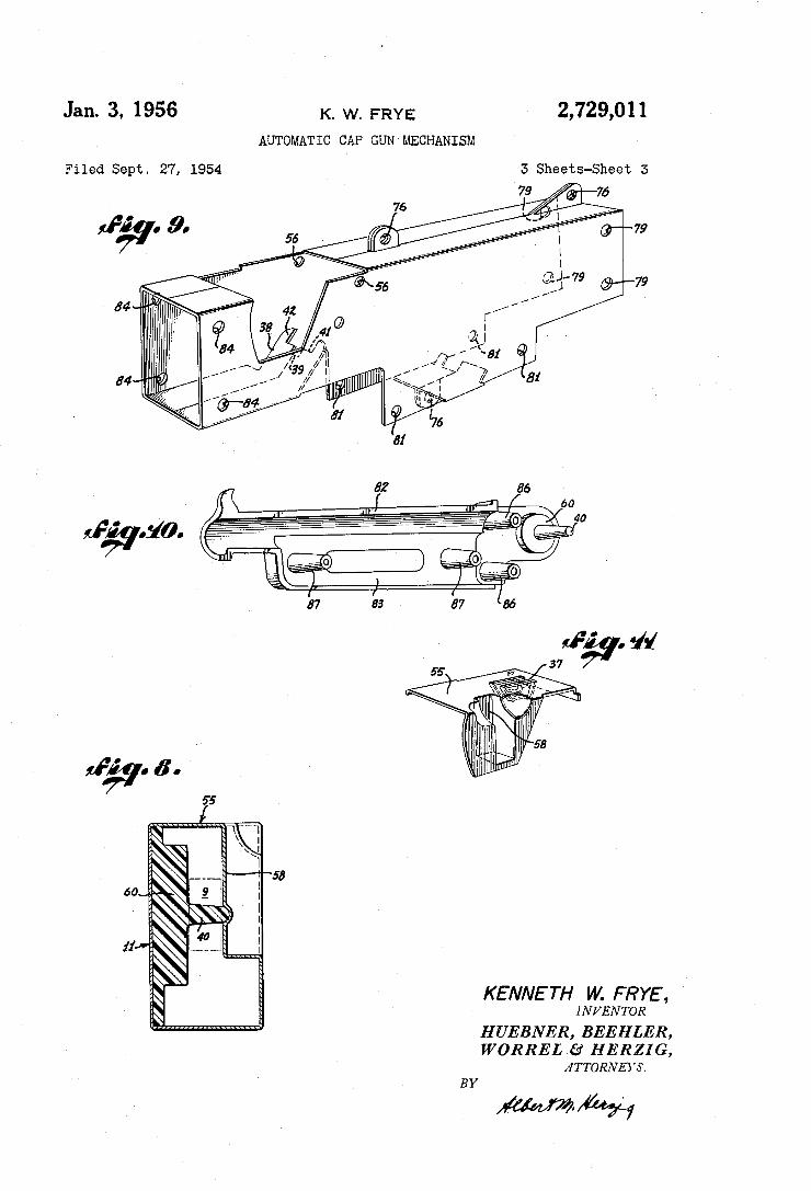
Jan. 3, 1956
Filed Sept. 27, 1954
K. W. FRYE 2,729,01 1 AUTOMATIC CAP GUN MECHANISM
60
3 Sheets-Sheet 3
KENNETH W. FRYE, INVENTOR
HUEBNER, BEEHLER, WORREL £9‘ HERZIG,
ATTORNEYS. Y
WM
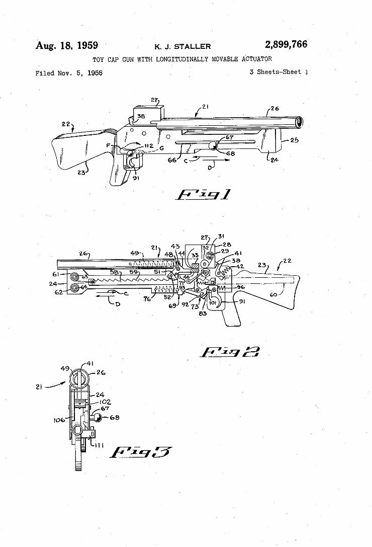
Aug. 18, 1959 ' K. J. sTALLER 2,899,765
TOY CAP GUN WITH LONGITUDINALLY MOVABLE ACTUATOR
Filed Nov. 5, 1956 ` 3 Sheets-Sheet 1
«n» î... Y \ul on
N Ñ
`\ E
\ N m
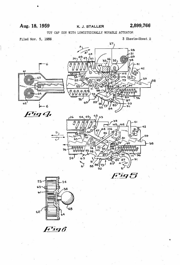
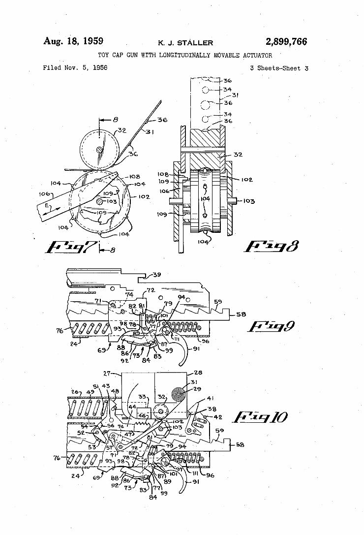
Aug. 18, 1959 K. J. sTALLER I ' 2,899,766
TOY CAP GUN WITH LONGITUDINALLY MOVABLE ACTUATOR
Filed Nov. 5, 19564 5 Shee‘cs-Sheet~2A
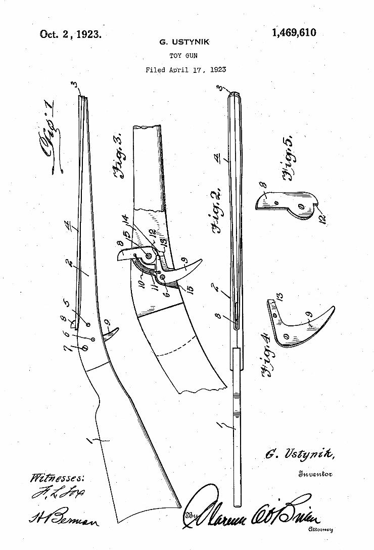
Oct. 2, 1923.’ - 1,469,610 ' I G. USTYNIK' I '
TOY GUN
Filed April V17, 1923
Z”? 1% I
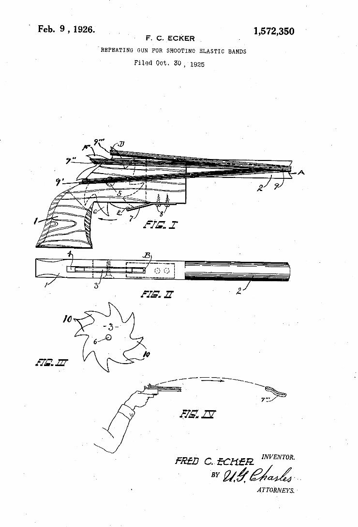
1,572,350 Feb. 9 , 1926; F. c. EcKER
JREPEATING GUN FOR SHOOTING ELASTIC BANDS
Filed Oct. 30, 1925
J . w
INVENTOR.
__BY
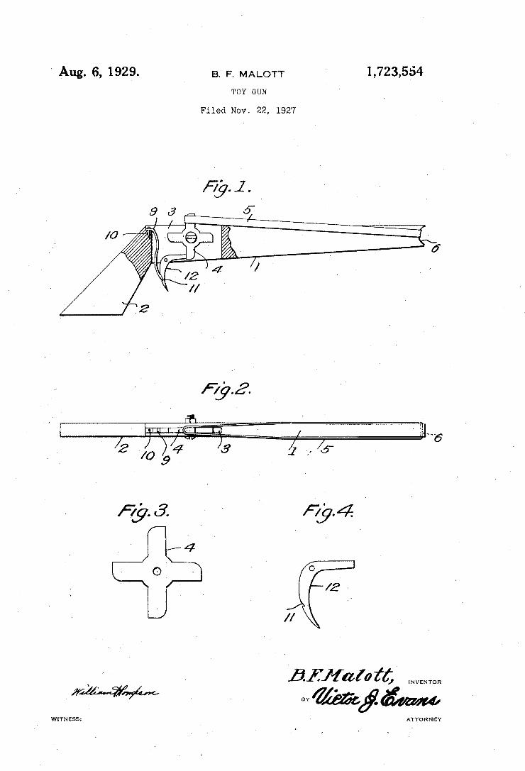
1,723,554 B. F. M ALOTT ~ Aug. 6, 1929.
Filed Nov. 22, 1927
(5..
i794 ‘
/2~
//
wrmess: ATTO R N EY
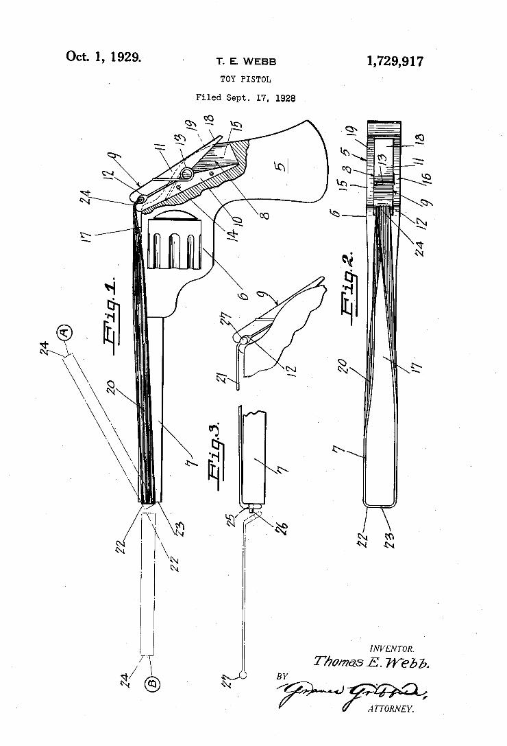
Oct. 1, 1929.’ - T. E. WEBB 1,729,917
TOY PISTOL
Filed Sept. 17, 1928
am A
> ' IN V EN TOR.
/ 7X T/mmas E. Web 5. O B Y
/ v.
4' I
‘ A TTORNE Y.
24 GD 25
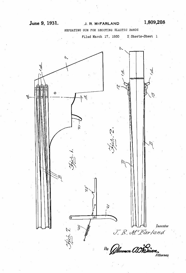
June 9, 1931. .1. R. MCFARLAND 1,809,203 ‘ _ REPEATING GUN FOR SHOOTING ELASTIC BANDS
Filed March 17, 1930 2" Sheets-Sheet l
v
A?
W
i
_ Inventor
f1? </_%C ar/amd
$5 ‘ ' 1392mm A ttomcy
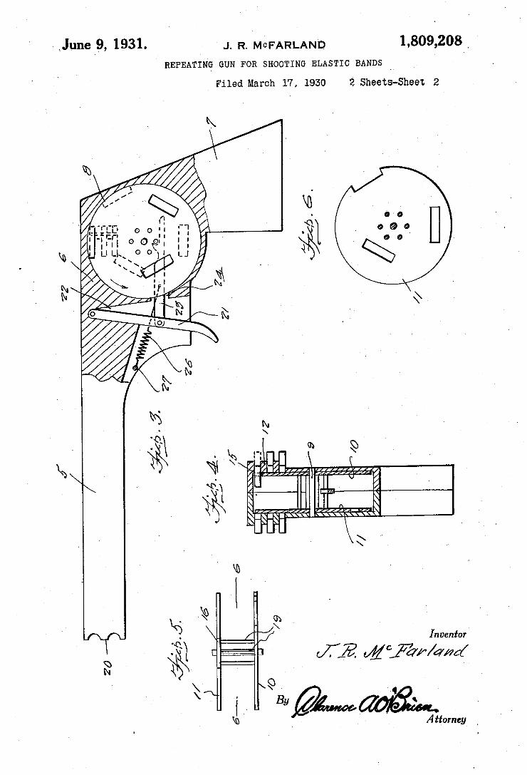
‘ June 9, 1931. J. R. MGFARLAND 1,309,208 .
' REPEATING GUN FOR SHOOTING ELASTIC BANDS ‘
Filed March 1'7, 1930 2 Sheets-Sheet 2
Inventor
Attorney _
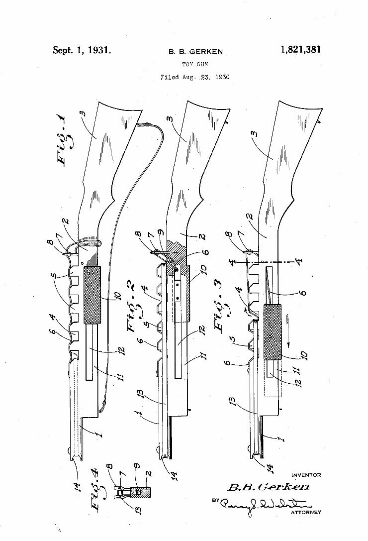
1,821,381 B` B. JGERKEN Sept. 1, 1931. TOY GUN
Filed Aug. _23. 1930
......... -.
INVENTOR A 5.5’. Gerkfn
MGM?? _ 9.13m ATTORN EY
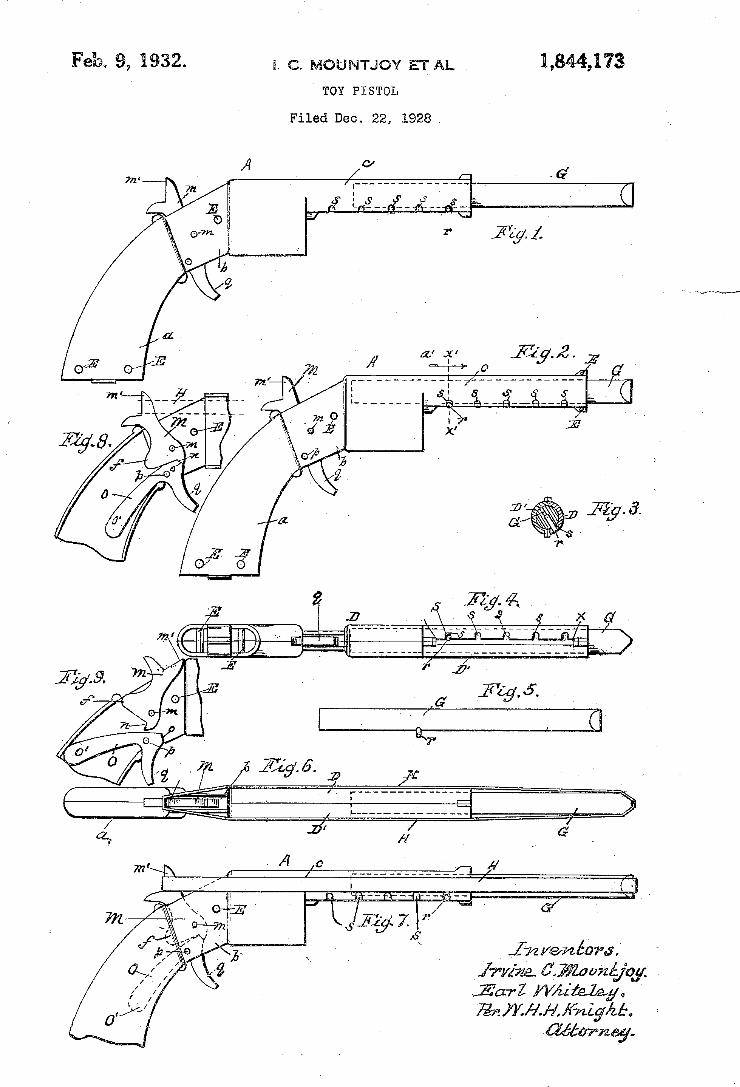
Feb, 9, M32. s. c. MOUNTJOY ET AL L8449l73
TOY PISTOL
Filed Dec. 22, 1928

May 23, 1933-v P. w. BEAUCHAMP ET AL 1,909,927 REPEATING RUBBER BAND RIFLE _ I
Filed Aug. 27, 19,52
-|
ATTORNEYS. '.
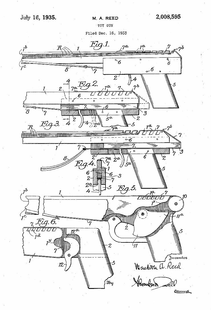
¿008,595 M. A. REED Äußy B6, 1935. TOY GUN
Filed DSC. 16, 1953
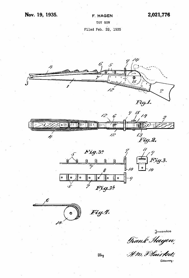
Nov. 19, 1935. , F. HAGEN 2,021,776 TOY GUN
Filed Feb. 28, 1935
$2», -
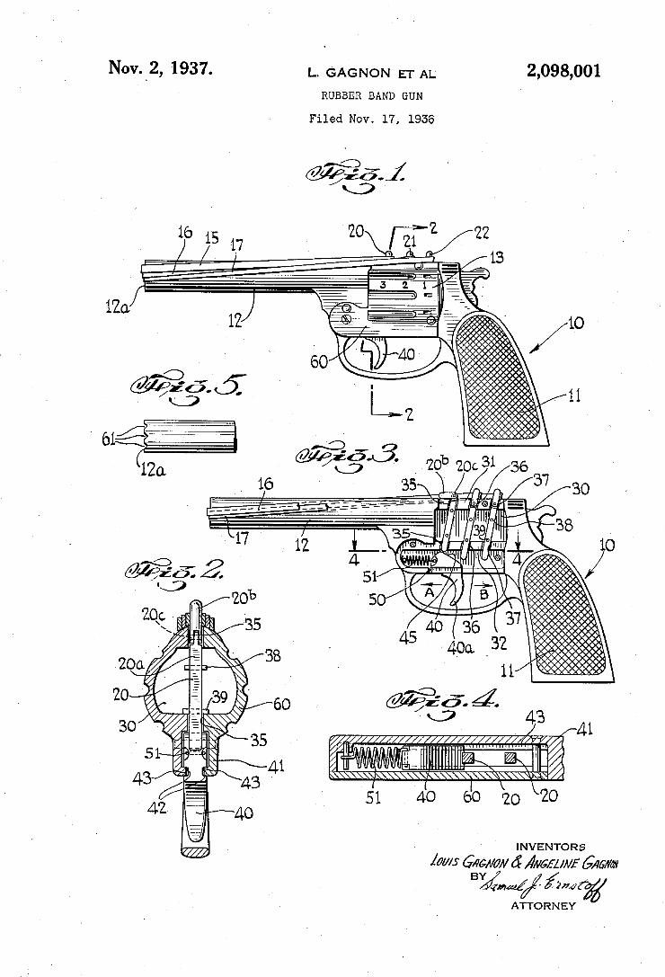
2,098,001 Nov._2, 1937. L. GAGNON ET AL RUBBER BAND GUN
Filed Nov. 17, 1936
INVENTORS
laws GAGA/0M a? ?/vm/A/f 6mm
0 000000 0000000000. ooooooooooé oono?owwwnwwowpobovosv .‘
16 1'5 0
/ _/v 17
__ _.______ _ ______
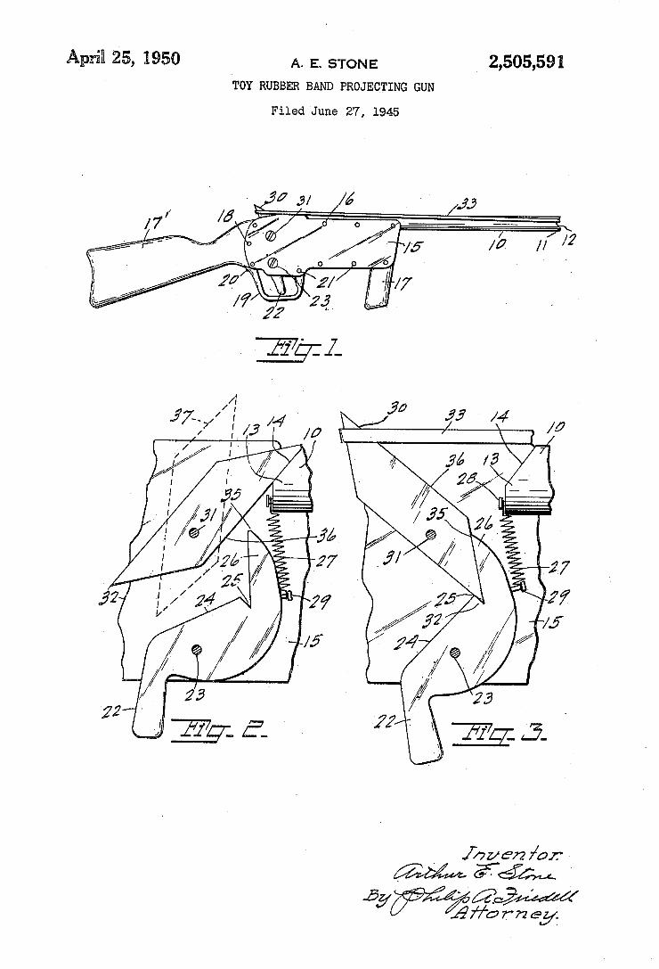
April! 25, 1950 A. E. STONE 7 2,505,591
TOY RUBBER BAND PROJECTING GUN
Filed 'June 27, 1945
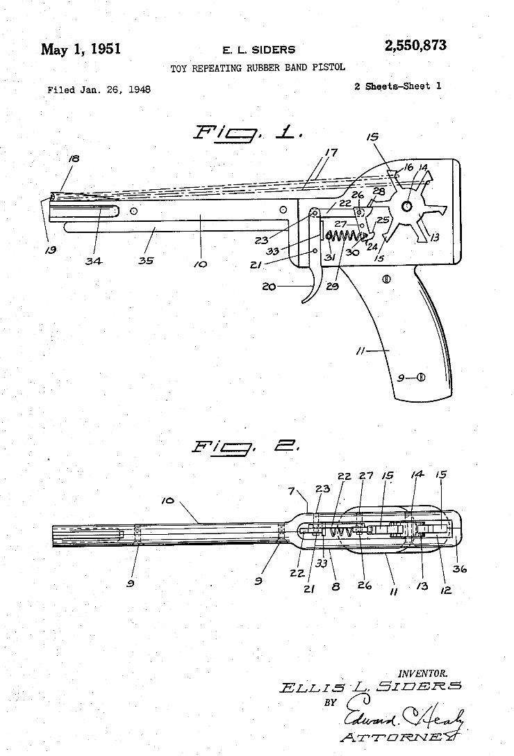
May 1, 1951 E. |_. SIDERS 2,550,873 Toy REPEATING RUBBER BAND PISTOL '
Filed Jan. 26, 1948 ’ 2 Sheets-Sheet l
9-4115
., INVENTOR.
ELLIS ‘L, EIDERS _BY I
ATTURAZE
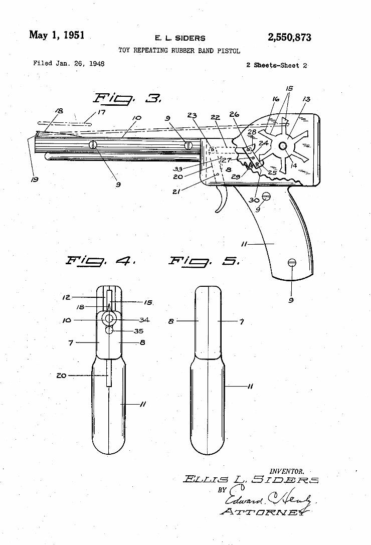
May 1, 1951 E. 1.. SIDERS 2,550,873 TOY REPEATING RUBBER BAND PISTOL
Filed Jan. 26, 1948 2 Sheets-Sheet 2'
INVENTOR. ELLIS L, 515E515
BYQMQ/ ' ATTURNE:
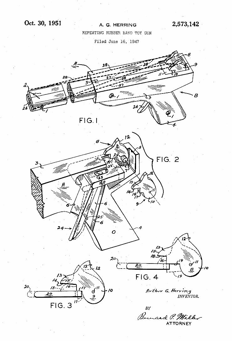
Oct. 30, 1951 ‘ ' A_ G_ HERR|NG I 2,573,142
REPEATING RUBBER BAND TOY_ GUN
Filed June 16, 1947
?vl‘lur G, lqerrr'irlg INVENTOR.
ATTORN EY
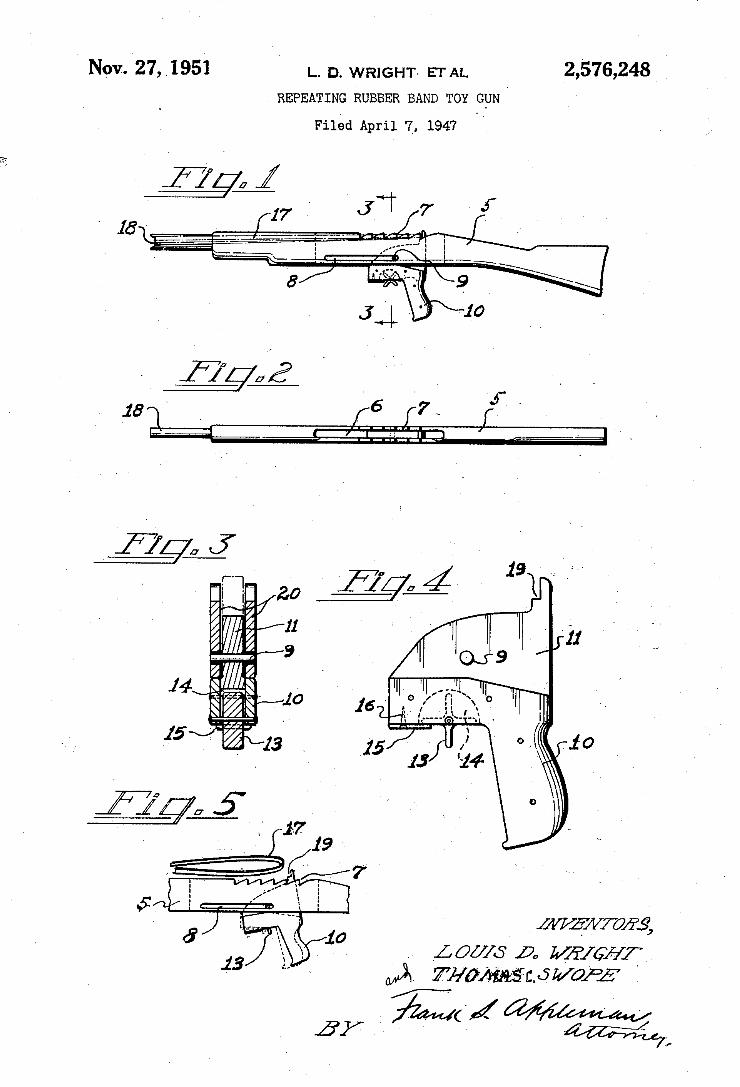
NOV. 27, |___ D_ wRlgHT. ETAL 2,576,248 REPEATING RUBBER BAND TOY GUN I '
Filed April 7, 1947 "
. Lox/1s p, WEIGHT ,
INVENTOR
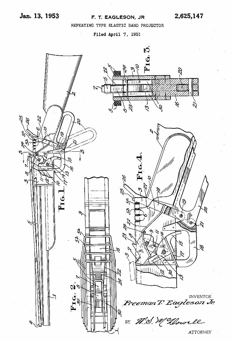
lfiz’emazz T Z’QyZesan Jr
ATTORNEY
2,625,147
BY. rid §%W
F. T. EAGLESON, JR
REPEATING TYPE ELASTIC BAND PROJECTOR
Filed April 7, 1951
Q
Jan. 13, 1953
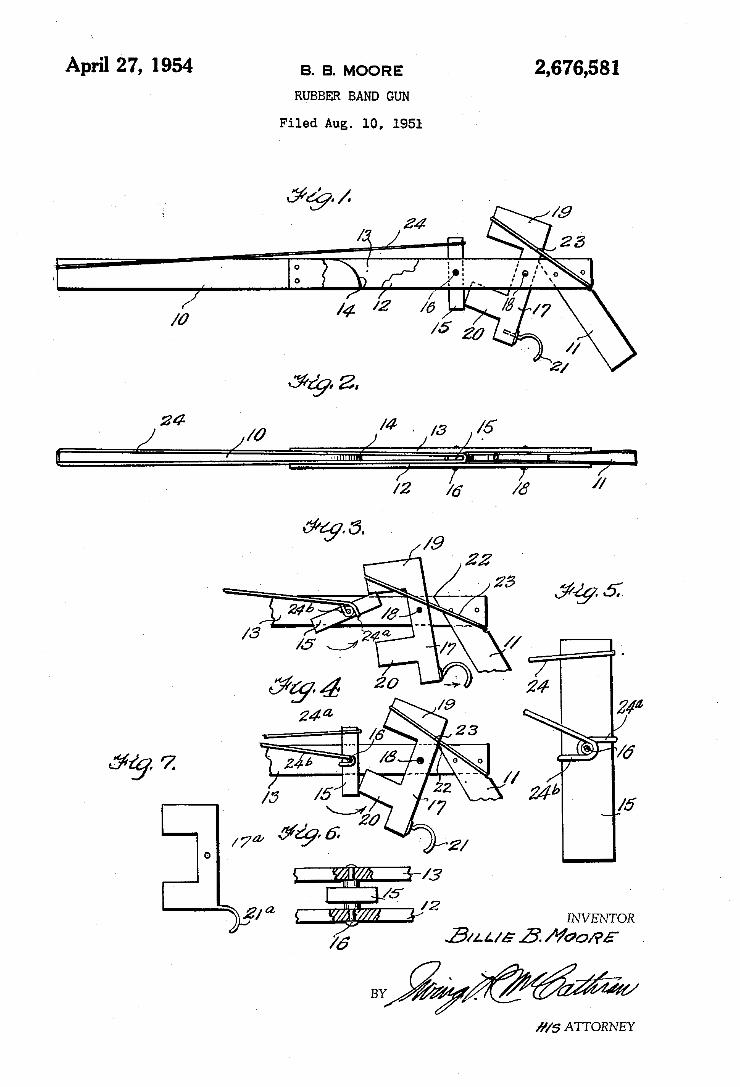
2,676,581 April 27, 1954 a. B. MOORE RUBBER BAND GUN
Filed Aug. 10, 1951
g. A
INVENTOR
3/2. 4 IE 15’. Moo/PE
BY
,y/s ATTORNEY
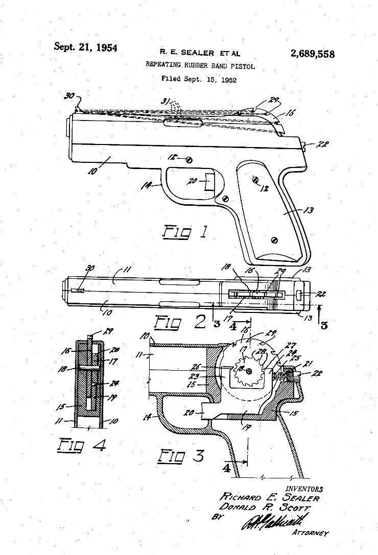
2,689,558 sept. 21, 1954
_ R. E. SEALER ETAL
REPEATING RUBBER BAND PISTOL
Filed sept. 15. l1952
f Il, »lll/IIIA ,lll/1111111141554 /f//lllrf/r;
INVENToRs ~ ff Sfmt-R
ßa/mzp Ä? «50077
Arran/vir
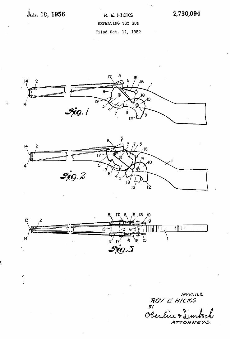
Jan. 10, 1956 ' R. E. HICKS 2,730,094
REPEATING TOY GUN
Filed Oct. 11, 1952
INVENTOR.
370V 5 f/lC/‘R‘S
(Quill. ‘TL/MAJ AWOENEYG.
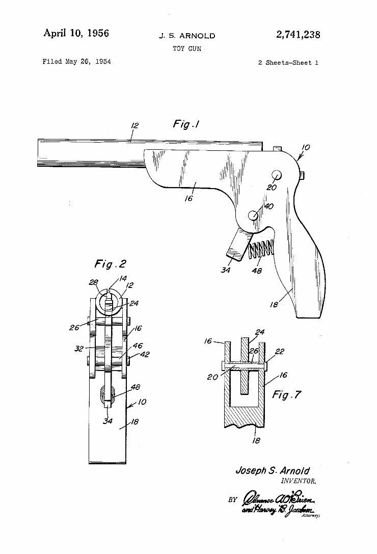
April 10, 1956 J. s. ARNOLD 2,741,238 TOY GUN
Filed May 26, 1954 2 Sheets-Sheet 1
%
Joseph .5’. Arnold IN V EN TOR.
BY MM yjmaifghm
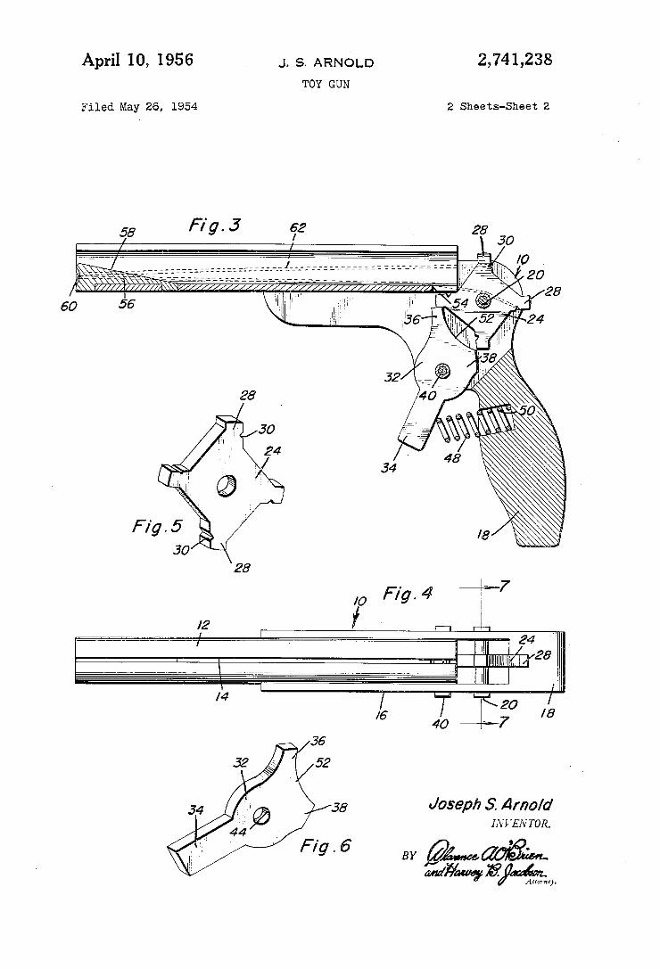
2,741,238 April 10, 1956 J. s. ARNOLD TOY GUN
2 Sheets-Sheet 2 Filed May 26, 1954
28 60
52 t 24 ‘H; ‘
Joseph 5‘. Arnold 11W ‘EN TOR.
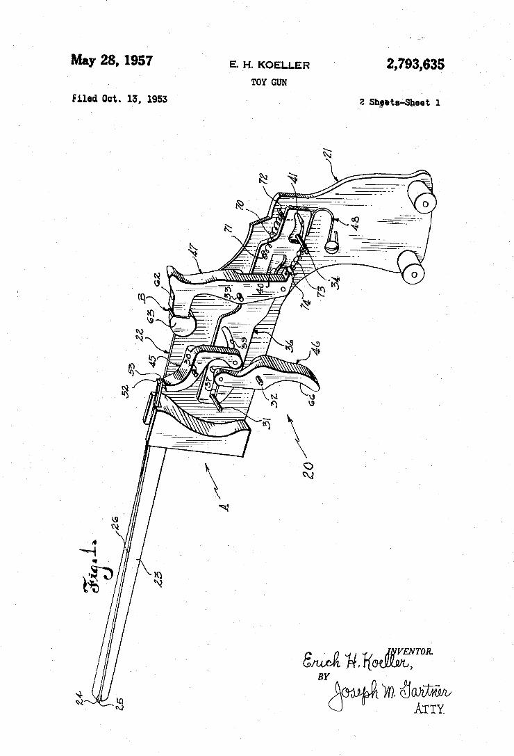
May 28, 1957 E. H. KOELLER 2,793,635 ' TOY sun
Filed Oct. 13, 1953 2 Shgeta‘Sheet 1
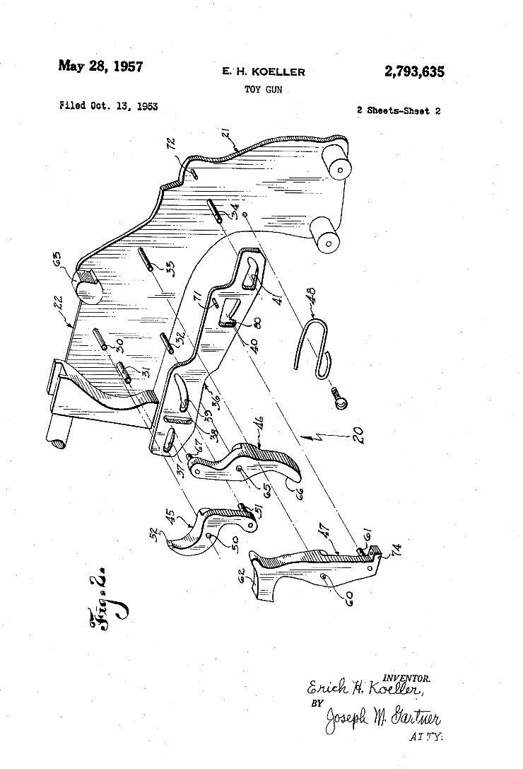
May 23, 1957 EH. KOELLER 2,793,635 TDY cuu
Filed on. 13, 1953 2 Sheets-Sheet 2
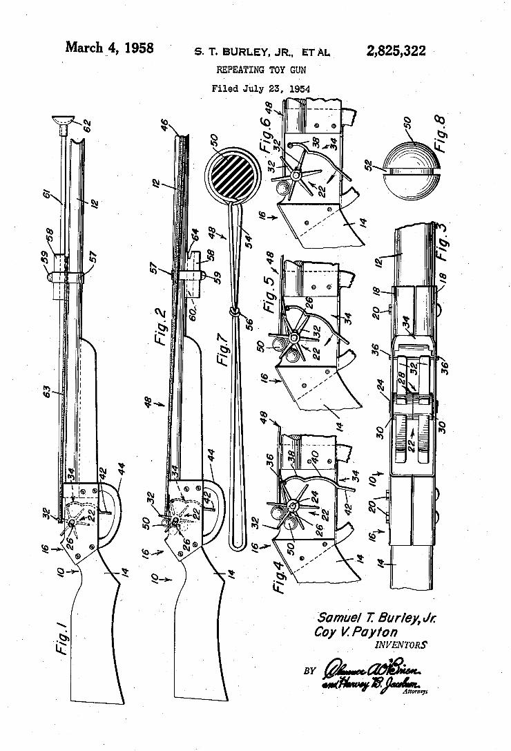
March __4, 1958 ‘ s. 'r. BURLE'Y, JR, ET AL 2,825,322 ' REPEATING TOY GUN l
Filed July 23, 1954 ‘
| '1'.’
.. M 1/
Samuel T. Bur/e], J1: Coy V. Payton
INVENTORS
B; 24mm » “#WFM,» -
30
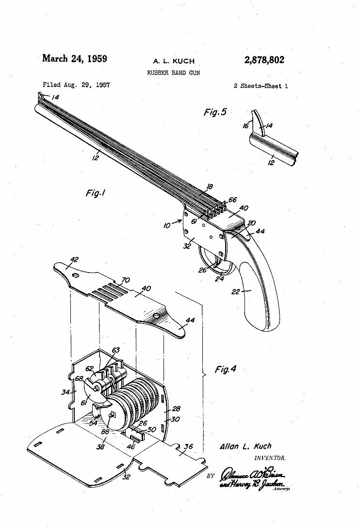
March 24, 1959 A. L. kucH 2,878,802 RUBBER BAND GUN
Filed Aug. 29, 1957 2 Sheets-Sheet l
Fig.5 '
Allan L. Kuch INVEN TOR.
£40m
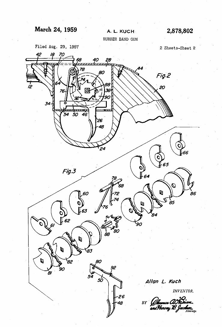
March 24, 1959 ' A. |_. KUCH 2,878,802
RUBBER BAND GUN
Filed Aug. 29, 1957 ‘ 2 Sheets-Sheet 2
44
F 1'92
20
Allan L. Kuch
INVENTOR.
BY '
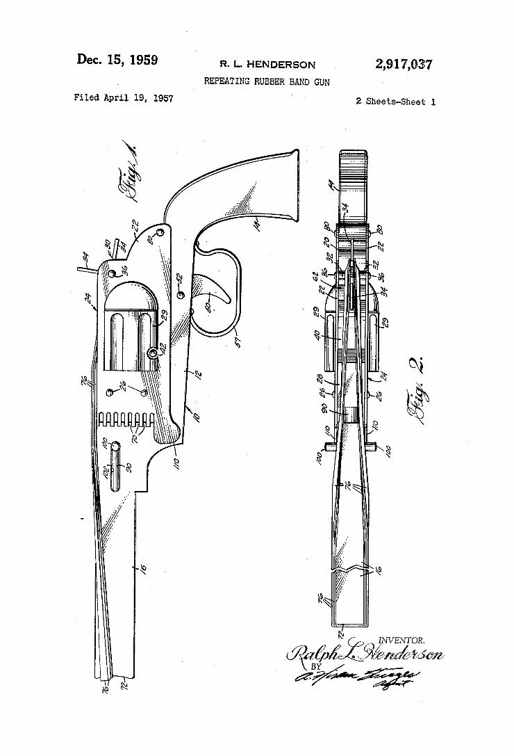
2,91 7,037 Dec. 15, 1959 R. L. HENDERSON
REPEATING RUBBER BAND GUN
2 Sheets-Sheet 1 Filed April 19, 1957
m
H h
‘M u
. lllliizl Mm KWJ
(Q1 ,, INVENOR.
J pKUZ%,/w%
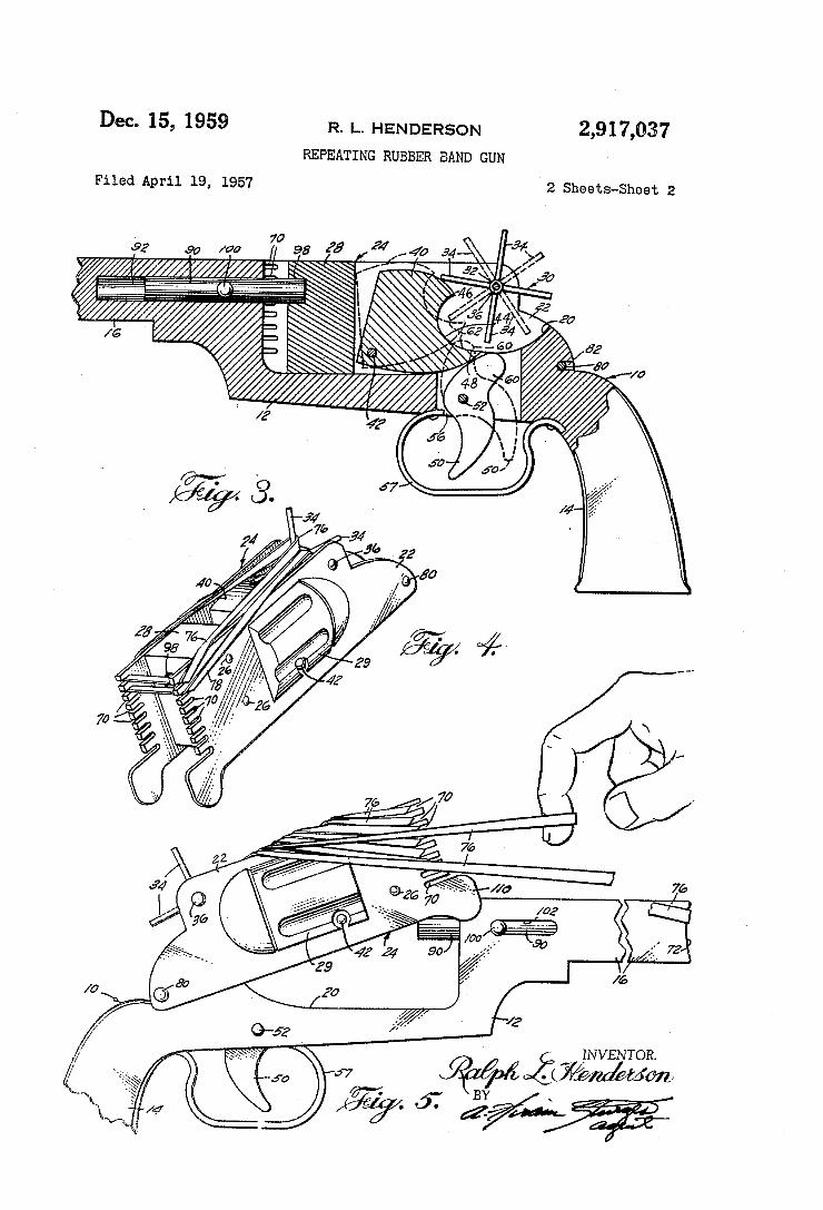
Dec. 15, 1959 R. |_. HENDERSON 2,917,037 REPEATING RUBBER BAND GUN
Filed April 19, 1957 2 Sheets-Sheet 2
/ QéjgéIiJVENTOR. /
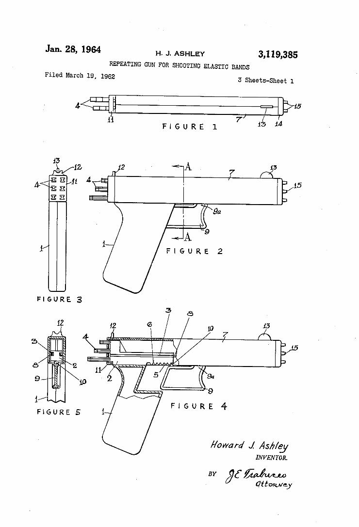
Jan. 28, 1964 H. J. ASHLEY 3,119,385 REPEATING GUN FOR SHOOTING ELASTIC BANDS
Filed March 19, 1962 3 Sheets-Sheet 1
7 4 M FIGURE 1 1 1
:5
Jib/‘Z 2 ' <_A ' 7 r”? £341 4 . ' 15 4\EE g . 33 E __/
9a
9 -+J_A_ 1/ 1 FIGURE 2
\___J FIGURE 3
3,’ a 12 12 6 10 15
7 5 I, A 5 sllli
d‘ : nkMAA/‘l ‘5 11 5/ 9a 9 1p 9
1 FIGURE 4 FIGURE 5 1
Howard J As/z/gy IN V EN TOR.
BY jg 5M 01 [011mg]
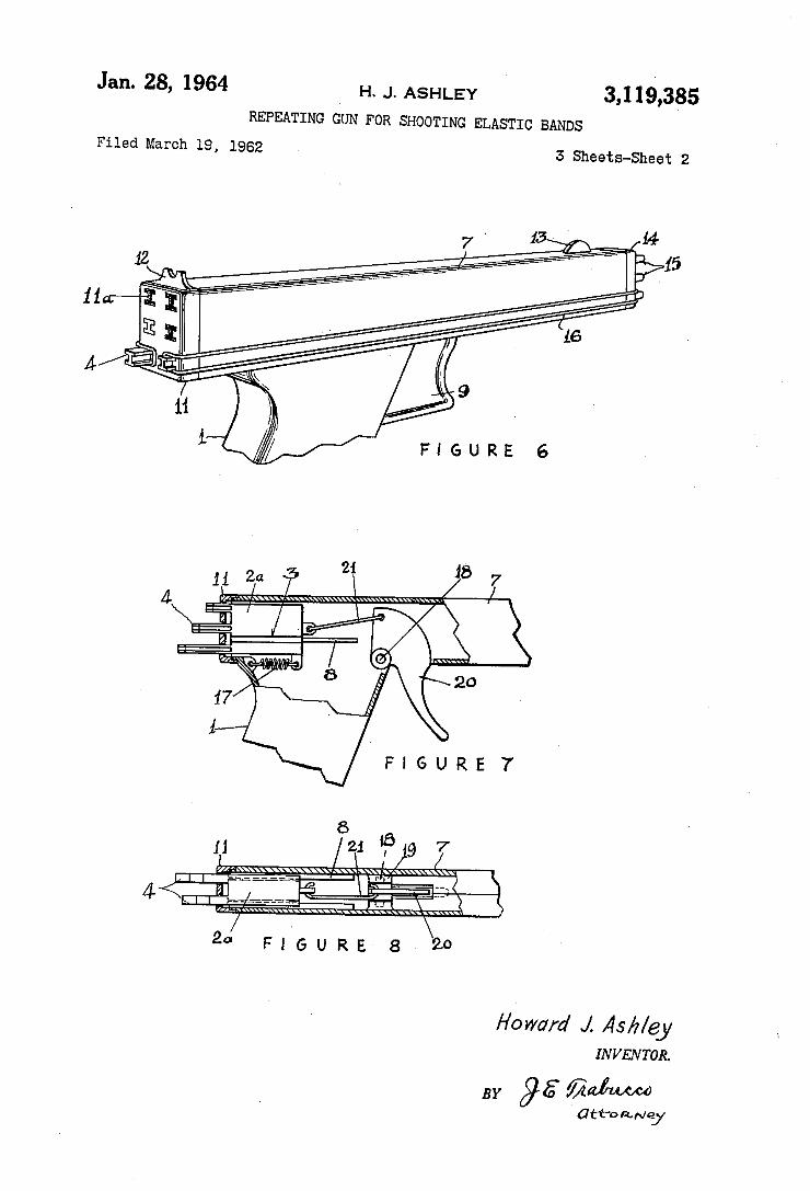
Jan. 28, 1964 H. J. ASHLEY 3,119.,385 REPEATING GUN FOR SHOOTING ELASTIC BANDS
Filed March 19, 1962 3 Sheets-Sheet 2
FIGURE 6
\\ \\\\\\\\
2“ FIGURE 8 20
Howard J. Ask/6y IN V EN TOR.
BY 95 $3M
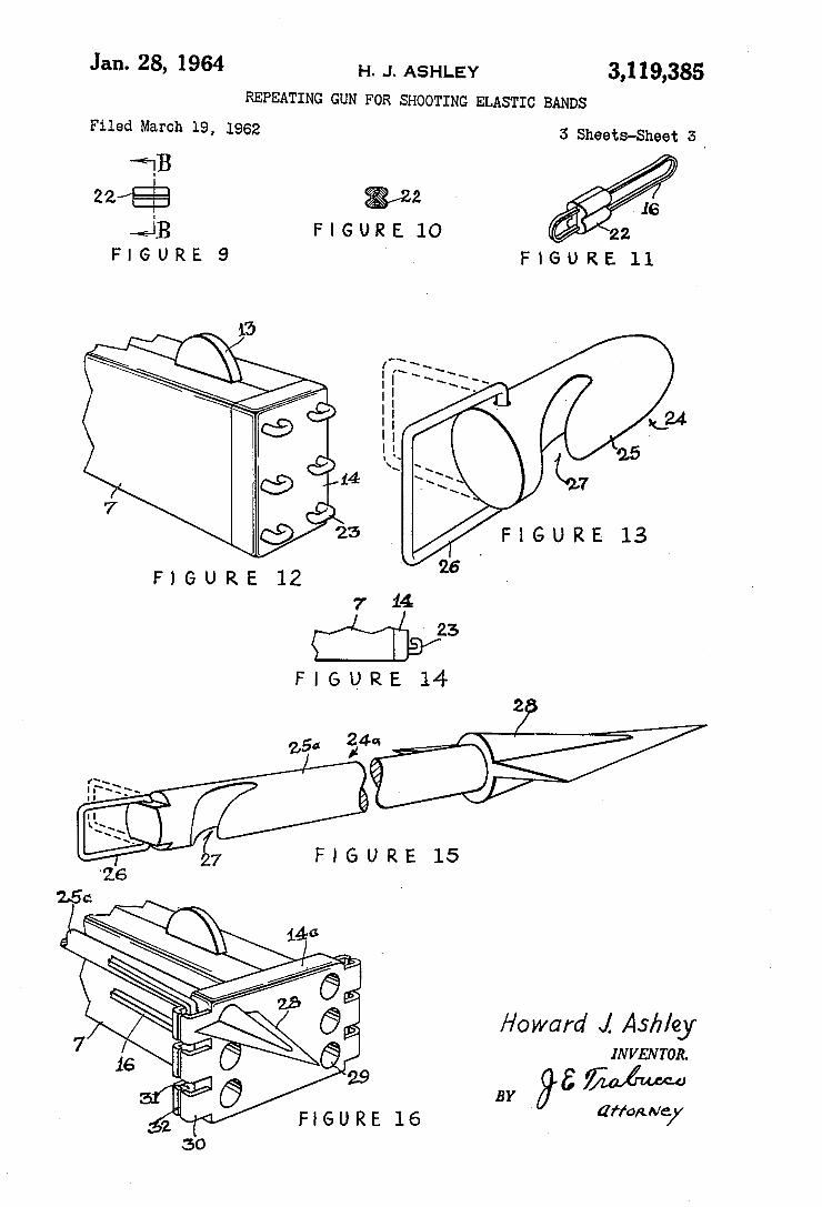
Jan. 28, 1964 H. J. ASHLEY 3,119,385 REPEATING GUN FOR SHOOTING ELASTIC BANDS
Filed March 19, 1962
*WB >
22/E5 W2 16 Q]; FIGURE 10 22
FIGURES FIGURE 11
Howard J. Ashley
ziffarznkgy
3 Sheets-Sheet 3‘
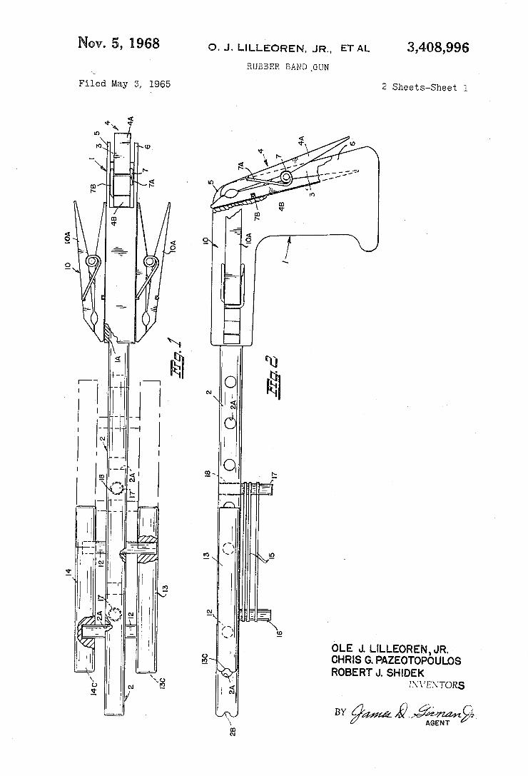
o. J. LILLEOREN, JR., ET AL 3,408,996 Nov. 5, 1968 RUBBER BAND _GUN
2 Sheets-Sheet l Filed May~ 5, 1965
AGENT
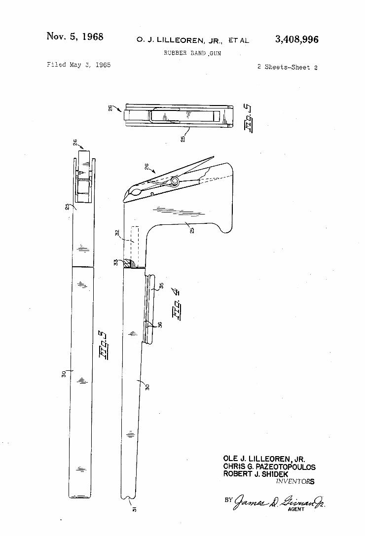
Nov. 5, 1968 o. J. LILLEOREN, JR., ET AL 3,408,995
RUBBER EAND _GUN
Filed May E, 1965 2 Sheets-Sheet 2
30I
OLE J. LILLEOREN, JR. CHRIS G. PAZEOTOPOULOS ROBERT J. SHIDEK
INVENTORS
lli
E AGENT
BY
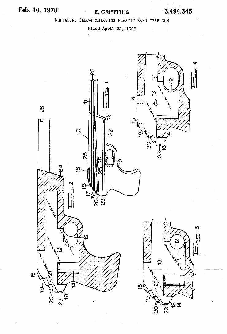
3,494,345 E. G R! FFITHS Feb. 10, 1970 REPEATING SELF-PROJECTING ELASTIC BAND TYPE GUN
Filed April 22, 1968
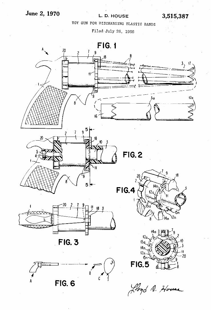
June 2, 1970 L. 5. HOUSE 3,515,387 TOY GUN FOR DISCHARGING ELASTIC BANDS
Filed - July 26, 1.968
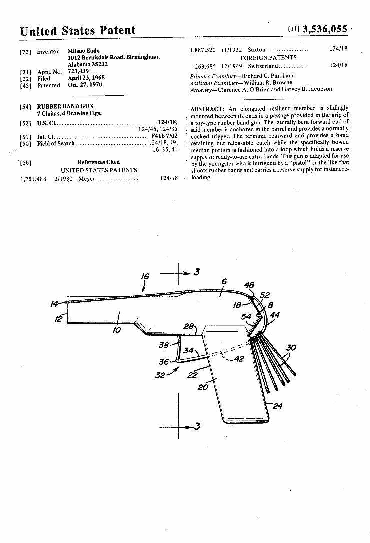
United States Patent
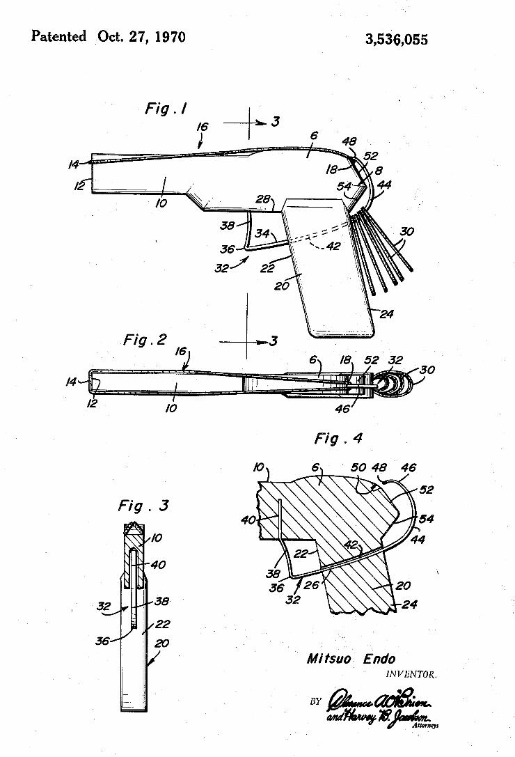
[72] Inventor Mitsuo Endo 1012 Barnisdale Road, Birmingham, Alabama 35232
[21] Appl. No. 723,439 [22] Filed April 23, 1968 [45] Patented Oct. 27, 1970
[54] RUBBER BAND GUN 7 Claims, 4 Drawing Figs.
[52] U.S.Cl ............. ... ...................................... .. 124/18,
124/45, 124/35 [51] lnt.Cl ....................................................... .. F4lb 7/02
[50] Field ofSearch .......................................... .. 124/18, 19, .,~ 16, 35. 41
v[56] References Cited UNITED STATES PATENTS
1,751,488 3/1930 Meyer ........................ .. 124/18
l11l3,53.6,055 -
11/1932 Saxton ........................ .. 1,887,520 124/18 FOREIGN PATENTS
263,685 12/1949 Switzerland ................ .. 124/18
Primary Examiner— Richard C. Pinkham Assistant Examiner—william R. Browne Attorney-Clarence A. O’Brien and Harvey B. Jacobson
ABSTRACT: An elongated resilient member is slidingly ; mounted between its ends in a passage provided in the grip of I a toy-type rubber band gun. The laterally bent forward end of 3 said member is anchored in the barrel and provides a normally cocked trigger. The terminal rearward end provides a band
i retaining but releasable catch while the speci?cally bowed median portion is fashioned into a loop which holds a reserve supply of ready-to-use extra bands. This gun is adapted for use
i by the youngster who is intrigued by a “pistol" or the like that shoots rubber bands and carries a reserve supply for instant re loading.
Patented Oct. 27, 1970 3,536,055
' Mifsuo Endo
INVENTOR.
BY ‘wmwg'ti?gw
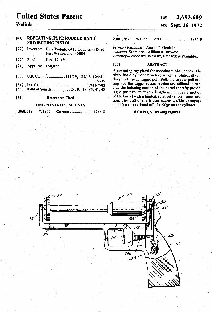
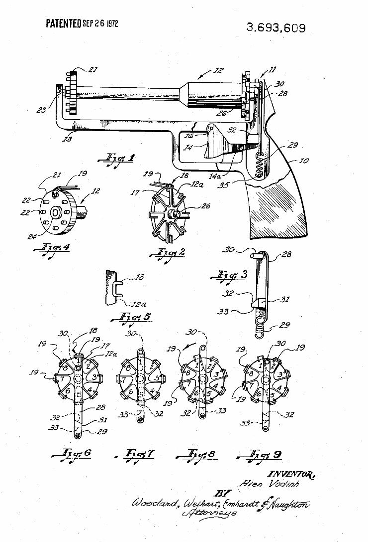
United States Patent Vodinh -
[151 3,693,609 [451 Sept. 26, 1972
I [72] Inventor:
- [54] REP-EATING TYPE ‘RUBBER BAND, PROJECTING PISTOL
Hien Vodinh, 6418 Covington Road, . Fort Wayne, lnd. 46804
[22‘] Filed: June17, 1971 [21] Appl.No.: 154,022
[52] U.S. Cl. .................. ..'...'.l24/l9,'l24/48, 124/41, , , ‘ 124/35
[51] I Int. Cl ........................................ ..... ..F4lb 7/02
[58] Field ofSear'ch ............... ..l24/l9_,-l8,35,41,48
[56] References Cited
UNITED STATES PATENTS
1,868,312 7/1932 Coventry ............... .;....l24/l8
2,001,267 5/1935 Ross ............ .; ............ ..124/19
Primary Examiner-Anton O. Oechsle Assistant Examiner—William R. Browne Attorney-Woodard,‘ Weikart, Emhardt & Naughton
[57] ABSTRACT A repeating toy pistol for shooting rubber bands. The pistol has a cylinder structure which is rotationally in
. dexed with each trigger pull. Both the tripper-pull mo tion and the trigger-retum motion are utilized to pro vide the indexing motion of the barrel thereby provid ing a positive, relatively lengthened indexing motion of the barrel with a limited, relatively short trigger mo tion. The pull of the trigger causes a slide to engage and lift a rubber band off of a ridge on the cylinder. ,
8 Claims, 9 Drawing Figures‘
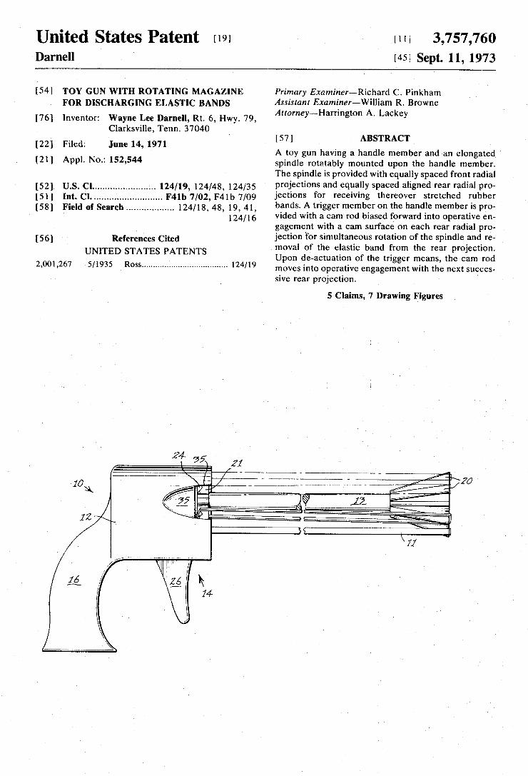
United States Patent [191
Darnell {111 3,757,760 [451 Sept. 11, 1973
[54]
[76]
[221
[21]
[52] [51] [581
[56]
2,001,267
TOY GUN WITH ROTATING MAGAZINE FOR DISCHARGING ELASTIC BANDS
Wayne Lee Darnell, Rt. 6, Hwy. 79, Clarksville, Tenn. 37040
Filed: June 14, 1971
Appl. No.: 152,544
Inventor:
US. Cl ....................... .. 124/19, 124/48, 124/35 Int. Cl. ......................... .. F4lb 7/02, F4lb 7/09
Field 01' Search ................. .. 124/18, 48, 19, 41, 124/16
References Cited UNITED STATES PATENTS
5/1935 Ross .................................... .. 124/19
Primary Examiner—Richard C. Pinkham Assistant Examiner—-William R. Browne Attorney—-—Harrington A. Lackey
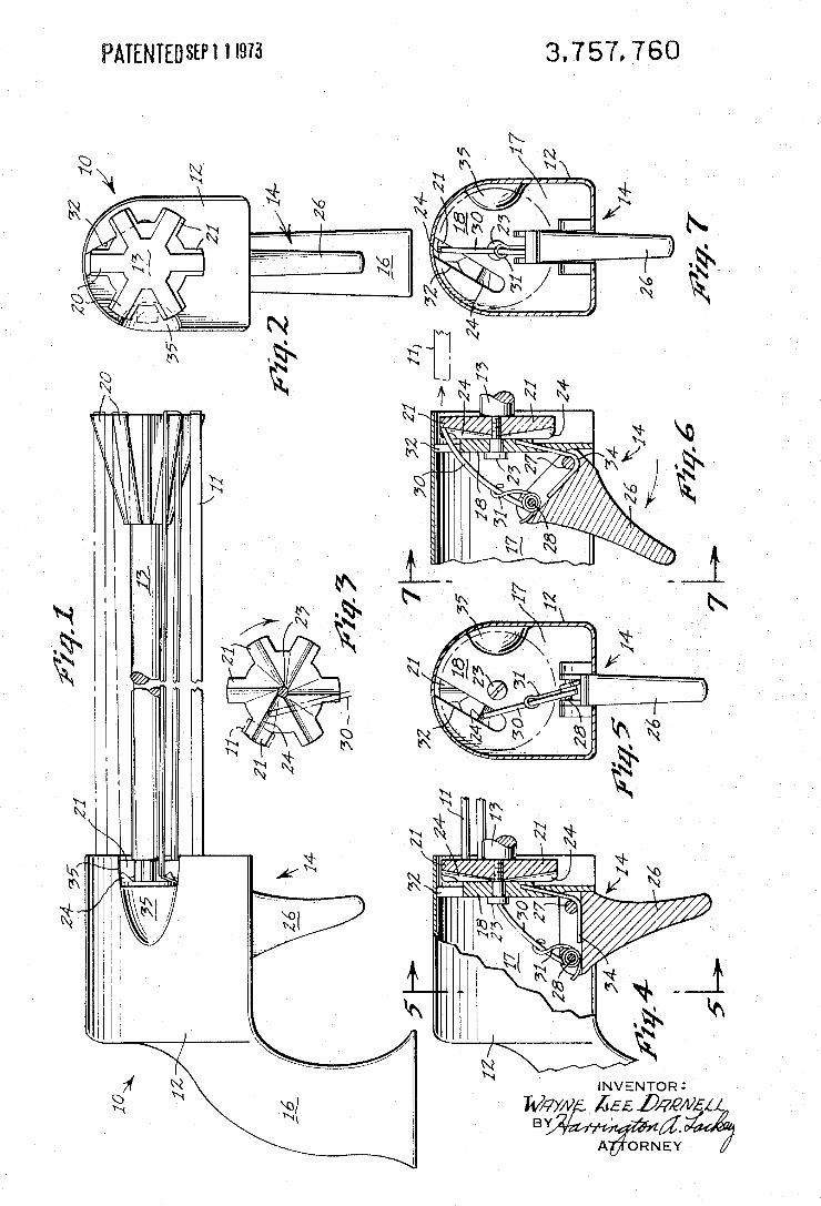
[57] ABSTRACT
A toy gun having a handle member and an elongated spindle rotatably mounted upon the handle member. The spindle is provided with equally spaced front radial projections and equally spaced aligned rear radial pro jections for receiving thereover stretched rubber bands. A trigger member on the handle member is pro vided with a cam rod biased forward into operative en gagement with a cam surface on each rear radial pro jection for simultaneous rotation of the spindle and re moval of the elastic band from the rear projection. Upon de-actuation of the trigger means, the cam rod moves into operative engagement with the next succes~ sive rear projection.
5 Claims, 7 Drawing Figures
3.757. 760 PAIENIEUSEH 1 I975
INVENTOR :
Way/v £55 Dam/£44
BY A ORNEY
Unite States atent r191 Skillern
[111 3,812,833 [451 May 28, 1974
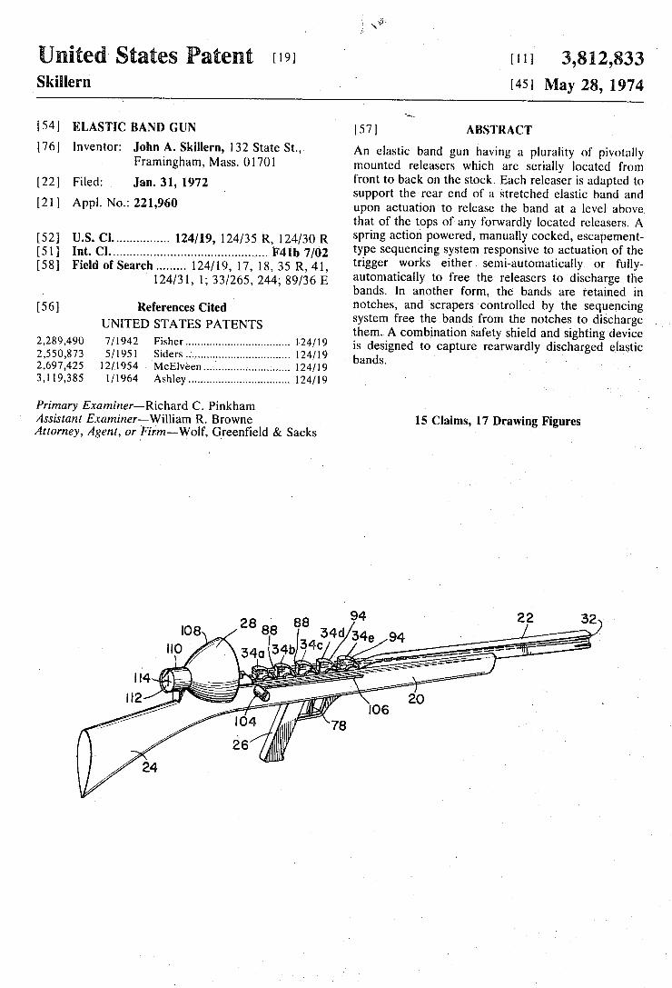
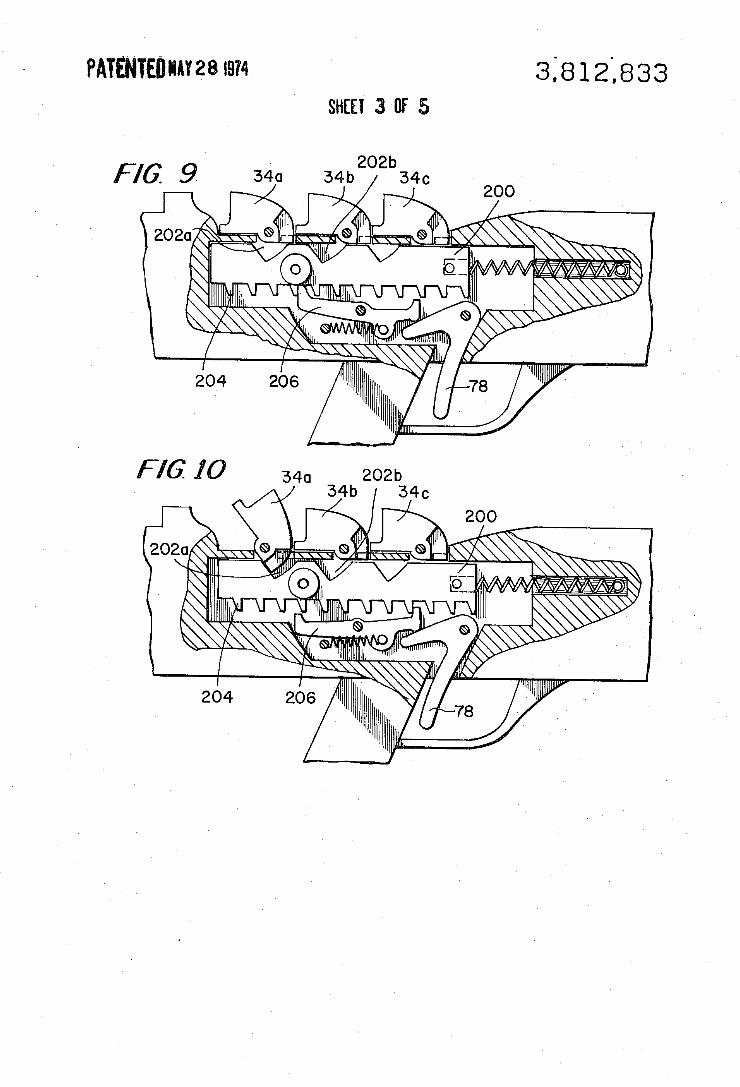
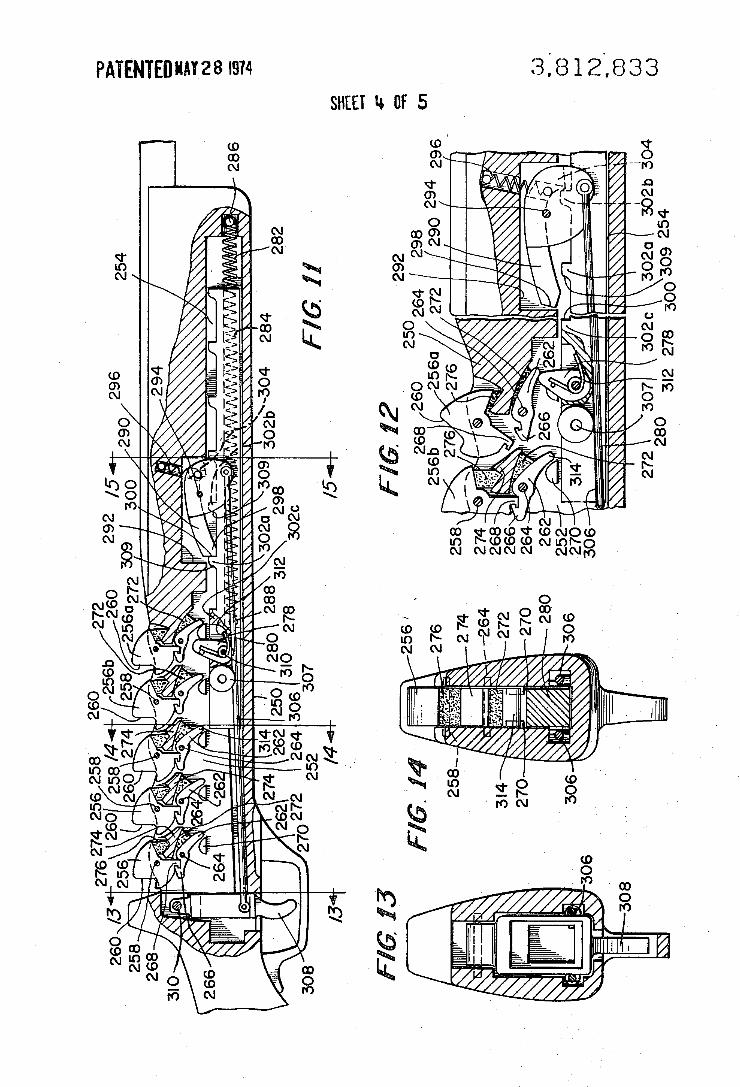
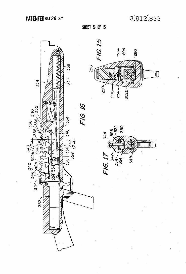
1541 ELASTIC BAND GUN
John A. Skillern, 132_State St., Framingham, Mass. 01701
[22] Filed: Jan. 31, 1972
[21] Appl. No.: 221,960
[76] Inventor:
[52] US. Cl. .............. .. 124/19, 124/35 R, 124/30 R [51] Int. Cl. ........................................ F41b 7/02 [58] Field of Search ....... ..124/19,17,18, 35 R, 41,
124/31, 1; 33/265, 244; 89/36 E
[56] References Cited UNITED STATES PATENTS
2,289,490 7/1942 Fisher ................................. .. 1-24/19
2,550,873 5/1951 Siders . . . . . . . . . . . . . .. 124/19
2,697,425 12/1954 McElveenunr . . . . . .. 124/19
3,119,385 l/l964 Ashley ................................ 1. 124/19
Primary Examiner~Richard C. Pinkham Assistant Examiner—Williarn R. Browne Attorney, Agent, or ~Firm--Wolf, Green?eld & Sacks
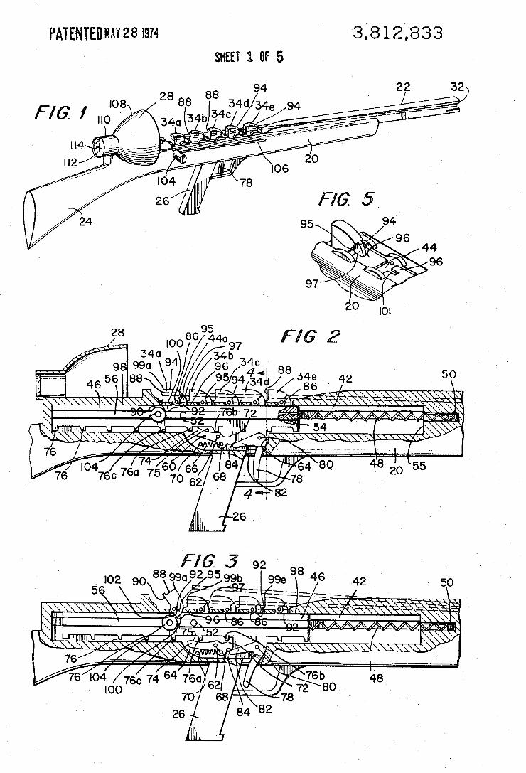
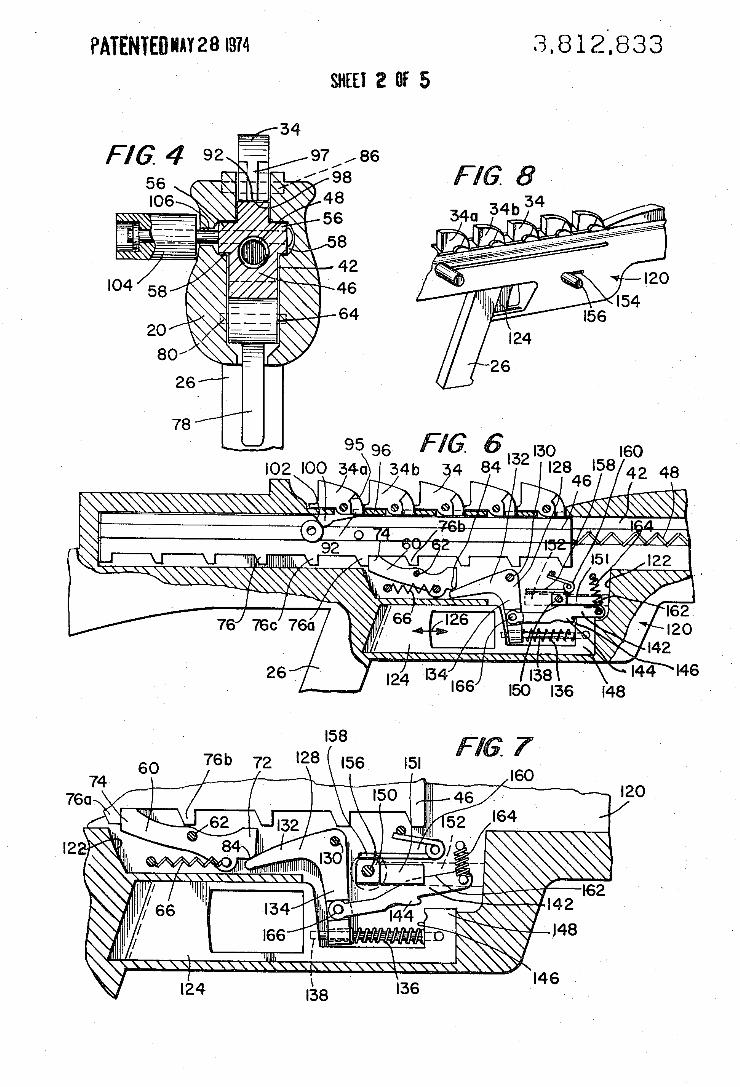
[57 ] ABSTRACT
An elastic band gun having a plurality of pivotally mounted releasers which are serially located from front to back on the stock. Each relcaser is adapted to support the rear end of a stretched elastic band and upon actuation to release the band at a level above that of the tops of any forwardly located releasers A spring action powered, manually cocked, escapement type sequencing system responsive to actuation of the trigger works either semi-automatically 'or fully automatically to free the releasers to discharge the bands. In another form, the bands are retained in notches, and scrapers controlled by the sequencing system free the bands from the notches to discharge them. A combination safety shield and sighting ‘device is designed to capture rearwardly discharged elastic bands. ' ' > >
15 Claims, 17 Drawing Figures
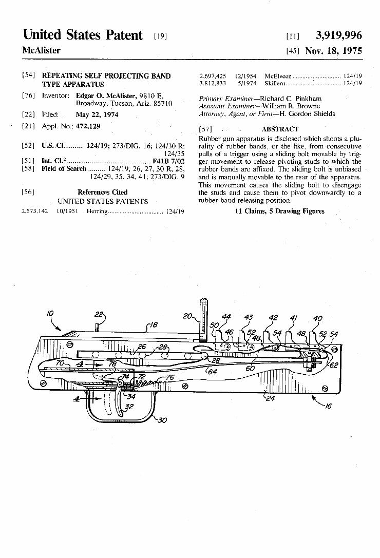
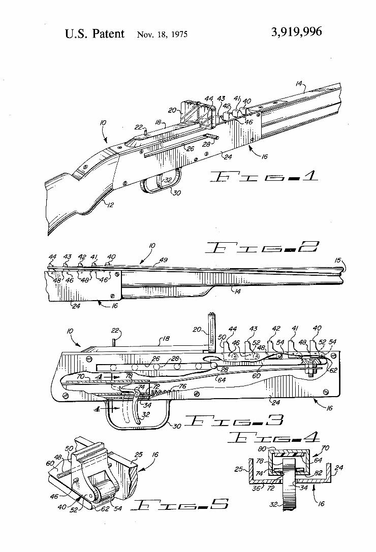
United States Patent [19] [11] 3,919,996 McAlister [45] Nov. 18, 1975
[54] REPEA'HNG SELF PROJECTING BAND 2,697,425 12/1954 McElveen ........................... .. 124/19 TYPE APPARATUS 3,812,833 5/1974 Skillern ............................... .. 124/19
[76] Inventor: Edgar O. McAlister, 9810 E. Broadway, Tucson, Ariz. 85710
[22] Filed: _ May 22, 1974
[21] Appl. No.: 472,129
[52] US. Cl ......... .. 124/19; 273/D1G. 16; 124/30 R; 124/35
[51] Int. Cl.2 .......................................... .. F41B 7/02 [58] Field of Search .... 124/19, 26, 27, 30 R, 28,
124/29, 35, 34, 41; 2_73/D1G. 9
[56] References Cited UNITED STATES PATENTS
2,573,142 10/1951 Herring ............................... .. 124/19
Primary Examiner-Richard C. Pinkham Assistant Etaminer-William R. Browne Attorney, Agent, or Firm-H. Gordon Shields
[57] ABSTRACT Rubber gun apparatus is disclosed which shoots a plu rality of rubber bands, or the like, from consecutive > pulls of a trigger using a sliding bolt movable by trig ger movement to release pivoting studs to which the rubber. bands are af?xed. The sliding bolt is unbiased and is manually movable to the rear of the apparatus. This movement causes the sliding bolt to disengage the studs and cause them to pivot downwardly to a rubber band releasing position.
11 Claims, 5 Drawing Figures
30
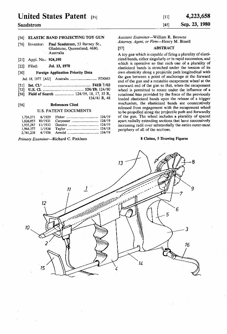
United States Patent [191 Sundstrom
[11] 4,223,658 [45] Sep. 23, 1980
[54] ELASTIC BAND PROJECT ING TOY GUN
Paul Sundstrom, 53 Barney St., Gladstone, Queensland, 4680,
[76] Inventor:
Australia
[21] Appl. No.: 924,190 [22] Filed: Jul. 13, 1978
[30] Foreign Application Priority Data Jul. 18, 1977 [AU] Australia ............................ .. PDO883
[51] Int. (:1.3 .............................................. .. F41B 7/02 [52] U.S. Cl. ............................ .. 124/19; 124/80 [58] Field of Search ................. .. 124/19, 18, 17, 35 R,
124/41 R, 48
[56] References Cited U.S. PATENT DOCUMENTS
1,724,271 8/1929 Fisher .................................. .. 124/19
1,826,053 10/1931 Carpenter .. 124/19 1,935,287 11/1933 Damico 124/19 1,944,377 l/l934 Taylor .... .. 124/18 2,741,238 4/1956 Arnold ................................. .. 124/19
Primary Examiner-Richard C. Pinkham
Assistant Examiner-‘William R. Browne Attorney, Agent, or Firm—Her1ry M. Bissell
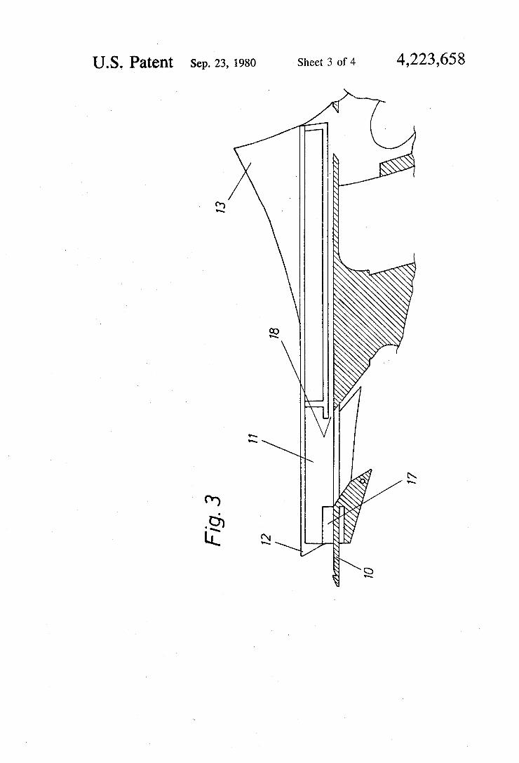
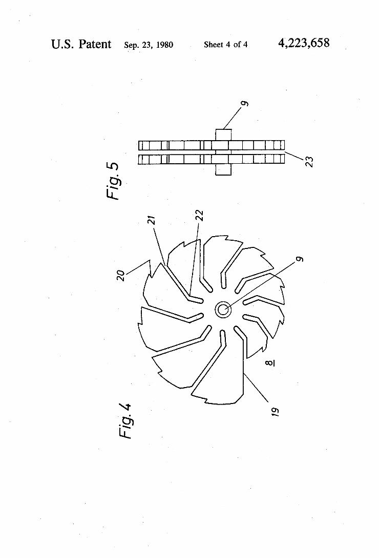
[57] ABSTRACT A toy gun which is capable of ?ring a plurality of elasti cized bands, either singularly'or in rapid succession, and which is operative so that each one of a plurality of elasticized bands is stretched under the tension of its own elasticity along a projectile path longitudinal with the gun between a point of anchorage at the forward end of the gun and a rotatable escapement wheel at the rearward end of the gun so that, when the escapement wheel is permitted to rotate under the in?uence of a rotational bias provided by the force of the previously loaded elasticized bands upon the release of a trigger mechanism, the elasticized bands are consecutively released from engagement with the escapement wheel to be propelled along the projectile path and forwardly of the gun. The wheel includes a plurality of spaced apart radially extending sections that have successively increasing radii over substantially the entire outer-most periphery of all of the sections.
8 Claims, 5 Drawing Figures
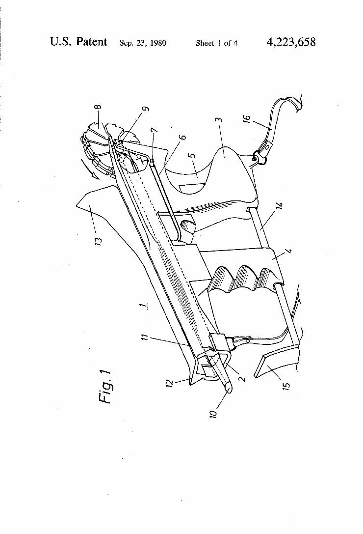
U.S. Patent Sep. 23, 1980 Sheet 1 of4 4,223,658
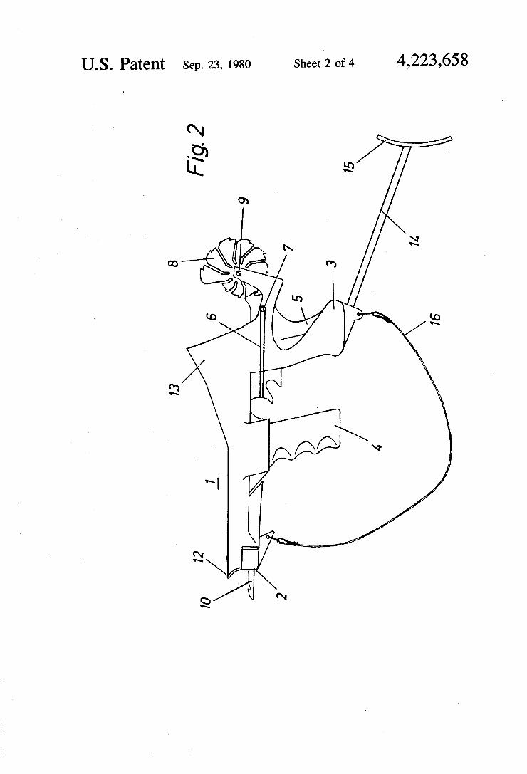
US. Patent Sep.23, 1980 Sheet‘2 0f4 4,223,658
2, ‘I :2
B. to 7” Ln -\ m
4|! 7 ~ 13 5 '1
US. Patent Sep. 23, 1980 Sheet 3 of4 4,223,658
73 / / / / / l////
78
I 7
/ ‘ m/m / 70
U.S. Patent Sep. 23, 1980 Sheet 4’ of4 4,223,658
I IN] I I
[11] 4,308,850 Jan. 5, 1982
United States Patent [19] ‘Hunter [45]
124/19
124/19 99 AA 44 22 ll
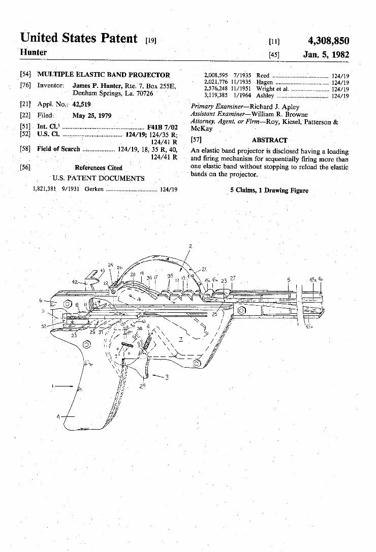
[54] MULTIPLE ELASTIC BAND PROJECTOR 2,008,595 7/1935 Reed 2,021,776 11/1935 Hagen
[76] Inventor: James P. Hunter, Rte. 7, BOX 255E, 2,576,248 11/1951 Wright et a1_
1 Denham Sprmgs, La- 70726 3,119,385 1/1964 Ashley [21] Appl. No.: 42,519 Primary Examiner—Richard J. Apley
- _ Assistant Examiner-William R. Browne [22] Flled' May 25’ 1979 Attorney, Agent, or Firm——-R0y, Kiesel, Patterson &
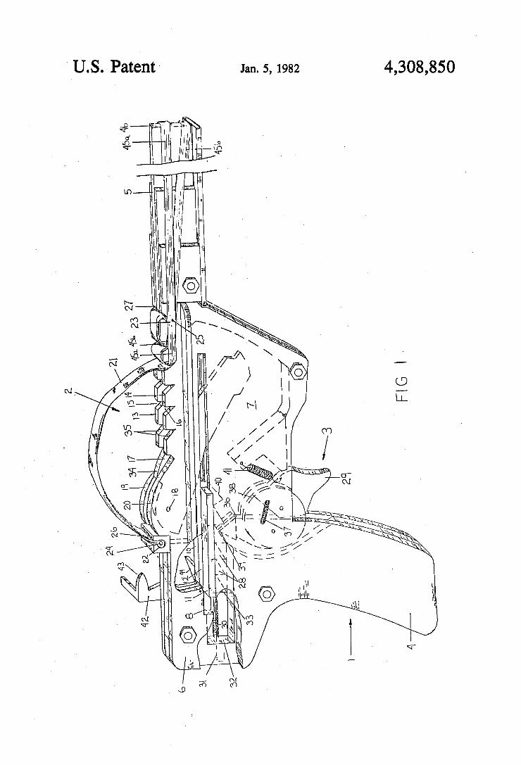
[57] ABSTRACT
F41B 7/02 .. 124/19; 124/35 R; [52] us. c1.
124/41 R 124/19, 18, 35 R, 40, An elastic band projector is disclosed having a loading
and ?ring mechanism for sequentially ?ring more than one elastic band without stopping to reload the elastic bands on the projector. ’
[58] Field of Search 124/41 R
_ ‘References Cited
us. PATENT DOCUMENTS 1,821,381 9/1931 Gerken
.1561 l
5 Claims, 1 Drawing Figure .. 124/19
4,308,850 Jan. 5, 1982
, _
9E
‘ U.S. Patent ‘
. v,
United States Patent [191 [111 » LoBiondo ' [45] Apr. 12, 1 83
[54] RUBBER BAND Primary Examiner-Richard C. Pinkham . . Assistant Examiner—William R. Browne
[76] Inventor' gllclgklitytll?gugdr {281373 19th Ave" Attorney, Agent, or Firm-Robert D. Farkas
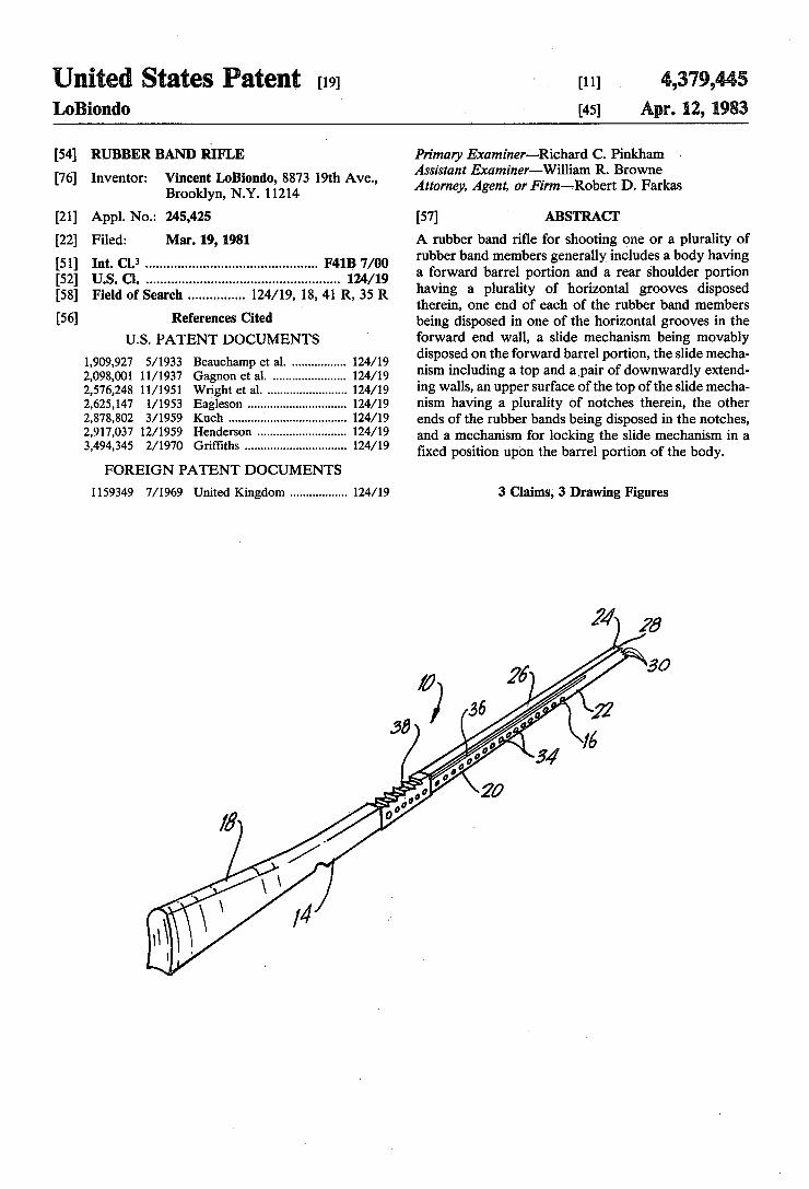
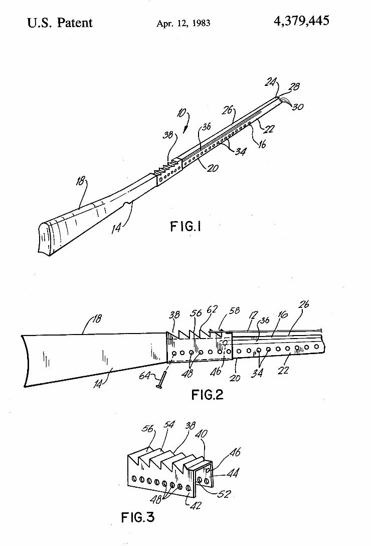
[21] Appl. No.: 245,425 [57] ABSTRACT [22] Filed: Mar. 19, 1981 A rubber band ri?e for shooting one or a plurality of
3 rubber band members generally includes a body having ' ' ' ' ' ' ' ' ' ' ' ' ' ' ' ' ' " a forward barrel portion and a rear shoulder portion
_. . . ............................................. .. having a plurality of horizontal grooves disposed l f h .............. ..l241,18,41R,35R _
Fla d o seal-CR f C‘ d/ 9 therein, one end of each of the rubber band members e erences 'te
U.S. PATENT DOCUMENTS
1,909,927 5/1933 Beauchamp et al. ............... .. 124/19 2,098,001 11/1937 Gagnon et a1. ..... .. 124/19 2,576,248 11/1951 Wright et al. 124/19 2,625,147 1/1953 Eagleson ................. .. 124/19 2,878,802 3/1959 Kuch ....... .. 124/19
2,917,037 12/1959 Henderson 124/19 3,494,345 2/1970 Griffiths .............................. .. 124/19
FOREIGN PATENT DOCUMENTS
1159349 7/1969 United Kingdom ................ .. 124/ 19
being disposed in one of the horizontal grooves in the forward end wall, a slide mechanism being movably disposed on the forward barrel portion, the slide mecha nism including atop and a,pair of downwardly extend ing walls, an upper surface of the top of the slide mecha nism having a plurality-of notches therein, the other ends of the rubber bands being disposed in the notches, and a mechanism for locking the slide mechanism in a ?xed position upon the barrel portion of the body.
3 Claims, 3 Drawing Figures
United States Patent [191 [11] Patent Number: ' 4,554,904
Endo [45] Date of Patent: Nov. 26, 1985
[54] TRIGGER ASSEMBLY FOR RUBBER BAND 819013 8/1959 United Kingdom ................ .. 124/27
GUN Primary Examiner—Paul E. Shapiro [76] Inventor: Mitsuo Endo, 1120 S. State, Attorney, Agent, or Firm—Harvejy B. Jacobson
Clear?eld, Utah 84015 [57] ABSTRACT
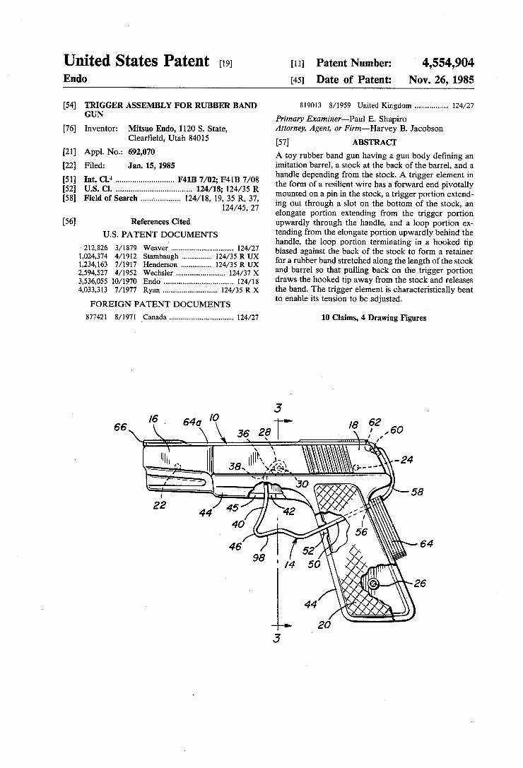
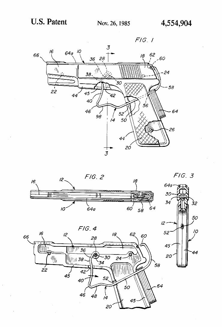
[21] Appl' No‘: 692’070 A toy rubber band gun having a gun body de?ning an [22] Filed; Jam 15, 1935 imitation barrel, a stock at the back of the barrel, and a
_ handle depending from the stock. A trigger element in C1Cl4 iiiiiiiiiiiiiiiiiiiiiiiiii u the form of a resilient wire has a forward end pivotally
[58] F.‘ l'd """ """"""" 4A8 19’ 35 R 37 mounted on a pin in the stock, a trigger portion extend~ 1e 0 care """"""""" " ’ 124/45’ 27’ ing out through a slot on the bottom of the stock, an
’ elongate portion extending from the trigger portion [56] References Cited upwardly through the handle, and a loop portion ex
U.S. PATENT DOCUMENTS
212,826 3/1879 Weaver ............................... .. 124/27
1,024,374 4/1912 Stambaugh . 124/35 R UX 1,234,163 7/1917 Henderson .. .. 124/35 R UX 2,594,527 4/1952 Wechsler ........ .. 124/37 X
3,536,055 10/1970 Endo . . . . . . . . . . . . . . . . . . . .. 124/18
4,033,313 7/1977 Ryan ........................ .. 124/35 R X
FOREIGN PATENT DOCUMENTS
877421 8/1971 vCanada ................................ .. 124/27
66
tending from the elongate portion upwardly behind the handle, the loop portion terminating in a hooked tip biased against the back of the stock to form a retainer for a rubber band stretched along the length of the stock and barrel so that pulling back on the trigger portion draws the hooked tip away from the stock and releases the band. The trigger element is characteristically bent to enable its tension to be adjusted.
10 Claims, 4 Drawing Figures
United States Patent [19] Miller
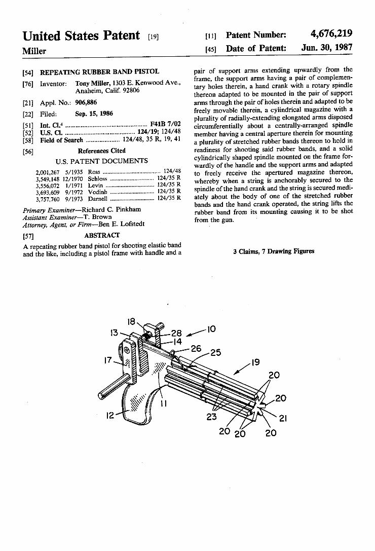
[54] REPEATING RUBBER BAND PISTOL
Tony Miller, 1303 E. Kenwood Ave., Anaheim, Calif. 92806
[211 App]. No.: 906,886 [22] Filed: Sep.15,1986
[51] Int. cm .............................................. .. F41B 7/02
[76] Inventor:
[52] US. Cl. ............................. .. 124/19; 124/48 [58] Field of Search .............. .. 124/48, 35 R, 19, 41
[56] References Cited U.S. PATENT DOCUMENTS
2,001,267 5/1935 Ross .................................... .. 124/48
3,549,148 12/1970 Schloss 124/35 R 3,556,072 1/1971 Levin . . . . . . . . . . .. 124/35 R
3,693,609 9/1972 Vodinh . . . . . . . . . . . .. 124/35 R
3,757,760 9/1973 Darnell ........................... .. l24/35R
Primary Examiner-Richard C. Pinkham Assistant Examiner—T. Brown Attorney, Agent, or Firm—-Ben E. Lofstedt
[57] ABSTRACT A repeating rubber band pistol for shooting elastic band and the like, including a pistol frame with handle and a
4,676,219 Jun. 30, 1987
[11] Patent Number:
[45] Date of Patent:
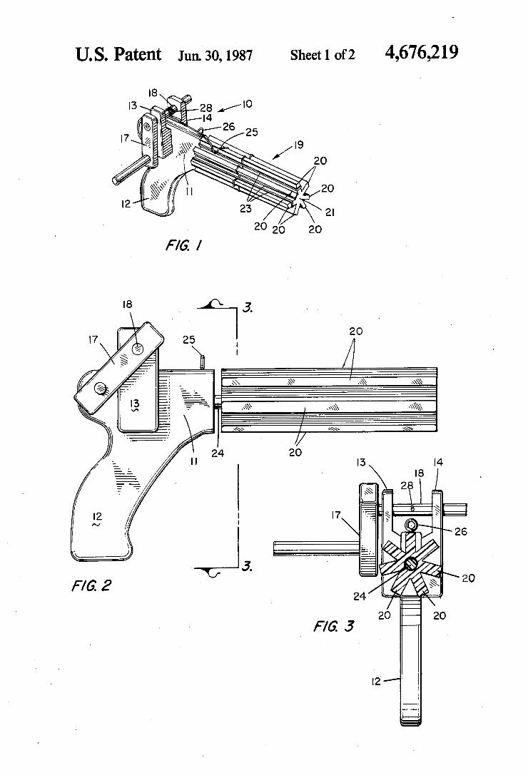
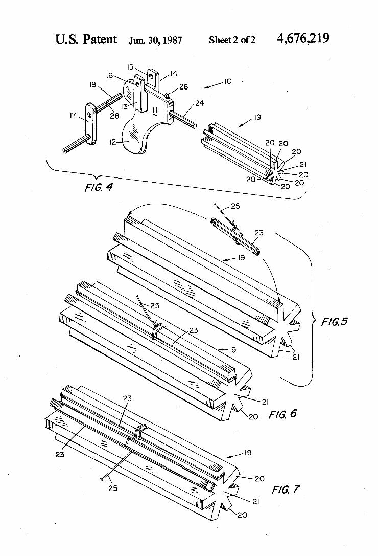
pair of support arms extending upwardly from the frame, the support arms having a pair of complemen tary holes therein, a hand crank with a rotary spindle thereon adapted to be mounted in the pair of support arms through the pair of holes therein and adapted to be freely movable therein, a cylindrical magazine with a plurality of radially-extending elongated arms disposed circumferentially about a centrally-arranged spindle member having a central aperture therein for mounting a plurality of stretched rubber bands thereon to hold in readiness for shooting said rubber bands, and a solid cylindrically shaped spindle mounted on the frame for wardly of the handle and the support arms and adapted to freely receive the apertured magazine thereon, whereby when a string is anchorably secured to the spindle of the hand crank and the string is secured medi ately about the body of one of the stretched rubber bands and the hand crank operated, the string lifts the rubber band from its mounting causing it to be shot from the gun.
3 Claims, 7 Drawing Figures
U. S. Patent Jun. 30,1987 Sheet1of2 4,676,219
4,676,219 U. S. Patent Jun. 30, 1987 Sheet2 of2
United States Patent 1191 Small
4,800,864 Jan. 31, 1989
[11] Patent Number:
[45] Date of Patent:
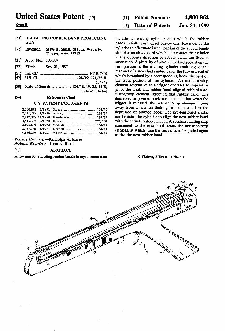
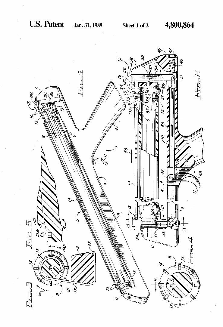
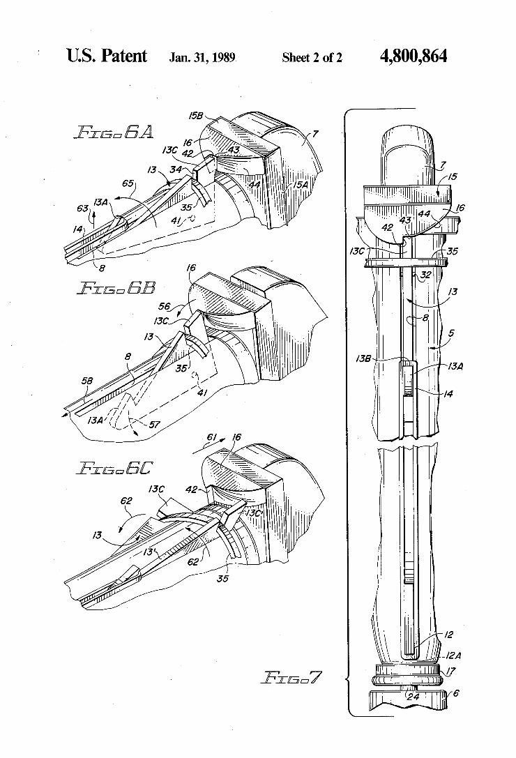
[54] REPEATING RUBBER BAND PROJECI'ING GUN
[76] Inventor: Steve E. Small, 5811 E. Waverly, Tucson, Ariz. 85712
[21] Appl. No.: 100,207 [22] Filed: Sep. 23, 1987 [51] Int. 01.4 .............................................. .. F41B 7/02 [52] us. 0. ................................. .. 124/19; 124/35 R;
124/48 [58] Field of Search ................. .. 124/18, 19, 35, 41 R,
124/48; 74/142 [56] References Cited
U.S. PATENT DOCUMENTS
2,550,873 5/1951 Siders .................................. .. 124/ 19 2,741,238 4/1956 Arnold . . . . . . . . . . . . .. 124/19
2,917,037 12/ 1959 Henderson 124/19 3,515,387 6/1970 House ......... .. 273/101 3,693,609 9/1972 Vodinh 124/19 3,757,760 9/ 1973 Darnell 124/19 4,676,219 6/1987 Miller . . . . . . . . . . .. 124/19
Primary Examiner-Randolph A. Reese Assistant Examiner-John A. Ricci
[57] ABSTRACT A toy gun for shooting rubber bands in rapid succession
includes a rotating cylinder onto which the rubber bands initially are loaded one-by-one. Rotation of the cylinder to effectuate initial loading of the rubber bands stretches an elastic cord which later rotates the cylinder in the opposite direction as rubber bands are tired in succession. A plurality of pivotal hooks disposed on the rear portion of the rotating cylinder each engage the rear end of a stretched rubber band, the forward end of which is retained by a corresponding hook disposed on the front portion of the cylinder. An actuator/stop element responsive to a trigger operates to depress or pivot the hook and rubber band aligned with the ac tuator/stop element, shooting that rubber band. The depressed or pivoted hook is retained so that when the trigger is released, the actuator/stop element moves away from a rotation limiting stop connected to the depressed or pivoted book. The pre-tensioned elastic cord rotates the cylinder to align the next rubber band with the actuator/stop element. A rotation limiting stop connected to the next hook abuts the actuator/stop element, at which time the trigger is to be pulled again to tire the next rubber band.
9 Claims, 2 Drawing Sheets
US. Patent Jam-31,1989 Sheet 1 of 2 4,800,864
IQiTmW Q m.
0
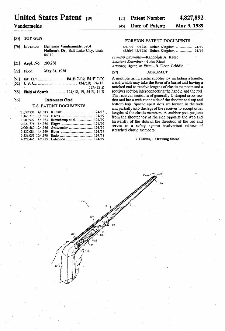
United States Patent [191 [11] Patent Number: 4,827,892 Vandermeide [45] Date of Patent: May 9, 1989
[54] TOY GUN FOREIGN PATENT DOCUMENTS
[76] Inventor: Benjamin Vandermeide, 3904 430799 6/1935 United Kingdom ................ .. 124/19 Hallmark Dr., Salt Lake City, Utah 458660 12/ 1936 United Kingdom ................ .. 124/ 19
84119 Primary Examiner-Randolph A. Reese 21 A L N ‘z 200 238 Assistant Examiner-John Ricci
[ ] pp 0 ’ Attorney, Agent, or Firm-B. Deon Criddle
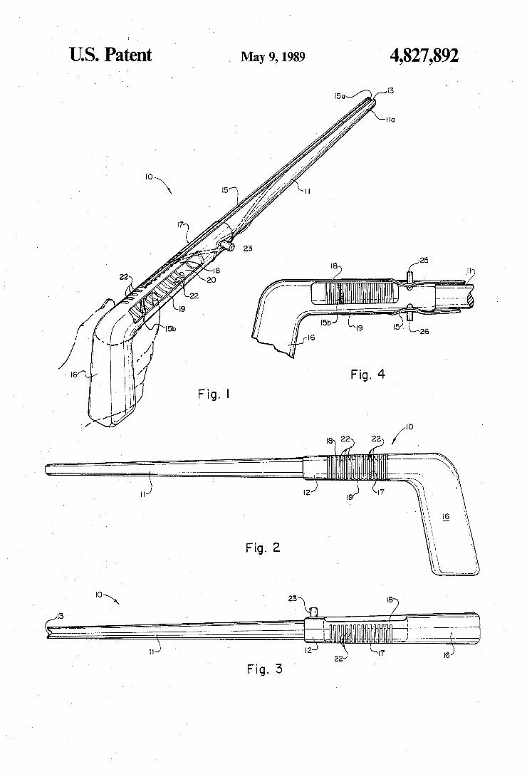
[22] Fll?dl May 31, 1988 [57] ABSTRACI ‘
[51] Int. cu .......................... .. F418 7/02; F41F 7/00 A multiple ?ring elastic shooter toy including a handle, [52] US. Cl. ...................................... .. 124/19; 124/18; 9 rod which may take the form of a barrel and having a
124/35 R notched end to receive lengths of elastic members and a [58] Field of Search .............. .. 124/18, 19, 35 R, 41 R receiver section interconnecting the handle and the rod.
' The receiver section is of generally U-shaped cross-sec [56] References Cited tion and has a web at one side of the shooter and top and
U S PATENT DOCUMENTS bottom legs. Spaced apart slots are formed in the web ' ' ' and partially into the legs of the receiver to accept other
Iliad?“ -------------------------------- ~ lengths of the elastic members. A snubber post projects I 1 ams """""""""""" " from the shooter toy at the side opposite the web and 1909927 5/1933 Beauchamp et a1‘ 124/19 forwardly of the slots in the direction of the rod and 2,021,776 11/1935 Hagen . . . . . . . . . . . . . . . . . . . . . .. 124/19 f . .
2,065,580 l2/l936 Grawunder __ 124/19 serves as a 'sa ety against inadvertant release of 3,437,084 4/1969 Hyter . . . . . . . 1 . . .. 124/19 Stretched elastw members
3,536,055 10/1970 Endo . . . . . . . . . . . .. 124/18
4,379,445 4/1983 Lobiondo ............................ .. 124/ 19 7 Claims, 1 Drawing Sheet
May 9, 1989 US. Patzent
a
O
Umted States Patent [19] [11] Patent Number: 4,949,494 Mims [45] Date of Patent: Aug. 21, 1990
[54] REPEATING RUBBER BAND PISTOL 4,223,658 9/ 1930 Sundstrom .......................... .. 124/19
[76] Inventor: Donald B. Mims, 5665 Banks Rd., FOREIGN PATENT DOCUMENTS I Fm wc’nh' Te" 76140 73436 6/1917 Austria .................................. .. 42/54
[21] APPL No_; 436,440 439978 12/1935 United Kingdom ................ .. 124/19
[22] Filed; No“ 14’ 1989 Primary Examiner-Charles T. Jordan 5 Assistant Examiner-Richard W. Wendtland
ClCi ---------------------- n‘ ---------------
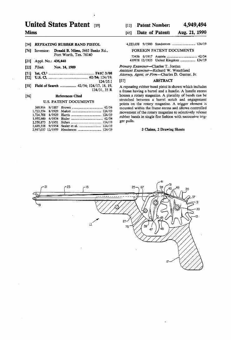
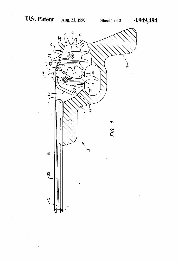
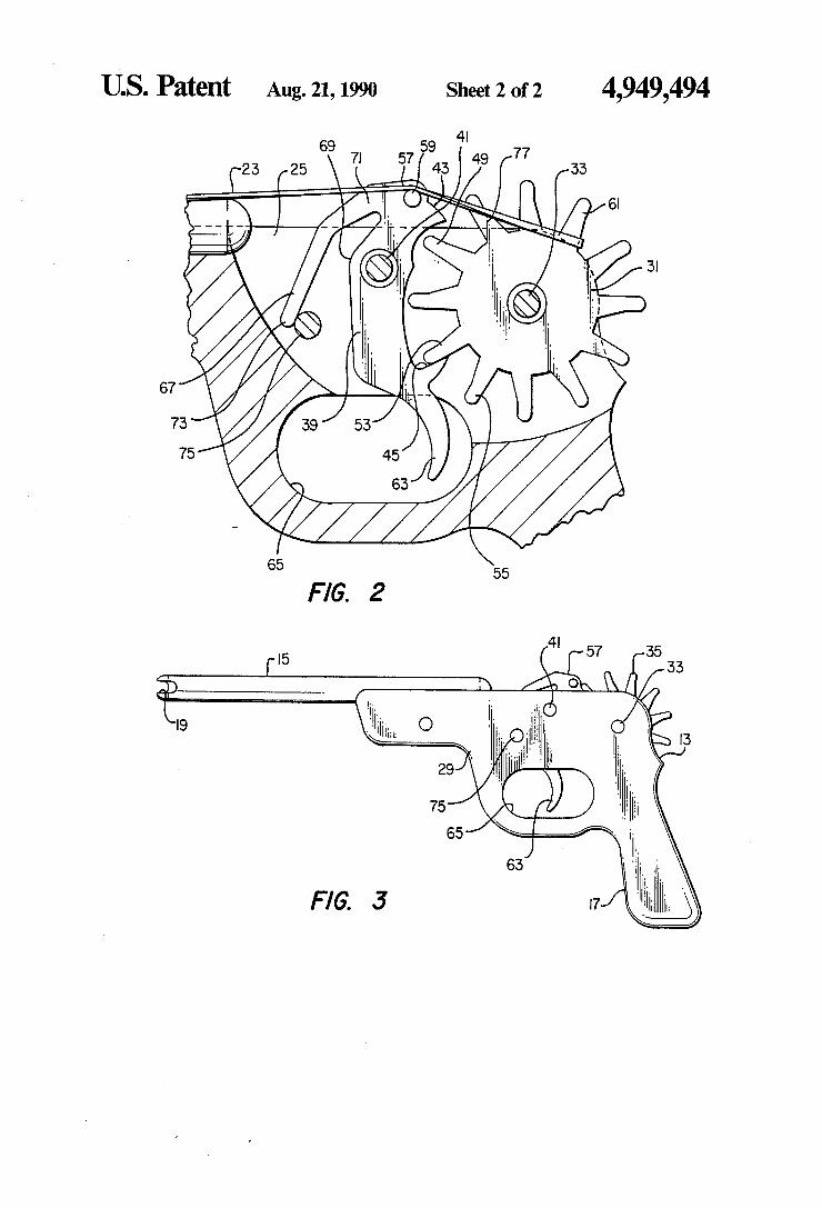
D. 124/351 [57] ABSTRACT [58] Field of Search ............... .. 42/ 54; 124/17, 18, 19, A repeating rubber band pistol is shown which includes
124/31’ 35 R a frame having a barrel and a handle. A handle recess [56] References Cited houses a rotary magazine. A plurality of bands can be
U S PATENT DOCUMENTS stretched between a barrel notch and engagement ' ' points on the rotary magazine. A trigger element is
Brown ................................... .. mounted the frame recess and allows Controlled
133109 """ " movement of the rotary magazine to selectively release 1’955’9o0 4/1934 Bil-1:: 42/54 rubber bands in single ?re fashion with successive trig 2,550,s73 5/1951 Siders ...... .. 124/19 g9r Pulls 2,689,558 9/1954 Sealer et al. .. 124/19 2,917,037 12/1959 Henderson .......................... .. 124/19 3 Claims, 2 Drawing Sheets
21 (-23 chi 1 égr \
US. Patent Aug. 21, 1990 ' Sheet 1 of2 4,949,494
4|
5| 59 43 49 35
// f‘
(I5
23 ,9
US. Patent Aug. 21, 1990 Sheet 2 of2 4,949,494
lllllllllllllllllIllllIIIIIIllllIllllllllllllllllllllllllllllllllllllllllll Umted States Patent 1191 [11] Patent Number: 5,170,770 Vosloh [45] Date of Patent: Dec. 15, 1992
[54] RUBBER BAND REPEATING GUN 4,379,445 4/1983 LoBiondo ........................... .. 124/19
[76] Inventor: Bradley L. Vosloh, 5369 FOREIGN PATENT DOCUMENTS
‘xlq‘gnclamn’ New Orleans’ La- 1159349 7/1969 United Kingdom ................ .. 124/19
_ Primary Examiner-Randolph A. Reese [21] App]. No.. 664,159 Assistant Examiner-Jeffrey L. Thompson [22] Filed: Mar. 4, 1991 Attorney, Agent, or Firm-Keaty & Keaty
[51] Im. c1.5 ...................................... ..‘ ...... .. F41B 7/00 [57] ABSTRACT
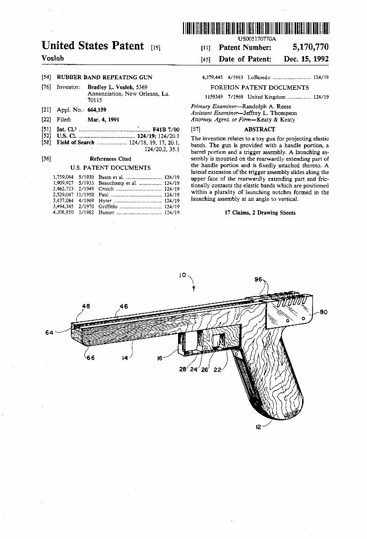
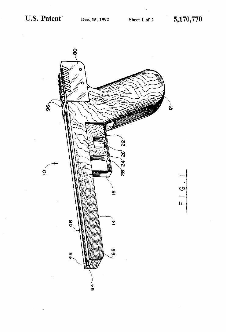
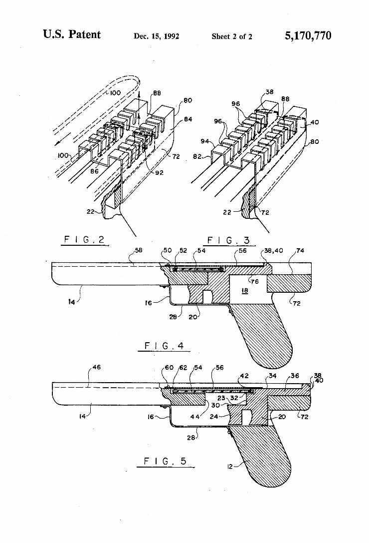
[52] U..Sl. Cl. . . . . . . . . . . . . . . . . . . . . . . . . . .. 1241/19; l24/20.l The invention relates to a toy gun for projecting elastic
Fle d of Search .................. .. 17, bands- The gun is provided a handle portion, 3 H02’ 3 ‘1 _ barrel portion and a trigger assembly. A launching as
[56] References Cited sembly is mounted on the rearwardly extending part of Us PATENT DOCUMENTS the handle portion and is ?xedly attached thereto. A
lateral extension of the tr1gger assembly slldes along the gum gt 3L --- ------------------ - upper face of the rearwardly extending part and fric
, , eauc amp et a . - ‘ ' ' ' '
2,462,723 2/1949 Crnich ................. .. 124/19 thgfells?gzhlzgndzgtvggg 2,529,047 11/1950 P1111 ..... .. 124/19 . p y g .
3,437,084 4/1969 Hyter 124/19 launching assembly at an angle to vertlcal. 3,494,345 2/1970 Grif?ths 124/19 4,308,850 1/1982 Hunter ................................ .. 124/19 17 Claims, 2 Drawing Sheets
64 I
amt’ . ,5
U.S. Patent Dec.‘15, 1992 Sheet 1 0f 2
US. Patent Dec. 15, 1992 Sheet 2 of 2 5,170,770
$58 (52 (5 68,40 /74

. USOO5205266A
Umted States Patent [191 [11] Patent Number: 5,205,266 Kilby, Jr. [45] Date of Patent: Apr. 27, 1993
[54] RUBBER BAND PROJECI'ILE TOY GUN Primary Examiner-Randolph A. Reese . Assistant Examiner-John Ricci [76] Inventor: A. Harold Krlby, Jr., Rte. 3, Box .
PM”, Tut?e, Okla“ 73089 Attorney, Agent, or Firm-Robert K. Rhea
[21] Appl. No.: 884,825 [57] ABSTRACT [22] Filed: May 18, 1992 A repeating rubber projectile ?ring toy gun is formed
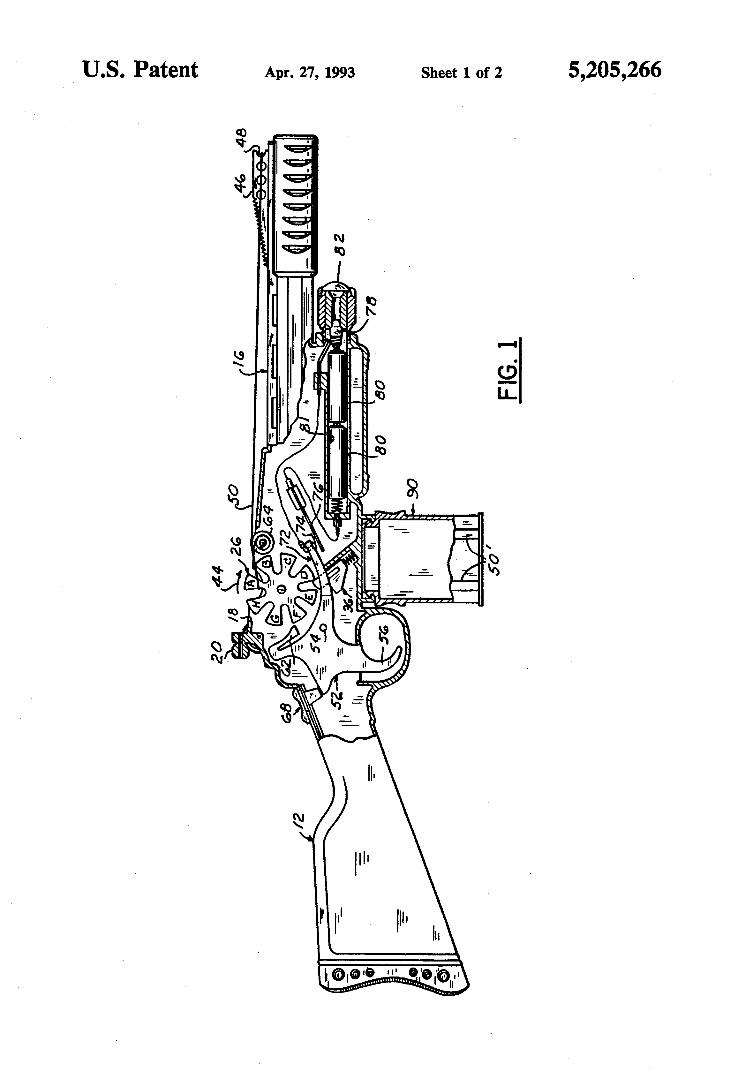
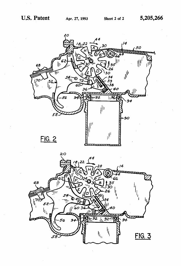
by a hollow handle and frame portion integrally con 51 . .5 .............................................. .. . .
{52} $5001 ........................ .. Willi/732°? reeree wrrr r rrr errrel rerrrer- A rrreeker wheel [58] Field of swell ................... .. 124/18, 19, 35.1, 31 magazine J'wmaned by °pp°sing side walls “the frame
. section projects above the gun frame for receiving one [56] References cued end portion of a rubber band, having its other end por
U.S. PATENT DOCUMENTS tion engaged over a notch at the forward end of the gun 1 724 70s 8/1929 Harris ........................ . . 124/19 barrel‘ A nigger mechanism biases a spring urged paw] 2:550:81“, 5/1951 Siders ' ' If: 124/19 °“t °f engagement with ‘he spmcke‘ wheel t° Permit 2,689,553 9/1954 Sealer et al . 124/19 angular rotation thereof and release at least one of the 2,741,238 4/1956 Arnold . . . . . . . . . . . . .. 124/19 projectiles while a second pawl on the trigger mecha
2,917,037 12/1959 Henderson . 124/19 nism interrupts the sprocket wheel rotation after the 1;; riFAhslel' - 1:22: release of only one rubber band projectile or a succes
, , lmS ..................................... .. sion of rubber projectiles repeated trigger puns‘
FOREIGN PATENT DOCUMENTS
339544 12/1930 United Kingdom ................ .. l24/l9 4 Claims, 2 Drawing Sheets
20 44 I8 26 O
_ || '_ 64 || 2
. 68 = e 72 /2 ' l" E 7 ll|
__ ._. 7' _; 5gb ___ 7 ll'
Q _—- 53 re . —
3; ‘E III 11. " x " ‘I' "
t T :a " " . 00 ea 75
.e a |" -5‘ ‘ _ II
I
US. Patent Apr. 27, 1993 Sheet 1 of 2 5,205,266
saw "(0H5
Sheet 2 of 2 5,205,266 US. Patent Apr. 27, 1993
20 44
/a 22 —-L~ 30 M H A :0
I l' J 64 _= I'G 2_= ' 5 _ 66 ||
62 5E _ II' 'I 68 Ill‘ _ 30 r C fésesl HI
5 I 5 l‘ D \so III 54 4 \ 24
If” 52 ‘=7?’ 72 3.9 l h- n... ._ w 38
36 40 ll,
_ 55 92 lnaz/
E 94
. g H" \ 5'8 90
United States Patent [191 Landingham
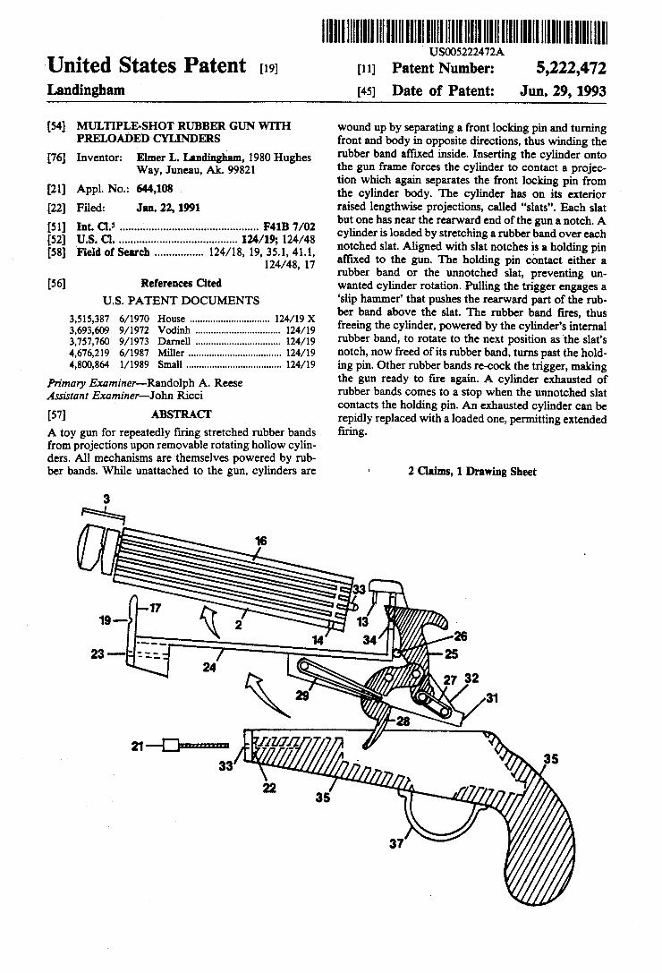
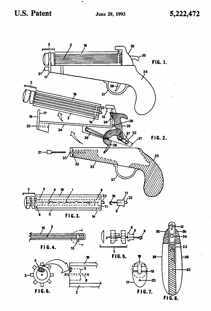
[54] MULTIPLE-SHOT RUBBER GUN WITH PRELOADED CYLINDERS
[76] Inventor: Elmer L. Landingham, 1980 Hughes Way, Juneau, Ak. 99821
[21] Appl. No.: 644,108 [22] Filed: Jan. 22, 1991
[51] Int. Cl.5 ...... ..; ..................................... .. F41B 7/02
[52] U.S. C1. ....................................... .. 124/19; 124/48 [58] Field of Search ............... .. 124/18, 19, 35.1, 41.1,
124/48, 17
[56] References Cited U.S. PATENT DOCUMENTS
3,515,387 6/1970 House .. 124/19 X 3,693,609 9/1972 Vodinh 124/19 3,757,760 9/1973 Darnell 124/19 4,676,219 6/1987 Miller . . . . . . . . . .. 124/19
4,800,864 l/l989 Small ................................... .. 124/19
Primary Examiner—-Randolph A. Reese Assistant Examiner-John Ricci
[5?] ABSTRACT A toy gun for repeatedly ?ring stretched rubber bands from projections upon removable rotating hollow cylin ders. All mechanisms are themselves powered by rub ber bands. While unattached to the gun, cylinders are
lIIIIIIIIIIIIIIllllllllllllllllllllllllllllllllllllllllllIIIIIIIIIIIIIHIII US005222472A
Patent Number: 5,222,472 Jun. 29, 1993 Date of Patent:
[11]
[45]
wound up by separating a front locking pin and turning front and body in opposite directions, thus winding the rubber band affixed inside. Inserting the cylinder onto the gun frame forces the cylinder to contact a projec tion which again separates the front locking pin from the cylinder body. The cylinder has on its exterior raised lengthwise projections, called “slats”. Each slat but one has near the rearward end of the gun a notch. A cylinder is loaded by stretching a rubber band over each notched slat. Aligned with slat notches is a holding pin affixed to the gun. The holding pin contact either a rubber band or the unnotched slat, preventing un wanted cylinder rotation. Pulling the trigger engages a ‘slip hammer’ that pushes the rearward part of the rub ber band above the slat. The rubber band ?res, thus freeing the cylinder, powered by the cylinder’s internal rubber band, to rotate to the next position as ‘the slat’s notch, now freed of its rubber band, turns past the hold ing pin. Other rubber bands re-cock the trigger, making the gun ready to ?re again. A cylinder exhausted of rubber bands comes to a stop when the unnotched slat contacts the holding pin. An exhausted cylinder can be repidly replaced with a loaded one, permitting extended ?ring.
2 Claims, 1 Drawing Sheet
l||||l|||l|l|l|||IIIIIllllll||||llllllllllll|l|Illlllllllllllllllllllllllll USOO5460150A
[11] Patent Number: 5,460,150
Oct. 24, 1995
United States Patent [191 Joppe [45] Date of Patent:
9 n M 1
Mn “0 .b “0 h h.w MN mK Lc .n 2. wr 0% am An no 2 id .m n P
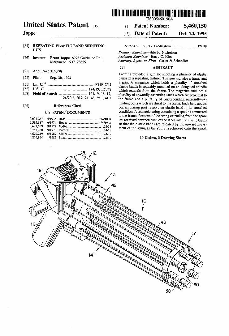
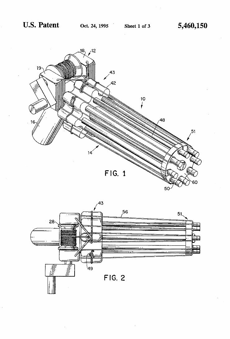
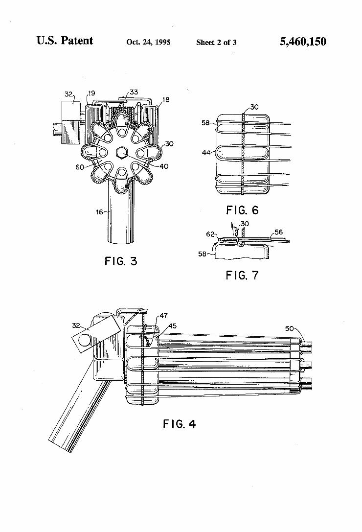
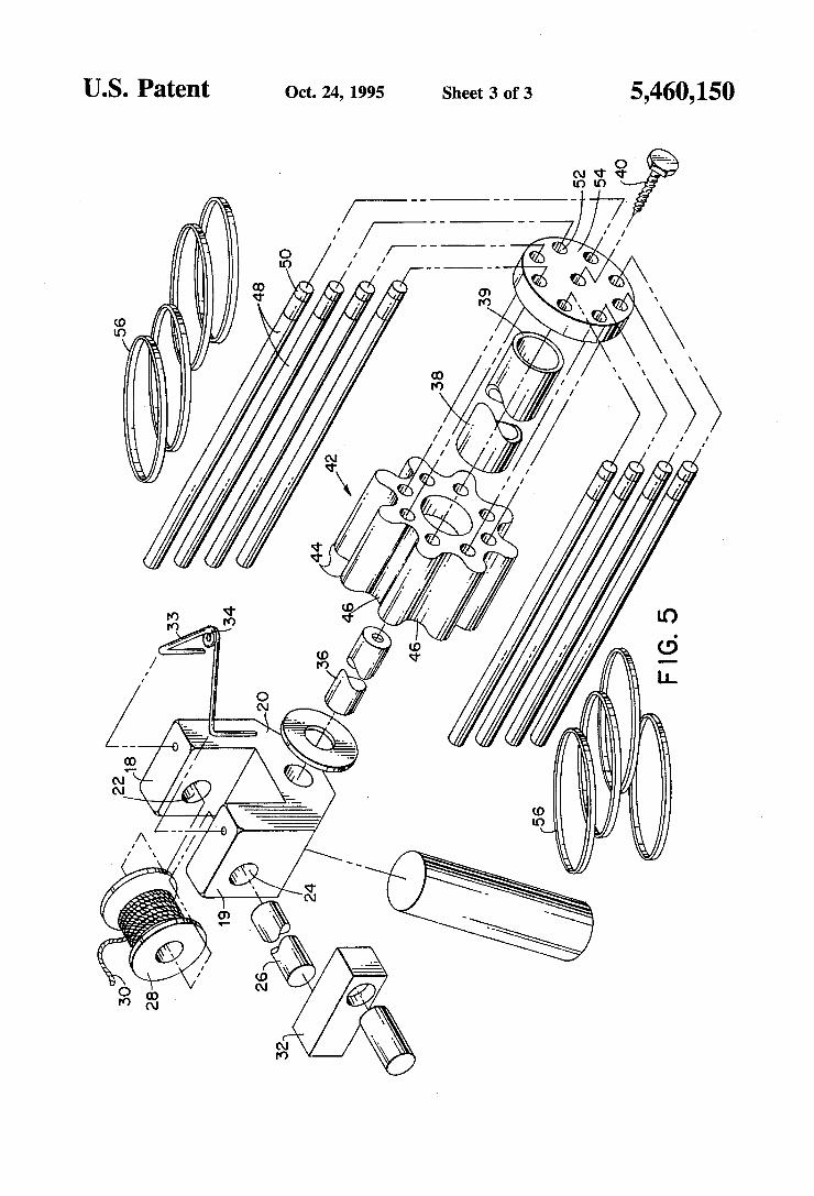
[54] REPEATING ELASTIC BAND SHOOTING GUN
. - Assistant Examiner—Harry C. Kim In . B 1 mm ., ,
[76] vemor £12333‘)? 29758??? 6 Rd Attorney, Agent, or F mn—Carter & Schnedler
[57] ABSTRACT
There is provided a gun for shooting a plurality of elastic bands in a repeating fashion. The gun includes a frame and a grip. A magazine which holds a plurality of stretched elastic bands is rotatably mounted on an elongated spindle which extends from the frame. The magazine includes a
[21] Appl.No.: 315,978
[22] Filed: Sep. 30 , 1994
plurality of upwardly-extending lands which are proximal to max... 11 WMRW4 49,9,? Fun , . O0 mmm4 "11 a n 1 mmmo mmm2 mmm0 mmm? """1 ""r ""3 ""e ."S 6 .f L10 C C-d LSM .mUF 1]] 128 555
the frame and a plurality of corresponding outwardly-ex tending posts which are distal to the frame. Each land and its
[56] References Cited corresponding post receive an elastic band in its stretched
U.S. PATENT D
2,001,267 5/1935 ROSS
OCUMENTS condition. A rotatable string containing a spool is connected to the frame. Portions of the string extending from the spool are received between each of the lands and the elastic bands so that the elastic bands are released by the upward move ment of the string as the string is retrieved onto the spool.
1/1989 Small .. 10 Claims, 3 Drawing Sheets
. .l.“ .l m. em u MB 00 HvD 0237 77700 9999 1111 //// 6996 79094 000616 3,6,7,2,8, 53760 19570 5,611,500, 33344
US. Patent Oct. 24, 1995 ' Sheet 1 of 3 5,460,150
FIG. 2
US. Patent Oct. 24, 1995 Sheet 3 of 3 5,460,150
United States Patent [191 [11] Patent Number: 5 505 186 9 9
Sta nero [45] Date of Patent: A r. 9 1996 a
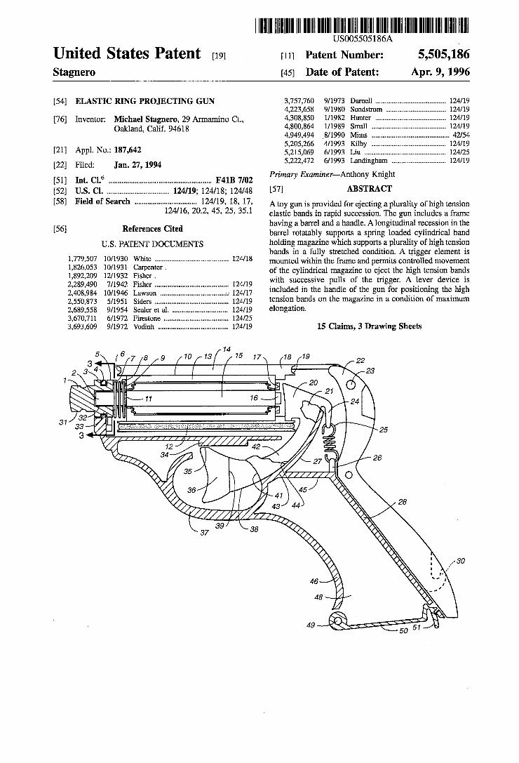
[54] ELASTIC RING PROJECTING GUN 3,757,760 9/1973 Darnell .................................... .. 124/19
4,223,658 9/ 1980 Sundstrom ............... .. [76] Inventor: Michael Stagnero, 29 Armamino Ct., 4,303,850 1/1982
Oakland, Calif. 94618 4,800,864 1/1989 4,949,494 8/1990 5,205,266 4/1993
[21] Appl. No.: 187,642 5,215,069 6/1993 [22] Filed: Jan. 27, 1994 5,222,472 “993
[51] Int C16 F41B 7/02 Primary Examiner—Anthony Knight
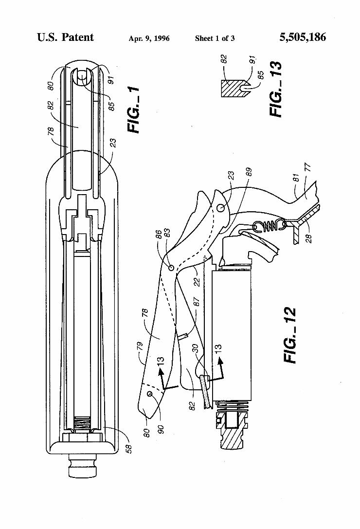
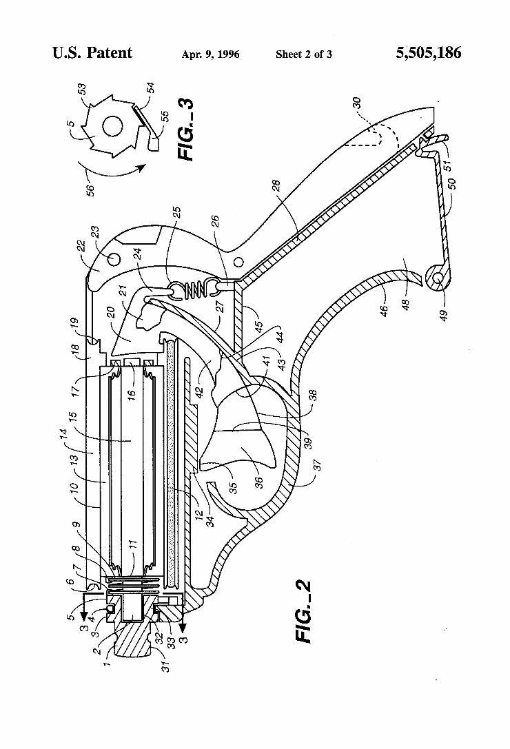
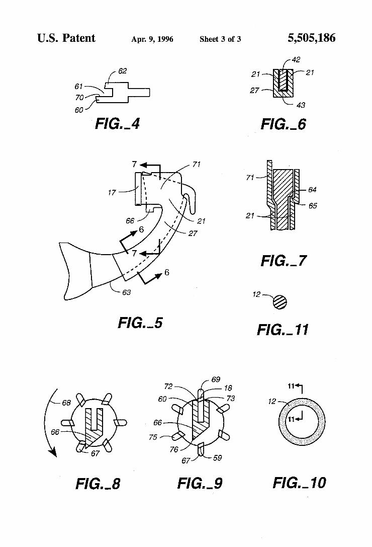
[52] US. Cl. ................................ .. 124/19; 124/18; 124/48 [57] ABSTRACT
[58] Field Of Search ................................ .. 124/19, 18, 17, A toy gun is provided for ejecting a plurality of high tension 124/16 20 2 45 25 351 ’ - ’ ’ ’ ' elastic bands in rapid succession. The gun includes a frame
56 R f Ct d having a barrel and a handle. A longitudinal recession in the [ l e erences l e barrel rotatably supports a spring loaded cylindrical band
U_S_ PATENT DOCUMENTS holding magazine which supports a plurality of high tension _ bands in a fully stretched condition. A trigger element is
1,779,507 10/1930 White ...................................... .. 124/18 mount?d within the frame and permits controlled movement
gf‘gpemer ' of the cylindrical magazine to eject the high tension bands 2’289’490 7/1942 13:11:; ' 124,19 with successive pulls of the trigger. A lever device is 2’408’984 10/1946 """"""""""""""""""" 124,17 included in the handle of the gun for positioning the high 2:550:33 5/1951 124/19 tension bands on the magazine in a condition of maximum 2,689,558 9/1954 .. 124/19 elongation 3,670,7l1 6/1972 124/25 3,693,609 9/1972 .. 124/19 15 Claims, 3 Drawing Sheets
(‘77/8 9 war” / 1 l
14 15 [f 17\ (1a [19 ' / l ‘
l l l
V
20
? / / / J
,1. 42
V II” 36 ‘4 41 ,1 43
’I’IIIIIIZV/IIII"" a9 37 38
A
' 1” yzvlllllll‘ 45
US. Patent Apr. 9, 1996 Sheet 1 of 3 5,505,186
FIG._ 12
US. Patent Apr. 9, 1996 Sheet 2 of 3 5,505,186
Rm.
N 16E
5,505,186
[42
US. Patent Apr. 9, 1996 Sheet 3 of 3
P21 62
FIG._,9 FIG._1.0 FIG._8
llllllllllllllIllllllllllllllllllllllllllllllllllllllllllllllllllllllllllll US005595165A
United States Patent [19] 1111 Patent Number: 5,595,165 Conte [45] Date of Patent: Jan. 21, 1997
[54] SINGLE-SHOT RUBBERBAND GUN AND Primary Examiner—John A. Ricci SNAP-TOY
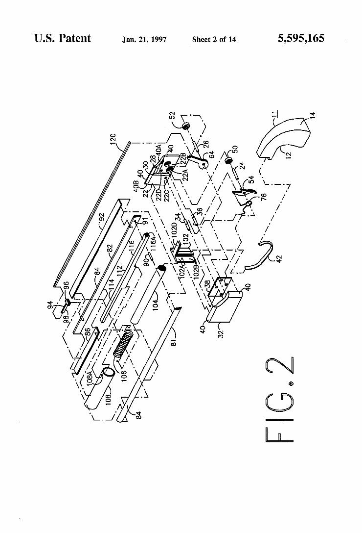
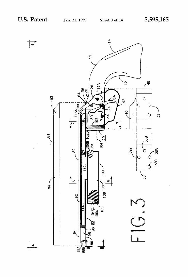
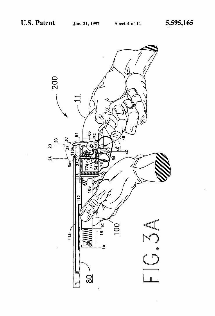
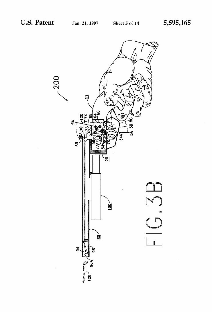
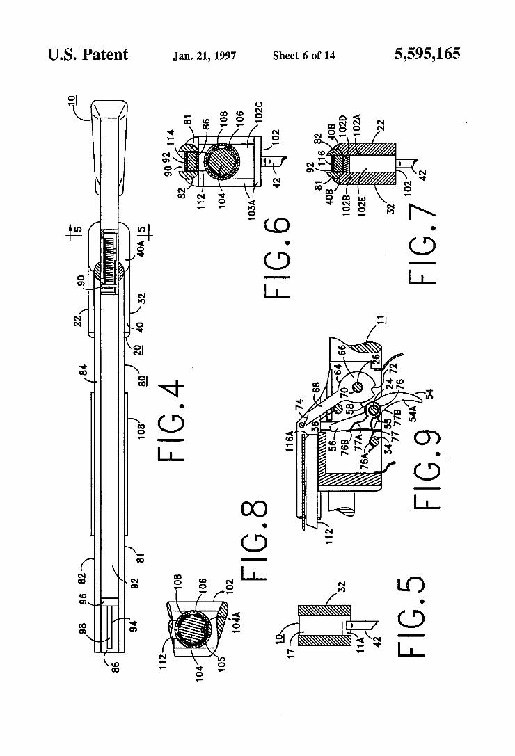
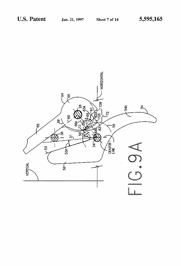
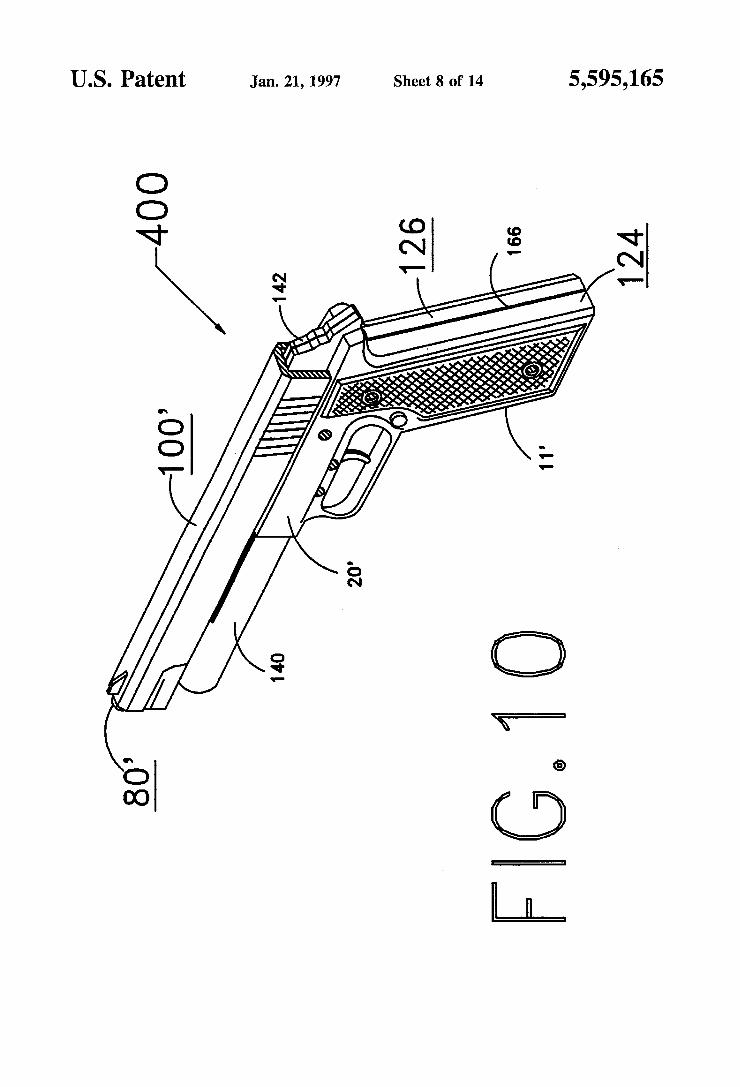
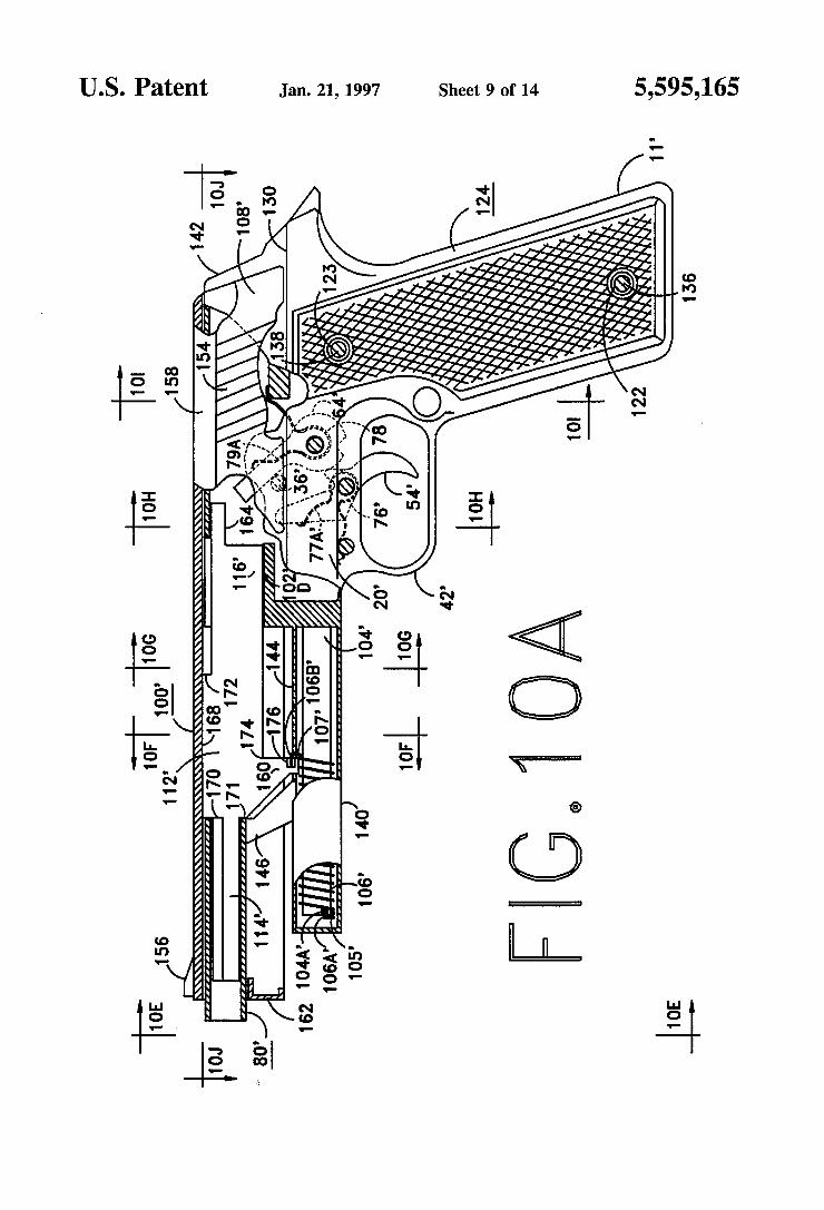
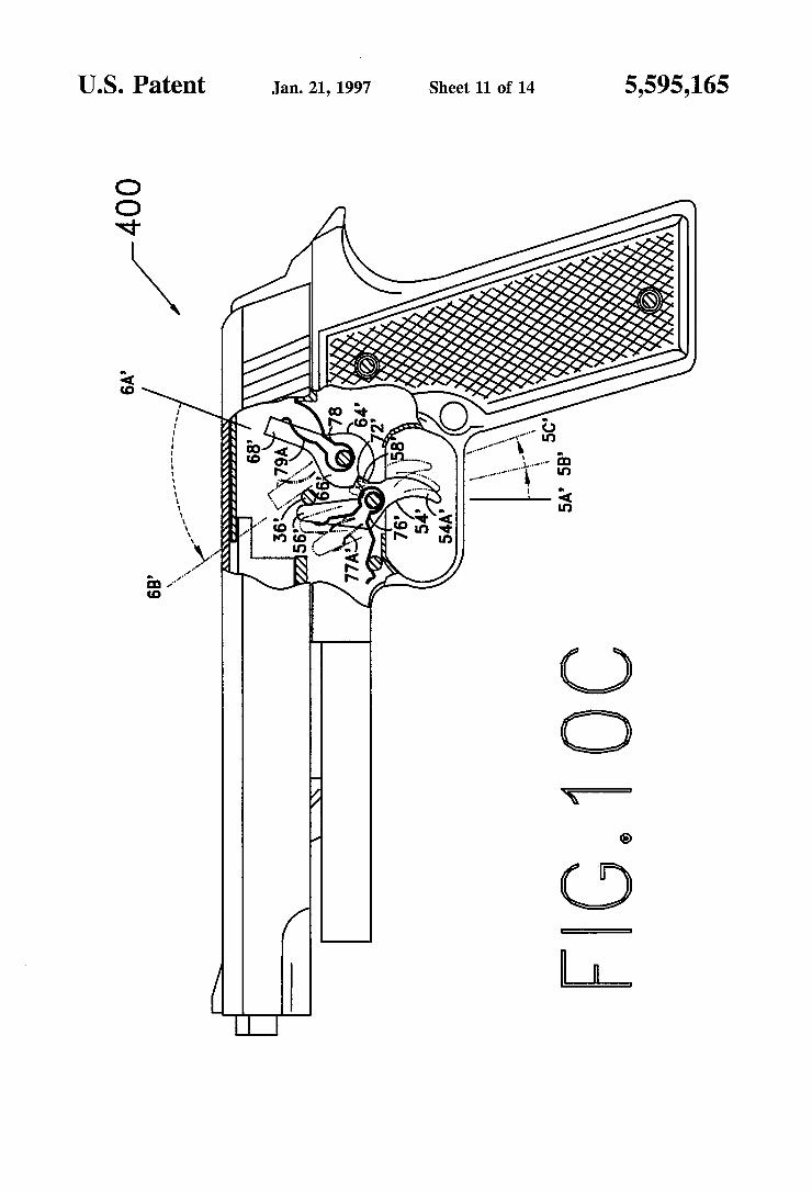
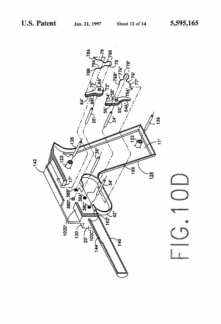
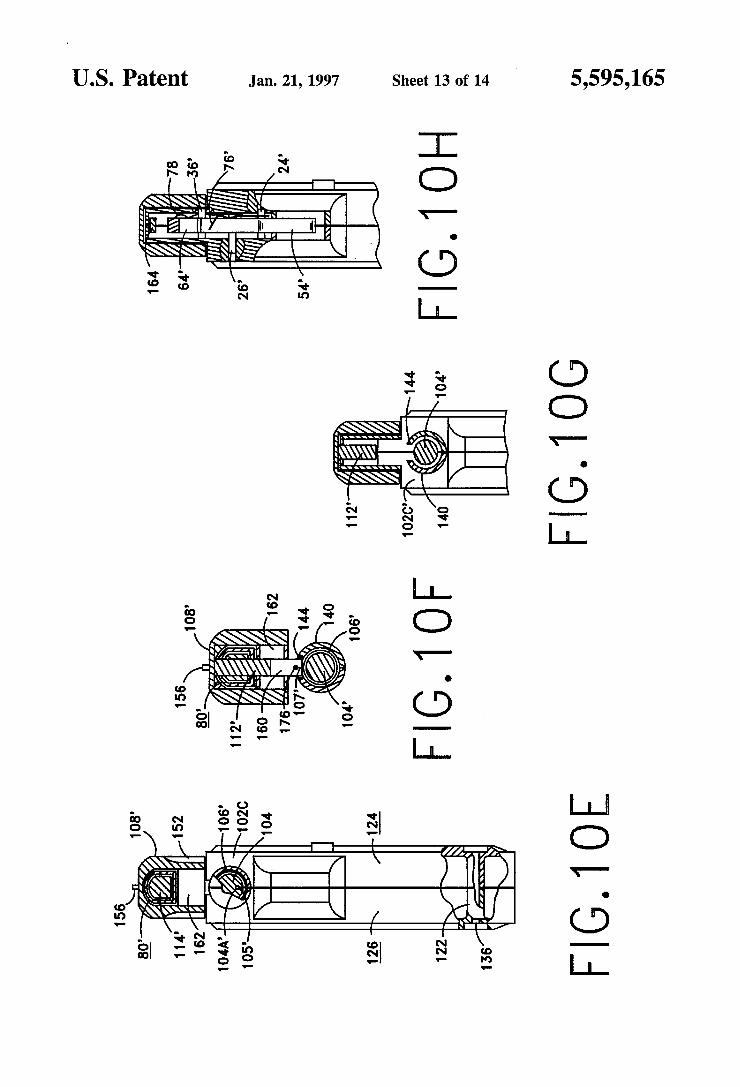
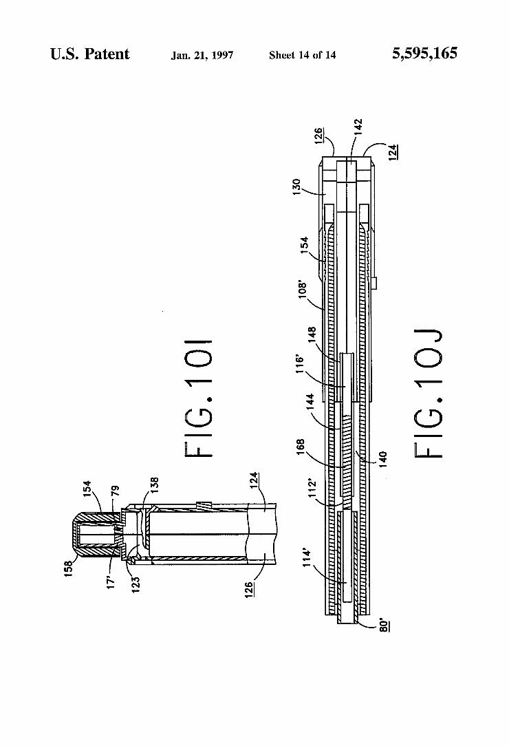
[57] ABSTRACT [76] Inventor: Agostino B. Conte, 2900 Wilkinson _ _ _
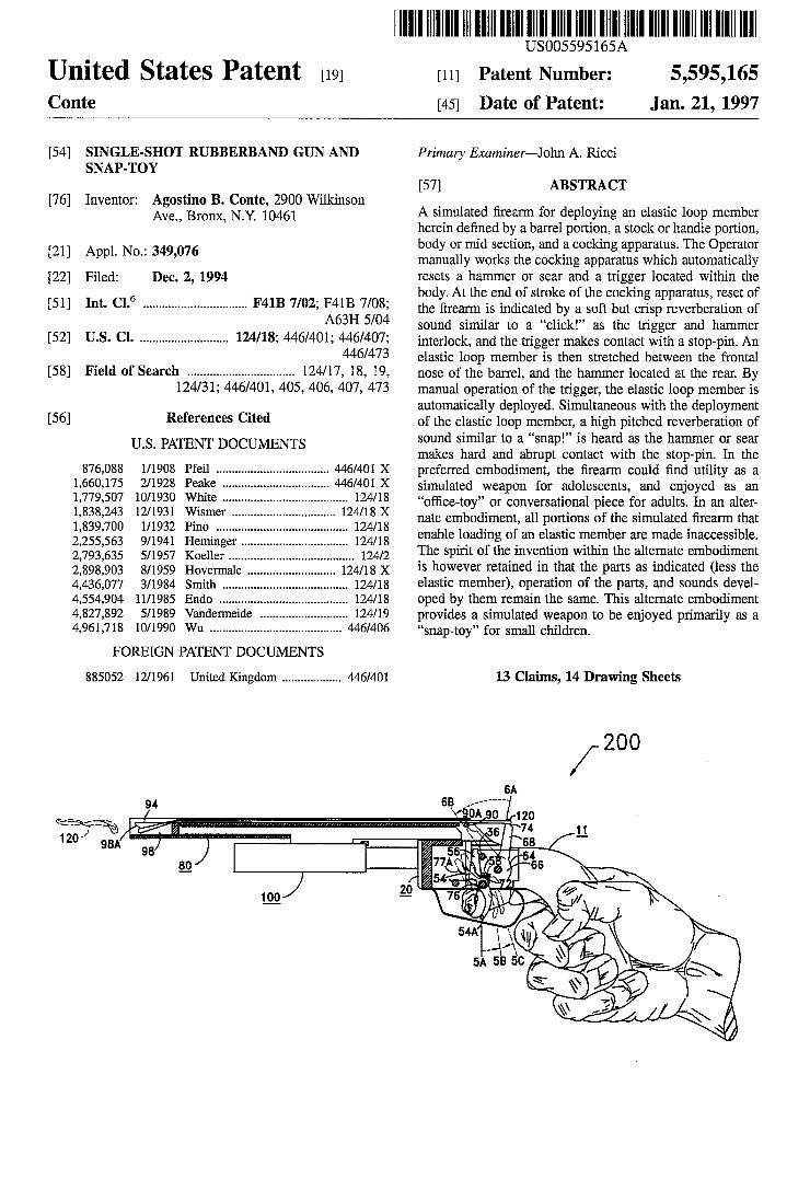
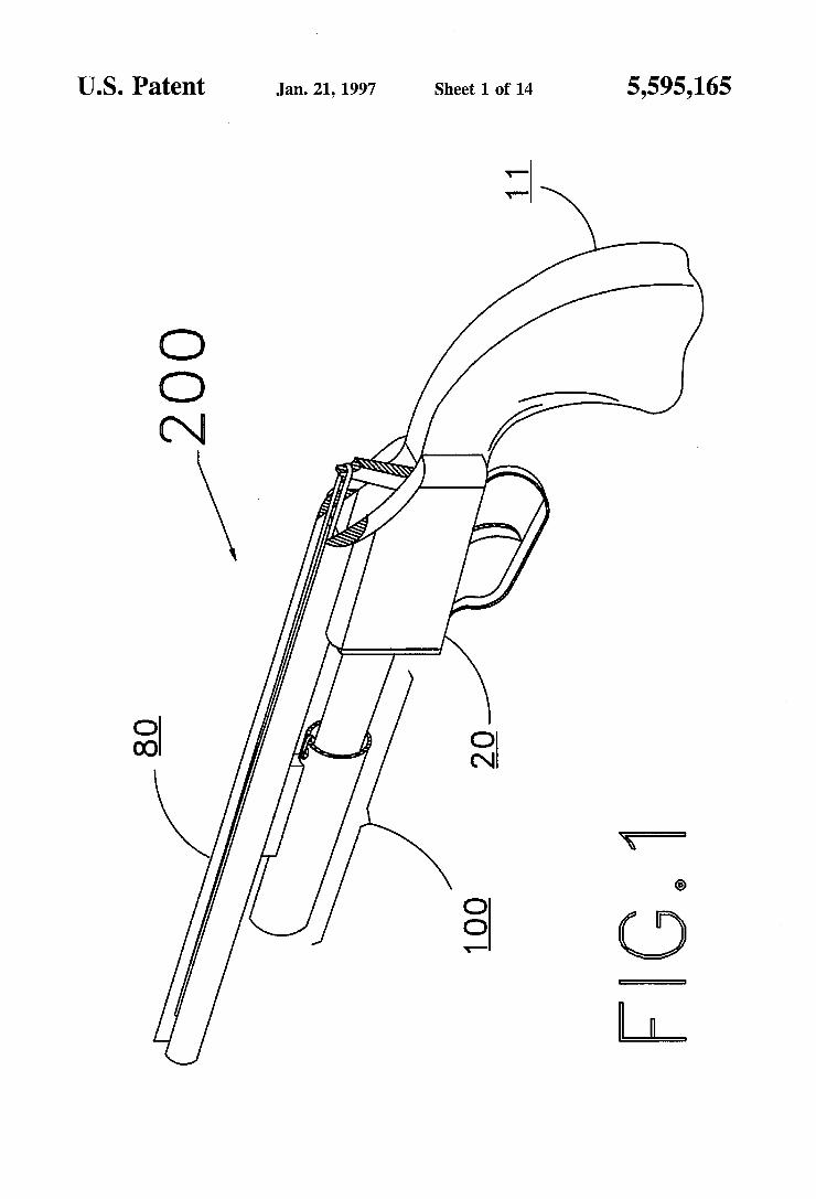
Ave” Bronx, N_Y_ 10461 A simulated ?rearm for deploying an elastic loop member herem de?ned by a barrel portion, a stock or handle portion,
_ body or mid section, and a cocking apparatus. The Operator [21] Appl' No" 349’076 manually works the cocking apparatus which automatically [22] Filed: Dec. 2, 1994 resets a hammer or sear and a trigger located within the
6 body. At the end of stroke of the cocking apparatus, reset of [51] Int. Cl. ............................... .. F41B 7/02; F4113 7/08; the ?rearm is indicated by a Soft but crisp reverberation of
A63H 5/04 sound similar to a “click!” as the trigger and hammer US. Cl- .......................... u interlock’ and the trigger makes Contact a st0p_pin_ An
446/473 elastic loop member is then stretched between the frontal [58] Field Of Search ................................ .. l24/l7, l8, l9, nose of the barrel, and the hammer located at the rear. By
124/31; 446/401, 405, 406, 407, 473 manual operation of the trigger, the elastic loop member is _ automatically deployed. Simultaneous with the deployment
[56] References Clted of the elastic loop member, a high pitched reverberation of Us PATENT DO UMENTS sound similar to a “snap!” is heard as the hammer or sear
c makes hard and abrupt contact with the stop-pin. In the 876,088 1/1908 Pfeil .................................. .. 446/401 X preferred embodiment, the ?rearm could ?nd utility as a
1,660,175 2/1928 Peal“? - - - - - - - - -- 446/401 X simulated weapon for adolescents, and enjoyed as an
1,779,507 10/1930 Wl'nte . . . . . . . . . . . . . . . . . . .. 124/18 “o?ice_toy” or conversational piece for adults_ In an altel;
1’838’243 12/1931 Wlsmer "" " 124,18 X nate embodiment, all portions of the simulated ?rearm that 1,839,700 l/1932 Pmo . . . . . . . . . . . . . . . . .. 124/18 . . . .
2 255 563 9/1941 H . enable loading of an elastic member are made maccessrble. , , emmger ..... .. 124/18 . . _ . . . .
2,793,635 5/1957 Koeller . . . . . . . . . . . . . . . . . . .. 124/2 The SPlm of the, mveFmon Wlthm the alternate embodlmem
2,898,903 3/1959 Hovermale 124/18 X is however retained in that the parts as mdlcated (less the 4,436,077 3/1984 Smith . . . . . . . . . . . . . . . . . . .. 124/18 elastic member), operation of the parts, and sounds devel
4,554,904 11/1985 Endo . . . . . . . . . . . . . . . . . . . . . . . .. 124/18 oped by them remain the same. This alternate embodiment
4,827,892 5/1989 Vandermeide . . . . . . . . . . .. 124/19 provides a simulated weapon to be enjoyed primarily as 21
4,961,718 10/1990 Wu ........................................ .. 446/406 “snaptoy” for small children
FOREIGN PATENT DOCUMENTS
885052 12/1961 United Kingdom ................. .. 446/401 13 Claims, 14 Drawing Sheets
65 6A 94 , ’’’’’ "
gs’g "(0A07120 “771% <.\-\ 5 74 11 1211- 98A I as _
98 55 " I .64
Q 77A ' ~65 \
f 54 7 \ m 2_o 7 ' E)‘. y/
/ \\ /
54A 1 \,
441g"! \\ \ / 5A 5e 0 \ _,
_\_ Q \ \\\
\\\ I? \
US. Patent Jan. 21, 1997 Sheet 1 0f 14 5,595,165
US. Patent Jan. 21, 1997 Sheet 2 of 14 5,595,165
~1
US. Patent Jan. 21, 1997 Sheet 3 of 14 5,595,165
g4. E1:
U.S. Patent Jan. 21, 1997 Sheet 4 of 14 5,595,165
US. Patent Jan. 21, 1997 Sheet 5 0f 14 5,595,165
5,595,165 Sheet 6 0f 14 Jan. 21, 1997 US. Patent
US. Patent Jan. 21, 1997 Sheet 7 of 14 5,595,165
em
US. Patent Jan. 21, 1997 Sheet 8 of 14 5,595,165
o2N
US. Patent Jan. 21, 1997 Sheet 9 0f 14 5,595,165
.:
on_ .2: 2:
N: mm mNF
NNF
@
~ (+5.8,

U.S. Patent Jan. 21, 1997 Sheet 10 of 14 5,595,165
400 AK
US. Patent Jan. 21, 1997 Sheet 11 0f 14 5,595,165
o3N
@
@E
US. Patent Jan. 21, 1997 Sheet 12 of 14 5,595,165
@
U.S. Patent Jan. 21, 1997 Sheet 13 of 14 5,595,165
F|G.1OF F|G.1OG
5,595,165
wOToE
US. Patent Jan. 21, 1997 Sheet 14 0f 14
United States Patent [191 Swanson et al.
US005692489A
5,692,489 Dec. 2, 1997
[11] Patent Number:
[45] Date of Patent:
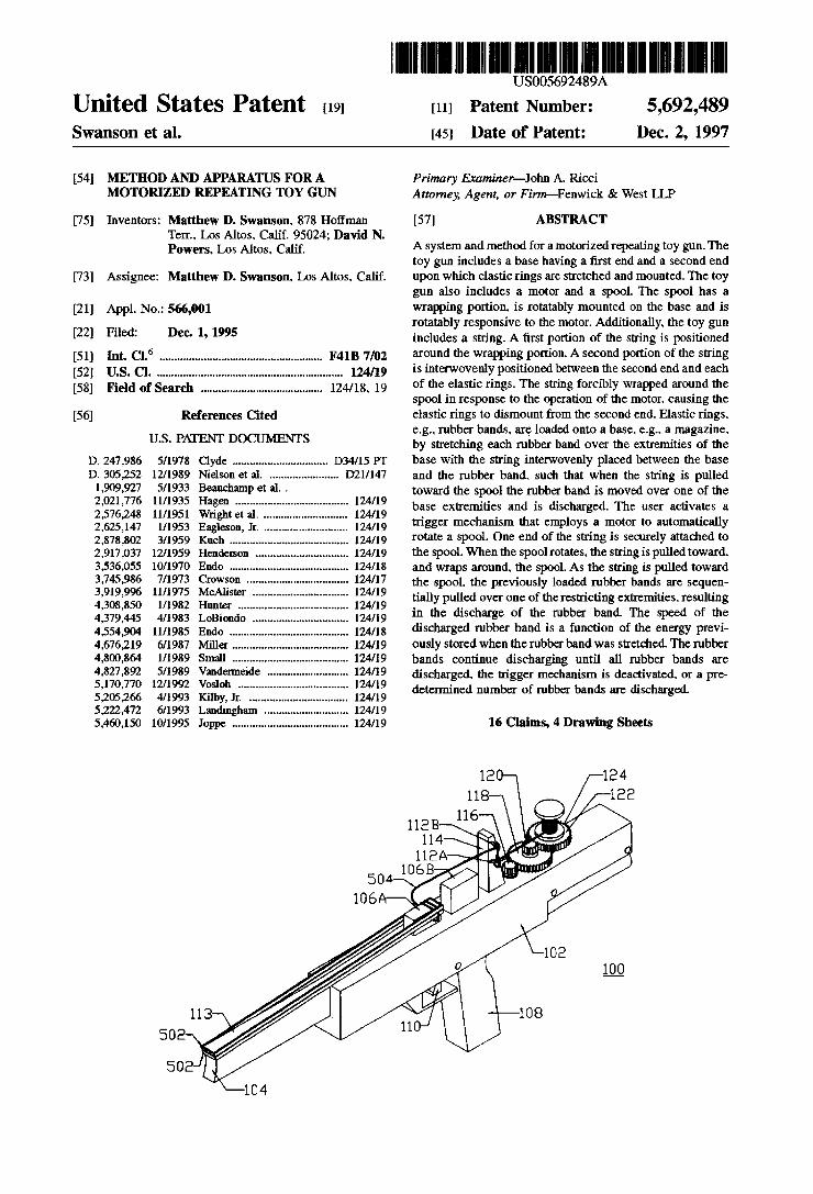
[54] METHOD AND APPARATUS FOR A MOTORIZED REPEATING TOY GUN
[75] Inventors: Matthew D. Swanson. 878 Holfman Tern. Los Altos. Calif. 95024; David N. Powers. Los Altos. Calif.
[73] Assignee: Matthew D. Swanson. Los Altos. Calif.
[21] Appl. No.: 566,001
[22] Filed: Dec. 1, 1995
[51] Int. cl.6 ...................................................... .. F41B 7/02
[52] U.S. Cl. 124/19 [58] Field of Search ........................................ .. 124/18. 19
[56] References Cited
U.S. PATENT DOCUMENTS
D. 247,986 5/1978 Clyde ............................... .. D34l15 PT D. 305,252 12/1989 Nidson et a1. ...................... .. D2l/l47 1,909,927 5/1933 Beauchamp et al. . 2,021,776 11/1935 Hagen ..................................... .. 124/19 2,576,248 ll/l95l Wright et a1. . 124/19 2,625,147 1/1953 Eagleson, Jr. . .. 124/19 2,878,802 3/1959 Kueh . . . . . . . . . . . . . . . . .. 124/19
2,917,037 12/1959 Henderson . 124/19 3,536,055 10/1970 Endo . 124/18 3,745,986 7/1973 Crowson 124/17 3,919,996 11/1975 McAlister . 124/19 4,308,850 l/1982 Hunter .... .. 124/19
4,379,445 4/1983 LoBiondo . 124/19 4,554,904 11/1985 Endo 124/18 4,676,219 6/1987 Miller .. 124/19 4,800,864 1/1989 Small ...... .. 124/19
4,827,892 5/1989 Vandermeide 124/19 5,170,770 12/1992 Vosloh ........ .. 124/19
5,205,266 4/1993 Ki1by,Jr. 124/19 5,222,472 6/1993 Landingham .. 124/19 5,460,150 lO/1995 Joppe ...................................... .. 124/19
104
Primary Examiner-John A. Ricci Attorney; Agent, or Finn-Fenwick & West LLP
[57] ABSTRACT
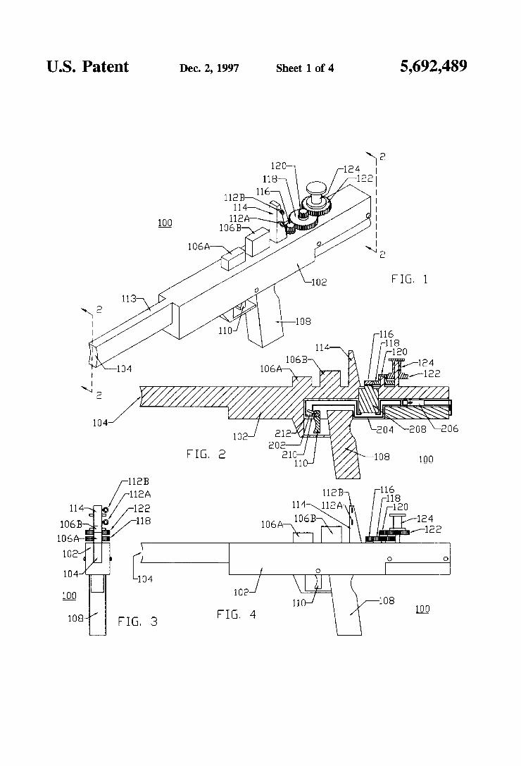
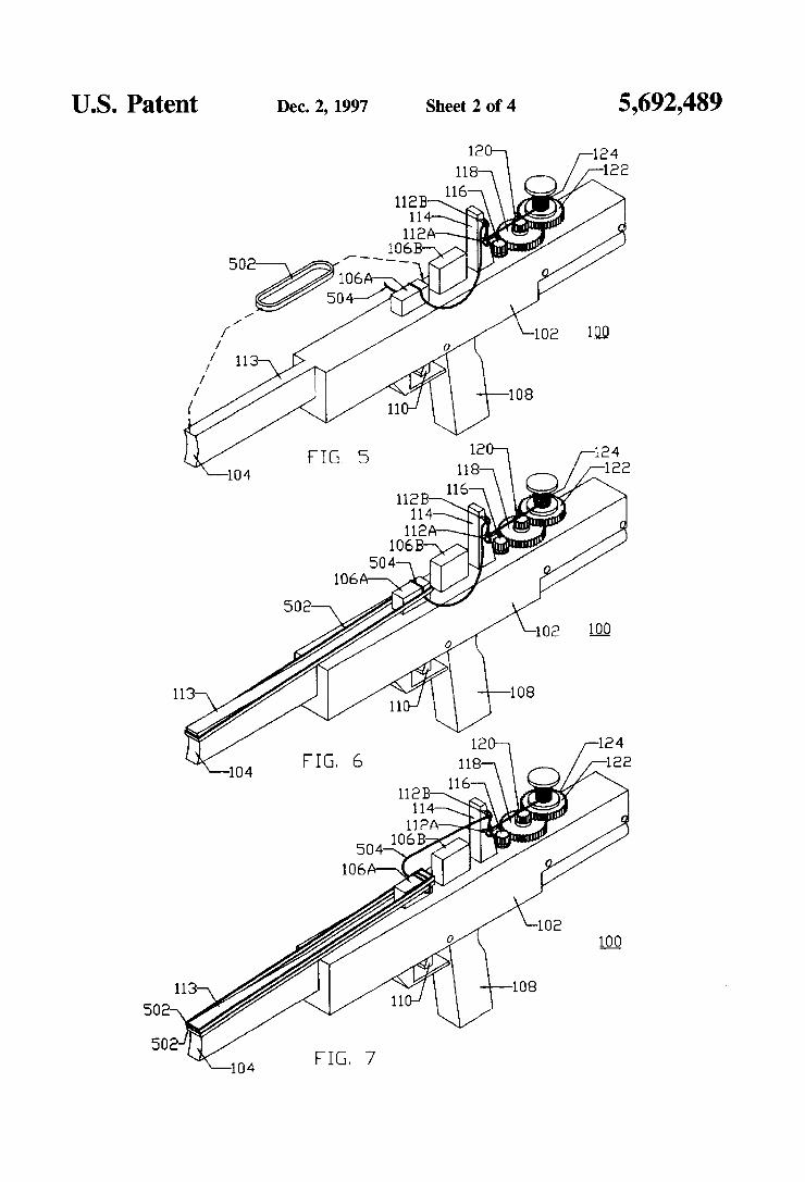
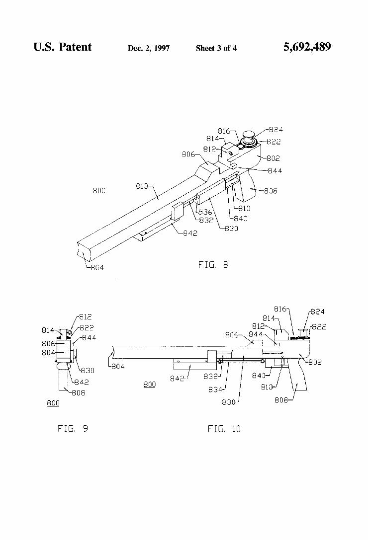
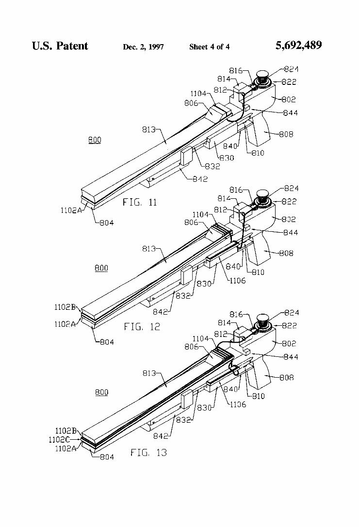
A system and method for a motorized repeating toy gun. The toy gun includes a base having a ?rst end and a second end upon which elastic rings are stretched and mounted. The toy gun also includes a motor and a spool. The spool has a wrapping portion. is rotatably mounted on the base and is rotatably responsive to the motor. Additionally. the toy gun includes a string. A ?rst portion of the string is positioned around the wrapping portion. A second portion of the string is interwovenly positioned between the second end and each of the elastic rings. The string forcibly wrapped around the spool in response to the operation of the motor. causing the elastic rings to dismount from the second end. Elastic rings. e.g.. rubber bands, are loaded onto a base. e.g.. a magazine. by stretching each rubber band over the extremities of the base with the string interwovenly placed between the base and the rubber band, such that when the string is pulled toward the spool the rubber band is moved over one of the base extremities and is discharged. The user activates a nigger mechanism that employs a motor to automatically rotate a spool. One end of the string is securely attached to the spool. When the spool rotates. the string is pulled toward. and wraps around. the spool. As the string is pulled toward the spool. the previously loaded rubber bands are sequen tially pulled over one of the restricting extremities. resulting in the discharge of the rubber band. The speed of the discharged rubber band is a function of the energy previ ously stored when the rubber band was stretched. ‘The rubber bands continue discharging until all rubber bands are discharged. the trigger mechanism is deactivated. or a pre determined number of rubber bands are discharged.
16 Claims, 4 Drawing Sheets
U.S. Patent Dec. 2, 1997 Sheet 1 0f 4
FIG. 1
1084/ 4
US. Patent Dec. 2, 1997 Sheet 2 of 4 5,692,489
US. Patent Dec. 2, 1997 Sheet 3 of 4 5,692,489
FIG. 9 FIG. 10
US. Patent Dec. 2, 1997 Sheet 4 of 4 5,692,489
US007640922B2
(12) Umted States Patent (10) Patent N0.2 US 7,640,922 B2 Siebelink (45) Date of Patent: Jan. 5, 2010
(54) FOAM DART GUN 3,014,308 A 12/1961 Parris 3,119,385 A 1/1964 Ashley
(76) Inventor: Thomas Siebelink, 3605 WentWorth 3,757,760 A * 9/1973 Darnell ...................... .. 124/19
SW., Wyoming, Ml (US) 49519 4,050,438 A 9/1977 Pfotenhauer 4,800,864 A 1/1989 Small
( * ) Notice: Subject to any disclaimer, the term ofthis 4,802,677 A 2/19g9 Homan patent is extended or adjusted under 35 5,232,453 A 2/1994 Chia U-S-C- 154(1)) by 229 days- 5,460,150 A 10/1995 Joppe
' 5,595,166 A 1/1997 Schmidt, III et al. (21) Appl' No" 11/683,499 6,079,398 A 6/2000 Grimm
(22) Filed: Mar- 8, 2007 6,247,990 B1 6/2001 Moor-house 6,500,042 B1 12/2002 LaPolnte
(65) Prior Publication Data
US 2007/0209646 A1 Sep. 13, 2007 * Cited by examiner
Related U-s- Application Data Primary Examinerilohn Ricci
(60) Provisional application No. 60/780,303, ?led on Mar. (74) {mm Agent! 0'’ Firmipnca Heneve1d> COOPer> 8’ 2006' DeW1tt & L1tton, LLP
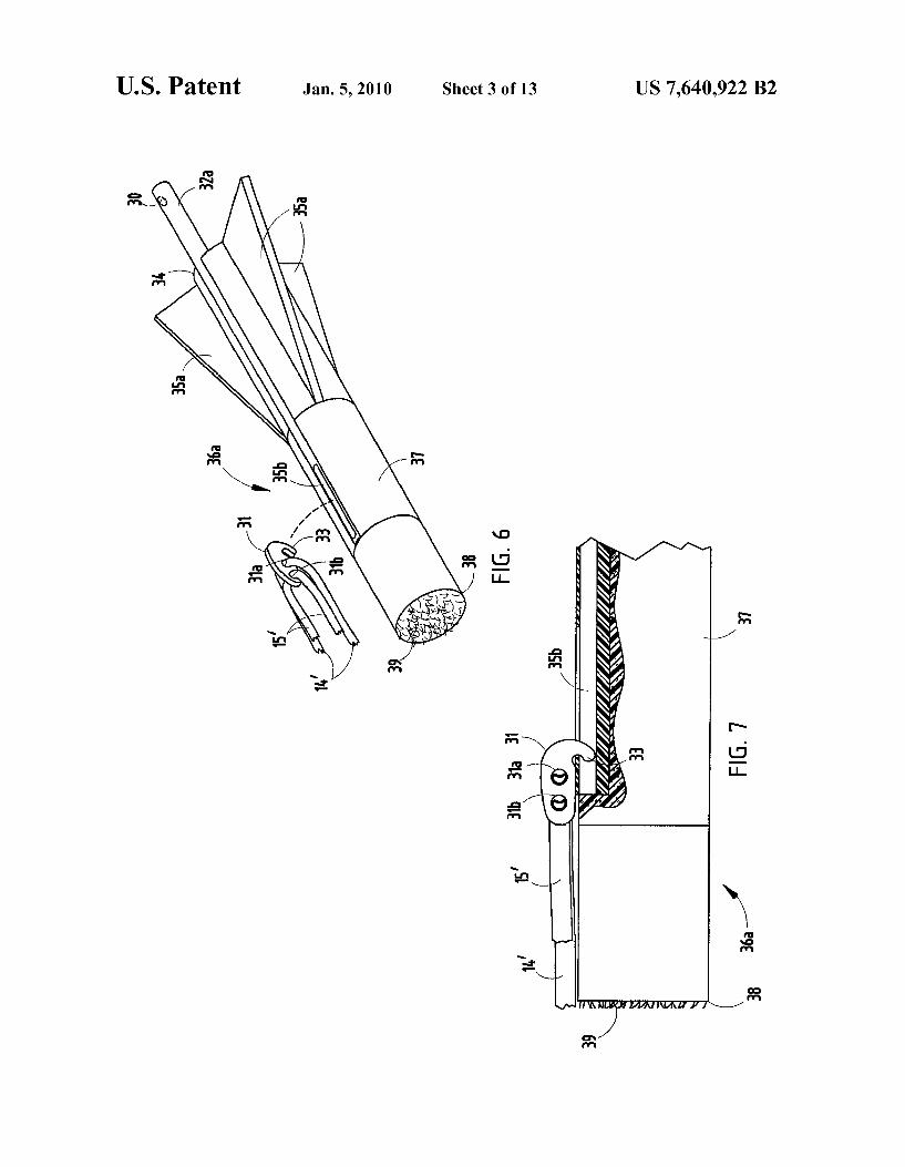
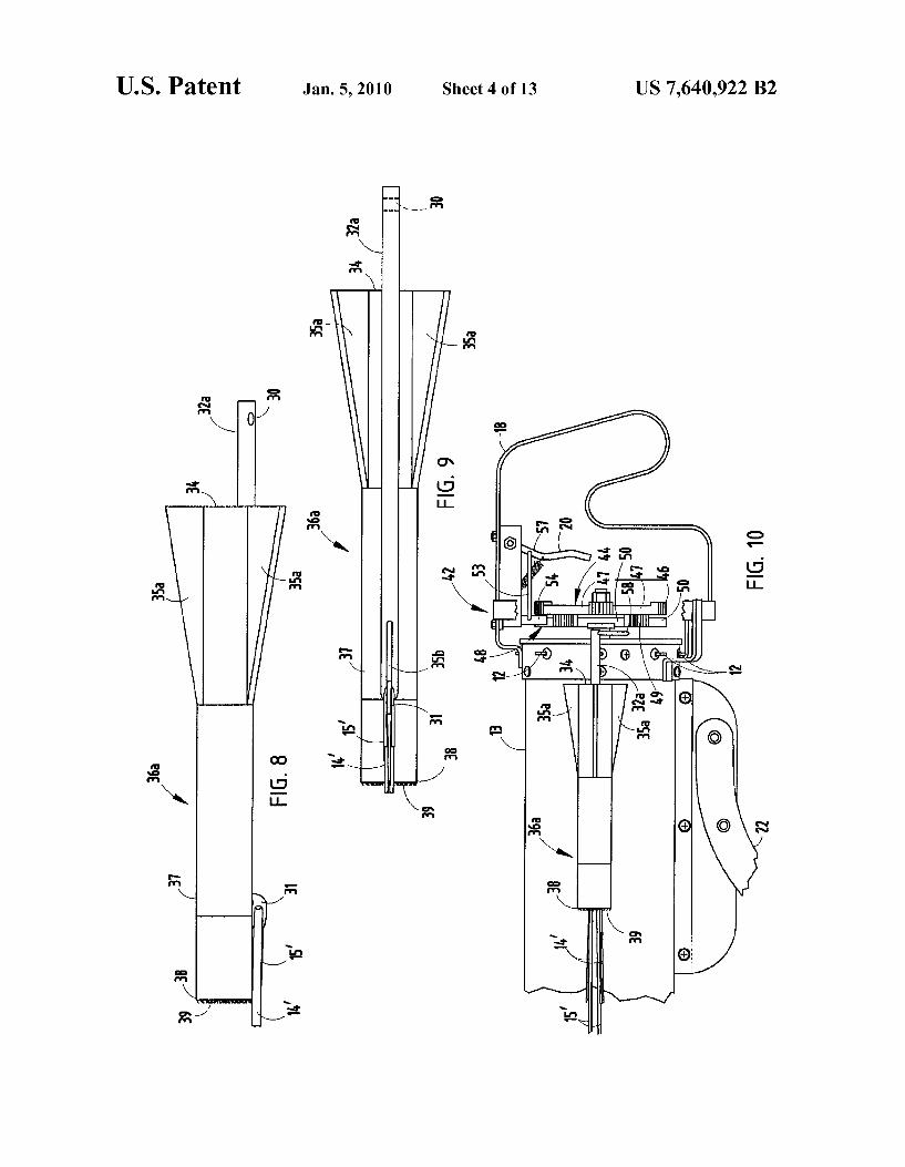
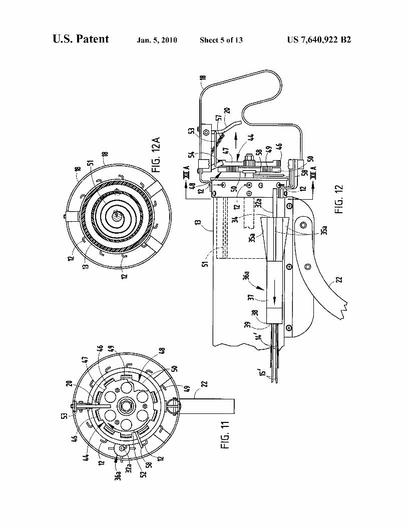
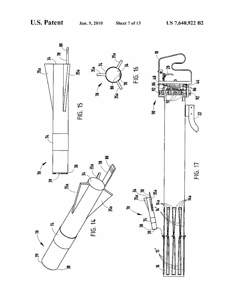
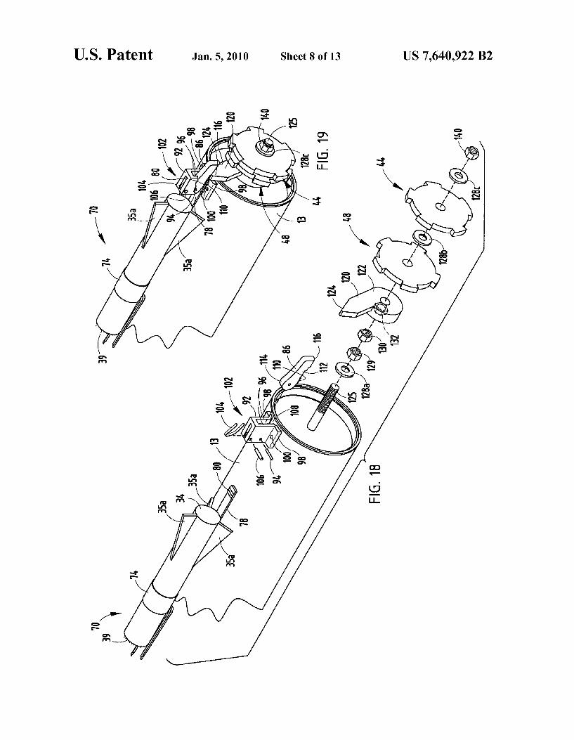
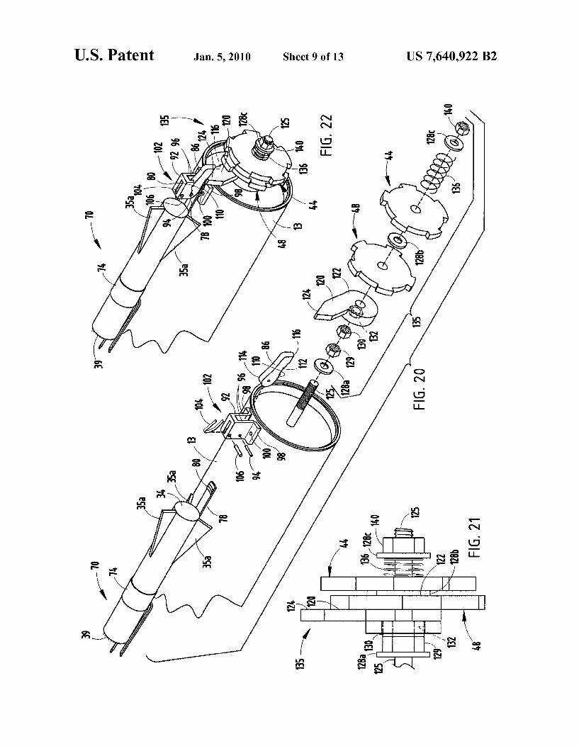
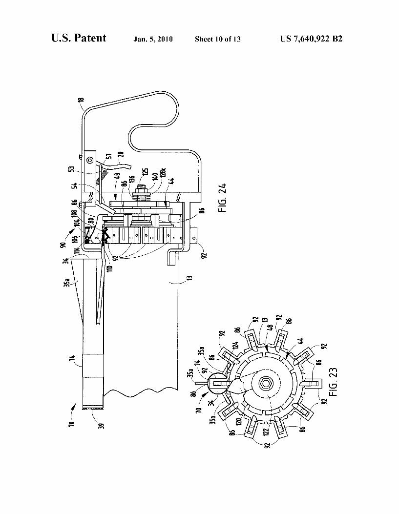
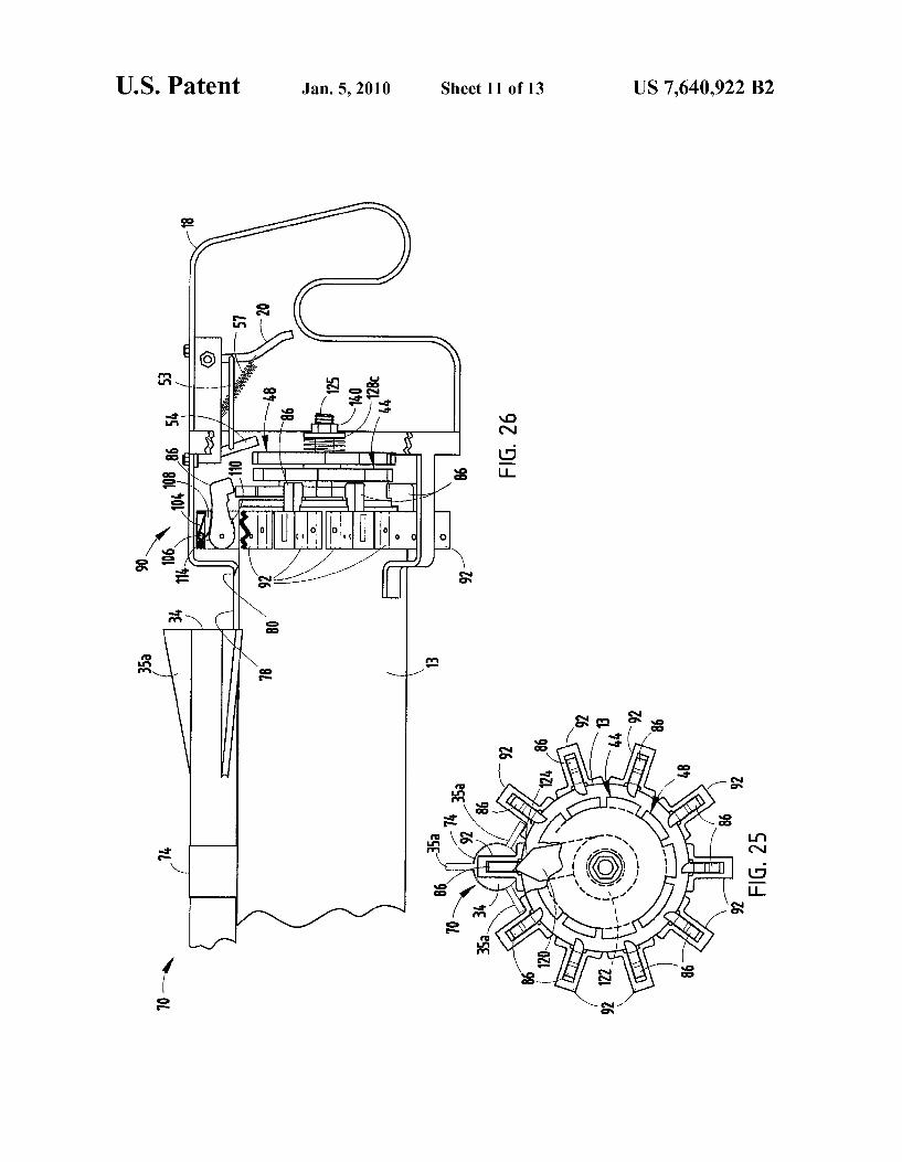
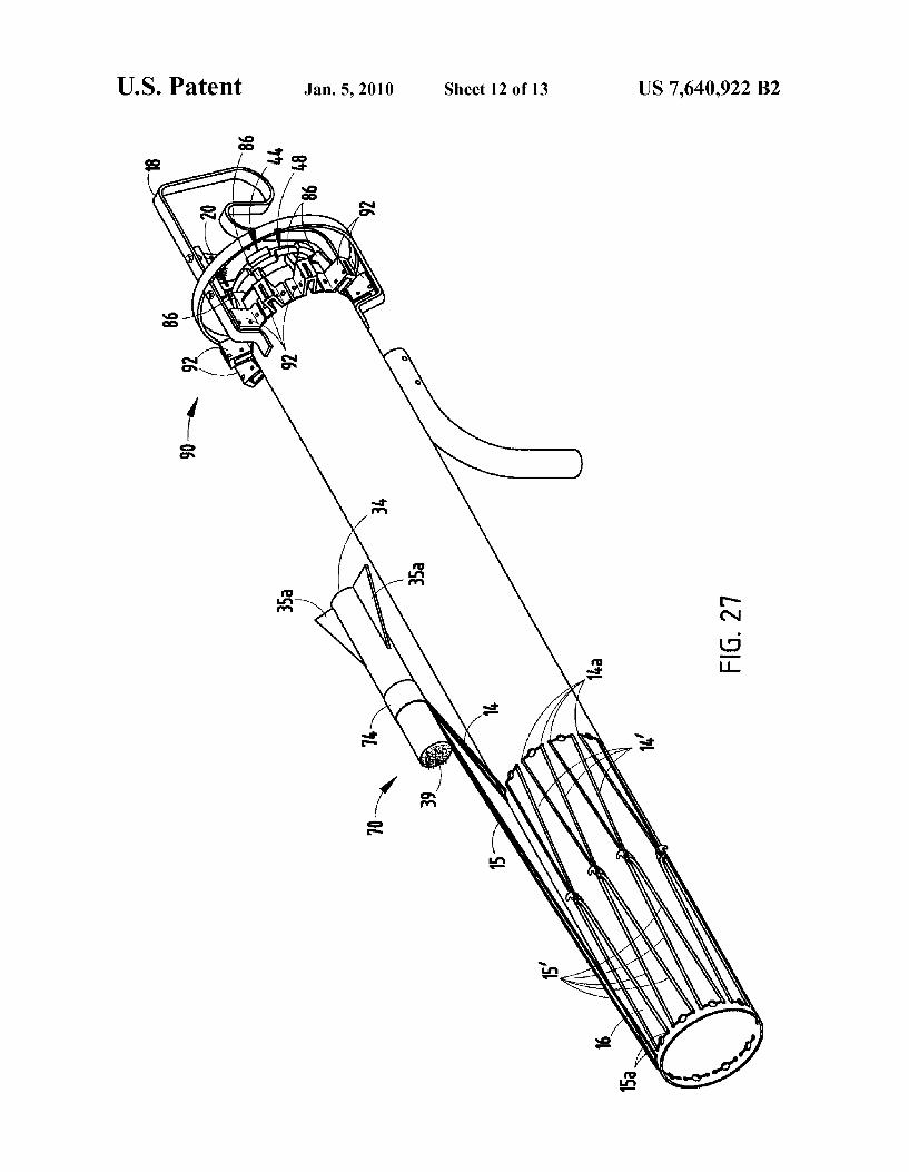
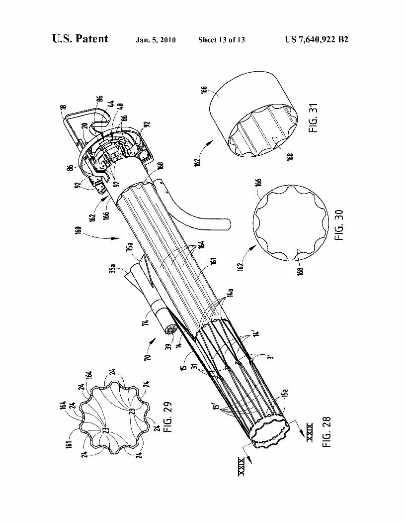
(51) Int. Cl. (57) ABSTRACT F41B 7/00 (2006.01)
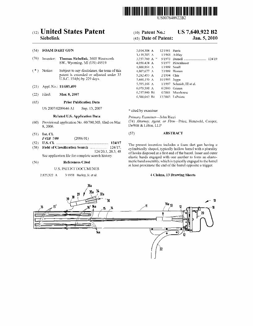
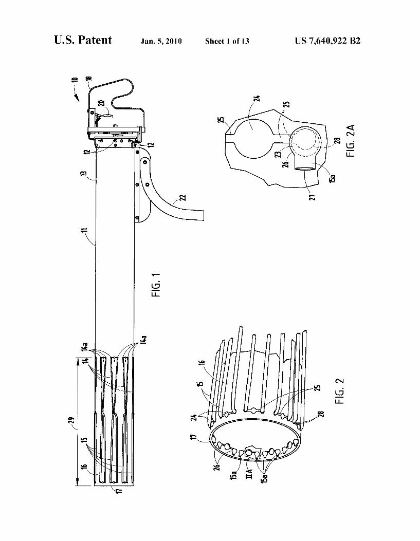
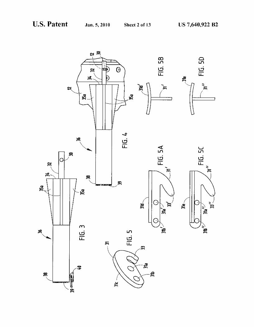
(52) U..S. Cl. ...... .... ...... ... ..................................... .. 124/17 The present invention includes a foam dart gun having a
Fleld 0f ClaSSl?CatlOIl Search ................. .. Shaped’ hollow barrel a _ _ 124091’ 203’ 48 ofhooks disposed at a ?rst end ofthe barrel. Inner and outer
See apphcanon ?le for Complete Search hlstory' elastic bands engaged With one another to form an elasto
(56) References Cited meric band assembly, Which is typically engaged to the barrel at least proximate the end of the barrel opposite a trigger.
U.S. PATENT DOCUMENTS
2,825,322 A 3/1958 Burley, Jr. et a1. 4 Claims, 13 Drawing Sheets
36a
3!. 31 I/ 353 32a 39 3” \ 30 36 r10
a 16 15’ 1,,’ 113 m 11 13 12 1|;
/ //?’ —" // 91 "5 / / 1 ° 0 l 76*; 1 _[ y / v w 20
/
US. Patent Jan. 5, 2010 Sheet 1 0f 13 US 7,640,922 B2
US. Patent Jan. 5, 2010 Sheet 2 0f 13 US 7,640,922 B2
312 12
35a 35a 31a’ W31! F
FIG. 3 31
FIG 5
33
31a 31b
US. Patent Jan. 5, 2010 Sheet 3 0f 13 US 7,640,922 B2
N. .wI
US. Patent Jan. 5, 2010 Sheet 4 0f 13 US 7,640,922 B2
US. Patent Jan. 5, 2010 Sheet 5 0f 13 US 7,640,922 B2
3
Z .wI

US. Patent Jan. 5, 2010 Sheet 6 0f 13 US 7,640,922 B2
FIG. 13
US. Patent Jan. 5, 2010 Sheet 7 0f 13 US 7,640,922 B2
2 .oE
US. Patent Jan. 5, 2010 Sheet 8 0f 13 US 7,640,922 B2
US. Patent Jan. 5, 2010 Sheet 9 0f 13 US 7,640,922 B2
US. Patent Jan. 5, 2010 Sheet 10 0f 13 US 7,640,922 B2
US. Patent Jan. 5, 2010 Sheet 11 0113 US 7,640,922 B2
US. Patent Jan. 5, 2010 Sheet 12 0f 13 US 7,640,922 B2
US. Patent Jan. 5, 2010 Sheet 13 0f 13 US 7,640,922 B2
166
168
168
FIG. 30
FIG. 28
US007690371B2
(12) Ulllted States Patent (10) Patent N0.: US 7,690,371 B2 Slaven (45) Date of Patent: Apr. 6, 2010
(54) TOY GUN 2,535,891 A * 12/1950 BoZaIth ..................... .. 124/18
2,642,057 A * 6/1953 Watkins 124/17
(75) Inventor: Michael Howard Slaven, Buena Park, 2,692,593 A * 10/ 1954 Flores, Jr~ -- - 124/18 CA (Us) 2,730,094 A * l/l956 Hicks ........................ .. 124/19
4,436,077 A 3/1984 Smith . _ . 4,554,904 A 11/1985 Endo
(73) Asslgnee. 151g Oldt1mer, LLC, Buena Park, CA 4,827,892 A 5/l989 Vandermeide ( ) 5,595,165 A l/l997 Conte
( * ) Notice: Subject to any disclaimer, the term of this OTHER PUBLICATIONS patent is extended or adjusted under 35 TU “R bb b d n f W_k_ d_ b (http //
1 e u er an guns rom 1 lpe 13. We page Z en.
U'S'C' 154(1)) by 351 days‘ Wikipedia.org/Wiki/Rubberbandfgun), date unknown, author
(21) Appl. N0.: 11/s39,547 “111mm; three (3)1’ageS' * cited by examiner
(22) Filed: Aug. 16, 2007 Primary Examinerilohn Ricci
(65) Prior Publication Data (74) Attorney, Agent, or FirmiHeidi L. Eisenhut; LoZa & L LLP
US 2008/0087261 A1 Apr. 17, 2008 0Z2"
57 ABSTRACT Related US. Application Data ( )
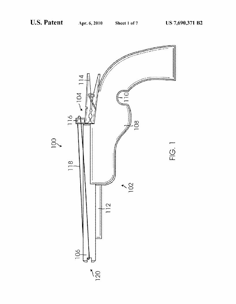
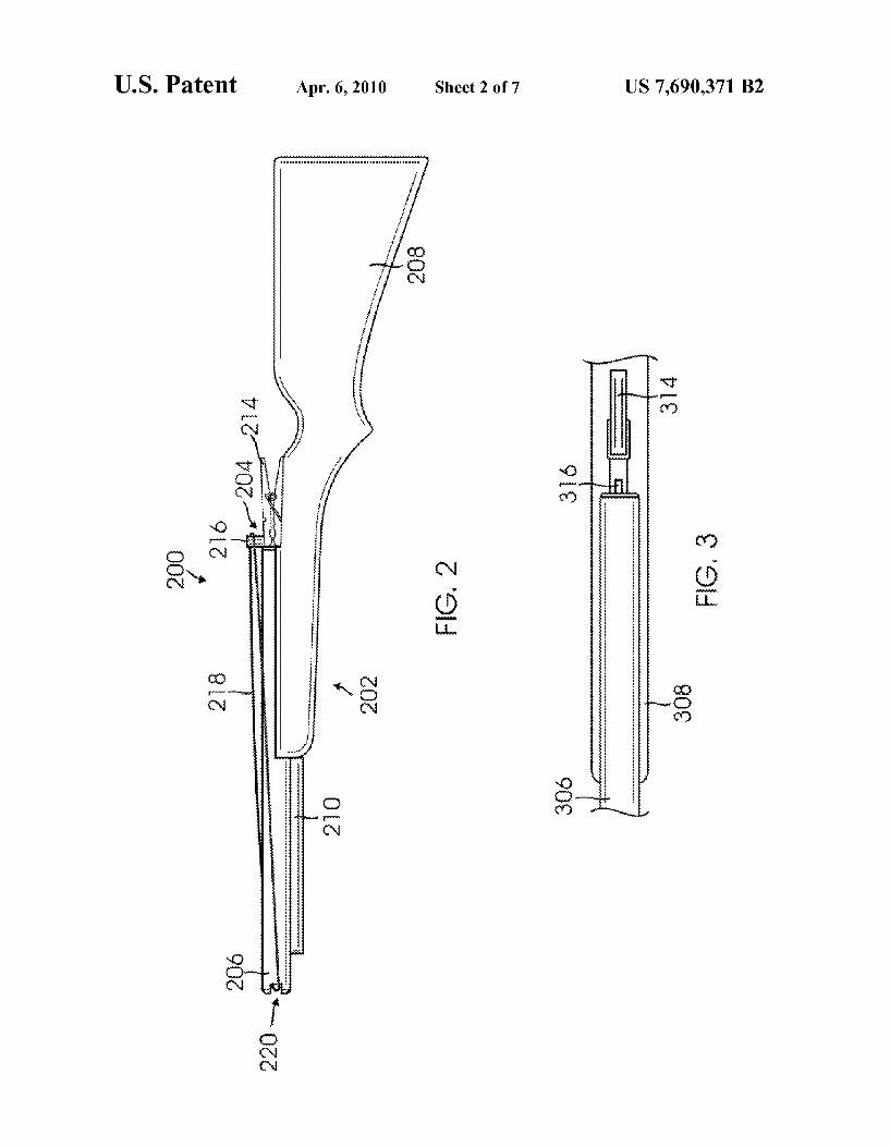
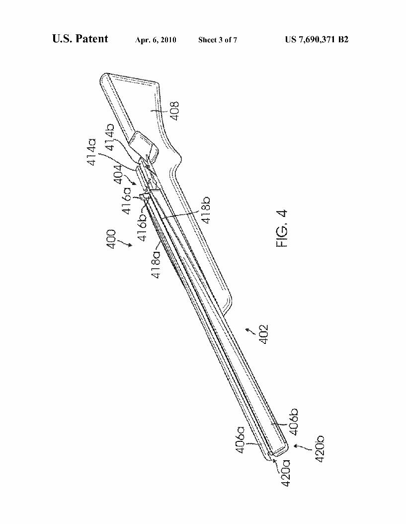
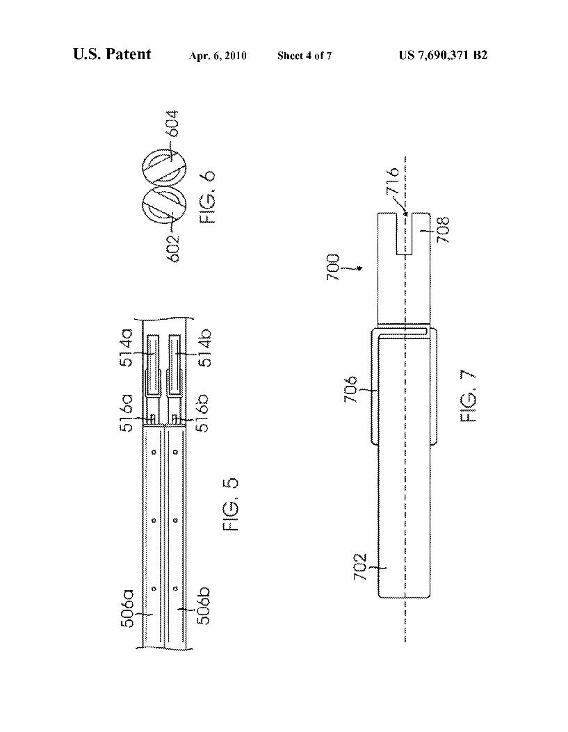
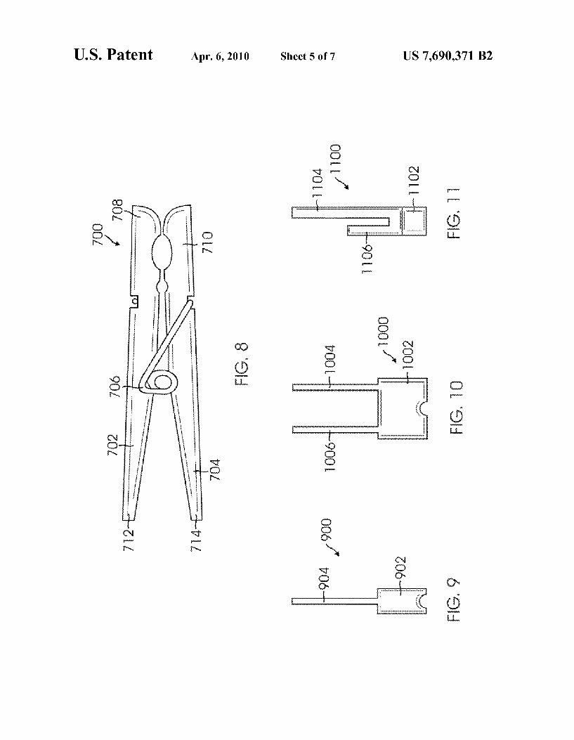
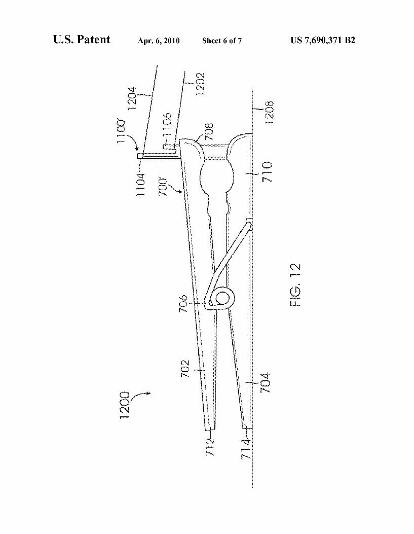
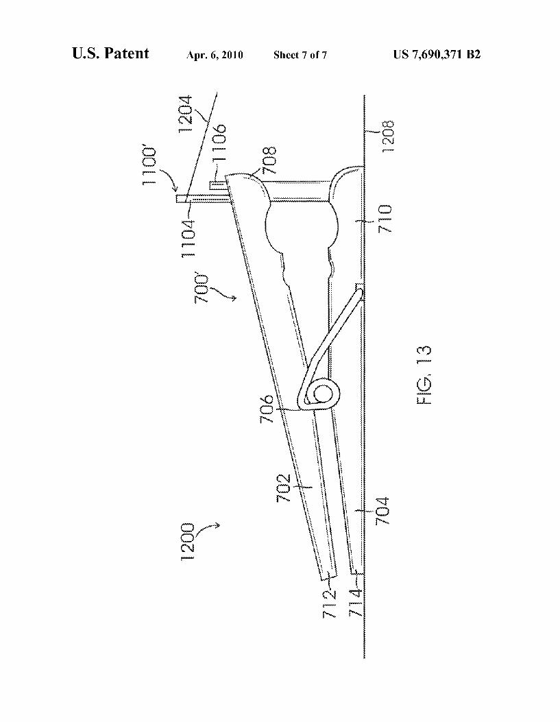
(60) Provisional application No. 60/829,062, ?led on Oct. t0y gun for laullching Projectiles is Provided The gun 1 1’ 2006' 1ncludes a stock hav1ng a ?rst end and a second end, Where the
?rst end is secured to an elongated barrel; and a trigger (51) Int_ CL mechanism is secured on the stock adjacent to the elongated
F413 7/02 (200601) barrel for launching the projectiles. The trigger mechanism F413 7/08 (200601) includes a release mechanism having a loWer leg connected to
(52) us. Cl. ......................................... .. 124/18; 124/19 the Stock and an upper leg Connected to the bottom leg by a (58) Field of Classi?cation Search ................. .. 124/18 Spring and ‘he “PPQr leg is moveable between a ?rst Position
124/19’ and a secondposition. The trigger mechanism also includes at See application ?le for Complete Search history' least one retaining member extends upwardly through a lon
gitudinal slits in the upper leg. As the release mechanism is (56) References Cited moved from the ?rst position to the second position, the
U S PATENT DOCUMENTS projectile attached to the trigger mechanism is launched.
1,729,917 A * 10/1929 Webb ........................ .. 124/18 19 Claims, 7 Drawing Sheets
100 f
120
l 1 20s
US. Patent Apr. 6, 2010 Sheet 1 017 US 7,690,371 B2
US. Patent Apr. 6, 2010 Sheet 2 of7 US 7,690,371 B2
m GI w 5. ?x
\ J j
, m k T
Q 5 0mm m .0:
US. Patent Apr. 6, 2010 Sheet 3 of7 US 7,690,371 B2
US. Patent Apr. 6, 2010 Sheet 4 of7 US 7,690,371 B2
m @E H J
, a ‘MD: ,,,,,,,,,,,,,,,,,,,,,,,,,,,,,,,, ,,,,, s. r M g Q Q? WE
OQN,
m ,®mu_
@ @m Q?m @Em 90%
a d. 0 m
mr0%..»00? : B 0 B , x
a a a M a w
“ Qim UQMQ UQOm
US. Patent Apr. 6, 2010 Sheet 5 of7 US 7,690,371 B2
m , , , , , , n
I! m , , m
mag , was” 9 @E
US. Patent Apr. 6, 2010 Sheet 6 0f7 US 7,690,371 B2
WK
US. Patent Apr. 6, 2010 Sheet 7 of7 US 7,690,371 B2
US008091539B2
(12) Ulllted States Patent (10) Patent N0.: US 8,091,539 B2 Siebelink (45) Date of Patent: Jan. 10, 2012
(54) FOAM DART GUN 3,757,760 A * 9/1973 Darnell ......................... .. 124/19 4,050,438 A 9/1977 Pfotenhauer
. . . - 4,800,864 A 1/1989 Small (76) Inventor. Thomas Siebelink, Wyoming, MI (US) 4,802,677 A 2/1989 Homan
( * ) Notice: Subject' to any disclaimer,~ the term of this 2 g3; patent is extended or adjusted under 35 5,595,166 A l/l997 Schmidt, III et a1. U.S.C. 154(b) by 54 days. 6,079,393 A 6/2000 Grimm
6,247,990 B1 6/2001 Moorhouse
* cited by examiner (22) Filed: Nov. 18, 2009
Primary Examiner * John Ricci
(65) Prior Publication Data (74) Attorney, Agent, or Firm * Price Heneveld LLP
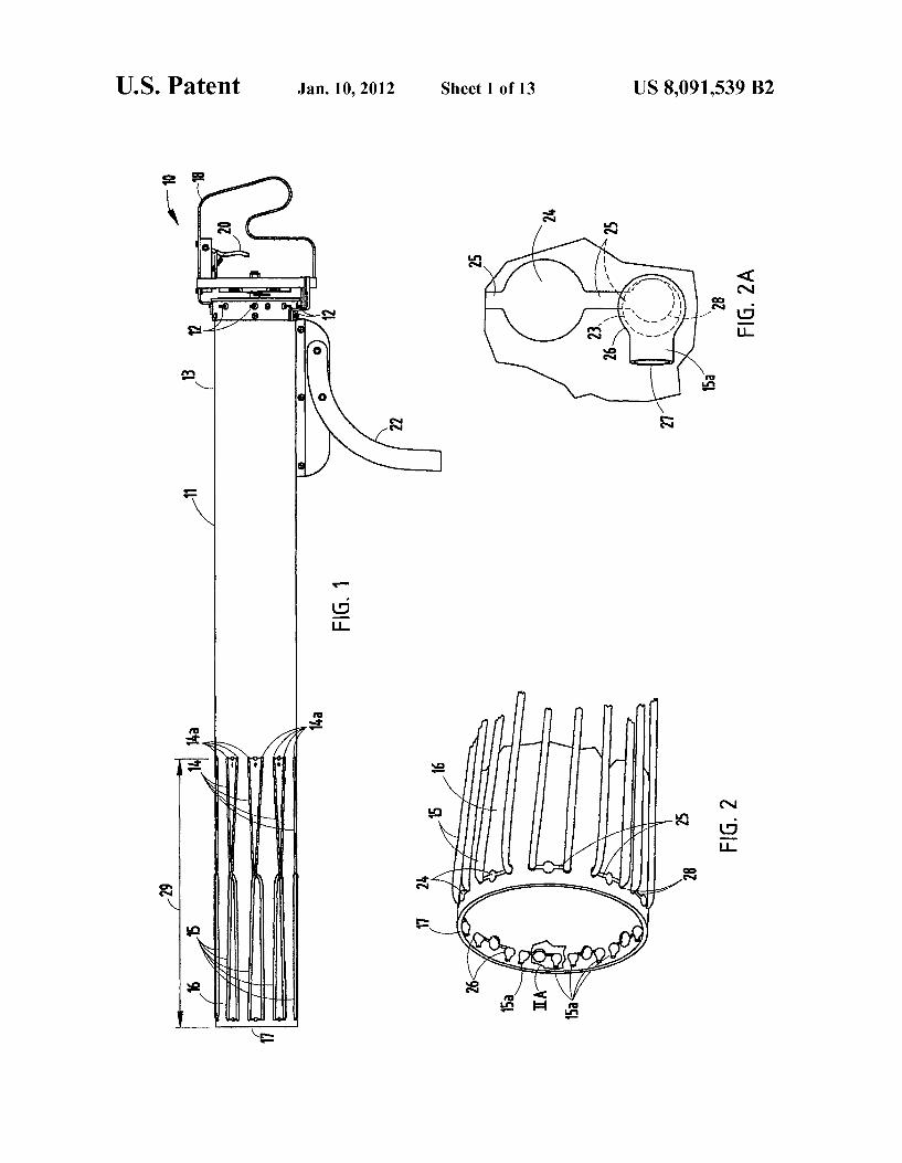
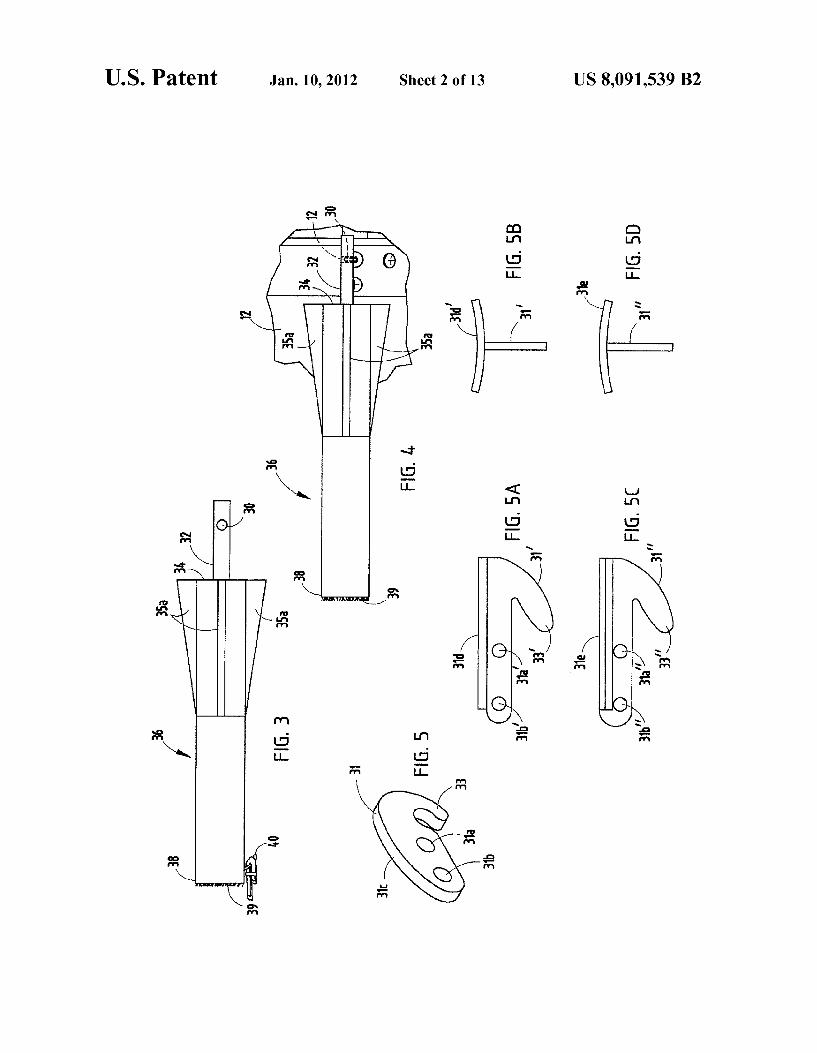
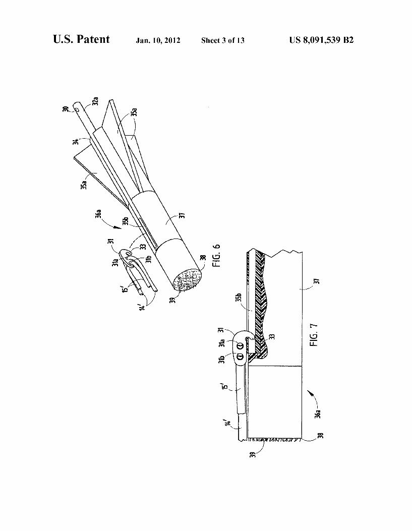
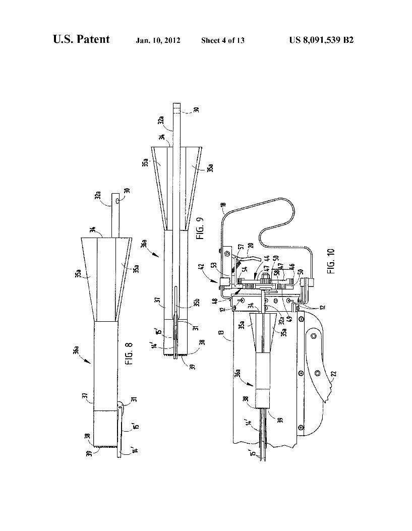
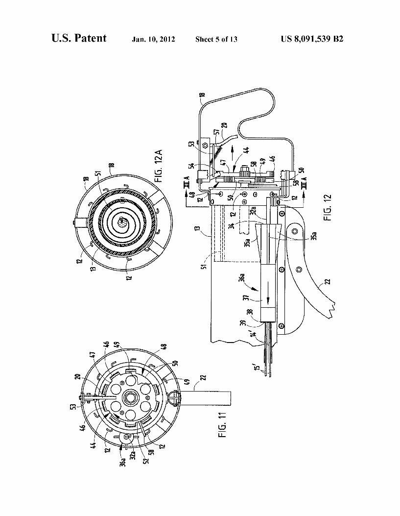
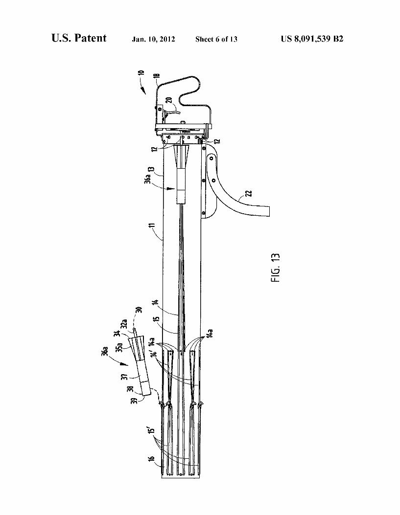
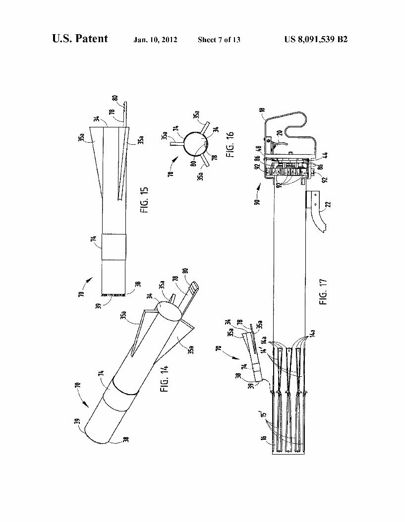
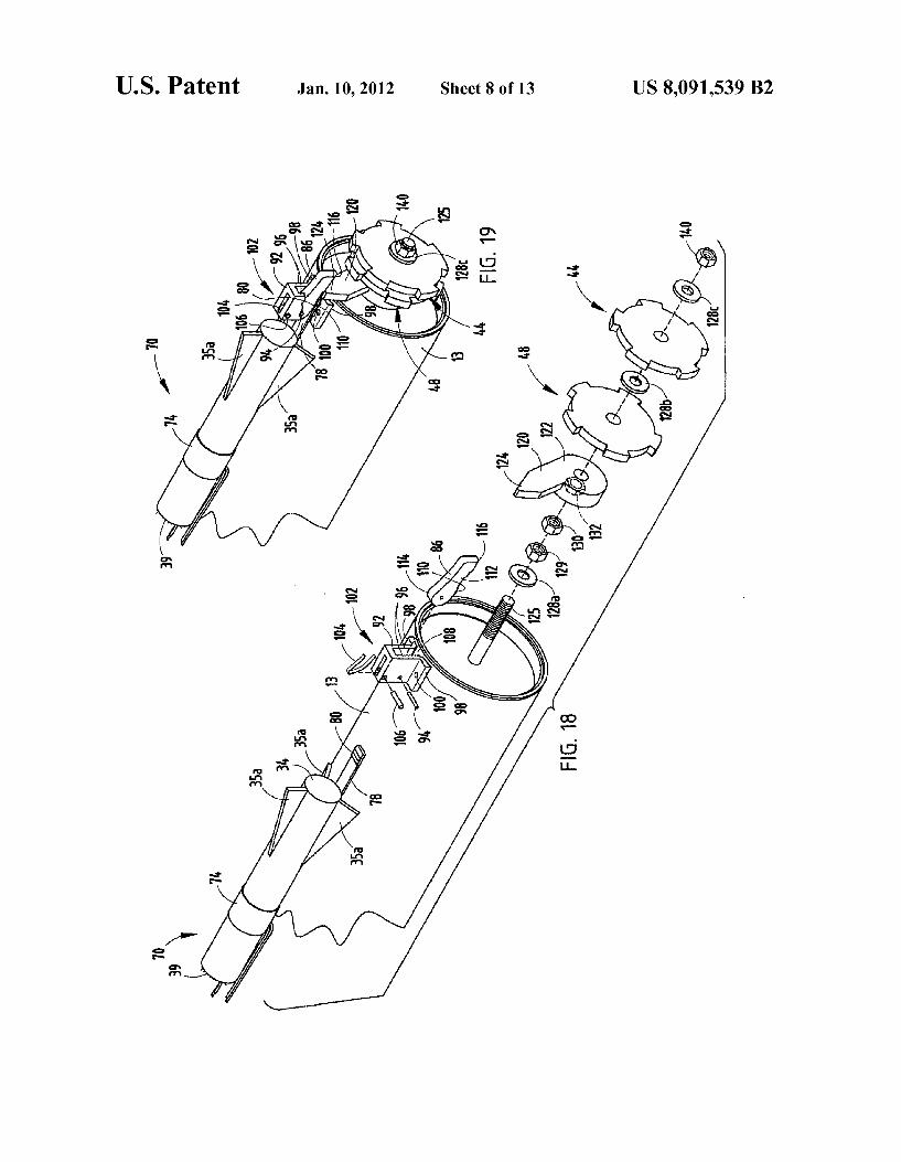
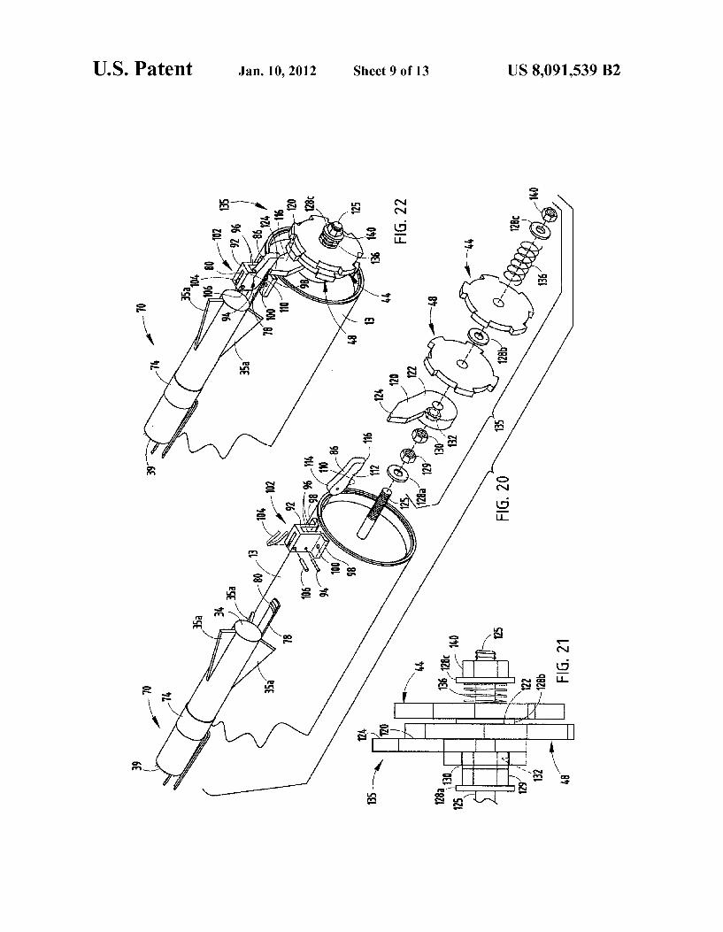
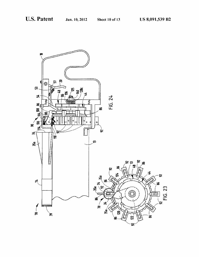
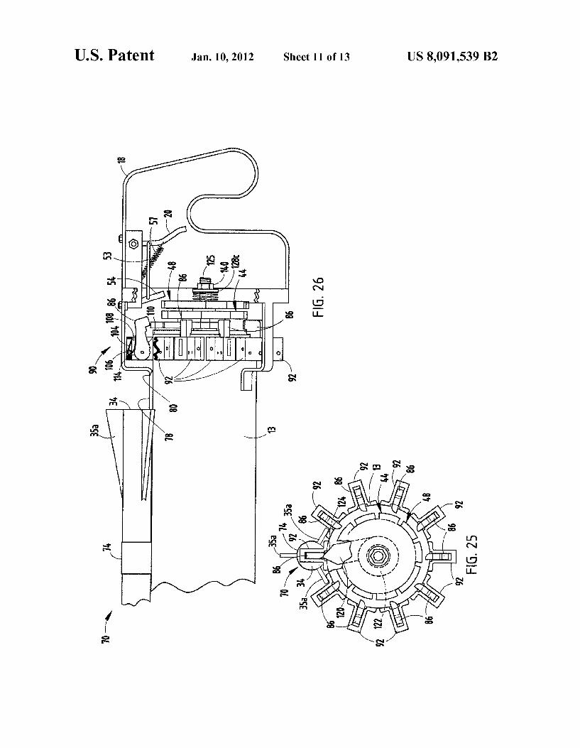
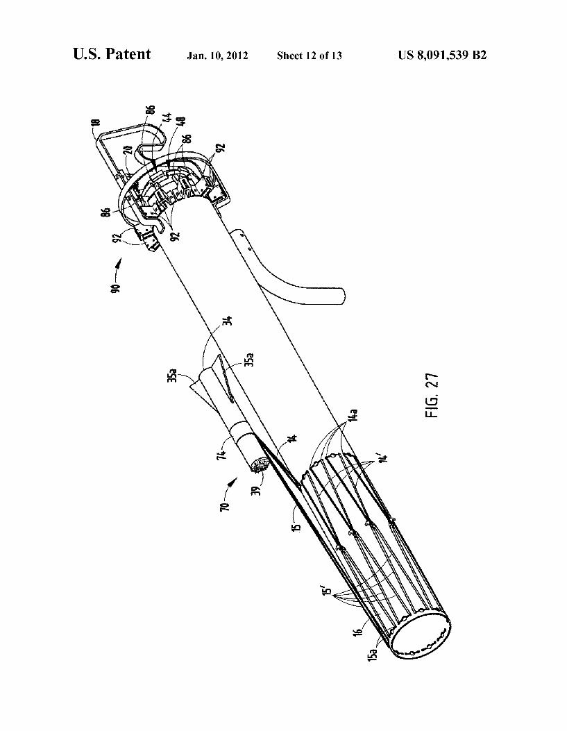
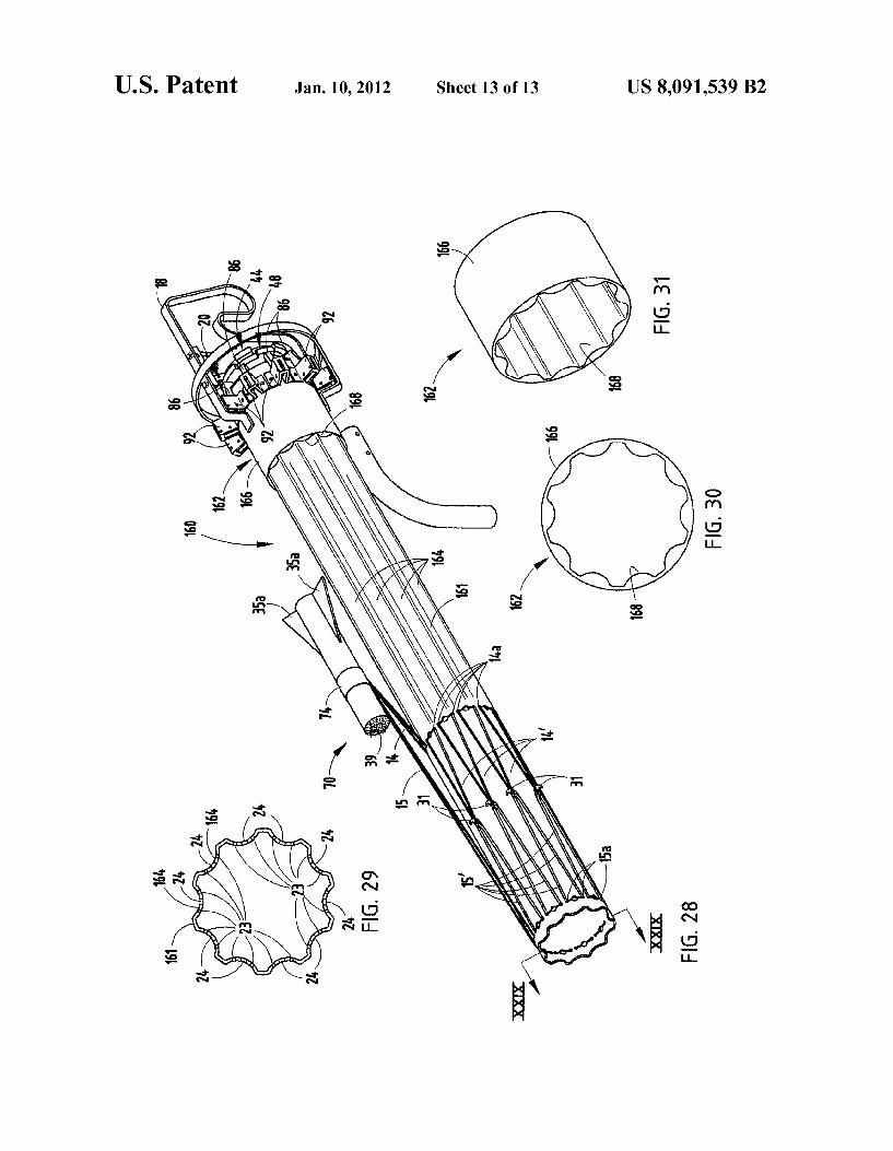
US 2010/0059031A1 Mar. 11,2010 (57) ABSTRACT
Related U-s- Application Data A dart gun having a plurality of darts removably connected
(63) Continuation of application NO 11/683,499, ?led on about a circumferential area of a cylindrical barrel. A spring Mar' 8, 2007, now pat No_ 7,640,922' biased gear assembly includes an engagement member that is
_ _ 1 1_ _ / ?l d rotatably aligned With the circumferential area of the cylin (60) Era/$160112‘ app lcanon NO‘ 60 780303’ e on Mar‘ drical barrel. The spring-biased gear assembly further
’ ' includes ?rst and second rotary gears having offset teeth. A
(51) Int Cl trigger bar is operable betWeen a ?rst position in abutting contact Wit t e teet o t e rst rot ear an a secon F41B 7/00 (2006.01) __ _'i1 i1_ h f h _? al'y g d d
52 US. Cl. ....................................................... .. 124/17 posmon m abumng Contact Wlth the teeth Ofthe Second rotary
E58; Field of Classi?cation Search 124/17 gear. A trigger is operably connected to the trigger bar. The iiiiiiiiiiiiiiiiii ii ’ tri er includes a forWard osition that locates the tri er bar
124/201, 20.3, 48 gg P gg See application ?le for Complete Search history' in the ?rst position and a rearWard position that locates the
trigger bar in the second position. Operation of the trigger (56) References Cited causes the spring-biased gear assembly to intermittently
U.S. PATENT DOCUMENTS
2,825,322 A 3/1958 Burley, Jr. et a1. 3,014,308 A 12/1961 Parris 3,119,385 A 1/1964 Ashley
rotate, thereby causing the lever to disconnect one of the plurality of darts from the circumferential area of the cylin drical barrel.
19 Claims, 13 Drawing Sheets
US. Patent Jan. 10, 2012 Sheet 1 0113 US 8,091,539 B2
US. Patent Jan. 10, 2012 Sheet 2 0f 13 US 8,091,539 B2
E .01 2%
a ‘a ‘mm
mm .wm _ <m .5 a ‘a
5m
a
Q” E m m a . m a:
E
\ am
, a \ mm m .5
N"
/
am a
US. Patent Jan. 10, 2012 Sheet 3 0f 13 US 8,091,539 B2
FIG. 6
31b 31a 31 FIG. 7
15'
US. Patent Jan. 10, 2012 Sheet 4 0f 13 US 8,091,539 B2
US. Patent Jan. 10, 2012 Sheet 5 0f 13 US 8,091,539 B2
I l I I I I I I
2 .DE
| | | | I 1 | | I a I I
P'I II
US. Patent Jan. 10, 2012 Sheet 6 0f 13 US 8,091,539 B2
m? .01
US. Patent Jan. 10, 2012 Sheet 7 0f 13 US 8,091,539 B2
5 .wE
mmm 8 3i )1] E.
US. Patent Jan. 10, 2012 Sheet 8 0f 13 US 8,091,539 B2
w /
\
\ a
US. Patent Jan. 10, 2012 Sheet 9 0f 13 US 8,091,539 B2
US. Patent Jan. 10, 2012 Sheet 10 0f 13 US 8,091,539 B2
US. Patent Jan. 10, 2012 Sheet 11 0113 US 8,091,539 B2
US. Patent Jan. 10, 2012 Sheet 12 0113 US 8,091,539 B2
US. Patent Jan. 10, 2012 Sheet 13 0f 13 US 8,091,539 B2
om .wI
(12) United States Patent Marsh
US008607771B1
US 8,607,771 B1 Dec. 17, 2013
(10) Patent N0.: (45) Date of Patent:
(54)
(76)
(21)
(22)
(60)
(51)
(52)
(58)
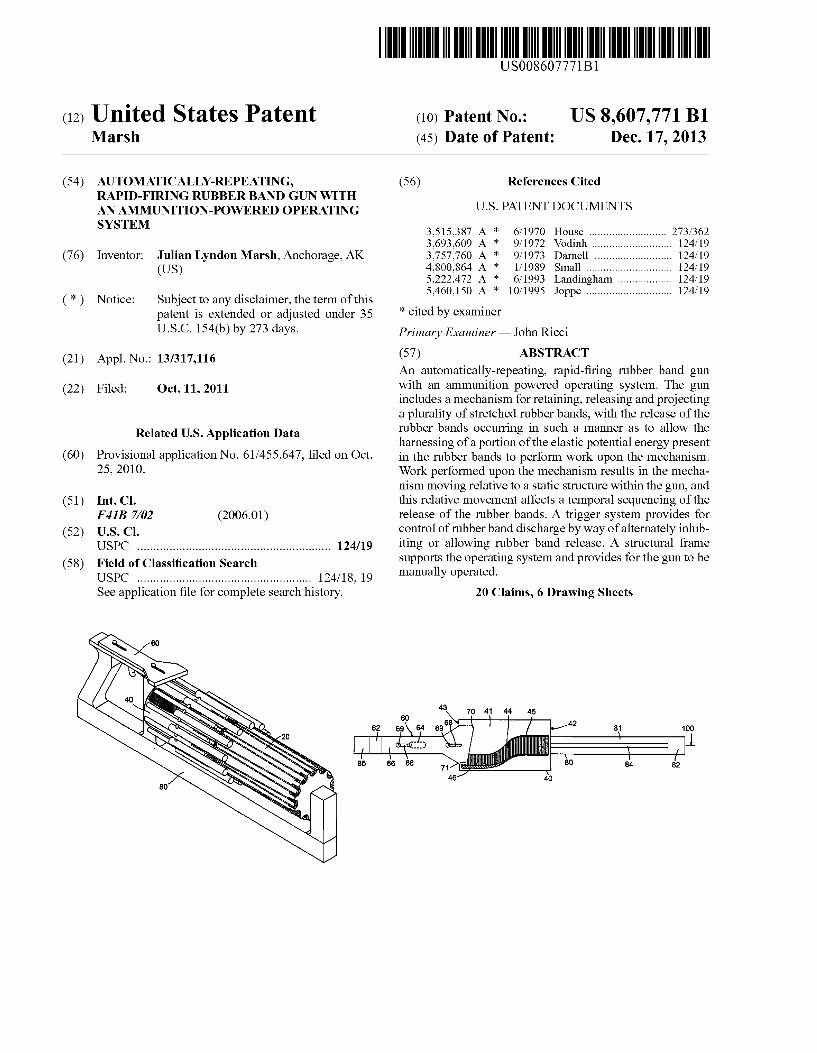
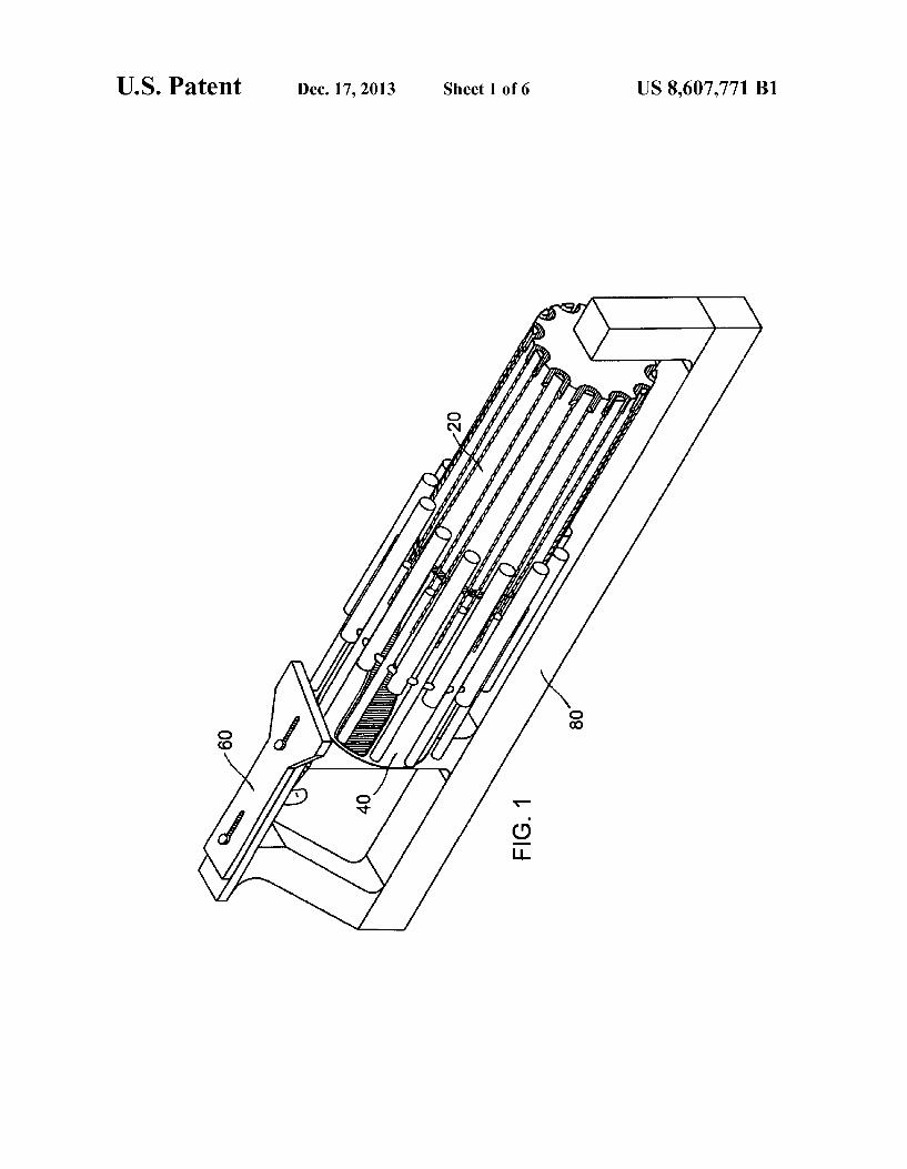
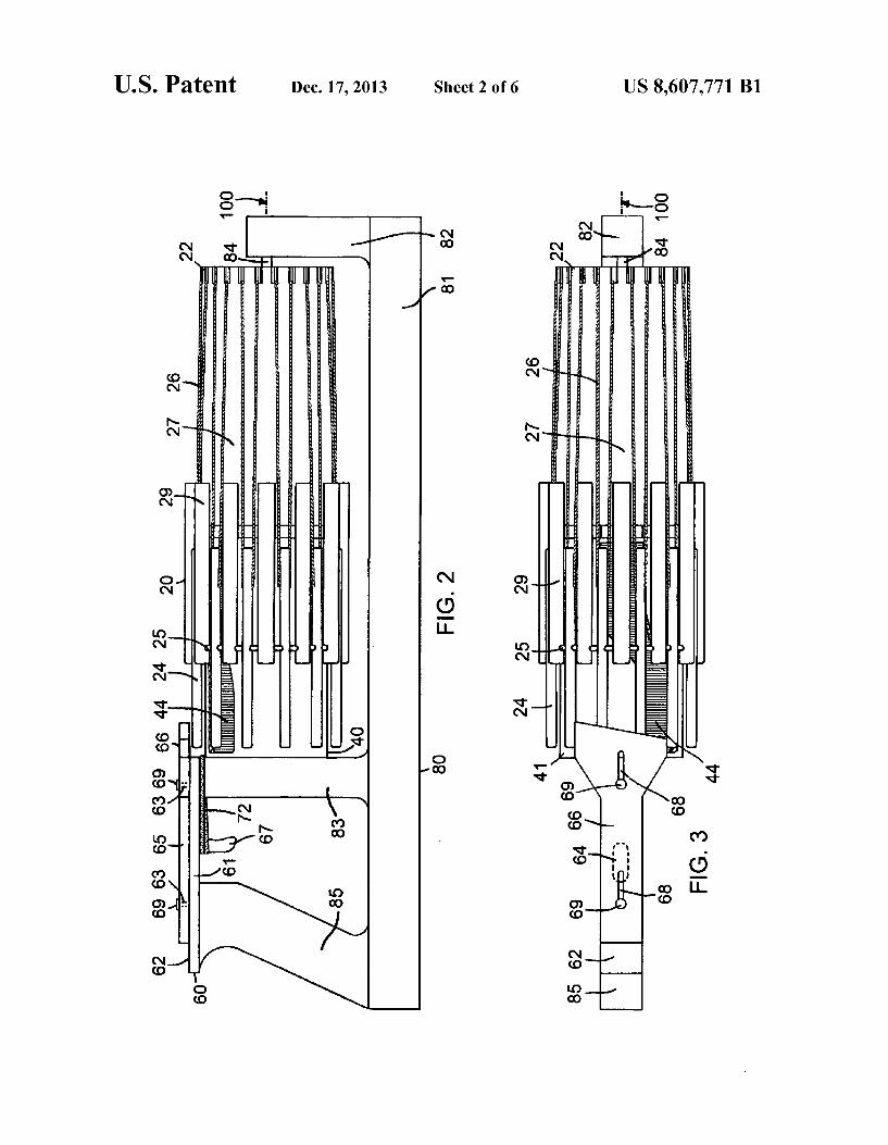
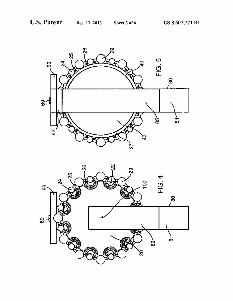
AUTOMATICALLY-REPEATING, RAPID-FIRING RUBBER BAND GUN WITH AN AMMUNITION-POWERED OPERATING SYSTEM
Inventor: Julian Lyndon Marsh, Anchorage, AK (Us)
Notice: Subject to any disclaimer, the term of this patent is extended or adjusted under 35 U.S.C. 154(b) by 273 days.
App1.No.: 13/317,116
Filed: Oct. 11, 2011
Related US. Application Data
Provisional application No. 61/455,647, ?led on Oct. 25, 2010.
Int. Cl. F 413 7/02
US. Cl. USPC .......................................................... .. 124/19
Field of Classi?cation Search USPC .................................................... .. 124/18, 19
See application ?le for complete search history.
(2006.01)
(56) References Cited
U.S. PATENT DOCUMENTS
3,515,387 A * 6/1970 House ......................... .. 273/362
3,693,609 A * 9/1972 '
3,757,760 A * 9/1973 4,800,864 A * 1/1989 5,222,472 A * 6/1993 5,460,150 A * 10/1995
* cited by examiner
Primary Examiner * John Ricci
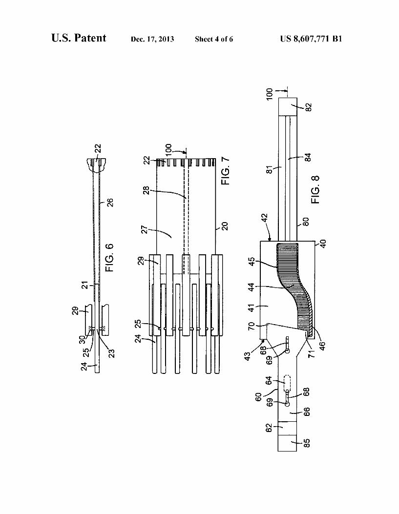
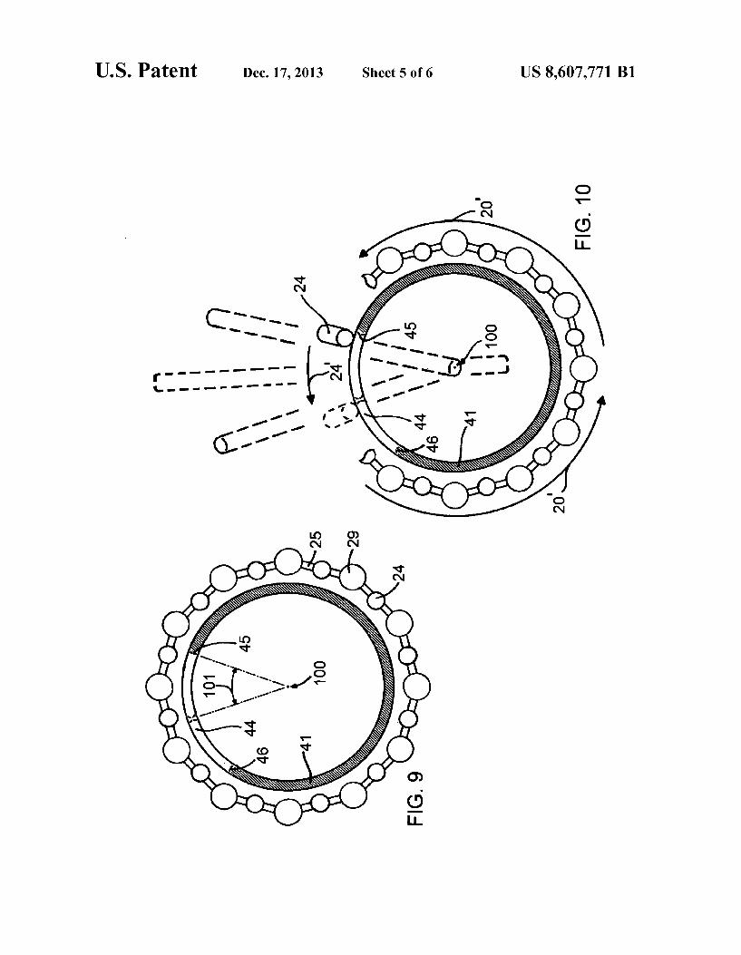
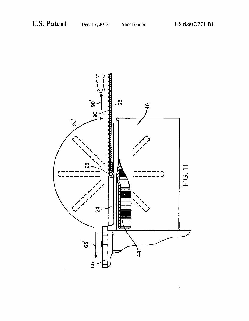
(57) ABSTRACT An automatically-repeating, rapid-?ring rubber band gun With an ammunition powered operating system. The gun includes a mechanism for retaining, releasing and projecting a plurality of stretched rubber bands, With the release of the rubber bands occurring in such a manner as to alloW the harnessing of a portion of the elastic potential energy present in the rubber bands to perform Work upon the mechanism. Work performed upon the mechanism results in the mecha nism moving relative to a static structure Within the gun, and this relative movement affects a temporal sequencing of the release of the rubber bands. A trigger system provides for control of rubber band discharge by Way of alternately inhib iting or alloWing rubber band release. A structural frame supports the operating system and provides for the gun to be manually operated.
20 Claims, 6 Drawing Sheets
US. Patent Dec. 17, 2013 Sheet 1 of6 US 8,607,771 B1
US. Patent Dec. 17, 2013 Sheet 3 of6 US 8,607,771 B1
mv MN
No
US. Patent Dec. 17, 2013 Sheet 4 of6 US 8,607,771 B1
|\
9 LI.
0 N
I
’ ‘ii I
Vli II || II N N
mm . mm
2% , w @E Q\
US. Patent Dec. 17, 2013 Sheet 5 of6 US 8,607,771 B1
US 20130340734A1
(19) United States (12) Patent Application Publication (10) Pub. No.: US 2013/0340734 A1
Coulston (43) Pub. Date: Dec. 26, 2013
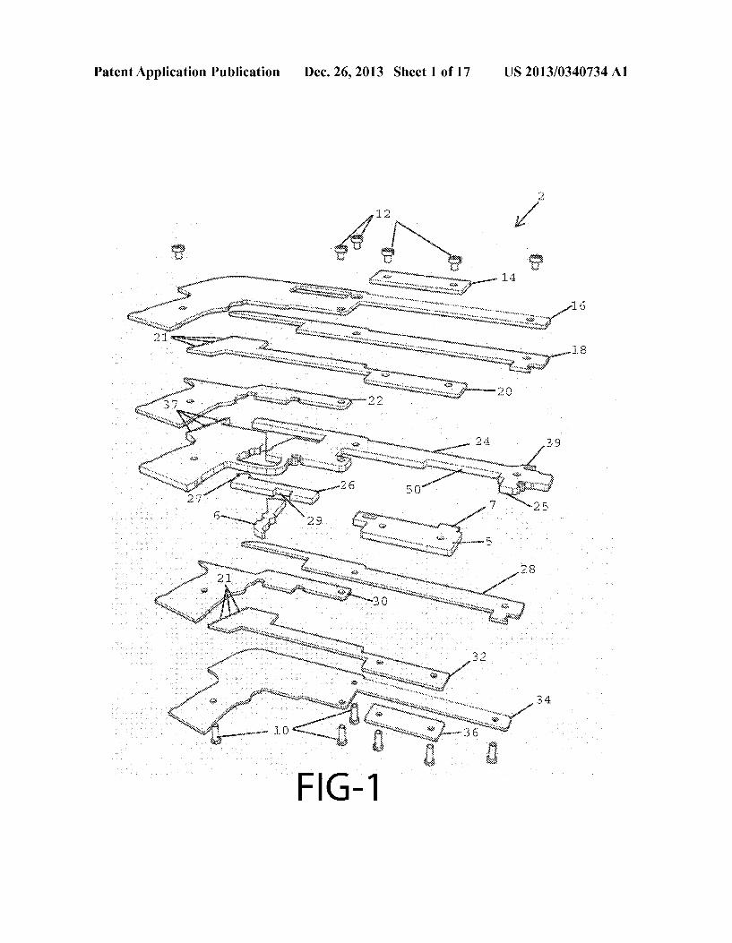
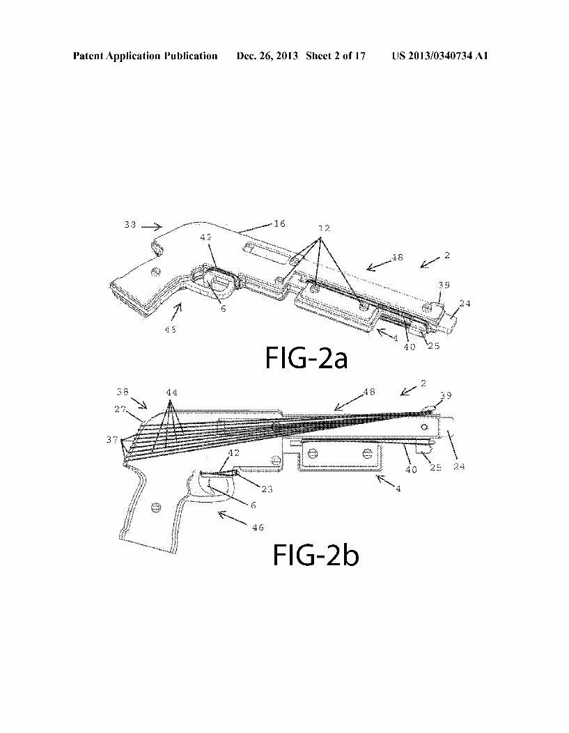
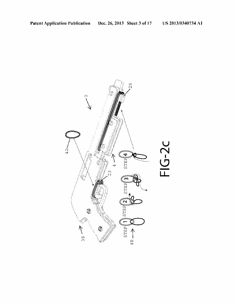
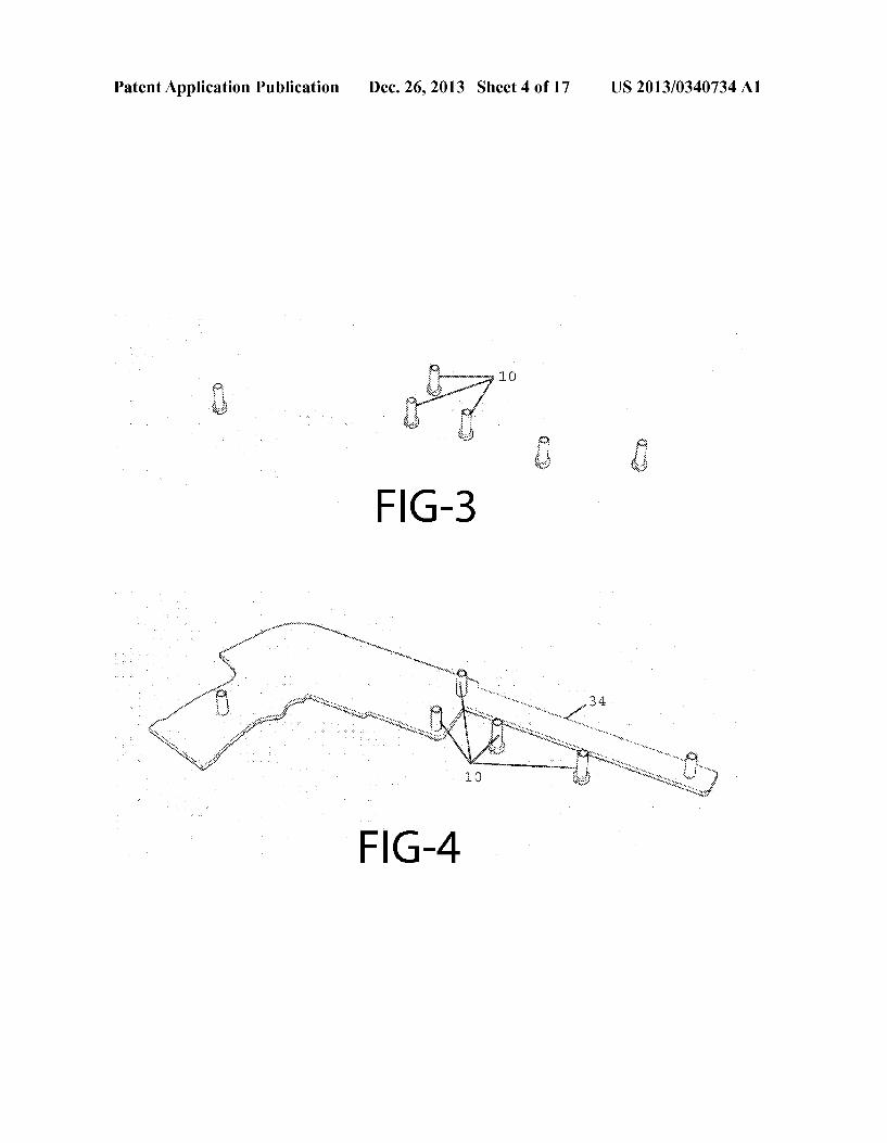
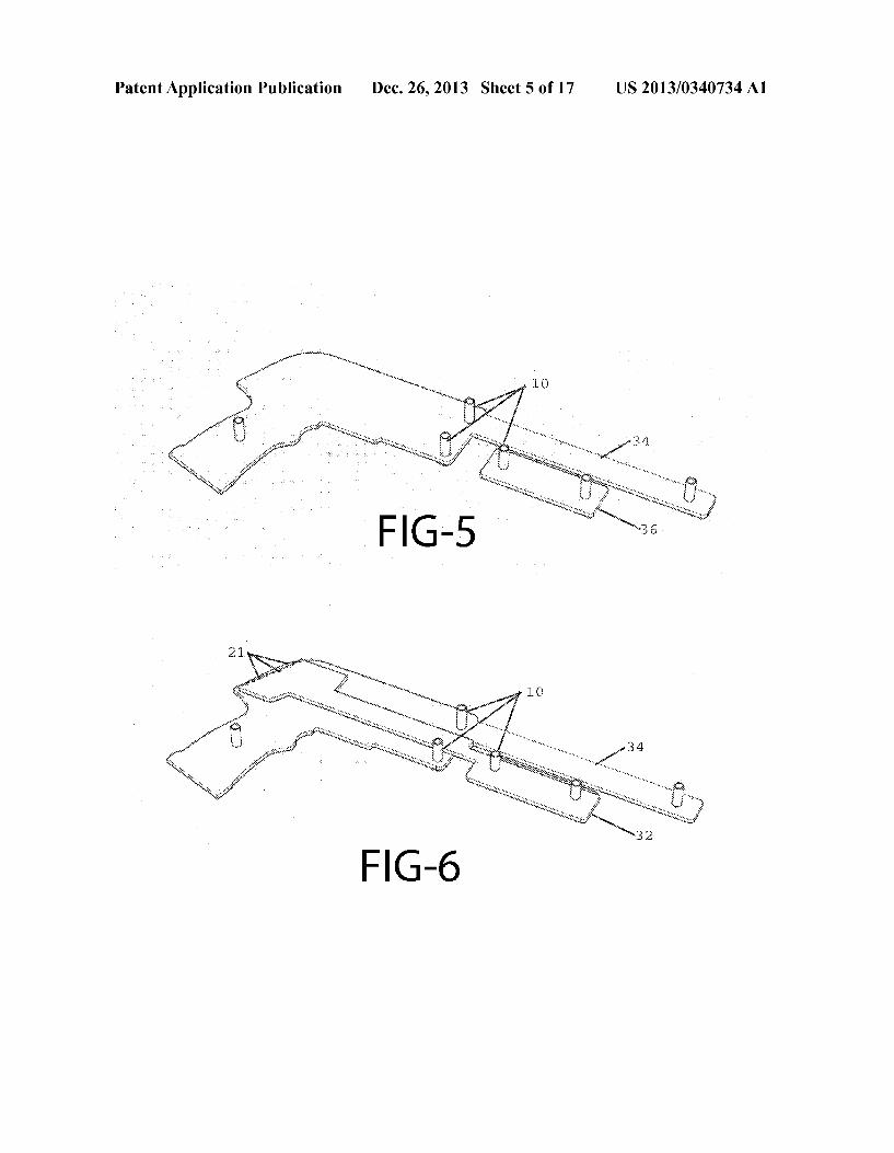
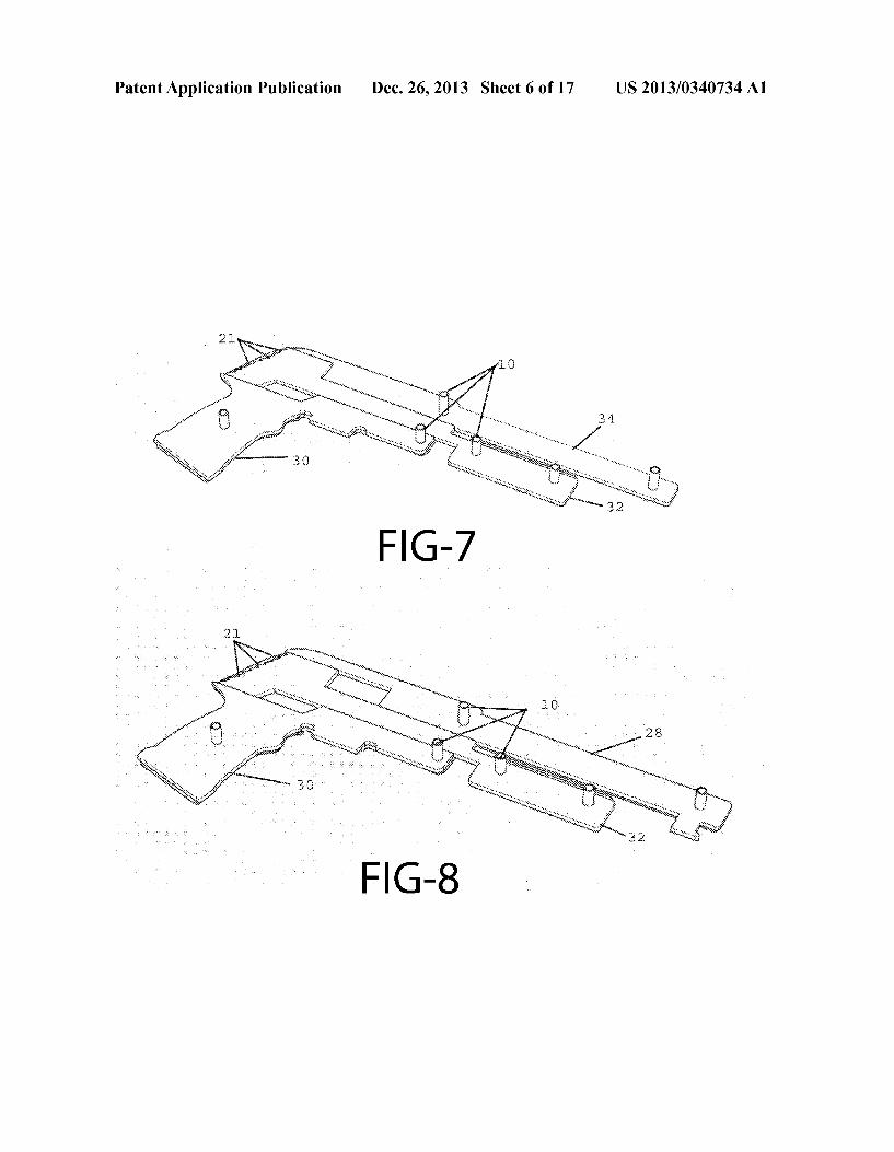
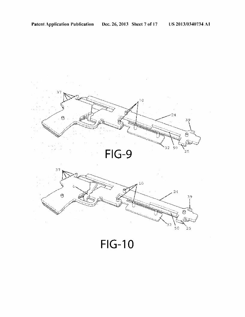
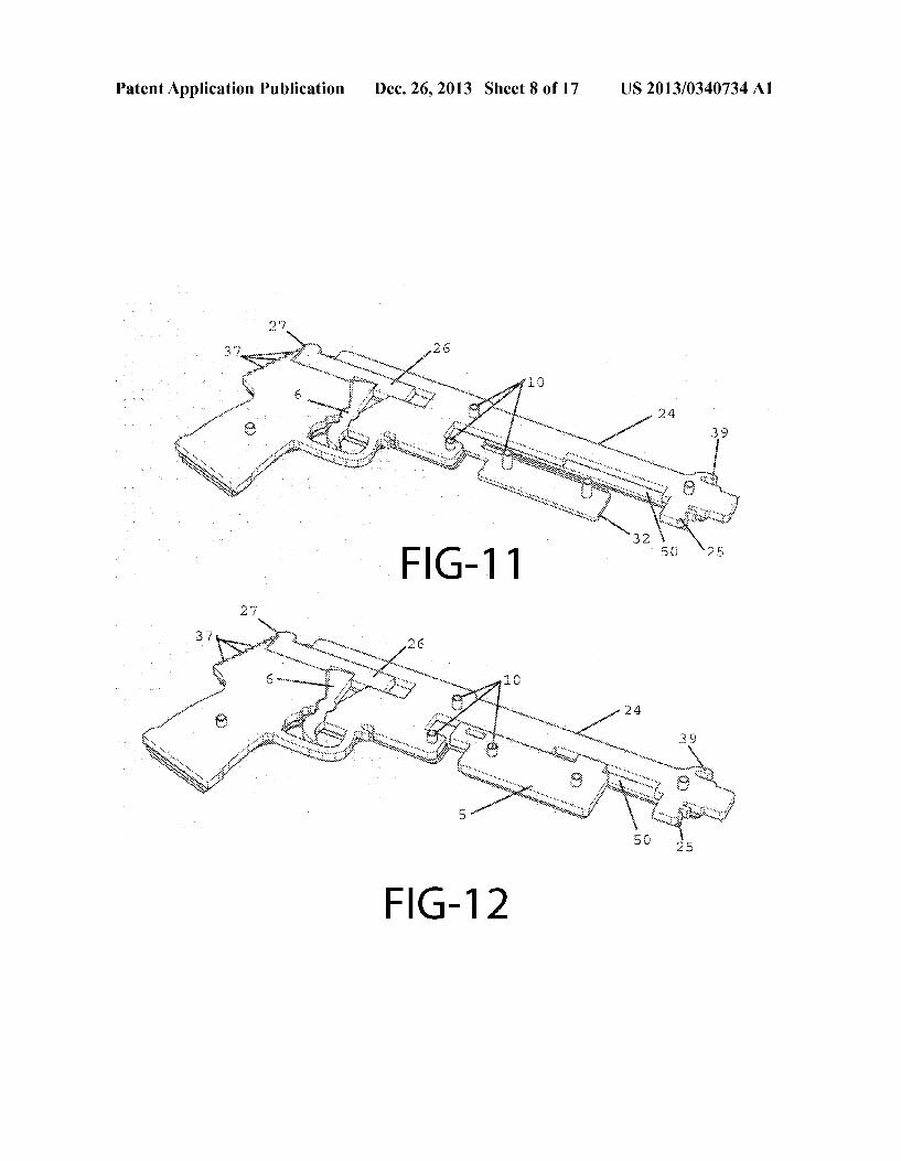
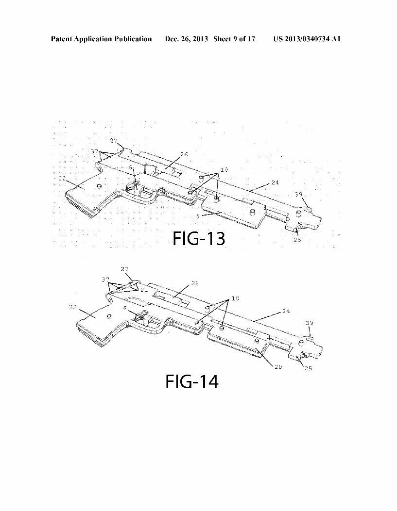
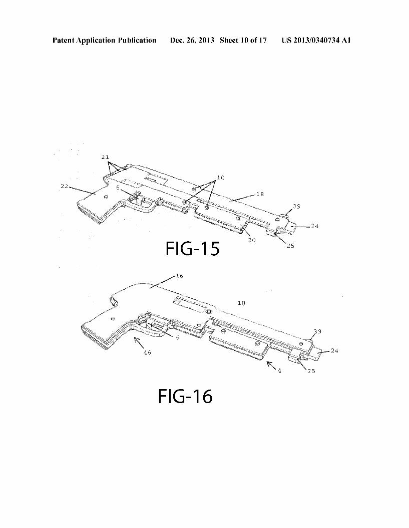
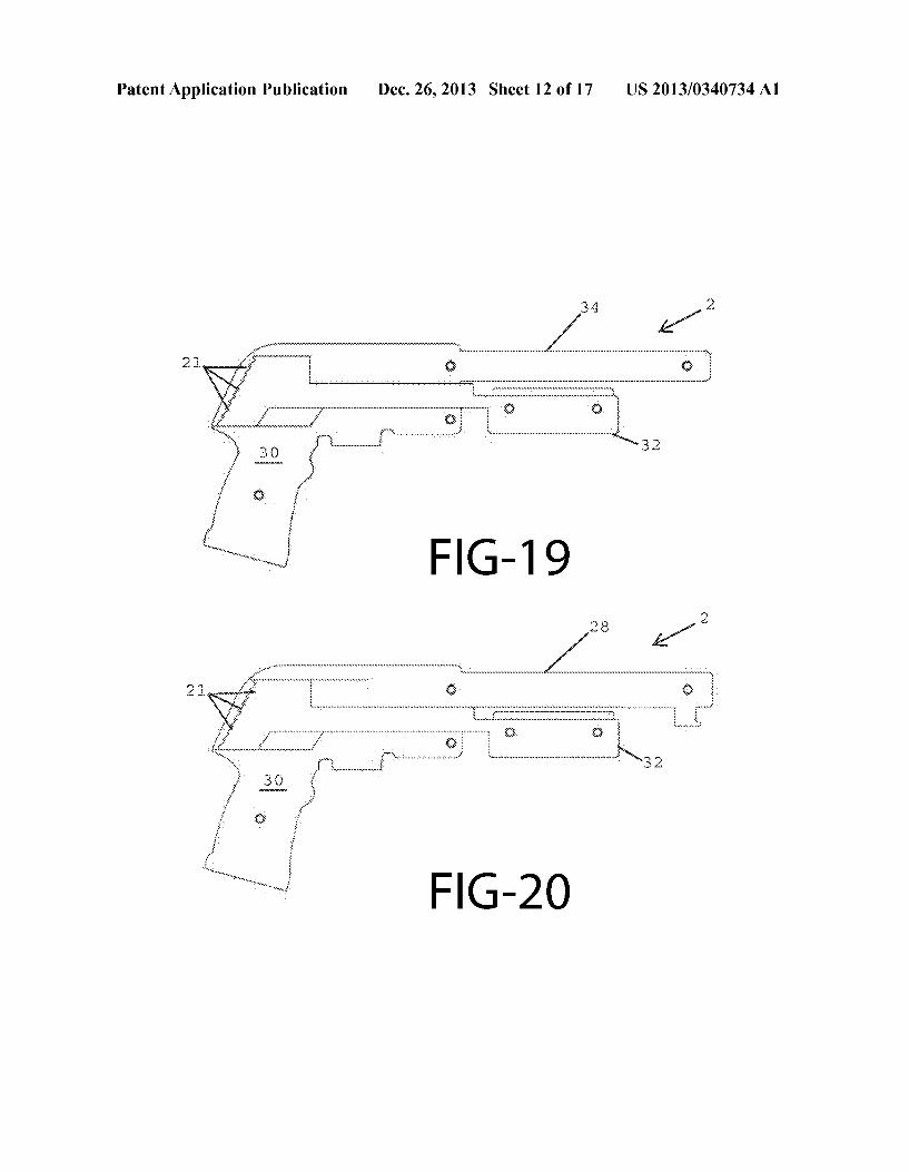
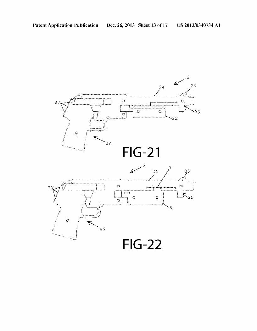
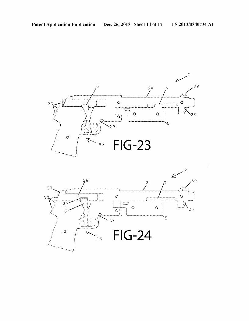
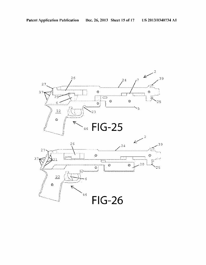
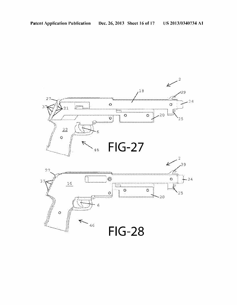
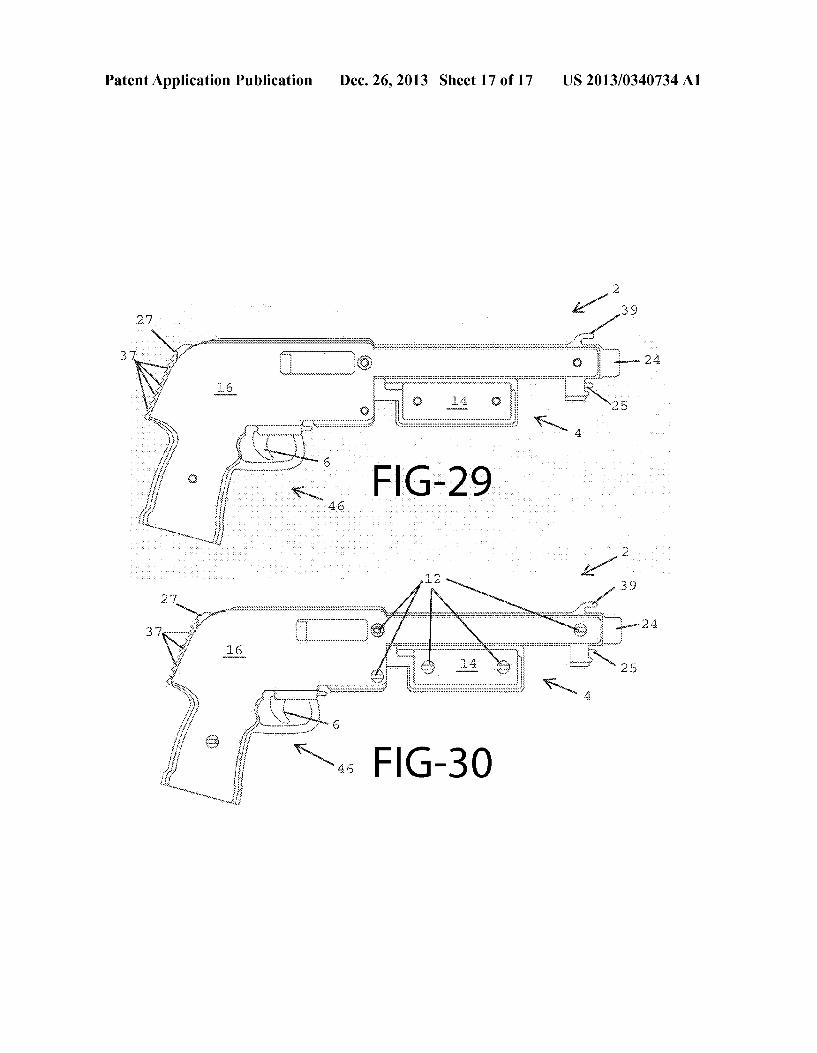
(54) ELASTIC BAND PROJECTILE TOY GUN AND (52) US. Cl. METHOD OF ASSEMBLY CPC .................................... .. F41B 7/025 (2013.01)
USPC ............................................. .. 124/19; 29/428
(71) Applicant: Robert M. Coulston, Kansas City, MO
(Us) (57) ABSTRACT
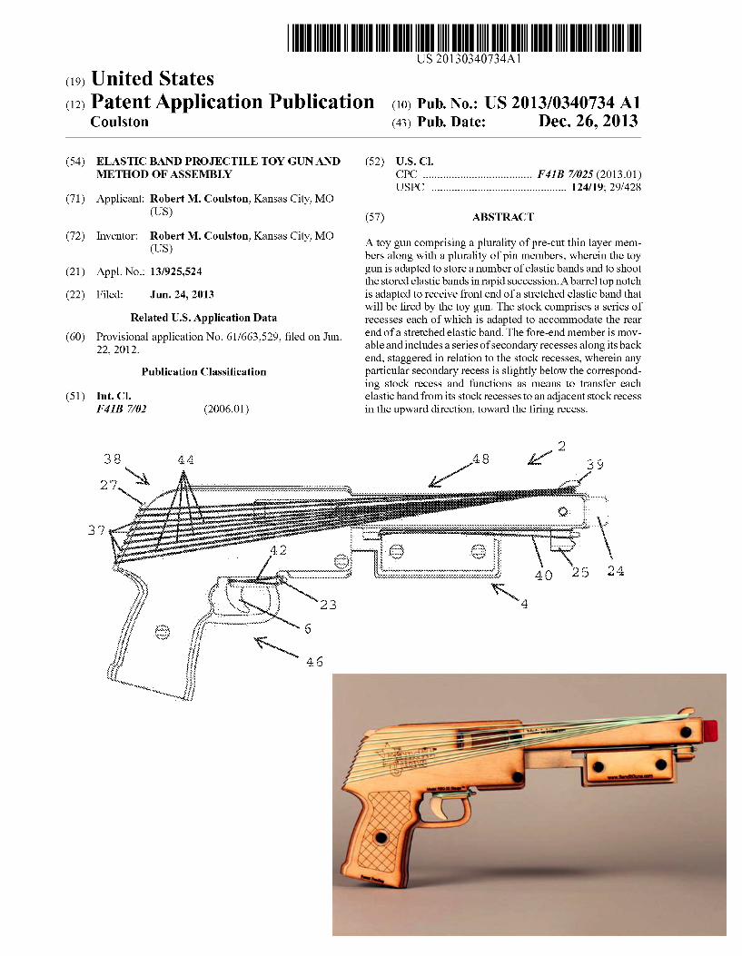
(72) Inventor' Robert M' Coulston’ Kansas Clty’ MO A toy gun comprising a plurality of pre-cut thin layer mem (US) . . . . bers along W1th a plurality of pin members, wherein the toy
(21) App1_ NO; 13/925,524 gun is adapted to store a number of elastic bands and to shoot the stored elastic bands in rapid succession. A barrel top notch
(22) Filed: Jun. 24, 2013 is adapted to receive front end of a stretched elastic band that Will be ?red by the toy gun. The stock comprises a series of
Related U-s- Application Data recesses each of Which is adapted to accommodate the rear
(60) Provisional application NO 61/663,529’ ?led on Jun end of a stretched elastic band. The fore-end member is mov 22 2012' able and includes a series of secondary recesses along its back
’ end, staggered in relation to the stock recesses, Wherein any Publication Classi?cation particular secondary recess is slightly beloW the correspond
ing stock recess and functions as means to transfer each (51) Int. Cl. elastic band from its stock recesses to an adjacent stock recess
F 413 7/02 (2006.01) in the upWard direction, toWard the ?ring recess.
8 4 4 s g” k,
Patent Application Publication Dec. 26, 2013 Sheet 1 0f 17 US 2013/0340734 A1
Qzi 39
Patent Application Publication Dec. 26, 2013 Sheet 2 0f 17 US 2013/0340734 A1
Patent Application Publication Dec. 26, 2013 Sheet 3 0f 17 US 2013/0340734 A1
FIG-2c
Patent Application Publication Dec. 26, 2013 Sheet 4 0f 17 US 2013/0340734 Al
O 1
FIG-3
FIG-4
Patent Application Publication Dec. 26, 2013 Sheet 5 0f 17 US 2013/0340734 A1
FIG-6
Patent Application Publication Dec. 26, 2013 Sheet 6 0f 17 US 2013/0340734 A1
FIG-7
FIG-8
Patent Application Publication Dec. 26, 2013 Sheet 7 0f 17 US 2013/0340734 A1
FIG-9
FIG-1O
Patent Application Publication Dec. 26, 2013 Sheet 8 0f 17 US 2013/0340734 A1
FIG-11
FIG-12
Patent Application Publication Dec. 26, 2013 Sheet 9 0f 17 US 2013/0340734 A1
Patent Application Publication Dec. 26, 2013 Sheet 10 0f 17 US 2013/0340734 A1
FIG-16

US 2013/0340734 A1
3 4
FIG-17
Patent Application Publication Dec. 26, 2013 Sheet 11 0f 17
FIG-18
Patent Application Publication Dec. 26, 2013 Sheet 12 0f 17 US 2013/0340734 A1
Patent Application Publication Dec. 26, 2013 Sheet 13 0f 17 US 2013/0340734 A1
Patent Application Publication Dec. 26, 2013 Sheet 14 0f 17 US 2013/0340734 A1
W
Patent Application Publication Dec. 26, 2013 Sheet 15 0f 17 US 2013/0340734 A1
Patent Application Publication Dec. 26, 2013 Sheet 16 0f 17 US 2013/0340734 A1
Patent Application Publication Dec. 26, 2013 Sheet 17 0f 17 US 2013/0340734 A1
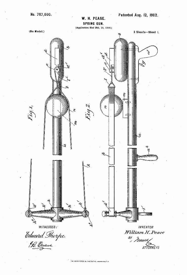
Patented Aug. I2, I902. W. H. PEASE. SPRING GUN.
(Application ?led Feb 10, 190
No. 707,000. '
2 Sheets-Sheet I. (No Model.)
//V VE N TOR
?/illz'aizz 17f. Pea we
8y % Arro rs
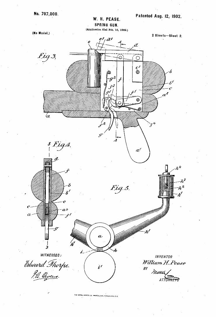
No. 707,000. Patented Aug. I2, 1902.‘ r w. H. PEASE.
‘SPRING GUN. (Application ?le'd Feb. 10, 1802.)
2 Sheets-Sheet 2. (No Model.)
97 d7 /
7////////////////AE_
/ N VE N TOR
i?llz'am J22’. Pawn" B Y
A 77
W/ TNE SSE 8 :
THE NORRIS prrzas cc. wcmurnnov, WASHINGTON, n. c.
_ (No Model.)
J. A. CRANDALL.` TOY GUN.v , r
Patented Nov. 21, 1882. N0.267,679.
United States Patent 1191 Crowson
[54] ELASTIC BAND TYPE GUN
[76] Inventor: Ray E. Crowson, Rte. 11, Box 522, Texarkana, Tex. 75501
[22] Filed: July‘7, 1971
[211 Appl.N0.: 160,337
[52] US. Cl ...................... .. 124/17, 124/41, 124/35, 124/ 18
[51] Int. CL... ......................................... .. F4lb 7/00 [58] Field of Search ................. .. 124/35, 41, 17, 26,
' , 124/27
[56] References Cited UNITED STATES PATENTS
1,486,403 ‘- 3/1924 ‘ Watkins .......................... .. 124/35 X
2,642,057 1 6/1953 Watkins .... .. 124/35 X
1,469,610 10/1923 Ustynik . . . . . . . . . . . . .. 124/35 X
1,941,082 12/1933 Giese .... .. 124/35 UX 2,500,509 3/1950 Bailey . . . . . . . . . . .. 124/35 X
2,842,114 ‘ 7/1958 Duncan... ..... .. 124/35 X
3,509,863 5/1970 Barkerm. ..................... .. 124/35 UX
[1711 3,745,986 145] July 17, 1973
Primary Examiner--Richard C. Pinkham Assistant Examiner-William R. Browne Att0rney~William T. Wofford et a1.
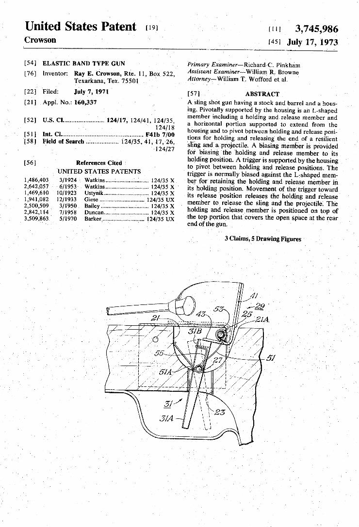
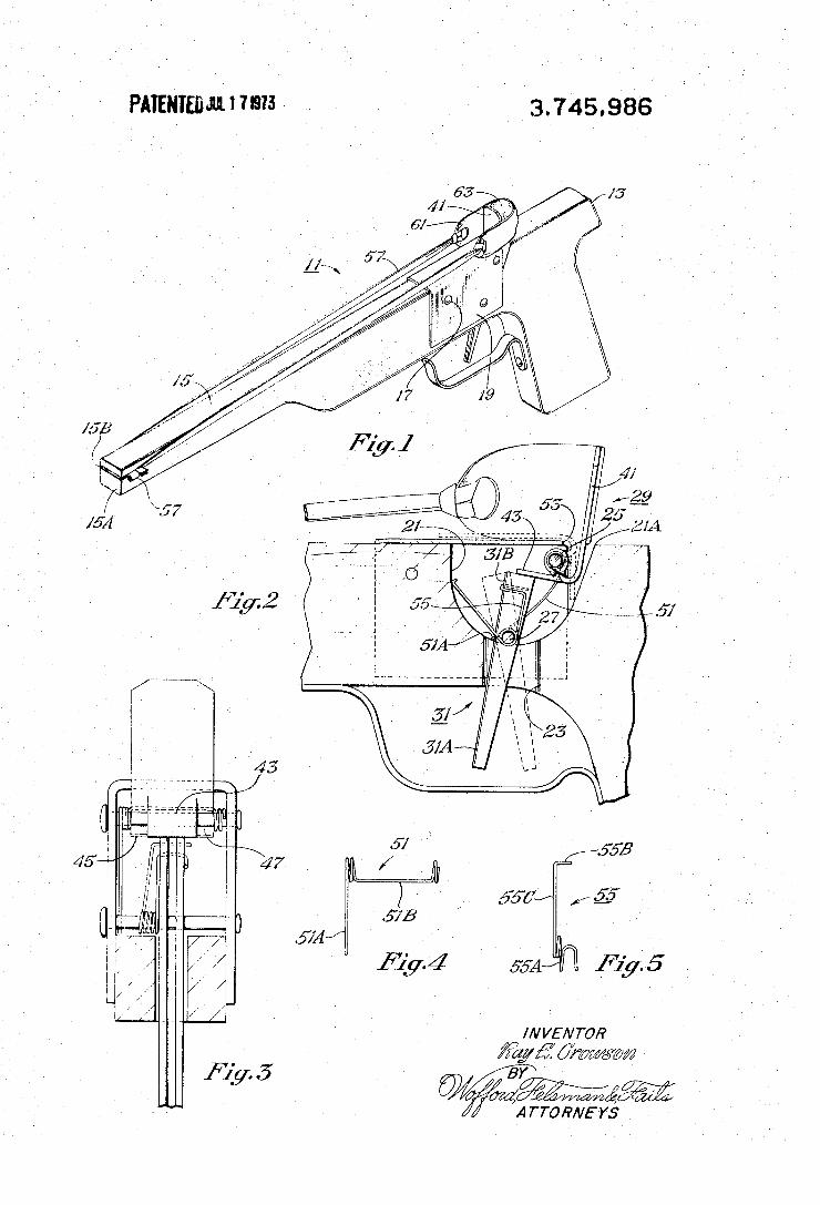
[57] ABSTRACT A sling shot gun having a stock and barrel and a hous~ ing. Pivotally supported by the housing is an L-shaped member including a holding and release member and a horizontal portion supported to extend from the housing and to pivot between holding and release posi~ tions for holding and releasing the end of a resilient sling and a projectile. A biasing member is provided for biasing the holding and release member to its holding position. A trigger is supported by the housing to pivot between holding and release positions. The trigger is normally biased against the L-shaped mem ber for retaining the holding and-release member in its holding position. Movement of the trigger toward its release position releases the holding and release member to release the sling and the projectile. The holding and release member is positioned on top of the top portion that covers the open space at the rear end of the gun.
3 Claims, 5 Drawing Figures
" 25
‘K I [21A
‘ -1; 7 ‘ 51
United States Patent
US007168424B1
(12) (10) Patent N0.: US 7,168,424 B1 Wing (45) Date of Patent: Jan. 30, 2007
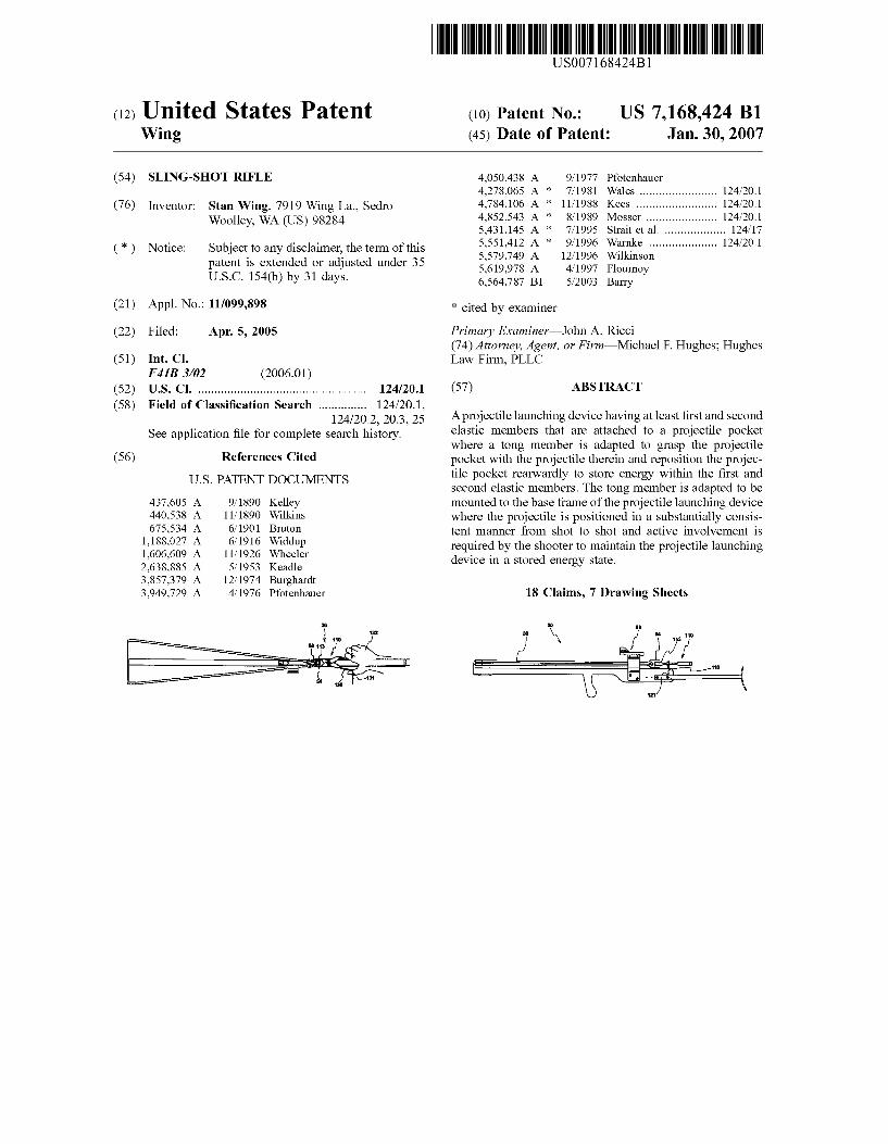
(54) SLING-SHOT RIFLE 4,050,438 A 9/1977 Pfotenhauer 4,278,065 A * 7/1981 Wales ...................... .. 124/20.1
Inventor: Stan Wing, La” Sedro 4,784,106 A * ll/l988 Kees . . . . . . . . . . .. Woolley WA (Us) 98284 4,852,543 A * 8/1989 Mosser .... .. .. 124/20.1
’ 5,431,145 A * 7/1995 Strait et al. . 124/17
(>3) Notice: Subject to any disclaimer’ the tenn ofthis A * . . . . . . . . . . . . . . . . . . . .. . . 5,579,749 A 12/1996 Wilkinson
patent is extended or adjusted under 35 5 619 978 A 4/l997 F1 , , Ournoy
U-S-C- 154(b) by 31 days- 6,564,787 B1 5/2003 Barry
(21) Appl. N0.: 11/099,898 * Cited by examiner
(22) Filed: Apr. 5, 2005 Primary Examinerilohn A. Ricci (74) Attorney, Agent, or F irmiMichael P. Hughes; Hughes
(51) Int. Cl. LaW Firm, PLLC F41B 3/02 (2006.01)
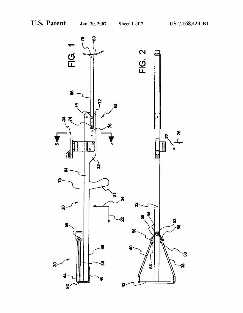
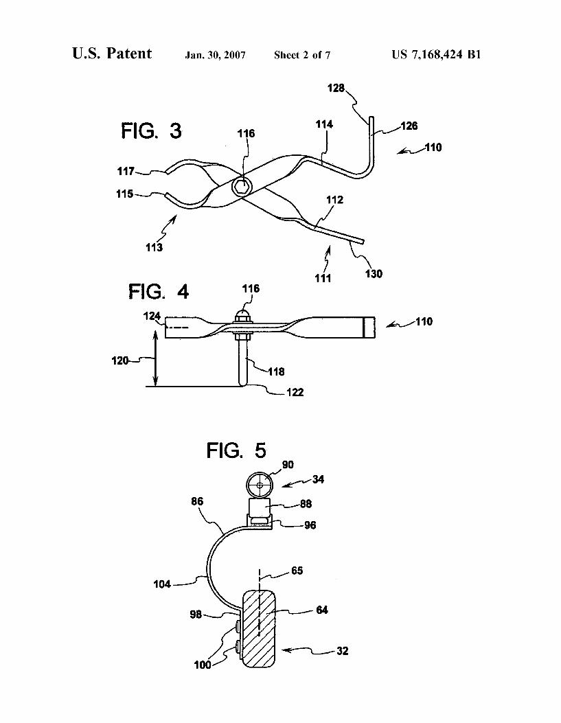
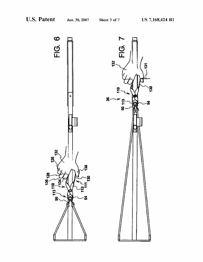
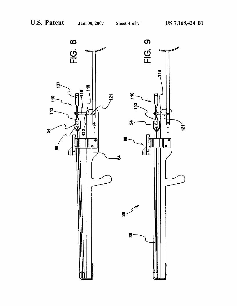
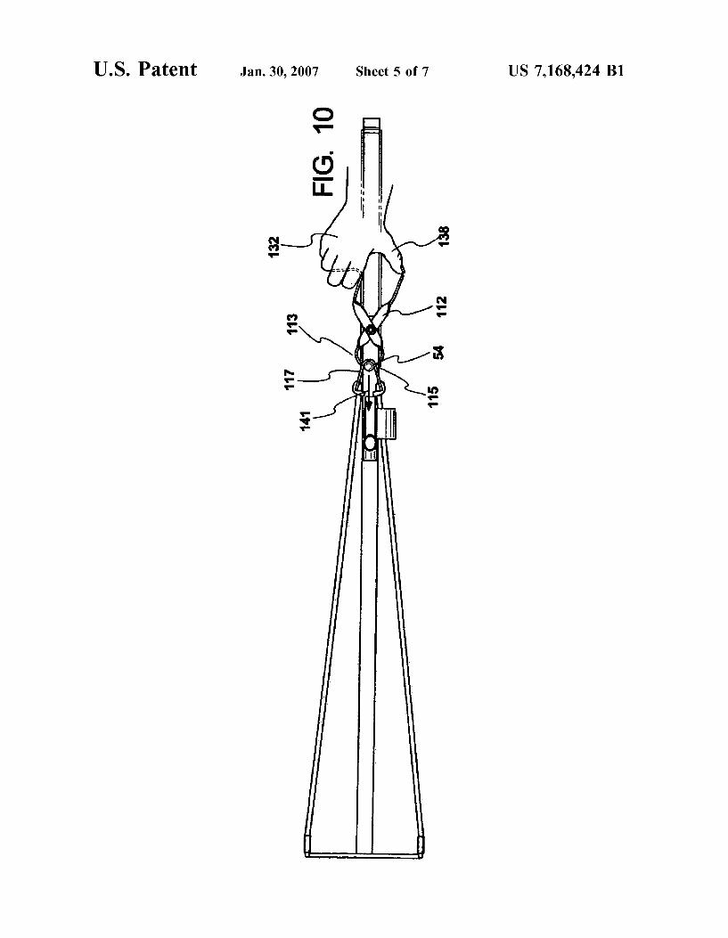
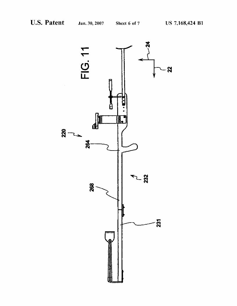
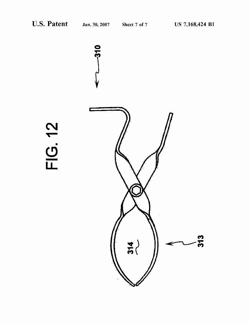
(52) us. Cl. .................................... .. 124/20.1 (57) ABSTRACT
(58) Field of Classi?cation Search ............. .. l24/20.l, _ _ _ _ _
124/202, 203, 25 Aprojectlle launching device having at least ?rst and second See application ?le for Complete Search history elastic members that are attached to a projectile pocket
Where a tong member is adapted to grasp the projectile (56) References Cited pocket With the projectile therein and reposition the projec
U.S. PATENT DOCUMENTS
437,605 A 9/1890 Kelley 440,538 A 11/1890 Wilkins 675,534 A 6/1901 Bruton
1,188,027 A 6/1916 Widdup 1,606,609 A 11/1926 Wheeler 2,638,885 A 5/1953 Keadle 3,857,379 A 12/1974 Burghardt 3,949,729 A 4/1976 Pfotenhauer
y-j; g...
tile pocket rearWardly to store energy Within the ?rst and second elastic members. The tong member is adapted to be mounted to the base frame of the projectile launching device Where the projectile is positioned in a substantially consis tent manner from shot to shot and active involvement is required by the shooter to maintain the projectile launching device in a stored energy state.
18 Claims, 7 Drawing Sheets
U.S. Patent Jan. 30, 2007 Sheet 1 0f 7 US 7,168,424 B1
78
FIG. 2 ' m1
U.S. Patent Jan. 30, 2007 Sheet 2 0f 7 US 7,168,424 B1
130
H110
86
WWW/VJ m
100
U.S. Patent Jan. 30, 2007 Sheet 3 0f 7 US 7,168,424 B1
U.S. Patent Jan. 30, 2007 Sheet 4 0f 7 US 7,168,424 B1
w .OE
U.S. Patent Jan. 30, 2007 Sheet 5 0r 7 US 7,168,424 B1
141 Ill
U.S. Patent Jan. 30, 2007 Sheet 6 0f 7 US 7,168,424 B1
U.S. Patent Jan. 30, 2007 Sheet 7 0r 7 US 7,168,424 B1
O F
3 FIG. 12
313
United States Patent [191 [11] 4,386,598 Blaser [45] Jun. 7, 1983
[54] SLING SHOT APPARATUS FOREIGN PATENT DOCUMENTS
[76] Invento? Anton J- B18881‘, 700 E- Mason, Santa 653458 5/1951 United Kingdom ........... .. 124/20 R Barbara, Calif. 93103 , _ _
Primary Examiner—R1chard C. Pinkham [2'1] Appl. No.: 280,079 Assistant Examiner—William R. Browne .22 F1 d J l 981 Attorney, Agent, or Firm—Ralph B. Pastoriza
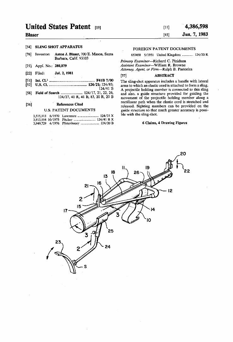
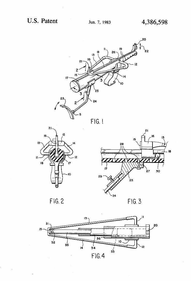
' : . 2 1 _[ 1 ‘e u ’ [57] ABSTRACT [51] Int. 01.3 .............................................. .. F41B 7/00 The Slingshot apparatus includes a handle with lateral [52] US. Cl. ..................................... .. 124/21; 124/ 83; arms to which an elastic cord is attached to form a Sling‘
_ ‘ 124/41 B A projectile holding member is connected to this sling [58] F161!‘ 01' Search ..................... .. 124/17, 21, 22, 26, and also’ a guide Structure provided for guiding the
124/27’ 41 R’ 41 B’ 83’ 20 R’ 20 B movement of the projectile holding member along a ‘ - . rectilinear path when the elastic cord is stretched and
[56] References cued released. Sighting members can be provided on the US. PATENT DOCUMENTS guide structure so that much greater accuracy is possi
3,51s,113 6/1970 Lawrence ....................... .. 124/25 x ble “"111 the slmg'sh°t~ 3,913,554 10/1975 Pitcher ............ .. 124/41 B X
3,949,729 4/1976 Pi‘otenhauer .................... .. 124/20 B 6 Claims, 4 Drawing Figures
US. Patent Jun. 7, 1983 4,386,598
5MTME 2o /
I I
United States Patent [19] Pfotenhauer
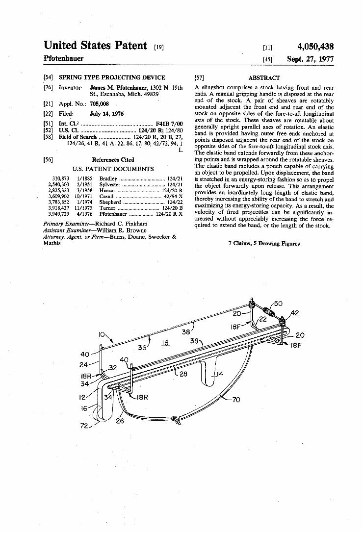
[11] 4,050,438 [45] Sept. 27, 1977
[54] SPRING TYPE PROJECI‘ING DEVICE
James M. Pfotenhauer, 1302 N. 19th St., Escanaba, Mich. 49829
[21] Appl. No.: 705,008
[76] Inventor:
[22] Filed: July 14, 1976
[51] Int. Cl.2 .............................................. .. F41B 7/00 [52] U.S. Cl. ............................... .. 124/20 R; 124/80 [58] Field of Search ................ .. 124/20 R, 20 B, 27,
124/26, 41 R, 41 A, 22, 86, 17, 80; 42/72, 94, I L
[56] References Cited U.S. PATENT DOCUMENTS
310,873 l/1885 Bradley ................................ .. 124/21 2,540,303 2/1951 Sylvester ...... .. 124/21 2,825,323 3/1958 Huszar 124/20 R 3,609,902 10/1971 Casull . . . . . . . . .. 42/94 X
3,783,852 l/l974 Shepherd ...... .. 124/22
3,918,427 11/1975 Turner . . . . . . . . . . . . . . . . . .. 124/20 B
3,949,729 4/ 1976 Pfotenhauer ................ .. 124/20 R X
Primary Examiner-Richard C. Pinkham Assistant Examiner—-William R. Browne Attorney, Agent, or Firm-Burns, Doane, Swecker & Mathis
[57] ABSTRACT A slingshot comprises a stoclg having front and rear ends. A manual gripping handle is disposed at the rear end of the stock. A pair of sheaves are rotatably mounted adjacent the front end and rear end of the stock on opposite sides of the fore~to-aft longitudinal axis of the stock. These sheaves are rotatable about generally upright parallel axes of rotation. An elastic band is provided having outer free ends anchored at points disposed adjacent the rear end of the stock on opposite sides of the fore-to-aft longitudinal stock axis. The elastic band extends forwardly from these anchor ing points and is wrapped around the rotatable sheaves. The elastic band includes a pouch capable of carrying an object to be propelled. Upon displacement, the band is stretched in an energy-storing fashion so as to propel the object forwardly upon release. This arrangement provides an inordinately long length of elastic band, thereby increasing the ability of the band to stretch and maximizing its energy-storing capacity. As a result, the velocity of ?red projectiles can be signi?cantly in creased without appreciably increasing the force re quired to extend the band, or the length of the stock.
7 Claims, 5 Drawing Figures
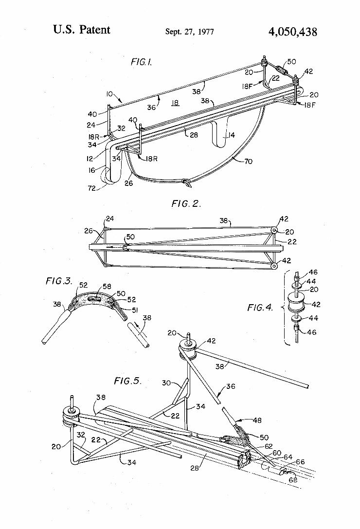
US. Patent Sept. 27, 1977 4,050,438
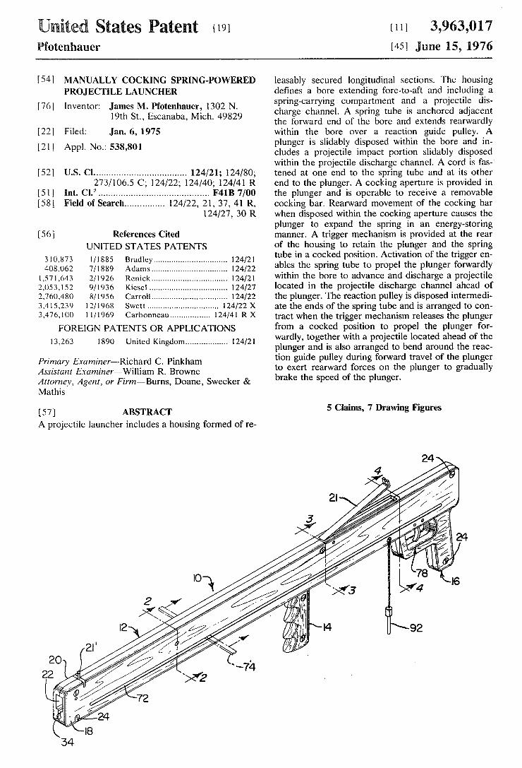
United States Patent 1191 Pfotenhauer
[11] 3,963,017 1451 June 15, 1976
I54l MANUALLY COCKING SPRING-POWERED PROJECTILE LAUNCHER
James M. Pfotenhauer, 1302 N. 19th St., Escanaba, Mich. 49829
[22] Filed: Jan. 6, 1975
[21] Appl. No.: 538,801
[76] Inventor:
[52] US. Cl. .................................. .. 124/21; 124/80;
273/1065 C; 124/22; 124/40; 124/41 R [51] Int. Cl.2 .......................................... .. F4113 7/00
[58] Field 01 Search .............. .. 124/22, 21, 37, 41 R, 124/27, 30 R
[56] References Cited UNITED STATES PATENTS
310,873 l/1885 Bradley ............................... .. 124/21
408,062 7/1889 Adams ...... .. 124/22
1,571,643 2/1926 ReniCk.... 124/21 2,053,152 9/1936 Kiescl . . . . . . . . . . . . . . . . . . .. 124/27
2,760,480 8/1956 Carroll.... ............. .. 124/22
3,415,239 12/1968 Swett .............................. .. 124/22 X
3,476,100 11/1969 Carbonneau ................ .. 124/41 R X
FOREIGN PATENTS OR APPLICATIONS
13,263 1890 United Kingdom ................. .. 124/21
Primary Examiner—Richard C. Pinkham Assistant Examiner—William R. Browne Attorney, Agent, or Firm—Burns, Doane, Swecker & Mathis
[57] ABSTRACT A projectile launcher includes a housing formed of re
leasably secured longitudinal sections. The housing de?nes a bore extending fore-to-aft and including a spring-carrying compartment and a projectile dis charge channel. A spring tube is anchored adjacent the forward end of the bore and extends rearwardly within the bore over a reaction guide pulley. A plunger is slidably disposed within the bore and in cludes a projectile impact portion slidably disposed within the projectile discharge channel. A cord is fas tened at one end to the spring tube and at its other end to the plunger. A cocking aperture is provided in the plunger and is operable to receive a removable cocking bar. Rearward movement of the cocking bar when disposed within the cocking aperture causes the plunger to expand the spring in an energy-storing manner. A trigger mechanism is provided at the rear of the housing to retain the plunger and the spring tube in a cocked position. Activation of the trigger en~ ables the spring tube to propel the plunger forwardly within the bore to advance and discharge a projectile located in the projectile discharge channel ahead of the plunger. The reaction pulley is disposed intermedi ate the ends of the spring tube and is arranged to con tract when the trigger mechanism releases the plunger from a cocked position to propel the plunger for wardly, together with a projectile located ahead of the plunger and is also arranged to bend around the reac tion guide pulley during forward travel of the plunger to exert rearward forces on the plunger to gradually brake the speed of the plunger.
5 Claims, 7 Drawing Figures
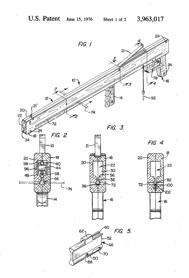
June 15, 1976 Sheet10f2 3,963,017 Q US. Patent
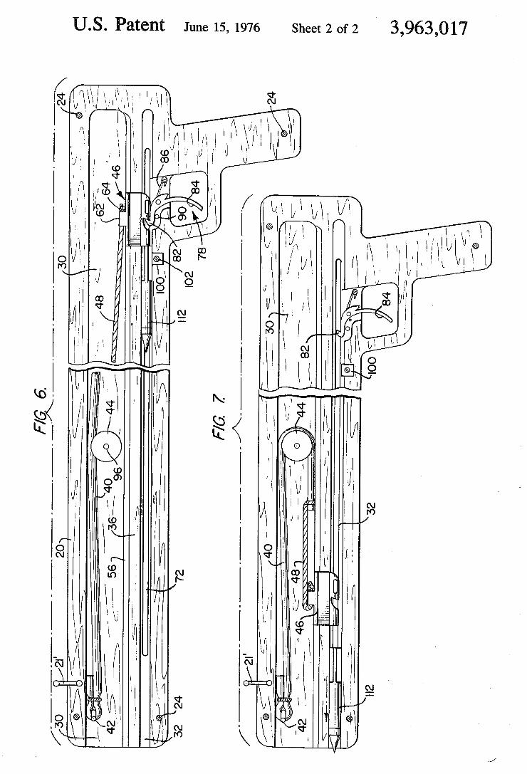
US. Patent June 15, 1976 Sheet20f2 3,963,017
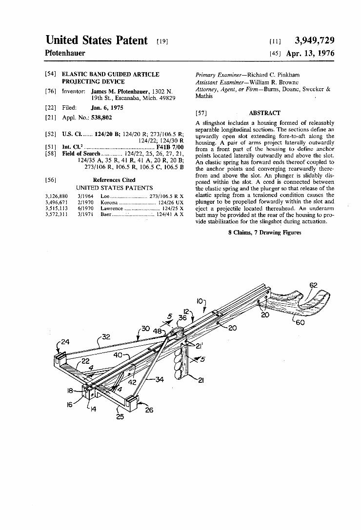
United States Patent [191 Pfotenhauer
[11] 3,949,729 [451 Apr. 13, 1976
[54] ELASTIC BAND GUIDED ARTICLE PROJECTING DEVICE
[76] Inventor: James M. Pfotenhauer, 1302 N. 19th St., Escanaba, Mich. 49829
[22] Filed: Jan. 6, 1975
[21] Appl. No.: 538,802
[52] US. Cl. .... .. 124/20 B; 124/20 R; 273/106.5 R; 124/22; 124/30 R
[51] Int. Cl.2 .......................................... .. F41B 7/00
[58] Field of Search ........... .. 124/22, 25, 26, 27, 21, 124/35 A, 35 R, 41 R, 41 A, 20 R, 20 B;
273/106 R, 106.5 R, 106.5 C, 106.5 B
[56] References Cited UNITED STATES PATENTS
3,126,880 3/1964 Loe ........................ .. 273/1065 R X 3,496,671 2/1970 Korona .................... .. 124/26 UX 3,515,113 6/1970 Lawrence .................... .. 124/25 X
3,572,311 3/1971 Baer .......................... 124/41 A X
Primary Examiner—Richard C. Pinkham Assistant Examiner~William R. Browne Attorney, Agent, or Firm—Bu'rns, Doane, Swecker & Mathis .
[57] ABSTRACT
A slingshot includes a housing formed of releasably separable longitudinal sections. The sections de?ne an upwardly open slot extending fore-to-aft along the housing. A pair of arms project laterally outwardly froma front part of the housing to de?ne anchor points located laterally outwardly and above the slot. An elastic spring has forward ends thereof coupled to the anchor points and converging rearwardly there from and above the slot. An plunger is slidably dis posed within the slot. A cord is connected between the elastic spring and the plunger so that release of the elastic spring from a tensioned condition causes the plunger to be propelled forwardly within the slot and eject a projectile located thereahead. An underarm butt may be provided at the rear of the housing to pro vide stabilization for the slingshot during actuation.
8 Claims, 7 Drawing Figures
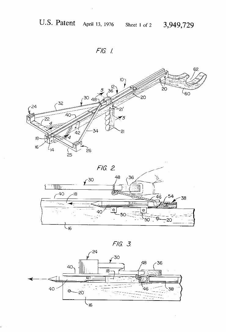
US. Patent Apn'l13, 1976 SheetlofZ 3,949,729
I [24
‘*0 Wm...
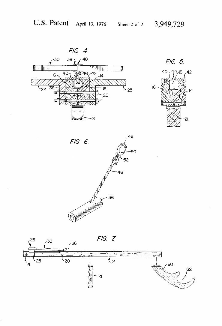
US. Patent April 13, 1976 Sheet20f2 3,949,72
F/G 4
FIG 5.
10142342 / {1
l6\ n
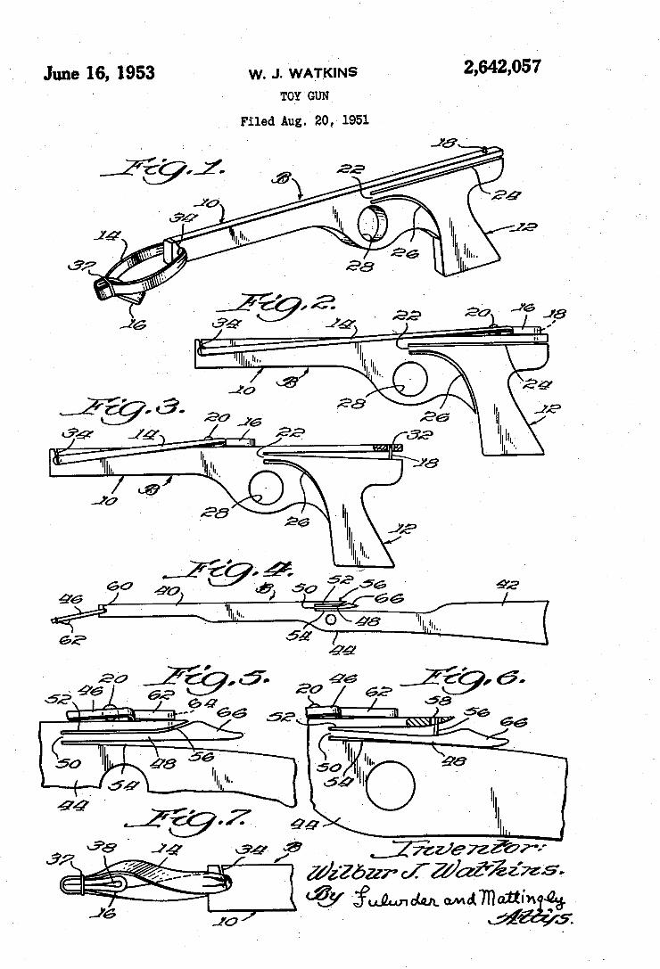
June 16, 1953 w. J. wAIKms . 2,642,057 TOY GUN
Filed Aug.- 20, 1951
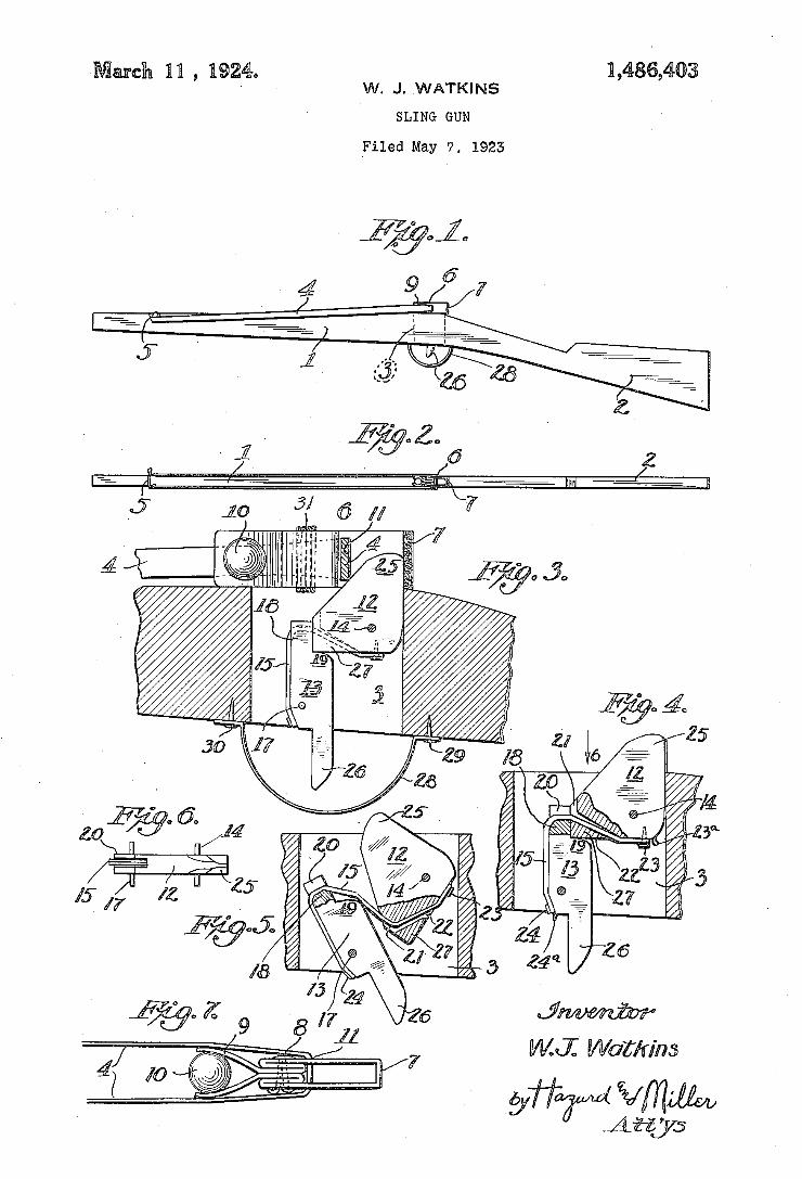
HASGAQB March 11 , 1924. W. J. WATKINS
SLING GUN
Filed May ‘7, 1925
W'I Warm/m
Ngr m iiiéik
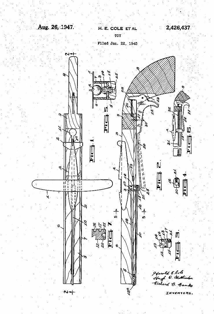
H'.ÍÈ. COLE ETAI.v ’ TOY' ’ `
«- Filed Jan. 22», 1945
. .. . , ._ . ..m„ .mflurnn n NN yl? f ,_ . n \. . Y . / , Y /
WN. z-- w 5x1»- w
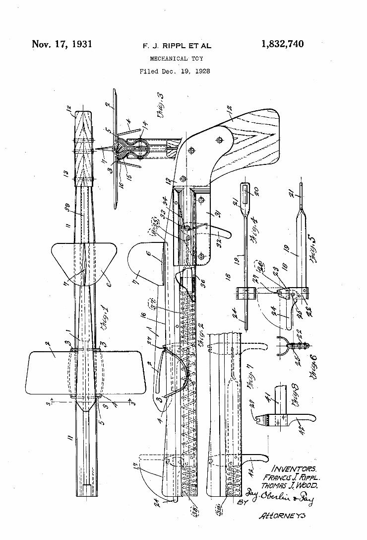
1,832,740 Nov. 17, 1931 F. J. RIPPL ET A_L
MECHANICAL TOY
Filed Deo. 19, 1928
_
l | l I | | | I | . | I l l I v IIN
Mafia
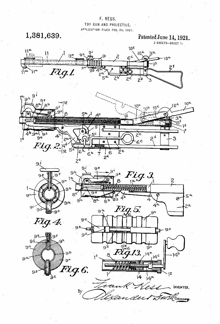
F. HESS. TOY GUN AND PROJECTILE.
APPLICATION FILED vm3. 26, 1921.
1,381,639. Patented June 14, 1921. 2 SHEETS-SHEET 1.
d. a.
l2?! 7 ............. .. . .
__ ........................ ....... ‘8* ,5 I > H“ v _ — \. I,
(A
wanna. mm:
am.
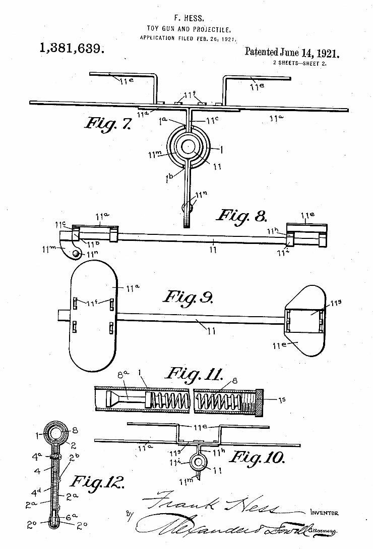
F. HESS. TOY GUN AND PROJECTILE.
APPLICATION FILED FEB. 25, 1921.v
1,381,639. Patented Juné 14, 1921. 2 _SHEETS—SHEET 2
F1397. ' 1°“
119
2
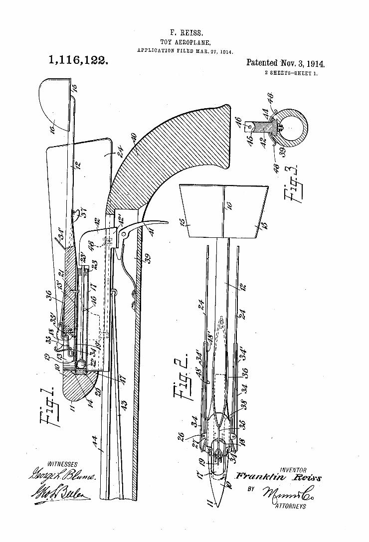
1?. REISS. TOY AEROPLANB.
APPLICATION FILED MAR. 27, 1014.
1 , 1 1 6, 1 22. Patented ‘Nov. 3, 1914. 2 SHEETS-SHEET 1.
WITNESSES l/VVEA/TOR
ATTORNEYS Mil
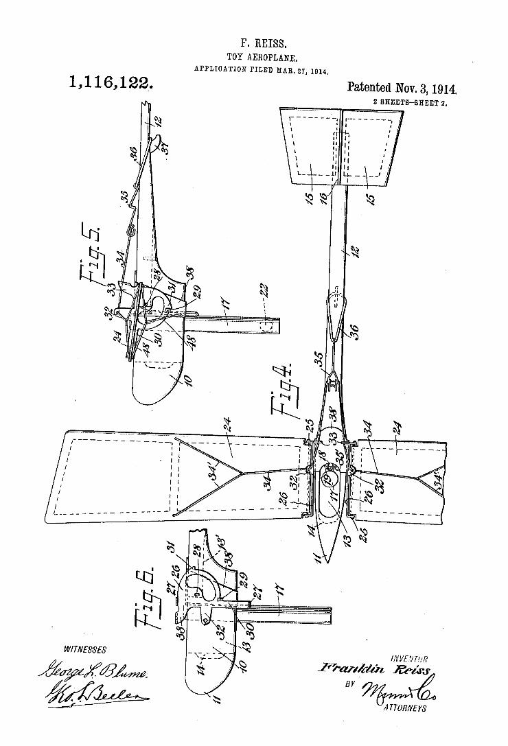
P. REISS. TOY AEROPLANE.
APPLICATION FILED MAR. 27, 1014.
M.
E T: E
,3 Ala N
3H 5% R
.S V 0
V_ W. U
0N 4.
NH .&
an M
Dunn t
D2 My
w W8 Dnm n
1 , l 1 6, 1 22‘.
WITNESSES
?gWK/BM
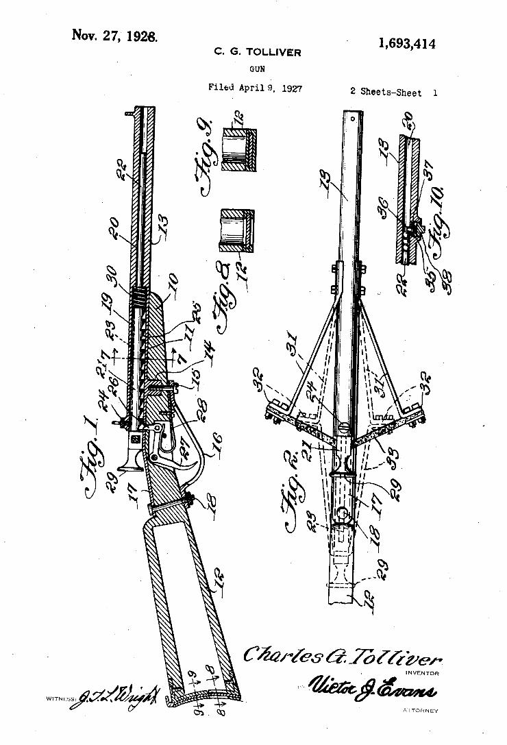
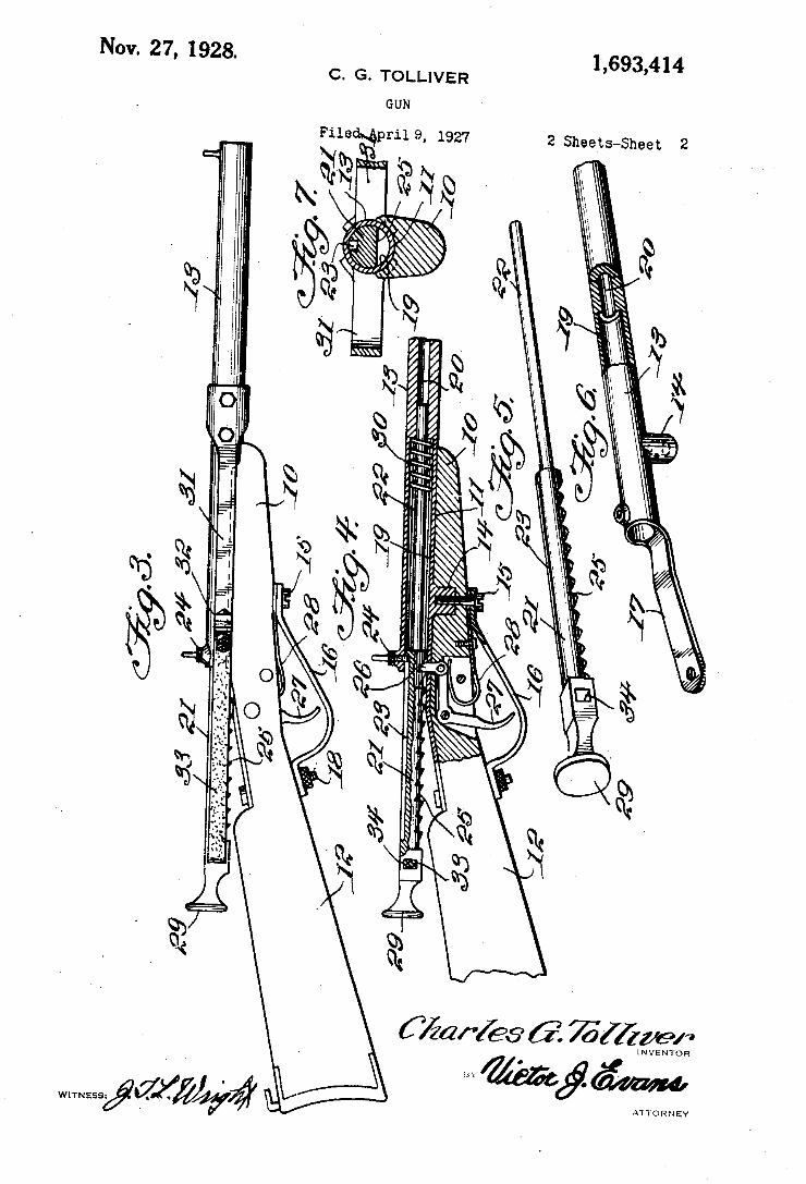
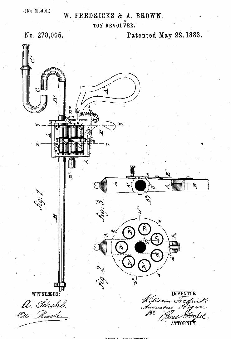
>(No Moaél.) W. FREDRIGKS & BROWN.
TOY REVOLVER. '
Patented May 22" 1883.
INVENTOR -
m M? WITNESSES: ‘ Q I
d. %4%% ’ ATTORN
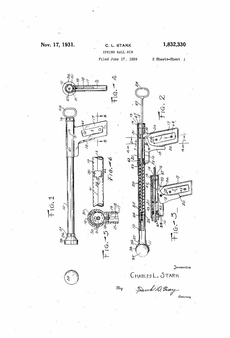
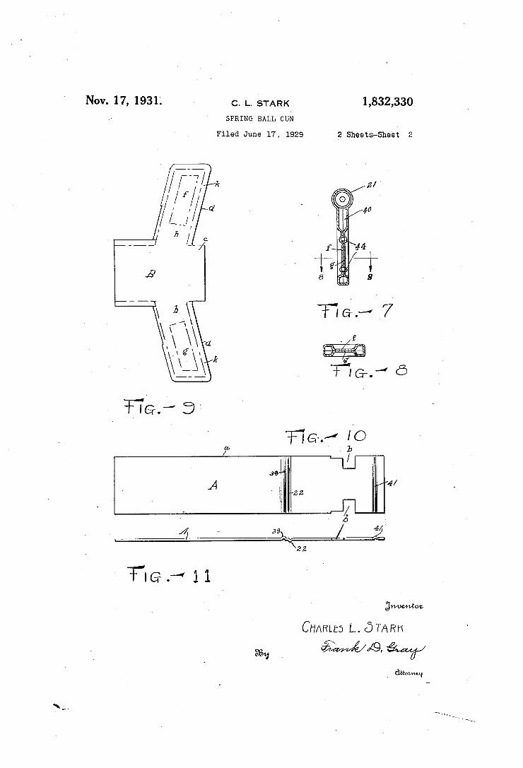
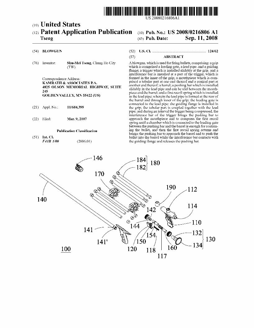
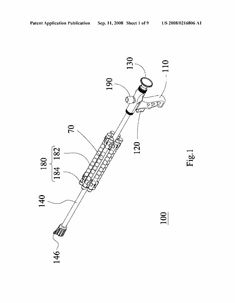
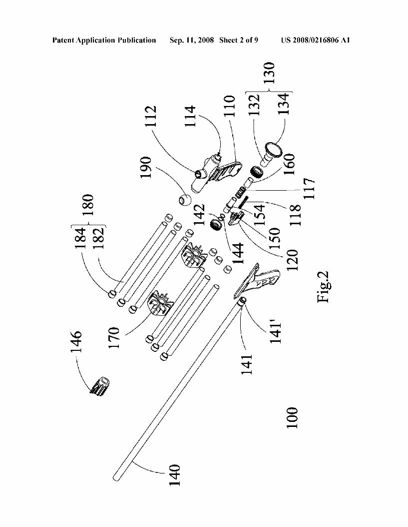
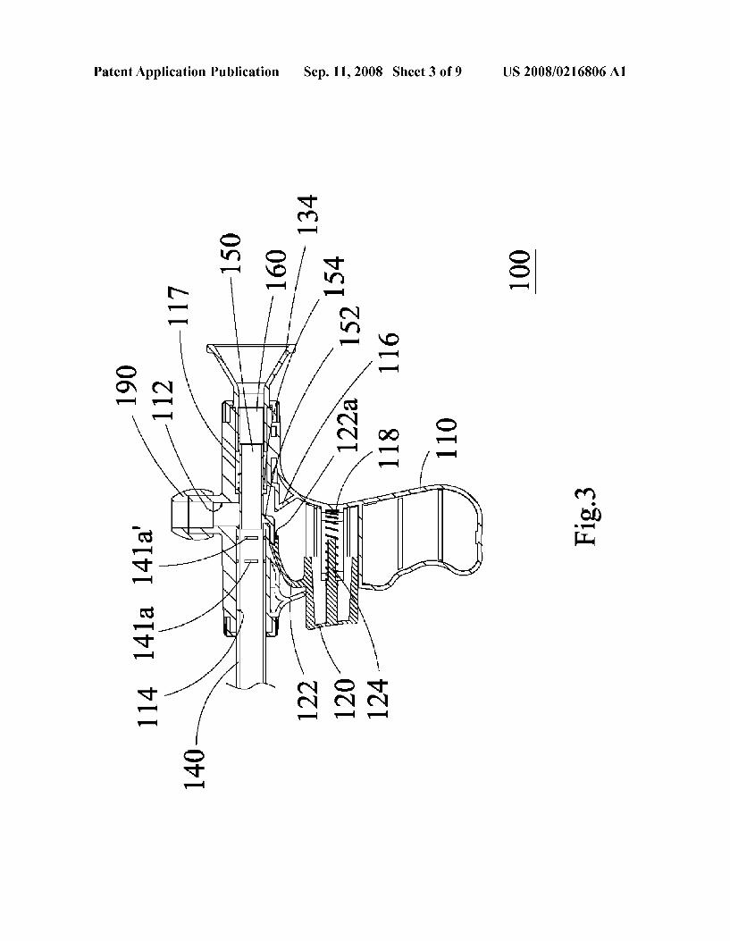
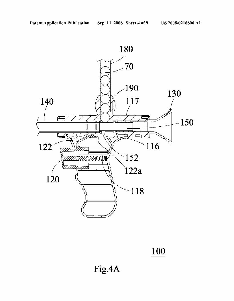
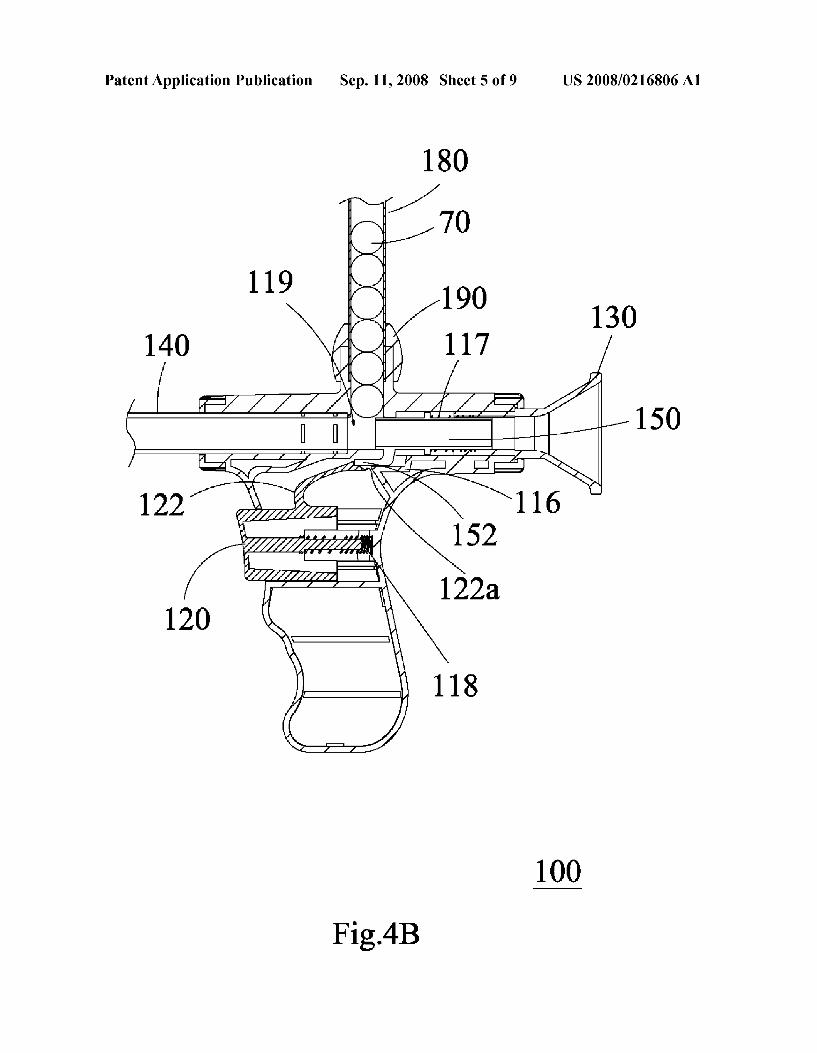
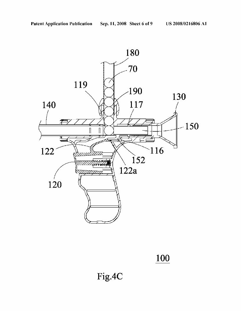
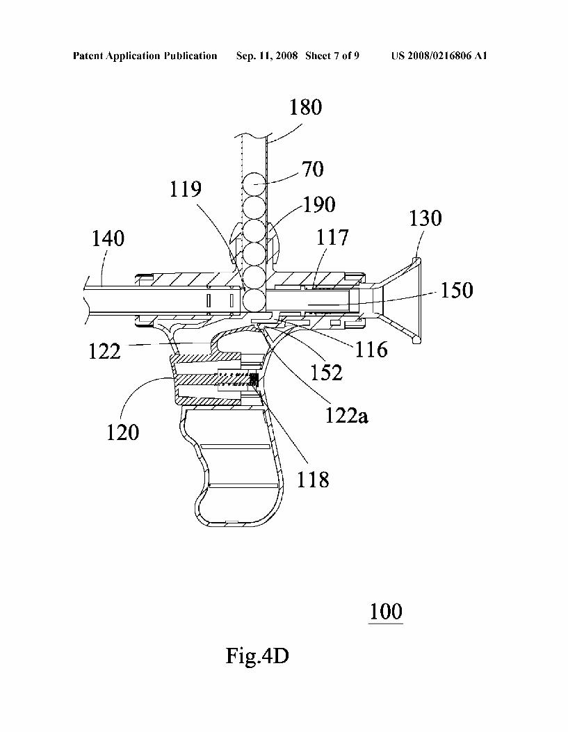
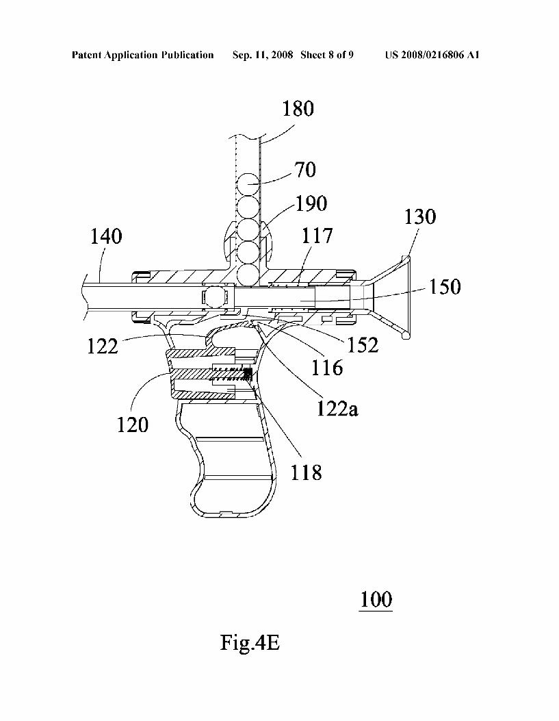
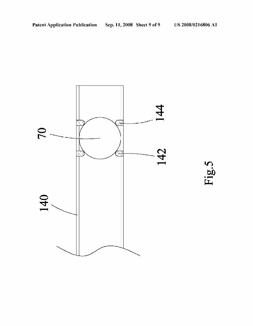
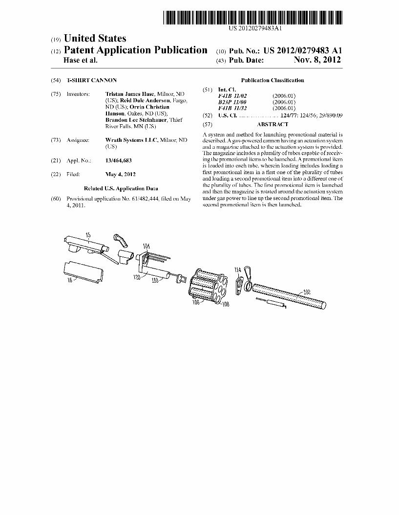
US 20120279483A1
(19) United States (12) Patent Application Publication (10) Pub. No.: US 2012/0279483 A1
Hase et al. (43) Pub. Date: NOV. 8, 2012
(54) T-SHIRT CANNON Publication Classi?cation
_ _ (51) Int. Cl. (75) Inventors: Tristan James Hase, Milnor, ND F41B 11/02 (200601)
(US); Reid Dale AIIdGI‘SOIl, Fargo, B231) 11/00 (200601) ND (US); Orrin Christian F41B 11/32 (2006.01) Hans”, Oakes, ND (Us); _ (52) us. Cl. ......................... .. 124/77; 124/56; 29/890.09 Brandon Lee Steinhauer, Thief River Falls, MN (US) (57) ABSTRACT
_ _ A system and method for launching promotional material is (73) Asslgneer Wrath Systems LLC, Mllnor, ND described. A gas-powered cannon having an actuation system
(US) and a magazine attached to the actuation system is provided. The magazine includes a plurality of tubes capable of receiv
(21) App1_ NO; 13/464,683 ing the promotional items to be launched. A promotional item is loaded into each tube, Wherein loading includes loading a
(22) Filed: May 4, 2012 ?rst promotional item in a ?rst one of the plurality of tubes
(60)
Related US. Application Data
Provisional application No. 61/482,444, ?led on May 4, 2011.
15
and loading a second promotional item into a different one of the plurality of tubes. The ?rst promotional item is launched and then the magazine is rotated around the actuation system under gas poWer to line up the second promotional item. The second promotional item is then launched.
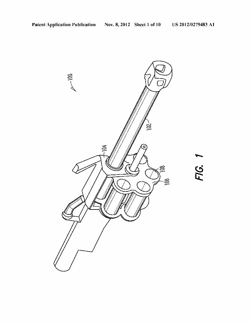
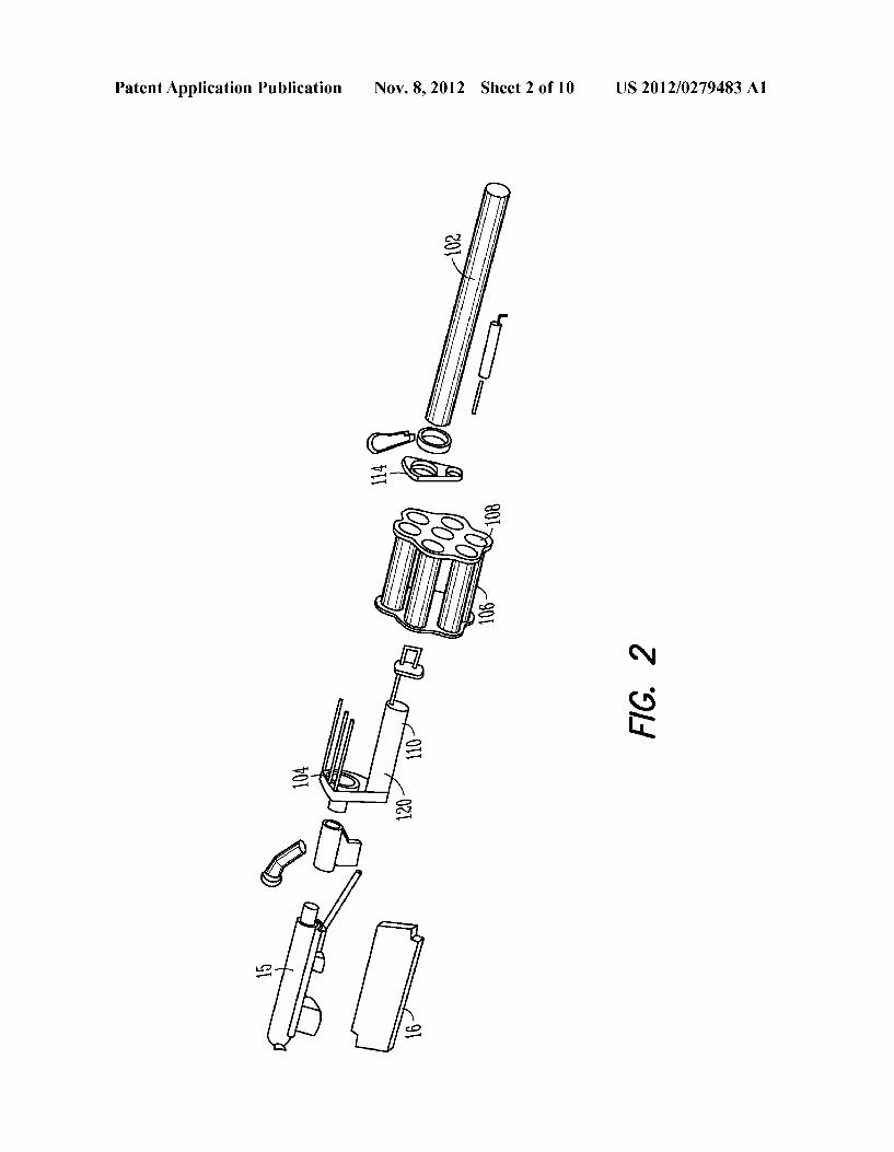
Patent Application Publication Nov. 8, 2012 Sheet 2 0f 10 US 2012/0279483 A1
g a
FIG. 2
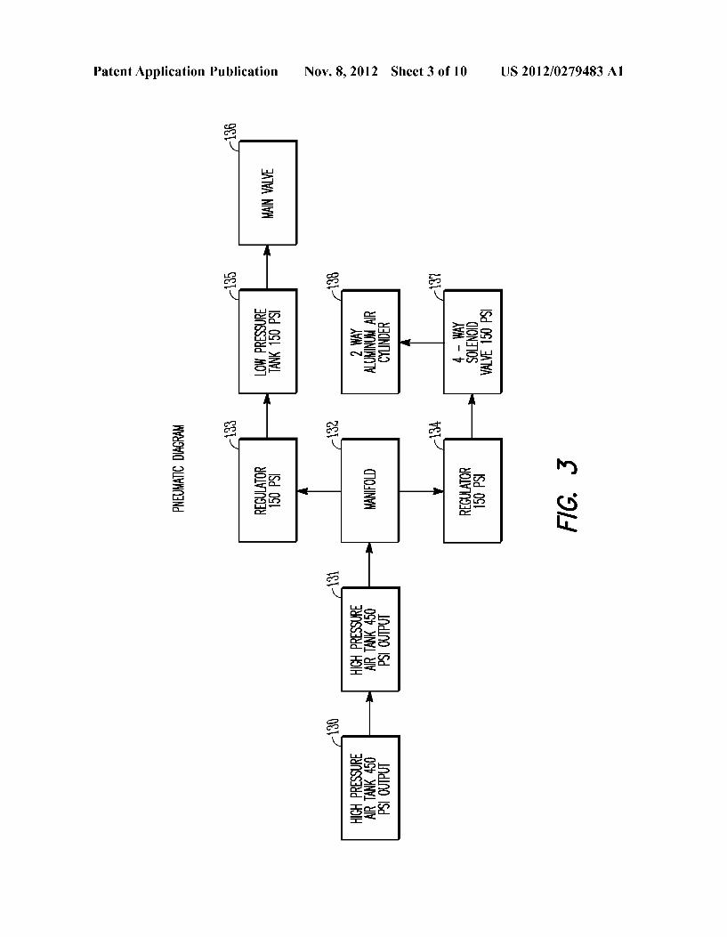
Patent Application Publication Nov. 8, 2012 Sheet 3 0f 10 US 2012/0279483 A1
m. 6R
A|
z 3 ma; 2 E mg?ow A| 558mm 51 k 21 H
“we? z_< 3%: 52252 T
£1 £1 R 51
. 2 3 V2; . 2 5 $5511 ‘>9 105% £1 £1
02k
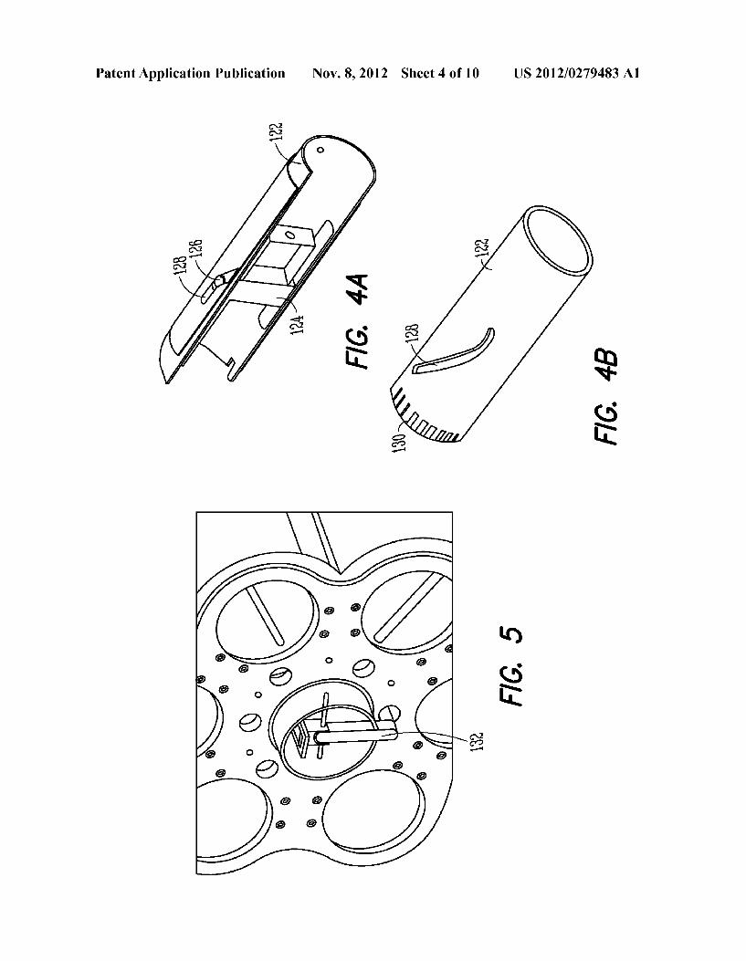
Patent Application Publication Nov. 8, 2012 Sheet 4 0f 10 US 2012/0279483 A1
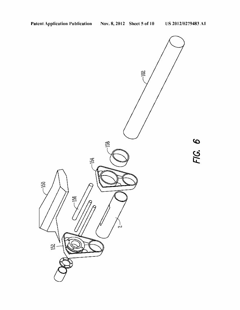
Patent Application Publication Nov. 8, 2012 Sheet 5 0f 10 US 2012/0279483 A1
W2
m
FIG. 5

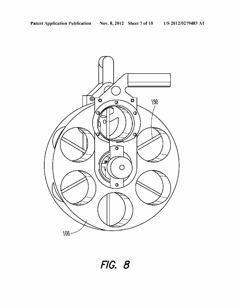
Patent Application Publication Nov. 8, 2012 Sheet 7 0f 10 US 2012/0279483 A1
FIG. 8
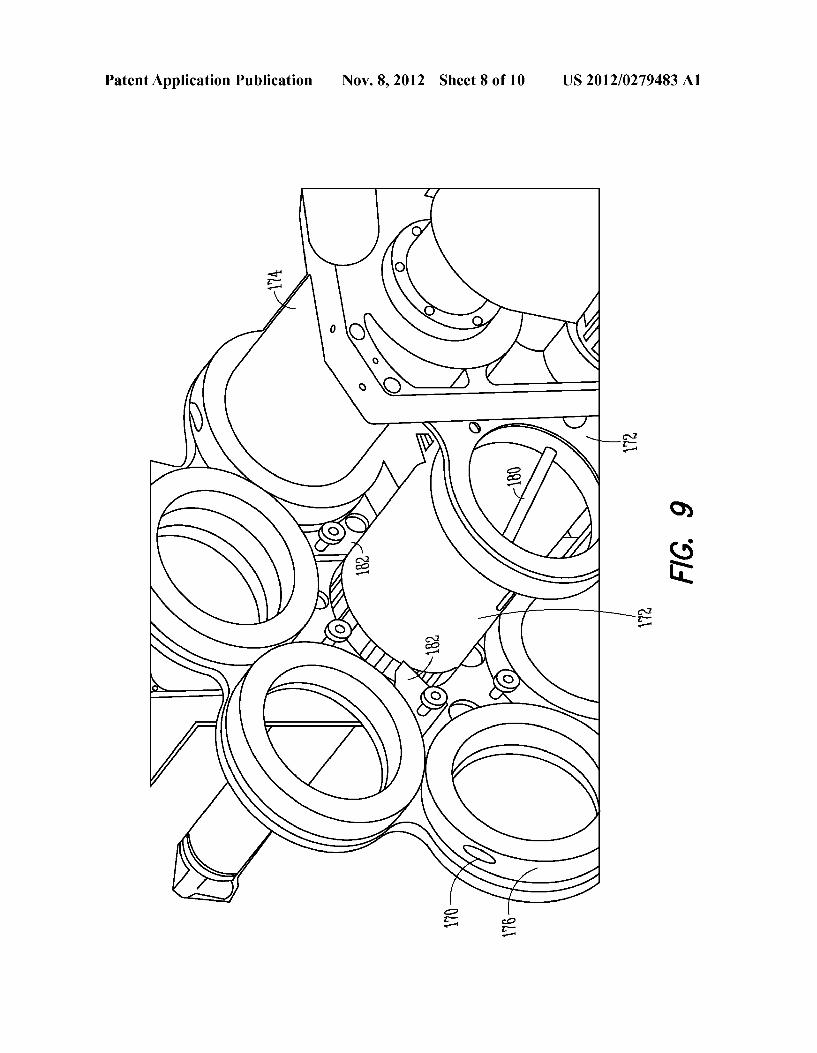
Patent Application Publication Nov. 8, 2012 Sheet 8 0f 10 US 2012/0279483 A1
TM
p a
‘s K) I/ C
n X72 FIG. 9
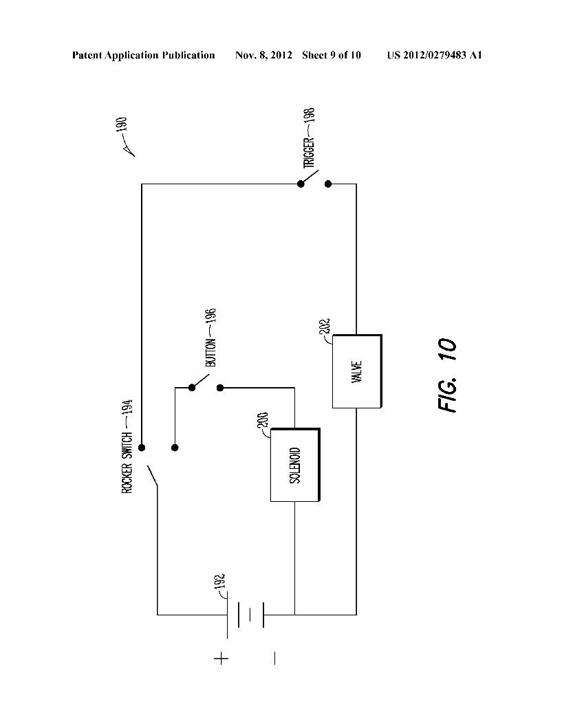
Patent Application Publication Nov. 8, 2012 Sheet 9 0f 10 US 2012/0279483 A1
g g T x‘ % £3,
E
/0—
g a N
( :00 é \ Q g N m 5:
> 0
v— Q) <1“ ‘G g a
< 6% :I:
E. Q u’ g
E\ a o (D
2
N 2
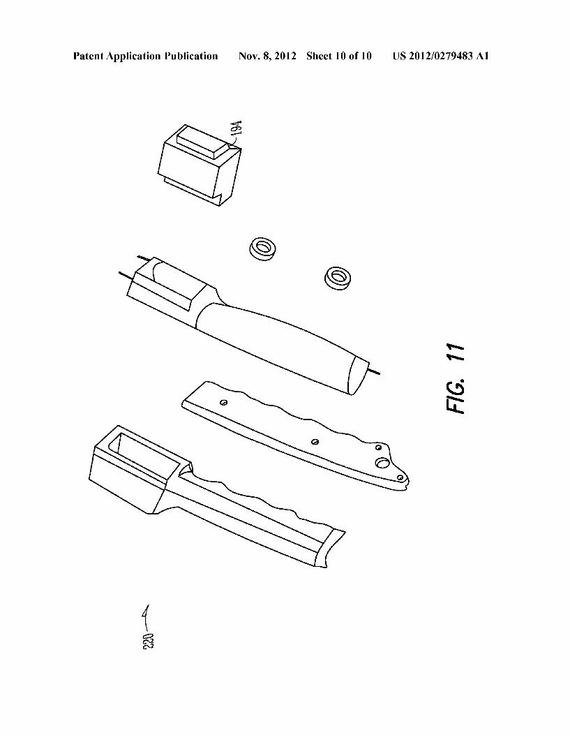
Patent Application Publication Nov. 8, 2012 Sheet 10 0f 10 US 2012/0279483 A1
WA
FIG‘. 11
22% A
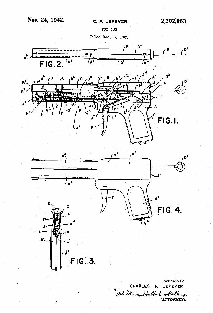
Nov. 24, 1942. c. F. LEFE'VER _ 2,302,963
TOY GUN
‘Filed Dec. 6, 1939
‘INVENTOR. _ CHARLES F. LEFEYER" BY .
‘ 'ATTORNEYs
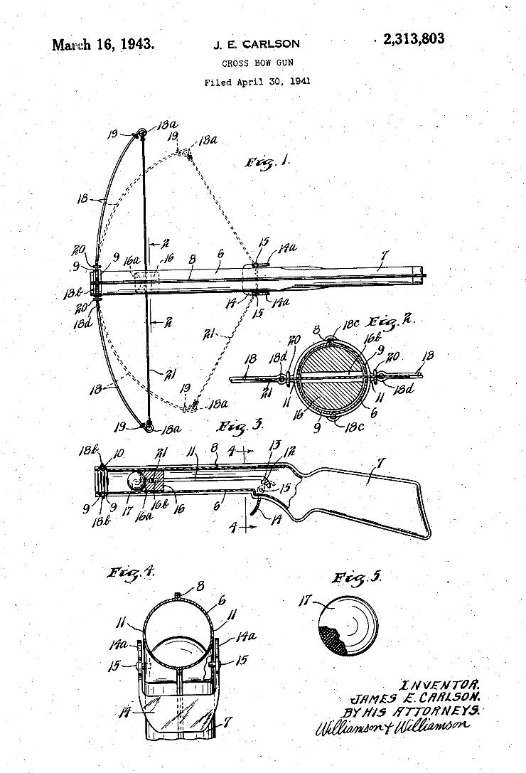
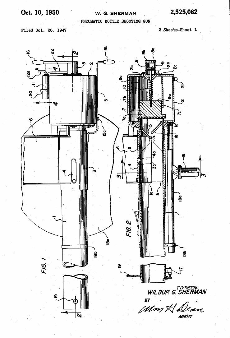
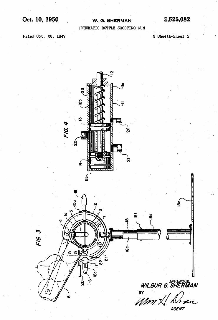
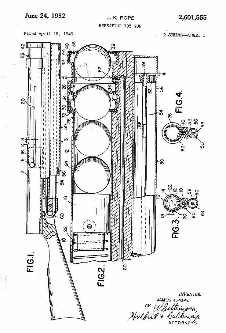
June 24, 1952 J. K. POPE
REPEATING TOY GUN
2,601,555
2 SHEETS-_SHEET l 9 .4 9 l 8, l l .l m. A d e l .l F
«llllllllllllllllllllll l
INVENTOR. JAMES K.POPE
ATTORNE SA
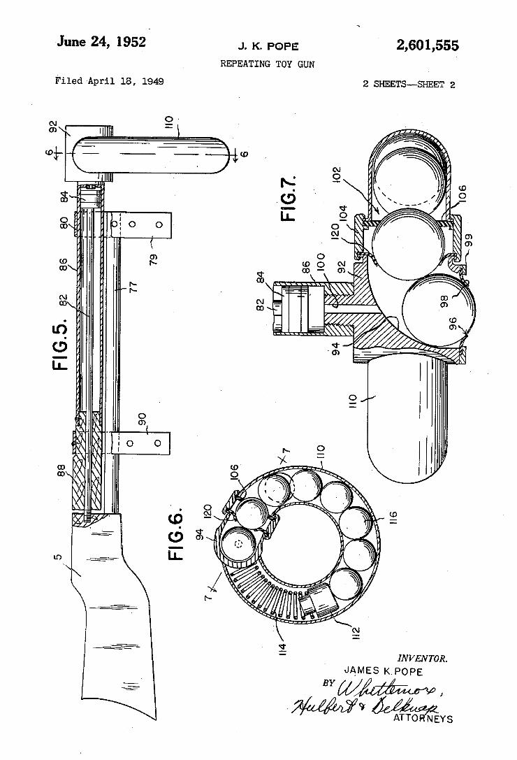
June 24, 1952 J. K. POPE
REPEATING TOY GUN
2 SHEETS-_SHEET 2 Filed April 1s, 1949
infix), l N
I
l INVENToR.
JAMES KPOPE BY www ,
v ATTO NEYS
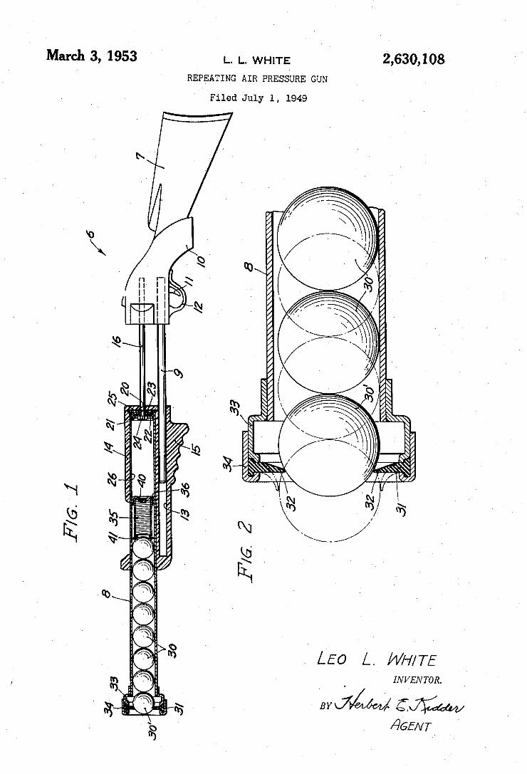
2,630,108 March 3, >1953 l.. L. WHITE
REPEATING AIR PRESSURE GUN
Filed July l, 1949
IN VEN TOR.
¿26E/v7 f
w
.l 1 . ...l ‘Ñ
MN ,
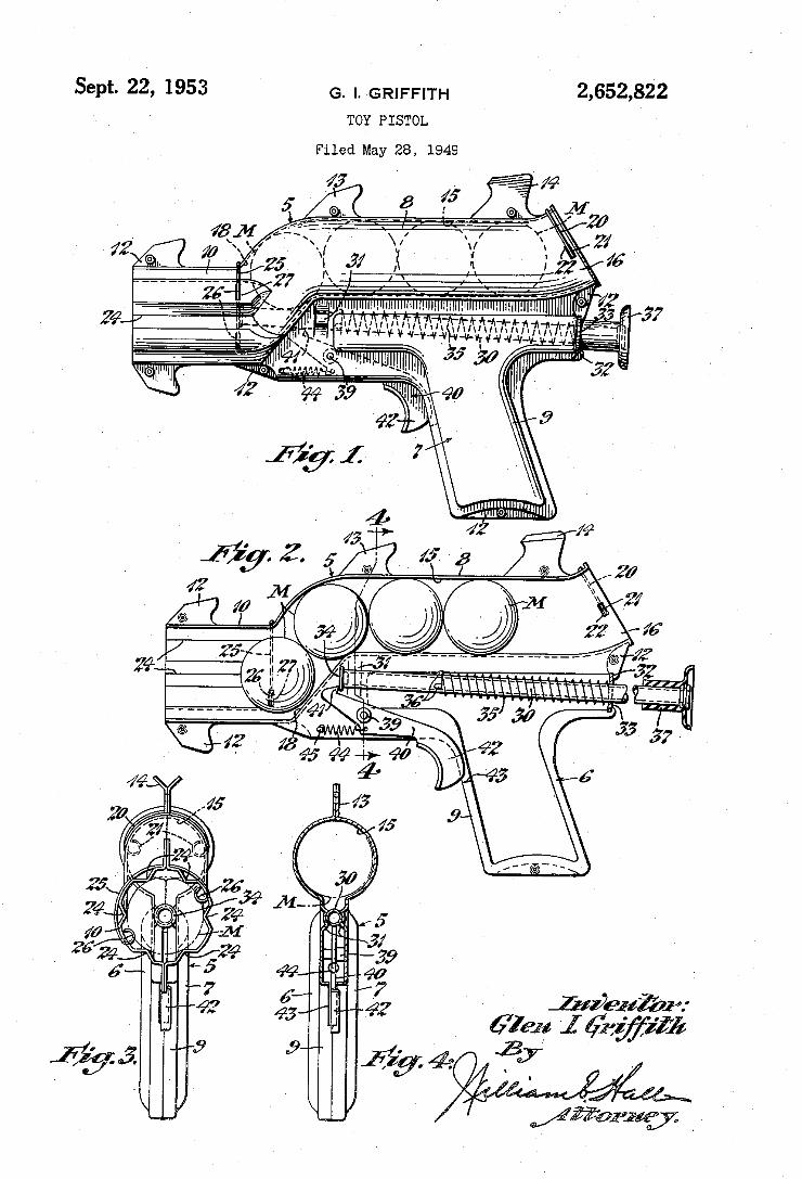
2,652,822 G. l. GRIFFITH
TOY PISTOL
Sept. 22, 1953
Filed May 28, 1949
Y ’ @ieui'Zr:
67191; I aw”
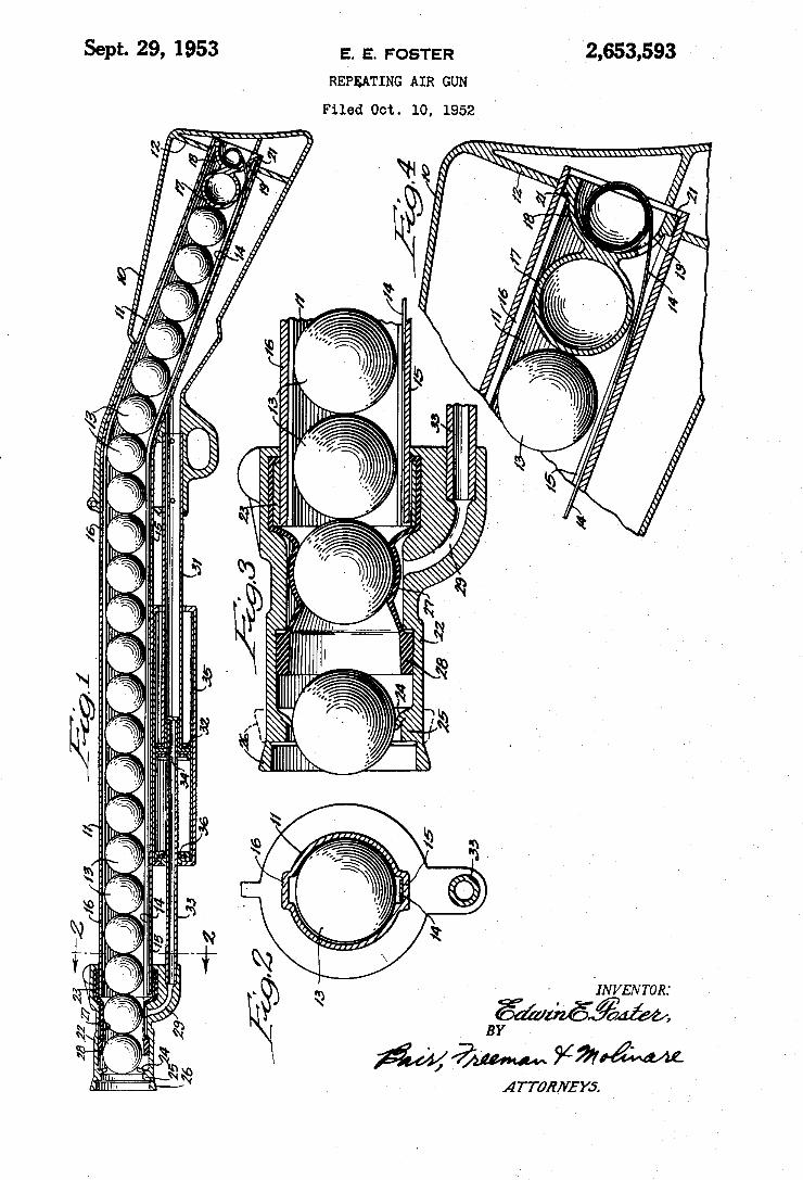
2,653,593 Sept. 29, 1953 E. E. FOSTER
REPBATING AIR GUN
Filed Oct. 10, 1952
' IN VEN TOR.
Egal/@6.43m ` j M
§54. lllllllllllllllllllllllllllllllllllllllllllllllllllllllllllllllllllllllllllllllllllllllllll . ` «
A TTÚR/VEYS.
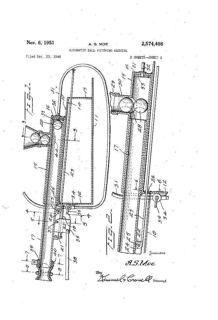
2,574,408 'Nov. 6, 1951 A. s. MOE
AUTOMATIC BALL PITCHING MACHINE
2 SHEETS--SHEET 1 Filed Dec. 25, 1946
, 5w’ ‘
i win: ‘ m
1. l @rf
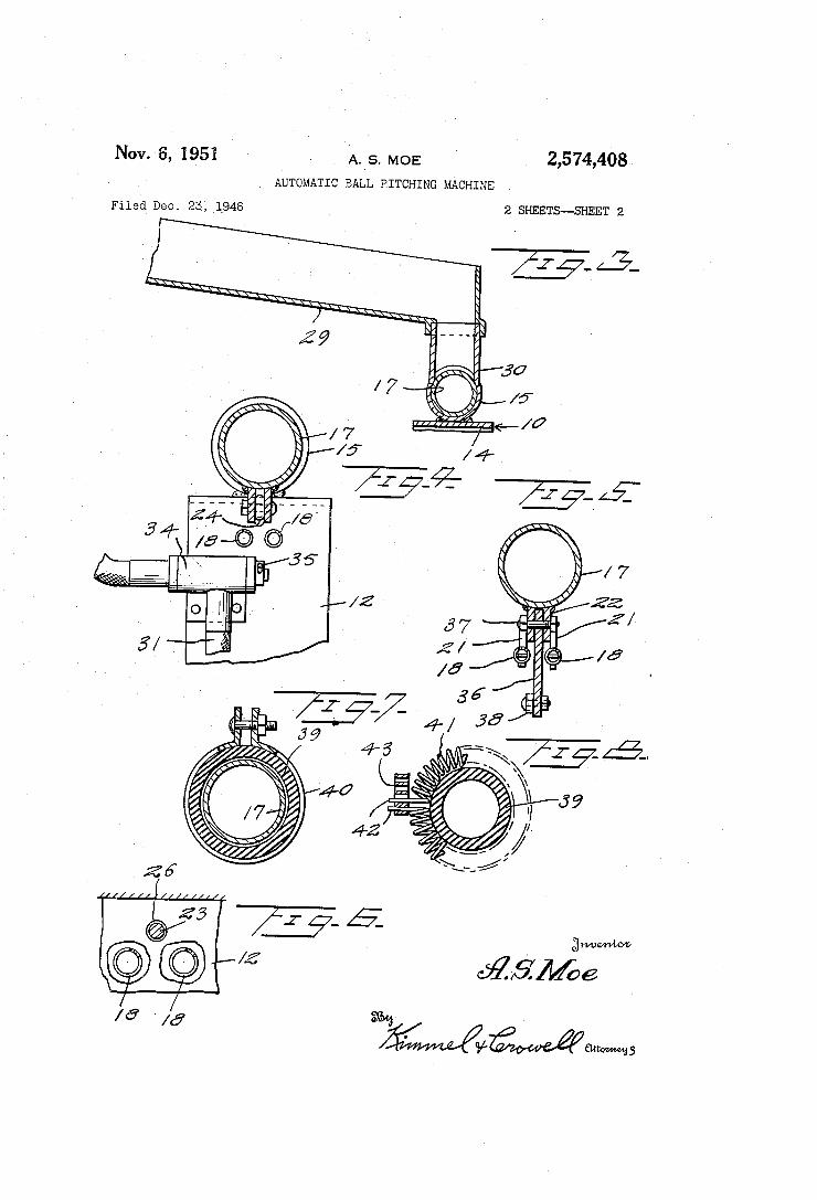
Nov. 6, 1951 - A._s. MOE _ 2,574,408
. AUTOMATIC BALL PITCHING MACHINE
Filed Dec. 23, i946 2 SI-lEETS-—SHEET 2
43.
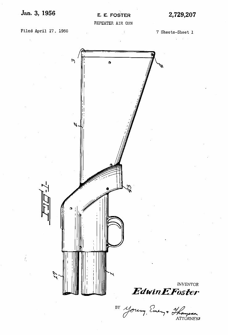
2,729,207 E. E. FOSTER
REPEATER AIR GUN
Jan. 3, 1956
7 Sheets-Sheet 1 Filed April 17, 1950
INVENTOR
Edm'rzEFosfer
BY Qua‘ 3:2 ATTORNEKS
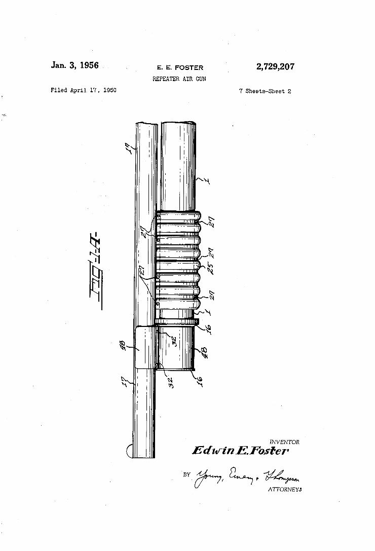
Jan. 3, 1956 v \ E. E. FOSTER ‘ 2,729,207
REPEATER AIR GUN
Filed April 17, 1950 7 Sheets-Sheet 2
Fig; 2? I l
l 25' 2"?
I b N
_| \
‘Q \N\ I ‘£1
' I
§\.; § *3 I I
INVENTOR
EdwinEFosi‘cr
ATTORNEYJ
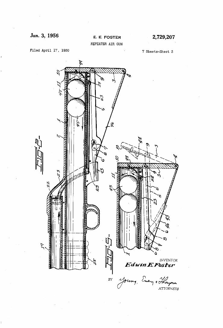
2,729,207 E. E. FOSTER
REPEATER AIR GUN
Jan. 3, 1956
7 Sheets-Sheet 3 Filed April 17, 1950
0 ‘00 I I
OHIWIIIIII/ . i
INVENTOR
Edwin E fbsl'er
ATTORNEY6
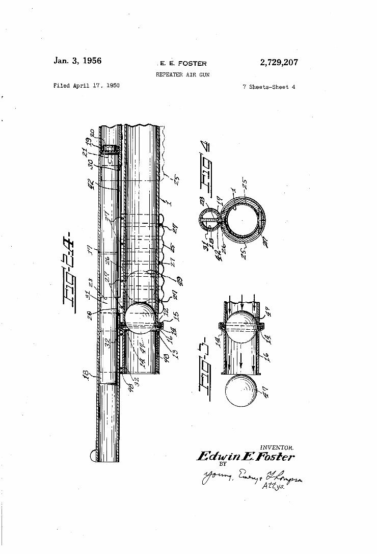
2,729,207 Jan. 3, 1956 ,E. E. FOSTER
REPEATER AIR GUN '
7 Sheets-Sheet 4 Filed April 17. 1950
I N VEN TOR.
Eda/i121‘: fbsfer BY
w, flaw/4%
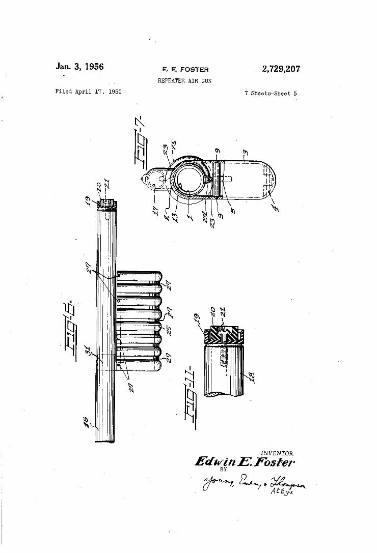
Jan. 3, 1956
Filed April 17, 1950
E. E. FOSTER
REPEATER AIR GUN
2,729,207
7 Sheets-Sheet 5
I N VEN TOR.
Edugrz E Ester
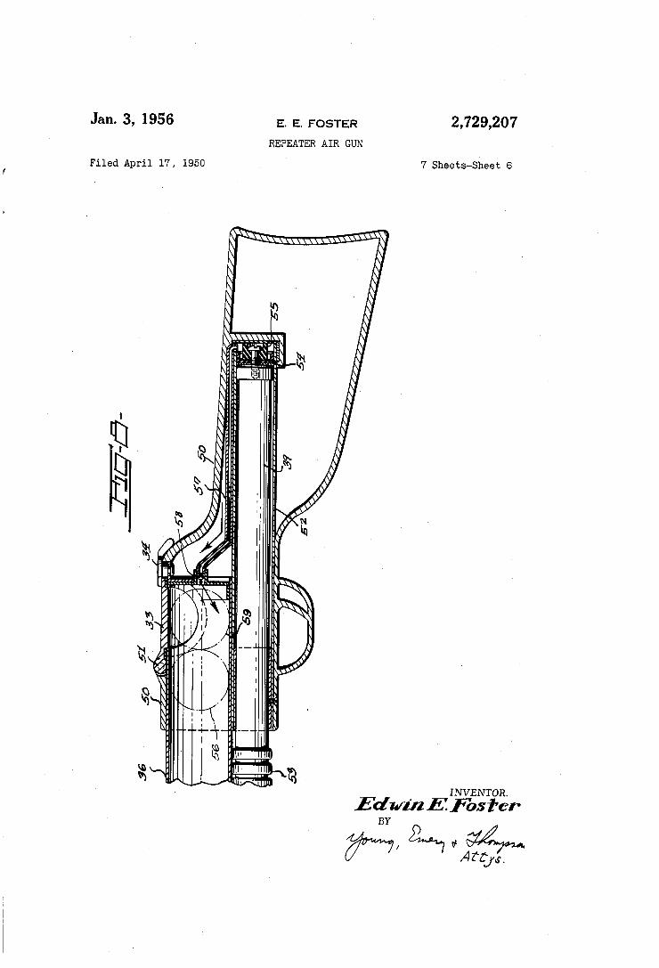
Jan. 3, 1956 E. E. FOSTER 2,729,207 REPEATER AIR GUN
Filed April 17, 1950 '7 Sheets-Sheet 6
'4')
‘N a ‘o
l
. Q .
l M Q
\I % ‘u |
N
\H h )J ‘a “‘ l
'\ 0a Q i :I “5
Q i \l l'
*3 _ ?’é '
§ \ “ Q INVENTOR.
EdwmEf'bsi'er
?rwww
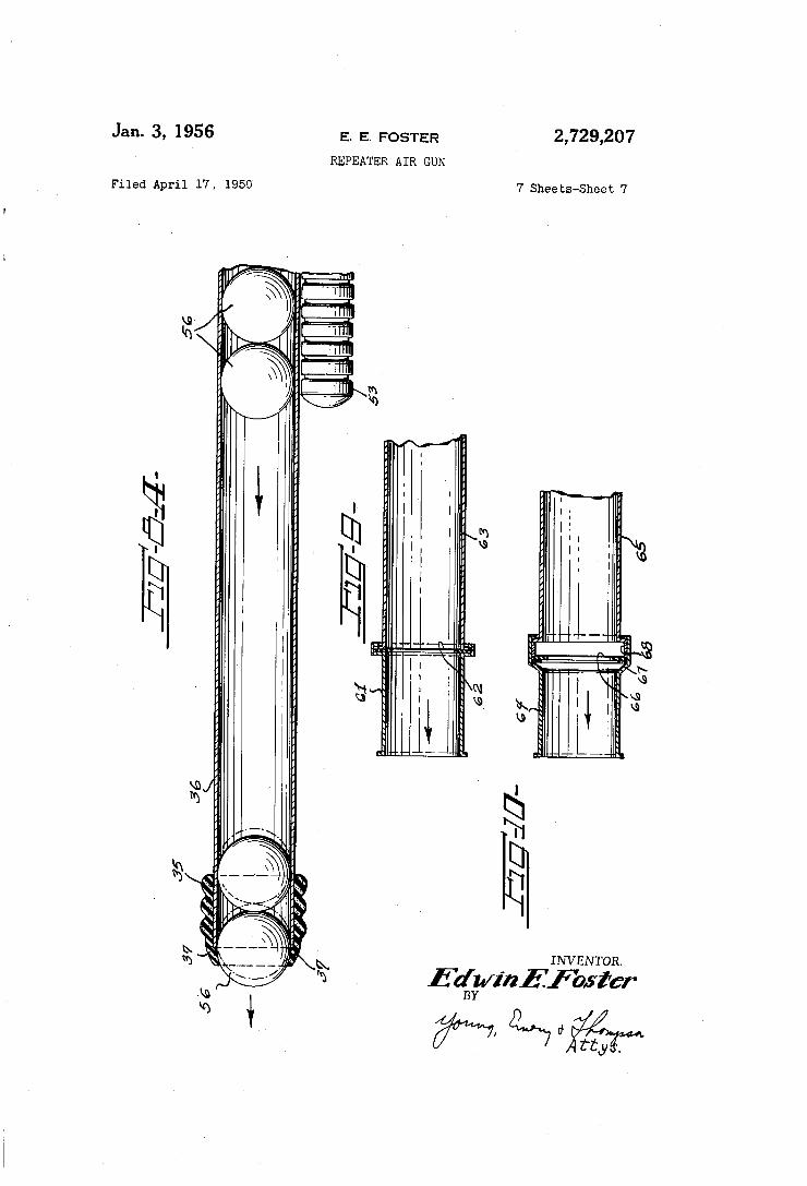
2,729,207 E. E. FOSTER
REPEATER AIR GUN
Jan. 3, 1956
7 Sheets-Sheet 7 Filed April 17 , 1950'
\u
INVENTOR.
Eagu/inl'f'osl'er W, 229‘; OK A tty .
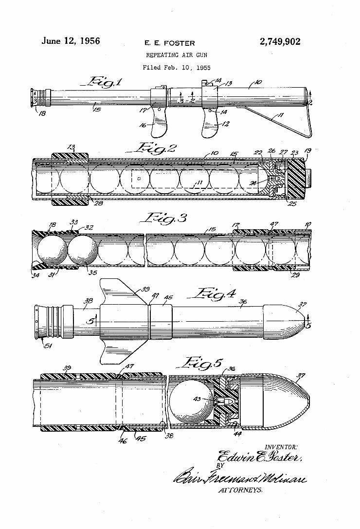
June l2, 1956 E. E. FOSTER
REPEATING AIR GUN
2,749,902
Filed Feb. l0, 1955
f'gj
ATTORNEYS.
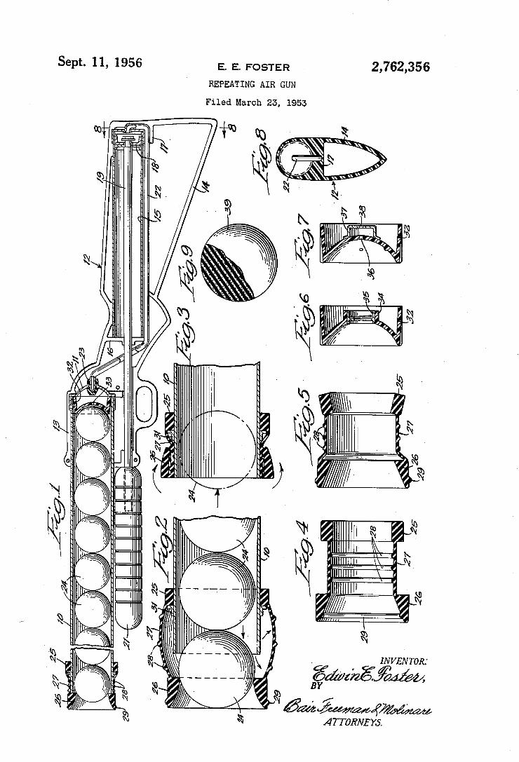
2,762,356 Sept. 11, 1956 E. E. FOSTER
REPEATING AIR ‘GUN
Filed March 25, 1953
. INVENTOR.‘
é’dzmé’if?m MIN. RN “N
ATTORNEYS. MN mN
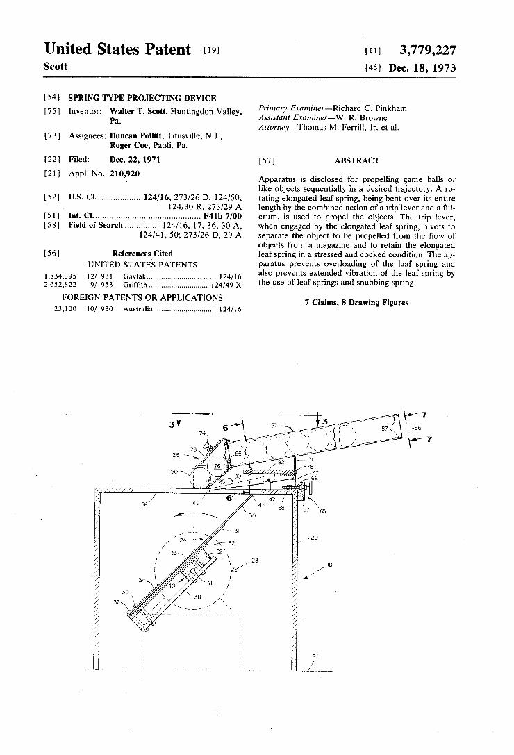
United States Patent [191 Scott
[111 3,779,227 [451 Dec. 18, 1973
1541 SPRING TYPE PROJECTING DEVICE
[75] Inventor: Walter T. Scott, Huntingdon Valley, Pa.
[73] Assignees: Duncan Pollitt, Titusville, N.J.; Roger Coe, Paoli, Pa.
[22] Filed: Dec. 22, 1971
[21] Appl. No.: 210,920
[52] U.S. Cl .................. .. 124/16, 273/26 D, 124/50, 124/30 R, 273/29 A
[51] Int. Cl. ............................................ .. F41b 7/00
[58] Field of Search ............. .. 124/16, 17, 36, 30 A, 124/41, 50; 273/26 D, 29 A
[56] References Cited UNITED STATES PATENTS
1,834,395 12/1931 Gavlak ................................ .. 124/16
2,652,822 9/1953 Grif?th ........................... .. l24/49X
FOREIGN PATENTS OR APPLICATIONS 23.100 10/1930 Australia ............................. .. 124/16
Primary Examiner-Richard C. Pinkham Assistant Examiner-W. R. Browne Attorney-Thomas M. Ferrill, Jr. et al.
[57] ABSTRACT
Apparatus is disclosed for propelling game balls or like objects sequentially in a desired trajectory. A r0 tating elongated leaf spring, being bent over its entire length by the combined action of a trip lever and a ful crum, is used to propel the objects. The trip lever, when engaged by the elongated leaf spring, pivots to separate the object to be propelled from the ?ow of objects from a magazine and to retain the elongated leaf spring in a stressed and cocked condition. The ap paratus prevents overloading of the leaf spring and also prevents extended vibration of the leaf spring by the use of leaf springs and snubbing spring.
7 Claims, 8 Drawing Figures
"5a....
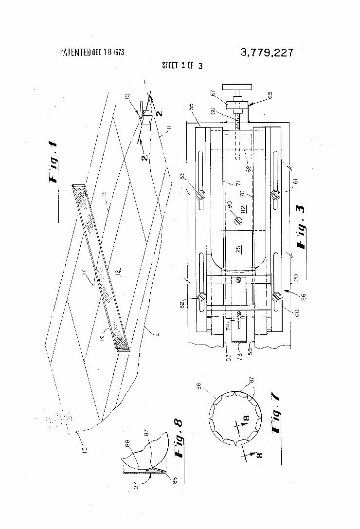
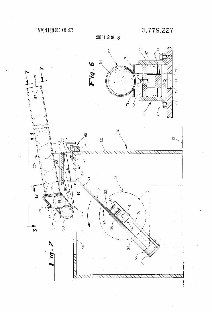
. 3.779.227 E’MENIEDUEC 18 £975 SHEET 2 OF 3
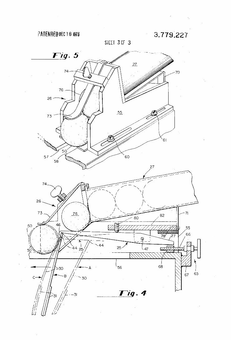
3.779.221 PATENIEUUEC 18 I975 SHEET 30F 3
/66 M22?) 55
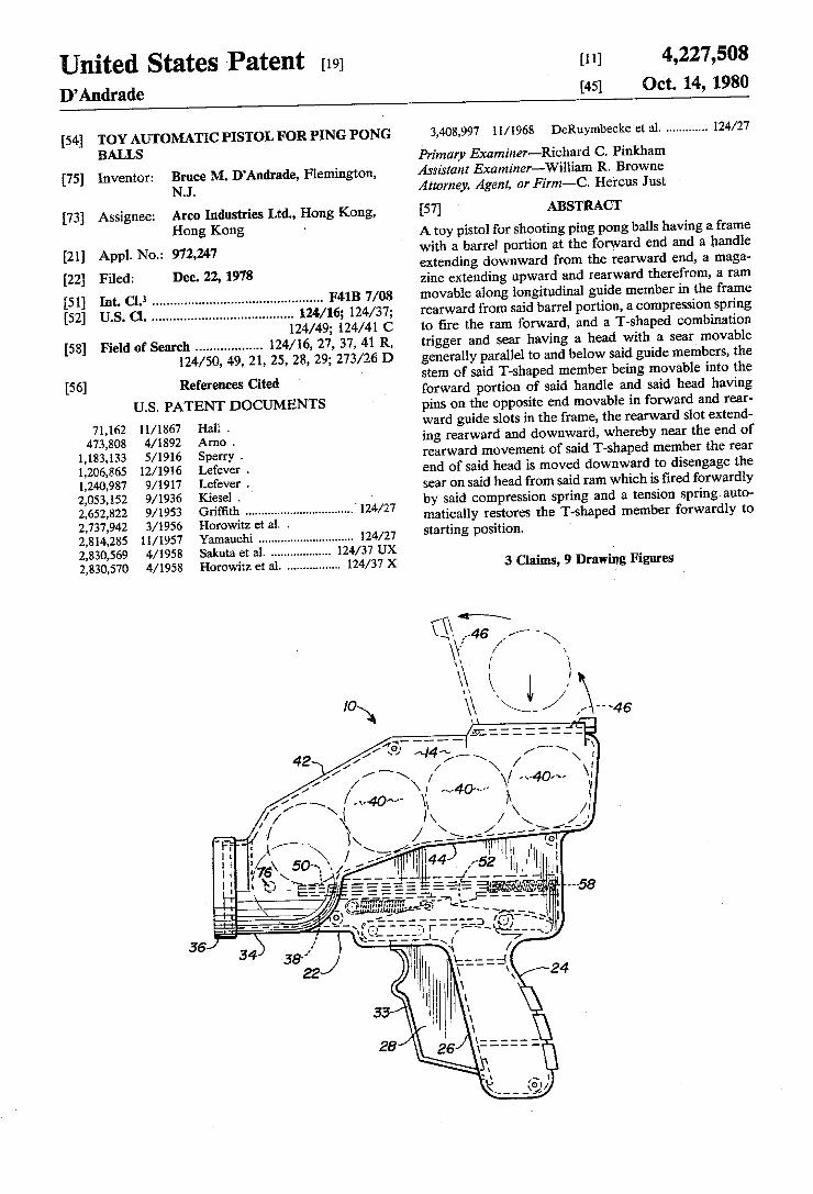
United States Patent [191 D’Andrade
[54] TOY AUTOMATIC PISTOL FOR PING PONG BALLS
[75] Inventor: Bruce M. D’Andrade, Flemington, NJ.
[73} Assignee: Arco Industries Ltd., Hong Kong, Hong Kong -
[21] Appl. No.: 972,247 [22] Filed: Dec. 22, 1978
[51] Int. Cl.3 .............................................. .. F418 7/08 [52] US. Cl. ...................................... .. 124/16; 124/37;
124/49; 124/41 C [58] Field of Search ................. .. 124/16, 27, 37, 41 R,
124/50, 49, 21, 25, 28, 29; 273/26 D
[56] References Cited U.S. PATENT DOCUMENTS
71,162 11/1867 Hall . 473,808 4/1892 Arno .
1,183,133 5/1916 Sperry . 1,206,865 12/1916 Lefever . 1,240,987 9/1917 Lefever . 2,053,152 9/1936 Kiesel . ’ 2,652,822 9/1953 Griffith ................................ ..' 124/27 2,737,942 3/1956 Horowitz et a1. . 2,814,285 11/1957 Yamauchi ............................ .. 124/27
2,830,569 4/1958 Sakuta et a1. 2,830,570 4/1958 Horowitz et a1. ............... .. 124/37 X
[11] 4,227,508 [45] Oct. 14, 1980
3,408,997 11/ 1968 DeRuymbecke et a1. ........... .. 124/27
Primary Examiner—Richard C. Pinkham Assistant Examiner-William R. Browne Attorney, Agent, or Firm—C. Hercus Just
[57] ABSTRACT A toy pistol for shooting ping pong balls having a frame with a barrel portion at the forward end and a handle extending downward from the rearward end, a maga zine extending upward and rearward therefrom, a ram movable along longitudinal guide member in the frame rearward from said barrel portion, a compression spring to tire the ram forward, and a T-shaped combination trigger and sear having a head with a sear movable generally parallel to and below said guide members, the stern of said T-shaped member being movable into the forward portion of said handle and said head having pins on the opposite end movable in forward and rear- a ward guide slots in the frame, the rearward slot extend ing rearward and downward, whereby near the end of rearward movement of said T-shaped member the rear end of said head is moved downward to disengage the sear on said head from said ram which is ?red forwardly by said compression spring and a tension spring-auto matically restores the T-shaped member forwardly to starting position.
3 Claims, 9 Drawing Figures
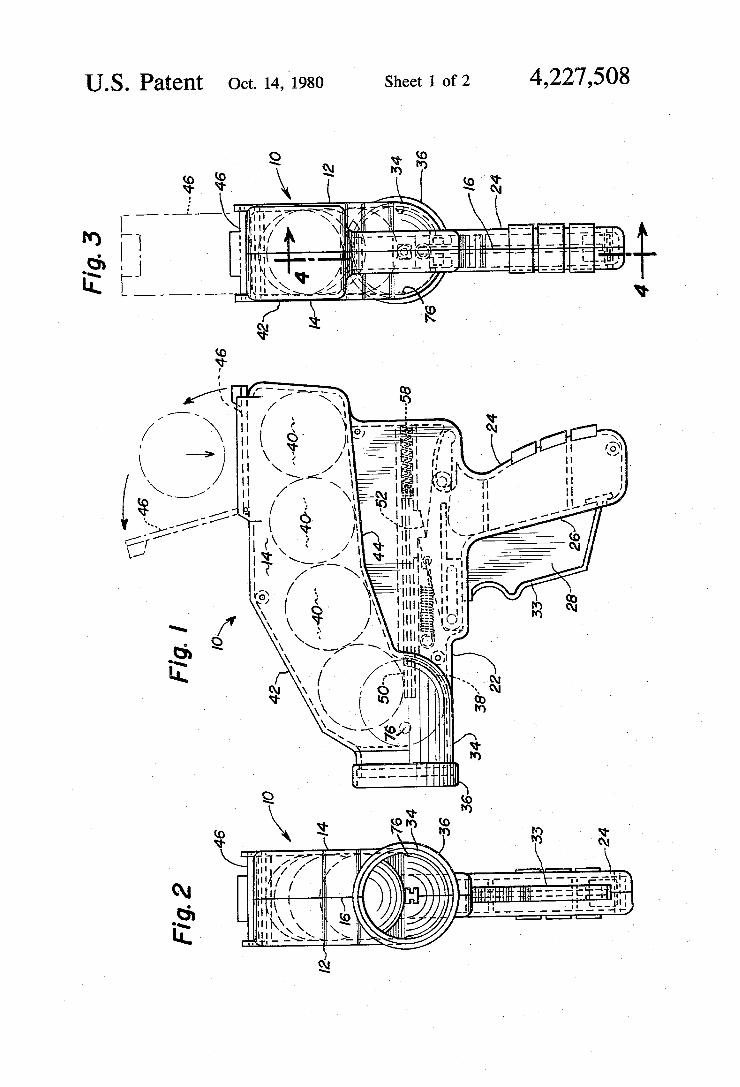
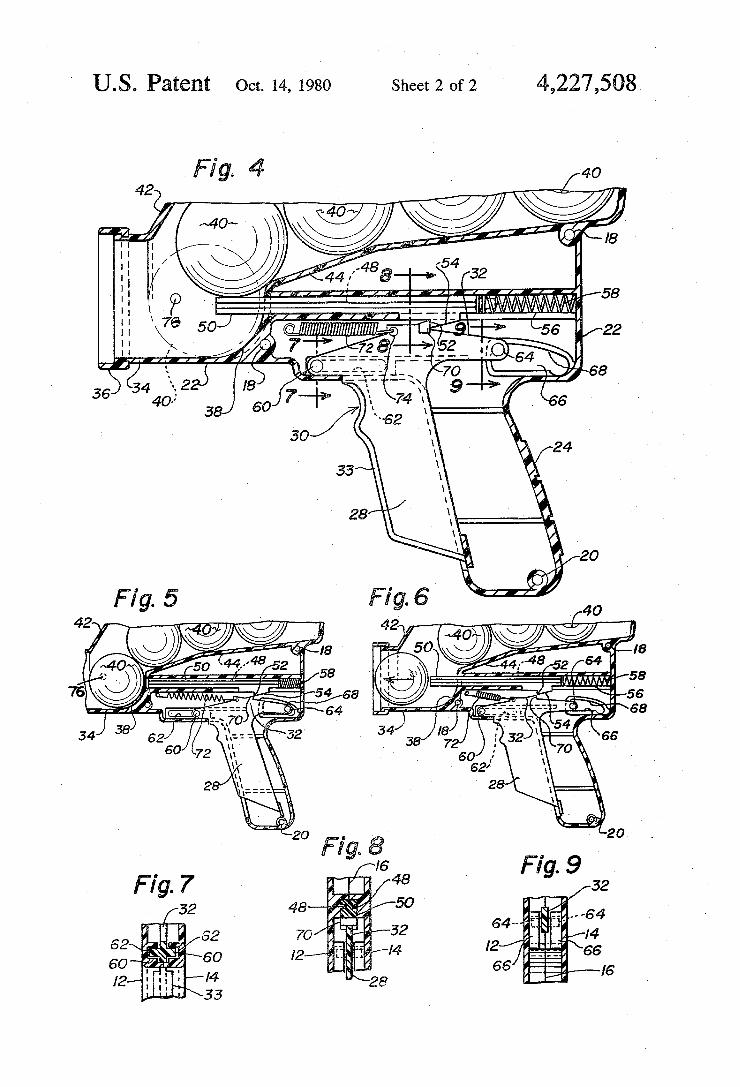
U.S. Patent Oct. 14,1980 Sheet 2 052 ' 4,227,508
'e "5 56 “Le 68
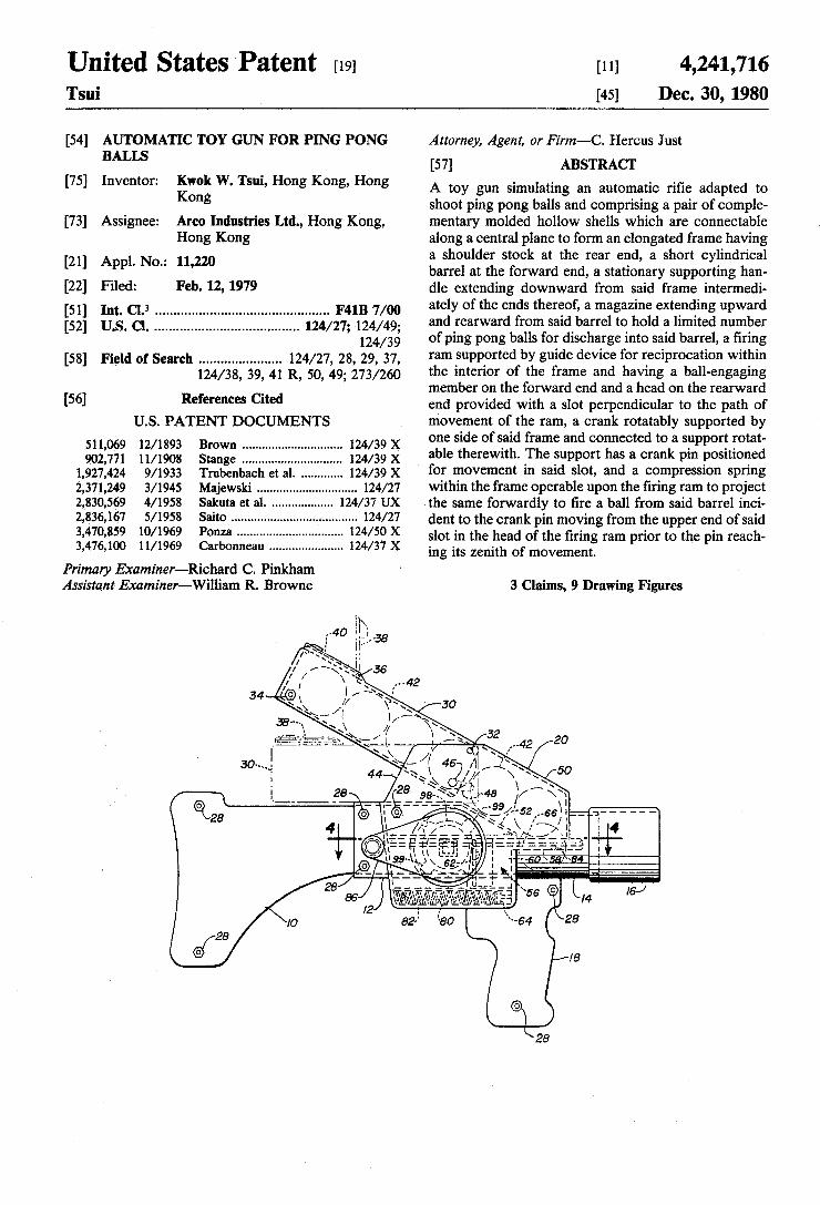
United States Patent [19] [11] 4,241,716 Tsui [45] Dec. 30, 1980
[54] AUTOMATIC TOY GUN FOR PING PONG Attorney, Agent, or Firm-C. Hercus Just BALLS
[75] Inventor: Kwok W. Tsui, Hong Kong, Hong Kong
[73] Assignee: Arco Industries Ltd., Hong Kong, Hong Kong
[21] Appl. No.: 11,220
[22] Filed: Feb. 12, 1979 [51] Int. Cl.3 .............................................. .. F41B 7/00
[52] US. Cl. ...................................... .. 124/27; 124/49; 124/39
[58] Field of Search ..................... .. 124/27, 28, 29, 37, 124/38, 39, 41 R, 50, 49; 273/260
[56] References Cited U.S. PATENT DOCUMENTS
511,069 12/1893 Brown ............................. .. 124/39x 902,771 11/1908 Stange ............... .. .. 124/39 x
1,927,424 9/1933 Trubenbach et a1. 124/39 X 2,371,249 3/1945 Majewski . . . . . . . . . . . . . . . . . .. 124/27
2,830,569 4/1958 Sakuta et a1. 124/37 UX 2,836,167 5/1958 Saito . . . . . . . . . . . . . . . . . . . . . .. 124/27.
3,470,859 10/1969 Ponza ..... .. 124/50 X 3,476,100 11/1969 Carbonneau ..................... .. 124/37 X
Primary Examiner-Richard C. Pinkham Assistant Examiner-William R. Browne
[57] ABSTRACT A toy gun simulating an automatic ri?e adapted to shoot ping pong balls and comprising a pair of comple mentary molded hollow shells which are connectable along a central plane to form an elongated frame having a shoulder stock at the rear end, a short cylindrical barrel at the forward end, a stationary supporting han dle extending downward from said frame intermedi ately of the ends thereof, a magazine extending upward and rearward from said barrel to hold a limited number of ping pong balls for discharge into said barrel, a ?ring ram supported by guide device for reciprocation within the interior of the frame and having a ball-engaging member on the forward end and a head on the rearward end provided with a slot perpendicular to the path of movement of the ram, a crank rotatably supported by one side of said frame and connected to a support rotat able therewith. The support has a crank pin positioned for movement in said slot, and a compression spring within the frame operable upon the ?ring ram to project the same forwardly to ?re a ball from said barrel inci dent to the crank pin moving from the upper end of said slot in the head of the ?ring ram prior to the pin reach ing its zenith of movement'
3 Claims, 9 Drawing Figures
28
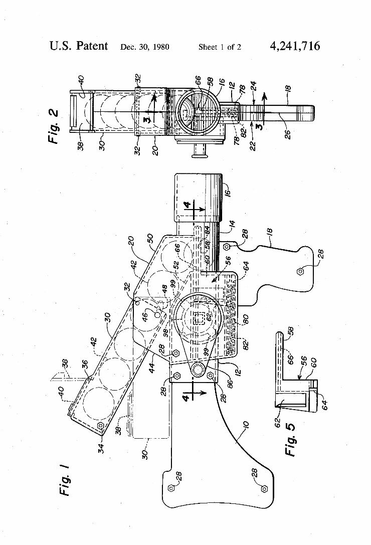
US. Patent Dec. 30, 1980 Sheet 1 of2 4,241,716
VN A\\INN
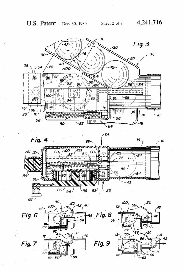
4,241,716 US. Patent Dec. 30, 1980 Sheet 2 of2
32
F ig; 3 24
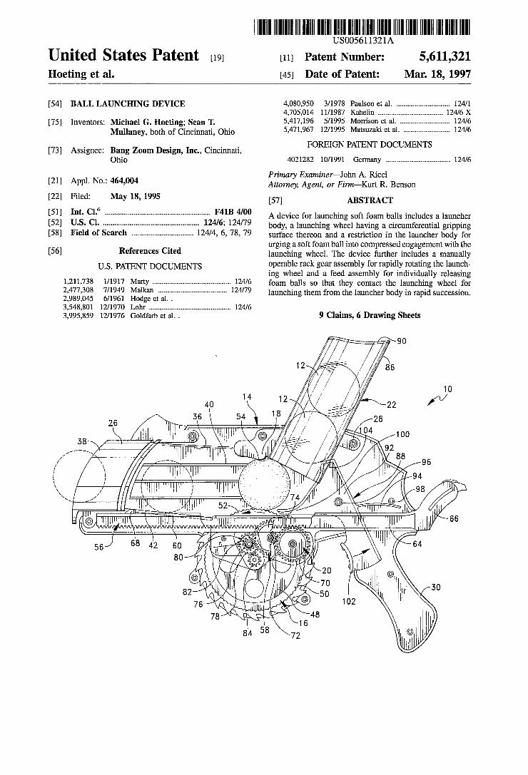
lllllllllllllllllllllllllllIlllllllllllllllllllllllllllllllllllllllllllllll USOO5611321A
United States Patent [19] [11] Patent Number: 5,611,321 Hoeting et al. [45] Date of Patent: Mar. 18, 1997
[54] BALL LAUNCHING DEVICE 4,080,950 3/1978 Paulson m1. ........................... .. 124/1 4,705,014 11/1987 Kahelin ........... .. .124/6X
Inventors: Michael G. Hoeting; Sean T. 5,417,196 5/1995 Morrison CI 2.1. . 124/6 Mullaney7 both of Cincinnati, 5,471,967 12/1995 Matsuzaki 61 a1. ....................... .. 124/6
FOREIGN PATENT D MENT [73] Assignee: Bang Zoom Design, Inc., Cincinnati, OCU S
Ohio 4021282 10/1991 Germany ................................. .. 124/6
Primary Examiner—.lohn A. Ricci [21] Appl' No" 464’004 Attorney, Agent, or Firm-Kurt R. Benson
[22] Filed: May 18, 1995 [57] ABSTRACT 6
[51] Int. Cl. ...................................................... .. F41B 4/00 A device for launching Soft foam balls includes a launcher [52] US. Cl. ................. .. 124/6; 124/79 body, a launching wheel having a Circumferential gripping
of Search ............................... .. 6, 78, Sui-face thereon and a restriction in the launcher for
_ urging a soft foam ball into compressed engagement with the [56] References Clted launching wheel. The device further includes a manually
Us. PATENT DOCUMENTS operable rack gear assembly for rapidly rotating the launch ing wheel and a feed assembly for individually releasing
1,211,738 1/1917 Marty ........................................ .. 124/6 foai'n so that they Contact the launching whsel for 2,477,308 7/1949 Malkan ................................... .. 124/79 launching them from the launcher body in rapid Succession 2,989,045 6/1961 Hodge et a1. . 3,548,801 12/1970 Lohr .......................................... .. 124/6
3,995,859 12/1976 Goldfarb et a1. . 9 Claims, 6 Drawing Sheets
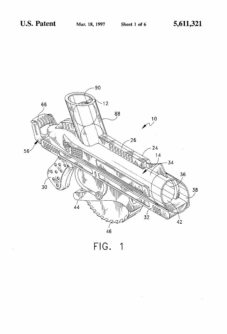
US. Patent Mar. 18, 1997 Sheet 1 0f 6 5,611,321
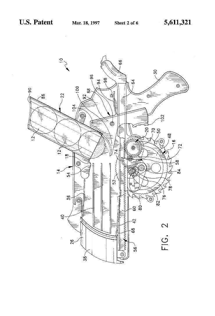
US. Patent Mar. 18, 1997 Sheet 2 of 6 5,611,321
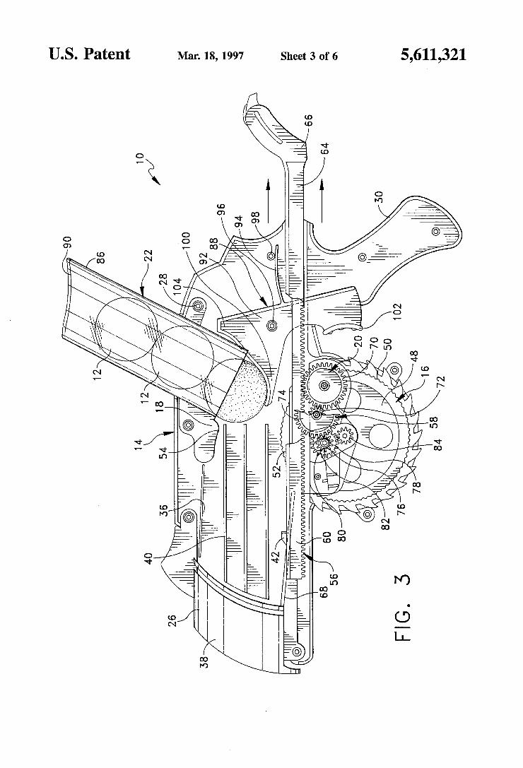
US. Patent Mar. 18, 1997 Sheet 3 of 6 5,611,321
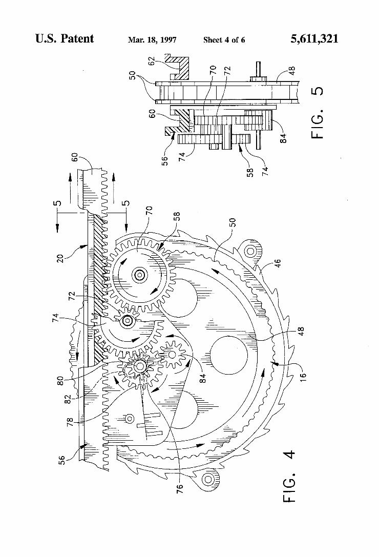
US. Patent Mar. 18,1997 Sheet 4 of6 5,611,321
mum. (2 I
I
a E .@ ~N% g'wiA
wmwom 3 Mar‘: “WW; @_ a _ Z” 1%
a E a ‘ _____ ‘ ~_ ___:
3 .lll . Q m 0N
1:
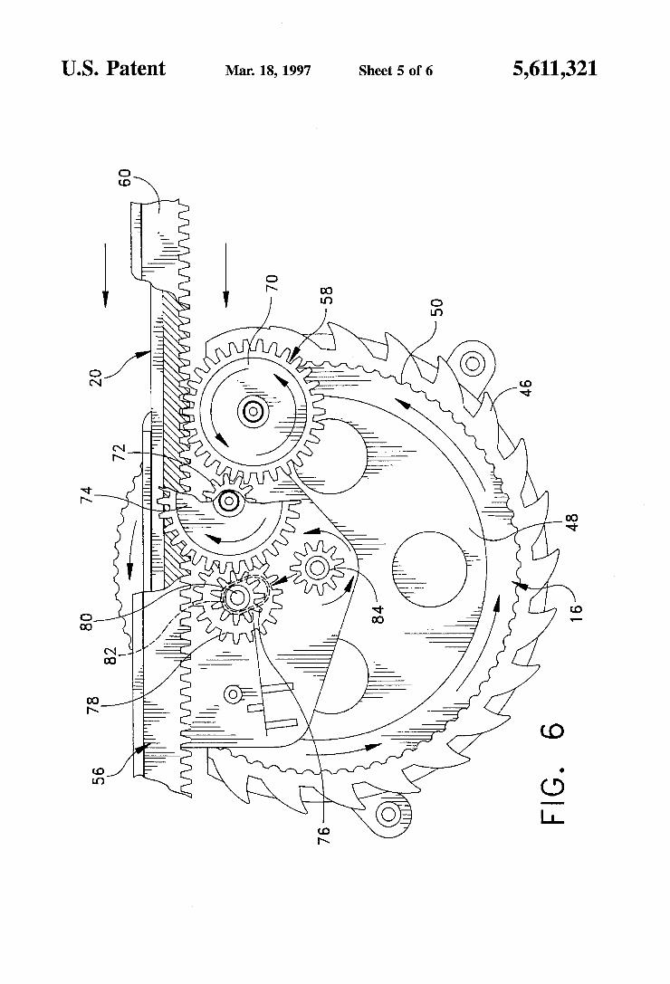
US. Patent Mar. 18, 1997 Sheet 5 0f 6 5,611,321
60
2K
H ]||"'
70
' 58
76
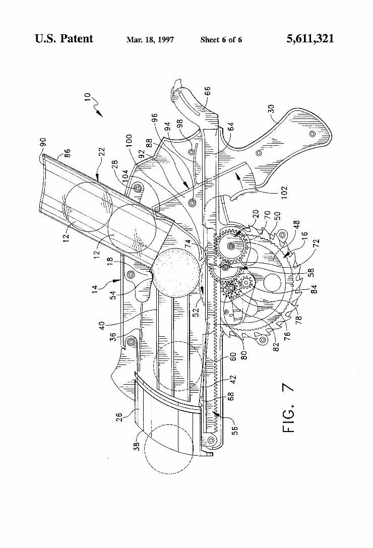
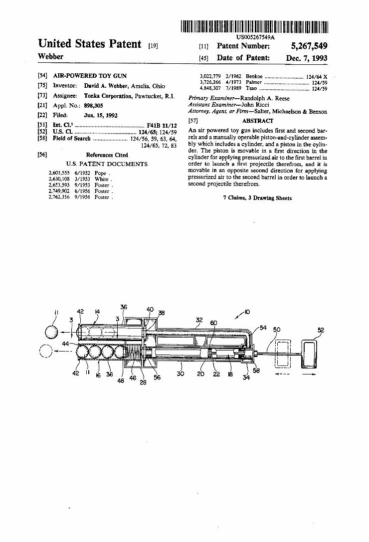
United States Patent [19] lllllllllllllllllllllllllllllllllllllllllllllllllllllllllllllllllllllllllll
US005267549A
[11] Patent Number: 5,267,549 Webber 45 Date of Patent: Dec. 7 1993 9
[54] AIR-POWERED TOY GUN 3,022,779 2/1962 Bcnkoe ........................... .. 124/64X 3,726,266 4/1973 Pal . . . . . . . . . . . . .. 124/59
[75] l?vcmoh David A- Webber, Amelia, Ohio 4,848,307 7/1989 .................................. .. 124/59
[73] Assignee: Tonka Corporation, Pawtucket, RI. priman, Exammer__Rando1ph A_ Reese [2]] App]. N05 898,305 Assistant Examiner-John Ricci ‘ [22] F1 d J 15 1992 Attorney, Agent, or Finn-Salter, Michaelson 8e Benson
[51] 11:6 5 m , F41B 11/12 [57] ABS Cr 11 . . ............................................ .. _
[52] us. 01. ............................. .. 124/65- 124/59 An air P°wered my 8"“ mdudes ?rs‘ and 5mm‘ bar‘ [58]‘ Field of Search ..................... .. 124/56, 59’, 63, 64, ‘e15 an‘? a “WWW °P¢r.ab1'= pism'anfi'cyliflder me!“
124/65, 72’ 83 bly which includes a cylinder, and a piston 1n the cylin . der. The piston is movable in a ?rst direction in the
[56] References Clted cylinder for applying pressurized air to the ?rst barrel in US. PATENT DOCUMENTS
2,601,555 6/1952 2,630,108 3/1953 2,653,593 9/1953 2,749,902 6/ 1956 2,762,356. 9/1956
Pope .
White .
Foster .
Foster .
Foster .
order to launch a ?rst projectile therefrom, and it is movable in an opposite second direction for applying pressurized air to the second barrel in order to launch a second projectile therefrom.
7 Claims, 3 Drawing Sheets
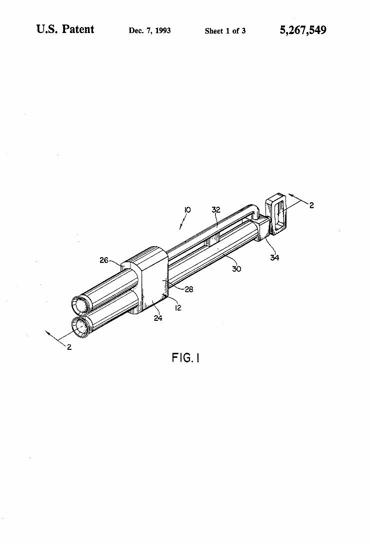
Sheet 1 of 3 5,267,549 US. Patent Dec. 7, 1993
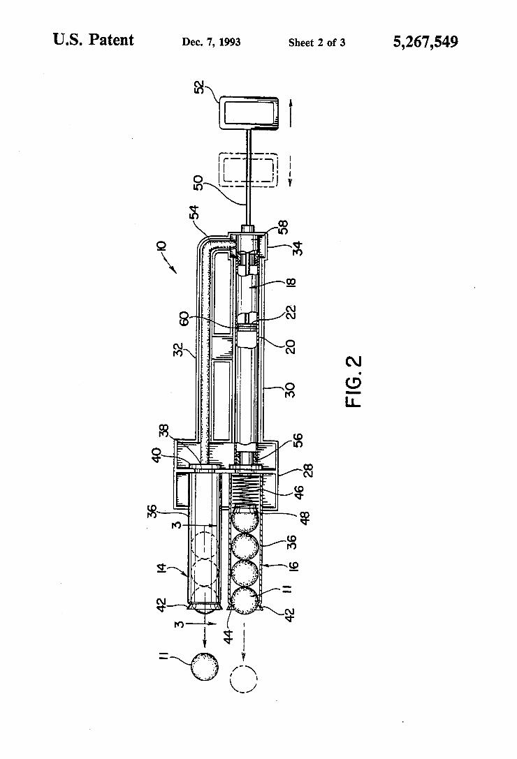
US. Patent Dec. 7, 1993 Sheet 2 of 3 5,267,549
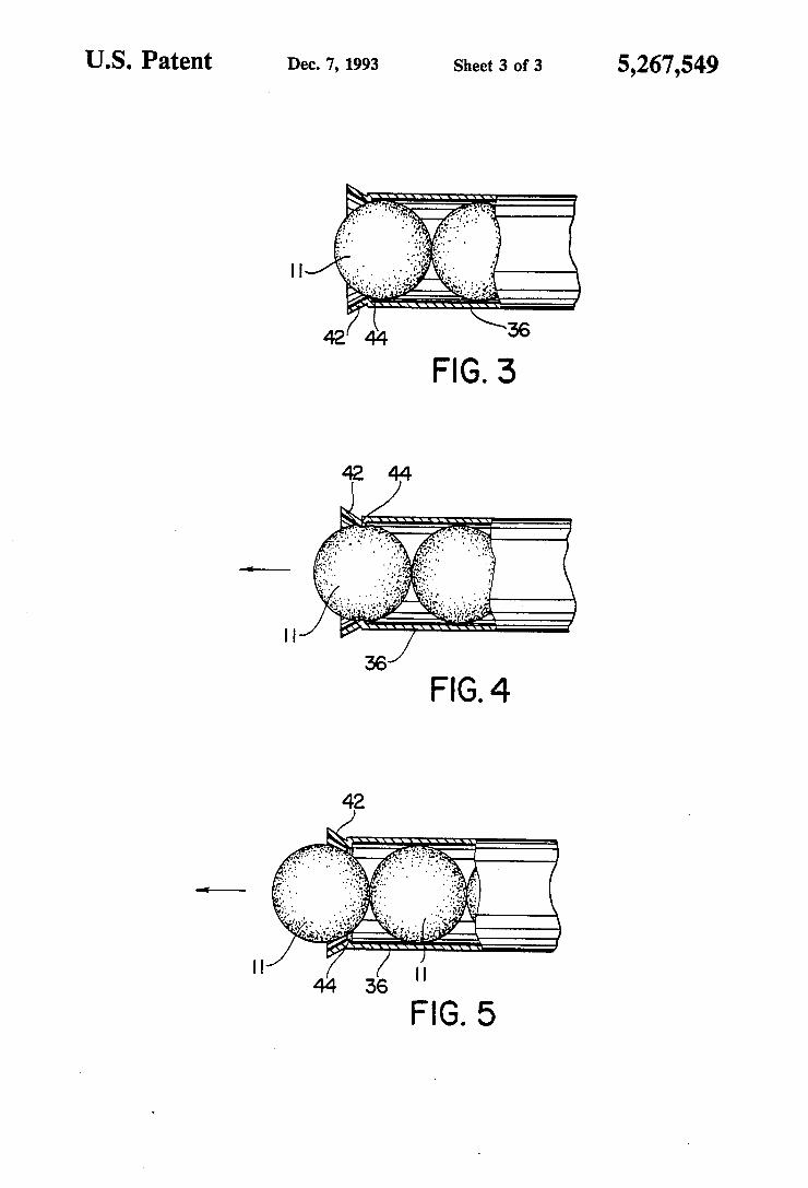
U.S. Patent Dec. 7, 1993 Sheet 3 of 3 5,267,549
1
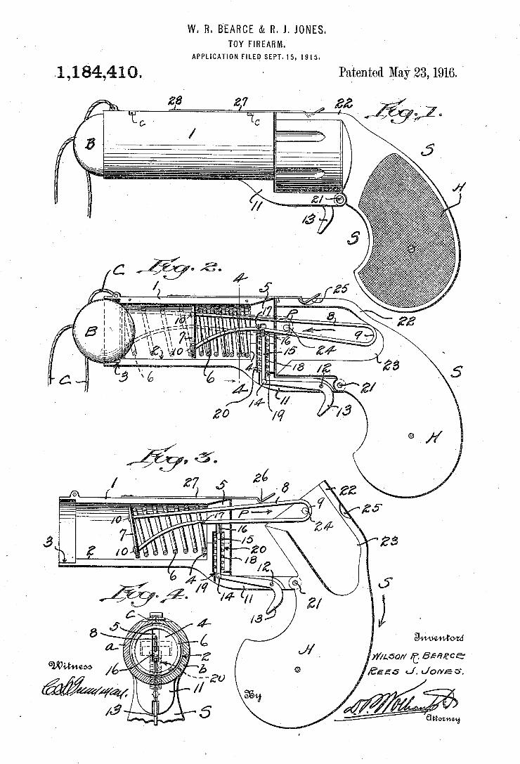
W. R. B'EARCE & R. J. JONES. TOY’ FIREARM.
APPLICATION FILED SEPT-15,1915.
A1 , 1 84,41. > Patented May 23; 71916. '
)Y/LdO/Y It. ISM/ace E556 <J. Jon/E 5.
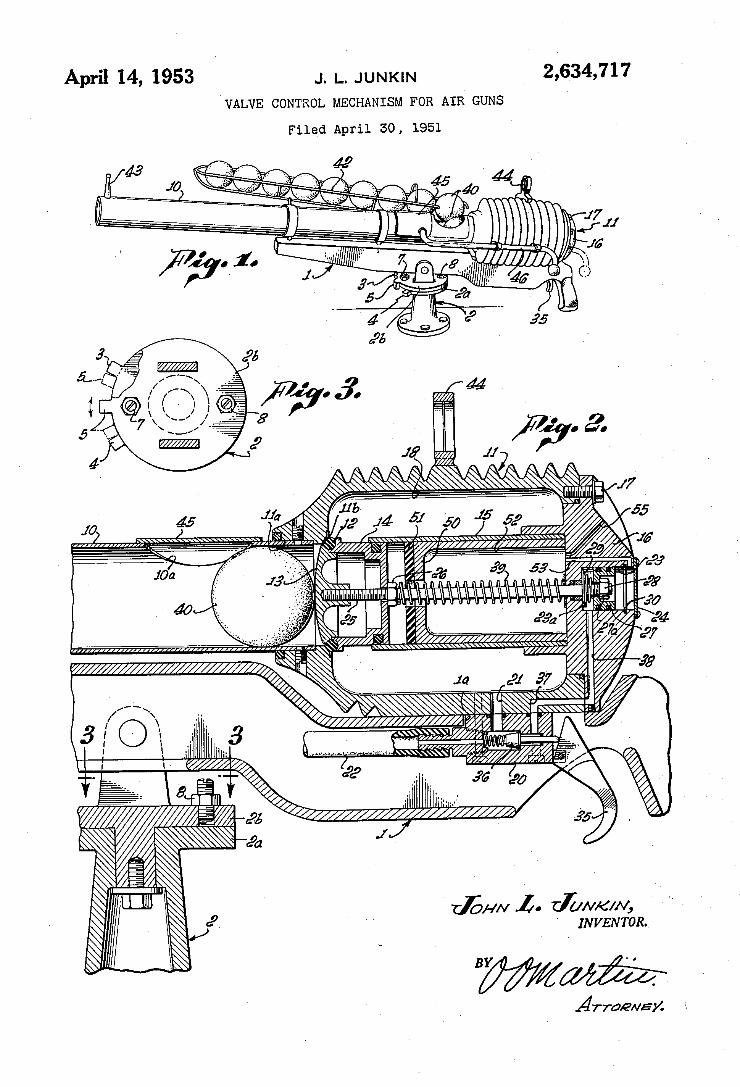
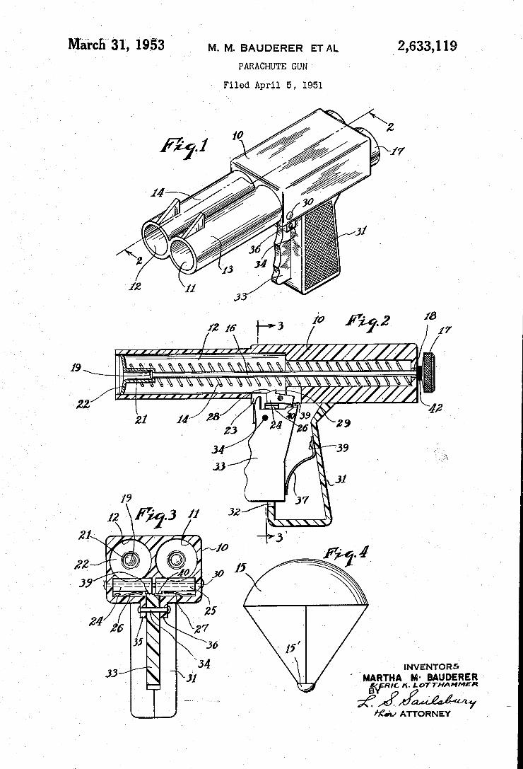
Márcfî‘ßl, 1953 _ M. M. BAUDERER ET AL _2,633,119 PARACHUTE GUN
Filed April 5, 1951
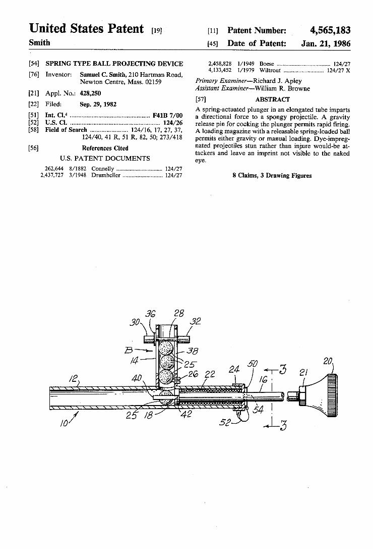
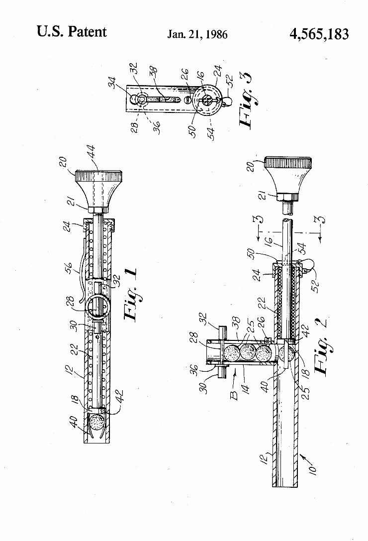
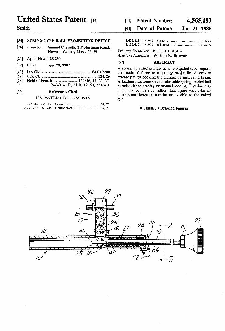
Unlted States Patent [19] [11] Patent Number: 4,565,183 Smith [45] Date of Patent: Jan. 21, 1986
[54] SPRING TYPE BALL PROJECI‘ING DEVICE 2,458,828 l/ 1949 Boese .................................. .. 124/27 4,133,452 1 1979 W'] ......................... ..
[76] Inventor: Samuel c. Smith, 210 Hartman Road, / ' "out mm X Newmn Centre, Mass‘ 02159 Primary Examiner-Richard J. Apley
[21] Appl No. 428 250 Assistant Examiner-Wi1liam R. Browne . .1 ,
57 AB T [22] Filed: Sep. 29, 1982 [ 1 . s .RACT .
A spring-actuated plunger in an elongated tube imparts Int. CL“ .............................................. .. F41B 7/00 a directional force to a spongy projectile. A gravity
_ release pin for cocking the plunger permits rapid ?ring. [53] Field of Search ..................... .. 124/ 16, 17, 27, 37, A loading magazine with a releasable spring-loaded ball
124/40, 41 R, 51 R, 82, 50; 273/413 perrréits eithetr‘lgravtity or rl’nanulal loading. Dyel-tijnLpreg 56 References C-t d na e proJec 1 es s un rat er t an injure wou - e at
[ 1 l e tackers and leave an imprint not visible to the naked U.S. PATENT DOCUMENTS eye’
262,644 8/1882 Connelly ............................. .. 124/27
2,437,727 3/1948 Drumheller ......................... .. 124/27 8 Claims, 3 Drawing Figures
36 28 30 / 32
B x ‘
/4
/2) 40 ‘
llllllllllllllllllllllllll
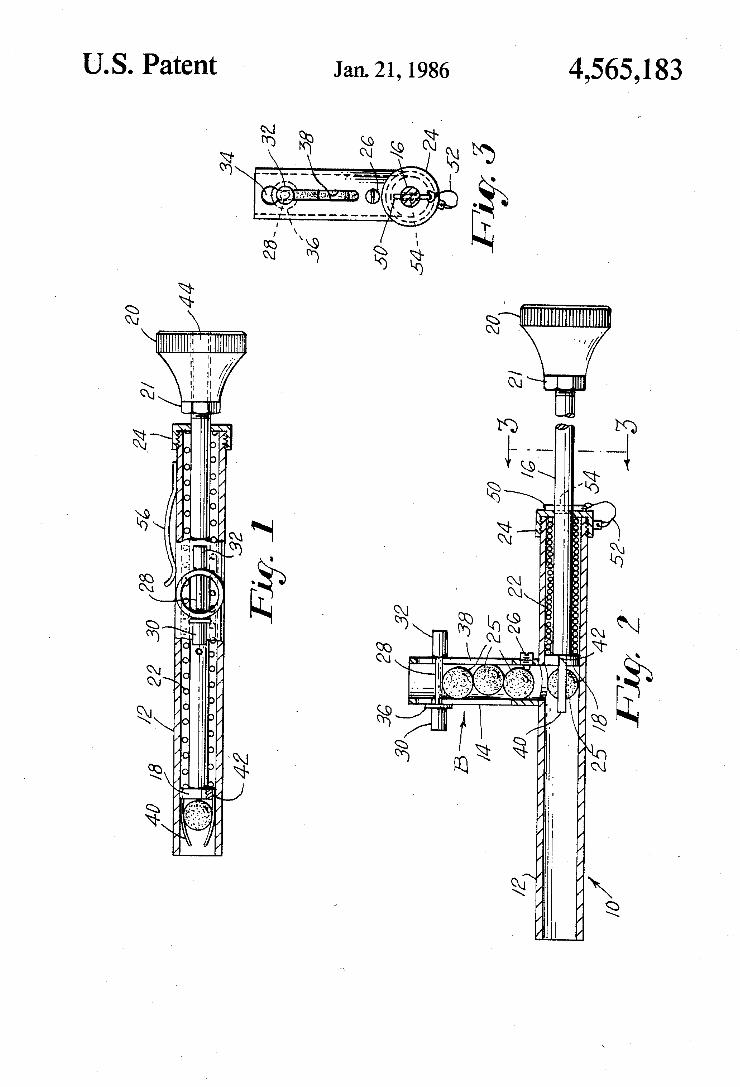
4,565,183 Jan. 21,1986 US. Patent
% MN
///// >///<//////// ///////////
///AA, g
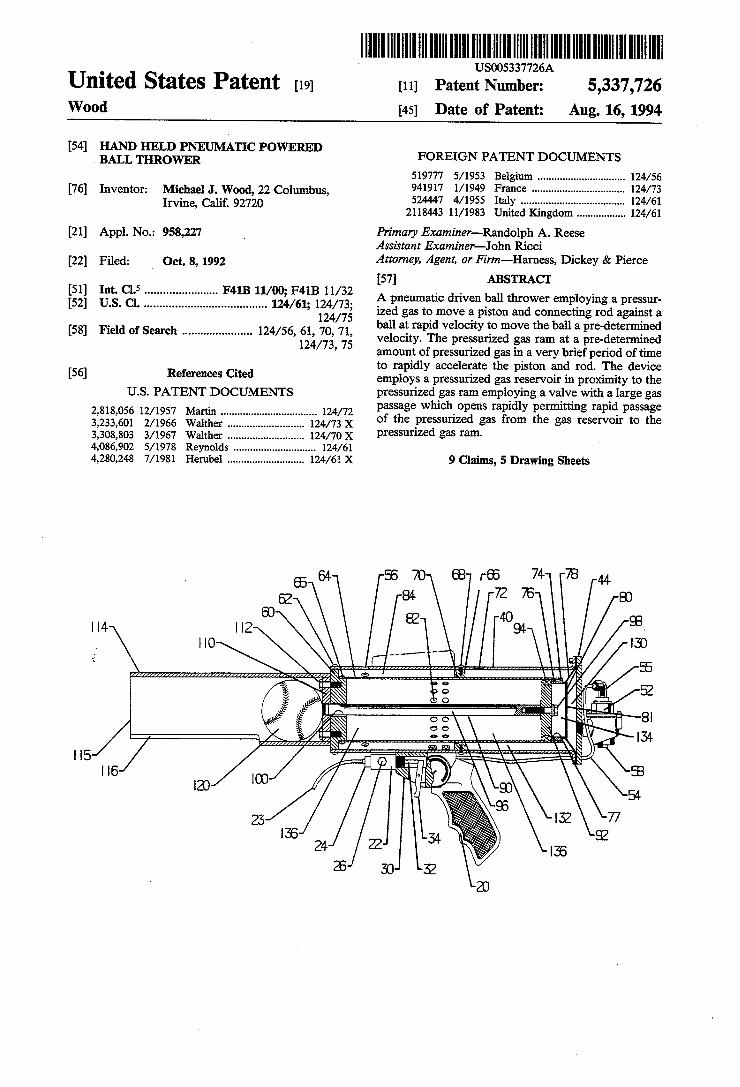
US005337726A
Patent Number:
Date of Patent 5,337,726
Aug. 16, 1994 [11]
[45]
United States Patent [191 Wood
[54] HAND HELD PNEUMATIC POWERED BALL THROWER FOREIGN PATENT DOCUMENTS
519777 5/1953 Belgium 124/56 124/73
.. 124/61 [76] Inventor: Michael J. Wood, 22 Columbus, 941917 V1949 France Irvine, Calif. 92720
5244-47 4/1955 Italy ..
2118443 11/1983 United Kingdom Primary Examiner-Randolph A. Reese
Asszlttant Examiner-John Ricci
124/61
[21] App1.No.: 958,227
Attorney, Agent, or Firm—-Harness, Dickey & Pierce
[57] [22] Filed: _ Oct. 8, 1992
ABSTRACT
A pneumatic driven ball thrower employing a pressur ized gas to move a piston and connecting rod against a ball at rapid velocity to move the ball a pre-determined velocity. The pressurized gas ram at a pre-determined amount of pressurized gas in a very brief period of time to rapidly accelerate the piston and rod. The device
2,5 ,5 mnnnv 1M4Oyl. 12277 11 / B ,4 1.! 12 4Q 61 F/ ,0: w,“ a /1 4 1" 2 1.." 1
h n" m
e
.N S 5. - ‘I ma 0 S. M f» . .8 .mU E um. m. 55 5 [.l. .l.
[56] References Cited employs a pressurized gas reservoir in proximity to the US. PATENT DOCUMENTS
2,818,056 12/1957 Martin
pressurized gas ram employing a valve with a large gas passage which opens rapidly permitting rapid passage
124/72 of the pressurized gas from the gas reservoir to the pressurized gas ram.
124/73 X 3,233,601 2/1966 Walther 124/ 70 X
124/61 124/61 X
3,308,803 3/1967 Walther 4,086,902 5/1978 Reynolds
9 Claims, 5 Drawing Sheets 4,280,248 7/1981 Herubel
.w 5 Q ole ulw mm mm mm I lk H W M ._i_.z a. Q
B t .\
I r
, viz/Ila (III) llrill/llIIIIIIll/IllllIlI/llllllllI/l/ll)
2 1 w I I I IIIIIIIIIII
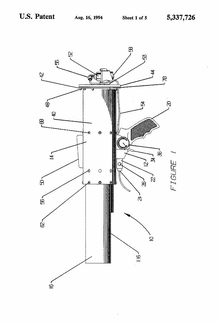
US. Patent Aug. 16, 1994 Sheet 1 of 5 5,337,726
"mm
\ MEDQNK
m:
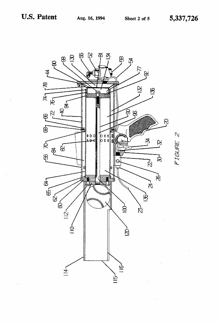
US. Patent Aug. 16, 1994 Sheet 2 of 5 5,337,726
$4 539%
N mtbwwk
mm; mm
/ /
000 000m
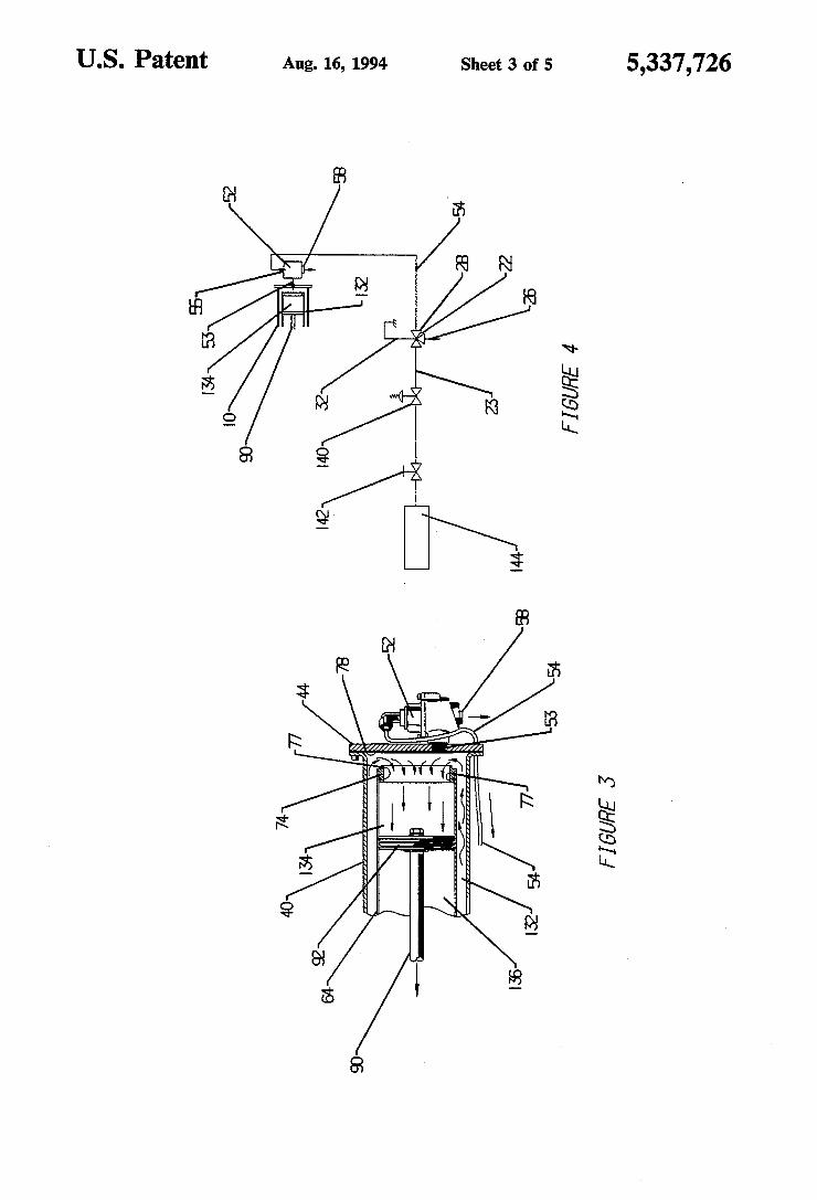
US. Patent Aug. 16, 1994 Sheet 3 of 5 5,337,726
M, mtbgm
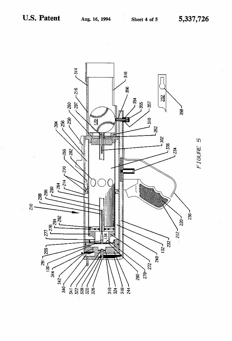
U.S.I Patent Aug. 16, 1994 Sheet 4 of 5 5,337,726
m MQDQNK
1N Em wmm own mwm NNm _ vm own
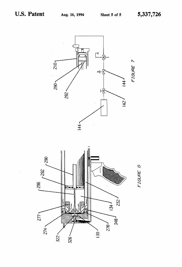
5,337,726
N MQDQNK
3.. N:
5 ,m 5 w
& /
M
m E
m,
w N8
A US. Patent
Q mfbmwk
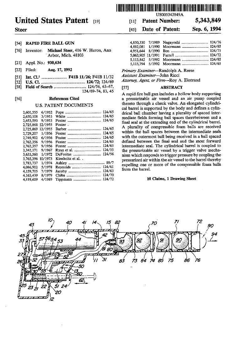
_ US005343849A
United States Patent [191 [11] Patent Number: 5,343,849 Steer [45] Date of Patent: Sep. 6, 1994
[54] RAPID FIRE BALL GUN 4,833,330 7/19s9 llzlliagayoshi .......................... .. 124/26 ,s , 1 1/1990 66mm 24 5
[76] Inventor: Michael Steer, 416 W- Huron, Ann 4,951,644 8/1990 B011 ...... 124/75 ’Arbor, Mich. 48103 5,063,90511/1991 Farrell ..... .. 124/72
5,113,842 5/1992 Moormann. 124/65 [21] APP1-N°-= 930,634 5,115,794 5/1992 Moormann .......................... .. 124/65
[22] Filed: Aug- 17’ 1992 Primary Examiner—-Randolph A. Reese
[51] 1111. c1.5 ...................... .. F41B 11/26;F41B11/32 Assistant Examl'1er—§°hn Rm [52] US. 01. ....................................... .. 124/72; 124/69 Attorney, Agent’ affirm-ROY A- Ekstrand [58] Field of Search ............................ .. 124/56, 63-67, [57] ABSTRACT
124/69 74’ 83’ 45 A rapid ?re ball gun includes a hollow body supporting [56] References Cited at pressurizable air vessel and an air pump coupled
UDS. PATENT DOCUMENTS thereto through a check valve. An elongated cylindri cal barrel is supported by the body and de?nes a cylin drical ball chamber having a plurality of spaced inter mediate ?elds forming ball spaces therebetween and a ?nal seal at the extending end of the cylindrical barrel. A plurality of compressible foam balls are received within the ball spaces between the intermediate seals with the outermost ball being received in a ball spaced de?ned between the ?nal seal and the most forward intermediate seal. The cylindrical barrel is coupled to the pressurizable air vessel by a trigger valve mecha nism which responds to trigger pressure by coupling the pressurized air within the air vessel to the barrel thereby expelling one or more of the compressible foam balls from the barrel.
2,601,555 6/1952 Pope . . . . . . . . . . . . . .. 124/65
2,630,108 3/1953 ' 2,653,593 9/1953 2,725,868 12/1955 2,725,869 12/1955 2,729,207 1/ 1956 2,749,902 6/1956 2,762,356 9/1956 2,762,357 9/ 1956 3,342,171 9/1967 3,633,560 l/l972 3,765,396 10/1973 3,783,737 1/ 1974 4,086,902 5/1978 4,159,705 7/1979 4,163,439 8/1979 4,819,609 4/1989 10 Claims, 1 Drawing Sheet
7/ 72 5 90 1i‘\ 3‘ I/
W )1 .94
I anal}
26 3? // / 23 7324742575 86 76
1 a?'l, 50 r
__ ~-'- -- 564:1, .521.
5 22 5/ 24 23 Z] 20
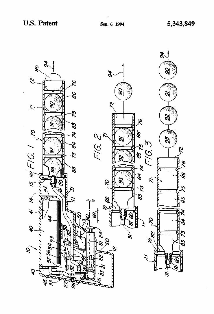
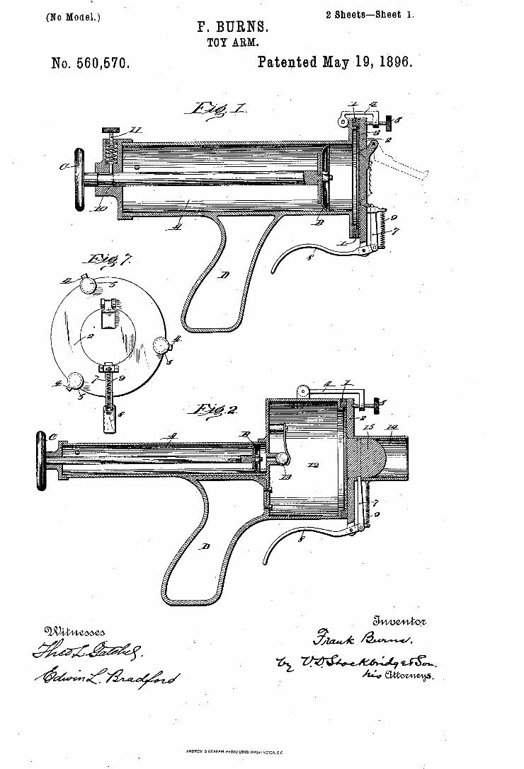
Z‘Sheets-Sheet 1. F. BURNS. TOY ARM
(No Model.)
Patented May '19, 1896. No. 560,570.
2M M.
YPHOTO-UTHQWASNI NGrON. u C
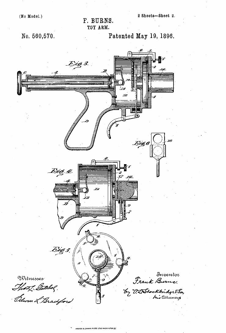
2 Sheets__-Sheet 2.
Patented May 19, 1896.
wad/444,115‘, Ill/16mm .
F. BURNS. (No Model.)
TOY ARM.
No. 560,570.
“ ANDREW B GRAHAM,PHOTO'LITHQWASHINGTON DP
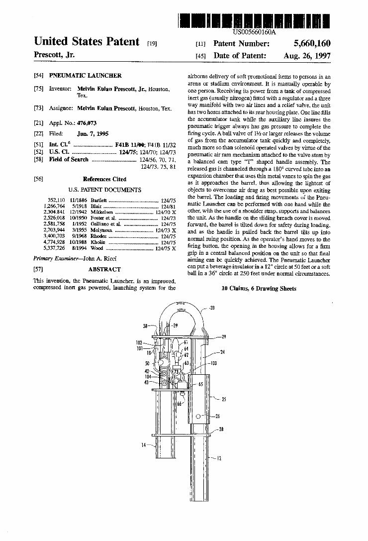
United States Patent [191 Prescott, Jr.
llllllllll 5,660,160
Aug. 26, 1997
US005660160A
[11] Patent Number:
[45] Date of Patent:
[5 4] PNEUMATIC LAUNCHER
[75] Inventor: Melvin Eulan Prescott, Jn. Houston. Tex.
[73] Assignee: Melvin Eulan Prescott, Houston, Tex.
[21] Appl. No.: 476,073
[22] Filed: Jun. 7, 1995
[51] Int. Cl.6 ............................ .. F4113 11/00; F41B 11/32 [52] U.S. Cl. ................................ .. 124/75; 124/70; 124/73 [58] Field of Search ................................ .. 124/56. 70. 71.
124/73, 75. 81
[56] References Cited
U.S. PATENT DOCUMENTS
352,110 11/1886 Bartlett .................................... .. 124/75
1,266,764 5/1918 Blair ........... .. 124/81 2,304,841 1211942 Mikkelsen 124/70 X 2,526,018 10/1950 Foster et a1. . . . . . . . . .. 124/73
2,581,758 1/1952 Galliano et al. . ....... .. 124/75
2,703,944 3/1955 Molyneux 124/73 X 3,400,703 9/1968 Rhodes . . . . . . . . . . . . .. 124/75
4,774,928 10/1988 Kholin . . . . . . . . .. 124/75
5,337,726 8/1994 Wood .................................. .. 124/75 X
Primary Examiner-John A. Ricci
[57] ABSTRACT
This invention, the Pneumatic Launcher. is an improved. compressed inert gas powered. launching system for the
airborne delivery of soft promotional items to persons in an arena or stadium environment. It is manually operable by one person. Receiving its power from a tank of compressed inert gas (usually nitrogen) ?tted with a regulator and a three Way manifold with two air lines and a relief valve. the unit has two hoses attached to its rear housing plate. One line ?lls the accumulator tank while the auxiliary line insures the pneumatic trigger always has gas pressure to complete the ?ring cycle. A ball valve of 11/2 or larger releases the volume of gas from the accumulator tank quickly and completely. much more so than solenoid operated valves by virtue of the pneumatic air ram mechanism attached to the valve stem by a balanced cam type ‘T” shaped handle assembly. The released gas is channeled through a 180° curved tube into an expansion chamber that uses thin metal vanes to spin the gas as it approaches the barrel. thus allowing the lightest of objects to overcome air drag as best possible upon exiting the barrel. The loading and ?ring movements of the Pneu matic Launcher can be performed with one hand while the other. with the use of a shoulder strap. supports and balances the unit. As the handle on the sliding breach cover is moved forward, the barrel is tilted down for safety during loading. and as the handle is pulled back the barrel tilts up into normal ruing position. As the operator’s hand moves to the ?ring button. the opening in the housing allows for a ?rm grip in a central balanced position on the unit so that ?nal aiming can be quickly achieved. The Pneumatic Launcher can put a beverage insulator in a 12" circle at 50 feet or a soft ball in a 36" circle at 250 feet under normal circumstances.
10 Claims, 6 Drawing Sheets
“e i
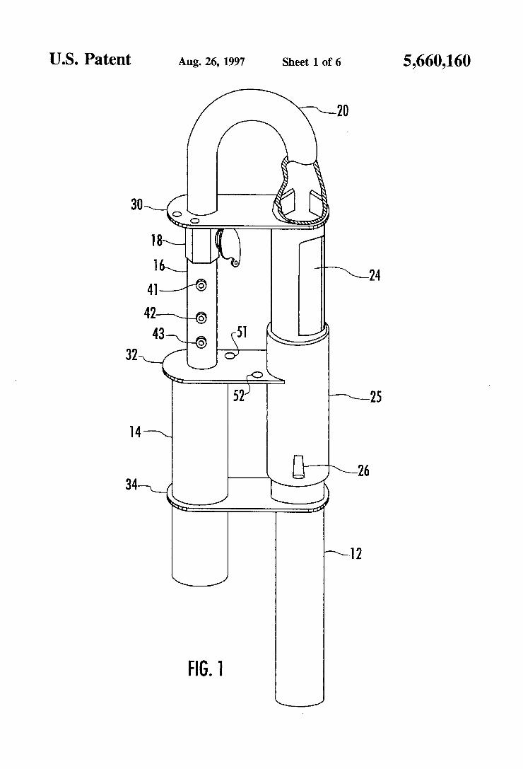
U.S. Patent
34H
Aug. 26, 1997 Sheet 1 0f 6
523
FIG. 1
5,660,160
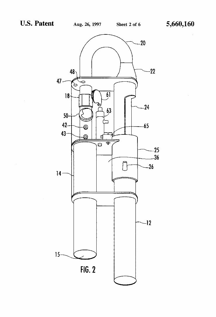
US. Patent Aug. 26, 1997 Sheet 2 of 6 5,660,160
FIG. 2
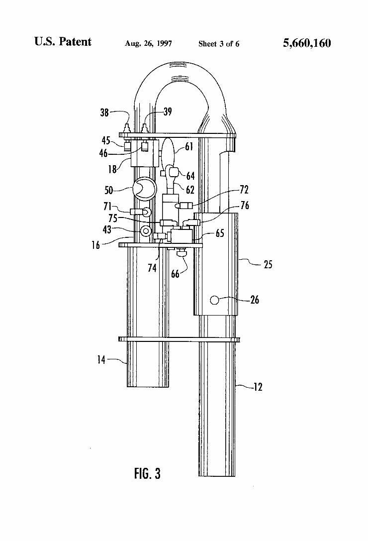
U.S. Patent Aug. 26, 1997 Sheet 3 0f 6 5,660,160
@/"~~L-26
64 62
r'lln/ {~65
55> E
IIH
FIG. 3
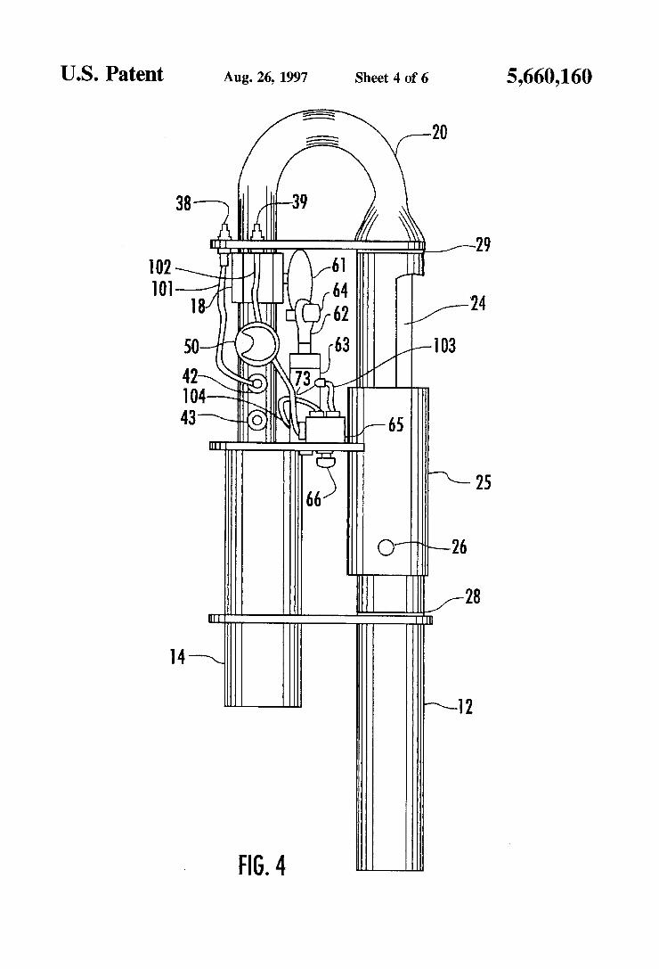
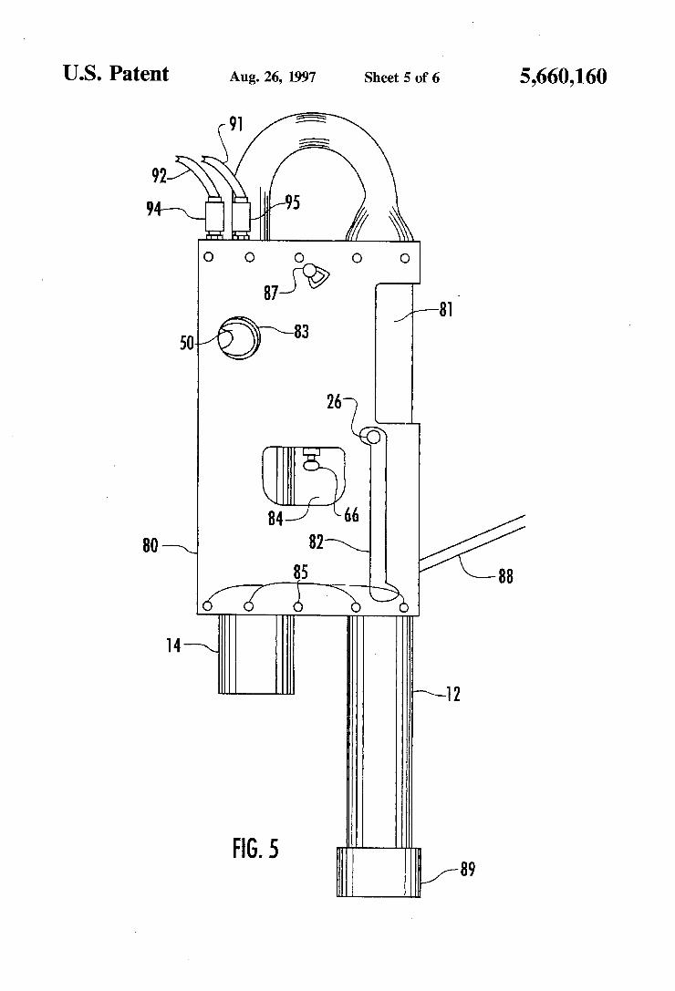
U.S. Patent - Aug. 26, 1997 Sheet 5 0f 6 5
FIG. 5
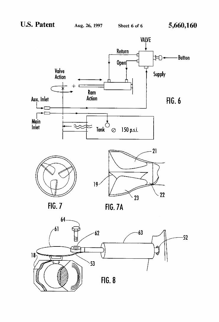
US. Patent Aug. 26, 1997 Sheet 6 of 6 5,660,160
@ I50 p.s.i.
V
W Tunk
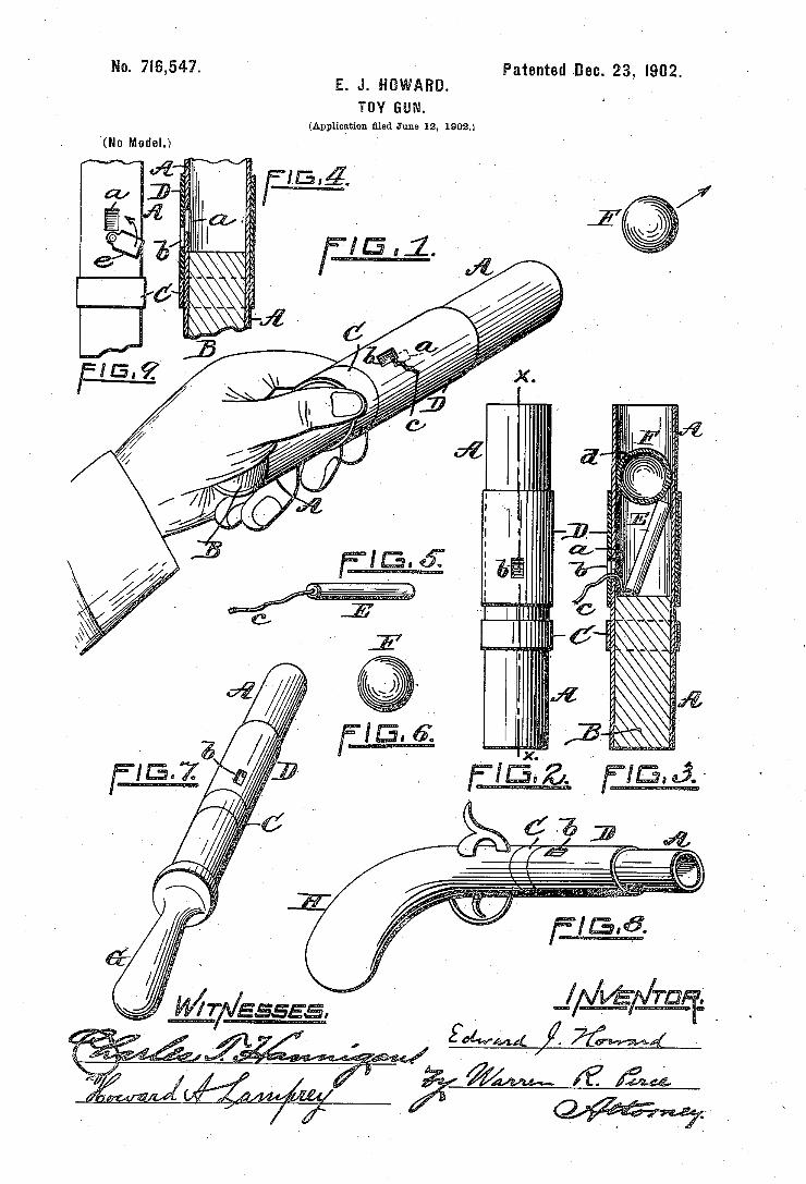
No. 7|5,547. ` Patented Dec. 23, i902. E. J. HÜWARD. 4
TOY GUN. (Application Bled June 12, 1902.)
i
l
f. l
i f Í
„E
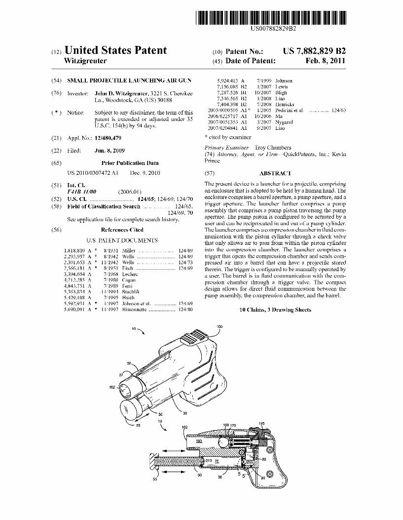
US007882829B2
(12) Ulllted States Patent (10) Patent N0.: US 7,882,829 B2 Witzigreuter (45) Date of Patent: Feb. 8, 2011
(54) SMALL PROJECTILE LAUNCHING AIR GUN 5,924,413 A 7/1999 Johnson 7,156,085 B2 1/2007 Lewis
(76) Inventor: John D. Witzigreuter, 3221 S. Cherokee 7,287,526 B1 10/2007 Bligh La., Woodstock, GA (Us) 30188 7,316,565 B2 1/2008 L139
7,404,398 B2 7/2008 Henrlcks
( * ) Notice: Subject to any disclaimer, the term of this * 1 523mm et a1‘ """"""" " 124/63
patent 15 extended or adjusted under 35 2007/005 1353 Al 3/2007 Nygarrd U50 1540’) by 94 days- 2007/0204841 A1 9/2007 Liao
(21) Appl. No.: 12/480,479 * Cited by examiner
- _ Primary ExamineriTroy Chambers
(22) Flled' Jun‘ 8’ 2009 (74) Attorney, Agent, or FirmiQuickPatents, 1nc.; Kevin
(65) Prior Publication Data Pnnce
US 2010/0307472 A1 Dec. 9, 2010 (57) ABSTRACT
(51) Int C]_ The present device is a launcher for a projectile, comprising F41B 11/00 (200601) an enclosure that is adapted to be held by a human hand. The
(52) us. Cl. ............................ .. 124/65- 124/69- 124/70 enclosure Comprises a barrel ape/“urea a Pump ape/“urea and a
(58) Field of Classi?cation Search ................. .. 124/65 trigger aPermre~ The launcher further Comprises a Pump 1 2 4 /69 70’ assembly that comprises a pump piston traversing the pump
See application ?le for Complete Search history' ’ aperture. The pump piston is con?gured to be actuated by a user and can be reciprocated in and out of a pump cylinder.
56 References Cited The launcher com rises a com ression chamber in ?uid com P P
U.S. PATENT DOCUMENTS
1,818,810 A * 8/1931 Miller ....................... .. 124/69
2,293,957 A * 8/1942 Wells 124/69 2,301,653 A * 11/1942 Wells 124/73 2,566,181 A * 8/1951 Fitch ......................... .. 124/69
3,394,694 A 7/1968 Leclerc 4,212,285 A 7/1980 Cagan 4,843,751 A 7/1989 Ferri 5,363,834 A 11/1994 Stuchlik 5,429,108 A 7/1995 Hsieh 5,592,931 A 1/1997 Johnson et a1. 124/69 5,690,091 A * 11/1997 Bissonnette ................ .. 124/80
munication With the piston cylinder through a check valve that only alloWs air to pass from Within the piston cylinder into the compression chamber. The launcher comprises a trigger that opens the compression chamber and sends com pressed air into a barrel that can have a projectile stored therein. The trigger is con?gured to be manually operated by a user. The barrel is in ?uid communication With the com pression chamber through a trigger valve. The compact design alloWs for direct ?uid communication betWeen the pump assembly, the compression chamber, and the barrel.
10 Claims, 3 Drawing Sheets
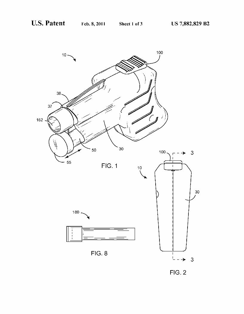
US. Patent Feb. 8, 2011 Sheet 1 013 US 7,882,829 B2
100
FIG. 2
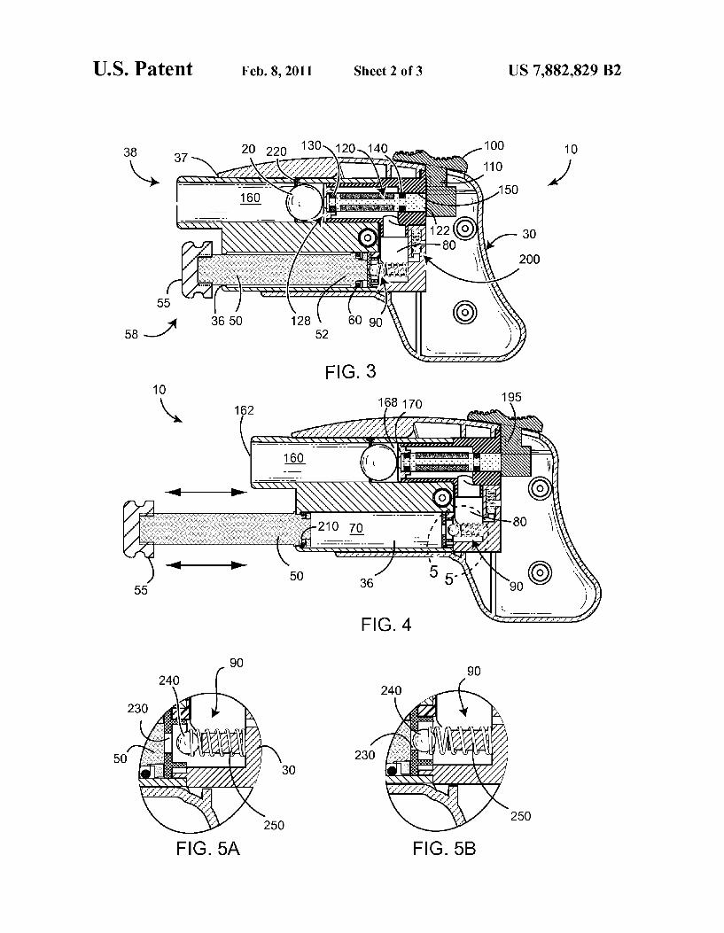
US. Patent Feb. 8, 2011 Sheet 2 of3 US 7,882,829 B2
168170
FIG_ 5B 250
/
FIG_ 5A
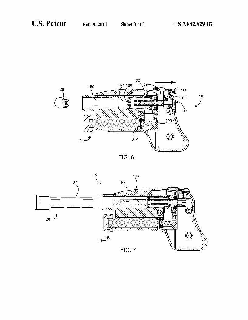
US. Patent Feb. 8, 2011 Sheet 3 of3 US 7,882,829 B2
10 180
80 \\ 160
)
. . . . . , . , I . ‘
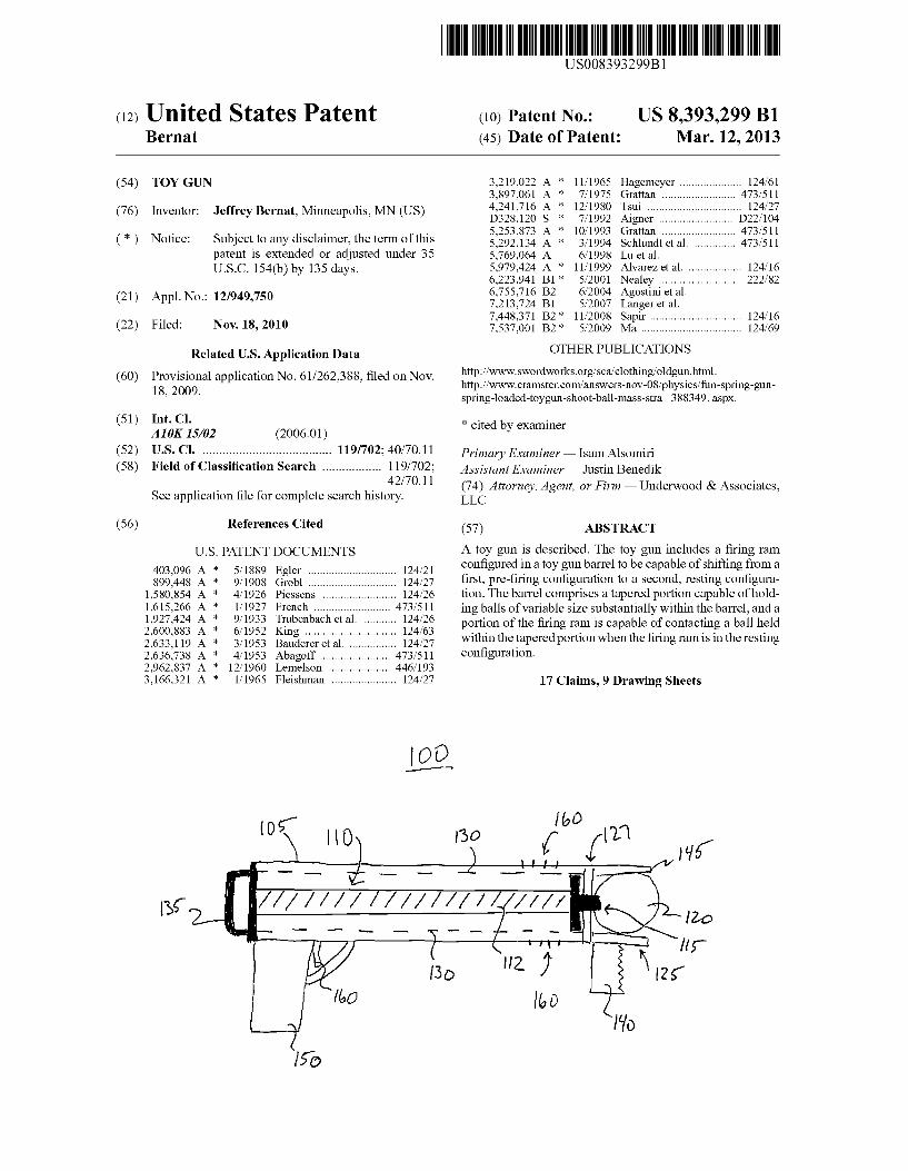
US008393299B1
(12) Ulllted States Patent (10) Patent N0.: US 8,393,299 B1 Bernat (45) Date of Patent: Mar. 12, 2013
(54) TOY GUN 3,219,022 A * 11/1965 Hagemeyer ................... .. 124/61 3,897,061 A * 7/1975 Grattan ..... .. 473/511
. ~ ' 4,241,716 A * 12/1980 Tsui . . . . . . . . . . . .. 124/27
(76) Inventor. Jeffrey Bernat, M1nneapol1s, MN (US) D328’l20 S * 7/1992 Aigner “ D22/l04 *
(>1) Notice: subject to any disclaimer, the/term 001115 253231;? 2 >1 12%???‘ 5511311511; ,,,,,,,,,,, ,jjj 133/21} patent is extended or adjusted under 35 5,769,064 A 6/1998 Lu et a1. U.S.C. 154(b) by 135 days. 5,979,424 A * 11/1999 Alvarez et al. ................ .. 124/16
6,223,941 Bl* 5/2001 Nealey .......................... .. 222/82 . 6,755,716 B2 6/2004 Agostini et al.
(21) Appl' NO" 12/949’750 7,213,724 B1 5/2007 Langeret al. _ 7,448,371 B2* ll/2008 Sapir ............................. .. 124/16
(22) Flledi NOV-18,2010 7,537,001 B2* 5/2009 Ma ................................ .. 124/69
Related US. Application Data OTHER PUBLICATIONS
(60) Provisional application No. 61/262,388, ?led on Nov. http?/ l l l ~SWOrdWOrkS~Org/“m1OmiHg/OMgUPhUm~ _ 18 2009 http://WWW.cramster.c0m/ansWers-n0v-08/phys1cs/fun-spnng-gun
’ ' spring-l0aded-toygun-sh00t-ball-mass-strai388349. aspX.
(51) Int. Cl. * ~t db - A10K 15/02 (2006.01) C1 e y exammer
(52) US. Cl. ..................................... .. 119/702; 40/70.11 Primary Examiner i 15am Alsomiri
(58) Field of Classi?cation Search ................ .. 119/702; Assistant Examiner i Justin Benedik
_ _ _ 42/7011 (74) Attorney, Agent, or Firm * Underwood & Associates, See appl1cat1on ?le for complete search h1story. LLC
References
U.S. PATENT DOCUMENTS A toy gun is described. The toy gun includes a ?ring rarn con?gured in a toy gun barrel to be capable of shifting from a
403,096 A * 5/1889 Egler ............................ .. 124/21 _ _ _
899,448 A * 9/1908 Grobl 124/27 ?rst, pre-?r1ng con?guratlon to a second, rest1ng con?gura 1,580,854 A * 4/1926 Piessens 124/26 t1on. The barrel compr1sesataperedport1on capable of hold 1,615,266 A : V1927 French ~~~~~~~~~~~~~~~ ~ ~ 473/511 ing balls of variable siZe substantially Withinthe barrel, anda l’927’424 A 9/1933 Tmbenbmh et a1‘ 124/26 portion of the ?ring ram is capable of contacting a ball held 2,600,883 A * 6/1952 Klng .................. .. 124/63 .thi th t d rt. h th ? . . . th t. 2,633,119 A * 3/1953 Baudereretal“ 124/27 W1 11 e.apere po 1onW en e nngram1s1n eres1ng 2,636,738 A * 4/1953 Abagoff ......... .. .. 473/511 Con?guranon
2,962,837 A * 12/1960 Lemelson .. 446/193 3,166,321 A * 1/1965 Fleishman .................... .. 124/27 17 Claims, 9 Drawing Sheets
1,”
‘ O 77/ l b 0
i l \ I 'l |
/////// ////////////// 1&0
_ _ _ __ T__ -1
( ‘Hf nr
[30 Hz) \IZ;
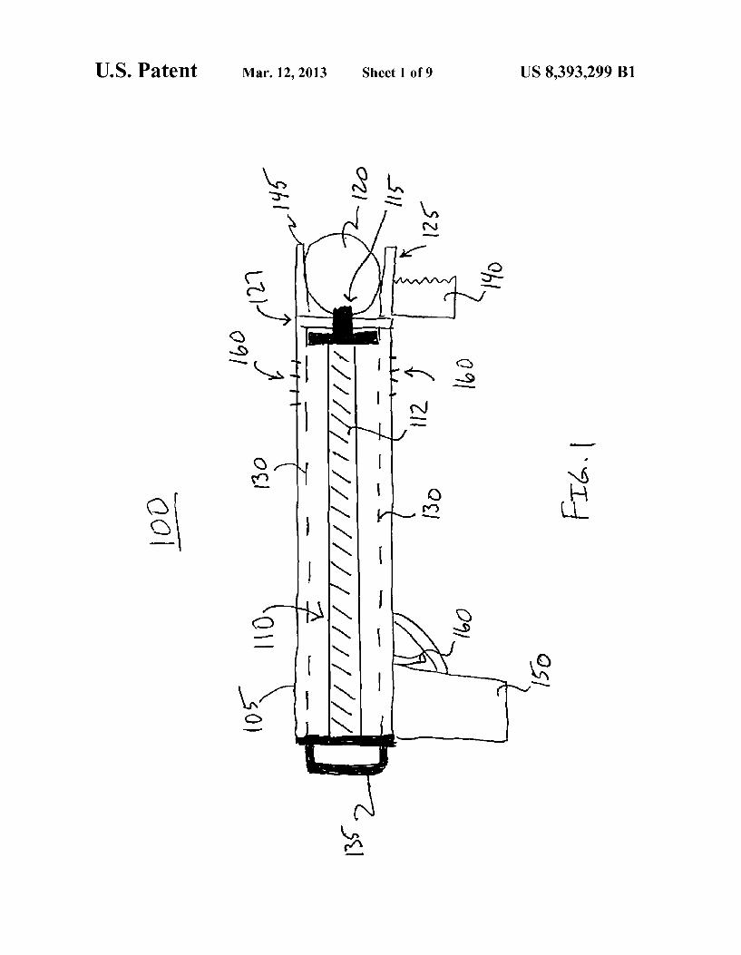
US. Patent Mar. 12, 2013 Sheet 1 of9 US 8,393,299 B1
fw?
Q
0:
Q2 Q6:
ME 02 u: / Lhi?f V
\ ,jlxluvilil S‘ _ ,, . 2 .\\\\\\\\\\\\\\\\\\\\\__~ FHLILW : 18% [WI 1
E1 s s
d on o: 5 Q2 \2.
m3
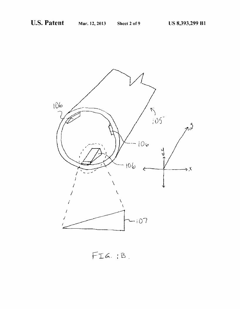
US. Patent Mar. 12, 2013 Sheet 2 of9 US 8,393,299 B1
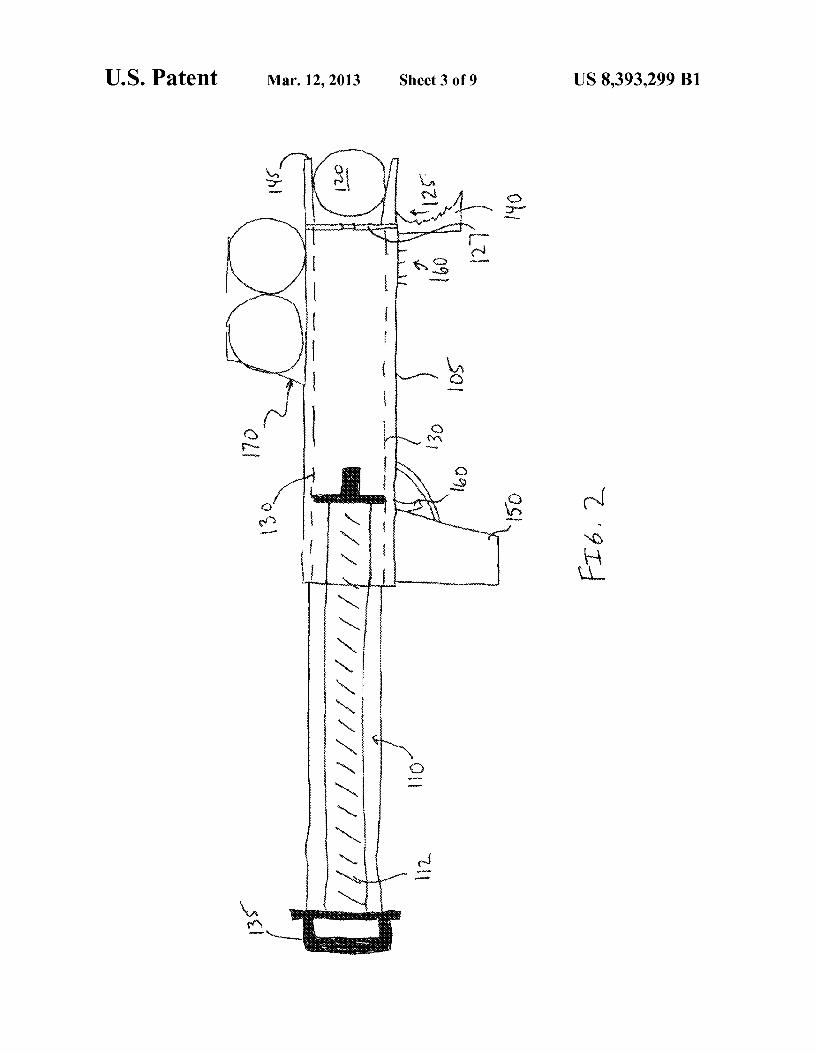
US. Patent Mar. 12, 2013 Sheet 3 of9 US 8,393,299 B1
533/
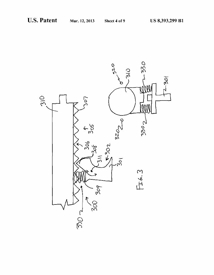
US. Patent Mar. 12, 2013 Sheet 4 of9 US 8,393,299 B1
U S. Patent Mar. 12, 2013 Sheet 5 of9 US 8,393,299 B1
FIG. 4
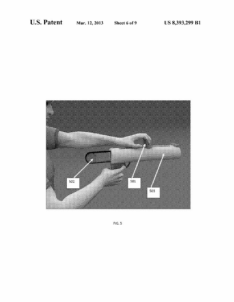
US. Patent Mar. 12, 2013 Sheet 6 of9 US 8,393,299 B1
FIG. 5
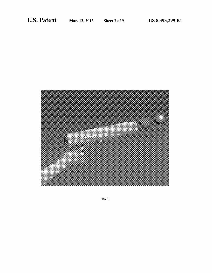
US. Patent Mar. 12, 2013 Sheet 7 of9 US 8,393,299 B1
H6. 6
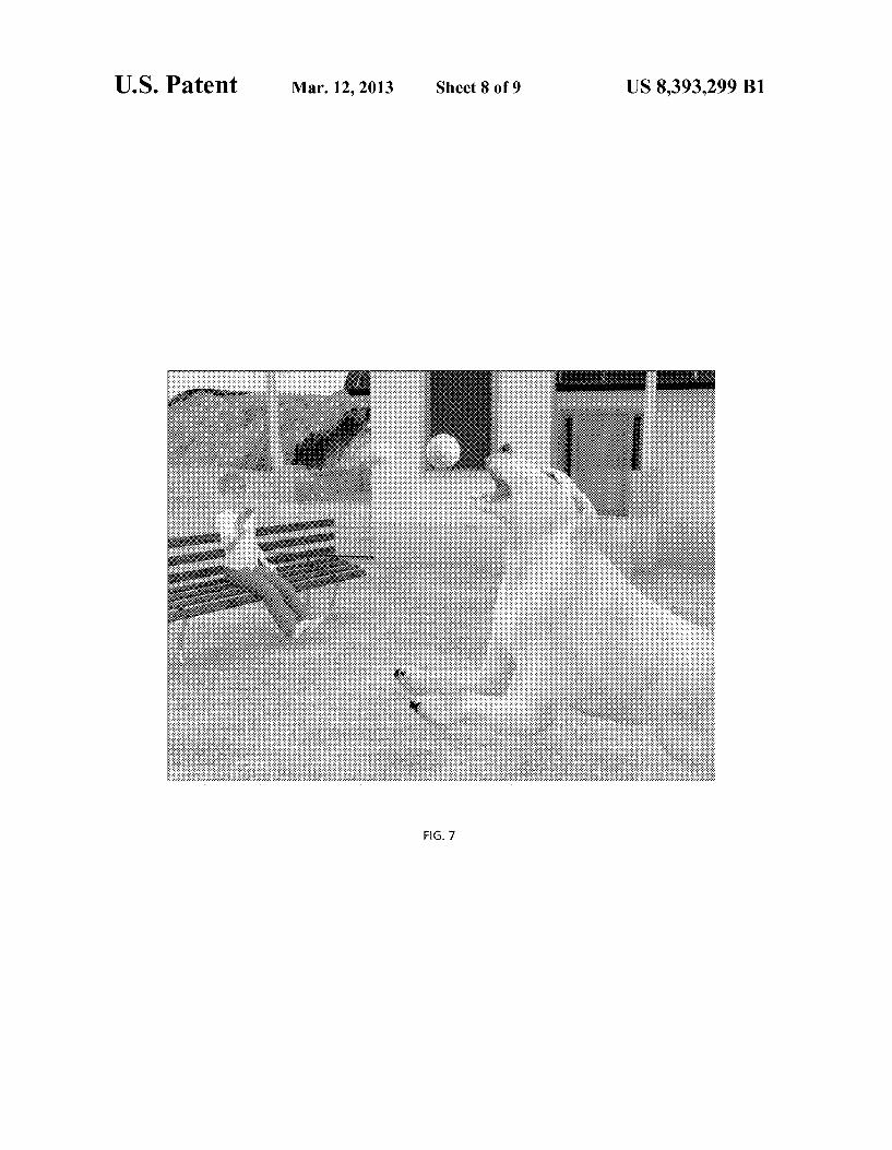
U S. Patent Mar. 12, 2013 Sheet 8 of9 US 8,393,299 B1
..
PIC-1.7
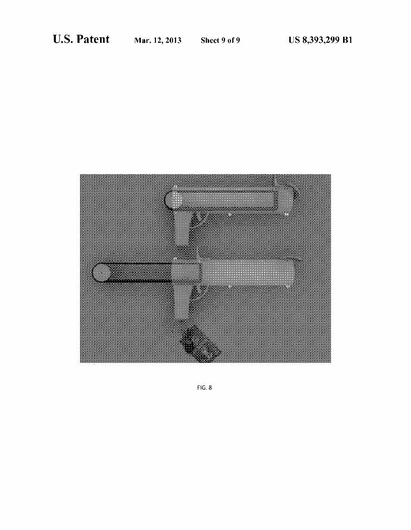
US. Patent Mar. 12, 2013 Sheet 9 of9 US 8,393,299 B1
FIG. 8
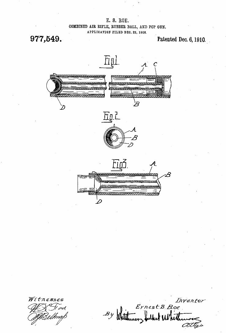
E. S. ROE. COMBINED AIR RIFLE, RUBBER BALL, AND POP GUN.
APPLIUATION FILED DEC. 22, 1908.
977,549. Patented Dec.6,1910._ .
74/2‘ {-22 ass es 152 renter
THE NORRIS PETERS 50., WASHINGTON. 1:. c.
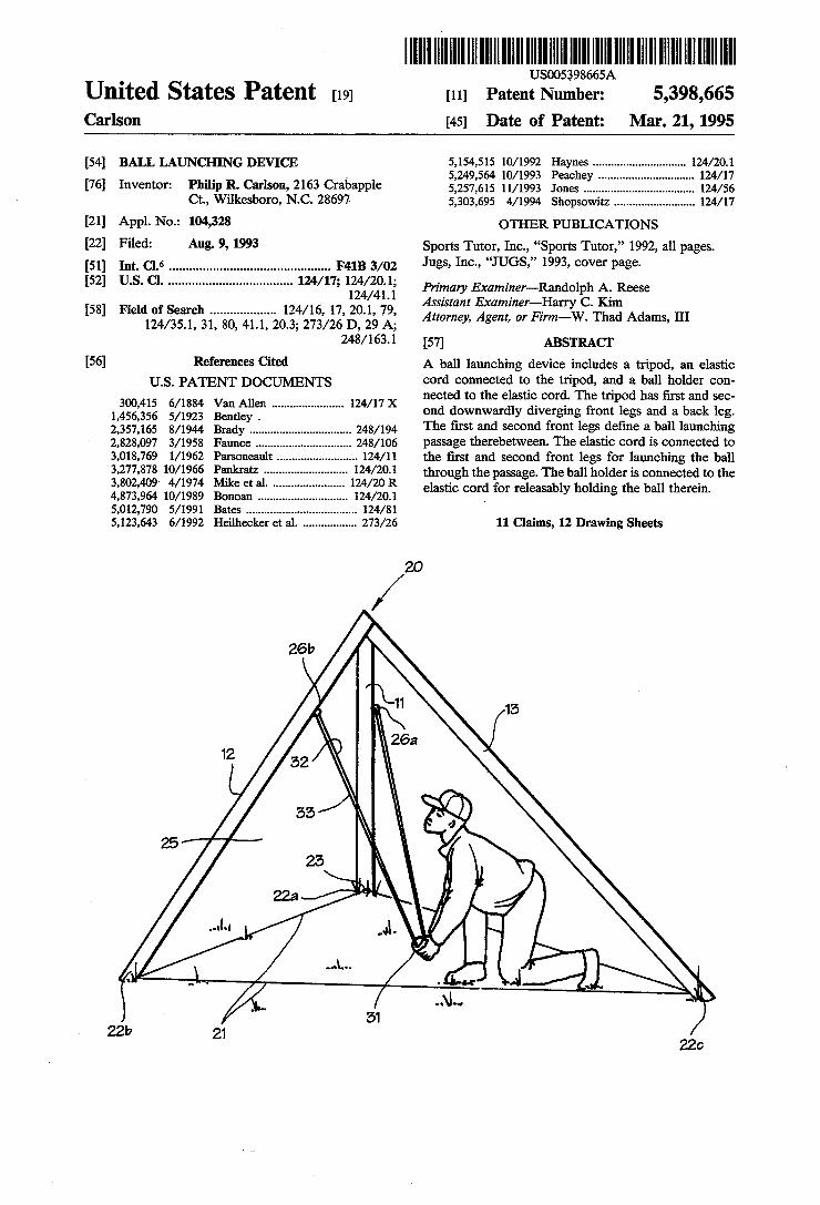
. US005398665A
United States Patent [19] [11] Patent Number: 5,398,665 Carlson [45] Date of Patent: Mar. 21, 1995
[54] BALL LAUNCHING DEVICE 5,154,522 10/19gg gay-ifs ............................. .. 124/291.1 _ _ 1 5,249,5 10/19 eac ey . 124 7
[76] Invcntcn P1111111 B- Carlson, 2163 Crabapple 5,257,615 11/1993 Jones ............ .. 124/56 Ct, W1lkesboro, N.C. 28691 5,303,695 4/1994 Shopsowitz 124/17
[21] App1~ No-= 104,328 OTHER PUBLICATIONS
[22] Filed! Allg- 9, 1993 Sports Tutor, Inc., “Sports Tutor,” 1992, all pages. [51] Int. (:1.6 .............................................. .. F41B 3/02 Jugs, Inc-1 “JUGS,” 1993’ cover Page
[52] US. Cl. ................................... .. 124/ 17; Primary Examiner__Randolph A_ Reese
. ' Assistant Examiner—Harry C. Kim
[58] Z2: Attorney, Agent, or Firm—W. Thad Adams, III
248/ 163.1 [57] ABSTRACT
[56] References Cited A ball launching device includes a tripod, an elastic
Us. PATENT DOCUMENTS cord connilcted to the griplolil, and (ail‘tlaallfholder con nected to t e e astic cor . e tripo as irst and sec
gzg?‘gslllen """"""""""" " 124/17 X 0nd downwardly diverging front legs and a back leg. 2:357:165 8/1944 Brady ............................ .. 248/194 The ?rst and second front legs de?ne a ball launching 2,828,097 3/1958 Faunce .............................. .. 248/106 passage therebetween- The elastic cord is connected to 3,018,769 1/1962 Parsoneault ..... .. 124/11 the ?rst and second front legs for launching the ball 3,277,373 10/1966 PaPk-‘aa ------ ~ 124/201 through the passage. The ball holder is connected to the i’ggg’gi gigs); a1‘ ' elastic cord for releasably holding the ball therein. 510121790 5/1991 Bates ........................... .. 124/81 ’
5,123,643 6/1992 Heilhecker et a1. ................ .. 273/26 11 Claims, 12 Drawing Sheets
/20 26}?
f \
26a 12 ‘
52
55 \ 25
25 \'’4
22a
.-\L|
-‘\Q~O , l _ .
‘ ? “ 22b 21
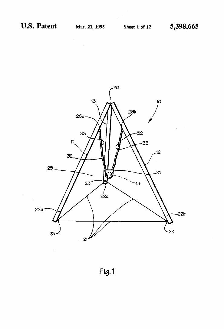
US. Patent Mar. 21, 1995 Sheet 1 of 12 5,398,665
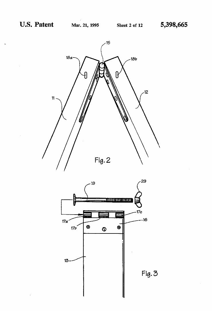
US. Patent Mar; 21, 1995 Sheet 2 of 12 5,398,665
1521
Fig. 5
15/
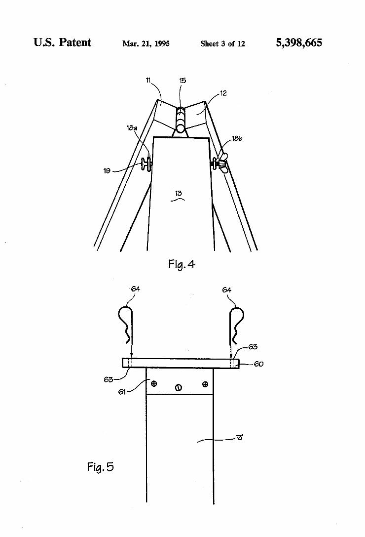
US. Patent Mar. 21, 1995 Sheet 3 of 12 5,398,665
Fig. 4
64 64
.1. V65 j: EH~60
65 —
61/ Q Q 6
/_____,15
Fig. 5
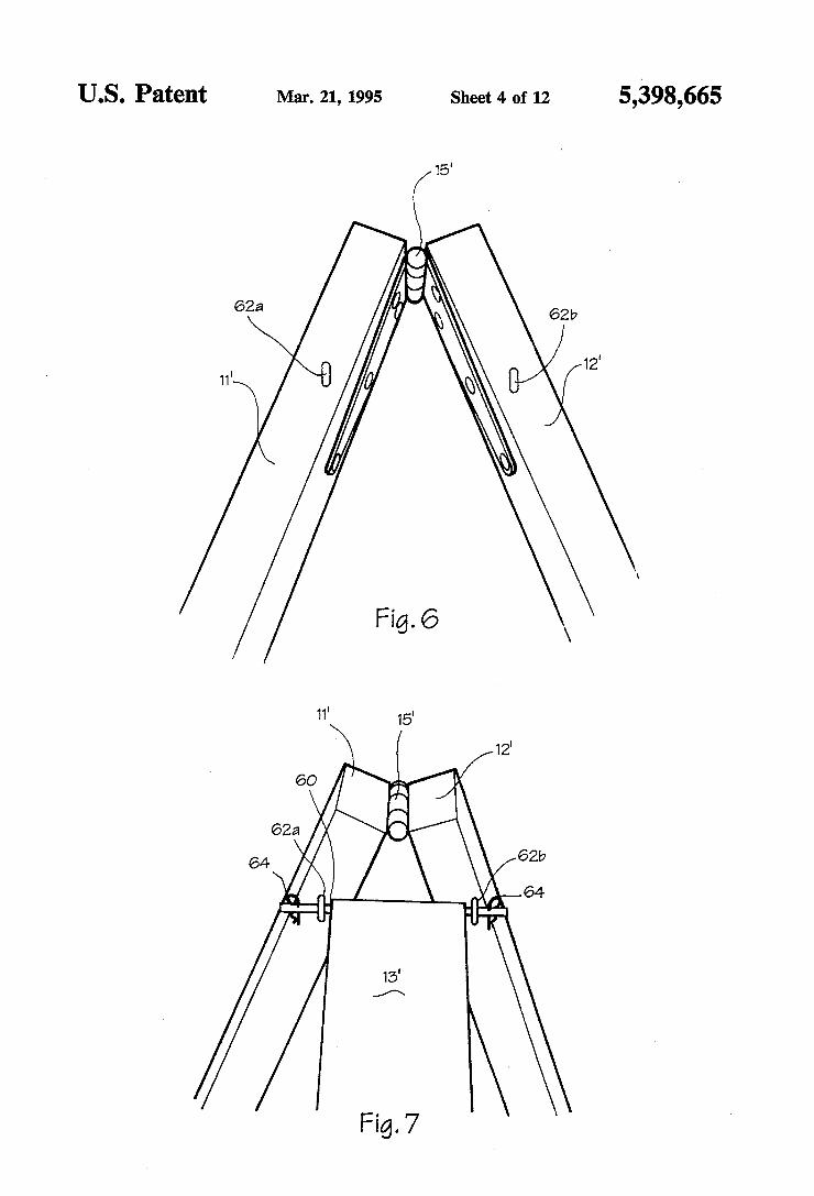
US. Patent Mar. 21, 1995 Sheet 4 of 12 5,398,665
6221
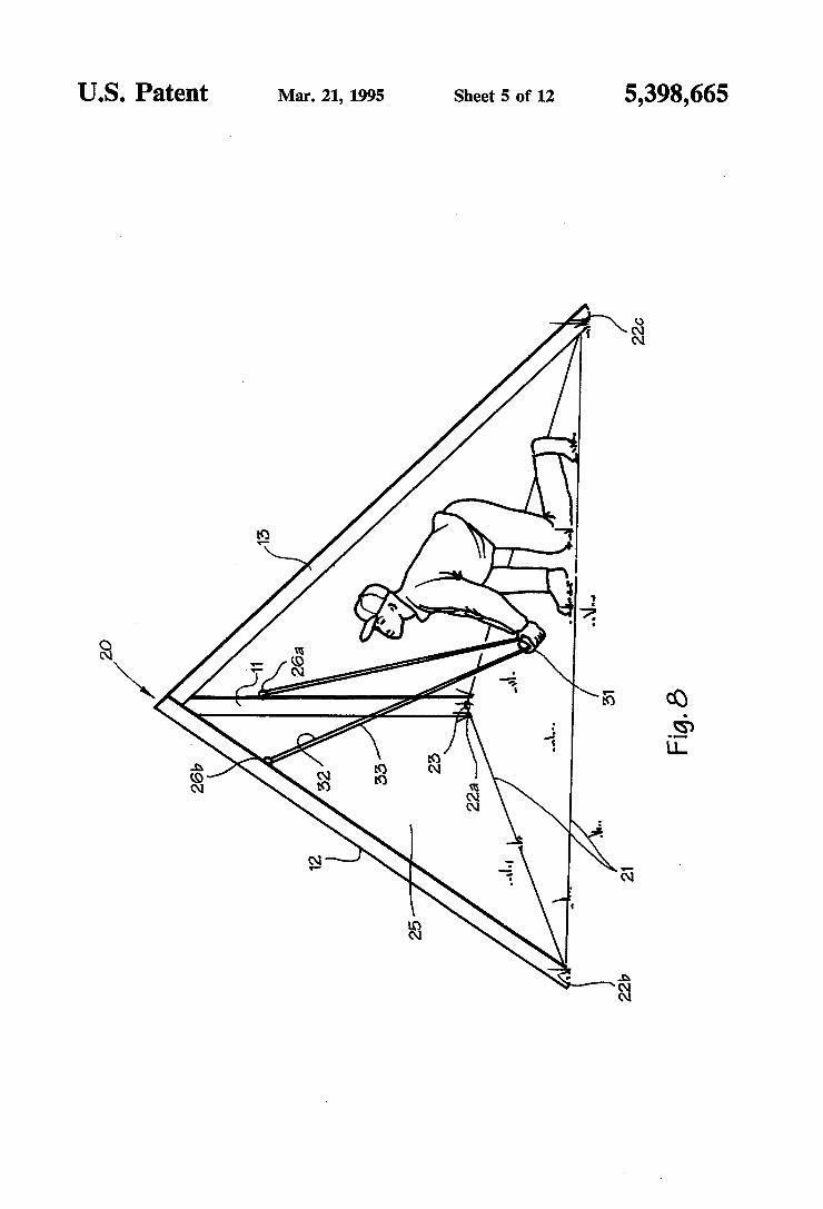
US. Patent Mar. 21, 1995 Sheet 5 of 12 5,398,665
A 22c
20
a ..\L..
26!? 52 55
25
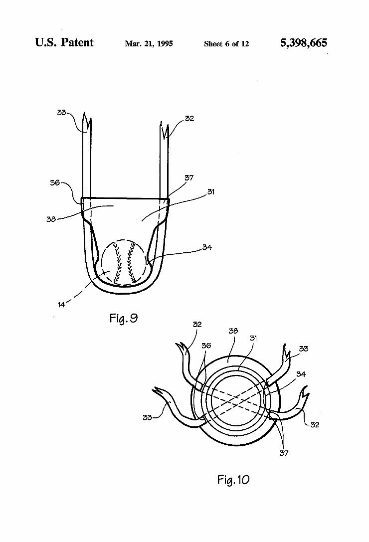
US. Patent Mar. 21, 1995 Sheet 6 of 12 5,398,665
52
{37 55
56
58
I
I I I l I
/ /
/ M
Fig.10
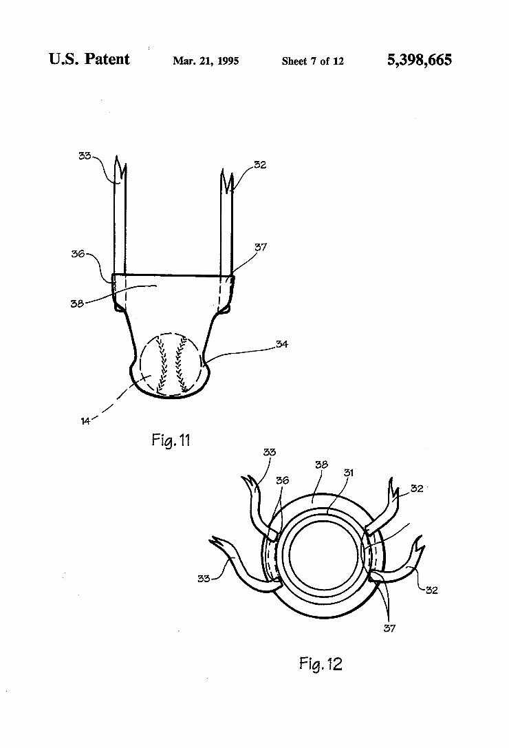
US. Patent Mar. 21, 1995 Sheet 7 of 12 5,398,665
52
[57 5
56
58
v
Fig.12
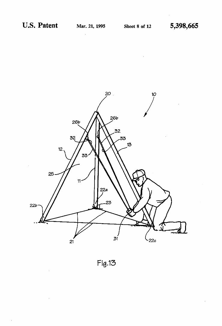
US. Patent Mar. 21, 1995 Sheet 80f 12 5,398,665
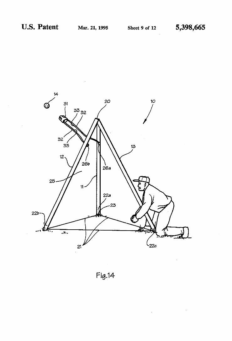
US. Patent Mar. 21, 1995 Sheet 9 of 12 5,398,665
2217
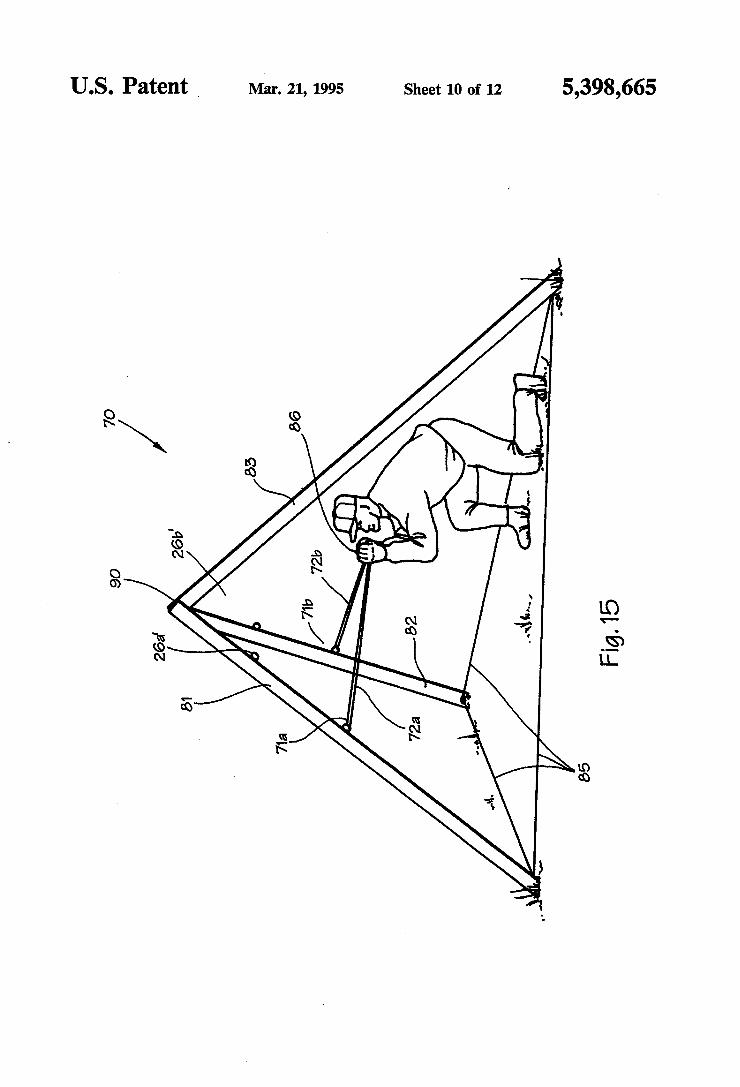
Sheet 10 of 12 5,398,665 Mar. 21, 1995 US. Patent _
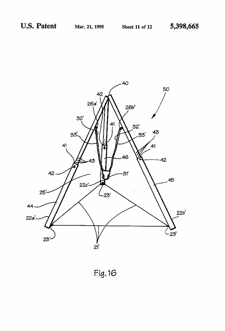
US. Patent Mar. 21, 1995 Sheet 11 of 12 5,398,665
Fig.16
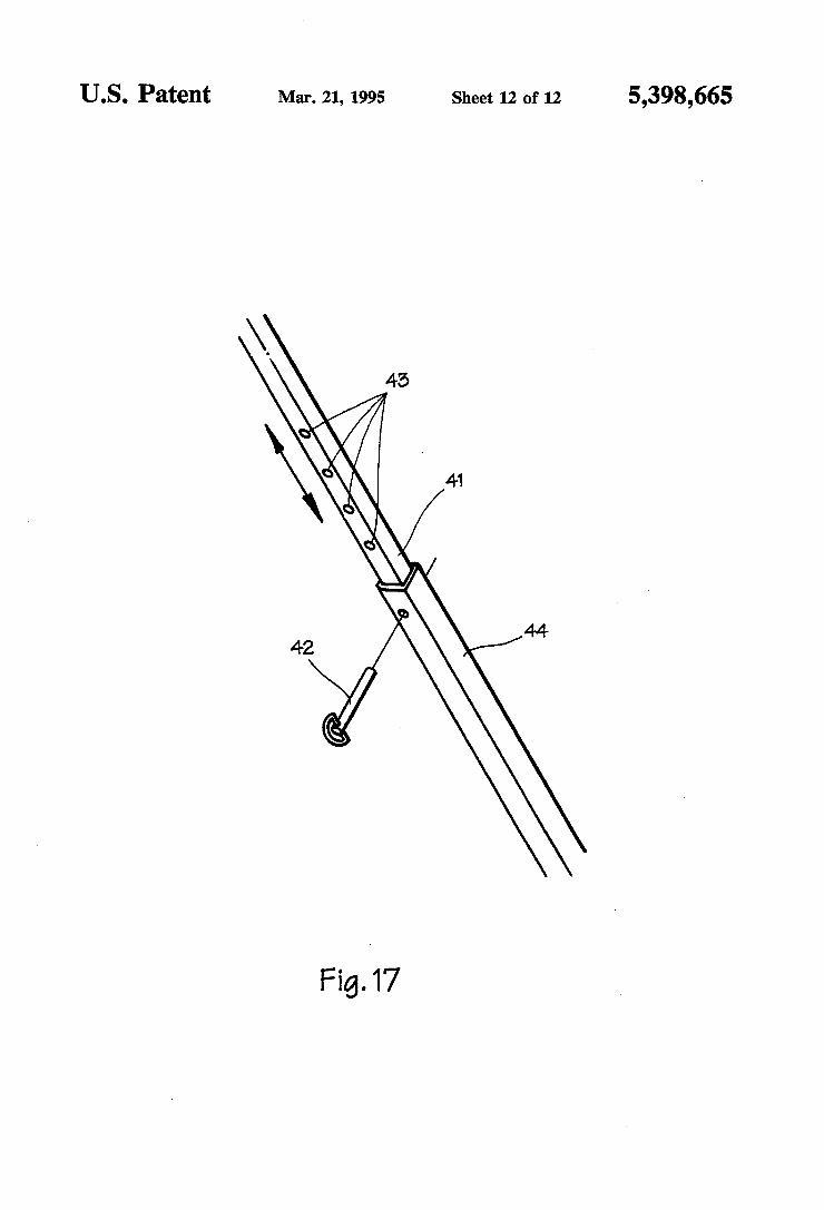
US. Patent Mar. 21, 1995 Sheet 12 0f 12 5,398,665
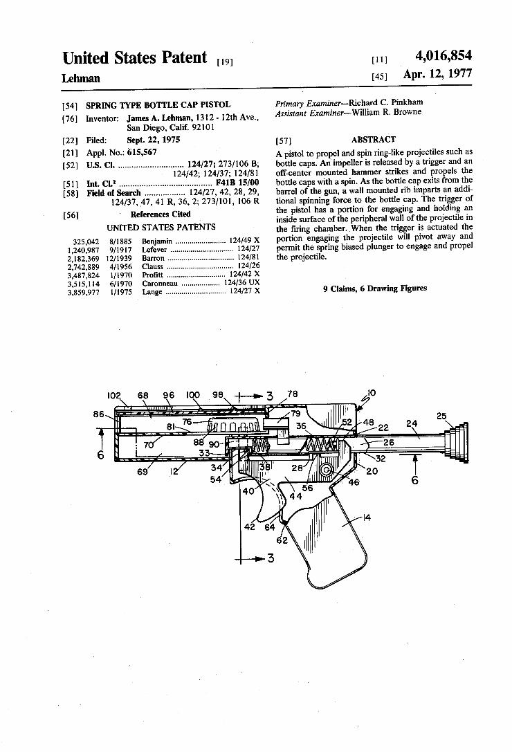
United States Patent [,9] Lehman
[11] 4,016,854 [45] Apr. 12, 1977
[54] SPRING TYPE BOTTLE CAP PISTOL
[76] Inventor: James A. Lehman, 1312 - 12th Ave., San Diego, Calif. 92101
[22] Filed: Sept. 22, 1975 [21] Appl. No.: 615,567 [52] US. Cl. ........................... .. 124/27; 273/106 B;
124/42; 124/37; 124/81 [51] Int. Cl.2 ....................................... .. F41B 15/00 [58] Field of Search ................ .. 124/27, 42, 28, 29,
124/37, _47, 41 R, 36, 2; 273/101, 106 R [56] References Cited '
UNITED STATES PATENTS
325,042 8/1885 Benjamin ...... .. 124/49 X 1,240,987 9/1917 Lefever .... .. . 124/27
2,182,369 12/1939 Barron ........................... .. 124/81 2,742,889 4/1956 Clauss .................. ..
3,487,824 1/1970 3,515,114 6/1970 3,859,977 l/1975
I02 68 96 \ \ "I
Primary Examiner-Richard C. Pinkham Assistant Examiner--William R. Browne
[57] ABSTRACT A pistol to propel and spin ring-like projectiles such as bottle caps. An impeller is released by a trigger and an off-center mounted hammer strikes and propels the bottle caps with a spin. As the bottle cap exits from the barrel of the gun, a wall mounted rib imparts an addi tional spinning force to the bottle cap. The trigger of the pistol has a portion for engaging and holding an inside surface of the peripheral wall of the projectile in the ?ring chamber. When the trigger is actuated the portion engaging the projectile will pivot away and permit the spring biased plunger to engage and propel the projectile.
9 Claims, 6 Drawing Figures
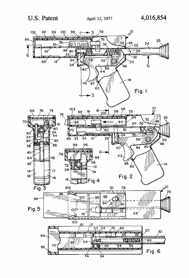
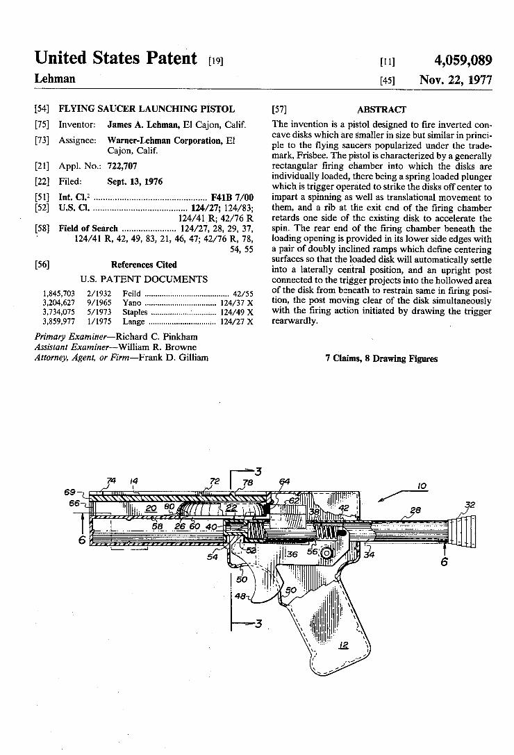
United States Patent [19] [11] 4,059,089 Lehman [45] Nov. 22, 1977
[54] FLYING SAUCER LAUNCHING PIISTOL [57] ABSTRACT
[75] Inventor; James A, Lehman, El CajQn, Calif, The invention is a pistol designed to ?re inverted con _ _ cave disks which are smaller in size but similar in princi
[73] Asslgnee: wafne'l'Le'lma“ Corporanon’ E1 plc to the flying saucers popularized under the trade ca-lon’ Cahf' mark, Frisbee. The pistol is characterized by a generally
[21] Appl, NO_; 722,707 rectangular ?ring chamber into which the disks are _ individually loaded, there being a spring loaded plunger
[22] Flled: Sept‘ 13’ 1976 which is trigger operated to strike the disks off center to [51] Int. Cl.2 .............................................. .. F41B 7/00 impart a spinning as well as translational movement to [52] US. Cl. ...................................... .. 124/27; 124/83; them, and a rib at. the exit end of the ?ring chamber
124/41_R; 42/76 R retards one side of the existing disk to accelerate the [58] Field of Search ..................... .. 124/27, 28, 29, 37, spin- The rear end of the ?ring chamber beneath the
‘ 124/41 R, 42, 49, 83, 21, 46, 47; 42/76 R, 78, loading opening is provided in its lower side edges with 54, 55 a pair of doubly inclined ramps which de?ne centering
_ surfaces so that the loaded disk will automatically settle [56] References C'ted into a laterally central position, and an upright post
U.S. PATENT DOCUMENTS connected to the trigger projects into the hollowed area 1 845 703 2/1932 Feild ...................................... .. 42/55 °f the disk fmm beneath to restrain Same in ?ring Posi' 3:2O4:627 9/1965 Yam _____ __ 124/37 X tion, the post moving clear of the disk simultaneously 3,734,075 5/1973 staples 124/49 X with the ?ring action initiated by drawing the trigger 3,859,977 1/1975 Lange ........................... mm x rearwardly
Primary Examiner—Richard C. Pinkham Assistant Examiner~William R. Browne Attorney, Agent, or Firm—Frank D. Gilliam 7 Claims, 8 Drawing Figures
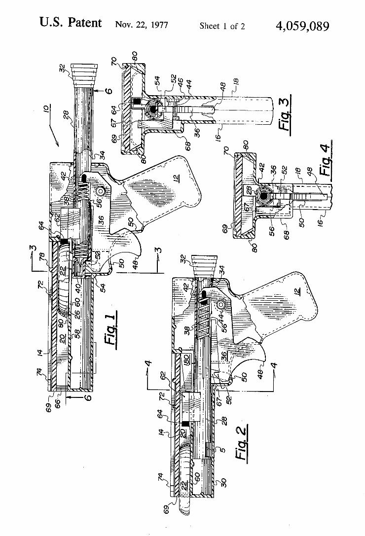
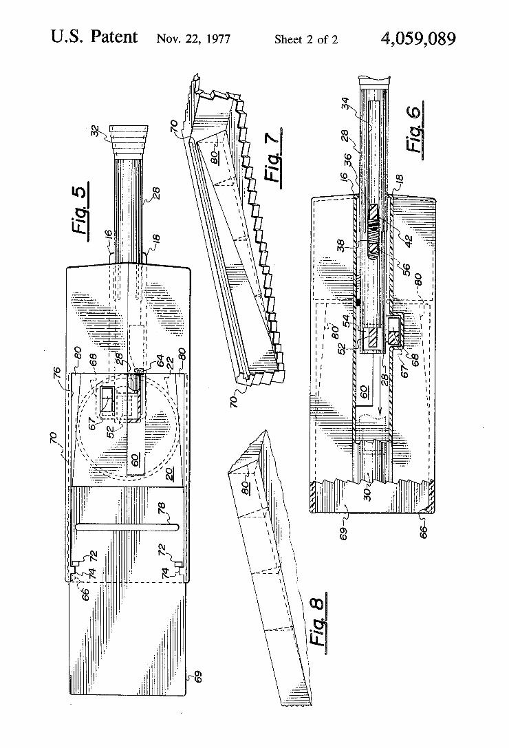
US. Patent Nov. 22, 1977 Sheet 2 of2 4,059,089
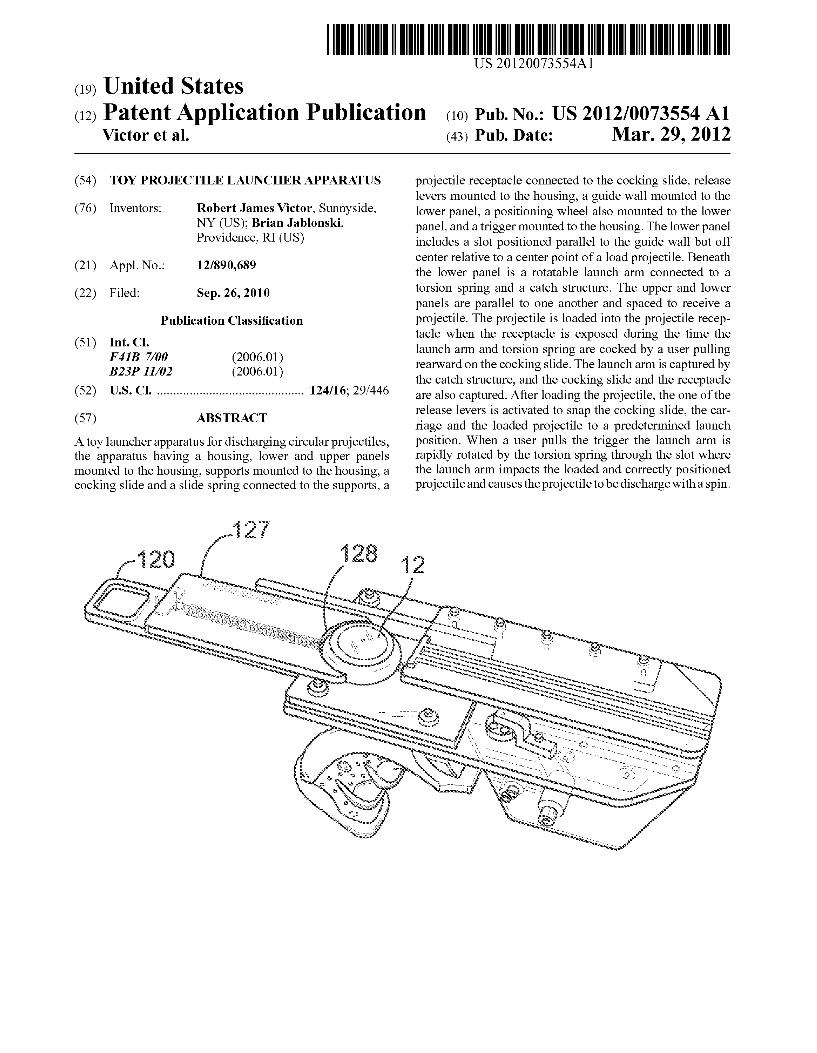
US 20120073554A1
(12) Patent Application Publication (10) Pub. No.: US 2012/0073554 A1 (19) United States
Victor et al. (43) Pub. Date: Mar. 29, 2012
(54) TOY PROJECTILE LAUNCHER APPARATUS
(76) Inventors: Robert James Victor, Sunnyside, NY (U S); Brian Jablonski, Providence, RI (U S)
(21) Appl. No.: 12/890,689
(22) Filed: Sep. 26, 2010
Publication Classi?cation
(51) Int. Cl. F 413 7/00 (2006.01) B23P 11/02 (2006.01)
(52) US. Cl. ........................................... .. 124/16; 29/446
(57) ABSTRACT
A toy launcher apparatus for discharging circular projectiles, the apparatus having a housing, loWer and upper panels mounted to the housing, supports mounted to the housing, a cocking slide and a slide spring connected to the supports, a
12?’
projectile receptacle connected to the cocking slide, release levers mounted to the housing, a guide Wall mounted to the loWer panel, a positioning Wheel also mounted to the loWer panel, and a trigger mounted to the housing. The loWer panel includes a slot positioned parallel to the guide Wall but off center relative to a center point of a load projectile. Beneath the loWer panel is a rotatable launch arm connected to a torsion spring and a catch structure. The upper and loWer panels are parallel to one another and spaced to receive a projectile. The projectile is loaded into the projectile recep tacle When the receptacle is exposed during the time the launch arm and torsion spring are cocked by a user pulling rearward on the cocking slide. The launch arm is captured by the catch structure, and the cocking slide and the receptacle are also captured. After loading the projectile, the one of the release levers is activated to snap the cocking slide, the car riage and the loaded projectile to a predetermined launch position. When a user pulls the trigger the launch arm is rapidly rotated by the torsion spring through the slot Where the launch arm impacts the loaded and correctly positioned projectile and causes the projectile to be discharge With a spin.
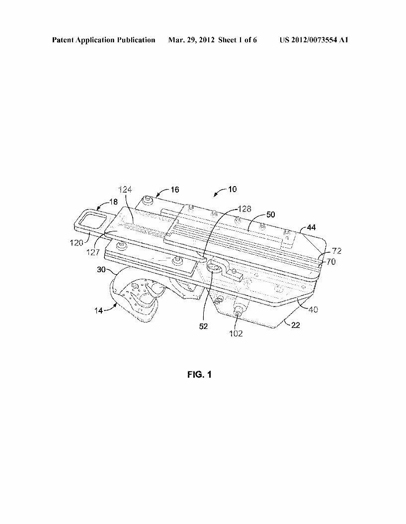
Patent Application Publication Mar. 29, 2012 Sheet 1 0f 6 US 2012/0073554 A1
FIG. 1
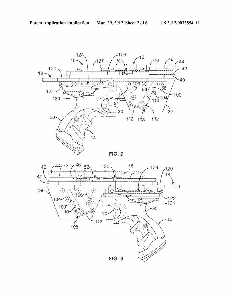
Patent Application Publication Mar. 29, 2012 Sheet 2 0f 6 US 2012/0073554 A1
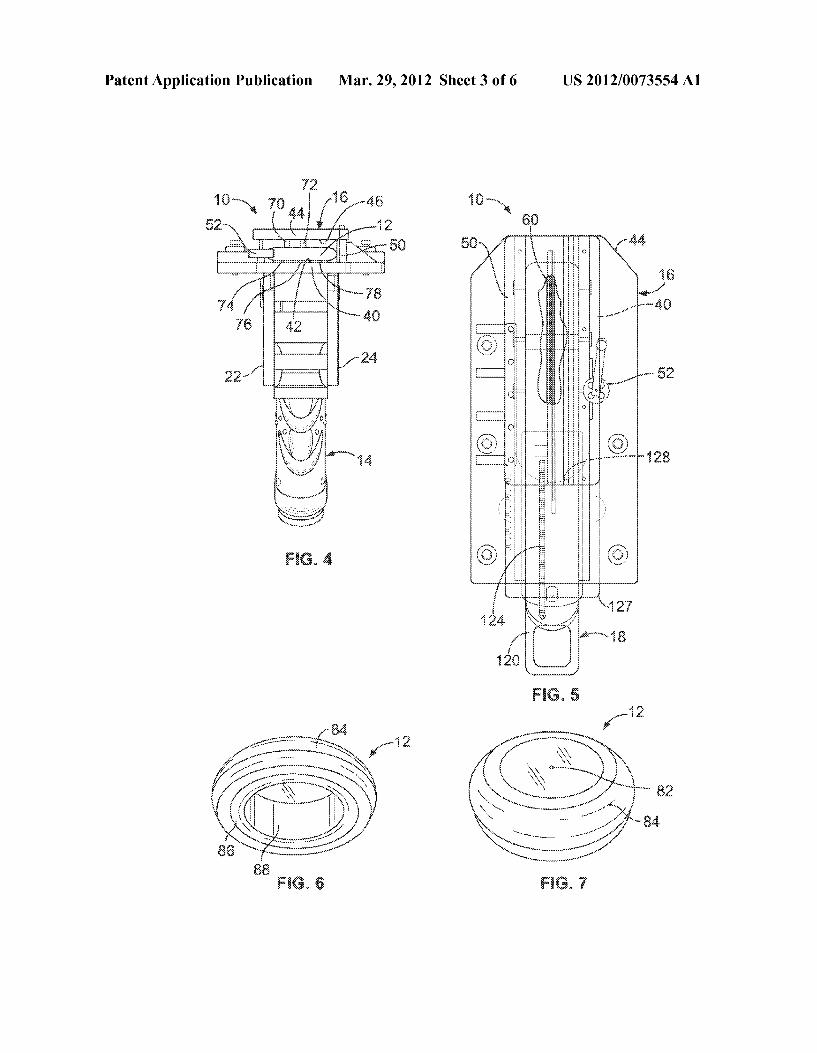
Patent Application Publication Mar. 29, 2012 Sheet 3 0f 6 US 2012/0073554 A1
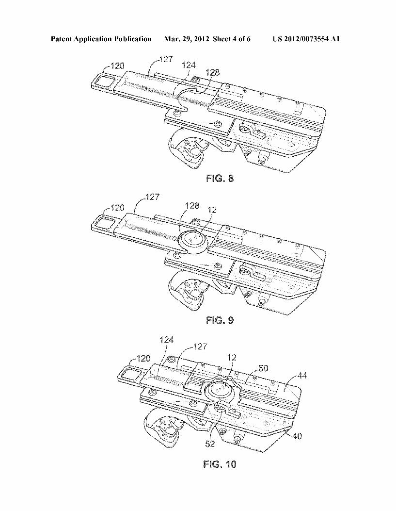
Patent Application Publication Mar. 29, 2012 Sheet 4 0f 6 US 2012/0073554 A1
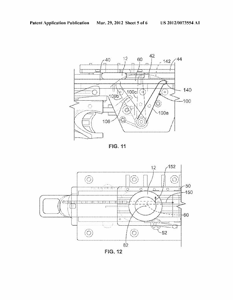
Patent Application Publication Mar. 29, 2012 Sheet 5 0f 6 US 2012/0073554 A1
“EGG
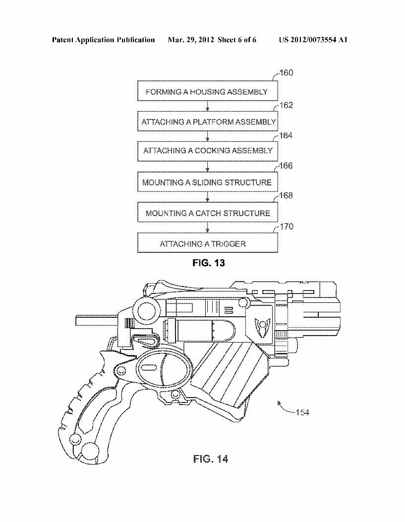
Patent Application Publication Mar. 29, 2012 Sheet 6 0f 6 US 2012/0073554 A1
{,1 $6
FQRMENQ A HGUSENQE ASSEMSLY
; 1/252 ATTAQHENG A PLATFQRM ASSEMLY
; {m4 ATTACHiNG A CQGKENG ASSEMBLY
g [1% MQUNTENG A SLEDENQ STRUCTURE
g f1 53 MGUNTENG A CATCH STRUQTURE
g {m ATTAGHWG ATRiGGER
FIG. 13
E2223
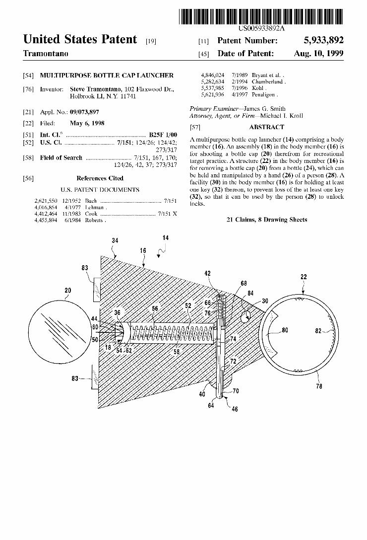
US005933892A
Ulllted States Patent [19] [11] Patent Number: 5,933,892 Tramontano [45] Date of Patent: Aug. 10, 1999
[54] MULTIPURPOSE BOTTLE CAP LAUNCHER 4,846,024 7/1989 Bryant et al. . 5,282,634 2/1994 Chamberland .
[76] Inventor: Steve Tramontano, 102 FlaXWood Dr., 5,537,985 7/1996 Kohl - Holbrook LI, N_Y_ 11741 5,621,936 4/1997 Penaligon .
_ Primary Examiner—James G. Smith [21] Appl' NO" 09/073’897 Attorney, Agent, or Firm—Michael I. Kroll
[22] Filed: May 6, 1998 [57] ABSTRACT
[51] Int. Cl.6 ...................................................... .. B25F 1/00 A If b m 1 h (14) _ _ b d _ _ _ mu ipurpose 0 e cap aunc er comprising a 0 y
[52] US‘ Cl‘ """ " 7/151’ 124/26’2172;/;127’ member (16). An assembly (18) in the body member (16) is , _ for shooting a bottle cap (20) therefrom for recreational
[58] Fleld of Search """"""""" target practice. A structure (22) in the body member (16) is ’ ’ ’ for removing a bottle cap (20) from a bottle (24), Which can
. be held and manipulated by a hand (26) of a person (28). A [56] References Clted facility (30) in the body member (16) is for holding at least
U.S. PATENT DOCUMENTS one key (32) thereon, to prevent loss of the at least one key 2621 550 12/1952 B h 7/151 (32), so that it can be used by the person (28) to unlock
, , ac ......................................... ..
4,016,854 4/1977 Lehman . locks‘
4,412,464 11/1983 Cook ..................................... .. 7/151 X
4,455,894 6/1984 Roberts . 21 Claims, 8 Drawing Sheets
14
83
20 ///////
83 ///////
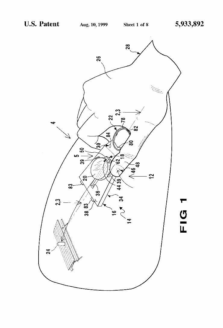
U.S. Patent Aug. 10,1999 Sheet 1 of8 5,933,892
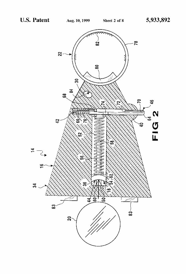
U.S. Patent Aug. 10,1999 Sheet 2 of8 5,933,892
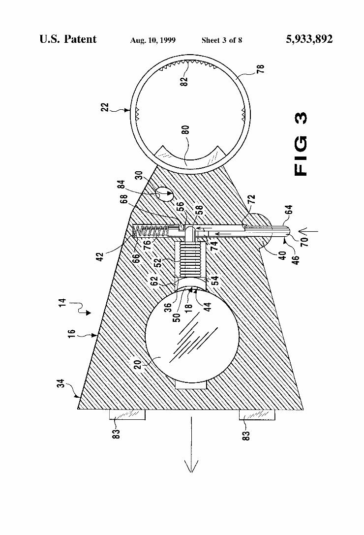
U.S. Patent Aug. 10,1999 Sheet 3 of8 5,933,892
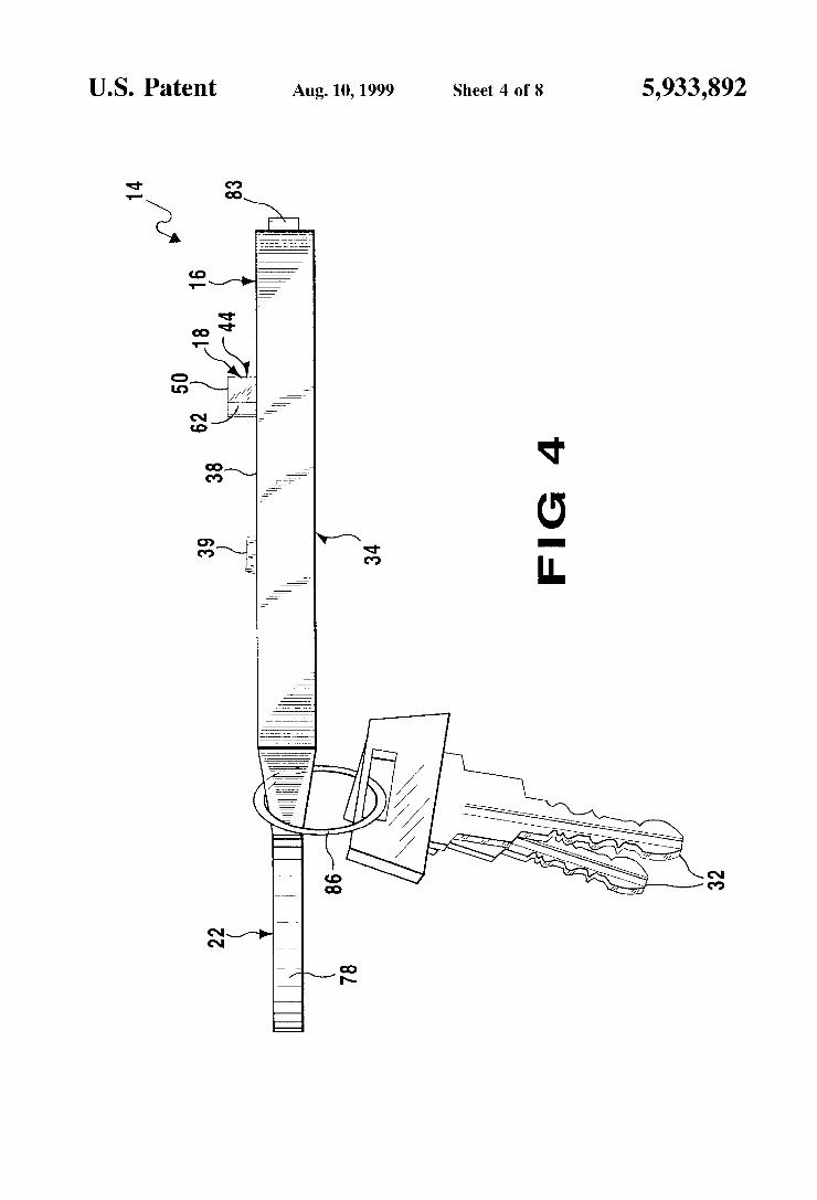
U.S. Patent Aug. 10,1999 Sheet 4 of8 5,933,892
aTZEEEZW 9
A: 2 2
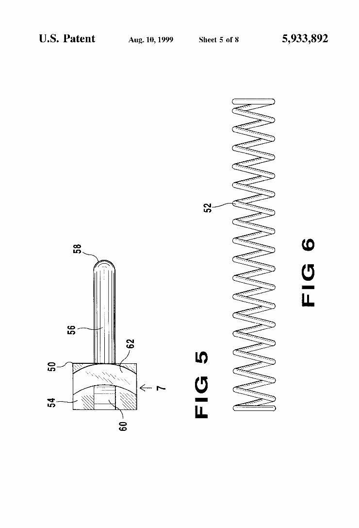
U.S. Patent Aug. 10, 1999 Sheet 5 0f 8 5,933,892
FIG 6
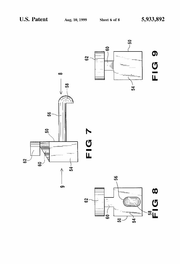
U.S. Patent Aug. 10,1999 Sheet 6 of8 5,933,892
G7
9 Ll.
FIG 7
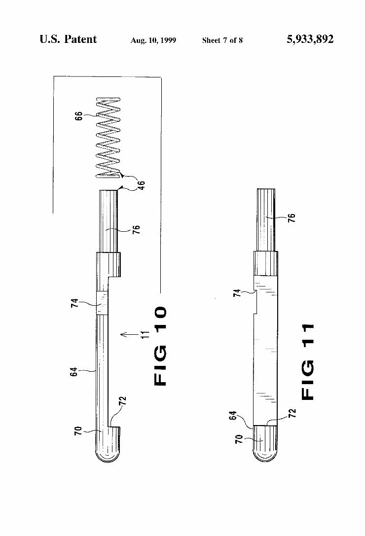
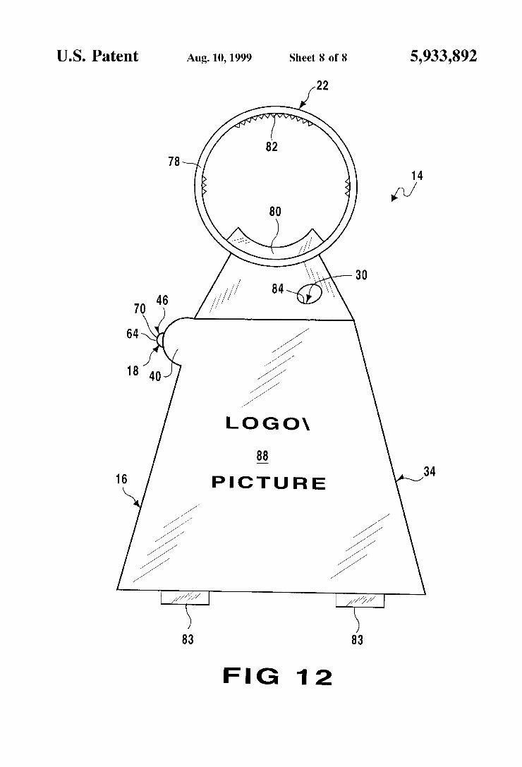
U.S. Patent Aug. 10,1999 Sheet 8 of8 5,933,892
34
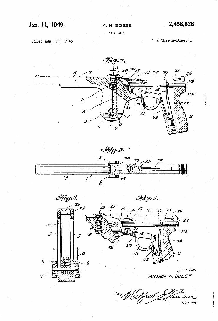
2,458,828 A. H. BOESE Jan. 1 1, 1949. TOY GUN
' 2 Sheets-Sheet 1 Filed Aug. 16, 1943
3
2 H _, J __‘-..,.//////a M.
17 74/119
g
gwuvrvbow ART/‘lbw H. 50555
&
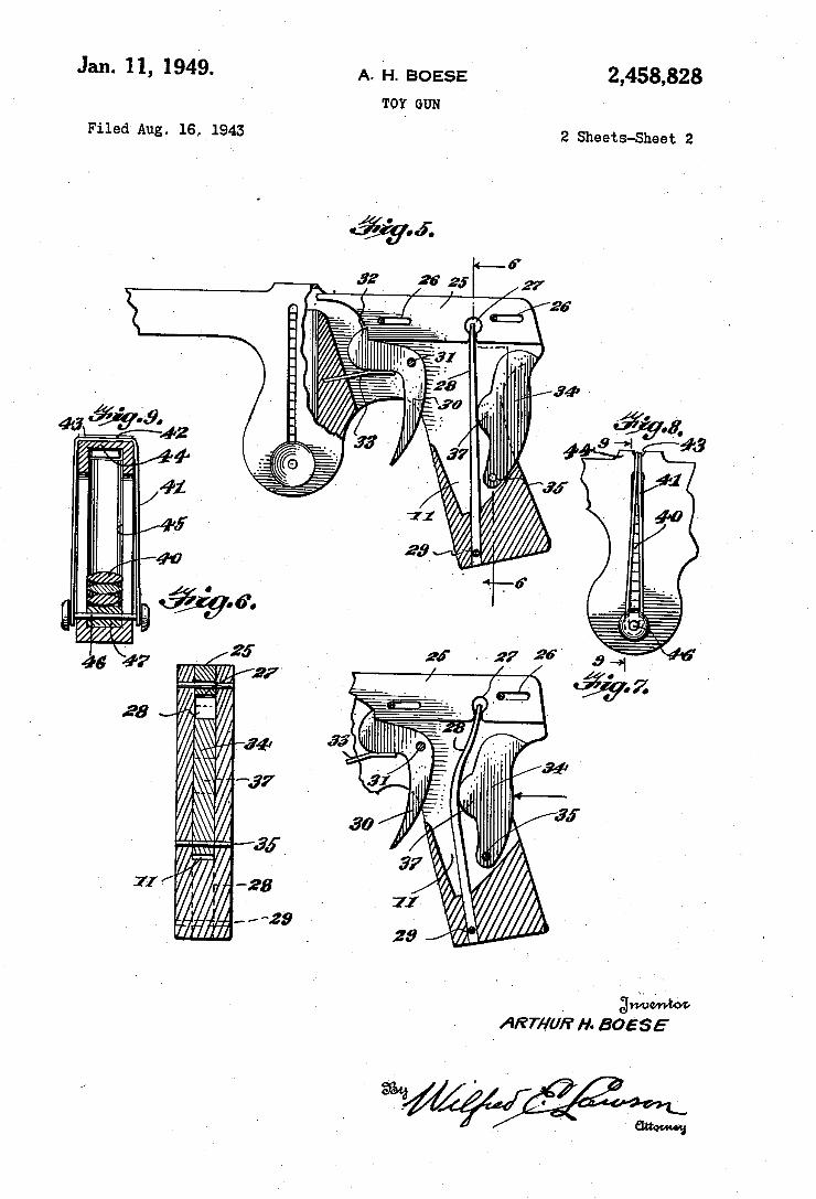
Jan. 11, 1949. A, B0555 2,458,828 TOY GUN
Filed Aug. 1641943 2 Sheets-Sheet 2
. awhm' '
ARTHUR H- BOESE
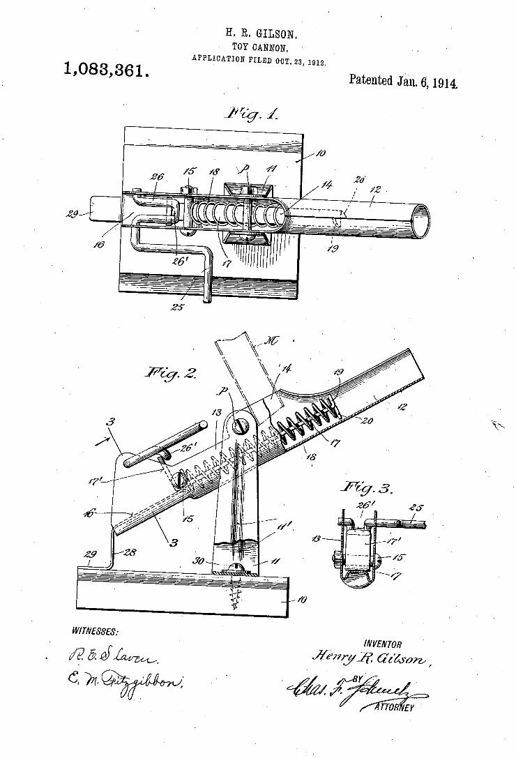
H. R. GILSON. TOY CANNON.
APPLICATION FILED 0012s, 1912.
1,083,361 . Patented Jan. 6,1914.
in
is
W/TA/ESSES: v _ ‘Wm/m v
/P. & ' I?WWy-ZID. 6255072, I
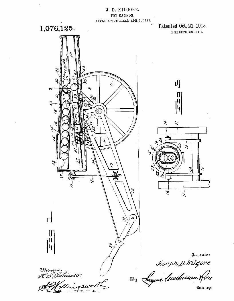
J. D. KILGORE. TOY CANNON.
APPLICATION FILED APR. 1, 1913.
1,076,125.
3.. M6 s
m: MWWMW
1E
Lu a 2% m?l
i K
On .
dm J.
M? a
n
e W
m w
J
IHmHIHF
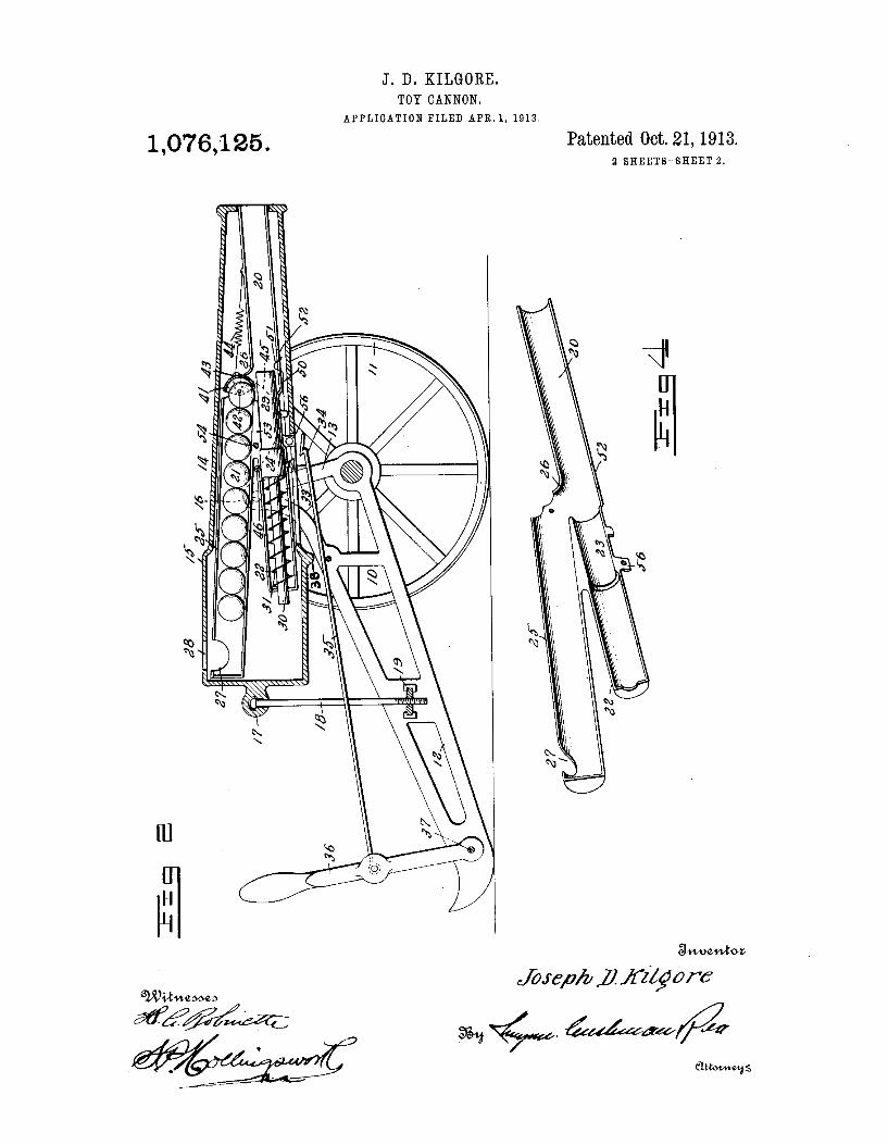
J. D. KILGORE. TOY CANNON.
APPLIGATION FILED APR. 1, 1913.
Patented 0013. 21, 1913. 2 SHBETSASHEET 2.
1,076,125.
awuawkva
wasp/u ? 122570115’ GLvi/Huzomw
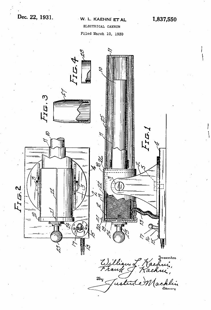
Dec. 22, 1931. <w. 1.. KAEHNT'ETAL
ELECTRIGAL CANNON
1,837,550
Filed March 10, 1930
55,2.
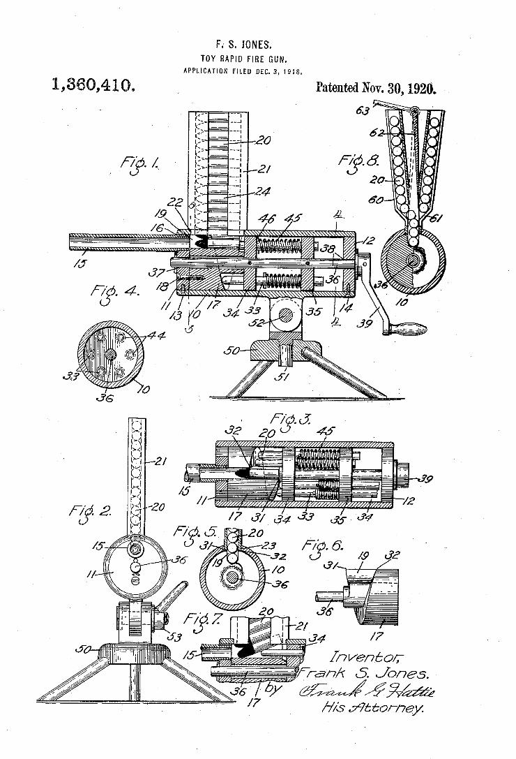
F.' S. JONES. TOY RAPID FIRE GUN.
APPLICATION FILED Dic. s, 1918.
1,360,410,
m
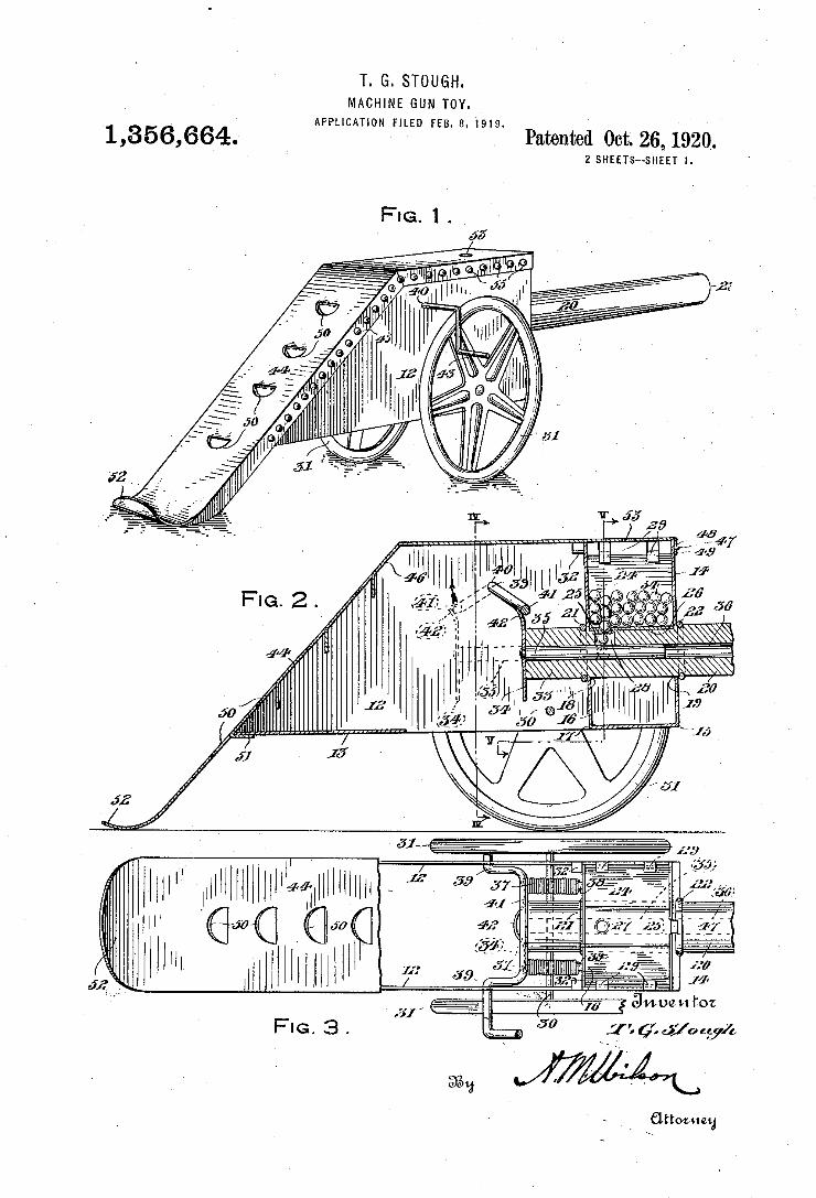
T. G. STOUGH. MACHINE GUN TOY.
APPLICATION FILED FEB. 8,1919. 1,356,664; Patented Oct; 26,1920. 2 SHEETS—SHEET l
.WI."VIHHHI‘HIHWILWHHHHM _ W 6M6 Q“, ‘Ci 1"“ [WWW
FIG. 3.
-_____,._
50 1'' J70
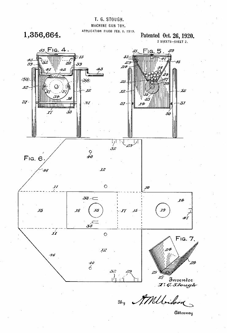
2 SHEETS~SHEET 2.
77 6? fjouyi/
Patented 001;. 26, 1920.
v
1/7 .m . a, 4 m
J U
n
. a 7
mo 2
@~@/
Lmw m;
[I _ .I II _ I w n J n Q\
N __ n u .|: | l l I l L l I | I | II. 0 ‘I.
T. G. STOUGH. MACHINE GUN TOY.
APPLICATION FILED FEB. a. 1919. 1,356,664.
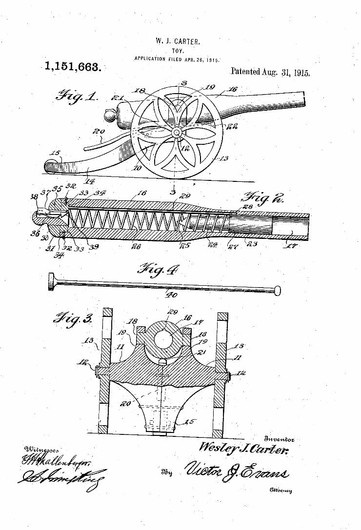
w.~1. CARTER. v Toy. l
APPLICATION FILED APR. 26.1915.A
Í 1,151,663. = Patented A_ug. >31, 1915.
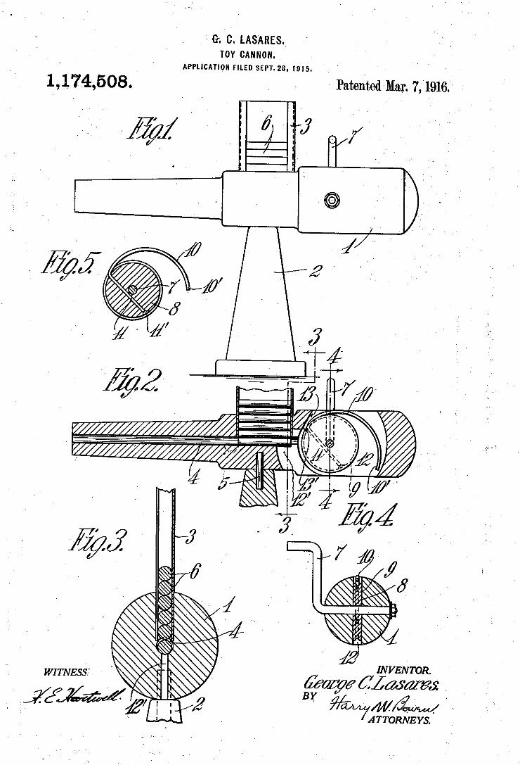
e. c. LAS‘ARES, '' TOY CANNON. ‘
APPLICATION FILED SEPT-28, I915
1,1,74,508. ' w Patented Mar. 7,1916;
|
-~\\ ~
5'_ I \’
5% -
~ INVENTOR.
é’wzye éflwaw . .
BY /ZW ‘ A TTORNE-YS. ‘
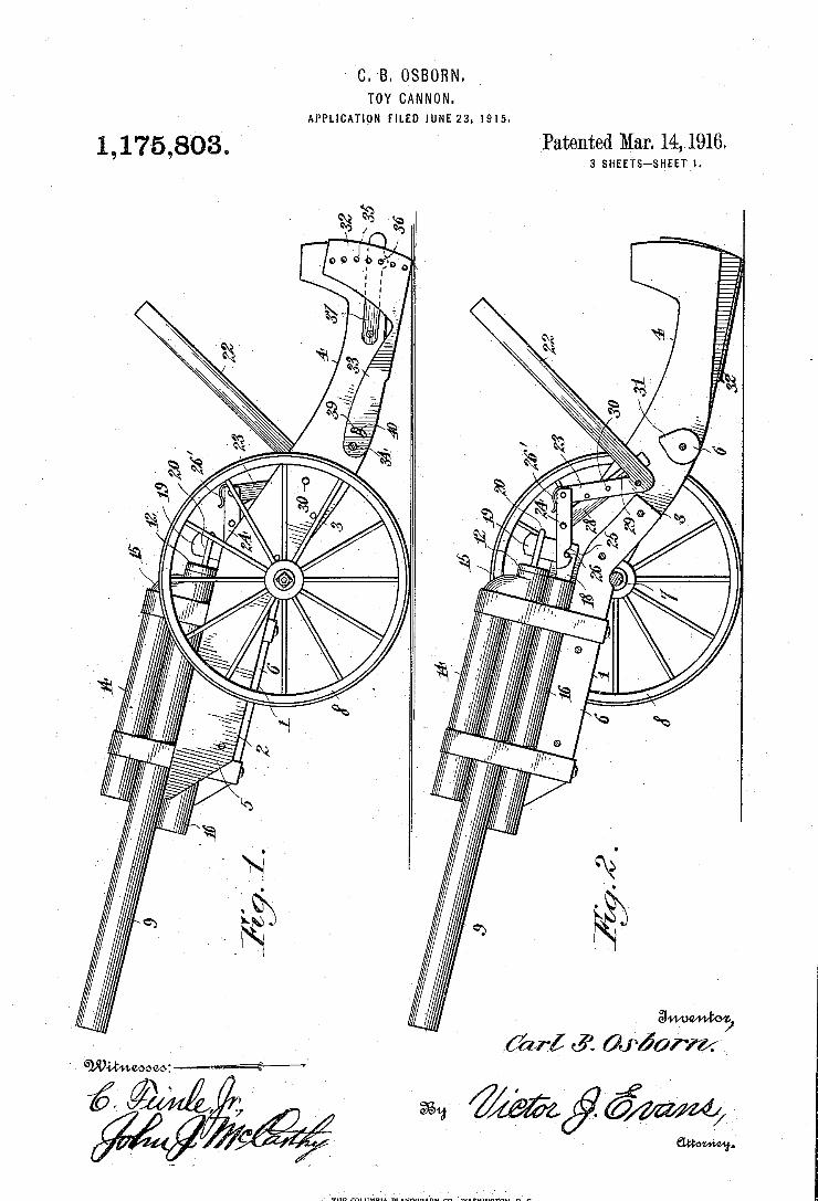
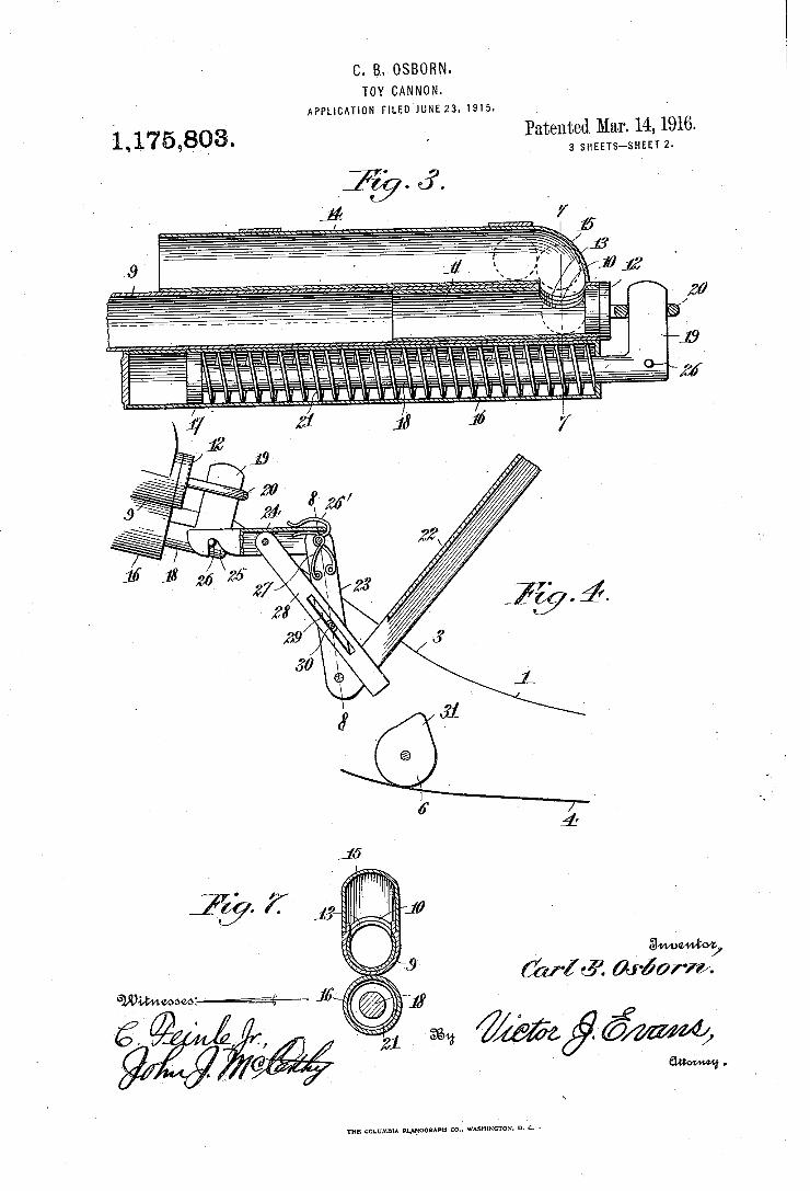
C. B. OSBORN. TOY CANNON.
APPLICATION rlLgo'luuszs. 1915. 1916.
3 SHEETS—SHEET 2. Patented Mar. 14, 1,175,803.
gvwewtm'y WZQR 011-507”.
I "Hid.
THE COLUMBIA PWOGRAPH ‘10-, WASHINGTON, n. c. -
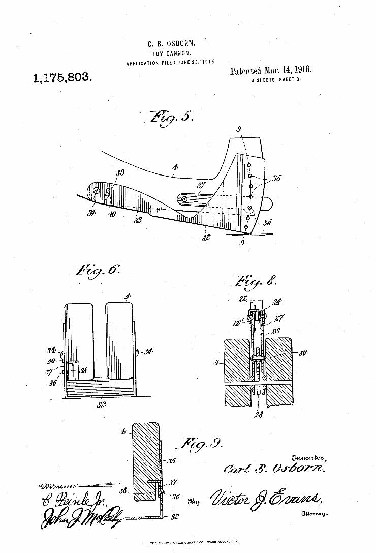
C. B. OSBORN. ' TOY CANNON.
APPUCATION FILED JUNE 23.4915.
I Patented Mar. 14, 1 3 SHEETS-SHEET 1,175,303.
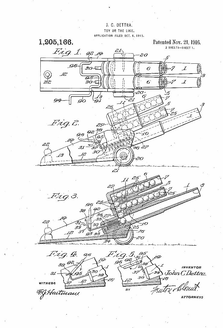
J. C. DETTRA. TOY OR THE LIKE.
APPLICATION FILED OCT. 6,1915.
0 6 mt mwm mH OT Nm‘ ds 62 m j
M P
0 6 1.. 5
W01 . 6 1% 5 O 2.] 1L
INVENTOR
1.
WITNESS
ATTORNEYS
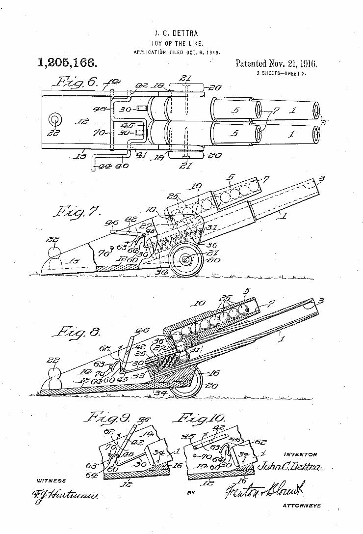
J. C. DETTRA TOY OR THE LIKE.
APPLICATION FILED OCT. 6. 1915.
Patented Nov. 21, 1916. 2 SHEETS—SHEET 2.
w a
E I Q, a.
Q _.. 1/ w 6. 1, Q 5 E
0 20) v 1
INVENTOR
WITNESS
@% ATTORNEYS’
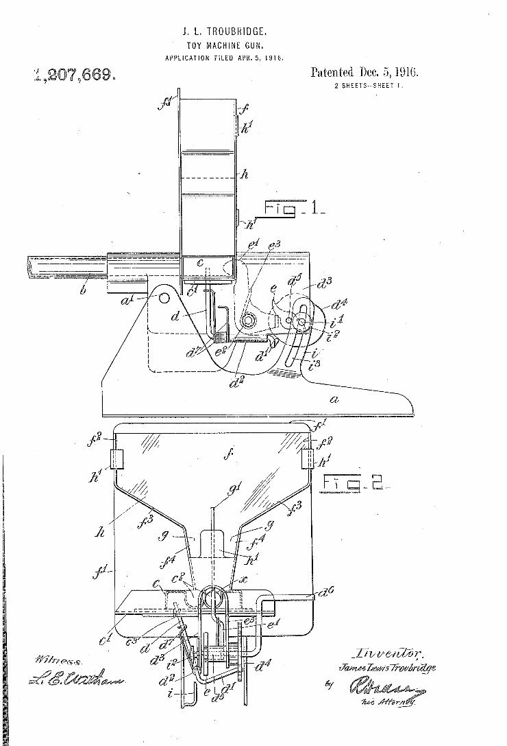
J. L. TROUBHIDGE. TOY MACHINE GUN.
APPLICATION FILED APR.5.1916.
Patented Dec. 5,1916. 2 SHEETS-~SHEET I.
lW/ma/
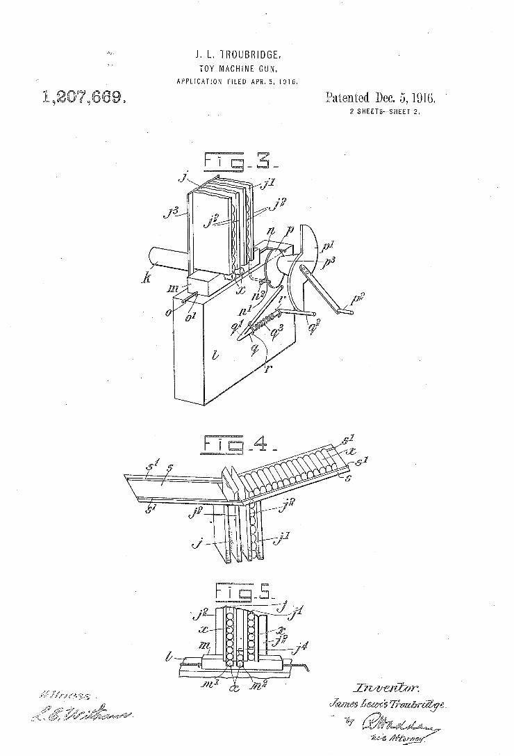
J. L‘ TROUBRIDGE. TOY MACHINE GUN.
APPLICATION FILED APR.5, I916.
Patented Dec. 5, 1916. 2 SHEETS-SHEET 2.
7% Wig-£53176
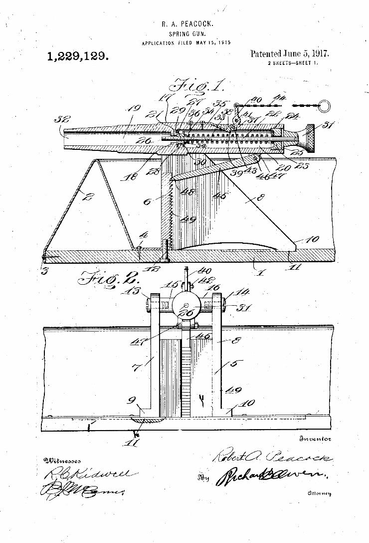
R. A. PEAcoçK. SPRING GUN.
`APPL|CAT10N man MAY15.1915
yPutenïed June 5, 1917. 2 SHEETS¢SHEET l 11,229,129.
w, a ¿wifi/lll „Il 1
3v» van to@
ff
@55.4.4 WHA/wm»
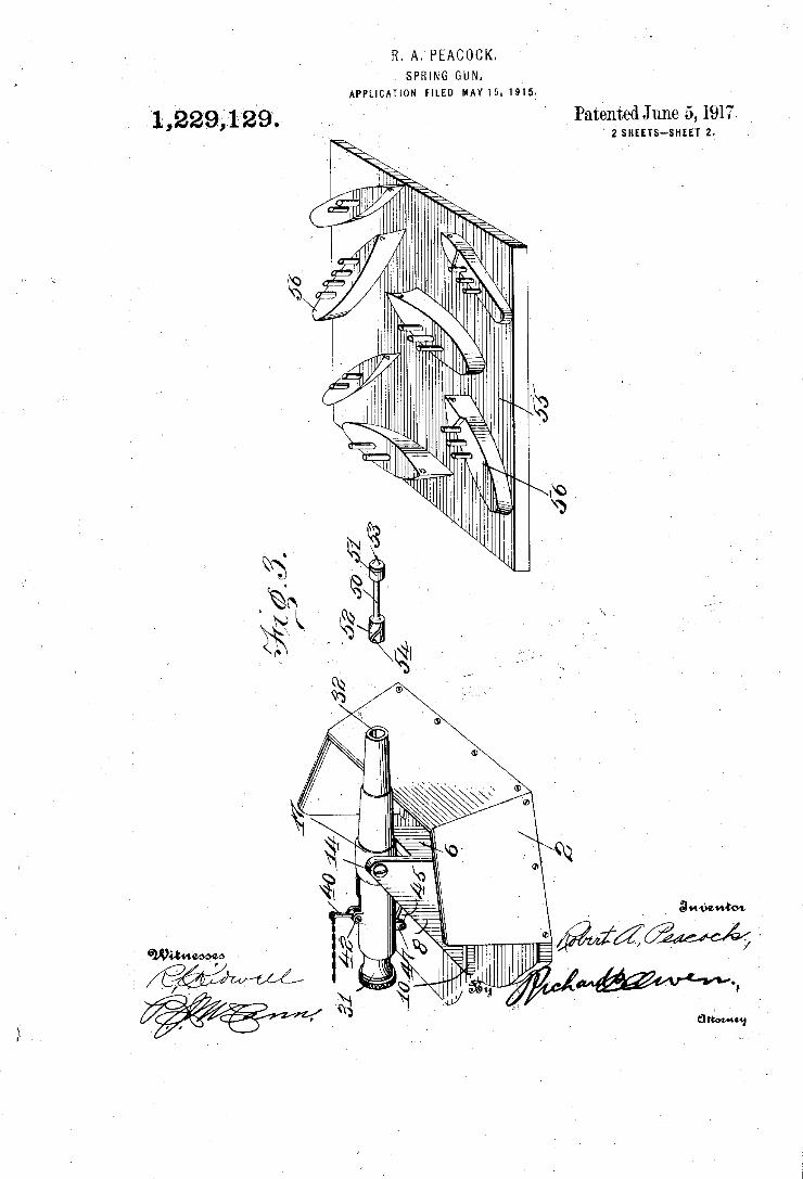
VR. A. PEACOCK. SPRING GUN.
` APPLICATKON FILED MAY 15. 1915: `
1,22931129. _ ‘ ' ' Patented June 5, 191?. ` 2 SHEETS--SHEET 2.
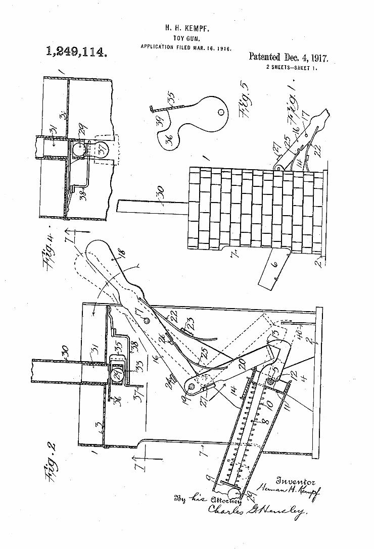
H. H. KEMPF. TOY GUN.
APPLICATION FILED MAR. 16. I916
Patented Dec. 4, 1917. 1 1 1L 2 SHEETS-SHEET I.
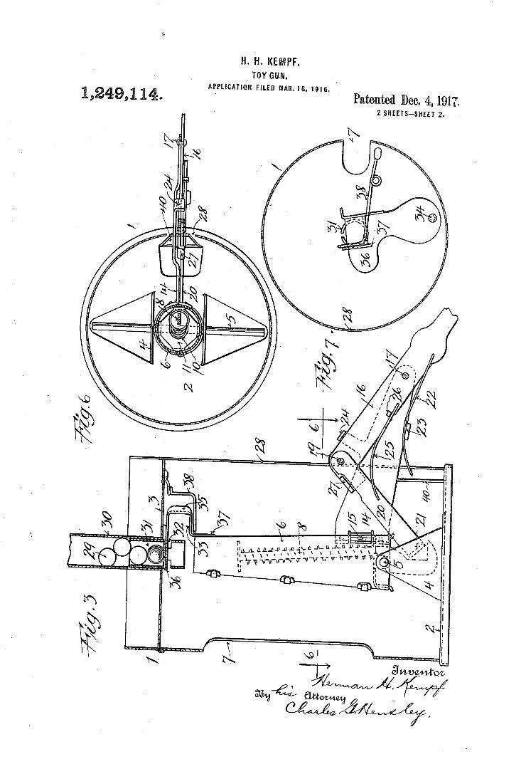
H- H- KEMPF. _ TOY euw.
APPLICATIQN FILED MAN. [8. l9l6.
Patented Dec. 4, 191?. 2 SHEETS~SHEET 2.
9,11,.
y??? 7 7/,
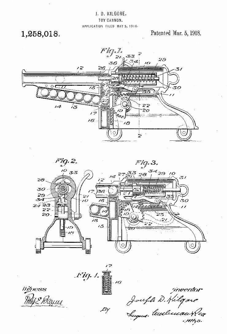
l. D. KILGORE. TOY CANNON.
APPLICATION FILED MM5. 191e.
1,258,018„ y Patented Mar. 5,1918.
Y «59” f’ / .
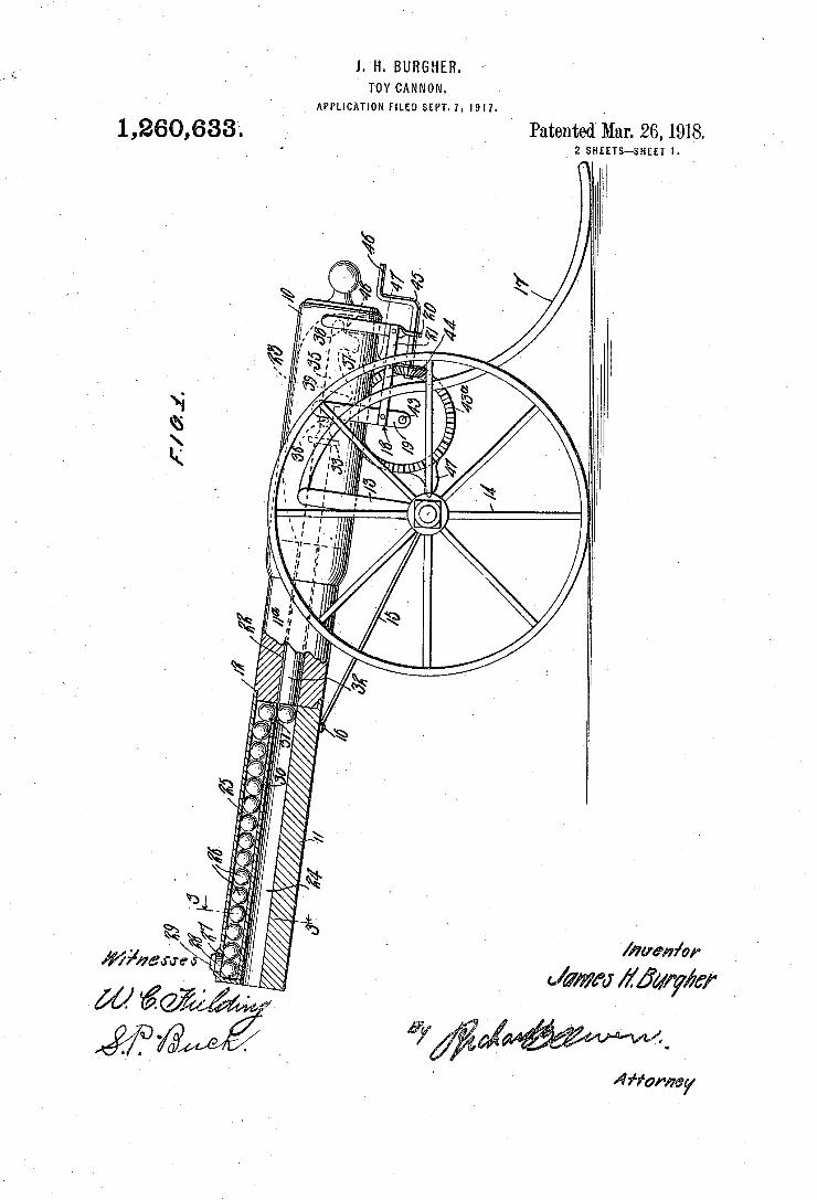
1. H. >BURGHEHl TOY CANNON.
APPLlC-ATION FILED SEPT. I. |917- _
Patented Mzu‘. 26, 1918. 2 SHEETS-SHEET I.
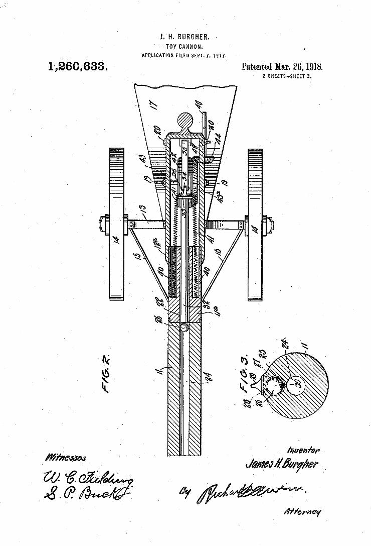
1. H. BURGHER. ’ ' TOY CANNON.
1,260,633..
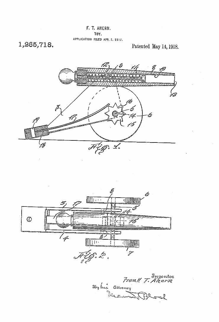
Y. T. AHERN. TûY.
APPLICATION mso APH. 1. 1911.
Patented May14,1918.
É
ÜÜ
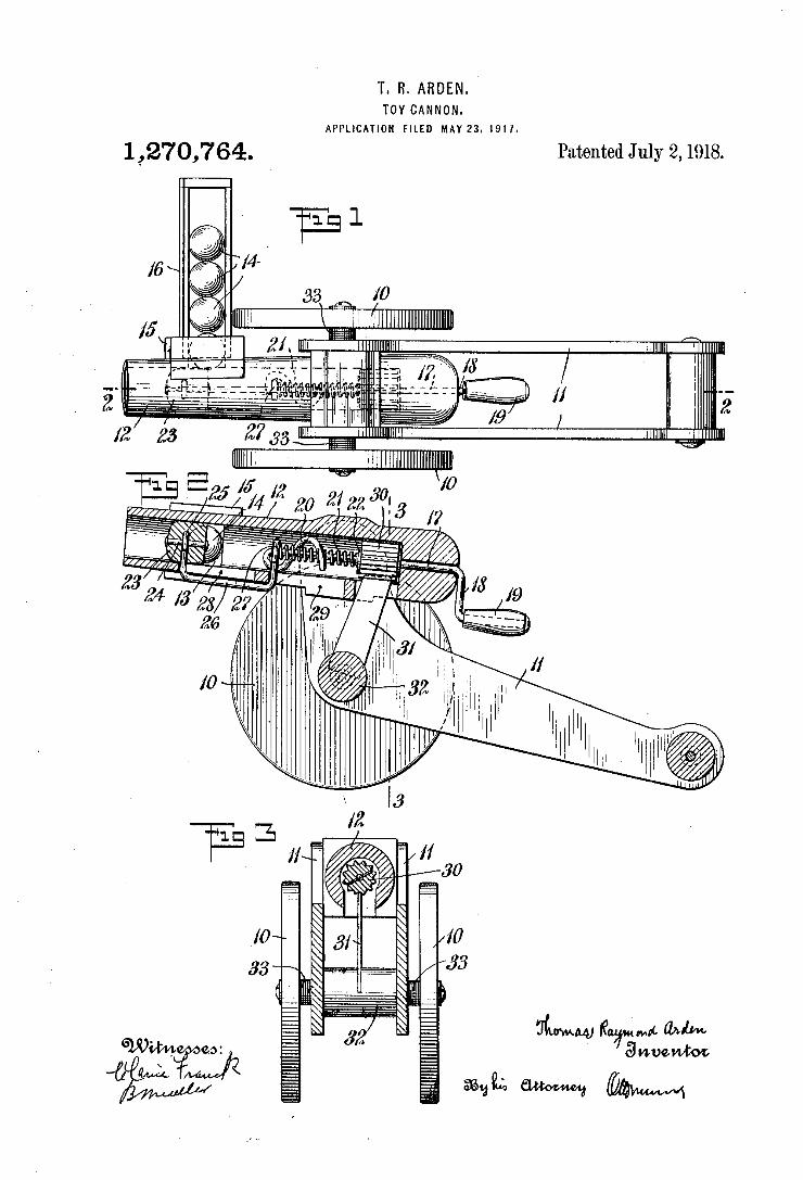
T. R. ARDEN. '
TOY CANNON. APPLICATION FILED MAY23. 19!].
1,270,764. Patented July 2,1918.
§$0\
11/1/72. " 24 A? as 2? "
Z6 .
,0 I? .
. 1| ‘
I]! ‘ lI" N1 w» w
*3:
NM“; M" and,“ 3 mnwtoz
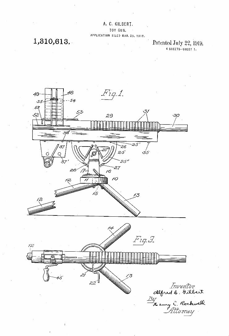
A. C. GILBERT. TOY GUN.
APPLICATION FILED MAR. 25. 1918.
1,810,613.- . ' Patented July 22, 1919. 4 SHEETS~SHEET l
jgwwzibz’
Jiforw
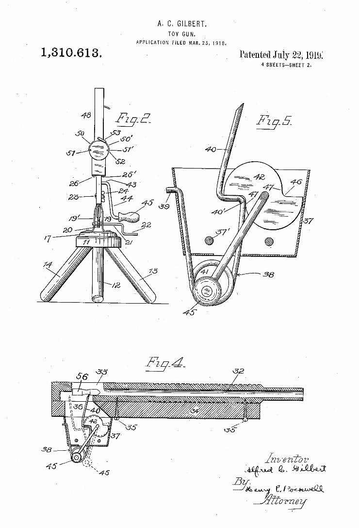
A. C. GILBERT. TOY GUN.
APPLICATION FILED MAR-25,1918.
1,3 1 0.6 1 3 . ~ » Patented July 22, 1919 4 SHEETS—SHEET 2.
32
A
_ _ . . _ _ _ _ _ _ _ _ .l
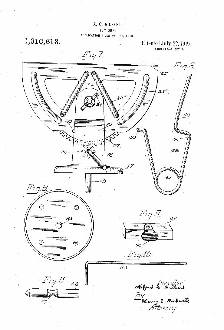
A. C. GILBERT. TOY GUN,
> APPLICATION FILED MAR-25, 1918-.
1,8 1 0,61 3. Emma July 22, 1919. 4 SHEETS-SHEET 3
37-5
$21M §V ' ‘
94 E. M. ?fomeg/
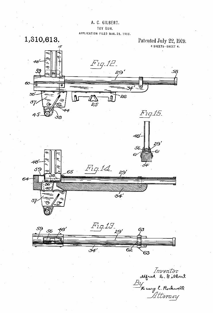
A. C. GILBERT. TOY GUN.
APPLICATION FILED MAR-Z5. I918.
1 ,3 1 0,6 1 3’ Patented July 22, 1919. 4 SHEETS—SHEET 4
/
64 """""""""""""" _________________________ n
é-ZQW 6. mm JZZZTW
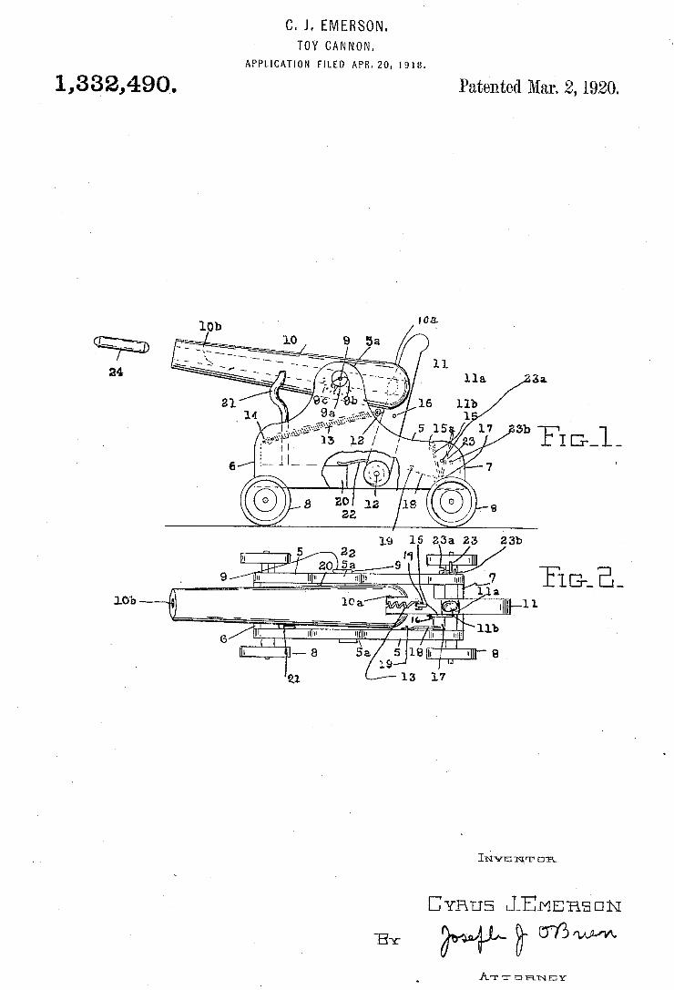
C. J. EMERSON. TOY CANNON.
APPLICATION FILED APR.20, 1918.
1,332,490, Patented Mar. 1920.
Imvmnm on
CYRUS \lEMEREEIN
BY WWW AT T EIRNBY
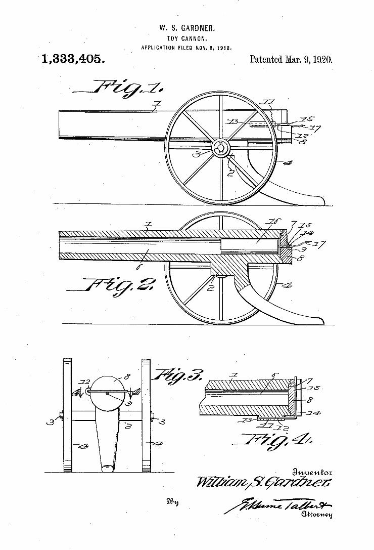
W. S. GARDNER. ' 10v CANNON.
APPLICATION FILED NOV. 97 1918.
'1‘,333,,405. _ , Patented Mar. 9,1920.
I.
I1’ ,1 / 1%
- 1g
4
I.
III! II"
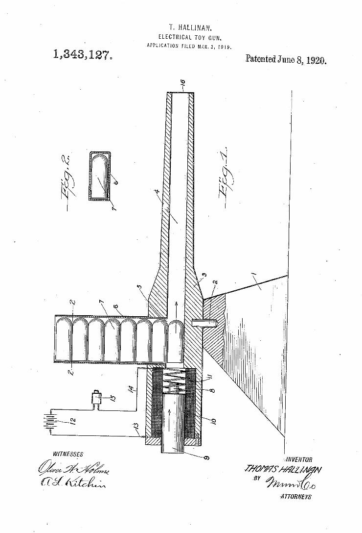
T. HALLINAN. ELECTRICAL TOY GUN.
APPLICATION FILED MAR. 3. 1919.
1 ,343, 1 27,, - Patented June 8, 1920.
WITIVESS'ES
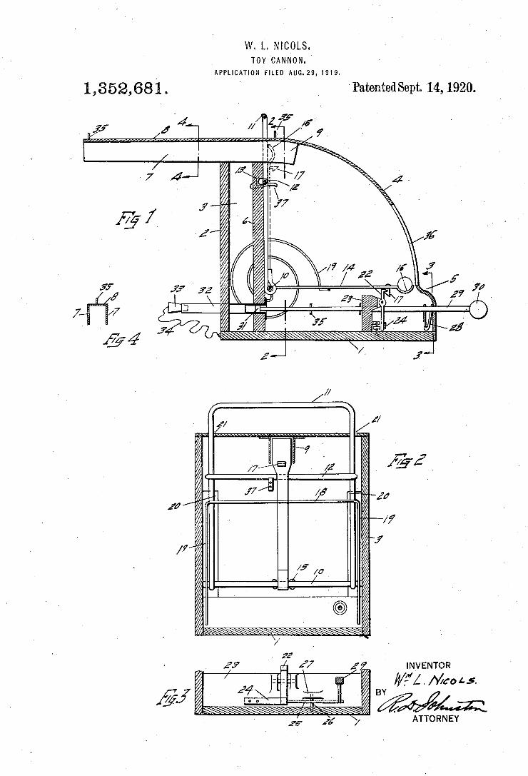
w. L. NICOLS. TOY CAN-NON.
APPLICATION-FILED AUG.29, I919. I
Patented Sept. 14, 1920.
q I \
a .. .6 (Ik- “
_ Z .l ( I. H
, J i D Y 4 .71, u
1,352,681‘
if
INVENTOR 4/7”! . Mac 1- .s.
' 'ATToRNEY
'4 I //
' 1/,”
1%
/7
8%
mm n”,
/. 4.
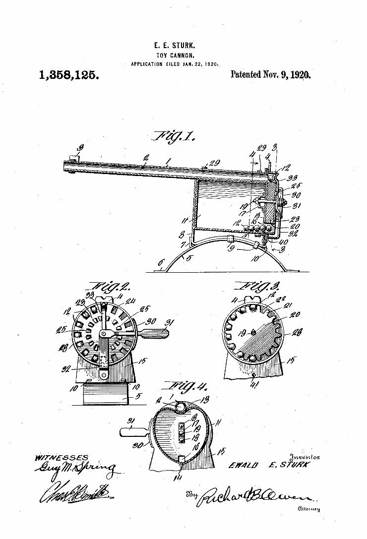
E. E. STURK. TOY CANNON.
APPLICATION man um. 22. |920.
Patented Nov. 9, 1920. 1,358,125.
ANNA
'rif/:w56 ses
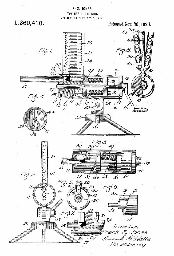
F.' S. JONES. TOY RAPID FIRE GUN.
APPLICATION FILED Dic. s, 1918.
1,360,410,
m
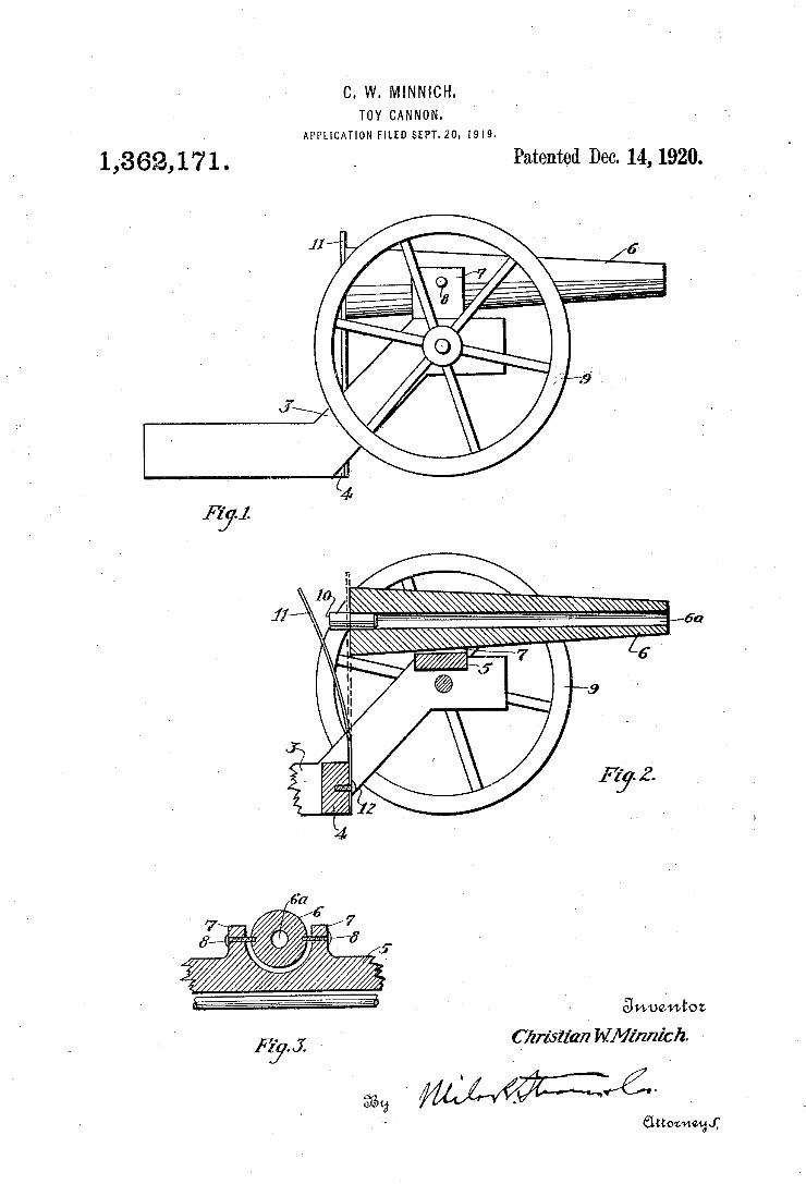
C. W. MINNICH. TOY CANNON.
APPLICATION FILED $EPT.20, 1919.
1436211 7 1 . _ Patented D60. 14, 1920.
I
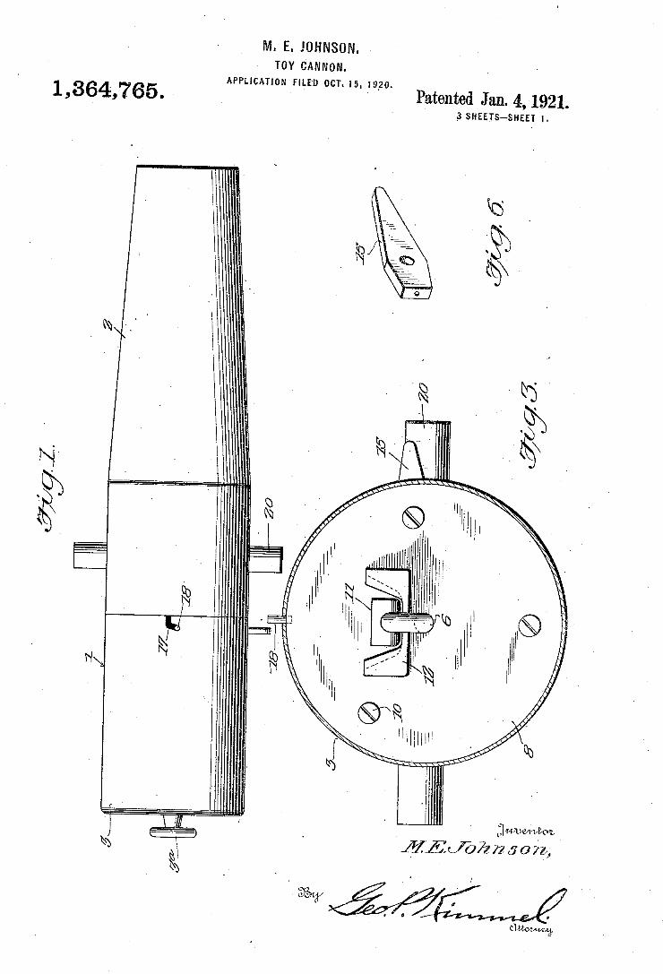
M. E. JOHNSON. TOY CANNON.
APPLICATION FILED on. 15, 1920.
Patented Jan. 4, 1921. _3 SHEETS-SHEET l.
1,364,765.
11511777222503,
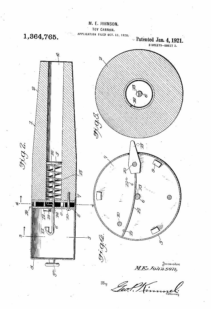
APPLICATION FILED OCT- 15. 1920‘ 1,364,765.
I \ %N m
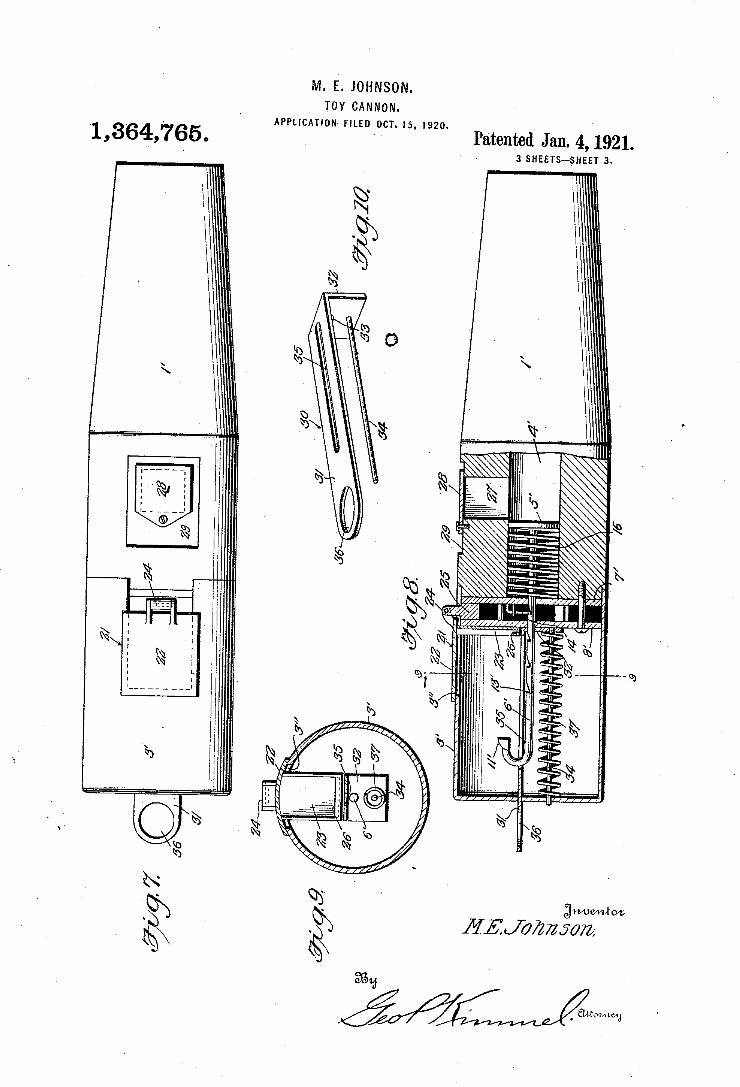
M. E. JOHNSON. TOY CANNON.
APPLICATION F|LED_0CT. 15, I920. ‘1,364,765.
I,
gwvemlroz MEL/‘072725022;
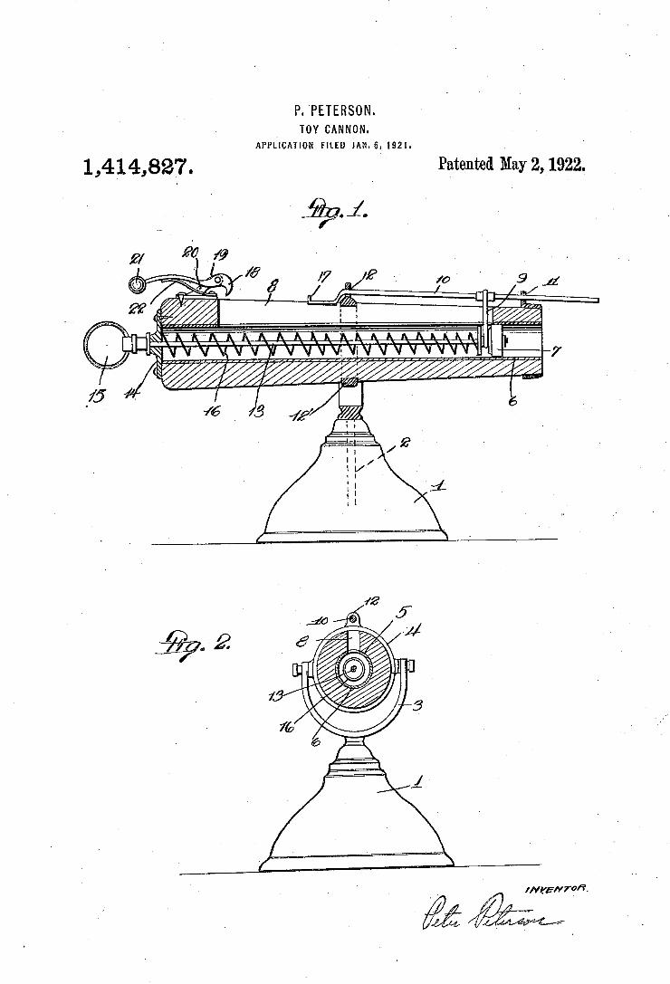
P. PETERSON. TOY CANNON.
APPLICATION FILED JAN-6.1921.
1 ,414,827. Patented May 2,1922.
I I? -. /0 ' 9 1i
v
2 % W42
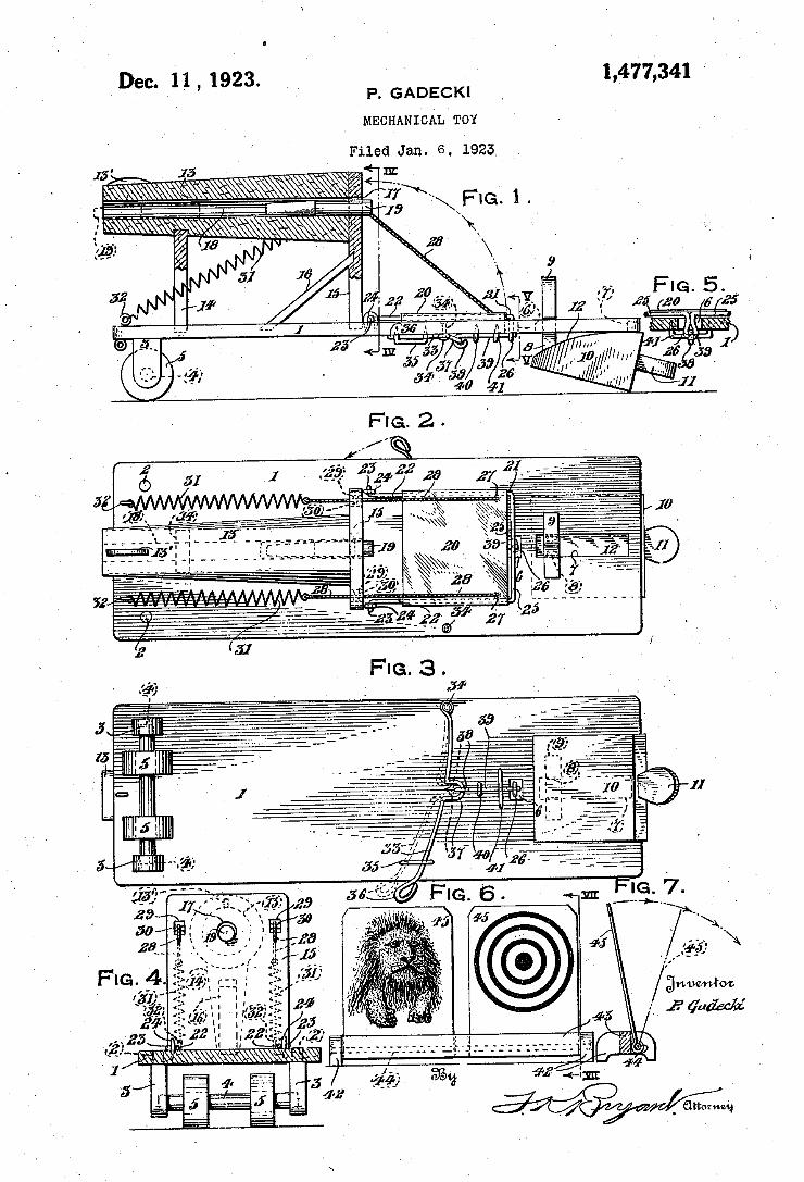
1,477,341 , 1923. P. GADECKI
MECHANICAL TOY
Dec. _11
Filed Jan. 6. 1923. 15
FIG.2
'4. km“
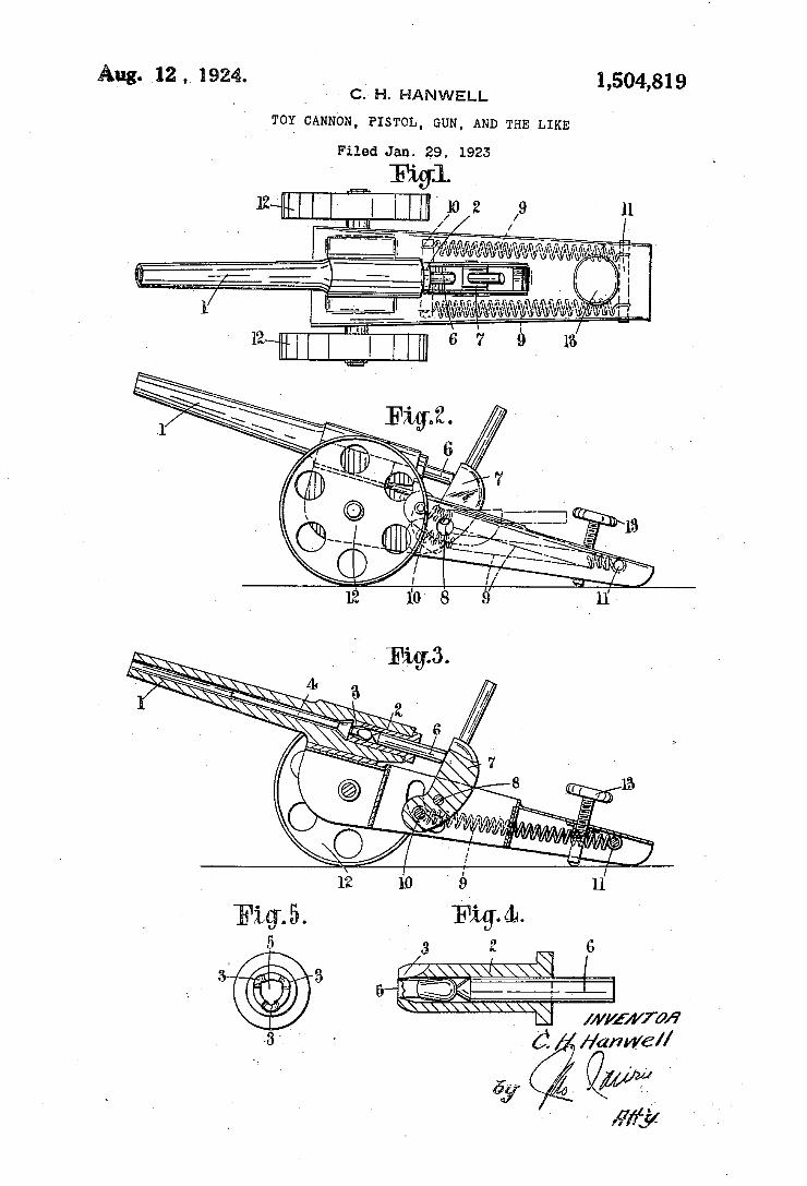
Aug. 12, 1924. _ 1,504,819 ` Y l C.' H. HANWELL Y Y
TOY CANNON, PISTOL, GUN, AND THE LIKE
Filed Jan. 29. 1923
@y á- . y
- ,my
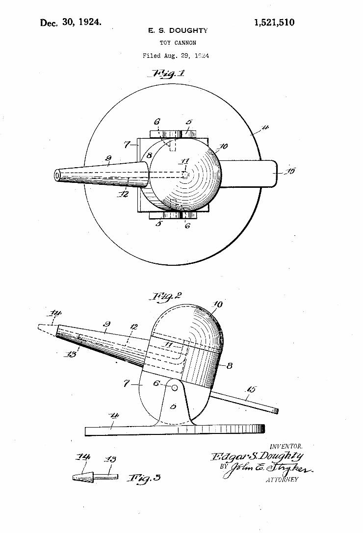
Dec. 30, 1924. 1,521,510 ' E. s. DOUGHTY
TOY CANNON
Filed Aug. 29, 1924
r I . ' IHHHHIIIIIHHHI
I INVENTOR.
34' 3,5 25.’ $021 Z5?
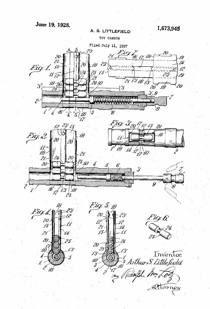
June 19, '1928. 1,673,945 » A. S. LITTLEFIELD
TOY CANNON
Filed July 11, 1927
e’ f Ik w j T
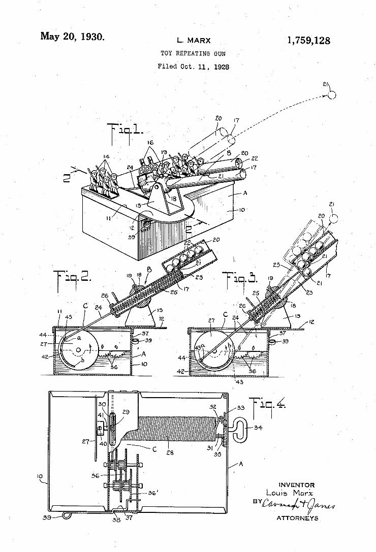
May 20, 1930. L. MARX _ 1,759,128 TOY REPEATING GUN ’
Filved Oct. 11. 1928‘
INVENTO‘R Louis Marx
BYC i (vigil/HM ATTO R N EYS
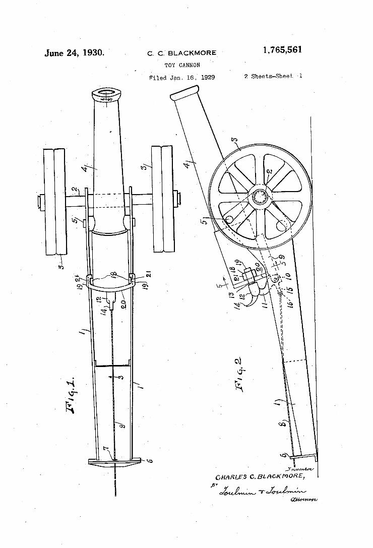
June 24, 1930. . c_ Q BLACKMQRE - 1,765,561
TOY CANNON 7‘ '
Filed 'Jan‘ 1e.v 1929 2 Sheets-Sheet 1
CHARLES c. BLACKMORE,_
WW
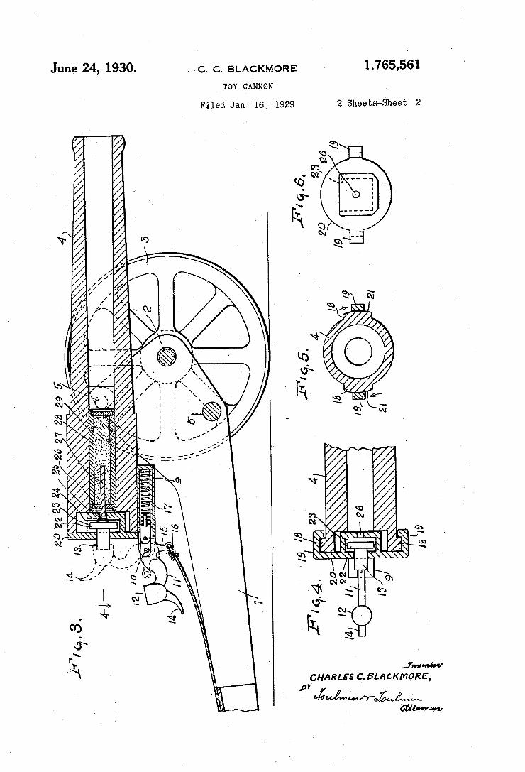
1,765,561 I June 24, 1930. - C. C, BLACKMORE
TOY CANNON
Filed Jan. 16, 1929 2 Sheets-Sheet 2
ME, WM
2 m‘ v 1m Q c
\\ h J L
ah :. B. * 1 _ Q. mm 2 \ 3 B .
/ QN W
W mm . 3 m5 . P
N
/,,,~,,, \\ \ I 4
\ I.(/\\ .\\ h x. a.
//+\\ \__ .3 .m , _ will--. ._ 8 ., n /, \ ____ a . § 5 , x 3
?n? / / . -M. ._.
9.
A h
mm QM R a 3 swam NW N
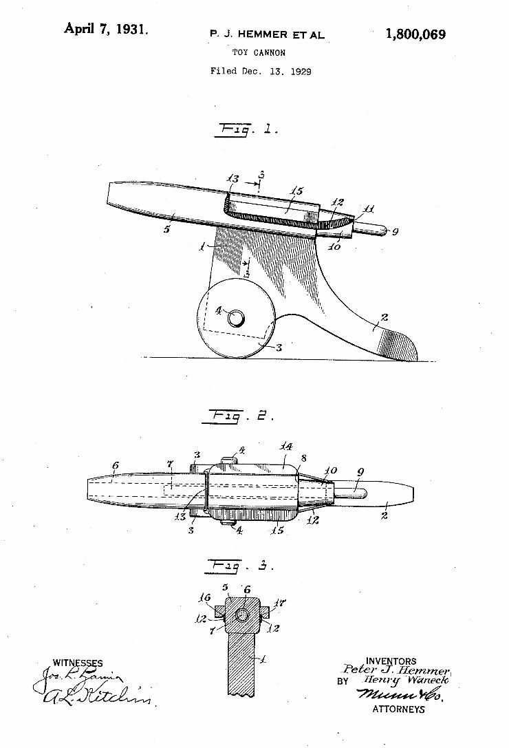
APril 7,, 1931. P. J. HEMMER ET AL 1,800,069 ‘ ‘TOY CANNON
Filed Dec. 13. 1929
INVENTORS Peier Jfj'emm _ BY .lfenly ‘WEI/"9c
1%. ATTORNEYS
“T55 5 -
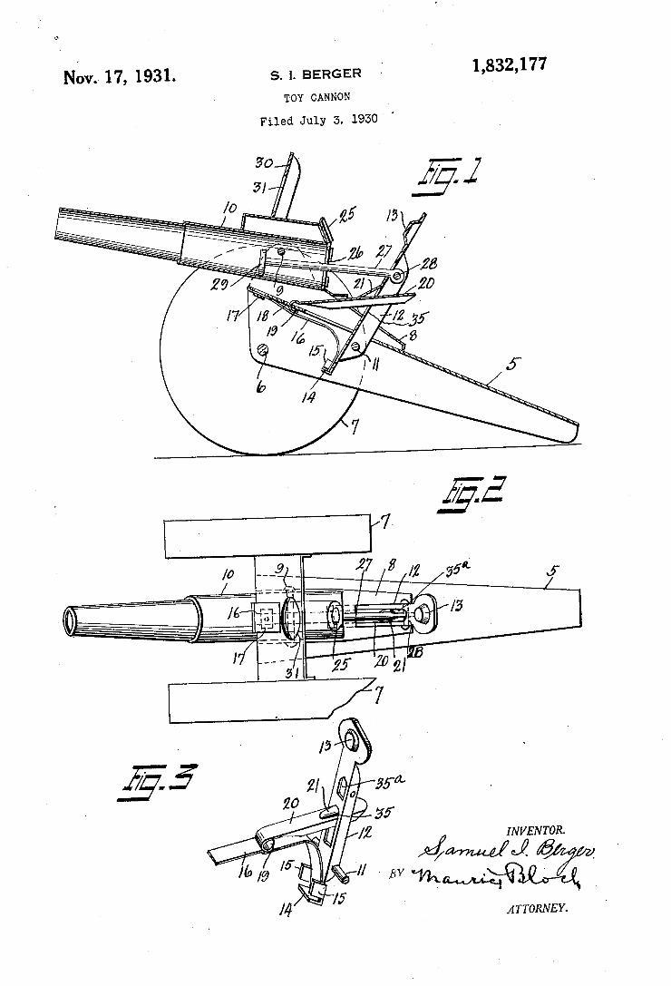
1,832,177 Nov. 17, 1931. s. 1. BERGER TOY CANNON
Filed July 3. 1930 '
I N VEN TOR.
/\ _ Jmé/J. @ _
g \l // - 13V: ATTORNEY.
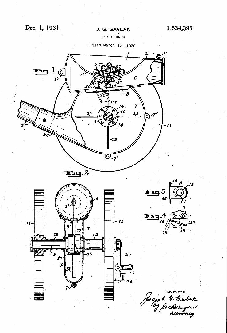
1,834,395
%M¢ @- {1M
J. G. GAVLAK
TOY CANNON
Filed March 10' 19.30
Dec. 1, 1931.
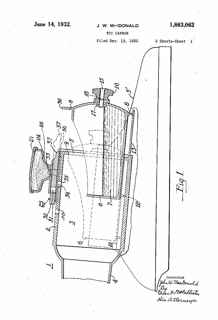
1,863,062 June 14, 1932. J. w. MaCDQNALD TOY CANNON
l ‘ Filed Dec. 13, 1930 2 Sheets-Sheet
NVENTOR
WWW
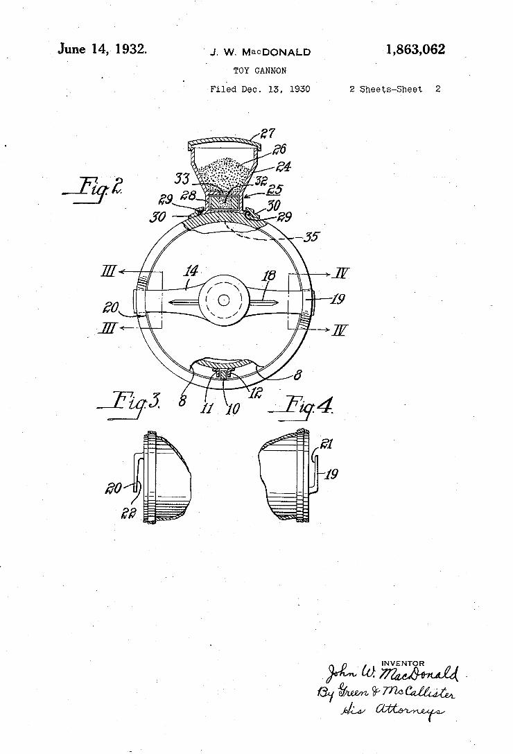
June 14, 1932. J. w. MaCDONALD 1,863,062
' TOY CANNON
Filéd Dec. 13, 1950 2 Sheets-Sheet 2
INVENTOR
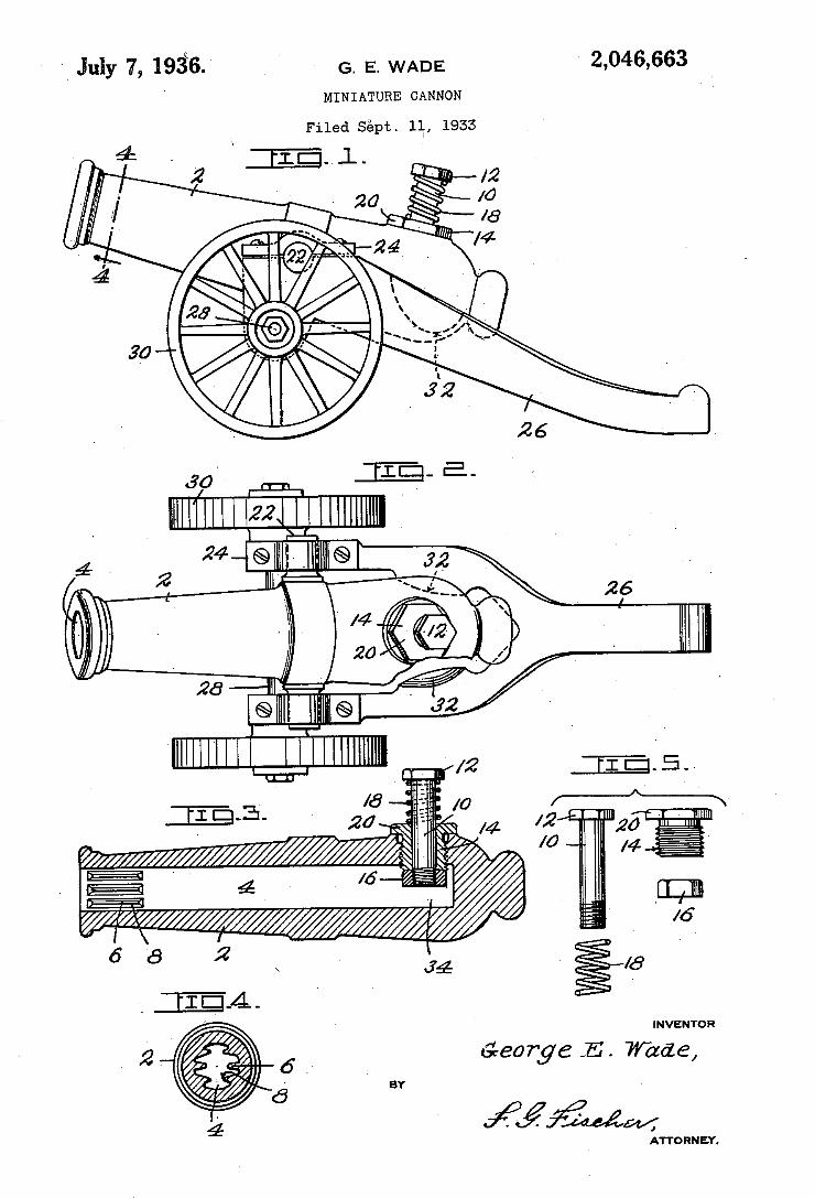
' July 7, 193B. G_ E, WADE 2,046,663
MINIATURE CANNON
Filed suept. 111., 1955
é z 24 @v ~ @ 7 3'2 \ ' “w; _ \ 26
/4 w >
20 26 -
® ® 32
L_Ul-J ' l ’ /2
E -3 - ~ - /4
g g ' 4 l6
I L??? 42////J///%// 8 . 34
INVENTOR
George -E. Wade, BY
ffffwzw, ATTO RN EY.
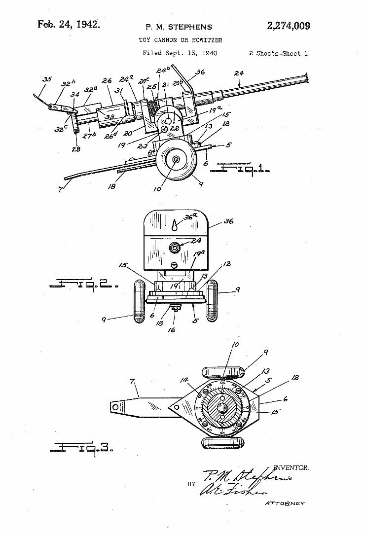
Feb- 24, 1942. P. M. STEPHENS 2,274,009 TOY CANNON OR HOWITZER
Filed Sept. 13, 1940 2 Sheets-Sheet l
T‘ ,| my ‘ ml 19" § / J2
ATTOEN EY
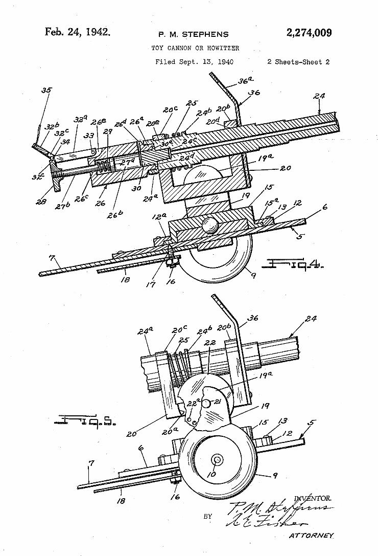
2,274,009 Feb. 24, 19421. P. M. STEPHENS TOY CANNON OR HOWITZER
Filed Sept. 13, 1940 2 Sheets-Sheet 2
- ATTORNEX
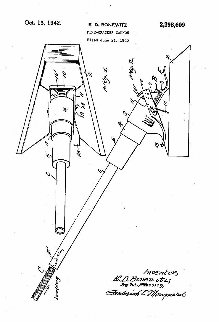
Oct. 13,‘ 1942. E.‘ o. ‘BONEWITZ 2,298,609 FIRE-CRACKER CANNON
Filed June 21>. 1940
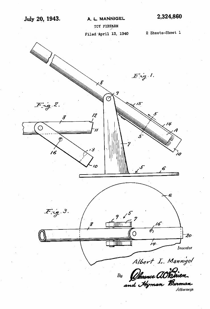
July 20, 1943- A. 4. MANNIGEL 2,324,860 TOY F'mgpam
Filed "April 13, 1940 2 Sheets-Sheet l
? 4/ 7 lgllllllll-ll ‘
A/éerf I. Manhéée/ ,- éy
and W .vumuo Attorneys
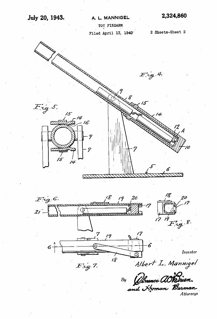
July 20, 1943. A. L. MANNIGEL 2,324,860 ' ‘ ' TOY FIREARM . - '
Filed April :3. 194a ‘ 2 Sheets-Sheet 2
1/9 9A4? 6+ C JQ\ ‘ - '-. 6
. , {I ‘O I _ Inventor I
16'’ ’ ‘ . i/l/5er7“ L’. Marmége/ By
Attorneys 1
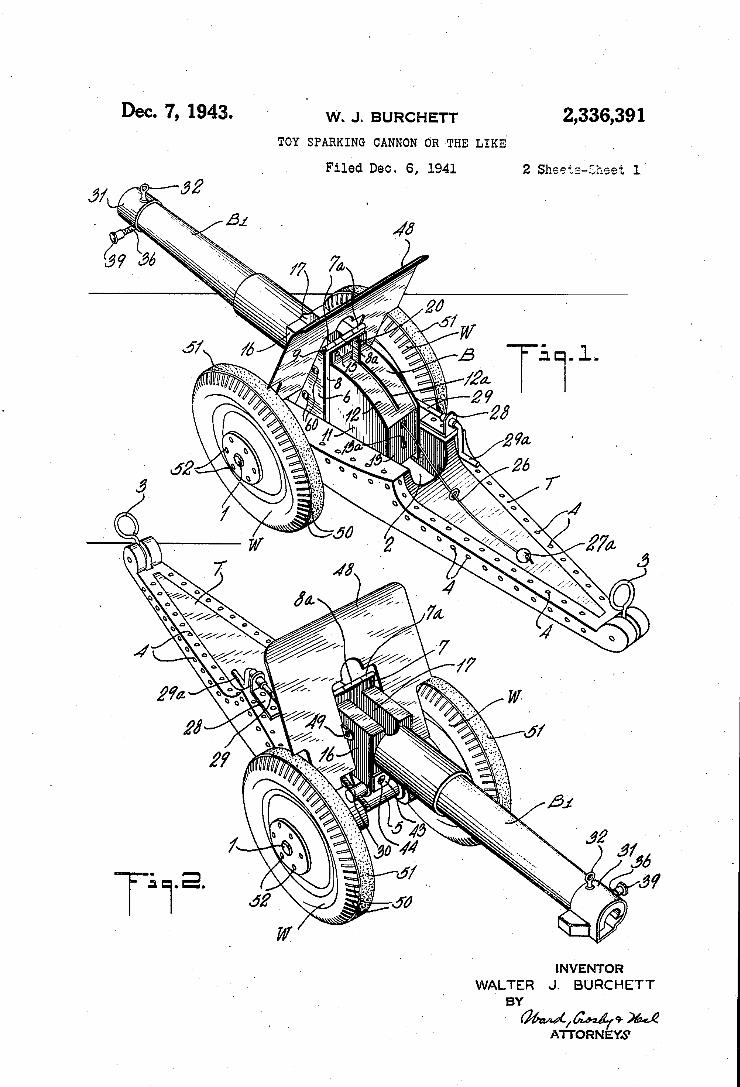
Dec. 7, 1943. w. J. BURCHETT 2,336,391 I TOY SPAHKING CANNON OR THE LIKE. .
Filéd Dec. 6, 1941 2 Sheets-?nest 1'
l lllé
INVENTQR
BY
W/MQM ATTORNEYS
2,336,391 > Dec. 7, ‘1943. W. J. BURCHETT '
TOY SPARKING CANNON >0R' THE LIKE
'Filed Dec. 6, 1941 ' Y 2 Sheets-Sheet 2
L
_ W .l. U. 5....51 m . J Q, §w mié NW1 .
mzmu i
March 6, 1945., 1-_ R‘MENDLES 2,371,059 TOY GUN
Filed May 29, 1943 3 Sheets-Sheet l
24
I'll O
I ul'cutor -
3mm I
March 6, 1945. V T_ R‘ MENDLES - 2,371,059
' TOY GUN '
Filed May 29, 1943 3 Sheets-Sheet 2
$42
30174
1 ' I lm'wlmr
72m E/WendZes $5. .+
WWW
‘March 6, ‘1945. _ ' T_ R MENDLES 2,371,059
TOY GUN
Filed May 29, 1943 3 Sheets—Sheet 3
~ /9
44
'J g”
aw" ‘ i '47
> W, %
71,9040)??? M rad/es
45' By I ,;..
M55104} g M35518]:
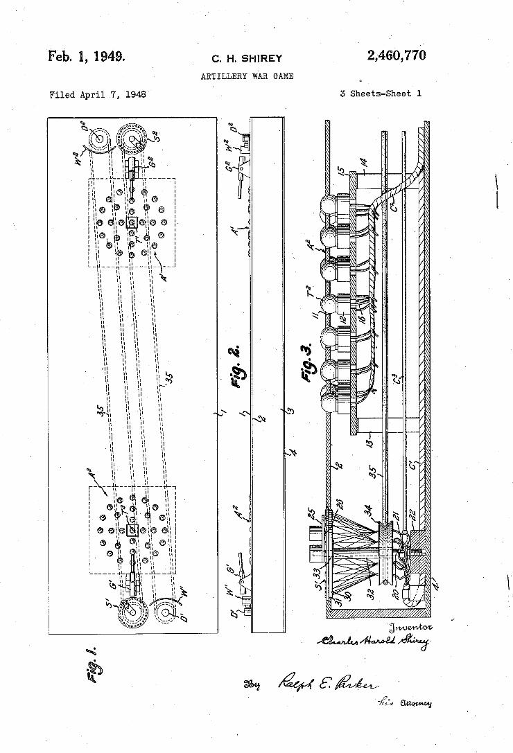
2,460,770 Feb. 1, 1949. c. H. sHlRl-:Y ARTILLERY WAR GAME
3 Sheets-Sheet l Filed April '7, 1948 '
.mfàk .N .mu NY
., . à ̀ E ìâ
ws @46m
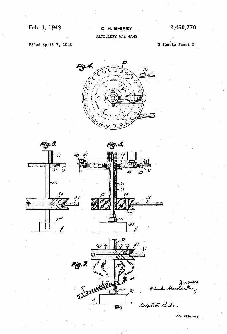
` Feb. 1, 1.949. ' c. H. sHlREY l 2,460,770
ARTILLERY wAR GAME
Filed April 7, 1948 s sheéts-sheet 2
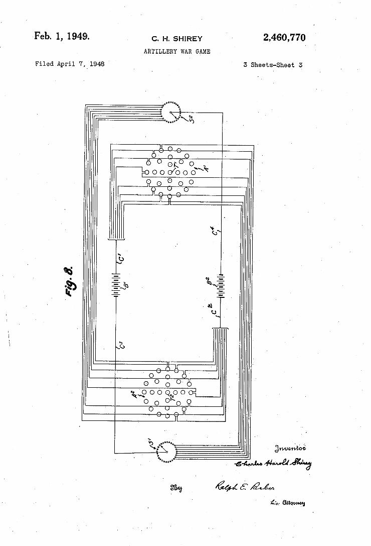
Feb. l, 1949.
Filed April 7,4 1948
C. H. SHIREY
ARTILLERY WAR GAME
2,460,770
3 Sheets-Shea?l 5
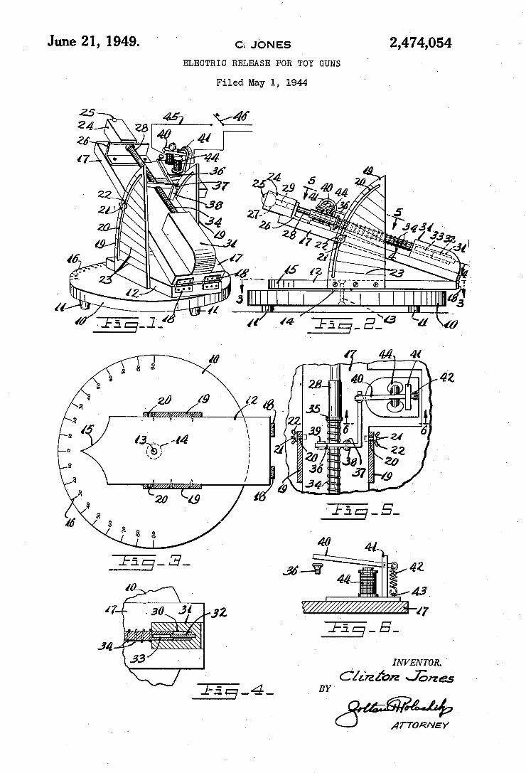
2,474,054 June 21, 1949. Q; JONES ELECTRIC RELEASE FOR TOY GUNS
Filed May 1, 1944
_ INVENTOR.
Clz‘rzz‘azz Jérzas
6 ATTORNEY
1
_ BY'
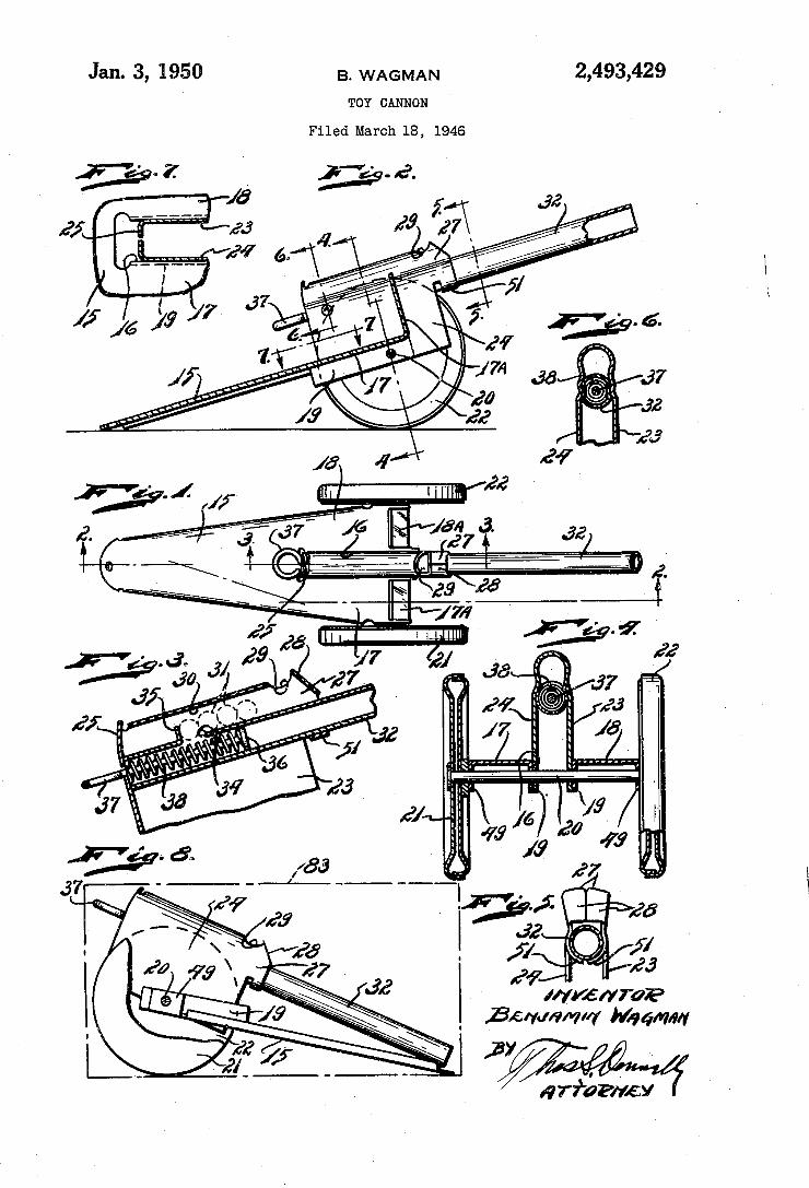
Jan. 3, 1950 B, wAGMAN 2,493,429 TOY CANNON
Filed March 18,‘ 1946
'7 N 07/6/2170?
I Bar/MM”! "441mm!
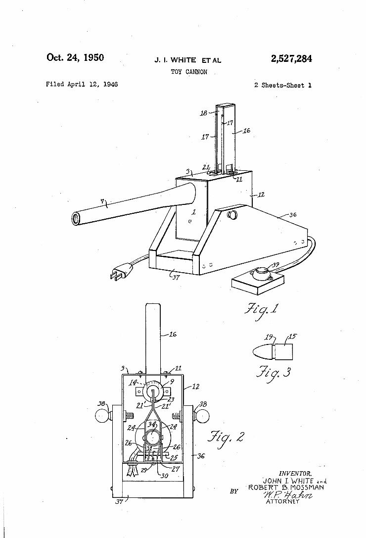
Oct- 24, 1950 J. l. WHITE ET AL 2,527,284
TOY CANNON
Filed April 12, 1946 2 Sheets-Sheet 1
24 34 Z; 7 - z' , Z
. 26 3 Z6 f z; '36 \
29: 30 Z INVENTOR. JOHN I.WHITE av-ni
‘ ROBERT BMOSSMAN
. WP #CLM 37/ ATTORNEY
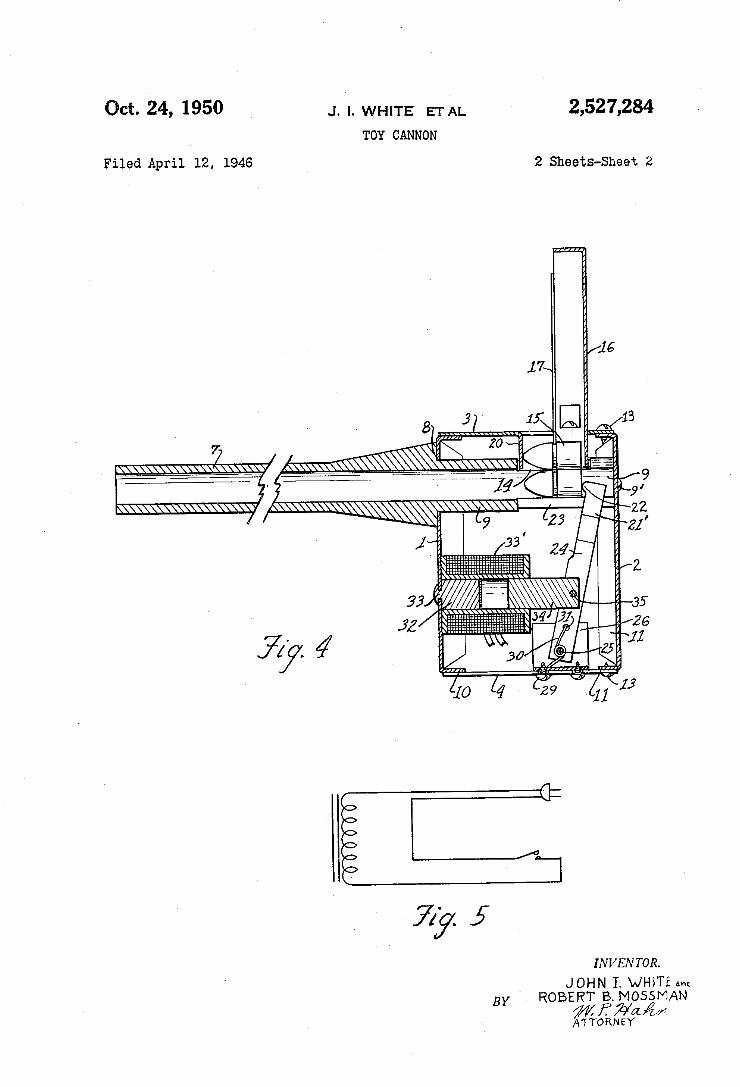
u——_.__________v‘4 “
J. ‘I. WHITE ETAL 2,527,284 TOY CANNON
Oct. 24, 1950
Filed April 12, 1946 2 Sheets-Sheet 2
33 35 32 34 3] 26
. J]
7/ % 30 Z1 Z3
I N VEN TOR.
4 JOHN I. wm'rz BY . ROBERT 1B.MOS5MAN
,. 4%” A'T'TORNEY
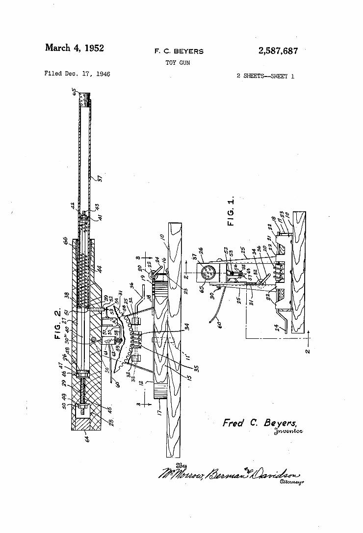
March 4, 1952 F_ C, BEYERS 2,587,687 TOY GUN
Filed Dec. 17, 1946 2 SHEETS--SHEET l
38
A, FIG. 2.
5049 2946 30%40275/
Fred C- B2 Yew'l
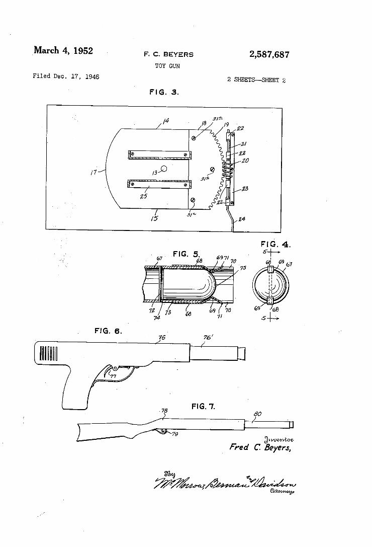
,March 4, 1952 F. c. BEYERs 2,587,687 TOY GUN
Filed Dec. 17, 1946 2 SHEETS--SHEET 2
FIG. 3.
gri/Umm Fred C ßeyers,
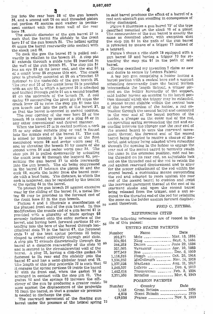
2,587,687
ing into the rear bore 2S of the gun breech 2t, and a second nut 5@ on said threaded piston rod portion #l5 secures said washer in perma~ nent contact with the front wall oil the rear bore 28. ' The outside- diarneter oi the gun barrel 31 is
such that the barrel nts slldably in the front bore 2l of the gun breech 2t. The helical spring lid urges the barrel rearwardly into Contact with the shock pad di’. To cool: the gun the barrel 3l is pulled out
wardly in relation to the breech 21%, A stop pin iii extends through a guide tube E52 inserted in the wall of the gun breech The stop pin 5i has an eye 53 on its lower end, and the end 5tV oí a crank lever 55 engages this eye. rThe crank lever is pivot-ally mounted at on a’bracket 5l "astened tc the underside o'î the gun breech 2li.
,e of the cranl: lever o is provided with an eye 5“, to which a lanyard is attached and trained '. on a second bracket u2 on the underside ci the breech "il «A coil spring 53s surrounding the pivot pin 5 urges the crank lever to raise the stop pin 5i into the gun breech and into the path of the barrel 3l, so that the barrel isssecured in cocked position. The rear opening of the rear bore 253 of the
breech 26 is closed by means of a plug or in any other conventional and desired manner. W hen the barrel El is in cocked position a cor * or any other suitable plug or wad is forced
into the muzzle end of the barrel 3l'. The gun is aimed by training it by means of the ilrst mentioned worm 2li and sector worm gear i“, and by elevating the breech ‘ill by means of the second 35i and sector worm gear rthe stop pin iii is pulled downwardly actuating the crank lever 5:5 through the lanyard Sil, per n'iitting the gun barrel 3l to slide rearwardly into the gun breech. The air being compressed in the barrel 3l between the piston tl and the cork expels the latter from the barrel muz zie with a loud bang. The distance, to which the cork is projected, can be regulated by the tension of the spring dll in the barrel. To protect the gun breech 2t against excessive
wear by the sliding of the barrel a metal lin ing 65 may be provided in the forward end of the `front bore ¿El in the gun breech.
Figures a and 2i illustrate a modification of the plugged front end et the gun barrel. In this modification the muzzle end of a gun barrel @l is provided with a plurality of blade springs 68 securely fastened onto the outer surface of the barrel, and having bent, forward portions Sil ex tending into the bore of the barrel through lon gitudinal slots ‘iii in the barrel El, the foremost ends li of the bent spring portions il@ being shaped to extend outwardly through said slots. A stop pin 'le extends diametrically through the barrel at a distance rearwardly of the slots l@ and is secured in the circumferential wall of the barrel. A plug lf3, having a disk-like gasketfid fastened to its rear end fits slidably into the barrel El and has a semi-globular iront end l5. ’.ïhe length or" this plug projectile riii is such that it engages the spring portions td inside the barrel tl' with its front end, when the gasket 'le is arranged in contact with the stop pin l2. rll‘he gasket lil and the springs SSB increase the eni ciency of the gun by producing a greater resist
v ance against the displacement of the projectile "it from the barrel, so that a greater air pressure is needed to discharge the gun. The rearward movement of the floating gun
barrel under the pressure of the helical spring
5
10
20
25
30
in said barrel produces the eiïect of a barrel of a real anti-aircraft gun recoiling in consequence of being discharged. _
vFigure d illustrates a gun barrel ‘i8’ oi the type described mounted on the stoel; liâ of a pistol'. The construction ci the gun barrel is exactly the same as described above, with exception that the stop pin 5l in the path ci the gun barrel isy retracted by means of a trigger 'il instead of a lanyard.
Figure '7 shows a rifle stock 'J8 equipped with a gun barrel di? and having a trigger l@ for re tracting the stop pin el in the path ci said barrel. »Having described my invention I claim as new
desire to secure by Letters Patent: A toy pop gun comprising a holder having a
barrel portion with a central bore and a support extending downwardly from the barrel portieri intermediate the length thereof, a. trigger piv oted on the holder forwardly of the support, said holder having an opening in its barrel por- tion through" which the 'gger ina-y be extended, second barrel slidable ‘within the> central bore
oi the barrel portion ci the h '.der, a rod ex~ through the barrel and connected
to the rear end oi the barrel portion of the c_unger on the outer end oi the rod, holder, _
spring surrounding the rod and ex l
an operating ten between the plunger the rear end of the second barrel to urge the rearw rd move inent thereof, the forward or" the second barrel being adapted to receive a charge oí ina~ terial, said trigger being adapted when extending through the opening the holder to engage the
. rear end ci the second barrel to normally retain
Li()
50
55
60
70
75
in the extended position, rod be ing threaded on its rear end, an adjustable lock nut on the threaded end of the rod to retain the _rod against rearward displacement and to allow for the proper adjustment oi the. rod within the second barrel, a cushioning means surrounding the rod and adapted to react against the rear end of the second barrer to lcushion and resist the rearward movement thereof at the end of its rearward stroke and upon the second barrel being released from the trigger, and a nut se cured to the threaded end oi the rod tor retaining the saine on the holder against forward displace nient therefrom. » «
FRED C. EEYERS.
@FEED The following references are of record in the
ille of this patent:
ÚNETE@ STATES PATENTS
Number Name Date 295,271 Mole ____________ __ Mar. 18, 1884 304,654 King ____________ __ Sept. 2, 18S-i 3fi4,353 Dannn __________ __ June 29, 1885 381,695 Vavasseur _______ __ Apr. 10, 1888 971,549* Roe _______________ ,_ Dec. e, 191€)
1,114,615 Hough __________ __ Get. 2li, 19111 1,204,803 McCullough ______ __ Nov. 1a, 1916 1,237,928 MacLean ________ __ Aug. 21, 191'! 1,248,507 Leiever ___________ __ Dec. 4, 1917 1,482,424 Zimmerman _____ -_ 5, 1924 2,371,059 Mendles __________ __ Mar. 6, 1945
FGREÍGN PATENTS
Number Country Date 1,181 Great Britain _ _ _ _ _ _ _ _ _ __ 1354
4,078 Britain ________ __1____ 1915
419,936 France _______ _____- Nov. 9, 1910
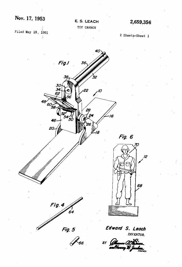
Nov. 17, 1953~ E. s. LEACH 2,659,356 TOY CANNON
Filed May 18, 1951 2 Sheet‘s-Sheet 1
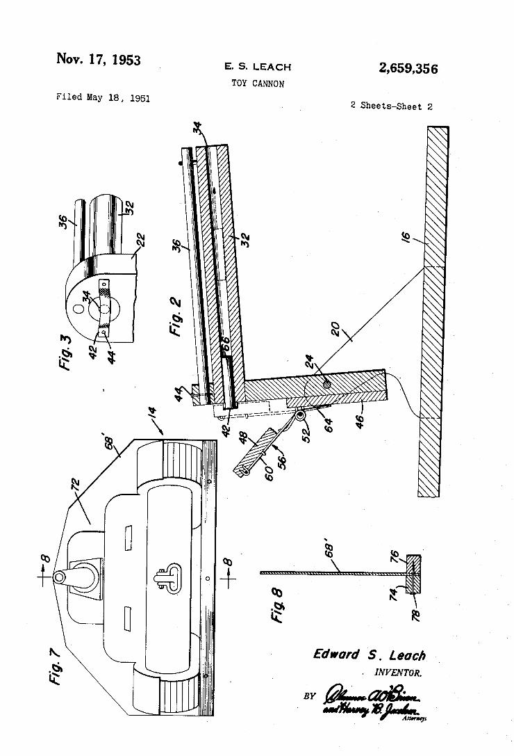
Nov. 17, 1953 E. S. LEACH
TOY CANNON
Filed May 18 , 1951
l i \
E
l. \ l
w J‘ n 9%‘;
2,659,356
2 Sheets-Sheet 2
//// W
Fig. 7 BY
Edward 5. Leach ‘
. INVENTOR.
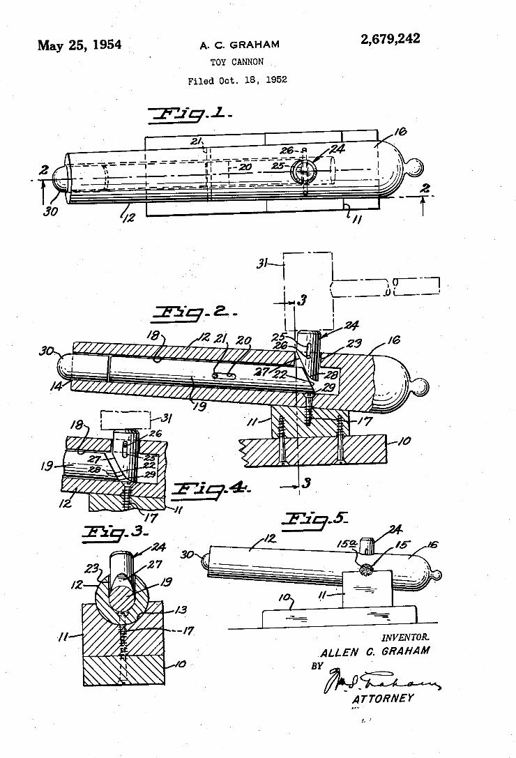
May 25, 1954 .I A, Q GRAHAM 2,679,242 ‘ TOY CANNON
Filed Oct. 18, 1952
155-2. , I l .J 4% l8 2 '
a gzz////////Lg)////§///2/’ 20' 22% " 29 I6 , , .
‘w _ I] _ . .3722 - 23 ‘
l4 - ‘* _ ‘ .
v I_“"'“s ‘,9 > .
/8 i__ "[223, '/// - __/7 .u I . ' . 2/0
19 » } '
' INVENTOR.
ALLEN 0. GRAHAM 27/ "Wm
' QTTOR/VEY
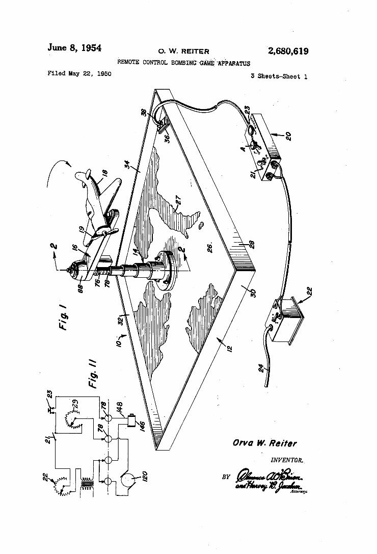
‘2,680,619 0. w. REITER
REMOTE CONTROL BOMBI-NGPGA‘MEMPPARATUS
June 8, 1954
I5 Sheets-Sheet 1 Filed May 22, 1950
Orva W- Reifer
, IN V EN TOR.
BY “1% mfg”
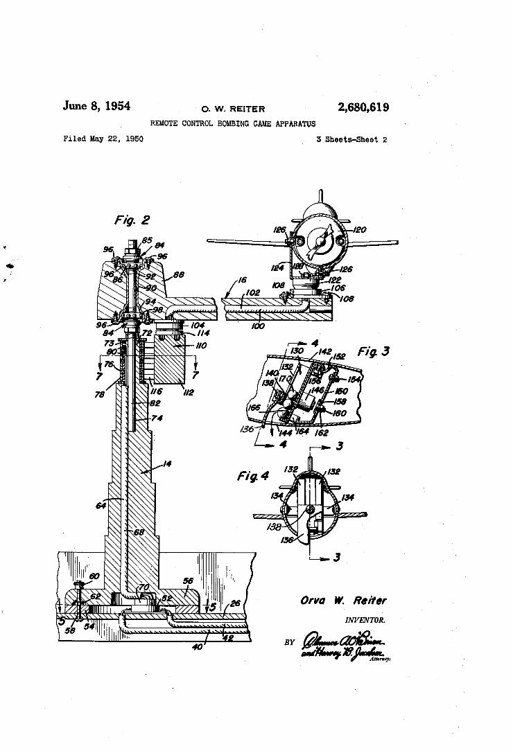
2’ 9619 June 8, 1954 o. w. REITER
REMOTE CONTROL BOMBING GAME APPARATUS
3 Sheets-Sheet 2 Filed May 22, 1950
I
5: '
I
Orva W. Reiier
INVENTOR.
- 1
BY ad
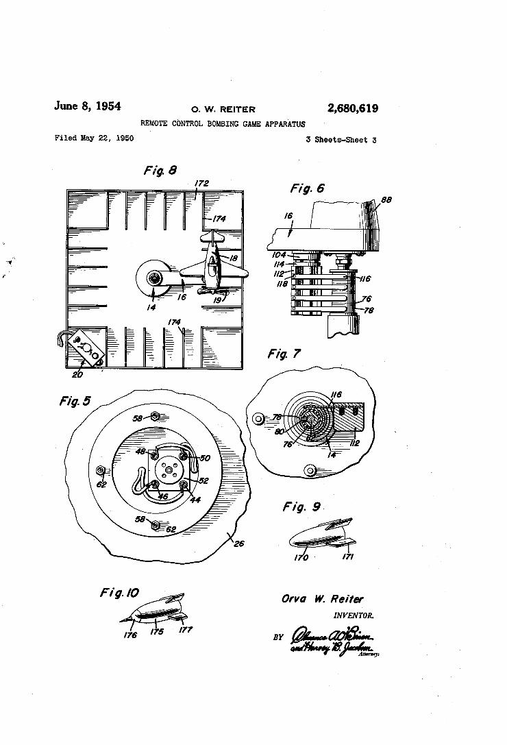
June 8, 1954 o. w. REITER 2,680,619 REMOTE CONTROL BOMBING GAME APPARATUS
Filed may 22, 1950 3 Sheets-Sheet 3
F ig. l0 Orva W. Reirer
mmvron.
17s '75 '77 BY
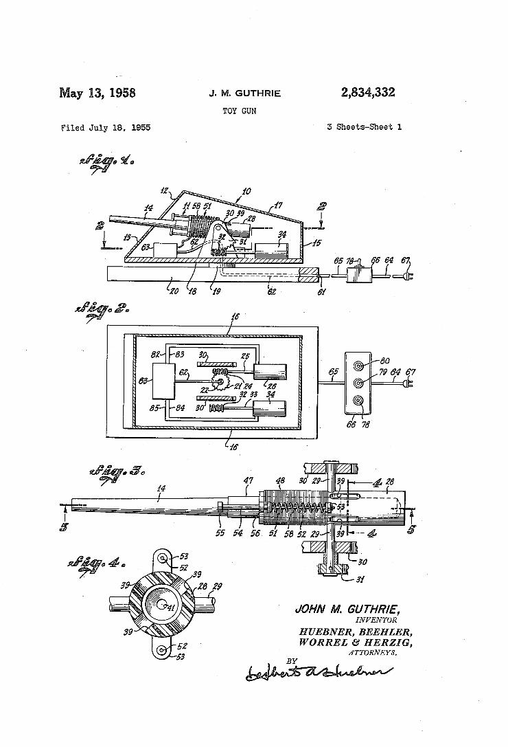
J. M. GUTHRIE 2,834,332 ay 13, 1958 TOY GUN
5 Sheets-Sheet 1 Filed July 18, 1955
JOHN M. GUTHR/E', INI/ENTOR
HUEBNER, BEEHLER, WORREL £9’ HERZ] G,
ÄTTORNEYS.
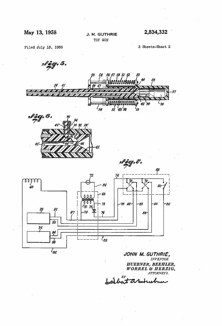
2,834,332 May 13, 1958 J. M. GUTHRIE TOY GUN
5 Sheets-Sheet 2 Filed July 18, 1955
53 ¿55 5456575651 Í
49 47"
I Inn“
86 ` JOHN M. GUTHR/E,
INVENTQR H UEBNER, BEEHLER, WORREL ¿d HERZIG,
lfTToRNEl/s.
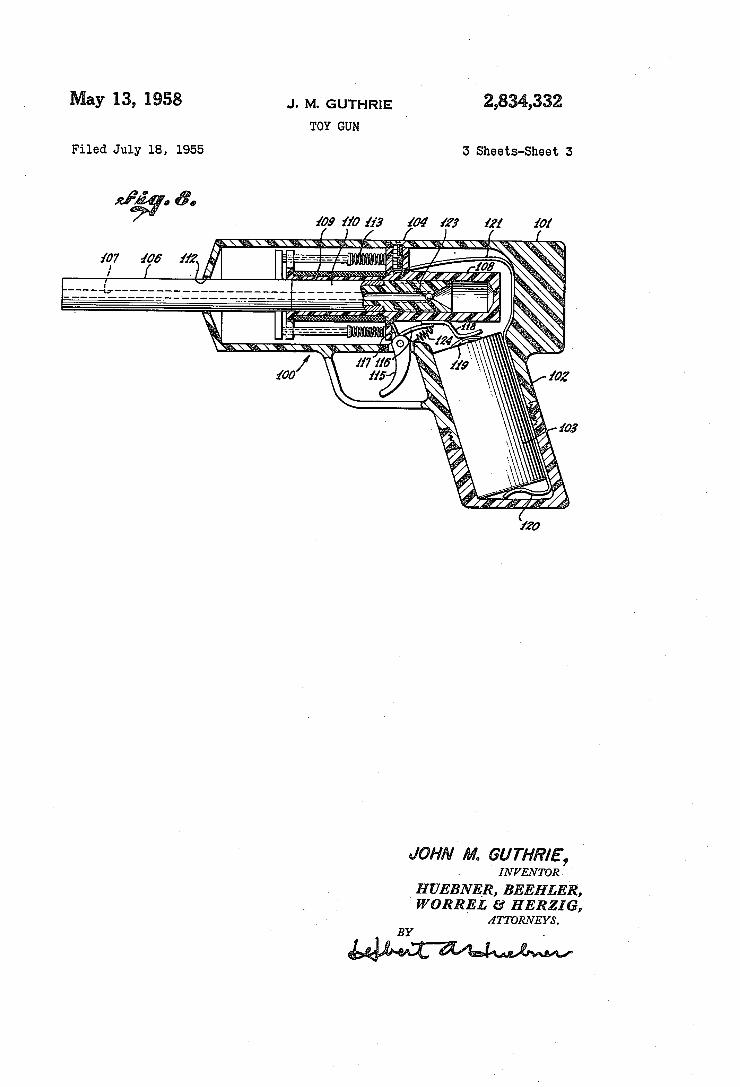
May 13, 1958 J. M.`GUTHR1E 2,834,332 TOY GUN '
Filed July 18, 1955 5 sheets-sheet s
103
JOHN M. GU THR/E' , ' INI/ENTORk
H UEBNER, BEEHLER, WORREL £9’ HERZIG,
ÄTTORNEYS. BY
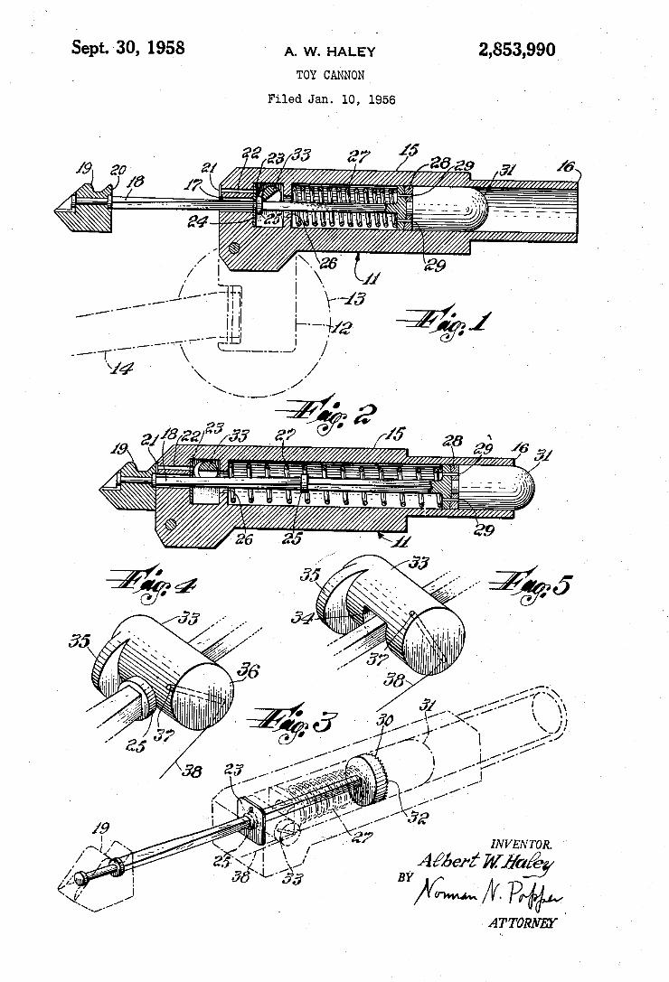
sept. 3o, 195s y A. w. HALEY 2,853,990 ` TOY CANNON `
Filed Jan. lO, 1956
2? g3 35 37v l5 26 2.9 ¿j /6
IN V EN TOR.
, BY
> ATTORNEY
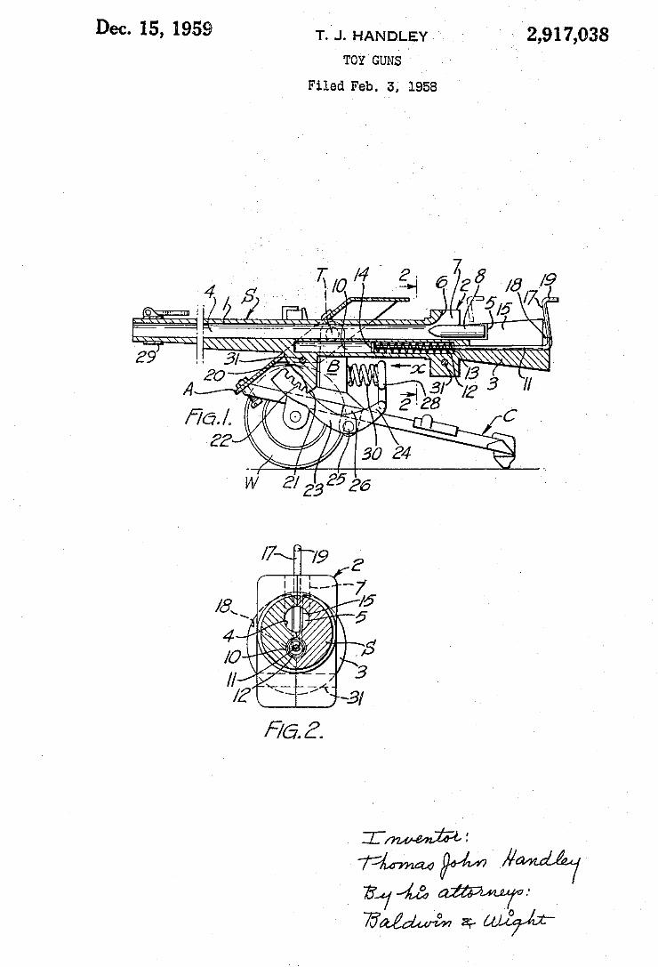
' 2,91 7,038 Dec. 15, 1959 T. J. HANDLEY "
TOY GUNS
Filed Feb. 3, 195a
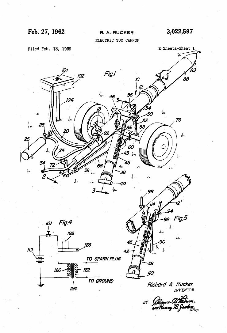
3,022,597 Feb. 27, 1962 R. A. RUCKER, -
ELECTRIC TOY CANNON
2 Sheets-Sheet 1 Filed Feb. 18, 1959
T0 GROUND ' Richard A. Rucker
'24 INVENTOR. L...
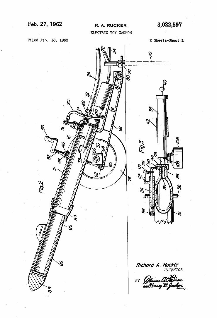
3,022,597 Feb. 27,, 1962 R. A. RUCKER‘
ELECTRIC TOY CANNON
2 Sheets~$heet 2 Filed Feb. 18, 1959
i-----~l 1."
Richard A. Ruc/rer INVENTOR.
. mg.
”’ Z‘Mwmm
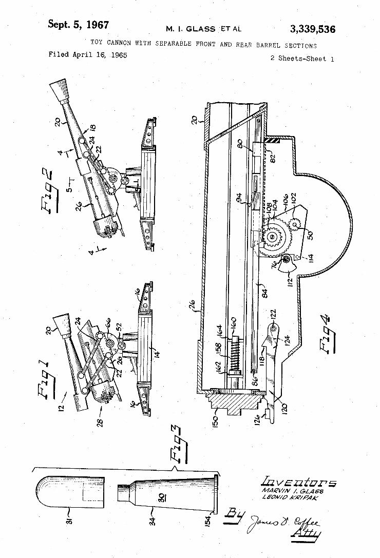
Sept. 5, 1967 _ M. l. GLASS ‘ET AL 3,339,536
TOY CANNON WITH SEPARABLE FRONT AND REAR BARREL. SECTIONS
Filed April 16, 1965 2 Sheets-Sheet l
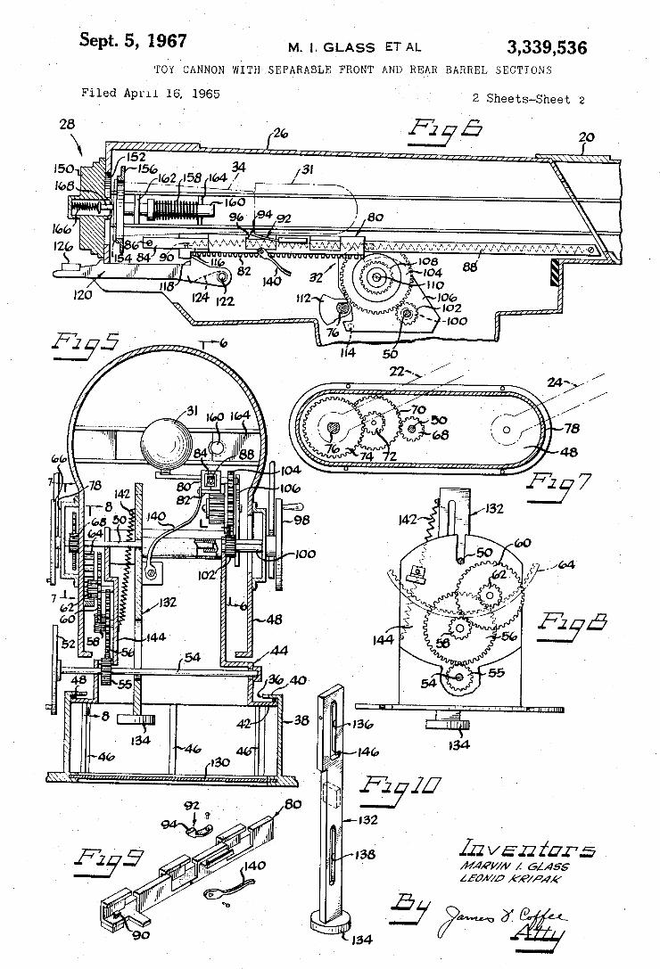
Sept. 5, 1967 M_ |, GLASS ET AL ' 3,339,536
TOY CANNON WITH ,SEFARABLE FRONT AND REAR BARREL SECTIONS
(ab
.34 @W%
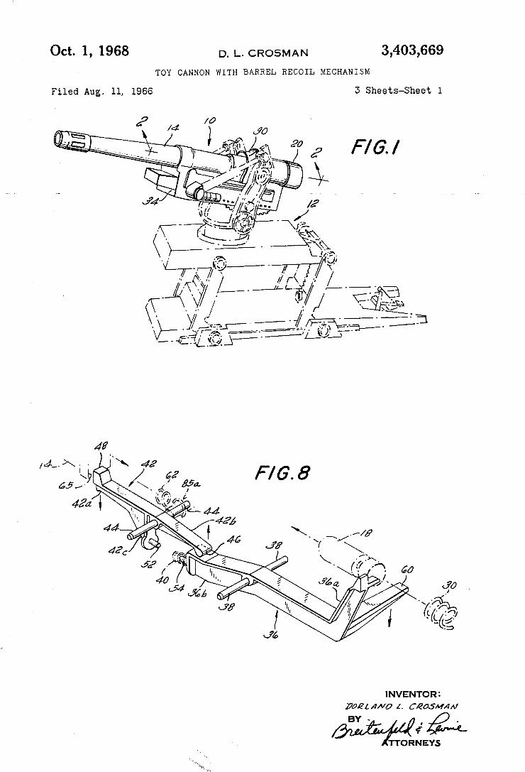
3,403,669 D. L. CROSMAN
TOY CANNON WITH BARREL RECOIL MECHANISM
Oct. 1, 1968
3 Sheets-Sheet 1 Filed Aug. 11, 1966
INVENTOR FJAQL 4”” l. CIQOJMHA/
¢ TTORNEYS
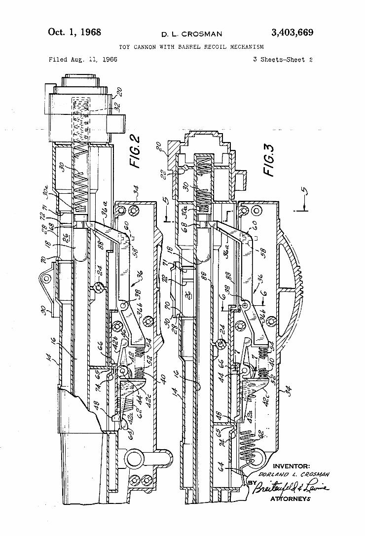
3,403,669 D. L. CROSMAN Oct. 1, 1968 TOY CANNON WITH BARREL RECOIL MECHANISM
3 Sheets-Sheet 2 Filed Aug. 11, 1966
NN NW
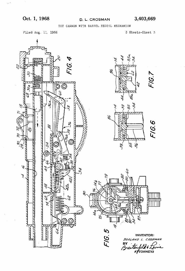
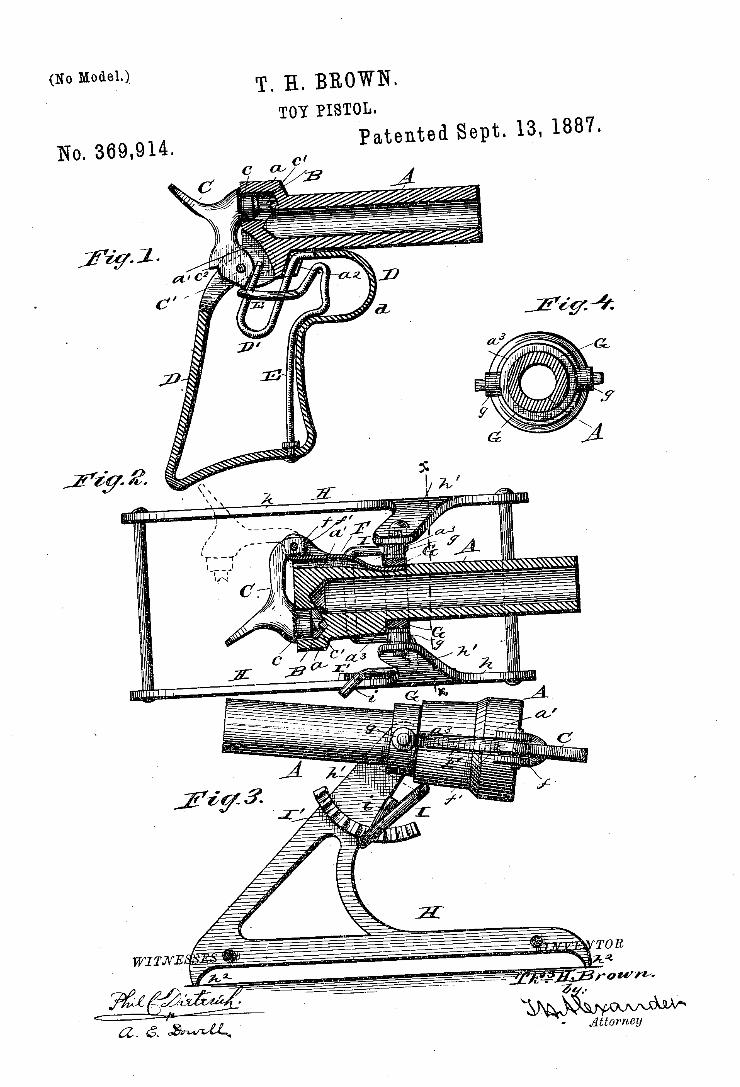
(No Model-)_ T' Hl BROWN. TOY PISTOL.
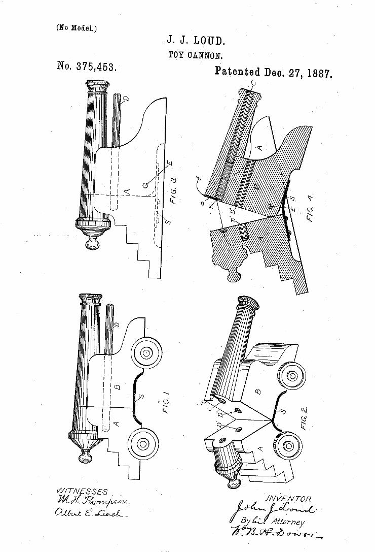
J. J.>LOUD. TOY CANNON.
Patented Dec. 27,1887. 0
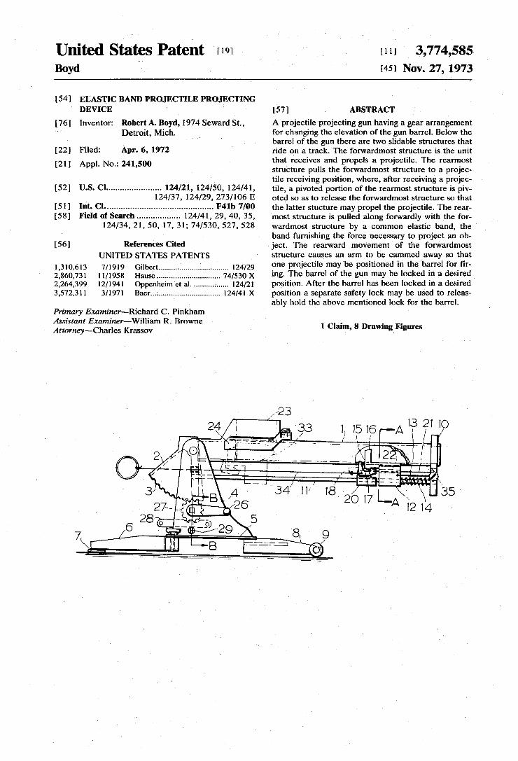
United States Patent 1191 Boyd '
1111 3,774,585 1451 Nov. 27, 1973
[54] ELASTIC BAND PROJECTILE PROJECTING DEVICE ‘
[76] Inventor: Robert A. Boyd, 1974 Seward St., Detroit, Mich.
[22] Filed: Apr. 6, 1972
[21] Appl. No.: 241,500
[52] US. Cl ...................... .. 124/21, 124/50, 124/41, 124/37, 124/29, 273/106 E
[51] Int. Cl. ............................................ .. F4lb 7/00
[58] Field of Search ................. .. 124/41, 29, 40, 35, 124/34, 21, 50, 17, 31; 74/530, 527, 528
[56] References Cited 1
UNITED STATES PATENTS
1,310,613 7/1919 Gilbert ................................ .. 124/29
2,860,731 11/1958 Hause ................... .. 74/530 X 2,264,399 12/1941 Oppenheim et al. ..... .. 124/21
3,572,311 3/1971
Primary Examiner-—Richard C. Pinkham Assistant Examiner—William R. Browne Att0rney~Charles Krassov
Baer ................................ .. 124/41 X
['57] ABSTRACT A projectile projecting gun having a gear arrangement for changing the elevation of the gun barrel. Below the barrel of the gun there are two slidable structures that ride on a track. The forwardmost structure is the unit that receives and propels a projectile. The rearmost structure pulls the forwardmost structure to a projec tile receiving position, where, after receiving a projec tile, a pivoted portion of the rearmost structure is piv oted so as to release the forwardmost structure so that the latter stucture may propel the projectile. The rear most structure is pulled along forwardly with the for~ wardmost structure by a common elastic band, the band furnishing the force necessary to project an ob ject, The rearward movement of the forwardmost structure causes an arm to be cammed away so that one projectile may be positioned in the barrel for ?r ing. The barrel of the gun may be locked in a desired position. After the barrel has been locked in a desired position a separate safety lock may be used to releas ably hold the above mentioned lock for the barrel.
1 Claim, 8 Drawing Figures
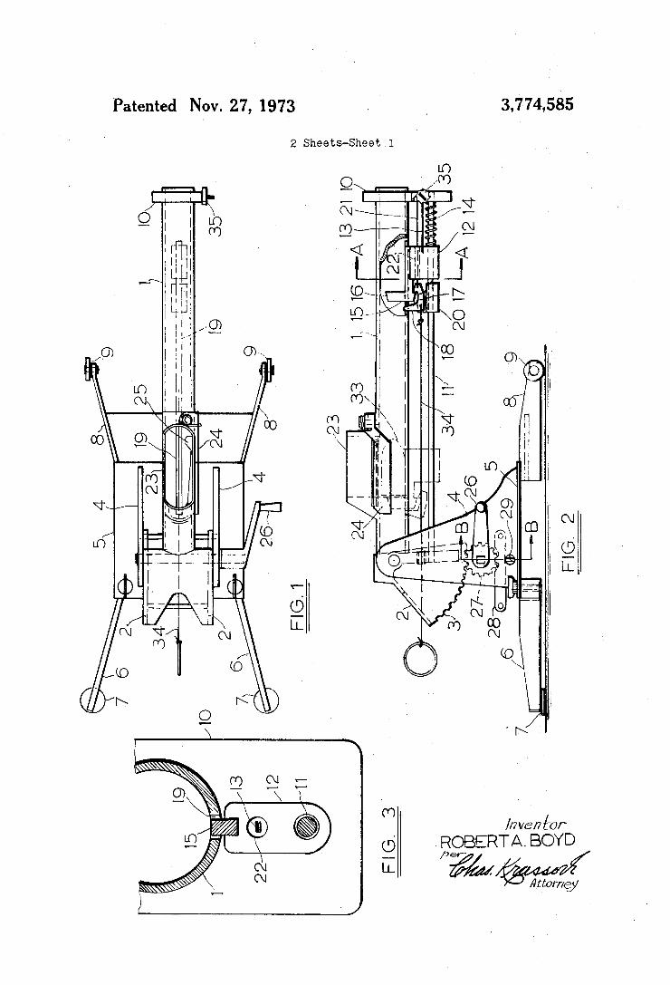
3,774,585 Patented Nov. 27, 1973
2 Sheets-Sheet l
//7 ve? ['Or
fFSOBERTA. BOYD I Attorney
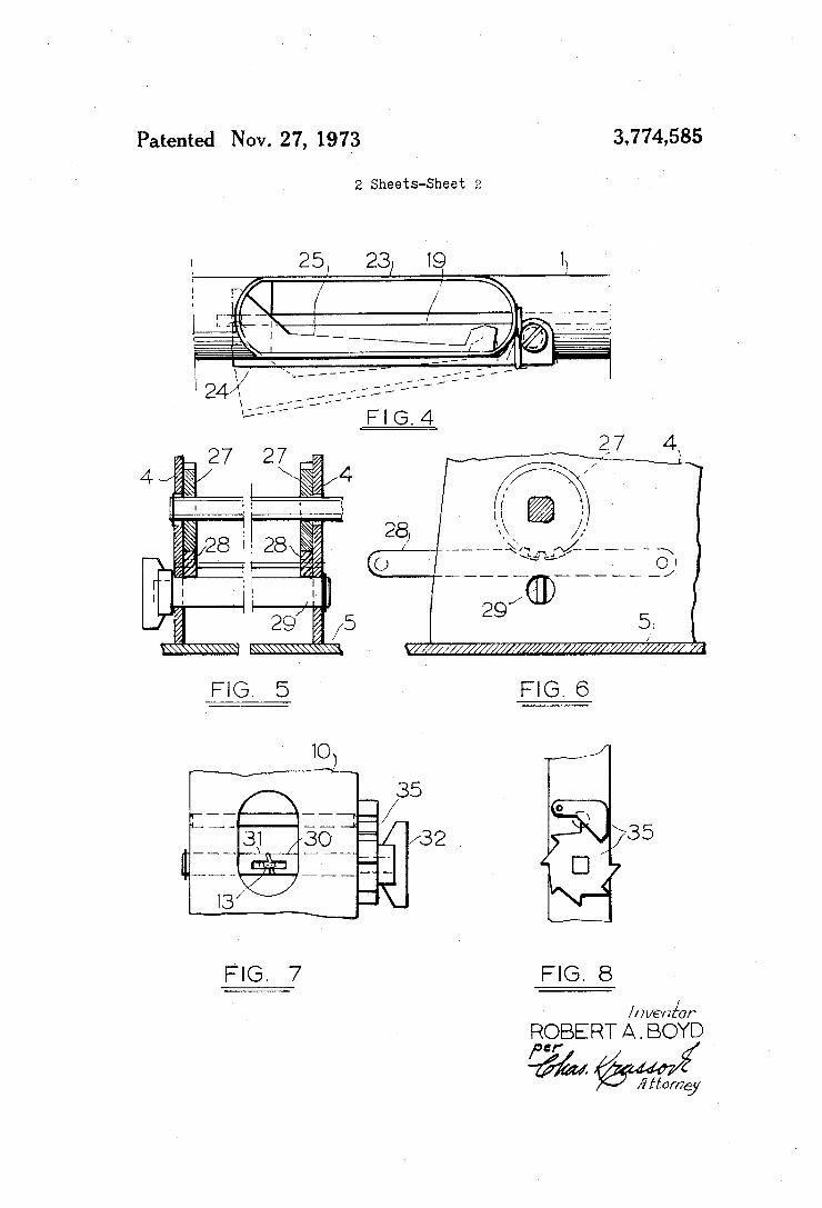
Patented Nov. 27, 1973 3.774585
2 Sheets-Sheet 2
W/ / // //// ///Y////' I // /7/]
FIG. 5 FIG. 6
ROBERT A . BOYD
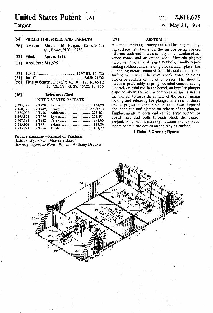
United States Patent [191 Torgow
v[11] 3,811,675 [451 May 21, 1974
‘ [54] PROJECTOR, FIELD, AND TARGETS
[76] lnventor: Abraham M. Torgow, 185 E. 206th St., Bronx, NY. 10458
[22] Filed: Apr. 6, 1972
[211 App]. No.: 241,696 '
[52] US. Cl. ................................. .. 273/101, 124/26 [51] Int. Cl ............ ................ ..; .......... .. A63b 71/02
[58] Field of Search... 273/95 R, l0l, 127 R, 85 R; ' 124/26, 37, 40, 29; 46/22, 15, 115
[56] ' References Cited
‘UNITED STATES PATENTS ' 3,495,828 2/1970 ‘Kymla ................................. .. 124/29
2,460,770 2/1949 Shirey ...... .. ..
3,375,008 3/1968 ‘Atkinson... 3,495,828 2/1970 Kymla ..... ..
2,607,591 8/1952 Tilley ...... .. 2,563,969 8/195] Skinner..... 2,735,221 2/1956 Fields ......................... ...... .. l24/37
Primary Examiner-Richard ‘C. Pinkham Assistant Examiner-Marvin Siskind Attorney, Agent, or Firm-William Anthony Drucker
[57] ABSTRACT A game combining strategy and skill has a game play ing surface with two ends, the surface being marked off from each end in an assembly zone, numbered ad vance zones, and an option zone. Movable playing pieces are two sets of target symbols, usually repre senting soldiers, and shielding blocks. Each player has a shooting means operated from his end of the game surface with which he may knock down shielding blocks or soldiers of the other player. The shooting means is preferrably a spring operated cannon having a barrel, an axial rod in the barrel, an impulse plunger disposed about the rod, a compression spring urging the plunger towards the muzzle of the barrel, means locking and releasing the plunger in a rear position, and a projectile containing an axial bore disposed about the rod and ejected on release of the plunger. Emplacements at each end of the game surface or board have end walls through which the cannon project. Side nets extending between the emplace ments contain projectiles on the playing surface.
1 Claim, 6 Drawing Figures
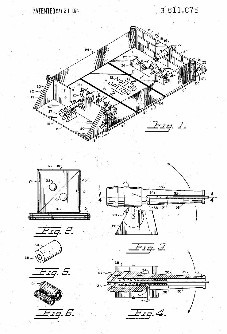
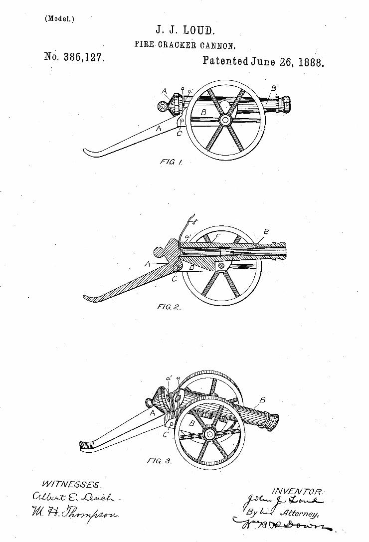
(Model.) J. JQLOU‘D..
PIRE GRACKER CANNON.
Nó. 385,127. Patented June 26, 1888.
I
W/ T/VESSES //\/ VEA/TOR. myx a „GM/Á _ - ` ¿ML
N. PErERg Fnnwlmmgnpher, washington. 0.-?,
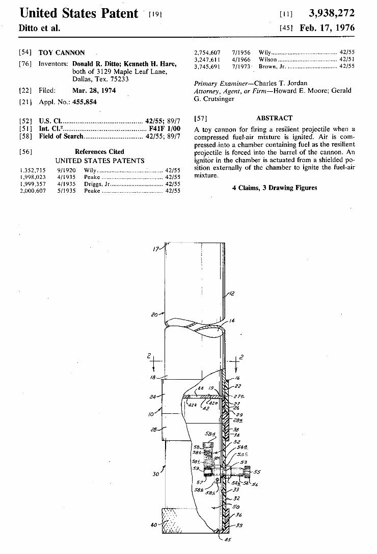
United States Patent ' [191 Ditto et al.
[11] 3,938,272 [45] Feb. 17, 1976
i541 TOY CANNON
[76] Inventors: Donald R. Ditto; Kenneth H. Hare, both of 3129 Maple Leaf Lane, Dallas, Tex. 75233
[22] Filed: Mar. 28, 1974
[2l] Appl. N0.: 455,854
[52] U.S. Cl .......................................... .. 42/55; 89/7 [51] Int. Cl.2 ........................................... .. F41F H00 [58] Field of Search .............................. .. 42/55; 89/7
[5 6] References Cited UNITED STATES PATENTS
1,352,715 9/1920 Wily 1 . . . . . . . . . .. 42/55
1,998,023 4/1935 Peake . . . . . . . . . . .. 42/55
1,999,357 4/1935 Driggs, .lr.. 42/55 2,000,607 5/1935 Peuke ................................... .. 42/55
17/
20/
2,754,607 7/1956 Wily ...................................... .. 42/55
3,247,611 4/1966 Wilson . . . . . . . . . . . . . .. 42/51
3,745,691 7/1973' Brown, Jr. ............................ .. 42/55
Primary Examiner—Charles T. Jordan Attorney, Agent, or Firm-Howard E. Moore; Gerald G. Crutsinger
[57] ABSTRACT
A toy cannon for ?ring a resilient projectile when a compressed fuel-air mixture is ignited. Air is com pressed-into a chamber containing fuel as the resilient projectile is forced into the barrel of the cannon. An ignitor in the chamber is actuated from a shielded po sition externally of the chamber to ignite the fuel-air mixture.
4 Claims, 3 Drawing Figures
i“ Tim
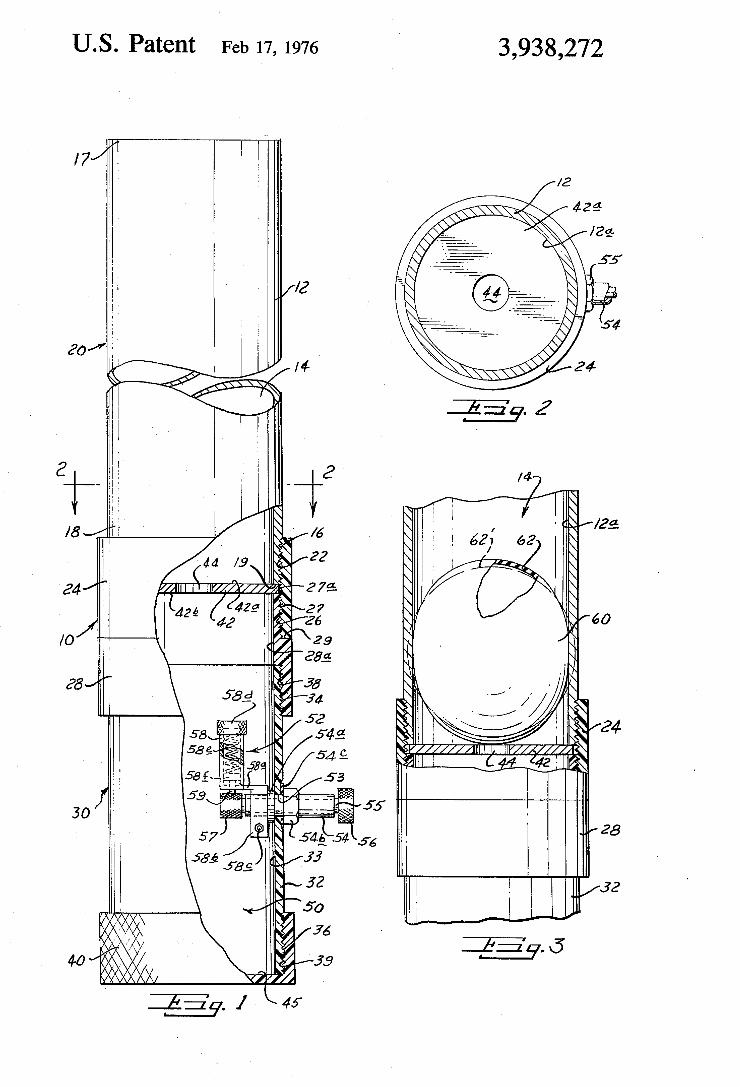
US. Patent Feb 17, 1976 3,938,272
1_ IIIIIIIIIAIIIIIIlV/l’l I y z ' 1 I
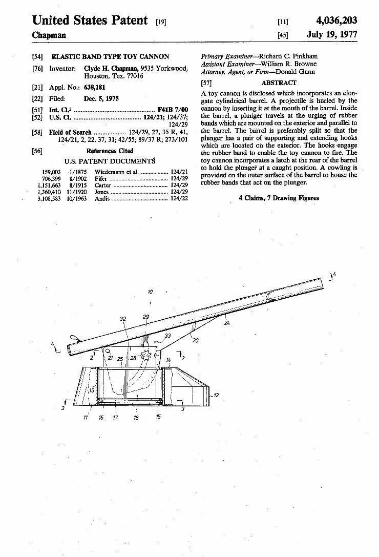
United States Patent [19] Chapman
[11] 4,036,203 [45] July 19, 1977
[54] ELASTIC BAND TYPE TOY CANNON
[76] Inventor: Clyde H. Chapman, 9535 Yorkwood, Houston, Tex. 77016
[21] Appl. No.: 638,181 [22] Filed: Dec. 5, 1975
[51] Int. (31.2 .............................................. .. F41B 7/00 [52] 11.5.01. ...................................... .. 124/21; 124/37;
~ 124/29
[58] Field of Search ................. .. 124/29, .27, 35 R, 41, 124/21, 2, 22, 37, 31; 42/55; 89/37 R; 273/101
[56] References Cited U.S. PATENT DOCUMENTS
159,003 1/1875 Wiedemann et a1. ................ .. 124/21 706,399 8/1902 Fifer ...................... .. 124/29
1,151,663 8/1915 Carter ........... .. .. 124/29
1,360,410 11/1920 Jones ......... .. 124/29
3,108,583 10/1963 Andis ........ .. .. 124/22
Primary Examiner-Richard C. Pinkharn Assistant Examiner-William R. Browne Attorney, Agent, or Firm-—Donald Gunn
[57] ABSTRACT A toy cannon is disclosed which incorporates an elon gate cylindrical barrel. A projectile is hurled by the cannon by inserting it at the mouth of the barrel. Inside the barrel, a plunger travels at the urging of rubber bands which are mounted on the exterior and parallel to the barrel. The barrel is preferably split so that the plunger has a pair of supporting and extending hooks which are located on the exterior. The hooks'engage the rubber band to enable the toy cannon to ?re. The toy cannon incorporates a latch at the rear of the barrel to hold the plunger at a caught position. A cowling is , provided on the outer surface of the barrel to house the rubber bands that act on the plunger.
4 Claims, 7 Drawing Figures
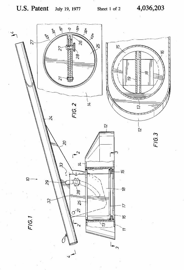
U.S. Patent July 19, 1977 Sheet 1 of2 4,036,203
M .DE
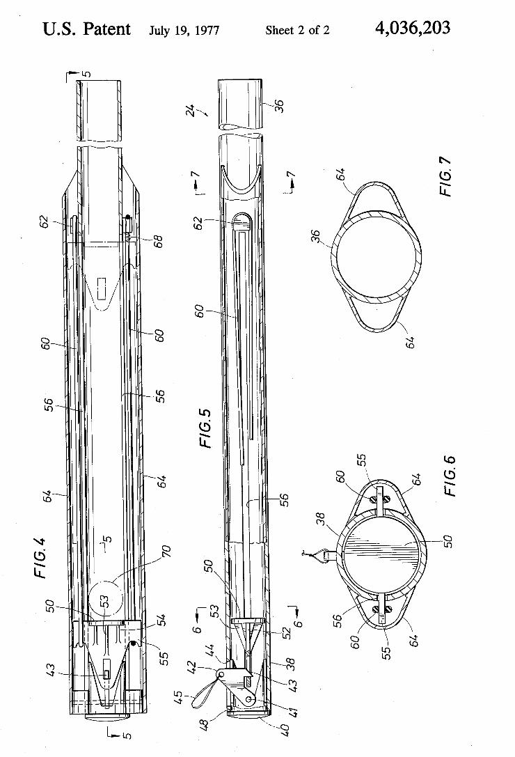
US. Patent July 19, 1977 Sheet 2 of2 4,036,203
m 6E
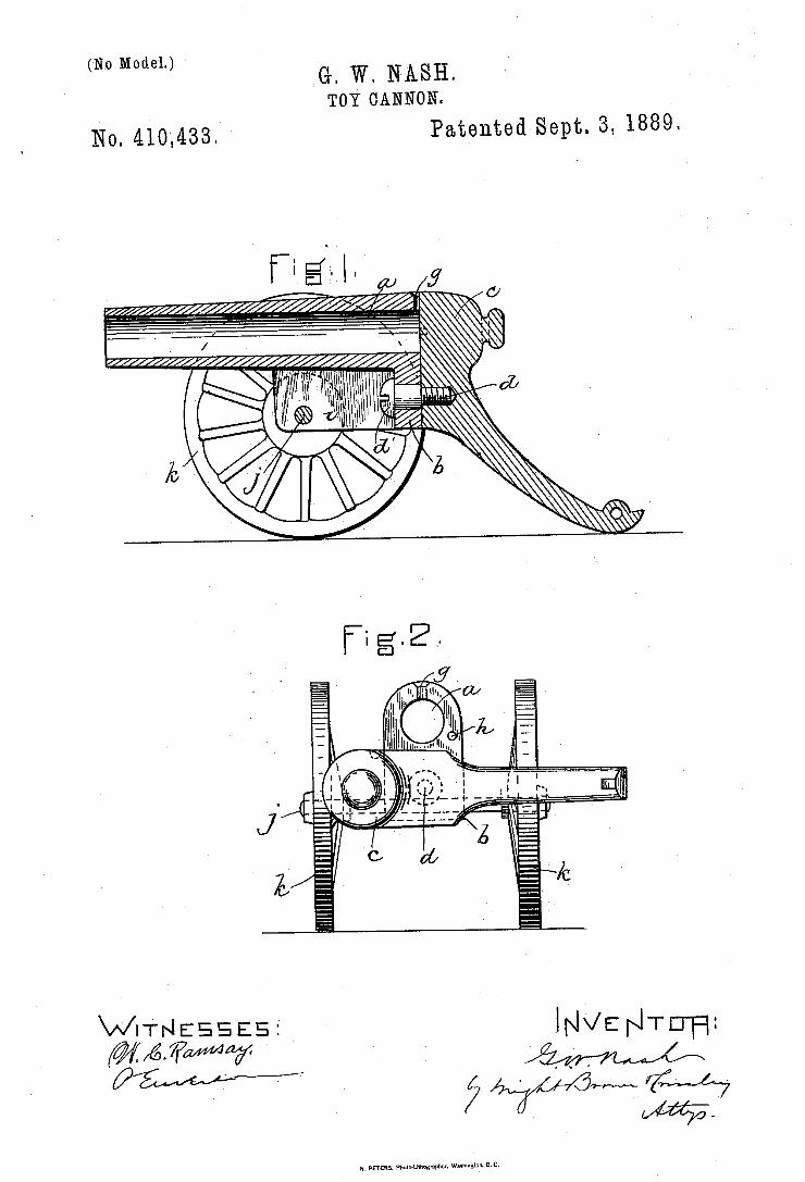
(No Model.) , G. W. NASH.
I TOY CANNON.
No. 410,433. Patented Sept. 3, 1889.
Wr'r?sssas: ‘ INVENTU-H:
N. PEIERS. Phawmnugnpher. wllhi nnnnnnn c.
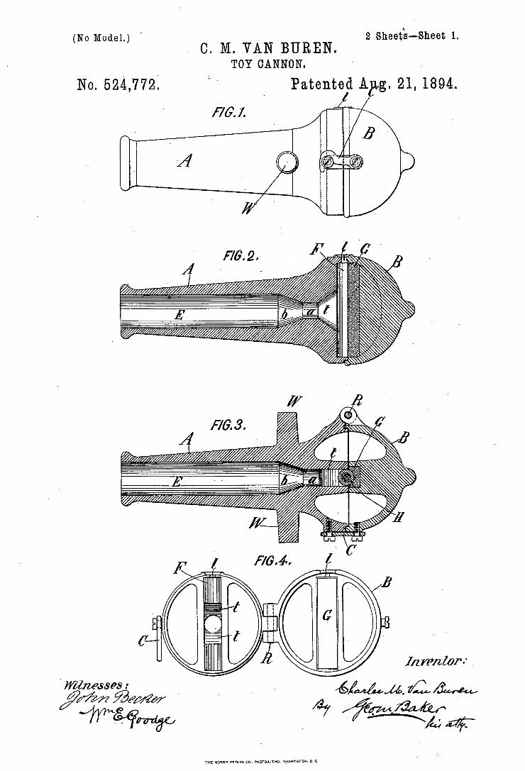
(No Model.) ' 2 sneeié-Qsneet 1. . O. M. VAN BUREN. .
TOY CANNON.
Patented A . 21, 1894. . A! 21%
[76.7. ‘ ~
No. 524,772;
a’ 3
I12 VPIZZOP" .
' WIZMSSPS :
‘ymggfw . -
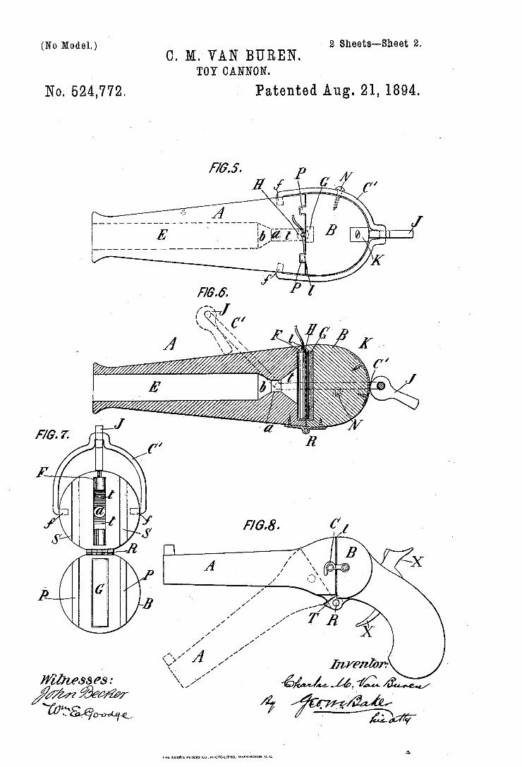
(No Model.) ' - 2 Sheets-Sheet 2.
O. M. VAN BURBN. TOY CANNON.
No. 524,772. Patented Aug. 21, 1894.
Wiliwsses: \v\/ 6 ‘w/M rZLM/ %//M @w/ZW é] J6 ' TUTWWQ @ '
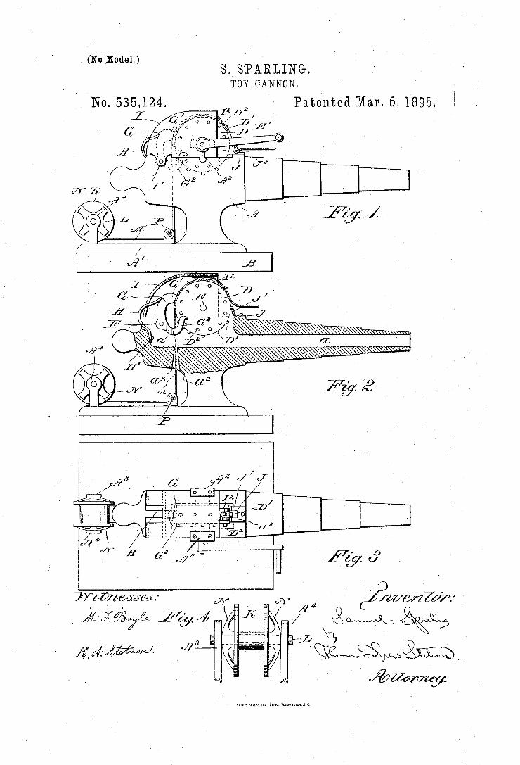
(No Model.) S._S'PARLING. VTOY CANNON.
l 1 I ‘No. 535,124. Patented‘ Mar. 5, 1895..
20%27571‘
‘2%;
WWMCWJ:
MM“ M
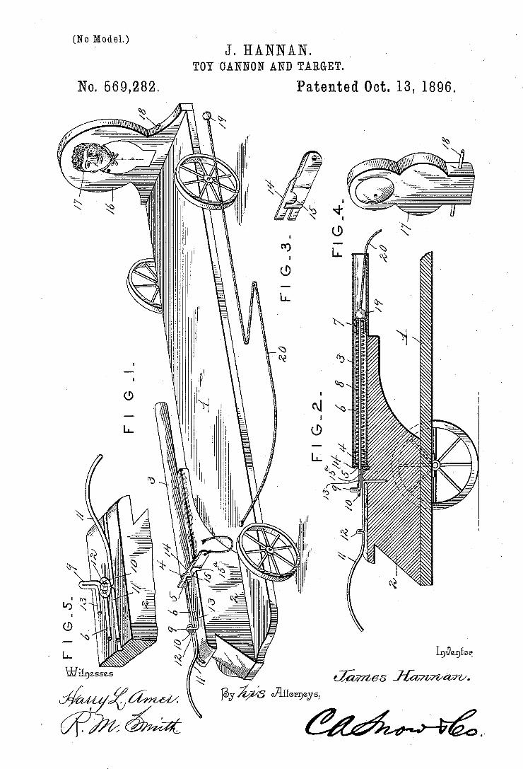
(No Model.) J HANNAN _
TOY CANNON AND TARGET.
No. 669,282. Patented Oct. 13, 1896.
In | E“
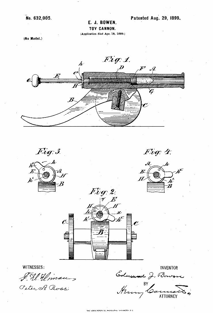
in. 632,005. Pa‘tent'e'd Aug‘. 29, I899. E. J. BOWEN. - * '
TOY CANNON. ' (Application ?led Apr. 15, 1899.)
Wu Model.)
WITNESSES: Q _ INVENTOR
/%5Z/% ' W 91. @WM
01,54,647 - Jam-678g - . ' _ , ATTORNEY Q "’
‘m: NORRIS Prrzns ca, nomad-mo w-snmcnm. n \:
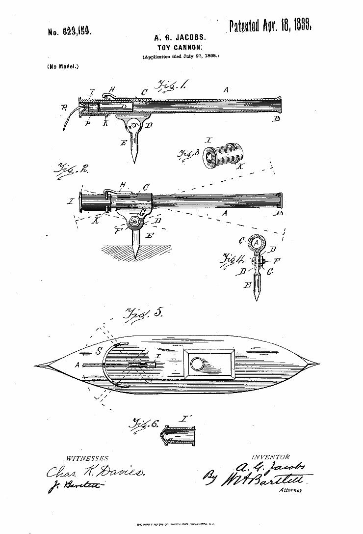
so. emga. ` ` 1 Patented kur. 18, |633. A. G. JACOBS. T 0 Y C A N N 0 N L
(Application ßled July 27, 1898.)
(No Model.)
. WÍTNESSES /NI/ENTOR
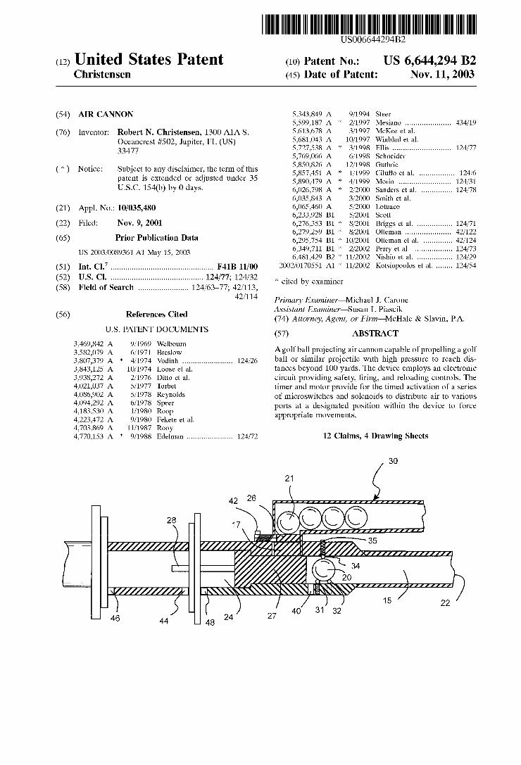
US006644294B2
(12) United States Patent (16) Patent N65 US 6,644,294 B2 Christensen (45) Date of Patent: Nov. 11, 2003
(54) AIR CANNON 5,343,849 A 9/1994 Steer 5,599,187 A * 2/1997 Mesiano .................... .. 434/19
(76) Inventor: Robert N. Christensen, 1300 AlA S. 5,613,678 A 3/1997 McKee 6t a1~ Oceancrest #502, Jupiter, FL (Us) 5,681,043 A 10/1997 Winblad et al. 33477 5,727,538 A * 3/1998 E1115 .......................... .. 124/77
5,769,066 A 6/1998 Schneider . . . . . 5,850,826 A 12/1998 Guthrie
(Hi) Nome: sublecito any ‘3531mm; the fiermé’fthlg 5,857,451 A * 1/1999 Ciluffo et a1. ............... .. 124/6 Patent 15 exten e or a 111ste 11“ er 3 5,890,479 A * 4/1999 Morin 124/31 U-S-C- 154(b) by 0 days~ 6,026,798 A * 2/2000 Sanders et a1. ............. .. 124/78
6,035,843 A 3/2000 Smith et a1. (21) APPL No; 10/035,430 6,065,460 A 5/2000 Lotuaco
6,233,928 B1 5/2001 Scott (22) Filed: NOV. 9, 2001 6,276,353 B1 * 8/2001 Briggs et a1. ............... .. 124/71
_ _ _ 6,279,259 B1 * 8/2001 Otteman ....... .. 42/122
(65) PYIOF Publlcatlon Data 6,295,754 B1 * 10/2001 Otteman et a1. 42/124 6,349,711 B1 * 2/2002 Perry et a1. .... .. 124/73
Us 2003/0089361 A1 May 15’ 2003 6,481,429 B2 * 11/2002 Nishio et a1. ........ .. 124/29
(51) Int. Cl.7 ............................................... .. F4113 11/00 2002/0170551 A1 * 11/2002 Kotsiopoulos et a1. ...... .. 124/54
(52) U..S. Cl. .......................................... .. 124/77; 124/32 * Cited by examiner (58) Field of Search ...................... .. 124/63—77; 42/113,
42/114 Primary Examiner—Michael J. Carone , Assistant Examiner—Susan L Piascik
(56) References Clted (74) Attorney, Agent, or Firm—McHale & Slavin, P.A.
U.S. PATENT DOCUMENTS (57) ABSTRACT
3 469 842 A 9 1969 W lb 375827079 A 6;1971 Breeslgifn Agolf ball projecting air cannon capable of propelling a golf 3:807:379 A * 4/1974 Vodinh ...................... .. 124/26 ball or Similar Projectile With high Pressure to reach dis 3,843,125 A 10/1974 Loose et a1, tances beyond 100 yards. The device employs an electronic 3,938,272 A 2/1976 Ditto et a1. circuit providing safety, ?ring, and reloading controls. The 4,021,037 A 5/ 1977 Torbet timer and motor provide for the timed activation of a series 47086902 A 5/1978 Reynolds of microsWitches and solenoids to distribute air to various
2 ?/ 3pc“ ports at a designated position Within the device to force ’ ’ / 00p appropriate movements.
4,223,472 A 9/1980 Fekete et 211. 4,703,869 A 11/1987 Rooy 4,770,153 A * 9/1988 Edelman .................... .. 124/72 12 Claims, 4 Drawing Sheets
30
21
42 I1&1llllllllllllllllllllllll _ \' Q _ l
28 t ,7 @QQ‘ \ \ \ - I‘
/////////////V I // 7 35 \ 7 W2 , / C 34
\ 20 ///////////A/ '
_ 31 15 22 4O 32
__ 46 44 48 24 27
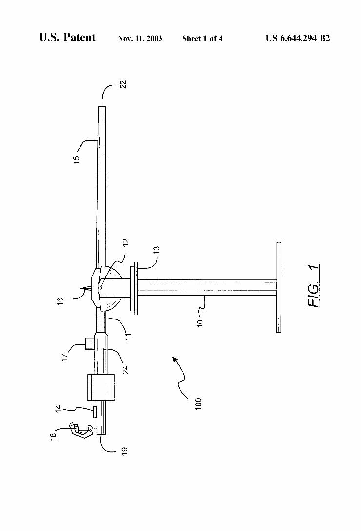
U.S. Patent Nov. 11,2003 Sheet 1 0f 4 US 6,644,294 B2
00? 3
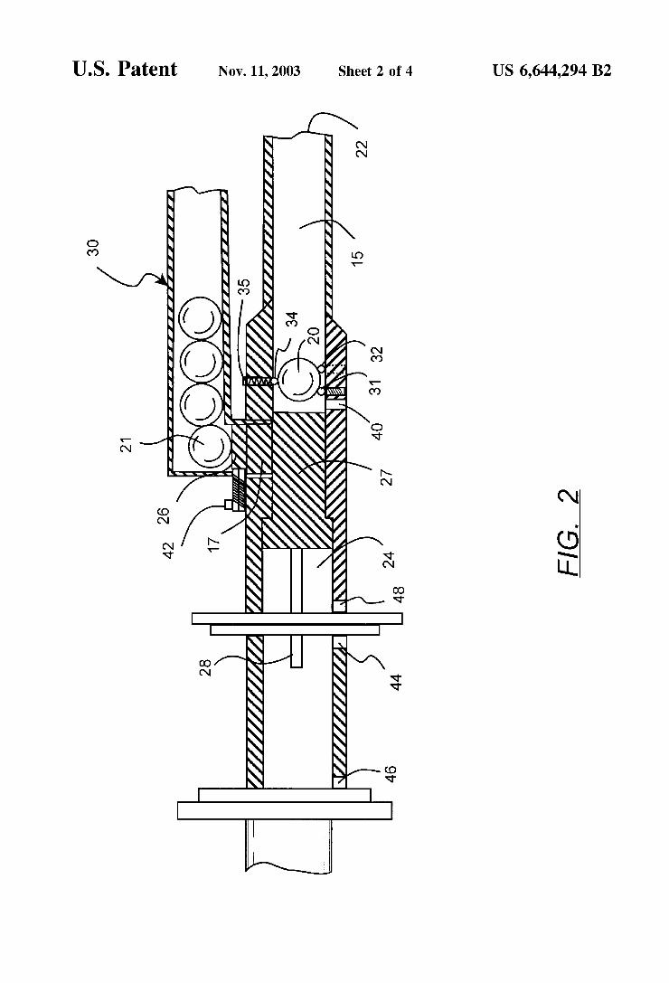
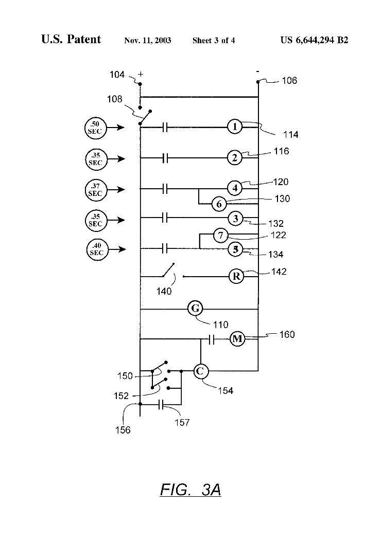
U.S. Patent Nov. 11,2003 Sheet 3 0f 4 US 6,644,294 B2
1‘ @106
L
D
|__®:_s— 160
150 4? 152_ °— 154
WK 157 156
FIG. 3A
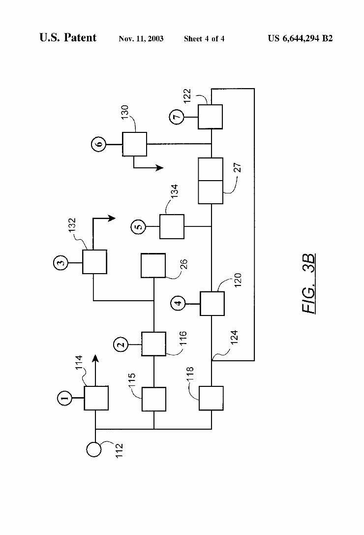
U.S. Patent Nov. 11,2003 Sheet 4 0f 4 US 6,644,294 B2
134 K 27
\ 120 FIG. 3B
124 [K118 K116 g) L26
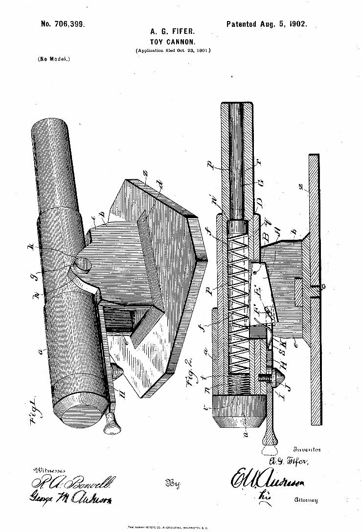
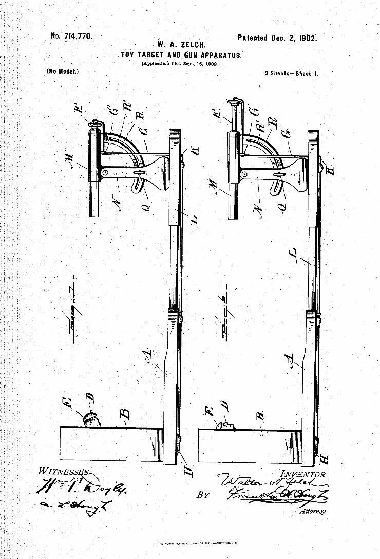
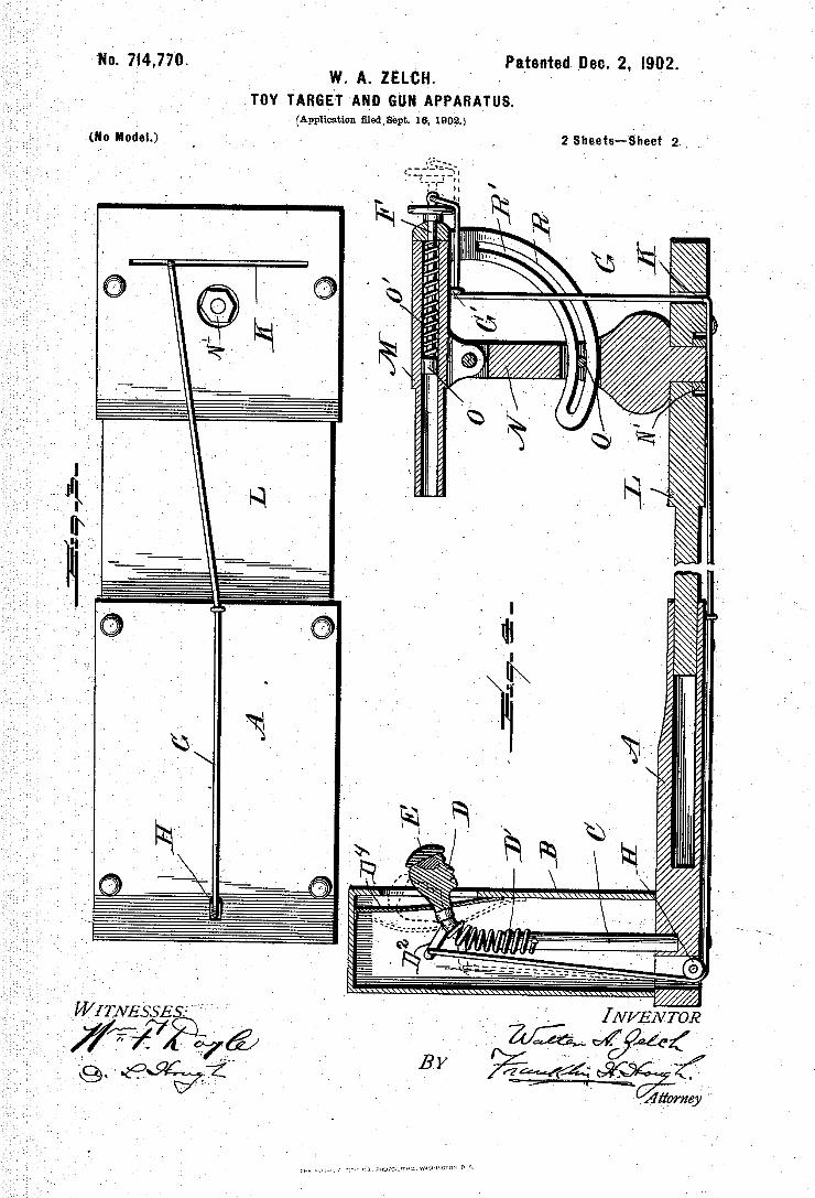
No. 7|4,770. Patented. Dec. 2, |902. ~ W A ZELCH ' '
TOY TARGET AND GUN APPARATUS. (Application medlsepc, 1.6% 1902.)
2 sheets-»Sheet 2.y .(No Model.) `l
[NVÈNTOR ' afg@ BY
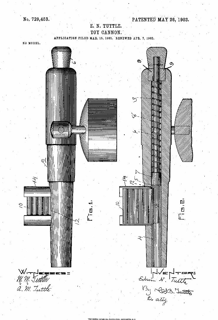
3 0 , 9 1 ,
. 7..
TOY CANNON.” „ MAN 15 1901; RNNEWEU
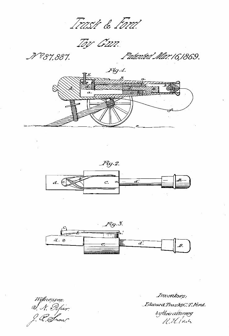
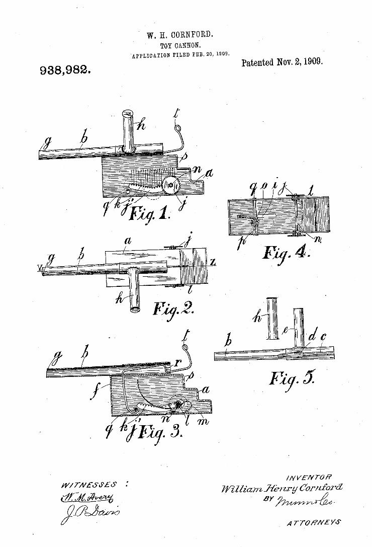
W. H. GORNPORD. TOY CANNON.
APPLICATION FILED fm. zo; 1909. Patented Nov. 2, 1909.
938,982.
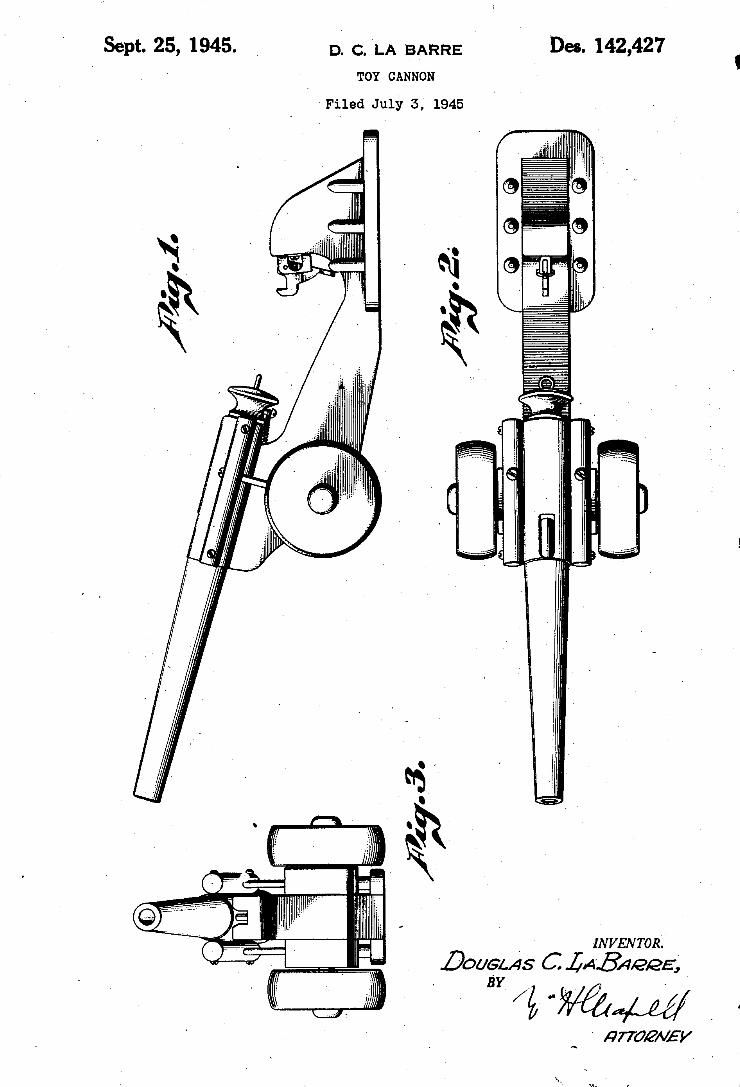
Sept. 25, 1945. D_ (3, ‘LA BARRE N 142,427 TOY CANNON
‘Filed July 5,‘ 1945 N
' ,1 v. .. 1 u'
_ I INVENTOR.
?ouans C LAB/422E;
w/kww _ a
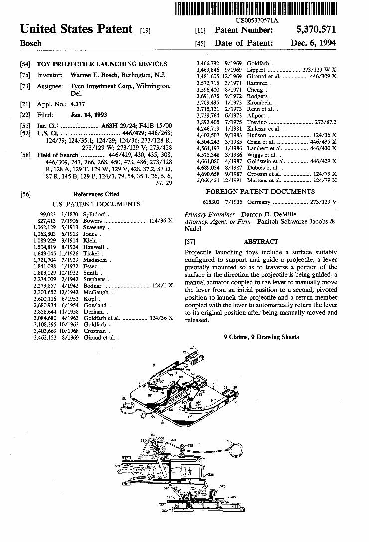
. US005370571A
Umted States Patent [19] [11] Patent Number: 5,370,571 Bosch [45] Date of Patent: Dec. 6, 1994
[54] TOY PROJECI‘ILE LAUNCHING DEVICES 3,466,792 9/1969 Goldfarb . _ 3,469,846 9/ 1969 Lippert .................... .. 273/129 W X
[75] Inventon Warren E- Bvsch, Bu?mgton, NJ‘ 3,481,605 12/1969 Giraurd et a1_ ............... .. 446/309 X ' . ~ 4 3,572,715 3/1971 Ramirez .
[73] Assrgnee. gyclo Investment Corp., W1lm1ngton, 3,596,400 8/1971 cheng . e' 3,691,675 9/1972 Rodgers .
[21] APPL No_; 4,377 3,709,495 1/ 1973 Krombein . _ 3,715,121 2/1973 Renn et a1. .
[22] Filed: Jan. 14, 1993 I 3,739,764 6/ 1973 Allport .
[51] Int. Cl's ..................... " A63H 29/24; F41B 15/00 3,892,405 7/1975 Trevlno ............................ .. 273/872 _ 4,246,719 1/1981 Kulesza et a1. .
UQS. Clo I u u a a 0 I o a n 6 I e e - e e e I e e l I - e 6 u n a n a - I u on IIIIIIIIIIIIIIIIIIIIIII " X
124/79; 124/35.1; 124/29; 124/36; 273/128 R; 4,504,242 3/1985 Grain et a]. _____ " " 273/129 W; 273/129 V; 273/428 4,564,197 l/ 1986 Lambert et a1. .............. .. 446/430 X
[58] Field of Search ............. .. 446/429, 430, 435, 308, 4,575,348 3/1986 Wiggs et a1. . 446/309, 247, 266, 268, 450, 473, 486; 273/128 4,661,080 4/1987 Goldstein et a1. ............ .. 446/429 X R, 128 A, 129 T, 129 W, 129 V, 428, 87.2, 87 D, gubois 6t ala-l ‘ 124/79 X 7 R 145 B 12 . , , 54’ 351, 26’ 5, 6, , , rosson et . ................. ..
8 ’ . ’ 9 P’ 124/1 79 37 29‘ 5,069,451 12/1991 Martens et a1. ................. .. 124/79 X
[56] References Cited FOREIGN PATENT DOCUMENTS
U_S_ PATENT DOCUMENTS 615302 7/1935 Germany ...................... 1. 273/129 V
99,023 1/1870 Splitdorf . Primary Examiner—-Danton D. DeMille BOWCI'S ........................... .. X Attorney’ Agent, or schwarze Jacobs &
1,062,129 5/ 1913 Sweeney . Nadel 1,063,803 6/1913 Jones . 1,089,229 3/1914 Klein . [57] ABSTRACT 1,504,819 8/1924 Hauwell . _ _ _ _ _
1,649,045 11/1926 Tickel . Projectile launching toys include a surface suitably 1,721,704 7/1929 Madaschi _ con?gured to support and guide a projectile, a lever
16; pivotally mounted so as to traverse a portion of the , , m, _ . . . . . . . .
2,274,009 2/1942 Stephens I surface in the dlrection the projectlle 18 being gulded, a 2 279 857 4/1942 Bodnar . . 124/1 X manual actuator coupled to the lever to manually move 2:303:652 12/1942 McGaug'g'j """"""""""""" " the lever from an initial position to a second, pivoted 2,600,116 6/1952 Kopf _ position to launch the projectile and a return member 2,680,934 6/ 1954 Gowland . coupled with the lever to automatically return the lever 2,853,644 11/1953 Derham - to its original position after being manually moved and 3,084,680 4/1963 Goldfarb et a1. ............... .. 124/36 X released 3,108,395 10/1963 Goldfarb . '
3,403,669 10/1968 Crosman . 3,462,153 8/1969 Giraud et a1. . 9 Claims, 9 Drawing Sheets
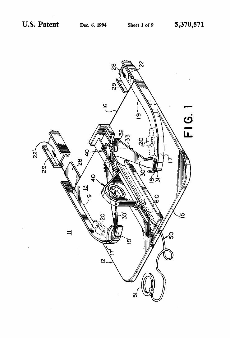
US. Patent Dec. 6, 1994 Sheet 1 of 9 5,370,571
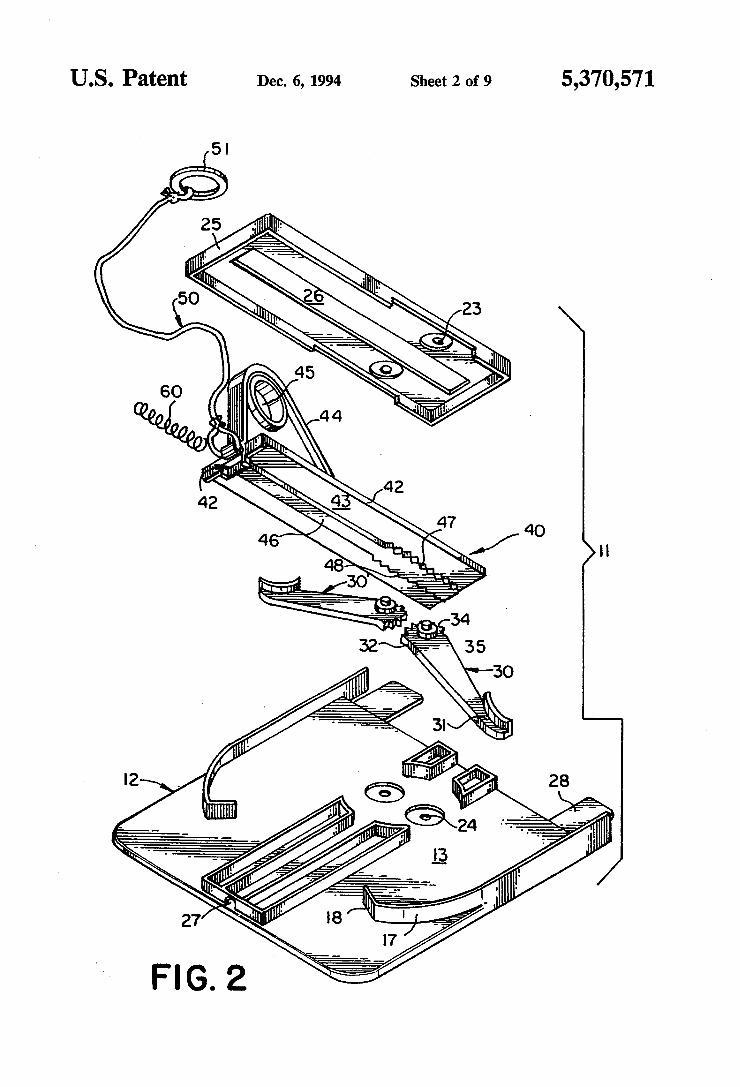
US. Patent Dec.6, 1994 Sheet 2 of 9 5,370,571
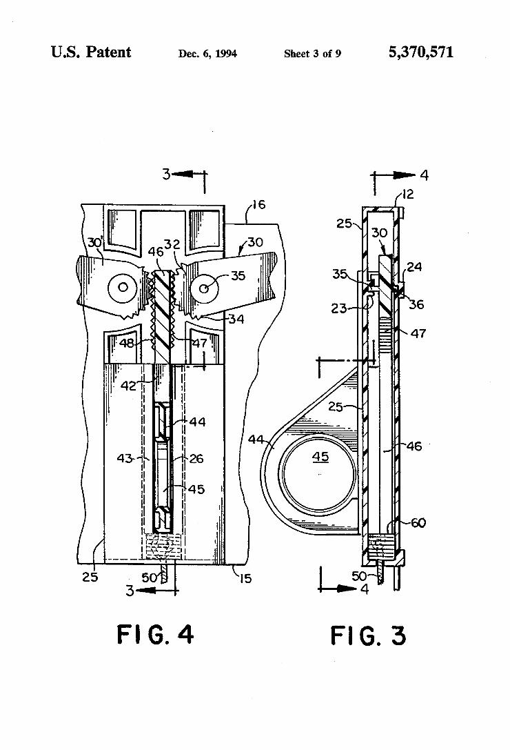
US. Patent Dec. 6, 1994 Sheet 3 of9 5,370,571
I2 ‘I I6
ml!’ . 3O 25 w 4632 W‘ ‘
‘11535 ' 35k 24 l .- 36
W4‘ -34 \ 47
m h ‘I n44 l‘ 46 ' 26 II
n
“45 l ‘I 1
-l in‘ 6° {:IH I ::'L __.
50'‘. I5 4 E [I
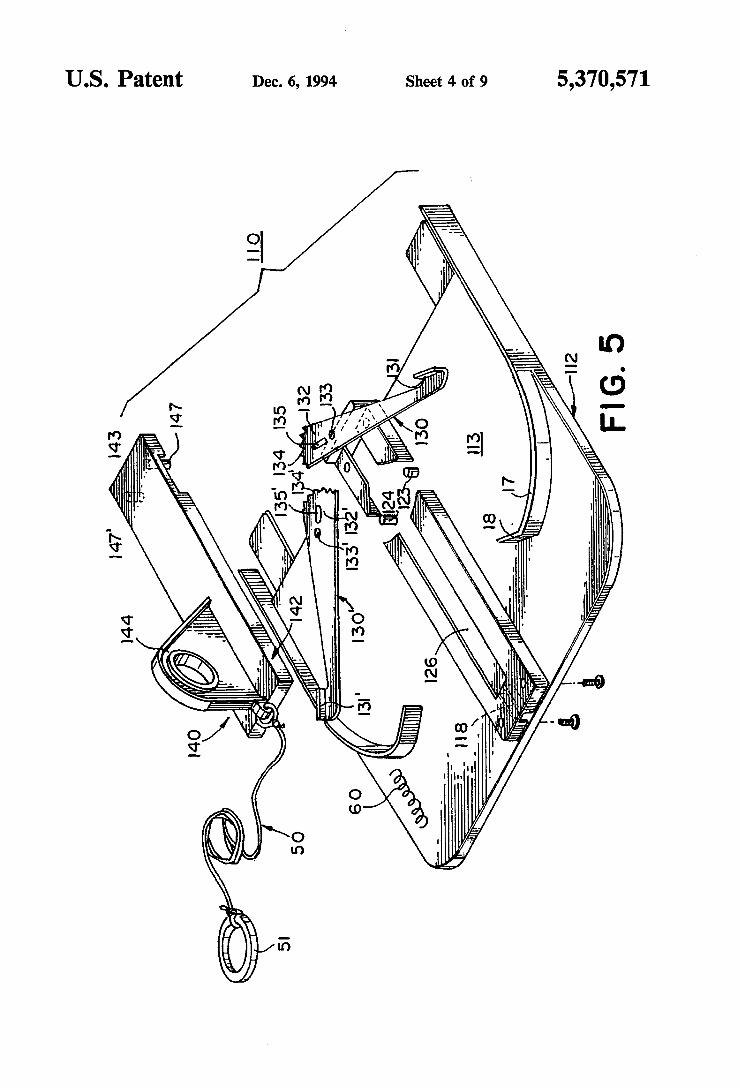
US. Patent Dec. 6, 1994 Sheet 4 of 9 5,370,571
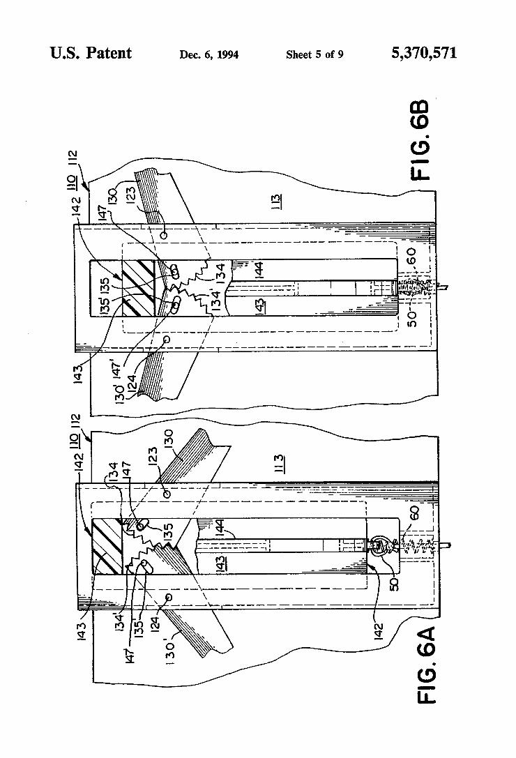
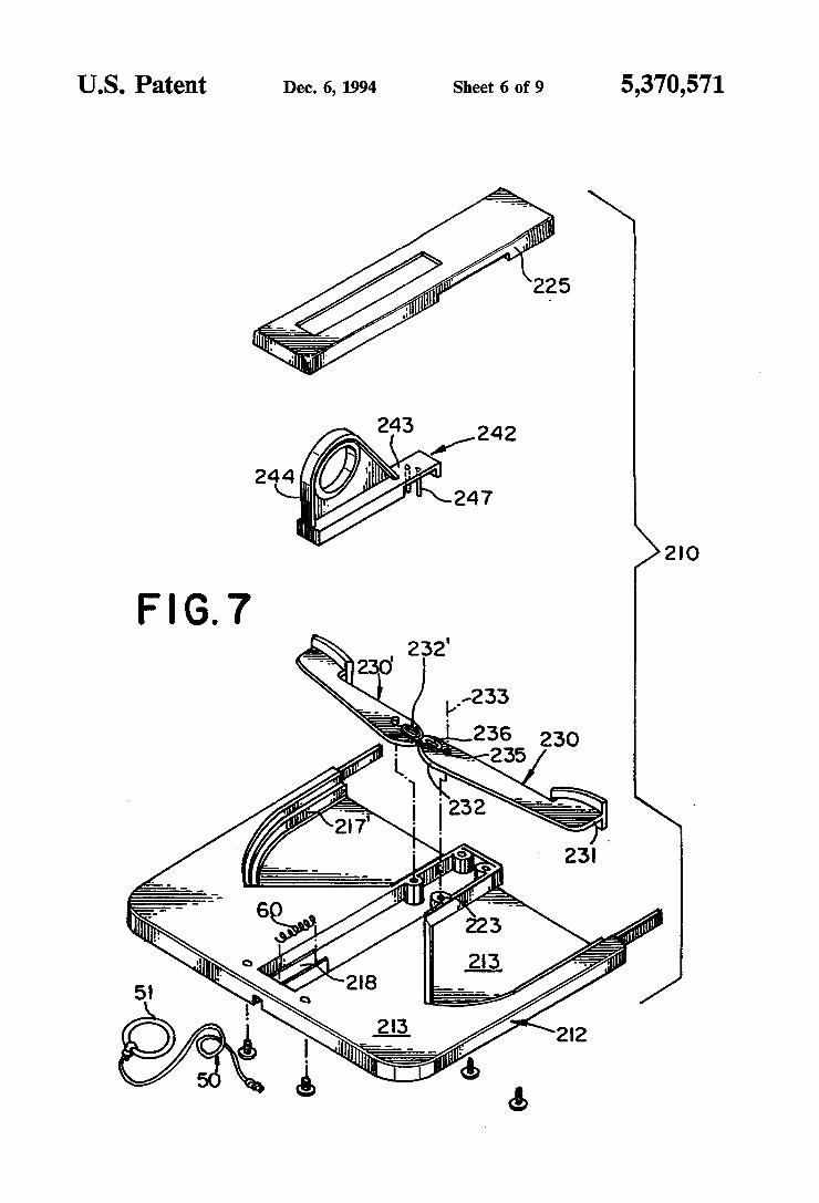
U.S. Patent Dec. 6, 1994 Sheet 6 of 9
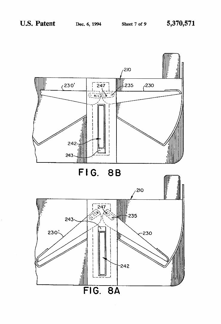
US. Patent Dec. 6, 1994 Sheet 7 of 9 5,370,571
..
“1-235 (230
all!” /
Iii“ FIG. 8A
\ \ ______._.._.___.__ __\
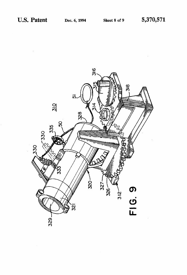
US. Patent Dec. 6, 1994 Sheet 8 of 9 5,370,571
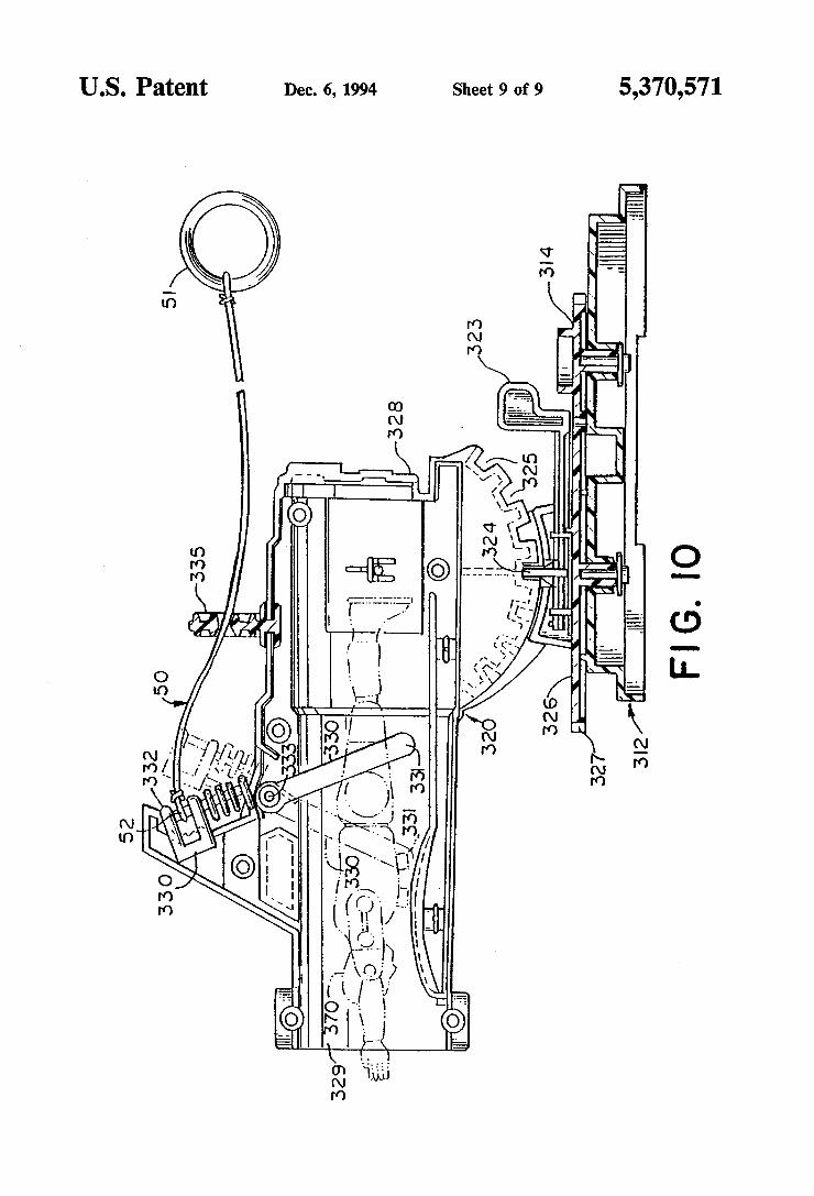
US. Patent Dec. 6, 1994 Sheet 9 of 9 5,370,571
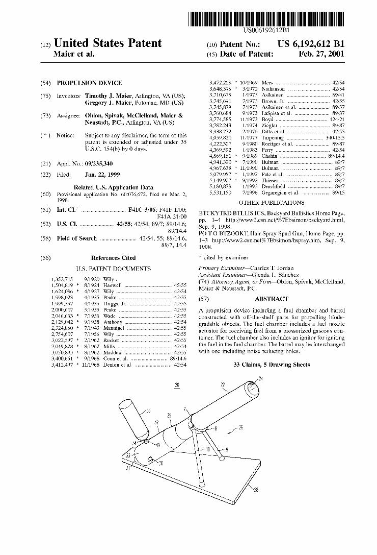
(12) United States Patent US006192612B1
(10) Patent N0.: US 6,192,612 B1 Maier et al. (45) Date of Patent: Feb. 27, 2001
(54) PROPULSION DEVICE 3,472,218 * 10/1969 Mers ...................................... .. 42/54 3,648,395 * 3/1972 Nathanson ............................. .. 42/54
(75) Inventors: Timothy J. Maier, Arlington, VA (US); 3,710,675 1/1973 Asikainen -~ 89/41 Gregory J_ Maier, Potomac, MD (Us) 3,745,691 7/1973 Brown, Jr. ..... .. . 42/55
3,745,879 7/1973 Aslkalnen et 211. 89/37
Assigneez Oblon, Spivak, Mcclelland’ Maier & LaSplsa 618.1. ........................ .. Neustadt PC Arhn ton VA (Us) 3,774,585 11/1973 Boyd .................................... .. 124/21
’ ' " g ’ 3,782,243 1/1974 Ziegler .. 89/87
. . . . . 3,938,272 2/1976 Ditto et a1. 42/55
( * ) Notlce: SIlbJGCI' to any dlsclalmer, the term of this 470597820 11/1977 Turpening 340/155 Pawnt 1S mended 0r adlllsted under 35 4,222,307 9/1980 Roettges et a1. . 89/87 U.S.C. 154(b) by 0 clays~ 4,369,592 1/1983 Perry . . . . . . . . . . . . . . . . .. 42/54
4,869,151 * 9/1989 Chahin .. 89/14.4
(21) App1_NO_:09/235’340 4,941,390 * 7/1990 Bulman . 89/7 4,967,638 * 11/1990 Bulman .89/7
(22) Filed: Jan. 22, 1999 5,079,987 * 1/1992 Pate et al. . 89/7 5,149,907 * 9/1992 Thiesen .89/7
Related U-SI Application Data ..... .. Provisional application NO_ 60/076,672’ ?led on Man 2’ 5,531,150 7/1996 Gegareglan 618.1. .................. .. 89/15
1998' OTHER PUBLICATIONS 7 . .
(51) Int. Cl. ............................... .. F41C 3/06, F41F 1/00, BTCKYTRD BTLLIS ICS, Backyard Ballistics Home Page, F41A 21/00 pp. 1—4 http://WWW2.csn.net/%7Ebsimon/backyard.html,
(52) US. Cl. ....................... .. 42/55; 42/54; 89/7; 89/14.6; Sep 9 1998
_ 89/14'4 PO T O BTZOOKT, Hair Spray Spud Gun, Home Page, pp. (58) Fleld 0f Search ......................... .. 42/54, 55§9§j3/1;.64, 1_3 httpI//WWW2~CSH~net%7Ebsimon/hspray'htm, Sep' 9,
’ ' 1998.
(56) References Cited * cited by examiner
U,S, PATENT DOCUMENTS Primary Examiner—Charles T. Jordan _ Assistant Examiner—Glenda L. Sanchez
1’352’715 9/1920 Wlly ' (74) Attorney, Agent, or Firm—Oblon, Spivak, McClelland, 1,504,819 * 8/1924 HanWell 45/55 M . & N t dt PC 1,624,086 * 4/1927 Wily ..... .. 42/54 aler eus a ’ ' '
1,998,023 4/1935 Peake ....... .. 42/55 (57) ABSTRACT 1,999,357 4/1935 Driggs, Jr. . 42/55 2,000,607 5/1935 Peake ..................................... .. 42/55 A propulsion device including a fuel chamber and barrel 2,046,663 : 7/1936 Wade ..................................... .. 42/55 Constructed With off_the_shelf parts for propelling biode_ 271297042 9/1938 Amh°_ny 42/54 gradable objects. The fuel chamber includes a fuel noZZle 2’324’860 * 7/1943 Manmgel 42/55 actuator for receiving fuel from a pressurized gaseous con 2,754,607 7/1956 Wily ......... .. 42/55 . . . . . . .
3,022,597 * 2/1962 Rucker ................................... .. 42/55 “men The fuelchamberalsomcludes anlgmtolforlgnmng 3,049,828 * 8/1962 Mills ...................................... .. 42/54 th? 916119916 £1191 ChaIPbeR The_ barrel may be lnterchanged 3,050,893 * 8/1962 Maddux 42/55 With one mcludmg nolse reducmg holes. 3,400,661 * 9/1968 Coon et al. . 89/14.6
3,412,497 * 11/1968 Denton et al. ......................... .. 42/54 33 Claims, 5 Drawing Sheets
24
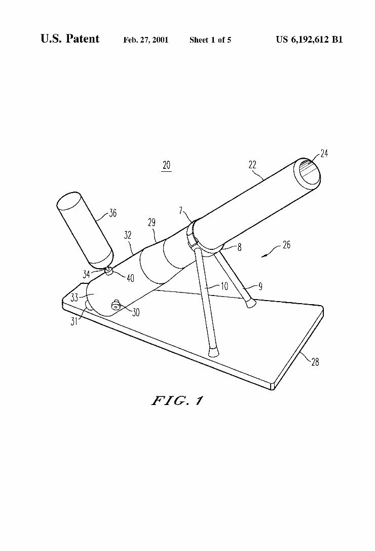
U.S. Patent Feb. 27, 2001 Sheet 1 0f 5 US 6,192,612 B1
FIG. 7
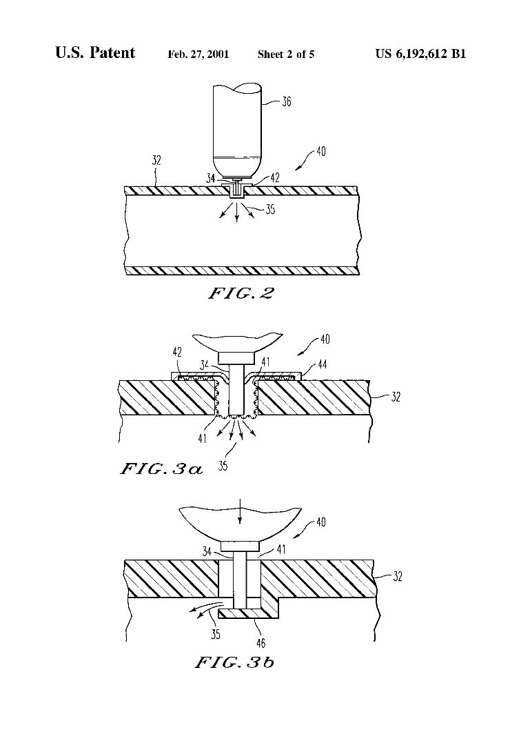
U.S. Patent Feb. 27, 2001 Sheet 2 0f 5 US 6,192,612 B1
40 32 /
54 42 \\\\\\\\Y‘_lk\\\\\\\\
Avis
\\\\\\\\\\\\\\\\
F1612
-....\
FIG. 3 0!, 35
I ; 40 /
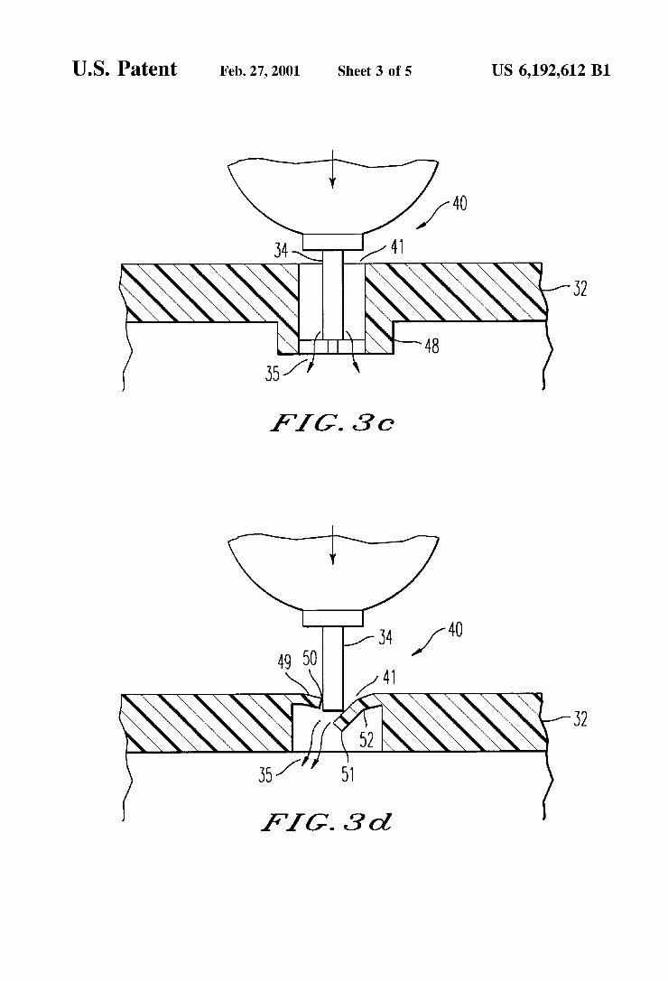
U.S. Patent Feb. 27, 2001 Sheet 3 0f 5 US 6,192,612 B1
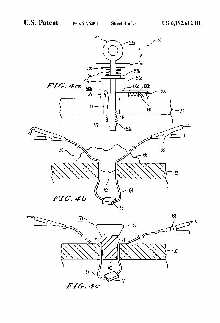
U.S. Patent Feb. 27, 2001 Sheet 4 0f 5 US 6,192,612 B1
600
30 68 —\ 66
64
FIG’. 40
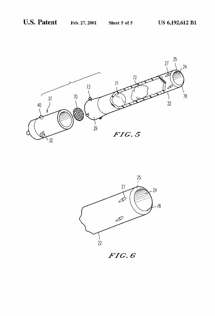
U.S. Patent Feb. 27, 2001 Sheet 5 0f 5 US 6,192,612 B1
FIG. 6
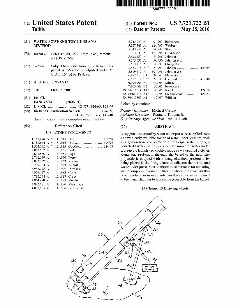
US007721722B1
(12) Unlted States Patent (10) Patent N0.: US 7,721,722 B1 Tulkis (45) Date of Patent: May 25, 2010
(54) WATER-POWERED TOY GUNS AND 5,242,323 A 9/ 1993 Rappaport METHOD 5,267,549 A 12/1993 Webber
5,343,850 A 9/1994 Steer
(76) Inventor: Peter Tulkis, 266 Central Ave., Paramus, i 1%; JDElndmde , , 0 son
NJ (Us) 07652 5,553,598 A 9/1996 Johnson et a1. . _ . . . . 5,653,215 A 8/1997 Chung et a1.
(*) Nome‘ sublectto any dlsclalmeritheterm Ofthls 5,653,216 A * 8/1997 Johnson ..................... .. 124/69 patent 15 extended or adjusted under 35 5 819 717 A 10/1998 Johnson et a1‘ U-S-C- 154(1)) by 18 days- 6,192,612 B1 2/2001 Maier et a1.
6,527,518 B2* 3/2003 OstroWski .................. .. 417/40
(21) Appl. No.: 11/924,732 6,904,901 B2 6/2005 Mitchell 7,163,009 B2 1/2007 Brown et a1.
(22) Filed: Oct. 26, 2007 2005/0016514 A1* 1/2005 Nadel ........................ .. 124/56 2005/0183711 A1* 8/2005 Eichner et a1. .............. .. 124/73
(51) Int. Cl. 2007/0012305 A1 1/2007 Williams F41B 11/28 (2006.01) * . . clted by examlner
(52) US. Cl. ............................ .. 124/73; 124/65; 124/69 (58) Field of Classi?cation Search ................. .. 124/69, Primary ExamineriMichael Carone
124/70, 75, 56, 63; 417/40 Assistant ExamineriReginald Tillman, Jr. See application ?le for complete search history. (74) A1101’ "6y! Agenll 01’ FirmiAl'thul‘ Jacob
(56) References Cited (57) ABSTRACT
1,167,178 1,183,644 1,324,772 2,000,607 2,601,555 2,762,356 3,022,597 3,739,764 3,938,272 4,376,327 4,712,274 4,854,480 4,892,081 4,897,065
A A
US. PATENT DOCUMENTS
* 1/1916 Hill ........................... ..
* 5/1916 Hill ........................... ..
124/56 124/75
A * 12/1919 Goodyear .................. .. 124/75
5/1935 6/1952 9/1956 2/1962 6/1973 2/1976 3/1983 12/1987 8/1989 1/1990 1/1990 Fertig et a1.
Peake Pope F0 ster Rucker Allport Ditto et a1. Curtis Curtis Shindo Moormann
A toy gun is operated by Water under pres sure, supplied from a conveniently available source of Water under pressure, such as a garden hose connected to a municipal Water supply, a household Water supply, or a similar source of Water under pressure, to launch a projectile, such as a Water-?lled balloon, along, and preferably through, the barrel of the gun. The projectile is coupled With a ?ring chamber, preferably by being placed in the ?ring chamber, adjacent the barrel, and Water under pressure is admitted to an actuator for actuating an air compressor Which, in turn, creates compressed air that is accumulated in an air chamber and then selectively released to the ?ring chamber to launch the projectile from the barrel.
20 Claims, 13 Drawing Sheets
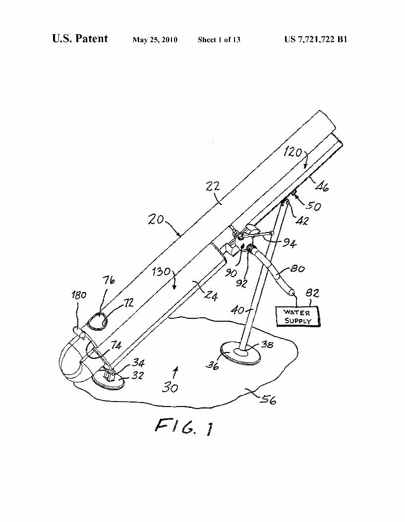
US. Patent May 25,2010 Sheet 1 or 13 US 7,721,722 B1
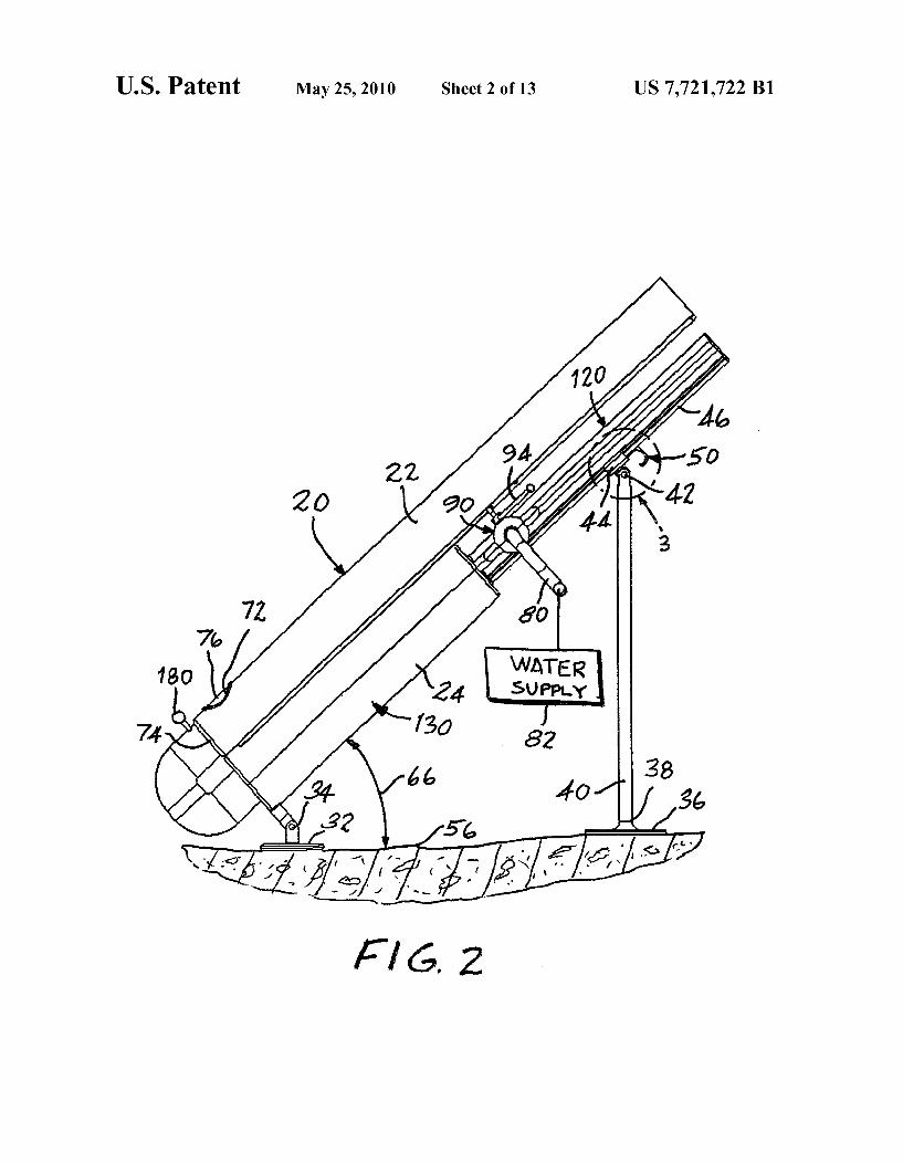
US. Patent May 25,2010 Sheet 2 or 13 US 7,721,722 B1
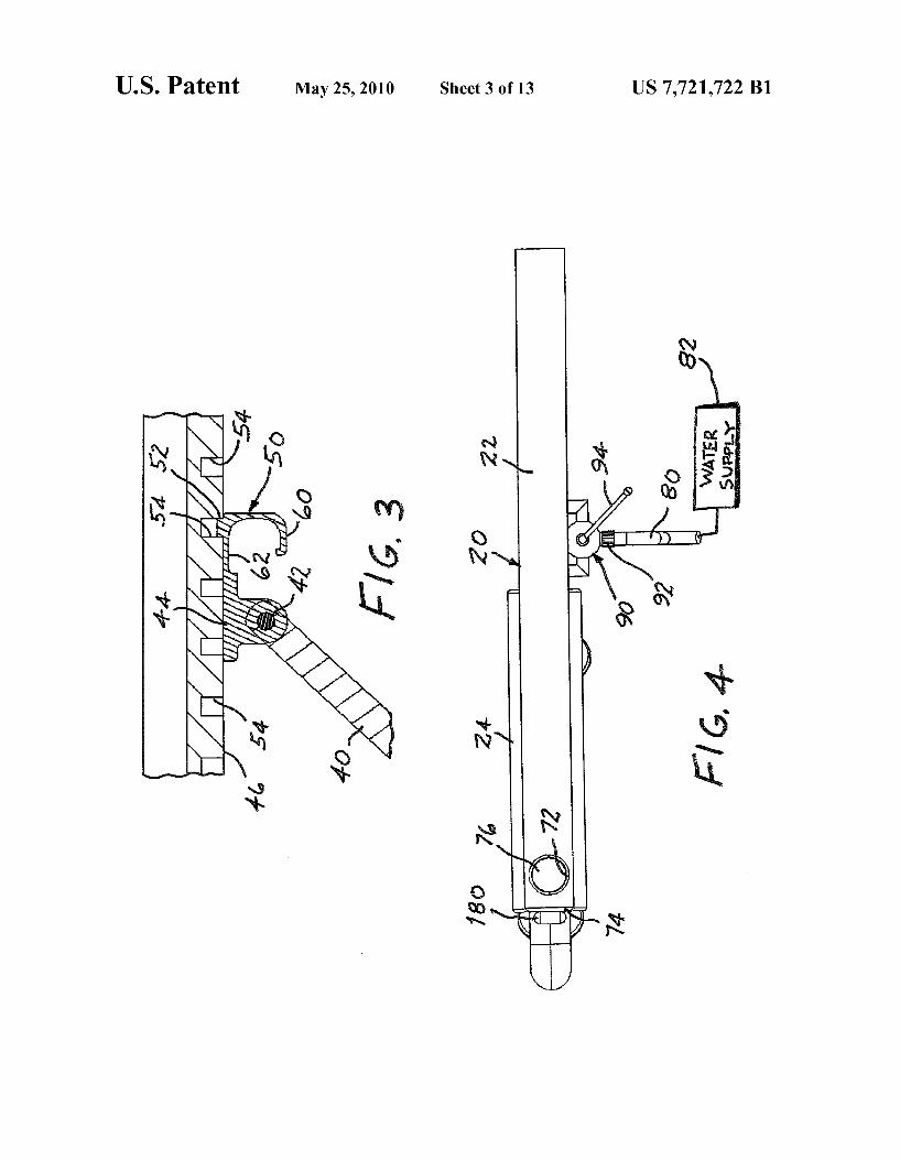
US. Patent May 25, 2010 Sheet 3 0f 13 US 7,721,722 B1
$/ T? A
W
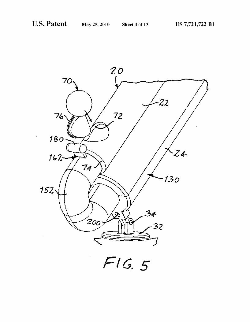
US. Patent May 25,2010 Sheet 4 or 13 US 7,721,722 B1
2 0 70, ~
180
752
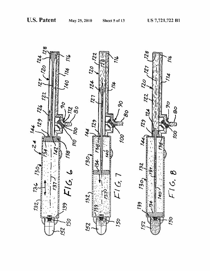
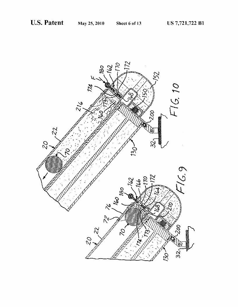
US. Patent May 25, 2010 Sheet 6 0f 13 US 7,721,722 B1
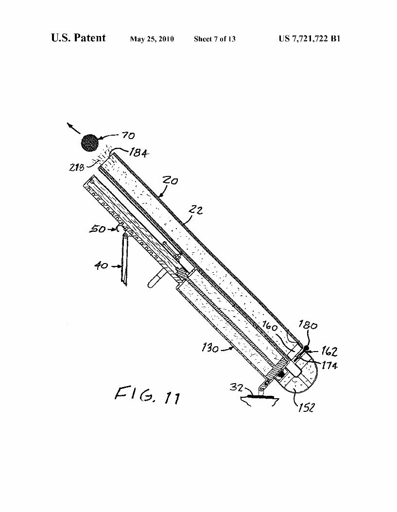
US. Patent May 25, 2010 Sheet 7 0f 13 US 7,721,722 B1
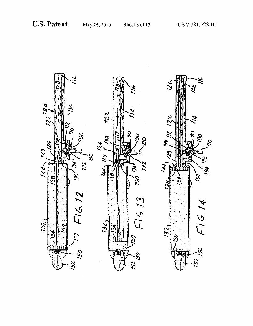
US. Patent May 25, 2010 Sheet 8 0f 13 US 7,721,722 B1
0%
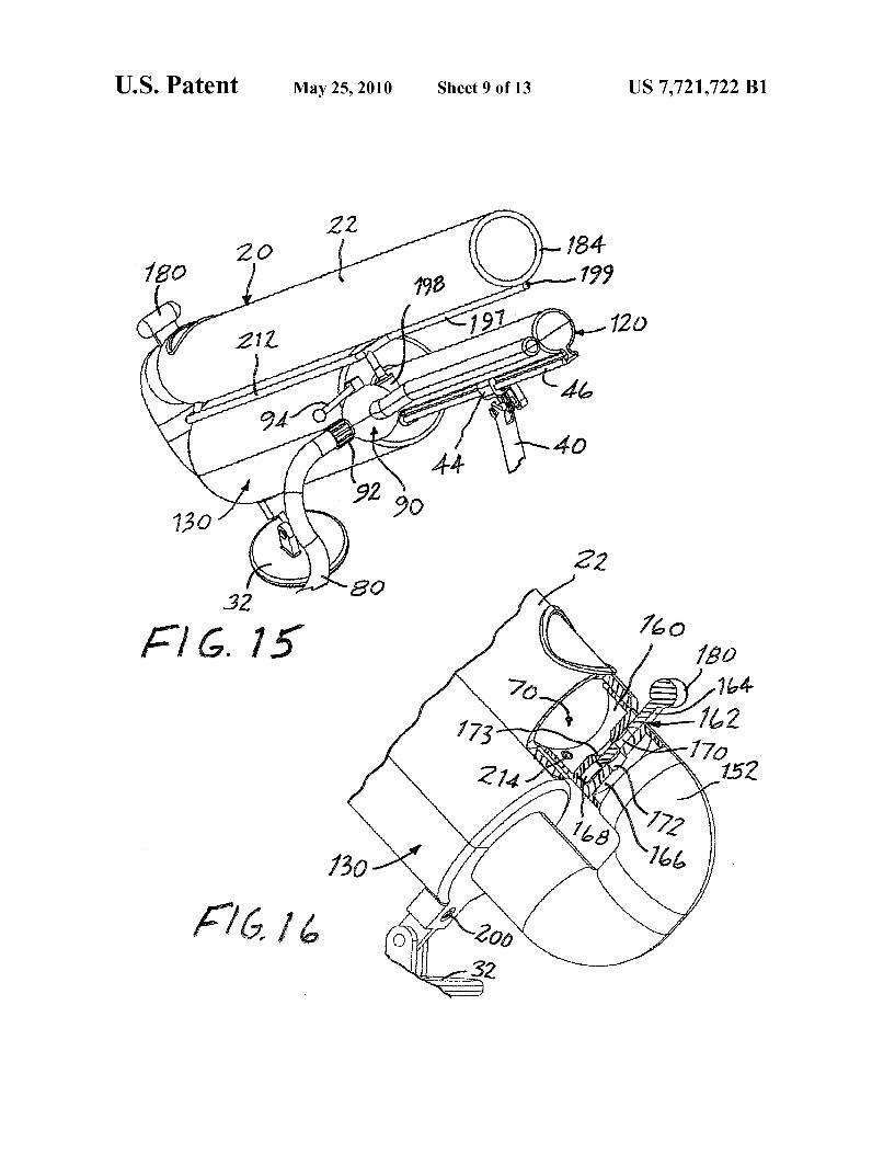
US. Patent May 25, 2010 Sheet 9 0f 13 US 7,721,722 B1
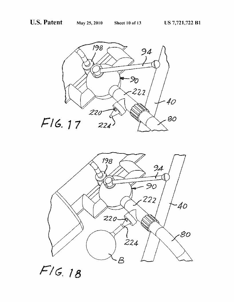
US. Patent May 25, 2010 Sheet 10 0f 13 US 7,721,722 B1
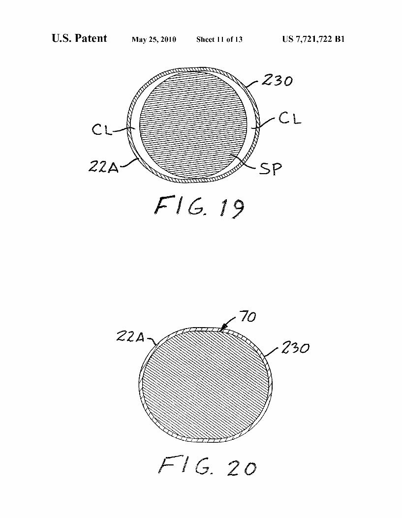
US. Patent May 25, 2010 Sheet 11 0113 US 7,721,722 B1
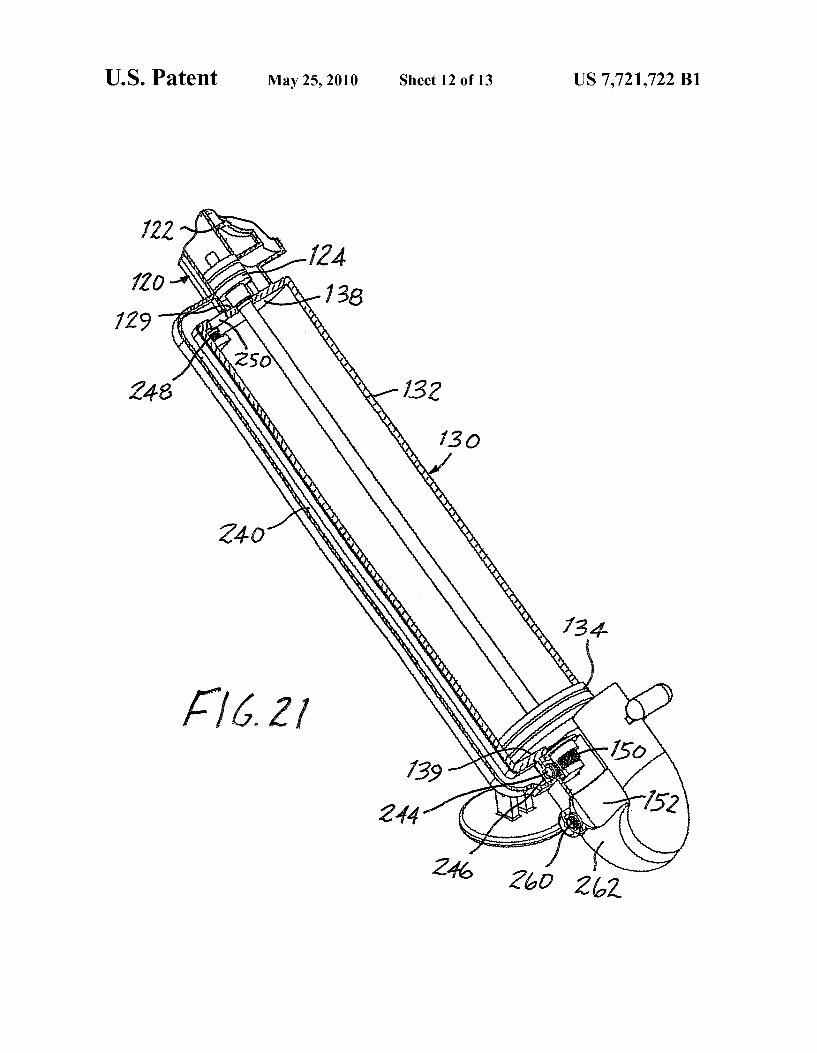
US. Patent May 25, 2010 Sheet 12 0113 US 7,721,722 B1
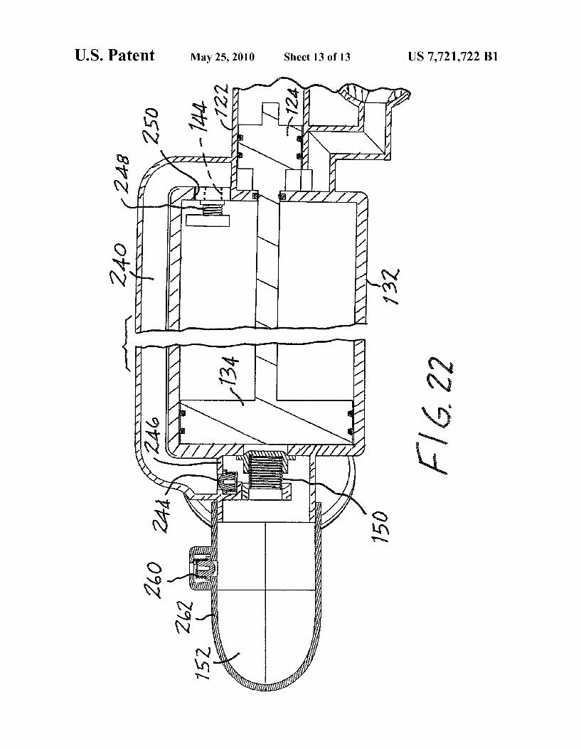
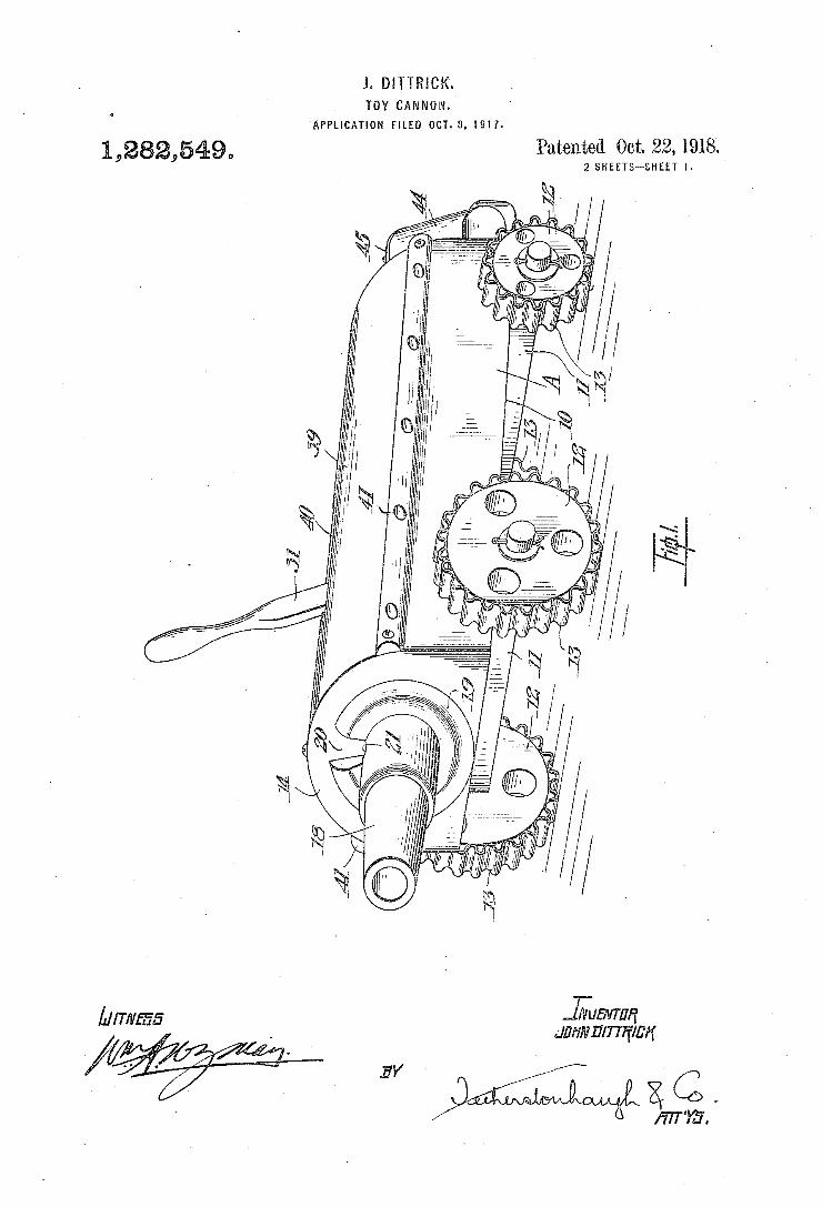
J. DITTRICK'. TOY CANNON.
'APPLICATION FILED OCT. 8. i917.
1,282,549a
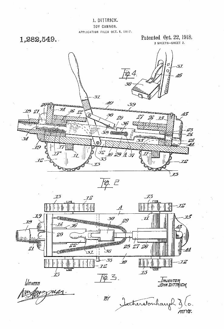
J. D'iTTRICK. I TOY CANNON.
APPLICATION FILED OCT- 8. 1917.
Patented Oct. 22, 1918'. 2 SHEETS—SHEET 2. 1,282,5%9...
7/47
55 ,7” l2
l5
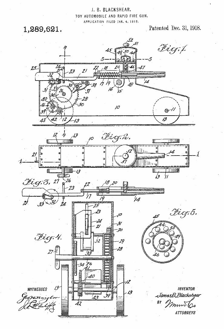
1. B. BLACKSHEAR. TOY`AUTOMOB|LE AND RAPID FIRE GUN.
‘ APPLICATION F|LED1AN.4.191B.
_ Patented Dec. 31, 1918.
1 1 v / llllI-pllllllllllll. ________„ ________ _____no __'_-- ____ __,--- _____ *6,
Q Q
M //
¿WwW/111,111,111,...
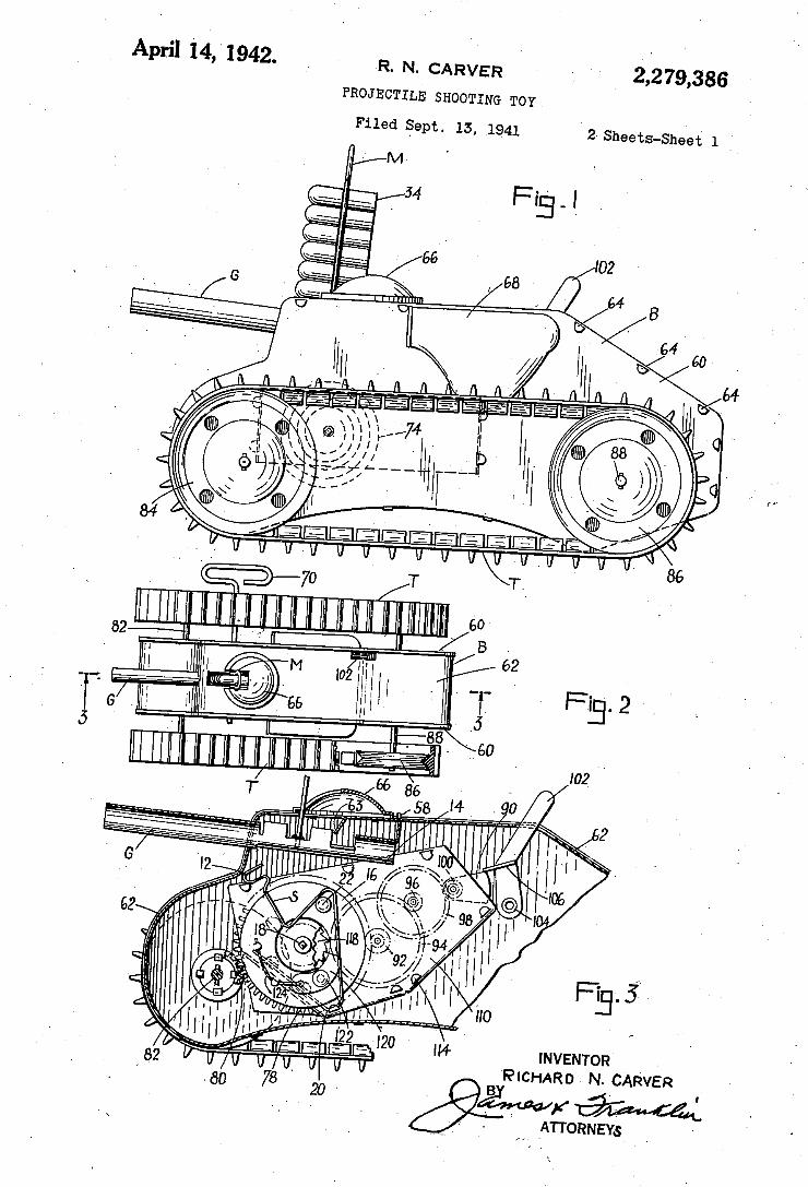
r _ April 14, ‘ 1942. R. N. CARVER p, 2,279,386
PROJECTILE SHOOTING TOY
Filed Sept. 15, .1941 ’2- Sheets-Shed 1 _
I02 '
"slur I" % ~
INVE‘NTOR PlcHARD- N. CARVER
. B '
' I . V ATTORNEYS _ -
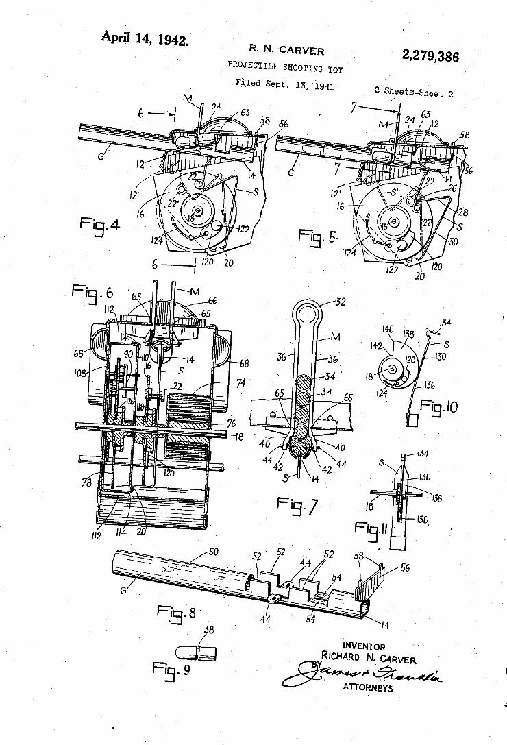
2,279,386‘ . '
April 14, 1942.‘ R. N. CARVER
I PROJECTILE SHOOTING TOY I
‘Filed Sept. 15, 1941' '2 Sheets-Sheet 2‘
ll. . Ii
INVENTOR RICH ARD N. CARVER
» ATTORNEYS
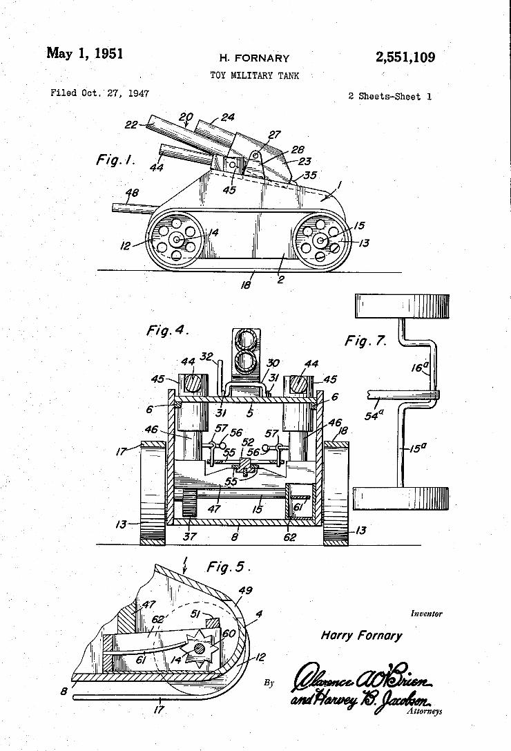
Mayl, 1951 H. FORNARY 2,551,109 ‘
TOY MILITARY TANK "
Filed 00%- 27, 1947 ‘ 2 Sheets-Sheet 1
Inventor
Harry F ornary
l2 ' ’
a ‘ By ‘ x7 _ ‘ WWW
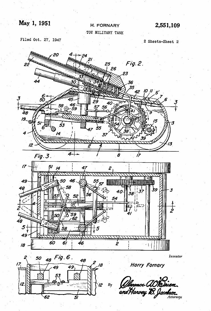
M5)’: 1, 1951 H. FORNARY 2,551,109 ' TOY MILITARY TANK ‘
Filed Oct. 27, 1947 2 Sheets-Sheet 2
Inventor
l8 ' Harry Fomary
72 B)’
WWW 8mm
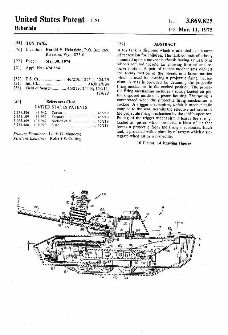
United States Patent [191 3,869,825 [111
1211 Appl. No.: 474,384
[52] US. Cl ....................... .. 415/219, 124/11, 124/19 [51] Int. Cl ........................................... .. A63h 17/04 [58] Field of Search ........... .. 46/219, 244 R; 124/11,
124/29
[56] References Cited UNITED STATES PATENTS
2,279,386 4/1942 Carver ................................ .. 46/219 2,551,109 5/1951 Fornary . . . . . . . . . . . . . . . .. 46/219
3,065,569 11/1962 Nielsen et a1. . t . . . . . . . . . .. 46/219
3,774,586 11/1973 Siato ................................... .. 46/219
Primary E.raminer—Louis G. Mancene Assista nt Examiner-Robert F. Cutting
% W
Heberlein [45] Mar. 11, 1975
[54] TOY TANK [57] ABSTRACT
[76] Inventor: Harold V. Heberlein, PO. Box 269, A toy tank is disclosed which is intended as a source Riverton, Wyo. 82501 of recreation for children. The tank consists of a body
1 . _ mounted upon a moveable chassis having a plurality of [22] Fned‘ May 30’ 1974 wheels secured thereto for allowing forward and re
verse motion. A pair of rachet mechanisms convert the rotary motion of the wheels into linear motion which is used for cocking a projectile ?ring mecha nism. A sear is provided for detaining the projectile ?ring mechanism in the cocked position. The projec tile ?ring mechanism includes a spring~loaded air pis~ ton disposed inside of a piston housing. The spring is compressed when the projectile firing mechanism is cocked. A trigger mechanism, which is mechanically coupled to the sear, permits the selective activation of the projectile ?ring mechanism by the tank’s operator. Pulling of the trigger mechanism releases the spring loaded air piston which produces a blast of air that forces a projectile from the ?ring mechanism. Each tank is provided with a plurality of targets which disin~ tegrate when hit by a projectile.
10 Claims, 14 Drawing Figures
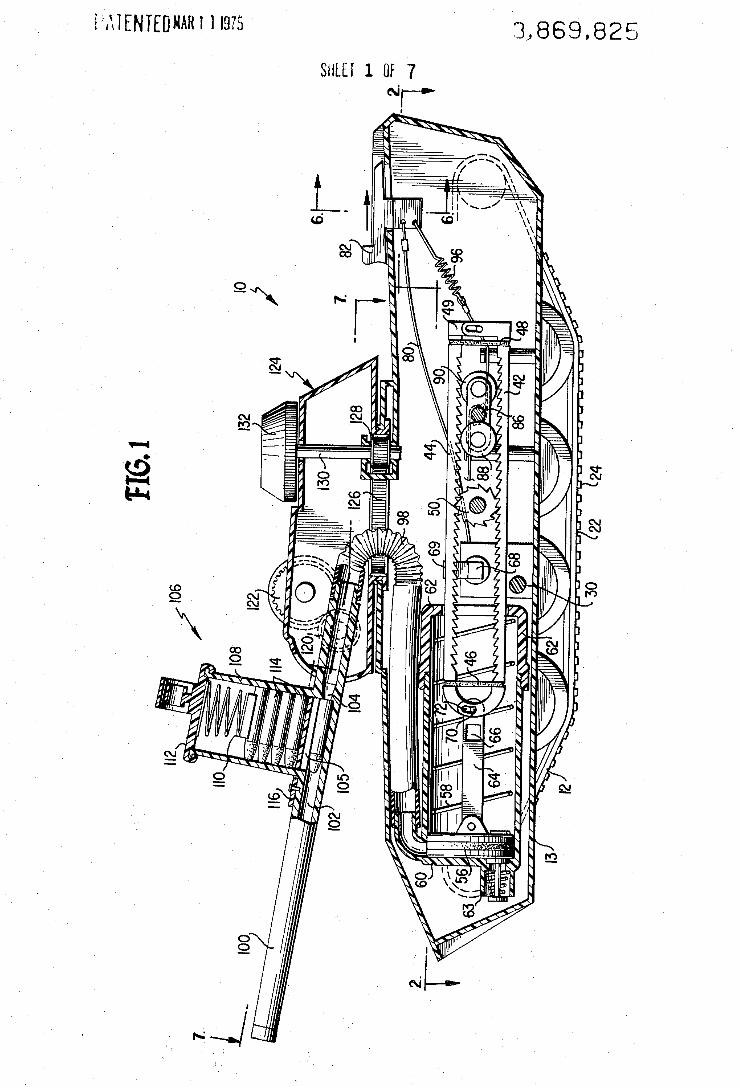
3,869,825 WENTEDRARI H975
SHLEI 1 [1f 7
~ 6E
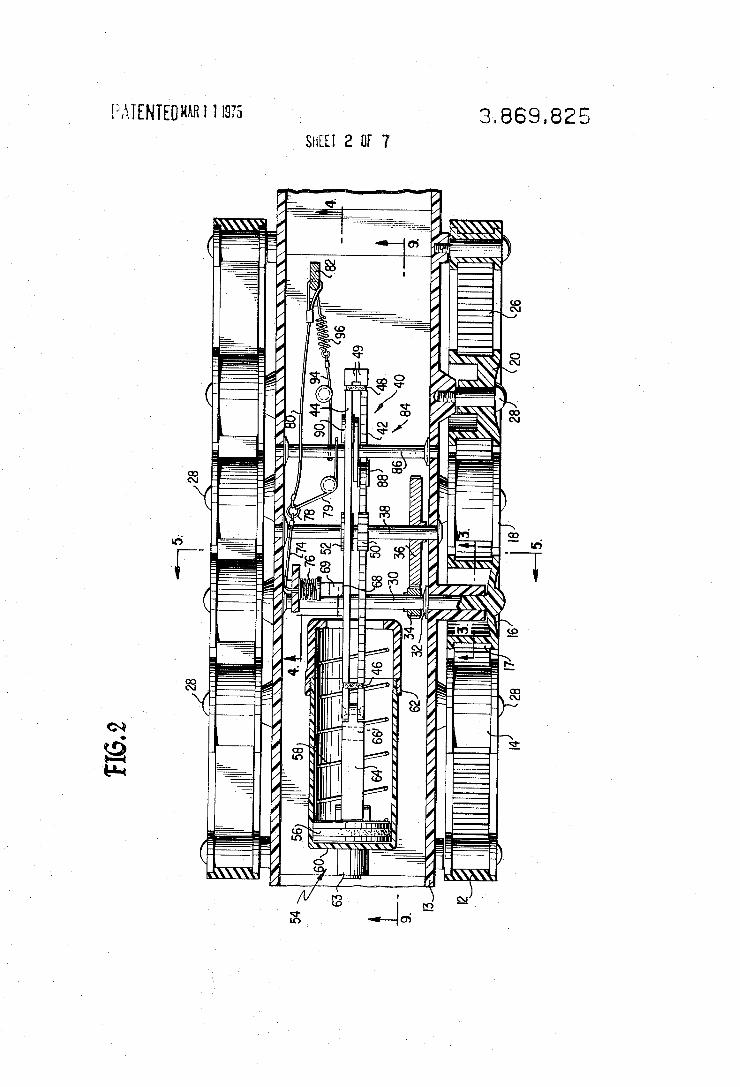
' 3869,8325 mgmgnumr 1 19.75 _
sum 2 or 7
NQE
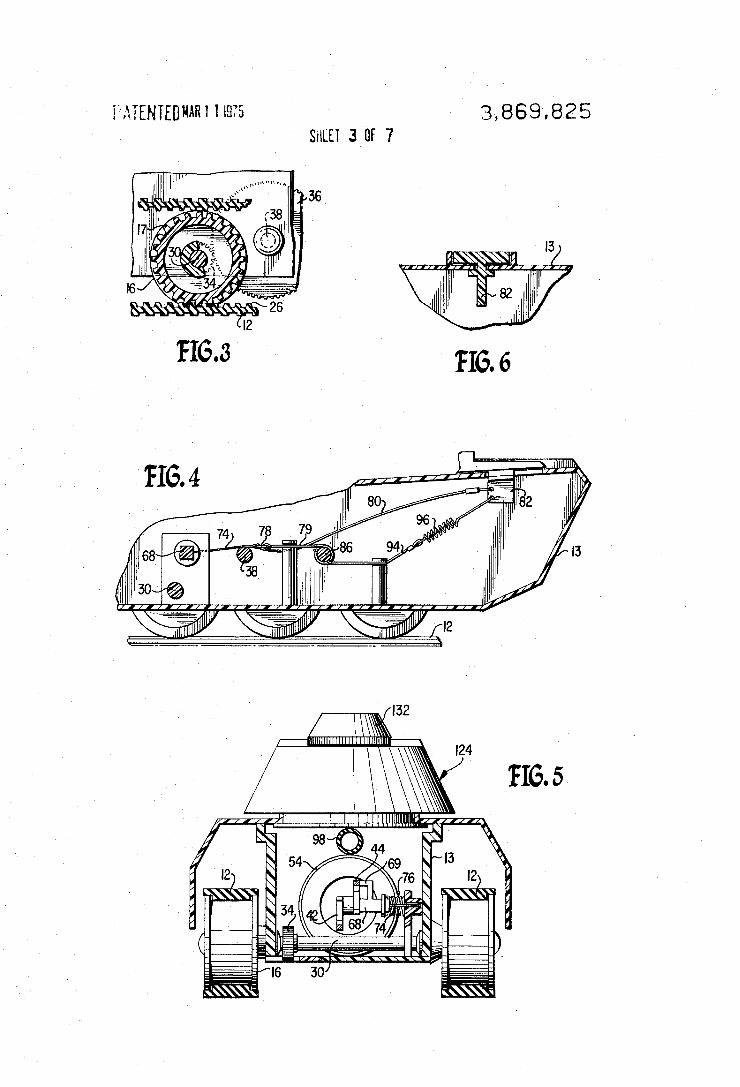
3,869,825 FMENTEB KARI I LQFS SHEET 3 BF 7
IIIW
5
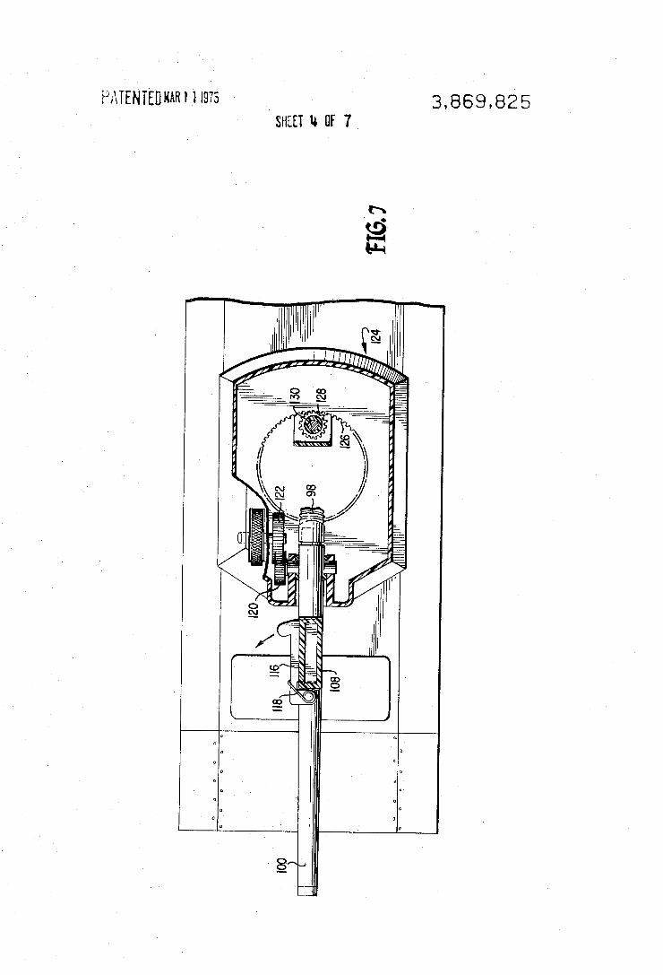
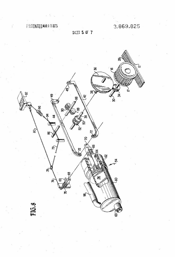
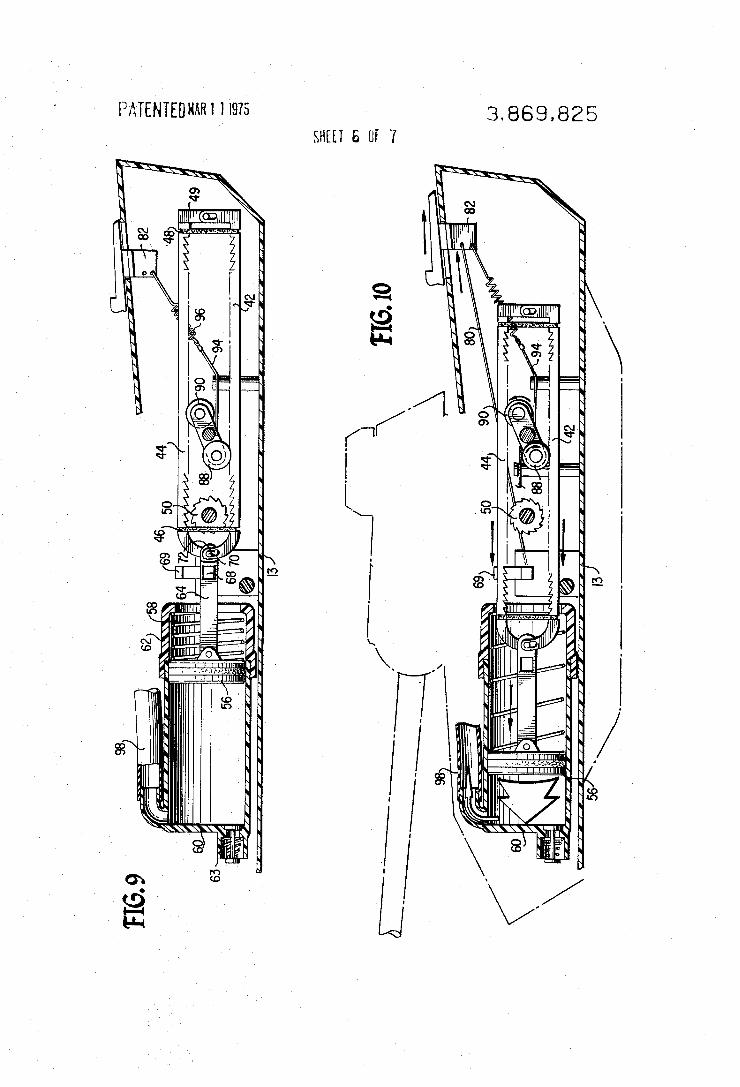
3,869,825 PATENTEDHARI 1 I975 SHEET 5 [If Y
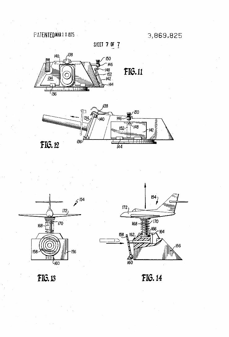
PATENTEUWI “975 3 869 825
FIG. 14
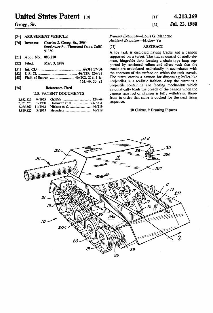
United States Patent [191 [11]
[45]
4,213,269 Jul. 22, 1980 Grogg, Sr.
[54] AMUSEMENT VEHICLE
[76] Inventor: Charles J. Grogg, Sr., 2964 Sun?ower St., Thousand Oaks, Calif. 91360 ,
[21] App]. No.: 883,210 [22] Filed: Mar. 3, 1978
[51] Int. Cl.2 ........................................... .. A63H 17/04 [52] U.S. Cl. ................................ .. 46/219; 124/82 [58] Field of Search ....................... .. 46/202, 219, l E;
124/49, 50, 82
[56] References Cited U.S. PATENT DOCUMENTS
2,652,822 9/1953 2,921,573 l/l960 3,065,569 1l/l962 3,869,825 3/1975 Heberlein ............................. .. 46/219
Primary Examiner-Louis G. Mancene Assistant Examiner—Mickey Yu
[5?] ABSTRACT A toy tank is disclosed having tracks and a cannon supported on a turret. The tracks consist of multi-ele ment, hingeable links forming a chain type loop sup ported by tensioned rollers and idlers such that the tracks are articulated realistically in accordance with the contours of the surface on which the tank travels. The turret carries a cannon for dispensing bullet-like projectiles in a realistic fashion. Atop the turret is a projectile containing and feeding mechanism ‘which automatically loads the breech of the cannon when the cannon ram rod or plunger is fully withdrawn there from in order that same is cocked for the next ?ring sequence. '
10 Claims, 9 Drawing Figures
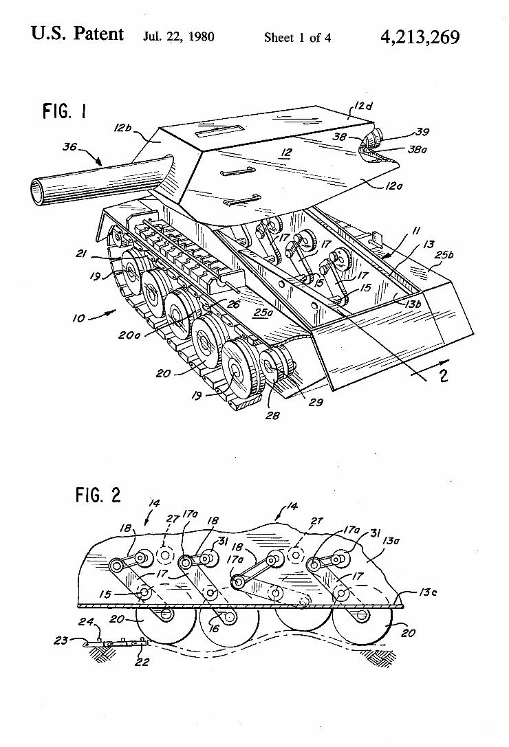
US Patent Jul. 22, 1980 Sheet 1 of4 4,213,269
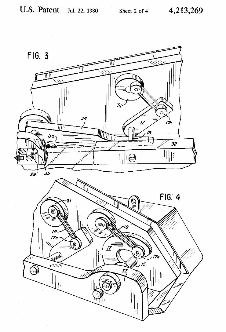
Sheet 2 of 4 4,213,269 U.S. Patent Jul. 22, 1980
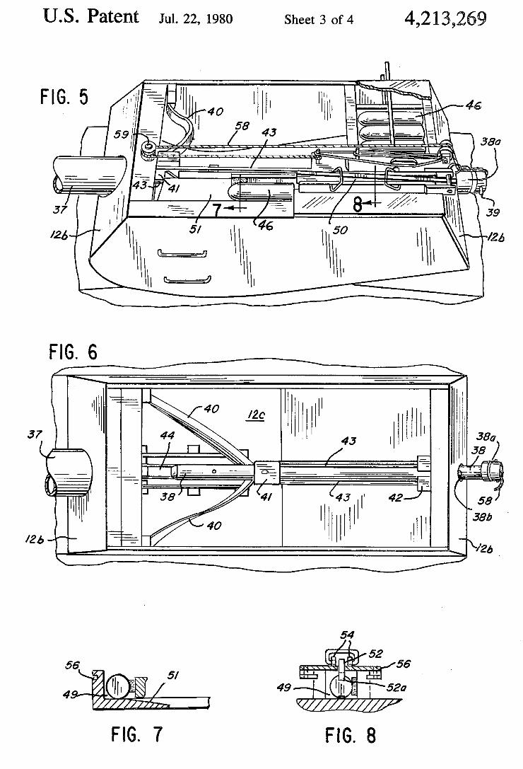
U.S. Patent Jul. 22, 1980 Sheet 3 of4 4,213,269
FIG. 5 ,-,1 cm’ "WI 1 40 ‘I111
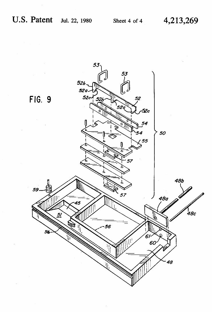
Sheet 4 of 4 4,213,269 U.S. Patent Jul. 22, 1980
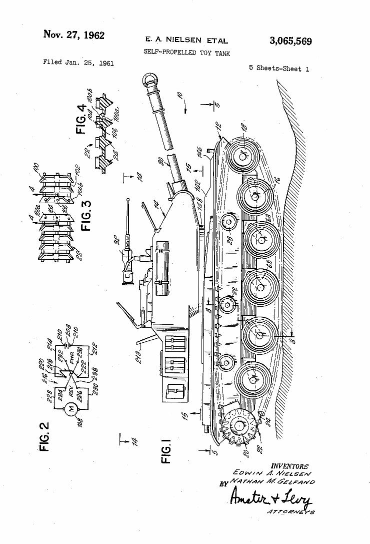
Nov. 27, 1962 3,065,569
5 Sheets-Sheet 1
v
n È f. ' , ì
' '
,l 11k" ; ll,
l 5;.; "Ã" L? ï:
7,41 ,',\ ‘_
INVENTORS ¿'ow//v 4 /V/¿Lsf/v
E. A. Nu-:Lsr-:N ETAL
SELF-PROPELLED TOY TANK
BY A44 ffm/v 4% 622 :A «vo
Filed Jan. 25. 1961
MNMAIY Nä NNY .
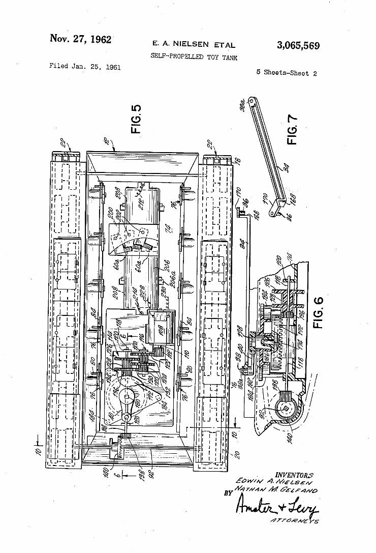
3,065,569 Nov. 27, 1962
E. A. NIELSEN ETAL
SELF-PROPELLED TOY TANK
5 Sheets-Sheet 2 Filed Jan. 25, 1961
| IL _ .
NN.
|IIL. l l | l l .Il
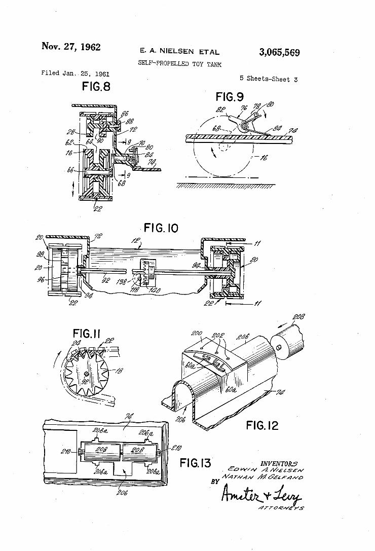
Nov. 27, 1962 E. A. NIELSEN ETAL 3,065,569 SELF-PROPELLED TOY TANK
Filed Jan. 25; 1961
FIGB 5 Sheets-Sheet 5
ff ff
-Iy 25
if /ä
al ¿90
INVENTORS , 60W/1v ,4A//fas5/v
Am@
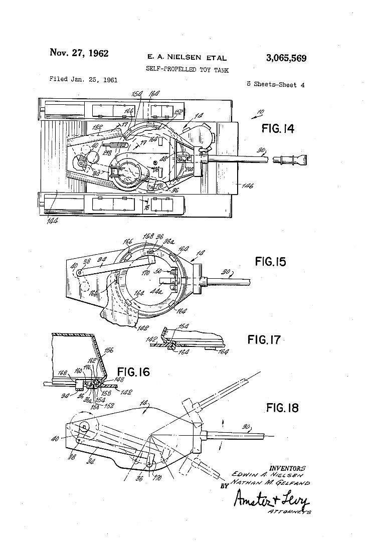
Nov. 27, 1962 E. A. NIELSEN ETAL 3,065,569 SELF-PROPELLED TOY TANK
Filed Jan. 25, 1961 5 .Sheets-Sheet 4
/
w FIG. I4
fía, 4M
/55 752
Amt/Ji@
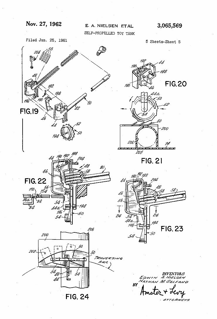
Nov. 27, 1962 E. A. NlELsl-:N ETAL 3,065,569
SELF-PROPELLED TOY TANK
Filed Jan. 25, 1961 5 sheets-sheets
Umd@
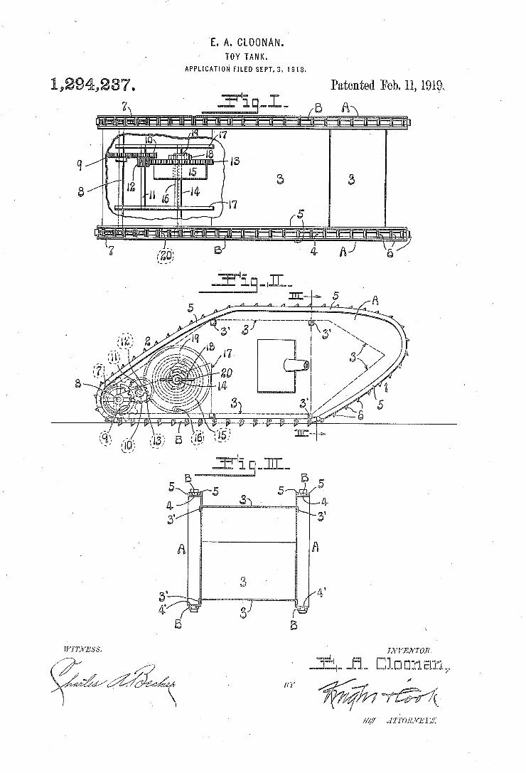
E. A. CLOONAN. TO'Y TANK.
APPLICATION FILED SEPT.3, I918.
13%,2370 Patented Feb. 11, 19191 Y ' ‘-l— e e
m
- in .31. Elm EJ113111, I? 1" y ,
/
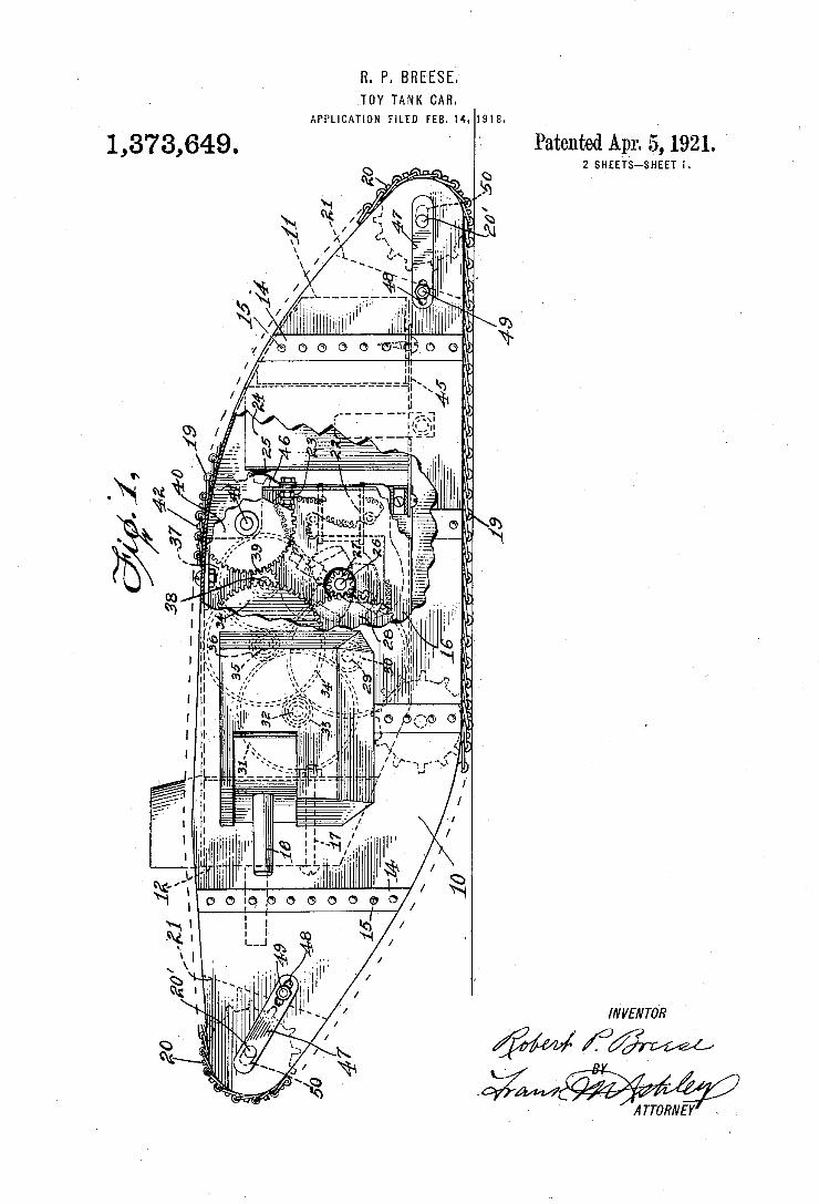
a. P. BREESE. TOY TANK CAR.
APPLICATION FILED FEB. Hr. 1918.
Patented Apr. 5|, 1921. 1,373,649. 2 SHEETS-SHEET I.
. x _mmf . „f/mm...
A TTORNEY
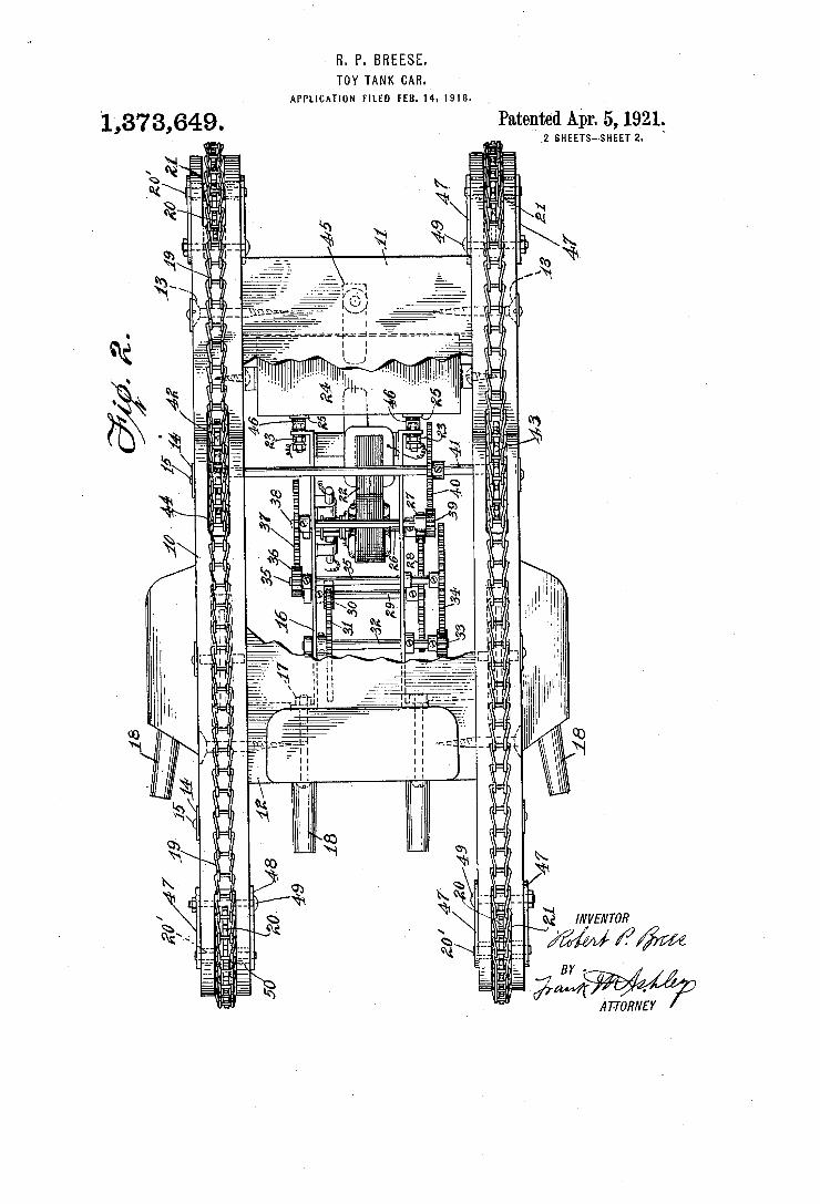
R. P. BREESE.
TOY TANK CAR.. APPLlcATloN FILED rEß.14. 191s.
1,373,649. ` ' Patented Apr. 5, 1921.` _2 SHEETS-SHEET 2
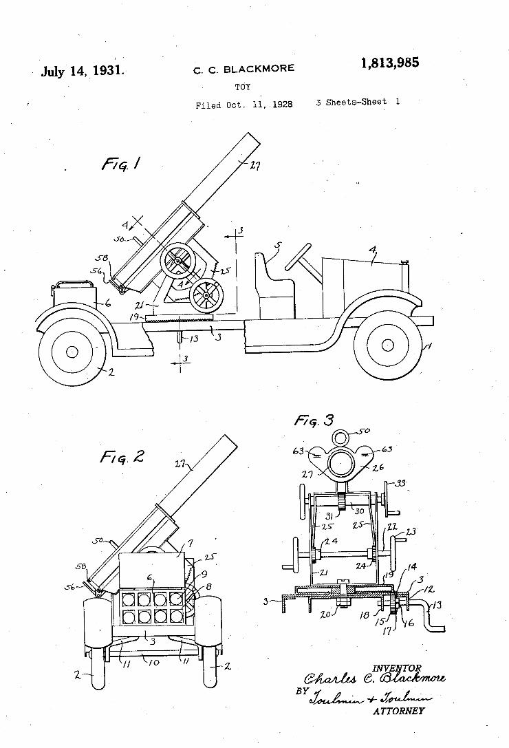
~ July 14,1931.‘ 1,813,985 C. C. BLACKMORE
TOY
5 Sheets-Sheet 1 Filed Oct. 11, 1928
1 I ‘ _ _ @IINVEZTOR
BYM'W 4- W A TTORNE Y
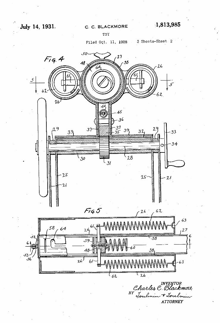
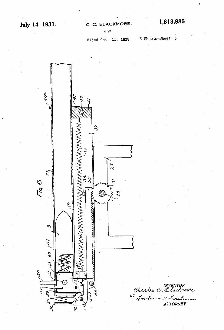
July 14. 1931. c. c. BLACKMORE- I 1,813,985
TOY ‘
Filed on. 11, 1928 s Sheets-Sheet s
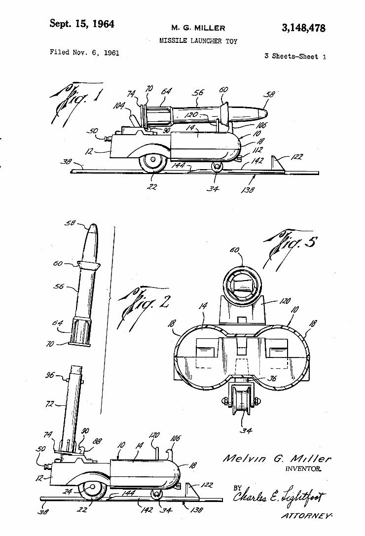
3,148,478 M. G- MILLER
MISSILE LAUNCHER TOY
Sept. 15, 1964
3 Sheets-Sheet 1 Filed NOV. 6, 1961
34 22
INVENTOR.
BYi é, g ; AIV'O/PA/L'V'
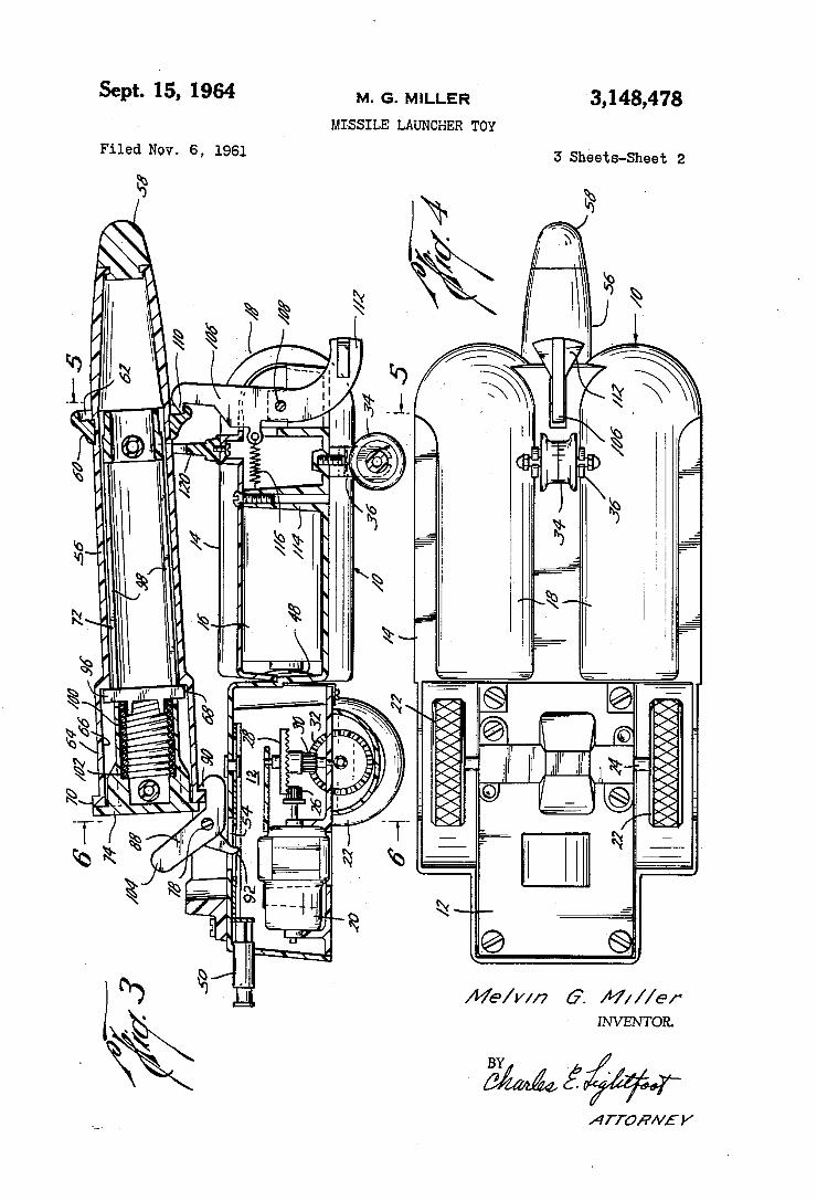
3,148,478 Sept. 15, 1964 M. G. MILLER
MISSILE LAUNCHER TOY
3 Sheets-Sheet 2 Filed NOV. 6, 1961
@
INVENTOR.
/ - /
BY
/
ATTORNEY
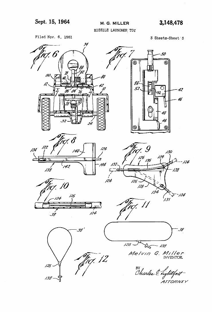
Sept. 15, 1964 M. G. MILLER 3,143,478 MISSILE LAUNCHER TOY
Filed Nov. 6, 1961 5 Sheets-Sheet‘3
Me/wn G‘. gig/£15243?
w my 3 / ‘y nrramvm/
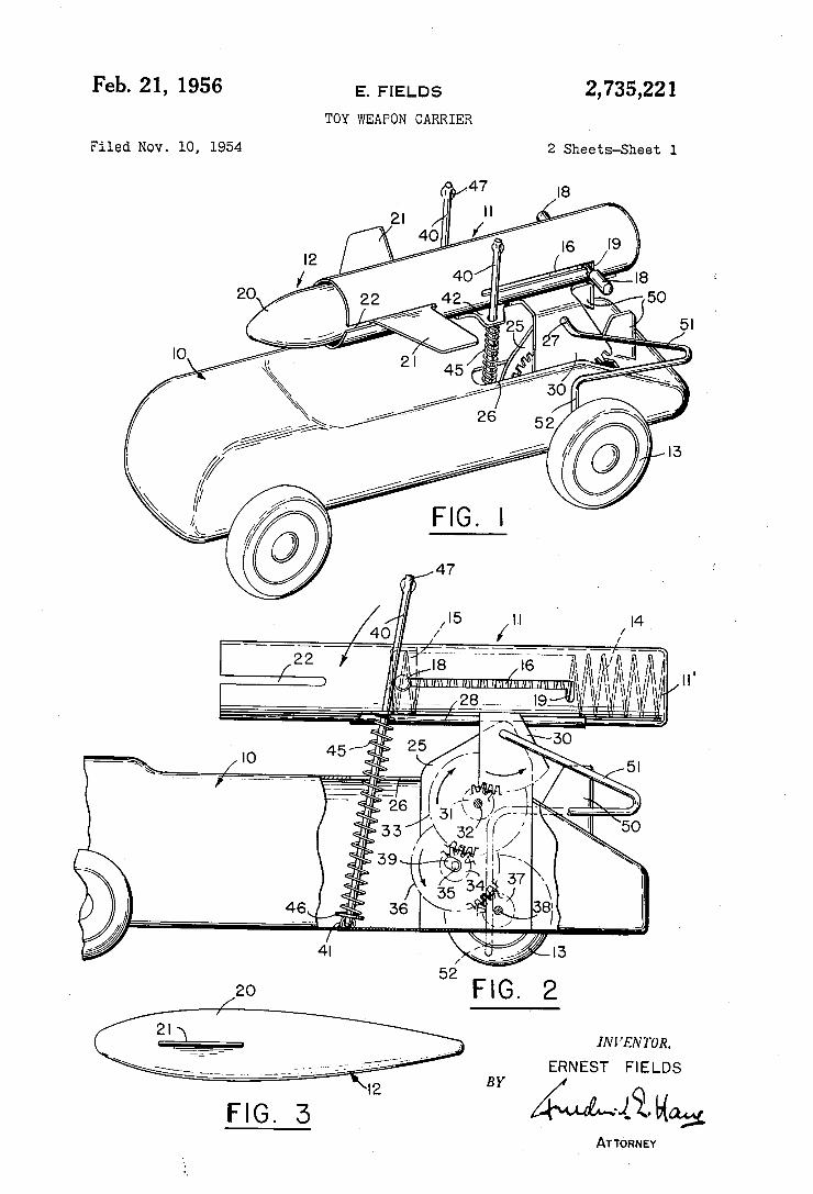
Feb. 21, 1956
Filed NOV. 10, 1954
E.’ FIELDS
TOY WEAPON CARRIER
2,735,221
2 Sheets-Sheet l
INVENTOR.
ERNEST FIELDS
BY M431. Hm}, ATTORNEY
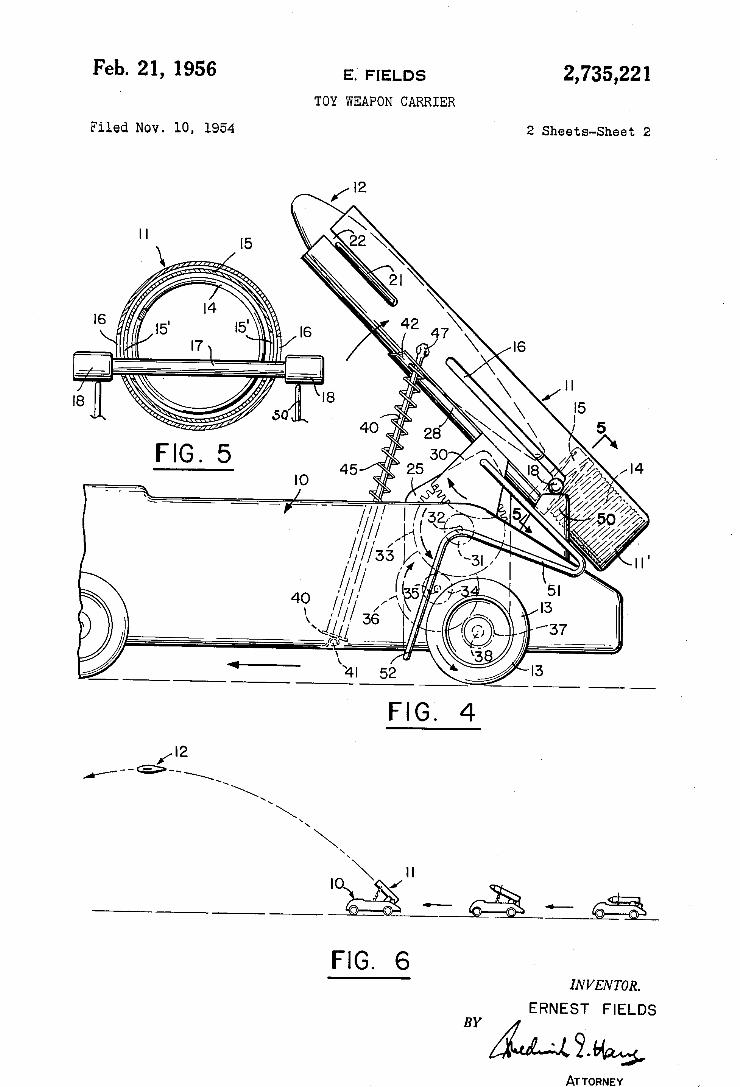
Feb. 21, 1956 E; FlELDs 2,735,221 TOY WEAPON CARRIER
Filed NOV. 10, 1954 2 Sheets-Sheet 2
INVENTOR.
ERNEST FIELDS BY
ATTORNEY
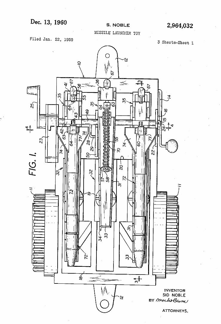
Dec. 13, 1960
Filed Jan. 22, 1959
S. NOBLE
MISSILE LAUNCHER TOY
12
2,964,032
3 Sheets-Sheet 1
II
INVENTOR SID NOBLE
BYMMMU
ATTORNEYS .
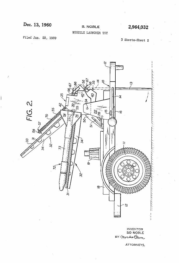
2,964,032 Dec. 13, 1960 s. NOBLE
MISSILE LAUNCHER TOY
5 Sheets-Sheet 2 Filed Jan. 22, 1959
INVENTOR SID NOBLE
BY
ATTORNEYS.
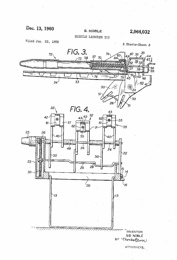
ec. 13, 1960
Filed Jan. 22, 1959
S. NOBLE
MISSILE LAUNCHER TOY
74 63 64
23\, 7
30 \/
BY
2,964,032
3 Sheets-Sheet I5
42 as 35 44
671
—INVENTOR SID NOBLE
ATTORNEYS,
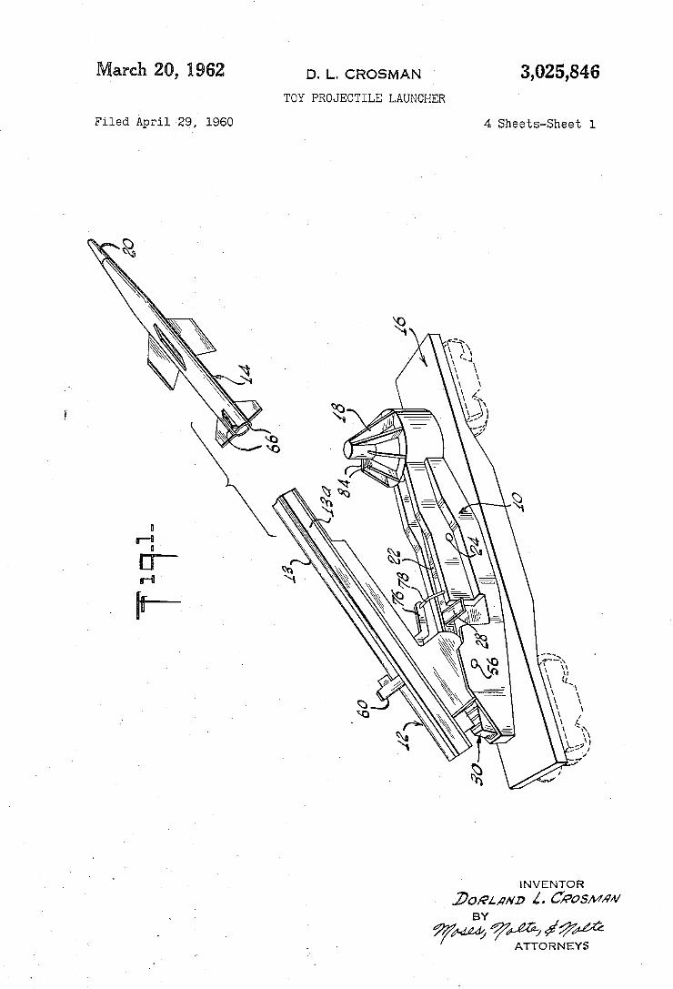
3,025,846 March 20, 1962 D. |_. CROSMAN
TOY PROJECTILE LAUNCHER
4 Sheets-Sheet 1 Filed April 29, 1960
INVENTOR
DUEL/7ND Z. U/PosMm/ BY
WM 74% #1 7M ATTO R NEYS
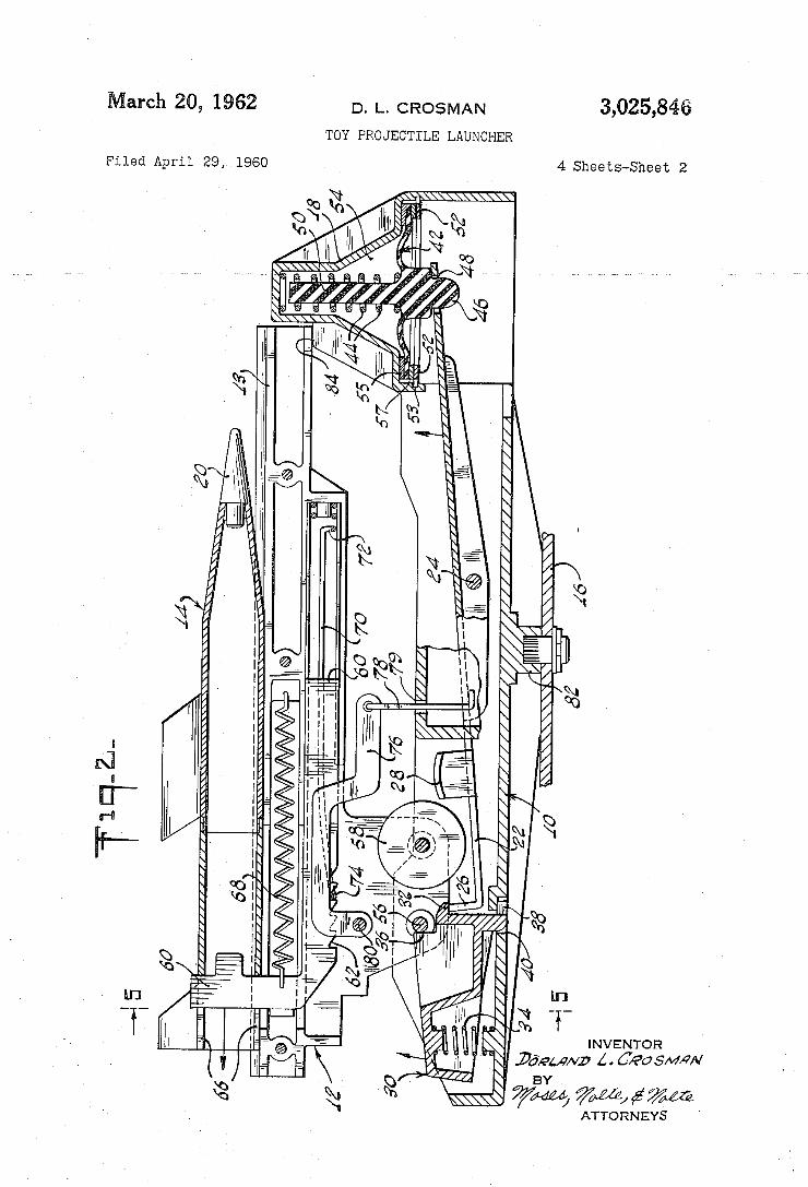
3,025,846 March 20, 1962 D, |_. CROSMAN
TOY PROJECTILE LAUNCHER
4 Sheets-Sheet 2 Filed April 29, 1960
N 9
RW MN 00 E ma’ MM E o V/w MT m T
mu _ w7/A N P11 mvw
_, B
7 a ‘“ & QM N\
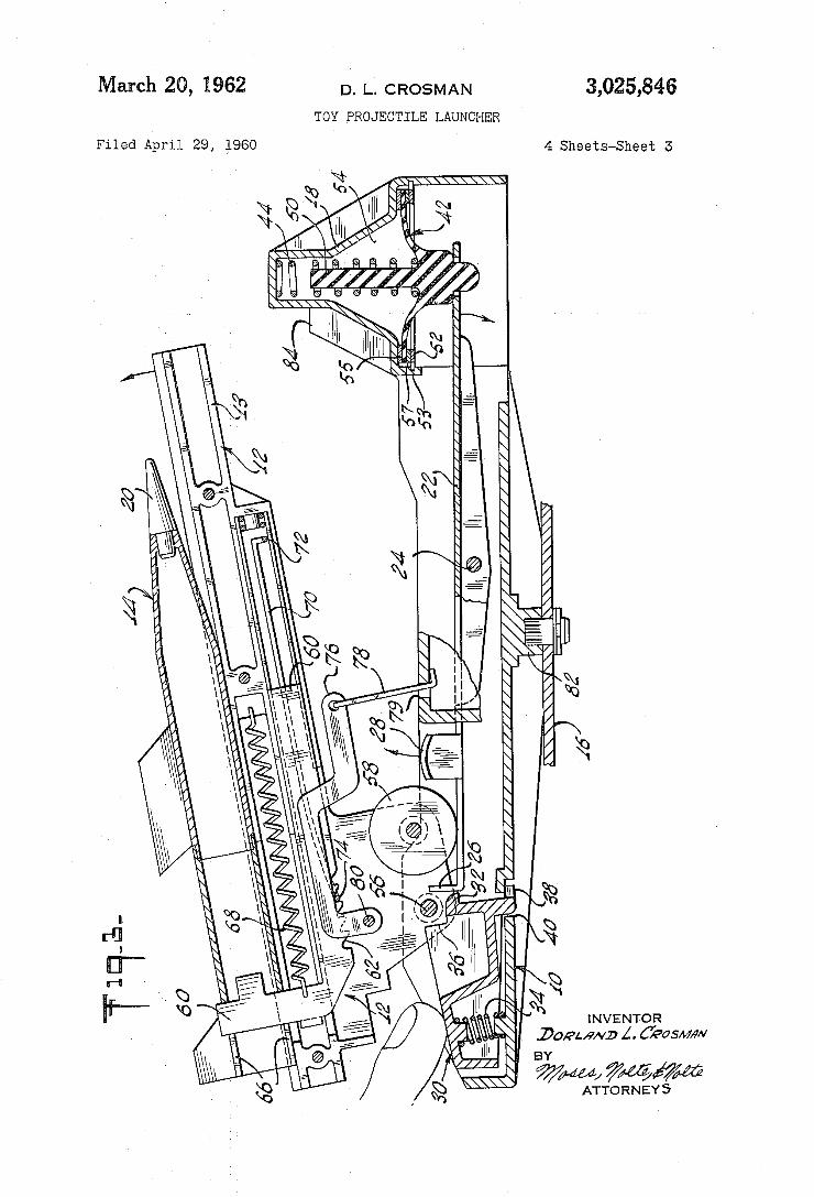
3,025,846 March 20, 1962 D. |_. CROSMAN
TOY PROJECTILE LAUNCHER
4 Sheets-Sheet 3 Filed April 29, 1960
ATTORNEY5
I i
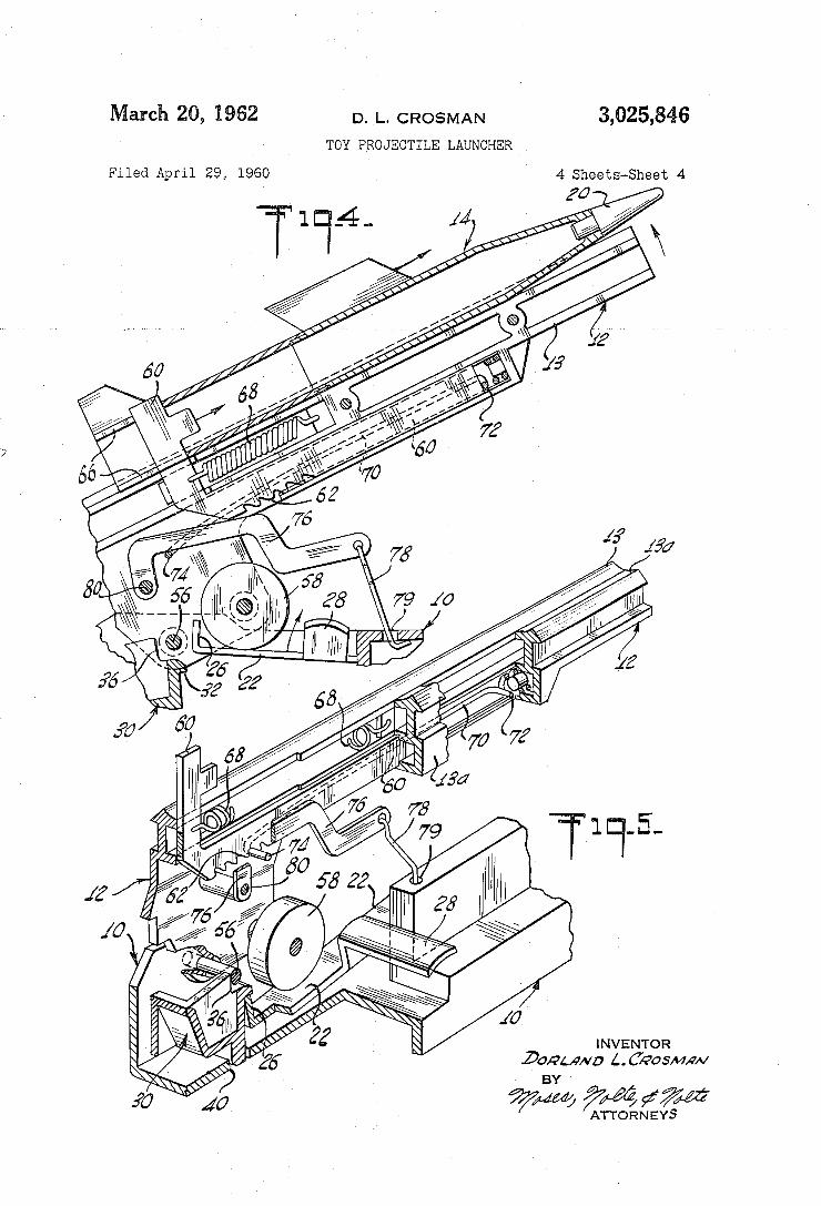
3,025,846 March 20, 1962 D. 1.. CROSMAN
TOY PROJECTILE LAUNCHER
4 Sheets-Sheet 4
INVENTOR .Do/a/wvo LC’Avos/wm/
Filed April 29, 1960
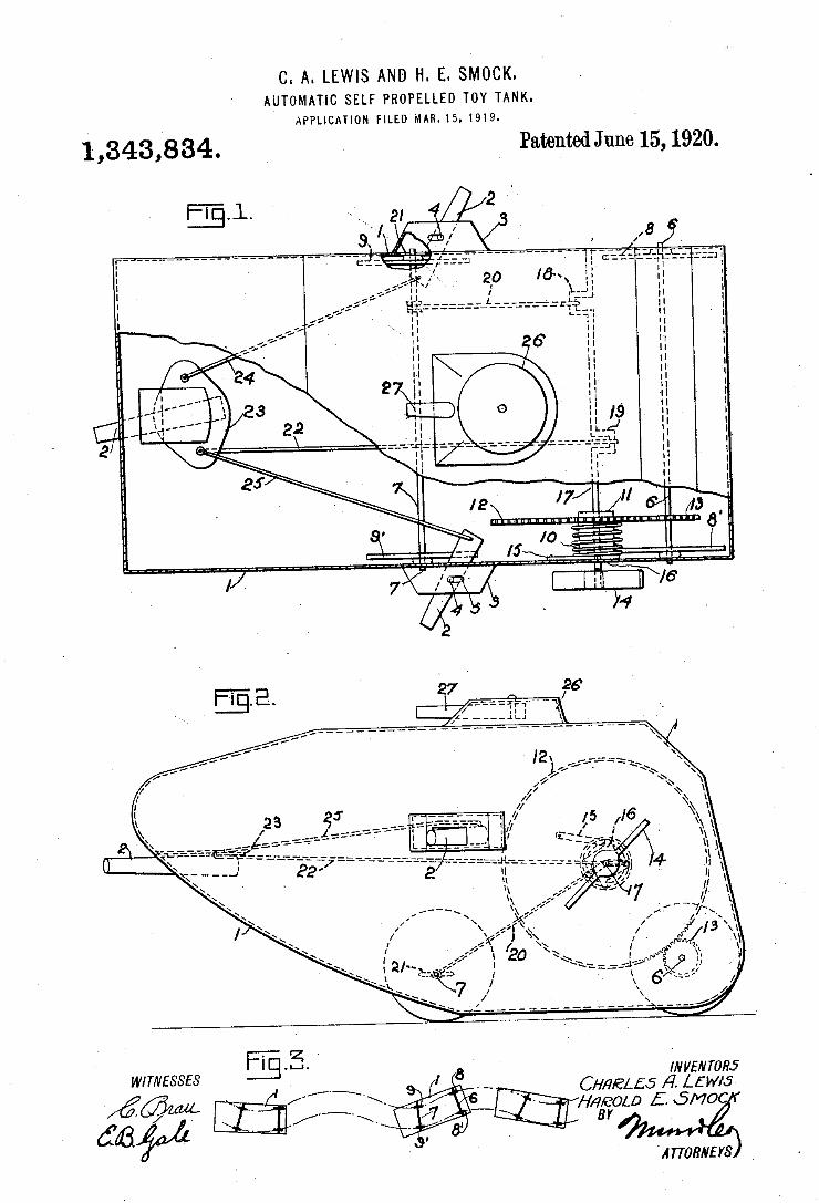
. SMOCK. C. A. LEWIS AND H. E AUTOMATIC SELF PROPELLED TOY TANK.
APPLICATION FILED MAR. 15. I919.
Patented June 15, 1920. 1,343,834.
INVENTORJ CH/IELES A’. L£w/5
’H,4e0L0 5. 50406 8 E 8 8 M T l W
BY
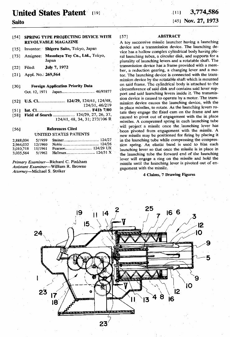
United States Patent [191 Saito
[111 3,774,586 [45] Nov. 27, 1973
SPRING TYPE PROJECTING DEVICE WITH 4 [5 ] REVOLVABLE MAGAZINE
[75] Inventor: Shigeru Saito, Tokyo, Japan
[7 3] Assignee: Masudaya Toy Co., Ltd., Tokyo, Japan
[22] Filed: July 7, 1972
[21] AppL. No.: 269,564
[30] Foreign Application Priority Data Oct. 12, 1971 Japan .............................. .. 46/93877
[52] US. Cl ...................... .. 124/29, 124/41, 124/48, 124/31, 46/219
[51] Int. Cl. ............................................ .. F41b 7/00
[58] Field of Search ................. .. 124/29, 27, 26, 37, 124/41, 48, 34, 31; 273/106 R
_ [56] References Cited
UNITED STATES PATENTS
2,888,004 5/1959 Steiner .............. ................ .. 124/27
2,964,032 12/1960 Noble . . . . . . . . . . . . .. 124/26
3,010,718 11/1961 Pearson... .. 124/29 UX 3,035,564 5/1962 Hellman .......................... .. 124/31 X
Primary Examiner-Richard C. Pinkham Assistant Examiner—Williarn R. Browne Attorney-Michael S. Striker
N
[5 7 ] ABSTRACT ' A toy successive missile launcher having a launching device and a transmission device. The launching de vice has a hollow complex cylindrical body having plu ral launching tubes, a circular disk, and supports for a plurality of launching levers and a rotatable shaft' The transmission device has a frame provided with a mem ber, a reduction gearing, a changing lever and a mo tor. The launching device is connected with the trans mission device by the rotatable shaft which is mounted on said frame. The cylindrical body is attached to the circumference of said disk and contains said lever sup port and said launching levers inside it. The transmis sion device is caused to operate by a motor. The trans mission device causes the launching device, with the in place missiles, to rotate. As the launching levers ro tate they engage the ?xed cam on the frame and are caused to pivot out of engagement with the in place missiles. A compressed spring in each launching tube will project a missile once the_ launching lever has ,been pivoted from engagement with the missile. A new missile may be positioned for ?ring by placing it in the launching tube while compressing the compres sion springv An elastic band is used to bias each launching lever so that once the missile is in place in the launching tube the forward end of the launching
‘ lever will engage a ring on the missile and hold the missile until the launching lever is pivoted out of en gagement with the missile.
4 Claims, 7 Drawing Figures
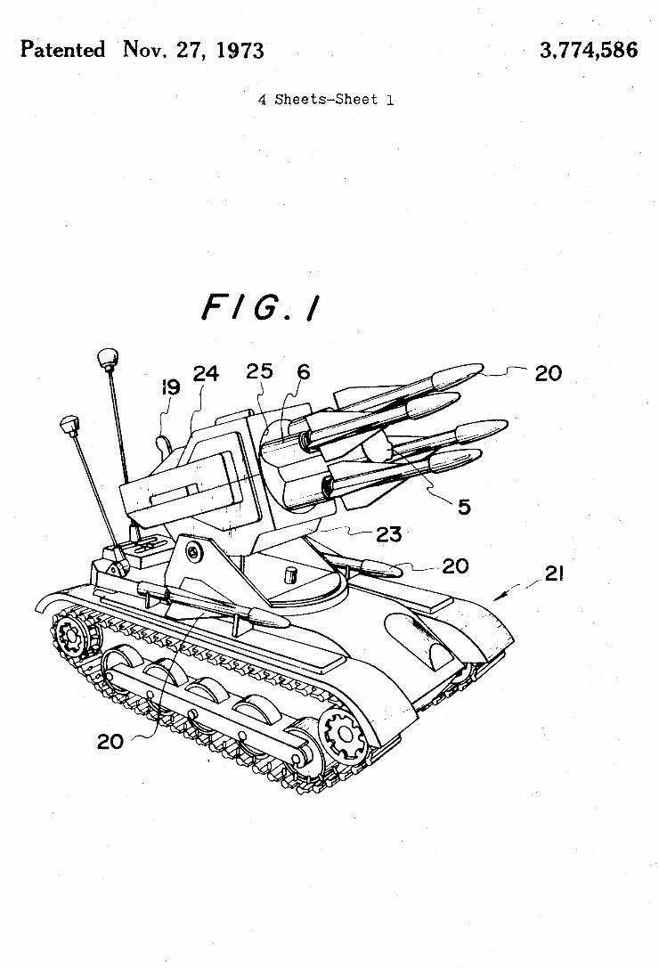
3,774,586 I Patented Nov. 27, 1973
4 Sheets-Sheet l
F/G./
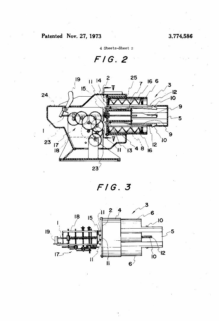
Patented Nov. 27, 1973 3.774,586
4 Sheets-Sheet 2
F/G.2
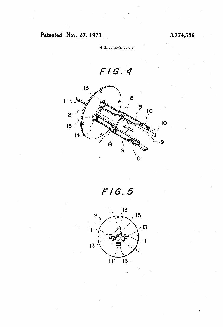
Patented Nov._ 27, 1973 3.774586
4 Sheets-Sheet :5
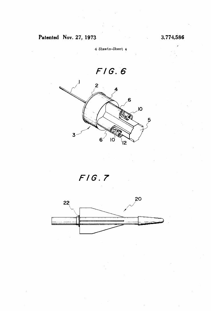
3,774,586 Patented Nov. 27, 1973
4 Sheets-Sheet 4
F/G.7
22
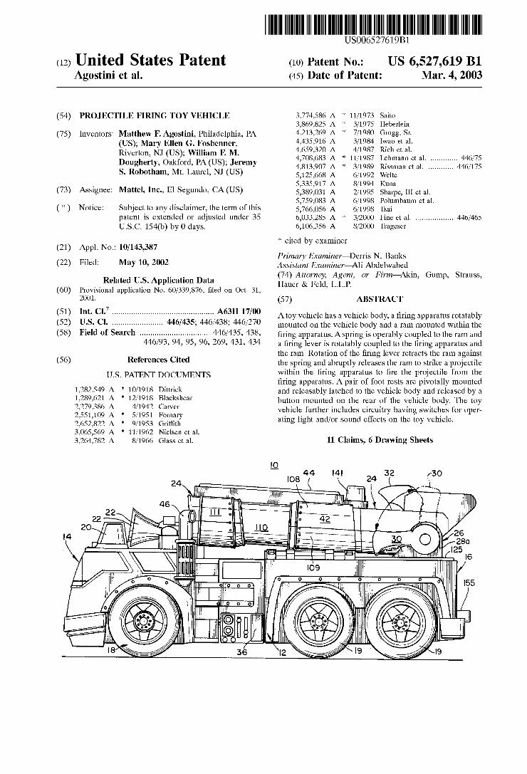
US006527619B1
(12) Umted States Patent (10) Patent N0.2 US 6,527,619 B1 Agostini et al. (45) Date of Patent: Mar. 4, 2003
(54) PROJECTILE FIRING TOY VEHICLE 3,774,586 A * 11/1973 Saito 3,869,825 A * 3/1975 Heberlein
(75) Inventors: Matthew F. Agostini, Philadelphia, PA 4213269 A * 7/1980 Grogg, SI
(US); Mary Ellen G. Fosbenner, 2 {gag 6: a11 - _ - - , , ic e a.
Rlverton’ NJ W5)’ Wllham F‘_ M‘ 4,708,683 A * 11/1987 Lehmann et al. ........... .. 446/75 Dougherty, Oakford, PA (US), Jeremy 4 813 907 A * 3 .
, , /1989 Rissman et al. .......... .. 446/175
S. R0b0tham, Mt. Laurel, NJ (US) 5 125 668 A @1992 Welte _ 5,335,917 A 8/1994 Kuna
(73) Asslgneei Mattel, Inc-31598119910, CA(US) 5,389,031 A 2/1995 Sharpe, IIIetal. 5,759,083 A 6/1998 Polumbaum et al.
( * ) Notice: Subject to any disclaimer, the term of this 5,766,056 A 6/1998 Tsai patent is extended or adjusted under 35 6,033,285 A * 3/2000 Fine et al. ................ .. 446/465
U.S.C. 154(b) by 0 days, 6,106,356 A 8/2000 Trageser
* cited by examiner (21) Appl. No.: 10/143,387
Primary Examiner—Derris N. Banks (22) Filed: May 10’ 2002 Assistant Examiner—Ali AbdelWahed
74 All A I F ' —Al(~ G St Related US. Application Data ghger 851E152 L i6; ’ Or Wm In’ ump’ muss’ (60) Provisional application No. 60/339,876, ?led on Oct. 31, ’ ~ ~ ~
2001. (57) ABSTRACT 7
(51) Int. Cl. .............................................. .. A63H 17/00 Atoy Vehicle has a Vehicle body, a ?ring apparatus rotatably (52) U..S. C]. ...................... .. 446/435; 446/438; 446/270 mounted on the Vehicle body and a ram mounted Within the (58) Fleld 0f Search ............................... .. 446/435, 438, ?ring apparatus Asprjng is Operably coupled to the ram and
446/93, 94, 95, 96, 269, 431, 434 a ?ring lever is rotatably coupled to the ?ring apparatus and the ram. Rotation of the ?ring lever retracts the ram against
(56) References Cited the spring and abruptly releases the ram to strike a projectile
Us PATENT DOCUMENTS Within the ?ring apparatus to ?re the projectile from the ?ring apparatus. A pair of foot rests are pivotally mounted
1,282,549 A * 10/1918 Dimick and releasably latched to the vehicle body and released by a 12897621 A * 12/1918 Blackshear button mounted on the rear of the vehicle body. The toy 2,279,386 A 4/1942 Carver 2,551,109 A * 5/1951 Fornary 2,652,822 A * 9/1953 Gri?ith 3,065,569 A * 11/1962 Nielsen et al. 3,264,782 A 8/1966 Glass et al. 11 Claims, 6 Drawing Sheets
vehicle further includes circuitry having sWitches for oper ating light and/or sound effects on the toy vehicle.
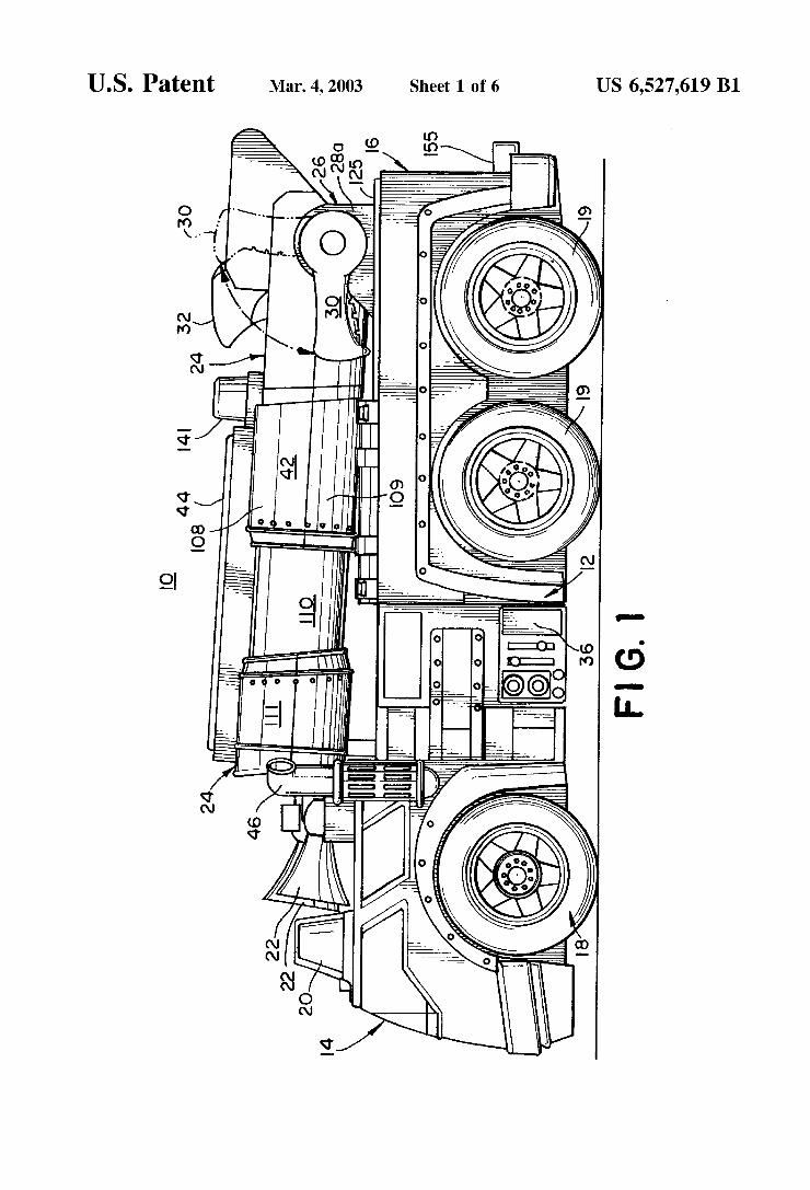
U.S. Patent Mar. 4, 2003 Sheet 1 6f 6 US 6,527,619 B1
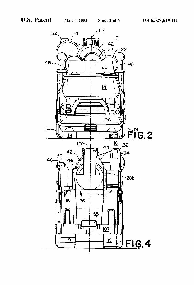
U.S. Patent Mar. 4, 2003 Sheet 2 6f 6 US 6,527,619 B1
3 44 f'o'
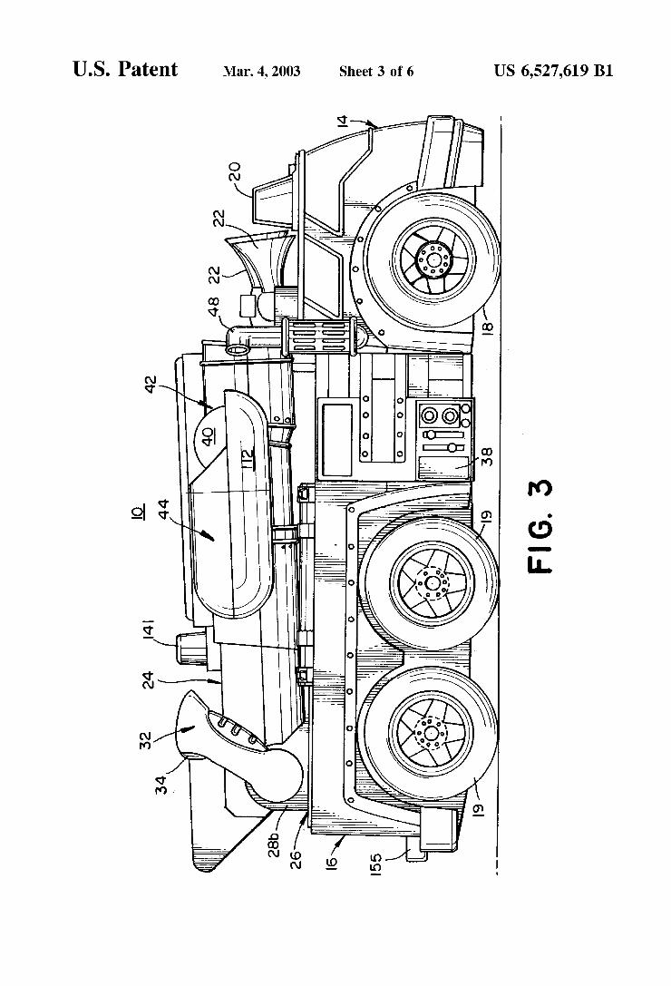
U.S. Patent Mar. 4, 2003 Sheet 3 6f 6 US 6,527,619 B1
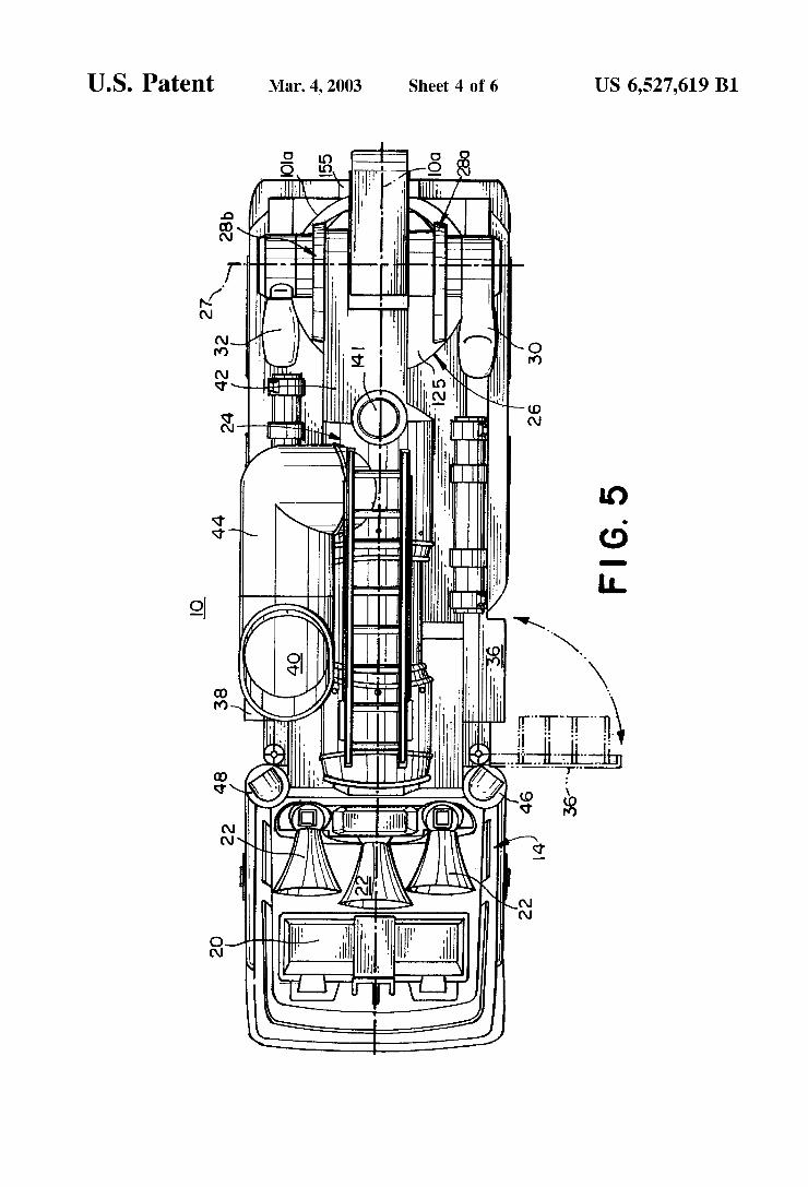
U.S. Patent Mar. 4, 2003 Sheet 4 6f 6 US 6,527,619 B1
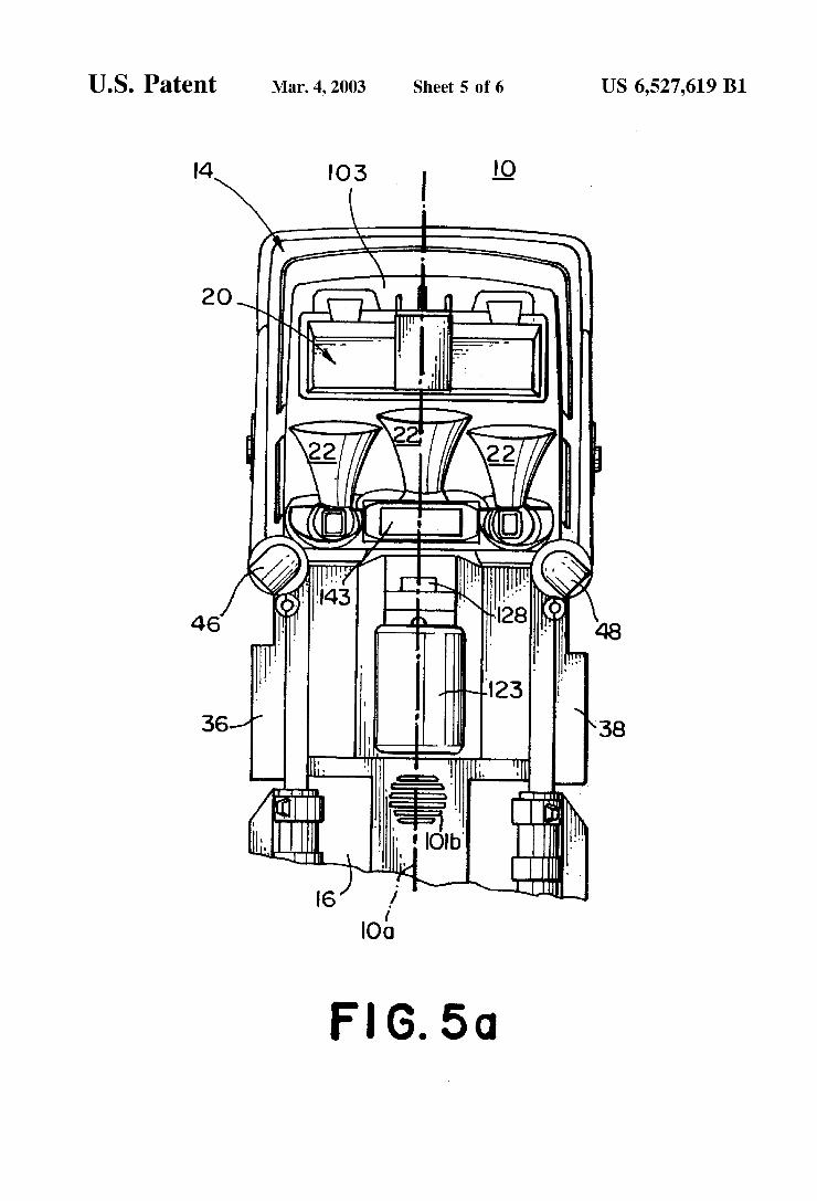
U.S. Patent Mar. 4, 2003 Sheet 5 6f 6 US 6,527,619 B1
I4 I03 I IQ
2O
46
36 ' 38
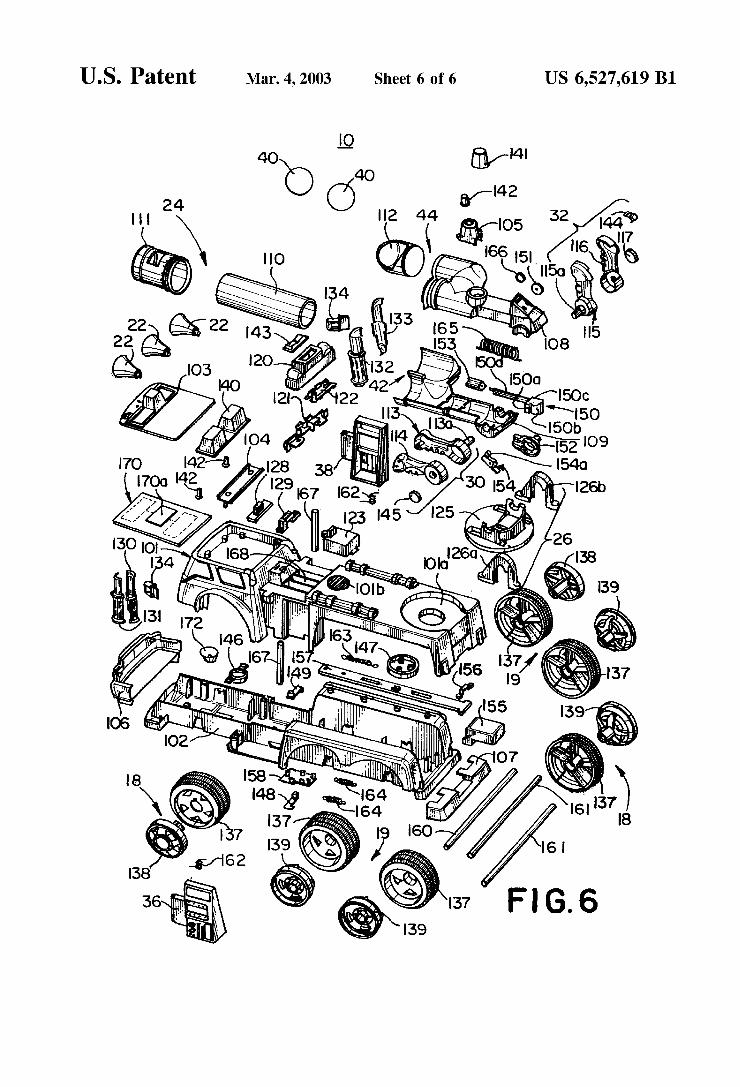
U.S. Patent Mar. 4, 2003 Sheet 6 6f 6 US 6,527,619 B1
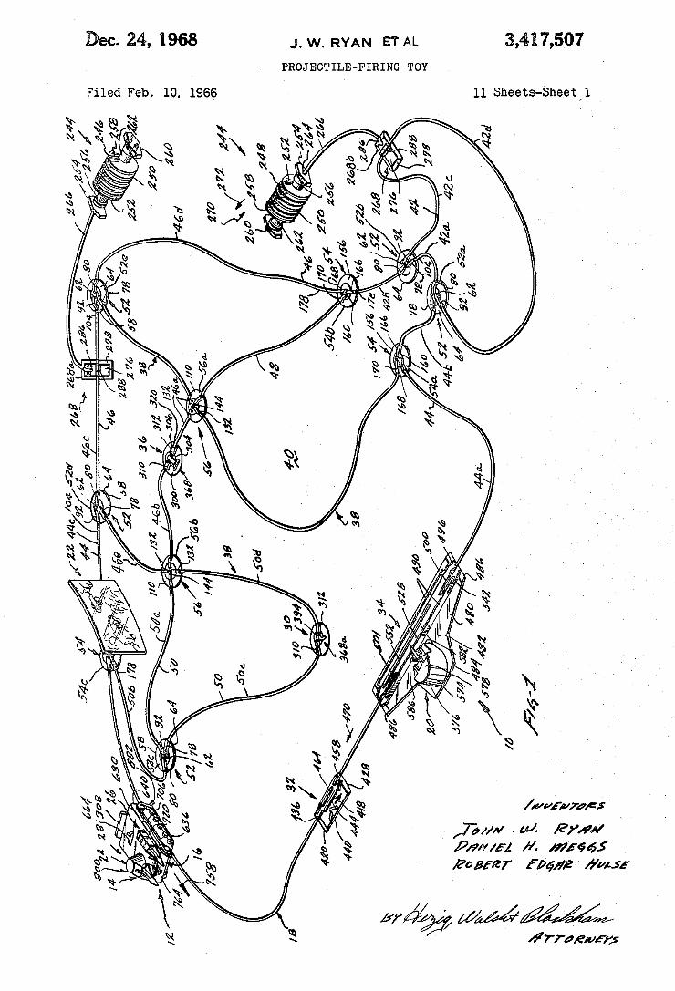
3,41 7,507 L A m N A Y R w lm
PROJECTILE-FIRING TOY
11 Sheets-Sheetvv l Filed Feb. 10, 1966
Wär/Q7
92 www *www www GEN Qì
uw - »_ w
“SNNNMs/X www w NDA. fa...
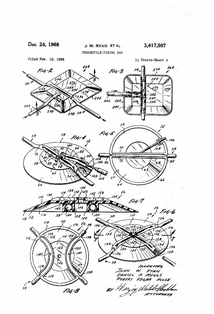
Dec- 24, 1968 .1.w. RYAN ETAL 3,417,507--` PROJECTILE-FIRING TOY
Filed Feb. l0, 1966 l1 Sheets-Sheet 2
if
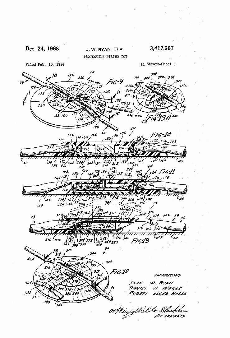
De¢.z4,196s ~ J,W_RYAN ETAL ' 3,417,507
PROJECTILE-FIRING TOY
Filed Feb. 10, 1966 11 SheetS-Shee‘l’, 5
Z #76:75
//// /// a02 40
¿rra/FMH;
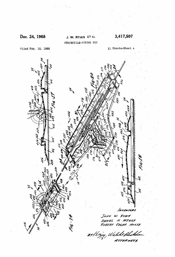
3,417,507 Dec. 24, 1968 .|.w. RYAN ETAL
PROJECTILE-FIRING TOY
l1 Sheets-Sheet 4 Filed Feb. l0. 1966
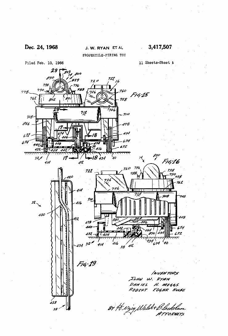
3,41 7,507 Dec. 24, 1968 J. w, RYAN ETAL
PRoJEcTILE-FIRING TOY
11 Sheets-Sheet 5 Filed Feb. l0, 1966
MMfßM /
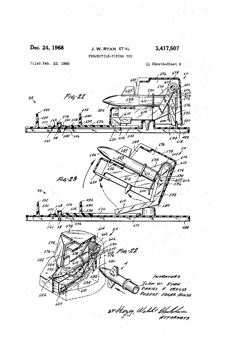
3,417,507 Dec. 24, 1968A J. w. RYAN ETAL
PROJECTILE-FIRING TOY
11 Sheets-Sheet 6 Filed Feb. 10. 1966
I - ’4 n. -n n. g.
K ( 433
646 / / fáz 32 «F75
f i 5,4%# e» ß armi „ß y, „..Mf @W27 »Je MM” fÃ
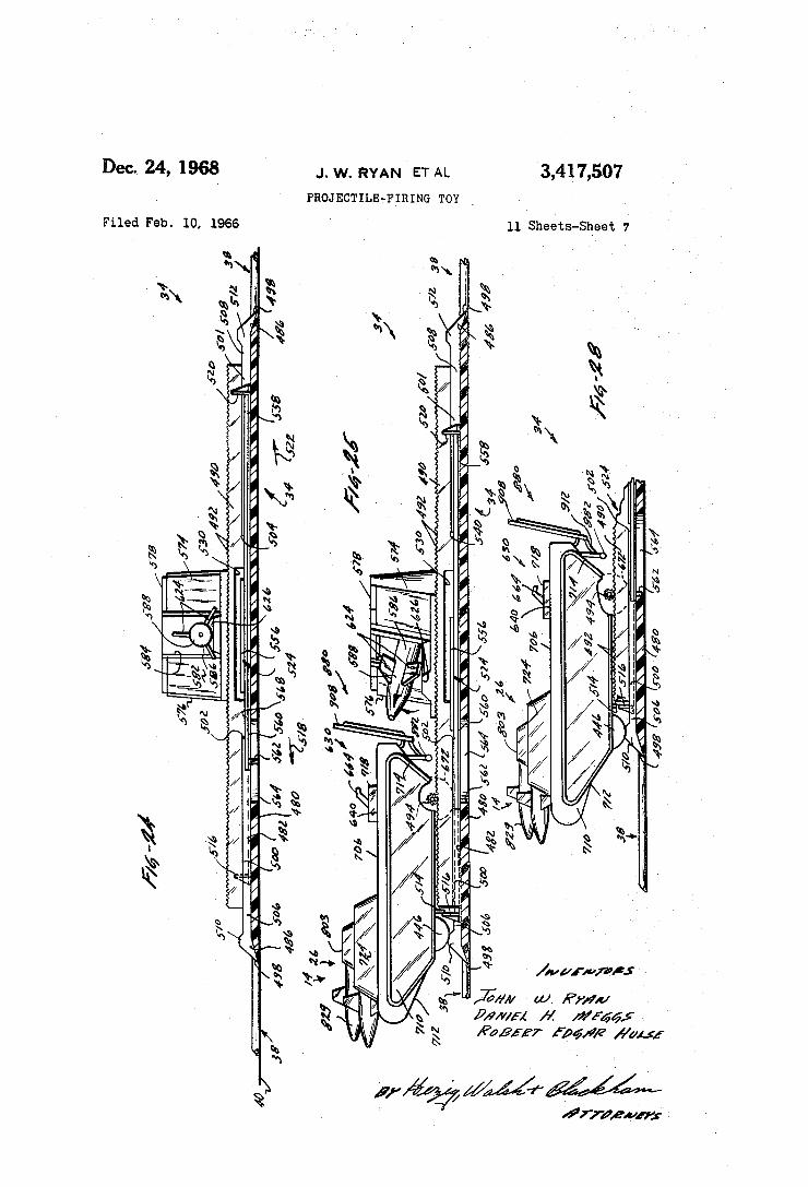
3,417,507 Dec. 24, 1968 J. w. RYAN ET AL
PROJECTILE-FIRING TOY Y
l1 Sheets-Sheet 7 Filed Feb. 10, 1966
ehm. ,
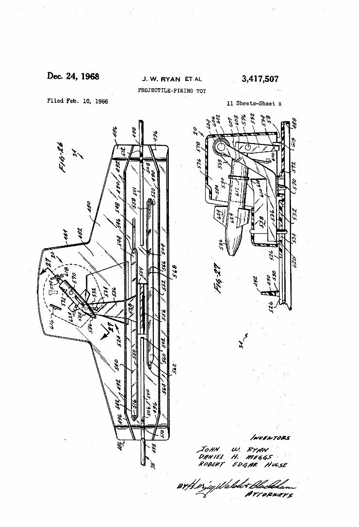
Dec. 24, 1968 _1.w. RYAN ETAL
PROJECTILE~FIRING TOY
3,417,507
Filed Feb. 10, 1966 11 Sheets-Shee'cl 8 '
I
rl Il. l.’ ÍÍ fdr 'l nä“ "IM` "
l? ll.
.... lith.
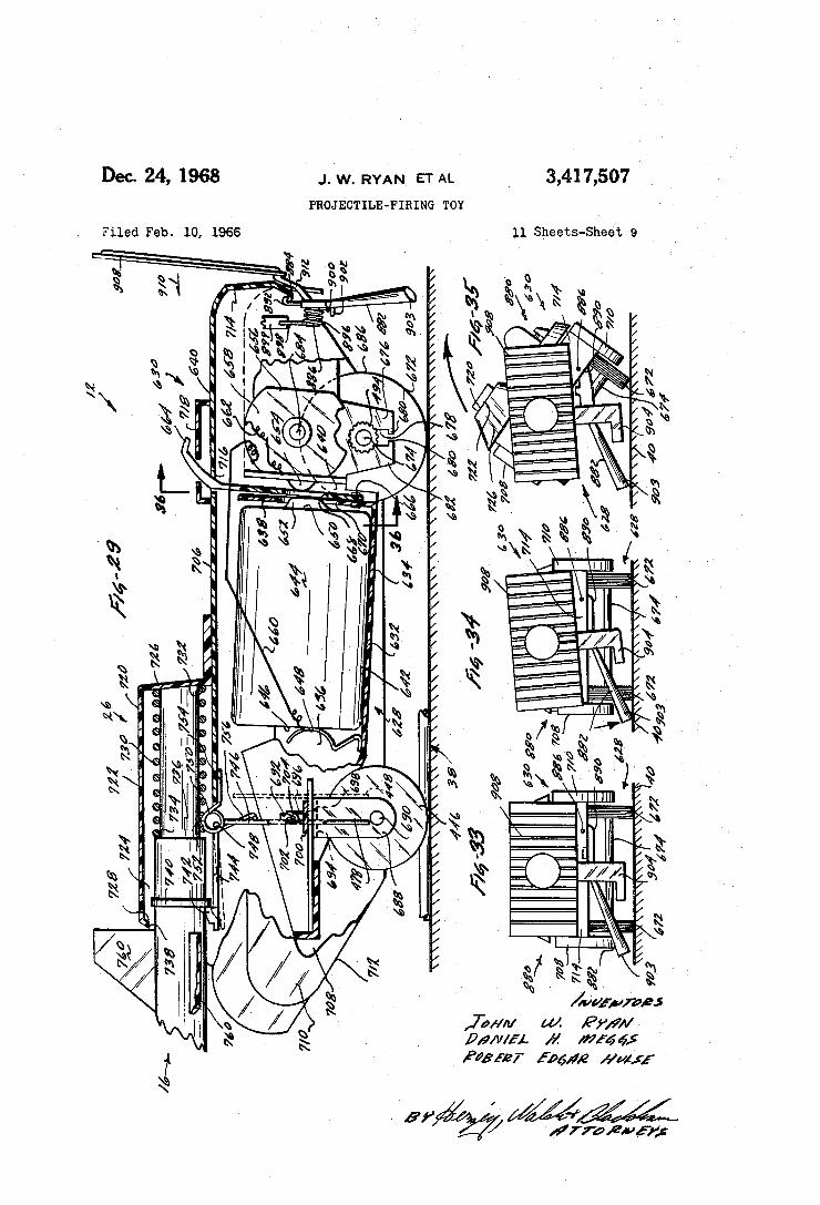
3,41 7,507 Dec. 24, 1968 J. w. RYAN ETAL
PROJECTILEFIRING TOY
l1 Sheets-Sheetl 9 Filed Feb. l0. 1966
/ /<^/ / / / f /////////. / //// , . Nrn» wh. \
, M
QMQ
n
, Il Il Ii ...Il Il Il Il Il l! .I6
@y
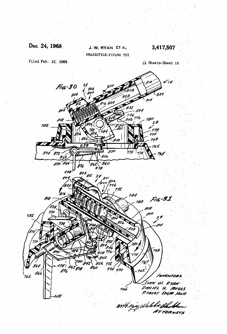
vDec. 24, 1968 J. w. RYAN ETAL 3,417,507 PRoJEcTlLE-FIRING Toy ì
Filed Feb. 1o, 1966 11 Asheets-sheet 1o
41X
frwfewsr;
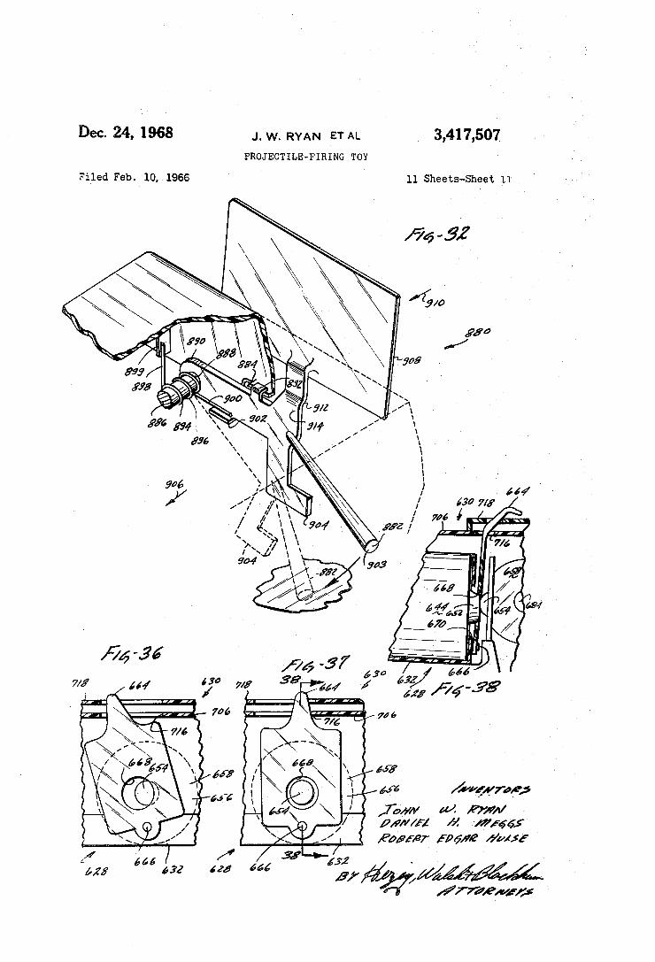
Dec. 24, 1968 J. w. RYAN ET AL 3,417,507
PROJECTILE-FIR ING TOY
Filled Feb. l0, 1966 11 Shee‘bS--Shee'tI ll
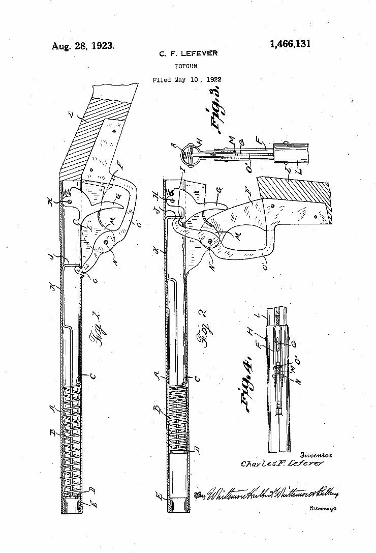
1,466,131 Aug.V 28, A'1923. v C. F. LEFEVER
POPGUN
Filed May 10 . 1922
o »www
W l »..lwll
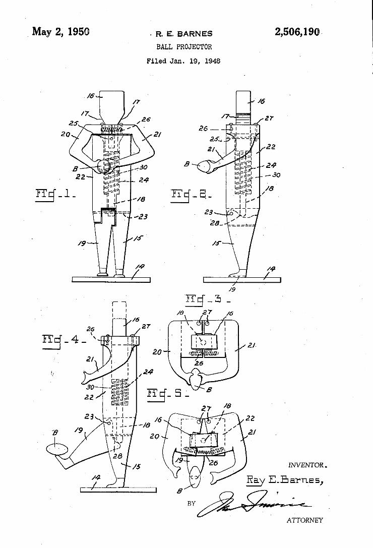
May 2» 195@ . R. E. BARNES 2,506,190
BALL PROJECTOR Filed Jan. 19, 1948
u_uçwi _ __ __
INVENTOR .
Ray E_Earnas,
ATTORNEY
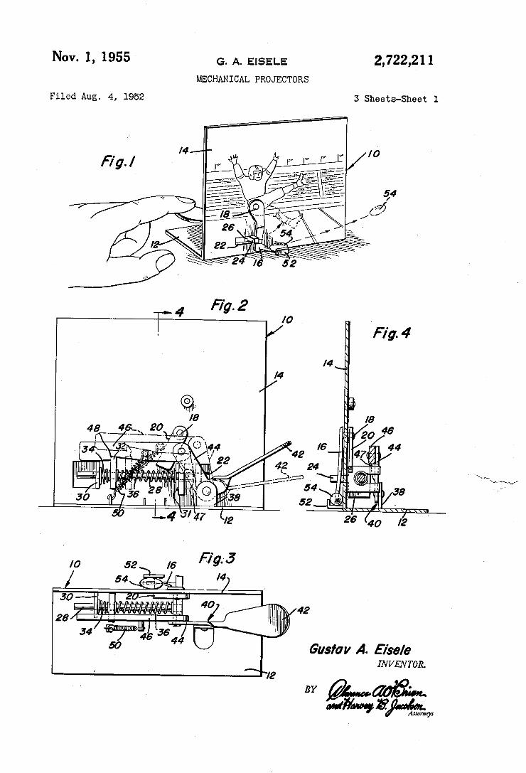
2,722,21 1 G- A. EISELE
MECHANICAL PROJECTORS
Nov. 1, 1955
3 Sheets-Sheet 1 Filed Aug. 4, 1952
1'9. 4
.. a 4 “a .. .31 (P. L2 .. 9 a
8 C TF4. \ i %/ ximwut TIT Uw , In 4
a , a L Am ‘F. i...»
4. . _ I.”
M .
,1 w
52 /0
v.
Gustav A. Eise/e INVENTOR.
BY 2mm ‘Mm “Fwy
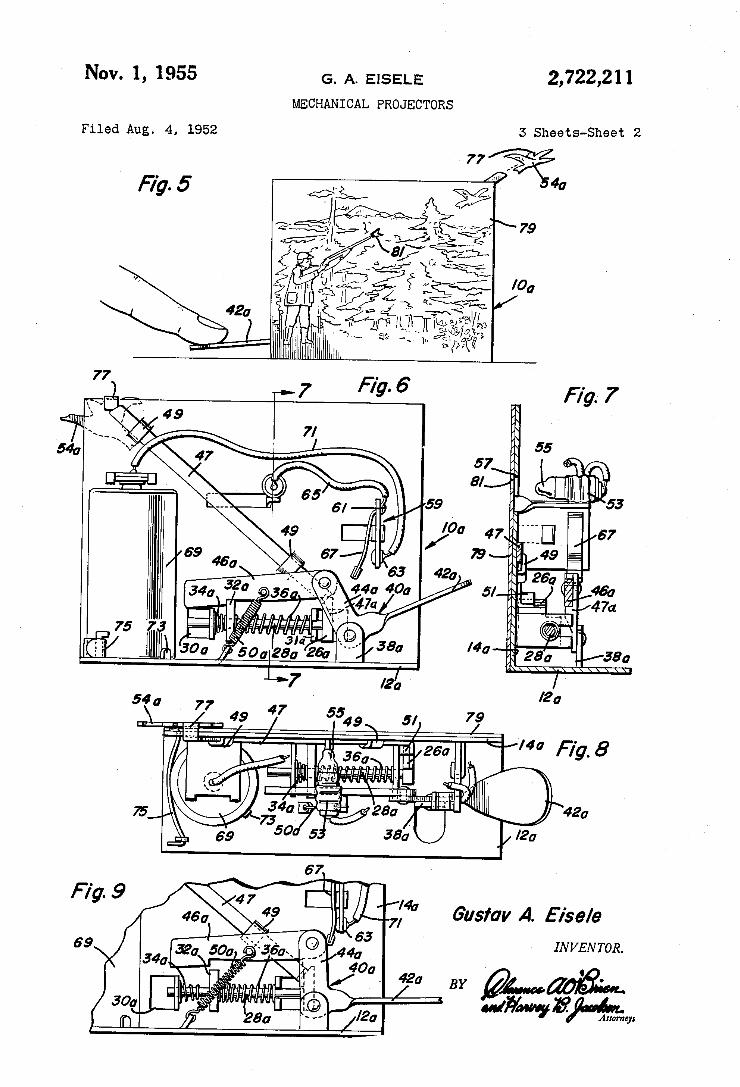
NOV. 1, 1955 G_ A, E|$ELE 2,722,211 MECHANICAL PROJECTORS
G‘usfav A. Eise/e
IN VEN TOR.
' 42g 0 BY QWWHMW
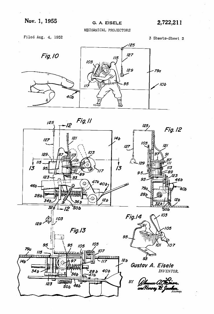
Nov. 1, 1955 G. A. EIISELE 2,722,211 MECHANICAL PROJECTORS
Filed Aug. 4, 1952 5 Sheets-Sheet I5
/25
Fig. /0 //5 27
/7.90
I 1 . - . Fig. / 4 $ /03 /29 H/ /
' Fig. /3
mil‘:- 95 f
Gustav A. E ise/e INVENTOR.
M406». ova/Wavy 3%w
BY
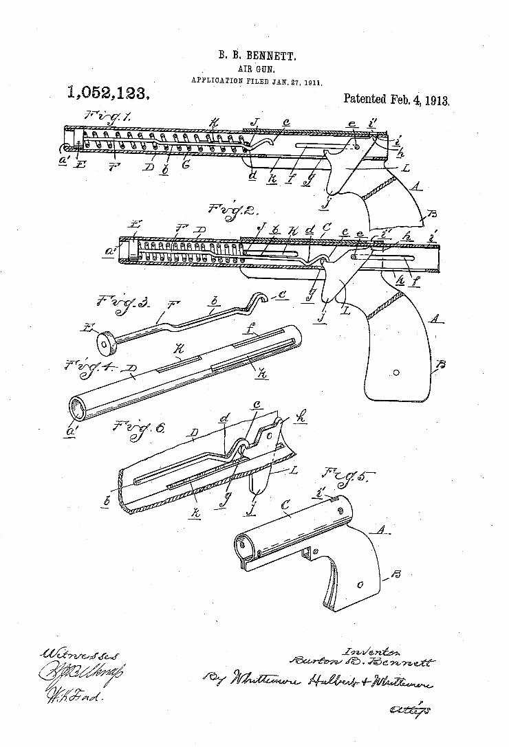
B. B. BENNETT. AIR GUN.
APPLICATION FILED JAN.27, 1911.
1,52,12‘3 Patented Feb. 4, 1913.
jaw/aw @corfaw/ @ - @zwneii"
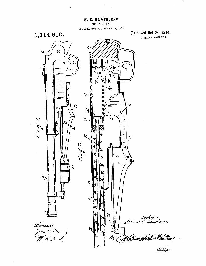
W. E. HAWTHORNE. SPRING GUN.
APPLICATION FILED MAY 31 , 1913.
Patented Oct. 20, 1914. 2 SHEETS-SHEET 1.
@n
II ll.'
, , 17u/md5»
WMM/L’. www
IHE NORRlß PETERS CO., PHorcrLlrr-io., wAsHlNcraN u r
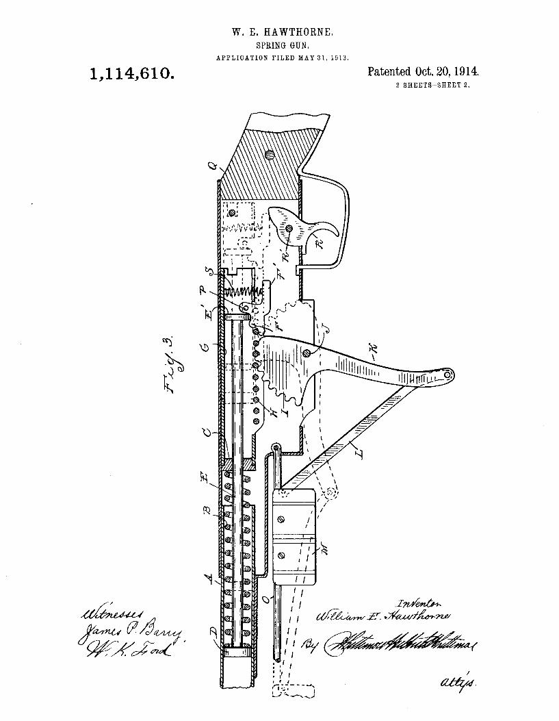
W. E. HAWTHORNE. SPRING GUN.
APPLICATION FILED MAY 31,1913.
1,1 14,610. Patented Oct. 20, 1914 2 SHEETSMSHEBT 2.
R
l I UNITI/"f4
ma Mí @X/Üfïï '
In» Nuls/els PHERS Co.PH01Ui!rn1 r
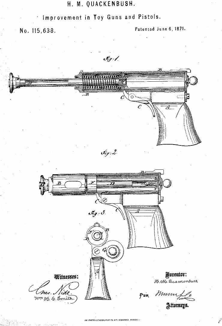
' No. 115,638.
H. M. QUACKENBUSHI
‘ Improvement in Toy Guns and Pistols.
Patented June 6,1871.
Wtmm;
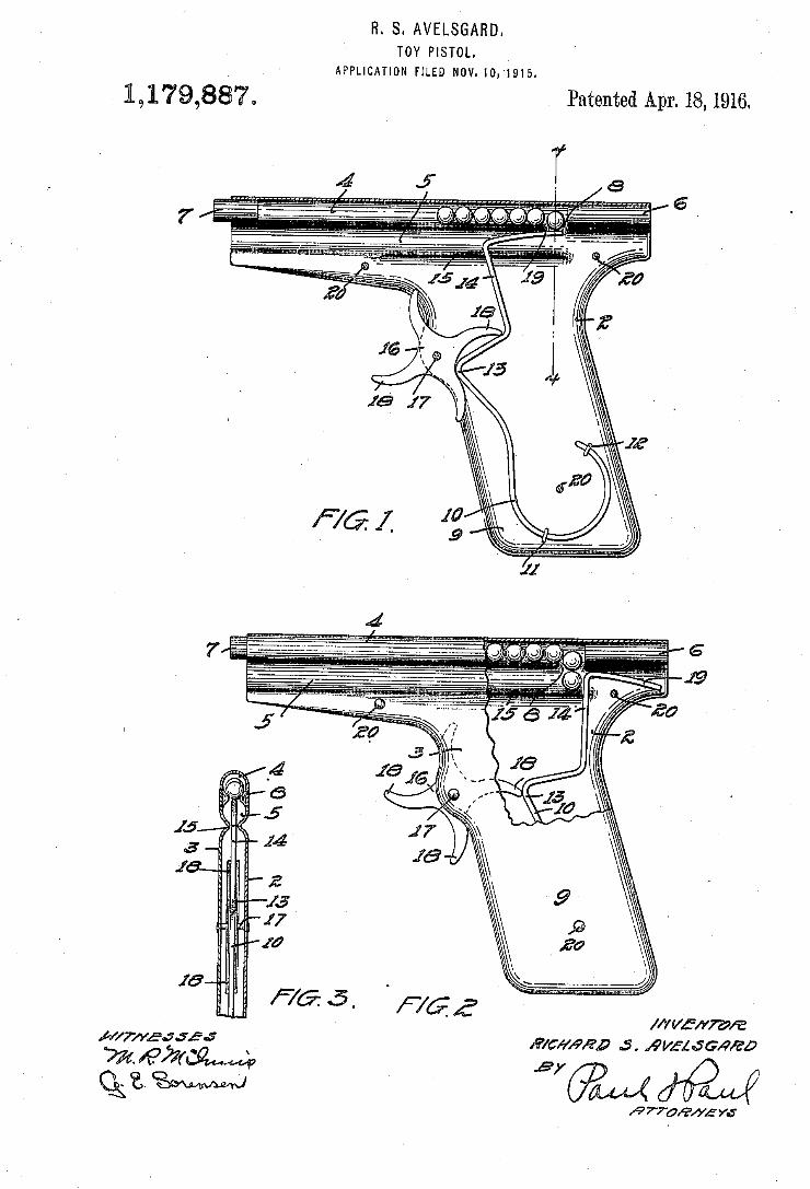
R. S. AVELSGARD. TOY PISTOL.
APPLICATION FILED NOV-10,1915.
1,179,887, Patented Apr. 18,1916.
Mai/,9”; .5. Amman/a0
/P 7708/75 Y6
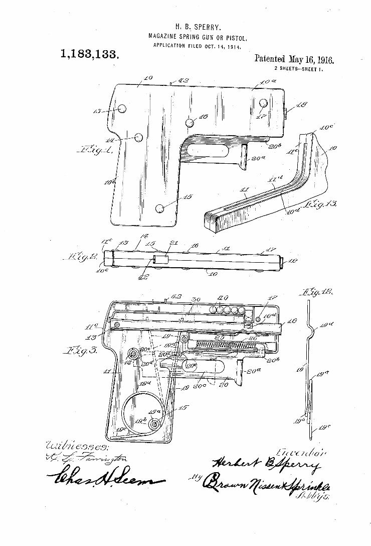
H. B.’ SPERRY. MAGAZINE SPRING GUN 0R PISTOL. APPLICATION FILED OCT-14,1914.
1,183,133. Patented May 16, 1916. 2 SHEETS-SHEET I
‘M ' . _ _____ __ llbéy 306
w N f 19 194
| l J 4
A A9!’
[9‘!
Zaz'hé 6.56 63;
?/I. v '1 v "4734, “m/?' ,, I v
JAM/s.
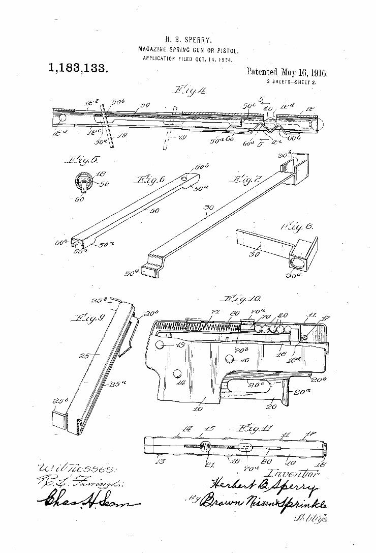
H. B. SPERRY. MAGAZINE SPRING GUN 07B PISTOL.’ APPLICATION FILED OCT. I4. 191-4.
1 , 1 83, 1 33 . _ ' Patented May 16, 1916. 2 SHEETS-SHEET 2
- Ma I ' i
1
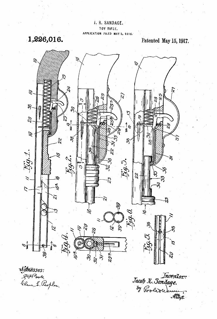
J. R. SANDAGE. TOY RIFLE.
‘APPLICATION FILED MAY 5. I916.
Patented May15, 1917. ' 1,226,016.
MN R.
m: NORRIS reruns m. r'nomlmnm. wumm: mu. m c,
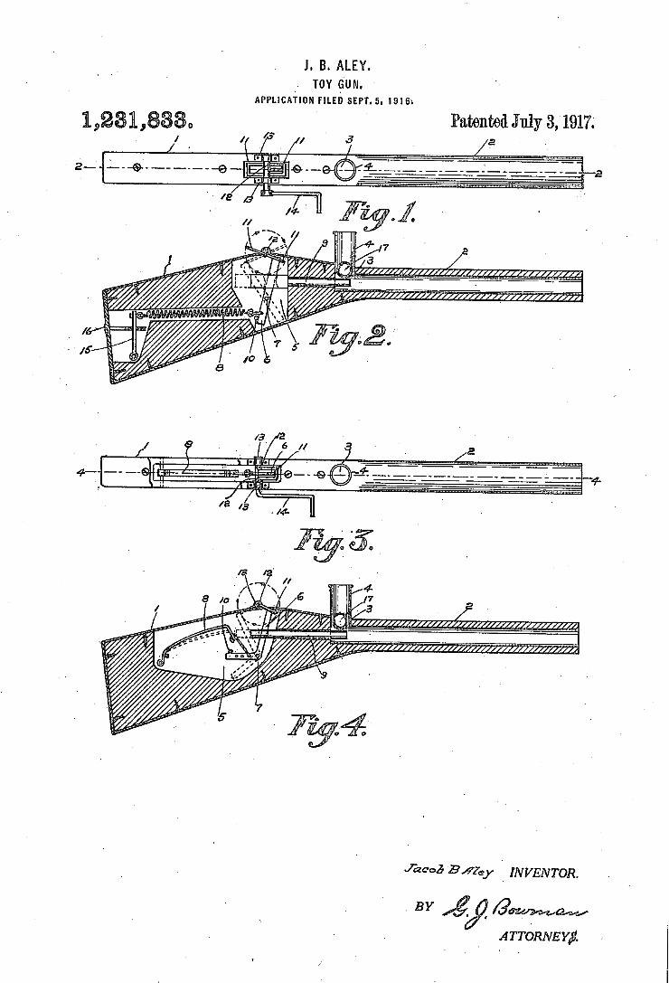
J. B. ALEY. '
v TOY Gum. APPLICATION FILED SEPT- 5. I916:
Patented July 3,1917;
Jézao5 BA'Zey I INVENTOR.
A TTORNE Y?
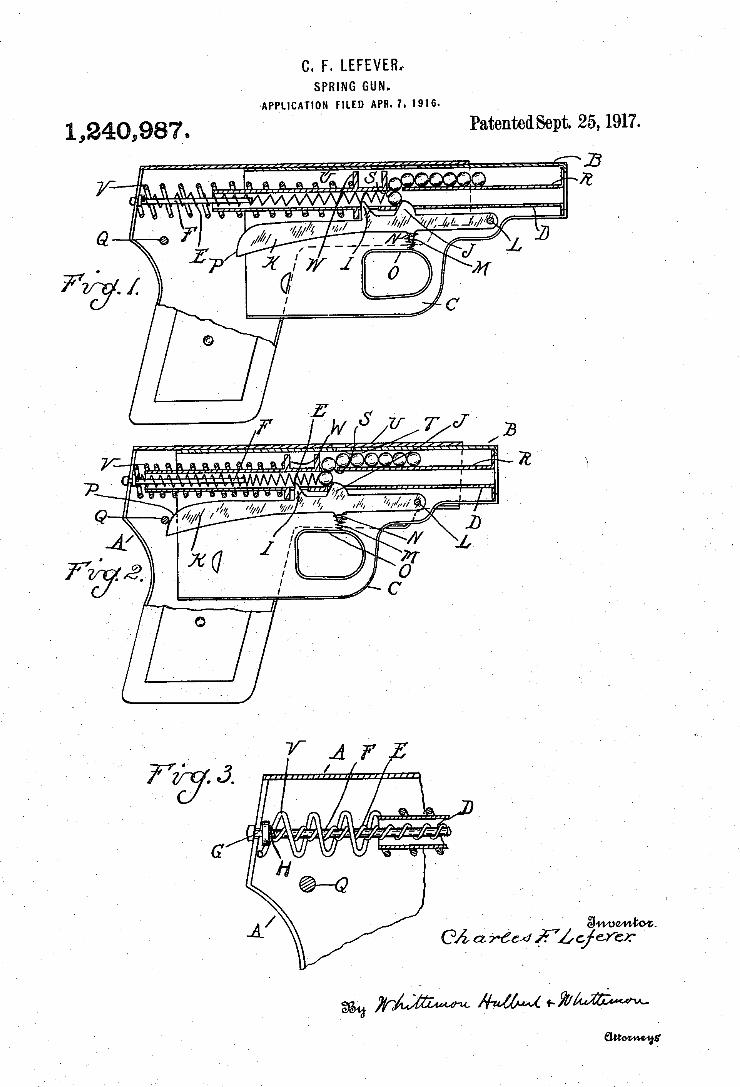
C. F. LEFEVER, SPRING GUN.
APPLICATION FILED APR- 7. 1916
1,240,987_. PaténtedSept. 25,1917.
Q
‘ ' am,
0/; a 7664 g7, 91”?”
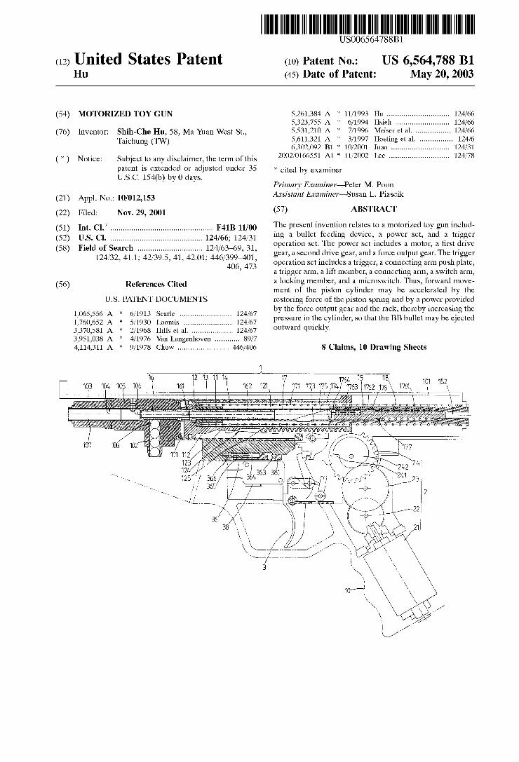
US006564788B1
(12) United States Patent (10) Patent N0.: US 6,564,788 B1 Hu (45) Date of Patent: May 20, 2003
(54) MOTORIZED TOY GUN 5,261,384 A * 11/1993 Hu ............................ .. 124/66 5,323,755 A * 6/1994 Hsieh ........................ .. 124/66
(76) Inventor: Shih-Che Hu, 58, Ma Yuan West St., 5531210 A * 7/1996 Meisef et a1~ 124/66 Taichung 5,611,321 A * 3/1997 Hoeting et al. .. 124/6
6,302,092 B1 * 10/2001 Juan .......... .. 124/31
( * ) NoticeZ Subject to any disclaimer, the term of this 2002/0166551 A1 * 11/2002 Lee ........................... .. 124/78
patent is extended or adjusted under 35 * Cited by examiner U.S.C. 154(b) by 0 days.
Primary Examiner—Peter M. Poon (21) Ap p1 N O _ 10/012 153 Assistant Examiner—Susan L. Piascik
. .. ,
(22) Filed: Nov. 29, 2001 (57) ABSTRACT
7 e resent lnventlon re ates to a motorlZe to n lnc u - (51) Int. Cl. ............................................... .. F41B 11/00 Th P ' _' 1 _ ' 01 Y gu ' _1 d (52) U S C] 124/66, 124/31 lng a bullet feeding device, a power set, and a trigger (58) Field 0 """""""""""""""" " 12 M63169 31 operation set. The poWer set includes a motor, a ?rst drive
124/32 41 446/399_’401’ gear, a second drive gear, and a force output gear. The trigger ’ ' ’ ' ’ ’ ' ’ 406 473’ operation set includes a trigger, a connecting arm push plate,
’ a trigger arm, a lift member, a connecting arm, a sWitch arm,
(56) References Cited a locking member, and a microsWitch. Thus, forWard move ment of the piston cylinder may be accelerated by the
US. PATENT DOCUMENTS restoring force of the piston spring and by a poWer provided by the force output gear and the rack, thereby increasing the
2 i 5:112:15 """""""""""" " 124/67 pressure in the cylinder, so that the BB bullet may be ejected
3,370,581 A * 2/1968 Hills et al ......... .. Outward qulckly
3,951,038 A * 4/1976 Van Langenhoven 4,114,311 A * 9/1978 Chow ....................... .. 446/406 8 Claims, 10 Drawing Sheets
1
16 17 T76), 15 18 10I 152 103 104 10? ‘1016 l 162 121 f 1171 1713 1'75 174/ 11763 (1162 176 1761\ \
l l I l l I l l l l l \ l \
' ,. _\~_._..._-, " V
107
4 . i , 1 . I , i l 4 . , . . . l
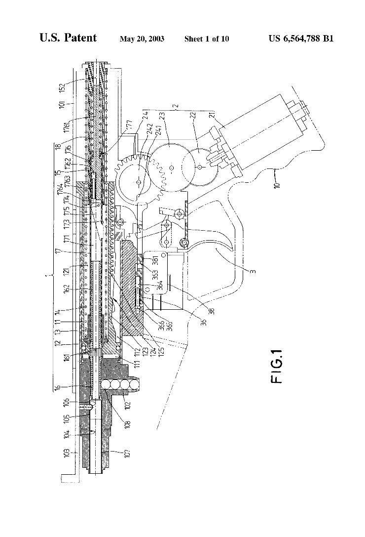
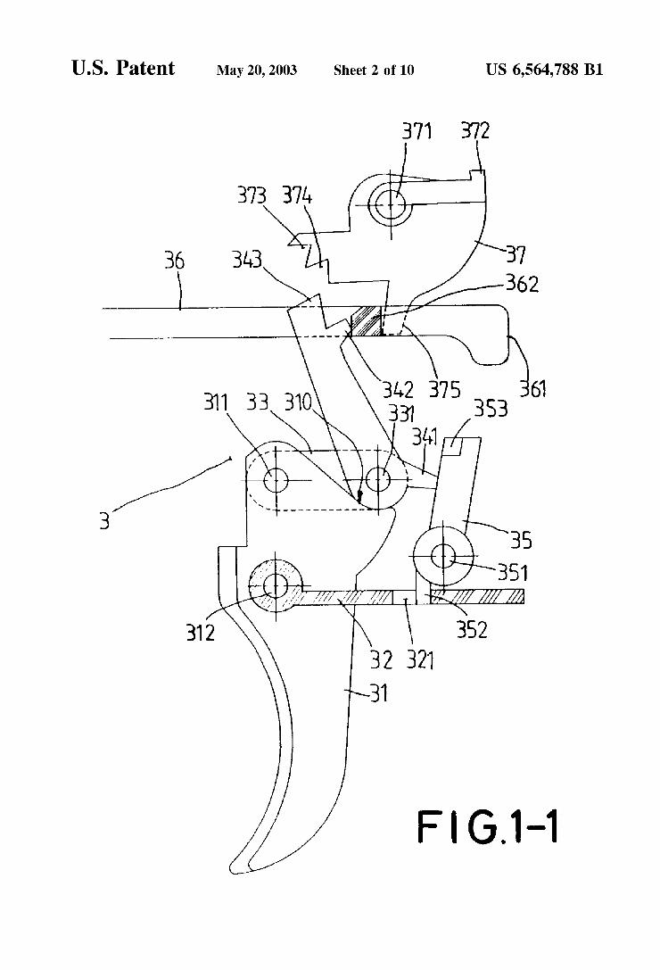
U.S. Patent May 20, 2003 Sheet 2 0f 10 US 6,564,788 B1
61
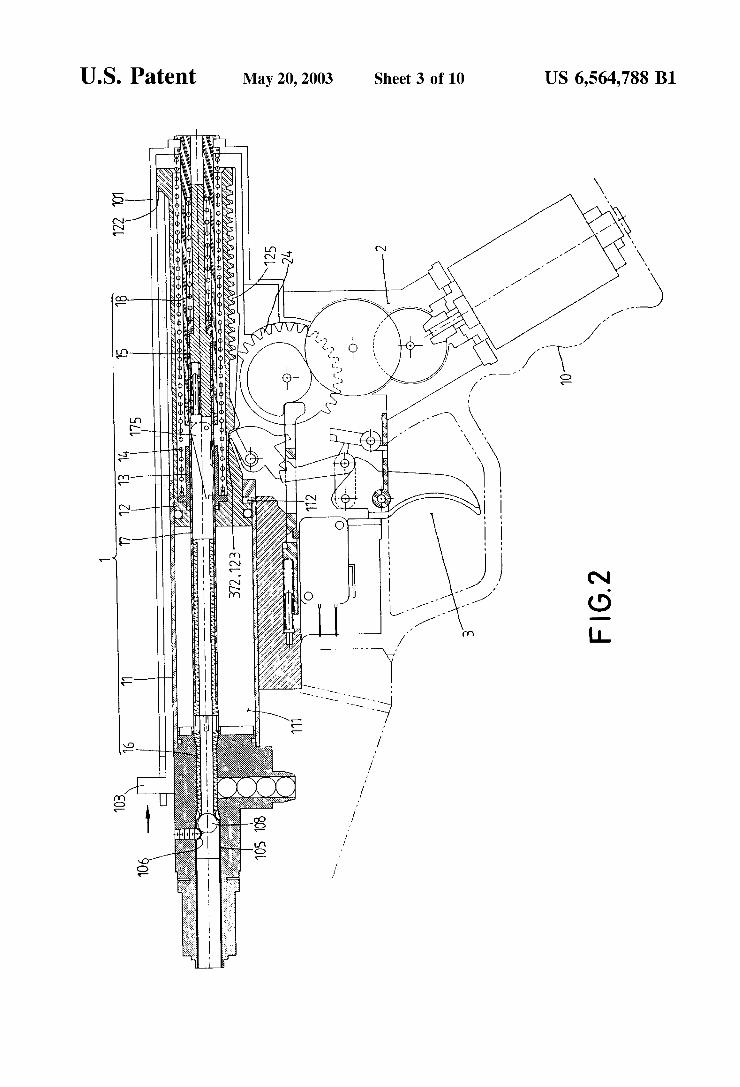
U.S. Patent May 20, 2003 Sheet 3 0f 10 US 6,564,788 B1
, mvuoimwmiwmloli
/ /
r
, _
v / mm mm?
5 NQ ¢
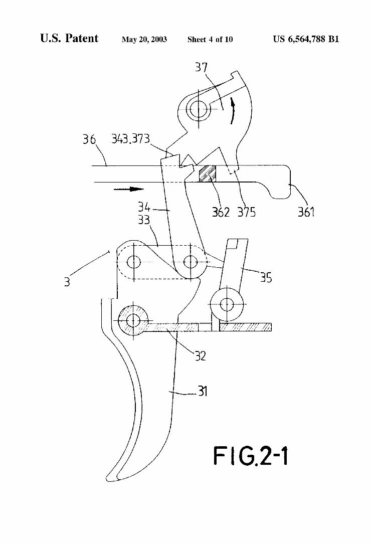
U.S. Patent May 20, 2003 Sheet 4 0f 10 US 6,564,788 B1
Fl (5.2-1
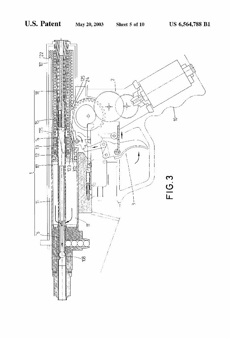
U.S. Patent May 20, 2003 Sheet 5 0f 10 US 6,564,788 B1
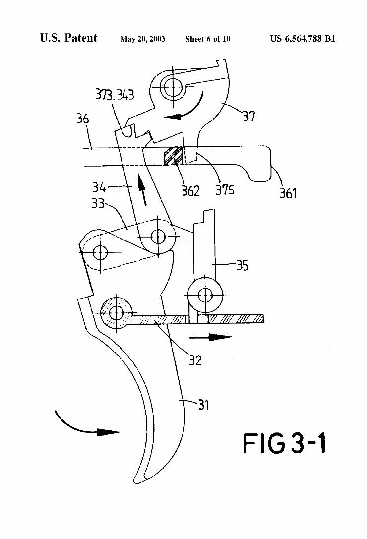
U.S. Patent May 20, 2003 Sheet 6 6f 10 US 6,564,788 B1
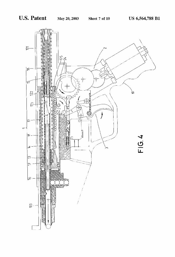
U.S. Patent May 20, 2003 Sheet 7 0f 10 US 6,564,788 B1
.m
5 _ -
X41
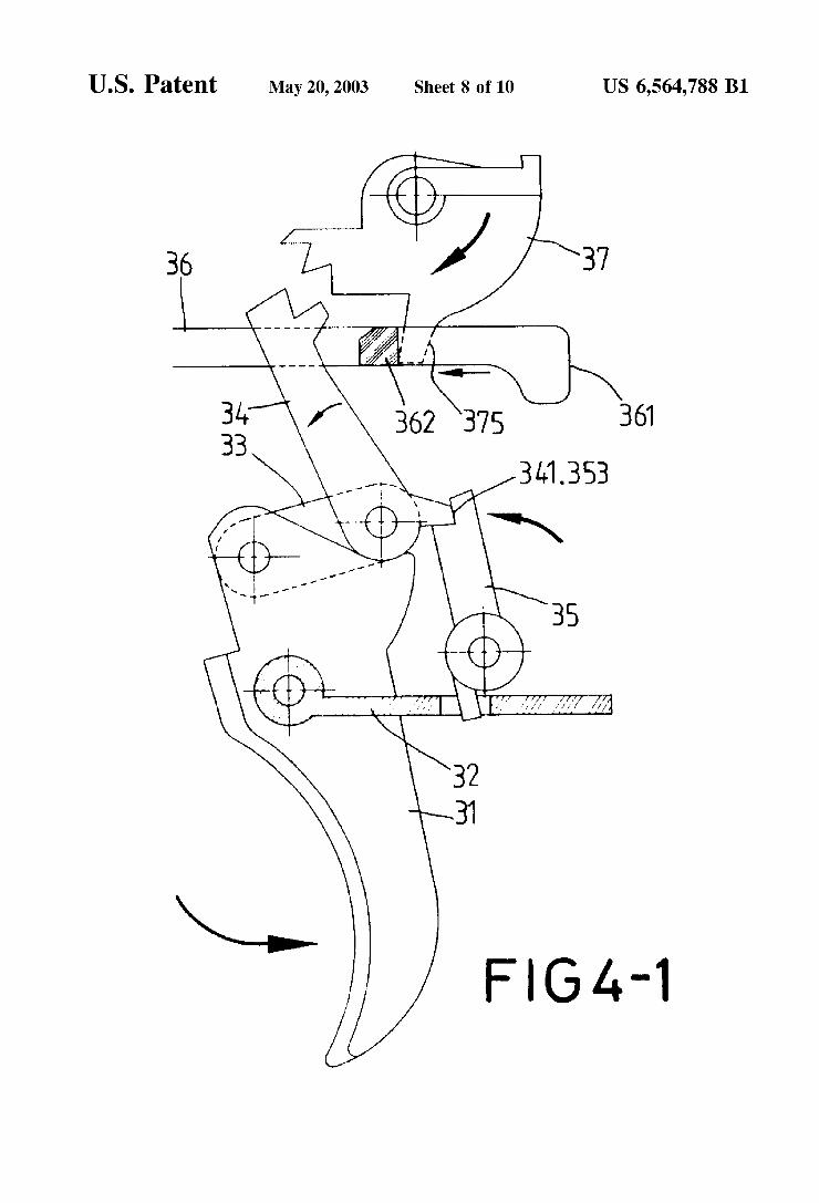
U.S. Patent May 20, 2003 Sheet 8 0f 10 US 6,564,788 B1
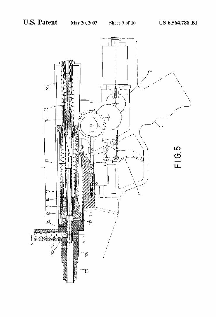
U.S. Patent May 20, 2003 Sheet 9 0f 10 US 6,564,788 B1
Flo
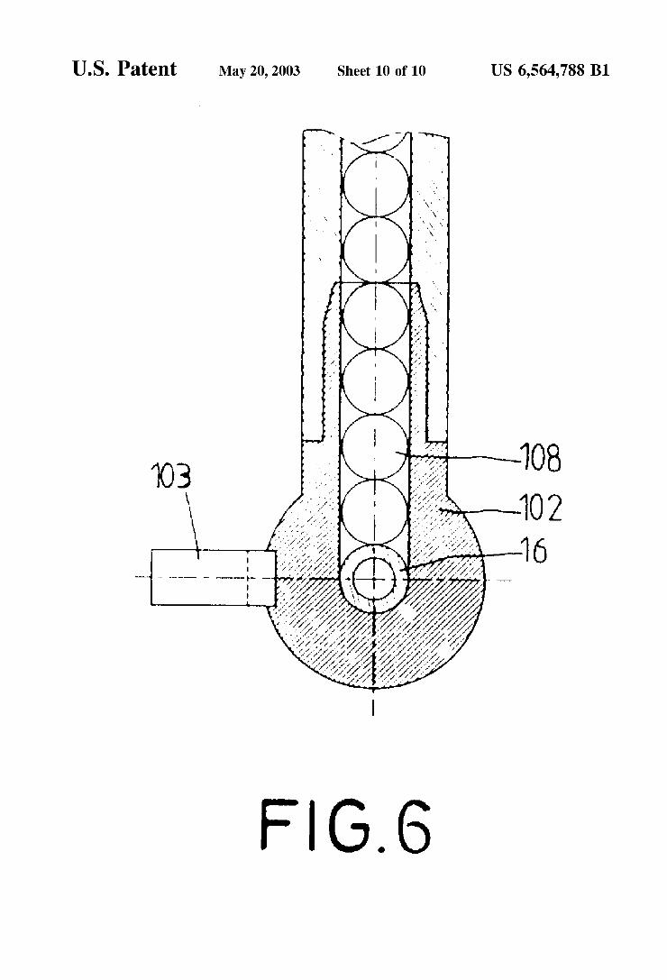
U.S. Patent May 20, 2003 Sheet 10 0f 10 US 6,564,788 B1
.. 1.. .. . 1.x.» ...., C ... ...,., . .1....r.. ». r
, . . ?aw?
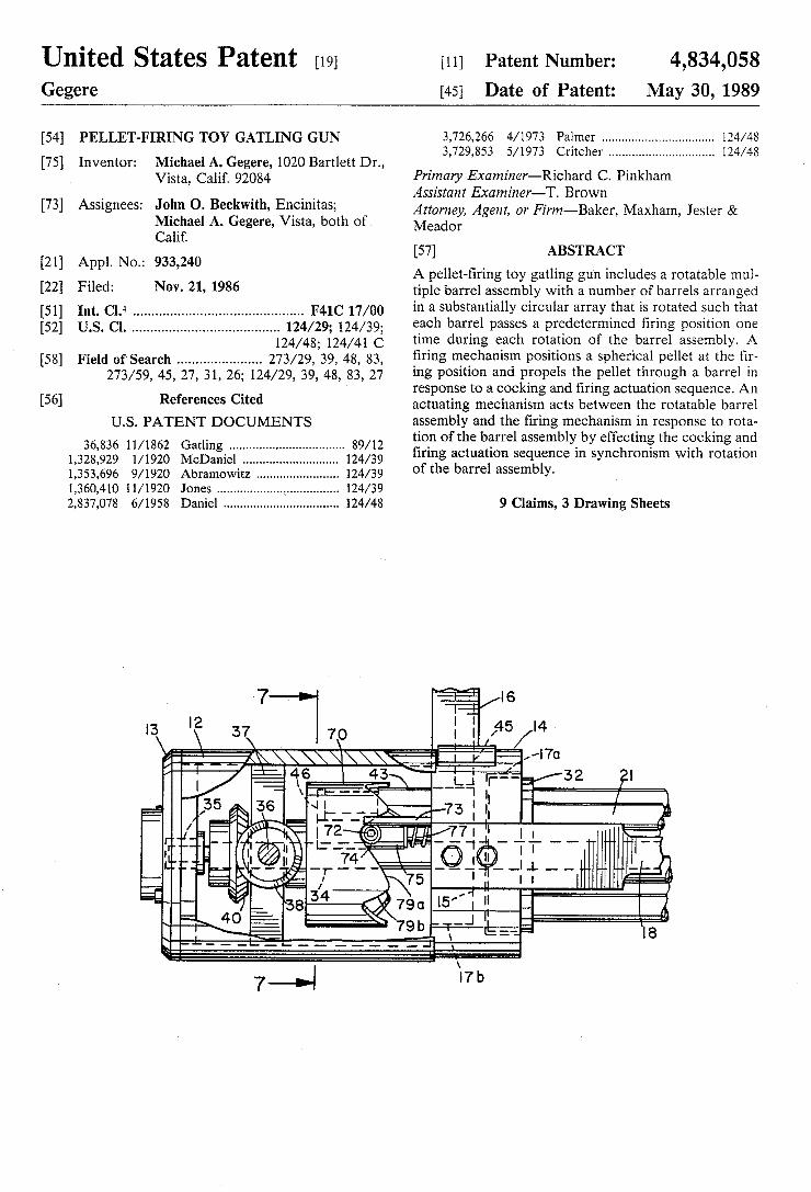
United States Patent [19] [11] Patent Number: 4,834,058 Gegere [45] Date of Patent: May 30, 1989
[54] PELLET-FIRING TOY GATLING GUN 3,726,266 4/1973 Palmer ................................ .. 124/48 _ 3,729,853 5/1973 Critcher .............................. .. 124/48
[75] Inventor: Michael A. Gegere, 1020 Bartlett Dr., . Vistay calm 92034 Primary Examiner—R1chard C. Pinkham
' _ _ , Assistant Examiner—T. Brown
[731 Asslgnees‘ John 0' Beckw‘th’ EnPmltas; Attorney, Agent, or Firm—Baker, Maxham, Jester & Michael A. Gegere, Vlsta, both of Meador Calif.
[57] ABSTRACT [21] Appl. No.: 933,240 , _ _
_ A pellet-?rlng toy gatlmg gun includes a rotatable mul [22l Flledi NOV- 21, 1986 tiple barrel assembly with a number of barrels arranged [51] Int. C19‘ ............................................ .. F41C 17/00 in a Substantially Circular array [hat is [mated $11911 that [52] us. 01. ...................................... .. 124/29; 124/39; each bwel Passes a Pfédetermmed ?ung Posmon one
124/48; 124/41 C tlme during each rotation of the ‘barrel assembly, A [58] Field of‘ Search ..................... .. 273/29, 39, 48, 83, ?rmg mechamsm Posmons a spherlcal pellet at the ?r
273/59’ 45’ 27, 31, 26; 124/29, 39, 43, 83, 27 ing position and propels the pellet through a barrel in _ response to a cooking and ?ring actuation sequence. An
[56] References C‘ted actuating mechanism acts between the rotatable barrel U.S. PATENT DOCUMENTS
36,836 11/1862 Gatling ................................. .. 89/12
1,328,929 1/1920 McDaniel ........ .. 124/39
1,353,696 9/1920 Abramowitz .... .. 124/39
1,360,410 ll/l920 Jones ............ .. 124/39
2,837,078 6/1958 Daniel ................................. .. 124/48
assembly and the ?ring mechanism in response to rota tion of the barrel assembly by effecting the cocking and ?ring actuation sequence in synchronism with rotation of the barrel assembly.
9 Claims, 3 Drawing Sheets
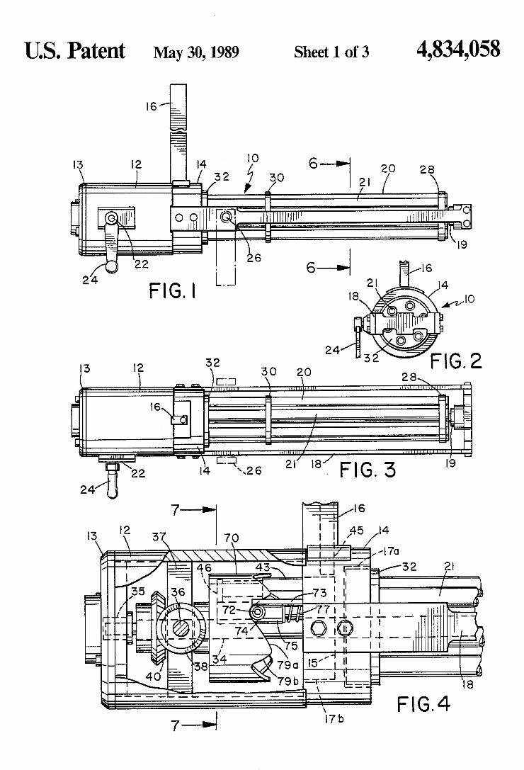
US. Patent May 30,1989 Sheet 1 of3 4,834,058
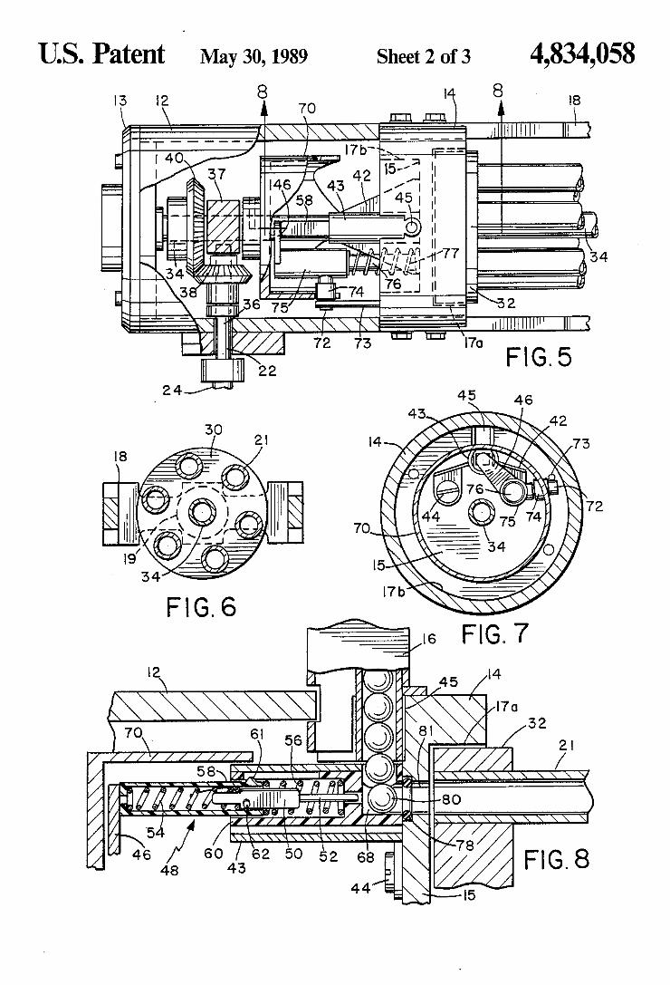
US. Patent May 30,1989 Sheet 2 of3 4,834,058
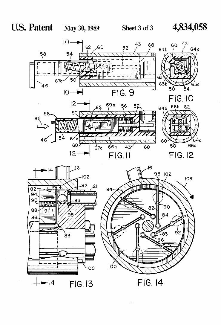
US. Patent May 30,1989 Sheet 3 of3 4,834,058
K '2 D 690 56 5 x
FIG. l3
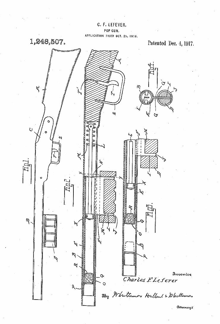
C. F. LEFEVER. POP GUN.
APPLICATION FILED OCT. 25, I916.
Patented Dec‘ ‘4, 1917.
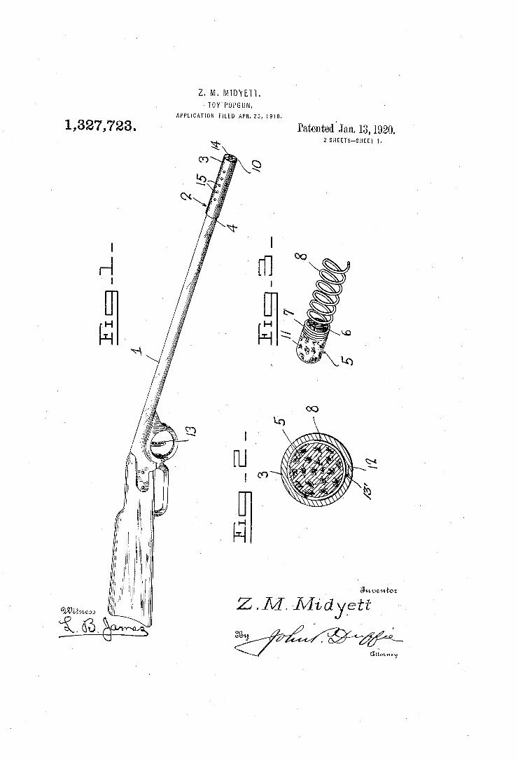
Z. M. MIDYETT. >TOY'POPGUN.
APPLICATION FILED APR.25, 1918.
1,327,723, Patented . Jan. 13, 1920. 2 SHEETS-SHEET l
1 Swuzmioz
l
'J l. W 66 a” ' 5% W
v ' ' aéiwm,
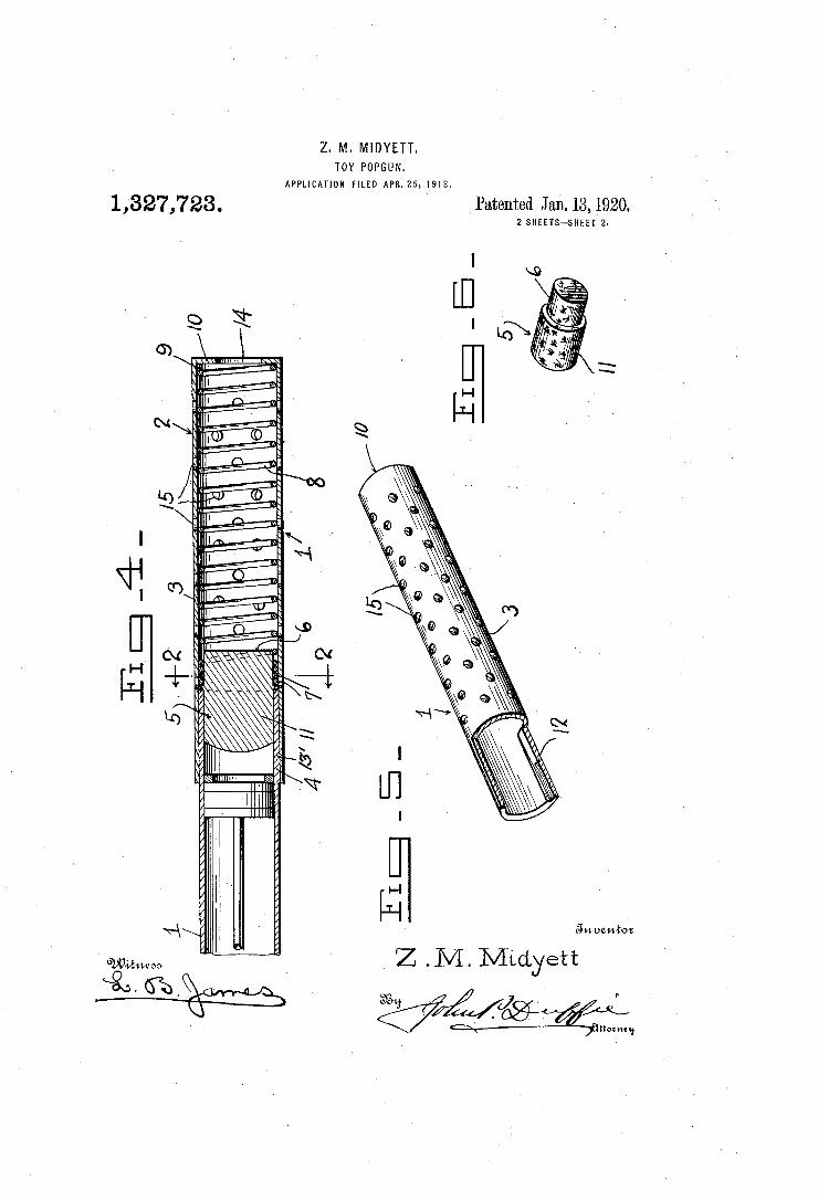
Z. M. MIDYETT. TOY POPGUN.
APPLICATION FILED APB.25,1918.
‘1,327,723. . Patented Ja1i.13,l920. 2 SHEETS-SHEET 2.
Z . M. Mtdye’tt \aa. h2g5 ,' ~ K5,.»
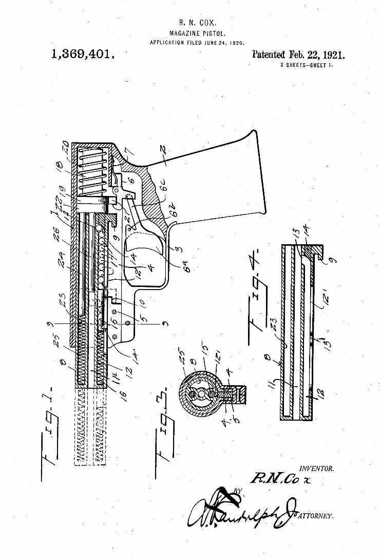
R. N. COX. MAGAZINE PISTOL.
APPLICATION FILED IuNI-:24, 1920.
1,369,401. Patented Feb. _22, 192.1. 2 SHEETS-SHEET I
M
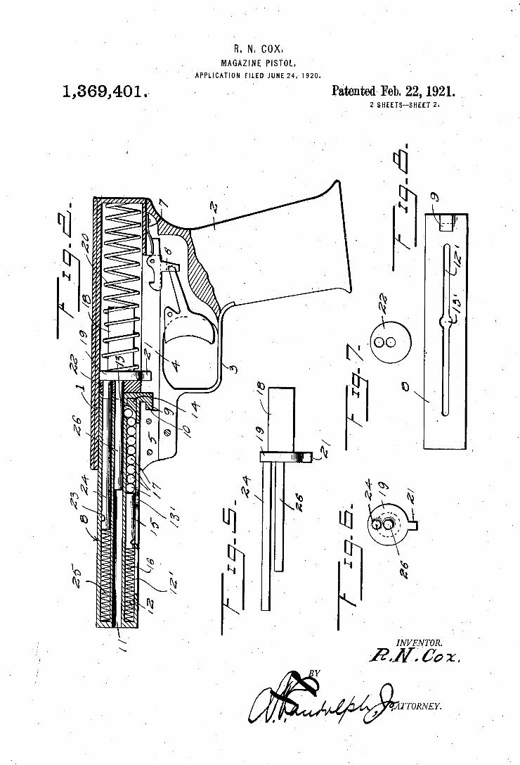
H. N. COX. MAGAZINE PISTOL.
APPLICATION F‘ILED JUNE 24, 1920.
PatentedI Feb. 22,1921. _ 2 SHEETS-SHEET 2
1,369,401 .
Úoz.
` l' ATTORNEY.
fmïwlNIm. è
El.: ,
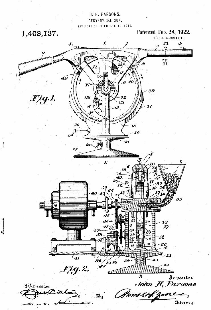
J. H. PARSONS. CENTRIFUGAL GUN.
APPLICATLON FILED OCT. 16, 1918.
1,408, 137, Patented Feb. 28,1922. ’ I 3 SHEETS—-SHEET l.
J’ 2 v1 11 4
15 27
J8 10
0 16
21 4] 26
I u; 22
anwwboz
Witmwom 4418!; f ".1
(Jbiiii ? fard‘opns
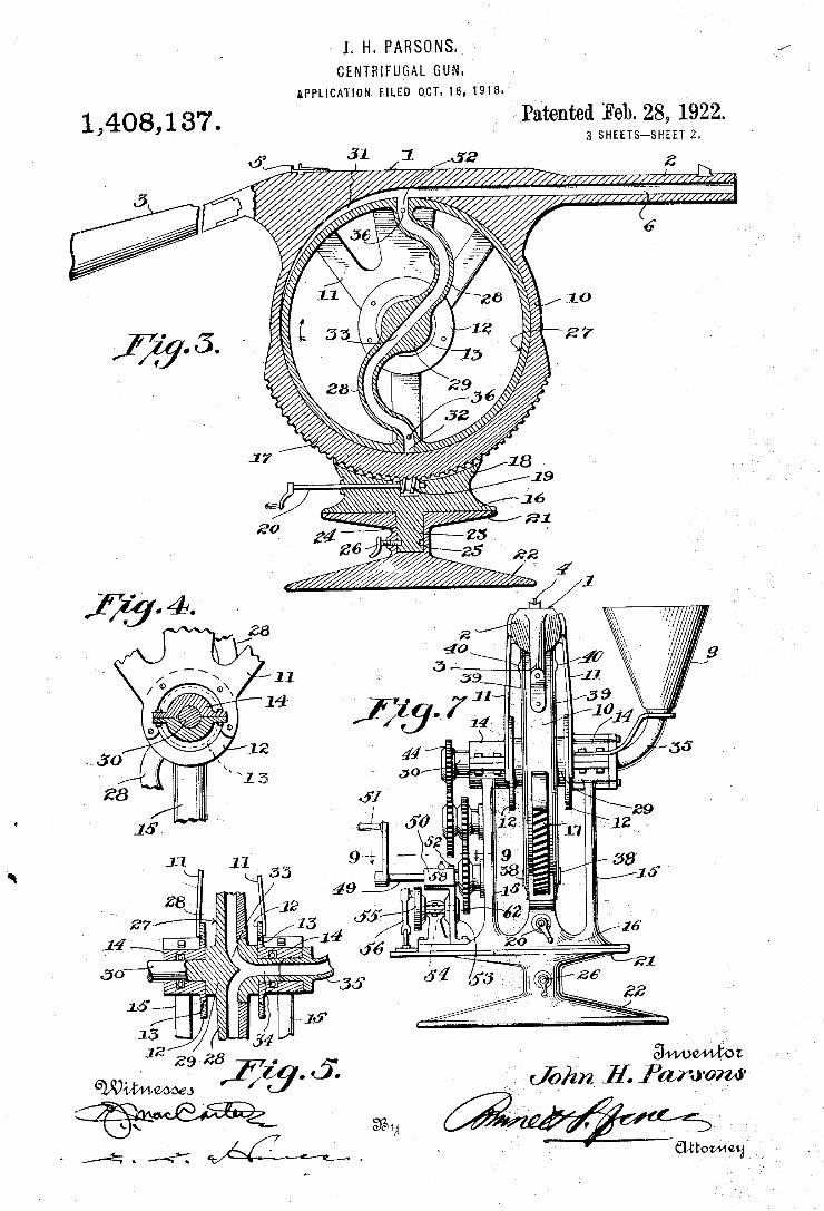
' L H. PARSONS.
CENTRIFUGAL GUN ‘APPLICATION EILED 0,cT.16,19|a.
Ahmed Feb. 28, 1922. 3 SHEETS-SHEET 2. 1,408,187
_, ammgz
(John E Pal/raw“
mm»
28 a
witmwow I $119‘ '5: i \.
A. X‘ M.
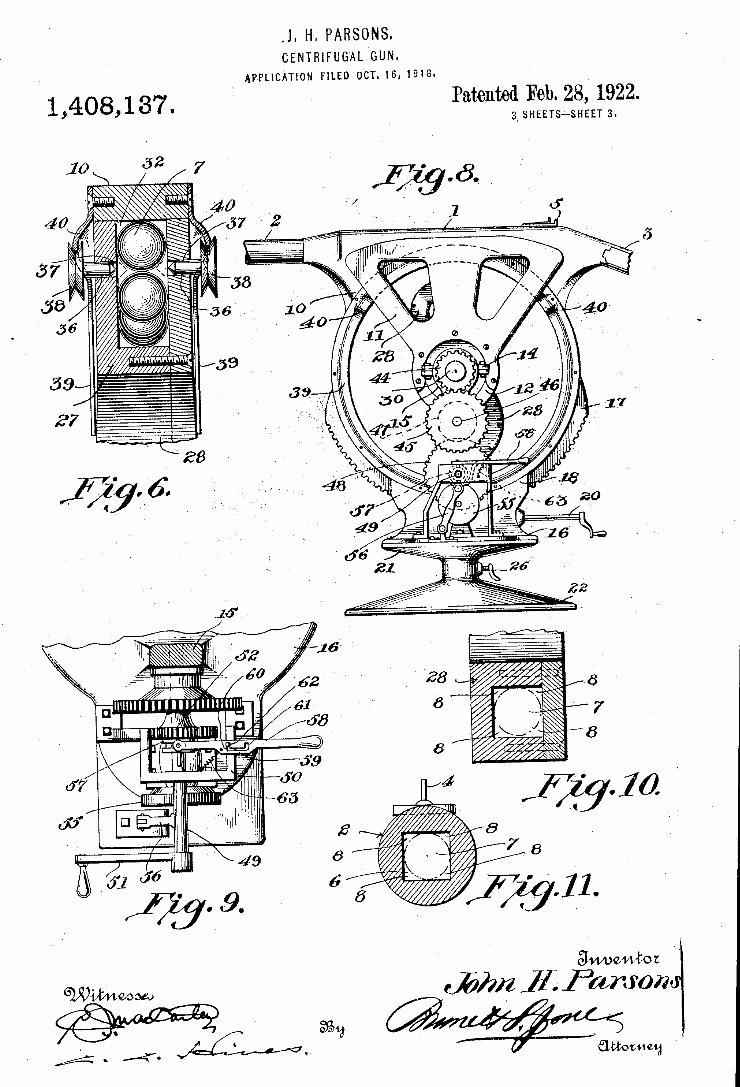
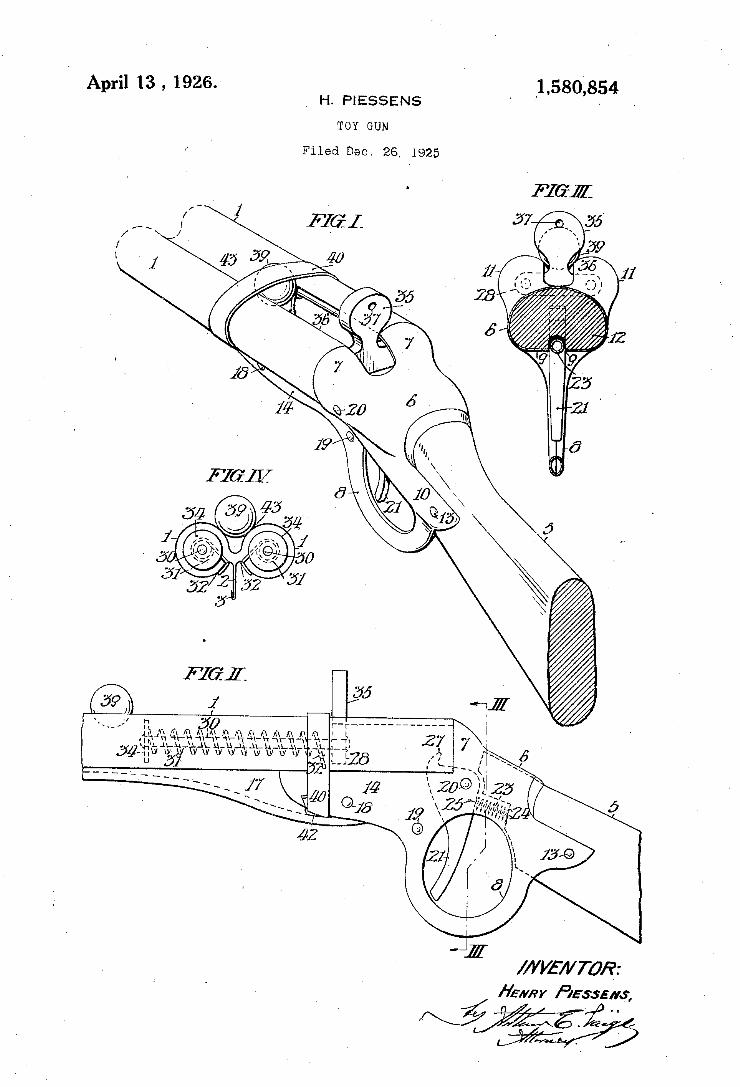
April 13 , 1926. ‘1,580,854 H. PIESSENS I ~
TOY GUN
Filed Dec. 26, 1925
/ b
í
ZZ .
mm1/rafa: /úwnr Hesse/vs,
/ m
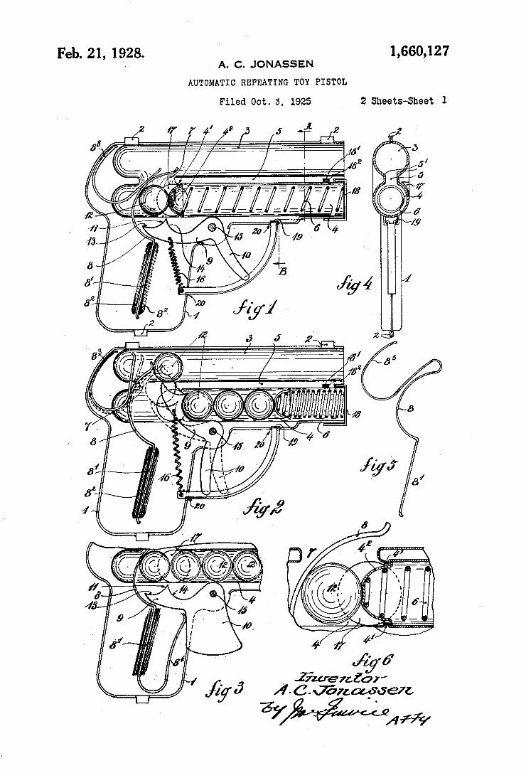
Feb. 21, 1928. 1,660,127 ‘ . A. c. JONASSEN
AUTOMATIC REPEATING TOY PISTOL
Filed Oct. 5, 1925 ‘ 2 Sheets-Sheet 1
_ .Zkaeraic?!’
A - C. J'an app'aeu
Yaw/1%
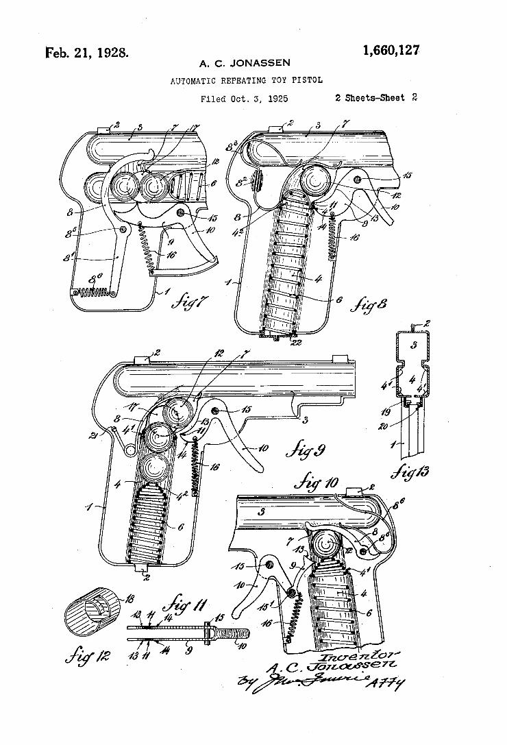
Feb. 21, 1928. 1,660,127 A. c. JONASSEN
AUTOMATIC REPEATING TOY PISTOL
Filed Oct. 3, 1925 2 Sheets-Sheet 2
/ ——-- n _
g p/ u
(I.
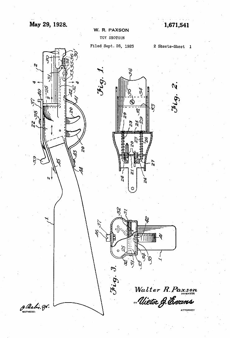
May 29, 192s. W. R. PAXSON
TOY SHOTGUN
Filed Sept. 26, 1925 2 Sheets-Sheet l
ATTORN EY
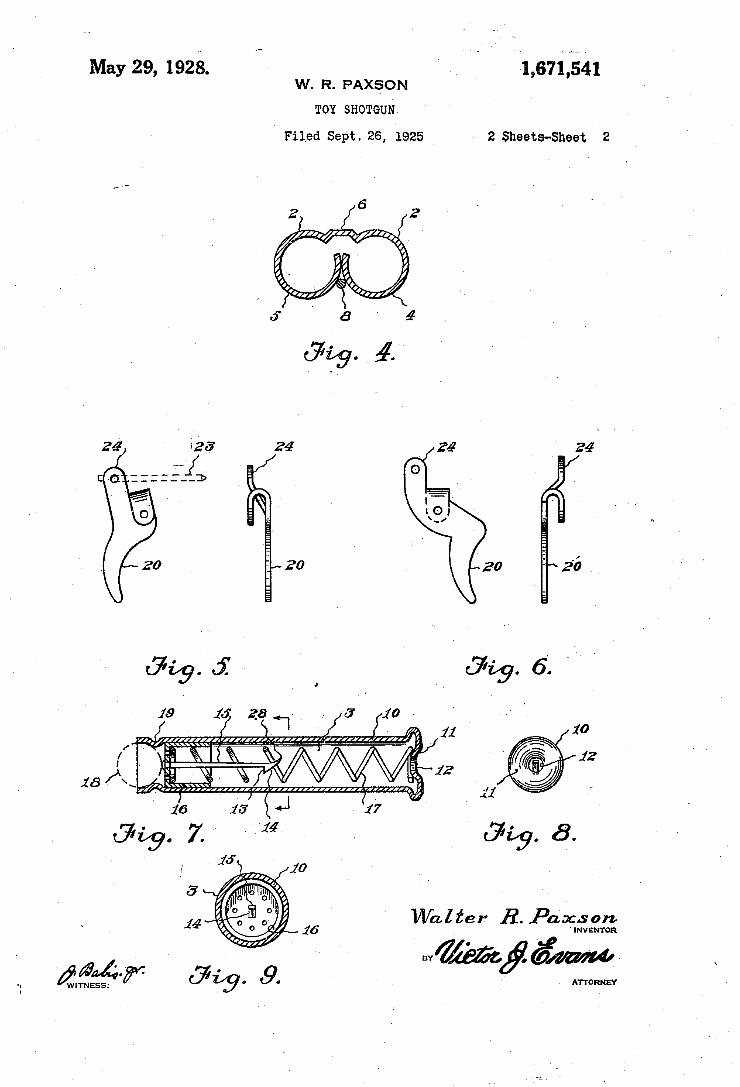
May 29, 1928. " - l‘ La7-i541 w. R. PAxsoN
TOY SHOTGUN
' Filed sept. 26, 1925 2 sheets-sheet 2
, ATTORNEY ¿fgfw ` afg. t9.
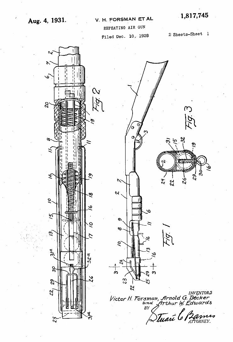
/ 1,817,745 Aug. 4, 1931. v. H. FoRsMYAN ET AL REPEATING AIR GUN
2 Sheets-Sheet l Filed Dec. l0,4 1928
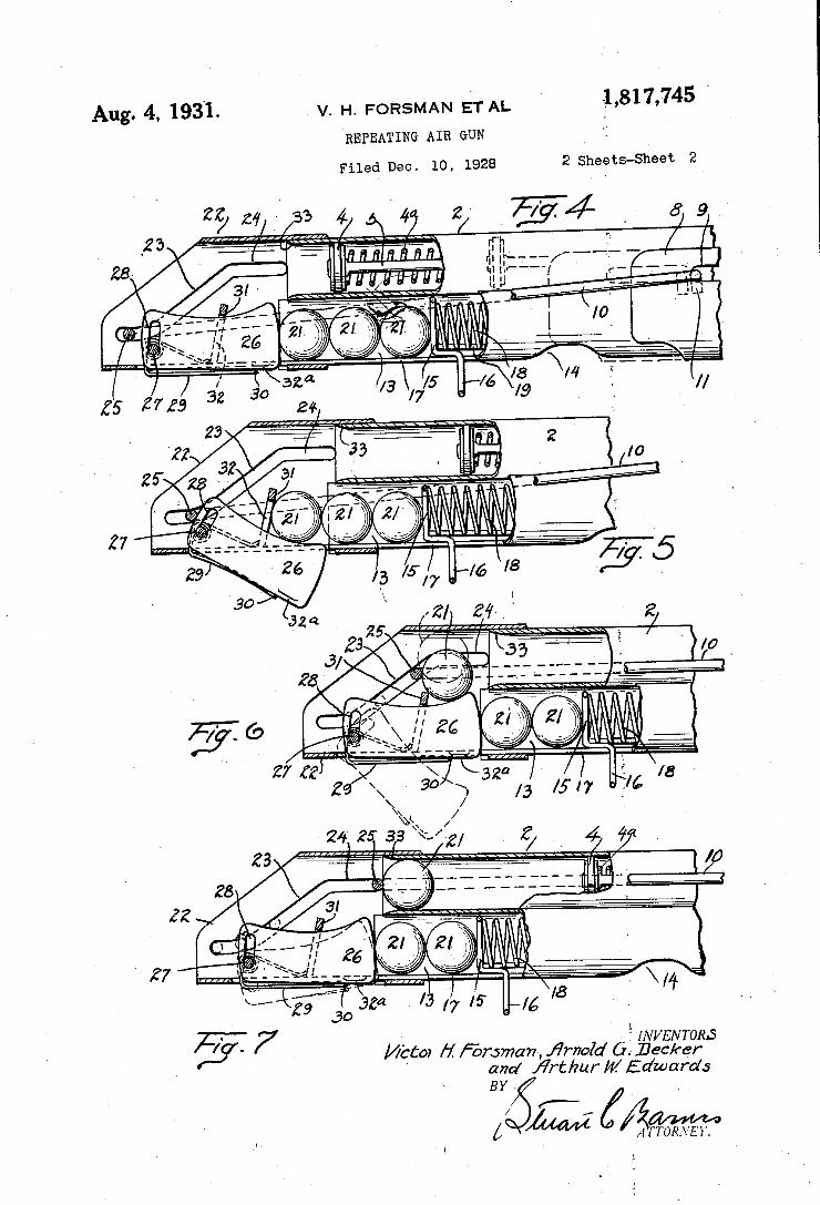
v. H. FORSMAN ET AL
REPEAT11~IG AIR GUN
Aug. 4, 193'1. .1,817,745 ‘
2 Sheets-Sheet 2
E414 . M
Filed Dec. 10, 1928
2a 2921/'33 454? 2/
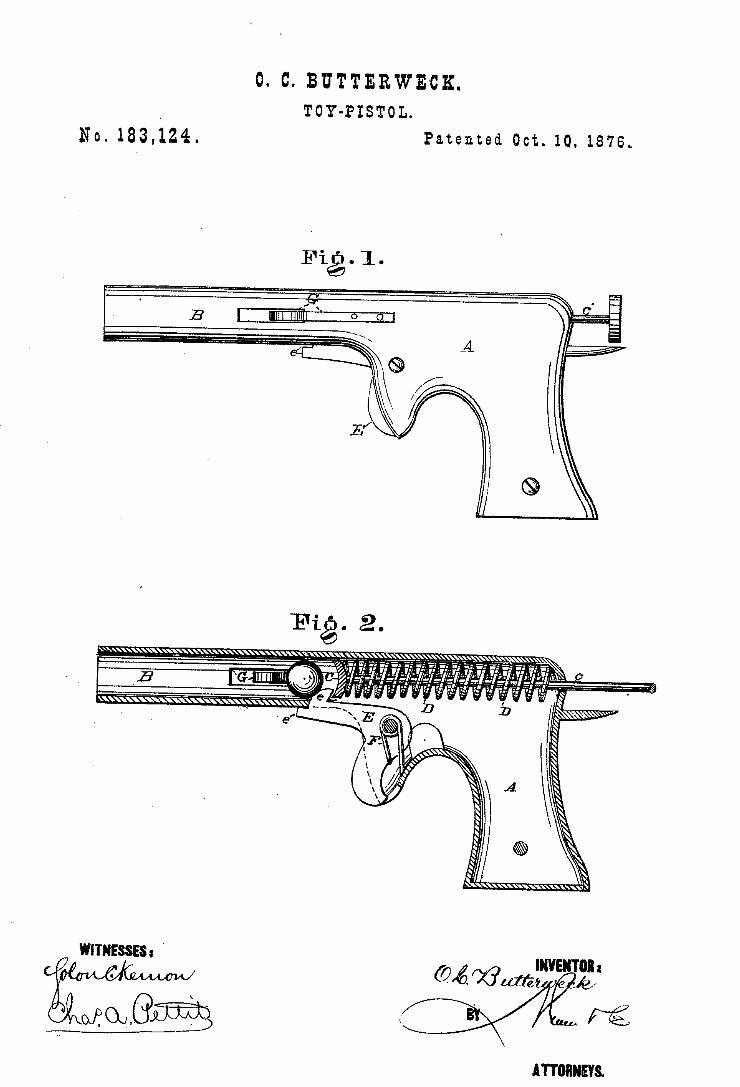
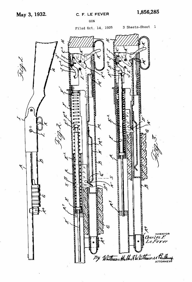
May 3, 1932- c. F` |_E FEVER 1,856,235 GUN '
Filed Oct. 14, 1929 IS Sheets-Sheet l
Y
ATTORNEYS
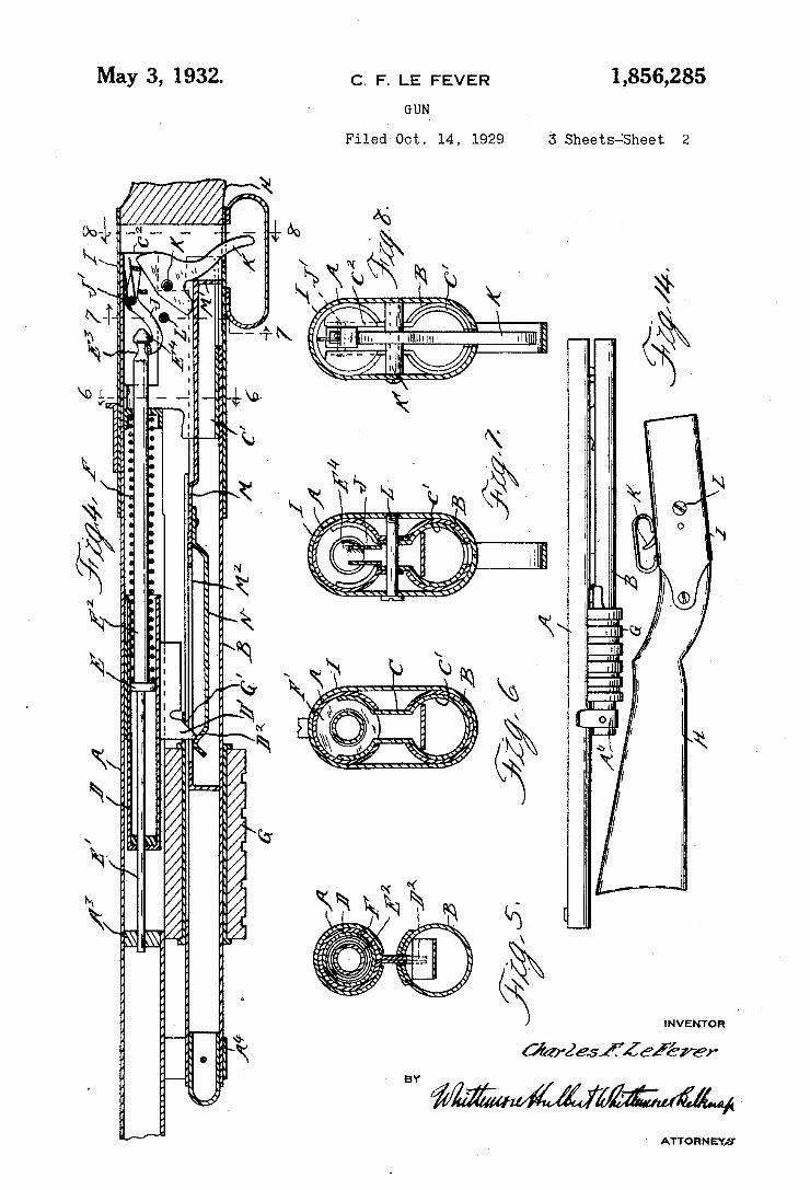
1,856,285 May 3, 1932. c. F. LE FEVER
GUN~ 3 SheetsÄSheet 2 Filed-OCT.. 14, 1929
INVENTOR
Ök/‘Zesfíáßrer
ATTORNEY/3
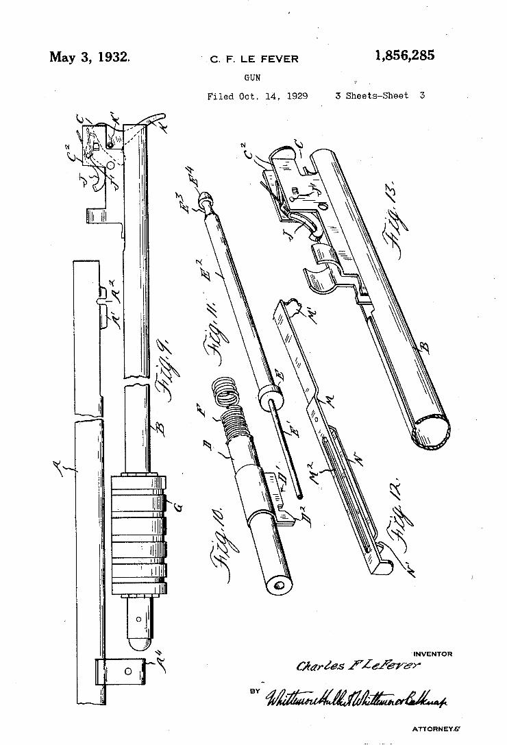
May 3, 1932» c. F. LE FEVER Y 1,355,285
GUN
Filed Oct. 14, 1929 3 Sheets-Sheet 5
INVENTOR
ATTORNEYS
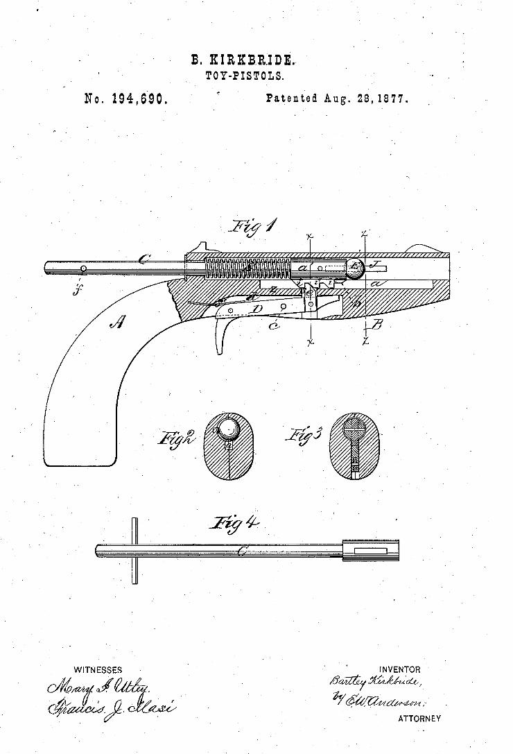
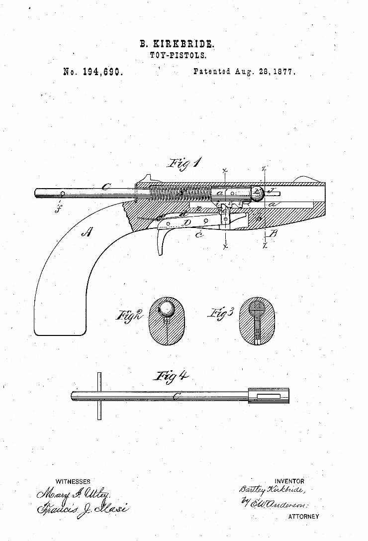
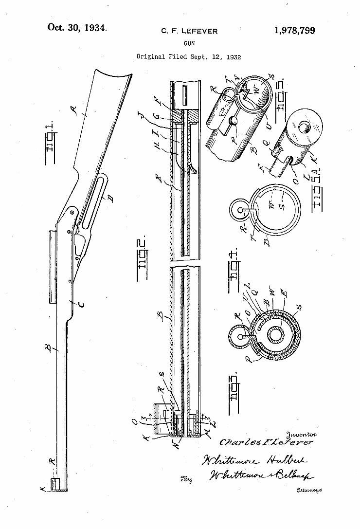
1,978,799 Oct. 30, 1934. c. F. LEFEVER
GUN
Original Filed Sept. 12, 1932
5“ V ' MW. i X C/mriasfiezg‘erer MM #MM WWW
' Gum/M1156
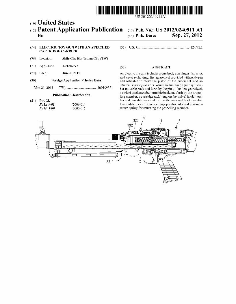
US 20120240911A1
(12) Patent Application Publication (10) Pub. No.: US 2012/0240911 A1 (19) United States
Hu (43) Pub. Date: Sep. 27, 2012
(54) ELECTRIC TOY GUN WITH AN ATTACHED CARTRIDGE CARRIER
(76) Inventor: Shih-Che Hu, Tainan City (TW)
(21) App1.No.: 13/155,397
(22) Filed: Jun. 8, 2011
(30) Foreign Application Priority Data
Mar. 21, 2011 (TW) ............................... .. 100109571
Publication Classi?cation
(51) Int. Cl. F41A 9/61 F41F 1/00
(2006.01) (2006.01)
(52) US. Cl. ..................................................... .. 124/411
(57) ABSTRACT
An electric toy gun includes a gun body carrying a piston set and a gear set having a ?rst gearWheel provided With a side pin and rotatable to move the piston of the piston set, and an attached cartridge carrier, Which includes a propelling mem ber movable back and forth by the pin of the ?rst gearWheel, a sWivel hook member tumable back and forth by the propel ling member, a cartridge rack hung on the sWivel hook mem ber and movable back and forth With the sWivel hook member to simulate the cartridge feeding operation of a real gun and a return spring for returning the propelling member.
323 1 A
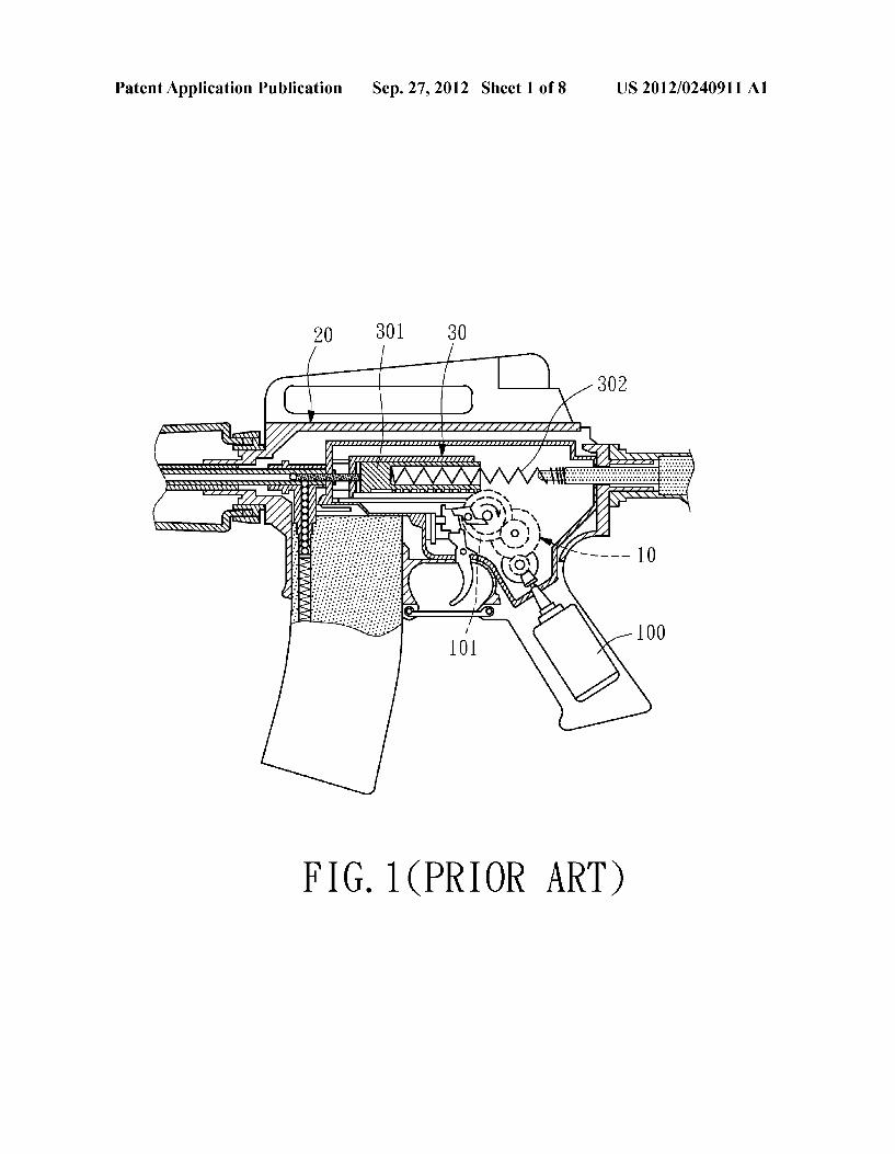
Patent Application Publication Sep. 27, 2012 Sheet 1 0f 8 US 2012/0240911 A1
20 301 30
FIG. MPRIOR ART)
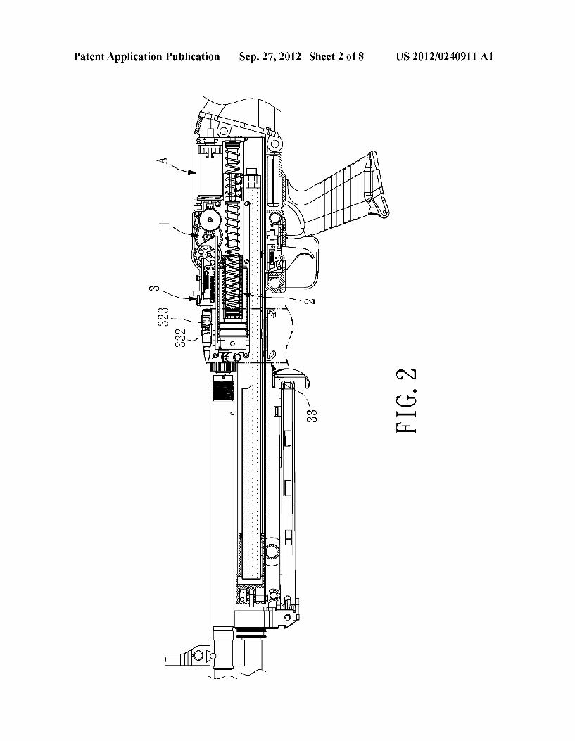
Patent Application Publication Sep. 27, 2012 Sheet 2 0f 8 US 2012/0240911 A1
FIG.2
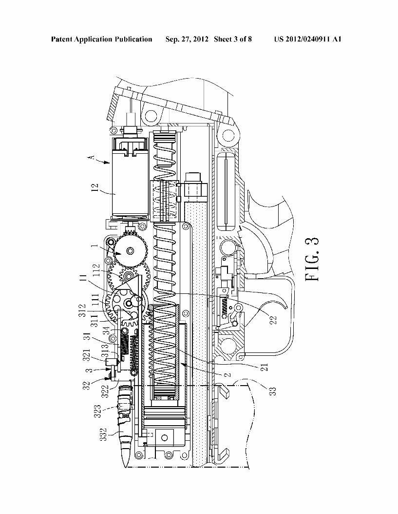
Patent Application Publication Sep. 27, 2012 Sheet 3 0f 8 US 2012/0240911 A1
11 FIG.3 312 311 111
32 3 321 31
323
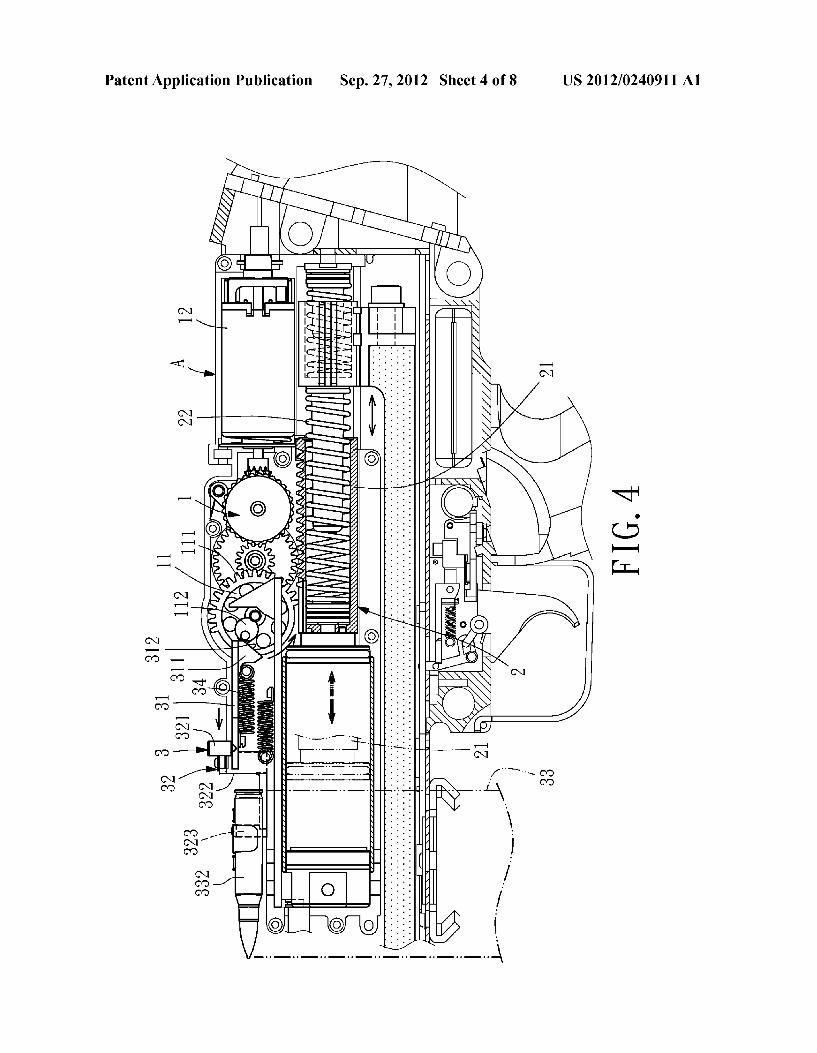
Patent Application Publication Sep. 27, 2012 Sheet 4 0f 8 US 2012/0240911 A1
is;
-995 D2 EFE
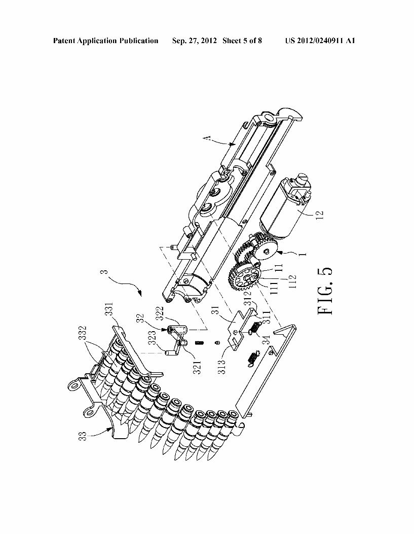
Patent Application Publication Sep. 27, 2012 Sheet 5 0f 8 US 2012/0240911 A1
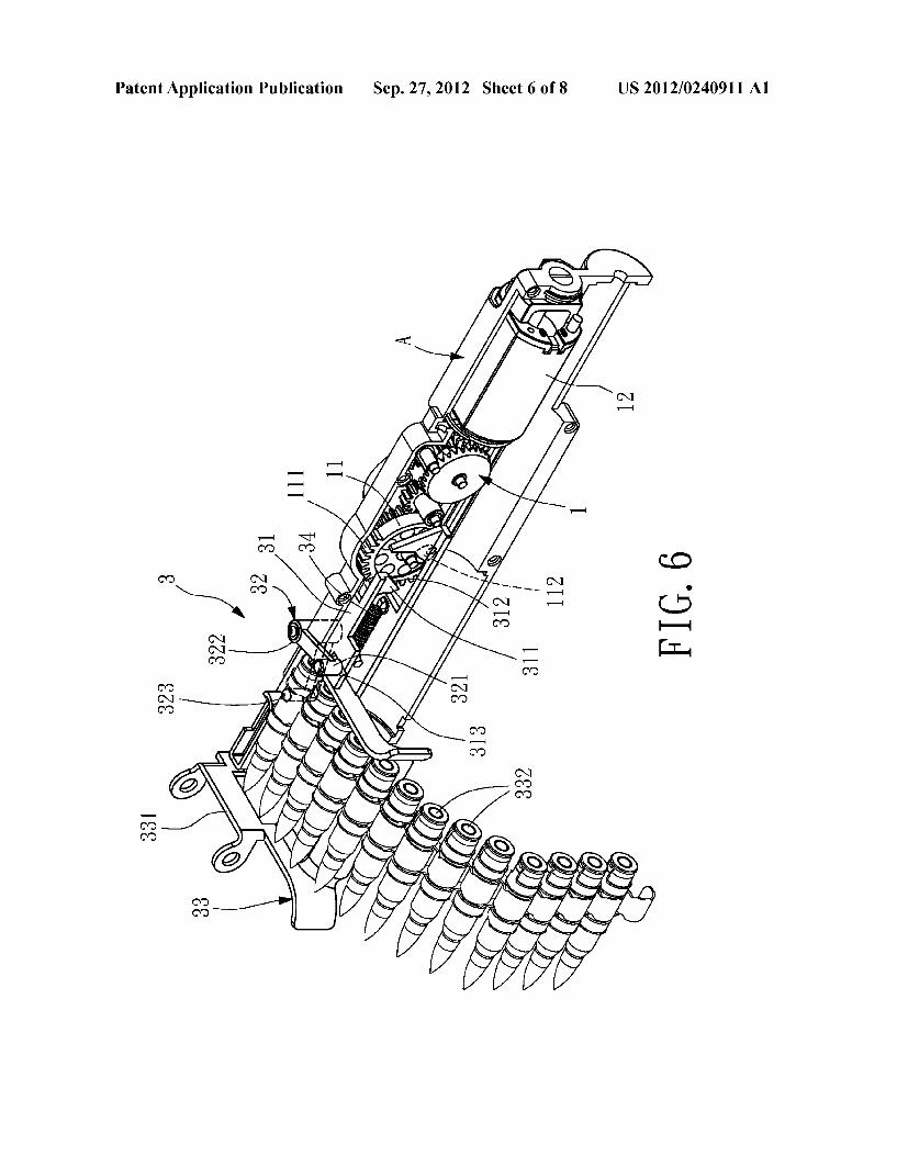
Patent Application Publication Sep. 27, 2012 Sheet 6 0f 8 US 2012/0240911 A1
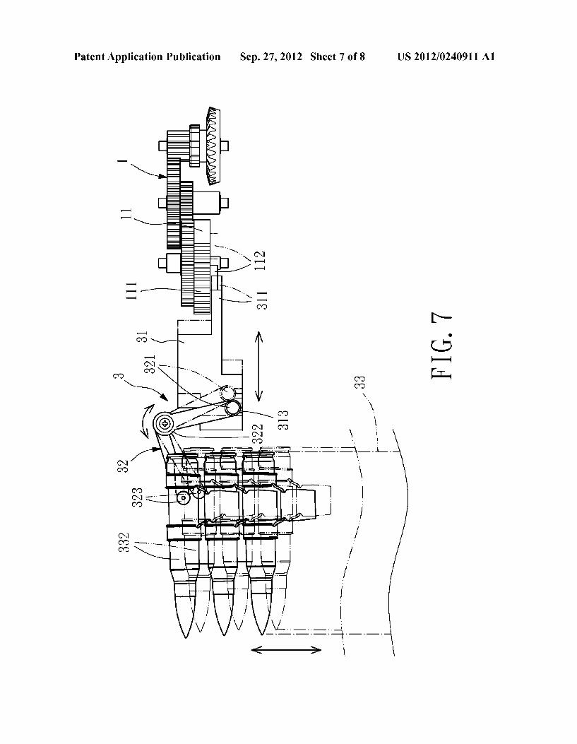
Patent Application Publication Sep. 27, 2012 Sheet 7 0f 8 US 2012/0240911 A1
FIG.7
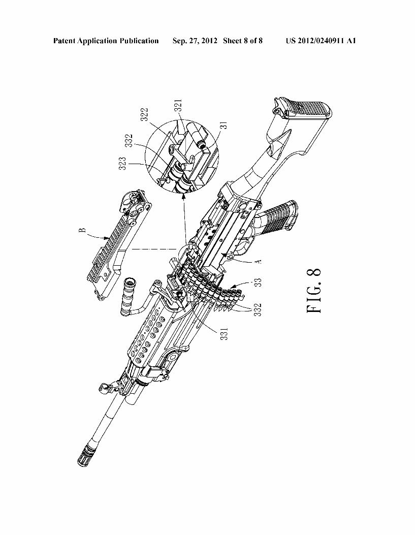
Patent Application Publication Sep. 27, 2012 Sheet 8 0f 8 US 2012/0240911 A1
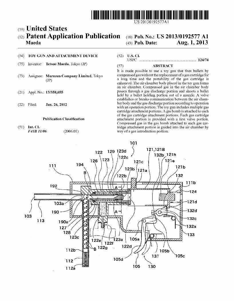
US 20130192577A1
(19) United States (12) Patent Application Publication (10) Pub. No.: US 2013/0192577 A1
Maeda (43) Pub. Date: Aug. 1, 2013
(54) TOY GUN AND ATTACHMENT DEVICE (52) US. Cl. USPC .......................................................... .. 124/74
(75) Inventor: Tetsuo Maeda, Tokyo (JP) (57) ABSTRACT
It is made possible to use a toy gun that ?res bullets by
(73) AssigneeZ Maruzen Company Limited’ Tokyo compressed gasWithoutthereplacement of a gas cartridge for (JP) a long time and the portablhty of the gas car‘tr1dge 1s
enhanced. The air chamber body placed in the toy gun forms an air chamber. Compressed gas in the air chamber body
(21) Appl_ No. 13/358,655 passes through a gas discharge portion and shoots a bullet held by a bullet holding portion out of a muZZle. A Valve establishes or breaks communication between the air cham
(22) Filed: Jam 26, 2012 her body and the gas discharge portion according to operation With an operation portion. The toy gun includes multiple gas cartridge attachment portions. A gas bomb is attached to each of the gas cartridge attachment portions. Each gas cartridge
Publication Classi?cation attachment portion is provided With a ?rst Valve portion. Compressed gas in the gas bomb attached to each gas car
(51) Int. Cl. tridge attachment portion is guided into the air chamber by F 413 11/06 (2006.01) Way of a gas introduction portion.
101
l 21 l 21 B 1 29 1 23d ' Y 122 5 132b 121 h
122c 126 123 121C 121e
1 1 1 194 121 b > B ' 123b 1213
k 1 22b ) % 32 192 \ \ \\ \l\\ \ I |\1\| __|> / r.\>x \\\\\1( lllb
A I A c
g:\\ $.31 N .\. 1 .,:@§\~124 r i
1 “ I ' ' Q l I nozxodgl'p'l d
.v
190 —/§ ~-/1 32d ‘I /\ \ -' _ H
I .l 3 190a , " Y 1326 I 1
127 , \ .. §\132a 12s , - \
1 2 3 133 c i 1 05a ‘L 1.x
, .
1 / A > / 1 12b 43/ 10510
‘ l 31 105C 112 105d
105 l 30 112a
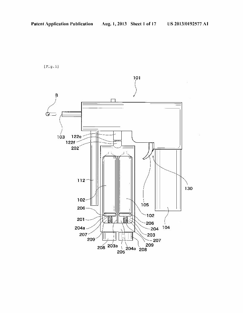
Patent Application Publication Aug. 1, 2013 Sheet 1 0f 17 US 2013/0192577 A1
[Fig.1]
101
|_|
103 122s /?:I\”/ 1221c |
w x " "aw \
112/»
"' 13o
// N O 03
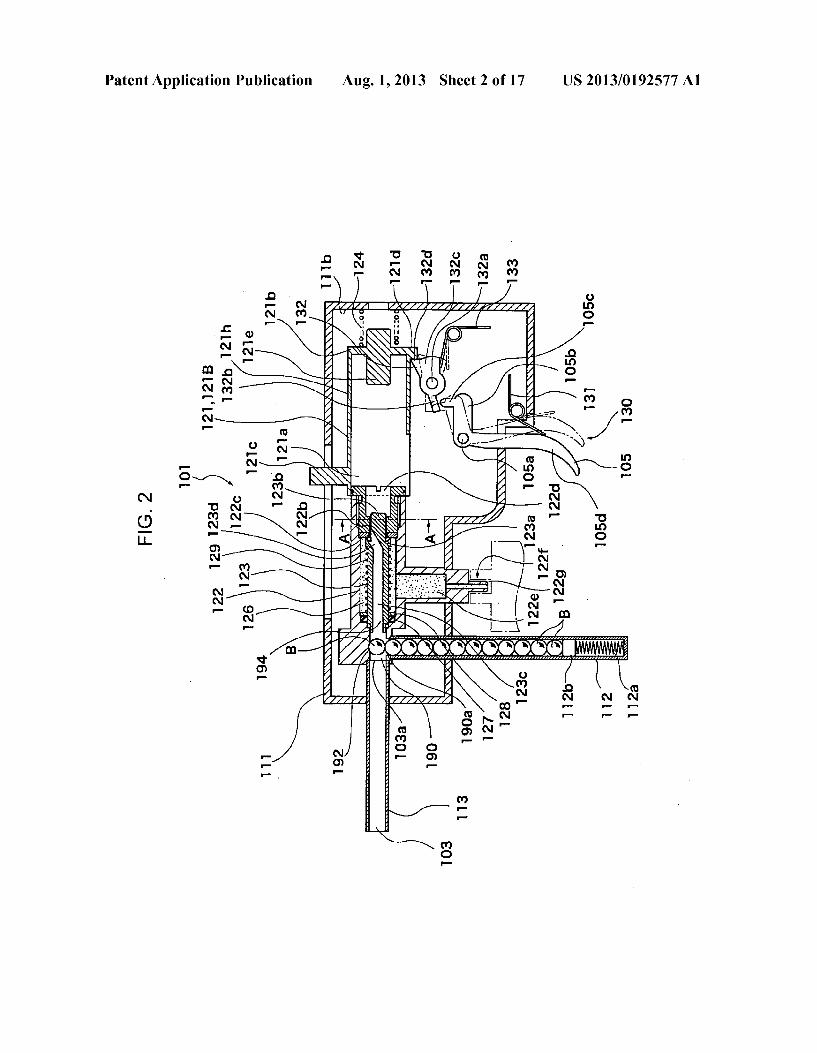
Patent Application Publication Aug. 1, 2013 Sheet 2 0f 17 US 2013/0192577 A1
o2 m2 “NF F
E P
NE 82 m:
mNmF oNmF UNMF
mop
YNP
2.
3?:
8E 2MP nmNF 2N,
NMF
DFNP imp
2w? ONN EN, £2 F N2
. ENE“: 3N. m2
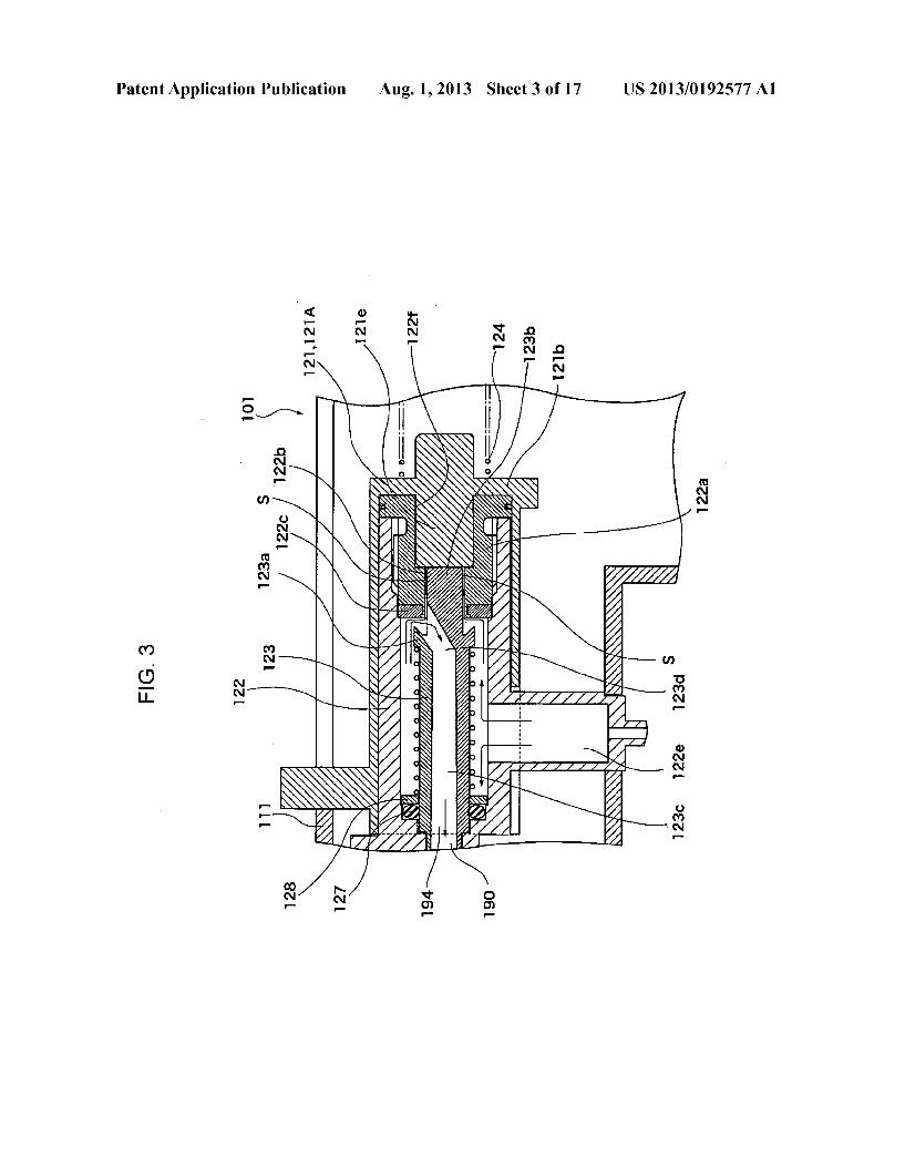
Patent Application Publication Aug. 1, 2013 Sheet 3 0f 17 US 2013/0192577 A1
mNN _.
w UMNF
\ / AV/A 1. \ 1
|+
wmp
\ \ \\\ \\\ »\\ \\ \\\\ \
\ \\\\
\ \
pop .NNF
\INF
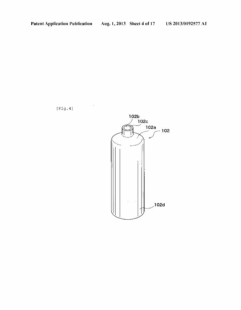
Patent Application Publication Aug. 1, 2013 Sheet 4 0f 17 US 2013/0192577 A1
[Fig.4]
102d
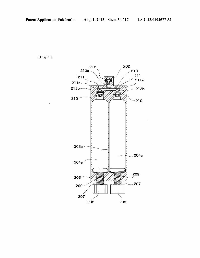
Patent Application Publication Aug. 1, 2013 Sheet 5 0f 17 US 2013/0192577 A1
[Fig.5]
212 202
213a \ / 213 21-‘ 21 'l
2“ 211a a'—\ _ : y /
213b/—\ J 1 /—213b
/\ 210 \210
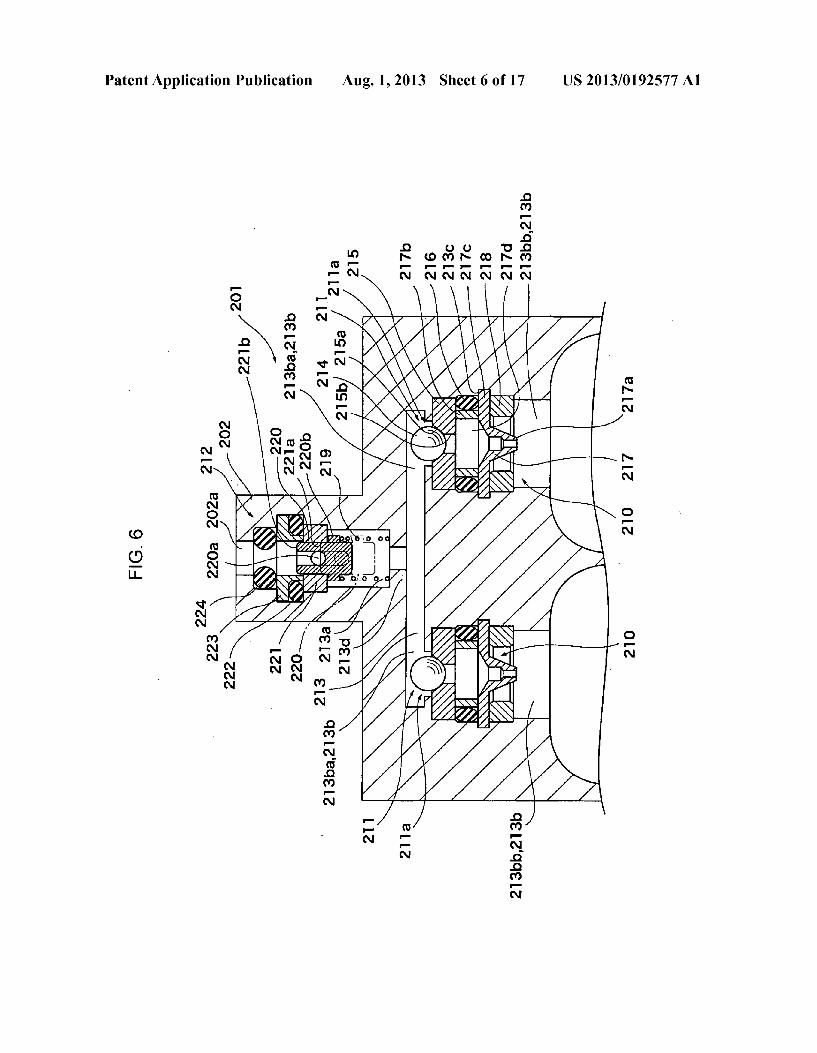
Patent Application Publication Aug. 1, 2013 Sheet 6 0f 17 US 2013/0192577 A1
MEN NFN OFN . O_.N
2.5
25 :N
UMFN
mmFN nmPN .
mmPN mpw nmFNmnmFN
IN SN EN
8% £5.32“ 2mm
ONN N8 w m
EN Now 8N
/o 5N NNN mNN
¢NN
@ GE
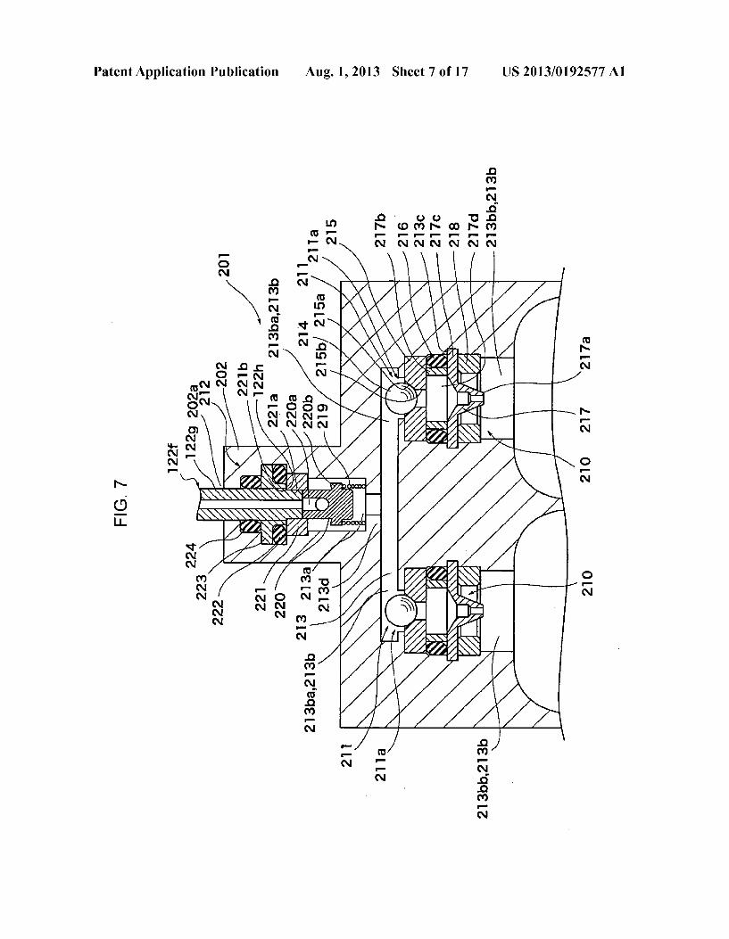
Patent Application Publication Aug. 1, 2013 Sheet 7 0f 17 US 2013/0192577 A1
ELM NFN OFN O_.N
nmpwdnmpw ONFN wFN £5 85 . 2N
mp FN :N
UMFN mm_.N MFN nmpmdnma
m_.N noNN mONN QQNSQN ENN INNF
\ 2% SN Now
NFN mNoN mNNF
wNNF
mmFN nmPN P _.N EN
NNN MNN
#NN
N OE
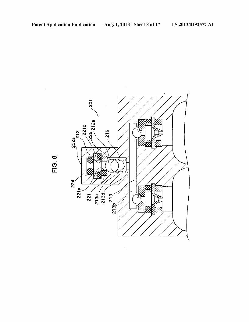
Patent Application Publication Aug. 1, 2013 Sheet 8 0f 17 US 2013/0192577 A1
mNoN
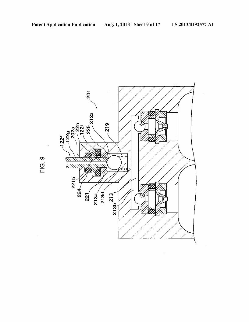
Patent Application Publication Aug. 1, 2013 Sheet 9 0f 17 US 2013/0192577 A1
FIG. 9
'l22f /
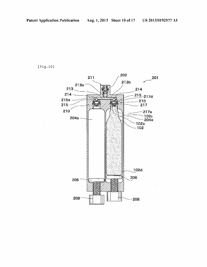
Patent Application Publication Aug. 1, 2013 Sheet 10 0f 17 US 2013/0192577 A1
[Fig.lO]
211 W201 213b
213a \* I
213 /\ 214 R - 215
I / 217d 215a / ' ’ " " a 7] do
215 \/ 217
‘I020
102d
' \goa
208
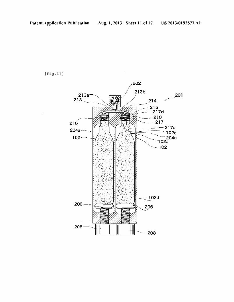
Patent Application Publication Aug. 1, 2013 Sheet 11 0f 17 US 2013/0192577 A1
[Fig.ll]
202
217a 1026 204a
102a 102
102d
206
208
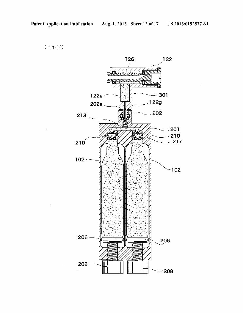
Patent Application Publication Aug. 1, 2013 Sheet 12 0f 17 US 2013/0192577 A1
[Fig.l2]
‘I22
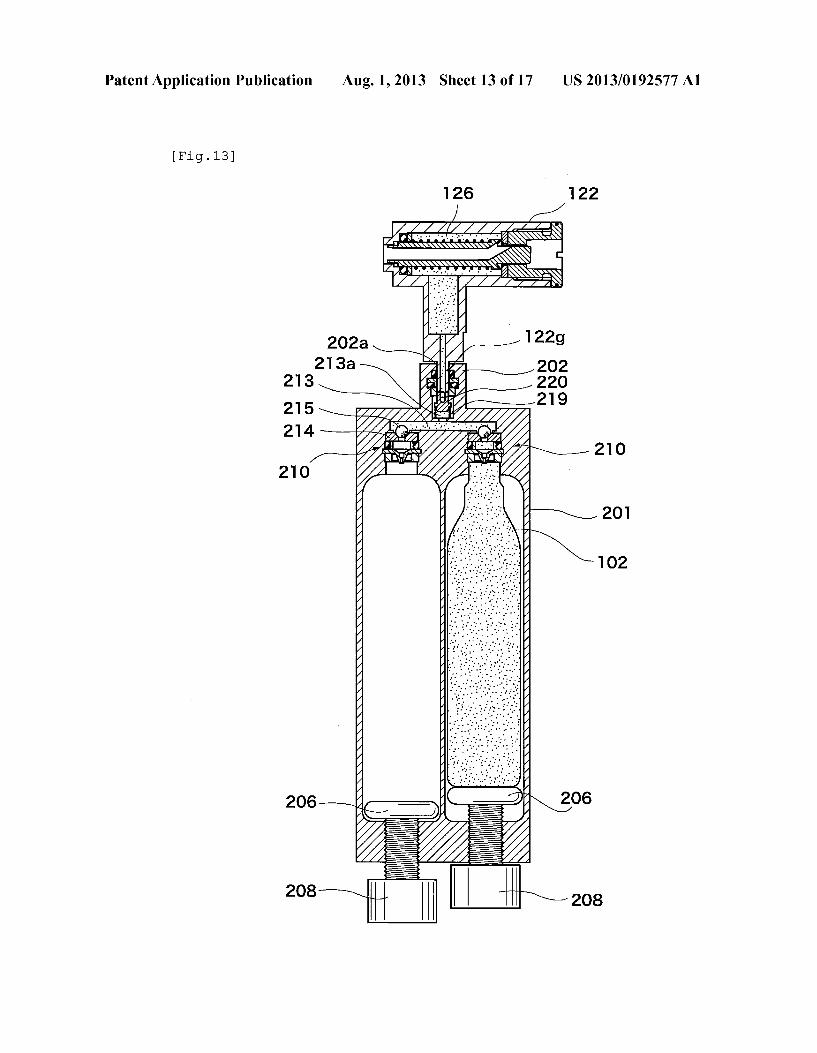
Patent Application Publication Aug. 1, 2013 Sheet 13 0f 17 US 2013/0192577 A1
[Fig.l3]
6 8
0 O 0
2 2

Patent Application Publication Aug. 1, 2013 Sheet 14 0f 17 US 2013/0192577 A1
[Fig.l4]
122e,213a
213
An 7
I" _
301
210
102\ _ I‘
206“ "
208
\/ 203
I \1o2
208
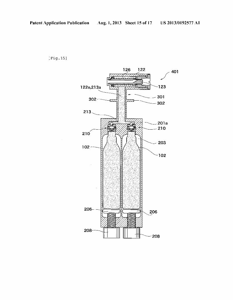
Patent Application Publication Aug. 1, 2013 Sheet 15 0f 17 US 2013/0192577 A1
[Fig.l5]
126 122 401
122e,213a -- 1;; \~
302m
213
P 21 o
102 \
206“ ’ \gos
20s '
208
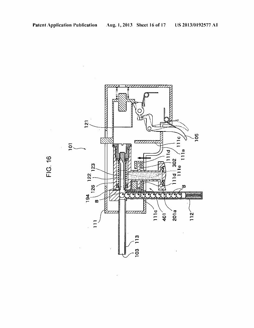
Patent Application Publication Aug. 1, 2013 Sheet 16 0f 17 US 2013/0192577 A1
121
FIG. 16
101
122
194
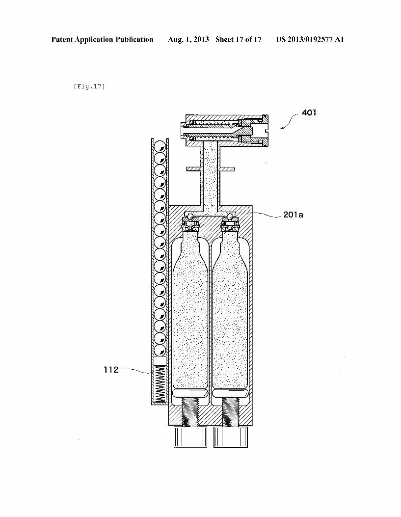
Patent Application Publication Aug. 1, 2013 Sheet 17 0f 17 US 2013/0192577 A1
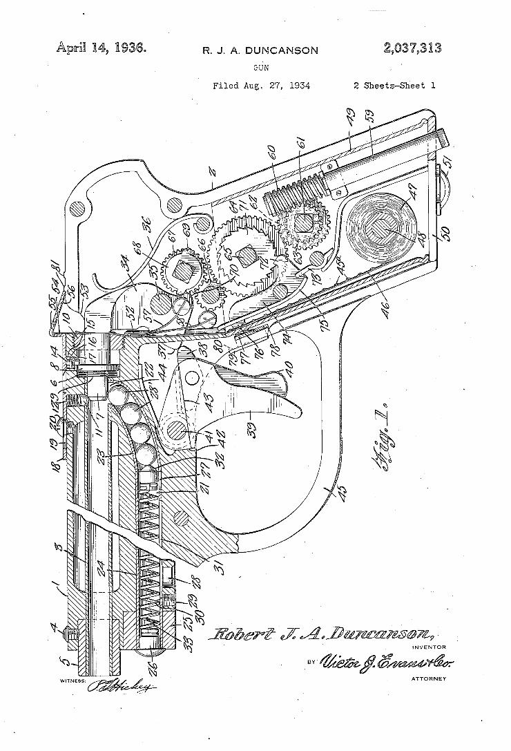
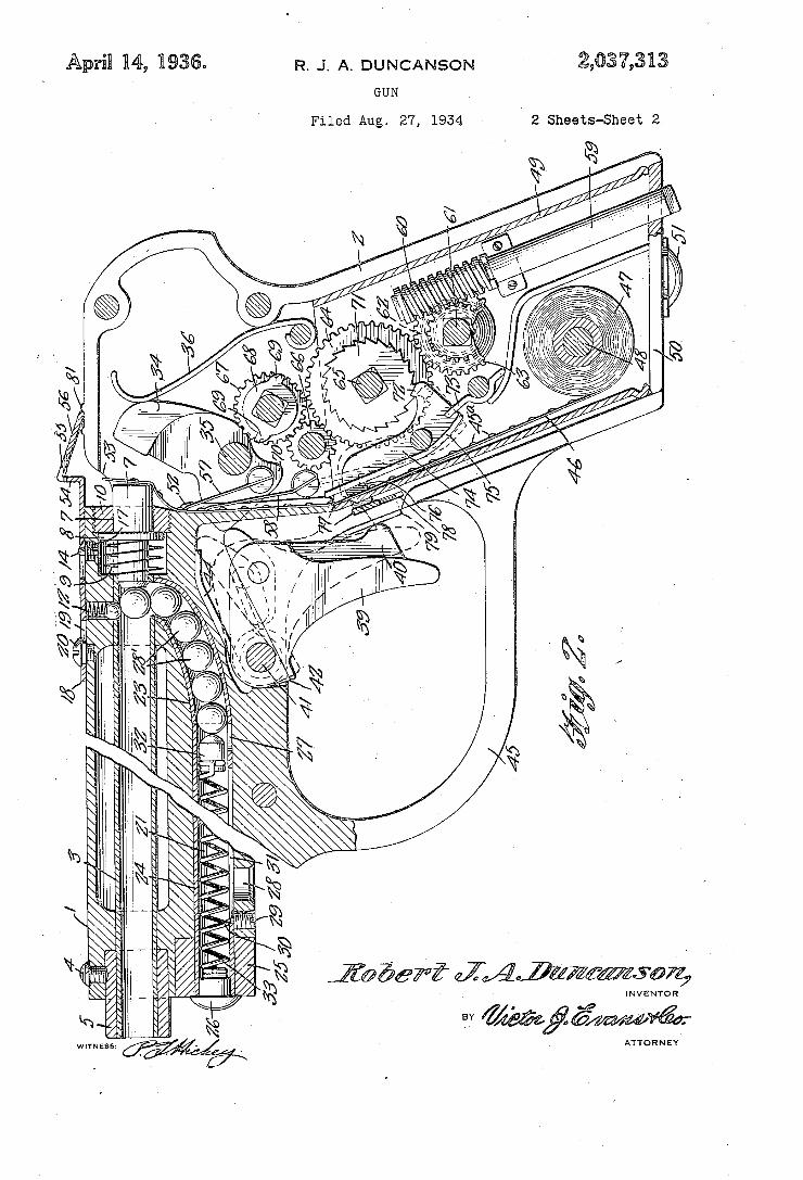
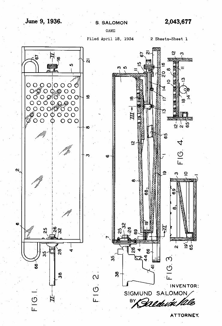
2,043,677 S. SALOMON nJun-e 9,1936. GAME
Filed April 18, 1934
.
2 Sheets-Sheet 1
. A h. I
1
\\\\\\\
A INVENTOR:
SIGMUND SALOMON '
ÚM .0C ATTORNEY.
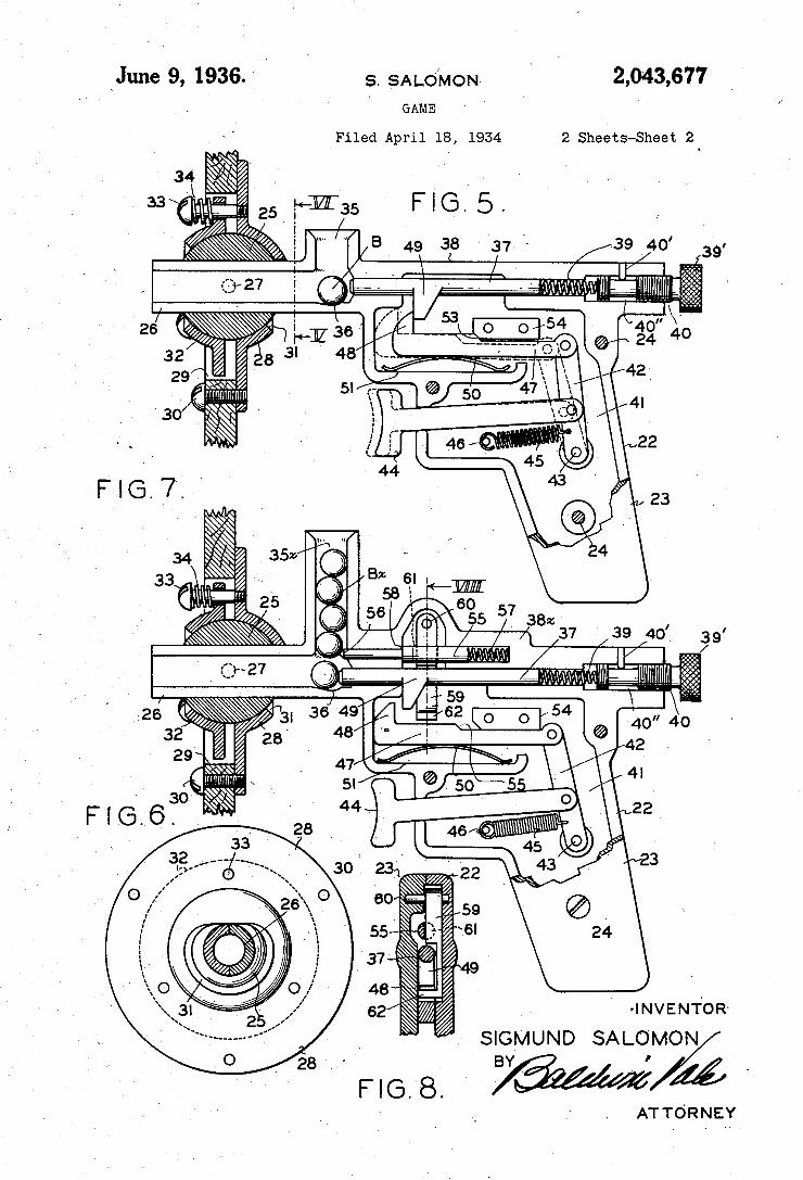
2,043,677 ~June 9, 1936.v s. sALo/MON ~ GAME
ATTORNEY
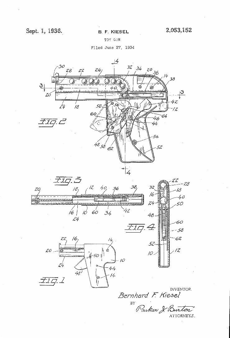
B. F. KIESEL Sep@o l, 15.93@ TOY GUN
Filed June 27, 1954
INVENTOR.
ßemham’ F /I//ïeöe/ BY
ATTORNEYS.
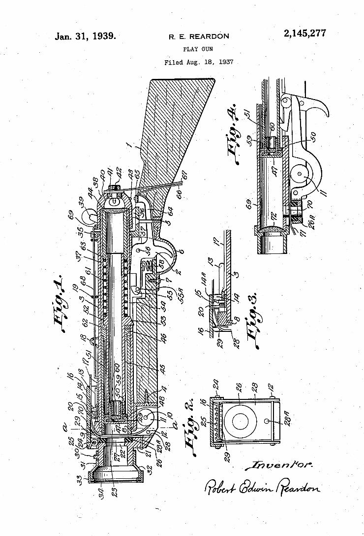
2,145,277 1 Jan. 31, 1939. R. E. REARDON
PLAY GUN
Filed Aug. 18, 1937
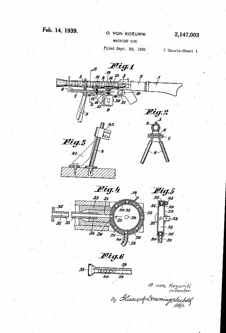
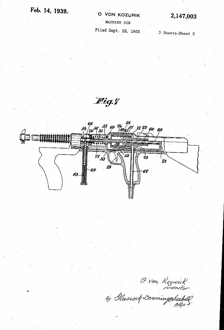
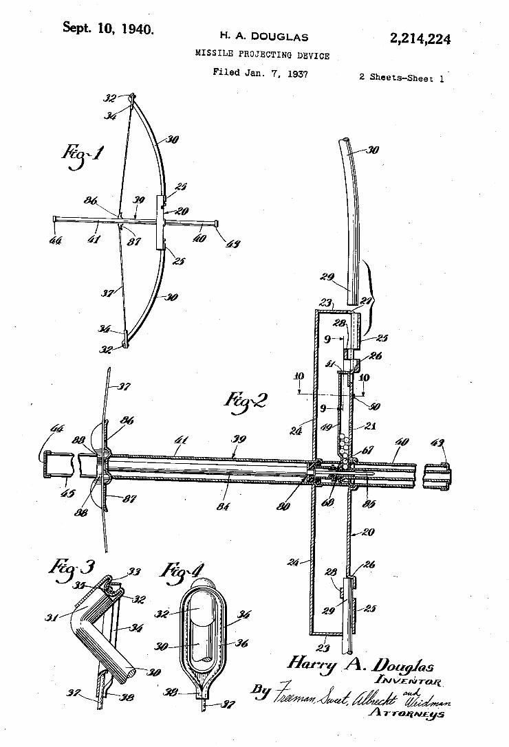
Sept. 10, 1940. H. A. DOUGLAS 2,214,224
MISSILE PROJECTING DEVICE
Filed Jan. 7, 1937 2 Sheets-Sheet 1'
30
29
23 27
as 9 5 ~95
1 26 11 i
if) 10 a7
13»? 9 w J‘ 24 I 2‘
f‘ 79 b7
,% _T 4; a, . a! w M a; as
20
.24 26 . .25 '
29 '9‘
.22 I
Jyamy A. 00259105 [JUVEIJITORI M @iwww WW
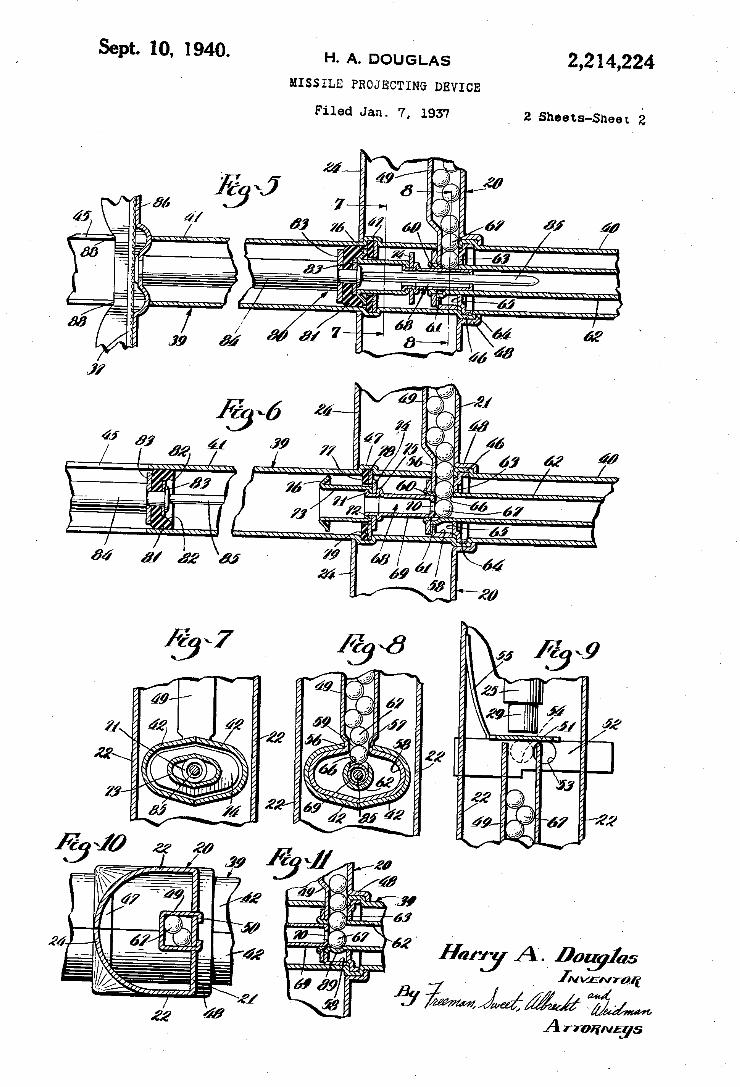
Sept. 10, 1940. H, A_ DOUGLAS 2,214,224 MISSILE PROJECTING DEVICE
Filed Jan. 7, 1957 2 Sheets-Sheer.
K a
z 2 . 7m m M! J 2 @Z W.
. 9 0 v r
\ 1 a 7 D IN T
Had J 6 . A
//w J 1 I j W _ M
6 I 4. J ,
6 6 ,0 90“ a m MJ #14,
a F . Ha W
00 99M 77
a, w, 1 "w
m6 \ . 3 7
‘ . , a
1m nmd J z
m a
8
v a a
. . . w 7 . a
m “ m l .j
r m a E a
m 1 L
M !m .r “ a 6_
wulhwluuuwwlyh?v , _ /
L 24
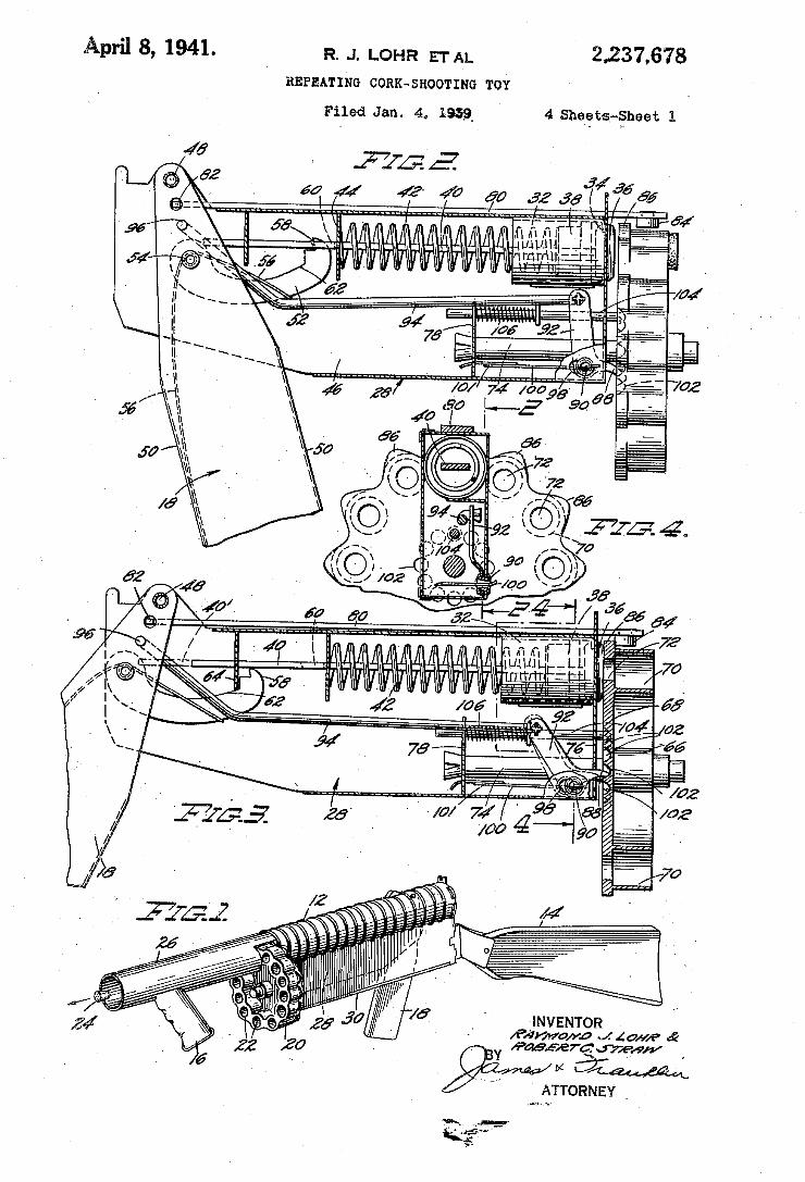
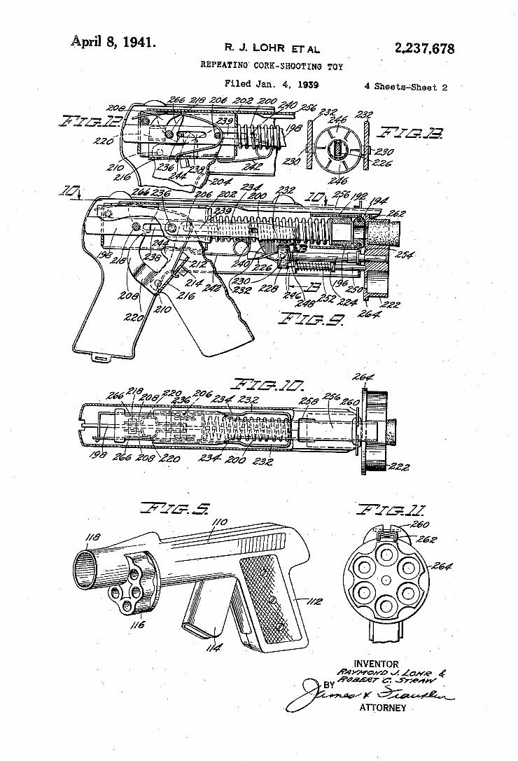
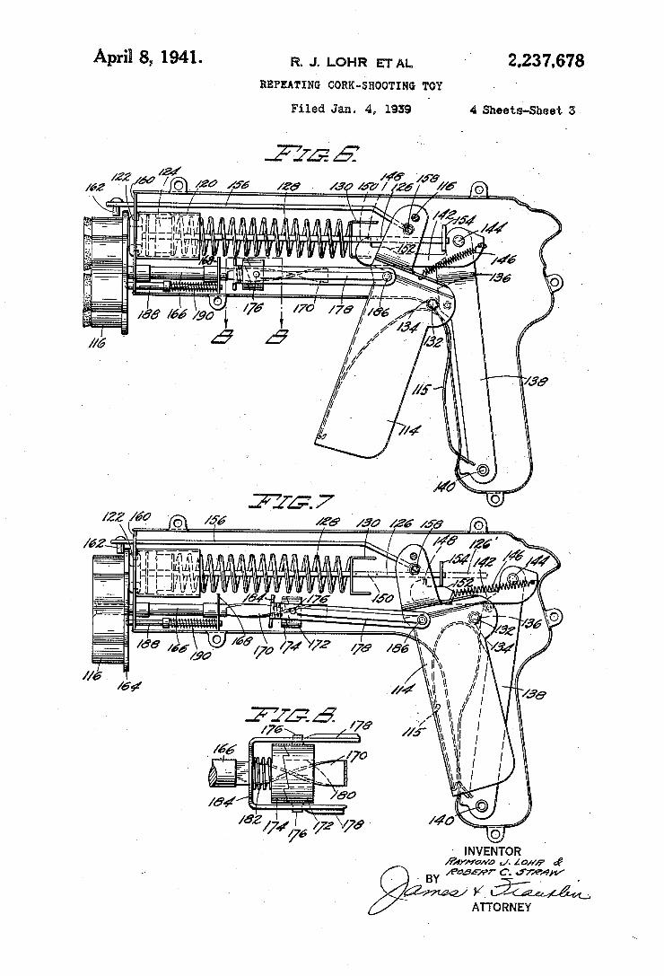
April 8, R J_ LQHR ETAL ‘v
REPEATING CORK-SHOOTING TOY
2 “a; rag‘. ATTORNEY
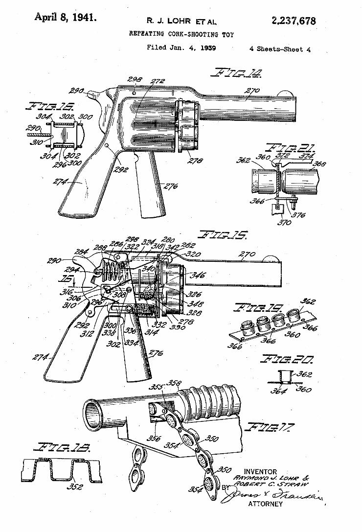
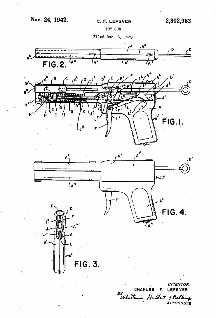
Nov. 24, 1942. c. F. LEFE'VER _ 2,302,963
TOY GUN
‘Filed Dec. 6, 1939
‘INVENTOR. _ CHARLES F. LEFEYER" BY .
‘ 'ATTORNEYs
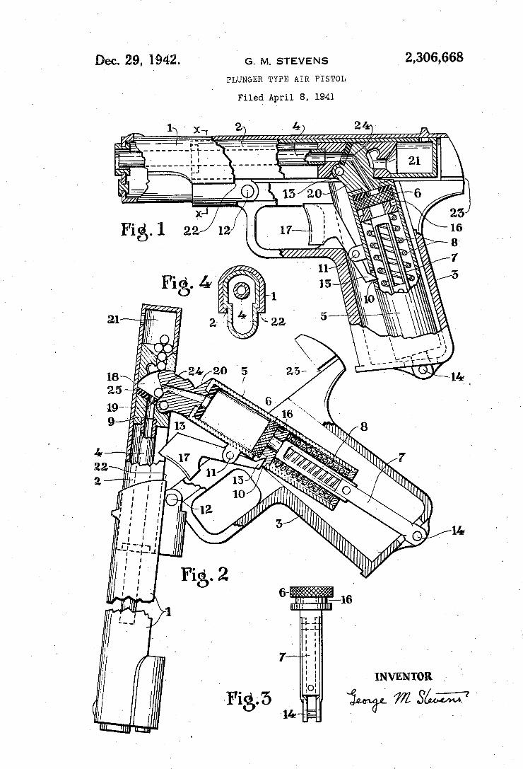
Dec. 29, 1942. G. M. STEVENS 2,306,668 PLUNGER TYPE AIR PISTOL
Filed April 8, 1941
1w ,(1 2) 4) 2
------ --:-J:------ ---------J _ —/ 21
2,) 16
Y INVENTOR "
WWZSW
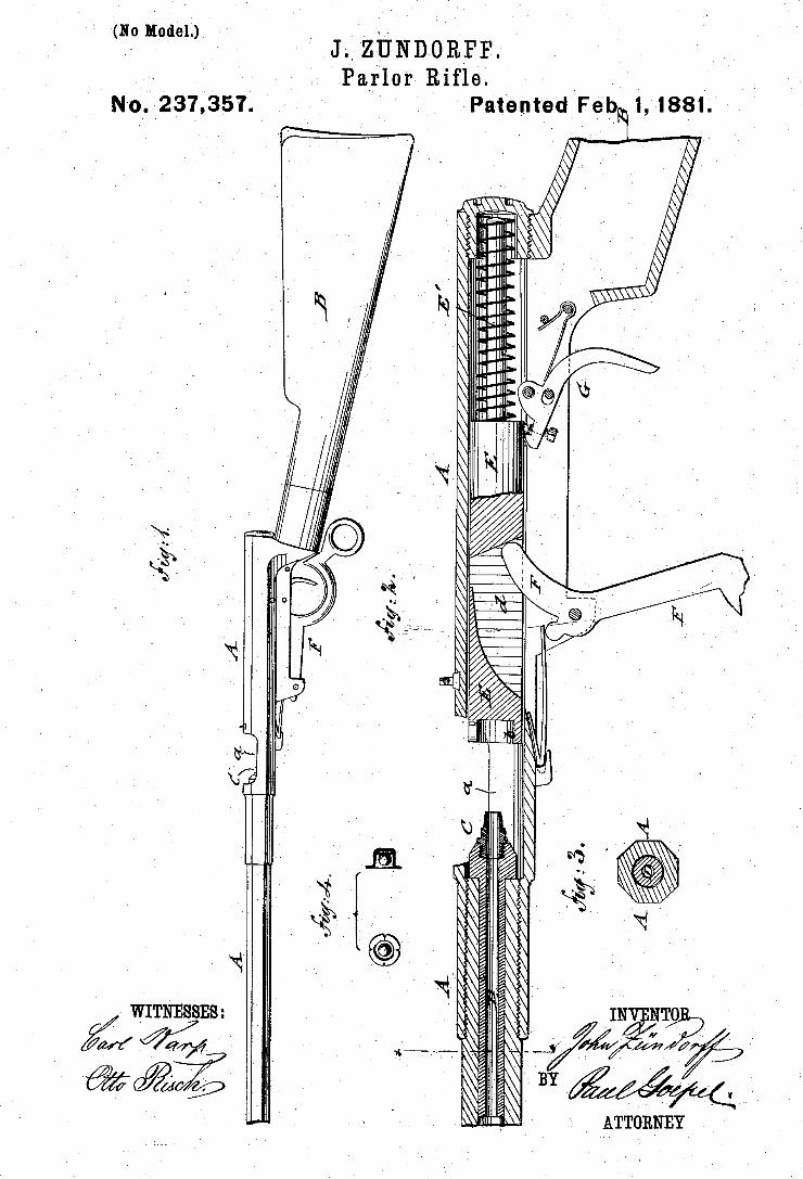
(No M‘odel.) ` ‘ Y. _
. `Parlor Rifle.
' . Patented »40.237,357. vFe 1,1881.
_l WITNBssEs: ’
ATTORNEY y
ì I 1N NTO `
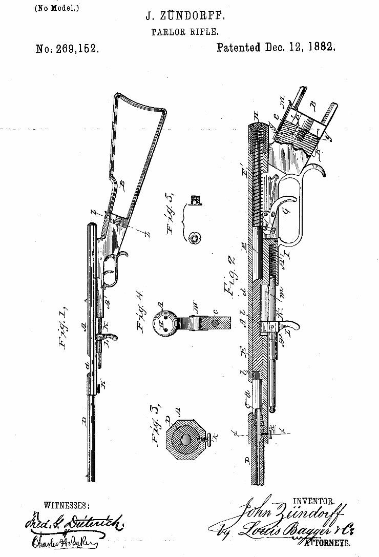
(Mmm J. ZÜNDORPF.
PARLOR RIFLE.
No. 269,152. Patented Deo. 12, 1882;
um
Ry/ m w w œ
N W Z
¿n lâ | .
m www
' WITNESSBS:
21d. ?ßm
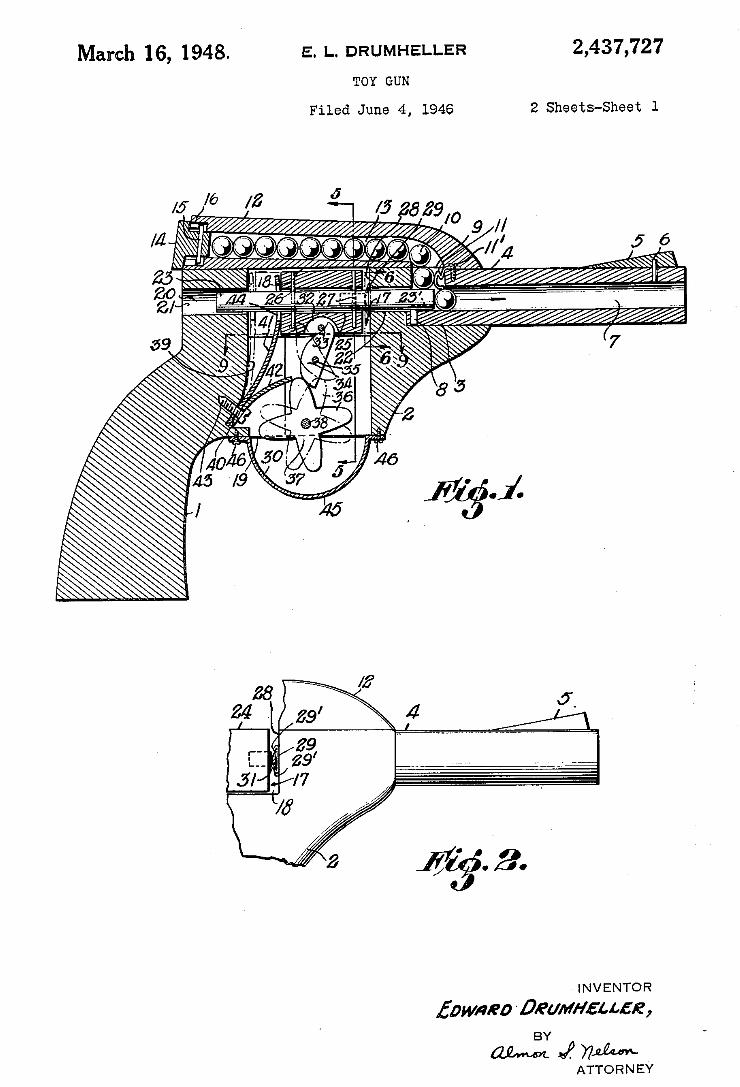
March 16, 1948. 5.1.. DRUMHELLER 2,437,727 TOY GUN
Filed June 4, 1946 2 Sheets-Sheet l
| N V E N T O R
fpwneo 'Deum/suse, BY
ATTO R N EY
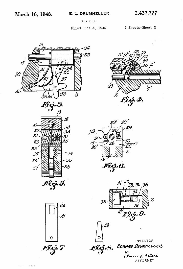
2,437,727 E. L. DRUMHELLER March 16, 1948. TOY GUN
Filed June 4, 1946 2 Sheets-Sheet 2
Z if' .4.
. i 9 Z
[VM 5 ’ i / @a 9.
¿IZ i
o I N V E NTO R
¿awt/pp Deum/œuf@
ATTO R N EY
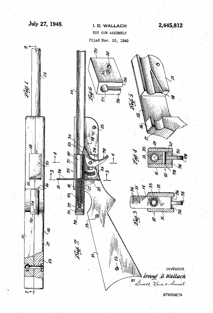
2,445,812 July 27, 1948. |. D. wALLAcH TOY GUN ASSEMBLY
. Filed Nov, 1o, 1945
NN
INVENTOR
l’ frz/111g“ ,ä Wàllaf/L -BYÄ
ATTORNEYS
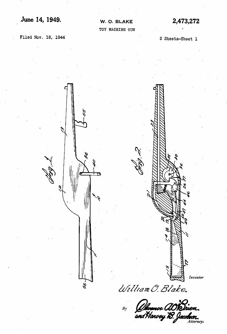
. `June 14, 1949. w. o. BLAK'E 2,473,272 TOY MACHINE GUN
Filed Nov. 18, 1944 2 Sheets-Sheet 1
ßá. //////\///////u/////////////¿g
3.5' .ía a6
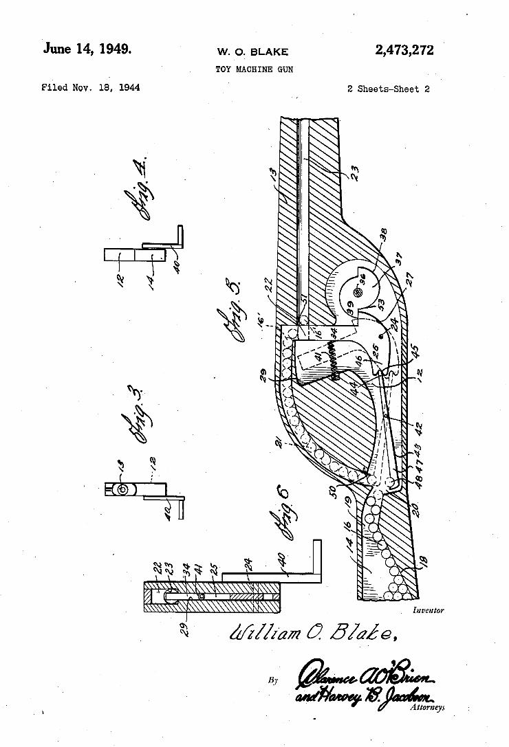
2,473,212 ’ June 14, 1949. W. O. BLAKE
TOY MACHINE GUN
Filed Nov. 1e, 1944 `2 Sheets-Sheet 2
Inventor
12m ¿my m
i
Hmm
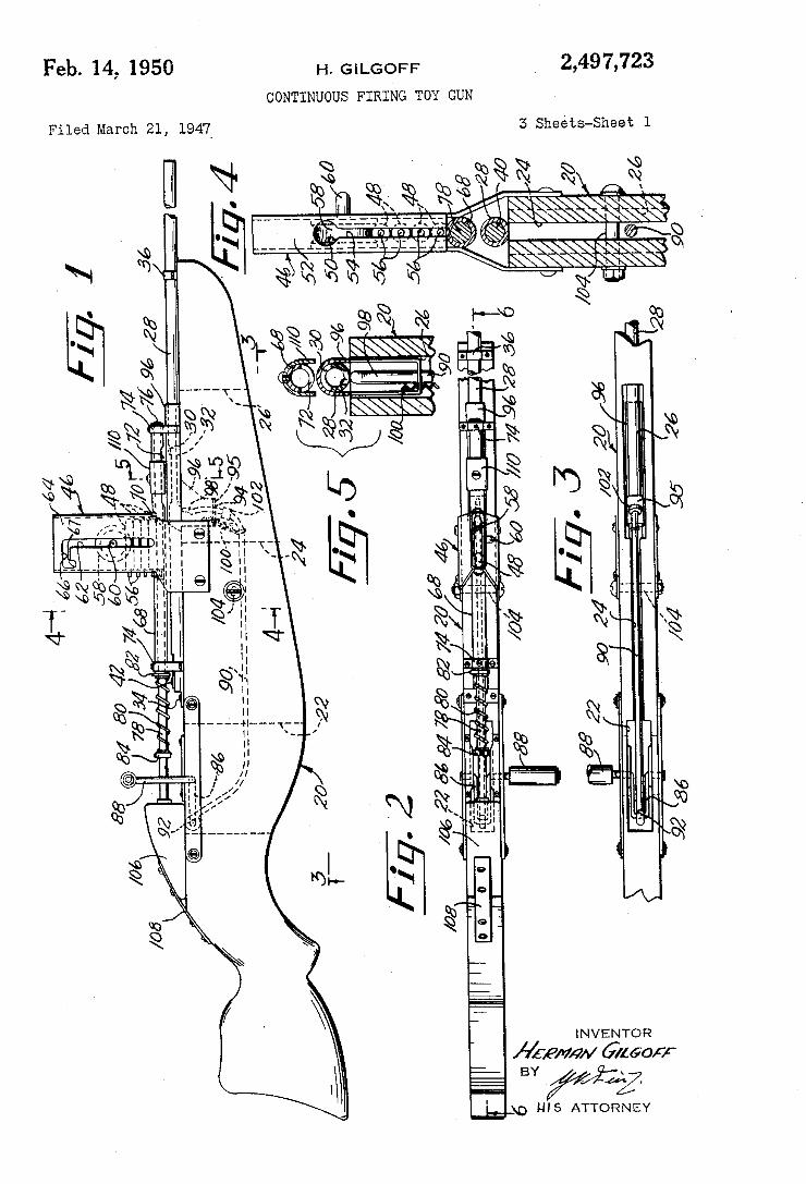
2,497,723 Feb. 14, 1950 H. GiLGoFF CONTINUOUS FIRïNG TOY GUN
3 Sheéts-Sheet l Filed March 21, 194:7Y
@ì
P
N È
Qn, mßwmw È QQ wm, QQ ä MQ
INVENTOR
Affe/»Mw 6160;; BY
_@ me ATTORNEY
e :U 1
ww ww œwëwm mw Nwwww NMQQ
___ÈT _ _v
Í
N .mmf
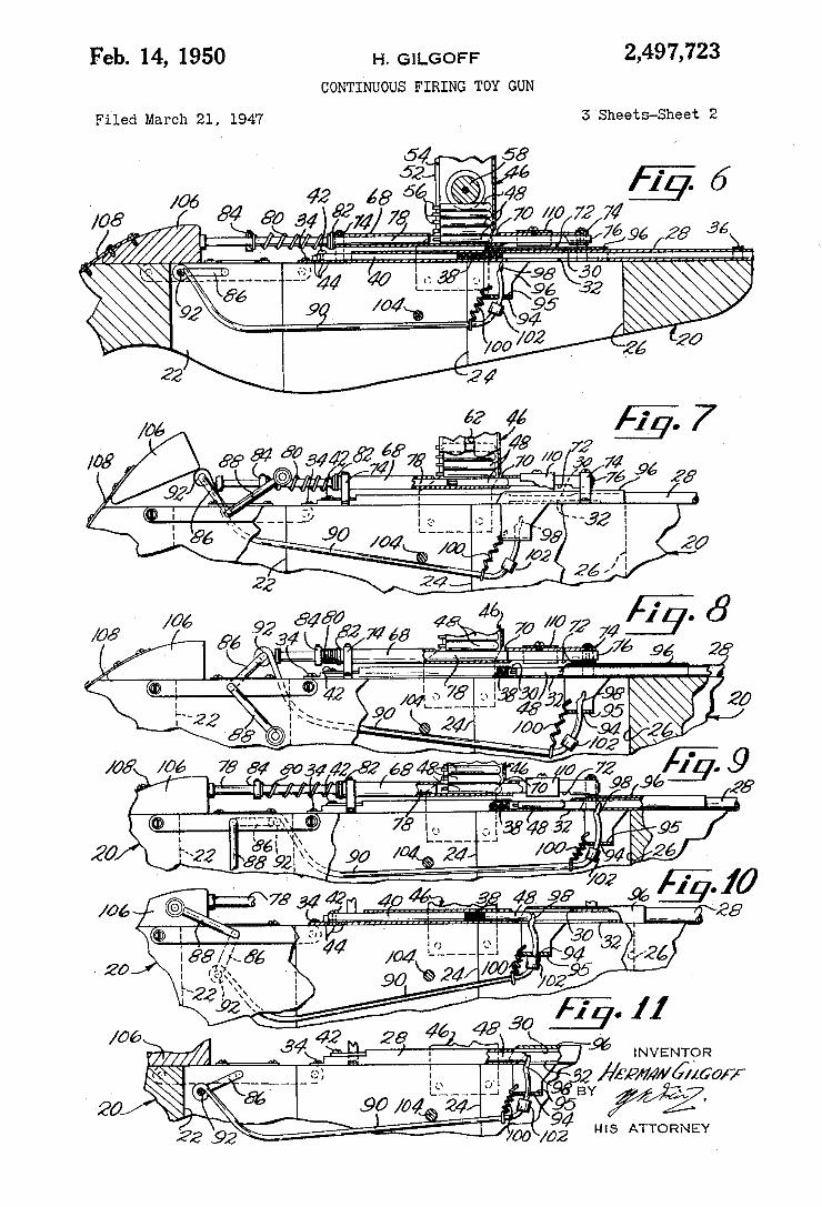
Feb. 14, 1950 H. GlLGor-'F 2,497,723 CONTINUOUS FIRINO TOY GUN
Filed March 21, 1947 3 Sheets-Sheet 2
70 //0 72
7@ 54 «905442 2 ¿a « dé /a 72 /1' „9 _ , .daß -5
¿may O .1 75J a, C, i 3545.55 95
/06 " Y
MM ¿34W . l 5% INVENTOR
22 /00 /02 HIS ATTORNEY
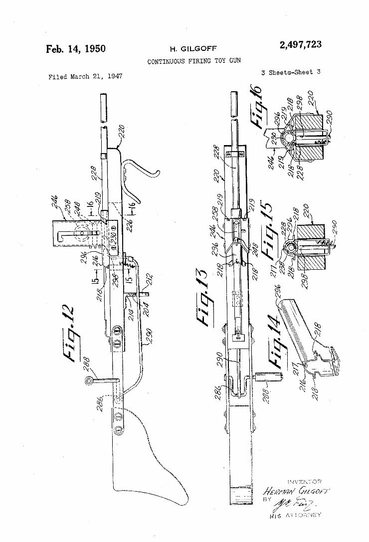
2,497,723 Feb. 14, 1950 H, GlLGor-F CONTINUOUS FIRINO TOY GUN
3 Sheets-Sheet 3 Filed March 21, 1947
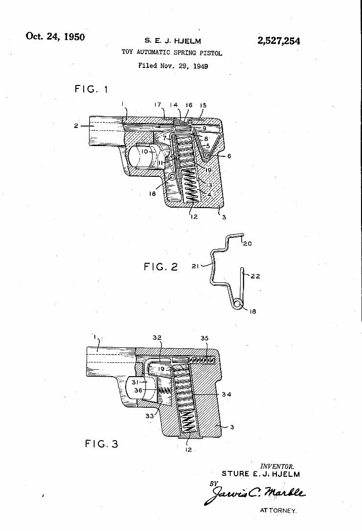
2,527,254 Oct. 24, 1950 s. E. J. HJELM
TOY AUTOMATIC SPRING PISTOL
Filed Nov. 29, 1949
I 4
20
22
4 3
I ,. lg
' INVENTOR.
STURE E.J. HJELM
ZQMWC’ M AT T‘ORNEY4
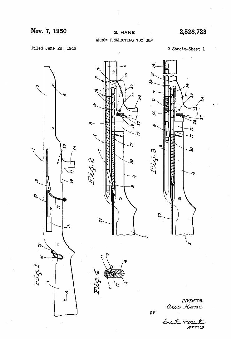
2,528,723 Nov. 7, 1950 G. HANE
ARROW PROJECTIKNG ToY GUN
2 Sheets-Sheet 1 Filed June 29, 1946
SÉ \ w î g a
INVENTQR. Gus J-¿a n e
BY
Mimi; 14 TTYS
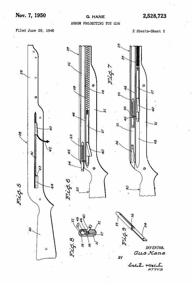
NOV. 7, 1950 G, HANE 2,528,723 ARROW PROJECTING TOY GUN
Filed June 29, 1946 2 sheets-sheet 2
MLM
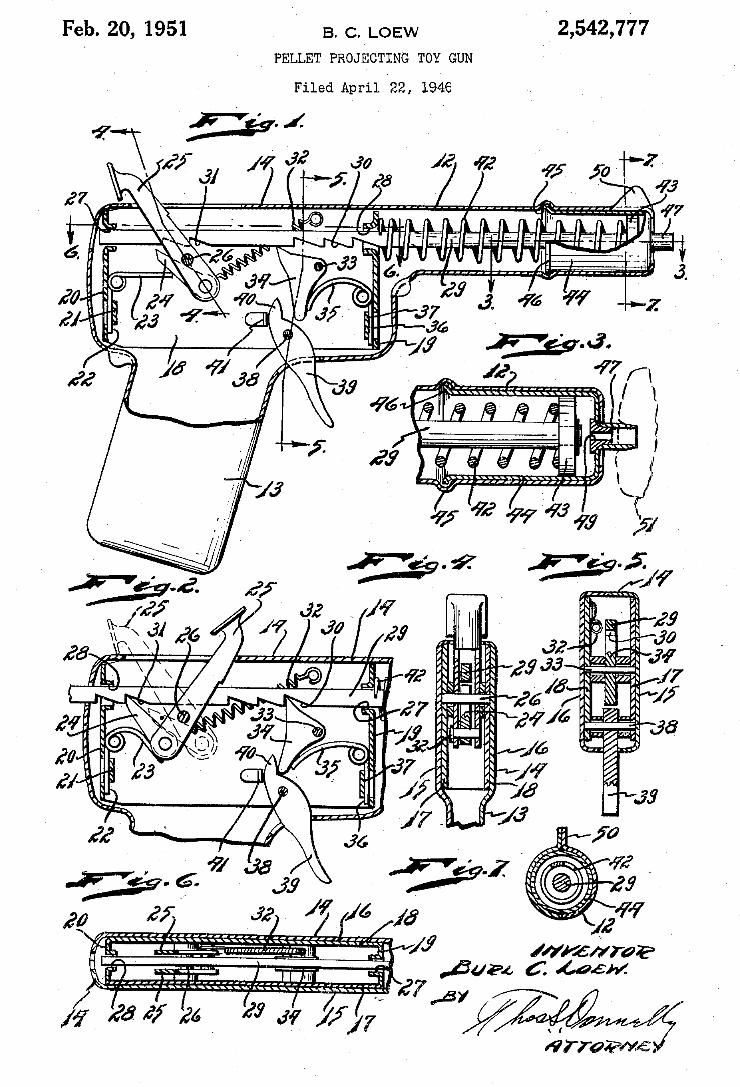
2,542,777 Feb. 20, 1951 B. C. LOEW ` _ PELLET PROJECTING TOY GUN
Filed April l22, 194e
/
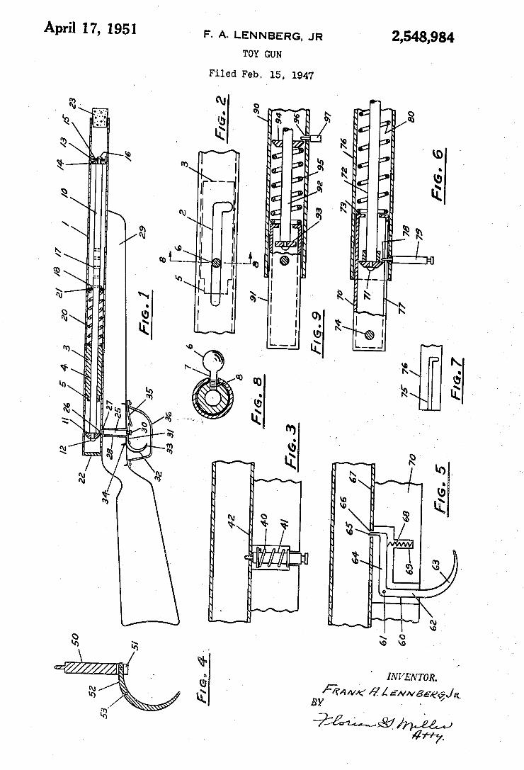
2,548,984 April 17, 1951 F. A. LENNBERG, JR
TOY GUN
Filed Feb. 15, 1947
n .Sm
w». wir
a@ Il( III Ilil. || I I
Wk lnk
ÍNVENTOR. Ffm/w( @Á
BY
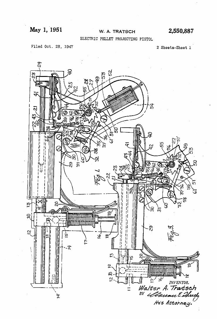
2,550,887 May l, 1951 w. A. TRATSCH
ELECTRIC PELLET PRoJEcTTNG PIsToL
2 Sheets-Sheet l Filed OC‘b. 28, 1947
wm mm mv , um .uw mm Nv
INVENTOR.
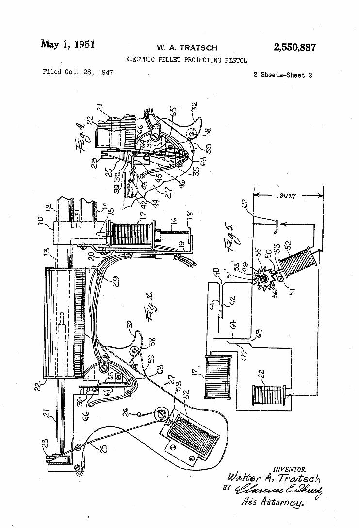
2,550,887 May H, i953 W. A. TRATscH ELECTRIC PELLET PRoJEcTING PIsToL
2 Sheets-Sheet 2 Filed Oct. 28, 1947
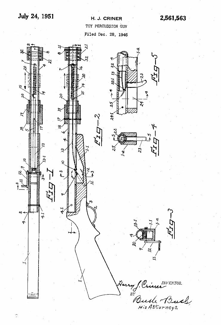
2,561,563 July 24, 1951 H. J. cRlNER
TOY PERCUSSION GUN
,Filed Dec. 28, 1946
/
ä 2 E@ *Al ww 2è
n
paw! INVENTOR. ` Y
M f7@ Hfs /Ífíîorneyóï
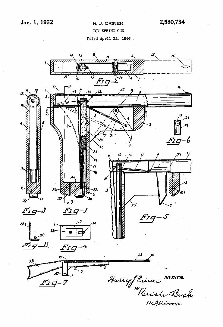
2,580,734 Jan- 1, 1952 H. J. CRINER TOY SPRING GUN
Filed April 22, 1946 .
_ _ a m A
V? ‘ ~ - > LVVENTOR.
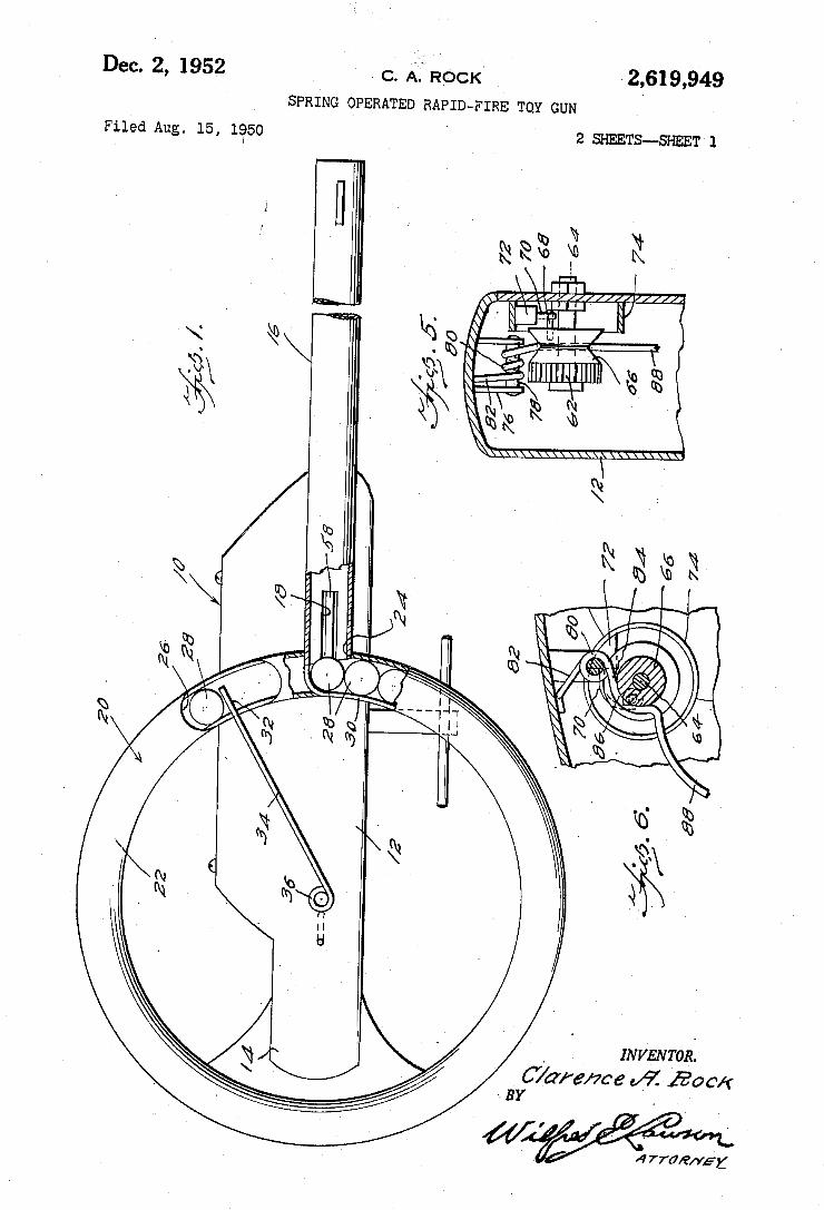
2,619,949 Dec. 2, 1952 c‘ A’ ROCK‘
SPRING OPERATED RAPID -FIRE TOY GUN . '
2 SHEETS-SHEET 1 I Filed Aug. 15, 1950
‘ INVENTOR;
Ware/me v9.’ 120 -- BY .
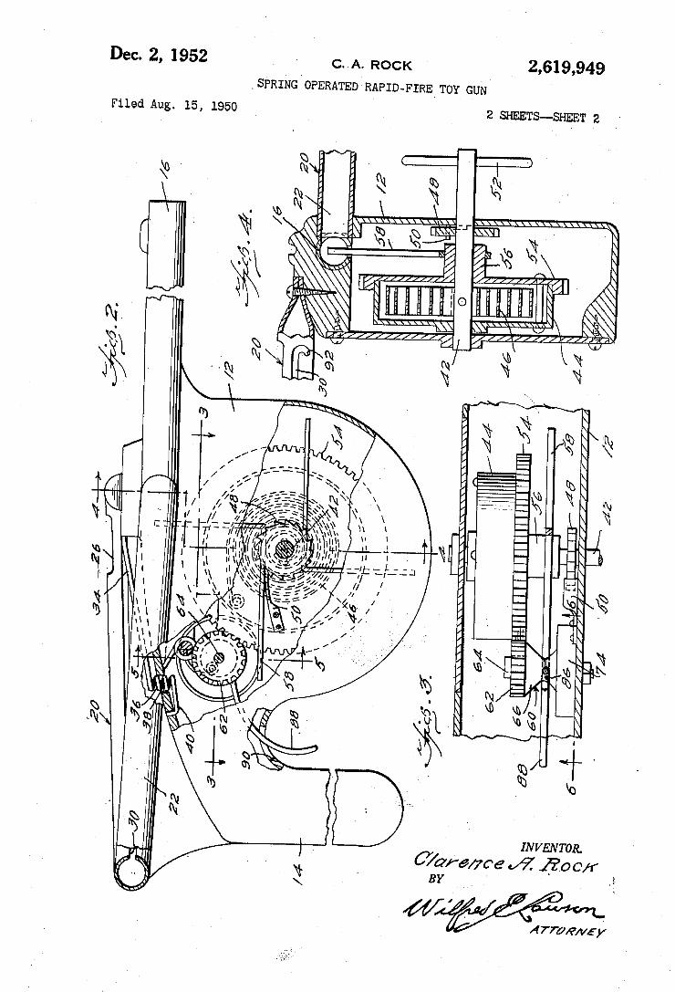
2,619,949 Dec. 2, 1952 c. A. ROCK
‘SPRING OPERATED RAPID-FIRE_ TOY GUN
2 SHEETS~SHEET 2 Filed Aug. 15, 1950
‘i. INVENTOR.
CY/aramre M7 220 OK BY
f// /
Arman/5y
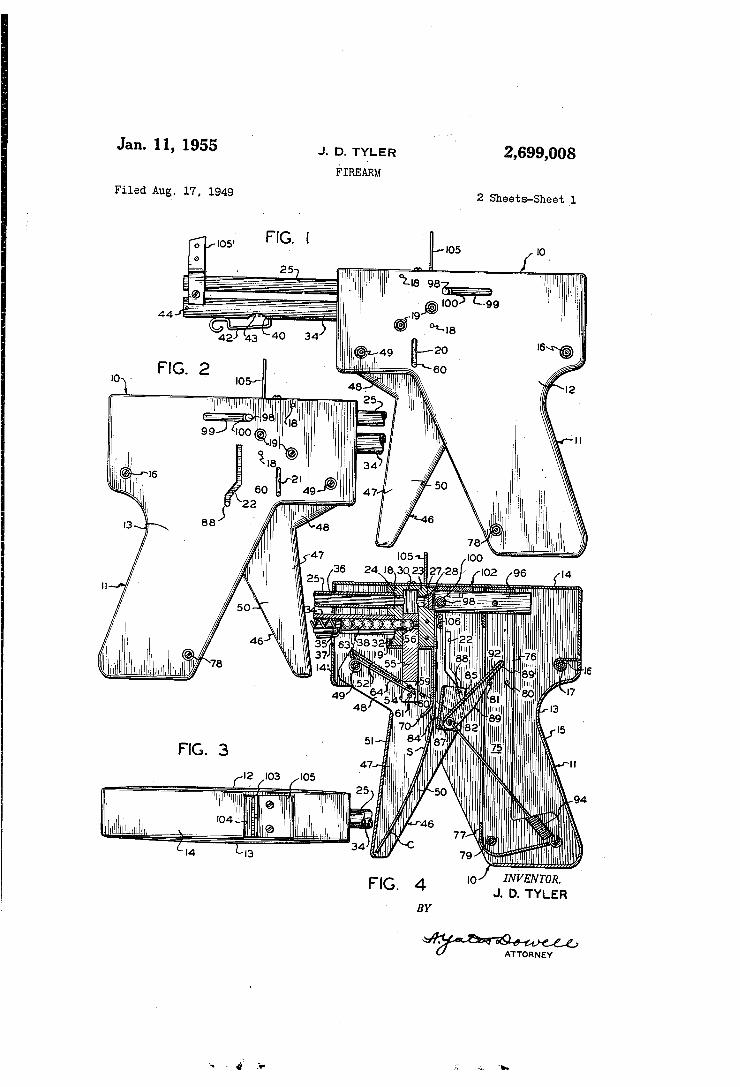
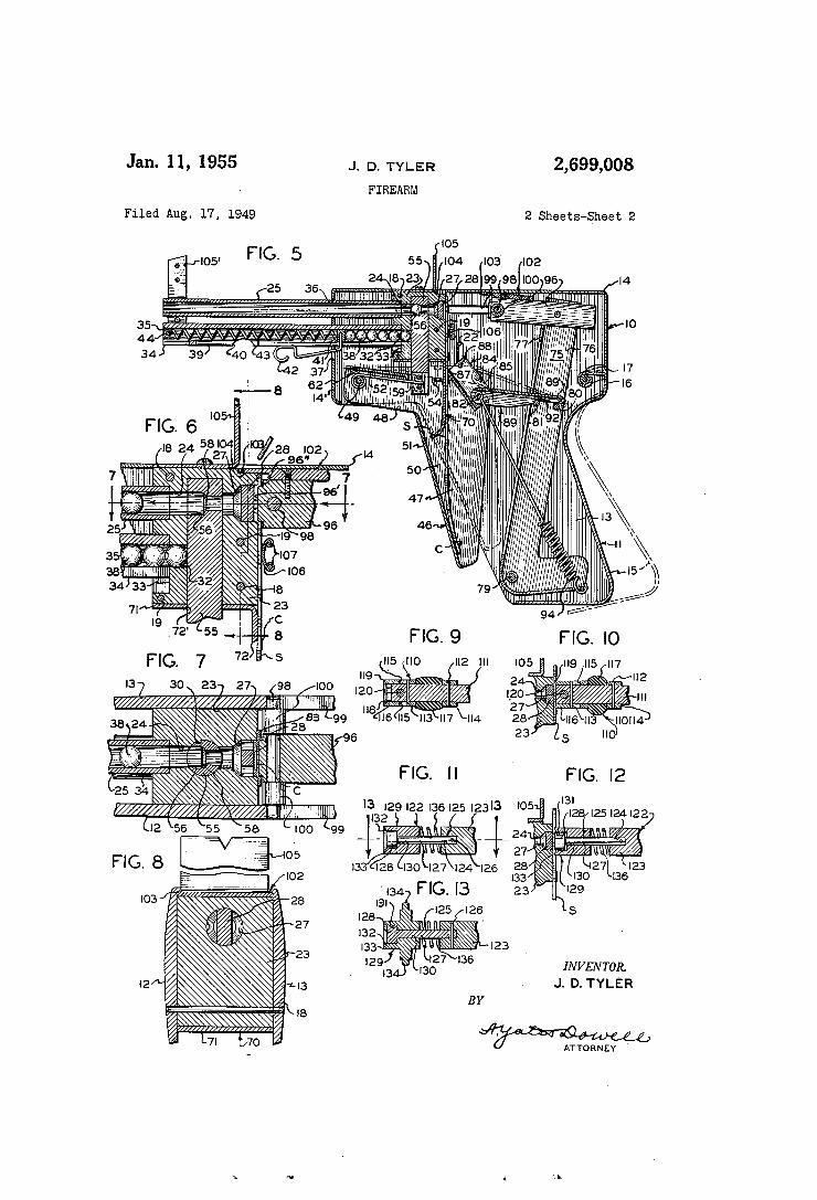
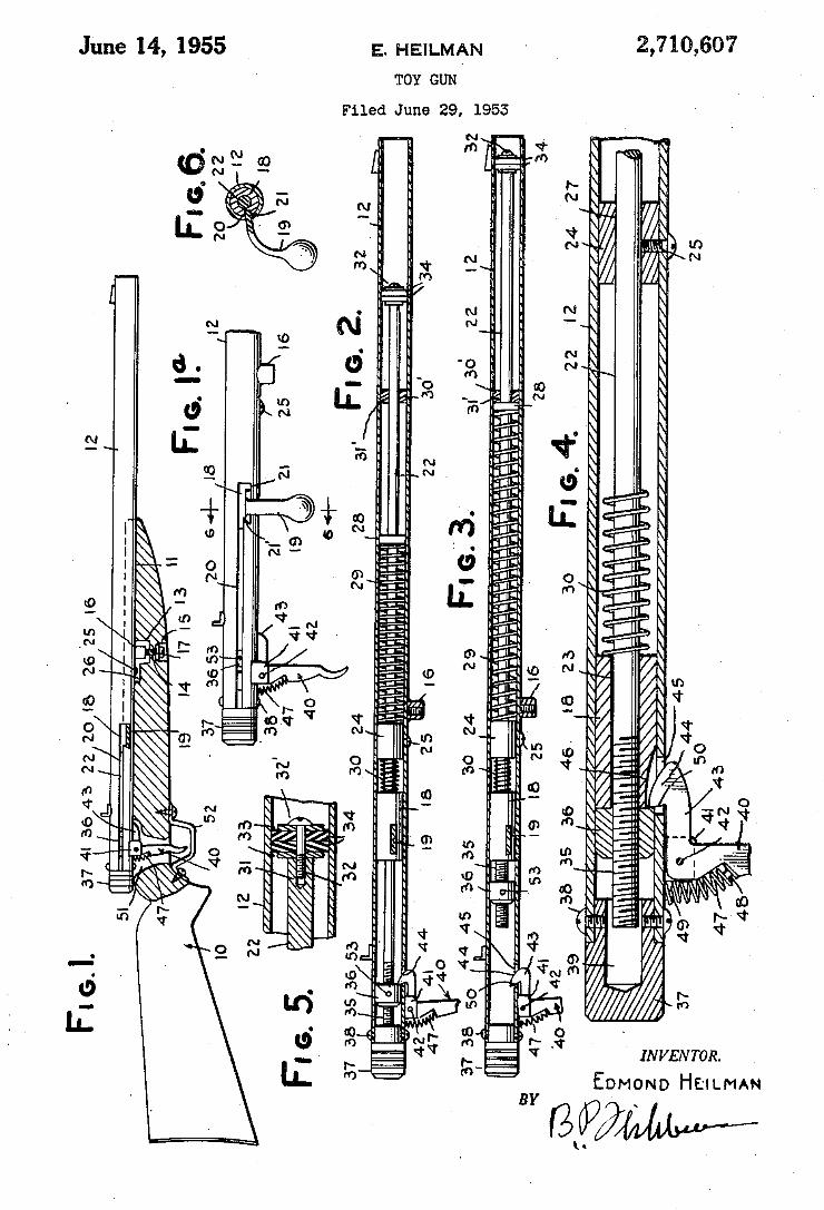
2,710,607 E. HEILMAN June 14, 1955 TOY GUN
Filed June 29, 1953
.aN/Awww .Wr âîl
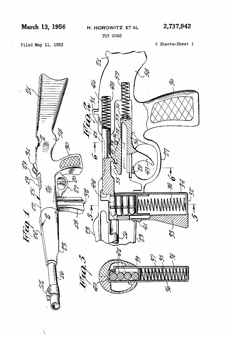
March 13, 1956 H. HOROWITZ ETAL 2,737,942 TOY GUNS
2 Sheets-Sheet 1 Filed May 11, 1955
\N.
k.“ \W MM iwwnmuwgg wax \ MAM ‘
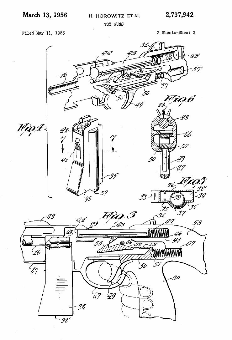
2,737,942
2 Sheets-Sheet 2
Ill’; &
March 13, 1956- H. HOROWITZ ET AL TOY GUNS
Filed May 11, 1953
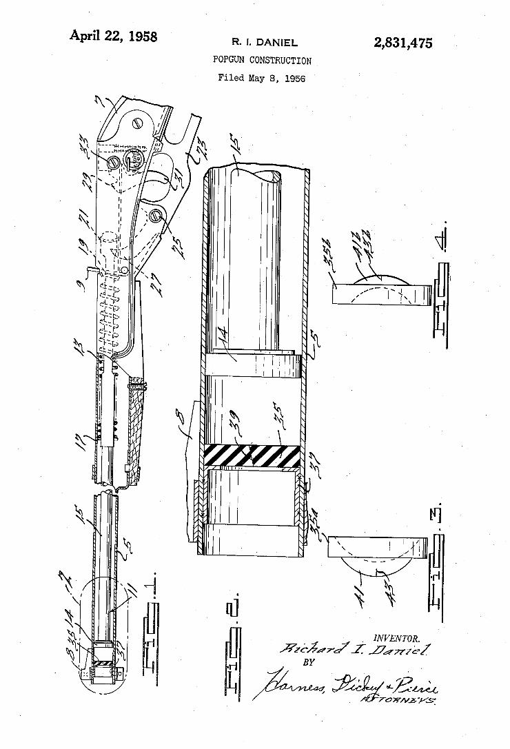
2,831,475 April 22, 1958 R. 1. DANIEL
POPGUN CONSTRUCTION
Filed May 8, 1956
/ '7 \
** lei/:44, FAIL 71/5:
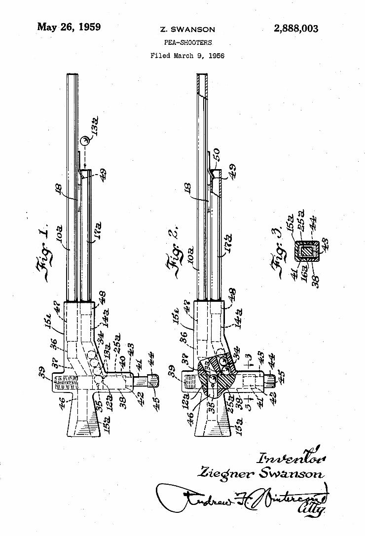
2,888,003 Z. SWANSON May 26, 1959 PEA-SHOOTERS
Filed March 9, 1956
Ziegner Swanson
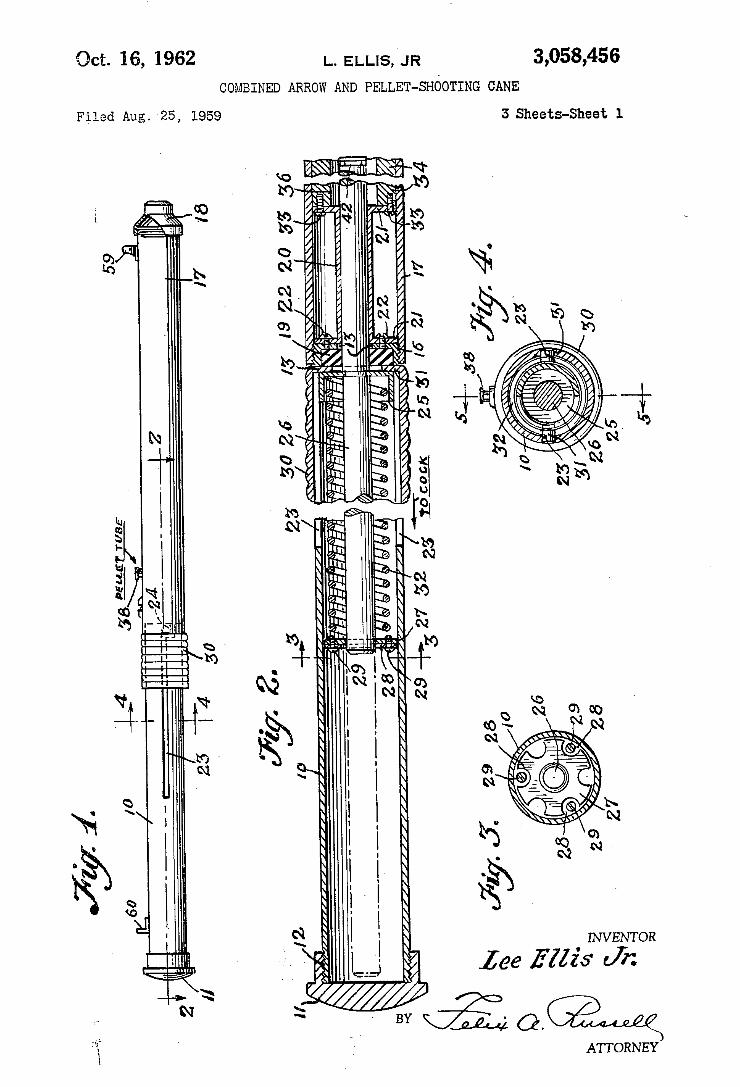
3,058,456 Oct. 16, 1962 |_. ELLIS, JR COMBINED ARROW AND PELLET-SHCOTING CANE
3 Sheets-Sheet 1 Filed Aug. 25, 1959
L Mush hwswa ! Qua MN M Q I» Wm R/i
mu
INVENTOR
lee Ellis Jr.
BY “214.42
ATTORNEY
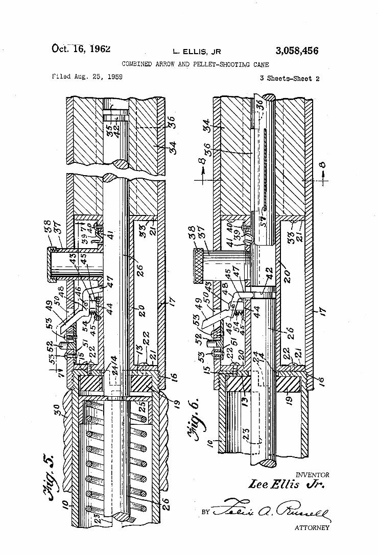
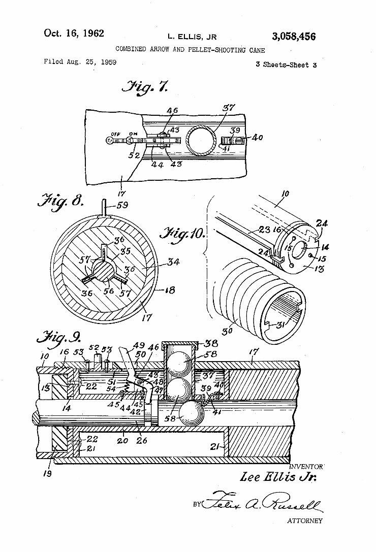
’ . 421 E8 @_.4,__‘ _I_ __
Oct. 16, 1962 L. ELLIS, JR 3,058,456 COMBINED ARROW AND PELLET-SHOOTING CANE
Filed Aug. 25, 1959 3 Sheets-Sheet 3
4,6 $7
7 59 OFF 0" — , .
@ImIuIElIlllll-H I ' -_ ‘1L _’
l n . 1'7
15$; {berg/5 " if? ‘5914M '////// /, A544 45 L
@212 Z» .916 I //////////é( '\\ \\\\\\\\\\\\\\\\\\\\\\\\\\\\\\\\\§\ \\\\\\\\\ NVENTOR.
'9 lee E'ZZz's Jr:
“a?” QQMQ ATTORNEY
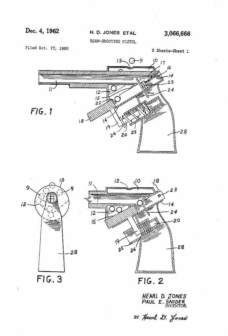
3,066,666
2 SheStS-Sheet l
„
l” /4
28
H. D. JONES ETAL
BEAN-SHOOTING PISTOL
2
Dec. 4, 1962
Filed oct. 17, 1960
FIG. 2
HEÀRL D. JONES PAUL E- was@
BY M QB’. ym@
FIG.3
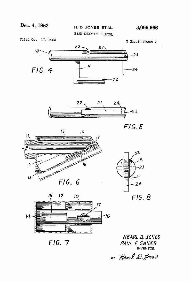
Dec. 4, 1962 H, D, JoNEs ETAL 3,066,666 BEAN-SHOOTING PISTOL
Filed Oct. 17, 1960 2 Sheets-Sheet 2
HEARL n. .ToNfs F l G. .7 PAUL f. smog/2
INVENTOR.
BY Mag/mw
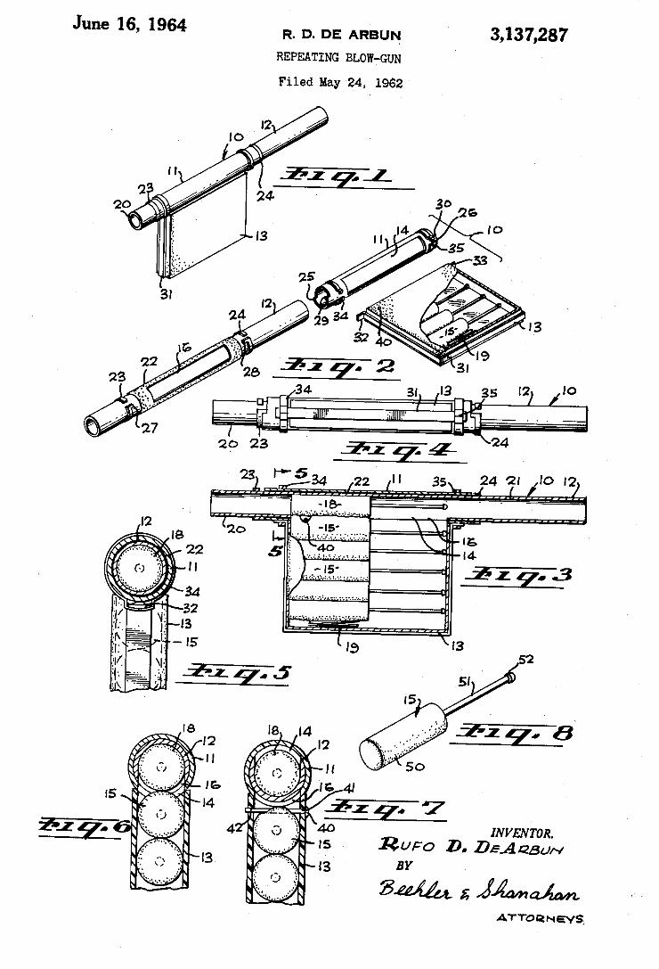
3,137,287 June '16, 1964 R. 0. DE AR'BUN REPEATING BLOW-GUN
Filed May 24, 1962
2p 23
INVENTOR. RuFo D. DEA 25u~
ATTORNEYS
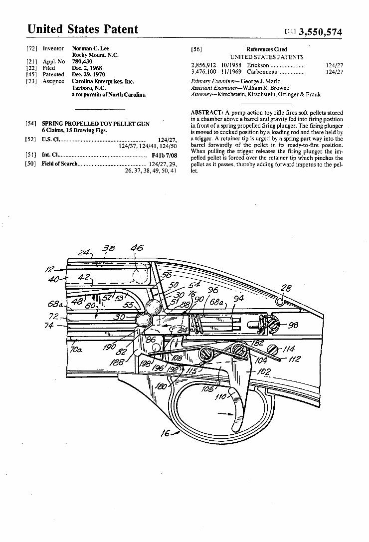
United States Patent [111 3,550,574
172]
[21 l 122] [45] [731
[54]
{52]
[51] [50]
lnventor Norman C. Lee Rocky Mount, N.C.
Appl. No. 780,430 Filed Dec. 2, 1968 Patented Dec. 29, 1970 Assignee Carolina Enterprises, Inc.
Tarboro, N.C. a corporatin of North Carolina
SPRING PROPELLED TOY PELIIJET GUN 6 Claims, 15 Drawing Figs. [1.8. CI ...................................................... .. 124/27,
124/37, 124/41, 124/50 Int. Cl ....................................................... .. F41b 7/08
Field of Search .......................................... .. 124/27, 29,
26,37, 38, 49, 50,41
[56] References Cited UNITED STATES PATENTS
2,856,912 10/1958 Erickson .................... .. 124/27 3,476,100 1 H1969 Carbonneau ............... .. 124/27
Primary Examiner-George J. Marlo Assistant Examiner—-William R. Browne Attorney-Kirschstein, Kirschstein, Ottinger & Frank
ABSTRACT: A pump action toy ri?e ?res soft pellets stored in a chamber above a barrel and gravity fed into ?ring position in front of a spring propelled ?ring plunger. The ?ring plunger is moved to cocked position by a loading rod and there held by a trigger. A retainer tip is urged by a spring part way into the barrel forwardly of the pellet in its ready-to-?re position. When pulling the trigger releases the ?ring plunger the im~ pelled pellet is forced over the retainer tip which pinches the pellet as it passes, thereby adding forward impetus to the pel let.
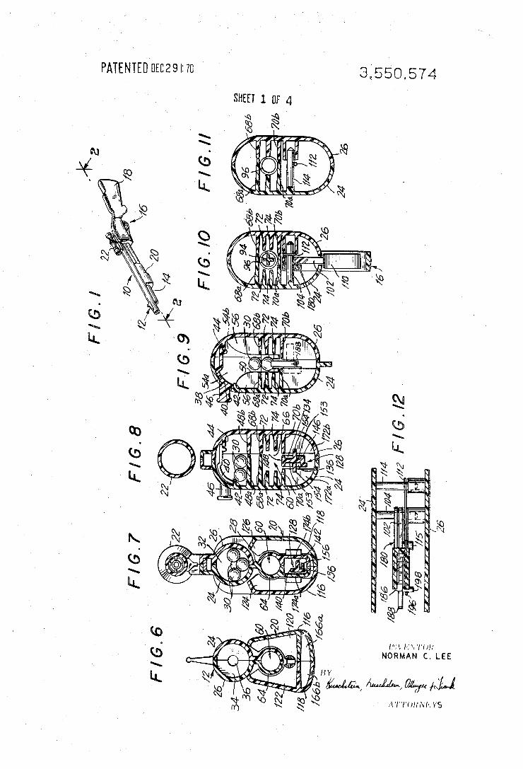
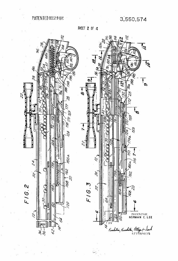
PATENTEUUECZQISYU 3550.574 sum 2 0F 4
_ S1 cm m
mm.‘ % Wm .
Q\\ IM _ @R mm N5 mm\ 3%! ®\ \sww wmw ‘ / Maw ., N
\\ NQ N . km“ \N
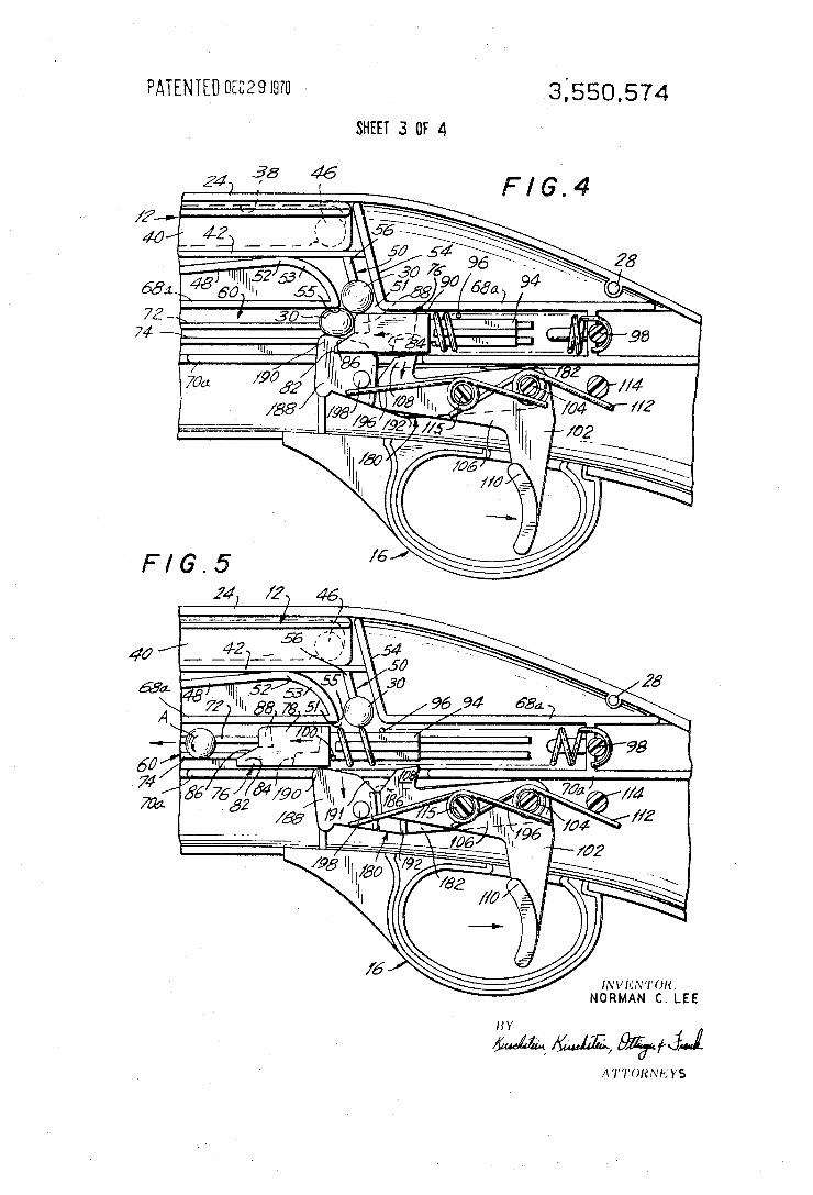
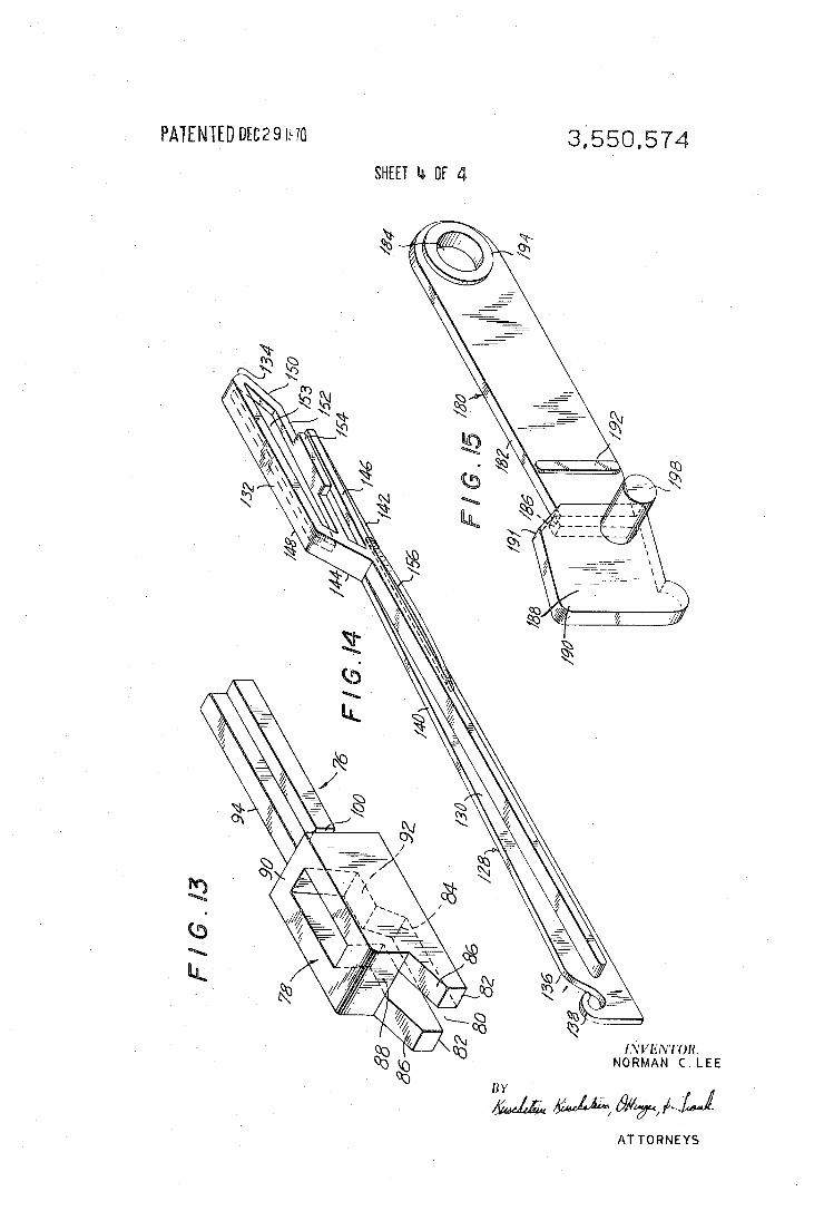
3550.574 PATENLED 0mm SHEET lb [1F d
NORMAN C. LEE
ATTORNEYS
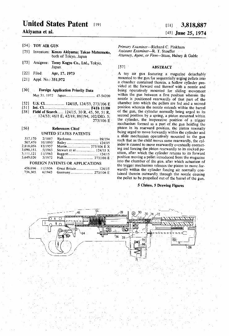
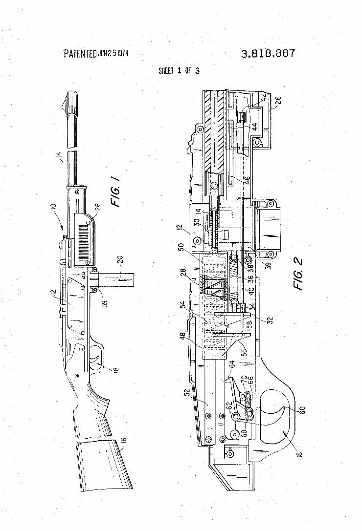
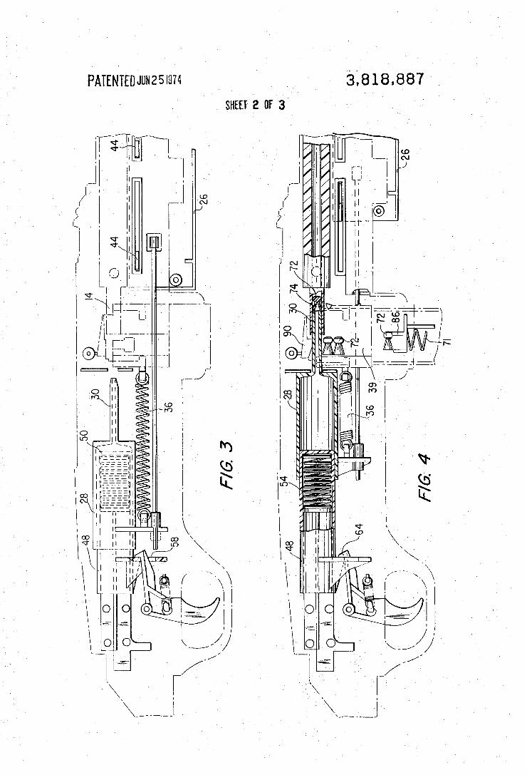
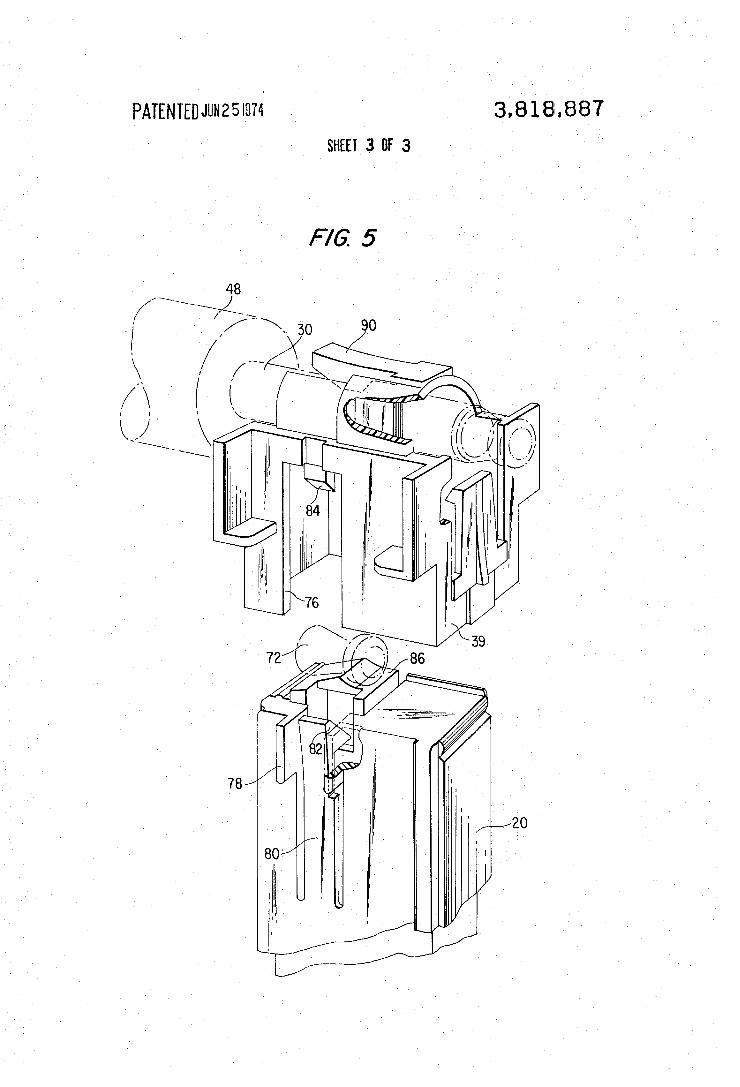
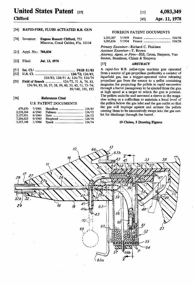
United States Patent [19] Clifford
[11] 4,083,349 [45] Apr. 11, 1978
[54] RAPID-FIRE, FLUID ACI'UATED B.B. GUN
[76] Inventor: Eugene Russett Clifford, 753 Minorca, Coral Gables, Fla. 33134
[21] Appl. No.: 704,836
[22] Filed: Jul. 13, 1976
[51] Int. Cl.2 . . . . . . . . . . . . . . . . . . . .. F41B 11/02
[52] US. Cl. ...................................... .. 124/72; 124/45; 124/83; 124/51 A; 124/71; 124/74
[58] Field of Search ................. .. 124/72, 51 A, 74, 83, 124/84, 85, 56, 57, 58, 59, 60, 53,45, 71, 73-74;
89/160, 191, 193
[56] References Cited U.S. PATENT DOCUMENTS
679,670 7/ 1901 Hamilton ............................. .. 124/85 2,238,384 4/1941 Feltman ........... .. 124/72 2,357,951 9/1944 Hale . . . . . . . . . . . . . . . . . .. 124/72
3,204,625 9/1965 Shepherd .. 124/74 3,227,148 1/ 1966 Spack ................................... .. 124/74
FOREIGN PATENT DOCUMENTS
1,203,207 7/1959 France .... ..' ........................... .. 124/56
1,085,636 7/1954 France ................................. .. 124/56
Primary Examiner—Richard C. Pinkham Assistant Examiner—T. Brown Attorney, Agent, or Firm-Hill, Gross, Simpson, Van Santen, Steadman, Chiara & Simpson
[57] ABSTRACT A rapid-?re B.B. pellet-type machine gun operated from a source of gas propellant preferably a canister of lique?eld gas, has a trigger-operated valve releasing propellant gas from the source to a pellet containing magazine for projecting the pellets in rapid succession through a barrel passageway to be ejected from the gun at high speed at a target to which the gun is pointed. The pellets underlie and surround a sleeve in the maga zine acting as a cofferdam to maintain a local level of the pellets below the gas inlet and the gas outlet so that the gas will impinge against and actuate the pellets causing them to be successively swept into the gas out let for discharge through the barrel.
19 Claims, 5 Drawing Figures
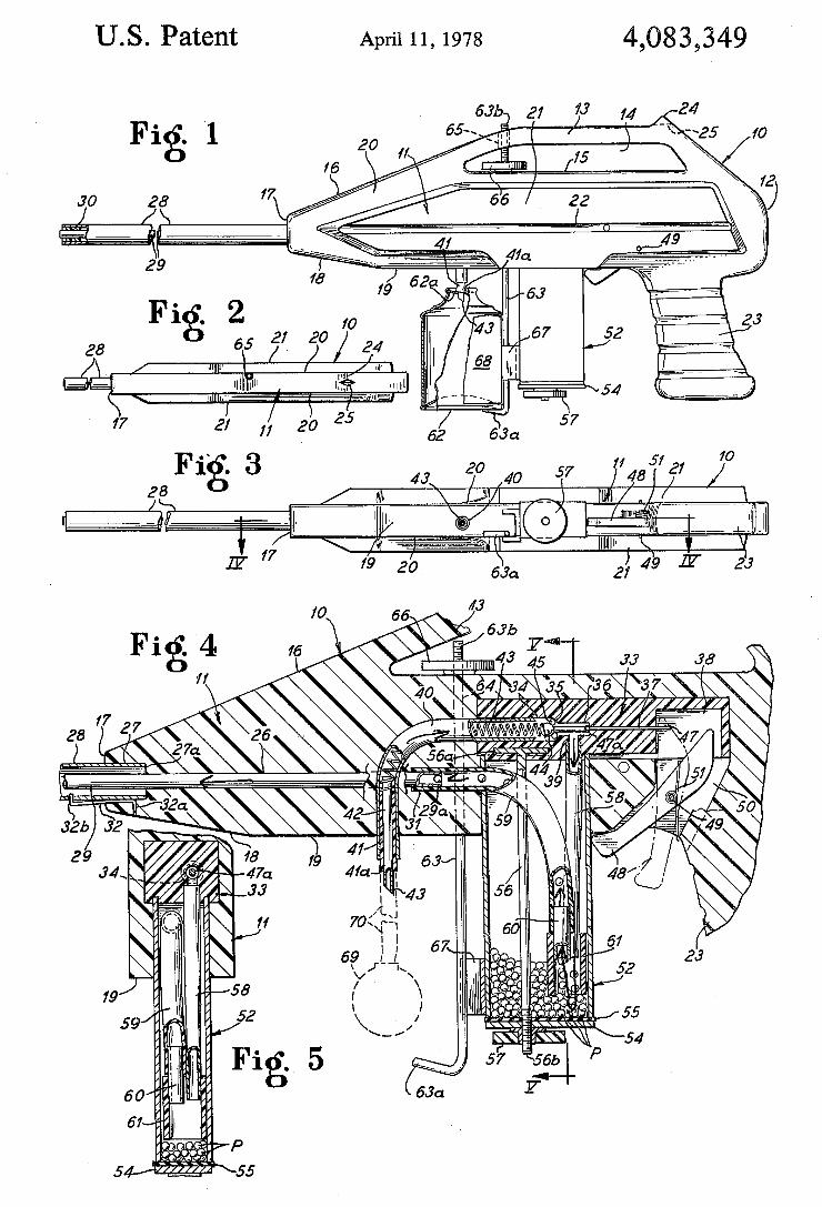
US. Patent April 11, 1978 4,083,349
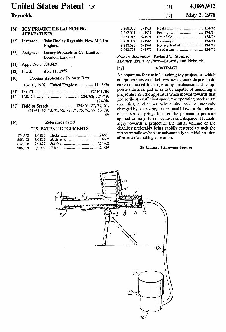
Unlted States Patent [191 [111 4,086,902 Reynolds [45] May 2, 1978
[54] TOY PROJECI‘ILE LAUNCHING 1,260,013 3/1918 Neats .................................... .. 124/65 APPARATUSES 1,262,004 4/1918 Beachy ..... .. 124/65
1,673,945 6/1928 Llttle?eld 124/26 [75] Inventon John Dudley Reynolds, New Malden, 3,219,022 11/1965 Hagemeyer ....... .. 124/61
England 3,388,696 6/1968 Hoverath et a1. 124/62 [73] Assigneez Lesney Products & Co‘ Limited’ 3,662,729 5/1972 Henderson ........................... .. 124/73
London, England Primary Examiner-Richard T. Stouffer [21] Appl NO _ 786 619 Attorney, Agent, or Firm-Browdy and Neimark
. .. ,
[22] Filed: Apr. 11, 1977 [57] ABSTRACT ' _ _ _ _ An apparatus for use in launching toy projectiles which
[30] Forelgn Applicant,“ Pnonty Data comprises a piston or bellows having one side pneumati Apr. 13, 1976 United Kingdom ............. .. 15148/76 cally connected to an operating mechanism and its op
[51] Int. c1.2 .............................................. .. F41F 1/04 Pm.“ side arranged 8° as t° be capable °f launching a [52] US. Cl. ...................................... .. 124/61; 124/49 Pmlectile {mm the apparatus when “med ‘Wards that
124%‘; projectile at a sufficient speed, the operating mechanism [58] Field Of Search ..................... .. 124/26, 27, 29, 61, exhibiting a chamber WhOSe Size can be Suddenly
124/64’ 65’ 70’ 71’ 72, 73, 74’ 75, 76, 77’ 50’ 79’ changed by squeezing, or a manual blow, or the release 49 of a stressed Spring, to alter the pneumatic pressure
_ applied to the piston or bellows and displace it launch [56] References C'ted ingly towards a projectile, the initial volume of the
US. PATENT DOCUMENTS chamber preferably being rapidly restored to suck the 174 628 3/1876 Hicks ................................... .. 124/61 Piston or bellows back t° Substantially its initial Position 565:423 8/1896 Beck et a1. . 124/62 after each launching Operation 632,838 9/1899 Jacobs ...... .. 124/62 706,399 8/1902 Fifer ..................................... .. 124/29 15 Claims, 4 Drawing Figures
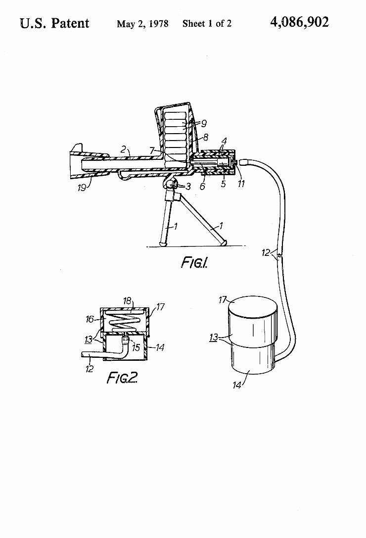
US. Patent May 2, 1978 Sheet 1 of2 4,086,902
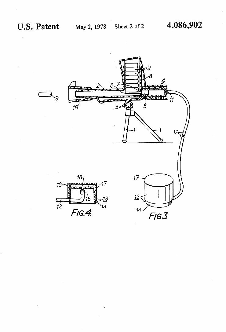
U.S. Patent May 2, 1978 Sheet 2 of2 4,086,902
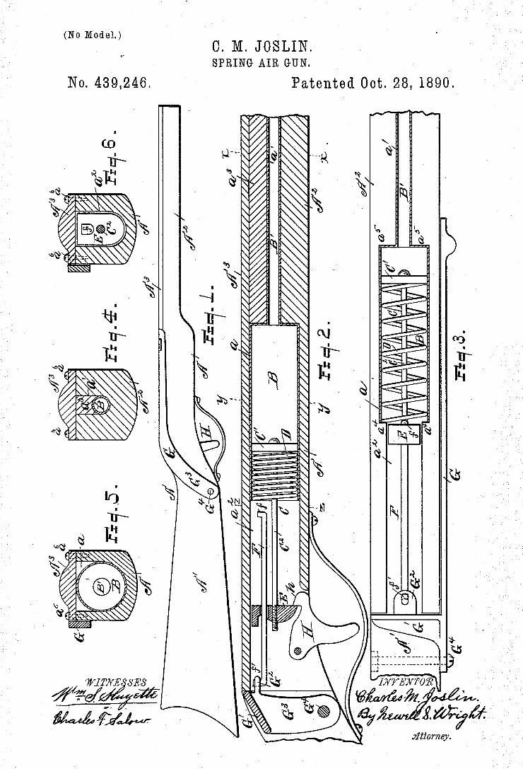
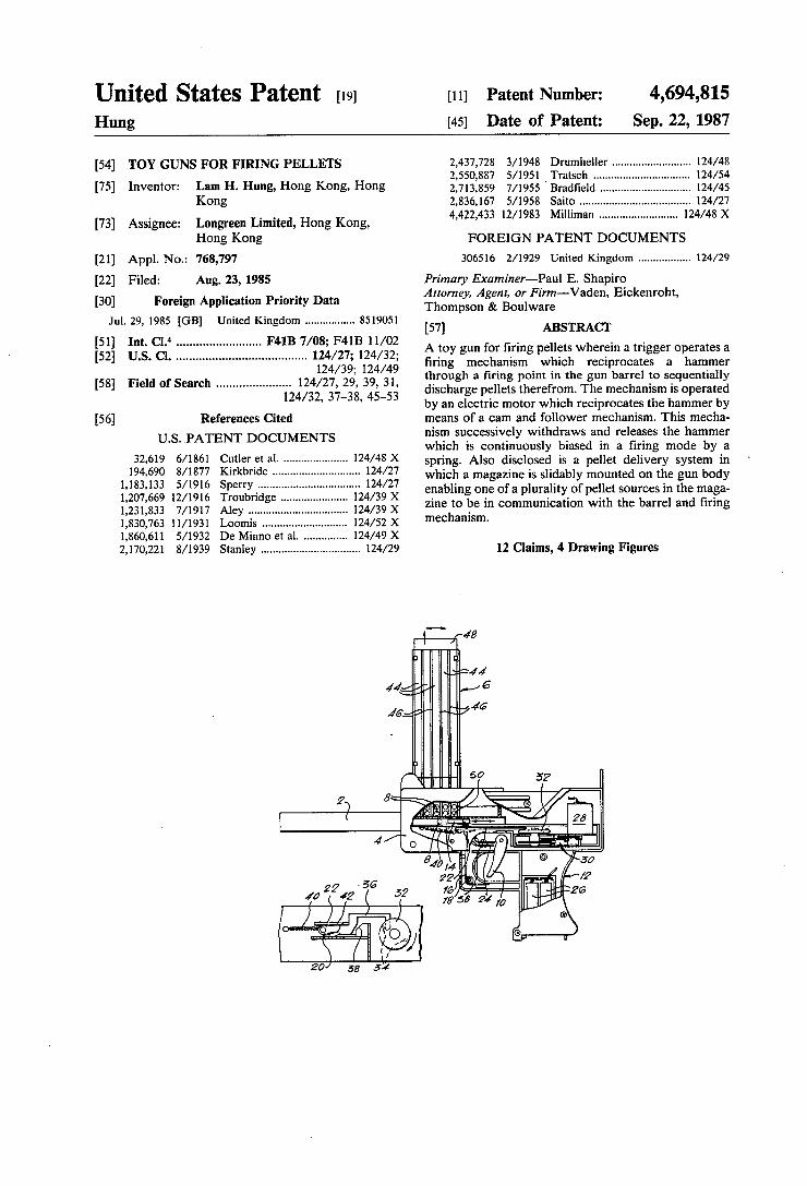
United States Patent [19] [11] Patent Number: 4,694,815 Hung [45] Date of Patent: Sep. 22, 1987
[54] TOY GUNS FOR FIRING PELLETS 2,437,728 3/1948 Drumlllleller ......................... .. 124/48 2,550,887 5/1951 'Tratsc ..... .. 124/54
[75] lnvenw? Lam H- Hung, Hong Kong, Hong 2,713,859 7/1955 Brad?eld 124/45 Kong 2,836,167 5/1958 Saito ..... .. 124/27
[73] Assigneei Longreen Limited, Hong Kong’ 4,422,433 12/1983 Mllllman ......................... .. 124/48 x
Hong Kong FOREIGN PATENT DOCUMENTS
[21] Appl. NO.: 768,797 306516 2/1929 United Kingdom ................ .. 124/29
[22] Filed: Aug. 23, 1985 Primary Examiner—-Paul E. Shapiro
[30] Foreign Application Priority Data 35:51:01’, 5 g’r’g‘vaden' Ewkenmh" Jul. 29, 1985 [GB] United Kingdom ............... .. 8519051 [57] ABSTRACT
4 o """""""""""" " F4113 A toy gun for ?ring pellets wherein a trigger operates a
. . . ...................................... .. 124/36. 124/49, ?ring mechanism which reciprocates a hammer
[58] Field of Search 124/27 29’ 39 31 through a ?ring point in the gun barrel ‘to sequentially """""""""" 4/32 3’7_3é 4543; discharge pellets therefrom. The mechanism is operated
’ ’ by an electric motor which reciprocates the hammer by [56] References Cited means of a cam and follower mechanism. This mecha
U S PATENT DOCUMENTS nism successively withdraws and releases the hammer ' " which is continuously biased in a firing mode by a
32,619 6/1361 CPU“ F1 31- - 124/48 X spring. Also disclosed is a pellet delivery system in 194,690 8/1877 Klrkbnde - - ' ' ' ~ ~ - ' " :2:/ which a magazine is slidably mounted on the gun body
ipetlrgrig'é ' ' ' ' ' ‘ 433; X enabling one of a plurality of pellet sources in the maga
1’23l’833 7/1917 Aggy l24/39 X zine to be in communication with the barrel and ?ring 1,830,763 11/1931 Loomis ........... .. 124/52 x mechamsm
1,860,611 5/1932 De Minno et al. 124/49 X 2,170,221 8/1939 Stanley ................................ .. 124/29 12 Claims, 4 Drawing Figures
17-’ 4B
\ J 46;: a ’ ~ I 746
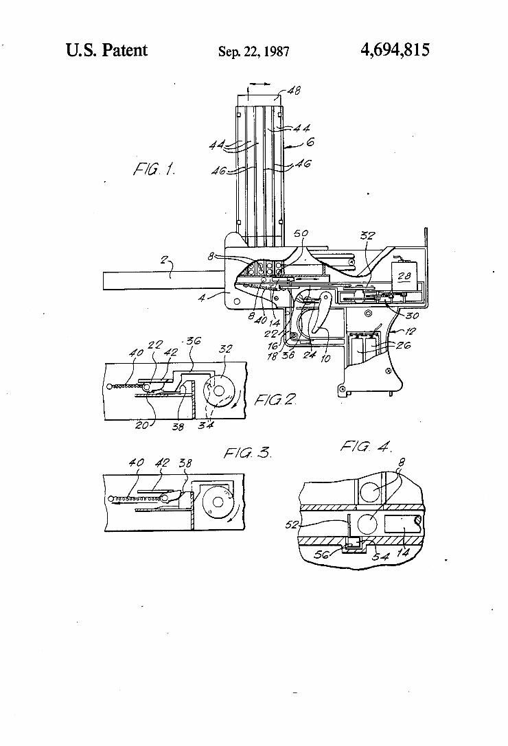
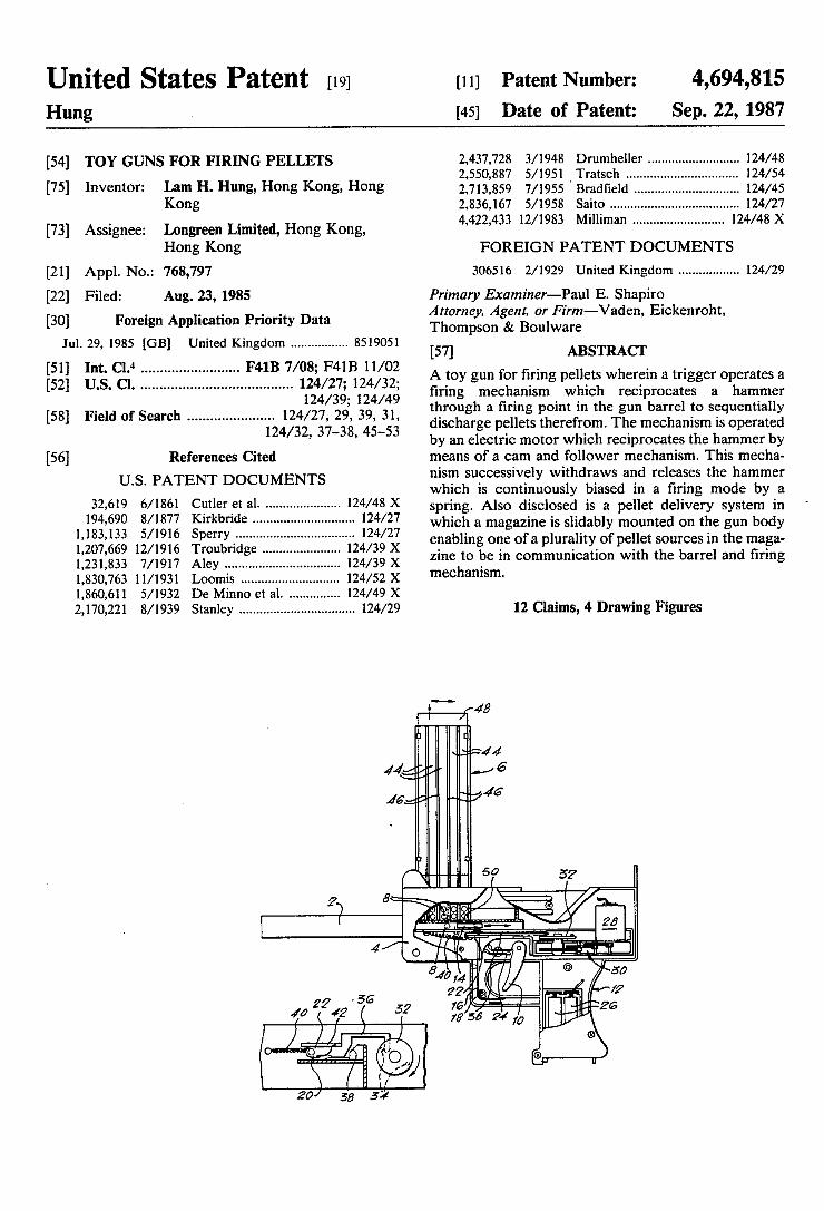
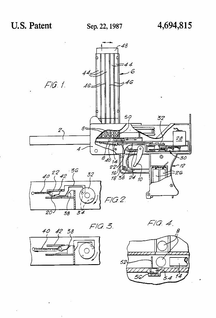
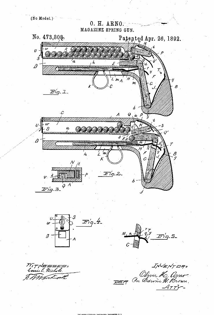
(No Mode1.)" 0.V H. ARNO;
MAGAZINE SPRING GUN.
No. 473,30@1
J Q 'Gv A A f
lill/’Ill1111111111111111.11”rl’rxllrllllllu".'n ,
@@@IL @@lll
(m e ///////¿///////////
@L a
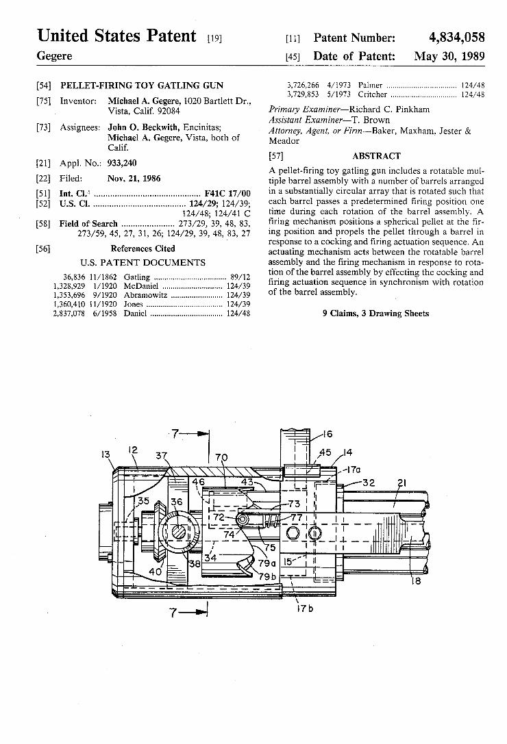
United States Patent [19] [11] Patent Number: 4,834,058 Gegere [45] Date of Patent: May 30, 1989
[54] PELLET-FIRING TOY GATLING GUN 3,726,266 4/1973 Palmer ................................ .. 124/48 _ 3,729,853 5/1973 Critcher .............................. .. 124/48
[75] Inventor: Michael A. Gegere, 1020 Bartlett Dr., . Vistay calm 92034 Primary Examiner—R1chard C. Pinkham
' _ _ , Assistant Examiner—T. Brown
[731 Asslgnees‘ John 0' Beckw‘th’ EnPmltas; Attorney, Agent, or Firm—Baker, Maxham, Jester & Michael A. Gegere, Vlsta, both of Meador Calif.
[57] ABSTRACT [21] Appl. No.: 933,240 , _ _
_ A pellet-?rlng toy gatlmg gun includes a rotatable mul [22l Flledi NOV- 21, 1986 tiple barrel assembly with a number of barrels arranged [51] Int. C19‘ ............................................ .. F41C 17/00 in a Substantially Circular array [hat is [mated $11911 that [52] us. 01. ...................................... .. 124/29; 124/39; each bwel Passes a Pfédetermmed ?ung Posmon one
124/48; 124/41 C tlme during each rotation of the ‘barrel assembly, A [58] Field of‘ Search ..................... .. 273/29, 39, 48, 83, ?rmg mechamsm Posmons a spherlcal pellet at the ?r
273/59’ 45’ 27, 31, 26; 124/29, 39, 43, 83, 27 ing position and propels the pellet through a barrel in _ response to a cooking and ?ring actuation sequence. An
[56] References C‘ted actuating mechanism acts between the rotatable barrel U.S. PATENT DOCUMENTS
36,836 11/1862 Gatling ................................. .. 89/12
1,328,929 1/1920 McDaniel ........ .. 124/39
1,353,696 9/1920 Abramowitz .... .. 124/39
1,360,410 ll/l920 Jones ............ .. 124/39
2,837,078 6/1958 Daniel ................................. .. 124/48
assembly and the ?ring mechanism in response to rota tion of the barrel assembly by effecting the cocking and ?ring actuation sequence in synchronism with rotation of the barrel assembly.
9 Claims, 3 Drawing Sheets
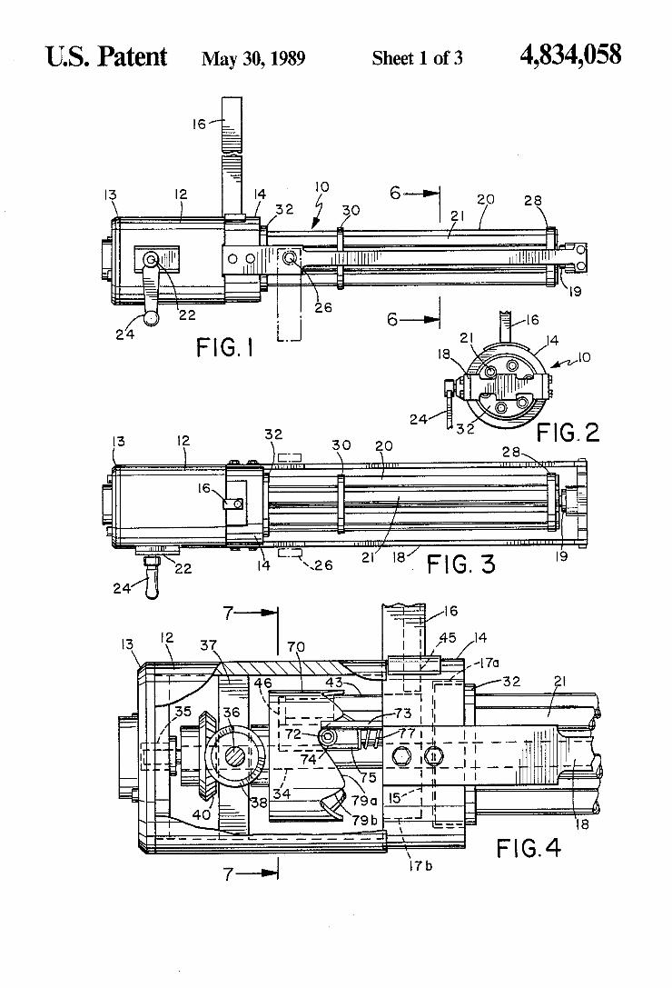
US. Patent May 30,1989 Sheet 1 of3 4,834,058
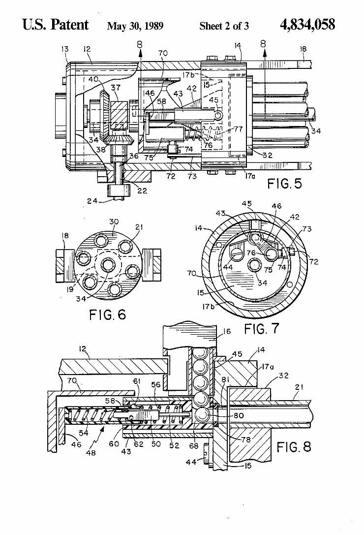
US. Patent May 30,1989 Sheet 2 of3 4,834,058
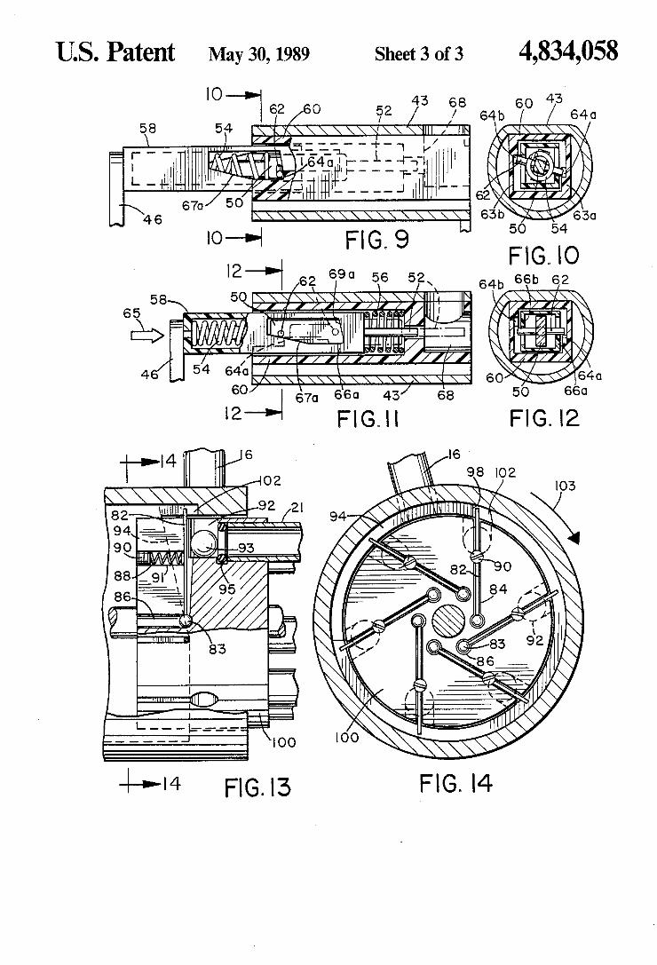
US. Patent May 30,1989 Sheet 3 of3 4,834,058
K '2 D 690 56 5 x
FIG. l3
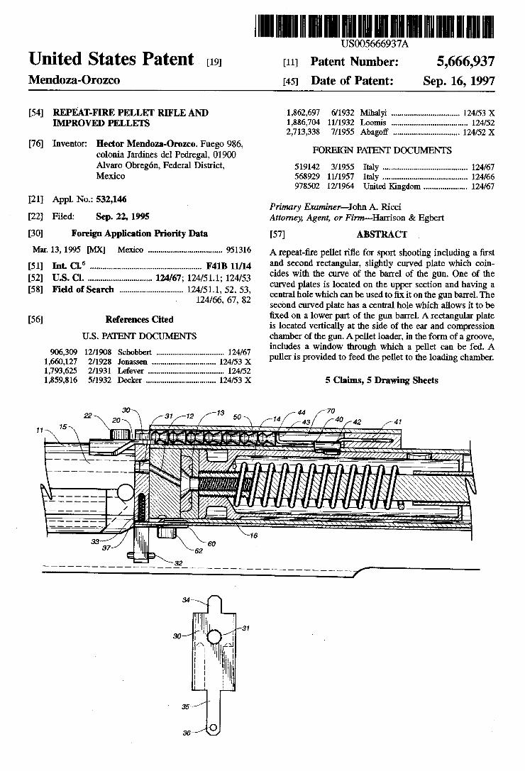
United States Patent 1191 Mendoza-Orozco
US005666937A
[54] REPEAT-FIRE PELLET RIFLE AND IMPROVED PELLETS
[76] Inventor: Hector Mendoza-Orozco, Fuego 986, colonia Jardines del Pedregal, 01900 Alvaro Obregon, Federal District, Mexico
[21] Appl. No.: 532,146
[22] Filed: Sep. 22, 1995
[30] Foreign Application Priority Data
Mar. 13, 1995 [MX] Mexico .................................. .. 951316
[51] Int. Cl.6 .................................................... .. F41B 11/14
[52] US. Cl. ............................. .. 124/67; 124/51.1; 124/53 [58] Field of Search ............................. .. 124/51.1, 52, 53,
124/66, 67, 82
[56] References Cited
U.S. PATENT DOCUMENTS
906,309 12/1908 Schobbert ............................... .. 124/67
1,660,127 2/1928 Jonassen 124/53 X 1,793,625 2/1931 Lafever ...... .. 124/52
1,859,816 5/1932 Decker ................................ .. 124/53 X
[11] Patent Number: 5,666,937 [45] Date of Patent: Sep. 16, 1997
1,862,697 6/1932 Mihalyi ............................... ..124/s3x 1,886,704 11/1932 Loomis .. 124/52 2,713,338 7/1955 Abagotf .............................. ..124/s2x
FOREIGN PATENT DOCUMENTS
519142 3/1955 Italy ....................................... .. 124/67
568929 11/1957 Italy .. ..
978502 1211964 United Kingdom . . . . . . . . . . . .. 124/67
Primary Examiner-John A. Ricci Attorney Agent, or Fimt-Han‘ison & Egbert
[57] ABSTRACT
A repeat-?re pellet ri?e for sport shooting including a ?rst and second rectangular, slightly curved plate which coin cides with the curve of the barrel of the gun. One of the curved plates is located on the upper section and having a central hole which can be used to ?x it on the gun barrel. The second curved plate has a central hole which allows it to be ?xed on a lower part of the gun barrel. A rectangular plate is located vertically at the side of the ear and compression chamber of the gun. A pellet loader, in the form of a groove, includes a window through which a pellet can be fed. A puller is provided to feed the pellet to the loading chamber.
5 Claims, 5 Drawing Sheets
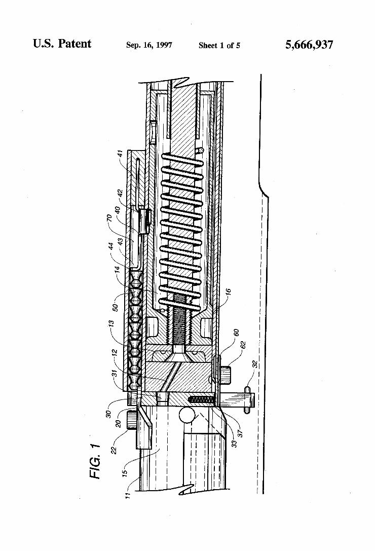
US. Patent Sep. 16, 1997 Sheet 1 of 5 5,666,937
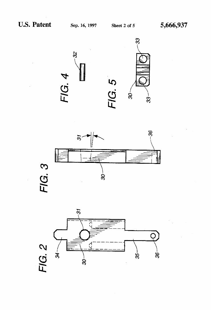
US. Patent Sep. 16, 1997 Sheet 2 of 5 5,666,937
_ m .GI
mm. mm.
m. GI N GE
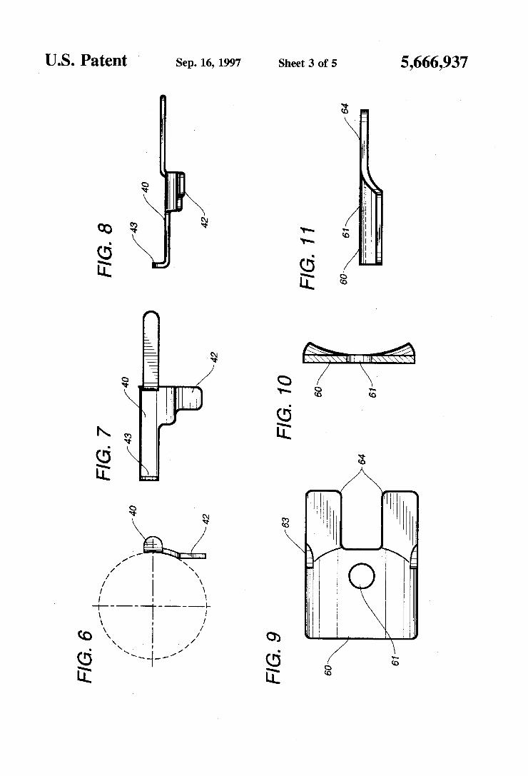
Sep. 16, 1997 Sheet 3 of 5 5,666,937 I US. Patent
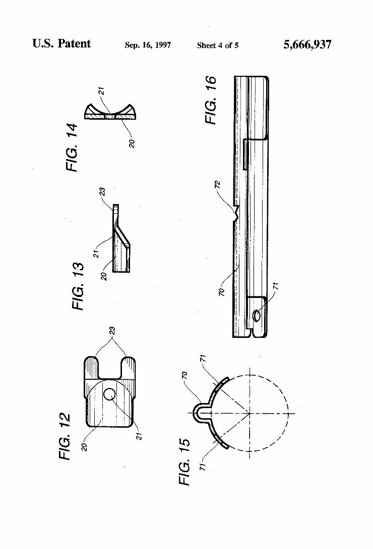
US. Patent Sep. 16, 1997 Sheet 4 of 5 5,666,937
3 .GE
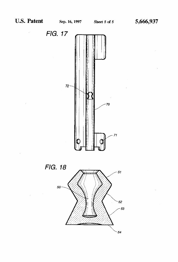
US. Patent Sep. 16, 1997 Sheet 5 of 5 5,666,937
FIG. 17
FIG. 18 51
Z47
54
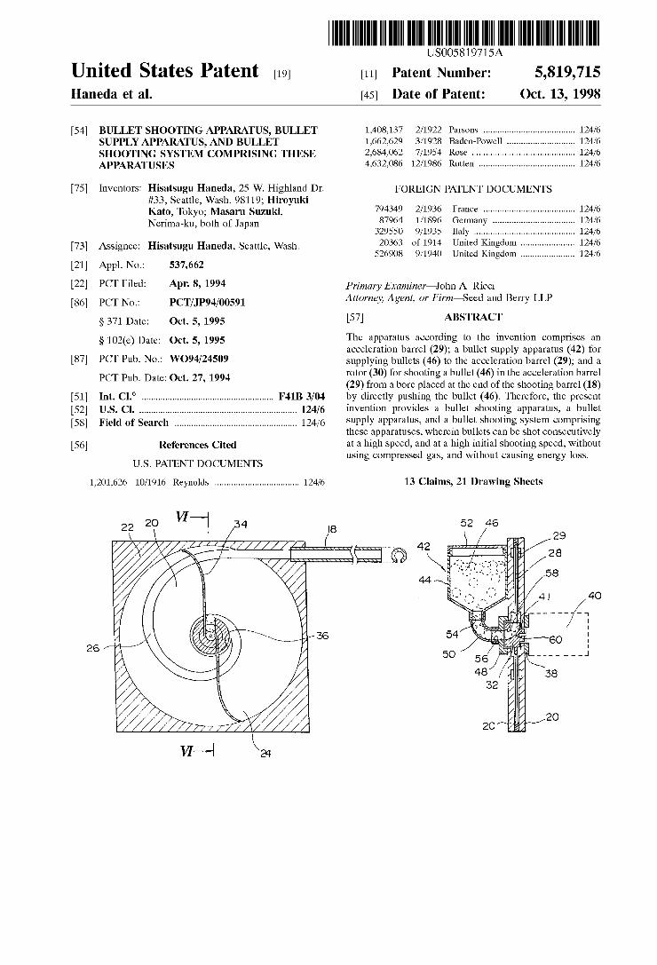
USOO5819715A
United States Patent [19] [11] Patent Number: 5,819,715 Haneda et al. [45] Date of Patent: Oct. 13, 1998
[54] BULLET SHOOTING APPARATUS, BULLET 1,408,137 2/1922 Parsons ..................................... .. 124/6 SUPPLY APPARATUS, AND BULLET 1,662,629 3/1928 Baden-Powell .. 124/6 SHOOTING SYSTEM COMPRISING THESE 2,684,062 7/1954 Rose .......... .. 124/6 APPARATUSES 4,632,086 12/1986 Rutten . 124/6
[75] Inventors: Hisatsugu Haneda, 25 W. Highland Dr. FOREIGN PATENT DOCUMENTS #33, Seattle, Wash. 98119; Hiroyuki Kata, Tokyo; Masaru Suzuki, 794349 2/1936 France ..................................... .. 124/6 Nerimaku both of Japan 87964 1/1896 Germany .. 124/6
’ 329550 9/1935 Italy .................... .. .. 124/6
[73] Assignee: Hisatsugu Haneda, Seattle, Wash. 20363 of 1914 Unlted Qngdom "" " " 124/6 526908 9/1940 United Kingdom ..................... .. 124/6
[21] Appl. No.: 537,662
[22] PCT Filed? APr- 8! 1994 Primary Examiner—John A. Ricci [86] PCT NO _ PCT/‘1P9 4/00591 Attorney, Agent, or Firm—Seed and Berry LLP
§ 371 Date: Oct. 5, 1995 [57] ABSTRACT
§ 102(6) Date: Oct 5’ 1995 The apparatus according to the invention comprises an acceleration barrel (29); a bullet supply apparatus (42) for
[87] PCT Pub- NO-I W094/24509 supplying bullets (46) to the acceleration barrel (29); and a _ rotor (30) for shooting a bullet (46) in the acceleration barrel
PCT Pub' Date' Oct‘ 27’ 1994 (29) from a bore placed at the end of the shooting barrel (18) [51] Int. Cl.6 ...................................................... .. F41B 3/04 by directly pushing the bullet (46). Therefore, the present 52 US. Cl. ................................................................. .. 124 6 lnventlon PTOVl 65 a 11 6t 5 ootlng apparatus, a 11 6t [ ] / ' ' 'd b ll h ' b ll
[58] Field of Search .................................................. .. 124/6 Supply apparatus> and a bullet Shooting System Comprising these apparatuses, Wherein bullets can be shot consecutively
56 References Cited ata 1g spee ,an ata 1g 1n1t1a s ooting spee ,Wit out [] h'h d d h'h"'lh' d 'h using compressed gas, and Without causing energy loss.
U.S. PATENT DOCUMENTS
1,201,626 10/1916 Reynolds .................................. .. 124/6 13 Claims, 21 Drawing Sheets
22 20 VI /34 I8 52 4e \ \ ‘ y W 29
‘Z A , 1‘ ---~ 42 -. ' "4 *1 \\ | Q ' __ E! 28
1.“ 1--- \ a 44 E "a I
. I 4 1 40
I 4 __ _ - _ f,
< - if / g
26 ,7‘ ° g/ 36 54 60 i 50 _ _ - - - _ _ J
38
2O
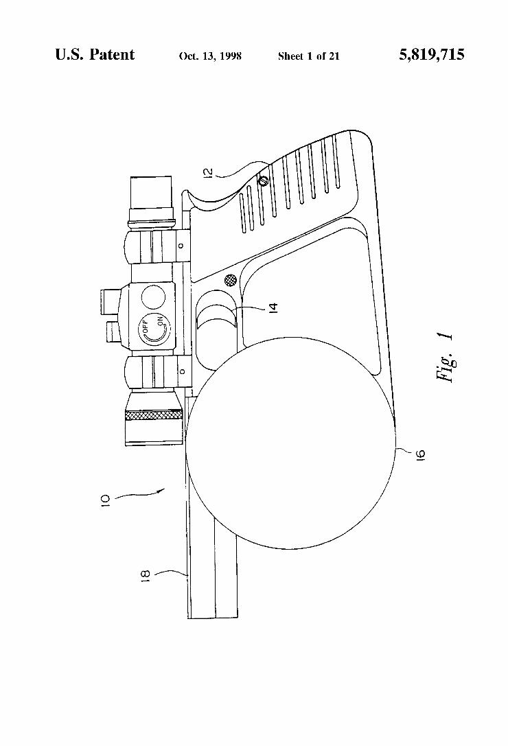
U.S. Patent Oct. 13,1998 Sheet 1 0f 21 5,819,715
Fig. 1
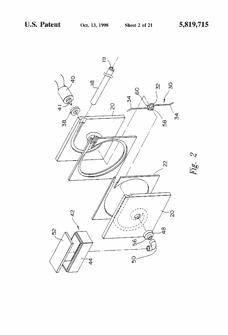
U.S. Patent Oct. 13,1998 Sheet 2 0f 21 5,819,715
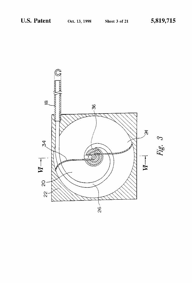
U.S. Patent Oct. 13,1998 Sheet 3 0f 21 5,819,715
% 3
///////AA /A
. /
a 1 ON
/ mm
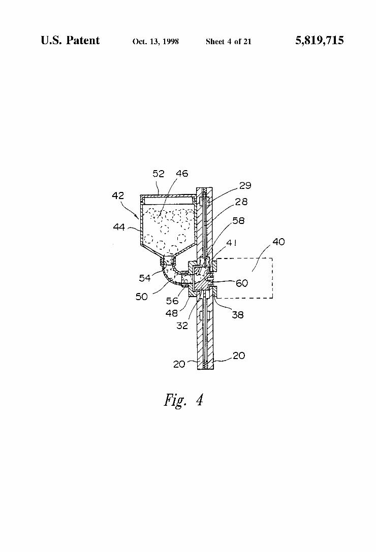
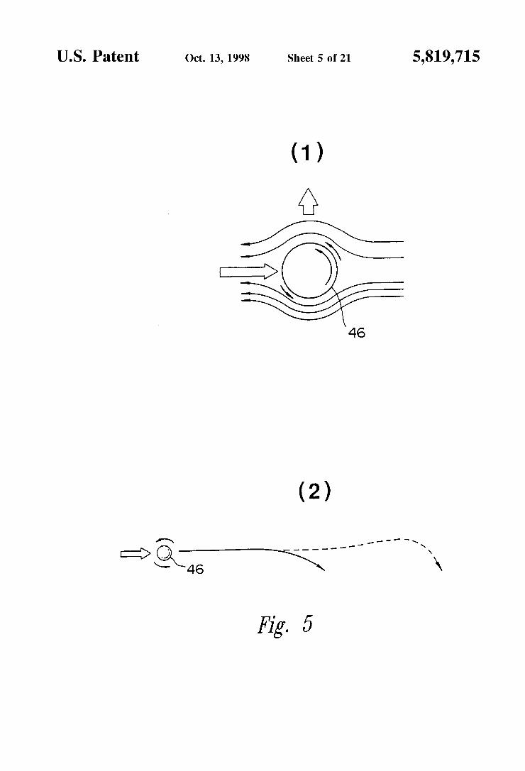
U.S. Patent Oct. 13,1998 Sheet 5 0f 21 5,819,715
46
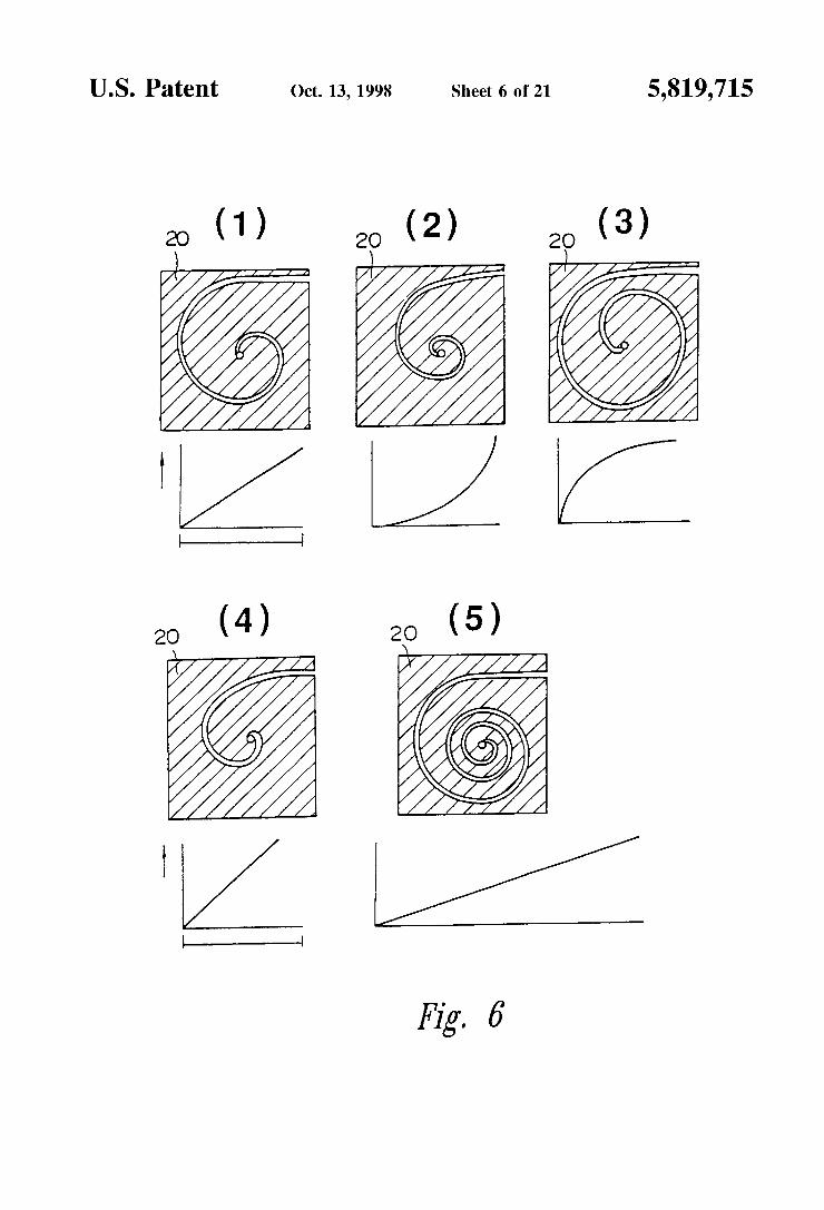
5,819,715 U.S. Patent
20 (1) 2O (2) 2O (3)
I; /'j"' /7 ‘ / /
Z
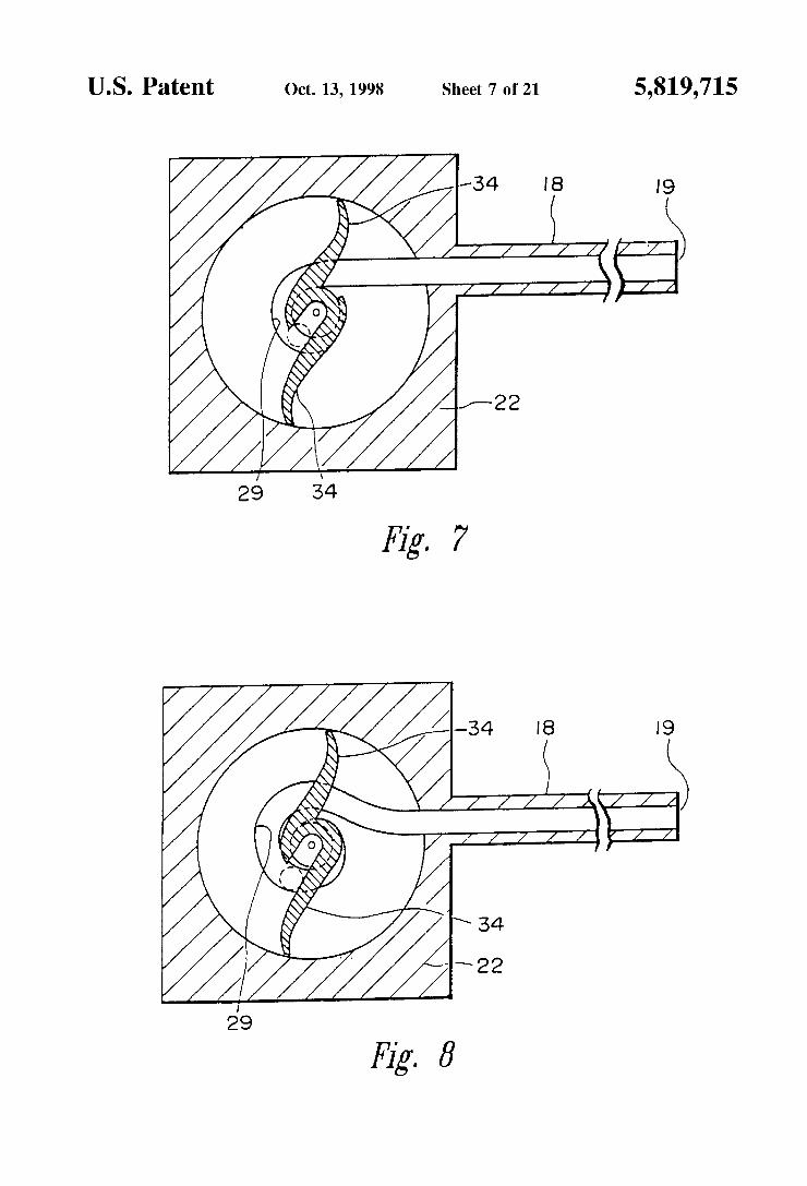
U.S. Patent Oct. 13,1998 Sheet 7 0f 21 5,819,715
Fig. 7
'3 I8
/////A‘T//
Fig. 8
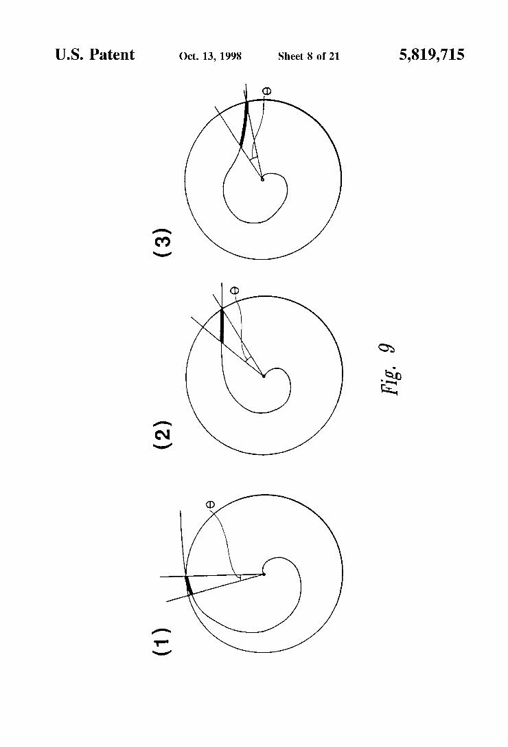
U.S. Patent Oct. 13,1998 Sheet 8 0f 21 5,819,715
A
(‘0 V
(D
Q}
E0 in.
A
N V
(1)
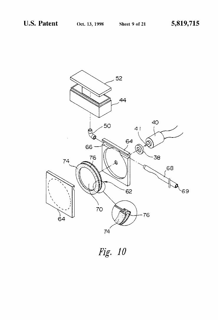
U.S. Patent Oct. 13,1998 Sheet 9 0f 21 5,819,715
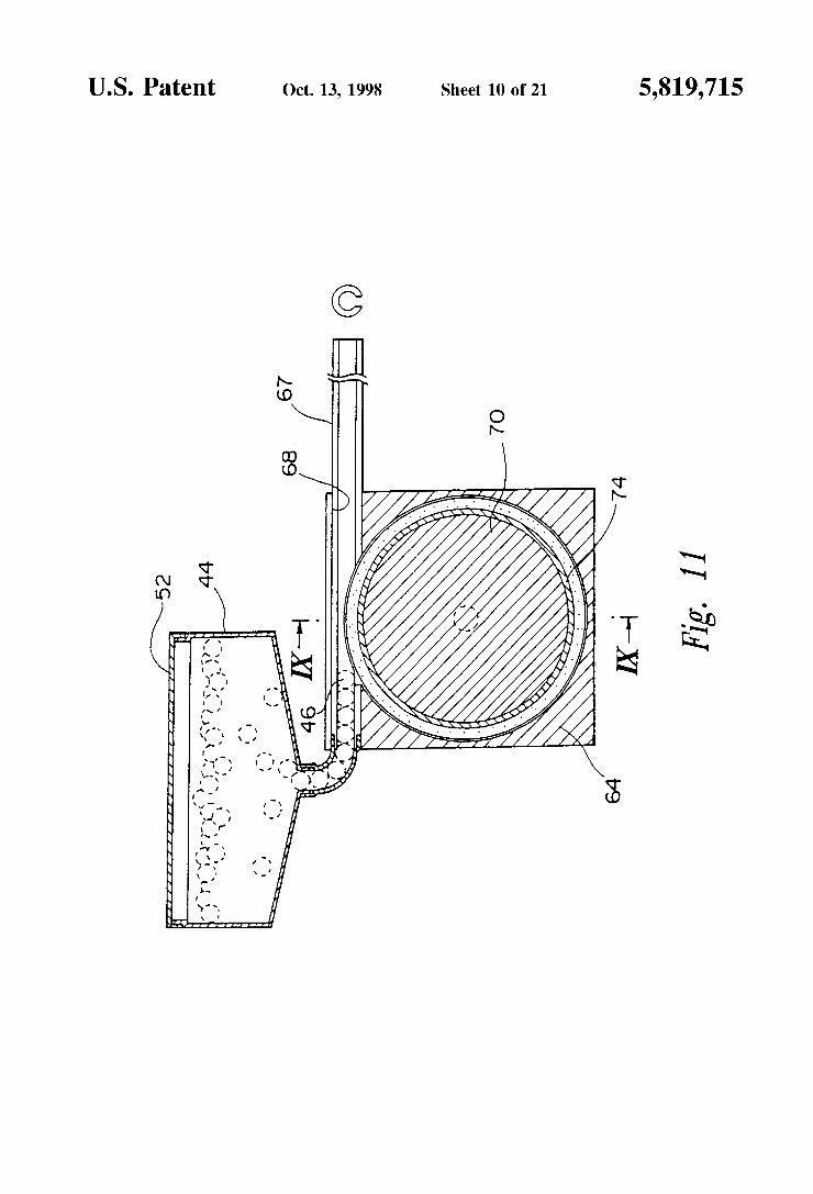
U.S. Patent 0a. 13, 1998 Sheet 10 0f 21 5,819,715
NNNNNNL>~NNNNNN
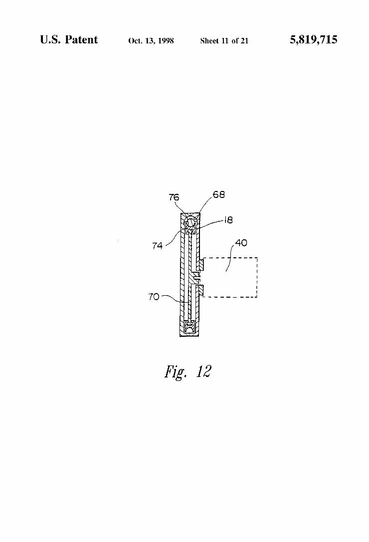
U.S. Patent Oct. 13,1998 Sheet 11 0f 21 5,819,715
O 7
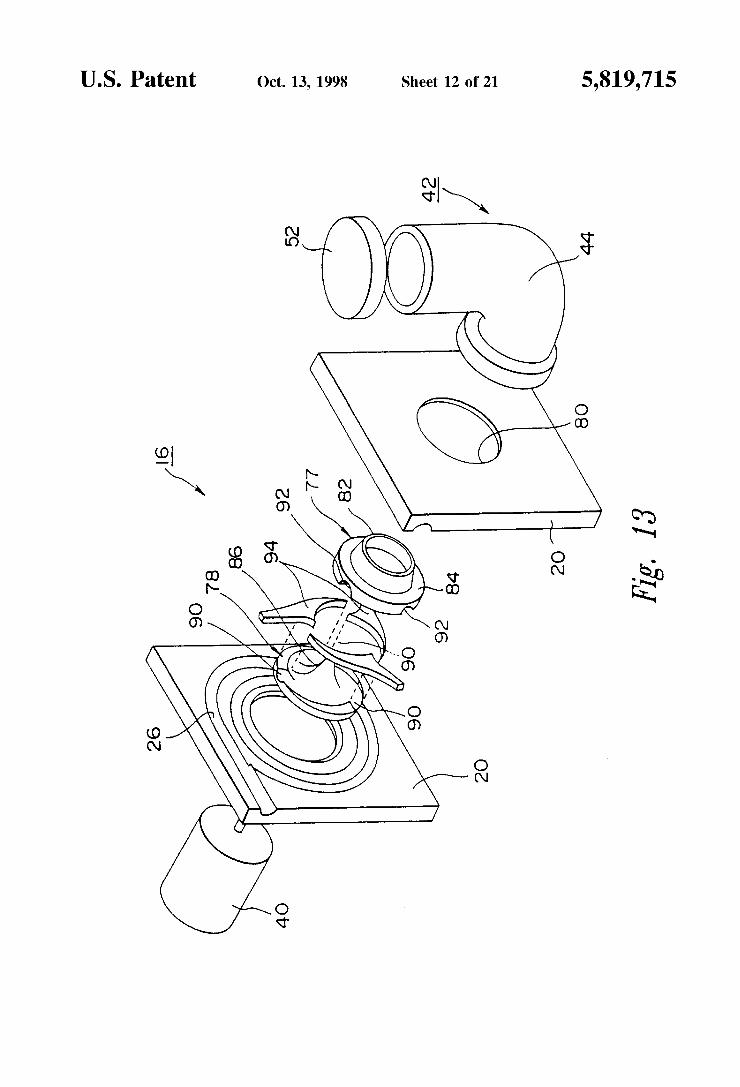
U.S. Patent 0a. 13, 1998 Sheet 12 0f 21 5,819,715
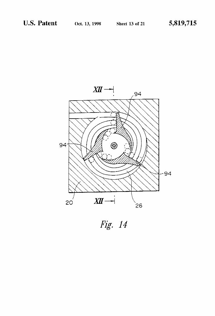
U.S. Patent 0a. 13, 1998 Sheet 13 0f 21 5,819,715
/94
J94
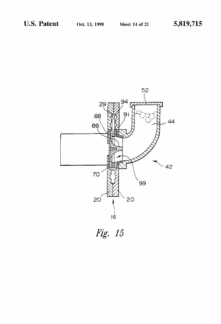
U.S. Patent 0a. 13, 1998 Sheet 14 0f 21 5,819,715
52
/94 Z _//S¥////1 fl ‘1 I
5
29 ‘\
88
86 \ \
Fig. 15
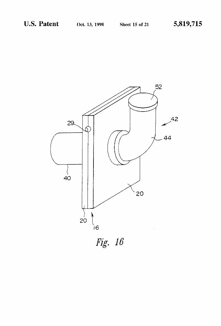
U.S. Patent 0a. 13, 1998 Sheet 15 0f 21 5,819,715
52
42 29\ / Q)
44
40
2O
/
Fig. 16‘
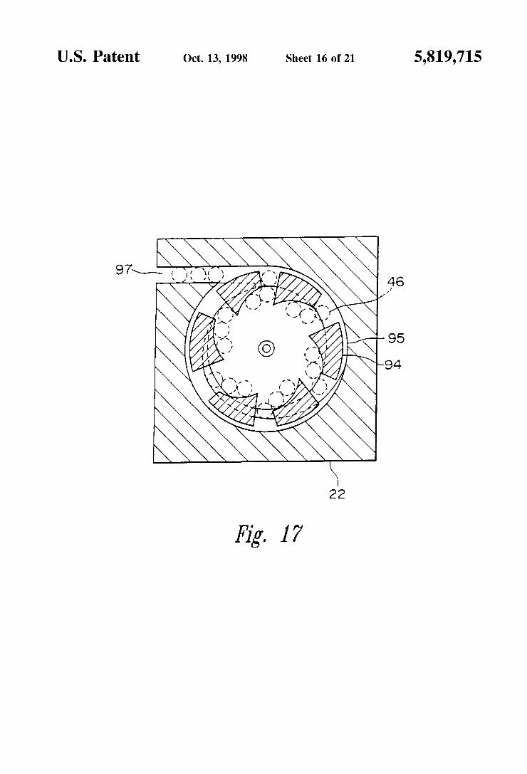
U.S. Patent 0a. 13, 1998 Sheet 16 0f 21 5,819,715
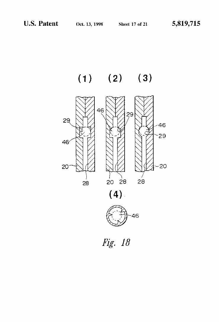
U.S. Patent 0a. 13, 1998 Sheet 17 0f 21 5,819,715
(1) (2) (3)
\
i- ~46 §~ \29 \ Q & ~20
28 2o 28 2s
(4). m .
Hg. 18
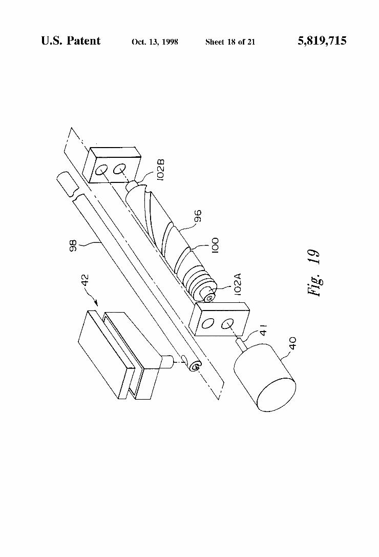
U.S. Patent 0a. 13, 1998 Sheet 18 0f 21 5,819,715
Hg. 19
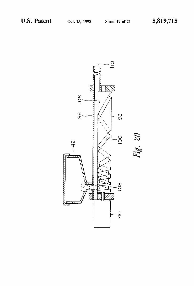
U.S. Patent 0a. 13, 1998 Sheet 19 0f 21 5,819,715
/ / / 4// / //////////////A/
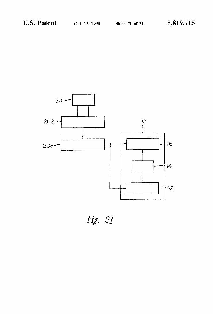
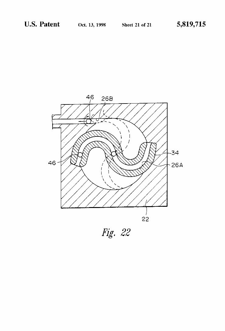
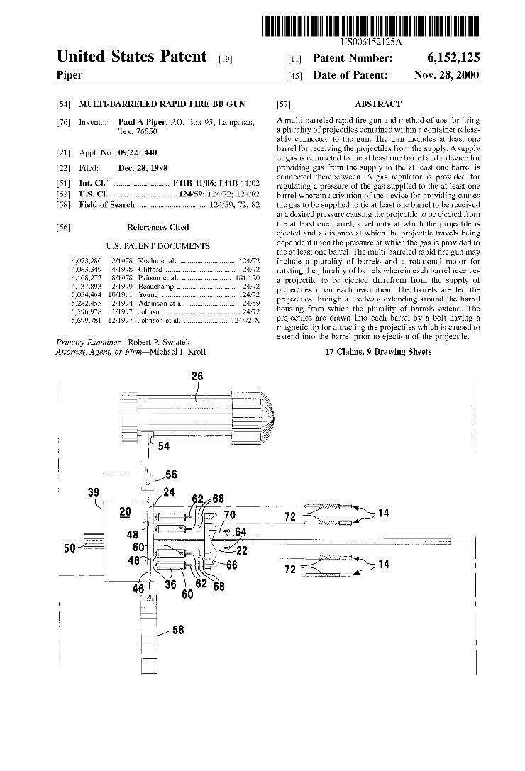
United States Patent [19] Piper
US006152125A
6,152,125 Nov. 28, 2000
[11] Patent Number:
[45] Date 0f Patent:
[54] MULTI-BARRELED RAPID FIRE BB GUN
[76] Inventor: Paul A Piper, PO. Box 95, Lamposas, Tex. 76550
[21] Appl. No.1 09/221,440
[22] Filed: Dec. 28, 1998
[51] Int. Cl.7 ............................ .. F41B 11/06; F41B 11/02
[52] US. Cl. ................................ .. 124/59; 124/72; 124/82
[58] Field of Search ................................. .. 124/59, 72, 82
[56] References Cited
U.S. PATENT DOCUMENTS
4,073,280 2/1978 Koehn et a1. ........................... .. 124/72
4,083,349 4/1978 Clifford . . . . . . . . . . . . . . . . .. 124/72
4,108,272 8/1978 Paitson et a1. 181/120 4,137,893 2/1979 Beauchamp . . . . . . . . . . .. 124/72
5,054,464 10/1991 Young ...................... .. 124/72
5,282,455 2/1994 Adamson et a1. 124/59 5,596,978 1/1997 Johnson . . . . . . . . . . . . . . . . . . . .. 124/72
5,699,781 12/1997 Johnson et a1. ..................... .. 124/72 X
Primary Examiner—Robert P. SWiatek Attorney, Agent, or Firm—Michael I. Kroll
[57] ABSTRACT
A multi-barreled rapid ?re gun and method of use for ?ring a plurality of projectiles contained Within a container releas ably connected to the gun. The gun includes at least one barrel for receiving the projectiles from the supply. Asupply of gas is connected to the at least one barrel and a device for providing gas from the supply to the at least one barrel is connected therebetWeen. A gas regulator is provided for regulating a pressure of the gas supplied to the at least one barrel Wherein activation of the device for providing causes the gas to be supplied to tie at least one barrel to be received at a desired pressure causing the projectile to be ejected from the at least one barrel, a velocity at Which the projectile is ejected and a distance at Which the projectile travels being dependent upon the pressure at Which the gas is provided to the at least one barrel. The multi-barreled rapid ?re gun may include a plurality of barrels and a rotational motor for rotating the plurality of barrels Wherein each barrel receives a projectile to be ejected therefrom from the supply of projectiles upon each revolution. The barrels are fed the projectiles through a feedWay extending around the barrel housing from Which the plurality of barrels extend. The projectiles are draWn into each barrel by a bolt having a magnetic tip for attracting the projectiles Which is caused to extend into the barrel prior to ejection of the projectile.
17 Claims, 9 Drawing Sheets
" " \\\\\\\\\WE 1 4
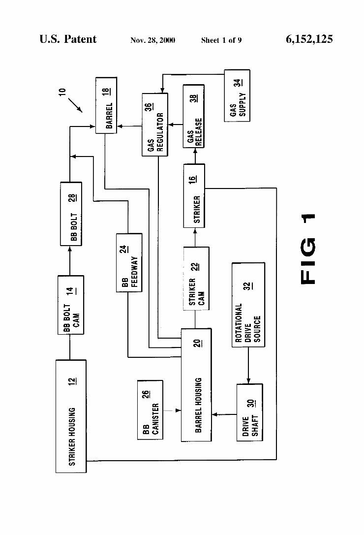
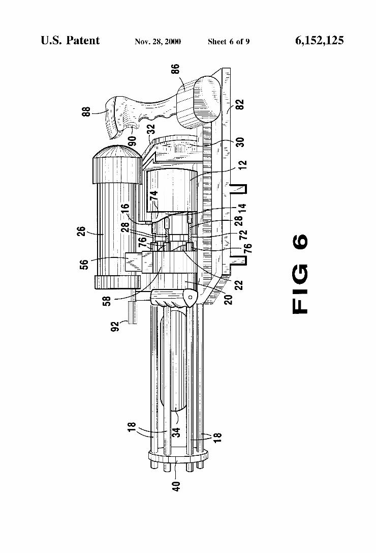
U.S. Patent Nov. 28,2000 Sheet 6 of9 6,152,125
FIG 6
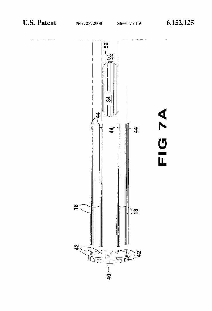
U.S. Patent Nov. 28,2000 Sheet 7 0f 9 6,152,125
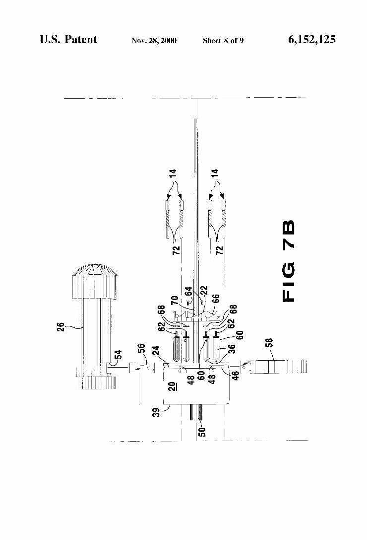
U.S. Patent Nov. 28,2000 Sheet 8 of9 6,152,125
MN m!“
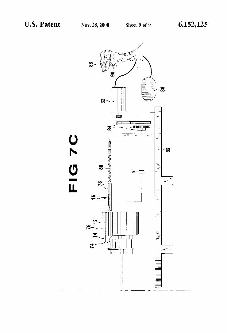
U.S. Patent Nov. 28,2000 Sheet 9 0f 9 6,152,125
FIG 7C
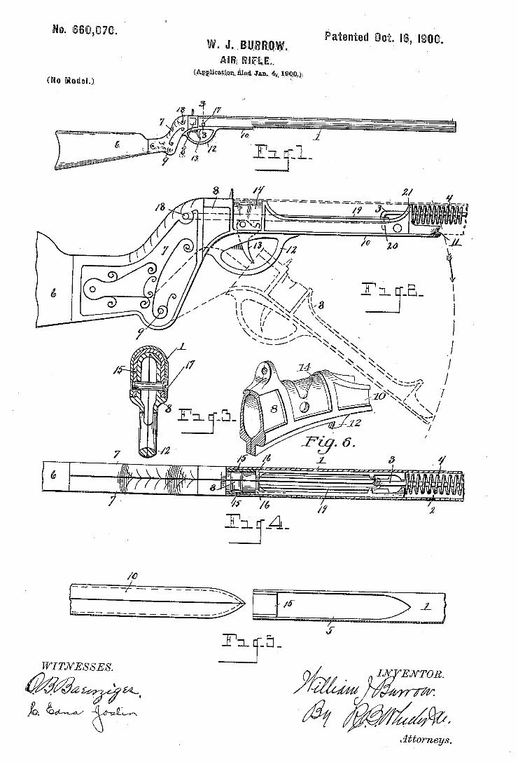
Attorneys.
(No Modal.)
/7
WI TJVESSES.
W@
\
Q ì \§
my” LN ENTOR, 'n Ä
Mw`
ma Nonfus PETERS co, mmourwo.. wAsHlNamu, n c.
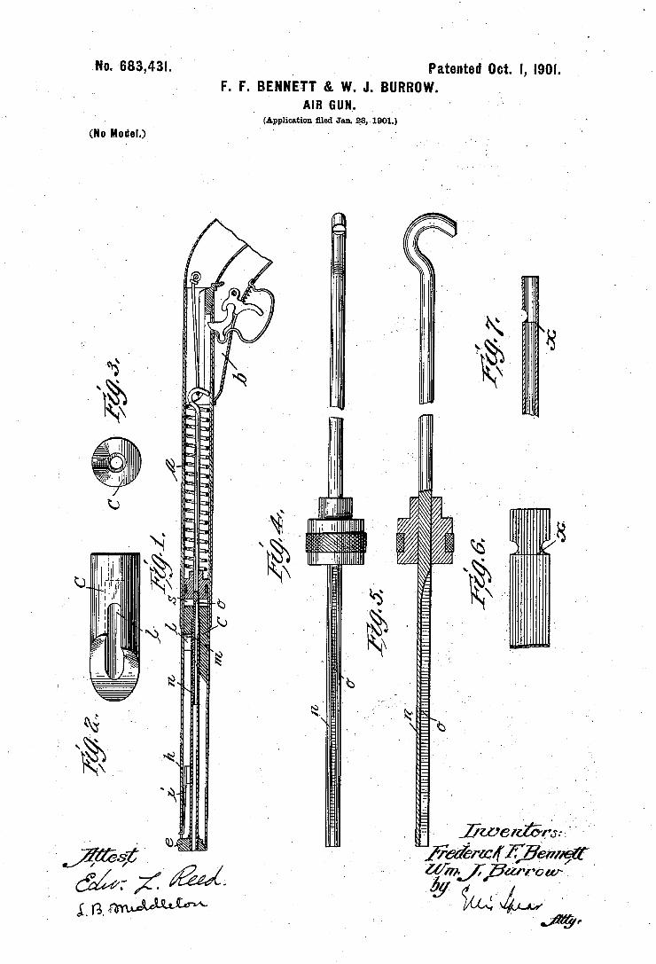
No. 683,431. ‘ ' _ ' Patented Oct. I, 19m.
F. r. BENNETT &. w. J. BURRUW. AIR GUN. '
I (Application ?led Jan. 23, 1901.)
(No Modal.) ‘
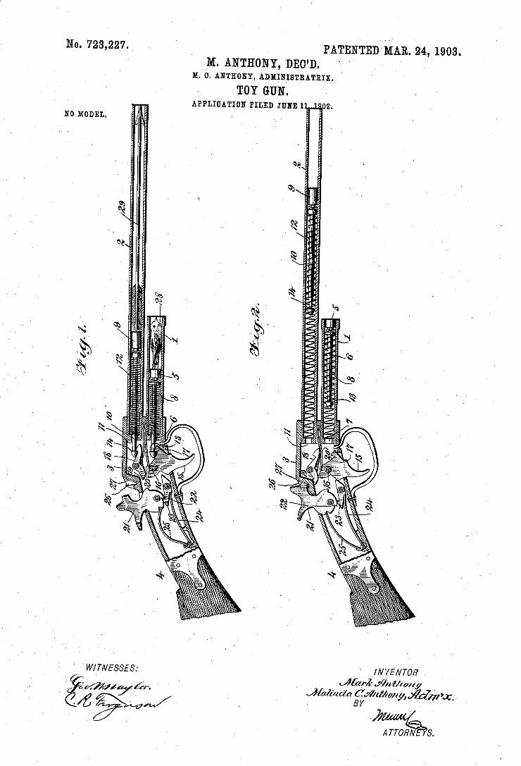
No. 723,227. PATENTEDMAR. 24.1903. M. ANTHONY, DEO'D.
M. o. ANTHONY, ADMINISTRATRIX. TOY GUN.
APPLIoATIoN FILED JUNE 1 Í N0 MODEL.
545454545454
â. A Tron/v' s.
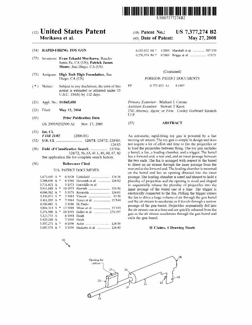
United States Patent
US007377274B2
(12) (10) Patent N0.: US 7,377,274 B2 Morikawa et a]. (45) Date of Patent: May 27, 2008
(54) RAPID-FIRING TOY GUN 6,181,032 B1* 1/2001 Marshall et a1. .......... .. 307/150
6,276,353 B1* 8/2001 Briggs et a1. ............... .. 124/71 (75) Inventors: Evan Takashi MorikaWa, Rancho
Santa Fe, CA (US); Patrick James Moore, San Diego, CA (US)
_ (Continued) (73) Ass1gnee: High Tech High Foundation, San
Diego, CA (US) FOREIGN PATENT DOCUMENTS
( * ) Notice: Subject to any disclaimer, the term of this EP 0 772 022 A1 5/1997 patent is extended or adjusted under 35 USC 154(b) by 112 days.
(21) Appl. No.: 10/845,058 Primary ExamineriMichael J. Carone _ Assistant ExamineriSteWart T Knox
(22) Flled? May 121 2004 (74) Attorney, Agent, or Firm4Cooley GodWard Kronish LLP
(65) Prior Publication Data
Us 2005/0252500 A1 Nov. 17, 2005 (57) ABSTRACT
(51) Int. Cl. F41B 11/02 (2006.01) An automatic, rapid-?ring toy gun is powered by a fast
(52) US. Cl. .......................... .. 124/71; 124/72; 124/49; moving air stream- The toy gun is simple in design and does 124/63 not require a lot of effort and time to ?re the projectiles or
(58) Field of Classi?cation Search ................ .. 15/334; to lead the Projectiles between ?ring- The my gun includes 124/72’ 56, 63, 411’ 49’ 60, 67, 82 a barrel, a fan, a loading chamber, and a trigger. The barrel
See application ?le for complete search history. has a forward end, a rear end, and an inner Passage between 56) R f C d the tWo ends. The fan is arranged With respect to the barrel
( e erences ite to direct an air stream through the inner passage from the
US. PATENT DOCUMENTS
1,673,945 A * 6/1928 Little?eld .................. .. 124/26
3,388,696 A * 6/1968 Hoverath et a1. ........... .. 124/62
3,731,421 A 5/1973 Frattolillo et a1. 3,911,888 A * 10/1975 Horvath ..................... .. 124/56
4,086,902 A * 5/1978 Reynolds ................... .. 124/61
4,430,821 A * 2/1984 Vincent ....................... .. 42/50
4,461,055 A * 7/1984 Zerrer et a1. ................ .. 15/344
4,586,482 A 5/1986 Di Pietro 4,884,314 A * 12/1989 Miner et a1. ................ .. 15/344
5,251,906 A * 10/1993 Heller et a1. .............. .. 273/397
5,323,755 A 6/1994 Hsieh 5,429,108 A 7/1995 Hsieh 5,507,271 A * 4/1996 Actor ........................ .. 124/56
5,887,578 A * 3/1999 Backeris et a1. ............ .. 124/49
10
Opening for
rear end to the forward end. The loading chamber is mounted on the barrel and has an opening directed into the inner passage. The loading chamber is sized and shaped to hold a plurality of projectiles and the opening is sized and shaped to sequentially release the plurality of projectiles into the inner passage of the barrel one at a time. The trigger is electrically connected to the fan. Pulling the trigger causes the fan to drive a large volume of air through the gun barrel and the air stream to accelerate as it travels through a narroW passage of the gun barrel. Projectiles sequentially fall into the air stream one at a time and are quickly released from the gun as the air stream accelerates through the gun barrel and exits the gun barrel.
11 Claims, 6 Drawing Sheets

US 7,377,274 B2 Page 2
US. PATENT DOCUMENTS 2003/0024519 A1 2/2003 Chen 2005/0252500 A1* 11/2005 Morikawa et a1. .......... .. 124/71
6,637,069 B2* 10/2003 Marshall et a1. ............ .. 15/405
6,644,294 B2* 11/2003 Christensen . 124/77 6,807,959 B1 * 10/2004 Murdock et a1. ........... .. 124/61 * cited by examiner
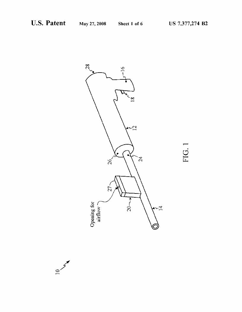
U.S. Patent May 27, 2008 Sheet 1 0f 6 US 7,377,274 B2
M .95
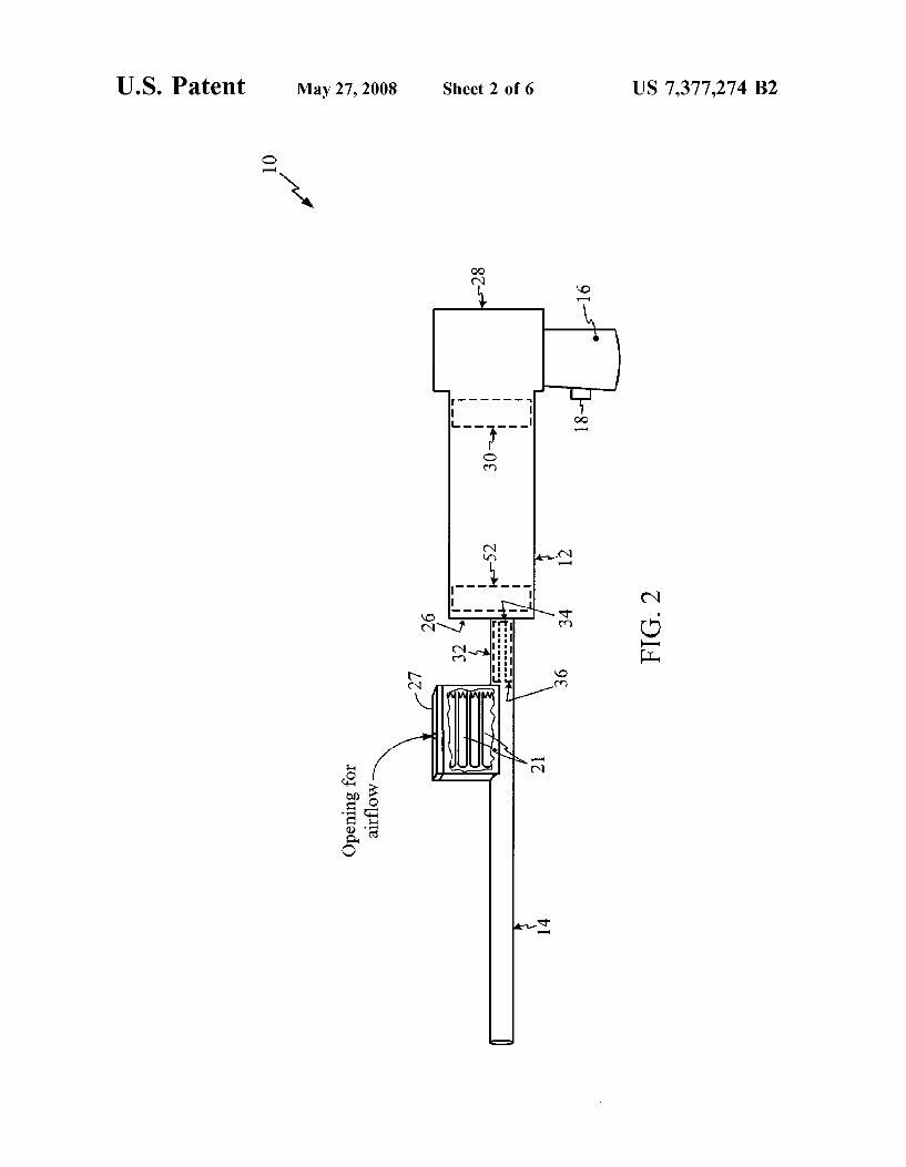
U.S. Patent May 27, 2008 Sheet 2 0f 6 US 7,377,274 B2
m .UE LL E _ ..||.... mm H n .liw Q ." mm
hm
Bomb“ Mom wEcoQO
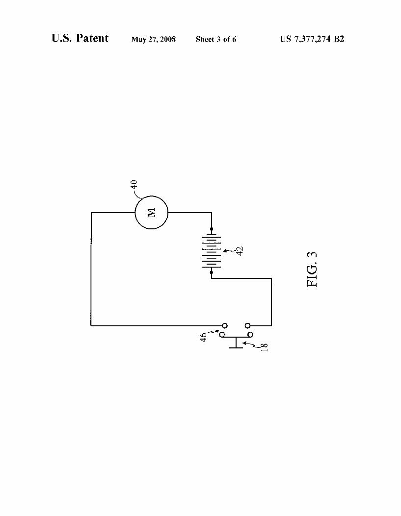
U.S. Patent May 27, 2008 Sheet 3 0f 6 US 7,377,274 B2
40
FIG 3
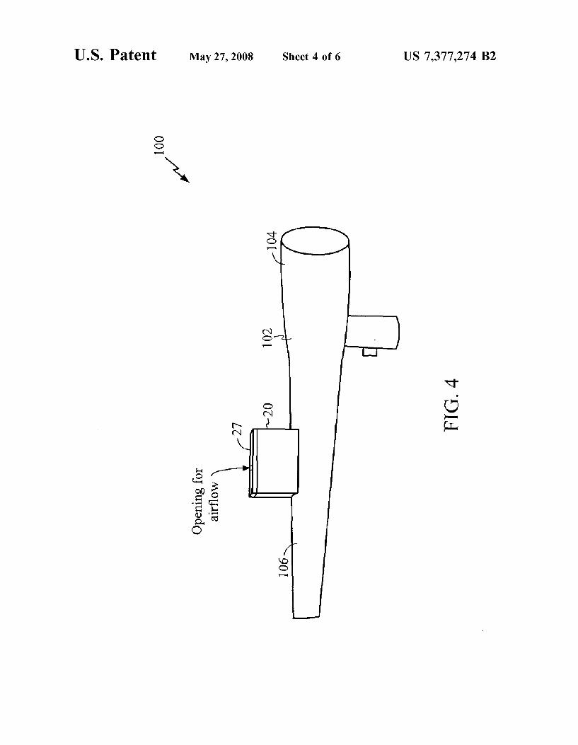
U.S. Patent May 27, 2008 Sheet 4 0f 6 US 7,377,274 B2
100
106\
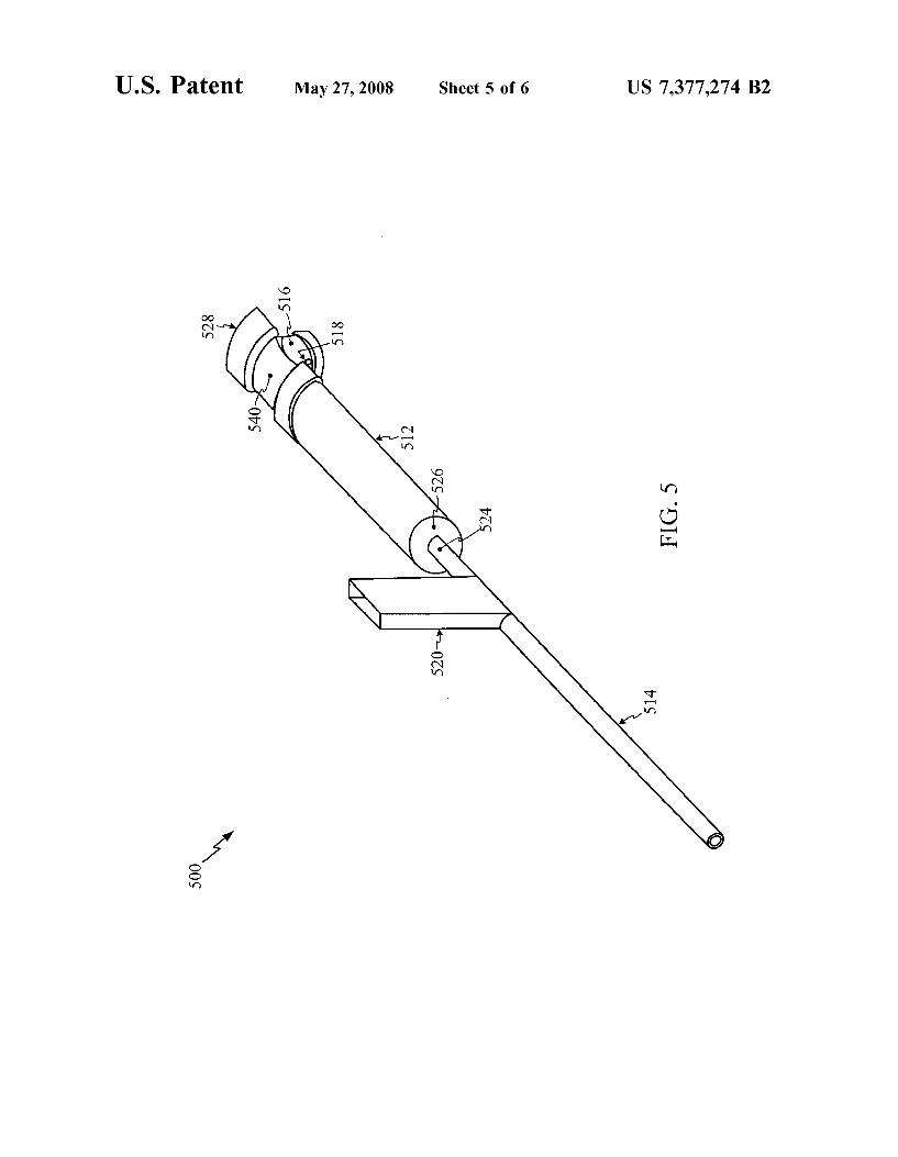
U.S. Patent May 27, 2008 Sheet 5 0f 6 US 7,377,274 B2
500
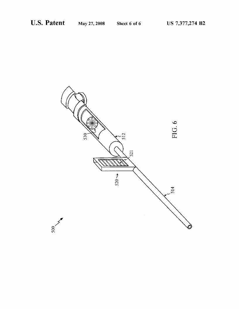
U.S. Patent May 27, 2008 Sheet 6 0f 6 US 7,377,274 B2
FIG. 6
5201+
500
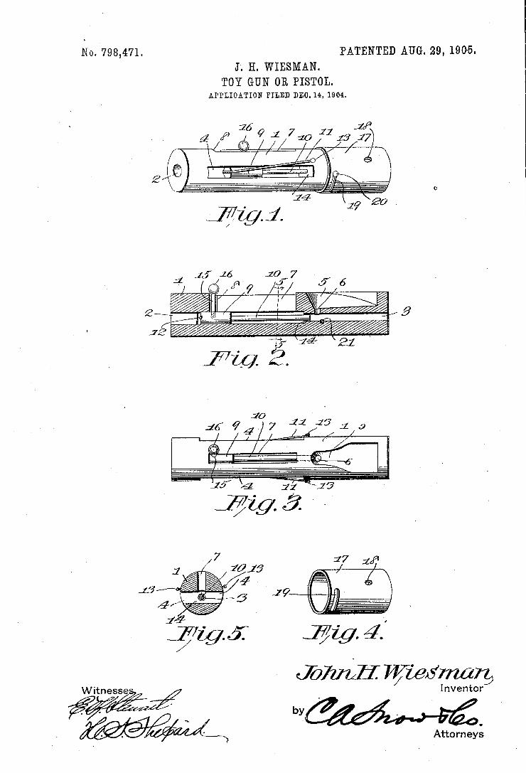
No. ‘798,471. PATENTED AUG. 29, 1905. J. H. WIESMAN.
TOY GUN 0R PISTOL. APPLIOATION FILED DEO.14, 1904.
WWW Inventor] I /’ , 1 I ~ , - // I ‘ I .
/ {1/ / '_.~ Attorneys
mmiw, a mum»! co‘ PNOTO-LITNOGRAPNERS wnsummou. o z.
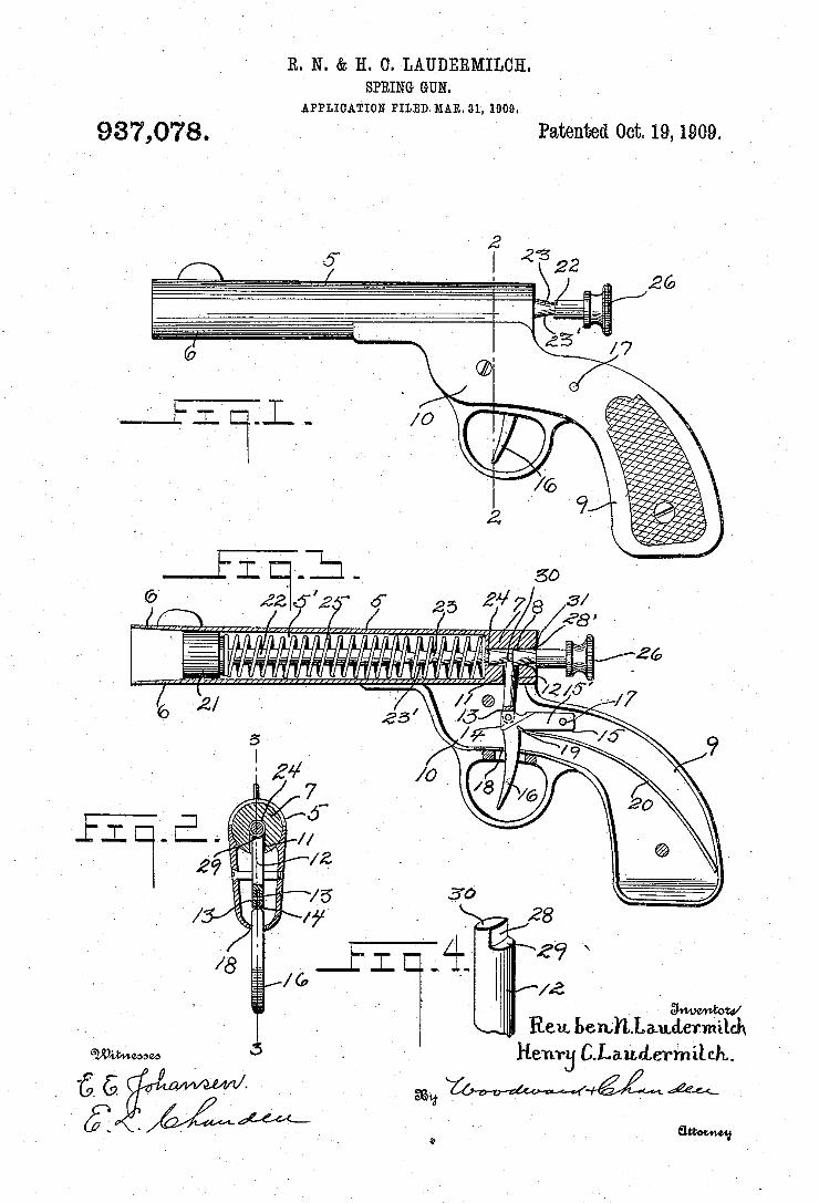
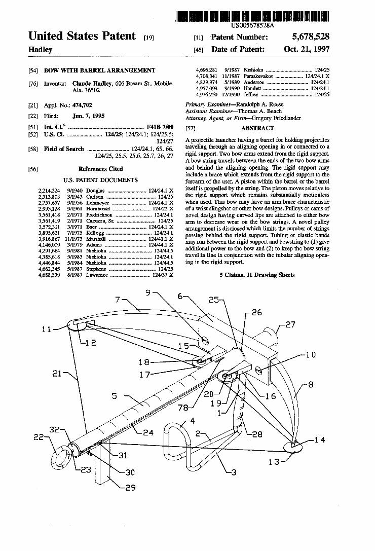
1‘1
mum - 01,
US00567528A
Umted States Patent [191 [11] “P1116111 Number: 5,678,528 Hadley [45] Date of Patent: Oct. 21, 1997
[54] Bow WITH BARREL ARRANGEMENT 4,696,281 9/1987 191511161111 ................................. .. 124/25 4,708,341 11/1987 Paraskevakos .124/241x
Inventor; Claude Hadley, Bream St” Mob?c, 4,829,974 5/1989 Anderson . . . . . . . . . .. l24/24.1
A1a_36502 4,957,093 9/1990 1111111160 124/241 4,976,250 12/1990 Je?rey ..................................... .. 124/25
[21] Appl. No.: 474,702
[22] F1166: Jun. 7, 1995
[51] Int. c1.6 ...................................................... .. F41B 7/00
[52] US. Cl. ........................ ..124/2s;124/24.1;124/25.5; 124/27
[58] Field ofSearch ............................. .. 124/24.1, 65, 66, 124/25, 25.5, 25.6, 25.7, 26, 27
[56] References Cited
U.S. PATENT DOCUMENTS
2,214,224 9/1940 Douglas ........................... .. 12404.1 X 2,313,803 3/1943 Ca?son .... .. 12405
2,757,657 9/1956 Lohme'yer 12404.1 X 2,995,128 9/1961 Hornbostel . . . . . . . . . . .. 12402 X
3,561,418 2/1971 Fredrickson 12404.1 3,561,419 2/1971 Cucuzza, Sr. ....... .. 12405 3,572,311 3/1971 Baer .......... .. 12404.1 X
3,895,621 7/1975 Kellogg ..... .. 124/24.1 3,916,867 11/1975 Marshall . 124/41.1 X 4,146,009 3/1979 Adams ...... .. 124/44.1 X 4,291,664 9/1981 Nishioka . . . . . . . . . . .. 124/445
4,385,618 5/1983 Nishioka 12404.1 4,446,844 5/1984 Nishioka . 124/44.5 4,662,345 5/1987 Stephens . . 12405 4,688,539 8/1987 Lawrence ............................ .. 124/37 X
Primary Examiner-Randolph A. Reese Assistant Examiner—Th0mas A. Beach Attorney, Agent, or Firm—Gregory Friedlander
[57] ABSTRACT
A projectile launcher having a barrel for holding projectiles traveling through an aligning opening in or connected to a rigid support. Two bow arms extend from the rigid support. A bow string travels between the ends of the two bow arms and behind the aligning opening. The rigid support may include a brace which extends from the rigid support to the forearm of the user. A piston within the barrel or the barrel itself is propelled by the string. The piston moves relative to the rigid support which remains substantially motionless when used. This bow may have an arm brace characteristic of a wrist slingshot or other bow designs. Pulleys or cams of novel design having curved lips are attached to either bow arm to decrease wear on the bow strings. A novel pulley arrangement is disclosed which limits the number of strings passing behind the rigid support. 'lubing or elastic bands may run between the rigid support and bowslring to (1) give additional power to the bow and (2) to keep the bow string travel in line in conjunction with the tubular aligning open ing in the rigid support.
5 Claims, 11 Drawing Sheets
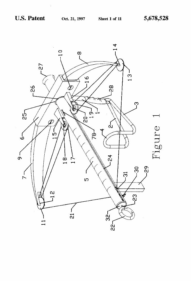
US. Patent 0a. 21, 1997 Sheet 1 of 11 5,678,528
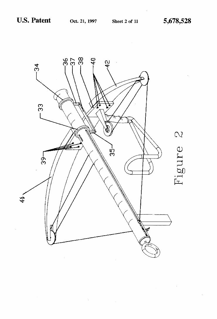
US. Patent Oct. 21, 1997 Sheet 2 of 11 5,678,528
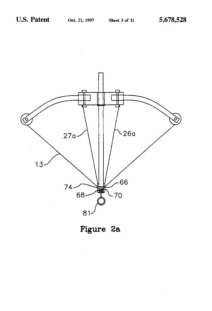
US. Patent 0a. 21, 1997 Sheet 3 0f 11 5,678,528
270 26G
66
68 7O 74
81
Figure 2a
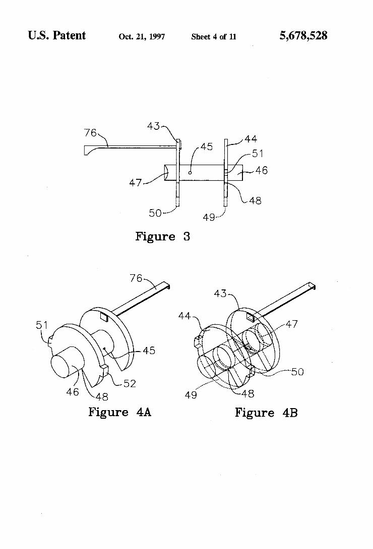
US. Patent 0a. 21, 1997 Sheet 4 of 11 5,678,528
45
76\ \u 45 -,/44 V .
J/ //5416 47/ - i\
“ 48
5O """ " x’:
Figure 3
76
51
45
52 46 48
Figure 4A Figure 4B
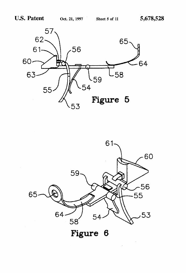
US. Patent 0a. 21, 1997 ' Sheet 50f 11 5,678,528
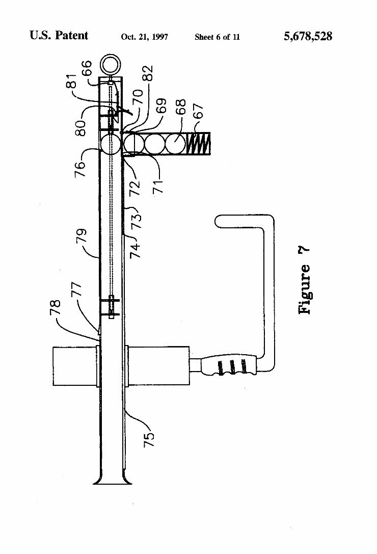
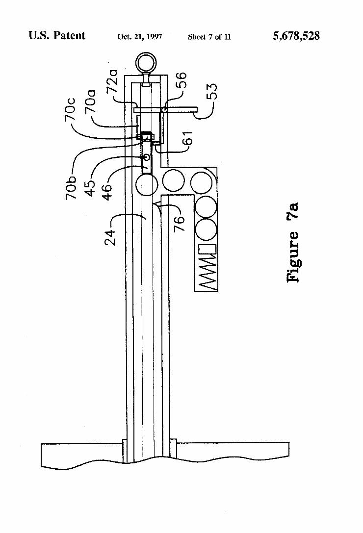
an. 95mg
5,678,528 Sheet 7 of 11
P’) LO
Q Fm)
0a. 21, 1997 '
L.‘
I
-(
\
US. Patent
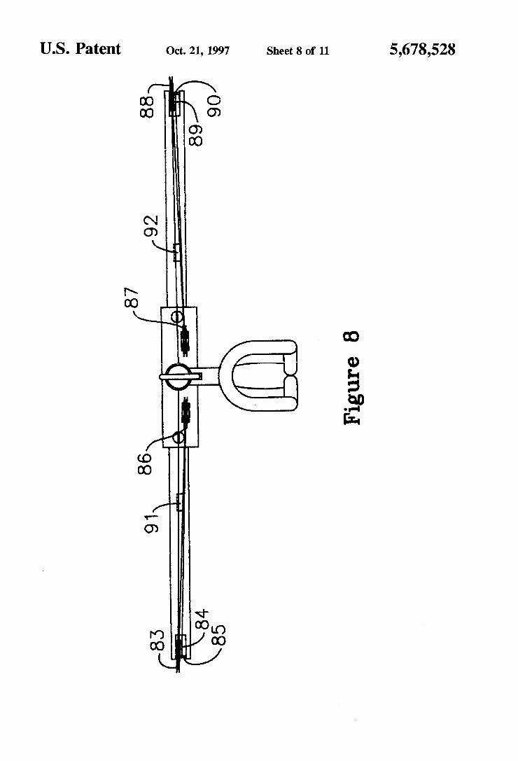
US. Patent Oct. 21, 1997 Sheet 8 of 11 5,678,528
m 0.53m
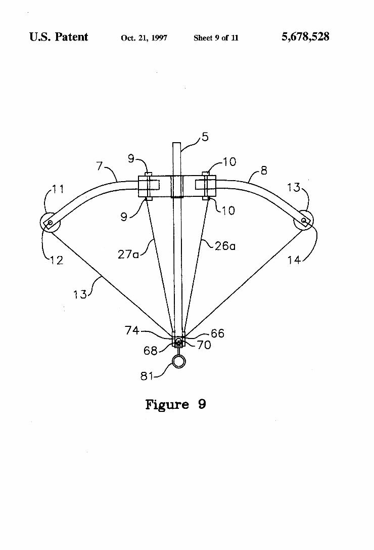
US. Patent Oct. 21, 1997 Sheet 9 of 11
1/5 9 10
7\ l f 1 1 I |
9 10
260 12 270
1 3
74 66
O 81
Figure 9
5,678,528
13'
14
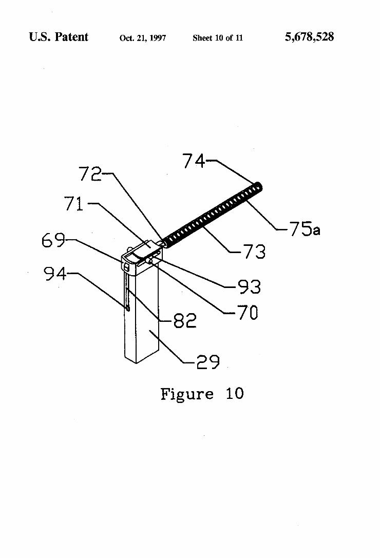
U.S. Patent Oct. 21, 1997 Sheet 10 of 11 5,678,528
a 5 _/
Figure 10
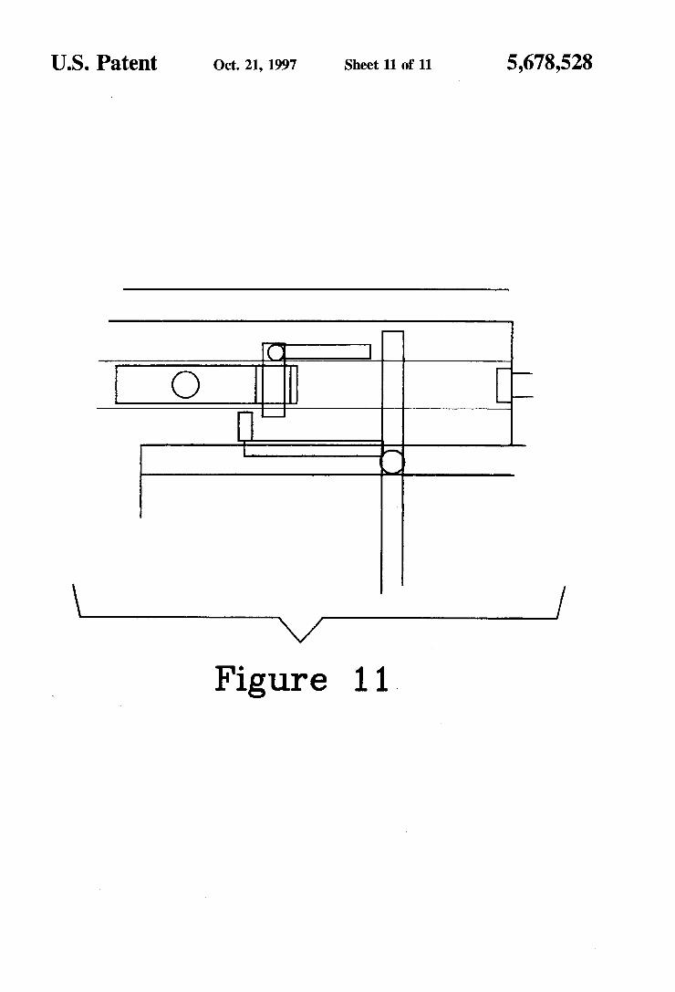
US. Patent Oct. 21, 1997 Sheet 11 0f 11 5,678,528
\/
Figure 1 1 >
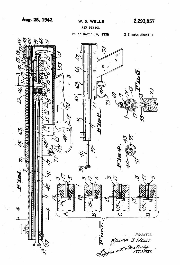
2,293,951 Aug. 25A, 1942. w. s. wELLs AIR PISTOL
Filed March 13, 1939 2 Sheets-Sheet 1
m. J _m T l E m n _ J
_ „ „M
m a MW wkiwbm
à . @d _
v _ . „Wìnnaiììa
,mw hw IÍ 1.1 „H Ñ» NN .n _Q \___ ,H1 7 , Ill'. \h. ¢\N MYÄMWXM, mm, Ñ Ñ EVRM. WM,
ww - „ _NNN l .- , : Iíll
m\ l. -l || I
my“, \\. \N W L ..____
mw. bww D» .ß w _ .È m kw .NEE à _
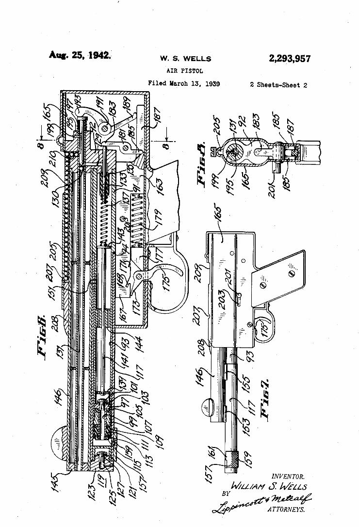
2,293,957 Aug. 25', 1941 w. s. wELLs Am rrsœor.
Filed »man 15. 1939 2 Sheets~Sheet 2
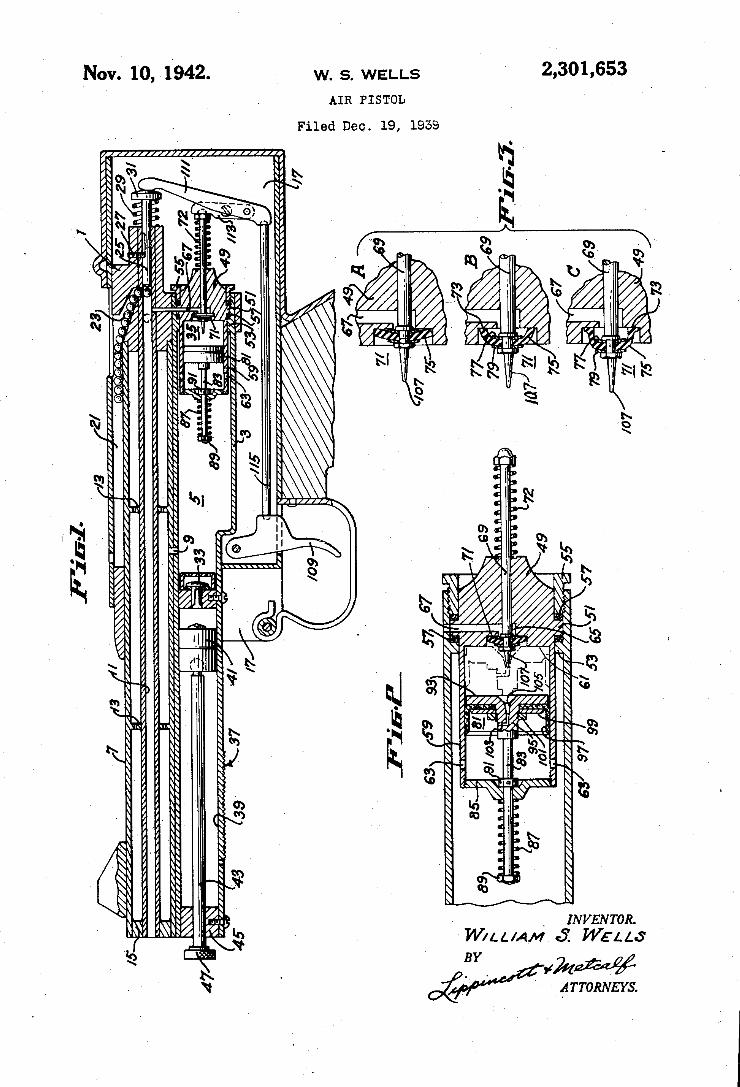
2,301 ,653 Nov. 10, 1.942. w. s. WELLS AIR PISTOL
Filed Deo. 19, 1959
82
, INVENToR.
-W/LL/AM áï WEL/.s
#kw ' ¿TroRNEx/s. a(
PL »mw d?äNhbNl
" `\ E
V/// //.
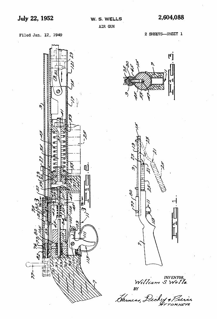
2,604,088 W. S. WELLS July 2.2, 1952 AIR GUN
2 Sl-IEETS--SE‘IEET l Filed Jan. l2, 1949
fami/Kyi
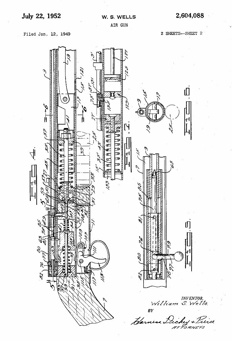
w. s. WELLS 2,604,088 `
AIR GUN
z SHEETS-_SHEET 2
LL
INVENTOR. v/f//f'dm 6T w/e/Zf.
BY
/77 @HWK/ó' v
\
MN www QJ
July 22, 1952
Filed Jan. 12, 1949
i
„ASQ 33.53
. = E
.HW H
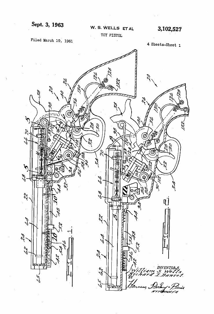
3,102,527 w. s. WELLS ETAL Sept. 3, 1963
TOY PISTOL Filed March 10,’ 1961
4 Sheets-Sheet 1
( = = = . >3???
3.24 , My.” % we” ‘r .H WW” 0% mil. . r
, I
m” 0M
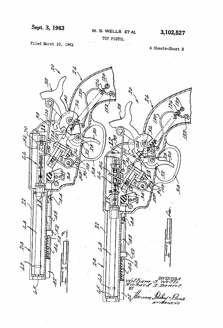
3,102,527 Sept. 3, 1963 w. s. WELLS ETAL
TOY PISTOL
4 Sheets-Sheet 2 Filed March 10, 1961
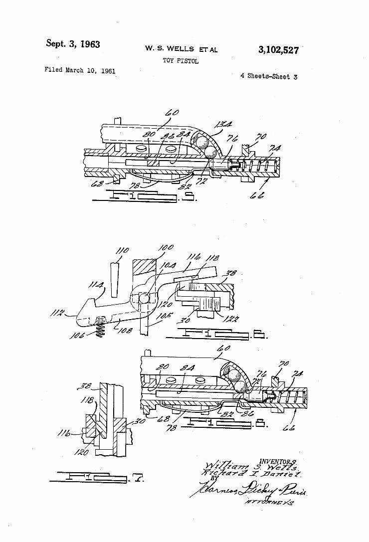
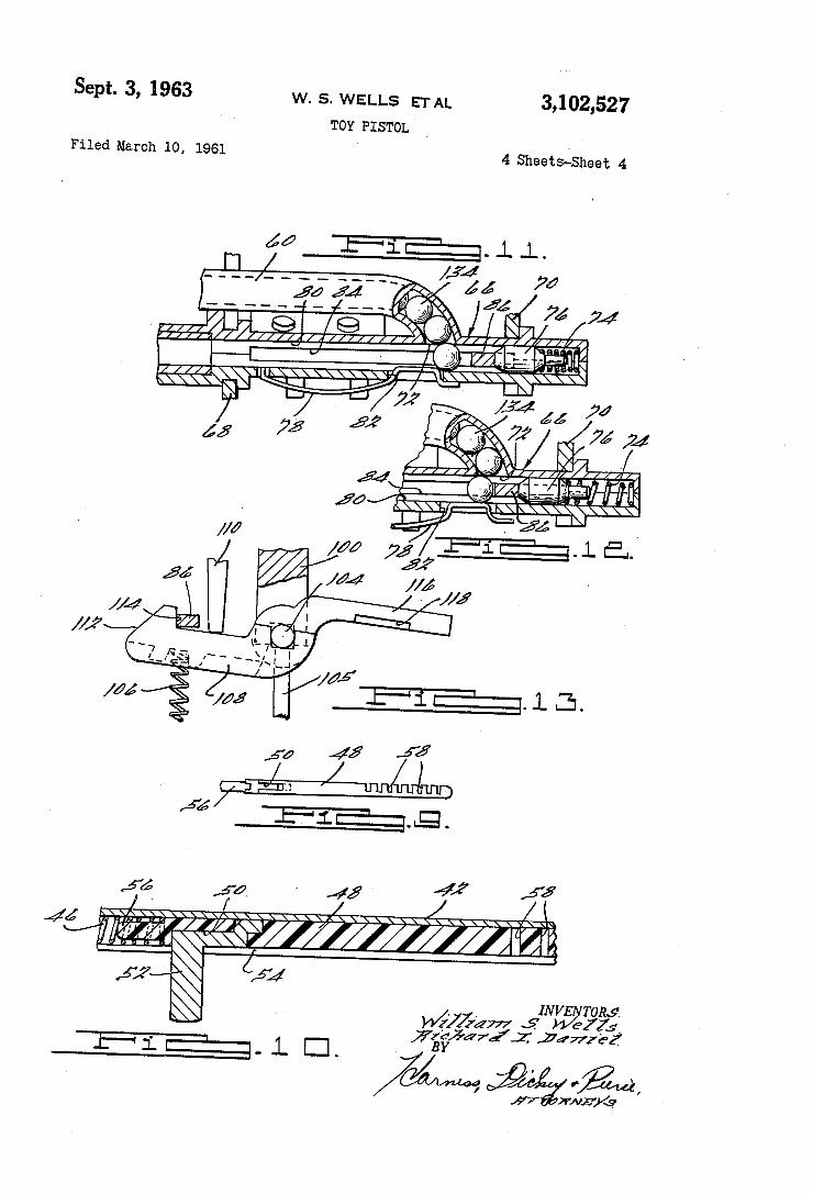
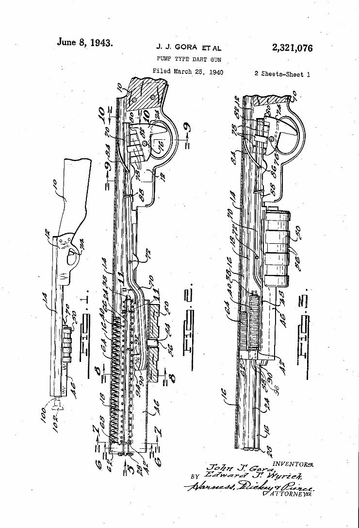
June 8,_ 1943. J. J. GORA EFAL. ‘
PUMP TYPE DART GUN
2,321,076
Filed March 25, 1940 2 Sheets-Sheet l
\\%\
INVENTOR?
9’ 4m. ATTORNEYS
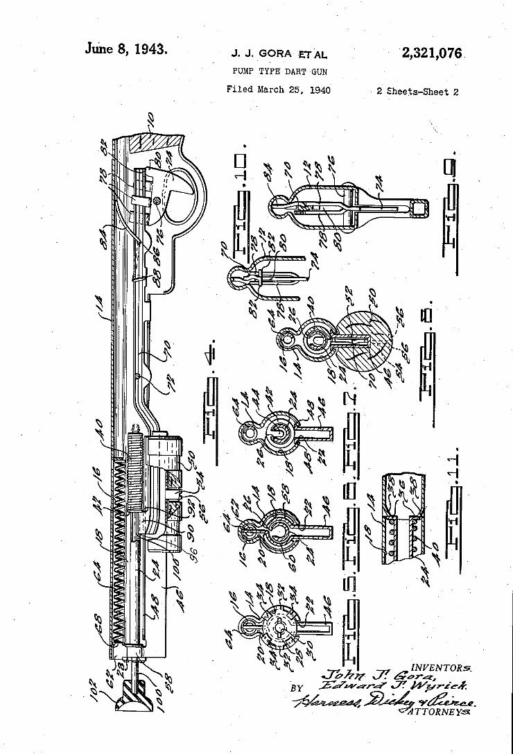
‘2,321,076, Jdne 8, 1943 J. J. 'GORA EI'AL PUMP TYPE DART GUN‘
2 Sheets-Sheet 2 Filed March 25, 1940
. . _ , m
.QH. m .H. M ‘ ‘3% M? ym
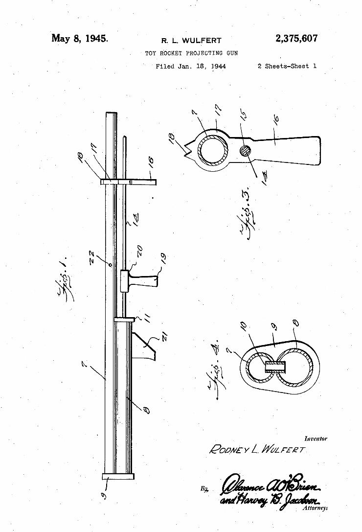
May 8, 1945- ‘ R. |_. WULFERT 2,375,607 ’ TOY ROCKET PROJECTING GUN
Filed Jan. 18, 1944 2 Sheets-Sheet l ,
Inventor
P00”: y L /l(/; F5? 7.
f - ‘
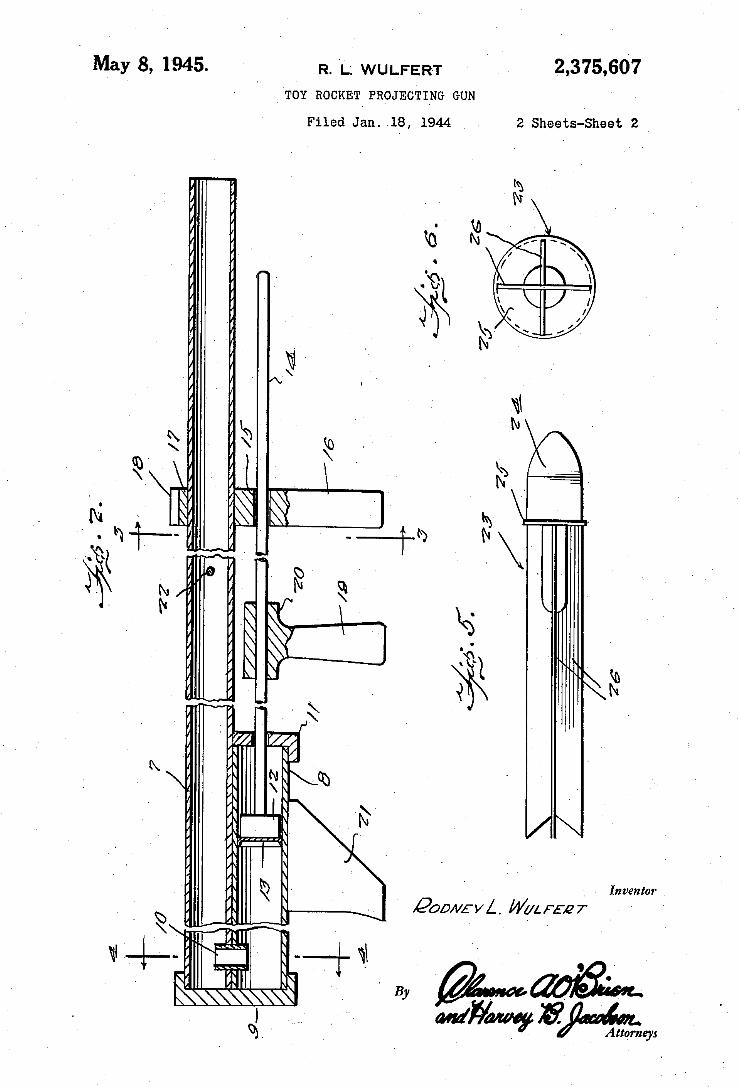
2,375,607 May 8, 1945. R. L; WULFER-T ‘ TOY ROCKET PROJECTI‘NG GUN
Filed Jan. 18, 1944 2 Sheets-Sheet 2
Inventor ‘
' Pom/EVA. Wane-er
a?“ Agtqrneys ‘
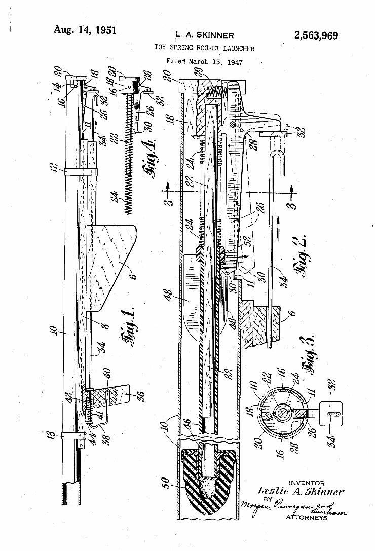
2,563,969 L. A. sKlNNl-:R
TOY SPRING ROCKET LAUNCHER
Aug. 14, 1951(
Filed March l5, 1947
INVENTO'R Leslie ¿L5/mzlwf' BY
> I A
mw/ . ~ È
TORNEYS
_à ,
n,
\ . .v
\. , \
ä E @Tm ä /%\ â
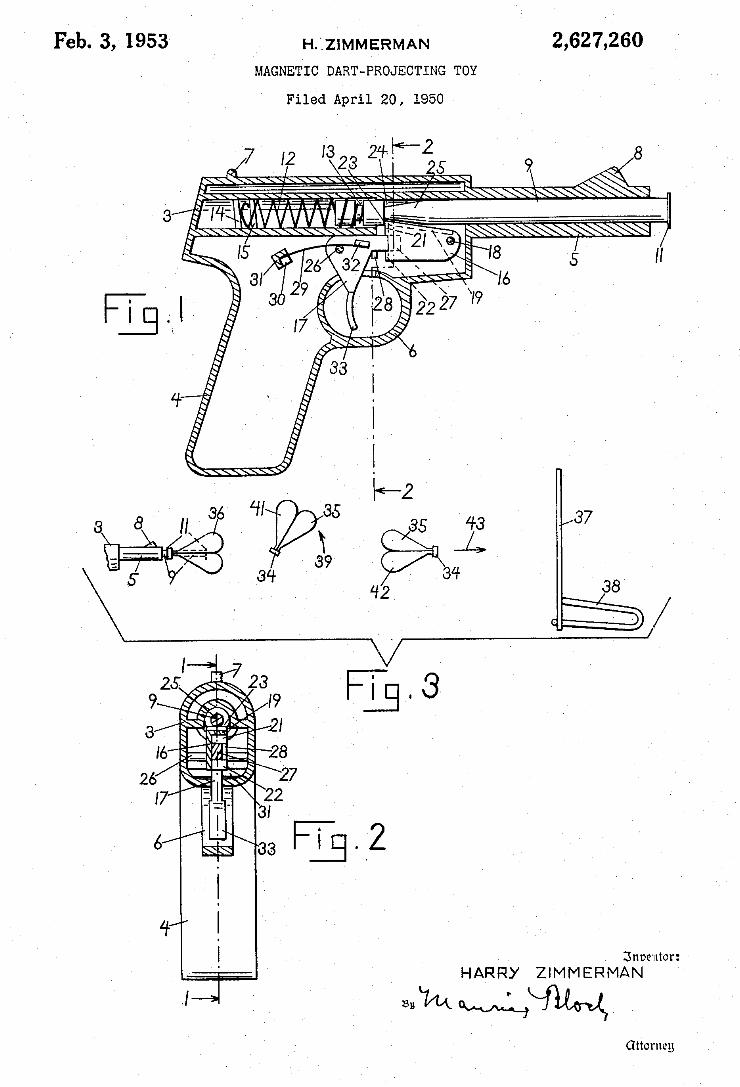
H.'.ZlMMERMAN 2,627,260 Feb. 3, 1953 MAGNETIC DART-PROJECTING TOY
Filed April 20, 1950
'23
In ' '%h N/ N 17/ _ "‘ 3i
. I‘ . 6/9»? "TE-.2 1
4/ l I Bnnemtor:
HARRY ZIMMERMAN
Clttorneg
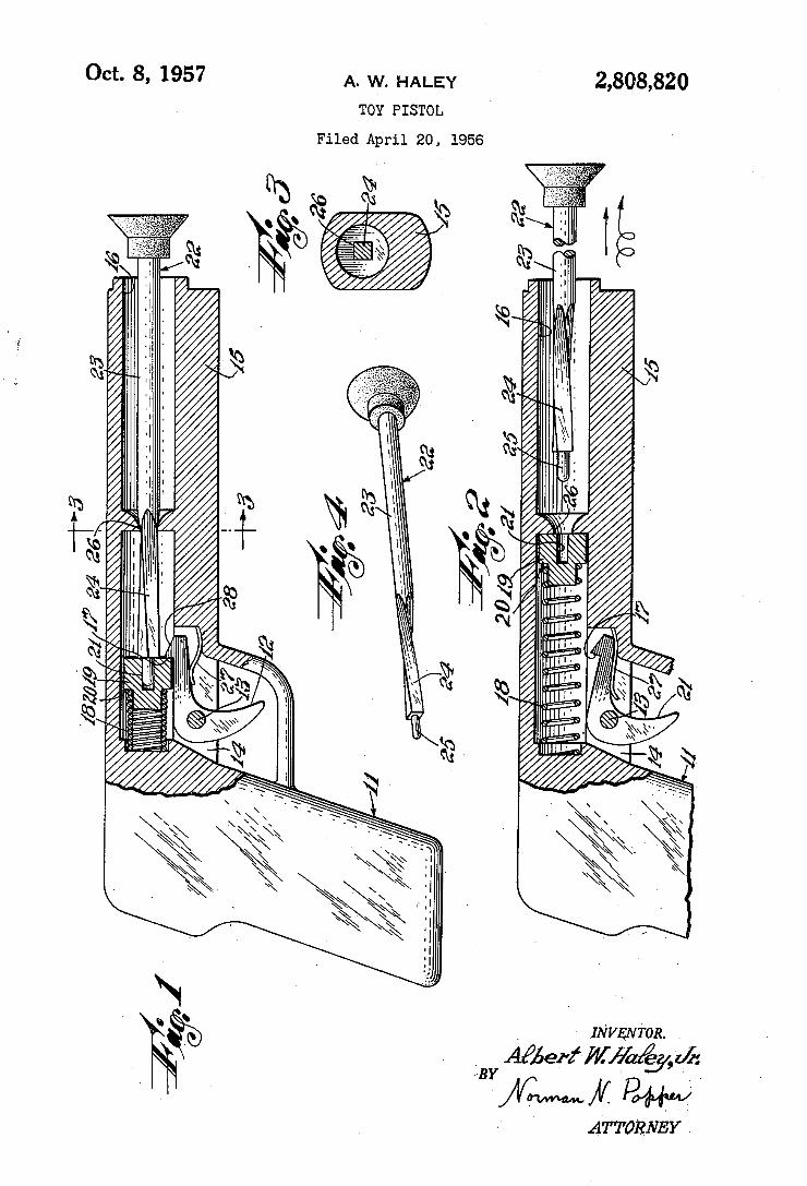
2,808,820
»HIILWÍI | , |.... . .\ . . .. |. V" IL" .13%.
\ wmuumîmü" /o/.PUIMHII A. \
0M. . ,
g wm. wm
A ¿TTURNEY _
Oct. 8, 1957 A. HALEY
TOY PISTOL
Filed April 20, 1956
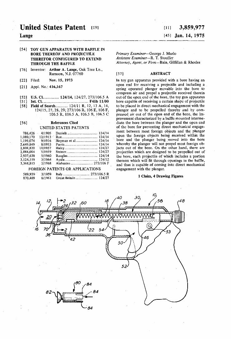
United States Patent 1191 Lange
1111 3,859,977 1451 Jan. 14,1975
[54] TOY GUN APPARATUS WITH BAFFLE IN BORE THEREOF AND PROJECTILE THEREFOR CONFIGURED T0 EXTEND THROUGH THE BAFFLE
Primary Examiner—George J. Marlo Assistant Examiner—R. T. Stouffer Attorney, Agent, or Firm—-Bain, Gil?llan & Rhodes
[76] Inventor: Arthur A. Lange, Oak Tree Ln., Rumson, NJ. 07760 [57] ABSTRACT
[22] Filed: Nov. 15, 1973 In toy gun apparatus provided with a bore having an _ open end for receiving a projectile and including a
[21] Appl' No" 416’167 spring operated plunger movable into the bore to compress air and propel a projectile received therein
[52] U.S. Cl .............. .. 124/14, 124/27, 273/1065 A out of the open end of the bore, the toy gun apparatus [51] Int. Cl. .......................................... .. F4lb 11/00 bore capable of receiving a certain shape of projectile
Field of Search .......... .. 124/11 R, 12, 13 A, 14, to be placed in direct mechanical engagement with the 124/15,27,28,29; 273/106 R, 106 E, 106 F, plunger and to be propelled thereby and by com
106.5 R, 106.5 A, 106.5 B, 106.5 C pressed air out of the open end of the bore, the'ini provement characterized by a baf?e mounted interme
[56] References Cited diate the bore between the plunger and the open end UNITED STATES PATENTS of the bore for preventing direct mechanical engage~
786 426 4/1905 Daniels ‘24/14 ment between most foreign objects and the plunger 1,0s0i170 12/1913 Roe...._.:::::::::::::::: """"""" '11:: 124/14 “P0n the foreign °bjects being received Within the 1,199,074 9/1916 I-Ieyman et al ....... _. 124/14 bore and the Plunger being moved into the bore 2,649,849 8/1953 Parris ................... .. 124/14 whereby the plunger will not propel most foreign ob 2,808,820 10/1957 Haley . . . . . . . . . I . . .. 124/27 jects out of the bore. On the other hand, there are
2,333,004 5/1959 Steiner ------------- u l24/27 projectiles which are designed to be propelled out of
iaulglah ------ - the bore, each projectile of which includes a portion 1 , ya a ---------------------------------- ~~ thereon which will ?t through openings in the baf?e,
3,368,815 ‘ 2/1968 Alabastro ...................... .. 273/106 F and thus is capable of coming into direct mechanical
FOREIGN PATENTS OR APPLICATIONS > engagement with the plunger. ‘
589,939 3/1959 Italy ................. .. 273/1065 R . g . .
870,409 6/1961 Great Britain.....' ................. .. 124/27 1 Clam" 4 D'awmg Flgures
IO ,8 4O .90 4
60 > /_;a / /56 8 t 2'! 1 ' ' T139, .
w 1\
I) i Jl I1 I‘ ' ""I' x
52
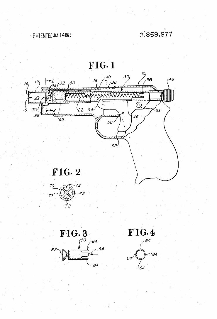
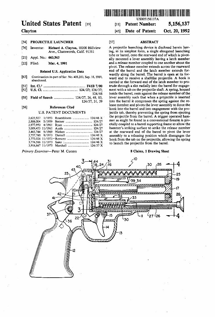
llllllllllllllIlllllllIllllllllllllllIlllllllllllllllllllllllllllllllllllll . US005156137A
UIlltBd States Patent [19] [11] Patent Number: 5,156,137 Clayton [45] Date of Patent: Oct. 20, 1992
[54] PROJECT ILE LAUNCHER [57] ABSTRACT
[76] Inventor; Richard A, Clayton, 10200 l-?llview A projectile launching device is disclosed herein hav- ’ Ave, Chatsworth, Calif, 91311 ing, in its simplest form, a single elongated launching
tube or barrel, onto the rearward end of which is pivot [21] Appl' No‘: 663’563 ally mounted-a lever assembly having a latch member [22] Filed; Mar, 4, 1991 and a release member coupled to one another about the
pivot. The release member extends across the rearward Related US Application Data end of the barrel and the latch member extends for
, , ‘ wardly along the barrel. The barrel is open at its for [63] ioménuatécm'm'pm of set‘ N°'408’283’ sep' 18' 1989’ ward end to receive a shaftlike projectile. A hook is
a an one ‘ carried at the forward end of the latch member to pro
[51] Int. Cl.5 .............................................. .. F41B 7/00 trude through a slot radially into the barrel for engage [52] US. Cl. ...................................... .. 124/27; 124/37; ment with a tab on the projectile shaft. A spring, housed
- 124/48 inside the barrel, rests against the release member of the [58] Field of Search ..................... .. 124/27, 26, 48, 83, lever assembly such that when a projectile is inserted
124/37, 31, 39 into the barrel it compresses the spring against the re 56 R f C, d lease member and pivots the lever assembly to force the
[ 1 e ?ames “e ‘hook into the barrel and into engagement with the pro U.S. PATENT DOCUMENTS jectile tab, thereby preventing the spring from ejecting
2 625 927 1/1953 Rosenbloom ................ .. 124/48 x the Pmjectile fmm the barrel- A trigger "Pam'sd ham‘ 2:888:004 5/1959 Steiner .... ' ' 124/27 m.“ as might be found in a convemmal ?rearm is Piv 2,977,950 4/1961 Ryan _______ ‘_ 124/27 otally coupled to a barrel supporting frame to allow the 3,009,453 11/1961 Ayala , 124/27 hammer’s striking surface to strike the release member 3,465,744 9/1969 Nielsen .. 124/27 at the rearward end of the barrel to pivot the lever 3,757,760 9/1973 Darnell 124/48 X assembly to a releasing position which disengages the
' lslqinero :2 i hook from the tab on the projectile, allowing the spring , , a1 0 ....... .. - - '
3,916,867 11/1975 Marshall ......................... .. 124/37 x to launch the molecule from the barrel‘
Primary Examiner—Peter M. Cuomo ' 8 Claims, 1 Drawing Sheet
l .
3 —~1 44 31 o , 1s 24 1s 30 2e 4
4O . .
43 : 23 [a1 /--2s
re) _' I 1 .n,”,”,,,, “U” ,,
! ,/ 1f’ ‘ ' \39 34 "9 I l l YJJJJ I/IIjI/IIIIII/Il Ill/[Ill
/ O __... -._ ' - '7 ,1?
/ 20 , g 42 ‘ . 28
4| " 33 I;
<7 1 _,__ \ I aka?!
I .
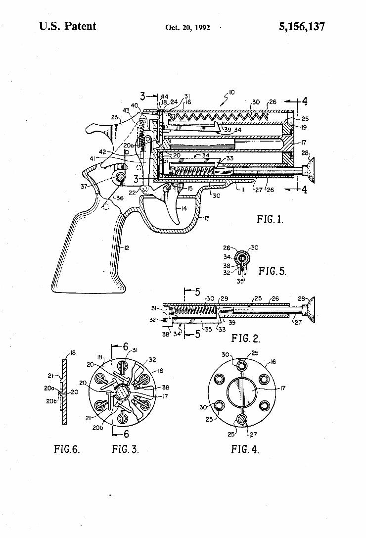
US. Patent Oct. 20, 1992 ‘ 5,156,137
no
3*?324 Bfc's ,5 30 26 ‘1-4 \ \Ylll/IIII 11141 [L1 1111
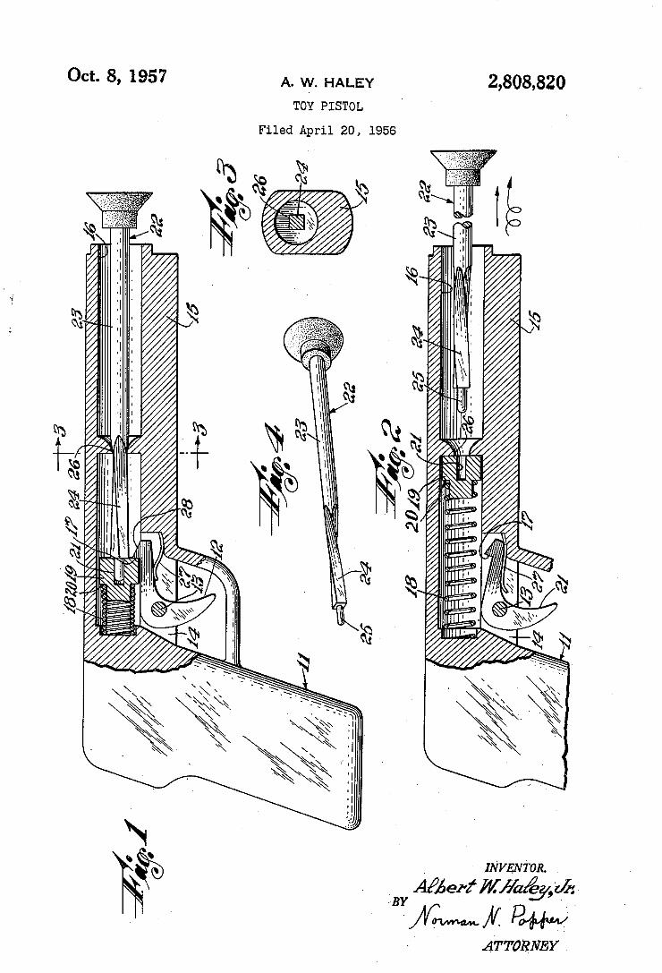
2,808,820
»HIILWÍI | , |.... . .\ . . .. |. V" IL" .13%.
\ wmuumîmü" /o/.PUIMHII A. \
0M. . ,
g wm. wm
A ¿TTURNEY _
Oct. 8, 1957 A. HALEY
TOY PISTOL
Filed April 20, 1956
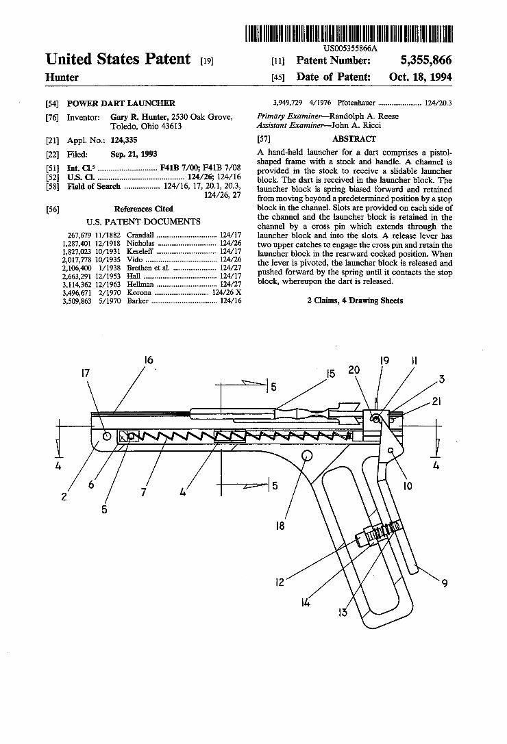
United States Patent [19] USO05355866A
[11] Patent Number: 5,355,866 Hunter [45] Date of Patent: Oct. 18, 1994
[54] POWER DART LAUNCHER 3,949,729 4/1976 Pfotenhauer ..................... .. 124/20.3
[76] Inventor: Gary R. Hunter, 2530 Oak Grove, Primary Examiner-Randolph A. Reese Toledo, Ohio 43613 Assistant Examiner—-John A. Ricci
[21] App1.No.: 124,335 [57] ABSTRACT [22] Filed: Sep. 21’ 1993 A hand-held launcher for a dart comprises a pistol
shaped frame with a stock and handle. A channel is [51] Int. C1.5 .......................... .. F4113 7/00; F4113 7/08 provided in the stock to receive a Slidable launcher [52] U..S. Cl. ....................................... .. 124/26; 124/16 block The dart is received in the launcher block The [58] Fleld 0f Search ............... .. 16, 17, 20.1, 20.3, launcher block is spring biased forward and retained
124/ 26’ 27 from moving beyond a predetermined position by a stop
[56] References Cited bllockhin thei chainnlel. lSlots ire lglovilsled on eacl; side 1(15f t e c anne an t e aunc er 00 1s retame m t e U'S' PATENT DOCUMENTS channel by a cross pin which extends through the
267,679 11/1882 Crandall .............................. .. 124/ 17 launcher block and into the slots. A release lever has 1,287,401 12/1918 1,827,023 10/1931 2,017,778 10/1935 2,106,400 l/1938 2,663,291 12/1953 3,114,362 12/1963 Hellman . . . . . . . . . .. 124/27
3,496,671 2/1970 Korona ..... .. 124/26 X 3,509,863 5/1970 Barker ................................. .. 124/16
two upper catches to engage the cross pin and retain the launcher block in the rearward cocked position. When the lever is pivoted, the launcher block is released and pushed forward by the spring until it contacts the stop block, whereupon the dart is released.
2 Claims, 4 Drawing Sheets
5 20
i b /j / / I.
2 7 A ——/—/—'l 5 lo 5
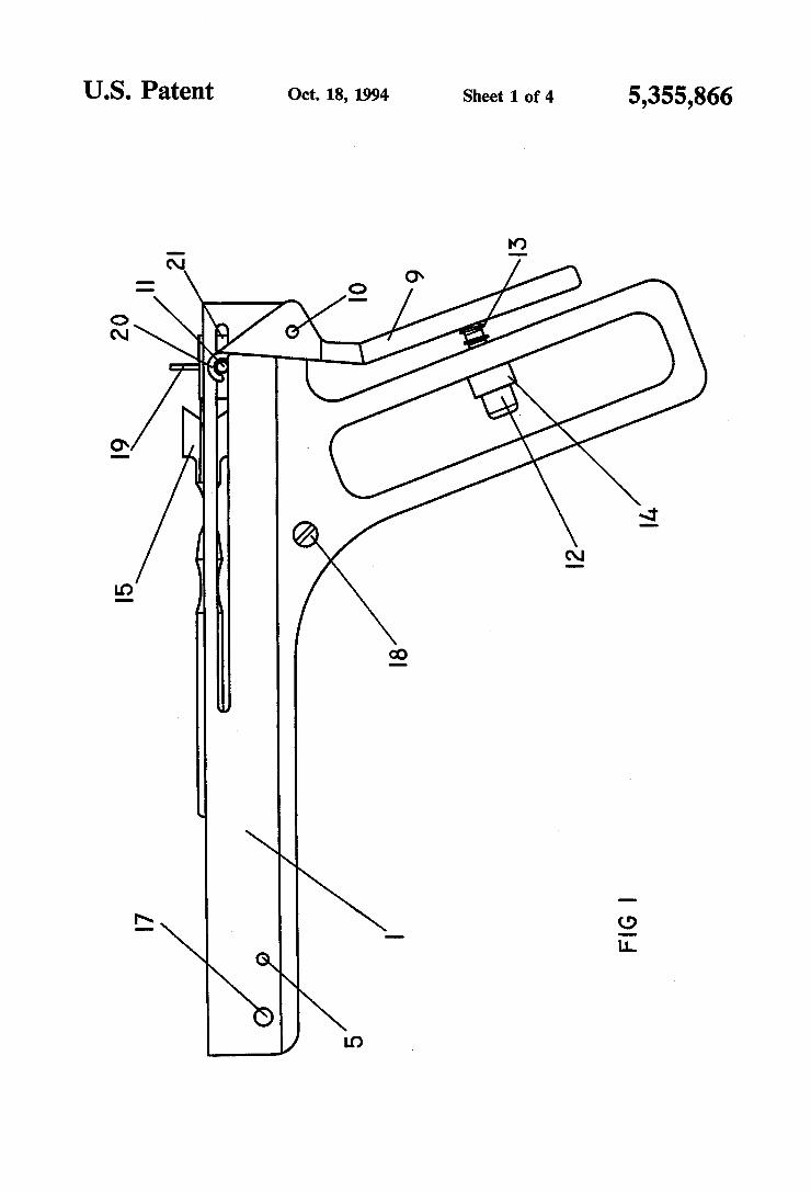
US. Patent Oct. 18, 1994 Sheet 1 of 4 5,355,866
5/ /

US. Patent Oct. 18, 1994 Sheet 2 of 4 5,355,866
IO
l5 \ a A
5
l7‘/ 1% FIG 2
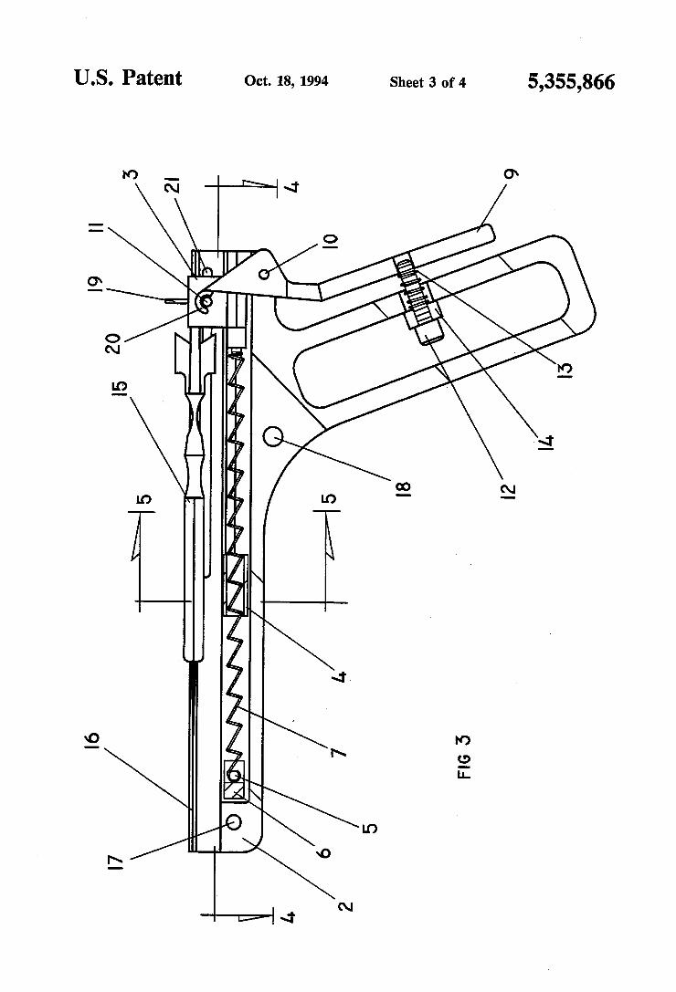
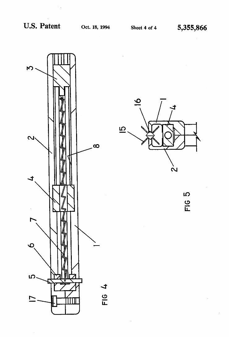
U.S. Patent Oct. 18, 1994 Sheet 4 of 4 5,355,866
I6 I
I5
FIG l4
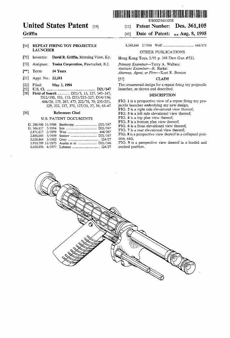
lllllllllllllllllllllllllllllllllllllllllllllllllllllllllllllllllllllllllll . USOOD361 lOSS
Unlted States Patent [19] [11] Patent Number: Des. 361,105 Grif?n [45] Date of Patent: ,1... Aug. 8, 1995
[54] REPEAT FIRING TOY PROJECI‘ILE 4,569,666 2/ 1986 Wolf .................................. .. 446/473
LAUNCHER OTHER PUBLICATIONS
[75] Inventor: David R. Griffin, Morning View, Ky. Hong Kong Toys, 2/91 p‘ 348 Dart Gun #531_
[73] Assignee: Tonka Corporation, Pawtucket, RI. Primary Examiner-Terry A. Wallace ** T ‘ 14 Y Assistant Examiner-R. Barkai
[ 1 arm‘ ears Attorney, Agent, or Firm-Kurt R. Benson
[21] Appl. No.: 22,261 [57] CLAIM
[22] Filed: May 2, 1994 The ornamental design for a repeat ?ring toy projectile {52] US. Cl. ................................................. .. D21/147 launcher, as shown and described. [58] Field of Search .......... .. D2l/3, 13, 127, 145~147;
132mm, 103, 113; D23/223-227; D14/116; DESCRIPTION 446/28, 175, 267, 473; 222/78, 79; 239/211, FIG- 1 is a Perspective View Of a repeat ?ring toy Pro
329, 332, 337, 373; 127/21, 27, 56, 65-67 jectile launcher embodying my new design; _ FIG. 2 is a right side elevational view thereof;
[56] References CIted FIG. 3 is a left side elevational view thereof; U.S. PATENT DOCUMENTS
D. 286,900 11/1986 D. 346,837 5/1994 2,871,617 2/1959 2,888,004 5/1959 3,026,864 3/1962 3,919,799 11/1975 4,016,854 4/1977
Barthropp ........................ .. D2l/ 147
Sun ....... .. D2l/l47
446/267 West _
Steiner D2l/147 Gray ................................... .. 124/27
Austin et a1. .................... .. D2l/l46
Lehman .............................. .. 124/27
FIG. 4 is a top plan view thereof; FIG. 5 is a bottom plan view thereof; FIG. 6 is a front elevational view thereof; FIG. 7 is a rear elevational view thereof; FIG. 8 is a perspective view thereof in a collapsed posi tion; and, FIG. 9 is a perspective view thereof in a loaded and cocked position.
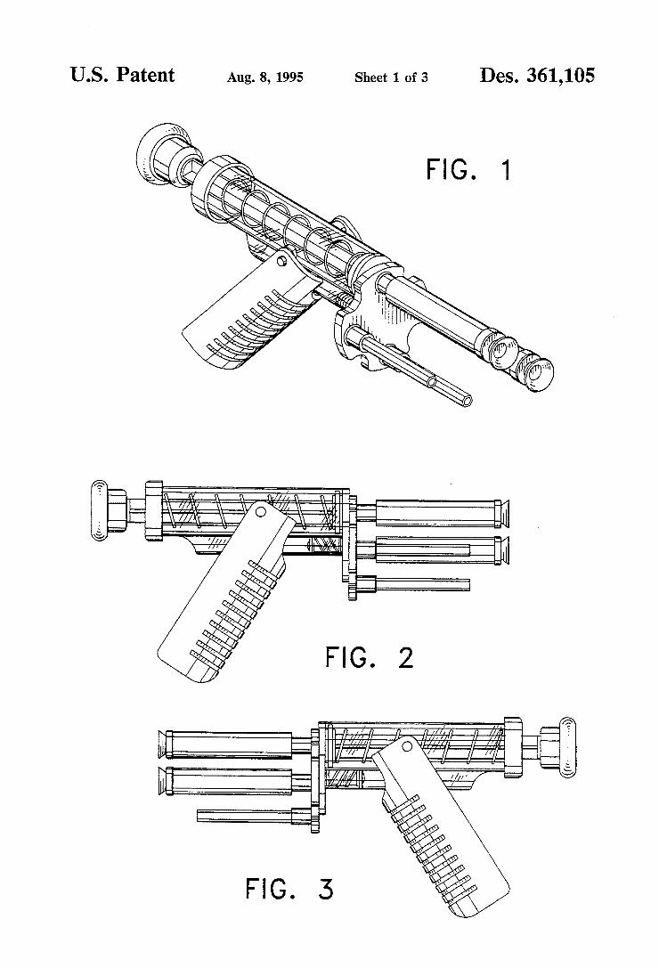
US. Patent Aug. s, 1995 Sheet 1 of3 Des. 361,105
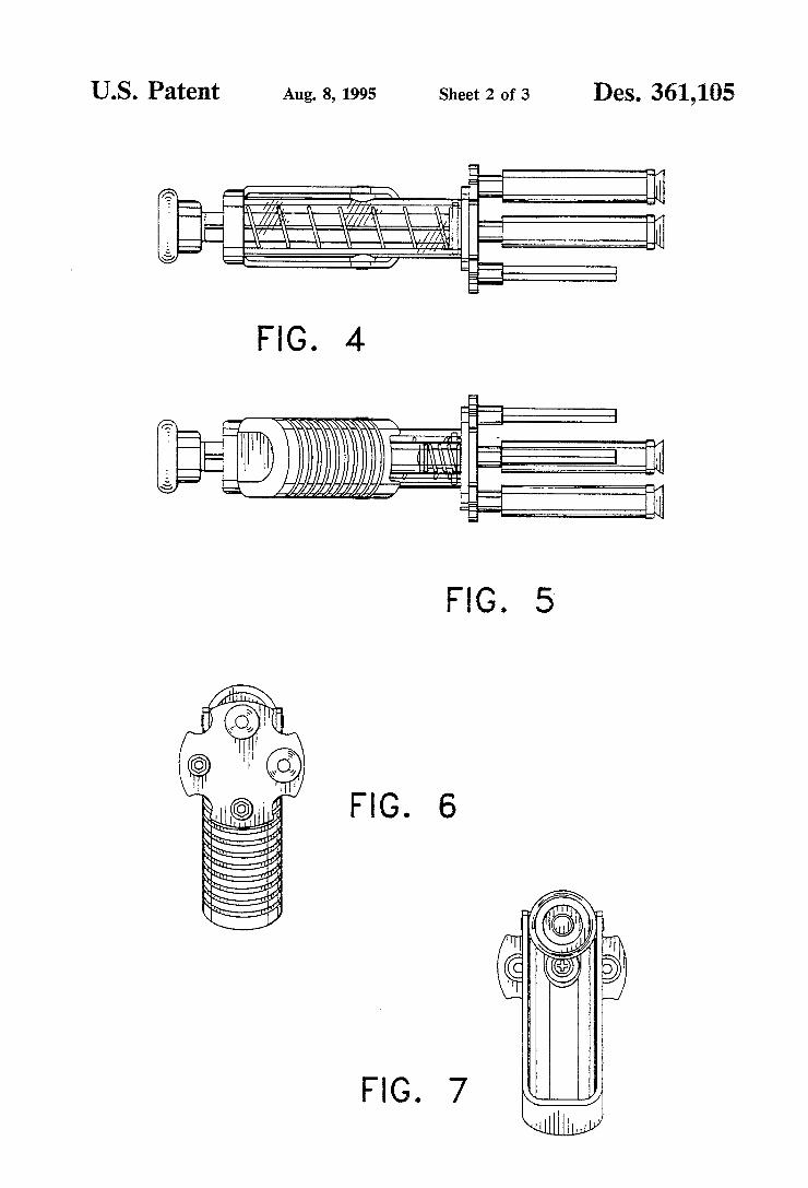
US. Patent Aug. 8, 1995 Sheet 2 0f 3 Des. 361,105
4
FIG.
FIG. 6
FIG. 7
FIG.
QM
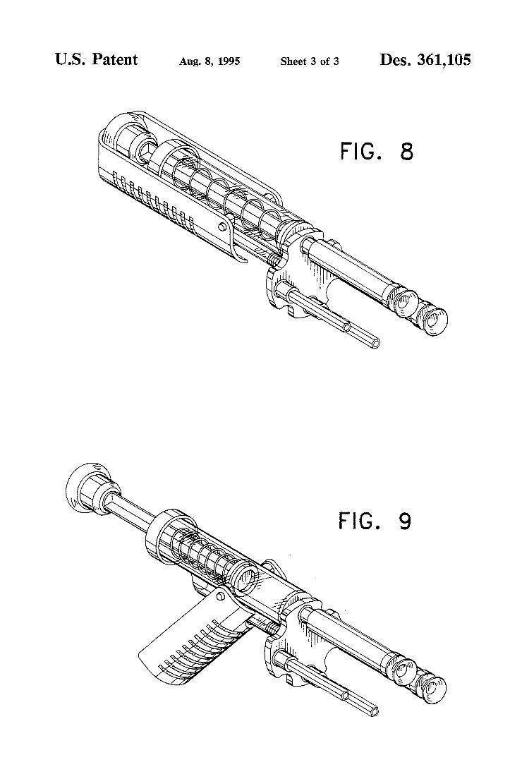
US. Patent Aug. 8, 1995 Sheet 3 of 3 Des. 361,105
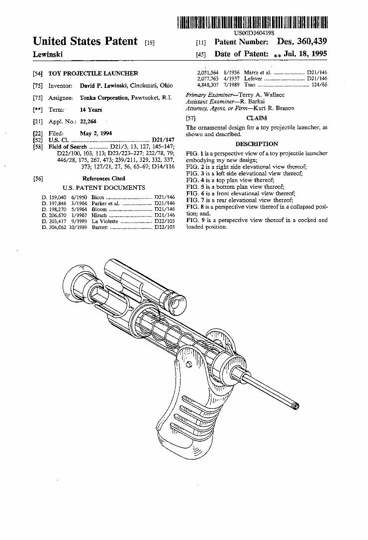
HllllllllllllIIIIIIIIIIIIIIIIIIIllllIlllllllllllllllllllllllllllllllllllll USOOD360439S
Patent Number: [11] Des. 360,439 Date of Patent: *1, Jul. 18, 1995
United States Patent [191 Lewinski [45]
2,051,564 8/1936 Man-a 6M1. D21/ 146 [54] TOY PROJECI'ILE LAUNCHER 6 4 1 / 1 2 D
2,077,763 4/1937 Lefever 4,848,307 7/1989 Tsao 124/66 [75] Inventor: David P. Lewinski, Cincinnati, Ohio - - Primary Examiner-Terry A. Wallace
73 A : T nka rpo P Wt k t, R.I. _ _ [ ] sslgnee 0 Co when’ a as 6 Assistant Examiner—-R. Barka1
Attorney, Agent, or Firm-Kurt R. Benson ["1 Term: 14 Years
CLAIR/I [57] The ornamental design for a toy projectile launcher, as shown and described.
[21] Appl. No.: 22,264
[22] Filed: May 2, 1994 [52] US. Cl. D21/147 {58] Field of Search 1321/3, 13, 127, 145-147; DESCRIPTION
D22/ 100, 103, 113; D23/ 223-227; 222/78, 79; FIG. 1 is a perspective view of a toy projectile launcher 446/28, 175, 267, 473; 239/211, 329, 332, 337, embodying my new design;
373; 127/21, 27, 56, 65-67; D14/ 116 FIG. 2 is a right side elevational view thereof; FIG. 3 is a left side elevational view thereof; FIG. 4 is a top plan view thereof; [56] References Cited
U.S. PATENT DOCUMENTS FIG. 5 is a bottom plan view thereof; FIG. 6 is a front elevational view thereof; FIG. 7 is a rear elevational view thereof; FIG. 8 is a perspective view thereof in a collapsed posi tion; and, FIG. 9 is a perspective view thereof in a cocked and loaded position.
Tm n mmm "t u "at" me H "mm
.r. h em .1 mkowvm .mmbwa BPB LB mmm?mwmw 999999 11111” MMMUWO 1 mnmmua 1016,30, 970063“ 59900 111233 DDDDDD
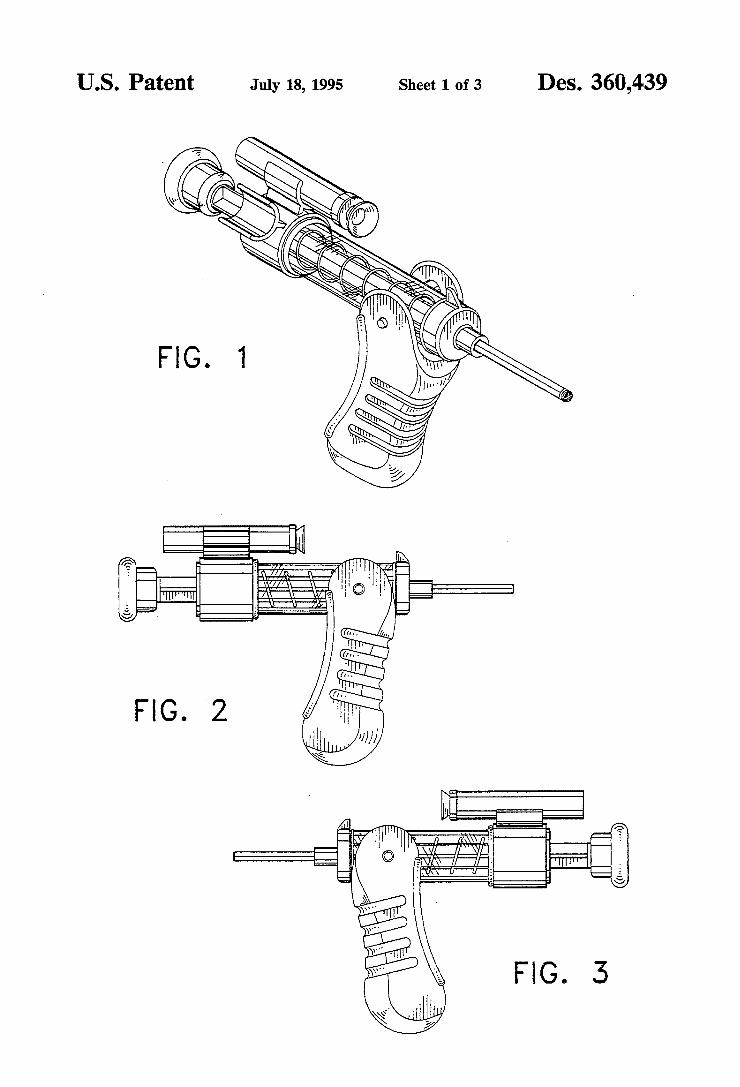
US. Patent July 18, 1995 Sheet 1 of 3 Des. 360,439
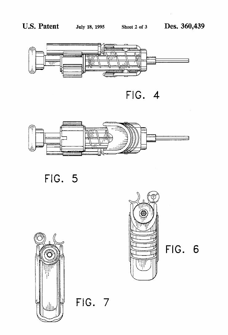
US. Patent July 18,1995 Sheet 2 of 3 Des. 360,439
FIG. 5
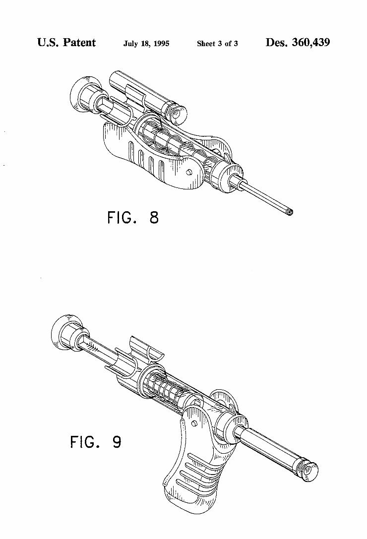
US. Patent July 18, 1995 Sheet 3 of 3 Des. 360,439
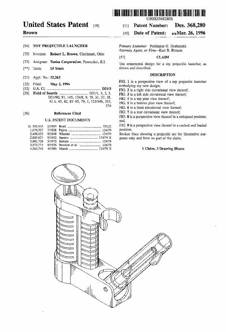
United States Patent [191 Brown
[54] TOY PROJECTILE LAUNCHER
[75] Inventor: Robert L. Brown, Cincinnati, Ohio
[73] Assignee: Tonka Corporation, Pawtucket, R.I.
[**] Term: 14 Years
[21] Appl. No.: 22,263
[22] Filed: May 2, 1994 [52] US. Cl. D2113 [58] Field of Search ................................. .. D21/1, 3, 2, 5,
D21/90, 91, 145; 124/8, 9, 79, 31, 37, 38, 41.1, 45, 82, 83-85, 79, 1; 123/348, 355,
374
[56] References Cited
U.S. PATENT DOCUMENTS
2/1995 7/1928 9/1948 9/1952 5/1972 8/1976 4/1986
D. 355,445 1,678,527 2,449,432 2,609,637 3,662,728 3,973,774 4,583,743
llllllllllllllllllllllllllllIlllIllllllllllllllIlllllllllllllllllllllllllll USOOD36828OS
[11] Patent Number:
[45] Date of Patent:
Des. 368,280 **Mar. 26, 1996
Primary Examiner-Prabhakar G. Deshmukh Attorney, Agent, or Firm~Kurt R. Benson
[57] CLAIM
The ornamental design for a toy projectile launcher, as shown and described.
DESCRIPTION
FIG. 1 is a perspective view of a toy projectile launcher embodying my new design; FIG. 2 is a right side elevational view thereof; FIG. 3 is a left side elevational view thereof; FIG. 4 is a top plan view thereof; FIG. 5 is a bottom plan view thereof; FIG. 6 is a front elevational view thereof; FIG. 7 is a rear elevational view thereof; FIG. 8 is a perspective view thereof in a collapsed position; and, FIG. 9 is a perspective view thereof in a cocked and loaded position. Broken lines showing a projectile are for illustrative pur poses only and form no part of the claim.
1 Claim, 3 Drawing Sheets
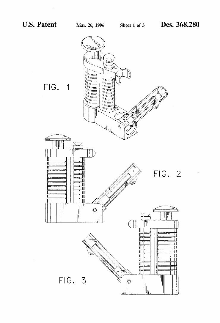
US. Patent Mar. 26, 1996 Sheet 1 0f 3 Des. 368,280
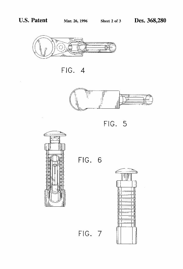
US. Patent Mar. 26, 1996 Sheet 2 0f3 Des. 368,280
FIG. 7
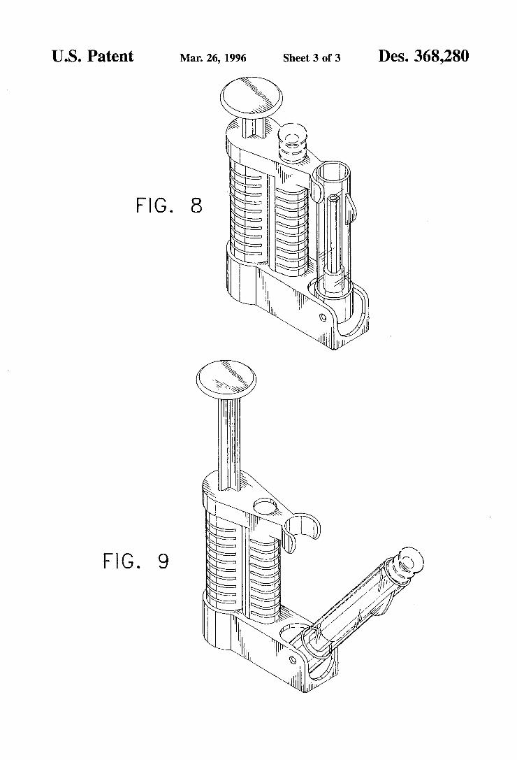
US. Patent Mar. 26, 1996 Sheet 3 of 3 Des. 368,280
kwm 2%
FIG. 8
\
ml .4 II | l , . 1 , , - b w. wavy‘ FIG. 9
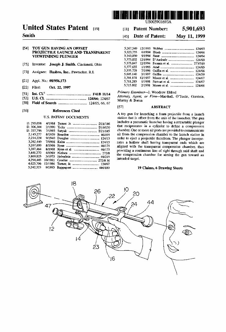
United States Patent 119] Smith
US005901693A
5,901,693 May 11, 1999
[11] Patent Number:
[45] Date of Patent:
[54] TOY GUN HAVING AN OFFSET PROJECTILE LAUNCH AND TRANSPARENT VIEWFINDING PLUNGER
[75] Inventor: Joseph J. Smith. Cincinnati. Ohio
[73] Assignee: Hasbro, Inc.. Pawtucket. R.I.
[21] Appl. No.: 08/956,173
[22] Filed: Oct. 22, 1997
[51] Int. Cl.6 .................................................... .. F41B 11/14
[52] US. Cl. ............................................... .. 124/66; 124/67
[58] Field of Search ................................. .. 124/65. 66. 67
[56] References Cited
U.S. PATENT DOCUMENTS
D. 295,058 4/1988 Turner, Jr. ............................ .. D21/146 D. 306,304 2/1990 Tichy D16/130 D, 337,796 7/1993 Sutyak D2l/145 2,145,277 8/1939 Rtmrdon . . 46/195
2,214,224 9/1940 Douglas . 124/15 3,262,440 7/1966 Kuhn .... .. 124/15
3,267,600 8/1966 Ryan .... .. 46/175 3,397,484 8/1968 Ryan et a1. 461175 3,441,270 4/1969 Nielsen . . . . . . . . . . .. 272/8
3,869,825 3/1975 Heberlein 46/219 4,294,445 10/1981 Crosbie .. 272/8 M 4,625,706 12/1986 Turner, Jr. .. 124/67 5,242,323 9/1993 Rappaport ............................. .. 446/180
5,267 ,549 12/1993 5,323,755 6/1994 5,343,850 9/1994 5,373,832 12/1994 5,375,847 1211994 5,377 ,655 1/ 1995 5,535,729 7/ 1996 5 .605, 140 2/1997 5,701,878 1211997 5,711,285 1/ 1998 5,715,802 2/1998
Primary Examiner-J. Woodrow Eldred Attorney, Agent, or Firm—Marsha1l. O‘Toole. Gerstein. Murray & Borun
[57] ABSTRACT
A toy gun for launching a foam projectile from a launch station that is oifset from the axis of the launcher. The gun includes a pneumatic launcher having a retractable plunger that reciprocates in a cylinder to de?ne a compression chamber. One or more air ports are provided to communicate air from the compression chamber to the launch station in order to eject a projectile therefrom. The plunger incorpo rates a hollow shaft having transparent ends which are aligned with the transparent compression chamber. thus providing a continuous line of sight through said shaft and the compression chamber for aiming the gun toward an intended target.
19 Claims, 6 Drawing Sheets
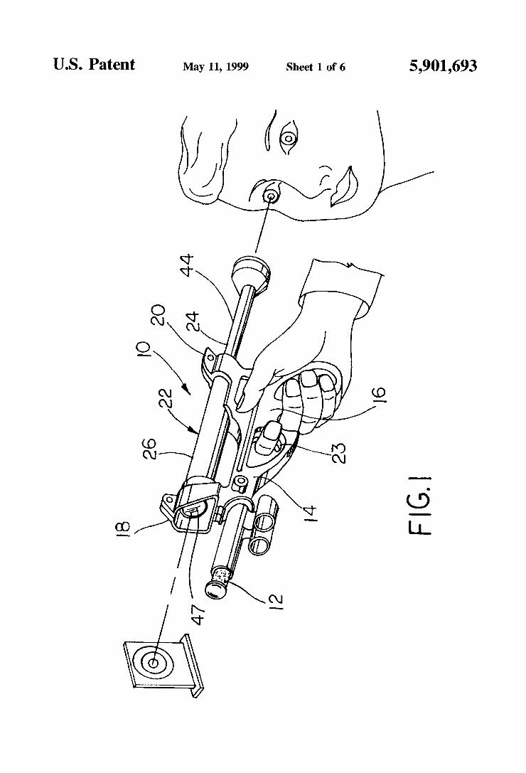
US. Patent May 11, 1999 Sheet 1 of6 5,901,693
FIGI
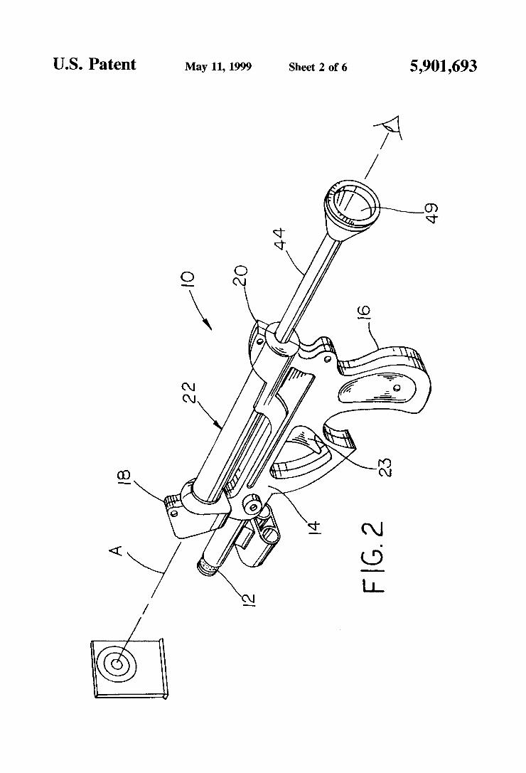
US. Patent May 11, 1999 Sheet 2 0f 6 5,901,693
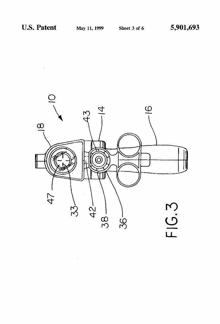
US. Patent May 11, 1999 Sheet 3 0f 6 5,901,693
no;
9 3
@MWQU 9 HM @ _ mm
O_\\ _ \lv Q ..L
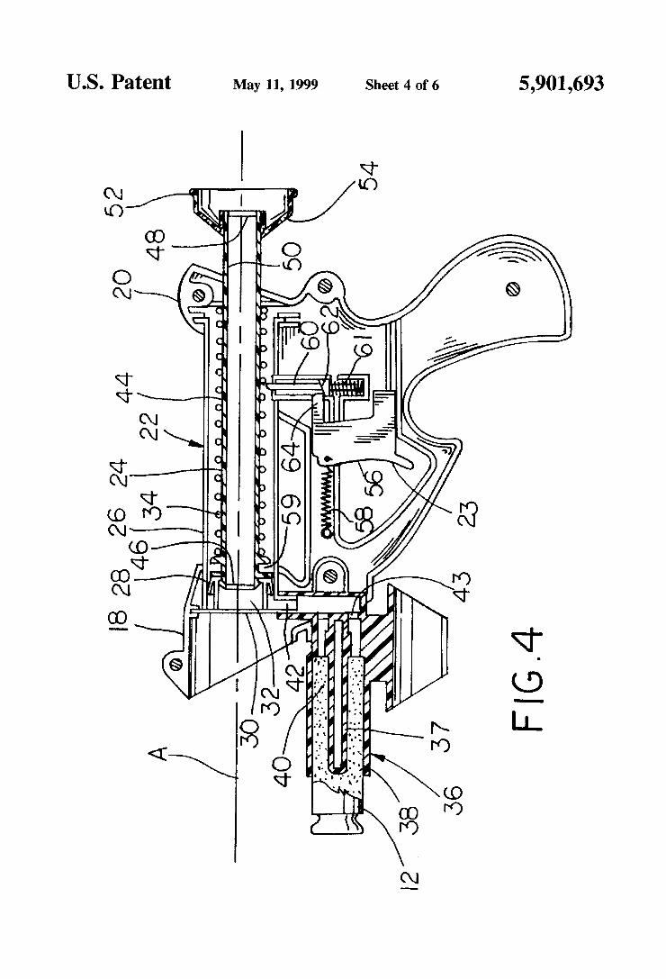
US. Patent May 11, 1999 Sheet 4 of 6 5,901,693
Q. @ w. @E
mm
1|! .9 mm
#0 \_ 1 __. 5: / ..1
® E: o @ .,....................;- .
/
J 8 vfé $1.1M NW, 9u
I / I \_ Ill >
s ,
v \. x f g \
3 mm 1% @w <
mm ON in wm. @m mm Q
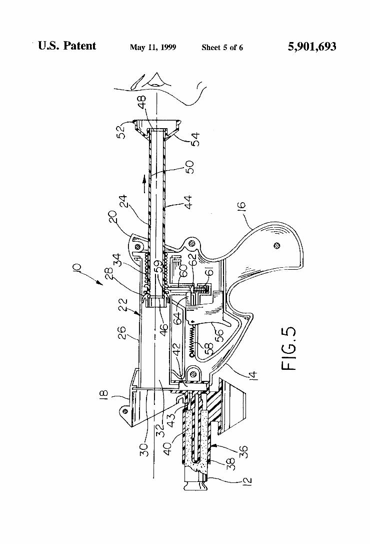
' US. Patent May 11, 1999 Sheet 5 0f 6 5,901,693
Q Q ,,
/
Q @@
mm
a _ ____ nw/ & _ ..... ;
Wm @ N _ E: .
ww %
Q
@Q _ 1w om
@ \\ M \ II @
mm X 1mm N @m
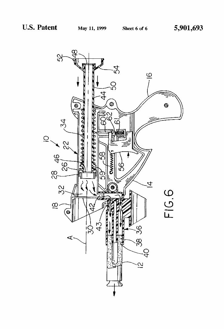
US. Patent May 11, 1999 Sheet 6 of 6 5,901,693
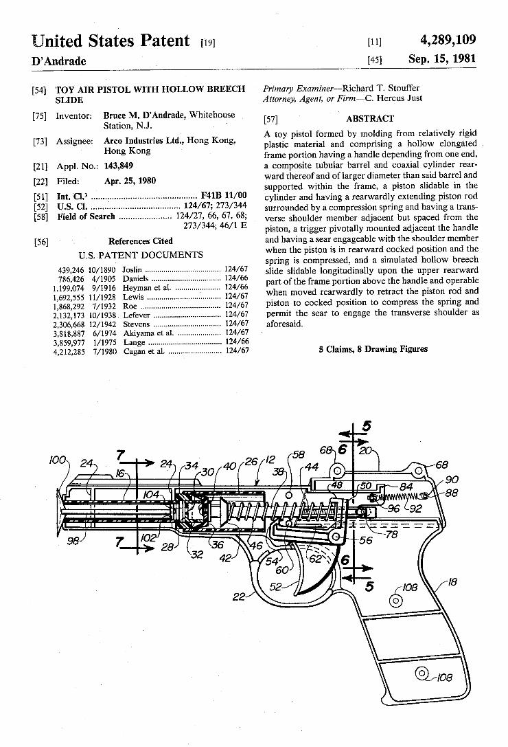
United States Patent [19] [11] 4,289,109 D’Andrade [45] Sep. 15, 1981
[54] TOY AIR PISTOL WITH HOLLOW BREECH ' Primary Examiner—Richard T. Stouffer SLIDE Attorney, Agent, or Firm—C. Hercus Just
[75] Inventor: lggltcignMlzlgAndrade, whitehouse [57] ABSTRACT
[73] Assignee: Arco Industries Ltd., Hong Kong, A} to}, plstol folrmeg by moldlng frog] Flam/$13, “g1: Hong Kong p astic materia an comprising a ‘o ow e ongate ,
. frame portion having a handle dependmg from one end, [21] Appl. No.: 143,849 a composite tubular barrel and coaxial cylinder rear [22] Filed: Apr. 25, 1980 ward thereof ‘and of larger diameter than said barrel and
supported within the frame, a piston slidable 1n the [51] Int. Cl.3 ...... ., .................................... .. F41B 11/00 cylinder and having a rearwardly extending piston rod [52] U‘.S. Cl. ........... .; . . . . . . . .. 124/67; 273/344 Surrounded by a Compression Spring and having a trans_
Fleld of Search ..................... .. 66, 67, Verse Shoulder member adjacent but Spaced from the 273/344; 46/1 E piston, a trigger pivotally mounted adjacent the handle
[56] References Cited and having a scar engageable with the shoulder member
Us PATENT DOCUMENTS when the piston is in rearward-cocked position and the _ spring 1s compressed, and a simulated hollow breech
439,246v 10/1890 10811111 ................................... .. Slide Slidable longitudinally upon the upper rearward 786’426 4/1905 Dame 5 ' ' ' ' ' ' ' ‘ ' ‘ ' ' " / part of the frame portion above the handle and operable
1,199,074 9/1916 Heyman et al. 124/66 h d d1 h . d d 1,692,555 11/1928 Lewis . . . . . . . . . . . . . . .. 124/67 “f 6“ move rearwar, _Y to retractt e Plsm“ To an
1,868,292 7/1932 Roe . . . . . . . . . . .. 124/67 Plston t0 cocked Posltlon to compress the Sprmg and
2,132,173 10/1938 Lefever . 124/67 permit the sear to engage the transverse shoulder as 2,306,668 12/ 1942 Stevens . . . . . . . . . . . . . . . .. 124/67 aforesaid‘
3,818,887 6/1974 Akiyama et a]. 124/67 3,859,977 l/1975 Lange . . . . . . . . . . . . . . . . . . .. 124/66
4,212,285 7/1980 Cagan et a1. ........................ .. 124/67 5 Claims, 8 Drawing Figures
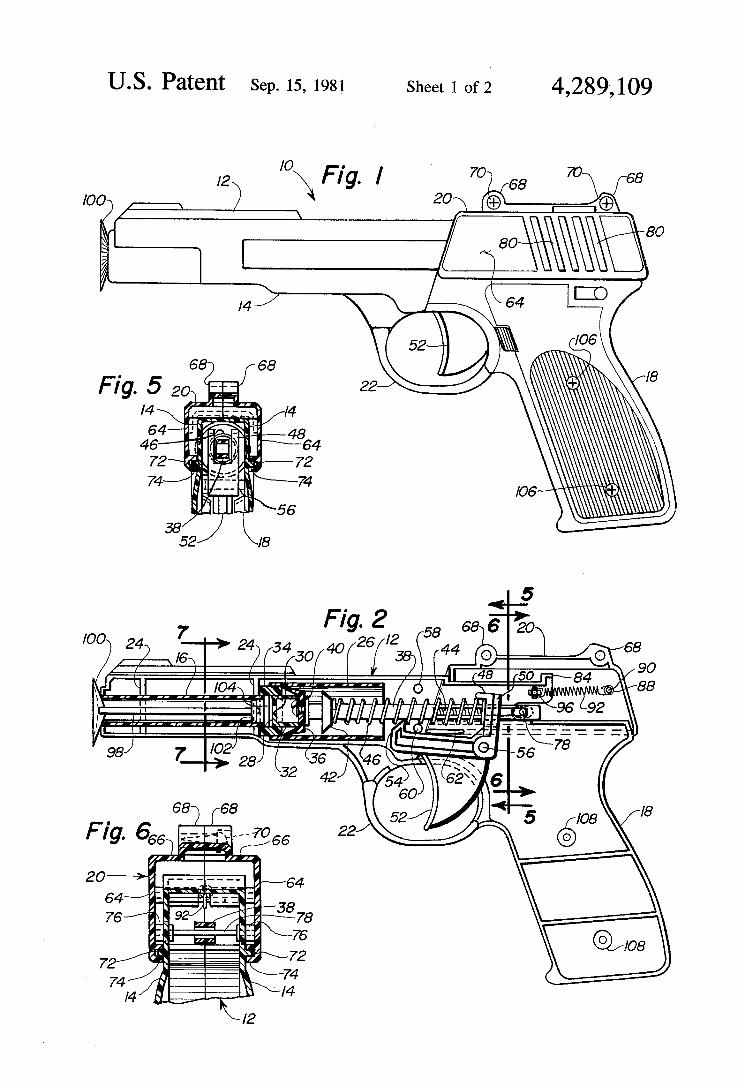
US. Patent sep. 15, 1981 $1611 1 011 4,289,109
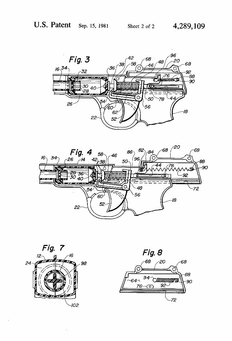
US. Patent Sep. 15, 1981 Sheet 2 of2 4,289,109
,6 Fig. 4 58 46 8e 82 a4 68 68
) 347 (26 (/4 42k38( 5 ho/____,\o/\ 88 44 78 90
22
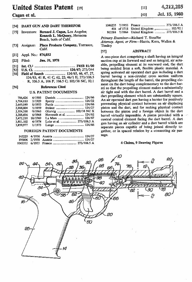
United tates atent [191 Cagan et a1.
[54] DAR’! GUN AND DART THEREFOR
[75] Inventors: Bernard J. Cagan, Los Angeles; Kenneth L. McQuary, Hermosa Beach, both of Calif.
[73] Assignee: Place Products Company, Torrance, Calif.
[21] Appl. No.: 874,032 [22] Filed: Jan. 31, 1978
[51] rm. cu ............................................ .. F4113 11/00 [52] US. CL ....................... .. 124/67; 273/344 [58] Field of Search ..................... .. 124/65, 66, 67, 27,
124/83, 41 R, 41 C, 62, 22; 46/1 E; 273/ 1065 R, 106.5 A, 106 F, 106.5 C; 102/38 NC, 92.1
[56] References Cited U.S. PATENT DOCUMENTS
4/1905 Daniels ................................ .. 124/ 66
3/ 1929 8/1953
5/ 1959 9/1963 6/1968 10/1969
786,426 1,704,810 2,649,849 2,888,004 3,104,588 3,388,696 3,472,218 3,801,102 4/1974 3,859,977 1/1975 Lange ................................... .. 124/66
FOREIGN PATENT DOCUMENTS
145220 4/1936 Austria ..................................... .. 124/27
195806 2/1958 Austria . . . . . . . . . . . . . .. 124/27
1043352 6/ 1953 France ............................ .. 273/ 10615 A
[11] 4,212,285 [45] J 1111. 15, 1930
1046235 7/1953 France ............................ .. 273/ 106.5 A 418 of 1718 United Kingdom .,.. ........ .. 102/921
963384 7/ 1964 United Kingdom ........... .. 273/ 106.5 R
Primary Examiner-Richard T. Stoui'fer Attorney, Agent. or Firm—Harris, Kern, Wallen & Tinsley [57] ABSTRACT A one-piece dart comprising a shaft having an integral suction cup at its forward end and an integral, air actu able, propelling element at its rearward end, the dart being molded from a soft, ?exible plastic material. A spring activated air operated dart gun including a dart barrel having a non-circular cross section uniform throughout the length of the barrel, the propelling ele ment on the dart being complementary to the dart bar rel so that the propelling element makes a substantially air tight seal with the dart barrel. A dart barrel and a dart propelling element which are substantially square. An air operated dart gun having a barrier for positively preventing physical contact between an air displacing piston and the dart, and for making physical contact between the piston and ‘a foreign object in the dart barrel virtually impossible. A piston provided with a 1 central conical element facing the dart barrel. A dart ‘gun having an air cylinder and a dart barrel which are separate pieces capable of being joined directly to gether, or in spaced relation by a connecting air pas sage.
4 , 9 Drawing Figures
20
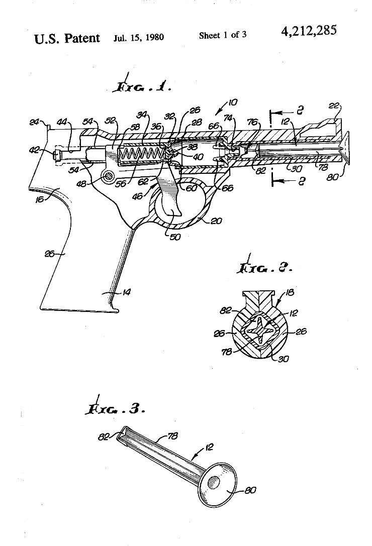
US. Patent Jul. 15, 1980 Sheet 1 Of?! 4,212,285
22
24 44 54 26 /IU ! I? a
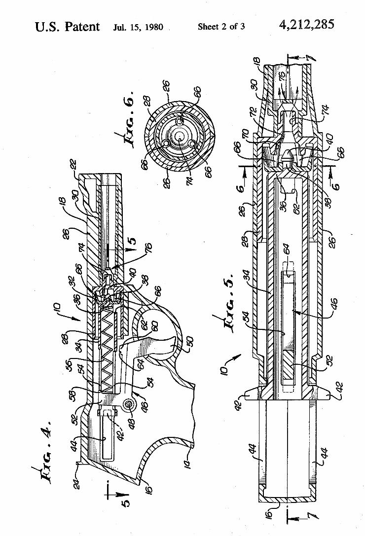
US. Patent Jul. 15, 1980 Sheet 2 of 3 4,212,285
I’!!! ov \ .. . . .. WH .
i §S.\ \ 3 E ., . NW 8 ma, QM; NM. wv “w
Q mm
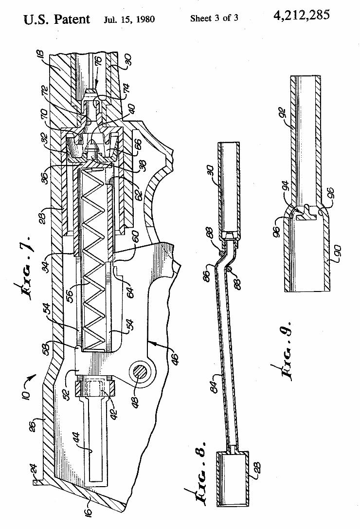
U.S. Patent Jul. 15, 1980 Sheet 3 of 3 4,212,285
.\ will; - y \ % §m \ tub‘
w 8 m \w
Qm § 9» “Egg \
. . . IIJBV/
. - /I!3 {xv , - h . .n
‘Y \ \ \ \‘ “\LIUM3? ____ _ $1551 EW/I V“ \2 A \ L 6% \
\ \YQXMV /\\v\/\ \ \ \ \\\ \\ . R, rmm, Q mkK E\ mmi (a, (m “a, \~\\ \.\\W
. \ . URN ((9 Q E k
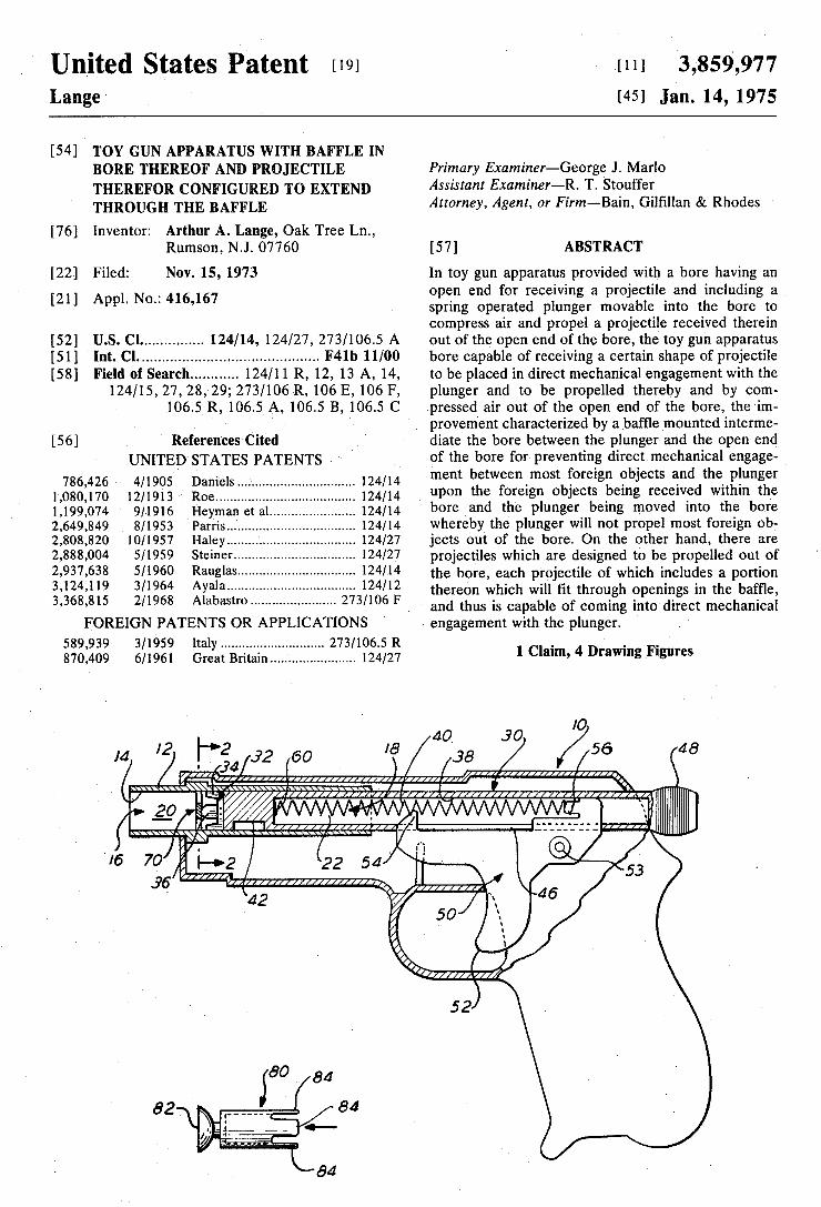
United States Patent 1191 Lange
1111 3,859,977 1451 Jan. 14,1975
[54] TOY GUN APPARATUS WITH BAFFLE IN BORE THEREOF AND PROJECTILE THEREFOR CONFIGURED T0 EXTEND THROUGH THE BAFFLE
Primary Examiner—George J. Marlo Assistant Examiner—R. T. Stouffer Attorney, Agent, or Firm—-Bain, Gil?llan & Rhodes
[76] Inventor: Arthur A. Lange, Oak Tree Ln., Rumson, NJ. 07760 [57] ABSTRACT
[22] Filed: Nov. 15, 1973 In toy gun apparatus provided with a bore having an _ open end for receiving a projectile and including a
[21] Appl' No" 416’167 spring operated plunger movable into the bore to compress air and propel a projectile received therein
[52] U.S. Cl .............. .. 124/14, 124/27, 273/1065 A out of the open end of the bore, the toy gun apparatus [51] Int. Cl. .......................................... .. F4lb 11/00 bore capable of receiving a certain shape of projectile
Field of Search .......... .. 124/11 R, 12, 13 A, 14, to be placed in direct mechanical engagement with the 124/15,27,28,29; 273/106 R, 106 E, 106 F, plunger and to be propelled thereby and by com
106.5 R, 106.5 A, 106.5 B, 106.5 C pressed air out of the open end of the bore, the'ini provement characterized by a baf?e mounted interme
[56] References Cited diate the bore between the plunger and the open end UNITED STATES PATENTS of the bore for preventing direct mechanical engage~
786 426 4/1905 Daniels ‘24/14 ment between most foreign objects and the plunger 1,0s0i170 12/1913 Roe...._.:::::::::::::::: """"""" '11:: 124/14 “P0n the foreign °bjects being received Within the 1,199,074 9/1916 I-Ieyman et al ....... _. 124/14 bore and the Plunger being moved into the bore 2,649,849 8/1953 Parris ................... .. 124/14 whereby the plunger will not propel most foreign ob 2,808,820 10/1957 Haley . . . . . . . . . I . . .. 124/27 jects out of the bore. On the other hand, there are
2,333,004 5/1959 Steiner ------------- u l24/27 projectiles which are designed to be propelled out of
iaulglah ------ - the bore, each projectile of which includes a portion 1 , ya a ---------------------------------- ~~ thereon which will ?t through openings in the baf?e,
3,368,815 ‘ 2/1968 Alabastro ...................... .. 273/106 F and thus is capable of coming into direct mechanical
FOREIGN PATENTS OR APPLICATIONS > engagement with the plunger. ‘
589,939 3/1959 Italy ................. .. 273/1065 R . g . .
870,409 6/1961 Great Britain.....' ................. .. 124/27 1 Clam" 4 D'awmg Flgures
IO ,8 4O .90 4
60 > /_;a / /56 8 t 2'! 1 ' ' T139, .
w 1\
I) i Jl I1 I‘ ' ""I' x
52
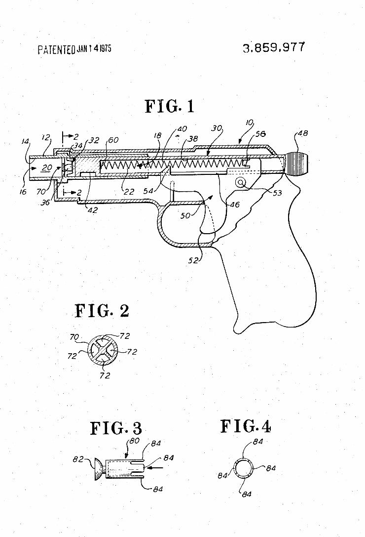
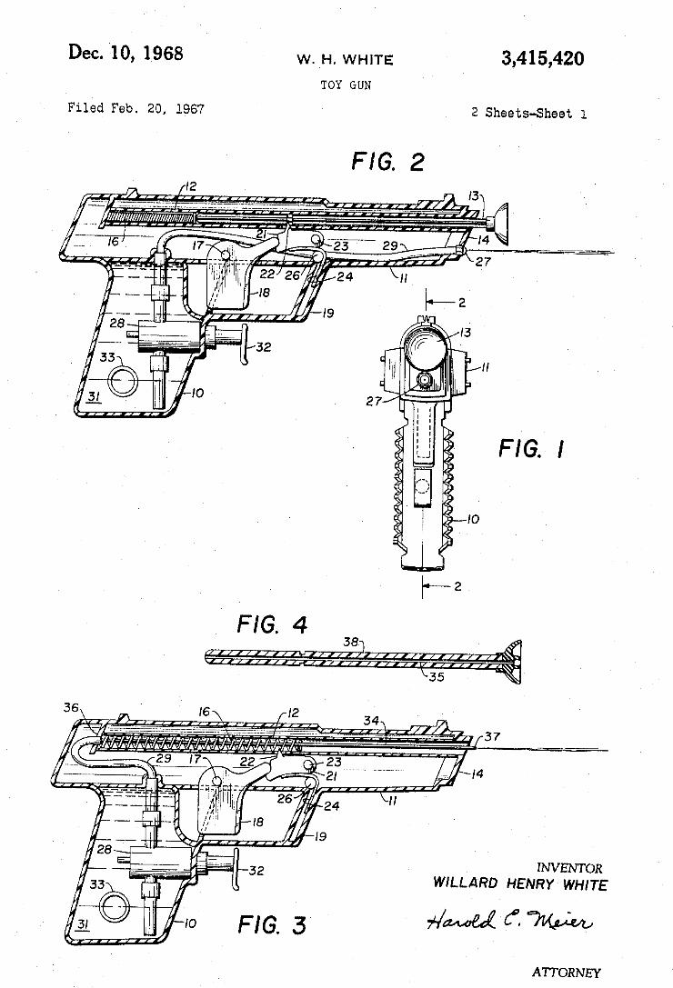
Dec. '10, 1968 ‘ w. H. WHITE 3,415,420
TOY GUN
Filed Feb. 20, 1967 2 Sheets-Sheet l
FIG. 2 I /'f I III I I I 13
_ I6 “ ,7 ,; I "'23 29 I’ I4 _-_——_=
*‘1 _. ' 2?
"1- * 22 26 24 1/
~ 57'‘ " I8 2 __ " I9 P
2a" I \
33 {; II
. FIG. I
<1 .
(1 IO
='\
]~—2 FIG. 4
38] LL] I I 1/71», I I I I I I I III/
\35 [37 _
I4
INVENTOR WILLARD HENRY WHITE
ATTORNEY
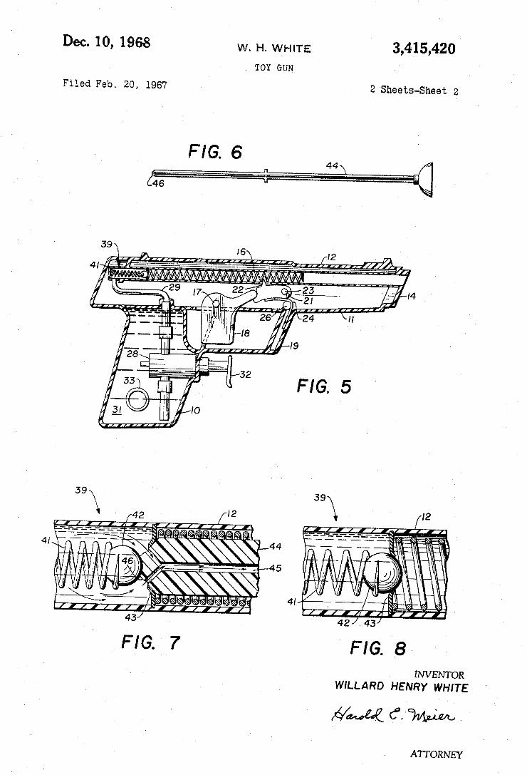
3,415,420 W. H. WHITE Dec. 10, 1968 TOY GUN
2 Sheets-Sheet 2 Filed Feb. 20, 1967
FIG. 6
FIG. 5
I
WILLARD HENRY WHITE
544,44 6. Wm
ATTORNEY
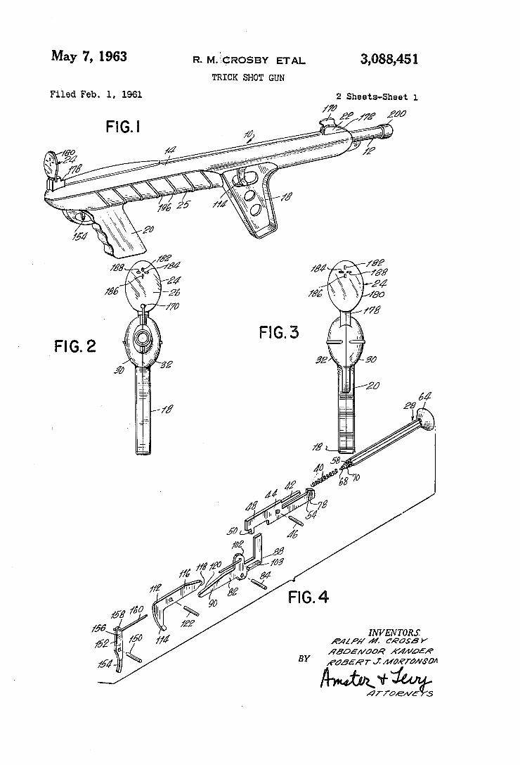
May 7, 1963 R. MQICROSBY ETAL 3,088,451 TRICK snow GUN
Filed Feb. 1, 1961 2 Sheets-Sheet 1
//d ‘ Z
I! ll lllI-lll ‘@ R
INVEN TORJI 1641p” 44. cease)’
sd.
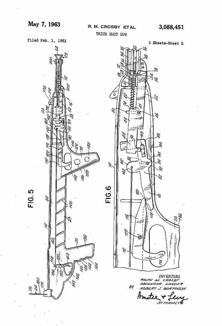
3,088,451 May 7, 1963 R. M. CROSBY ETAL
TRICK SHOT GUN
Filed Feb. 1, 1961
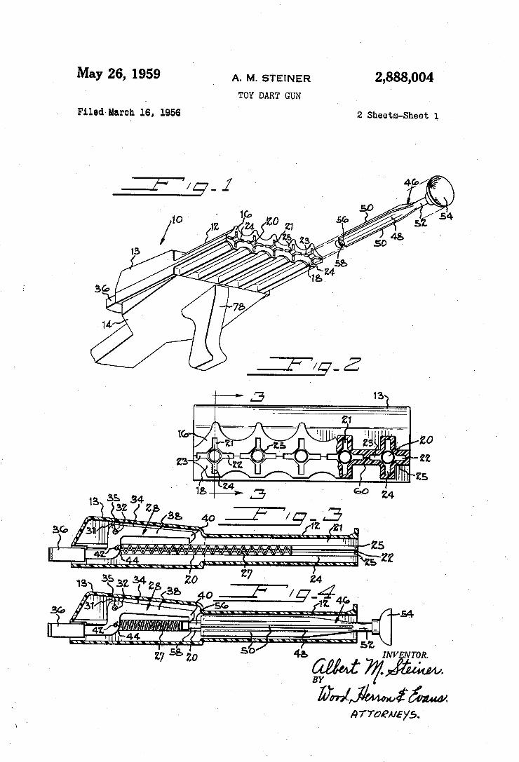
May 26, 1959 A. M. STEINER
Filed'MarOh 16. 1956
2,888,004 TOY DART GUN I
2 Sheets-Sheet 1.
Arran/sys. '
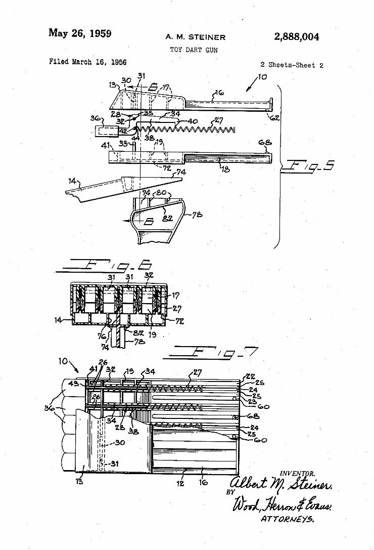
2,888,004 May 26, 1959 A. M. STEINER
TOY DART GUN
Filed Marchv 1s, 195s 2 Sheets-Sheet 2
s ` l
"Am
INUÑHHHCWTI INVENT R.
l BY )y

United States Patent [19] USO05355866A
[11] Patent Number: 5,355,866 Hunter [45] Date of Patent: Oct. 18, 1994
[54] POWER DART LAUNCHER 3,949,729 4/1976 Pfotenhauer ..................... .. 124/20.3
[76] Inventor: Gary R. Hunter, 2530 Oak Grove, Primary Examiner-Randolph A. Reese Toledo, Ohio 43613 Assistant Examiner—-John A. Ricci
[21] App1.No.: 124,335 [57] ABSTRACT [22] Filed: Sep. 21’ 1993 A hand-held launcher for a dart comprises a pistol
shaped frame with a stock and handle. A channel is [51] Int. C1.5 .......................... .. F4113 7/00; F4113 7/08 provided in the stock to receive a Slidable launcher [52] U..S. Cl. ....................................... .. 124/26; 124/16 block The dart is received in the launcher block The [58] Fleld 0f Search ............... .. 16, 17, 20.1, 20.3, launcher block is spring biased forward and retained
124/ 26’ 27 from moving beyond a predetermined position by a stop
[56] References Cited bllockhin thei chainnlel. lSlots ire lglovilsled on eacl; side 1(15f t e c anne an t e aunc er 00 1s retame m t e U'S' PATENT DOCUMENTS channel by a cross pin which extends through the
267,679 11/1882 Crandall .............................. .. 124/ 17 launcher block and into the slots. A release lever has 1,287,401 12/1918 1,827,023 10/1931 2,017,778 10/1935 2,106,400 l/1938 2,663,291 12/1953 3,114,362 12/1963 Hellman . . . . . . . . . .. 124/27
3,496,671 2/1970 Korona ..... .. 124/26 X 3,509,863 5/1970 Barker ................................. .. 124/16
two upper catches to engage the cross pin and retain the launcher block in the rearward cocked position. When the lever is pivoted, the launcher block is released and pushed forward by the spring until it contacts the stop block, whereupon the dart is released.
2 Claims, 4 Drawing Sheets
5 20
i b /j / / I.
2 7 A ——/—/—'l 5 lo 5

US. Patent Oct. 18, 1994 Sheet 1 of 4 5,355,866
5/ /
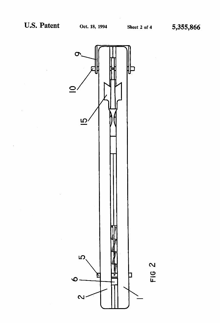
US. Patent Oct. 18, 1994 Sheet 2 of 4 5,355,866
IO
l5 \ a A
5
l7‘/ 1% FIG 2


U.S. Patent Oct. 18, 1994 Sheet 4 of 4 5,355,866
I6 I
I5
FIG l4
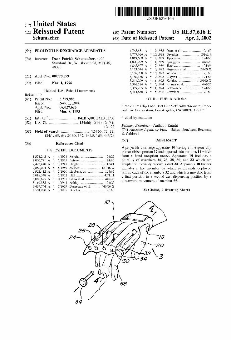
(19) United States (12) Reissued Patent (10) Patent Number:
USO0RE37616E
US RE37,616 E Schumacher (45) Date of Reissued Patent: Apr. 2, 2002
(54) PROJECTILE DISCHARGE APPARATUS 4,768,681 A * 9/1988 Dean et a1. .................. .. 2/160 4,777,666 A * 10/1988 Beverlin . . . . . . . . . .. 2/161.5
(76) Inventor: Dean Patrick Schumacher, 4922 4,819,609 A * 4/1989 Tippmifnn ~~~~ ~~ 124/66 Stamford Dr” W_ Bloom?eld, MI (Us) 4,820,229 A * 4/1989 Spraggms .... .. 446/26 48323 4,848,307 A * 7/1989 Tsao .......................... .. 124/66
5,123,674 A * 6/1992 Bagneres et a1. ......... .. 2/160 X
5,158,208 A * 10/1992 Wilson ........................ .. 2/160
(21) APPI- NO-I 08/778,059 5,186,156 A * 2/1993 Clayton .... .. 124/66 . 5,261,299 A * 11/1993 Kondos ........ .. 2/160X
(22) Flled: NOV-1’ 1996 5,316,514 A * 5/1994 Ellman e161. .. ..... .. 446/26
5,359,985 A * 11/1994 Schumacher .... .. 124/66 R _ f Related [15- Patent Documents 5,414,868 A * 5/1995 Crawford ..................... .. 2/160 eissue 0 :
(64) Patent No.: 5,359,985 OTHER PUBLICATIONS Issued: Nov. 1 1994 APPL N0: 08/027:623 “Rapid Fire Clip Ifoad Dart Gun Set” Advertisement, impe F?ed: Man 8’ 1993 rial Toy Corporation, Los Angeles, CA 90021, 1991.
(51) Int. c1.7 ........................... .. F41B 7/00; F41B 11/00 * cited by examiner
(52) US. Cl. ............................. .. 124/66; 124/1; 124/64; _ _ _ rzmar xamzner on 1
(58) Field Of Search ............................ .. 124/66, 72, 22, 234% igm’?ey’ Agent’ 0’ F"m_Baker’ Donelson’ Bearman 124/1, 65, 64; 2/160, 162, 161.5, 163; 446/26 a We
(57) ABSTRACT (56) References Cited
Aprojectile discharge apparatus 10 having a ?rst generally U'S' PATENT DOCUMENTS planar ribbed portion 12 and opposed side portions 14 Which
1,374,242 A * 4/1921 Sekula ...................... .. 124/22 form a hand reception recess- Apparatus 10 includes 4 2,006,741 A * 7/1935 Lefever _ _ _ _ _ _ _ _ __ 124/66 plurality of chambers 24, 26, 28, 30, and 32 Which are
2,423,448 A * 7/1947 Haight . . . . . . . . . . . .. 124/1 adapted to movably receive a dart 34. Apparatus 10 further
2,888,004 A * 5/1959 Steiner ------- -- -- 124/16 X includes a ?rst member 56 Which is movably deployed
29227412 A : 1/1960 Hf’sbacha Jr- - 124/66 Within each of the chambers 32 and Which is movable from 3,018,578 A 1/1962 Hill . . . . . . . . . . . . . . . . . . . . . .. 42/111 a ?rst position to a Second dart dispensing position by a
3,060,625 A * 10/1962 Glass et al. 446/26 downward movement of member 66 3,119,385 A * 1/1964 Ashley ...................... .. 124/22 '
3,453,774 A * 7/1969 Breneman et a1. . 446/26 X 4,504,980 A * 3/1985 Butcher ....................... .. 2/160 23 Claims, 2 Drawing Sheets
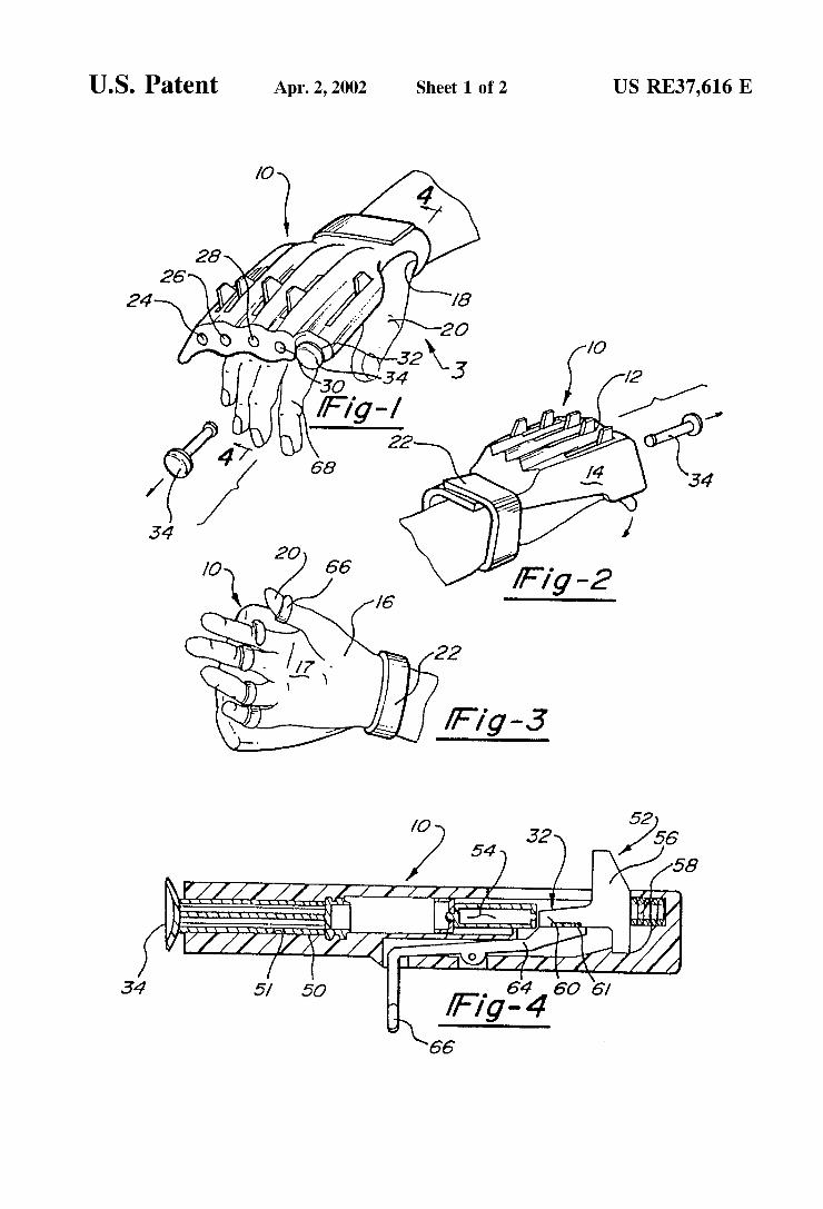
U.S. Patent Apr. 2, 2002 Sheet 1 0f 2 US RE37,616 E
_ 64 60 6/ fFlg-4 66
4 3
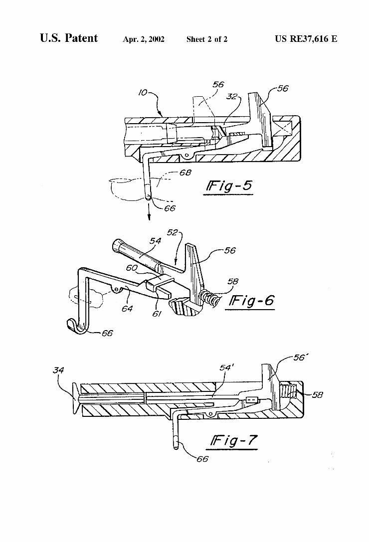
U.S. Patent Apr. 2, 2002 Sheet 2 0f 2 US RE37,616 E
(//////l

Note: Within nine months of the publication of the mention of the grant of the European patent in the European PatentBulletin, any person may give notice to the European Patent Office of opposition to that patent, in accordance with theImplementing Regulations. Notice of opposition shall not be deemed to have been filed until the opposition fee has beenpaid. (Art. 99(1) European Patent Convention).
Printed by Jouve, 75001 PARIS (FR)
(19)E
P2
208
959
B1
TEPZZ Z8959B_T(11) EP 2 208 959 B1
(12) EUROPEAN PATENT SPECIFICATION
(45) Date of publication and mention of the grant of the patent: 13.03.2013 Bulletin 2013/11
(21) Application number: 10150722.6
(22) Date of filing: 14.01.2010
(51) Int Cl.:F41B 11/646 (2013.01) F41B 11/89 (2013.01)
(54) Paper bullet firing pistol toy
Papiergeschosse abfeuernde Spielzeugpistole
Jouet de pistolet tirant des balles de papier
(84) Designated Contracting States: AT BE BG CH CY CZ DE DK EE ES FI FR GB GR HR HU IE IS IT LI LT LU LV MC MK MT NL NO PL PT RO SE SI SK SM TR
(30) Priority: 20.01.2009 JP 2009009584
(43) Date of publication of application: 21.07.2010 Bulletin 2010/29
(73) Proprietor: Agatsuma Co., Ltd.Tokyo (JP)
(72) Inventor: Funaki, ShotaroTokyo (JP)
(74) Representative: Skone James, Robert EdmundGill Jennings & Every LLP The Broadgate Tower 20 Primrose StreetLondon EC2A 2ES (GB)
(56) References cited: FR-A- 918 278 FR-A- 991 950US-A- 2 490 991 US-B2- 6 669 530

EP 2 208 959 B1
16

EP 2 208 959 B1
17

EP 2 208 959 B1
18
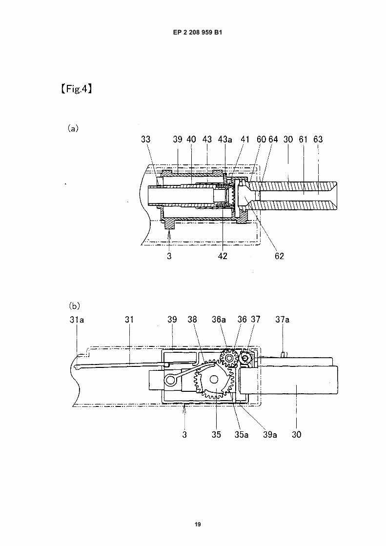
EP 2 208 959 B1
19
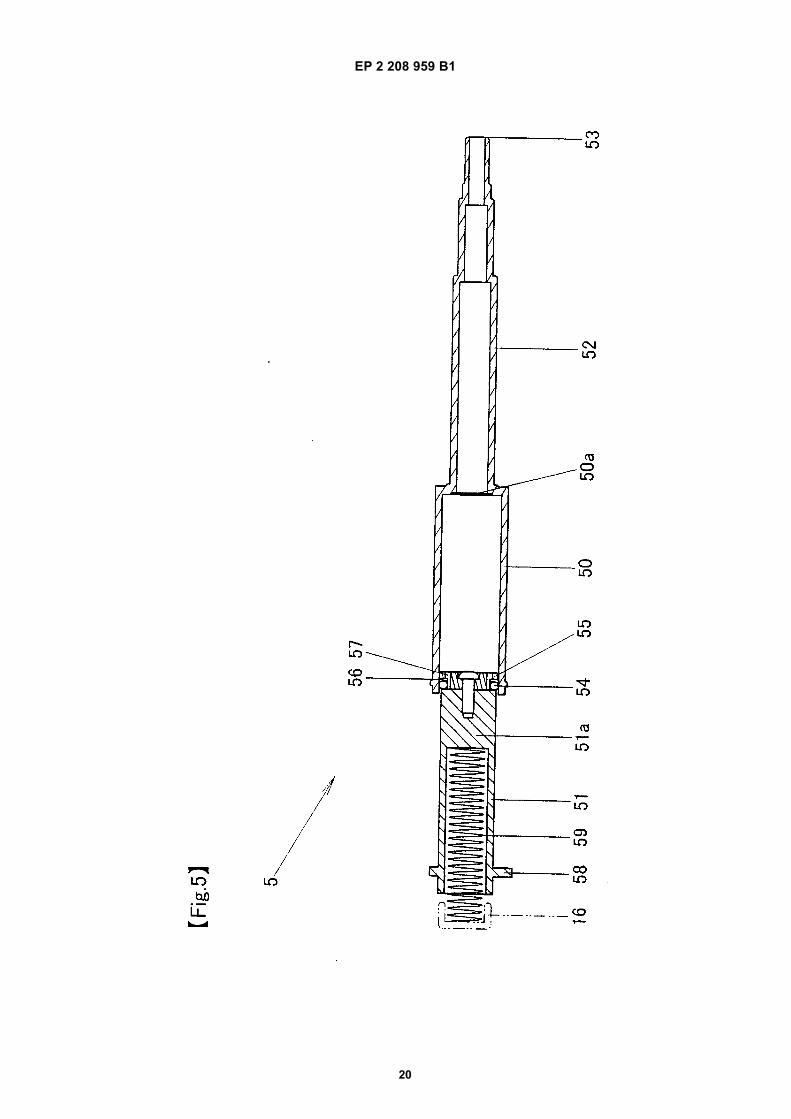
EP 2 208 959 B1
20

EP 2 208 959 B1
21

EP 2 208 959 B1
22

EP 2 208 959 B1
23

EP 2 208 959 B1
24
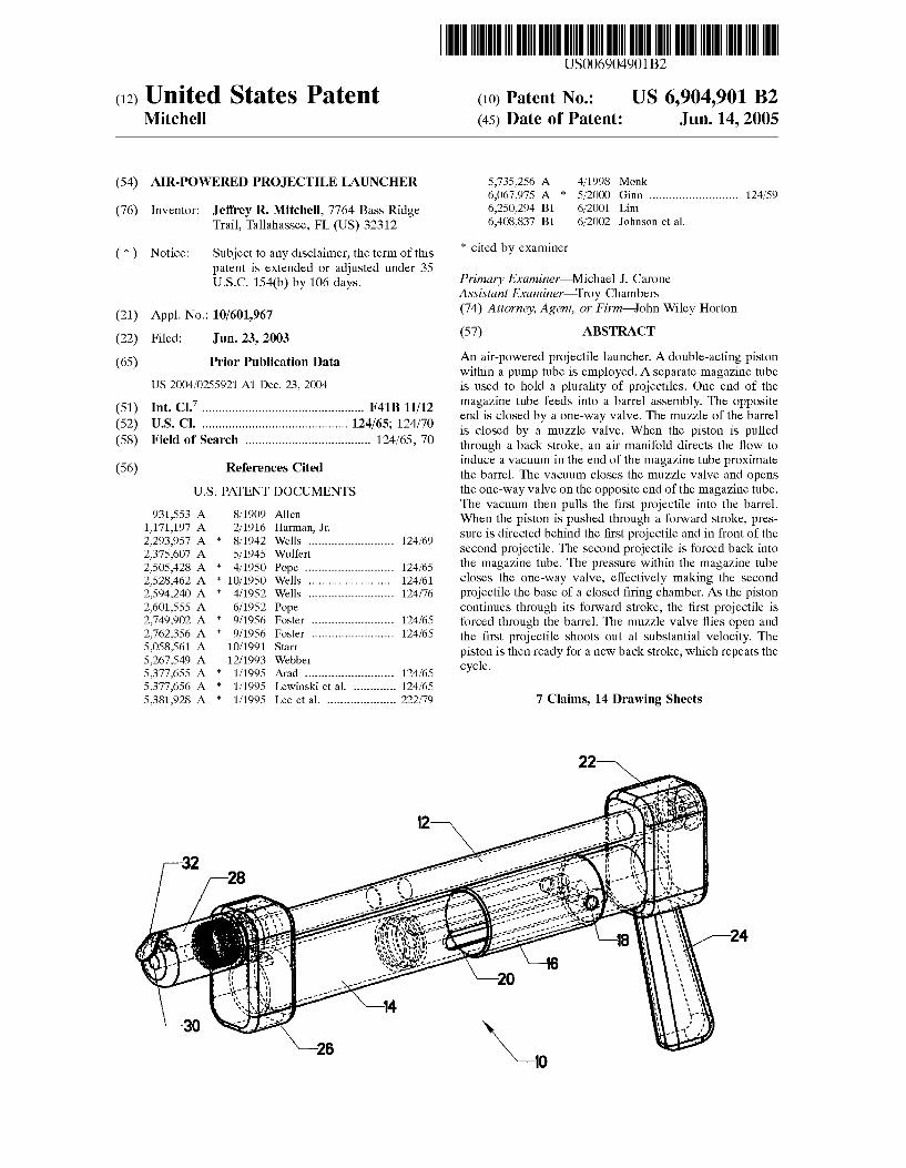
United States Patent US006904901B2
(12) (10) Patent N0.: US 6,904,901 B2 Mitchell (45) Date of Patent: Jun. 14, 2005
(54) AIR-POWERED PROJECTILE LAUNCHER 5,735,256 A 4/1998 Monk 6,067,975 A * 5/2000 Ginn ......................... .. 124/59
(76) Inventor: Je?'rey R. Mitchell, 7764 Bass Ridge 6,250,294 B1 6/2001 Lim Trail, Tallahassee, FL (Us) 32312 6,408,837 B1 6/2002 Johnson et a1.
( * ) Notice: Subject to any disclaimer, the term of this * cued by exammer patent is extended or adjusted under 35 _ U_S_C_ 154(k)) by 106 days_ Primary Examiner—M1chael J. Carone
Assistant Examiner—Troy Chambers (21) Appl' NO‘: 10/601,967 (74) Attorney, Agent, or Firm—John Wiley Horton
(22) Filed: Jun. 23, 2003 (57) ABSTRACT
(65) Prior Publication Data An air-powered projectile launcher. A double-acting piston Within a pump tube is employed. A separate magazine tube
US 2004/0255921 A1 DeC- 23, 2004 is used to hold a plurality of projectiles. One end of the 7 magazine tube feeds into a barrel assembly. The opposite
B1 end is closed by a one-Way valve. The muzzle of the barrel _' ' ' """"""" " ’ is closed by a muzzle valve. When the piston is pulled
(58) Fleld of Search " "" " 124/65’ 70 through a back stroke, an air manifold directs the How to
, induce a vacuum in the end of the ma azine tube roXimate (56) References Clted the barrel. The vacuum closes the mfzzle valve End opens
U_S_ PATENT DOCUMENTS the one-Way valve on the opposite end of the magazine tube. The vacuum then pulls the ?rst projectile into the barrel.
9317553 A 8/1909 Allen When the piston is pushed through a forWard stroke, pres 2 * girlrlrslan’ Jr‘ 124/69 sure is directed behind the ?rst projectile and in front of the
2:375j607 A 5/1945 wulferj """""""""""" " second projectile. The second projectile is forced back into 2,505,428 A 4/1950 Pope ......................... .. 124/65 the magazine hlhe The Pressure Whhih the magazine hlhe 2,528,462 A 4 10/1950 Wells 124/61 closes the one-Way valve, effectively making the second 2,594,240 A * 4/1952 Wells _ 124/76 projectile the base of a closed ?ring chamber. As the piston 2,601,555 A 6/1952 Pope continues through its forWard stroke, the ?rst projectile is 2,749,902 A * 9/1956 FOSICI ....................... .. 124/65 forced through the barreL The muzzle Valve ?ies Open and 2,762,356 A * 9/1956 Foster ....................... .. 124/65 the ?rst projectile Shoots out at Substantial Velocity The
g’ggg’g 2 féiifber piston is then ready for a neW back stroke, Which repeats the 5,377,655 A * 1/1995 Arad ......................... .. 124/65 Cycle‘ 5,377,656 A * 1/1995 Lewinski et a1. 124/65 5,381,928 A * 1/1995 Lee et a1. ................... .. 222/79 7 Claims, 14 Drawing Sheets
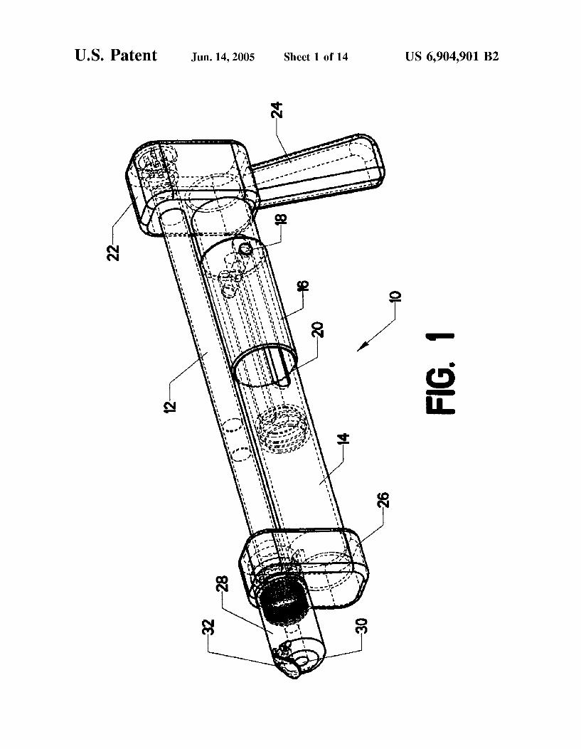
U.S. Patent Jun. 14,2005 Sheet 1 0f 14 US 6,904,901 B2
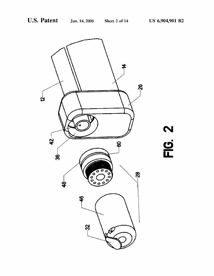
U.S. Patent Jun. 14,2005 Sheet 2 0f 14 US 6,904,901 B2
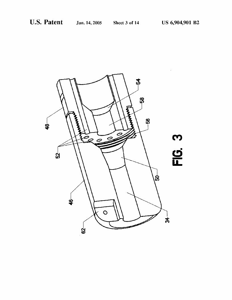
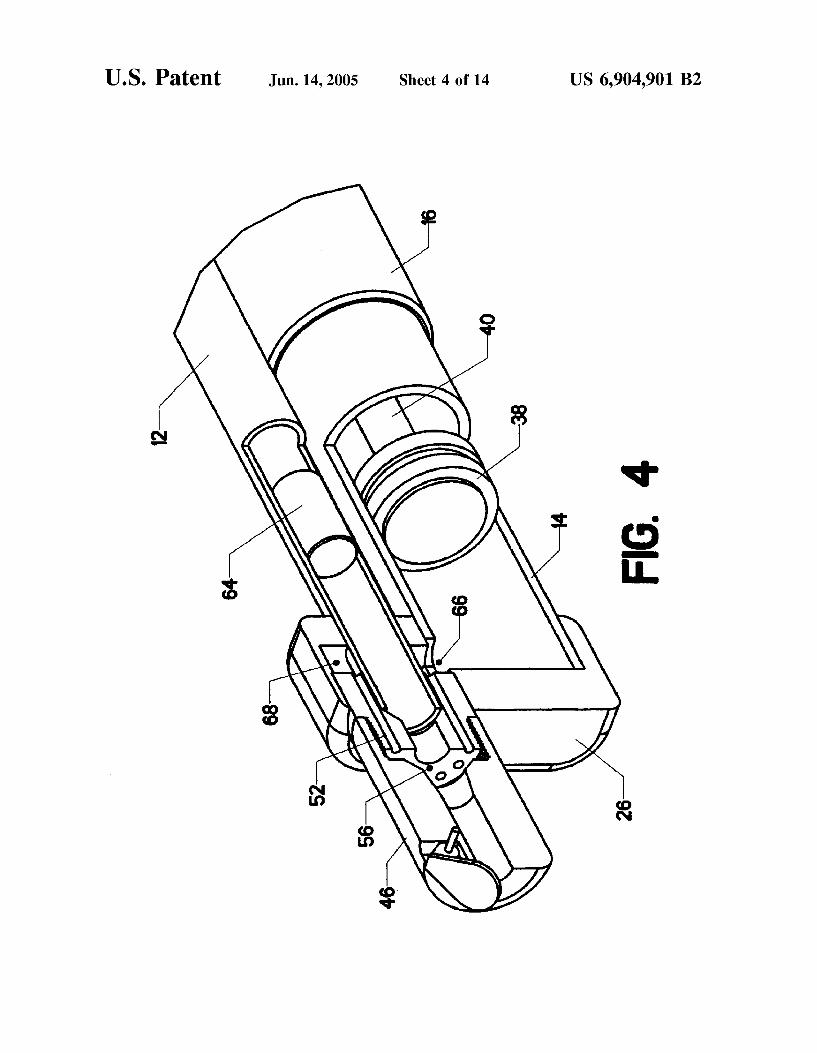
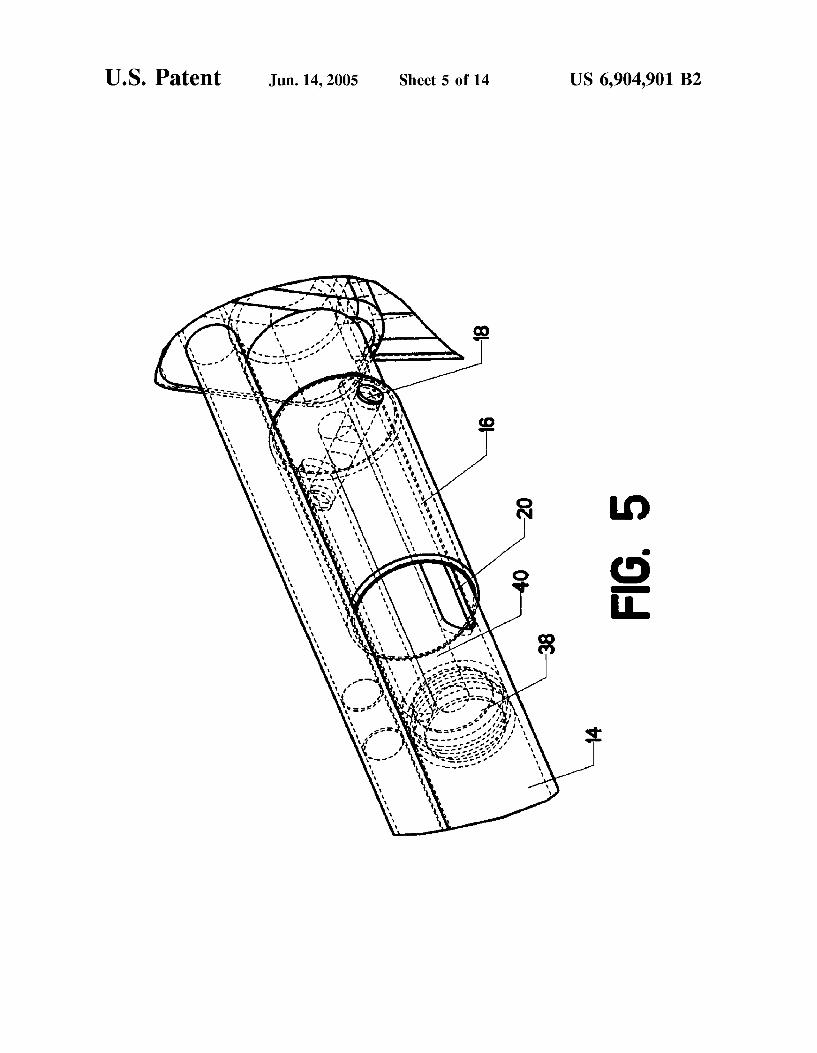
U.S. Patent Jun. 14,2005 Sheet 5 0f 14 US 6,904,901 B2
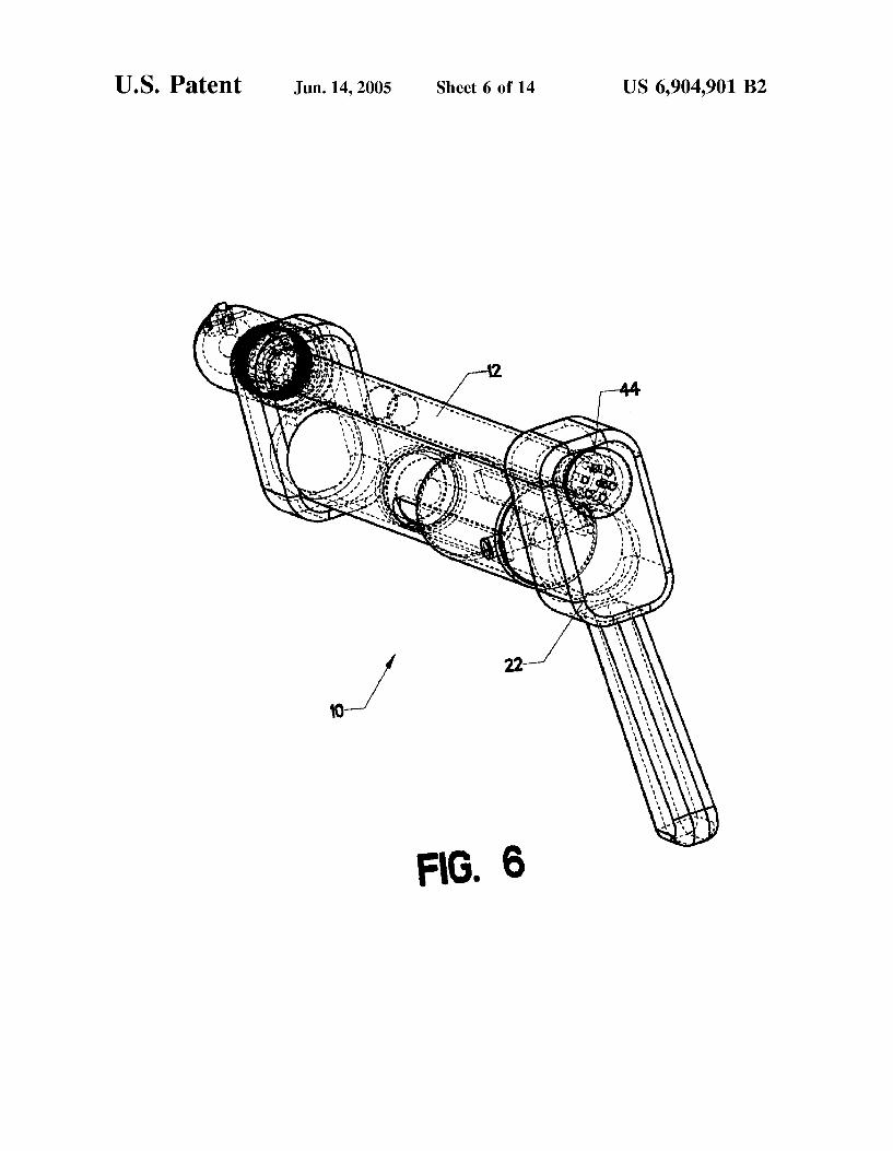
U.S. Patent Jun. 14,2005 Sheet 6 0f 14 US 6,904,901 B2
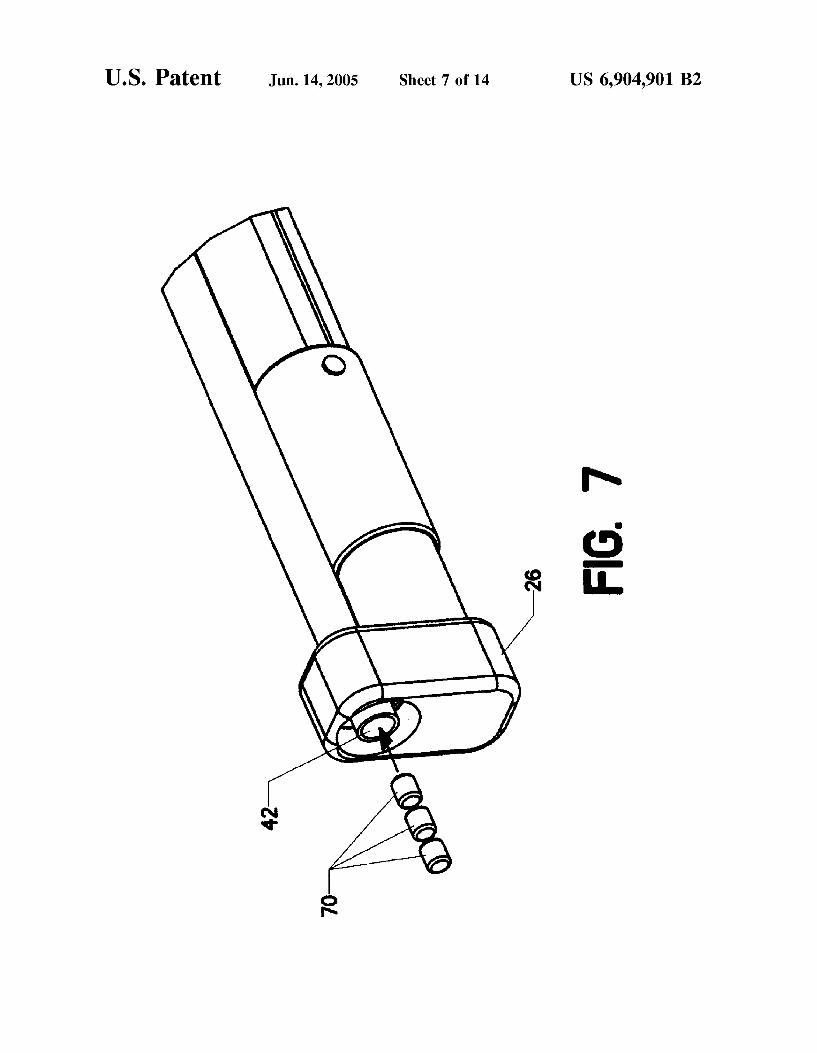
U.S. Patent Jun. 14,2005 Sheet 7 0f 14 US 6,904,901 B2
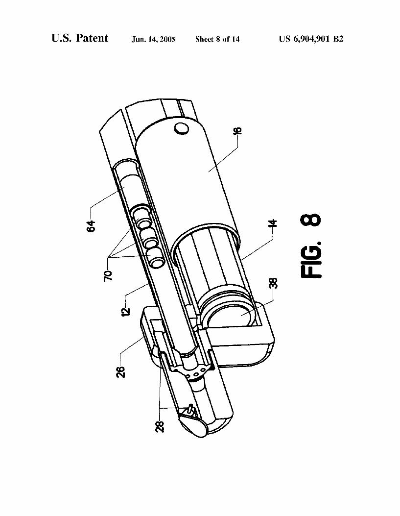
U.S. Patent Jun. 14 2005 Sheet 8 0f 14
FIG. 8

U.S. Patent Jun. 14,2005 Sheet 9 0f 14 US 6,904,901 B2
FIG. 9


Sheet 11 0f 14 US 6,904,901 B2 U.S. Patent Jun. 14,2005

U.S. Patent Jun. 14,2005 Sheet 12 0f 14 US 6,904,901 B2

U.S. Patent Jun. 14,2005 Sheet 13 0f 14 US 6,904,901 B2
H6. 13

U.S. Patent Jun. 14 2005 Sheet 14 0f 14

J
Europaisches Patentamt
European Patent Office
Office europeen des brevets 0 6 1 8 4 2 1 A 1 Oy Publication number:
E U R O P E A N PATENT A P P L I C A T I O N
© int. CIA F41B 7/00, F42B 12/54, F41G 1/35, F41G 1/02
© Application number: 93104874.8
(§) Date of filing: 24.03.93
Applicant: Kan, Chun-Chien No. 3, Alley 2, Lane 332, Row Yang Street Taidong City (TW)
Inventor: Kan, Chun-Chien No. 3, Alley 2, Lane 332, Row Yang Street Taidong City (TW)
@ Date of publication of application: 05.10.94 Bulletin 94/40
@ Designated Contracting States: AT BE CH DE DK ES FR GB GR IE IT LI LU MC NL PT SE
Representative: Strehl Schubel-Hopf Groening & Partner Maximilianstrasse 54 D-80538 Munchen (DE)
Revolver type spring gun.
@ A multi-cartridge shooting gun device includes a magazine (12) with a central hole (16) engaging a supporting shaft (18) extending from a gun housing (11). The magazine has a plurality of magazine holds (17) disposed around the axis, each for receiving a cartridge (14). A spring (15) is disposed in each
cartridge hole (17) for being compressed between the magazine (12) and the respective cartridge (14). When a cartridge (14) is actuated by a trigger (41) the resilience of the spring (15) will assist shooting the cartridge (1 4) towards the target.
55
U CM
00
CO
FIG.2
Rank Xerox (UK) Business Services (3.10/3.09/3.3.4)

EP 0 618 421 A1
CM

EP 0 618 421 A1
CO
L _
CT\
ON

EP 0 618 421 A1
ir>
j
d
cm
a L ^ — s5
LO

EP 0 618 421 A1
LO
O
UL

EP 0 618 421 A1
CD
O
U l
U z F - *
10

EP 0 618 421 A1
11

J European Patent Office
Application Number EP 93 10 4874
EUROPEAN SEARCH REPORT
DOCUMENTS CONSIDERED TO BE RELEVANT
/ - . ._ , Citation of document with indication, where appropriate, Relevant CLASSIFICATION OF THE Category of relevant passages to claim APPLICATION (Int.CL5)
Y US-A-2 962 017 (H. HOROWITZ) 1,3-5 F41B7/00 * column 2, line 27 - column 3, line 53; F42B12/54 figures 1-5 * F41G1/35
F41G1/02 Y US-A-2 509 552 (J. WOLF) 1,3-5
* column 1; f igures 4-6 *
Y US-A-3 296 729 (F. STEVENS) 3 * column 3, line 15 - line 25; figures 1,2 *
Y CH-A-29 708 (E. CAILLEZ) 4 * the whole document *
Y US-A-4 934 086 (W. HOUDE-WALTER) 4 * claim 1; f igures 1-3 *
Y US-A-3 584 582 (C. MULLER) 5 * column 1, line 27 - line 49; figures 1-3 *
TECHNICAL FIELDS A US-A-1 338 239 (J. MATYS) 4 SEARCHED * " «
* f igures 1,2 * F41B F42B
A US-A-3 502 025 (P. PAYNE) 5 F41G F41C
A US-A-3 219 023 (J. RYAN) 1 A01K * column 2, line 16 - line 34; figure 4 *
A US-A-2 625 927 (I. ROSENBLOOM)
A US-A-3 369 534 (D. CROSMAN)
A US-A-2 977 950 (J. RYAN)
A US-A-3 009 453 (C. AYALA)
The present search report has been drawn up for all claims Place of icnk Date of completion of Ike uaxk Exeniaer
THE HAGUE 11 February 1994 Van der PI as, J
CATEGORY OF CITED DOCUMENTS T : theory or principle underlying the invention E : earlier patent document, but published on, or X : particularly relevant if taken alone after the filing date V : particularly relevant if combined with another D : document cited in the application
document of the same category L : document cited for other reasons A : technological background O : non-written disclosure & : member of the same patent family, corresponding P : intermediate document document

. US005373832A
United States Patent [19] [11] Patent Number: 5,373,832 D’Andrade [45] Date of Patent: Dec. 20, 1994
[54] MUL'I'I-SHOT SOFI‘ PROJECI‘ILE 5,242,323 9/1993 Rappaport ...................... .. 124/66 X
PRESSURIZED TOY GUN Primary Examiner—Randolph A. Reese [76] Inventor: Bruce M. D’Andrade, 3 Ten Eyck ASSllWant Examiner—JOhn A. Ricci
Rd., Whitehouse Station, NJ. 08889 Attorney, Agent, or Firm—Kenneth P- Glynn
[2]] Appl. No.: 89,835 [57] ABSTRACT [22] Filed; Jul, 12, 1993 The present invention is a multiple projectile-shooting
air gun. It includes a main housing having a barrel 5 ........................................ adapted for receiving a projectile, a handle and a trig
. . . ...................................... .. , 124/73; gar, as well as a high pressure, in?atable bladder com
[58] Field of Search ..................... .. 124/56, 59, 69-74, nected to the mam mime’ ‘he bladde.’ .havmg a“ “PM 124/76’ 66 and an outlet. There 1s also a pressurizmg mechanism
_ for providing air pressure to the bladder to in?ate it. [56] References cued The pressurizing mechanism is physically connected to
US, PATENT DOCUMENTS the housing and functionally connected to the bladder
1,026,303 5/1912 Dickey ................................ .. 124/69 met‘ The“ ‘S a bladder de?atlc?“ valve 111mg an up‘ 1,214,398 V1917 welsh 124/69 stream side and a downstream side, and it is connected 1,309,321 7/1919 Fail-weather _ 124/69 to the bladder outlet at the valve’s upstream side, and is 1,404,689 1/1922 Fairweather ........................ .. 124/69 connected to the trigger for opening and closing 1,438,995 4/1924 Mccqllom - thereof, and is connected to a projectile launch port at 1,575,644 3/1926 sehmldt - the valve’s downstream side for launching a projectile
2421;! """"""""""""""""""" " 124/69 upon de?ation of at least a portion of the bladder when
2’237’678 4/1941 Lghr 6% _ it has been in?ated. The launch port is located in the 2:733:699 2/1958 Krinsky ............................... .. 124/69 barrel of the main housing and connected to the dQWH 2,784,712, 3/1957 Cassidy ............................... .. 124/69 stream side of the bladder de?ation valve, and is func 2,818,056 12/1957 Martin . tionally connected to a launch tube adapted for receiv
Jacoby ............................ .. X and shooting a projectile. The launch tube is one of genie et a1" """""""""" " 124/70 X a plurality of launch tubes which are located on a rotat
4’735’239 4/1988 821130;‘ et a1 ing magazine. The magazine advances after each shot to 4:848:307 7/1989 Tsao .......... Q...’ ..................... .. 124/59 P°Siti°n the next launch tube with Projectile f°r ?ring 4,854,480 8/1989 Shindo . 4,892,081 1/1990 Moormann . 11 Claims, 3 Drawing Sheets
13' 15 SS
91. 91 _ 93 97 27 212319 f] 13 \ \ 17 \\ 95 l / f / / /: / 1
63 ,, __
77 139 11 143 \85 65 Q ._ s9 / 57 111 x ‘\ \_ 103 " 9 \l 2 1 87\\ ‘\ / 51 M ‘- 61
137 Q
107/ 141 0
j‘ / V 1 / \49 I \ \ \ l I I -_Q\ \
m/ / / ( 1 / ,1 47 105 41 67 59 ' 35 3'
81 7s 9 39 53 83 37

U.S. Patent Dec. 20, 1994 Sheet 1 of 3 5,373,832
2 m@
mm 9: mg I.

US. Patent Dec. 20, 1994 Sheet 2 of 3 5,373,832
207 201
2 777i/l/l/l//77///////7/////]
207 201
3 //77777l/l/l/l7I7I/7////////
207 201 205 203
FIG. 4 \
FIG. 5


US006523535B2
(12) United States Patent (10) Patent N0.2 US 6,523,535 B2 Rehkemper et al. (45) Date 0f Patent: Feb. 25, 2003
(54) TOY PROJECTILE LAUNCHER 5,471,967 A 12/1995 Matsuzaki et al. 5,611,321 A 3/1997 Hoeling et a1.
(75) Inventors: Steven Rehkemper, Chicago, IL (US); 5,711,285 A 1/1998 Stewart et a1. Jeffrey Rehkemper, Chicago, IL (Us); 5,782,228 A * 7/1998 Wu ............................. .. 124/6 Todd Hann0n, Burlington, WI (US); 5,791,326 A 8/1998 Brown et o1~ Ryan Kratz, Chicago, IL (Us) 5,988,152 A 11/1999 Halter et 211.
5,996,564 A * 12/1999 Kotowski .................... .. 124/6
(73) Assignee; Rehco, LLC, Chicago, IL (Us) 6,116,229 A * 9/2000 Wu ............................. .. 124/6 6,119,671 A 9/2000 Smith et a1.
( * ) Notice: Subject to any disclaimer, the term of this patent is extended or adjusted under 35 * cited by examiner U.S.C. 154(b) by 0 days.
(21) App1_ No_; 09/813,675 Primary Examiner—John A. Ricci
(22) Filed: Mar. 21, 2001 (57) ABSTRACT
(65) Prior Publication Data This invention is a toy projectile launcher that launches projectiles. The launcher includes a housing having an
US 2002 0134366 A1 S . 26 2002 . . . . . / ep ’ entrance and an exit in communication therewith to de?ne a
(51) Int. Cl.7 ................................................. .. F41B 4/00 channel, a pair of ?ywheels supported by the housing and (52) US. Cl. ....................................................... .. 124/78 positioned about and in Communication With the Channel, (58) Field Of Search ...................................... .. 124/6, 78 and a Pump handle for rotating the ?ywheels such that a
projectile entering the channel may be engaged by the (56) References Cited rotating ?ywheels and impelled through the channel and out
through the eXit. U.S. PATENT DOCUMENTS
4,325,351 A * 4/1982 Yuasa ........................ .. 124/78 17 Claims, 10 Drawing Sheets

U.S. Patent Feb. 25,2003 Sheet 1 0f 10 US 6,523,535 B2

U.S. Patent Feb. 25,2003 Sheet 2 0f 10 US 6,523,535 B2

U.S. Patent Feb. 25,2003 Sheet 3 0f 10 US 6,523,535 B2
FIG. 3A

U.S. Patent Feb. 25,2003 Sheet 4 0f 10 US 6,523,535 B2
38
FIG. 3B
14 (
///////V/\////lZ7I[i//////
FIG. 3C

U.S. Patent Feb. 25,2003 Sheet 5 0f 10 US 6,523,535 B2

U.S. Patent Feb. 25,2003 Sheet 6 0f 10 US 6,523,535 B2

U.S. Patent Feb. 25,2003 Sheet 7 0f 10 US 6,523,535 B2
FIG.5A
| 62
' ‘J62 63E E m 5 65
ST \ 1 (/k////// /)1/~/12 / :cpimgm / k/(//\\//jA//‘\/£/}/>l//////gf)/t
2 I \ I \ 69 68 66 69 68
FIG. 5B

U.S. Patent Feb. 25,2003 Sheet 8 0f 10 US 6,523,535 B2
FIG. 6

U.S. Patent Feb. 25,2003 Sheet 9 0f 10 US 6,523,535 B2
96a
96b ’ 95 97
86 86
O O
72
FIG. 7A
@ 96a 96b
86 ' 86
72
FIG. 7B

U.S. Patent Feb. 25,2003 Sheet 10 0f 10 US 6,523,535 B2

US007458371B2
(12) Ulllted States Patent (10) Patent N0.: US 7,458,371 B2 Ong et a]. (45) Date of Patent: Dec. 2, 2008
(54) TOY SOFT DART LAUNCHER 2,834,332 A * 5/1958 Guthrie ..................... .. 124/65
2,962,017 A 11/1960 Horowitz et a1. (75) Inventors: Kenlip Ong, Singapore (SG); KWok Fai 2,964,032 A 12/1960 Noble
Tam, HOng Kong (HK); Tai T0 Lee, 3,009,453 A 11/1961 Ayala Kowloon (HK) 3,065,569 A 11/1962 Nielsen et a1.
_ 3,148,478 A 9/1964 Miller (73) Ass1gnee. Mattel, Inc., El Segundo, CA (US) 3,339,536 A 9/l967 Glass et a1‘
( * ) Notice: Subject to any disclaimer, the term of this 3’392’484 A 7/1968 Ry_an et 31' patent is extended or adjusted under 35 3’774’586 A 11/1973 Sam) _ IJ'S'C~ 154(1)) by 31 days' 3,869,825 A 3/1975 Heberleln
4,213,269 A 7/1980 Grogg, Sr.
(21) App1.No.: 11/540,926
(22) Filed: Sep. 30, 2006 (Continued)
(65) Prior Publication Data FOREIGN PATENT DOCUMENTS US 2007/0101982 A1 May 10, 2007
EP 0700703 A2 3/1996 Related US. Application Data
(60) Provisional application No. 60/722,930, ?led on Sep. 30, 2005, provisional application No. 60/733,551, ?led on Nov. 4, 2005, provisional application No. OTHER PUBLICATIONS
60/846’124> ?led on Sep' 20’ 2006' Tippman 98 CustomTM Parts Lists, Tippman Sports LLC, Buffalo Grove, IL, 1 sheet; Jun. 13, 2005.
(51) I C] nt. .
F41B 11/00 (2006.01) (Continued) (52) US. Cl. ......................................... .. 124/65; 124/59 . .
_ _ _ Primary ExammeriTroy Chambers
(58) Fleld of Classl?catlon Search """"""""" " 1122445695’ Assistant Examiner4Gabriel J Klein
See a lication ?le for Com lete Search histo (74)AZZ0rney,Agenl, orFirmiPanitch SchWarze Belisario & PP P "Y Nadel LLP
(56) References Cited (57) ABSTRACT
U.S. PATENT DOCUMENTS
1,184,410 A 5/1916 B t l. . . . 1,282,549 A 10/1918 Diééfke a A toy launcher for launch1ng soft darts 1ncludes a housmg; a l 289 621 A 0/1918 Blackshear motor in the housing; adart magazine subassembly supported 230973749 A 1 H1937 Wade by the housing; a dart magazine rotation subassembly sup 2 279 386 A 4/ 1942 N 618 O n ported by the housing and operated by the motor; and a dart 234743054 A @1949 Jones launcher assembly supported by the housing and operated by 2,551,109 A 5/1951 Fornay the motor' 2,674,989 A 4/1954 Morsch 2,735,221 A 2/1956 Fields 4 Claims, 14 Drawing Sheets

US 7,458,371 B2 Page 2
US. PATENT DOCUMENTS 6,067,975 A 5/2000 Ginn 6,076,513 A 6/2000 Dohertyetal.
4,834,058 A 5/1989 Gegere 6,119,671 A 9/2000 Smith @1111. 4,848,307 A 7/1989 T899 6,220,237 B1 4/2001 Johnson @1111. 5,069,649 A 12/1991 Wu 6,264,528 B1 7/2001 Doan @1111. 5,256,100 A 10/1993 Wang 6,276,353 B1 8/2001 Briggs et a1. 5,267,549 A 12/1993 Webber 6,280,286 B1 8/2001 Andrews 5,343,849 A 9/1994 Steer 6,364,162 B1 4/2002 Johnson @1111. 5,373,832 A 12/1994 D’Andrade 6,408,837 B1 6/2002 Johnson @1111. 5,415,151 A 5/1995 Fusiet a1. 6,428,384 B1 8/2002 Su 5,474,486 A 12/1995 Chilton et 211. 6,439,216 B1 8/2002 Johnson et 31‘ 5,529,050 A 6/1996 D’AIlclracle 6,527,619 B1 3/2003 Agostini et a1. 5,535,729 A 7/1996 Grlf?n eta1~ 6,663,463 B1 12/2003 Dougherty @1111. 5,564,964 A 10/1996 Chin-Chien 6,807,959 Bl* 10/2004 Murdock 61111. ............ .. 124/61 5,592,931 A V1997 Johnson et 91- 6,832,604 Bl* 12/2004 Thompson ................. .. 124/75 5,596,978 A V1997 Johnson eta1~ 6,857,422 B2 2/2005 Pedicini @1111. 5,699,781 A 12/1997 Johnson et a1. 6,857,930 B1 2/2005 LawleY’Jr‘ 5,709,199 A 1/1998 Johnson eta1~ 7,018,264 B2 3/2006 Foster et al. 51724955 A 3/1998 Johnson et 91- 7,121,917 B2 10/2006 Hardouin @1111. 5,787,869 A 8/1998 Johnson eta1~ 2002/0074343 A1 6/2002 Johnson @1111. 5,791,326 A 8/1998 Brown eta1~ 2005/0074277 A1 4/2005 Brown @1111. 5,791,967 A 8/1998 Yeh_ 2005/0183708 A1 8/2005 Eddins et a1. 57971385 A 8/1998 Thal 2006/0003666 A1 1/2006 Hardouin @1111. 5,842,907 A * 12/1998 Niimura 61111. ........... .. 446/435
5,878,735 A 3/1999 Johnson OTHER PUBLICATIONS
590L693 A 5/1999 Smith Air Zone “Rapid Fire Shooter”, Just Toys, Inc.; NeWYork, NY; Four 5,924,413 A 7/1999 Johnson et a1. - , _ (4) sheets (photos of box and disassembled gun), 1995 (see photo of 5,924,910 A 7/1999 L1u back ofbox) 5,975,068 A 11/1999 1111116161111. 5,988,152 A * ll/l999 Halter et a1. ................ .. 124/65 * cited by examiner

US. Patent Dec. 2, 2008 Sheet 1 0f 14 US 7,458,371 B2
10 \ 16 9O
Z 1
22a ~. 22 \
"n:
I 13
FIG. 2

US. Patent Dec. 2, 2008 Sheet 2 0f 14 US 7,458,371 B2
1" \ 6 ‘7 98 96 99 36 92 92a 94% 2O 90 95
16 25 o 24
44
28
24
38 91a
42 22
6O 62 8 14
FIG. 4

US. Patent Dec. 2, 2008 Sheet 3 0f 14 US 7,458,371 B2
TO\ 76 28 s4
78 24 12
44
24 32 36 38
26
FIG. 5
FIG. 6


US. Patent Dec. 2 2008 Sheet 5 or 14

US 7,458,371 B2 Dec. 2, 2008 Sheet 6 0f 14
3 .UI
_' |||||||||||||||||||||||||||||||||||||||||||||||||||||||||||||||||||||||||||| .5“ 4 M. ..... 1“ m
_1 ...... QB: "
on E m M .... L m
. m .m, 1111 w
u m 1%; m "1 ................ "3 EEEE m m m .... L m ?2.\
m m m m
m2 " ................ L "3.1L. . _ m m
................. m m 32
M £2 "£2 _
u "
£2 $2 a _ {NS m
M
$2 $2 I... m
B h n
d m
(KQS
US. Patent

US. Patent Dec. 2 2008 Sheet 7 or 14

US. Patent Dec. 2, 2008 Sheet 8 0f 14 US 7,458,371 B2
FIG. 12

US. Patent Dec. 2, 2008 Sheet 9 0f 14 US 7,458,371 B2
FIG. 1 6


US. Patent Dec. 2, 2008 Sheet 11 0f 14 US 7,458,371 B2
m, h .DE

US. Patent Dec. 2, 2008 Sheet 12 0f 14 US 7,458,371 B2
8 0 O 5
FIG. 17

US. Patent Dec. 2, 2008 Sheet 13 0f 14 US 7,458,371 B2
502
0 5
500a
50Gb 50Gb
FIG. 18


US008453633B2
(12) Ulllted States Patent (10) Patent N0.: US 8,453,633 B2 Tsai (45) Date of Patent: Jun. 4, 2013
(54) SPRING-PISTON AIRSOFT GUN 7,963,281 B2 * 6/2011 Pong ............................. .. 124/67 8,297,269 B2 * 10/2012 Hu . . . . . . . . . .. 124/67
(76) Inventor: Ching-Li Tsai, Chiayi (TW) 8,375,930 B2 * 2/2013 Gore . . . . . . . . . . . . . .. 124/66
2012/0216786 A1* 8/2012 Hadley et a1. ................. .. 124/66
( * ) Notice: Subject to any disclaimer, the term of this * Cited b examiner patent is extended or adjusted under 35 y U.S.C. 154(b) by 211 days.
P ' E ' i J. W d Eld d (21) Appl. NO‘: 13/167,510 rzmary xammer oo roW re '
[Zorn , enl, 0r zrm * anner 1tco , t . (74)A eyAg F' B &W ff Ld (22) Filed: Jun. 23, 2011
(65) Prior Publication Data (57) ABSTRACT
Us 2011/0315134 A1 1336- 29, 2011 A spring-piston airsoft gun includes a cylinder-and-piston _ _ _ _ _ assembly disposed in a barrel to force air through a muZZle
(30) Forelgn Apphcatlon Pnonty Data end to make a shooting action, and a coil spring disposed to
Jun. 25, 2010 (TW) ........................... .. 099212110 U exen ?‘b1asmg acnon ‘0 dnve a Plston head Ofthe Cyhnder' and-piston assembly When changed from a compressed state
(51) Int CL to a released state. Front and rear anchor shanks are disposed F41B 11/00 (200601) for respectively mounting front and rear coil segments of the
(52) us CL coil spring. A major shell and a minor ring are sleeved on the USPC ................................ .. 124/66; 124/67; 124/68 rear anchor Shank to permit the C011 SPn'ng to be Sleeved
- - - thereon. The minor ring is in frictional contact With and (58) Field of Classi?cation Search USPC ........................................ .. 124/66, 65, 67, 68 angularly moveable relativewthe majorshell suchthanwhen
' ' ' the coil spring is released to expand to the released state, the See appl1cat1on ?le for complete search history. rear coil segment is tensed to drag the minor ring to angularly
(56) References Cited move thereWith so as to minimiZe the frictional force therebe tWeen.
U.S. PATENT DOCUMENTS
5,655,509 A * 8/1997 Casas Salva .................. .. 124/66
7,946,283 B2 * 5/2011 Lee et a1. ...................... .. 124/67 9 Claims, 5 Drawing Sheets
3 6
5 5332b 32 4 31 302 30 62 6132201 42 ( ) (3% 1 7 32211512, / ,41,\H§4/,/,/ 321 @011 \ ,' ,Q/WJ/ I / o y l r‘ ' ‘ ' ._
'I.\|\ \\\ I\I\|| _ _ 1 Q X iii 110111113\/\/\/\/\/\/\/\/\/\/\/\/\/\/11ml
i" / 3! SW“? NV“ N'n“ " 1 | I l l \ \ O
I 5W“? \ 323 O
O 53 331
@ f’ 332 .6 —
ll!

US. Patent Jun. 4, 2013 Sheet 1 of5 US 8,453,633 B2
FIG. 1 PRIOR ART

US. Patent Jun. 4, 2013 Sheet 2 of5 US 8,453,633 B2
141
FIG. 2 PRIOR ART
FIG. 3 PRIOR ART

US. Patent Jun. 4, 2013 Sheet 3 of5 US 8,453,633 B2
FIG. 4

US. Patent Jun. 4, 2013 Sheet 4 of5 US 8,453,633 B2
FIG.5

US. Patent Jun. 4, 2013 Sheet 5 of5 US 8,453,633 B2
FIG. 6

(12) United States Patent Corlett et a].
US008678877B2
US 8,678,877 B2 Mar. 25,2014
(10) Patent N0.: (45) Date of Patent:
(54)
(71)
(72)
(73)
(21)
(22)
(65)
(62)
(51)
(52)
(58)
MARKER TAG DARTS, DART GUNS THEREFOR, AND METHODS
Applicant: Shoot the Moon Products II, LLC, Pleasanton, CA (US)
Inventors: Richard Jonathan Corlett, Woodland Hills, CA (US); David B. Small, Pleasanton, CA (US); Paul S. Rago, Danville, CA (US)
Assignee: Shoot the Moon Products II, LLC, Pleasanton, CA (US)
Notice: Subject to any disclaimer, the term of this patent is extended or adjusted under 35 USC 154(b) by 0 days.
Appl. N0.: 14/013,242
Filed: Aug. 29, 2013
Prior Publication Data
US 2014/0004769 A1 Jan. 2, 2014
Related US. Application Data
Division of application No. 13/035,564, ?led on Feb. 25, 2011, noW Pat. No. 8,529,384.
Int. Cl. A63H 33/30 (2006.01) F41B 11/00 (2013.01) A63B 65/02 (2006.01) US. Cl. USPC ............... .. 446/473; 124/56; 124/59; 124/69;
124/71; 124/73; 222/79; 473/581 Field of Classi?cation Search USPC .................. .. 473/581; 124/56, 59, 69, 71, 73;
446/473; 222/79 See application ?le for complete search history.
(56) References Cited
U.S. PATENT DOCUMENTS
3,190,654 A 6/1965 Ross 3,320,941 A * 5/1967 Houghton ..................... .. 124/67
3,330,561 A 7/1967 Kandel 3,399,485 A * 9/1968 Cashavelly et al. ........... .. 446/15 3,415,420 A * 12/1968 White ........................... .. 222/79
3,457,921 A 7/1969 Waldeisen 3,528,662 A 9/1970 Merchant et al. 3,565,435 A 2/1971 Bear 3,701,533 A 10/1972 Palmer 3,823,847 A * 7/1974 Ware ............................. .. 222/79
3,893,866 A 7/1975 Hollingsworth 4,214,674 A * 7/1980 Jones et al. ................... .. 222/79
4,257,188 A 3/1981 Barker 4,726,584 A 2/1988 Bishop 4,733,799 A * 3/1988 Wiskur ......................... .. 222/79
4,735,612 A 4/1988 Chevalier 4,743,030 A * 5/1988 Auer et al. .................. .. 273/349 4,807,586 A * 2/1989 Kao .............................. .. 124/73
(Continued) Primary Examiner * Gene Kim
Assistant Examiner * Alexander Niconovich
(74) Attorney, Agent, or Firm * Blakely Sokoloff Taylor & Zafman LLP
(57) ABSTRACT
Marker tag darts, dart guns therefor, and methods Which alloW a toy gun to receive a marker tag dart, to put Water in the forward tip of the dart and to shoot the dart. The marker tag dart itself has slits in the Wall of a small chamber at the front of the dart so that on impact With a target, the inertia of the Water causes deformation of the tip and opening of the slits to eject Water for marking the location of the marker tag dart hit. The dart guns are spring chocked, and propel the dart With a blast of air from an air pump powered by the spring. Various embodiments and modes of operation are disclosed.
7 Claims, 7 Drawing Sheets
water int-11w

US 8,678,877 B2 Page 2
(56) References Cited 6,203,397 B1 * 3/2001 Applewhite et a1. ........ .. 446/475 6,241,634 B1 6/2001 Armer, Jr.
U,S_ PATENT DOCUMENTS 6,247,995 B1 * 6/2001 Bryan ......................... .. 446/473 6,279,562 B1* 8/2001 Clayton ........................ .. 124/59
4,863,428 A 9/1989 Chevalier 6,364,162 B1* 4/2002 Johnson et a1. ............... .. 222/61 4,881,743 A 11/19g9 Fiorenzo 6,439,216 B1* 8/2002 Johnson et a1. ............... .. 124/70 5,074,437 A * 12/1991 D’Andrade et a1. ...... .. 222/79 6,450,905 B1 9/2002 Edlund 5,123,657 A 6/1992 Colt et 31, 6,474,507 B1* 11/2002 Hornsby et a1. .............. .. 222/79 5,150,819 A * 9/1992 Johnson et a1. ............... .. 222/79 6,540,108 Bl* 4/2003 ~~ ZZZ/79 5,202,533 A 4/1993 Vandersteen 6,698,414 131* 3/2004 ~~ 124/69 5,238,149 A * 8/1993 Johnson et a1. ............... .. 222/79 6,802,756 B2* 10/2004 446/176 5241944 A * 9/1993 Rappaport “ 124/67 6,892,902 B2* 5/2005 Hornsby et a1. .. 222/79 5284274 A * 2/1994 Lee et a1, 222/79 7,097,073 B2* 8/2006 Zlmmerman ................. .. 222/79 5,373,832 A * 12/1994 D>Andrade , 124/69 7,131,557 B2* 11/2006 Zimmerman et a1. ........ .. 222/79 5,373,833 A * 12/1994 D’Andmde ,,,,,,,,,,,,,,,,,,, H 124/69 7,185,787 B2* 3/2007 Brown etal. ..... .. .. 222/79
5,377,656 A 1/1995 Lewinskiet 31‘ 7,219,817 B2* 5/2007 Panzarella 222/386 5381928 A * 1/1995 Lee et a1‘ “““““““““““““ “ 222/79 7,267,118 B2* 9/2007 Eddins et a1. .. 124/63 5,415,151 A * 5/1995 Fusi et a1. 124/56 RE39,947 E * 12/2007 Johnson ~~~~~~~~~~~~~~~~~~~~~~~~ ~~ ZZZ/79
5,433,646 A * 7/1995 Tarng ..... .. .446/473 7,488,267 B2 2/2009 Hun? 5,448,984 A * 9/1995 Brovelli 124/69 7,601,084 B2 10/2009 Mamn 5,531,627 A * 7/1996 Deal ,,,,,,,,, n ,446/473 7,641,668 B2* 1/2010 Perryet a1. .................. .. 606/192
RE35,412 E * 12/1996 Johnson et a1 222/79 7,658,302 132* 2/2010 Berman ~~ ZZZ/79 5,626,343 A * 5/1997 Sanders ........... .. . 273/349 7731612 B2 6/2010 Martln 5,730,321 A * 3/199g MoAllister et a1, 222/1 7,798,364 Bl* 9/2010 Eddlns et a1. ~~~~~~~~~~~~~~~~~ ~ 222/79 5,799,828 A * 9/1998 Crawford 222/79 8,074,838 B1* 12/2011 Tate ....... .. .. 222/79 5,826,750 A * 10/1998 Johnson 222/79 8,490,830 132* 7/2013 Magers ~~ ZZZ/79 5,826,879 A * 10/199g spector “““““““““““““ “ 273/349 2004/0040551 A1* 3/2004 Menowetal. .. 124/71 5,836,842 A 11/199g McLeamn 2005/0072412 A1* 4/2005 Cuisinier 124/1 5,850,941 A * 12/199g Johnson et a1, ,,,,,,,,,,,,,,, H 222/79 2005/0183708 A1* 8/2005 Eddins et a1. ................. .. 124/59
5,876,995 A * 3/1999 Bryan “““““““““““““ “ 435/189 2007/0012720 A1 1/2007 Rosenblum 5,878,914 A >1< 3/1999 Johnson ““ “ 222/79 2009/0064919 A1 23/2009 Greenwald 6,000,386 A * 12/1999 Johnson et a1. 124/69 2009/0127789 A1 5/2009 Andersen 6,003,503 A * 12/1999 Johnson et a1. ............... .. 124/69 2009/0140493 A1 6/2009 Andersen 6113 886 A * 90000 B an ““““““““““““““ “ 424/49 2010/0031945 A1 2/2010 Shafferet a1.
, , ry * 6146292 A 110000 Yamanaka 2010/0320228 A1 12/2010 C_arrol1 .......................... .. 222/79
’ ’ 2012/0153036 A1 6/2012 Plerce et 31. 6,149,488 A * 11/2000 Stark ~~~~~~~~~~~~~~~~~~~~~~ ~~ 446/220 2012/0178338 A1* 7/2012 Mowbray 446/473 6,152,358 A * 11/2000 Bryan ...................... .. 229/87.19 """""""""" "
6,174,251 B1 1/2001 Lemote * cited by examiner

US. Patent Mar. 25, 2014 Sheet 1 of7 US 8,678,877 B2

US. Patent Mar. 25, 2014 Sheet 2 of7 US 8,678,877 B2
needie injects water into dart through sht

US. Patent Mar. 25, 2014 Sheet 3 of7 US 8,678,877 B2
» W
v32 mm 8%? mam

US. Patent Mar. 25, 2014 Sheet 4 of7 US 8,678,877 B2
. v23 E L335
33 ? i. / .....
622s £5, 2% 3m? 2 23m;
AEQEQESV
Emu 6%


US. Patent Mar. 25, 2014 Sheet 6 of7 US 8,678,877 B2
?ing mm?» @3533 EM 3 5m mam; “Eng .m h?mé 5?”. mama M1655, tan gnaw ‘m
tam. “EM, 335 v5; 5%») ?rs xx 3% Q
.wmmwca Eta,» 335mm? E: Wm 3s warm i Mi“ 93$ 3 any»; Again?"
E Q“. 83% dad

US. Patent Mar. 25,2014 Sheet 7 of7 US 8,678,877 B2
Exam“ E 83%,
53 £32 5%?
N32,). xx; 2% “wag 3 wmmwwc M M
,,,, . QRRRRMDN.
w.‘ M
v. A a,
x’. 5 .8
am w w: 1%

US 20100147277A1
(19) United States (12) Patent Application Publication (10) Pub. No.: US 2010/0147277 A1
Zimmerman et al. (43) Pub. Date: Jun. 17, 2010
(54)
(76)
(21)
(22)
(30)
Dec. 17, 2008
1138
13A
TOY GUN
Inventors: Jeffrey C. Zimmerman, Kowloon (CN); Chor-Ming Ma, Kowloon (CN)
Correspondence Address: ALIX YALE & RISTAS LLP 750 MAIN STREET, SUITE 1400 HARTFORD, CT 06103 (US)
Appl. No.:
Filed:
13
18
12/37 8,680
Feb. 18, 2009
Foreign Application Priority Data
(HK) ............................... .. 081137186
Publication Classi?cation
(51) Int. Cl. F41B 11/00 (2006.01) F41F 1/00 (2006.01)
(52) U.S. Cl. ........................................ .. 124/56; 124/41.1
(57) ABSTRACT
A toy gun for individually shooting soft projectiles has a body and a magazine attached to the body for housing an array of soft projectiles and delivering them individually to a ?ring position Within the body. A ?ring mechanism in the body ?res a ?rst projectile from the ?ring position. A projectile separa tor acts upon a second projectile adjacent to the ?rst projectile to at least reduce frictional interaction between the ?rst and second projectiles during ?ring and to smooth the projectile loading process.
10

Patent Application Publication Jun. 17, 2010 Sheet 1 0f 4 US 2010/0147277 A1
10
/ 13
13B 17
13A
18 20 19
Fig. 1
13
1 Mn»
13A

Patent Application Publication Jun. 17, 2010 Sheet 2 0f 4 US 2010/0147277 A1
10
/
20 Fig‘ 3

Patent Application Publication Jun. 17, 2010 Sheet 3 0f 4 US 2010/0147277 A1

Patent Application Publication Jun. 17, 2010 Sheet 4 0f 4 US 2010/0147277 A1

United States Patent [191 Johnson et a1.
US00578‘7869A Patent Number: 5,787,869
Aug. 4, 1998 [11]
[45] Date of Patent:
[54]
[75]
[73]
[21]
[22]
[63]
[51] [52] [53]
[56]
COMPRESSED AIR TOY GUN
Inventors: Lonnie G. Johnson. Smyrna; John T. Applewhite. Atlanta; Shane Matthews, Marietta. all of Ga.
Assignee: Johnson Research & Development Corp., Inc.. Atlanta. Ga.
Appl. No.: 799,702
Filed: Feb. 11, 1997
Related US. Application Data
Continuation-impart of Ser. No. 730,619, Oct. 21, 1996, Pat, No. 5,709,199, which is a continuation-in-part of Ser. No. 699,431, Aug. 19, 1996, Pat. No. 5,699,781, which is a continuation-in-part of Ser. No. 494,407, Jun. 26, 1995, Pat. No. 5,592,931, which is a continuation-in-part of Ser. No. 441,229, May 15, 1995, Pat No. 5,596,978.
rm. (:1.6 .............................. .. F4113 11/00; F41B 9100
US. Cl. ................................ .. 124/69; 124/83; 124/85 Field of Search ................................ .. 124/69. 63. 72.
124/53.5. 48. 59. 81. 82. 83. 84. 85; 42J77. 76.01
References Cited
U.S. PATENT DOCUMENTS
2,147,003 2/1939 Von Kozuiik 124/11 2,312,244 2/1943 Feltman .... .. 124/11 2,357,951 9/1944 Hale ...... .. 124/11
2,654,973 10/1953 Lemelson 46/56 2,733,699 2/1956 Krinsky 124/13 2,927,398 6/1960 Kaye et a1. . 46f/4 3,025,633 6/1962 Kayeet al. . . . . . . . . .. 46fl4
3,121,292 2/1964 Butler et al. . 46/74 3,139,692 7/1964 Sellers et a1. 124/83 X 3,262,440 7/1966 Kuhn ................................... .. 124/83 X
3,397,476 8/1968 Weber .......................... .. 43/6
3,859,977 1/1975 Lange 124/83 X 3,962,818 6/1976 Pippin ........ .. 46/74
4,073,280 2/1978 Koehn .. 124/72 4,083,349 4/1978 Cli?‘ord . .. 124/72
4,159,705 7/1979 Jacoby .... .. 124/63 4,223,472 9/1980 Feket et a1. .... .. 46/44 4,411,249 10/1983 Fogartyetal. ...... .. 124/64 4,559,737 12/1985 Washington .... .. 124/83 X 4,890,767 1/1990 Burlison ...... .. 222/78
4,897,065 1/1990 Fertigetal. .. .. 446163 5,090,708 2/1992 Gerlitz et al. . 273/310 5,188,557 2/1993 Brown ............. .. 446/212
5,228,427 7/1993 Gargner, Jr, .. 124/81 5,280,917 l/1994 Ortiz ....... .. 273/318
5,343,849 9/1994 Steer . . . . . . . . .. 124/72
5,343,850 9/1994 Steer . . . . . . . . .. 124/64
5,370,278 1211994 Raynie .... .. 222/175 5,373,832 12/1994 D’Andrade ...... .. 124/69
5,415,152 5/1995 Adamson et al. 124/59 5,640,945 6/1997 Slonaker et al. ........................ .. 124/56
FOREIGN PATENT DOCUMENTS
258791l-A1 10/1985 France.
Primary Examiner-John A. Ricci Assistant Examiner-Thomas A. Beach Attorney, Agent, or Firm—Kennedy. Davis & Kennedy
[57] ABSTRACT
An air compressed gun (10) is provided having a stock (11). a barrel (12). a trigger (13) and a manual air pump (14). The gun also has a mounting tube (201) con?gured to be received within the tail bore (203) of a projectile (P) and a barrel (200) in which the projectile is positioned for launching. The mounting tube has a tapered air exit end (210) and a safety bar (211). The barrel has an lelongated slot (217) for venting compressed air.
15 Claims, 9 Drawing Sheets

US. Patent Aug. 4, 1998 Sheet 1 of 9 5,787,869

US. Patent Aug. 4, 1998 Sheet 2 0f 9 5,787,869
O v 16
15
FIG 2
64


5,787,869 US. Patent Aug. 4, 1998 Sheet 4 of 9

US. Patent Aug. 4, 1998 Sheet 5 0f 9 5,787,869
10\
FIG 7
732 76 141 151 \
128 129 B0 133 139 136 739

US. Patent Aug. 4, 1998 Sheet 6 0f 9 5,787,869
FIG 9

US. Patent Aug. 4, 1998 Sheet 7 0f 9 5,787,869
/
mm:
<__
n E: g_/, t mil % i.. i.
?zz 3:
p9 @E 21 m: x
i‘ N “N \‘ “I \ \ \ \\ T.‘ N 1- a
_ ___ __ \l\ \ \ \, \ \ \
T \ y ll. x\ \
.. <8. m2 mm: . a“ - 1 : H
QIEIE/ \ N _ \ \ \ \
f \
\ ht \ l\ \ \ \ my‘ \. Ks \ 3..

US. Patent Aug. 4, 1998 Sheet 8 of 9 5,787,869
/
/
/
W! Q§hi %/ \ 1////////


(12) United States Patent W00dh0use et al.
US007731061B1
(54) WEARABLE TOY WITH ROTATABLE DISCHARGE PODS FOR FIRING PROJECTILES AND METHODS
(75) Inventors: Hampton RWoodhouse, Hope, RI (US); Alric J Lam, Attleboro, MA (US)
(73) Assignee: Hasbro, Inc., PaWtucket, RI (US)
( * ) Notice: Subject to any disclaimer, the term of this patent is extended or adjusted under 35 U.S.C. 154(b) by 658 days.
(21) Appl.No.: 11/744,272
(22) Filed: May 4, 2007
(51) Int. Cl. B67D 99/00 (2010.01)
(52) US. Cl. ......................... .. 222/175; 222/78; 222/79; 124/56; 446/26; 446/473; 446/483
(58) Field of Classi?cation Search ................. .. 124/56;
222/78, 79, 175, 333; 239/152, 153, 154; 446/26, 27, 28, 473, 475, 483; 2/160, 163;
42/54 See application ?le for complete search history.
(56) References Cited
U.S. PATENT DOCUMENTS
2,423,448 A * 7/1947 3,018,578 A * 1/1962 3,453,774 A * 7/1969 Gruber et a1. ............. .. 446/353
4,756,703 A 7/1988 Kennedy et a1. 4,768,681 A * 9/1988 Dean et a1. .................. .. 222/79
4,820,229 A 4/1989 Spraggins 5,072,856 A 12/1991 Kimble
(10) Patent N0.: US 7,731,061 B1 (45) Date of Patent: Jun. 8, 2010
5,088,624 A * 2/1992 Hackett et a1. .............. .. 222/78
5,316,514 A 5/1994 Ellman et 31. 5,538,457 A 7/1996 Deal 5,673,436 A * 10/1997 Piper ....... .. 2/160
5,678,730 A * 10/1997 Fabek et a1. . . . . . . . . . . .. 222/78
5,724,955 A * 3/1998 Johnson et a1. ............. .. 124/72
6,203,397 B1 3/2001 Applewhite et a1. B1 6,279,562 8/2001 Clayton
RE37,616 E 4/2002 Schumacher 6,802,435 B1* 10/2004 Brawner, Jr. ............... .. 222/79
6,814,260 B2 11/2004 Caffrey 6,824,442 B2 11/2004 Andrews et a1.
* cited by examiner
Primary ExamineriTroy Chambers (74) Attorney, Agent, or FirmiPerry Hoffman
(57) ABSTRACT
A Wearable toy having an outer housing capable of rotating around a Wearable component With more than one pod at the outer housing each able to receive a contained discharge element. The pods are engaged by an actuator assembly Which operates to project the contained discharge element of each pod. The pods at the outer housing may receive, e.g., a removable canister containing the discharge elements. The actuator assembly includes a ?rst actuator coupled to the Wearable component for manipulation by a user and a second actuator capable of engaging the ?rst actuator projecting the contained discharge element of each of the plurality of pods. The canister may include a second actuator coupled and capable of engagement With the ?rst actuator as the outer housing member is rotated to alloW alignment of ?rst and second actuators for projecting the contained discharge ele ment.
20 Claims, 10 Drawing Sheets

US. Patent Jun. 8, 2010 Sheet 1 0110 US 7,731,061 B1

US. Patent Jun. 8, 2010 Sheet 2 0110 US 7,731,061 B1
0 0

US. Patent Jun. 8, 2010 Sheet 3 0110 US 7,731,061 B1

US. Patent Jun. 8, 2010 Sheet 4 0110 US 7,731,061 B1

US. Patent Jun. 8, 2010 Sheet 5 0110 US 7,731,061 B1

US. Patent Jun. 8, 2010 Sheet 6 0110 US 7,731,061 B1

US. Patent Jun. 8, 2010 Sheet 7 0110 US 7,731,061 B1

US. Patent Jun. 8, 2010 Sheet 8 0110 US 7,731,061 B1
2 74
28

US. Patent Jun. 8, 2010 Sheet 9 0110 US 7,731,061 B1

US. Patent Jun. 8, 2010 Sheet 10 0110 US 7,731,061 B1
. 0mm

Unlted States Patent [191 [11] Patent Number: 5,724,955 Johnson et a]. [45] Date of Patent: Mar. 10, 1998
[54] VOICE ACTIVATED COMPRESSED AIR TOY 3,397,476 8/1968 Weber ......................................... .. 43/6 GUN 3,962,818 6/1976 Pippin 46/74
4,073,280 2/1978 Koehn . . . . . . . . . . .. 124/72
[75] Inventors: Lonnie G. Johnson. Smyrna; John T. gm?grd - -------------- - ~ , , aco y . . . . . . . . . ..
Applewh‘te‘ Atlanta’ both of Ga’ 4,223,472 9/1980 Feket et a1. ..... .. 46/44
. _ 4,411,249 10/1983 Fogarty et a1. 124/64 [73] Asslgnee' £01m” Relffarch 8‘ Devehpment 4,890,767 1/1990 Burlison . . . . . . . . . . . .. 222r/8
empany’ 9 4,897,065 1/1990 Fenig e181. .. 446/63 5,090,708 2/1992 Geditz et a1. . ..... .. 273/310
[21] App1.No.: 788,225 5,158,212 10/1992 Sirhan ..... .. 222/192 X _ 5,188,557 2/1993 Brown ..... .. 446/212
[22] Fll?di Jan. 27, 1997 5,280,917 1/1994 Ortiz 273/318 5,343,849 9/1994 Steer 124/72
Related US. Application Data 5,343,850 9/1994 Steer . . . . . . . . . . . . .. 124/64
5,359,576 10/1994 Bunner et a1. 124/34X [63] Continuation-impart of Ser. No. 730,619, Oct. 21, 1996, 5,370,278 1211994 Raynie ........ .. 2221175
whichisacontinuation-in-part ofSer.No.699,431,Aug. 19, 5,373,832 12/1994 D’Andrade 124/69 1996, which is a continuation-impart of Ser. No. 494,407, 5,415,152 5/1995 Adamson et a1. 124/59 1191-267 1995,1919 NO- 515921931, which is a cominua?on- 5,535,729 7/1996 Gri?in et a1. ....................... .. 124/48 X in-part of Ser. No. 441,229, May 15, 1995, Pat. No. 5,596, 978. FOREIGN PATENT DOCUMENTS
[51] Int. Cl.6 .............................. .. F41B 11/00; F41A 9/61 2587911-A1 10/1985 France,
[52] us. 61. .......... .. 124/72; 124/48; 124/53 .5 Primary Emmi-MET“), Lea Menus Fleld of Search ................................ .. 1.24/67, 69, 72, Assistant Examiner_Thomas A‘ B?ach 124/70, 48, 53.5. 32. 59; 446/27, 475; 273/DIG. 17; Attomey’ Agent, or FiWKemdyq Davis & Kennedy
222/175, 192 [57] ABSTRACT
[56] References Cited An air compressed gun (10) is provided having a stock (11), US. PATENT DOCUMENTS a barrel (12), a trigger (13) and a manual air pump (14). The
. gun also has a magazine (18) having a series of barrels (26) gill-3,003 2/1939 Von Kozunk ........................... .. 124/11 for holding Se var a1 projcc?les An actuator (50) indexas
, ,244 2/1943 Feltman . . . .
2,357,951 9/1944 Hale ......... .. 124/11 the “legume Wlth eaeh she?“ the gun-“61118891118 of the 2,654,973 10,1953 Lemelson __ 46/56 gun is controlled by a vo1ce actlvated tnggenng system 2,733,699 2/1956 Kn'nsky ,,,, __ 124/13 (215) which includes a microphone (216), a control circuit 2,927,398 3/1960 Kaye et a1. .. 46/74 (220) and a control valve (219). 3,025,633 3/1962 Kaye et a1. g .. 3,121,292 2/1964 Butler et a1. ....................... .l ..... .. 46/74 12 Claims, 12 Drawing Sheets
n n 5:

1998 Sheet 1 0f 12 5,724,955 Mar. 10, US. Patent

US. Patent Mar. 10, 1998 Sheet 2 0f 12 5,724,955
16
W FIG 2
-_____
64

US. Patent Mar. 10, 1998 Sheet 3 0f 12 5,724,955

5,724,955 Sheet 4 0f 12 US. Patent Mar. 10, 1998

US. Patent Mar. 10, 1998 Sheet 5 0f 12 5,724,955

US. Patent Mar. 10,1998 Sheet 6 0f 12 5,724,955
FIG 9

Sheet 7 0f 12 US. Patent Mar. 10, 1998
I59 /
FIG 10
5,724,955

US. Patent Mar. 10,1998 Sheet 3 0f 12 5,724,955

US. Patent Mar. 10, 1998 Sheet 9 0f 12 5,724,955
ZIO
FIG 13

US. Patent Mar. 10, 1998 Sheet 10 of 12 5,724,955
8 m s ww
@w\ W nwjf g NE E
_ IE \M. @NN mm if
no.

US. Patent Mar. 10, 1998 Sheet 11 0f 12 5,7 24,955

US. Patent Mar. 10, 1998 Sheet 12 of 12 5,724,955

US008453633B2
(12) Ulllted States Patent (10) Patent N0.: US 8,453,633 B2 Tsai (45) Date of Patent: Jun. 4, 2013
(54) SPRING-PISTON AIRSOFT GUN 7,963,281 B2 * 6/2011 Pong ............................. .. 124/67 8,297,269 B2 * 10/2012 Hu . . . . . . . . . .. 124/67
(76) Inventor: Ching-Li Tsai, Chiayi (TW) 8,375,930 B2 * 2/2013 Gore . . . . . . . . . . . . . .. 124/66
2012/0216786 A1* 8/2012 Hadley et a1. ................. .. 124/66
( * ) Notice: Subject to any disclaimer, the term of this * Cited b examiner patent is extended or adjusted under 35 y U.S.C. 154(b) by 211 days.
P ' E ' i J. W d Eld d (21) Appl. NO‘: 13/167,510 rzmary xammer oo roW re '
[Zorn , enl, 0r zrm * anner 1tco , t . (74)A eyAg F' B &W ff Ld (22) Filed: Jun. 23, 2011
(65) Prior Publication Data (57) ABSTRACT
Us 2011/0315134 A1 1336- 29, 2011 A spring-piston airsoft gun includes a cylinder-and-piston _ _ _ _ _ assembly disposed in a barrel to force air through a muZZle
(30) Forelgn Apphcatlon Pnonty Data end to make a shooting action, and a coil spring disposed to
Jun. 25, 2010 (TW) ........................... .. 099212110 U exen ?‘b1asmg acnon ‘0 dnve a Plston head Ofthe Cyhnder' and-piston assembly When changed from a compressed state
(51) Int CL to a released state. Front and rear anchor shanks are disposed F41B 11/00 (200601) for respectively mounting front and rear coil segments of the
(52) us CL coil spring. A major shell and a minor ring are sleeved on the USPC ................................ .. 124/66; 124/67; 124/68 rear anchor Shank to permit the C011 SPn'ng to be Sleeved
- - - thereon. The minor ring is in frictional contact With and (58) Field of Classi?cation Search USPC ........................................ .. 124/66, 65, 67, 68 angularly moveable relativewthe majorshell suchthanwhen
' ' ' the coil spring is released to expand to the released state, the See appl1cat1on ?le for complete search history. rear coil segment is tensed to drag the minor ring to angularly
(56) References Cited move thereWith so as to minimiZe the frictional force therebe tWeen.
U.S. PATENT DOCUMENTS
5,655,509 A * 8/1997 Casas Salva .................. .. 124/66
7,946,283 B2 * 5/2011 Lee et a1. ...................... .. 124/67 9 Claims, 5 Drawing Sheets
3 6
5 5332b 32 4 31 302 30 62 6132201 42 ( ) (3% 1 7 32211512, / ,41,\H§4/,/,/ 321 @011 \ ,' ,Q/WJ/ I / o y l r‘ ' ‘ ' ._
'I.\|\ \\\ I\I\|| _ _ 1 Q X iii 110111113\/\/\/\/\/\/\/\/\/\/\/\/\/\/11ml
i" / 3! SW“? NV“ N'n“ " 1 | I l l \ \ O
I 5W“? \ 323 O
O 53 331
@ f’ 332 .6 —
ll!

US. Patent Jun. 4, 2013 Sheet 1 of5 US 8,453,633 B2
FIG. 1 PRIOR ART

US. Patent Jun. 4, 2013 Sheet 2 of5 US 8,453,633 B2
141
FIG. 2 PRIOR ART
FIG. 3 PRIOR ART

US. Patent Jun. 4, 2013 Sheet 3 of5 US 8,453,633 B2
FIG. 4

US. Patent Jun. 4, 2013 Sheet 4 of5 US 8,453,633 B2
FIG.5

US. Patent Jun. 4, 2013 Sheet 5 of5 US 8,453,633 B2
FIG. 6

US 20070261689A1
(12) Patent Application Publication (10) Pub. No.: US 2007/0261689 A1 (19) United States
Tai et al. (43) Pub. Date: NOV. 15, 2007
(54) BULLET-LOADING STRUCTURE OF TOY GUN
(75) Inventors: Chiao-Chih Tai, Taoyuan Hsien (TW); Szu-Ming Huang, Taoyuan Hsien (TW); Chia-Chen Wang, Taoyuan Hsien (TW); Chih-Ming Tien, Taoyuan Hsien (TW)
Correspondence Address: TROXELL LAW OFFICE PLLC Suite 1404 5205 Leesburg Pike Falls Church, VA 22041 (US)
(73) Assignee: Enlight Corporation
(21) Appl. No.: 11/430,835
(22) Filed: May 10, 2006
Publication Classi?cation
(51) Int. Cl. F41B 11/00 (2006.01)
(52) Us. or. .............................................................. .. 124/67
(57) ABSTRACT In a toy gun With a bullet-loading structure, a cylinder, a piston, a ?nal gear, and a pull rod are mounted in a gun body. The piston and the pull rod are driven by the rotation of the ?nal gear. An actuation time of the pull rod is later than that of the piston to enable the piston to suck a lot amount of gas before the loading of the bullet, thereby preventing a gun tunnel from being blocked by the raised bullet and providing the simulated recoil effect of real shooting so as to promote the shooting performance of the toy gun.

Patent Application Publication Nov. 15, 2007 Sheet 1 0f 11 US 2007/0261689 A1

Patent Application Publication Nov. 15, 2007 Sheet 2 0f 11 US 2007/0261689 A1
Fig.2

Patent Application Publication Nov. 15, 2007 Sheet 3 0f 11 US 2007/0261689 A1
////////
max; \ \ \ l\ \ \ \ \ \ \ \ \ \? \ \ \ \ -
\ \ \
\ \ /////////r//// i I K
E
//////////////////////////////////_ \ \ \k!\ \ \ \ \ \ \ \ \ \ \ \ \ u
N\ _ q

Patent Application Publication Nov. 15, 2007 Sheet 4 0f 11 US 2007/0261689 A1
3
wwE I, Q. o/
\ \ \ \ \ \ ~ \ \ \ an n
\ \ \ \ /\
‘ mm
/////// K
. /////////////////////////////////////_ \ \ \ \ \ \ \ \ \ \ \ -
f

Patent Application Publication Nov. 15, 2007 Sheet 5 0f 11 US 2007/0261689 A1
m .wE \ \ \ \ \ \ \ \ N \ \ \ \ \ \ \ \|
,////// (1,, /
2
4 , l) I A
_ Z
w m; »;\$é\ ,, /
b \ m Ill’ . /// /////////////////////////////A
i _‘N
K x K r
. \ A
\ I
~

Patent Application Publication Nov. 15, 2007 Sheet 6 0f 11 US 2007/0261689 A1
Pm
/
\ \ \ \nN \ \ \ \ \
/// //>//////////////////////////////A K r

Patent Application Publication Nov. 15, 2007 Sheet 7 0f 11 US 2007/0261689 Al
N .wE
mm . © .
0/ 1“ Bi //////////////////////////////////~////////////////////////_ \ N \ N \ \ \ \ \ \ \ \ \ \ \ \ w
ii
mm
‘ w
////////////w/////////////////////£ \ \ \ \\\ \ \ \\\ \ \ \ \ \ \ \ \ - /

Patent Application Publication Nov. 15, 2007 Sheet 8 0f 11 US 2007/0261689 A1
//////////////////////////////////L \n\ \ \ \ \ \ \ \ N \ \ \_

Patent Application Publication Nov. 15, 2007 Sheet 9 0f 11 US 2007/0261689 A1
Ow
U12 5T5 @ .mE
2/ 0/////////////////////////////////////////////////////////L \ ~ \ \ \
/ //////////////%//////////%////////_ \ \ \ \ \ \ \ \ \ \ ~ \ \ \ N \ \ \ a
S

Patent Application Publication Nov. 15, 2007 Sheet 10 0f 11 US 2007/0261689 A1
U12 poCm 3 .mE /////////////////////////////////////////////////////////A ////p
.\\\
\2
\ \ \ \ \ \ \ \ \ \ \ \ a \ \ \ \ \ \ -
I'll/Ill . \ N \ \
\ \ \ \ \ 11/! IVVJ
\ \ \ \ \ \ \ \ \ \ \ \ \ \ \ \ \ \u
om

Patent Application Publication Nov. 15, 2007 Sheet 11 0f 11 US 2007/0261689 A1
Fig. 11 ‘ Prior Art

US008402958B2
(12) United States Patent (10) Patent No.: US 8,402,958 B2 Victor et a]. (45) Date of Patent: Mar. 26, 2013
(54) TOY DART MAGAZINE APPARATUS 4,834,059 A 5/ 1989 Moorhouse et al. 4,879,828 A * 11/1989 Dieringer et al. ............... .. 42/50
. - ~ . 4,888,899 A 12/1989 Chesnut et a1.
(75) Inventors‘ gobert ‘Sign’ su?lqnysgdi; Nialgstxm 4,986,251 A * 1/1991 Lilley ............................ .. 124/67 aym‘m am“ ea ’ aw C e ’ 5,099,595 A * 3/1992 Chesnut et a1. (Us); Robert L- Brown, NOnh 5,156,137 A * 10/1992 Clayton ....... ..
Kingstown, RI (US); Fred D. Eddins, 5,285,766 A * 2/1994 Milliman Mapleville, R1 (US); Meredith Brooks, 2 * ~~~~~~~~~~~~~~~~~~~~~~~ ~~ 124/ 59 . ' , , a e
Attleboro, MA (US), Douglas C. Weller, 5,553,598 A 9/l996 Johnson et a1‘ Bndgewater, MA (Us) 5,596,978 A * 1/1997 Johnson et a1. ............... .. 124/72
_ 5,634,564 A 6/1997 Spamer et al. (73) Ass1gnee: Hasbro, Inc., Pawtucket, RI (US) 5,709,199 A * 1/1998 Johnson et a1. ............... .. 124/69
5,724,955 A * 3/1998 Johnson et a1. ( * ) Notice: Subject to any disclaimer, the term ofthis 2 * ghnsontetlal ~~~~~~~~~~~~~~~ ~~ 124/69 - ~ , , roWn e a .
patent 1s extended or adjusted under 35 5,913,304 A * 619% Johnson tttttttttttttttttttt “ 124/59 U.S.C. 154(b) by 750 days. _
(Contmued) (21) Appl. No.: 12/545,305 _
Primary Examiner * Gene K1m
(22) Filed: Aug. 21, 2009 Assistant Examiner * Alexander Niconovich (74) Attorney, Agent, or Firm * Perry Hoffman
(65) Prior Publication Data
Us 2011/0041823 A1 Feb. 24, 2011 (57) ABSTRACT The Wheel also includes an opening in the third portion lead
(51) Int- Cl- ing to a chamber in a holloW support of the Wheel. A spring F 41A 9/61 (2006-01) biased knob is mounted on a shaft that also mounts the Wheel.
(52) US. Cl. ........... .. 124/45; 124/48; 124/51.1; 124/52; Both the knob and the Wheel have axially align protrusions 89/3302; 89/3317 that may engage each other to alloW the Wheel to be rotation
(58) Field of Classi?cation Search .................. .. 124/45, ally adjusted I0 Correct any Or misalignment Of the darts 124/48, 51 _1, 52; 89/3302, 33_ 17 stored on the Wheel. A ?exible arm and a pusher structure are
See application ?le for complete Search history, also included With the magazine apparatus and are connected to a constant force spring, Where the ?exible arm and a portion
56 References Cited of the constant force s rin are lod ed in the chamber of the P g 8
US. PATENT DOCUMENTS
1,328,929 A * 1/1920 McDaniel ..................... .. 124/29
2,777,235 A 1/1957 Hopkins 2,962,017 A * 11/1960 Horowitz et a1. ............. .. 124/27
3,009,453 A * 11/1961 Ayala ............. .. 124/27 4,127,954 A * 12/1978 Hausmann ...................... .. 42/50
4,289,109 A 9/1981 D’Andrade 4,384,508 A * 5/1983 Sullivan et a1. ............ .. 89/33.02 4,776,122 A * 10/1988 Dieringer et al. ............... .. 42/50
holloW support during a dart loading process of the Wheel, and the constant force spring uncoils When the Wheel is rotated during the loading process. The constant force spring biases the Wheel to feed the darts from both the drum and the clip to a ?ring position at the end of the clip located in the launcher, but the constant force spring is insuf?cient to discharge the darts When the magazine is not connected to the launcher.
20 Claims, 8 Drawing Sheets

US 8,402,958 B2 Page 2
US. PATENT DOCUMENTS 7,357,130 B2* 4/2008 Broersma .................. .. 124/51.1 *
6,109,252 A * 8/2000 Stevens ...................... .. 124/51.1 $232225 5%,, 135831‘; 811% 6131' 12 4/511 6,327,953 B1* 12/2001 Andresen . 89/33.17 * * *“TIPO """""""""""""""" " '
6,408,837 131* 60002 Johnson et a1, 1245M 8,061,342 132* 11/2011 Chnstopheretal. ...... .. 124/51.1
6,439,216 B1* 8/2002 Johnson et a1. 124/70 8,091,541 132* 6,488,019 B2* 12/2002 Kotsiopoulos . 124/51.1 2006/0042613 A1*
6,752,137 B2* 6/2004 Brunette et a1. 124/74 2006/0180134 A1* 6,796,300 B2* 9/2004 Petrosyan et a1. . 124/48 2009/0145412 A1* 7,222,617 132* 5/2007 Andresen ..... .. 124/51.1 2009/0211562 Al* 7,234,456 132* 6/2007 Andresen . 124/51.1 2009/0314272 A1* 7,267,118 132 9/2007 Eddins et :11. 7,287,526 B1 * 10/2007 Bligh et a1. ................... .. 124/63 * cited by examiner

US. Patent Mar. 26, 2013 Sheet 1 of8 US 8,402,958 B2

US. Patent Mar. 26, 2013 Sheet 2 of8 US 8,402,958 B2

US. Patent Mar. 26, 2013 Sheet 3 of8 US 8,402,958 B2

US. Patent Mar. 26, 2013 Sheet 4 of8 US 8,402,958 B2
w .UE

US. Patent Mar. 26, 2013 Sheet 5 0f 8
..... ..
I . I x v v v v v v
US 8,402,958 B2
FIG. 11

US. Patent Mar. 26, 2013 Sheet 6 0f 8
Forming a housing
Forming an alignment and storage structure
v
Rotatably mounting the alignment and
storage structure \ 204
Mounting a spring to bias the alignment and storage structure
Forming a knob \ 20a
‘
Mounting the knob to enable manual rotation of
the alignment and storage struotu re
H6. 12
US 8,402,958 B2

US. Patent Mar. 26, 2013 Sheet 7 of8 US 8,402,958 B2

US. Patent Mar. 26, 2013 Sheet 8 of8 US 8,402,958 B2
FIG. 16

2,733,699 Feb. 7, 1956 B. KRINSKY
ROCKET TOY
Filed Nov. 6, 1952'
S
W] m T N
45 O m/w‘ .m 1,2 _z ?vm w N
< 110. A // w \M
1% Ju
10 m 554. _/ 1G
4 1 W
e
n B
Y
_ 1 x B
6
2 3 3 .
1/‘8 Lu L 4 .5 '. 44 all” _/4\ A:
56%. 2
- i
in?
u 3
Ox‘ A.
3 5
0O
3 2
SM

United States Patent [191 [11] 4,223,472 Fekete et a1. [45] Sep. 23, 1980
[54] TOY PROJECI‘ILE LAUNCHING DEVICE 3,121,292 2/ 1964 Butler et al. ........................... .. 46/74 , 3,191,342 6/1965 Chambers . 46/74
[75] Inventors: Ferenc Fekete, Huntington Beach; 3,368,301 2/1963 Kinberg _ _ _ I _ _ _ _ _ _ __ 46/74
Wayne R. Halford, Manhattan 3,739,764 6/1973 Allport . 46/74 B Beach, both of Calif.; Michael 0. 4,149,338 4/1979 Wolf ....................................... .. 46/44 H'rtle E tA ror , N.Y.
_ I ’ as u a ' Primary Examiner-Robert Peshock
[73] Assignee: _ Mattel, Inc., Hawthorne, Calif. Assistant Examiner_Mickey Yu 21 A 1. NW 899 374 * Attorney, Agent, or Firm—John G. Mesaros; Max B.
[ 1 Pp ’ Shirk; Ronald M. Goldman . [22] Filed: Apr. 24, 1978 57 ABSTRACT [51] Int. Cl.3 . . . . . . . . . . . .. A63H 29/16 [ 1 I _ _ _ _ _
[52] US. Cl. ...................................... .. 46/44; 46/74 B; A toléprolefflitllg 1311116111118 devlce hills/111g a mam tubular 124/70 mem er in ui communication wit an air pump, an air
[58] Field of Search ........... .. 46/74, 74 A, 74 B, 74 C, Storage tank and a projectile launching housing rotat 46/76 A, 44; 124/70, 71, 73, 76, 69; 272/4 ably coupled to the main tubular member. A valve
[56] References Cited member manually operable within the main tubular member, and with the valve member in a ?rst position
‘U-s- PATENT DOCUMENTS air from the air pump passes into the air storage tank; in 1,260,013 3/1918 Neats ................................. .. 46/44 x a second position of the valve member, the pressurized 2,675,642 4/1954 Coleman et a1. . . . . . . . . . . .. 46/86A air within the tank is released to propel a projectile
2,733,699 2/1956 Kl'insky ---------- - 46/ 74 X within the housing. A third position of the valve mem~ gig: ' ' ' ' ' ' ' " ber permits air from the air tank to be released in minute
3ioosj49o 10/1961 Deterding e; 46/74 quantities to actuate an air-operated sounding device. 3,025,633 3/1962 Kaye ct a1. 46/74 B 3,046,694 7/ 1962 Holderer 46/74 14 Claims, 5 Drawing Figures
I56
64 I46
I44
i ||4
'4 62
i 24 H 60 I I6
23 22 5, 1 \ 50 I
98 , = 54
96 "a 92 4e 46 2O _ 94 75 56 52 66 43 I25
88 I00 ‘ I016 I20
84 _
I06 [I0 I08 I09 I07 I02 74 I8 70 8\O l0 72 H6 H2

US. Patent Sep. 23, 1980 Sheet 1 of2 4,223,472
m9

' US. Patent Sep.23, 1980 Sheet20f2 4,223,472

United States Patent 1191
Fogelgren
i541 COMPRESSED GAS OPERATED GUN HAVING VARIABLE UPPER AND LOWER PRESSURE LIMITS OF OPERATION
[75] Inventor: John E. Fogelgren, Annapolis, Md.
[73} Assignee: Haybro C0.‘ Moorestown, NJ.
[221 Filed: Mar. 24, 1969
[211 Appl.No1:809,920
[52] [1.8. CI .................. .. 124/30 R; 102/38; 102/90; 102/927; 124/11 R; 273/106 E
[51] lnt.C|.?1 F41B 11/06; F425 5/02; F42B 11/18‘I F4213 11/22
[58] Field of Search 124/1 1, l3, 13 A, 30,13 R, 124/30 R
[56] References Cited UNITED STATES PATENTS
3,000,371 9/1961 Hyde ................................... .. 124/11
3.240100 3/1966 Jones r . . . . 1 t . . i , . . . .. 124/11
3,428,037 2/1969 Capriolo ............................. .1 124/11
26 3a 353/ 3? 444040455444
6656 62.
a
50 5,1
//8 29 I i 41 93 i E‘ 98 94
702 \‘//a Mo , 9 70 Z3 25 i 0/ Z
l .96
24 i 94 | I
1111 3,921,614 1451 Nov. 25, 1975
Primary Examiner-Richard C. Pinkham Assistant Examiner-R. T. Stouffer Attorney, Agent, or Firm-Cushman, Darby and Cushman
{57] ABSTRACT A compressed gas operated hand gun includes an an— nular ?ring chamber de?ned between the sides of a main piston and the wall of a bore, the forward end of the piston cooperating with an annular valve seat which communicates with a projectile—h0lding cham ber. In a cocked position the piston is held in sealing engagement with the valve seat by a trigger assembly and is biased in an opposite direction by the gas pres sure in the firing chamber. Upon actuation of the trig ger assembly the piston moves away from the valve seat and releases the charge of gas against the projec tile. A fresh charge of gas is introduced into the firing chamber automatically from a high pressure gas cham ber by a piston valve assembly concentrically disposed in the main piston and operated in response to gas pressure in the high pressure chamber.
9 Claims, 13 Drawing Figures


i
US. Patent Nov. 25, 1975 Sheet 2 of4 3,921,614
Nu w
m
Nw w 3
w A», w.“
w“? “N36 v% a, MW
mvmon
F5662 area/v cfa/swg
ATTORNEYS’
BY

U.S. Patent Nov. 25, 1975 Sheet 3 of4 3,921,614
INVENTOR
5662 9/75”
“I @ rfo/m/z. Bwwaw/Qé

‘ US. Patent Nov. 25, 1975 Sheet4 0f4 3,921,614
S\\\\\\\\\\\\
' J0. zg/Lzy/e.
@ 264 g" Z66 Z66’
INVENTOR day/Y5 5am”
MMZM ,JM§Q%MQM ATTORNEYS -

. US005383442A
Ulllt?d States Patent [19] [11] Patent Number: 5,383,442 Tippmann [45] Date of Patent: Jan. 24, 1995
[54] PUlVIP ACTION MARKING PELLET GUN Attorney, Agent, or Firm-Roger M. Rickert
[76] Inventor: Dennis J. Tippmann, 12708 Parent [57] ABSTRACT Rd" Fort Wayne’ Ind‘ 46809 A compressed powered gun has a receiver with a com
[21] App]. No.: 896,575 pressed gas source fastened to one end thereof and an . _ elongated barrel through which projectiles may be
[22] Filed‘ Jun‘ 10’ 1992 sequentially discharged fastened to the other end [51] Int. Cl.6 ...................... .. F41B 11/06; F41B ll/32 thereof, A'clamp is formed as an integral portion of the [52] US. Cl. ...................................... .. 124/76; 124/73; receiver and adapted to encircle and be tightened about
124/74 the barrel near one barrel end to connect the barrel to [58] Field of Search ..................... .. 124/56, 70, 71, 73, the receiver, A projectile supply hopper containing a
124/74, 76 plurality of projectiles supplies projectiles sequentially . to the receiver by way of a feed tube which is formed as
[56] References Cited an integral portion of the receiver, A clamp formed as 11.8. PATENT DOCUMENTS an integral portion of the feed tube is arranged to encir
433,674 8/1890 D’Arcy~lrvine ............... .. mm X dc and be tightened about a P°1'ti°n 0f the Pmjectile 2,307,015 l/ 1943 2,574,408 1 l/ 1951 2,791,944 5/1957 3,612,026 10/1971 4,531,503 7/1985 4,819,609 4/1989
supply hopper thereby securing the projectile supply hopper to the feed tube portion of the receiver. The gun is has a pump action with a forestock manually movable along the barrel in the direction of elongation thereof to position a projectile from the feed tube in a location within the gun to be subsequently discharged there
4,936,282 6/1990 Dobbins et al. ................ .. l24/73 X from. There is a from sight Supported on and movable
FOREIGN PATENT DOCUMENTS fwith thekni‘ovable forestock and a pockgt ftgimecll in the _ 1377593 9/1964 France ................................ .. 124/76 rg?stoc °r recewmg and swung 3 ex‘ 6 ° eanmg
Primary Examiner—Dennis L. Taylor Assistant Examiner-John Ricci 19 Claims, 4 Drawing Sheets
4 49
55 I09 5 ¢—- ‘05
37 t i
- l/IlV/l' 35 “‘\\‘!7‘n\\\\\\" — — — — — —_—_ 1?‘ _ _ l ‘\ I"
' ' ' / \.\_\;'_;'=-'=-:-. " 'III’
’ E S [\(Ila, \ Awe-ll ' I ‘\‘\‘\\\\\\\\\\\ ; ‘s: 11 ,I , 1‘
(‘I W/ / o l |
,1 '9 1'

US. Patent Jan. 24, 1995 Sheet 1 of 4 5,383,442
hm


US. Patent Jan. 24, 1995 Sheet 3 of 4 5,383,442 '
83
73
r1111:
77
73 65 as);
' 77 lb 7_
I ‘s "In",
‘ /\\\ Q , -/ 0,4,
73
"I / (1, “"6 £4.
'14 4 ‘mg
3 t
/ 35 O
.\\\\\\\\\\\\\\
87 g
‘I: I G - 6C


USOO5769066A
Ulllted States Patent [19] [11] Patent Number: 5,769,066 Schneider [45] Date of Patent: Jun. 23, 1998
[54] GAS POWERED BALL GUN 5,285,765 2/1994 Lee .......................................... .. 124/50 5,333,594 8/1994 Robinson
[75] Inventor: Larrie Schneider, Nokomis, Fla. 2,343,822 9/1992 SW6; ------- ~ ,377,6 1/199 Ara ............ ..
[73] Assignee: Ronald Fowler, Bradenton, Fla. 573777656 1/1995 Lewinski et “1 5,396,877 3/1995 Amron ........ ..
5,431,410 7/1995 Hampton [21] APPI- NO-I 831,107 5,448,984 9/1995 Brovelli [22] Filed: Apt 1’ 1997 5,494,024 2/1996 Scott ....................................... .. 124/73
6 FOREIGN PATENT DOCUMENTS [51] Int. Cl. ............................ .. F41B 11/00; F41B 11/32 [52] US. Cl. .............................................................. .. 124/75 77504 1/1949 Czechoslovakia --------------------- -- 124/75
[58] Field Of Search ................................ .. 124/63, 71, 73, Primary Examiner—]ohn A, Ricci 124/75, 77 Attorney, Agent, or Firm—Charles J. Prescott
[56] References Cited [57] ABSTRACT
U_S_ PATENT DOCUMENTS Apressurized gas powered rapid ?re hall gun for propelling ball pro]ectiles automatically or semi-automatically. An air
2,327,653 8/1943 Lisle .................................... .. 124/73 X Chamber formed in a housing which Slidably Supports an air 3’465’742 9/1969 Hen 124/77 control spool for longitudinal translation, stores a pressur 3’572’309 3/1971 DeFreltas 124/56 iZed as char e Within an internal air reservoir Which 3,868,113 2/1975 Glass et a1. . 273/357 h g b Hg . f1 1 . h . 1t 1 471127911 9/1978 Petrick 124/56 en ances a. pro]ec 1'6 propu sion W en simu aneousy 478197609 4/1989 Tippmann ____ __ 124/72 combined With pressurized gas from a separate source and 4,936,282 6/1990 Dobbins et al_ 124/74 fed into a ?ring chamber adjacent the elongated cylindrical 5,063,905 11/1991 Farrell .......... .. 124/72 barrel at each ?ring. 5,161,516 11/1992 Ekstrom .. 124/73 5,267,549 12/1993 Webber ................................... .. 124/65 3 Claims, 5 Drawing Sheets
14
36")
H8 _ \ePRESSURE BYPASS
r9 CYLINDER 122 J
B
104

U.S. Patent Jun. 23, 1998 Sheet 1 of5 5,769,066
., 0 "l, M 9 -m-|||@||— IIIEIII 36 30 24 22 18
/
‘ FIG. 1
\ g4 86 88
92 /

U.S. Patent Jun. 23, 1998 Sheet 2 of5 5,769,066
2 6E

U.S. Patent Jun. 23, 1998 Sheet 3 of5 5,769,066
a“) FIG. 16 FIG. 17 60
FIG. 19
62
FIG. 18

U.S. Patent Jun. 23, 1998 Sheet 4 of5 5,769,066
‘22’ FIG. 24

U.S. Patent Jun. 23, 1998 Sheet 5 of5 5,769,066
FIG. 26

US007478632B2
(12) United States Patent (10) Patent No.: US 7,478,632 B2 (45) Date of Patent: Jan. 20, 2009 Halmone
(56) References Cited
U.S. PATENT DOCUMENTS
(54) COMPACT PAINTBALL MARKER
(75) Inventor: Fabrice N. V. Halmone, Ville la Grand
(FR) 2001/0042543 A1 11/2001 Perrone
(73) Assignee: Kingman International Corporation, OTHER PUBLICATIONS PCT International Search Report, dated Jun. 8, 2008, mailed Jul. 17, Baldwin Park, CA (U S) 2008, International Application No. PCT/US07/19346, International Filing Date Sep. 5, 2007, 7 pgs. ( * ) Notice: Subject to any disclaimer, the term of this
patent is extended or adjusted under 35 U.S.C. 154(b) by 212 days.
Primary ExamineriTroy Chambers (74) Attorney, Agent, or FirmiBlakely, Sokoloff, Taylor & Zafman, LLP
(21) Appl.No.: 11/520,916 ABSTRACT (57)
(22) Filed: Sep. 13, 2006 A compact paintball marker having an internal paintball hold ing mechanism, internal compressed gas holding mechanism and distributed striker mechanism. The strike mechanism is
(65) Prior Publication Data
US 2008/0060630 A1 Mar‘ 13’ 2008 divided between tWo compartments With the striker in a proximal compartment and a biasing mechanism in the distal
(51) Int. Cl. compartment. The striker is coupled to the biasing mecha nism by a striker shaft that may be disposed at least partially external to the housing of the marker.
F41B 11/00 (2006.01) 124/74
(58) Field of Classi?cation Search l24/7li77 See application ?le for complete search history. 15 Claims, 8 Drawing Sheets

US. Patent Jan. 20, 2009 Sheet 1 of8 US 7,478,632 B2

US. Patent Jan. 20, 2009 Sheet 2 of8 US 7,478,632 B2

US. Patent Jan. 20, 2009 Sheet 3 of8 US 7,478,632 B2
FIG. 3A

Sheet 4 0f 8 US 7,478,632 B2 US. Patent Jan. 20, 2009

US. Patent Jan. 20, 2009 Sheet 5 of8 US 7,478,632 B2
FIG. 3C

US. Patent Jan. 20, 2009 Sheet 6 of8 US 7,478,632 B2
FIG. 4

US. Patent Jan. 20, 2009 Sheet 7 of8 US 7,478,632 B2
FIG. 5

US. Patent Jan. 20, 2009 Sheet 8 0f 8
ASSEMBLE HOUSING w
I ASSEMBLE STRIKER
MECHANISM m
I ASSEM BLE TRIGGER
M ECHANISM w
I ATTACH COOKING BLOCK
60_7
I CON FIGURE ELECTRONICS
w
I ASSEM BLE GAS CONTAINER
COM PON ENTS m
I INSERT BALL CHARGER
m
FIG. 6
US 7,478,632 B2


(12) United States Patent Williams et al.
US007975683B1
US 7,975,683 B1 Jul. 12, 2011
(10) Patent N0.: (45) Date of Patent:
(54)
(75)
(73)
(*)
(21)
(22)
(60)
(51)
(52) (58)
SPRING ACTION PAINTBALL MARKER
Inventors: Steve Williams, Lowell, AR (US); Cole Krebs, Tega Cay, SC (US); Ho Bun Choi, Hong Kong (CN)
Assignee: Kee Action Sports, LLC, SeWell, NJ (Us)
Notice: Subject to any disclaimer, the term of this patent is extended or adjusted under 35 U.S.C. 154(b) by 0 days.
Appl. No.: 12/655,359
Filed: Dec. 29, 2009
Related US. Application Data
Provisional application No. 61/203,755, ?led on Dec. 29, 2008.
Int. Cl. F41B 11/00 (2006.01) US. Cl. ....................................................... .. 124/67
Field of Classi?cation Search ............. .. 124/ 65*68
See application ?le for complete search history.
(56) References Cited
U.S. PATENT DOCUMENTS
3,766,903 A * 10/1973 Fischer ......................... .. 124/67
3,908,626 A * 9/1975 Hammond ........... .. . 124/67
3,951,038 A * 4/1976 Van Langenhoven . 89/7 4,002,156 A * 1/1977 Fischer ................ .. 124/67
4,367,723 A 1/1983 Resuggan . . . . . . . . . .. 124/67
4,771,758 A * 9/1988 Tayloret a1. 124/68 4,883,042 A * 11/1989 Wackrow . . . . . . . . . . .. 124/67
5,133,331 A * 7/1992 Hutchinson 124/68 5,349,939 A 9/1994 Perrone . . . . . . . . . . . . . . . . . .. 124/76
5,775,312 A 7/1998 Wilkinson et a1. ............ .. 124/67
* cited by examiner
Primary Examiner * Troy Chambers
(74) Attorney, Agent, or Firm *Keisling & Pieper PLC; David B. Pieper
(57) ABSTRACT A paintball marker using a piston and compression spring mounted in an air focus tube for generating compressed air for launching a paintball doWn a barrel. A trigger and sear are used to catch the compression spring When it is compressed to control the launching of the paintball. Exterior pull handles mounted behind the marker, and slideably mounted on the barrel are described for compressing the spring. Also, a piv otally mounted barrel is provided as another embodiment for compressing the spring.
3 Claims, 4 Drawing Sheets

US. Patent Jul. 12, 2011 Sheet 1 014 US 7,975,683 B1

US 7,975,683 B1 US. Patent Jul. 12, 2011 Sheet 2 014

US. Patent Jul. 12, 2011 Sheet 3 of4 US 7,975,683 B1

US. Patent Jul. 12, 2011 Sheet 4 of4 US 7,975,683 B1
gmzoicou gmzoavcoo


US006371099B1
(12) United States Patent (10) Patent N0.: US 6,371,099 B1 Lee (45) Date of Patent: Apr. 16, 2002
(54) PAINT BALL GUN Primary Examiner—Charles T. Jordan Assistant Examiner—Stephen A HolZen
(76) Inventor: Yi'Hsin Lee> 4E NO~ 4> Alley 9> Lane (74) Attorney, Agent, or Firm—Brinks Hofer Gilson & 123, Sec. 3, Jen-Ai Rd., Ta-An Dist, Lione
Taipei City _ _ _ _ _ (57) ABSTRACT
( * ) Notice: SubJect to any disclaimer, the term of this patent is eXtended 0r adjusted under 35 A paint ball gun includes a gun barrel mounted on a gun U-S-C- 154(k)) by 0 days- handle. The gun barrel is formed With parallel propelling and
recuperator chambers for respectively receiving a propelling (21) APPL N05 09/758,571 member and a recuperating unit. Aconnecting rod intercon (22) Filed; Jam 10, 2001 nects the propelling member and a recuperator member such
7 that the propelling member is movable together With the (51) Int. Cl. ............................................... .. F41B 11/00 recuperator member_ A manually Operable pull unit is (52) US. Cl. ........................... .. 124/66; 124/58; 124/59; mounted in the propelling chamber posteriorly of the pro
124/60; 124/61; 124/63; 124/64; 124/65; pelling member, and includes a pull rod With a front rod 124/67; 124/68; 124/69; 124/70 portion formed With an elongated slot and a rear rod portion
(58) Field of Search .................................... .. 124/60—70 Which extends out of the propelling chamber. The connect _ ing rod extends through and is slidable along the elongated
(56) References Clted slot. The pull unit further has a biasing spring for biasing the US. PATENT DOCUMENTS pull rod forWard. An operating knob provided on the rear rod
1,052,123 A * 2/1913 Bennett ..................... .. 124/66 porno“ 1S Operable .to pull the pun rod rearwaldly so as to 2,580,356 A * 12/1951 Martin ~ _ _ _ _ _ _ _ _ n 124/66 enable the connecting rod to pull the propelling member
5,634,456 A * 6/1997 Perrone .................. .. 124/76 rearward1y> thereby resulting in Corresponding rearward 5,775,312 A * 7/1998 Wilkinson et a1_ 124/67 movement of the recuperator member for engaging a latch 5,924,413 A * 7/1999 Johnson et al. ......... .. 124/72 member on the gun handle.
6,250,294 B1 * 6/2001 Lim .......................... .. 124/66
* cited by examiner 3 Claims, 8 Drawing Sheets

U.S. Patent Apr. 16, 2002 Sheet 1 0f 8 US 6,371,099 B1

U.S. Patent Apr. 16, 2002 Sheet 2 0f 8 US 6,371,099 B1
rE< N535

U.S. Patent Apr. 16, 2002 Sheet 3 0f 8 US 6,371,099 B1
LO r-i
O O3
FIG. 3 PRIOR ART

U.S. Patent Apr. 16, 2002 Sheet 4 0f 8 US 6,371,099 B1
5cm
,5? N635 w .w;

U.S. Patent Apr. 16, 2002 Sheet 5 0f 8 US 6,371,099 B1

U.S. Patent Apr. 16, 2002 Sheet 6 6f 8 US 6,371,099 B1

U.S. Patent Apr. 16, 2002 Sheet 7 0f 8 US 6,371,099 B1

US 6,371,099 B1 Sheet 8 0f 8
3
Apr. 16, 2002
“2T3? m5 m5 3 £5
U.S. Patent
mNS mm
Sm
w d;

US008430085B2
(12) Ulllted States Patent (10) Patent N0.: US 8,430,085 B2 Tippmann, Sr. et al. (45) Date of Patent: Apr. 30, 2013
(54) AIR POWERED BELT-FED GUN 2,312,244 A 2/1943 Feltman 2,801,624 A 8/1957 Feltman
. - - 2,837,076 A 6/1958 Koci et a1.
(75) Inventors‘ ?ns‘; fI'lglppnlla?l’ sr'l’pNevélHavenfN 3,695,246 A 10/1972 Filippi et a1. ( )’ 6V1“ - 0“, on ayne’ 4,819,609 A 4/1989 Tippmann
(Us) 4,834,058 A 5/1989 Gegere 5,383,442 A 1/1995 Tippmann
(73) Assignee: Tippmann Industrial Products, Inc, 5,592,931 A l/ 1997 Johnson et 81. Fort Wayne IN (Us) 5,596,978 A l/l997 Johnson et a1.
’ 5,660,159 A 8/1997 Clayton
( * ) Notice: Subject' to any disclaimer, the term of this 2 gigging’ et al' patent 1s extended or adjusted under 35 5,873,734 A 3/1999 Johnson et a1, U.S.C. 154(b) by 360 days. 6,003,503 A 12/1999 Johnson et 211.
6,152,125 A 11/2000 Piper . 6,364,162 B1 4/2002 Johnson et a1.
(21) Appl' NO" 13/008’145 6,439,216 B1 8/2002 Johnson et a1. . _ 6,739,323 B2 5/2004 Tippmann, Jr.
(22) F11ed~ Jan-181 2011 6,772,746 B2 8/2004 Gabrel 7,882,830 B1 2/2011 Gabrel
(65) Prior Publication Data 2008/0078369 A1 4/2008 Yeung
US 2011/0186026 A1 Aug. 4, 2011 Primary Examiner * Michael Carone
Related US. Application Data Assistant Examiner * Reginald Tillman, Jr.
(60) Provisional application No. 61/391,268, ?led on Oct. (74) Attorney’ Agent’ or Firm * Barnes & Thomburg LLP
8, 2010, provisional application No. 61/296,150, ?led on Jan. 19, 2010. (57) ABSTRACT
(51) Int- Cl- A less-than-lethal ellet unis rovided. The 11 includes a P g P 811 F 413 11/02 (2006-01) plurality of links each holding a pellet. A feed cylinder is
(52) U-S- Cl- con?gured to advance the links to a ?ring position and eject USPC ............................................. .. 124/73; 124/48 each link after its pellet has been ?red, The feed cylinder
(58) Field of Classi?cation Search .. ......... .. 124/48, includes a slot portion and a gear portion. The slot portion 124/45, 72, 73, 74, 76 includes a ?rst slot region, a second slot region, a ?rst angled
See application ?le for complete search history. slot region, and a second angled slot region. A linkage arm is con?gured to engage the slot portion of the feed cylinder such
(56) References Cited that linear movement of the linkage arm rotates the feed
2,238,384 A
U.S. PATENT DOCUMENTS
399,882 A 3/1889 Graydon 4/1941 Feltman
cylinder to move the pellet to a ?ring position.
22 Claims, 34 Drawing Sheets

US. Patent Apr. 30, 2013 Sheet 1 0f 34 US 8,430,085 B2

US. Patent Apr. 30, 2013 Sheet 2 0f 34 US 8,430,085 B2

US. Patent Apr. 30, 2013 Sheet 3 0f 34 US 8,430,085 B2

US. Patent Apr. 30, 2013 Sheet 4 0f 34 US 8,430,085 B2
FIG. 5

US. Patent Apr. 30, 2013 Sheet 5 0f 34 US 8,430,085 B2
a 6R

US. Patent Apr. 30, 2013 Sheet 6 0f 34 US 8,430,085 B2
2 6E
a Si

US. Patent Apr. 30, 2013 Sheet 7 0f 34 US 8,430,085 B2
FIG. 11

US. Patent Apr. 30, 2013 Sheet 8 0f 34 US 8,430,085 B2
FIG. 12

US. Patent Apr. 30, 2013 Sheet 9 0f 34 US 8,430,085 B2

US. Patent Apr. 30, 2013 Sheet 10 0f 34 US 8,430,085 B2
FIG. 15
FIG. 14

US. Patent Apr. 30, 2013 Sheet 11 0134 US 8,430,085 B2

US. Patent Apr. 30, 2013 Sheet 12 0f 34 US 8,430,085 B2

US. Patent Apr. 30, 2013 Sheet 13 0f 34 US 8,430,085 B2
FIG. 18

US. Patent Apr. 30, 2013 Sheet 14 0f 34 US 8,430,085 B2
FIG. 20

US. Patent Apr. 30, 2013 Sheet 15 0f 34 US 8,430,085 B2
mm 6E

US. Patent Apr. 30, 2013 Sheet 16 0f 34 US 8,430,085 B2
\>
/ 306
119~
K12
~l A
g 302
308
FIG. 25 FIG. 24

US. Patent Apr. 30, 2013 Sheet 17 0f 34 US 8,430,085 B2

US. Patent Apr. 30, 2013 Sheet 18 0f 34 US 8,430,085 B2
MN 6E

US. Patent Apr. 30, 2013 Sheet 19 0f 34 US 8,430,085 B2
mm 6E
g1
(Paw


US 20110083654A1
(12) Patent Application Publication (10) Pub. No.: US 2011/0083654 A1 (19) United States
Galinson (43) Pub. Date: Apr. 14, 2011
(54) PAINTBALL LOADER AND PAINTBALL GALTING GUN
(76) Inventor: Richard David Galinson, Toluca Lake, CA (U S)
(21) Appl. No.: 12/583,902
(22) Filed: Aug. 27, 2009
Related US. Application Data
(60) Provisional application No. 61/270,096, ?led on Jul. 2, 2009.
Publication Classi?cation
(51) Int. Cl. F41B 11/02 (2006.01)
(52) us. c1. ........................... ..124/59;124/71;124/51.1
(57) ABSTRACT
A gatling gun style projectile launcher comprising an assem bly of rotating, pressurized-air driven guns. A loader assem bly mounted on the gun assembly rotates synchronously through mating of drive gears With the assembly of guns. The loader applies centrifugal force to the paintballs Within, urg ing them into loader tubes positioned in the Wall of the loader. Synchronous timing gears align the rotating loader tubes With cognate breech openings in the guns, thereby transferring paintballs into the ?ring positions from Which the paintballs are launched.

Patent Application Publication Apr. 14, 2011 Sheet 1 0f 26 US 2011/0083654 A1

Patent Application Publication Apr. 14, 2011 Sheet 2 0f 26 US 2011/0083654 A1
MERE“? . :. msviaii
. 11:3?

Patent Application Publication Apr. 14, 2011 Sheet 3 0f 26 US 2011/0083654 A1
utiisul
, . .1

Patent Application Publication Apr. 14, 2011 Sheet 4 0f 26 US 2011/0083654 A1
7/11
"a..."

Patent Application Publication Apr. 14, 2011 Sheet 5 0f 26 US 2011/0083654 A1
m @E

Patent Application Publication Apr. 14, 2011 Sheet 6 0f 26 US 2011/0083654 A1

Patent Application Publication Apr. 14, 2011 Sheet 7 0f 26 US 2011/0083654 A1
.3955. .

Patent Application Publication Apr. 14, 2011 Sheet 8 0f 26 US 2011/0083654 A1
‘ Q\\\\\\\\\\\\\\\\\\\\\\\\\\\\\\\\\\\\\\\\\\\\\\\\\\\\\\\\\€L\\
Emma» 33m. ?mgg.

Patent Application Publication Apr. 14, 2011 Sheet 9 0f 26 US 2011/0083654 A1
W .................................................. U ?g?uas? xwg? uw?mw a,
m

Patent Application Publication Apr. 14, 2011 Sheet 10 0f 26 US 2011/0083654 A1

Patent Application Publication Apr. 14, 2011 Sheet 11 0f 26 US 2011/0083654 A1
o

Patent Application Publication Apr. 14, 2011 Sheet 12 0f 26 US 2011/0083654 A1

Patent Application Publication Apr. 14, 2011 Sheet 13 0f 26 US 2011/0083654 A1
"way w

Patent Application Publication Apr. 14, 2011 Sheet 14 0f 26 US 2011/0083654 A1
21.1 v V
"M Y» .
M
w.\\\\\\\\\\\\\\\\\\\\\\\\\\\\\\\\\\ \\

Patent Application Publication Apr. 14, 2011 Sheet 15 0f 26 US 2011/0083654 A1
11/1/11;

US 2011/0083654 A1 Apr. 14, 2011 Sheet 16 0f 26 Patent Application Publication
\\

Patent Application Publication Apr. 14, 2011 Sheet 17 0f 26 US 2011/0083654 A1
Wau

Patent Application Publication Apr. 14, 2011 Sheet 18 0f 26 US 2011/0083654 A1
a

Patent Application Publication Apr. 14, 2011 Sheet 19 0f 26 US 2011/0083654 A1
.e.


“United States Patent [191
[561
2/16; 42/1.11, 54; 109/29, 32; 239/211, 289, 375, 529; 272/27 W, 27 N; 273/349; 446/26,
475, 473, 483; 222/192, 175, 78, 79, 74, 75, 635, 394, 402.23, 402.25, 405
>7 References Cited
U.S. PATENT DOCUMENTS
1,177,412 3/1916 Hopkins ............................ .. 239/529 1,534,208 4/ 1925 Gibson ...... ._ 239/529 X 1,885,180 11/1932 Cameron 222/175 2,192,082 2/1940 Hunicke .... .. 222/175
3,445,046 5/1969 Wilson .......... .. .. 224/26
3,523,645 8/1970 Beauchamp . . . . . . . . .. 239/154
3,945,571 3/1976 Rash .............. .. 239/152
4,037,790 7/ 1977 Reiser et al. ...................... .. 239/529
20
[11] Patent Number: 5,072,856 Kimble [45] Date of Patent: Dec. 17, 1991
[54] Toy wEB.sHooT1N(; GLOVE 4,214,674 7/1980 Jones et a1. ......................... .. 222/79 _ _ 4,286,407 9/1981 Adickes, Jr. 61 al. 222/21sx
[761 lnvemon Stephen E-K1mbl§,2607 N- WIISOH 4,768,681 9/1988 Dean 6131. ..... 222/175 x Ave, Tucson, Anz- 85719 4,848,246 7/1989 Rosen . . . . . . . . . . . . . . .. 109/25
4,890,767 1/1990 Burlison 222/78 [21] APPI' NC“ 528,419 4,903,864 2/1990 Sirhan . . . . . . . . . . .. 222/78
[22] Filed; M83125, 1990 4,997,110 3/1991 Swenson ...... ..~. ................ 222/175
[51]. 1m. (:1.5 ............................................. .. B67D 5/64 Primary Examiner-Kevin P- Shaver [52] U5. Cl. .................................... .. 222/78; 222/ 175; Assistant Examiner-Kenneth DcRosa
ZZZ/402.25; 2/ 160; 239/529; 446/475 Attorney, Agent, or Firm-Antonio R. Durando; Harry [58] Field‘ of Search ......... .. 2/l59, 160, 161 R, 161 A, M- Weiss
[57] ABSTRACT The combination of known components to produce a new toy shooting apparatus.‘ A toy that makes it possi ble for a player to act like a spider person by shooting webs from the palm of his or her hand. The webbing material consists of string foam delivered from a hidden pressurized container through a valve incorporated into a glove worn by the player. A trigger mechanism ena bles the player to activate the valve at will by the exer cise of pressure with the ?ngers of the hand wearing the glove. -
20 Claims, 1 Drawing Sheet

5,072,856 Dec. 17, 1991' US. Patent

3,038,483 June 12, 1962 L. ALTSHELER
COMBINATION UMBRELLA AND WATER PISTOL
Filed May 18. 1960
FIG. I. 28
a M, v .v a T.
. w WIN ._._
¢ 5. 2:5 f ///7////
V// /7%%/////A7//// P P J/ / Z /_
M / w
w % 2i
............ -
,...A.......,.....H..,, - B Z
1%
INVENTOR: LEONARD ALTSHELER
8* Maw/4: W ATTYS.


sèPL 5, 1938. s. G. ANTHONY - 2,129,042 . FIRECRACKER PISTOL
Filed may 1v, 1937

NOV- 26, 1968 R. M. DENTON ETAL 3,412,497 FIRECRACKER SHOOTER
Filed July 11, 1967
. Y
ma E MT. W E54 .0 o T mm” J” MR RoBERT
Gsoma RAY WILSON
B

Primary Examiner—Randolph A. Reese
. ' US005415152A
United States Patent [19] [11] Patent Number: 5,415,152 - Adamson et al. [45] Date of Patent: May 16, 1995
[54] METHOD OF LAUNCHING MULTIPLE Assistant Examiner—-John A. Ricci FIREWORKS PROJECI‘ILES Attorney, Agent, or Firm-Pretty, Schroeder,
[76] Inventors: William G. Adamson, 12850 Louvre Bh’eggemahh 8‘ Clark St., Pacoima, Calif. 91331; Donald [57] ABSTRACT
gglggzl’e‘hga?ngggzmucket Dr" A method of successively launching a plurality of pro ’ ' jectiles, such as ?reworks projectiles, which explode
[21] Appl. No.: 152,223 into an aerial pyrotechnic display. The projectiles are [22] Filed_ Nov 12 1993 launched from a launcher having a pressure tank con
' ' ’ taining a compressed gas and a plurality of launching . . tubes for holding the projectiles. The launching tubes
Related U's' Apphcatlon Data are constructed to form a magazine to enable successive [62] Division of Ser. No. 897,306, Jun. 11, 1992, Pat. No. launching of ?reworks projectiles by appropriate index
5’282’455- ing of the magazine which brings the launching tubes [51] Int. 01.6 ..................... .. F41B 11/00; F41B 11/02; ihte regishehm with the eutpht P°rt °f e valve The
F41]; 11/32 valve introduces compressed gas into one of the launch [52] US. Cl. ...................................... .. 124/59; 124/48; ing tubes to launch a Projectile into the air- Indexing of
124/77 the launching tubes when the pressure tank is pressur [58] Field of Search ..................... .. 124/48, 59, 71, 72, ized Prior to launch is prevented by a Stop mechanism.
124/73, 77, 82, 56; 39/1304, L312, 1313 The stop mechanism also prevents inadvertent or acci _ dental detonation of the projectile in the launching tube.
[56] References cued The method further includes the step of aiming the US. PATENT DOCUMENTS projectiles, preferably with an aiming apparatus com
278,005 5/1883 Fredricks et al. .............. .. 124/48 x prising actuators that supp“ the launcher ahd which 399,882 3/1889 Graydon . . . . . . . . . . . . . . .. 124/59 are adjustable to ‘mange the launching angle of the
502,759 3/1393 Rapieff 124/56 launcher with respect to the ground each time a new 1,478,597 12/1923 Bebler . . . . . . . . . . .. 124/59 launching tube is indexed to a launching position. The
3,397,476 8/1968 Weber .... .. 124/72 X adjustment of these actuators is controlled by pneu 3’827’360 8/1974 Geimer 124/82 X matic switches that are operated during indexing of the 4,040,334 8/1977 Smethers 89/ 1.804 launching tubes_ 5,339,741 8/1994 Craven et al. .................... 1. 102/361
18 Claims, 7 Drawing Sheets

US. Patent May 16, 1995 Sheet 1 of 7 5,415,152
86

US. Patent May 16, 1995 Sheet 2 of 7 5,415,152


US. Patent May 16, 1995 Sheet 4 0f 7 5,415,152
34 46 16 I _
/O I 0 l/o
\ /78 6° Fig.6
I W ‘ I as s, O 72


US. Patent May 16, 1995 Sheet 6 0f 7 5,415,152
III,’ I, I II II
EX \
92
"II" II II I
50
EXT
EX
IN
‘20
xk/sz
EX
91 Fig.1O D
F:';Y______
IN EX\
EX
91 Fig.10c

US. Patent May 16,1995 Sheet 7 of 7 v 5,415,152
Fig.1 1
84 112
111/9a,1oo,102 11o\ / 14 1 l' l
1 _ /
86\ ‘T ‘ 72
.\ / 1
l
34/ 104,106,108 _ F|g.12

US 20110303208A1
(19) United States (12) Patent Application Publication (10) Pub. No.: US 2011/0303208 A1
Taylor (43) Pub. Date: Dec. 15, 2011
(54) APPARATUS FOR PROJECTING AN OBJECT Publication Classi?cation
51 Int. Cl. (75) Inventor: Graeme John Taylor, ( ) A63B 69/40 (200601)
Wolverhampton (GB) A01K 15/02 (2006.01) (52) US. Cl. ......................................... .. 124/54; 119/707
(73) Assignee: China Industries Limited, Wolverhampton (GB) (57) ABSTRACT
Apparatus for projecting an object such as a ball is described. (21) Appl, No.1 13/147,348 The apparatus comprises a support for the object to be pro
jected, an impeller assembly con?gured to transfer energy to (22) PCT Filed: Feb 1, 2010 the object to project it aWay from the apparatus; and an
actuating mechanism operable by a user interaction With the apparatus. The impeller assembly may be driven mechani cally by the actuating mechanism by transfer of energy input by the user interaction. The apparatus may be used for an
§371 (0)0)’ animal and in particular a dog. The described apparatus (2)’ (4) Date: Aug‘ 23’ 2011 removes the need for a further poWer supply and so avoids
unnecessary energy consumption and provides advantages in
(86) PCT No.: PCT/GB2010/050155
(30) Foreign Application Priority Data relation to Cost, reliability, and longevity. Embodiments of the invention are modular in nature Which greatly assists in train
Jan. 31, 2009 (GB) ................................. .. 09017062 ing the animal to use the apparatus.
110 12 K 118 122 150152 f
120 -/ 7'\,
132 ' . . .148 ,‘ '/
142' --~ ' ‘Q1128
126
124 116 \114

Patent Application Publication Dec. 15, 2011 Sheet 1 0f 5 US 2011/0303208 A1
10
12
14 / Z4 26
18
20 48 ./"ZZ
44 “40
x42
32
//" W F I I J
/ 30 36 54 38
Fnél

Patent Application Publication Dec. 15, 2011 Sheet 2 0f 5 US 2011/0303208 A1
u..\\v\\\\\\\\\\

Patent Application Publication Dec. 15, 2011 Sheet 3 0f 5 US 2011/0303208 A1
110 12 \ 118 122 150 f
152 /-—). 12° _ u 154 ' \.
l l l h \ H ' ,_\I\. \_ 1
14s '_ \\ / 142 ' i ,4 H1, 128
: /./-/ _p /'././' ;/ 34
N N’ 124

Patent Application Publication
150
118
152 154 148 122
Dec. 15, 2011 Sheet 4 0f 5
152 ,154 ,124
HA. 5(a)
Flé. 5/11)
US 2011/0303208 A1
110
/
124
12
110
122
12

Patent Application Publication Dec. 15, 2011 Sheet 5 0f 5 US 2011/0303208 A1