Embed Size (px)
Citation preview
Magnete
Solenoids
Diese Produkte entsprechen der Niederspan-nungsrichtlinie 2014/35/EU. Die Einhaltungder EMV-Richtlinie 2014/30/EU ist mit ent-sprechenden Schaltgeräten bzw-. Ansteue-rungen vom Anwender sicherzustellen.
Dieser Katalog ist vor allem für denKonstrukteur, Projekteur und Geräteentwicklerbestimmt.Er gibt keine Auskunft über Liefermöglichkeiten.Die angegebenen Daten dienen allein der Pro-duktbeschreibung und sind nicht als garantierteBeschaffenheit des Produktes im Rechtssinneaufzufassen. Beschaffenheitsvereinbarungen bleiben demkonkreten Vertragsverhältnis vorbehalten.Etwaige Schadensersatzansprüche gegen uns– gleich aus welchem Rechtsgrund – sind aus-geschlossen, soweit uns nicht Vorsatz odergrobe Fahrlässigkeit trifft. Änderungen, Auslassungen und Irrtümer vor-behalten.
These products comply with low voltage regulations 2014/35/EU. The user must ensure that EMC regulation 2014/30/EU iscomplied with using the appropriate switchingdevices or drivers respectively.
This catalogue is primarily intended for thedesign and development engineer. It is not an indication of delivery possibilities.The indicated data only serve the descriptionof the product, they are not to be understoodas the guaranteed quality of the product inlegal terms. Agreements as to the quality of the product arereserved to the proper contractual relationship.Claims of damages against us – on whatevergrounds – are excluded, except in instances ofdeliberate intent or gross negligence on ourpart. Reproduction, even of extracts only withthe author’s approval. We reserve the rights of modification, omission,error.
* Bei 100 % ED reduziert sich die Kraft auf ca. 10 %.** Bei 100 % ED reduziert sich das Anfangsdrehmoment
auf ca. 50 %.*** Andere Drehwinkel s. Datenblatt.
Funktion Linearbewegung Drehbewegung Haftaufgabe
stoßen, ziehen schwenken festhalten
Hub < 35 mm
j a nein j
Drehwinkel < 95°
a nein
Kraft < 1400 N
j a nein
Typenwahl Einfach-, Umkehr-, Bistabil-abhängig von Hub, Anfangs-,Endkraft, EinschaltdauerHub Anfangs-
Einfach-, Umkehrwirkendabhängig von Drehwinkel, Anfangs-,
TypEndmoment, Einschaltdauer*Winkel Anfangs- Typ
Einfach-, Permanent-abhängig von Haltekraft
Haftkraft Typ
- einfachwirkend
kraft*bei 5 % ED
mm≤ 2
N< 2
≤ 6 < 15
≤ 10 < 100
MM 25°
moment**bei 5 % EDNcm≤ 45 D2, D3, D5, D6, E3, E5
HM, HU, H22, H24H32, V30, RM20
25°35°
H34, H42, V45, RM32, RM040, RM050
35°45°
≤ 450≤ 40
D7, D9, E7, E9D2, D3, D5, D6, E3, E5
≤ 400≤ 35
D7, D9, E7, E9D2, D3, D5, D6, E3, E5
≤ 20 < 20
≤ 35 < 500
- umkehrwirkend ≤ 6≤ 10
< 15< 100
H62, RM060, RM070RM080
45°65°
HL618, HD82, RM090,RM100
65°95°
≤ 350≤ 30
D7, D9, E7, E9D2, D3, D5, D6, E3, E5
≤ 300≤ 20
D7, D9, E7, E9D2, D3, D5, D6, E3, E5
95°***
UH2, URM20UV40, URM50
45°45°
≤ 200 D7, D9, E7, E9
≤ 10≤ 20
UD3UD5
N≤ 40 HT-D 20≤ 115≤ 200
HT-D 25HT-D 30
≤ 400≤ 750
HT-D 40HT-D 50
≤ 1000≤ 1400
HT-D 55HT-D 70
- bistabil- permanent
≤ 6 < 15
Stellzeit/LebensdauerPreis/Leistung
Kleine Magnete erreichen im allgemeinen die kürzere Stellzeit und die längere Lebensdauer als größere Magneteinnerhalb der gleichen Baureihe. Die Stellzeit ist abhängig vom Kraftüberschuss.Die offenen Magnete, deren Typenbezeichnung mit M, H, UH beginnt, sind niedriger im Preis als die Typen,
BI
Die Drehmagnete der Typenreihe D sind niedriger imPreis als die Typen der Reihe E. Die Typen der Reihe E
Modifikation- Magnetkraft,
die mit V, R, UV und UR beginnen und ihrerseitsrelativ stärker sind.
Bei den meisten Hubmagneten kann die Kraft-Hubkenn- Hub
- Rückstellkraft- Kraftabnahme
linie in steigend, waagerecht oder fallend angepasstwerden.interne oder externe Rückstellfederabweichende Stößellänge
sind relativ stärker.
Bei Serienbedarf die kostenoptimierte Lösung
externe Rückstellfederabweichende Wellenlänge mit Bohrung, Nute,
≤ 45≤ 120
PH-D 24PH-D 34
- Befestigung
Gewinde an Stößel und AnkerGabelkopf am Anker oder separat
- Spule, Erregung Umgebungs- temperatur- Oberflächenschutz
Die Anpassung an abweichende Spannungen, Einschaltdauer und Umgebungstemperatur ist nur durch die Staffelung der genormten Kupferlackdrähte begrenzt.
Der Standardkorrosionsschutz ist galvanisch verzinkt. Alternativen sind galvanisch oder chemisch vernickelt und
Anfräsung
Veränderung des Gewindelochbildes und dessen LageAnschrauben, Klemmen, Schnappen, Nieten, Befestigungsfuß
- Neuentwicklungenbei Hubmagnetkernen und -ankern aus rostfreiem Stahl.Nach kundenspezifischen Anforderungen. Füllen Sie die Magnetcheckliste aus oder rufen Sie uns in denGeschäftsstellen, Vertretungen oder direkt im Hauptwerk an (Tel.: D-04523 - 4 02-0)
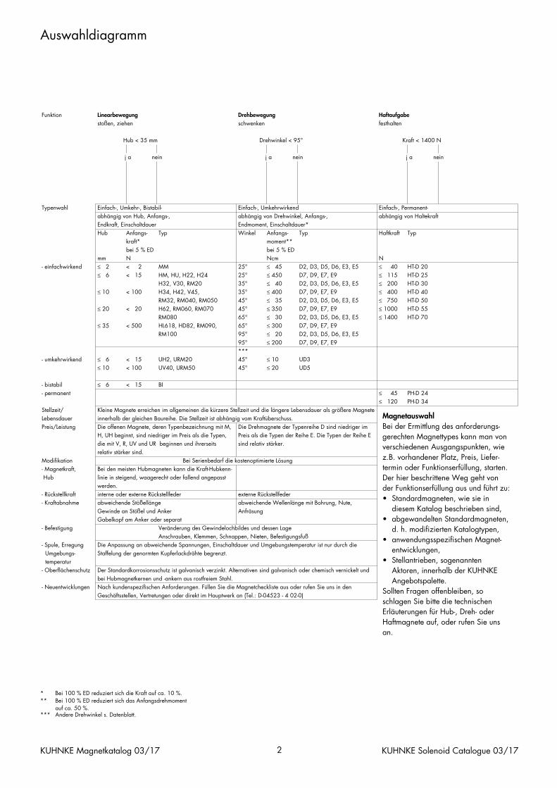
Auswahldiagramm
KUHNKE Magnetkatalog 03/17 2 KUHNKE Solenoid Catalogue 03/17
MagnetauswahlBei der Ermittlung des anforderungs-gerechten Magnettypes kann man vonverschiedenen Ausgangspunkten, wiez.B. vorhandener Platz, Preis, Liefer-termin oder Funktionserfüllung, starten.Der hier beschrittene Weg geht von der Funktionserfüllung aus und führt zu:• Standardmagneten, wie sie in
diesem Katalog beschrieben sind,• abgewandelten Standardmagneten,
d. h. modifizierten Katalogtypen,• anwendungsspezifischen Magnet-
entwicklungen,• Stellantrieben, sogenannten
Aktoren, innerhalb der KUHNKEAngebotspalette.
Sollten Fragen offenbleiben, soschlagen Sie bitte die technischenErläuterungen für Hub-, Dreh- oderHaftmagnete auf, oder rufen Sie unsan.
* At 100 % ED the force is reduced to approx. 10 %.** At 100 % ED the initial torque is reduced to approx.
50 %.*** Other torques see data sheet.
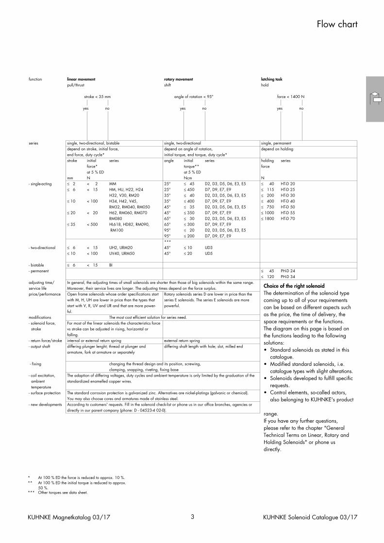
Flow chart
KUHNKE Magnetkatalog 03/17 3 KUHNKE Solenoid Catalogue 03/17
function linear movement rotary movement latching task
pull/thrust shift hold
stroke < 35 mm
yes no ye
angle of rotation < 95°
s no
force < 1400 N
yes no
series single, two-directional, bistabledepend on stroke, initial force,end force, duty cycle*stroke initial
single, two-directionaldepend on angle of rotation,
seriesinitial torque, end torque, duty cycle*angle initial series
single, permanentdepend on holding
holding series
- single-acting
force*at 5 % ED
mm≤ 2
N< 2
≤ 6 < 15
≤ 10 < 100
MM 25°
torque**at 5 % EDNcm≤ 45 D2, D3, D5, D6, E3, E5
HM, HU, H22, H24H32, V30, RM20
25°35°
H34, H42, V45, RM32, RM040, RM050
35°45°
≤ 450≤ 40
D7, D9, E7, E9D2, D3, D5, D6, E3, E5
≤ 400≤ 35
D7, D9, E7, E9D2, D3, D5, D6, E3, E5
≤ 20 < 20
≤ 35 < 500
- two-directional ≤ 6≤ 10
< 15< 100
H62, RM060, RM070RM080
45°65°
HL618, HD82, RM090, RM100
65°95°
≤ 350≤ 30
D7, D9, E7, E9D2, D3, D5, D6, E3, E5
≤ 300≤ 20
D7, D9, E7, E9D2, D3, D5, D6, E3, E5
95°***
UH2, URM20UV40, URM50
45°45°
≤ 200 D7, D9, E7, E9
≤ 10≤ 20
UD3UD5
force
N≤ 40 HT-D 20≤ 115≤ 200
HT-D 25HT-D 30
≤ 400≤ 750
HT-D 40HT-D 50
≤ 1000≤ 1800
HT-D 55HT-D 70
- bistable- permanent
≤ 6 < 15
adjusting time/service lifeprice/performance
In general, the adjusting times of small solenoids are shorter than those of big solenoids within the same range.Moreover, their service lives are longer. The adjusting times depend on the force surplus.Open frame solenoids whose order specifications startwith M, H, UH are lower in price than the types that
BI
Rotary solenoids series D are lower in price than theseries E solenoids. The series E solenoids are more
modifications- solenoid force,
start with V, R, UV and UR and that are more power-ful.
For most of the linear solenoids the characteristics force stroke
- return force/stroke- output shaft
vs stroke can be adjusted in rising, horizontal orfalling.internal or external return springdiffering plunger lenght; thread at plunger and
powerful.
The most cost efficient solution for series need.
external return springdiffering shaft length with hole; slot, milled end
≤ 45≤ 120
PH-D 24PH-D 34
- fixing
armature, fork at armature or separately
- coil excitation, ambient temperature- surface protection
The adaption of differing voltages, duty cycles and ambient temperature is only limited by the graduation of thestandardized enamelled copper wires.
The standard corrosion protection is galvanized zinc. Alternatives are nickel-platings (galvanic or chemical).
changing the thread design and its position, screwing,clamping, snapping, riveting, fixing base
- new developmentsYou may also choose cores and armatures made of stainless steel.According to customers' requests. Fill in the solenoid check-list or phone us in our office branches, agencies ordirectly in our parent company (phone: D - 04523-4 02-0).
Choice of the right solenoidThe determination of the solenoid typecoming up to all of your requirementscan be based on different aspects suchas the price, the time of delivery, thespace requirements or the functions.The diagram on this page is based onthe functions leading to the followingsolutions:• Standard solenoids as stated in this
catalogue.• Modified standard solenoids, i.e.
catalogue types with slight alterations.• Solenoids developed to fulfill specific
requests.• Control elements, so-called actors,
also belonging to KUHNKE's product
range.If you have any further questions,please refer to the chapter "GeneralTechnical Terms on Linear, Rotary andHolding Solenoids" or phone usdirectly.
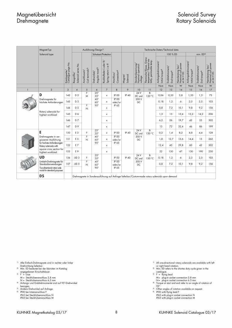
1) All one-directional rotary solenoids are available with left or right hand rotation.
2) Min. ED refers to the shortes duty cycle given in the catalogue.
3) F = flying leadM= plug-in socket connection 2.8 mmN = plug-in socket connection 6.3 mm
4) Torque at start and end refer to an angle of rotation of 95°.
5) Other angles of rotation available on request.6) IP00 with flying lead F
IP65 with plug-in socket connection NIP65 with plug-in socket connection M
1) Alle Einfach-Drehmagnete sind in rechter oder linker Drehrichtung lieferbar.
2) Min. ED bedeutet bei der kleinsten im Katalog angegebenen Einschaltdauer.
3) F = LitzeM = Steckhülsenanschluss 2,8 mmN = Steckhülsenanschluss 6,3 mm
4) Anfangs- und Enddrehmomente sind auf 95°-Drehwinkel bezogen.
5) Andere Drehwinkel auf Anfrage. 6) IP00 bei Litzenanschluss F
IP65 bei Steckhülsenanschluss NIP65 bei Steckhülsenanschluss M
MagnetübersichtDrehmagnete
Solenoid SurveyRotary Solenoids
KUHNKE Magnetkatalog 03/17 8 KUHNKE Solenoid Catalogue 03/17
Magnet-Typ Ausführung/Design1) Technische Daten/Technical data
Solenoid type
Kata
logs
eite
/C
atal
ogue
pag
e N
o.
Baug
röße
/
Sole
noid
ser
ies
No.
Ans
chlu
ssar
t/
Coi
l ter
min
als3
)
Schutzart/Protection
Dre
hwin
kel/
Ang
ular
trav
el5)
Rück
holfe
der
L od
er R
/
Sprin
g re
turn
L o
r R
Ans
chlu
ss/
Con
nect
ion6
)
Mag
net/
Sole
noid
Stan
dard
span
nung
/N
omin
al o
pera
tion
volta
ge
Ther
mis
che
Klas
se, G
renz
-te
mpe
ratu
r/ T
herm
al s
ta-
bilit
y, p
erm
issi
ble
tem
p.
Anf
angs
dreh
mom
ent/
Initi
al to
rque
4)
100 % ED
Endd
rehm
omen
t/
End
torq
ue4)
Nen
nlei
stun
g be
i/N
omin
al c
oil p
ower
at
24
V D
C
Anf
angs
dreh
mom
ent/
Initi
al to
rque
4)
min. ED2)
Endd
rehm
omen
t/
End
torq
ue4)
Nen
nlei
stun
g be
i/N
omin
al c
oil p
ower
at
24
V D
C
1 2 3
DDrehmagnete fürhöchste Anforderungen
142
143
4 5
D 2
D 3
FM
6 725°35°45°65°
x
x
8 9
IP 00
IP 00oder/or
IP 40
10 1124 V
DC und205 V
DC
B130 °C
Ncm
12
Ncm
13
0,06
0,18
0,35
1,2
W
14
Ncm
15
3,8
6
1,35
2,5
Ncm
16
W
17
1,3
2,5
73
103
Rotary solenoids forhighest workload
144
145
146
147
EDrehmagnete in ver-gossener Ausführung
150
151
für höchste AnforderungenRotary solenoids withsquare cross section forhighest workload
152
153
D 5
D 6
FN
D 7
D 9
95°x
x
x
x
E 3
E 5
F
FN
E 7
E 9
25°35°45°65°
x
x
95°x
x
IP 65
IP 00
IP 00oder/or
IP 40
IP 65
24 VDC und205 V
DC
B130 °C
0,8
1,3
7,2
15
6,2
13
26
72
10,1
13,4
9,8
13,2
19,7
32,4
42
46
0,2
1,8
1,4
12,7
12,4
22
45
130
8,2
15,6
4,8
14,4
29,8
47
60
130
9,2
14,2
156
206
25
86
302
199
4,4
15
128
262
42
190
302
250
UDUmkehr-Drehmagnete fürStandardanwendungen
156
157
Two-directional rotary sole-noids for standard purposes
DS
UD 3
UD 5
F
FN
Drehmagnete in Sonderausführung auf Anfrage lieferbar/Custom-made rotary solenoids upon demand
25°35°45°65°95°
IP 00
IP 00oder/or
IP 40
IP 65
24 VDC und205 V
DC
B130 °C 0,18
0,8
1,2
7,2
6
10,1
2,5
9,8
2,5
9,2
103
156
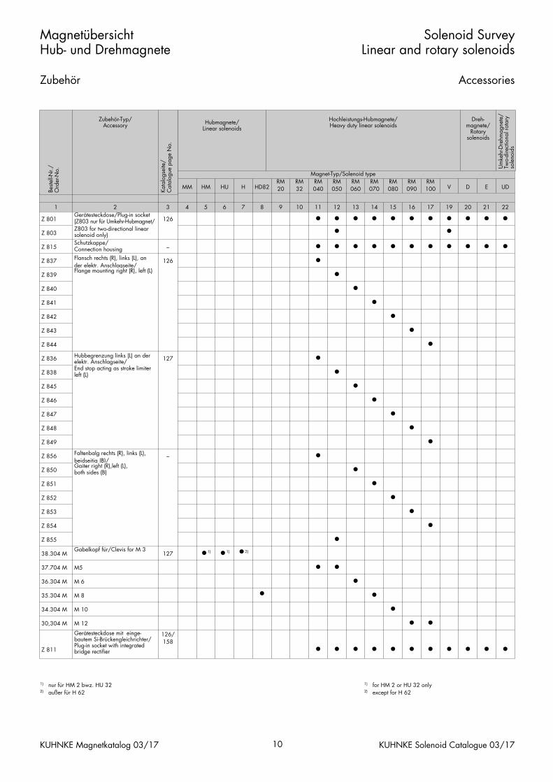
1) for HM 2 or HU 32 only2) except for H 62
1) nur für HM 2 bwz. HU 322) außer für H 62
MagnetübersichtHub- und Drehmagnete
Zubehör
Solenoid SurveyLinear and rotary solenoids
Accessories
KUHNKE Magnetkatalog 03/17 10 KUHNKE Solenoid Catalogue 03/17
Magnet-Typ/Solenoid type
MM HM HU H HD82RM20
RM32
RM040
RM050
RM060
RM070
RM080
RM090
RM100 V D E UD
1
Z 801
Z 803
Z 815
2Gerätesteckdose/Plug-in socket(Z803 nur für Umkehr-Hubmagnet/
3
126
Z803 for two-directional linearsolenoid only)Schutzkappe/ Connection housing –
4 5 6 7 8 9 10 11
•
•
12
•13
••• •
14
•15
•
• •
16
•17
•
• •
19
•20
••• •
21
•22
•
• •Z 837
Z 839
Z 840
Z 841
Flansch rechts (R), links (L), ander elektr. Anschlagseite/Flange mounting right (R), left (L)
126
Z 842
Z 843
Z 844
Z 836 Hubbegrenzung links (L) an derelektr. Anschlagseite/ 127
•
•
••
••
••
Z 838
Z 845
Z 846
Z 847
End stop acting as stroke limiterleft (L)
Z 848
Z 849
Z 856
Z 850
Faltenbalg rechts (R), links (L),beidseitig (B)/Gaiter right (R),left (L),both sides (B)
–
Z 851
Z 852
Z 853
Z 854
Z 855
38.304 M
37.704 M
36.304 M
Gabelkopf für/Clevis for M 3127
M5
M 6
•1) •1) •2)
•
••
••
•
•
••
•
••
••
••
35.304 M
34.304 M
30,304 M
Z 811
M 8
M 10
M 12
Gerätesteckdose mit einge-bautem Si-Brückengleichrichter/Plug-in socket with integratedbridge rectifier
126/158
•
• • •
••
• •
•
•
•
• • • • •
Hubmagnete/Linear solenoids
Hochleistungs-Hubmagnete/Heavy duty linear solenoids
Dreh-magnete/
Rotarysolenoids
Um
kehr
-Dre
hmag
nete
/Tw
o-di
rect
iona
l rot
ary
sole
noid
s
Best
ell-N
r./
Ord
er-N
o.
Zubehör-Typ/Accessory
Kata
logs
eite
/C
atal
ogue
pag
e N
o.
Drehmagnete D, E, UD
Rotary SolenoidsSeries D, E, UD
Technische Informationenfür Drehmagnete
1. Begrifferklärungen1.1 Drehmagnete1.2 Mechanische Begriffe
2. Montagehinweise
3. Drehmomentabnahme an der Welle
4. Funktionsbeschreibung
5. Drehwinkel
6. Anzugszeit
7. Detaildarstellung eines Drehmagneten D
8. Wellenausführungen
9. Anwendungsbeispiele
Drehmagnete
Technische Beschreibung/VorzugstypenTyp D und E einfachwirkend, Typ UD umkehrwirkendDrehmagnete nach Kundenspezifikation
Vorzugstypen
Typ D
Typ E
Typ UD
Zubehör Typen D, E und UD
Seite Page
132132132
133
133
134
134
135
136
137
138
139–140141
139
140
141–148
149–154
155–157
158
131
InhaltDrehmagnete
RegisterRotary Solenoids
KUHNKE Magnetkatalog 03/17 KUHNKE Solenoid Catalogue 03/17
Technical Noteson Rotary Solenoids
1. Definitions1.1 Rotary solenoids1.2 Mechanical data
2. Mounting instructions
3. Torque take off from the output spindle
4. Function description
5. Angle of rotation
6. Actuation time
7. Detailed diagram of a rotary solenoid, series D
8. Shaft designs
9. Examples of application
Rotary Solenoids
Technical description/Preferred typesSeries D and E single acting, series UD two directionalRotary solenoids made to customer's specificationsPreferred types
Series D
Series E
Series UD
Accessories for series D, E and UD
1. Begriffserklärungen
1.1 Drehmagnete
Ein Einfachdrehmagnet ist eineKomponente, bei der dieDrehbewegung von derAnfangslage in die Endlage durchdie elektromagnetischeKraftwirkung und bei dem die Rück-stellung durch äußere Kraft erfolgt.
Umkehrdrehmagnet (ohne Null-stellung). Die Drehbewegung er-folgt je nach Erregung von einerEndlage in die andere oder um-gekehrt.
1.2 Mechanische Begriffe
Drehmoment ist der ausnutzbare,um die Reibung verminderte Teilder im Magneten in Drehrichtungerzeugten Kraft, multipliziert mitdem Hebelarm.
Anfangsdrehmoment in derAnfangslage des Ankers gemessen.
Enddrehmoment gemessen 5° vorEnde der Drehbewegung.
Rückholfeder Anfangsdrehmoment der Rückholfeder.
Drehwinkel ist der vom Ankerzwischen Anfangslage undEndlage zurückgelegte Weg.
Anfangslage ist die Lage desAnkers vor Beginn der Drehbewe-gung bzw. nach Beendigung derRückstellung.
Endlage ist die im Magneten kon-struktiv festgelegte Stellung desAnkers nach Beendigung der Dreh-bewegung.
Drehmagnete Technische Informationen
Rotary Solenoids Technical Notes
132 KUHNKE Solenoid Catalogue 03/17KUHNKE Magnetkatalog 03/17
1. Definitions
1.1 Rotary solenoids
A single acting rotary solenoid is aunit that utilises a rotary motionfrom a neutral position throughenergization of the solenoid. Returnaction follows through other means.
Reversing rotary solenoid (withoutneutral position). The rotary motionis from one end position to theother when energization occurs.The end position in one direction istherefore the start position for theother direction.
1.2 Mechanical data
The torque of the solenoid is givenby the useful force generated in thedirection of motion, taking accountof friction loss, multiplied by thelength of the actuating arm.
Starting torque is measured in thestart position of the armature.
End torque is measured 5° beforethe end position.
Return spring Starting torque of re-turn spring.
Angle of rotation is the anglemoved through from start to endposition.
The start position is the position ofthe armature before commencingrotation (or else after completion ofreturn action).
The end position is the selectedposition of the armature afterenergizing.
2. MontagehinweiseFür die Befestigung sind zwei bzw.drei Gewindelöcher auf beidenStirnseiten vorgesehen (siehe Maß-bilder).
– Bei der Auswahl der Befesti-gungsschrauben ist die in denMaßbildern angegebene Ge-windetiefe zu berücksichtigen.Gewaltsames Hineindrehen derSchrauben sowie Aufbohren derBefestigungslöcher führt zu Be-schädigung der Wicklung.
– Schläge auf die kugelgelagerteWelle sind zu vermeiden.
– Um die Lebensdauer der Dreh-magnete zu erhöhen, empfehlenwir, zusätzliche Massenkräftevon den internen Anschlägender Drehmagnete durch äußereDrehwinkelbegrenzung fernzu-halten.
– Wenn die Wärmeabgabe durch eine zusätzliche Kühl-fläche, die mit dem Dreh-magneten in gut wärmeleitenderVerbindung steht, verbessertwird (z. B. durch Montage aufeine größere Metallplatte), isteine größere relative Einschalt-dauer zulässig.
3. Drehmomentabnahme an der WelleWir empfehlen, die Drehmoment-abnahme über Klemmbacken vor-zusehen. Wird die Welle zumBefestigen einer Kupplungseinrich-tung nachträglich spanabhebendbearbeitet (Bohrung, Nute, Anfrä-sung), so ist darauf zu achten, dassder Drehmagnet an der Welle ge-spannt wird, und die Kugellagervor dem Eindringen von Spänengeschützt sind.
Drehmagnete Technische Informationen
Rotary Solenoids Technical Notes
133 KUHNKE Solenoid Catalogue 03/17KUHNKE Magnetkatalog 03/17
2. Mounting instructionsFor fixing purposes, 2 or 3threaded holes are provided onboth flanges (see diagrams). Thefollowing points are to be parti-cularly observed:
– Selection of screws should takeaccount of the depth of threadindicated in the diagram.Forced tightening of a screw orboring out of the threaded holescan result in damage to thewinding.
– Hard blows on the bearingmounted spindle should beavoided.
– In order to increase the life ex-pectancy of rotary solenoids werecommend that the additionalinertia forces resulting from theinternal stops are eliminated byexternal stops.
– If the cooling process is en-hanced by using additionalcooling surfaces, e.g. bymounting on a large surfaceplate, then a higher relativeduty cycle is permissible.
3. Torque take off from the outputspindleWe recommend that a clamp typecoupling is used for torque take off. If the coupling selected involvesmachining of the spindle (hole, key-way, slot) it should be ensured thatthe spindle is secured to the sole-noid and the bearings are pro-tected against the ingress of swarf.
4. FunktionsbeschreibungDer Drehmagnet besitzt einen Dreh-anker, der auf einer beiderseitiggelagerten Welle befestigt ist undzwischen zwei internenAnschlägen eine winkelbegrenzteDrehbewegung ausführt. Anker undKern sind z. B. mit schräg zurAnkerwelle liegenden Stirnflächenversehen, zwischen denen sich derArbeitsluftspalt befindet. Wird dieMagnetspule erregt, hat derDrehanker das Bestreben, denArbeitsluftspalt zu verringern, d. h.der Anker dreht sich bis zumErreichen der Anschläge. DieRückstellung des Ankers kann durchdie äußere Mechanik, eineRückholfeder oder einen entgegen-gesetzt wirkenden zweiten Dreh-magneten – als Umkehrdrehmagnetlieferbar – erfolgen.
5. DrehwinkelDie Standardausführungen werdenmit Drehwinkeln von 25°, 35°,45°, 65° oder 95° geliefert. DerDrehwinkel kann um +3° ab-weichen.
Drehmagnete Technische Informationen
Rotary Solenoids Technical Notes
134 KUHNKE Solenoid Catalogue 03/17KUHNKE Magnetkatalog 03/17
4. Function descriptionThe rotary solenoid has a rotationalarmature that is mounted on aspindle supported at each end byall bearings and can move be-tween two internal limit stops. Thearmature and the core are inclined,relative to the armature shaft centreline, with an air gap in between.When the coil is energized thetendency is for the rotary armatureto try to close this gap and rota-tional motion occurs until an endstop is reached. The return actionfor the armature can be achievedeither by a return spring or by asecond rotary solenoid – suppliedas a reversing solenoid.
5. Angle of rotationStandard types are produced withangular travels of 25°, 35°, 45°,65°, or 95°. The angle of rotationis subject to manufacturingtolerance of +3°.
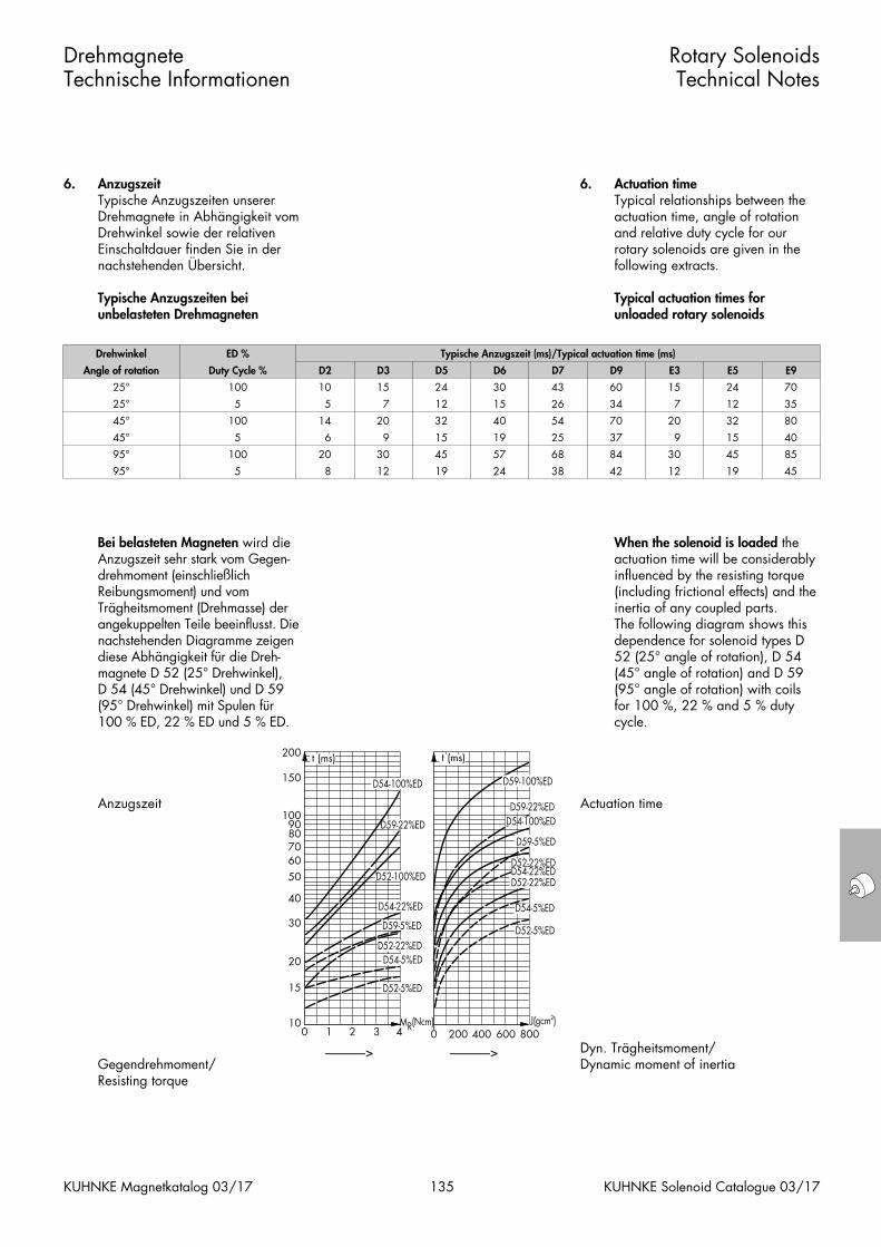
6. AnzugszeitTypische Anzugszeiten unsererDrehmagnete in Abhängigkeit vomDrehwinkel sowie der relativenEinschaltdauer finden Sie in dernachstehenden Übersicht.
Typische Anzugszeiten beiunbelasteten Drehmagneten
Bei belasteten Magneten wird dieAnzugszeit sehr stark vom Gegen-drehmoment (einschließlich Reibungsmoment) und vomTrägheitsmoment (Drehmasse) derangekuppelten Teile beeinflusst. Dienachstehenden Diagramme zeigendiese Abhängigkeit für die Dreh-magnete D 52 (25° Drehwinkel), D 54 (45° Drehwinkel) und D 59(95° Drehwinkel) mit Spulen für 100 % ED, 22 % ED und 5 % ED.
Anzugszeit
Gegendrehmoment/Resisting torque
Drehmagnete Technische Informationen
Rotary Solenoids Technical Notes
135 KUHNKE Solenoid Catalogue 03/17KUHNKE Magnetkatalog 03/17
6. Actuation timeTypical relationships between theactuation time, angle of rotationand relative duty cycle for ourrotary solenoids are given in thefollowing extracts.
Typical actuation times forunloaded rotary solenoids
When the solenoid is loaded theactuation time will be considerablyinfluenced by the resisting torque(including frictional effects) and theinertia of any coupled parts.The following diagram shows thisdependence for solenoid types D52 (25° angle of rotation), D 54(45° angle of rotation) and D 59(95° angle of rotation) with coilsfor 100 %, 22 % and 5 % dutycycle.
Actuation time
Dyn. Trägheitsmoment/Dynamic moment of inertia
Drehwinkel ED % Typische Anzugszeit (ms)/Typical actuation time (ms)
Angle of rotation
25°
Duty Cycle %
100
D2
10
D3
15
D5
24
D6
30
D7
43
D9
60
E3
15
E5
24
E9
70
25°
45°
45°
95°
5
100
5
14
5
100
6
20
7
20
12
32
9
30
15
45
15
40
26
54
19
57
25
68
34
70
7
20
37
84
9
30
12
32
35
80
15
45
40
85
95° 5 8 12 19 24 38 42 12 19 45
t (ms)t (ms)
0 0 200 400 600 8001 2 3 410
15
20
30
40
5060708090
100
150
200
J(gcm2)
D52-5%ED
D54-5%ED
D52-22%ED
D59-22%ED
D59-100%ED
D54-100%ED
D59-5%ED
D52-5%ED
D54-5%EDD52-22%ED
D59-5%ED
D54-22%ED
D52-100%ED
D59-22%ED
D54-100%ED
MR(Ncm)
D54-22%EDD52-22%ED
––––––> ––––––>
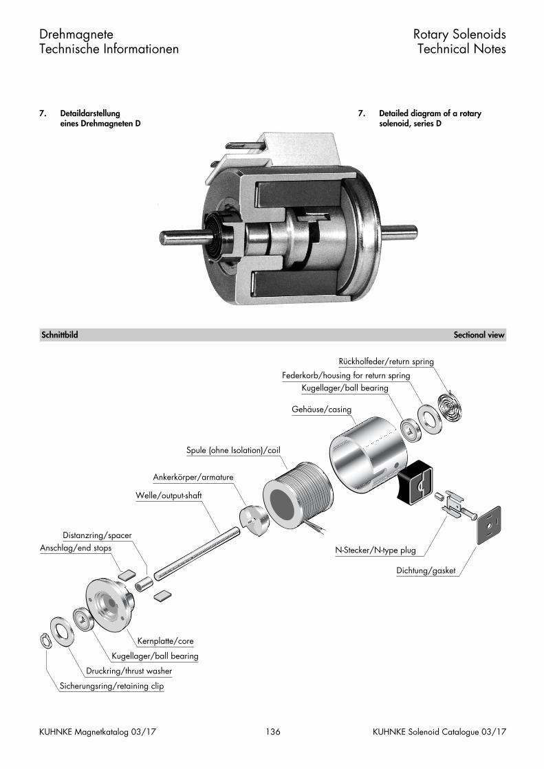
7. Detaildarstellung eines Drehmagneten D
Drehmagnete Technische Informationen
Rotary Solenoids Technical Notes
136 KUHNKE Solenoid Catalogue 03/17KUHNKE Magnetkatalog 03/17
7. Detailed diagram of a rotarysolenoid, series D
Rückholfeder/return spring
Federkorb/housing for return springKugellager/ball bearing
Gehäuse/casing
Spule (ohne Isolation)/coil
Ankerkörper/armature
Welle/output-shaft
Sicherungsring/retaining clip
Kernplatte/core
Kugellager/ball bearing
Druckring/thrust washer
Distanzring/spacerAnschlag/end stops N-Stecker/N-type plug
Dichtung/gasket
Schnittbild Sectional view
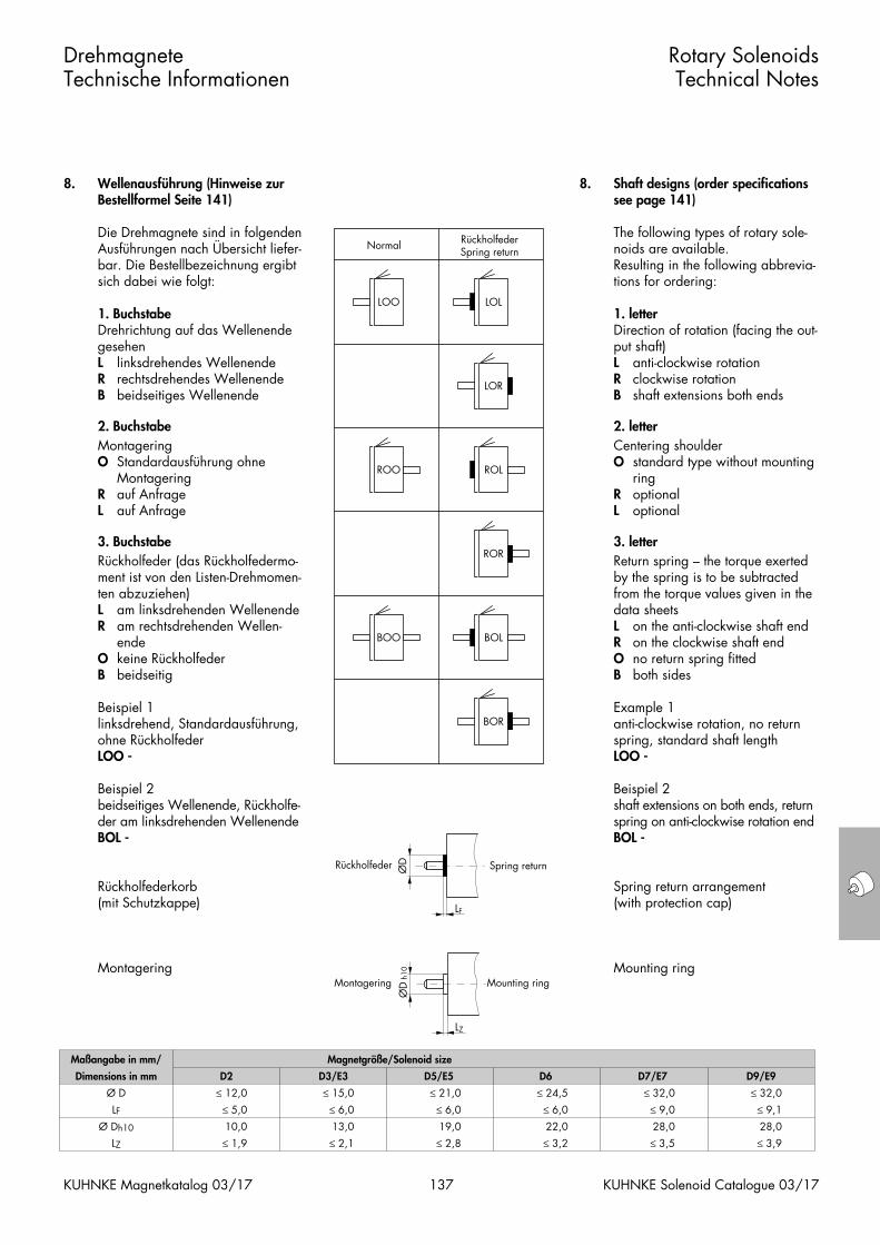
8. Wellenausführung (Hinweise zurBestellformel Seite 141)
Die Drehmagnete sind in folgendenAusführungen nach Übersicht liefer-bar. Die Bestellbezeichnung ergibtsich dabei wie folgt:
1. BuchstabeDrehrichtung auf das WellenendegesehenL linksdrehendes WellenendeR rechtsdrehendes WellenendeB beidseitiges Wellenende
2. Buchstabe
MontageringO Standardausführung ohne
MontageringR auf AnfrageL auf Anfrage
3. Buchstabe
Rückholfeder (das Rückholfedermo-ment ist von den Listen-Drehmomen-ten abzuziehen)L am linksdrehenden WellenendeR am rechtsdrehenden Wellen-
endeO keine RückholfederB beidseitig
Beispiel 1linksdrehend, Standardausführung,ohne RückholfederLOO -
Beispiel 2beidseitiges Wellenende, Rückholfe-der am linksdrehenden WellenendeBOL -
Rückholfederkorb(mit Schutzkappe)
Montagering
Drehmagnete Technische Informationen
Rotary Solenoids Technical Notes
137 KUHNKE Solenoid Catalogue 03/17KUHNKE Magnetkatalog 03/17
8. Shaft designs (order specificationssee page 141)
The following types of rotary sole-noids are available. Resulting in the following abbrevia-tions for ordering:
1. letterDirection of rotation (facing the out-put shaft)L anti-clockwise rotationR clockwise rotationB shaft extensions both ends
2. letter
Centering shoulderO standard type without mounting
ringR optionalL optional
3. letter
Return spring – the torque exertedby the spring is to be subtractedfrom the torque values given in thedata sheetsL on the anti-clockwise shaft endR on the clockwise shaft endO no return spring fittedB both sides
Example 1anti-clockwise rotation, no returnspring, standard shaft lengthLOO -
Beispiel 2shaft extensions on both ends, returnspring on anti-clockwise rotation endBOL -
Spring return arrangement(with protection cap)
Mounting ring
Maßangabe in mm/ Magnetgröße/Solenoid size
Dimensions in mm
Ø D
D2
≤ 12,0
D3/E3
≤ 15,0
D5/E5
≤ 21,0
D6
≤ 24,5
D7/E7
≤ 32,0
D9/E9
≤ 32,0
LFØ Dh10
LZ
≤ 5,0
10,0
≤ 6,0
13,0
≤ 1,9 ≤ 2,1
≤ 6,0
19,0
≤ 6,0
22,0
≤ 2,8 ≤ 3,2
≤ 9,0
28,0
≤ 9,1
28,0
≤ 3,5 ≤ 3,9
Normal RückholfederSpring return
BOR
BOL
ROR
ROL
LOR
LOL
BOO
ROO
LOO
LZ
Montagering
ØD
h10
LF
Rückholfeder ØD
Mounting ring
Spring return
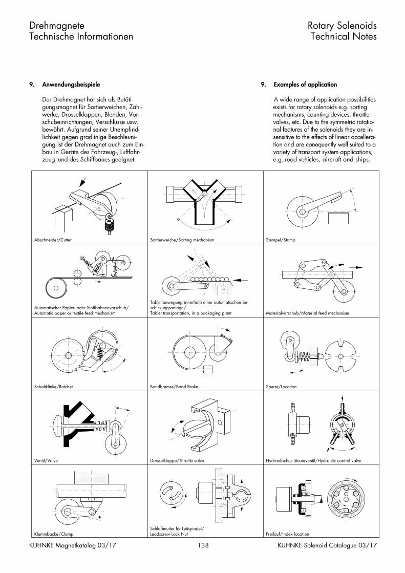
9. Anwendungsbeispiele
Der Drehmagnet hat sich als Betäti-gungsmagnet für Sortierweichen, Zähl-werke, Drosselklappen, Blenden, Vor-schubeinrichtungen, Verschlüsse usw.bewährt. Aufgrund seiner Unempfind-lichkeit gegen gradlinige Beschleuni-gung ist der Drehmagnet auch zum Ein-bau in Geräte des Fahrzeug-, Luftfahr-zeug- und des Schiffbaues geeignet.
Drehmagnete Technische Informationen
Rotary Solenoids Technical Notes
138 KUHNKE Solenoid Catalogue 03/17KUHNKE Magnetkatalog 03/17
9. Examples of application
A wide range of application possibilitiesexists for rotary solenoids e.g. sortingmechanisms, counting devices, throttlevalves, etc. Due to the symmetric rotatio-nal features of the solenoids they are in-sensitive to the effects of linear accellera-tion and are conequently well suited to avariety of transport system applications,e.g. road vehicles, aircraft and ships.
�������
�����������������������������
����������� ������
�����
���������������������������
����������������������
���������������
������
����������
Abschneider/Cutter Sortierweiche/Sorting mechanism Stempel/Stamp
Automatischer Papier- oder Stoffbahnenvorschub/Automatic paper or textile feed mechanism
Tablettbewegung innerhalb einer automatischen Be-schickungsanlage/Tablet transportation, in a packaging plant Materialvorschub/Material feed mechanism
Schaltklinke/Ratchet Bandbremse/Band Brake Sperre/Location
Ventil/Valve Drosselklappe/Throttle valve Hydraulisches Steuerventil/Hydraulic control valve
Klemmbacke/ClampSchloßmutter für Leitspindel/Leadscrew Lock Nut Freilauf/Index location
���������������������������������
������������
�������������������������
��������������
�����
���������������
�������
�������
����
��������������
�����������
������������������������
���
�������������������������
����������������������
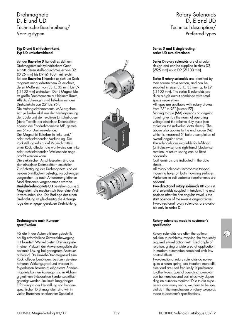
Typ D und E einfachwirkend, Typ UD umkehrwirkend
Bei der Baureihe D handelt es sich umDrehmagnete mit zylindrischem Quer-schnitt, deren Außendurchmesser von D2(Ø 25 mm) bis D9 (Ø 100 mm) reicht. Bei der Baureihe E handelt es sich um Dreh-magnete mit quadratischem Querschnitt,deren Maße sich von E3 (� 35 mm) bis E9(� 100 mm) erstrecken. Der E-Magnet bie-tet große Drehmomente auf kleinem Raum.Alle Ausführungen sind lieferbar mit denDrehwinkeln von 25° bis 95°.Die Anfangsdrehmomente (MA) ergebensich je Drehwinkel aus der Nennspannungder Spule und der relativen Einschaltdauer(siehe Tabelle der einzelnen Datenblätter),ebenso die Enddrehmomente ME, gemes-sen 5° vor Drehwinkelende.Der Magnet ist lieferbar in links- und/oder rechtsdrehender Ausführung. DieRückstellung erfolgt auf Wunsch mittelseiner Rückholfeder, die wahlweise am links-oder rechtsdrehenden Wellenende ange-bracht werden kann.Die elektrischen Anschlussarten sind ausden einzelnen Datenblättern ersichtlich.Zur Befestigung der Drehmagnete sind anbeiden Stirnflächen Befestigungsbohrungenvorgesehen. Je nach Anforderung könnenModifikationen vorgenommen werden.Umkehrdrehmagnete UD bestehen aus je 2Magneten, die mechanisch über eine Wel-le verbunden sind. Die Endlage der einenDrehrichtung ist gleichzeitig die Anfangs-lage der entgegengesetzten Drehrichtung.
Drehmagnete nach Kunden-spezifikation
Für die in der Automatisierungstechnikhäufig erforderliche Schwenkbewegung mit fixiertem Winkel bieten Drehmagnete in einer Vielzahl der Anwendungsfälle dieoptimale Lösung bei geringstem Ansteuer-aufwand. Da Umkehr-Drehmagnete keineRückholfeder benötigen, besitzen sie einenhöheren Wirkungsgrad und werden in-folgedessen bevorzugt eingesetzt. Sonder-magnete können kostengünstig in Abhän-gigkeit von Stückzahlen kundenspezifischgefertigt werden. Im Laufe langjährigerErfahrung in der Herstellung von kunden-spezifischen Drehmagneten sind wir invielen Branchen anerkannter Spezialist.
DrehmagneteD, E und UDTechnische Beschreibung/Vorzugstypen
Rotary Solenoids D, E and UD
Technical description/Preferred types
139 KUHNKE Solenoid Catalogue 03/17KUHNKE Magnetkatalog 03/17
Series D and E single acting, series UD two directional
Series D rotary solenoids are of circulardesign and can be supplied in sizes D2(Ø25 mm) up to D9 (Ø 100 mm).
Series E rotary solenoids are identified bytheir square cross section, and can besupplied in sizes E3 (� 35 mm) up to E9(� 100 mm). The series E solenoids pro-duce a high output combined with smallspace requirement.All types are available with rotary strokesfrom 25° to 95° (except E7).Starting torque (MA) depends on angulartravel, given by the nominal operatingvoltage and the relative duty cycle (seetables on the individual data sheets). Theabove also applies to the end torque (ME)which is measured 5° before completion ofoverall angular travel. The solenoids are available for left-hand(anti-clockwise) and right-hand (clockwise)rotation. A return spring can be fittedoptionally.Coil terminals are indicated in the datasheets.All rotary solenoids incorporate tappedmounting holes on both mounting surfaces.Variations to suit customer requirements areoptional.Two-directional rotary solenoids UD consistof 2 solenoids coupled in tandem. The endposition after the first angular travel is thestart position of the reverse angular travel.Two-directional rotary solenoids are availa-ble only in series D.
Rotary solenoids made to customer'sspecification
Rotary solenoids are often the optimal solution to problems involving the frequentlyrequired swivel action with fixed angle ofrotation, giving a wide area of applicationin modern automation combined with lowcontrol efforts.Two-directional rotary solenoids do not re-quire a return spring, are therefore more effi-cient and are used frequently in preferenceto other types. Special operating solenoidscan be manufactured cost effectively depen-ding on numbers required. Due to our expe-rience over many years, we claim to be spe-cialists in the manufacture of rotary solenoidsmade to customer's specifications.
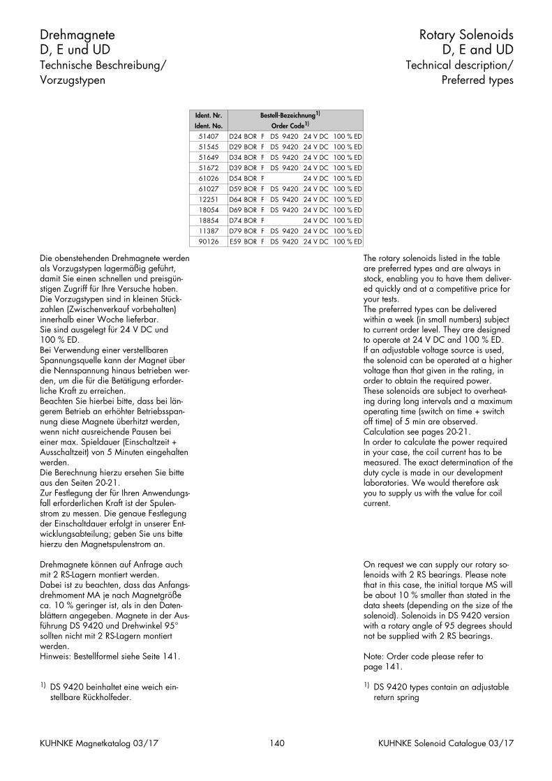
Die obenstehenden Drehmagnete werdenals Vorzugstypen lagermäßig geführt,damit Sie einen schnellen und preisgün-stigen Zugriff für Ihre Versuche haben.Die Vorzugstypen sind in kleinen Stück-zahlen (Zwischenverkauf vorbehalten)innerhalb einer Woche lieferbar.Sie sind ausgelegt für 24 V DC und 100 % ED.Bei Verwendung einer verstellbarenSpannungsquelle kann der Magnet überdie Nennspannung hinaus betrieben wer-den, um die für die Betätigung erforder-liche Kraft zu erreichen.Beachten Sie hierbei bitte, dass bei län-gerem Betrieb an erhöhter Betriebsspan-nung diese Magnete überhitzt werden,wenn nicht ausreichende Pausen beieiner max. Spieldauer (Einschaltzeit +Ausschaltzeit) von 5 Minuten eingehaltenwerden.Die Berechnung hierzu ersehen Sie bitteaus den Seiten 20-21.Zur Festlegung der für Ihren Anwendungs-fall erforderlichen Kraft ist der Spulen-strom zu messen. Die genaue Festlegungder Einschaltdauer erfolgt in unserer Ent-wicklungsabteilung; geben Sie uns bittehierzu den Magnetspulenstrom an.
Drehmagnete können auf Anfrage auchmit 2 RS-Lagern montiert werden. Dabei ist zu beachten, dass das Anfangs-drehmoment MA je nach Magnetgrößeca. 10 % geringer ist, als in den Daten-blättern angegeben. Magnete in der Aus-führung DS 9420 und Drehwinkel 95°sollten nicht mit 2 RS-Lagern montiertwerden.Hinweis: Bestellformel siehe Seite 141.
1) DS 9420 beinhaltet eine weich ein-stellbare Rückholfeder.
DrehmagneteD, E und UDTechnische Beschreibung/Vorzugstypen
Rotary Solenoids D, E and UD
Technical description/Preferred types
140 KUHNKE Solenoid Catalogue 03/17KUHNKE Magnetkatalog 03/17
The rotary solenoids listed in the tableare preferred types and are always instock, enabling you to have them deliver-ed quickly and at a competitive price foryour tests.The preferred types can be deliveredwithin a week (in small numbers) subjectto current order level. They are designedto operate at 24 V DC and 100 % ED.If an adjustable voltage source is used,the solenoid can be operated at a highervoltage than that given in the rating, inorder to obtain the required power.These solenoids are subject to overheat-ing during long intervals and a maximumoperating time (switch on time + switchoff time) of 5 min are observed.Calculation see pages 20-21.In order to calculate the power requiredin your case, the coil current has to bemeasured. The exact determination of theduty cycle is made in our developmentlaboratories. We would therefore askyou to supply us with the value for coilcurrent.
On request we can supply our rotary so-lenoids with 2 RS bearings. Please notethat in this case, the initial torque MS willbe about 10 % smaller than stated in thedata sheets (depending on the size of thesolenoid). Solenoids in DS 9420 versionwith a rotary angle of 95 degrees shouldnot be supplied with 2 RS bearings.
Note: Order code please refer to page 141.
1) DS 9420 types contain an adjustable return spring
Ident. Nr. Bestell-Bezeichnung1)
Ident. No.
51407 D24 BOR F DS
Order Code1)
9420 24 V DC 100 % ED
51545
51649
51672
61026
D29
D34
BOR
BOR
D39
D54
BOR
BOR
F
F
DS
DS
F
F
DS
9420
9420
24 V DC
24 V DC
9420 24 V DC
24 V DC
100 % ED
100 % ED
100 % ED
100 % ED
61027
12251
18054
18854
D59
D64
BOR
BOR
D69
D74
BOR
BOR
11387
90126
D79
E59
BOR
BOR
F
F
DS
DS
F
F
DS
9420
9420
24 V DC
24 V DC
9420 24 V DC
24 V DC
F
F
DS
DS
9420
9420
24 V DC
24 V DC
100 % ED
100 % ED
100 % ED
100 % ED
100 % ED
100 % ED
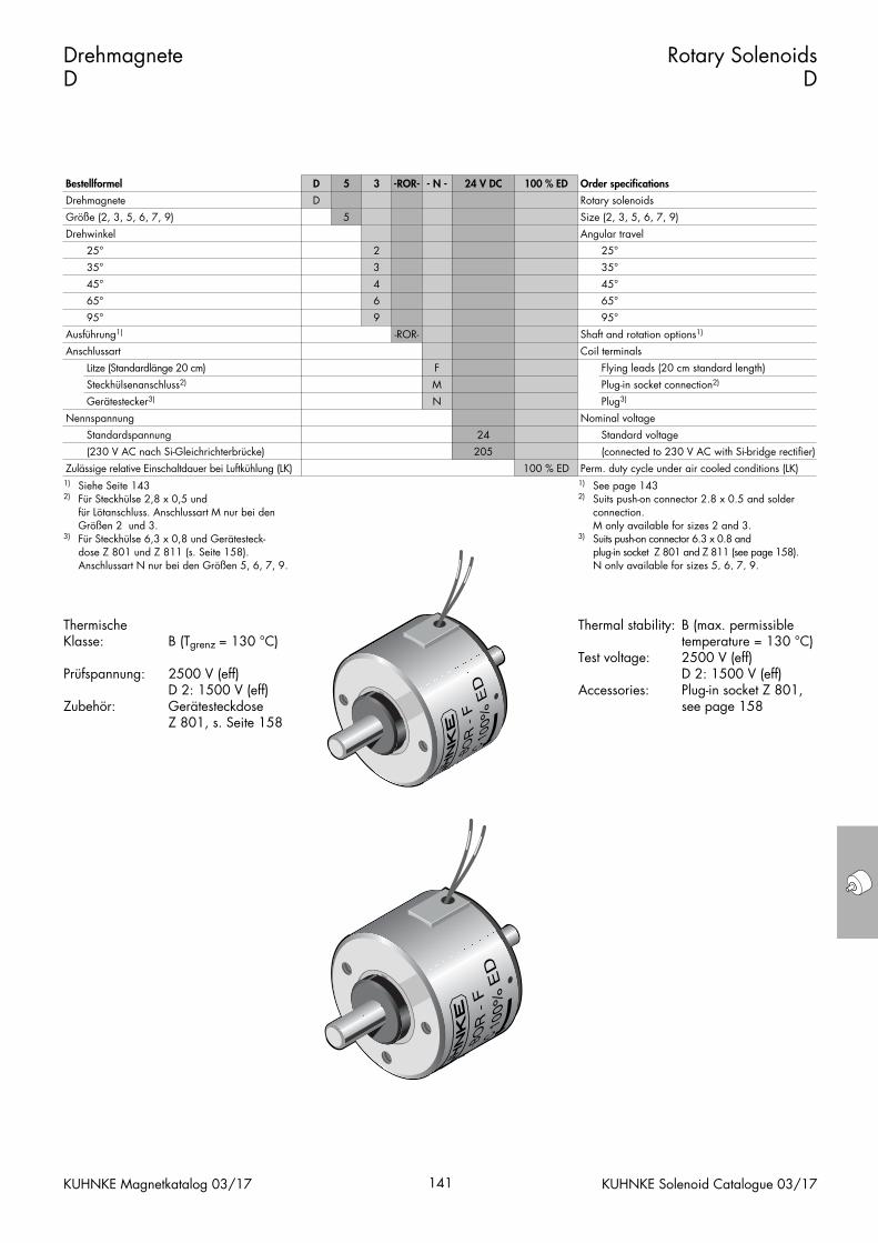
Thermal stability: B (max. permissibletemperature = 130 °C)
Test voltage: 2500 V (eff)D 2: 1500 V (eff)
Accessories: Plug-in socket Z 801, see page 158
Thermische Klasse: B (Tgrenz = 130 °C)
Prüfspannung: 2500 V (eff)D 2: 1500 V (eff)
Zubehör: Gerätesteckdose Z 801, s. Seite 158
Drehmagnete D
Rotary SolenoidsD
KUHNKE Magnetkatalog 03/17 141 KUHNKE Solenoid Catalogue 03/17
Bestellformel D 5 3 -ROR- - N - 24 V DC 100 % ED Order specifications
Drehmagnete
Größe (2, 3, 5, 6, 7, 9)
D
5
Rotary solenoids
Size (2, 3, 5, 6, 7, 9)
Drehwinkel
25°
35°
45°
2
3
4
Angular travel
25°
35°
45°
Ausführung1)
Anschlussart
65°
95°
Nennspannung
Litze (Standardlänge 20 cm)
Steckhülsenanschluss2)
Gerätestecker3)
6
9
-ROR-
F
M
N
65°
95°
Shaft and rotation options1)
Coil terminals
Flying leads (20 cm standard length)
Plug-in socket connection2)
Nominal voltage
Plug3)
Zulässige relative Einschaltdauer bei Luftkühlung (LK)
Standardspannung
(230 V AC nach Si-Gleichrichterbrücke)
24
205
100 % ED
Standard voltage
(connected to 230 V AC with Si-bridge rectifier)
Perm. duty cycle under air cooled conditions (LK)1) Siehe Seite 1432) Für Steckhülse 2,8 x 0,5 und
für Lötanschluss. Anschlussart M nur bei den Größen 2 und 3.
3) Für Steckhülse 6,3 x 0,8 und Gerätesteck-dose Z 801 und Z 811 (s. Seite 158). Anschlussart N nur bei den Größen 5, 6, 7, 9.
1) See page 1432) Suits push-on connector 2.8 x 0.5 and solder
connection.M only available for sizes 2 and 3.
3) Suits push-on connector 6.3 x 0.8 and plug-in socket Z 801 and Z 811 (see page 158).N only available for sizes 5, 6, 7, 9.
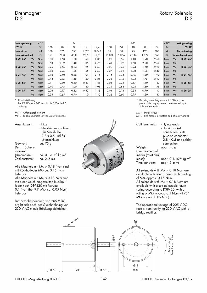
Coil terminals: - Flying leads- Plug-in socket connection (suits push-on connector 2.8 x 0.5 and solder connection)
Weight: appr. 75 gDyn. moment ofinertia (rotationalmass): appr. 0.1•10--6 kg m2
Time constant: appr. 2–6 ms
All solenoids with MA > 0.18 Ncm areavailable with return spring, with a ratingof MRA approx. 0.15 Ncm.All solenoids with MA ≤ 0.18 Ncm areavailable with a soft adjustable returnspring according to DS9420, with a rating of MRA approx. 0.1 Ncm (at 95°MRA approx. 0.05 Ncm).
The operational voltage of 205 V DC results from rectifying 230 V AC with abridge rectifier.
Anschlussart: - Litze- Steckhülsenanschluss (für Steckhülse 2,8 x 0,5 und für Lötanschluss)
Gewicht: ca. 75 gDyn. Trägheits-moment (Drehmasse): ca. 0,1•10--6 kg m2
Zeitkonstante: ca. 2–6 ms
Alle Magnete mit MA > 0,18 Ncm sind mit Rückholfeder MRA ca. 0,15 Ncm lieferbar.Alle Magnete mit MA ≤ 0,18 Ncm sind mit einer weich eingestellten Rückhol-feder nach DS9420 mit MRA ca. 0,1 Ncm (bei 95° MRA ca. 0,05 Ncm)lieferbar.
Die Betriebsspannung von 205 V DC ergibt sich nach der Gleichrichtung von230 V AC mittels Brückengleichrichter.
DrehmagnetD 2
Rotary SolenoidD 2
KUHNKE Magnetkatalog 03/17 142 KUHNKE Solenoid Catalogue 03/17
M3
Ø18
Ø25
3
25 15 ±0,515 ±0,5
Ø3h9
Dre
hric
htun
g/D
irect
ion
of r
otat
ion
Nennspannung V DC 24 205 V DC Voltage rating
ED* LK
Nennstrom
%
mA
100
160
48
325
27
550
14
1.020
4,4
3.040
100
15
50
38
18
95
8
190
5
308
%
mA
ED* LK
Current rating
Nennwiderstand
D 22, 25°
D 23, 35°
MA
�
Ncm
ME
MA
Ncm
Ncm
151
0,30
73,8
0,68
0,53
0,25
1,02
0,55
43,8
1,00
23,5
1,50
1,40
0,84
1,85
1,25
7,9
2,85
13.028
0,23
2,75
2,50
0,41
0,20
5.356
0,56
2.146
1,10
0,92
0,45
1,50
0,94
1.077
1,90
665
2,50
2,20
1,60
2,60
2,20
�
Ncm MA
Ncm
Ncm
ME
MA
Nominal resistance
D 22, 25°
D 23, 35°
D 24, 45°
D 26, 65°
ME
MA
Ncm
Ncm
ME
MA
Ncm
Ncm
D 29, 95°
ME
MA
Ncm
Ncm
ME Ncm
0,48
0,18
0,95
0,40
0,44
0,11
0,85
0,30
1,25
0,66
1,65
1,04
1,15
0,50
1,50
0,83
0,40
0,06
0,75
0,17
0,35 0,65
1,00
0,32
1,30
0,52
0,90 1,10
2,50
2,15
0,37
0,14
2,25
1,85
0,35
0,08
0,82
0,34
1,38
0,75
0,75
0,24
1,23
0,57
1,95
1,35
0,31
0,04
1,30 0,26
0,66
0,13
1,08
0,34
0,60 0,95
1,95
1,30
2,40
1,90
1,75
1,10
2,10
1,60
Ncm
Ncm
ME
MA
Ncm
Ncm
ME
MA
1,50
0,70
1,75
1,10
1,20 1,30
Ncm
Ncm
ME
MA
Ncm ME
D 24, 45°
D 26, 65°
D 29, 95°
* LK = Luftkühlung,bei Kühlfläche ≥ 100 cm2 ist die 1,7fache ED zulässig
MA = AnfangsdrehmomentME = Enddrehmoment (5° vor Drehwinkelende)
* By using a cooling surface ≥ 100 cm2, the permissible duty cycle can be extended up to 1.7x normal rating
MA = Initial torqueME = End torque (5° before end of rotary angle)
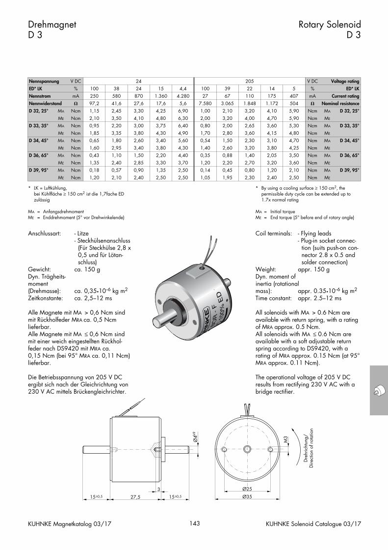
Coil terminals: - Flying leads- Plug-in socket connec- tion (suits push-on con- nector 2.8 x 0.5 and solder connection)
Weight: appr. 150 gDyn. moment ofinertia (rotationalmass): appr. 0.35•10--6 kg m2
Time constant: appr. 2.5–12 ms
All solenoids with MA > 0.6 Ncm areavailable with return spring, with a ratingof MRA approx. 0.5 Ncm.All solenoids with MA ≤ 0.6 Ncm areavailable with a soft adjustable returnspring according to DS9420, with a rating of MRA approx. 0.15 Ncm (at 95°MRA approx. 0.11 Ncm).
The operational voltage of 205 V DC results from rectifying 230 V AC with abridge rectifier.
Anschlussart: - Litze- Steckhülsenanschluss (Für Steckhülse 2,8 x 0,5 und für Lötan- schluss)
Gewicht: ca. 150 gDyn. Trägheits-moment (Drehmasse): ca. 0,35•10--6 kg m2
Zeitkonstante: ca. 2,5–12 ms
Alle Magnete mit MA > 0,6 Ncm sind mit Rückholfeder MRA ca. 0,5 Ncm lieferbar.Alle Magnete mit MA ≤ 0,6 Ncm sind mit einer weich eingestellten Rückhol-feder nach DS9420 mit MRA ca. 0,15 Ncm (bei 95° MRA ca. 0,11 Ncm) lieferbar.
Die Betriebsspannung von 205 V DC ergibt sich nach der Gleichrichtung von230 V AC mittels Brückengleichrichter.
Drehmagnet D 3
Rotary SolenoidD 3
KUHNKE Magnetkatalog 03/17 143 KUHNKE Solenoid Catalogue 03/17
* LK = Luftkühlung,bei Kühlfläche ≥ 150 cm2 ist die 1,7fache ED zulässig
MA = AnfangsdrehmomentME = Enddrehmoment (5° vor Drehwinkelende)
* By using a cooling surface ≥ 150 cm2, the permissible duty cycle can be extended up to 1.7x normal rating
MA = Initial torqueME = End torque (5° before end of rotary angle)
Nennspannung V DC 24 205 V DC Voltage rating
ED* LK
Nennstrom
%
mA
100
250
38
580
24
870
15
1.360
4,4
4.280
100
27
39
67
22
110
14
175
5
407
%
mA
ED* LK
Current rating
Nennwiderstand
D 32, 25°
D 33, 35°
MA
�
Ncm
ME
MA
Ncm
Ncm
97,2
1,15
41,6
2,45
2,10
0,95
3,50
2,20
27,6
3,30
17,6
4,25
4,10
3,00
4,80
3,75
5,6
6,90
7.580
1,00
6,30
6,40
2,00
0,80
3.065
2,10
1.848
3,20
3,20
2,00
4,00
2,65
1.172
4,10
504
5,90
4,70
3,60
5,90
5,30
�
Ncm MA
Ncm
Ncm
ME
MA
Nominal resistance
D 32, 25°
D 33, 35°
D 34, 45°
D 36, 65°
ME
MA
Ncm
Ncm
ME
MA
Ncm
Ncm
D 39, 95°
ME
MA
Ncm
Ncm
ME Ncm
1,85
0,65
3,35
1,80
1,60
0,43
2,95
1,10
3,80
2,60
4,30
3,40
3,40
1,50
3,80
2,20
1,35
0,18
2,40
0,57
1,20 2,10
2,85
0,90
3,30
1,35
2,40 2,50
4,90
5,60
1,70
0,54
4,30
4,40
1,40
0,35
2,80
1,50
3,60
2,30
2,60
0,88
3,20
1,40
3,70
2,50
1,20
0,14
2,50 1,05
2,20
0,45
2,70
0,80
1,95 2,30
4,15
3,10
4,80
4,70
3,80
2,05
4,25
3,50
Ncm
Ncm
ME
MA
Ncm
Ncm
ME
MA
3,20
1,20
3,60
2,10
2,40 2,50
Ncm
Ncm
ME
MA
Ncm ME
D 34, 45°
D 36, 65°
D 39, 95°
Ø25
Ø35
3
27,5
M3
15±0,515±0,5
Ø4h9
Dre
hric
htun
g/D
irect
ion
of r
otat
ion
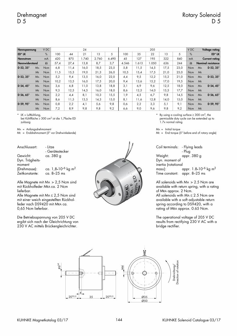
Coil terminals: - Flying leads- Plug
Weight: appr. 380 gDyn. moment ofinertia (rotationalmass): appr. 1.8•10--6 kg m2
Time constant: appr. 8–25 ms
All solenoids with MA > 2.5 Ncm areavailable with return spring, with a ratingof MRA approx. 2 Ncm.All solenoids with MA ≤ 2.5 Ncm areavailable with a soft adjustable returnspring according to DS9420, with a rating of MRA approx. 0.65 Ncm.
The operational voltage of 205 V DC results from rectifying 230 V AC with abridge rectifier.
Anschlussart: - Litze- Gerätestecker
Gewicht: ca. 380 gDyn. Trägheits-moment (Drehmasse): ca. 1,8•10--6 kg m2
Zeitkonstante: ca. 8–25 ms
Alle Magnete mit MA > 2,5 Ncm sind mit Rückholfeder MRA ca. 2 Ncm lieferbar.Alle Magnete mit MA ≤ 2,5 Ncm sind mit einer weich eingestellten Rückhol-feder nach DS9420 mit MRA ca. 0,65 Ncm lieferbar.
Die Betriebsspannung von 205 V DC ergibt sich nach der Gleichrichtung von230 V AC mittels Brückengleichrichter.
Drehmagnet D 5
Rotary SolenoidD 5
KUHNKE Magnetkatalog 03/17 144 KUHNKE Solenoid Catalogue 03/17
* LK = Luftkühlung,bei Kühlfläche ≥ 300 cm2 ist die 1,7fache ED zulässig
MA = AnfangsdrehmomentME = Enddrehmoment (5° vor Drehwinkelende)
* By using a cooling surface ≥ 300 cm2, the permissible duty cycle can be extended up to 1.7x normal rating
MA = Initial torqueME = End torque (5° before end of rotary angle)
Nennspannung V DC 24 205 V DC Voltage rating
ED* LK
Nennstrom
%
mA
100
420
44
875
21
1.740
13
2.760
5
6.490
100
45
35
127
22
195
13
322
5
840
%
mA
ED* LK
Current rating
Nennwiderstand
D 52, 25°
D 53, 35°
MA
�
Ncm
ME
MA
Ncm
Ncm
57,4
6,8
27,4
11,4
11,5
5,2
15,3
9,4
13,8
16,0
8,7
18,5
19,0
13,5
21,3
16,0
3,7
23,5
4.546
5,8
26,0
22,0
10,5
4,4
1.613
11,5
1.050
14,5
15,4
9,5
17,5
12,2
636
17,5
244
23,0
21,0
15,2
25,0
21,0
�
Ncm MA
Ncm
Ncm
ME
MA
Nominal resistance
D 52, 25°
D 53, 35°
D 54, 45°
D 56, 65°
ME
MA
Ncm
Ncm
ME
MA
Ncm
Ncm
D 59, 95°
ME
MA
Ncm
Ncm
ME Ncm
10,2
3,6
13,5
6,8
9,3
2,2
12,5
4,4
16,0
11,0
17,5
13,8
14,5
8,1
16,0
10,3
8,6
0,8
11,5
2,2
7,2 8,9
13,5
4,1
14,3
5,6
9,8 9,8
20,0
18,8
9,4
3,1
18,0
15,5
8,6
1,9
13,6
6,9
15,2
9,6
12,5
4,5
14,0
6,7
15,0
9,8
8,1
0,6
9,2 6,6
11,6
2,2
12,8
3,3
9,0 9,6
17,0
12,5
19,5
18,0
15,5
9,8
17,7
14,5
Ncm
Ncm
ME
MA
Ncm
Ncm
ME
MA
14,0
5,1
15,0
9,1
9,8 9,2
Ncm
Ncm
ME
MA
Ncm ME
D 54, 45°
D 56, 65°
D 59, 95°
Ø35Ø50
435
6h9
M4
20+0,5- 20+0,5-
Dre
hric
htun
g/D
irect
ion
of r
otat
ion
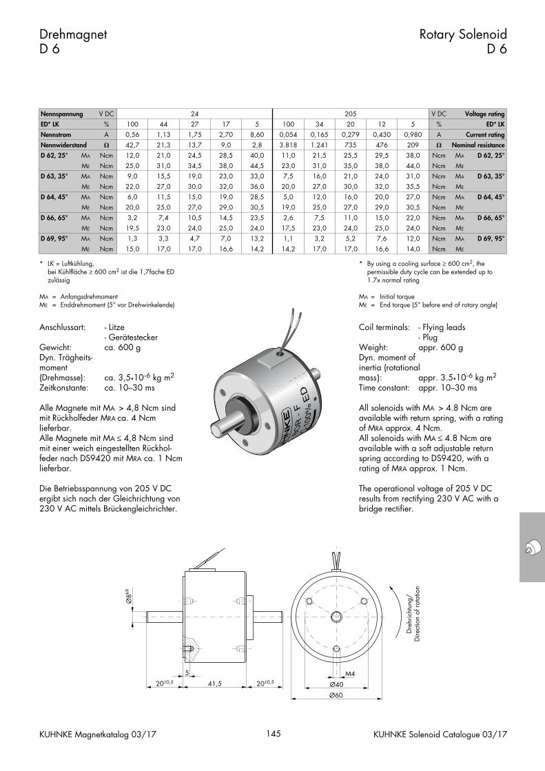
Coil terminals: - Flying leads- Plug
Weight: appr. 600 gDyn. moment ofinertia (rotationalmass): appr. 3.5•10--6 kg m2
Time constant: appr. 10–30 ms
All solenoids with MA > 4.8 Ncm areavailable with return spring, with a ratingof MRA approx. 4 Ncm.All solenoids with MA ≤ 4.8 Ncm areavailable with a soft adjustable returnspring according to DS9420, with a rating of MRA approx. 1 Ncm.
The operational voltage of 205 V DC results from rectifying 230 V AC with abridge rectifier.
Anschlussart: - Litze- Gerätestecker
Gewicht: ca. 600 gDyn. Trägheits-moment (Drehmasse): ca. 3,5•10--6 kg m2
Zeitkonstante: ca. 10–30 ms
Alle Magnete mit MA > 4,8 Ncm sind mit Rückholfeder MRA ca. 4 Ncm lieferbar.Alle Magnete mit MA ≤ 4,8 Ncm sind mit einer weich eingestellten Rückhol-feder nach DS9420 mit MRA ca. 1 Ncmlieferbar.
Die Betriebsspannung von 205 V DC ergibt sich nach der Gleichrichtung von230 V AC mittels Brückengleichrichter.
Drehmagnet D 6
Rotary SolenoidD 6
KUHNKE Magnetkatalog 03/17 145 KUHNKE Solenoid Catalogue 03/17
* LK = Luftkühlung,bei Kühlfläche ≥ 600 cm2 ist die 1,7fache ED zulässig
MA = AnfangsdrehmomentME = Enddrehmoment (5° vor Drehwinkelende)
* By using a cooling surface ≥ 600 cm2, the permissible duty cycle can be extended up to 1.7x normal rating
MA = Initial torqueME = End torque (5° before end of rotary angle)
Nennspannung V DC 24 205 V DC Voltage rating
ED* LK
Nennstrom
%
A
100
0,56
44
1,13
27
1,75
17
2,70
5
8,60
100
0,054
34
0,165
20
0,279
12
0,430
5
0,980
%
A
ED* LK
Current rating
Nennwiderstand
D 62, 25°
D 63, 35°
MA
�
Ncm
ME
MA
Ncm
Ncm
42,7
12,0
21,3
21,0
25,0
9,0
31,0
15,5
13,7
24,5
9,0
28,5
34,5
19,0
38,0
23,0
2,8
40,0
3.818
11,0
44,5
33,0
23,0
7,5
1.241
21,5
735
25,5
31,0
16,0
35,0
21,0
476
29,5
209
38,0
38,0
24,0
44,0
31,0
�
Ncm MA
Ncm
Ncm
ME
MA
Nominal resistance
D 62, 25°
D 63, 35°
D 64, 45°
D 66, 65°
ME
MA
Ncm
Ncm
ME
MA
Ncm
Ncm
D 69, 95°
ME
MA
Ncm
Ncm
ME Ncm
22,0
6,0
27,0
11,5
20,0
3,2
25,0
7,4
30,0
15,0
32,0
19,0
27,0
10,5
29,0
14,5
19,5
1,3
23,0
3,3
15,0 17,0
24,0
4,7
25,0
7,0
17,0 16,6
36,0
28,5
20,0
5,0
30,5
23,5
19,0
2,6
27,0
12,0
30,0
16,0
25,0
7,5
27,0
11,0
24,0
13,2
17,5
1,1
14,2 14,2
23,0
3,2
24,0
5,2
17,0 17,0
32,0
20,0
35,5
27,0
29,0
15,0
30,5
22,0
Ncm
Ncm
ME
MA
Ncm
Ncm
ME
MA
25,0
7,6
24,0
12,0
16,6 14,0
Ncm
Ncm
ME
MA
Ncm ME
D 64, 45°
D 66, 65°
D 69, 95°
M4
Ø40
Ø60
5
41,520±0,5 20±0,5
Ø8h9
Dre
hric
htun
g/D
irect
ion
of r
otat
ion
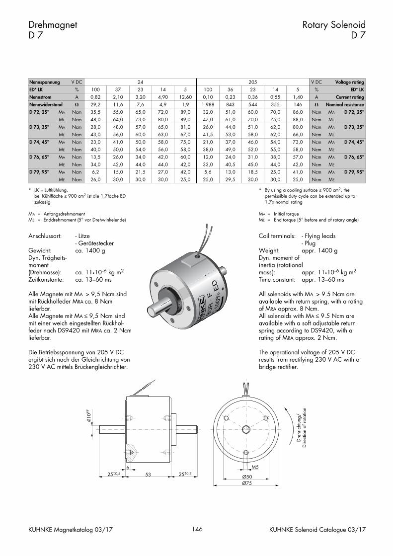
Coil terminals: - Flying leads- Plug
Weight: appr. 1400 gDyn. moment ofinertia (rotationalmass): appr. 11•10--6 kg m2
Time constant: appr. 13–60 ms
All solenoids with MA > 9.5 Ncm areavailable with return spring, with a ratingof MRA approx. 8 Ncm.All solenoids with MA ≤ 9.5 Ncm areavailable with a soft adjustable returnspring according to DS9420, with a rating of MRA approx. 2 Ncm.
The operational voltage of 205 V DC results from rectifying 230 V AC with abridge rectifier.
Anschlussart: - Litze- Gerätestecker
Gewicht: ca. 1400 gDyn. Trägheits-moment (Drehmasse): ca. 11•10--6 kg m2
Zeitkonstante: ca. 13–60 ms
Alle Magnete mit MA > 9,5 Ncm sind mit Rückholfeder MRA ca. 8 Ncm lieferbar.Alle Magnete mit MA ≤ 9,5 Ncm sind mit einer weich eingestellten Rückhol-feder nach DS9420 mit MRA ca. 2 Ncmlieferbar.
Die Betriebsspannung von 205 V DC ergibt sich nach der Gleichrichtung von230 V AC mittels Brückengleichrichter.
Drehmagnet D 7
Rotary SolenoidD 7
KUHNKE Magnetkatalog 03/17 146 KUHNKE Solenoid Catalogue 03/17
* LK = Luftkühlung,bei Kühlfläche ≥ 900 cm2 ist die 1,7fache ED zulässig
MA = AnfangsdrehmomentME = Enddrehmoment (5° vor Drehwinkelende)
* By using a cooling surface ≥ 900 cm2, the permissible duty cycle can be extended up to 1.7x normal rating
MA = Initial torqueME = End torque (5° before end of rotary angle)
Nennspannung V DC 24 205 V DC Voltage rating
ED* LK
Nennstrom
%
A
100
0,82
37
2,10
23
3,20
14
4,90
5
12,60
100
0,10
36
0,23
23
0,36
14
0,55
5
1,40
%
A
ED* LK
Current rating
Nennwiderstand
D 72, 25°
D 73, 35°
MA
�
Ncm
ME
MA
Ncm
Ncm
29,2
35,5
11,6
55,0
48,0
28,0
64,0
48,0
7,6
65,0
4,9
72,0
73,0
57,0
80,0
65,0
1,9
89,0
1.988
32,0
89,0
81,0
47,0
26,0
843
51,0
544
60,0
61,0
44,0
70,0
51,0
355
70,0
146
86,0
75,0
62,0
88,0
80,0
�
Ncm MA
Ncm
Ncm
ME
MA
Nominal resistance
D 72, 25°
D 73, 35°
D 74, 45°
D 76, 65°
ME
MA
Ncm
Ncm
ME
MA
Ncm
Ncm
D 79, 95°
ME
MA
Ncm
Ncm
ME Ncm
43,0
23,0
56,0
41,0
40,0
13,5
50,0
26,0
60,0
50,0
63,0
58,0
54,0
34,0
56,0
42,0
34,0
6,2
42,0
15,0
26,0 30,0
44,0
21,5
44,0
27,0
30,0 30,0
67,0
75,0
41,5
21,0
58,0
60,0
38,0
12,0
53,0
37,0
58,0
46,0
49,0
24,0
52,0
31,0
42,0
42,0
33,0
5,6
25,0 25,0
40,5
13,0
45,0
18,5
29,5 30,0
62,0
54,0
66,0
73,0
55,0
38,0
58,0
57,0
Ncm
Ncm
ME
MA
Ncm
Ncm
ME
MA
44,0
25,0
42,0
41,0
30,0 25,0
Ncm
Ncm
ME
MA
Ncm ME
D 74, 45°
D 76, 65°
D 79, 95°
Ø50Ø75
M5653
10h9
25+0,5- 25+0,5-
Dre
hric
htun
g/D
irect
ion
of r
otat
ion
Coil terminals: - Flying leads- Plug
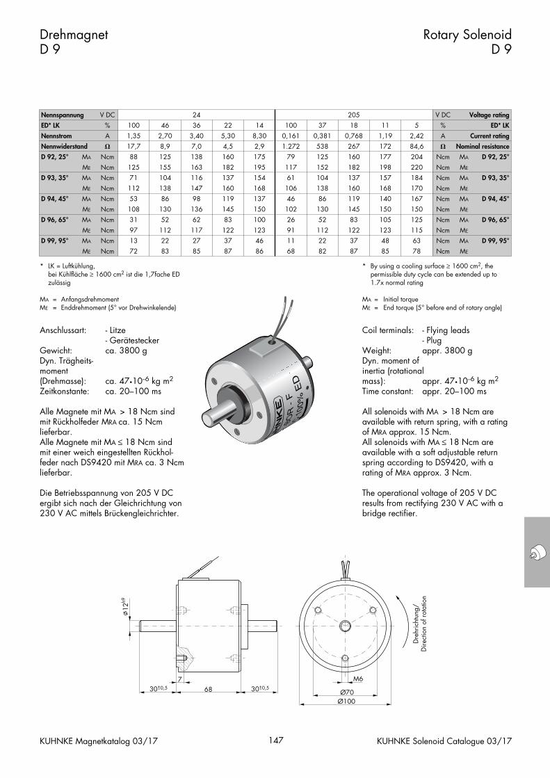
Weight: appr. 3800 gDyn. moment ofinertia (rotationalmass): appr. 47•10--6 kg m2
Time constant: appr. 20–100 ms
All solenoids with MA > 18 Ncm areavailable with return spring, with a ratingof MRA approx. 15 Ncm.All solenoids with MA ≤ 18 Ncm areavailable with a soft adjustable returnspring according to DS9420, with a rating of MRA approx. 3 Ncm.
The operational voltage of 205 V DC results from rectifying 230 V AC with abridge rectifier.
Anschlussart: - Litze- Gerätestecker
Gewicht: ca. 3800 gDyn. Trägheits-moment (Drehmasse): ca. 47•10--6 kg m2
Zeitkonstante: ca. 20–100 ms
Alle Magnete mit MA > 18 Ncm sind mit Rückholfeder MRA ca. 15 Ncm lieferbar.Alle Magnete mit MA ≤ 18 Ncm sind mit einer weich eingestellten Rückhol-feder nach DS9420 mit MRA ca. 3 Ncmlieferbar.
Die Betriebsspannung von 205 V DC ergibt sich nach der Gleichrichtung von230 V AC mittels Brückengleichrichter.
Drehmagnet D 9
Rotary SolenoidD 9
KUHNKE Magnetkatalog 03/17 147 KUHNKE Solenoid Catalogue 03/17
* LK = Luftkühlung,bei Kühlfläche ≥ 1600 cm2 ist die 1,7fache ED zulässig
MA = AnfangsdrehmomentME = Enddrehmoment (5° vor Drehwinkelende)
* By using a cooling surface ≥ 1600 cm2, the permissible duty cycle can be extended up to 1.7x normal rating
MA = Initial torqueME = End torque (5° before end of rotary angle)
Nennspannung V DC 24 205 V DC Voltage rating
ED* LK
Nennstrom
%
A
100
1,35
46
2,70
36
3,40
22
5,30
14
8,30
100
0,161
37
0,381
18
0,768
11
1,19
5
2,42
%
A
ED* LK
Current rating
Nennwiderstand
D 92, 25°
D 93, 35°
MA
�
Ncm
ME
MA
Ncm
Ncm
17,7
88
8,9
125
125
71
155
104
7,0
138
4,5
160
163
116
182
137
2,9
175
1.272
79
195
154
117
61
538
125
267
160
152
104
182
137
172
177
84,6
204
198
157
220
184
�
Ncm MA
Ncm
Ncm
ME
MA
Nominal resistance
D 92, 25°
D 93, 35°
D 94, 45°
D 96, 65°
ME
MA
Ncm
Ncm
ME
MA
Ncm
Ncm
D 99, 95°
ME
MA
Ncm
Ncm
ME Ncm
112
53
138
86
108
31
130
52
147
98
160
119
136
62
145
83
97
13
112
22
72 83
117
27
122
37
85 87
168
137
106
46
150
100
102
26
138
86
160
119
130
52
145
83
123
46
91
11
86 68
112
22
122
37
82 87
168
140
170
167
150
105
150
125
Ncm
Ncm
ME
MA
Ncm
Ncm
ME
MA
123
48
115
63
85 78
Ncm
Ncm
ME
MA
Ncm ME
D 94, 45°
D 96, 65°
D 99, 95°
Ø70Ø100
M6768
12h9
30+0,5- 30+0,5-
Dre
hric
htun
g/D
irect
ion
of r
otat
ion
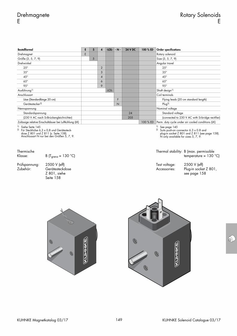
Thermal stability: B (max. permissibletemperature = 130 °C)
Test voltage: 2500 V (eff)Accessories: Plug-in socket Z 801,
see page 158
Thermische Klasse: B (Tgrenz = 130 °C)
Prüfspannung: 2500 V (eff)Zubehör: Gerätesteckdose
Z 801, siehe Seite 158
Drehmagnete E
Rotary SolenoidsE
KUHNKE Magnetkatalog 03/17 149 KUHNKE Solenoid Catalogue 03/17
Bestellformel E 5 4 -LOL- - N - 24 V DC 100 % ED Order specifications
Drehmagnet
Größe (3, 5, 7, 9)
E
5
Rotary solenoid
Size (3, 5, 7, 9)
Drehwinkel
25°
35°
45°
2
3
4
Angular travel
25°
35°
45°
Ausführung1)
Anschlussart
65°
95°
Nennspannung
Litze (Standardlänge 20 cm)
Gerätestecker2)
Standardspannung
6
9
-LOL-
F
N
65°
95°
Shaft design1)
Coil terminals
24
Flying leads (20 cm standard length)
Plug2)
Nominal voltage
Standard voltage
Zulässige relative Einschaltdauer bei Luftkühlung (LK)
(230 V AC nach Si-Brückengleichrichter) 205
100 % ED Perm. duty cycle under air cooled conditions (LK)
(connected to 230 V AC with Si-bridge rectifier)
1) Siehe Seite 1452) Für Steckhülse 6,3 x 0,8 und Gerätesteck-
dose Z 801 und Z 811 (s. Seite 158). Anschlussart N nur bei den Größen 5, 7, 9.
1) See page 1452) Suits push-on connector 6.3 x 0.8 and
plug-in socket Z 801 and Z 811 (see page 158). N only available for sizes 5, 7, 9.
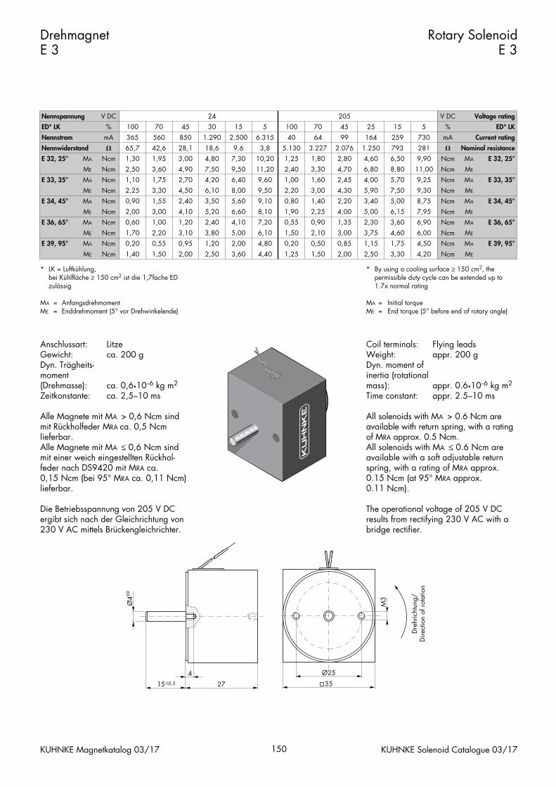
Coil terminals: Flying leadsWeight: appr. 200 gDyn. moment ofinertia (rotationalmass): appr. 0.6•10--6 kg m2
Time constant: appr. 2.5–10 ms
All solenoids with MA > 0.6 Ncm areavailable with return spring, with a ratingof MRA approx. 0.5 Ncm.All solenoids with MA ≤ 0.6 Ncm areavailable with a soft adjustable returnspring, with a rating of MRA approx.0.15 Ncm (at 95° MRA approx. 0.11 Ncm).
The operational voltage of 205 V DC results from rectifying 230 V AC with abridge rectifier.
Anschlussart: LitzeGewicht: ca. 200 gDyn. Trägheits-moment (Drehmasse): ca. 0,6•10--6 kg m2
Zeitkonstante: ca. 2,5–10 ms
Alle Magnete mit MA > 0,6 Ncm sind mit Rückholfeder MRA ca. 0,5 Ncm lieferbar.Alle Magnete mit MA ≤ 0,6 Ncm sind mit einer weich eingestellten Rückhol-feder nach DS9420 mit MRA ca. 0,15 Ncm (bei 95° MRA ca. 0,11 Ncm) lieferbar.
Die Betriebsspannung von 205 V DC ergibt sich nach der Gleichrichtung von230 V AC mittels Brückengleichrichter.
Drehmagnet E 3
Rotary SolenoidE 3
KUHNKE Magnetkatalog 03/17 150 KUHNKE Solenoid Catalogue 03/17
* LK = Luftkühlung,bei Kühlfläche ≥ 150 cm2 ist die 1,7fache ED zulässig
MA = AnfangsdrehmomentME = Enddrehmoment (5° vor Drehwinkelende)
* By using a cooling surface ≥ 150 cm2, the permissible duty cycle can be extended up to 1.7x normal rating
MA = Initial torqueME = End torque (5° before end of rotary angle)
Nennspannung V DC 24 205 V DC Voltage rating
ED* LK
Nennstrom
%
mA
100
365
70
560
45
850
30
1.290
15
2.500
5
6.315
100
40
70
64
45
99
25
164
15
259
5
730
%
mA
ED* LK
Current rating
Nennwiderstand
E 32, 25°
E 33, 35°
MA
�
Ncm
ME
MA
Ncm
Ncm
65,7
1,30
42,6
1,95
2,50
1,10
3,60
1,75
28,1
3,00
18,6
4,80
4,90
2,70
7,50
4,20
9,6
7,30
3,8
10,20
9,50
6,40
11,20
9,60
5.130
1,25
3.227
1,80
2,40
1,00
3,30
1,60
2.076
2,80
1.250
4,60
4,70
2,45
6,80
4,00
793
6,50
281
9,90
8,80
5,70
11,00
9,25
�
Ncm MA
Ncm
Ncm
ME
MA
Nominal resistance
E 32, 25°
E 33, 35°
E 34, 45°
E 36, 65°
ME
MA
Ncm
Ncm
ME
MA
Ncm
Ncm
E 39, 95°
ME
MA
Ncm
Ncm
ME Ncm
2,25
0,90
3,30
1,55
2,00
0,60
3,00
1,00
4,50
2,40
6,10
3,50
4,10
1,20
5,20
2,40
1,70
0,20
2,20
0,55
1,40 1,50
3,10
0,95
3,80
1,20
2,00 2,50
8,00
5,60
9,50
9,10
6,60
4,10
8,10
7,20
2,20
0,80
3,00
1,40
1,90
0,55
2,25
0,90
5,00
2,00
6,10
4,80
3,60 4,40
1,50
0,20
2,10
0,50
1,25 1,50
4,30
2,20
5,90
3,40
4,00
1,35
5,00
2,30
7,50
5,00
9,30
8,75
6,15
3,60
7,95
6,90
3,00
0,85
3,75
1,15
2,00 2,50
4,60
1,75
6,00
4,50
3,30 4,20
Ncm
Ncm
ME
MA
Ncm
Ncm
ME
MA
E 34, 45°
E 36, 65°
Ncm
Ncm
ME
MA
Ncm ME
E 39, 95°
Ø25
35
4
27
M3
15±0,5
Ø4h9
Dre
hric
htun
g/D
irect
ion
of r
otat
ion
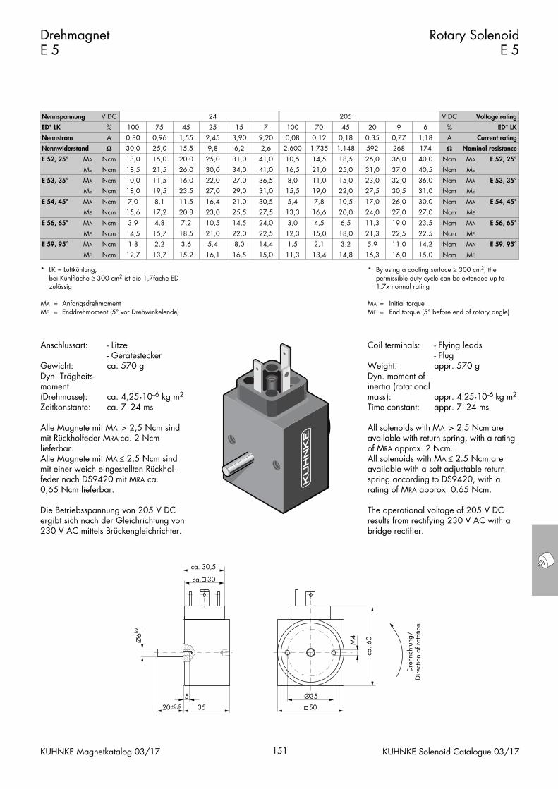
Coil terminals: - Flying leads- Plug
Weight: appr. 570 gDyn. moment ofinertia (rotationalmass): appr. 4.25•10--6 kg m2
Time constant: appr. 7–24 ms
All solenoids with MA > 2.5 Ncm areavailable with return spring, with a ratingof MRA approx. 2 Ncm.All solenoids with MA ≤ 2.5 Ncm areavailable with a soft adjustable returnspring according to DS9420, with a rating of MRA approx. 0.65 Ncm.
The operational voltage of 205 V DC results from rectifying 230 V AC with abridge rectifier.
Anschlussart: - Litze- Gerätestecker
Gewicht: ca. 570 gDyn. Trägheits-moment (Drehmasse): ca. 4,25•10--6 kg m2
Zeitkonstante: ca. 7–24 ms
Alle Magnete mit MA > 2,5 Ncm sind mit Rückholfeder MRA ca. 2 Ncm lieferbar.Alle Magnete mit MA ≤ 2,5 Ncm sind mit einer weich eingestellten Rückhol-feder nach DS9420 mit MRA ca. 0,65 Ncm lieferbar.
Die Betriebsspannung von 205 V DC ergibt sich nach der Gleichrichtung von230 V AC mittels Brückengleichrichter.
Drehmagnet E 5
Rotary SolenoidE 5
KUHNKE Magnetkatalog 03/17 151 KUHNKE Solenoid Catalogue 03/17
* LK = Luftkühlung,bei Kühlfläche ≥ 300 cm2 ist die 1,7fache ED zulässig
MA = AnfangsdrehmomentME = Enddrehmoment (5° vor Drehwinkelende)
* By using a cooling surface ≥ 300 cm2, the permissible duty cycle can be extended up to 1.7x normal rating
MA = Initial torqueME = End torque (5° before end of rotary angle)
Nennspannung V DC 24 205 V DC Voltage rating
ED* LK
Nennstrom
%
A
100
0,80
75
0,96
45
1,55
25
2,45
15
3,90
7
9,20
100
0,08
70
0,12
45
0,18
20
0,35
9
0,77
6
1,18
%
A
ED* LK
Current rating
Nennwiderstand
E 52, 25°
E 53, 35°
MA
�
Ncm
ME
MA
Ncm
Ncm
30,0
13,0
25,0
15,0
18,5
10,0
21,5
11,5
15,5
20,0
9,8
25,0
26,0
16,0
30,0
22,0
6,2
31,0
2,6
41,0
34,0
27,0
41,0
36,5
2.600
10,5
1.735
14,5
16,5
8,0
21,0
11,0
1.148
18,5
592
26,0
25,0
15,0
31,0
23,0
268
36,0
174
40,0
37,0
32,0
40,5
36,0
�
Ncm MA
Ncm
Ncm
ME
MA
Nominal resistance
E 52, 25°
E 53, 35°
E 54, 45°
E 56, 65°
ME
MA
Ncm
Ncm
ME
MA
Ncm
Ncm
E 59, 95°
ME
MA
Ncm
Ncm
ME Ncm
18,0
7,0
19,5
8,1
15,6
3,9
17,2
4,8
23,5
11,5
27,0
16,4
20,8
7,2
23,0
10,5
14,5
1,8
15,7
2,2
12,7 13,7
18,5
3,6
21,0
5,4
15,2 16,1
29,0
21,0
31,0
30,5
25,5
14,5
27,5
24,0
15,5
5,4
19,0
7,8
13,3
3,0
16,6
4,5
22,0
8,0
22,5
14,4
16,5 15,0
12,3
1,5
15,0
2,1
11,3 13,4
22,0
10,5
27,5
17,0
20,0
6,5
24,0
11,3
30,5
26,0
31,0
30,0
27,0
19,0
27,0
23,5
18,0
3,2
21,3
5,9
14,8 16,3
22,5
11,0
22,5
14,2
16,0 15,0
Ncm
Ncm
ME
MA
Ncm
Ncm
ME
MA
E 54, 45°
E 56, 65°
Ncm
Ncm
ME
MA
Ncm ME
E 59, 95°
50
Ø6h9
ca. 30
ca. 6
0
ca. 30,5
5
3520 ±0,5
M4
Ø35
Dre
hric
htun
g/D
irect
ion
of r
otat
ion
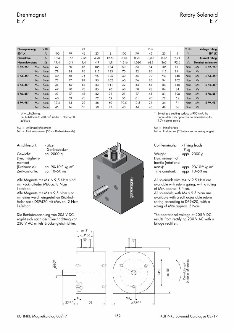
Coil terminals: - Flying leads- Plug
Weight: appr. 2000 gDyn. moment ofinertia (rotationalmass): appr. 90•10--6 kg m2
Time constant: appr. 10–50 ms
All solenoids with MA > 9.5 Ncm areavailable with return spring, with a ratingof MRA approx. 8 Ncm.All solenoids with MA ≤ 9.5 Ncm areavailable with a soft adjustable returnspring according to DS9420, with a rating of MRA approx. 2 Ncm.
The operational voltage of 205 V DC results from rectifying 230 V AC with abridge rectifier.
Anschlussart: - Litze- Gerätestecker
Gewicht: ca. 2000 gDyn. Trägheits-moment (Drehmasse): ca. 90•10--6 kg m2
Zeitkonstante: ca. 10–50 ms
Alle Magnete mit MA > 9,5 Ncm sind mit Rückholfeder MRA ca. 8 Ncm lieferbar.Alle Magnete mit MA ≤ 9,5 Ncm sind mit einer weich eingestellten Rückhol-feder nach DS9420 mit MRA ca. 2 Ncmlieferbar.
Die Betriebsspannung von 205 V DC ergibt sich nach der Gleichrichtung von230 V AC mittels Brückengleichrichter.
Drehmagnet E 7
Rotary SolenoidE 7
KUHNKE Magnetkatalog 03/17 152 KUHNKE Solenoid Catalogue 03/17
* LK = Luftkühlung,bei Kühlfläche ≥ 900 cm2 ist die 1,7fache ED zulässig
MA = AnfangsdrehmomentME = Enddrehmoment (5° vor Drehwinkelende)
* By using a cooling surface ≥ 900 cm2, the permissible duty cycle can be extended up to 1.7x normal rating
MA = Initial torqueME = End torque (5° before end of rotary angle)
Nennspannung V DC 24 205 V DC Voltage rating
ED* LK
Nennstrom
%
A
100
1,24
79
1,56
46
2,55
23
4,90
8
12,60
100
0,13
70
0,20
45
0,30
23
0,57
5
2,21
%
A
ED* LK
Current rating
Nennwiderstand
E 72, 25°
E 73, 35°
MA
�
Ncm
ME
MA
Ncm
Ncm
19,4
62
15,4
70
78
50
84
58
9,4
85
4,9
105
96
74
112
95
1,9
134
1.616
50
133
126
70
40
1.020
63
685
84
82
55
96
79
362
105
92,6
151
112
94
141
140
�
Ncm MA
Ncm
Ncm
ME
MA
Nominal resistance
E 72, 25°
E 73, 35°
E 74, 45°
E 76, 65°
ME
MA
Ncm
Ncm
ME
MA
Ncm
Ncm
E 79, 95°
ME
MA
Ncm
Ncm
ME Ncm
72
38
77
45
67
23
70
27
87
63
95
84
78
43
85
62
60
12,4
63
14
45 46
70
22
72
36
50 50
102
111
60
32
90
92
60
21
76
44
86
63
70
27
78
43
69
60
55
10,5
42 40
61
13,5
70
21
44 48
94
84
102
130
84
61
84
106
Ncm
Ncm
ME
MA
Ncm
Ncm
ME
MA
72
34
65
71
48 36
Ncm
Ncm
ME
MA
Ncm ME
E 74, 45°
E 76, 65°
E 79, 95°
Ø50
6
53 7525 ±0,5
Ø10
h9
ca. 8
5
ca. 30
ca. 31
M5-0,5
Dre
hric
htun
g/D
irect
ion
of r
otat
ion
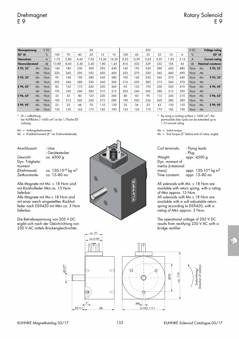
Coil terminals: - Flying leads- Plug
Weight: appr. 4500 gDyn. moment ofinertia (rotationalmass): appr. 150•10--6 kg m2
Time constant: appr. 15–80 ms
All solenoids with MA > 18 Ncm areavailable with return spring, with a ratingof MRA approx. 15 Ncm.All solenoids with MA ≤ 18 Ncm areavailable with a soft adjustable returnspring according to DS9420, with a rating of MRA approx. 3 Ncm.
The operational voltage of 205 V DC results from rectifying 230 V AC with abridge rectifier.
Anschlussart: - Litze- Gerätestecker
Gewicht: ca. 4500 gDyn. Trägheits-moment (Drehmasse): ca. 150•10--6 kg m2
Zeitkonstante: ca. 15–80 ms
Alle Magnete mit MA > 18 Ncm sind mit Rückholfeder MRA ca. 15 Ncm lieferbar.Alle Magnete mit MA ≤ 18 Ncm sind mit einer weich eingestellten Rückhol-feder nach DS9420 mit MRA ca. 3 Ncmlieferbar.
Die Betriebsspannung von 205 V DC ergibt sich nach der Gleichrichtung von230 V AC mittels Brückengleichrichter.
Drehmagnet E 9
Rotary SolenoidE 9
KUHNKE Magnetkatalog 03/17 153 KUHNKE Solenoid Catalogue 03/17
* LK = Luftkühlung,bei Kühlfläche ≥ 1600 cm2 ist die 1,7fache ED zulässig
MA = AnfangsdrehmomentME = Enddrehmoment (5° vor Drehwinkelende)
* By using a cooling surface ≥ 1600 cm2, the permissible duty cycle can be extended up to 1.7x normal rating
MA = Initial torqueME = End torque (5° before end of rotary angle)
Nennspannung V DC 24 205 V DC Voltage rating
ED* LK
Nennstrom
%
A
100
1,75
70
2,80
40
4,45
25
7,05
15
13,30
10
16,50
100
0,25
60
0,39
35
0,62
25
0,81
10
1,95
6
3,15
%
A
ED* LK
Current rating
Nennwiderstand
E 92, 25°
E 93, 35°
MA
�
Ncm
ME
MA
Ncm
Ncm
13,80
140
8,60
180
220
95
260
140
5,40
230
3,40
300
305
190
355
280
1,80
395
1,45
430
420
345
450
380
816
145
533
195
225
105
270
145
329
250
252
280
320
220
345
245
105
420
65
480
440
370
490
440
�
Ncm MA
Ncm
Ncm
ME
MA
Nominal resistance
E 92, 25°
E 93, 35°
E 94, 45°
E 96, 65°
ME
MA
Ncm
Ncm
ME
MA
Ncm
Ncm
E 99, 95°
ME
MA
Ncm
Ncm
ME Ncm
205
85
240
125
195
35
230
55
280
175
320
245
260
80
285
125
185
22
215
33
130 150
245
48
260
70
165 175
360
330
360
360
310
220
315
260
210
95
250
135
205
40
240
60
275
110
280
130
185 190
190
25
220
36
135 155
285
195
315
230
265
90
280
115
360
350
370
410
315
245
320
310
256
53
260
63
175 175
280
120
280
155
185 190
Ncm
Ncm
ME
MA
Ncm
Ncm
ME
MA
E 94, 45°
E 96, 65°
Ncm
Ncm
ME
MA
Ncm ME
E 99, 95°
Ø70
7
68 100,1 30±0,5
Ø12
h9
ca. 1
10
ca. 30
ca. 31
M6±0,4
Dre
hric
htun
g/D
irect
ion
of r
otat
ion
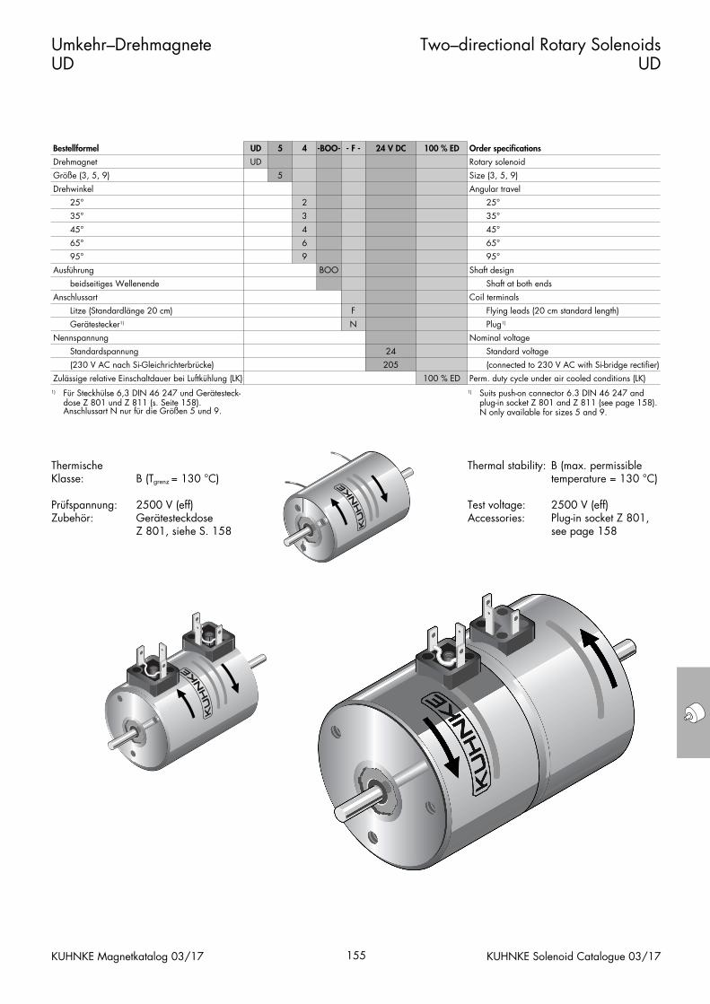
Thermal stability: B (max. permissibletemperature = 130 °C)
Test voltage: 2500 V (eff)Accessories: Plug-in socket Z 801,
see page 158
Thermische Klasse: B (Tgrenz = 130 °C)
Prüfspannung: 2500 V (eff)Zubehör: Gerätesteckdose
Z 801, siehe S. 158
Umkehr–Drehmagnete UD
Two–directional Rotary SolenoidsUD
KUHNKE Magnetkatalog 03/17 155 KUHNKE Solenoid Catalogue 03/17
Bestellformel UD 5 4 -BOO- - F - 24 V DC 100 % ED Order specifications
Drehmagnet
Größe (3, 5, 9)
UD
5
Rotary solenoid
Size (3, 5, 9)
Drehwinkel
25°
35°
45°
2
3
4
Angular travel
25°
35°
45°
Ausführung
65°
95°
beidseitiges Wellenende
Anschlussart
Nennspannung
Litze (Standardlänge 20 cm)
Gerätestecker1)
6
9
BOO
F
N
65°
95°
Shaft design
Shaft at both ends
Coil terminals
Flying leads (20 cm standard length)
Nominal voltage
Plug1)
Zulässige relative Einschaltdauer bei Luftkühlung (LK)
Standardspannung
(230 V AC nach Si-Gleichrichterbrücke)
24
205
100 % ED
Standard voltage
(connected to 230 V AC with Si-bridge rectifier)
Perm. duty cycle under air cooled conditions (LK)1) Für Steckhülse 6,3 DIN 46 247 und Gerätesteck-
dose Z 801 und Z 811 (s. Seite 158). Anschlussart N nur für die Größen 5 und 9.
1) Suits push-on connector 6.3 DIN 46 247 and plug-in socket Z 801 and Z 811 (see page 158). N only available for sizes 5 and 9.
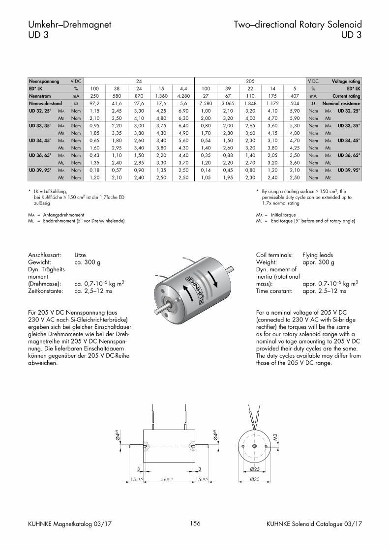
Coil terminals: Flying leadsWeight: appr. 300 gDyn. moment ofinertia (rotationalmass): appr. 0.7•10--6 kg m2
Time constant: appr. 2.5–12 ms
For a nominal voltage of 205 V DC (connected to 230 V AC with Si-bridgerectifier) the torques will be the sameas for our rotary solenoid range with a nominal voltage amounting to 205 V DCprovided their duty cycles are the same.The duty cycles available may differ fromthose of the 205 V DC range.
Anschlussart: LitzeGewicht: ca. 300 gDyn. Trägheits-moment (Drehmasse): ca. 0,7•10--6 kg m2
Zeitkonstante: ca. 2,5–12 ms
Für 205 V DC Nennspannung (aus 230 V AC nach Si-Gleichrichterbrücke)ergeben sich bei gleicher Einschaltdauergleiche Drehmomente wie bei der Dreh-magnetreihe mit 205 V DC Nennspan-nung. Die lieferbaren Einschaltdauernkönnen gegenüber der 205 V DC-Reiheabweichen.
Umkehr–Drehmagnet UD 3
Two–directional Rotary SolenoidUD 3
KUHNKE Magnetkatalog 03/17 156 KUHNKE Solenoid Catalogue 03/17
* LK = Luftkühlung,bei Kühlfläche ≥ 150 cm2 ist die 1,7fache ED zulässig
MA = AnfangsdrehmomentME = Enddrehmoment (5° vor Drehwinkelende)
* By using a cooling surface ≥ 150 cm2, the permissible duty cycle can be extended up to 1.7x normal rating
MA = Initial torqueME = End torque (5° before end of rotary angle)
Nennspannung V DC 24 205 V DC Voltage rating
ED* LK
Nennstrom
%
mA
100
250
38
580
24
870
15
1.360
4,4
4.280
100
27
39
67
22
110
14
175
5
407
%
mA
ED* LK
Current rating
Nennwiderstand
UD 32, 25°
UD 33, 35°
MA
�
Ncm
ME
MA
Ncm
Ncm
97,2
1,15
41,6
2,45
2,10
0,95
3,50
2,20
27,6
3,30
17,6
4,25
4,10
3,00
4,80
3,75
5,6
6,90
7.580
1,00
6,30
6,40
2,00
0,80
3.065
2,10
1.848
3,20
3,20
2,00
4,00
2,65
1.172
4,10
504
5,90
4,70
3,60
5,90
5,30
�
Ncm MA
Ncm
Ncm
ME
MA
Nominal resistance
UD 32, 25°
UD 33, 35°
UD 34, 45°
UD 36, 65°
ME
MA
Ncm
Ncm
ME
MA
Ncm
Ncm
UD 39, 95°
ME
MA
Ncm
Ncm
ME Ncm
1,85
0,65
3,35
1,80
1,60
0,43
2,95
1,10
3,80
2,60
4,30
3,40
3,40
1,50
3,80
2,20
1,35
0,18
2,40
0,57
1,20 2,10
2,85
0,90
3,30
1,35
2,40 2,50
4,90
5,60
1,70
0,54
4,30
4,40
1,40
0,35
2,80
1,50
3,60
2,30
2,60
0,88
3,20
1,40
3,70
2,50
1,20
0,14
2,50 1,05
2,20
0,45
2,70
0,80
1,95 2,30
4,15
3,10
4,80
4,70
3,80
2,05
4,25
3,50
Ncm
Ncm
ME
MA
Ncm
Ncm
ME
MA
3,20
1,20
3,60
2,10
2,40 2,50
Ncm
Ncm
ME
MA
Ncm ME
UD 34, 45°
UD 36, 65°
UD 39, 95°
Ø25
Ø35
M3
15±0,5 15±0,5
3
56±0,5
Ø4h
9
Ø4h
9
3
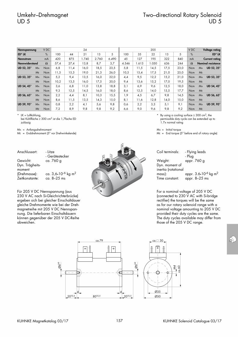
Coil terminals: - Flying leads- Plug
Weight: appr. 760 gDyn. moment ofinertia (rotationalmass): appr. 3.6•10--6 kg m2
Time constant: appr. 8–25 ms
For a nominal voltage of 205 V DC (connected to 230 V AC with Si-bridgerectifier) the torques will be the sameas for our rotary solenoid range with a nominal voltage amounting to 205 V DCprovided their duty cycles are the same.The duty cycles available may differ fromthose of the 205 V DC range.
Anschlussart: - Litze- Gerätestecker
Gewicht: ca. 760 gDyn. Trägheits-moment (Drehmasse): ca. 3,6•10--6 kg m2
Zeitkonstante: ca. 8–25 ms
Für 205 V DC Nennspannung (aus 230 V AC nach Si-Gleichrichterbrücke)ergeben sich bei gleicher Einschaltdauergleiche Drehmomente wie bei der Dreh-magnetreihe mit 205 V DC Nennspan-nung. Die lieferbaren Einschaltdauernkönnen gegenüber der 205 V DC-Reiheabweichen.
Umkehr–Drehmagnet UD 5
Two–directional Rotary SolenoidUD 5
KUHNKE Magnetkatalog 03/17 157 KUHNKE Solenoid Catalogue 03/17
* LK = Luftkühlung,bei Kühlfläche ≥ 300 cm2 ist die 1,7fache ED zulässig
MA = AnfangsdrehmomentME = Enddrehmoment (5° vor Drehwinkelende)
* By using a cooling surface ≥ 300 cm2, the permissible duty cycle can be extended up to 1.7x normal rating
MA = Initial torqueME = End torque (5° before end of rotary angle)
Nennspannung V DC 24 205 V DC Voltage rating
ED* LK
Nennstrom
%
mA
100
420
44
875
21
1.740
13
2.760
5
6.490
100
45
35
127
22
195
13
322
5
840
%
mA
ED* LK
Current rating
Nennwiderstand
UD 52, 25°
UD 53, 35°
MA
�
Ncm
ME
MA
Ncm
Ncm
57,4
6,8
27,4
11,4
11,5
5,2
15,3
9,4
13,8
16,0
8,7
18,5
19,0
13,5
21,3
16,0
3,7
23,5
4.546
5,8
26,0
22,0
10,5
4,4
1.613
11,5
1.050
14,5
15,4
9,5
17,5
12,2
636
17,5
244
23,0
21,0
15,2
25,0
21,0
�
Ncm MA
Ncm
Ncm
ME
MA
Nominal resistance
UD 52, 25°
UD 53, 35°
UD 54, 45°
UD 56, 65°
ME
MA
Ncm
Ncm
ME
MA
Ncm
Ncm
UD 59, 95°
ME
MA
Ncm
Ncm
ME Ncm
10,2
3,6
13,5
6,8
9,3
2,2
12,5
4,4
16,0
11,0
17,5
13,8
14,5
8,1
16,0
10,3
8,6
0,8
11,5
2,2
7,2 8,9
13,5
4,1
14,3
5,6
9,8 9,8
20,0
18,8
9,4
3,1
18,0
15,5
8,6
1,9
13,6
6,9
15,2
9,6
12,5
4,5
14,0
6,7
15,0
9,8
8,1
0,6
9,2 6,6
11,6
2,2
12,8
3,3
9,0 9,6
17,0
12,5
19,5
18,0
15,5
9,8
17,7
14,5
Ncm
Ncm
ME
MA
Ncm
Ncm
ME
MA
14,0
5,1
15,0
9,1
9,8 9,2
Ncm
Ncm
ME
MA
Ncm ME
UD 54, 45°
UD 56, 65°
UD 59, 95°
Ø6h9
Ø6h9
20±0,520±0,5 80±0,5
ca.79
4 4
ca.6
0
M4
Ø35
Ø50
ca. 30
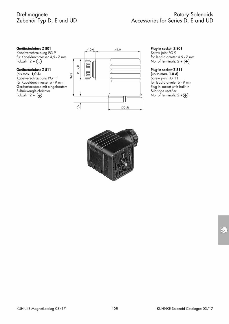
Plug-in socket Z 801Screw joint PG 9for lead diameter 4.5 - 7 mmNo. of terminals: 2 +
Plug-in sockett Z 811 (up to max. 1.0 A)Screw joint PG 11 for lead diameter 6 - 9 mmPlug-in socket with built inSi-bridge rectifierNo. of terminals: 2 +
Gerätesteckdose Z 801Kabelverschraubung PG 9für Kabeldurchmesser 4,5 - 7 mmPolzahl: 2 +
Gerätesteckdose Z 811(bis max. 1,0 A)Kabelverschraubung PG 11 für Kabeldurchmesser 6 - 9 mmGerätesteckdose mit eingebautemSi-BrückengleichrichterPolzahl: 2 +
Drehmagnete Zubehör Typ D, E und UD
Rotary Solenoids Accessories for Series D, E and UD
KUHNKE Magnetkatalog 03/17 158 KUHNKE Solenoid Catalogue 03/17
41,0≈10,0
(30,5)
Ø 1
9,0
5,5
34,2
Füllen Sie die Magnet-Checkliste aus, so-weit Ihnen die Daten zur Verfügung ste-hen.
Unsere Vertriebsingenieure beraten Siegern.
Für Ihre Versuche liefern wir Ihnen in weni-gen Tagen einen Mustermagneten aus derReihe unserer Vorzugstypen, der nach denersten Versuchen Ihren Problemstellungengemäß optimiert werden kann.
Sie haben ein Magnetproblem?
Do You Have a Problemwith Your Solenoids?
166 KUHNKE Solenoid Catalogue 03/17KUHNKE Magnetkatalog 03/17
Please fill in the solenoid check list with asmany data as are available.
Our agents will be pleased to advise you.
For your own experiments, we can pro-vide you with a prototype solenoid fromour series of preferred types within a fewdays of ordering. After the first few tests itcan then be adapted according to yourrequirements.

Datum: _________________________ Unterschrift: _________________________
Magnet-ChecklisteProjekt-Nr.� Maschinenbau � Medizingerätetechnik � Automotive � Komponenten
Kundenspezifische Angaben
Firma: _______________________________________________Straße: ______________________________________________Ort: _________________________________________________Gesprächspartner: ____________________________________Abt.: ___________ Tel.: ____________ Fax: ___________E-mail: _______________________________________________
Interne Angaben
Vertretung: ___________________________________________Kundenmanager: ______________________________________Applikationsberater: ___________________________________Kundenbesuche am: ___________________________________Wettbewerber: _______________________________________Basisgerät: ___________________________________________
Aktion � Maßbild � Muster � Angebot � Richtpreis
Stück Termin Preisvorstellung des Kunden:
Muster _________________________
Anlaufserie
Jahresbedarf Applikation:
Losgröße _________________________
Gesamtbedarf
Technische Anforderungen
Typ: � Hubmagnet � stoßend � ziehend
� Drehmagnet � einfachwirkend � umkehrwirkend � doppelwirkend (mit Mittelstellung)
� Haftmagnet � ohne Ankerplatte � mit Ankerplatte � Haftkraft ______ N = 0,1 kp
Einbauraum: L x B x H ______ x ______ x ______ mm
Einbaulage: � waagerecht � senkrecht � Ankergew. wirkt gegen Hub � Ankergew. wirkt mit Hub
Befestigung: � anschrauben � klemmen � schnappen � nieten � längsseitig � stirnseitig
Kraftabnahme: _________________________________ (Gabelkopf, Gewinde usw.)
Korrosionsschutz: � verzinkt � chem. vernickelt � vernickelt � rostfreier Anker und Kern
Hub- bzw. Drehwinkel mit Toleranz: ______ mm
Anschlussart: � freie Litzenenden: ______ cm � Stecker nach DIN __________ oder Lieferant/Bestell-Nr.: __________
Schutzart: � elektrisch IP ______ � mechanisch IP ______
Schutzmaßnahmen: � Kleinspannung ≤ 42 V � Masseanschluss durch Befestigung � Masseanschluss zusätzlich vorsehen
Umgebungstemperatur: -______ °C / +______ °C / max. Magnetoberflächentemperatur: ______ °C
Kühlfläche: ______ cm2
Betriebsspannung: ______ V, + _______ %, - ______ %
Max. Stromaufnahme: ______ mA
Relative Einschaltdauer: ______ % ED bei max. 5 Min. Spieldauer oder Arbeitsfrequenz
Arbeitsfrequenz: ______ Hz bzw. tein ______ msec / taus ______ msec
Schaltzeiten: ______ msec Anzugszeit, ______ s Abfallzeit
Mech. Lebensdauer: ______ Schaltungen
Diagramm: � Kraft-Weg-Diagramm ______ F (N)
� Drehmagnetkennlinie ______ M (Ncm)
� Rückholfeder _ _ _ _
Geforderte Normen: � Ja � Nein
(z.B. VDI, VDE, VDS, VDA, DIN, ISO etc.) Welche: ____________________ Gesetzliche Forderungen: __________________
s (mm)� (Grad))
KUHNKE Magnetkatalog 03/17 KUHNKE Solenoid Catalogue 03/17
KU 2
63D
/060
2
Skizze:
KUHNKE Magnetkatalog 03/17 KUHNKE Solenoid Catalogue 03/17
Ergänzungen: ______________________________________________________________________________________________________________________________________________________________________________________________________________________________________________________________________________________________________________________________________________________________________________________________________________________________________________________________________________________________________________________________________________________________________________________________________________________________________________________________________________________________________________________________________________________________________________________________________________________________________________________________________________________________________________________________________________________________________________________________________________________________________________________________________________________________________________________________________________________________________________________________________________________________
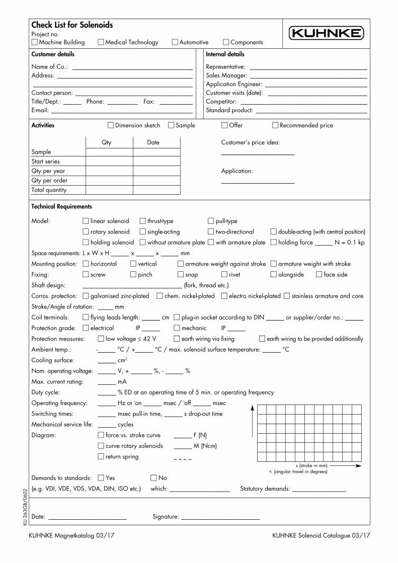
Date: __________________________ Signature: __________________________
Check List for Solenoids Project no.� Machine Building � Medical Technology � Automotive � Components
Customer details
Name of Co.: ________________________________________Address: __________________________________________________________________________________________________Contact person: _______________________________________Title/Dept.: ______ Phone: __________ Fax: ___________E-mail: _______________________________________________
Internal details
Representative: _______________________________________Sales Manager: _______________________________________Application Engineer: __________________________________Customer visits (date): _________________________________Competitor: __________________________________________Standard product: _____________________________________
KUHNKE Magnetkatalog 03/17 KUHNKE Solenoid Catalogue 03/17
Activities � Dimension sketch � Sample � Offer � Recommended price
Qty Date Customer’s price idea:
Sample _________________________
Start series
Qty per year Application:
Qty per order _________________________
Total quantity
Technical Requirements
Model: � linear solenoid � thrust-type � pull-type
� rotary solenoid � single-acting � two-directional � double-acting (with central position)
� holding solenoid � without armature plate � with armature plate � holding force ______ N = 0.1 kp
Space requirements: L x W x H ______ x ______ x ______ mm
Mounting position: � horizontal � vertical � armature weight against stroke � armature weight with stroke
Fixing: � screw � pinch � snap � rivet � alongside � face side
Shaft design: _________________________________ (fork, thread etc.)
Corros. protection: � galvanised zinc-plated � chem. nickel-plated � electro nickel-plated � stainless armature and core
Stroke/Angle of rotation: _____ mm
Coil terminals: � flying leads length: ______ cm � plug-in socket according to DIN ______ or supplier/order no.: ______
Protection grade: � electrical IP ______ � mechanic IP ______
Protection measures: � low voltage ≤ 42 V � earth wiring via fixing � earth wiring to be provided additionally
Ambient temp.: -______ °C / +______ °C / max. solenoid surface temperature: ______ °C
Cooling surface: ______ cm2
Nom. operating voltage: ______ V, + _______ %, - ______ %
Max. current rating: ______ mA
Duty cycle: ______ % ED at an operating time of 5 min. or operating frequency
Operating frequency: ______ Hz or ton ______ msec / toff ______ msec
Switching times: ______ msec pull-in time, ______ s drop-out time
Mechanical service life: ______ cycles
Diagram: � force vs. stroke curve ______ F (N)
� curve rotary solenoids ______ M (Ncm)
� return spring _ _ _ _
Demands to standards: � Yes � No
(e.g. VDI, VDE, VDS, VDA, DIN, ISO etc.) which: ____________________ Statutory demands: __________________
s (stroke in mm)� (angular travel in degrees)
KU 2
63G
B/06
02
Sketch:
KUHNKE Magnetkatalog 03/17 KUHNKE Solenoid Catalogue 03/17
Comments: _________________________________________________________________________________________________________________________________________________________________________________________________________________________________________________________________________________________________________________________________________________________________________________________________________________________________________________________________________________________________________________________________________________________________________________________________________________________________________________________________________________________________________________________________________________________________________________________________________________________________________________________________________________________________________________________________________________________________________________________________________________________________________________________________________________________________________________________________________________________________________________________________________________________________
Kendrion Kuhnke Automation GmbH
Lütjenburger Straße 101
23714 Malente
Deutschland
Tel: +49 4523 402-0
Fax: +49 4523 402-201
www.kuhnke.kendrion.com
M044/D/EN/16 57324
© KENDRION 25.03.2017