Embed Size (px)
Citation preview
Z-E3215-MKII
ZENEC · Bohrturmweg 1 · CH-5330 Bad Zurzach · Schweiz/Switzerland · Mail: [email protected] · www.zenec.com
MONTAGEANLEITUNG
DE
DEVICE INSTALLATION MANUAL EN
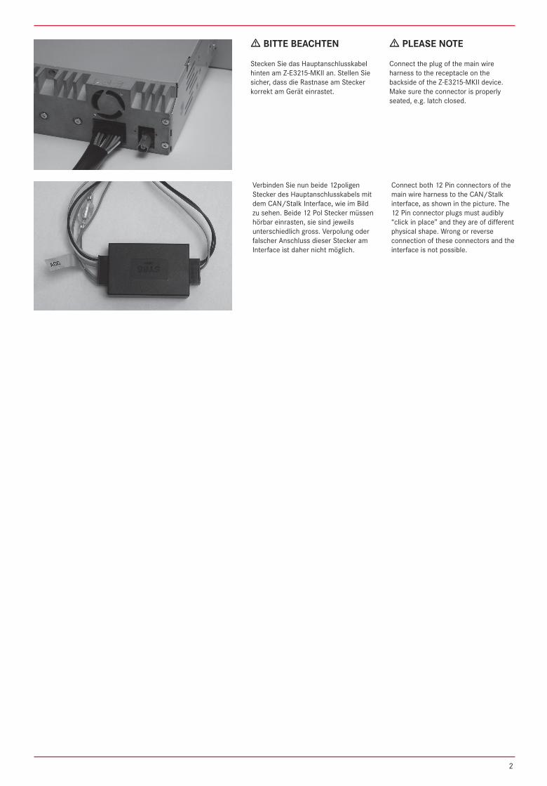
Stecken Sie das Hauptanschlusskabel hinten am Z-E3215-MKII an. Stellen Sie sicher, dass die Rastnase am Stecker korrekt am Gerät einrastet.
Connect the plug of the main wire harness to the receptacle on the backside of the Z-E3215-MKII device. Make sure the connector is properly seated, e.g. latch closed.
BITTE BEACHTEN PLEASE NOTE
Verbinden Sie nun beide 12poligen Stecker des Hauptanschlusskabels mit dem CAN/Stalk Interface, wie im Bild zu sehen. Beide 12 Pol Stecker müssen hörbar einrasten, sie sind jeweils unterschiedlich gross. Verpolung oder falscher Anschluss dieser Stecker am Interface ist daher nicht möglich.
Connect both 12 Pin connectors of the main wire harness to the CAN/Stalk interface, as shown in the picture. The 12 Pin connector plugs must audibly “click in place” and they are of different physical shape. Wrong or reverse connection of these connectors and the interface is not possible.
2
Montage: Installation:
6
2
3
4
5
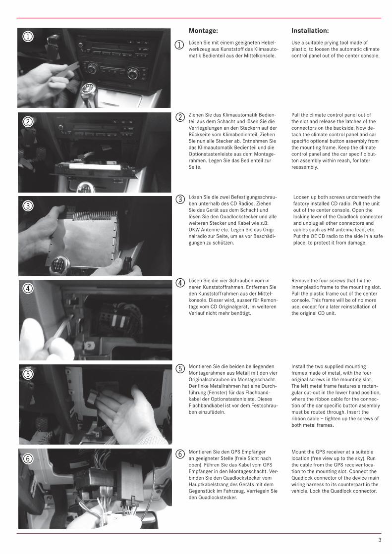
1Lösen Sie mit einem geeigneten Hebel-werkzeug aus Kunststoff das Klimaauto-matik Bedienteil aus der Mittelkonsole.
Use a suitable prying tool made of plastic, to loosen the automatic climate control panel out of the center console.
Ziehen Sie das Klimaautomatik Bedien-teil aus dem Schacht und lösen Sie die Verriegelungen an den Steckern auf der Rückseite vom Klimabedienteil. Ziehen Sie nun alle Stecker ab. Entnehmen Sie das Klimaautomatik Bedienteil und die Optionstastenleiste aus dem Montage-rahmen. Legen Sie das Bedienteil zur Seite.
Pull the climate control panel out of the slot and release the latches of the connectors on the backside. Now de-tach the climate control panel and car specific optional button assembly from the mounting frame. Keep the climate control panel and the car specific but-ton assembly within reach, for later reassembly.
Lösen Sie die zwei Befestigungsschrau-ben unterhalb des CD Radios. Ziehen Sie das Gerät aus dem Schacht und lösen Sie den Quadlockstecker und alle weiteren Stecker und Kabel wie z.B. UKW Antenne etc. Legen Sie das Origi-nalradio zur Seite, um es vor Beschädi-gungen zu schützen.
Loosen up both screws underneath the factory installed CD radio. Pull the unit out of the center console. Open the locking lever of the Quadlock connector and unplug all other connectors and cables such as FM antenna lead, etc. Put the OE CD radio to the side in a safe place, to protect it from damage.
Lösen Sie die vier Schrauben vom in-neren Kunststoffrahmen. Entfernen Sie den Kunststoffrahmen aus der Mittel-konsole. Dieser wird, ausser für Remon-tage vom CD Originalgerät, im weiteren Verlauf nicht mehr benötigt.
Remove the four screws that fix the inner plastic frame to the mounting slot. Pull the plastic frame out of the center console. This frame will be of no more use, except for a later reinstallation of the original CD unit.
Montieren Sie die beiden beiliegenden Montagerahmen aus Metall mit den vier Originalschrauben im Montageschacht. Der linke Metallrahmen hat eine Durch-führung (Fenster) für das Flachband-kabel der Optionstastenleiste. Dieses Flachbandkabel ist vor dem Festschrau-ben einzufädeln.
Install the two supplied mounting frames made of metal, with the four original screws in the mounting slot. The left metal frame features a rectan-gular cut-out in the lower hand position, where the ribbon cable for the connec-tion of the car specific button assembly must be routed through. Insert the ribbon cable – tighten up the screws of both metal frames.
Montieren Sie den GPS Empfänger an geeigneter Stelle (freie Sicht nach oben). Führen Sie das Kabel vom GPS Empfänger in den Montageschacht. Ver-binden Sie den Quadlockstecker vom Hauptkabelstrang des Geräts mit dem Gegenstück im Fahrzeug. Verriegeln Sie den Quadlockstecker.
Mount the GPS receiver at a suitable location (free view up to the sky). Run the cable from the GPS receiver loca-tion to the mounting slot. Connect the Quadlock connector of the device main wiring harness to its counterpart in the vehicle. Lock the Quadlock connector.
6
2
3
4
5
1
3
7
8
9
bl
bm
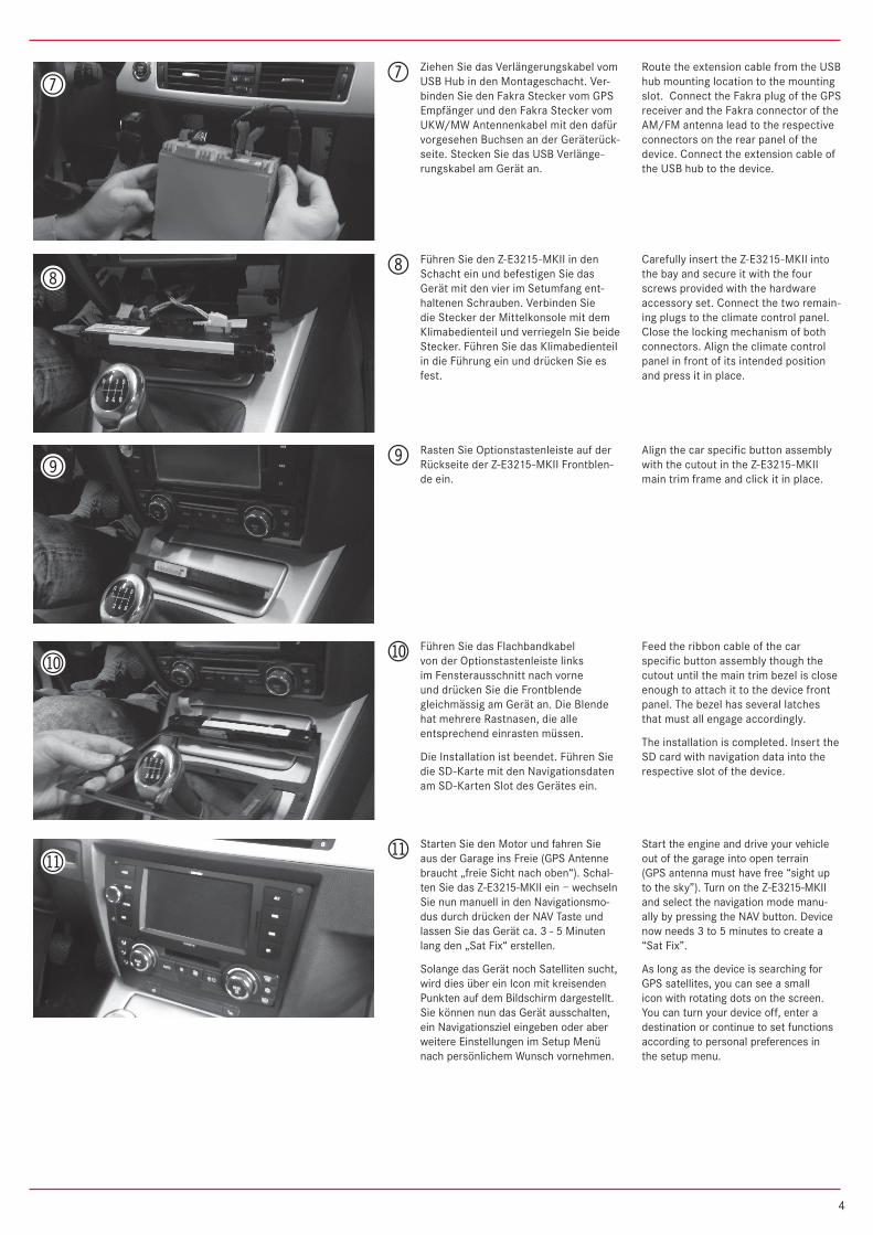
Ziehen Sie das Verlängerungskabel vom USB Hub in den Montageschacht. Ver-binden Sie den Fakra Stecker vom GPS Empfänger und den Fakra Stecker vom UKW/MW Antennenkabel mit den dafür vorgesehen Buchsen an der Geräterück-seite. Stecken Sie das USB Verlänge-rungskabel am Gerät an.
Route the extension cable from the USB hub mounting location to the mounting slot. Connect the Fakra plug of the GPS receiver and the Fakra connector of the AM/FM antenna lead to the respective connectors on the rear panel of the device. Connect the extension cable of the USB hub to the device.
Führen Sie den Z-E3215-MKII in den Schacht ein und befestigen Sie das Gerät mit den vier im Setumfang ent-haltenen Schrauben. Verbinden Sie die Stecker der Mittelkonsole mit dem Klimabedienteil und verriegeln Sie beide Stecker. Führen Sie das Klimabedienteil in die Führung ein und drücken Sie es fest.
Carefully insert the Z-E3215-MKII into the bay and secure it with the four screws provided with the hardware accessory set. Connect the two remain-ing plugs to the climate control panel. Close the locking mechanism of both connectors. Align the climate control panel in front of its intended position and press it in place.
Rasten Sie Optionstastenleiste auf der Rückseite der Z-E3215-MKII Frontblen-de ein.
Align the car specific button assembly with the cutout in the Z-E3215-MKII main trim frame and click it in place.
Führen Sie das Flachbandkabel von der Optionstastenleiste links im Fensterausschnitt nach vorne und drücken Sie die Frontblende gleichmässig am Gerät an. Die Blende hat mehrere Rastnasen, die alle entsprechend einrasten müssen.
Die Installation ist beendet. Führen Sie die SD-Karte mit den Navigationsdaten am SD-Karten Slot des Gerätes ein.
Feed the ribbon cable of the car specific button assembly though the cutout until the main trim bezel is close enough to attach it to the device front panel. The bezel has several latches that must all engage accordingly.
The installation is completed. Insert the SD card with navigation data into the respective slot of the device.
Starten Sie den Motor und fahren Sie aus der Garage ins Freie (GPS Antenne braucht „freie Sicht nach oben“). Schal-ten Sie das Z-E3215-MKII ein – wechseln Sie nun manuell in den Navigationsmo-dus durch drücken der NAV Taste und lassen Sie das Gerät ca. 3 - 5 Minuten lang den „Sat Fix“ erstellen.
Solange das Gerät noch Satelliten sucht, wird dies über ein Icon mit kreisenden Punkten auf dem Bildschirm dargestellt. Sie können nun das Gerät ausschalten, ein Navigationsziel eingeben oder aber weitere Einstellungen im Setup Menü nach persönlichem Wunsch vornehmen.
7
8
9
bl
bm Start the engine and drive your vehicle out of the garage into open terrain (GPS antenna must have free “sight up to the sky”). Turn on the Z-E3215-MKII and select the navigation mode manu-ally by pressing the NAV button. Device now needs 3 to 5 minutes to create a “Sat Fix”.
As long as the device is searching for GPS satellites, you can see a small icon with rotating dots on the screen. You can turn your device off, enter a destination or continue to set functions according to personal preferences in the setup menu.
4
➜ Das Fahrzeug ist mit einem Eigendiagnosegerät (DME) ausgestattet. Um Fehlermeldungen zu vermeiden, muss vor Montagebeginn unbedingt der negative Pol der Fahrzeugbatterie abgehängt werden.
➜ Eine einwandfreie Funktion des Z-E3215-MKII kann nur dann gewährleistet werden, wenn Sie das im Lieferumfang enthaltene Zubehör verwenden.
➜ Es ist nicht nötig, am originalen Anschlusskabel des Z-E3215-MKII Veränderungen irgendwelcher Art vorzunehmen.
➜ Achten Sie bei der Installation darauf, dass die verschiedenen Anschlusskabel und Zubehörteile nicht durch scharfe Kanten beschädigt und die Anschlusskabel nicht geknickt werden.
➜ Je nach Präferenz und Wahl des geräteinternen oder des externen (zu montierenden) Mikrofons, muss im „Setup Menü“ die Mikrofonquelle für den Bluetooth Modus entsprechend angepasst werden.
➜ Achten Sie vor der finalen Montage des Z-E3215-MKII darauf, dass alle Steckverbindungen auf der Geräte-rückseite richtig verbunden und fest eingerastet sind.
➜ Bei Fragen oder Problemen wenden Sie sich an Ihren ZENEC-Händler, bei dem Sie das Gerät gekauft haben. Zusätzlich finden Sie unter www.zenec.com eine ausführliche FAQ Datenbank, wo viele der Fragen und Probleme, welche während der Installation auftreten könnten, entsprechend beantwortet werden.
➜ Da Main System Updates nur über den USB-Anschluss installiert werden können und sich der USB-Anschluss an der Rückseite des Z-E3215-MKII befindet, sollten Sie den im Lieferumfang befindlichen USB-Hub unbedingt an einem leicht zugänglichen Ort installieren.
Bitte Beachten/Please Note
➜ Tampering with the on-board electrical system might cause error codes to be stored in the DME.It is thus recommended to disconnect the GND wire of the negative battery pole before you start with any installation work. ➜ The flawless function of the Z-E3215-MKII can only be guaranteed, when the original accessories and wire harnesses contained in the set are deployed.
➜ Modifications on the original wire loom of the Z-E3215-MKII are not required.
➜ Always pay proper attention not to damage any of the wires, plugs or other parts. Avoid applying too much mechanical force especially when pushing the unit back into the slot.
➜ Depending on the preference and selection of the device internal or external (to be installed) microphone, the BT microphone source must be checked and chosen accordingly, in the setup menu. ➜ Please check if all plug-and-socket connections on the rear of the Z-E3215-MKII are properly seated before you mount the unit in place.
➜ Please contact your authorized ZENEC dealer or the distributor of the country, where you have purchased your E>GO unit, if you have any technical problems or further questions. In addition, you can look up a detailed FAQ data base on www.zenec.com, where most of the questions revolving around the connectivity or the installation of a given E>GO model are explained in detail.
➜ Updates of the main system software require the USB hub to be present and accessible. For this purpose, the installation of the USB hub is mandatory. The USB hub is contained in the Z-E3215-MKII set – just make sure you find a good and suitable mounting location that is easy to access (i.e. glove compartment, arm rest box etc.).
5
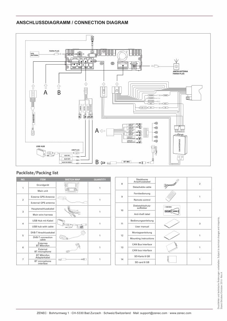
ANSCHLUSSDIAGRAMM / CONNECTION DIAGRAM
Dru
ckfe
hler
und
tech
nisc
he Ä
nder
unge
n vo
rbeh
alte
n. S
ubje
ct to
tech
nica
l cha
nges
and
mis
prin
ts.
Stan
d O
ktob
er/O
ctob
er 2
016
· Rev
.A
Packliste/Packing listNO. ITEM SKETCH MAP QUANTITY
1Grundgerät
1Main unit
2Externe GPS-Antenne
1External GPS antenna
3Hauptanschlusskabel
1Main wire harness
4USB Hub mit Kabel
1USB hub with cable
5DVB-T Anschlusskabel
1DVB-T connection
cable
6
Externes BT Mikrofon
1External
BT microphone
7
BT Mikrofon Adapterkabel
1BT microphone
interface
8
Steckbares Anschlusskabel
2Detachable cable
9Fernbedienung
1Remote control
10
Diebstahlschutz-aufkleber
1
Anti-theft label
11Bedienungsanleitung
3User manual
12Montageanleitung
1Mounting instructions
13CAN Bus Interface
1CAN bus interface
14SD-Karte 8 GB
1SD card 8 GB
ZENEC · Bohrturmweg 1 · CH-5330 Bad Zurzach · Schweiz/Switzerland · Mail: [email protected] · www.zenec.com