Embed Size (px)
Citation preview
Großbekohlungsanlage 76510
Inhaltsverzeichnis Table of Contents Soommaire Inhoudsopgave
Seite
Funktion 3
Bekohlungsanlage aufbauen 4
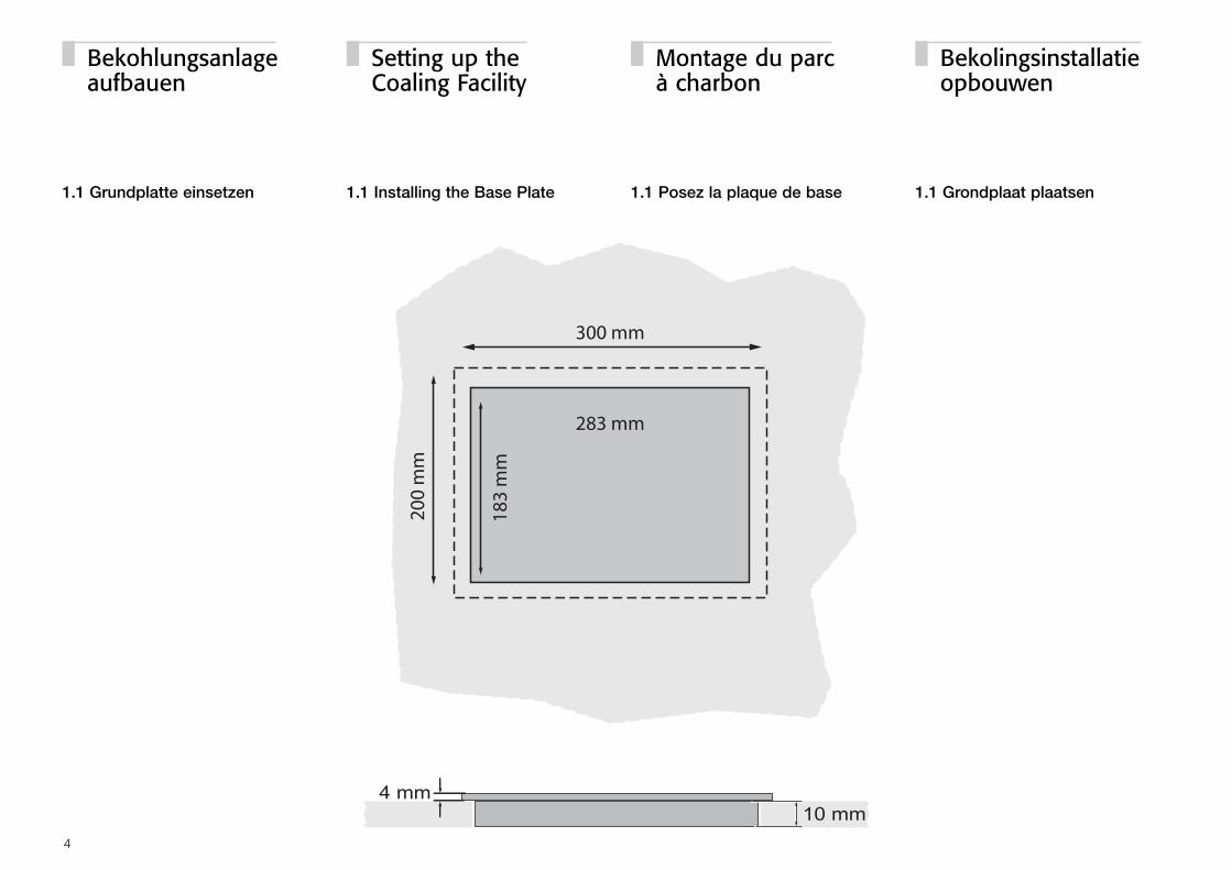
1.1 Grundplatte einsetzen 4
2.1 Grundplatte anschließen mit 5Control Unit / Mobile Station
2.2 Grundplatte anschließen mit 6Bedienpult und Empfänger aus 76500
3. Kranbrücke aufsetzen 7
4. Kranschaufel anschließen 8
Inbetriebnahme 9
5. Adresse einstellen 9
6.1 Bedienung über Control Unit 10
6.2 Bedienung über die 11Mobile Station
6.3 Bedienung über Bedienpult 11von 76500
Page
Function 3
Setting up the Coaling Facility 4
1.1 Installing the Base Plate 4
2.1 Connecting the Base Plate 5to the Control Unit / Mobile Station
2.2 Connecting the Base Plate 6to the Controller and the Receiver from Item No. 76500
3. Erecting the crane bridge 7
4. Connecting the Crane Bucket 8
Commissioning 9
5. Setting the Address 9
6.1 Operating the Crane 10with the Control Unit
6.2 Operating the Crane 11with the Mobile Station
6.3 Operating the Crane 11with the Controller from Item No. 76500
Page
Fonction 3
Montage du parc à charbon 4
1.1 Posez la plaque de base 4
2.1 Raccordez la plaque de base 5à la Control Unit / Mobile Station
2.2 Raccordez la plaque de base 6au pupitre de commande et au récepteur de 76500
3. Mettre le pont roulant en place 7
4. Raccordez le grappin 8
Mise en service 9
5. Réglez l’adresse 9
6.1 Commande à partir 10de la Control Unit
6.2 Commande au moyen 11de la Mobile Station
6.3 Commande au moyen 11du pupitre de commande provenant de la grue 76500
Blz.
Functie 3
Bekolingsinstallatie opbouwen 4
1.1 Grondplaat plaatsen 4
2.1 Grondplaat aansluiten met 5Control Unit / Mobile Station
2.2 Grondplaat aansluiten met 6bedieningsapparaat en ontvanger van 76500
3. Kraanbrug plaatsen 7
4. Kraanschep aansluiten 8
Inbedrijfstelling 9
5. Adres instellen 9
6.1 Bediening via de Control Unit 10
6.2 Bediening via het 11Mobile Station
6.3 Bediening via het 11bedieningsapparaat van 76500
2
Funktion:
� Motorisch angetriebenes Krangestell.Fahrrichtung vor- und rückwärts.
� Kranhaus um 360 º drehbar. Drehrichtung wählbar.
� Funktionierende Kohleschaufel, heb- undsenkbar.
� Simultan mit einer Arbeitsleuchte schalt-bare Beleuchtung der Krankabine.
� Geeignete Bediengeräte: Control Unit 6021, Mobile Station, Central Station, Bediengerät (609603) und Empfänger (312 381) vom Portal-kran 76500.
� Nur für den Betrieb im Innenbereich (trockene Räume).
Function:
� Crane cab powered by a motor. Can travel forward and backward.
� Crane cab can be turned 360 º. Direction of rotation can be selected.
� Working bucket, can be raised and lowered.
� Lighting in crane cab can be turned onand off simultaneously with work light.
� Suitable control components: 6021 Control Unit, Mobile Station, Central Station, controller (609603) andreceiver (312 381) from the 76500 gantrycrane.
� Can only be used indoors (dry rooms).
Fonctionnement:
� Châssis de grue motorisé. Sens de marche avant et arrière.
� Cabine de grue pivotante sur 360 º. Sens de rotation au choix.
� Grappin fonctionnel à translation verticaledans les 2 sens.
� Projecteur de travail fonctionnel commu-table sur cabine de grue.
� Appareil de commande approprié: Control Unit 6021, Mobile Station, Central Station, pupitre de commande(609603) et récepteur (312 381) de lagrue à portique 76500.
� Uniquement pour usage à l’intérieur (dans des locaux secs).
Werking:
� Door een motor aangedreven kraan-onderstel. Rijrichting voor- en achteruit.
� Kraanhuis 360 º draaibaar. Draairichting naar keuze.
� Werkende kolenschep, hef- en draaibaar.
� Gelijktijdig met een werklicht schakelbareverlichting van de kraancabine.
� Geschikte besturingsapparaten: Control Unit 6021, Mobile Station, Central Station, bedieningsapparaat(609603) en ontvanger (312381) van portaalkraan 76500.
� Alleen geschikt voor het gebruik binnens-huis (droge ruimte).
3
FonctionFunctionFunktion Functie
1.1 Grundplatte einsetzen 1.1 Installing the Base Plate 1.1 Posez la plaque de base 1.1 Grondplaat plaatsen
4
Bekohlungsanlage aufbauen
Setting up the Coaling Facility
Montage du parcà charbon
Bekolingsinstallatie opbouwen
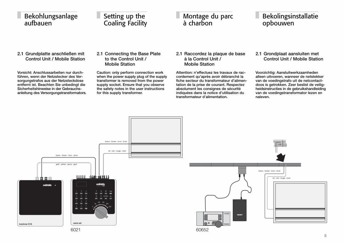
2.1 Grundplatte anschließen mitControl Unit / Mobile Station
Vorsicht: Anschlussarbeiten nur durch-führen, wenn der Netzstecker des Ver-sorgungstrafos aus der Netzsteckdoseentfernt ist. Beachten Sie unbedingt dieSicherheitshinweise in der Gebrauchs-anleitung des Versorgungstransformators.
2.1 Connecting the Base Plate to the Control Unit / Mobile Station
Caution: only perform connection workwhen the power supply plug of the supplytransformer is removed from the powersupply socket. Ensure that you observethe safety notes in the user instructionsfor this supply transformer.
2.1 Raccordez la plaque de baseà la Control Unit / Mobile Station
Attention: n’effectuez les travaux de rac-cordement qu’après avoir débranché lafiche secteur du transformateur d’alimen-tation de la prise de courant. Respectezabsolument les consignes de sécuritéindiquées dans la notice d’utilisation dutransformateur d’alimentation.
2.1 Grondplaat aansluiten metControl Unit / Mobile Station
Voorzichtig: Aansluitwerkzaamhedenalleen uitvoeren, wanneer de netstekkervan de voedingstrafo uit de netcontact-doos is getrokken. Zeer beslist de veilig-heidsinstructies in de gebruikshandleidingvan de voedingstransformator lezen ennaleven.
5
6021 60652
Bekohlungsanlage aufbauen
Setting up the Coaling Facility
Montage du parcà charbon
Bekolingsinstallatie opbouwen
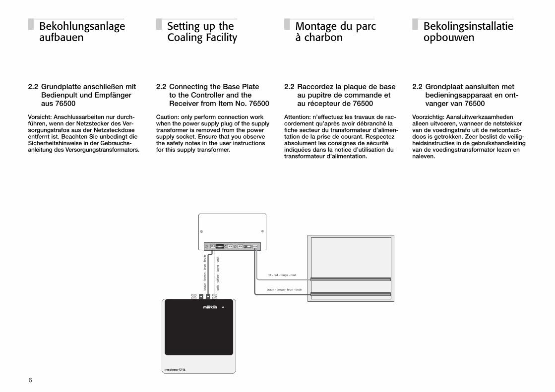
2.2 Grundplatte anschließen mitBedienpult und Empfänger aus 76500
Vorsicht: Anschlussarbeiten nur durch-führen, wenn der Netzstecker des Ver-sorgungstrafos aus der Netzsteckdoseentfernt ist. Beachten Sie unbedingt dieSicherheitshinweise in der Gebrauchs-anleitung des Versorgungstransformators.
2.2 Connecting the Base Plate to the Controller and theReceiver from Item No. 76500
Caution: only perform connection workwhen the power supply plug of the supplytransformer is removed from the powersupply socket. Ensure that you observethe safety notes in the user instructionsfor this supply transformer.
2.2 Raccordez la plaque de baseau pupitre de commande et au récepteur de 76500
Attention: n’effectuez les travaux de rac-cordement qu’après avoir débranché lafiche secteur du transformateur d’alimen-tation de la prise de courant. Respectezabsolument les consignes de sécuritéindiquées dans la notice d’utilisation dutransformateur d’alimentation.
2.2 Grondplaat aansluiten metbedieningsapparaat en ont-vanger van 76500
Voorzichtig: Aansluitwerkzaamhedenalleen uitvoeren, wanneer de netstekkervan de voedingstrafo uit de netcontact-doos is getrokken. Zeer beslist de veilig-heidsinstructies in de gebruikshandleidingvan de voedingstransformator lezen ennaleven.
6
Bekohlungsanlage aufbauen
Setting up the Coaling Facility
Montage du parcà charbon
Bekolingsinstallatie opbouwen
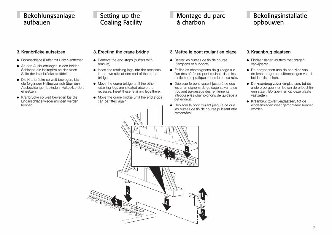
3. Kranbrücke aufsetzen
� Endanschläge (Puffer mit Halter) entfernen.
� An den Ausbuchtungen in den beidenSchienen die Haltepilze an der einenSeite der Kranbrücke einfädeln.
� Die Kranbrücke so weit bewegen, bis die folgenden Haltepilze sich über denAusbuchtungen befinden. Haltepilze dorteinsetzen.
� Kranbrücke so weit bewegen bis dieEndanschläge wieder montiert werdenkönnen.
3. Erecting the crane bridge
� Remove the end stops (buffers with bracket).
� Insert the retaining legs into the recessesin the two rails at one end of the cranebridge.
� Move the crane bridge until the otherretaining legs are situated above therecesses. Insert these retaining legs there.
� Move the crane bridge until the end stopscan be fitted again.
3. Mettre le pont roulant en place
� Retirer les butées de fin de course(tampons et supports).
� Enfiler les champignons de guidage surl’un des côtés du pont roulant, dans lesrenflements pratiqués dans les deux rails.
� Déplacer le pont roulant jusqu’à ce queles champignons de guidage suivants setrouvent au-dessus des renflements.Introduire les champignons de guidage àcet endroit.
� Déplacer le pont roulant jusqu’à ce queles butées de fin de course puissent êtreremontées.
3. Kraanbrug plaatsen
� Eindaanslagen (buffers met drager) verwijderen.
� De borgpennen aan de ene zijde van de kraanbrug in de uitbochtingen van debeide rails steken.
� De kraanbrug zover verplaatsen, tot deandere borgpennen boven de uitbochtin-gen staan. Borgpennen op deze plaatsvastzetten.
� Kraanbrug zover verplaatsen, tot de eindaanslagen weer gemonteerd kunnenworden.
7
Bekohlungsanlage aufbauen
Setting up the Coaling Facility
Montage du parcà charbon
Bekolingsinstallatie opbouwen
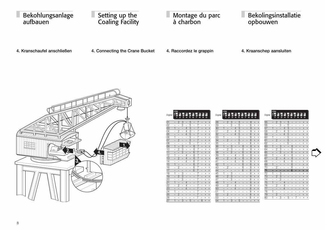
4. Kranschaufel anschließen 4. Connecting the Crane Bucket 4. Raccordez le grappin 4. Kraanschep aansluiten
8
➮
Digital Digital Digital
28 – 2 3 – 5 – – 8 * *29 – – 3 – 5 – – 8 * *30 1 – – 4 5 – – 8 * *31 – 2 – 4 5 – – 8 * *32 – – – 4 5 – – 8 * *33 1 – – – 5 – – 8 * *34 – 2 – – 5 – – 8 * *35 – – – – 5 – – 8 * *36 1 – 3 – – 6 – 8 * *37 – 2 3 – – 6 – 8 * *38 – – 3 – – 6 – 8 * *39 1 – – 4 – 6 – 8 * *40 – 2 – 4 – 6 – 8 * *41 – – – 4 – 6 – 8 * *42 1 – – – – 6 – 8 * *43 – 2 – – – 6 – 8 * *44 – – – – – 6 – 8 * *45 1 – 3 – – – – 8 * *46 – 2 3 – – – – 8 * *47 – – 3 – – – – 8 * *48 1 – – 4 – – – 8 * *49 – 2 – 4 – – – 8 * *50 – – – 4 – – – 8 * *51 1 – – – – – – 8 * *52 – 2 – – – – – 8 * *53 – – – – – – – 8 * *54 1 – 3 – 5 – – – * *
55 – 2 3 – 5 – – – * *56 – – 3 – 5 – – – * *57 1 – – 4 5 – – – * *58 – 2 – 4 5 – – – * *59 – – – 4 5 – – – * *60 1 – – – 5 – – – * *61 – 2 – – 5 – – – * *62 – – – – 5 – – – * *63 1 – 3 – – 6 – – * *64 – 2 3 – – 6 – – * *65 – – 3 – – 6 – – * *66 1 – – 4 – 6 – – * *67 – 2 – 4 – 6 – – * *68 – – – 4 – 6 – – * *69 1 – – – – 6 – – * *70 – 2 – – – 6 – – * *71 – – – – – 6 – – * *72 1 – 3 – – – – – * *73 – 2 3 – – – – – * *74 – – 3 – – – – – * *75 1 – – 4 – – – – * *76 – 2 – 4 – – – – * *77 – – – 4 – – – – * *78 1 – – – – – – – * *79 – 2 – – – – – – * *80 1 – 3 – 5 – 7 – * *
01 – 2 3 – 5 – 7 – * *02 – – 3 – 5 – 7 – * *03 1 – – 4 5 – 7 – * *04 – 2 – 4 5 – 7 – * *05 – – – 4 5 – 7 – * *06 1 – – – 5 – 7 – * *07 – 2 – – 5 – 7 – * *08 – – – – 5 – 7 – * *09 1 – 3 – – 6 7 – * *10 – 2 3 – – 6 7 – * *11 – – 3 – – 6 7 – * *12 1 – – 4 – 6 7 – * *13 – 2 – 4 – 6 7 – * *14 – – – 4 – 6 7 – * *15 1 – – – – 6 7 – * *16 – 2 – – – 6 7 – * *17 – – – – – 6 7 – * *18 1 – 3 – – – 7 – * *19 – 2 3 – – – 7 – * *20 – – 3 – – – 7 – * *21 1 – – 4 – – 7 – * *22 – 2 – 4 – – 7 – * *23 – – – 4 – – 7 – * *24 1 – – – – – 7 – * *25 – 2 – – – – 7 – * *26 – – – – – – 7 – * *27 1 – 3 – 5 – – 8 * *
Bekohlungsanlage aufbauen
Setting up the Coaling Facility
Montage du parcà charbon
Bekolingsinstallatie opbouwen
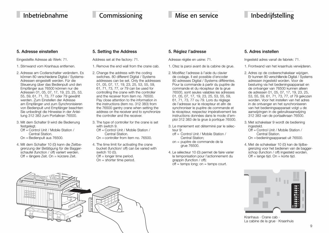
5. Adresse einstellen
Eingestellte Adresse ab Werk: 71.
1. Stirnwand vom Kranhaus entfernen.
2. Adresse am Codierschalter verändern. Eskönnen 80 verschiedene Digital-/ Systems-Adressen eingestellt werden. Für dieSteuerung über das Bedienpult und denEmpfänger aus 76500 können nur dieAdressen 01, 05, 07, 17, 19, 23, 25, 53,55, 59, 61, 71, 73, 77 oder 79 gewähltwerden. Zum Einstellen der Adresse am Empfänger und zum Synchronisierenvon Bedienpult und Empfänger beachtenSie unbedingt die Hinweise in der Anlei-tung 312 383 zum Portalkran 76500.
3. Mit dem Schalter 9 wird die Bedienungfestgelegt. Off = Control Unit / Mobile Station /
Central Station. On = Bedienpult aus 76500.
4. Mit dem Schalter 10 (0) kann die Zeitbe-grenzung der Betätigung für die Bagger-schaufel (function / off) variiert werden. Off = längere Zeit. On = kürzere Zeit.
5. Setting the Address
Address set at the factory: 71.
1. Remove the end wall from the crane cab.
2. Change the address with the coding switches. 80 different Digital / Systemsaddresses can be set. Only the addresses01, 05, 07, 17, 19, 23, 25, 53, 55, 59,61, 71, 73, 77, or 79 can be used forcontrolling the crane with the controllerand the receiver from item no. 76500.Pay close attention to the information inthe instructions (item no. 312 383) fromthe 76500 gantry crane when setting theaddress on the receiver and to synchronizethe controller and the receiver.
3. The type of controller for the crane is setwith switch 9. Off = Control Unit / Mobile Station /
Central Station. On = controller from item no. 76500.
4. The time limit for activating the crane bucket (function/ off) can be varied withswitch 10 (0). Off = longer time period. On = shorter time period.
5. Réglez l’adresse
Adresse réglée en usine: 71.
1. Otez la paroi avant de la cabine de grue.
2. Modifiez l’adresse à l’aide du clavier de codage. Il est possible d’encoder 80 adresses Digital / Systems différentes.Pour la commande à partir du pupitre decommande et du récepteur de la grue76500, sont seules valables les adresses01, 05, 07, 17, 19, 23, 25, 53, 55, 59,61, 71, 73, 77 ou 79. Lors du réglage de l’adresse sur le récepteur et afin desynchroniser le pupitre de commande etle récepteur, respectez impérativement lesinstructions données dans le mode d’em-ploi 312 383 de la grue à portique 76500.
3. Le maniement est déterminé par le sélec-teur 9: off = Control Unit / Mobile Station /
Central Station; on = pupitre de commande de la
grue 76500.
4. Le sélecteur 10 (0) permet de faire varierla temporisation pour l’actionnement dugrappin (function / off): off = temps long; on = temps court.
5. Adres instellen
Ingesteld adres vanaf de fabriek: 71.
1. Frontwand van het kraanhuis verwijderen.
2. Adres op de codeerschakelaar wijzigen.Er kunnen 80 verschillende Digital / Systemsadressen ingesteld worden. Voor debesturing via het bedieningsapparaat ende ontvanger van 76500 kunnen alleen de adressen 01, 05, 07, 17, 19, 23, 25,53, 55, 59, 61, 71, 73, 77, of 79 gekozenworden. Voor het instellen van het adresin de ontvanger en het synchroniserenvan het bedieningsapparaat volgt u deaanwijzingen in de gebruiksaanwijzing312 383 van de portaalkraan 76500.
3. Met schakelaar 9 wordt de bedieningingesteld. Off = Control Unit / Mobile Station /
Central Station. On = bedieningsapparaat uit 76500.
4. Met de schakelaar 10 (0) kan de tijdbe-grenzing voor het bedienen van de bagger-schop (function / off) ingesteld worden. Off = lange tijd. On = korte tijd.
9
Inbetriebnahme Commissioning Mise en service Inbedrijfstelling
Kranhaus · Crane cab ·La cabine de la grue · Kraanhuis
6.1 Bedienung über Control Unit
1. Adresse 71 auf der Zehnertastaur eingeben.
Fuktionsbelegung:Function/off: Kohleschaufel schließen / öffnenf1 = Zu- / Abschalten der Motoren im Lauf-
gestellf2 = Führerhaus-Beleuchtung / Arbeits-
scheinwerfer ein/ausf3 = Kohleschaufel heben / senken f4 = Führerhaus Drehen ein/aus
Hinweis: Die Richtung bei den Funktionenf1, f3 und f4 wird über den Umschaltbefehlgeändert. Die Geschwindigkeit dieser Funk-tionen wird über den Fahrregler verändert.
Wichtig: Das Einschalten der Baggerschaufel(function) ist durch eine Zeitschaltung ge-schützt. Ca. 30 Sekunden vor dem Anspre-chen dieser Sicherung beginnt das Licht imFührerhaus mit schneller Frequenz zu blinken.Nach dem Ansprechen dieser Sicherungblinkt das Licht im Führerhaus mit langsamerFrequenz. Erst nach einer ausreichendenAbkühlphase kann „function“ wieder genutztwerden.
6.1 Operating the Crane with the Control Unit
1. Enter address 71 on the keypad.
Control function assignments:Function/off: closing / opening the cranebucketf1 = turning the motors in the crane’s
movable frame on/offf2 = turning the crane cab lighting / work
light on/offf3 = raising / lowering the bucket f4 = turning the rotation of the crane cab
on/off
Important: The direction of the functions f1,f3, and f4 is changed with the reversingcommand. The speed for these functions ischanged with the speed control knob.
Important: The function of turning the cranebucket on (“function” on the controller) is pro-tected by a time circuit. About 30 secondsbefore this safeguard is activated, the light in the crane cab begins to blink with a fastfrequency. After this safeguard has beenactivated, the light in the crane cab blinkswith a slow frequency. “function” cannot beused again until the solenoid for the buckethas cooled off sufficiently.
6.1 Commande à partir de la Control Unit
1. Introduisez l’adresse 71 à l’aide du claviernumérique.
Attribution des fonctions:Function/off: fermer / ouvrir grappinf1 = Activation / désactivation des moteurs
du châssis de gruef2 = Activation / désactivation de l’éclairage
de cabine de grue/du projecteur de travail
f3 = Levée / descente du grappin.f4 = Activation / désactivation de la rotation
de la cabine
Remarque: Le sens de translation ou derotation des mouvements commandés parles fonctions f1, f3 et f4 est modifié à l’aided’un ordre d’inversion. La vitesse de ces mou-vements est modifiée à l’aide du régulateur.
Important: L’activation du grappin (touchefunction) est protégée par une temporisation.Environ 30 secondes avant la fin de cettetemporisation, l’éclairage de la cabine com-mence à clignoter à une cadence rapide.Une fois la temporisation terminée, la caden-ce de clignotement baisse. Ce n’est qu’a-près un temps de refroidissement suffisant que la touche „function“ peut êtreutilisée de nouveau.
6.1 Bediening via de Control Unit
1. Adres 71 met de numerieke toetseninvoeren.
Functiebelegging:function/off: kolenschop sluiten / openenf1 = bij- / afschakelen van de motoren in het
loopstelf2 = cabineverlichting / werkschijnwerper
aan/uitf3 = kolenschop hijsen / vierenf4 = cabine draaien aan/uit
Opmerking: de richting van de functies f1,f3 en f4 worden met een omschakelcom-mando veranderd. De snelheid van dezefuncties kunnen met de rijregelaar veranderdworden.
Belangrijk: het inschakelen van de kolen-schop (function) is door een tijdschakelingbegrenst. Ca. 30 seconden voor het aan-spreken van de begrenzing begint het lichtin de cabine met een hogere frequentie teknipperen. Na het aanspreken van dezebeveiliging knippert de verlichting in eenlagere frequentie. Pas na een volledige afkoelperiode kan de “function” weer gebru-ikt worden.
10
Inbetriebnahme Commissioning Mise en service Inbedrijfstelling
6.2 Bedienung über die Mobile Station
1. Bekohlungsanlage in die Lokliste auf-nehmen (in der Datenbank nach Artikel-nummer 76510 suchen).
2. Bedient wird der Portalkran über dieBeleuchtungstaste (Baggerschaufel) sowieüber 4 Funktionstasten zum Einschaltender verschiedenen Motoren und der Be-leuchtung. Geregelt werden die Motorenüber den Fahrregler. Richtungswechseldurch Drücken auf den Fahrregler. Ver-gleichen Sie hierzu die Funktionen bei derBedienung über die Control Unit. Beach-ten Sie auch unbedingt die Hinweise zurzeitgeregelten Sicherheitsschaltung.
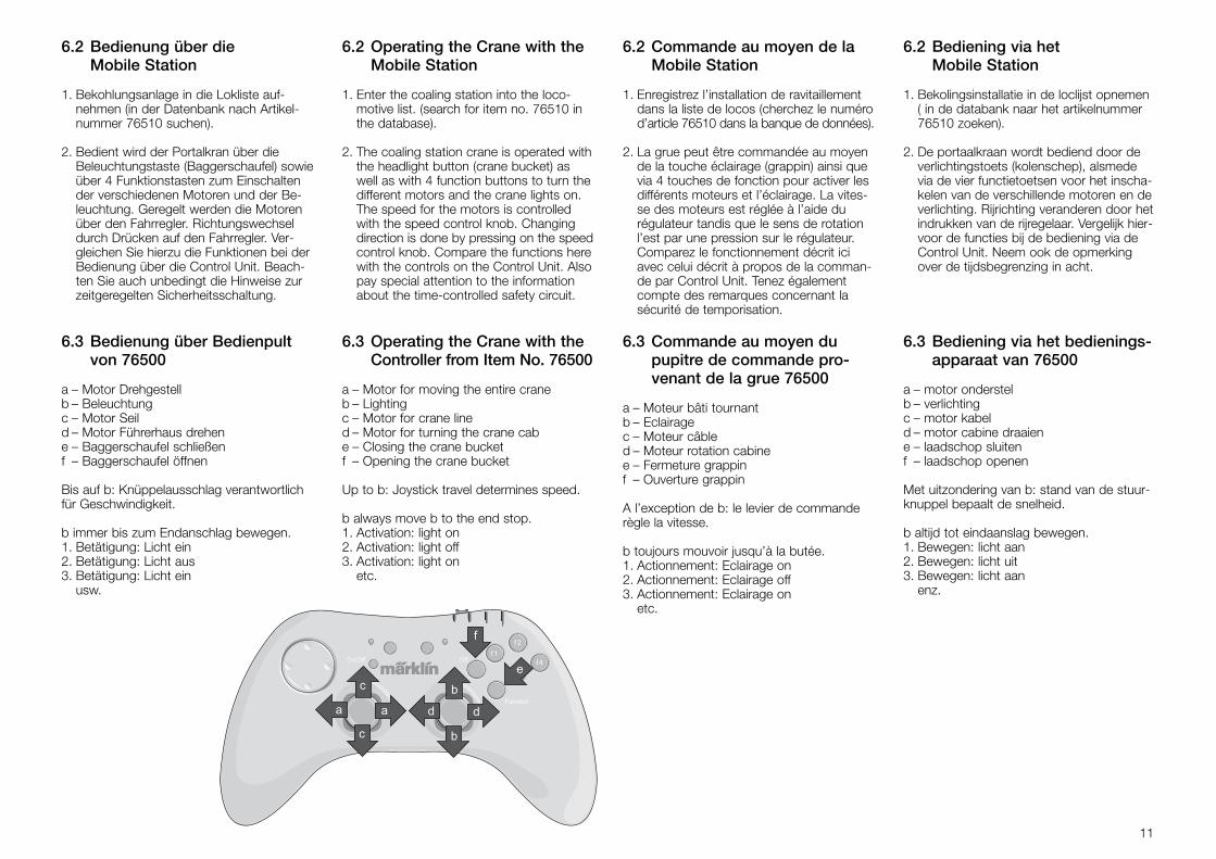
6.3 Bedienung über Bedienpultvon 76500
a – Motor Drehgestell b – Beleuchtung c – Motor Seil d – Motor Führerhaus drehen e – Baggerschaufel schließenf – Baggerschaufel öffnen
Bis auf b: Knüppelausschlag verantwortlichfür Geschwindigkeit.
b immer bis zum Endanschlag bewegen.1. Betätigung: Licht ein2. Betätigung: Licht aus3. Betätigung: Licht ein
usw.
6.2 Operating the Crane with theMobile Station
1. Enter the coaling station into the loco-motive list. (search for item no. 76510 inthe database).
2. The coaling station crane is operated withthe headlight button (crane bucket) aswell as with 4 function buttons to turn thedifferent motors and the crane lights on.The speed for the motors is controlledwith the speed control knob. Changingdirection is done by pressing on the speedcontrol knob. Compare the functions herewith the controls on the Control Unit. Alsopay special attention to the informationabout the time-controlled safety circuit.
6.3 Operating the Crane with theController from Item No. 76500
a – Motor for moving the entire crane b – Lighting c – Motor for crane line d – Motor for turning the crane cab e – Closing the crane bucketf – Opening the crane bucket
Up to b: Joystick travel determines speed.
b always move b to the end stop.1. Activation: light on 2. Activation: light off 3. Activation: light on
etc.
6.2 Commande au moyen de laMobile Station
1. Enregistrez l’installation de ravitaillementdans la liste de locos (cherchez le numérod’article 76510 dans la banque de données).
2. La grue peut être commandée au moyende la touche éclairage (grappin) ainsi quevia 4 touches de fonction pour activer lesdifférents moteurs et l’éclairage. La vites-se des moteurs est réglée à l’aide durégulateur tandis que le sens de rotationl’est par une pression sur le régulateur.Comparez le fonctionnement décrit iciavec celui décrit à propos de la comman-de par Control Unit. Tenez égalementcompte des remarques concernant lasécurité de temporisation.
6.3 Commande au moyen dupupitre de commande pro-venant de la grue 76500
a – Moteur bâti tournant b – Eclairage c – Moteur câble d – Moteur rotation cabine e – Fermeture grappinf – Ouverture grappin
A l’exception de b: le levier de commanderègle la vitesse.
b toujours mouvoir jusqu’à la butée.1. Actionnement: Eclairage on2. Actionnement: Eclairage off3. Actionnement: Eclairage on
etc.
6.2 Bediening via het Mobile Station
1. Bekolingsinstallatie in de loclijst opnemen( in de databank naar het artikelnummer76510 zoeken).
2. De portaalkraan wordt bediend door deverlichtingstoets (kolenschep), alsmedevia de vier functietoetsen voor het inscha-kelen van de verschillende motoren en deverlichting. Rijrichting veranderen door hetindrukken van de rijregelaar. Vergelijk hier-voor de functies bij de bediening via deControl Unit. Neem ook de opmerkingover de tijdsbegrenzing in acht.
6.3 Bediening via het bedienings-apparaat van 76500
a – motor onderstelb – verlichtingc – motor kabeld – motor cabine draaiene – laadschop sluitenf – laadschop openen
Met uitzondering van b: stand van de stuur-knuppel bepaalt de snelheid.
b altijd tot eindaanslag bewegen.1. Bewegen: licht aan2. Bewegen: licht uit3. Bewegen: licht aan
enz.
11
Gebr. Märklin & Cie. GmbHPostfach 8 60D-73008 Göppingenwww.maerklin.com
325 483 08 04 he fhÄnderungen vorbehaltenCopyright byGebr. Märklin & Cie. GmbH
This device complies with Part 15 of the FCC Rules. Operation is subject to the following two conditions:(1) This device may not cause harmful interference, and(2) this device must accept any interference received, including
interference that may cause undesired operation.