Embed Size (px)
Citation preview
Systemvoraussetzungen
Konsolen• Ein PC-kompatibler Computer mit VGA-Ausgang• Zwei VGA, SVGA, XGA, SXGA oder Multisync-Monitore
Übersicht und Bedienung der HardwareVorderseitige Ansicht des VE-150L
Rückseitige Ansicht des VE-150L
Vorderseitige Ansicht des VE-150R
VE-150
VE-150 Video Extender User Guide
System Requirements
Consoles• A PC compatible computer with a VGA output port• Two VGA, SVGA, XGA, SXGA or Multisync monitors
Hardware Overview and OperationVE-150L Front View
VE-150L Rear View
VE-150R Front View
VE-150R Rear View
Hardware Installation
The numbers on the installation diagram indicate the order of steps to take to set up your system.
Important:
• Ensure that all equipment to be connected is powered off before beginning.
• To prevent damage to your installation, make sure that all devices are properly grounded.
• Power on the PCs and monitors only after following the numbered steps on the diagram.
• Category 5 UTP cable is not supplied with this package. It requires a separate purchase. The cable can be up to 150m (500 feet) in length.
Gain Setting Table
Approximate distances only. Actually distances may vary by up to 10 meters. For optimal display, please refer to the following display resolution and refresh rate settings: at 10 meters use 1600 x 1200 60Hz, at 70m use 1280 x 1024 75Hz, at 150m use 1280 x 1024 60Hz. (These settings are for reference only and may be affected by the type of monitor and graphic display card used, as well as cable quality.)
Specifications
*DDC, DDC2 and DDC2B support is for the Local Monitor only.
Specifications
*Die Unterstützung von DDC, DDC2 und DDC2B ist nur für den lokalen Monitor erforderlich.
Rückseitige Ansicht des VE-150R
Hardware installieren
Die Zahlen im Installationsdiagramm entsprechen der Reihenfolge der Schritte, die zur Installation durchgeführt werden müssen.
Wichtig:
• Schalten Sie zuerst alle anzuschließenden Geräte aus.
• Um eine Beschädigung Ihrer Geräte zu vermeiden, müssen alle Geräte ordnungsgemäß geerdet sein.
• Schalten Sie die PCs und Bildschirme nur in der im Diagramm angegebenen Reihenfolge ein.
• Das Kat.5-UTP-Kabel ist nicht im Lieferumfang enthalten. Sie müssen es separat erwerben. Die Kabellänge darf maximal 150 m betragen.
Tabelle zur Pegeleinstellung
Diese Werte sind angenähert. Die tatsächlichen Entfernungen können um bis zu 10 m variieren. Zur optimalen Anzeige, siehe die folgenden Empfehlungen für Auflösung und Bildwiederholfrequenz: bei 10 m verwenden Sie 1600 x 1200 mit 60 Hz, bei 70 m 1280 x 1024 mit 75 Hz, bei 150 m verwenden Sie 1280 x 1024 mit 60 Hz. (Diese Werte sind rein orientativ und können je nach verwendetem Monitor und Grafikkarte sowie der Kabelqualität variieren.)
VE-150Video Extender Guide de l’utilisateur
VE-150 Grafiksignal-Erweiterung
Especificaciones
*La prise en charge de DDC, DD C2 et DDC2B est uniquement pour l’écran local.
Requisitos del sistema
Consolas• Un ordenador PC compatible con puerto VGA• Dos monitores VGA, SVGA, XGA, SXGA o Multisync
Aspectos generales del hardware y del manejoVista frontal del VE-150L
Vista posterior del VE-150L
Vista frontal del VE-150R
Tabla de ajuste de ganancia
Distances approximatives uniquement : En effet les distances peuvent varier jusqu’à 10 mètres. Pour un affichage optimal, veuillez vous reporter aux paramètres de vitesse de régénération et de résolution d'affichage : à 10 mètres, utilisez 1600 x 1200 à 60Hz, à 70 m utilisez 1280 x 1024 à 75Hz et à 150 m utilisez 1280 x 1024 à 60Hz. (Ces paramètres servent de référence uniquement et peuvent être affectés par le type d’écran et de carte graphique utilisés, ainsi que la qualité du câble.)
VE-150 Extensión de vídeo Manual del usuario
# Description Function
1 PC PortThe VGA cable that connects to the computer’s VGA port plugs in here.
2 Monitor Port The local monitor’s VGA cable plugs in here.
1
Setting Category 5 UTP Cable Length (meters)
0 Not longer than 150
1 140-150
2 130-140
3 120-130
4 110-120
5 100-110
6 90-100
7 80-90
8 70-80
9 60-70
A 50-60
B 40-50
C 30-40
D 20-30
E 10-20
F 0-10
# Description Function
1 Remote I/OThe Category 5 UTP cable that connects this unit to the Remote Unit plugs in here.
2 Power Jack The Power Adapter cable plugs in here.
3 Power LED (top cover) Lights to indicate that the unit is receiving power.
# Description Function
1 Monitor Port The remote monitor’s VGA cable plugs in here.
# Description Function
1 Rotary Video Gain Switch
A 16 position rotary switch. Refer to the Gain Setting Table to match the video gain setting to the Category 5 cable length. Use a flathead screwdriver or similar object to change the switch position.
2 Remote I/OThe Category 5 UTP cable that connects this unit to the Local Unit plugs in here.
3 Power Jack The Power Adapter cable plugs in here.
4 Power LED (top cover) Lights to indicate that the unit is receiving power.
Function VE-150L VE-150R
Computer Connection 1 N/A
Connectors
Console Video 1 x HDB-15 female (blue)
Computer Video 1 x HDB-15 male (blue) N/A
Link 1 x RJ-45 socket
Power 1 x DC 5.3V jack
Switch Video Gain N/A 1 x 16 position switch
LEDs Power 1 (orange)
Cable Length 150m (500') (max.)
Resolution 1280x1024, 60Hz DDC, DDC2, DDC2B*
Power Consumption 1.2W 1.2W
Operation Temperature 0~50˚C (0~80% RH, Non-condensing)
Storage Temperature -20˚C~60˚C (0~80% RH, Non-condensing)
Housing Metal
Weight 250 g 250 g
Dimensions 119 x 86 x 23 mm 119 x 86 x 23 mm
# Beschreibung Funktion
1 PC-PortHier wird das VGA-Kabel zum VGA-Ausgang des Computers angeschlossen.
2 MonitoranschlussHier schließen Sie das VGA-Kabel des lokalen Bildschirms an.
# Beschreibung Funktion
1 E/A zur GegenstelleHier schließen Sie das UTP-Kabel der Kategorie 5 an, das dieses Gerät mit dem der Gegenstelle verbindet.
2Stromeingangs-buchse
Hier schließen Sie das Stromkabel des Netzteils an.
3LED-Betriebsanzeige (obere Abdeckung)
Leuchtet, wenn das Gerät mit Strom gespeist wird.
# Beschreibung Funktion
1 MonitoranschlussHier schließen Sie das VGA-Kabel des entfernten Bildschirms an.
# Beschreibung Funktion
1 Signalpegel-Drehregler
Ein 16-stuf iger Drehregler. Um die r icht ige E inste l lung für versch iedene Kabel längen h e r a u s z u f i n d e n , s i e h e d i e Ta b e l l e z u r Pegeleinstellung. Drehen Sie den Regler mithilfe eines Schraubendrehers oder mit einem ähnlichen Gegenstand.
2 E/A zur GegenstelleHier schließen Sie das UTP-Kabel der Kategorie 5 an, das dieses Gerät mit dem lokalen verbindet.
3 Stromeingangs-buchse Hier schließen Sie das Stromkabel des Netzteils an.
4LED-Betriebsanzeige (obere Abdeckung)
Leuchtet, wenn das Gerät mit Strom gespeist wird.
Einstellung Kabellänge (m) UTP Kat. 5
0 Nicht mehr als 150
1 140-150
2 130-140
3 120-130
4 110-120
5 100-110
6 90-100
7 80-90
8 70-80
9 60-70
A 50-60
B 40-50
C 30-40
D 20-30
E 10-20
F 0-10
Funktion VE-150L VE-150R
Verbindung zum Computer 1 _
Anschlüsse
Konsole Bildschirm 1 x HDB-15 Weiblein (blau)
Computer Bildschirm 1 x HDB-15 Männlein (blau) _
Link 1 x RJ-45-Buchse
Stromversorgung 1 x Stromeingangsbuchse 5,3 V=
Switch Signalpegeleinstellung _ 1 x Schalter mit 16 Stufen
LED-Anzeigen Stromversorgung 1 (orange)
Kabellänge 150 m (max.)
Auflösung 1280 x 1024, 60Hz DDC, DDC2, DDC2B*
Stromverbrauch 1.2W 1.2W
Betriebstemperatur 0~50˚C (0 - 80% rel. Luftfeuchte, nicht kondensierend)
Lagertemperatur -20˚C~60˚C (0 - 80% rel. Luftfeuchte, nicht kondensierend)
Gehäuse Metall
Gewicht 250 g 250 g
Abmessungen 119 x 86 x 23 mm 119 x 86 x 23 mm
Configuration système
Consoles• Un ordinateur compatible PC avec un port de sortie VGA• Deux moniteurs VGA, SVGA, XGA, SXGA ou Multisync
Présentation du matériel et FonctionnementVue Avant du VE-150L
Vue Arrière du 150L
Vue avant du VE-150R
Spécifications
*La prise en charge de DDC, DD C2 et DDC2B est uniquement pour l’écran local.
Vue Arrière du 150R
Installation du matériel
Les numéros sur le schéma d’installation indiquent l’ordre des étapes à suivre pour configurer votre système.
Important :
• Assurez-vous que tous les matériels à connecter sont hors tension avant de démarrer.• Afin d’éviter d’endommager votre installation, vérifiez que tous les périphériques sont
correctement reliés à la terre.• Allumez les PC et les moniteurs uniquement après avoir suivi les étapes numérotées sur le
schéma.• Le câble UTP de catégorie 5 n’est pas fourni dans cet emballage. Il doit être acheté
séparément. Le câble peut mesurer jusqu’à 150 m de long.
Tableau des paramètres de gain
Distances approximatives uniquement : En effet les distances peuvent varier jusqu’à 10 mètres. Pour un affichage optimal, veuillez vous reporter aux paramètres de vitesse de régénération et de résolution d'affichage : à 10 mètres, utilisez 1600 x 1200 à 60Hz, à 70 m utilisez 1280 x 1024 à 75Hz et à 150 m utilisez 1280 x 1024 à 60Hz. (Ces paramètres servent de référence uniquement et peuvent être affectés par le type d’écran et de carte graphique utilisés, ainsi que la qualité du câble.)
# Description Fonction
1 Port PCLe câble VGA qui se connecte au port VGA de l’ordinateur se branche ici.
2 Port moniteur Le câble VGA du moniteur local se branche ici.
# Description Fonction
1 E/S distantesLe câble UTP de catégorie 5 qui connecte cette unité à l’unité distante se branche ici.
2Prise jack d'alimentation
Le câble de l’adaptateur secteur se branche ici.
3Voyant d’alimentation (cache supérieur)
S’allume pour indiquer que l’unité reçoit du courant.
# Description Fonction
1 Port moniteur Le câble VGA du moniteur distant se branche ici.
# Description Fonction
1Commutateur de gain vidéo rotatif
Un commutateur rotatif à 16 positions. Reportez-vous au Tableau des paramètres de gain pour faire correspondre le paramètre de gain vidéo à la longueur du câble de catégorie 5. Utilisez un tournevis à tête fraisée ou un autre objet similaire pour modifier la position du commutateur.
2 E/S distantesLe câble UTP de catégorie 5 qui connecte cette unité à l’unité locale se branche ici.
3 Prise jack d'alimentation Le câble de l’adaptateur secteur se branche ici.
4Voyant d’alimentation (cache supérieur)
S’allume pour indiquer que l’unité reçoit du courant.
Paramètre Longueur de câble UTP de catégorie 5 (en mètres)
0 Pas plus de 150
1 140-150
2 130-140
3 120-130
4 110-120
5 100-110
6 90-100
7 80-90
8 70-80
9 60-70
A 50-60
B 40-50
C 30-40
D 20-30
E 10-20
F 0-10
Fonction VE-150L VE-150R
Connexion de l’ordinateur 1 Ne s’applique pas
Connecteurs
Console Vidéo 1 x HDB 15 broches - femelle (bleu)
Ordinateur Vidéo 1 x HDB 15 broches - mâle (bleu) Ne s’applique pas
Liaison 1 x prise RJ45
Alimentation 1 x prise jack CC 5,3 V
Commutateur Gain vidéo Ne s’applique pas 1 x commutateur à16 positions
Voyants Alimentation 1 (orange)
Longueur de câble 150 m (max.)
Résolution 1280 x 1024, 60Hz DDC, DDC2, DDC2B*
Consommation électrique 1.2W 1.2W
Température de fonctionnement de 0°C à 50°C (HR de 0 à 80 %, sans condensation)
Température de conservation de -20˚C à 60˚C (HR de 0 à 80 %, sans condensation)
Boîtier Métallique
Poids 250 g 250 g
Dimensions 119 x 86 x 23 mm 119 x 86 x 23 mm
# Descripción Función
1 Puerto PCAquí se conecta el cable VGA procedente del puerto VGA del ordenador.
2 Puerto de monitor Aquí se conecta el cable VGA del monitor local.
# Descripción Función
1 E/S remotoAquí se conecta el cable UTP de Categoría 5 procedente de la unidad remota.
2 Entrada de alimentaciónAquí se conecta e l cab le de l adaptador de alimentación.
3Indicador de alimentación (tapa superior)
Se ilumina cuando la unidad está recibiendo corriente eléctrica.
# Descripción Función
1 Puerto de monitor Aquí se conecta el cable VGA del monitor remoto.
Vista posterior del VE-150R
Instalación del hardware
Los números del diagrama de instalación equivalen al orden de los pasos necesarios para instalar el sistema.
Importante:
• Apague todos los equipos que vaya a conectar.• Para evitar daños en los dispositivos, verifique que todos ellos estén conectados a tierra
correctamente.• Encienda los PCs y los monitores sólo después de seguir los pasos exactamente en el
orden indicado en el diagrama.• El cable UTP de categoría 5 no está incluido en el paquete. Deberá adquirirlo por separado.
Su longitud máxima puede ser de 150 m.
# Descripción Función
1 Dial de ganancia de vídeo
Dial de selección con 16 posiciones. Consulte la Tabla de ajuste de ganancia para ajustarlo a la longitud del cable de categoría 5. Emplee un destornillador o un objeto similar para girarlo.
2 E/S remotoAquí se conecta el cable UTP de Categoría 5 procedente de la unidad local.
3 Entrada de alimentaciónAquí se conecta el cable del adaptador de alimentación.
4Indicador de alimentación (tapa superior)
Se ilumina cuando la unidad está recibiendo corriente eléctrica.
Ajuste Longitud del cable UTP de categoría 5 (metros)
0 Máximo 150
1 140-150
2 130-140
3 120-130
4 110-120
5 100-110
6 90-100
7 80-90
8 70-80
9 60-70
A 50-60
B 40-50
C 30-40
D 20-30
E 10-20
F 0-10
Función VE-150L VE-150R
Conexión al ordenador 1 _
Conectores
Consola Pantalla 1 x HDB-15 hembra (azul)
Ordenador Pantalla 1 x HDB-15 macho (azul) _
Enlace 1 x conector RJ-45
Alimentación 1 x toma de c.c. 5,3 V
Concen-trador Ganancia de señal de vídeo _ 1 conmutador
de 16 posiciones
Indicadores LED Alimentación 1 (anaranjado)
Longueur de câble 150 m (max.)
Résolution 1280 x 1024, 60Hz DDC, DDC2, DDC2B*
Consumo 1.2W 1.2W
Temperatura de funcionamiento 0~50˚C (0 a 80% HR, sin condensar)
Temperatura de almacenamiento -20˚C~60˚C (0 a 80% HR, sin condensar)
Carcasa Metal
Peso 250 g 250 g
Dimensiones 119 x 86 x 23 mm 119 x 86 x 23 mm
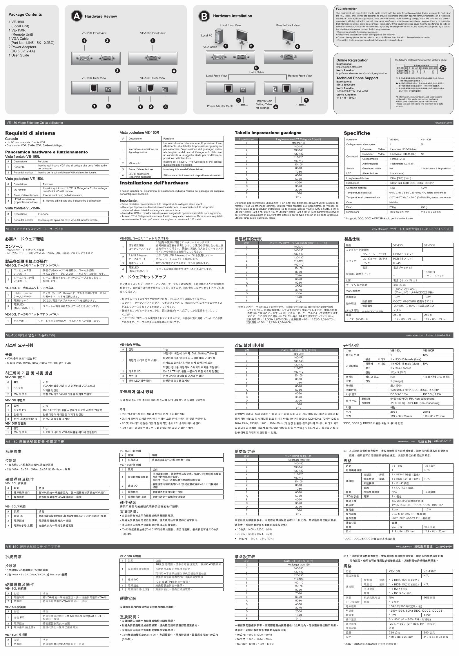
The following contains information that relates to China:
www.aten.com
www.aten.com
www.aten.com
www.aten.com
8-Port Video Switch
© Copyright 2011 ATEN® International Co., Ltd.ATEN and the ATEN logo are trademarks of ATEN International Co., Ltd. All rights reserved. All other trademarks are the property of their respective owners.
This product is RoHS compliant.
Part No. PAPE-1223-162G Printing Date: 02/2011
VS881
User Guide
A/V Over Cat 5 Extender
Patent No.CN ZL 98252015.8CN ZL 01124239.6CN ZL 200410042772.8US 7340556US 7472217
DE 29903667.7DE 102004058233TW 194030TW 150098TW I243890
US 6160543US 6489854US 7532998JP 4160936
VE-150
All information, documentation, and specifications contained in this media are subject to change without prior notification by the manufacturer. Please visit our website to find the most up to date version.
Online RegistrationInternational:http://support.aten.comNorth America:http://www.aten-usa.com/product_registration
Technical Phone SupportInternational:886-2-86926959North America:1-888-999-ATEN Ext: 4988 United Kingdom:44-8-4481-58923
FCC Information
This equipment has been tested and found to comply with the limits for a Class A digital device, pursuant to Part 15 of the FCC Rules. These limits are designed to provide reasonable protection against harmful interference in a residential installation. This equipment generates, uses and can radiate radio frequency energy, and if not installed and used in accordance with the instruction manual, may cause interference to radio communications. However, there is no guarantee that interference will not occur in a particular installation. If this equipment does cause harmful interference to radio or television reception, which can be determined by turning the equipment off and on, the user is encouraged to try to correct the interference by one or more of the following measures: • Reorient or relocate the receiving antenna; • Increase the separation between the equipment and receiver; • Connect the equipment into an outlet on a circuit different from
that which the receiver is connected; • Consult the dealer/an experienced radio/television technician for
help.
A
B Hardware Installation
Local Front View Remote Front View
VGA Cable
Local PC
Local Front View Remote Front View
Power Adapter CableRefer to Gain Setting Table for settings
VE-150L Front View
Hardware Review
VE-150R Front View
1
VE-150L Rear View VE-150R Rear View
2
3
1 2
4
1 2 3
43
Cat 5 Cable
1 2
5
6
7
Package Contents
1 VE-150L (Local Unit)1 VE-150R (Remote Unit)1 VGA Cable (Part No.: LIN5-15X1-X2BG)2 Power Adapters (DC 5.3V; 2.4A)1 User Guide
VE-150 Video Extender Guida dell’utente
Requisiti di sistemaConsole• Un PC con una porta d’uscita VGA• Due monitor VGA, SVGA, XGA, SXGA o Multisync
Panoramica hardware e funzionamentoVista frontale VE-150L
Vista posteriore VE-150L
Vista frontale VE-150R
Vista posteriore VE-150R
Installazione dell’hardware
I numeri riportati nel diagramma di installazione indicano l'ordine dei passaggi da eseguire per configurare il sistema.
Importante:• Prima di iniziare, accertarsi che tutti i dispositivi da collegare siano spenti.• Allo scopo di prevenire danni durante l’installazione, assicurarsi che tutti i dispositivi
interessati siano dotati di un’adeguata messa a terra• Accendere i PC e i monitor solo dopo aver eseguito le operazioni riportate nel diagramma.• Il cavo UTP di Categoria 5 non viene fornito con questa confezione. Deve essere acquistato
separatamente. Il cavo può avere una lunghezza massima di 150 metri.
Tabella impostazione guadagno
Distances approximatives uniquement : En effet les distances peuvent varier jusqu’à 10 mètres. Pour un affichage optimal, veuillez vous reporter aux paramètres de vitesse de régénération et de résolution d'affichage : à 10 mètres, utilisez 1600 x 1200 à 60Hz, à 70 m utilisez 1280 x 1024 à 75Hz et à 150 m utilisez 1280 x 1024 à 60Hz. (Ces paramètres servent de référence uniquement et peuvent être affectés par le type d’écran et de carte graphique utilisés, ainsi que la qualité du câble.)
Specifiche
* Il supporto DDC, DDC2 e DDC2B è solo per il monitor locale.
A B Hardware InstallationHardware ReviewPackage Contents
1 VE-150L (Local Unit)1 VE-150R (Remote Unit)1 VGA Cable (Part No.: LIN5-15X1-X2BG)2 Power Adapters (DC 5.3V; 2.4A)1 User Guide
# Descrizione Funzione
1 Porta PCInserire qui il cavo VGA che si collega alla porta VGA audio del computer.
2 Porta del monitor Inserire qui la spina del cavo VGA del monitor locale.
# Descrizione Funzione
1 I/O remotoInserire qui il cavo UTP di Categoria 5 che collega quest'unità all'unità remota.
2 Presa d’alimentazione Inserire qui il cavo dell’alimentatore.
3LED di accensione (coperchio superiore)
Si illumina ad indicare che il dispositivo è alimentato.
# Descrizione Funzione
1 Porta del monitor Inserire qui la spina del cavo VGA del monitor remoto.
# Descrizione Funzione
1Interruttore a rotazione per il guadagno video
Un interruttore a rotazione con 16 posizioni. Fare riferimento alla tabella Impostazione guadagno per associare l'impostazione del guadagno video alla lunghezza del cavo di Categoria 5. Utilizzare un cacciavite o un oggetto simile per modificare la posizione dell'interruttore.
2 I/O remotoInserire qui il cavo UTP di Categoria 5 che collega quest'unità all'unità locale.
3 Presa d’alimentazione Inserire qui il cavo dell’alimentatore.
4LED di accensione(coperchio superiore)
Si illumina ad indicare che il dispositivo è alimentato.
Impostazione Linghezza cavo UTP Categoria 5 (metri)
0 Máximo 150
1 140-150
2 130-140
3 120-130
4 110-120
5 100-110
6 90-100
7 80-90
8 70-80
9 60-70
A 50-60
B 40-50
C 30-40
D 20-30
E 10-20
F 0-10
Funzione VE-150L VE-150R
Collegamento al computer 1 No
Connettori
Console Video 1 femmina HDB-15 (blu)
Computer Video 1 maschio HDB-15 (blu) No
Collegamento 1 presa RJ-45
Alimentazione 1 connettore CC 5,3V
Switch Guadagno video No 1 interruttore a 16 posizioni
LED Alimentazione 1 (arancione)
Lunghezza del cavo 150 m [500’] (max.)
Risoluzione 1280x1024, 60Hz DDC, DDC2, DDC2B*
Consumo elettrico 1.2W 1.2W
Temperatura operativa: 0~50˚C da 0 a 50˚C (0~80% RH, senza condensa)
Temperatura di conservazione -20˚C~60˚C da 0 a 50˚C (0~80% RH, senza condensa)
Case Metallo
Peso 250 g 250 g
Dimensioni 119 x 86 x 23 mm 119 x 86 x 23 mm
1
VE-150L Front View VE-150R Front View
1
VE-150L Rear View VE-150R Rear View
2
3
1 2
4
1 2 3
www.aten.com
The following contains information that relates to China:
All information, documentation, and specifications contained in this media are subject to change without prior notification by the manufacturer. Please visit our website to find the most up to date version.
Online RegistrationInternational:http://support.aten.comNorth America:http://www.aten-usa.com/product_registration
Technical Phone SupportInternational:886-2-86926959North America:1-888-999-ATEN Ext: 4988 United Kingdom:44-8-4481-58923
FCC Information
This equipment has been tested and found to comply with the limits for a Class A digital device, pursuant to Part 15 of the FCC Rules. These limits are designed to provide reasonable protection against harmful interference in a residential installation. This equipment generates, uses and can radiate radio frequency energy, and if not installed and used in accordance with the instruction manual, may cause interference to radio communications. However, there is no guarantee that interference will not occur in a particular installation. If this equipment does cause harmful interference to radio or television reception, which can be determined by turning the equipment off and on, the user is encouraged to try to correct the interference by one or more of the following measures: • Reorient or relocate the receiving antenna; • Increase the separation between the equipment and receiver; • Connect the equipment into an outlet on a circuit different from that which the receiver is connected; • Consult the dealer/an experienced radio/television technician for help.
Local Front View Remote Front View
VGA Cable
Local PC
Local Front View Remote Front View
Power Adapter Cable
Refer to Gain Setting Table for settings 4
3
Cat 5 Cable
1 2
5
6
7