Embed Size (px)
Citation preview
Digitalausgabe Reihe 9275
1. Sicherheitshinweise
1.1 Errichtungshinweise
• Das Gerät ist ein zugehöriges Betriebsmittel (Kategorie 1) der Zündschutzart "Eigensicherheit" und kann als
Gerät der Kategorie 3 im explosionsgefährdeten Bereich der Zone 2 installiert werden. Es erfüllt die Anfor-
derungen der EN 60079-0:2012+A11:2013, EN 60079-11:2012 und EN 60079-15:2010 bzw. IEC 60079-0
Ed. 6.0, IEC 60079-11 Ed. 6.0 und IEC 60079-15 Ed. 4.0.
• Die Installation, Bedienung und Wartung ist von elektrotechnisch qualifiziertem Fachpersonal durchzufüh-
ren. Befolgen Sie die beschriebenen Installationsanweisungen. Halten Sie die für das Errichten und Betrei-
ben geltenden Bestimmungen und Sicherheitsvorschriften (auch nationale Sicherheitsvorschriften), sowie
die allgemeinen Regeln der Technik ein. Die sicherheitstechnischen Daten sind diesem Dokument und den
Zertifikaten (EU-Baumusterprüfbescheinigung, ggf. weitere Approbationen) zu entnehmen.
• Öffnen oder Verändern des Geräts ist nicht zulässig. Reparieren Sie das Gerät nicht selbst, sondern erset-
zen Sie es durch ein gleichwertiges Gerät. Reparaturen dürfen nur vom Hersteller vorgenommen werden.
Der Hersteller haftet nicht für Schäden aus Zuwiderhandlung.
• Die Schutzart IP20 (IEC/EN 60529) des Geräts ist für eine saubere und trockene Umgebung vorgesehen
(Verschmutzungsgrad 2, IEC/EN 60664-1). Setzen Sie das Gerät keiner mechanischen und/oder thermi-
schen Beanspruchung aus, die die beschriebenen Grenzen überschreitet.
• Das Gerät erfüllt die Funkschutzbestimmungen (EMV) für den industriellen Bereich (Funkschutzklasse A).
Beim Einsatz im Wohnbereich kann es Funkstörungen verursachen.
1.2 Eigensicherheit
• Das Gerät ist für eigensichere (Ex i) Stromkreise bis in Zone 0 (Gas) und Zone 20 (Staub) des Ex-Bereichs
zugelassen. Die sicherheitstechnischen Werte der eigensicheren Betriebsmittel sowie der verbindenden
Leitungen sind bei der Zusammenschaltung (IEC/EN 60079-14) zu beachten und müssen die angegebe-
nen Werte dieser Einbauanweisung bzw. der EU-Baumusterprüfbescheinigung einhalten.
• Beachten Sie bei Messungen auf der eigensicheren Seite unbedingt die für das Zusammenschalten von ei-
gensicheren Betriebsmitteln geltenden einschlägigen Bestimmungen. Verwenden Sie in eigensicheren
Stromkreisen nur für diese zugelassene Messgeräte.
• Wurde das Gerät in nicht eigensicheren Stromkreisen eingesetzt, ist die erneute Verwendung in eigensi-
cheren Stromkreisen verboten! Kennzeichnen Sie das Gerät eindeutig als nicht eigensicher.
1.3 Installation im Ex-Bereich (Zone 2)
• Halten Sie die festgelegten Bedingungen für den Einsatz in explosionsgefährdeten Bereichen ein! Setzen
Sie bei der Installation ein geeignetes, zugelassenes Gehäuse der Mindestschutzart IP54 ein, das die An-
forderungen der IEC/EN 60079-15 erfüllt. Beachten Sie auch die Anforderungen der IEC/EN 60079-14.
• Das Anschließen und das Trennen von nicht-eigensicheren Leitungen im explosionsgefährdeten Bereich
ist nur im spannungslosen Zustand zulässig.
• Das Auf- und Abrasten auf den pac-Bus 9294 bzw. das Anschließen und das Trennen von Leitungen im ex-
plosionsgefährdeten Bereich ist nur im spannungslosen Zustand zulässig.
• Das Gerät ist außer Betrieb zu nehmen und unverzüglich aus dem Ex-Bereich zu entfernen, wenn es be-
schädigt ist, unsachgemäß belastet oder gelagert wurde bzw. Fehlfunktionen aufweist.
1.4 Staubexplosionsgefährdete Bereiche
• Das Gerät ist nicht für die Installation in der Zone 22 ausgelegt.
• Wollen Sie das Gerät dennoch in der Zone 22 einsetzen, dann müssen Sie es in ein Gehäuse gemäß IEC/
EN 60079-31 einbauen. Beachten Sie dabei die maximalen Oberflächentemperaturen. Halten Sie die An-
forderungen der IEC/EN 60079-14 ein.
• Nehmen Sie die Zusammenschaltung mit dem eigensicheren Stromkreis in staubexplosionsgefährdeten
Bereichen der Zonen 20, 21 bzw. 22 nur vor, wenn die an diesen Stromkreis angeschlossenen Betriebsmit-
tel für diese Zone zugelassen sind (z. B. Kategorie 1D, 2D bzw. 3D).
1.5 Sicherheitsgerichtete Anwendungen (SIL)
2. Kurzbeschreibung
Die 1-kanalige Digitalausgabe ist zur eigensicheren Ansteuerung von im Ex-Bereich installierten Ex i Magnet-
ventilen, Alarmgebern oder Anzeigen ausgelegt.
Der Eingang besitzt eine Low/High-Signal Logik.
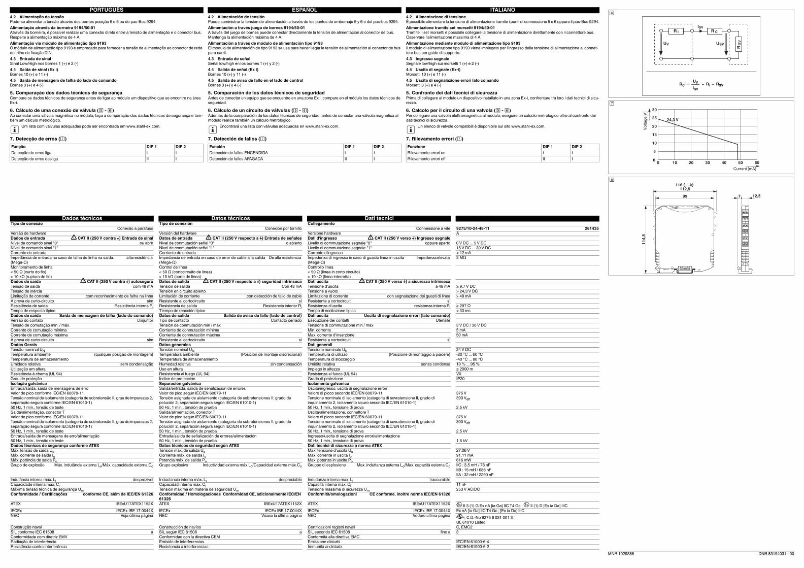
Der eigensichere Ausgangsstromkreis hat eine lineare Kennlinie mit einer Leerlaufspannung von 24 V DC und
einer Strombegrenzung bei 48 mA. ()
Der eigensichere Ausgangsstromkreis wird auf Leitungsfehler (Drahtbruch und Kurzschluss) überwacht. Die
Leitungsfehler in der Feldverdrahtung können steuerungsseitig direkt über den Signaleingang und über einen
separaten Fehlermeldeausgang den nachfolgenden Auswerteeinheiten gemeldet werden.
Zusätzlich können Fehlermeldungen über den pac-Bus 9294 auf das Einspeisemodul Typ 9193 übertragen
werden.
Auftretende Fehler werden durch eine rot blinkende LED (gemäß NE 44) angezeigt.
Eingang, Ausgänge und Versorgung sind galvanisch voneinander getrennt.
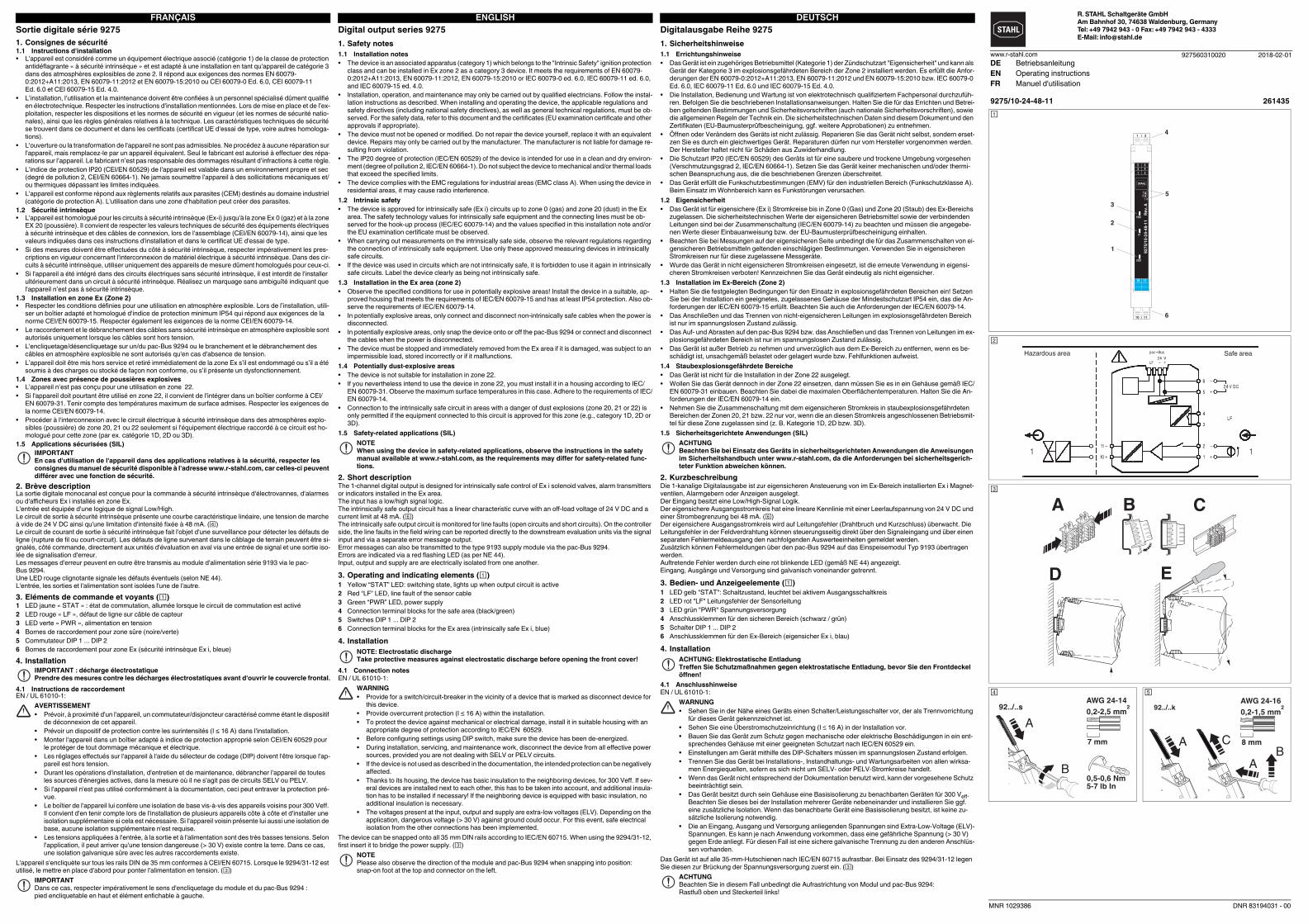
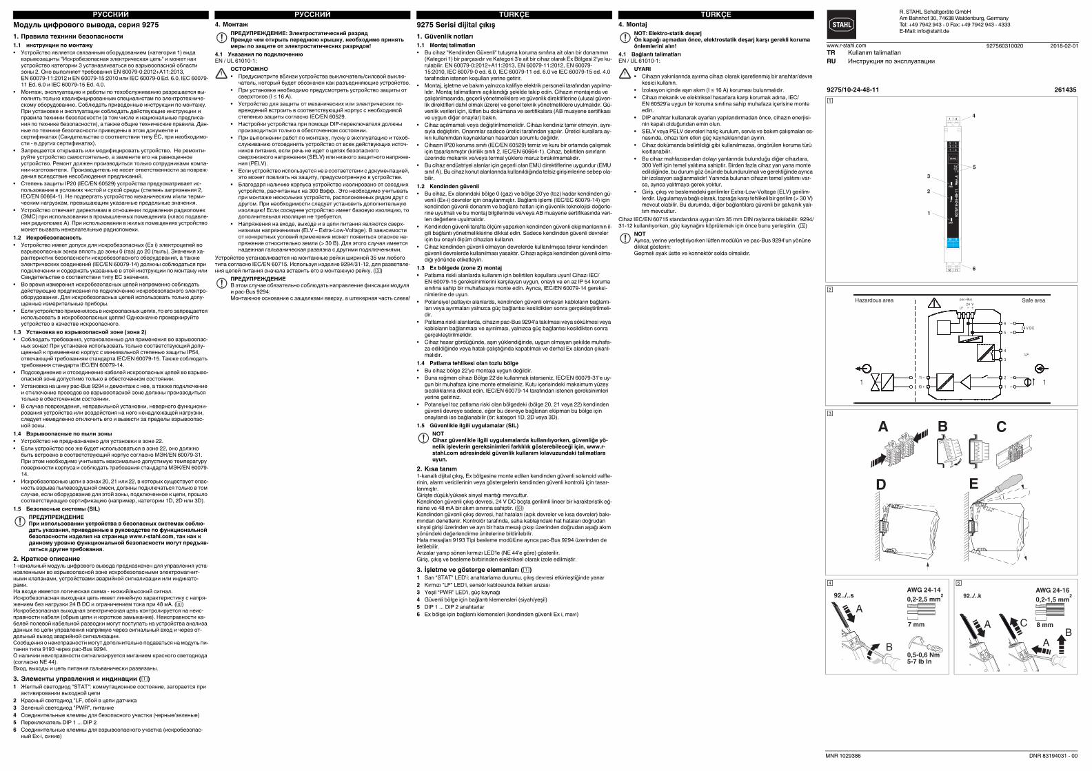
3. Bedien- und Anzeigeelemente ()
1 LED gelb "STAT": Schaltzustand, leuchtet bei aktivem Ausgangsschaltkreis
2 LED rot "LF" Leitungsfehler der Sensorleitung
3 LED grün "PWR" Spannungsversorgung
4 Anschlussklemmen für den sicheren Bereich (schwarz / grün)
5 Schalter DIP 1 ... DIP 2
6 Anschlussklemmen für den Ex-Bereich (eigensicher Ex i, blau)
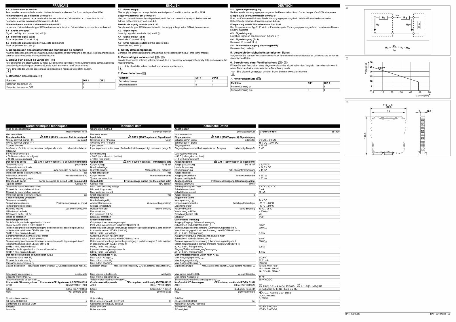
4. Installation
4.1 Anschlusshinweise
EN / UL 61010-1:
Das Gerät ist auf alle 35-mm-Hutschienen nach IEC/EN 60715 aufrastbar. Bei Einsatz des 9294/31-12 legen
Sie diesen zur Brückung der Spannungsversorgung zuerst ein. ()
ACHTUNG
Beachten Sie bei Einsatz des Geräts in sicherheitsgerichteten Anwendungen die Anweisungen
im Sicherheitshandbuch unter www.r-stahl.com, da die Anforderungen bei sicherheitsgerich-
teter Funktion abweichen können.
ACHTUNG: Elektrostatische Entladung
Treffen Sie Schutzmaßnahmen gegen elektrostatische Entladung, bevor Sie den Frontdeckel
öffnen!
WARNUNG
• Sehen Sie in der Nähe eines Geräts einen Schalter/Leistungsschalter vor, der als Trennvorrichtung
für dieses Gerät gekennzeichnet ist.
• Sehen Sie eine Überstromschutzeinrichtung (I 16 A) in der Installation vor.
• Bauen Sie das Gerät zum Schutz gegen mechanische oder elektrische Beschädigungen in ein ent-
sprechendes Gehäuse mit einer geeigneten Schutzart nach IEC/EN 60529 ein.
• Einstellungen am Gerät mithilfe des DIP-Schalters müssen im spannungslosen Zustand erfolgen.
• Trennen Sie das Gerät bei Installations-, Instandhaltungs- und Wartungsarbeiten von allen wirksa-
men Energiequellen, sofern es sich nicht um SELV- oder PELV-Stromkreise handelt.
• Wenn das Gerät nicht entsprechend der Dokumentation benutzt wird, kann der vorgesehene Schutz
beeinträchtigt sein.
• Das Gerät besitzt durch sein Gehäuse eine Basisisolierung zu benachbarten Geräten für 300 Veff.
Beachten Sie dieses bei der Installation mehrerer Geräte nebeneinander und installieren Sie ggf.
eine zusätzliche Isolation. Wenn das benachbarte Gerät eine Basisisolierung besitzt, ist keine zu-
sätzliche Isolierung notwendig.
• Die an Eingang, Ausgang und Versorgung anliegenden Spannungen sind Extra-Low-Voltage (ELV)-
Spannungen. Es kann je nach Anwendung vorkommen, dass eine gefährliche Spannung (> 30 V)
gegen Erde anliegt. Für diesen Fall ist eine sichere galvanische Trennung zu den anderen Anschlüs-
sen vorhanden.
ACHTUNG
Beachten Sie in diesem Fall unbedingt die Aufrastrichtung von Modul und pac-Bus 9294:
Rastfuß oben und Steckerteil links!
Sortie digitale série 9275
1. Consignes de sécurité
1.1 Instructions d'installation
• L'appareil est considéré comme un équipement électrique associé (catégorie 1) de la classe de protection
antidéflagrante « à sécurité intrinsèque » et est adapté à une installation en tant qu'appareil de catégorie 3
dans des atmosphères explosibles de zone 2. Il répond aux exigences des normes EN 60079-
0:2012+A11:2013, EN 60079-11:2012 et EN 60079-15:2010 ou CEI 60079-0 Ed. 6.0, CEI 60079-11
Ed. 6.0 et CEI 60079-15 Ed. 4.0.
• L’installation, l’utilisation et la maintenance doivent être confiées à un personnel spécialisé dûment qualifié
en électrotechnique. Respecter les instructions d'installation mentionnées. Lors de mise en place et de l’ex-
ploitation, respecter les dispositions et les normes de sécurité en vigueur (et les normes de sécurité natio-
nales), ainsi que les règles générales relatives à la technique. Les caractéristiques techniques de sécurité
se trouvent dans ce document et dans les certificats (certificat UE d'essai de type, voire autres homologa-
tions).
• L'ouverture ou la transformation de l'appareil ne sont pas admissibles. Ne procédez à aucune réparation sur
l'appareil, mais remplacez-le par un appareil équivalent. Seul le fabricant est autorisé à effectuer des répa-
rations sur l’appareil. Le fabricant n’est pas responsable des dommages résultant d’infractions à cette règle.
• L'indice de protection IP20 (CEI/EN 60529) de l'appareil est valable dans un environnement propre et sec
(degré de pollution 2, CEI/EN 60664-1). Ne jamais soumettre l'appareil à des sollicitations mécaniques et/
ou thermiques dépassant les limites indiquées.
• L'appareil est conforme répond aux règlements relatifs aux parasites (CEM) destinés au domaine industriel
(catégorie de protection A). L'utilisation dans une zone d'habitation peut créer des parasites.
1.2 Sécurité intrinsèque
• L'appareil est homologué pour les circuits à sécurité intrinsèque (Ex-i) jusqu'à la zone Ex 0 (gaz) et à la zone
EX 20 (poussière). Il convient de respecter les valeurs techniques de sécurité des équipements électriques
à sécurité intrinsèque et des câbles de connexion, lors de l'assemblage (CEI/EN 60079-14), ainsi que les
valeurs indiquées dans ces instructions d'installation et dans le certificat UE d'essai de type.
• Si des mesures doivent être effectuées du côté à sécurité intrinsèque, respecter impérativement les pres-
criptions en vigueur concernant l'interconnexion de matériel électrique à sécurité intrinsèque. Dans des cir-
cuits à sécurité intrinsèque, utiliser uniquement des appareils de mesure dûment homologués pour ceux-ci.
• Si l'appareil a été intégré dans des circuits électriques sans sécurité intrinsèque, il est interdit de l'installer
ultérieurement dans un circuit à sécurité intrinsèque. Réalisez un marquage sans ambiguïté indiquant que
l'appareil n’est pas à sécurité intrinsèque.
1.3 Installation en zone Ex (Zone 2)
• Respecter les conditions définies pour une utilisation en atmosphère explosible. Lors de l’installation, utili-
ser un boîtier adapté et homologué d'indice de protection minimum IP54 qui répond aux exigences de la
norme CEI/EN 60079-15. Respecter également les exigences de la norme CEI/EN 60079-14.
• Le raccordement et le débranchement des câbles sans sécurité intrinsèque en atmosphère explosible sont
autorisés uniquement lorsque les câbles sont hors tension.
• L'encliquetage/désencliquetage sur un/du pac-Bus 9294 ou le branchement et le débranchement des
câbles en atmosphère explosible ne sont autorisés qu'en cas d'absence de tension.
• L’appareil doit être mis hors service et retiré immédiatement de la zone Ex s’il est endommagé ou s’il a été
soumis à des charges ou stocké de façon non conforme, ou s’il présente un dysfonctionnement.
1.4 Zones avec présence de poussières explosives
• L’appareil n’est pas conçu pour une utilisation en zone 22.
• Si l'appareil doit pourtant être utilisé en zone 22, il convient de l'intégrer dans un boîtier conforme à CEI/
EN 60079-31. Tenir compte des températures maximum de surface admises. Respecter les exigences de
la norme CEI/EN 60079-14.
• Procéder à l'interconnexion avec le circuit électrique à sécurité intrinsèque dans des atmosphères explo-
sibles (poussière) de zone 20, 21 ou 22 seulement si l'équipement électrique raccordé à ce circuit est ho-
mologué pour cette zone (par ex. catégorie 1D, 2D ou 3D).
1.5 Applications sécurisées (SIL)
2. Brève description
La sortie digitale monocanal est conçue pour la commande à sécurité intrinsèque d'électrovannes, d'alarmes
ou d'afficheurs Ex i installés en zone Ex.
L'entrée est équipée d'une logique de signal Low/High.
Le circuit de sortie à sécurité intrinsèque présente une courbe caractéristique linéaire, une tension de marche
à vide de 24 V DC ainsi qu'une limitation d'intensité fixée à 48 mA. ()
Le circuit de courant de sortie à sécurité intrinsèque fait l'objet d'une surveillance pour détecter les défauts de
ligne (rupture de fil ou court-circuit). Les défauts de ligne survenant dans le câblage de terrain peuvent être si-
gnalés, côté commande, directement aux unités d'évaluation en aval via une entrée de signal et une sortie iso-
lée de signalisation d'erreur.
Les messages d'erreur peuvent en outre être transmis au module d'alimentation série 9193 via le pac-
Bus 9294.
Une LED rouge clignotante signale les défauts éventuels (selon NE 44).
L'entrée, les sorties et l'alimentation sont isolées l'une de l'autre.
3. Eléments de commande et voyants ()
1 LED jaune « STAT » : état de commutation, allumée lorsque le circuit de commutation est activé
2 LED rouge « LF », défaut de ligne sur câble de capteur
3 LED verte « PWR », alimentation en tension
4 Bornes de raccordement pour zone sûre (noire/verte)
5 Commutateur DIP 1 ... DIP 2
6 Bornes de raccordement pour zone Ex (sécurité intrinsèque Ex i, bleue)
4. Installation
4.1 Instructions de raccordement
EN / UL 61010-1:
L'appareil s'encliquète sur tous les rails DIN de 35 mm conformes à CEI/EN 60715. Lorsque le 9294/31-12 est
utilisé, le mettre en place d'abord pour ponter l'alimentation en tension. ()
IMPORTANT
En cas d'utilisation de l'appareil dans des applications relatives à la sécurité, respecter les
consignes du manuel de sécurité disponible à l'adresse www.r-stahl.com, car celles-ci peuvent
différer avec une fonction de sécurité.
IMPORTANT : décharge électrostatique
Prendre des mesures contre les décharges électrostatiques avant d'ouvrir le couvercle frontal.
AVERTISSEMENT
• Prévoir, à proximité d'un l'appareil, un commutateur/disjoncteur caractérisé comme étant le dispositif
de déconnexion de cet appareil.
• Prévoir un dispositif de protection contre les surintensités (I ≤ 16 A) dans l'installation.
• Monter l'appareil dans un boîtier adapté à indice de protection approprié selon CEI/EN 60529 pour
le protéger de tout dommage mécanique et électrique.
• Les réglages effectués sur l'appareil à l'aide du sélecteur de codage (DIP) doivent l'être lorsque l'ap-
pareil est hors tension.
• Durant les opérations d'installation, d'entretien et de maintenance, débrancher l'appareil de toutes
les sources d'énergies actives, dans la mesure où il ne s'agit pas de circuits SELV ou PELV.
• Si l'appareil n'est pas utilisé conformément à la documentation, ceci peut entraver la protection pré-
vue.
• Le boîtier de l'appareil lui confère une isolation de base vis-à-vis des appareils voisins pour 300 Veff.
Il convient d'en tenir compte lors de l'installation de plusieurs appareils côte à côte et d'installer une
isolation supplémentaire si cela est nécessaire. Si l'appareil voisin présente lui aussi une isolation de
base, aucune isolation supplémentaire n'est requise.
• Les tensions appliquées à l'entrée, à la sortie et à l'alimentation sont des très basses tensions. Selon
l'application, il peut arriver qu'une tension dangereuse (> 30 V) existe contre la terre. Dans ce cas,
une isolation galvanique sûre avec les autres raccordements existe.
IMPORTANT
Dans ce cas, respecter impérativement le sens d'encliquetage du module et du pac-Bus 9294 :
pied encliquetable en haut et élément enfichable à gauche.
Digital output series 9275
1. Safety notes
1.1 Installation notes
• The device is an associated apparatus (category 1) which belongs to the "Intrinsic Safety" ignition protection
class and can be installed in Ex zone 2 as a category 3 device. It meets the requirements of EN 60079-
0:2012+A11:2013, EN 60079-11:2012, EN 60079-15:2010 or IEC 60079-0 ed. 6.0, IEC 60079-11 ed. 6.0,
and IEC 60079-15 ed. 4.0.
• Installation, operation, and maintenance may only be carried out by qualified electricians. Follow the instal-
lation instructions as described. When installing and operating the device, the applicable regulations and
safety directives (including national safety directives), as well as general technical regulations, must be ob-
served. For the safety data, refer to this document and the certificates (EU examination certificate and other
approvals if appropriate).
• The device must not be opened or modified. Do not repair the device yourself, replace it with an equivalent
device. Repairs may only be carried out by the manufacturer. The manufacturer is not liable for damage re-
sulting from violation.
• The IP20 degree of protection (IEC/EN 60529) of the device is intended for use in a clean and dry environ-
ment (degree of pollution 2, IEC/EN 60664-1). Do not subject the device to mechanical and/or thermal loads
that exceed the specified limits.
• The device complies with the EMC regulations for industrial areas (EMC class A). When using the device in
residential areas, it may cause radio interference.
1.2 Intrinsic safety
• The device is approved for intrinsically safe (Ex i) circuits up to zone 0 (gas) and zone 20 (dust) in the Ex
area. The safety technology values for intrinsically safe equipment and the connecting lines must be ob-
served for the hook-up process (IEC/EC 60079-14) and the values specified in this installation note and/or
the EU examination certificate must be observed.
• When carrying out measurements on the intrinsically safe side, observe the relevant regulations regarding
the connection of intrinsically safe equipment. Use only these approved measuring devices in intrinsically
safe circuits.
• If the device was used in circuits which are not intrinsically safe, it is forbidden to use it again in intrinsically
safe circuits. Label the device clearly as being not intrinsically safe.
1.3 Installation in the Ex area (zone 2)
• Observe the specified conditions for use in potentially explosive areas! Install the device in a suitable, ap-
proved housing that meets the requirements of IEC/EN 60079-15 and has at least IP54 protection. Also ob-
serve the requirements of IEC/EN 60079-14.
• In potentially explosive areas, only connect and disconnect non-intrinsically safe cables when the power is
disconnected.
• In potentially explosive areas, only snap the device onto or off the pac-Bus 9294 or connect and disconnect
the cables when the power is disconnected.
• The device must be stopped and immediately removed from the Ex area if it is damaged, was subject to an
impermissible load, stored incorrectly or if it malfunctions.
1.4 Potentially dust-explosive areas
• The device is not suitable for installation in zone 22.
• If you nevertheless intend to use the device in zone 22, you must install it in a housing according to IEC/
EN 60079-31. Observe the maximum surface temperatures in this case. Adhere to the requirements of IEC/
EN 60079-14.
• Connection to the intrinsically safe circuit in areas with a danger of dust explosions (zone 20, 21 or 22) is
only permitted if the equipment connected to this circuit is approved for this zone (e.g., category 1D, 2D or
3D).
1.5 Safety-related applications (SIL)
2. Short description
The 1-channel digital output is designed for intrinsically safe control of Ex i solenoid valves, alarm transmitters
or indicators installed in the Ex area.
The input has a low/high signal logic.
The intrinsically safe output circuit has a linear characteristic curve with an off-load voltage of 24 V DC and a
current limit at 48 mA. ()
The intrinsically safe output circuit is monitored for line faults (open circuits and short circuits). On the controller
side, the line faults in the field wiring can be reported directly to the downstream evaluation units via the signal
input and via a separate error message output.
Error messages can also be transmitted to the type 9193 supply module via the pac-Bus 9294.
Errors are indicated via a red flashing LED (as per NE 44).
Input, output and supply are are electrically isolated from one another.
3. Operating and indicating elements ()
1 Yellow “STAT” LED: switching state, lights up when output circuit is active
2 Red “LF” LED, line fault of the sensor cable
3 Green “PWR” LED, power supply
4 Connection terminal blocks for the safe area (black/green)
5 Switches DIP 1 ... DIP 2
6 Connection terminal blocks for the Ex area (intrinsically safe Ex i, blue)
4. Installation
4.1 Connection notes
EN / UL 61010-1:
The device can be snapped onto all 35 mm DIN rails according to IEC/EN 60715. When using the 9294/31-12,
first insert it to bridge the power supply. ()
NOTE
When using the device in safety-related applications, observe the instructions in the safety
manual available at www.r-stahl.com, as the requirements may differ for safety-related func-
tions.
NOTE: Electrostatic discharge
Take protective measures against electrostatic discharge before opening the front cover!
WARNING
• Provide for a switch/circuit-breaker in the vicinity of a device that is marked as disconnect device for
this device.
• Provide overcurrent protection (I ≤ 16 A) within the installation.
• To protect the device against mechanical or electrical damage, install it in suitable housing with an
appropriate degree of protection according to IEC/EN 60529.
• Before configuring settings using DIP switch, make sure the device has been de-energized.
• During installation, servicing, and maintenance work, disconnect the device from all effective power
sources, provided you are not dealing with SELV or PELV circuits.
• If the device is not used as described in the documentation, the intended protection can be negatively
affected.
• Thanks to its housing, the device has basic insulation to the neighboring devices, for 300 Veff. If sev-
eral devices are installed next to each other, this has to be taken into account, and additional insula-
tion has to be installed if necessary! If the neighboring device is equipped with basic insulation, no
additional insulation is necessary.
• The voltages present at the input, output and supply are extra-low voltages (ELV). Depending on the
application, dangerous voltage (> 30 V) against ground could occur. For this event, safe electrical
isolation from the other connections has been implemented.
NOTE
Please also observe the direction of the module and pac-Bus 9294 when snapping into position:
snap-on foot at the top and connector on the left.
DEUTSCHENGLISHFRANÇAISR. STAHL Schaltgeräte GmbH
Am Bahnhof 30, 74638 Waldenburg, Germany
Tel: +49 7942 943 - 0 Fax: +49 7942 943 - 4333
E-Mail: [email protected]
927560310020www.r-stahl.com
9275/10-24-48-11 261435
1
2
3
5
4
6
PWR
LF
STAT
5 6
1 2
10 11
92
75
/10
-24
-48
-11
R
ev.
A
12
I II
1
10
|
|
2
11
3 4
Hazardous area Safe area
A B C
D E
0,5-0,6 Nm5-7 lb In
7 mm
AWG 24-14
0,2-2,5 mm292../..s
A
B
92../..k
DE Betriebsanleitung
EN Operating instructions
FR Manuel d'utilisation
2018-02-01
MNR 1029386 DNR 83194031 - 00
Caractéristiques techniques Technical data Technische Daten
Type de raccordement Connection method Anschlussart
Raccordement vissé Screw connection Schraubanschluss 9275/10-24-48-11 261435
Version matériel Hardware version Hardwareversion A
Données d'entrée CAT II (250 V contre ) Entrée de signal Input data CAT II (250 V against ) Signal input Eingangsdaten CAT II (250 V gegen ) Signaleingang
Niveau commut. signal « 0 » ou ouvert Switching level "0" signal Open Schaltpegel "0"-Signal oder offen 0 V DC ... 5 V DC
Niveau commut. signal « 1 » Switching level "1" signal Schaltpegel "1"-Signal 15 V DC ... 30 V DC
Courant d'entrée Input current Eingangsstrom < 12 mA
Impédance d'entrée en cas de défaut de ligne à la sortie à haute impédance
(Mega-Ω)
Input impedance in the event of a line fault at the outputHigh resistance (Mega Ω) Eingangsimpedanz bei Leitungsfehler am Ausgang hochohmig (Mega-Ω) 3 MΩ
Surveillance de la ligne
< 50 Ω (court-circuit de la ligne)
> 10 kΩ (rupture de ligne)
Line monitoring
< 50 Ω (short circuit on the line)
> 10 kΩ (line break)
Leitungsüberwachung
< 50 Ω (Leitungskurzschluss)
> 10 kΩ (Leitungsbruch)
Données de sortie CAT II (250 V contre ) à sécurité intrinsèque Output data CAT II (250 V against ) Intrinsically safe Ausgangsdaten CAT II (250 V gegen ) eigensicher
Tension de sortie pour 48 mA Output voltage At 48 mA Ausgangsspannung bei 48 mA ≥ 9,7 V DC
Tension de marche à vide Non-load voltage Leerlaufspannung > 24,3 V DC
Limitation du courant avec détection de défaut de ligne Current limitation With cable error detection Strombegrenzung mit Leitungsfehlerkennung > 48 mA
Protection contre les courts-circuits oui Short-circuit-proof yes Kurzschlussfest ja
Résistance de sortie Résistance interne Ri Output resistor Internal resistance Ri Ausgangswiderstand Innenwiderstand Ri ≥ 297 Ω
Temps d'amorçage typique Typical response time Ansprechzeit typisch < 30 ms
Données de sortie Sortie de signal de défaut (côté commande) Output data Error message output (on the control side) Ausgangsdaten Fehlermeldeausgang (steuerungsseitig)
Type de contact Contact NF Contact type N/C contact Kontaktausführung Öffner
Tension de commutation max./min. Max. / min. switching voltage Schaltspannung min / max 3 V DC / 30 V DC
Courant de commutation minimal Min. switching current Schaltstrom minimal 5 mA
Courant de commutation maximal Max. switching current Schaltstrom maximal 50 mA
Protection contre les courts-circuits oui Short-circuit-proof yes Kurzschlussfest ja
Caractéristiques générales General data Allgemeine Daten
Tension nominale UN Nominal voltage UN Nennspannung UN 24 V DC
Température ambiante (Position de montage au choix) Ambient temperature (Any mounting position) Umgebungstemperatur (beliebige Einbaulage) -20 °C ... 60 °C
Température de stockage Storage temperature Lagertemperatur -40 °C ... 80 °C
Humidité relative pas de condensation Relative humidity non-condensing Relative Feuchte keine Betauung 10 % ... 95 %
Utilisation en altitude Use at altitude Verwendung in Höhe ≤ 2000 m
Résistance au feu (UL 94) Fire resistance (UL 94) Brandfestigkeit (UL 94) V0
Indice de protection Degree of protection Schutzart IP20
Isolation galvanique Electrical isolation Galvanische Trennung
Sortie/entrée, sortie de signalisation d'erreur
Valeur de crête selon CEI/EN 60079-11
Tension assignée d'isolement (catégorie de surtension II, degré de pollution 2,
isolement sécurisé selon CEI/EN 61010-1)
50 Hz, 1 min., tension d'essai
Output/input, error message output
Peak value in accordance with IEC/EN 60079-11
Rated insulation voltage (overvoltage category II; pollution degree 2, safe isolation
in accordance with IEC/EN 61010-1)
50 Hz, 1 min., test voltage
Ausgang/Eingang, Fehlermeldeausgang
Scheitelwert nach IEC/EN 60079-11
Bemessungsisolationsspannung (Überspannungskategorie II,
Verschmutzungsgrad 2, sichere Trennung nach IEC/EN 61010-1)
50 Hz, 1 min., Prüfspannung
375 V
300 Veff
2,5 kV
Sortie/alimentation, connecteur sur profilé
Valeur de crête selon CEI/EN 60079-11
Tension assignée d'isolement (catégorie de surtension II, degré de pollution 2,
isolement sécurisé selon CEI/EN 61010-1)
50 Hz, 1 min., tension d'essai
Output/supply, DIN rail connector
Peak value in accordance with IEC/EN 60079-11
Rated insulation voltage (overvoltage category II; pollution degree 2, safe isolation
in accordance with IEC/EN 61010-1)
50 Hz, 1 min., test voltage
Ausgang/Versorgung, Tragschienen-Busverbinder
Scheitelwert nach IEC/EN 60079-11
Bemessungsisolationsspannung (Überspannungskategorie II,
Verschmutzungsgrad 2, sichere Trennung nach IEC/EN 61010-1)
50 Hz, 1 min., Prüfspannung
375 V
300 Veff
2,5 kV
Entrée/sortie de signalisation d'erreur/alimentation
50 Hz, 1 min., tension d'essai
Input/error message output/supply
50 Hz, 1 min., test voltage
Eingang/Fehlermeldeausgang/Versorgung
50 Hz, 1 min., Prüfspannung 1,5 kV
Données relatives à la sécurité selon ATEX Safety data as per ATEX Sicherheitstechnische Daten nach ATEX
Tension de sortie max. Uo Max. output voltage Uo Max. Ausgangsspannung Uo 27,06 V
Courant de sortie max. Io Max. output current Io Max. Ausgangsstrom Io 91,11 mA
Puissance de sortie max. Po Max. output power Po Max. Ausgangsleistung Po 616 mW
Classe d'explosion Inductance extérieure max. Lo/Capacité extérieure max. Co Explosion group Max. external inductivity Lo/Max. external capacitance Co Explosionsgruppe Max. äußere Induktivität Lo/Max. äußere Kapazität Co IIC : 3,5 mH / 78 nF
IIB : 15 mH / 686 nF
IIA : 32 mH / 2290 nF
Inductance interne max. Li négligeable Max. internal inductance Li negligible Max. innere Induktivität Li vernachlässigbar
Capacité interne max. Ci Max. internal capacitance Ci Max. innere Kapazität Ci 11 nF
Tension maximale de sécurité Um Safety-related maximum voltage Um Sicherheitstechnische Maximalspannung Um 253 V AC/DC
Conformité / Homologations Conforme à CE, également à CEI/EN 61326 Conformance/Approvals CE-compliant, additionally IEC/EN 61326 Konformität / Zulassungen CE-konform, zusätzlich IEC/EN 61326
ATEX IBExU17ATEX1152X ATEX IBExU17ATEX1152X ATEX IBExU17ATEX1152X II 3 (1) G Ex nA [ia Ga] IIC T4 Gc ; II (1) D [Ex ia Da] IIIC
IECEx IECEx IBE 17.0044X IECEx IECEx IBE 17.0044X IECEx IECEx IBE 17.0044X Ex nA [ia Ga] IIC T4 Gc ; [Ex ia Da] IIIC
NEC Voir dernière page NEC See final page NEC Siehe letzte Seite , C.D.-No 9275 6 031 001 3
UL 61010 Listed
Constructions navales Shipbuilding Schiffbau C, EMC2
SIL selon CEI 61508 à SIL in accordance with IEC 61508 to SIL gemäß IEC 61508 bis 3
Conformité à la directive CEM Conformance with EMC directive Konformität zur EMV-Richtlinie
Emission Noise emission Störabstrahlung IEC/EN 61000-6-4
Immunité Noise immunity Störfestigkeit IEC/EN 61000-6-2
4.2 Spannungsversorgung
Sie können die Versorgungsspannung über die Klemmstellen 5 und 6 oder den pac-Bus 9294 einspeisen.
Einspeisung über Klemmenset 9194/50-01
Über das Klemmenset können Sie die Versorgungsspannung direkt mit dem Busverbinder verbinden.
Halten Sie die maximale Einspeisung von 4 A ein.
Einspeisung mittels Einspeisemodul Typ 9193
Das Einspeisemodul Typ 9193 wird zur Einspeisung der Versorgungspannung auf den Hutschienen-Busver-
binder eingesetzt.
4.3 Signaleingang
Low/High-Signal an den Klemmen 1 (+) und 2 (-)
4.4 Signalausgang (Ex i)
Klemmen 10 (+) und 11 (-)
4.5 Fehlermeldeausgang steuerungsseitig
Klemmen 3 (+) und 4 (-)
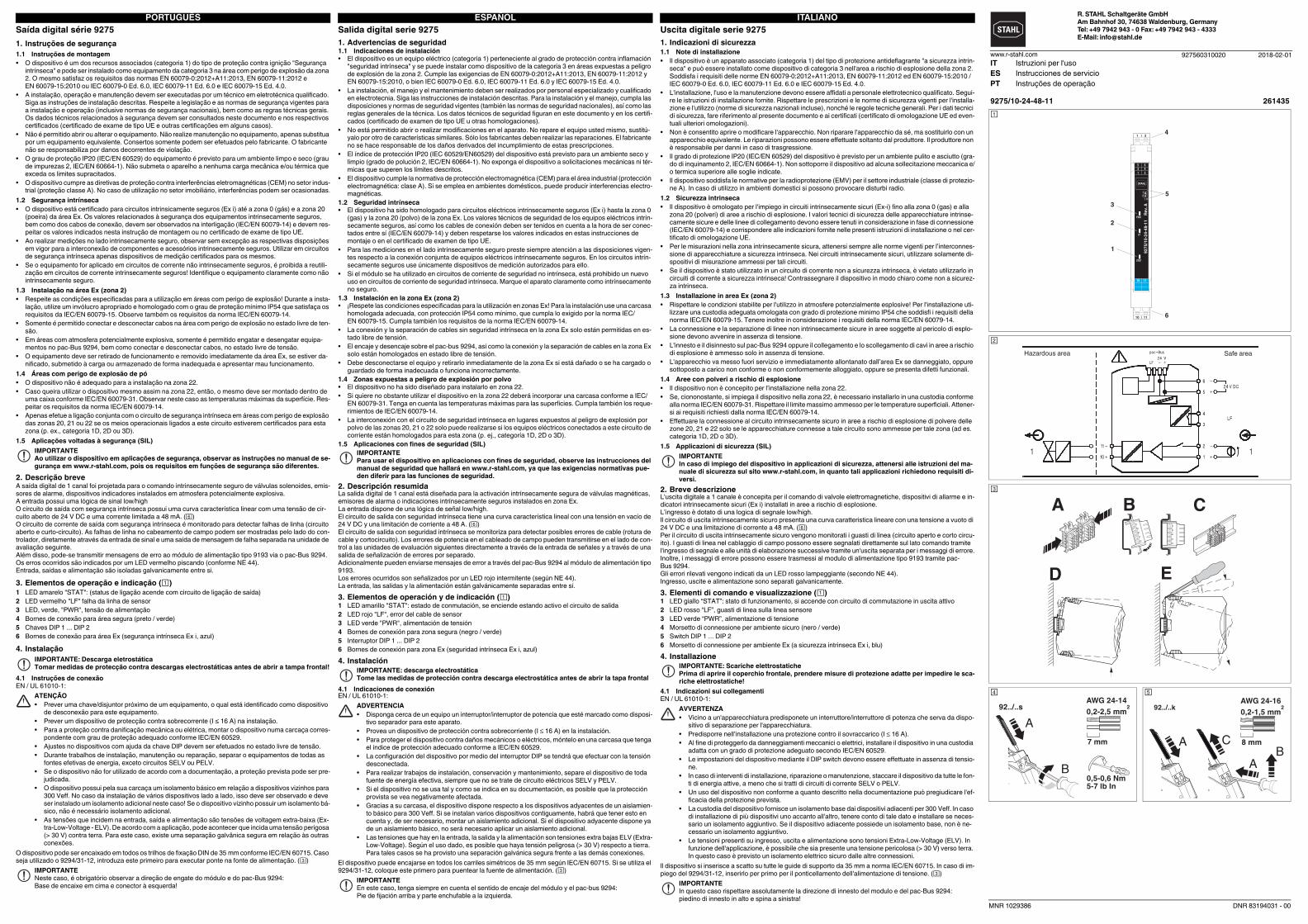
5. Vergleich der sicherheitstechnischen Daten
Vergleichen Sie vor dem Anschalten eines im Ex i-Bereich befindlichen Gerätes an das Modul die sicherheit-
stechnischen Daten.
6. Berechnung einer Ventilschaltung ( - )
Führen Sie zum Anschalten eines Magnetventils an das Modul neben dem Vergleich der sicherheitstechni-
schen Daten auch eine messtechnische Berechnung durch.
7. Fehlererkennung ()
Eine Liste mit geeigneten Ventilen finden Sie unter www.stahl-ex.com.
Funktion DIP 1 DIP 2
Fehlererkennung an I I
Fehlererkennung aus II I
4.2 Alimentation en tension
Il est possible de raccorder la tension d'alimentation via les bornes 5 et 6, ou via le pac-Bus 9294.
Alimentation via jeu de bornes 9194/50-01
Le jeu de bornes permet de raccorder directement la tension d'alimentation au connecteur de bus.
Respecter la valeur maximum d'alimentation, de 4 A.
Alimentation via module d'alimentation série 9193
Le module d'alimentation de type 9193 sert à amener la tension d'alimentation au connecteur sur bus rail.
4.3 Entrée de signal
Signal Low/High aux bornes 1 (+) et 2 (-)
4.4 Sortie de signal (Ex i)
Blocs de jonction 10 (+) et 11 (-)
4.5 Sortie de signalisation d'erreur, côté commande
Blocs de jonction 3 (+) et 4 (-)
5. Comparaison des caractéristiques techniques de sécurité
Avant de procéder à la connexion au module d'un appareil se trouvant dans la zone Ex i, il est impératif de com-
parer les caractéristiques techniques de sécurité.
6. Calcul d'un circuit de vanne ( - )
Pour connecter une électrovanne au module, il convient de procéder non seulement à une comparaison des
caractéristiques techniques de sécurité, mais aussi à un calcul relatif aux mesures.
7. Détection des erreurs ()
Une liste des vannes appropriées est disponible à l'adresse www.stahl-ex.com.
Fonction DIP 1 DIP 2
Détection des erreurs ON I I
Détection des erreurs OFF II I
4.2 Power supply
The supply voltage can be supplied via terminal points 5 and 6 or via the pac-Bus 9294.
Supply via terminal set 9194/50-01
You can connect the supply voltage directly with the bus connector by way of the terminal set.
Adhere to the maximum feed-in of 4 A.
Feed-in via supply module type 9193
Supply module type 9193 is used to feed in the supply voltage to the DIN rail bus connector.
4.3 Signal input
Low/high signal at terminals 1 (+) and 2 (-).
4.4 Signal output (Ex-i)
Terminals 10 (+) and 11 (-)
4.5 Error message output on the control side
Terminals 3 (+) and 4 (-)
5. Safety data comparison
Compare the safety data before connecting a device located in the Ex-i area to the module.
6. Calculating a valve circuit ( - )
In order to connect a solenoid valve to the module, it is necessary to compare the safety data, and calculate the
measurements.
7. Error detection ()
A list of suitable valves can be found at www.stahl-ex.com.
Function DIP 1 DIP 2
Error detection on I I
Error detection off II I
DEUTSCHENGLISHFRANÇAIS
DNR 83194031 - 00
SVIiR
SVU
CR
SV
R
VU
UVRC = –––– – Ri – RSV
ISV
0
10
5
15
20
25
30
0 302010 40 50 60
24,3 V
Current [mA]
Vo
lta
ge
[V]
99
112,5
12,57
11
4,5
116 (...-k)
MNR 1029386
Uscita digitale serie 9275
1. Indicazioni di sicurezza
1.1 Note di installazione
• Il dispositivo è un apparato associato (categoria 1) del tipo di protezione antideflagrante "a sicurezza intrin-
seca" e può essere installato come dispositivo di categoria 3 nell'area a rischio di esplosione della zona 2.
Soddisfa i requisiti delle norme EN 60079-0:2012+A11:2013, EN 60079-11:2012 ed EN 60079-15:2010 /
IEC 60079-0 Ed. 6.0, IEC 60079-11 Ed. 6.0 e IEC 60079-15 Ed. 4.0.
• L'installazione, l'uso e la manutenzione devono essere affidati a personale elettrotecnico qualificato. Segui-
re le istruzioni di installazione fornite. Rispettare le prescrizioni e le norme di sicurezza vigenti per l'installa-
zione e l'utilizzo (norme di sicurezza nazionali incluse), nonché le regole tecniche generali. Per i dati tecnici
di sicurezza, fare riferimento al presente documento e ai certificati (certificato di omologazione UE ed even-
tuali ulteriori omologazioni).
• Non è consentito aprire o modificare l'apparecchio. Non riparare l'apparecchio da sé, ma sostituirlo con un
apparecchio equivalente. Le riparazioni possono essere effettuate soltanto dal produttore. Il produttore non
è responsabile per danni in caso di trasgressione.
• Il grado di protezione IP20 (IEC/EN 60529) del dispositivo è previsto per un ambiente pulito e asciutto (gra-
do di inquinamento 2, IEC/EN 60664-1). Non sottoporre il dispositivo ad alcuna sollecitazione meccanica e/
o termica superiore alle soglie indicate.
• Il dispositivo soddisfa le normative per la radioprotezione (EMV) per il settore industriale (classe di protezio-
ne A). In caso di utilizzo in ambienti domestici si possono provocare disturbi radio.
1.2 Sicurezza intrinseca
• Il dispositivo è omologato per l'impiego in circuiti intrinsecamente sicuri (Ex-i) fino alla zona 0 (gas) e alla
zona 20 (polveri) di aree a rischio di esplosione. I valori tecnici di sicurezza delle apparecchiature intrinse-
camente sicure e delle linee di collegamento devono essere tenuti in considerazione in fase di connessione
(IEC/EN 60079-14) e corrispondere alle indicazioni fornite nelle presenti istruzioni di installazione o nel cer-
tificato di omologazione UE.
• Per le misurazioni nella zona intrinsecamente sicura, attenersi sempre alle norme vigenti per l’interconnes-
sione di apparecchiature a sicurezza intrinseca. Nei circuiti intrinsecamente sicuri, utilizzare solamente di-
spositivi di misurazione ammessi per tali circuiti.
• Se il dispositivo è stato utilizzato in un circuito di corrente non a sicurezza intrinseca, è vietato utilizzarlo in
circuiti di corrente a sicurezza intrinseca! Contrassegnare il dispositivo in modo chiaro come non a sicurez-
za intrinseca.
1.3 Installazione in area Ex (zona 2)
• Rispettare le condizioni stabilite per l'utilizzo in atmosfere potenzialmente esplosive! Per l'installazione uti-
lizzare una custodia adeguata omologata con grado di protezione minimo IP54 che soddisfi i requisiti della
norma IEC/EN 60079-15. Tenere inoltre in considerazione i requisiti della norma IEC/EN 60079-14.
• La connessione e la separazione di linee non intrinsecamente sicure in aree soggette al pericolo di esplo-
sione devono avvenire in assenza di tensione.
• L'innesto e il disinnesto sul pac-Bus 9294 oppure il collegamento e lo scollegamento di cavi in aree a rischio
di esplosione è ammesso solo in assenza di tensione.
• L'apparecchio va messo fuori servizio e immediatamente allontanato dall’area Ex se danneggiato, oppure
sottoposto a carico non conforme o non conformemente alloggiato, oppure se presenta difetti funzionali.
1.4 Aree con polveri a rischio di esplosione
• Il dispositivo non è concepito per l’installazione nella zona 22.
• Se, ciononostante, si impiega il dispositivo nella zona 22, è necessario installarlo in una custodia conforme
alla norma IEC/EN 60079-31. Rispettare il limite massimo ammesso per le temperature superficiali. Attener-
si ai requisiti richiesti dalla norma IEC/EN 60079-14.
• Effettuare la connessione al circuito intrinsecamente sicuro in aree a rischio di esplosione di polvere delle
zone 20, 21 e 22 solo se le apparecchiature connesse a tale circuito sono ammesse per tale zona (ad es.
categoria 1D, 2D o 3D).
1.5 Applicazioni di sicurezza (SIL)
2. Breve descrizione
L'uscita digitale a 1 canale è concepita per il comando di valvole elettromagnetiche, dispositivi di allarme e in-
dicatori intrinsecamente sicuri (Ex i) installati in aree a rischio di esplosione.
L’ingresso è dotato di una logica di segnale low/high.
Il circuito di uscita intrinsecamente sicuro presenta una curva caratteristica lineare con una tensione a vuoto di
24 V DC e una limitazione di corrente a 48 mA. ()
Per il circuito di uscita intrinsecamente sicuro vengono monitorati i guasti di linea (circuito aperto e corto circu-
ito). I guasti di linea nel cablaggio di campo possono essere segnalati direttamente sul lato comando tramite
l'ingresso di segnale e alle unità di elaborazione successive tramite un'uscita separata per i messaggi di errore.
Inoltre, i messaggi di errore possono essere trasmessi al modulo di alimentazione tipo 9193 tramite pac-
Bus 9294.
Gli errori rilevati vengono indicati da un LED rosso lampeggiante (secondo NE 44).
Ingresso, uscite e alimentazione sono separati galvanicamente.
3. Elementi di comando e visualizzazione ()
1 LED giallo “STAT”: stato di funzionamento, si accende con circuito di commutazione in uscita attivo
2 LED rosso “LF”, guasti di linea sulla linea sensore
3 LED verde “PWR”, alimentazione di tensione
4 Morsetto di connessione per ambiente sicuro (nero / verde)
5 Switch DIP 1 ... DIP 2
6 Morsetto di connessione per ambiente Ex (a sicurezza intrinseca Ex i, blu)
4. Installazione
4.1 Indicazioni sui collegamenti
EN / UL 61010-1:
Il dispositivo si inserisce a scatto su tutte le guide di supporto da 35 mm a norma IEC/EN 60715. In caso di im-
piego del 9294/31-12, inserirlo per primo per il ponticellamento dell'alimentazione di tensione. ()
IMPORTANTE
In caso di impiego del dispositivo in applicazioni di sicurezza, attenersi alle istruzioni del ma-
nuale di sicurezza sul sito www.r-stahl.com, in quanto tali applicazioni richiedono requisiti di-
versi.
IMPORTANTE: Scariche elettrostatiche
Prima di aprire il coperchio frontale, prendere misure di protezione adatte per impedire le sca-
riche elettrostatiche!
AVVERTENZA
• Vicino a un'apparecchiatura predisponete un interruttore/interruttore di potenza che serva da dispo-
sitivo di separazione per l'apparecchiatura.
• Predisporre nell’installazione una protezione contro il sovraccarico (I 16 A).
• Al fine di proteggerlo da danneggiamenti meccanici o elettrici, installare il dispositivo in una custodia
adatta con un grado di protezione adeguato secondo IEC/EN 60529.
• Le impostazioni del dispositivo mediante il DIP switch devono essere effettuate in assenza di tensio-
ne.
• In caso di interventi di installazione, riparazione o manutenzione, staccare il dispositivo da tutte le fon-
ti di energia attive, a meno che si tratti di circuiti di corrente SELV o PELV.
• Un uso del dispositivo non conforme a quanto descritto nella documentazione può pregiudicare l'ef-
ficacia della protezione prevista.
• La custodia del dispositivo fornisce un isolamento base dai dispositivi adiacenti per 300 Veff. In caso
di installazione di più dispositivi uno accanto all'altro, tenere conto di tale dato e installare se neces-
sario un isolamento aggiuntivo. Se il dispositivo adiacente possiede un isolamento base, non è ne-
cessario un isolamento aggiuntivo.
• Le tensioni presenti su ingresso, uscita e alimentazione sono tensioni Extra-Low-Voltage (ELV). In
funzione dell'applicazione, è possibile che sia presente una tensione pericolosa (> 30 V) verso terra.
In questo caso è previsto un isolamento elettrico sicuro dalle altre connessioni.
IMPORTANTE
In questo caso rispettare assolutamente la direzione di innesto del modulo e del pac-Bus 9294:
piedino di innesto in alto e spina a sinistra!
Saída digital série 9275
1. Instruções de segurança
1.1 Instruções de montagem
• O dispositivo é um dos recursos associados (categoria 1) do tipo de proteção contra ignição "Segurança
intrínseca" e pode ser instalado como equipamento da categoria 3 na área com perigo de explosão da zona
2. O mesmo satisfaz os requisitos das normas EN 60079-0:2012+A11:2013, EN 60079-11:2012 e
EN 60079-15:2010 ou IEC 60079-0 Ed. 6.0, IEC 60079-11 Ed. 6.0 e IEC 60079-15 Ed. 4.0.
• A instalação, operação e manutenção devem ser executadas por um técnico em eletrotécnica qualificado.
Siga as instruções de instalação descritas. Respeite a legislação e as normas de segurança vigentes para
a instalação e operação (inclusive normas de segurança nacionais), bem como as regras técnicas gerais.
Os dados técnicos relacionados à segurança devem ser consultados neste documento e nos respectivos
certificados (certificado de exame de tipo UE e outras certificações em alguns casos).
• Não é permitido abrir ou alterar o equipamento. Não realize manutenção no equipamento, apenas substitua
por um equipamento equivalente. Consertos somente podem ser efetuados pelo fabricante. O fabricante
não se responsabiliza por danos decorrentes de violação.
• O grau de proteção IP20 (IEC/EN 60529) do equipamento é previsto para um ambiente limpo e seco (grau
de impurezas 2, IEC/EN 60664-1). Não submeta o aparelho a nenhuma carga mecânica e/ou térmica que
exceda os limites supracitados.
• O dispositivo cumpre as diretivas de proteção contra interferências eletromagnéticas (CEM) no setor indus-
trial (proteção classe A). No caso de utilização no setor imobiliário, interferências podem ser ocasionadas.
1.2 Segurança intrínseca
• O dispositivo está certificado para circuitos intrinsicamente seguros (Ex i) até a zona 0 (gás) e a zona 20
(poeira) da área Ex. Os valores relacionados à segurança dos equipamentos intrinsecamente seguros,
bem como dos cabos de conexão, devem ser observados na interligação (IEC/EN 60079-14) e devem res-
peitar os valores indicados nesta instrução de montagem ou no certificado de exame de tipo UE.
• Ao realizar medições no lado intrinsecamente seguro, observar sem excepção as respectivas disposições
em vigor para a interconexão de componentes e acessórios intrinsecamente seguros. Utilizar em circuitos
de segurança intrínseca apenas dispositivos de medição certificados para os mesmos.
• Se o equipamento for aplicado em circuitos de corrente não intrinsecamente seguros, é proibida a reutili-
zação em circuitos de corrente intrinsecamente seguros! Identifique o equipamento claramente como não
intrinsecamente seguro.
1.3 Instalação na área Ex (zona 2)
• Respeite as condições especificadas para a utilização em áreas com perigo de explosão! Durante a insta-
lação, utilize um invólucro apropriado e homologado com o grau de proteção mínimo IP54 que satisfaça os
requisitos da IEC/EN 60079-15. Observe também os requisitos da norma IEC/EN 60079-14.
• Somente é permitido conectar e desconectar cabos na área com perigo de explosão no estado livre de ten-
são.
• Em áreas com atmosfera potencialmente explosiva, somente é permitido engatar e desengatar equipa-
mentos no pac-Bus 9294, bem como conectar e desconectar cabos, no estado livre de tensão.
• O equipamento deve ser retirado de funcionamento e removido imediatamente da área Ex, se estiver da-
nificado, submetido à carga ou armazenado de forma inadequada e apresentar mau funcionamento.
1.4 Áreas com perigo de explosão de pó
• O dispositivo não é adequado para a instalação na zona 22.
• Caso queira utilizar o dispositivo mesmo assim na zona 22, então, o mesmo deve ser montado dentro de
uma caixa conforme IEC/EN 60079-31. Observar neste caso as temperaturas máximas da superfície. Res-
peitar os requisitos da norma IEC/EN 60079-14.
• Apenas efetue a ligação conjunta com o circuito de segurança intrínseca em áreas com perigo de explosão
das zonas 20, 21 ou 22 se os meios operacionais ligados a este circuito estiverem certificados para esta
zona (p. ex., categoria 1D, 2D ou 3D).
1.5 Aplicações voltadas à segurança (SIL)
2. Descrição breve
A saída digital de 1 canal foi projetada para o comando intrinsecamente seguro de válvulas solenoides, emis-
sores de alarme, dispositivos indicadores instalados em atmosfera potencialmente explosiva.
A entrada possui uma lógica de sinal low/high
O circuito de saída com segurança intrínseca possui uma curva característica linear com uma tensão de cir-
cuito aberto de 24 V DC e uma corrente limitada a 48 mA. ()
O circuito de corrente de saída com segurança intrínseca é monitorado para detectar falhas de linha (circuito
aberto e curto-circuito). As falhas de linha no cabeamento de campo podem ser mostradas pelo lado do con-
trolador, diretamente através da entrada de sinal e uma saída de mensagem de falha separada na unidade de
avaliação seguinte.
Além disso, pode-se transmitir mensagens de erro ao módulo de alimentação tipo 9193 via o pac-Bus 9294.
Os erros ocorridos são indicados por um LED vermelho piscando (conforme NE 44).
Entrada, saídas e alimentação são isoladas galvanicamente entre si.
3. Elementos de operação e indicação ()
1 LED amarelo "STAT": (status de ligação acende com circuito de ligação de saída)
2 LED vermelho "LF" falha da linha de sensor
3 LED, verde, "PWR", tensão de alimentação
4 Bornes de conexão para área segura (preto / verde)
5 Chaves DIP 1 ... DIP 2
6 Bornes de conexão para área Ex (segurança intrínseca Ex i, azul)
4. Instalação
4.1 Instruções de conexão
EN / UL 61010-1:
O dispositivo pode ser encaixado em todos os trilhos de fixação DIN de 35 mm conforme IEC/EN 60715. Caso
seja utilizado o 9294/31-12, introduza este primeiro para executar ponte na fonte de alimentação. ()
IMPORTANTE
Ao utilizar o dispositivo em aplicações de segurança, observar as instruções no manual de se-
gurança em www.r-stahl.com, pois os requisitos em funções de segurança são diferentes.
IMPORTANTE: Descarga eletrostática
Tomar medidas de protecção contra descargas electrostáticas antes de abrir a tampa frontal!
ATENÇÃO
• Prever uma chave/disjuntor próximo de um equipamento, o qual está identificado como dispositivo
de desconexão para este equipamento.
• Prever um dispositivo de protecção contra sobrecorrente (I ≤ 16 A) na instalação.
• Para a proteção contra danificação mecânica ou elétrica, montar o dispositivo numa carcaça corres-
pondente com grau de proteção adequado conforme IEC/EN 60529.
• Ajustes no dispositivos com ajuda da chave DIP devem ser efetuados no estado livre de tensão.
• Durante trabalhos de instalação, manutenção ou reparação, separar o equipamentos de todas as
fontes efetivas de energia, exceto circuitos SELV ou PELV.
• Se o dispositivo não for utilizado de acordo com a documentação, a proteção prevista pode ser pre-
judicada.
• O dispositivo possui pela sua carcaça um isolamento básico em relação a dispositivos vizinhos para
300 Veff. No caso da instalação de vários dispositivos lado a lado, isso deve ser observado e deve
ser instalado um isolamento adicional neste caso! Se o dispositivo vizinho possuir um isolamento bá-
sico, não é necessário isolamento adicional.
• As tensões que incidem na entrada, saída e alimentação são tensões de voltagem extra-baixa (Ex-
tra-Low-Voltage - ELV). De acordo com a aplicação, pode acontecer que incida uma tensão perigosa
(> 30 V) contra terra. Para este caso, existe uma separação galvânica segura em relação às outras
conexões.
IMPORTANTE
Neste caso, é obrigatório observar a direção de engate do módulo e do pac-Bus 9294:
Base de encaixe em cima e conector à esquerda!
Salida digital serie 9275
1. Advertencias de seguridad
1.1 Indicaciones de instalación
• El dispositivo es un equipo eléctrico (categoría 1) perteneciente al grado de protección contra inflamación
"seguridad intrínseca" y se puede instalar como dispositivo de la categoría 3 en áreas expuestas a peligro
de explosión de la zona 2. Cumple las exigencias de EN 60079-0:2012+A11:2013, EN 60079-11:2012 y
EN 60079-15:2010, o bien IEC 60079-0 Ed. 6.0, IEC 60079-11 Ed. 6.0 y IEC 60079-15 Ed. 4.0.
• La instalación, el manejo y el mantenimiento deben ser realizados por personal especializado y cualificado
en electrotecnia. Siga las instrucciones de instalación descritas. Para la instalación y el manejo, cumpla las
disposiciones y normas de seguridad vigentes (también las normas de seguridad nacionales), así como las
reglas generales de la técnica. Los datos técnicos de seguridad figuran en este documento y en los certifi-
cados (certificado de examen de tipo UE u otras homologaciones).
• No está permitido abrir o realizar modificaciones en el aparato. No repare el equipo usted mismo, sustitú-
yalo por otro de características similares. Sólo los fabricantes deben realizar las reparaciones. El fabricante
no se hace responsable de los daños derivados del incumplimiento de estas prescripciones.
• El índice de protección IP20 (IEC 60529/EN60529) del dispositivo está previsto para un ambiente seco y
limpio (grado de polución 2, IEC/EN 60664-1). No exponga el dispositivo a solicitaciones mecánicas ni tér-
micas que superen los límites descritos.
• El dispositivo cumple la normativa de protección electromagnética (CEM) para el área industrial (protección
electromagnética: clase A). Si se emplea en ambientes domésticos, puede producir interferencias electro-
magnéticas.
1.2 Seguridad intrínseca
• El dispositivo ha sido homologado para circuitos eléctricos intrínsecamente seguros (Ex i) hasta la zona 0
(gas) y la zona 20 (polvo) de la zona Ex. Los valores técnicos de seguridad de los equipos eléctricos intrín-
secamente seguros, así como los cables de conexión deben ser tenidos en cuenta a la hora de ser conec-
tados entre sí (IEC/EN 60079-14) y deben respetarse los valores indicados en estas instrucciones de
montaje o en el certificado de examen de tipo UE.
• Para las mediciones en el lado intrínsecamente seguro preste siempre atención a las disposiciones vigen-
tes respecto a la conexión conjunta de equipos eléctricos intrínsecamente seguros. En los circuitos intrín-
secamente seguros use únicamente dispositivos de medición autorizados para ello.
• Si el módulo se ha utilizado en circuitos de corriente de seguridad no intrínseca, está prohibido un nuevo
uso en circuitos de corriente de seguridad intrínseca. Marque el aparato claramente como intrínsecamente
no seguro.
1.3 Instalación en la zona Ex (zona 2)
• ¡Respete las condiciones especificadas para la utilización en zonas Ex! Para la instalación use una carcasa
homologada adecuada, con protección IP54 como mínimo, que cumpla lo exigido por la norma IEC/
EN 60079-15. Cumpla también los requisitos de la norma IEC/EN 60079-14.
• La conexión y la separación de cables sin seguridad intrínseca en la zona Ex solo están permitidas en es-
tado libre de tensión.
• El encaje y desencaje sobre el pac-bus 9294, así como la conexión y la separación de cables en la zona Ex
solo están homologados en estado libre de tensión.
• Debe desconectarse el equipo y retirarlo inmediatamente de la zona Ex si está dañado o se ha cargado o
guardado de forma inadecuada o funciona incorrectamente.
1.4 Zonas expuestas a peligro de explosión por polvo
• El dispositivo no ha sido diseñado para instalarlo en zona 22.
• Si quiere no obstante utilizar el dispositivo en la zona 22 deberá incorporar una carcasa conforme a IEC/
EN 60079-31. Tenga en cuenta las temperaturas máximas para las superficies. Cumpla también los reque-
rimientos de IEC/EN 60079-14.
• La interconexión con el circuito de seguridad intrínseca en lugares expuestos al peligro de explosión por
polvo de las zonas 20, 21 o 22 solo puede realizarse si los equipos eléctricos conectados a este circuito de
corriente están homologados para esta zona (p. ej., categoría 1D, 2D o 3D).
1.5 Aplicaciones con fines de seguridad (SIL)
2. Descripción resumida
La salida digital de 1 canal está diseñada para la activación intrínsecamente segura de válvulas magnéticas,
emisores de alarma o indicaciones intrínsecamente seguros instalados en zona Ex.
La entrada dispone de una lógica de señal low/high.
El circuito de salida con seguridad intrínseca tiene una curva característica lineal con una tensión en vacío de
24 V DC y una limitación de corriente a 48 A. ()
El circuito de salida con seguridad intrínseca se monitoriza para detectar posibles errores de cable (rotura de
cable y cortocircuito). Los errores de potencia en el cableado de campo pueden transmitirse en el lado de con-
trol a las unidades de evaluación siguientes directamente a través de la entrada de señales y a través de una
salida de señalización de errores por separado.
Adicionalmente pueden enviarse mensajes de error a través del pac-Bus 9294 al módulo de alimentación tipo
9193.
Los errores ocurridos son señalizados por un LED rojo intermitente (según NE 44).
La entrada, las salidas y la alimentación están galvánicamente separadas entre sí.
3. Elementos de operación y de indicación ()
1 LED amarillo "STAT": estado de conmutación, se enciende estando activo el circuito de salida
2 LED rojo "LF", error del cable de sensor
3 LED verde "PWR", alimentación de tensión
4 Bornes de conexión para zona segura (negro / verde)
5 Interruptor DIP 1 ... DIP 2
6 Bornes de conexión para zona Ex (seguridad intrínseca Ex i, azul)
4. Instalación
4.1 Indicaciones de conexión
EN / UL 61010-1:
El dispositivo puede encajarse en todos los carriles simétricos de 35 mm según IEC/EN 60715. Si se utiliza el
9294/31-12, coloque este primero para puentear la fuente de alimentación. ()
IMPORTANTE
Para usar el dispositivo en aplicaciones con fines de seguridad, observe las instrucciones del
manual de seguridad que hallará en www.r-stahl.com, ya que las exigencias normativas pue-
den diferir para las funciones de seguridad.
IMPORTANTE: descarga electrostática
Tome las medidas de protección contra descarga electrostática antes de abrir la tapa frontal
ADVERTENCIA
• Disponga cerca de un equipo un interruptor/interruptor de potencia que esté marcado como disposi-
tivo separador para este aparato.
• Provea un dispositivo de protección contra sobrecorriente (I 16 A) en la instalación.
• Para proteger el dispositivo contra daños mecánicos o eléctricos, móntelo en una carcasa que tenga
el índice de protección adecuado conforme a IEC/EN 60529.
• La configuración del dispositivo por medio del interruptor DIP se tendrá que efectuar con la tensión
desconectada.
• Para realizar trabajos de instalación, conservación y mantenimiento, separe el dispositivo de toda
fuente de energía efectiva, siempre que no se trate de circuito eléctricos SELV y PELV.
• Si el dispositivo no se usa tal y como se indica en su documentación, es posible que la protección
provista se vea negativamente afectada.
• Gracias a su carcasa, el dispositivo dispone respecto a los dispositivos adyacentes de un aislamien-
to básico para 300 Veff. Si se instalan varios dispositivos contiguamente, habrá que tener esto en
cuenta y, de ser necesario, montar un aislamiento adicional. Si el dispositivo adyacente dispone ya
de un aislamiento básico, no será necesario aplicar un aislamiento adicional.
• Las tensiones que hay en la entrada, la salida y la alimentación son tensiones extra bajas ELV (Extra-
Low-Voltage). Según el uso dado, es posible que haya tensión peligrosa (> 30 V) respecto a tierra.
Para tales casos se ha provisto una separación galvánica segura frente a las demás conexiones.
IMPORTANTE
En este caso, tenga siempre en cuenta el sentido de encaje del módulo y el pac-bus 9294:
Pie de fijación arriba y parte enchufable a la izquierda.
ITALIANOESPAÑOLPORTUGUÊSR. STAHL Schaltgeräte GmbH
Am Bahnhof 30, 74638 Waldenburg, Germany
Tel: +49 7942 943 - 0 Fax: +49 7942 943 - 4333
E-Mail: [email protected]
927560310020www.r-stahl.com
9275/10-24-48-11 261435
1
2
3
5
4
6
PWR
LF
STAT
5 6
1 2
10 11
92
75
/10
-24
-48
-11
R
ev.
A
12
I II
1
10
|
|
2
11
3 4
Hazardous area Safe area
A B C
D E
0,5-0,6 Nm5-7 lb In
7 mm
AWG 24-14
0,2-2,5 mm292../..s
A
B
92../..k
IT Istruzioni per l'uso
ES Instrucciones de servicio
PT Instruções de operação
2018-02-01
MNR 1029386 DNR 83194031 - 00
Dados técnicos Datos técnicos Dati tecnici
Tipo de conexão Tipo de conexión Collegamento
Conexão a parafuso Conexión por tornillo Connessione a vite 9275/10-24-48-11 261435
Versão de hardware Versión del hardware Versione hardware A
Dados de entrada CAT II (250 V contra ) Entrada de sinal Datos de entrada CAT II (250 V respecto a ) Entrada de señales Dati d'ingresso CAT II (250 V verso ) Ingresso segnale
Nível de comando sinal "0" ou abrir Nivel de conmutación señal "0" o abierto Livello di commutazione segnale "0" oppure aperto 0 V DC ... 5 V DC
Nível de comando sinal "1" Nivel de conmutación señal "1" Livello di commutazione segnale "1" 15 V DC ... 30 V DC
Corrente de entrada Corriente de entrada Corrente d'ingresso < 12 mA
Impedância de entrada no caso de falha de linha na saída. alta resistência
(Mega-Ω)
Impedancia de entrada en caso de error de cable a la salida De alta resistencia
(Mega-Ω)
Impedenza di ingresso in caso di guasto linea in uscita Impedenza elevata
(Mega-Ω)
3 MΩ
Monitoramento de linha
< 50 Ω (curto do fio)
> 10 kΩ (ruptura de fio)
Control de línea
< 50 Ω (cortocircuito de línea)
> 10 kΩ (corte de línea)
Controllo linea
< 50 Ω (linea in corto circuito)
> 10 kΩ (linea interrotta)
Dados de saída CAT II (250 V contra ) autoseguro Datos de salida CAT II (250 V respecto a ) seguridad intrínseca Dati uscita CAT II (250 V verso ) a sicurezza intrinseca
Tensão de saída com 48 mA Tensión de salida Con 48 mA Tensione d'uscita a 48 mA ≥ 9,7 V DC
Tensão de inércia Tensión en circuito abierto Tensione a vuoto > 24,3 V DC
Limitação de corrente com reconhecimento de falha na linha Limitación de corriente con detección de fallo de cable Limitazione di corrente con segnalazione dei guasti di linea > 48 mA
À prova de curto-circuito sim Resistente al cortocircuito sí Resistente a cortocircuiti sì
Resistência de saída Resistência interna Ri Resistencia de salida Resistencia interior Ri Resistenza d'uscita resistenza interna Ri ≥ 297 Ω
Tempo de resposta típico Tiempo de reacción típico Tempo di eccitazione tipica < 30 ms
Dados de saída Saída de mensagem de falha (lado do comando) Datos de salida Salida de aviso de fallo (lado de control) Dati uscita Uscita di segnalazione errori (lato comando)
Versão do contato Disjuntor Tipo de contacto Contacto cerrado Esecuzione dei contatti Utensile
Tensão de comutação mín. / máx. Tensión de conmutación mín / máx Tensione di commutazione min / max 3 V DC / 30 V DC
Corrente de comutação mínima Corriente de conmutación mínima Min. corrente 5 mA
Corrente de comutação máxima Corriente de conmutación máxima Max. corrente d'inserzione 50 mA
À prova de curto-circuito sim Resistente al cortocircuito sí Resistente a cortocircuiti sì
Dados Gerais Datos generales Dati generali
Tensão nominal UN Tensión nominal UN Tensione nominale UN 24 V DC
Temperatura ambiente (qualquer posição de montagem) Temperatura ambiente (Posición de montaje discrecional) Temperatura di utilizzo (Posizione di montaggio a piacere) -20 °C ... 60 °C
Temperatura de armazenamento Temperatura de almacenamiento Temperatura di stoccaggio -40 °C ... 80 °C
Umidade relativa sem condensação Humedad relativa sin condensación Umidità relativa senza condensa 10 % ... 95 %
Utilização em altura Uso en altura Impiego in altezza ≤ 2000 m
Resistência à chama (UL 94) Resistencia al fuego (UL 94) Resistenza al fuoco (UL 94) V0
Grau de proteção Índice de protección Grado di protezione IP20
Isolação galvânica Separación galvánica Isolamento galvanico
Entrada/saída, saída de mensagens de erro
Valor de pico conforme IEC/EN 60079-11
Tensão nominal de isolamento (categoria de sobretensão II, grau de impurezas 2,
separação segura conforme IEC/EN 61010-1)
50 Hz, 1 min., tensão de teste
Salida/entrada, salida de señalización de errores
Valor de pico según IEC/EN 60079-11
Tensión asignada de aislamiento (categoría de sobretensiones II; grado de
polución 2, separación segura según IEC/EN 61010-1)
50 Hz, 1 min., tensión de prueba
Uscita/ingresso, uscita di segnalazione errori
Valore di picco secondo IEC/EN 60079-11
Tensione nominale di isolamento (categoria di sovratensione II, grado di
inquinamento 2, isolamento sicuro secondo IEC/EN 61010-1)
50 Hz, 1 min., tensione di prova
375 V
300 Veff
2,5 kV
Saída/alimentação, conector T
Valor de pico conforme IEC/EN 60079-11
Tensão nominal de isolamento (categoria de sobretensão II, grau de impurezas 2,
separação segura conforme IEC/EN 61010-1)
50 Hz, 1 min., tensão de teste
Salida/alimentación, conector T
Valor de pico según IEC/EN 60079-11
Tensión asignada de aislamiento (categoría de sobretensiones II; grado de
polución 2, separación segura según IEC/EN 61010-1)
50 Hz, 1 min., tensión de prueba
Uscita/alimentazione, connettore T
Valore di picco secondo IEC/EN 60079-11
Tensione nominale di isolamento (categoria di sovratensione II, grado di
inquinamento 2, isolamento sicuro secondo IEC/EN 61010-1)
50 Hz, 1 min., tensione di prova
375 V
300 Veff
2,5 kV
Entrada/saída de mensagens de erro/alimentação
50 Hz, 1 min., tensão de teste
Entrada/salida de señalización de errores/alimentación
50 Hz, 1 min., tensión de prueba
Ingresso/uscita di segnalazione errori/alimentazione
50 Hz, 1 min., tensione di prova 1,5 kV
Dados técnicos de segurança conforme ATEX Datos técnicos de seguridad según ATEX Dati tecnici di sicurezza a norma ATEX
Máx. tensão de saída Uo Tensión máx. de salida Uo Max. tensione d’uscita Uo 27,06 V
Máx. corrente de saída Io Corriente máx. de salida Io Max. corrente in uscita Io 91,11 mA
Máx. potência de saída Po Potencia máx. de salida Po Max. potenza in uscita Po 616 mW
Grupo de explosão Máx. indutância externa Lo/Máx. capacidade externa Co Grupo explosivo Inductividad externa máx.Lo/Capacidad externa máx.Co Gruppo di esplosione Max. induttanza esterna Lo/Max. capacità esterna Co IIC : 3,5 mH / 78 nF
IIB : 15 mH / 686 nF
IIA : 32 mH / 2290 nF
Indutância interna máx. Li desprezível Inductancia interna máx. Li despreciable Induttanza interna max. Li trascurabile
Capacidade interna máx. Ci Capacidad interna máx. Ci Capacità interna max. Ci 11 nF
Máxima tensão técnica de segurança Um Tensión máxima en materia de seguridad Um Tensione massima di sicurezza Um 253 V AC/DC
Conformidade / Certificações conforme CE, além de IEC/EN 61326 Conformidad / Homologaciones Conformidad CE, adicionalmente IEC/EN
61326
Conformità/omologazioni CE conforme, inoltre norma IEC/EN 61326
ATEX IBExU17ATEX1152X ATEX IBExU17ATEX1152X ATEX IBExU17ATEX1152X II 3 (1) G Ex nA [ia Ga] IIC T4 Gc ; II (1) D [Ex ia Da] IIIC
IECEx IECEx IBE 17.0044X IECEx IECEx IBE 17.0044X IECEx IECEx IBE 17.0044X Ex nA [ia Ga] IIC T4 Gc ; [Ex ia Da] IIIC
NEC Veja última página NEC Véase la última página NEC Vedere ultima pagina , C.D.-No 9275 6 031 001 3
UL 61010 Listed
Construção naval Construcción de navíos Certificazioni registri navali C, EMC2
SIL conforme IEC 61508 a SIL según IEC 61508 a SIL secondo IEC 61508 fino a 3
Conformidade com diretriz EMV Conformidad con la directiva CEM Conformità alla direttiva EMC
Radiação de interferência Emisión de interferencias Emissione disturbi IEC/EN 61000-6-4
Resistência contra interferência Resistencia a interferencias Immunità ai disturbi IEC/EN 61000-6-2
4.2 Alimentazione di tensione
È possibile alimentare la tensione di alimentazione tramite i punti di connessione 5 e 6 oppure il pac-Bus 9294.
Alimentazione tramite set morsetti 9194/50-01
Tramite il set morsetti è possibile collegare la tensione di alimentazione direttamente con il connettore bus.
Osservare l’alimentazione massima di 4 A.
Alimentazione mediante modulo di alimentazione tipo 9193
Il modulo di alimentazione tipo 9193 viene impiegato per l'ingresso della tensione di alimentazione al connet-
tore bus per guide di supporto.
4.3 Ingresso segnale
Segnale low/high sui morsetti 1 (+) e 2 (-)
4.4 Uscita di segnale (Ex-i)
Morsetti 10 (+) e 11 (-)
4.5 Uscita di segnalazione errori lato comando
Morsetti 3 (+) e 4 (-)
5. Confronto dei dati tecnici di sicurezza
Prima di collegare al modulo un dispositivo installato in una zona Ex-i, confrontare tra loro i dati tecnici di sicu-
rezza.
6. Calcolo per il circuito di una valvola ( - )
Per collegare una valvola elettromagnetica al modulo, eseguire un calcolo metrologico oltre al confronto dei
dati tecnici di sicurezza.
7. Rilevamento errori ()
Un elenco di valvole compatibili è disponibile sul sito www.stahl-ex.com.
Funzione DIP 1 DIP 2
Rilevamento errori on I I
Rilevamento errori off II I
4.2 Alimentação da tensão
Pode-se alimentar a tensão através dos bornes posição 5 e 6 ou do pac-Bus 9294.
Alimentação através da borneira 9194/50-01
Através da borneira, é possível realizar uma conexão direta entre a tensão de alimentação e o conector bus.
Respeite a alimentação máxima de 4 A.
Alimentação via módulo de alimentação tipo 9193
O módulo de alimentação tipo 9193 é empregado para fornecer a tensão de alimentação ao conector de rede
do trilho de fixação DIN.
4.3 Entrada de sinal
Sinal Low/High nos bornes 1 (+) e 2 (-)
4.4 Saída de sinal (Ex i)
Bornes 10 (+) e 11 (-)
4.5 Saída de mensagem de falha do lado do comando
Bornes 3 (+) e 4 (-)
5. Comparação dos dados técnicos de segurança
Compare os dados técnicos de segurança antes de ligar ao módulo um dispositivo que se encontre na área
Ex-i.
6. Cálculo de uma conexão de válvula ( - )
Ao conectar uma válvula magnética no módulo, faça a comparação dos dados técnicos de segurança e tam-
bém um cálculo metrológico.
7. Detecção de erros ()
Um lista com válvulas adequadas pode ser encontrada em www.stahl-ex.com.
Função DIP 1 DIP 2
Detecção de erros liga I I
Detecção de erros desliga II I
4.2 Alimentación de tensión
Puede suministrar la tensión de alimentación a través de los puntos de embornaje 5 y 6 o del pac-bus 9294.
Alimentación a través juego de bornes 9194/50-01
A través del juego de bornes puede conectar directamente la tensión de alimentación al conector de bus.
Mantenga la alimentación máxima de 4 A.
Alimentación a través de módulo de alimentación tipo 9193
El modulo de alimentación de tipo 9193 se usa para hacer llegar la tensión de alimentación al conector de bus
para carril.
4.3 Entrada de señal
Señal low/high en los bornes 1 (+) y 2 (-)
4.4 Salida de señal (Ex i)
Bornes 10 (+) y 11 (-)
4.5 Salida de aviso de fallo en el lado de control
Bornes 3 (+) y 4 (-)
5. Comparación de los datos técnicos de seguridad
Antes de conectar un equipo que se encuentre en una zona Ex i, compare en el módulo los datos técnicos de
seguridad.
6. Cálculo de un circuito de válvulas ( - )
Además de la comparación de los datos técnicos de seguridad, antes de conectar una válvula magnética al
módulo realice también un cálculo metrológico.
7. Detección de fallos ()
Encontrará una lista con válvulas adecuadas en www.stahl-ex.com.
Función DIP 1 DIP 2
Detección de fallos ENCENDIDA I I
Detección de fallos APAGADA II I
ITALIANOESPAÑOLPORTUGUÊS
DNR 83194031 - 00
SVIiR
SVU
CR
SV
R
VU
UVRC = –––– – Ri – RSV
ISV
0
10
5
15
20
25
30
0 302010 40 50 60
24,3 V
Current [mA]
Vo
lta
ge
[V]
99
112,5
12,57
11
4,5
116 (...-k)
MNR 1029386
TÜRKÇETÜRKÇEРУССКИЙРУССКИЙ
4. Montaj
4.1 Bağlantı talimatları
EN / UL 61010-1:
Cihaz IEC/EN 60715 standardına uygun tüm 35 mm DIN raylarına takılabilir. 9294/
31-12 kullanılıyorken, güç kaynağını köprülemek için önce bunu yerleştirin. ()
NOT: Elektro-statik deşarj
Ön kapağı açmadan önce, elektrostatik deşarj karşı gerekli koruma
önlemlerini alın!
UYARI
• Cihazın yakınlarında ayırma cihazı olarak işaretlenmiş bir anahtar/devre
kesici kullanın.
• İzolasyon içinde aşırı akım (I ≤ 16 A) koruması bulunmalıdır.
• Cihazı mekanik ve elektriksel hasarlara karşı korumak adına, IEC/
EN 60529'a uygun bir koruma sınıfına sahip muhafaza içerisine monte
edin.
• DIP anahtar kullanarak ayarları yapılandırmadan önce, cihazın enerjisi-
nin kapalı olduğundan emin olun.
• SELV veya PELV devreleri hariç kurulum, servis ve bakım çalışmaları es-
nasında, cihazı tüm etkin güç kaynaklarından ayırın.
• Cihaz dokümanda belirtildiği gibi kullanılmazsa, öngörülen koruma türü
kısıtlanabilir.
• Bu cihaz mahfazasından dolayı yanlarında bulunduğu diğer cihazlara,
300 Veff için temel yalıtıma sahiptir. Birden fazla cihaz yan yana monte
edildiğinde, bu durum göz önünde bulundurulmalı ve gerektiğinde ayrıca
bir izolasyon sağlanmalıdır! Yanında bulunan cihazın temel yalıtımı var-
sa, ayrıca yalıtmaya gerek yoktur.
• Giriş, çıkış ve beslemedeki gerilimler Extra-Low-Voltage (ELV) gerilim-
lerdir. Uygulamaya bağlı olarak, toprağa karşı tehlikeli bir gerilim (> 30 V)
mevcut olabilir. Bu durumda, diğer bağlantılara güvenli bir galvanik yalı-
tım mevcuttur.
NOT
Ayrıca, yerine yerleştiriyorken lütfen modülün ve pac-Bus 9294'un yönüne
dikkat gösterin:
Geçmeli ayak üstte ve konnektör solda olmalıdır.
Модуль цифрового вывода, серия 9275
1. Правила техники безопасности
1.1 инструкции по монтажу
• Устройство является связанным оборудованием (категория 1) вида
взрывозащиты "Искробезопасная электрическая цепь" и может как
устройство категории 3 устанавливаться во взрывоопасной области
зоны 2. Оно выполняет требования EN 60079-0:2012+A11:2013,
EN 60079-11:2012 и EN 60079-15:2010 или IEC 60079-0 Ed. 6.0, IEC 60079-
11 Ed. 6.0 и IEC 60079-15 Ed. 4.0.
• Монтаж, эксплуатацию и работы по техобслуживанию разрешается вы-
полнять только квалифицированным специалистам по электротехниче-
скому оборудованию. Соблюдать приведенные инструкции по монтажу.
При установке и эксплуатации соблюдать действующие инструкции и
правила техники безопасности (в том числе и национальные предписа-
ния по технике безопасности), а также общие технические правила. Дан-
ные по технике безопасности приведены в этом документе и
сертификатах (Свидетельстве о соответствии типу ЕС, при необходимо-
сти - в других сертификатах).
• Запрещается открывать или модифицировать устройство. Не ремонти-
руйте устройство самостоятельно, а замените его на равноценное
устройство. Ремонт должен производиться только сотрудниками компа-
нии-изготовителя. Производитель не несет ответственности за повреж-
дения вследствие несоблюдения предписаний.
• Степень защиты IP20 (IEC/EN 60529) устройства предусматривает ис-
пользование в условиях чистой и сухой среды (cтепень загрязнения 2,
IEC/EN 60664-1). Не подвергать устройство механическим и/или терми-
ческим нагрузкам, превышающим указанные предельные значения.
• Устройство отвечает директивам в отношении подавления радиопомех
(ЭМС) при использовании в промышленных помещениях (класс подавле-
ния радиопомех А). При использовании в жилых помещениях устройство
может вызвать нежелательные радиопомехи.
1.2 Искробезопасность
• Устройство имеет допуск для искробезопасных (Ex i) электроцепей во
взрывоопасных зонах вплоть до зоны 0 (газ) до 20 (пыль). Значения ха-
рактеристик безопасности искробезопасного оборудования, а также
электрических соединений (IEC/EN 60079-14) должны соблюдаться при
подключении и содержать указанные в этой инструкции по монтажу или
Свидетельстве о соответствии типу ЕС значения.
• Во время измерения искробезопасных цепей непременно соблюдать
действующие предписания по подключению искробезопасного электро-
оборудования. Для искробезопасных цепей использовать только допу-
щенные измерительные приборы.
• Если устройство применялось в искроопасных цепях, то его запрещается
использовать в искробезопасных цепях! Однозначно промаркируйте
устройство в качестве искроопасного.
1.3 Установка во взрывоопасной зоне (зона 2)
• Соблюдать требования, установленные для применения во взрывоопас-
ных зонах! При установке использовать только соответствующий допу-
щенный к применению корпус с минимальной степенью защиты IP54,
отвечающий требованиям стандарта IEC/EN 60079-15. Также соблюдать
требования стандарта IEC/EN 60079-14.
• Подсоединение и отсоединение кабелей искроопасных цепей во взрыво-
опасной зоне допустимо только в обесточенном состоянии.
• Установка на шину pac-Bus 9294 и демонтаж с нее, а также подключение
и отключение проводов во взрывоопасной зоне должны производиться
только в обесточенном состоянии.
• В случае повреждения, неправильной установки, неверного функциони-
рования устройства или воздействия на него ненадлежащей нагрузки,
следует немедленно отключить его и вывести за пределы взрывоопас-
ной зоны.
1.4 Взрывоопасные по пыли зоны
• Устройство не предназначено для установки в зоне 22.
• Если устройство все же будет использоваться в зоне 22, оно должно
быть встроено в соответствующий корпус согласно МЭК/EN 60079-31.
При этом необходимо учитывать максимально допустимую температуру
поверхности корпуса и соблюдать требования стандарта МЭК/EN 60079-
14.
• Искробезопасные цепи в зонах 20, 21 или 22, в которых существует опас-
ность взрыва пылевоздушной смеси, должны подключаться только в том
случае, если оборудование для этой зоны, подключенное к цепи, прошло
соответствующую сертификацию (например, категории 1D, 2D или 3D).
1.5 Безопасные системы (SIL)
2. Краткое описание
1-канальный модуль цифрового вывода предназначен для управления уста-
новленными во взрывоопасной зоне искробезопасными электромагнит-
ными клапанами, устройствами аварийной сигнализации или индикато-
рами.
На входе имеется логическая схема - низкий/высокий сигнал.
Искробезопасная выходная цепь имеет линейную характеристику с напря-
жением без нагрузки 24 В DC и ограничением тока при 48 мА. ()
Искробезопасная выходная электрическая цепь контролируется на неис-
правности кабеля (обрыв цепи и короткое замыкание). Неисправности ка-
белей полевой кабельной разводки могут поступать на устройства анализа
данных по цепи управления напрямую через сигнальный вход и через от-
дельный выход аварийной сигнализации.
Сообщения о неисправности могут дополнительно подаваться на модуль пи-
тания типа 9193 через pac-Bus 9294.
О наличии неисправности сигнализируется миганием красного светодиода
(согласно NE 44).
Вход, выходы и цепь питания гальванически развязаны.
3. Элементы управления и индикации ()
1 Желтый светодиод "STAT": коммутационное состояние, загорается при
активировании выходной цепи
2 Красный светодиод "LF, сбой в цепи датчика
3 Зеленый светодиод "PWR", питание
4 Соединительные клеммы для безопасного участка (черные/зеленые)
5 Переключатель DIP 1 ... DIP 2
6 Соединительные клеммы для взрывоопасного участка (искробезопас-
ный Ex-i, синие)
ПРЕДУПРЕЖДЕНИЕ
При использовании устройства в безопасных системах соблю-
дать указания, приведенные в руководстве по функциональной
безопасности изделия на странице www.r-stahl.com, так как к
данному уровню функциональной безопасности могут предъяв-
ляться другие требования.
4. Монтаж
4.1 Указания по подключению
EN / UL 61010-1:
Устройство устанавливается на монтажные рейки шириной 35 мм любого
типа согласно IEC/EN 60715. Используя изделие 9294/31-12, для разветвле-
ния цепей питания сначала вставить его в монтажную рейку. ()
ПРЕДУПРЕЖДЕНИЕ: Электростатический разряд
Прежде чем открыть переднюю крышку, необходимо принять
меры по защите от электростатических разрядов!
ОСТОРОЖНО
• Предусмотрите вблизи устройства выключатель/силовой выклю-
чатель, который будет обозначен как разъединяющие устройство.
• При установке необходимо предусмотреть устройство защиты от
сверхтоков (I 16 A).
• Устройство для защиты от механических или электрических по-
вреждений встроить в соответствующий корпус с необходимой
степенью защиты согласно IEC/EN 60529.
• Настройки устройства при помощи DIP-переключателя должны
производиться только в обесточенном состоянии.
• При выполнении работ по монтажу, пуску в эксплуатацию и техоб-
служиванию отсоединять устройство от всех действующих источ-
ников питания, если речь не идет о цепях безопасного
сверхнизкого напряжения (SELV) или низкого защитного напряже-
ния (PELV).
• Если устройство используется не в соответствии с документацией,
это может повлиять на защиту, предусмотренную в устройстве.
• Благодаря наличию корпуса устройство изолировано от соседних
устройств, расчитанных на 300 Вэфф.. Это необходимо учитывать
при монтаже нескольких устройств, расположенных рядом друг с
другом. При необходимости следует установить дополнительную
изоляцию! Если соседнее устройство имеет базовую изоляцию, то
дополнительная изоляция не требуется.
• Напряжения на входе, выходе и в цепи питания являются сверх-
низкими напряжениями (ELV – Extra-Low-Voltage). В зависимости
от конкретных условий применения может появиться опасное на-
пряжение относительно земли (> 30 В). Для этого случая имеется
надежная гальваническая развязка с другими подключениями.
ПРЕДУПРЕЖДЕНИЕ
В этом случае обязательно соблюдать направление фиксации модуля
и pac-Bus 9294:
Монтажное основание с защелками вверху, а штекерная часть слева!
9275 Serisi dijital çıkış
1. Güvenlik notları
1.1 Montaj talimatları
• Bu cihaz "Kendinden Güvenli" tutuşma koruma sınıfına ait olan bir donanımın
(Kategori 1) bir parçasıdır ve Kategori 3'e ait bir cihaz olarak Ex Bölgesi 2'ye ku-
rulabilir. EN 60079-0:2012+A11:2013, EN 60079-11:2012, EN 60079-
15:2010, IEC 60079-0 ed. 6.0, IEC 60079-11 ed. 6.0 ve IEC 60079-15 ed. 4.0
tarafından istenen koşulları yerine getirir.
• Montaj, işletme ve bakım yalnızca kalifiye elektrik personeli tarafından yapılma-
lıdır. Montaj talimatlarını açıklandığı şekilde takip edin. Cihazın montajında ve
çalıştırılmasında, geçerli yönetmeliklere ve güvenlik direktiflerine (ulusal güven-
lik direktifleri dahil olmak üzere) ve genel teknik yönetmeliklere uyulmalıdır. Gü-
venlik verileri için, lütfen bu dokümana ve sertifikalara (AB muayene sertifikası
ve uygun diğer onaylar) bakın.
• Cihaz açılmamalı veya değiştirilmemelidir. Cihazı kendiniz tamir etmeyin, aynı-
sıyla değiştirin. Onarımlar sadece üretici tarafından yapılır. Üretici kurallara ay-
kırı kullanımdan kaynaklanan hasardan sorumlu değildir.
• Cihazın IP20 koruma sınıfı (IEC/EN 60529) temiz ve kuru bir ortamda çalışmak
için tasarlanmıştır (kirlilik sınıfı 2, IEC/EN 60664-1). Cihaz, belirtilen sınırların
üzerinde mekanik ve/veya termal yüklere maruz bırakılmamalıdır.
• Bu cihaz endüstriyel alanlar için geçerli olan EMU direktiflerine uygundur (EMU
sınıf A). Bu cihaz konut alanlarında kullanıldığında telsiz girişimlerine sebep ola-
bilir.
1.2 Kendinden güvenli
• Bu cihaz, Ex alanındaki bölge 0 (gaz) ve bölge 20'ye (toz) kadar kendinden gü-
venli (Ex-i) devreler için onaylanmıştır. Bağlantı işlemi (IEC/EC 60079-14) için
kendinden güvenli donanım ve bağlantı hatları için güvenlik teknolojisi değerle-
rine uyulmalı ve bu montaj bilgilerinde ve/veya AB muayene sertifikasında veri-
len değerlere uyulmalıdır.
• Kendinden güvenli tarafta ölçüm yaparken kendinden güvenli ekipmanlarının il-
gili bağlantı yönetmeliklerine dikkat edin. Sadece kendinden güvenli devreler
için bu onaylı ölçüm cihazları kullanın.
• Cihaz kendinden güvenli olmayan devrelerde kullanılmışsa tekrar kendinden
güvenli devrelerde kullanılması yasaktır. Cihazı açıkça kendinden güvenli olma-
dığı yönünde etiketleyin.
1.3 Ex bölgede (zone 2) montaj
• Patlama riskli alanlarda kullanım için belirtilen koşullara uyun! Cihazı IEC/
EN 60079-15 gereksinimlerini karşılayan uygun, onaylı ve en az IP 54 koruma
sınıfına sahip bir muhafazaya monte edin. Ayrıca, IEC/EN 60079-14 gereksi-
nimlerine de uyun.
• Potansiyel patlayıcı alanlarda, kendinden güvenli olmayan kabloların bağlantı-
ları veya ayırmaları yalnızca güç bağlantısı kesildikten sonra gerçekleştirilmeli-
dir.
• Patlama riskli alanlarda, cihazın pac-Bus 9294'a takılması veya sökülmesi veya
kabloların bağlanması ve ayırılması, yalnızca güç bağlantısı kesildikten sonra
gerçekleştirilmelidir.
• Cihaz hasar gördüğünde, aşırı yüklendiğinde, uygun olmayan şekilde muhafa-
za edildiğinde veya hatalı çalıştığında kapatılmalı ve derhal Ex alandan çıkarıl-
malıdır.
1.4 Patlama tehlikesi olan tozlu bölge
• Bu cihaz bölge 22'ye montaja uygun değildir.
• Buna rağmen cihazı Bölge 22'de kullanmak isterseniz, IEC/EN 60079-31'e uy-
gun bir muhafaza içine monte etmelisiniz. Kutu içerisindeki maksimum yüzey
sıcaklıklarına dikkat edin. IEC/EN 60079-14 tarafından istenen gereksinimleri
yerine getiriniz.
• Potansiyel toz patlama riski olan bölgedeki (bölge 20, 21 veya 22) kendinden
güvenli devreye sadece, eğer bu devreye bağlanan ekipman bu bölge için
onaylandı ise bağlanabilir (ör: kategori 1D, 2D veya 3D).
1.5 Güvenlikle ilgili uygulamalar (SIL)
2. Kısa tanım
1-kanallı dijital çıkış, Ex bölgesine monte edilen kendinden güvenli solenoid valfle-
rinin, alarm vericilerinin veya göstergelerin kendinden güvenli kontrolü için tasar-
lanmıştır.
Girişte düşük/yüksek sinyal mantığı mevcuttur.
Kendinden güvenli çıkış devresi, 24 V DC boşta gerilimli lineer bir karakteristik eğ-
risine ve 48 mA bir akım sınırına sahiptir. ()
Kendinden güvenli çıkış devresi, hat hataları (açık devreler ve kısa devreler) bakı-
mından denetlenir. Kontrolör tarafında, saha kablajındaki hat hataları doğrudan
sinyal girişi üzerinden ve ayrı bir hata mesajı çıkışı üzerinden doğrudan aşağı akım
yönündeki değerlendirme ünitelerine bildirilebilir.
Hata mesajları 9193 Tipi besleme modülüne ayrıca pac-Bus 9294 üzerinden de
iletilebilir.
Arızalar yanıp sönen kırmızı LED'le (NE 44'e göre) gösterilir.
Giriş, çıkış ve besleme birbirinden elektriksel olarak izole edilmiştir.
3. İşletme ve gösterge elemanları ()
1 Sarı "STAT" LED'i: anahtarlama durumu, çıkış devresi etkinleştiğinde yanar
2 Kırmızı "LF" LED'i, sensör kablosunda iletken arızası
3 Yeşil “PWR” LED'i, güç kaynağı
4 Güvenli bölge için bağlantı klemensleri (siyah/yeşil)
5 DIP 1 ... DIP 2 anahtarlar
6 Ex bölge için bağlantı klemensleri (kendinden güvenli Ex i, mavi)
NOT
Cihaz güvenlikle ilgili uygulamalarda kullanılıyorken, güvenliğe yö-
nelik işlevlerin gereksinimleri farklılık gösterebileceği için, www.r-
stahl.com adresindeki güvenlik kullanım kılavuzundaki talimatlara
uyun.
R. STAHL Schaltgeräte GmbH
Am Bahnhof 30, 74638 Waldenburg, Germany
Tel: +49 7942 943 - 0 Fax: +49 7942 943 - 4333
E-Mail: [email protected]
927560310020www.r-stahl.com
9275/10-24-48-11 261435
1
2
3
5
4
6
PWR
LF
STAT
5 6
1 2
10 11
92
75
/10
-24
-48
-11
R
ev.
A
12
I II
1
10
|
|
2
11
3 4
Hazardous area Safe area
A B C
D E
0,5-0,6 Nm5-7 lb In
7 mm
AWG 24-14
0,2-2,5 mm292../..s
A
B
92../..k
TR Kullanım talimatları
RU Инструкция по эксплуатации
2018-02-01
MNR 1029386 DNR 83194031 - 00
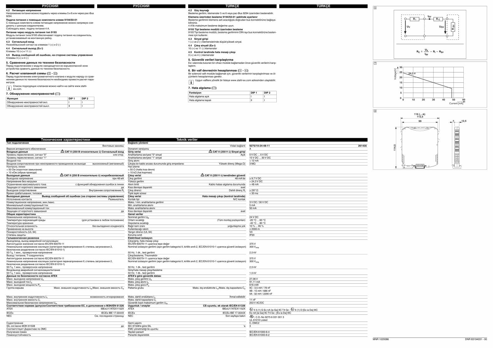
TÜRKÇETÜRKÇEРУССКИЙРУССКИЙ
Технические характеристики Teknik veriler
Тип подключения Bağlantı yöntemi
Винтовые зажимы Vidalı bağlantı 9275/10-24-48-11 261435
Версия аппаратного обеспечения Donanım versiyonu A
Входные данные CAT II (250 В относительно ) Сигнальный вход Giriş verisi CAT II (250 V ) Sinyal girişi
Уровень переключения, сигнал "0" или откр. Anahtarlama seviyesi "0" sinyal Açık 0 V DC ... 5 V DC
Уровень переключения, сигнал "1" Anahtarlama seviyesi "1" sinyal 15 V DC ... 30 V DC
Входной ток Giriş akımı < 12 mA
Входное сопротивление при неисправности проводников на выходе высокоомный (мегаомный) Çıkışta bir kablo arızası durumunda giriş empedansı Yüksek direnç (Mega Ω) 3 MΩ
Контроль линии
< 50 Ом (короткое замыкание)
> 10 кОм (обрыв провода)
Hat izleme
< 50 Ω (hatta kısa devre)
> 10 kΩ (hat kopması)
Выходные данные CAT II (250 В относительно ) искробезопасный Çıkış verisi CAT II (250 V ) kendinden güvenli
Выходное напряжение при 48 мА Çıkış gerilimi 48 mA'de ≥ 9,7 V DC
Напряжение без нагрузки Yüksüz gerilim > 24,3 V DC
Ограничение максимального тока с функцией обнаружения ошибок в линии Akım limiti Kablo hatası algılama durumunda > 48 mA
Защищен от короткого замыкания да Kısa devreye dayanıklı evet
Выходное сопротивление Внутреннее сопротивление Ri Çıkış direnci Dahili direnç Ri ≥ 297 Ω
Время срабатывания, типовое Tipik tepki süresi < 30 ms
Выходные данные Вывод сообщений об ошибках (на стороне системы управления) Çıkış verisi Hata mesajı çıkışı (kontrol tarafında)
Исполнение контакта Размыкатель Kontak tipi N/C kontak
Коммутационное напряжение, мин./макс. Maks. / min. anahtarlama gerilimi 3 V DC / 30 V DC
Минимальный коммутационный ток Min. anahtarlama akımı 5 mA
Максимальный коммутационный ток Maks. anahtarlama akımı 50 mA
Защищен от короткого замыкания да Kısa devreye dayanıklı evet
Общие характеристики Genel veriler
Номинальное напряжение UN Nominal gerilim UN 24 V DC
Температура окружающей среды (для установки в любом положении) Ortam sıcaklığı (Tüm montaj pozisyonları) -20 °C ... 60 °C
Температура хранения Depolama sıcaklığı -40 °C ... 80 °C
Oтносительная влажность без выпадения конденсата Bağıl nem oranı yoğunlaşma yok 10 % ... 95 %
Применение на высоте Kullanılacağı rakım ≤ 2000 m
Пожаростойкость (UL 94) Yangın direnci (UL 94) V0
Степень защиты Koruma sınıfı IP20
Гальваническая развязка Elektriksel izolasyon
Выход/вход, выход аварийной сигнализации
Амплитудное значение согласно IEC/EN 60079-11
Номинальное напряжение изоляции (категория перенапряжения II; степень загрязнения 2,
безопасное разделение согласно IEC/EN 61010-1)
50 Гц, 1 мин., проверочное напряжение
Çıkış/giriş, hata mesajı çıkışı
IEC/EN 60079-11 uyarınca tepe değer
Nominal izolasyon gerilimi (aşırı gerilim kategorisi II, kirlilik sınıfı 2, IEC/EN 61010-1 uyarınca güvenli izolasyon)
50 Hz, 1 dk., test gerilimi
375 V
300 Vrms
2,5 kV
Выход / питание, Т-соединитель
Амплитудное значение согласно IEC/EN 60079-11
Номинальное напряжение изоляции (категория перенапряжения II; степень загрязнения 2,
безопасное разделение согласно IEC/EN 61010-1)
50 Гц, 1 мин., проверочное напряжение
Çıkış/besleme, T-konnektör
IEC/EN 60079-11 uyarınca tepe değer
Nominal izolasyon gerilimi (aşırı gerilim kategorisi II, kirlilik sınıfı 2, IEC/EN 61010-1 uyarınca güvenli izolasyon)
50 Hz, 1 dk., test gerilimi
375 V
300 Vrms
2,5 kV
Вход/выход аварийной сигнализации/питание
50 Гц, 1 мин., проверочное напряжение
Giriş/hata mesajı çıkışı/besleme
50 Hz, 1 dk., test gerilimi 1,5 kV
Данные по безопасности согласно ATEX ATEX'e göre güvenlik datası
Макс. выходное напряжение Uo Maks. çıkış gerilimi Uo 27,06 V
Макс. выходной ток Io Maks. çıkış akımı Io 91,11 mA
Макс. выходная мощность Po Maks. çıkış gücü Po 616 mW
Группа взрыва Макс. внешняя индуктивность Lo/Макс. внешняя емкость Co Patlama grubu Maks. dış endüktivite Lo/Maks. dış kapasitans Co IIC : 3,5 mH / 78 nF
IIB : 15 mH / 686 nF
IIA : 32 mH / 2290 nF
Макс. внутренняя индуктивность Li возможность игнорирования Maks. dahili endüktans Li İhmal edilebilir
Макс. внутренняя емкость Ci Maks. dahili kapasitans Ci 11 nF
Максимальное безопасное напряжение Um Güvenlik bazlı maksimum gerilim Um 253 V AC/DC
Соответствие нормам /допускиСоответствие требованиям ЕС, в дополнение к МЭК/EN 61326 Uygunluk / onaylar CE-uyumlu, ek olarak IEC/EN 61326
ATEX IBExU17ATEX1152X ATEX IBExU17ATEX1152X II 3 (1) G Ex nA [ia Ga] IIC T4 Gc ; II (1) D [Ex ia Da] IIIC
IECEx IECEx IBE 17.0044X IECEx IECEx IBE 17.0044X Ex nA [ia Ga] IIC T4 Gc ; [Ex ia Da] IIIC
NEC См. последнюю страницу NEC Son sayfaya bakın , C.D.-No 9275 6 031 001 3
UL 61010 Listed
Судостроение Gemi yapımı C, EMC2
SIL согласно МЭК 61508 до IEC 61508'e göre SIL 'a 3
Соответствует Директиве по ЭМС EMC yönetmeliği ile uyumlu
Излучение помех Yayılan parazit IEC/EN 61000-6-4
Помехоустойчивость Parazite dayanıklılık IEC/EN 61000-6-2
4.2 Питающее напряжение
Напряжение питания можно подавать через клеммы 5 и 6 или через pac-Bus
9294.
Подача питания с помощью комплекта клемм 9194/50-01
С помощью комплекта клемм питающее напряжение можно напрямую сое-
динить с шинным соединителем.
Соблюдать макс. подачу питания 4 A.
Питание через модуль питания тип 9193
Модуль питания типа 9193 обеспечивает подачу питания на соединитель,
устанавливаемый на монтажную рейку.
4.3 Сигнальный вход
Низкий/высокий сигнал на клеммах 1 (+) и 2 (-)
4.4 Сигнальный выход (Ex i)
Клеммы 10 (+) и 11 (-)
4.5 Вывод сообщений об ошибках, на стороне системы управления
Клеммы 3 (+) и 4 (-)
5. Сравнение данных по технике безопасности
Перед подключением к модулю находящегося во взрывоопасной зоне
устройства сравнить данные по технике безопасности.
6. Расчет клапанной схемы ( - )
Перед подключением электромагнитного клапана к модулю наряду со срав-
нением данных по технике безопасности необходимо провести расчет пара-
метров.
7. Обнаружение неисправностей ()
Список подходящих клапанов можно найти на сайте www.stahl-
ex.com.
Функция DIP 1 DIP 2
Обнаружение неисправностей вкл. I I
Обнаружение неисправностей выкл. II I
4.2 Güç kaynağı
Besleme gerilimi, klemensler 5 ve 6 veya pac-Bus 9294 üzerinden beslenebilir.
Klemens üzerinden besleme 9194/50-01 şeklinde ayarlanır
Besleme gerilimini klemens seti aracılığıyla doğrudan bus konnektörüne bağlaya-
bilirsiniz.
4 A'lik maksimum besleme değerine uyun.
9193 Tipi besleme modülü üzerinden besleme
9193 Tipi besleme modülü, besleme geriliminin DIN rayı bus konnektörüne beslen-
mesi için kullanılır.
4.3 Sinyal girişi
1 (+) ve 2 (-) klemenslerinde düşük/yüksek sinyal.
4.4 Çıkış sinyali (Ex-i)
10 (+) ve 11 (-) klemensler
4.5 Kontrol tarafında hata mesajı çıkışı
3 (+) ve 4 (-) klemensler
5. Güvenlik verileri karşılaştırma
Ex-i alanında bulunan bir cihazı modüle bağlamadan önce güvenlik verilerini karşı-
laştırın.
6. Bir valf devresinin hesaplanması ( - )
Bir solenoid valfı modüle bağlamak için, güvenlik verilerinin karşılaştırılması ve öl-
çümlerin hesaplanması gerekir.
7. Hata algılama ()
Uygun valflere yönelik bir listeye www.stahl-ex.com adresinden ulaşılabilir.
Fonksiyon DIP 1 DIP 2
Hata algılama açık I I
Hata algılama kapalı II I
DNR 83194031 - 00
SVIiR
SVU
CR
SV
R
VU
UVRC = –––– – Ri – RSV
ISV
0
10
5
15
20
25
30
0 302010 40 50 60
24,3 V
Current [mA]
Vo
lta
ge
[V]
99
112,5
12,57
11
4,5
116 (...-k)
MNR 1029386
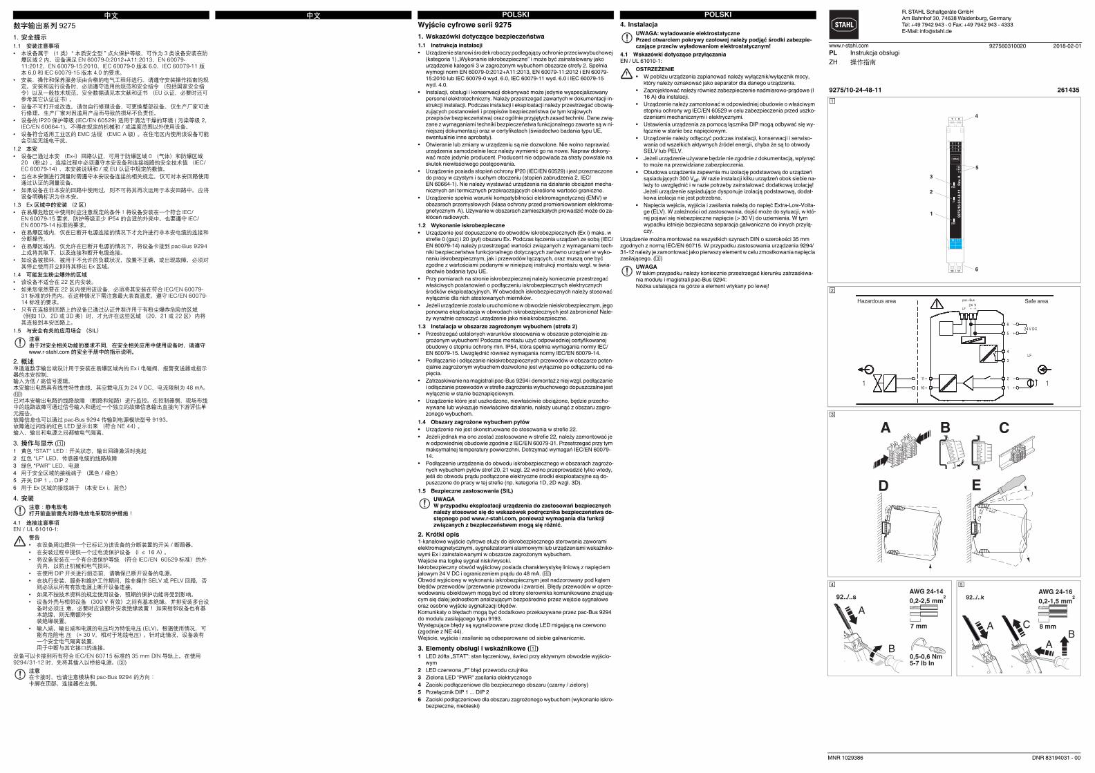
POLSKIPOLSKI中文中文4. Instalacja
4.1 Wskazówki dotyczące przyłączania
EN / UL 61010-1:
Urządzenie można montować na wszystkich szynach DIN o szerokości 35 mm
zgodnych z normą IEC/EN 60715. W przypadku zastosowania urządzenia 9294/
31-12 należy je zamontować jako pierwszy element w celu zmostkowania napięcia
zasilającego. ()
UWAGA: wyładowanie elektrostatyczne
Przed otwarciem pokrywy czołowej należy podjąć środki zabezpie-
czające przeciw wyładowaniom elektrostatycznym!
OSTRZEŻENIE
• W pobliżu urządzenia zaplanować należy wyłącznik/wyłącznik mocy,
który należy oznakować jako separator dla danego urządzenia.
• Zaprojektować należy również zabezpieczenie nadmiarowo-prądowe (I
16 A) dla instalacji.
• Urządzenie należy zamontować w odpowiedniej obudowie o właściwym
stopniu ochrony wg IEC/EN 60529 w celu zabezpieczenia przed uszko-
dzeniami mechanicznymi i elektrycznymi.
• Ustawienia urządzenia za pomocą łącznika DIP mogą odbywać się wy-
łącznie w stanie bez napięciowym.
• Urządzenie należy odłączyć podczas instalacji, konserwacji i serwiso-
wania od wszelkich aktywnych źródeł energii, chyba że są to obwody
SELV lub PELV.
• Jeżeli urządzenie używane będzie nie zgodnie z dokumentacją, wpłynąć
to może na przewidziane zabezpieczenia.
• Obudowa urządzenia zapewnia mu izolację podstawową do urządzeń
sąsiadujących 300 Veff. W razie instalacji kilku urządzeń obok siebie na-
leży to uwzględnić i w razie potrzeby zainstalować dodatkową izolację!
Jeżeli urządzenie sąsiadujące dysponuje izolacją podstawową, dodat-
kowa izolacja nie jest potrzebna.
• Napięcia wejścia, wyjścia i zasilania należą do napięć Extra-Low-Volta-
ge (ELV). W zależności od zastosowania, dojść może do sytuacji, w któ-
rej pojawi się niebezpieczne napięcie (> 30 V) do uziemienia. W tym
wypadku istnieje bezpieczna separacja galwaniczna do innych przyłą-
czy.
UWAGA
W takim przypadku należy koniecznie przestrzegać kierunku zatrzaskiwa-
nia modułu i magistrali pac-Bus 9294:
Nóżka ustalająca na górze a element wtykany po lewej!
数字输出系列 92751. 安全提示1.1 安装注意事项• 本设备属于 (1 类)“ 本质安全型 ” 点火保护等级,可作为 3 类设备安装在防
爆区域 2 内。设备满足 EN 60079-0:2012+A11:2013、EN 60079-11:2012、EN 60079-15:2010、IEC 60079-0 版本 6.0、IEC 60079-11 版本 6.0 和 IEC 60079-15 版本 4.0 的要求。
• 安装、操作和保养服务须由合格的电气工程师进行。请遵守安装操作指南的规定。安装和运行设备时,必须遵守适用的规范和安全指令 (包括国家安全指令)以及一般技术规范。安全数据请见本文献和证书 (EU 认证,必要时还可参考其它认证证书)。
• 设备不可打开或改造。 请勿自行修理设备,可更换整部设备。 仅生产厂家可进行修理。 生产厂家对因滥用产品而导致的损坏不负责任。
• 设备的 IP20 保护等级 (IEC/EN 60529) 适用于清洁干燥的环境 ( 污染等级 2,IEC/EN 60664-1)。不得在规定的机械和 / 或温度范围以外使用设备。
• 设备符合适用工业区的 EMC 法规 (EMC A 级)。在住宅区内使用该设备可能会引起无线电干扰。
1.2 本安• 设备已通过本安 (Ex-i)回路认证,可用于防爆区域 0 (气体)和防爆区域
20 (粉尘)。连接过程中必须遵守本安设备和连接线路的安全技术值 (IEC/EC 60079-14)、本安装说明和 / 或 EU 认证中规定的数值。
• 当在本安侧进行测量时需遵守本安设备连接的相关规定。 仅可对本安回路使用通过认证的测量设备。
• 如果设备在非本安的回路中使用过,则不可将其再次运用于本安回路中。 应将设备明确标识为非本安。
1.3 Ex 区域中的安装 (2 区)• 在易爆危险区中使用时应注意规定的条件!将设备安装在一个符合 IEC/
EN 60079-15 要求、防护等级至少 IP54 的合适的外壳中。也要遵守 IEC/EN 60079-14 标准的要求。
• 在易爆区域内,仅在已断开电源连接的情况下才允许进行非本安电缆的连接和分断操作。
• 在易爆区域内,仅允许在已断开电源的情况下,将设备卡接到 pac-Bus 9294上或将其取下,以及连接和断开电缆连接。
• 如设备被损坏,被用于不允许的负载状况,放置不正确,或出现故障,必须对其停止使用并立即将其移出 Ex 区域。
1.4 可能发生粉尘爆炸的区域• 该设备不适合在 22 区内安装。• 如果您依然要在 22 区内使用该设备,必须将其安装在符合 IEC/EN 60079-
31 标准的外壳内。在这种情况下需注意最大表面温度。遵守 IEC/EN 60079-14 标准的要求。
• 只有在连接到回路上的设备已通过认证并准许用于有粉尘爆炸危险的区域(例如 1D、2D 或 3D 类)时,才允许在这些区域 (20、21 或 22 区)内将其连接到本安回路上。
1.5 与安全有关的应用场合 (SIL)
2. 概述单通道数字输出端设计用于安装在易爆区域内的 Ex i 电磁阀、报警变送器或指示器的本安控制。输入为低 / 高信号逻辑。本安输出电路具有线性特性曲线,其空载电压为 24 V DC,电流限制为 48 mA。()已对本安输出电路的线路故障 (断路和短路)进行监控。在控制器侧,现场布线中的线路故障可通过信号输入和通过一个独立的故障信息输出直接向下游评估单元报告。故障信息也可以通过 pac-Bus 9294 传输到电源模块型号 9193。故障通过闪烁的红色 LED 显示出来 (符合 NE 44)。输入、输出和电源之间都被电气隔离。
3. 操作与显示 ()1 黄色 “STAT” LED:开关状态,输出回路激活时亮起2 红色 “LF” LED,传感器电缆的线路故障3 绿色 “PWR” LED,电源4 用于安全区域的接线端子 (黑色 / 绿色)5 开关 DIP 1 ... DIP 26 用于 Ex 区域的接线端子 (本安 Ex i,蓝色)
4. 安装
4.1 连接注意事项EN / UL 61010-1:
设备可以卡接到所有符合 IEC/EN 60715 标准的 35 mm DIN 导轨上。在使用9294/31-12 时,先将其插入以桥接电源。()
注意由于对安全相关功能的要求不同,在安全相关应用中使用设备时,请遵守www.r-stahl.com 的安全手册中的指示说明。
注意:静电放电打开前盖前需先对静电放电采取防护措施!
警告• 在设备周边提供一个已标记为该设备的分断装置的开关 / 断路器。• 在安装过程中提供一个过电流保护设备 (I ≤ 16 A)。• 将设备安装在一个有合适保护等级 (符合 IEC/EN 60529 标准)的外
壳内,以防止机械和电气损坏。• 在使用 DIP 开关进行组态前,请确保已断开设备的电源。• 在执行安装、服务和维护工作期间,除非操作 SELV 或 PELV 回路,否
则必须从所有有效电源上断开设备连接。• 如果不按技术资料的规定使用设备,预期的保护功能将受到影响。• 设备外壳与相邻设备(300 V 有效)之间有基本绝缘。 并排安装多台设
备时必须注 意,必要时应该额外安装绝缘装置! 如果相邻设备也有基本绝缘,则无需额外安装绝缘装置。
• 输入端、输出端和电源的电压均为特低电压 (ELV)。根据使用情况,可能有危险电 压 (> 30 V,相对于地线电压)。针对此情况,设备装有一个安全电气隔离装置,用于中断与其它接口的连接。
注意在卡接时,也请注意模块和 pac-Bus 9294 的方向:卡脚在顶部,连接器在左侧。
Wyjście cyfrowe serii 9275
1. Wskazówki dotyczące bezpieczeństwa
1.1 Instrukcja instalacji
• Urządzenie stanowi środek roboczy podlegający ochronie przeciwwybuchowej
(kategoria 1) „Wykonanie iskrobezpieczne” i może być zainstalowany jako
urządzenie kategorii 3 w zagrożonym wybuchem obszarze strefy 2. Spełnia
wymogi norm EN 60079-0:2012+A11:2013, EN 60079-11:2012 i EN 60079-
15:2010 lub IEC 60079-0 wyd. 6.0, IEC 60079-11 wyd. 6.0 i IEC 60079-15
wyd. 4.0.
• Instalacji, obsługi i konserwacji dokonywać może jedynie wyspecjalizowany
personel elektrotechniczny. Należy przestrzegać zawartych w dokumentacji in-
strukcji instalacji. Podczas instalacji i eksploatacji należy przestrzegać obowią-
zujących postanowień i przepisów bezpieczeństwa (w tym krajowych
przepisów bezpieczeństwa) oraz ogólnie przyjętych zasad techniki. Dane zwią-
zane z wymaganiami techniki bezpieczeństwa funkcjonalnego zawarte są w ni-
niejszej dokumentacji oraz w certyfikatach (świadectwo badania typu UE,
ewentualnie inne aprobaty).
• Otwieranie lub zmiany w urządzeniu są nie dozwolone. Nie wolno naprawiać
urządzenia samodzielnie lecz należy wymienić go na nowe. Napraw dokony-
wać może jedynie producent. Producent nie odpowiada za straty powstałe na
skutek niewłaściwego postępowania.
• Urządzenie posiada stopień ochrony IP20 (IEC/EN 60529) i jest przeznaczone
do pracy w czystym i suchym otoczeniu (stopień zabrudzenia 2, IEC/
EN 60664-1). Nie należy wystawiać urządzenia na działanie obciążeń mecha-
nicznych ani termicznych przekraczających określone wartości graniczne.
• Urządzenie spełnia warunki kompatybilności elektromagnetycznej (EMV) w
obszarach przemysłowych (klasa ochrony przed promieniowaniem elektroma-
gnetycznym A). Używanie w obszarach zamieszkałych prowadzić może do za-
kłóceń radiowych.
1.2 Wykonanie iskrobezpieczne
• Urządzenie jest dopuszczone do obwodów iskrobezpiecznych (Ex i) maks. w
strefie 0 (gaz) i 20 (pył) obszaru Ex. Podczas łączenia urządzeń ze sobą (IEC/
EN 60079-14) należy przestrzegać wartości związanych z wymaganiami tech-
niki bezpieczeństwa funkcjonalnego dotyczących zarówno urządzeń w wyko-
naniu iskrobezpiecznym, jak i przewodów łączących, oraz muszą one być
zgodne z wartościami podanymi w niniejszej instrukcji montażu wzgl. w świa-
dectwie badania typu UE.
• Przy pomiarach na stronie iskrobezpiecznej należy koniecznie przestrzegać
właściwych postanowień o podłączeniu iskrobezpiecznych elektrycznych
środków eksploatacyjnych. W obwodach iskrobezpiecznych należy stosować
wyłącznie dla nich atestowanych mierników.
• Jeżeli urządzenie zostało uruchomione w obwodzie nieiskrobezpiecznym, jego
ponowna eksploatacja w obwodach iskrobezpiecznych jest zabroniona! Nale-
ży wyraźnie oznaczyć urządzenie jako nieiskrobezpieczne.
1.3 Instalacja w obszarze zagrożonym wybuchem (strefa 2)
• Przestrzegać ustalonych warunków stosowania w obszarze potencjalnie za-
grożonym wybuchem! Podczas montażu użyć odpowiedniej certyfikowanej
obudowy o stopniu ochrony min. IP54, która spełnia wymagania normy IEC/
EN 60079-15. Uwzględnić również wymagania normy IEC/EN 60079-14.
• Podłączanie i odłączanie nieiskrobezpiecznych przewodów w obszarze poten-
cjalnie zagrożonym wybuchem dozwolone jest wyłącznie po odłączeniu od na-
pięcia.
• Zatrzaskiwanie na magistrali pac-Bus 9294 i demontaż z niej wzgl. podłączanie
i odłączanie przewodów w strefie zagrożenia wybuchowego dopuszczalne jest
wyłącznie w stanie beznapięciowym.
• Urządzenie które jest uszkodzone, niewłaściwie obciążone, będzie przecho-
wywane lub wykazuje niewłaściwe działanie, należy usunąć z obszaru zagro-
żonego wybuchem.
1.4 Obszary zagrożone wybuchem pyłów
• Urządzenie nie jest skonstruowane do stosowania w strefie 22.
• Jeżeli jednak ma ono zostać zastosowane w strefie 22, należy zamontować je
w odpowiedniej obudowie zgodnie z IEC/EN 60079-31. Przestrzegać przy tym
maksymalnej temperatury powierzchni. Dotrzymać wymagań IEC/EN 60079-
14.
• Podłączenie urządzenia do obwodu iskrobezpiecznego w obszarach zagrożo-
nych wybuchem pyłów stref 20, 21 wzgl. 22 wolno przeprowadzić tylko wtedy,
jeśli do obwodu prądu podłączone elektryczne środki eksploatacyjne są do-
puszczone do pracy w tej strefie (np. kategoria 1D, 2D wzgl. 3D).
1.5 Bezpieczne zastosowania (SIL)
2. Krótki opis
1-kanałowe wyjście cyfrowe służy do iskrobezpiecznego sterowania zaworami
elektromagnetycznymi, sygnalizatorami alarmowymi lub urządzeniami wskaźniko-
wymi Ex i zainstalowanymi w obszarze zagrożonym wybuchem.
Wejście ma logikę sygnał niski/wysoki.
Iskrobezpieczny obwód wyjściowy posiada charakterystykę liniową z napięciem
jałowym 24 V DC i ograniczeniem prądu do 48 mA. ()
Obwód wyjściowy w wykonaniu iskrobezpiecznym jest nadzorowany pod kątem
błędów przewodów (przerwanie przewodu i zwarcie). Błędy przewodów w oprze-
wodowaniu obiektowym mogą być od strony sterownika komunikowane znajdują-
cym się dalej jednostkom analizującym bezpośrednio przez wejście sygnałowe
oraz osobne wyjście sygnalizacji błędów.
Komunikaty o błędach mogą być dodatkowo przekazywane przez pac-Bus 9294
do modułu zasilającego typu 9193.
Występujące błędy są sygnalizowane przez diodę LED migającą na czerwono
(zgodnie z NE 44).
Wejście, wyjścia i zasilanie są odseparowane od siebie galwanicznie.
3. Elementy obsługi i wskaźnikowe ()
1 LED żółta „STAT”: stan łączeniowy, świeci przy aktywnym obwodzie wyjścio-
wym
2 LED czerwona „F” błąd przewodu czujnika
3 Zielona LED "PWR" zasilania elektrycznego
4 Zaciski podłączeniowe dla bezpiecznego obszaru (czarny / zielony)
5 Przełącznik DIP 1 ... DIP 2
6 Zaciski podłączeniowe dla obszaru zagrożonego wybuchem (wykonanie iskro-
bezpieczne, niebieski)
UWAGA
W przypadku eksploatacji urządzenia do zastosowań bezpiecznych
należy stosować się do wskazówek podręcznika bezpieczeństwa do-
stępnego pod www.r-stahl.com, ponieważ wymagania dla funkcji
związanych z bezpieczeństwem mogą się różnić.
R. STAHL Schaltgeräte GmbH
Am Bahnhof 30, 74638 Waldenburg, Germany
Tel: +49 7942 943 - 0 Fax: +49 7942 943 - 4333
E-Mail: [email protected]
927560310020www.r-stahl.com
9275/10-24-48-11 261435
1
2
3
5
4
6
PWR
LF
STAT
5 6
1 2
10 11
92
75
/10
-24
-48
-11
R
ev.
A
12
I II
1
10
|
|
2
11
3 4
Hazardous area Safe area
A B C
D E
0,5-0,6 Nm5-7 lb In
7 mm
AWG 24-14
0,2-2,5 mm292../..s
A
B
92../..k
PL Instrukcja obsługi
ZH 操作指南
2018-02-01
MNR 1029386 DNR 83194031 - 00
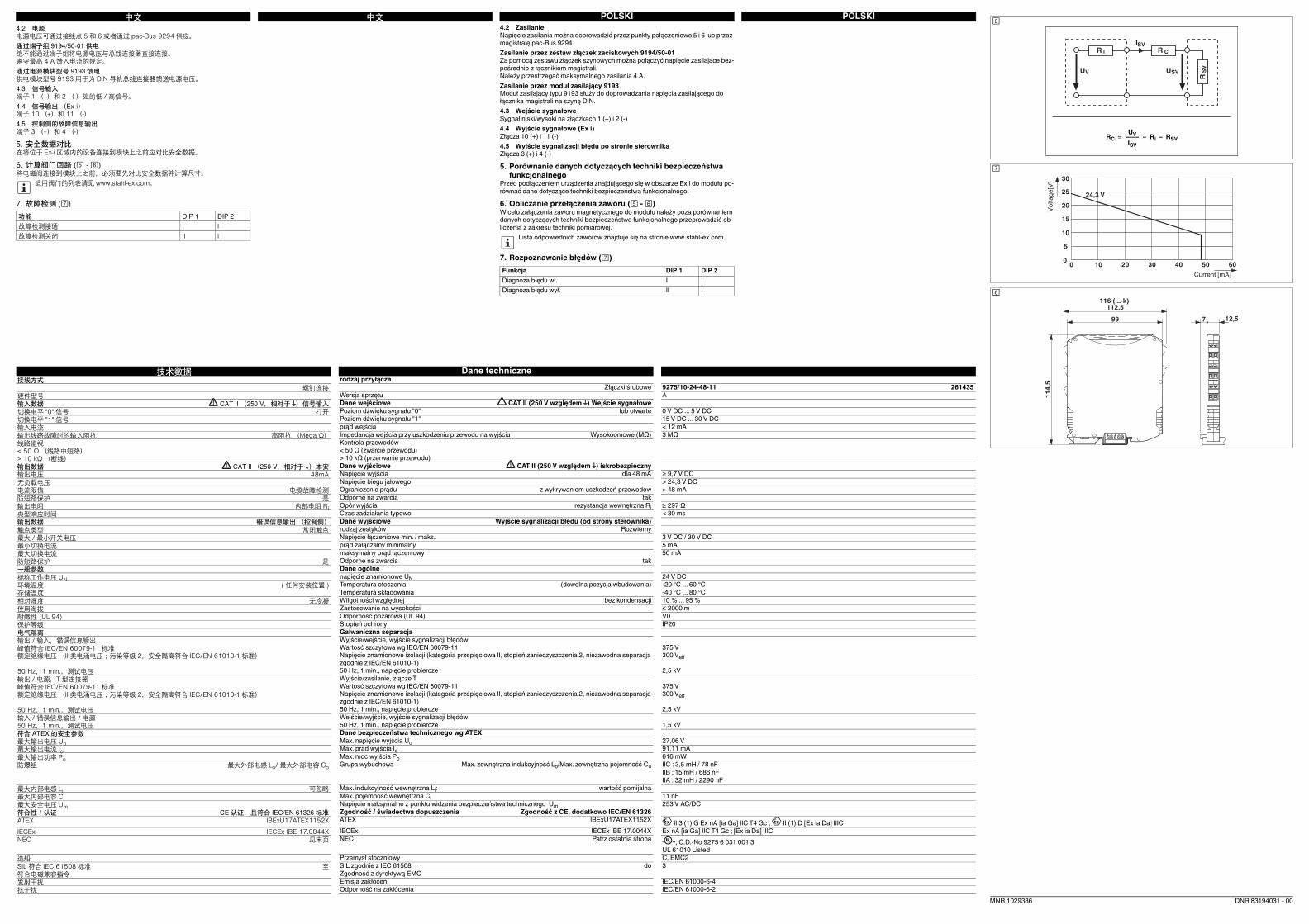
POLSKIPOLSKI中文中文
技术数据 Dane techniczne
接线方式 rodzaj przyłącza
螺钉连接 Złączki śrubowe 9275/10-24-48-11 261435
硬件型号 Wersja sprzętu A
输入数据 CAT II (250 V,相对于 ) 信号输入 Dane wejściowe CAT II (250 V względem ) Wejście sygnałowe
切换电平 "0" 信号 打开 Poziom dźwięku sygnału "0" lub otwarte 0 V DC ... 5 V DC
切换电平 "1" 信号 Poziom dźwięku sygnału "1" 15 V DC ... 30 V DC
输入电流 prąd wejścia < 12 mA
输出线路故障时的输入阻抗 高阻抗 (Mega Ω) Impedancja wejścia przy uszkodzeniu przewodu na wyjściu Wysokoomowe (MΩ) 3 MΩ
线路监视< 50 Ω (线路中短路)> 10 kΩ (断线)
Kontrola przewodów
< 50 Ω (zwarcie przewodu)
> 10 kΩ (przerwanie przewodu)
输出数据 CAT II (250 V,相对于 ) 本安 Dane wyjściowe CAT II (250 V względem ) iskrobezpieczny
输出电压 48mA Napięcie wyjścia dla 48 mA ≥ 9,7 V DC
无负载电压 Napięcie biegu jałowego > 24,3 V DC
电流限值 电缆故障检测 Ograniczenie prądu z wykrywaniem uszkodzeń przewodów > 48 mA
防短路保护 是 Odporne na zwarcia tak
输出电阻 内部电阻 Ri Opór wyjścia rezystancja wewnętrzna Ri ≥ 297 Ω
典型响应时间 Czas zadziałania typowo < 30 ms
输出数据 错误信息输出 (控制侧) Dane wyjściowe Wyjście sygnalizacji błędu (od strony sterownika)
触点类型 常闭触点 rodzaj zestyków Rozwierny
最大 / 最小开关电压 Napięcie łączeniowe min. / maks. 3 V DC / 30 V DC
最小切换电流 prąd załączalny minimalny 5 mA
最大切换电流 maksymalny prąd łączeniowy 50 mA
防短路保护 是 Odporne na zwarcia tak
一般参数 Dane ogólne
标称工作电压 UN napięcie znamionowe UN 24 V DC
环境温度 ( 任何安装位置 ) Temperatura otoczenia (dowolna pozycja wbudowania) -20 °C ... 60 °C
存储温度 Temperatura składowania -40 °C ... 80 °C
相对湿度 无冷凝 Wilgotności względnej bez kondensacji 10 % ... 95 %
使用海拔 Zastosowanie na wysokości ≤ 2000 m
耐燃性 (UL 94) Odporność pożarowa (UL 94) V0
保护等级 Stopień ochrony IP20
电气隔离 Galwaniczna separacja
输出 / 输入,错误信息输出峰值符合 IEC/EN 60079-11 标准额定绝缘电压 (II 类电涌电压;污染等级 2,安全隔离符合 IEC/EN 61010-1 标准)
50 Hz,1 min.,测试电压
Wyjście/wejście, wyjście sygnalizacji błędów
Wartość szczytowa wg IEC/EN 60079-11
Napięcie znamionowe izolacji (kategoria przepięciowa II, stopień zanieczyszczenia 2, niezawodna separacja
zgodnie z IEC/EN 61010-1)
50 Hz, 1 min., napięcie probiercze
375 V
300 Veff
2,5 kV
输出 / 电源,T 型连接器峰值符合 IEC/EN 60079-11 标准额定绝缘电压 (II 类电涌电压;污染等级 2,安全隔离符合 IEC/EN 61010-1 标准)
50 Hz,1 min.,测试电压
Wyjście/zasilanie, złącze T
Wartość szczytowa wg IEC/EN 60079-11
Napięcie znamionowe izolacji (kategoria przepięciowa II, stopień zanieczyszczenia 2, niezawodna separacja
zgodnie z IEC/EN 61010-1)
50 Hz, 1 min., napięcie probiercze
375 V
300 Veff
2,5 kV
输入 / 错误信息输出 / 电源50 Hz,1 min.,测试电压
Wejście/wyjście, wyjście sygnalizacji błędów
50 Hz, 1 min., napięcie probiercze 1,5 kV
符合 ATEX 的安全参数 Dane bezpieczeństwa technicznego wg ATEX
最大输出电压 Uo Max. napięcie wyjścia Uo 27,06 V
最大输出电流 Io Max. prąd wyjścia Io 91,11 mA
最大输出功率 Po Max. moc wyjścia Po 616 mW
防爆组 最大外部电感 Lo/ 最大外部电容 Co Grupa wybuchowa Max. zewnętrzna indukcyjność Lo/Max. zewnętrzna pojemność Co IIC : 3,5 mH / 78 nF
IIB : 15 mH / 686 nF
IIA : 32 mH / 2290 nF
最大内部电感 Li 可忽略 Max. indukcyjność wewnętrzna Li: wartość pomijalna
最大内部电容 Ci Max. pojemność wewnętrzna Ci 11 nF
最大安全电压 Um Napięcie maksymalne z punktu widzenia bezpieczeństwa technicznego Um 253 V AC/DC
符合性/认证 CE 认证,且符合 IEC/EN 61326 标准 Zgodność / świadectwa dopuszczenia Zgodność z CE, dodatkowo IEC/EN 61326
ATEX IBExU17ATEX1152X ATEX IBExU17ATEX1152X II 3 (1) G Ex nA [ia Ga] IIC T4 Gc ; II (1) D [Ex ia Da] IIIC
IECEx IECEx IBE 17.0044X IECEx IECEx IBE 17.0044X Ex nA [ia Ga] IIC T4 Gc ; [Ex ia Da] IIIC
NEC 见末页 NEC Patrz ostatnia strona , C.D.-No 9275 6 031 001 3
UL 61010 Listed
造船 Przemysł stoczniowy C, EMC2
SIL 符合 IEC 61508 标准 至 SIL zgodnie z IEC 61508 do 3
符合电磁兼容指令 Zgodność z dyrektywą EMC
发射干扰 Emisja zakłóceń IEC/EN 61000-6-4
抗干扰 Odporność na zakłócenia IEC/EN 61000-6-2
4.2 电源电源电压可通过接线点 5 和 6 或者通过 pac-Bus 9294 供应。通过端子组 9194/50-01 供电绝不能通过端子组将电源电压与总线连接器直接连接。遵守最高 4 A 馈入电流的规定。通过电源模块型号 9193 馈电供电模块型号 9193 用于为 DIN 导轨总线连接器馈送电源电压。4.3 信号输入端子 1 (+)和 2 (-)处的低 / 高信号。4.4 信号输出 (Ex-i)端子 10 (+)和 11 (-)4.5 控制侧的故障信息输出端子 3 (+)和 4 (-)
5. 安全数据对比在将位于 Ex-i 区域内的设备连接到模块上之前应对比安全数据。
6. 计算阀门回路 ( - )将电磁阀连接到模块上之前,必须要先对比安全数据并计算尺寸。
7. 故障检测 ()
适用阀门的列表请见 www.stahl-ex.com。
功能 DIP 1 DIP 2故障检测接通 I I故障检测关闭 II I
4.2 Zasilanie
Napięcie zasilania można doprowadzić przez punkty połączeniowe 5 i 6 lub przez
magistralę pac-Bus 9294.
Zasilanie przez zestaw złączek zaciskowych 9194/50-01
Za pomocą zestawu złączek szynowych można połączyć napięcie zasilające bez-
pośrednio z łącznikiem magistrali.
Należy przestrzegać maksymalnego zasilania 4 A.
Zasilanie przez moduł zasilający 9193
Moduł zasilający typu 9193 służy do doprowadzania napięcia zasilającego do
łącznika magistrali na szynę DIN.
4.3 Wejście sygnałowe
Sygnał niski/wysoki na złączkach 1 (+) i 2 (-)
4.4 Wyjście sygnałowe (Ex i)
Złącza 10 (+) i 11 (-)
4.5 Wyjście sygnalizacji błędu po stronie sterownika
Złącza 3 (+) i 4 (-)
5. Porównanie danych dotyczących techniki bezpieczeństwa
funkcjonalnego
Przed podłączeniem urządzenia znajdującego się w obszarze Ex i do modułu po-
równać dane dotyczące techniki bezpieczeństwa funkcjonalnego.
6. Obliczanie przełączenia zaworu ( - )
W celu załączenia zaworu magnetycznego do modułu należy poza porównaniem
danych dotyczących techniki bezpieczeństwa funkcjonalnego przeprowadzić ob-
liczenia z zakresu techniki pomiarowej.
7. Rozpoznawanie błędów ()
Lista odpowiednich zaworów znajduje się na stronie www.stahl-ex.com.
Funkcja DIP 1 DIP 2
Diagnoza błędu wł. I I
Diagnoza błędu wył. II I
DNR 83194031 - 00
SVIiR
SVU
CR
SV
R
VU
UVRC = –––– – Ri – RSV
ISV
0
10
5
15
20
25
30
0 302010 40 50 60
24,3 V
Current [mA]
Vo
lta
ge
[V]
99
112,5
12,57
11
4,5
116 (...-k)
MNR 1029386
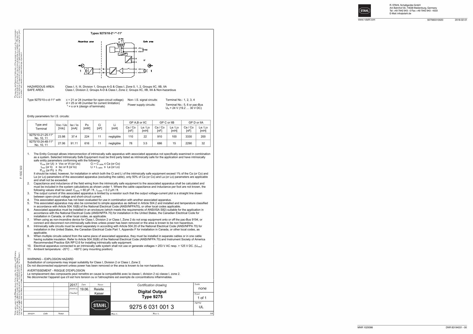
R. STAHL Schaltgeräte GmbH
Am Bahnhof 30, 74638 Waldenburg, Germany
Tel: +49 7942 943 - 0 Fax: +49 7942 943 - 4333
E-Mail: [email protected]
927560310020www.r-stahl.com 2018-02-01
MNR 1029386 DNR 83194031 - 00
Digital Output Type 9275
9275 6 031 001 3
2017 19.06. Reistle Kaiser
UL
1 of 1
Types 9275/10-2*-**-11*
HAZARDOUS AREA: Class I, II, III, Division 1, Groups A-G & Class I, Zone 0, 1, 2, Groups IIC, IIB, IIA SAFE AREA: Class I, Division 2, Groups A-D & Class I, Zone 2, Groups IIC, IIB, IIA & Non-hazardous
Type 9275/10-c-d-11* with c = 21 or 24 (number for open-circuit voltage) d = 25 or 48 (number for current limitation) * = s or k (design of terminals)
Non- I.S. signal circuits: Terminal No.: 1, 2, 3, 4
Power supply circuits: Terminal No.: 5, 6 or pac-Bus UN = 24 V (19.2 … 30 V DC)
Entity parameters for I.S. circuits:
Type and Terminal
Voc / Uo[Vdc]
Isc / Io [mA]
Po [mW]
Ci [nF]
Li [mH]
GP A,B or IIC GP C or IIB GP D or IIA
Ca / Co [nF]
La / Lo [mH]
Ca / Co [nF]
La / Lo [mH]
Ca / Co [nF]
La / Lo [mH]
9275/10-21-25-11* No. 10, 11 23.98 37.4 224 11 negligible 110 22 910 100 3330 200
9275/10-24-48-11* No. 10, 11 27.06 91.11 616 11 negligible 78 3.5 686 15 2290 32
1. The Entity Concept allows interconnection of intrinsically safe apparatus with associated apparatus not specifically examined in combination as a system. Selected Intrinsically Safe Equipment must be third party listed as intrinsically safe for the application and have intrinsically safe entity parameters conforming with the following: Vmax (or Ui) Voc or Vt (or Uo) Ci + C cable Ca (or Co) Imax (or Ii) Isc or It (or Io) Li + L cable La (or Lo) Pmax (or Pi) Po It should be noted, however, for installation in which both the Ci and Li of the intrinsically safe equipment exceed 1% of the Ca (or Co) and La (or Lo) parameters of the associated apparatus (excluding the cable), only 50% of Ca (or Co) and La (or Lo) parameters are applicable and shall not be exceeded.
2. Capacitance and inductance of the field wiring from the intrinsically safe equipment to the associated apparatus shall be calculated and must be included in the system calculations as shown under 1. Where the cable capacitance and inductance per foot are not known, the following values shall be used: Ccable = 60 pF / ft., Lcable = 0.2 µH / ft.
3. The output current of this associated apparatus is limited by a resistor such that the output voltage-current plot is a straight line drawn between open-circuit voltage and short-circuit current.
4. This associated apparatus has not been evaluated for use in combination with another associated apparatus. 5. This associated apparatus may also be connected to simple apparatus as defined in Article 504.2 and installed and temperature classified
in accordance with Article 504.10(B) of the National Electrical Code (ANSI/NFPA70), or other local codes applicable. 6. Associated apparatus must be installed in an enclosure (which meets the requirements of ANSI/ISA S82) suitable for the application in
accordance with the National Electrical Code (ANSI/NFPA 70) for installation in the United States, the Canadian Electrical Code for installation in Canada, or other local codes, as applicable.
7. When using as non-incendive device for Class I, Division 2 or Class I, Zone 2 do not snap equipment onto or off the pac-Bus 9194, or connect and disconnect non-intrinsically safe-lines unless power has been removed or the area is known to be non hazardous.
8. Intrinsically safe circuits must be wired separately in according with Article 504.20 of the National Electrical Code (ANSI/NFPA 70) for installation in the United States, the Canadian Electrical Code Part 1, Appendix F for installation in Canada, or other local codes, as applicable.
9. When multiple circuits extend from the same piece of associated apparatus, they must be installed in separate cables or in one cable having suitable insulation. Refer to Article 504.30(B) of the National Electrical Code (ANSI/NFPA 70) and Instrument Society of America Recommended Practice ISA RP12.6 for installing intrinsically safe equipment.
10. Electrical apparatus connected to an intrinsically safe system shall not use or generate voltages > 253 V AC resp. > 125 V DC. (Umax) 11. Ambient temperature: -20°C … +60°C (any mounting position)
WARNING – EXPLOSION HAZARD Substitution of components may impair suitability for Class I, Division 2 or Class I, Zone 2. Do not disconnected equipment unless power has been removed or the area is known to be non-hazardous.
AVERTISSEMENT - RISQUE D'EXPLOSION Le remplacement des composants peut remettre en cause la compatibilité avec la classe I, division 2 oú classe I, zone 2. Ne déconnecter l'appareil que s'il est hors tension ou si l'atmosphère est exempte de concentrations inflammables.