Embed Size (px)
Citation preview
1
A transportable 40Ca+ single-ion clock with
7.7×10⁻¹⁷ systematic uncertainty Jian Cao1,2,, Ping Zhang1,2,3,4, Junjuan Shang1,2,3, Kaifeng Cui1,2,3, Jinbo Yuan1,2,3, Sijia Chao1,2,3,
Shaomao Wang1,2,3, Hualin Shu1,2, Xueren Huang1,2,†
1State Key Laboratory of Magnetic Resonance and Atomic and Molecular Physics, Wuhan Institute of Physics and Mathematics,
Chinese Academy of Sciences, Wuhan 430071, China 2Key Laboratory of Atomic Frequency Standards, Wuhan Institute of Physics and Mathematics,
Chinese Academy of Sciences, Wuhan 430071, China 3University of Chinese Academy of Sciences, Beijing 100080, China
4School of Physics and Electrical Engineering, Taizhou University, Taizhou 318000, China
Abstract: A transportable optical clock refer to the 4s2S1/2-3d2D5/2 electric quadrupole transition at 729 nm of single 40Ca+ trapped in mini Paul trap has been developed. The physical system of 40Ca+ optical clock is re-engineered from a
bulky and complex setup to an integration of two subsystems: a compact single ion unit including ion trapping and
detection modules, and a compact laser unit including laser sources, beam distributor and frequency reference modules.
Apart from the electronics, the whole equipment has been constructed within a volume of 0.54 m3. The systematic
fractional uncertainty has been evaluated to be 7.7×10⁻¹⁷, and the Allan deviation fits to be 142.3 10 by clock
self-comparison with a probe pulse time 20 ms.
Keywords: Optical clock; Ion trap; Transportable.
1. Introduction
Due to the impressive progress in recent years, optical clocks are deemed for the redefinition of SI second
in future as they have surpassed the performance of Cs primary clocks in both accuracy and stability[1-5]. At
the same time, these ultra-precise optical clocks offer new possibilities for high precision tests of fundamental
physics[6-9], geophysics[10; 11], improved timekeeping and satellites navigation[12; 13]. On the other hand, a more
accurate and direct mean of optical frequency comparison is required for today’s best clocks over quite long
distance. Since the uncertainty of satellite links are limited and dedicated equipments should be employed, and
optical fiber links are not feasible enough especially for intercontinental comparison[14; 15]. For these reasons,
it’s quite necessary to develop the applicable optical clocks on ground and even in the space.
It’s feasible to develop a transportable optical clock in the first stage. Essential characteristics for a
transportable optical clock are: compact size and proper mass, ensuring at the same time a high performance
and reliability, but also fully automatic operation. Undertaking a necessary step towards optical clocks in
space, the “Space Optical Clock” program of European Space Agency (ESA) aims at accurate transportable 87Sr and 171Yb optical lattice clock demonstrators with an expected performance of fractional uncertainty
below 5×10-17 and fractional instability below 151 10 [16]. At present, a transportable 87Sr optical lattice
clock (excluding electronics) fits within a volume of <2 m3 with uncertainty of 7×10-15 have been developed
in LENS of Italy[17]. Other similar prototypes are under development in PTB, HHUD and NPL[18-20].
In addition to neutral atoms, a trapped 40Ca+ single-ion is another promising option in the programs of
transportable optical clocks. These kinds of optical clock have their own advantages on the relatively simple
scheme of clock system, especially the simplicity on all semiconductor lasers that allowing for developing
compact, robust and low-cost applicable clock. Moreover, an excellent performance of frequency uncertainty
2
and instability make them quite attractive and cost-effective[21]. In this article, we present the realization of a
transportable optical clock refer to the 4s2S1/2-3d2D5/2 electric quadrupole transition at 729 nm of 40Ca+
single-ion trapped in miniature Paul trap. Apart from the electronics, the whole equipment has been
constructed within a volume of 0.54 m3. The overall systematic fractional uncertainty has been evaluated to be
7.7×10⁻¹⁷, and the Allan deviation fits to be 142.3 10 by clock self-comparison with a probe pulse time
20 ms.
2. Clock design
The design of the first-generation transportable 40Ca+ single-ion optical clock , which is fully operational in
our laboratory, is shown in Fig. 1. The physical system of this apparatus is re-engineered from a bulky and
complex setup to an integration of two subsystems: a compact single ion subsystem including ion trapping and
detection modules, and a compact laser subsystem including laser sources, beam distributor and frequency
stabilization modules. All the connections between each modules are provided in single-mode
polarization-maintaining fibers. This kind of modular design ensures better stability and reliability essential
for long-term operation of transportable clock. Moreover, the development in the field of commercial
optoelectronic subcomponents allows for independent testing and maintenance of each modules, such as a
simple replacement or promotion of components.
The ion system consists of a compact vacuum chamber with the trap region takes the form of a cuboid
(size:7×7×7 cm3) which is kept to less than 5×10⁻⁸ Pa by a 10 L/s ion pump. A miniature ring-endcap ion trap
optimized by finite element analysis method, with a center-to-ring electrode distance of 0 0.75r mm and an
endcap-to-center distance of 0 0.75z mm[22], is driven by a helical resonator at 2 24.54(10)rf
MHz at which the rf-induced 2nd-order Doppler frequency shifts and Stark shift cancel each other
approximately[23; 24]. The background magnetic field is reduced by two layers of magnetic shielding to
2.2B μT. Laser induced fluorescence emitted by the 40Ca+ single-ion at 397 nm is collected by a
custom-made objective which is fixed to the vacuum window to ensure the stability of the module during
transporting. All the photons collected by the objective are send to a photomultiplier (PMT), and both a
narrow bandpass filter and an aperture stop are employed to filt the background stray light. The efficiency of
this fluorescence detecting module is about 0.002, considering the collection of the solid angle, the
transmittance of optical elements and the quantum efficiency of the PMT.
The design of the compact laser system is modular and mainly consists of the following modules: laser
source, laser beam distributor and laser frequency reference. The laser source box contains all of the 5 external
cavity diode lasers (ECDLs) employed for 40Ca+ single-ion optical clock, and the wavelength are 423 nm
(photo-ionization of calcium atoms), 397 nm (Doppler cooling and fluorescence detection), 866 nm
(repumping for keeping the cycles of cooling), 729 nm (clock transition inquiring) and 854 nm (quenching
from the metastable state after clock inquiring). Through the laser beam distributor, each output of these
ECDLs is splitted into a few parts and then are coupled to wavemeter, the ion system and modules of laser
frequency reference, respectively.
The module of laser frequency reference contains two Fabry-Pérot cavities. One is a 3-in-1
ultralow-expansion (ULE) glass cavity used for three lasers (397/866/854 nm, fineness ~ 100)
simultaneously by three pairs of fused-silica mirrors for each wavelength. Due to the cavity is made of ULE
glass and further sealed in a thermal shield and vacuum chamber which are encapsulated in a box
(size:52×46×34 cm3), the frequency fluctuation of these lasers is about 1 MHz/day which is acceptable for
3
daily operation. The other one is an all ULE glass cavity including mirrors (fineness ~300,000) used for 729
nm clock laser. By means of finite element analysis, the shape of the cavity and the supporting way are
optimized and the setup is placed on a small active vibration isolated platform to get a vibration-insensitive
performance. A set of thermal shield and a temperature controlled vacuum chamber as similar as the one used
for 3-in-1 cavity are also employed and all of these devices including compact designed optical components
are encapsulated in a box (size: 52×46×45 cm3) to get a thermal-insensitive performance. After the free
running 729 nm laser is locked to this ultra-stable cavity by Pound-Drever-Hall (PDH) method[25], the
linewidth is measured to be 1Hz at 1s and frequency instability is measured to be less than 2×10-15 at 1-100 s
after removing the linear drift which is always at the level of 0.05 Hz/s.
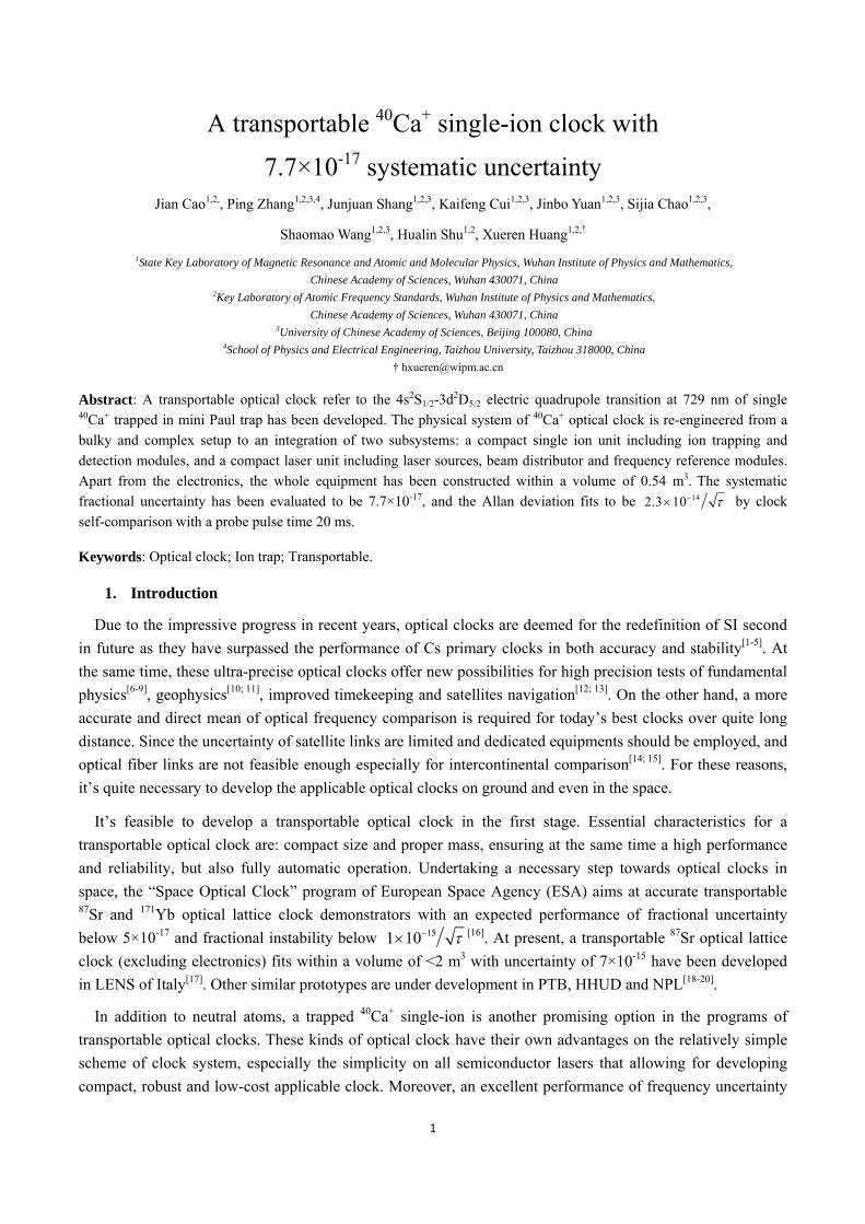
FIG. 1. Overview of the transportable 40Ca+ single-ion clock. (a) Schematic diagram of clock system. (b) Design effect
drawing of clock system. The blue “L” module is control electronics and the part that is not fully exposed under the elec-
tronics is the trap and detection module and laser source module. The rest of the space is mainly occupied by the laser
reference module, which is represented by the green boxes.
3. Clock running and evaluation of its performance
A single 40Ca+ ion is loaded into the trap by photoionizing neutral calcium atoms with a 423 nm diode laser
and a 370 nm LED effectively. Typically, ~10 μW of the 397 nm laser power is focused on the ion with a
beam waist of ~50 um, ~350 μW/350 μW/10 nW of power with ~100 μm beam size for the 866/854/729 nm
laser, respectively. After micromotion minimization, the single ion can be trapped about one day continuously
with laser Doppler cooling. An on-resonance fluorescence count rate of 40,000 /s is obtained for a single ion.
For a typical background count rate of 2,000 /s this results in a signal-to-background ratio of 20. The secular
motion frequencies of trapped ions are ( , ) 2 (2.1, 4.2)r z MHz when the forward power to the helical
resonator is 5 W routinely, which are measured by ‘tickling’ the ions with low-power rf field applied to the
compensation electrodes and endcap electrodes, respectively.
The 729 nm laser is locked to the TEM00 mode of the ultra-stable cavity which is the closest to the clock
transition frequency. This frequency difference is covered with a double-passed acousto-optic modulator
(AOM) driven by a signal generator referenced to an active hydrogen maser. This computer controlled signal
generator updates the probe laser frequency every 40 cycles of pulses for spectroscopic measurements and
locking to the transition line center by the “four points locking scheme”[26]. At the same time, the
double-passed AOM also serves as a shutter for the probe laser beam. For cancellation of the linear Zeeman
shift, the quadrupole shift and the tensor part of the Stark shifts, the laser is locked to the three inner pairs of
Zeeman components with magnetic sublevels 1 2 , 3 2 , 5 2jm in the upper 3d2D5/2 state[27],
sequentially in each cycle during the lock runs [Fig. 2(a)]. Each of the 6 components is measured
4
independently and the resulting line center is combined by averaging the center frequencies of the 3 pair of
components.
In order to prevent large ac-Stark shift of the 729 nm clock transition caused by the other 397/866/854 nm
lasers, a pulse light sequence is introduced to observe the spectra. In this experiment, the cooling pulse, which
includes the 397/866/854 nm radiations, is 15 ms. The 729 nm probe pulse is various according to the
experimental requirements, and it induces a Fourier limited linewidth of 22 Hz with pulse time 40 ms [Fig.
2(b)], while all the other radiations are blocked by mechanical shutters. Buffer times of 3 ms are used before
and after the probe pulse to again prevent ac-Stark shifts as the actuation time of each shutter is ~2 ms. After
the clock probing pulse, the state of the ion is interrogated within 1ms using 397 nm and 866 nm lasers.
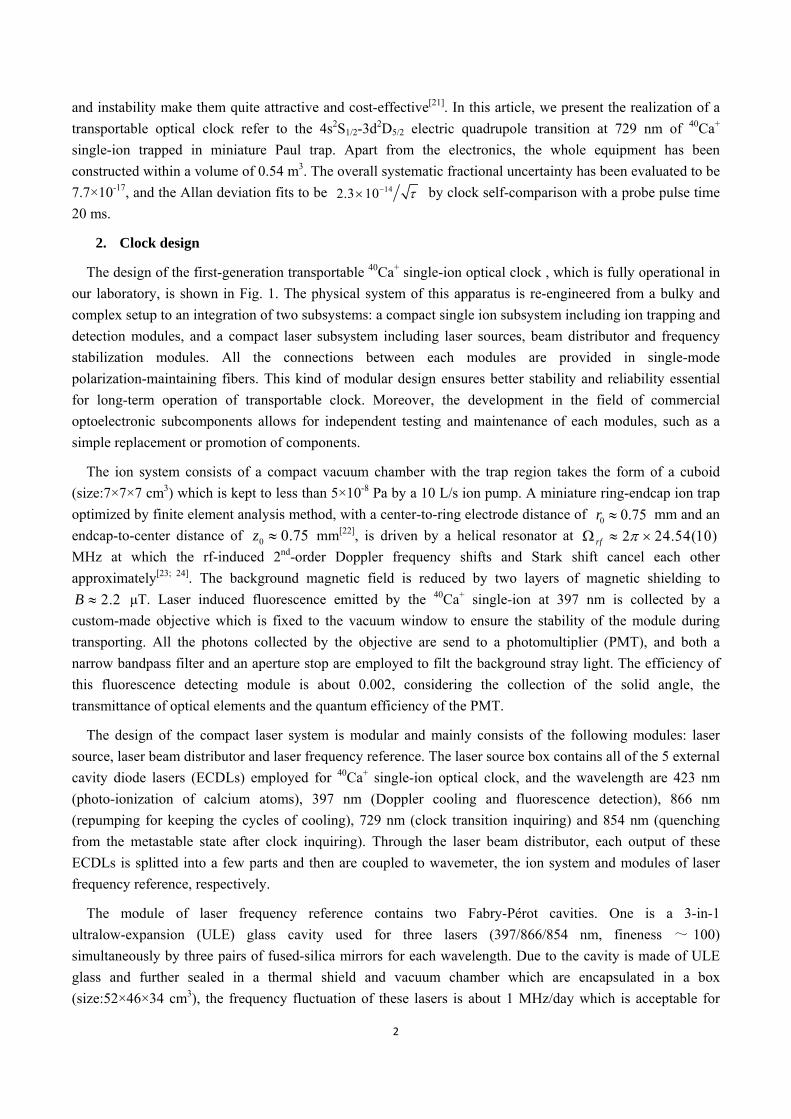
FIG. 2. Zeeman spectra of the 4s2S1/2-3d2D5/2 clock transition. (a) Ten components of the Zeeman profile with the whole
separation of ~180 kHz in the magnetic field of ~2.2 μT. The values of jm of magnetic sublevels in the upper 3d2D5/2
state selected for clock operation are shown in red marks. (b) Rabbi excitation spectrum of the 1 2jm component
with 729 nm pulse time 40 ms shows the spectrum resolution at 22 Hz level.
The thermal motion of the ion in the rf trap with secular motion frequency ,r z causes Doppler frequency
shift. For our ring-endcap trap, the ion temperature is estimated from the intensity of the secular sidebands
relative to the carrier[28]. These ratios normally are 0.02~0.05 for the radial sideband and 0.005~0.012 for the
axial sideband, yielding a mean temperature of 6(1) mK which is nearly an order higher than the Doppler
cooling limit. But thanks to the high secular motion frequencies, the single ion is laser-cooled to the
Lamb-Dicke regime as the Lamb-Dicke approximation is satisfied well and therefore the first-order Doppler
shift should not be considered. With the ion temperature estimated, the related second-order Doppler shift is
calculated to be -8.6(1.4) mHz[29]. On the other side, thermal secular motion can push the ion into nonzero
mean-square electric fields from the trap, which introduce a Stark shift. This shift can also be calculated from
the ion temperature above for the selected three pairs of transition and the average shift is 16.7(2.8) mHz[29].
As similar as the thermal motion, the excess micromotion can also produce a second-order Doppler shift
and a Stark shift. Since it’s always one of the greatest contributions of systematic uncertainty for optical clock
based on the ion in the rf trap, reduction of this micromotion to extremely low level is particularly important.
Adjustment of the DC voltages on two compensation electrodes in the radial plane and one of the endcap
electrodes while observing the trap region with both the EMCCD and PMT as the ion alternates between weak
and tight trap confinement (rf power: 2-5 W) allows observation of possible changes of ion position and
fluorescence counts by any residual trap asymmetry and stray fields[23]. This method rapidly converges the
system to a low state of micromotion which is parallel to the EMCCD sensor and thus the upper limit can be
estimated[21]. Ion displacement perpendicular to the EMCCD sensor will cause micromotion on the k-vector
direction of the 729 nm laser beam, which can be estimated by measuring the ratio of micromotion sideband
relative to carrier intensity. This ratio normally is 0.001~0.008 and the related second-order Doppler shift is
5
calculated to be , 2 18(18)D mHz[23]. However, considering the Stark shift due to excess
micromotion, the combined shifts can be shown as
2 2, 2 0 0[1 ],D rfmc e (1)
where 0 is the differential static scalar polarizability of clock transition, m the mass of ion, 0 the
clock transition angular frequency, c the speed of light, the Plank’s constant, and e the charge of an
electron. For ions with a negative value of 0 , such as 40Ca+, the term in square brackets vanishes when the
rf frequency takes the value of 0 0 0e mc . For our trap, which currently works at
2 24.54(10)rf MHz, the term in the square brackets is 0.018(16) and therefore the micromotion shifts
are suppressed by a factor of 63[27]. When applied to the value of second-order Doppler shift, the combined
shifts are canceled down to a level of ±0.29(29) mHz. The estimated total micromotion shifts is thus -0.33(58)
mHz and the tiny residual shift is produced from the little lower trap frequency.
The electric quadrupole shift caused by the interaction between the quadrupole moment and electric field
gradient is always a great source of systematic shift. This shift of a magnetic sublevel jm is given by[30]
2 23cos 1 1 3 4 ,EQ EQ jf m j j (2)
where EQ is a characteristic frequency proportional to the electric quadrupole moment and the electric field
gradient, and is the angle between the applied magnetic field and the electric field gradient. For the
selected three pairs of Zeeman components with 1 2, 3 2, 5 2jm , there is
2 1 3 0.j
j
jm j
m j j
(3)
It means the net electric quadrupole shift can be canceled to an extremely high level naturally. Measurements
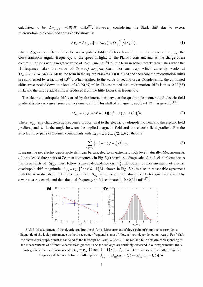
of the selected three pairs of Zeeman components in Fig. 3(a) provides a diagnostic of the lock performance as
the three shifts of EQf must follow a linear dependence on 2jm . Histogram of measurements of electric
quadrupole shift magnitude 23cos 1 4EQ EQA shown in Fig. 3(b) is also in reasonable agreement
with Gaussian distribution. The uncertainty of EQA is employed to evaluate the electric quadrupole shift by
a worst-case scenario and thus the total frequency shift is estimated to be 0(31) mHz[27].
FIG. 3. Measurement of the electric quadrupole shift. (a) Measurement of three pairs of components provides a
diagnostic of the lock performance as the three center frequencies must follow a linear dependence on 2jm . For 40Ca+,
the electric quadrupole shift is canceled at the intercept of 2 35 12jm . The red and blue dots are corresponding to
the measurements at different electric field gradient, and the red ones are routinely observed in our experiments. (b) A
histogram of the measurements of 23 cos 1 4
EQ EQA . EQ
A is determined experimentally using the
frequency difference between shifted pairs: [ (m 5 2) (m 1 2)] / 6EQ j EQ jEQ f fA .
6
The largest frequency shift in our transportable clock is the ac Stark shift induced by the blackbody
radiation (BBR) emitted by the ion’s environment. Both the temperature difference of the trap relative to the
vacuum chamber and the temperature fluctuation of the vacuum chamber are evaluated for our system. A
main complication in this evaluation is that the strong rf trap field will heat the dielectrics which are
necessarily incorporated into the structure of an ion trap to electrically insulate various components. So the
finite element models (FEM) is employed to calculate the temperature rise of any part of the trap structure and
the resulting steady-state temperature distribution due to thermal conduction and radiation[31]. Then these
results of simulation can be compared with experimental measurements by thermistor[3] and infrared camera[32]
at critical test points in a dummy trap in vacuum chamber, which almost identical to the system used for the
transportable clock. This comparison is essential for validation of the model to account for fabrication
tolerances, and as some material and surface characterizations which are not clearly known. As indicated in
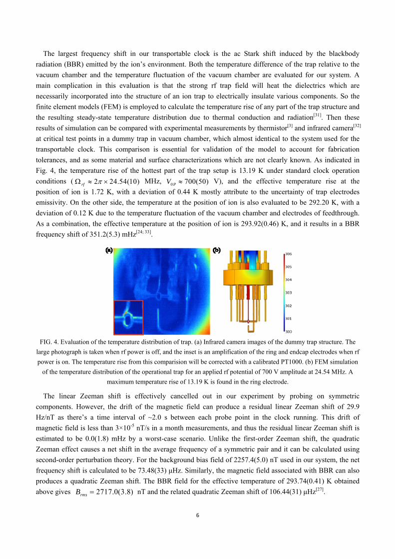
Fig. 4, the temperature rise of the hottest part of the trap setup is 13.19 K under standard clock operation
conditions ( 2 24.54(10)rf MHz, 0 700(50)PV V), and the effective temperature rise at the
position of ion is 1.72 K, with a deviation of 0.44 K mostly attribute to the uncertainty of trap electrodes
emissivity. On the other side, the temperature at the position of ion is also evaluated to be 292.20 K, with a
deviation of 0.12 K due to the temperature fluctuation of the vacuum chamber and electrodes of feedthrough.
As a combination, the effective temperature at the position of ion is 293.92(0.46) K, and it results in a BBR
frequency shift of 351.2(5.3) mHz[24; 33].
FIG. 4. Evaluation of the temperature distribution of trap. (a) Infrared camera images of the dummy trap structure. The
large photograph is taken when rf power is off, and the inset is an amplification of the ring and endcap electrodes when rf
power is on. The temperature rise from this comparision will be corrected with a calibrated PT1000. (b) FEM simulation
of the temperature distribution of the operational trap for an applied rf potential of 700 V amplitude at 24.54 MHz. A
maximum temperature rise of 13.19 K is found in the ring electrode.
The linear Zeeman shift is effectively cancelled out in our experiment by probing on symmetric
components. However, the drift of the magnetic field can produce a residual linear Zeeman shift of 29.9
Hz/nT as there’s a time interval of ~2.0 s between each probe point in the clock running. This drift of
magnetic field is less than 3×10⁻⁵ nT/s in a month measurements, and thus the residual linear Zeeman shift is
estimated to be 0.0(1.8) mHz by a worst-case scenario. Unlike the first-order Zeeman shift, the quadratic
Zeeman effect causes a net shift in the average frequency of a symmetric pair and it can be calculated using
second-order perturbation theory. For the background bias field of 2257.4(5.0) nT used in our system, the net
frequency shift is calculated to be 73.48(33) μHz. Similarly, the magnetic field associated with BBR can also
produces a quadratic Zeeman shift. The BBR field for the effective temperature of 293.74(0.41) K obtained
above gives 2717.0(3.8)rmsB nT and the related quadratic Zeeman shift of 106.44(31) μHz[27].
7
Electromagnetic fields of the lasers incident on the ion during the interrogations can cause ac Stark shift of
the clock transition. For 397 nm laser, two shutters are employed to switch off the laser beam. With the first
shutter is kept closed during the interrogations, the frequency difference between the states of the second
shutter on and off is measured to be 1.67(16) Hz. Therefore, with an attenuation of >50 dB for the second
shutter which switches off the 397 nm laser during the interrogations, the frequency shift is estimated to be
0.02(1) mHz by a worst-case scenario. For 854 nm laser, it’s similar to the situation of 397 nm and the
frequency shift is estimated with the same method to be -0.13(3) mHz. For the 866nm laser, only one shutter
is used and the frequency difference between the states of the second shutter on and off is measured to be
-29.89(33) Hz. Therefore, with an attenuation of >40 dB for the shutter which switches off the 866nm laser
during the interrogations, the upper limit of frequency shift is estimated to be -2.99(4) mHz by a worst-case
scenario. The ac Stark shift produced by the 729 nm laser is calculated by ac I where is the
coefficient of frequency shift as a function of laser intensity I [29]. The average of parameter for the
selected three pairs of Zeeman components is 0.8(2)mHz/(W/m2). In our current clock operation, the laser
power incident on the ion is 7(3) nW focused to a spot waist of 137(20) μm, and the related frequency shift is
calculated to be 0.19(10) mHz.
The frequency shift resulting from collisions with nonpolar gas molecules is estimated using a model based
on phase changing Langevin collisions. As without a calibrated quadrupole mass analyzer assembled in our
miniaturized vacuum chamber to measure the partial pressure of each gas components, an assumption is
adopted that all the gas is composed of H2. Therefore, the collisional frequency shift is calculated to be 1.7(1.7)
mHz with a measured pressure of 3.0(3.0)×10-8 Pa by a worst-case scenario[29].
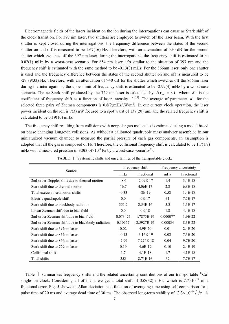
TABLE. Ⅰ. Systematic shifts and uncertainties of the transportable clock.
Source Frequency shift Frequency uncertainty
mHz Fractional mHz Fractional
2nd-order Doppler shift due to thermal motion -8.6 -2.09E-17 1.4 3.4E-18
Stark shift due to thermal motion 16.7 4.06E-17 2.8 6.8E-18
Total excess micromotion shifts -0.33 -8E-19 0.58 1.4E-18
Electric quadrupole shift 0.0 0E-17 31 7.5E-17
Stark shift due to blackbody radiation 351.2 8.54E-16 5.3 1.3E-17
Linear Zeeman shift due to bias field 0.0 0E-18 1.8 4.4E-18
2nd-order Zeeman shift due to bias field 0.073475 1.7875E-19 0.000077 1.9E-22
2nd-order Zeeman shift due to blackbody radiation 0.10657 2.5927E-19 0.00034 8.3E-22
Stark shift due to 397nm laser 0.02 4.9E-20 0.01 2.4E-20
Stark shift due to 854nm laser -0.13 -3.16E-19 0.03 7.3E-20
Stark shift due to 866nm laser -2.99 -7.274E-18 0.04 9.7E-20
Stark shift due to 729nm laser 0.19 4.6E-19 0.10 2.4E-19
Collisional shift 1.7 4.1E-18 1.7 4.1E-18
Total shifts 358 8.71E-16 32 7.7E-17
Table summarizes freⅠ quency shifts and the related uncertainty contributions of our transportable 40Ca+
single-ion clock. Considering all of them, we get a total shift of 358(32) mHz, which is 7.7×10⁻¹⁷ of a
fractional error. Fig. 5 shows an Allan deviation as a function of averaging time using self-comparison for a
pulse time of 20 ms and average dead time of 30 ms. The observed long-term stability of 142.3 10 is
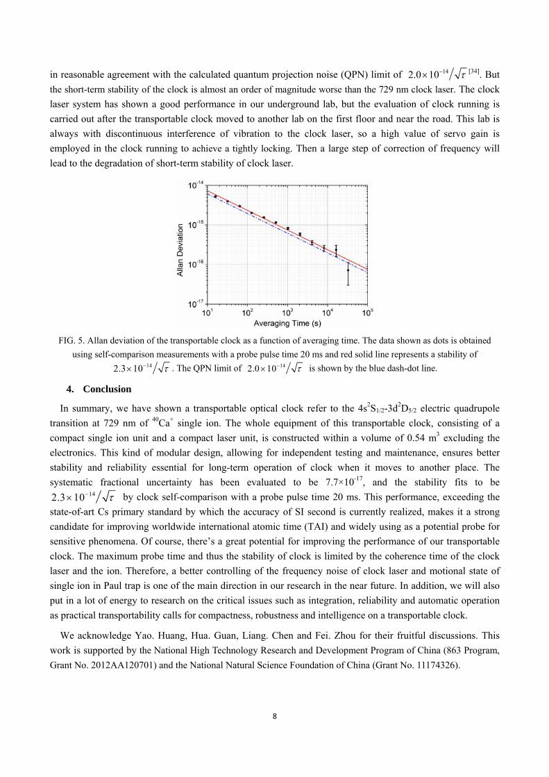
8
in reasonable agreement with the calculated quantum projection noise (QPN) limit of 142.0 10 [34]. But
the short-term stability of the clock is almost an order of magnitude worse than the 729 nm clock laser. The clock
laser system has shown a good performance in our underground lab, but the evaluation of clock running is
carried out after the transportable clock moved to another lab on the first floor and near the road. This lab is
always with discontinuous interference of vibration to the clock laser, so a high value of servo gain is
employed in the clock running to achieve a tightly locking. Then a large step of correction of frequency will
lead to the degradation of short-term stability of clock laser.
FIG. 5. Allan deviation of the transportable clock as a function of averaging time. The data shown as dots is obtained
using self-comparison measurements with a probe pulse time 20 ms and red solid line represents a stability of 142.3 10 . The QPN limit of 142.0 10 is shown by the blue dash-dot line.
4. Conclusion
In summary, we have shown a transportable optical clock refer to the 4s2S1/2-3d2D5/2 electric quadrupole
transition at 729 nm of 40Ca+ single ion. The whole equipment of this transportable clock, consisting of a
compact single ion unit and a compact laser unit, is constructed within a volume of 0.54 m3 excluding the
electronics. This kind of modular design, allowing for independent testing and maintenance, ensures better
stability and reliability essential for long-term operation of clock when it moves to another place. The
systematic fractional uncertainty has been evaluated to be 7.7×10⁻¹⁷, and the stability fits to be 142.3 10 by clock self-comparison with a probe pulse time 20 ms. This performance, exceeding the
state-of-art Cs primary standard by which the accuracy of SI second is currently realized, makes it a strong
candidate for improving worldwide international atomic time (TAI) and widely using as a potential probe for
sensitive phenomena. Of course, there’s a great potential for improving the performance of our transportable
clock. The maximum probe time and thus the stability of clock is limited by the coherence time of the clock
laser and the ion. Therefore, a better controlling of the frequency noise of clock laser and motional state of
single ion in Paul trap is one of the main direction in our research in the near future. In addition, we will also
put in a lot of energy to research on the critical issues such as integration, reliability and automatic operation
as practical transportability calls for compactness, robustness and intelligence on a transportable clock.
We acknowledge Yao. Huang, Hua. Guan, Liang. Chen and Fei. Zhou for their fruitful discussions. This
work is supported by the National High Technology Research and Development Program of China (863 Program,
Grant No. 2012AA120701) and the National Natural Science Foundation of China (Grant No. 11174326).
9
References
[1] Ludlow A D, Boyd M M, Ye J, et al. Optical atomic clocks[J]. Reviews of Modern Physics, 2015, 87(2): 637-701.
[2] Huntemann N, Sanner C, Lipphardt B, et al. Single-Ion Atomic Clock with 3×10-18 Systematic Uncertainty[J]. Physical Review
Letters, 2016, 116(6): 063001.
[3] Chou C W, Hume D B, Koelemeij J C J, et al. Frequency Comparison of Two High-Accuracy Al+ Optical Clocks[J]. Physical Review
Letters, 2010, 104(7): 070802.
[4] Nicholson T L, Campbell S L, Hutson R B, et al. Systematic evaluation of an atomic clock at 2 x 10-18 total uncertainty[J]. Nature
Communications, 2015, 6: 8.
[5] Ushijima I, Takamoto M, Das M, et al. Cryogenic optical lattice clocks[J]. Nat Photonics, 2015, 9(3): 185-189.
[6] Godun R M, Nisbet-Jones P B R, Jones J M, et al. Frequency Ratio of Two Optical Clock Transitions in 171Yb+ and Constraints on the
Time Variation of Fundamental Constants[J]. Physical Review Letters, 2014, 113(21): 210801.
[7] Huntemann N, Lipphardt B, Tamm C, et al. Improved Limit on a Temporal Variation of mp/me from Comparisons of Yb+ and Cs
Atomic Clocks[J]. Physical Review Letters, 2014, 113(21): 210802.
[8] Joao S M, Martins C, Mota I, et al. On the stability of fundamental couplings in the Galaxy[J]. Physics Letters B, 2015, 749: 389-392.
[9] Vutha A. Optical frequency standards for gravitational wave detection using satellite Doppler velocimetry[J]. New Journal of Physics,
2015, 17: 6.
[10] Chou C W, Hume D B, Rosenband T, et al. Optical Clocks and Relativity[J]. Science, 2010, 329(5999): 1630-1633.
[11] Bondarescu R, Scharer A, Lundgren A, et al. Ground-based optical atomic clocks as a tool to monitor vertical surface motion[J].
Geophysical Journal International, 2015, 202(3): 1770-1774.
[12] Fortier T M, Kirchner M S, Quinlan F, et al. Generation of ultrastable microwaves via optical frequency division[J]. Nature
Photonics, 2011, 5(7): 425-429.
[13] Petit G, Arias F, Panfilo G. International atomic time: Status and future challenges[J]. Comptes Rendus Physique, 2015, 16(5):
480-488.
[14] Hachisu H, Fujieda M, Nagano S, et al. Direct comparison of optical lattice clocks with an intercontinental baseline of 9000 km[J].
Optics Letters, 2014, 39(14): 4072-4075.
[15] Predehl K, Grosche G, Raupach S, et al. A 920-kilometer optical fiber link for frequency metrology at the 19th decimal place[J].
Science, 2012, 336(6080): 441-444.
[16] Schiller S, Gorlitz A, Nevsky A, et al. The Space Optical Clocks Project: Development of high-performance transportable and
breadboard optical clocks and advanced subsystems[J]. 2012 European Frequency and Time Forum (Eftf), 2012: 412-418.
[17] Poli N, Schioppo M, Vogt S, et al. A transportable strontium optical lattice clock[J]. Applied Physics B, 2014, 117(4): 1107-1116.
[18] Riehle F. Towards a redefinition of the second based on optical atomic clocks[J]. Comptes Rendus Physique, 2015, 16(5): 506-515.
[19] Bongs K, Singh Y, Smith L, et al. Development of a strontium optical lattice clock for the SOC mission on the ISS[J]. Comptes
Rendus Physique, 2015, 16(5): 553-564.
[20] Hill I R, Hobson R, Bowden W, et al. A low maintenance Sr optical lattice clock[J]. arXiv:1602.05810, 2016.
[21] Huang Y, Guan H, Liu P, et al. Frequency Comparison of Two 40Ca+ Optical Clocks with an Uncertainty at the 10-17 Level[J].
Physical Review Letters, 2016, 116(1): 013001.
[22] Cao Jian, T X, Cui Kai-Feng, Shang Jun-Juan, Shu Hua-Lin, Huang Xue-Ren. Simulation and Optimization of Miniature
Ring-Endcap Ion Traps[J]. Chin. Phys. Lett., 2014, 31(04): 43701-.
[23] Berkeland D J, Miller J D, Bergquist J C, et al. Minimization of ion micromotion in a Paul trap[J]. Journal of Applied Physics, 1998,
83(10): 5025-5033.
[24] Safronova M S, Safronova U I. Blackbody radiation shift, multipole polarizabilities, oscillator strengths, lifetimes, hyperfine
constants, and excitation energies in Ca+[J]. Physical Review A, 2011, 83(1): 012503.
[25] Drever R W P, Hall J L, Kowalski F, et al. Laser phase and frequency stabilization using an optical resonator[J]. Applied Physics B,
1983, 31(2): 97-105.
10
[26] Bernard J E, Madej A A, Marmet L, et al. Cs-based frequency measurement of a single, trapped ton transition in the visible region of
the spectrum[J]. Physical Review Letters, 1999, 82(16): 3228-3231.
[27] Dubé P, Madej A A, Zhou Z, et al. Evaluation of systematic shifts of the 88Sr+ single-ion optical frequency standard at the 10−17
level[J]. Physical Review A, 2013, 87(2): 023806.
[28] Urabe S, Watanabe M, Imajo H, et al. Observation of Doppler sidebands of a laser-cooled Ca+ ion by using a
low-temperature-operated laser diode[J]. Applied Physics B-Lasers and Optics, 1998, 67(2): 223-227.
[29] Madej A A, Bernard J E, Dubé P, et al. Absolute frequency of the 88Sr+ 5s 2S1⁄2 - 4d 2D5⁄2 reference transition at 445THz and
evaluation of systematic shifts[J]. Physical Review A, 2004, 70(1): 012507.
[30] Itano W M. External-field shifts of the 199Hg+ optical frequency standard[J]. Journal of Research of the National Institute of
Standards and Technology, 2000, 105(6): 829-837.
[31] Dolezal M, Balling P, Nisbet-Jones P B R, et al. Analysis of thermal radiation in ion traps for optical frequency standards[J].
Metrologia, 2015, 52(6): 842-856.
[32] Barwood G P, Huang G, Klein H A, et al. Agreement between two 88Sr+ optical clocks to 4 parts in 1017[J]. Physical Review A, 2014,
89(5): 050501.
[33] Itano W M, Lewis L L, Wineland D J. Shift of 2S1/2 hyperfine splittings due to blackbody radiation[J]. Physical Review A, 1982,
25(2): 1233-1235.
[34] Itano W, Bergquist J, Bollinger J, et al. Quantum projection noise: Population fluctuations in two-level systems[J]. Physical Review
A, 1993, 47(5): 3554.