Embed Size (px)
Citation preview
Friedrich-Alexander-Universitat Erlangen-Nurnberg
Technische Fakultat, Department Informatik
HANNES FLEISCHER
BACHELOR THESIS
APPLYING EVENT-DRIVEN
ARCHITECTURE IN THE JVALUE ODS
Submitted on 13 July 2020
Supervisor: Prof. Dr. Dirk Riehle, M.B.A.Professur fur Open-Source-SoftwareDepartment Informatik, Technische FakultatFriedrich-Alexander-Universitat Erlangen-Nurnberg

Versicherung
Ich versichere, dass ich die Arbeit ohne fremde Hilfe und ohne Benutzung andererals der angegebenen Quellen angefertigt habe und dass die Arbeit in gleicher oderahnlicher Form noch keiner anderen Prufungsbehorde vorgelegen hat und vondieser als Teil einer Prufungsleistung angenommen wurde. Alle Ausfuhrungen,die wortlich oder sinngemaß ubernommen wurden, sind als solche gekennzeichnet.
Erlangen, 13 July 2020
License
This work is licensed under the Creative Commons Attribution 4.0 Internationallicense (CC BY 4.0), see https://creativecommons.org/licenses/by/4.0/
Erlangen, 13 July 2020
i
Abstract
In a world of Big Data and data transparency “open data” might not be con-sidered as an unknown term anymore. As the name suggests, it describes datathat is commonly available and free to use for everyone.
The vision of the software “JValue Open Data Software (ODS)” is to providea solid solution for the community to achieve data availability and homogeneityin representation regarding open data. With the provision of an user interface toconfigure the way open data is extracted and how it is presented, ETL (Extract-Transform-Load) processes are exceedingly facilitated.
The challenges of scaling large for a platform, based on a software orientatedarchitecture, demand a solution that can handle a large set of interactions. Thepurpose of this thesis is to apply an “Event-Driven Architecture” to the alreadyexisting model of the software in order to fulfil these requirements. This is doneby reevaluating the current software design that is composed of distributed Mi-croservices and identify events of its current architecture with a technique called“Event-Storming”. The results will be applied to an architecture design that willbe implemented in the “JValue ODS”.
ii
Contents
1 Introduction 1
2 Fundamentals 32.1 Domain Driven Design . . . . . . . . . . . . . . . . . . . . . . . . 3
2.1.1 Definition . . . . . . . . . . . . . . . . . . . . . . . . . . . 32.1.2 Domain and Bounded Context . . . . . . . . . . . . . . . . 32.1.3 Ubiquitous language . . . . . . . . . . . . . . . . . . . . . 42.1.4 Layered Architecture . . . . . . . . . . . . . . . . . . . . . 42.1.5 Model-Driven Design . . . . . . . . . . . . . . . . . . . . . 5
2.2 microservices . . . . . . . . . . . . . . . . . . . . . . . . . . . . . 72.2.1 Definition . . . . . . . . . . . . . . . . . . . . . . . . . . . 72.2.2 Characteristics . . . . . . . . . . . . . . . . . . . . . . . . 82.2.3 Structure . . . . . . . . . . . . . . . . . . . . . . . . . . . 92.2.4 Communication . . . . . . . . . . . . . . . . . . . . . . . . 102.2.5 Analysis . . . . . . . . . . . . . . . . . . . . . . . . . . . . 12
2.3 JValue ODS . . . . . . . . . . . . . . . . . . . . . . . . . . . . . . 142.3.1 Definition . . . . . . . . . . . . . . . . . . . . . . . . . . . 142.3.2 Structure . . . . . . . . . . . . . . . . . . . . . . . . . . . 142.3.3 Components . . . . . . . . . . . . . . . . . . . . . . . . . . 152.3.4 Process Flow . . . . . . . . . . . . . . . . . . . . . . . . . 18
2.4 Event-Driven Architecture . . . . . . . . . . . . . . . . . . . . . . 202.4.1 Definition . . . . . . . . . . . . . . . . . . . . . . . . . . . 202.4.2 Elements . . . . . . . . . . . . . . . . . . . . . . . . . . . . 202.4.3 Topologies . . . . . . . . . . . . . . . . . . . . . . . . . . . 222.4.4 Event-Based Patterns . . . . . . . . . . . . . . . . . . . . . 24
3 Requirements 263.1 Functional . . . . . . . . . . . . . . . . . . . . . . . . . . . . . . . 263.2 Non-Functional . . . . . . . . . . . . . . . . . . . . . . . . . . . . 27
4 Architecture Design 284.1 Analysis with Event-Storming . . . . . . . . . . . . . . . . . . . . 28
iii
4.1.1 Definition . . . . . . . . . . . . . . . . . . . . . . . . . . . 294.1.2 Procedure . . . . . . . . . . . . . . . . . . . . . . . . . . . 304.1.3 Results . . . . . . . . . . . . . . . . . . . . . . . . . . . . . 31
4.2 Event-Based Design of ODS . . . . . . . . . . . . . . . . . . . . . 344.2.1 Technology Considerations . . . . . . . . . . . . . . . . . . 344.2.2 Architecture . . . . . . . . . . . . . . . . . . . . . . . . . . 354.2.3 Choreography . . . . . . . . . . . . . . . . . . . . . . . . . 404.2.4 Evaluation . . . . . . . . . . . . . . . . . . . . . . . . . . . 42
5 Implementation 435.1 Iteration 1: Transformation-Notification segregation . . . . . . . . 435.2 Iteration 2: Introduction of config databases . . . . . . . . . . . . 445.3 Iteration 3: Deletion of pipeline repository . . . . . . . . . . . . . 465.4 Iteration 4: Transformation-notification communication . . . . . . 475.5 Iteration 5: Adapter-transformation communication . . . . . . . . 485.6 Iteration 6: Storage-Transformation communication . . . . . . . . 495.7 Iteration 5: Adapter-scheduler communication . . . . . . . . . . . 51
6 Evaluation 526.1 Requirements . . . . . . . . . . . . . . . . . . . . . . . . . . . . . 52
6.1.1 Functional . . . . . . . . . . . . . . . . . . . . . . . . . . . 526.1.2 Non-functional . . . . . . . . . . . . . . . . . . . . . . . . 53
6.2 Scalability . . . . . . . . . . . . . . . . . . . . . . . . . . . . . . . 546.3 Further improvements . . . . . . . . . . . . . . . . . . . . . . . . 54
Appendices 55Appendix A Event storming workshop . . . . . . . . . . . . . . . . . 55Appendix B Event driven architecture - Scaled . . . . . . . . . . . . 56
References 63
iv
Acronyms
AMQP Advanced Message Queuing Protocol. 35
API Application Programming Interface. 11, 13–15, 25, 34, 38, 49–52, 54
CI Continuous Integration. 8, 9
CQRS Command-Query Responsibility Segregation. 25, 49
CRUD Create-Request-Update-Delete Operations. 39, 45, 51
CUD Create-Update-Delete Operations. 25, 38, 39, 50
DDD Domain Driven Design. 3, 4, 29, 44
DDL Data Definition Language. 49
DevOPS Development Operations. 8, 9
DML Data Modeling Language. 50
EDA Event-Driven Architecture. 2, 20, 40
EERM Enhanced Relationship-Entity Model. 37
ODS Open Data Service. 27, 32, 35–37, 41, 43, 47, 48, 53, 54, 62
REST Representational State Transfer. 11, 13–16, 35, 38–41, 49–52
RPC Remote Proceedure Calls. 11
SJON JavaScript Object Notation. 14, 15, 45, 46
v
1 Introduction
Nowadays more and more importance gets attached to data transparancy andknowledge exchange, resulting in a demand for provisioning of data for generalwelfare purposes. Therefore an increasing amount of establishments is providingopen data to satisfy these needs. Open data describes data, that is commonlyavailable and free to use for everyone and is the main subject of JValue OpenData Service .This software supports open data consumers when it comes to extracting andmaintaining this data from various web services. It provides a platform for thegeneral public to gain unified control over the ETL-Processes (Extract-Transform-Load) regarding the obtainment of open data from web interfaces, such as REST-ful Application Programming Interfaces (APIs).
Extract - To accomplish higher availability this service not only stores alreadyaquired data sets, it also enables the operators to choose a frequency to updatethe persistent data with data from related sources, giving the opportunity to re-spond to quota restrictions and to counteract scheduled downtimes.
Transform - Furthermore it reduces the efforts of handling various data rep-resentations, such as XML or JSON, from several sources by giving the user theopportunity to choose the structure of the data to be received. As a consequencea consuming application no longer has to take care of covering multiple formatswhen aquiring data from different sources, in order to achieve a specific goal.
Load - While many of these applications only use a specific share of the res-ult sets from web service calls, they might suffer from efficiency losses, due tohaving to deal with data, they do not utilize. A solution for this problem is givenby JValue ODS by serving a built-in and easy-to-use filter mechanism. It enablesusers to apply filters, in order to retain or omit data sections within the responsesof open data webservices. This feature not only simplifies the processing of thedata in applications, it enhances performance by decreasing webservice responsetimings when using JValue ODS as intermediate platform, resulting in an in-crease of “reponsiveness“.
1
Its structure is composed of different Microservices, whereas every of these com-ponents serves a specific purpose, contributing to the core functionality of thewhole application.With its architecture design JValue ODS follows the trend of modularizing “old-fashioned“ monolithic software structures to a coherent set of services, that rep-resent specific all functional aspects the application. Many design patterns haveemerged from this proceeding with the intention to provide a more beneficialsolution, in terms of exchangability, scalability and robustness.One particular pattern, this thesis is paying attention to, is the Event-DrivenArchitecture (EDA) in the context of JValue ODS. As Microservices describesthe segmentation of software to isolated services, EDA is more concerned aboutthe communication between these.
The current design of the software, regarding the inter-service communication,led to the consideration of a more flexible and scalable message system solution.The goal this thesis is trying to achieve is to move from the current orchestra-tion or respectively communication mechanism of JValue ODS to a event drivenchoreography. This is done by analysing the current architecture and communic-ation patterns with a technique called Event-Storming Workshop. The resultsof this workshop can be derived to establish a new architecture that enclosesevent-based messaging and serves as the basis for the implementation. It will fur-thermore investigate critical paths in the messaging flow, in order to substitudethe communication patterns efficiently. The results of the implementation will beevaluated by executing stress tests, regarding the communication, to the formerand new architecture and putting them into comparison.
2
2 Fundamentals
2.1 Domain Driven Design
As the Structure of the Jvalue Open Data Service is, to some extent, createdby Domain Driven Design and the technique to identify events of its currentarchitecture (Event-Storming) refers to it, a definition of this design pattern isrequired.
2.1.1 Definition
Domain Driven Design (DDD) is a technique for designing complex software byclosing the knowledge gap between software developers and domain experts, suchas project owners, business analysts, stakeholders, etc. in order to build mean-ingful models, that reflect business logic. It was first proposed by Eric Evans inhis work “Domain-Driven Design: Tackling Complexity in the Heart of Software“and aims at providing more transparency to all participants of a software project,as well as designing flexible and robust software architectures. It can furthermorebe understood as a way of thinking and a set of priorities, aimed at accelerat-ing software projects that have to deal with complicated domains [Eva04]. Thismodeling approach helps explaining complex relations on an abstract level by de-termining delimited boundaries and facilitates the design of an evolving softwarearchitecture that is a projection of core business concepts.
2.1.2 Domain and Bounded Context
A domain is, per definition, a “sphere of knowledge“ and should be the primaryfocus for most software projects, when it comes to reducing complexity, accordingto Evans [Eva04]. In the context of an software application, domains can bedetermined by problems and objectives that have to be solved. A domain canfurthermore divided into Subdomains that represent areas of capability, definebusiness processes and represent functionality of a system [MT15].Subdomains can moreover differentiated by three categories.
3
Core Domain - DDD mainly focuses on Core Domains, which are part ofthe business domain that represent the main purpose of the system. Primaryimportance is attached to this Subdomain due to having significant impact onthe success of an organization [Ver13, p. 71].
Supporting Subdomain - These domains are essential for the business, butdo not represent he core business logic. They rather have a supporting functionfor the Core Domain.
Generic Subdomain - A Generic Subdomain captures nothing special to thebusiness, yet is required for the overall business solution [Ver13, p. 71].
Generally business models and the feasibility of technical implementation of thesemay differ and may be modeled in another way. Bounded Contexts representcoherent functional aspects of the system that might not fit exactly into a sub-domain and define the range of applicability of each model [Eva04, p. 239]. Theyshould be clearly separated from other contexts to ensure clear competences andnaming conventions and may be connected to each other. In Addition a ContextMap can be defined to provide a global overview of the contexts and relationshipsbetween them [Eva04, p. 239].
2.1.3 Ubiquitous language
When it comes to building a domain model, several parties may contribute toits design. When domain experts and developers collaborate on this model, theuse of common language plays an important role. Domain experts may havea limited understanding of technical jargon of software development, but theyuse the jargon of their field. On the other hand developers may make use ofdescriptive and functional terms, regarding the discussion of systems [Eva04].Therefore the use of an ubiquitous language is highly recommended to facilitatethe communication between corresponding responsibles.
2.1.4 Layered Architecture
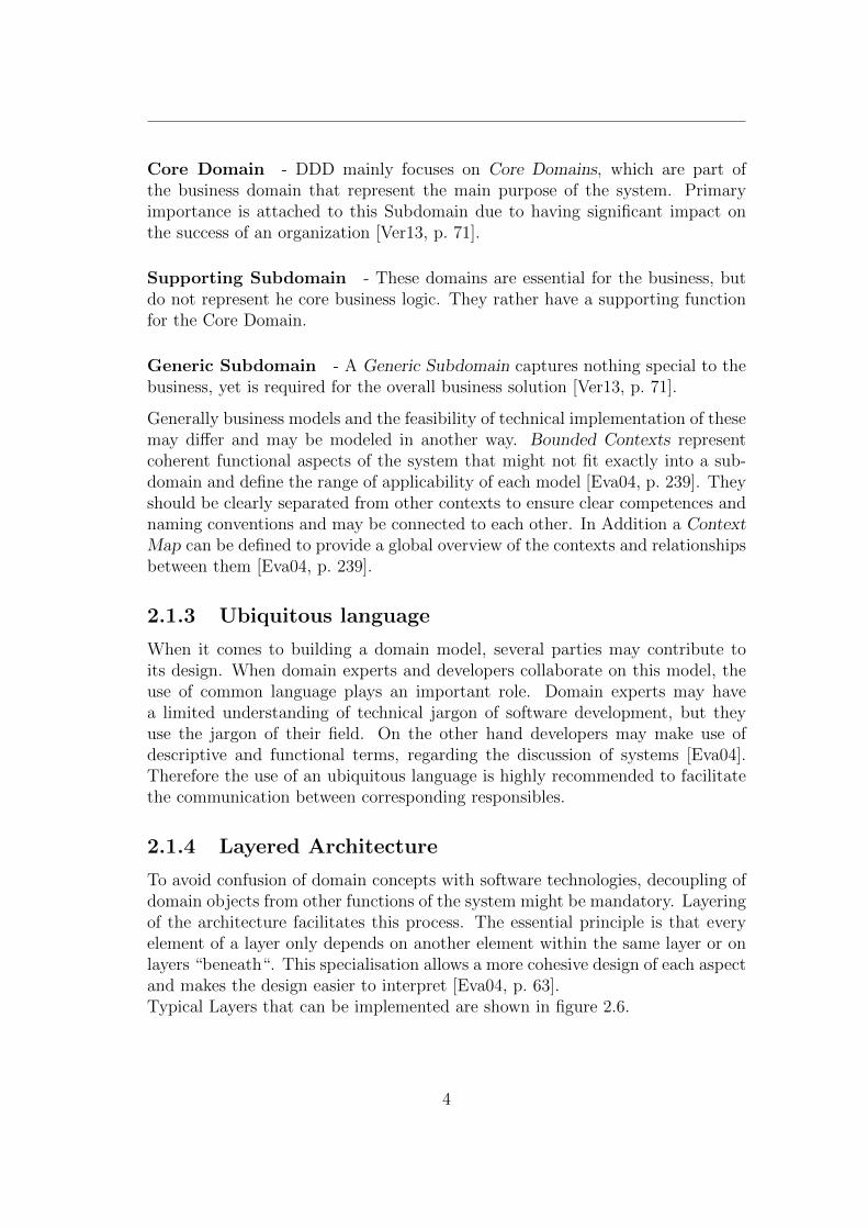
To avoid confusion of domain concepts with software technologies, decoupling ofdomain objects from other functions of the system might be mandatory. Layeringof the architecture facilitates this process. The essential principle is that everyelement of a layer only depends on another element within the same layer or onlayers “beneath“. This specialisation allows a more cohesive design of each aspectand makes the design easier to interpret [Eva04, p. 63].Typical Layers that can be implemented are shown in figure 2.6.
4
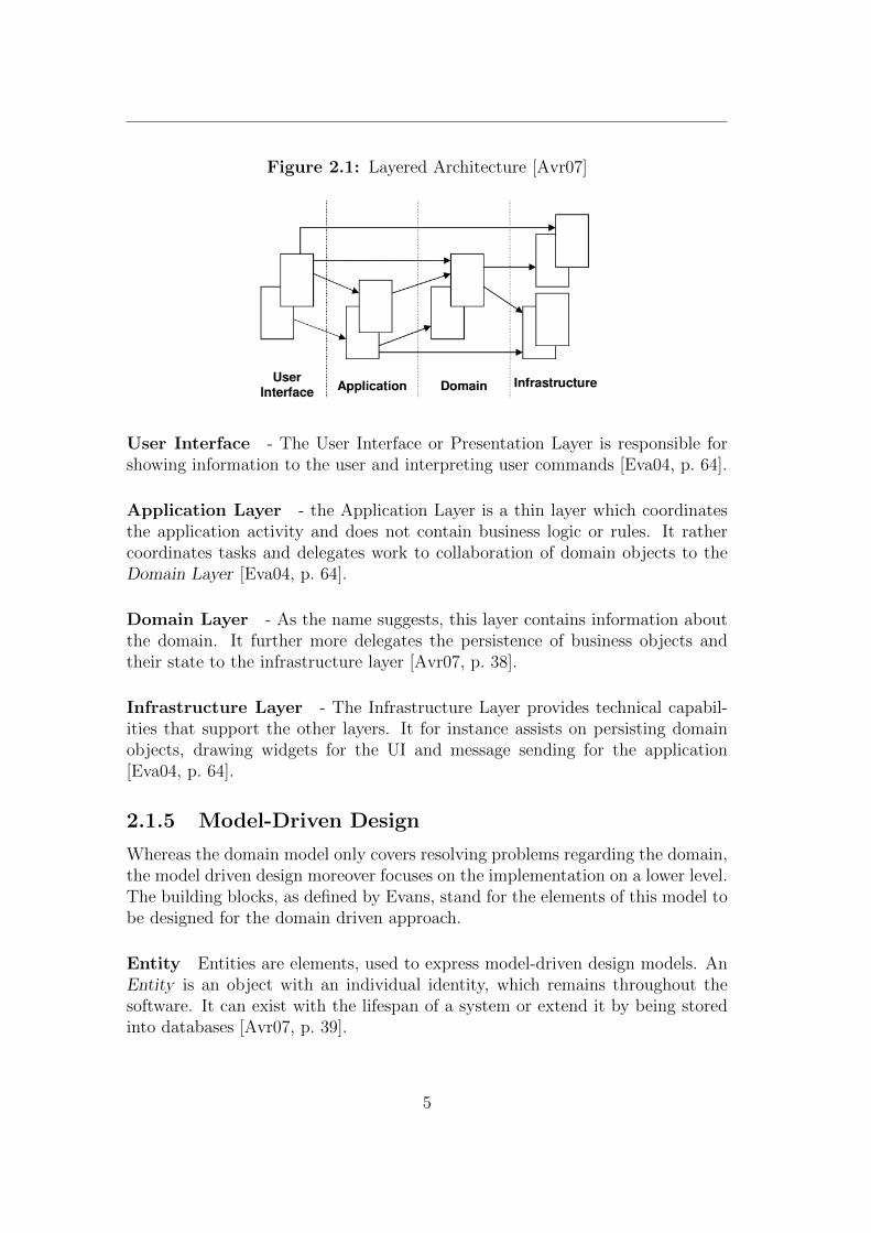
Figure 2.1: Layered Architecture [Avr07]
User Interface - The User Interface or Presentation Layer is responsible forshowing information to the user and interpreting user commands [Eva04, p. 64].
Application Layer - the Application Layer is a thin layer which coordinatesthe application activity and does not contain business logic or rules. It rathercoordinates tasks and delegates work to collaboration of domain objects to theDomain Layer [Eva04, p. 64].
Domain Layer - As the name suggests, this layer contains information aboutthe domain. It further more delegates the persistence of business objects andtheir state to the infrastructure layer [Avr07, p. 38].
Infrastructure Layer - The Infrastructure Layer provides technical capabil-ities that support the other layers. It for instance assists on persisting domainobjects, drawing widgets for the UI and message sending for the application[Eva04, p. 64].
2.1.5 Model-Driven Design
Whereas the domain model only covers resolving problems regarding the domain,the model driven design moreover focuses on the implementation on a lower level.The building blocks, as defined by Evans, stand for the elements of this model tobe designed for the domain driven approach.
Entity Entities are elements, used to express model-driven design models. AnEntity is an object with an individual identity, which remains throughout thesoftware. It can exist with the lifespan of a system or extend it by being storedinto databases [Avr07, p. 39].
5
Figure 2.2: The Building Blocks Of A Model-Driven Design [Avr07]
Value Objects Value Objects do not have their own identity and are purelydescribing domain-relevant attributes of entities, usually in the form of somequantity [MT15]. They have no state throughout the system might be moreoverconsidered as an state of an Entity. They are therefore immutable objects andcan be distributed among the system.
Aggregates Aggregates are composite domain objects and decrease complexityof a model by providing one interface for its coherent Entities and Value Objects.The root is an Entity and is the only object accessible from outside and holdsreferences to any of the aggregate objects. With the provision of only one interfacefor those coherent domain objects, it ensures data integrity and enforces invariants[Avr07, p. 44].
Services Services represent domain concepts and are stateless [MT15, p. 435].They are used when the behaviour does not conform with the concept of theModel-Driven Design using Entities and Value Objects. The main intention is toformulate business rules.
6
Repositories Repositories are used to manage the persistence and retrievalof aggregates usually using a database. It ensures the separation of the domainmodel and the data model by mediating between these two models [MT15, p. 525].
Factories The creation of domain objects by encapsulation. Factories can re-constitute object from a persistence model or create new domain objects , encap-sulating complex domain logic [MT15, p. 470].
2.2 microservices
2.2.1 Definition
Since the architecture of JValue ODS is based on microservices, further ex-planation might be mandatory. Although there is no common definition of mi-croservices, the segmentation or modularisation of software by functionality mightbe the best fitting term. A comprehensive definition was given by Nadareishviliet al. [Nad+16, p. 6]:
“A microservice is an independently deployable component of boundedscope that sup- ports interoperability through message-based commu-nication. microservice architec- ture is a style of engineering highlyautomated, evolvable software systems made up of capability-alignedmicroservices.“
Furthermore a good approach of defining a microservice might be to describe itscore functionalities and benefits in comparison with software monoliths.While traditional software monoliths describe software, that keeps the whole func-tionality of a program at one place, the microservice pattern is more focused onseparating the program into components, that represent all functional aspectsof the former structure. The static architecture of the monolith leads generallyto difficulties in terms of changeability, exchangability and team collaboration,whereas the microservice patterns seem to solve these problems. These advant-ages over the monolith led to a trend of splitting it into autonomous services toachieve a more agile development of software.
Referring to Newman [New15] the main key aspect is the autonomy of the ser-vices. Each microservice of an application is responsible for a specific purposeand does not interfere with other components of the infrastructure. Therebysharing information between the services have to be accomplished vie networkcommunication, such as requests over application programming interfaces (API)or remote procedure calls (RPC) to attain the separation between these.
7
2.2.2 Characteristics
According to Nadareishvili et al. [Nad+16, p. 7] a microservice can be identifiedby these important characteristics:
Small in size As a result of the segmentation of software by contexts, smallservices arise. These exclusively cover one purpose and by that only come in smallsize compared to software monoliths. To reduce complexity for the developers,microservices can generally be owned by separate teams. Thereby microservicemeasurements can be somewhat determined by team size.
Messaging enabled With the modularization of software into different ser-vices, an opportunity of deploying these components on different systems emerged.To consequently asure correct behaviour of the application, a microservice hasto provide an interface for communication or respectively for messaging in or-der to exchange information with the other components of the microservice ar-chitetcture.
Bounded by contexts As the microservice architecture to some extent followsthe Domain Driven Design pattern, the concession of software components withsimilar properties to a “bounded context“ results in a microservice, comprising itsfunction. As a consequence every microservice is defined by one context only anddoes not interfere with other microservices and therefore not with other contexts.
Autonomously developed As a key feature this pattern enables teams toimplement each microservice separately without having impact on the function-ality of the other services. With well-defined contracts to other microservicesthe responsible team takes care of the correct behaviour of the service, as wellas provisioning of an interface for communication. This way of implementationcontributes to a more beneficial solution, regarding agile software developmentand Development Operations (DevOPS).
Built and released with automated processes Continuous Integration CIis a development practise where members of a team integrate their work fre-quently, whereby each integration is verified by an automated build to detectintegration errors by including tests [FF06].With the segmentation of the software monolith, a need for validation of each unitbefore deployment derives and results in the consideration of a integration tech-nique like CI, that assures the correct behaviour of the independently developedunits.
8
Independently deployable Since every microservice is segregated completelyfrom the other microservices within an application, the transition of getting newfeatures into production gets faster and provides more flexible options for pilotingand prototyping Nadareishvili et al. [Nad+16, p. 16]. With DevOPS deploymenttechniques, like Continuous Integration (CI), only tested units get deployed intoproduction and therefore do not interfere with the application’s stability.
Decentralized Since every microservice is a independently deployed unit andthe communication between these is typically done via network calls, they mightbe distributed among different servers or virtual machines.With respect to software development, decentralization means that the bulk ofwork done within a system will no longer be managed and controlled by a centralbody. Consequently the implementation of software changes become easier, fasterand will result in fewer bottlenecks and less resistance to change [Nad+16, p. 8].
2.2.3 Structure
The composition of software modules to microservices is generally determinedby applying the Domain Driven Design and therefore determines which mir-coservice within the system should implement which domain [Wol16, p. 100].The key concept within the microservices pattern is the distributed architecture.microservices are completely separated from each other and therefore have tocommunicate via network calls. As shown in figure 2.4, related modules are com-bined to service components which represent microservices.Every microservice serves one purpose and gets in general accessed by an UserInterface Layer via remote access protocol (e.g., AMQP, REST, SOAP, etc.)[Ric15]. Client requests can be user interactions or other systems interacting withthe microservice system and are typically done via Application Programming In-terface. The system itself takes care of the correct orchestration or choreographyby either communicating with each other over these interfaces or publishing andconsuming Events in order to maintain the core functionality.
Two architectural characteristics that all microservice implementations have incommon are Loose Coupling and High Cohesion:
Looslely coupled As mentioned before, they are loosely coupled and may bedistributed across various systems. Each microservice should have few depend-encies on other microservies to facilitate the modification of them, since changewill have only have an impact on other individual microservices [Wol16, p. 102].Breaking up systems and identifying bounded contexts in a system by applyingDomain Driven Design is an effective way of designing microservice boundaries[Nad+16, p. 64]. Therefore the boundaries of microservices align to some extentto the Bounded Contexts of a Domain Driven Design.
9
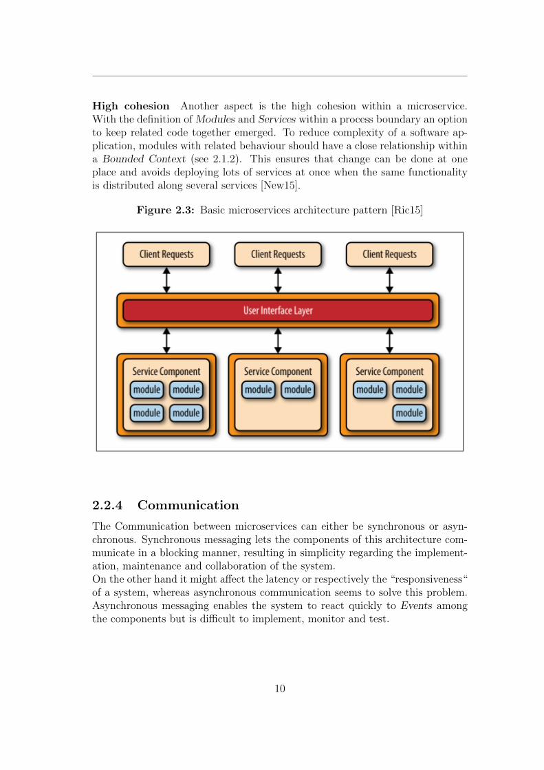
High cohesion Another aspect is the high cohesion within a microservice.With the definition of Modules and Services within a process boundary an optionto keep related code together emerged. To reduce complexity of a software ap-plication, modules with related behaviour should have a close relationship withina Bounded Context (see 2.1.2). This ensures that change can be done at oneplace and avoids deploying lots of services at once when the same functionalityis distributed along several services [New15].
Figure 2.3: Basic microservices architecture pattern [Ric15]
2.2.4 Communication
The Communication between microservices can either be synchronous or asyn-chronous. Synchronous messaging lets the components of this architecture com-municate in a blocking manner, resulting in simplicity regarding the implement-ation, maintenance and collaboration of the system.On the other hand it might affect the latency or respectively the “responsiveness“of a system, whereas asynchronous communication seems to solve this problem.Asynchronous messaging enables the system to react quickly to Events amongthe components but is difficult to implement, monitor and test.
10
Each collaboration pattern is based on another model. While synchronous mes-saging follows the Request/Response model, asynchronous communication ismore concerned about event-based collaboration [New15, p. 89].
Request/Response Model Implementations of the Request/Response pat-tern, like Representational State Transfer (REST) and Remote Proceedure Calls(RPC), have in common that a client initiates a request to an Application Pro-gramming Interface and has to wait until the remote process, that handles therequest, is finished. The end of the remote process is signaled by a response tothe client.
Event-Based Model In Event-Based Models microservices do not know theexistence of other components of the system. They rather wait for Events tohappen, react to them and may moreover publish further Events. High decoup-ling and scalability gets achieved by the opportunity of adding new subscribersto events without the event publisher ever needing to know [New15, p. 89].
Another aspect in terms of architecture considerations is the decision to im-plement Orchestration or Choreography [New15, p. 90]. Both describe a style ofcollaboration between components of a system.
Orchestration Orchestration relies on a central component, the Orchestrator,that controls the behaviour of the microservices. This component acts as a su-pervisor and coordinates the whole process flow of the system by interactingwith each component. With this type of service composition every service withinthe system only cooperates with the Orchestrator in order to achieve a specificdomain functionality. As a consequence microservices only have access to theirdomain and therefore have a limited scope.
Choreography Choreography describes the sequence and conditions in whichdata is exchanged between participants in order to meet some useful purpose[BK04]. The core focus of this approach is on implementing domain logic bydecentralizing the communication to a set of peers or respectively microservices.In comparison to the Orchestration the services do not need a central componentin order to implement desired behaviour. They rather organize themselves byinteracting with each other in an synchronous or asynchronous manner. Withthe implementation of Service Choreography the system are significantly moreloosely coupled, as well as more flexible and amenable to change [New15, p. 92].
11
2.2.5 Analysis
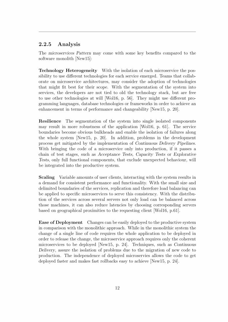
The microservices Pattern may come with some key benefits compared to thesoftware monolith [New15]:
Technology Heterogeneity With the isolation of each microservice the pos-sibility to use different technologies for each service emerged. Teams that collab-orate on microservice architectures, may consider the adoption of technologiesthat might fit best for their scope. With the segmentation of the system intoservices, the developers are not tied to old the technology stack, but are freeto use other technologies at will [Wol16, p. 56]. They might use different pro-gramming languages, database technologies or frameworks in order to achieve anenhancement in terms of performance and changeability [New15, p. 20].
Resilience The segmentation of the system into single isolated componentsmay result in more robustness of the application [Wol16, p. 61]. The serviceboundaries become obvious bulkheads and enable the isolation of failures alongthe whole system [New15, p. 20]. In addition, problems in the developmentprocess get mitigated by the implementation of Continuous Delivery Pipelines.With bringing the code of a microservice only into production, if it passes achain of test stages, such as Acceptance Tests, Capacity Tests or ExplorativeTests, only full functional components, that exclude unexpected behaviour, willbe integrated into the productive system.
Scaling Variable amounts of user clients, interacting with the system results ina demand for consistent performance and functionality. With the small size anddelimited boundaries of the services, replication and therefore load balancing canbe applied to specific microservices to serve this consistency. With the distribu-tion of the services across several servers not only load can be balanced acrossthose machines, it can also reduce latencies by choosing corresponding serversbased on geographical proximities to the requesting client [Wol16, p.61].
Ease of Deployment Changes can be easily deployed to the productive systemin comparison with the monolithic approach. While in the monolithic system thechange of a single line of code requires the whole application to be deployed inorder to release the change, the microservice approach requires only the coherentmicroservices to be deployed [New15, p. 24]. Techniques, such as ContinuousDelivery, assure the isolation of problems due to the migration of new code toproduction. The independence of deployed microservies allows the code to getdeployed faster and makes fast rollbacks easy to achieve [New15, p. 24].
12
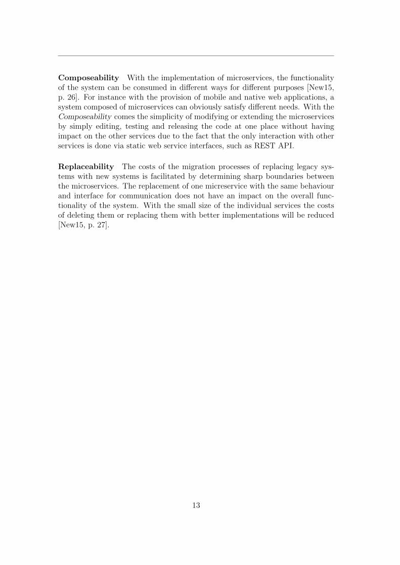
Composeability With the implementation of microservices, the functionalityof the system can be consumed in different ways for different purposes [New15,p. 26]. For instance with the provision of mobile and native web applications, asystem composed of microservices can obviously satisfy different needs. With theComposeability comes the simplicity of modifying or extending the microservicesby simply editing, testing and releasing the code at one place without havingimpact on the other services due to the fact that the only interaction with otherservices is done via static web service interfaces, such as REST API.
Replaceability The costs of the migration processes of replacing legacy sys-tems with new systems is facilitated by determining sharp boundaries betweenthe microservices. The replacement of one micreservice with the same behaviourand interface for communication does not have an impact on the overall func-tionality of the system. With the small size of the individual services the costsof deleting them or replacing them with better implementations will be reduced[New15, p. 27].
13
2.3 JValue ODS
2.3.1 Definition
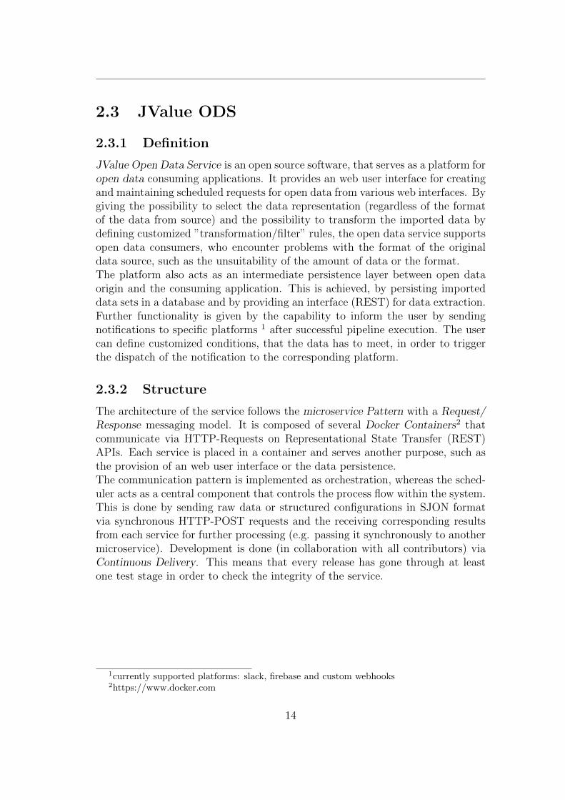
JValue Open Data Service is an open source software, that serves as a platform foropen data consuming applications. It provides an web user interface for creatingand maintaining scheduled requests for open data from various web interfaces. Bygiving the possibility to select the data representation (regardless of the formatof the data from source) and the possibility to transform the imported data bydefining customized ”transformation/filter” rules, the open data service supportsopen data consumers, who encounter problems with the format of the originaldata source, such as the unsuitability of the amount of data or the format.The platform also acts as an intermediate persistence layer between open dataorigin and the consuming application. This is achieved, by persisting importeddata sets in a database and by providing an interface (REST) for data extraction.Further functionality is given by the capability to inform the user by sendingnotifications to specific platforms 1 after successful pipeline execution. The usercan define customized conditions, that the data has to meet, in order to triggerthe dispatch of the notification to the corresponding platform.
2.3.2 Structure
The architecture of the service follows the microservice Pattern with a Request/Response messaging model. It is composed of several Docker Containers2 thatcommunicate via HTTP-Requests on Representational State Transfer (REST)APIs. Each service is placed in a container and serves another purpose, such asthe provision of an web user interface or the data persistence.The communication pattern is implemented as orchestration, whereas the sched-uler acts as a central component that controls the process flow within the system.This is done by sending raw data or structured configurations in SJON formatvia synchronous HTTP-POST requests and the receiving corresponding resultsfrom each service for further processing (e.g. passing it synchronously to anothermicroservice). Development is done (in collaboration with all contributors) viaContinuous Delivery. This means that every release has gone through at leastone test stage in order to check the integrity of the service.
1currently supported platforms: slack, firebase and custom webhooks2https://www.docker.com
14
2.3.3 Components
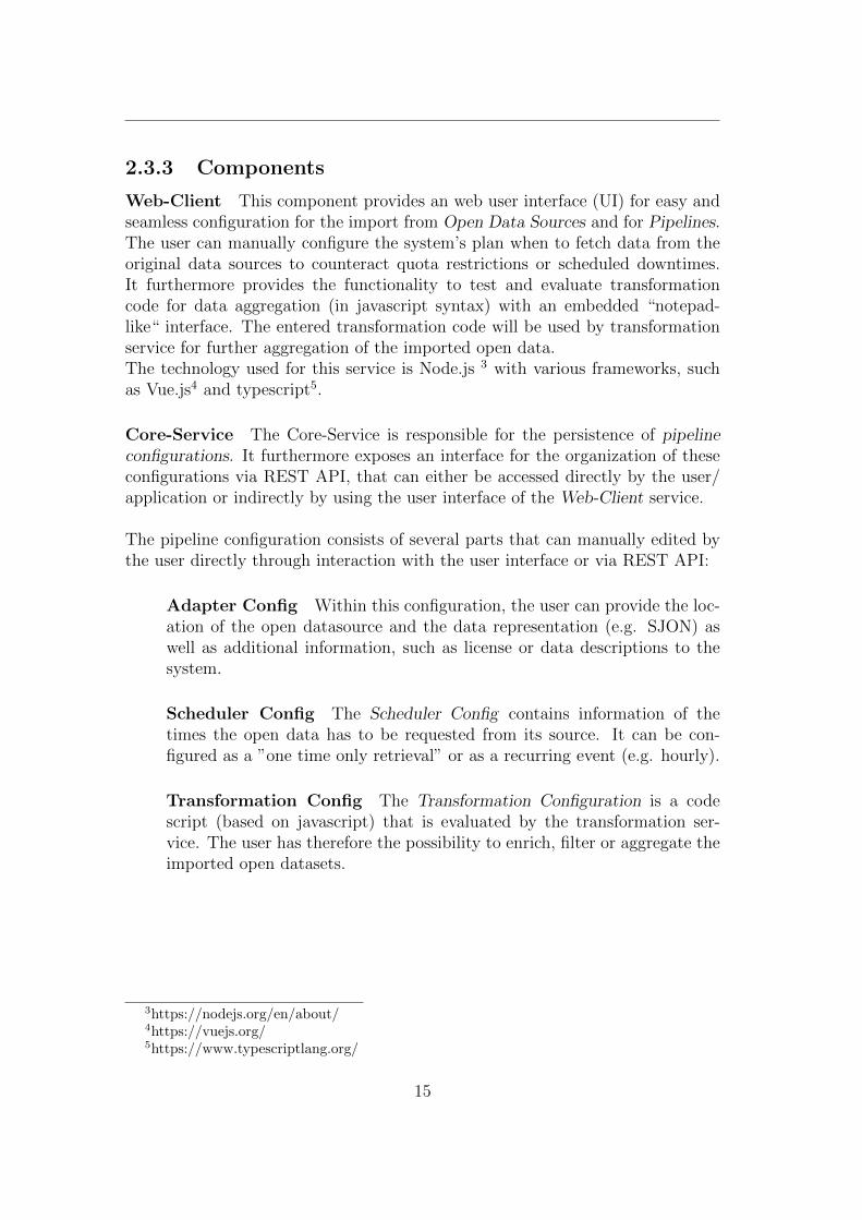
Web-Client This component provides an web user interface (UI) for easy andseamless configuration for the import from Open Data Sources and for Pipelines.The user can manually configure the system’s plan when to fetch data from theoriginal data sources to counteract quota restrictions or scheduled downtimes.It furthermore provides the functionality to test and evaluate transformationcode for data aggregation (in javascript syntax) with an embedded “notepad-like“ interface. The entered transformation code will be used by transformationservice for further aggregation of the imported open data.The technology used for this service is Node.js 3 with various frameworks, suchas Vue.js4 and typescript5.
Core-Service The Core-Service is responsible for the persistence of pipelineconfigurations. It furthermore exposes an interface for the organization of theseconfigurations via REST API, that can either be accessed directly by the user/application or indirectly by using the user interface of the Web-Client service.
The pipeline configuration consists of several parts that can manually edited bythe user directly through interaction with the user interface or via REST API:
Adapter Config Within this configuration, the user can provide the loc-ation of the open datasource and the data representation (e.g. SJON) aswell as additional information, such as license or data descriptions to thesystem.
Scheduler Config The Scheduler Config contains information of thetimes the open data has to be requested from its source. It can be con-figured as a ”one time only retrieval” or as a recurring event (e.g. hourly).
Transformation Config The Transformation Configuration is a codescript (based on javascript) that is evaluated by the transformation ser-vice. The user has therefore the possibility to enrich, filter or aggregate theimported open datasets.
3https://nodejs.org/en/about/4https://vuejs.org/5https://www.typescriptlang.org/
15
Notification Config With the Notification Config the user can indicatewhether to be informed when open data is received and available withinthe system of the JValue ODS. Users can choose between various platforms,such as Slack6 and FireBase7 to be notified on or can configure individualwebhooks. In addition a condition (javascript based) can be provided thatgets evaluated after successful transformation. If the condition is met thenotification will be delivered to the corresponding platform.
The Core-Service utilizes a postgres database for pipeline configuration persist-ence and is implemented in Java with springboot framework8.
Scheduler-Service The Scheduler-Service is a component that orchestratesthe executions of pipelines. It is a central component, that is responsible for thecorrect process flow within the system, which is composed of distributed services.On frequent basis, it extracts pipeline configurations from the Core Service andcaches them locally. With its integrated scheduling functionality, it is capable totrigger a sequence of actions according to the time that is defined in the schedulerconfiguration of a pipeline.
After the retrieval of the open data by the Adapter microservice it redirects thedata to the Transformation Service that filters and transforms the received datato the desired format. The resulting data gets persisted by the Storage-Serviceand a notification will be sent by the Notification Service (if configured). TheScheduler Service acts as a central component which triggers these consecutiveactions and takes care of the intercommunication between the microservices.
The technology used for this service is Node.js with typescript framework.
Adapter-Service The purpose of this microservice is to retrieve raw open datafrom external data sources over Hyper Text Transfer Protocol (HTTP). Withthe provision of the Adapter Configuration to its REST interface the Adapter-Service retrieves information of the location of the open data source as wellof the desired resulting data representation (e.g. JSON). It provides an RESTinterface which returns the requested data by providing an Adapter Config to itsREST application interface via HTTP POST request. The Adapter Service isimplemented in Java with springboot framework.
6https://slack.com7https://firebase.google.com/8https://spring.io
16
Transformation-Service The purpose of the transformation service is to ag-gregate the imported open data according to the corresponding transformationconfig of the same pipeline. By presenting data and transformation configurationsto its interface via HTTP-Post requests, it will evaluate and transform the data.The resulting aggregations of the data will be returned as a HTTP response.It furthermore provides an interface for dispatching notifications to various plat-forms, such as slack. With the supply of transformed data and a notificationconfig, it will evaluate the condition that is embedded in notification config withthe provided data. If the condition is met for the data, it will trigger a notificationto the corresponding platform.
The underlying technology is Node.js with typescript framework.
Auth-Service The authentication service adds a layer of security to the sys-tem. The user has to authenticate to it in order to get access to the resources inhis scope (e.g. to created pipeline configurations). With this service the systemis capable to achieve access control in an efficient way. Every service is connectedto this service for maintaining controlled utilization to their interfaces.
Storage-Service The Storage-Service is the last stage of the life cycle of opendatasets. After import by the Adapter-Service and further aggregation by theTransformation-Service the transformed data gets persisted in its database ofthe Storage-Service. The bounded context of this service is composed of twoaggregates. One is the database itself and the other is a service, providing aREST interface to operate on the data in the database. The Auth-Service therebyensures that the user can only access with read privileges.
The chosen technology for the database is postgres9. For accessing the data viaHTTP-Requests a postgrest 10 docker container will be deployed.
Reverse-Proxy Due to its decomposed structure, it might be possible thatthe locations of the services are distributed or may change. Therefore the reverseproxy is a entrypoint for the user to interact with the system’s components. Itcan also be used for inter-service communication.
9https://www.postgresql.org/10http://postgrest.org
17
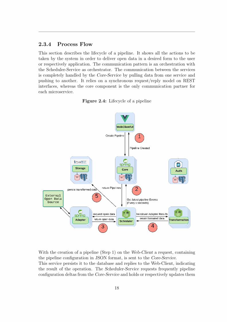
2.3.4 Process Flow
This section describes the lifecycle of a pipeline. It shows all the actions to betaken by the system in order to deliver open data in a desired form to the useror respectively application. The communication pattern is an orchestration withthe Scheduler-Service as orchestrator. The communication between the servicesis completely handled by the Core-Service by pulling data from one service andpushing to another. It relies on a synchronous request/reply model on RESTinterfaces, whereas the core component is the only communication partner foreach microservice.
Figure 2.4: Lifecycle of a pipeline
With the creation of a pipeline (Step 1) on the Web-Client a request, containingthe pipeline configuration in JSON format, is sent to the Core-Service.This service persists it to the database and replies to the Web-Client, indicatingthe result of the operation. The Scheduler-Service requests frequently pipelineconfiguration deltas from the Core-Service and holds or respectively updates them
18

in its local cache (Step 2). It loads the scheduling configuration to its schedulingmodule and triggers the execution of the pipeline when the time criteria is met.Upon pipeline execution the Scheduler-Service sends the local cached adapterconfiguration to the Adapter Service, which will then import open data from theexternal source and will respond with the extracted data as payload (Step 3).The Scheduler-Service will publish the extracted data and the correspondingtransformation config to the Transformation-Service. This service takes care ofthe transformation and will result in replying with the transformed data (Step4).The scheduler will send the transformed data to the REST interface of theStorage-Service, where the data gets persisted (Step 6).As last step it will send the transformed data and the notification config to theTransformation-Service which will evaluate the condition in the config with thetransformed data as input and send a notification to an external platform onevaluation success.
19
2.4 Event-Driven Architecture
2.4.1 Definition
Event-Driven Architecture (EDA) describes a pattern in which interaction orrespectively messaging between components of a distributed system is done byusing Event Notifications. It can furthermore be understood as an asynchronousmessaging approach for systems consisting of highly decoupled components, likemicroservices. Systems, that implement this pattern, include units that produce,transmit, process and consume events.
An Event can thereby be interpreted as an occurrence or happening, which ori-ginates inside or outside a system and can be consumed by a system’s component[HPX13, p. 13]. An Event Notification on the other hand is a message that in-forms interested recipients that an Event happened. It can be moreover definedas an event-triggered signal sent to a at run-time defined recipient [Fai11]. Inthe context of EDA Event and Event Notification might be considered as inter-changeable terms.
Event-Based Systems consist of Event Producers/Publishers, that emit Events,such as system state changes and Event Consumers, which represent interestedparties that evaluate the Event and optionally take action based upon the type ofthe Event. An important note to take is that event publishers do not know whichpart of the system consumes the emitted events, as well that event consumershave no information of the origin of the events, they subscribed to.
This pattern has the potential of easy integration of autonomous, heterogeneouscomponents into complex systems that are easy to evolve and scale [MFP06].
2.4.2 Elements
Events The structure of events can be subdivided into event header and eventbody. The header contains meta information that describes the event, such as theevent type, event name, event timestamp and event creator, whereas the bodycontains relevant payload that needs to be published and consumed.Events can be primitive and composite. While the former describes occurrenceswithin the system, which are atomic and occur only at one point in time, thelatter is composed of several primitive events that occur over time and may havespecific patterns [HPX13, p. 13].
20
Event Producer An event producer is a component that publishes events toan event driven system and is often denoted as “publisher“. One key concept is,that it does not address a specific receiver. Its implementation can be moreoverinterpreted as “self-focused“ and does only observe its own state. It will ratherforward it to a notification service, for instance rabbitmq11, which will take careof the correct distribution of the published events [MFP06, p. 12].
Event Consumer Event consumers interact with elements of a notificationservice, such as event channels. They indicate interests in specific system statechanges by issuing subscriptions[MFP06, p. 12]. A subscription can be describedas a set of events to which consumers can show interest by subscribing.Events are generally published with the intention to trigger further processingactions. This can be achieved either by the consumer itself or by delegation bythe consumer, whereas the consumer also can act as a producer.
Channels An event channel portrays a mechanism to propagate system statechanges from the producer to interested parties and can be furthermore under-stood as a subscription model [Fai11, p. 91].
A channel is composed of these elements [EN10, p. 135]:
Event channel identifier Every channel can by identified by a uniquename, that is provided to it.
Terminals Each channel has an input and an output terminal. The fur-ther is used to publish events to the queue while the latter is for eventconsumption.
Routing scheme A channel makes routing decisions in order to routeevents that have been demanded by subscribing to event subscribers.
Quality of service assertions These assertions specify non-functionalcharacteristics, such as security, performance or availability aspects.
11https://www.rabbitmq.com
21
Routing Routing can also be interpreted as a filter mechanism for channels andis therefore often denoted as filtering. It represents a set of rules for a channelto make a decision where to send incoming events, whereby the events remainunchanged.
Events can be routed by using one of these mechanisms:
Fixed This is the simplest for of routing, where no filtering is applied. Thechannel routes every event that is published to it to the output terminal,with the consequence that every consumer that subscribed to that channelwill receive all published events [EN10, p.136].
Subject-Based This routing type uses string matching, whereas publish-ers annotate each event with a subject string, that denotes a rooted pathin a tree of subjects [Fai11, p. 19]. “/University/fau/tecfac/oss“ can besuch a subject path to identify location where an event can be published to.Consumers can then subscribe for instance to the path “University/fau/*“in order to get all events that have been published in that tree structure.
Type-based With this form of filtering, the channel utilizes the eventtypes to make routing decisions. Path expressions, as well subtype inclu-sions will be therefore used, resulting in routing of to the same node of arouted path (such as in subject based filtering) [MFP06, p.19].
Content-based With content-based routing, the whole content of anevent will be evaluated. If a the event contents match with a specific con-ditional expression, it will be routed to the corresponding location. Thiscan be achieved in various ways, for instance by template matching, simplecomparisons or XPath expressions in XML [MFP06, p. 20].
2.4.3 Topologies
Mediator With the mediator topology the system is composed of multipleevent consuming and producing software components that rely on the orchestra-tion by a central unit, the mediator. The mediator takes care of the order ofevents that have to be processed, as well as of the communication between eventproducers and event-processing consumers.
22
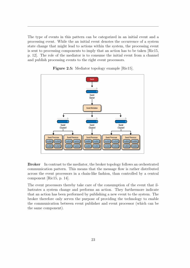
The type of events in this pattern can be categorized in an initial event and aprocessing event. While the an initial event denotes the occurrence of a systemstate change that might lead to actions within the system, the processing eventis sent to processing components to imply that an action has to be taken [Ric15,p. 12]. The role of the mediator is to consume the initial event from a channeland publish processing events to the right event processors.
Figure 2.5: Mediator topology example [Ric15].
Broker In contrast to the mediator, the broker topology follows an orchestratedcommunication pattern. This means that the message flow is rather distributedacross the event processors in a chain-like fashion, than controlled by a centralcomponent [Ric15, p. 14].
The event processors thereby take care of the consumption of the event that il-lustrates a system change and performs an action. They furthermore indicatethat an action has been performed by publishing a new event to the system. Thebroker therefore only serves the purpose of providing the technology to enablethe communication between event publisher and event processor (which can bethe same component).
23
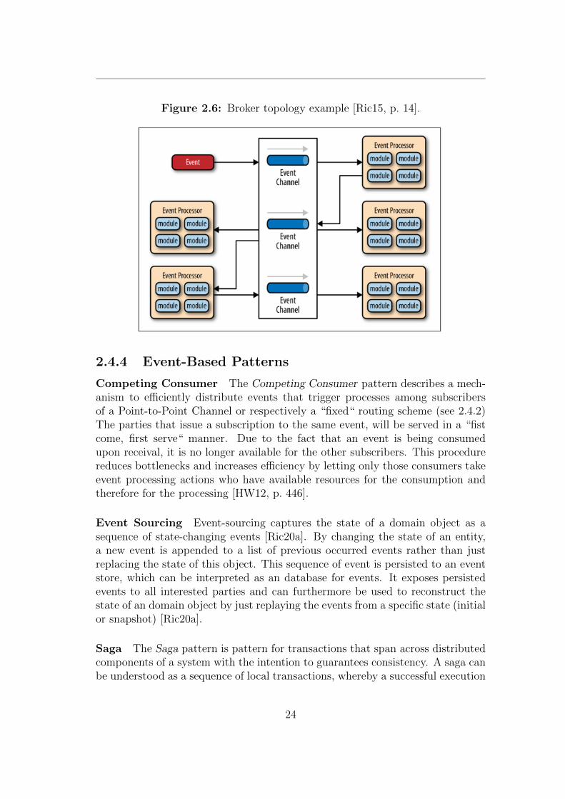
Figure 2.6: Broker topology example [Ric15, p. 14].
2.4.4 Event-Based Patterns
Competing Consumer The Competing Consumer pattern describes a mech-anism to efficiently distribute events that trigger processes among subscribersof a Point-to-Point Channel or respectively a “fixed“ routing scheme (see 2.4.2)The parties that issue a subscription to the same event, will be served in a “fistcome, first serve“ manner. Due to the fact that an event is being consumedupon receival, it is no longer available for the other subscribers. This procedurereduces bottlenecks and increases efficiency by letting only those consumers takeevent processing actions who have available resources for the consumption andtherefore for the processing [HW12, p. 446].
Event Sourcing Event-sourcing captures the state of a domain object as asequence of state-changing events [Ric20a]. By changing the state of an entity,a new event is appended to a list of previous occurred events rather than justreplacing the state of this object. This sequence of event is persisted to an eventstore, which can be interpreted as an database for events. It exposes persistedevents to all interested parties and can furthermore be used to reconstruct thestate of an domain object by just replaying the events from a specific state (initialor snapshot) [Ric20a].
Saga The Saga pattern is pattern for transactions that span across distributedcomponents of a system with the intention to guarantees consistency. A saga canbe understood as a sequence of local transactions, whereby a successful execution
24
of such a transaction triggers another transaction located another component. Ifa local transaction fails due to the violation of business constraints, compensat-ing transactions that undo the changes are chained back to the component thatinitiated the saga in order to maintain the original state and consequently con-sistency across the distributed services [Ric20b].In an event driven context, the saga is implemented as an event based choreo-graphy. Each local transaction publishes events to the succeeding componentthat causes another locatl transaction.
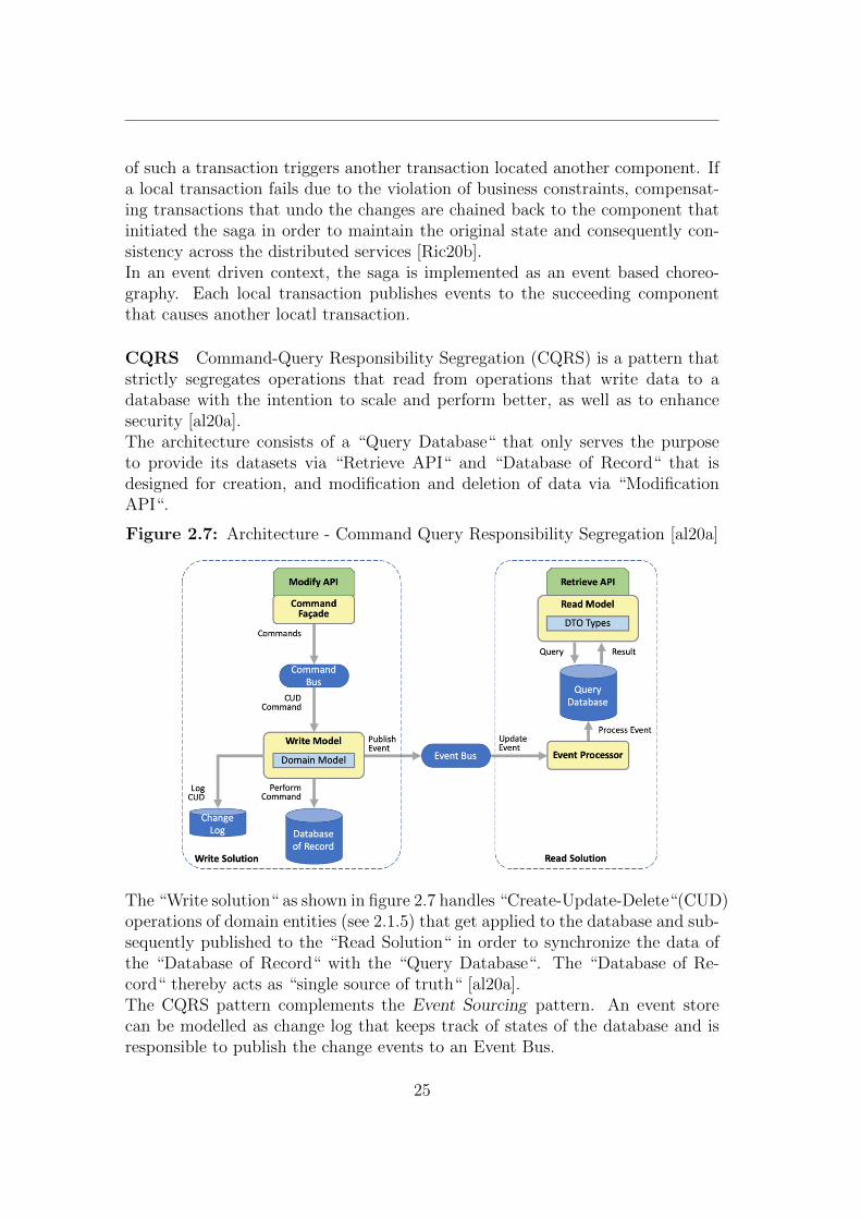
CQRS Command-Query Responsibility Segregation (CQRS) is a pattern thatstrictly segregates operations that read from operations that write data to adatabase with the intention to scale and perform better, as well as to enhancesecurity [al20a].The architecture consists of a “Query Database“ that only serves the purposeto provide its datasets via “Retrieve API“ and “Database of Record“ that isdesigned for creation, and modification and deletion of data via “ModificationAPI“.
Figure 2.7: Architecture - Command Query Responsibility Segregation [al20a]
The “Write solution“ as shown in figure 2.7 handles “Create-Update-Delete“(CUD)operations of domain entities (see 2.1.5) that get applied to the database and sub-sequently published to the “Read Solution“ in order to synchronize the data ofthe “Database of Record“ with the “Query Database“. The “Database of Re-cord“ thereby acts as “single source of truth“ [al20a].The CQRS pattern complements the Event Sourcing pattern. An event storecan be modelled as change log that keeps track of states of the database and isresponsible to publish the change events to an Event Bus.
25
3 Requirements
3.1 Functional
F1 Choreography instead of orchestration The system should move fromthe existing orchestrated communication pattern to a event-based choreography.As process flow of the system is currently determined by the control of a cent-ral component, the scheduler, a need for the replacement of the orchestratedcommunication pattern with event-based choreography emerges.
F2 Asynchronous messaging All synchronous request/reply patterns shouldbe replaced with asynchronous event messaging. Due to the blocking behaviour ofthe request/reply model that is implemented in the open data service, the switchof all these communication mechanisms to asynchronous event-based messageexchange is required
F3 Inter-service dependencies A microservice should be only depending onthe message bus when running and not on other microservices.
26

3.2 Non-Functional
N1 Functionality of the system has to be preserved The behaviour ofthe system should not change to the outside, so that ODS users will not recognizethat a change has been made to the system. The Invariant of the system shouldstay unchanged.
N2 Increase in performance The overall system should increase the through-put of the system (amount of parallel running pipelines).
N3 Collaboration and Development The changes to the architecture shouldbe planed in meaningful iterations, that are all applicable to the repository 1,without interfering the functionality. In Addition drastic changes have to bediscussed with the contributors of the software,
1https://github.com/jvalue/open-data-service
27
4 Architecture Design
4.1 Analysis with Event-Storming
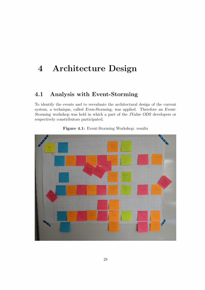
To identify the events and to reevaluate the architectural design of the currentsystem, a technique, called Even-Storming, was applied. Therefore an Event-Storming workshop was held in which a part of the JValue ODS developers orrespectively constributors participated.
Figure 4.1: Event-Storming Workshop: results
28
4.1.1 Definition
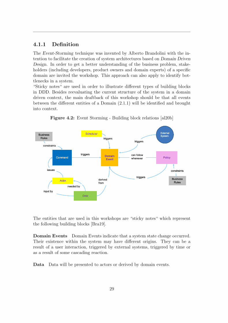
The Event-Storming technique was invented by Alberto Brandolini with the in-tention to facilitate the creation of system architectures based on Domain DrivenDesign. In order to get a better understanding of the business problem, stake-holders (including developers, product owners and domain experts) of a specificdomain are invited the workshop. This approach can also apply to identify bot-tlenecks in a system.“Sticky notes“ are used in order to illustrate different types of building blocksin DDD. Besides reevaluating the current structure of the system in a domaindriven context, the main draftback of this workshop should be that all eventsbetween the different entities of a Domain (2.1.1) will be identified and broughtinto context.
Figure 4.2: Event Storming - Building block relations [al20b]
The entities that are used in this workshops are “sticky notes“ which representthe following building blocks [Bra19].
Domain Events Domain Events indicate that a system state change occurred.Their existence within the system may have different origins. They can be aresult of a user interaction, triggered by external systems, triggered by time oras a result of some cascading reaction.
Data Data will be presented to actors or derived by domain events.
29
Actor An actor can be a user or an application that interacts with the system.They may use data to make decisions and issue commands. Actors can alsotrigger Events directly.
Command Commands are the entities which will result in a system state trans-ition and have therefore a domain event as consequence.
Policies Policies represent some logical rules that exist within a domain. Theymight be considered as rules that may trigger an domain event with interactionby an actor.
External systems Systems outside of the domain may interact with the systemand therefore can trigger events.
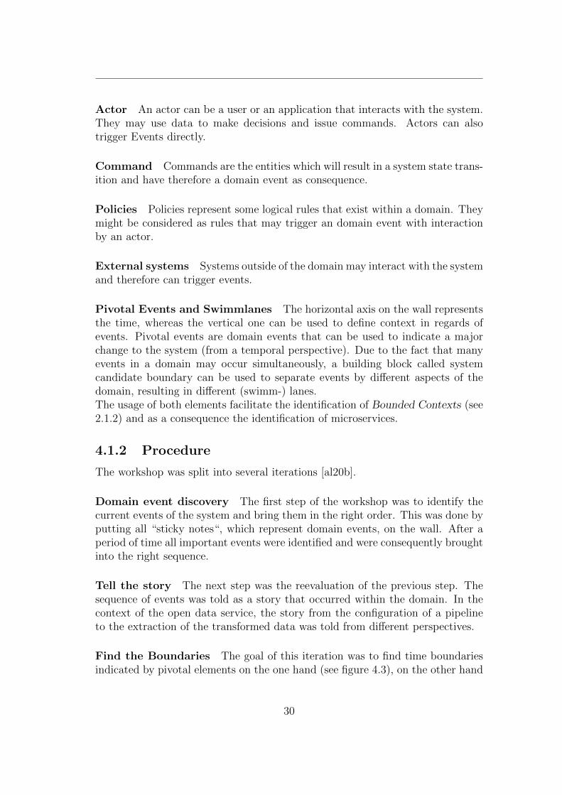
Pivotal Events and Swimmlanes The horizontal axis on the wall representsthe time, whereas the vertical one can be used to define context in regards ofevents. Pivotal events are domain events that can be used to indicate a majorchange to the system (from a temporal perspective). Due to the fact that manyevents in a domain may occur simultaneously, a building block called systemcandidate boundary can be used to separate events by different aspects of thedomain, resulting in different (swimm-) lanes.The usage of both elements facilitate the identification of Bounded Contexts (see2.1.2) and as a consequence the identification of microservices.
4.1.2 Procedure
The workshop was split into several iterations [al20b].
Domain event discovery The first step of the workshop was to identify thecurrent events of the system and bring them in the right order. This was done byputting all “sticky notes“, which represent domain events, on the wall. After aperiod of time all important events were identified and were consequently broughtinto the right sequence.
Tell the story The next step was the reevaluation of the previous step. Thesequence of events was told as a story that occurred within the domain. In thecontext of the open data service, the story from the configuration of a pipelineto the extraction of the transformed data was told from different perspectives.
Find the Boundaries The goal of this iteration was to find time boundariesindicated by pivotal elements on the one hand (see figure 4.3), on the other hand
30
to identify subject boundaries, that can be detected when multiple simultaneousseries of events that only come together at a later time occur [al20b].
These boundaries will be used to identify bounded contexts and consequentlymicroservices.
Figure 4.3: Event-Storming: Boundaries [al20b]
Locate the commands In this iteration the origins of all events were iden-tified. Events may occur when commands are issued within a system or whenconditions of policies of the domain are met. In addition they can be triggeredby a scheduler or when external systems or sensors provide a stimulus [al20b]
Describe the data In this step the data that is used in the domain was intro-duced to the model. Therefore “sticky notes“ that represent data with the cor-responding description were placed near the previous modelled building blocks.
Identify the Aggregates Aggregates emerged from the process by groupingrelated events and commands and suggest microservice boundaries and are mostlikely defined by pivotal evens and candidate system boundaries [al20b]).
4.1.3 Results
The results of the event storming workshop can be found in Appendix A.
Lanes and aggregates The resulting lanes, and microservice boundaries differto some extent from the previous architecture.A new lane with the topic ”notification” was introduced. All events (and otherbuilding blocks) that are related to the functionality of sending notifications to
31
another platform were put in the ”notification” context. These events were previ-ously a part of the transformation service (see 2.3.3) but represent another aspectof the system and should be therefore defined in an own context.Another outcome is that there exists no lane that represents the scheduler service(see 2.3.3). It belongs moreover to the adapter aggregate, due to the fact thatthe event, that a specific time occurred, is only consumed by the adapter service.
In addition storage was not considered to be a an own aggregate and assign tothe transformation lane, due to its purpose to persist transformation results.
Core-Service Due to the fact that an architecture for the open data servicealready existed, previous elements were taking into consideration, resulting inthe lane ”pipeline” for the core service (see 2.3.3), even though it might not cor-rectly defined in a domain driven context. The purpose of this service is thepersistence and offering of pipeline configurations. The pipeline configurationof previous architecture is composed of adapter, scheduler, transformation andnotification configuration. The event storming modeling approach resulted inthe insight that each configuration within the pipeline configuration should belocated to the corresponding bounded context and therefore in the correspondinglane. The consequence is that every configuration will have an own repositorythat is attached to the related microservice., resulting in the unnecessity and asa consequence to the elimination of the core service. For example the transform-ation configuration will not be stored within a pipeline configuration in the coreservice. It will be furthermore persisted in a repository in the transformationservice.Another outcome regarding the open data service configuration is that the sched-uler configuration is a part of the adapter configuration. The reason behind thisis that a scheduler configuration cannot exist without a adapter config, meaningthat a data import cannot be triggered if a data source does not exist. Thisembedded configuration structure will be persisted within the adapter boundedcontext.
Events
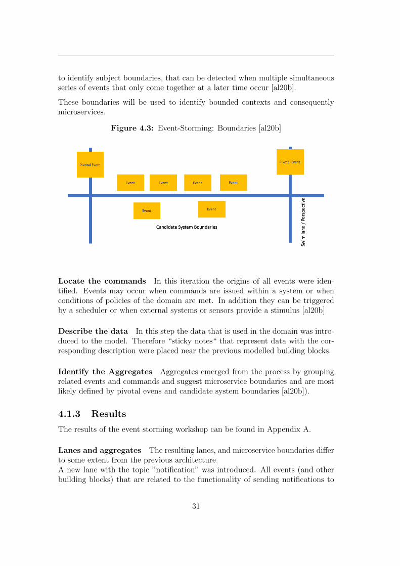
Adapter Several events have been discovered within the adapter aggregate. Inorder to apply event driven architecture to the existing system of ODS only theevents that have been triggered from other aggregates in the ODS domain weretaken into account (see figure 4.4).
32
Three critical events exist within the adapter aggregate that are related to theadapter configuration. Due to the reconsideration of the deletion of the coreaggregate adapter configs will be stored within the adapter context. The com-mands to create, modify or delete those imply the existence of correspondingevents. Another crucial event that exists within the adapter boundary is anevent that indicates that the imported data is available to the system for furtherprocessing (transformation).
Figure 4.4: Event Storming - Adapter Events
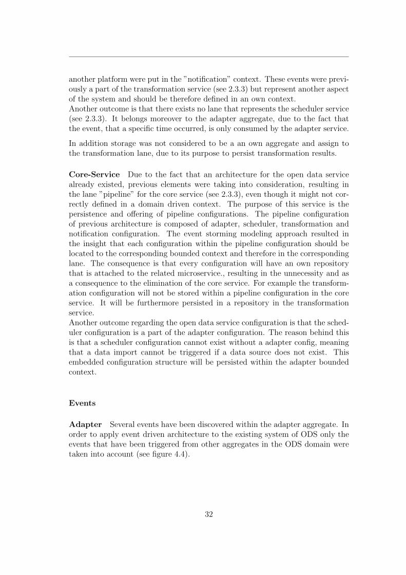
Transformation The transformation aggregate consumes the event “Adapterdata available“, that is located to the adapter lane with the consecutive actionof data processing (transformation). The configuration related events are similarto the ones in the adapter lane. After the transformation process has finished anevent is published to the notification service in order to trigger the dispatch of anotification.
Figure 4.5: Event Storming - Transformation Events
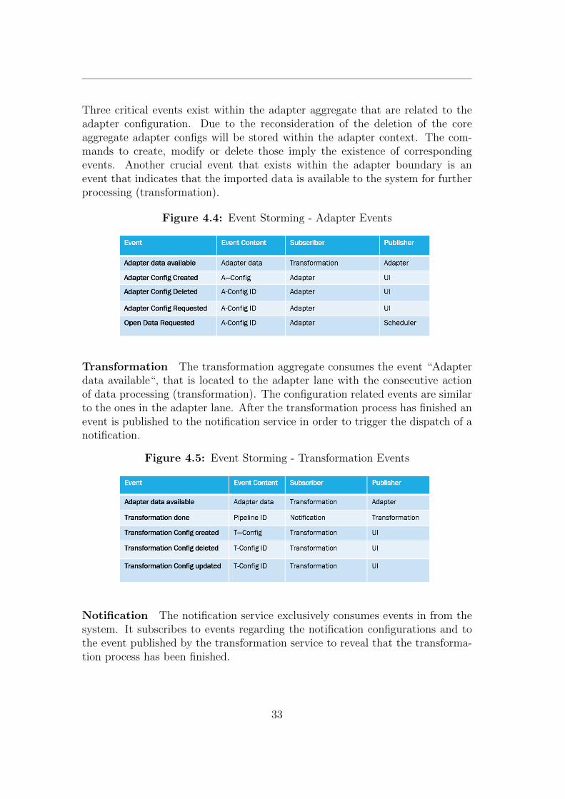
Notification The notification service exclusively consumes events in from thesystem. It subscribes to events regarding the notification configurations and tothe event published by the transformation service to reveal that the transforma-tion process has been finished.
33
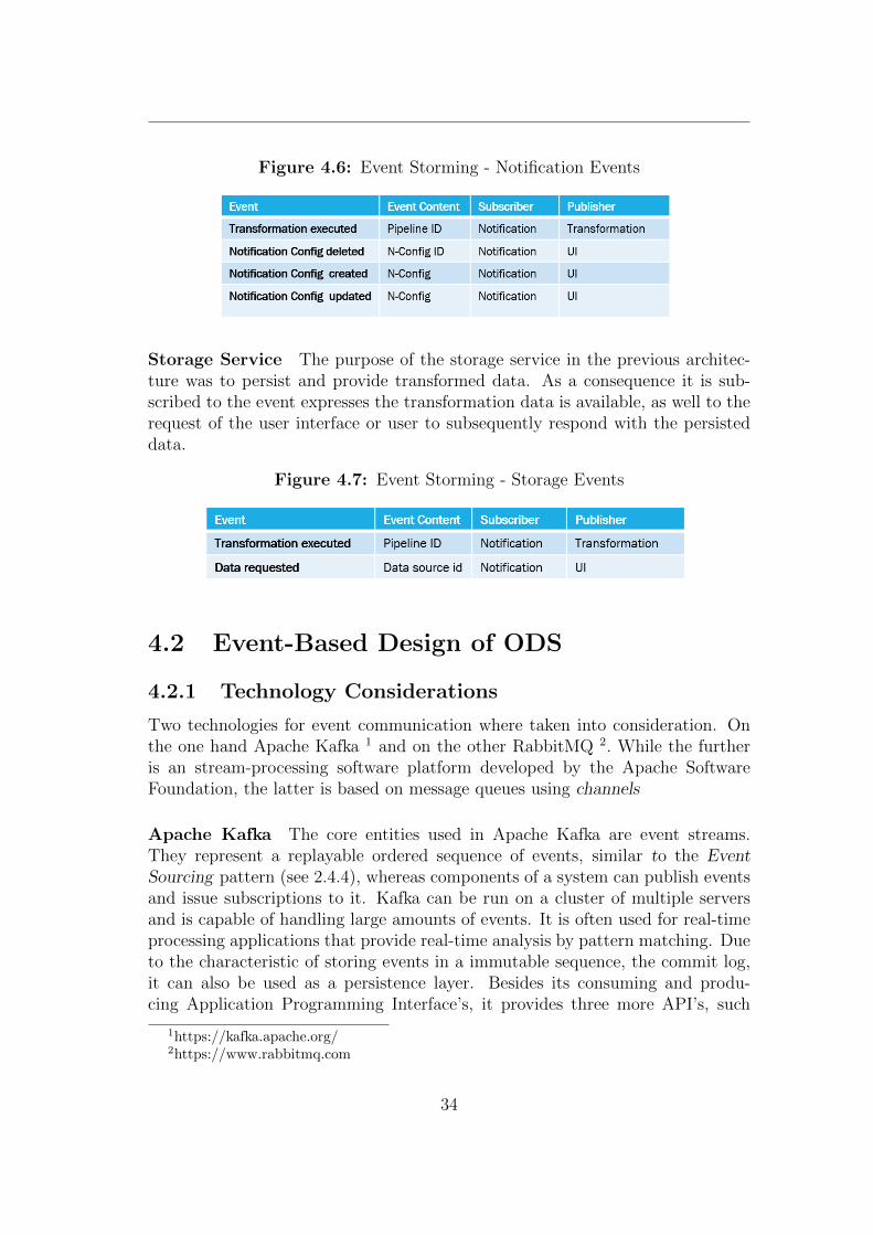
Figure 4.6: Event Storming - Notification Events
Storage Service The purpose of the storage service in the previous architec-ture was to persist and provide transformed data. As a consequence it is sub-scribed to the event expresses the transformation data is available, as well to therequest of the user interface or user to subsequently respond with the persisteddata.
Figure 4.7: Event Storming - Storage Events
4.2 Event-Based Design of ODS
4.2.1 Technology Considerations
Two technologies for event communication where taken into consideration. Onthe one hand Apache Kafka 1 and on the other RabbitMQ 2. While the furtheris an stream-processing software platform developed by the Apache SoftwareFoundation, the latter is based on message queues using channels
Apache Kafka The core entities used in Apache Kafka are event streams.They represent a replayable ordered sequence of events, similar to the EventSourcing pattern (see 2.4.4), whereas components of a system can publish eventsand issue subscriptions to it. Kafka can be run on a cluster of multiple serversand is capable of handling large amounts of events. It is often used for real-timeprocessing applications that provide real-time analysis by pattern matching. Dueto the characteristic of storing events in a immutable sequence, the commit log,it can also be used as a persistence layer. Besides its consuming and produ-cing Application Programming Interface’s, it provides three more API’s, such
1https://kafka.apache.org/2https://www.rabbitmq.com
34
as a Connector API that allows users or respectively applications to connect toadditional resources, such as databases or REST interfaces.
RabbitMQ RabbitMQ,whereby MQ stands for message queue, is a messagebroker system (see 2.4.3) that enables applications to connect and scale. It actsas an intermediate layer of communication for system components to exchangemessages asynchronously over so called “channels“. As Kafka it can be clusteredand therefore scaled. Main subjects, besides channels, are exchanges which arelogical entities where events or respectively messages can be sent to, similar toTerminals (see 2.4.2). Another building block in the context of the RabbitMQmessage broker are bindings that implement the functionality of routing schemes(see 2.4.2).RabbitMQ supports a variety of messaging protocols, including the AdvancedMessage Queuing Protocol (AMQP) 3, that is most commonly used.
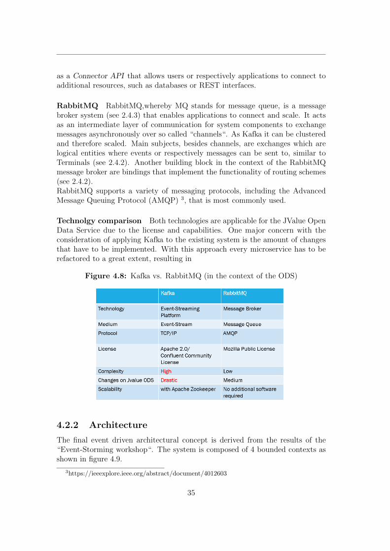
Technolgy comparison Both technologies are applicable for the JValue OpenData Service due to the license and capabilities. One major concern with theconsideration of applying Kafka to the existing system is the amount of changesthat have to be implemented. With this approach every microservice has to berefactored to a great extent, resulting in
Figure 4.8: Kafka vs. RabbitMQ (in the context of the ODS)
4.2.2 Architecture
The final event driven architectural concept is derived from the results of the“Event-Storming workshop“. The system is composed of 4 bounded contexts asshown in figure 4.9.
3https://ieeexplore.ieee.org/abstract/document/4012603
35
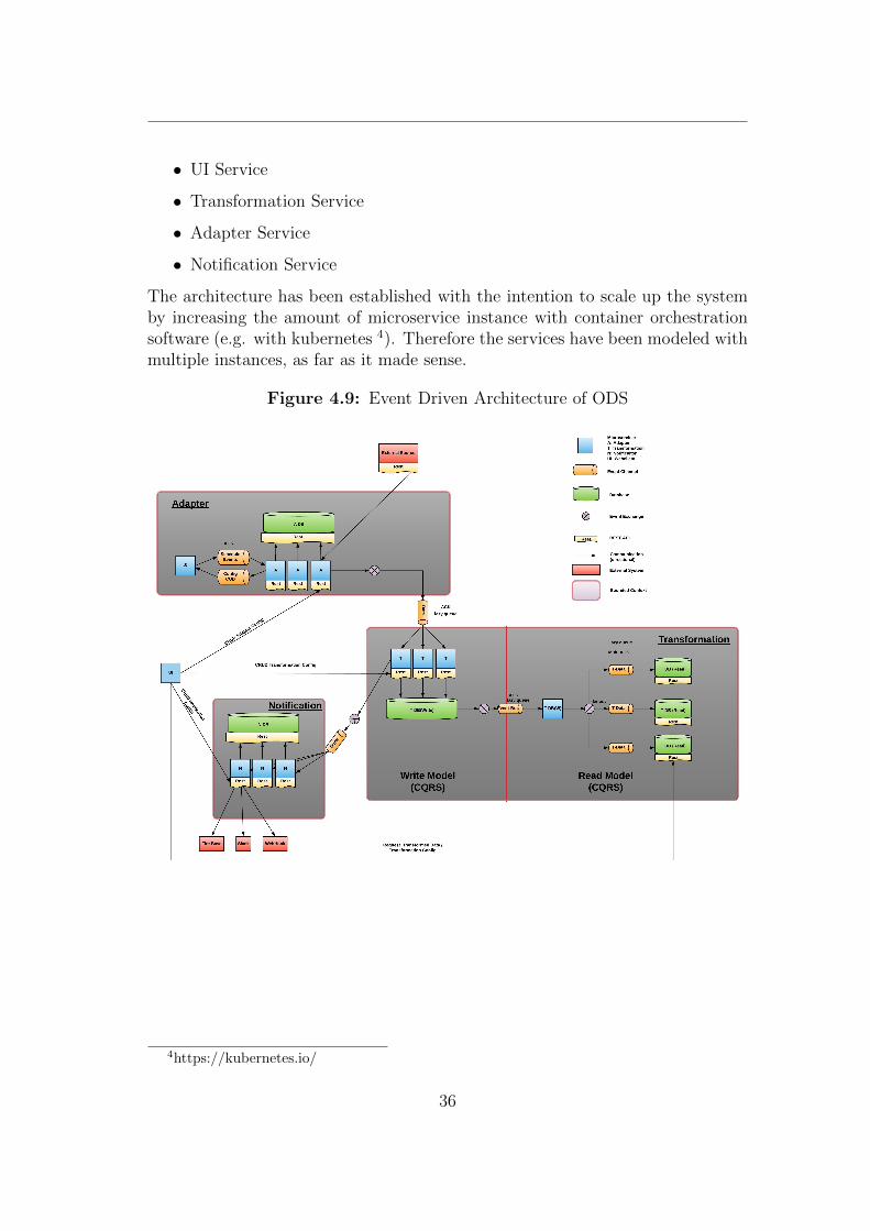
• UI Service
• Transformation Service
• Adapter Service
• Notification Service
The architecture has been established with the intention to scale up the systemby increasing the amount of microservice instance with container orchestrationsoftware (e.g. with kubernetes 4). Therefore the services have been modeled withmultiple instances, as far as it made sense.
Figure 4.9: Event Driven Architecture of ODS
4https://kubernetes.io/
36
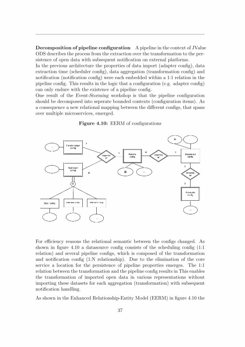
Decomposition of pipeline configuration A pipeline in the context of JValueODS describes the process from the extraction over the transformation to the per-sistence of open data with subsequent notification on external platforms.In the previous architecture the properties of data import (adapter config), dataextraction time (scheduler config), data aggregation (transformation config) andnotification (notification config) were each embedded within a 1:1 relation in thepipeline config. This results in the logic that a configuration (e.g. adapter config)can only endure with the existence of a pipeline config.One result of the Event-Storming workshop is that the pipeline configurationshould be decomposed into seperate bounded contexts (configuration items). Asa consequence a new relational mapping between the different configs, that spansover multiple microservices, emerged.
Figure 4.10: EERM of configurations
For efficiency reasons the relational semantic between the configs changed. Asshown in figure 4.10 a datasource config consists of the scheduling config (1:1relation) and several pipeline configs, which is composed of the transformationand notification config (1:N relationship). Due to the elimination of the coreservice a location for the persistence of pipeline properties emerges. The 1:1relation between the transformation and the pipeline config results in This enablesthe transformation of imported open data in various representations withoutimporting these datasets for each aggregation (transformation) with subsequentnotification handling.
As shown in the Enhanced Relationship-Entity Model (EERM) in figure 4.10 the
37
only non-weak entity is the Datasource config. This means that all the otherconfigs cannot not exist without it. Due to the distributed architecture almostevery weak relationship is modeled on the side of the weak entity resulting inhaving references to the entity it depends on. For example, the relationshipbetween adapter and pipeline config is modeled with a reference to the datasourceconfig on pipeline config side. As the scheduler
The segregation of datasource properties and pipeline configuration improvesefficiency of the system by mapping
The embedded configuration “transformation config“ will be assigned to thetransformation microservice.
Adapter The adapter bounded context is composed of the adapter configur-ation database, the adapter service and the scheduler service. The interactionof the user with the system in regards to adapter config creation, modificationand deletion accounts for the provision of a REST API instead of an event basedmessage queue.Two queues have been modeled for the inter-service communication in this con-text. One queue is responsible for the exchange of the scheduler config (that ispart of the adapter config) that is published by the adapter and consumed bythe scheduler. Due to the existence of the config REST API on adapter side,this event can either contain the config (fat event) or contain a reference to theconfig interface (thin event) for its extraction. The queue is configured with a“fixed“ routing mechanism (see 2.4.2) to adapt the Competing Consumer pat-tern, resulting in the distribution of the scheduled data import jobs. Increasingthe amount of adapter service instances therefore enhances the performance ofthe system.The scheduler holds these configurations in its local cache and triggers the adapterservice as soon as the scheduled time occurs by sending an event over anotherqueue to the adapter service. The adapter service executes the import of opendata from an external source as event processing action and publishes the resultsto the transformation service via event channel (queue).
Transformation The transformation bounded context is composed of a configdatabase, the transformation and the storage service. It offers, analog to theadapter service, a configuration REST API for CUD operations and receives im-ported open data for further transformation via event channel and matches itsdatasource identifier with the transformation configs in the database. If trans-formation configs that refer to the datasource exist, it will execute the transform-ation with the subsequent persistence of the data.As the open data service consumer/consuming application is interested in re-questing (un-) aggregated open datasets that will be delivered by the storage
38
system, a demand emerges for a more efficient solution when scaling large inorder to handle enormous amount of requests. The Command-Query Responsib-ility Segregation pattern has been, to some extent, applied to the model for thatpurpose. The design of the storage model has been split into a “Read“ and a“Write Solution“ (see 2.7).
• Write Solution The “Write Solution“ is composed of the transformationservice and RabbitMQ. While RabbitMQ acts like a the “Event Bus“ withthe provision of a lazy queue 5, the transformation service serves as the writemodel that receives CUD operations by the previous mentioned reception of“adapter data events“ from the adapter service. Optionally an Event Store(see 2.7) can be attached to this solution, in order to scale the storageservices (and therefore databases) at run time. A storage service instancethat will be introduced to the system will be consequently synchronizedwith the event store in order to maintain consistency.
• Read Solution The “Read Solution“ consists of the storage service, thatconsumes events from the transformation service via “Event Bus“ andprovides a REST interface for the request of the data only and a data-base that serves as “Query Database“ (see 2.7. The routing scheme on the“persistence queue“ (Event Bus) is modeled as an exchange with “fanout“binding. This means that all events that are published to the exchange willbe forwarded to all queues that are bound to the exchange.
For a better performance the number of databases and storage services canbe scaled up. Each service must register a channel to the RabbitMQ brokerin order to synchronize with the “Event Store“ to reach the current stateand to achieve consistency.
A “Read“REST interface is exposed to the user (-interface) for queryingtransformed datasets from the the storage service and therefore from theopen data service platform.
Another channel was modeled within this bounded context. It serves the publica-tion of events that indicate that the transformation has been done and persisted.
Notification The notification bounded context consists of a notification serviceand a configuration database. Likewise the other contexts, it provides a CRUDinterface for notification configs. It subscribes to the channel on which eventsare published by the transformation service to express that the transformed opendatasets are available for extraction. In order to evaluate a condition that isprovided by the user via config, the transformed data must be delivered to thenotification service. This can either be done by embedding the contents of the
5Lazy queue persists the events on local storage until consumed
39
transformation in the event itself (fat event) or by exposing the location of thetransformed data for extraction.With the arrival of one of these events, it matches the pipeline reference of no-tification configs in the database to the pipeline reference in the event. For eachnotification config, that refers to the pipeline, a notification is sent to the cor-responding platform if the an evaluation of the condition upon the transformeddata succeeds.
4.2.3 Choreography
With this architectural modeling approach, the scheduler does not act as an or-chestrator, its rather an initiator of a choreographed process flow. The figure4.11 illustrates the process from the creation of datasource and pipeline config-urations, over the extraction of the open data and its subsequent transformationto its persistence and notification to a external platform.For simplicity reasons the initial state of this process is that all configs have beenpersisted via REST interface and the datasource config is held in the local cacheof the scheduler. Only one instance per microservice is modeled in this diagramand all events have been models as fat events (see 4.2.2) .The process flow can be understood as a pipeline in the context of the open dataservice, as well as a Saga in the context of Event-Driven Architecture.
1. Scheduled time occurs The scheduler service checks for the scheduleproperties that are held in its local cache. If a specific time occurs anevent is sent to the adapter service to trigger event processing actions (dataimport).
2. Data Import The adpater service searches for the adapter config thatcorresponds to the event in its config database and executes the data ex-traction.
3. Send imported data After successful import of the data is sent as a fatevent that contains the data and the internal identified of the datasourceto the transformation service.
4. Transformation The transformation service receives the imported datawith the datasource id and searches in its configuration database for peris-ted pipeline/transformation configs that are related to the datasource (viaid). It executes the function that is contained in the transformation configupon the imported data.
5. Persist the transformation results After successful execution of thetransformation function the aggregated data will be sent (as fat event) tothe storage service.
40
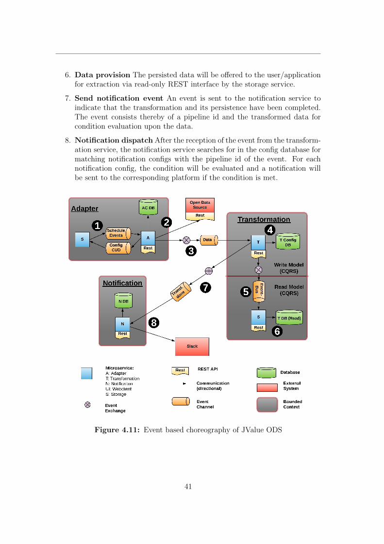
6. Data provision The persisted data will be offered to the user/applicationfor extraction via read-only REST interface by the storage service.
7. Send notification event An event is sent to the notification service toindicate that the transformation and its persistence have been completed.The event consists thereby of a pipeline id and the transformed data forcondition evaluation upon the data.
8. Notification dispatch After the reception of the event from the transform-ation service, the notification service searches for in the config database formatching notification configs with the pipeline id of the event. For eachnotification config, the condition will be evaluated and a notification willbe sent to the corresponding platform if the condition is met.
Figure 4.11: Event based choreography of JValue ODS
41
4.2.4 Evaluation
Microservice and Bounded Context The 1:1 relation constraint betweenmicroservice and bounded context could not consistently be applied throughoutthis modeling approach. In the results of the Event-Storming work, the schedulerwas interpreted as an actor in the adapter context (see 4.1.3). In this architec-tural design, it has been modeled as an own microservice that is located in thebounded context of the adapter. If it is considered to be integrated in the adapterservice, scaling would have no effect due to the fact that either all adapter servicecontainer instances would be triggered by a scheduled time event or only one ifa leader election is implemented.This applies also for the transformation bounded context due to having the stor-age service integrated in the context.
Scaling All services in this pattern can be scaled by increasing the amount ofinstances per service. This does not apply to the scheduler service. If it is scaledwith no additional control, each instance would trigger the process flow of thesame pipeline. The consideration of keeping it unscaled or to scale it with theleader election pattern emerges (for instance with Apache zookeeper 6).
Communication analysis Another outcome of this architecture is that thecommunication throughput can be reduced. This could be achieved on the onehand by separating the configuration databases, resulting in the unnecessity toshare the configurations across the microservices. On the other hand by elimin-ating the orchestrated pattern (the message exchange had to be sent twice, dueto the scheduler as intermediate component).
6https://zookeeper.apache.org
42
5 Implementation
The implementation was planned in several consecutive iterations. The strategypursued is to replace synchronous communication patterns step by step withevent based message queues. The major requirement for each iteration is thatthe system has at least the same functionality as before.It has been implemented on github 1 as a git fork of the original repository 2.At the end of all phases integration tests have been modified in order to checkthe integrity of the system after the implementation. Due to the continuousdevelopment of the JValue Open Data Service the collaborators, some developerscontributed to the implementation of the architecture.
5.1 Iteration 1: Transformation-Notification se-
gregation
The purpose of this iteration is to segregate the functionality of transformingimported data from the functionality to send notifications to external systems.Both processes are previously defined within the transformation service and aretriggered by the scheduler service (see 2.3.3). After a successful transformationand persistence of the imported data the user gets a notification send to an ex-ternal system (e.g. Slack) if it has been configured in the notification part of thepipeline configuration.According to the outcomes of the “Event-Storming Workshop“ the dispatch ofnotifications is in another bounded context then the transformation of the im-ported data and has to be therefore defined in a separated microservice. As aconsequence the “notification service“ was introduced to the system, wherebyit derived all the functionalities of the transformation service in regards of thenotification handling.These modules have been integrated into the notification service:
1https://github.com/ke45xumo/open-data-service2https://github.com/jvalue/open-data-service
43
Notification Dispatch All modules that refer to the transmission of notifica-tions to external systems have been migrated in this iteration.
Notification REST-API The scheduler service triggers the notification emis-sion by sending a HTTP-POST request with the notification configuration aspayload to the notification service. All interfaces regarding the notification havebeen implemented and the scheduler service was modified to use the new end-point.
Condition evaluation The module for the evaluation of conditions of thetransformed data was imported and additionally extended by the functionalityto send notifications upon failures in the system. The requirement to keep thefunctionality of the system was met and even extended.
The technology used for the notification service is NodeJS 3 that runs in a Dockercontainer.
5.2 Iteration 2: Introduction of config databases
Due to the composition of several configuration items within the pipeline con-fig, the need to separate them and assign them to the corresponding boundedcontexts emerged (see 4.1.3). To comply with the domain correctness one con-figuration repository was a applied to each bounded context. This adapts thelayered structure of Domain Driven Design. It represents the building block re-pository and is part of the persistence layer (see 2.1.4).The technology that is used for the configuration repositories are PostgreSQL 4
databases that introduced to the system as Docker containers. Each microservicecommunicates with its corresponding configuration database via ODBC.
Adapter configuration Database A Database for the adapter service wascreated in order to persist the configuration of the properties of a data import.The configuration items, named “Datasource-Configs“ contain thereby all theproperties, such as the data location, that are mandatory for the extraction ofopen data from its data sources. The time, as well as the frequency of the extrac-tion is considered to be the scheduler configuration, which has been embeddedwithin the structure of a data source configuration.
Transformation configuration Database The persistence of the propertiesof a transformation is introduced to the transformation service as a repository. A
3https://nodejs.org4https://www.postgresql.org/
44
conclusion of the Event-Storming workshop was that the core service should beeliminated. As the target database for pipeline configurations vanishes, a need forthe persistence of pipeline meta data, which describes the purpose these emerges.
Notification-configuration Database There are currently three types of no-tification configurations available
• Slack configuration
• Firebase (FCM) configuration
• Webhook configuration
The communication to each platform requires different options (e.g. workspaceid for Slack) resulting in the need of differentiating notification configurationsinto these types. Every notification config refers to a pipeline configuration,enabling a relational mapping of 1:N A database table was created for everytype of configuration. The persistence of these configuration types is handled viaObject-relational mapping (ORM) in typescript 5.
The separation of the entities results in having 1:N relationships between the sep-arated configuration items. For instance can one datasource config be referencedby multiple pipeline configs, which reduces resource consumption by not havingto import the same dataset for different transformation results.
Configuration interfaces An interface for the control of configurations hasto be implemented for each microservice. Handling these CRUD operations viaevent communication was taking into consideration, but would interfere with therequirement not to restrict the functionality of the platform. , because the userwould no longer be able to persist configs in a convenient way.
As a consequence, an endpoint for the persistence of configuration was imple-mented for each microservice. The endpoint provides this interface:
• GET {service url}/config?{query parameter} This interface returnsa list of configurations that match the conditions provided by the queryparameters in SJON format.
• POST {service url}/config This interface’s purpose is to persist the con-fig by sending a configuration in SJON format. It will return the persistedconfig, containing an id.
• DELETE {service url}/config/{id} This interface’s purpose is to de-lete a config. The results of the delete operation can be derived from thestatus code.
5https://github.com/typeorm/typeorm
45
• PUT {service url}/config/{id} This interface’s purpose is to update aconfig with id id by sending a configuration in SJON format. The resultsof the delete operation can be derived from the status code.
5.3 Iteration 3: Deletion of pipeline repository
Elimination of Core-Service The purpose of the core service, was to persistpipeline configurations. With the successful implementation of the config data-bases for each service and the corresponding interfaces, the core service is nolonger required and has been therefore removed from the system.
UI-Service modification The ui service offers a web based user interface forthe creation, deletion and modification of pipeline configurations. Due to theelimination of the pipeline repository, the communication patterns of the ui ser-vice have to be modified, in order to move from the communication with thecore service to a meaningful way to communicate with the distributed configrepositories.
The configuration of a pipeline on this frontend previously consisted of a con-secutive selection of properties of its embedded configuration items, such as thenotification configuration. A pipeline could only be persisted if all of those stepshave been applied and confirmed in the user interface.
This procedure been replaced by the segregation of these embedded items intothese single web parts on the webclient:
• Datasources: This webpart serves the configuration of the open data im-port (“Datasource Configs“). The user may select the data location, metadata and the time, as well as the frequency of the data extraction (em-bedded scheduler config). Data sources are now handled separately. Theresults will be sent to the adapter service for persistence.
• Pipelines: The pipeline configuration on the user interface has been de-constructed and simplified. It only consists of meta data information, thetransformation config and a reference to the data source config id.
• Notifications: With the decomposition of the pipeline config, After suc-cessful pipeline creation the user will be forwarded
46
Scheduler Service modification For the orchestrated communication withall microservices within the JValue ODS, the scheduler uses pipeline configs inorder to dispatch the embedded configs to the corresponding service.To maintain the logic or respectively the functionality, the requests to the inter-face of the core service has to be replaced by requests to the microservice thatoffer the embedded configurations of the pipeline. After the retrieval of the con-figurations, they have to be composed to the previous pipeline config structure,so that the scheduler can process pipeline executions the same way as before.
5.4 Iteration 4: Transformation-notification com-
munication
Introduction AMQP-Service In this phase a new service is introduced to thecurrent infrastructure of the open data service. A RabbitMQ server embeddedin a Docker container has been integrated. It serves as an intermediate layerof communication and provides mechanisms (e.g. channels) for event exchangesbetween the services.
Notification queue According to the outcomes of the architecture design, aqueue (channel) has to be implemented in order to notify the notification serviceafter transformation execution. Several ways to implement this have been eval-uated. A trade-off between domain correctness and unnecessary network load inregards of the condition evaluation has been identified.The condition that are persisted within the notification configuration in the noti-fication config database are evaluated upon the transformed data for the decisionwhether to dispatch a notification. This can either be achieved by handing thetransformed data over to the notification service, where the evaluation takesplace, or by sending the conditions to the transformation service for conditionevaluation by the transformation service.The further approach maintains domain correctness by assigning the conditionevaluation functionality to the notification service, where it should be semantic-ally located. Due to sending the transformed data from the transformation tothe notification service, a higher network load will be the consequence (becausethe transformed data is in the means larger than the contents of a conditionevaluation function that would be sent in the second scenario).The latter approach causes domain incorrectness by having the transformationservice evaluate the conditions for the notification service to check whether anotification should be sent or not, but causes a lower network work load.The transformation service has in general a higher resource consumption thanthe notification service because of the execution of the aggregation of data. Inorder to distribute the load across the microservice evenly and to ensure simpli-
47
city in development due to domain correctness, the decision has been made toimplement the first solution.
Fat vs. thin event Another consideration has been taken into account, eitherto embed the transformation data in the event body (fat event) or to send areference to it (thin event), whereas the notification service requests the datasynchronously from the storage service. The storage service is expected to havea high network throughput due to having to respond to many data requests byusers/applications. The overall performance of the implementation of the fatevent is expected to be better and should be therefore chosen.
Notification Message Because of the direct communication between trans-formation and notification service, the possibility emerged, to send additionalmeta data, such as the duration of the transformation execution to the notific-ation service. This additional information has been embedded in the messagethat is sent to the platform, serving the users of the open data service moretransparency in regards of when to expect the data after the schedule.
Condition Evaluation The evaluation of condition has been extended withthe functionality for error conditions, for the use case that a ODS user wants onlyto be informed when the data import and aggregation fails. This makes sense,since the import frequency can be set to minutely.An event with an undefined dataset is sent to the notification service, when thetransformation of the imported data fails. The user is now able to check whetherthe pipeline fails, by checking for the condition “data == undefined“ or “data== null“ (in javascript syntax).
At the end of this phase, the orchestrated communication behaviour in regardsof the notification has been removed from the scheduler. The requirement tomaintain the functionality is given or even extended by the introduction of thisfeature.
5.5 Iteration 5: Adapter-transformation com-
munication
The communication between adapter and transformation in this phase was im-plemented by using an event queue. After successful import of the desired data,the adapter service publishes an “AdapterData“ event to this channel.Also in this section considerations have been made whether to use thin or fatevents for the exchange of the imported data. In this case the event has beenimplemented as a hybrid solution. The event type is defined by these properties:
48
• datasourceId This id is used to search for pipelines or respectively trans-formation configs with the same datasourceId in order to execute them.
• data This is the field where the imported data can be set (when it is usedas a fat event)
• dataLocation This property can be set to indicate the location (adapterRESTendpoint) where the imported open data sets can be extracted.
If the data is contained in the event itself (“ data != null“), the transformationservice will process it directly. It extracts otherwise the data from the RESTinterface referenced by the entry dataLocataion.With the reception of an event the transformation service searches its databasefor pipeline configs that refer to the “datasourceId“ and executes the correspond-ing transformation functions with the subsequent publication of events to thenotification service.
5.6 Iteration 6: Storage-Transformation com-
munication
Introduction of Storage-MQ-Service Hence the previous storage service isbased on a predefined docker image that is based on the software PostgREST 6
and is therefore not modifiable, an implementation of a new service that incor-porates event based massaging is mandatory.The technology used for this service is based on NodeJS 7 with typescript 8
framework. It is connected to the storage database via ODBC connection and issubscribed to a queue, which the transformation service publishes various eventsto. An REST API has been implemented that only accepts HTTP-GET requeststo align with the concept of CQRS (see 2.7). The queue thereby acts as an Event-Bus between the transformation service and this storage service.
Two event types have been defined with this iteration, whereas these containevent subtypes as shown in figure 5.1. One the one hand, the event type DDL,whereby DDL stands for Data Definition Language. These event types are ne-cessary due to the current structure of the database, where for each pipeline acorresponding table exists. They indicate that a table has to be created uponpipeline creation or that a table has to be deleted within a pipeline deletion. Asub event type for each of these database structure defining operations has beencreated.
6http://postgrest.org7https://nodejs.org8https://www.typescriptlang.org
49
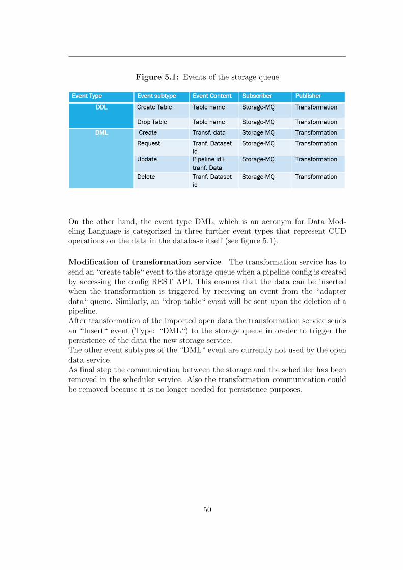
Figure 5.1: Events of the storage queue
On the other hand, the event type DML, which is an acronym for Data Mod-eling Language is categorized in three further event types that represent CUDoperations on the data in the database itself (see figure 5.1).
Modification of transformation service The transformation service has tosend an “create table“ event to the storage queue when a pipeline config is createdby accessing the config REST API. This ensures that the data can be insertedwhen the transformation is triggered by receiving an event from the “adapterdata“ queue. Similarly, an “drop table“ event will be sent upon the deletion of apipeline.After transformation of the imported open data the transformation service sendsan “Insert“ event (Type: “DML“) to the storage queue in oreder to trigger thepersistence of the data the new storage service.The other event subtypes of the “DML“ event are currently not used by the opendata service.As final step the communication between the storage and the scheduler has beenremoved in the scheduler service. Also the transformation communication couldbe removed because it is no longer needed for persistence purposes.
50
5.7 Iteration 5: Adapter-scheduler communica-
tion
This iteration has not been fully implemented. Nevertheless, the implementationstrategy will be demonstrated in this section.Two queues or respectively channels are introduced in this phase. The objectiveof both queues is to provide an event based mechanism for the communicationbetween scheduler and adapter service. One queue is responsible for the exchangeof “trigger“ events, that are published by the scheduler and consumed by the ad-apter service to initiate the open data import and therefore the whole processflow of a pipeline. The events thereby contain references (id) to the datasourceconfig, whereas the adapter can identify the corresponding config from its data-base upon event reception.The purpose of the other queue is to keep the cached scheduling configs, or re-spectively adapter configs up to date. These events are published by the adapterservice as soon as it receives a CRUD request for datasource config persistenceon its REST API. The event types are thereby categorized in CRUD operations,which illustrate a change of the datasource config to the scheduler.
51
6 Evaluation
6.1 Requirements
6.1.1 Functional
F1 Choreography instead of orchestration The requirement was to movefrom a orchestrated communication pattern to a event-based choreography. Thiscould be achieved by removing the blocking REST API requests by the schedulerand introducing queues between the microservices for information or respectivelyevent exchange. The scheduler is no longer assigned to the role as an orchestrator. It can be moreover understood as an “event flow initiator“, since it publishesthe initial event to the system, which engages other services to publish events aswell.
F2 Asynchronous messaging The goal of this architecture was to eliminateall synchronous communication mechanisms (request reply). This has only beenimplemented to some extent. For some endpoints, it was either not applicable,for instance ODBC connections to the databases or it was unreasonable to do so(e.g. for the REST interface that are exposed to the user/application.
F3 Inter-service dependencies This requirement states that a microserviceshould not communicate with other microservices directly. It should instead usethe event bus, or respectively the channels for that purpose. This has been ap-plied to some microservices, mainly those who consume and publish fat events.The microservices that use thin events, like the scheduler still depend on com-municating directly with the adapter service for datasource config extraction.
52
6.1.2 Non-functional
N1 Functionality of the system has to be preserved The demand to thesystem is that the functionality of the ODS platform stay the same. This couldbe fully achieved. The system was even extend by further functional aspects,such as the provision of conditional evaluation of platform failures.
N2 Increase in performance The overall performance should be increased(untested) due to the fact that less communication takes place within the system.The reason for this is the elimination of the orchestrated behaviour of the sched-uler, that forced inter-service communication to be exchanged at least twice. Thenotification execution, for instance, required the scheduler to extract transformeddata from the transformation service and then pass it to this service. This prob-lem has been resolved by the direct communication in an choreographed manner.
Another aspect that should be considered in terms of performance increase, isthat pipelines that refer to the same datasource, will not instruct the adapterservice to extract the data from the open data sources anymore. Due to the sep-aration of the context of pipeline and datasource and their corresponding configs,the data is only extracted once and processed several times.
N3 Collaboration and Development This non-functional requirement isabout how to handle the development for a successful integration of the codeinto the existing repository, as well about collaboration with the open data con-tributor team.The development was planned in several phases, that each did not reduce func-tionality and were applicable to the repository. The implementation of thesephases was not done as planned. The challenge of implementing simultaneouslyon several, different microservices lead to the tendency to implement on one mi-croservice one after another, or to implement similar functionalities within aniteration. As a consequence the git “pull requests“ that have been made for thegit “master branch“ were not properly separated and lead to difficulties in termsof integration.In regards to the collaboration, every major change that has been made was dis-cussed in a collaboration standup meeting, that was scheduled every two weeks.
53
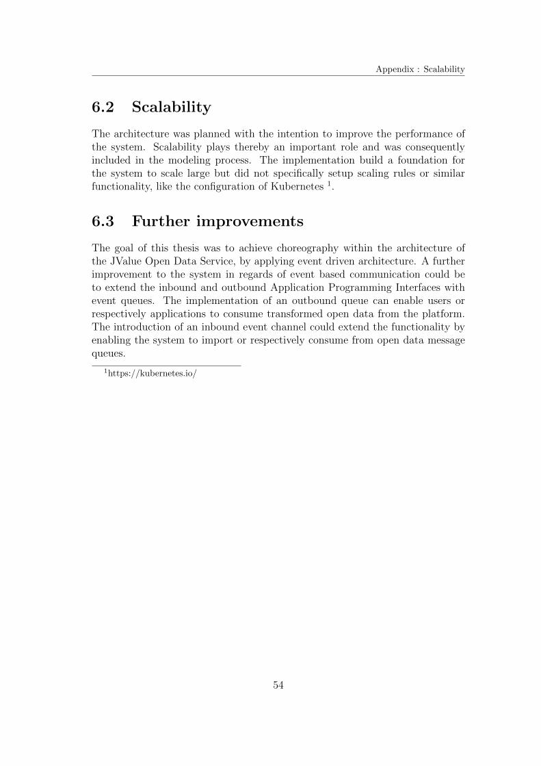
Appendix : Scalability
6.2 Scalability
The architecture was planned with the intention to improve the performance ofthe system. Scalability plays thereby an important role and was consequentlyincluded in the modeling process. The implementation build a foundation forthe system to scale large but did not specifically setup scaling rules or similarfunctionality, like the configuration of Kubernetes 1.
6.3 Further improvements
The goal of this thesis was to achieve choreography within the architecture ofthe JValue Open Data Service, by applying event driven architecture. A furtherimprovement to the system in regards of event based communication could beto extend the inbound and outbound Application Programming Interfaces withevent queues. The implementation of an outbound queue can enable users orrespectively applications to consume transformed open data from the platform.The introduction of an inbound event channel could extend the functionality byenabling the system to import or respectively consume from open data messagequeues.
1https://kubernetes.io/
54

Appendix A Event storming workshop
55

Event driven architecture - Scaled
Appendix B Event driven architecture - Scaled
56
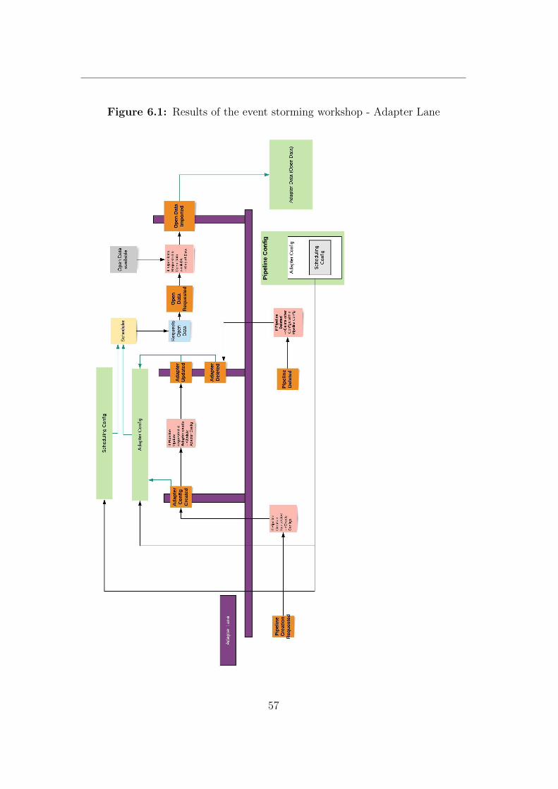
Figure 6.1: Results of the event storming workshop - Adapter Lane
57
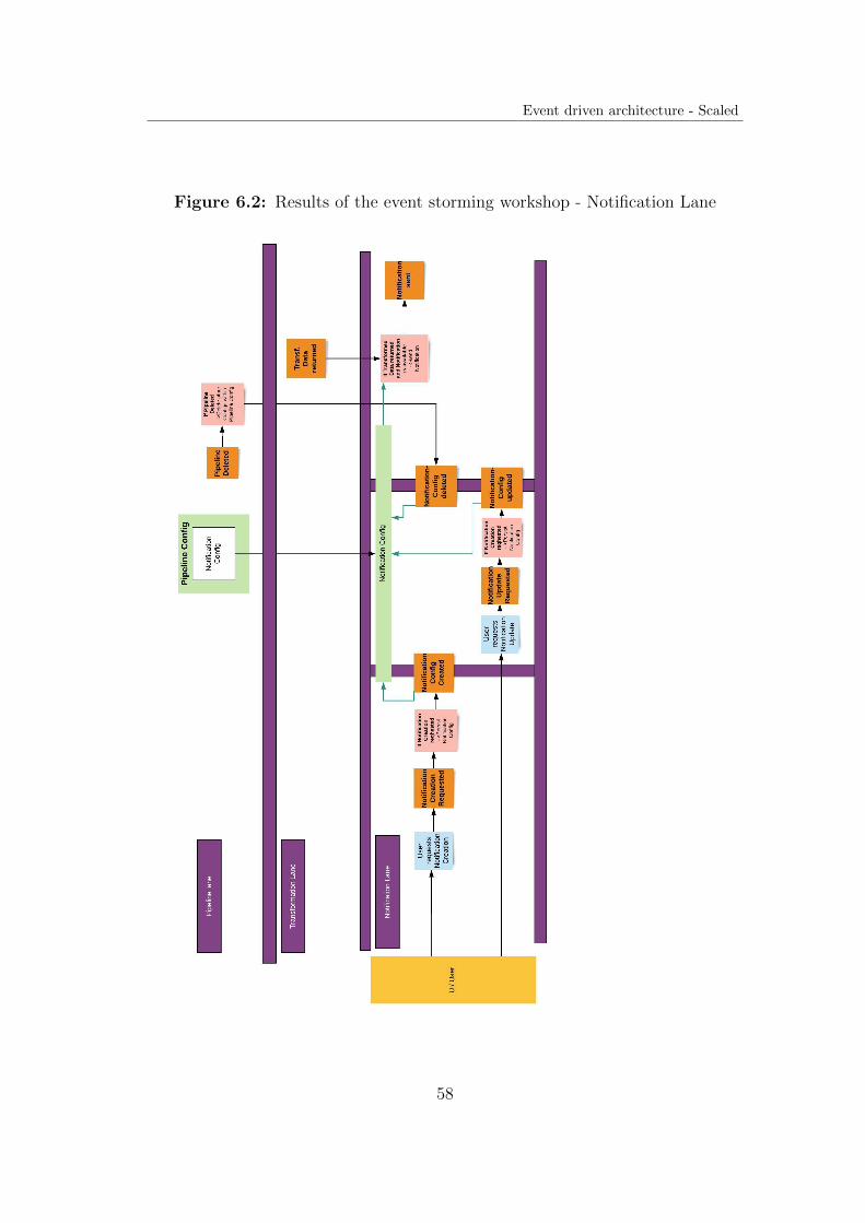
Event driven architecture - Scaled
Figure 6.2: Results of the event storming workshop - Notification Lane
58
Figure 6.3: Results of the event storming workshop - Transformation Lane
59
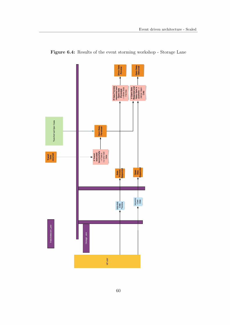
Event driven architecture - Scaled
Figure 6.4: Results of the event storming workshop - Storage Lane
60
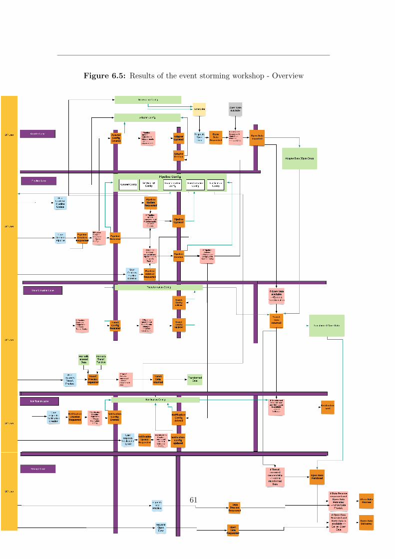
Figure 6.5: Results of the event storming workshop - Overview
61
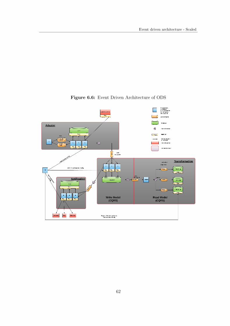
Event driven architecture - Scaled
Figure 6.6: Event Driven Architecture of ODS
62
References
[al20a] Jerome Boyer et al. Command-Query Responsibility Segregation (CQRS).2020. url: https://ibm-cloud-architecture.github.io/refarch-eda/patterns/cqrs/ (visited on 12/05/2020).
[al20b] Jerome Boyer et al. Event driven solution implementation methodo-logy. 2020. url: https://ibm-cloud-architecture.github.io/refarch-eda/methodology/event-storming/ (visited on 03/05/2020).
[Avr07] Abel Avram. Domain-Driven Design Quickly. Lulu.com, 2007. isbn:1411609255. url: https://www.infoq.com/minibooks/domain-driven-design-quickly.
[BK04] David Burdett and Nickolas Kavantzas. WS Choreography Model Over-view. WD not longer in development. http://www.w3.org/TR/2004/WD-ws-chor-model-20040324/. W3C, Mar. 2004.
[Bra19] Alberto Brandolini. Introducing EventStormin. Apress, 2019. url:https://leanpub.com/introducing_eventstorming.
[EN10] Opher Etzion and Peter Niblett. Event Processing in Action. 1st.USA: Manning Publications Co., 2010. isbn: 1935182218.
[Eva04] Eric Evans. Domain-Driven Design: Tackling Complexity in the Heartof Software. Addison-Wesley, 2004.
[Fai11] Ted Faison. Event-Based Programming: Taking Events to the Limit.1st. USA: Apress, 2011. isbn: 1430243260.
[FF06] Martin Fowler and Matthew Foemmel. Continuous integration. 2006.url: https://martinfowler.com/articles/continuousIntegration.html.
[HPX13] Sven Helmer, Alexandra Poulovassilis and Fatos Xhafa. Reasoningin Event-Based Distributed Systems. Springer Publishing Company,Incorporated, 2013. isbn: 3642267866.
[HW12] G. Hohpe and B. Woolf. Enterprise Integration Patterns: Designing,Building, and Deploying Messaging Solutions. Addison-Wesley Signa-ture Series (Fowler). Pearson Education, 2012. isbn: 9780133065107.url: https://books.google.de/books?id=qqB7nrrna%5C_sC.
[MFP06] Gero Muhl, Ludger Fiege and Peter Pietzuch. Distributed Event-Based Systems. Berlin, Heidelberg: Springer-Verlag, 2006. isbn: 3540326510.
63

REFERENCES
[MT15] S. Millett and N. Tune. Patterns, Principles, and Practices of Domain-Driven Design. Wiley, 2015. isbn: 9781118714706. url: https://books.google.de/books?id=SsK5mwEACAAJ.
[Nad+16] Irakli Nadareishvili et al. Microservice Architecture: Aligning Prin-ciples, Practices, and Culture. 1st. O’Reilly Media, Inc., 2016. isbn:1491956259.
[New15] S. Newman. Building Microservices. O’Reilly Media, 2015. isbn: 9781491950357.url: https://books.google.de/books?id=1uUDoQEACAAJ.
[Ric15] Mark Richards. Software Architecture Patterns. O’Reilly Media, Inc.,2015. isbn: 9781491925409.
[Ric20a] Chris Richardson. Pattern: Event sourcing. 2020. url: https: //
microservices.io/patterns/data/event-sourcing.html (visitedon 10/04/2020).
[Ric20b] Chris Richardson. Pattern: Saga. 2020. url: https://microservices.io/patterns/data/saga.html (visited on 12/04/2020).
[Ver13] Vaughn Vernon. Implementing Domain-Driven Design. 1st. Addison-Wesley Professional, 2013. isbn: 0321834577.
[Wol16] E. Wolff. Microservices: Flexible Software Architectures. CreateSpaceIndependent Publishing Platform, 2016. isbn: 9781523361250. url:https://books.google.de/books?id=X7YzjwEACAAJ.
64