Embed Size (px)
Citation preview
Filser Electronic GmbH • Gewerbestraße 2 • 86875 Waal phone: 08246 / 96 99-0 • fax: 08246 / 10 49 • web: www.filser.de
TRT800
P/N 800ATC-(2XX)-(2XX)
ATC Transponder
Mode A, A-C, S
Installation and Operation
Dokument-Nr.: 03.2102.010.71e Revision: 1.01 Date: 06.07.2007
TRT800 Installation and Operation
2 Dokument-Nr.: 03.2102.010.71e / Revision: 1.01
List of Changes Revision Date Description of Change 1.00 04.04.2007 initial version 1.01 06.07.2007 Description Address Adapter
Responsibility for transponder data List of Service Bulletins (SB)
Service Bulletins have to be inserted into this manual and to be enlisted in the following table.
SB No Rev. No Issue Date Entry Date Name
TRT800 Installation and Operation
3 Dokument-Nr.: 03.2102.010.71e / Revision: 1.01
Contents 1 GENERAL.........................................................................................5
1.1 Symbols ......................................................................................5 1.2 Customer Support.......................................................................5 1.3 Survey of Variants.......................................................................6 1.4 Introduction .................................................................................7 1.5 Features......................................................................................7 1.6 Technical Data............................................................................8 1.7 Telecommunication Data ............................................................9 1.8 Environmental Conditions .........................................................10 1.9 Scope of Delivery......................................................................11 1.10 Accessories ..............................................................................11
2 INSTALLATION ..............................................................................12 2.1 Note ..........................................................................................12 2.2 Unpacking and Inspecting of the Equipment .............................12 2.3 Mounting...................................................................................13 2.4 Equipment Connections ............................................................14
2.4.1 Electrical Connections ........................................................14 2.4.2 Static Air Port......................................................................14 2.4.3 Background Illumination......................................................14 2.4.4 Mutual Suppression ............................................................14
2.5 Antenna ....................................................................................15 2.5.1 Antenna Selection...............................................................15 2.5.2 Installation Recommendations ............................................15 2.5.3 Antenna Wiring ...................................................................16
2.6 Post Installation Check..............................................................16
3 SETTINGS......................................................................................17 3.1 Overview...................................................................................17
3.1.1 Error Logging ......................................................................17 3.1.2 ICAO 24-Bit Aircraft Address (AA) ......................................17 3.1.3 Aircraft Category Identification Code (AC) ..........................18 3.1.4 Flight Identification (FID) .....................................................18 3.1.5 Ground Switch Connection .................................................18 3.1.6 RS232 Interface..................................................................19
3.2 Configuration ............................................................................20 3.3 Test Mode.................................................................................22
4 WIRING ..........................................................................................24 4.1 Conductor Cross-Section ..........................................................24 4.2 TRT800EM – Address Adaptor .................................................24 4.3 TRT800EMSS – Address Adaptor with RS232 .........................25
5 DRAWINGS ....................................................................................26
TRT800 Installation and Operation
4 Dokument-Nr.: 03.2102.010.71e / Revision: 1.01
6 OPERATION...................................................................................27 6.1 ON/OFF ....................................................................................27 6.2 FID – Flight ID...........................................................................27 6.3 Transponder Mode Selection ....................................................28 6.4 Squawk Setting.........................................................................28 6.5 VFR – Visual Flight Rules .........................................................29 6.6 ID – Special Position Identification (SPI) ...................................30 6.7 Error Codes ..............................................................................30 6.8 Display......................................................................................30 6.9 Controls ....................................................................................31
TRT800 Installation and Operation
5 Dokument-Nr.: 03.2102.010.71e / Revision: 1.01
1 GENERAL 1.1 Symbols
Instructions whose non-observance can cause radiation damage to the human body or ignition of combustible materials.
Instructions whose non-observance can cause damage to the device or other parts of the equipment.
Supplementary information.
1.2 Customer Support For fastest handling of reshipments please use the reshipment form available from our homepage www.filser.de.
Any suggestions for improvement of our manuals are welcome. Feel free to contact [email protected].
TRT800 Installation and Operation
6 Dokument-Nr.: 03.2102.010.71e / Revision: 1.01
1.3 Survey of Variants Part Number Description P/N 800ATC–(2XX)–(2XX) VFR key; one VFR mode
supply voltage 14 V
TRT800 Installation and Operation
7 Dokument-Nr.: 03.2102.010.71e / Revision: 1.01
1.4 Introduction This manual contains information about the physical, mechanical and electrical characteristics and about installation and operation of the Mode S Transponder TRT800.
Please care for the ICAO 24-Bit Aircraft Address before installation. Ask your national aviation authority.
1.5 Features
• Level 2es Class 2 Non-Diversity Mode S Transponder, providing downlink of aircraft information
• radio transmitter and receiver for ground radar interrogations on 1030 MHz and transmission of coded reply pulses to ground-based radar on 1090 MHz
• Replies to ATCRBS interrogations using the ICAO 24-bit mode S address, which is unique to the particular aircraft. o Mode A replies, consisting of any one of 4,096 codes
(squawk), which differ in the position and number of pulses o Mode C replies, including encoded flight level o Mode S replies, including aircraft address and flight level o Acquisition Squitter, including aircraft address and flight level o Extended Squitter, additionally including position and velocity
• IDENT capability for activating the Special Position Identification (SPI) pulse for 18 seconds.
• certified to EUROCAE ED-73B and CS-ETSO-2C112a • maximum flight level 15000 ft, maximum velocity 175 kt • Display information contains code, reply symbol, mode of operation
and pressure altitude. • temperature compensated high precision piezo-resistive pressure
sensor • RS-232 I/O data port • 8 entries for AA-/AC-Code, FID, Ground-Switch, GPS-/Interface-
setting
TRT800 Installation and Operation
8 Dokument-Nr.: 03.2102.010.71e / Revision: 1.01
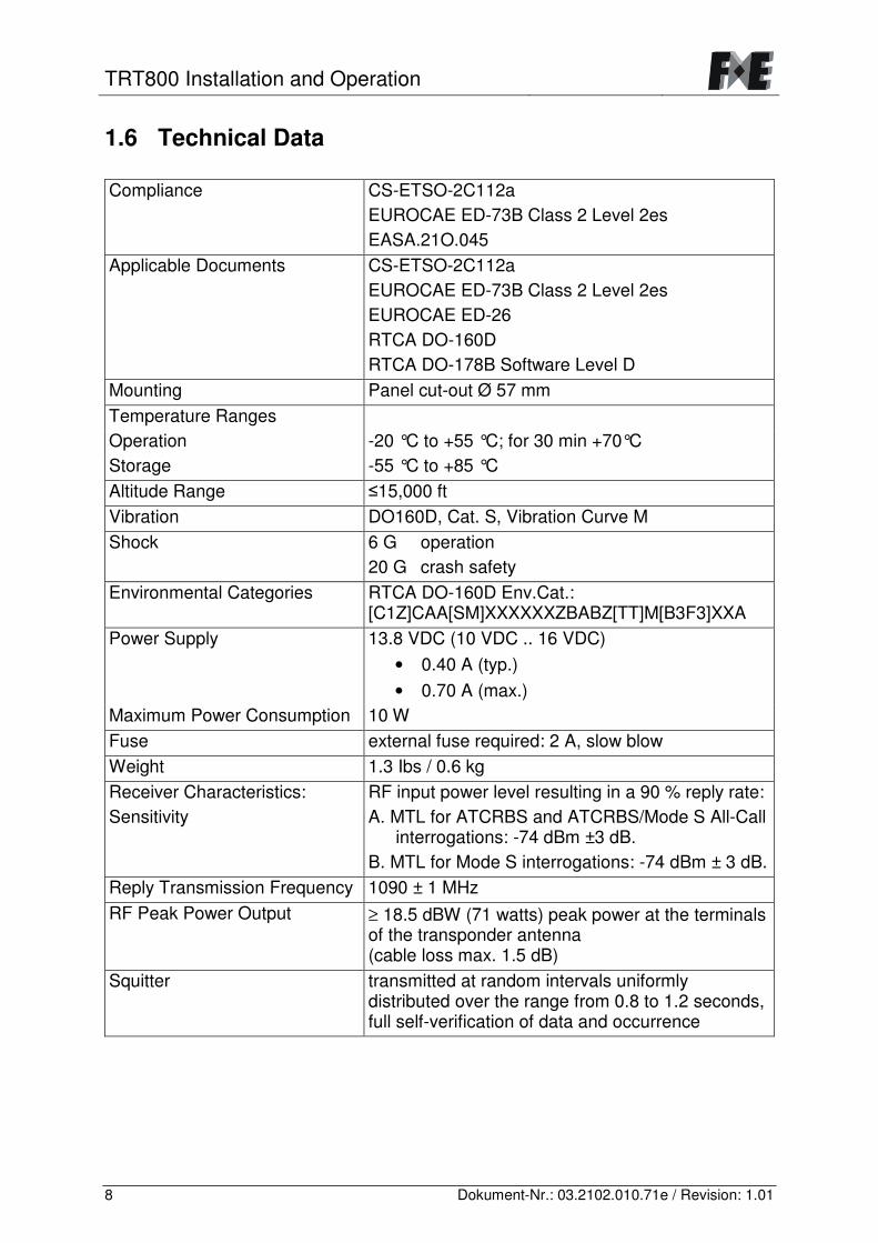
1.6 Technical Data Compliance CS-ETSO-2C112a
EUROCAE ED-73B Class 2 Level 2es EASA.21O.045
Applicable Documents CS-ETSO-2C112a EUROCAE ED-73B Class 2 Level 2es EUROCAE ED-26 RTCA DO-160D RTCA DO-178B Software Level D
Mounting Panel cut-out Ø 57 mm Temperature Ranges Operation -20 °C to +55 °C; for 30 min +70°C Storage -55 °C to +85 °C Altitude Range �15,000 ft Vibration DO160D, Cat. S, Vibration Curve M Shock 6 G operation
20 G crash safety Environmental Categories RTCA DO-160D Env.Cat.:
[C1Z]CAA[SM]XXXXXXZBABZ[TT]M[B3F3]XXA Power Supply 13.8 VDC (10 VDC .. 16 VDC)
• 0.40 A (typ.) • 0.70 A (max.)
Maximum Power Consumption 10 W Fuse external fuse required: 2 A, slow blow Weight 1.3 Ibs / 0.6 kg Receiver Characteristics: Sensitivity
RF input power level resulting in a 90 % reply rate: A. MTL for ATCRBS and ATCRBS/Mode S All-Call
interrogations: -74 dBm ±3 dB. B. MTL for Mode S interrogations: -74 dBm ± 3 dB.
Reply Transmission Frequency 1090 ± 1 MHz RF Peak Power Output ≥ 18.5 dBW (71 watts) peak power at the terminals
of the transponder antenna (cable loss max. 1.5 dB)
Squitter transmitted at random intervals uniformly distributed over the range from 0.8 to 1.2 seconds, full self-verification of data and occurrence
TRT800 Installation and Operation
9 Dokument-Nr.: 03.2102.010.71e / Revision: 1.01
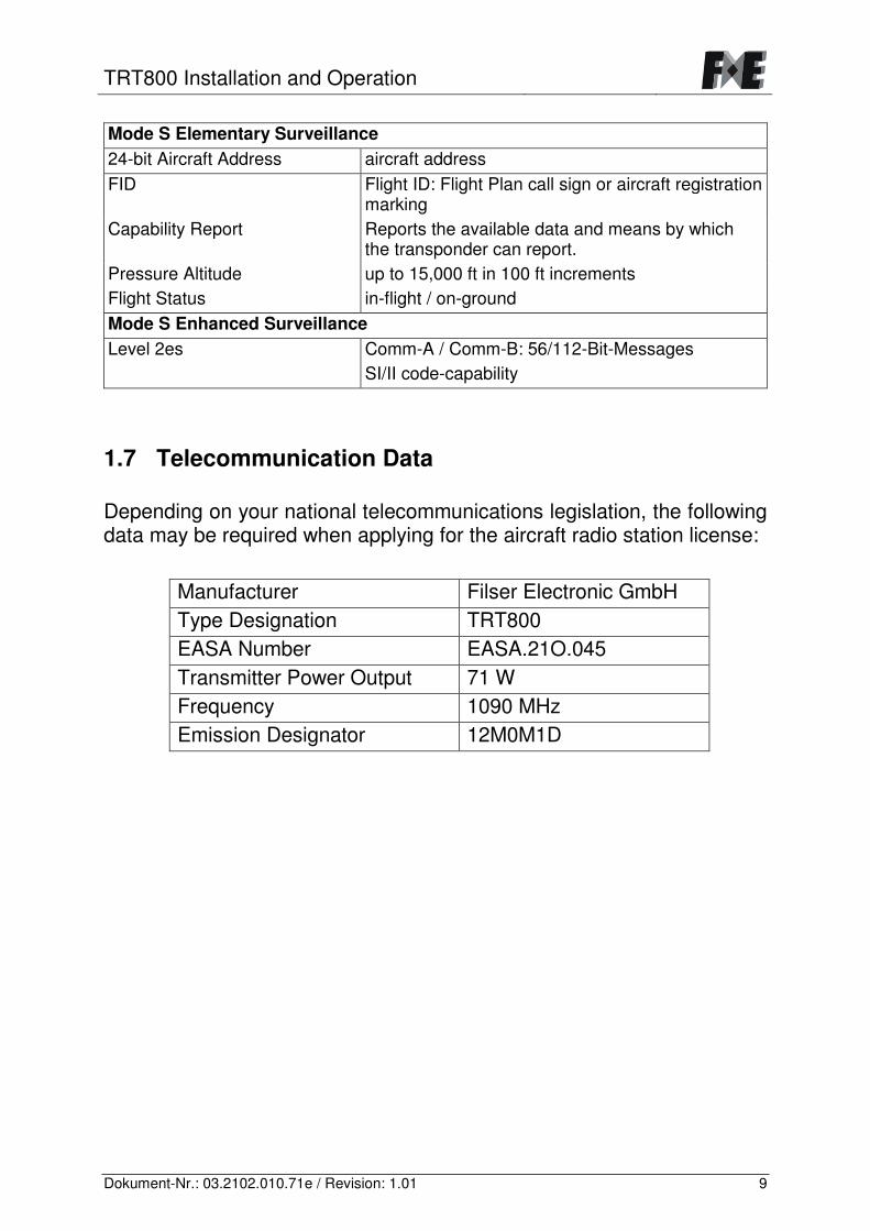
Mode S Elementary Surveillance 24-bit Aircraft Address aircraft address FID Flight ID: Flight Plan call sign or aircraft registration
marking Capability Report Reports the available data and means by which
the transponder can report. Pressure Altitude up to 15,000 ft in 100 ft increments Flight Status in-flight / on-ground Mode S Enhanced Surveillance Level 2es Comm-A / Comm-B: 56/112-Bit-Messages
SI/II code-capability
1.7 Telecommunication Data Depending on your national telecommunications legislation, the following data may be required when applying for the aircraft radio station license:
Manufacturer Filser Electronic GmbH Type Designation TRT800 EASA Number EASA.21O.045 Transmitter Power Output 71 W Frequency 1090 MHz Emission Designator 12M0M1D
TRT800 Installation and Operation
10 Dokument-Nr.: 03.2102.010.71e / Revision: 1.01
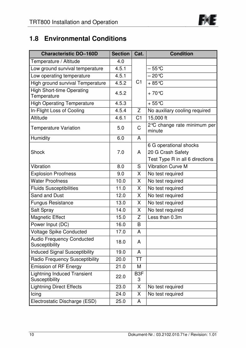
1.8 Environmental Conditions
Characteristic DO–160D Section Cat. Condition Temperature / Altitude 4.0 Low ground survival temperature 4.5.1 – 55°C Low operating temperature 4.5.1 – 20°C High ground survival Temperature 4.5.2 + 85°C High Short-time Operating Temperature 4.5.2 + 70°C
High Operating Temperature 4.5.3
C1
+ 55°C In-Flight Loss of Cooling 4.5.4 Z No auxiliary cooling required Altitude 4.6.1 C1 15,000 ft
Temperature Variation 5.0 C 2°C change rate minimum per minute
Humidity 6.0 A
Shock 7.0 A 6 G operational shocks 20 G Crash Safety Test Type R in all 6 directions
Vibration 8.0 S Vibration Curve M Explosion Proofness 9.0 X No test required Water Proofness 10.0 X No test required Fluids Susceptibilities 11.0 X No test required Sand and Dust 12.0 X No test required Fungus Resistance 13.0 X No test required Salt Spray 14.0 X No test required Magnetic Effect 15.0 Z Less than 0.3m Power Input (DC) 16.0 B Voltage Spike Conducted 17.0 A Audio Frequency Conducted Susceptibility 18.0 A
Induced Signal Susceptibility 19.0 A Radio Frequency Susceptibility 20.0 TT Emission of RF Energy 21.0 M Lightning Induced Transient Susceptibility 22.0 B3F
3
Lightning Direct Effects 23.0 X No test required Icing 24.0 X No test required Electrostatic Discharge (ESD) 25.0 A
TRT800 Installation and Operation
11 Dokument-Nr.: 03.2102.010.71e / Revision: 1.01
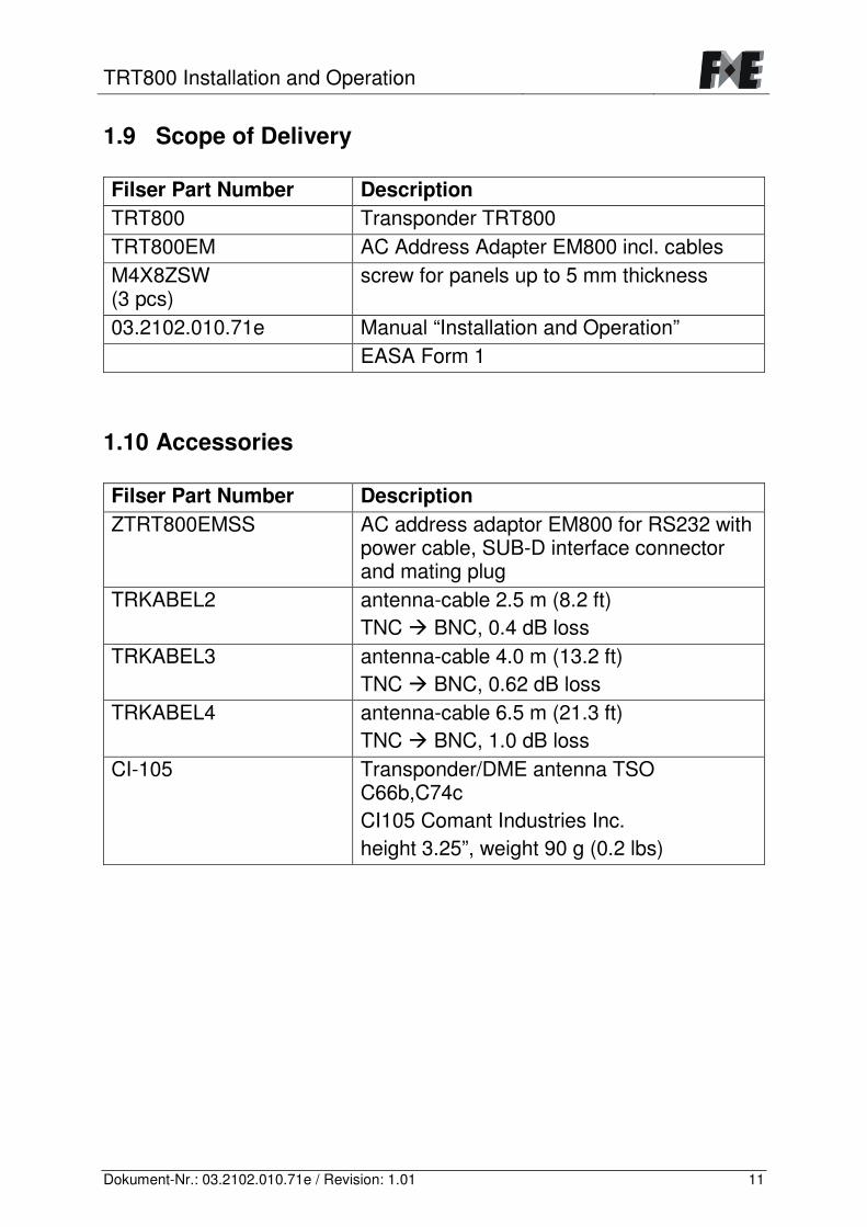
1.9 Scope of Delivery Filser Part Number Description TRT800 Transponder TRT800 TRT800EM AC Address Adapter EM800 incl. cables M4X8ZSW (3 pcs)
screw for panels up to 5 mm thickness
03.2102.010.71e Manual “Installation and Operation” EASA Form 1
1.10 Accessories Filser Part Number Description ZTRT800EMSS AC address adaptor EM800 for RS232 with
power cable, SUB-D interface connector and mating plug
TRKABEL2 antenna-cable 2.5 m (8.2 ft) TNC � BNC, 0.4 dB loss
TRKABEL3 antenna-cable 4.0 m (13.2 ft) TNC � BNC, 0.62 dB loss
TRKABEL4 antenna-cable 6.5 m (21.3 ft) TNC � BNC, 1.0 dB loss
CI-105 Transponder/DME antenna TSO C66b,C74c CI105 Comant Industries Inc. height 3.25”, weight 90 g (0.2 lbs)
TRT800 Installation and Operation
12 Dokument-Nr.: 03.2102.010.71e / Revision: 1.01
2 INSTALLATION 2.1 Note The following suggestions should be considered before installing. The installer will supply wiring. For diagrams refer to chapter 4 WIRING. Transponder, AC address adaptor, all cables and antennas should be installed as per “FAA Advisory Circular AC43.13-2A Methods and Guidelines” and the appropriate manufacturer’s instructions. 2.2 Unpacking and Inspecting of the Equipment Carefully unpack the equipment and inspect for transport damages. If a damage claim has to be filed, save the shipping container and all packing materials to substantiate your claim.
For storage or reshipment the original packaging should be used.
TRT800 Installation and Operation
13 Dokument-Nr.: 03.2102.010.71e / Revision: 1.01
2.3 Mounting
• For mounting details/drawing refer to chapter 5. • In cooperation with a maintenance shop, location and kind of the
installation are specified. The maintenance shop can supply all cables. Suitable sets of cables are available from Filser Electronic GmbH.
• Select a position away from heat sources. Care for adequate convection cooling.
• Leave sufficient space for the installation of cables and connectors. • Avoid sharp bends and wiring close to control cables. • Leave sufficient lead length for inspection or repair of the wiring of
the connector (containing the memory), so that when the mounting hardware for the rear connectors is removed, the assembly may be pulled forward several inches.
• Bend the harness at the rear connectors to inhibit water droplets (formed due to condensation) from collecting in the connector.
• Remove rotary knob before mounting: o Lift off faceplate with an appropriate tool. o Loosen screw and remove rotary knob. o Insert cap correctly orientated!
TRT800 Installation and Operation
14 Dokument-Nr.: 03.2102.010.71e / Revision: 1.01
2.4 Equipment Connections 2.4.1 Electrical Connections One 15 pin D-SUB miniature connector includes all electrical connections, except for the antenna. Use only an AC Address Adaptor TRT800EM or ZTRT800EMSS as they include an EEPROM with the memorized ICAO Aircraft code.
The TRT800 has to be protected by an external 2 amp slow-blow fuse.
2.4.2 Static Air Port Install an approved soft tubing fitting the 5 mm static air port at the backside of the transponder and secure plumbing with appropriate clamps. 2.4.3 Background Illumination
• To switch off illumination connect „LIGHT“ to „Power GND“ or leave it unconnected.
• Illumination can be varied using an input voltage (dimmer or switch) from 0 V .. +UB connected to „LIGHT“.
2.4.4 Mutual Suppression Other equipment on board (e. g. DME or TACAN) may transmit in the same frequency band as the transponder. Mutual suppression is a synchronous pulse that is sent to the other equipment to suppress transmission of a competing transmitter for the duration of the pulse train transmission. The transponder transmission may be suppressed by an external source and vice versa. To activate mutual suppression connect the SUPP_I/O signal to the according signals of the other equipment.
TRT800 Installation and Operation
15 Dokument-Nr.: 03.2102.010.71e / Revision: 1.01
2.5 Antenna 2.5.1 Antenna Selection
• For applicable antennas refer to 1.10 Accessories. • Choose an antenna type compatible with the vehicle and the
mounting location. • Specified features depend on proper installation of the antenna. • The radiation pattern needs to be verified per aircraft type. Credit
can be taken from the approval of a similar type. • The electrical interference between the antenna and any other
equipment must be taken into account in such a way that no reduction of the performance of any other system will occur.
2.5.2 Installation Recommendations
In order to avoid the possibility of human body damage (e. g. to eyes) and/or ignition of combustible materials by radiated energy, a safe distance to the installed antenna must be ensured by adequate installation provisions!
• Take note of the antenna manufacturer’s instructions. • Blade antennas are ground plane antennas. They can be installed
in metal aircrafts or where a ground plane can be installed. For installation in composite aircrafts, ground planes are to be added. The ground plane should be as large as possible but not less than 30 cm x 30 cm. If in doubt, please contact the aircraft manufacturer.
• Keep away three feet from the ADF sense antenna or any other communication antenna and six feet from the DME antenna.
• Pursue mounting in vertical position under the belly
TRT800 Installation and Operation
16 Dokument-Nr.: 03.2102.010.71e / Revision: 1.01
2.5.3 Antenna Wiring
• Refer to 1.10 Accessories for suitable antenna cables. • Keep wiring as short as possible. • Avoid sharp bends. • Avoid cable running near RF generating sources (generators, trim
motors, ignition coil or battery charger). • Keep away from an ADF antenna cable at least 12 inches. • Electrical connections to the antenna shall be protected against
moisture to avoid loss of efficiency. • A special cable type (CELLFOIL or AIRCELL) has low attenuation
at 1090 MHz but is not very resistant against mechanical stress.
Attenuation from antenna to transponder at 1090 MHz must not exceed 1.5 dB!
2.6 Post Installation Check
A certified maintenance shop must verify proper operation of the transponder by testing in accordance with Appendix F of “14 CFR Part 43 – ATC Transponder Tests and Inspections”.
All steering and control functions of the aircraft are to be examined, in order to exclude disturbances by the wiring. The most important factor in the transponder configuration is the setting of the ICAO address. Verify proper operation of the transponder during an in-flight test under VFR conditions.
TRT800 Installation and Operation
17 Dokument-Nr.: 03.2102.010.71e / Revision: 1.01
3 SETTINGS 3.1 Overview The TRT800 has the contingency of storing the following information (for model differences refer to 1.3 Survey of Variants):
• error logging • eight configurations for
o ICAO 24-Bit Aircraft Address (AA) o Aircraft Category identification code (AC) o Flight Identification (FID) o ground switch availability o interface setting
AA, AC and FID are stored in a memory device located inside the housing of the D-SUB connector (included in delivery). The cable with this connector shall remain in the aircraft even if the unit is removed, to ensure that the ICAO aircraft address is fixed to the aircraft. 3.1.1 Error Logging Errors are counted and ordered in the sequence of their occurrence. The error list can be displayed as described in chapter 3.2 Configuration 3.1.2 ICAO 24-Bit Aircraft Address (AA) Ask your national aviation authority (e. g. in Germany: LBA, department “Verkehrszulassung”) how to obtain the AA. The assigned AA must not be modified at any time, because a duplicate address would jeopardize the data surveillance and integrity figures of Mode S.
If no AA is stored, after power on the display shows “CRADLE OFF” and the transponder operates in Mode A/C.
TRT800 Installation and Operation
18 Dokument-Nr.: 03.2102.010.71e / Revision: 1.01
3.1.3 Aircraft Category Identification Code (AC) Code Beschreibung Code Beschreibung 11 vehicle 1C ultra light 12 emergency vehicle 1E drone 19 glider 21 light aircraft, motor glider
< 7031 kg (15.500 lbs) 1A balloon & airship 27 helicopter 1B paraglider
3.1.4 Flight Identification (FID) ICAO Document “8168-OPS/611 Volume I (Procedures for Air Navigation Services)” requires that flight crews of aircraft equipped with Mode S shall set the flight identification (FID) into the transponder to ensure that the correlation between flight plan and radar data will work automatically. FID setting is required to correspond to the aircraft identification that has been (correctly!) specified at item 7 of the ICAO flight plan:
• seven characters maximum, left-aligned, no additional zeros, dashes or spaces
For an aircraft using a company call sign, the Flight-ID consists of the ICAO three-letter designator for the aircraft operator, followed by an identification code, e.g. KLM511, BAW213, JTR25. If no company call sign is used or no flight plan is filed, the default FID to be set consists of the registration marking of the aircraft (e.g. GXXXX, DEABC) with no dashes, spaces or additional zeros, even if they are included in the registration marking on the aircraft (tail number).
The ICAO Flight Plan only specifies 7 characters for FID. Filser reserves 8 characters as stated in ED-73B for further expansion of the flight plan. The user shall only program 7 characters for FID.
3.1.5 Ground Switch Connection If a ground switch is connected (and declared in the configuration!), the transponder is able to acknowledge on-ground and in-flight state. In on-ground state, stand-by mode is activated.
TRT800 Installation and Operation
19 Dokument-Nr.: 03.2102.010.71e / Revision: 1.01
3.1.6 RS232 Interface With the additionally available address adaptor ZTRT800EMSS the RS232 interface can be connected to a datalink processor (COMM-A/B) or to a GPS system.
• COMM-A/B-usage: o COMM-A e. g. to receive the Traffic Information Service (TIS) o COMM-B to transmit a ground- or an air-initiated message or to
transmit an addressed air-initiated message to a specified ground station.
• GPS-usage: o transmission of the position data from the GPS as ADS-B-data
with extended squitter to other aircraft
Options (entering procedure: 3.2 Configuration): • Comm-A/B-support, 38400 Bd)
Data format for special purpose. An additional data link processor allows COMM-A/B operation and processing of the position information of a flight management system simultanously.
• FREEFLIGHT (GPS / WAAS Sensor 1201, 19200 Bd) o setting of the GPS receiver: not required o Transponder expects data format „Continuous GWSS
Navigation Packet”.
• KLN94 (Bendix King, KLN 89B, KLN 94, KMD 150, 9600 Bd) o setting of KLN89B/KLN94: “Standard RS232 Sentence”
setting of KMD 150: “Type 1 Sentence”
• NMEA-Format (4800 Bd) o setting: data format RMC is expected; to minimize the amount
of data other formats are to be avoided.
Setting for all described GPS-systems: 1 .. 2 messages per 2 secs. Information regarding Comm-A/B support as to usability of other GPS equipment are available from Filser Electronic GmbH.
TRT800 Installation and Operation
20 Dokument-Nr.: 03.2102.010.71e / Revision: 1.01
3.2 Configuration
Programming of the ICAOA 24-bit Aircraft Address and of the Aircraft Category shall be executed by qualified personnel only! A wrong Aircraft Address or Flight ID may cause serious problems with ACAS or ATC systems! Pilot and owner are responsible for correctly set transponder data, which shall be checked prior to every flight.
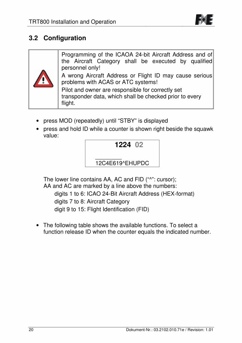
• press MOD (repeatedly) until “STBY” is displayed • press and hold ID while a counter is shown right beside the squawk
value:
1224 02
12C4E619^EHUPDC
The lower line contains AA, AC and FID (“^”: cursor); AA and AC are marked by a line above the numbers:
digits 1 to 6: ICAO 24-Bit Aircraft Address (HEX-format) digits 7 to 8: Aircraft Category digit 9 to 15: Flight Identification (FID)
• The following table shows the available functions. To select a
function release ID when the counter equals the indicated number.
TRT800 Installation and Operation
21 Dokument-Nr.: 03.2102.010.71e / Revision: 1.01
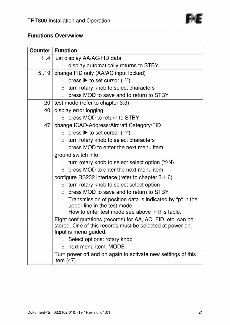
Functions Overvwiew Counter Function
1..4 just display AA/AC/FID data o display automatically returns to STBY
5..19 change FID only (AA/AC input locked) o press � to set cursor (“^”) o turn rotary knob to select characters o press MOD to save and to return to STBY
20 test mode (refer to chapter 3.3) 40 display error logging
o press MOD to return to STBY 47 change ICAO-Address/Aircraft Category/FID
o press � to set cursor (“^”) o turn rotary knob to select characters o press MOD to enter the next menu item
ground switch info o turn rotary knob to select select option (Y/N) o press MOD to enter the next menu item
configure RS232 interface (refer to chapter 3.1.6) o turn rotary knob to select select option o press MOD to save and to return to STBY o Transmission of position data is indicated by “p“ in the
upper line in the test mode. How to enter test mode see above in this table.
Eight configurations (records) for AA, AC, FID, etc. can be stored. One of this records must be selected at power on. Input is menu-guided.
o Select options: rotary knob o next menu item: MODE
Turn power off and on again to activate new settings of this item (47).
TRT800 Installation and Operation
22 Dokument-Nr.: 03.2102.010.71e / Revision: 1.01
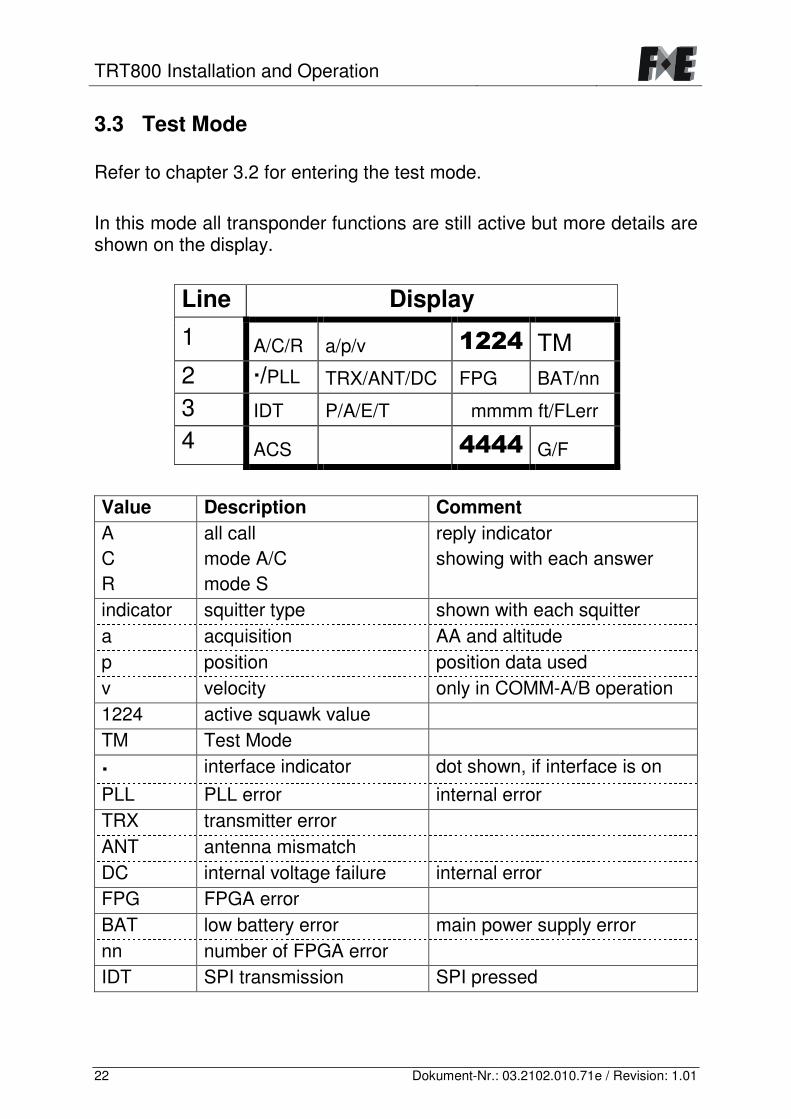
3.3 Test Mode Refer to chapter 3.2 for entering the test mode. In this mode all transponder functions are still active but more details are shown on the display.
Line Display
1 A/C/R a/p/v ����� TM 2 �/PLL TRX/ANT/DC FPG BAT/nn
3 IDT P/A/E/T mmmm ft/FLerr
4 ACS ����� G/F Value Description Comment A C R
all call mode A/C mode S
reply indicator showing with each answer
indicator squitter type shown with each squitter a acquisition AA and altitude p position position data used v velocity only in COMM-A/B operation 1224 active squawk value TM Test Mode
� interface indicator dot shown, if interface is on PLL PLL error internal error TRX transmitter error ANT antenna mismatch DC internal voltage failure internal error FPG FPGA error BAT low battery error main power supply error nn number of FPGA error IDT SPI transmission SPI pressed
TRT800 Installation and Operation
23 Dokument-Nr.: 03.2102.010.71e / Revision: 1.01
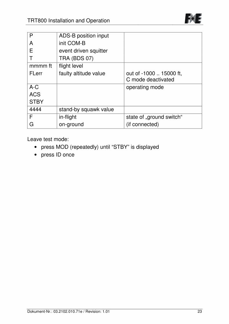
P ADS-B position input A init COM-B E event driven squitter T TRA (BDS 07) mmmm ft flight level FLerr faulty altitude value out of -1000 .. 15000 ft,
C mode deactivated A-C ACS STBY
operating mode
4444 stand-by squawk value F G
in-flight on-ground
state of „ground switch“ (if connected)
Leave test mode:
• press MOD (repeatedly) until “STBY” is displayed • press ID once
TRT800 Installation and Operation
24 Dokument-Nr.: 03.2102.010.71e / Revision: 1.01
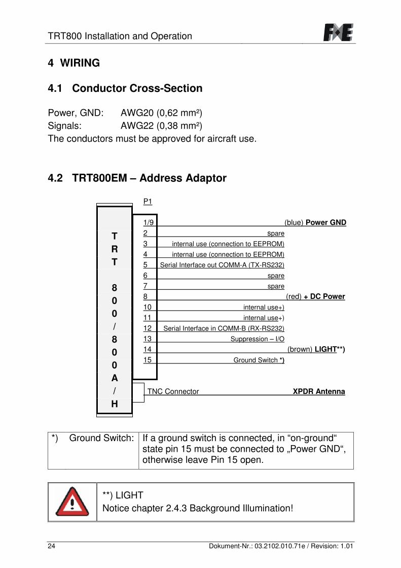
4 WIRING 4.1 Conductor Cross-Section Power, GND: AWG20 (0,62 mm²) Signals: AWG22 (0,38 mm²) The conductors must be approved for aircraft use. 4.2 TRT800EM – Address Adaptor
P1 1/9 (blue) Power GND 2 spare 3 internal use (connection to EEPROM) 4 internal use (connection to EEPROM) 5 Serial Interface out COMM-A (TX-RS232) 6 spare 7 spare 8 (red) + DC Power 10 internal use+) 11 internal use+) 12 Serial Interface in COMM-B (RX-RS232) 13 Suppression – I/O 14 (brown) LIGHT**) 15 Ground Switch *) TNC Connector XPDR Antenna
*) Ground Switch: If a ground switch is connected, in “on-ground“
state pin 15 must be connected to „Power GND“, otherwise leave Pin 15 open.
**) LIGHT Notice chapter 2.4.3 Background Illumination!
T R T
8 0 0 / 8 0 0 A / H
TRT800 Installation and Operation
25 Dokument-Nr.: 03.2102.010.71e / Revision: 1.01
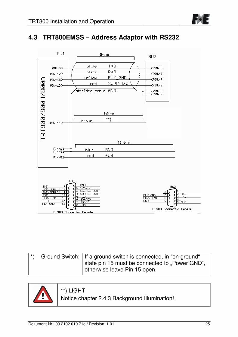
4.3 TRT800EMSS – Address Adaptor with RS232
*) Ground Switch: If a ground switch is connected, in “on-ground“
state pin 15 must be connected to „Power GND“, otherwise leave Pin 15 open.
**) LIGHT Notice chapter 2.4.3 Background Illumination!
**)
TRT800 Installation and Operation
26 Dokument-Nr.: 03.2102.010.71e / Revision: 1.01
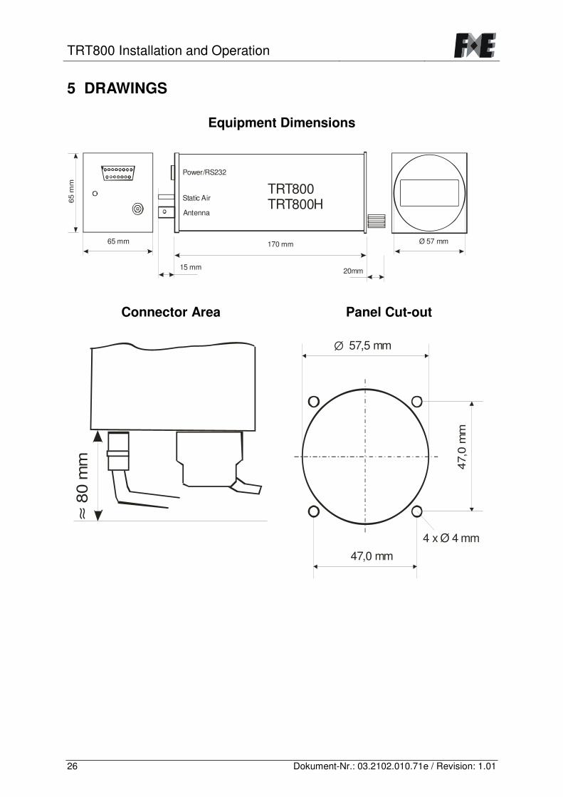
5 DRAWINGS
Equipment Dimensions
20mm15 mm
170 mm
TRT800TRT800H
65 mm
65 m
m
Ø 57 mm
Static Air
Antenna
Power/RS232
Connector Area
≈ 80
mm
Panel Cut-out
47,0 mm
47,0
mm
57,5 mm
4 x Ø 4 mm
�
TRT800 Installation and Operation
27 Dokument-Nr.: 03.2102.010.71e / Revision: 1.01
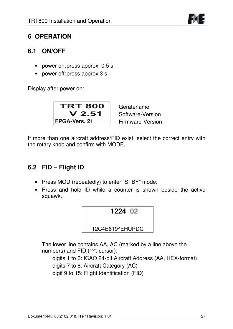
6 OPERATION 6.1 ON/OFF
• power on: press approx. 0.5 s • power off: press approx 3 s
Display after power on:
FPGA-Vers. 21
Gerätename Software-Version Firmware-Version
If more than one aircraft address/FID exist, select the correct entry with the rotary knob and confirm with MODE. 6.2 FID – Flight ID
• Press MOD (repeatedly) to enter “STBY” mode. • Press and hold ID while a counter is shown beside the active
squawk.
1224 02
12C4E619^EHUPDC
The lower line contains AA, AC (marked by a line above the numbers) and FID (“^”: cursor):
digits 1 to 6: ICAO 24-bit Aircraft Address (AA, HEX-format) digits 7 to 8: Aircraft Category (AC) digit 9 to 15: Flight Identification (FID)
TRT800 Installation and Operation
28 Dokument-Nr.: 03.2102.010.71e / Revision: 1.01
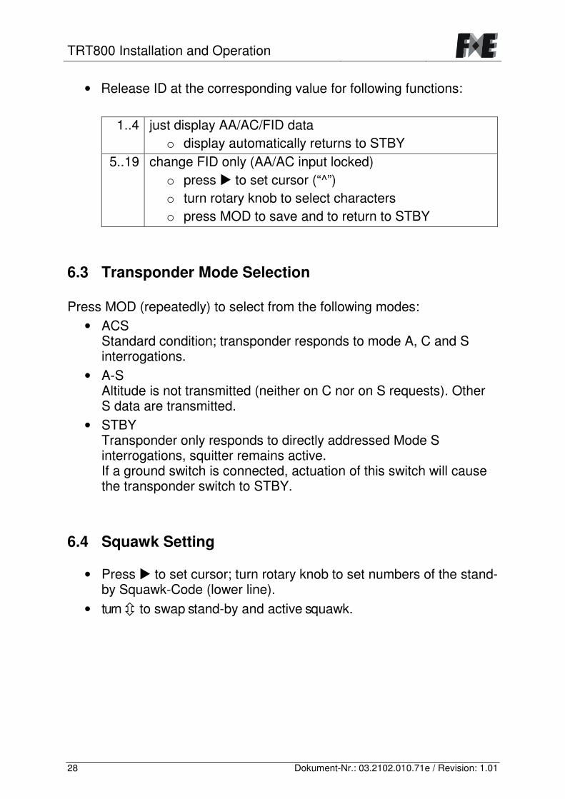
• Release ID at the corresponding value for following functions:
1..4 just display AA/AC/FID data o display automatically returns to STBY
5..19 change FID only (AA/AC input locked) o press � to set cursor (“^”) o turn rotary knob to select characters o press MOD to save and to return to STBY
6.3 Transponder Mode Selection Press MOD (repeatedly) to select from the following modes:
• ACS Standard condition; transponder responds to mode A, C and S interrogations.
• A-S Altitude is not transmitted (neither on C nor on S requests). Other S data are transmitted.
• STBY Transponder only responds to directly addressed Mode S interrogations, squitter remains active. If a ground switch is connected, actuation of this switch will cause the transponder switch to STBY.
6.4 Squawk Setting
• Press � to set cursor; turn rotary knob to set numbers of the stand-by Squawk-Code (lower line).
• turn � to swap stand-by and active squawk.
TRT800 Installation and Operation
29 Dokument-Nr.: 03.2102.010.71e / Revision: 1.01
6.5 VFR – Visual Flight Rules The transponder features a user-defined squawk code for VFR-flight (factory setting: 7000):
• Activate VFR mode and VFR squawk: Press VFR in normal mode.
• Return to normal mode: Use VFR key or any rotary knob (VFR squawk remains active).
• Save active squawk as VFR squawk: Keep VFR pressed until “S” is displayed (3 s); after releasing the key, VFR mode is activated.
Note When VFR is activated, the previously active squawk code is stored as stand-by squawk. However it is not visible as it is hidden by the appearing VFR indication. After leaving VFR mode, the previously used squawk can be activated again by pressing �.
TRT800 Installation and Operation
30 Dokument-Nr.: 03.2102.010.71e / Revision: 1.01
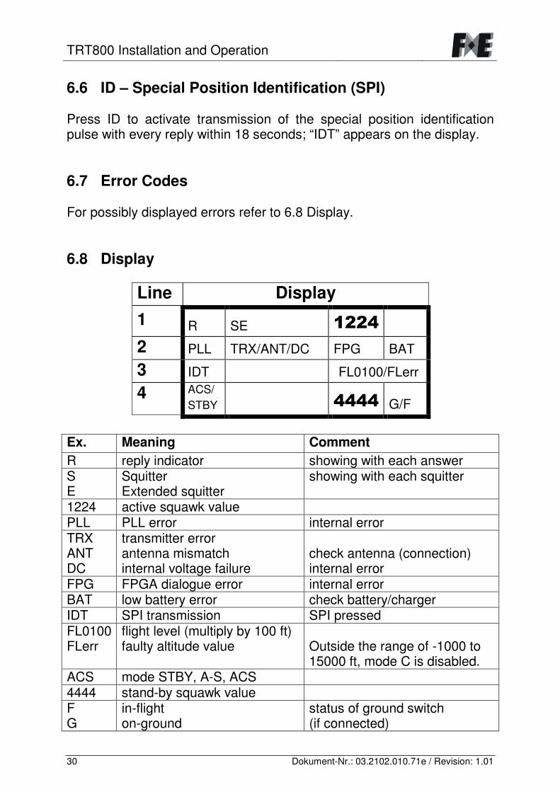
6.6 ID – Special Position Identification (SPI) Press ID to activate transmission of the special position identification pulse with every reply within 18 seconds; “IDT” appears on the display. 6.7 Error Codes For possibly displayed errors refer to 6.8 Display. 6.8 Display
Line Display
1 R SE ����� 2 PLL TRX/ANT/DC FPG BAT
3 IDT FL0100/FLerr
4 ACS/ STBY ����� G/F
Ex. Meaning Comment R reply indicator showing with each answer S E
Squitter Extended squitter
showing with each squitter
1224 active squawk value PLL PLL error internal error TRX ANT DC
transmitter error antenna mismatch internal voltage failure
check antenna (connection) internal error
FPG FPGA dialogue error internal error BAT low battery error check battery/charger IDT SPI transmission SPI pressed FL0100 FLerr
flight level (multiply by 100 ft) faulty altitude value
Outside the range of -1000 to 15000 ft, mode C is disabled.
ACS mode STBY, A-S, ACS 4444 stand-by squawk value F G
in-flight on-ground
status of ground switch (if connected)
TRT800 Installation and Operation
31 Dokument-Nr.: 03.2102.010.71e / Revision: 1.01
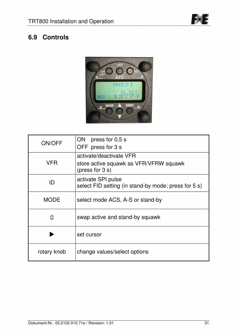
6.9 Controls
ON/OFF ON press for 0,5 s OFF press for 3 s
VFR activate/deactivate VFR store active squawk as VFR/VFRW squawk (press for 3 s)
ID activate SPI pulse select FID setting (in stand-by mode; press for 5 s)
MODE select mode ACS, A-S or stand-by
� swap active and stand-by squawk
����� set cursor
rotary knob change values/select options


![PROTOKOLL - atskulmbach-schwimmen.de · Seite 1 von 2 Druckdatum: 30.06.2019 14:56:07 ZEITGEM[A]ESS Transponder Timing GmbH · Regionalliga Damen / BM Elite | Regionalliga Einzel](https://img.pdfslide.org/doc/110x75/6034a21b07c8953cdd239de6/protokoll-atskulmbach-seite-1-von-2-druckdatum-30062019-145607-zeitgemaess.jpg)


![Internet Radio Internetradio · 1 Controls and Displays A: Front 1 Display 2 [ ] On/off switch 3 [INFO] Display additional information 4 [MODE] Changing operating mode (Internet radio,](https://img.pdfslide.org/doc/110x75/5fb06ac9d6b62416926432c9/internet-radio-internetradio-1-controls-and-displays-a-front-1-display-2-onoff.jpg)


![Massenspektrometrie II Arnd Ingendoh Teil 2 ... · Positive Ion Mode Negative Ion Mode Formation of protonated Formation of deprotonated species Molecular ions M + HA -[M+H]+ + A](https://img.pdfslide.org/doc/110x75/60191f7be3a05a3fa300f44f/massenspektrometrie-ii-arnd-ingendoh-teil-2-positive-ion-mode-negative-ion-mode.jpg)