Embed Size (px)
Citation preview
04.2016
Sommiers pour ponts roulants suspendus etposés antidéflagrants _Informations sur le produit
Explosionsgeschützte Hänge- und Lauf-krankopfträger _ Produktinformation
Explosion-protected endcarriages forsuspension and o.h.t. cranes _ Product information
ATEX IECEx
KEH
KEL
KZL

KLEX
.FM
0/2 04.16
Gültigkeit
Die vorliegende Auflage der Produktinformation für explosi-onsgeschützte Hänge- und Lauf-krankopfträger ist ab 04.2016 gültig und ersetzt damit alle vori-gen Produktinformationen.
STAHL CraneSystems steht für Weiterentwicklung, Verbesse-rung und Innovation. Aus diesem Grund müssen wir uns Änderun-gen der technischen Daten, Maße, Gewichte, Konstruktions-zeichnungen sowie der Lieferter-mine vorbehalten. Die Abbildungen dienen der anschaulichen Information, sind jedoch nicht verbindlich. Irrtümer und Druckfehler sind vorbehalten.
Validity
This edition of the Product information brochure for explosion-protected endcarriages for suspension and overhead travelling cranes is valid from 04.2016 and supersedes all previous product information brochures.
STAHL CraneSystems stands for further development, improvement and innovation. We must therefore reserve the right to modify technical data, dimensions, weights, design drawings and delivery dates.The drawings serve to illustrate the products but are not binding.Errors and printing errors are excepted.
Validité
Cette édition des Informations sur le produit pour les sommiers pour ponts roulants suspendus et posés antidéflagrants est valable à partir de 04.2016 et remplace ainsi toutes Informations sur le produit précédentes.
STAHL CraneSystems signifie l'évolution, le perfectionnement et l'innovation. Par conséquence nous devons nous réserver le droit de modifier les caractéristi-ques techniques, dimensions, poids, les plans de construction ainsi que les délais de livraison.Les illustrations servent à la clarté de l’information, mais ne revêtent pas de caractère obligatoire. Sous réserve d’erreurs et de fautes d’impression.
KLEX
.FM
04.16 0/3
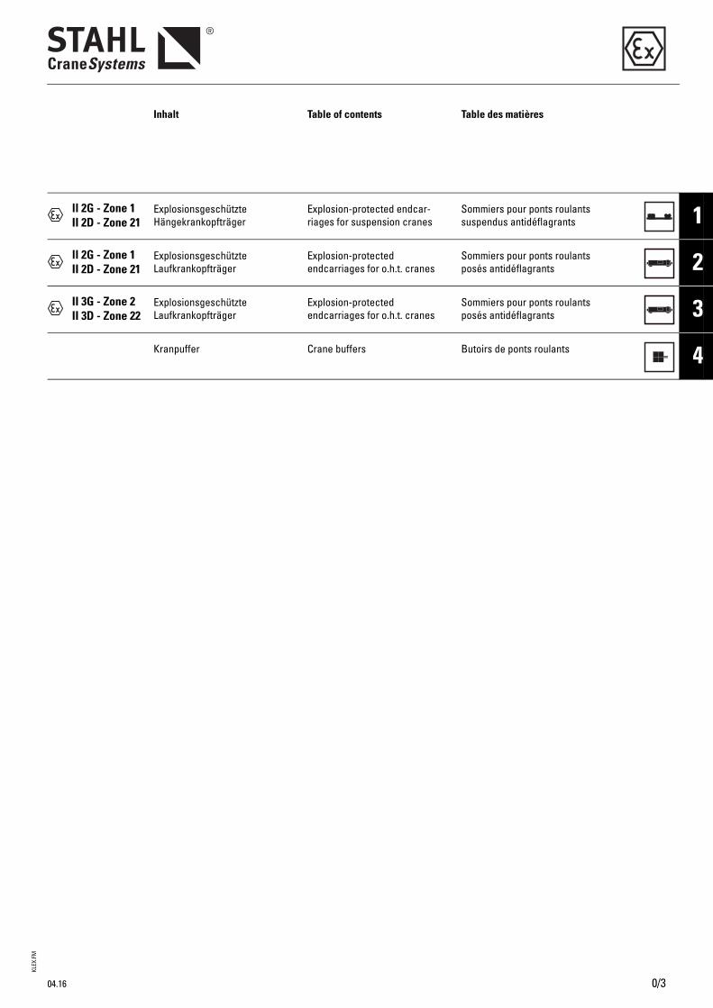
Inhalt Table of contents Table des matières
ll 2G - Zone 1II 2D - Zone 21
ExplosionsgeschützteHängekrankopfträger
Explosion-protected endcar-riages for suspension cranes
Sommiers pour ponts roulants suspendus antidéflagrants 1
ll 2G - Zone 1II 2D - Zone 21
ExplosionsgeschützteLaufkrankopfträger
Explosion-protected endcarriages for o.h.t. cranes
Sommiers pour ponts roulants posés antidéflagrants 2
II 3G - Zone 2II 3D - Zone 22
ExplosionsgeschützteLaufkrankopfträger
Explosion-protected endcarriages for o.h.t. cranes
Sommiers pour ponts roulants posés antidéflagrants 3
Kranpuffer Crane buffers Butoirs de ponts roulants 4
KLEX
.FM
0/4 04.16
Eignung für den Einsatz in explo-sionsgefährdeter Umgebung
Die hier aufgeführten explosions-geschützten Kopfträger entspre-chen der Richtlinie 2014/34/EU und sind für den Einsatz in explo-sionsgefährdeter Umgebung kon-zipiert. Sie werden wahlweise entweder für Staub- oder für Gas-explosion ausgelegt.
Für den Fall, dass der Wunsch nach Auslegung sowohl für Gas als auch Staub besteht (Ausfüh-rung entsprechend Kategorie ll 2G und gleichzeitig nach Kategorie ll 2D bzw. Ausführung entspre-chend Kategorie ll 3G und gleich-zeitig nach Kategorie ll 3D), hat der Anwender zu prüfen, ob dies seinen tatsächlichen Anforderun-gen genügt.Der Kopfträger entspricht in diesem Fall den baulichen Anforderungen für Gasexplo-sionsschutz als auch Staubexplo-sionsschutz entsprechend Richtlinie 2014/34/EU.
Das gemeinsame Auftreten von Gas und Staub (hybrides Gemisch *) ist von der Richtlinie 2014/34/EU jedoch nicht abge-deckt.
IECExDie aufgeführten explosionsge-schützten Kopfträger sind auch entsprechend IECEx lieferbar.
Suitability for use in potentially explosive atmospheres
The explosion-protected endcar-riages shown here comply with directive 2014/34/EU and are desi-gned for use in potentially explo-sive atmospheres. They are designed with the option of pro-tection against either dust or gas explosions.
If a design for use with gas and dust is required (version comp-lying with category II 2G and at the same time II 2D or version complying with category II 3G and at the same time II 3D), the user must check whether this meets his actual requirements.In this case the endcarriage complies with the constructional requirements both for gas explo-sion protection and dust explosion protection in acc. with directive 2014/34/EU.
The simultaneous occurrence of gas and dust (hybrid mixture *) is however not covered by directive 2014/34/EU.
IECExThe explosion-protected endcar-riages listed are also available in compliance with IECEx.
Aptitude pour l'utilisation dans des zones présentant des dangers d'explosion
Les sommiers antidéflagrants ici mentionnés correspondent à la directive 2014/34/UE et sont con-çus pour l'utilisation dans des zones présentant des dangers d'explosion. Ils sont construits en option avec protection soit contre les coups de poussière, soit con-tre les explosions de gaz.
Dans le cas que la conception en combinaison avec le gaz et aussi en combinaison avec la poussière soit voulue (exécution correspon-dant à la catégorie II 2G et en même temps à la catégorie II 2D, ou exécution correspondant à la catégorie II 3G et en même temps à la catégorie II 3D), le respon-sable de l'exploitation doit vérifier si ceci satisfait à ses exigences effectives.Dans ce cas, le sommier satisfait aux exigences constructives pour la protection antidéflagrante contre le gaz et pour la protection antidéflagrante contre la poussière selon la directive 2014/34/UE.
Cependant, la présence simulta-née de gaz et de poussière (mélange hybride *) n'est pas trai-tée par la directive 2014/34/UE.
IECExLes sommiers antidéflagrants indiqués sont livrables aussi en accord avec IECEx.
*1 Ein hybrides Gemisch ist ein Gemisch von Luft mit brennbaren Stoffen in unterschiedlichen Aggregatzuständen. Hybride Gemische können unter ande-rem schon dann explosionsfähig sein, wenn die Konzentrationen der Gase, Dämpfe oder Stäube für sich allein unterhalb ihrer Explosionsgrenzen lie-gen.
*1 A hybrid mixture is a mixture of air with combustible materials in various states of aggregation. Hybrid mixtures may inter alia already be explosive when the concentrations of gases, vapours or dusts individually are still below their explosion limits.
*1 Une mélange hybride est une mélange d'air et de matières combustibles en divers états physiques. Entre autres, une mélange hybride peut être déjà explosive quand les concentrations de gaz, de vapeur ou de poussière toutes seules se trouvent au-dessous de leurs limites d'explosabilité.
2
1
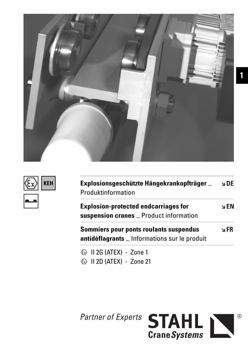
KEH
II 2G (ATEX) - Zone 1 II 2D (ATEX) - Zone 21
Explosionsgeschützte Hängekrankopfträger _ Produktinformation
Explosion-protected endcarriages for suspension cranes _ Product information
Sommiers pour ponts roulants suspendus antidéflagrants _ Informations sur le produit
KEHE
X_Z1
.FM
Hängekrankopfträger, Zone 1, 21Endcarriages for suspension cranes, zone 1, 21Sommiers pour ponts roulants suspendus, zone 1, 21
1/2 04.16
KEHex Mit den Hängekrankopfträgern KEHex können moderne Hänge-krane bis zu einer Tragfähigkeit von 10.000 kg und einer Spann-weite bis zu 20 m gebaut werden.
Nutzen Sie die robuste Konstruk-tion, kompakte Bauweise, War-tungsfreundlichkeit und Zuver-lässigkeit in Verbindung mit den wirtschaftlichen Vorteilen der Serienfertigung für Ihren Kran-bau.
Die explosionsgeschützten Hän-gekrankopfträger KEHex ent-sprechen der Gerätegruppe und Kategorie der Richtlinie 2014/34/EU (ATEX):Für Gas: ll 2G oderFür Staub: ll 2D
On the basis of KEHex endcarriages for suspension cranes, modern suspension cranes up to an working load of 10,000 kg and a span of 20 m can be manufactured.
Make use of their sturdy design, compact construction, maintenance friendliness and reliability in conjunction with the economic advantages of series production for your crane manufacturing.
The explosion-protected suspension crane endcarriages KEHex comply with the equipment group and category of the directive 2014/34/EU (ATEX):For gas: ll 2G orFor dust: ll 2D
Avec les sommiers pour ponts roulants suspendus KEHex, il peut être construit des ponts roulants suspendus modernes ayant une charge d’utilisation allant jusqu'à 10.000 kg et une portée allant jusqu'à 20 m.
Profitez de la construction robuste et compacte, de la facilité d'entretien et de la fiabilité allant de pair avec les avantages économiques de la fabrication en série pour votre construction de ponts roulants.
Les sommiers pour ponts roulants suspendus antidéflagrants KEHex correspondent au groupe d'appareils et à la catégorie de la directive 2014/34/UE (ATEX) :Pour le gaz : ll 2G ouPour la poussière : ll 2D
Erklärung der Symbole Explanations of symbols Explication des symboles
Maximale Tragfähigkeit [kg] Maximum working load [kg] Charge maximale d’utilisation [kg]
Gewicht [kg] Weight [kg] Poids [kg]
Fahrgeschwindigkeit [m/min] Travel speed [m/min] Vitesse de direction [m/min]
Abmessungen siehe Seite .. Dimensions see page .. Dimensions voir page ..
↑ Siehe Seite .. See page .. Voir page ..
KEHE
X_Z1
.FM
Hängekrankopfträger, Zone 1, 21Endcarriages for suspension cranes, zone 1, 21
Sommiers pour ponts roulants suspendus, zone 1, 21
1
04.16 1/3
Inhaltsverzeichnis Contents Indice
Erklärung der Symbole..................1/2 Explanations of symbols............... 1/2 Explication des symboles............. 1/2Die Technik im Überblick..............1/4 Technical features at a glance.... 1/4 La technique en un coup d’œil.... 1/4Typenerklärung ..............................1/5 Explanation of types...................... 1/5 Explication des types.................... 1/5Auswahlanleitung..........................1/6 Selection instructions................... 1/6 Instructions pour la sélection ..... 1/6
Hängekrankopfträger Endcarriages for suspension cranes
Sommiers pour ponts roulants suspendus
Auswahltabelle ..............................1/7 Selection table ............................... 1/7 Tableau de sélection..................... 1/7Abmessungen.................................1/8 Dimensions ..................................... 1/8 Dimensions..................................... 1/8KEH-A 080........................................1/8 KEH-A 080.. ..................................... 1/8 KEH-A 080.. ..................................... 1/8KEH-A 100........................................1/9 KEH-A 100.. ..................................... 1/9 KEH-A 100.. ..................................... 1/9KEH-A 125......................................1/10 KEH-A 125.. ................................... 1/10 KEH-A 125.. ................................... 1/10KEH-A 160......................................1/11 KEH-A 160.. ................................... 1/11 KEH-A 160.. ................................... 1/11
Ausstattung und Option Equipment and options Équipement et optionsA015 Motoranschlussspannungen.....1/12 Motor supply voltages ................ 1/12 Tensions d'alimentation des
moteurs ......................................... 1/12A018 Temperaturüberwachung der Moto-
ren ..................................................1/12Motor temperature control ........ 1/12 Surveillance de la température des
moteurs ......................................... 1/12A050 Einsatz unter besonderen Bedin-
gungen...........................................1/12Use in non-standard conditions 1/12 Mise en œuvre en conditions
exceptionnelles ........................... 1/12A051 Schutzart IP 66 .............................1/12 IP 66 protection............................ 1/12 Protection de type IP 66 ............. 1/12A053 Bremskonus galvanisch hartver-
chromt............................................1/12Brake cone hard chromium- plated..........................................1/12
Cône de freinage chromé dur ... 1/12
A054 Anomale Umgebungstemperatu-ren ................................................ 1/12
Off-standard ambient tempera-tures............................................. 1/12
Températures ambiantes anorma-les .................................................. 1/12
A059 Höherer Explosionsschutz..........1/13 Higher explosion protection ...... 1/13 Meilleure protection antidéfla-grante ............................................ 1/13
A060 Lackierung/Korrosionsschutz....1/13 Paint/corrosion protection......... 1/13 Peinture/protection anticorrosive 1/13A061 Anstrich A20 .................................1/13 A20 paint system.......................... 1/13 Peinture A20................................. 1/13A062 Anstrich A30 .................................1/14 A30 paint system.......................... 1/14 Peinture A30................................. 1/14A140 Alternative Fahrgeschwindigkeiten1/14 Alternative travel speeds ........... 1/14 Autres vitesses de direction...... 1/14A200 Wegfall des Kopfträgerprofils ...1/15 Non-supply of of endcarriage sec-
tion ................................................. 1/15Suppression du profilé de som-mier ............................................. 1/15
A210 Pufferverlängerung .....................1/15 Longer buffers.............................. 1/15 Rallonge de butoir ....................... 1/15
Komponenten und Zubehör Components and accessories Composants et accessoiresB081 Fahrbahnendanschläge ohne Puf-
fer................................................1/16Runway end stops without buffers1/16 Butées de fin de voie de roulement
sans tampons............................... 1/16B100 Auslösegeräte für Kaltleiter-Tempe-
raturüberwachung.......................1/16Tripping devices for PTC thermistor temperature control .................... 1/16
Disjoncteurs pour surveillance de la température par thermistance.. 1/16
Technische Daten Technical data Caractéristiques techniquesC010 Auslegung .....................................1/17 Design............................................ 1/17 Conception ................................... 1/17C011 Einstufung .....................................1/17 Classification................................ 1/17 Classification................................ 1/17C012 Sicherheitsvorschriften ..............1/17 Safety regulations ....................... 1/17 Prescriptions de sécurité........... 1/17C014 Wärmeklasse................................1/17 Thermal class............................... 1/17 Classe thermique......................... 1/17C020 Motor-Anschlussspannungen...1/17 Motor supply voltages ................ 1/17 Tensions d'alimentation des
moteurs ......................................... 1/17C030 Geräteeinstufung .........................1/17 Equipment classification ............ 1/17 Classification des appareils ...... 1/17C031 Explosionsschutz nach EN/IEC..1/17 Explosion protection to EN/IEC . 1/17 Protection antidéflagrante selon
NE/C.E.I. ........................................ 1/17C040 Schutzart EN 60529 / IEC.............1/17 Protection class EN 60529 / IEC 1/17 Type de protection NE 60529/C.E.I.1/17C050 Zulässige Umgebungstemperatu-
ren ................................................. 1/17Permissible ambient tempera-tures............................................1/17
Températures ambiantes admissi-bles ................................................ 1/17
C070 Fahrmotoren .................................1/17 Travel motors................................ 1/17 Moteurs de direction .................. 1/17
Faxblatt ..........................................1/18 Fax.................................................. 1/18 Faxer.............................................. 1/18
Technische Änderungen, Irrtümer und Druckfehler vorbehalten.
Subject to alterations, errors and printing errors excepted.
Sous réserve de modifications, d’erreurs et de fautes d’impression.
KEHE
X_Z1
.FM
Hängekrankopfträger, Zone 1, 21Endcarriages for suspension cranes, zone 1, 21Sommiers pour ponts roulants suspendus, zone 1, 21
1/4
Die Technik im Überblick Technical features at a glance La technique en un coup d’œil
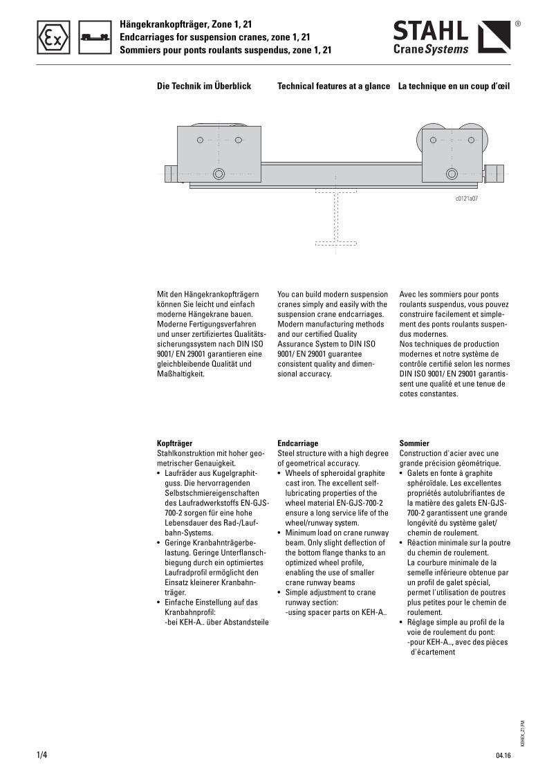
You can build modern suspension cranes simply and easily with the suspension crane endcarriages.Modern manufacturing methods and our certified Quality Assurance System to DIN ISO 9001/ EN 29001 guarantee consistent quality and dimen-sional accuracy.
EndcarriageSteel structure with a high degree of geometrical accuracy.• Wheels of spheroidal graphite
cast iron. The excellent self-lubricating properties of the wheel material EN-GJS-700-2 ensure a long service life of the wheel/runway system.
• Minimum load on crane runway beam. Only slight deflection of the bottom flange thanks to an optimized wheel profile, enabling the use of smaller crane runway beams
• Simple adjustment to crane runway section:-using spacer parts on KEH-A..
Avec les sommiers pour ponts roulants suspendus, vous pouvez construire facilement et simple-ment des ponts roulants suspen-dus modernes.Nos techniques de production modernes et notre système de contrôle certifié selon les normes DIN ISO 9001/ EN 29001 garantis-sent une qualité et une tenue de cotes constantes.
Sommier Construction d'acier avec une grande précision géométrique.• Galets en fonte à graphite
sphéroïdale. Les excellentes propriétés autolubrifiantes de la matière des galets EN-GJS-700-2 garantissent une grande longévité du système galet/chemin de roulement.
• Réaction minimale sur la poutre du chemin de roulement. La courbure minimale de la semelle inférieure obtenue par un profil de galet spécial, permet l'utilisation de poutres plus petites pour le chemin de roulement.
• Réglage simple au profil de la voie de roulement du pont:-pour KEH-A.., avec des pièces
d'écartement
Mit den Hängekrankopfträgern können Sie leicht und einfach moderne Hängekrane bauen. Moderne Fertigungsverfahren und unser zertifiziertes Qualitäts-sicherungssystem nach DIN ISO 9001/ EN 29001 garantieren eine gleichbleibende Qualität und Maßhaltigkeit.
Kopfträger Stahlkonstruktion mit hoher geo-metrischer Genauigkeit.• Laufräder aus Kugelgraphit-
guss. Die hervorragenden Selbstschmiereigenschaften des Laufradwerkstoffs EN-GJS-700-2 sorgen für eine hohe Lebensdauer des Rad-/Lauf-bahn-Systems.
• Geringe Kranbahnträgerbe-lastung. Geringe Unterflansch-biegung durch ein optimiertes Laufradprofil ermöglicht den Einsatz kleinerer Kranbahn-träger.
• Einfache Einstellung auf das Kranbahnprofil:-bei KEH-A.. über Abstandsteile
04.16
KEHE
X_Z1
.FM
Hängekrankopfträger, Zone 1, 21Endcarriages for suspension cranes, zone 1, 21
Sommiers pour ponts roulants suspendus, zone 1, 21
1
04.16
Die Technik im Überblick Technical features at a glance La technique en un coup d’œil
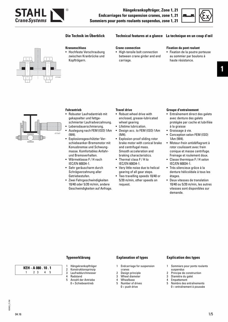
Typenerklärung
1 Hängekrankopfträger2 Konstruktionsprinzip3 Laufraddurchmesser4 Radstand5 Anzahl der Antriebe
0 = Schiebeantrieb
KEH - A 080 . 10 . 11 2 3 4 5
Crane connection• High-tensile bolt connection
between crane girder and end carriage.
Travel drive • Robust wheel drive with
enclosed, grease-lubricated wheel gearing
• Lifetime lubrication. • Design acc. to FEM (ISO) 1Am
(M4).• Explosion-proof sliding rotor
brake motor with conical brake and centrifugal mass. Smooth acceleration and braking characteristics.
• Thermal class F / H to IEC/EN 60034-1.
• Very little noise due to helical gearing of all gear steps.
• Two travelling speeds 10/40 or 5/20 m/min, other speeds on request.
Explanation of types
1 Endcarriage for suspension cranes
2 Design principle3 Wheel diameter4 Wheelbase5 Number of drives
0 = push drive
Fixation du pont roulant• Fixation de la poutre porteuse
au sommier par boulons à haute résistance.
Groupe d'entraînement • Entraînement direct des galets
avec denture des galets protégée par cache et lubrifiée à la graisse
• Graissage à vie.• Conception selon FEM (ISO)
1Am (M4).• Moteur-frein antidéflagrant à
rotor coulissant avec frein conique et masse centrifuge. Freinage et roulement doux.
• Classe thermique F / H selon IEC/EN 60034-1.
• Trés silencieux grâce à la denture hélicoïdale à tous les étages.
• Deux vitesses de translation 10/40 ou 5/20 m/min, les autres vitesses sont disponibles sur demande.
Krananschluss• Hochfeste Verschraubung
zwischen Kranbrücke und Kopfträgern.
Fahrantrieb • Robuster Laufradantrieb mit
gekapselter und fettge-schmierter Laufradverzahnung.
• Lebensdauerschmierung.• Auslegung nach FEM (ISO) 1Am
(M4).• Explosionsgeschützter Ver-
schiebeanker-Bremsmotor mit Konusbremse und Schwung-masse. Komfortables Anfahr- und Bremsverhalten.
• Wärmeklasse F / H nach IEC/EN 60034-1.
• Sehr geräuscharm durch Schrägverzahnung aller Getriebestufen.
• Zwei Fahrgeschwindigkeiten 10/40 oder 5/20 m/min, andere Geschwindigkeiten auf Anfrage.
1/5
Explication des types
1 Sommiers pour ponts roulants suspendus
2 Principe de construction3 Diamètre du galet4 Empattement5 Nombre des entraînements
0 = entraînement à poussée
KEHE
X_Z1
.FM
Hängekrankopfträger, Zone 1, 21Endcarriages for suspension cranes, zone 1, 21Sommiers pour ponts roulants suspendus, zone 1, 21
1/6 04.16
Auswahlanleitung Selection instructions Instructions pour la sélection
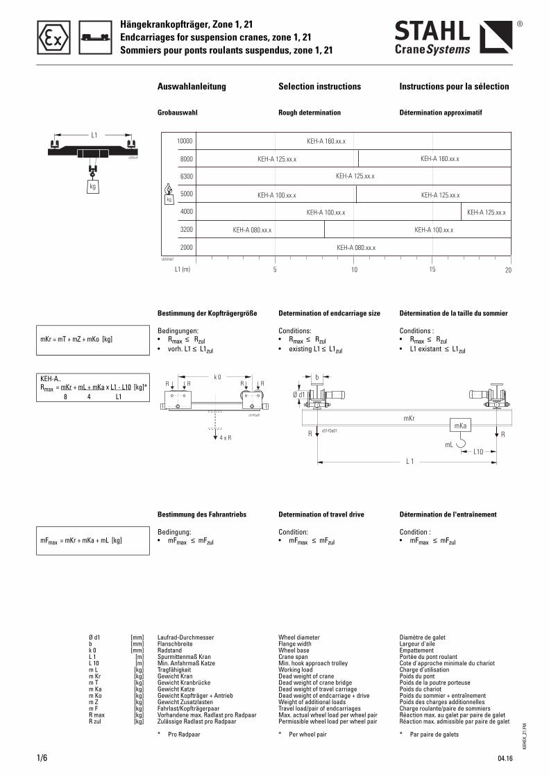
Grobauswahl Rough determination Détermination approximatif
Bestimmung der Kopfträgergröße Determination of endcarriage size Détermination de la taille du sommier
mKr = mT + mZ + mKo [kg]Bedingungen: • Rmax ≤ Rzul• vorh. L1 ≤ L1zul
Conditions: • Rmax ≤ Rzul• existing L1 ≤ L1zul
Conditions : • Rmax ≤ Rzul• L1 existant ≤ L1zul
KEH-A..Rmax = mKr + mL + mKa x L1 - L10 [kg]*
8 4 L1
Bestimmung des Fahrantriebs Determination of travel drive Détermination de l'entraînement
mFmax = mKr + mKa + mL [kg]Bedingung:• mFmax ≤ mFzul
Condition:• mFmax ≤ mFzul
Condition :• mFmax ≤ mFzul
Ø d1 [mm]b [mm]k 0 [mm]L 1 [m]L 10 [m]m L [kg]m Kr [kg]m T [kg]m Ka [kg]m Ko [kg]m Z [kg]m F [kg]R max [kg]R zul [kg]
Laufrad-Durchmesser FlanschbreiteRadstand Spurmittenmaß KranMin. Anfahrmaß Katze Tragfähigkeit Gewicht Kran Gewicht KranbrückeGewicht KatzeGewicht Kopfträger + AntriebGewicht ZusatzlastenFahrlast/KopfträgerpaarVorhandene max. Radlast pro RadpaarZulässige Radlast pro Radpaar
* Pro Radpaar
Wheel diameterFlange widthWheel baseCrane spanMin. hook approach trolleyWorking loadDead weight of craneDead weight of crane bridgeDead weight of travel carriageDead weight of endcarriage + driveWeight of additional loadsTravel load/pair of endcarriagesMax. actual wheel load per wheel pairPermissible wheel load per wheel pair
* Per wheel pair
Diamètre de galetLargeur d'aileEmpattement Portée du pont roulantCote d'approche minimale du chariotCharge d’utilisationPoids du pont Poids de la poutre porteusePoids du chariotPoids du sommier + entraînementPoids des charges additionnellesCharge roulante/paire de sommiersRéaction max. au galet par paire de galetRéaction max. admissible par paire de galet
* Par paire de galets
KEHE
X_Z1
.FM
Hängekrankopfträger, Zone 1, 21Endcarriages for suspension cranes, zone 1, 21
Sommiers pour ponts roulants suspendus, zone 1, 21
1
04.16 1/7
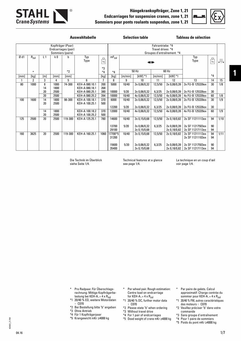
Auswahltabelle Selection table Tableau de sélection
Kopfträger (Paar) Endcarriages (pair) Sommiers (paire)
Fahrantriebe *4Travel drives *4
Groupes d’entraînement *4
Ø d1 Rzul
*
L 1 k 0 b
*2
Typ Type
*3*4
mFzul
*4
Typ Type
*450 Hz 60 Hz
[mm] [kg] [m] [mm] [mm] [kg] [kg] [m/min] [kW] *1 [m/min] [kW] *11 2 3 4 5 6 7 8 9 10 11 12 13 14 1580 1000 8
14 20
1000 1800 2500
74-300 KEH-A 080.10.1KEH-A 080.18.1KEH-A 080.25.1
200268380
5000
10000
10/40
5/20
2x 0,06/0,32
2x 0,06/0,32
12,5/50
6,3/25
2x 0,08/0,39
2x 0,08/0,39
2x FU-B 125339ex
2x FU-B 125326ex
30
30
1/8
20 2500 KEH-A 080.25.2 394 10000 10/40 4x 0,06/0,32 12,5/50 4x 0,08/0,39 4x FU-B 125339ex 60 1/8100 1600 14
201800 2500
98-300 KEH-A 100.18.1KEH-A 100.25.1
370500
6000
12200
10/40
5/20
2x 0,06/0,32
2x 0,06/0,32
12,5/50
6,3/25
2x 0,08/0,39
2x 0,08/0,39
2x FU-B 125339ex
2x FU-B 125326ex
30
30
1/9
14 20
1800 2500
KEH-A 100.18.2KEH-A 100.25.2
370500
12000 10/40 4x 0,06/0,32 12,5/50 4x 0,08/0,39 4x FU-B 125339ex 60 1/9
125 2500 20 2500 119-300 KEH-A 125.25.1 780 14600
1370029100
10/40
5/20
2x 0,15/0,68
2x 0,06/0,322x 0,15/0,68
12,5/50
6,3/25
2x 0,18/0,82
2x 0,08/0,392x 0,18/0,82
2x SF 11211113ex
2x SF 11217503ex2x SF 11217113ex
94
9094
1/10
160 3625 20 2500 119-300 KEH-A 160.25.1 1060 17700*531200
1560035400
10/40
5/20
2x 0,15/0,68
2x 0,06/0,322x 0,15/0,68
12,5/50
6,3/25
2x 0,18/0,82
2x 0,08/0,392x 0,18/0,82
2x SF 11211113ex2x SF 11211103ex
2x SF 11217503ex2x SF 11217113ex
9494
9094
1/11
Die Technik im Überblick siehe Seite 1/4.
Technical features at a glance see page 1/4.
La technique en un coup d’œil voir page 1/4.
* Pro Radpaar. Für Überschlags-rechnung: Mittige Kopfträgerbe-lastung bei KEH-A..= 4 x Rzul
*1 20/40 % ED, weitere Motordaten ↑ C070
*2 Bei Bestellung bitte "b" angeben*3 Ohne Antrieb*4 Für 1 Kopfträgerpaar*5 Krangewicht mKr ≥4000 kg
* Per wheel pair. Rough estimation: Centre load on endcarriage for KEH-A..= 4 x Rzul
*1 20/40 % DC, further motor data ↑ C070
*2 Please state "b" when ordering*3 Without travel drive*4 For 1 pair of endcarriages*5 Dead weight of crane mKr ≥4000 kg
* Par paire de galets. Calcul approximatif: Charge centrée du sommier pour KEH-A..= 4 x Rzul
*1 20/40 % FM, autres caractéristiques des moteurs ↑ C070
*2 Veuillez préciser "b" dans votre commande
*3 Sans groupe d'entraînement*4 Pour 1 paire de sommiers*5 Poids du pont mKr ≥4000 kg
KEHE
X_Z1
.FM
Hängekrankopfträger, Zone 1, 21Endcarriages for suspension cranes, zone 1, 21Sommiers pour ponts roulants suspendus, zone 1, 21
1/8 04.16
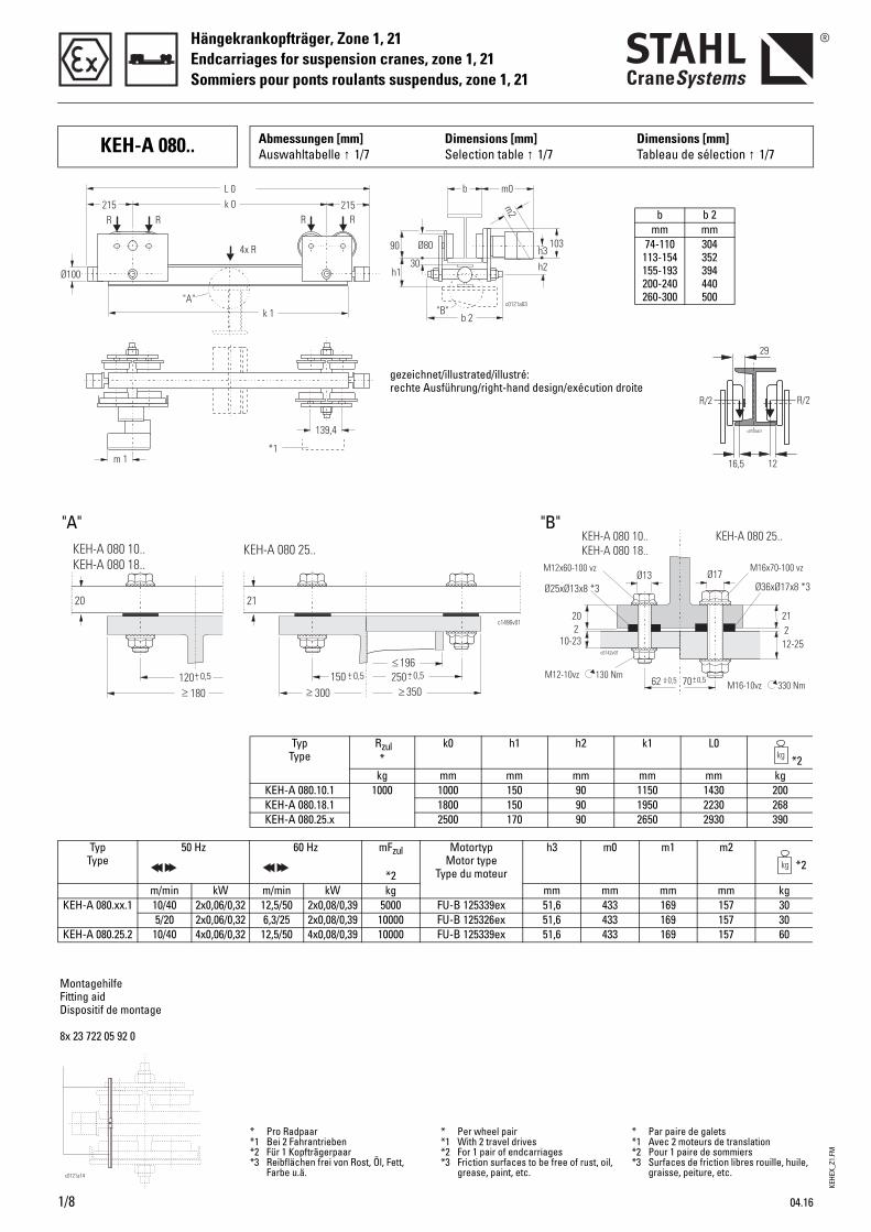
KEH-A 080.. Abmessungen [mm] Auswahltabelle ↑ 1/7
Dimensions [mm]Selection table ↑ 1/7
Dimensions [mm]Tableau de sélection ↑ 1/7
2120
12-2510-23
Ø13 Ø17
62 70+ +- -0,5 0,5
c0142v01
130 Nm330 Nm
M12x60-100 vz M16x70-100 vz
M12-10vzM16-10vz
2
KEH-A 080 10..KEH-A 080 18..
KEH-A 080 25..
Ø25xØ13x8 *3 Ø36xØ17x8 *3
2
Ø80
b m0
b 2c0121a03
h2
L 0
k 1
k 0R RR R
4x R
215215
Ø100
m 1
139,4
h1
90
30h3
m2
103
*1
"A""B"
gezeichnet/illustrated/illustré:rechte Ausführung/right-hand design/exécution droite
MontagehilfeFitting aidDispositif de montage
8x 23 722 05 92 0
b b 2mm mm
74-110 113-154 155-193 200-240 260-300
304 352 394 440 500
"A" "B"
Typ Type
Rzul*
k0 h1 h2 k1 L0*2
kg mm mm mm mm mm kgKEH-A 080.10.1 1000 1000 150 90 1150 1430 200KEH-A 080.18.1 1800 150 90 1950 2230 268KEH-A 080.25.x 2500 170 90 2650 2930 390
Typ Type
50 Hz 60 Hz mFzul
*2
Motortyp Motor type
Type du moteur
h3 m0 m1 m2*2
m/min kW m/min kW kg mm mm mm mm kgKEH-A 080.xx.1 10/40 2x0,06/0,32 12,5/50 2x0,08/0,39 5000 FU-B 125339ex 51,6 433 169 157 30
5/20 2x0,06/0,32 6,3/25 2x0,08/0,39 10000 FU-B 125326ex 51,6 433 169 157 30KEH-A 080.25.2 10/40 4x0,06/0,32 12,5/50 4x0,08/0,39 10000 FU-B 125339ex 51,6 433 169 157 60
* Pro Radpaar*1 Bei 2 Fahrantrieben*2 Für 1 Kopfträgerpaar*3 Reibflächen frei von Rost, Öl, Fett,
Farbe u.ä.
* Per wheel pair*1 With 2 travel drives*2 For 1 pair of endcarriages*3 Friction surfaces to be free of rust, oil,
grease, paint, etc.
* Par paire de galets*1 Avec 2 moteurs de translation*2 Pour 1 paire de sommiers*3 Surfaces de friction libres rouille, huile,
graisse, peiture, etc.
� 350
� 196150 +- 0,5 250+- 0,5
� 300
c1496v01
21
KEH-A 080 25..
120+- 0,5
� 180
KEH-A 080 10..KEH-A 080 18..
20
KEHE
X_Z1
.FM
Hängekrankopfträger, Zone 1, 21Endcarriages for suspension cranes, zone 1, 21
Sommiers pour ponts roulants suspendus, zone 1, 21
1
04.16 1/9
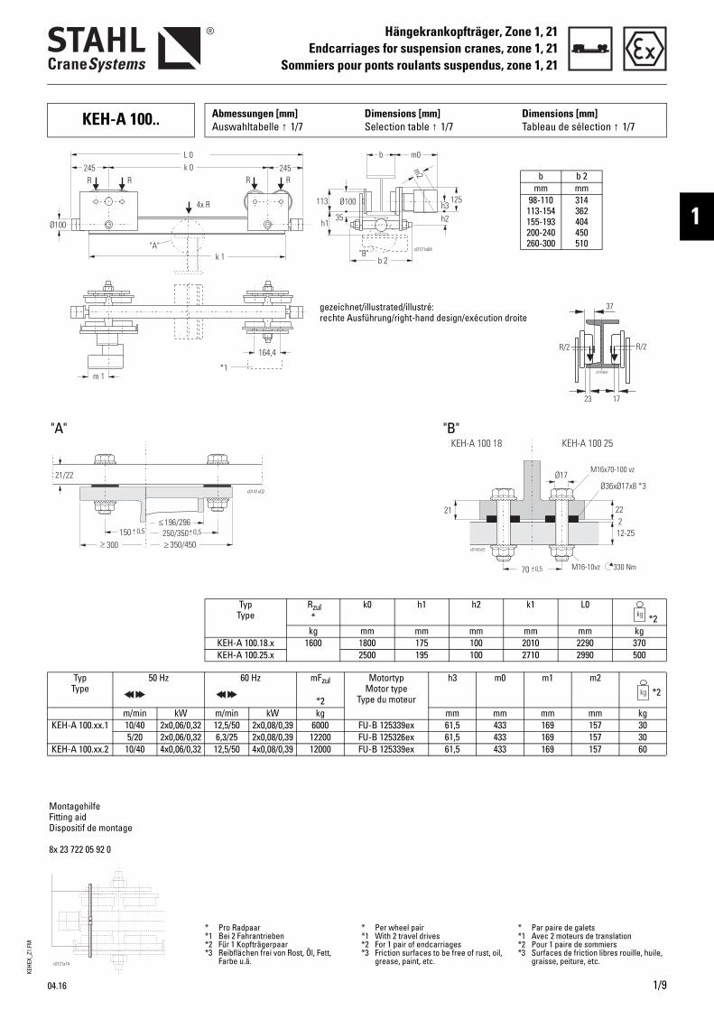
KEH-A 100.. Abmessungen [mm] Auswahltabelle ↑ 1/7
Dimensions [mm]Selection table ↑ 1/7
Dimensions [mm]Tableau de sélection ↑ 1/7
Ø100
b m0
b 2c0121a04
h2
L 0
k 1
k 0 245245
Ø100
m 1
164,4
h1
113
35h3
m2
*1
"A""B"
R RR R
4x R 125
MontagehilfeFitting aidDispositif de montage
8x 23 722 05 92 0
b b 2mm mm
98-110 113-154 155-193 200-240 260-300
314 362 404 450 510
"A" "B"
Typ Type
Rzul*
k0 h1 h2 k1 L0*2
kg mm mm mm mm mm kgKEH-A 100.18.x 1600 1800 175 100 2010 2290 370KEH-A 100.25.x 2500 195 100 2710 2990 500
Typ Type
50 Hz 60 Hz mFzul
*2
Motortyp Motor type
Type du moteur
h3 m0 m1 m2*2
m/min kW m/min kW kg mm mm mm mm kgKEH-A 100.xx.1 10/40 2x0,06/0,32 12,5/50 2x0,08/0,39 6000 FU-B 125339ex 61,5 433 169 157 30
5/20 2x0,06/0,32 6,3/25 2x0,08/0,39 12200 FU-B 125326ex 61,5 433 169 157 30KEH-A 100.xx.2 10/40 4x0,06/0,32 12,5/50 4x0,08/0,39 12000 FU-B 125339ex 61,5 433 169 157 60
gezeichnet/illustrated/illustré:rechte Ausführung/right-hand design/exécution droite
* Pro Radpaar*1 Bei 2 Fahrantrieben*2 Für 1 Kopfträgerpaar*3 Reibflächen frei von Rost, Öl, Fett,
Farbe u.ä.
* Per wheel pair*1 With 2 travel drives*2 For 1 pair of endcarriages*3 Friction surfaces to be free of rust, oil,
grease, paint, etc.
* Par paire de galets*1 Avec 2 moteurs de translation*2 Pour 1 paire de sommiers*3 Surfaces de friction libres rouille, huile,
graisse, peiture, etc.
2221
12-25
70 +- 0,5
c0142v02
330 Nm
M16x70-100 vz
M16-10vz
Ø17
2
KEH-A 100 18 KEH-A 100 25
Ø36xØ17x8 *3
� 350/450
� 196/296150 +- 0,5 250/350+- 0,5
� 300
c0141v02
21/22
KEHE
X_Z1
.FM
Hängekrankopfträger, Zone 1, 21Endcarriages for suspension cranes, zone 1, 21Sommiers pour ponts roulants suspendus, zone 1, 21
1/10 04.16
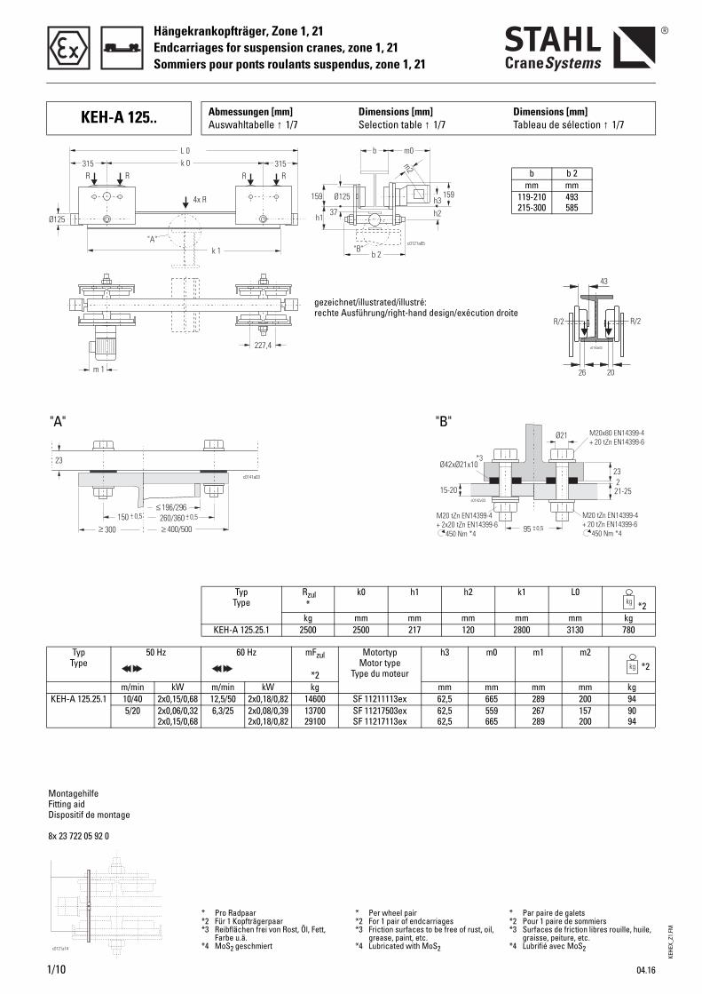
KEH-A 125.. Abmessungen [mm] Auswahltabelle ↑ 1/7
Dimensions [mm]Selection table ↑ 1/7
Dimensions [mm]Tableau de sélection ↑ 1/7
23
21-2515-20
95 +- 0,5
c0142v03
450 Nm *4450 Nm *4
M20x80 EN14399-4+ 20 tZn EN14399-6
M20 tZn EN14399-4EN14399-6+ 20 tZn
M20 tZn+ 2x20 tZn
EN14399-4EN14399-6
2
Ø42xØ21x10
Ø21
*3
Ø125
b m0
b 2c0121a05
h2
L 0
k 1
k 0 315315
Ø125
227,4
h1
159
37h3
m2
159
"A""B"
m 1
R RR R
4x R
MontagehilfeFitting aidDispositif de montage
8x 23 722 05 92 0
b b 2mm mm
119-210 215-300
493 585
"A"
Typ Type
Rzul*
k0 h1 h2 k1 L0*2
kg mm mm mm mm mm kgKEH-A 125.25.1 2500 2500 217 120 2800 3130 780
Typ Type
50 Hz 60 Hz mFzul
*2
Motortyp Motor type
Type du moteur
h3 m0 m1 m2*2
m/min kW m/min kW kg mm mm mm mm kgKEH-A 125.25.1 10/40 2x0,15/0,68 12,5/50 2x0,18/0,82 14600 SF 11211113ex 62,5 665 289 200 94
5/20 2x0,06/0,322x0,15/0,68
6,3/25 2x0,08/0,392x0,18/0,82
1370029100
SF 11217503exSF 11217113ex
62,562,5
559665
267289
157200
9094
* Pro Radpaar*2 Für 1 Kopfträgerpaar*3 Reibflächen frei von Rost, Öl, Fett,
Farbe u.ä.*4 MoS2 geschmiert
* Per wheel pair*2 For 1 pair of endcarriages*3 Friction surfaces to be free of rust, oil,
grease, paint, etc.*4 Lubricated with MoS2
* Par paire de galets*2 Pour 1 paire de sommiers*3 Surfaces de friction libres rouille, huile,
graisse, peiture, etc.*4 Lubrifié avec MoS2
gezeichnet/illustrated/illustré:rechte Ausführung/right-hand design/exécution droite
"B"
KEHE
X_Z1
.FM
Hängekrankopfträger, Zone 1, 21Endcarriages for suspension cranes, zone 1, 21
Sommiers pour ponts roulants suspendus, zone 1, 21
1
04.16 1/11
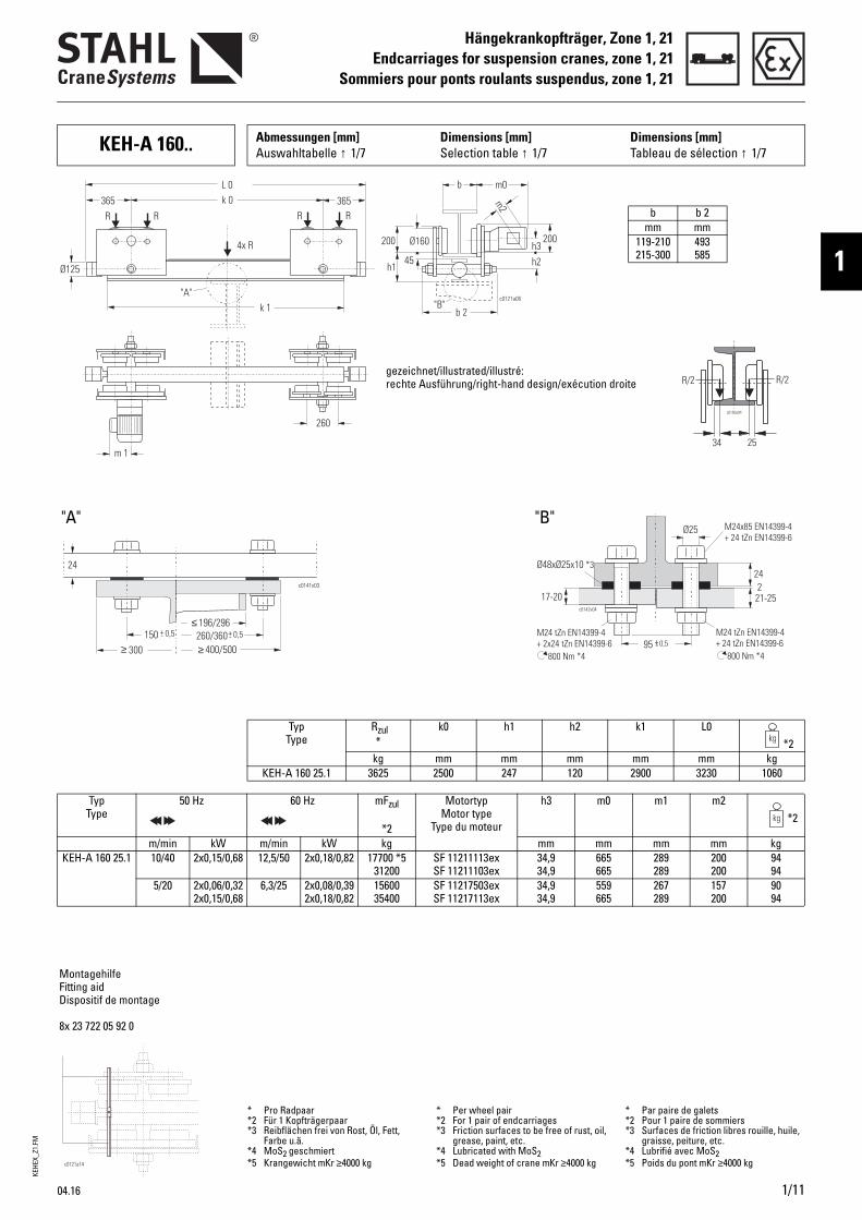
KEH-A 160.. Abmessungen [mm] Auswahltabelle ↑ 1/7
Dimensions [mm]Selection table ↑ 1/7
Dimensions [mm]Tableau de sélection ↑ 1/7
24
21-2517-20
95 +- 0,5
c0142v04
800 Nm *4800 Nm *4
M24x85 EN14399-4+ 24 tZn EN14399-6
M24 tZn EN14399-424 tZn EN14399-6+
M24 tZn+ 2x24 tZn
EN14399-4EN14399-6
2
Ø48xØ25x10 *3
Ø25
Ø160
b m0
b 2c0121a06
h2
L 0
k 1
k 0 365365
Ø125
260
h1
200
45h3
m2
200
"A""B"
m 1
R RR R
4x R
≥ 400/500
≤ 196/296150 +- 0,5 260/360+- 0,5
≥ 300
c0141v03
24
MontagehilfeFitting aidDispositif de montage
8x 23 722 05 92 0
b b 2mm mm
119-210 215-300
493 585
"A"
Typ Type
Rzul*
k0 h1 h2 k1 L0*2
kg mm mm mm mm mm kgKEH-A 160 25.1 3625 2500 247 120 2900 3230 1060
Typ Type
50 Hz 60 Hz mFzul
*2
Motortyp Motor type
Type du moteur
h3 m0 m1 m2*2
m/min kW m/min kW kg mm mm mm mm kgKEH-A 160 25.1 10/40 2x0,15/0,68 12,5/50 2x0,18/0,82 17700 *5
31200SF 11211113exSF 11211103ex
34,934,9
665665
289289
200200
9494
5/20 2x0,06/0,322x0,15/0,68
6,3/25 2x0,08/0,392x0,18/0,82
1560035400
SF 11217503exSF 11217113ex
34,934,9
559665
267289
157200
9094
* Pro Radpaar*2 Für 1 Kopfträgerpaar*3 Reibflächen frei von Rost, Öl, Fett,
Farbe u.ä.*4 MoS2 geschmiert*5 Krangewicht mKr ≥4000 kg
* Per wheel pair*2 For 1 pair of endcarriages*3 Friction surfaces to be free of rust, oil,
grease, paint, etc.*4 Lubricated with MoS2*5 Dead weight of crane mKr ≥4000 kg
* Par paire de galets*2 Pour 1 paire de sommiers*3 Surfaces de friction libres rouille, huile,
graisse, peiture, etc.*4 Lubrifié avec MoS2*5 Poids du pont mKr ≥4000 kg
gezeichnet/illustrated/illustré:rechte Ausführung/right-hand design/exécution droite
"B"
KEHE
X_Z1
.FM
Hängekrankopfträger, Zone 1, 21Endcarriages, zone 1, 21Sommiers ponts susp., zone 1, 21
1/12
Ausstattung und OptionEquipment and optionsÉquipement et options
A015
A018
A050
A051
A053
A054
Tensions d'alimentation des moteursLa tension standard d'alimentation des moteurs est 400 V, 50 Hz ou 460 V, 60 Hz.D'autres tensions d'alimentation sont livrables, en partie contre supplément de prix, veuillez nous consulter.
Surveillance de la température des moteursEn version standard, les moteurs de direction sont dotés d'une sur-veillance de la température avec sondes thermiques. Le disjoncteur doit être comman-dé à part, voir Informations sur le produit "Équipement électrique antidéflagrant de ponts roulants", B100.
Mise en œuvre en conditions exceptionnellesPour cette mise en œuvre, diverses exécutions spéciales sont livrables.
Protection de type IP 66(option)La protection de type IP 66 est requise en cas de mise en œuvre en plein air sans toit de protec-tion, ou d'exposition à jet d'eau.Si cette option est sélectionnée, nous préconisons le chauffage des moteurs et des coffrets des appareillages.
Cône de freinage chromé dur Si le sommier est exposé à pério-des d'arrêt longues dans une ambiance humide et agressive, nous recommandons de chromer le cône-frein. Ceci évite que le frein se coince après une longue période d'arrêt.
Températures ambiantes anormales(option)Le modèle standard des sommiers peut être mis en œuvre dans la plage de température de -20 °C à +40 °C.Autres plages de températures sur demande.
Motor supply voltagesThe standard motor supply voltage is 400 V, 50 Hz or 460 V, 60 Hz.Other supply voltages are available, in some cases with surcharge, please enquire.
Motor temperature controlThe travel motors have PTC thermistor temperature control as standard.The necessary tripping device must be ordered separately, see Product information "Explosion-protected crane electrics", B100.
Use in non-standard conditionsVarious off-standard designs are available for use in these conditions.
IP 66 protection(option)IP 66 protection is required for outdoor use if the hoist is not protected by a roof, or is exposed to water jets.If this option is selected, we recommend heating for motors and panel boxes.
Brake cone hard chromium-platedIf the endcarriage is subject to long dead times in a damp and aggressive ambience chrome-plating the brake cone is recom-mended. This prevents the brake seizing after long dead times.
Off-standard ambient tempera-tures(option)In standard design the encarria-ges can be used in a temperature range from -20°C to +40°C.Other temperature ranges on request.
50 Hz 60 Hz
380 V, 400 V, 415 V, 500 V440 V, 525 V, 660 V, 690 V
460 V480 V
380 V, 400 V, 440 V, 575 V, 600 V
MotoranschlussspannungenDie Standard-Motoranschluss-spannung ist 400 V, 50 Hz bzw. 460 V, 60 Hz.Darüber hinaus sind weitere Spannungen, teilweise mit Mehr-preis lieferbar, bitte fragen Sie an.
Temperaturüberwachung der MotorenDie Fahrmotoren sind standard-mäßig mit Kaltleiterfühler für eine Temperaturüberwachung ausge-stattet.Erforderliche Auslösegeräte bitte separat bestellen, siehe Produkt-information "Explosionsge-schützte Kranelektrik", B100.
Einsatz unter besonderen BedingungenHierfür sind verschiedene Son-derausführungen lieferbar.
Schutzart IP 66(Option)Die Schutzart IP 66 ist erforderlich beim Einsatz im Freien ohne Schutzdach oder bei Strahlwas-ser.Bei Auswahl dieser Option wird die Heizung der Motoren und Gerätekästen empfohlen.
Bremskonus galvanisch hartver-chromtIst der Kopfträger in feuchter und aggressiver Umgebung längeren Stillstandszeiten ausgesetzt wird empfohlen die Bremskonen zu verchromen. So kann das Festsit-zen der Bremse nach langen Still-standszeiten verhindert werden.
Anomale Umgebungstemperatu-ren(Option)In der Standardausführung kön-nen die Kopfträger im Tempera-turbereich von -20°C bis +40°C eingesetzt werden. Andere Temperaturbereiche auf Anfrage.
Anschlussspannungen →Supply voltages →
Tensions de raccordement →
04.16
KEHE
X_Z1
.FM
Hängekrankopfträger, Zone 1, 21Endcarriages, zone 1, 21
Sommiers ponts susp., zone 1, 21
1
04.16
Ausstattung und OptionEquipment and optionsÉquipement et options
A059
A060
A061
Höherer ExplosionsschutzGegen Mehrpreis ist der Fahr-antrieb in Schutzart Ex de IIC T4 lieferbar. Schutzarten Ex d IIB T4 und Ex d IIC T4 auf Anfrage.
Lackierung/KorrosionsschutzStandard-Vorbehandlung: Stahlkiesentrostung nach DIN EN ISO 12944-4, Entrostungs-grad SA2,5. Bearbeitete Flächen, Alu- und Tiefziehteile entfettet.
Grundanstrich: Zweikomponen-ten-PUR-Grundierung ca. 40-60 µm. Farbton lichtgrau, ähnlich RAL 7035.Fahrwerksschilder: Deckanstrich ca. 80 µm. Farbton schwarzgrau.
Bestimmungsgemäße Verwen-dung: Alle dargestellten Lackierungen erfüllen die Anforderungen für den Einsatz im Ex-Bereich (schwach ladungserzeugende Prozesse).In besonderen Fällen (insbeson-dere beim Einsatz des Kopfträgers in der Nähe einer elektrostati-schen Lackiereinrichtung mit < 1 m Abstand Luftlinie zur Hoch-spannungselektrode) können abweichende Beschichtungen erforderlich sein. Auf Anfrage.
Anstrich A20 Polyurethan-Decklack (Standard)Zweikomponentenlack, Farbe nach RAL Farbkarte.Einzelheiten siehe Datenblatt Beschichtungssystem.Weitere Zusatzmaßnahmen zur Lackierung sind notwendig, siehe Anwendungsspezifikationen im Freien.
HTiEPE
PSSiMa
PuSTa
IAtdtDrctelhO
APTpFpFaa
igher explosion protectionhe travel drive is available
n explosion protection type x de IIC T4 against surcharge. rotection types Ex d IIB T4 and x d IIC T4 on request.
aint/corrosion protectiontandard pre-treatment: teel shot de-rusting grade SA2.5
n acc. to DIN EN ISO 12944-4. achined surfaces, aluminium
nd deep-drawn parts degreased.
rimer coat: two-component poly-rethane primer approx. 40-60 µm. hade light grey, like RAL 7035.rolley side plates: top coat pprox. 80 µm. Shade black grey.
ntended use: ll paint systems described meet
he requirements for use in hazar-ous areas (low charge-genera-
ing processes).ifferent paint systems may be
equired in special cases (in parti-ular if the endcarriage is opera-ed in the vicinity of an lectrostatic painting system at a
inear distance of < 1 m from the igh voltage electrode). n request.
20 paint systemolyurethane top coat (standard)wo-component paint, colour as er RAL chart.or details, see data sheet on aint system.urther measures are required in ddition to the paint, see outdoor pplication guide.
MgLrdste
PTGdSmd
CdcCRFfg
UtTfd(tDvpdisehS
PC(PlPnDesl
eilleure protection antidéfla-rantee groupe d'entraînement est liv-able en type de protection anti-éflagrante Ex de IIB T4 contre upplément de prix. Type de pro-ection antidéflagrante Ex d IIB T4 t Ex d IIC T4 sur demande.
einture/protection anticorrosiveraitement préalable standard : renaillé selon DIN EN ISO 12944-4 ; egré de dérouillage SA2,5. urfaces usinées, pièces en alu-inium et pièces embouties,
égraissées.
ouche d'apprêt : couche 'apprêt polyuréthane à deux omposants env. 40-60 µm. ouleur gris clair, semblable à AL 7035.lasques des chariots : couche de inition, approx. 80 µm. Couleur ris noir.
tilisation conforme à la destina-ion : outes peintures spécifiées satis-ont aux exigences pour l'emploi ans les atmosphères explosibles processus faiblement généra-eurs de charges).es peintures différentes peu-ent être requises dans des cas articuliers (notamment l'emploi u sommier à proximité d'une
nstallation de peinture électro-tatique à une distance de < 1 m n ligne droite de l'électrode à aute tension). ur demande.
einture A20ouche de finition polyuréthane
standard)einture à deux composants, cou-
eur selon carte RAL.our des détails, voir fiche tech-ique "Peinture".'autres mesures additionnelles n plus de la peinture sont néces-aires, voir spécification pour
'utilisation à l'extérieur.
1/13
KEHE
X_Z1
.FM
Hängekrankopfträger, Zone 1, 21Endcarriages, zone 1, 21Sommiers ponts susp., zone 1, 21
1/14
Ausstattung und OptionEquipment and optionsÉquipement et options
DIN EN ISO 12944-5 *
TypType
C2 A20/80
(80 µm)
Produktionsrgeringer FeuLager, FabrikRelative Luft< 90%.
C2hochhigh
élevée
A20/120
(120 µm)
Produktionsrgeringer FeuLager, FabrikRelative Luft< 90%.
C3 A20/160
(160 µm)
Produktionsrhoher Feuch≤ 100% und Luftverunrei
C4hochhigh
élevée
A20/240
(240 µm)
Chemieanlaganlagen, Zemwerke, Berenahezu stänKondensatiostarker Verugung, Gebäuan Meerwas
* Korrosivitätskategorie / Corrosivity cate
A062
DIN EN ISO 12944-5 *
TypType
C4hochhigh
élevée
A30/240
(240 µm)
Chemieanlaganlagen, Zemwerke, GießGebäude in Mnähe.
* Korrosivitätskategorie / Corrosivity cate
A140
Andere Schichtdicken auf Anfrage.
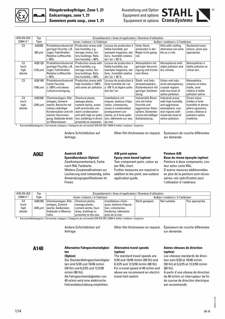
Anstrich A30 Epoxidharzbasis (Option)Zweikomponentenlack, Farbe nach RAL Farbkarte.Weitere Zusatzmaßnahmen zur Lackierung sind notwendig, siehe Anwendungsspezifikationen im Freien.
Andere Schichtdicken auf Anfrage.
Alternative Fahrgeschwindigkei-ten(Option)Die Standardfahrgeschwindigkei-ten sind 5/20 und 10/40 m/min (50 Hz) und 6,3/25 und 12,5/50 m/min (60 Hz).Ab Fahrgeschwindigkeiten von 40 m/min wird eine elektrische Fahrendabschaltung empfohlen.
Einsatzbereich / AInnen / indoors / à l’intérieur
äume mit chte, z.B. hallen. feuchte
Production areas with low humidity, e.g. storage rooms, fac-tory buildings. Rela-tive humidity < 90%.
Locaux dfaible huexempleliers ; hude l'air <
äume mit chte, z.B. hallen. feuchte
Production areas with low humidity, e.g. storage rooms, fac-tory buildings. Rela-tive humidity < 90%.
Locaux dfaible huexempleliers ; hude l'air <
äume mit te etwas nigung.
Production areas with high humidity ≤ 100% and some air pollution.
Locaux dforte hum≤ 100 % tion de l
en, Klär-ent-
iche mit diger n und mit nreini-de direkt ser.
Chemical plants, sewage plants, cement works, areas with practically con-stant condensation and with high air pollu-tion, buildings in direct proximity to seawater.
Installatmiques, ration, czones à pratiquestante, etion, bâtde mer.
gory / Catégorie de corrosivité DIN EN ISO 12944-5
Einsatzbereich / AInnen / indoors / à l’intérieur
en, Klär-ent-
ereien, eeres-
Chemical plants, sewage plants, cement works, foun-dries, buildings in proximity to the sea.
Installatques, station, cimfonderieprès de
gory / Catégorie de corrosivité DIN EN ISO 12944-5
O
AETpFaa
O
A(T56Fat
rea of application / Domaine d’utilisationAußen /
e production à midité, par magasins, ate-midité relative 90 %.
Unter Dach, ansonsten in der Regel nicht geeig-net.
Onlothble
e production à midité, par magasins, ate-midité relative 90 %.
Atmosphären mit geringer Verunrei-nigung und trocke-nem Klima.
Atmsligdry
e production à idité de l'air
et légère pollu-'air.
Stadt- und Indu-strieatmosphäre, Küstenbereich mit geringer Salzbela-stung.
Urbstricoawitsali
ions chi-stations d’épu-imentaries, condensation ment con-t à forte pollu-iments sur eau
Industrielle Berei-che mit hoher Feuchte und aggressiver Atmo-sphäre, Küstenbe-reiche mit mäßiger Salzbelastung.
Indwitandatmstamosali
mittel / medium / moyenne
rea of application / Domaine d’utilisationAußen /
ions chimi-tions d’épura-
entaries, s, bâtiments la mer.
Nicht geeignet. Not
mittel / medium / moyenne
ther film thicknesses on request.
30 paint system poxy resin based (option)wo-component paint, colour as er RAL chart.urther measures are required in ddition to the paint, see outdoor pplication guide.
ther film thicknesses on request.
lternative travel speedsoption)he standard travel speeds are /20 and 10/40 m/min (50 Hz) and .3/25 and 12.5/50 m/min (60 Hz). or a travel speed of 40 m/min and bove we recommend an electric
ravel limit switch.
És
PBPlDesl
És
A(Lt((Àdde
outdoors / à l’extérieury with roofing, erwise not suita- as a rule.
Seulement avec toiture, sinon pas appropriée.
ospheres with ht pollution and climate.
Atmosphères à faible pollution et climat sec.
an and indu-al atmospheres, stal regions
h low level of ne pollution.
Atmosphère urbaine et indus-trielle, zone côtière à faible pollution saline.
ustrial areas h high humidity aggressive osphere, coa-
l regions with derate level of ne pollution.
Zones indus-trielles à forte humidité et atmos-phère agressive, zones côtières à pollution saline modérée.
outdoors / à l’extérieur suitable. Pas appropriée.
paisseurs de couche différentes ur demande.
einture A30ase de résine époxyde (option)einture à deux composants, cou-
eur selon carte RAL.'autres mesures additionnelles n plus de la peinture sont néces-aires, voir spécification pour
'utilisation à l'extérieur.
paisseurs de couche différentes ur demande.
utres vitesses de directionoption)es vitesses standards de direc-ion sont 5/20 et 10/40 m/min 50 Hz) et 6,3/25 et 12,5/50 m/min 60 Hz). partir d'une vitesse de direction e 40 m/min un interrupteur de fin e course de direction électrique st recommandé.
04.16

KEHE
X_Z1
.FM
Hängekrankopfträger, Zone 1, 21Endcarriages, zone 1, 21
Sommiers ponts susp., zone 1, 21
1
04.16
Ausstattung und OptionEquipment and optionsÉquipement et options
A200
A210
Wegfall des KopfträgerprofilsIm Lieferumfang verbleiben: Fahrwerksschilder, Aufhängeteile und Puffer mit Befestigungsele-menten (Minderpreis).
PufferverlängerungDie Puffer auf den Stirnseiten können verlängert werden. An Standardverlängerungen sind lieferbar: 100, 200, 300, 400 und 500 mm (Mehrpreis). Andere Verlängerungen auf Anfrage.
NsTscbr
LTbTo4O
on-supply of of endcarriage ectionhe following remain part of the cope of supply: Trolley side heeks, suspension parts and uffers with fixing elements (price eduction).
onger buffershe buffers on the end faces can e extended.he following standard extensi-ns are available: 100, 200, 300, 00 and 500 mm (surcharge).ther extensions on request.
SsLpcb(
RLprs5A
uppression du profilé de ommier'étendue de la fourniture com-rend simplement : Flasques du hariot, pièces de suspension et utoirs avec éléments de fixation réduction de prix).
allonge de butoires butoirs sur les faces frontales euvent être rallongés. Comme allonges standards de butoirs ont livrables : 100, 200, 300, 400 et 00 mm (supplément de prix).utres rallonges sur demande.
1/15
KEHE
X_Z1
.FM
Hängekrankopfträger, Zone 1, 21Endcarriages, zone 1, 21Sommiers ponts susp., zone 1, 21
1/16
Komponenten und ZubehörComponents and accessories
Composants et accessoires
B081
B100
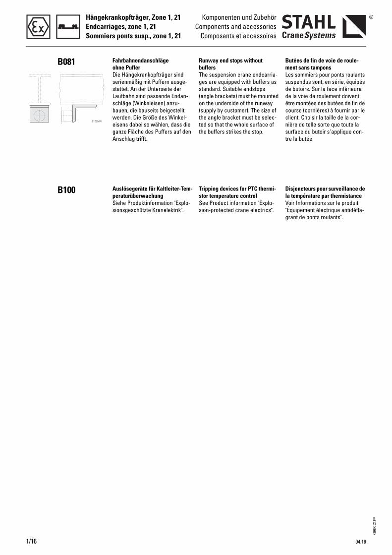
Fahrbahnendanschläge ohne PufferDie Hängekrankopfträger sind serienmäßig mit Puffern ausge-stattet. An der Unterseite der Laufbahn sind passende Endan-schläge (Winkeleisen) anzu-bauen, die bauseits beigestellt werden. Die Größe des Winkel-eisens dabei so wählen, dass die ganze Fläche des Puffers auf den Anschlag trifft.
Auslösegeräte für Kaltleiter-Tem-peraturüberwachungSiehe Produktinformation "Explo-sionsgeschützte Kranelektrik".
RbTgs(o(ttt
TsSs
unway end stops without uffershe suspension crane endcarria-es are equipped with buffers as tandard. Suitable endstops angle brackets) must be mounted n the underside of the runway supply by customer). The size of he angle bracket must be selec-ed so that the whole surface of he buffers strikes the stop.
ripping devices for PTC thermi-tor temperature controlee Product information "Explo-ion-protected crane electrics".
BmLsddêccnst
DlV"g
utées de fin de voie de roule-ent sans tampons
es sommiers pour ponts roulants uspendus sont, en série, équipés e butoirs. Sur la face inférieure e la voie de roulement doivent tre montées des butées de fin de ourse (cornières) à fournir par le lient. Choisir la taille de la cor-ière de telle sorte que toute la urface du butoir s'applique con-re la butée.
isjoncteurs pour surveillance de a température par thermistanceoir Informations sur le produit
Équipement électrique antidéfla-rant de ponts roulants".
04.16

KEHE
X_Z1
.FM
Hängekrankopfträger, Zone 1, 21Endcarriages, zone 1, 21
Sommiers ponts susp., zone 1, 21
1
04.16 1/17
Technische DatenTechnical dataCaractéristiques techniques
AuslegungDIN 15018.DIN 15070, 15071.
Einstufungnach DIN 15018, H2/B3, andere auf Anfrage.
SicherheitsvorschriftenEG-Maschinenrichtlinie 2006/42/EG, Richtlinie 2014/34/EU.
Wärmeklassefür Fahrmotoren F / H (Ausnut-zung/Isoliersystem) nach IEC/EN 60034-1
Motor-AnschlussspannungenSiehe A015.
Geräteeinstufungnach Richtlinie 2014/34/EU (ATEX):
Gas: Gerätegruppe II, Kategorie 2G
oderStaub: Gerätegruppe II, Kategorie 2D
Explosionsschutz nach EN/IEC
Schutzart EN 60529 / IECStandard: IP 55Option bzw. Zone 21: IP 66
Zulässige Umgebungstemperatu-renStandard: -20 °C...+40 °C, andere Umgebungstemperaturen auf Anfrage.
FahrmotorenSiehe Produktinformation "Explo-sionsgeschützte Fahrantriebe".
Gas:II 2G Ex de IIB T4 Gb (Standard)II 2G ck llB T4
(siehe auch A059)
oderStaub:
ll 2D Ex tb lllC T120°C Dbll 2D ck T120°C
C010
C011
C012
C014
C020
C030
C031
C040
C050
C070
DesignDIN 15018.DIN 15070, 15071.
Classificationto DIN 15018, H2/B3, other classi-fications on request.
Safety regulationsEC Machinery Directive 2006/42/CE, directive 2014/34/EU.
Thermal classfor travel motors F / H (utilisation/insulation system) complying with IEC/EN 60034-1
Motor supply voltagesSee A015.
Equipment classificationacc. to directive 2014/34/EU (ATEX):
Gas: Equipment group II, category 2G
orDust: Equipment group II, category 2D
Explosion protection to EN/IEC
Protection class EN 60529 / IECStandard: IP 55Option or zone 21: IP 66
Permissible ambient tempera-turesStandard: -20 °C...+40 °C, other ambient temperatures on request.
Travel motorsSee Product information "Explo-sion-protected travel drives".
Gas:II 2G Ex de IIB T4 Gb (standard)II 2G ck llB T4
(see also A059)
orDust:
ll 2D Ex tb lllC T120°C Dbll 2D ck T120°C
ConceptionDIN 15018.DIN 15070, 15071.
Classificationselon DIN 15018, H2/B3, autres classifications possibles sur demande.
Prescriptions de sécuritéDirective CE relative aux machines 2006/42/C.E., directive 2014/34/UE.
Classe thermiquepour moteurs de direction F / H (utilisation/système d'isolation) selon IEC/EN 60034-1
Tensions d'alimentation des moteursVoir A015.
Classification des appareilsselon directive 2014/34/UE (ATEX) :
Gaz : Groupe des appareils II, catégorie 2G
ouPoussière : Groupe des appareils II, catégorie 2D
Protection antidéflagrante selon NE/C.E.I.
Type de protection NE 60529/C.E.I.Standard: IP 55Option ou zone 21: IP 66
Températures ambiantes admissiblesStandard: -20 °C...+40 °C, autres températures ambiantes sur demande.
Moteurs de directionVoir Informations sur le produit "Groupes d’entraînement antidé-flagrants".
Gaz :II 2G Ex de IIB T4 Gb (standard)II 2G ck llB T4
(voir aussi A059)
ouPoussière :
ll 2D Ex tb lllC T120°C Dbll 2D ck T120°C
KEHE
X_Z1
.FM
Hängekrankopfträger, Zone 1, 21Endcarriages for suspension cranes, zone 1, 21Sommiers pour ponts roulants suspendus, zone 1, 21
1/18 04.16
FaxblattFax
Faxer
AnschriftAddressAdresseTel. / Fax
.................................................................................................................................................................
.................................................................................................................................................................
.................................................................................................................................................................
.................................................................................................................................................................
...........................................................
BxH .....................mm
...........................................................
...........................................................
.......................................................kg
................................................ m/min
.........................................................V
50 Hz 60 Hz
Ex de IIB T4 Ex de IIC T4
IP 66
.......................................................°C
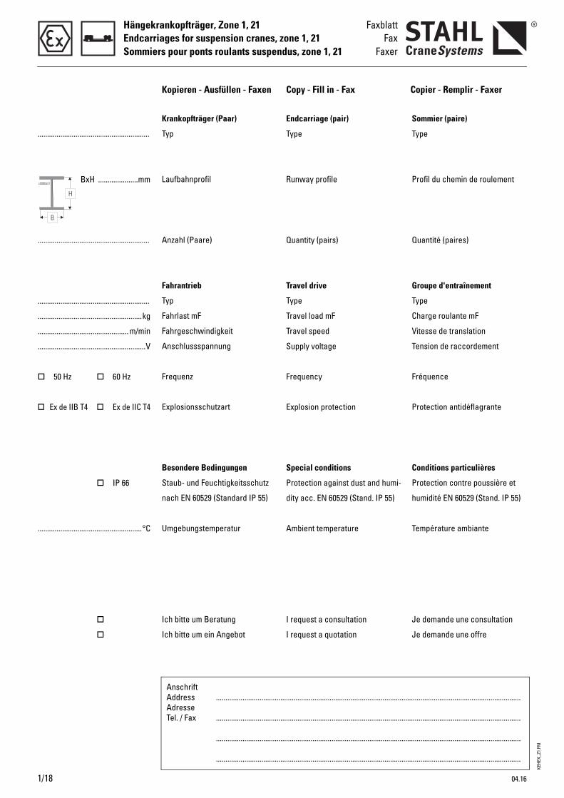
Kopieren - Ausfüllen - Faxen Copy - Fill in - Fax Copier - Remplir - Faxer
Endcarriage (pair)
Type
Runway profile
Quantity (pairs)
Travel drive
Type
Travel load mF
Travel speed
Supply voltage
Frequency
Explosion protection
Special conditions
Protection against dust and humi-
dity acc. EN 60529 (Stand. IP 55)
Ambient temperature
I request a consultation
I request a quotation
Sommier (paire)
Type
Profil du chemin de roulement
Quantité (paires)
Groupe d'entraînement
Type
Charge roulante mF
Vitesse de translation
Tension de raccordement
Fréquence
Protection antidéflagrante
Conditions particulières
Protection contre poussière et
humidité EN 60529 (Stand. IP 55)
Température ambiante
Je demande une consultation
Je demande une offre
Krankopfträger (Paar)
Typ
Laufbahnprofil
Anzahl (Paare)
Fahrantrieb
Typ
Fahrlast mF
Fahrgeschwindigkeit
Anschlussspannung
Frequenz
Explosionsschutzart
Besondere Bedingungen
Staub- und Feuchtigkeitsschutz
nach EN 60529 (Standard IP 55)
Umgebungstemperatur
Ich bitte um Beratung
Ich bitte um ein Angebot
2
KEL
KZL
II 2G (ATEX) - Zone 1 II 2D (ATEX) - Zone 21
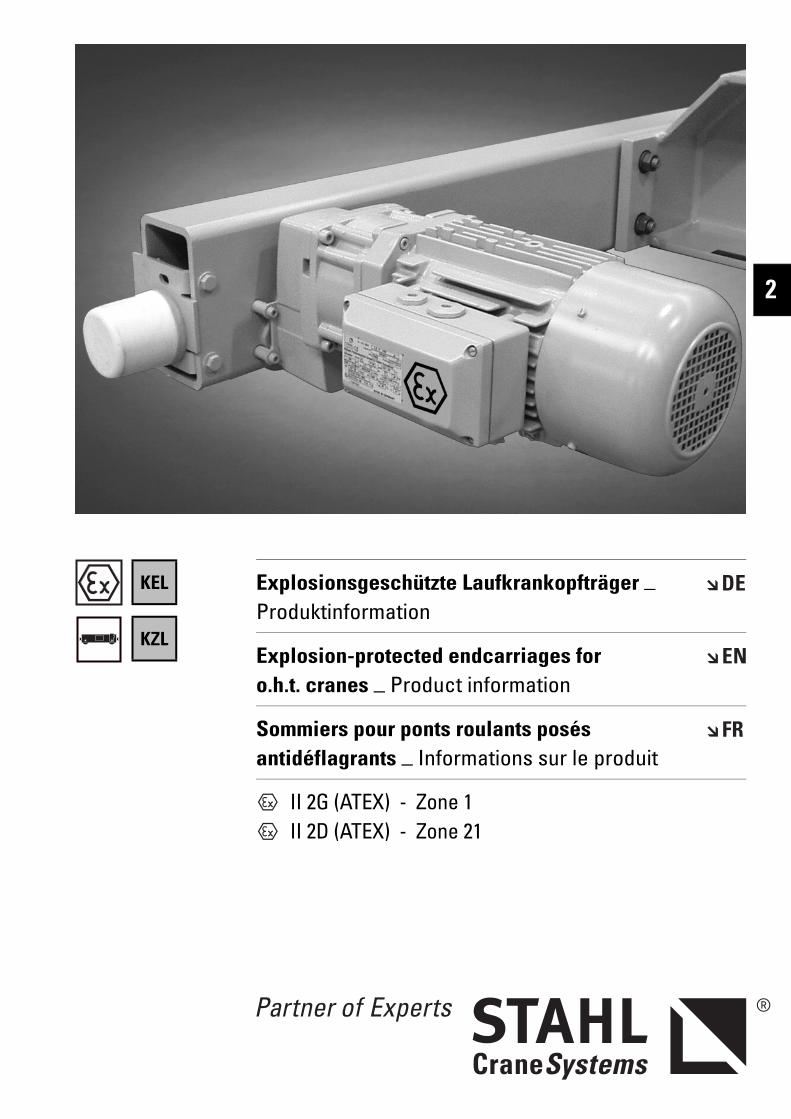
Explosionsgeschützte Laufkrankopfträger _ Produktinformation
Explosion-protected endcarriages for o.h.t. cranes _ Product information
Sommiers pour ponts roulants posés antidéflagrants _ Informations sur le produit
K_LE
X_Z1
.FM
Laufkrankopfträger, Zone 1, 21Endcarriages for o.h.t. cranes, zone 1, 21Sommiers pour ponts roulants posés, zone 1, 21
2/2 04.16
K . Lex Mit den Laufkrankopfträgern K.Lex können moderne Einträger- und Zweiträgerlaufkrane bis zu einer Tragfähigkeit von 50.000 kg und einer Spannweite bis zu 30 m gebaut werden.
Nutzen Sie die robuste Konstruk-tion, kompakte Bauweise, War-tungsfreundlichkeit und Zuver-lässigkeit in Verbindung mit den wirtschaftlichen Vorteilen der Serienfertigung für Ihren Kran-bau.
Die explosionsgeschützten Lauf-krankopfträger K.Lex entspre-chen der Gerätegruppe und Kategorie der Richtlinie 2014/34/EU (ATEX):Für Gas: ll 2G oderFür Staub: ll 2D
On the basis of K.Lex endcarria-ges for overhead travelling cra-nes, modern single girder and double girder overhead travelling cranes up to an working loadof 50,000 kg and a span of 30 m can be manufactured.
Make use of their sturdy design, compact construction, mainte-nance friendliness and reliability in conjunction with the economic advantages of series production for your crane manufacturing.
The explosion-protected over-head travelling crane endcarria-ges K.Lex comply with the equipment group and category of the directive 2014/34/EU (ATEX):For gas: ll 2G orFor dust: ll 2D
Avec les sommiers pour ponts roulants posés K.Lex, il peut être construit des ponts roulants posés modernes ayant une charge d’utilisation allant jusqu'à 50.000 kg et une portée allant jusqu'à 30 m.
Profitez de la construction robuste et compacte, de la facilité d'entretien et de la fiabilité allant de pair avec les avantages économiques de la fabrication en série pour votre construction de ponts roulants.
Les sommiers pour ponts roulants posés antidéflagrants K.Lex correspondent au groupe d’appareils et à la catégorie de la directive 2014/34/UE (ATEX) :Pour le gaz : ll 2G ouPour la poussière : ll 2D
Erklärung der Symbole Explanations of symbols Explication des symboles
Maximale Tragfähigkeit [kg] Maximum working load [kg] Charge maximale d’utilisation [kg]
Gewicht [kg] Weight [kg] Poids [kg]
Fahrgeschwindigkeit [m/min] Travel speed [m/min] Vitesse de direction [m/min]
Abmessungen siehe Seite .. Dimensions see page .. Dimensions voir page ..
↑ Siehe Seite .. See page .. Voir page ..
K_LE
X_Z1
.FM
Laufkrankopfträger, Zone 1, 21Endcarriages for o.h.t. cranes, zone 1, 21
Sommiers pour ponts roulants posés, zone 1, 21
2
Inhaltsverzeichnis Contents Indice
Erklärung der Symbole..................2/2 Explanations of symbols............... 2/2 Explication des symboles............. 2/2Die Technik im Überblick..............2/5 Technical features at a glance.... 2/5 La technique en un coup d’œil.... 2/5
Kopfträger für Einträger-laufkrane
Endcarriages for single girder o.h.t. cranes
Sommiers pour ponts roulants posés monopoutre
Auswahlanleitung..........................2/7 Selection instructions................... 2/7 Instructions pour la sélection ..... 2/7Auswahltabelle ..............................2/9 Selection table ............................... 2/9 Tableau de sélection..................... 2/9Typenerklärung ..............................2/9 Explanation of types...................... 2/9 Explication des types.................... 2/9Abmessungen...............................2/10 Dimensions ................................... 2/10 Dimensions................................... 2/10Faxblatt ..........................................2/15 Fax.................................................. 2/15 Faxer.............................................. 2/15
Kopfträger für Zweiträger-laufkrane
Endcarriages for double girder o.h.t. cranes
Sommiers pour ponts roulants posés bipoutre
Auswahlanleitung........................2/16 Selection instructions................. 2/16 Instructions pour la sélection ... 2/16Typenerklärung ............................2/16 Explanation of types.................... 2/16 Explication des types.................. 2/16Auswahltabelle ............................2/17 Selection table ............................. 2/17 Tableau de sélection................... 2/17Abmessungen...............................2/18 Dimensions ................................... 2/18 Dimensions................................... 2/18Faxblatt ..........................................2/23 Fax.................................................. 2/23 Faxer.............................................. 2/23
Ausstattung und Option Equipment and options Équipement et optionsA015 Motoranschlussspannungen.....2/24 Motor supply voltages ................ 2/24 Tensions d'alimentation des
moteurs ......................................... 2/24A018 Temperaturüberwachung der Moto-
ren ..................................................2/24Motor temperature control ........ 2/24 Surveillance de la température des
moteurs ......................................... 2/24A050 Einsatz unter besonderen Bedin-
gungen...........................................2/24Use in non-standard conditions 2/24 Mise en œuvre en conditions
exceptionnelles ........................... 2/24A051 Schutzart IP 66 .............................2/24 IP 66 protection............................ 2/24 Protection de type IP 66 ............. 2/24A053 Bremskonus galvanisch hart-
verchromt......................................2/24Brake cone hard chromium-plated .2/24
Cône de freinage chromé dur ... 2/24
A054 Anomale Umgebungstemperatu-ren ................................................ 2/24
Off-standard ambient tempera-tures............................................. 2/24
Températures ambiantes anorma-les .................................................. 2/24
A059 Höherer Explosionsschutz..........2/25 Higher explosion protection ...... 2/25 Meilleure protection antidéfla-grante ............................................ 2/25
A060 Lackierung/Korrosionsschutz....1/13 Paint/corrosion protection......... 1/13 Peinture/protection anticorrosive 1/13A140 Alternative Fahrgeschwindigkeiten2/25 Alternative travel speeds ........... 2/25 Autres vitesses de direction...... 2/25A210 Pufferverlängerung .....................2/25 Longer buffers.............................. 2/25 Rallonge de butoir ....................... 2/25A220 Wegfall der Anschlussplatten ...2/25 Non-supply of connection plates 2/25 Suppression des plaques de con-
nexion............................................ 2/25A230 Führungsrollen und Entgleisungs-
schutz.............................................2/26Guide rollers and anti-derail device .......................................... 2/26
Galets de guidage et protection antidéraillement........................... 2/26
Komponenten und Zubehör Components and accessories Composants et accessoiresB081 Fahrbahnendanschläge ohne Puf-
fer................................................2/27Runway end stops without buffers2/27 Butées de fin de voie de roulement
sans tampons............................... 2/27B100 Auslösegeräte für Kaltleiter-Tempe-
raturüberwachung.......................2/27Tripping devices for PTC thermistor temperature control .................... 2/27
Disjoncteurs pour surveillance de la température par thermistance.. 2/27
04.16 2/3
K_LE
X_Z1
.FM
Laufkrankopfträger, Zone 1, 21Endcarriages for o.h.t. cranes, zone 1, 21Sommiers pour ponts roulants posés, zone 1, 21
Technische Daten Technical data Caractéristiques techniquesC010 Auslegung .....................................2/28 Design............................................ 2/28 Conception ................................... 2/28C011 Einstufung .....................................2/28 Classification................................ 2/28 Classification................................ 2/28C012 Sicherheitsvorschriften ..............2/28 Safety regulations ....................... 2/28 Prescriptions de sécurité........... 2/28C014 Wärmeklasse................................2/28 Thermal class............................... 2/28 Classe thermique......................... 2/28C020 Motor-Anschlussspannungen...2/28 Motor supply voltages ................ 2/28 Tensions d'alimentation des
moteurs ......................................... 2/28C030 Geräteeinstufung .........................2/28 Equipment classification ............ 2/28 Classification des appareils ...... 2/28C031 Explosionsschutz nach EN/IEC..2/28 Explosion protection to EN/IEC . 2/28 Protection antidéflagrante selon
NE/C.E.I. ........................................ 2/28C040 Schutzart EN 60529 / IEC.............2/28 Protection class EN 60529 / IEC 2/28 Type de protection NE 60529/C.E.I.2/28C050 Zulässige Umgebungstemperatu-
ren ................................................. 2/28Permissible ambient tempera-tures............................................2/28
Températures ambiantes admissi-bles ................................................ 2/28
C070 Fahrmotoren .................................2/28 Travel motors................................ 2/28 Moteurs de direction .................. 2/28C095 Zulässige ideelle Radlasten .......2/29 Permissible ideal wheel loads... 2/29 Charges idéales admissibles par
galet............................................... 2/29C096 Anforderungen an das Rad-/Schie-
nesystem .......................................2/30Requirements on wheel/rail system .........................................2/30
Propriétés requises du système rail/galet............................................... 2/30
Technische Änderungen, Irrtümer und Druckfehler vorbehalten.
Subject to alterations, errors and printing errors excepted.
Sous réserve de modifications, d’erreurs et de fautes d’impression.
2/4 04.16
K_LE
X_Z1
.FM
04.16 2/5
Laufkrankopfträger, Zone 1, 21Endcarriages for o.h.t. cranes, zone 1, 21
Sommiers pour ponts roulants posés, zone 1, 21
2
Die Technik im Überblick Technical features at a glance La technique en un coup d’œil
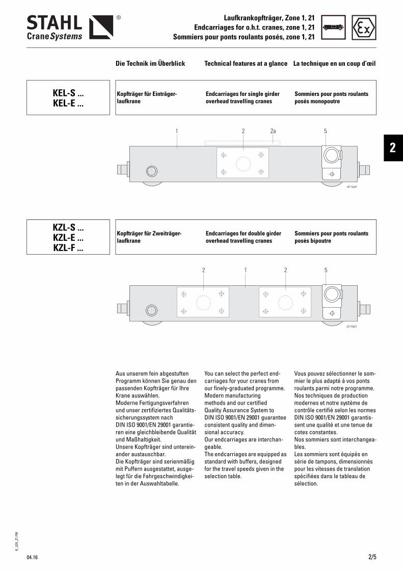
KEL-S ...KEL-E ...
Kopfträger für Einträger-laufkrane
Endcarriages for single girder overhead travelling cranes
Sommiers pour ponts roulants posés monopoutre
KZL-S ...KZL-E ...KZL-F ...
Kopfträger für Zweiträger-laufkrane
Endcarriages for double girder overhead travelling cranes
Sommiers pour ponts roulants posés bipoutre
You can select the perfect end-carriages for your cranes from our finely-graduated programme.Modern manufacturing methods and our certified Quality Assurance System to DIN ISO 9001/EN 29001 guarantee consistent quality and dimen-sional accuracy. Our endcarriages are interchan-geable.The endcarriages are equipped as standard with buffers, designed for the travel speeds given in the selection table.
Vous pouvez sélectionner le som-mier le plus adapté à vos ponts roulants parmi notre programme.Nos techniques de production modernes et notre système de contrôle certifié selon les normes DIN ISO 9001/EN 29001 garantis-sent une qualité et une tenue de cotes constantes. Nos sommiers sont interchangea-bles.Les sommiers sont équipés en série de tampons, dimensionnés pour les vitesses de translation spécifiées dans le tableau de sélection.
Aus unserem fein abgestuften Programm können Sie genau den passenden Kopfträger für Ihre Krane auswählen. Moderne Fertigungsverfahren und unser zertifiziertes Qualitäts-sicherungssystem nach DIN ISO 9001/EN 29001 garantie-ren eine gleichbleibende Qualität und Maßhaltigkeit. Unsere Kopfträger sind unterein-ander austauschbar.Die Kopfträger sind serienmäßig mit Puffern ausgestattet, ausge-legt für die Fahrgeschwindigkei-ten in der Auswahltabelle.
K_LE
X_Z1
.FM
Laufkrankopfträger, Zone 1, 21Endcarriages for o.h.t. cranes, zone 1, 21Sommiers pour ponts roulants posés, zone 1, 21
2/6 04.16
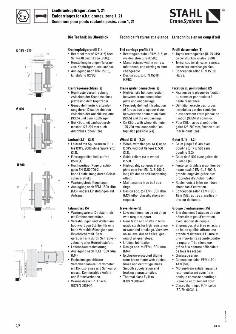
End carriage profile (1)• Rectangular tube (Ø125-315) or
welded structure (Ø500).• Manufactured within narrow
tolerances, end carriages inter-changeable.
• Design acc. to DIN 15018, H2/B3.
Crane girder connection (2)• High-tensile bolt connection
between crane connection plate and endcarriage.
• Precisely defined introduction of forces due to spacer discs between the connection plate (S355) and the endcarriage.
• On KEL-.. with wheel diameter 125-200 mm, connection "on top" also possible (2a).
Wheel (3.1) - (3.2)• Wheel with flanges (3.1) up to
Ø 315, without flanges Ø 500 (3.2).
• Guide rollers (4) at wheel Ø 500.
• High-quality spheroidal gra-phite cast iron EN-GJS-700-2, long life due to self-lubricating effect.
• Maintenance-free ball bea-rings.
• Design acc. to FEM (ISO) 1Bm (M3), other classifications on request.
Travel drive (5)• Low-maintenance direct drive
with torque support.• Gear teeth and shafts in high-
grade steels for high resistance to wear and breakage. Very low noise level due to helical gea-ring of all gear steps.
• Lifetime lubrication. • Design acc. to FEM (ISO) 1Am
(M4).• Explosion-protected sliding
rotor brake motor with conical brake and centrifugal mass. Smooth acceleration and braking characteristics.
• Thermal class F / H to IEC/EN 60034-1.
Profil du sommier (1)• Tuyau rectangulaire (Ø125-315)
ou construction soudée (Ø500). • Tolérances de fabrication serrées,
sommiers interchangeables.• Conception selon DIN 15018,
H2/B3.
Fixation du pont roulant (2)• Fixation de la plaque de fixation
au sommier par boulons à haute résistance.
• Définition exacte des forces introduites par des rondelles d'espacement entre plaque de fixation (S355) et sommier.
• Pour KEL-.. avec diamètre de galet 125-200 mm, fixation aussi "par le haut" (2a).
Galet (3.1) - (3.2)• Galet jusqu'à Ø 315 avec
boudins (3.1), Ø 500 sans boudins (3.2).
• Galet de Ø 500 avec galets de guidage (4).
• Fonte sphéroïdale graphitée de haute qualité EN-GJS-700-2, grande longévité grâce aux propriétés d'autolubrication.
• Roulements à billes ne néces-sitant pas d'entretien.
• Conception selon FEM (ISO) 1Bm (M3), autres classificati-ons sur demande.
Groupe d'entraînement (5)• Entraînement à attaque directe
nécessitant peu d'entretien, avec support de couple.
• Engrenages et arbres en aciers de haute qualité, offrant une grande résistance à l'usure et une importante sécurité contre la rupture. Très silencieux grâce à la denture hélicoïdale de tous les étages.
• Graissage à vie.• Conception selon FEM (ISO)
1Am (M4).• Moteur-frein antidéflagrant à
rotor coulissant avec frein conique et masse centrifuge. Freinage et roulement doux.
• Classe thermique F / H selon IEC/EN 60034-1.
Krankopfträgerprofil (1)• Rechteckrohr (Ø125-315) bzw.
Schweißkonstruktion (Ø500).• Herstellung in engen Toleran-
zen, Kopfträger austauschbar.• Auslegung nach DIN 15018,
Einstufung H2/B3.
Kranträgeranschluss (2)• Hochfeste Verschraubung
zwischen der Krananschluss-platte und dem Kopfträger.
• Genau definierte Krafteinlei-tung durch Distanzscheiben zwischen der Anschlussplatte (S355) und dem Kopfträger.
• Bei KEL-.. mit Laufraddurch-messer 125-200 mm auch Anschluss "oben" (2a).
Laufrad (3.1) - (3.2)• Laufrad mit Spurkränzen (3.1)
bis Ø315, Ø500 ohne Spurkranz (3.2).
• Führungsrollen bei Laufrad-Ø500 (4).
• Hochwertiger Kugelgraphit-guss EN-GJS-700-2, hohe Laufleistung durch Selbst-schmiereffekt.
• Wartungsfreie Kugellager.• Auslegung nach FEM (ISO) 1Bm
(M3), andere Einstufungen auf Anfrage.
Fahrantrieb (5)• Wartungsarmer Direktantrieb
mit Drehmomentstütze.• Verzahnungen und Wellen aus
hochwertigen Stählen für eine hohe Verschleißfestigkeit und Bruchsicherheit. Sehr geräuscharm durch Schrägver-zahnung aller Getriebestufen.
• Lebensdauerschmierung.• Auslegung nach FEM (ISO) 1Am
(M4).• Explosionsgeschützter
Verschiebeanker-Bremsmotor mit Konusbremse und Schwung-masse. Komfortables Anfahr- und Bremsverhalten.
• Wärmeklasse F / H nach IEC/EN 60034-1.
Die Technik im Überblick Technical features at a glance La technique en un coup d’œil
Ø 125 - 315
Ø 400
Ø 500
K_LE
X_Z1
.FM
04.16 2/7
Kopfträger für Einträgerlaufkrane, Zone 1, 21Endcarriages for single girder o.h.t. cranes, zone 1, 21
Sommiers pour ponts roulants posés monopoutre, zone 1, 21
2
Auswahlanleitung Selection instructions Instructions pour la sélection
Grobauswahl Rough determination Détermination approximatif
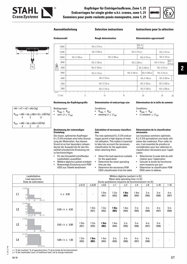
Bestimmung der Kopfträgergröße Determination of endcarriage size Détermination de la taille du sommier
mKr = mT + mZ + mKo [kg]
Rmax = mKr + mL + mKa x (L1 - L10) [kg]4 2 L1
Rmin = mKr + mL + mKa x L10 [kg]4 2 L1
Bedingungen: • Rmax < Rzul• vorh. L1 < L1zul
Conditions: • Rmax < Rzul• existing L1 < L1zul
Conditions : • Rmax < Rzul• L1 existant < L1zul
Bestimmung der notwendigen Einstufung
Calculation of necessary classifica-tion
Détermination de la classification nécessaire
Die neuen, optimierten Kopfträger K.L-E 315 erlauben eine hohe Ausnut-zung der Materialien. Aus diesem Grund ist es hier besonders notwen-dig bei der Auswahl die für den Ein-satzfall erforderliche Einstufung mit zu berücksichtigen.
The new optimised K.L-E 315 endcar-riages permit a high degree of mate-rial utilisation. This makes it essential to take into account the necessary classification for the application when selecting them.
Les nouveaux sommiers optimisés K.L-E 315 permettrent une haute utili-sation des matériaux. Pour cette rai-son, il est essentiel de prendre en considération pour leur sélection la classification nécessaire pour l'appli-cation.
• Für den Einsatzfall zutreffendes Lastkollektiv auswählen
• Mittlere tägliche Laufzeit ermitteln• Notwendige Einstufung nach FEM
(ISO) aus Tabelle bestimmen
• Select the load spectrum suitable for the application
• Determine the mean operating time per day
• Determine the necessary FEM (ISO) classification from the table
• Sélectionner le juste état de solli-citation pour l'application
• Calculer la durée de fonctionne-ment moyenne par jour
• Déterminer la classification FEM (ISO) selon le tableau
2
x = % der Laufzeit / % of operating time / % de la durée de fonctionnementy = % der maximalen Last / of maximum load / de la charge maximale
LastkollektiveLoad spectrums
États de sollicitation
Mittlere tägliche Laufzeit t in [h] Mean daily operating time t in [h]
Durée quotidienne moyenne de fonctionnement t en [h]≤ 0,12 ≤ 0,25 ≤ 0,5 ≤ 1 ≤ 2 ≤ 4 ≤ 8 ≤ 16 > 16
k ≤ 0,50 - - 1 Dm(M1)
1 Cm(M2)
1 Bm(M3)
1 Am(M4)
2 m(M5)
3 m(M6)
4 m(M7)
0,50 < k ≤ 0,63 - 1 Dm(M1)
1 Cm(M2)
1 Bm(M3)
1 Am(M4)
2 m(M5)
3 m(M6)
4 m(M7)
5 m(M8)
0,63 < k ≤ 0,80 1 Dm(M1)
1 Cm(M2)
1 Bm(M3)
1 Am(M4)
2 m(M5)
3 m(M6)
4 m(M7)
5 m(M8) -
0,80 < k ≤ 1,00 1 Cm(M2)
1 Bm(M3)
1 Am(M4)
2 m(M5)
3 m(M6)
4 m(M7)
5 m(M8) - -
L1
L2
L3
L4
K_LE
X_Z1
.FM
Kopfträger für Einträgerlaufkrane, Zone 1, 21Endcarriages for single girder o.h.t. cranes, zone 1, 21Sommiers pour ponts roulants posés monopoutre, zone 1, 21
2/8 04.16
Auswahlanleitung Selection instructions Instructions pour la sélection
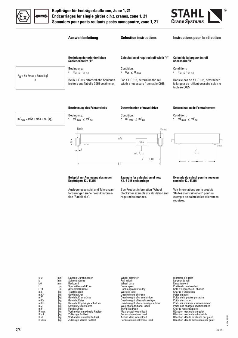
Ermittlung der erforderlichen Schienenbreite "k"
Calculation of required rail width "k" Calcul de la largeur de rail nécessaire "k"
Rid = 2 x Rmax + Rmin [kg]3
Bedingung:• Rid < Rid zul
Bei K.L-E 315 erforderliche Schienen-breite k aus Tabelle C095 bestimmen.
Condition:• Rid < Rid zul
For K.L-E 315, determine the rail width k necessary from table C095.
Condition :• Rid < Rid zul
Dans le cas de K.L-E 315, déterminer la largeur de rail k nécessaire selon le tableau C095.
Bestimmung des Fahrantriebs Determination of travel drive Détermination de l'entraînement
mFmax. = mKr + mKa + mL [kg]Bedingung:• mFmax < mFzul
Condition:• mFmax < mFzul
Condition :• mFmax < mFzul
Beispiel zur Auslegung des neuen Kopfträgers K.L-E 315
Example for calculation of new K.L-E 315 endcarriage
Exemple de calcul pour le nouveau sommier K.L-E 315
Auslegungsbeispiel und Toleranzan-forderungen siehe Produktinforma-tion "Radblöcke".
See Product information "Wheel blocks" for example of calculation and required tolerances.
Voir Informations sur le produit "Unités d'entraînement" pour un exemple de calcul et les tolérances requises.
Ø D [mm]k [mm]k 0 [mm]L 1 [m]L 10 [m]m L [kg]m Kr [kg]m T [kg]m Ka [kg]m Ko [kg]m Z [kg]m F [kg]R max [kg]R zul [kg]R id [kg]R id zul [kg]
Laufrad-Durchmesser SchienenbreiteRadstand Spurmittenmaß KranAnfahrmaß Katze Tragfähigkeit Gewicht Kran Gewicht KranbrückeGewicht KatzeGewicht Kopfträger + AntriebGewicht ZusatzlastenFahrlast/PaarVorhandene maximale RadlastZulässige RadlastVorhandene ideelle RadlastZulässige ideelle Radlast
Wheel diameterRail widthWheel baseCrane spanHook approach trolleyWorking loadDead weight of craneDead weight of crane bridgeDead weight of travel carriageDead weight of endcarriage + driveWeight of additional loadsTravel load/pairMax. actual wheel loadPermissible wheel loadActual ideal wheel loadPermissible ideal wheel load
Diamètre de galetLargeur de railEmpattement Portée du pont roulantCote d'approche du chariotCharge d’utilisationPoids du pont Poids de la poutre porteusePoids du chariotPoids du sommier + entraînementPoids des charges additionnellesCharge roulante/paireRéaction maximale au galetRéaction maximale admissibleRéaction idéelle existante par galetRéaction idéelle admissible par galet
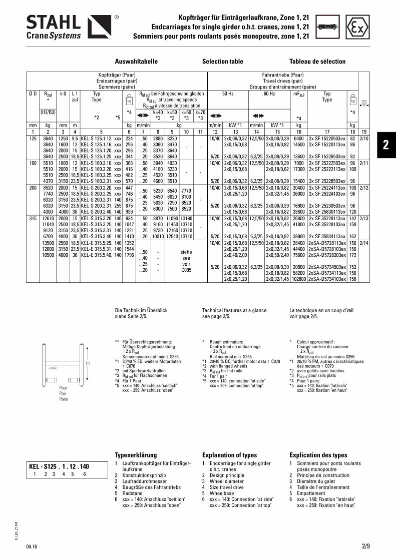
K_LE
X_Z1
.FM
04.16 2/9
Kopfträger für Einträgerlaufkrane, Zone 1, 21Endcarriages for single girder o.h.t. cranes, zone 1, 21
Sommiers pour ponts roulants posés monopoutre, zone 1, 21
2
Auswahltabelle Selection table Tableau de sélection
Kopfträger (Paar) Endcarriages (pair) Sommiers (paire)
Fahrantriebe (Paar)Travel drives (pair)
Groupes d’entraînement (paire)Ø D Rzul
*k 0 L 1
zulTyp
Type
*2 *5*4
Rid zul bei FahrgeschwindigkeitenRid zul at travelling speeds
Rid zul à vitesse de translation
50 Hz 60 Hz mFzul
*4
TypType
*4(H2/B3) k=40 *3
k=50 *3
k=60 *3
k=70 *3
mm kg mm m kg m/min kg m/min kW *1 m/min kW *1 kg kg1 2 3 4 5 6 7 8 9 10 11 12 13 14 15 16 17 18 19
125 3640364036403640
1250160020002500
9,51215
18,5
KEL-S 125.1.12.KEL-S 125.1.16.KEL-S 125.1.20.KEL-S 125.1.25.
xxxxxxxxxxxx
224256296344
...50
...40
...25
...20
2880306033703520
3220347036403640
- -
10/40
5/20
2x0,06/0,322x0,15/0,68
2x0,06/0,32
12,5/50
6,3/25
2x0,08/0,392x0,18/0,82
2x0,08/0,39
640014500
13600
2x SF 15220503ex2x SF 15220113ex
2x SF 15226503ex
8286
82
2/10
160 5510551055104370
1600200025003150
1215
18,523,5
KEL-S 160.2.16.KEL-S 160.2.20.KEL-S 160.2.25.KEL-S 160.2.31.
xxxxxxxxxxxx
366416482570
...50
...40
...25
...20
3940418045204660
4930523055105510
- -
10/40
5/20
2x0,06/0,322x0,15/0,68
2x0,06/0,32
12,5/50
6,3/25
2x0,08/0,392x0,18/0,82
2x0,08/0,39
700017300
15400
2x SF 25222503ex2x SF 25222113ex
2x SF 25228503ex
96100
96
2/11
200 85207740632063204300
2000250031503150 4000
1518,523,523,530
KEL-S 200.2.20.KEL-S 200.2.25.KEL-S 200.2.31.KEL-S 200.2.31.KEL-S 200.2.40.
xxxxxx140259140
447746875875939
...50
...40
...25
...20
5230545058306000
6540682072907500
7770810085208520
-
10/40
5/20
2x0,15/0,682x0,25/1,20
2x0,06/0,322x0,15/0,68
12,5/50
6,3/25
2x0,18/0,822x0,32/1,45
2x0,08/0,392x0,18/0,82
2040036000
1690028800
2x SF 25224113ex2x SF 25224103ex
2x SF 25230503ex2x SF 25830113ex
10096
96120
2/12
315 126101104091206700
2000250031504000
1518,523,530
KEL-S 315.3.20.KEL-S 315.3.25.KEL-S 315.3.31.KEL-S 315.3.40.
140140140140
934104712211410
...50
...40
...25
...20
887091609730
10010
11090114501216012540
13190137101371013710
-
10/40
5/20
2x0,15/0,682x0,25/1,20
2x0,15/0,68
12,5/50
6,3/25
2x0,18/0,822x0,32/1,45
2x0,18/0,82
2680041800
38900
2x SF 35228113ex2x SF 35228103ex
2x SF 35834113ex
142158
162
2/13
135001200010500
250031504000
18,523,530
KEL-E 315.5.25.KEL-E 315.5.31.KEL-E 315.5.40.
140140140
135215441796 ...50
...40
...25
...20
----
sieheseevoirC095
10/40
5/20
2x0,15/0,682x0,25/1,202x0,40/2,00
2x0,06/0,322x0,15/0,682x0,25/1,20
12,5/50
6,3/25
2x0,18/0,822x0,32/1,452x0,50/2,40
2x0,08/0,392x0,18/0,822x0,32/1,45
284004440075600
2080058200
102800
2xSA-D5728113ex2xSA-D5728103ex2xSA-D5728203ex
2xSA-D5734503ex2xSA-D5734113ex2xSA-D5734103ex
156156172
152156156
2/14
Die Technik im Überblick siehe Seite 2/5.
Technical features at a glance see page 2/5.
La technique en un coup d’œil voir page 2/5.
** Für Überschlagsrechnung: Mittige Kopfträgerbelastung = 2 x Rzul Schienenwerkstoff mind. S355
*1 20/40 % ED, weitere Motordaten ↑ C070
*2 mit Spurkranzlaufrollen*3 Rid zul für Flachschienen*4 Für 1 Paar*5 xxx = 140: Anschluss "seitlich"
xxx = 259: Anschluss "oben"
* Rough estimation: Centre load on endcarriage = 2 x RzulRail material min. S355
*1 20/40 % DC, further motor data ↑ C070*2 with flanged wheels*3 Rid zul for flat rails*4 For 1 pair*5 xxx = 140: connection "at side"
xxx = 259: connection "at top"
* Calcul approximatif : Charge centrée du sommier = 2 x RzulMatériau du rail au moins S355
*1 20/40 % FM, autres caractéristiques des moteurs ↑ C070
*2 avec galets avec boudins*3 Rid zul pour rails plats*4 Pour 1 paire*5 xxx = 140: fixation "latérale"
xxx = 259: fixation "en haut"
Typenerklärung Explanation of types Explication des types1 Laufkrankopftäger für Einträger-
laufkrane2 Konstruktionsprinzip3 Laufraddurchmesser4 Baugröße des Fahrantriebs5 Radstand6 xxx = 140: Anschluss "seitlich"
xxx = 259: Anschluss "oben"
1 Endcarriage for single girder o.h.t. cranes
2 Design principle3 Wheel diameter4 Size travel drive5 Wheelbase6 xxx = 140: Connection "at side"
xxx = 259: Connection "at top"
1 Sommiers pour ponts roulants posés monopoutre
2 Principe de construction3 Diamètre du galet4 Taille de l'entraînenment5 Empattement6 xxx = 140: Fixation "latérale"
xxx = 259: Fixation "en haut"
KEL - S 125 . 1 . 12 . 1401 2 3 4 5 6
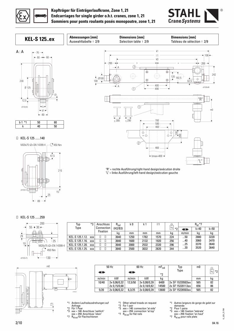
K_LE
X_Z1
.FM
Kopfträger für Einträgerlaufkrane, Zone 1, 21Endcarriages for single girder o.h.t. cranes, zone 1, 21Sommiers pour ponts roulants posés monopoutre, zone 1, 21
2/10 04.16
KEL-S 125..ex Abmessungen [mm] Auswahltabelle ↑ 2/9
Dimensions [mm]Selection table ↑ 2/9
Dimensions [mm]Tableau de sélection ↑ 2/9
c0102v05
b1k
80
10
12,5
Ø 125
230
76
60 60
< 300 < 290
c0100v081
1
2= =
l 1
k1
266266
106
Ø100100
A
A
120 182,5242
400490
k0
62,5
2
700590460
460
100
200
bmax=400
m0
"R"
"L"
b 1 *1 50 60k 40 50
Typ Type
*3 Anschluss Connection
Fixation
Rzul(H2/B3)
k 0 k 1 l 1*2
Rid *7k=40 k=50
kg mm mm mm kg m/min kg kgKEL-S 125.1.12. xxx ➀ ➁ 3640 1250 1782 1570 224 ...50
...40
...25
...20
2880306033703520
3220347036403640
KEL-S 125.1.16. xxx ➀ ➁ 3640 1600 2132 1920 256KEL-S 125.1.20. xxx ➀ ➁ 3640 2000 2532 2320 296KEL-S 125.1.25. xxx ➀ ➁ 3640 2500 3032 2820 344
50 Hz 60 Hz mFzul
*2
Typ Type
m0*2
m/min kW m/min kW kg mm kg10/40 2x 0,06/0,32
2x 0,15/0,6812,5/50 2x 0,08/0,39
2x 0,18/0,82640014500
2x SF 15220503ex2x SF 15220113ex
565656
8286
5/20 2x 0,06/0,32 6,3/25 2x 0,08/0,39 13600 2x SF 15226503ex 565 82
➁ KEL-S 125 ......259
➀ KEL-S 125 ......140
A : A
"R" = rechte Ausführung/right-hand design/exécution droite"L" = linke Ausführung/left-hand design/exécution gauche
*1 Andere Laufradausdrehungen auf Anfrage
*2 Für 1 Paar*3 xxx = 140: Anschluss "seitlich"
xxx = 259: Anschluss "oben"*7 Rid zul für Flachschienen
*1 Other wheel treads on request*2 For 1 pair*3 xxx = 140: connection "at side"
xxx = 259: connection "at top"*7 Rid zul for flat rails
*1 Autres largeurs de gorge de galet sur demande
*2 Pour 1 paire*3 xxx = 140: fixation "latérale"
xxx = 259: fixation "en haut"*7 Rid zul pour rails plats
215
25
89
c0103v13
450 NmM20x75 tZn EN 14399-4
15
47,5
2003055
25
c0103v15
29
10
450 NmM20x75 tZn EN 14399-4
130
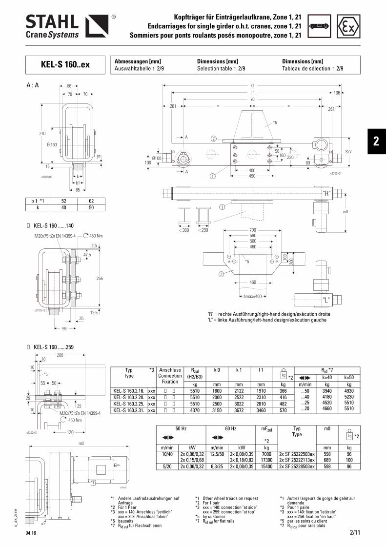
K_LE
X_Z1
.FM
04.16 2/11
Kopfträger für Einträgerlaufkrane, Zone 1, 21Endcarriages for single girder o.h.t. cranes, zone 1, 21
Sommiers pour ponts roulants posés monopoutre, zone 1, 21
2
KEL-S 160..ex Abmessungen [mm] Auswahltabelle ↑ 2/9
Dimensions [mm]Selection table ↑ 2/9
Dimensions [mm]Tableau de sélection ↑ 2/9
< 300 < 290
c1303v011
1
2
= =
l 1
k1
k0
261261
106
Ø100100
A
A
90160 220
327
400490
80
m0
*5
700590
460500
46010
020
0bmax=400
2
*5
"R"
"L"
b 1 *1 52 62k 40 50
Typ Type
*3 Anschluss Connection
Fixation
Rzul(H2/B3)
k 0 k 1 l 1*2
Rid *7k=40 k=50
kg mm mm mm kg m/min kg kgKEL-S 160.2.16. xxx ➀ ➁ 5510 1600 2122 1910 366 ...50
...40
...25
...20
3940418045204660
4930523055105510
KEL-S 160.2.20. xxx ➀ ➁ 5510 2000 2522 2310 416KEL-S 160.2.25. xxx ➀ ➁ 5510 2500 3022 2810 482KEL-S 160.2.31. xxx ➀ ➁ 4370 3150 3672 3460 570
50 Hz 60 Hz mFzul
*2
Typ Type
m0*2
m/min kW m/min kW kg mm kg10/40 2x 0,06/0,32
2x 0,15/0,6812,5/50 2x 0,08/0,39
2x 0,18/0,82700017300
2x SF 25222503ex2x SF 25222113ex
598689
96100
5/20 2x 0,06/0,32 6,3/25 2x 0,08/0,39 15400 2x SF 25228503ex 598 96
➁ KEL-S 160 ......259
➀ KEL-S 160 ......140
A : A
"R" = rechte Ausführung/right-hand design/exécution droite"L" = linke Ausführung/left-hand design/exécution gauche
*1 Andere Laufradausdrehungen auf Anfrage
*2 Für 1 Paar*3 xxx = 140: Anschluss "seitlich"
xxx = 259: Anschluss "oben"*5 bauseits*7 Rid zul für Flachschienen
*1 Other wheel treads on request*2 For 1 pair*3 xxx = 140: connection "at side"
xxx = 259: connection "at top"*5 by customer*7 Rid zul for flat rails
*1 Autres largeurs de gorge de galet sur demande
*2 Pour 1 paire*3 xxx = 140: fixation "latérale"
xxx = 259: fixation "en haut"*5 par les soins du client*7 Rid zul pour rails plats
255
25
99
c0103v12
450 NmM20x75 tZn EN 14399-4
12,5
47,5
2,5
200
5055
25
c1302v01
29
10
450 NmM20x75 tZn EN 14399-4
120
*5
10
10
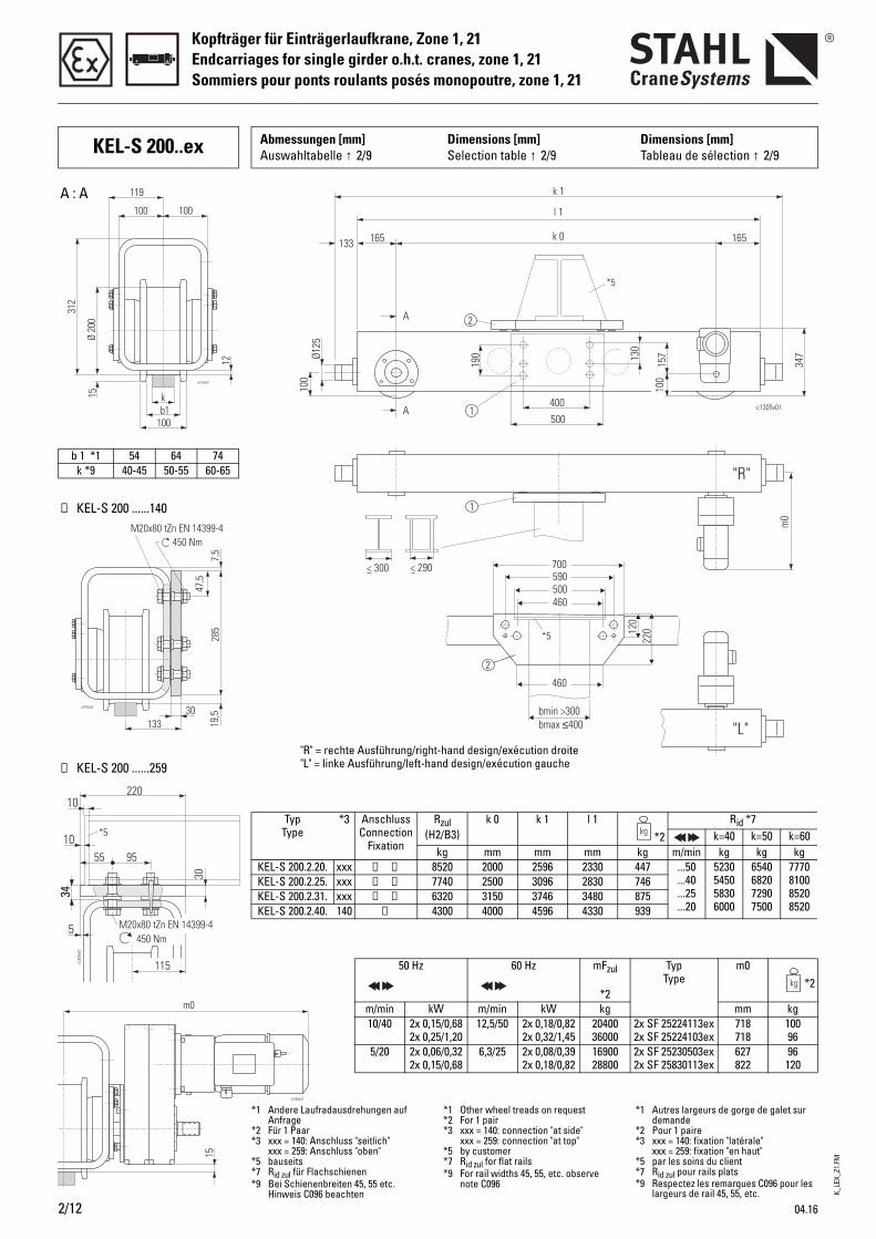
K_LE
X_Z1
.FM
Kopfträger für Einträgerlaufkrane, Zone 1, 21Endcarriages for single girder o.h.t. cranes, zone 1, 21Sommiers pour ponts roulants posés monopoutre, zone 1, 21
2/12 04.16
KEL-S 200..ex Abmessungen [mm] Auswahltabelle ↑ 2/9
Dimensions [mm]Selection table ↑ 2/9
Dimensions [mm]Tableau de sélection ↑ 2/9
c130
4v01
220
30
3434
5450 Nm
M20x80 tZn EN 14399-4
115
*5
10
109555
< 300 < 290
k 1
l 1
k 0
A
A
133 165
400
165
190
100
Ø125
500
157
347
c1305v01
130
m0
1
1
2
100
*5
700590
460500
460
120
220
bmin >300bmax 400≤
2
*5
"R"
"L"
Typ Type
*3 Anschluss Connection
Fixation
Rzul(H2/B3)
k 0 k 1 l 1*2
Rid *7k=40 k=50 k=60
kg mm mm mm kg m/min kg kg kgKEL-S 200.2.20. xxx ➀ ➁ 8520 2000 2596 2330 447 ...50
...40
...25
...20
5230545058306000
6540682072907500
7770810085208520
KEL-S 200.2.25. xxx ➀ ➁ 7740 2500 3096 2830 746KEL-S 200.2.31. xxx ➀ ➁ 6320 3150 3746 3480 875KEL-S 200.2.40. 140 ➀ 4300 4000 4596 4330 939
50 Hz 60 Hz mFzul
*2
Typ Type
m0*2
m/min kW m/min kW kg mm kg10/40 2x 0,15/0,68
2x 0,25/1,2012,5/50 2x 0,18/0,82
2x 0,32/1,452040036000
2x SF 25224113ex2x SF 25224103ex
718718
10096
5/20 2x 0,06/0,322x 0,15/0,68
6,3/25 2x 0,08/0,392x 0,18/0,82
1690028800
2x SF 25230503ex2x SF 25830113ex
627822
96120
b 1 *1 54 64 74k *9 40-45 50-55 60-65
➁ KEL-S 200 ......259
➀ KEL-S 200 ......140
A : A
"R" = rechte Ausführung/right-hand design/exécution droite"L" = linke Ausführung/left-hand design/exécution gauche
*1 Andere Laufradausdrehungen auf Anfrage
*2 Für 1 Paar*3 xxx = 140: Anschluss "seitlich"
xxx = 259: Anschluss "oben"*5 bauseits*7 Rid zul für Flachschienen*9 Bei Schienenbreiten 45, 55 etc.
Hinweis C096 beachten
*1 Other wheel treads on request*2 For 1 pair*3 xxx = 140: connection "at side"
xxx = 259: connection "at top"*5 by customer*7 Rid zul for flat rails*9 For rail widths 45, 55, etc. observe
note C096
*1 Autres largeurs de gorge de galet sur demande
*2 Pour 1 paire*3 xxx = 140: fixation "latérale"
xxx = 259: fixation "en haut"*5 par les soins du client*7 Rid zul pour rails plats*9 Respectez les remarques C096 pour les
largeurs de rail 45, 55, etc.
c0754v02
47,5
7,5
30133
285
19,5
450 NmM20x80 tZn EN 14399-4
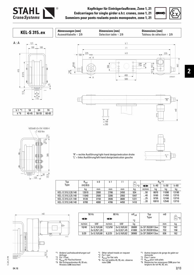
K_LE
X_Z1
.FM
04.16 2/13
Kopfträger für Einträgerlaufkrane, Zone 1, 21Endcarriages for single girder o.h.t. cranes, zone 1, 21
Sommiers pour ponts roulants posés monopoutre, zone 1, 21
2
*5 Sicherungsscheibe (Schnorr)*6 Seiltrommelzugkraft
*5 Lock washer (Schnorr)*6 Traction on drum
*5 Rondelle-frein (Schnorr)*6 Effort de charge au tambour
KEL-S 315..ex Abmessungen [mm] Auswahltabelle ↑ 2/9
Dimensions [mm]Selection table ↑ 2/9
Dimensions [mm]Tableau de sélection ↑ 2/9
> 190< 290
k 1
l 1
k 0
A
A
168225
400
225
280
100
Ø160
500
197,
5
c0763v01
215
447
m0
157,
5
150
"R"
"L"
b 1 *1 54 64 74k *9 40-45 50-55 60-65
Typ Type
Rzul(H2/B3)
k 0 k 1 l 1*2
Rid *7k=40 k=50 k=60
kg mm mm mm kg m/min kg kg kgKEL-S 315.3.20.140 12610 2000 2786 2450 934 ...50
...40
...25
...20
887091609730
10010
11090114501216012540
13190137101371013710
KEL-S 315.3.25.140 11040 2500 3286 2950 1047KEL-S 315.3.31.140 9120 3150 3936 3600 1221KEL-S 315.3.40.140 6700 4000 4786 4450 1410
50 Hz 60 Hz mFzul
*2
Typ Type
m0*2
m/min kW m/min kW kg mm kg10/40 2x 0,15/0,68
2x 0,25/1,2012,5/50 2x 0,18/0,82
2x 0,32/1,452680041800
2x SF 35228113ex2x SF 35228103ex
732732
142158
5/20 2x 0,15/0,68 6,3/25 2x 0,18/0,82 38900 2x SF 35834113ex 836 162
A : A
"R" = rechte Ausführung/right-hand design/exécution droite"L" = linke Ausführung/left-hand design/exécution gauche
*1 Andere Laufradausdrehungen auf Anfrage
*2 Für 1 Paar*7 Rid zul für Flachschienen*9 Bei Schienenbreiten 45, 55 etc.
Hinweis C096 beachten
*1 Other wheel treads on request*2 For 1 pair*7 Rid zul for flat rails*9 For rail widths 45, 55, etc. observe
note C096
*1 Autres largeurs de gorge de galet sur demande
*2 Pour 1 paire*7 Rid zul pour rails plats*9 Respectez les remarques C096 pour les
largeurs de rail 45, 55, etc.
c0757v01
385
13330
52,5
22,5
7,5
450 NmM20x80 tZn EN 14399-4
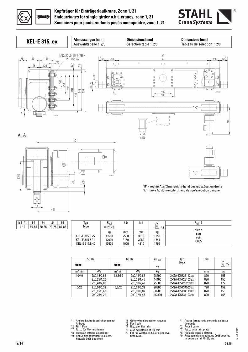
K_LE
X_Z1
.FM
Kopfträger für Einträgerlaufkrane, Zone 1, 21Endcarriages for single girder o.h.t. cranes, zone 1, 21Sommiers pour ponts roulants posés monopoutre, zone 1, 21
2/14 04.16
KEL-E 315..ex Abmessungen [mm] Auswahltabelle ↑ 2/9
Dimensions [mm]Selection table ↑ 2/9
Dimensions [mm]Tableau de sélection ↑ 2/9
> 190< 290
"R"
"L"
257,
5
400500
A
A
= =k0k1
230175 230 175
Ø160
100
*8
157,
5
m0
c1579v01
22,5
c1580v01
d6
kb1
130427
Ø315
m0
b 1 *1 64 74 84 94k *9 50-55 60-65 70-75 80-85
Typ Type
Rzul(H2/B3)
k 0 k 1*2
Rid *7
sieheseevoirC095
kg mm mm kgKEL-E 315.5.25.KEL-E 315.5.31.KEL-E 315.5.40
135001200010500
2500 3150 4000
331039604810
135215441796
50 Hz 60 Hz mFzul
*2
Typ Type
m0*2
m/min kW m/min kW kg mm kg10/40 2x0,15/0,68
2x0,25/1,202x0,40/2,00
12,5/50 2x0,18/0,822x0,32/1,452x0,50/2,40
284004440075600
2xSA-D5728113ex2xSA-D5728103ex2xSA-D5728203ex
820820870
156156172
5/20 2x0,06/0,322x0,15/0,682x0,25/1,20
6,3/25 2x0,08/0,392x0,18/0,822x0,32/1,45
2080058200
102800
2xSA-D5734503ex2xSA-D5734113ex2xSA-D5734103ex
720820820
152156156
A : A
"R" = rechte Ausführung/right-hand design/exécution droite"L" = linke Ausführung/left-hand design/exécution gauche
*1 Andere Laufradausdrehungen auf Anfrage
*2 Für 1 Paar*7 Rid zul für Flachschienen*8 auch auf 150 mm einstellbar*9 Bei Schienenbreiten 45, 55 etc.
Hinweis C096 beachten
*1 Other wheel treads on request*2 For 1 pair*7 Rid zul for flat rails*8 also adjustable at 150 mm*9 For rail widths 45, 55, etc. observe
note C096
*1 Autres largeurs de gorge de galet sur demande
*2 Pour 1 paire*7 Rid zul pour rails plats*8 réglable aussi à 150 mm*9 Respectez les remarques C096 pour les
largeurs de rail 45, 55, etc.
450 NmM20x80 tZn EN 14399-4
27521
0145
340
415 44
547
07,
5
47,5
125 12530
15815678
20
c1531v05
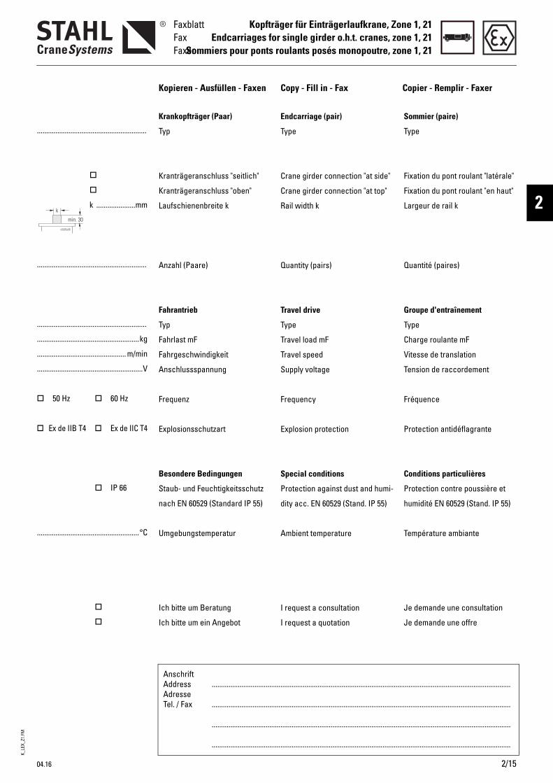
K_LE
X_Z1
.FM
04.16 2/15
Kopfträger für Einträgerlaufkrane, Zone 1, 21Endcarriages for single girder o.h.t. cranes, zone 1, 21
Sommiers pour ponts roulants posés monopoutre, zone 1, 21
FaxblattFaxFaxer
2
AnschriftAddressAdresseTel. / Fax
.................................................................................................................................................................
.................................................................................................................................................................
.................................................................................................................................................................
.................................................................................................................................................................
...........................................................
k .....................mm
...........................................................
...........................................................
.......................................................kg
................................................ m/min
.........................................................V
50 Hz 60 Hz
Ex de IIB T4 Ex de IIC T4
IP 66
.......................................................°C
Kopieren - Ausfüllen - Faxen Copy - Fill in - Fax Copier - Remplir - Faxer
Endcarriage (pair)
Type
Crane girder connection "at side"
Crane girder connection "at top"
Rail width k
Quantity (pairs)
Travel drive
Type
Travel load mF
Travel speed
Supply voltage
Frequency
Explosion protection
Special conditions
Protection against dust and humi-
dity acc. EN 60529 (Stand. IP 55)
Ambient temperature
I request a consultation
I request a quotation
Sommier (paire)
Type
Fixation du pont roulant "latérale"
Fixation du pont roulant "en haut"
Largeur de rail k
Quantité (paires)
Groupe d'entraînement
Type
Charge roulante mF
Vitesse de translation
Tension de raccordement
Fréquence
Protection antidéflagrante
Conditions particulières
Protection contre poussière et
humidité EN 60529 (Stand. IP 55)
Température ambiante
Je demande une consultation
Je demande une offre
Krankopfträger (Paar)
Typ
Kranträgeranschluss "seitlich"
Kranträgeranschluss "oben"
Laufschienenbreite k
Anzahl (Paare)
Fahrantrieb
Typ
Fahrlast mF
Fahrgeschwindigkeit
Anschlussspannung
Frequenz
Explosionsschutzart
Besondere Bedingungen
Staub- und Feuchtigkeitsschutz
nach EN 60529 (Standard IP 55)
Umgebungstemperatur
Ich bitte um Beratung
Ich bitte um ein Angebot
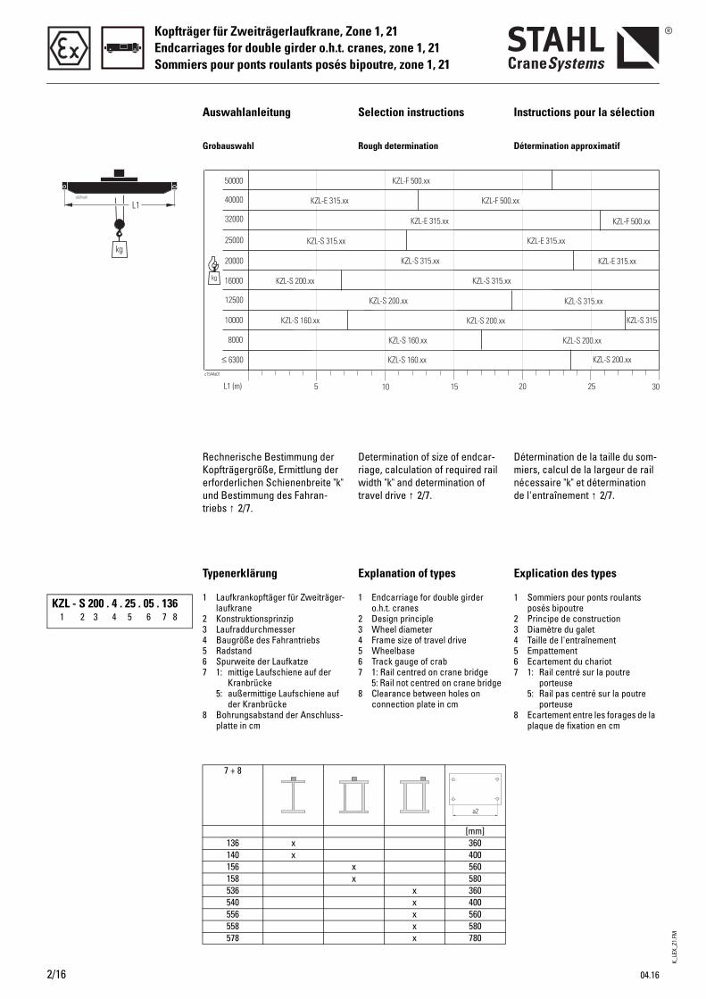
K_LE
X_Z1
.FM
Kopfträger für Zweiträgerlaufkrane, Zone 1, 21Endcarriages for double girder o.h.t. cranes, zone 1, 21Sommiers pour ponts roulants posés bipoutre, zone 1, 21
2/16 04.16
Auswahlanleitung Selection instructions Instructions pour la sélection
Grobauswahl Rough determination Détermination approximatif
Rechnerische Bestimmung der Kopfträgergröße, Ermittlung der erforderlichen Schienenbreite "k" und Bestimmung des Fahran-triebs ↑ 2/7.
Determination of size of endcar-riage, calculation of required rail width "k" and determination of travel drive ↑ 2/7.
Détermination de la taille du som-miers, calcul de la largeur de rail nécessaire "k" et détermination de l'entraînement ↑ 2/7.
Typenerklärung Explanation of types Explication des types
1 Laufkrankopftäger für Zweiträger-laufkrane
2 Konstruktionsprinzip3 Laufraddurchmesser4 Baugröße des Fahrantriebs5 Radstand6 Spurweite der Laufkatze7 1: mittige Laufschiene auf der
Kranbrücke5: außermittige Laufschiene auf
der Kranbrücke8 Bohrungsabstand der Anschluss-
platte in cm
1 Endcarriage for double girder o.h.t. cranes
2 Design principle3 Wheel diameter4 Frame size of travel drive5 Wheelbase6 Track gauge of crab7 1: Rail centred on crane bridge
5: Rail not centred on crane bridge8 Clearance between holes on
connection plate in cm
1 Sommiers pour ponts roulants posés bipoutre
2 Principe de construction3 Diamètre du galet4 Taille de l'entraînement5 Empattement6 Ecartement du chariot7 1: Rail centré sur la poutre
porteuse5: Rail pas centré sur la poutre
porteuse8 Ecartement entre les forages de la
plaque de fixation en cm
7 + 8
[mm]136 x 360140 x 400156 x 560158 x 580536 x 360540 x 400556 x 560558 x 580578 x 780
KZL - S 200 . 4 . 25 . 05 . 1361 2 3 4 5 6 7 8
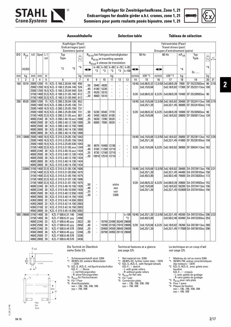
K_LE
X_Z1
.FM
04.16 2/17
Kopfträger für Zweiträgerlaufkrane, Zone 1, 21Endcarriages for double girder o.h.t. cranes, zone 1, 21
Sommiers pour ponts roulants posés bipoutre, zone 1, 21
2
Auswahltabelle Selection table Tableau de sélection
Kopfträger (Paar) Endcarriages (pair) Sommiers (paire)
Fahrantriebe (Paar) Travel drives (pair)
Groupes d’entraînement (paire)Ø D Rzul
*
(H2/B3)
k 0 Spw L 1 zul
Typ Type
*2 *5
Rid zul bei Fahrgeschwindigkeiten Rid zul at travelling speeds
Rid zul à vitesse de translation
50 Hz 60 Hz mFzul
*4
Typ Type
2x ......
*4 k=40 *3
k=50 *3
k=60 *3
k=70 *3
k=80k=100
*4
mm kg mm mm m kg m/min kg m/min kW *1 m/min kW *1 kg kg1 2 3 4 5 6 7 8 9 10 11 12 13 14 15 16 17 18 19 20 21
160 5510 2000 2500 2500 3150 3150
1250 1250 1250 1400 1400
15 18,5 18,5 23,5 23,5
KZL-S 160.2.20.04.140 KZL-S 160.2.25.04.140 KZL-S 160.2.25.04.540 KZL-S 160.2.31.05.140 KZL-S 160.2.31.05.540
458 524 524 612612
...50
...40
...25
...20
3940 4180 45204660
49305230 55105510
----
----
----
10/40
5/20
2x0,06/0,322x0,15/0,68
2x0,06/0,32
12,5/50
6,3/25
2x0,08/0,392x0,18/0,82
2x0,08/0,39
700017300
15400
SF 25222503exSF 25222113ex
SF 25228503ex
96100
96
2/18
200 8520 2000 2500 2500 2500 3150 4000 4000 4000 4000 4000
1250 1400 1400 1400 1400 2240 2500 2500 2800 2800
15 18,5 18,518,5 23,5 3030303030
KZL-S 200.2.20.04.136 KZL-S 200.2.25.05.136 KZL-S 200.2.25.05.156 KZL-S 200.2.25.05.536 KZL-S 200.2.31.05.xxx KZL-S 200.2.40.10.xxx KZL-S 200.2.40.12.136 KZL-S 200.2.40.12.156 KZL-S 200.2.40.14.136 KZL-S 200.2.40.14.156
652 731 731 731 907 1000 1000 1000 1000 1000
...50
...40
...25
...20
5230 5450 58306000
65406820 72907500
7770810085208520
----
----
10/40
5/20
2x0,15/0,682x0,25/1,20
2x0,06/0,322x0,15/0,68
12,5/50
6,3/25
2x0,18/0,822x0,32/1,45
2x0,08/0,392x0,18/0,82
2040036000
1690028800
SF 25224113exSF 25224103ex
SF 25230503exSF 25830113ex
100116
96120
2/19
315 13680 2500 2500 2500 3150 4000 4000 4000 4000 4000
1400 1400 1400 1400 2240 2500 2500 2800 2800
18,5 18,5 18,5 23,5 3030303030
KZL-S 315.3.25.05.136 KZL-S 315.3.25.05.156 KZL-S 315.3.25.05.536 KZL-S 315.3.31.05.xxx KZL-S 315.3.40.10.xxx KZL-S 315.3.40.12.136 KZL-S 315.3.40.12.156 KZL-S 315.3.40.14.136 KZL-S 315.3.40.14.156
1043 1043 1043 1249 1434 1434 1434 1434 1434
...50
...40
...25
...20
88709160 973010010
1048011290 1216012510
13190137101371013710
----
----
10/40
5/20
2x0,15/0,682x0,25/1,20
2x0,15/0,68
12,5/50
6,3/25
2x0,18/0,822x0,32/1,45
2x0,18/0,82
2680041800
38900
SF 35228113exSF 35228103ex
SF 35834113ex
142158
162
2/20
22000 3150315031503150315040004000400040004260426042604560
1400140014001800180022402240250028002800280031502800
23,523,523,523,523,53030303032323234
KZL-E 315.5.31.05.136KZL-E 315.5.31.05.556KZL-E 315.5.31.05.156KZL-E 315.5.31.07.136KZL-E 315.5.31.07.156KZL-E 315.5.40.10.156KZL-E 315.5.40.10.556KZL-E 315.5.40.12.556KZL-E 315.5.40.14.156KZL-E 315.5.42.14.556KZL-E 315.5.42.14.156KZL-E 315.5.42.16.156KZL-E 315.5.45.14.556
1606167516751606167519261926192619262003200320032092
...50
...40
...25
...20
----
sieheseevoirC095
10/40
5/20
2x0,15/0,682x0,25/1,202x0,40/2,00
2x0,06/0,322x0,15/0,682x0,25/1,20
12,5/50
6,3/25
2x0,18/0,822x0,32/1,452x0,50/2,40
2x0,08/0,392x0,18/0,822x0,32/1,45
284004440075600
2080058200102800
SA-D5728113exSA-D5728103exSA-D5728203ex
SA-D5734503exSA-D5734113exSA-D5734103ex
156156172
152156156
2/21
500 29600 3150 3150 4000 4260 4400 4560 4660 4960
1400 1400 2240 2500 2240 2800 2500 2800
2626323435363739
KZL-F 500.6.31.140 KZL-F 500.6.31.yyy KZL-F 500.6.40.yyy KZL-F 500.6.42.yyy KZL-F 500.6.44.578 KZL-F 500.6.45.yyy KZL-F 500.6.46.578 KZL-F 500.6.49.578
2490 2490 2822 2858 2958 3248 3336 3436
...50
...40
...25
...20
----
1874019290 2046020790
2249023150 2455024950
2624027010 2864029110
k=100 *3
2960029600 2960029600
10/40
5/20
2x0,25/1,202x0,40/2,00
2x0,15/0,682x0,25/1,20
12,5/50
6,3/25
2x0,32/1,452x0,50/2,40
2x0,18/0,822x0,32/1,45
4920083400
78200117000
SA-D6732103exSA-D6732203ex
SA-D6738113exSA-D6738103ex
296354
280296
2/22
Die Technik im Überblick siehe Seite 2/5.
Technical features at a glance see page 2/5.
La technique en un coup d’œil voir page 2/5.
* Schienenwerkstoff mind. S355*1 20/40% ED, weitere Motordaten
↑ C070*2 KZL-S../KZL-E.. mit Spurkranzlaufrollen
KZL-F.. : ↑ Skizze - L: mit Führungsrollen - R: ohne Führungsrollen
*3 Rid zul für Flachschienen*4 Für 1 Paar*5 Anschlussplatte:
xxx = .136; .156; .536; .556 yyy = .158; .558
* Rail material min. S355*1 20/40% DC, further motor data ↑ C070*2 KZL-S../KZL-E.. with flanged wheels
KZL-F..: ↑ sketch - L: with guide rollers - R: without guide rollers
*3 Rid zul for flat rails*4 For 1 pair*5 Connection plate:
xxx = .136; .156; .536; .556 yyy = .158; .558
* Matériau du rail au moins S355*1 20/40% FM, autres caractéristiques
des moteurs ↑ C070*2 KZL-S../KZL-E.. avec galets avec
boudins KZL-F...: ↑ croquis - L: avec galets de guidage - R: sans galets de guidage
*3 Rid zul pour rails plats*4 Pour 1 paire*5 Plaque de fixation:
xxx = .136; .156; .536; .556 yyy = .158; .558
R zul
ØD
k
c0110a04
*2
c0109a03
PaarPairPaire
Spwk0
L1
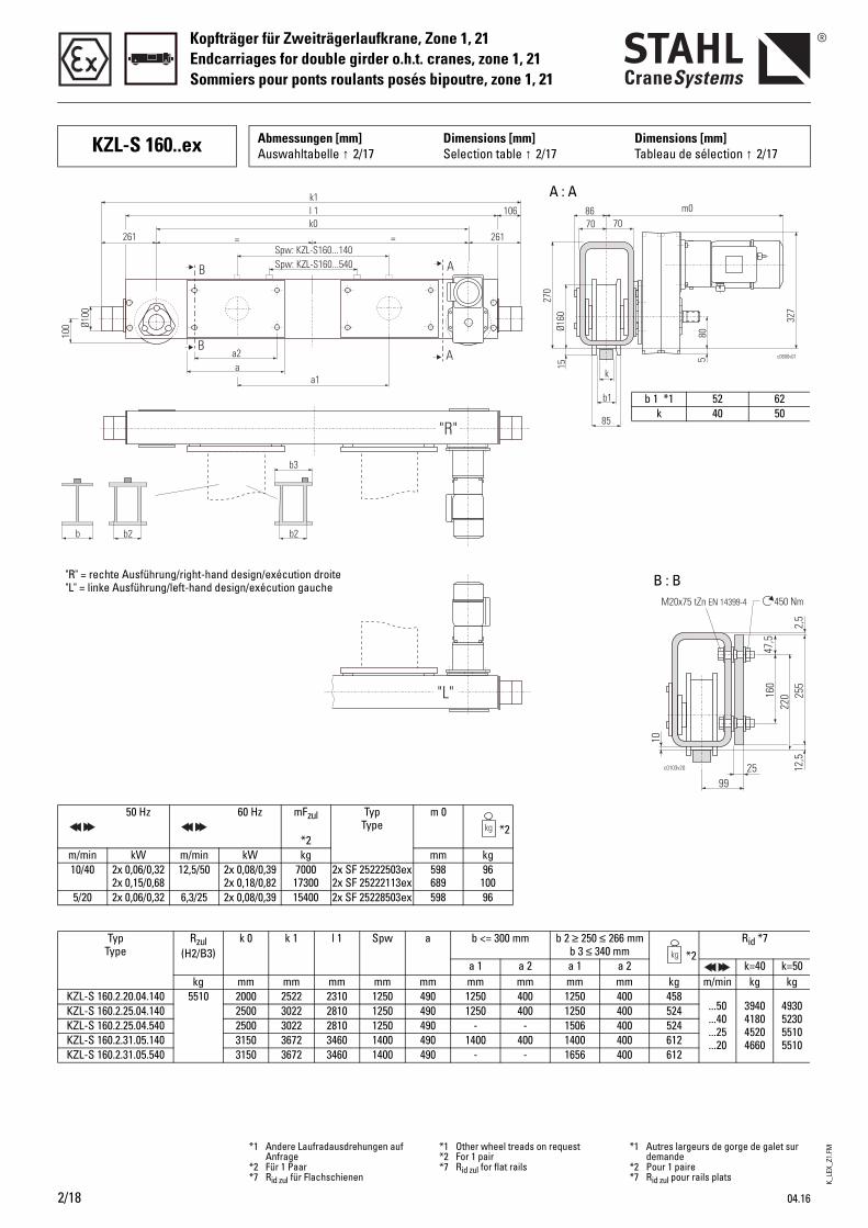
K_LE
X_Z1
.FM
Kopfträger für Zweiträgerlaufkrane, Zone 1, 21Endcarriages for double girder o.h.t. cranes, zone 1, 21Sommiers pour ponts roulants posés bipoutre, zone 1, 21
2/18 04.16
* Standard = 300 mm*1 bei geneigtem Flansch*3 ohne Fahrmotor bei Rollfahrwerk.
Fahrmotoren ↑ 1/66*7 bei Schützsteuerung (Getriebe-
endschalter)
* Standard = 300 mm*1 With sloping flange*3 With push trolley without travel motor.
Travel motors ↑ 1/66*7 With contactor control (gear-type
limit switch)
* Standard = 300 mm*1 Avec bride inclinée*3 Avec chariot à poussée sans moteur
de direction. Moteurs de direction ↑ 1/66
*7 En cas de commande par contacteurs (sélecteur de fin de course)
KZL-S 160..ex Abmessungen [mm] Auswahltabelle ↑ 2/17
Dimensions [mm]Selection table ↑ 2/17
Dimensions [mm]Tableau de sélection ↑ 2/17
= =
l 1k1
k0106
Ø100
100
B
B
Spw: KZL-S160...540Spw: KZL-S160...140
a2a
a1
b b2 b2
c0800v01
m0
580
k
b1
85
70 7086
1527
0
327
Ø160
261 261
A
A
b3
"R"
"L"
b 1 *1 52 62k 40 50
50 Hz 60 Hz mFzul
*2
Typ Type
m 0 *2
m/min kW m/min kW kg mm kg10/40 2x 0,06/0,32
2x 0,15/0,6812,5/50 2x 0,08/0,39
2x 0,18/0,827000
173002x SF 25222503ex2x SF 25222113ex
598689
96100
5/20 2x 0,06/0,32 6,3/25 2x 0,08/0,39 15400 2x SF 25228503ex 598 96
Typ Type
Rzul(H2/B3)
k 0 k 1 l 1 Spw a b <= 300 mm b 2 ≥ 250 ≤ 266 mm b 3 ≤ 340 mm *2
Rid *7
a 1 a 2 a 1 a 2 k=40 k=50kg mm mm mm mm mm mm mm mm mm kg m/min kg kg
KZL-S 160.2.20.04.140 5510 2000 2522 2310 1250 490 1250 400 1250 400 458...50...40...25...20
39404180 45204660
4930523055105510
KZL-S 160.2.25.04.140 2500 3022 2810 1250 490 1250 400 1250 400 524KZL-S 160.2.25.04.540 2500 3022 2810 1250 490 - - 1506 400 524KZL-S 160.2.31.05.140 3150 3672 3460 1400 490 1400 400 1400 400 612KZL-S 160.2.31.05.540 3150 3672 3460 1400 490 - - 1656 400 612
A : A
B : B"R" = rechte Ausführung/right-hand design/exécution droite"L" = linke Ausführung/left-hand design/exécution gauche
*1 Andere Laufradausdrehungen auf Anfrage
*2 Für 1 Paar*7 Rid zul für Flachschienen
*1 Other wheel treads on request*2 For 1 pair*7 Rid zul for flat rails
*1 Autres largeurs de gorge de galet sur demande
*2 Pour 1 paire*7 Rid zul pour rails plats
47,5
255
22016
025
10
99
c0103v20
450 NmM20x75 tZn EN 14399-4
2,5
12,5
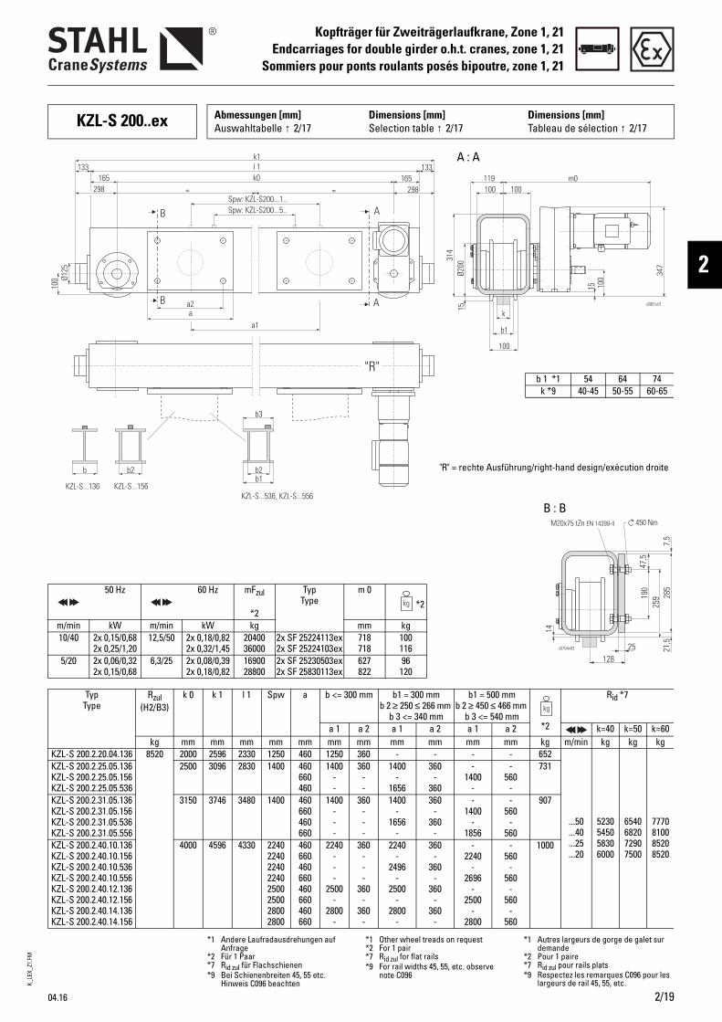
K_LE
X_Z1
.FM
04.16 2/19
Kopfträger für Zweiträgerlaufkrane, Zone 1, 21Endcarriages for double girder o.h.t. cranes, zone 1, 21
Sommiers pour ponts roulants posés bipoutre, zone 1, 21
2
KZL-S 200..ex Abmessungen [mm] Auswahltabelle ↑ 2/17
Dimensions [mm]Selection table ↑ 2/17
Dimensions [mm]Tableau de sélection ↑ 2/17
c0754v03 25128
450 NmM20x75 tZn EN 14399-4
47,5
285
25919
0
7,5
21,5
14
= =
l 1k1
k0133
B
B
Spw: KZL-S200...5..Spw: KZL-S200...1..
a2a
a1
b b2 b2b1
298 298
KZL-S...136 KZL-S...156KZL-S...536, KZL-S...556
m0
c0801v01
15 100
k
b1
100
100 100119
1531
4
347
Ø200
133165 165
Ø125
100
A
A
b3
"R"b 1 *1 54 64 74
k *9 40-45 50-55 60-65
50 Hz 60 Hz mFzul
*2
Typ Type
m 0 *2
m/min kW m/min kW kg mm kg10/40 2x 0,15/0,68
2x 0,25/1,2012,5/50 2x 0,18/0,82
2x 0,32/1,452040036000
2x SF 25224113ex2x SF 25224103ex
718718
100116
5/20 2x 0,06/0,322x 0,15/0,68
6,3/25 2x 0,08/0,392x 0,18/0,82
1690028800
2x SF 25230503ex2x SF 25830113ex
627822
96120
Typ Type
Rzul (H2/B3)
k 0 k 1 l 1 Spw a b <= 300 mm b1 = 300 mm b 2 ≥ 250 ≤ 266 mm
b 3 <= 340 mm
b1 = 500 mm b 2 ≥ 450 ≤ 466 mm
b 3 <= 540 mm*2
Rid *7
a 1 a 2 a 1 a 2 a 1 a 2 k=40 k=50 k=60kg mm mm mm mm mm mm mm mm mm mm mm kg m/min kg kg kg
KZL-S 200.2.20.04.136 8520 2000 2596 2330 1250 460 1250 360 - - - - 652
...50
...40
...25
...20
52305450 58306000
65406820 72907500
7770810085208520
KZL-S 200.2.25.05.136 KZL-S 200.2.25.05.156 KZL-S 200.2.25.05.536
2500 3096 2830 1400 460 660 460
1400 - -
360 - -
1400 -
1656
360 -
360
- 1400
-
- 560
-
731
KZL-S 200.2.31.05.136 KZL-S 200.2.31.05.156 KZL-S 200.2.31.05.536 KZL-S 200.2.31.05.556
3150 3746 3480 1400 460 660 460 660
1400 - - -
360 - - -
1400 -
1656 -
360 -
360 -
- 1400
- 1856
- 560
- 560
907
KZL-S 200.2.40.10.136 KZL-S 200.2.40.10.156 KZL-S 200.2.40.10.536 KZL-S 200.2.40.10.556 KZL-S 200.2.40.12.136 KZL-S 200.2.40.12.156 KZL-S 200.2.40.14.136 KZL-S 200.2.40.14.156
4000 4596 4330 2240 2240 2240 2240 2500 2500 2800 2800
460 660 460 660 460 660 460 660
2240 - - -
2500 -
2800 -
360 - - -
360 -
360 -
2240 -
2496 -
2500 -
2800 -
360 -
360 -
360 -
360 -
- 2240
- 2696
- 2500
- 2800
- 560
- 560
- 560
- 560
1000
A : A
B : B
"R" = rechte Ausführung/right-hand design/exécution droite
*1 Andere Laufradausdrehungen auf Anfrage
*2 Für 1 Paar*7 Rid zul für Flachschienen*9 Bei Schienenbreiten 45, 55 etc.
Hinweis C096 beachten
*1 Other wheel treads on request*2 For 1 pair*7 Rid zul for flat rails*9 For rail widths 45, 55, etc. observe
note C096
*1 Autres largeurs de gorge de galet sur demande
*2 Pour 1 paire*7 Rid zul pour rails plats*9 Respectez les remarques C096 pour les
largeurs de rail 45, 55, etc.
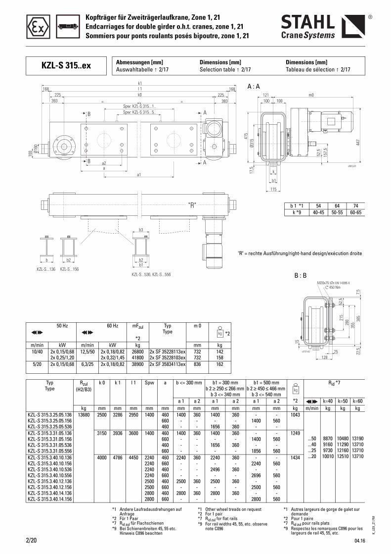
K_LE
X_Z1
.FM
Kopfträger für Zweiträgerlaufkrane, Zone 1, 21Endcarriages for double girder o.h.t. cranes, zone 1, 21Sommiers pour ponts roulants posés bipoutre, zone 1, 21
2/20 04.16
KZL-S 315..ex Abmessungen [mm] Auswahltabelle ↑ 2/17
Dimensions [mm]Selection table ↑ 2/17
Dimensions [mm]Tableau de sélection ↑ 2/17
= =
l 1k1
k0168
B
B
Spw: KZL-S 315...5..Spw: KZL-S 315...1..
a2a
a1
b b2 b2
393 393
KZL-S...136 KZL-S...156KZL-S...536, KZL-S...556
m0
c0802v01
52,5
157,
5
k
b1
115
100 100121
17,5
415
447
Ø315
168225 225
Ø160
100
A
A
b3
b1
"R" b 1 *1 54 64 74k *9 40-45 50-55 60-65
50 Hz 60 Hz mFzul
*2
Typ Type
m 0 *2
m/min kW m/min kW kg mm kg10/40 2x 0,15/0,68
2x 0,25/1,2012,5/50 2x 0,18/0,82
2x 0,32/1,452680041800
2x SF 35228113ex2x SF 35228103ex
732732
142158
5/20 2x 0,15/0,68 6,3/25 2x 0,18/0,82 38900 2x SF 35834113ex 836 162
Typ Type
Rzul (H2/B3)
k 0 k 1 l 1 Spw a b <= 300 mm b1 = 300 mm b 2 ≥ 250 ≤ 266 mm
b 3 <= 340 mm
b1 = 500 mm b 2 ≥ 450 ≤ 466 mm
b 3 <= 540 mm*2
Rid *7
a 1 a 2 a 1 a 2 a 1 a 2 k=40 k=50 k=60kg mm mm mm mm mm mm mm mm mm mm mm kg m/min kg kg kg
KZL-S 315.3.25.05.136 KZL-S 315.3.25.05.156 KZL-S 315.3.25.05.536
13680 2500 3286 2950 1400 460 660 460
1400 - -
360 - -
1400 -
1656
360 -
360
- 1400
-
- 560
-
1043
...50
...40
...25
...20
88709160 973010010
1048011290 1216012510
13190137101371013710
KZL-S 315.3.31.05.136 KZL-S 315.3.31.05.156 KZL-S 315.3.31.05.536 KZL-S 315.3.31.05.556
3150 3936 3600 1400 460 660 460 660
1400 - - -
360 - - -
1400 -
1656 -
360 -
360 -
- 1400
- 1856
- 560
- 560
1249
KZL-S 315.3.40.10.136 KZL-S 315.3.40.10.156 KZL-S 315.3.40.10.536 KZL-S 315.3.40.10.556 KZL-S 315.3.40.12.136 KZL-S 315.3.40.12.156 KZL-S 315.3.40.14.136 KZL-S 315.3.40.14.156
4000 4786 4450 2240 2240 2240 2240 2500 2500 2800 2800
460 660 460 660 460 660 460 660
2240 - - -
2500 -
2800 -
360 - - -
360 -
360 -
2240 -
2496 -
2500 -
2800 -
360 -
360 -
360 -
360 -
- 2240
- 2696
- 2500
- 2800
- 560
- 560
- 560
- 560
1434
A : A
B : B
c0757v02
450 NmM20x75 tZn EN 14399-4
52,5
385
35528
0215
7,5
22,525
15
128
*1 Andere Laufradausdrehungen auf Anfrage
*2 Für 1 Paar*7 Rid zul für Flachschienen*9 Bei Schienenbreiten 45, 55 etc.
Hinweis C096 beachten
*1 Other wheel treads on request*2 For 1 pair*7 Rid zul for flat rails*9 For rail widths 45, 55, etc. observe
note C096
*1 Autres largeurs de gorge de galet sur demande
*2 Pour 1 paire*7 Rid zul pour rails plats*9 Respectez les remarques C096 pour les
largeurs de rail 45, 55, etc.
"R" = rechte Ausführung/right-hand design/exécution droite
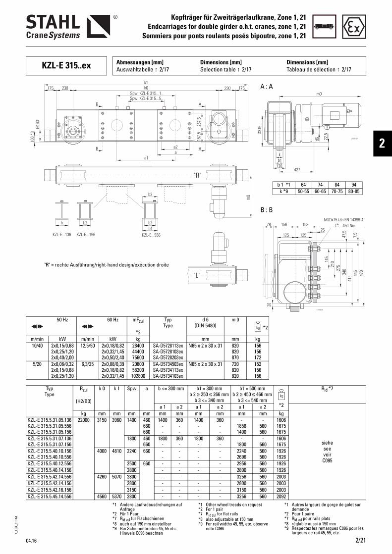
K_LE
X_Z1
.FM
04.16 2/21
Kopfträger für Zweiträgerlaufkrane, Zone 1, 21Endcarriages for double girder o.h.t. cranes, zone 1, 21
Sommiers pour ponts roulants posés bipoutre, zone 1, 21
2
KZL-E 315..ex Abmessungen [mm] Auswahltabelle ↑ 2/17
Dimensions [mm]Selection table ↑ 2/17
Dimensions [mm]Tableau de sélection ↑ 2/17
"R"
"L"
257,
5
a2a
a1
AB
AB
k0k1
Spw: KZL-E 315...1..Spw: KZL-E 315...5..
230175 230 175
Ø160
100
*8
157,
5
m0
c1581v01
b b2 b2
KZL-E...136 KZL-E...156 KZL-E...556
b3
b1
22,5
d6
kb1
130427
Ø315
m0
50 Hz 60 Hz mFzul
*2
Typ Type
d 6 (DIN 5480)
m 0 *2
m/min kW m/min kW kg mm mm kg10/40 2x0,15/0,68
2x0,25/1,202x0,40/2,00
12,5/50 2x0,18/0,822x0,32/1,452x0,50/2,40
284004440075600
SA-D5728113exSA-D5728103exSA-D5728203ex
N65 x 2 x 30 x 31 820820870
156156172
5/20 2x0,06/0,322x0,15/0,682x0,25/1,20
6,3/25 2x0,08/0,392x0,18/0,822x0,32/1,45
2080058200102800
SA-D5734503exSA-D5734113exSA-D5734103ex
N65 x 2 x 30 x 31 720820820
152156156
Typ Type
Rzul
(H2/B3)
k 0 k 1 Spw a b <= 300 mm b1 = 300 mm b 2 ≥ 250 ≤ 266 mm
b 3 <= 340 mm
b1 = 500 mm b 2 ≥ 450 ≤ 466 mm
b 3 <= 540 mm*2
Rid *7
a 1 a 2 a 1 a 2 a 1 a 2
sieheseevoirC095
kg mm mm mm mm mm mm mm mm mm mm kgKZL-E 315.5.31.05.136KZL-E 315.5.31.05.556KZL-E 315.5.31.05.156
22000 3150 3960 1400 460660660
1400--
360--
1400--
360--
-18561400
-560560
160616751675
KZL-E 315.5.31.07.136KZL-E 315.5.31.07.156
1800 460660
1800-
360-
1800-
360-
-1800
-560
16061675
KZL-E 315.5.40.10.156KZL-E 315.5.40.10.556
4000 4810 2240 660 --
--
--
--
22402696
560560
19261926
KZL-E 315.5.40.12.556 2500 660 - - - - 2956 560 1926KZL-E 315.5.40.14.156 2800 - - - - 2800 560 1926KZL-E 315.5.42.14.556 4260 5070 2800 - - - - 3256 560 2003KZL-E 315.5.42.14.156 2800 - - - - 2800 560 2003KZL-E 315.5.42.16.156 3150 - - - - 3150 560 2003KZL-E 315.5.45.14.556 4560 5370 2800 - - - - 3256 560 2092
A : A
b 1 *1 64 74 84 94k *9 50-55 60-65 70-75 80-85
B : B
"R" = rechte Ausführung/right-hand design/exécution droite
450 NmM20x75 tZn EN 14399-4
27521
0145
340
415 44
547
07,
5
47,5
125 12525
15315678
20
c1532v03
*1 Andere Laufradausdrehungen auf Anfrage
*2 Für 1 Paar*7 Rid zul für Flachschienen*8 auch auf 150 mm einstellbar*9 Bei Schienenbreiten 45, 55 etc.
Hinweis C096 beachten
*1 Other wheel treads on request*2 For 1 pair*7 Rid zul for flat rails*8 also adjustable at 150 mm*9 For rail widths 45, 55, etc. observe
note C096
*1 Autres largeurs de gorge de galet sur demande
*2 Pour 1 paire*7 Rid zul pour rails plats*8 réglable aussi à 150 mm*9 Respectez les remarques C096 pour les
largeurs de rail 45, 55, etc.
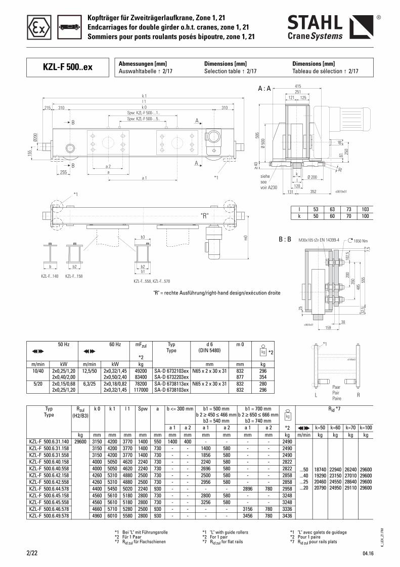
K_LE
X_Z1
.FM
Kopfträger für Zweiträgerlaufkrane, Zone 1, 21Endcarriages for double girder o.h.t. cranes, zone 1, 21Sommiers pour ponts roulants posés bipoutre, zone 1, 21
2/22 04.16
c0819v01
61 250
*1
155
Ø200
a 1 *1255
b b2 b2
KZL-F...140 KZL-F...158KZL-F...558, KZL-F...578
k 1l 1k 0215 310 310
Spw: KZL-F 500-...5..Spw: KZL-F 500-...1..
B
B
A
A
352
a 2a
121
Ø 200
30
251415
125
Ø 50
0595
kl
120131
≥40
d6
m0b3
b1
sieheseevoir A230
"R"
50 Hz 60 Hz mFzul
*2
Typ Type
d 6 (DIN 5480)
m 0 *2
m/min kW m/min kW kg mm mm kg10/40 2x0,25/1,20
2x0,40/2,0012,5/50 2x0,32/1,45
2x0,50/2,404920083400
SA-D 6732103exSA-D 6732203ex
N65 x 2 x 30 x 31 832877
296354
5/20 2x0,15/0,682x0,25/1,20
6,3/25 2x0,18/0,822x0,32/1,45
78200117000
SA-D 6738113exSA-D 6738103ex
N65 x 2 x 30 x 31 832832
280296
Typ Type
Rzul (H2/B3)
k 0 k 1 l 1 Spw a b <= 300 mm b1 = 500 mm b 2 ≥ 450 ≤ 466 mm
b3 = 540 mm
b1 = 700 mm b 2 ≥ 650 ≤ 666 mm
b3 = 740 mm*2
Rid *7
a 1 a 2 a 1 a 2 a 1 a 2 k=50 k=60 k=70 k=100kg mm mm mm mm mm mm mm mm mm mm mm kg m/min kg kg kg kg
KZL-F 500.6.31.140 29600 3150 4200 3770 1400 550 1400 400 - - - - 2490
...50
...40
...25
...20
18740192902046020790
22940231502455024950
26240270102864029110
29600296002960029600
KZL-F 500.6.31.158 3150 4200 3770 1400 730 - - 1400 580 - - 2490KZL-F 500.6.31.558 3150 4200 3770 1400 730 - - 1856 580 - - 2490KZL-F 500.6.40.158 4000 5050 4620 2240 730 - - 2240 580 - - 2822KZL-F 500.6.40.558 4000 5050 4620 2240 730 - - 2696 580 - - 2822KZL-F 500.6.42.158 4260 5310 4880 2500 730 - - 2500 580 - - 2858KZL-F 500.6.42.558 4260 5310 4880 2500 730 - - 2956 580 - - 2858KZL-F 500.6.44.578 4400 5450 5020 2240 930 - - - - 2896 780 2958KZL-F 500.6.45.158 4560 5610 5180 2800 730 - - 2800 580 - - 3248KZL-F 500.6.45.558 4560 5610 5180 2800 730 - - 3256 580 - - 3248KZL-F 500.6.46.578 4660 5710 5280 2500 930 - - - - 3156 780 3336KZL-F 500.6.49.578 4960 6010 5580 2800 930 - - - - 3456 780 3436
l 53 63 73 103k 50 60 70 100
A : A
B : B
"R" = rechte Ausführung/right-hand design/exécution droite
*1 Bei "L" mit Führungsrolle*2 Für 1 Paar*7 Rid zul für Flachschienen
*1 "L" with guide rollers*2 For 1 pair*7 Rid zul for flat rails
*1 "L" avec galets de guidage*2 Pour 1 paire*7 Rid zul pour rails plats
30
25
159
1650 NmM30x105 tZn EN 14399-4
c0820v01
102,
5 7,5
555
350
485
200
32,5
KZL-F 500..ex Abmessungen [mm] Auswahltabelle ↑ 2/17
Dimensions [mm]Selection table ↑ 2/17
Dimensions [mm]Tableau de sélection ↑ 2/17
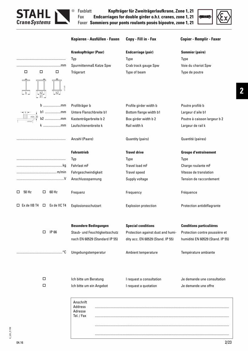
K_LE
X_Z1
.FM
04.16 2/23
Kopfträger für Zweiträgerlaufkrane, Zone 1, 21Endcarriages for double girder o.h.t. cranes, zone 1, 21
Sommiers pour ponts roulants posés bipoutre, zone 1, 21
FaxblattFaxFaxer
2
AnschriftAddressAdresseTel. / Fax
.................................................................................................................................................................
.................................................................................................................................................................
.................................................................................................................................................................
.................................................................................................................................................................
...........................................................
.....................................................mm
b .....................mm
b1 ...................mm
b2 ...................mm
k .....................mm
...........................................................
...........................................................
.......................................................kg
................................................ m/min
.........................................................V
50 Hz 60 Hz
Ex de IIB T4 Ex de IIC T4
IP 66
.......................................................°C
Kopieren - Ausfüllen - Faxen Copy - Fill in - Fax Copier - Remplir - Faxer
Endcarriage (pair)
Type
Crab track gauge Spw
Type of beam
Profile girder width b
Bottom flange width b1
Box girder width b 2
Rail width k
Quantity (pairs)
Travel drive
Type
Travel load mF
Travel speed
Supply voltage
Frequency
Explosion protection
Special conditions
Protection against dust and humi-
dity acc. EN 60529 (Stand. IP 55)
Ambient temperature
I request a consultation
I request a quotation
Sommier (paire)
Type
Voie du chariot Spw
Type de poutre
Poutre profilé b
Largeur d'aile b1
Poutre à caisson largeur b 2
Largeur de rail k
Quantité (paires)
Groupe d'entraînement
Type
Charge roulante mF
Vitesse de translation
Tension de raccordement
Fréquence
Protection antidéflagrante
Conditions particulières
Protection contre poussière et
humidité EN 60529 (Stand. IP 55)
Température ambiante
Je demande une consultation
Je demande une offre
Krankopfträger (Paar)
Typ
Spurmittenmaß Katze Spw
Trägerart
Profilträger b
Untere Flanschbreite b1
Kastenträgerbreite b 2
Laufschienenbreite k
Anzahl (Paare)
Fahrantrieb
Typ
Fahrlast mF
Fahrgeschwindigkeit
Anschlussspannung
Frequenz
Explosionsschutzart
Besondere Bedingungen
Staub- und Feuchtigkeitsschutz
nach EN 60529 (Standard IP 55)
Umgebungstemperatur
Ich bitte um Beratung
Ich bitte um ein Angebot
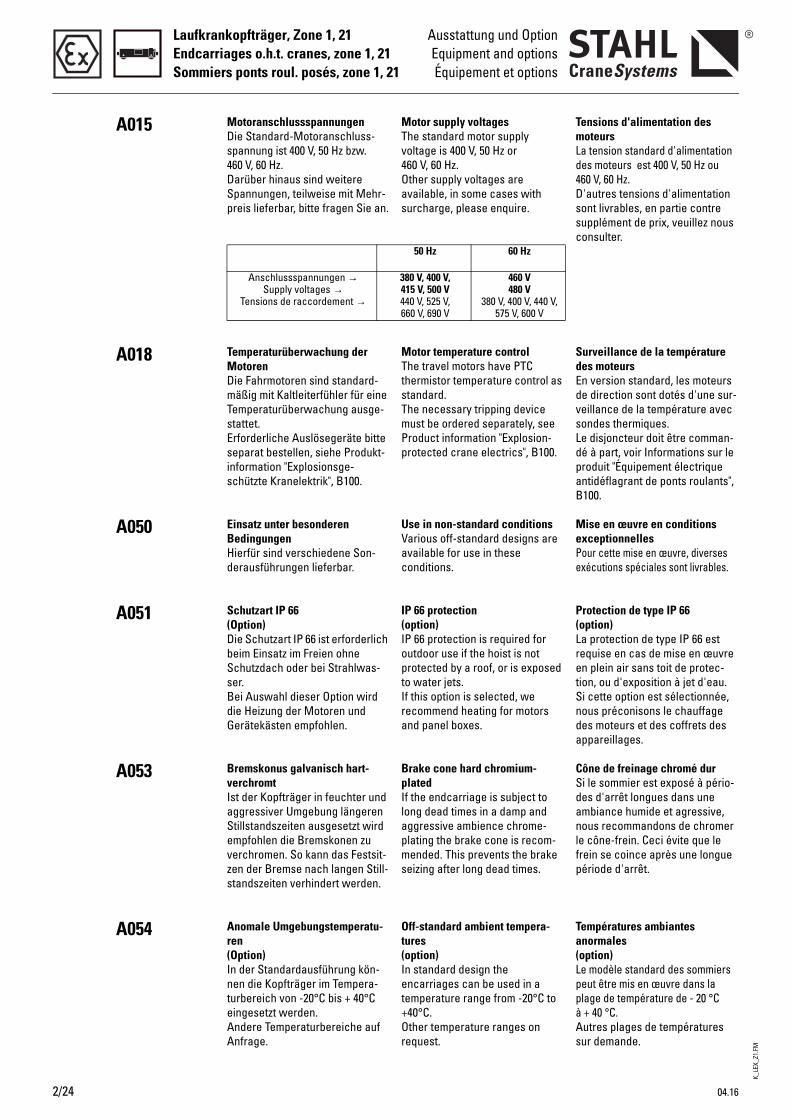
K_LE
X_Z1
.FM
Laufkrankopfträger, Zone 1, 21Endcarriages o.h.t. cranes, zone 1, 21Sommiers ponts roul. posés, zone 1, 21
2/24
Ausstattung und OptionEquipment and optionsÉquipement et options
A015
A018
A050
A051
A053
A054
Tensions d'alimentation des moteursLa tension standard d'alimentation des moteurs est 400 V, 50 Hz ou 460 V, 60 Hz.D'autres tensions d'alimentation sont livrables, en partie contre supplément de prix, veuillez nous consulter.
Surveillance de la température des moteursEn version standard, les moteurs de direction sont dotés d'une sur-veillance de la température avec sondes thermiques. Le disjoncteur doit être comman-dé à part, voir Informations sur le produit "Équipement électrique antidéflagrant de ponts roulants", B100.
Mise en œuvre en conditions exceptionnellesPour cette mise en œuvre, diverses exécutions spéciales sont livrables.
Protection de type IP 66(option)La protection de type IP 66 est requise en cas de mise en œuvre en plein air sans toit de protec-tion, ou d'exposition à jet d'eau.Si cette option est sélectionnée, nous préconisons le chauffage des moteurs et des coffrets des appareillages.
Cône de freinage chromé dur Si le sommier est exposé à pério-des d'arrêt longues dans une ambiance humide et agressive, nous recommandons de chromer le cône-frein. Ceci évite que le frein se coince après une longue période d'arrêt.
Températures ambiantes anormales(option)Le modèle standard des sommiers peut être mis en œuvre dans la plage de température de - 20 °C à + 40 °C.Autres plages de températures sur demande.
Motor supply voltagesThe standard motor supply voltage is 400 V, 50 Hz or 460 V, 60 Hz.Other supply voltages are available, in some cases with surcharge, please enquire.
Motor temperature controlThe travel motors have PTC thermistor temperature control as standard.The necessary tripping device must be ordered separately, see Product information "Explosion-protected crane electrics", B100.
Use in non-standard conditionsVarious off-standard designs are available for use in these conditions.
IP 66 protection(option)IP 66 protection is required for outdoor use if the hoist is not protected by a roof, or is exposed to water jets.If this option is selected, we recommend heating for motors and panel boxes.
Brake cone hard chromium-platedIf the endcarriage is subject to long dead times in a damp and aggressive ambience chrome-plating the brake cone is recom-mended. This prevents the brake seizing after long dead times.
Off-standard ambient tempera-tures(option)In standard design the encarriages can be used in a temperature range from -20°C to +40°C.Other temperature ranges on request.
50 Hz 60 Hz
380 V, 400 V, 415 V, 500 V440 V, 525 V, 660 V, 690 V
460 V480 V
380 V, 400 V, 440 V, 575 V, 600 V
MotoranschlussspannungenDie Standard-Motoranschluss-spannung ist 400 V, 50 Hz bzw. 460 V, 60 Hz.Darüber hinaus sind weitere Spannungen, teilweise mit Mehr-preis lieferbar, bitte fragen Sie an.
Temperaturüberwachung der MotorenDie Fahrmotoren sind standard-mäßig mit Kaltleiterfühler für eine Temperaturüberwachung ausge-stattet.Erforderliche Auslösegeräte bitte separat bestellen, siehe Produkt-information "Explosionsge-schützte Kranelektrik", B100.
Einsatz unter besonderen BedingungenHierfür sind verschiedene Son-derausführungen lieferbar.
Schutzart IP 66(Option)Die Schutzart IP 66 ist erforderlich beim Einsatz im Freien ohne Schutzdach oder bei Strahlwas-ser.Bei Auswahl dieser Option wird die Heizung der Motoren und Gerätekästen empfohlen.
Bremskonus galvanisch hart-verchromtIst der Kopfträger in feuchter und aggressiver Umgebung längeren Stillstandszeiten ausgesetzt wird empfohlen die Bremskonen zu verchromen. So kann das Festsit-zen der Bremse nach langen Still-standszeiten verhindert werden.
Anomale Umgebungstemperatu-ren(Option)In der Standardausführung kön-nen die Kopfträger im Tempera-turbereich von -20°C bis + 40°C eingesetzt werden. Andere Temperaturbereiche auf Anfrage.
Anschlussspannungen →Supply voltages →
Tensions de raccordement →
04.16
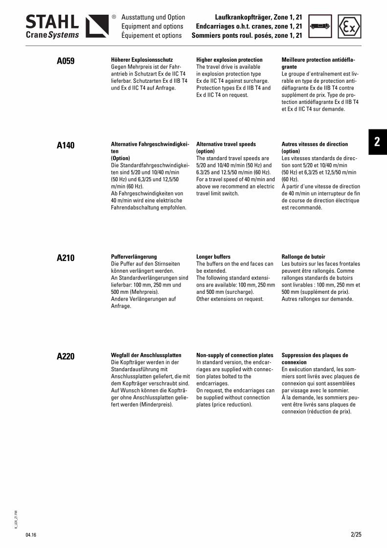
K_LE
X_Z1
.FM
04.16
Laufkrankopfträger, Zone 1, 21Endcarriages o.h.t. cranes, zone 1, 21
Sommiers ponts roul. posés, zone 1, 21
Ausstattung und OptionEquipment and optionsÉquipement et options
2
A059
A140
A210
A220
Höherer ExplosionsschutzGegen Mehrpreis ist der Fahr-antrieb in Schutzart Ex de IIC T4 lieferbar. Schutzarten Ex d IIB T4 und Ex d IIC T4 auf Anfrage.
Alternative Fahrgeschwindigkei-ten(Option)Die Standardfahrgeschwindigkei-ten sind 5/20 und 10/40 m/min (50 Hz) und 6,3/25 und 12,5/50 m/min (60 Hz).Ab Fahrgeschwindigkeiten von 40 m/min wird eine elektrische Fahrendabschaltung empfohlen.
PufferverlängerungDie Puffer auf den Stirnseiten können verlängert werden. An Standardverlängerungen sind lieferbar: 100 mm, 250 mm und 500 mm (Mehrpreis). Andere Verlängerungen auf Anfrage.
Wegfall der AnschlussplattenDie Kopfträger werden in der Standardausführung mit Anschlussplatten geliefert, die mit dem Kopfträger verschraubt sind.Auf Wunsch können die Kopfträ-ger ohne Anschlussplatten gelie-fert werden (Minderpreis).
HTiEPE
A(T56Fat
LTbToaO
NIrteObp
igher explosion protectionhe travel drive is available
n explosion protection type x de IIC T4 against surcharge. rotection types Ex d IIB T4 and x d IIC T4 on request.
lternative travel speedsoption)he standard travel speeds are /20 and 10/40 m/min (50 Hz) and .3/25 and 12.5/50 m/min (60 Hz). or a travel speed of 40 m/min and bove we recommend an electric
ravel limit switch.
onger buffershe buffers on the end faces can e extended.he following standard extensi-ns are available: 100 mm, 250 mm nd 500 mm (surcharge).ther extensions on request.
on-supply of connection platesn standard version, the endcar-iages are supplied with connec-ion plates bolted to the ndcarriages.n request, the endcarriages can e supplied without connection lates (price reduction).
MgLrdste
A(Lt((Àdde
RLprs5A
ScEmcpÀvc
eilleure protection antidéfla-rantee groupe d'entraînement est liv-able en type de protection anti-éflagrante Ex de IIB T4 contre upplément de prix. Type de pro-ection antidéflagrante Ex d IIB T4 t Ex d IIC T4 sur demande.
utres vitesses de directionoption)es vitesses standards de direc-ion sont 5/20 et 10/40 m/min 50 Hz) et 6,3/25 et 12,5/50 m/min 60 Hz). partir d'une vitesse de direction e 40 m/min un interrupteur de fin e course de direction électrique st recommandé.
allonge de butoires butoirs sur les faces frontales euvent être rallongés. Comme allonges standards de butoirs ont livrables : 100 mm, 250 mm et 00 mm (supplément de prix).utres rallonges sur demande.
uppression des plaques de onnexionn exécution standard, les som-iers sont livrés avec plaques de
onnexion qui sont assemblées ar vissage avec le sommier. la demande, les sommiers peu-ent être livrés sans plaques de onnexion (réduction de prix).
2/25
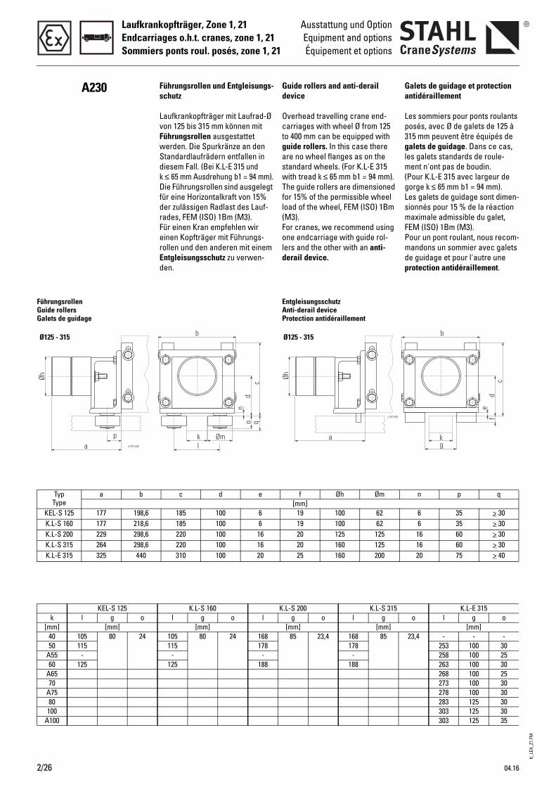
Laufkrankopfträger, Zone 1, 21Endcarriages o.h.t. cranes, zone 1, 21Sommiers ponts roul. posés, zone 1, 21
2/26
Ausstattung und OptionEquipment and optionsÉquipement et options
A230
pa
Øh
c1077a02
FührungsrollenGuide rollersGalets de guidage
Ø125 - 315
TypType
a b
KEL-S 125 177 198,6K.L-S 160 177 218,6K.L-S 200 229 298,6K.L-S 315 264 298,6K.L-E 315 325 440
KEL-S 125k l g o
[mm] [mm]40 105 80 2450 115
A55 -60 125
A6570
A7580
100A100
Guide rollers and anti-derail device
Overhead travelling crane end-carriages with wheel Ø from 125 to 400 mm can be equipped with guide rollers. In this case there are no wheel flanges as on the standard wheels. (For K.L-E 315 with tread k ≤ 65 mm b1 = 94 mm).The guide rollers are dimensioned for 15% of the permissible wheel load of the wheel, FEM (ISO) 1Bm (M3).For cranes, we recommend using one endcarriage with guide rol-lers and the other with an anti-derail device.
EntgleisungsschutzAnti-derail deviceProtection antidéraillement
Ø125 - 315
f Øh Øm[mm]
19 100 62
Ga
Lp3glm(gLsmFPmdp
K_LE
X_Z1
.FM
04.16
19 100 62 6 35 > 3020 125 125 16 60 > 3020 160 125 16 60 > 3025 160 200 20 75 > 40
.L-S 200 K.L-S 315 K.L-E 315g o l g o l g o
[mm] [mm] [mm]85 23,4 168 85 23,4 - - -
178 253 100 30- 258 100 25
188 263 100 30268 100 25273 100 30278 100 30283 125 30303 125 30303 125 35
Führungsrollen und Entgleisungs-schutz
Laufkrankopfträger mit Laufrad-Ø von 125 bis 315 mm können mit Führungsrollen ausgestattet werden. Die Spurkränze an den Standardlaufrädern entfallen in diesem Fall. (Bei K.L-E 315 und k ≤ 65 mm Ausdrehung b1 = 94 mm).Die Führungsrollen sind ausgelegt für eine Horizontalkraft von 15% der zulässigen Radlast des Lauf-rades, FEM (ISO) 1Bm (M3).Für einen Kran empfehlen wir einen Kopfträger mit Führungs-rollen und den anderen mit einem Entgleisungsschutz zu verwen-den.
b
dn
oc
q
kl
Øm
c d e
185 100 6185 100 6220 100 16220 100 16310 100 20
K.L-S 160 Kl g o l
[mm]105 80 24 168115 178
- -125 188
n p q
6 35 > 30
alets de guidage et protection ntidéraillement
es sommiers pour ponts roulants osés, avec Ø de galets de 125 à 15 mm peuvent être équipés de alets de guidage. Dans ce cas,
es galets standards de roule-ent n'ont pas de boudin.
Pour K.L-E 315 avec largeur de orge k ≤ 65 mm b1 = 94 mm).es galets de guidage sont dimen-ionnés pour 15 % de la réaction aximale admissible du galet,
EM (ISO) 1Bm (M3).our un pont roulant, nous recom-andons un sommier avec galets
e guidage et pour l'autre une rotection antidéraillement.
K_LE
X_Z1
.FM
04.16
Laufkrankopfträger, Zone 1, 21Endcarriages o.h.t., zone 1, 21
Sommiers ponts posés, zone 1, 21
Komponenten und ZubehörComponents and accessoriesComposants et accessoires
2
B081
B100
Fahrbahnendanschläge ohne PufferDie Laufkrankopfträger sind serienmäßig mit Puffern ausge-stattet. Passende Endanschläge sind bauseits anzubauen. Die Größe der Anschläge ist ent-sprechend den Pufferkräften aus-zulegen. Die Abmessungen sind so zu wählen, dass die ganze Fläche des Puffers auf den Anschlag trifft.
Auslösegeräte für Kaltleiter-Tem-peraturüberwachungSiehe Produktinformation "Explo-sionsgeschützte Kranelektrik".
RbTebrbTefbf
TsSs
unway end stops without uffershe overhead travelling crane ndcarriages are fitted with uffers as standard. The stops equired on the crane bridge must e supplied by the customer.he size of the stops must be sel-cted in accordance with the buf-er forces. The dimensions must e selected so that the whole sur-ace of the buffer strikes the stop.
ripping devices for PTC thermi-tor temperature controlee Product information "Explo-ion-protected crane electrics".
BmLpbcdttq
DlV"g
2/27
utées de fin de voie de roule-ent sans tampons
es sommiers pour ponts roulants osés sont, en série, équipés de utoirs. Des butées de fin de ourse, à fournir par le client, oivent être montées. Choisir la aille des butées de telle sorte que oute la surface du butoir s'appli-ue contre la butée.
isjoncteurs pour surveillance de a température par thermistanceoir Informations sur le produit
Équipement électrique antidéfla-rant de ponts roulants".

K_LE
X_Z1
.FM
Laufkrankopfträger, Zone 1, 21Endcarriages o.h.t., zone 1, 21Sommiers ponts posés, zone 1, 21
2/28 04.16
Technische DatenTechnical data
Caractéristiques techniques
AuslegungDIN 15018.DIN 15070, 15071.
Einstufungnach DIN 15018, H2/B3, andere auf Anfrage.
SicherheitsvorschriftenEG-Maschinenrichtlinie 2006/42/EG, Richtlinie 2014/34/EU.
Wärmeklassefür Fahrmotoren F / H (Ausnut-zung/Isoliersystem) nach IEC/EN 60034-1
Motor-AnschlussspannungenSiehe A015.
Geräteeinstufungnach Richtlinie 2014/34/EU (ATEX):
Gas: Gerätegruppe II, Kategorie 2G
oderStaub: Gerätegruppe II, Kategorie 2D
Explosionsschutz nach EN/IEC
Schutzart EN 60529 / IECStandard: IP 55Option bzw. Zone 21: IP 66
Zulässige Umgebungstemperatu-renStandard: -20 °C...+40 °C, andere Umgebungstemperaturen auf Anfrage.
FahrmotorenSiehe Produktinformation "Explo-sionsgeschützte Fahrantriebe".
Gas:II 2G Ex de IIB T4 Gb (Standard)II 2G ck llB T4
(siehe auch A059)
oderStaub:
ll 2D Ex tb lllC T120°C Dbll 2D ck T120°C
C010
C011
C012
C014
C020
C030
C031
C040
C050
C070
DesignDIN 15018.DIN 15070, 15071.
Classificationto DIN 15018, H2/B3, other classi-fications on request.
Safety regulationsEC Machinery Directive 2006/42/CE, directive 2014/34/EU.
Thermal classfor travel motors F / H (utilisation/insulation system) complying with IEC/EN 60034-1
Motor supply voltagesSee A015.
Equipment classificationacc. to directive 2014/34/EU (ATEX):
Gas: Equipment group II, category 2G
orDust: Equipment group II, category 2D
Explosion protection to EN/IEC
Protection class EN 60529 / IECStandard: IP 55Option or zone 21: IP 66
Permissible ambient tempera-turesStandard: -20 °C...+40 °C, other ambient temperatures on request.
Travel motorsSee Product information "Explo-sion-protected travel drives".
Gas:II 2G Ex de IIB T4 Gb (standard)II 2G ck llB T4
(see also A059)
orDust:
ll 2D Ex tb lllC T120°C Dbll 2D ck T120°C
ConceptionDIN 15018.DIN 15070, 15071.
Classificationselon DIN 15018, H2/B3, autres classifications possibles sur demande.
Prescriptions de sécuritéDirective CE relative aux machines 2006/42/C.E., directive 2014/34/UE.
Classe thermiquepour moteurs de direction F / H (utilisation/système d'isolation) selon IEC/EN 60034-1
Tensions d'alimentation des moteursVoir A015.
Classification des appareilsselon directive 2014/34/UE (ATEX) :
Gaz : Groupe des appareils II, catégorie 2G
ouPoussière : Groupe des appareils II, catégorie 2D
Protection antidéflagrante selon NE/C.E.I.
Type de protection NE 60529/C.E.I.Standard: IP 55Option ou zone 21: IP 66
Températures ambiantes admissiblesStandard: -20 °C...+40 °C, autres températures ambiantes sur demande.
Moteurs de directionVoir Informations sur le produit "Groupes d’entraînement antidé-flagrants".
Gaz :II 2G Ex de IIB T4 Gb (standard)II 2G ck llB T4
(voir aussi A059)
ouPoussière :
ll 2D Ex tb lllC T120°C Dbll 2D ck T120°C
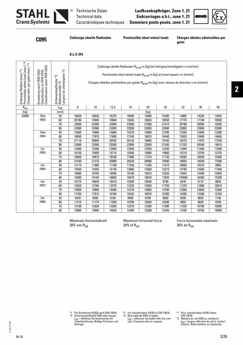
K_LE
X_Z1
.FM
04.16 2/29
Laufkrankopfträger, Zone 1, 21Endcarriages o.h.t., zone 1, 21
Sommiers ponts posés, zone 1, 21
Technische DatenTechnical dataCaractéristiques techniques
2
C095 Zulässige ideelle Radlasten Permissible ideal wheel loads Charges idéales admissibles par galet
K.L-E 315
Zulä
ssig
e Ra
dlas
t (m
ax.)
*1Pe
rmis
sibl
e w
heel
load
(max
.) *1
Char
ge a
dm. p
ar g
alet
(max
.) *1
Eins
tufu
ng n
ach
FEM
(ISO
)Cl
assi
ficat
ion
to F
EM (I
SO)
Clas
sific
atio
n se
lon
FEM
(ISO
)
Schi
enen
kopf
brei
te *
3Ra
ilhea
d w
idth
*3
Larg
eur d
u ch
ampi
gnon
*3
Zulässige ideelle Radlasten Rid zul in [kg] bei Fahrgeschwindigkeit v in [m/min]
Permissible ideal wheel loads Rid zul in [kg] at travel speed v in [m/min]
Charges idéelles admissibles par galets Rid zul en [kg] avec vitesse de direction v en [m/min]
Rzul keff 8 10 12,5 16 20 25 32 40 50[kg] [mm] [kg]
22000 1Bm (M3)
50 16830 16620 16370 16040 15690 15290 14800 14320 1382060 20190 19940 19840 19240 18830 18350 17770 17190 1658070 22000 22000 22000 22000 21960 21410 20780 20050 1935080 22000 22000 22000 22000 22000 22000 22000 22000 22000
1Am (M4)
50 15080 14890 14660 14370 14060 13700 13260 12830 1238060 18090 17870 17800 17240 16870 16440 15920 15400 1466070 21110 20840 20530 20120 19680 19180 18570 17970 1733080 22000 22000 22000 22000 22000 21930 21220 20540 19810
2m (M5)
50 13460 13290 13090 12830 12550 12230 11840 11460 1105060 16150 15950 15710 15400 15060 14680 14210 13750 1327070 18850 18810 18330 17960 17370 17130 16580 16040 1548080 21540 21270 20900 20530 20080 19580 18950 18340 17690
3m (M6)
50 12110 11960 11780 11550 11300 11010 10660 10310 995060 14540 14350 14140 13860 13560 13210 12790 12380 1194070 18960 18750 16500 16160 15810 15420 14920 14440 1393080 19380 19140 18850 18470 18070 17620 170500 16350 15290
4m (M7)
50 10770 10630 10470 10260 10040 9790 9470 9170 884060 12920 12760 12570 12320 12050 11750 11370 11000 1081070 15000 14890 14580 14370 14060 13700 13260 12830 1236080 17230 17010 16760 18420 16070 15290 14200 13280 12420
5m (M8)
50 9420 9300 9180 8990 8790 8500 8290 8020 774060 11310 11170 11000 10780 10540 10280 9950 9630 929070 13190 13030 12830 12570 12300 11990 11530 10790 1009080 15080 14890 14650 14200 13280 12420 11530 10790 10090
Maximale Horizontalkraft: 20% von Rzul
Maximum horizontal force: 20% of Rzul
Force horizontale maximale : 20% de Rzul
*1 Für Einstufung H2/B3 nach DIN 15018*3 Schienenwerkstoff S355 oder besser.
keff = effektive Schienenbreite mit Linienberührung. Ballige Schienen auf Anfrage.
*1 For classification H2/B3 to DIN 15018*3 Rail material S355 or better.
keff = effective rail width with line con-tact. Crowned rails on request.
*1 Pour classification H2/B3 selon DIN 15018
*3 Matière du rail S355 ou meilleure. keff = largeur effective de rail à contact linéaire. Rails bombés sur demande.
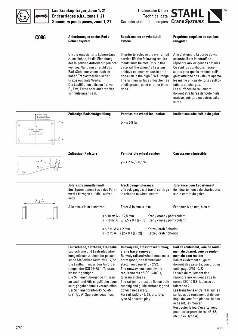
K_LE
X_Z1
.FM
Laufkrankopfträger, Zone 1, 21Endcarriages o.h.t., zone 1, 21Sommiers ponts posés, zone 1, 21
Technische DatenTechnical data
Caractéristiques techniques
C096 Anforderungen an das Rad-/Schienesystem
Requirements on wheel/rail system
Propriétés requises du système rail/galet
Um die zugesicherte Lebensdauer zu erreichen, ist die Einhaltung der folgenden Anforderungen not-wendig. Nur dann erreicht das Rad-/Schienesystem auch im hohen Traglastbereich in der Praxis optimale Werte.Die Laufflächen müssen frei von Öl, Fett, Farbe oder anderen Ver-schmutzungen sein.
In order to achieve the warranted service life the following require-ments must be met. Only in this case will the wheel/rail system achieve optimum values in prac-tice even in the high S.W.L. range.The running surfaces must be free of oil, grease, paint or other impu-rities.
Afin d'atteindre la durée de vie assurée, il est impératif de répondre aux exigences définies. Ce sont les conditions néces-saires pour que le système rail/galet atteigne des valeurs optima-les même en cas de fortes sollici-tations de charges. Les surfaces de roulement doivent être libres de toute huile, graisse, peinture ou autres salis-sures.
Zulässige Radschrägstellung Permissible wheel inclination
ϕ = ± 0,5 ‰
Inclinaison admissible du galet
Zulässiger Radsturz Permissible wheel camber
γ = + 2 ‰ / - 0,5 ‰
Carrossage admissible
Toleranz Spurmittenmaßdes Spurmittenmaßes s des Fahr-werks bezogen auf die Laufrad-mitte.
A in mm, s in m einsetzen.
Track gauge toleranceof track gauge s of travel carriage in relatino to wheel centre.
Enter A in mm, s in m
Tolérance pour l’écartementde l'écartement s du chariot pris sur le centre du galet.
Exprimer A en mm, s en m.
s ≤ 10 m: A = ± 2,5 mm Kran / crane / pont roulants > 10 m: A = ± [2,5 + 0,1 (s - 10)]Kran / crane / pont roulant
s ≤ 2 m: A = ± 2 mm Katze / crab / chariots > 2 m: A = ± [2 + 0,1 (s - 2)] Katze / crab / chariot
Laufschiene, Katzbahn, KranbahnLaufschiene und Laufradausdre-hung müssen zueinander passen, siehe Maßskizze Seite 2/10 - 2/22.Die Laufbahn muss den Anforde-rungen der ISO 12488-1, Toleranz-klasse 2 genügen.Die Schienenübergänge müssen an Lauf- und Führungsfläche eben sein; gegebenenfalls verschleifen.Bei Schienenbreiten 45, 55 etc. (z.B. Typ A) Spurspiel beachten.
Runway rail, cross travel runway, crane travel runway Runway rail and wheel tread must correspond, see dimensional sketch on page 2/10 - 2/22.The runway must comply the requirements of ISO 12488-1, tolerance class 2.The rail joints must be flat on both running and guide surfaces; grind down if necessary. For rail widths 45, 55, etc. (e.g. type A) observe play.
Rail de roulement, voie de roule-ment du chariot, voie de roule-ment du pont roulantRail et évidement du galet doivent être assortis, voir croquis coté, page 2/10 - 2/22.La voie de roulement doit répondre aux exigences de la norme ISO 12488-1, classe de tolérance 2. Les transitions entre rails sur les surfaces de roulement et de gui-dage doivent être planes ; le cas échéant, les meuler. Respecter le jeu d'écartement pour les largeurs de rail 45, 55, etc. (p.ex. type A).
+ ϕ
+ ϕ
+an allen Laufrädern
to all wheelssur tous les galets
ϕ
FahrtrichtungDirection of travelSens de direction
c1535v01
S A+
c1537v01
2/30 04.16
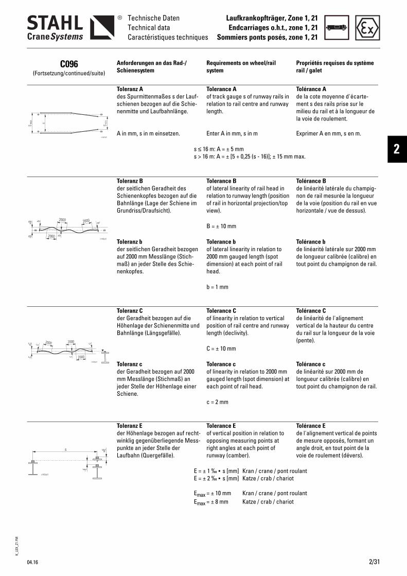
K_LE
X_Z1
.FM
Laufkrankopfträger, Zone 1, 21Endcarriages o.h.t., zone 1, 21
Sommiers ponts posés, zone 1, 21
Technische DatenTechnical dataCaractéristiques techniques
2
C096(Fortsetzung/continued/suite)
Anforderungen an das Rad-/Schienesystem
Requirements on wheel/rail system
Propriétés requises du système rail / galet
Toleranz Ades Spurmittenmaßes s der Lauf-schienen bezogen auf die Schie-nenmitte und Laufbahnlänge.
A in mm, s in m einsetzen.
Tolerance Aof track gauge s of runway rails in relation to rail centre and runway length.
Enter A in mm, s in m
Tolérance Ade la cote moyenne d'écarte-ment s des rails prise sur le milieu du rail et à la longueur de la voie de roulement.
Exprimer A en mm, s en m.
s ≤ 16 m: A = ± 5 mms > 16 m: A = ± [5 + 0,25 (s - 16)]; ± 15 mm max.
Toleranz Bder seitlichen Geradheit des Schienenkopfes bezogen auf die Bahnlänge (Lage der Schiene im Grundriss/Draufsicht).
Tolerance Bof lateral linearity of rail head in relation to runway length (position of rail in horizontal projection/top view).
Tolérance Bde linéarité latérale du champig-non de rail mesurée la longueur de la voie (position du rail en vue horizontale / vue de dessus).
B = ± 10 mm
Toleranz bder seitlichen Geradheit bezogen auf 2000 mm Messlänge (Stich-maß) an jeder Stelle des Schie-nenkopfes.
Tolerance bof lateral linearity in relation to 2000 mm gauged length (spot dimension) at each point of rail head.
Tolérance bde linéarité latérale sur 2000 mm de longueur calibrée (calibre) en tout point du champignon de rail.
b = 1 mm
Toleranz Cder Geradheit bezogen auf die Höhenlage der Schienenmitte und Bahnlänge (Längsgefälle).
Tolerance Cof linearity in relation to vertical position of rail centre and runway length (declivity).
Tolérance Cde linéarité de l'alignement vertical de la hauteur du centre du rail sur la longueur de la voie (pente).
C = ± 10 mm
Toleranz cder Geradheit bezogen auf 2000 mm Messlänge (Stichmaß) an jeder Stelle der Höhenlage einer Schiene.
Tolerance cof linearity in relation to 2000 mm gauged length (spot dimension) at each point of rail head.
Tolérance cde linéarité sur 2000 mm de longueur calibrée (calibre) en tout point du champignon de rail.
c = 2 mm
Toleranz Eder Höhenlage bezogen auf recht-winklig gegenüberliegende Mess-punkte an jeder Stelle der Laufbahn (Quergefälle).
Tolerance Eof vertical position in relation to opposing measuring points at right angles at each point of runway (camber).
Tolérance Ede l'alignement vertical de points de mesure opposés, formant un angle droit, en tout point de la voie de roulement (dévers).
E = ± 1 ‰ • s [mm] Kran / crane / pont roulantE = ± 2 ‰ • s [mm] Katze / crab / chariot
Emax = ± 10 mm Kran / crane / pont roulantEmax = ± 8 mm Katze / crab / chariot
04.16 2/31
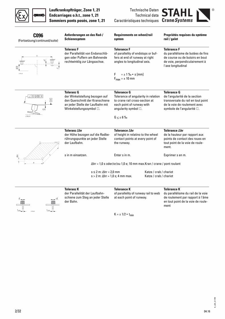
K_LE
X_Z1
.FM
Laufkrankopfträger, Zone 1, 21Endcarriages o.h.t., zone 1, 21Sommiers ponts posés, zone 1, 21
Technische DatenTechnical data
Caractéristiques techniques
C096(Fortsetzung/continued/suite)
Anforderungen an das Rad-/Schienesystem
Requirements on wheel/rail system
Propriétés requises du système rail / galet
Toleranz Fder Parallelität von Endanschlä-gen oder Puffern am Bahnende rechtwinklig zur Längsachse.
Tolerance Fof parallelity of endstops or buf-fers at end of runway at right angles to longitudinal axis.
Tolérance Fdu parallélisme de butées de fins de course ou de butoirs en bout de voie, perpendiculairement à l'axe longitudinal
F = ± 1 ‰ • s [mm]Fmax = ± 10 mm
Toleranz Gder Winkelstellung bezogen auf den Querschnitt der Kranschiene an jeder Stelle der Laufbahn mit Winkelstellungssymbol ∠ .
Tolerance GTolerance of angularity in relation to crane rail cross-section at each point of runway with angularity symbol ∠ .
Tolérance Gde l’angularité de la section transversale du rail en tout point de la voie de roulement avec symbole de l’angularité ∠ .
G < ± 6 ‰
Toleranz ∆hrder Höhe bezogen auf die Radbe-rührungspunkte an jeder Stelle der Laufbahn.
s in m einsetzen.
Tolerance ∆hrof height in relatino to the wheel contact points at every point of the runway.
Enter s in m.
Tolérance ∆hrde la hauteur par rapport aux points de contact des roues en tout point de la voie de roule-ment.
Exprimer s en m.
∆hr = 1,0 s oder/or/ou 1,0 e; 10 mm max.Kran / crane / pont roulant
s ≤ 2 m: ∆hr = 2,0 mm Katze / crab / chariots > 2 m: ∆hr = 1,0 s; 4 mm max. Katze / crab / chariot
Toleranz Kder Parallelität der Laufbahn-schiene zum Steg an jeder Stelle der Bahn.
Tolerance Kof parallelity of runway rail to web at each point of runway.
Tolérance Kdu parallélisme du rail de la voie de roulement par rapport à l'âme en tout point de la voie de roule-ment
K = ± 1/2 • tmin
∆hr
e
s
c1754v01
2/32 04.16
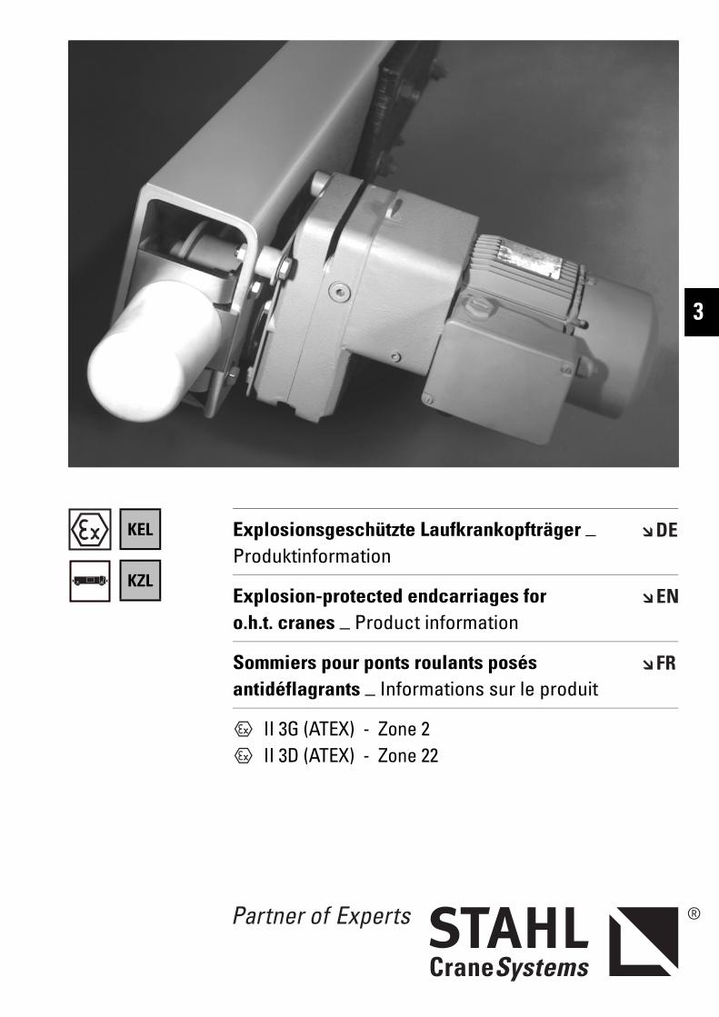
KEL
KZL
II 3G (ATEX) - Zone 2 II 3D (ATEX) - Zone 22
Explosionsgeschützte Laufkrankopfträger _ Produktinformation
Explosion-protected endcarriages for o.h.t. cranes _ Product information
Sommiers pour ponts roulants posés antidéflagrants _ Informations sur le produit
3
K_LE
X_Z2
.FM
3/2 04.16
Laufkrankopfträger, Zone 2, 22Endcarriages for o.h.t. cranes, zone 2, 22Sommiers pour ponts roulants posés, zone 2, 22
K.Lex n Mit den Laufkrankopfträgern K.Lex n können moderne Einträ-ger- und Zweiträgerlaufkrane bis zu einer Tragfähigkeit von 50.000 kg und einer Spannweite bis zu 30 m gebaut werden.
Nutzen Sie die robuste Konstruk-tion, kompakte Bauweise, War-tungsfreundlichkeit und Zuver-lässigkeit in Verbindung mit den wirtschaftlichen Vorteilen der Serienfertigung für Ihren Kran-bau.
Die explosionsgeschützten Lauf-krankopfträger K.Lex n entspre-chen der Gerätegruppe und Kategorie der Richtlinie 2014/34/EU (ATEX):Für Gas: ll 3G oderFür Staub: ll 3D
Weitere Informationen zur Zone 2 siehe Produktinformation "Explosionsgeschützte Seilzüge".
On the basis of K.Lex n endcarriages for overhead travelling cranes, modern single girder and double girder overhead travelling cranes up to an working load of 50,000 kg and a span of 30 m can be manufactured.
Make use of their sturdy design, compact construction, maintenance friendliness and reliability in conjunction with the economic advantages of series production for your crane manufacturing.
The explosion-protected overhead travelling crane endcarriages K.Lex n comply with the equipment group and category of the directive 2014/34/EU (ATEX):For gas: ll 3G orFor dust: ll 3D
For further information on Zone 2, see Product information "Explosion-protected wire rope hoists".
Avec les sommiers pour ponts roulants posés K.Lex n, il peut être construit des ponts roulants posés modernes ayant une charge d’utilisation allant jusqu'à 50.000 kg et une portée allant jusqu'à 30 m.
Profitez de la construction robuste et compacte, de la facilité d'entretien et de la fiabilité allant de pair avec les avantages économiques de la fabrication en série pour votre construction de ponts roulants.
Les sommiers pour ponts roulants posés antidéflagrants K.Lex n correspondent au groupe d’appareils et à la catégorie de la directive 2014/34/UE (ATEX) :Pour le gaz : ll 3G ouPour la poussière : ll 3D
Pour plus d’informations sur la zone 2, voir Informations sur le produit "Palans à câble antidéflagrants".
Erklärung der Symbole Explanation of symbols Explication des symboles
Maximale Tragfähigkeit [kg] Maximum working load [kg] Charge maximale d’utilisation [kg]
Gewicht [kg] Weight [kg] Poids [kg]
Fahrgeschwindigkeit [m/min] Travel speed [m/min] Vitesse de direction [m/min]
Abmessungen siehe Seite .. Dimensions see page .. Dimensions voir page ..
↑ Siehe Seite .. See page .. Voir page ..
K_LE
X_Z2
.FM
04.16 3/3
Laufkrankopfträger, Zone 2, 22Endcarriages for o.h.t. cranes, zone 2, 22
Sommiers pour ponts roulants posés, zone 2, 22
3
Inhaltsverzeichnis Contents Indice
Erklärung der Symbole..................3/2 Explanation of symbols................. 3/2 Explication des symboles............. 3/2Die Technik im Überblick..............3/4 Technical features at a glance.... 3/4 La technique en un coup d’œil.... 3/4
Kopfträger für Einträger-laufkrane
Endcarriages for single girder o.h.t. cranes
Sommiers pour ponts roulants posés monopoutre
Auswahltabelle ..............................3/5 Selection table ............................... 3/5 Tableau de sélection..................... 3/5Typenerklärung ..............................3/5 Explanation of types...................... 3/5 Explication des types.................... 3/5Abmessungen.................................3/6 Dimensions ..................................... 3/6 Dimensions..................................... 3/6Faxblatt ..........................................3/11 Fax.................................................. 3/11 Faxer.............................................. 3/11
Kopfträger für Zweiträger-laufkrane
Endcarriages for double girder o.h.t. cranes
Sommiers pour ponts roulants posés bipoutre
Auswahltabelle ............................3/12 Selection table ............................. 3/12 Tableau de sélection................... 3/12Abmessungen...............................3/13 Dimensions ................................... 3/13 Dimensions................................... 3/13Faxblatt ..........................................3/18 Fax.................................................. 3/18 Faxer.............................................. 3/18
Ausstattung und Option Equipment and options Équipement et optionsA015 Motoranschlussspannungen.....3/19 Motor supply voltages ................ 3/19 Tensions d'alimentation des
moteurs ......................................... 3/19A018 Temperaturüberwachung der Moto-
ren ..................................................2/24Motor temperature control ........ 2/24 Surveillance de la température des
moteurs ......................................... 2/24A050 Einsatz unter besonderen Bedin-
gungen...........................................2/24Use in non-standard conditions 2/24 Mise en œuvre en conditions
exceptionnelles ........................... 2/24A051 Schutzart IP 66 .............................2/24 IP 66 protection............................ 2/24 Protection de type IP 66 ............. 2/24A054 Anomale Umgebungstemperatu-
ren ................................................ 2/24Off-standard ambient tempera-tures............................................. 2/24
Températures ambiantes anorma-les .................................................. 2/24
A060 Lackierung/Korrosionsschutz....1/13 Paint/corrosion protection......... 1/13 Peinture/protection anticorrosive 1/13A140 Alternative Fahrgeschwindigkeiten2/25 Alternative travel speeds ........... 2/25 Autres vitesses de direction...... 2/25A210 Pufferverlängerung .....................2/25 Longer buffers.............................. 2/25 Rallonge de butoir ....................... 2/25A220 Wegfall der Anschlussplatten ...2/25 Non-supply of connection plates 2/25 Suppression des plaques de con-
nexion............................................ 2/25A230 Führungsrollen und Entgleisungs-
schutz.............................................2/26Guide rollers and anti-derail device .......................................... 2/26
Galets de guidage et protection antidéraillement........................... 2/26
Komponenten und Zubehör Components and accessories Composants et accessoiresB081 Fahrbahnendanschläge ohne Puf-
fer................................................2/27Runway end stops without buffers2/27 Butées de fin de voie de roulement
sans tampons............................... 2/27B100 Auslösegeräte für Kaltleiter-Tempe-
raturüberwachung.......................2/27Tripping devices for PTC thermistor temperature control .................... 2/27
Disjoncteurs pour surveillance de la température par thermistance.. 2/27
Technische Daten Technical data Caractéristiques techniquesC010 Auslegung .....................................3/19 Design............................................ 3/19 Conception ................................... 3/19C011 Einstufung .....................................3/19 Classification................................ 3/19 Classification................................ 3/19C012 Sicherheitsvorschriften ..............3/19 Safety regulations ....................... 3/19 Prescriptions de sécurité........... 3/19C014 Wärmeklasse................................3/19 Thermal class............................... 3/19 Classe thermique......................... 3/19C020 Motor-Anschlussspannungen...3/19 Motor supply voltages ................ 3/19 Tensions d'alimentation des
moteurs ......................................... 3/19C030 Geräteeinstufung .........................3/19 Equipment classification ............ 3/19 Classification des appareils ...... 3/19C031 Explosionsschutz nach EN/IEC..3/20 Explosion protection to EN/IEC . 3/20 Protection antidéflagrante selon
NE/C.E.I. ........................................ 3/20C040 Schutzart EN 60529 / IEC.............3/20 Protection class EN 60529 / IEC 3/20 Type de protection NE 60529/C.E.I.3/20C050 Zulässige Umgebungstemperatu-
ren ................................................. 3/20Permissible ambient tempera-tures............................................3/20
Températures ambiantes admissi-bles ................................................ 3/20
C070 Fahrmotoren .................................3/20 Travel motors................................ 3/20 Moteurs de direction .................. 3/20C095 Zulässige ideelle Radlasten .......3/20 Permissible ideal wheel loads... 3/20 Charges idéales admissibles par
galet............................................... 3/20C096 Anforderungen an das Rad-/Schie-
nesystem .......................................3/20Requirements on wheel/rail system .........................................3/20
Propriétés requises du système rail/galet............................................... 3/20
Technische Änderungen, Irrtümer und Druckfehler vorbehalten.
Subject to alterations, errors and printing errors excepted.
Sous réserve de modifications, d’erreurs et de fautes d’impression.
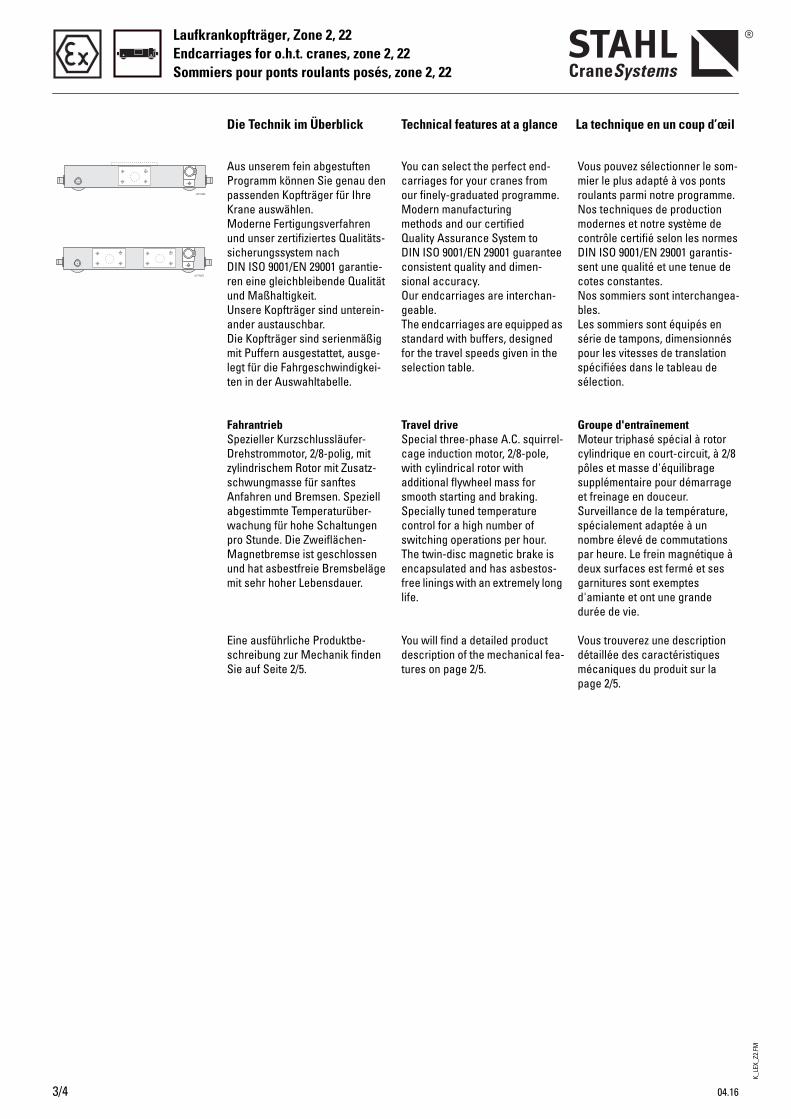
K_LE
X_Z2
.FM
3/4 04.16
Laufkrankopfträger, Zone 2, 22Endcarriages for o.h.t. cranes, zone 2, 22Sommiers pour ponts roulants posés, zone 2, 22
You can select the perfect end-carriages for your cranes from our finely-graduated programme.Modern manufacturing methods and our certified Quality Assurance System to DIN ISO 9001/EN 29001 guarantee consistent quality and dimen-sional accuracy. Our endcarriages are interchan-geable.The endcarriages are equipped as standard with buffers, designed for the travel speeds given in the selection table.
Travel driveSpecial three-phase A.C. squirrel-cage induction motor, 2/8-pole, with cylindrical rotor with additional flywheel mass for smooth starting and braking. Specially tuned temperature control for a high number of switching operations per hour. The twin-disc magnetic brake is encapsulated and has asbestos-free linings with an extremely long life.
You will find a detailed product description of the mechanical fea-tures on page 2/5.
Vous pouvez sélectionner le som-mier le plus adapté à vos ponts roulants parmi notre programme.Nos techniques de production modernes et notre système de contrôle certifié selon les normes DIN ISO 9001/EN 29001 garantis-sent une qualité et une tenue de cotes constantes. Nos sommiers sont interchangea-bles.Les sommiers sont équipés en série de tampons, dimensionnés pour les vitesses de translation spécifiées dans le tableau de sélection.
Groupe d'entraînementMoteur triphasé spécial à rotor cylindrique en court-circuit, à 2/8 pôles et masse d'équilibrage supplémentaire pour démarrage et freinage en douceur. Surveillance de la température, spécialement adaptée à un nombre élevé de commutations par heure. Le frein magnétique à deux surfaces est fermé et ses garnitures sont exemptes d'amiante et ont une grande durée de vie.
Vous trouverez une description détaillée des caractéristiques mécaniques du produit sur la page 2/5.
Aus unserem fein abgestuften Programm können Sie genau den passenden Kopfträger für Ihre Krane auswählen. Moderne Fertigungsverfahren und unser zertifiziertes Qualitäts-sicherungssystem nach DIN ISO 9001/EN 29001 garantie-ren eine gleichbleibende Qualität und Maßhaltigkeit. Unsere Kopfträger sind unterein-ander austauschbar.Die Kopfträger sind serienmäßig mit Puffern ausgestattet, ausge-legt für die Fahrgeschwindigkei-ten in der Auswahltabelle.
FahrantriebSpezieller Kurzschlussläufer-Drehstrommotor, 2/8-polig, mit zylindrischem Rotor mit Zusatz-schwungmasse für sanftes Anfahren und Bremsen. Speziell abgestimmte Temperaturüber-wachung für hohe Schaltungen pro Stunde. Die Zweiflächen-Magnetbremse ist geschlossen und hat asbestfreie Bremsbeläge mit sehr hoher Lebensdauer.
Eine ausführliche Produktbe-schreibung zur Mechanik finden Sie auf Seite 2/5.
Die Technik im Überblick Technical features at a glance La technique en un coup d’œil
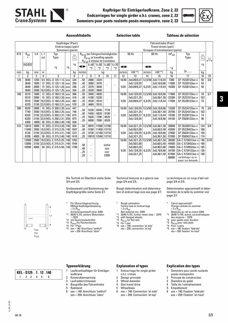
K_LE
X_Z2
.FM
04.16 3/5
Kopfträger für Einträgerlaufkrane, Zone 2, 22Endcarriages for single girder o.h.t. cranes, zone 2, 22
Sommiers pour ponts roulants posés monopoutre, zone 2, 22
3
Auswahltabelle Selection table Tableau de sélection
Kopfträger (Paar) Endcarriages (pair) Sommiers (paire)
Fahrantriebe (Paar)Travel drives (pair)
Groupes d’entraînement (paire)Ø D Rzul
*k 0 L 1
zulTyp
Type
*2 *5*4
Rid zul bei FahrgeschwindigkeitenRid zul at travelling speeds
Rid zul à vitesse de translation
50 Hz 60 Hz mFzul
*4
TypType
2x ......
*4(H2/B3) k=40 *3
k=50 *3
k=60 *3
k=70 *3
mm kg mm m kg m/min kg m/min kW *1 m/min kW *1 kg kg1 2 3 4 5 6 7 8 9 10 11 12 13 14 15 16 17 18 19
125 3640364036403640
1250160020002500
9,51215
18,5
KEL-S 125.1.12.KEL-S 125.1.16.KEL-S 125.1.20.KEL-S 125.1.25.
xxxxxxxxxxxx
224256296344
...50
...40
...25
...20
2880306033703520
3220347036403640
- -
10/40
5/20
2x0,09/0,372x0,13/0,552x0,09/0,37
12,5/50
6,3/25
2x0,11/0,442x0,16/0,662x0,11/0,44
72001100016300
SF 15220123ex nSF 15220133ex nSF 15226123ex n
505450
3/6
160 5510551055104370
1600200025003150
1215
18,523,5
KEL-S 160.2.16.KEL-S 160.2.20.KEL-S 160.2.25.KEL-S 160.2.31.
xxxxxxxxxxxx
366416482570
...50
...40
...25
...20
3940418045204660
4930523055105510
- -
10/40
5/20
2x0,13/0,552x0,32/1,252x0,09/0,37
12,5/50
6,3/25
2x0,16/0,662x0,36/1,502x0,11/0,44
119002320017400
SF 25222133ex nSF 25222313ex nSF 25228123ex n
7810274
3/7
200 85207740632063204300
2000250031503150 4000
1518,523,523,530
KEL-S 200.2.20.KEL-S 200.2.25.KEL-S 200.2.31.KEL-S 200.2.31.KEL-S 200.2.40.
xxxxxx140259140
447746875875939
...50
...40
...25
...20
5230545058306000
6540682072907500
7770810085208520
-
10/40
5/20
2x0,13/0,552x0,32/1,252x0,09/0,372x0,13/0,55
12,5/50
6,3/25
2x0,16/0,662x0,36/1,502x0,11/0,442x0,16/0,66
13200257001970024100
SF 25224133ex nSF 25224313ex nSF 25230123ex nSF 25830133ex n
781027496
3/8
315 126101104091206700
2000250031504000
1518,523,530
KEL-S 315.3.20.KEL-S 315.3.25.KEL-S 315.3.31.KEL-S 315.3.40.
140140140140
934104712211410
...50
...40
...25
...20
887091609730
10010
11090114501216012540
13190137101371013710
-
10/40
5/20
2x0,32/1,252x0,50/2,002x0,13/0,552x0,32/1,25
12,5/50
6,3/25
2x0,36/1,502x0,60/2,402x0,16/0,662x0,36/1,50
28900435002780057300
SF 35228313ex nSF 35228423ex nSF 35834133ex nSF 35834313ex n
154166150174
3/9
135001200010500
250031504000
18,523,530
KEL-E 315.5.25.KEL-E 315.5.31.KEL-E 315.5.40.
140140140
135215441796
...50
...40
...25
...20
----
sieheseevoirC095
10/40
5/20
2x0,32/1,252x0,50/2,002x0,80/3,202x0,13/0,552x0,32/1,25
12,5/50
6,3/25
2x0,36/1,502x0,60/2,402x0,90/3,802x0,16/0,662x0,36/1,50
302004550074600347006740080000
SA-C 5728313ex nSA-C 5728423ex nSA-C 5728523ex nSA-C 5734133ex nSA-C 5734313ex n
auf Anfrage / on re-quest / sur demande
146166185126146
3/10
Die Technik im Überblick siehe Seite 3/4 und 2/5.
Grobauswahl und Bestimmung der Kopfträgergröße siehe Seite 2/7.
Technical features at a glance see page 3/4 and 2/5.
Rough determination and determina-tion of endcarriage size see page 2/7.
La technique en un coup d’œil voir page 3/4 et 2/5.
Détermination approximatif et déter-mination de la taille du sommier voir page 2/7.
* Für Überschlagsrechnung: Mittige Kopfträgerbelastung = 2 x Rzul Schienenwerkstoff mind. S355
*1 20/40 % ED, weitere Motordaten ↑ C070
*2 mit Spurkranzlaufrollen*3 Rid zul für Flachschienen*4 Für 1 Paar*5 xxx = 140: Anschluss "seitlich"
xxx = 259: Anschluss "oben"
* Rough estimation: Centre load on endcarriage = 2 x RzulRail material min. S355
*1 20/40 % DC, further motor data ↑ C070*2 with flanged wheels*3 Rid zul for flat rails*4 For 1 pair*5 xxx = 140: connection "at side"
xxx = 259: connection "at top"
* Calcul approximatif : Charge centrée du sommier = 2 x RzulMatériau du rail au moins S355
*1 20/40 % FM, autres caractéristiques des moteurs ↑ C070
*2 avec galets avec boudins*3 Rid zul pour rails plats*4 Pour 1 paire*5 xxx = 140: fixation "latérale"
xxx = 259: fixation "en haut"
Typenerklärung Explanation of types Explication des types1 Laufkrankopftäger für Einträger-
laufkrane2 Konstruktionsprinzip3 Laufraddurchmesser4 Baugröße des Fahrantriebs5 Radstand6 xxx = 140: Anschluss "seitlich"
xxx = 259: Anschluss "oben"
1 Endcarriage for single girder o.h.t. cranes
2 Design principle3 Wheel diameter4 Size travel drive5 Wheelbase6 xxx = 140: Connection "at side"
xxx = 259: Connection "at top"
1 Sommiers pour ponts roulants posés monopoutre
2 Principe de construction3 Diamètre du galet4 Taille de l'entraînenment5 Empattement6 xxx = 140: Fixation "latérale"
xxx = 259: Fixation "en haut"
KEL - S 125 . 1 . 12 . 1401 2 3 4 5 6

K_LE
X_Z2
.FM
3/6 04.16
Kopfträger für Einträgerlaufkrane, Zone 2, 22Endcarriages for single girder o.h.t. cranes, zone 2, 22Sommiers pour ponts roulants posés monopoutre, zone 2, 22
Typ Type
*3 Anschluss Connection
Fixation
Rzul(H2/B3)
k 0 k 1 l 1*2
Rid *7k=40 k=50
kg mm mm mm kg m/min kg kgKEL-S 125.1.12. xxx ➀ ➁ 3640 1250 1782 1570 224 ...50
...40
...25
...20
2880306033703520
3220347036403640
KEL-S 125.1.16. xxx ➀ ➁ 3640 1600 2132 1920 256KEL-S 125.1.20. xxx ➀ ➁ 3640 2000 2532 2320 296KEL-S 125.1.25. xxx ➀ ➁ 3640 2500 3032 2820 344
50 Hz 60 Hz mFzul
*2
Typ Type
m0*2
m/min kW m/min kW kg mm kg10/40 2x 0,09/0,37
2x 0,13/0,5512,5/50 2x 0,11/0,44
2x 0,16/0,66720011000
2x SF 15220123ex n2x SF 15220133ex n
512512
5054
5/20 2x 0,09/0,37 6,3/25 2x 0,11/0,44 16300 2x SF 15226123ex n 512 50
< 300 < 290
c0100v081
1
2= =
l 1
k1
266266
106
Ø100100
A
A
120 182,5242
400490
k0
62,5
2
700590460
460
100
200
bmax=400
m0
"R"
"L"
"R" = rechte Ausführung/right-hand design/exécution droite"L" = linke Ausführung/left-hand design/exécution gauche
c0102v05
b1k
80
10
12,5
Ø 125
230
76
60 60
b 1 *1 50 60k 40 50
➁ KEL-S 125 ......259
➀ KEL-S 125 ......140
A : A
*1 Andere Laufradausdrehungen auf Anfrage
*2 Für 1 Paar*3 xxx = 140: Anschluss "seitlich"
xxx = 259: Anschluss "oben"*7 Rid zul für Flachschienen
*1 Other wheel treads on request*2 For 1 pair*3 xxx = 140: connection "at side"
xxx = 259: connection "at top"*7 Rid zul for flat rails
*1 Autres largeurs de gorge de galet sur demande
*2 Pour 1 paire*3 xxx = 140: fixation "latérale"
xxx = 259: fixation "en haut"*7 Rid zul pour rails plats
215
25
89
c0103v13
450 NmM20x75 tZn EN 14399-4
15
47,5
2003055
25
c0103v15
29
10
450 NmM20x75 tZn EN 14399-4
130
KEL-S 125..ex n Abmessungen [mm] Auswahltabelle ↑ 3/5
Dimensions [mm]Selection table ↑ 3/5
Dimensions [mm]Tableau de sélection ↑ 3/5
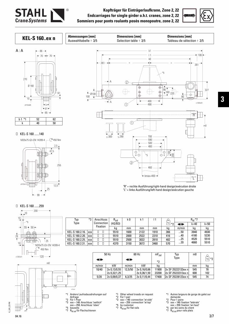
K_LE
X_Z2
.FM
04.16 3/7
Kopfträger für Einträgerlaufkrane, Zone 2, 22Endcarriages for single girder o.h.t. cranes, zone 2, 22
Sommiers pour ponts roulants posés monopoutre, zone 2, 22
3
Typ Type
*3 Anschluss Connection
Fixation
Rzul(H2/B3)
k 0 k 1 l 1*2
Rid *7k=40 k=50
kg mm mm mm kg m/min kg kgKEL-S 160.2.16. xxx ➀ ➁ 5510 1600 2122 1910 366 ...50
...40
...25
...20
3940418045204660
4930523055105510
KEL-S 160.2.20. xxx ➀ ➁ 5510 2000 2522 2310 416KEL-S 160.2.25. xxx ➀ ➁ 5510 2500 3022 2810 482KEL-S 160.2.31. xxx ➀ ➁ 4370 3150 3672 3460 570
50 Hz 60 Hz mFzul
*2
Typ Type
m0*2
m/min kW m/min kW kg mm kg10/40 2x 0,13/0,55
2x 0,32/1,2512,5/50 2x 0,16/0,66
2x 0,36/1,501190023200
2x SF 25222133ex n2x SF 25222313ex n
545600
78 102
5/20 2x 0,09/0,37 6,3/25 2x 0,11/0,44 17400 2x SF 25228123ex n 545 74
< 300 < 290
c1303v011
1
2
= =
l 1
k1
k0
261261
106
Ø100100
A
A
90160 220
327
400490
80
m0
*5
700590
460500
46010
020
0bmax=400
2
*5
"R"
"L"
"R" = rechte Ausführung/right-hand design/exécution droite"L" = linke Ausführung/left-hand design/exécution gauche
b 1 *1 52 62k 40 50
➁ KEL-S 160 ......259
➀ KEL-S 160 ......140
A : A
*1 Andere Laufradausdrehungen auf Anfrage
*2 Für 1 Paar*3 xxx = 140: Anschluss "seitlich"
xxx = 259: Anschluss "oben"*5 bauseits*7 Rid zul für Flachschienen
*1 Other wheel treads on request*2 For 1 pair*3 xxx = 140: connection "at side"
xxx = 259: connection "at top"*5 by customer*7 Rid zul for flat rails
*1 Autres largeurs de gorge de galet sur demande
*2 Pour 1 paire*3 xxx = 140: fixation "latérale"
xxx = 259: fixation "en haut"*5 par les soins du client*7 Rid zul pour rails plats
255
25
99
c0103v12
450 NmM20x75 tZn EN 14399-4
12,5
47,5
2,5
200
5055
25
c1302v01
29
10
450 NmM20x75 tZn EN 14399-4
120
*5
10
10
KEL-S 160..ex n Abmessungen [mm] Auswahltabelle ↑ 3/5
Dimensions [mm]Selection table ↑ 3/5
Dimensions [mm]Tableau de sélection ↑ 3/5

K_LE
X_Z2
.FM
3/8 04.16
Kopfträger für Einträgerlaufkrane, Zone 2, 22Endcarriages for single girder o.h.t. cranes, zone 2, 22Sommiers pour ponts roulants posés monopoutre, zone 2, 22
KEL-S 200..ex n Abmessungen [mm] Auswahltabelle ↑ 3/5
Dimensions [mm]Selection table ↑ 3/5
Dimensions [mm]Tableau de sélection ↑ 3/5
c130
4v01
220
30
3434
5450 Nm
M20x80 tZn EN 14399-4
115
*5
10
109555
Typ Type
*3 Anschluss Connection
Fixation
Rzul(H2/B3)
k 0 k 1 l 1*2
Rid *7k=40 k=50 k=60
kg mm mm mm kg m/min kg kg kgKEL-S 200.2.20. xxx ➀ ➁ 8520 2000 2596 2330 447 ...50
...40
...25
...20
5230545058306000
6540682072907500
7770810085208520
KEL-S 200.2.25. xxx ➀ ➁ 7740 2500 3096 2830 746KEL-S 200.2.31. xxx ➀ ➁ 6320 3150 3746 3480 875KEL-S 200.2.40. 140 ➀ 4300 4000 4596 4330 939
50 Hz 60 Hz mFzul
*2
Typ Type
m0*2
m/min kW m/min kW kg mm kg10/40 2x 0,13/0,55
2x 0,32/1,2512,5/50 2x 0,16/0,66
2x 0,36/1,501320025700
2x SF 25224133ex n2x SF 25224313ex n
575630
78 102
5/20 2x 0,09/0,372x 0,13/0,55
6,3/25 2x 0,11/0,442x 0,16/0,66
1970024100
2x SF 25230123ex n2x SF 25830133ex n
575575
7496
< 300 < 290
k 1
l 1
k 0
A
A
133 165
400
165
190
100
Ø125
500
157
347
c1305v01
130
m0
1
1
2
100
*5
700590
460500
460
120
220
bmin >300bmax 400≤
2
*5
"R"
"L""R" = rechte Ausführung/right-hand design/exécution droite"L" = linke Ausführung/left-hand design/exécution gauche
b 1 *1 54 64 74k *9 40-45 50-55 60-65
➁ KEL-S 200 ......259
➀ KEL-S 200 ......140
A : A
c0754v02
47,5
7,5
30133
285
19,5
450 NmM20x80 tZn EN 14399-4
*1 Andere Laufradausdrehungen auf Anfrage
*2 Für 1 Paar*3 xxx = 140: Anschluss "seitlich"
xxx = 259: Anschluss "oben"*5 bauseits*7 Rid zul für Flachschienen*9 Bei Schienenbreiten 45, 55 etc.
Hinweis C096 beachten
*1 Other wheel treads on request*2 For 1 pair*3 xxx = 140: connection "at side"
xxx = 259: connection "at top"*5 by customer*7 Rid zul for flat rails*9 For rail widths 45, 55, etc. observe
note C096
*1 Autres largeurs de gorge de galet sur demande
*2 Pour 1 paire*3 xxx = 140: fixation "latérale"
xxx = 259: fixation "en haut"*5 par les soins du client*7 Rid zul pour rails plats*9 Respectez les remarques C096 pour les
largeurs de rail 45, 55, etc.
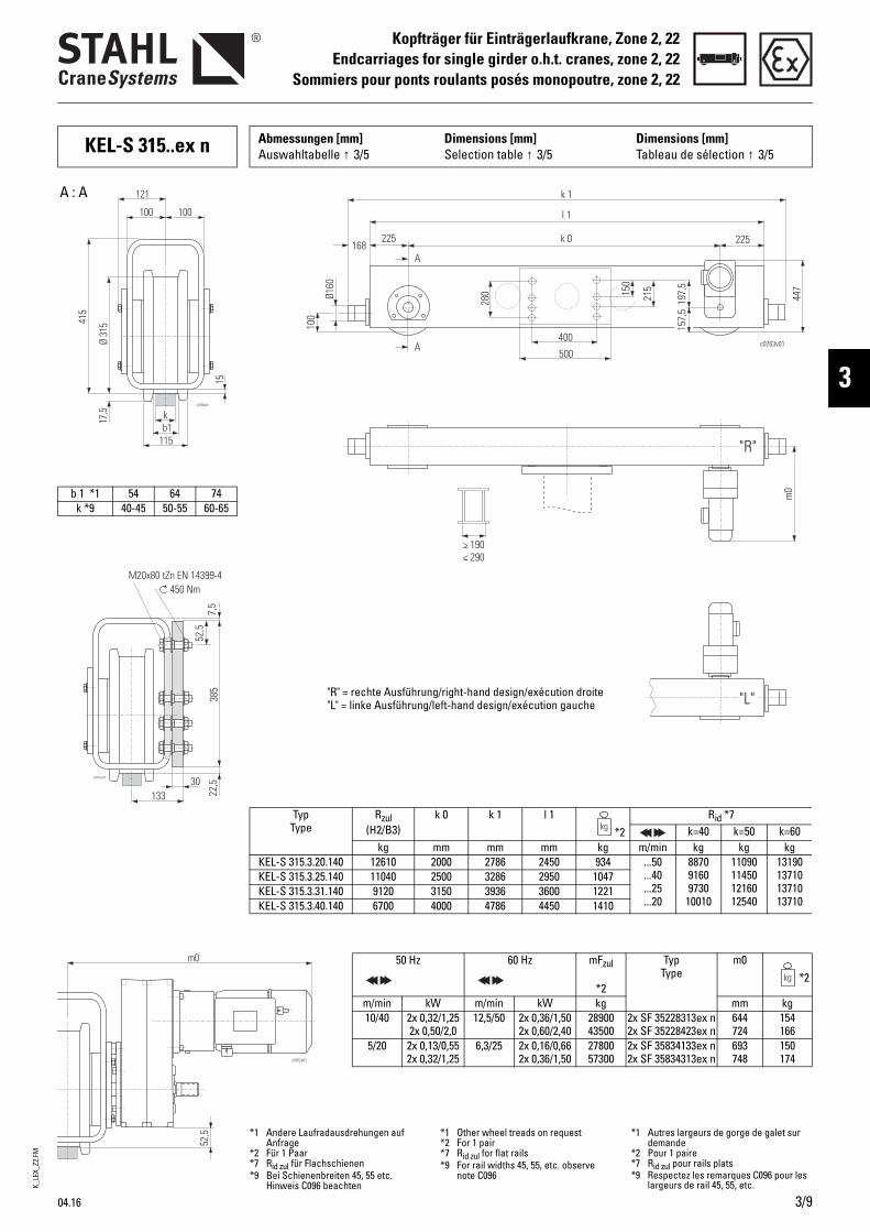
K_LE
X_Z2
.FM
04.16 3/9
Kopfträger für Einträgerlaufkrane, Zone 2, 22Endcarriages for single girder o.h.t. cranes, zone 2, 22
Sommiers pour ponts roulants posés monopoutre, zone 2, 22
3
KEL-S 315..ex n Abmessungen [mm] Auswahltabelle ↑ 3/5
Dimensions [mm]Selection table ↑ 3/5
Dimensions [mm]Tableau de sélection ↑ 3/5
Typ Type
Rzul(H2/B3)
k 0 k 1 l 1*2
Rid *7k=40 k=50 k=60
kg mm mm mm kg m/min kg kg kgKEL-S 315.3.20.140 12610 2000 2786 2450 934 ...50
...40
...25
...20
887091609730
10010
11090114501216012540
13190137101371013710
KEL-S 315.3.25.140 11040 2500 3286 2950 1047KEL-S 315.3.31.140 9120 3150 3936 3600 1221KEL-S 315.3.40.140 6700 4000 4786 4450 1410
50 Hz 60 Hz mFzul
*2
Typ Type
m0*2
m/min kW m/min kW kg mm kg10/40 2x 0,32/1,25
2x 0,50/2,012,5/50 2x 0,36/1,50
2x 0,60/2,402890043500
2x SF 35228313ex n2x SF 35228423ex n
644724
154166
5/20 2x 0,13/0,552x 0,32/1,25
6,3/25 2x 0,16/0,662x 0,36/1,50
2780057300
2x SF 35834133ex n2x SF 35834313ex n
693748
150174
> 190< 290
k 1
l 1
k 0
A
A
168225
400
225
280
100
Ø160
500
197,
5
c0763v01
215
447
m0
157,
5
150
"R"
"L""R" = rechte Ausführung/right-hand design/exécution droite"L" = linke Ausführung/left-hand design/exécution gauche
b 1 *1 54 64 74k *9 40-45 50-55 60-65
A : A
c0757v01
385
13330
52,5
22,5
7,5
450 NmM20x80 tZn EN 14399-4
*1 Andere Laufradausdrehungen auf Anfrage
*2 Für 1 Paar*7 Rid zul für Flachschienen*9 Bei Schienenbreiten 45, 55 etc.
Hinweis C096 beachten
*1 Other wheel treads on request*2 For 1 pair*7 Rid zul for flat rails*9 For rail widths 45, 55, etc. observe
note C096
*1 Autres largeurs de gorge de galet sur demande
*2 Pour 1 paire*7 Rid zul pour rails plats*9 Respectez les remarques C096 pour les
largeurs de rail 45, 55, etc.
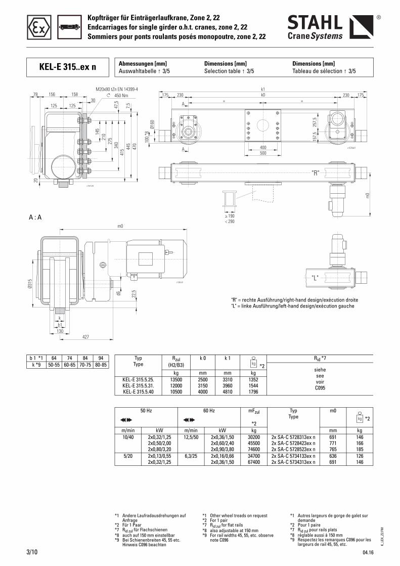
K_LE
X_Z2
.FM
3/10 04.16
Kopfträger für Einträgerlaufkrane, Zone 2, 22Endcarriages for single girder o.h.t. cranes, zone 2, 22Sommiers pour ponts roulants posés monopoutre, zone 2, 22
KEL-E 315..ex n Abmessungen [mm] Auswahltabelle ↑ 3/5
Dimensions [mm]Selection table ↑ 3/5
Dimensions [mm]Tableau de sélection ↑ 3/5
> 190< 290
"R"
"L"
257,
5
400500
A
A
= =k0k1
230175 230 175
Ø160
100
*8
157,
5
m0
c1579v01
22,5
c1580v01
d6
kb1
130427
Ø315
m0
b 1 *1 64 74 84 94k *9 50-55 60-65 70-75 80-85
Typ Type
Rzul(H2/B3)
k 0 k 1*2
Rid *7
sieheseevoirC095
kg mm mm kgKEL-E 315.5.25.KEL-E 315.5.31.KEL-E 315.5.40
135001200010500
250031504000
331039604810
135215441796
50 Hz 60 Hz mFzul
*2
Typ Type
m0*2
m/min kW m/min kW kg mm kg10/40 2x0,32/1,25
2x0,50/2,002x0,80/3,20
12,5/50 2x0,36/1,502x0,60/2,402x0,90/3,80
302004550074600
2x SA-C 5728313ex n2x SA-C 5728423ex n2x SA-C 5728523ex n
691771765
146166185
5/20 2x0,13/0,552x0,32/1,25
6,3/25 2x0,16/0,662x0,36/1,50
3470067400
2x SA-C 5734133ex n2x SA-C 5734313ex n
636691
126146
A : A
"R" = rechte Ausführung/right-hand design/exécution droite"L" = linke Ausführung/left-hand design/exécution gauche
450 NmM20x80 tZn EN 14399-4
27521
0145
340
415 44
547
07,
5
47,5
125 12530
15815678
20
c1531v05
*1 Andere Laufradausdrehungen auf Anfrage
*2 Für 1 Paar*7 Rid zul für Flachschienen*8 auch auf 150 mm einstellbar*9 Bei Schienenbreiten 45, 55 etc.
Hinweis C096 beachten
*1 Other wheel treads on request*2 For 1 pair*7 Rid zul for flat rails*8 also adjustable at 150 mm*9 For rail widths 45, 55, etc. observe
note C096
*1 Autres largeurs de gorge de galet sur demande
*2 Pour 1 paire*7 Rid zul pour rails plats*8 réglable aussi à 150 mm*9 Respectez les remarques C096 pour les
largeurs de rail 45, 55, etc.
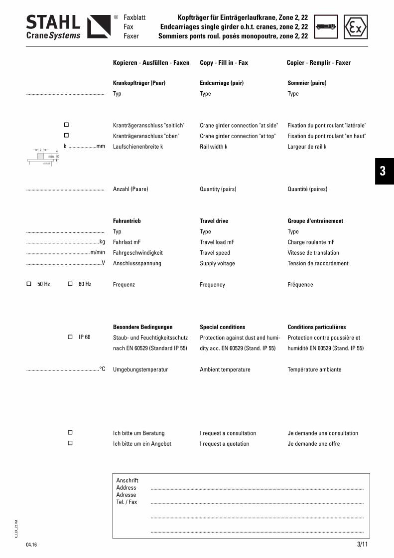
K_LE
X_Z2
.FM
04.16 3/11
Kopfträger für Einträgerlaufkrane, Zone 2, 22Endcarriages single girder o.h.t. cranes, zone 2, 22
Sommiers ponts roul. posés monopoutre, zone 2, 22
FaxblattFaxFaxer
3
AnschriftAddressAdresseTel. / Fax
.................................................................................................................................................................
.................................................................................................................................................................
.................................................................................................................................................................
.................................................................................................................................................................
...........................................................
k .....................mm
...........................................................
...........................................................
.......................................................kg
................................................ m/min
.........................................................V
50 Hz 60 Hz
IP 66
.......................................................°C
Kopieren - Ausfüllen - Faxen Copy - Fill in - Fax Copier - Remplir - Faxer
Endcarriage (pair)
Type
Crane girder connection "at side"
Crane girder connection "at top"
Rail width k
Quantity (pairs)
Travel drive
Type
Travel load mF
Travel speed
Supply voltage
Frequency
Special conditions
Protection against dust and humi-
dity acc. EN 60529 (Stand. IP 55)
Ambient temperature
I request a consultation
I request a quotation
Sommier (paire)
Type
Fixation du pont roulant "latérale"
Fixation du pont roulant "en haut"
Largeur de rail k
Quantité (paires)
Groupe d'entraînement
Type
Charge roulante mF
Vitesse de translation
Tension de raccordement
Fréquence
Conditions particulières
Protection contre poussière et
humidité EN 60529 (Stand. IP 55)
Température ambiante
Je demande une consultation
Je demande une offre
Krankopfträger (Paar)
Typ
Kranträgeranschluss "seitlich"
Kranträgeranschluss "oben"
Laufschienenbreite k
Anzahl (Paare)
Fahrantrieb
Typ
Fahrlast mF
Fahrgeschwindigkeit
Anschlussspannung
Frequenz
Besondere Bedingungen
Staub- und Feuchtigkeitsschutz
nach EN 60529 (Standard IP 55)
Umgebungstemperatur
Ich bitte um Beratung
Ich bitte um ein Angebot
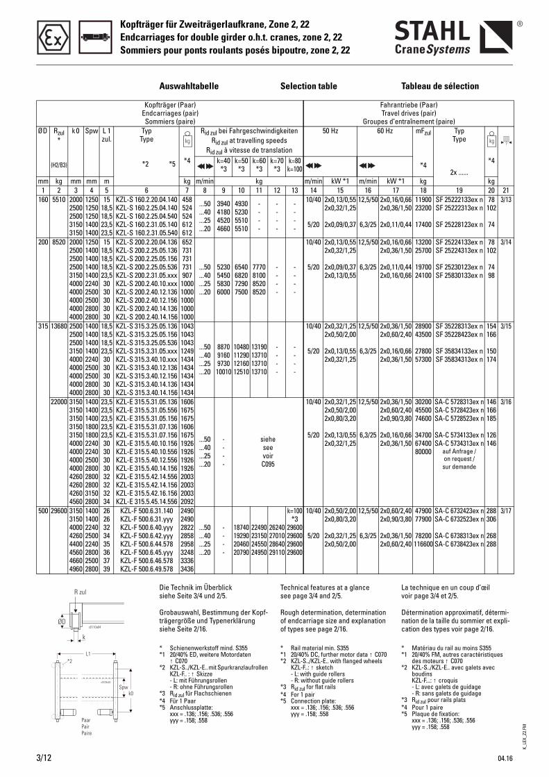
K_LE
X_Z2
.FM
3/12 04.16
Kopfträger für Zweiträgerlaufkrane, Zone 2, 22Endcarriages for double girder o.h.t. cranes, zone 2, 22Sommiers pour ponts roulants posés bipoutre, zone 2, 22
Auswahltabelle Selection table Tableau de sélection
Kopfträger (Paar) Endcarriages (pair) Sommiers (paire)
Fahrantriebe (Paar) Travel drives (pair)
Groupes d’entraînement (paire)Ø D Rzul
*
(H2/B3)
k 0 Spw L 1 zul.
Typ Type
*2 *5
Rid zul bei Fahrgeschwindigkeiten Rid zul at travelling speeds
Rid zul à vitesse de translation
50 Hz 60 Hz mFzul
*4
Typ Type
2x ......
*4 k=40 *3
k=50 *3
k=60 *3
k=70 *3
k=80k=100
*4
mm kg mm mm m kg m/min kg m/min kW *1 m/min kW *1 kg kg1 2 3 4 5 6 7 8 9 10 11 12 13 14 15 16 17 18 19 20 21
160 5510 2000 2500 2500 3150 3150
1250 1250 1250 1400 1400
15 18,5 18,5 23,5 23,5
KZL-S 160.2.20.04.140 KZL-S 160.2.25.04.140 KZL-S 160.2.25.04.540 KZL-S 160.2.31.05.140 KZL-S 160.2.31.05.540
458 524 524 612612
...50
...40
...25
...20
3940 4180 45204660
49305230 55105510
----
----
----
10/40
5/20
2x0,13/0,552x0,32/1,25
2x0,09/0,37
12,5/50
6,3/25
2x0,16/0,662x0,36/1,50
2x0,11/0,44
1190023200
17400
SF 25222133ex nSF 25222313ex n
SF 25228123ex n
78 102
74
3/13
200 8520 2000 2500 2500 2500 3150 4000 4000 4000 4000 4000
1250 1400 1400 1400 1400 2240 2500 2500 2800 2800
15 18,5 18,518,5 23,5 3030303030
KZL-S 200.2.20.04.136 KZL-S 200.2.25.05.136 KZL-S 200.2.25.05.156 KZL-S 200.2.25.05.536 KZL-S 200.2.31.05.xxx KZL-S 200.2.40.10.xxx KZL-S 200.2.40.12.136 KZL-S 200.2.40.12.156 KZL-S 200.2.40.14.136 KZL-S 200.2.40.14.156
652 731 731 731 907
1000 1000 1000 1000 1000
...50
...40
...25
...20
5230 5450 58306000
65406820 72907500
7770810085208520
----
----
10/40
5/20
2x0,13/0,552x0,32/1,25
2x0,09/0,372x0,13/0,55
12,5/50
6,3/25
2x0,16/0,662x0,36/1,50
2x0,11/0,442x0,16/0,66
1320025700
1970024100
SF 25224133ex nSF 25224313ex n
SF 25230123ex nSF 25830133ex n
78 102
74 98
3/14
315 13680 2500 2500 2500 3150 4000 4000 4000 4000 4000
1400 1400 1400 1400 2240 2500 2500 2800 2800
18,5 18,5 18,5 23,5 3030303030
KZL-S 315.3.25.05.136 KZL-S 315.3.25.05.156 KZL-S 315.3.25.05.536 KZL-S 315.3.31.05.xxx KZL-S 315.3.40.10.xxx KZL-S 315.3.40.12.136 KZL-S 315.3.40.12.156 KZL-S 315.3.40.14.136 KZL-S 315.3.40.14.156
1043 1043 1043 1249 1434 1434 1434 1434 1434
...50
...40
...25
...20
88709160 973010010
1048011290 1216012510
13190137101371013710
----
----
10/40
5/20
2x0,32/1,252x0,50/2,00
2x0,13/0,552x0,32/1,25
12,5/50
6,3/25
2x0,36/1,502x0,60/2,40
2x0,16/0,662x0,36/1,50
2890043500
2780057300
SF 35228313ex nSF 35228423ex n
SF 35834133ex nSF 35834313ex n
154166
150174
3/15
22000 3150315031503150315040004000400040004260426042604560
1400140014001800180022402240250028002800280031502800
23,523,523,523,523,53030303032323234
KZL-E 315.5.31.05.136KZL-E 315.5.31.05.556KZL-E 315.5.31.05.156KZL-E 315.5.31.07.136KZL-E 315.5.31.07.156KZL-E 315.5.40.10.156KZL-E 315.5.40.10.556KZL-E 315.5.40.12.556KZL-E 315.5.40.14.156KZL-E 315.5.42.14.556KZL-E 315.5.42.14.156KZL-E 315.5.42.16.156KZL-E 315.5.45.14.556
1606167516751606167519261926192619262003200320032092
...50
...40
...25
...20
----
sieheseevoirC095
10/40
5/20
2x0,32/1,252x0,50/2,002x0,80/3,20
2x0,13/0,552x0,32/1,25
12,5/50
6,3/25
2x0,36/1,502x0,60/2,402x0,90/3,80
2x0,16/0,662x0,36/1,50
302004550074600
347006740080000
SA-C 5728313ex nSA-C 5728423ex nSA-C 5728523ex n
SA-C 5734133ex nSA-C 5734313ex n
auf Anfrage / on request /
sur demande
146166185
126146
3/16
500 29600 3150 3150 4000 4260 4400 4560 4660 4960
1400 1400 2240 2500 2240 2800 2500 2800
2626323435363739
KZL-F 500.6.31.140 KZL-F 500.6.31.yyy KZL-F 500.6.40.yyy KZL-F 500.6.42.yyy KZL-F 500.6.44.578 KZL-F 500.6.45.yyy KZL-F 500.6.46.578 KZL-F 500.6.49.578
2490 2490 2822 2858 2958 3248 3336 3436
...50
...40
...25
...20
----
1874019290 2046020790
2249023150 2455024950
2624027010 2864029110
k=100 *3
2960029600 2960029600
10/40
5/20
2x0,50/2,002x0,80/3,20
2x0,32/1,252x0,50/2,00
12,5/50
6,3/25
2x0,60/2,402x0,90/3,80
2x0,36/1,502x0,60/2,40
4790077900
78200116600
SA-C 6732423ex nSA-C 6732523ex n
SA-C 6738313ex nSA-C 6738423ex n
288306
268288
3/17
Die Technik im Überblick siehe Seite 3/4 und 2/5.
Grobauswahl, Bestimmung der Kopf-trägergröße und Typenerklärung siehe Seite 2/16.
Technical features at a glance see page 3/4 and 2/5.
Rough determination, determination of endcarriage size and explanation of types see page 2/16.
La technique en un coup d’œil voir page 3/4 et 2/5.
Détermination approximatif, détermi-nation de la taille du sommier et expli-cation des types voir page 2/16.
* Schienenwerkstoff mind. S355*1 20/40% ED, weitere Motordaten
↑ C070*2 KZL-S../KZL-E.. mit Spurkranzlaufrollen
KZL-F.. : ↑ Skizze - L: mit Führungsrollen - R: ohne Führungsrollen
*3 Rid zul für Flachschienen*4 Für 1 Paar*5 Anschlussplatte:
xxx = .136; .156; .536; .556 yyy = .158; .558
* Rail material min. S355*1 20/40% DC, further motor data ↑ C070*2 KZL-S../KZL-E.. with flanged wheels
KZL-F..: ↑ sketch - L: with guide rollers - R: without guide rollers
*3 Rid zul for flat rails*4 For 1 pair*5 Connection plate:
xxx = .136; .156; .536; .556 yyy = .158; .558
* Matériau du rail au moins S355*1 20/40% FM, autres caractéristiques
des moteurs ↑ C070*2 KZL-S../KZL-E.. avec galets avec
boudins KZL-F...: ↑ croquis - L: avec galets de guidage - R: sans galets de guidage
*3 Rid zul pour rails plats*4 Pour 1 paire*5 Plaque de fixation:
xxx = .136; .156; .536; .556 yyy = .158; .558
R zul
ØD
k
c0110a04
*2
c0109a03
PaarPairPaire
Spwk0
L1
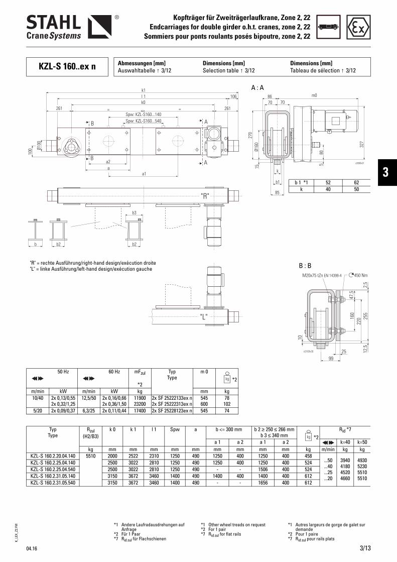
K_LE
X_Z2
.FM
04.16 3/13
Kopfträger für Zweiträgerlaufkrane, Zone 2, 22Endcarriages for double girder o.h.t. cranes, zone 2, 22
Sommiers pour ponts roulants posés bipoutre, zone 2, 22
3
KZL-S 160..ex n Abmessungen [mm] Auswahltabelle ↑ 3/12
Dimensions [mm]Selection table ↑ 3/12
Dimensions [mm]Tableau de sélection ↑ 3/12
50 Hz 60 Hz mFzul
*2
Typ Type
m 0 *2
m/min kW m/min kW kg mm kg10/40 2x 0,13/0,55
2x 0,32/1,2512,5/50 2x 0,16/0,66
2x 0,36/1,501190023200
2x SF 25222133ex n2x SF 25222313ex n
545600
78 102
5/20 2x 0,09/0,37 6,3/25 2x 0,11/0,44 17400 2x SF 25228123ex n 545 74
Typ Type
Rzul(H2/B3)
k 0 k 1 l 1 Spw a b <= 300 mm b 2 ≥ 250 ≤ 266 mm b 3 ≤ 340 mm *2
Rid *7
a 1 a 2 a 1 a 2 k=40 k=50kg mm mm mm mm mm mm mm mm mm kg m/min kg kg
KZL-S 160.2.20.04.140 5510 2000 2522 2310 1250 490 1250 400 1250 400 458...50...40...25...20
39404180 45204660
4930523055105510
KZL-S 160.2.25.04.140 2500 3022 2810 1250 490 1250 400 1250 400 524KZL-S 160.2.25.04.540 2500 3022 2810 1250 490 - - 1506 400 524KZL-S 160.2.31.05.140 3150 3672 3460 1400 490 1400 400 1400 400 612KZL-S 160.2.31.05.540 3150 3672 3460 1400 490 - - 1656 400 612
= =
l 1k1
k0106
Ø100
100
B
B
Spw: KZL-S160...540Spw: KZL-S160...140
a2a
a1
b b2 b2
c0800v01
m0
580
k
b1
85
70 7086
1527
0
327
Ø160
261 261
A
A
b3
"R"
"L"
b 1 *1 52 62k 40 50
A : A
B : B"R" = rechte Ausführung/right-hand design/exécution droite"L" = linke Ausführung/left-hand design/exécution gauche
*1 Andere Laufradausdrehungen auf Anfrage
*2 Für 1 Paar*7 Rid zul für Flachschienen
*1 Other wheel treads on request*2 For 1 pair*7 Rid zul for flat rails
*1 Autres largeurs de gorge de galet sur demande
*2 Pour 1 paire*7 Rid zul pour rails plats
47,5
255
22016
025
10
99
c0103v20
450 NmM20x75 tZn EN 14399-4
2,5
12,5

K_LE
X_Z2
.FM
3/14 04.16
Kopfträger für Zweiträgerlaufkrane, Zone 2, 22Endcarriages for double girder o.h.t. cranes, zone 2, 22Sommiers pour ponts roulants posés bipoutre, zone 2, 22
KZL-S 200..ex n Abmessungen [mm] Auswahltabelle ↑ 3/12
Dimensions [mm]Selection table ↑ 3/12
Dimensions [mm]Tableau de sélection ↑ 3/12
50 Hz 60 Hz mFzul
*2
Typ Type
m 0 *2
m/min kW m/min kW kg mm kg10/40 2x 0,13/0,55
2x 0,32/1,2512,5/50 2x 0,16/0,66
2x 0,36/1,501320025700
2x SF 25224133ex n2x SF 25224313ex n
575630
78 102
5/20 2x 0,09/0,37 2x 0,13/0,55
6,3/25 2x 0,11/0,44 2x 0,16/0,66
1970024100
2x SF 25230123ex n2x SF 25830133ex n
575679
7498
Typ Type
Rzul (H2/B3)
k 0 k 1 l 1 Spw a b <= 300 mm b1 = 300 mm b 2 ≥ 250 ≤ 266 mm
b 3 <= 340 mm
b1 = 500 mm b 2 ≥ 450 ≤ 466 mm
b 3 <= 540 mm*2
Rid *7
a 1 a 2 a 1 a 2 a 1 a 2 k=40 k=50 k=60kg mm mm mm mm mm mm mm mm mm mm mm kg m/min kg kg kg
KZL-S 200.2.20.04.136 8520 2000 2596 2330 1250 460 1250 360 - - - - 652
...50
...40
...25
...20
52305450 58306000
65406820 72907500
7770810085208520
KZL-S 200.2.25.05.136 KZL-S 200.2.25.05.156 KZL-S 200.2.25.05.536
2500 3096 2830 1400 460 660 460
1400 - -
360 - -
1400 -
1656
360 -
360
- 1400
-
- 560
-
731
KZL-S 200.2.31.05.136 KZL-S 200.2.31.05.156 KZL-S 200.2.31.05.536 KZL-S 200.2.31.05.556
3150 3746 3480 1400 460 660 460 660
1400 - - -
360 - - -
1400 -
1656 -
360 -
360 -
- 1400
- 1856
- 560
- 560
907
KZL-S 200.2.40.10.136 KZL-S 200.2.40.10.156 KZL-S 200.2.40.10.536 KZL-S 200.2.40.10.556 KZL-S 200.2.40.12.136 KZL-S 200.2.40.12.156 KZL-S 200.2.40.14.136 KZL-S 200.2.40.14.156
4000 4596 4330 2240 2240 2240 2240 2500 2500 2800 2800
460 660 460 660 460 660 460 660
2240 - - -
2500 -
2800 -
360 - - -
360 -
360 -
2240 -
2496 -
2500 -
2800 -
360 -
360 -
360 -
360 -
- 2240
- 2696
- 2500
- 2800
- 560
- 560
- 560
- 560
1000
= =
l 1k1
k0133
B
B
Spw: KZL-S200...5..Spw: KZL-S200...1..
a2a
a1
b b2 b2b1
298 298
KZL-S...136 KZL-S...156KZL-S...536, KZL-S...556
m0
c0801v01
15 100
k
b1
100
100 100119
1531
4
347
Ø200
133165 165
Ø125
100
A
A
b3
"R"b 1 *1 54 64 74
k *9 40-45 50-55 60-65
A : A
B : B
"R" = rechte Ausführung/right-hand design/exécution droite
c0754v03 25128
450 NmM20x75 tZn EN 14399-4
47,5
285
25919
0
7,5
21,5
14
*1 Andere Laufradausdrehungen auf Anfrage
*2 Für 1 Paar*7 Rid zul für Flachschienen*9 Bei Schienenbreiten 45, 55 etc.
Hinweis C096 beachten
*1 Other wheel treads on request*2 For 1 pair*7 Rid zul for flat rails*9 For rail widths 45, 55, etc. observe
note C096
*1 Autres largeurs de gorge de galet sur demande
*2 Pour 1 paire*7 Rid zul pour rails plats*9 Respectez les remarques C096 pour les
largeurs de rail 45, 55, etc.
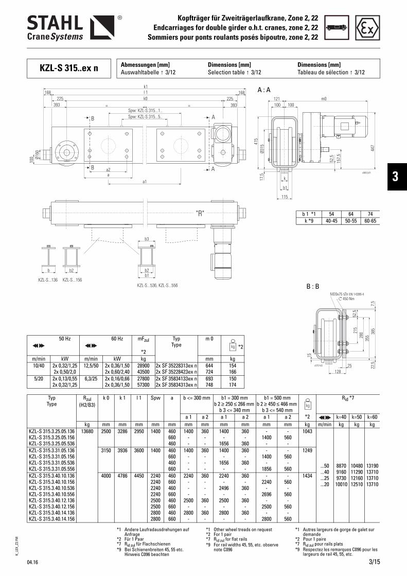
K_LE
X_Z2
.FM
04.16 3/15
Kopfträger für Zweiträgerlaufkrane, Zone 2, 22Endcarriages for double girder o.h.t. cranes, zone 2, 22
Sommiers pour ponts roulants posés bipoutre, zone 2, 22
3
KZL-S 315..ex n Abmessungen [mm] Auswahltabelle ↑ 3/12
Dimensions [mm]Selection table ↑ 3/12
Dimensions [mm]Tableau de sélection ↑ 3/12
50 Hz 60 Hz mFzul
*2
Typ Type
m 0 *2
m/min kW m/min kW kg mm kg10/40 2x 0,32/1,25
2x 0,50/2,012,5/50 2x 0,36/1,50
2x 0,60/2,402890043500
2x SF 35228313ex n2x SF 35228423ex n
644724
154166
5/20 2x 0,13/0,552x 0,32/1,25
6,3/25 2x 0,16/0,662x 0,36/1,50
2780057300
2x SF 35834133ex n2x SF 35834313ex n
693748
150174
Typ Type
Rzul (H2/B3)
k 0 k 1 l 1 Spw a b <= 300 mm b1 = 300 mm b 2 ≥ 250 ≤ 266 mm
b 3 <= 340 mm
b1 = 500 mm b 2 ≥ 450 ≤ 466 mm
b 3 <= 540 mm*2
Rid *7
a 1 a 2 a 1 a 2 a 1 a 2 k=40 k=50 k=60kg mm mm mm mm mm mm mm mm mm mm mm kg m/min kg kg kg
KZL-S 315.3.25.05.136 KZL-S 315.3.25.05.156 KZL-S 315.3.25.05.536
13680 2500 3286 2950 1400 460 660 460
1400 - -
360 - -
1400 -
1656
360 -
360
- 1400
-
- 560
-
1043
...50
...40
...25
...20
88709160 973010010
1048011290 1216012510
13190137101371013710
KZL-S 315.3.31.05.136 KZL-S 315.3.31.05.156 KZL-S 315.3.31.05.536 KZL-S 315.3.31.05.556
3150 3936 3600 1400 460 660 460 660
1400 - - -
360 - - -
1400 -
1656 -
360 -
360 -
- 1400
- 1856
- 560
- 560
1249
KZL-S 315.3.40.10.136 KZL-S 315.3.40.10.156 KZL-S 315.3.40.10.536 KZL-S 315.3.40.10.556 KZL-S 315.3.40.12.136 KZL-S 315.3.40.12.156 KZL-S 315.3.40.14.136 KZL-S 315.3.40.14.156
4000 4786 4450 2240 2240 2240 2240 2500 2500 2800 2800
460 660 460 660 460 660 460 660
2240 - - -
2500 -
2800 -
360 - - -
360 -
360 -
2240 -
2496 -
2500 -
2800 -
360 -
360 -
360 -
360 -
- 2240
- 2696
- 2500
- 2800
- 560
- 560
- 560
- 560
1434
= =
l 1k1
k0168
B
B
Spw: KZL-S 315...5..Spw: KZL-S 315...1..
a2a
a1
b b2 b2
393 393
KZL-S...136 KZL-S...156KZL-S...536, KZL-S...556
m0
c0802v01
52,5
157,
5
k
b1
115
100 100121
17,5
415
447
Ø315
168225 225
Ø160
100
A
A
b3
b1
"R" b 1 *1 54 64 74k *9 40-45 50-55 60-65
A : A
B : B
c0757v02
450 NmM20x75 tZn EN 14399-4
52,5
385
35528
0215
7,5
22,525
15
128
*1 Andere Laufradausdrehungen auf Anfrage
*2 Für 1 Paar*7 Rid zul für Flachschienen*9 Bei Schienenbreiten 45, 55 etc.
Hinweis C096 beachten
*1 Other wheel treads on request*2 For 1 pair*7 Rid zul for flat rails*9 For rail widths 45, 55, etc. observe
note C096
*1 Autres largeurs de gorge de galet sur demande
*2 Pour 1 paire*7 Rid zul pour rails plats*9 Respectez les remarques C096 pour les
largeurs de rail 45, 55, etc.
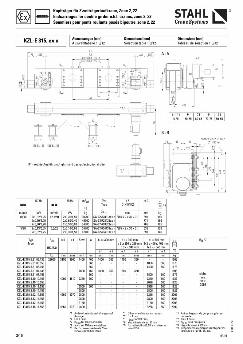
K_LE
X_Z2
.FM
3/16 04.16
Kopfträger für Zweiträgerlaufkrane, Zone 2, 22Endcarriages for double girder o.h.t. cranes, zone 2, 22Sommiers pour ponts roulants posés bipoutre, zone 2, 22
KZL-E 315..ex n Abmessungen [mm] Auswahltabelle ↑ 3/12
Dimensions [mm]Selection table ↑ 3/12
Dimensions [mm]Tableau de sélection ↑ 3/12
"R"
"L"
257,
5
a2a
a1
AB
AB
k0k1
Spw: KZL-E 315...1..Spw: KZL-E 315...5..
230175 230 175
Ø160
100
*8
157,
5
m0
c1581v01
b b2 b2
KZL-E...136 KZL-E...156 KZL-E...556
b3
b1
22,5
d6
kb1
130427
Ø315
m0
50 Hz 60 Hz mFzul
*2
Typ Type
2x ....
d 6 (DIN 5480)
m 0 *2
m/min kW m/min kW kg mm mm kg10/40 2x0,32/1,25
2x0,50/2,002x0,80/3,20
12,5/50 2x0,36/1,502x0,60/2,402x0,90/3,80
302004550074600
SA-C 5728313ex nSA-C 5728423ex nSA-C 5728523ex n
N65 x 2 x 30 x 31 691771765
146166185
5/20 2x0,13/0,552x0,32/1,25
6,3/25 2x0,16/0,662x0,36/1,50
3470067400
SA-C 5734133ex nSA-C 5734313ex n
N65 x 2 x 30 x 31 635691
126146
Typ Type
Rzul
(H2/B3)
k 0 k 1 Spw a b <= 300 mm b1 = 300 mm b 2 ≥ 250 ≤ 266 mm
b 3 <= 340 mm
b1 = 500 mm b 2 ≥ 450 ≤ 466 mm
b 3 <= 540 mm*2
Rid *7
a 1 a 2 a 1 a 2 a 1 a 2
sieheseevoirC095
kg mm mm mm mm mm mm mm mm mm mm kgKZL-E 315.5.31.05.136KZL-E 315.5.31.05.556KZL-E 315.5.31.05.156
22000 3150 3960 1400 460660660
1400--
360--
1400--
360--
-18561400
-560560
160616751675
KZL-E 315.5.31.07.136KZL-E 315.5.31.07.156
1800 460660
1800-
360-
1800-
360-
-1800
-560
16061675
KZL-E 315.5.40.10.156KZL-E 315.5.40.10.556
4000 4810 2240 660 --
--
--
--
22402696
560560
19261926
KZL-E 315.5.40.12.556 2500 660 - - - - 2956 560 1926KZL-E 315.5.40.14.156 2800 - - - - 2800 560 1926KZL-E 315.5.42.14.556 4260 5070 2800 - - - - 3256 560 2003KZL-E 315.5.42.14.156 2800 - - - - 2800 560 2003KZL-E 315.5.42.16.156 3150 - - - - 3150 560 2003KZL-E 315.5.45.14.556 4560 5370 2800 - - - - 3256 560 2092
A : A
b 1 *1 64 74 84 94k *9 50-55 60-65 70-75 80-85
B : B
"R" = rechte Ausführung/right-hand design/exécution droite
450 NmM20x75 tZn EN 14399-4
27521
0145
340
415 44
547
07,
5
47,5
125 12525
15315678
20
c1532v03
*1 Andere Laufradausdrehungen auf Anfrage
*2 Für 1 Paar*7 Rid zul für Flachschienen*8 auch auf 150 mm einstellbar*9 Bei Schienenbreiten 45, 55 etc.
Hinweis C096 beachten
*1 Other wheel treads on request*2 For 1 pair*7 Rid zul for flat rails*8 also adjustable at 150 mm*9 For rail widths 45, 55, etc. observe
note C096
*1 Autres largeurs de gorge de galet sur demande
*2 Pour 1 paire*7 Rid zul pour rails plats*8 réglable aussi à 150 mm*9 Respectez les remarques C096 pour les
largeurs de rail 45, 55, etc.
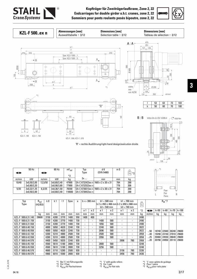
K_LE
X_Z2
.FM
04.16 3/17
Kopfträger für Zweiträgerlaufkrane, Zone 2, 22Endcarriages for double girder o.h.t. cranes, zone 2, 22
Sommiers pour ponts roulants posés bipoutre, zone 2, 22
3
KZL-F 500..ex n Abmessungen [mm] Auswahltabelle ↑ 3/12
Dimensions [mm]Selection table ↑ 3/12
Dimensions [mm]Tableau de sélection ↑ 3/12
c0819v01
61 250
*1
155
Ø200
a 1 *1255
b b2 b2
KZL-F...140 KZL-F...158KZL-F...558, KZL-F...578
k 1l 1k 0215 310 310
Spw: KZL-F 500-...5..Spw: KZL-F 500-...1..
B
B
A
A
352
a 2a
121
Ø 200
30
251415
125
Ø 50
0595
kl
120131
≥40
d6
m0b3
b1
sieheseevoir A230
"R"
50 Hz 60 Hz mFzul
*2
Typ Type
2x ....
d 6 (DIN 5480)
m 0 *2
m/min kW m/min kW kg mm mm kg10/40 2x0,50/2,00
2x0,80/3,2012,5/50 2x0,60/2,40
2x0,90/3,804790077900
SA-C 6732423ex nSA-C 6732523ex n
N65 x 2 x 30 x 31 784778
288306
5/20 2x0,32/1,252x0,50/2,00
6,3/25 2x0,36/1,502x0,60/2,40
78200116600
SA-C 6738313ex nSA-C 6738423ex n
N65 x 2 x 30 x 31 704784
268288
Typ Type
Rzul (H2/B3)
k 0 k 1 l 1 Spw a b <= 300 mm b1 = 500 mm b 2 ≥ 450 ≤ 466 mm
b3 = 540 mm
b1 = 700 mm b 2 ≥ 650 ≤ 666 mm
b3 = 740 mm*2
Rid *7
a 1 a 2 a 1 a 2 a 1 a 2 k=50 k=60 k=70 k=100kg mm mm mm mm mm mm mm mm mm mm mm kg m/min kg kg kg kg
KZL-F 500.6.31.140 29600 3150 4200 3770 1400 550 1400 400 - - - - 2490
...50
...40
...25
...20
18740192902046020790
22940231502455024950
26240270102864029110
29600296002960029600
KZL-F 500.6.31.158 3150 4200 3770 1400 730 - - 1400 580 - - 2490KZL-F 500.6.31.558 3150 4200 3770 1400 730 - - 1856 580 - - 2490KZL-F 500.6.40.158 4000 5050 4620 2240 730 - - 2240 580 - - 2822KZL-F 500.6.40.558 4000 5050 4620 2240 730 - - 2696 580 - - 2822KZL-F 500.6.42.158 4260 5310 4880 2500 730 - - 2500 580 - - 2858KZL-F 500.6.42.558 4260 5310 4880 2500 730 - - 2956 580 - - 2858KZL-F 500.6.44.578 4400 5450 5020 2240 930 - - - - 2896 780 2958KZL-F 500.6.45.158 4560 5610 5180 2800 730 - - 2800 580 - - 3248KZL-F 500.6.45.558 4560 5610 5180 2800 730 - - 3256 580 - - 3248KZL-F 500.6.46.578 4660 5710 5280 2500 930 - - - - 3156 780 3336KZL-F 500.6.49.578 4960 6010 5580 2800 930 - - - - 3456 780 3436
l 53 63 73 103k 50 60 70 100
A : A
B : B
"R" = rechte Ausführung/right-hand design/exécution droite
*1 Bei "L" mit Führungsrolle*2 Für 1 Paar*7 Rid zul für Flachschienen
*1 "L" with guide rollers*2 For 1 pair*7 Rid zul for flat rails
*1 "L" avec galets de guidage*2 Pour 1 paire*7 Rid zul pour rails plats
30
25
159
1650 NmM30x105 tZn EN 14399-4
c0820v01
102,
5 7,5
555
350
485
200
32,5
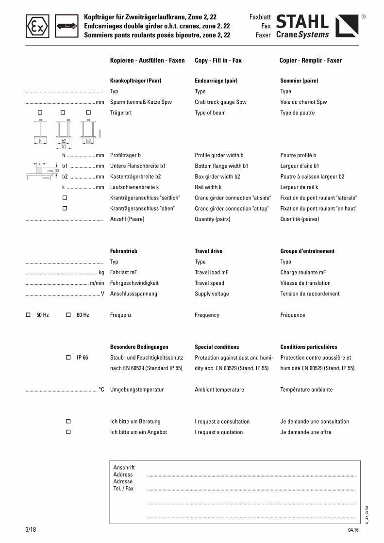
K_LE
X_Z2
.FM
3/18 04.16
Kopfträger für Zweiträgerlaufkrane, Zone 2, 22Endcarriages double girder o.h.t. cranes, zone 2, 22Sommiers ponts roulants posés bipoutre, zone 2, 22
FaxblattFax
Faxer
Endcarriage (pair)
Type
Crab track gauge Spw
Type of beam
Profile girder width b
Bottom flange width b1
Box girder width b2
Rail width k
Crane girder connection "at side"
Crane girder connection "at top"
Quantity (pairs)
Travel drive
Type
Travel load mF
Travel speed
Supply voltage
Frequency
Special conditions
Protection against dust and humi-
dity acc. EN 60529 (Stand. IP 55)
Ambient temperature
I request a consultation
I request a quotation
Sommier (paire)
Type
Voie du chariot Spw
Type de poutre
Poutre profilé b
Largeur d'aile b1
Poutre à caisson largeur b2
Largeur de rail k
Fixation du pont roulant "latérale"
Fixation du pont roulant "en haut"
Quantité (paires)
Groupe d'entraînement
Type
Charge roulante mF
Vitesse de translation
Tension de raccordement
Fréquence
Conditions particulières
Protection contre poussière et
humidité EN 60529 (Stand. IP 55)
Température ambiante
Je demande une consultation
Je demande une offre
Krankopfträger (Paar)
Typ
Spurmittenmaß Katze Spw
Trägerart
Profilträger b
Untere Flanschbreite b1
Kastenträgerbreite b2
Laufschienenbreite k
Kranträgeranschluss "seitlich"
Kranträgeranschluss "oben"
Anzahl (Paare)
Fahrantrieb
Typ
Fahrlast mF
Fahrgeschwindigkeit
Anschlussspannung
Frequenz
Besondere Bedingungen
Staub- und Feuchtigkeitsschutz
nach EN 60529 (Standard IP 55)
Umgebungstemperatur
Ich bitte um Beratung
Ich bitte um ein Angebot
............................................................
......................................................mm
b ...................... mm
b1 .................... mm
b2 .................... mm
k ...................... mm
............................................................
............................................................
........................................................ kg
................................................. m/min
..........................................................V
50 Hz 60 Hz
IP 66
........................................................ °C
Kopieren - Ausfüllen - Faxen Copy - Fill in - Fax Copier - Remplir - Faxer
AnschriftAddressAdresseTel. / Fax
..................................................................................................................................................................
..................................................................................................................................................................
..................................................................................................................................................................
..................................................................................................................................................................
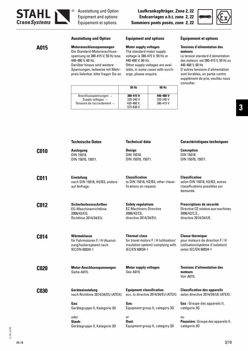
K_LE
X_Z2
.FM
04.16
Laufkrankopfträger, Zone 2, 22Endcarriages o.h.t, zone 2, 22
Sommiers ponts posés, zone 2, 22
Ausstattung und OptionEquipment and optionsÉquipement et options
3
A015
C010
C011
C012
C014
C020
C030
Équipement et options
Tensions d'alimentation des moteursLa tension standard d'alimentation des moteurs est 380-415 V, 50 Hz ou 440-480 V, 60 Hz.D'autres tensions d'alimentation sont livrables, en partie contre supplément de prix, veuillez nous consulter.
Caractéristiques techniques
ConceptionDIN 15018.DIN 15070, 15071.
Classificationselon DIN 15018, H2/B3, autres classifications possibles sur demande.
Prescriptions de sécuritéDirective CE relative aux machines 2006/42/C.E., directive 2014/34/UE.
Classe thermiquepour moteurs de direction F / H (utilisation/système d'isolation) selon IEC/EN 60034-1
Tensions d'alimentation des moteursVoir A015.
Classification des appareilsselon directive 2014/34/UE (ATEX) :
Gaz : Groupe des appareils II, catégorie 3G
ouPoussière : Groupe des appareils II, catégorie 3D
Equipment and options
Motor supply voltagesThe standard motor supply voltage is 380-415 V, 50 Hz or 440-480 V, 60 Hz.Other supply voltages are avai-lable, in some cases with surch-arge, please enquire.
Technical data
DesignDIN 15018.DIN 15070, 15071.
Classificationto DIN 15018, H2/B3, other classi-fications on request.
Safety regulationsEC Machinery Directive 2006/42/CE, directive 2014/34/EU.
Thermal classfor travel motors F / H (utilisation/insulation system) complying with IEC/EN 60034-1
Motor supply voltagesSee A015.
Equipment classificationacc. to directive 2014/34/EU (ATEX):
Gas: Equipment group II, category 3G
orDust: Equipment group II, category 3D
50 Hz 60 Hz
380-415 V220-240 V420-460 V,575-630 V
440-480 V220-240 V380-415 V
Ausstattung und Option
MotoranschlussspannungenDie Standard-Motoranschluss-spannung ist 380-415 V, 50 Hz bzw. 440-480 V, 60 Hz.Darüber hinaus sind weitere Spannungen, teilweise mit Mehr-preis lieferbar, bitte fragen Sie an.
Technische Daten
AuslegungDIN 15018.DIN 15070, 15071.
Einstufungnach DIN 15018, H2/B3, andere auf Anfrage.
SicherheitsvorschriftenEG-Maschinenrichtlinie 2006/42/EG, Richtlinie 2014/34/EU.
Wärmeklassefür Fahrmotoren F / H (Ausnut-zung/Isoliersystem) nach IEC/EN 60034-1
Motor-AnschlussspannungenSiehe A015.
Geräteeinstufungnach Richtlinie 2014/34/EU (ATEX):
Gas: Gerätegruppe II, Kategorie 3G
oderStaub: Gerätegruppe II, Kategorie 3D
Anschlussspannungen →Supply voltages →
Tensions de raccordement →
3/19

K_LE
X_Z2
.FM
3/20
Laufkrankopfträger, Zone 2, 22Endcarriages o.h.t, zone 2, 22Sommiers ponts posés, zone 2, 22
Technische DatenTechnical data
Caractéristiques techniques
C031
C040
C050
C070
C095
C096
Protection antidéflagrante selon NE/C.E.I.
Type de protection NE 60529/C.E.I.Standard: IP 55Option ou zone 22: IP 66
Températures ambiantes admissiblesStandard: -20 °C...+40 °C, autres températures ambiantes sur demande.
Moteurs de directionVoir Informations sur le produit "Groupes d’entraînement antidé-flagrants".
Charges idéales admissibles par galetVoir chapitre 2, C095.
Propriétés requises du système rail/galetVoir chapitre 2, C096.
Gaz :II 3G Ex nA IIC T3 GcII 3G ck llB T4
ouPoussière :
ll 3D Ex tc lllC T120°C Dcll 3D ck T120°C
Explosion protection to EN/IEC
Protection class EN 60529 / IECStandard: IP 55Option or zone 22: IP 66
Permissible ambient tempera-turesStandard: -20 °C...+40 °C, other ambient temperatures on request.
Travel motorsSee Product information "Explo-sion-protected travel drives".
Permissible ideal wheel loadsSee chapter 2, C095.
Requirements on wheel/rail systemSee chapter 2, C096.
Gas:II 3G Ex nA IIC T3 GcII 3G ck llB T4
orDust:
ll 3D Ex tc lllC T120°C Dcll 3D ck T120°C
Explosionsschutz nach EN/IEC
Schutzart EN 60529 / IECStandard: IP 55Option bzw. Zone 22: IP 66
Zulässige Umgebungstemperatu-renStandard: -20 °C...+40 °C, andere Umgebungstemperaturen auf Anfrage.
FahrmotorenSiehe Produktinformation "Explo-sionsgeschützte Fahrantriebe".
Zulässige ideelle RadlastenSiehe Kapitel 2, C095.
Anforderungen an das Rad-/SchienesystemSiehe Kapitel 2, C096.
Gas:II 3G Ex nA IIC T3 GcII 3G ck llB T4
oderStaub:
ll 3D Ex tc lllC T120°C Dcll 3D ck T120°C
04.16
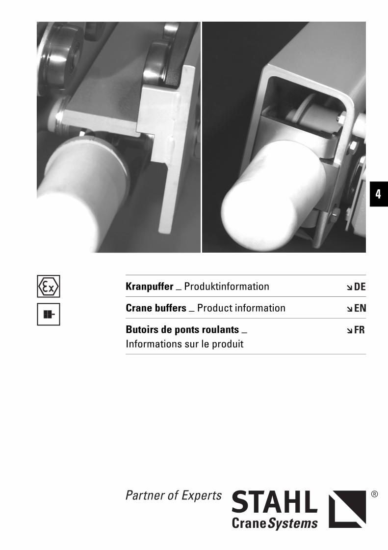
Kranpuffer _ Produktinformation
Crane buffers _ Product information
Butoirs de ponts roulants _ Informations sur le produit
4

KPEX
.FM
4/2 04.16
KranpufferCrane buffersButoirs de ponts roulants
Diese Komponenten sind wichtige Bauteile der qualitativ hochwertigen Krane von STAHL CraneSystems.
Eine wirtschaftliche, zertifizierte Serienfertigung garantiert eine gleichbleibend hohe Qualität.
Die Krankomponenten bewähren sich im täglichen Einsatz tausend-fach.
Nutzen Sie diese Vorteile auch für Ihren Kranbau.
These components are important parts of STAHL CraneSystems’ high-quality cranes.
Economical, certified series production guarantees consistently high quality.
The crane components have proven themselves in thousands of applications in day-to-day use.
Make use of these advantages for your crane manufacturing.
Ces composants sont des ensembles importants des palans et ponts roulants de haute qualité de STAHL CraneSystems.
Une fabrication en série, rentable, garantit une haute qualité constante.
Les composants pour ponts roulants donnent de bons résultats dans des milliers de cas d'utilisation de tous les jours.
Profitez aussi de ces avantages pour la construction de vos ponts roulants.

KPEX
.FM
04.16 4/3
KranpufferCrane buffers
Butoirs de ponts roulants
4
Inhaltsverzeichnis Contents Indice
Kranpuffer .......................................4/4 Crane buffers.................................. 4/4 Butoirs de ponts roulants............. 4/4
Technische Änderungen, Irrtümer und Druckfehler vorbehalten.
Subject to alterations, errors and printing errors excepted.
Sous réserve de modifications, d’erreurs et de fautes d’impression.
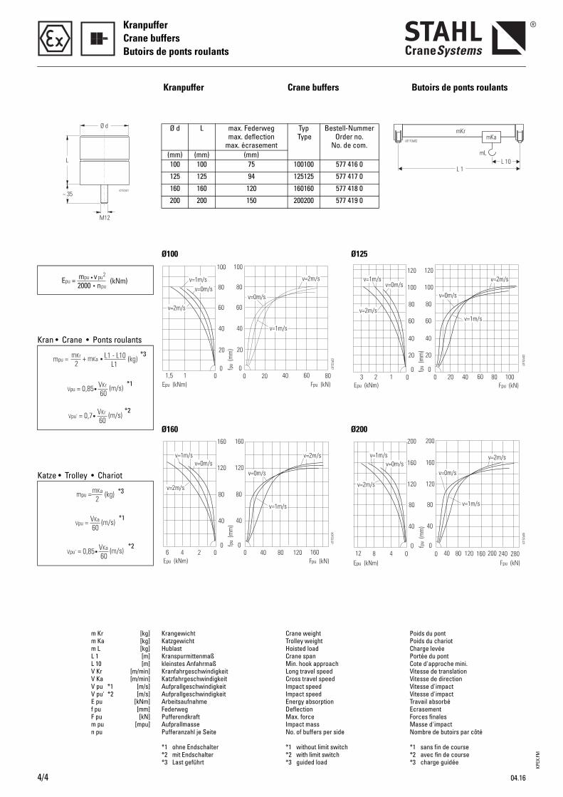
KPEX
.FM
4/4 04.16
KranpufferCrane buffersButoirs de ponts roulants
Kranpuffer Crane buffers Butoirs de ponts roulants
Ø100
Ø d L max. Federweg max. deflection
max. écrasement
Typ Type
Bestell-Nummer Order no.
No. de com.(mm) (mm) (mm)100 100 75 100100 577 416 0
125 125 94 125125 577 417 0
160 160 120 160160 577 418 0
200 200 150 200200 577 419 0
Kran • Crane • Ponts roulants
Katze • Trolley • Chariot
*1
*3
*2
*1
*3
*2
Ø125
Ø160 Ø200
m Kr [kg]m Ka [kg]m L [kg]L 1 [m]L 10 [m]V Kr [m/min]V Ka [m/min]V pu *1 [m/s]V pu' *2 [m/s]E pu [kNm]f pu [mm]F pu [kN]m pu [mpu]n pu
Krangewicht Katzgewicht Hublast Kranspurmittenmaß kleinstes Anfahrmaß Kranfahrgeschwindigkeit Katzfahrgeschwindigkeit Aufprallgeschwindigkeit AufprallgeschwindigkeitArbeitsaufnahme Federweg Pufferendkraft Aufprallmasse Pufferanzahl je Seite
*1 ohne Endschalter*2 mit Endschalter*3 Last geführt
Crane weight Trolley weight Hoisted load Crane span Min. hook approach Long travel speed Cross travel speed Impact speedImpact speedEnergy absorptionDeflectionMax. forceImpact massNo. of buffers per side
*1 without limit switch*2 with limit switch*3 guided load
Poids du pontPoids du chariotCharge levéePortée du pontCote d'approche mini.Vitesse de translationVitesse de directionVitesse d'impactVitesse d'impactTravail absorbéEcrasementForces finales Masse d'impactNombre de butoirs par côté
*1 sans fin de course*2 avec fin de course*3 charge guidée

Prin
ted
in G
erm
any
Sac
h-N
r. 99
0 237
0 F
-PI-
9.5-
DE/
EN/F
R-04
.16-v
STAHL CraneSystems GmbH Daimlerstr. 6, 74653 Künzelsau, Germany Tel +49 7940 128-0, Fax +49 7940 [email protected]
Argentina Australia Austria Belgium Brazil Bulgaria Canada Chile
China Columbia Croatia Cyprus Czech Republic Denmark Ecuador Egypt Estonia Finland France Germany Great Britain Greece Hongkong Hungary India
Indonesia Iran Ireland Israel Italy Jordan Korea (South) Latvia Libanon
Libya Lithuania Malaysia Mexico Netherlands Norway
Pakistan Peru Poland Portugal Romania Russia Singapore Slovakia Slovenia South Afrika Spain
Sweden Switzerland Syria Taiwan Venezuela Vietnam Thailand Turkey UAE Uruguay USA
Vertriebspartner Tochtergesellschaften
Argentina Australia Austria Belgium Brazil Canada Chile China Columbia Croatia Czech Republic
Denmark Ecuador Egypt Estonia Finland France Germany Great Britain Greece Hongkong Hungary India Indonesia
Ireland Israel Italy Jordan Latvia Lebanon Lithuania Malaysia Mexico
Netherlands Nigeria Norway Pakistan Peru Philippines Poland Portugal Rumania Russia
Taiwan Thailand Turkey UAE Uruguay USA Venezuela Vietnam Singapore Slovakia Slovenia South Africa South Korea Spain Sweden Syria
Sales partners Subsidiaries
Presented by
Subsidiaries
ChinaShanghaiTel +86 21 66083737Fax +86 21 [email protected]
FranceParisTel +33 1 39985060Fax +33 1 [email protected]
Great BritainWarwickshireTel +44 1675 437 280Fax +44 1675 437 [email protected]
IndiaChennaiTel +91 44 43523955Fax +91 44 [email protected]
PortugalLisbonTel +351 21 4447160Fax +351 21 [email protected]
SingaporeSingaporeTel +65 6268 9228Fax +65 6268 [email protected]
SpainMadridTel +34 91 4840865 Fax +34 91 [email protected]
United Arab EmiratesDubaiTel +971 4 8053700Fax +971 4 [email protected]
USACharleston, SCTel +1 843 7671951Fax +1 843 [email protected]
Sales partners
You will find the addresses of over 140 sales partners on the Internet at www.stahlcranes.com under contact.


![Eurocode 1-Partie 5 Actions Induites Par Les Ponts Roulants---FA100321[1]](https://img.pdfslide.org/doc/110x75/5572119f497959fc0b8f3ed8/eurocode-1-partie-5-actions-induites-par-les-ponts-roulants-fa1003211.jpg)