Embed Size (px)
Citation preview
10.2014
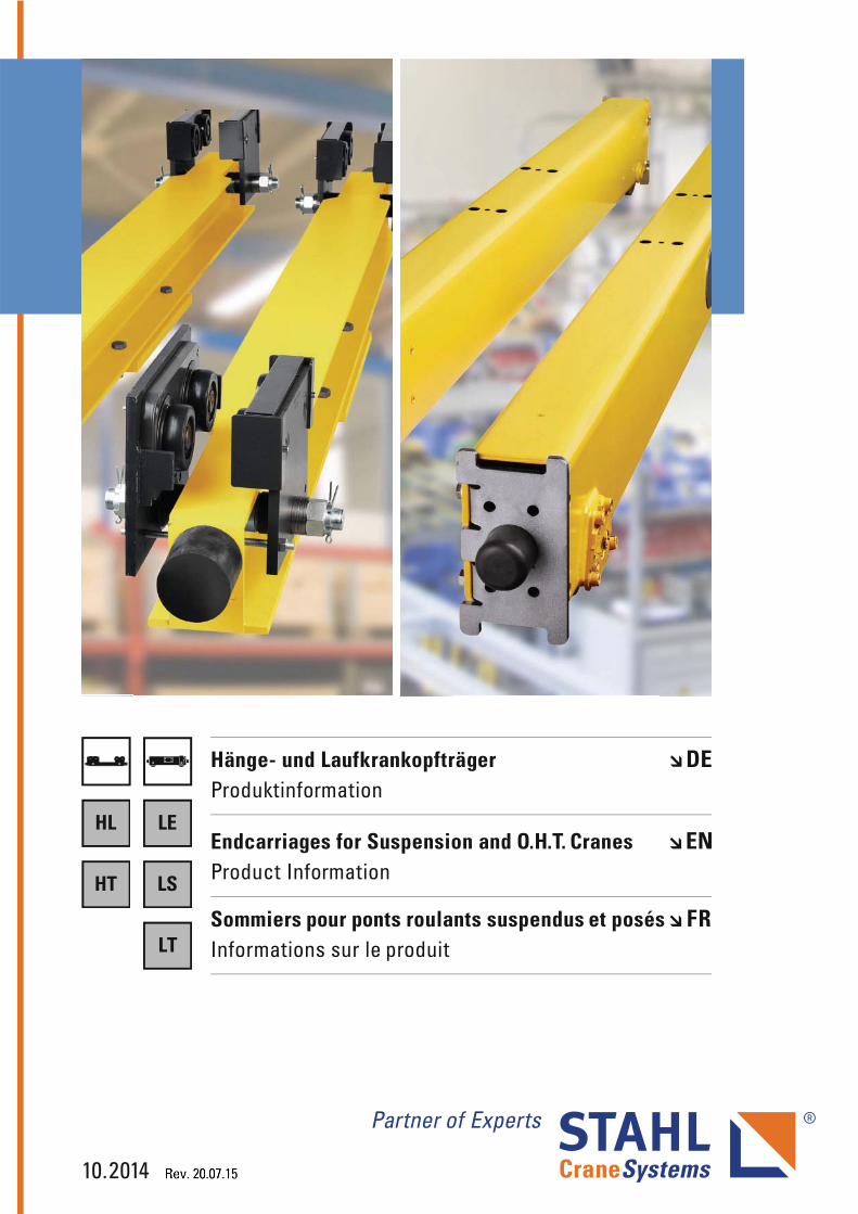
Sommiers pour ponts roulants suspendus et posésInformations sur le produit
Hänge- und LaufkrankopfträgerProduktinformation
Endcarriages for Suspension and O.H.T. CranesProduct Information
HL LE
LS
LT
HT
HL-T
_LS-
T.FM
2 10.14
Gültigkeit
Die vorliegende Auflage der Produktinformation für Hänge- und Laufkrankopfträger ist ab 10.2014 gültig und ersetzt damit alle vorigen Produktinformatio-nen.
STAHL CraneSystems steht für Weiterentwicklung, Verbesse-rung und Innovation. Aus diesem Grund müssen wir uns Änderun-gen der technischen Daten, Maße, Gewichte, Konstruktions-zeichnungen sowie der Lieferter-mine vorbehalten. Die Abbildungen dienen der anschaulichen Information, sind jedoch nicht verbindlich. Irrtümer und Druckfehler sind vorbehalten.
Diese Produktinformation dient zur manuellen Auslegung von Kopfträgern. Die Ergebnisse kön-nen von denen aus Konfigura-tionsprogrammen abweichen.
Validity
This edition of the Product Information brochure for endcarriages for suspension and overhead travelling cranes is valid from 10.2014 and supersedes all previous product information brochures.
STAHL CraneSystems stands for further development, improvement and innovation. We must therefore reserve the right to modify technical data, dimensions, weights, design drawings and delivery dates.The drawings serve to illustrate the products but are not binding.Errors and printing errors are excepted.
This Product Information bro-chure permits the manual config-uration of endcarriages. The results may differ from those pro-vided by configuration programs.
Validité
Cette édition des Informations sur le produit pour les sommiers pour ponts roulants suspendus et posés est valable à partir de 10.2014 et remplace ainsi toutes Informations sur le produit précé-dentes.
STAHL CraneSystems signifie l'évolution, le perfectionnement et l'innovation. Par conséquence nous devons nous réserver le droit de modifier les caractéri-stiques techniques, dimensions, poids, les plans de construction ainsi que les délais de livraison.Les illustrations servent à la clarté de l’information, mais ne revêtent pas de caractère obligatoire. Sous réserve d’erreurs et de fautes d’impression.
Ces Informations sur le produit servent à calculer manuellement les sommiers. Les résultats peu-vent différer de ceux qu'on obtient d'un programme de configuration.

HL-T
_LS-
T.FM
10.14 3
Inhalt Table of contents Table des matières
Hängekrankopfträger Endcarriages for Suspension Cranes
Sommiers pour ponts roulants suspendus 1
Laufkrankopfträger Endcarriages for O.H.T. Cranes Sommiers pour ponts roulants posés 2
Sonstige Komponenten Other Components Autres composants
3

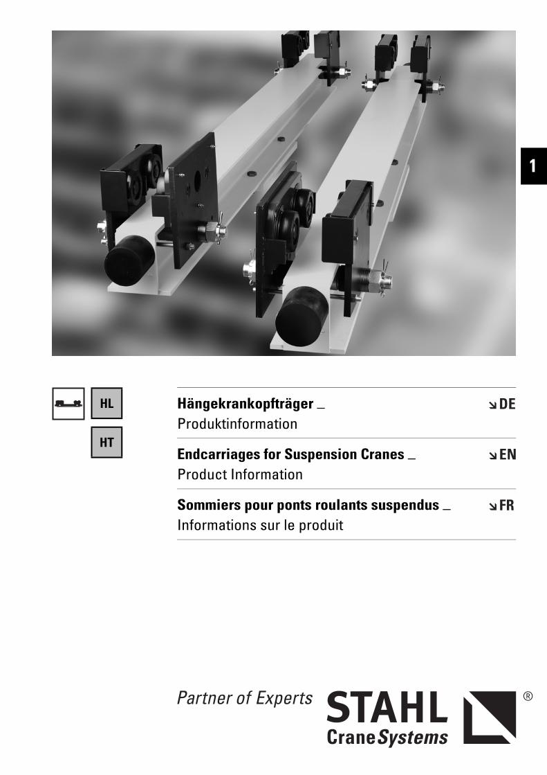
Hängekrankopfträger _ Produktinformation
Endcarriages for Suspension Cranes _ Product Information
Sommiers pour ponts roulants suspendus _ Informations sur le produit
1
HL
HT
HL-T
_01.
FM
HängekrankopfträgerEndcarriages for suspension cranesSommiers pour ponts roulants suspendus
HLHT
Mit den Hängekrankopfträgern HL/HT können moderne Hänge-krane bis zu einer Tragfähigkeit von 16.000 kg bzw. 20.000 kg bei kleinen Spannweiten gebaut wer-den.
Nutzen Sie die robuste Konstruk-tion, kompakte Bauweise, War-tungsfreundlichkeit und Zuver-lässigkeit in Verbindung mit den wirtschaftlichen Vorteilen der Serienfertigung für Ihren Kran-bau.
Modern small-span suspension cranes up to a working load of 16,000 kg or 20,000 kg can be manufactured on the basis of HL/HT endcarriages for suspen-sion cranes.
Make use of their sturdy design, compact construction, mainte-nance friendliness and reliability in conjunction with the economic advantages of series production for your crane manufacturing.
Avec les sommiers pour ponts roulants suspendus HL/HT, il peut être construit des ponts roulants suspendus modernes ayant une charge d'utilisation allant jusqu'à 16.000 kg resp. 20.000 kg et des portées basses.
Profitez de la construction robuste et compacte, de la facilité d'entretien et de la fiabilité allant de pair avec les avantages éco-nomiques de la fabrication en série pour votre construction de ponts roulants.
Symbole Symbols Symboles
Maximale Tragfähigkeit [kg] Maximum working load [kg] Charge maximale d’utilisation [kg]
Gewicht [kg] Weight [kg] Poids [kg]
Fahrgeschwindigkeit [m/min] Travel speed [m/min] Vitesse de déplacement [m/min]
Abmessungen siehe Seite .. Dimensions see page .. Dimensions voir page ..
↑ Siehe Seite .. See page .. Voir page ..
6 10.14
HL-T
_01.
FMHängekrankopfträger
Endcarriages for suspension cranesSommiers pour ponts roulants suspendus
1
Inhaltsverzeichnis Table of contents Table des matières
Symbole.............................................. 6 Symbols.............................................. 6 Symboles ............................................6
1 Die Technik im Überblick ............... 8 Technical features at a glance...... 8 La technique en un coup d’oeil ......81.1 Ausstattung........................................ 8 Equipment .......................................... 8 Équipement.........................................81.2 Typenbezeichnung.......................... 10 Type designation............................. 10 Désignation du type ........................10
2 Auswahlanleitung.......................... 11 Selection instructions................... 11 Instructions pour la sélection ......112.1 Grobauswahl ................................... 11 Rough determination...................... 11 Détermination approximatif...........112.2 Bestimmung der Kopfträgergröße11 Determination of endcarriage size 11 Détermination de la taille du som-
mier....................................................112.3 Bestimmung des Fahrantriebs...... 11 Determination of travel drive........ 11 Détermination de l'entraînement..112.4 Bestimmung des Kranpuffers ....... 11 Determination of crane buffer...... 11 Détermination du butoir .................112.4.1 Pufferauswahltabelle..................... 12 Buffer selection table .................... 12 Sélection du butoir..........................122.5 Fahrbahnendanschläge................. 12 Runway end stops .......................... 12 Butées de fin de chemin de roule-
ment...................................................122.6 Erklärung der Abkürzungen .......... 13 Explanation of abbreviations ........ 13 Explication des abbréviations .......13
3 Abmessungen.................................. 14 Dimensions...................................... 14 Dimensions ......................................14Hängekrankopfträger Endcarriages for suspension
cranesSommiers pour ponts roulants suspendus
HL08................................................... 14 HL08 .................................................. 14 HL08 ...................................................14HL10................................................... 16 HL10 .................................................. 16 HL10 ...................................................16HL13................................................... 18 HL13 .................................................. 18 HL13 ...................................................18HL20................................................... 20 HL20 .................................................. 20 HL20 ...................................................20HT10 .................................................. 22 HT10 .................................................. 22 HT10...................................................22HT13 .................................................. 24 HT13 .................................................. 24 HT13...................................................24HT20 .................................................. 26 HT20 .................................................. 26 HT20...................................................26
4 Optionen........................................... 28 Options ............................................. 28 Options..............................................284.1 Lackierung/Korrosionsschutz....... 28 Paint/corrosion protection............ 28 Peinture/protection anticorrosive .284.2 Pufferverlängerung ........................ 29 Buffer extension ............................. 29 Rallonge de butoir ...........................294.3 Horizontale Führungsrollen........... 30 Horizontal guide rollers ................. 30 Galets de guidage horizontaux .....304.4 Vertikale Führungsrollen ............... 31 Vertical guide rollers...................... 31 Galets de guidage verticaux..........314.5 Erdungsbürste (Schienenräumer). 32 Earth brush (rail sweep) ................ 32 Balai de mise à la terre (balai de
rail) .....................................................324.6 Montagehilfe ................................... 32 Assembly help tool ......................... 32 Dispositif de montage.....................324.7 Verdrehsicherung........................... 33 Anti-skew support .......................... 33 Sécurité antirotation.......................33
5 Technische Daten........................... 34 Technical data ................................ 34 Caractéristiques techniques ........345.1 Übersicht Kopfträgeranschluss-
kombinationen................................. 34Summary of endcarriage connec-tion combinations ........................... 34
Vue d’ensemble des combinaisons des fixations de sommier ...............34
5.2 Zulässige ideelle Ecklasten aus Lagerlebensdauer........................... 34
Permissible ideal corner loads cal-culated on the basis of bearing life34
Charges angulaires idéales admis-sibles selon la durée de vie des paliers................................................34
5.2.1 HL08................................................... 34 HL08 .................................................. 34 HL08 ...................................................345.2.2 HL/HT10 ............................................ 34 HL/HT10 ............................................ 34 HL/HT10.............................................345.2.3 HL/HT13 ............................................ 34 HL/HT13 ............................................ 34 HL/HT13.............................................345.2.4 HL/HT20 ............................................ 34 HL/HT20 ............................................ 34 HL/HT20.............................................34
Technische Änderungen, Irrtümer und Druckfehler vorbehalten.
Subject to technical modifications, errors and printing errors excepted.
Sous réserve de modifications techni-ques, d’erreurs et de fautes d’impres-sion.
10.14 7
HL-T
_01.
FM
HängekrankopfträgerEndcarriages for suspension cranesSommiers pour ponts roulants suspendus
Die Technik im ÜberblickTechnical features at a glanceLa technique en un coup d’oeil
1 Die Technik im Überblick Technical features at a glance La technique en un coup d’oeil
HL
HT
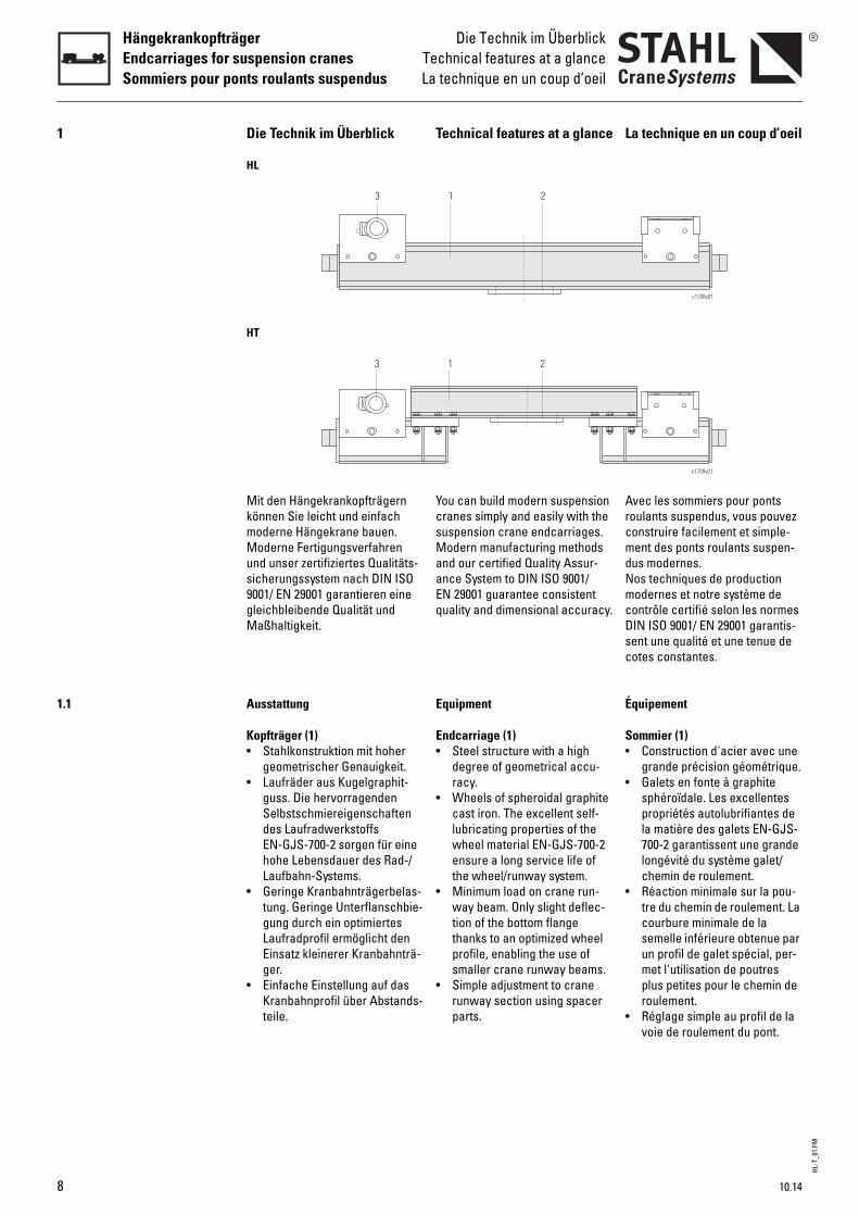
Mit den Hängekrankopfträgern können Sie leicht und einfach moderne Hängekrane bauen.Moderne Fertigungsverfahren und unser zertifiziertes Qualitäts-sicherungssystem nach DIN ISO 9001/ EN 29001 garantieren eine gleichbleibende Qualität und Maßhaltigkeit.
You can build modern suspension cranes simply and easily with the suspension crane endcarriages.Modern manufacturing methods and our certified Quality Assur-ance System to DIN ISO 9001/EN 29001 guarantee consistent quality and dimensional accuracy.
Avec les sommiers pour ponts roulants suspendus, vous pouvez construire facilement et simple-ment des ponts roulants suspen-dus modernes.Nos techniques de production modernes et notre système de contrôle certifié selon les normes DIN ISO 9001/ EN 29001 garantis-sent une qualité et une tenue de cotes constantes.
1.1 Ausstattung Equipment Équipement
Kopfträger (1)• Stahlkonstruktion mit hoher
geometrischer Genauigkeit.• Laufräder aus Kugelgraphit-
guss. Die hervorragenden Selbstschmiereigenschaften des Laufradwerkstoffs EN-GJS-700-2 sorgen für eine hohe Lebensdauer des Rad-/ Laufbahn-Systems.
• Geringe Kranbahnträgerbelas-tung. Geringe Unterflanschbie-gung durch ein optimiertes Laufradprofil ermöglicht den Einsatz kleinerer Kranbahnträ-ger.
• Einfache Einstellung auf das Kranbahnprofil über Abstands-teile.
Endcarriage (1)• Steel structure with a high
degree of geometrical accu-racy.
• Wheels of spheroidal graphite cast iron. The excellent self-lubricating properties of the wheel material EN-GJS-700-2 ensure a long service life of the wheel/runway system.
• Minimum load on crane run-way beam. Only slight deflec-tion of the bottom flange thanks to an optimized wheel profile, enabling the use of smaller crane runway beams.
• Simple adjustment to crane runway section using spacer parts.
Sommier (1)• Construction d'acier avec une
grande précision géométrique.• Galets en fonte à graphite
sphéroïdale. Les excellentes propriétés autolubrifiantes de la matière des galets EN-GJS-700-2 garantissent une grande longévité du système galet/chemin de roulement.
• Réaction minimale sur la pou-tre du chemin de roulement. La courbure minimale de la semelle inférieure obtenue par un profil de galet spécial, per-met l'utilisation de poutres plus petites pour le chemin de roulement.
• Réglage simple au profil de la voie de roulement du pont.
c1708v01
3 1 2
c1709v01
3 1 2
8 10.14
HL-T
_01.
FMDie Technik im ÜberblickTechnical features at a glanceLa technique en un coup d’oeil
HängekrankopfträgerEndcarriages for suspension cranes
Sommiers pour ponts roulants suspendus
1
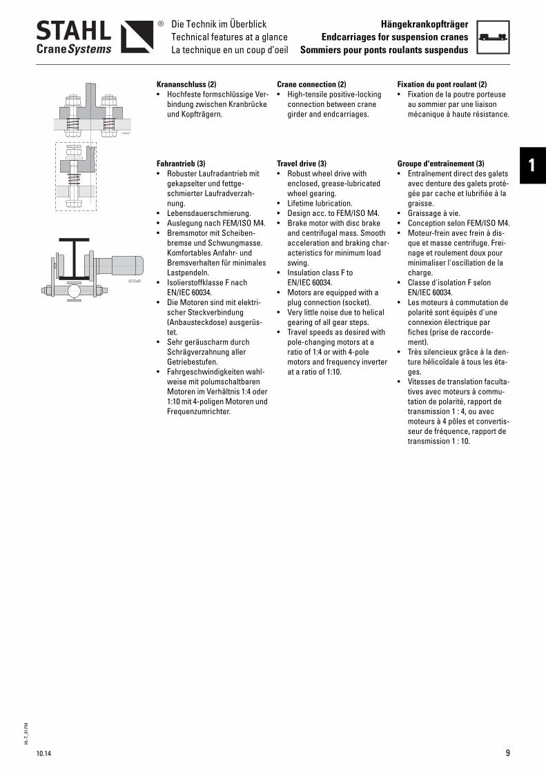
Krananschluss (2)• Hochfeste formschlüssige Ver-
bindung zwischen Kranbrücke und Kopfträgern.
Fahrantrieb (3)• Robuster Laufradantrieb mit
gekapselter und fettge-schmierter Laufradverzah-nung.
• Lebensdauerschmierung.• Auslegung nach FEM/ISO M4.• Bremsmotor mit Scheiben-
bremse und Schwungmasse. Komfortables Anfahr- und Bremsverhalten für minimales Lastpendeln.
• Isolierstoffklasse F nach EN/IEC 60034.
• Die Motoren sind mit elektri-scher Steckverbindung (Anbausteckdose) ausgerüs-tet.
• Sehr geräuscharm durch Schrägverzahnung aller Getriebestufen.
• Fahrgeschwindigkeiten wahl-weise mit polumschaltbaren Motoren im Verhältnis 1:4 oder 1:10 mit 4-poligen Motoren und Frequenzumrichter.
Crane connection (2)• High-tensile positive-locking
connection between crane girder and endcarriages.
Travel drive (3)• Robust wheel drive with
enclosed, grease-lubricated wheel gearing.
• Lifetime lubrication.• Design acc. to FEM/ISO M4.• Brake motor with disc brake
and centrifugal mass. Smooth acceleration and braking char-acteristics for minimum load swing.
• Insulation class F to EN/IEC 60034.
• Motors are equipped with a plug connection (socket).
• Very little noise due to helical gearing of all gear steps.
• Travel speeds as desired with pole-changing motors at a ratio of 1:4 or with 4-pole motors and frequency inverter at a ratio of 1:10.
Fixation du pont roulant (2)• Fixation de la poutre porteuse
au sommier par une liaison mécanique à haute résistance.
Groupe d'entraînement (3)• Entraînement direct des galets
avec denture des galets proté-gée par cache et lubrifiée à la graisse.
• Graissage à vie.• Conception selon FEM/ISO M4.• Moteur-frein avec frein à dis-
que et masse centrifuge. Frei-nage et roulement doux pour minimaliser l'oscillation de la charge.
• Classe d'isolation F selon EN/IEC 60034.
• Les moteurs à commutation de polarité sont équipés d'une connexion électrique par fiches (prise de raccorde-ment).
• Très silencieux grâce à la den-ture hélicoïdale à tous les éta-ges.
• Vitesses de translation faculta-tives avec moteurs à commu-tation de polarité, rapport de transmission 1 : 4, ou avec moteurs à 4 pôles et convertis-seur de fréquence, rapport de transmission 1 : 10.
c1584v01
10.14 9
HL-T
_01.
FM
HängekrankopfträgerEndcarriages for suspension cranesSommiers pour ponts roulants suspendus
Die Technik im ÜberblickTechnical features at a glanceLa technique en un coup d’oeil
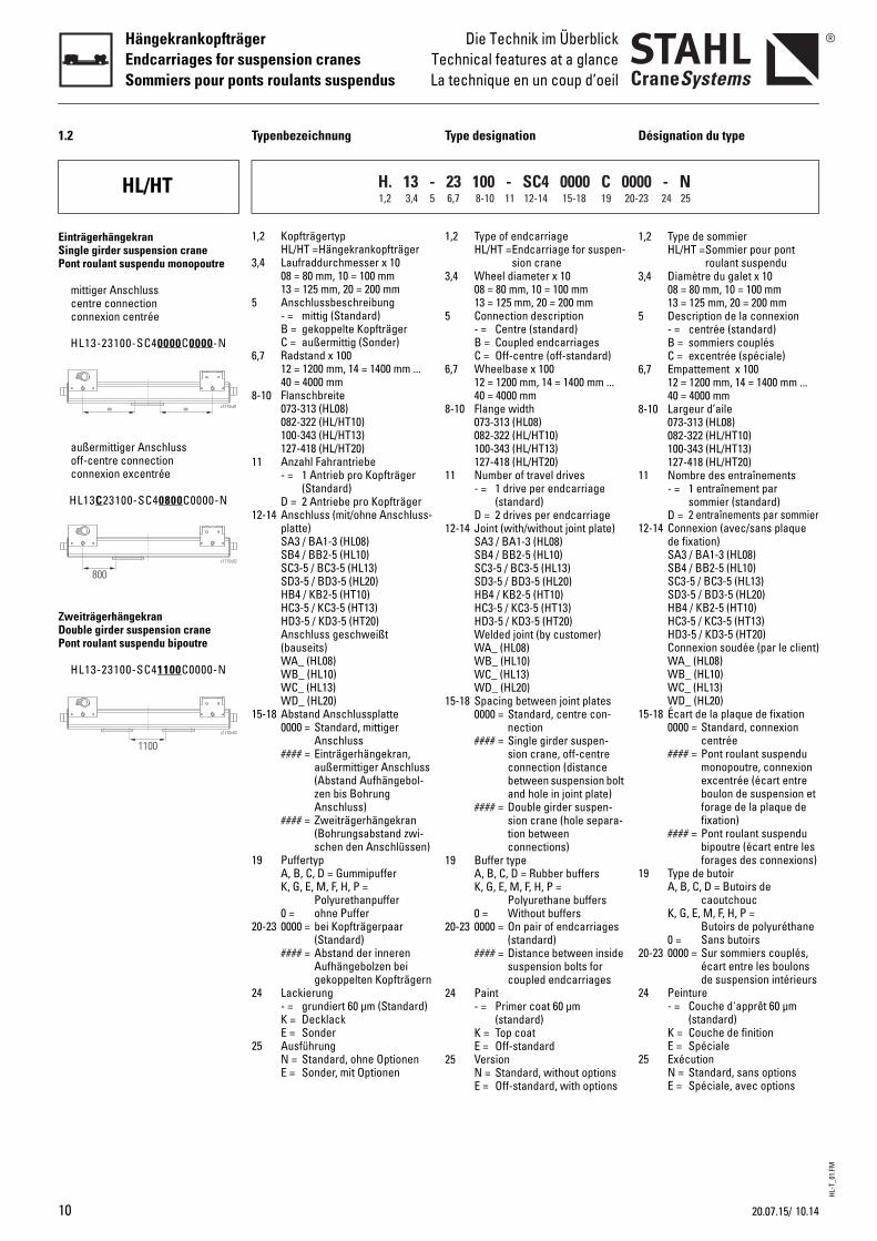
1.2 Typenbezeichnung Type designation Désignation du type
HL/HT
1,2 KopfträgertypHL/HT =Hängekrankopfträger
3,4 Laufraddurchmesser x 1008 = 80 mm, 10 = 100 mm13 = 125 mm, 20 = 200 mm
5 Anschlussbeschreibung- = mittig (Standard)B = gekoppelte KopfträgerC = außermittig (Sonder)
6,7 Radstand x 10012 = 1200 mm, 14 = 1400 mm ...40 = 4000 mm
8-10 Flanschbreite073-313 (HL08)082-322 (HL/HT10)100-343 (HL/HT13)127-418 (HL/HT20)
11 Anzahl Fahrantriebe- = 1 Antrieb pro Kopfträger
(Standard)D = 2 Antriebe pro Kopfträger
12-14 Anschluss (mit/ohne Anschluss-platte)SA3 / BA1-3 (HL08)SB4 / BB2-5 (HL10)SC3-5 / BC3-5 (HL13)SD3-5 / BD3-5 (HL20)HB4 / KB2-5 (HT10)HC3-5 / KC3-5 (HT13)HD3-5 / KD3-5 (HT20)Anschluss geschweißt (bauseits)WA_ (HL08)WB_ (HL10)WC_ (HL13)WD_ (HL20)
15-18 Abstand Anschlussplatte0000 = Standard, mittiger
Anschluss#### = Einträgerhängekran,
außermittiger Anschluss (Abstand Aufhängebol-zen bis Bohrung Anschluss)
#### = Zweiträgerhängekran (Bohrungsabstand zwi-schen den Anschlüssen)
19 PuffertypA, B, C, D = GummipufferK, G, E, M, F, H, P =
Polyurethanpuffer0 = ohne Puffer
20-23 0000 = bei Kopfträgerpaar (Standard)
#### = Abstand der inneren Aufhängebolzen bei gekoppelten Kopfträgern
24 Lackierung- = grundiert 60 µm (Standard)K = DecklackE = Sonder
25 AusführungN = Standard, ohne OptionenE = Sonder, mit Optionen
1,2 Type of endcarriageHL/HT =Endcarriage for suspen-
sion crane3,4 Wheel diameter x 10
08 = 80 mm, 10 = 100 mm13 = 125 mm, 20 = 200 mm
5 Connection description- = Centre (standard)B = Coupled endcarriagesC = Off-centre (off-standard)
6,7 Wheelbase x 10012 = 1200 mm, 14 = 1400 mm ...40 = 4000 mm
8-10 Flange width073-313 (HL08)082-322 (HL/HT10)100-343 (HL/HT13)127-418 (HL/HT20)
11 Number of travel drives- = 1 drive per endcarriage
(standard)D = 2 drives per endcarriage
12-14 Joint (with/without joint plate)SA3 / BA1-3 (HL08)SB4 / BB2-5 (HL10)SC3-5 / BC3-5 (HL13)SD3-5 / BD3-5 (HL20)HB4 / KB2-5 (HT10)HC3-5 / KC3-5 (HT13)HD3-5 / KD3-5 (HT20)Welded joint (by customer)WA_ (HL08)WB_ (HL10)WC_ (HL13)WD_ (HL20)
15-18 Spacing between joint plates0000 = Standard, centre con-
nection#### = Single girder suspen-
sion crane, off-centre connection (distance between suspension bolt and hole in joint plate)
#### = Double girder suspen-sion crane (hole separa-tion between connections)
19 Buffer typeA, B, C, D = Rubber buffersK, G, E, M, F, H, P =
Polyurethane buffers0 = Without buffers
20-23 0000 = On pair of endcarriages (standard)
#### = Distance between inside suspension bolts for coupled endcarriages
24 Paint- = Primer coat 60 µm
(standard)K = Top coatE = Off-standard
25 VersionN = Standard, without optionsE = Off-standard, with options
1,2 Type de sommierHL/HT =Sommier pour pont
roulant suspendu3,4 Diamètre du galet x 10
08 = 80 mm, 10 = 100 mm13 = 125 mm, 20 = 200 mm
5 Description de la connexion- = centrée (standard)B = sommiers couplésC = excentrée (spéciale)
6,7 Empattement x 10012 = 1200 mm, 14 = 1400 mm ...40 = 4000 mm
8-10 Largeur d’aile073-313 (HL08)082-322 (HL/HT10)100-343 (HL/HT13)127-418 (HL/HT20)
11 Nombre des entraînements- = 1 entraînement par
sommier (standard)D = 2 entraînements par sommier
12-14 Connexion (avec/sans plaque de fixation)SA3 / BA1-3 (HL08)SB4 / BB2-5 (HL10)SC3-5 / BC3-5 (HL13)SD3-5 / BD3-5 (HL20)HB4 / KB2-5 (HT10)HC3-5 / KC3-5 (HT13)HD3-5 / KD3-5 (HT20)Connexion soudée (par le client)WA_ (HL08)WB_ (HL10)WC_ (HL13)WD_ (HL20)
15-18 Écart de la plaque de fixation0000 = Standard, connexion
centrée#### = Pont roulant suspendu
monopoutre, connexion excentrée (écart entre boulon de suspension et forage de la plaque de fixation)
#### = Pont roulant suspendu bipoutre (écart entre les forages des connexions)
19 Type de butoirA, B, C, D = Butoirs de
caoutchoucK, G, E, M, F, H, P =
Butoirs de polyuréthane0 = Sans butoirs
20-23 0000 = Sur sommiers couplés, écart entre les boulons de suspension intérieurs
24 Peinture- = Couche d'apprêt 60 µm
(standard)K = Couche de finitionE = Spéciale
25 ExécutionN = Standard, sans optionsE = Spéciale, avec options
H. 13 - 23 100 - SC4 0000 C 0000 - N1,2 3,4 5 6,7 8-10 11 12-14 15-18 19 20-23 24 25
= = c1710v01
c1710v02
800
c1710v03
1100
EinträgerhängekranSingle girder suspension cranePont roulant suspendu monopoutre
mittiger Anschlusscentre connectionconnexion centrée
HL13-23100-SC40000C0000-N
außermittiger Anschlussoff-centre connectionconnexion excentrée
HL13C23100-SC40800C0000-N
ZweiträgerhängekranDouble girder suspension cranePont roulant suspendu bipoutre
HL13-23100-SC41100C0000-N
10 10.1420.07.15/
HL-T
_01.
FMAuswahlanleitungSelection instructionsInstructions pour la sélection
HängekrankopfträgerEndcarriages for suspension cranes
Sommiers pour ponts roulants suspendus
1
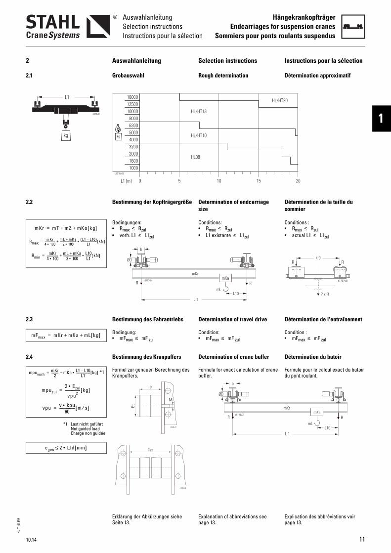
2 Auswahlanleitung Selection instructions Instructions pour la sélection
2.1 Grobauswahl Rough determination Détermination approximatif
2.2 Bestimmung der Kopfträgergröße Determination of endcarriage size
Détermination de la taille du sommier
Bedingungen: • Rmax ≤ Rzul• vorh. L1 ≤ L1zul
Conditions: • Rmax ≤ Rzul• L1 existante ≤ L1zul
Conditions : • Rmax ≤ Rzul• actual L1 ≤ L1zul
2.3 Bestimmung des Fahrantriebs Determination of travel drive Détermination de l'entraînement
Bedingung: • mFmax ≤ mF zul
Condition: • mFmax ≤ mF zul
Condition : • mFmax ≤ mF zul
2.4 Bestimmung des Kranpuffers Determination of crane buffer Détermination du butoir
*1 Formel zur genauen Berechnung des Kranpuffers.
Formula for exact calculation of crane buffer.
Formule pour le calcul exact du butoir du pont roulant.
*1 Last nicht geführtNot guided loadCharge non guidée
Erklärung der Abkürzungen siehe Seite 13.
Explanation of abbreviations see page 13.
Explication des abbréviations voir page 13.
5 10 15 20L1 [m]
kg
c1716v01
10001600200032004000500063008000
100001250016000
0
HL08
HL/HT10
HL/HT13
HL/HT20
mKr mT mZ mKo kg[ ]+ +=
RmaxmKr
4 100•---------------- mL mKa+
2 100•------------------------- L1 L10–( )
L1------------------------- kN[ ]•+=
RminmKr
4 100•---------------- mL mKa+
2 100•------------------------- L10
L1--------• kN[ ]+=
2 x R
R Rk 0
c1707v01
L10L 1
b
ØD
mKr
mL
mKaRR
c0143v01
mFmax mKr mKa mL kg[ ]+ +=
mpuvorhmKr
2---------- mKa L1 L10–
L1--------------------• kg[ ]+=
mpuzul2 Ezul•
vpu2----------------- kg[ ]=
vpu v kpu•60
------------------ m s⁄[ ]=
c1686v01
e
Ød
M
L10L 1
b
ØD
mKr
mL
mKaRR
c0143v01
eges 2 ∅ d mm[ ]•≤
c1686v02
eges
10.14 11
HL-T
_01.
FM
HängekrankopfträgerEndcarriages for suspension cranesSommiers pour ponts roulants suspendus
AuswahlanleitungSelection instructions
Instructions pour la sélection
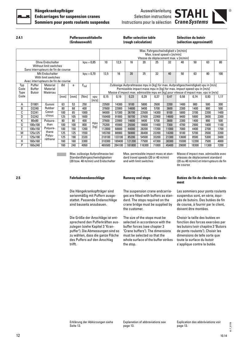
2.4.1 Pufferauswahltabelle(Grobauswahl)
Buffer selection table(rough calculation)
Sélection du butoir(sélection approximatif)
Max. Fahrgeschwindigkeit v [m/min]Max. travel speed v [m/min]
Vitesse de déplacement max. v [m/min]Ohne Endschalter
Without limit switchesSans interrupteurs de fin de course
kpu = 0,85 10 12,5 16 20 25 32 40 50 63 80
Mit EndschalterWith limit switches
Avec interrupteurs de fin de course
kpu = 0,70 12,5 16 20 25 32 40 50 63 80 100
Typ CodeType Code
PufferBufferButoir
MaterialMaterialMatériau
Ød e Ezul Zulässige Aufprallmasse mpu in [kg] für max. Aufprallgeschwindigkeit vpu in [m/s]Permissible impact mass mpu in [kg] for max. impact speed vpu in [m/s]
Masse d'impact max. admissible mpu en [kg] pour vitesse d'impact max. vpu in [m/s][mm] [mm] [Nm] vpu
[m/s]0,15 0,19 0,23 0,29 0,37 0,47 0,58 0,74 0,93 1,17
A D1801 GummiRubberCaout-chouc
63 53 250
mpu [kg]
23500 14300 9100 5800 3500 2200 1400 900 500 300B D2240 80 68 400 37600 22900 14600 9400 5700 3600 2300 1400 900 500C D2241 100 85 1000 94000 57300 36700 23500 14300 9100 5800 3700 2200 1400D D2242 125 105 1600 150400 91800 58700 37600 22900 14600 9400 5900 3600 2300K 80x80 Polyure-
thanPolyure-
thanePolyu-
réthane
80 80 400 37600 22900 14600 9400 5700 3600 2300 1400 900 500G 100x100 100 100 800 75200 45900 29300 18800 11400 7300 4700 2900 1800 1100E 100x150 100 150 1200 112800 68800 44000 28200 17200 11000 7000 4400 2700 1700M 125x125 125 125 1550 145700 88900 56900 36400 22200 14200 9100 5700 3500 2200F 125x190 125 190 2320 218100 133100 85200 54500 33200 21300 13600 8500 5300 3400H 160x160 160 160 3300 310300 189400 121200 77500 47300 30300 19300 12200 7500 4800P 160x240 160 240 4950 465500 284100 181800 116300 71000 45400 29000 18300 11300 7200
Max. zulässige Aufprallmasse bei Standardfahrgeschwindigkeiten (20 bzw. 40 m/min) und Endschalter
Max. permissible impact mass at stan-dard travel speeds (20 or 40 m/min) and with limit switches
Masse d'impact max. admissible avec vitesses de déplacement standard (20 ou 40 m/min) et interrupteurs de fin de course
2.5 Fahrbahnendanschläge Runway end stops Butées de fin de chemin de roule-ment
Die Hängekrankopfträger sind serienmäßig mit Puffern ausge-stattet. Passende Endanschläge sind bauseits anzubauen.
Die Größe der Anschläge ist ent-sprechend den Pufferkräften aus-zulegen (siehe Kapitel 3 "Kran-puffer"). Die Abmessungen sind so zu wählen, dass die ganze Fläche des Puffers auf den Anschlag trifft.
The suspension crane endcarria-ges are fitted with buffers as stan-dard. The stops required on the crane bridge must be supplied by the customer.
The size of the stops must be selected in accordance with the buffer forces (see chapter 3 "Crane buffers"). The dimensions must be selected so that the whole surface of the buffer strikes the stop.
Les sommiers pour ponts roulants suspendus sont, en série, équi-pés de butoirs. Des butées de fin de course, à fournir par le client, doivent être montées.
Choisir la taille des butées en fonction des forces exercées par les butoirs (voir chapitre 3 "Butoirs de ponts roulants"). Choisir les dimensions de telle sorte que toute la surface du butoir s'applique contre la butée.
Erklärung der Abkürzungen siehe Seite 13.
Explanation of abbreviations see page 13.
Explication des abbréviations voir page 13.
12 10.14
HL-T
_01.
FMAuswahlanleitungSelection instructionsInstructions pour la sélection
HängekrankopfträgerEndcarriages for suspension cranes
Sommiers pour ponts roulants suspendus
1
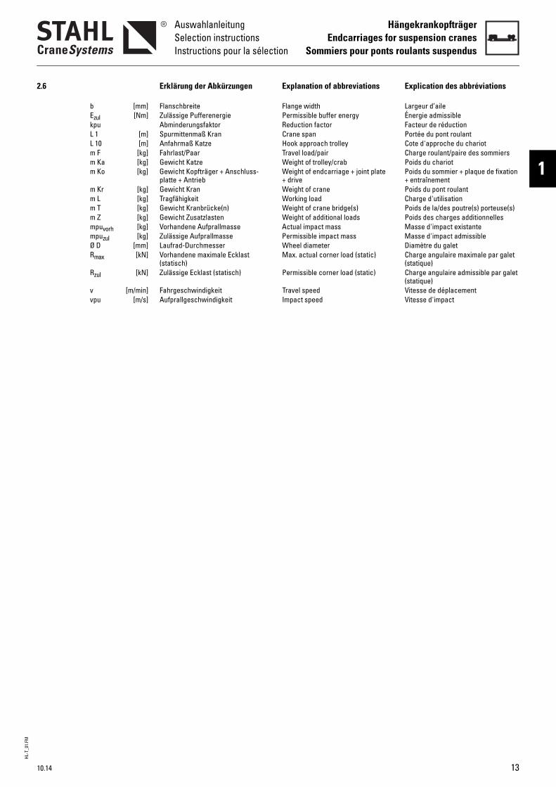
2.6 Erklärung der Abkürzungen Explanation of abbreviations Explication des abbréviations
b [mm] Flanschbreite Flange width Largeur d’aileEzul [Nm] Zulässige Pufferenergie Permissible buffer energy Énergie admissiblekpu Abminderungsfaktor Reduction factor Facteur de réductionL 1 [m] Spurmittenmaß Kran Crane span Portée du pont roulantL 10 [m] Anfahrmaß Katze Hook approach trolley Cote d'approche du chariotm F [kg] Fahrlast/Paar Travel load/pair Charge roulant/paire des sommiersm Ka [kg] Gewicht Katze Weight of trolley/crab Poids du chariotm Ko [kg] Gewicht Kopfträger + Anschluss-
platte + AntriebWeight of endcarriage + joint plate + drive
Poids du sommier + plaque de fixation + entraînement
m Kr [kg] Gewicht Kran Weight of crane Poids du pont roulantm L [kg] Tragfähigkeit Working load Charge d'utilisationm T [kg] Gewicht Kranbrücke(n) Weight of crane bridge(s) Poids de la/des poutre(s) porteuse(s)m Z [kg] Gewicht Zusatzlasten Weight of additional loads Poids des charges additionnellesmpuvorh [kg] Vorhandene Aufprallmasse Actual impact mass Masse d'impact existantempuzul [kg] Zulässige Aufprallmasse Permissible impact mass Masse d'impact admissibleØ D [mm] Laufrad-Durchmesser Wheel diameter Diamètre du galetRmax [kN] Vorhandene maximale Ecklast
(statisch)Max. actual corner load (static) Charge angulaire maximale par galet
(statique)Rzul [kN] Zulässige Ecklast (statisch) Permissible corner load (static) Charge angulaire admissible par galet
(statique)v [m/min] Fahrgeschwindigkeit Travel speed Vitesse de déplacementvpu [m/s] Aufprallgeschwindigkeit Impact speed Vitesse d'impact
10.14 13
HL-T
_02.
FM
14
HängekrankopfträgerEndcarriages for suspension cranesSommiers pour ponts roulants suspendus
AbmessungenDimensionsDimensions
3
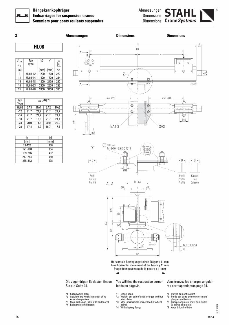
HL08
L1zul
*1
TypType
k0 k1
[m] [mm] [mm] *29 HL08-12 1200 1530 220
11 HL08-14 1400 1730 23414 HL08-18 1800 2130 26218 HL08-23 2300 2630 29621 HL08-28 2800 3130 330
TypType
Rzul [kN] *3
HL08 SA3 BA1 BA2 BA3-12 21,7 21,7 21,7 21,7-14 21,7 21,7 21,7 21,7-18 21,7 18,5 21,7 21,7-23 20,0 14,5 20,0 20,0-28 17,4 11,9 16,7 17,4
b b2[mm] [mm]
73-120 306121-168 354169-216 402217-264 450265-313 498
Dimensions
You will find the respective corner loads on page 34.
D
Vr
*1 Crane span*2 Weight per pair of endcarriages without
joint plates*3 Max. permissible corner load (2 wheel
pairs)*4 With sloping flange
**
*
*
c1701v01
m70-10.9 ISO 4014
b
b + 52
26 41
8030
b2
±4°
Ø18
=
k1
k0
SA3
Z
0 min
1-3
orizontale Bewegungsfreiheit Träger + 11 mmee horizontal movement of the beam + 11 mmPlage de mouvement de la poutre + 11 mm
imensions
ous trouvez les charges angulai-es correspondantes page 34.
1 Portée du pont roulant2 Poids par paire de sommiers sans
plaques de fixaton3 Charge angulaire max. admissible
(2 paires de galets)4 Avec bride inclinée
B B
12,6 (17,0) *426
ProfilProfileProfilé
KastenBox
Caisson
Ød
c1700v01
e
146
R
220
Die zugehörigen Ecklasten finden Sie auf Seite 34.
Abmessungen
*1 Spannweite Kran*2 Gewicht pro Kopfträgerpaar ohne
Anschlussplatten*3 Max. zulässige Ecklast (2 Radpaare)*4 Bei geneigtem Flansch
"Z"300 NM16x
B
303
133
82
A - A
ProfilProfileProfilé
m2
=
m0
A
A
R
min 22
BA
HFr
10.14
HL-T
_02.
FM
10.14
AbmessungenDimensionsDimensions
HängekrankopfträgerEndcarriages for suspension cranes
Sommiers pour ponts roulants suspendus
1
c1686v01
e
Ød
M
B
p1
c1702v01
350
90
450SA3
90
p1
B
c1702v02
BA1-3
Buffer
Calculation see "Buffer selection table" page 46.
Joint
With joint plate
Without joint plate
Travel drives
For more details, see Product information "Travel drives".
B
Pb
C
A
S
G
Ptd
Ød e max. Federwegmax. deflection
max. écrasement[mm] [mm] [mm]
c
63 53 3080 68 32
100 85 42nee
80 80 60100 100 75100 150 113
SA3360
160-30031
BA1 BA2 BA3100 150 200
154-203 204-253 254-320
MotorMotor
Moteur
m0 m2
[mm]8/2F12 396 898/2F134F18 89/137 *1
*1 Plug-in electrical connection *
utoirs
our le calcul, voir "Sélection du utoir", page 46.
onnexion
vec plaque de fixation
ans plaque de fixation
roupes d’entraînement
our de plus amples informa-ions, voir Informations sur le pro-uit "Groupes d’entraînement".
Ezul GewindeThread
Filet[Nm]250 M12x35 0,3400 0,6
1000 1,2400 0,4800 0,6
1200 0,8
1 Connexion électrique enfichable
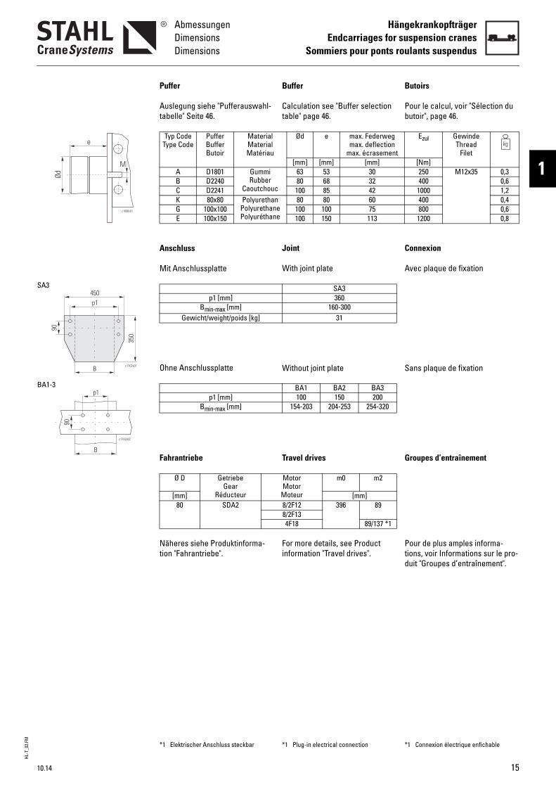
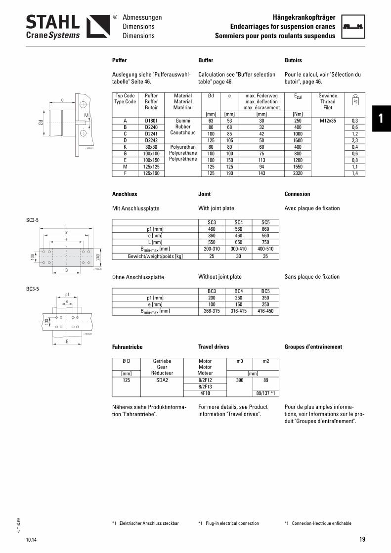
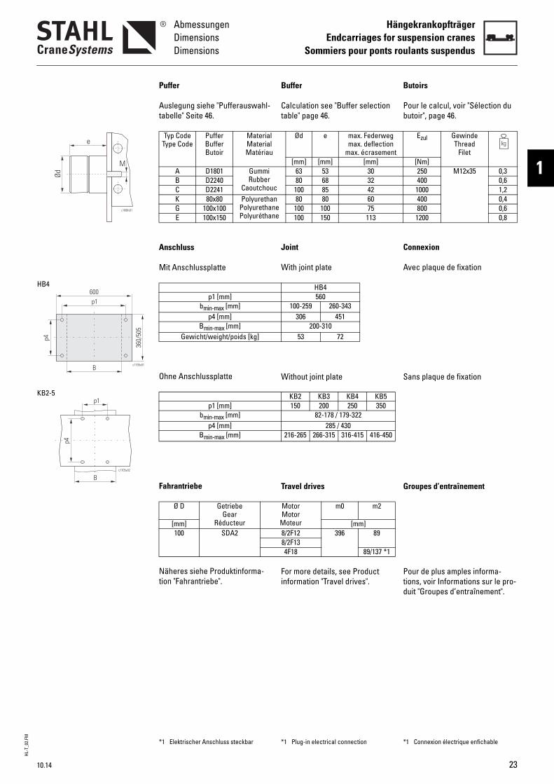
Puffer
Auslegung siehe "Pufferauswahl-tabelle" Seite 46.
Anschluss
Mit Anschlussplatte
Ohne Anschlussplatte
Fahrantriebe
Näheres siehe Produktinforma-tion "Fahrantriebe".
Typ CodeType Code
PufferBufferButoir
MaterialMaterialMatériau
A D1801 GummiRubber
CaoutchouB D2240C D2241K 80x80 Polyuretha
PolyurethanPolyuréthan
G 100x100E 100x150
p1 [mm]Bmin-max [mm]
Gewicht/weight/poids [kg]
p1 [mm]Bmin-max [mm]
Ø D GetriebeGear
Réducteur[mm]80 SDA2
*1 Elektrischer Anschluss steckbar
15
HL-T
_02.
FM
16
HängekrankopfträgerEndcarriages for suspension cranesSommiers pour ponts roulants suspendus
AbmessungenDimensionsDimensions
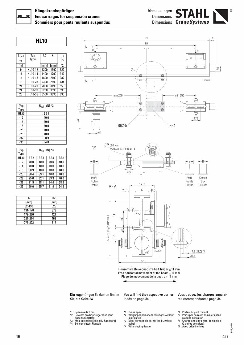
HL10
L1zul
*1
TypType
k0 k1
[m] [mm] [mm] *29 HL10-12 1200 1590 322
11 HL10-14 1400 1790 34214 HL10-18 1800 2190 38218 HL10-23 2300 2690 43421 HL10-28 2800 3190 55024 HL10-32 3200 3590 59826 HL10-35 3500 3890 636
TypType
Rzul [kN] *3
HL10 SB4-12 40,0-14 40,0-18 40,0-23 40,0-28 40,0-32 38,3-35 34,8
TypType
Rzul [kN] *3
HL10 BB2 BB3 BB4 BB5-12 40,0 40,0 40,0 40,0-14 40,0 40,0 40,0 40,0-18 38,9 40,0 40,0 40,0-23 30,4 39,1 40,0 40,0-28 25,0 32,1 39,3 40,0-32 21,9 28,1 34,4 38,3-35 20,0 25,7 31,4 34,8
b b2[mm] [mm]
82-130 325131-178 373179-226 421227-274 469275-322 517
You will find the respective corner loads on page 34.
Vr
*1 Crane span*2 Weight per pair of endcarriages without
joint plates*3 Max. permissible corner load (2 wheel
pairs)*4 With sloping flange
**
*
*
=
k1
k0
0 mi
SB42-5
Z
c1701v02
0.9 ISO 4014
b
b + 51
25,5 41,5
100
35
b2
±4°
Ø22
orizontale Bewegungsfreiheit Träger + 11 mmee horizontal movement of the beam + 11 mmPlage de mouvement de la poutre + 11 mm
ous trouvez les charges angulai-es correspondantes page 34.
1 Portée du pont roulant2 Poids par paire de sommiers sans
plaques de fixaton3 Charge angulaire max. admissible
(2 paires de galets)4 Avec bride inclinée
Ød
c1700v02
e
176
R
n 250
B B
17,5 (23,0) *431,5
ProfilProfileProfilé
KastenBox
Caisson
Die zugehörigen Ecklasten finden Sie auf Seite 34.
*1 Spannweite Kran*2 Gewicht pro Kopfträgerpaar ohne
Anschlussplatten*3 Max. zulässige Ecklast (2 Radpaare)*4 Bei geneigtem Flansch
m2
=
m0
A
A
R
min 25
BB
"Z"590 NmM20x70-1
B
143
95
A - A
ProfilProfileProfilé
358/
378
(k0
230
0/35
00)
<
HFr
10.14
HL-T
_02.
FM
10.14
AbmessungenDimensionsDimensions
HängekrankopfträgerEndcarriages for suspension cranes
Sommiers pour ponts roulants suspendus
1
c1686v01
e
Ød
M
B
p1
c1703v01
200
90
600SB4
90
p1
B
c1702v02
BB2-5
Buffer
Calculation see "Buffer selection table" page 46.
Joint
With joint plate
Without joint plate
Travel drives
For more details, see Product information "Travel drives".
B
Pb
C
A
S
G
Ptd
Ød e max. Federwegmax. deflection
max. écrasement[mm] [mm] [mm]
c
63 53 3080 68 32
100 85 42nee
80 80 60100 100 75100 150 113
SB4500
200-41024
BB2 BB3 BB4 BB5150 200 250 350
216-265 266-315 316-415 416-450
MotorMotor
Moteur
m0 m2
[mm]8/2F12 396 898/2F134F18 89/137 *1
*1 Plug-in electrical connection *
utoirs
our le calcul, voir "Sélection du utoir", page 46.
onnexion
vec plaque de fixation
ans plaque de fixation
roupes d’entraînement
our de plus amples informa-ions, voir Informations sur le pro-uit "Groupes d’entraînement".
Ezul GewindeThread
Filet[Nm]250 M12x35 0,3400 0,6
1000 1,2400 0,4800 0,6
1200 0,8
1 Connexion électrique enfichable
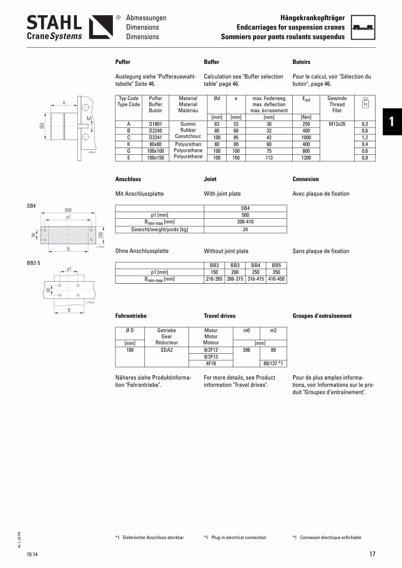
Puffer
Auslegung siehe "Pufferauswahl-tabelle" Seite 46.
Anschluss
Mit Anschlussplatte
Ohne Anschlussplatte
Fahrantriebe
Näheres siehe Produktinforma-tion "Fahrantriebe".
Typ CodeType Code
PufferBufferButoir
MaterialMaterialMatériau
A D1801 GummiRubber
CaoutchouB D2240C D2241K 80x80 Polyuretha
PolyurethanPolyuréthan
G 100x100E 100x150
p1 [mm]Bmin-max [mm]
Gewicht/weight/poids [kg]
p1 [mm]Bmin-max [mm]
Ø D GetriebeGear
Réducteur[mm]100 SDA2
*1 Elektrischer Anschluss steckbar
17
HL-T
_02.
FM
18
HängekrankopfträgerEndcarriages for suspension cranesSommiers pour ponts roulants suspendus
AbmessungenDimensionsDimensions
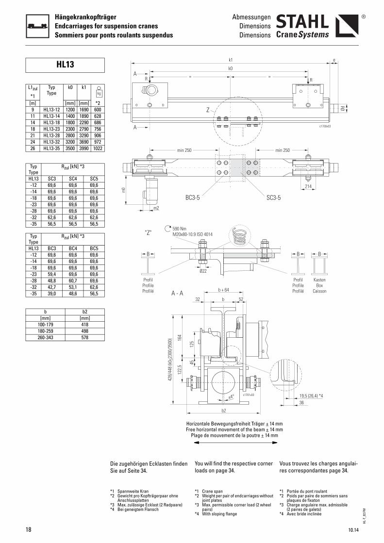
HL13
L1zul
*1
TypType
k0 k1
[m] [mm] [mm] *29 HL13-12 1200 1690 600
11 HL13-14 1400 1890 62814 HL13-18 1800 2290 68618 HL13-23 2300 2790 75621 HL13-28 2800 3290 90624 HL13-32 3200 3690 97226 HL13-35 3500 3990 1022
TypType
Rzul [kN] *3
HL13 SC3 SC4 SC5-12 69,6 69,6 69,6-14 69,6 69,6 69,6-18 69,6 69,6 69,6-23 69,6 69,6 69,6-28 69,6 69,6 69,6-32 62,6 62,6 62,6-35 56,5 56,5 56,5
TypType
Rzul [kN] *3
HL13 BC3 BC4 BC5-12 69,6 69,6 69,6-14 69,6 69,6 69,6-18 69,6 69,6 69,6-23 59,4 69,6 69,6-28 48,8 60,7 69,6-32 42,7 53,1 62,6-35 39,0 48,6 56,5
b b2[mm] [mm]
100-179 418180-259 498260-343 578
You will find the respective corner loads on page 34.
Vr
*1 Crane span*2 Weight per pair of endcarriages without
joint plates*3 Max. permissible corner load (2 wheel
pairs)*4 With sloping flange
**
*
*
=
k1
k0
0 mi
SC3-53-5
Z
c1701v03
0.9 ISO 4014
b
b + 64
32 52
125
45
b2
±4°
Ø22
orizontale Bewegungsfreiheit Träger + 14 mmee horizontal movement of the beam + 14 mmPlage de mouvement de la poutre + 14 mm
ous trouvez les charges angulai-es correspondantes page 34.
1 Portée du pont roulant2 Poids par paire de sommiers sans
plaques de fixaton3 Charge angulaire max. admissible
(2 paires de galets)4 Avec bride inclinée
Ød
c1700v03
e
214
R
n 250
B B
19,5 (26,4) *436
ProfilProfileProfilé
KastenBox
Caisson
Die zugehörigen Ecklasten finden Sie auf Seite 34.
*1 Spannweite Kran*2 Gewicht pro Kopfträgerpaar ohne
Anschlussplatten*3 Max. zulässige Ecklast (2 Radpaare)*4 Bei geneigtem Flansch
m2
=
m0
A
A
R
min 25
BC
"Z"590 NmM20x80-1
B
164
122,
5
A - A
ProfilProfileProfilé
428/
448
(k0
230
0/35
00)
<
HFr
10.14
HL-T
_02.
FM
10.14
AbmessungenDimensionsDimensions
HängekrankopfträgerEndcarriages for suspension cranes
Sommiers pour ponts roulants suspendus
1
c1686v01
e
Ød
M
B
p1
c1704v01
240
100
L
e
SC3-5
100
e
B
c1704v02
p1BC3-5
Buffer
Calculation see "Buffer selection table" page 46.
Joint
With joint plate
Without joint plate
Travel drives
For more details, see Product information "Travel drives".
B
Pb
C
A
S
G
Ptd
Ød e max. Federwegmax. deflection
max. écrasement[mm] [mm] [mm]
c
63 53 3080 68 32
100 85 42125 105 50
nee
80 80 60100 100 75100 150 113125 125 94125 190 143
SC3 SC4 SC5460 560 660360 460 560550 650 750
200-310 300-410 400-51025 30 35
BC3 BC4 BC5200 250 350100 150 250
266-315 316-415 416-450
MotorMotor
Moteur
m0 m2
[mm]8/2F12 396 898/2F134F18 89/137 *1
*1 Plug-in electrical connection *
utoirs
our le calcul, voir "Sélection du utoir", page 46.
onnexion
vec plaque de fixation
ans plaque de fixation
roupes d’entraînement
our de plus amples informa-ions, voir Informations sur le pro-uit "Groupes d’entraînement".
Ezul GewindeThread
Filet[Nm]250 M12x35 0,3400 0,6
1000 1,21600 2,3400 0,4800 0,6
1200 0,81550 1,12320 1,4
1 Connexion électrique enfichable
Puffer
Auslegung siehe "Pufferauswahl-tabelle" Seite 46.
Anschluss
Mit Anschlussplatte
Ohne Anschlussplatte
Fahrantriebe
Näheres siehe Produktinforma-tion "Fahrantriebe".
Typ CodeType Code
PufferBufferButoir
MaterialMaterialMatériau
A D1801 GummiRubber
CaoutchouB D2240C D2241D D2242K 80x80 Polyuretha
PolyurethanPolyuréthan
G 100x100E 100x150M 125x125F 125x190
p1 [mm]e [mm]L [mm]
Bmin-max [mm]Gewicht/weight/poids [kg]
p1 [mm]e [mm]
Bmin-max [mm]
Ø D GetriebeGear
Réducteur[mm]125 SDA2
*1 Elektrischer Anschluss steckbar
19
HL-T
_02.
FM
20
HängekrankopfträgerEndcarriages for suspension cranesSommiers pour ponts roulants suspendus
AbmessungenDimensionsDimensions
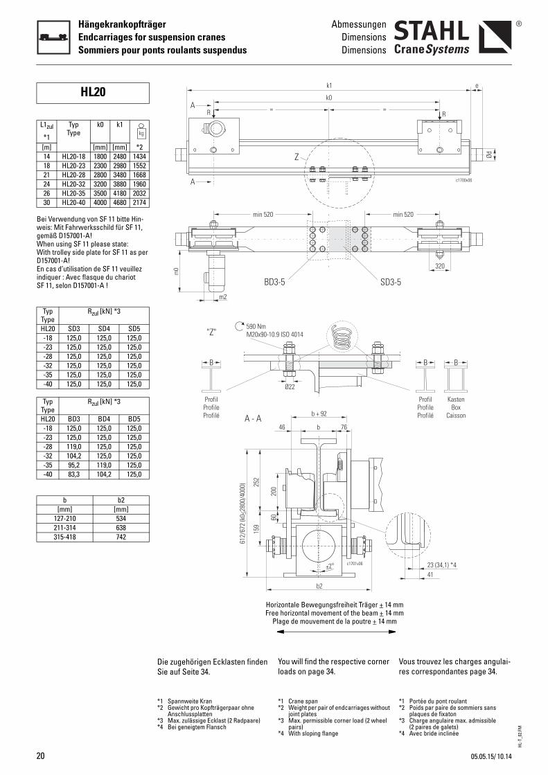
Bei Verwendung von SF 11 bitte Hin-weis: Mit Fahrwerksschild für SF 11, gemäß D157001-A!When using SF 11 please state: With trolley side plate for SF 11 as per D157001-A!En cas d’utilisation de SF 11 veuillez indiquer : Avec flasque du chariot SF 11, selon D157001-A !
HL20
L1zul
*1
TypType
k0 k1
[m] [mm] [mm] *214 HL20-18 1800 2480 143418 HL20-23 2300 2980 155221 HL20-28 2800 3480 166824 HL20-32 3200 3880 196026 HL20-35 3500 4180 203230 HL20-40 4000 4680 2174
TypType
Rzul [kN] *3
HL20 SD3 SD4 SD5-18 125,0 125,0 125,0-23 125,0 125,0 125,0-28 125,0 125,0 125,0-32 125,0 125,0 125,0-35 125,0 125,0 125,0-40 125,0 125,0 125,0
TypType
Rzul [kN] *3
HL20 BD3 BD4 BD5-18 125,0 125,0 125,0-23 125,0 125,0 125,0-28 119,0 125,0 125,0-32 104,2 125,0 125,0-35 95,2 119,0 125,0-40 83,3 104,2 125,0
b b2[mm] [mm]
127-210 534211-314 638315-418 742
You will find the respective corner loads on page 34.
Vr
*1 Crane span*2 Weight per pair of endcarriages without
joint plates*3 Max. permissible corner load (2 wheel
pairs)*4 With sloping flange
**
*
*
=
k1
k0
0 mi
SD3-53-5
Z
c1701v06
0.9 ISO 4014
b
b + 92
46 76
200
60
b2
±2°
Ø22
orizontale Bewegungsfreiheit Träger + 14 mmee horizontal movement of the beam + 14 mmPlage de mouvement de la poutre + 14 mm
ous trouvez les charges angulai-es correspondantes page 34.
1 Portée du pont roulant2 Poids par paire de sommiers sans
plaques de fixaton3 Charge angulaire max. admissible
(2 paires de galets)4 Avec bride inclinée
Ød
c1700v06
e
320
R
n 520
B B
23 (34,1) *441
ProfilProfileProfilé
KastenBox
Caisson
Die zugehörigen Ecklasten finden Sie auf Seite 34.
*1 Spannweite Kran*2 Gewicht pro Kopfträgerpaar ohne
Anschlussplatten*3 Max. zulässige Ecklast (2 Radpaare)*4 Bei geneigtem Flansch
m2
=
m0
A
A
R
min 52
BD
"Z"590 NmM20x90-1
B
252
159
A - A
ProfilProfileProfilé
612/
672
(k0
280
0/40
00)
<
HFr
10.1405.05.15/
HL-T
_02.
FM
10.14
AbmessungenDimensionsDimensions
HängekrankopfträgerEndcarriages for suspension cranes
Sommiers pour ponts roulants suspendus
1
c1686v01
e
Ød
M
p1
c1740v01
300
136
L
e
234
B
SD3-5
e
B
c1740v02
p1
136
234
BD3-5
Buffer
Calculation see "Buffer selection table" page 46.
Joint
With joint plate
Without joint plate
Travel drives
For more details, see Product information "Travel drives".
B
Pb
C
A
S
G
Ptd
Ød e max. Federwegmax. deflection
max. écrasement[mm] [mm] [mm]
c
63 53 3080 68 32
100 85 42125 105 50
nee
80 80 60100 100 75100 150 113125 125 94125 190 143160 160 120160 240 180
SD3 SD4 SD5560 660 760360 460 560660 760 860
200-310 300-410 400-51042 48 54
BD3 BD4 BD5234 334 434114 214 314
300-399 400-499 500-599
MotorMotor
Moteur
m0 m2 *1
[mm]123 440 127133184313 495 151384 500 151
*1 Plug-in electrical connection *
utoirs
our le calcul, voir "Sélection du utoir", page 46.
onnexion
vec plaque de fixation
ans plaque de fixation
roupes d’entraînement
our de plus amples informa-ions, voir Informations sur le pro-uit "Groupes d’entraînement".
Ezul GewindeThread
Filet[Nm]250 M12x35 0,3400 0,6
1000 1,21600 2,3400 0,4800 0,6
1200 0,81550 1,12320 1,43300 2,64950 3,5
1 Connexion électrique enfichable
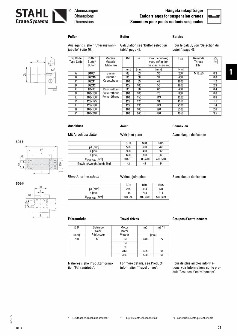
Puffer
Auslegung siehe "Pufferauswahl-tabelle" Seite 46.
Anschluss
Mit Anschlussplatte
Ohne Anschlussplatte
Fahrantriebe
Näheres siehe Produktinforma-tion "Fahrantriebe".
Typ CodeType Code
PufferBufferButoir
MaterialMaterialMatériau
A D1801 GummiRubber
CaoutchouB D2240C D2241D D2242K 80x80 Polyuretha
PolyurethanPolyuréthan
G 100x100E 100x150M 125x125F 125x190H 160x160P 160x240
p1 [mm]e [mm]L [mm]
Bmin-max [mm]Gewicht/weight/poids [kg]
p1 [mm]e [mm]
Bmin-max [mm]
Ø D GetriebeGear
Réducteur[mm]200 SF1
*1 Elektrischer Anschluss steckbar
21
HL-T
_02.
FM
22
HängekrankopfträgerEndcarriages for suspension cranesSommiers pour ponts roulants suspendus
AbmessungenDimensionsDimensions
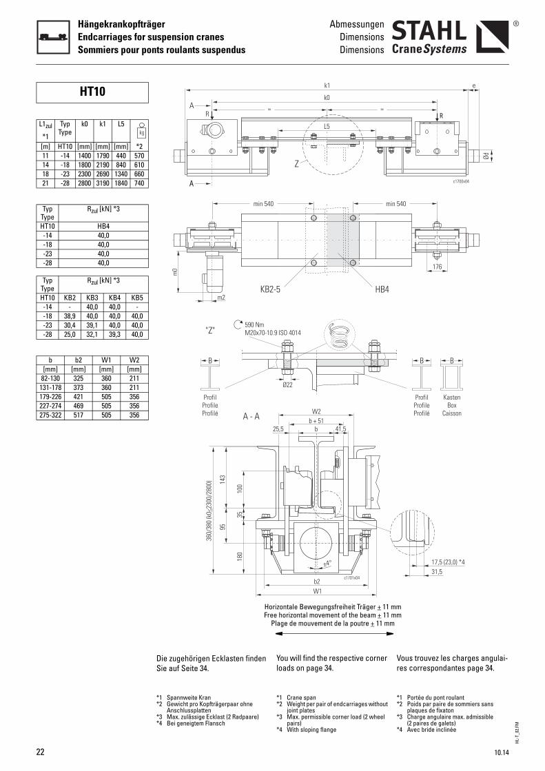
HT10
L1zul
*1
TypType
k0 k1 L5
[m] HT10 [mm] [mm] [mm] *211 -14 1400 1790 440 57014 -18 1800 2190 840 61018 -23 2300 2690 1340 66021 -28 2800 3190 1840 740
TypType
Rzul [kN] *3
HT10 HB4-14 40,0-18 40,0-23 40,0-28 40,0
TypType
Rzul [kN] *3
HT10 KB2 KB3 KB4 KB5-14 - 40,0 40,0 --18 38,9 40,0 40,0 40,0-23 30,4 39,1 40,0 40,0-28 25,0 32,1 39,3 40,0
b b2 W1 W2[mm] [mm] [mm] [mm]
82-130 325 360 211131-178 373 360 211179-226 421 505 356227-274 469 505 356275-322 517 505 356
You will find the respective corner loads on page 34.
Vr
*1 Crane span*2 Weight per pair of endcarriages without
joint plates*3 Max. permissible corner load (2 wheel
pairs)*4 With sloping flange
**
*
*
k1
k0
=
L5
0 min 5
HB42-5
Z
c1701v04
0.9 ISO 4014
W2
b25,5 41,5
b2
±4°
b + 51
W1
Ø22
orizontale Bewegungsfreiheit Träger + 11 mmee horizontal movement of the beam + 11 mmPlage de mouvement de la poutre + 11 mm
ous trouvez les charges angulai-es correspondantes page 34.
1 Portée du pont roulant2 Poids par paire de sommiers sans
plaques de fixaton3 Charge angulaire max. admissible
(2 paires de galets)4 Avec bride inclinée
Ød
c1700v04
e
176
R
40
B B
17,5 (23,0) *431,5
ProfilProfileProfilé
KastenBox
Caisson
Die zugehörigen Ecklasten finden Sie auf Seite 34.
*1 Spannweite Kran*2 Gewicht pro Kopfträgerpaar ohne
Anschlussplatten*3 Max. zulässige Ecklast (2 Radpaare)*4 Bei geneigtem Flansch
=R
A
A
m2
m0
min 54
KB
"Z"590 NmM20x70-1
B
100
3518
0
143
95
A - A
ProfilProfileProfilé
360/
380
(k0
230
0/28
00)
<
HFr
10.14
HL-T
_02.
FM
10.14
AbmessungenDimensionsDimensions
HängekrankopfträgerEndcarriages for suspension cranes
Sommiers pour ponts roulants suspendus
1
c1686v01
e
Ød
M
B
p1
c1705v01
360/
505
p4
600HB4
p4
Bc1705v02
p1KB2-5
Buffer
Calculation see "Buffer selection table" page 46.
Joint
With joint plate
Without joint plate
Travel drives
For more details, see Product information "Travel drives".
B
Pb
C
A
S
G
Ptd
Ød e max. Federwegmax. deflection
max. écrasement[mm] [mm] [mm]
c
63 53 3080 68 32
100 85 42nee
80 80 60100 100 75100 150 113
HB4560
100-259 260-343306 451
200-31053 72
KB2 KB3 KB4 KB5150 200 250 350
82-178 / 179-322285 / 430
216-265 266-315 316-415 416-450
MotorMotor
Moteur
m0 m2
[mm]8/2F12 396 898/2F134F18 89/137 *1
*1 Plug-in electrical connection *
utoirs
our le calcul, voir "Sélection du utoir", page 46.
onnexion
vec plaque de fixation
ans plaque de fixation
roupes d’entraînement
our de plus amples informa-ions, voir Informations sur le pro-uit "Groupes d’entraînement".
Ezul GewindeThread
Filet[Nm]250 M12x35 0,3400 0,6
1000 1,2400 0,4800 0,6
1200 0,8
1 Connexion électrique enfichable
Puffer
Auslegung siehe "Pufferauswahl-tabelle" Seite 46.
Anschluss
Mit Anschlussplatte
Ohne Anschlussplatte
Fahrantriebe
Näheres siehe Produktinforma-tion "Fahrantriebe".
Typ CodeType Code
PufferBufferButoir
MaterialMaterialMatériau
A D1801 GummiRubber
CaoutchouB D2240C D2241K 80x80 Polyuretha
PolyurethanPolyuréthan
G 100x100E 100x150
p1 [mm]bmin-max [mm]
p4 [mm]Bmin-max [mm]
Gewicht/weight/poids [kg]
p1 [mm]bmin-max [mm]
p4 [mm]Bmin-max [mm]
Ø D GetriebeGear
Réducteur[mm]100 SDA2
*1 Elektrischer Anschluss steckbar
23
HL-T
_02.
FM
24
HängekrankopfträgerEndcarriages for suspension cranesSommiers pour ponts roulants suspendus
AbmessungenDimensionsDimensions
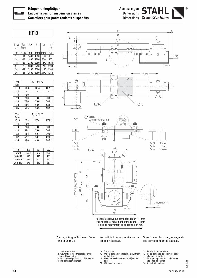
HT13
L1zul
*1
TypType
k0 k1 L5
[m] HT13 [mm] [mm] [mm] *211 -14 1400 1890 370 90014 -18 1800 2290 770 96018 -23 2300 2790 1270 103421 -28 2800 3290 1770 119024 -32 3200 3690 2170 126426 -35 3500 3990 2470 1318
TypType
Rzul [kN] *3
HT13 HC3 HC4 HC5-14 - - --18 70,0 - --23 70,0 70,0 70,0-28 70,0 70,0 70,0-32 62,6 62,6 62,6-35 56,5 56,5 56,5
TypType
Rzul [kN] *3
HT13 KC3 KC4 KC5-14 70,0 - --18 70,0 70,0 70,0-23 59,4 70,0 70,0-28 48,8 60,7 70,0-32 42,7 53,1 62,6-35 39,0 48,6 56,5
b b2 W1 W2[mm] [mm] [mm] [mm]
100-179 418 412 212180-259 498 557 357260-343 578 557 357
You will find the respective corner loads on page 34.
Vr
*1 Crane span*2 Weight per pair of endcarriages without
joint plates*3 Max. permissible corner load (2 wheel
pairs)*4 With sloping flange
**
*
*
k1
k0
=
L5
min
HC3-53-5
Z
c1701v05
0.9 ISO 4014
W2
b32 52
b2
±4°
b + 64
W1
Ø22
orizontale Bewegungsfreiheit Träger + 14 mmee horizontal movement of the beam + 14 mmPlage de mouvement de la poutre + 14 mm
ous trouvez les charges angulai-es correspondantes page 34.
1 Portée du pont roulant2 Poids par paire de sommiers sans
plaques de fixaton3 Charge angulaire max. admissible
(2 paires de galets)4 Avec bride inclinée
Ød
c1700v05
e
214
R
575
B B
19,5 (26,4) *436
ProfilProfileProfilé
KastenBox
Caisson
Die zugehörigen Ecklasten finden Sie auf Seite 34.
*1 Spannweite Kran*2 Gewicht pro Kopfträgerpaar ohne
Anschlussplatten*3 Max. zulässige Ecklast (2 Radpaare)*4 Bei geneigtem Flansch
=R
A
A
m2
m0
min 575
KC
"Z"590 NmM20x80-1
B
125
4524
0
164
122,
5
A - A
ProfilProfileProfilé
500/
540
(k0
230
0/35
00)
<
HFr
10.1408.01.15/
HL-T
_02.
FM
10.14
AbmessungenDimensionsDimensions
HängekrankopfträgerEndcarriages for suspension cranes
Sommiers pour ponts roulants suspendus
1
c1686v01
e
Ød
M
B
p1
c1706v01
412/
557
p4
L
e
HC3-5
p4
p1
Bc1706v02
e
KC3-5
Buffer
Calculation see "Buffer selection table" page 46.
Joint
With joint plate
Without joint plate
Travel drives
For more details, see Product information "Travel drives".
B
Pb
C
A
S
G
Ptd
Ød e max. Federwegmax. deflection
max. écrasement[mm] [mm] [mm]
c
63 53 3080 68 32
100 85 42125 105 50
nee
80 80 60100 100 75100 150 113125 125 94125 190 143
HC3 HC4560 660360 460650 750
100-259 260-343 100-259306 451 306
200-310 311-453 72 61
KC3 KC4 KC5240 282 382108 150 250
100-259 / 260-343306 / 451
300-347 348-447 448-500
MotorMotor
Moteur
m0 m2
[mm]8/2F12 396 898/2F134F18 89/137 *1
*1 Plug-in electrical connection *
utoirs
our le calcul, voir "Sélection du utoir", page 46.
onnexion
vec plaque de fixation
ans plaque de fixation
roupes d’entraînement
our de plus amples informa-ions, voir Informations sur le pro-uit "Groupes d’entraînement".
Ezul GewindeThread
Filet[Nm]250 M12x35 0,3400 0,6
1000 1,21600 2,3400 0,4800 0,6
1200 0,81550 1,12320 1,4
HC5760560850
260-343 100-259 260-343451 306 451
10 411-51083 69 94
1 Connexion électrique enfichable
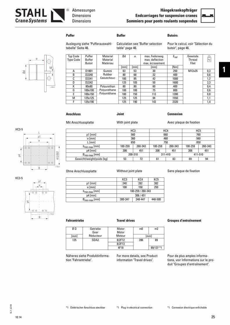
Puffer
Auslegung siehe "Pufferauswahl-tabelle" Seite 46.
Anschluss
Mit Anschlussplatte
Ohne Anschlussplatte
Fahrantriebe
Näheres siehe Produktinforma-tion "Fahrantriebe".
Typ CodeType Code
PufferBufferButoir
MaterialMaterialMatériau
A D1801 GummiRubber
CaoutchouB D2240C D2241D D2242K 80x80 Polyuretha
PolyurethanPolyuréthan
G 100x100E 100x150M 125x125F 125x190
p1 [mm]e [mm]L [mm]
bmin-max [mm]p4 [mm]
Bmin-max [mm]Gewicht/weight/poids [kg]
p1 [mm]e [mm]
bmin-max [mm]p4 [mm]
Bmin-max [mm]
Ø D GetriebeGear
Réducteur[mm]125 SDA2
*1 Elektrischer Anschluss steckbar
25
HL-T
_02.
FM
26
HängekrankopfträgerEndcarriages for suspension cranesSommiers pour ponts roulants suspendus
AbmessungenDimensionsDimensions
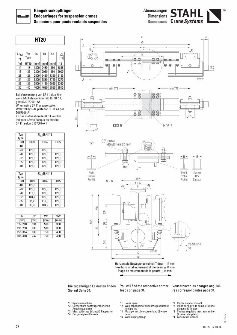
Bei Verwendung von SF 11 bitte Hin-weis: Mit Fahrwerksschild für SF 11, gemäß D157001-A!When using SF 11 please state: With trolley side plate for SF 11 as per D157001-A!En cas d’utilisation de SF 11 veuillez indiquer : Avec flasque du chariot SF 11, selon D157001-A !
HT20
L1zul
*1
TypType
k0 k1 L5
[m] HT20 [mm] [mm] [mm] *214 -18 1800 2480 360 184818 -23 2300 2980 860 200021 -28 2800 3480 1360 215024 -32 3200 3880 1760 227026 -35 3500 4180 2060 236030 -40 4000 4680 2560 2510
TypType
Rzul [kN] *3
HT20 HD3 HD4 HD5-18 - - --23 125,0 125,0 --28 125,0 125,0 125,0-32 125,0 125,0 125,0-35 125,0 125,0 125,0-40 125,0 125,0 125,0
TypType
Rzul [kN] *3
HT20 KD3 KD4 KD5-18 125,0 - --23 125,0 125,0 125,0-28 119,0 125,0 125,0-32 104,2 125,0 125,0-35 95,2 119,0 125,0-40 83,3 104,2 125,0
b b2 W1 W2[mm] [mm] [mm] [mm]
127-210 534 590 300211-258 638 590 300259-314 638 750 460315-418 742 750 460
You will find the respective corner loads on page 34.
Vr
*1 Crane span*2 Weight per pair of endcarriages without
joint plates*3 Max. permissible corner load (2 wheel
pairs)*4 With sloping flange
**
*
*
k1
k0
=
L5
min
HD3-53-5
Z
c1701v07
0.9 ISO 4014
W2
b46 76
b2
±2°
b + 92
W1
Ø22
orizontale Bewegungsfreiheit Träger + 14 mmee horizontal movement of the beam + 14 mmPlage de mouvement de la poutre + 14 mm
ous trouvez les charges angulai-es correspondantes page 34.
1 Portée du pont roulant2 Poids par paire de sommiers sans
plaques de fixaton3 Charge angulaire max. admissible
(2 paires de galets)4 Avec bride inclinée
Ød
c1700v07
e
320
R
775
B B
23 (34,1) *436
ProfilProfileProfilé
KastenBox
Caisson
Die zugehörigen Ecklasten finden Sie auf Seite 34.
*1 Spannweite Kran*2 Gewicht pro Kopfträgerpaar ohne
Anschlussplatten*3 Max. zulässige Ecklast (2 Radpaare)*4 Bei geneigtem Flansch
=R
A
A
m2
m0
min 775
KD
"Z"590 NmM20x90-1
B
200
6024
5
260
159
A - A
ProfilProfileProfilé
565
HFr
10.1405.05.15/
HL-T
_02.
FM
10.14
AbmessungenDimensionsDimensions
HängekrankopfträgerEndcarriages for suspension cranes
Sommiers pour ponts roulants suspendus
1
c1686v01
e
Ød
M
B
p1
c1741v01
Hp5
L
e
p4
HD3-5
p1
Bc1741v02
e
p5p4
KD3-5
Buffer
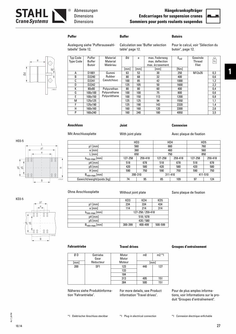
Calculation see "Buffer selection table" page 12.
Joint
With joint plate
Without joint plate
Travel drives
For more details, see Product information "Travel drives".
B
Pb
C
A
S
G
Ptd
Ød e max. Federwegmax. deflection
max. écrasement[mm] [mm] [mm]
c
63 53 3080 68 32
100 85 42125 105 50
nee
80 80 60100 100 75100 150 113125 125 94125 190 143160 160 120160 240 180
HD3 HD4560 660360 460650 750
127-258 259-418 127-258518 678 518420 580 420590 750 590
200-310 311-474 95 85
KD3 KD4 KD5234 334 434114 214 314
127-258 / 259-418518 / 678420 / 580
300-399 400-499 500-599
MotorMotor
Moteur
m0 m2 *1
[mm]123 440 127133184313 495 151384 500 151
*1 Plug-in electrical connection *
utoirs
our le calcul, voir "Sélection du utoir", page 12.
onnexion
vec plaque de fixation
ans plaque de fixation
roupes d’entraînement
our de plus amples informa-ions, voir Informations sur le pro-uit "Groupes d’entraînement".
Ezul GewindeThread
Filet[Nm]250 M12x35 0,3400 0,6
1000 1,21600 2,3400 0,4800 0,6
1200 0,81550 1,12320 1,43300 2,64950 3,5
HD5760560850
259-418 127-258 259-418678 518 678580 420 580750 590 750
10 411-510109 97 124
1 Connexion électrique enfichable
Puffer
Auslegung siehe "Pufferauswahl-tabelle" Seite 12.
Anschluss
Mit Anschlussplatte
Ohne Anschlussplatte
Fahrantriebe
Näheres siehe Produktinforma-tion "Fahrantriebe".
Typ CodeType Code
PufferBufferButoir
MaterialMaterialMatériau
A D1801 GummiRubber
CaoutchouB D2240C D2241D D2242K 80x80 Polyuretha
PolyurethanPolyuréthan
G 100x100E 100x150M 125x125F 125x190H 160x160P 160x240
p1 [mm]e [mm]L [mm]
bmin-max [mm]p4 [mm]p5 [mm]H [mm]
Bmin-max [mm]Gewicht/weight/poids [kg]
p1 [mm]e [mm]
bmin-max [mm]p4 [mm]p5 [mm]
Bmin-max [mm]
Ø D GetriebeGear
Réducteur[mm]200 SF1
*1 Elektrischer Anschluss steckbar
27

HL-T
_03.
FM
28
HängekrankopfträgerEndcarriages for suspension cranesSommiers pour ponts roulants suspendus
OptionenOptionsOptions
4
4.1
Options
Paint/corrosion protection
Standard pre-treatment: Steel shot de-rusting grade SA2.5 in acc. with EN ISO 12944-4. Machined surfaces, aluminium and deep-drawn parts degreased.
Standard primer coat:
All endcarriages and joint plates: epoxy resin-based two-compo-nent primer (KorroE), 20 µm. Colour oxide red (RAL 3009), can be welded.
Trolley side plates: top coat black grey RAL 7021, total thickness approx. 120 µm.
Option• Epoxy resin-based two-com-
ponent primer, 60 µm. Colour agate grey (RAL 7038), cannot be welded (must be removed before welding).
• Epoxy resin-based two-com-ponent top coat, 120 µm. Colour melon yellow (RAL 1028), corrosivity category C3. Others on request.
O
P
TGdSmd
C
Tfcs2Cs
Ffs
O•
•
ptions
einture/protection anticorrosive
raitement préalable standard : renaillé selon DIN EN ISO 12944-4 ; egré de dérouillage SA2,5. urfaces usinées, pièces en alu-inium et pièces embouties,
égraissées.
ouche d'apprêt standard :
ous les sommiers et plaques de ixation : ouche d'apprêt à deux compo-ants à base d'époxy (KorroE), 0 µm. ouleur rouge oxyde (RAL 3009), oudable.
lasques des chariots : couche de inition gris noir RAL 7021, épais-eur de couche totale env. 120 µm.
ptionCouche d'apprêt à deux com-posants à base d'époxy, 60 µm. Couleur gris agate (RAL 7038), pas soudable (doit être éli-miné avant le soudage).
Couche de finition à deux com-posants à base de résine epoxy, 120 µm. Couleur jaune melon (RAL 1028), catégorie de corrosivité C3. Autres sur demande.
Standard-Vorbehandlung: Stahlkiesentrostung nach DIN EN ISO 12944-4, Entrostungs-grad SA2,5. Bearbeitete Flächen, Alu- und Tiefziehteile entfettet.
Standard-Grundanstrich:
Alle Kopfträger und Anschluss-platten: Zweikomponenten-Grundierung auf Epoxidharzbasis (KorroE), 20 µm. Farbton oxidrot (RAL 3009), schweißfähig.
Fahrwerksschilder: Deckanstrich schwarzgrau RAL 7021, Gesamt-schichtdicke ca. 120 µm.
Option• Zweikomponenten-Grundie-
rung auf Epoxidharzbasis, 60 µm. Farbton achatgrau (RAL 7038), nicht schweißfähig (muss vor dem Schweißen entfernt wer-den).
• Zweikomponenten-Deckan-strich auf Epoxidharzbasis, 120 µm. Farbton melonengelb (RAL 1028), Korrosivitätskategorie C3. Andere auf Anfrage.
Optionen
Lackierung/Korrosionsschutz
10.1408.01.15/
HL-T
_03.
FM
10.14
OptionenOptionsOptions
HängekrankopfträgerEndcarriages for suspension cranes
Sommiers pour ponts roulants suspendus
1
4.2
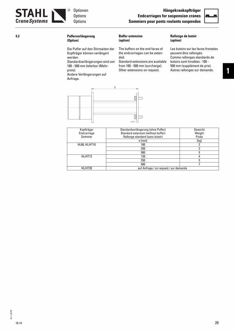
Buffer extension(option)The buffers on the end faces of the endcarriages can be exten-ded.Standard extensions are available from 100 - 500 mm (surcharge).Other extensions on request.
R(
LpCb5A
Standardverlängerung (ohne Puffer)Standard extension (without buffer)
Rallonge standard (sans butoir)e [mm]
100250500120250500
auf Anfrage / on request /
c1682v01
allonge de butoiroption)
es butoirs sur les faces frontales euvent être rallongés.omme rallonges standards de utoirs sont livrables : 100 - 00 mm (supplément de prix).utres rallonges sur demande.
GewichtWeightPoids[kg]
235457
sur demande
(Option)
Die Puffer auf den Stirnseiten der Kopfträger können verlängert werden.Standardverlängerungen sind von 100 - 500 mm lieferbar (Mehr-preis).Andere Verlängerungen auf Anfrage.
Pufferverlängerung
KopfträgerEndcarriage
Sommier
HL08, HL/HT10
HL/HT13
HL/HT20
e
29
HL-T
_03.
FM
30
HängekrankopfträgerEndcarriages for suspension cranesSommiers pour ponts roulants suspendus
OptionenOptionsOptions
4.3
e
l bx
Galets de guidage horizontaux(option)
Des galets de guidage horizon-taux avec jeu d’écartement régla-ble en continu peuvent être montés aux extrémités des som-miers pour absorber les contrain-tes horizontales perpendiculaires à la voie. Ils réduisent l’usure des boudins et des faces latérales du chemin de roulement. Pour cela, il est nécessaire que le chemin de rou-lement guidant soit installé con-formément aux normes.Les galets de guidage sont dimen-sionnés pour une force horizon-tale de 10% de la réaction maximale admissible du galet.
Dans la commande il faut indiquer :• Largeur d'aile du chemin de
roulement• Côté de montage au pont rou-
lant (sommier gauche ou droit, le côté opposé est équipé d'une rallonge de butoir appro-prié)
x e GewichtWeightPoids
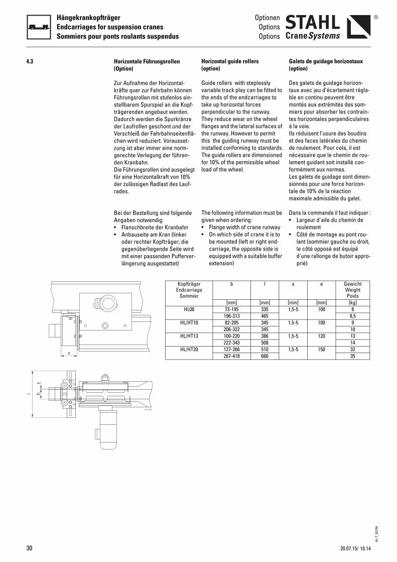
[mm] [mm] [kg]1,5-5 100 8
8,51,5-5 100 9
101,5-5 120 13
141,5-5 150 32
35
Horizontal guide rollers(option)
Guide rollers with steplessly variable track play can be fitted to the ends of the endcarriages to take up horizontal forces perpendicular to the runway. They reduce wear on the wheel flanges and the lateral surfaces of the runway. However to permit this the guiding runway must be installed conforming to standards.The guide rollers are dimensioned for 10% of the permissible wheel load of the wheel.
The following information must be given when ordering:• Flange width of crane runway• On which side of crane it is to
be mounted (left or right end-carriage, the opposite side is equipped with a suitable buffer extension)
erger
b l
[mm] [mm]73-195 335
196-313 4650 82-205 345
206-322 3453 100-220 386
222-343 5080 127-266 510
267-418 660
(Option)
Zur Aufnahme der Horizontal-kräfte quer zur Fahrbahn können Führungsrollen mit stufenlos ein-stellbarem Spurspiel an die Kopf-trägerenden angebaut werden.Dadurch werden die Spurkränze der Laufrollen geschont und der Verschleiß der Fahrbahnseitenflä-chen wird reduziert. Vorausset-zung ist aber immer eine norm-gerechte Verlegung der führen-den Kranbahn.Die Führungsrollen sind ausgelegt für eine Horizontalkraft von 10% der zulässigen Radlast des Lauf-rades.
Bei der Bestellung sind folgende Angaben notwendig:• Flanschbreite der Kranbahn• Anbauseite am Kran (linker
oder rechter Kopfträger; die gegenüberliegende Seite wird mit einer passenden Pufferver-längerung ausgestattet)
Horizontale Führungsrollen
c1711v01
KopfträgEndcarria
Sommie
HL08
HL/HT1
HL/HT1
HL/HT2
10.1420.07.15/
HL-T
_03.
FM
10.14
OptionenOptionsOptions
HängekrankopfträgerEndcarriages for suspension cranes
Sommiers pour ponts roulants suspendus
1
4.4
/20.07.15
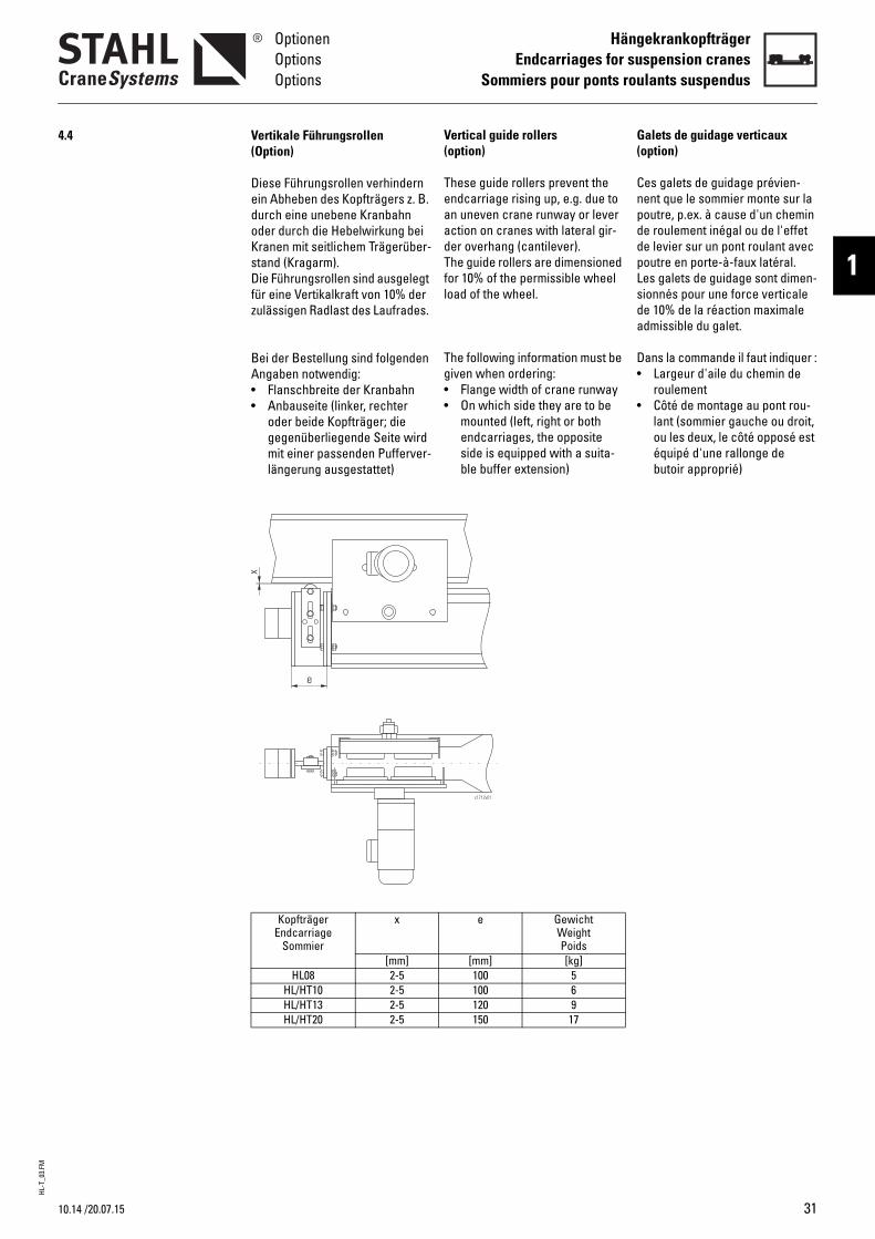
Vertical guide rollers(option)
These guide rollers prevent the endcarriage rising up, e.g. due to an uneven crane runway or lever action on cranes with lateral gir-der overhang (cantilever).The guide rollers are dimensioned for 10% of the permissible wheel load of the wheel.
The following information must be given when ordering:• Flange width of crane runway• On which side they are to be
mounted (left, right or both endcarriages, the opposite side is equipped with a suita-ble buffer extension)
G(
CnpddpLsda
D•
•
e GewichtWeightPoids
[mm] [kg]100 5100 6120 9150 17
c1712v01
alets de guidage verticauxoption)
es galets de guidage prévien-ent que le sommier monte sur la outre, p.ex. à cause d'un chemin e roulement inégal ou de l'effet e levier sur un pont roulant avec outre en porte-à-faux latéral.es galets de guidage sont dimen-ionnés pour une force verticale e 10% de la réaction maximale dmissible du galet.
ans la commande il faut indiquer :Largeur d'aile du chemin de roulementCôté de montage au pont rou-lant (sommier gauche ou droit, ou les deux, le côté opposé est équipé d'une rallonge de butoir approprié)
(Option)
Diese Führungsrollen verhindern ein Abheben des Kopfträgers z. B. durch eine unebene Kranbahn oder durch die Hebelwirkung bei Kranen mit seitlichem Trägerüber-stand (Kragarm).Die Führungsrollen sind ausgelegt für eine Vertikalkraft von 10% der zulässigen Radlast des Laufrades.
Bei der Bestellung sind folgenden Angaben notwendig:• Flanschbreite der Kranbahn• Anbauseite (linker, rechter
oder beide Kopfträger; die gegenüberliegende Seite wird mit einer passenden Pufferver-längerung ausgestattet)
Vertikale Führungsrollen
KopfträgerEndcarriage
Sommier
x
[mm]HL08 2-5
HL/HT10 2-5HL/HT13 2-5HL/HT20 2-5
e
x
31
HL-T
_03.
FM
32
HängekrankopfträgerEndcarriages for suspension cranesSommiers pour ponts roulants suspendus
OptionenOptionsOptions
4.5
4.6
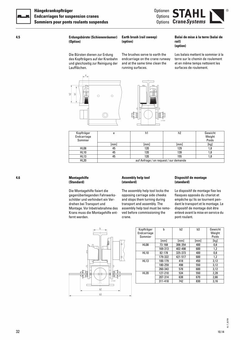
Earth brush (rail sweep)(option)
The brushes serve to earth the endcarriage on the crane runway and at the same time clean the running surfaces.
Assembly help tool(standard)
The assembly help tool locks the opposing carriage side cheeks and stops them turning during transport and assembly. The assembly help tool must be remo-ved before commissioning the crane.
Br(
Ltes
D(
Lfeddep
h1
[mm]120120120
auf Anfrage / on request / sur d
c1713v01
KopfträgerEndcarriage
Sommier
b
[mm]HL08 73-168
169-313HL10 82-178
179-322HL13 100-179
180-259260-343
HL20 127-210207-314311-418
alai de mise à la terre (balai de ail)option)
es balais mettent le sommier à la erre sur le chemin de roulement t en même temps nettoient les urfaces de roulement.
ispositif de montagestandard)
e dispositif de montage fixe les lasques opposés du chariot et mpêche qu'ils se tournent pen-ant le transport et le montage. Le ispositif de montage doit être nlevé avant la mise en service du ont roulant.
h2 GewichtWeightPoids
[mm] [kg]129 1,8139 1,8155 1,8
emande
b2 b3 GewichtWeightPoids
[mm] [mm] [kg]306-354 400 0,8402-498 600 1,2325-373 400 0,8421-517 600 1,2
418 450 3,12498 550 3,12578 600 3,12534 550 2,28638 670 2,66742 830 3,16
(Option)
Die Bürsten dienen zur Erdung des Kopfträgers auf der Kranbahn und gleichzeitig zur Reinigung der Laufflächen.
(Standard)
Die Montagehilfe fixiert die gegenüberliegenden Fahrwerks-schilder und verhindert ein Ver-drehen bei Transport und Montage. Vor Inbetriebnahme des Krans muss die Montagehilfe ent-fernt werden.
Erdungsbürste (Schienenräumer)
KopfträgerEndcarriage
Sommier
e
[mm]HL08 45HL10 45HL13 45HL20
Montagehilfe
h1e
h2
c1714v01
b
b2
b3
10.14
HL-T
_03.
FM
10.14
OptionenOptionsOptions
HängekrankopfträgerEndcarriages for suspension cranes
Sommiers pour ponts roulants suspendus
1
4.7
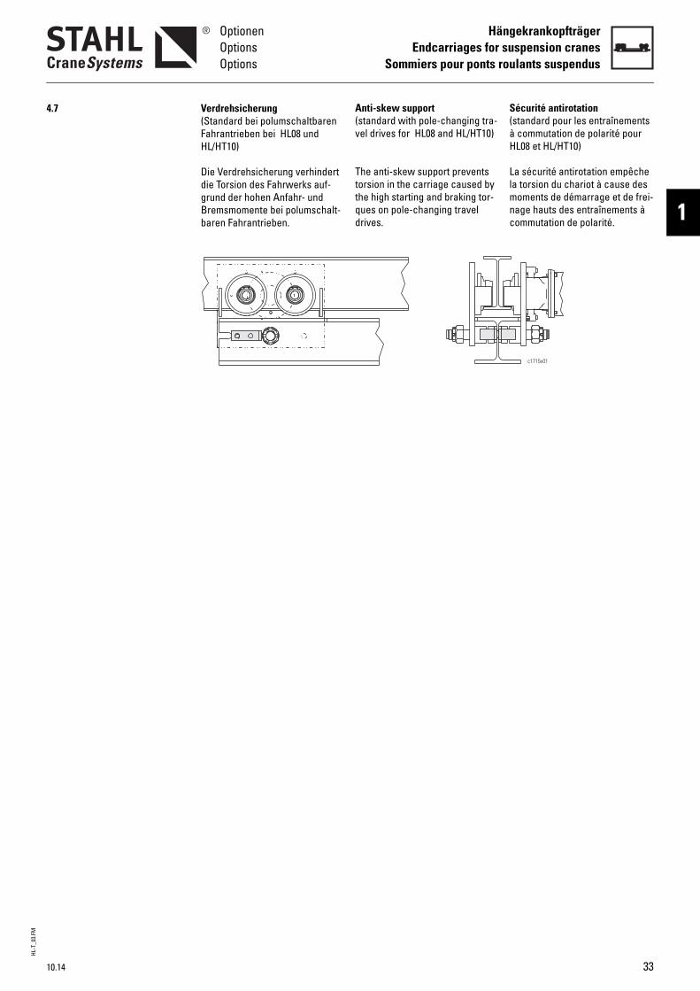
Anti-skew support(standard with pole-changing tra-vel drives for HL08 and HL/HT10)The anti-skew support prevents torsion in the carriage caused by the high starting and braking tor-ques on pole-changing travel drives.
S(àH
Llmnc
écurité antirotationstandard pour les entraînements commutation de polarité pour L08 et HL/HT10)
a sécurité antirotation empêche a torsion du chariot à cause des
oments de démarrage et de frei-age hauts des entraînements à ommutation de polarité.
c1715v01
(Standard bei polumschaltbaren Fahrantrieben bei HL08 und HL/HT10)
Die Verdrehsicherung verhindert die Torsion des Fahrwerks auf-grund der hohen Anfahr- und Bremsmomente bei polumschalt-baren Fahrantrieben.
Verdrehsicherung
33
HL-T
_03.
FM
34
HängekrankopfträgerEndcarriages for suspension cranesSommiers pour ponts roulants suspendus
Technische DatenTechnical data
Caractéristiques techniques
5
5.1
AnschlussJoint
Connexion
Mit AnschlussplatteWith joint plate
Avec plaque de fixationOhne Anschlussplatte
Without joint plateSans plaque de fixation
Geschweißt / Welded / Soudée
5.2
5.2.1
5.2.2
5.2.3
5.2.4
Caractéristiques techniques
Vue d’ensemble des combinai-sons des fixations de sommier
Charges angulaires idéales admissibles selon la durée de vie des paliers
HL08
HL/HT10
HL/HT13
HL/HT20
HT13 HT20HC3HC4HC5
HD3HD4HD5
KC3KC4KC5
KD3KD4KD5
- -
igkeit v in [m/min]d v in [m/min]ement v en [m/min]
32 40] *3
21,7 21,721,7 21,721,3 19,8
igkeit v in [m/min]d v in [m/min]ement v en [m/min]
32 40] *3
40,0 40,040,0 40,038,2 35,4
igkeit v in [m/min]d v in [m/min]ement v en [m/min]
32 40] *3
70,0 70,070,0 70,066,1 61,4
igkeit v in [m/min]d v in [m/min]ement v en [m/min]
32 40] *3
125,0 125,0125,0 125,0112,2 104,2
*3 Charge angulaire max. admissible (2 paires de galets)
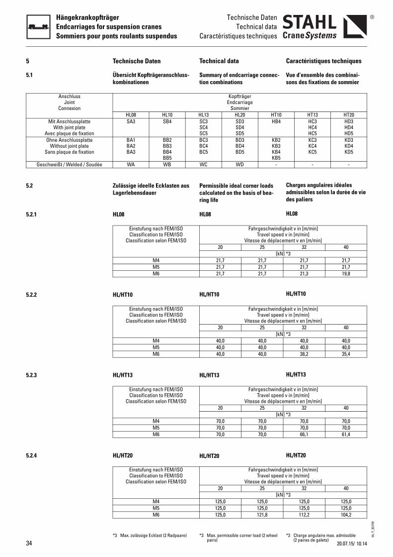
Technical data
Summary of endcarriage connec-tion combinations
Permissible ideal corner loads calculated on the basis of bea-ring life
HL08
HL/HT10
HL/HT13
HL/HT20
KopfträgerEndcarriage
SommierHL13 HL20 HT10SC3SC4SC5
SD3SD4SD5
HB4
BC3BC4BC5
BD3BD4BD5
KB2KB3KB4KB5
WC WD -
FahrgeschwindTravel spee
Vitesse de déplac20 25
[kN21,7 21,721,7 21,721,7 21,7
FahrgeschwindTravel spee
Vitesse de déplac20 25
[kN40,0 40,040,0 40,040,0 40,0
FahrgeschwindTravel spee
Vitesse de déplac20 25
[kN70,0 70,070,0 70,070,0 70,0
FahrgeschwindTravel spee
Vitesse de déplac20 25
[kN125,0 125,0125,0 125,0125,0 121,8
*3 Max. permissible corner load (2 wheel pairs)
10.1420.07.15/
Technische Daten
Übersicht Kopfträgeranschluss-kombinationen
HL08 HL10SA3 SB4
BA1BA2BA3
BB2BB3BB4BB5
WA WB
Zulässige ideelle Ecklasten aus Lagerlebensdauer
HL08
Einstufung nach FEM/ISOClassification to FEM/ISO
Classification selon FEM/ISO
M4M5M6
HL/HT10
Einstufung nach FEM/ISOClassification to FEM/ISO
Classification selon FEM/ISO
M4M5M6
HL/HT13
Einstufung nach FEM/ISOClassification to FEM/ISO
Classification selon FEM/ISO
M4M5M6
HL/HT20
Einstufung nach FEM/ISOClassification to FEM/ISO
Classification selon FEM/ISO
M4M5M6
*3 Max. zulässige Ecklast (2 Radpaare)
Laufkrankopfträger _ Produktinformation
Endcarriages for Overhead Travelling Cranes _ Product Information
Sommiers pour ponts roulants posés _ Informations sur le produit
2
LE
LS
LT

LS-T
_01.
FM
LaufkrankopfträgerEndcarriages for o.h.t. cranesSommiers pour ponts roulants posés
LELSLT
Mit den Laufkrankopfträgern LE/LS/LT können moderne Einträ-ger- und Zweiträgerlaufkrane bis zu einer Tragfähigkeit von 50.000 kg und einer Spannweite bis zu 41 m gebaut werden.
Nutzen Sie die robuste Konstruk-tion, kompakte Bauweise, War-tungsfreundlichkeit und Zuver-lässigkeit in Verbindung mit den wirtschaftlichen Vorteilen der Serienfertigung für Ihren Kran-bau.
On the basis of LE/LS/LT endcar-riages for overhead travelling cranes, modern single girder and double girder overhead travelling cranes up to a working load of 50,000 kg and a span of 41 m can be manufactured.
Make use of their sturdy design, compact construction, mainte-nance friendliness and reliability in conjunction with the economic advantages of series production for your crane manufacturing.
Avec les sommiers pour ponts roulants posés LE/LS/LT, il peut être construit des ponts roulants posés modernes ayant une charge d'utilisation allant jusqu'à 50.000 kg et une portée allant jusqu'à 41 m.
Profitez de la construction robuste et compacte, de la facilité d'entretien et de la fiabilité allant de pair avec les avantages éco-nomiques de la fabrication en série pour votre construction de ponts roulants.
Symbole Symbols Symboles
Maximale Tragfähigkeit [kg] Maximum working load [kg] Charge maximale d’utilisation [kg]
Gewicht [kg] Weight [kg] Poids [kg]
Fahrgeschwindigkeit [m/min] Travel speed [m/min] Vitesse de déplacement [m/min]
Abmessungen siehe Seite .. Dimensions see page .. Dimensions voir page ..
↑ Siehe Seite .. See page .. Voir page ..
36 10.14
LS-T
_01.
FMLaufkrankopfträger
Endcarriages for o.h.t. cranesSommiers pour ponts roulants posés
2
Inhaltsverzeichnis Table of contents Table des matières
Symbole............................................ 36 Symbols............................................ 36 Symboles ..........................................36
1 Die Technik im Überblick ............. 39 Technical features at a glance.... 39 La technique en un coup d’oeil ....391.1 Ausstattung...................................... 40 Equipment ........................................ 40 Équipement.......................................401.2 Typenbezeichnung.......................... 41 Type designation............................. 41 Désignation du type ........................41
2 Auswahlanleitung.......................... 43 Selection instructions................... 43 Instructions pour la sélection ......432.1 Grobauswahl ................................... 43 Rough determination...................... 43 Détermination approximatif...........432.2 Bestimmung der notwendigen Ein-
stufung.............................................. 44Calculation of necessary classifica-tion .................................................... 44
Détermination de la classification nécessaire........................................44
2.3 Bestimmung der Kopfträgergröße45 Determination of endcarriage size 45 Détermination de la taille du som-mier....................................................45
2.4 Ermittlung der erforderlichen Schie-nenbreite k ....................................... 45
Calculation of required rail width k..45 Calcul de la largeur de rail néces-saire k................................................45
2.5 Bestimmung des Abstands a der Anschlussplatten (Zweiträgerlauf-kran) .................................................. 45
Determining spacing a between joint plates (double girder o.h.t. crane) ............................................... 45
Détermination de l'écart a des pla-ques de fixation (pont roulant posé bipoutre)............................................45
2.6 Bestimmung des Fahrantriebs...... 45 Determination of travel drive........ 45 Détermination de l'entraînement..452.7 Bestimmung des Kranpuffers ....... 46 Determination of crane buffer...... 46 Détermination du butoir .................462.7.1 Pufferauswahltabelle..................... 46 Buffer selection table .................... 46 Sélection du butoir..........................462.8 Fahrbahnendanschläge................. 47 Runway end stops .......................... 47 Butées de fin de chemin de roule-
ment...................................................472.9 Erklärung der Abkürzungen .......... 47 Explanation of abbreviations ........ 47 Explication des abbréviations .......47
3 Abmessungen.................................. 48 Dimensions...................................... 48 Dimensions ......................................48Kopfträger für Einträgerlaufkrane Endcarriages for single girder
o.h.t. cranesSommiers pour ponts roulants posés monopoutre
LE-09.................................................. 48 LE-09 ................................................. 48 LE-09 ..................................................48LS/LT-09 ............................................ 50 LS/LT-09 ............................................ 50 LS/LT-09.............................................50LS/LT-11 ............................................ 52 LS/LT-11 ............................................ 52 LS/LT-11.............................................52LS/LT-14 ............................................ 54 LS/LT-14 ............................................ 54 LS/LT-14.............................................54LS/LT-16 ............................................ 56 LS/LT-16 ............................................ 56 LS/LT-16.............................................56LT-20 .................................................. 58 LT-20.................................................. 58 LT-20...................................................58LT-25 .................................................. 60 LT-25.................................................. 60 LT-25...................................................60LT-32 .................................................. 62 LT-32.................................................. 62 LT-32...................................................62LT-40 .................................................. 64 LT-40.................................................. 64 LT-40...................................................64
Kopfträger für Zweiträgerlaufkrane Endcarriages for double girder o.h.t. cranes
Sommiers pour ponts roulants posés bipoutre
LE-09.................................................. 66 LE-09 ................................................. 66 LE-09 ..................................................66LS/LT-09 ............................................ 68 LS/LT-09 ............................................ 68 LS/LT-09.............................................68LS/LT-11 ............................................ 70 LS/LT-11 ............................................ 70 LS/LT-11.............................................70LS/LT-14 ............................................ 72 LS/LT-14 ............................................ 72 LS/LT-14.............................................72LS/LT-16 ............................................ 74 LS/LT-16 ............................................ 74 LS/LT-16.............................................74LT-20 .................................................. 76 LT-20.................................................. 76 LT-20...................................................76LT-25 .................................................. 78 LT-25.................................................. 78 LT-25...................................................78LT-32 .................................................. 80 LT-32.................................................. 80 LT-32...................................................80LT-40 .................................................. 82 LT-40.................................................. 82 LT-40...................................................82
Gekoppelte Kopfträger Coupled endcarriages Sommiers couplésLT-20B ............................................... 84 LT-20B ............................................... 84 LT-20B................................................84LT-25B ............................................... 86 LT-25B ............................................... 86 LT-25B................................................86LT-32B ............................................... 88 LT-32B ............................................... 88 LT-32B................................................88LT-40B ............................................... 90 LT-40B ............................................... 90 LT-40B................................................90
10.14 37
LS-T
_01.
FM
LaufkrankopfträgerEndcarriages for o.h.t. cranesSommiers pour ponts roulants posés
4 Optionen........................................... 92 Options ............................................. 92 Options..............................................924.1 Lackierung/Korrosionsschutz....... 92 Paint/corrosion protection............ 92 Peinture/protection anticorrosive .924.2 Pufferverlängerung ........................ 93 Buffer extension ............................. 93 Rallonge de butoir ...........................934.3 Wegfall der Anschlussplatten ...... 93 Non-supply of joint plates ............. 93 Suppression des plaques de fixa-
tion.................................................... 934.4 Führungsrollen ................................ 93 Guide rollers .................................... 93 Galets de guidage ...........................934.5 Abhebesicherung ........................... 96 Anti-jump catch .............................. 96 Dispositif anti-soulèvement...........964.6 Schienenräumer ............................. 97 Rail sweep ....................................... 97 Balai de rail ......................................974.7 Sturmsicherung............................... 97 Storm lock device........................... 97 Sécurité-tempête ............................974.8 Polyurethanbeschichtete Laufräder
(ohne Spurkranz)............................. 99Polyurethane-coated wheels (with-out flanges)...................................... 99
Galets revêtus de polyuréthane (sans boudins)..................................99
5 Technische Daten......................... 100 Technical data .............................. 100 Caractéristiques techniques ......1005.1 Übersicht Kopfträgeranschluss-
kombinationen............................... 100Summary of endcarriage connec-tion combinations ......................... 100
Vue d’ensemble des combinaisons des fixations de sommier .............100
5.1.1 Anschluss oben............................. 100 Top connection ............................. 100 Fixation par le haut........................1005.1.2 Anschluss seitlich......................... 100 Side connection............................ 100 Fixation latérale .............................1005.2 Zulässige ideelle Radlasten ........ 101 Permissible ideal wheel loads.... 101 Charges idéales admissibles par
galet.................................................101LE/LS/LT-09..................................... 101 LE/LS/LT-09..................................... 101 LE/LS/LT-09 .....................................101LS/LT-11 .......................................... 102 LS/LT-11 .......................................... 102 LS/LT-11...........................................102LS/LT-14 .......................................... 103 LS/LT-14 .......................................... 103 LS/LT-14...........................................103LS/LT-16 .......................................... 104 LS/LT-16 .......................................... 104 LS/LT-16...........................................104LT-20, LT-20B .................................. 105 LT-20, LT-20B.................................. 105 LT-20, LT-20B...................................105LT-25, LT-25B .................................. 106 LT-25, LT-25B.................................. 106 LT-25, LT-25B...................................106LT-32, LT-32B .................................. 108 LT-32, LT-32B.................................. 108 LT-32, LT-32B...................................108LT-40, LT-40B .................................. 110 LT-40, LT-40B.................................. 110 LT-40, LT-40B...................................110
5.3 Anforderungen an das Rad-/Schie-nesystem ........................................ 112
Requirements on wheel/rail system .......................................... 112
Propriétés requises du système rail/galet.................................................112
Technische Änderungen, Irrtümer und Druckfehler vorbehalten.
Subject to technical modifications, errors and printing errors excepted.
Sous réserve de modifications techni-ques, d’erreurs et de fautes d’impres-sion.
38 10.14
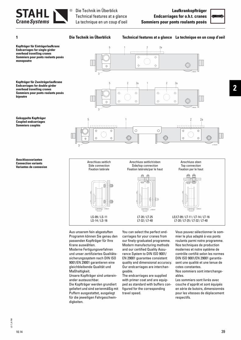
LS-T
_01.
FMDie Technik im ÜberblickTechnical features at a glanceLa technique en un coup d’oeil
LaufkrankopfträgerEndcarriages for o.h.t. cranes
Sommiers pour ponts roulants posés
2
1 Die Technik im Überblick Technical features at a glance La technique en un coup d’oeil
Kopfträger für EinträgerlaufkraneEndcarriages for single girder overhead travelling cranesSommiers pour ponts roulants posés monopoutre
Kopfträger für ZweiträgerlaufkraneEndcarriages for double girder overhead travelling cranesSommiers pour ponts roulants posés bipoutre
Gekoppelte KopfträgerCoupled endcarriagesSommiers couplés
AnschlussvariantenConnection variantsVariantes de connexion
Aus unserem fein abgestuften Programm können Sie genau den passenden Kopfträger für Ihre Krane auswählen.Moderne Fertigungsverfahren und unser zertifiziertes Qualitäts-sicherungssystem nach DIN ISO 9001/EN 29001 garantieren eine gleichbleibende Qualität und Maßhaltigkeit.Unsere Kopfträger sind unterein-ander austauschbar.Die Kopfträger werden grundiert geliefert und sind serienmäßig mit Puffern ausgestattet, ausgelegt für die jeweiligen Fahrgeschwin-digkeiten.
You can select the perfect end-carriages for your cranes from our finely-graduated programme.Modern manufacturing methods and our certified Quality Assu-rance System to DIN ISO 9001/EN 29001 guarantee consistent quality and dimensional accuracy.Our endcarriages are interchan-geable.The endcarriages are supplied with primer coat and are equip-ped as standard with buffers con-figured for the corresponding travel speed.
Vous pouvez sélectionner le som-mier le plus adapté à vos ponts roulants parmi notre programme.Nos techniques de production modernes et notre système de contrôle certifié selon les normes DIN ISO 9001/EN 29001 garantis-sent une qualité et une tenue de cotes constantes.Nos sommiers sont interchange-ables.Les sommiers sont livrés avec couche d'apprêt et sont équipés en série de butoirs, dimensionnés pour les vitesses de déplacement respectifs.
15
c1689v01
2 2a
3
15
c1690v01
2 2a2 2a
3
c1742v01
15 2 2a
3
Anschluss seitlich Anschluss seitlich/oben Anschluss obenSide connection Side/top connection Top connectionFixation latérale Fixation latérale/par le haut Fixation par le haut
LS-09 / LS-11 LT-20 / LT-25 LE/LT-09 / LT-11 / LT-14 / LT-16LS-14 / LS-16 LT-32 / LT-40 LT-20 / LT-25 / LT-32 / LT-40
c1695v01c1693v01 c1694v01
10.14 39
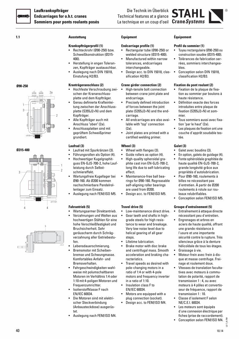
LS-T
_01.
FM
LaufkrankopfträgerEndcarriages for o.h.t. cranesSommiers pour ponts roulants posés
Die Technik im ÜberblickTechnical features at a glanceLa technique en un coup d’oeil
1.1 Ausstattung Equipment Équipement
Krankopfträgerprofil (1)• Rechteckrohr (Ø90-250) bzw.
Schweißkonstruktion (Ø315-400).
• Herstellung in engen Toleran-zen, Kopfträger austauschbar.
• Auslegung nach DIN 15018, Einstufung H2/B3.
Kranträgeranschluss (2)• Hochfeste Verschraubung zwi-
schen der Krananschluss-platte und dem Kopfträger.
• Genau definierte Krafteinlei-tung zwischen der Anschluss-platte (S355J2+N) und dem Kopfträger.
• Alle Kopfträger auch mit Anschluss "oben" (2a).
• Anschlussplatten sind mit geprüftem Schweißprimer grundiert.
Laufrad (3)• Laufrad mit Spurkränzen (3).• Führungsrollen als Option (4).• Hochwertiger Kugelgraphit-
guss EN-GJS-700-2, hohe Lauf-leistung durch Selbst-schmiereffekt.
• Wartungsfreie Kugellager bei Ø90-160. Ab Ø200 kommen nachschmierbare Pendelrol-lenlager zum Einsatz.
• Auslegung nach FEM/ISO M5.
Fahrantrieb (5)• Wartungsarmer Direktantrieb.• Verzahnungen und Wellen aus
hochwertigen Stählen für eine hohe Verschleißfestigkeit und Bruchsicherheit. Sehr geräuscharm durch Schräg-verzahnung aller Getriebestu-fen.
• Lebensdauerschmierung.• Bremsmotor mit Scheiben-
bremse und Schwungmasse. Komfortables Anfahr- und Bremsverhalten.
• Fahrgeschwindigkeiten wahl-weise mit polumschaltbaren Motoren im Verhältnis 1:4 oder 1:10 mit 4-poligen Motoren und Frequenzumrichter.
• Isolierstoffklasse F nach EN/IEC 60034.
• Die Motoren sind mit elektri-scher Steckverbindung (Anbausteckdose) ausgerüs-tet.
• Auslegung nach FEM/ISO M4.
Endcarriage profile (1)• Rectangular tube (Ø90-250) or
welded structure (Ø315-400).• Manufactured within narrow
tolerances, endcarriages interchangeable.
• Design acc. to DIN 15018, clas-sification H2/B3.
Crane girder connection (2)• High-tensile bolt connection
between crane joint plate and endcarriage.
• Precisely defined introduction of forces between the joint plate (S355J2+N) and the end-carriage.
• All endcarriages are also avai-lable with "top" connection (2a).
• Joint plates are primed with a certified welding primer.
Wheel (3)• Wheel with flanges (3).• Guide rollers as option (4).• High-quality spheroidal gra-
phite cast iron EN-GJS-700-2, long life due to self-lubricating effect.
• Maintenance-free ball bea-rings for Ø90-160. Regreasable self-aligning roller bearings are used from Ø200.
• Design acc. to FEM/ISO M5.
Travel drive (5)• Low-maintenance direct drive.• Gear teeth and shafts in high-
grade steels for high resis-tance to wear and breakage. Very low noise level due to helical gearing of all gear steps.
• Lifetime lubrication.• Brake motor with disc brake
and centrifugal mass. Smooth acceleration and braking cha-racteristics.
• Travel speeds as desired with pole-changing motors in a ratio of 1:4 or with 4-pole motors and frequency inverter in a ratio of 1:10.
• Insulation class F to EN/IEC 60034.
• Motors are equipped with a plug connection (socket).
• Design acc. to FEM/ISO M4.
Profil du sommier (1)• Tuyau rectangulaire (Ø90-250) ou
construction soudée (Ø315-400).• Tolérances de fabrication ser-
rées, sommiers interchangea-bles.
• Conception selon DIN 15018, classification H2/B3.
Fixation du pont roulant (2)• Fixation de la plaque de fixa-
tion au sommier par boulons à haute résistance.
• Définition exacte des forces introduites entre plaque de fixation (S355J2+N) et som-mier.
• Tous sommiers aussi avec fixa-tion "par le haut" (2a).
• Les plaques de fixation ont une couche d'apprêt soudable tes-tée.
Galet (3)• Galet avec boudins (3).• En option, galets de guidage (4).• Fonte sphéroïdale graphitée de
haute qualité EN-GJS-700-2, grande longévité grâce aux propriétés d'autolubrication.
• Pour Ø90-160, roulements à billes ne nécessitant pas d'entretien. À partir de Ø200 roulements à rotule sur rou-leaux relubrifiables.
• Conception selon FEM/ISO M5.
Groupe d'entraînement (5)• Entraînement à attaque directe
nécessitant peu d'entretien.• Engrenages et arbres en
aciers de haute qualité, offrant une grande résistance à l'usure et une importante sécurité contre la rupture. Très silencieux grâce à la denture hélicoïdale de tous les étages.
• Graissage à vie.• Moteur-frein avec frein à dis-
que et masse centrifuge. Frei-nage et roulement doux.
• Vitesses de translation faculta-tives avec moteurs à commu-tation de polarité, rapport de transmission 1 : 4, ou avec moteurs à 4 pôles et convertis-seur de fréquence, rapport de transmission 1 : 10.
• Classe d'isolement F selon NE/C.E.I. 60034.
• Les moteurs sont équipés d'une connexion électrique par fiches (prise de raccordement).
• Conception selon FEM/ISO M4.
c0117v01
4 4
2
1
3
c0103v17
2
2a
1
3
c1691v01
5
Ø90-250
Ø315-400
40 10.14
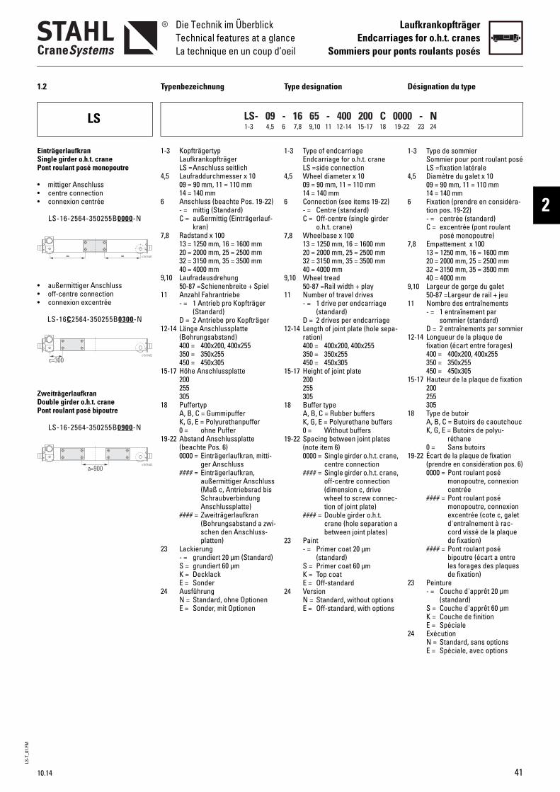
LS-T
_01.
FMDie Technik im ÜberblickTechnical features at a glanceLa technique en un coup d’oeil
LaufkrankopfträgerEndcarriages for o.h.t. cranes
Sommiers pour ponts roulants posés
2
1.2 Typenbezeichnung Type designation Désignation du type
LS
1-3 KopfträgertypLaufkrankopfträgerLS =Anschluss seitlich
4,5 Laufraddurchmesser x 1009 = 90 mm, 11 = 110 mm14 = 140 mm
6 Anschluss (beachte Pos. 19-22)- = mittig (Standard)C = außermittig (Einträgerlauf-
kran)7,8 Radstand x 100
13 = 1250 mm, 16 = 1600 mm20 = 2000 mm, 25 = 2500 mm32 = 3150 mm, 35 = 3500 mm40 = 4000 mm
9,10 Laufradausdrehung50-87 =Schienenbreite + Spiel
11 Anzahl Fahrantriebe- = 1 Antrieb pro Kopfträger
(Standard)D = 2 Antriebe pro Kopfträger
12-14 Länge Anschlussplatte (Bohrungsabstand)400 = 400x200, 400x255350 = 350x255450 = 450x305
15-17 Höhe Anschlussplatte200255305
18 PuffertypA, B, C = GummipufferK, G, E = Polyurethanpuffer0 = ohne Puffer
19-22 Abstand Anschlussplatte (beachte Pos. 6)0000 = Einträgerlaufkran, mitti-
ger Anschluss#### = Einträgerlaufkran,
außermittiger Anschluss (Maß c, Antriebsrad bis Schraubverbindung Anschlussplatte)
#### = Zweiträgerlaufkran (Bohrungsabstand a zwi-schen den Anschluss-platten)
23 Lackierung- = grundiert 20 µm (Standard)S = grundiert 60 µmK = DecklackE = Sonder
24 AusführungN = Standard, ohne OptionenE = Sonder, mit Optionen
1-3 Type of endcarriageEndcarriage for o.h.t. craneLS =side connection
4,5 Wheel diameter x 1009 = 90 mm, 11 = 110 mm14 = 140 mm
6 Connection (see items 19-22)- = Centre (standard)C = Off-centre (single girder
o.h.t. crane)7,8 Wheelbase x 100
13 = 1250 mm, 16 = 1600 mm20 = 2000 mm, 25 = 2500 mm32 = 3150 mm, 35 = 3500 mm40 = 4000 mm
9,10 Wheel tread50-87 =Rail width + play
11 Number of travel drives- = 1 drive per endcarriage
(standard)D = 2 drives per endcarriage
12-14 Length of joint plate (hole sepa-ration)400 = 400x200, 400x255350 = 350x255450 = 450x305
15-17 Height of joint plate200255305
18 Buffer typeA, B, C = Rubber buffersK, G, E = Polyurethane buffers0 = Without buffers
19-22 Spacing between joint plates (note item 6)0000 = Single girder o.h.t. crane,
centre connection#### = Single girder o.h.t. crane,
off-centre connection (dimension c, drive wheel to screw connec-tion of joint plate)
#### = Double girder o.h.t. crane (hole separation a between joint plates)
23 Paint- = Primer coat 20 µm
(standard)S = Primer coat 60 µmK = Top coatE = Off-standard
24 VersionN = Standard, without optionsE = Off-standard, with options
1-3 Type de sommierSommier pour pont roulant poséLS =fixation latérale
4,5 Diamètre du galet x 1009 = 90 mm, 11 = 110 mm14 = 140 mm
6 Fixation (prendre en considéra-tion pos. 19-22)- = centrée (standard)C = excentrée (pont roulant
posé monopoutre)7,8 Empattement x 100
13 = 1250 mm, 16 = 1600 mm20 = 2000 mm, 25 = 2500 mm32 = 3150 mm, 35 = 3500 mm40 = 4000 mm
9,10 Largeur de gorge du galet50-87 =Largeur de rail + jeu
11 Nombre des entraînements- = 1 entraînement par
sommier (standard)D = 2 entraînements par sommier
12-14 Longueur de la plaque de fixation (écart entre forages)400 = 400x200, 400x255350 = 350x255450 = 450x305
15-17 Hauteur de la plaque de fixation200255305
18 Type de butoirA, B, C = Butoirs de caoutchoucK, G, E = Butoirs de polyu-
réthane0 = Sans butoirs
19-22 Écart de la plaque de fixation (prendre en considération pos. 6)0000 = Pont roulant posé
monopoutre, connexion centrée
#### = Pont roulant posé monopoutre, connexion excentrée (cote c, galet d'entraînement à rac-cord vissé de la plaque de fixation)
#### = Pont roulant posé bipoutre (écart a entre les forages des plaques de fixation)
23 Peinture- = Couche d'apprêt 20 µm
(standard)S = Couche d'apprêt 60 µmK = Couche de finitionE = Spéciale
24 ExécutionN = Standard, sans optionsE = Spéciale, avec options
LS- 09 - 16 65 - 400 200 C 0000 - N1-3 4,5 6 7,8 9,10 11 12-14 15-17 18 19-22 23 24
= = c1577v01
c1577v02
c=300
c1577v03
a=900
EinträgerlaufkranSingle girder o.h.t. cranePont roulant posé monopoutre
• mittiger Anschluss• centre connection• connexion centrée
LS-16-2564-350255B0000-N
• außermittiger Anschluss• off-centre connection• connexion excentrée
LS-16C2564-350255B0300-N
ZweiträgerlaufkranDouble girder o.h.t. cranePont roulant posé bipoutre
LS-16-2564-350255B0900-N
10.14 41

LS-T
_01.
FM
LaufkrankopfträgerEndcarriages for o.h.t. cranesSommiers pour ponts roulants posés
Die Technik im ÜberblickTechnical features at a glanceLa technique en un coup d’oeil
42 10.14
LE/LT
1-3 KopfträgertypLaufkrankopfträger LE = Anschluss obenLT = Anschluss oben oder
seitlich/oben4,5 Laufraddurchmesser x 10
09 = 90 mm, 11 = 110 mm ...32 = 315 mm, 40 = 400 mm
6 Anschluss (beachte Pos. 14-17)- = mittig (Standard)B = gekoppelte Kopfträger
(Bogie)C = außermittig (Einträgerlauf-
kran)7,8 Radstand x 100
13 = 1250 mm, 16 = 1600 mm ...32 = 3150 mm ... 55 = 5500 mm
9,10 Laufradausdrehung(= Schienenbreite + Spiel)50-99 =05-99 mm05-20 =105-120mm00 = Laufrad ohne Spurkranz
11 Anzahl Fahrantriebe- = 1 Antrieb pro Kopfträger
(Standard)S = 1 angetriebenes Rad pro
gekoppelter EinheitD = 2 angetriebe Räder pro
gekoppelter Einheit12,13 Anschlussplatte
Anschluss obenA3 (LE/LT-09)A4, A6 (LT-11, LT-14)B4, B6 (LT-16) ...
Anschluss seitlich/obenR3, R4, R5, R6 (LT-20.)F4, F5, F7, F8 (LT-25.)Q3, Q4, Q5, Q6, Q7, Q8, Q9, Q0 (LT-32.)S6, S7, S9 (LT-40.)
14-17 Abstand Anschlussplatte (beachte Pos. 6)0000 = Einträgerlaufkran, mitti-
ger Anschluss#### = Einträgerlaufkran,
außermittiger Anschluss (Maß c, Antriebsrad bis Fixierstift Anschluss-platte)
#### = Zweiträgerlaufkran/gekoppelte Kopfträger (Bohrungsabstand a zwi-schen den Anschluss-platten)
18 PuffertypA, B, C, D = GummipufferK, G, E, M, F, H, P, I, S, T, Y =
Polyurethanpuffer0 = ohne Puffer
19-22 Innerer Radabstand0000 = keine gekoppelten Kopf-
träger#### = gekoppelte Kopfträger
(Abstand s der inneren Laufräder)
23 Lackierung- = grundiert 20 µm (Standard)S = grundiert 60 µmK = DecklackE = Sonder
24 AusführungN = Standard, ohne OptionenE = Sonder, mit Optionen
1-3 Type of endcarriageEndcarriage for o.h.t. craneLE =top connectionLT = top connection or side/top
connection4,5 Wheel diameter x 10
09 = 90 mm, 11 = 110 mm ...32 = 315 mm, 40 = 400 mm
6 Connection (see items 14-17)- = Centre (standard)B = Coupled endcarriages
(Bogie)C = Off-centre (single girder
o.h.t. crane)7,8 Wheelbase x 100
13 = 1250 mm, 16 = 1600 mm ...32 = 3150 mm ... 55 = 5500 mm
9,10 Wheel tread (= rail width + play)50-99 =05-99 mm05-20 =105-120mm00 = Wheel without flanges
11 Number of travel drives- = 1 drive per endcarriage
(standard)S = 1 driven wheel per coupled
unitD = 2 driven wheels per cou-
pled unit12,13 Joint plate
Top connectionA3 (LE/LT-09)A4, A6 (LT-11, LT-14)B4, B6 (LT-16) ...
Side/top connectionR3, R4, R5, R6 (LT-20.)F4, F5, F7, F8 (LT-25.)Q3, Q4, Q5, Q6, Q7, Q8, Q9, Q0 (LT-32.)S6, S7, S9 (LT-40.)
14-17 Spacing between joint pla-tes(note item 6)0000 = Single girder o.h.t. crane,
centre connection#### = Single girder o.h.t. crane,
off-centre connection (dimension c, drive wheel to fixing pin of joint plate)
#### = Double girder o.h.t. crane/coupled endcarri-ages (hole separation a between joint plates)
18 Buffer typeA, B, C, D = Rubber buffersK, G, E, M, F, H, P, I, S, T, Y =
Polyurethane buffers0 = Without buffers
19-22 Inside wheelbase0000 = Endcarriages not cou-
pled#### = Coupled endcarriages
(distance s between inside wheels)
23 Paint- = Primer coat 20 µm
(standard)S = Primer coat 60 µmK = Top coatE = Off-standard
24 VersionN = Standard, without optionsE = Off-standard, with options
1-3 Type de sommierSommier pour pont roulant poséLE =fixation par le hautLT = fixation par le haut ou
latérale/par le haut4,5 Diamètre du galet x 10
09 = 90 mm, 11 = 110 mm ...32 = 315 mm, 40 = 400 mm
6 Fixation (prendre en considéra-tion pos. 14-17)- = centrée (standard)B = sommiers couplés (Bogie)C = excentrée (pont roulant
posé monopoutre)7,8 Empattement x 100
13 = 1250 mm, 16 = 1600 mm ...32 = 3150 mm ... 55 = 5500 mm
9,10 Largeur de gorge du galet (= largeur du rail + jeu)50-99 =05-99 mm05-20 =105-120mm00 = Galet sans boudins
11 Nombre des entraînements- = 1 entraînement par
sommier (standard)S = 1 galet entraîné par unité
coupléeD = 2 galets entraînés par unité
couplée12,13 Plaque de fixation
Fixation par le hautA3 (LE/LT-09)A4, A6 (LT-11, LT-14)B4, B6 (LT-16) ...
Fixation latérale/par le hautR3, R4, R5, R6 (LT-20.)F4, F5, F7, F8 (LT-25.)Q3, Q4, Q5, Q6, Q7, Q8, Q9, Q0 (LT-32.)S6, S7, S9 (LT-40.)
14-17 Écart de la plaque de fixation (prendre en considération pos. 6)0000 = Pont roulant posé
monopoutre, connexion centrée
#### = Pont roulant posé monopoutre, connexion excentrée (cote c, galet d'entraînement à gou-pille de fixation de la plaque de fixation)
#### = Pont roulant posé bipoutre/sommiers cou-plés (écart a entre les forages des plaques de fixation)
18 Type de butoirA, B, C, D = Butoirs de
caoutchoucK, G, E, M, F, H, P, I, S, T, Y =
Butoirs de polyuréthane0 = Sans butoirs
19-22 Empattement intérieur0000 = Sommiers non couplés#### = Sommiers couplés
(écart s entre les galets intérieurs)
23 Peinture- = Couche d'apprêt 20 µm
(standard)S = Couche d'apprêt 60 µmK = Couche de finitionE = Spéciale
24 ExécutionN = Standard, sans optionsE = Spéciale, avec options
LT- 09 - 16 60 - A3 0000 C 0000 - N1-3 4,5 6 7,8 9,10 11 12,13 14-17 18 19-22 23 24
= = c1577v04
c1577v05
c=350
c1577v06
a=1967
c1577v07
s=830a=2020
EinträgerlaufkranSingle girder o.h.t. cranePont roulant posé monopoutre
• mittiger Anschluss• centre connection• connexion centrée
LT-20-4084-L40000C0000-N
• außermittiger Anschluss• off-centre connection• connexion excentrée
LT-20C4084-L40350C0000-N
ZweiträgerlaufkranDouble girder o.h.t. cranePont roulant posé bipoutre
LT-20-4084-L41967C0000-N
• gekoppelte Kopfträger (Bogie)• coupled endcarriages (Bogie)• sommiers couplés (Bogie)
LT-32B1689K42020H0830-N
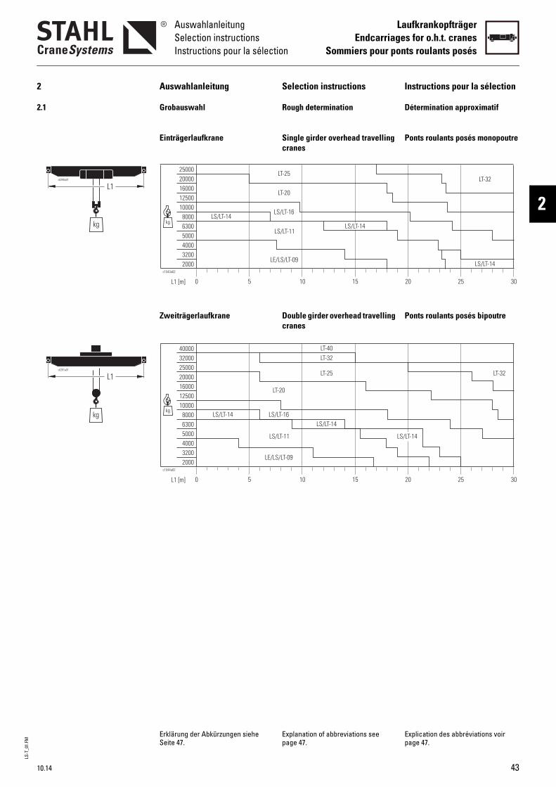
LS-T
_01.
FMAuswahlanleitungSelection instructionsInstructions pour la sélection
LaufkrankopfträgerEndcarriages for o.h.t. cranes
Sommiers pour ponts roulants posés
2
10.14 43
2 Auswahlanleitung Selection instructions Instructions pour la sélection
2.1 Grobauswahl Rough determination Détermination approximatif
Einträgerlaufkrane Single girder overhead travelling cranes
Ponts roulants posés monopoutre
Zweiträgerlaufkrane Double girder overhead travelling cranes
Ponts roulants posés bipoutre
Erklärung der Abkürzungen siehe Seite 47.
Explanation of abbreviations see page 47.
Explication des abbréviations voir page 47.
5 10 15 20 25 30L1 [m]
kg
c1543a02
200032004000500063008000
1000012500160002000025000
0
LS/LT-11
LE/LS/LT-09
LS/LT-16
LT-20
LT-25LT-32
LS/LT-14LS/LT-14
LS/LT-14
5 10 15 20 25 30L1 [m]
kg
c1544a02
200032004000500063008000
10000125001600020000250003200040000
LE/LS/LT-09
LS/LT-11
LS/LT-16
LT-20
0
LT-25
LT-32
LT-32
LT-40
LS/LT-14LS/LT-14
LS/LT-14
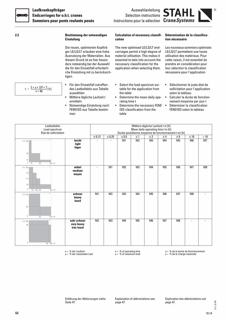
LS-T
_01.
FM
LaufkrankopfträgerEndcarriages for o.h.t. cranesSommiers pour ponts roulants posés
AuswahlanleitungSelection instructions
Instructions pour la sélection
2.2 Bestimmung der notwendigen Einstufung
Calculation of necessary classifi-cation
Détermination de la classifica-tion nécessaire
Die neuen, optimierten Kopfträ-ger LE/LS/LT erlauben eine hohe Ausnutzung der Materialien. Aus diesem Grund ist es hier beson-ders notwendig bei der Auswahl die für den Einsatzfall erforderli-che Einstufung mit zu berücksich-tigen.
The new optimised LE/LS/LT end-carriages permit a high degree of material utilisation. This makes it essential to take into account the necessary classification for the application when selecting them.
Les nouveaux sommiers optimisés LE/LS/LT permettent une haute utilisation des matériaux. Pour cette raison, il est essentiel de prendre en considération pour leur sélection la classification nécessaire pour l'application.
• Für den Einsatzfall zutreffen-des Lastkollektiv aus Tabelle auswählen
• Select the load spectrum sui-table for the application from the table
• Sélectionner le juste état de sollicitation pour l'application selon le tableau
• Mittlere tägliche Laufzeit t ermitteln
• Notwendige Einstufung nach FEM/ISO aus Tabelle bestim-men
• Determine the mean daily ope-rating time t
• Determine the necessary FEM/ISO classification from the table
• Calculer la durée de fonction-nement moyenne par jour t
• Déterminer la classification FEM/ISO selon le tableau
LastkollektivLoad spectrum
État de sollicitation
Mittlere tägliche Laufzeit t in [h] Mean daily operating time t in [h]
Durée quotidienne moyenne de fonctionnement t en [h]≤ 0,12 ≤ 0,25 ≤ 0,5 ≤ 1 ≤ 2 ≤ 4 ≤ 8 ≤ 16 > 16
leichtlightléger
- - M1 M2 M3 M4 M5 M6 M7
mittelmediummoyen
- M1 M2 M3 M4 M5 M6 M7 M8
schwerheavylourd
M1 M2 M3 M4 M5 M6 M7 M8 -
sehr schwervery heavytrès lourd
M2 M3 M4 M5 M6 M7 M8 - -
x = % der Laufzeity = % der maximalen Last
x = % of operating timey = % of maximum load
x = % de la durée de fonctionnementy = % de la charge maximale
Erklärung der Abkürzungen siehe Seite 47.
Explanation of abbreviations see page 47.
Explication des abbréviations voir page 47.
t 2 s SP T•••v 60•
-------------------------------- h[ ]=
44 10.14
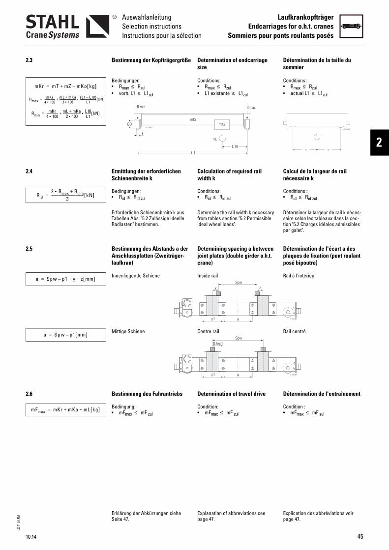
LS-T
_01.
FMAuswahlanleitungSelection instructionsInstructions pour la sélection
LaufkrankopfträgerEndcarriages for o.h.t. cranes
Sommiers pour ponts roulants posés
2
2.3 Bestimmung der Kopfträgergröße Determination of endcarriage size
Détermination de la taille du sommier
Bedingungen: • Rmax ≤ Rzul• vorh. L1 ≤ L1zul
Conditions: • Rmax ≤ Rzul• L1 existante ≤ L1zul
Conditions : • Rmax ≤ Rzul• actual L1 ≤ L1zul
2.4 Ermittlung der erforderlichen Schienenbreite k
Calculation of required rail width k
Calcul de la largeur de rail nécessaire k
Bedingungen: • Rid ≤ Rid zul
Conditions: • Rid ≤ Rid zul
Conditions : • Rid ≤ Rid zul
Erforderliche Schienenbreite k aus Tabellen Abs. "5.2 Zulässige ideelle Radlasten" bestimmen.
Determine the rail width k necessary from tables section "5.2 Permissible ideal wheel loads".
Déterminer la largeur de rail k néces-saire selon les tableaux dans la sec-tion "5.2 Charges idéales admissibles par galet".
2.5 Bestimmung des Abstands a der Anschlussplatten (Zweiträger-laufkran)
Determining spacing a between joint plates (double girder o.h.t. crane)
Détermination de l'écart a des plaques de fixation (pont roulant posé bipoutre)
Innenliegende Schiene Inside rail Rail à l'intérieur
Mittige Schiene Centre rail Rail centré
2.6 Bestimmung des Fahrantriebs Determination of travel drive Détermination de l'entraînement
Bedingung: • mFmax ≤ mF zul
Condition: • mFmax ≤ mF zul
Condition : • mFmax ≤ mF zul
Erklärung der Abkürzungen siehe Seite 47.
Explanation of abbreviations see page 47.
Explication des abbréviations voir page 47.
mKr mT mZ mKo kg[ ]+ +=
RmaxmKr
4 100•---------------- mL mKa+
2 100•------------------------- L1 L10–( )
L1------------------------- kN[ ]•+=
RminmKr
4 100•---------------- mL mKa+
2 100•------------------------- L10
L1--------• kN[ ]+=
Rid2 Rmax Rmin+•
3------------------------------------- kN[ ]=
a Spw p1– y z mm[ ]+ +=
c1574v01ap1
Spwy z
a Spw p1 mm[ ]–=
c1575v01ap1
Spw0,5xp1
mFmax mKr mKa mL kg[ ]+ +=
10.14 45
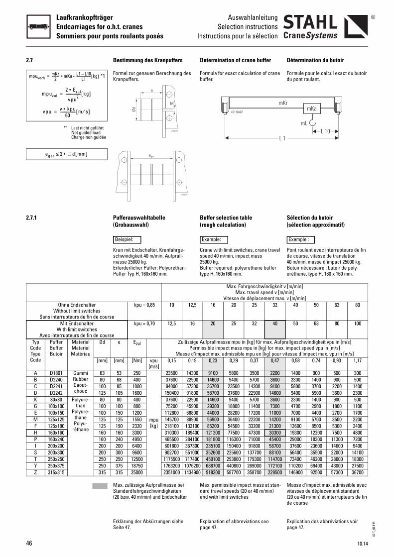
LS-T
_01.
FM
LaufkrankopfträgerEndcarriages for o.h.t. cranesSommiers pour ponts roulants posés
AuswahlanleitungSelection instructions
Instructions pour la sélection
2.7 Bestimmung des Kranpuffers Determination of crane buffer Détermination du butoir
*1 Formel zur genauen Berechnung des Kranpuffers.
Formula for exact calculation of crane buffer.
Formule pour le calcul exact du butoir du pont roulant.
*1 Last nicht geführtNot guided loadCharge non guidée
2.7.1 Pufferauswahltabelle(Grobauswahl)
Buffer selection table(rough calculation)
Sélection du butoir(sélection approximatif)
Kran mit Endschalter, Kranfahrge-schwindigkeit 40 m/min, Aufprall-masse 25000 kg.Erforderlicher Puffer: Polyurethan-Puffer Typ H, 160x160 mm.
Crane with limit switches, crane travel speed 40 m/min, impact mass 25000 kg.Buffer required: polyurethane buffer type H, 160x160 mm.
Pont roulant avec interrupteurs de fin de course, vitesse de translation 40 m/min, masse d'impact 25000 kg.Butoir nécessaire : butoir de poly-uréthane, type H, 160 x 160 mm.
Max. Fahrgeschwindigkeit v [m/min]Max. travel speed v [m/min]
Vitesse de déplacement max. v [m/min]Ohne Endschalter
Without limit switchesSans interrupteurs de fin de course
kpu = 0,85 10 12,5 16 20 25 32 40 50 63 80
Mit EndschalterWith limit switches
Avec interrupteurs de fin de course
kpu = 0,70 12,5 16 20 25 32 40 50 63 80 100
Typ CodeType Code
PufferBufferButoir
MaterialMaterialMatériau
Ød e Ezul Zulässige Aufprallmasse mpu in [kg] für max. Aufprallgeschwindigkeit vpu in [m/s]Permissible impact mass mpu in [kg] for max. impact speed vpu in [m/s]
Masse d'impact max. admissible mpu en [kg] pour vitesse d'impact max. vpu in [m/s][mm] [mm] [Nm] vpu
[m/s]0,15 0,19 0,23 0,29 0,37 0,47 0,58 0,74 0,93 1,17
A D1801 GummiRubberCaout-chouc
63 53 250
mpu [kg]
23500 14300 9100 5800 3500 2200 1400 900 500 300B D2240 80 68 400 37600 22900 14600 9400 5700 3600 2300 1400 900 500C D2241 100 85 1000 94000 57300 36700 23500 14300 9100 5800 3700 2200 1400D D2242 125 105 1600 150400 91800 58700 37600 22900 14600 9400 5900 3600 2300K 80x80 Polyure-
thanPolyure-
thanePolyu-
réthane
80 80 400 37600 22900 14600 9400 5700 3600 2300 1400 900 500G 100x100 100 100 800 75200 45900 29300 18800 11400 7300 4700 2900 1800 1100E 100x150 100 150 1200 112800 68800 44000 28200 17200 11000 7000 4400 2700 1700M 125x125 125 125 1550 145700 88900 56900 36400 22200 14200 9100 5700 3500 2200F 125x190 125 190 2320 218100 133100 85200 54500 33200 21300 13600 8500 5300 3400H 160x160 160 160 3300 310300 189400 121200 77500 47300 30300 19300 12200 7500 4800P 160x240 160 240 4950 465500 284100 181800 116300 71000 45400 29000 18300 11300 7200I 200x200 200 200 6400 601800 367300 235100 150400 91800 58700 37600 23600 14600 9400S 200x300 200 300 9600 902700 551000 352600 225600 137700 88100 56400 35500 22000 14100T 250x250 250 250 12500 1175500 717400 459100 293800 179300 114700 73400 46200 28600 18300Y 250x375 250 375 18750 1763200 1076200 688700 440800 269000 172100 110200 69400 43000 27500Z 315x315 315 315 25000 2351000 1434900 918300 587700 358700 229500 146900 92500 57300 36700
Max. zulässige Aufprallmasse bei Standardfahrgeschwindigkeiten (20 bzw. 40 m/min) und Endschalter
Max. permissible impact mass at stan-dard travel speeds (20 or 40 m/min) and with limit switches
Masse d'impact max. admissible avec vitesses de déplacement standard (20 ou 40 m/min) et interrupteurs de fin de course
Erklärung der Abkürzungen siehe Seite 47.
Explanation of abbreviations see page 47.
Explication des abbréviations voir page 47.
mpuvorhmKr
2---------- mKa L1 L10–
L1--------------------• kg[ ]+=
mpuzul2 Ezul•
vpu2----------------- kg[ ]=
vpu v kpu•60
------------------ m s⁄[ ]=
c1686v01
e
Ød
M
eges 2 ∅ d mm[ ]•≤
c1686v02
eges
Beispiel: Example: Exemple :
46 10.14
LS-T
_01.
FMAuswahlanleitungSelection instructionsInstructions pour la sélection
LaufkrankopfträgerEndcarriages for o.h.t. cranes
Sommiers pour ponts roulants posés
2
2.8 Fahrbahnendanschläge Runway end stops Butées de fin de chemin de roule-ment
Die Laufkrankopfträger sind seri-enmäßig mit Puffern ausgestat-tet. Passende Endanschläge sind bauseits anzubauen.
Die Größe der Anschläge ist ent-sprechend den Pufferkräften aus-zulegen (siehe Kapitel 3 "Kran-puffer"). Die Abmessungen sind so zu wählen, dass die ganze Fläche des Puffers auf den Anschlag trifft.
The overhead travelling crane endcarriages are fitted with buf-fers as standard. The stops required on the crane bridge must be supplied by the customer.
The size of the stops must be selected in accordance with the buffer forces (see chapter 3 "Crane buffers"). The dimensions must be selected so that the whole surface of the buffer strikes the stop.
Les sommiers pour ponts roulants posés sont, en série, équipés de butoirs. Des butées de fin de course, à fournir par le client, doivent être montées.
Choisir la taille des butées en fonction des forces exercées par les butoirs (voir chapitre 3 "Butoirs de ponts roulants"). Choisir les dimensions de telle sorte que toute la surface du butoir s'applique contre la butée.
2.9 Erklärung der Abkürzungen Explanation of abbreviations Explication des abbréviations
a [mm] Bohrungsabstand a zwischen den Anschlussplatten (Zweiträgerlaufkran)
Hole separation a between joint plates (double girder o.h.t. crane)
Écart des forages a entre plaques de fixation (pont roulant posé bipoutre)
Ezul [Nm] Zulässige Pufferenergie Permissible buffer energy Énergie admissiblek [mm] Schienenbreite Rail width Largeur de railkeff [mm] Effektive Schienenbreite Effective rail width Largeur effective de railkpu Abminderungsfaktor Reduction factor Facteur de réductionL 1 [m] Spurmittenmaß Kran Crane span Portée du pont roulantL 10 [m] Anfahrmaß Katze Hook approach trolley Cote d'approche du chariotm F [kg] Fahrlast/Paar Travel load/pair Charge roulant/paire des sommiersm Ka [kg] Gewicht Katze Weight of trolley/crab Poids du chariotm Ko [kg] Gewicht Kopfträger + Anschluss-
platte + AntriebWeight of endcarriage + joint plate + drive
Poids du sommier + plaque de fixation + entraînement
m Kr [kg] Gewicht Kran Weight of crane Poids du pont roulantm L [kg] Tragfähigkeit Working load Charge d'utilisationm T [kg] Gewicht Kranbrücke(n) Weight of crane bridge(s) Poids de la/des poutre(s) porteuse(s)m Z [kg] Gewicht Zusatzlasten Weight of additional loads Poids des charges additionnellesmpuvorh [kg] Vorhandene Aufprallmasse Actual impact mass Masse d'impact existantempuzul [kg] Zulässige Aufprallmasse Permissible impact mass Masse d'impact admissibleØ D [mm] Laufrad-Durchmesser Wheel diameter Diamètre du galetp 1 [mm] Bohrungsabstand Anschlussplatte
(siehe "3 Abmessungen")Hole separation of joint plate (see "3 Dimensions")
Écart des forages de la plaque de fixa-tion (voir "3 Dimensions")
Rid [kN] Vorhandene ideelle Radlast (statisch) Actual ideal wheel load (static) Réaction idéale existante par galet (statique)
Rid zul [kN] Zulässige ideelle Radlast (statisch) Permissible ideal wheel load (static) Réaction idéale admissible par galet (statique)
Rmax [kN] Vorhandene maximale Radlast (statisch)
Max. actual wheel load (static) Réaction maximale par galet (statique)
Rzul [kN] Zulässige Radlast (statisch) Permissible wheel load (static) Réaction admissible par galet (statique)
s [m] Mittlerer Fahrweg Average running distance Translation moyenneSP [1/h] Arbeitsspiel je Stunde Cycles per hour Jeu de travail par heureSpw [mm] Spurmittenmaß Katze Crab track gauge Écartement du chariott [h] Mittlere tägliche Laufzeit Mean daily operating time Durée de fonctionnement moyenne
par jourT [h] Arbeitszeit je Tag Operating hours per day Durée de travail par jourv [m/min] Fahrgeschwindigkeit Travel speed Vitesse de déplacementvpu [m/s] Aufprallgeschwindigkeit Impact speed Vitesse d'impacty [mm] Abstand Mitte Kranträger bis Mitte
KatzschieneSpacing from centre crane girder to centre c.t. rail
Distance centre de la poutre porteuse à centre du rail du chariot
10.14 47
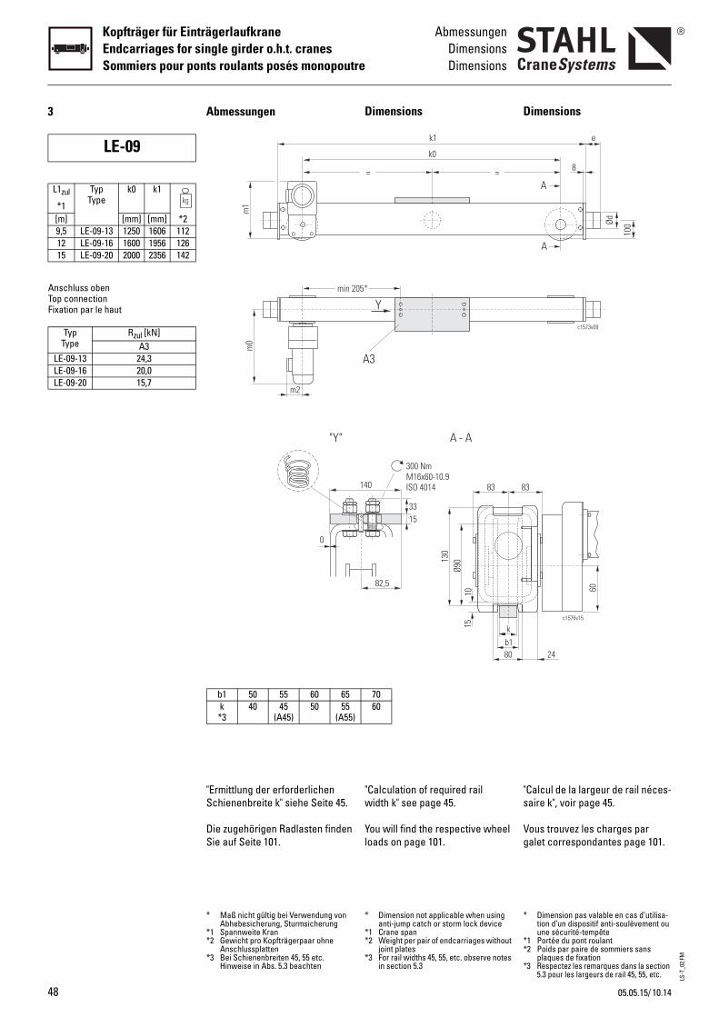
LS-T
_02.
FM
48
Kopfträger für EinträgerlaufkraneEndcarriages for single girder o.h.t. cranesSommiers pour ponts roulants posés monopoutre
AbmessungenDimensionsDimensions
3
Anschluss obenTop connectionFixation par le haut
LE-09
L1zul
*1
TypType
k0 k1
[m] [mm] [mm] *29,5 LE-09-13 1250 1606 11212 LE-09-16 1600 1956 12615 LE-09-20 2000 2356 142
TypType
Rzul [kN]A3
LE-09-13 24,3LE-09-16 20,0LE-09-20 15,7
Dimensions
"Calculation of required rail width k" see page 45.
You will find the respective wheel loads on page 101.
D
"s
Vg
140
15
300 NmM16x60-10.9ISO 4014
82,5
33
A - A
b1k
80
1015
Ø9013
0
83 8
= =
k1
k0
Y
A3
05*
7060
* Dimension not applicable when using anti-jump catch or storm lock device
*1 Crane span*2 Weight per pair of endcarriages without
joint plates*3 For rail widths 45, 55, etc. observe notes
in section 5.3
*
**
*
imensions
Calcul de la largeur de rail néces-aire k", voir page 45.
ous trouvez les charges par alet correspondantes page 101.
3
c1576v15
60
24
c1573v09
e
100Ød
A
A
8
Dimension pas valable en cas d’utilisa-tion d’un dispositif anti-soulèvement ou une sécurité-tempête
1 Portée du pont roulant2 Poids par paire de sommiers sans
plaques de fixation3 Respectez les remarques dans la section
5.3 pour les largeurs de rail 45, 55, etc.
"Ermittlung der erforderlichen Schienenbreite k" siehe Seite 45.
Die zugehörigen Radlasten finden Sie auf Seite 101.
Abmessungen
0
"Y"
m1
m0
m2
min 2
b1 50 55 60 65k *3
40 45(A45)
50 55(A55)
* Maß nicht gültig bei Verwendung von Abhebesicherung, Sturmsicherung
*1 Spannweite Kran*2 Gewicht pro Kopfträgerpaar ohne
Anschlussplatten*3 Bei Schienenbreiten 45, 55 etc.
Hinweise in Abs. 5.3 beachten
10.1405.05.15/

LS-T
_02.
FM
10.14
AbmessungenDimensionsDimensions
Kopfträger für EinträgerlaufkraneEndcarriages for single girder o.h.t. cranes
Sommiers pour ponts roulants posés monopoutre
2c1686v01
e
Ød
M
p3
c1674v02B
p1p2
A3
/05.05.15
Buffer
Calculation see "Buffer selection table" page 46.
Joint plates
Travel drives
For more details, see Product information "Travel drives".
B
Pb
P
G
Ptp
Ød e max. Federwegmax. deflection
max. écrasement[mm] [mm] [mm]
c
63 53 3080 68 32
100 85 42nee
80 80 60100 100 75100 150 113
A3360410140
90-3107
MotorMotor
Moteur
m0 m1
[mm]8/2F12 505 2258/2F134F18
utoirs
our le calcul, voir "Sélection du utoir", page 46.
laques de fixation
roupes d’entraînement
our de plus amples informa-ions, voir Informations sur le roduit "Groupes d’entraînement".
B B
c1762v01
Profil KastenProfile BoxProfilé Caisson
Ezul GewindeThread
Filet[Nm]250 M12x35 0,3400 0,6
1000 1,2400 0,4800 0,6
1200 0,8
m2
134
182
Puffer
Auslegung siehe "Pufferauswahl-tabelle" Seite 46.
Anschlussplatten
Fahrantriebe
Näheres siehe Produktinforma-tion "Fahrantriebe".
Typ CodeType Code
PufferBufferButoir
MaterialMaterialMatériau
A D1801 GummiRubber
CaoutchouB D2240C D2241K 80x80 Polyuretha
PolyurethanPolyuréthan
G 100x100E 100x150
p1 [mm]p2 [mm]p3 [mm]
Bmin-max [mm]Gewicht pro Platte/weight per plate/
poids par plaque [kg]
Ø D GetriebeGear
Réducteur[mm]90 SDB3
49
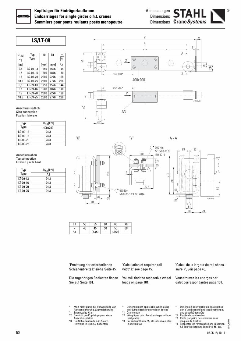
LS-T
_02.
FM
50
Kopfträger für EinträgerlaufkraneEndcarriages for single girder o.h.t. cranesSommiers pour ponts roulants posés monopoutre
AbmessungenDimensionsDimensions
Anschluss seitlichSide connectionFixation latérale
Anschluss obenTop connectionFixation par le haut
LS/LT-09
L1zul
*1
TypType
k0 k1
[m] [mm] [mm] *29,5 LS-09-13 1250 1526 14412 LS-09-16 1600 1876 17015 LS-09-20 2000 2276 198
18,5 LS-09-25 2500 2776 2369,5 LT-09-13 1250 1526 14412 LT-09-16 1600 1876 17015 LT-09-20 2000 2276 198
18,5 LT-09-25 2500 2776 236
TypType
Rzul [kN]400x200
LS-09-13 24,3LS-09-16 24,3LS-09-20 24,3LS-09-25 24,3
TypType
Rzul [kN]A3
LT-09-13 24,3LT-09-16 24,3LT-09-20 24,3LT-09-25 24,3
"Calculation of required rail width k" see page 45.
You will find the respective wheel loads on page 101.
"s
Vg
140
15
0
300 NmM16x60-10.9ISO 4014
82,5
33
590 NmM20x70-10.9 ISO 4014
"Y" A - A
Ø90
210
=
80*
=
k1
k0
X
400x200
Y
A3
05*
7060
* Dimension not applicable when using anti-jump catch or storm lock device
*1 Crane span*2 Weight per pair of endcarriages without
joint plates*3 For rail widths 45, 55, etc. observe notes
in section 5.3
*
**
*
Calcul de la largeur de rail néces-aire k", voir page 45.
ous trouvez les charges par alet correspondantes page 101.
b1k
80
1015
83 83
c1576v01
60
24
c1573v01
e
100Ød
A
A
8
Dimension pas valable en cas d’utilisa-tion d’un dispositif anti-soulèvement ou une sécurité-tempête
1 Portée du pont roulant2 Poids par paire de sommiers sans
plaques de fixation3 Respectez les remarques dans la section
5.3 pour les largeurs de rail 45, 55, etc.
"Ermittlung der erforderlichen Schienenbreite k" siehe Seite 45.
Die zugehörigen Radlasten finden Sie auf Seite 101.
200
20 10
84
"X"
min 2
m0
m2
min 2
m1
b1 50 55 60 65k *3
40 45(A45)
50 55(A55)
* Maß nicht gültig bei Verwendung von Abhebesicherung, Sturmsicherung
*1 Spannweite Kran*2 Gewicht pro Kopfträgerpaar ohne
Anschlussplatten*3 Bei Schienenbreiten 45, 55 etc.
Hinweise in Abs. 5.3 beachten
10.1405.05.15/

LS-T
_02.
FM
10.14
AbmessungenDimensionsDimensions
Kopfträger für EinträgerlaufkraneEndcarriages for single girder o.h.t. cranes
Sommiers pour ponts roulants posés monopoutre
2c1686v01
e
Ød
M
c1674v01
p3
B
p1p2
400x200
p3
c1674v02B
p1p2
A3
/05.05.15
Buffer
Calculation see "Buffer selection table" page 46.
Joint plates
Travel drives
For more details, see Product information "Travel drives".
B
Pb
P
G
Ptp
Ød e max. Federwegmax. deflection
max. écrasement[mm] [mm] [mm]
c
63 53 3080 68 32
100 85 42nee
80 80 60100 100 75100 150 113
400x200400490200
146-40032017
A3360410140
90-3107
MotorMotor
Moteur
m0 m1
[mm]8/2F12 505 2258/2F134F18
utoirs
our le calcul, voir "Sélection du utoir", page 46.
laques de fixation
roupes d’entraînement
our de plus amples informa-ions, voir Informations sur le roduit "Groupes d’entraînement".
B B
c1763v01
b2
Profil KastenProfile BoxProfilé Caisson
Ezul GewindeThread
Filet[Nm]250 M12x35 0,3400 0,6
1000 1,2400 0,4800 0,6
1200 0,8
m2
134
182
Puffer
Auslegung siehe "Pufferauswahl-tabelle" Seite 46.
Anschlussplatten
Fahrantriebe
Näheres siehe Produktinforma-tion "Fahrantriebe".
Typ CodeType Code
PufferBufferButoir
MaterialMaterialMatériau
A D1801 GummiRubber
CaoutchouB D2240C D2241K 80x80 Polyuretha
PolyurethanPolyuréthan
G 100x100E 100x150
p1 [mm]p2 [mm]p3 [mm]
Bmin-max [mm]b2max [mm]
Gewicht pro Platte/weight per plate/poids par plaque [kg]
p1 [mm]p2 [mm]p3 [mm]
Bmin-max [mm]Gewicht pro Platte/weight per plate/
poids par plaque [kg]
Ø D GetriebeGear
Réducteur[mm]90 SDB3
51
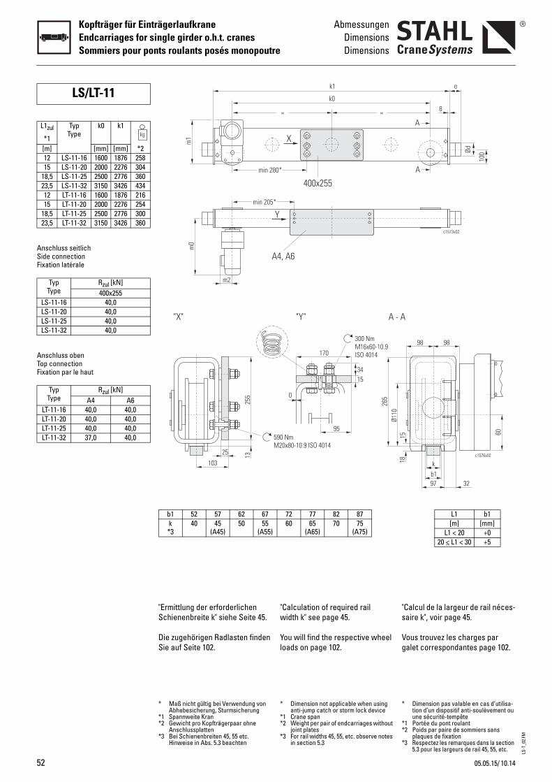
LS-T
_02.
FM
52
Kopfträger für EinträgerlaufkraneEndcarriages for single girder o.h.t. cranesSommiers pour ponts roulants posés monopoutre
AbmessungenDimensionsDimensions
Anschluss seitlichSide connectionFixation latérale
Anschluss obenTop connectionFixation par le haut
LS/LT-11
L1zul
*1
TypType
k0 k1
[m] [mm] [mm] *212 LS-11-16 1600 1876 25815 LS-11-20 2000 2276 304
18,5 LS-11-25 2500 2776 36023,5 LS-11-32 3150 3426 43412 LT-11-16 1600 1876 21615 LT-11-20 2000 2276 254
18,5 LT-11-25 2500 2776 30023,5 LT-11-32 3150 3426 360
TypType
Rzul [kN]400x255
LS-11-16 40,0LS-11-20 40,0LS-11-25 40,0LS-11-32 40,0
TypType
Rzul [kN]A4 A6
LT-11-16 40,0 40,0LT-11-20 40,0 40,0LT-11-25 40,0 40,0LT-11-32 37,0 40,0
"Calculation of required rail width k" see page 45.
You will find the respective wheel loads on page 102.
"s
Vg
170
15
0
300 NmM16x60-10.9ISO 4014
95
34
"Y" A - A
590 NmM20x80-10.9 ISO 4014
Ø110
265
=
80*
=
k1
k0
X
400x255
4, A6
*
Y
72 77 82 8760 65
(A65)70 75
(A75)
* Dimension not applicable when using anti-jump catch or storm lock device
*1 Crane span*2 Weight per pair of endcarriages without
joint plates*3 For rail widths 45, 55, etc. observe notes
in section 5.3
*
**
*
Calcul de la largeur de rail néces-aire k", voir page 45.
ous trouvez les charges par alet correspondantes page 102.
b1k
97
1518
98 98
c1576v02
60
32
c1573v02
e
100Ød
A
A
8
L1 b1[m] [mm]
L1 < 20 +020 < L1 < 30 +5
Dimension pas valable en cas d’utilisa-tion d’un dispositif anti-soulèvement ou une sécurité-tempête
1 Portée du pont roulant2 Poids par paire de sommiers sans
plaques de fixation3 Respectez les remarques dans la section
5.3 pour les largeurs de rail 45, 55, etc.
"Ermittlung der erforderlichen Schienenbreite k" siehe Seite 45.
Die zugehörigen Radlasten finden Sie auf Seite 102.
"X"
255
25 13
103
min 2
m0
A
m2
min 205
m1
b1 52 57 62 67k *3
40 45(A45)
50 55(A55)
* Maß nicht gültig bei Verwendung von Abhebesicherung, Sturmsicherung
*1 Spannweite Kran*2 Gewicht pro Kopfträgerpaar ohne
Anschlussplatten*3 Bei Schienenbreiten 45, 55 etc.
Hinweise in Abs. 5.3 beachten
10.1405.05.15/
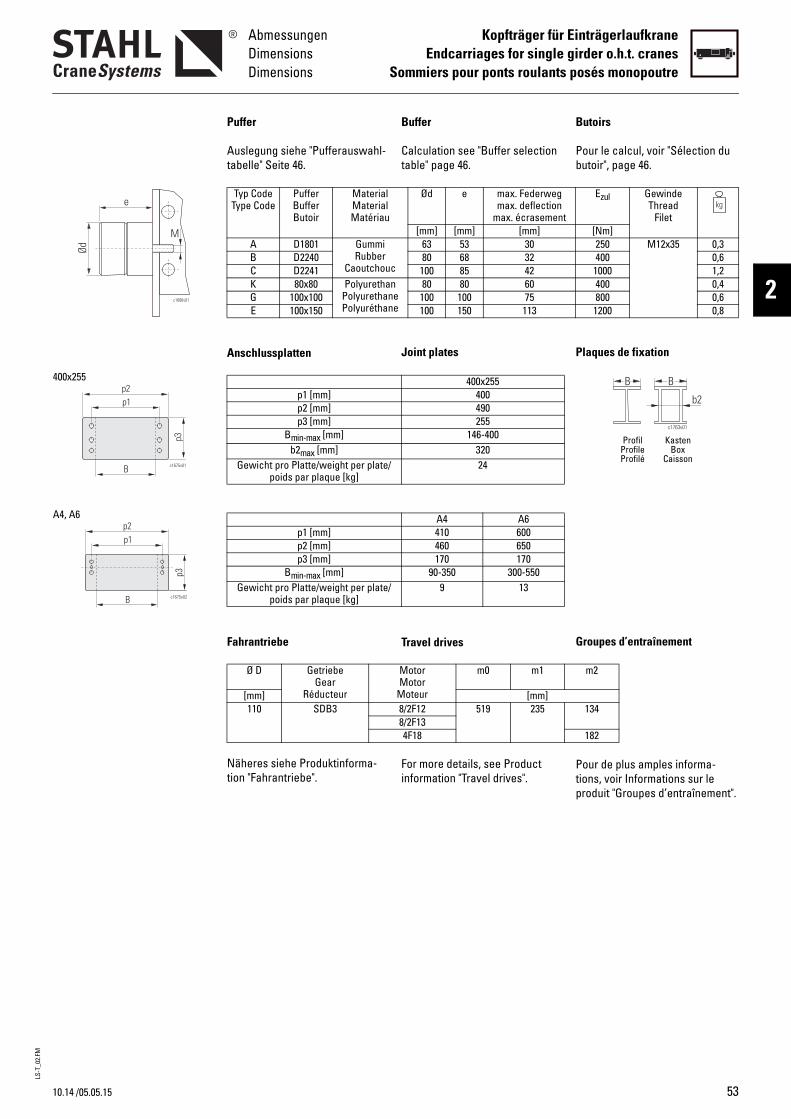
LS-T
_02.
FM
10.14
AbmessungenDimensionsDimensions
Kopfträger für EinträgerlaufkraneEndcarriages for single girder o.h.t. cranes
Sommiers pour ponts roulants posés monopoutre
2c1686v01
e
Ød
M
p3
B c1675v01
p1p2
400x255
p3
c1675v02B
p1p2
A4, A6
/05.05.15
Buffer
Calculation see "Buffer selection table" page 46.
Joint plates
Travel drives
For more details, see Product information "Travel drives".
B
Pb
P
G
Ptp
Ød e max. Federwegmax. deflection
max. écrasement[mm] [mm] [mm]
c
63 53 3080 68 32
100 85 42nee
80 80 60100 100 75100 150 113
400x255400490255
146-40032024
A4 A6410 600460 650170 170
90-350 300-5509 13
MotorMotor
Moteur
m0 m1
[mm]8/2F12 519 2358/2F134F18
utoirs
our le calcul, voir "Sélection du utoir", page 46.
laques de fixation
roupes d’entraînement
our de plus amples informa-ions, voir Informations sur le roduit "Groupes d’entraînement".
B B
c1763v01
b2
Profil KastenProfile BoxProfilé Caisson
Ezul GewindeThread
Filet[Nm]250 M12x35 0,3400 0,6
1000 1,2400 0,4800 0,6
1200 0,8
m2
134
182
Puffer
Auslegung siehe "Pufferauswahl-tabelle" Seite 46.
Anschlussplatten
Fahrantriebe
Näheres siehe Produktinforma-tion "Fahrantriebe".
Typ CodeType Code
PufferBufferButoir
MaterialMaterialMatériau
A D1801 GummiRubber
CaoutchouB D2240C D2241K 80x80 Polyuretha
PolyurethanPolyuréthan
G 100x100E 100x150
p1 [mm]p2 [mm]p3 [mm]
Bmin-max [mm]b2max [mm]
Gewicht pro Platte/weight per plate/poids par plaque [kg]
p1 [mm]p2 [mm]p3 [mm]
Bmin-max [mm]Gewicht pro Platte/weight per plate/
poids par plaque [kg]
Ø D GetriebeGear
Réducteur[mm]110 SDB3
53
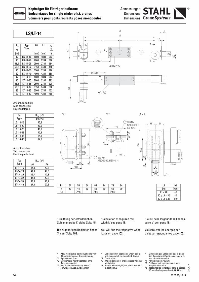
LS-T
_02.
FM
54
Kopfträger für EinträgerlaufkraneEndcarriages for single girder o.h.t. cranesSommiers pour ponts roulants posés monopoutre
AbmessungenDimensionsDimensions
Anschluss seitlichSide connectionFixation latérale
Anschluss obenTop connectionFixation par le haut
LS/LT-14
L1zul
*1
TypType
k0 k1
[m] [mm] [mm] *212 LS-14-16 1600 1884 28215 LS-14-20 2000 2284 328
18,5 LS-14-25 2500 2784 38423,5 LS-14-32 3150 3434 45826 LS-14-35 3500 3784 49830 LS-14-40 4000 4284 55812 LT-14-16 1600 1884 24415 LT-14-20 2000 2284 282
18,5 LT-14-25 2500 2784 32823,5 LT-14-32 3150 3434 38826 LT-14-35 3500 3784 42230 LT-14-40 4000 4284 468
TypType
Rzul [kN]400x255
LS-14-16 40,9LS-14-20 40,9LS-14-25 40,9LS-14-32 40,9LS-14-35 34,8LS-14-40 27,8
TypType
Rzul [kN]A4 A6
LT-14-16 47,8 47,8LT-14-20 47,8 47,8LT-14-25 46,7 47,8LT-14-32 37,0 47,8LT-14-35 33,3 41,7LT-14-40 27,8 27,8
"Calculation of required rail width k" see page 45.
You will find the respective wheel loads on page 103.
"s
Vg
170
15
0
300 NmM16x60-10.9ISO 4014
95
34
"Y" A - A
90 Nm20x80-10.9 ISO 4014
Ø140
265
=
80*
=
k1
k0
X
400x255
4, A6
*
Y
74 79 8460 65
(A65)70
* Dimension not applicable when using anti-jump catch or storm lock device
*1 Crane span*2 Weight per pair of endcarriages without
joint plates*3 For rail widths 45, 55, etc. observe notes
in section 5.3
*
**
*
Calcul de la largeur de rail néces-aire k", voir page 45.
ous trouvez les charges par alet correspondantes page 103.
60 75(S
DB3)
(SDB
4)
b1k
100
15
98 98
c1576v07
31
18
c1573v07
e
100Ød
A
A
12
L1 b1[m] [mm]
L1 < 20 +020 < L1 < 30 +530 < L1 < 35 +10
Dimension pas valable en cas d’utilisa-tion d’un dispositif anti-soulèvement ou une sécurité-tempête
1 Portée du pont roulant2 Poids par paire de sommiers sans
plaques de fixation3 Respectez les remarques dans la section
5.3 pour les largeurs de rail 45, 55, etc.
"Ermittlung der erforderlichen Schienenbreite k" siehe Seite 45.
Die zugehörigen Radlasten finden Sie auf Seite 103.
"X"
255
25 13
103
5M
min 2
m0
A
m2
min 205
m1
b1 54 59 64 69k *3
40 45(A45)
50 55(A55)
* Maß nicht gültig bei Verwendung von Abhebesicherung, Sturmsicherung
*1 Spannweite Kran*2 Gewicht pro Kopfträgerpaar ohne
Anschlussplatten*3 Bei Schienenbreiten 45, 55 etc.
Hinweise in Abs. 5.3 beachten
10.1405.05.15/
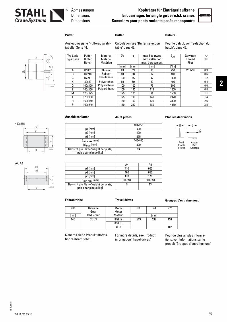
LS-T
_02.
FM
10.14
AbmessungenDimensionsDimensions
Kopfträger für EinträgerlaufkraneEndcarriages for single girder o.h.t. cranes
Sommiers pour ponts roulants posés monopoutre
2c1686v01
e
Ød
M
p3
B c1675v01
p1p2
400x255
p3
c1675v02B
p1p2
A4, A6
/05.05.15
Buffer
Calculation see "Buffer selection table" page 46.
Joint plates
Travel drives
For more details, see Product information "Travel drives".
B
Pb
P
G
Ptp
Ød e max. Federwegmax. deflection
max. écrasement[mm] [mm] [mm]
c
63 53 3080 68 32
100 85 42nee
80 80 60100 100 75100 150 113125 125 94125 190 143160 160 120160 240 180
400x255400490255
146-40032024
A4 A6410 600460 650170 170
90-350 300-5509 13
MotorMotor
Moteur
m0 m1
[mm]8/2F12 519 2498/2F134F18
utoirs
our le calcul, voir "Sélection du utoir", page 46.
laques de fixation
roupes d’entraînement
our de plus amples informa-ions, voir Informations sur le roduit "Groupes d’entraînement".
B B
c1763v01
b2
Profil KastenProfile BoxProfilé Caisson
Ezul GewindeThread
Filet[Nm]250 M12x35 0,3400 0,6
1000 1,2400 0,4800 0,6
1200 0,81550 1,12320 1,43300 2,64950 3,5
m2
134
182
Puffer
Auslegung siehe "Pufferauswahl-tabelle" Seite 46.
Anschlussplatten
Fahrantriebe
Näheres siehe Produktinforma-tion "Fahrantriebe".
Typ CodeType Code
PufferBufferButoir
MaterialMaterialMatériau
A D1801 GummiRubber
CaoutchouB D2240C D2241K 80x80 Polyuretha
PolyurethanPolyuréthan
G 100x100E 100x150M 125x125F 125x190H 160x160P 160x240
p1 [mm]p2 [mm]p3 [mm]
Bmin-max [mm]b2max [mm]
Gewicht pro Platte/weight per plate/poids par plaque [kg]
p1 [mm]p2 [mm]p3 [mm]
Bmin-max [mm]Gewicht pro Platte/weight per plate/
poids par plaque [kg]
Ø D GetriebeGear
Réducteur[mm]140 SDB3
55
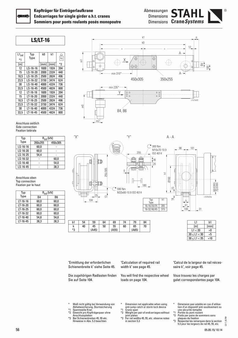
LS-T
_02.
FM
56
Kopfträger für EinträgerlaufkraneEndcarriages for single girder o.h.t. cranesSommiers pour ponts roulants posés monopoutre
AbmessungenDimensionsDimensions
Anschluss seitlichSide connectionFixation latérale
Anschluss obenTop connectionFixation par le haut
LS/LT-16
L1zul
*1
TypType
k0 k1
[m] [mm] [mm] *212 LS-16-16 1600 1924 39415 LS-16-20 2000 2324 440
18,5 LS-16-25 2500 2824 49623,5 LS-16-32 3150 3474 62430 LS-16-40 4000 4324 736
33,5 LS-16-45 4500 4824 80012 LT-16-16 1600 1924 39415 LT-16-20 2000 2324 440
18,5 LT-16-25 2500 2824 49623,5 LT-16-32 3150 3474 62430 LT-16-40 4000 4324 736
33,5 LT-16-45 4500 4824 800
TypType
Rzul [kN]350x255 450x305
LS-16-16 60,0 -LS-16-20 60,0 -LS-16-25 54,4 -LS-16-32 - 60,0LS-16-40 - 54,0LS-16-45 - 38,3
TypType
Rzul [kN]B4 B6
LT-16-16 60,0 60,0LT-16-20 60,0 60,0LT-16-25 60,0 60,0LT-16-32 60,0 60,0LT-16-40 54,8 54,8LT-16-45 38,3 38,3
"Calculation of required rail width k" see page 45.
You will find the respective wheel loads on page 104.
"s
Vg
255
20
0
300 NmM16x70-10.9ISO 4014
180
36
"Y" A - A
90 Nm20x80-10.9 ISO 4014
Ø160
h1
=
10*
=
k1
k0
X
450x305
4, B6
*
Y
350x255
74 79 8460 65
(A65)70
TypType
h1
16-16/20/25 26516-32/40/45 315
* Dimension not applicable when using anti-jump catch or storm lock device
*1 Crane span*2 Weight per pair of endcarriages without
joint plates*3 For rail widths 45, 55, etc. observe notes
in section 5.3
*
**
*
Calcul de la largeur de rail néces-aire k", voir page 45.
ous trouvez les charges par alet correspondantes page 104.
60 75(S
DB3)
(SDB
4)
b1k
100
15
98 101
c1576v03a
31
18
c1573v03
e
100Ød
A
A
12
L1 b1[m] [mm]
L1 < 20 +020 < L1 < 30 +530 < L1 < 35 +10
Dimension pas valable en cas d’utilisa-tion d’un dispositif anti-soulèvement ou une sécurité-tempête
1 Portée du pont roulant2 Poids par paire de sommiers sans
plaques de fixation3 Respectez les remarques dans la section
5.3 pour les largeurs de rail 45, 55, etc.
"Ermittlung der erforderlichen Schienenbreite k" siehe Seite 45.
Die zugehörigen Radlasten finden Sie auf Seite 104.
"X"
255/
305
25 13
104
5M
min 3
m0
B
m2
min 235
m1
b1 54 59 64 69k *3
40 45(A45)
50 55(A55)
* Maß nicht gültig bei Verwendung von Abhebesicherung, Sturmsicherung
*1 Spannweite Kran*2 Gewicht pro Kopfträgerpaar ohne
Anschlussplatten*3 Bei Schienenbreiten 45, 55 etc.
Hinweise in Abs. 5.3 beachten
10.1405.05.15/
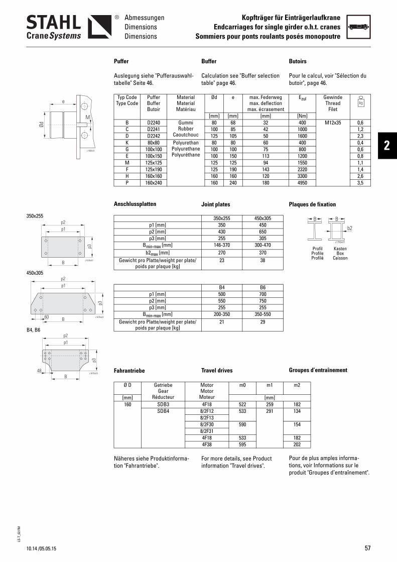
LS-T
_02.
FM
10.14
AbmessungenDimensionsDimensions
Kopfträger für EinträgerlaufkraneEndcarriages for single girder o.h.t. cranes
Sommiers pour ponts roulants posés monopoutre
2c1686v01
e
Ød
M
c1676v01
p3
B
p1p2
c1676v02
p3
B
p1p2
60
c1676v03
p3
p1p2
B48
350x255
450x305
B4, B6
/05.05.15
Buffer
Calculation see "Buffer selection table" page 46.
Joint plates
Travel drives
For more details, see Product information "Travel drives".
B
Pb
P
G
Ptp
Ød e max. Federwegmax. deflection
max. écrasement[mm] [mm] [mm]
c
80 68 32100 85 42125 105 50
nee
80 80 60100 100 75100 150 113125 125 94125 190 143160 160 120160 240 180
350x255 450x305350 450430 650255 305
146-370 300-470270 37023 38
B4 B6500 700550 750255 255
200-350 350-55021 29
MotorMotor
Moteur
m0 m1
[mm]4F18 522 259
8/2F12 533 2918/2F138/2F30 5908/2F314F18 5334F38 595
utoirs
our le calcul, voir "Sélection du utoir", page 46.
laques de fixation
roupes d’entraînement
our de plus amples informa-ions, voir Informations sur le roduit "Groupes d’entraînement".
B B
c1763v01
b2
Profil KastenProfile BoxProfilé Caisson
Ezul GewindeThread
Filet[Nm]400 M12x35 0,6
1000 1,21600 2,3400 0,4800 0,6
1200 0,81550 1,12320 1,43300 2,64950 3,5
m2
182134
154
182202
Puffer
Auslegung siehe "Pufferauswahl-tabelle" Seite 46.
Anschlussplatten
Fahrantriebe
Näheres siehe Produktinforma-tion "Fahrantriebe".
Typ CodeType Code
PufferBufferButoir
MaterialMaterialMatériau
B D2240 GummiRubber
CaoutchouC D2241D D2242K 80x80 Polyuretha
PolyurethanPolyuréthan
G 100x100E 100x150M 125x125F 125x190H 160x160P 160x240
p1 [mm]p2 [mm]p3 [mm]
Bmin-max [mm]b2max [mm]
Gewicht pro Platte/weight per plate/poids par plaque [kg]
p1 [mm]p2 [mm]p3 [mm]
Bmin-max [mm]Gewicht pro Platte/weight per plate/
poids par plaque [kg]
Ø D GetriebeGear
Réducteur[mm]160 SDB3
SDB4
57
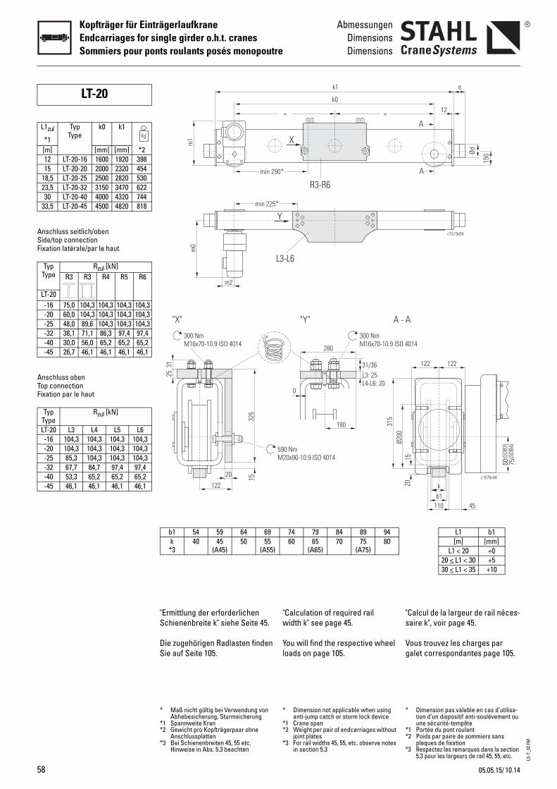
LS-T
_02.
FM
58
Kopfträger für EinträgerlaufkraneEndcarriages for single girder o.h.t. cranesSommiers pour ponts roulants posés monopoutre
AbmessungenDimensionsDimensions
Anschluss seitlich/obenSide/top connectionFixation latérale/par le haut
Anschluss obenTop connectionFixation par le haut
LT-20
L1zul
*1
TypType
k0 k1
[m] [mm] [mm] *212 LT-20-16 1600 1920 39815 LT-20-20 2000 2320 454
18,5 LT-20-25 2500 2820 53023,5 LT-20-32 3150 3470 62230 LT-20-40 4000 4320 744
33,5 LT-20-45 4500 4820 818
TypType
Rzul [kN]R3 R3 R4 R5 R6
LT-20-16 75,0 104,3 104,3 104,3 104,3-20 60,0 104,3 104,3 104,3 104,3-25 48,0 89,6 104,3 104,3 104,3-32 38,1 71,1 86,3 97,4 97,4-40 30,0 56,0 65,2 65,2 65,2-45 26,7 46,1 46,1 46,1 46,1
TypType
Rzul [kN]
LT-20 L3 L4 L5 L6-16 104,3 104,3 104,3 104,3-20 104,3 104,3 104,3 104,3-25 85,3 104,3 104,3 104,3-32 67,7 84,7 97,4 97,4-40 53,3 65,2 65,2 65,2-45 46,1 46,1 46,1 46,1
"Calculation of required rail width k" see page 45.
You will find the respective wheel loads on page 105.
"s
Vg
280
L3: 25L4-L6: 20
0
300 NmM16x70-10.9 ISO 4
180
31/36
"Y" A - A
590 NmM20x90-10.9 ISO 4014
Ø200
315
=
0*
=
k1
k0
X
R3-R6
L3-L6
*
Y
74 79 84 89 9460 65
(A65)70 75
(A75)80
* Dimension not applicable when using anti-jump catch or storm lock device
*1 Crane span*2 Weight per pair of endcarriages without
joint plates*3 For rail widths 45, 55, etc. observe notes
in section 5.3
*
**
*
Calcul de la largeur de rail néces-aire k", voir page 45.
ous trouvez les charges par alet correspondantes page 105.
014
60 75(S
DB3)
(SDB
4)
b1k
110
15
122 122
c1576v04
45
20
c1573v04
e
150Ød
A
A
12
L1 b1[m] [mm]
L1 < 20 +020 < L1 < 30 +530 < L1 < 35 +10
Dimension pas valable en cas d’utilisa-tion d’un dispositif anti-soulèvement ou une sécurité-tempête
1 Portée du pont roulant2 Poids par paire de sommiers sans
plaques de fixation3 Respectez les remarques dans la section
5.3 pour les largeurs de rail 45, 55, etc.
"Ermittlung der erforderlichen Schienenbreite k" siehe Seite 45.
Die zugehörigen Radlasten finden Sie auf Seite 105.
"X"
325
20 15
122
25
300 NmM16x70-10.9 ISO 4014
31min 29
m0
m2
min 225
m1
b1 54 59 64 69k *3
40 45(A45)
50 55(A55)
* Maß nicht gültig bei Verwendung von Abhebesicherung, Sturmsicherung
*1 Spannweite Kran*2 Gewicht pro Kopfträgerpaar ohne
Anschlussplatten*3 Bei Schienenbreiten 45, 55 etc.
Hinweise in Abs. 5.3 beachten
10.1405.05.15/
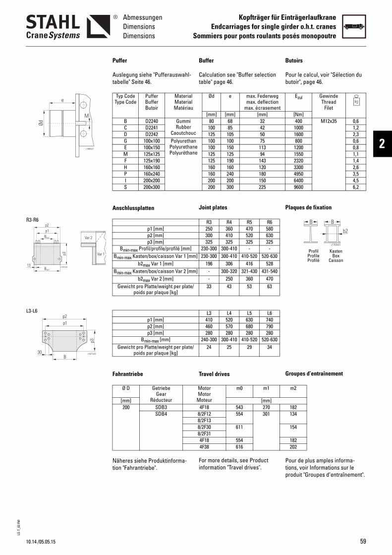
LS-T
_02.
FM
10.14
AbmessungenDimensionsDimensions
Kopfträger für EinträgerlaufkraneEndcarriages for single girder o.h.t. cranes
Sommiers pour ponts roulants posés monopoutre
2c1686v01
e
Ød
M
p3
c1677v01BVar1
BVar2
p1p2
13
Var 2
Var 1
R3-R6
p1p2
p3
c1677v02
B30
L3-L6
/05.05.15
Buffer
Calculation see "Buffer selection table" page 46.
Joint plates
Travel drives
For more details, see Product information "Travel drives".
B
Pb
P
G
Ptp
Ød e max. Federwegmax. deflection
max. écrasement[mm] [mm] [mm]
c
80 68 32100 85 42125 105 50
nee
100 100 75100 150 113125 125 94125 190 143160 160 120160 240 180200 200 150200 300 225
R3 R4 R5 R6250 360 470 580300 410 520 630325 325 325 325
230-300 300-410 - -] 230-300 300-410 410-520 520-630
196 306 416 528] - 300-320 321-430 431-540
- 250 360 47033 43 53 63
L3 L4 L5 L6410 520 630 740460 570 680 790280 280 280 280
240-300 300-410 410-520 520-63024 25 29 34
MotorMotor
Moteur
m0 m1
[mm]4F18 543 270
8/2F12 554 3018/2F138/2F30 6118/2F314F18 5544F38 616
utoirs
our le calcul, voir "Sélection du utoir", page 46.
laques de fixation
roupes d’entraînement
our de plus amples informa-ions, voir Informations sur le roduit "Groupes d’entraînement".
B B
c1763v01
b2
Profil KastenProfile BoxProfilé Caisson
Ezul GewindeThread
Filet[Nm]400 M12x35 0,6
1000 1,21600 2,3800 0,6
1200 0,81550 1,12320 1,43300 2,64950 3,56400 4,59600 6,2
m2
182134
154
182202
Puffer
Auslegung siehe "Pufferauswahl-tabelle" Seite 46.
Anschlussplatten
Fahrantriebe
Näheres siehe Produktinforma-tion "Fahrantriebe".
Typ CodeType Code
PufferBufferButoir
MaterialMaterialMatériau
B D2240 GummiRubber
CaoutchouC D2241D D2242G 100x100 Polyuretha
PolyurethanPolyuréthan
E 100x150M 125x125F 125x190H 160x160P 160x240I 200x200S 200x300
p1 [mm]p2 [mm]p3 [mm]
Bmin-max Profil/profile/profilé [mm]Bmin-max Kasten/box/caisson Var 1 [mm
b2max Var 1 [mm]Bmin-max Kasten/box/caisson Var 2 [mm
b2max Var 2 [mm]Gewicht pro Platte/weight per plate/
poids par plaque [kg]
p1 [mm]p2 [mm]p3 [mm]
Bmin-max [mm]Gewicht pro Platte/weight per plate/
poids par plaque [kg]
Ø D GetriebeGear
Réducteur[mm]200 SDB3
SDB4
59
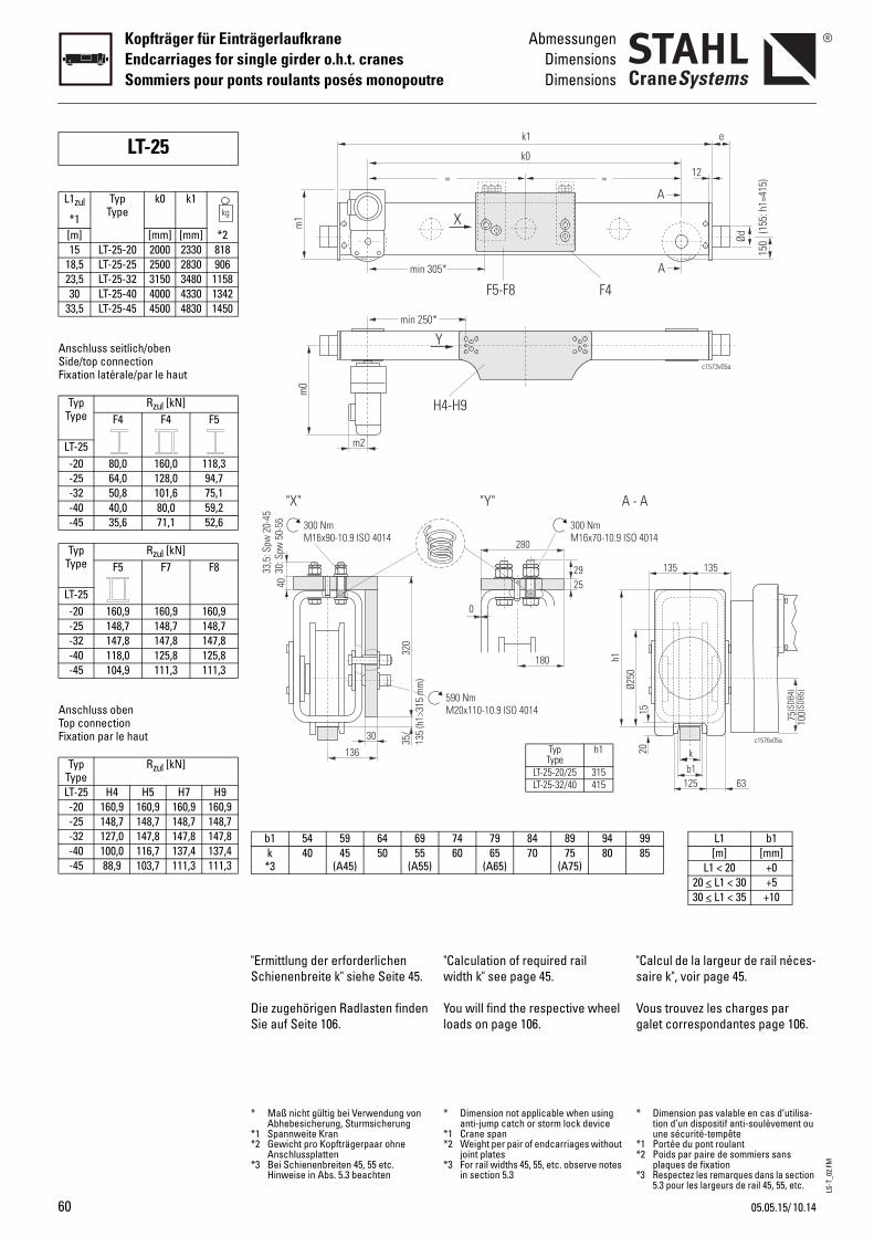
LS-T
_02.
FM
60
Kopfträger für EinträgerlaufkraneEndcarriages for single girder o.h.t. cranesSommiers pour ponts roulants posés monopoutre
AbmessungenDimensionsDimensions
Anschluss seitlich/obenSide/top connectionFixation latérale/par le haut
Anschluss obenTop connectionFixation par le haut
LT-25
L1zul
*1
TypType
k0 k1
[m] [mm] [mm] *215 LT-25-20 2000 2330 818
18,5 LT-25-25 2500 2830 90623,5 LT-25-32 3150 3480 115830 LT-25-40 4000 4330 1342
33,5 LT-25-45 4500 4830 1450
TypType
Rzul [kN]F4 F4 F5
LT-25-20 80,0 160,0 118,3-25 64,0 128,0 94,7-32 50,8 101,6 75,1-40 40,0 80,0 59,2-45 35,6 71,1 52,6
TypType
Rzul [kN]F5 F7 F8
LT-25-20 160,9 160,9 160,9-25 148,7 148,7 148,7-32 147,8 147,8 147,8-40 118,0 125,8 125,8-45 104,9 111,3 111,3
TypType
Rzul [kN]
LT-25 H4 H5 H7 H9-20 160,9 160,9 160,9 160,9-25 148,7 148,7 148,7 148,7-32 127,0 147,8 147,8 147,8-40 100,0 116,7 137,4 137,4-45 88,9 103,7 111,3 111,3
"Calculation of required rail width k" see page 45.
You will find the respective wheel loads on page 106.
"s
Vg
280
25
0
300 NmM16x70-10.9 ISO
180
29
590 NmM20x110-10.9 ISO 4014
Ø250
"Y" A -
h1
=
05*
=
k1
k0
X
F5-F8
H4-H9
*
Y
F4
74 79 84 89 9460 65
(A65)70 75
(A75)80
TypType
h1
LT-25-20/25 315LT-25-32/40 415
* Dimension not applicable when using anti-jump catch or storm lock device
*1 Crane span*2 Weight per pair of endcarriages without
joint plates*3 For rail widths 45, 55, etc. observe notes
in section 5.3
*
**
*
Calcul de la largeur de rail néces-aire k", voir page 45.
ous trouvez les charges par alet correspondantes page 106.
4014
75 100(S
DB4)
(SDB
5)
b1k
125
1520
135 135
c1576v05a
63
A
c1573v05a
e
Ød
A
A
150
(15
5: h
1=41
5)
12
9985
L1 b1[m] [mm]
L1 < 20 +020 < L1 < 30 +530 < L1 < 35 +10
Dimension pas valable en cas d’utilisa-tion d’un dispositif anti-soulèvement ou une sécurité-tempête
1 Portée du pont roulant2 Poids par paire de sommiers sans
plaques de fixation3 Respectez les remarques dans la section
5.3 pour les largeurs de rail 45, 55, etc.
"Ermittlung der erforderlichen Schienenbreite k" siehe Seite 45.
Die zugehörigen Radlasten finden Sie auf Seite 106.
320
30 35/
135
(h1>
315
mm
)
136
4033
,5: S
pw 2
0-45
30: S
pw 5
0-55 300 Nm
M16x90-10.9 ISO 4014
"X"
min 3
m0
m2
min 250
m1
b1 54 59 64 69k *3
40 45(A45)
50 55(A55)
* Maß nicht gültig bei Verwendung von Abhebesicherung, Sturmsicherung
*1 Spannweite Kran*2 Gewicht pro Kopfträgerpaar ohne
Anschlussplatten*3 Bei Schienenbreiten 45, 55 etc.
Hinweise in Abs. 5.3 beachten
10.1405.05.15/
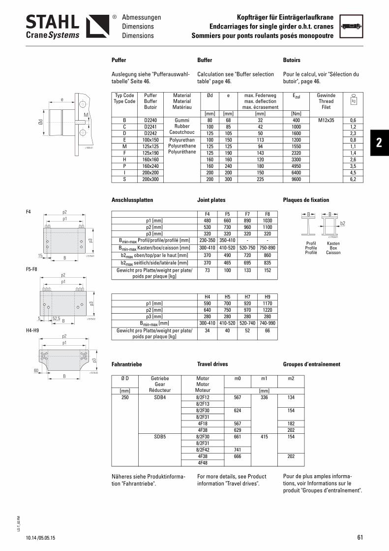
LS-T
_02.
FM
10.14
AbmessungenDimensionsDimensions
Kopfträger für EinträgerlaufkraneEndcarriages for single girder o.h.t. cranes
Sommiers pour ponts roulants posés monopoutre
2c1686v01
e
Ød
M
p3
p1p2
B c1678v0115
B
p1p2
p3
c1678v0252,55
p3
Bc1678v03
p1p2
60
F4
F5-F8
H4-H9
/05.05.15
Buffer
Calculation see "Buffer selection table" page 46.
Joint plates
Travel drives
For more details, see Product information "Travel drives".
B
Pb
P
G
Ptp
Ød e max. Federwegmax. deflection
max. écrasement[mm] [mm] [mm]
c
80 68 32100 85 42125 105 50
nee
100 150 113125 125 94125 190 143160 160 120160 240 180200 200 150200 300 225
F4 F5 F7 F8480 660 890 1030530 730 960 1100320 320 320 320
230-350 350-410 - -300-410 410-520 520-750 750-890
370 490 720 860370 465 695 83573 100 133 152
H4 H5 H7 H9590 700 920 1170640 750 970 1220280 280 280 280
300-410 410-520 520-740 740-99034 40 52 66
MotorMotor
Moteur
m0 m1
[mm]8/2F12 567 3368/2F138/2F30 6248/2F314F18 5674F38 629
8/2F30 661 4158/2F318/2F42 7414F38 6664F48
utoirs
our le calcul, voir "Sélection du utoir", page 46.
laques de fixation
roupes d’entraînement
our de plus amples informa-ions, voir Informations sur le roduit "Groupes d’entraînement".
B B
c1763v01
b2
Profil KastenProfile BoxProfilé Caisson
Ezul GewindeThread
Filet[Nm]400 M12x35 0,6
1000 1,21600 2,31200 0,81550 1,12320 1,43300 2,64950 3,56400 4,59600 6,2
m2
134
154
182202154
202
Puffer
Auslegung siehe "Pufferauswahl-tabelle" Seite 46.
Anschlussplatten
Fahrantriebe
Näheres siehe Produktinforma-tion "Fahrantriebe".
Typ CodeType Code
PufferBufferButoir
MaterialMaterialMatériau
B D2240 GummiRubber
CaoutchouC D2241D D2242E 100x150 Polyuretha
PolyurethanPolyuréthan
M 125x125F 125x190H 160x160P 160x240I 200x200S 200x300
p1 [mm]p2 [mm]p3 [mm]
Bmin-max Profil/profile/profilé [mm]Bmin-max Kasten/box/caisson [mm]b2max oben/top/par le haut [mm]b2max seitlich/side/latérale [mm]
Gewicht pro Platte/weight per plate/poids par plaque [kg]
p1 [mm]p2 [mm]p3 [mm]
Bmin-max [mm]Gewicht pro Platte/weight per plate/
poids par plaque [kg]
Ø D GetriebeGear
Réducteur[mm]250 SDB4
SDB5
61
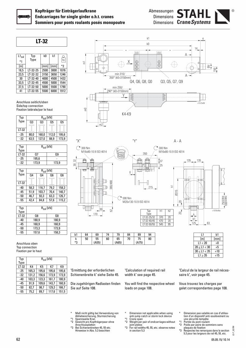
LS-T
_02.
FM
62
Kopfträger für EinträgerlaufkraneEndcarriages for single girder o.h.t. cranesSommiers pour ponts roulants posés monopoutre
AbmessungenDimensionsDimensions
Anschluss seitlich/obenSide/top connectionFixation latérale/par le haut
Anschluss obenTop connectionFixation par le haut
LT-32
L1zul
*1
TypType
k0 k1
[m] [mm] [mm] *218,5 LT-32-25 2500 3000 107623,5 LT-32-32 3150 3650 124630 LT-32-40 4000 4500 1432
33,5 LT-32-45 4500 5000 154437,5 LT-32-50 5000 5500 179041 LT-32-55 5500 6000 1912
TypType
Rzul [kN]Q3 Q3 Q5 Q5
LT-32-25 80,0 160,0 112,0 195,6-32 63,5 127,0 88,9 173,9
TypType
Rzul [kN]
LT-32 Q7 Q9-25 195,6 --32 173,9 173,9
TypType
Rzul [kN]Q4 Q4 Q6 Q6
LT-32-40 58,3 116,7 79,2 158,3-45 51,9 103,7 70,4 140,7-50 46,7 93,3 63,3 126,7-55 42,4 84,8 57,6 115,2
TypType
Rzul [kN]
LT-32 Q8 Q0-40 180,9 180,9-45 160,9 160,9-50 173,3 173,9-55 157,6 158,3
TypType
Rzul [kN]
LT-32 K4 K5 K7 K9-25 165,3 195,6 195,6 195,6-32 131,2 156,6 173,9 173,9-40 103,3 123,3 161,7 180,9-45 91,9 109,6 143,7 160,9-50 82,7 98,7 129,3 166,7-55 75,2 89,7 117,6 151,5
"Calculation of required rail width k" see page 45.
You will find the respective wheel loads on page 108.
"s
Vg
590 NmM20x130-10.9 ISO 4014
350
0
215
2537
300 NmM16x80-10.9 ISO 4
Ø315
"Y" A - A
h1
=
10/150mm)
=
k1
k0
X
Q4, Q6, Q8, Q0
K4-K9
/0mm)
Y
Q3, Q5, Q7, Q
84 89 9470 75
(A75)80
TypType
h1 h2
LT-32-25/32 370 20LT-32-40/45 470 20LT-32-50/55 545 95
* Dimension not applicable when using anti-jump catch or storm lock device
*1 Crane span*2 Weight per pair of endcarriages without
joint plates*3 For rail widths 45, 55, etc. observe notes
in section 5.3
*
**
*
Calcul de la largeur de rail néces-aire k", voir page 45.
ous trouvez les charges par alet correspondantes page 108.
014
b1k
20
c1576v06a
125 63
135 135
75 100(S
DB4)
(SDB
5)
20
c1573v06
e
150Ød
A
A
9
14
L1 b1[m] [mm]
L1 < 20 +020 < L1 < 30 +530 < L1 < 35 +10
L1 > 35 +15
Dimension pas valable en cas d’utilisa-tion d’un dispositif anti-soulèvement ou une sécurité-tempête
1 Portée du pont roulant2 Poids par paire de sommiers sans
plaques de fixation3 Respectez les remarques dans la section
5.3 pour les largeurs de rail 45, 55, etc.
"Ermittlung der erforderlichen Schienenbreite k" siehe Seite 45.
Die zugehörigen Radlasten finden Sie auf Seite 108.
380/
480
30 h2
170
3032
300 NmM16x80-10.9 ISO 4014
"X"
min 3350* (k0>3
m0
m2
min 250290* (k0>315
m1
b1 64 69 74 79k *3
50 55(A55)
60 65(A65)
* Maß nicht gültig bei Verwendung von Abhebesicherung, Sturmsicherung
*1 Spannweite Kran*2 Gewicht pro Kopfträgerpaar ohne
Anschlussplatten*3 Bei Schienenbreiten 45, 55 etc.
Hinweise in Abs. 5.3 beachten
10.1405.05.15/
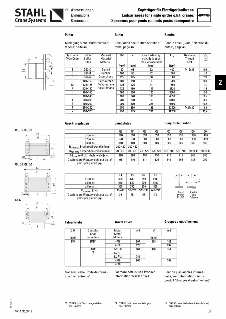
LS-T
_02.
FM
10.14
AbmessungenDimensionsDimensions
Kopfträger für EinträgerlaufkraneEndcarriages for single girder o.h.t. cranes
Sommiers pour ponts roulants posés monopoutre
2c1686v01
e
Ød
M
c1679v01
p3
B
p1p2
30
B
p1p2
c1679v02
p3
30
p3
p1p2
c1679v03
B30
Q3, Q5, Q7, Q9
K4-K9
Q4, Q6, Q8, Q0
/05.05.15
Buffer
Calculation see "Buffer selection table" page 46.
Joint plates
Travel drives
For more details, see Product information "Travel drives".
B
Pb
P
G
Ptp
Ød e max. Federwegmax. deflection
max. écrasement[mm] [mm] [mm]
c
80 68 32100 85 42125 105 50
nee
100 150 113125 125 94125 190 143160 160 120160 240 180200 200 150200 300 225250 250 188250 375 281
Q3 Q4 Q5 Q6520 520 630 630570 570 680 680380 480 380 480
300-420 300-420 - -300-410 300-410 410-520 410-520 5
380 380 490 49094 110 111 126
K4 K5 K7 K9520 630 850 1100570 680 900 1150350 350 350 350
90-410 90-520 520-740 740-99039 46 61 78
MotorMotor
Moteur
m0 m1
[mm]4F18 567 3694F38 629
8/2F30 661 4488/2F318/2F42 7414F38 6664F48
*1 SDB5Z (with intermediate gear) m0+100mm
*
utoirs
our le calcul, voir "Sélection du utoir", page 46.
laques de fixation
roupes d’entraînement
our de plus amples informa-ions, voir Informations sur le roduit "Groupes d’entraînement".
B B
c1763v01
b2
Profil KastenProfile BoxProfilé Caisson
Ezul GewindeThread
Filet[Nm]400 M12x35 0,6
1000 1,21600 2,31200 0,81550 1,12320 1,43300 2,64950 3,56400 4,59600 6,212500 M24x80 9,318750 12,4
Q7 Q8 Q9 Q0850 850 1100 1100900 900 1150 1150380 480 380 480
- - - -20-740 520-740 740-990 740-990710 710 960 960144 165 183 209
m2
182202154
202
1 SDB5Z (avec réducteur intermédiaire) m0+100mm
Puffer
Auslegung siehe "Pufferauswahl-tabelle" Seite 46.
Anschlussplatten
Fahrantriebe
Näheres siehe Produktinforma-tion "Fahrantriebe".
Typ CodeType Code
PufferBufferButoir
MaterialMaterialMatériau
B D2240 GummiRubber
CaoutchouC D2241D D2242E 100x150 Polyuretha
PolyurethanPolyuréthan
M 125x125F 125x190H 160x160P 160x240I 200x200S 200x300T 250x250Y 250x375
p1 [mm]p2 [mm]p3 [mm]
Bmin-max Profil/profile/profilé [mm]Bmin-max Kasten/box/caisson [mm]b2max seitlich/side/latérale [mm]
Gewicht pro Platte/weight per plate/poids par plaque [kg]
p1 [mm]p2 [mm]p3 [mm]
Bmin-max [mm]Gewicht pro Platte/weight per plate/
poids par plaque [kg]
Ø D GetriebeGear
Réducteur[mm]315 SDB4
SDB5*1
*1 SDB5Z (mit Zwischengetriebe) m0+100mm
63
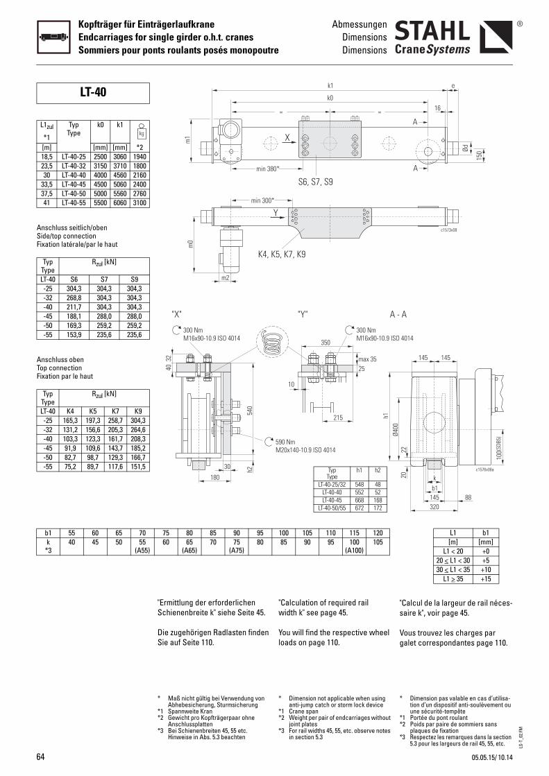
LS-T
_02.
FM
64
Kopfträger für EinträgerlaufkraneEndcarriages for single girder o.h.t. cranesSommiers pour ponts roulants posés monopoutre
AbmessungenDimensionsDimensions
b1 55 60 65 70k
*340 45 50 55
(A55)
Anschluss seitlich/obenSide/top connectionFixation latérale/par le haut
Anschluss obenTop connectionFixation par le haut
LT-40
L1zul
*1
TypType
k0 k1
[m] [mm] [mm] *218,5 LT-40-25 2500 3060 194023,5 LT-40-32 3150 3710 180030 LT-40-40 4000 4560 2160
33,5 LT-40-45 4500 5060 240037,5 LT-40-50 5000 5560 276041 LT-40-55 5500 6060 3100
TypType
Rzul [kN]
LT-40 S6 S7 S9-25 304,3 304,3 304,3-32 268,8 304,3 304,3-40 211,7 304,3 304,3-45 188,1 288,0 288,0-50 169,3 259,2 259,2-55 153,9 235,6 235,6
TypType
Rzul [kN]
LT-40 K4 K5 K7 K9-25 165,3 197,3 258,7 304,3-32 131,2 156,6 205,3 264,6-40 103,3 123,3 161,7 208,3-45 91,9 109,6 143,7 185,2-50 82,7 98,7 129,3 166,7-55 75,2 89,7 117,6 151,5
"Calculation of required rail width k" see page 45.
You will find the respective wheel loads on page 110.
"s
Vg
100 105 110 115 12085 90 95 100
(A100)105
590 NmM20x140-10.9 ISO 4014
Ø400
350
10
215
25max 35
300 NmM16x90-10.9 ISO
"Y" A -
h1
= =
k1
k0
X
S6, S7, S9
K5, K7, K9
Y*
0*
TypType
h1 h2
LT-40-25/32 548 48LT-40-40 552 52LT-40-45 668 168
LT-40-50/55 672 172
* Dimension not applicable when using anti-jump catch or storm lock device
*1 Crane span*2 Weight per pair of endcarriages without
joint plates*3 For rail widths 45, 55, etc. observe notes
in section 5.3
*
**
*
Calcul de la largeur de rail néces-aire k", voir page 45.
ous trouvez les charges par alet correspondantes page 110.
L1 b1[m] [mm]
L1 < 20 +020 < L1 < 30 +530 < L1 < 35 +10
L1 > 35 +15
b1k
22
c1576v08a
145 88
145 145
100(
SDB5
)
20
320
4014
A
c1573v08
e
150Ød
A
A
16
Dimension pas valable en cas d’utilisa-tion d’un dispositif anti-soulèvement ou une sécurité-tempête
1 Portée du pont roulant2 Poids par paire de sommiers sans
plaques de fixation3 Respectez les remarques dans la section
5.3 pour les largeurs de rail 45, 55, etc.
"Ermittlung der erforderlichen Schienenbreite k" siehe Seite 45.
Die zugehörigen Radlasten finden Sie auf Seite 110.
75 80 85 90 9560 65
(A65)70 75
(A75)80
540
30
180
4032
300 NmM16x90-10.9 ISO 4014
"X"
h2
m0
K4,
m2
min 300
m1
min 38
* Maß nicht gültig bei Verwendung von Abhebesicherung, Sturmsicherung
*1 Spannweite Kran*2 Gewicht pro Kopfträgerpaar ohne
Anschlussplatten*3 Bei Schienenbreiten 45, 55 etc.
Hinweise in Abs. 5.3 beachten
10.1405.05.15/

LS-T
_02.
FM
10.14
AbmessungenDimensionsDimensions
Kopfträger für EinträgerlaufkraneEndcarriages for single girder o.h.t. cranes
Sommiers pour ponts roulants posés monopoutre
2c1686v01
e
Ød
M
B
p1p2
c1717v01
p3
5
S6-S9
p3
p1p2
c1679v03
B30
K4-K9
/05.05.15
Buffer
Calculation see "Buffer selection table" page 46.
Joint plates
Travel drives
For more details, see Product information "Travel drives".
B
Pb
P
G
Ptp
Ød e max. Federwegmax. deflection
max. écrasement[mm] [mm] [mm]
c
80 68 32100 85 42125 105 50
nee
100 150 113125 125 94125 190 143160 160 120160 240 180200 200 150200 300 225250 250 188250 375 281
S6 S7 S9520 730 1100590 800 1170540 540 540
410-520 550-740 750-1100410 620 990430 640 1010126 172 252
K4 K5 K7 K9520 630 850 1100570 680 900 1150350 350 350 350
90-410 90-520 520-740 740-99039 46 61 78
MotorMotor
Moteur
m0 m1
[mm]8/2F30 671 4908/2F318/2F42 7514F38 6764F48
*1 SDB5Z (with intermediate gear) m0+100mm
*
utoirs
our le calcul, voir "Sélection du utoir", page 46.
laques de fixation
roupes d’entraînement
our de plus amples informa-ions, voir Informations sur le roduit "Groupes d’entraînement".
B B
c1763v01
b2
Profil KastenProfile BoxProfilé Caisson
Ezul GewindeThread
Filet[Nm]400 M12x35 0,6
1000 1,21600 2,31200 0,81550 1,12320 1,43300 2,64950 3,56400 4,59600 6,212500 M24x80 9,318750 12,4
m2
154
202
1 SDB5Z (avec réducteur intermédiaire) m0+100mm
Puffer
Auslegung siehe "Pufferauswahl-tabelle" Seite 46.
Anschlussplatten
Fahrantriebe
Näheres siehe Produktinforma-tion "Fahrantriebe".
Typ CodeType Code
PufferBufferButoir
MaterialMaterialMatériau
B D2240 GummiRubber
CaoutchouC D2241D D2242E 100x150 Polyuretha
PolyurethanPolyuréthan
M 125x125F 125x190H 160x160P 160x240I 200x200S 200x300T 250x250Y 250x375
p1 [mm]p2 [mm]p3 [mm]
Bmin-max [mm]b2max oben/top/par le haut [mm]b2max seitlich/side/latérale [mm]
Gewicht pro Platte/weight per plate/poids par plaque [kg]
p1 [mm]p2 [mm]p3 [mm]
Bmin-max [mm]Gewicht pro Platte/weight per plate/
poids par plaque [kg]
Ø D GetriebeGear
Réducteur[mm]400 SDB5
*1
*1 SDB5Z (mit Zwischengetriebe) m0+100mm
65
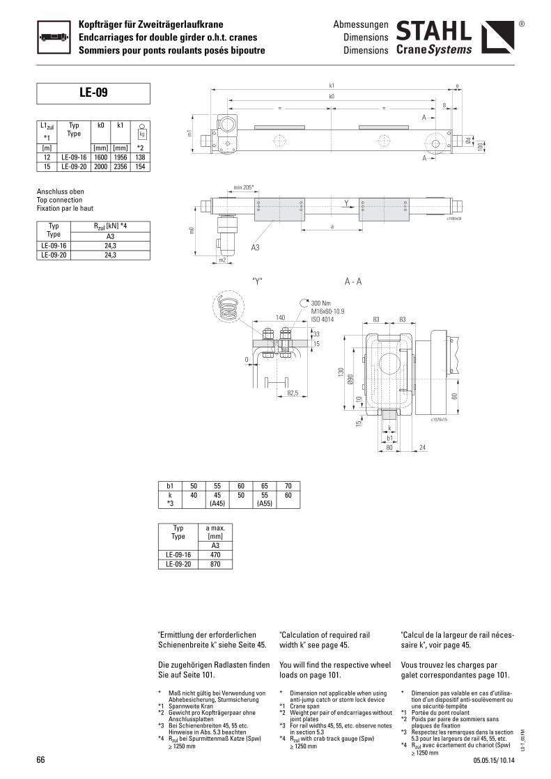
LS-T
_03.
FM
66
Kopfträger für ZweiträgerlaufkraneEndcarriages for double girder o.h.t. cranesSommiers pour ponts roulants posés bipoutre
AbmessungenDimensionsDimensions
Anschluss obenTop connectionFixation par le haut
LE-09
L1zul
*1
TypType
k0 k1
[m] [mm] [mm] *212 LE-09-16 1600 1956 13815 LE-09-20 2000 2356 154
TypType
Rzul [kN] *4A3
LE-09-16 24,3LE-09-20 24,3
"Calculation of required rail width k" see page 45.
You will find the respective wheel loads on page 101.
"s
Vg
= =
k1
k0
a
Y
7060
140
15
300 NmM16x60-10.9ISO 4014
82,5
33
A - A
b1k
80
1015
Ø9013
0
83 8
* Dimension not applicable when using anti-jump catch or storm lock device
*1 Crane span*2 Weight per pair of endcarriages without
joint plates*3 For rail widths 45, 55, etc. observe notes
in section 5.3*4 Rzul with crab track gauge (Spw)
> 1250 mm
*
**
*
*
Calcul de la largeur de rail néces-aire k", voir page 45.
ous trouvez les charges par alet correspondantes page 101.
c1669v09
e
100Ød
A
A
8
3
c1576v15
6024
Dimension pas valable en cas d’utilisa-tion d’un dispositif anti-soulèvement ou une sécurité-tempête
1 Portée du pont roulant2 Poids par paire de sommiers sans
plaques de fixation3 Respectez les remarques dans la section
5.3 pour les largeurs de rail 45, 55, etc.4 Rzul avec écartement du chariot (Spw)
> 1250 mm
"Ermittlung der erforderlichen Schienenbreite k" siehe Seite 45.
Die zugehörigen Radlasten finden Sie auf Seite 101.
m0
A3m2
min 205*m
1
b1 50 55 60 65k *3
40 45(A45)
50 55(A55)
TypType
a max. [mm]
A3LE-09-16 470LE-09-20 870
0
"Y"
* Maß nicht gültig bei Verwendung von Abhebesicherung, Sturmsicherung
*1 Spannweite Kran*2 Gewicht pro Kopfträgerpaar ohne
Anschlussplatten*3 Bei Schienenbreiten 45, 55 etc.
Hinweise in Abs. 5.3 beachten*4 Rzul bei Spurmittenmaß Katze (Spw)
> 1250 mm
10.1405.05.15/
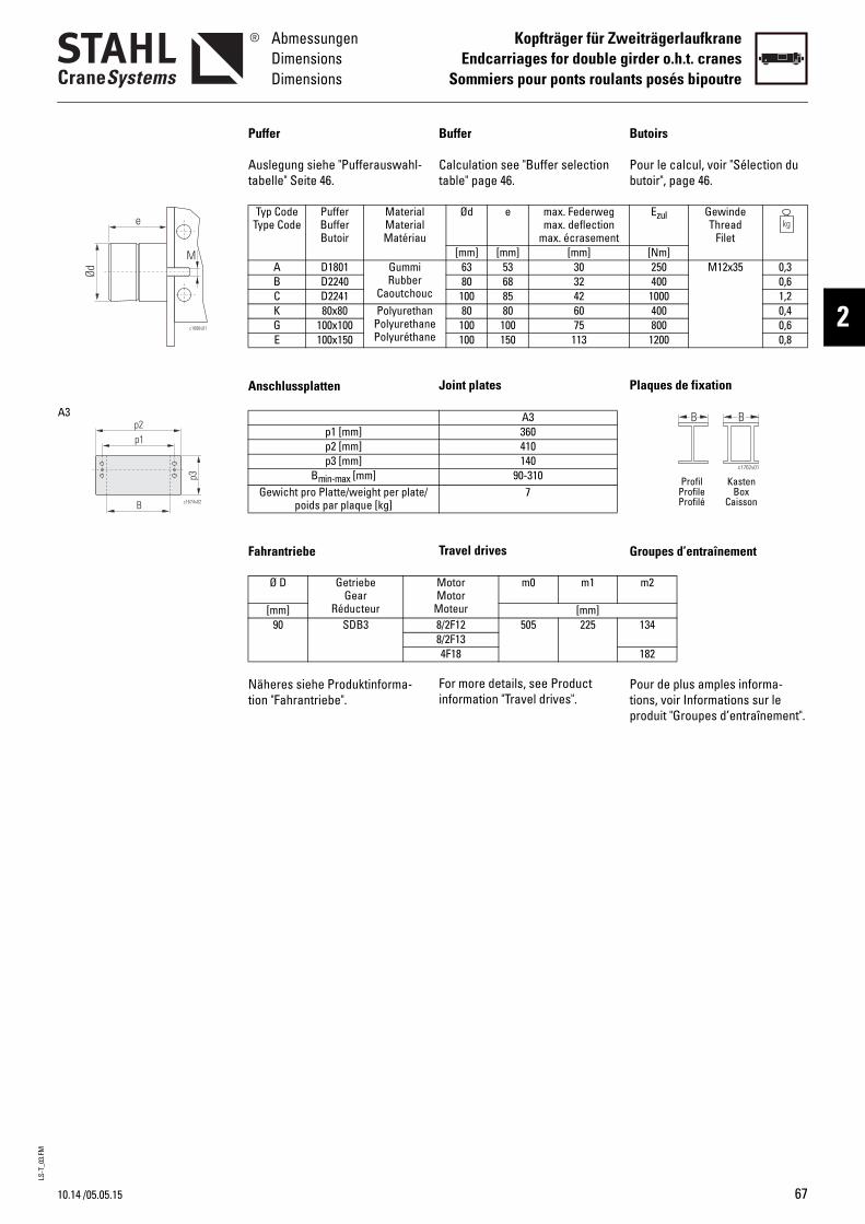
LS-T
_03.
FM
10.14
AbmessungenDimensionsDimensions
Kopfträger für ZweiträgerlaufkraneEndcarriages for double girder o.h.t. cranes
Sommiers pour ponts roulants posés bipoutre
2c1686v01
e
Ød
M
p3
c1674v02B
p1p2
A3
/05.05.15
Buffer
Calculation see "Buffer selection table" page 46.
Joint plates
Travel drives
For more details, see Product information "Travel drives".
B
Pb
P
G
Ptp
Ød e max. Federwegmax. deflection
max. écrasement[mm] [mm] [mm]
c
63 53 3080 68 32
100 85 42nee
80 80 60100 100 75100 150 113
A3360410140
90-3107
MotorMotor
Moteur
m0 m1
[mm]8/2F12 505 2258/2F134F18
utoirs
our le calcul, voir "Sélection du utoir", page 46.
laques de fixation
roupes d’entraînement
our de plus amples informa-ions, voir Informations sur le roduit "Groupes d’entraînement".
B B
c1762v01
Profil KastenProfile BoxProfilé Caisson
Ezul GewindeThread
Filet[Nm]250 M12x35 0,3400 0,6
1000 1,2400 0,4800 0,6
1200 0,8
m2
134
182
Puffer
Auslegung siehe "Pufferauswahl-tabelle" Seite 46.
Anschlussplatten
Fahrantriebe
Näheres siehe Produktinforma-tion "Fahrantriebe".
Typ CodeType Code
PufferBufferButoir
MaterialMaterialMatériau
A D1801 GummiRubber
CaoutchouB D2240C D2241K 80x80 Polyuretha
PolyurethanPolyuréthan
G 100x100E 100x150
p1 [mm]p2 [mm]p3 [mm]
Bmin-max [mm]Gewicht pro Platte/weight per plate/
poids par plaque [kg]
Ø D GetriebeGear
Réducteur[mm]90 SDB3
67
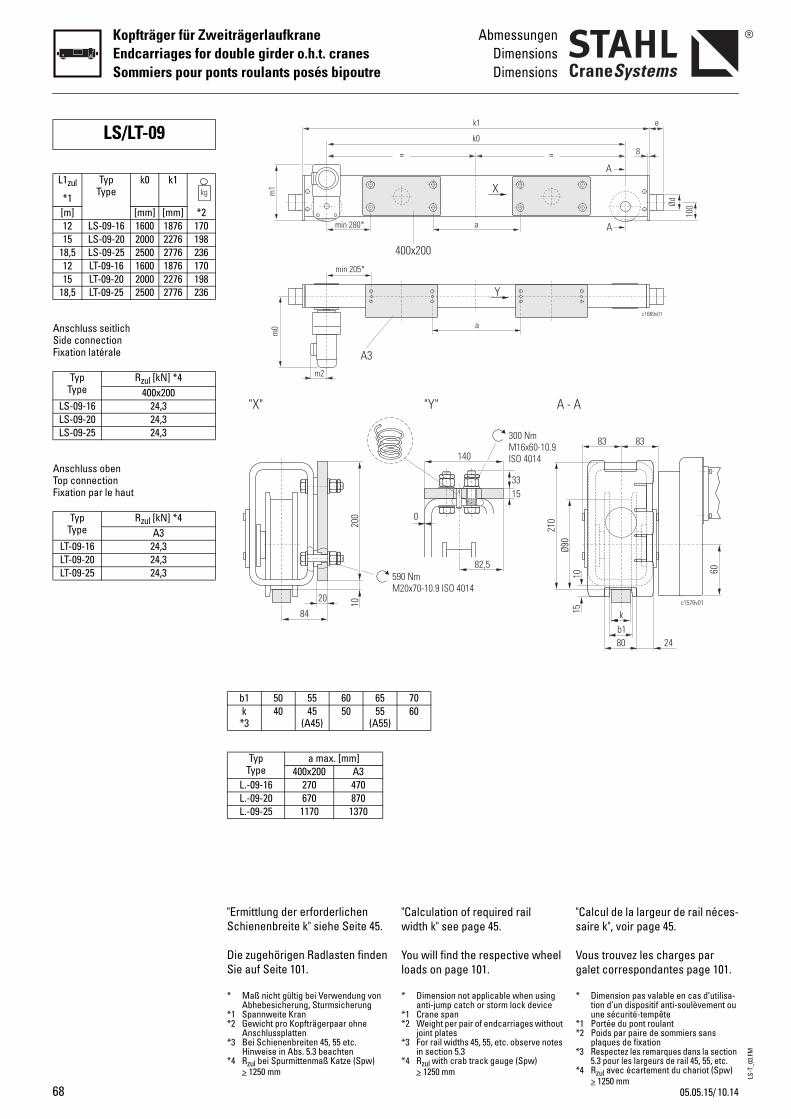
LS-T
_03.
FM
68
Kopfträger für ZweiträgerlaufkraneEndcarriages for double girder o.h.t. cranesSommiers pour ponts roulants posés bipoutre
AbmessungenDimensionsDimensions
Anschluss seitlichSide connectionFixation latérale
Anschluss obenTop connectionFixation par le haut
LS/LT-09
L1zul
*1
TypType
k0 k1
[m] [mm] [mm] *212 LS-09-16 1600 1876 17015 LS-09-20 2000 2276 198
18,5 LS-09-25 2500 2776 23612 LT-09-16 1600 1876 17015 LT-09-20 2000 2276 198
18,5 LT-09-25 2500 2776 236
TypType
Rzul [kN] *4400x200
LS-09-16 24,3LS-09-20 24,3LS-09-25 24,3
TypType
Rzul [kN] *4A3
LT-09-16 24,3LT-09-20 24,3LT-09-25 24,3
"Calculation of required rail width k" see page 45.
You will find the respective wheel loads on page 101.
"s
Vg
140
15
0
300 NmM16x60-10.9ISO 4014
82,5
33
590 NmM20x70-10.9 ISO 4014
"Y" A - A
Ø90
210
= =
k1
k0
X
a
a
Y
400x200
7060
* Dimension not applicable when using anti-jump catch or storm lock device
*1 Crane span*2 Weight per pair of endcarriages without
joint plates*3 For rail widths 45, 55, etc. observe notes
in section 5.3*4 Rzul with crab track gauge (Spw)
> 1250 mm
*
**
*
*
Calcul de la largeur de rail néces-aire k", voir page 45.
ous trouvez les charges par alet correspondantes page 101.
b1k
80
1015
83 83
c1576v01
60
24
c1669v01
e
100Ød
A
A
8
Dimension pas valable en cas d’utilisa-tion d’un dispositif anti-soulèvement ou une sécurité-tempête
1 Portée du pont roulant2 Poids par paire de sommiers sans
plaques de fixation3 Respectez les remarques dans la section
5.3 pour les largeurs de rail 45, 55, etc.4 Rzul avec écartement du chariot (Spw)
> 1250 mm
"Ermittlung der erforderlichen Schienenbreite k" siehe Seite 45.
Die zugehörigen Radlasten finden Sie auf Seite 101.
200
20 10
84
"X"
m0
A3m2
min 205*
min 280*
m1
b1 50 55 60 65k *3
40 45(A45)
50 55(A55)
TypType
a max. [mm]400x200 A3
L.-09-16 270 470L.-09-20 670 870L.-09-25 1170 1370
* Maß nicht gültig bei Verwendung von Abhebesicherung, Sturmsicherung
*1 Spannweite Kran*2 Gewicht pro Kopfträgerpaar ohne
Anschlussplatten*3 Bei Schienenbreiten 45, 55 etc.
Hinweise in Abs. 5.3 beachten*4 Rzul bei Spurmittenmaß Katze (Spw)
> 1250 mm
10.1405.05.15/
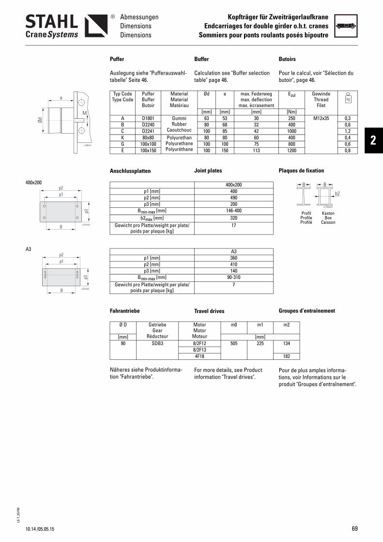
LS-T
_03.
FM
10.14
AbmessungenDimensionsDimensions
Kopfträger für ZweiträgerlaufkraneEndcarriages for double girder o.h.t. cranes
Sommiers pour ponts roulants posés bipoutre
2c1686v01
e
Ød
M
c1674v01
p3
B
p1p2
400x200
p3
c1674v02B
p1p2
A3
/05.05.15
Buffer
Calculation see "Buffer selection table" page 46.
Joint plates
Travel drives
For more details, see Product information "Travel drives".
B
Pb
P
G
Ptp
Ød e max. Federwegmax. deflection
max. écrasement[mm] [mm] [mm]
c
63 53 3080 68 32
100 85 42nee
80 80 60100 100 75100 150 113
400x200400490200
146-40032017
A3360410140
90-3107
MotorMotor
Moteur
m0 m1
[mm]8/2F12 505 2258/2F134F18
utoirs
our le calcul, voir "Sélection du utoir", page 46.
laques de fixation
roupes d’entraînement
our de plus amples informa-ions, voir Informations sur le roduit "Groupes d’entraînement".
B B
c1763v01
b2
Profil KastenProfile BoxProfilé Caisson
Ezul GewindeThread
Filet[Nm]250 M12x35 0,3400 0,6
1000 1,2400 0,4800 0,6
1200 0,8
m2
134
182
Puffer
Auslegung siehe "Pufferauswahl-tabelle" Seite 46.
Anschlussplatten
Fahrantriebe
Näheres siehe Produktinforma-tion "Fahrantriebe".
Typ CodeType Code
PufferBufferButoir
MaterialMaterialMatériau
A D1801 GummiRubber
CaoutchouB D2240C D2241K 80x80 Polyuretha
PolyurethanPolyuréthan
G 100x100E 100x150
p1 [mm]p2 [mm]p3 [mm]
Bmin-max [mm]b2max [mm]
Gewicht pro Platte/weight per plate/poids par plaque [kg]
p1 [mm]p2 [mm]p3 [mm]
Bmin-max [mm]Gewicht pro Platte/weight per plate/
poids par plaque [kg]
Ø D GetriebeGear
Réducteur[mm]90 SDB3
69
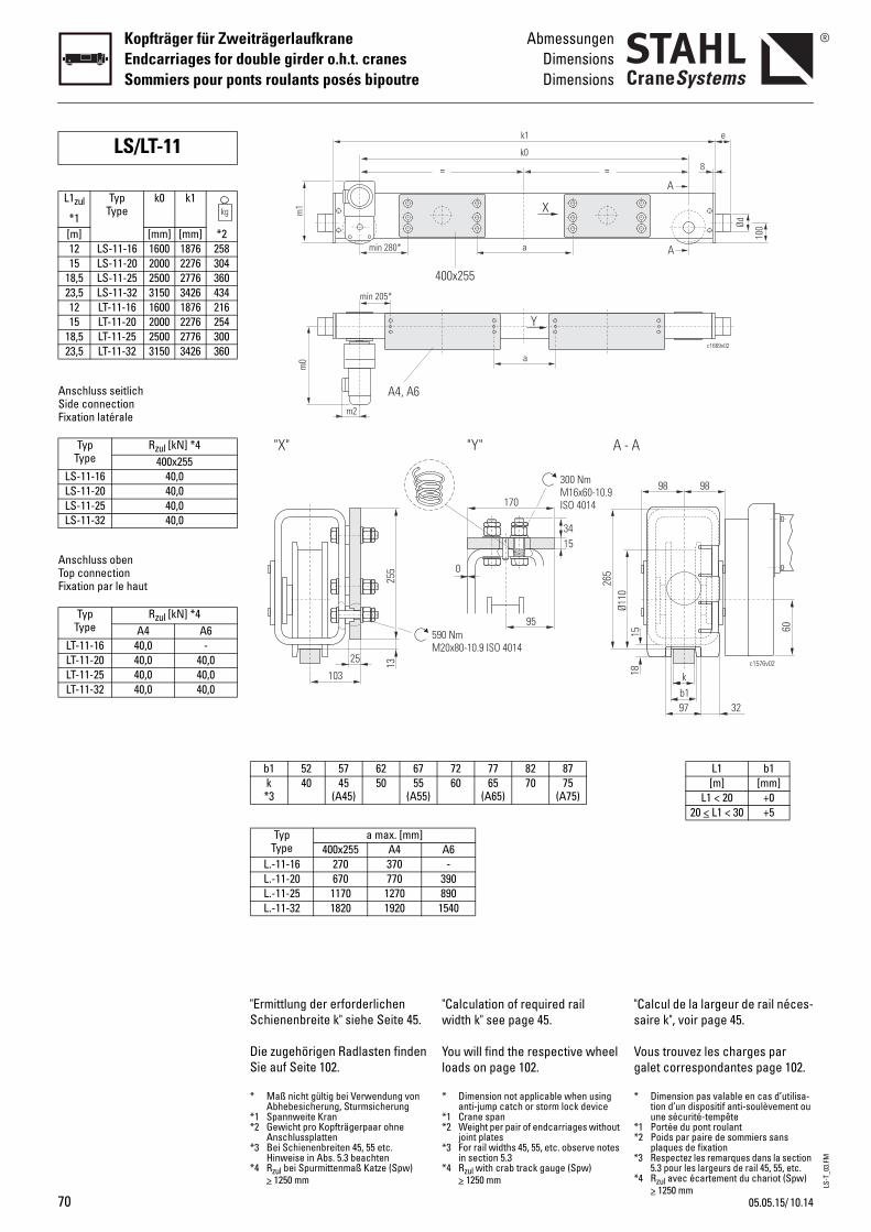
LS-T
_03.
FM
70
Kopfträger für ZweiträgerlaufkraneEndcarriages for double girder o.h.t. cranesSommiers pour ponts roulants posés bipoutre
AbmessungenDimensionsDimensions
Anschluss seitlichSide connectionFixation latérale
Anschluss obenTop connectionFixation par le haut
LS/LT-11
L1zul
*1
TypType
k0 k1
[m] [mm] [mm] *212 LS-11-16 1600 1876 25815 LS-11-20 2000 2276 304
18,5 LS-11-25 2500 2776 36023,5 LS-11-32 3150 3426 43412 LT-11-16 1600 1876 21615 LT-11-20 2000 2276 254
18,5 LT-11-25 2500 2776 30023,5 LT-11-32 3150 3426 360
TypType
Rzul [kN] *4400x255
LS-11-16 40,0LS-11-20 40,0LS-11-25 40,0LS-11-32 40,0
TypType
Rzul [kN] *4A4 A6
LT-11-16 40,0 -LT-11-20 40,0 40,0LT-11-25 40,0 40,0LT-11-32 40,0 40,0
"Calculation of required rail width k" see page 45.
You will find the respective wheel loads on page 102.
"s
Vg
170
15
0
300 NmM16x60-10.9ISO 4014
95
34
"Y" A - A
590 NmM20x80-10.9 ISO 4014
Ø110
265
= =
k1
k0
X
a
a
Y
400x255
72 77 82 8760 65
(A65)70 75
(A75)
A6-
3908901540
* Dimension not applicable when using anti-jump catch or storm lock device
*1 Crane span*2 Weight per pair of endcarriages without
joint plates*3 For rail widths 45, 55, etc. observe notes
in section 5.3*4 Rzul with crab track gauge (Spw)
> 1250 mm
*
**
*
*
Calcul de la largeur de rail néces-aire k", voir page 45.
ous trouvez les charges par alet correspondantes page 102.
b1k
97
1518
98 98
c1576v02
60
32
c1669v02
e
100Ød
A
A
8
L1 b1[m] [mm]
L1 < 20 +020 < L1 < 30 +5
Dimension pas valable en cas d’utilisa-tion d’un dispositif anti-soulèvement ou une sécurité-tempête
1 Portée du pont roulant2 Poids par paire de sommiers sans
plaques de fixation3 Respectez les remarques dans la section
5.3 pour les largeurs de rail 45, 55, etc.4 Rzul avec écartement du chariot (Spw)
> 1250 mm
"Ermittlung der erforderlichen Schienenbreite k" siehe Seite 45.
Die zugehörigen Radlasten finden Sie auf Seite 102.
"X"
255
25 13
103
m0
A4, A6
min 280*
min 205*
m2
m1
b1 52 57 62 67k *3
40 45(A45)
50 55(A55)
TypType
a max. [mm]400x255 A4
L.-11-16 270 370L.-11-20 670 770L.-11-25 1170 1270L.-11-32 1820 1920
* Maß nicht gültig bei Verwendung von Abhebesicherung, Sturmsicherung
*1 Spannweite Kran*2 Gewicht pro Kopfträgerpaar ohne
Anschlussplatten*3 Bei Schienenbreiten 45, 55 etc.
Hinweise in Abs. 5.3 beachten*4 Rzul bei Spurmittenmaß Katze (Spw)
> 1250 mm
10.1405.05.15/
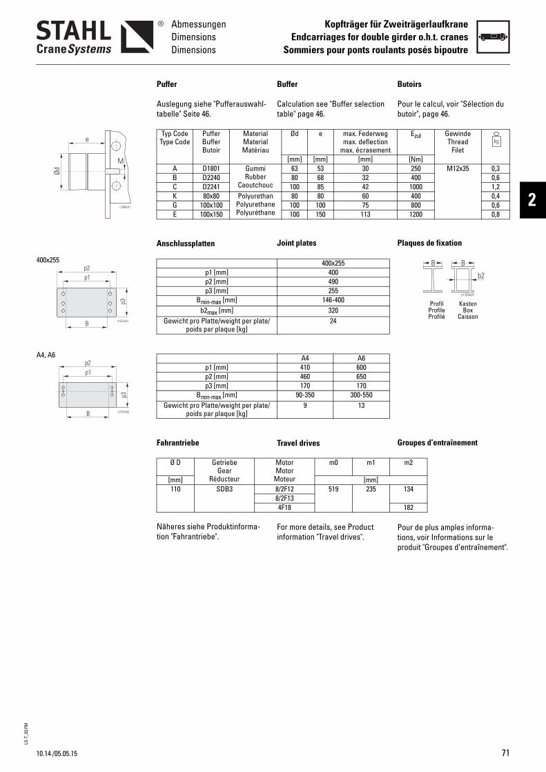
LS-T
_03.
FM
10.14
AbmessungenDimensionsDimensions
Kopfträger für ZweiträgerlaufkraneEndcarriages for double girder o.h.t. cranes
Sommiers pour ponts roulants posés bipoutre
2c1686v01
e
Ød
M
p3
B c1675v01
p1p2
400x255
p3
c1675v02B
p1p2
A4, A6
/05.05.15
Buffer
Calculation see "Buffer selection table" page 46.
Joint plates
Travel drives
For more details, see Product information "Travel drives".
Ød e max. Federwegmax. deflection
max. écrasement[mm] [mm] [mm]
c
63 53 3080 68 32
100 85 42nee
80 80 60100 100 75100 150 113
400x255400490255
146-40032024
A4 A6410 600460 650170 170
90-350 300-5509 13
MotorMotor
Moteur
m0 m1
[mm]8/2F12 519 2358/2F134F18
B
Pb
P
G
Ptp
Puffer
Auslegung siehe "Pufferauswahl-tabelle" Seite 46.
Anschlussplatten
Fahrantriebe
Näheres siehe Produktinforma-tion "Fahrantriebe".
Typ CodeType Code
PufferBufferButoir
MaterialMaterialMatériau
A D1801 GummiRubber
CaoutchouB D2240C D2241K 80x80 Polyuretha
PolyurethanPolyuréthan
G 100x100E 100x150
p1 [mm]p2 [mm]p3 [mm]
Bmin-max [mm]b2max [mm]
Gewicht pro Platte/weight per plate/poids par plaque [kg]
p1 [mm]p2 [mm]p3 [mm]
Bmin-max [mm]Gewicht pro Platte/weight per plate/
poids par plaque [kg]
Ø D GetriebeGear
Réducteur[mm]110 SDB3
Ezul GewindeThread
Filet[Nm]250 M12x35 0,3400 0,6
1000 1,2400 0,4800 0,6
1200 0,8
m2
134
182
utoirs
our le calcul, voir "Sélection du utoir", page 46.
laques de fixation
roupes d’entraînement
our de plus amples informa-ions, voir Informations sur le roduit "Groupes d’entraînement".
B B
c1763v01
b2
Profil KastenProfile BoxProfilé Caisson
71
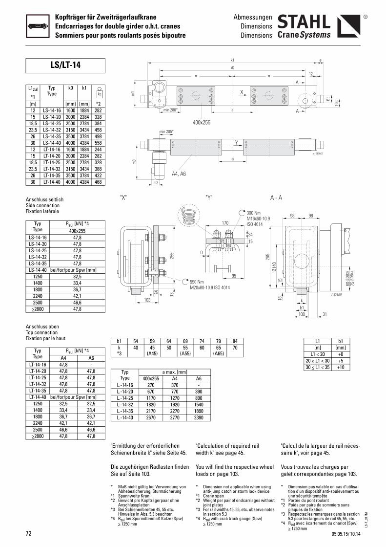
LS-T
_03.
FM
72
Kopfträger für ZweiträgerlaufkraneEndcarriages for double girder o.h.t. cranesSommiers pour ponts roulants posés bipoutre
AbmessungenDimensionsDimensions
Anschluss seitlichSide connectionFixation latérale
Anschluss obenTop connectionFixation par le haut
LS/LT-14
L1zul
*1
TypType
k0 k1
[m] [mm] [mm] *212 LS-14-16 1600 1884 28215 LS-14-20 2000 2284 328
18,5 LS-14-25 2500 2784 38423,5 LS-14-32 3150 3434 45826 LS-14-35 3500 3784 49830 LS-14-40 4000 4284 55812 LT-14-16 1600 1884 24415 LT-14-20 2000 2284 282
18,5 LT-14-25 2500 2784 32823,5 LT-14-32 3150 3434 38826 LT-14-35 3500 3784 42230 LT-14-40 4000 4284 468
TypType
Rzul [kN] *4400x255
LS-14-16 47,8LS-14-20 47,8LS-14-25 47,8LS-14-32 47,8LS-14-35 47,8LS-14-40 bei/for/pour Spw [mm]
1250 32,51400 33,41800 36,72240 42,12500 46,6
>2800 47,8
TypType
Rzul [kN] *4A4 A6
LT-14-16 47,8 -LT-14-20 47,8 47,8LT-14-25 47,8 47,8LT-14-32 47,8 47,8LT-14-35 47,8 47,8LT-14-40 bei/for/pour Spw [mm]
1250 32,5 32,51400 33,4 33,41800 36,7 36,72240 42,1 42,12500 46,6 46,6
>2800 47,8 47,8
"Calculation of required rail width k" see page 45.
You will find the respective wheel loads on page 103.
"s
Vg
170
15
0
300 NmM16x60-10.9ISO 4014
95
34
"Y" A - A
90 Nm20x80-10.9 ISO 4014
Ø140
265
= =
k1
k0
X
a
a
Y
400x255
74 79 8460 65
(A65)70
A6-
390890154018902390
* Dimension not applicable when using anti-jump catch or storm lock device
*1 Crane span*2 Weight per pair of endcarriages without
joint plates*3 For rail widths 45, 55, etc. observe notes
in section 5.3*4 Rzul with crab track gauge (Spw)
> 1250 mm
*
**
*
*
Calcul de la largeur de rail néces-aire k", voir page 45.
ous trouvez les charges par alet correspondantes page 103.
60 75(S
DB3)
(SDB
4)
b1k
100
15
98 98
c1576v07
31
18
c1669v07
e
100Ød
A
A
12
L1 b1[m] [mm]
L1 < 20 +020 < L1 < 30 +530 < L1 < 35 +10
Dimension pas valable en cas d’utilisa-tion d’un dispositif anti-soulèvement ou une sécurité-tempête
1 Portée du pont roulant2 Poids par paire de sommiers sans
plaques de fixation3 Respectez les remarques dans la section
5.3 pour les largeurs de rail 45, 55, etc.4 Rzul avec écartement du chariot (Spw)
> 1250 mm
"Ermittlung der erforderlichen Schienenbreite k" siehe Seite 45.
Die zugehörigen Radlasten finden Sie auf Seite 103.
"X"
255
25 13
103
5M
m0
A4, A6
min 280*
min 205*
m2
m1
b1 54 59 64 69k *3
40 45(A45)
50 55(A55)
TypType
a max. [mm]400x255 A4
L.-14-16 270 370L.-14-20 670 770L.-14-25 1170 1270L.-14-32 1820 1920L.-14-35 2170 2270L.-14-40 2670 2770
* Maß nicht gültig bei Verwendung von Abhebesicherung, Sturmsicherung
*1 Spannweite Kran*2 Gewicht pro Kopfträgerpaar ohne
Anschlussplatten*3 Bei Schienenbreiten 45, 55 etc.
Hinweise in Abs. 5.3 beachten*4 Rzul bei Spurmittenmaß Katze (Spw)
> 1250 mm
10.1405.05.15/

LS-T
_03.
FM
10.14
AbmessungenDimensionsDimensions
Kopfträger für ZweiträgerlaufkraneEndcarriages for double girder o.h.t. cranes
Sommiers pour ponts roulants posés bipoutre
2c1686v01
e
Ød
M
p3
B c1675v01
p1p2
400x255
p3
c1675v02B
p1p2
A4, A6
/05.05.15
Buffer
Calculation see "Buffer selection table" page 46.
Joint plates
Travel drives
For more details, see Product information "Travel drives".
B
Pb
P
G
Ptp
Ød e max. Federwegmax. deflection
max. écrasement[mm] [mm] [mm]
c
63 53 3080 68 32
100 85 42nee
80 80 60100 100 75100 150 113125 125 94125 190 143160 160 120160 240 180
400x255400490255
146-40032024
A4 A6410 600460 650170 170
90-350 300-5509 13
MotorMotor
Moteur
m0 m1
[mm]8/2F12 519 2498/2F134F18
utoirs
our le calcul, voir "Sélection du utoir", page 46.
laques de fixation
roupes d’entraînement
our de plus amples informa-ions, voir Informations sur le roduit "Groupes d’entraînement".
B B
c1763v01
b2
Profil KastenProfile BoxProfilé Caisson
Ezul GewindeThread
Filet[Nm]250 M12x35 0,3400 0,6
1000 1,2400 0,4800 0,6
1200 0,81550 1,12320 1,43300 2,64950 3,5
m2
134
182
Puffer
Auslegung siehe "Pufferauswahl-tabelle" Seite 46.
Anschlussplatten
Fahrantriebe
Näheres siehe Produktinforma-tion "Fahrantriebe".
Typ CodeType Code
PufferBufferButoir
MaterialMaterialMatériau
A D1801 GummiRubber
CaoutchouB D2240C D2241K 80x80 Polyuretha
PolyurethanPolyuréthan
G 100x100E 100x150M 125x125F 125x190H 160x160P 160x240
p1 [mm]p2 [mm]p3 [mm]
Bmin-max [mm]b2max [mm]
Gewicht pro Platte/weight per plate/poids par plaque [kg]
p1 [mm]p2 [mm]p3 [mm]
Bmin-max [mm]Gewicht pro Platte/weight per plate/
poids par plaque [kg]
Ø D GetriebeGear
Réducteur[mm]140 SDB3
73
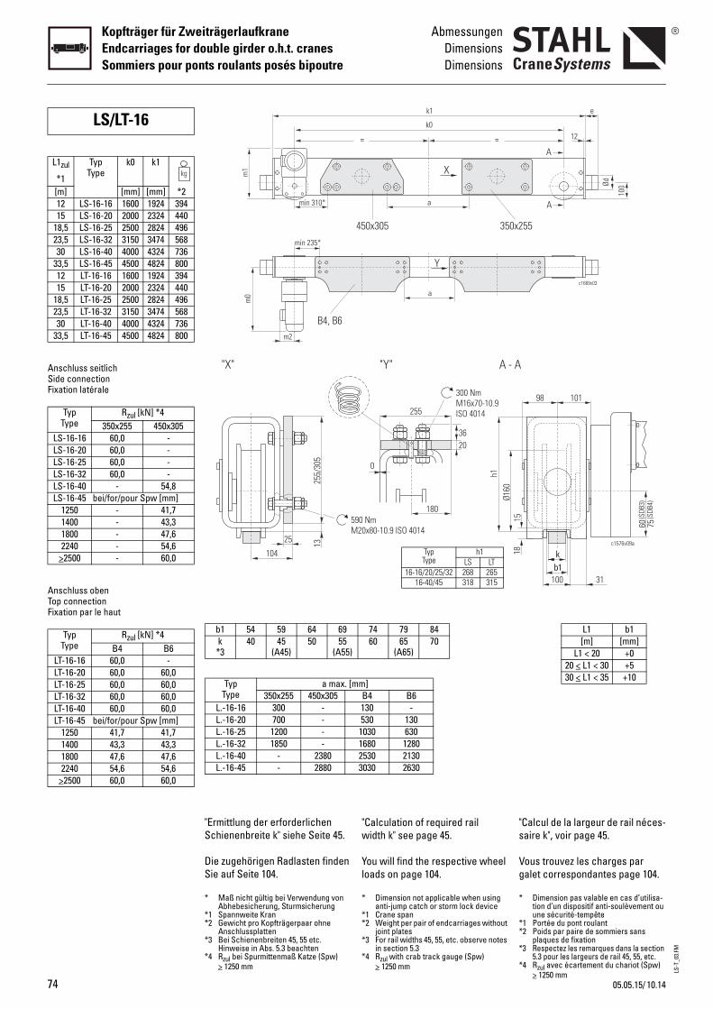
LS-T
_03.
FM
74
Kopfträger für ZweiträgerlaufkraneEndcarriages for double girder o.h.t. cranesSommiers pour ponts roulants posés bipoutre
AbmessungenDimensionsDimensions
Anschluss seitlichSide connectionFixation latérale
Anschluss obenTop connectionFixation par le haut
LS/LT-16
L1zul
*1
TypType
k0 k1
[m] [mm] [mm] *212 LS-16-16 1600 1924 39415 LS-16-20 2000 2324 440
18,5 LS-16-25 2500 2824 49623,5 LS-16-32 3150 3474 56830 LS-16-40 4000 4324 736
33,5 LS-16-45 4500 4824 80012 LT-16-16 1600 1924 39415 LT-16-20 2000 2324 440
18,5 LT-16-25 2500 2824 49623,5 LT-16-32 3150 3474 56830 LT-16-40 4000 4324 736
33,5 LT-16-45 4500 4824 800
TypType
Rzul [kN] *4350x255 450x305
LS-16-16 60,0 -LS-16-20 60,0 -LS-16-25 60,0 -LS-16-32 60,0 -LS-16-40 - 54,8LS-16-45 bei/for/pour Spw [mm]
1250 - 41,71400 - 43,31800 - 47,62240 - 54,6
>2500 - 60,0
TypType
Rzul [kN] *4B4 B6
LT-16-16 60,0 -LT-16-20 60,0 60,0LT-16-25 60,0 60,0LT-16-32 60,0 60,0LT-16-40 60,0 60,0LT-16-45 bei/for/pour Spw [mm]
1250 41,7 41,71400 43,3 43,31800 47,6 47,62240 54,6 54,6
>2500 60,0 60,0
"Calculation of required rail width k" see page 45.
You will find the respective wheel loads on page 104.
"s
Vg
255
20
0
300 NmM16x70-10.9ISO 4014
180
36
"Y" A - A
90 Nm20x80-10.9 ISO 4014
Ø160
h1
= =
k1
k0
a
Y
450x305
X
a
350x2
74 79 8460 65
(A65)70
mm]B4 B6130 -530 1301030 6301680 12802530 21303030 2630
TypType
h1LS LT
16-16/20/25/32 268 26516-40/45 318 315
* Dimension not applicable when using anti-jump catch or storm lock device
*1 Crane span*2 Weight per pair of endcarriages without
joint plates*3 For rail widths 45, 55, etc. observe notes
in section 5.3*4 Rzul with crab track gauge (Spw)
> 1250 mm
*
**
*
*
Calcul de la largeur de rail néces-aire k", voir page 45.
ous trouvez les charges par alet correspondantes page 104.
60 75(S
DB3)
(SDB
4)
b1
k
100
15
98 101
c1576v09a
31
18
c1669v03
e
100Ød
A
A
55
12
L1 b1[m] [mm]
L1 < 20 +020 < L1 < 30 +530 < L1 < 35 +10
Dimension pas valable en cas d’utilisa-tion d’un dispositif anti-soulèvement ou une sécurité-tempête
1 Portée du pont roulant2 Poids par paire de sommiers sans
plaques de fixation3 Respectez les remarques dans la section
5.3 pour les largeurs de rail 45, 55, etc.4 Rzul avec écartement du chariot (Spw)
> 1250 mm
"Ermittlung der erforderlichen Schienenbreite k" siehe Seite 45.
Die zugehörigen Radlasten finden Sie auf Seite 104.
"X"
255/
305
25 13
104
5M
m0
B4, B6
min 310*
min 235*
m2
m1
b1 54 59 64 69k *3
40 45(A45)
50 55(A55)
TypType
a max. [350x255 450x305
L.-16-16 300 -L.-16-20 700 -L.-16-25 1200 -L.-16-32 1850 -L.-16-40 - 2380L.-16-45 - 2880
* Maß nicht gültig bei Verwendung von Abhebesicherung, Sturmsicherung
*1 Spannweite Kran*2 Gewicht pro Kopfträgerpaar ohne
Anschlussplatten*3 Bei Schienenbreiten 45, 55 etc.
Hinweise in Abs. 5.3 beachten*4 Rzul bei Spurmittenmaß Katze (Spw)
> 1250 mm
10.1405.05.15/
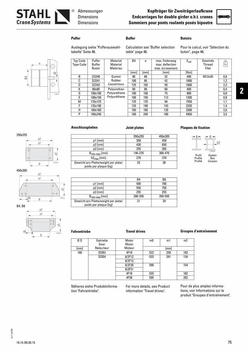
LS-T
_03.
FM
10.14
AbmessungenDimensionsDimensions
Kopfträger für ZweiträgerlaufkraneEndcarriages for double girder o.h.t. cranes
Sommiers pour ponts roulants posés bipoutre
2c1686v01
e
Ød
M
c1676v01
p3
B
p1p2
c1676v02
p3
B
p1p2
60
c1676v03
p3
p1p2
B48
350x255
450x305
B4, B6
/05.05.15
Buffer
Calculation see "Buffer selection table" page 46.
Joint plates
Travel drives
For more details, see Product information "Travel drives".
B
Pb
P
G
Ptp
Ød e max. Federwegmax. deflection
max. écrasement[mm] [mm] [mm]
c
80 68 32100 85 42125 105 50
nee
80 80 60100 100 75100 150 113125 125 94125 190 143160 160 120160 240 180
350x255 450x305350 450430 650255 305
146-370 300-470270 37023 38
B4 B6500 700550 750255 255
200-350 350-55021 29
MotorMotor
Moteur
m0 m1
[mm]4F18 522 259
8/2F12 533 2918/2F138/2F30 5908/2F314F18 5334F38 595
utoirs
our le calcul, voir "Sélection du utoir", page 46.
laques de fixation
roupes d’entraînement
our de plus amples informa-ions, voir Informations sur le roduit "Groupes d’entraînement".
B B
c1763v01
b2
Profil KastenProfile BoxProfilé Caisson
Ezul GewindeThread
Filet[Nm]400 M12x35 0,6
1000 1,21600 2,3400 0,4800 0,6
1200 0,81550 1,12320 1,43300 2,64950 3,5
m2
182134
154
182202
Puffer
Auslegung siehe "Pufferauswahl-tabelle" Seite 46.
Anschlussplatten
Fahrantriebe
Näheres siehe Produktinforma-tion "Fahrantriebe".
Typ CodeType Code
PufferBufferButoir
MaterialMaterialMatériau
B D2240 GummiRubber
CaoutchouC D2241D D2242K 80x80 Polyuretha
PolyurethanPolyuréthan
G 100x100E 100x150M 125x125F 125x190H 160x160P 160x240
p1 [mm]p2 [mm]p3 [mm]
Bmin-max [mm]b2max [mm]
Gewicht pro Platte/weight per plate/poids par plaque [kg]
p1 [mm]p2 [mm]p3 [mm]
Bmin-max [mm]Gewicht pro Platte/weight per plate/
poids par plaque [kg]
Ø D GetriebeGear
Réducteur[mm]160 SDB3
SDB4
75
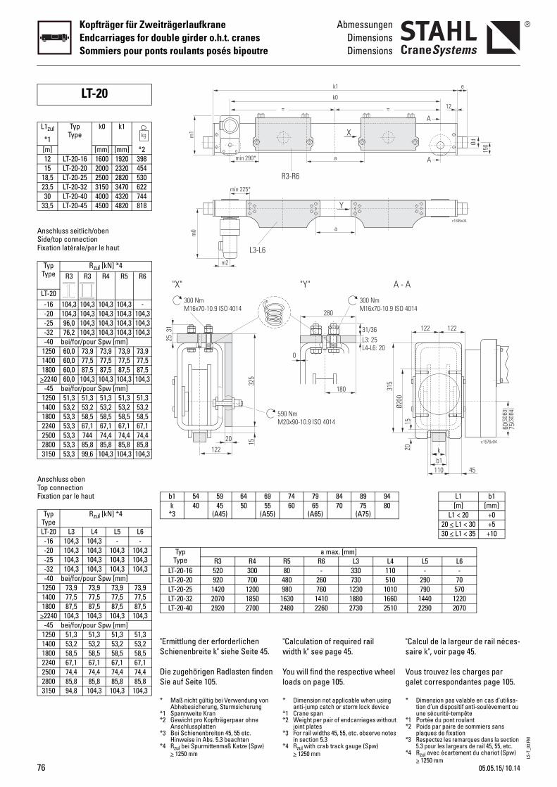
LS-T
_03.
FM
76
Kopfträger für ZweiträgerlaufkraneEndcarriages for double girder o.h.t. cranesSommiers pour ponts roulants posés bipoutre
AbmessungenDimensionsDimensions
Anschluss seitlich/obenSide/top connectionFixation latérale/par le haut
Anschluss obenTop connectionFixation par le haut
LT-20
L1zul
*1
TypType
k0 k1
[m] [mm] [mm] *212 LT-20-16 1600 1920 39815 LT-20-20 2000 2320 454
18,5 LT-20-25 2500 2820 53023,5 LT-20-32 3150 3470 62230 LT-20-40 4000 4320 744
33,5 LT-20-45 4500 4820 818
TypType
Rzul [kN] *4R3 R3 R4 R5 R6
LT-20-16 104,3 104,3 104,3 104,3 --20 104,3 104,3 104,3 104,3 104,3-25 96,0 104,3 104,3 104,3 104,3-32 76,2 104,3 104,3 104,3 104,3-40 bei/for/pour Spw [mm]
1250 60,0 73,9 73,9 73,9 73,91400 60,0 77,5 77,5 77,5 77,51800 60,0 87,5 87,5 87,5 87,5
>2240 60,0 104,3 104,3 104,3 104,3-45 bei/for/pour Spw [mm]
1250 51,3 51,3 51,3 51,3 51,31400 53,2 53,2 53,2 53,2 53,21800 53,3 58,5 58,5 58,5 58,52240 53,3 67,1 67,1 67,1 67,12500 53,3 744 74,4 74,4 74,42800 53,3 85,8 85,8 85,8 85,83150 53,3 99,6 104,3 104,3 104,3
TypType
Rzul [kN] *4
LT-20 L3 L4 L5 L6-16 104,3 104,3 - --20 104,3 104,3 104,3 104,3-25 104,3 104,3 104,3 104,3-32 104,3 104,3 104,3 104,3-40 bei/for/pour Spw [mm]
1250 73,9 73,9 73,9 73,91400 77,5 77,5 77,5 77,51800 87,5 87,5 87,5 87,5
>2240 104,3 104,3 104,3 104,3-45 bei/for/pour Spw [mm]
1250 51,3 51,3 51,3 51,31400 53,2 53,2 53,2 53,21800 58,5 58,5 58,5 58,52240 67,1 67,1 67,1 67,12500 74,4 74,4 74,4 74,42800 85,8 85,8 85,8 85,83150 94,8 104,3 104,3 104,3
"Calculation of required rail width k" see page 45.
You will find the respective wheel loads on page 105.
"s
Vg
= =
k1
k0
a
Y
R3-R6
X
a
74 79 84 89 9460 65
(A65)70 75
(A75)80
a max. [mm]R5 R6 L3 L480 - 330 110
480 260 730 510980 760 1230 10101630 1410 1880 16602480 2260 2730 2510
280
L3: 25L4-L6: 20
0
300 NmM16x70-10.9 ISO 4
180
31/36
"Y" A - A
590 NmM20x90-10.9 ISO 4014
Ø200
315
* Dimension not applicable when using anti-jump catch or storm lock device
*1 Crane span*2 Weight per pair of endcarriages without
joint plates*3 For rail widths 45, 55, etc. observe notes
in section 5.3*4 Rzul with crab track gauge (Spw)
> 1250 mm
*
**
*
*
Calcul de la largeur de rail néces-aire k", voir page 45.
ous trouvez les charges par alet correspondantes page 105.
c1669v04
e
150Ød
A
A
12
L1 b1[m] [mm]
L1 < 20 +020 < L1 < 30 +530 < L1 < 35 +10
L5 L6- -
290 70790 570
1440 12202290 2070
014
60 75(S
DB3)
(SDB
4)
b1k
110
15
122 122
c1576v04
45
20
Dimension pas valable en cas d’utilisa-tion d’un dispositif anti-soulèvement ou une sécurité-tempête
1 Portée du pont roulant2 Poids par paire de sommiers sans
plaques de fixation3 Respectez les remarques dans la section
5.3 pour les largeurs de rail 45, 55, etc.4 Rzul avec écartement du chariot (Spw)
> 1250 mm
"Ermittlung der erforderlichen Schienenbreite k" siehe Seite 45.
Die zugehörigen Radlasten finden Sie auf Seite 105.
m0
L3-L6
min 290*
min 225*
m2
m1
b1 54 59 64 69k *3
40 45(A45)
50 55(A55)
TypType R3 R4
LT-20-16 520 300LT-20-20 920 700LT-20-25 1420 1200LT-20-32 2070 1850LT-20-40 2920 2700
"X"
325
20 15
122
25
300 NmM16x70-10.9 ISO 4014
31
* Maß nicht gültig bei Verwendung von Abhebesicherung, Sturmsicherung
*1 Spannweite Kran*2 Gewicht pro Kopfträgerpaar ohne
Anschlussplatten*3 Bei Schienenbreiten 45, 55 etc.
Hinweise in Abs. 5.3 beachten*4 Rzul bei Spurmittenmaß Katze (Spw)
> 1250 mm
10.1405.05.15/

LS-T
_03.
FM
10.14
AbmessungenDimensionsDimensions
Kopfträger für ZweiträgerlaufkraneEndcarriages for double girder o.h.t. cranes
Sommiers pour ponts roulants posés bipoutre
2c1686v01
e
Ød
M
p3
c1677v01BVar1
BVar2
p1p2
13
Var 2
Var 1
R3-R6
p1p2
p3
c1677v02
B30
L3-L6
/05.05.15
Buffer
Calculation see "Buffer selection table" page 46.
Joint plates
Travel drives
For more details, see Product information "Travel drives".
B
Pb
P
G
Ptp
Ød e max. Federwegmax. deflection
max. écrasement[mm] [mm] [mm]
c
80 68 32100 85 42125 105 50
nee
100 100 75100 150 113125 125 94125 190 143160 160 120160 240 180200 200 150200 300 225
R3 R4 R5 R6250 360 470 580300 410 520 630325 325 325 325
230-300 300-410 - -] 230-300 300-410 410-520 520-630
196 306 416 528] - 300-320 321-430 431-540
- 250 360 47033 43 53 63
L3 L4 L5 L6410 520 630 740460 570 680 790280 280 280 280
240-300 300-410 410-520 520-63024 25 29 34
MotorMotor
Moteur
m0 m1
[mm]4F18 543 270
8/2F12 554 3018/2F138/2F30 6118/2F314F18 5544F38 616
utoirs
our le calcul, voir "Sélection du utoir", page 46.
laques de fixation
roupes d’entraînement
our de plus amples informa-ions, voir Informations sur le roduit "Groupes d’entraînement".
B B
c1763v01
b2
Profil KastenProfile BoxProfilé Caisson
Ezul GewindeThread
Filet[Nm]400 M12x35 0,6
1000 1,21600 2,3800 0,6
1200 0,81550 1,12320 1,43300 2,64950 3,56400 4,59600 6,2
m2
182134
154
182202
Puffer
Auslegung siehe "Pufferauswahl-tabelle" Seite 46.
Anschlussplatten
Fahrantriebe
Näheres siehe Produktinforma-tion "Fahrantriebe".
Typ CodeType Code
PufferBufferButoir
MaterialMaterialMatériau
B D2240 GummiRubber
CaoutchouC D2241D D2242G 100x100 Polyuretha
PolyurethanPolyuréthan
E 100x150M 125x125F 125x190H 160x160P 160x240I 200x200S 200x300
p1 [mm]p2 [mm]p3 [mm]
Bmin-max Profil/profile/profilé [mm]Bmin-max Kasten/box/caisson Var 1 [mm
b2max Var 1 [mm]Bmin-max Kasten/box/caisson Var 2 [mm
b2max Var 2 [mm]Gewicht pro Platte/weight per plate/
poids par plaque [kg]
p1 [mm]p2 [mm]p3 [mm]
Bmin-max [mm]Gewicht pro Platte/weight per plate/
poids par plaque [kg]
Ø D GetriebeGear
Réducteur[mm]200 SDB3
SDB4
77
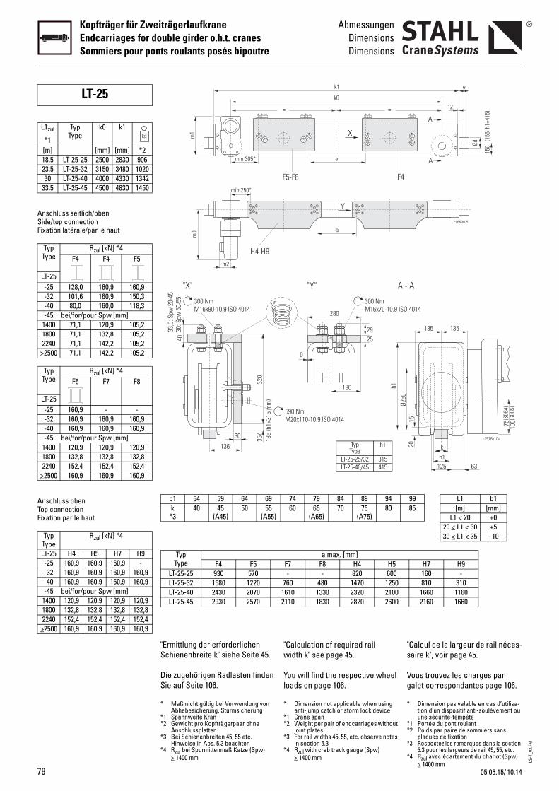
LS-T
_03.
FM
78
Kopfträger für ZweiträgerlaufkraneEndcarriages for double girder o.h.t. cranesSommiers pour ponts roulants posés bipoutre
AbmessungenDimensionsDimensions
Anschluss seitlich/obenSide/top connectionFixation latérale/par le haut
Anschluss obenTop connectionFixation par le haut
LT-25
L1zul
*1
TypType
k0 k1
[m] [mm] [mm] *218,5 LT-25-25 2500 2830 90623,5 LT-25-32 3150 3480 102030 LT-25-40 4000 4330 1342
33,5 LT-25-45 4500 4830 1450
TypType
Rzul [kN] *4F4 F4 F5
LT-25-25 128,0 160,9 160,9-32 101,6 160,9 150,3-40 80,0 160,0 118,3-45 bei/for/pour Spw [mm]
1400 71,1 120,9 105,21800 71,1 132,8 105,22240 71,1 142,2 105,2
>2500 71,1 142,2 105,2
TypType
Rzul [kN] *4F5 F7 F8
LT-25-25 160,9 - --32 160,9 160,9 160,9-40 160,9 160,9 160,9-45 bei/for/pour Spw [mm]
1400 120,9 120,9 120,91800 132,8 132,8 132,82240 152,4 152,4 152,4
>2500 160,9 160,9 160,9
TypType
Rzul [kN] *4
LT-25 H4 H5 H7 H9-25 160,9 160,9 160,9 --32 160,9 160,9 160,9 160,9-40 160,9 160,9 160,9 160,9-45 bei/for/pour Spw [mm]
1400 120,9 120,9 120,9 120,91800 132,8 132,8 132,8 132,82240 152,4 152,4 152,4 152,4
>2500 160,9 160,9 160,9 160,9
"Calculation of required rail width k" see page 45.
You will find the respective wheel loads on page 106.
"s
Vg
280
25
0
300 NmM16x70-10.9 ISO
180
29
590 NmM20x110-10.9 ISO 4014
Ø250
"Y" A -
h1
= =
k1
k0
a
Y
F5-F8
X
a
F4
74 79 84 89 9460 65
(A65)70 75
(A75)80
a max. [mm]F7 F8 H4 H5- - 820 600
760 480 1470 12501610 1330 2320 21002110 1830 2820 2600
TypType
h1
LT-25-25/32 315LT-25-40/45 415
* Dimension not applicable when using anti-jump catch or storm lock device
*1 Crane span*2 Weight per pair of endcarriages without
joint plates*3 For rail widths 45, 55, etc. observe notes
in section 5.3*4 Rzul with crab track gauge (Spw)
> 1400 mm
*
**
*
*
Calcul de la largeur de rail néces-aire k", voir page 45.
ous trouvez les charges par alet correspondantes page 106.
4014
75 100(S
DB4)
(SDB
5)
b1k
125
1520
135 135
c1576v10a
63
A
c1669v05
e
Ød
A
A
150
(15
5: h
1=41
5)
12
9985
L1 b1[m] [mm]
L1 < 20 +020 < L1 < 30 +530 < L1 < 35 +10
H7 H9160 -810 310
1660 11602160 1660
Dimension pas valable en cas d’utilisa-tion d’un dispositif anti-soulèvement ou une sécurité-tempête
1 Portée du pont roulant2 Poids par paire de sommiers sans
plaques de fixation3 Respectez les remarques dans la section
5.3 pour les largeurs de rail 45, 55, etc.4 Rzul avec écartement du chariot (Spw)
> 1400 mm
"Ermittlung der erforderlichen Schienenbreite k" siehe Seite 45.
Die zugehörigen Radlasten finden Sie auf Seite 106.
320
30 35/
135
(h1>
315
mm
)
136
4033
,5: S
pw 2
0-45
30: S
pw 5
0-55 300 Nm
M16x90-10.9 ISO 4014
"X"
m0
H4-H9
min 305*
min 250*
m2
m1
b1 54 59 64 69k *3
40 45(A45)
50 55(A55)
TypType F4 F5
LT-25-25 930 570LT-25-32 1580 1220LT-25-40 2430 2070LT-25-45 2930 2570
* Maß nicht gültig bei Verwendung von Abhebesicherung, Sturmsicherung
*1 Spannweite Kran*2 Gewicht pro Kopfträgerpaar ohne
Anschlussplatten*3 Bei Schienenbreiten 45, 55 etc.
Hinweise in Abs. 5.3 beachten*4 Rzul bei Spurmittenmaß Katze (Spw)
> 1400 mm
10.1405.05.15/
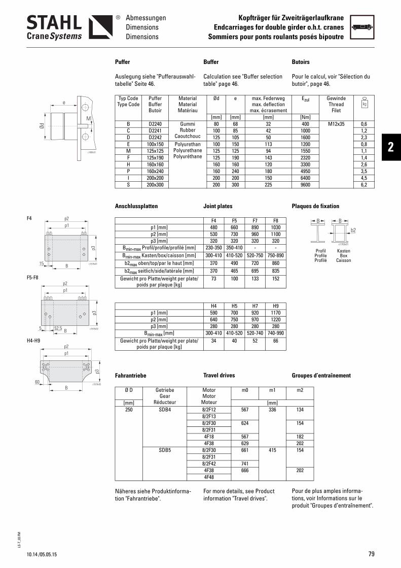
LS-T
_03.
FM
10.14
AbmessungenDimensionsDimensions
Kopfträger für ZweiträgerlaufkraneEndcarriages for double girder o.h.t. cranes
Sommiers pour ponts roulants posés bipoutre
2c1686v01
e
Ød
M
p3
p1p2
B c1678v0115
B
p1p2
p3
c1678v0252,55
p3
Bc1678v03
p1p2
60
F4
F5-F8
H4-H9
/05.05.15
Buffer
Calculation see "Buffer selection table" page 46.
Joint plates
Travel drives
For more details, see Product information "Travel drives".
B
Pb
P
G
Ptp
Ød e max. Federwegmax. deflection
max. écrasement[mm] [mm] [mm]
c
80 68 32100 85 42125 105 50
nee
100 150 113125 125 94125 190 143160 160 120160 240 180200 200 150200 300 225
F4 F5 F7 F8480 660 890 1030530 730 960 1100320 320 320 320
230-350 350-410 - -300-410 410-520 520-750 750-890
370 490 720 860370 465 695 83573 100 133 152
H4 H5 H7 H9590 700 920 1170640 750 970 1220280 280 280 280
300-410 410-520 520-740 740-99034 40 52 66
MotorMotor
Moteur
m0 m1
[mm]8/2F12 567 3368/2F138/2F30 6248/2F314F18 5674F38 629
8/2F30 661 4158/2F318/2F42 7414F38 6664F48
utoirs
our le calcul, voir "Sélection du utoir", page 46.
laques de fixation
roupes d’entraînement
our de plus amples informa-ions, voir Informations sur le roduit "Groupes d’entraînement".
B B
c1763v01
b2
Profil KastenProfile BoxProfilé Caisson
Ezul GewindeThread
Filet[Nm]400 M12x35 0,6
1000 1,21600 2,31200 0,81550 1,12320 1,43300 2,64950 3,56400 4,59600 6,2
m2
134
154
182202154
202
Puffer
Auslegung siehe "Pufferauswahl-tabelle" Seite 46.
Anschlussplatten
Fahrantriebe
Näheres siehe Produktinforma-tion "Fahrantriebe".
Typ CodeType Code
PufferBufferButoir
MaterialMaterialMatériau
B D2240 GummiRubber
CaoutchouC D2241D D2242E 100x150 Polyuretha
PolyurethanPolyuréthan
M 125x125F 125x190H 160x160P 160x240I 200x200S 200x300
p1 [mm]p2 [mm]p3 [mm]
Bmin-max Profil/profile/profilé [mm]Bmin-max Kasten/box/caisson [mm]b2max oben/top/par le haut [mm]b2max seitlich/side/latérale [mm]
Gewicht pro Platte/weight per plate/poids par plaque [kg]
p1 [mm]p2 [mm]p3 [mm]
Bmin-max [mm]Gewicht pro Platte/weight per plate/
poids par plaque [kg]
Ø D GetriebeGear
Réducteur[mm]250 SDB4
SDB5
79
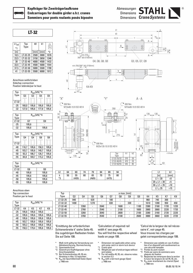
LS-T
_03.
FM
80
Kopfträger für ZweiträgerlaufkraneEndcarriages for double girder o.h.t. cranesSommiers pour ponts roulants posés bipoutre
AbmessungenDimensionsDimensions
Anschluss seitlich/obenSide/top connectionFixation latérale/par le haut
Anschluss obenTop connectionFixation par le haut
LT-32
L1zul
*1
TypType
k0 k1
[m] [mm] [mm] *218,5 LT-32-25 2500 3000 107623,5 LT-32-32 3150 3650 124630 LT-32-40 4000 4500 1432
33,5 LT-32-45 4500 5000 154437,5 LT-32-50 5000 5500 179041 LT-32-55 5500 6000 1912
TypType
Rzul [kN] *4Q3 Q3 Q5 Q5
LT-32-25 160,0 195,6 195,6 195,6-32 127,0 195,6 177,8 195,6
TypType
Rzul [kN] *4
LT-32 Q7 Q9-25 195,6 --32 195,6 195,6
TypType
Rzul [kN] *4Q4 Q4 Q6 Q6
LT-32-40 116,7 195,6 158,3 195,6-45 103,7 195,6 140,7 195,6-50 93,3 186,7 126,7 195,6-55 84,8 169,7 115,2 195,6
TypType
Rzul [kN] *4
LT-32 Q8 Q0-40 195,6 195,6-45 195,6 195,6-50 195,6 195,6-55 195,6 195,6
TypType
Rzul [kN] *4
LT-32 K4 K5 K7 K9-25 195,6 195,6 195,6 --32 195,6 195,6 195,6 195,6-40 195,6 195,6 195,6 195,6-45 183,7 195,6 195,6 195,6-50 165,3 195,6 195,6 195,6-55 150,3 179,4 195,6 195,6
"Calculation of required rail width k" see page 45.You will find the respective wheel loads on page 108.
"sVg
= =
k1
k0
a
Y
, Q6, Q8, Q0
X
a
Q3, Q5, Q
84 89 9470 75
(A75)80
a max. [mm]Q6 Q7 Q8 Q9 Q0- 180 - - -- 830 - 330 -
2040 - 1600 - 11002540 - 2100 - 16003040 - 2600 - 21003540 - 3100 - 2600
590 NmM20x130-10.9 ISO 4014
350
0
215
2537
300 NmM16x80-10.9 ISO 4
Ø315
"Y" A - A
h1
TypType
h1 h2
LT-32-25/32 370 20LT-32-40/45 470 20LT-32-50/55 545 95
* Dimension not applicable when using anti-jump catch or storm lock device
*1 Crane span*2 Weight per pair of endcarriages without
joint plates*3 For rail widths 45, 55, etc. observe notes
in section 5.3*4 Rzul with crab track gauge (Spw)
> 1400 mm
*
**
*
*
Calcul de la largeur de rail néces-aire k", voir page 45.ous trouvez les charges par alet correspondantes page 108.
c1669v06
e
150Ød
A
A
7, Q9
14
L1 b1[m] [mm]
L1 < 20 +020 < L1 < 30 +530 < L1 < 35 +10
L1 > 35 +15
K4 K5 K7 K9960 740 300 -
1610 1390 950 4502380 2160 1720 12202880 2660 2220 17203380 3160 2720 22203880 3660 3220 2720
014
b1k
20
c1576v06a
125 63
135 135
75 100(S
DB4)
(SDB
5)
20
Dimension pas valable en cas d’utilisa-tion d’un dispositif anti-soulèvement ou une sécurité-tempête
1 Portée du pont roulant2 Poids par paire de sommiers sans
plaques de fixation3 Respectez les remarques dans la section
5.3 pour les largeurs de rail 45, 55, etc.4 Rzul avec écartement du chariot (Spw)
> 1400 mm
"Ermittlung der erforderlichen Schienenbreite k" siehe Seite 45.Die zugehörigen Radlasten finden Sie auf Seite 108.
m0
K4-K9
min 310/350* (k0>3150mm)
Q4
min 250/290* (k0>3150mm)
m2
m1
b1 64 69 74 79k *3
50 55(A55)
60 65(A65)
TypType Q3 Q4 Q5
LT-32-25 840 - 620LT-32-32 1490 - 1270LT-32-40 - 2260 -LT-32-45 - 2760 -LT-32-50 - 3260 -LT-32-55 - 3760 -
380/
480
30 h2
170
3032
300 NmM16x80-10.9 ISO 4014
"X"
* Maß nicht gültig bei Verwendung von Abhebesicherung, Sturmsicherung
*1 Spannweite Kran*2 Gewicht pro Kopfträgerpaar ohne
Anschlussplatten*3 Bei Schienenbreiten 45, 55 etc.
Hinweise in Abs. 5.3 beachten*4 Rzul bei Spurmittenmaß Katze (Spw)
> 1400 mm
10.1405.05.15/

LS-T
_03.
FM
10.14
AbmessungenDimensionsDimensions
Kopfträger für ZweiträgerlaufkraneEndcarriages for double girder o.h.t. cranes
Sommiers pour ponts roulants posés bipoutre
2c1686v01
e
Ød
M
c1679v01
p3
B
p1p2
30
B
p1p2
c1679v02
p3
30
p3
p1p2
c1679v03
B30
Q3, Q5, Q7, Q9
K4-K9
Q4, Q6, Q8, Q0
/05.05.15
Buffer
Calculation see "Buffer selection table" page 46.
Joint plates
Travel drives
For more details, see Product information "Travel drives".
B
Pb
P
G
Ptp
Ød e max. Federwegmax. deflection
max. écrasement[mm] [mm] [mm]
c
80 68 32100 85 42125 105 50
nee
100 150 113125 125 94125 190 143160 160 120160 240 180200 200 150200 300 225250 250 188250 375 281
Q3 Q4 Q5 Q6520 520 630 630570 570 680 680380 480 380 480
300-420 300-420 - -300-410 300-410 410-520 410-520 5
380 380 490 49094 110 111 126
K4 K5 K7 K9520 630 850 1100570 680 900 1150350 350 350 350
90-410 90-520 520-740 740-99039 46 61 78
MotorMotor
Moteur
m0 m1
[mm]4F18 567 3694F38 629
8/2F30 661 4488/2F318/2F42 7414F38 6664F48
*1 SDB5Z (with intermediate gear) m0+100mm
*
utoirs
our le calcul, voir "Sélection du utoir", page 46.
laques de fixation
roupes d’entraînement
our de plus amples informa-ions, voir Informations sur le roduit "Groupes d’entraînement".
B B
c1763v01
b2
Profil KastenProfile BoxProfilé Caisson
Ezul GewindeThread
Filet[Nm]400 M12x35 0,6
1000 1,21600 2,31200 0,81550 1,12320 1,43300 2,64950 3,56400 4,59600 6,212500 M24x80 9,318750 12,4
Q7 Q8 Q9 Q0850 850 1100 1100900 900 1150 1150380 480 380 480
- - - -20-740 520-740 740-990 740-990710 710 960 960144 165 183 209
m2
182202154
202
1 SDB5Z (avec réducteur intermédiaire) m0+100mm
Puffer
Auslegung siehe "Pufferauswahl-tabelle" Seite 46.
Anschlussplatten
Fahrantriebe
Näheres siehe Produktinforma-tion "Fahrantriebe".
Typ CodeType Code
PufferBufferButoir
MaterialMaterialMatériau
B D2240 GummiRubber
CaoutchouC D2241D D2242E 100x150 Polyuretha
PolyurethanPolyuréthan
M 125x125F 125x190H 160x160P 160x240I 200x200S 200x300T 250x250Y 250x375
p1 [mm]p2 [mm]p3 [mm]
Bmin-max Profil/profile/profilé [mm]Bmin-max Kasten/box/caisson [mm]b2max seitlich/side/latérale [mm]
Gewicht pro Platte/weight per plate/poids par plaque [kg]
p1 [mm]p2 [mm]p3 [mm]
Bmin-max [mm]Gewicht pro Platte/weight per plate/
poids par plaque [kg]
Ø D GetriebeGear
Réducteur[mm]315 SDB4
SDB5*1
*1 SDB5Z (mit Zwischengetriebe) m0+100mm
81
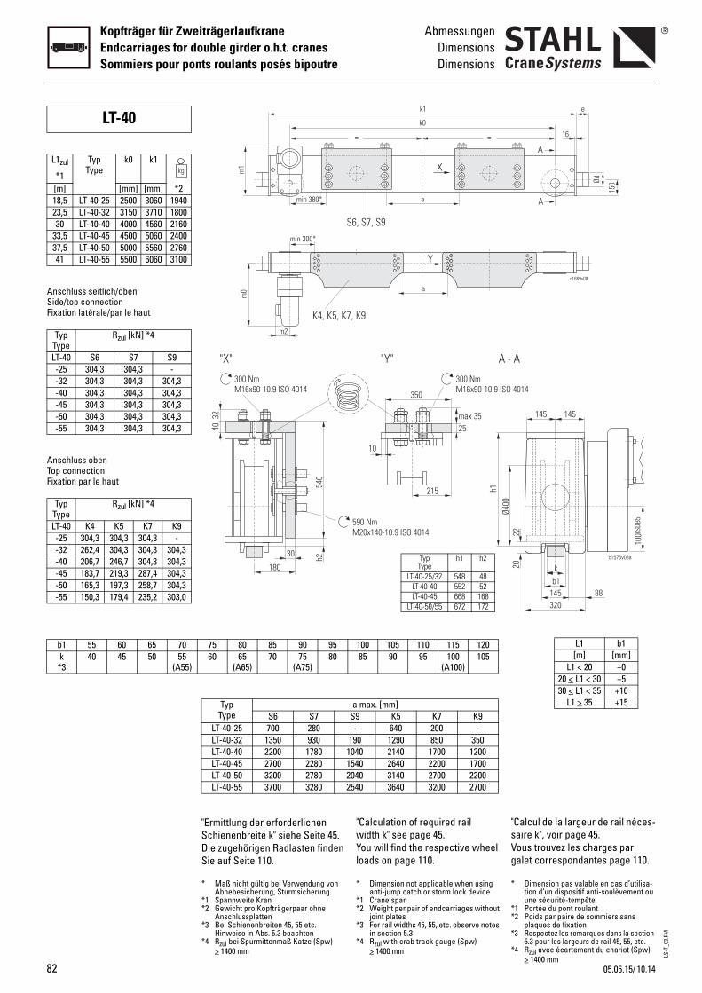
LS-T
_03.
FM
82
Kopfträger für ZweiträgerlaufkraneEndcarriages for double girder o.h.t. cranesSommiers pour ponts roulants posés bipoutre
AbmessungenDimensionsDimensions
b1 55 60 65 70k
*340 45 50 55
(A55)
Anschluss seitlich/obenSide/top connectionFixation latérale/par le haut
Anschluss obenTop connectionFixation par le haut
LT-40
L1zul
*1
TypType
k0 k1
[m] [mm] [mm] *218,5 LT-40-25 2500 3060 194023,5 LT-40-32 3150 3710 180030 LT-40-40 4000 4560 2160
33,5 LT-40-45 4500 5060 240037,5 LT-40-50 5000 5560 276041 LT-40-55 5500 6060 3100
TypType
Rzul [kN] *4
LT-40 S6 S7 S9-25 304,3 304,3 --32 304,3 304,3 304,3-40 304,3 304,3 304,3-45 304,3 304,3 304,3-50 304,3 304,3 304,3-55 304,3 304,3 304,3
TypType
Rzul [kN] *4
LT-40 K4 K5 K7 K9-25 304,3 304,3 304,3 --32 262,4 304,3 304,3 304,3-40 206,7 246,7 304,3 304,3-45 183,7 219,3 287,4 304,3-50 165,3 197,3 258,7 304,3-55 150,3 179,4 235,2 303,0
"Calculation of required rail width k" see page 45.You will find the respective wheel loads on page 110.
"sVg
100 105 110 115 12085 90 95 100
(A100)105
a max. [mm]S9 K5 K7 K9- 640 200 -
190 1290 850 3501040 2140 1700 12001540 2640 2200 17002040 3140 2700 22002540 3640 3200 2700
590 NmM20x140-10.9 ISO 4014
Ø400
350
10
215
25max 35
300 NmM16x90-10.9 ISO
"Y" A -
h1
= =
k1
k0
a
Y
7, K9
S6, S7, S9
X
a
TypType
h1 h2
LT-40-25/32 548 48LT-40-40 552 52LT-40-45 668 168
LT-40-50/55 672 172
* Dimension not applicable when using anti-jump catch or storm lock device
*1 Crane span*2 Weight per pair of endcarriages without
joint plates*3 For rail widths 45, 55, etc. observe notes
in section 5.3*4 Rzul with crab track gauge (Spw)
> 1400 mm
*
**
*
*
Calcul de la largeur de rail néces-aire k", voir page 45.ous trouvez les charges par alet correspondantes page 110.
L1 b1[m] [mm]
L1 < 20 +020 < L1 < 30 +530 < L1 < 35 +10
L1 > 35 +15
b1k
22
c1576v08a
145 88
145 145
100(
SDB5
)
20
320
4014
A
c1669v08
e
150Ød
A
A
16
Dimension pas valable en cas d’utilisa-tion d’un dispositif anti-soulèvement ou une sécurité-tempête
1 Portée du pont roulant2 Poids par paire de sommiers sans
plaques de fixation3 Respectez les remarques dans la section
5.3 pour les largeurs de rail 45, 55, etc.4 Rzul avec écartement du chariot (Spw)
> 1400 mm
"Ermittlung der erforderlichen Schienenbreite k" siehe Seite 45.Die zugehörigen Radlasten finden Sie auf Seite 110.
75 80 85 90 9560 65
(A65)70 75
(A75)80
TypType S6 S7
LT-40-25 700 280LT-40-32 1350 930LT-40-40 2200 1780LT-40-45 2700 2280LT-40-50 3200 2780LT-40-55 3700 3280
540
30
180
4032
300 NmM16x90-10.9 ISO 4014
"X"
h2
m0
K4, K5, Km2
min 300*
min 380*
m1
* Maß nicht gültig bei Verwendung von Abhebesicherung, Sturmsicherung
*1 Spannweite Kran*2 Gewicht pro Kopfträgerpaar ohne
Anschlussplatten*3 Bei Schienenbreiten 45, 55 etc.
Hinweise in Abs. 5.3 beachten*4 Rzul bei Spurmittenmaß Katze (Spw)
> 1400 mm
10.1405.05.15/
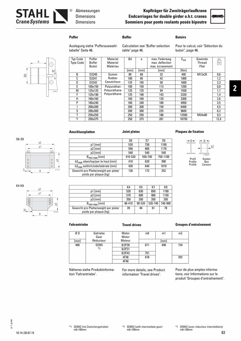
LS-T
_03.
FM
10.14
AbmessungenDimensionsDimensions
Kopfträger für ZweiträgerlaufkraneEndcarriages for double girder o.h.t. cranes
Sommiers pour ponts roulants posés bipoutre
2c1686v01
e
Ød
M
B
p1p2
c1717v01
p3
5
S6-S9
p3
p1p2
c1679v03
B30
K4-K9
/20.07.15
Buffer
Calculation see "Buffer selection table" page 46.
Joint plates
Travel drives
For more details, see Product information "Travel drives".
B
Pb
P
G
Ptp
Ød e max. Federwegmax. deflection
max. écrasement[mm] [mm] [mm]
c
80 68 32100 85 42125 105 50
nee
100 150 113125 125 94125 190 143160 160 120160 240 180200 200 150200 300 225250 250 188250 375 281
S6 S7 S9520 730 1100590 800 1170540 540 540
410-520 550-740 750-1100410 620 990430 640 1010126 172 252
K4 K5 K7 K9520 630 850 1100570 680 900 1150350 350 350 350
90-410 90-520 520-740 740-99039 46 61 78
MotorMotor
Moteur
m0 m1
[mm]8/2F30 671 4908/2F318/2F42 7514F38 6764F48
*1 SDB5Z (with intermediate gear) m0+100mm
*
utoirs
our le calcul, voir "Sélection du utoir", page 46.
laques de fixation
roupes d’entraînement
our de plus amples informa-ions, voir Informations sur le roduit "Groupes d’entraînement".
B B
c1763v01
b2
Profil KastenProfile BoxProfilé Caisson
Ezul GewindeThread
Filet[Nm]400 M12x35 0,6
1000 1,21600 2,31200 0,81550 1,12320 1,43300 2,64950 3,56400 4,59600 6,212500 M24x80 9,318750 12,4
m2
154
202
1 SDB5Z (avec réducteur intermédiaire) m0+100mm
Puffer
Auslegung siehe "Pufferauswahl-tabelle" Seite 46.
Anschlussplatten
Fahrantriebe
Näheres siehe Produktinforma-tion "Fahrantriebe".
Typ CodeType Code
PufferBufferButoir
MaterialMaterialMatériau
B D2240 GummiRubber
CaoutchouC D2241D D2242E 100x150 Polyuretha
PolyurethanPolyuréthan
M 125x125F 125x190H 160x160P 160x240I 200x200S 200x300T 250x250Y 250x375
p1 [mm]p2 [mm]p3 [mm]
Bmin-max [mm]b2max oben/top/par le haut [mm]b2max seitlich/side/latérale [mm]
Gewicht pro Platte/weight per plate/poids par plaque [kg]
p1 [mm]p2 [mm]p3 [mm]
Bmin-max [mm]Gewicht pro Platte/weight per plate/
poids par plaque [kg]
Ø D GetriebeGear
Réducteur[mm]400 SDB5
*1
*1 SDB5Z (mit Zwischengetriebe) m0+100mm
83
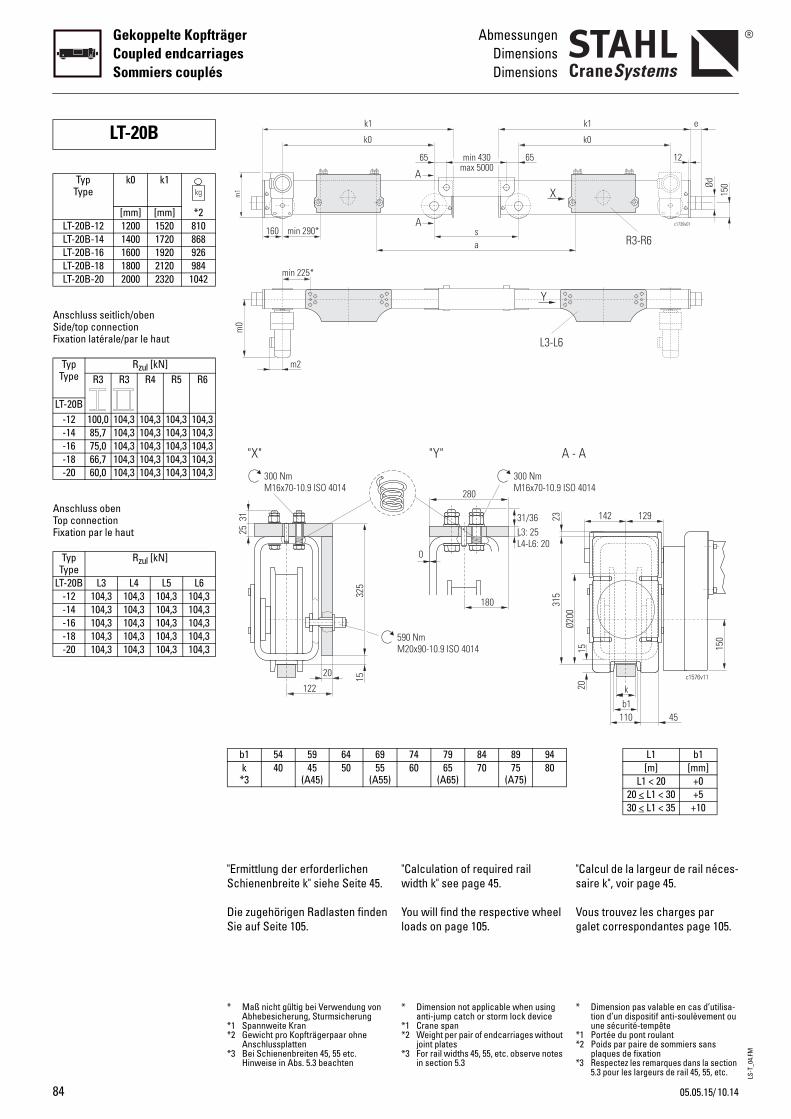
LS-T
_04.
FM
84
Gekoppelte KopfträgerCoupled endcarriagesSommiers couplés
AbmessungenDimensionsDimensions
Anschluss seitlich/obenSide/top connectionFixation latérale/par le haut
Anschluss obenTop connectionFixation par le haut
LT-20B
TypType
k0 k1
[mm] [mm] *2LT-20B-12 1200 1520 810LT-20B-14 1400 1720 868LT-20B-16 1600 1920 926LT-20B-18 1800 2120 984LT-20B-20 2000 2320 1042
TypType
Rzul [kN]R3 R3 R4 R5 R6
LT-20B-12 100,0 104,3 104,3 104,3 104,3-14 85,7 104,3 104,3 104,3 104,3-16 75,0 104,3 104,3 104,3 104,3-18 66,7 104,3 104,3 104,3 104,3-20 60,0 104,3 104,3 104,3 104,3
TypType
Rzul [kN]
LT-20B L3 L4 L5 L6-12 104,3 104,3 104,3 104,3-14 104,3 104,3 104,3 104,3-16 104,3 104,3 104,3 104,3-18 104,3 104,3 104,3 104,3-20 104,3 104,3 104,3 104,3
"Calculation of required rail width k" see page 45.
You will find the respective wheel loads on page 105.
"s
Vg
280
L3: 25L4-L6: 20
0
300 NmM16x70-10.9 ISO
180
31/36
"Y" A -
590 NmM20x90-10.9 ISO 4014
Ø200
315
23
A
A
L3-L6
a
65 65min 430
s
Y
X
max 5000
74 79 84 89 9460 65
(A65)70 75
(A75)80
* Dimension not applicable when using anti-jump catch or storm lock device
*1 Crane span*2 Weight per pair of endcarriages without
joint plates*3 For rail widths 45, 55, etc. observe notes
in section 5.3
*
**
*
Calcul de la largeur de rail néces-aire k", voir page 45.
ous trouvez les charges par alet correspondantes page 105.
4014
A
150
b1k
110
15
142 129
c1576v11
45
20
c1739v01
k1
k0
e
150Ød
R3-R6
12
L1 b1[m] [mm]
L1 < 20 +020 < L1 < 30 +530 < L1 < 35 +10
Dimension pas valable en cas d’utilisa-tion d’un dispositif anti-soulèvement ou une sécurité-tempête
1 Portée du pont roulant2 Poids par paire de sommiers sans
plaques de fixation3 Respectez les remarques dans la section
5.3 pour les largeurs de rail 45, 55, etc.
"Ermittlung der erforderlichen Schienenbreite k" siehe Seite 45.
Die zugehörigen Radlasten finden Sie auf Seite 105.
"X"
325
20 15
122
25
300 NmM16x70-10.9 ISO 4014
31min 290*
k1
k0
m0
m2
min 225*
160m
1
b1 54 59 64 69k *3
40 45(A45)
50 55(A55)
* Maß nicht gültig bei Verwendung von Abhebesicherung, Sturmsicherung
*1 Spannweite Kran*2 Gewicht pro Kopfträgerpaar ohne
Anschlussplatten*3 Bei Schienenbreiten 45, 55 etc.
Hinweise in Abs. 5.3 beachten
10.1405.05.15/
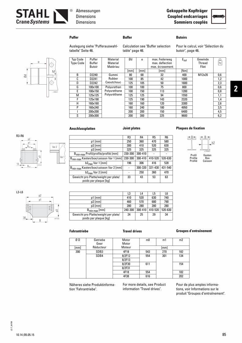
LS-T
_04.
FM
10.14
AbmessungenDimensionsDimensions
Gekoppelte KopfträgerCoupled endcarriages
Sommiers couplés
2c1686v01
e
Ød
M
p3
c1677v01BVar1
BVar2
p1p2
13
Var 2
Var 1
R3-R6
p1p2
p3
c1677v02
B30
L3-L6
/05.05.15
Buffer
Calculation see "Buffer selection table" page 46.
Joint plates
Travel drives
For more details, see Product information "Travel drives".
B
Pb
P
G
Ptp
Ød e max. Federwegmax. deflection
max. écrasement[mm] [mm] [mm]
c
80 68 32100 85 42125 105 50
nee
100 100 75100 150 113125 125 94125 190 143160 160 120160 240 180200 200 150200 300 225
R3 R4 R5 R6250 360 470 580300 410 520 630325 325 325 325
230-300 300-410 - -] 230-300 300-410 410-520 520-630
196 306 416 528] - 300-320 321-430 431-540
- 250 360 47033 43 53 63
L3 L4 L5 L6410 520 630 740460 570 680 790280 280 280 280
240-300 300-410 410-520 520-63024 25 29 34
MotorMotor
Moteur
m0 m1
[mm]4F18 543 270
8/2F12 554 3018/2F138/2F30 6118/2F314F18 5544F38 616
utoirs
our le calcul, voir "Sélection du utoir", page 46.
laques de fixation
roupes d’entraînement
our de plus amples informa-ions, voir Informations sur le roduit "Groupes d’entraînement".
B B
c1763v01
b2
Profil KastenProfile BoxProfilé Caisson
Ezul GewindeThread
Filet[Nm]400 M12x35 0,6
1000 1,21600 2,3800 0,6
1200 0,81550 1,12320 1,43300 2,64950 3,56400 4,59600 6,2
m2
182134
154
182202
Puffer
Auslegung siehe "Pufferauswahl-tabelle" Seite 46.
Anschlussplatten
Fahrantriebe
Näheres siehe Produktinforma-tion "Fahrantriebe".
Typ CodeType Code
PufferBufferButoir
MaterialMaterialMatériau
B D2240 GummiRubber
CaoutchouC D2241D D2242G 100x100 Polyuretha
PolyurethanPolyuréthan
E 100x150M 125x125F 125x190H 160x160P 160x240I 200x200S 200x300
p1 [mm]p2 [mm]p3 [mm]
Bmin-max Profil/profile/profilé [mm]Bmin-max Kasten/box/caisson Var 1 [mm
b2max Var 1 [mm]Bmin-max Kasten/box/caisson Var 2 [mm
b2max Var 2 [mm]Gewicht pro Platte/weight per plate/
poids par plaque [kg]
p1 [mm]p2 [mm]p3 [mm]
Bmin-max [mm]Gewicht pro Platte/weight per plate/
poids par plaque [kg]
Ø D GetriebeGear
Réducteur[mm]200 SDB3
SDB4
85
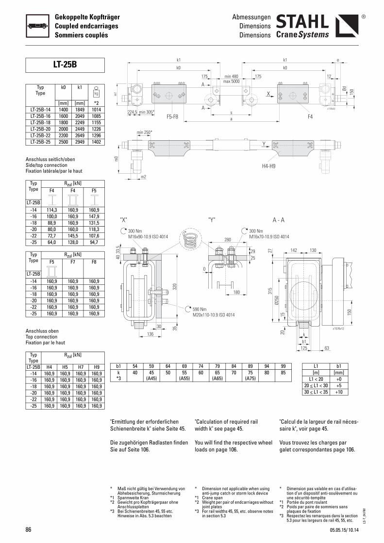
LS-T
_04.
FM
86
Gekoppelte KopfträgerCoupled endcarriagesSommiers couplés
AbmessungenDimensionsDimensions
Anschluss seitlich/obenSide/top connectionFixation latérale/par le haut
Anschluss obenTop connectionFixation par le haut
LT-25B
TypType
k0 k1
[mm] [mm] *2LT-25B-14 1400 1849 1014LT-25B-16 1600 2049 1085LT-25B-18 1800 2249 1155LT-25B-20 2000 2449 1226LT-25B-22 2200 2649 1296LT-25B-25 2500 2949 1402
TypType
Rzul [kN]F4 F4 F5
LT-25B-14 114,3 160,9 160,9-16 100,0 160,9 147,9-18 88,9 160,9 131,5-20 80,0 160,0 118,3-22 72,7 145,5 107,6-25 64,0 128,0 94,7
TypType
Rzul [kN]F5 F7 F8
LT-25B-14 160,9 160,9 160,9-16 160,9 160,9 160,9-18 160,9 160,9 160,9-20 160,9 160,9 160,9-22 160,9 160,9 160,9-25 160,9 160,9 160,9
TypType
Rzul [kN]
LT-25B H4 H5 H7 H9-14 160,9 160,9 160,9 160,9-16 160,9 160,9 160,9 160,9-18 160,9 160,9 160,9 160,9-20 160,9 160,9 160,9 160,9-22 160,9 160,9 160,9 160,9-25 160,9 160,9 160,9 160,9
"Calculation of required rail width k" see page 45.
You will find the respective wheel loads on page 106.
"s
Vg
280
25
0
300 NmM16x70-10.9 ISO
180
29
590 NmM20x110-10.9 ISO 4014
Ø250
"Y" A -
315
27
A
A
H4-H9
a
175 175min 480
s
X
Y
max 5000
74 79 84 89 9460 65
(A65)70 75
(A75)80
* Dimension not applicable when using anti-jump catch or storm lock device
*1 Crane span*2 Weight per pair of endcarriages without
joint plates*3 For rail widths 45, 55, etc. observe notes
in section 5.3
*
**
*
Calcul de la largeur de rail néces-aire k", voir page 45.
ous trouvez les charges par alet correspondantes page 106.
4014
b1k
125
1520
142 130
c1576v12
63
A
150
c1739v02
k1
k0
e
150Ød
F4
12
9985
L1 b1[m] [mm]
L1 < 20 +020 < L1 < 30 +530 < L1 < 35 +10
Dimension pas valable en cas d’utilisa-tion d’un dispositif anti-soulèvement ou une sécurité-tempête
1 Portée du pont roulant2 Poids par paire de sommiers sans
plaques de fixation3 Respectez les remarques dans la section
5.3 pour les largeurs de rail 45, 55, etc.
"Ermittlung der erforderlichen Schienenbreite k" siehe Seite 45.
Die zugehörigen Radlasten finden Sie auf Seite 106.
320
30 35
136
4033
,5
300 NmM16x90-10.9 ISO 4014
"X"
min 305*
k1
k0
m0
m2
min 250*
224,5F5-F8
m1
b1 54 59 64 69k *3
40 45(A45)
50 55(A55)
* Maß nicht gültig bei Verwendung von Abhebesicherung, Sturmsicherung
*1 Spannweite Kran*2 Gewicht pro Kopfträgerpaar ohne
Anschlussplatten*3 Bei Schienenbreiten 45, 55 etc.
Hinweise in Abs. 5.3 beachten
10.1405.05.15/

LS-T
_04.
FM
10.14
AbmessungenDimensionsDimensions
Gekoppelte KopfträgerCoupled endcarriages
Sommiers couplés
2c1686v01
e
Ød
M
p3
p1p2
B c1678v0115
B
p1p2
p3
c1678v0252,55
p3
Bc1678v03
p1p2
60
F4
F5-F8
H4-H9
/05.05.15
Buffer
Calculation see "Buffer selection table" page 46.
Joint plates
Travel drives
For more details, see Product information "Travel drives".
B
Pb
P
G
Ptp
Ød e max. Federwegmax. deflection
max. écrasement[mm] [mm] [mm]
c
80 68 32100 85 42125 105 50
nee
100 150 113125 125 94125 190 143160 160 120160 240 180200 200 150200 300 225
F4 F5 F7 F8480 660 890 1030530 730 960 1100320 320 320 320
230-350 350-410 - -300-410 410-520 520-750 750-890
370 490 720 860370 465 695 83573 100 133 152
H4 H5 H7 H9590 700 920 1170640 750 970 1220280 280 280 280
300-410 410-520 520-740 740-99034 40 52 66
MotorMotor
Moteur
m0 m1
[mm]8/2F12 567 3368/2F138/2F30 6248/2F314F18 5674F38 629
8/2F30 661 4158/2F318/2F42 7414F38 6664F48
utoirs
our le calcul, voir "Sélection du utoir", page 46.
laques de fixation
roupes d’entraînement
our de plus amples informa-ions, voir Informations sur le roduit "Groupes d’entraînement".
B B
c1763v01
b2
Profil KastenProfile BoxProfilé Caisson
Ezul GewindeThread
Filet[Nm]400 M12x35 0,6
1000 1,21600 2,31200 0,81550 1,12320 1,43300 2,64950 3,56400 4,59600 6,2
m2
134
154
182202154
202
Puffer
Auslegung siehe "Pufferauswahl-tabelle" Seite 46.
Anschlussplatten
Fahrantriebe
Näheres siehe Produktinforma-tion "Fahrantriebe".
Typ CodeType Code
PufferBufferButoir
MaterialMaterialMatériau
B D2240 GummiRubber
CaoutchouC D2241D D2242E 100x150 Polyuretha
PolyurethanPolyuréthan
M 125x125F 125x190H 160x160P 160x240I 200x200S 200x300
p1 [mm]p2 [mm]p3 [mm]
Bmin-max Profil/profile/profilé [mm]Bmin-max Kasten/box/caisson [mm]b2max oben/top/par le haut [mm]b2max seitlich/side/latérale [mm]
Gewicht pro Platte/weight per plate/poids par plaque [kg]
p1 [mm]p2 [mm]p3 [mm]
Bmin-max [mm]Gewicht pro Platte/weight per plate/
poids par plaque [kg]
Ø D GetriebeGear
Réducteur[mm]250 SDB4
SDB5
87
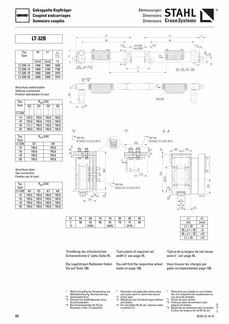
LS-T
_04.
FM
88
Gekoppelte KopfträgerCoupled endcarriagesSommiers couplés
AbmessungenDimensionsDimensions
Anschluss seitlich/obenSide/top connectionFixation latérale/par le haut
Anschluss obenTop connectionFixation par le haut
LT-32B
TypType
k0 k1
[mm] [mm] *2LT-32B-14 1400 1900 1658LT-32B-16 1600 2100 1766LT-32B-18 1800 2300 1870LT-32B-20 2000 2500 1974
TypType
Rzul [kN]Q3 Q3 Q5 Q5
LT-32B-14 142,9 195,6 195,6 195,6-16 125,0 195,6 175,0 195,6-18 111,1 195,6 155,6 195,6-20 100,0 195,6 140,0 195,6
TypType
Rzul [kN]
LT-32B Q7 Q9-14 195,6 195,6-16 195,6 195,6-18 195,6 195,6-20 195,6 195,6
TypType
Rzul [kN]
LT-32B K4 K5 K7 K9-14 195,6 195,6 195,6 195,6-16 195,6 195,6 195,6 195,6-18 195,6 195,6 195,6 195,6-20 195,6 195,6 195,6 195,6
"Calculation of required rail width k" see page 45.
You will find the respective wheel loads on page 108.
"s
Vg
590 NmM20x130-10.9 ISO 4014
350
0
215
2537
300 NmM16x80-10.9 ISO
Ø315
"Y" A -
370
24
A
A
K4-K9
a
170 170min 490
s
X
Y
max 5000
84 89 9470 75
(A75)80
* Dimension not applicable when using anti-jump catch or storm lock device
*1 Crane span*2 Weight per pair of endcarriages without
joint plates*3 For rail widths 45, 55, etc. observe notes
in section 5.3
*
**
*
Calcul de la largeur de rail néces-aire k", voir page 45.
ous trouvez les charges par alet correspondantes page 108.
4014
b1k
20
c1576v13
125 63
160 145
20
A
150
c1739v03
k1
k0
e
150Ød
14
Q3, Q5, Q7, Q9
L1 b1[m] [mm]
L1 < 20 +020 < L1 < 30 +530 < L1 < 35 +10
L1 > 35 +15
Dimension pas valable en cas d’utilisa-tion d’un dispositif anti-soulèvement ou une sécurité-tempête
1 Portée du pont roulant2 Poids par paire de sommiers sans
plaques de fixation3 Respectez les remarques dans la section
5.3 pour les largeurs de rail 45, 55, etc.
"Ermittlung der erforderlichen Schienenbreite k" siehe Seite 45.
Die zugehörigen Radlasten finden Sie auf Seite 108.
380
30 20
170
3032
300 NmM16x80-10.9 ISO 4014
"X"
min 310*
k1
k0
m0
m2
min 250*
250m
1
b1 64 69 74 79k *3
50 55(A55)
60 65(A65)
* Maß nicht gültig bei Verwendung von Abhebesicherung, Sturmsicherung
*1 Spannweite Kran*2 Gewicht pro Kopfträgerpaar ohne
Anschlussplatten*3 Bei Schienenbreiten 45, 55 etc.
Hinweise in Abs. 5.3 beachten
10.1405.05.15/
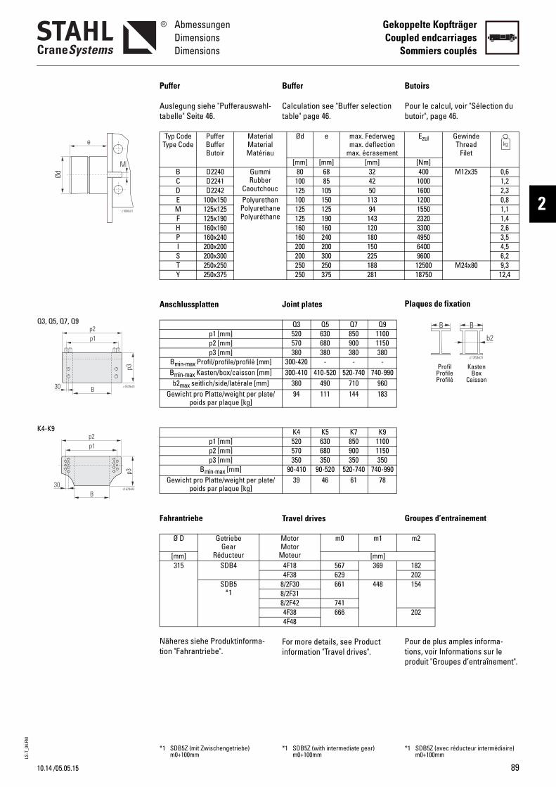
LS-T
_04.
FM
10.14
AbmessungenDimensionsDimensions
Gekoppelte KopfträgerCoupled endcarriages
Sommiers couplés
2c1686v01
e
Ød
M
c1679v01
p3
B
p1p2
30
Q3, Q5, Q7, Q9
p3
p1p2
c1679v03
B30
K4-K9
/05.05.15
Buffer
Calculation see "Buffer selection table" page 46.
Joint plates
Travel drives
For more details, see Product information "Travel drives".
B
Pb
P
G
Ptp
Ød e max. Federwegmax. deflection
max. écrasement[mm] [mm] [mm]
c
80 68 32100 85 42125 105 50
nee
100 150 113125 125 94125 190 143160 160 120160 240 180200 200 150200 300 225250 250 188250 375 281
Q3 Q5 Q7 Q9520 630 850 1100570 680 900 1150380 380 380 380
300-420 - - -300-410 410-520 520-740 740-990
380 490 710 96094 111 144 183
K4 K5 K7 K9520 630 850 1100570 680 900 1150350 350 350 350
90-410 90-520 520-740 740-99039 46 61 78
MotorMotor
Moteur
m0 m1
[mm]4F18 567 3694F38 629
8/2F30 661 4488/2F318/2F42 7414F38 6664F48
*1 SDB5Z (with intermediate gear) m0+100mm
*
utoirs
our le calcul, voir "Sélection du utoir", page 46.
laques de fixation
roupes d’entraînement
our de plus amples informa-ions, voir Informations sur le roduit "Groupes d’entraînement".
B B
c1763v01
b2
Profil KastenProfile BoxProfilé Caisson
Ezul GewindeThread
Filet[Nm]400 M12x35 0,6
1000 1,21600 2,31200 0,81550 1,12320 1,43300 2,64950 3,56400 4,59600 6,212500 M24x80 9,318750 12,4
m2
182202154
202
1 SDB5Z (avec réducteur intermédiaire) m0+100mm
Puffer
Auslegung siehe "Pufferauswahl-tabelle" Seite 46.
Anschlussplatten
Fahrantriebe
Näheres siehe Produktinforma-tion "Fahrantriebe".
Typ CodeType Code
PufferBufferButoir
MaterialMaterialMatériau
B D2240 GummiRubber
CaoutchouC D2241D D2242E 100x150 Polyuretha
PolyurethanPolyuréthan
M 125x125F 125x190H 160x160P 160x240I 200x200S 200x300T 250x250Y 250x375
p1 [mm]p2 [mm]p3 [mm]
Bmin-max Profil/profile/profilé [mm]Bmin-max Kasten/box/caisson [mm]b2max seitlich/side/latérale [mm]
Gewicht pro Platte/weight per plate/poids par plaque [kg]
p1 [mm]p2 [mm]p3 [mm]
Bmin-max [mm]Gewicht pro Platte/weight per plate/
poids par plaque [kg]
Ø D GetriebeGear
Réducteur[mm]315 SDB4
SDB5*1
*1 SDB5Z (mit Zwischengetriebe) m0+100mm
89
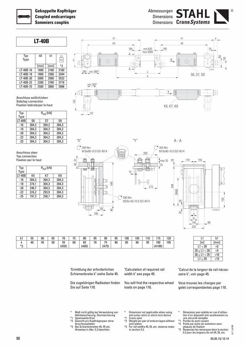
LS-T
_04.
FM
90
Gekoppelte KopfträgerCoupled endcarriagesSommiers couplés
AbmessungenDimensionsDimensions
b1 55 60 65 70k
*340 45 50 55
(A55)
Anschluss seitlich/obenSide/top connectionFixation latérale/par le haut
Anschluss obenTop connectionFixation par le haut
LT-40B
TypType
k0 k1
[mm] [mm] *2LT-40B-16 1600 2160 3160LT-40B-18 1800 2360 3344LT-40B-20 2000 2560 3532LT-40B-22 2200 2760 3716LT-40B-25 2500 3060 3996
TypType
Rzul [kN]
LT-40B S6 S7 S9-16 304,3 304,3 304,3-18 304,3 304,3 304,3-20 304,3 304,3 304,3-22 304,3 304,3 304,3-25 304,3 304,3 304,3
TypType
Rzul [kN]
LT-40B K5 K7 K9-16 304,3 304,3 304,3-18 274,1 304,3 304,3-20 246,7 304,3 304,3-22 224,2 293,9 304,3-25 197,3 258,7 304,3
"Calculation of required rail width k" see page 45.
You will find the respective wheel loads on page 110.
"s
Vg
100 105 110 115 12085 90 95 100
(A100)105
590 NmM20x140-10.9 ISO 4014
Ø400
350
10
215
25max 35
300 NmM16x90-10.9 ISO
"Y" A -
548
26
A
A
K5, K7, K9
a
190 190min 620
s
X
Y
max 5000
* Dimension not applicable when using anti-jump catch or storm lock device
*1 Crane span*2 Weight per pair of endcarriages without
joint plates*3 For rail widths 45, 55, etc. observe notes
in section 5.3
*
**
*
Calcul de la largeur de rail néces-aire k", voir page 45.
ous trouvez les charges par alet correspondantes page 110.
L1 b1[m] [mm]
L1 < 20 +020 < L1 < 30 +530 < L1 < 35 +10
L1 > 35 +15
b1k
26
c1576v14
145 88
170 155
150
20
320
4014
A
c1739v04
k1
k0
e
150Ød
16
S6, S7, S9
Dimension pas valable en cas d’utilisa-tion d’un dispositif anti-soulèvement ou une sécurité-tempête
1 Portée du pont roulant2 Poids par paire de sommiers sans
plaques de fixation3 Respectez les remarques dans la section
5.3 pour les largeurs de rail 45, 55, etc.
"Ermittlung der erforderlichen Schienenbreite k" siehe Seite 45.
Die zugehörigen Radlasten finden Sie auf Seite 110.
75 80 85 90 9560 65
(A65)70 75
(A75)80
540
30
180
4032
300 NmM16x90-10.9 ISO 4014
"X"
48
min 380*
k1
k0
m0
m2
min 300*
280m
1
* Maß nicht gültig bei Verwendung von Abhebesicherung, Sturmsicherung
*1 Spannweite Kran*2 Gewicht pro Kopfträgerpaar ohne
Anschlussplatten*3 Bei Schienenbreiten 45, 55 etc.
Hinweise in Abs. 5.3 beachten
10.1405.05.15/
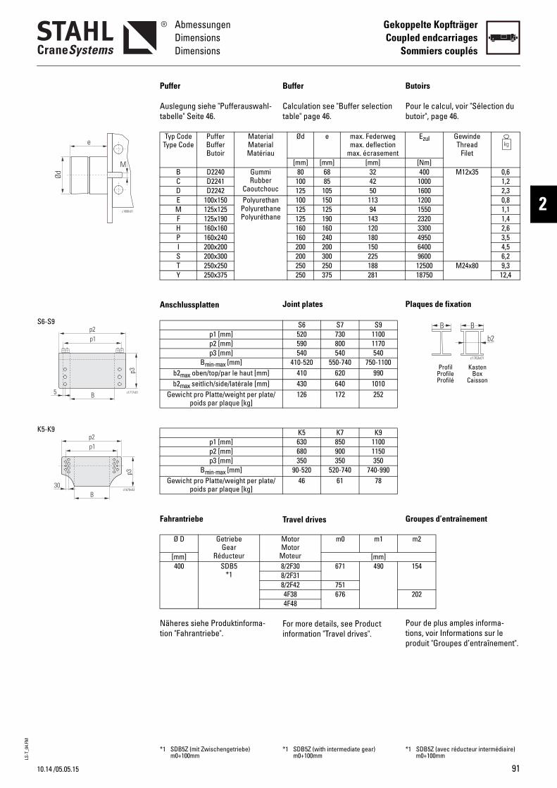
LS-T
_04.
FM
10.14
AbmessungenDimensionsDimensions
Gekoppelte KopfträgerCoupled endcarriages
Sommiers couplés
2c1686v01
e
Ød
M
B
p1p2
c1717v01
p3
5
S6-S9
p3
p1p2
c1679v03
B30
K5-K9
/05.05.15
Buffer
Calculation see "Buffer selection table" page 46.
Joint plates
Travel drives
For more details, see Product information "Travel drives".
B
Pb
P
G
Ptp
Ød e max. Federwegmax. deflection
max. écrasement[mm] [mm] [mm]
c
80 68 32100 85 42125 105 50
nee
100 150 113125 125 94125 190 143160 160 120160 240 180200 200 150200 300 225250 250 188250 375 281
S6 S7 S9520 730 1100590 800 1170540 540 540
410-520 550-740 750-1100410 620 990430 640 1010126 172 252
K5 K7 K9630 850 1100680 900 1150350 350 350
90-520 520-740 740-99046 61 78
MotorMotor
Moteur
m0 m1
[mm]8/2F30 671 4908/2F318/2F42 7514F38 6764F48
*1 SDB5Z (with intermediate gear) m0+100mm
*
utoirs
our le calcul, voir "Sélection du utoir", page 46.
laques de fixation
roupes d’entraînement
our de plus amples informa-ions, voir Informations sur le roduit "Groupes d’entraînement".
B B
c1763v01
b2
Profil KastenProfile BoxProfilé Caisson
Ezul GewindeThread
Filet[Nm]400 M12x35 0,6
1000 1,21600 2,31200 0,81550 1,12320 1,43300 2,64950 3,56400 4,59600 6,212500 M24x80 9,318750 12,4
m2
154
202
1 SDB5Z (avec réducteur intermédiaire) m0+100mm
Puffer
Auslegung siehe "Pufferauswahl-tabelle" Seite 46.
Anschlussplatten
Fahrantriebe
Näheres siehe Produktinforma-tion "Fahrantriebe".
Typ CodeType Code
PufferBufferButoir
MaterialMaterialMatériau
B D2240 GummiRubber
CaoutchouC D2241D D2242E 100x150 Polyuretha
PolyurethanPolyuréthan
M 125x125F 125x190H 160x160P 160x240I 200x200S 200x300T 250x250Y 250x375
p1 [mm]p2 [mm]p3 [mm]
Bmin-max [mm]b2max oben/top/par le haut [mm]b2max seitlich/side/latérale [mm]
Gewicht pro Platte/weight per plate/poids par plaque [kg]
p1 [mm]p2 [mm]p3 [mm]
Bmin-max [mm]Gewicht pro Platte/weight per plate/
poids par plaque [kg]
Ø D GetriebeGear
Réducteur[mm]400 SDB5
*1
*1 SDB5Z (mit Zwischengetriebe) m0+100mm
91

LS-T
_05.
FM
92
LaufkrankopfträgerEndcarriages for o.h.t. cranesSommiers pour ponts roulants posés
OptionenOptionsOptions
4
4.1
Options
Paint/corrosion protection
Standard pre-treatment: Steel shot de-rusting grade SA2.5 in acc. with EN ISO 12944-4. Machined surfaces, aluminium and deep-drawn parts degreased.
Standard primer coat:
All endcarriages and joint plates: epoxy resin-based two-compo-nent primer (KorroE), 20 µm. Colour oxide red (RAL 3009), can be welded.
Option• Epoxy resin-based two-com-
ponent primer, 60 µm. Colour agate grey (RAL 7038), cannot be welded (must be removed before welding).
• Epoxy resin-based two-com-ponent top coat, 120 µm. Colour melon yellow (RAL 1028), corrosivity category C3. Others on request.
O
P
TGdSmd
C
Tfcs2Cs
O•
•
ptions
einture/protection anticorrosive
raitement préalable standard : renaillé selon DIN EN ISO 12944-4 ; egré de dérouillage SA2,5. urfaces usinées, pièces en alu-inium et pièces embouties,
égraissées.
ouche d'apprêt standard :
ous les sommiers et plaques de ixation : ouche d'apprêt à deux compo-ants à base d'époxy (KorroE), 0 µm. ouleur rouge oxyde (RAL 3009), oudable.
ptionCouche d'apprêt à deux com-posants à base d'époxy, 60 µm. Couleur gris agate (RAL 7038), pas soudable (doit être éli-miné avant le soudage).
Couche de finition à deux com-posants à base de résine epoxy, 120 µm. Couleur jaune melon (RAL 1028), catégorie de corrosivité C3. Autres sur demande.
Standard-Vorbehandlung: Stahlkiesentrostung nach DIN EN ISO 12944-4, Entrostungs-grad SA2,5. Bearbeitete Flächen, Alu- und Tiefziehteile entfettet.
Standard-Grundanstrich:
Alle Kopfträger und Anschluss-platten: Zweikomponenten-Grundierung auf Epoxidharzbasis (KorroE), 20 µm. Farbton oxidrot (RAL 3009), schweißfähig.
Option• Zweikomponenten-Grundie-
rung auf Epoxidharzbasis, 60 µm. Farbton achatgrau (RAL 7038), nicht schweißfähig (muss vor dem Schweißen entfernt wer-den).
• Zweikomponenten-Deckan-strich auf Epoxidharzbasis, 120 µm. Farbton melonengelb (RAL 1028), Korrosivitätskategorie C3. Andere auf Anfrage.
Optionen
Lackierung/Korrosionsschutz
10.14
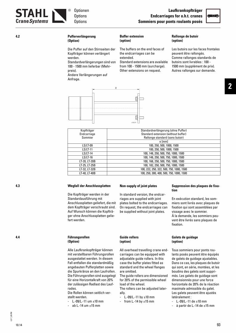
LS-T
_05.
FM
10.14
OptionenOptionsOptions
LaufkrankopfträgerEndcarriages for o.h.t. cranes
Sommiers pour ponts roulants posés
2
4.2
4.3
4.4
Buffer extension(option)
The buffers on the end faces of the endcarriages can be extended.Standard extensions are available from 100 - 1500 mm (surcharge).Other extensions on request.
Non-supply of joint plates
In standard version, the endcar-riages are supplied with joint plates bolted to the endcarriages.On request, the endcarriages can be supplied without joint plates.
Guide rollers(option)
All overhead travelling crane end-carriages can be equipped with adjustable guide rollers. In this case the buffer plates fitted as standard and the wheel flanges are omitted.The guide rollers are dimensioned for 20% of the permissible wheel load of the wheel.The rollers can be adjusted later-ally. - L.-09/L.-11 by ±10 mm- from L.-14 by ±15 mm
R(
LpCb1A
St
EmfvÀvf
G(
TldDqbmdhmLl--
Standardverlängerung (oStandard extension (with
Rallonge standard (sane [mm]
100, 250, 500, 1000,100, 250, 500, 1000,
100, 148, 250, 500, 750, 1100, 148, 250, 500, 750, 1100, 168, 250, 500, 750, 1100, 182, 250, 500, 750, 1
100, 222, 250, 322, 500, 750100, 250, 300, 400, 500, 750
c1682v01
allonge de butoiroption)
es butoirs sur les faces frontales euvent être rallongés.omme rallonges standards de utoirs sont livrables : 100 - 500 mm (supplément de prix).utres rallonges sur demande.
uppression des plaques de fixa-ion
n exécution standard, les som-iers sont livrés avec plaques de
ixation qui sont assemblées par issage avec le sommier. la demande, les sommiers peu-ent être livrés sans plaques de ixation.
alets de guidageoption)
ous sommiers pour ponts rou-ants posés peuvent être équipés e galets de guidage ajustables. ans ce cas, les plaques de butoir ui sont, en série, montées, et les oudins des galets sont suppri-és. Les galets de guidage sont
imensionnés pour une force orizontale de 20% de la réaction aximale admissible du galet.
es galets peuvent être ajustés atéralement :
L.-09/L.-11 de ±10 mmà partir de L.-14 de ±15 mm
hne Puffer)out buffer)s butoir)
1500 1500000, 1500000, 1500000, 1500000, 1500, 1000, 1500, 1000, 1500
(Option)
Die Puffer auf den Stirnseiten der Kopfträger können verlängert werden.Standardverlängerungen sind von 100 - 1500 mm lieferbar (Mehr-preis).Andere Verlängerungen auf Anfrage.
Die Kopfträger werden in der Standardausführung mit Anschlussplatten geliefert, die mit dem Kopfträger verschraubt sind.Auf Wunsch können die Kopfträ-ger ohne Anschlussplatten gelie-fert werden.
(Option)
Alle Laufkrankopfträger können mit verstellbaren Führungsrollen ausgestattet werden. In diesem Fall entfallen die standardmäßig angebauten Pufferplatten sowie die Spurkränze an den Laufrollen.Die Führungsrollen sind ausgelegt für eine Horizontalkraft von 20% der zulässigen Radlast des Lauf-rades. Die Rollen können seitlich ver-stellt werden. - L.-09/L.-11 um ±10 mm- ab L.-14 um ±15 mm
Pufferverlängerung
KopfträgerEndcarriage
Sommier
LS/LT-09LS/LT-11LS/LT-14LS/LT-16
LT-20, LT-20BLT-25, LT-25BLT-32, LT-32BLT-40, LT-40B
Wegfall der Anschlussplatten
Führungsrollen
e
93
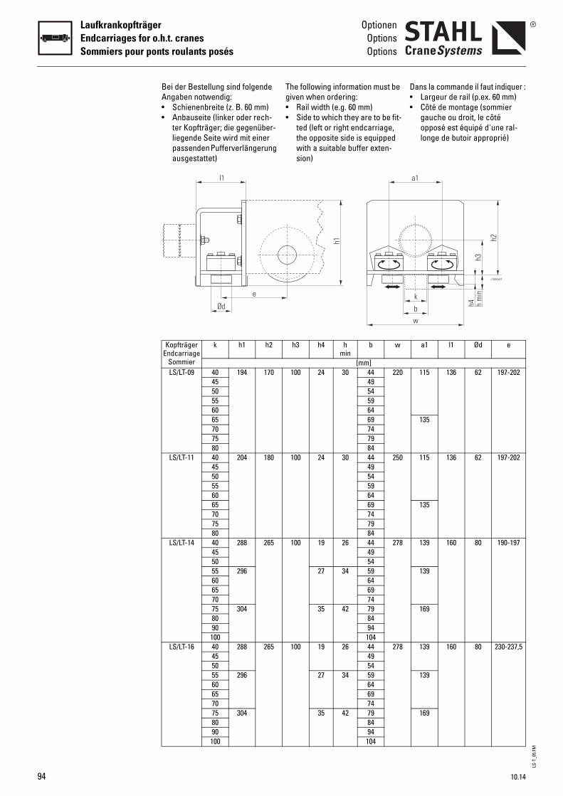
LS-T
_05.
FM
94
LaufkrankopfträgerEndcarriages for o.h.t. cranesSommiers pour ponts roulants posés
OptionenOptionsOptions
The following information must be given when ordering:• Rail width (e.g. 60 mm)• Side to which they are to be fit-
ted (left or right endcarriage, the opposite side is equipped with a suitable buffer exten-sion)
D••
h3 h4 hmin
b w
[mm]100 24 30 44 220
4954596469747984
100 24 30 44 2504954596469747984
100 19 26 44 2784954
27 34 59646974
35 42 798494
104100 19 26 44 278
4954
27 34 59646974
35 42 798494
104
h1
ans la commande il faut indiquer :Largeur de rail (p.ex. 60 mm)Côté de montage (sommier gauche ou droit, le côté opposé est équipé d'une ral-longe de butoir approprié)
a1 l1 Ød e
115 136 62 197-202
135
115 136 62 197-202
135
139 160 80 190-197
139
169
139 160 80 230-237,5
139
169
c1684v01
k
bw
a1
h2
h4h3
h m
in
Bei der Bestellung sind folgende Angaben notwendig:• Schienenbreite (z. B. 60 mm)• Anbauseite (linker oder rech-
ter Kopfträger; die gegenüber-liegende Seite wird mit einer passenden Pufferverlängerung ausgestattet)
KopfträgerEndcarriage
Sommier
k h1 h2
LS/LT-09 40 194 1704550556065707580
LS/LT-11 40 204 1804550556065707580
LS/LT-14 40 288 265455055 29660657075 3048090100
LS/LT-16 40 288 265455055 29660657075 3048090100
l1
e
Ød
10.14
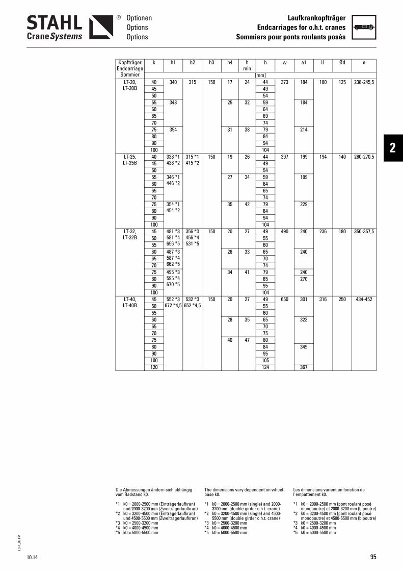
LS-T
_05.
FM
10.14
OptionenOptionsOptions
LaufkrankopfträgerEndcarriages for o.h.t. cranes
Sommiers pour ponts roulants posés
2
150 17 24 44 3734954
25 32 59646974
31 38 798494
104150 19 26 44 397
4954
27 34 59646574
35 42 798494
104150 20 27 49 490
5560
26 33 657074
34 41 798595
104150 20 27 49 650
5560
28 35 657075
40 47 808495
105124
The dimensions vary dependent on wheel-base k0.
*1 k0 = 2000-2500 mm (single) and 2000-3200 mm (double girder o.h.t. crane)
*2 k0 = 3200-4500 mm (single) and 4500-5500 mm (double girder o.h.t. crane)
*3 k0 = 2500-3200 mm*4 k0 = 4000-4500 mm*5 k0 = 5000-5500 mm
Ll
*
*
***
h3 h4 hmin
b w
[mm]
184 180 125 238-245,5184
214
199 194 140 260-270,5
199
229
240 236 180 350-357,5
240
240270
301 316 250 434-452
323
345
367
es dimensions varient en fonction de 'empattement k0.
1 k0 = 2000-2500 mm (pont roulant posé monopoutre) et 2000-3200 mm (bipoutre)
2 k0 = 3200-4500 mm (pont roulant posé monopoutre) et 4500-5500 mm (bipoutre)
3 k0 = 2500-3200 mm4 k0 = 4000-4500 mm5 k0 = 5000-5500 mm
a1 l1 Ød e
LT-20,LT-20B
40 340 315455055 34860657075 3548090100
LT-25,LT-25B
40 338 *1438 *2
315 *1415 *245
5055 346 *1
446 *260657075 354 *1
454 *28090100
LT-32,LT-32B
45 481 *3581 *4656 *5
356 *3456 *4531 *5
505560 487 *3
587 *4662 *5
657075 495 *3
595 *4670 *5
8090100
LT-40,LT-40B
45 552 *3672 *4,5
532 *3652 *4,550
55606570758090100120
Die Abmessungen ändern sich abhängig vom Radstand k0.
*1 k0 = 2000-2500 mm (Einträgerlaufkran) und 2000-3200 mm (Zweiträgerlaufkran)
*2 k0 = 3200-4500 mm (Einträgerlaufkran) und 4500-5500 mm (Zweiträgerlaufkran)
*3 k0 = 2500-3200 mm*4 k0 = 4000-4500 mm*5 k0 = 5000-5500 mm
KopfträgerEndcarriage
Sommier
k h1 h2
95
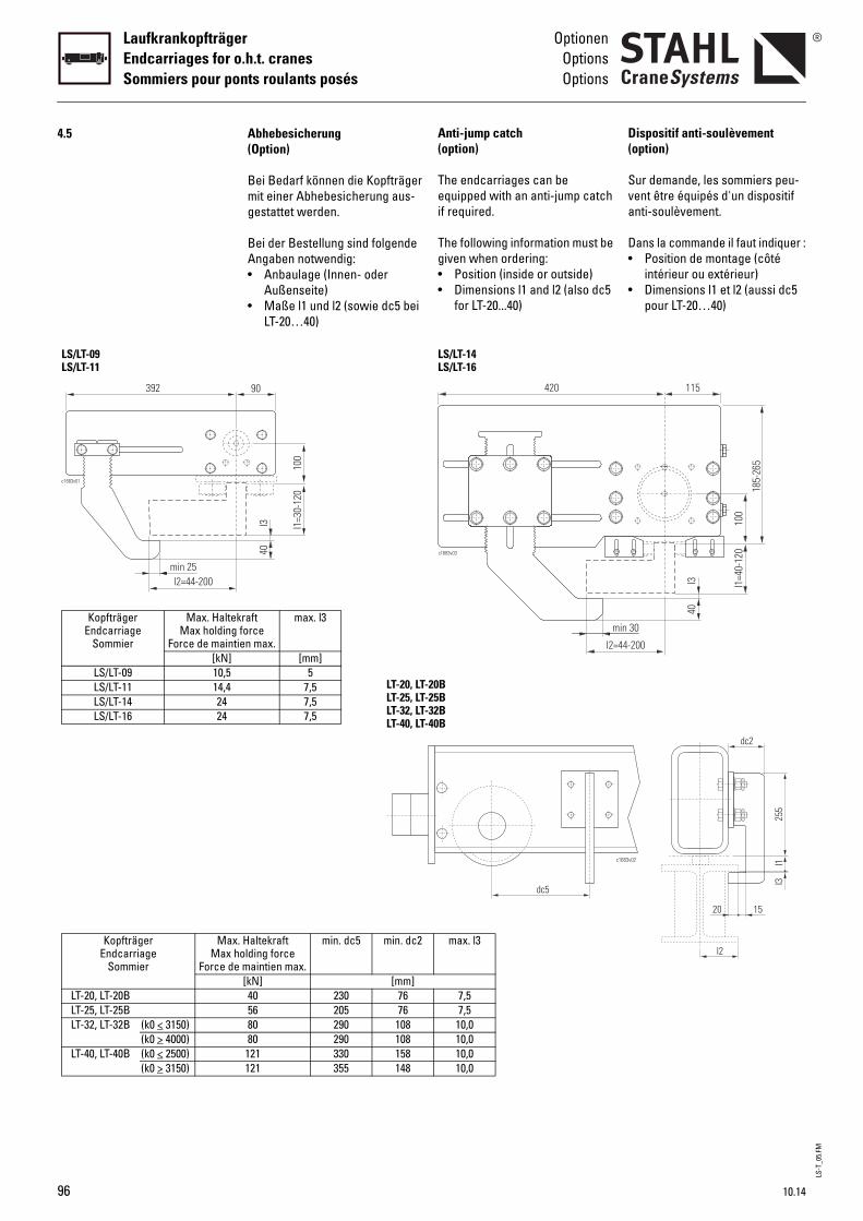
LS-T
_05.
FM
96
LaufkrankopfträgerEndcarriages for o.h.t. cranesSommiers pour ponts roulants posés
OptionenOptionsOptions
4.5
392
min 25l2=44-200
c1683v01
LS/LT-09LS/LT-11
KopfträgerEndcarriage
Sommier
Max. HalteMax holding
Force de maint[kN]
LS/LT-09 10,5LS/LT-11 14,4LS/LT-14 24LS/LT-16 24
KopfträgerEndcarriage
Sommier
MaxMax h
Force de
LT-20, LT-20BLT-25, LT-25BLT-32, LT-32B (k0 < 3150)
(k0 > 4000)LT-40, LT-40B (k0 < 2500)
(k0 > 3150)
Anti-jump catch(option)
The endcarriages can be equipped with an anti-jump catch if required.
The following information must be given when ordering:• Position (inside or outside)• Dimensions l1 and l2 (also dc5
for LT-20...40)
D(
Sva
D•
•
c1683v03
420
l2=44-
min
c1683
dc5
LS/LT-14LS/LT-16
20B25B32B40B
max. l3
7,57,5
10,010,010,010,0
ispositif anti-soulèvementoption)
ur demande, les sommiers peu-ent être équipés d'un dispositif nti-soulèvement.
ans la commande il faut indiquer :Position de montage (côté intérieur ou extérieur)Dimensions l1 et l2 (aussi dc5 pour LT-20…40)
185-
265
115
l1=4
0-12
0
200
30
100
l340
255
l2
l1
15
l3
v02
20
dc2
(Option)
Bei Bedarf können die Kopfträger mit einer Abhebesicherung aus-gestattet werden.
Bei der Bestellung sind folgende Angaben notwendig:• Anbaulage (Innen- oder
Außenseite)• Maße l1 und l2 (sowie dc5 bei
LT-20…40)
Abhebesicherung
90
100
l1=3
0-12
0
l340
kraft forceien max.
max. l3
[mm]5
7,57,57,5
LT-20, LT-LT-25, LT-LT-32, LT-LT-40, LT-
. Haltekraftolding force maintien max.
min. dc5 min. dc2
[kN] [mm]40 230 7656 205 7680 290 10880 290 108
121 330 158121 355 148
10.14
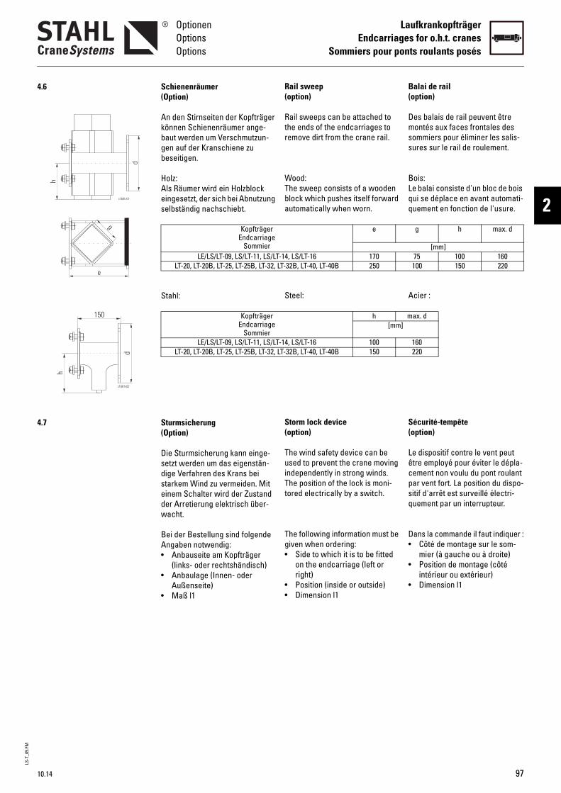
LS-T
_05.
FM
10.14
OptionenOptionsOptions
LaufkrankopfträgerEndcarriages for o.h.t. cranes
Sommiers pour ponts roulants posés
2
4.6
4.7
c1681v01
e
g
d
h
c1681v02
d
h
150
Rail sweep(option)
Rail sweeps can be attached to the ends of the endcarriages to remove dirt from the crane rail.
Wood:The sweep consists of a wooden block which pushes itself forward automatically when worn.
Steel:
Storm lock device(option)
The wind safety device can be used to prevent the crane moving independently in strong winds. The position of the lock is moni-tored electrically by a switch.
The following information must be given when ordering:• Side to which it is to be fitted
on the endcarriage (left or right)
• Position (inside or outside)• Dimension l1
B(
Dmss
BLqq
A
S(
Lêcpsq
D•
•
•
e
-14, LS/LT-16 170LT-32B, LT-40, LT-40B 250
h m[mm]
-14, LS/LT-16 100LT-32B, LT-40, LT-40B 150
alai de railoption)
es balais de rail peuvent être ontés aux faces frontales des
ommiers pour éliminer les salis-ures sur le rail de roulement.
ois:e balai consiste d'un bloc de bois ui se déplace en avant automati-uement en fonction de l'usure.
cier :
écurité-tempêteoption)
e dispositif contre le vent peut tre employé pour éviter le dépla-ement non voulu du pont roulant ar vent fort. La position du dispo-itif d'arrêt est surveillé électri-uement par un interrupteur.
ans la commande il faut indiquer :Côté de montage sur le som-mier (à gauche ou à droite)Position de montage (côté intérieur ou extérieur)Dimension l1
g h max. d
[mm]75 100 160100 150 220
ax. d
160220
(Option)
An den Stirnseiten der Kopfträger können Schienenräumer ange-baut werden um Verschmutzun-gen auf der Kranschiene zu beseitigen.
Holz:Als Räumer wird ein Holzblock eingesetzt, der sich bei Abnutzung selbständig nachschiebt.
Stahl:
(Option)
Die Sturmsicherung kann einge-setzt werden um das eigenstän-dige Verfahren des Krans bei starkem Wind zu vermeiden. Mit einem Schalter wird der Zustand der Arretierung elektrisch über-wacht.
Bei der Bestellung sind folgende Angaben notwendig:• Anbauseite am Kopfträger
(links- oder rechtshändisch)• Anbaulage (Innen- oder
Außenseite)• Maß l1
Schienenräumer
KopfträgerEndcarriage
SommierLE/LS/LT-09, LS/LT-11, LS/LT
LT-20, LT-20B, LT-25, LT-25B, LT-32,
KopfträgerEndcarriage
SommierLE/LS/LT-09, LS/LT-11, LS/LT
LT-20, LT-20B, LT-25, LT-25B, LT-32,
Sturmsicherung
97
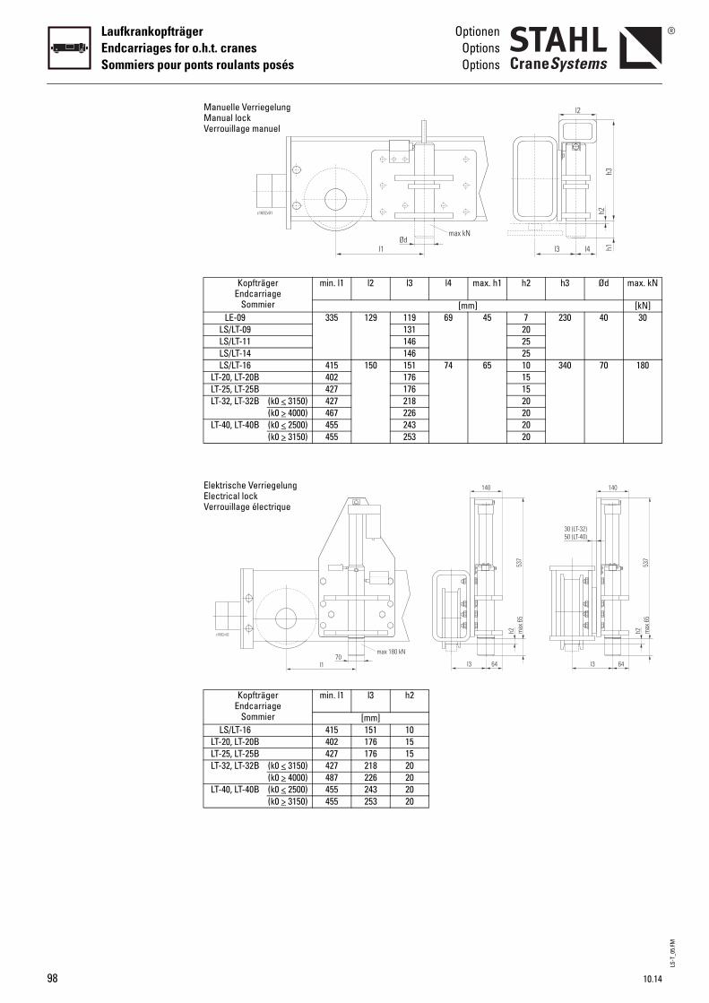
LS-T
_05.
FM
98
LaufkrankopfträgerEndcarriages for o.h.t. cranesSommiers pour ponts roulants posés
OptionenOptionsOptions
l2 l3 l4 max. h1
[mm]129 119 69 45
131146146
150 151 74 65176176218226243253
l3 h2
[mm]151 10176 15176 15218 20226 20243 20253 20
l1Ød
max kN
max 180 kN
140
l3 64
h2
h2 h3 Ød max. kN
[kN]7 230 40 3020252510 340 70 180151520202020
h3
l3
h2
l2
h1l4
140
l3 64
h2max
65
max
65
537
537
30 (LT-32)50 (LT-40)
KopfträgerEndcarriage
Sommier
min. l1
LE-09 335LS/LT-09LS/LT-11LS/LT-14LS/LT-16 415
LT-20, LT-20B 402LT-25, LT-25B 427LT-32, LT-32B (k0 < 3150) 427
(k0 > 4000) 467LT-40, LT-40B (k0 < 2500) 455
(k0 > 3150) 455
KopfträgerEndcarriage
Sommier
min. l1
LS/LT-16 415LT-20, LT-20B 402LT-25, LT-25B 427LT-32, LT-32B (k0 < 3150) 427
(k0 > 4000) 487LT-40, LT-40B (k0 < 2500) 455
(k0 > 3150) 455
c1692v01
Manuelle VerriegelungManual lockVerrouillage manuel
c1692v02
l170
Elektrische VerriegelungElectrical lockVerrouillage électrique
10.14
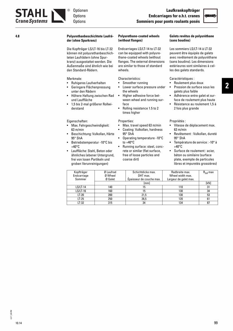
LS-T
_05.
FM
10.14
OptionenOptionsOptions
LaufkrankopfträgerEndcarriages for o.h.t. cranes
Sommiers pour ponts roulants posés
2
4.8
Polyurethane-coated wheels (without flanges)Endcarriages LS/LT-14 to LT-32 can be equipped with polyure-thane-coated wheels (without flanges. The external dimensions are similar to those of standard wheels.
Characteristics:• Smoother running• Lower surface pressure under
the wheels• Higher adhesive force bet-
ween wheel and running sur-face
• Rolling resistance 1.5 to 2 times higher
Properties:• Max. travel speed 63 m/min• Coating: Vulkollan, hardness
95° ShA• Operating temperature -10°C
to +40°C• Running surface: steel, conc-
rete or similar (flat surface, free of loose particles and coarse dirt)
G(
Lpa(el
C••
•
•
P•
•
•
•
lSchichtdicke max.
DHT max.Épaisseur de couche max.
WLa
[mm]1515
21,526,534
alets revêtus de polyuréthane sans boudins)
es sommiers LS/LT-14 à LT-32 euvent être équipés de galets vec revêtement de polyuréthane sans boudins). Les dimensions xtérieures sont similaires à cel-
es des galets standards.
aractéristiques :Roulement plus douxPression de surface sous les galets plus faibleAdhérence entre galet et sur-face de roulement plus hauteRésistance au roulement 1,5 à 2 fois plus grande
ropriétés :Vitesse de déplacement max. 63 m/minRevêtement : Vulkollan, dureté 95° ShATempérature de service : -10° à +40°CSurface de roulement : acier, béton ou similaire (surface plate, exempte de particules libres et impuretés grossières)
Radbreite max.heel width max.
rgeur de galet max.
Rzul max
[kN]110 31130 34130 53120 61134 87
Die Kopfträger LS/LT-16 bis LT-32 können mit polyurethanbeschich-teten Laufrädern (ohne Spur-kranz) ausgestattet werden. Die Außenmaße sind ähnlich wie bei den Standard-Rädern.
Merkmale:• Ruhigeres Laufverhalten• Geringere Flächenpressung
unter den Rädern• Höhere Haftung zwischen Rad
und Lauffläche• 1,5 bis 2-mal größerer Rollwi-
derstand
Eigenschaften:• Max. Fahrgeschwindigkeit:
63 m/min• Beschichtung: Vulkollan, Härte
95° ShA• Betriebstemperatur -10°C bis
+40°C• Lauffläche: Stahl, Beton oder
ähnliches (ebener Untergrund, frei von losen Partikeln und groben Verunreinigungen)
Polyurethanbeschichtete Laufrä-der (ohne Spurkranz)
KopfträgerEndcarriage
Sommier
Ø LaufradØ WheeØ Galet
LS/LT-14 140LS/LT-16 160
LT-20 200LT-25 250LT-32 315
99
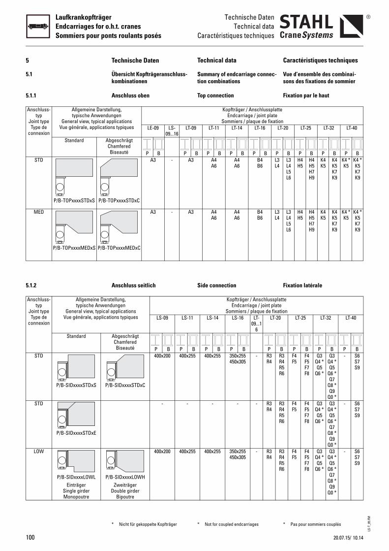
LS-T
_05.
FM
100
LaufkrankopfträgerEndcarriages for o.h.t. cranesSommiers pour ponts roulants posés
Technische DatenTechnical data
Caractéristiques techniques
5
5.1
5.1.1
Anschluss-typ
Joint typeType de
connexion
Allgemeine Darstypische Anwend
General view, typical Vue générale, applicat
Standard A
STD
P/B-TOPxxxxSTDxS P/B
MED
P/B-TOPxxxxMEDxS P/B-
5.1.2
Anschluss-typ
Joint typeType de
connexion
Allgemeine Datypische Anwe
General view, typicaVue générale, applic
Standard
STD
P/B-SIDxxxxSTDxS P
STD
P/B-SIDxxxxSTDxE
LOW
P/B-SIDxxxxLOWLEinträger
Single girderMonopoutre
P
Caractéristiques techniques
Vue d’ensemble des combinai-sons des fixations de sommier
Fixation par le haut
Fixation latérale
te
onLT-20 LT-25 LT-32 LT-40
B P B P B P BL3L4L5L6
H4H5
H4H5H7H9
K4K5
K4K5K7K9
K4 *K5
K4 *K5K7K9
L3L4L5L6
H4H5
H4H5H7H9
K4K5
K4K5K7K9
K4 *K5
K4 *K5K7K9
attetetion
0 LT-25 LT-32 LT-40
B P B P B P BR3R4R5R6
F4F5
F4F5F7F8
Q3Q4 *Q5
Q6 *
Q3Q4 *Q5
Q6 *Q7
Q8 *Q9
Q0 *
- S6S7S9
R3R4R5R6
F4F5
F4F5F7F8
Q3Q4 *Q5
Q6 *
Q3Q4 *Q5
Q6 *Q7
Q8 *Q9
Q0 *
- S6S7S9
R3R4R5R6
F4F5
F4F5F7F8
Q3Q4 *Q5
Q6 *
Q3Q4 *Q5
Q6 *Q7
Q8 *Q9
Q0 *
- S6S7S9
* Pas pour sommiers couplés
Technical data
Summary of endcarriage connec-tion combinations
Top connection
Side connection
Kopfträger / AnschlussplatEndcarriage / joint plate
Sommiers / plaque de fixati9 LT-11 LT-14 LT-16
B P B P B P B PA4A6
A4A6
B4B6
L3L4
A4A6
A4A6
B4B6
L3L4
Kopfträger / AnschlussplEndcarriage / joint pla
Sommiers / plaque de fixaLS-14 LS-16 LT-
09...16
LT-2
B P B P B P5 400x255 350x255
450x305- R3
R4
- - - R3R4
5 400x255 350x255450x305
- R3R4
* Not for coupled endcarriages
Technische Daten
Übersicht Kopfträgeranschluss-kombinationen
Anschluss oben
tellung, ungen
applicationsions typiques LE-09 LS-
09...16LT-0
bgeschrägtChamferedBiseauté P B P
-TOPxxxxSTDxC
A3 - A3
TOPxxxxMEDxC
A3 - A3
Anschluss seitlich
rstellung, ndungenl applications
ations typiques LS-09 LS-11
AbgeschrägtChamferedBiseauté P B P
/B-SIDxxxxSTDxC
400x200 400x25
- -
/B-SIDxxxxLOWHZweiträger
Double girderBipoutre
400x200 400x25
* Nicht für gekoppelte Kopfträger
10.1420.07.15/
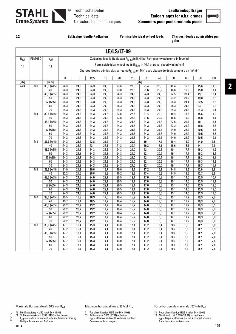
LS-T
_05.
FM
10.14
Technische DatenTechnical dataCaractéristiques techniques
LaufkrankopfträgerEndcarriages for o.h.t. cranes
Sommiers pour ponts roulants posés
2
5.2
Rzul
*1
FEM/ISO keff
*2
[kN] [mm]24,3 M3 39,6 (A45) 24
40 2448,3 (A55) 24
50 2457 (A65) 24
60 2470 24
M4 39,6 (A45) 2440 24
48,3 (A55) 2450 24
57 (A65) 2460 2470 24
M5 39,6 (A45) 2440 24
48,3 (A55) 2450 24
57 (A65) 2460 2470 24
M6 39,6 (A45) 2140 22
48,3 (A55) 2450 24
57 (A65) 2460 2470 24
M7 39,6 (A45) 1940 19
48,3 (A55) 2250 22
57 (A65) 2260 2270 22
M8 39,6 (A45) 1740 17
48,3 (A55) 1750 17
57 (A65) 1760 1770 17
Maximale Horizontalkraft: 20% von Rzul
*1 Für Einstufung H2/B3 nach DIN 15018*2 Schienenwerkstoff S355 (ST52) oder bes
keff = effektive Schienenbreite mit LinienBallige Schienen auf Anfrage.
Permissible ideal wheel loads Cg
/LT-09lasten Rid zul in [kN] bei Fahrgeschwindigkei
wheel loads Rid zul in [kN] at travel speed v i
par galet Rid zul en [kN] avec vitesse de dépl
20 25 32 40 5[kN]
23,6 22,6 21,4 20,0 123,8 22,8 21,6 20,2 124,3 24,3 24,3 24,3 224,3 24,3 24,3 24,3 224,3 24,3 24,3 24,3 224,3 24,3 24,3 24,3 224,3 24,3 24,3 24,3 223,6 22,6 21,4 20,0 123,8 22,8 21,6 20,2 124,3 24,3 24,3 24,3 224,3 24,3 24,3 24,3 224,3 24,3 24,3 24,3 224,3 24,3 24,3 24,3 224,3 24,3 24,3 24,3 221,1 20,2 19,1 17,9 121,3 20,4 19,3 18,1 124,3 24,0 22,1 20,5 124,3 24,0 22,1 20,5 124,3 24,0 22,1 20,5 124,3 24,0 22,1 20,5 124,3 24,0 22,1 20,5 119,0 18,2 17,2 16,1 119,2 18,3 17,4 16,3 120,5 19,1 17,6 16,3 120,5 19,1 17,6 16,3 120,5 19,1 17,6 16,3 120,5 19,1 17,6 16,3 120,5 19,1 17,6 16,3 116,4 15,2 14,0 13,0 116,4 15,2 14,0 13,0 116,4 15,2 14,0 13,0 116,4 15,2 14,0 13,0 116,4 15,2 14,0 13,0 116,4 15,2 14,0 13,0 116,4 15,2 14,0 13,0 113,0 12,1 11,2 10,4 913,0 12,1 11,2 10,4 913,0 12,1 11,2 10,4 913,0 12,1 11,2 10,4 913,0 12,1 11,2 10,4 913,0 12,1 11,2 10,4 913,0 12,1 11,2 10,4 9
e: 20% of Rzul
to DIN 15018 or better. with line contact. t.
Force horizont
*1 Pour classif*2 Matière du r
keff = largeuRails bombé
harges idéales admissibles par alet
t v in [m/min]
n [m/min]
acement v en [m/min]
0 63 80 100
8,4 16,8 15,6 11,08,6 16,9 15,8 11,12,5 20,4 19,1 13,43,2 21,2 19,8 13,84,3 24,1 22,5 15,84,3 24,3 23,7 16,64,3 24,3 24,3 19,48,4 16,8 15,6 11,08,6 16,9 15,8 11,12,5 20,4 19,1 13,43,2 21,2 19,8 13,84,0 22,2 20,5 15,84,0 22,2 20,5 16,64,0 22,2 20,5 19,16,4 15,0 14,0 9,86,6 15,1 14,1 9,99,1 17,7 16,3 11,99,1 17,7 16,3 12,49,1 17,7 16,3 14,19,1 17,7 16,3 14,89,1 17,7 16,3 15,14,8 13,5 12,6 8,84,9 13,6 12,7 8,95,1 14,0 12,9 10,75,1 14,0 12,9 11,15,1 14,0 12,9 12,05,1 14,0 12,9 12,05,1 14,0 12,9 12,02,1 11,2 10,3 7,82,1 11,2 10,3 7,92,1 11,2 10,3 9,52,1 11,2 10,3 9,62,1 11,2 10,3 9,62,1 11,2 10,3 9,62,1 11,2 10,3 9,6,6 8,9 8,2 6,8,6 8,9 8,2 6,9,6 8,9 8,2 7,6,6 8,9 8,2 7,6,6 8,9 8,2 7,6,6 8,9 8,2 7,6,6 8,9 8,2 7,6
ale maximale : 20% de Rzul
ication H2/B3 selon DIN 15018ail S 355 (ST 52) ou meilleure.r effective de rail à contact linéaire. s sur demande.
Zulässige ideelle Radlasten
LE/LSZulässige ideelle Rad
Permissible ideal
Charges idéales admissibles
8 10 12,5 16
,3 24,3 24,3 24,3,3 24,3 24,3 24,3,3 24,3 24,3 24,3,3 24,3 24,3 24,3,3 24,3 24,3 24,3,3 24,3 24,3 24,3,3 24,3 24,3 24,3,3 24,3 24,3 24,3,3 24,3 24,3 24,3,3 24,3 24,3 24,3,3 24,3 24,3 24,3,3 24,3 24,3 24,3,3 24,3 24,3 24,3,3 24,3 24,3 24,3,3 23,6 22,8 21,9,3 23,9 23,1 22,1,3 24,3 24,3 24,3,3 24,3 24,3 24,3,3 24,3 24,3 24,3,3 24,3 24,3 24,3,3 24,3 24,3 24,3,9 21,3 20,6 19,7,2 21,5 20,8 19,9,3 24,3 24,0 22,1,3 24,3 24,0 22,1,3 24,3 24,0 22,1,3 24,3 24,0 22,1,3 24,3 24,0 22,1,5 18,9 18,3 17,5,7 19,1 18,5 17,7,2 20,7 19,2 17,7,2 20,7 19,2 17,7,2 20,7 19,2 17,7,2 20,7 19,2 17,7,2 20,7 19,2 17,7,1 16,4 15,3 14,1,2 16,4 15,3 14,1,7 16,4 15,3 14,1,7 16,4 15,3 14,1,7 16,4 15,3 14,1,7 16,4 15,3 14,1,7 16,4 15,3 14,1
ser. berührung.
Maximum horizontal forc
*1 For classification H2/B3 *2 Rail material S355 (ST52)
keff = effective rail widthCrowned rails on reques
101
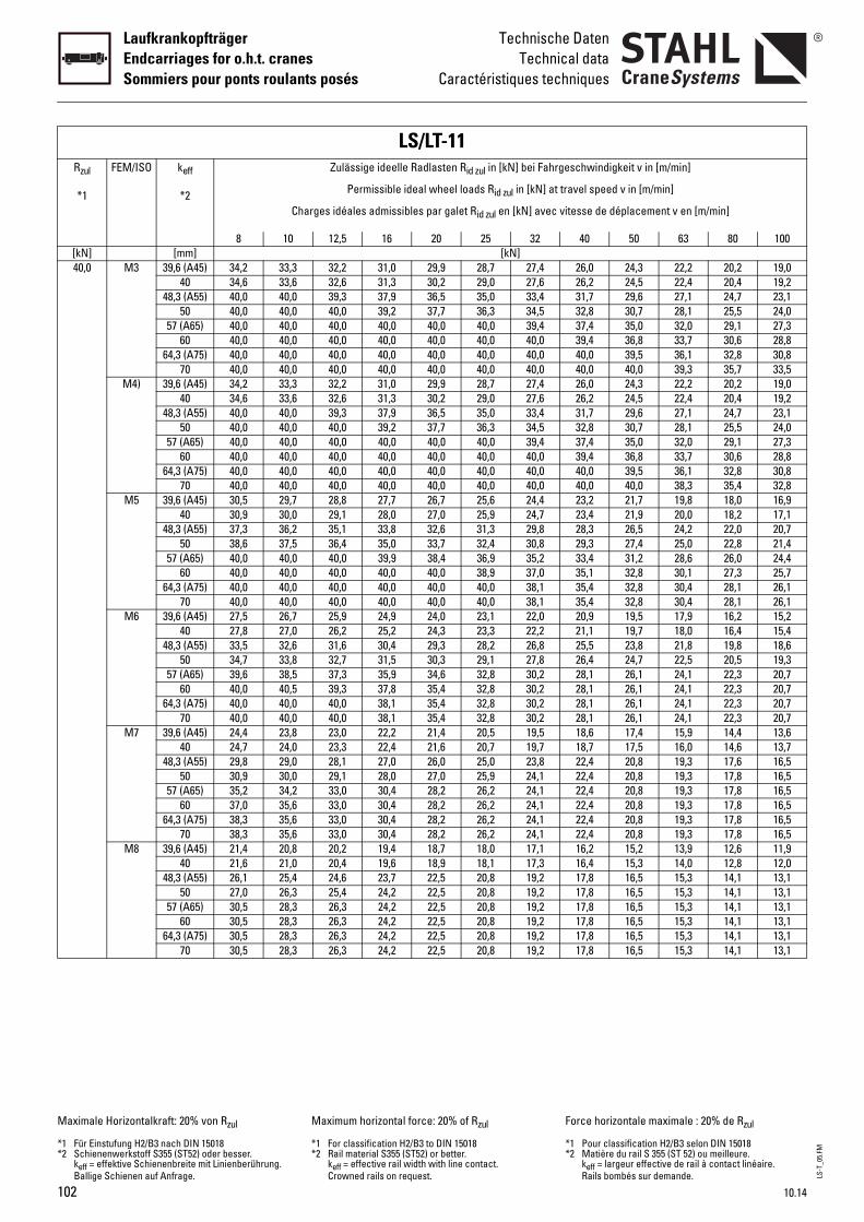
LS-T
_05.
FM
102
LaufkrankopfträgerEndcarriages for o.h.t. cranesSommiers pour ponts roulants posés
Technische DatenTechnical data
Caractéristiques techniques
Rzul
*1
FEM/ISO keff
*2 eel loads Rid zul in [kN] at travel speed
galet Rid zul en [kN] avec vitesse de déplacement v en [m/min]
25 32 40 50 63 80 100[kN] [mm] [kN]40,0 M3 39,6 (A45) 34 9 28,7 27,4 26,0 24,3 22,2 20,2 19,0
40 34 2 29,0 27,6 26,2 24,5 22,4 20,4 19,248,3 (A55) 40 5 35,0 33,4 31,7 29,6 27,1 24,7 23,1
50 40 7 36,3 34,5 32,8 30,7 28,1 25,5 24,057 (A65) 40 0 40,0 39,4 37,4 35,0 32,0 29,1 27,3
60 40 0 40,0 40,0 39,4 36,8 33,7 30,6 28,864,3 (A75) 40 0 40,0 40,0 40,0 39,5 36,1 32,8 30,8
70 40 0 40,0 40,0 40,0 40,0 39,3 35,7 33,5M4) 39,6 (A45) 34 9 28,7 27,4 26,0 24,3 22,2 20,2 19,0
40 34 2 29,0 27,6 26,2 24,5 22,4 20,4 19,248,3 (A55) 40 5 35,0 33,4 31,7 29,6 27,1 24,7 23,1
50 40 7 36,3 34,5 32,8 30,7 28,1 25,5 24,057 (A65) 40 0 40,0 39,4 37,4 35,0 32,0 29,1 27,3
60 40 0 40,0 40,0 39,4 36,8 33,7 30,6 28,864,3 (A75) 40 0 40,0 40,0 40,0 39,5 36,1 32,8 30,8
70 40 0 40,0 40,0 40,0 40,0 38,3 35,4 32,8M5 39,6 (A45) 30 7 25,6 24,4 23,2 21,7 19,8 18,0 16,9
40 30 0 25,9 24,7 23,4 21,9 20,0 18,2 17,148,3 (A55) 37 6 31,3 29,8 28,3 26,5 24,2 22,0 20,7
50 38 7 32,4 30,8 29,3 27,4 25,0 22,8 21,457 (A65) 40 4 36,9 35,2 33,4 31,2 28,6 26,0 24,4
60 40 0 38,9 37,0 35,1 32,8 30,1 27,3 25,764,3 (A75) 40 0 40,0 38,1 35,4 32,8 30,4 28,1 26,1
70 40 0 40,0 38,1 35,4 32,8 30,4 28,1 26,1M6 39,6 (A45) 27 0 23,1 22,0 20,9 19,5 17,9 16,2 15,2
40 27 3 23,3 22,2 21,1 19,7 18,0 16,4 15,448,3 (A55) 33 3 28,2 26,8 25,5 23,8 21,8 19,8 18,6
50 34 3 29,1 27,8 26,4 24,7 22,5 20,5 19,357 (A65) 39 6 32,8 30,2 28,1 26,1 24,1 22,3 20,7
60 40 4 32,8 30,2 28,1 26,1 24,1 22,3 20,764,3 (A75) 40 4 32,8 30,2 28,1 26,1 24,1 22,3 20,7
70 40 4 32,8 30,2 28,1 26,1 24,1 22,3 20,7M7 39,6 (A45) 24 4 20,5 19,5 18,6 17,4 15,9 14,4 13,6
40 24 6 20,7 19,7 18,7 17,5 16,0 14,6 13,748,3 (A55) 29 0 25,0 23,8 22,4 20,8 19,3 17,6 16,5
50 30 0 25,9 24,1 22,4 20,8 19,3 17,8 16,557 (A65) 35 2 26,2 24,1 22,4 20,8 19,3 17,8 16,5
60 37 2 26,2 24,1 22,4 20,8 19,3 17,8 16,564,3 (A75) 38 2 26,2 24,1 22,4 20,8 19,3 17,8 16,5
70 38 2 26,2 24,1 22,4 20,8 19,3 17,8 16,5M8 39,6 (A45) 21 7 18,0 17,1 16,2 15,2 13,9 12,6 11,9
40 21 9 18,1 17,3 16,4 15,3 14,0 12,8 12,048,3 (A55) 26 5 20,8 19,2 17,8 16,5 15,3 14,1 13,1
50 27 5 20,8 19,2 17,8 16,5 15,3 14,1 13,157 (A65) 30 5 20,8 19,2 17,8 16,5 15,3 14,1 13,1
60 30 5 20,8 19,2 17,8 16,5 15,3 14,1 13,164,3 (A75) 30 5 20,8 19,2 17,8 16,5 15,3 14,1 13,1
70 30 5 20,8 19,2 17,8 16,5 15,3 14,1 13,1
Maximale Horizontalkraft: 20% von Rzul
*1 Für Einstufung H2/B3 nach DIN 15018*2 Schienenwerkstoff S355 (ST52) oder bes
keff = effektive Schienenbreite mit LinienBallige Schienen auf Anfrage.
0% of Rzul
IN 15018better. h line contact.
Force horizontale maximale : 20% de Rzul
*1 Pour classification H2/B3 selon DIN 15018*2 Matière du rail S 355 (ST 52) ou meilleure.
keff = largeur effective de rail à contact linéaire. Rails bombés sur demande.
LS/LTZulässige ideelle Radlas
Permissible ideal wh
Charges idéales admissibles par
8 10 12,5 16 20
,2 33,3 32,2 31,0 29,,6 33,6 32,6 31,3 30,,0 40,0 39,3 37,9 36,,0 40,0 40,0 39,2 37,,0 40,0 40,0 40,0 40,,0 40,0 40,0 40,0 40,,0 40,0 40,0 40,0 40,,0 40,0 40,0 40,0 40,,2 33,3 32,2 31,0 29,,6 33,6 32,6 31,3 30,,0 40,0 39,3 37,9 36,,0 40,0 40,0 39,2 37,,0 40,0 40,0 40,0 40,,0 40,0 40,0 40,0 40,,0 40,0 40,0 40,0 40,,0 40,0 40,0 40,0 40,,5 29,7 28,8 27,7 26,,9 30,0 29,1 28,0 27,,3 36,2 35,1 33,8 32,,6 37,5 36,4 35,0 33,,0 40,0 40,0 39,9 38,,0 40,0 40,0 40,0 40,,0 40,0 40,0 40,0 40,,0 40,0 40,0 40,0 40,,5 26,7 25,9 24,9 24,,8 27,0 26,2 25,2 24,,5 32,6 31,6 30,4 29,,7 33,8 32,7 31,5 30,,6 38,5 37,3 35,9 34,,0 40,5 39,3 37,8 35,,0 40,0 40,0 38,1 35,,0 40,0 40,0 38,1 35,,4 23,8 23,0 22,2 21,,7 24,0 23,3 22,4 21,,8 29,0 28,1 27,0 26,,9 30,0 29,1 28,0 27,,2 34,2 33,0 30,4 28,,0 35,6 33,0 30,4 28,,3 35,6 33,0 30,4 28,,3 35,6 33,0 30,4 28,,4 20,8 20,2 19,4 18,,6 21,0 20,4 19,6 18,,1 25,4 24,6 23,7 22,,0 26,3 25,4 24,2 22,,5 28,3 26,3 24,2 22,,5 28,3 26,3 24,2 22,,5 28,3 26,3 24,2 22,,5 28,3 26,3 24,2 22,
ser. berührung.
Maximum horizontal force: 2
*1 For classification H2/B3 to D*2 Rail material S355 (ST52) or
keff = effective rail width witCrowned rails on request.
-11ten Rid zul in [kN] bei Fahrgeschwindigkei
t v in [m/min]v in [m/min]
10.14
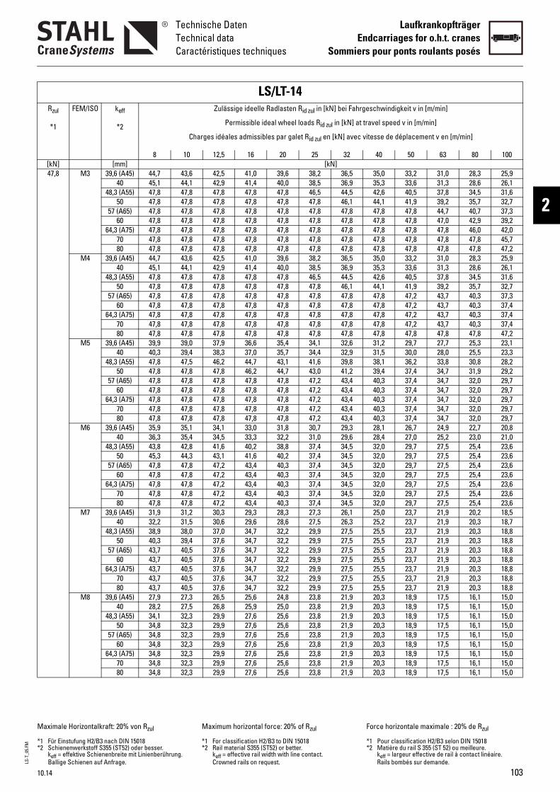
LS-T
_05.
FM
10.14
Technische DatenTechnical dataCaractéristiques techniques
LaufkrankopfträgerEndcarriages for o.h.t. cranes
Sommiers pour ponts roulants posés
2
Rzul
*1
FEM/ISO keff
*2 eel loads Rid zul in [kN] at travel speed
galet Rid zul en [kN] avec vitesse de déplacement v en [m/min]
25 32 40 50 63 80 100[kN] [mm] [kN]47,8 M3 39,6 (A45) 44 6 38,2 36,5 35,0 33,2 31,0 28,3 25,9
40 45 0 38,5 36,9 35,3 33,6 31,3 28,6 26,148,3 (A55) 47 8 46,5 44,5 42,6 40,5 37,8 34,5 31,6
50 47 8 47,8 46,1 44,1 41,9 39,2 35,7 32,757 (A65) 47 8 47,8 47,8 47,8 47,8 44,7 40,7 37,3
60 47 8 47,8 47,8 47,8 47,8 47,0 42,9 39,264,3 (A75) 47 8 47,8 47,8 47,8 47,8 47,8 46,0 42,0
70 47 8 47,8 47,8 47,8 47,8 47,8 47,8 45,780 47 8 47,8 47,8 47,8 47,8 47,8 47,8 47,2
M4 39,6 (A45) 44 6 38,2 36,5 35,0 33,2 31,0 28,3 25,940 45 0 38,5 36,9 35,3 33,6 31,3 28,6 26,1
48,3 (A55) 47 8 46,5 44,5 42,6 40,5 37,8 34,5 31,650 47 8 47,8 46,1 44,1 41,9 39,2 35,7 32,7
57 (A65) 47 8 47,8 47,8 47,8 47,2 43,7 40,3 37,360 47 8 47,8 47,8 47,8 47,2 43,7 40,3 37,4
64,3 (A75) 47 8 47,8 47,8 47,8 47,2 43,7 40,3 37,470 47 8 47,8 47,8 47,8 47,2 43,7 40,3 37,480 47 8 47,8 47,8 47,8 47,8 47,8 47,8 47,2
M5 39,6 (A45) 39 4 34,1 32,6 31,2 29,7 27,7 25,3 23,140 40 7 34,4 32,9 31,5 30,0 28,0 25,5 23,3
48,3 (A55) 47 1 41,6 39,8 38,1 36,2 33,8 30,8 28,250 47 7 43,0 41,2 39,4 37,4 34,7 31,9 29,2
57 (A65) 47 8 47,2 43,4 40,3 37,4 34,7 32,0 29,760 47 8 47,2 43,4 40,3 37,4 34,7 32,0 29,7
64,3 (A75) 47 8 47,2 43,4 40,3 37,4 34,7 32,0 29,770 47 8 47,2 43,4 40,3 37,4 34,7 32,0 29,780 47 8 47,2 43,4 40,3 37,4 34,7 32,0 29,7
M6 39,6 (A45) 35 8 30,7 29,3 28,1 26,7 24,9 22,7 20,840 36 2 31,0 29,6 28,4 27,0 25,2 23,0 21,0
48,3 (A55) 43 8 37,4 34,5 32,0 29,7 27,5 25,4 23,650 45 2 37,4 34,5 32,0 29,7 27,5 25,4 23,6
57 (A65) 47 3 37,4 34,5 32,0 29,7 27,5 25,4 23,660 47 3 37,4 34,5 32,0 29,7 27,5 25,4 23,6
64,3 (A75) 47 3 37,4 34,5 32,0 29,7 27,5 25,4 23,670 47 3 37,4 34,5 32,0 29,7 27,5 25,4 23,680 47 3 37,4 34,5 32,0 29,7 27,5 25,4 23,6
M7 39,6 (A45) 31 3 27,3 26,1 25,0 23,7 21,9 20,2 18,540 32 6 27,5 26,3 25,2 23,7 21,9 20,3 18,7
48,3 (A55) 38 2 29,9 27,5 25,5 23,7 21,9 20,3 18,850 40 2 29,9 27,5 25,5 23,7 21,9 20,3 18,8
57 (A65) 43 2 29,9 27,5 25,5 23,7 21,9 20,3 18,860 43 2 29,9 27,5 25,5 23,7 21,9 20,3 18,8
64,3 (A75) 43 2 29,9 27,5 25,5 23,7 21,9 20,3 18,870 43 2 29,9 27,5 25,5 23,7 21,9 20,3 18,880 43 2 29,9 27,5 25,5 23,7 21,9 20,3 18,8
M8 39,6 (A45) 27 8 23,8 21,9 20,3 18,9 17,5 16,1 15,040 28 0 23,8 21,9 20,3 18,9 17,5 16,1 15,0
48,3 (A55) 34 6 23,8 21,9 20,3 18,9 17,5 16,1 15,050 34 6 23,8 21,9 20,3 18,9 17,5 16,1 15,0
57 (A65) 34 6 23,8 21,9 20,3 18,9 17,5 16,1 15,060 34 6 23,8 21,9 20,3 18,9 17,5 16,1 15,0
64,3 (A75) 34 6 23,8 21,9 20,3 18,9 17,5 16,1 15,070 34 6 23,8 21,9 20,3 18,9 17,5 16,1 15,080 34 6 23,8 21,9 20,3 18,9 17,5 16,1 15,0
Maximale Horizontalkraft: 20% von Rzul
*1 Für Einstufung H2/B3 nach DIN 15018*2 Schienenwerkstoff S355 (ST52) oder bes
keff = effektive Schienenbreite mit LinienBallige Schienen auf Anfrage.
0% of Rzul
IN 15018better. h line contact.
Force horizontale maximale : 20% de Rzul
*1 Pour classification H2/B3 selon DIN 15018*2 Matière du rail S 355 (ST 52) ou meilleure.
keff = largeur effective de rail à contact linéaire. Rails bombés sur demande.
LS/LTZulässige ideelle Radlas
Permissible ideal wh
Charges idéales admissibles par
8 10 12,5 16 20
,7 43,6 42,5 41,0 39,,1 44,1 42,9 41,4 40,,8 47,8 47,8 47,8 47,,8 47,8 47,8 47,8 47,,8 47,8 47,8 47,8 47,,8 47,8 47,8 47,8 47,,8 47,8 47,8 47,8 47,,8 47,8 47,8 47,8 47,,8 47,8 47,8 47,8 47,,7 43,6 42,5 41,0 39,,1 44,1 42,9 41,4 40,,8 47,8 47,8 47,8 47,,8 47,8 47,8 47,8 47,,8 47,8 47,8 47,8 47,,8 47,8 47,8 47,8 47,,8 47,8 47,8 47,8 47,,8 47,8 47,8 47,8 47,,8 47,8 47,8 47,8 47,,9 39,0 37,9 36,6 35,,3 39,4 38,3 37,0 35,,8 47,5 46,2 44,7 43,,8 47,8 47,8 46,2 44,,8 47,8 47,8 47,8 47,,8 47,8 47,8 47,8 47,,8 47,8 47,8 47,8 47,,8 47,8 47,8 47,8 47,,8 47,8 47,8 47,8 47,,9 35,1 34,1 33,0 31,,3 35,4 34,5 33,3 32,,8 42,8 41,6 40,2 38,,3 44,3 43,1 41,6 40,,8 47,8 47,2 43,4 40,,8 47,8 47,2 43,4 40,,8 47,8 47,2 43,4 40,,8 47,8 47,2 43,4 40,,8 47,8 47,2 43,4 40,,9 31,2 30,3 29,3 28,,2 31,5 30,6 29,6 28,,9 38,0 37,0 34,7 32,,3 39,4 37,6 34,7 32,,7 40,5 37,6 34,7 32,,7 40,5 37,6 34,7 32,,7 40,5 37,6 34,7 32,,7 40,5 37,6 34,7 32,,7 40,5 37,6 34,7 32,,9 27,3 26,5 25,6 24,,2 27,5 26,8 25,9 25,,1 32,3 29,9 27,6 25,,8 32,3 29,9 27,6 25,,8 32,3 29,9 27,6 25,,8 32,3 29,9 27,6 25,,8 32,3 29,9 27,6 25,,8 32,3 29,9 27,6 25,,8 32,3 29,9 27,6 25,
ser. berührung.
Maximum horizontal force: 2
*1 For classification H2/B3 to D*2 Rail material S355 (ST52) or
keff = effective rail width witCrowned rails on request.
-14ten Rid zul in [kN] bei Fahrgeschwindigkei
t v in [m/min]v in [m/min]
103
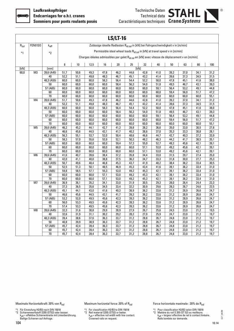
LS-T
_05.
FM
104
LaufkrankopfträgerEndcarriages for o.h.t. cranesSommiers pour ponts roulants posés
Technische DatenTechnical data
Caractéristiques techniques
Rzul
*1
FEM/ISO keff
*2 eel loads Rid zul in [kN] at travel speed
galet Rid zul en [kN] avec vitesse de déplacement v en [m/min]
25 32 40 50 63 80 100[kN] [mm] [kN]60,0 M3 39,6 (A45) 51 2 44,6 42,8 41,0 39,2 37,0 34,1 31,2
40 52 7 45,1 43,2 41,4 39,6 37,3 34,5 31,548,3 (A55) 60 4 54,4 52,2 50,0 47,8 45,1 41,6 38,0
50 60 4 56,3 54,0 51,8 49,5 46,7 43,1 39,357 (A65) 60 0 60,0 60,0 59,1 56,4 53,2 49,1 44,8
60 60 0 60,0 60,0 60,0 59,4 56,0 51,7 47,270 60 0 60,0 60,0 60,0 60,0 60,0 60,0 55,1
M4 39,6 (A45) 51 2 44,6 42,8 41,0 39,2 37,0 34,1 31,240 52 7 45,1 43,2 41,4 39,6 37,3 34,5 31,5
48,3 (A55) 60 4 54,4 52,2 50,0 47,8 45,1 41,6 38,050 60 4 56,3 54,0 51,8 49,5 46,7 43,1 39,3
57 (A65) 60 0 60,0 60,0 59,1 56,4 53,2 49,1 44,860 60 0 60,0 60,0 60,0 59,4 56,0 51,7 47,270 60 0 60,0 60,0 60,0 60,0 60,0 60,0 55,1
M5 39,6 (A45) 46 3 39,8 38,2 36,6 35,0 33,0 30,5 27,840 46 7 40,2 38,6 37,0 35,3 33,3 30,8 28,1
48,3 (A55) 56 4 48,6 46,6 44,7 42,7 40,3 37,2 33,950 58 1 50,3 48,2 46,3 44,2 41,7 38,5 35,1
57 (A65) 60 4 57,3 55,0 52,7 49,2 45,6 42,1 39,160 60 0 60,0 57,1 53,0 49,2 45,6 42,1 39,170 60 0 60,0 57,1 53,0 49,2 45,6 42,1 39,1
M6 39,6 (A45) 41 2 35,8 34,4 33,0 31,5 29,7 27,4 25,040 42 5 36,2 34,7 33,3 31,8 30,0 27,7 25,3
48,3 (A55) 50 3 43,7 41,9 40,2 38,4 36,2 33,4 30,550 52 9 45,3 43,4 41,6 39,1 36,2 33,4 31,0
57 (A65) 59 0 49,2 45,3 42,1 39,1 36,2 33,4 31,060 60 0 49,2 45,3 42,1 39,1 36,2 33,4 31,070 60 0 49,2 45,3 42,1 39,1 36,2 33,4 31,0
M7 39,6 (A45) 36 0 31,9 30,5 29,3 28,0 26,4 24,4 22,340 37 4 32,2 30,9 29,6 28,3 26,7 24,6 22,5
48,3 (A55) 45 3 38,9 36,2 33,6 31,2 28,9 26,6 24,750 46 7 39,3 36,2 33,6 31,2 28,9 26,6 24,7
57 (A65) 53 3 39,3 36,2 33,6 31,2 28,9 26,6 24,760 56 3 39,3 36,2 33,6 31,2 28,9 26,6 24,770 57 3 39,3 36,2 33,6 31,2 28,9 26,6 24,7
M8 39,6 (A45) 32 9 27,9 26,7 25,6 24,5 23,0 21,2 19,540 32 2 28,2 27,0 25,9 24,7 23,0 21,2 19,7
48,3 (A55) 39 7 31,2 28,8 26,7 24,8 23,0 21,2 19,750 40 7 31,2 28,8 26,7 24,8 23,0 21,2 19,7
57 (A65) 45 7 31,2 28,8 26,7 24,8 23,0 21,2 19,760 45 7 31,2 28,8 26,7 24,8 23,0 21,2 19,770 45 7 31,2 28,8 26,7 24,8 23,0 21,2 19,7
Maximale Horizontalkraft: 20% von Rzul
*1 Für Einstufung H2/B3 nach DIN 15018*2 Schienenwerkstoff S355 (ST52) oder bes
keff = effektive Schienenbreite mit LinienBallige Schienen auf Anfrage.
0% of Rzul
IN 15018better. h line contact.
Force horizontale maximale : 20% de Rzul
*1 Pour classification H2/B3 selon DIN 15018*2 Matière du rail S 355 (ST 52) ou meilleure.
keff = largeur effective de rail à contact linéaire. Rails bombés sur demande.
LS/LTZulässige ideelle Radlas
Permissible ideal wh
Charges idéales admissibles par
8 10 12,5 16 20
,7 50,6 49,3 47,8 46,,2 51,1 49,8 48,3 46,,0 60,0 60,0 58,3 56,,0 60,0 60,0 60,0 58,,0 60,0 60,0 60,0 60,,0 60,0 60,0 60,0 60,,0 60,0 60,0 60,0 60,,7 50,6 49,3 47,8 46,,2 51,1 49,8 48,3 46,,0 60,0 60,0 58,3 56,,0 60,0 60,0 60,0 58,,0 60,0 60,0 60,0 60,,0 60,0 60,0 60,0 60,,0 60,0 60,0 60,0 60,,2 45,2 44,1 42,7 41,,6 45,6 44,5 43,1 41,,3 55,1 53,7 52,0 50,,3 57,0 55,6 53,9 52,,0 60,0 60,0 60,0 59,,0 60,0 60,0 60,0 60,,0 60,0 60,0 60,0 60,,6 40,7 39,6 38,4 37,,0 41,1 40,0 38,8 37,,7 49,6 48,4 46,8 45,,5 51,3 50,1 48,5 46,,8 58,5 57,1 55,3 53,,0 60,0 60,0 57,1 53,,0 60,0 60,0 57,1 53,,9 36,1 35,2 34,1 33,,3 36,5 35,6 34,5 33,,1 44,1 43,0 41,6 40,,6 45,6 44,5 43,1 41,,2 52,0 49,5 45,6 42,,0 53,3 49,5 45,6 42,,4 53,3 49,5 45,6 42,,3 31,6 30,8 29,9 28,,6 31,9 31,1 30,2 29,,4 38,6 37,6 36,3 33,,8 39,9 38,9 36,3 33,,7 42,4 39,4 36,3 33,,7 42,4 39,4 36,3 33,,7 42,4 39,4 36,3 33,
ser. berührung.
Maximum horizontal force: 2
*1 For classification H2/B3 to D*2 Rail material S355 (ST52) or
keff = effective rail width witCrowned rails on request.
-16ten Rid zul in [kN] bei Fahrgeschwindigkei
t v in [m/min]v in [m/min]
10.14
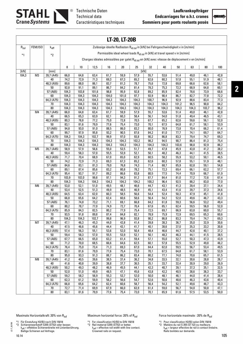
LS-T
_05.
FM
10.14
Technische DatenTechnical dataCaractéristiques techniques
LaufkrankopfträgerEndcarriages for o.h.t. cranes
Sommiers pour ponts roulants posés
2
Rzul
*1
FEM/ISO keff
*2 eel loads Rid zul in [kN] at travel speed
galet Rid zul en [kN] avec vitesse de déplacement v en [m/min]
25 32 40 50 63 80 100[kN] [mm] [kN]104,3 M3 39,7 (A45) 66 9 57,9 55,7 53,6 51,4 49,0 46,1 42,8
40 74 3 65,2 62,6 60,3 57,8 55,1 51,9 48,148,3 (A55) 89 3 78,7 75,6 72,8 69,8 66,6 62,6 58,1
50 92 2 81,4 78,3 75,3 72,3 68,9 64,8 60,157 (A65) 10 9 92,8 89,2 85,9 82,4 78,6 73,9 68,6
60 10 ,0 97,7 93,9 90,4 86,7 82,7 77,8 72,264,3 (A75) 10 ,3 104,3 100,7 96,9 92,9 88,6 83,4 77,3
70 10 ,3 104,3 104,3 104,3 101,2 96,5 90,8 84,280 10 ,3 104,3 104,3 104,3 104,3 104,3 103,7 96,2
M4 39,7 (A45) 66 9 57,9 55,7 53,6 51,4 49,0 46,1 42,840 66 3 58,4 56,1 54,0 51,8 49,4 46,5 43,1
48,3 (A55) 80 8 70,5 67,7 65,2 62,6 59,6 56,1 52,050 83 4 73,0 70,1 67,5 64,8 61,7 58,1 53,9
57 (A65) 94 0 83,2 80,0 76,9 73,8 70,4 66,2 61,460 99 5 87,6 84,2 81,0 77,7 74,1 69,7 64,7
64,3 (A75) 10 0 93,8 90,2 86,8 83,3 79,4 74,7 69,370 10 ,3 102,2 98,2 94,5 90,7 86,4 81,3 75,480 10 ,3 104,3 104,3 104,3 103,6 98,8 92,9 86,2
M5 39,7 (A45) 58 5 51,7 49,7 47,8 45,9 43,8 41,2 38,240 59 9 52,1 50,1 48,2 46,3 44,1 41,5 38,5
48,3 (A55) 71 0 62,9 60,5 58,2 55,9 53,2 50,1 46,550 74 3 65,2 62,6 60,3 57,8 55,1 51,9 48,1
57 (A65) 84 8 74,3 71,4 68,7 65,9 62,8 59,1 54,860 89 8 78,2 75,1 72,3 69,4 66,1 62,2 57,7
64,3 (A75) 95 6 83,8 80,5 77,5 74,4 70,9 66,7 61,970 10 3 91,2 87,7 84,4 81,0 77,2 72,6 67,480 10 ,3 104,2 100,2 96,4 92,5 88,2 83,0 77,0
M6 39,7 (A45) 53 1 46,6 44,7 43,1 41,3 39,4 37,1 34,440 53 5 46,9 45,1 43,4 41,6 39,7 37,3 34,6
48,3 (A55) 64 5 56,6 54,4 52,4 50,3 47,9 45,1 41,850 66 6 58,6 56,4 54,2 52,0 49,6 46,7 43,3
57 (A65) 76 1 66,8 64,2 61,8 59,3 56,6 53,2 49,460 80 7 70,4 67,6 65,1 62,4 59,5 56,0 52,0
64,3 (A75) 85 9 75,4 72,5 69,7 66,9 63,8 60,0 55,770 93 8 82,1 78,9 75,9 72,9 69,5 65,3 60,680 10 9 93,8 90,2 86,8 83,3 79,4 74,7 69,3
M7 39,7 (A45) 47 8 41,4 39,8 38,3 36,7 35,0 32,9 30,640 47 1 41,7 40,1 38,6 37,0 35,3 33,2 30,8
48,3 (A55) 57 0 50,4 48,4 46,6 44,7 42,6 40,1 37,250 59 9 52,1 50,1 48,2 46,3 44,1 41,5 38,5
57 (A65) 67 4 59,4 57,1 55,0 52,7 50,3 47,3 43,960 71 6 62,5 60,1 57,8 55,5 52,9 49,8 46,2
64,3 (A75) 76 3 67,0 64,4 62,0 59,5 56,7 53,4 49,570 83 4 73,0 70,1 67,5 64,8 61,7 58,1 53,980 95 2 83,4 80,2 77,1 74,0 70,6 65,7 61,5
M8 39,7 (A45) 41 4 36,2 34,8 33,5 32,1 30,6 28,8 26,740 41 7 36,5 35,1 33,7 32,4 30,9 29,0 26,9
48,3 (A55) 50 5 44,1 42,3 40,7 39,1 37,3 35,1 32,550 52 1 45,6 43,8 42,2 40,5 38,6 36,3 33,7
57 (A65) 59 7 52,0 50,0 48,1 46,1 44,0 41,4 38,460 62 6 54,7 52,6 50,6 48,6 46,3 43,6 40,4
64,3 (A75) 66 6 58,7 56,4 54,2 52,1 49,6 46,7 43,370 72 0 63,9 61,4 59,0 56,7 54,0 50,8 47,180 83 4 73,0 70,1 65,9 61,6 57,5 53,5 50,0
Maximale Horizontalkraft: 20% von Rzul
*1 Für Einstufung H2/B3 nach DIN 15018*2 Schienenwerkstoff S355 (ST52) oder bes
keff = effektive Schienenbreite mit LinienBallige Schienen auf Anfrage.
LT-20, LTZulässige ideelle Radlas
Permissible ideal wh
Charges idéales admissibles par
8 10 12,5 16 20
,0 64,8 63,4 61,7 59,,2 72,9 71,3 69,3 67,,6 88,0 86,1 83,7 81,,8 91,1 89,1 86,7 84,
4,3 103,8 101,6 98,8 95,4,3 104,3 104,3 104,0 1014,3 104,3 104,3 104,3 1044,3 104,3 104,3 104,3 1044,3 104,3 104,3 104,3 104,0 64,8 63,4 61,7 59,,5 65,3 63,9 62,1 60,,3 78,8 77,2 75,0 72,,1 81,6 79,9 77,6 75,,8 93,0 91,0 88,5 86,,7 97,9 95,8 93,2 90,
4,3 104,3 102,7 99,9 97,4,3 104,3 104,3 104,3 1044,3 104,3 104,3 104,3 104,9 57,9 56,6 55,0 53,,4 58,3 57,0 55,5 53,,7 70,4 68,9 67,0 65,,2 72,9 71,3 69,3 67,,6 83,1 81,3 79,0 76,,1 87,4 85,6 83,2 80,,4 93,7 91,7 89,2 86,
3,9 102,0 99,8 97,1 94,4,3 104,3 104,3 104,3 104,0 52,1 51,0 49,5 48,,4 52,5 51,3 49,9 48,,5 63,4 62,0 60,3 58,,8 65,6 64,2 62,4 60,,1 74,8 73,2 71,1 69,,2 78,7 77,0 74,9 72,,9 84,3 82,5 80,2 77,,5 91,8 89,8 87,4 84,
4,3 104,3 102,7 99,8 96,,1 46,3 45,3 44,0 42,,5 46,6 45,6 44,4 43,,4 56,3 55,1 53,6 52,,4 58,3 57,0 55,5 53,,7 66,5 65,0 63,2 61,,2 70,0 68,5 66,6 64,,4 75,0 73,4 71,3 69,,1 81,6 79,9 77,6 75,,0 93,3 91,3 88,7 86,,2 40,5 39,6 38,5 37,,6 40,8 39,9 38,8 37,,2 49,3 48,2 46,9 45,,0 51,0 49,9 48,5 47,,2 58,2 56,9 55,3 53,,3 61,2 59,9 58,2 56,,8 65,6 64,2 62,4 60,,7 71,4 69,9 67,9 66,,1 81,6 79,9 77,6 75,
ser. berührung.
Maximum horizontal forc
*1 For classification H2/B3 *2 Rail material S355 (ST52)
keff = effective rail widthCrowned rails on reques
-20Bten Rid zul in [kN] bei Fahrgeschwindigkei
e: 20% of Rzul
to DIN 15018 or better. with line contact. t.
Force horiz
*1 Pour clas*2 Matière
keff = largRails bom
t v in [m/min]
v in [m/min]
105
ontale maximale : 20% de Rzul
sification H2/B3 selon DIN 15018du rail S 355 (ST 52) ou meilleure.eur effective de rail à contact linéaire. bés sur demande.

106
LaufkrankopfträgerEndcarriages for o.h.t. cranesSommiers pour ponts roulants posés
Technische DatenTechnical data
Caractéristiques techniques
Rzul
*1
FEM/ISO keff
*2 eel loads Rid zul in [kN] at travel speed
galet Rid zul en [kN] avec vitesse de déplacement v en [m/min]
25 32 40 50 63 80 100[kN] [mm] [kN]160,9 M3 39,7 (A45) 83 1 74,8 72,2 69,6 67,0 64,2 61,1 57,6
40 94 7 84,2 81,1 78,3 75,3 72,2 68,7 64,848,3 (A55) 11 ,6 101,6 98,0 94,5 90,9 87,1 82,9 78,3
50 11 ,3 105,2 101,4 97,8 94,1 90,2 85,8 81,057 (A65) 13 ,5 119,9 115,6 111,5 107,3 102,8 97,8 92,4
60 14 ,0 126,2 121,7 117,4 113,0 108,2 103,0 97,264,3 (A75) 15 ,3 135,3 130,4 125,8 121,1 116,0 110,4 104,2
70 16 ,7 147,3 142,0 137,0 131,8 126,3 120,2 113,480 16 ,9 160,9 160,9 156,5 150,6 144,3 137,3 129,790 16 ,9 160,9 160,9 160,9 160,9 160,9 154,5 145,9
M4 39,7 (A45) 83 1 74,8 72,2 69,6 67,0 64,2 61,1 57,640 84 6 75,4 72,7 70,1 67,5 64,7 61,5 58,1
48,3 (A55) 10 8 91,1 87,8 84,7 81,5 78,1 74,3 70,150 10 1 94,3 90,9 87,7 84,4 80,8 76,9 72,6
57 (A65) 12 ,6 107,5 103,6 99,9 96,2 92,1 87,7 82,860 12 ,5 113,1 109,1 105,2 101,2 97,0 92,3 87,1
64,3 (A75) 13 ,8 121,2 116,9 112,7 108,5 103,9 98,9 93,470 14 ,9 132,0 127,2 122,7 118,1 113,2 107,7 101,680 16 ,3 150,8 145,4 140,3 135,0 129,3 123,0 116,290 16 ,9 160,9 160,9 157,8 151,8 145,5 138,4 130,7
M5 39,7 (A45) 74 8 66,8 64,4 62,1 59,8 57,3 54,5 51,540 75 3 67,3 64,9 62,6 60,3 57,7 54,9 51,9
48,3 (A55) 91 7 81,3 78,4 75,6 72,8 69,7 66,3 62,650 94 7 84,2 81,1 78,3 75,3 72,2 68,7 64,8
57 (A65) 10 8 95,9 92,5 89,2 85,9 82,3 78,3 73,960 11 ,0 101,0 97,4 93,9 90,4 86,6 82,4 77,8
64,3 (A75) 12 ,4 108,2 104,4 100,7 96,9 92,8 88,3 83,470 13 ,3 117,8 113,6 109,6 105,4 101,0 96,1 90,880 15 ,7 134,7 129,8 125,2 120,5 115,5 109,9 103,790 16 ,0 151,5 146,1 140,9 135,6 128,6 119,7 111,9
M6 39,7 (A45) 67 9 60,1 58,0 55,9 53,8 51,6 49,1 46,340 67 4 60,6 58,4 56,4 54,2 52,0 49,4 46,7
48,3 (A55) 81 3 73,2 70,5 68,1 65,5 62,7 59,7 56,450 84 0 75,7 73,0 70,4 67,8 64,9 61,8 58,3
57 (A65) 96 9 86,3 83,3 80,3 77,3 74,0 70,4 66,560 10 6 90,9 87,6 84,5 81,3 77,9 74,2 70,0
64,3 (A75) 10 ,3 97,4 93,9 90,6 87,2 83,5 79,5 75,070 11 ,2 106,0 102,2 98,6 94,9 90,9 86,5 81,780 13 ,8 121,2 116,9 112,7 108,5 103,9 97,2 90,990 15 ,4 136,3 128,0 119,7 111,9 104,4 97,2 90,9
M7 39,7 (A45) 59 0 53,5 51,5 49,7 47,8 45,8 43,6 41,240 60 5 53,9 51,9 50,1 48,2 46,2 43,9 41,5
48,3 (A55) 72 0 65,0 62,7 60,5 58,2 55,8 53,1 50,150 75 3 67,3 64,9 62,6 60,3 57,7 54,9 51,9
57 (A65) 85 0 76,8 74,0 71,4 68,7 65,8 62,6 59,160 90 2 80,8 77,9 75,1 72,3 69,3 65,9 62,2
64,3 (A75) 96 2 86,6 83,5 80,5 77,5 74,2 70,6 66,770 10 1 94,3 90,9 87,7 84,4 80,8 76,9 72,680 12 ,9 107,7 103,9 97,7 91,3 85,2 79,3 74,290 13 ,2 112,4 104,4 97,7 91,3 85,2 79,3 74,2
Maximale Horizontalkraft: 20% von Rzul
*1 Für Einstufung H2/B3 nach DIN 15018*2 Schienenwerkstoff S355 (ST52) oder bes
keff = effektive Schienenbreite mit LinienBallige Schienen auf Anfrage.
LT-25, LTZulässige ideelle Radlas
Permissible ideal wh
Charges idéales admissibles par
8 10 12,5 16 20
,8 82,5 81,0 79,1 77,,2 92,8 91,1 88,9 86,
3,7 112,0 110,0 107,4 1047,7 116,0 113,9 111,1 1084,2 132,2 129,8 126,7 1231,3 139,2 136,6 133,4 1301,4 149,1 146,4 142,9 1390,9 160,9 159,4 155,6 1510,9 160,9 160,9 160,9 1600,9 160,9 160,9 160,9 160,8 82,5 81,0 79,1 77,,4 83,1 81,6 79,7 77,
1,9 100,4 98,5 96,2 93,5,5 103,9 102,0 99,6 97,0,3 118,4 116,3 113,5 1106,6 124,7 122,4 119,5 1165,7 133,6 131,2 128,1 1247,7 145,5 142,8 139,4 1350,9 160,9 160,9 159,3 1550,9 160,9 160,9 160,9 160,8 73,7 72,3 70,6 68,,4 74,2 72,9 71,1 69,,0 89,6 88,0 85,9 83,,2 92,8 91,1 88,9 86,
7,4 105,8 103,8 101,4 98,3,0 111,3 109,3 106,7 1041,1 119,3 117,1 114,3 1111,9 129,9 127,5 124,5 1210,7 148,4 145,7 142,3 1380,9 160,9 160,9 160,0 156,3 66,3 65,1 63,5 61,,8 66,8 65,6 64,0 62,,9 80,7 79,2 77,3 75,,8 83,5 82,0 80,0 78,,6 95,2 93,5 91,2 88,
1,7 100,2 98,4 96,0 93,9,0 107,4 105,4 102,9 1008,7 116,9 114,8 112,0 1095,6 133,6 131,2 128,0 1242,6 150,3 147,6 144,0 140,8 58,9 57,9 56,5 55,,3 59,4 58,3 56,9 55,,8 71,7 70,4 68,7 67,,4 74,2 72,9 71,1 69,,9 84,6 83,1 81,1 79,,4 89,1 87,4 85,4 83,,9 95,4 93,7 91,5 89,
5,5 103,9 102,0 99,6 97,0,6 118,7 116,6 113,8 1105,6 133,6 131,2 128,0 120
ser. berührung.
Maximum horizontal forc
*1 For classification H2/B3 *2 Rail material S355 (ST52)
keff = effective rail widthCrowned rails on reques
-25Bten Rid zul in [kN] bei Fahrgeschwindigkei
e: 20% of Rzul
to DIN 15018 or better. with line contact. t.
Force horiz
*1 Pour clas*2 Matière
keff = largRails bom
t v in [m/min]
v in [m/min]
LS-T
_05.
FM
10.14
ontale maximale : 20% de Rzul
sification H2/B3 selon DIN 15018du rail S 355 (ST 52) ou meilleure.eur effective de rail à contact linéaire. bés sur demande.
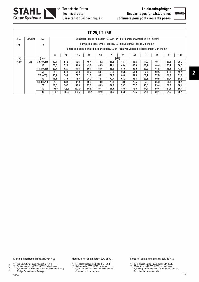
LS-T
_05.
FM
10.14
Technische DatenTechnical dataCaractéristiques techniques
LaufkrankopfträgerEndcarriages for o.h.t. cranes
Sommiers pour ponts roulants posés
2
160,9 M8 39,7 (A45) 52 2 46,8 45,1 43,5 41,9 40,1 38,2 36,040 52 5 47,1 45,4 43,8 42,2 40,4 38,4 36,3
48,3 (A55) 63 6 56,9 54,9 52,9 50,9 48,8 46,4 43,850 65 7 58,9 56,8 54,8 52,7 50,5 48,1 45,4
57 (A65) 75 2 67,2 64,8 62,5 60,1 57,6 54,8 51,760 79 8 70,7 68,2 65,8 63,3 60,6 57,7 54,5
64,3 (A75) 84 0 75,8 73,0 70,5 67,8 65,0 61,8 58,470 92 9 82,5 79,5 76,7 73,8 69,4 64,6 60,480 10 1 91,6 85,0 79,5 74,4 69,4 64,6 60,490 11 9 91,6 85,0 79,5 74,4 69,4 64,6 60,4
Rzul
*1
FEM/ISO keff
*2 eel loads Rid zul in [kN] at travel speed
galet Rid zul en [kN] avec vitesse de déplacement v en [m/min]
25 32 40 50 63 80 100[kN] [mm] [kN]
Maximale Horizontalkraft: 20% von Rzul
*1 Für Einstufung H2/B3 nach DIN 15018*2 Schienenwerkstoff S355 (ST52) oder bes
keff = effektive Schienenbreite mit LinienBallige Schienen auf Anfrage.
0% of Rzul Force horizontale maximale : 20% de Rzul
,4 51,6 50,6 49,4 48,,8 52,0 51,0 49,8 48,,7 62,7 61,6 60,1 58,,9 64,9 63,8 62,2 60,,2 74,0 72,7 71,0 69,,1 77,9 76,5 74,7 72,,8 83,5 82,0 80,0 78,,3 90,9 89,3 87,1 84,
5,5 103,9 102,0 99,6 97,8,7 116,9 112,7 104,7 97,
LT-25, LTZulässige ideelle Radlas
Permissible ideal wh
Charges idéales admissibles par
8 10 12,5 16 20
Maximum horizontal force: 2
ser. berührung.
*1 For classification H2/B3 *2 Rail material S355 (ST52)
keff = effective rail widthCrowned rails on reques
-25Bten Rid zul in [kN] bei Fahrgeschwindigkei
to DIN 15018 or better. with line contact. t.
*1 Pour clas*2 Matière
keff = largRails bom
t v in [m/min]
v in [m/min]
107
sification H2/B3 selon DIN 15018du rail S 355 (ST 52) ou meilleure.eur effective de rail à contact linéaire. bés sur demande.
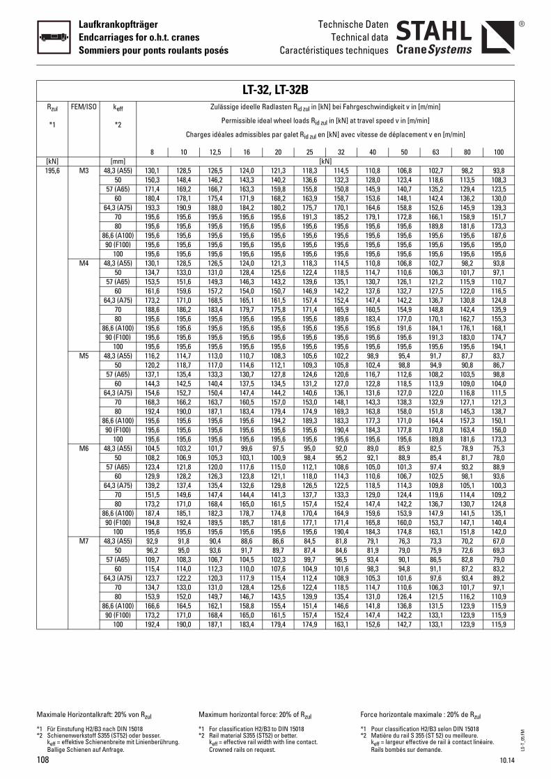
108
LaufkrankopfträgerEndcarriages for o.h.t. cranesSommiers pour ponts roulants posés
Technische DatenTechnical data
Caractéristiques techniques
Rzul
*1
FEM/ISO keff
*2 eel loads Rid zul in [kN] at travel speed
galet Rid zul en [kN] avec vitesse de déplacement v en [m/min]
25 32 40 50 63 80 100[kN] [mm] [kN]195,6 M3 48,3 (A55) 13 ,3 118,3 114,5 110,8 106,8 102,7 98,2 93,8
50 15 ,2 136,6 132,3 128,0 123,4 118,6 113,5 108,357 (A65) 17 ,8 155,8 150,8 145,9 140,7 135,2 129,4 123,5
60 18 ,2 163,9 158,7 153,6 148,1 142,4 136,2 130,064,3 (A75) 19 ,2 175,7 170,1 164,6 158,8 152,6 145,9 139,3
70 19 ,6 191,3 185,2 179,1 172,8 166,1 158,9 151,780 19 ,6 195,6 195,6 195,6 195,6 189,8 181,6 173,3
86,6 (A100) 19 ,6 195,6 195,6 195,6 195,6 195,6 195,6 187,690 (F100) 19 ,6 195,6 195,6 195,6 195,6 195,6 195,6 195,0
100 19 ,6 195,6 195,6 195,6 195,6 195,6 195,6 195,6M4 48,3 (A55) 13 ,3 118,3 114,5 110,8 106,8 102,7 98,2 93,8
50 13 ,6 122,4 118,5 114,7 110,6 106,3 101,7 97,157 (A65) 15 ,2 139,6 135,1 130,7 126,1 121,2 115,9 110,7
60 16 ,7 146,9 142,2 137,6 132,7 127,5 122,0 116,564,3 (A75) 17 ,5 157,4 152,4 147,4 142,2 136,7 130,8 124,8
70 18 ,8 171,4 165,9 160,5 154,9 148,8 142,4 135,980 19 ,6 195,6 189,6 183,4 177,0 170,1 162,7 155,3
86,6 (A100) 19 ,6 195,6 195,6 195,6 191,6 184,1 176,1 168,190 (F100) 19 ,6 195,6 195,6 195,6 195,6 191,3 183,0 174,7
100 19 ,6 195,6 195,6 195,6 195,6 195,6 195,6 194,1M5 48,3 (A55) 11 ,3 105,6 102,2 98,9 95,4 91,7 87,7 83,7
50 12 ,1 109,3 105,8 102,4 98,8 94,9 90,8 86,757 (A65) 13 ,8 124,6 120,6 116,7 112,6 108,2 103,5 98,8
60 14 ,5 131,2 127,0 122,8 118,5 113,9 109,0 104,064,3 (A75) 15 ,2 140,6 136,1 131,6 127,0 122,0 116,8 111,5
70 16 ,0 153,0 148,1 143,3 138,3 132,9 127,1 121,380 19 ,4 174,9 169,3 163,8 158,0 151,8 145,3 138,7
86,6 (A100) 19 ,2 189,3 183,3 177,3 171,0 164,4 157,3 150,190 (F100) 19 ,6 195,6 190,4 184,3 177,8 170,8 163,4 156,0
100 19 ,6 195,6 195,6 195,6 195,6 189,8 181,6 173,3M6 48,3 (A55) 10 5 95,0 92,0 89,0 85,9 82,5 78,9 75,3
50 10 ,9 98,4 95,2 92,1 88,9 85,4 81,7 78,057 (A65) 12 ,0 112,1 108,6 105,0 101,3 97,4 93,2 88,9
60 12 ,1 118,0 114,3 110,6 106,7 102,5 98,1 93,664,3 (A75) 13 ,8 126,5 122,5 118,5 114,3 109,8 105,1 100,3
70 15 ,3 137,7 133,3 129,0 124,4 119,6 114,4 109,280 17 ,5 157,4 152,4 147,4 142,2 136,7 130,7 124,8
86,6 (A100) 18 ,8 170,4 164,9 159,6 153,9 147,9 141,5 135,190 (F100) 19 ,6 177,1 171,4 165,8 160,0 153,7 147,1 140,4
100 19 ,6 195,6 190,4 184,3 174,8 163,1 151,8 142,0M7 48,3 (A55) 92 6 84,5 81,8 79,1 76,3 73,3 70,2 67,0
50 96 7 87,4 84,6 81,9 79,0 75,9 72,6 69,357 (A65) 10 ,3 99,7 96,5 93,4 90,1 86,5 82,8 79,0
60 11 ,6 104,9 101,6 98,3 94,8 91,1 87,2 83,264,3 (A75) 12 ,4 112,4 108,9 105,3 101,6 97,6 93,4 89,2
70 13 ,6 122,4 118,5 114,7 110,6 106,3 101,7 97,180 15 ,5 139,9 135,4 131,0 126,4 121,5 116,2 110,9
86,6 (A100) 16 ,4 151,4 146,6 141,8 136,8 131,5 123,9 115,990 (F100) 17 ,5 157,4 152,4 147,4 142,2 133,1 123,9 115,9
100 19 ,4 174,9 163,1 152,6 142,7 133,1 123,9 115,9
Maximale Horizontalkraft: 20% von Rzul
*1 Für Einstufung H2/B3 nach DIN 15018*2 Schienenwerkstoff S355 (ST52) oder bes
keff = effektive Schienenbreite mit LinienBallige Schienen auf Anfrage.
LT-32, LTZulässige ideelle Radlas
Permissible ideal wh
Charges idéales admissibles par
8 10 12,5 16 20
0,1 128,5 126,5 124,0 1210,3 148,4 146,2 143,3 1401,4 169,2 166,7 163,3 1590,4 178,1 175,4 171,9 1683,3 190,9 188,0 184,2 1805,6 195,6 195,6 195,6 1955,6 195,6 195,6 195,6 1955,6 195,6 195,6 195,6 1955,6 195,6 195,6 195,6 1955,6 195,6 195,6 195,6 1950,1 128,5 126,5 124,0 1214,7 133,0 131,0 128,4 1253,5 151,6 149,3 146,3 1431,6 159,6 157,2 154,0 1503,2 171,0 168,5 165,1 1618,6 186,2 183,4 179,7 1755,6 195,6 195,6 195,6 1955,6 195,6 195,6 195,6 1955,6 195,6 195,6 195,6 1955,6 195,6 195,6 195,6 1956,2 114,7 113,0 110,7 1080,2 118,7 117,0 114,6 1127,1 135,4 133,3 130,7 1274,3 142,5 140,4 137,5 1344,6 152,7 150,4 147,4 1448,3 166,2 163,7 160,5 1572,4 190,0 187,1 183,4 1795,6 195,6 195,6 195,6 1945,6 195,6 195,6 195,6 1955,6 195,6 195,6 195,6 1954,5 103,2 101,7 99,6 97,8,2 106,9 105,3 103,1 1003,4 121,8 120,0 117,6 1159,9 128,2 126,3 123,8 1219,2 137,4 135,4 132,6 1291,5 149,6 147,4 144,4 1413,2 171,0 168,4 165,0 1617,4 185,1 182,3 178,7 1744,8 192,4 189,5 185,7 1815,6 195,6 195,6 195,6 195,9 91,8 90,4 88,6 86,,2 95,0 93,6 91,7 89,
9,7 108,3 106,7 104,5 1025,4 114,0 112,3 110,0 1073,7 122,2 120,3 117,9 1154,7 133,0 131,0 128,4 1253,9 152,0 149,7 146,7 1436,6 164,5 162,1 158,8 1553,2 171,0 168,4 165,0 1612,4 190,0 187,1 183,4 179
ser. berührung.
Maximum horizontal forc
*1 For classification H2/B3 *2 Rail material S355 (ST52)
keff = effective rail widthCrowned rails on reques
-32Bten Rid zul in [kN] bei Fahrgeschwindigkei
e: 20% of Rzul
to DIN 15018 or better. with line contact. t.
Force horiz
*1 Pour clas*2 Matière
keff = largRails bom
t v in [m/min]
v in [m/min]
LS-T
_05.
FM
10.14
ontale maximale : 20% de Rzul
sification H2/B3 selon DIN 15018du rail S 355 (ST 52) ou meilleure.eur effective de rail à contact linéaire. bés sur demande.
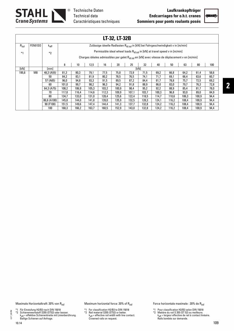
LS-T
_05.
FM
10.14
Technische DatenTechnical dataCaractéristiques techniques
LaufkrankopfträgerEndcarriages for o.h.t. cranes
Sommiers pour ponts roulants posés
2
195,6 M8 48,3 (A55) 81 8 73,9 71,5 69,2 66,8 64,2 61,4 58,650 84 5 76,5 74,1 71,7 69,1 66,4 63,6 60,7
57 (A65) 96 5 87,2 84,4 81,7 78,8 75,7 72,5 69,260 10 2 91,8 88,9 86,0 83,0 79,7 76,3 72,8
64,3 (A75) 10 ,9 98,4 95,2 92,2 88,9 85,4 81,7 78,070 11 ,9 107,1 103,7 100,3 96,8 93,0 89,0 84,980 13 ,6 122,4 118,5 114,7 110,6 106,3 100,9 94,4
86,6 (A100) 14 ,9 132,5 128,3 124,1 116,2 108,4 100,9 94,490 (F100) 15 ,3 137,7 132,8 124,2 116,2 108,4 100,9 94,4
100 16 ,9 143,0 132,8 124,2 116,2 108,4 100,9 94,4
Rzul
*1
FEM/ISO keff
*2 eel loads Rid zul in [kN] at travel speed
galet Rid zul en [kN] avec vitesse de déplacement v en [m/min]
25 32 40 50 63 80 100[kN] [mm] [kN]
Maximale Horizontalkraft: 20% von Rzul
*1 Für Einstufung H2/B3 nach DIN 15018*2 Schienenwerkstoff S355 (ST52) oder bes
keff = effektive Schienenbreite mit LinienBallige Schienen auf Anfrage.
,3 80,3 79,1 77,5 75,,2 83,1 81,9 80,2 78,,0 94,8 93,3 91,5 89,
1,0 99,7 98,2 96,3 94,8,2 106,9 105,3 103,2 1007,8 116,4 114,6 112,3 1094,7 133,0 131,0 128,4 1255,8 144,0 141,8 139,0 1351,5 149,6 147,4 144,4 1418,3 166,2 163,7 160,5 152
LT-32, LTZulässige ideelle Radlas
Permissible ideal wh
Charges idéales admissibles par
8 10 12,5 16 20
ser. berührung.
Maximum horizontal forc
*1 For classification H2/B3 *2 Rail material S355 (ST52)
keff = effective rail widthCrowned rails on reques
-32Bten Rid zul in [kN] bei Fahrgeschwindigkei
e: 20% of Rzul
to DIN 15018 or better. with line contact. t.
Force horiz
*1 Pour clas*2 Matière
keff = largRails bom
t v in [m/min]
v in [m/min]
109
ontale maximale : 20% de Rzul
sification H2/B3 selon DIN 15018du rail S 355 (ST 52) ou meilleure.eur effective de rail à contact linéaire. bés sur demande.
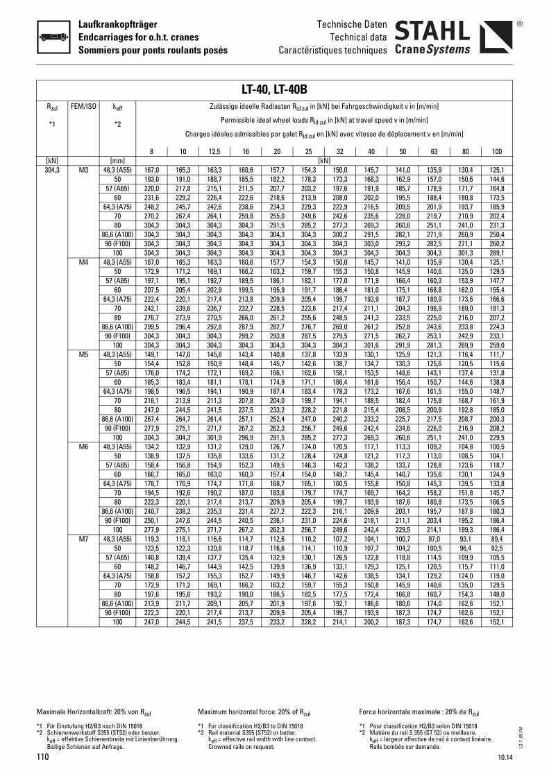
110
LaufkrankopfträgerEndcarriages for o.h.t. cranesSommiers pour ponts roulants posés
Technische DatenTechnical data
Caractéristiques techniques
Rzul
*1
FEM/ISO keff
*2 eel loads Rid zul in [kN] at travel speed
galet Rid zul en [kN] avec vitesse de déplacement v en [m/min]
25 32 40 50 63 80 100[kN] [mm] [kN]304,3 M3 48,3 (A55) 16 ,7 154,3 150,0 145,7 141,0 135,9 130,4 125,1
50 19 ,2 178,3 173,3 168,3 162,9 157,0 150,6 144,657 (A65) 22 ,7 203,2 197,6 191,9 185,7 178,9 171,7 164,8
60 23 ,6 213,9 208,0 202,0 195,5 188,4 180,8 173,564,3 (A75) 24 ,3 229,3 222,9 216,5 209,5 201,9 193,7 185,9
70 27 ,0 249,6 242,6 235,6 228,0 219,7 210,9 202,480 30 ,5 285,2 277,3 269,3 260,6 251,1 241,0 231,3
86,6 (A100) 30 ,3 304,3 300,2 291,5 282,1 271,9 260,9 250,490 (F100) 30 ,3 304,3 304,3 303,0 293,2 282,5 271,1 260,2
100 30 ,3 304,3 304,3 304,3 304,3 304,3 301,3 289,1M4 48,3 (A55) 16 ,7 154,3 150,0 145,7 141,0 135,9 130,4 125,1
50 17 ,2 159,7 155,3 150,8 145,9 140,6 135,0 129,557 (A65) 19 ,1 182,1 177,0 171,9 166,4 160,3 153,9 147,7
60 20 ,9 191,7 186,4 181,0 175,1 168,8 162,0 155,464,3 (A75) 22 ,9 205,4 199,7 193,9 187,7 180,9 173,6 166,6
70 24 ,5 223,6 217,4 211,1 204,3 196,9 189,0 181,380 27 ,2 255,6 248,5 241,3 233,5 225,0 216,0 207,2
86,6 (A100) 29 ,7 276,7 269,0 261,2 252,8 243,6 233,8 224,390 (F100) 30 ,8 287,5 279,5 271,5 262,7 253,1 242,9 233,1
100 30 ,3 304,3 304,3 301,6 291,9 281,3 269,9 259,0M5 48,3 (A55) 14 ,8 137,8 133,9 130,1 125,9 121,3 116,4 111,7
50 15 ,7 142,6 138,7 134,7 130,3 125,6 120,5 115,657 (A65) 17 ,1 162,6 158,1 153,5 148,6 143,1 137,4 131,8
60 18 ,9 171,1 166,4 161,6 156,4 150,7 144,6 138,864,3 (A75) 19 ,4 183,4 178,3 173,2 167,6 161,5 155,0 148,7
70 21 ,0 199,7 194,1 188,5 182,4 175,8 168,7 161,980 24 ,2 228,2 221,8 215,4 208,5 200,9 192,8 185,0
86,6 (A100) 26 ,4 247,0 240,2 233,2 225,7 217,5 208,7 200,390 (F100) 27 ,3 256,7 249,6 242,4 234,6 226,0 216,9 208,2
100 30 ,5 285,2 277,3 269,3 260,6 251,1 241,0 229,5M6 48,3 (A55) 13 ,7 124,0 120,5 117,1 113,3 109,2 104,8 100,5
50 13 ,2 128,4 124,8 121,2 117,3 113,0 108,5 104,157 (A65) 15 ,5 146,3 142,3 138,2 133,7 128,8 123,6 118,7
60 16 ,4 154,0 149,7 145,4 140,7 135,6 130,1 124,964,3 (A75) 17 ,7 165,1 160,5 155,8 150,8 145,3 139,5 133,8
70 19 ,6 179,7 174,7 169,7 164,2 158,2 151,8 145,780 22 ,9 205,4 199,7 193,9 187,6 180,8 173,5 166,5
86,6 (A100) 24 ,2 222,3 216,1 209,9 203,1 195,7 187,8 180,390 (F100) 25 ,1 231,0 224,6 218,1 211,1 203,4 195,2 186,4
100 27 ,3 256,7 249,6 242,4 229,5 214,1 199,3 186,4M7 48,3 (A55) 11 ,6 110,2 107,2 104,1 100,7 97,0 93,1 89,4
50 12 ,6 114,1 110,9 107,7 104,2 100,5 96,4 92,557 (A65) 14 ,9 130,1 126,5 122,8 118,8 114,5 109,9 105,5
60 14 ,9 136,9 133,1 129,3 125,1 120,5 115,7 111,064,3 (A75) 15 ,9 146,7 142,6 138,5 134,1 129,2 124,0 119,0
70 17 ,2 159,7 155,3 150,8 145,9 140,6 135,0 129,580 19 ,5 182,5 177,5 172,4 166,8 160,7 154,3 148,0
86,6 (A100) 21 ,9 197,6 192,1 186,6 180,6 174,0 162,6 152,190 (F100) 22 ,9 205,4 199,7 193,9 187,3 174,7 162,6 152,1
100 24 ,2 228,2 214,1 200,2 187,3 174,7 162,6 152,1
Maximale Horizontalkraft: 20% von Rzul
*1 Für Einstufung H2/B3 nach DIN 15018*2 Schienenwerkstoff S355 (ST52) oder bes
keff = effektive Schienenbreite mit LinienBallige Schienen auf Anfrage.
LT-40, LTZulässige ideelle Radlas
Permissible ideal wh
Charges idéales admissibles par
8 10 12,5 16 20
7,0 165,3 163,3 160,6 1573,0 191,0 188,7 185,5 1820,0 217,8 215,1 211,5 2071,6 229,2 226,4 222,6 2188,2 245,7 242,6 238,6 2340,2 267,4 264,1 259,8 2554,3 304,3 304,3 304,3 2914,3 304,3 304,3 304,3 3044,3 304,3 304,3 304,3 3044,3 304,3 304,3 304,3 3047,0 165,3 163,3 160,6 1572,9 171,2 169,1 166,2 1637,1 195,1 192,7 189,5 1867,5 205,4 202,9 199,5 1952,4 220,1 217,4 213,8 2092,1 239,6 236,7 232,7 2286,7 273,9 270,5 266,0 2619,5 296,4 292,8 287,9 2824,3 304,3 304,3 299,2 2934,3 304,3 304,3 304,3 3049,1 147,6 145,8 143,4 1404,4 152,8 150,9 148,4 1456,0 174,2 172,1 169,2 1665,3 183,4 181,1 178,1 1748,5 196,5 194,1 190,9 1876,1 213,9 211,3 207,8 2047,0 244,5 241,5 237,5 2337,4 264,7 261,4 257,1 2527,9 275,1 271,7 267,2 2624,3 304,3 301,9 296,9 2914,2 132,9 131,2 129,0 1268,9 137,5 135,8 133,6 1318,4 156,8 154,9 152,3 1496,7 165,0 163,0 160,3 1578,7 176,9 174,7 171,8 1684,5 192,6 190,2 187,0 1832,3 220,1 217,4 213,7 2090,7 238,2 235,3 231,4 2270,1 247,6 244,5 240,5 2367,9 275,1 271,7 267,2 2629,3 118,1 116,6 114,7 1123,5 122,3 120,8 118,7 1160,8 139,4 137,7 135,4 1328,2 146,7 144,9 142,5 1398,8 157,2 155,3 152,7 1492,9 171,2 169,1 166,2 1637,6 195,6 193,2 190,0 1863,9 211,7 209,1 205,7 2012,3 220,1 217,4 213,7 2097,0 244,5 241,5 237,5 233
ser. berührung.
Maximum horizontal forc
*1 For classification H2/B3 *2 Rail material S355 (ST52)
keff = effective rail widthCrowned rails on reques
-40Bten Rid zul in [kN] bei Fahrgeschwindigkei
e: 20% of Rzul
to DIN 15018 or better. with line contact. t.
Force horiz
*1 Pour clas*2 Matière
keff = largRails bom
t v in [m/min]
v in [m/min]
LS-T
_05.
FM
10.14
ontale maximale : 20% de Rzul
sification H2/B3 selon DIN 15018du rail S 355 (ST 52) ou meilleure.eur effective de rail à contact linéaire. bés sur demande.

LS-T
_05.
FM
10.14
Technische DatenTechnical dataCaractéristiques techniques
LaufkrankopfträgerEndcarriages for o.h.t. cranes
Sommiers pour ponts roulants posés
2
304,3 M8 48,3 (A55) 1050 10
57 (A65) 1260 12
64,3 (A75) 1370 1580 17
86,6 (A100) 1890 (F100) 19
100 21
Rzul
*1
FEM/ISO keff
*2
[kN] [mm]
Maximale Horizontalkraft: 20% von Rzul
*1 Für Einstufung H2/B3 nach DIN 15018*2 Schienenwerkstoff S355 (ST52) oder bes
keff = effektive Schienenbreite mit LinienBallige Schienen auf Anfrage.
88,1 84,9 81,5 78,291,2 87,9 84,4 81,0104,0 100,2 96,2 92,3109,5 105,5 101,2 97,1117,3 113,0 108,5 104,1127,7 123,1 118,1 113,3145,9 140,6 132,4 123,8152,5 142,3 132,4 123,8152,5 142,3 132,4 123,8152,5 142,3 132,4 123,8
keit v in [m/min]
v in [m/min]
placement v en [m/min]
50 63 80 100
ontale maximale : 20% de Rzul
sification H2/B3 selon DIN 15018du rail S 355 (ST 52) ou meilleure.eur effective de rail à contact linéaire. bés sur demande.
98,5 96,4 93,8 91,102,0 99,8 97,1 94,316,3 113,8 110,6 107,522,4 119,8 116,5 113,131,2 128,4 124,8 121,242,8 139,8 135,9 132,063,2 159,7 155,3 150,876,7 172,9 168,1 163,083,6 179,7 174,3 163,000,7 187,7 174,3 163,0
LT-40Blasten Rid zul in [kN] bei Fahrgeschwindig
wheel loads Rid zul in [kN] at travel speed
par galet Rid zul en [kN] avec vitesse de dé
20 25 32 40[kN]
e: 20% of Rzul
to DIN 15018 or better. with line contact. t.
Force horiz
*1 Pour clas*2 Matière
keff = largRails bom
111
4,4 103,3 102,1 100,48,1 107,0 105,7 103,9 13,2 121,9 120,4 118,4 19,7 128,4 126,8 124,7 19,0 137,6 135,9 133,6 11,3 149,8 147,9 145,5 12,9 171,2 169,1 166,2 17,2 185,3 183,0 180,0 14,5 192,6 190,2 187,0 16,1 213,9 211,3 207,8 2
LT-40,Zulässige ideelle Rad
Permissible ideal
Charges idéales admissibles
8 10 12,5 16
ser. berührung.
Maximum horizontal forc
*1 For classification H2/B3 *2 Rail material S355 (ST52)
keff = effective rail widthCrowned rails on reques
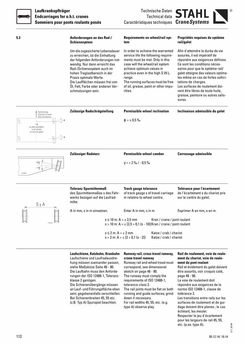
LS-T
_05.
FM
112
LaufkrankopfträgerEndcarriages for o.h.t. cranesSommiers pour ponts roulants posés
Technische DatenTechnical data
Caractéristiques techniques
5.3
+ ϕ
+ ϕ
+an allen Laufrädern
to all wheelssur tous les galets
ϕ
FahrtrichtungDirection of travelSens de direction
c1535v01
S A+
c1537v01
Propriétés requises du système rail/galet
Afin d'atteindre la durée de vie assurée, il est impératif de répondre aux exigences définies. Ce sont les conditions néces-saires pour que le système rail/galet atteigne des valeurs optima-les même en cas de fortes sollici-tations de charges. Les surfaces de roulement doi-vent être libres de toute huile, graisse, peinture ou autres salis-sures.
Inclinaison admissible du galet
Carrossage admissible
Tolérance pour l’écartementde l'écartement s du chariot pris sur le centre du galet.
Exprimer A en mm, s en m.
ont roulantont roulant
ariotariot
Rail de roulement, voie de roule-ment du chariot, voie de roule-ment du pont roulantRail et évidement du galet doivent être assortis, voir croquis coté, page 48 - 90.La voie de roulement doit répondre aux exigences de la norme ISO 12488-1, classe de tolérance 2. Les transitions entre rails sur les surfaces de roulement et de gui-dage doivent être planes ; le cas échéant, les meuler. Respecter le jeu d'écartement pour les largeurs de rail 45, 55, etc. (p.ex. type A).
Requirements on wheel/rail sys-tem
In order to achieve the warranted service life the following require-ments must be met. Only in this case will the wheel/rail system achieve optimum values in practice even in the high S.W.L. range.The running surfaces must be free of oil, grease, paint or other impu-rities.
Permissible wheel inclination
ϕ = ± 0,5 ‰
Permissible wheel camber
γ = + 2 ‰ / - 0,5 ‰
Track gauge toleranceof track gauge s of travel carriage in relatino to wheel centre.
Enter A in mm, s in m
= ± 2,5 mm Kran / crane / p = ± [2,5 + 0,1 (s - 10)]Kran / crane / p
± 2 mm Katze / crab / ch ± [2 + 0,1 (s - 2)] Katze / crab / ch
Runway rail, cross travel runway, crane travel runway Runway rail and wheel tread must correspond, see dimensional sketch on page 48 - 90.The runway must comply the requirements of ISO 12488-1, tolerance class 2.The rail joints must be flat on both running and guide surfaces; grind down if necessary. For rail widths 45, 55, etc. (e.g. type A) observe play.
Um die zugesicherte Lebensdauer zu erreichen, ist die Einhaltung der folgenden Anforderungen not-wendig. Nur dann erreicht das Rad-/Schienesystem auch im hohen Traglastbereich in der Praxis optimale Werte.Die Laufflächen müssen frei von Öl, Fett, Farbe oder anderen Ver-schmutzungen sein.
Anforderungen an das Rad-/Schienesystem
Zulässige Radschrägstellung
Zulässiger Radsturz
Toleranz Spurmittenmaßdes Spurmittenmaßes s des Fahr-werks bezogen auf die Laufrad-mitte.
A in mm, s in m einsetzen.
s ≤ 10 m: As > 10 m: A
s ≤ 2 m: A =s > 2 m: A =
Laufschiene, Katzbahn, KranbahnLaufschiene und Laufradausdre-hung müssen zueinander passen, siehe Maßskizze Seite 48 - 90.Die Laufbahn muss den Anforde-rungen der ISO 12488-1, Toleranz-klasse 2 genügen.Die Schienenübergänge müssen an Lauf- und Führungsfläche eben sein; gegebenenfalls verschleifen.Bei Schienenbreiten 45, 55 etc. (z.B. Typ A) Spurspiel beachten.
10.1405.12.14/
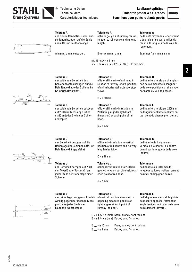
LS-T
_05.
FM
10.14
Technische DatenTechnical dataCaractéristiques techniques
LaufkrankopfträgerEndcarriages for o.h.t. cranes
Sommiers pour ponts roulants posés
2
/05.02.14
Tolérance Ade la cote moyenne d'écartement s des rails prise sur le milieu du rail et à la longueur de la voie de roulement.
Exprimer A en mm, s en m.
max.
Tolérance Bde linéarité latérale du champig-non de rail mesurée la longueur de la voie (position du rail en vue horizontale / vue de dessus).
Tolérance bde linéarité latérale sur 2000 mm de longueur calibrée (calibre) en tout point du champignon de rail.
Tolérance Cde linéarité de l'alignement vertical de la hauteur du centre du rail sur la longueur de la voie (pente).
Tolérance cde linéarité sur 2000 mm de longueur calibrée (calibre) en tout point du champignon de rail.
Tolérance Ede l'alignement vertical de points de mesure opposés, formant un angle droit, en tout point de la voie de roulement (dévers).
oulantt
oulantt
Tolerance Aof track gauge s of runway rails in relation to rail centre and runway length.
Enter A in mm, s in m
16 m: A = ± 5 mm 16 m: A = ± [5 + 0,25 (s - 16)]; ± 15 mm
Tolerance Bof lateral linearity of rail head in relation to runway length (position of rail in horizontal projection/top view).
B = ± 10 mm
Tolerance bof lateral linearity in relation to 2000 mm gauged length (spot dimension) at each point of rail head.
b = 1 mm
Tolerance Cof linearity in relation to vertical position of rail centre and runway length (declivity).
C = ± 10 mm
Tolerance cof linearity in relation to 2000 mm gauged length (spot dimension) at each point of rail head.
c = 2 mm
Tolerance Eof vertical position in relation to opposing measuring points at right angles at each point of runway (camber).
± 1 ‰ • s [mm] Kran / crane / pont r ± 2 ‰ • s [mm] Katze / crab / chario
ax = ± 10 mm Kran / crane / pont r
ax = ± 8 mm Katze / crab / chario
Toleranz Ades Spurmittenmaßes s der Lauf-schienen bezogen auf die Schie-nenmitte und Laufbahnlänge.
A in mm, s in m einsetzen.
s ≤s >
Toleranz Bder seitlichen Geradheit des Schienenkopfes bezogen auf die Bahnlänge (Lage der Schiene im Grundriss/Draufsicht).
Toleranz bder seitlichen Geradheit bezogen auf 2000 mm Messlänge (Stich-maß) an jeder Stelle des Schie-nenkopfes.
Toleranz Cder Geradheit bezogen auf die Höhenlage der Schienenmitte und Bahnlänge (Längsgefälle).
Toleranz cder Geradheit bezogen auf 2000 mm Messlänge (Stichmaß) an jeder Stelle der Höhenlage einer Schiene.
Toleranz Eder Höhenlage bezogen auf recht-winklig gegenüberliegende Mess-punkte an jeder Stelle der Laufbahn (Quergefälle).
E =E =
EmEm
113
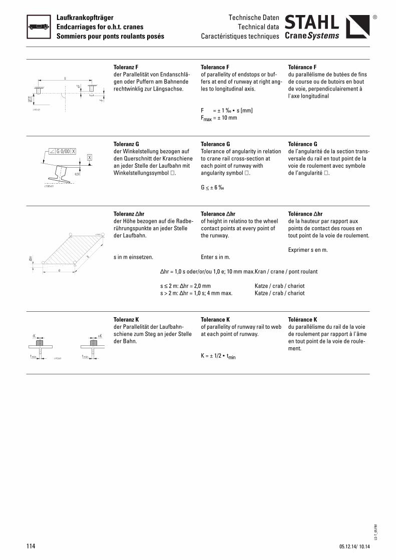
LS-T
_05.
FM
114
LaufkrankopfträgerEndcarriages for o.h.t. cranesSommiers pour ponts roulants posés
Technische DatenTechnical data
Caractéristiques techniques∆h
r
e
s
c1754v01
Tolérance Fdu parallélisme de butées de fins de course ou de butoirs en bout de voie, perpendiculairement à l'axe longitudinal
Tolérance Gde l’angularité de la section trans-versale du rail en tout point de la voie de roulement avec symbole de l’angularité ∠ .
Tolérance ∆hrde la hauteur par rapport aux points de contact des roues en tout point de la voie de roulement.
Exprimer s en m.
/ pont roulant
/ chariot / chariot
Tolérance Kdu parallélisme du rail de la voie de roulement par rapport à l'âme en tout point de la voie de roule-ment.
Tolerance Fof parallelity of endstops or buf-fers at end of runway at right ang-les to longitudinal axis.
F = ± 1 ‰ • s [mm]Fmax = ± 10 mm
Tolerance GTolerance of angularity in relation to crane rail cross-section at each point of runway with angularity symbol ∠ .
G < ± 6 ‰
Tolerance ∆hrof height in relatino to the wheel contact points at every point of the runway.
Enter s in m.
r/or/ou 1,0 e; 10 mm max.Kran / crane
,0 mm Katze / crab,0 s; 4 mm max. Katze / crab
Tolerance Kof parallelity of runway rail to web at each point of runway.
K = ± 1/2 • tmin
Toleranz Fder Parallelität von Endanschlä-gen oder Puffern am Bahnende rechtwinklig zur Längsachse.
Toleranz Gder Winkelstellung bezogen auf den Querschnitt der Kranschiene an jeder Stelle der Laufbahn mit Winkelstellungssymbol ∠ .
Toleranz ∆hrder Höhe bezogen auf die Radbe-rührungspunkte an jeder Stelle der Laufbahn.
s in m einsetzen.
∆hr = 1,0 s ode
s ≤ 2 m: ∆hr = 2s > 2 m: ∆hr = 1
Toleranz Kder Parallelität der Laufbahn-schiene zum Steg an jeder Stelle der Bahn.
10.1405.12.14/
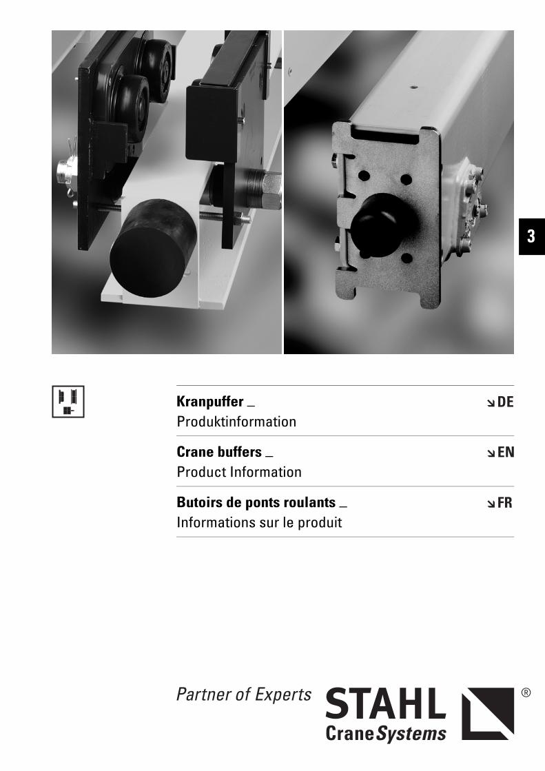
Kranpuffer _ Produktinformation
Crane buffers _ Product Information
Butoirs de ponts roulants _ Informations sur le produit
3

KOM
P.FM
KranpufferCrane buffersButoirs de ponts roulants
Diese Komponenten sind wichtige Bauteile der qualitativ hochwertigen Krane von STAHL CraneSystems.
Die Krankomponenten bewähren sich im täglichen Einsatz tausend-fach.
Nutzen Sie diese Vorteile auch für Ihren Kranbau.
These components are important parts of STAHL CraneSystems’ high-quality cranes.
The crane components have proven themselves in thousands of applications in day-to-day use.
Make use of these advantages for your crane manufacturing.
Ces composants sont des ensem-bles importants des palans et ponts roulants de haute qualité de STAHL CraneSystems.
Les composants pour ponts rou-lants donnent de bons résultats dans des milliers de cas d'utilisa-tion de tous les jours.
Profitez aussi de ces avantages pour la construction de vos ponts roulants.
Symbole Symbols Symboles
Gewicht [kg] Weight [kg] Poids [kg]
116 10.14

KOM
P.FM
KranpufferCrane buffers
Butoirs de ponts roulants
3
Inhaltsverzeichnis Table of contents Table des matières
Symbole.......................................... 116 Symbols.......................................... 116 Symboles ........................................116
1 Kranpuffer ...................................... 118 Crane buffers................................. 118 Butoirs de ponts roulants ............118
1.1 Gummipuffer .................................. 118 Rubber buffers .............................. 118 Butoirs de caoutchouc.................118
1.2 Polyurethan-Puffer ....................... 119 Polyurethane buffers ................... 119 Butoirs de polyuréthane...............119
1.3 Erklärung der Abkürzungen ........ 120 Explanation of abbreviations ...... 120 Explication des abbréviations .....120
Technische Änderungen, Irrtümer und Druckfehler vorbehalten.
Subject to technical modifications, errors and printing errors excepted.
Sous réserve de modifications techni-ques, d’erreurs et de fautes d’impres-sion.
10.14 117
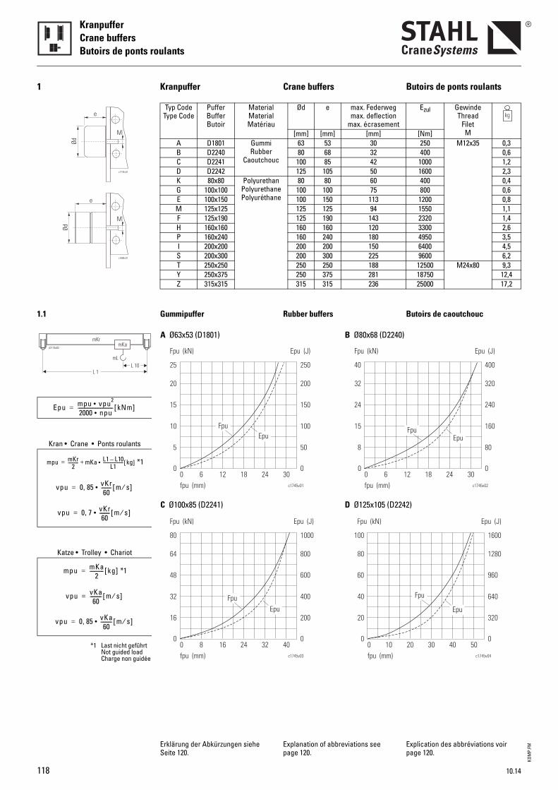
KOM
P.FM
KranpufferCrane buffersButoirs de ponts roulants
1 Kranpuffer Crane buffers Butoirs de ponts roulants
Typ CodeType Code
PufferBufferButoir
MaterialMaterialMatériau
Ød e max. Federwegmax. deflection
max. écrasement
Ezul GewindeThread
FiletM[mm] [mm] [mm] [Nm]
A D1801 GummiRubber
Caoutchouc
63 53 30 250 M12x35 0,3B D2240 80 68 32 400 0,6C D2241 100 85 42 1000 1,2D D2242 125 105 50 1600 2,3K 80x80 Polyurethan
PolyurethanePolyuréthane
80 80 60 400 0,4G 100x100 100 100 75 800 0,6E 100x150 100 150 113 1200 0,8M 125x125 125 125 94 1550 1,1F 125x190 125 190 143 2320 1,4H 160x160 160 160 120 3300 2,6P 160x240 160 240 180 4950 3,5I 200x200 200 200 150 6400 4,5S 200x300 200 300 225 9600 6,2T 250x250 250 250 188 12500 M24x80 9,3Y 250x375 250 375 281 18750 12,4Z 315x315 315 315 236 25000 17,2
1.1 Gummipuffer Rubber buffers Butoirs de caoutchouc
Erklärung der Abkürzungen siehe Seite 120.
Explanation of abbreviations see page 120.
Explication des abbréviations voir page 120.
c1744v01
e
Ød
M
c1686v01
e
Ød
M
Kran • Crane • Ponts roulants
*1
Katze • Trolley • Chariot
*1
*1 Last nicht geführtNot guided loadCharge non guidée
Epu mpu vpu2•2000 npu•---------------------------- kNm[ ]=
mpu mKr2
---------- mKa L1 L10–L1
--------------------• kg[ ]+=
vpu 0 85 vKr60
--------• m s⁄[ ],=
vpu 0 7 vKr60
--------• m s⁄[ ],=
mpu mKa2
----------- kg[ ]=
vpu vKa60
--------- m s⁄[ ]=
vpu 0 85 vKa60
---------• m s⁄[ ],=
15
10
5
0
20
25
Fpu
0 241812c1745v01
Epu (J)Fpu (kN)
fpu (mm)6 30
150
100
50
0
200
250
Epu
48
32
16
0
64
80
Fpu
0 322416c1745v03
Epu (J)Fpu (kN)
fpu (mm)8 40
600
400
200
0
800
1000
Epu
A Ø63x53 (D1801)
C Ø100x85 (D2241)
24
15
8
0
32
40
Fpu
0 241812c1745v02
Epu (J)Fpu (kN)
fpu (mm)6 30
240
160
80
0
320
400
Epu
60
40
20
0
80
100
Fpu
0 403020c1745v04
Epu (J)Fpu (kN)
fpu (mm)10 50
960
640
320
0
1280
1600
Epu
B Ø80x68 (D2240)
D Ø125x105 (D2242)
118 10.14
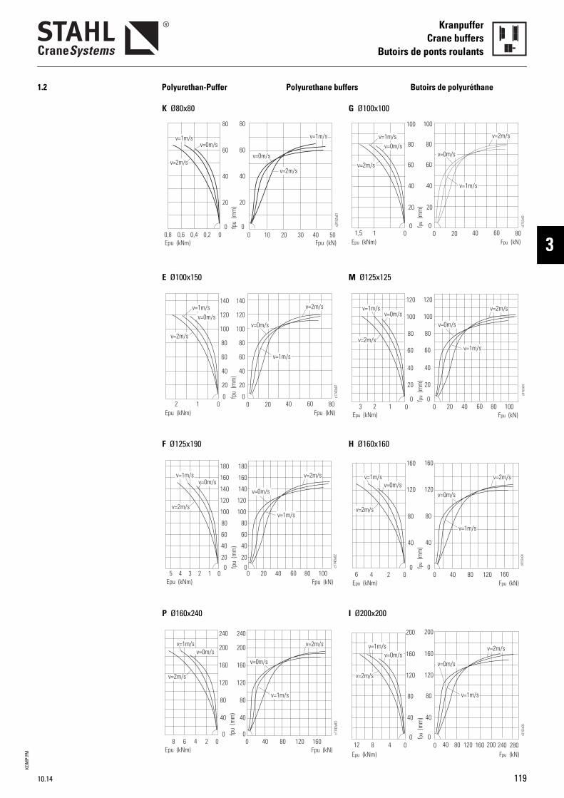
KOM
P.FM
KranpufferCrane buffers
Butoirs de ponts roulants
3
1.2 Polyurethan-Puffer Polyurethane buffers Butoirs de polyuréthane
0,8 0,4 0,2 00,6 0 10 20 30 40 50
80
60
40
20
0
80
60
40
20
0
v=1m/s v=1m/s
v=2m/sv=2m/s
v=0m/s
v=0m/s
Epu (kNm) Fpu (kN)fp
u (m
m)
c015
2a01
0 0 2012 40 8060
c174
3v01
v=1m/s
v=2m/s
v=0m/s
v=1m/s
v=2m/s
v=0m/s
Epu (kNm) Fpu (kN)
fpu
(mm
)
80
60
40
20
0
100
120
140
80
60
40
20
0
100
120
140
c174
3v02
0
80
60
40
20
0
100
120
80
60
40
20
100
120
0 20 40 60 80 1000123
v=0m/sv=1m/s
v=2m/sv=1m/s
v=0m/s
v=2m/s
Epu (kNm) Fpu (kN)
fpu
(mm
)
45
140
160
180
140
160
180
160
120
80
40
0
160
120
80
40
00246 0 40 80 120 160
v=1m/s
v=1m/s v=2m/s
v=2m/s
v=0m/sv=0m/s
Epu (kNm) Fpu (kN)
fpu
(mm
)
c174
3v03
200
240
200
240
8
K Ø80x80
E Ø100x150
F Ø125x190
P Ø160x240
G Ø100x100
M Ø125x125
H Ø160x160
I Ø200x200
10.14 119
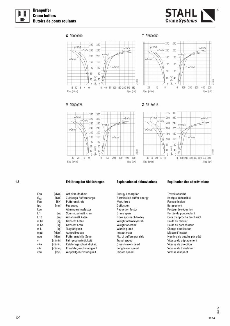
KOM
P.FM
KranpufferCrane buffersButoirs de ponts roulants
1.3 Erklärung der Abkürzungen Explanation of abbreviations Explication des abbréviations
Epu [kNm] Arbeitsaufnahme Energy absorption Travail absorbéEzul [Nm] Zulässige Pufferenergie Permissible buffer energy Énergie admissibleFpu [kN] Pufferendkraft Max. force Forces finales fpu [mm] Federweg Deflection Ecrasementkpu Abminderungsfaktor Reduction factor Facteur de réductionL 1 [m] Spurmittenmaß Kran Crane span Portée du pont roulantL 10 [m] Anfahrmaß Katze Hook approach trolley Cote d'approche du chariotm Ka [kg] Gewicht Katze Weight of trolley/crab Poids du chariotm Kr [kg] Gewicht Kran Weight of crane Poids du pont roulantm L [kg] Tragfähigkeit Working load Charge d'utilisationmpu [kNm] Aufprallmasse Impact mass Masse d'impactnpu [kNm] Pufferanzahl je Seite No. of buffers per side Nombre de butoirs par côtév [m/min] Fahrgeschwindigkeit Travel speed Vitesse de déplacementvKa [m/min] Katzfahrgeschwindigkeit Cross travel speed Vitesse de directionvKr [m/min] Kranfahrgeschwindigkeit Long travel speed Vitesse de translationvpu [m/s] Aufprallgeschwindigkeit Impact speed Vitesse d'impact
v=1m/s
v=1m/s v=2m/s
v=2m/s
v=0m/s
120
80
40
0
160
120
80
40
0
160
280
v=0m/s
04812 0 40 80 120 200 280160 240
c174
3v04
Epu (kNm) Fpu (kN)fp
u (m
m)
200
240
280
200
240
16
v=1m/s
v=1m/s v=2m/s
v=2m/s
v=0m/s
120
80
400
160
120
80
400
160
280v=0m/s
0102030 0 100 200 300 500400
c174
3v06
Epu (kNm) Fpu (kN)
fpu
(mm
)
200
240
280
200
240
320
360
320
360
S Ø200x300
Y Ø250x375
v=1m/s
v=1m/s v=2m/s
v=2m/s
v=0m/s
120
80
40
0
160
120
80
40
0
160
v=0m/s
01020 0 100 200 300 500400
c174
3v05
Epu (kNm) Fpu (kN)
fpu
(mm
)
200
240
200
240
v=1m/s
v=1m/s v=2m/s
v=2m/s
v=0m/s
120
80
40
0
160
200
120
80
40
0
160
200
v=0m/s
0102030 0 100 200 300 500 700400 600
c174
3v07
Epu (kNm) Fpu (kN)
fpu
(mm
)
40
240
280
315
240
280
315
T Ø250x250
Z Ø315x315
120 10.14


Prin
ted
in G
erm
any
Sac
h-N
r. 99
0 142
0 F
-PI-
3.2-
DE/
EN/F
R-10
.14-v
STAHL CraneSystems GmbH Daimlerstr. 6, 74653 Künzelsau, Germany Tel +49 7940 128-0, Fax +49 7940 [email protected]
Argentina Australia Austria Belgium Brazil Canada Chile China Columbia Croatia Czech Republic
Denmark Ecuador Egypt Estonia Finland France Germany Great Britain Greece Hongkong Hungary India Indonesia
Ireland Israel Italy Jordan Latvia Lebanon Lithuania Malaysia Mexico
Netherlands Nigeria Norway Pakistan Peru Philippines Poland Portugal Rumania Russia
Taiwan Thailand Turkey UAE Uruguay USA Venezuela Vietnam Singapore Slovakia Slovenia South Africa South Korea Spain Sweden Syria
Sales partners Subsidiaries
Presented by
Subsidiaries
ChinaShanghaiTel +86 21 66083737Fax +86 21 [email protected]
FranceParisTel +33 1 39985060Fax +33 1 [email protected]
Great BritainWarwickshireTel +44 1675 437 280Fax +44 1675 437 [email protected]
IndiaChennaiTel +91 44 43523955Fax +91 44 [email protected]
PortugalLisbonTel +351 21 4447160Fax +351 21 [email protected]
SingaporeSingaporeTel +65 6268 9228Fax +65 6268 [email protected]
SpainMadridTel +34 91 4840865 Fax +34 91 [email protected]
United Arab EmiratesDubaiTel +971 4 8053700Fax +971 4 [email protected]
USACharleston, SCTel +1 843 7671951Fax +1 843 [email protected]
Sales partners
You will find the addresses of over 100 sales partners on the Internet at www.stahlcranes.com under contact.


![Eurocode 1-Partie 5 Actions Induites Par Les Ponts Roulants---FA100321[1]](https://img.pdfslide.org/doc/110x75/5572119f497959fc0b8f3ed8/eurocode-1-partie-5-actions-induites-par-les-ponts-roulants-fa1003211.jpg)