Embed Size (px)
Citation preview
Axial-field Vernier-type Flux Modulation Machinesfor Low-speed Direct-drive Applications
Vandana Rallabandi�, Peng Han, Murat Gurhan Kesgin, Narges Taran, and Dan M. IonelSPARK Laboratory, ECE Dept, University of Kentucky, Lexington, KY, USA
[email protected], [email protected], [email protected], [email protected], [email protected]
Abstract—This paper proposes different configurations ofaxial-field machines featuring a very large ratio of the numberof rotor poles to stator teeth and coils suitable for low-speeddirect-drive traction applications. The machines have a singlerotor with spoke-type permanent magnets and the stator teethinclude auxiliary slots, the function of which is to enhancethe high-polarity component of the stator magnetomotive forceinteracting with the rotor to produce a net torque. The machinescan be constructed with three or two phases, in which case theyinherently exhibit high tolerance to faults due to the combinedeffect of a lack of coupling between phases and a relatively largephase inductance. A preliminary comparative simulation studyshows performance improvement over a conventional referencepermanent magnet synchronous machine.
Index Terms—Axial-field, direct-drive, flux concentration, fluxmodulation, fault tolerance, permanent magnet synchronousmachine, low-speed
I. INTRODUCTION
In-wheel motors are being increasingly sought in automotiveapplications in an attempt to simplify the drive train andeliminate gear boxes, which constitute points of failure. Inthis regard, high-polarity permanent magnet (PM) synchronousmachines with fractional-slot concentrated windings, whichfeature high efficiency, torque density and power factor arecommonly employed. Other competitive candidates include thevernier-type, conceptualized first in [1], followed by others,notably [2], [3].
High-polarity PM machines in low-speed applications leadto increased torque density and efficiency, due to the reductionin the flux per pole linked by the stator winding, which allowsthe use of more compact magnetic parts, as well as shorterend turn volume. Larger rotor polarities require a proportionalincrease in the number of stator slots and coils, which, for aspecified envelope, may become too small to be practicallymanufacturable. For example, the slot width may becomecomparable to the thickness of coil insulation, leading to verypoor slot filling, increased winding resistance and conductorlosses. To address such limitations, a three-phase radial-fieldvernier-type PM machine with 46 rotor poles, and only 6stator coils has been proposed in [4]. Other recent paperson the subject with radial- and axial-field versions include[5], [6]. In addition, a three-phase axial-field version with a
�Dr. Vandana Rallabandi was with the SPARK Laboratory, ECE Depart-ment, University of Kentucky, Lexington, KY and is now with GE Research,Niskayuna, NY.
central yokeless stator and two high-polarity spoke rotors wasproposed by the authors in [7].
This paper presents a two-phase machine topology, whichalso features a large disparity between the number of statorcoils and rotor poles, such that, for example, as few as fourstator winding coils can be used with as many as sixty rotorpoles. Compared with three-phase topologies, the proposedtwo-phase machines can achieve a higher polarity for a givennumber of stator slots and coils. More specifically, this paperpresents a two-phase axial-field vernier-type flux modulation(VTFM) PM machine with two stators and a high-polaritycentral spoke rotor. The stators include teeth with slots andnotches and concentrated coils. The second stator can alsobe constructed without coils. The advantages of a two-phaseconstruction include the inherent absence of mutual couplingbetween phases, which promotes the fault-tolerant capabilitydesired in direct-drive traction applications.
This paper is organized as follows. Section II introducesthe operating principle of the proposed VTFM PM machine,based on which feasible pole-slot combinations are derived.Section III presents the performance characteristics of theVTFM machine based on the finite element analysis (FEA)results for a 16-slot 56-pole example machine. The steady-state performance in both the healthy and faulty conditionsis included. A comparison study between the example VTFMmachine and a conventional axial-field PM machine is con-ducted in Section IV. Section V concludes the paper anddiscusses the futher work.
II. ANALYSIS OF THE OPERATING PRINCIPLE ANDTOPOLOGY
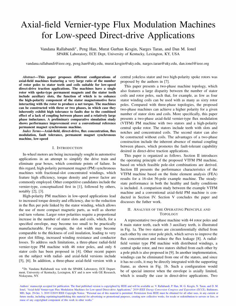
A representative two-phase machine with 44 rotor poles and8 main stator teeth, each with 3 auxiliary teeth, is illustratedin Fig. 1a. The two stators are circumferentially shifted fromeach other by one rotor pole pitch, which serves to improve theflux concentration and reduce the flux leakage [8]. A radial-field vernier type PM machine with distributed windings, acentral spoke rotor, and two stators shifted from each other bya pole pitch is also proposed in [9]. In another implementation,windings can be eliminated from one of the stators, and sinceit has no coils, it may be directly integrated with the supportingframe, as shown in Fig. 1b. Such a configuration wouldbe of special interest when the envelope is axially limited,which is usually the case in direct-drive applications. Two
Authors’ manuscript accepted for publication. The final published version is copyrighted by IEEE and will be available as: V. Rallabandi, P. Han, M. G. Kesgin, N. Taran, and D. M.Ionel, “Axial-field Vernier-type Flux Modulation Machines for Low-speed Direct-drive Applications,” 2019 IEEE Energy Conversion Congress and Exposition (ECCE), Baltimore,MD, Sept. 29-Oct. 3, 2019 ©2019 IEEE Copyright Notice. “Personal use of this material is permitted. Permission from IEEE must be obtained for all other uses, in any current orfuture media, including reprinting/republishing this material for advertising or promotional purposes, creating new collective works, for resale or redistribution to servers or lists, orreuse of any copyrighted component of this work in other works.”
(a)
(b)
Figure 1. Three-dimensional views for the proposed VTFM PM machineswith 1 central spoke rotor and: (a) two active stators, (b) one active statorand one passive stator. The windings, shown as the wave type, can also beimplemented as concentrated, full-pitched or gramme windings.
(a)
(b)
Figure 2. “Developed” two-dimensional views for the proposed VTFM PMmachines with 1-central spoke rotor and a single active stator with: (a) full-pitched winding, (b) concentrated tooth winding. Only half the 2D view isshown for each winding type.
typical winding types, i.e., the full-pitched winding and theconcentrated tooth winding, can be used, as illustrated in Fig.2.
The operating principle for these machines is the sameas that of other vernier-type PM synchronous motors. Thestator coils produce an airgap magnetomotive force (MMF)and armature reaction flux density rich in harmonics, with themagnitude decreasing with the order, in line with expectations.The stator teeth include dummy slots, the function of which isto enhance the stator winding MMF component correspondingto the number of rotor poles. The dummy slots make it possibleto use a stator with a relatively small number of teeth andarmature coils along with a high polarity rotor.
The number of spoke rotor poles required may be obtainedby considering the following two constraints: (a) at a giventime, an odd number of PM poles are opposite to each stator
tooth, and (b) the required phase shift is achieved between thephases. The first of these conditions ensures that, at a giventime, either only north or only south PM poles lead to phaseflux linkage. These conditions are mathematically stated as thefollowing for a two-phase machine,
Pr A �2ta � 1�Tm , Pr �Tm2k1 , (1)
where Pr is the number of rotor poles; Tm, the number ofmain stator teeth; ta, the number of auxiliary stator slots;and k1 is any odd number. For a two-phase machine with8 main stator teeth, 2 auxiliary or dummy slots, the first valueof Pr satisfying both these conditions is 28. Additionally,the machines can also be constructed with different windingconfigurations, with full-pitched coils or concentrated toothwinding (Fig. 2). Some example slot-pole combinations aregiven (Table I).
Machines of the vernier-type inherently incorporate torquemagnification. In AFPM machines, the peak PM flux linkageper phase (ψPM ) may be approximately given as,
ψPM � NcBgLakπDm
Pr, (2)
where Nc is the number of coils per phase; Bg , the air-gapflux density; La, the active length; k, a constant; and Dm, theair-gap diameter. The electromagnetic torque in a motor withm phases with a pure q-axis excitation equal to Iq is given as,
Tem �mPr4ψPMIq . (3)
From (2) and (3), it may be noticed as PM flux linkage reduceswith increasing number of rotor poles, the electromagnetictorque is independent of it. Second order effects such asreduction in the stator core volume with the increasing numberof poles, and consequently increased slot area, permittinghigher values of Iq may lead to higher torque.
In the vernier-type PM machines under study in this paper,the number of permanent magnets contributing to the fluxlinkage of one coil increases linearly with the number ofauxiliary teeth per main tooth [7]. As observed in Table I, ahigher number of rotor poles is required when the number ofauxiliary stator slots increases, and therefore, the flux linkagein these types of PM machines is expected to increase withthe number of rotor poles. This indicates that these machineswould benefit more substantially with higher rotor polaritythan conventional machines. Further improvements will alsobe achieved due to the higher flux concentration in spoke rotorswith the increasing number of poles.
The operating principle of these axial-field machines canalso be explained by the simple MMF-permeance model.Assuming that there are only fundamental components in theMMF of the spoke rotor and the airgap permeance, the MMFdistribution produced by the PM array fm�φ, t� and the airgappermeance λ�r, φ�, based on the coordinate system illustratedin Fig. 3 can be written as:
fm�φ, t� � Fm cos �pm�φ � φ0m�� (4)
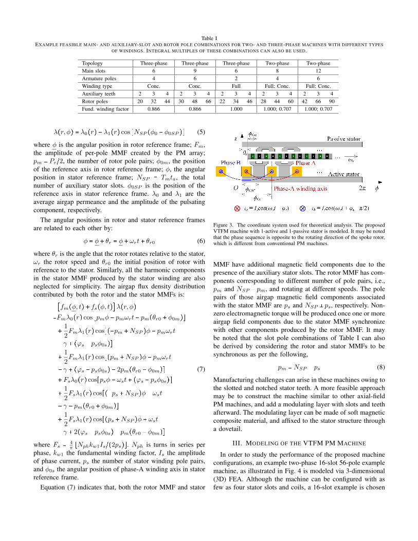
Table IEXAMPLE FEASIBLE MAIN- AND AUXILIARY-SLOT AND ROTOR POLE COMBINATIONS FOR TWO- AND THREE-PHASE MACHINES WITH DIFFERENT TYPES
OF WINDINGS. INTEGRAL MULTIPLES OF THESE COMBINATIONS CAN ALSO BE USED.
Topology Three-phase Three-phase Three-phase Two-phase Two-phaseMain slots 6 9 6 8 12Armature poles 4 6 2 4 6Winding type Conc. Conc. Full Full; Conc. Full; Conc.Auxiliary teeth 2 3 4 2 3 4 2 3 4 2 3 4 2 3 4Rotor poles 20 32 44 30 48 66 22 34 46 28 44 60 42 66 90Fund. winding factor 0.866 0.866 1.000 1.000; 0.707 1.000; 0.707
λ�r, φ� � λ0�r� � λ1�r� cos �NSP �φ0 � φ0SP �� (5)
where φ is the angular position in rotor reference frame; Fm,the amplitude of per-pole MMF created by the PM array;pm � Pr~2, the number of rotor pole pairs; φ0m, the positionof the reference axis in rotor reference frame; φ, the angularposition in stator reference frame; NSP � Tmta, the totalnumber of auxiliary stator slots. φ0SP is the position of thereference axis in stator reference frame. λ0 and λ1 are theaverage airgap permeance and the amplitude of the pulsatingcomponent, respectively.
The angular positions in rotor and stator reference framesare related to each other by:
φ � φ � θr � φ � ωrt � θr0 (6)
where θr is the angle that the rotor rotates relative to the stator,ωr the rotor speed and θr0 the initial position of rotor withreference to the stator. Similarly, all the harmonic componentsin the stator MMF produced by the stator winding are alsoneglected for simplicity. The airgap flux density distributioncontributed by both the rotor and the stator MMFs is:
�fm�φ, t� � fs�φ, t��λ�r, φ��Fmλ0�r� cos �pmφ � pmωrt � pm�θr0 � φ0m���
1
2Fmλ1�r� cos���pm �NSP �φ � pmωrt
� γ � �ϕs � psφ0s���
1
2Fmλ1�r� cos��pm �NSP �φ � pmωrt
� γ � �ϕs � psφ0s� � 2pm�θr0 � φ0m��� Fsλ0�r� cos�psφ � ωst � �ϕs � psφ0s���
1
2Fsλ1�r� cos���ps �NSP �φ � ωst
� γ � pm�θr0 � φ0m���
1
2Fsλ1�r� cos��ps �NSP �φ � ωst
� γ � 2�ϕs � psφ0s� � pm�θr0 � φ0m��
(7)
where Fs � 4π�Nphkw1Is~�2ps��. Nph is turns in series per
phase, kw1 the fundamental winding factor, Is the amplitudeof phase current, ps the number of stator winding pole pairs,and φ0s the angular position of phase-A winding axis in statorreference frame.
Equation (7) indicates that, both the rotor MMF and stator
Figure 3. The coordinate system used for theoretical analysis. The proposedVTFM machine with 1-active and 1-passive stator is modeled. It may be notedthat the phase sequence is opposite to the rotating direction of the spoke rotor,which is different from conventional PM machines.
MMF have additional magnetic field components due to thepresence of the auxiliary stator slots. The rotor MMF has com-ponents corresponding to different number of pole pairs, i.e.,pm and NSP � pm, and rotating at different speeds. The polepairs of those airgap magnetic field components associatedwith the stator MMF are ps and NSP � ps, respectively. Non-zero electromagnetic torque will be produced once one or moreairgap field components due to the stator MMF synchronizewith other components produced by the rotor MMF. It maybe noted that the slot pole combinations of Table I can alsobe derived by considering the rotor and stator MMFs to besynchronous as per the following,
pm � NSP � ps (8)
Manufacturing challenges can arise in these machines owing tothe slotted and notched stator teeth. A more feasible approachmay be to construct the machine similar to other axial-fieldPM machines, and add a modulating layer with slots and teethafterward. The modulating layer can be made of soft magneticcomposite material, and affixed to the stator structure througha dovetail.
III. MODELING OF THE VTFM PM MACHINE
In order to study the performance of the proposed machineconfigurations, an example two-phase 16-slot 56-pole examplemachine, as illustrated in Fig. 4 is modeled via 3-dimensional(3D) FEA. Although the machine can be configured with asfew as four stator slots and coils, a 16-slot example is chosen
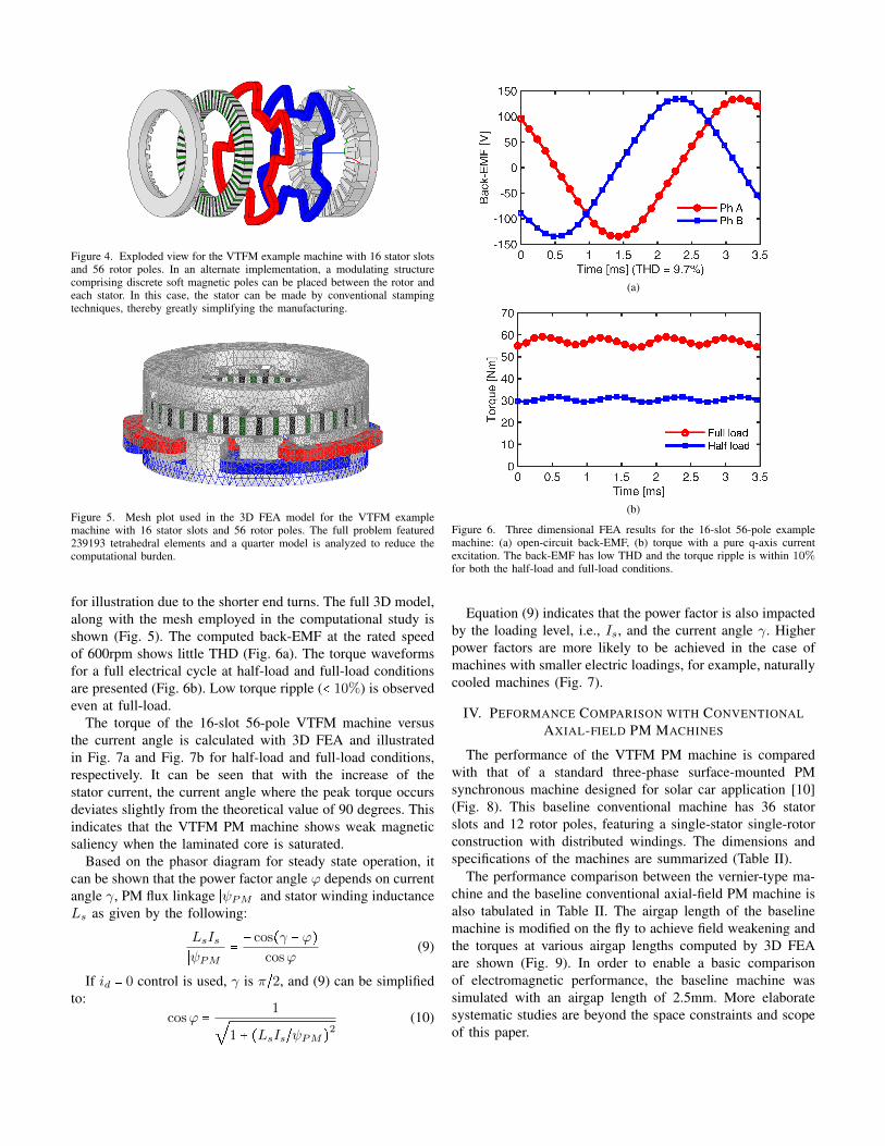
Figure 4. Exploded view for the VTFM example machine with 16 stator slotsand 56 rotor poles. In an alternate implementation, a modulating structurecomprising discrete soft magnetic poles can be placed between the rotor andeach stator. In this case, the stator can be made by conventional stampingtechniques, thereby greatly simplifying the manufacturing.
Figure 5. Mesh plot used in the 3D FEA model for the VTFM examplemachine with 16 stator slots and 56 rotor poles. The full problem featured239193 tetrahedral elements and a quarter model is analyzed to reduce thecomputational burden.
for illustration due to the shorter end turns. The full 3D model,along with the mesh employed in the computational study isshown (Fig. 5). The computed back-EMF at the rated speedof 600rpm shows little THD (Fig. 6a). The torque waveformsfor a full electrical cycle at half-load and full-load conditionsare presented (Fig. 6b). Low torque ripple (@ 10%) is observedeven at full-load.
The torque of the 16-slot 56-pole VTFM machine versusthe current angle is calculated with 3D FEA and illustratedin Fig. 7a and Fig. 7b for half-load and full-load conditions,respectively. It can be seen that with the increase of thestator current, the current angle where the peak torque occursdeviates slightly from the theoretical value of 90 degrees. Thisindicates that the VTFM PM machine shows weak magneticsaliency when the laminated core is saturated.
Based on the phasor diagram for steady state operation, itcan be shown that the power factor angle ϕ depends on currentangle γ, PM flux linkage SψPM S and stator winding inductanceLs as given by the following:
LsIsSψPM S �
� cos�γ � ϕ�cosϕ
(9)
If id � 0 control is used, γ is π~2, and (9) can be simplifiedto:
cosϕ �
1¼1 � �LsIs~ψPM�2 (10)
(a)
(b)
Figure 6. Three dimensional FEA results for the 16-slot 56-pole examplemachine: (a) open-circuit back-EMF, (b) torque with a pure q-axis currentexcitation. The back-EMF has low THD and the torque ripple is within 10%for both the half-load and full-load conditions.
Equation (9) indicates that the power factor is also impactedby the loading level, i.e., Is, and the current angle γ. Higherpower factors are more likely to be achieved in the case ofmachines with smaller electric loadings, for example, naturallycooled machines (Fig. 7).
IV. PEFORMANCE COMPARISON WITH CONVENTIONALAXIAL-FIELD PM MACHINES
The performance of the VTFM PM machine is comparedwith that of a standard three-phase surface-mounted PMsynchronous machine designed for solar car application [10](Fig. 8). This baseline conventional machine has 36 statorslots and 12 rotor poles, featuring a single-stator single-rotorconstruction with distributed windings. The dimensions andspecifications of the machines are summarized (Table II).
The performance comparison between the vernier-type ma-chine and the baseline conventional axial-field PM machine isalso tabulated in Table II. The airgap length of the baselinemachine is modified on the fly to achieve field weakening andthe torques at various airgap lengths computed by 3D FEAare shown (Fig. 9). In order to enable a basic comparisonof electromagnetic performance, the baseline machine wassimulated with an airgap length of 2.5mm. More elaboratesystematic studies are beyond the space constraints and scopeof this paper.
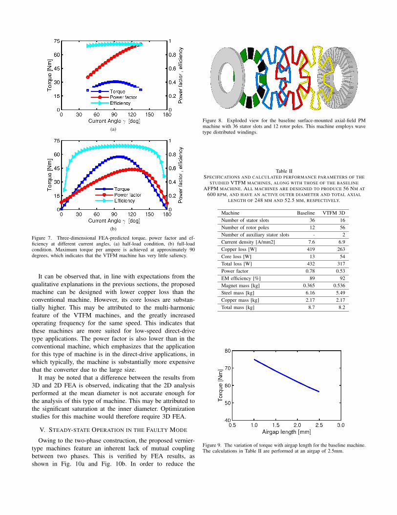
(a)
(b)
Figure 7. Three-dimensional FEA-predicted torque, power factor and ef-ficiency at different current angles, (a) half-load condition, (b) full-loadcondition. Maximum torque per ampere is achieved at approximately 90degrees, which indicates that the VTFM machine has very little saliency.
It can be observed that, in line with expectations from thequalitative explanations in the previous sections, the proposedmachine can be designed with lower copper loss than theconventional machine. However, its core losses are substan-tially higher. This may be attributed to the multi-harmonicfeature of the VTFM machines, and the greatly increasedoperating frequency for the same speed. This indicates thatthese machines are more suited for low-speed direct-drivetype applications. The power factor is also lower than in theconventional machine, which emphasizes that the applicationfor this type of machine is in the direct-drive applications, inwhich typically, the machine is substantially more expensivethat the converter due to the large size.
It may be noted that a difference between the results from3D and 2D FEA is observed, indicating that the 2D analysisperformed at the mean diameter is not accurate enough forthe analysis of this type of machine. This may be attributed tothe significant saturation at the inner diameter. Optimizationstudies for this machine would therefore require 3D FEA.
V. STEADY-STATE OPERATION IN THE FAULTY MODE
Owing to the two-phase construction, the proposed vernier-type machines feature an inherent lack of mutual couplingbetween two phases. This is verified by FEA results, asshown in Fig. 10a and Fig. 10b. In order to reduce the
Figure 8. Exploded view for the baseline surface-mounted axial-field PMmachine with 36 stator slots and 12 rotor poles. This machine employs wavetype distributed windings.
Table IISPECIFICATIONS AND CALCULATED PERFORMANCE PARAMETERS OF THE
STUDIED VTFM MACHINES, ALONG WITH THOSE OF THE BASELINEAFPM MACHINE. ALL MACHINES ARE DESIGNED TO PRODUCE 56 NM AT
600 RPM, AND HAVE AN ACTIVE OUTER DIAMETER AND TOTAL AXIALLENGTH OF 248 MM AND 52.5 MM, RESPECTIVELY.
Machine Baseline VTFM 3DNumber of stator slots 36 16Number of rotor poles 12 56Number of auxiliary stator slots - 2Current density [A/mm2] 7.6 6.9Copper loss [W] 419 263Core loss [W] 13 54Total loss [W] 432 317Power factor 0.78 0.53EM efficiency [%] 89 92Magnet mass [kg] 0.365 0.536Steel mass [kg] 6.16 5.49Copper mass [kg] 2.17 2.17Total mass [kg] 8.7 8.2
Figure 9. The variation of torque with airgap length for the baseline machine.The calculations in Table II are performed at an airgap of 2.5mm.
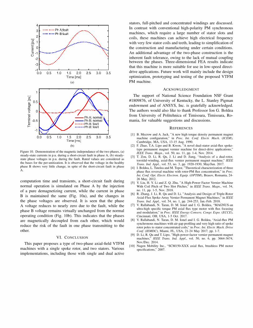
(a)
(b)
Figure 10. Demonstration of the magnetic independance of the two phases, (a)steady-state currents in p.u. during a short-circuit fault in phase A, (b) steady-state phase voltages in p.u. during the fault. Rated values are considered asthe bases for the per-unitization. It is observed that the voltage in the healthyphase B shows very little change, in spite of the short-circuit fault in phaseA.
computation time and transients, a short-circuit fault duringnormal operation is simulated on Phase A by the injectionof a pure demagnetizing current, while the current in phaseB is maintained the same (Fig. 10a), and the changes inthe phase voltages are observed. It is seen that the phaseA voltage reduces to nearly zero due to the fault, while thephase B voltage remains virtually unchanged from the normaloperating condition (Fig. 10b). This indicates that the phasesare magnetically decoupled from each other, which wouldreduce the risk of the fault in one phase transmitting to theother.
VI. CONCLUSION
This paper proposes a type of two-phase axial-field VTFMmachines with a single spoke rotor, and two stators. Variousimplementations, including those with single and dual active
stators, full-pitched and concentrated windings are discussed.In contrast with conventional high-polarity PM synchronousmachines, which require a large number of stator slots andcoils, these machines can achieve high electrical frequencywith very few stator coils and teeth, leading to simplification ofthe construction and manufacturing under certain conditions.An additional advantage of the two-phase construction is theinherent fault tolerance, owing to the lack of mutual couplingbetween the phases. Three-dimensional FEA results indicatethat this machine is more suitable for use in low-speed direct-drive applications. Future work will mainly include the designoptimization, prototyping and testing of the proposed VTFMPM machine.
ACKNOWLEDGMENT
The support of National Science Foundation NSF Grant#1809876, of University of Kentucky, the L. Stanley Pigmanendowment and of ANSYS, Inc. is gratefully acknowledged.The authors would also like to thank Professor Ion G. Boldeafrom University of Politehnica of Timisoara, Timisoara, Ro-mania, for valuable suggestions and discussions.
REFERENCES
[1] B. Mecrow and A. Jack, ”A new high torque density permanent magnetmachine configuration,” in Proc. Int. Conf. Electr. Mach. (ICEM),Cambridge, MA, USA, 13-15 Aug. 1990.
[2] F. Zhao, T.A. Lipo and B. Kwon, ”A novel dual-stator axial-flux spoke-type permanent magnet vernier machine for direct-drive applications,”IEEE Trans. Magn., vol. 50, no. 11, pp. 1-4, Nov. 2014.
[3] T. Zou, D. Li, R. Qu, J. Li and D. Jiang, “Analysis of a dual-rotor,toroidal-winding, axial-flux vernier permanent magnet machine,” IEEETrans. Ind. Appl., vol. 53, no. 3, pp. 1920-1930, May/Jun. 2017.
[4] I. Boldea, L. Tutelea and M. Topor, ”Theoretical characterization of threephase flux reversal machine with rotor-PM flux concentration,” in Proc.Int. Conf. Opt. Electr. Electron. Equip. (OPTIM), Brasov, Romania, 24-26 May, 2012.
[5] Y. Liu, H. Y. Li and Z. Q. Zhu, ”A High-Power Factor Vernier MachineWith Coil Pitch of Two Slot Pitches,” in IEEE Trans. Magn., vol. 54,no. 11, pp. 1-5, Nov. 2018.
[6] R. Zhang, J. Li, R. Qu and D. Li, ”Analysis and Design of Triple-RotorAxial-Flux Spoke-Array Vernier Permanent Magnet Machines,” in IEEETrans. Ind. Appl., vol. 54, no. 1, pp. 244-253, Jan.-Feb. 2018.
[7] V. Rallabandi, N. Taran, D. M. Ionel and I. G. Boldea, “MAGNUS-anultra-high specific torque PM axial flux type motor with flux focusingand modulation,” in Proc. IEEE Energy Convers. Congr. Expo. (ECCE),Cincinnati, OH, USA, 1-5 Oct. 2017.
[8] V. Rallabandi, N. Taran, D. M. Ionel and I. G. Boldea, “Axial-flux PMsynchronous machines with air-gap profiling and very high ratio of spokerotor poles to stator concentrated coils,” in Proc. Int. Electr. Mach. DriveConf. (IEMDC), Miami, FL, USA, 21-24 May 2017, pp. 1-7.
[9] D. Li, R. Qu and T. Lipo, ”High-power-factor vernier permanent-magnetmachines,” IEEE Trans. Ind. Appl., vol. 50, no. 6, pp. 3664-3674,Nov./Dec. 2014.
[10] Nugen Mobility Inc., “SCM150-XXX axial flux, brushless PM motorspecifications,” 2007.


![Unbenannt-1detailforschung.info/Texte/quick.pdf · Konstruktive Umsetzung der Solarwand Messergebnisse Name Tmax [°C] Heat Flux y1 Heat Flux y2 Heat Flux aussen Heat Flux innen Georg](https://img.pdfslide.org/doc/110x75/5fe58fbd5e888a7169649e0d/unbenannt-konstruktive-umsetzung-der-solarwand-messergebnisse-name-tmax-c-heat.jpg)