Embed Size (px)
Citation preview
ELECTRIC SAUNA HEATER
DEUTSCH / ENGLISH
Änderungen vorbehalten.Subject to change without notice.
EinbausteuergerätBuilt-in Control Unit
18
15
17
8
9
10
12
13
14 16
11
MN-23NBMN-30NBMN-36NB
ELEKTRISCHER SAUNAOFEN
19
20
21
MN-23NSMN-30NSMN-36NS
Für Modelle mit separatem Steuergerät For Models With Separate Control Unit
MANUAL
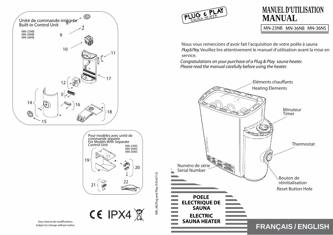
Congratulations on your purchase of a Plug & Play sauna heater.Please read the manual carefully before using the heater.
Wir gratulieren Ihnen zum Kauf Ihres Plug & Play Saunaheizgeräts.Bevor Sie das Heizgerät benutzen, lesen Sie sich bitte die Bedienungsanleitung sorgfältig durch.
MN-36NB MN-23NB
BEDIENUNGSANLEITUNG
MN-36NS
Thermostat
ZeitschalterTimer
MN
_ML
(GeE
n07
13)
HeizelementeHeating Elements
Reset-Taste Reset Button Hole
SeriennummerSerial Number
WICHTIGE HINWEISE!IMPORTANT INFORMATION!
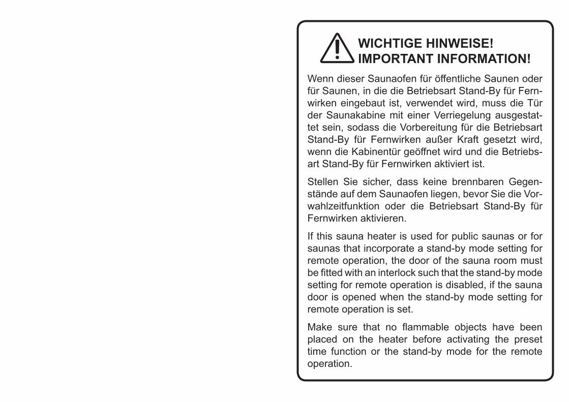
Wenn dieser Saunaofen für öffentliche Saunen oder für Saunen, in die die Betriebsart Stand-By für Fern-wirken eingebaut ist, verwendet wird, muss die Tür der Saunakabine mit einer Verriegelung ausgestat-tet sein, sodass die Vorbereitung für die Betriebsart Stand-By für Fernwirken außer Kraft gesetzt wird, wenn die Kabinentür geöffnet wird und die Betriebs-art Stand-By für Fernwirken aktiviert ist.
Stellen Sie sicher, dass keine brennbaren Gegen-stände auf dem Saunaofen liegen, bevor Sie die Vor-wahlzeitfunktion oder die Betriebsart Stand-By für Fernwirken aktivieren.
If this sauna heater is used for public saunas or for saunas that incorporate a stand-by mode setting for remote operation, the door of the sauna room must be fitted with an interlock such that the stand-by mode setting for remote operation is disabled, if the sauna door is opened when the stand-by mode setting for remote operation is set.
Make sure that no flammable objects have been placed on the heater before activating the preset time function or the stand-by mode for the remote operation.
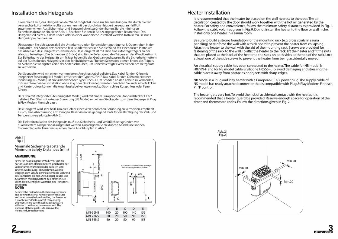
Heater InstallationIt is recommended that the heater be placed on the wall nearest to the door. The air circulation created by the door should work together with the hot air generated by the heater. For safety and convenience, follow the minimum safety distances as provided in Fig. 1. Follow the cubic volumes given in Fig. 9. Do not install the heater to the floor or wall niche. Install only one heater in a sauna room.
Be sure to build a strong foundation for the mounting rack (e.g. cross struts in sauna paneling) or reinforce the wall with a thick board to prevent the heater from collapsing. Attach the heater to the wall with the aid of the mounting rack. Screws are provided for fastening of the rack to the wall. To affix the heater to the rack, lift the heater and fit the nuts that are placed at the back of the heater to the slots on both sides at the top of the rack. Lock at least one of the side screws to prevent the heater from being accidentally moved.
An electrical supply cable has been connected to the heater. The cable for NB model is H07RN-F and for NS model cable is Silicone H05SS-F. To avoid damaging and stressing the cable place it away from obstacles or objects with sharp edges.
NB Model is a Plug and Play heater with a European CE7/7 power plug. The supply cable of NS model has ready attached connector that is compatible with Plug & Play Modern Finnisch, P’n’P control.
The heater gets very hot. To avoid the risk of accidental contact with the heater, it is recommended that a heater guard be provided. Reserve enough space for operation of the timer and thermostat knobs. Follow the directions given in Fig. 2.
Abb. 2Fig. 2
32DEUTSCH / ENGLISH DEUTSCH / ENGLISH
Remove the carton from the heating elements and behind the serial number (between outer and inner cover) before installing the heater as it is only intended to protect them during shipment. Make sure that silicagel packs are still attach on the carton are removed. The purpose of those packs is to remove the moisture during shipment.
NOTE:
Abb. 1Fig. 1
Es empfiehlt sich, das Heizgerät an der Wand möglichst nahe zur Tür anzubringen. Die durch die Tür verursachte Luftzirkulation sollte zusammen mit der durch das Heizgerät erzeugten Heißluft zusammenwirken. Aus Sicherheits- und Bequemlichkeitsgründen halten Sie die minimalen Sicherheitsabstände ein, siehe Abb. 1. Beachten Sie den in Abb. 9 angegebenen Rauminhalt. Das Heizgerät soll nicht auf dem Boden oder in einer Wandnische installiert werden. Installieren Sie nur 1 Heizgerät pro Saunaraum.
Überzeugen Sie sich davon, daß die Unterkonstruktion für den Montageträger (z. B. Querstreben in den Bauplatten der Sauna) entsprechend fest ist oder verstärken Sie die Wand mit einer dicken Platte, um das Absenken des Heizgeräts zu vermeiden. Das Heizgerät ist mit Hilfe eines Montageträgers an der Wand zu befestigen. Die Schrauben (6 Stück) sind für die Befestigung des Trägers an der Wand bestimmt. Zur Befestigung des Heizgeräts am Träger heben Sie das Gerät an und passen Sie die Sicherheitsmuttern auf der Rückseite des Heizgeräts in den Schlitzlöchern auf beiden Seiten des oberen Endes des Trägers an. Sichern Sie wenigstens eine der Seitenschrauben, um unbeabsichtigtes Verschieben des Heizgeräts zu vermeiden.
Der Saunaofen wird mit einem vormonierten Anschlusskabel geliefert. Das Kabel für den Ofen mit integrierter Steuerung (NB Model) entspricht der Type H07RN-F. Das Kabel für den Ofen mit externer Steuerung (NS Model) ist ein Silikonkabel der Type H05SS-F. Um Schäden an den Kabeln zu vermeiden, müssen diese bei der Installation ohne Zug oder Druck verlegt werden. Beachten Sie auch scharfe Ecken und Kanten, diese können die Anschlusskabel verletzen und zu Stromschlag, Kurzschluss oder Feuer führen.
Der Ofen mit integrierter Steuerung (NB Model) wird mit einem Europäischen Standardstecker CE7/7 geliefert. Der Ofen mit externer Steuerung (NS Model) mit einem Stecker, der zum dem Steuergerät Plug & Play Modern Finnisch passt.
Das Heizgerät wird sehr heiß. Um die Gefahr einer versehentlichen Berührung zu vermeiden, empfiehlt es sich, eine Abschirmung anzubringen. Reservieren Sie genügend Platz für die Betätigung der Zeit- und Temperaturreglerknöpfe (Abb. 2).
Die Elektroinstallation des Heizgeräts muß aus Sicherheits- und Verläßlichkeitsgründen von qualifiziertem Fachpersonal ausgeführt werden. Unsachgemäße elektrische Anschlüsse können Stromschlag oder Feuer verursachen. Siehe Anschlußplan in Abb. 6.
Installation des Heizgeräts
Minimale SicherheitsabständeMinimum Safety Distances (mm)
Bevor Sie das Heizgerät installieren, sind die Kartons von den Heizelementen und hinter der Seriennummer (zwischen der äußeren und inneren Abdeckung) abzunehmen, weil sie lediglich zum Schutz der Heizelemente während des Transports dienen. Die Silikagel-Beutel sind zusammen mit den Kartons zu entfernen. Sie sollen die Feuchtigkeit während des Transports beseitigen.
ANMERKUNG:
MN-23NSMN-36NS
6060
2020
5050
9090
155155
A B C D EMN-36NB 100 20 100 140 155
Installieren des WandmontageträgersWall Mounting Rack Installation
1900
150
1200
A
B
20
225
380
C E
D
Min.20
Min.20
Min.20
4
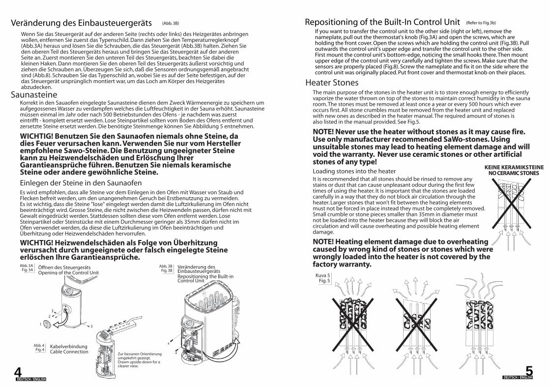
Wenn Sie das Steuergerät auf der anderen Seite (rechts oder links) des Heizgerätes anbringen wollen, entfernen Sie zuerst das Typenschild. Dann ziehen Sie den Temperaturreglerknopf (Abb.3A) heraus und lösen Sie die Schrauben, die das Steuergerät (Abb.3B) halten. Ziehen Sie den oberen Teil des Steuergeräts heraus und bringen Sie das Steuergerät auf der anderen Seite an. Zuerst montieren Sie den unteren Teil des Steuergeräts, beachten Sie dabei die kleinen Haken. Dann montieren Sie den oberen Teil des Steuergeräts äußerst vorsichtig und ziehen die Schrauben an. Überzeugen Sie sich, daß die Sensoren ordnungsgemäß angebracht sind (Abb.8). Schrauben Sie das Typenschild an, wobei Sie es auf der Seite befestigen, auf der das Steuergerät ursprünglich montiert war, um das Loch am Körper des Heizgerätes abzudecken.
Veränderung des Einbausteuergeräts (Abb. 3B)
DEUTSCH / ENGLISH
Abb. 3AFig. 3A Öffnen des Steuergeräts
Opening of the Control UnitAbb. 3B
Fig. 3BVeränderung des EinbausteuergerätsRepositioning the Built-in Control Unit
4
4Zur besseren Orientierung umgekehrt gezeigt.Drawn upside-down for a clearer view.
Abb. 4Fig. 4
KabelverbindungCable Connection
Einlegen der Steine in den Saunaofen
SaunasteineKorrekt in den Sauaofen eingelegte Saunasteine dienen dem Zweck Wärmeenergie zu speichern umaufgegossenes Wasser zu verdampfen welches die Luftfeuchtigkeit in der Sauna erhöht. Saunasteinemüssen einmal im Jahr oder nach 500 Betriebstunden des Ofens - je nachdem was zuerst eintrifft - komplett ersetzt werden. Lose Steinpartikel sollten vom Boden des Ofens entfernt und zersetzte Steine ersetzt werden. Die benötigte Steinmenge können Sie Abbildung 5 entnehmen.
WICHTIG! Benutzen Sie den Saunaofen niemals ohne Steine, da dies Feuer verursachen kann. Verwenden Sie nur vom Herstellerempfohlene Sawo-Steine. Die Benutzung ungeeigneter Steine kann zu Heizwendelschäden und Erlöschung Ihrer Garantieansprüche führen. Benutzen Sie niemals keramische Steine oder andere gewöhnliche Steine.
Es wird empfohlen, dass alle Steine vor dem Einlegen in den Ofen mit Wasser von Staub und Flecken befreit werden, um den unangenehmen Geruch bei Erstbenutzung zu vermeiden. Es ist wichtig, dass die Steine "lose" eingelegt werden damit die Luftzirkulierung im Ofen nichtbeeinträchtigt wird. Grosse Steine, die nicht zwischen die Heizwendeln passen, dürfen nicht mit Gewalt eingedrückt werden. Stattdessen sollten diese vom Ofen entfernt werden. Lose Steinpartikel oder Steinstücke mit einem Durchmesser geringer als 35mm dürfen nicht im Ofen verwendet werden, da diese die Luftzirkulierung im Ofen beeinträchtigen und Überhitzung oder Heizwendelschäden hervorrufen.
WICHTIG! Heizwendelschäden als Folge von Überhitzung verursacht durch ungeeignete oder falsch eingelegte Steine erlöschen Ihre Garantieansprüche.
If you want to transfer the control unit to the other side (right or left), remove the nameplate, pull out the thermostat's knob (Fig.3A) and open the screws, which are holding the front cover. Open the screws which are holding the control unit (Fig.3B). Pull outwards the control unit's upper edge and transfer the control unit to the other side. First mount the control unit's bottom-edge, noticing the small hooks there. Then mount upper edge of the control unit very carefully and tighten the screws. Make sure that the sensors are properly placed (Fig.8). Screw the nameplate and fix it on the side where the control unit was originally placed. Put front cover and thermostat knob on their places.
Repositioning of the Built-In Control Unit (Refer to Fig.3b)
5DEUTSCH / ENGLISH
Kuva 5Fig. 5
NO CERAMIC STONESKEINE KERAMIKSTEINE
Heater StonesThe main purpose of the stones in the heater unit is to store enough energy to efficientlyvaporize the water thrown on top of the stones to maintain correct humidity in the sauna room. The stones must be removed at least once a year or every 500 hours which everoccurs first. All stone crumbles must be removed from the heater unit and replaced with new ones as described in the heater manual. The required amount of stones is also listed in the manual provided. See Fig.5.
NOTE! Never use the heater without stones as it may cause fire. Use only manufacturer recommended SaWo-stones. Using unsuitable stones may lead to heating element damage and will void the warranty. Never use ceramic stones or other artificial stones of any type!Loading stones into the heaterIt is recommended that all stones should be rinsed to remove any stains or dust that can cause unpleasant odour during the first few times of using the heater. It is important that the stones are loaded carefully in a way that they do not block air circulation through theheater. Larger stones that won’t fit between the heating elements must not be forced in place instead they must be completely removed.Small crumble or stone pieces smaller than 35mm in diameter mustnot be loaded into the heater because they will block the air circulation and will cause overheating and possible heating element damage.
NOTE! Heating element damage due to overheatingcaused by wrong kind of stones or stones which were wrongly loaded into the heater is not covered by thefactory warranty.
1
2
3
3
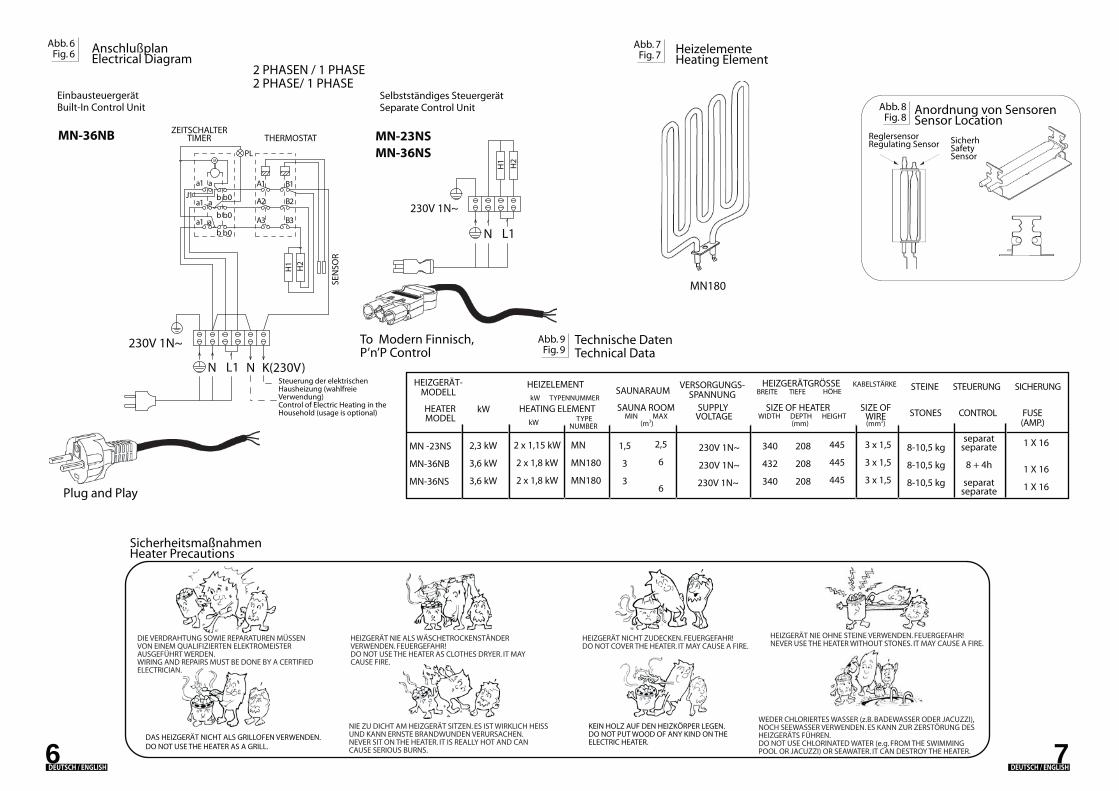
Abb. 7Fig. 7
Abb. 6Fig. 6 Anschlußplan
Electrical Diagram
EinbausteuergerätBuilt-In Control Unit
2 PHASE/ 1 PHASESelbstständiges Steuergerät Separate Control Unit
HeizelementeHeating Element
Abb. 9Fig. 9
Technische DatenTechnical Data
6
Steuerung der elektrischen Hausheizung (wahlfreie Verwendung)Control of Electric Heating in the Household (usage is optional)
SEN
SOR
ZEITSCHALTER TIMER THERMOSTAT
2 PHASEN / 1 PHASE
7
SicherheitsmaßnahmenHeater Precautions
DIE VERDRAHTUNG SOWIE REPARATUREN MÜSSEN VON EINEM QUALIFIZIERTEN ELEKTROMEISTER AUSGEFÜHRT WERDEN.WIRING AND REPAIRS MUST BE DONE BY A CERTIFIED ELECTRICIAN.
DAS HEIZGERÄT NICHT ALS GRILLOFEN VERWENDEN.DO NOT USE THE HEATER AS A GRILL.
KEIN HOLZ AUF DEN HEIZKÖRPER LEGEN.DO NOT PUT WOOD OF ANY KIND ON THE ELECTRIC HEATER.
HEIZGERÄT NICHT ZUDECKEN. FEUERGEFAHR! DO NOT COVER THE HEATER. IT MAY CAUSE A FIRE.
HEIZGERÄT NIE ALS WÄSCHETROCKENSTÄNDER VERWENDEN. FEUERGEFAHR!DO NOT USE THE HEATER AS CLOTHES DRYER. IT MAY CAUSE FIRE.
NIE ZU DICHT AM HEIZGERÄT SITZEN. ES IST WIRKLICH HEISS UND KANN ERNSTE BRANDWUNDEN VERURSACHEN.NEVER SIT ON THE HEATER. IT IS REALLY HOT AND CAN CAUSE SERIOUS BURNS.
HEIZGERÄT NIE OHNE STEINE VERWENDEN. FEUERGEFAHR!NEVER USE THE HEATER WITHOUT STONES. IT MAY CAUSE A FIRE.
WEDER CHLORIERTES WASSER (z.B. BADEWASSER ODER JACUZZI), NOCH SEEWASSER VERWENDEN. ES KANN ZUR ZERSTÖRUNG DES HEIZGERÄTS FÜHREN. DO NOT USE CHLORINATED WATER (e.g. FROM THE SWIMMING POOL OR JACUZZI) OR SEAWATER. IT CAN DESTROY THE HEATER.
Anordnung von SensorenSensor Location
Abb. 8Fig. 8
ReglersensorRegulating Sensor Sicherheitssensor
Safety Sensor
MN-23NSMN-36NS
MN180
MN-36NB
DEUTSCH / ENGLISH DEUTSCH / ENGLISH
a
a
M
230V 1N~
N
a1
a1 a
a1
J1
NL1 K(230V)
A3
H1
H2
B3
b0b
b0b
b0b
A2
A1
PL
B2
B1
230V 1N~
H1
H2
N L1
Plug and Play
To Modern Finnisch, P’n’P Control
STONES CONTROLkW kW
HEATER SAUNA ROOM SUPPLY SIZE OF HEATER SIZE OFWIREDEPTH HEIGHTWIDTHVOLTAGE
HEATING ELEMENTMIN MAXTYPE
NUMBER (m3) (mm2)(mm)MODEL
kW SAUNARAUM
VERSORGUNGS-SPANNUNG
STEINE STEUERUNG
FUSE(AMP.)
SICHERUNGHEIZGERÄTGRÖSSEHÖHEBREITE TIEFE
HEIZELEMENTTYPENNUMMER
HEIZGERÄT-MODELL
KABELSTÄRKE
2,3 kW
3,6 kW
3,6 kW
MN -23NS
MN-36NB
MN-36NS
2 x 1,15 kW
2 x 1,8 kW
2 x 1,8 kW
1,5
3
3
2,5
6
6
208
208
208
445
445
445
3 x 1,5
3 x 1,5
3 x 1,5
340
432
340
separatseparate
8 + 4h
separatseparate
8-10,5 kg
8-10,5 kg
8-10,5 kg
1 X 16
1 X 16
1 X 16
MN
MN180
MN180
230V 1N~
230V 1N~
230V 1N~
Air VentilationTo have a soothing sauna, there should be a proper mixing of hot and cold air inside the sauna room. Another reason for ventilation is to draw air around the heater and move the heat to the farthest part of the sauna. The positioning of the inlet and outlet vents may vary depending on the design of the sauna room or preference of the owner.
The inlet vent may be installed on the wall directly below the heater (Fig. 10A). When using the mechanical ventilation, inlet vent is placed at least 60 cm above the heater (Fig 10B) or on the ceiling above the heater (Fig. 10C). Through these positions, the heavy cold air that is blown into the sauna is mixed with the light hot air from the heater, bringing fresh air for the bathers. The inlet vent must have a diameter of 5-10cm (recommended).
The outlet vent should be placed diagonally opposite to the inlet. It is recommended that the outlet vent is placed under the platform in a sauna as far as possible from the fresh air vent. It may be installed near the floor, or led outside through a pipe from the floor going to a vent to the sauna ceiling, or under the door (to the washroom). In this case, the sill slot must be at least 5 cm and it is recommended that there is mechanical ventilation in the washroom. The size of the exhaust should be twice that of the inlet.
InsulationThe sauna must have proper insulation on the walls, ceiling and door. One square meter (m²) of uninsulated surface increases the cubic volume by approximately 1,2m³ when determining the power requirement of the heater. Refer to Fig.9.
Ensure that moisture proofing is appropriate in sauna room. The purpose of this is to prevent spreading of moisture to the other rooms or wall structure. Moisture proofing must be placed between heating insulation and panel. Nordic spruce wood is recommended for the walls and ceiling inside the sauna.
Thermal and moisture proofing need to be installed according to the following order from outside to inside.
TIMER
Control Settings
Adjust the temperature of the sauna by simply turning the operating knob. Thermostat support automatically the choosen temperature.
In case the heater overheats, the safety sensor will automatically stop the heater even if the timer is on. Find out for what reason the heater overheated. The reason for this could be too tightly placed sauna stones, heater´s location or inappropriate ventilation. If this occurs, find out the cause and fix the problem before resetting the safety sensor. The reset button is located below the temperature knob.
To start the heater at once, turn the knob to anywhere between 1-4 on the operating time scale. The heater will start and remain on for the time selected.
THERMOSTAT
The recommended minimum thickness of the thermal insulation in the walls is 50 mm and in the ceiling 100 mm.It is possible to use carton- or aluminum foil laminate as a vapor barrier, which is affixed over the insulation aluminum foil inwards.Leave at least 20 mm air slot between vapor barrier and inside panelTo prevent gathering of the moisture behind the panel, leave the slot between wall panel and ceiling.
1.
2.
3.4.
A B CAbb. 10Fig. 10
9DEUTSCH / ENGLISH
ZeitschalterTimer
8
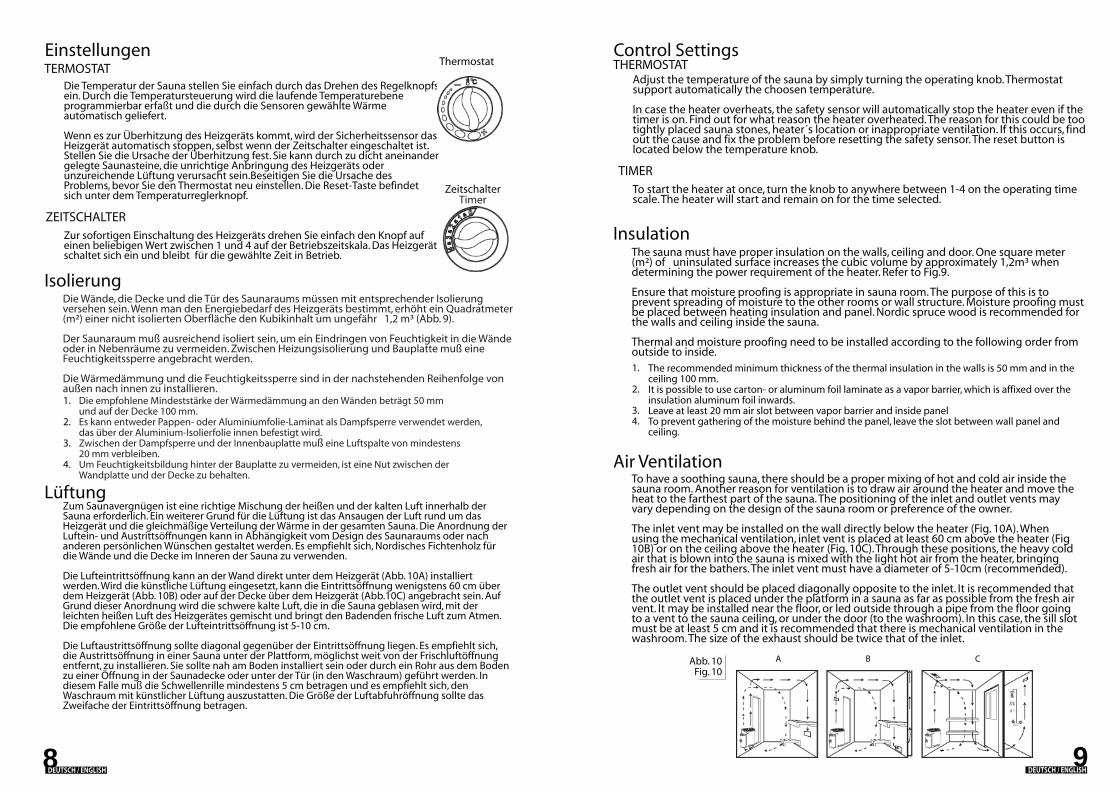
LüftungZum Saunavergnügen ist eine richtige Mischung der heißen und der kalten Luft innerhalb der Sauna erforderlich. Ein weiterer Grund für die Lüftung ist das Ansaugen der Luft rund um das Heizgerät und die gleichmäßige Verteilung der Wärme in der gesamten Sauna. Die Anordnung der Luftein- und Austrittsöffnungen kann in Abhängigkeit vom Design des Saunaraums oder nach anderen persönlichen Wünschen gestaltet werden. Es empfiehlt sich, Nordisches Fichtenholz für die Wände und die Decke im Inneren der Sauna zu verwenden.
Die Lufteintrittsöffnung kann an der Wand direkt unter dem Heizgerät (Abb. 10A) installiert werden. Wird die künstliche Lüftung eingesetzt, kann die Eintrittsöffnung wenigstens 60 cm über dem Heizgerät (Abb. 10B) oder auf der Decke über dem Heizgerät (Abb.10C) angebracht sein. Auf Grund dieser Anordnung wird die schwere kalte Luft, die in die Sauna geblasen wird, mit der leichten heißen Luft des Heizgerätes gemischt und bringt den Badenden frische Luft zum Atmen. Die empfohlene Größe der Lufteintrittsöffnung ist 5-10 cm.
Die Luftaustrittsöffnung sollte diagonal gegenüber der Eintrittsöffnung liegen. Es empfiehlt sich, die Austrittsöffnung in einer Sauna unter der Plattform, möglichst weit von der Frischluftöffnung entfernt, zu installieren. Sie sollte nah am Boden installiert sein oder durch ein Rohr aus dem Boden zu einer Öffnung in der Saunadecke oder unter der Tür (in den Waschraum) geführt werden. In diesem Falle muß die Schwellenrille mindestens 5 cm betragen und es empfiehlt sich, den Waschraum mit künstlicher Lüftung auszustatten. Die Größe der Luftabfuhröffnung sollte das Zweifache der Eintrittsöffnung betragen.
IsolierungDie Wände, die Decke und die Tür des Saunaraums müssen mit entsprechender Isolierung versehen sein. Wenn man den Energiebedarf des Heizgeräts bestimmt, erhöht ein Quadratmeter (m²) einer nicht isolierten Oberfläche den Kubikinhalt um ungefähr 1,2 m³ (Abb. 9).
Der Saunaraum muß ausreichend isoliert sein, um ein Eindringen von Feuchtigkeit in die Wände oder in Nebenräume zu vermeiden. Zwischen Heizungsisolierung und Bauplatte muß eine Feuchtigkeitssperre angebracht werden.
Die Wärmedämmung und die Feuchtigkeitssperre sind in der nachstehenden Reihenfolge von außen nach innen zu installieren.
ZEITSCHALTER
Einstellungen
Die Temperatur der Sauna stellen Sie einfach durch das Drehen des Regelknopfs ein. Durch die Temperatursteuerung wird die laufende Temperaturebene programmierbar erfaßt und die durch die Sensoren gewählte Wärme automatisch geliefert.
Wenn es zur Überhitzung des Heizgeräts kommt, wird der Sicherheitssensor das Heizgerät automatisch stoppen, selbst wenn der Zeitschalter eingeschaltet ist. Stellen Sie die Ursache der Überhitzung fest. Sie kann durch zu dicht aneinander gelegte Saunasteine, die unrichtige Anbringung des Heizgeräts oder unzureichende Lüftung verursacht sein.Beseitigen Sie die Ursache des Problems, bevor Sie den Thermostat neu einstellen. Die Reset-Taste befindet sich unter dem Temperaturreglerknopf.
Zur sofortigen Einschaltung des Heizgeräts drehen Sie einfach den Knopf auf einen beliebigen Wert zwischen 1 und 4 auf der Betriebszeitskala. Das Heizgerät schaltet sich ein und bleibt für die gewählte Zeit in Betrieb.
TERMOSTAT
Die empfohlene Mindeststärke der Wärmedämmung an den Wänden beträgt 50 mm und auf der Decke 100 mm.Es kann entweder Pappen- oder Aluminiumfolie-Laminat als Dampfsperre verwendet werden, das über der Aluminium-Isolierfolie innen befestigt wird.Zwischen der Dampfsperre und der Innenbauplatte muß eine Luftspalte von mindestens 20 mm verbleiben.Um Feuchtigkeitsbildung hinter der Bauplatte zu vermeiden, ist eine Nut zwischen der Wandplatte und der Decke zu behalten.
1.
2.
3.
4.
Thermostat
DEUTSCH / ENGLISH
Mini Heater Spare Parts
Heating of the sauna
Malfunctions
Always check the sauna room before switching the sauna heater on (make sure that there is nothing near the heater). When you are using the heater for the first time, the heater and the stones may emit smells. Make sure that the sauna room has been efficiently ventilated. If the output of the heater is proper it will take about an hour to reach suitable temperature (Fig. 10). The temperature in sauna room should be between +60 - + 90 °C, according to the preference of the user. Too powerful heater will heat the sauna room too quickly and the stones won't have enough time to warm. Because of this the water thrown on the stones will run through. If the heater is underpowered the heating time will be much longer.
If heater doesn't work, check the following:
Only a certified electrician is allowed to open the heater for repairs. Improper electrical connections can cause electric shock or fire. Refer to electrical diagram in Fig 6.
That the heater has been switched to operating time not to the presetting time. That the source of electricity to the heater has been switched on.That the heater's fuses are not undamaged.That the overheat guard has been resetted if the heater has overheated earlier.
1.2.3.4.
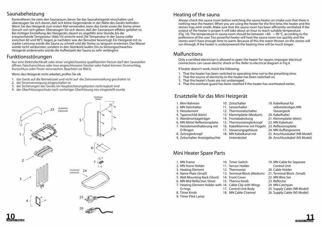
Ersatzteile für das Mini Heizgerät1.2.3.4.5.6.7.
8. 9.
10.11.12.13.14.15.16.17.18.
1110
Nur eine Elektrofachkraft oder einer vergleichsweise qualifizierten Person darf den Saunaofen öffnen. Falschanschluss oder lose angeschlossene Stecker oder Kabel können Stromschlag, Kurzschluss oder Feuer verursachen. Beachten sie Bild 6.
Saunabeheizung
Funktionsstörungen
Kontrollieren Sie stets den Saunaraum, bevor Sie das Saunaheizgerät einschalten und überzeugen Sie sich davon, daß sich keine Gegenstände in der Nähe des Geräts befinden. Wenn Sie das Heizgerät zum ersten Mal verwenden, kann das Gerät sowie die Steine einen Geruch von sich geben. Überzeugen Sie sich davon, daß der Saunaraum effektiv gelüftet ist. Bei richtiger Einstellung des Heizgeräts, dauert es ungefähr eine Stunde, bis die entsprechende Temperatur (Abb.10) erreicht wird. Die Temperatur in der Sauna sollte zwischen 60 und 90°C liegen, je nachdem was der Benutzer bevorzugt. Ein Heizgerät mit zu starker Leistung würde die Sauna zu schnell und die Steine zu langsam erwärmen. Das Wasser würde nicht verdunsten, sondern in den Steinkorb laufen. Ein zu leistungsschwaches Heizgerät andererseits würde die Aufheizzeit der Sauna zu sehr verlängern.
Wenn das Heizgerät nicht arbeitet, prüfen Sie ob
das Gerät auf die Betriebszeit und nicht auf die Zeitvoreinstellung geschaltet istdie Stromversorgung eingeschaltet istdie Sicherungen des Geräts im Hauptsicherungskasten nicht kaputt sindder Überhitzungsschutz nach vorheriger Überhitzung neu eingestellt wurde
1.2.3.4.
Mini-RahmenMN SteinhalterHeizelementTypenschild (klein)WandmontageträgerMN Mittel-ReflexionsplatteHeizelementhalterung mit O-RingenZeitreglerknopfZeitschalter-Anzeigeleuchte
ZeitschalterSensorhalterThermostatschalterKlemmplatte (Medium)FrontabdeckungThermostatreglerknopfKabelklemme mit FlügelnSteuerungsgehäuseMN Kabelkanal mit Unterdeckel
Kabelkanal für selbstständiges MN SteuergerätKabelhalterKlemmplatte (klein)MN KabelsatzReflexionsplatteMN Auffangwanne Anschlusskabel (NB Model)Anschlusskabel (NS Model)
19.
20.21.22.23.24.25.26.
1.2.3.4.5.6.7.
8. 9.
10.11.12.13.14.15.16.17.18.
MN FrameMN Stone HolderHeating ElementName Plate (Small)Wall Mounting Rack (Short)MN Mid Reflection SheetHeating Element Holder with O-ringsTimer KnobTimer Pilot Lamp
Timer SwitchSensor HolderThermostat Terminal Block (Medium)Front CoverThermo KnobCable Clip with WingsControl Unit BodyMN Cable Channel
MN Cable for Separate Control UnitCable Holder Terminal Block (Small)MN Wire SetReflectorMN CatchpanSupply Cable (NB Model)Supply Cable (NS Model)
19.
20.21.22.23.24.25. 26.
DEUTSCH / ENGLISHDEUTSCH / ENGLISH
(Zubehör)(Optional)
(Schlitze)(Slots)
6
7
4
5
3
23
1
2
24
25
26
(Zubehör)(optional)
ELECTRIC SAUNA HEATER
FRANÇAIS / ENGLISH
18
15
17
8
9
10
12
13
14 16
11
19
20
21
MN-23NSMN-30NSMN-36NS
Congratulations on your purchase of a Plug & Play sauna heater.Please read the manual carefully before using the heater.
MN-36NB MN-23NB MN-36NS
Thermostat
MinuteurTimer
MN
_MLP
lug
an
d P
lay
(FrE
n07
13)
Heating Elements-Eléments chauffants
Reset Button Hole
Numéro de sérieSerial Number
MN-23NBMN-30NBMN-36NB
MANUALMANUEL D’UTILISATION
Pour modèles avec unité decommande séparéeFor Models With Separate Control Unit
Sous réserve de modifications.Subject to change without notice.
Nous vous remercions d’avoir fait l’acquisition de votre poêle à sauna Plug & Play. Veuillez lire attentivement le manuel d’utilisation avant la mise en service.
Bouton de réinitialisation
POELE ELECTRIQUE DE
SAUNA
Unité de commande intégréeBuilt-in Control Unit
REMARQUES IMPORTANTES!WICHTIGE INFORMATION!
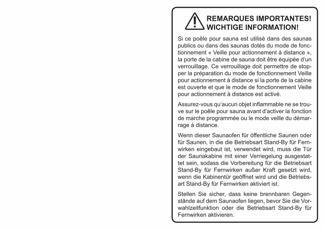
Si ce poêle pour sauna est utilisé dans des saunas publics ou dans des saunas dotés du mode de fonc-tionnement « Veille pour actionnement à distance », la porte de la cabine de sauna doit être équipée d‘un verrouillage. Ce verrouillage doit permettre de stop-per la préparation du mode de fonctionnement Veille pour actionnement à distance si la porte de la cabine est ouverte et que le mode de fonctionnement Veille pour actionnement à distance est activé.
Assurez-vous qu‘aucun objet inflammable ne se trou-ve sur le poêle pour sauna avant d‘activer la fonction de marche programmée ou le mode veille du démar-rage à distance.
Wenn dieser Saunaofen für öffentliche Saunen oder für Saunen, in die die Betriebsart Stand-By für Fern-wirken eingebaut ist, verwendet wird, muss die Tür der Saunakabine mit einer Verriegelung ausgestat-tet sein, sodass die Vorbereitung für die Betriebsart Stand-By für Fernwirken außer Kraft gesetzt wird, wenn die Kabinentür geöffnet wird und die Betriebs-art Stand-By für Fernwirken aktiviert ist.
Stellen Sie sicher, dass keine brennbaren Gegen-stände auf dem Saunaofen liegen, bevor Sie die Vor-wahlzeitfunktion oder die Betriebsart Stand-By für Fernwirken aktivieren.
Heater InstallationIt is recommended that the heater be placed on the wall nearest to the door. The air circulation created by the door should work together with the hot air generated by the heater. For safety and convenience, follow the minimum safety distances as provided in Fig. 1. Follow the cubic volumes given in Fig. 9. Do not install the heater to the floor or wall niche. Install only one heater in a sauna room.
Be sure to build a strong foundation for the mounting rack (e.g. cross struts in sauna paneling) or reinforce the wall with a thick board to prevent the heater from collapsing. Attach the heater to the wall with the aid of the mounting rack. Screws are provided for fastening of the rack to the wall. To affix the heater to the rack, lift the heater and fit the nuts that are placed at the back of the heater to the slots on both sides at the top of the rack. Lock at least one of the side screws to prevent the heater from being accidentally moved.
An electrical supply cable has been connected to the heater. The cable for NB model is H07RN-F and for NS model cable is Silicone H05SS-F. To avoid damaging and stressing the cable place it away from obstacles or objects with sharp edges.
NB Model is a Plug and Play heater with a European CE7/7 power plug. The supply cable of NS model has ready attached connector that is compatible with Plug & Play Modern Finnisch, P’n’P control.
The heater gets very hot. To avoid the risk of accidental contact with the heater, it is recommended that a heater guard be provided. Reserve enough space for operation of the timer and thermostat knobs. Follow the directions given in Fig. 2.
Fig. 2Fig. 2
32FRANÇAIS/ ENGLISH FRANÇAIS/ ENGLISH
Remove the carton from the heating elements and behind the serial number (between outer and inner cover) before installing the heater as it is only intended to protect them during shipment. Make sure that silicagel packs are still attach on the carton are removed. The purpose of those packs is to remove the moisture during shipment.
NOTE:
Fig. 1Fig. 1
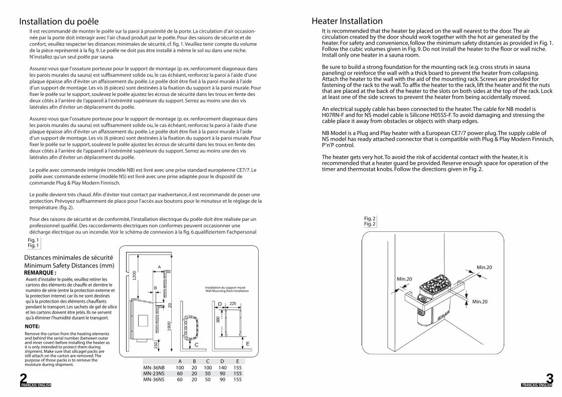
Il est recommandé de monter le poêle sur la paroi à proximité de la porte. La circulation d’air occasion-née par la porte doit interagir avec l’air chaud produit par le poêle. Pour des raisons de sécurité et de confort, veuillez respecter les distances minimales de sécurité, cf. fig. 1. Veuillez tenir compte du volume de la pièce représenté à la fig. 9. Le poêle ne doit pas être installé à même le sol ou dans une niche. N’installez qu’un seul poêle par sauna.
Assurez-vous que l’ossature porteuse pour le support de montage (p. ex. renforcement diagonaux dans les parois murales du sauna) est suffisamment solide ou, le cas échéant, renforcez la paroi à l’aide d’une plaque épaisse afin d’éviter un affaissement du poêle. Le poêle doit être fixé à la paroi murale à l’aide d’un support de montage. Les vis (6 pièces) sont destinées à la fixation du support à la paroi murale. Pour fixer le poêle sur le support, soulevez le poêle ajustez les écrous de sécurité dans les trous en fente des deux côtés à l’arrière de l‘appareil à l’extrémité supérieure du support. Serrez au moins une des vis latérales afin d’éviter un déplacement du poêle.
Assurez-vous que l’ossature porteuse pour le support de montage (p. ex. renforcement diagonaux dans les parois murales du sauna) est suffisamment solide ou, le cas échéant, renforcez la paroi à l’aide d’une plaque épaisse afin d’éviter un affaissement du poêle. Le poêle doit être fixé à la paroi murale à l’aide d’un support de montage. Les vis (6 pièces) sont destinées à la fixation du support à la paroi murale. Pour fixer le poêle sur le support, soulevez le poêle ajustez les écrous de sécurité dans les trous en fente des deux côtés à l’arrière de l‘appareil à l’extrémité supérieure du support. Serrez au moins une des vis latérales afin d’éviter un déplacement du poêle.
Le poêle avec commande intégrée (modèle NB) est livré avec une prise standard européenne CE7/7. Le poêle avec commande externe (modèle NS) est livré avec une prise adaptée pour le dispositif de commande Plug & Play Modern Finnisch.
Le poêle devient très chaud. Afin d’éviter tout contact par inadvertance, il est recommandé de poser une protection. Prévoyez suffisamment de place pour l’accès aux boutons pour le minuteur et le réglage de la température. (fig. 2).
Pour des raisons de sécurité et de conformité, l’installation électrique du poêle doit être réalisée par un professionnel qualifié. Des raccordements électriques non conformes peuvent occasionner une décharge électrique ou un incendie. Voir le schéma de connexion à la fig. 6.qualifiziertem Fachpersonal
Installation du poêle
Distances minimales de sécuritéMinimum Safety Distances (mm)
Avant d’installer le poêle, veuillez retirer les cartons des éléments de chauffe et derrière le numéro de série (entre la protection externe et la protection interne) car ils ne sont destinés qu’à la protection des éléments chauffants pendant le transport. Les sachets de gel de silice et les cartons doivent être jetés. Ils ne servent qu’à éliminer l’humidité durant le transport.
REMARQUE :
MN-23NSMN-36NS
6060
2020
5050
9090
155155
A B C D EMN-36NB 100 20 100 140 155
1900
150
1200
A
B
20
225
380
C E
D
Min.20
Min.20
Min.20
Installation du support muralWall Mounting Rack Installation
FRANÇAIS/ ENGLISH4
Fig. 3AFig. 3A
Fig. 3BFig. 3B
4
4
Fig. 4Fig. 4
If you want to transfer the control unit to the other side (right or left), remove the nameplate, pull out the thermostat's knob (Fig.3A) and open the screws, which are holding the front cover. Open the screws which are holding the control unit (Fig.3B). Pull outwards the control unit's upper edge and transfer the control unit to the other side. First mount the control unit's bottom-edge, noticing the small hooks there. Then mount upper edge of the control unit very carefully and tighten the screws. Make sure that the sensors are properly placed (Fig.8). Screw the nameplate and fix it on the side where the control unit was originally placed. Put front cover and thermostat knob on their places.
Repositioning of the Built-In Control Unit (Refer to Fig.3b)
5
Fig 5Fig. 5
Heater StonesThe main purpose of the stones in the heater unit is to store enough energy to efficientlyvaporize the water thrown on top of the stones to maintain correct humidity in the sauna room. The stones must be removed at least once a year or every 500 hours which everoccurs first. All stone crumbles must be removed from the heater unit and replaced with new ones as described in the heater manual. The required amount of stones is also listed in the manual provided. See Fig.5.
NOTE! Never use the heater without stones as it may cause fire. Use only manufacturer recommended SaWo-stones. Using unsuitable stones may lead to heating element damage and will void the warranty. Never use ceramic stones or other artificial stones of any type!Loading stones into the heaterIt is recommended that all stones should be rinsed to remove any stains or dust that can cause unpleasant odour during the first few times of using the heater. It is important that the stones are loaded carefully in a way that they do not block air circulation through theheater. Larger stones that won’t fit between the heating elements must not be forced in place instead they must be completely removed.Small crumble or stone pieces smaller than 35mm in diameter mustnot be loaded into the heater because they will block the air circulation and will cause overheating and possible heating element damage.
NOTE! Heating element damage due to overheatingcaused by wrong kind of stones or stones which were wrongly loaded into the heater is not covered by thefactory warranty.
1
2
3
3
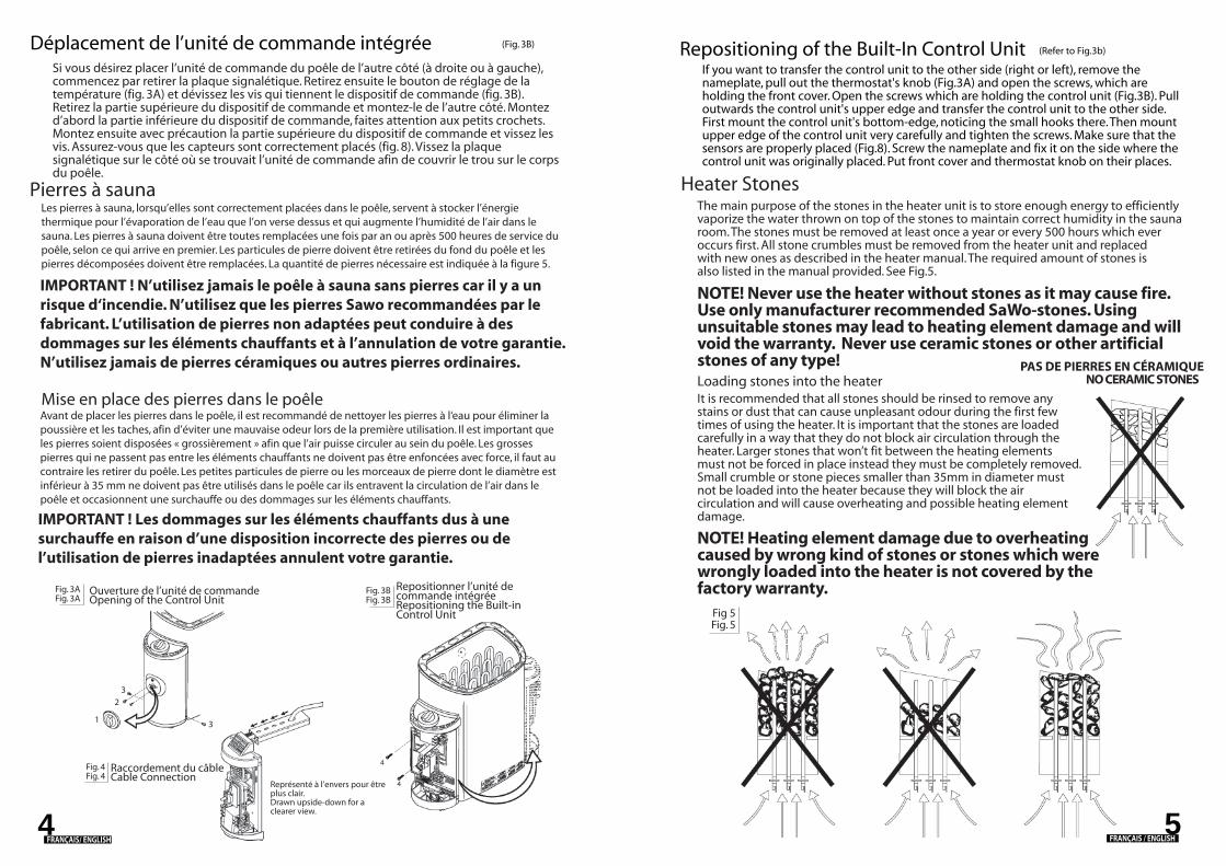
Si vous désirez placer l’unité de commande du poêle de l’autre côté (à droite ou à gauche), commencez par retirer la plaque signalétique. Retirez ensuite le bouton de réglage de la température (fig. 3A) et dévissez les vis qui tiennent le dispositif de commande (fig. 3B). Retirez la partie supérieure du dispositif de commande et montez-le de l’autre côté. Montez d’abord la partie inférieure du dispositif de commande, faites attention aux petits crochets. Montez ensuite avec précaution la partie supérieure du dispositif de commande et vissez les vis. Assurez-vous que les capteurs sont correctement placés (fig. 8). Vissez la plaque signalétique sur le côté où se trouvait l’unité de commande afin de couvrir le trou sur le corps du poêle.
Déplacement de l’unité de commande intégrée (Fig. 3B)
Mise en place des pierres dans le poêle
Pierres à saunaLes pierres à sauna, lorsqu’elles sont correctement placées dans le poêle, servent à stocker l’énergie thermique pour l’évaporation de l’eau que l’on verse dessus et qui augmente l’humidité de l’air dans le sauna. Les pierres à sauna doivent être toutes remplacées une fois par an ou après 500 heures de service du poêle, selon ce qui arrive en premier. Les particules de pierre doivent être retirées du fond du poêle et les pierres décomposées doivent être remplacées. La quantité de pierres nécessaire est indiquée à la figure 5.
IMPORTANT ! N’utilisez jamais le poêle à sauna sans pierres car il y a un risque d‘incendie. N’utilisez que les pierres Sawo recommandées par le fabricant. L’utilisation de pierres non adaptées peut conduire à des dommages sur les éléments chauffants et à l’annulation de votre garantie. N’utilisez jamais de pierres céramiques ou autres pierres ordinaires.
Avant de placer les pierres dans le poêle, il est recommandé de nettoyer les pierres à l‘eau pour éliminer la poussière et les taches, afin d’éviter une mauvaise odeur lors de la première utilisation. Il est important que les pierres soient disposées « grossièrement » afin que l’air puisse circuler au sein du poêle. Les grosses pierres qui ne passent pas entre les éléments chauffants ne doivent pas être enfoncées avec force, il faut au contraire les retirer du poêle. Les petites particules de pierre ou les morceaux de pierre dont le diamètre est inférieur à 35 mm ne doivent pas être utilisés dans le poêle car ils entravent la circulation de l’air dans le poêle et occasionnent une surchauffe ou des dommages sur les éléments chauffants.
IMPORTANT ! Les dommages sur les éléments chauffants dus à une surchauffe en raison d’une disposition incorrecte des pierres ou de l’utilisation de pierres inadaptées annulent votre garantie.
Ouverture de l’unité de commandeOpening of the Control Unit
Repositionner l’unité de commande intégréeRepositioning the Built-in Control Unit
Raccordement du câbleCable Connection
Représenté à l’envers pour être plus clair.Drawn upside-down for a clearer view.
NO CERAMIC STONESPAS DE PIERRES EN CÉRAMIQUE
FRANÇAIS / ENGLISH
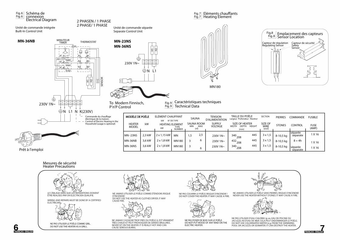
Fig. 7Fig. 7
Fig. 6Fig. 6
2 PHASE/ 1 PHASE
Fig. 9Fig. 9
SEN
SOR
THERMOSTAT
2 PHASEN / 1 PHASE
7
MN-23NSMN-36NS
MN180
MN-36NB
a
a
M
230V 1N~
N
a1
a1 a
a1
J1
NL1 K(230V)
A3
H1
H2
B3
b0b
b0b
b0b
A2
A1
PL
B2
B1
230V 1N~
H1
H2
N L1
Prêt à l’emploi
To Modern Finnisch, P’n’P Control
NUMBER
2,3 kW
3,6 kW
3,6 kW
MN -23NS
MN-36NB
MN-36NS
2 x 1,15 kW
2 x 1,8 kW
2 x 1,8 kW
2,5
6
6
208
208
208
445
445
445
3 x 1,5
3 x 1,5
3 x 1,5
340
432
340
séparéeseparate
8 + 4h
séparéeseparate
8-10,5 kg
8-10,5 kg
8-10,5 kg
1 X 16
1 X 16
1 X 16
230V 1N~
230V 1N~
230V 1N~
Schéma de connexion Electrical Diagram
Unité de commande intégréeBuilt-In Control Unit
Unité de commande séparée Separate Control Unit
Eléments chauffantsHeating Element
MINUTEURTIMER
Emplacement des capteursSensor Location
Fig.8Fig. 8
Capteur de régulationRegulating Sensor
Capteur de sécuritéSafety Sensor
Commande du chauffage électrique de la maison.Control of Electric Heating in the Household (usage is optional)
Caractéristiques techniquesTechnical Data
kW kW
HEATER HEATiNG ELEMENTMODEL
kW
MODÈLE DE POÊLE
STONES CONTROLSAUNA ROOM SUPPLY SIZE OF HEATER SIZE OF
WIREDEPTH HEIGHTWIDTHVOLTAGEMIN MAXTYPE 3 2
SAUNATENSION
D‘ALIMENTATIONPIERRES COMMANDE
FUSE(AMP.)
FUSIBLETAILLE DU POÊLEHauteurLargeur Profondeur
ELÉMENT CHAUFFANT N° DE TYPE
MODÈLE DE POÊLE SECTION
1,5
3
3
MN
MN180
MN180
LE CÂBLAGE AINSI QUE LES REPARATIONS DOIVENT ËTRE REALISES PAR UN ELECTRICIEN QUALIFIE.
WIRING AND REPAIRS MUST BE DONE BY A CERTIFIED ELECTRICIAN.
NE PAS UTILISER LE POÊLE COMME GRIL.DO NOT USE THE HEATER AS A GRILL.
NE JAMAIS UTILISER LE POÊLE COMME ETENDOIR; RISQUE D‘INCENDIE!DO NOT USE THE HEATER AS CLOTHES DRYER. IT MAY CAUSE FIRE.
NE JAMAIS S’ASSEOIR TROP PRES DU POÊLE; IL EST VRAIMENT TRES CHAUD ET PEUT PROVOQUER DE GRAVES BRULURES.NEVER SIT ON THE HEATER. IT IS REALLY HOT AND CAN CAUSE SERIOUS BURNS.
NE PAS POSER DE BOIS SUR LE POÊLE.DO NOT PUT WOOD OF ANY KIND ON THE ELECTRIC HEATER.
NE PAS COUVRIR LE POÊLE; RISQUE D’INCENDIE !DO NOT COVER THE HEATER. IT MAY CAUSE A FIRE.
NE JAMAIS UTILISER LE POÊLE SANS PIERRES. RISQUE D’INCENDIE!NEVER USE THE HEATER WITHOUT STONES. IT MAY CAUSE A FIRE.
NE PAS UTILISER D’EAU CHLOREE (p. ex. EAU DE PISCINE OU JACUZZI), NI D’EAU DE MER. CELA PEUT ENDOMMAGER LE POÊLE;DO NOT USE CHLORINATED WATER (e.g. FROM THE SWIMMING POOL OR JACUZZI) OR SEAWATER. IT CAN DESTROY THE HEATER.
Mesures de sécuritéHeater Precautions
(m) (mm)(mm)
6FRANÇAIS / ENGLISH6
FRANÇAIS / ENGLISH
Air VentilationTo have a soothing sauna, there should be a proper mixing of hot and cold air inside the sauna room. Another reason for ventilation is to draw air around the heater and move the heat to the farthest part of the sauna. The positioning of the inlet and outlet vents may vary depending on the design of the sauna room or preference of the owner.
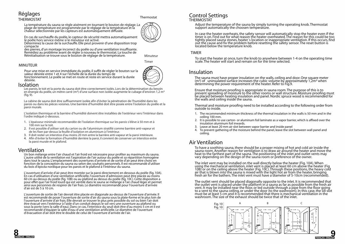
The inlet vent may be installed on the wall directly below the heater (Fig. 10A). When using the mechanical ventilation, inlet vent is placed at least 60 cm above the heater (Fig 10B) or on the ceiling above the heater (Fig. 10C). Through these positions, the heavy cold air that is blown into the sauna is mixed with the light hot air from the heater, bringing fresh air for the bathers. The inlet vent must have a diameter of 5-10cm (recommended).
The outlet vent should be placed diagonally opposite to the inlet. It is recommended that the outlet vent is placed under the platform in a sauna as far as possible from the fresh air vent. It may be installed near the floor, or led outside through a pipe from the floor going to a vent to the sauna ceiling, or under the door (to the washroom). In this case, the sill slot must be at least 5 cm and it is recommended that there is mechanical ventilation in the washroom. The size of the exhaust should be twice that of the inlet.
InsulationThe sauna must have proper insulation on the walls, ceiling and door. One square meter (m²) of uninsulated surface increases the cubic volume by approximately 1,2m³ when determining the power requirement of the heater. Refer to Fig.9.
Ensure that moisture proofing is appropriate in sauna room. The purpose of this is to prevent spreading of moisture to the other rooms or wall structure. Moisture proofing must be placed between heating insulation and panel. Nordic spruce wood is recommended for the walls and ceiling inside the sauna.
Thermal and moisture proofing need to be installed according to the following order from outside to inside.
TIMER
Control Settings
Adjust the temperature of the sauna by simply turning the operating knob. Thermostat support automatically the choosen temperature.
In case the heater overheats, the safety sensor will automatically stop the heater even if the timer is on. Find out for what reason the heater overheated. The reason for this could be too tightly placed sauna stones, heater´s location or inappropriate ventilation. If this occurs, find out the cause and fix the problem before resetting the safety sensor. The reset button is located below the temperature knob.
To start the heater at once, turn the knob to anywhere between 1-4 on the operating time scale. The heater will start and remain on for the time selected.
THERMOSTAT
The recommended minimum thickness of the thermal insulation in the walls is 50 mm and in the ceiling 100 mm.It is possible to use carton- or aluminum foil laminate as a vapor barrier, which is affixed over the insulation aluminum foil inwards.Leave at least 20 mm air slot between vapor barrier and inside panelTo prevent gathering of the moisture behind the panel, leave the slot between wall panel and ceiling.
1.
2.
3.4.
A B CFig. 10Fig. 10
98
Minuteur
Timer
VentilationUn bon mélange entre l’air chaud et l’air froid est nécessaire pour profiter au maximum du sauna. L’autre utilité de la ventilation est l’aspiration de l’air autour du poêle et sa répartition homogène dans tout le sauna. L’emplacement des ouvertures d’arrivée et de sortie d’air peut être choisi en fonction de la conception du sauna ou selon des souhaits personnels. Il est recommandé d’utiliser du bois d’épicéa nordique pour les parois et le plafond à l’intérieur du sauna.
L’ouverture d’arrivée d’air peut être montée sur la paroi directement en dessous du poêle (fig. 10A). En cas d’utilisation d’une ventilation artificielle, l’ouverture d’admission peut être placée au moins 60 cm au-dessus du poêle (fig. 10B) ou au plafond au dessus du poêle (fig. 10C). Cette disposition a pour effet que l’air froid lourd qui est ventilé dans le sauna se mélange à l’air chaud léger et permet ainsi aux personnes de respirer de l’air frais. Le diamètre recommandé pour l’ouverture d’arrivée d’air est de 5 à 10 cm.
L’ouverture de sortie de l’air devrait être placée en diagonale au-dessus de l’ouverture d’arrivée. Il est recommandé de poser l’ouverture de sortie d’air du sauna sous la plate-forme et le plus loin de l’ouverture d’arrivée d’air frais. Elle devrait se trouver le plus près possible du sol ou bien l’air doit être évacué vers l’extérieur à l’aide d’un conduit depuis le sol vers une ouverture au plafond ou sous la porte (vers la salle d’eau). Dans ce cas, l’interstice du seuil doit être d’au moins 5 cm et il est recommandé d’équiper la salle d’eau d’une ventilation artificielle. Le diamètre de l’ouverture d’évacuation d’air doit être le double de celui de l’ouverture d’arrivée de l’air.
IsolationLes parois, le toit et la porte du sauna doit être correctement isolés. Lors de la détermination du besoin en énergie du poêle, un mètre carré (m²) d’une surface non isolée augmente le cubage d’environ 1,2 m³ (fig. 9).
La cabine de sauna doit être suffisamment isolée afin d’éviter la pénétration de l’humidité dans les parois ou dans les pièces voisines. Une barrière d’humidité doit être posée entre l’isolation du poêle et la paroi murale.
L’isolation thermique et la barrière d’humidité doivent être installées de l’extérieur vers l’intérieur dans l’ordre indiqué ci-dessous.
MINUTEUR
Réglages
La température du sauna se règle aisément en tournant le bouton de réglage. La plage de température est programmée par le réglage de la température et la chaleur sélectionnée par les capteurs est automatiquement diffusée.
En cas de surchauffe du poêle, le capteur de sécurité mettra automatiquementle poêle hors service même si le minuteur est activé.Déterminez la cause de la surchauffe. Elle peut provenir d’une disposition trop compactedes pierres, d’un montage incorrect du poêle ou d’une ventilation insuffisante.Remédiez au problème avant de régler à nouveau le thermostat. La touche deRéinitialisation se trouve sous le bouton de réglage de la température.
Pour une mise en service immédiate du poêle, il suffit de régler le bouton sur la valeur désirée entre 1 et 4 sur l’échelle de la durée du temps de fonctionnement. Le poêle se met en route et reste en service durant la durée désirée.
THERMOSTAT
L’épaisseur minimale recommandée de l’isolation thermique sur les parois s’élève à 50 mm et à 100 mm sur le toit.Il est possible d’utiliser soit du carton ou de l’aluminium stratifié comme barrière anti-vapeur et de les fixer par-dessus la feuille d’isolation en aluminium à l’intérieur.Il doit rester un interstice d’au moins 20 mm entre la barrière anti-vapeur et la paroi intérieure.Afin d’éviter la formation d’humidité derrière la paroi, il convient de conserver un interstice entre la paroi murale et le plafond.
1.
2.
3.4.
Thermostat
C
32
10
FRANÇAIS / ENGLISH FRANÇAIS / ENGLISH
Mini Heater Spare Parts
Heating of the sauna
Malfunctions
Always check the sauna room before switching the sauna heater on (make sure that there is nothing near the heater). When you are using the heater for the first time, the heater and the stones may emit smells. Make sure that the sauna room has been efficiently ventilated. If the output of the heater is proper it will take about an hour to reach suitable temperature (Fig. 10). The temperature in sauna room should be between +60 - + 90 °C, according to the preference of the user. Too powerful heater will heat the sauna room too quickly and the stones won't have enough time to warm. Because of this the water thrown on the stones will run through. If the heater is underpowered the heating time will be much longer.
If heater doesn't work, check the following:
Only a certified electrician is allowed to open the heater for repairs. Improper electrical connections can cause electric shock or fire. Refer to electrical diagram in Fig 6.
That the heater has been switched to operating time not to the presetting time. That the source of electricity to the heater has been switched on.That the heater's fuses are not undamaged.That the overheat guard has been resetted if the heater has overheated earlier.
1.2.3.4.
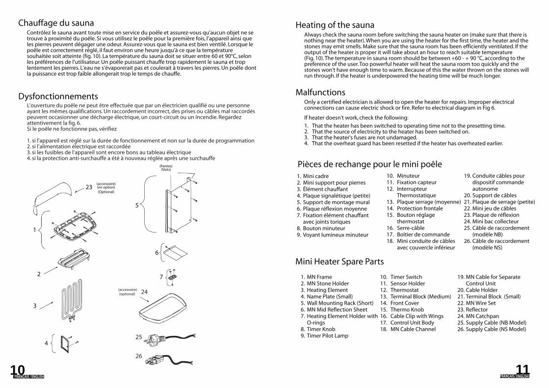
Pièces de rechange pour le mini poêle
1110
1.2.3.4.5.6.7.
8. 9.
10.11.12.13.14.15.16.17.18.
MN FrameMN Stone HolderHeating ElementName Plate (Small)Wall Mounting Rack (Short)MN Mid Reflection SheetHeating Element Holder with O-ringsTimer KnobTimer Pilot Lamp
Timer SwitchSensor HolderThermostat Terminal Block (Medium)Front CoverThermo KnobCable Clip with WingsControl Unit BodyMN Cable Channel
MN Cable for Separate Control UnitCable Holder Terminal Block (Small)MN Wire SetReflectorMN CatchpanSupply Cable (NB Model)Supply Cable (NS Model)
19.
20.21.22.23.24.25. 26.
6
7
4
5
3
23
1
2
24
25
26
1.2.3.4.5.6.7.
8. 9.
Mini cadreMini support pour pierres Élément chauffantPlaque signalétique (petite)Support de montage mural Plaque réflexion moyenneFixation élément chauffant avec joints toriquesBouton minuteurVoyant lumineux minuteur
10.11.12.
13.14.15.
16.17.18.
MinuteurFixation capteur InterrupteurThermostatiquePlaque serrage (moyenne)Protection frontaleBouton réglage thermostatSerre-câbleBoîtier de commandeMini conduite de câbles avec couvercle inférieur
Conduite câbles pour dispositif commande autonomeSupport de câblesPlaque de serrage (petite)Mini jeu de câblesPlaque de réflexion Mini bac collecteurCâble de raccordement (modèle NB)Câble de raccordement (modèle NS)
19.
20.21.22.23.24.25.
26.
L’ouverture du poêle ne peut être effectuée que par un électricien qualifié ou une personne ayant les mêmes qualifications. Un raccordement incorrect, des prises ou câbles mal raccordés peuvent occasionner une décharge électrique, un court-circuit ou un incendie. Regardez attentivement la fig. 6.Si le poêle ne fonctionne pas, vérifiez
1. si l’appareil est réglé sur la durée de fonctionnement et non sur la durée de programmation2. si l’alimentation électrique est raccordée3. si les fusibles de l’appareil sont encore bons au tableau électrique4. si la protection anti-surchauffe a été à nouveau réglée après une surchauffe
Chauffage du sauna
Dysfonctionnements
Contrôlez le sauna avant toute mise en service du poêle et assurez-vous qu’aucun objet ne se trouve à proximité du poêle. Si vous utilisez le poêle pour la première fois, l’appareil ainsi que les pierres peuvent dégager une odeur. Assurez-vous que le sauna est bien ventilé. Lorsque le poêle est correctement réglé, il faut environ une heure jusqu’à ce que la température souhaitée soit atteinte (fig. 10). La température du sauna doit se situer entre 60 et 90°C, selon les préférences de l’utilisateur. Un poêle puissant chauffe trop rapidement le sauna et trop lentement les pierres. L’eau ne s’évaporerait pas et coulerait à travers les pierres. Un poêle dont la puissance est trop faible allongerait trop le temps de chauffe.
(accessoire) (en option)(Optional)
(Fentes)(Slots)
(accessoire)(optional)
FRANÇAIS / ENGLISH FRANÇAIS / ENGLISH