Embed Size (px)
Citation preview
Bedienungsanleitung User manual
Rotationslaser Rotating Laser LevelFL 260VA / FLG 260VA-Green
2
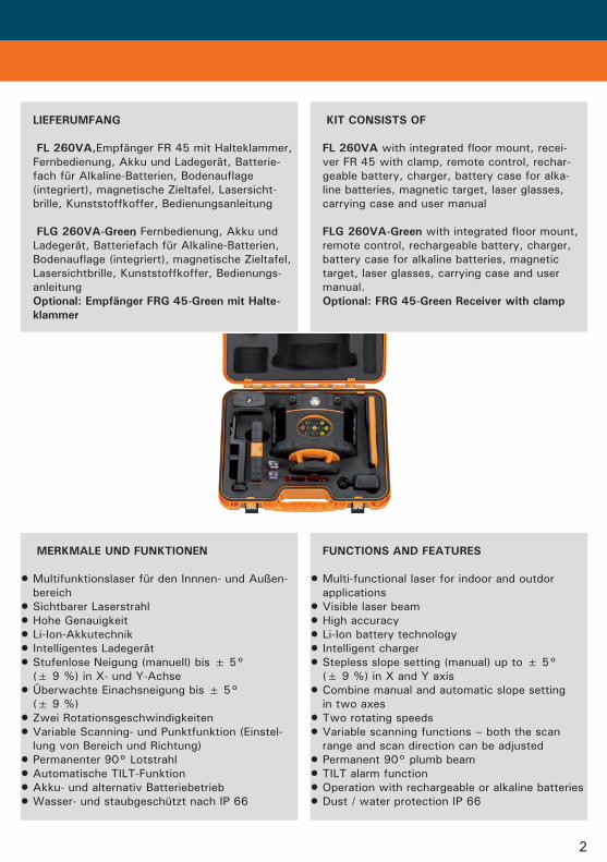
LIEFERUMFANG
FL260VA,Empfänger FR 45 mit Halteklammer, Fernbedienung, Akku und Ladegerät, Batterie- fach für Alkaline-Batterien, Bodenauflage (integriert), magnetische Zieltafel, Lasersicht- brille, Kunststoffkoffer, Bedienungsanleitung
FLG260VA-Green,Fernbedienung, Akku und Ladegerät, Batteriefach für Alkaline-Batterien, Bodenauflage (integriert), magnetische Zieltafel, Lasersichtbrille, Kunststoffkoffer, Bedienungs- anleitung Optional:EmpfängerFRG45-GreenmitHalte- klammer
KITCONSISTSOF
FL260VAwith integrated floor mount, recei- ver FR 45 with clamp, remote control, rechar- geable battery, charger, battery case for alka- line batteries, magnetic target, laser glasses, carrying case and user manual
FLG260VA-Greenwith integrated floor mount, remote control, rechargeable battery, charger, battery case for alkaline batteries, magnetic target, laser glasses, carrying case and user manual. Optional:FRG45-GreenReceiverwithclamp
MERKMALEUNDFUNKTIONEN
Multifunktionslaser für den Innnen- und Außen- bereich
Sichtbarer LaserstrahlHohe GenauigkeitLi-Ion-AkkutechnikIntelligentes LadegerätStufenlose Neigung (manuell) bis ± 5°
(± 9 %) in X- und Y-AchseÜberwachte Einachsneigung bis ± 5°
(± 9 %)Zwei RotationsgeschwindigkeitenVariable Scanning- und Punktfunktion (Einstel-
lung von Bereich und Richtung)Permanenter 90° LotstrahlAutomatische TILT-FunktionAkku- und alternativ BatteriebetriebWasser- und staubgeschützt nach IP 66
•
•••••
•
••
••••
FUNCTIONSANDFEATURES
Multi-functional laser for indoor and outdor applications
Visible laser beamHigh accuracyLi-Ion battery technologyIntelligent chargerStepless slope setting (manual) up to ± 5°
(± 9 %) in X and Y axisCombine manual and automatic slope setting
in two axesTwo rotating speedsVariable scanning functions – both the scan
range and scan direction can be adjustedPermanent 90° plumb beamTILT alarm functionOperation with rechargeable or alkaline batteriesDust / water protection IP 66
•
•••••
•
••
••••
3
Neigungsfunktion im Horizontalbetrieb: - Manuelle Neigung in X- und Y-Achse - Eine Achse (X oder Y) manuell geneigt, zweite Achse selbstnivelliert
Richtungseinstellung im Vertikalbetrieb (nur mit Fernbedienung): - Richtungseinstellung in X- und Z-Achse - X- und Z-Achse manuell verstellbar, Y-Achse selbstnivelliert
Vibrations-Wind-Schutz-Funktion (kombiniert mit TILT-Funktion) - Gerät rotiert weiter auch bei leichten Bodenerschütterungen oder leich- tem Wind
Abschaltbare Fernbedienungsfunktion: Zur Ver- meidung von Störungen durch andere Fernbe- dienungen, Mobiltelefone usw.
Integrierte Bodenauflage mit Rißspitze FLG260VA-Green
Alle Funktionen wie beim FL 260VA, jeodch mit gründer Diode
Klare Vorteile im InnenausbauErhöhte Sichtbarkeit des Laserstrahls unter
schwierigen Bedingungen (helle Umgebung, lange Distanzen, dunkle Messfläche)
•
•
•
•
•
•
••
Horizontal slope setting function: - Manual slope setting of X and Y axis - Manual slope setting of one axis (X or Y), 2nd axis self-levelled
Direction setting of vertical axis (with remote control only): - Direction setting of X and Z axis - Manual setting of X and Z axis, Y axis self- levelled
Vibration-Wind-Security function (combined with TILT-function) - rotation will not stop du- ring light ground / wind vibrations
Remote control shield: Remote control can be switched off to avoid interference with other instruments working on the same site
Integrated floor mount with datum point
FLG260VA-GreenSame functions as FL 260VA, but with green
laser diodeIdeally suited for indoor applicationsImproved visibility of laser beam. Especially
useful in bright surroundings and over longer distances.
•
•
•
•
•
••
••
TECHNISCHEDATEN
Selbstnivellierbereich ± 5° TILT-Funktion ja Vibrations-Wind-Schutz ja Genauigkeit horizontal ± 0,75 mm / 10 m vertikal ± 1,5 mm / 10 m Reichweite FL 260VA mit FR 45 Ø 600 m FLG 260VA-Green mit FRG 45-Green Ø 400 m Punktfunktion ohne Empfänger FL 260VA ca. 50 m* FLG 260VA-Green ca. 80 m* Scanning ohne Empfänger FL 260VA ca. 30 m* FLG 260VA-Green ca. 40 m*
TECHNICALDATA
Self-levelling range ± 5° TILT-function yes Vibration-Wind-Security yes Accuracy horizontal ± 0,75 mm / 10 m vertical ± 1,5 mm / 10 m Working range FL 260VA with FR 45 Ø 600 m FLG 260VA-Green with FRG 45-Green Ø 400 m Not rotating w/o receiver FL 260VA approx. 50 m* FLG 260VA-Green approx. 80 m* Scanning w/o receiver FL 260VA approx. 30 m* FLG 260VA-Green approx. 40 m*
4
BATTERYANDCHARGER
The instrument comes with with 3.6V Li-Ion rechargeable battery. The battery charger plug is connected to the socket on the rechargeable battery pack (after removing the rubber plug). The battery pack can be charged on or off the laser.
Charging LED at charger indicates: Permanent RED light = battery pack is being charged. Permanent GREEN light = battery is fully charged.
Charging time is approx. 7 hours.
Before using the laser for the first time we re- commend that you fully charge the battery pack.
STROMVERSORGUNG
Der Laser ist mit einem 3,6V-Akkupack der neuesten Li-Ion-Technik ausgestattet. Ladege- rät mit Netz und Ladebuchse am Gerät (auf der Rückseite über dem Batteriefachverschluß) ver- binden.
Die Ladekontrollleuchte am Ladegerät zeigt an: Permanentes ROTES Licht = Akku wird geladen. Permanentes GRÜNES Licht = Akku ist vollständig aufgeladen.
Die Ladezeit, um die Akkus vollständig aufzu- laden, beträgt ca. 7 Stunden.
Vor der ersten Inbetriebnahme Akku vollständig aufladen.
Rotierend ohne Empfänger FL 260VA ca. 20 m* FLG 260VA-Green ca. 30 m* Manuelle Neigung X- und Y-Achse ± 5° (± 9 %) Rotationsgeschwindigkeit 800, 300 U / Min. Betriebsdauer FL 260VA Li-Ion-Akku 50h Alkaline-Batterie 30h Betriebsdauer FLG 260VA-Green Li-Ion-Akku 25h Alkaline-Batterie 16h Stromversorgung 3,6V Li-Ion-Akku alternativ 3 x 1,5V C Alkaline- Batterien Temperaturbereich FL 260VA -10°C - +45°C FLG 260VA-Green 0°C - +40°C Laserdiode / Laserklasse FL 260VA 635 nm / 3R FLG 260VA-Green 532 nm / 3R Staub-/Wasserschutz IP 66
* abhängig von der Raumhelligkeit
Rotating w/o receiver FL 260VA approx. 20 m* FLG 260VA-Green approx. 30 m* Gradual slope setting in X and Y axis ± 5° (± 9 %) Rotating speed 800, 300 rpm Operating time FL 260VA Li-Ion battery 50h Alkaline battery 30h Operating time FLG 260VA-Green Li-Ion battery 25h Alkaline battery 16h Power supply 3.6V Li-Ion rechargeable battery alternatively 3 x 1.5V C alkaline battery Temperature range FL 260VA -10°C - +45°C FLG 260VA-Green 0°C - +40°C Laser diode / laser class FL 260VA 635 nm / 3R FLG 260VA-Green 532 nm / 3R Dust/water protection IP 66
* depending on room illumination
5
If the POWER LED (9) on the instrument con- trol panel is flashing the battery pack needs to be charged.
The battery charger can be used to run the laser and charge the battery pack at the same time.
As an alternative, the laser can be powered by using the battery case for alkaline batteries fitted with 3 x 1.5V C alkaline batteries.
Wenn die POWER-LED am Gerät während des Betriebes zu blinken beginnt, muß der Akku geladen werden.
Das Ladegerät kann bei eingesetztem Akkupack auch als Netzgerät verwendet werden.
Alternativ kann der Laser auch mit 3 x 1,5V C Alkaline-Batterien betrieben werden.
BEDIENUNG OPERATION
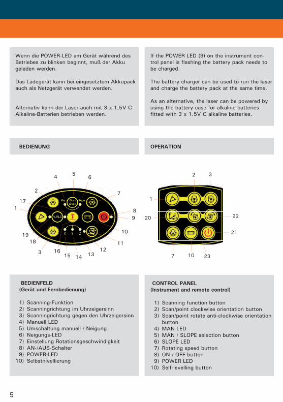
BEDIENFELD (GerätundFernbedienung)
1) Scanning-Funktion 2) Scanningrichtung im Uhrzeigersinn 3) Scanningrichtung gegen den Uhrzeigersinn 4) Manuell LED 5) Umschaltung manuell / Neigung 6) Neigungs-LED 7) Einstellung Rotationsgeschwindigkeit 8) AN-/AUS-Schalter 9) POWER-LED 10) Selbstnivellierung
CONTROLPANEL (Instrumentandremotecontrol)
1) Scanning function button 2) Scan/point clockwise orientation button 3) Scan/point rotate anti-clockwise orientation button 4) MAN LED 5) MAN / SLOPE selection button 6) SLOPE LED 7) Rotating speed button 8) ON / OFF button 9) POWER LED 10) Self-levelling button
89
10
11
131415163
19
117
2
4 56
7
1218
2 3
22
21
23107
20
1
6
TASTENFUNKTIONEN KEYFUNCTION
11) TILT-Funktion 12) TILT-LED 13) LED Z-Richtung 14) LED Y-Richtung 15) LED X-Richtung 16) Fernbedienung an / aus 17) LED Fernbedienung aus 18) Vibrations-Wind-Schutz-Funktion 19 ) Vibrations-Wind-Schutz-LED 20) Auswahl Neigungsachse X / Y / Z 21) Energiesparfunktion (Sleep) 22) Neigungseinstellung auf 23) Neigungseinstellung ab
11) TILT function button 12) TILT LED 13) Z direction LED 14) Y direction LED 15) X direction LED 16) Remote control shield button 17) Remote control shield LED 18) Vibration-Wind-Security button 19) Vibration-Wind-Security LED 20) Slope X / Y / Z selection button 21) Remote control sleep button 22) Slope up adjustment button 23) Slope down adjustment button
GERÄTEIN-/AUSSCHALTEN
Taste (8) drücken, um den Laser FL 260VA / FLG 260VA-Green einzuschalten. Die POWER- LED (9) leuchtet permanent. Taste (8) erneut drücken, um das Gerät wieder auszuschalten.
Wenn die POWER-LED (9) zu blinken beginnt, muss der Akku geladen werden.
ON/OFFBUTTON
Press on/off button (8) to switch the laser on. The POWER LED (9) is illuminated. Press on/off button once more to switch unit off.
If POWER LED (9) is flashing during use the battery power is low.
7
ROTATINGSPEED
When switched on the laser automatically ro- tates at the maximum speed of 800 rpm. Press button (7) to reduce the speed to 300 rpm. Press button (7) once more to stop the rotation.
Laserpointfunction Enter the „laser point function“ by pressing button (7) until the rotation has stopped. Press button (2) to orientate the laser point in a clock- wise direction and button (3) for anti-clockwise.
ROTATIONSGESCHWINDIGKEIT
Nach dem Einschalten dreht das Gerät mit maxi- maler Geschwindigkeit. Mit Taste (7) kann diese verändert werden: 800 U/Min. -> 300 U/Min. -> 0 U/Min. -> 800 U/Min.
Punktfunktion Rotationsgeschwindigkeit 0 U/Min = Punkt- funktion. Mit den Tasten (2) und (3) kann die Richtung des Laserpunktes verstellt werden.
TILTALARMFUNCTION
Switching on the laser automatically activates the TILT function. The TILT LED (12) is flashing during activation procedure. When activation is completed (after 90 sec. approx.) the LED is illuminated. If the laser is disturbed, rotation stops and the laser beam and TILT LED (12) will flash.The laser will not re-level automatically.
If required the self-levelling procedure can be re-activated by pressing button (10).
To quit TILT function press button (11).
If the laser is disturbed due to a positional change of the tripod it will automatically self- level itself (within the self-levelling range of 5°), a height offset can occur. This will be avoided by using TILT function. Using this function ensures the laser is shut off even within the self-levelling range when the laser is disturbed. Switch unit on, wait until self-levelling proce- dure is completed.
TILT-FUNKTION
Mit dem Einschalten des Gerätes wird automa- tisch die TILT-Funktion aktiviert; die TILT-LED (12) blinkt während der Aktivierung. Wenn die- se abgeschlossen ist (nach ca. 90 Sek.), leuch- tet die LED permanent. Wenn das Gerät nun aus seiner Lage gebracht wird, stoppt die Rotation, und der Laserstrahl sowie TILT-LED (12) blinken (keine automatische Nachstellung).
Wenn gewünscht, kann die Selbstnivellierung aus dieser Position heraus mit Taste (10) ge- startet werden.
Zum Verlassen der TILT-Funktion Taste (11) drücken. Bei deaktivierter TILT-Funktion stellt sich der FL 260VA / FLG 260VA-Green bei Lageverän- derungen automatisch nach. Bei einer großen Lageveränderung (z.B. unbeabsichtigtes Ver- stellen eines Stativbeines) kommt es zu einer Veränderung der Bezugshöhe. Dies wird durch die TILT-Funktion verhindert – das Gerät schal- tet dann auch innerhalb des Selbstnivellierbe- reiches ab: Gerät einschalten und Selbstnivel- lierungsvorgang abwarten.
8
SCANNNGFUNKTION
Durch Drücken der Taste (1) gelangt man in die Scanningfunktion. Der Scanningwinkel beim Einschalten beträgt 180°.
Durch erneutes Drücken der Taste (1) kann der Scanningwinkel eingestellt werden: 180° -> 90° -> 45°-> 10° -> 45° -> 90° -> 180°.
Mit den Tasten (2) und (3) wird die Richtung des Scanningbereiches nach links oder rechts verändert. Zum Verlassen der Scanningfunktion Taste (7) drücken.
SCANNINGMODE
Press button (1) to select the scanning function. The scan angle is 180°.
Press button (1) to change the scan angle: 180° -> 90° -> 45°-> 10° -> 45° -> 90° -> 180°.
Press button (2) to orientate the scan line in a clockwise direction and button (3) for anti- clockwise. Press button (7) to exit the scanning function.
ABSCHALTUNGDERFERNBEDIENUNG
Mit der Taste (16) kann die Fernbedienung aus- geschaltet werden; LED (17) leuchtet.
Durch Ausschalten der Fernbedienung wird vermieden, dass sich mehrere Geräte auf einer Baustelle gegenseitig stören.
Die Fernbedienung kann nur über die Tastatur am Gerät ausgeschaltet werden.
Taste (16) drücken, um Fernbedienung wieder zu aktivieren.
REMOTECONTROLSHIELD
Press button (16) to switch off remote control. The remote control LED (17) is illuminated to confirm activation. It may be necessary to switch off the remote control to avoid interference with other instru- ments working on the same site.
Remote control can only be switched off on the instrument keypad.
Press key (16) to re-activate remote control.
VIBRATIONS-WIND-SCHUTZ-FUNKTION (V-W-S)
Taste (18) drücken, um die V-W-S-Funktion zu aktivieren; V-W-S-LED (19) leuchtet. Die V-W-S- Funktion erlaubt Arbeiten während starker Winde, Vibrationen und Stöße. Geringe Bewe- gungen werden ignoriert. Bei bedeutenden Be- wegungen stoppt automatisch die Rotation, und der Laserstrahl blinkt. Da mit dem V-W-S-Modus auch die TILT-Funktion aktiviert wird, blinkt auch die TILT-LED (12). Drücken Sie Taste (18), um den V-W-S-Modus zu verlassen. Danach kann mit Taste (18) der V-W-S-Modus wieder neu gestartet werden.
VIBRATION-WIND-SECURITYFUNCTION (V-W-S)
Press button (18) to activate V-W-S. V-W-S LED (19) is illuminted and the TILT LED (12) starts flashing. When V-W-S LED (19) and the TILT LED are both illuminated V-W-S is ac- tivated. The V-W-S function automatically ac- tivates the TILT function. This function allows coninuous operation during periods of vibration and wind. If as significant movement occurs the laser stops rotating and TILT LED (12) and the laser beam start flashing. Press V-W-S button (18) to cancel. Press V-W-S button (18) once more to re-activate.
9
NEIGUNGSFUNKTION
Neigungen können manuell bis ± 5°(± 9 %) eingestellt werden.
Mit Taste (5) die jeweilige Neigungsfunktion auswählen. Nach einmaligem Drücken befindet sich das Gerät im SLOPE-Modus. Taste (5) drük- ken, um zwischen MAN- und SLOPE-Modus zu wechseln.
Die Auswahl der Achsen erfolgt mit Taste (20) der Fernbedienung.
SLOPE Horizontalbetrieb Eine Achse (X oder Y) kann manuell geneigt werden, die jeweils andere Achse nivelliert sich selbst.
Vertikalbetrieb Die Richtung der X-Achse ist manuell verstell- bar, die Y-Achse bleibt selbstnivelliert.
Hier können die TILT-Funktion und die V-W-S- Funktion zugeschaltet werden.
MAN Horizontalbetrieb Hier können beide Achsen (X und / oder Y) ma- nuell geneigt werden.
Vertikalbetrieb Die Richtungen der X- und Z-Achse sind manuell verstellbar.
Die TILT-Funktion und die V-W-S-Funktion kön- nen hier nicht zugeschaltet werden.
Taste (5) am Gerät drücken, um die Neigungs- funktion zu verlassen.
Nach Verlassen der Neigungsfunktion ist die TILT-Taste nicht aktiv. Wenn gewünscht, mit Taste (11) aktivieren.
SLOPEMODE
Slopes can be set manually up to 5° (± 9 %).
Press button (5) to enter SLOPE function. The SLOPE LED (6) is illuminated. Press button (5) once more to switch to MAN function. The MAN LED is illuminated.
Choose relevant axis (X, Y, Z) by pressing button (20) on the remote control.
SLOPE Horizontaloperation One axis (X or Y) can be set manually, the other axis is automatically self-levelled.
Verticaloperation The direction of the X axis can be set manually, Y axis is self-levelled.
In both horizontal and vertical operation TILT and/or V-W-S function can be activated.
MAN Horizontaloperation In this mode both (X and / or Y) axes can be set manually.
Verticaloperation Both (X and Z) axes can be set manually.
In horizontal and vertical operation TILT and V-W-S cannot be activated.
Press button (5) to quit SOPE / MAN mode.
After leaving the slope function the TILT button is not active. If required press button (11).
10
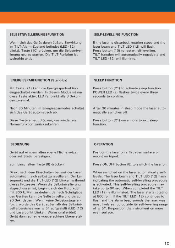
SELBSTNIVELLIERUNGSFUNKTION
Wenn sich das Gerät durch äußere Einwirkung im TILT-Alarm-Zustand befindet (LED (12) blinkt), Taste (10) drücken, um die Selbstnivel- lierung neu zu starten. Die TILT-Funktion ist weiterhin aktiv.
SELF-LEVELLINGFUNCTION
If the laser is disturbed, rotation stops and the laser beam and TILT LED (12) will flash. Press button (10) to restart lelf-levelling. TILT function will automatically reactivate and TILT LED (12) will illuminte.
BEDIENUNG
Gerät auf einigermaßen ebene Fläche setzen oder auf Stativ befestigen.
Zum Einschalten Taste (8) drücken.
Direkt nach dem Einschalten beginnt der Laser automatisch, sich selbst zu nivellieren. Der La- serpunkt und die TILT-LED (12) blinken während dieses Prozesses. Wenn die Selbstnivellierung abgeschossen ist, beginnt sich der Rotorkopf mit 800 U/Min. zu drehen. Je nach Schräglage des Gerätes kann die Selbstnivellierung bis zu 90 Sek. dauern. Wenn keine Selbstjustage er- folgt, wurde das Gerät außerhalb des Selbstni- vellierbereiches von ± 5° aufgestellt (LED (12) und Laserpunkt blinken, Warnsignal ertönt). Gerät dann auf eine waagerechtere Ebene stel- len.
OPERATION
Position the laser on a flat even surface or mount on tripod. Press ON/OFF button (8) to switch the laser on.
When switched on the laser automatically self- levels. The laser beam and TILT LED (12) flash indicating the automatic self-levelling procedure is activated. This self-levelling procedure may take up to 90 sec. When completed the TILT LED (12) is illuminated. The laser starts rotating at 800 rpm. If the TILT LED (12) continues to flash and the alarm beep sounds the laser was most likely set up outside its self-levelling range of ± 5°. Re-position the instrument on more even surface.
ENERGIESPARFUNKTION(Stand-by)
Mit Taste (21) kann die Energiesparfunktion eingeschaltet werden. In diesem Modus ist nur diese Taste aktiv; LED (9) blinkt alle 3 Sekun- den zweimal.
Nach 30 Minuten im Energiesparmodus schaltet sich das Gerät automatisch ab.
Diese Taste erneut drücken, um wieder zur Normalfunktion zurückzukehren.
SLEEPFUNCTION
Press button (21) to activate sleep function. POWER LED (9) flashes twice every three seconds to confirm.
After 30 minutes in sleep mode the laser auto- matically switches off.
Press button (21) once more to exit sleep function.
11
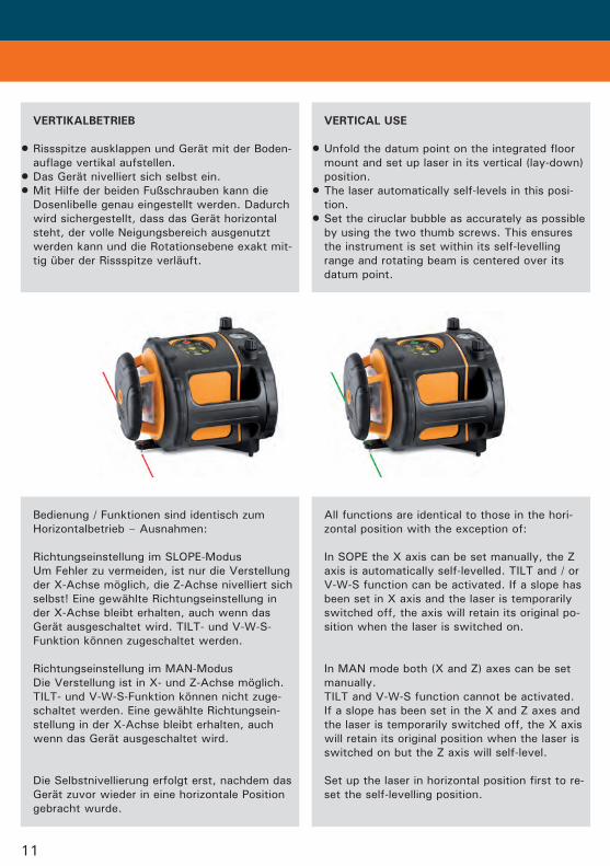
Bedienung / Funktionen sind identisch zum Horizontalbetrieb – Ausnahmen:
Richtungseinstellung im SLOPE-Modus Um Fehler zu vermeiden, ist nur die Verstellung der X-Achse möglich, die Z-Achse nivelliert sich selbst! Eine gewählte Richtungseinstellung in der X-Achse bleibt erhalten, auch wenn das Gerät ausgeschaltet wird. TILT- und V-W-S- Funktion können zugeschaltet werden.
Richtungseinstellung im MAN-Modus Die Verstellung ist in X- und Z-Achse möglich. TILT- und V-W-S-Funktion können nicht zuge- schaltet werden. Eine gewählte Richtungsein- stellung in der X-Achse bleibt erhalten, auch wenn das Gerät ausgeschaltet wird.
Die Selbstnivellierung erfolgt erst, nachdem das Gerät zuvor wieder in eine horizontale Position gebracht wurde.
All functions are identical to those in the hori- zontal position with the exception of:
In SOPE the X axis can be set manually, the Z axis is automatically self-levelled. TILT and / or V-W-S function can be activated. If a slope has been set in X axis and the laser is temporarily switched off, the axis will retain its original po- sition when the laser is switched on.
In MAN mode both (X and Z) axes can be set manually. TILT and V-W-S function cannot be activated. If a slope has been set in the X and Z axes and the laser is temporarily switched off, the X axis will retain its original position when the laser is switched on but the Z axis will self-level.
Set up the laser in horizontal position first to re- set the self-levelling position.
VERTIKALBETRIEB
Rissspitze ausklappen und Gerät mit der Boden- auflage vertikal aufstellen.
Das Gerät nivelliert sich selbst ein.Mit Hilfe der beiden Fußschrauben kann die
Dosenlibelle genau eingestellt werden. Dadurch wird sichergestellt, dass das Gerät horizontal steht, der volle Neigungsbereich ausgenutzt werden kann und die Rotationsebene exakt mit- tig über der Rissspitze verläuft.
•
••
VERTICALUSE
Unfold the datum point on the integrated floor mount and set up laser in its vertical (lay-down) position.
The laser automatically self-levels in this posi- tion.
Set the ciruclar bubble as accurately as possible by using the two thumb screws. This ensures the instrument is set within its self-levelling range and rotating beam is centered over its datum point.
•
•
•
12
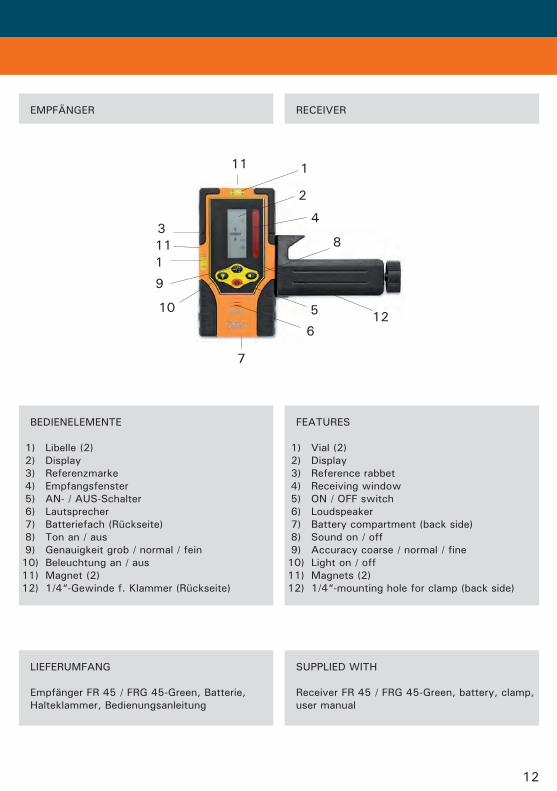
BEDIENELEMENTE
1) Libelle (2) 2) Display 3) Referenzmarke 4) Empfangsfenster 5) AN- / AUS-Schalter 6) Lautsprecher 7) Batteriefach (Rückseite) 8) Ton an / aus 9) Genauigkeit grob / normal / fein 10) Beleuchtung an / aus 11) Magnet (2) 12) 1/4“-Gewinde f. Klammer (Rückseite)
FEATURES
1) Vial (2) 2) Display 3) Reference rabbet 4) Receiving window 5) ON / OFF switch 6) Loudspeaker 7) Battery compartment (back side) 8) Sound on / off 9) Accuracy coarse / normal / fine 10) Light on / off 11) Magnets (2) 12) 1/4“-mounting hole for clamp (back side)
LIEFERUMFANG
Empfänger FR 45 / FRG 45-Green, Batterie, Halteklammer, Bedienungsanleitung
SUPPLIED WITH
Receiver FR 45 / FRG 45-Green, battery, clamp, user manual
1
2
1
7
5
83
4
6
9
10
11
11
12
EMPFÄNGER RECEIVER
13
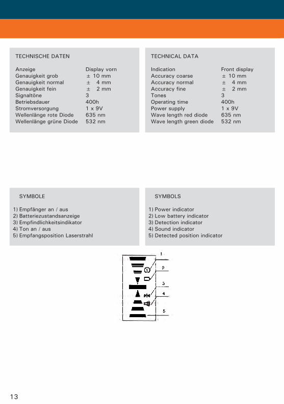
SYMBOLE
1) Empfänger an / aus 2) Batteriezustandsanzeige 3) Empfindlichkeitsindikator 4) Ton an / aus 5) Empfangsposition Laserstrahl
SYMBOLS
1) Power indicator 2) Low battery indicator 3) Detection indicator 4) Sound indicator 5) Detected position indicator
TECHNISCHE DATEN
Anzeige Display vorn Genauigkeit grob ± 10 mm Genauigkeit normal ± 4 mm Genauigkeit fein ± 2 mm Signaltöne 3 Betriebsdauer 400h Stromversorgung 1 x 9V Wellenlänge rote Diode 635 nm Wellenlänge grüne Diode 532 nm
TECHNICAL DATA
Indication Front display Accuracy coarse ± 10 mm Accuracy normal ± 4 mm Accuracy fine ± 2 mm Tones 3 Operating time 400h Power supply 1 x 9V Wave length red diode 635 nm Wave length green diode 532 nm
14
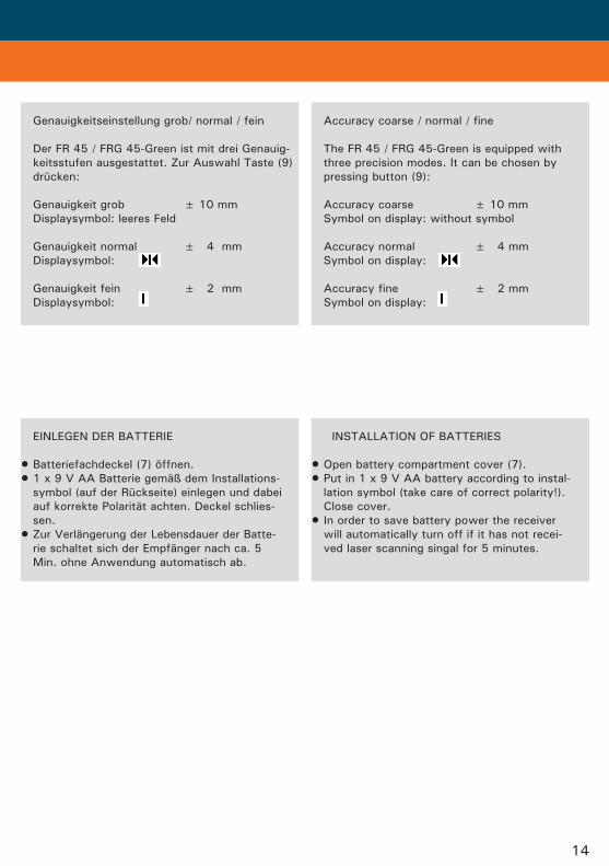
EINLEGEN DER BATTERIE
Batteriefachdeckel (7) öffnen. 1 x 9 V AA Batterie gemäß dem Installations-
symbol (auf der Rückseite) einlegen und dabei auf korrekte Polarität achten. Deckel schlies- sen.
Zur Verlängerung der Lebensdauer der Batte- rie schaltet sich der Empfänger nach ca. 5 Min. ohne Anwendung automatisch ab.
••
•
INSTALLATION OF BATTERIES
Open battery compartment cover (7).Put in 1 x 9 V AA battery according to instal-
lation symbol (take care of correct polarity!). Close cover.
In order to save battery power the receiver will automatically turn off if it has not recei- ved laser scanning singal for 5 minutes.
••
•
Genauigkeitseinstellung grob/ normal / fein
Der FR 45 / FRG 45-Green ist mit drei Genauig- keitsstufen ausgestattet. Zur Auswahl Taste (9) drücken:
Genauigkeit grob ± 10 mm Displaysymbol: leeres Feld
Genauigkeit normal ± 4 mm Displaysymbol:
Genauigkeit fein ± 2 mm Displaysymbol:
Accuracy coarse / normal / fine
The FR 45 / FRG 45-Green is equipped with three precision modes. It can be chosen by pressing button (9):
Accuracy coarse ± 10 mm Symbol on display: without symbol
Accuracy normal ± 4 mm Symbol on display:
Accuracy fine ± 2 mm Symbol on display:
15
HALTEKLAMMER FÜR NIVELLIERLATTE
Der Empfänger kann in Verbindung mit der Halteklammer an einer Nivellierlatte oder anderen Gegenständen befestigt werden.
CLAMP FOR LEVELLING STAFF
If required FR 45 / FRG 45-Green can be at- tached to laser poles or any other equipment by means of the clamp supplied with.
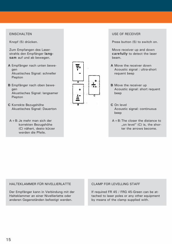
EINSCHALTEN
Knopf (5) drücken.
Zum Empfangen des Laser- strahls den Empfänger lang- sam auf und ab bewegen.
A Empfänger nach unten bewe- gen Akustisches Signal: schneller Piepton
B Empfänger nach oben bewe- gen Akustisches Signal: langsamer Piepton
C Korrekte Bezugshöhe Akustisches Signal: Dauerton
A+B: Je mehr man sich der korrekten Bezugshöhe (C) nähert, desto kürzer werden die Pfeile.
USE OF RECEIVER
Press button (5) to switch on.
Move receiver up and down carefully to detect the laser beam.
A Move the receiver down Acoustic signal : ultra-short requent beep
B Move the receiver up Acoustic signal: short requent beep
C On level Acoustic signal: continuous beep
A+B: The closer the distance to „on level“ (C) is, the shor- ter the arrows become.
Optionales Zubehör
16
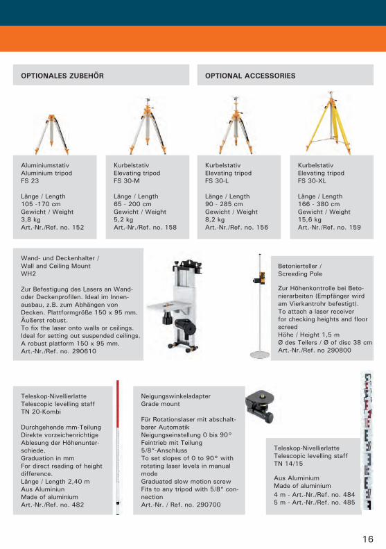
OPTIONALESZUBEHÖR
Betonierteller / Screeding Pole Zur Höhenkontrolle bei Beto- nierarbeiten (Empfänger wird am Vierkantrohr befestigt). To attach a laser receiver for checking heights and floor screed Höhe / Height 1,5 m Ø des Tellers / Ø of disc 38 cm Art.-Nr./Ref. no 290800
Neigungswinkeladapter Grade mount
Für Rotationslaser mit abschalt- barer Automatik Neigungseinstellung 0 bis 90° Feintrieb mit Teilung 5/8“-Anschluss To set slopes of 0 to 90° with rotating laser levels in manual mode Graduated slow motion screw Fits to any tripod with 5/8“ con- nection Art.-Nr. / Ref. no. 290700
Wand- und Deckenhalter / Wall and Ceiling Mount WH2
Zur Befestigung des Lasers an Wand- oder Deckenprofilen. Ideal im Innen- ausbau, z.B. zum Abhängen von Decken. Plattformgröße 150 x 95 mm. Äußerst robust. To fix the laser onto walls or ceilings. Ideal for setting out suspended ceilings. A robust platform 150 x 95 mm. Art.-Nr./Ref. no. 290610
Teleskop-Nivellierlatte Telescopic levelling staff TN 14/15 Aus Aluminium Made of aluminium 4 m - Art.-Nr./Ref. no. 484 5 m - Art.-Nr./Ref. no. 485
Teleskop-Nivellierlatte Telescopic levelling staff TN 20-Kombi Durchgehende mm-Teilung Direkte vorzeichenrichtige Ablesung der Höhenunter- schiede. Graduation in mm For direct reading of height difference. Länge / Length 2,40 m Aus Aluminiun Made of aluminium Art.-Nr./Ref. no. 482
OPTIONALACCESSORIES
Aluminiumstativ Aluminium tripod FS 23
Länge / Length 105 -170 cm Gewicht / Weight 3,8 kg Art.-Nr./Ref. no. 152
Kurbelstativ Elevating tripod FS 30-M
Länge / Length 65 - 200 cm Gewicht / Weight 5,2 kg Art.-Nr./Ref. no. 158
Kurbelstativ Elevating tripod FS 30-L
Länge / Length 90 - 285 cm Gewicht / Weight 8,2 kg Art.-Nr./Ref. no. 156
Kurbelstativ Elevating tripod FS 30-XL Länge / Length 166 - 380 cm Gewicht / Weight 15,6 kg Art.-Nr./Ref. no. 159
17
Optionales Zubehör
CAREANDCLEANING
Please handle measuring instruments with care.
Clean with soft cloth, moistened with water or pure alcool if necessary.
Ensure the instrument and carrying case are both clean and completely dry before returning for storage or transportation.
Transport in original container / case only.
•
•
•
•
UMGANGUNDPFLEGE
Messinstrumente generell bitte sorgsam behand- deln.
Nach Benutzung mit weichem Tuch reinigen (ggfs. Tuch etwas in Wasser tränken). Wenn das Gerät feucht war, sorgsam trocknen.
Erst in den Koffer oder die Tasche packen, wenn es absolut trocken ist. Bitte darauf ach- ten, dass auch der Koffer innen immer trocken ist, bevor das Gerät hineingepackt wird.
Transport nur in Originalbehälter oder- tasche.
•
•
•
•
SAFETYINSTRUCTIONS SICHERHEITSHINWEISE
BESTIMMUNGSGEMÄSSEVERWENDUNG
Das Gerät sendet einen sichtbaren Laserstrahl aus, um z.B. folgende Messaufgaben durchzu- führen: Ermittlung von Höhen; rechten Winkeln, Ausrichtung von horizontalen und vertikalen Bezugsebenen sowie Lotpunkten.
INTENDEDUSEOFINSTRUMENT
The instrument emits a visible laser beam in order to carry out the following measuring tasks: Setting up and control heights, horizontal and vertical planes, right angle. Plumbing points.
WARN-UNDSICHERHEITSHINWEISE
Bitte richten Sie sich nach den Anweisungen der Bedienungsanleitung.
Anleitung vor Benutzung des Gerätes lesen.Blicken Sie niemals in den Laserstrahl, auch
nicht mit optischen Instrumenten. Es besteht die Gefahr von Augenschäden.
Laserstrahl nicht auf Personen richten.Die Laserebene soll sich über der Augenhöhe
von Personen befinden.Niemals das Gehäuse öffnen. Reparaturen nur
vom autorisierten Fachhändler durchführen lassen.
Keine Warn- oder Sicherheitshinweise entfernen.Lasergerät nicht in Kinderhände gelangen lassen.Gerät nicht in explosionsgefährdeter Umgebung
betreiben.
•
••
••
•
•••
SAFTEYINSTRUCTIONS
Carefully read the User Manual before use.Do not stare into the beam. Laser beams can
lead to eye injury. Directy looking into can cause damage to your eyes.
Do not aim laser beam directly at persons or animals.
The laser plane should be set up above eye level.
Use instrument for its intended tasks only.Do not attempt to dismantle intrument. Repairs should only be carried out by geo-
FENNEL authorized workshops. Please contact your local dealer.
Do not remove warning labels or safety instru- ctions.
Keep instrument away from children.Do not use in agressive or explosive environ-
ment.
••
•
•
•••
•
••
18
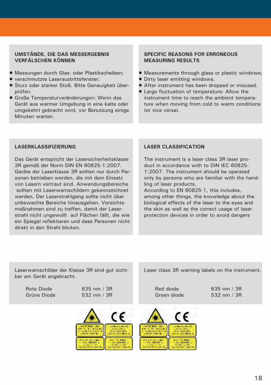
LASERKLASSIFIZIERUNG
Das Gerät entspricht der Lasersicherheitsklasse 3R gemäß der Norm DIN EN 60825-1:2007. Geräte der Laserklasse 3R sollten nur durch Per- sonen betrieben werden, die mit dem Einsatz von Lasern vertraut sind. Anwendungsbereiche sollten mit Laserwarnschildern gekennzeichnet werden. Der Laserstrahlgang sollte nicht über unbewachte Bereiche hinausgehen. Vorsichts- maßnahmen sind zu treffen, damit der Laser- strahl nicht ungewollt auf Flächen fällt, die wie ein Spiegel reflektieren und dass Personen nicht direkt in den Strahl blicken.
LASERCLASSIFICATION
The instrument is a laser class 3R laser pro- duct in accordance with to DIN IEC 60825- 1:2007. The instrument should be operated only by persons who are familiar with the hand- ling of laser products. According to EN 60825-1, this includes, among other things, the knowledge about the biological effects of the laser to the eyes and the skin as well as the correct usage of laser protection devices in order to avoid dangers
SPECIFICREASONSFORERRONEOUS MEASURINGRESULTS
Measurements through glass or plastic windows;Dirty laser emitting windows.After instrument has been dropped or misused.Large fluctuation of temperature: Allow the
instrument time to reach the ambient tempera- ture when moving from cold to warm conditions (or vice versa).
••••
UMSTÄNDE,DIEDASMESSERGEBNIS VERFÄLSCHENKÖNNEN
Messungen durch Glas- oder Plastikscheiben;verschmutzte Laseraustrittsfenster;Sturz oder starker Stoß. Bitte Genauigkeit über-
prüfen.Große Temperaturveränderungen: Wenn das
Gerät aus warmer Umgebung in eine kalte oder umgekehrt gebracht wird, vor Benutzung einige Minuten warten.
•••
•
Laserwarnschilder der Klasse 3R sind gut sicht- bar am Gerät angebracht.
Rote Diode 635 nm / 3R Grüne Diode 532 nm / 3R
Laser class 3R warning labels on the instrument.
Red diode 635 nm / 3R Green diode 532 nm / 3R
19
ELECTROMAGNETICACCEPTABILITY(EMC)
Although this product meets the strict regula- tions and standards which are in force in this respect, geo-FENNEL cannot completely exclude the possibility that this instrument:
will cause interference to other devices (e.g. navigation systems)
will be disturbed by other devices (e.g. inten- sive electromagnetic radiation from radio transmitters)
•
•
ELEKTROMAGNETISCHEVERTRÄGLICHKEIT
Es kann nicht generell ausgeschlossen werden, dass das Gerät andere Geräte stört (z.B. Navi- gationseinrichtungen);
durch andere Geräte gestört wird (z.B. elektro- magnetische Strahlung bei erhöhter Feldstärke z.B. in der unmittelbaren Nähe von Industrie- anlagen oder Rundfunksendern).
•
•
CE-KONFORMITÄT
Das Gerät hat das CE-Zeichen gemäß den EN 61010-1:2001 + corrig. 1+2.
CECONFORMITY
Instrument has CE-mark in accordance with EN 61010-1:2001 +corrig. 1+2.
GARANTIE
Die Garantiezeit beträgt zwei (2) Jahre, begin- nend mit dem Verkaufsdatum. Die Garantie erstreckt sich nur auf Mängel wie Material-oder Herstellungsfehler, sowie die Nichterfüllung zugesicherter Eigenschaften. Ein Garantieanspruch besteht nur bei bestim- mungsgemäßer Verwendung. Mechanischer Verschleiß und äußerliche Zerstörung durch Gewaltanwendung und Sturz unterliegen nicht der Garantie. Der Garantieanspruch erlischt, wenn das Gehäuse geöffnet wurde. Der Her- steller behält sich vor, im Garantiefall die schadhaften Teile instand zusetzen bzw. das Gerät gegen ein gleiches oder ähnliches (mit gleichen technischen Daten) auszutauschen. Ebenso gilt das Auslaufen der Batterie nicht als Garantiefall.
WARRANTY
This product is warranted by the manufacturer to the original purchaser to be free from de- fects in material and workmanship under nor- mal use for a period of two (2) years from the date of purchase. During the warranty period, and upon proof of purchase, the product will be repaired or replaced (with the same or similar model at manufacturers discretion), without charge for either parts or labour. In case of a defect please contact the dealer where you originally purchased this product. The warranty will not apply to this product if it has been misused, abused or altered in any way. Without limiting the foregoing, leakage of the battery, bending or dropping the product are presumed to be defects resulting from misuse or abuse.
geo-FENNEL GmbH Kupferstraße 6 D-34225 Baunatal Tel. +49 561 49 21 45 Fax +49 561 49 72 34 Email: [email protected] www.geo-fennel.de
05/2010
Technische Änderungen vorbehalten. All instruments subject to technical changes.
EXCEPTIONSFROMRESPONSIBILITY
The user of this product is expected to follow the instructions given in User Manual. Although all instruments left our warehouse in perfect condition and adjustment the user is expected to carry out periodic checks of the product’s accuracy and general perfor- mance. The manufacturer, or its representatives, assumes no responsibility of results of a faul- ty or intentional usage or misuse including any direct, indirect, consequential damage, and loss of profits. The manufacturer, or its representatives, assumes no responsibility for consequential damage, and loss of profits by any disaster (earthquake, storm, flood etc.), fire, accident, or an act of a third party and/or a usage in other than usual conditions. The manufacturer, or its representatives, assumes no responsibility for any damage, and loss of profits due to a change of data, loss of data and interruption of business etc., caused by using the product or an unusable product. The manufacturer, or its representatives, assumes no responsibility for any damage, and loss of profits caused by usage other than explained in the users‘ manual. The manufacturer, or its representatives, assumes no responsibility for damage caused by wrong movement or action due to connec- ting with other products.
HAFTUNGSAUSSCHLUSS
Der Benutzer dieses Produktes ist angehalten, sich exakt an die Anweisungen der Bedienungs- anleitung zu halten. Alle Geräte sind vor der Auslieferung genauestens überprüft worden. Der Anwender sollte sich trotzdem vor jeder Anwendung von der Genauigkeit des Gerätes überzeugen. Der Hersteller und sein Vertreter haften nicht für fehlerhafte oder absichtlich falsche Verwen- dung sowie daraus eventuell resultierende Fol- geschäden und entgangenen Gewinn. Der Hersteller und sein Vertreter haften nicht für Folgeschäden und entgangenen Gewinn durch Naturkatastrophen wie z.B. Erdbeben, Sturm, Flut, usw. sowie Feuer, Unfall, Ein- griffe durch Dritte oder einer Verwendung außerhalb der üblichen Einsatzbereiche. Der Hersteller und sein Vertreter haften nicht für Schäden und entgangenen Gewinn durch geänderte oder verlorene Daten, Unterbre- chung des Geschäftsbetriebes usw., die durch das Produkt oder die nicht mögliche Verwen- dung des Produktes verursacht wurden. Der Hersteller und sein Vertreter haften nicht für Schäden und entgangenen Gewinn resul- tierend aus einer nicht anleitungsgemäßen Bedienung. Der Hersteller und sein Vertreter haften nicht für Schäden, die durch unsachgemäße Ver- wendung oder in Verbindung mit Produkten anderer Hersteller verursacht wurden.


![Flyer "Nedo Rotationslaser Primus" - download.nedo.comdownload.nedo.com/flyer/[de] rotationslaser primus2.pdf · Nedo PRIMUS H Der vollautomatische horizontale Rotationslaser Merkmale:](https://img.pdfslide.org/doc/110x75/5a78a33b7f8b9a1f128df638/flyer-nedo-rotationslaser-primus-de-rotationslaser-primus2pdfnedo-primus-h-der.jpg)