Embed Size (px)
Citation preview

Meteorol Atmos Phys 101, 191–210 (2008)DOI 10.1007/s00703-008-0290-yPrinted in The Netherlands
Institut f€uur Physik der Atmosph€aare, Deutsches Zentrum f€uur Luft- und Raumfahrt (DLR), Oberpfaffenhofen, Germany
Cb-TRAM: Tracking and monitoring severe convectionfrom onset over rapid development to mature phaseusing multi-channel Meteosat-8 SEVIRI data
T. Zinner, H. Mannstein, A. Tafferner
With 14 Figures
Received 10 April 2006; Accepted 29 January 2008Published online 26 May 2008 # Springer-Verlag 2008
Summary
Cb-TRAM is a new fully automated tracking and now-casting algorithm. Intense convective cells are detected,tracked and discriminated with respect to onset, rapiddevelopment, and mature phase. The detection is based onMeteosat-8 SEVIRI (Spinning Enhanced Visible and Infra-Red Imager) data from the broad band high resolutionvisible, infra-red 6.2 mm (water vapour), and the infra-red10.8 mm channels. In addition, tropopause temperature datafrom ECMWF operational model analyses is utilised as anadaptive detection criterion. The tracking is based ongeographical overlap between current detections and firstguess patterns of cells predicted from preceeding timesteps. The first guess patterns as well as short range forecastextrapolations are obtained with the aid of a new imagematching algorithm providing complete fields of approx-imate differential cloud motion. Based on these motionvector fields interpolation and extrapolation of satellite dataare obtained which allow to generate synthetic intermediatedata fields between two known fields as well as nowcasts ofmotion and development of detected areas. Examples of theapplication of Cb-TRAM and a comparison to precipitationradar and lightning data as independent data sourcesdemonstrate the capabilities of the new technique.
1. Introduction
Thunderstorms have always been one of the fun-damental meteorological hazards to society andeconomy. Ground and air transport, the construc-tion and energy industry as well as all kinds ofoutdoor activities depend on early warnings andcorrect forecasts of thunderstorm developmentand propagation.
Although routine numerical forecasts operatedby the weather services show some skill in fore-casting the propagation of thunderstorm com-plexes connected to synoptic disturbances they,in general, cannot predict the onset and path ofindividual thunderstorms. Main reasons are theinaccurate representation of the atmospheric stateat small scales in the model fields, in particu-lar moisture and hydrometeor distributions, aswell as the dynamic and microphysical state ofclouds. In addition, operational grid resolutionis far from being able to simulate cloud physicsprocesses directly. Furthermore thunderstormsare generated and propagated by an often com-plex interaction of processes on various scales,e.g., large scale forcing by synoptic scale sys-tems, boundary layer processes like convectionand turbulence, and energy conversion at the
Correspondence: Tobias Zinner, Deutsches Zentrum f€uur
Luft- und Raumfahrt (DLR), Institut f€uur Physik der Atmosph€aare,
Oberpfaffenhofen, 82234 Wessling, Germany (E-mail: tobias.

ground due to the fluxes of solar radiation, heat,and moisture.
Short range forecasting of up to about 2 to 6 h,also referred to as ‘‘nowcasting’’, is thereforemainly based on an appropriate extrapolation ofnear real-time observations in time. Starting fromobservations, e.g., of lightning, precipitation pat-terns in radar data, or of cloud patterns in satellitedata, individual thunderstorms are detected andtracked. Future position and growth is then es-timated using information from past developmentsometimes using complementary data from nu-merical models or conceptual convective life-cycle models.
A large number of nowcasting tools has beendeveloped during the past 20 years providingshort range warnings of strong winds and heavyprecipitation, as well as convective cloud systemlife-cycle climatologies. Very early there havebeen first attempts to determine the motion ofprecipitation echoes from two consecutive radarimages and to obtain an extrapolation of theirposition for the near future (e.g., Ligda 1953).Soon after satellite imagery was utilised to derivecloud motions as well (e.g., Fujita 1969). Stillmost current techniques are based on these twosources of near real-time information.
A group of radar echo tracking techniqueshas been developed, e.g., TITAN (Dixon andWiener 1993), COTREC=TREC (Mecklenburget al. 2000), CONRAD (Lang 2001), TRACE3D(Handwerker 2002), TRT (Hering et al. 2004), orin combination with lightning data in (Steinackeret al. 2000). The advantage of using real-timeradar data for storm tracking is given by the factthat precipitation echoes allow to detect the ac-tive convective cores within the thunderstorm re-liably. However, there is no possibility to detecta developing convective cell before the pre-cipitation stage is reached. Also, radar networksproviding more than a local coverage are still lim-ited to Western Europe and North America andeven there complete spatial radar coverage isnot guaranteed, mainly due to ground shielding.
The alternative source of near real-time in-formation providing global data coverage is sat-ellite data. The detection of convectively activeareas for this type of data is a more difficult taskcompared to radar echoes. This is mostly ac-complished on the basis of temperature thresh-olds in thermal infra-red observations where
the coldest and highest cloud tops, presumablyof convective origin, can be distinguished fromwarmer more shallow clouds. Examples are, e.g.,Machado et al. (1998), Riosalido et al. (1998),MASCOTTE (Carvalho and Jones 2001), RDT(Morel and Senesi 2002), Bolliger et al. (2003),or Feidas and Cartarlis (2005).
The information on the thunderstorm cells’ mo-tion gained from the above mentioned trackingtechniques is then widely used to forecast theirfuture location and intensity, often in an opera-tional way by the national weather services. Inaddition there is an increasing effort to combinethe advantages of radar and satellite data withother near real-time observations like lightningdata, as well as numerical or conceptual life-cyclemodels to form so called ‘‘expert systems’’ (e.g.,UK Met Office GANDOLF Pierce et al. 2000;NCAR Auto-Nowcast Mueller et al. 2003).
In this paper, a new tool for the early detectionof thunderstorm development and the tracking ofconvection of intense activity is introduced: TheCb-TRAM algorithm (Cumulonim Bus TRackingAnd Monitoring), which is based on satellite dataof the Meteosat-8 SEVIRI instrument. The pre-sented algorithm concentrates on the exploitationof the novel capabilities offered by the MeteosatSecond Generation=Meteosat-8 SEVIRI in-strument, to detect convection before the onsetof precipitation and in regions without radarcoverage.
The above listed satellite based tools are al-most exclusively based on data from a thermalinfra-red channel at 11 mm (IR) thereby offeringa detection which is insensitive to day and nightdifferences. The detection mostly uses a singlefixed temperature threshold for the IR brightnesstemperature between 218 and 245 K. Thus thetechniques have problems to account for differentsynoptic or seasonal situations and to discrimi-nate convective and non-convective cloud sys-tems. Convection warmer than the temperaturethreshold is missed.
To improve some of these issues, this workemphasises the early detection of potentially con-vective activity, the detection of rapid devel-opments in storm cells still warmer than theclassical thresholds, and the separation of areasof severe convective activity from extensive cir-rus shields. For this purpose, additional informa-tion from the SEVIRI high resolution visible
192 T. Zinner et al.
channel (HRV) as well as the infra-red 6.2 mm‘‘water-vapor’’ channel (WV) is used. As re-flected solar radiation is used an adaption ofthe detection algorithm moving from daylightto nighttime is therefore unavoidable. This al-lows for an optimal exploitation of satellite dataregarding the detection of early stages of con-vection, which is mostly triggered during day-time, and discrimination of convectively activeareas within inactive cloud fields. In addition,
the above mentioned fixed threshold principle isreplaced by an adaptive technique using tropo-pause temperature from short range numericalweather forecasts or ECMWF operational analy-sis data.
The Cb-TRAM tool consists of the followingparts:
(1) Central to the algorithm is the extraction ofa general transformation or disparity vectorfield from two consecutive satellite imagesdescribing the cloud motion and local clouddevelopments.
(2) The detection analyses the current satellitedata from three channels and identifies cellpatterns of convective activity.
(3) The tracking and monitoring (TRAM) linksdetected cell patterns at different time stepswith each other and creates a cell historylog file with information on the detectedpatterns.
(4) The displaying routine reads this file andplots selectable information, like a cell pat-tern’s extent, its past track, or the extrapo-lated position on top of the current satelliteimage.
Here and throughout the paper the term ‘‘cell pat-tern’’ is used for a convective object detectable byour satellite algorithm. In fact, it can contain morethan one real convection cell since the techniqueis limited to the spatial resolution and informa-tion available from the satellite instrument.
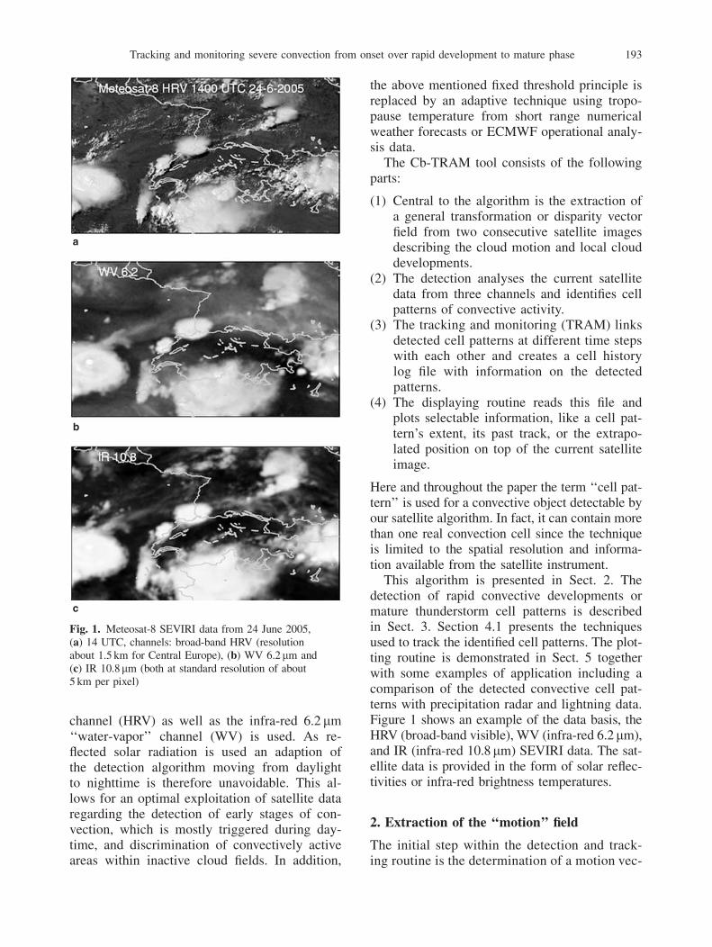
This algorithm is presented in Sect. 2. Thedetection of rapid convective developments ormature thunderstorm cell patterns is describedin Sect. 3. Section 4.1 presents the techniquesused to track the identified cell patterns. The plot-ting routine is demonstrated in Sect. 5 togetherwith some examples of application including acomparison of the detected convective cell pat-terns with precipitation radar and lightning data.Figure 1 shows an example of the data basis, theHRV (broad-band visible), WV (infra-red 6.2mm),and IR (infra-red 10.8mm) SEVIRI data. The sat-ellite data is provided in the form of solar reflec-tivities or infra-red brightness temperatures.
2. Extraction of the ‘‘motion’’ field
The initial step within the detection and track-ing routine is the determination of a motion vec-
Fig. 1. Meteosat-8 SEVIRI data from 24 June 2005,(a) 14 UTC, channels: broad-band HRV (resolutionabout 1.5 km for Central Europe), (b) WV 6.2mm and(c) IR 10.8mm (both at standard resolution of about5 km per pixel)
Tracking and monitoring severe convection from onset over rapid development to mature phase 193

tor field from two consecutive images. Thisproblem is identical to the derivation of dispa-rities from stereo pairs of images, only the in-terpretation differs: In our case the disparitiesresult from cloud motion, not from changes ofthe view point. In analogy to the visual inter-pretation the first automated image matchers,like those still used in cloud motion vector de-termination (Schmetz et al. 1993; Menzel 2001),were feature based. Interesting cloud patternsin the first image are selected and searched forin a target area within the second one. The ad-vantage of such matchers is that the computingeffort is concentrated on a few items. The obvi-ous disadvantage is that only a few individualmotion vectors are derived and that each ofthese motion vectors is derived independentlyfrom the others. As computation speed is nolonger a limiting factor, here an area based im-age matcher is used. The result of the matcheris a disparity vector field ~VV defined at each pixelposition ~PP of the image often called ‘‘opticalflow’’. This field ~VV describes the warping ofone of the images onto the other in a way thateither the difference of the image intensitiesis minimised (classical optical flow) or the localcorrelation is maximised. A variety of differentways to calculate the optical flow can be foundin literature (Lucas and Kanade 1981, Hornand Schunck 1981). In the following our im-plementation of a general purpose matcher isdescribed.
2.1 Pyramidal matcher
Clouds and cloud fields show a strong spatialautocorrelation and often the motion of smallscale features is dominated by the large scaleflow. In order to take this scale dependencyinto account, image pairs are successively ana-lysed from low to high resolution – a pyramidalscheme (Fig. 2). In Fig. 3a and b, an examplefor a simple moving structure is given. Initial-ly the images A and B are extended to dimen-sions of a multiple of 2N, with N being thenumber of additional sub-sampling levels ofthe pyramid, in both image dimensions to al-low for the stepwise (pyramidal) processing.The images A and B are sub-sampled to the se-lected dimensions for all pyramid levels (com-pare Fig. 2).
The disparity vector ~VV field between the twosub-sampled images is now determined by suc-cessively shifting image A to As ¼ Að~PPþ�~SSi;jÞ by �~SSi;j ¼ �2. . .2 pixels in both dimen-sions and comparing it to image B. Figure 4shows the results for the 25 comparisons of thetopmost level of our example. For each imagepixel ~PP the resolution dependent incremental
shift �~SSfit
i and �~SSfit
j that provides the best fit ofAs to image B(~PP) is stored in ~VV .
Implemented are two different quality criteriafor the best fit:
– (default) the minimum of the squared differ-ence of the intensities (which might be eitherreflectivities or brightness temperatures) in alocal surrounding of the image pixel of inter-est or
– the maximum of a localised correlationcoefficient.
The localisation of both fields of quality cri-teria is obtained by weighting with a Gaussianfilter (Fig. 5). That means, the first criterion issimply the low pass filtered squared differencecalculated as the convolution
dloc ¼ ðAs � BÞ2 � Ke ð1Þ
with Ke being the Gaussian Kernel. Accordingto this criterion those pixels in Fig. 4 aremarked, which show the lowest dloc of all 25comparisons.
To describe the localised correlation coeffi-cient, it is necessary to introduce the localised
Fig. 2. Pyramid with three levels (i.e., number of sub-sampling levels N¼ 2): On the topmost level (dimen-sions nx=4, ny=4) the large scale disparity vector field isobtained. It is then successively refined steppingthrough the other levels (dimensions nx=2, ny=2 andoriginal dimensions nx, ny)
194 T. Zinner et al.
version of the mean A ¼ A� Ke and the local-ised ‘‘standard deviation’’ of the image A as
SðAÞ ¼ffiffiffiffiffiffiffiffiffiffiffiffiffiffiffiffiffiffiffiffiffiffiffiffiffiffiffiffiffiðA� AÞ2 � Ke
q: ð2Þ
Then the local correlation coefficient cloc forthe images A and B reads as
cloc ¼½ðA� AÞ � ðB� BÞ� � Ke
SðAÞ � SðBÞ : ð3Þ
The ‘‘�’’ symbolises a point-wise multiplicationoperation.
These localised rotational symmetric versionsof mean, standard deviation, and correlation co-efficient have first been used in Mannstein et al.
(1999) for other image processing tasks. Theiradvantage over the use of unweighted rectangularareas for the calculation of these quantities is thatartificial high frequency artefacts (from the rect-angular filter edges) are suppressed. In additionthe performance of the matcher does not varybetween the along-axis and diagonal imagedirections.
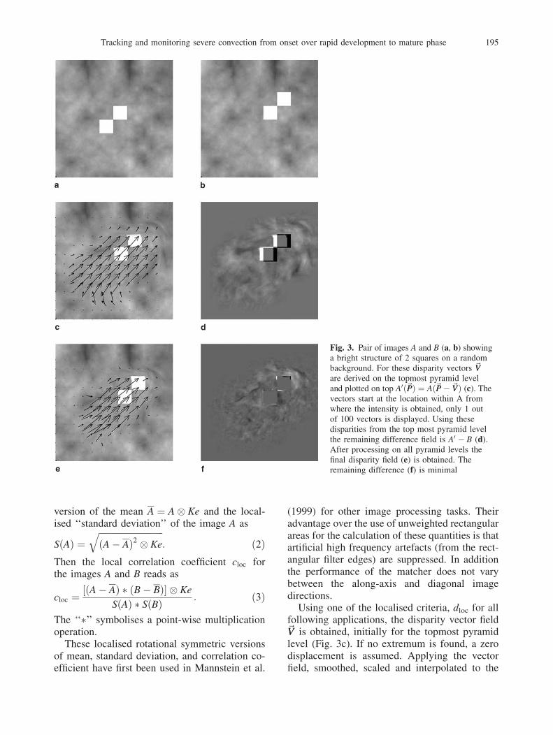
Using one of the localised criteria, dloc for allfollowing applications, the disparity vector field~VV is obtained, initially for the topmost pyramidlevel (Fig. 3c). If no extremum is found, a zerodisplacement is assumed. Applying the vectorfield, smoothed, scaled and interpolated to the
Fig. 3. Pair of images A and B (a, b) showinga bright structure of 2 squares on a randombackground. For these disparity vectors ~VVare derived on the topmost pyramid leveland plotted on top A0ð~PPÞ ¼ Að~PP� ~VVÞ (c). Thevectors start at the location within A fromwhere the intensity is obtained, only 1 outof 100 vectors is displayed. Using thesedisparities from the top most pyramid levelthe remaining difference field is A0 � B (d).After processing on all pyramid levels thefinal disparity field (e) is obtained. Theremaining difference (f) is minimal
Tracking and monitoring severe convection from onset over rapid development to mature phase 195

original image resolution, the image A is warpedby creating
A0ð~PPÞ ¼ Að~PP� ~VVÞ: ð4ÞFigure 3c shows the warped image A0 and thedisparity vector ~VV after the topmost pyramidprocessing. The test structure of two adjacentsquares is shifted to the approximate target posi-tion 3d. As the matching starts at a low resolu-
tion, the whole cloud structure is shifted.Matching without sub-sampling the image reso-lution (without pyramid levels) would limit themaximum area of detectable displacement, calledthe ‘‘search radius’’ in traditional matchers, andthereby lead to erroneous disparity vectors: thetop right square object in Fig. 3a would bematched to the lower left square in Fig. 3b. Theinterpolation also creates non-integer values for
Fig. 4. The localised quality of fit between image A (see Fig. 3a) shifted by �2 to 2 pixels in both dimensions and imageB in the topmost pyramid level. Black refers to a perfect fit. Marked are those pixels, which give the best fit. The disparityvector ~VV field is obtained from their shift values which are indicated in upper left and lower right corners, e.g. the topright image is the quality field of a shift by 2 pixels in both positive x- and y-directions of image A relative to image B
196 T. Zinner et al.

~VV . We use a bilinear interpolation to sample thevalue of A0 from A. The new A0 now replaces theoriginal image A and is used as starting point forthe matching at the next lower pyramid level.Resulting disparities from each level are addedto ~VV until the full resolution image is matched(Fig. 3e).
With this pyramidal structure the ‘‘searchradius’’ is given by at least 2ðNþ2Þ pixels (cornerto corner size is even
ffiffiffi2
p� 2ðNþ2Þ) and therefore
related to the highest pyramid level. With fourpyramid levels (N¼ 3) a shift of at least 32pixels can be detected. For mid latitude MSGinfrared and water vapour images with 15 mintime difference, this is equivalent to a cloud oratmospheric motion with more than 360 km=h.The search radius is also limited by the sizeof the original image, as edge effects occur ifthe kernel Ke is not fully covered by imagedata. The kernel used in this application of thematcher has a size of 7� 7 pixel. At the thirdpyramid level it covers 56� 56 pixels of theoriginal image. Thus the detection of largedisplacements is limited at the outer approxi-mately 50–80 pixels at each edge of the imagedepending on the direction of the motion. Theimage edges are therefore excluded from anal-ysis for all following applications. Smaller ker-
nels result in more blunders, i.e., false matches,larger kernels reduce the useful part of theimage.
Result of the matcher is a disparity vector field~VVð~PPÞ and a warped image A0 ð~PPÞ, which solvesthe optical flow problem in a scale dependentway. To be precise, this vector field is not a purecloud pattern displacement field but also includesall local changes of cloud patterns as well (e.g.,area changes). This has to be kept in mind for thefollowing application.
2.2 Image warping and morphing
The warping of an image A onto an image Bis given in Eq. (4). This technique can also beused for an interpolation that takes motion in-to account, the so called morphing. In order toget information on each pixel, not only thedisparity vector fields ~VVA!B, mapping imageA onto B, but also the vector field ~VVB!A,which maps B onto A has to be taken intoaccount. ~VVB!A is similar but not identical to�~VVA!B.
Using these vectors we calculate the interpo-lated image D at relative distance d from the firstimage as (e.g., d is a relative time distance0< t0=�t<1, with �t as the time step betweentwo satellite images):
Dð~PPÞ ¼ d Að~PP� d ~VVA!BÞþ ð1 � dÞ Bð~PP� ð1 � dÞ ~VVB!AÞ: ð5Þ
With a factor d>1 a development can be ex-trapolated. While the interpolation by morphingis useful for the generation of additional satelliteimages between available time steps, e.g., ofmissing images, the extrapolation can be usedfor the nowcasting of the short range future ofdetected convective cell patterns.
3. Detection
Next step is the detection of the different stagesof thunderstorm development. Different ‘‘devel-opment stages’’ are attributed to detectionsaccording to their significance for real thunder-storm activity – stage 1 – for strong local devel-opment of convective low level clouds, – stage2 – for rapid cooling, or – stage 3 – for thedetection of a mature cumulonimbus.
Fig. 5. 2-D Gaussian filter
Tracking and monitoring severe convection from onset over rapid development to mature phase 197

3.1 Detection of convection initiation
Early detection of low-level convergence oftenmarked by shallow cumulus fields is supposed tobe one of the clearest warning signals for theinitiation of convection (Purdom 1976; Wilsonand Mueller 1993; Wilson et al. 1998). Withthe SEVIRI HRV channel an unprecedented op-erational sensor is available for this purpose. Arepeat cycle of only 15 min and a spatial reso-lution of about 1.5 km� 1.5 km (for CentralEurope) is ideal for the detection of rapid localscale development of the initiation of convec-tion (see also Bugliaro and Mayer 2004). Asnot each detected cumulus humilis develop-ment will result in a mature cumulonimbus onlyrapid development is detected and a early stage1 development is issued for such detections.Figure 6 shows an example of such a develop-ment within just 15 min.
The routine utilises a disparity vector field to geta first guess of the HRV cloud structures from thepreceeding time step t� 1 for the current time twithout any additional cloud area development.This first-guess image HRVfg (corresponding toA0 in Eq. (4)) is then subtracted from the currentimage at time t. The resulting difference field�HRV¼HRV-HRVfg reflects gains and losses incloud area between the time t� 1 and t as positiveand negative areas, respectively.
The selection of the right disparity vector fieldobtained with the matching algorithm (Sect. 2) isimportant, since these vector fields are not purecloud motion fields, but also include changes ofcloud amount. For example, the perfect repro-duction of the HRV image at the current timet would be obtained, if the disparity vector field
~VV extracted from the two HRV images at timest� 1 and t would be used. To avoid that, a vectorfield which does not contain the current visibleimage development itself, but still contains use-ful information on the cloud motion has to beused. Such a field can be generated by averagingover several time steps or by spatial averaging (tokeep average motion on a greater scale) or by theuse of an image pair from another spectral chan-nel. Here a motion field is approximated by thedisparity vector field derived from the IR imagesat the times t� 2 and t� 1 which, in addition, issmoothed by a running mean over 25 km. Thisway an approximate motion field is obtained ona lower resolution that is independent from thelocal spatial and temporal developments to beanalysed.
To further limit the detection to real low levelcloud developments the following refinementsare introduced: (1) Only HRV developments aretaken into account which are supported by acooling in the IR detected in an analogous wayas the change in cloud area. Any positive clouddevelopment has to be related to a cooling in theIR image indicating real cloud growth. (To avoidthe above mentioned problems with local devel-opments the difference field of �IR is obtainedusing WV images from time t� 1 and t� 2.) (2)Also excluded are regions which have a HRVreflectivity less than 0.5. Thereby miss-detec-tions due to moving fields of thin (dark) cirruscloud fields over bright background (e.g., snowor lower cloud layers) are minimised.
Next the HRV and IR development informa-tion has to be combined. The application of sep-arate thresholds to the quality fields �HRV and�IR would lead to a loss of the possibility of a
Fig. 6. 24 June 2005, cumulusfields over Central Franceexhibiting rapid developmentbetween the 10:00 and10:15 UTC images
198 T. Zinner et al.
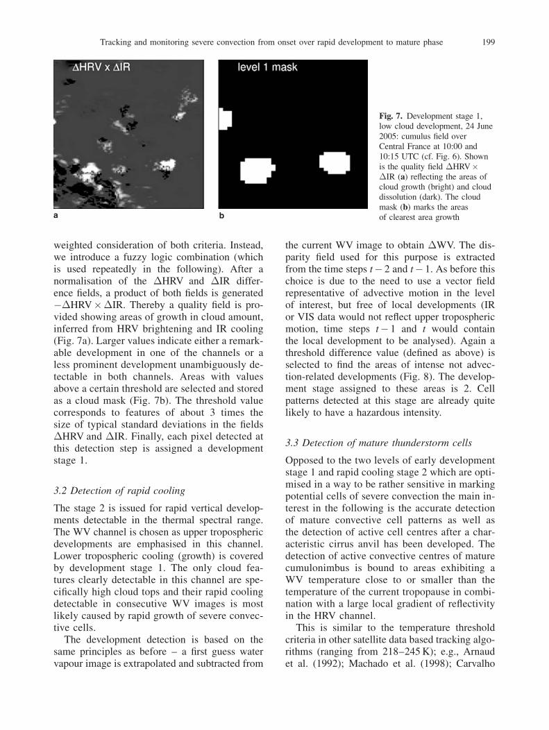
weighted consideration of both criteria. Instead,we introduce a fuzzy logic combination (whichis used repeatedly in the following). After anormalisation of the �HRV and �IR differ-ence fields, a product of both fields is generated��HRV��IR. Thereby a quality field is pro-vided showing areas of growth in cloud amount,inferred from HRV brightening and IR cooling(Fig. 7a). Larger values indicate either a remark-able development in one of the channels or aless prominent development unambiguously de-tectable in both channels. Areas with valuesabove a certain threshold are selected and storedas a cloud mask (Fig. 7b). The threshold valuecorresponds to features of about 3 times thesize of typical standard deviations in the fields�HRV and �IR. Finally, each pixel detected atthis detection step is assigned a developmentstage 1.
3.2 Detection of rapid cooling
The stage 2 is issued for rapid vertical develop-ments detectable in the thermal spectral range.The WV channel is chosen as upper troposphericdevelopments are emphasised in this channel.Lower tropospheric cooling (growth) is coveredby development stage 1. The only cloud fea-tures clearly detectable in this channel are spe-cifically high cloud tops and their rapid coolingdetectable in consecutive WV images is mostlikely caused by rapid growth of severe convec-tive cells.
The development detection is based on thesame principles as before – a first guess watervapour image is extrapolated and subtracted from
the current WV image to obtain �WV. The dis-parity field used for this purpose is extractedfrom the time steps t� 2 and t� 1. As before thischoice is due to the need to use a vector fieldrepresentative of advective motion in the levelof interest, but free of local developments (IRor VIS data would not reflect upper troposphericmotion, time steps t� 1 and t would containthe local development to be analysed). Again athreshold difference value (defined as above) isselected to find the areas of intense not advec-tion-related developments (Fig. 8). The develop-ment stage assigned to these areas is 2. Cellpatterns detected at this stage are already quitelikely to have a hazardous intensity.
3.3 Detection of mature thunderstorm cells
Opposed to the two levels of early developmentstage 1 and rapid cooling stage 2 which are opti-mised in a way to be rather sensitive in markingpotential cells of severe convection the main in-terest in the following is the accurate detectionof mature convective cell patterns as well asthe detection of active cell centres after a char-acteristic cirrus anvil has been developed. Thedetection of active convective centres of maturecumulonimbus is bound to areas exhibiting aWV temperature close to or smaller than thetemperature of the current tropopause in combi-nation with a large local gradient of reflectivityin the HRV channel.
This is similar to the temperature thresholdcriteria in other satellite data based tracking algo-rithms (ranging from 218–245 K); e.g., Arnaudet al. (1992); Machado et al. (1998); Carvalho
Fig. 7. Development stage 1,low cloud development, 24 June2005: cumulus field overCentral France at 10:00 and10:15 UTC (cf. Fig. 6). Shownis the quality field �HRV��IR (a) reflecting the areas ofcloud growth (bright) and clouddissolution (dark). The cloudmask (b) marks the areasof clearest area growth
Tracking and monitoring severe convection from onset over rapid development to mature phase 199

and Jones (2001); Morel and Senesi (2002) apartfrom three important differences:
(1) The WV is used instead of the IR as the WVimage clearly indicates severe convectivecells as especially cold overshooting fea-tures above the tropospheric water vapourbackground.
(2) Not a fixed but an adaptive temperaturethreshold is used which allows for a con-sideration of the synoptic situation as wellas seasonal differences in typical convectivecloud top temperatures.
(3) The local variability of the HRV reflectivityis used to further refine the detection of theactive centres of cell patterns.
For the second point the current temperatureof the tropopause determined from ECMWFmodel analyses is used (ECMWF, 2005, MARSArchive). The analysis is provided daily at 0, 6,12, and 18 UTC. Here lapse rate tropopause tem-
perature (World Meteorological Organisation1957) is used and is determined from the atmo-spheric profiles available in the region of interest.The algorithm described in Sect. 2.2 is used tobest interpolate the tropopause temperature fieldfor each image time. If Cb-TRAM is used in real-time nowcasting situations, short range forecastdata is used instead of the analysis data.
The temperature threshold linked to the lapserate tropopause temperature Ttrop is chosen to beTtrop� 1.5 K. This value representative of cloudsreaching a height slightly below the actual modeltropopause is found by extensive testing to workbest both for isolated air mass thunderstormsand along frontal systems with abrupt changesof tropopause height. The temperature criterionis now to be combined with the secondary crite-rion for the detection of active cell patterns,the HRV roughness. A quantitative combinationwith this second criterion is again reached usingfuzzy logic. A quality field is generated from the
Fig. 8. Development stage 2,i.e., rapid cooling, for 24 June2005: cumulus field overCentral France 15 min after thesituation displayed in Fig. 6.A cooling is detectable fromthe WV images (a, b). Thedifference field �WV (c)reflects the cooling (bright)and warming areas (dark). Themask (d) selects the areasof maximum cooling
200 T. Zinner et al.

WV temperature field using the hyperbolic tan-gent function to spread the value range aroundthe threshold without completely loosing the in-formation detail below the threshold (compareFig. 9a and b).
Figures 1a and 9c show the characteristic HRVroughness. The regions of strongest up-draft arenot only marked by the highest and thus coldestcloud tops, but even more generally by the stron-gest variability in cloud top height. This variabil-ity leads to strong geometric illumination effects(shadows and bright slopes) generating visibleroughness, which is particularly well detectablein the HRV. The measure of variability is a two-
dimensional gradient value obtained for the localsurrounding of each pixel of the field.
This secondary criterion facilitates the separa-tion of rough up-draft from smooth outflowregions at the top of thunderstorms or larger me-soscale frontal cloud systems, and at the sametime it allows for the detection of clouds whichmight still be slightly below the temperaturethreshold, but show a distinct variability of thecloud top. The local gradient field is stronglydepending on illumination, and thus it is normal-ised with the typical diurnal variation of the localHRV gradient (obtained from the analysis of anumber of days for Central Europe) before the
Fig. 9. Development stage 3, i.e., matureconvective cell patterns, for 24 June 2005:shown is the same region over CentralFrance (cf. Figs. 6–8) at 14:00 UTC.Extracted from the WV (a) and HRV images(c) are the quality fields ‘‘weighted WV’’(b) and ‘‘HRV roughness’’ (d). These arethen combined by multiplication (e), andfinally a threshold is used to mark the areasof clearest convective activity
Tracking and monitoring severe convection from onset over rapid development to mature phase 201

two quality fields are combined by multiplication.A threshold is set to select the cloud cell patternsof interest (Fig. 9e and f). These cloud areas cor-respond to active convective cells which are eitherdistinctively high (cold), display a strong cloudtop turbulence (strong up-drafts), or both. The de-velopment stage of 3 for mature thunderstorm isassigned to the detected cloudy pixels.
When HRV reflectivities are no longer avail-able at sunset, the detection of initial cumulusdevelopment (Sect. 3.1) is de-activated and thedetection of mature thunderstorms (Sect. 3.3) isadjusted in a way that only the part using WVtemperature is used and the best possible transi-tion between day and night mask is achieved.
As mentioned before, thresholds used through-out the detection of stage 1–3 are optimised bytesting with a data set from a number of convec-tive events throughout continental Europe. Valueswere not always given since the fuzzy logic com-bination of quality fields often leads to a loss ofeasily understandable physical meaning of valuesand thus does not add clarity to the description.
3.4 Combination of development stage masks
The three development stage masks (Figs. 7b, 8d,and 9f) are combined to one mask displaying allthe detected cell patterns which are to be trackedin the following (Fig. 10). If a cell pattern con-tains detections of different development stages,the most developed stage is chosen to character-ise the whole pattern. To be accepted for tracking
detected cell patterns must have a minimum areaof more than two connected normal resolutionSEVIRI pixels, i.e., about 50 km2. Individual cellpatterns closer than about 10 km (2 SEVIRI pix-els) are merged as large patterns are easier totrack – at the same time the discrimination ofindividual cells is somewhat blurred this way.
4. Tracking
4.1 Basic algorithm
In general, the tracking of detected cell patterns,whether radar or satellite data based, is dividedinto two main techniques: pattern-oriented corre-lation techniques and overlapping techniques.The technique widely used in the determinationof general cloud motion vectors is the patternoriented correlation technique. An arbitrary (insome respect prominent) cloud pattern in oneimage is recovered in the next one, by findingthe position of maximum correlation betweenthe identified pattern and a part of the new image.Several applications of this principle can befound for different tracking algorithms, e.g.,Schmetz et al. (1993), Mecklenburg et al. (2000),or Bolliger at al. (2003). This method even worksfor images separated in time for one or morehours (Carvalho and Jones 2001).
The second – the overlapping – tracking meth-od relies on a short image repeat cycle. It is basedon the overlap of identified cell patterns in twoconsecutive images and thus only works as long
Fig. 10. Combination of development stagemasks for the situation shown in Fig. 1:Three stage sub-masks are combined, patternssmaller than 2 pixels are filtered, and theremaining cell patterns are extended to thefinal combined mask
202 T. Zinner et al.

as overlap occurs, which depends on the timeinterval between two images and on the size ofthe tracked cell patterns. An important improve-ment to this method is the use of the approximatemoving direction and velocity of a detected cloudpattern at time t� 1 to retrieve a first-guess ofposition and size of the pattern at time t. Thisway better overlap with the new (time t) cellpattern detections is given. Examples of applica-tion are given in Arnaud et al. (1992), Dixon andWiener (1993), Morel and Senesi (2002), orHandwerker (2002).
The Cb-TRAM algorithm utilises the lattermethod. The minimum cell pattern size of50 km2 is exceptionally small for satellite track-ing algorithms compared to most of the hithertoexisting algorithms and therefore requires (a) ahigh time resolution, which is provided by theSEVIRI sensor (15 min), and (b) a detailed ap-proximation of the cloud motion field to findoverlap between two consecutive images, whichis provided by the pyramid matching algorithm(Sect. 2). Where other tracking algorithms arereliant on average wind vectors derived for thewhole image or from single cell’s history, ouralgorithm uses an approximate motion field, de-fined for each image pixel. That way not only thedisplacement but also trends of area or shapechanges are considered.
Starting from the combined cell pattern mask(Sect. 3.4) at time t� 1 a first-guess cell patternmask is extrapolated for time t by application ofEq. (4) with the disparity vector field derive from
WV images. For each pattern detected at time tthe maximum overlap with the extrapolatedcell patterns detected at time t� 1 is determined(Fig. 11a). If no overlap is found a new cellpattern number is issued which will be usedthroughout the whole tracking cycle to unambig-uously identify the cloud pattern. A history logfile is created for each cell pattern, which is alsoused by the displaying routine later. At each timestep t the detection time, the detected pattern’spixel positions, the development stage, the posi-tion of the centre of gravity (weighted with 1-TIR), and the displacement since last time stept� 1 are stored for each pattern detected. If over-lap is found for several cell patterns the numberof the pattern with the maximum overlap is iden-tified and the related history log file is updated.If a cell pattern at time t overlaps with more thanone of the extrapolated patterns of time t� 1 onlythe track of the pattern with the largest overlaparea is continued. The other cell patterns die, acell merging has happened. If more than one cellpattern at time t overlaps with an extrapolatedpattern from time t� 1, the one with the largestoverlap area inherits the history. For all otherpatterns new history logs are initialised, the cellsplits.
4.2 Monitoring of cells no longer detected
The disparity vector fields extracted followingSect. 2 were already extensively used for the de-tection of cloud developments before. Of course,
Fig. 11a. Basic tracking principle: a cell pattern detected at time t is recovered at time tþ 1 through determination of theoverlap using the first guess extrapolation; (b) extrapolation: forecasts of the patterns shape for the following time stepsare obtained by extrapolation using the differential disparity vector field; (c) monitoring of patterns no longer detected:the extrapolated patterns are used to bridge gaps in detection
Tracking and monitoring severe convection from onset over rapid development to mature phase 203
these fields can be used for short range extra-polations as well (Fig. 11b). In contrast to theextrapolations used in the detection of rapiddevelopments (stages 1 and 2) this time an ex-trapolation is sought which provides not only ad-vection, but the local developments as well to getthe best possible guess for a future detailed shapeof a cell pattern. Consequently, extrapolationsare generated using the most recent IR disparityvector fields on a pixel by pixel basis. IR data ispreferred for this task since it offers detailedinformations for clouds in all vertical levels.For up to 4 time steps (1 h) the predicted cell pat-terns are stored in the history log files. Not onlythe current velocity but also the current stage ofthe convective life-cycle is extrapolated. For ex-ample, a detection of a thunderstorm cell grow-ing during the last 15 min interval will result ina prediction of further growth for the next timesteps.
Sometimes the tracking for particular cell pat-terns, especially during the development stages 1and 2, is interrupted for short time intervals, be-cause phases of weak cloud development are notdetected. For example, a early development stage1 is issued because of rapid low level cumulusdevelopment at a time t. After this initial stage nofurther development is detectable that is strongenough to meet one of the detection criteria, be-cause there is only a slow vertical growth ofthe cell without further horizontal extension.Nonetheless, 30 min later the convective devel-opment becomes more intense and the rapidcooling stage 2 is triggered. Without an addition-al monitoring of cell patterns once detected, thestage 1 pattern at time t would die out and a newone would be initialised at time tþ 30 min. Thedifferent phases of the cell development wouldbe disconnected. Therefore, the tracking is con-tinued after the last detection for two more timesteps. A synthetic cell pattern is introduced intothe tracking mask using the extrapolation pat-terns (Fig. 11c). Only if cell patterns are notdetected again within 45 min, the tracking of aspecific cloud pattern ends.
5. Comparison with radar and lightning data
Figure 12 shows examples of the Cb-TRAM dis-playing routine products. A SEVIRI HRV satel-lite image (IR, WV also selectable) and a map
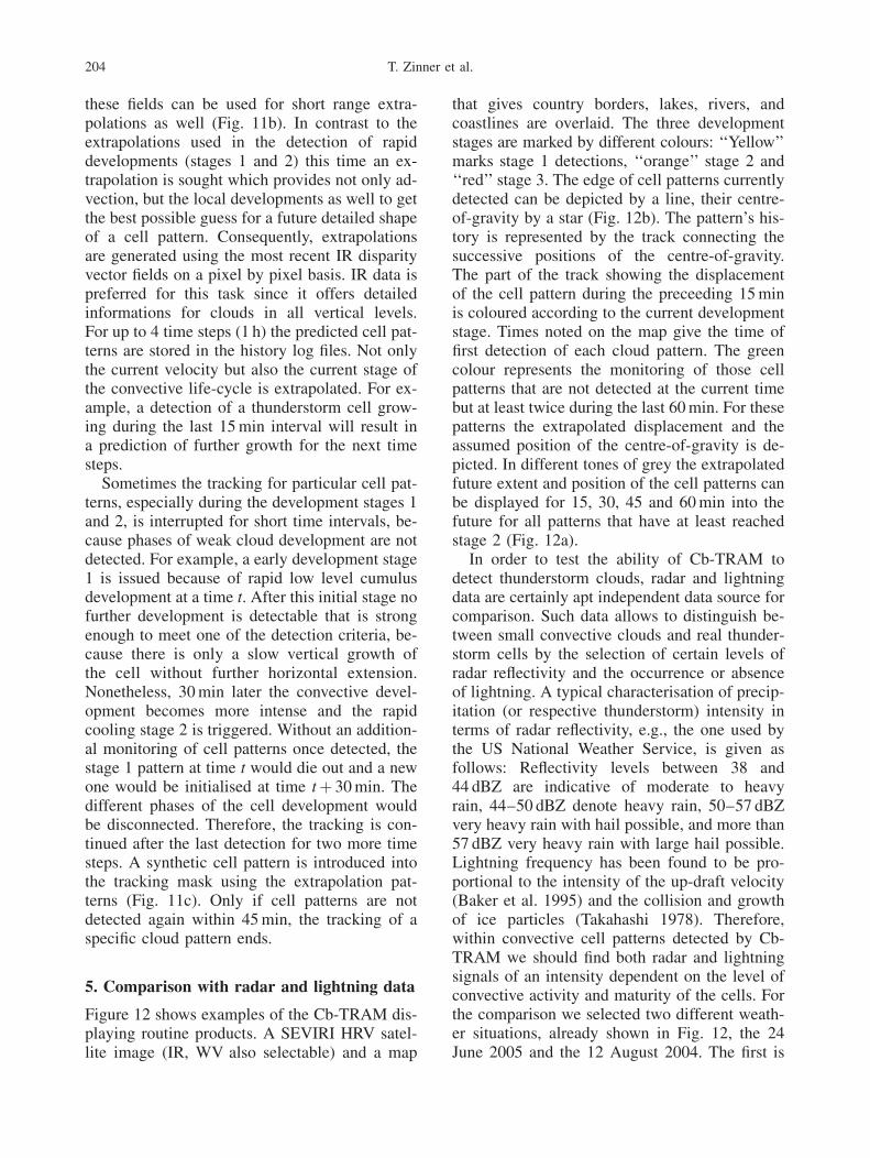
that gives country borders, lakes, rivers, andcoastlines are overlaid. The three developmentstages are marked by different colours: ‘‘Yellow’’marks stage 1 detections, ‘‘orange’’ stage 2 and‘‘red’’ stage 3. The edge of cell patterns currentlydetected can be depicted by a line, their centre-of-gravity by a star (Fig. 12b). The pattern’s his-tory is represented by the track connecting thesuccessive positions of the centre-of-gravity.The part of the track showing the displacementof the cell pattern during the preceeding 15 minis coloured according to the current developmentstage. Times noted on the map give the time offirst detection of each cloud pattern. The greencolour represents the monitoring of those cellpatterns that are not detected at the current timebut at least twice during the last 60 min. For thesepatterns the extrapolated displacement and theassumed position of the centre-of-gravity is de-picted. In different tones of grey the extrapolatedfuture extent and position of the cell patterns canbe displayed for 15, 30, 45 and 60 min into thefuture for all patterns that have at least reachedstage 2 (Fig. 12a).
In order to test the ability of Cb-TRAM todetect thunderstorm clouds, radar and lightningdata are certainly apt independent data source forcomparison. Such data allows to distinguish be-tween small convective clouds and real thunder-storm cells by the selection of certain levels ofradar reflectivity and the occurrence or absenceof lightning. A typical characterisation of precip-itation (or respective thunderstorm) intensity interms of radar reflectivity, e.g., the one used bythe US National Weather Service, is given asfollows: Reflectivity levels between 38 and44 dBZ are indicative of moderate to heavyrain, 44–50 dBZ denote heavy rain, 50–57 dBZvery heavy rain with hail possible, and more than57 dBZ very heavy rain with large hail possible.Lightning frequency has been found to be pro-portional to the intensity of the up-draft velocity(Baker et al. 1995) and the collision and growthof ice particles (Takahashi 1978). Therefore,within convective cell patterns detected by Cb-TRAM we should find both radar and lightningsignals of an intensity dependent on the level ofconvective activity and maturity of the cells. Forthe comparison we selected two different weath-er situations, already shown in Fig. 12, the 24June 2005 and the 12 August 2004. The first is
204 T. Zinner et al.
a weather situation with generally unstable sum-mertime conditions and weak synoptic forcingwith consecutive development of individual thun-derstorm cells during the day (Fig. 12a). Thesecond case is dominated by the passage of acold front through middle Europe accompaniedby a pre-frontal thunderstorm line and a post-frontal convection line (Fig. 12b).
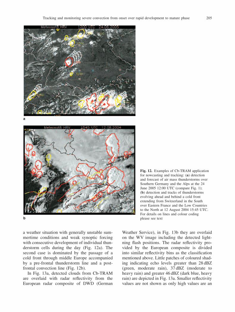
In Fig. 13a, detected clouds from Cb-TRAMare overlaid with radar reflectivity from theEuropean radar composite of DWD (German
Weather Service), in Fig. 13b they are overlaidon the WV image including the detected light-ning flash positions. The radar reflectivity pro-vided by the European composite is dividedinto similar reflectivity bins as the classificationmentioned above. Little patches of coloured shad-ing indicating echo levels greater than 28 dBZ(green, moderate rain), 37 dBZ (moderate toheavy rain) and greater 46 dBZ (dark blue, heavyrain) are depicted in Fig. 13a. Smaller reflectivityvalues are not shown as only high values are an
Fig. 12. Examples of Cb-TRAM applicationfor nowcasting and tracking: (a) detectionand forecast of air mass thunderstorms overSouthern Germany and the Alps at the 24June 2005 12:00 UTC (compare Fig. 1);(b) detection and tracks of thunderstormsevolving ahead and behind a cold frontextending from Switzerland in the Southover Eastern France and the Low Countriesto the North at 12 August 2004 15:45 UTC.For details on lines and colour codingplease see text
Tracking and monitoring severe convection from onset over rapid development to mature phase 205
evidence of thunderstorm activity (and for rea-sons of clarity). Coloured contours in Figs. 13and 14 are identical to the respective contoursin Fig. 12. It can be seen that within the redbounded regions, i.e., the regions of developmentstage 3 (mature cumulonimbus), spots of highradar reflectivity as well as the majority of light-ning detections can be found. Only for the cellpattern in southern Germany, at about 9� E and49� N, the patch of high reflectivity and lightningactivity is just at the edge of the detected cell
pattern at its southwestern end. Another patchedof a radar reflectivity greater than 37 dBZ andlightning activity is visible within the Cb-TRAM cell pattern at 10� E, 50.5� N. This cellpattern is marked as a region of developmentstage 2, i.e., rapid cooling (orange contour inFig. 12a). It is notable that high radar reflectiv-ities are neither found within the patterns of earlydevelopment stage 1 (yellow contour) nor withinthe other patterns of stage 2 over the Alps and atthe French=Swiss border in the lower left corner
Fig. 13. Case 24 June 2005 12:00 UTC:overlay of identified clouds from Cb-TRAM(a) with radar reflectivity (>28 dBZ,moderate rain, green; >37 dBZ, moderate toheavy rain, light blue; >46 dBZ, heavy rain,dark blue) and (b) with detected lightningactivity within the last 15 min (positiveground to cloud flashes marked by þ, allother marked by �). In (b), the WV imageis underlaid as background
206 T. Zinner et al.

of the figure. On the contrary lightning is foundin some of the stage 2 cell patterns.
Summarising, for this scene Cb-TRAM seemsto be capable of correctly identifying the maturethunderstorm cells in the sense that cell patternsassigned the development stage 3 do exhibitprominent convective activity. Considering theadditional information that the stage 1 patternsat 9.5� E, 48.3� N and 6.5� E, 47� N do both infact reach the mature thunderstorm stage 3 at12:45 UTC, also the onset of convection before
precipitation or lightning occurs is correctly de-tected. In between those two stages the develop-ment stage 2 includes patterns which exhibit lesssevere or less definite thunderstorm activity, e.g.,the cell patterns without clear precipitation radarecho but already showing lightning activity.
The inspection of Fig. 12b showing the secondcase reveals a more complex cloud situation. Thebroad white band covering the centre of the im-age is a frontal zone, predominantly showing asmooth cloud structure of high cirrus. Ahead of
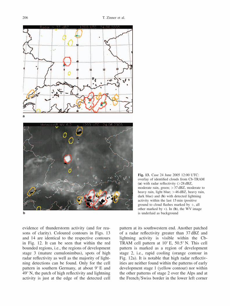
Fig. 14. Case 12 August 2004 11:45UTC: overlay of identified clouds fromCb-TRAM (a) with radar reflectivity(>28 dBZ, moderate rain, green; >37 dBZ,moderate to heavy rain, light blue; >46 dBZ,heavy rain, dark blue; >55 dBZ, very heavyrain with hail, purple) and (b) with detectedlightning within the last 15 min (positiveground to cloud flashes marked by þ, allother marked by �). In (b), the WV imageis underlaid as a background
Tracking and monitoring severe convection from onset over rapid development to mature phase 207

the front to the East the pre-frontal thunderstormcell patterns are marked by red contours. Somecell patterns of development stage 3 are alsomarked behind the cold front within a convectiveline over France. Furthermore, a large stage 3pattern is situated well within the frontal zone(centred at about 7.7� E and 48.5� N). Referringto the overlay with radar and lightning (Fig. 14),clear signs of heavy rain (in the pre-frontal cellsreaching the hail level) and strong lightning ac-tivity are visible for the stage 3 patterns aheadand behind the front. Notably within the frontalzone no lightning flashes are detectable besidesthe few flashes in the region close to the stage 3cell pattern identified by Cb-TRAM. However,there are areas of moderate radar reflectivitiesvisible at some locations outside the identifiedpatterns.
Of course, strong precipitation along a sum-mertime cold front is a common process, evenwithout severe thunderstorm activity and thesecases of advective precipitation are not supposedto be detected by Cb-TRAM. With respect to theconvection line behind the front it has to beemphasised that its detection together with thepre-frontal cells is only possible due to the adap-tive tropopause temperature criterion. Since thetropopause temperature increases strongly as thefront passes through, a fixed thunderstorm toptemperature threshold would either provide nodetection of the post-frontal cells or provide avery indiscriminate detection of the whole fron-tal cloud cover. Still, at least one individual cellin the post-frontal convection line is missed.However, Cb-TRAM should not be expected toresolve any individual cell within a thunderstormline especially when these features are of smallerscale, due to the limited information content ana-lysing cloud (mainly cloud top) characteristicsfrom a satellite sensor. It can be seen that Cb-TRAM is able to separate thunderstorm cells fromfrontal cirrus cloud systems of similar brightnesstemperature and to some extent the active cellcentres from thunderstorm cirrus shields.
In fact, there seems to exist one striking detec-tion failure of the Cb-TRAM diagnosis in thiscase. That is the small radar reflectivity cell withpurple shading (greater 55 dBZ) at about 6.3� E,50.7� N. This feature within the frontal line hasbeen detected within the preceeding 2 h as well,however without any detectable indication in the
satellite images (cf. the HRV image in Fig. 12band the WV image in Fig. 14b). On the one hand,the radar data might not give the true pictureof precipitation processes due to incomplete ra-dar coverage, beam blocking by orography anddifferent scanning modes of the radars within theradar network providing the composite. On theother hand, the strong precipitation there is ob-viously not produced by a thunderstorm as itshould be apparent in the IR and WV images then.
Concluding for these two cases of thunder-storm development and propagation, Cb-TRAMis not only capable of correctly identifying thun-derstorm cells but also of the detection of severalstages of the convective life-cycle including theearly onset of convection at a time when corre-sponding signals in radar and lightning are notyet visible.
6. Conclusion
In this paper, a new automated tool for the detec-tion, tracking and nowcasting of thunderstormcells was presented which is based on infor-mation from three different channels of theMeteosat-8=SEVIRI sensor and on ECMWF op-erational analysis data. Detected are three dif-ferent combinations of characteristics related tothree stages of the convective life-cycle. Each ofthem is particularly interesting be it that it allowsfor an early issue of warnings of potential con-vective activity or that it marks fully developedsevere convective activity. Especially the two de-velopment stages for rapid convective develop-ments, which use two consecutive satelliteimages in the HRV, IR, or WV channels, repre-sents a novel exploitation of the specific possibil-ities offered by the SEVIRI sensor – short imagerepeat cycle and high resolution information(HRV). The traditional method of detection ofmature severe convection, a temperature thresh-old in an infra-red channel, is extended to moregenerality by the use of ECMWF tropopause in-formation. That way, the detection automaticallyadapts to variable seasonal or current weatherconditions. During day-time the availability ofthe HRV is used to further restrict the detectionof mature cells to the most active cell centres bythe analysis of high resolution variability.
The central techniques of the tracking algo-rithm linking detected cell patterns in consecu-
208 T. Zinner et al.

tive images are the pyramid matching algorithmand the analysis of overlap between detected cellpatterns in two time steps. The former providesdisparity vector fields describing the develop-ment of patterns during a time step. The latterlooks for spatial overlap between detected pat-terns in one time step and extrapolations of thepreceeding time step’s detected cell patterns. Thedisparity vectors provide the basis for an interpo-lation of satellite images or other data fields forintermediate time steps between two known datafields as well as for short-range forecasts ofdevelopments by extrapolation.
Two cases – thunderstorms embedded in a me-soscale frontal system and isolated air mass thun-derstorms – were presented which illustratethe capabilities of the new algorithm. The de-tection algorithm was tested by comparison ofdetected convective cell patterns to precipitationradar echoes and lightning data from operationalnetworks.
7. Discussion
From this point further more systematic verifica-tion is to be conducted, e.g., through the analysisof conventional error measures or preferablythrough the use of object-oriented verificationprocedures (e.g., Ebert and McBride 2000).Conceivable are the extension of the early devel-opment detection capabilities through satellitedata based determination of air mass stability(as discussed in Senesi et al. 1998) or the identi-fication of active cell centres with precipitationradar data or lightning networks.
Nonetheless, the demonstration case section ofthis paper widely supports the used detection ap-proach. Maxima of precipitation and lightningactivity were always found within the identifiedcell pattern outlines although the detected pat-terns tend to include areas of low convective ac-tivity as well. On the one hand, this of courserepresents a general shortcoming of satellite databased detection as only secondary effects of se-vere convection (cloud top temperature or cloudtop turbulence) can be evaluated. On the otherhand, the fact that not every detected area in-cludes clear signals of heavy precipitation orlightning activity – mainly the cell patterns withthe development stage 1 of initial convective de-velopment – demonstrates a specific capability
of satellite data based detection. It allows foran early detection of pre-thunderstorm convec-tion stages. The nowcasting capabilities of Cb-TRAM are not tested so far. Extrapolation withthe disparity vector fields nonetheless illustratethe potential. There is large room for improve-ment, be it by better taking into account indica-tions of decay or by including some life-cyclemodel.
The matching and tracking algorithms (TRAM)used here can of course be used for tracking andmonitoring of other atmospheric characteristicslike precipitation fields from radar data or othertypes of cloud patterns in satellite images.
Acknowledgements
We gratefully acknowledge Andreas D€oornbrack who provid-ed the operational analysis data from the ECMWF MarsArchive. The work was supported by the EuropeanCommission Projects RISK-AWARE (INTERREG III BCADSES Neighbourhood Programme) and FLYSAVE (6thFramework Programme). Meteosat data are copyrighted byEUMETSAT. The European radar composite is a product ofDWD (German Weather Service). We thank two anonymousreviewers for their valuable contributions to the final form ofthis manuscript.
References
Arnaud Y, Desbois M, Maizi J (1992) Automatic trackingand characterization of African convective systems onMETEOSAT pictures. J Appl Meteorol 31: 443–53
Baker MB, Christian HJ, Latham J (1995) A computationalstudy of the relationship linking lightning frequency andother thundercloud parameters. Q J Roy Meteorol Soc121: 1525–48
Bolliger M, Binder P, Rossa A (2003) Tracking cloudpatterns by METEOSAT rapid scan imagery in complexterrain. Meteorol Z 12: 73–80
Bugliaro L, Mayer B (2004) Study on quantitative use of thehigh resolution visible channel onboard the METEOSTATsecond generation satellite, Final Report phase II. ITTNo. 03=542 EUMETSAT Study EUMETSAT, Am Kaval-leriesand 31, 64295 Darmstadt, Germany
Carvalho L, Jones C (2001) A satellite method to identifystructural properties of mesoscale convective systemsbased on the maximum spatial correlation tracking tech-nique (MASCOTTE). J Appl Meteorol 40: 1683–701
Dixon M, Wiener G (1993) TITAN: Thunderstorm identifi-cation, tracking, analysis, and nowcasting – a radar-basedmethodology. J Atmos Ocean Tech 10: 785–97
Ebert EE, McBride JL (2000) Verification of precipitation inweather systems: Determination of systematic errors. JHydrol 239: 179–202
ECMWF (2005) MARS User Guide European Center forMedium Range Weather Forecast – ECMWF, Reading,
Tracking and monitoring severe convection from onset over rapid development to mature phase 209

United Kingdom; Manual available at www.ecmwf.int=publications=manuals=mars=
Evans JE (1997) Safely reducing delays due to adverseterminal weather. In: Bianco L, Dell’Olmo P, and OdoniAR (eds). Modelling and Simulation in Air TrafficManagement. Springer, New York, pp. 185–202
Feidas H, Cartarlis C (2005) Application of an automatedcloud-tracking algorithm on satellite imagery for trackingand monitoring small mesoscale convective cloud sys-tems. Int J Remote Sens 26: 1677–98
Fujita T (1969) Present status of cloud velocity computationsfrom ATS-1 and ATS-3 satellites. In: COSPAR SpaceResearch IX, North-Holland, Amsterdam, pp. 557–70
Handwerker J (2002) Cell tracking with TRACE3D – a newalgorithm. Atmos Res 61: 15–34
Hering AM, Morel C, Galli G, Senesi S, Ambrosetti P,Boscacci M (2004) Nowcasting thunderstorms in theAlpine Region using a radar based adaptive threshold-ing scheme. In: Proc. ERAD Conference 2004, Visby,Sweden, pp. 206–11
Horn BKP, Schunck BG (1981) Determining optical flow.Artificial Intelligence 17: 185–203
Lang P (2001) Cell tracking and warning indicators derivedfrom operational radar products. In: Proc. 30th Int.Conference on Radar Meteorology, Munich, Germany,Amer Met Soc, pp. 245–7
Ligda MG (1953) The horizontal motion of small precipita-tion areas as observed by radar, Tech. Rep. 21. Availablefrom Library, Massachusetts Institute of Technology, 77Massachusetts Ave., Cambridge, MA, Department ofMeteorology, M.I.T.
Lucas BD, and Kanade T (1981) An iterative image regis-tration technique with an application to stereo vision.In: Proc. Imaging Understanding Workshop, pp. 121–30.Available from www-cse.ucsd.edu=classes=sp02=cse252=lucaskanade81.pdf
Machado LAT, Rossow WB, Guedes RL, Walker AW(1998) Life cycle variations of mesoscale convectivesystems over the Americas. Mon Wea Rev 126: 1630–54
Mannstein H, Meyer R, Wendling P (1999) Operationaldetection of contrails from NOAA-AVHRR data. Int JRemote Sens 20: 1641–60
Mecklenburg S, Joss J, Schmid W (2000) Improving thenowcasting of precipitation in an Alpine region with an
enhanced radar echo tracking algorithm. J Hydrol 239:46–68
Menzel WP (2001) Cloud tracking with satellite imagery:From the pioneering work of Ted Fujita to the present.B Am Meteorol Soc 82: 33–47
Morel C, Senesi S (2002) A climatology of mesoscale con-vective systems over Europe using satellite infrared imag-ery. I: Methodology. Q J Roy Meteorol Soc 128: 1953–71
Mueller C, Saxen T, Roberts R, Wilson J, Betancourt T,Dettling S, Oien N, Yee J (2003) NCAR Auto-NowcastSystem. Wea Forecast 18: 545–61
Pierce CE, Hardaker PJ, Collier CG, Haggett CM (2000)GANDOLF: a system for generating automated nowcastsof convective precipitation. Meteorol Appl 7: 341–60
Purdom JFW (1976) Some uses of high resolution GOESimagery in the mesoscale forecasting of convection and itsbehavior. Mon Wea Rev 104: 1474–83
Riosalido R, Carretero O, Elizaga F, Martin F (1998) Anexperimental tool for mesoscale convective systems track-ing. In: Proc. 1st Joint NWC SAF Training Workshop,Madrid
Schmetz J, Holmlund K, Hoffman J, Strauss B, Mason B,Gaertner V, Koch A, Van De Berg L (1993) Operationalcloud-motion winds from Meteosat infrared images. JAppl Meteorol 32: 1206–25
Senesi S, Ducrocq V, Thepenier RM, Calas C (1998) MSGand the nowcasting of convective systems: relevance ofinstability indices and other convection-related diagnos-tics. In: Proc. 1st Joint NWC SAF Training Workshop,Madrid
Steinacker R, Dorninger M, W€oolfelmaier F, Krennert T(2000) Automatic tracking of convective cells and cellcomplexes from lightning and radar data. Meteorol AtmosPhys 72: 101–10
Takahashi T (1978) Riming electrification as a chargegeneration mechanism in thunderstorms. J Atmos Sci35: 1536–48
Wilson JW, Mueller CK (1993) Nowcasts of thunderstorminitiation and evolution. Wea Forecast 8: 113–31
Wilson JW, Crook NA, Mueller CK, Sun J, Dixon M (1998)Nowcasting thunderstorms: A status report. B AmMeteorol Soc 79: 2079–99
World Meteorological Organisation (1957) Meteorology: athree-dimensional science. WMO Bull 6: 134–8
210 T. Zinner et al.: Tracking and monitoring severe convection from onset over rapid development to mature phase