Embed Size (px)
Citation preview
VGB PowerTech - Autorenexemplar - © 2015>>> VGB DIGITAL <<<
VGB
Pow
erTe
ch -
Aut
oren
exem
plar
- ©
201
5
73
VGB PowerTech 4 l 2015 Centralised multivariable feedback control of steam drums
Authors
Kurzfassung
Mehrgrößenregelung für den Trommelfüllstand in GuD-Anlagen
Die Deregulierung des Energiemarktes und die zunehmende Integration erneuerbarer Ener-gieerzeugung in das Netz haben zu neuen, hochdynamischen Anforderungen an die Kraft-werke geführt, die mit klassischen Regelungen vom PID-Typ teilweise nicht mehr zu bewälti-gen sind. In dem vorliegenden Beitrag wird ein moderner, multivariabler Regler zur Regelung des Füllstandes der Niederdrucktrommel im 450-MW-GuD-HKW München Süd der Stadt-werke München beschrieben. Die bisher einge-setzte Struktur aus zwei PI-Regler-Kaskaden setzte dem Betrieb enge Grenzen hinsichtlich der Blockdynamik und der entsprechenden Fähigkeit, Sollwerten aus der Netzregelung zu folgen. Daher wurde ein beobachtergestützter, multivariabler Zustandsregler konzeptioniert.Der Beobachter wurde zunächst in MATLAB/Simulink implementiert und anhand der vor-handenen, umfangreichen Messdaten verifi-ziert. Realisiert wurden Regler und Beobachter dann im Leitsystem Mauell ME-4012. Die Rege-lung beinhaltet außerdem eine umfangreiche Umschaltlogik zwischen den fünf vorhandenen Dampfventilen, die jeweils für andere Betriebs-zustände aktiv werden. Der fertige Regler in der Anlage zeigt ein deutlich verbessertes dy-namisches Gesamtverhalten des Systems, wie man anhand von Doppelhöckerkurven für die Präqualifikation für die Teilnahme am Regel-energiemarkt gut erkennen kann. l
Centralised multivariable feedback control of steam drums in combined cycle power plantsAhmed El-Guindy, Fabian Nickel and Kai Michels
Ahmed El-Guindy, M.Sc. Wissenschaftlicher MitarbeiterFormerly FWBI Forschungsges. GmbHTechnische Universität MünchenMünchen/GermanyDipl-Ing. Fabian NickelProjektleiter Automatisierung und Leittechnik SWM Services GmbHMünchen/Germany Prof. Dr.-Ing. Kai MichelsInstitutsleitung Universität BremenBremen/Germany
Introduction
The integration of renewable energy sourc-es has led to a continuous increase of com-plexity, design and management of power systems. The installed process controllers have to be designed in such a way, which can simultaneously offer a high degree of flexibility and at the same time, should bear in mind safety and lifetime of the plant crucial elements. The process con-trollers have to comply with the require-ments imposed by load change demands preserving the grid stability and frequency, which is processed in primary grid control. In particular, control of the steam drum unit water level is very critical for boiler op-eration, and the controller should maintain it within safety limits over the complete op-erating range of the boiler. The steam generation process using the drum unit is a multiple-input multiple-out-put (MIMO) system, with a strong coupling between its input channels and non-linear dynamics depending on the operating point. Additionally, it has a non-minimum phase behaviour, leading to an initial in-verse response of the water level, which is associated with the shrink and swell physical phenomena of steam bubbles un-der the water level. This makes the control task extremely challenging with classical techniques using decentralised PID control loops, which regulate feedwater and steam flow rates separately from each other.The industry standard 1-, 2- and 3-element cascaded architecture PID controllers can be found in nearly all current power plants [1]. Although they can behave fairly well with low load changes (≤20 MW) with long time interval between each transi-tion, their performance can become unsat-isfactory for higher steps (≥30 MW), thus resulting in large deviations in the system response. The modification of the control-ler parameters to improve the system per-formance is not a straight-forward task due to the strong coupling between different actuating variables. The adjustment of a particular loop, without considering the effects on the overall multivariable system, can result in instability of the plant and even worse tripping of the boiler unit. Sta-tistically speaking, it was reported recently, that 30 % of emergency shutdowns in pow-er plants are caused by poor level control of the steam drum unit [2].
The control theorists from academia have been proposing entirely new emerging concepts to solve this reoccurring problem, such as genetic algorithms (GAs), fuzzy logic, neutral networks, and norm-optimal control. As these modern techniques are only examined within simulation environ-ments, i.e. MATLAB or Modelica, the same control performance cannot be guaranteed in practice because of the unavoidable mis-match between a mathematical model and reality. Furthermore, very small perturba-tions of modern controller coefficients can cause instability of the closed loop. From a practical point of view, these con-trollers are unusable in a commercial dis-tributed control system (DCS), for the fol-lowing main reasonsMethodology: Plant operators are unfa-miliar with state-of-the-art concepts. In ad-dition, a very well established mathemati-cal background is mandatory, to barely even understand the basics of a modern controller. This knowledge is not available among plant personnel, so that the con-troller will always act as a black box system from the operator’s view, and therefore rarely accepted.Implementation: The controller is struc-turally unconstrained and its order is usu-ally higher or equal to that of the plant, making it unrealisable, due to hardware and software limitations.Tuning: Controller online re-tuning or re-adjusting is practically impossible, as the feedback parameters are neither set direct-ly nor have a clear physical meaning that one can easily relate to. This matter is very critical in practical applications, since the operating mode may be redefined in differ-ent ways, or, more often, plant parameters may change caused by pipe contamination or actuator deterioration, thus re-tuning is necessary many times during the process lifetime.Switching mechanism: The possibility to switch back from modern controller to conventional structure should be always given in case of any problem, especially for critical industries. The mechanism has to ensure, that both controller outputs are following one another, so that an output discontinuous course is avoided during transient switching.Motivated by the above mentioned, a new control strategy for the low-pressure
VGB PowerTech - Autorenexemplar - © 2015>>> VGB DIGITAL <<<
VGB
Pow
erTe
ch -
Aut
oren
exem
plar
- ©
201
5
74
Centralised multivariable feedback control of steam drums VGB PowerTech 4 l 2015
steam drum unit of the 450 MW CCHPP (combined cycle heat and power plant) München Süd belonging to Stadtwerke München will be presented. The strategy offers the powerful features of state-space control, while at the same time complies with the practical requirements of a power plant. The work is a cooperation project between the University of Bremen, Insti-tute of Automation (IAT), Chair of Sys-tem Dynamics and Control Engineering, and Munich City Utilities – Stadtwerke München (SWM Services GmbH).
Process description
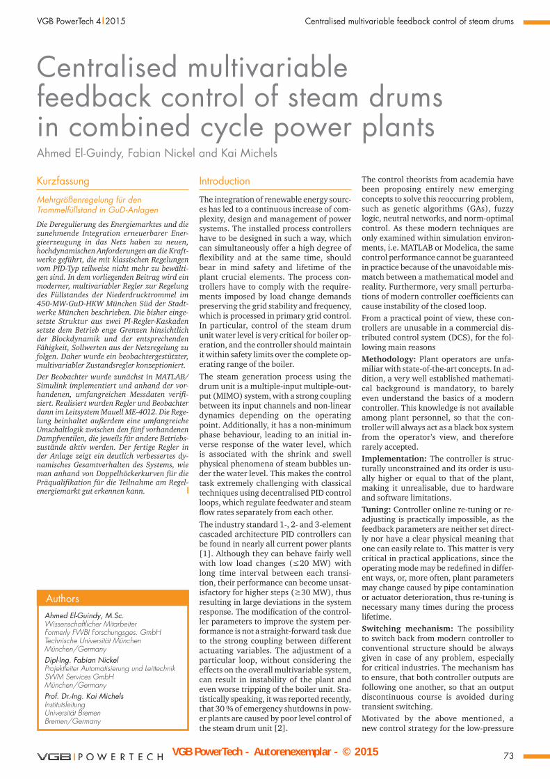
The simplified diagram of the steam gen-eration process using the steam drum is shown in F i g u r e 1 . Cold water from the feedwater tank is pumped and heated at the economiser stage before going through the drum inlet. Due to gravitational force, the feedwater flows through the naturally circulated downcomer-riser loop, in which the liquid is converted into steam at the evaporator stage. The steam is collected through different riser tubes and fed back into the drum. As the drum contains a mix-ture of saturated liquid/steam and due to the difference in density between both, the steam starts leaving from the drum outlet to be superheated at the superheater stage. The generated steam can flow throughout 5 different steam ways, according to the process requirements, in the following or-der.Feedwater tank: A portion of the steam flow of approximately 1 kg/s is always sup-plied for preheating the feedwater tank, and the valve is kept fixed at a constant opening.
Over-the-roof: If none of the below paths is available, steam is simply released to the environment. Besides that, the respec-tive valve is employed for safety measures, when the drum pressure exceeds certain limitations.District heating network: Heat can be supplied through the heating network to the residents of Munich, using a butterfly valve.Steam turbine (DT-60): Additional elec-trical power can be generated by the steam turbine through the secondary steam inlet, if the corresponding valve is opened.Condenser: Throughout this valve, the steam can be condensed directly by by-passing the steam turbine. Additionally, it is operated during start-up and shut-down of DT-60.
The level control is the industry standard, cascaded PID controller, with a level con-troller at the outer-loop and a flow rate controller at the inner-loop to adjust the control valve opening percentage (%). The pressure is controlled by PI steam pressure controllers with one controller for each steam valve.This results in a total of six different PI controllers in a decentralised network, employed to regulate the water level and pressure of the steam drum unit. In the following section it will be shown how it is possible to improve the performance sig-nificantly with a centralised multivariable feedback control technique.
Controller development
The state-feedback methodology is a mod-ern control strategy, which uses the inner states of the system, given by the vector x, for feedback. Using this internal knowledge of the system, the controller performance can be much better than the classical con-troller performance, where only output measurements are used for feedback and control error calculations.The main disadvantage of the state space approach is the necessity of an observer to estimate the internal states that normally cannot be measured in practice. Moreover, since the observer is nothing more than a mathematical model, derived from first principles to capture dynamics of the sys-tem, its design can be an extremely time-consuming task. For correction of model errors, the model output is compared to the measured plant output, and the model error is multiplied with an observer feed-back matrix L and fed back into the model as a correction term. With a proper and guaranteed estimation of the inner states in the observer, the cal-culated states of the model can be used for feedback with the help of a matrix F. However, as this is merely a multidimen-sional proportional gain matrix, steady
Feedwater pump
Feedwater tank
Superheater
Steam drum
Downcomer-riser loop
Over-the-roofvalve
To air
To heatingnetwork
Butterfly valve
Bypass valve To condensor
To steamturbine
DT-60 valve
Evaporator
Exhaust heatfrom the gas turbine
Feedwater tankvalve
Economizer Feedwatervalve
Fig. 1. Steam generation process using the steam drum.
w
State controller
Controlvalves
Stateobserver
Steam drummodel
- F
Steam drumprocess
L
y
x
z
z
uPl- I
- -
-
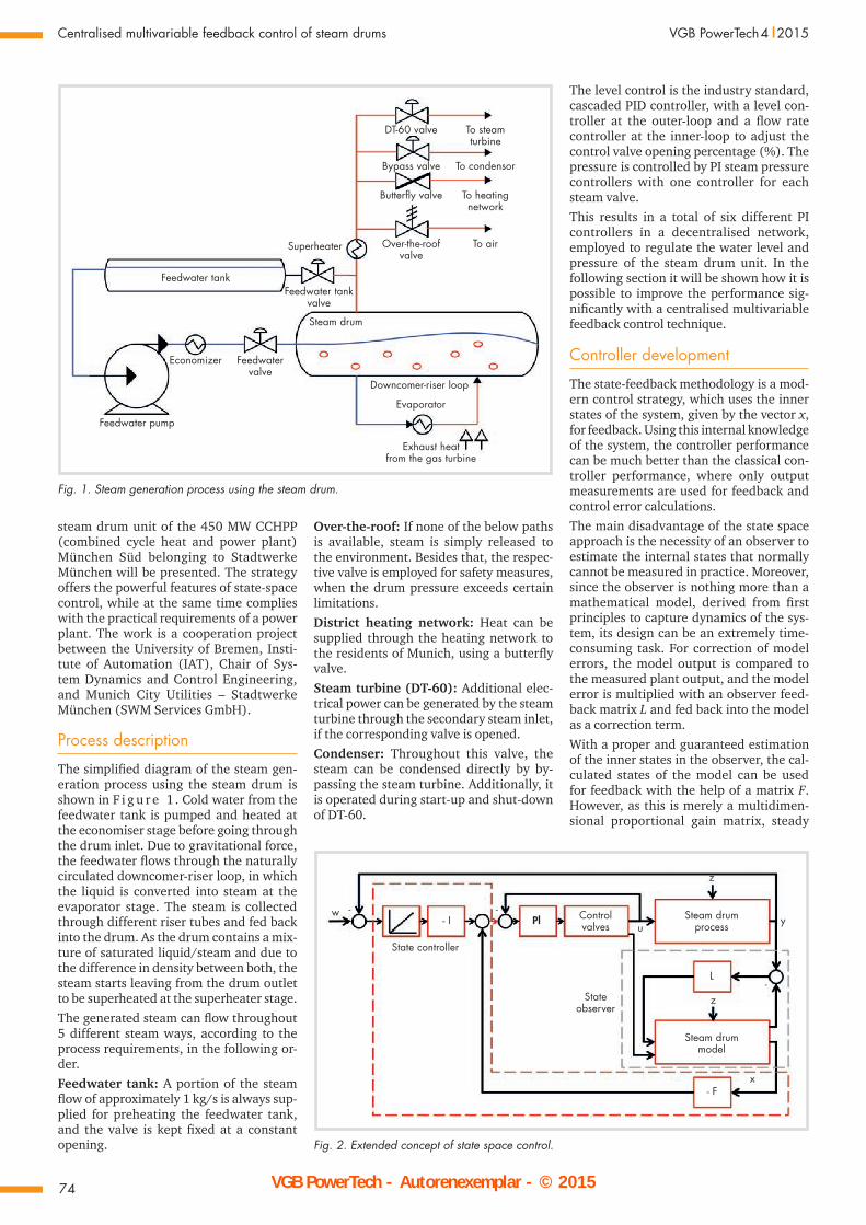
Fig. 2. Extended concept of state space control.
VGB PowerTech - Autorenexemplar - © 2015>>> VGB DIGITAL <<<
VGB
Pow
erTe
ch -
Aut
oren
exem
plar
- ©
201
5
75
VGB PowerTech 4 l 2015 Centralised multivariable feedback control of steam drums
state accuracy cannot be achieved, similar to the classical problem with the pure pro-portional controller. Therefore, an integral part is required, which is a multidimen-sional integral controller in addition to the state-feedback controller. The coefficient matrix of the integral part I has to be de-signed together with the state-feedback matrix F, as the outputs of the multidimen-sional integrator have to be treated as ad-ditional state variables of the system.The key advantages of this extended struc-ture when compared to a decentralised network of PI controllers, is that all effects, that have to be neglected for PI control-ler design (strong coupling, non-linearity, non-minimum phase behaviour) are auto-matically taken into account by state-space controller design.
Observer designThe observer used to estimate the steam drum states is the very well developed Åström-Bell model [2]. It went through several iterations since the seventies, which resulted nowadays in a 4th order non-linear model that can predict the drum pressure and water level by means of defining en-ergy and mass balance. The four chosen state variables have a good physical inter-pretation: The steam drum pressure P is obviously chosen as it describes the total energy of the system. The accumulation of water, related to the total water volume Vw in the system is selected since it represents the storage of mass. Steam quality αr in the riser tubes and steam bubbles volume un-der the liquid level Vd are chosen as well to describe distribution of steam under the water level, thus estimating the level inside the drum. The model actuating variables u are the feedwater and steam flow rates, while the heat flow rate is considered as a model in-put disturbance z, due to the power plant combined cycle working principle. Its amount is associated with the gas turbine exhaust heat, which in return corresponds to its electrical output power. The relation between both was assumed to follow a performance of 1st order lag element PT1, where its time constant T and gain P were chosen according to measurements of the real process.The observer model was validated in MATLAB/Simulink against data measure-ments from the plant with very rich excita-tion, covering a wide spectrum of operating conditions. For further details concerning the observer model, the reader can refer to a previous publication by the authors [3].
Controller designThe design of the above-mentioned con-troller matrices L, F and I can be achieved using different mathematical algorithms. We are using the Linear-Quadratic method for optimal control, in which the resulting controller is known as a Riccati Controller.
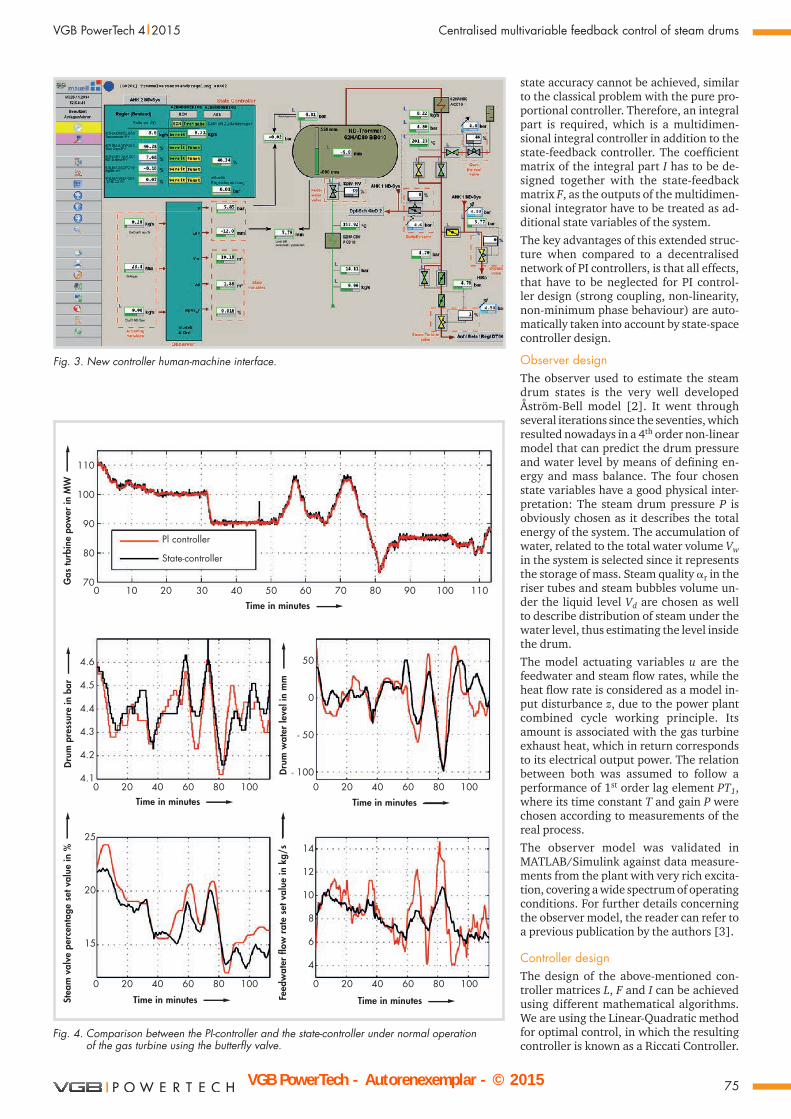
Fig. 3. New controller human-machine interface.
0 10
Pl controller
State-controller
20 30 40
0 20 40 60 80 100 0 20 40 60 80 100
50 60 70 80 90 100 110
110
100
90
80
70
4.6
4.5
4.4
4.3
4.2
4.1
14
12
10
8
6
4
50
0
- 50
- 100
25
20
15
0 20 40 60 80 100 0 20 40 60 80 100
Drum
pre
ssur
e in
bar
Stea
m v
alve
per
cent
age
set v
alue
in %
Drum
wat
er le
vel i
n m
mFe
edw
ater
flow
rate
set
val
ue in
kg/
s
Gas
turb
ine
pow
er in
MW
Time in minutes
Time in minutes
Time in minutes Time in minutes
Time in minutes
Fig. 4. Comparison between the PI-controller and the state-controller under normal operation of the gas turbine using the butterfly valve.
VGB PowerTech - Autorenexemplar - © 2015>>> VGB DIGITAL <<<
VGB
Pow
erTe
ch -
Aut
oren
exem
plar
- ©
201
5
76
Centralised multivariable feedback control of steam drums VGB PowerTech 4 l 2015
It offers a trade-off between the ampli-tude of the actuating variables u and performance of the state variables x over the course of time, by minimising a cost function J described in equation (1). The controller performance depends on the weighting matrices Q and R, that have to be chosen by the design engineer like the parameters of a PID controller: gain Kp, integrator time constant Ti and derivative gain KD.
Yet, the synthesis principle is still the same, as a trial-and-error process takes place until a satisfactory performance is attained. The initial choice of the matrices is straightforward, with the help of the Bry-son’s rule. Then if a faster convergence of a particular state towards zero is required, its equivalent coefficient inside the matrix Q should increase, and if a slower response of the actuating variables is preferred to lower the energy consumption, then the coefficients of R have to be chosen larger.
∞
J = ∙ ∙xT (t)Qx(t) + uT (t)Ru(t)∙dt .. (1) 0
The block diagram for the proposed con-trol strategy using the state-space control-ler is shown in F i g u r e 2 . The non-linear model combined with the error feedback matrix L2x4 is the observer of the real steam drum process. The four estimated variables are fed to the state feedback matrix F2x4, and the output of this matrix stabilises the system. Additionally, integral controllers for two inputs and two outputs for steady-state accuracy of the system were coupled, represented by matrix I2x2. This results in the computation of two set values, e.g. the feedwater flow rate kg/s and the respective steam valve opening position (%).
The highlighted red path in the block dia-gram between matrix I2x2 and PI controllers for the valves includes the switching logic to switch between old and new control set values. The switching for the feedwa-
ter flow rate set value is self-explanatory, since there exists only one single valve to regulate the feedwater. However, the issue becomes more complicated with the steam flow rate, which leads to the design of a special switching mechanism with several selection criteria, to ensure that the correct valve is being controlled, according to the process requirements.
Switching mechanism
F i g u r e 3 shows an illustrative descrip-tion of the new HMI to use the new con-troller. A modification of the existing HMI of the steam drum unit was necessary to include the observer state variables and the binary signals of the switching circuit.
The switching unit has to cover many dif-ferent operation scenarios that cannot be explained here completely. In the follow-ing, only the switching from the PI control-ler to the state controller is explained. All control valves’ opening percentages are supplied to the logical circuit, to decide which steam way, e.g. district heating net-work, condenser or steam turbine, is cur-rently in use according to the following decisions:
Ready – Bereit: A valve is ready according to feedback signals from the Mauell DCS system.
The valves are being controlled automati-cally.
No measurement errors or disturbances are present.
Leading – Führt: If two or more valves are ready, then it must be decided which one is leading. The highest opening percentage gives a good indication, which steam way is currently in operation, since only one steam way can be used at time.
The opening percentage is only considered when the valve is operated automatically, otherwise it is regarded as closed.
The over-the-roof valve is only employed for safety measures and rarely operated by itself, it has to be opened more than 30 %, otherwise it is considered as closed.
Due to the fact that both boilers are using the same bypass valve, another criterion is included using the preceding one-way valve: The opening percentage is consid-ered only if its one-way valve is opened.
Tracking signals: Once a valve is ready and leading, its opening percentage is sup-plied to the state-controller integrators to ensure that they are following the corre-sponding PI control loop output. This will ensure a continuous output course during switching between both controllers.
Released – Freigabe: The state-controller performs one final check before allowing the operators to turn it ON (EIN).
The electrical load of the gas turbine should be higher than 65 MW, to avoid op-eration during start-up, which is handled
0 1 2 3
Pl controller
State-controller
0 1 2 3 0 1 2 3
120
110
100
90
80
70
4.7
4.6
4.5
4.4
4.3
14
12
10
8
6
4
80
40
0
-40
- 65
24
22
20
18
16
14
Drum
pre
ssur
e in
bar
Stea
m v
alve
per
cent
age
set v
alue
in %
Drum
wat
er le
vel i
n m
mFe
edw
ater
flow
rate
set v
alue
in k
g/s
Gas
turb
ine
pow
er in
MW
Time in hours
Time in hours
Time in hours Time in hours
Time in hours
0 1 2 3 0 1 2 3
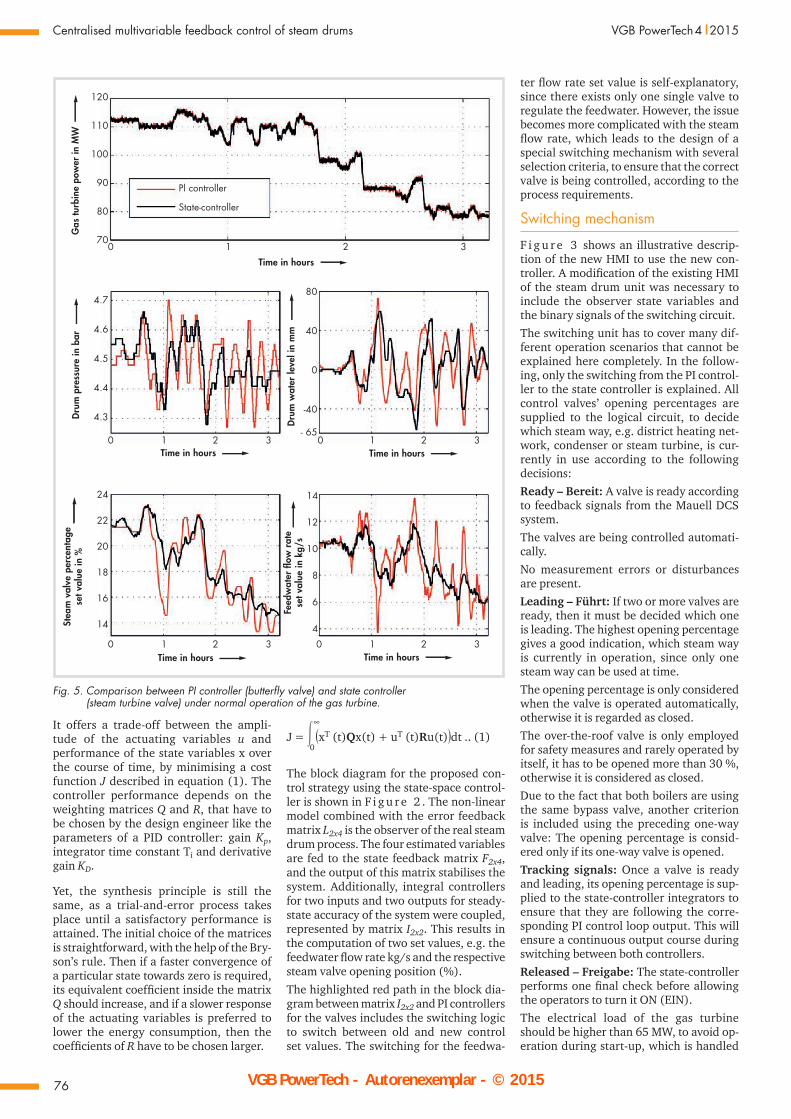
Fig. 5. Comparison between PI controller (butterfly valve) and state controller (steam turbine valve) under normal operation of the gas turbine.
VGB PowerTech - Autorenexemplar - © 2015>>> VGB DIGITAL <<<
VGB
Pow
erTe
ch -
Aut
oren
exem
plar
- ©
201
5
77
VGB PowerTech 4 l 2015 Centralised multivariable feedback control of steam drums
by a separate controller and is not part of the state-controller tasks.The leading steam valve opening percent-age should be higher than 3 %.The errors between the observer and actual measurements have not exceeded the pre-defined limits for more than 5 minutes, i.e. 0.1 bar pressure or ±20 mm level errors.Finally, if all previous criteria are met, the operator can turn the controller ON (EIN).Once the state-controller is turned ON, its set values are provided to the respective steam valve which was previously regulat-ed by the old PI controller, while the other valves are not affected. Switching off the state controller takes place automatically, if one of the above-mentioned rules is no longer met. Additionally, it can be turned OFF (AUS) by the operators manually.
Results
This section compares the old PI controller and the new state-controller under differ-ent conditions.
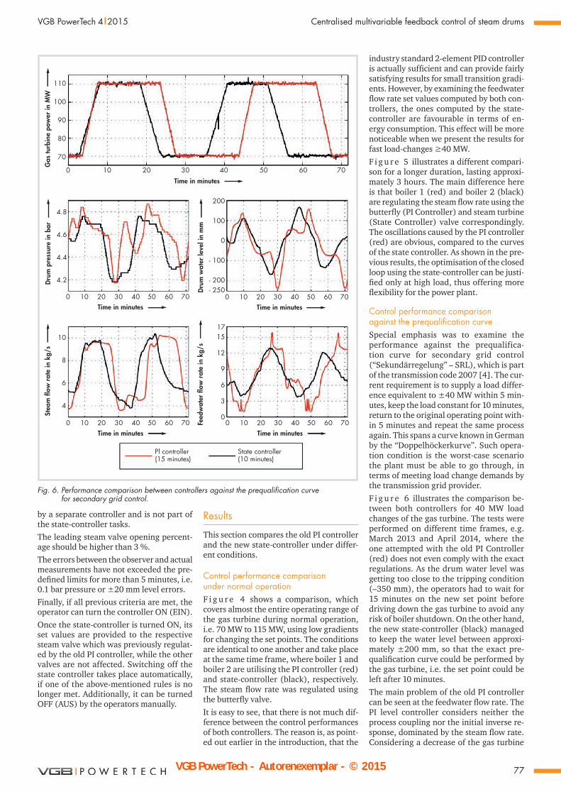
Control performance comparison under normal operationF i g u r e 4 shows a comparison, which covers almost the entire operating range of the gas turbine during normal operation, i.e. 70 MW to 115 MW, using low gradients for changing the set points. The conditions are identical to one another and take place at the same time frame, where boiler 1 and boiler 2 are utilising the PI controller (red) and state-controller (black), respectively. The steam flow rate was regulated using the butterfly valve.
It is easy to see, that there is not much dif-ference between the control performances of both controllers. The reason is, as point-ed out earlier in the introduction, that the
industry standard 2-element PID controller is actually sufficient and can provide fairly satisfying results for small transition gradi-ents. However, by examining the feedwater flow rate set values computed by both con-trollers, the ones computed by the state-controller are favourable in terms of en-ergy consumption. This effect will be more noticeable when we present the results for fast load-changes ≥40 MW.
F i g u r e 5 illustrates a different compari-son for a longer duration, lasting approxi-mately 3 hours. The main difference here is that boiler 1 (red) and boiler 2 (black) are regulating the steam flow rate using the butterfly (PI Controller) and steam turbine (State Controller) valve correspondingly. The oscillations caused by the PI controller (red) are obvious, compared to the curves of the state controller. As shown in the pre-vious results, the optimisation of the closed loop using the state-controller can be justi-fied only at high load, thus offering more flexibility for the power plant.
Control performance comparison against the prequalification curveSpecial emphasis was to examine the performance against the prequalifica-tion curve for secondary grid control (“Sekundärregelung” – SRL), which is part of the transmission code 2007 [4]. The cur-rent requirement is to supply a load differ-ence equivalent to ±40 MW within 5 min-utes, keep the load constant for 10 minutes, return to the original operating point with-in 5 minutes and repeat the same process again. This spans a curve known in German by the “Doppelhöckerkurve”. Such opera-tion condition is the worst-case scenario the plant must be able to go through, in terms of meeting load change demands by the transmission grid provider.
F i g u r e 6 illustrates the comparison be-tween both controllers for 40 MW load changes of the gas turbine. The tests were performed on different time frames, e.g. March 2013 and April 2014, where the one attempted with the old PI Controller (red) does not even comply with the exact regulations. As the drum water level was getting too close to the tripping condition (–350 mm), the operators had to wait for 15 minutes on the new set point before driving down the gas turbine to avoid any risk of boiler shutdown. On the other hand, the new state-controller (black) managed to keep the water level between approxi-mately ±200 mm, so that the exact pre-qualification curve could be performed by the gas turbine, i.e. the set point could be left after 10 minutes.
The main problem of the old PI controller can be seen at the feedwater flow rate. The PI level controller considers neither the process coupling nor the initial inverse re-sponse, dominated by the steam flow rate. Considering a decrease of the gas turbine
0 10 20 30 40
0 10 20 30 40 50 60 70
50 60 70
110
100
90
80
70
4.8
4.6
4.4
4.2
15
12
9
6
3
0
200
100
0
- 100
- 200- 250
1710
8
6
4
Drum
pre
ssur
e in
bar
Stea
m fl
ow ra
te in
kg/
s
Drum
wat
er le
vel i
n m
mFe
edw
ater
flow
rate
in k
g/s
Gas
turb
ine
pow
er in
MW
Time in minutes
Time in minutes
Pl controller(15 minutes)
State controller(10 minutes)
0 10 20 30 40 50 60 70Time in minutes
0 10 20 30 40 50 60 70Time in minutes
0 10 20 30 40 50 60 70Time in minutes
Fig. 6. Performance comparison between controllers against the prequalification curve for secondary grid control.
VGB PowerTech - Autorenexemplar - © 2015>>> VGB DIGITAL <<<
VGB
Pow
erTe
ch -
Aut
oren
exem
plar
- ©
201
5
78
Centralised multivariable feedback control of steam drums VGB PowerTech 4 l 2015
load, the PI controller only reacts on the level drop, by merely opening the feedwa-ter valve and feeding more cold water into the drum, to restore the level back to its ini-tial position. However, this control action affects the overall process badly, as adding more cold water to the system affects the steam pressure and its corresponding con-trol loop. This problem does not appear in the state-controller, as this considers the inner states of the system as well as the strong coupling between both input and output channels.
Conclusion
An implementation of a modern multivari-able feedback control strategy was present-ed to regulate pressure and water level of a steam drum unit within a 450 MW CCHPP in Munich, Germany. Although, a modern multivariable control scheme was used, the entire control structure was kept close to classical control schemes, to simplify
integration into the existing control struc-tures. Contrary to other publications pre-sented by academia, which consider only simulation results, the presented results were obtained from real data measure-ments and our strategy is realisable from a practical perspective.
The mathematical model used to design the state-controller achieves a high degree of re-usability. By simply adjusting its pa-rameters, which are extracted from con-struction data, it can be fitted to any class of power plants, for both low- and high-pressure steam drum units. Retuning of the controller gains during process lifetime is possible online within the DCS or offline through MATLAB/Simulink environment.
The water level performance at München Süd control was significantly improved at high load changes of the gas turbine, thus offering more flexibility to the power plant to meet load changes according to the trans-mission grid provider. A special switching
mechanism was introduced, allowing the new controller to regulate 5 different valves simultaneously. The controller is 100 % operational and has officially replaced the industry standard decentralised PI control scheme since November 2014.
References[1] Asea Brown Boveri: Drum Level Control Sys-
tems in the Process Industries, 1997.[2] Åström, K.J., and Bell, B.: Drum Boiler Dy-
namics. Automatica, 36: 363-378, March 2000.
[3] Elguindy, A., Rünzi, S., and Michels. K.: Optimizing Drum-Boiler Water Level Control Performance: A Practical Approach. Confer-ence proceedings of the IEEE Multi-Conference on Systems and Control, pp. 1675:1680, Oc-tober 2014, Antibes – France.
[4] Verband der Netzbetreiber e.V. beim VDEW: TransmissionCode 2007: Netz- und System-regeln der deutschen Übertragungsnetz-betreiber. Version 1.1, August 2007. l
• Sie profitieren vom Image unserer international anerkannten Fachzeitschrift für alle Bereiche der Strom- und Wärmeerzeugung.
• Sonderdrucke werden individuell nach Ihren Angaben gestaltet.
• Ihr Logo und Ihre Kontaktdaten erhöhen die Werbewirksamkeit.
Nehmen Sie mit uns Kontakt auf, wir unterbreiten Ihnen gerne ein unverbindliches Angebot: Rita Maria Wilke, Telefon: +49 201 8128-300 Telefax: +49 201 8128-302, E-Mail: [email protected]
Interesse an repräsentativen Sonderdrucken Ihrer Beiträge?
Das werbewirksame Medium, gedruckt oder digital.
Sonderdrucke_A4_2014_DE_ALT.indd 1 30.04.2014 11:27:39

International Journal for Electricity and Heat Generation
Please copy >>> fill in and return by mail or fax
Yes, I would like order a subscription of VGB PowerTech.The current price is Euro 275.– plus postage and VAT.Unless terminated with a notice period of one month to the end of the year, this subscription will be extended for a further year in each case.
Return by fax to
VGB PowerTech Service GmbHFax No. +49 201 8128-302
or access our on-line shop at www.vgb.org | MEDIA | SHOP.
Name, First Name
Street
Postal Code City Country
Phone/Fax
Date 1st Signature
Cancellation: This order may be cancelled within 14 days. A notice must be sent to to VGB PowerTech Service GmbH within this period. The deadline will be observed by due mailing. I agree to the terms with my 2nd signature.
Date 2nd Signature
Vo lu me 89/2009 · ISSN 1435-3199
K 43600
In ter na tio nal Edi ti on
Focus: Power Plants in Competiton
New Power Plant Projects of EskomQuality Assurance for New Power PlantsAdvantages of Flexible Thermal Generation
Market Overview for Imported Coal
In ter na tio nal Jour nalfor Elec tri ci ty and Heat Ge ne ra ti on
Pub li ca ti on ofVGB Po wer Tech e.V.www.vgb.org
Vo lu me 89/2009 · ISSN 1435-3199
K 43600
In ter na tio nal Edi ti on
Focus: VGB Congress
Power Plants 2009
Report on the Activities
of VGB PowerTech
2008/2009
EDF Group Reduces
its Carbon Footprint
Optimising Wind Farm
Maintenance
Concept for Solar
Hybrid Power Plants
Qualifying Power Plant Operators
In ter na tio nal Jour nal
for Elec tri ci ty and Heat Ge ne ra ti on
Pub li ca ti on of
VGB Po wer Tech e.V.
www.vgb.org
Con gress Is sue
Vo lu me 89/2009 · ISSN 1435-3199
K 43600
In ter na tio nal Edi ti on
Focus: Furnaces, Steam Generators and Steam TurbinesUSC 700 °C Power Technology
Ultra-low NOx Combustion
Replacement Strategy of a Superheater StageEconomic Post-combustion Carbon Capture Processes
In ter na tio nal Jour nalfor Elec tri ci ty and Heat Ge ne ra ti onPub li ca ti on ofVGB Po wer Tech e.V.www.vgb.org
Vo lu me 90/2010 · ISSN 1435-3199
K 43600
In ter na tio nal Edi ti on
Fo cus: Pro Quality
The Pro-quality
Approach
Quality in the
Construction
of New Power Plants
Quality Monitoring of
Steam Turbine Sets
Supply of Technical
Documentations
In ter na tio nal Jour nal
for Elec tri ci ty and Heat Ge ne ra ti on
Pub li ca ti on of
VGB Po wer Tech e.V.
www.vgb.org
V
00634 K
9913-5341 NSSI · 5002/58 emulo
International Edition
Schwerpunktthema:
Erneuerbare Energien
Hydrogen Pathways
and Scenarios
Kopswerk II –
Prevailing Conditions
and Design
Arklow Bank
Offshore Wind Park
The EU-Water
Framework Directive
International Journal
for Electricity and Heat Generation
Publication of
VGB PowerTech e.V.
www.vgb.org
Vo lu me 89/2009 · ISSN 1435-3199
K 43600
In ter na tio nal Edi ti on
Focus: Maintenance
of Power Plants
Concepts of
IGCC Power Plants
Assessment of
Generators for
Wind Power Plants
Technical Data for
Power Plants
Oxidation Properties
of Turbine Oils
In ter na tio nal Jour nal
for Elec tri ci ty and Heat Ge ne ra ti on
Pub li ca ti on of
VGB Po wer Tech e.V.
www.vgb.org

PowerTech-CD/DVD!Kontakt: Gregaro Scharpey Tel: +49 201 [email protected] | www.vgb.org
Ausgabe 2014: Mehr als 1.100 Seiten Daten, Fakten und Kompetenz aus der internationalen Fachzeitschrift VGB PowerTech
(einschließlich Recherchefunktion über alle Dokumente)Bruttopreis 98,- Euro incl. 19 % MWSt. + 5,90 Euro Versand (Deutschland) / 19,90 Euro (Europa)
Jetzt auch als
Jahres-CD 2014
mit allen Ausgaben
der VGB PowerTech
des Jahres: nur 98,– €
Fachzeitschrift: 1990 bis 2014
Diese DVD und ihre Inhalte sind urheberrechtlich geschützt.© VGB PowerTech Service GmbH
Essen | Deutschland | 2015
· 1990 bis 2014 · · 1990 bis 2014 ·
© S
erge
y N
iven
s - F
otol
ia
VGB PowerTech DVD 1990 bis 2014: 25 Jahrgänge geballtes Wissen rund um die Strom- und Wärmeerzeugung Mehr als 25.000 Seiten Daten, Fakten und Kompetenz
Bestellen Sie unter www.vgb.org > shop