Embed Size (px)
Citation preview
02/2004
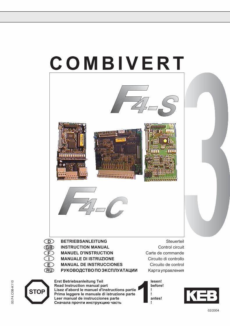
C O M B I V E R T
00.F
4.C
0B-K
110
D BETRIEBSANLEITUNG SteuerteilGB INSTRUCTION MANUAL Control circuitF MANUEL D'INSTRUCTION Carte de commandeI MANUALE DI ISTRUZIONE Circuito di controlloE MANUAL DE INSTRUCCIONES Circuito de controlRU РУКОВОДСТВО ПО ЭКСПЛУАТАЦИИ Карта управления
Erst Betriebsanleitung Teil lesen!Read Instruction manual part before!Lisez d'abord le manuel d'instructions partie !Prima leggere le manuale di istruzione parte !Leer manual de instrucciones parte antes!Сначала прочти инструкцию часть !1STOP

3
D
GB
F
I
E
D Steuerteil Seite 4 ................... 23
GB Control circuit Page 24 ................ 43
F Carte de commande Page 44 ................ 63
I Circuito di controllo Page 64 ................ 83
E Circuito de control Page 84 .............. 103
RU Карта управления Страница 104 ... 123
Passwords Page 129
RU
24
D
This Instruction Manual describes the control boards F4-C(ompact) and F4-S(mall). It is only validtogether with the Instruction Manuals COMBIVERT F4 Part 1 and Part 2. Both Instruction Manuals mustbe made available to the user. Prior to performing any work on the unit the user must familiarize himselfwith the unit. This includes especially the knowledge and observance of the safety and warningdirections of Part 1. The pictographs used in this Instruction Manual have following meaning:
Danger Used when life or health of the user are exposed to danger orWarning when severe damage to the material can occur.Caution
Attention,observe at Special instructions for a safe and trouble-free operation.
all costs
TipHelp Used to mark additional important informations.Information
The KEB COMBIVERT is operated with voltages that can cause asevere electric shock dangerous to life. Therefore the installation ofthe unit as well as of the available accessories is only permissible byqualified electro-personnel. A safe and trouble-free operation is onlypossible when the valid regulations according to DIN VDE 0100,IEC1000, EN 60204-1, EN 55014, EN 50082-2 as well as therelevant regulations for your area are observed.
After clearing the frequency inverter the intermediate circuit capacitorsare still charged with high voltage for a short period of time. The unitcan be worked on again after it has been switched off for 5 minutes.
Attention
Only qualifiedElectro-personnel
Danger
Note capacitordischarge time
25
GB
Table of Contents
Table of Contents1. Installation and Connection.. ....................... 261.1. Control circuit Version C.. ..................................... 261.1.1 Assignment of Terminal Strip X1 ............................. 261.1.2 Connection of the Control ........................................ 271.1.3 Digital Inputs.......................................................... ..271.1.4 Analog Inputs .......................................................... 271.1.5 Outputs .................................................................... 271.2 Control circuit Version S ....................................... 281.2.1 Assignment of Terminal Strip X1 ............................. 281.2.2 Connection of the control ........................................ 281.2.3 Digital inputs ............................................................ 281.2.4 Analog inputs .......................................................... 281.2.5 Outputs .................................................................... 29
2. Operation of the unit ..................................... 292.1 Digital operator ...................................................... 292.1.1 Interface operator .................................................... 292.1.2 Keyboard ................................................................. 302.2 Parameter Summary ........................................... ..312.3 Password Input ...................................................... 312.4 Operating Display .................................................. 322.5 Basic Adjustment of the Drive ............................. 332.6 Special Adjustments ............................................. 352.7 The Drive Mode...................................................... 412.7.1 Start / Stop Drive ..................................................... 412.7.2 Change Direction of Rotation .................................. 412.7.3 Preset Set Value ...................................................... 412.7.4 Leave Drive Mode ................................................... 41
3. Error Diagnosis ............................................. 42
4. Passwords .................................................... 129
26
GB
1. Installation and Connection
1 2 3 4 5 6 7 8 9 10 11 12 13 14 15 16 17 18 19 20 21 22 23
20 22 231 2 3 4 21
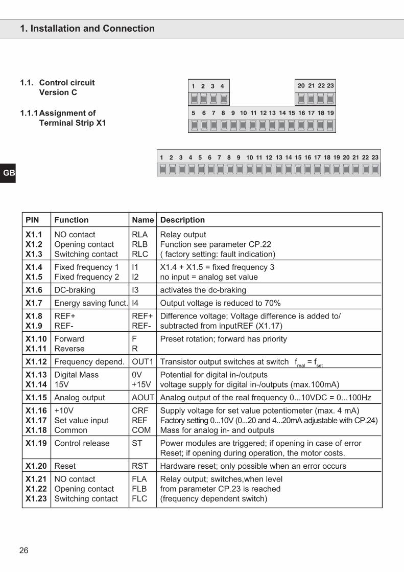
16 17 185 6 7 8 9 10 11 12 13 14 15 191.1.1Assignment ofTerminal Strip X1
1.1. Control circuitVersion C
PIN Function Name Description
X1.1 NO contact RLA Relay outputX1.2 Opening contact RLB Function see parameter CP.22X1.3 Switching contact RLC ( factory setting: fault indication)X1.4 Fixed frequency 1 I1 X1.4 + X1.5 = fixed frequency 3X1.5 Fixed frequency 2 I2 no input = analog set valueX1.6 DC-braking I3 activates the dc-brakingX1.7 Energy saving funct. I4 Output voltage is reduced to 70%X1.8 REF+ REF+ Difference voltage; Voltage difference is added to/X1.9 REF- REF- subtracted from inputREF (X1.17)X1.10 Forward F Preset rotation; forward has priorityX1.11 Reverse RX1.12 Frequency depend. OUT1 Transistor output switches at switch freal = fset
X1.13 Digital Mass 0V Potential for digital in-/outputsX1.14 15V +15V voltage supply for digital in-/outputs (max.100mA)X1.15 Analog output AOUT Analog output of the real frequency 0...10VDC = 0...100HzX1.16 +10V CRF Supply voltage for set value potentiometer (max. 4 mA)X1.17 Set value input REF Factory setting 0...10V (0...20 and 4...20mA adjustable with CP.24)X1.18 Common COM Mass for analog in- and outputsX1.19 Control release ST Power modules are triggered; if opening in case of error
Reset; if opening during operation, the motor costs.X1.20 Reset RST Hardware reset; only possible when an error occursX1.21 NO contact FLA Relay output; switches,when levelX1.22 Opening contact FLB from parameter CP.23 is reachedX1.23 Switching contact FLC (frequency dependent switch)
27
GB
Installation and Connection
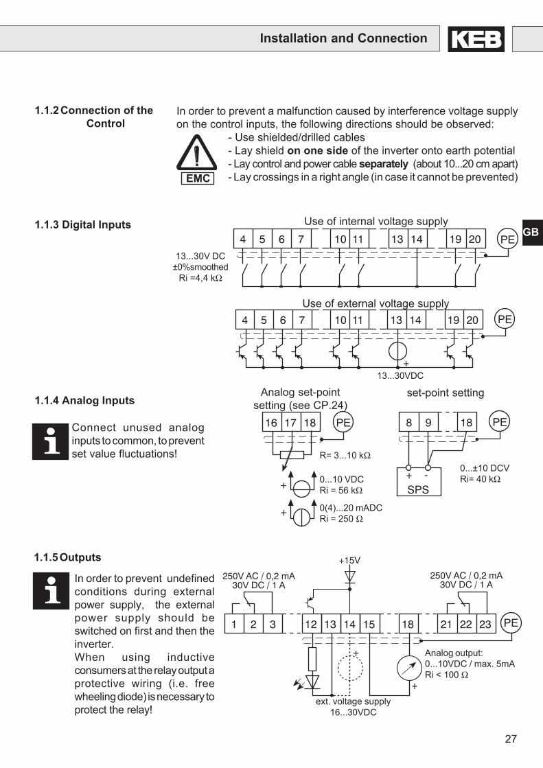
1.1.2Connection of theControl
In order to prevent a malfunction caused by interference voltage supplyon the control inputs, the following directions should be observed:
- Use shielded/drilled cables- Lay shield on one side of the inverter onto earth potential- Lay control and power cable separately (about 10...20 cm apart)- Lay crossings in a right angle (in case it cannot be prevented)
1.1.4 Analog Inputs
1.1.3 Digital Inputs
13...30VDC
set-point setting
0...±10 DCVRi= 40 kΩ
4 5 6 7 10 11 13 14 19 20 PE
4 5 6 7 10 11 13 14 19 20
+
PE
EMC
Use of external voltage supply
Use of internal voltage supply
16 17 18 PE
+
+
R= 3...10 kΩ
0...10 VDCRi = 56 kΩ
0(4)...20 mADCRi = 250 Ω
Analog set-pointsetting (see CP.24)
In order to prevent undefinedconditions during externalpower supply, the externalpower supply should beswitched on first and then theinverter.When using inductiveconsumers at the relay output aprotective wiring (i.e. freewheeling diode) is necessary toprotect the relay!
Connect unused analoginputs to common, to preventset value fluctuations!
8 9 18
+ -SPS
PE
13...30V DC±0%smoothed
Ri =4,4 kΩ
Analog output:0...10VDC / max. 5mARi < 100 Ω
ext. voltage supply16...30VDC
1.1.5Outputs
1 2 3 12 21 22 231413
+15V
15 18
+
PE
+
250V AC / 0,2 mA30V DC / 1 A
250V AC / 0,2 mA30V DC / 1 A30V DC/0,01...1A 30V DC/0,01...1A
28
GB
Installation and Connection
1 2 3 4 5 6 7 8 9 10 11 12 13 14
PIN Function Name Description
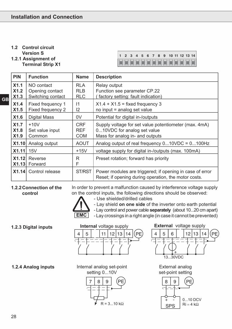
X1.1 NO contact RLA Relay outputX1.2 Opening contact RLB Function see parameter CP.22X1.3 Switching contact RLC ( factory setting: fault indication)X1.4 Fixed frequency 1 I1 X1.4 + X1.5 = fixed frequency 3X1.5 Fixed frequency 2 I2 no input = analog set valueX1.6 Digital Mass 0V Potential for digital in-/outputsX1.7 +10V CRF Supply voltage for set value potentiometer (max. 4mA)X1.8 Set value input REF 0...10VDC for analog set valueX1.9 Common COM Mass for analog in- and outputsX1.10 Analog output AOUT Analog output of real frequency 0...10VDC = 0...100HzX1.11 15V +15V voltage supply for digital in-/outputs (max. 100mA)X1.12 Reverse R Preset rotation; forward has priorityX1.13 Forward FX1.14 Control release ST/RST Power modules are triggered; if opening in case of error
Reset; if opening during operation, the motor costs.
In order to prevent a malfunction caused by interference voltage supplyon the control inputs, the following directions should be observed:
- Use shielded/drilled cables- Lay shield on one side of the inverter onto earth potential- Lay control and power cable separately (about 10...20 cm apart)- Lay crossings in a right angle (in case it cannot be prevented)
1.2.2Connection of thecontrol
EMC
1.2.3 Digital inputs4 5 11 12 13 14 PE 4 6 12 13 14 PE
+
5
13...30VDC
External voltage supplyInternal voltage supply
Internal analog set-pointsetting 0...10V
External analogset-point setting
1.2.4 Analog inputs
7 8 9 PE 8 9
+ -SPS
PE
R = 3...10 kΩ0...10 DCVRi = 4 kΩ
1.2 Control circuitVersion S
1.2.1 Assignment ofTerminal Strip X1
29
GB
1 2 3 9 10
+
PE
Analog output:0...10VDC / max. 5mAat Ri ≥ 56 KΩ const.
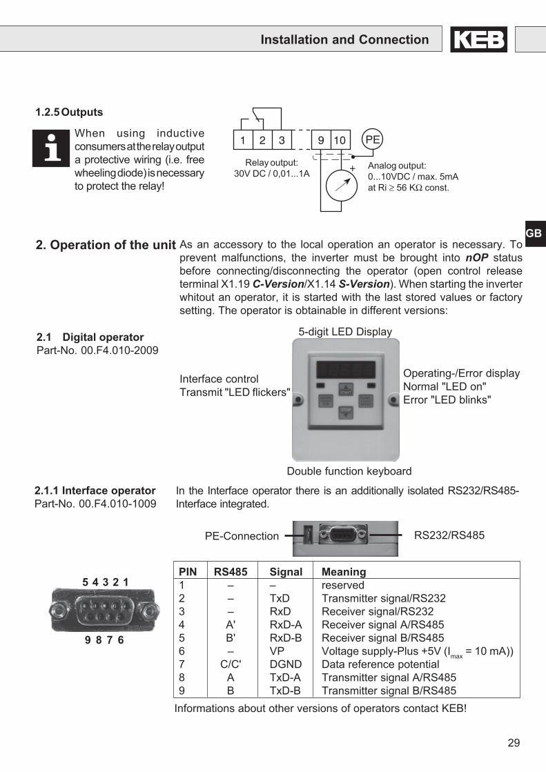
1.2.5Outputs
Installation and Connection
As an accessory to the local operation an operator is necessary. Toprevent malfunctions, the inverter must be brought into nOP statusbefore connecting/disconnecting the operator (open control releaseterminal X1.19 C-Version/X1.14 S-Version). When starting the inverterwhitout an operator, it is started with the last stored values or factorysetting. The operator is obtainable in different versions:
2. Operation of the unit
Interface controlTransmit "LED flickers"
Double function keyboard
Operating-/Error displayNormal "LED on"Error "LED blinks"
5-digit LED Display2.1 Digital operatorPart-No. 00.F4.010-2009
9 8 7 6
5 4 3 2 1
RS232/RS485
PIN RS485 Signal Meaning1 – – reserved2 – TxD Transmitter signal/RS2323 – RxD Receiver signal/RS2324 A' RxD-A Receiver signal A/RS4855 B' RxD-B Receiver signal B/RS4856 – VP Voltage supply-Plus +5V (Imax = 10 mA))7 C/C' DGND Data reference potential8 A TxD-A Transmitter signal A/RS4859 B TxD-B Transmitter signal B/RS485
PE-Connection
2.1.1 Interface operatorPart-No. 00.F4.010-1009
In the Interface operator there is an additionally isolated RS232/RS485-Interface integrated.
Informations about other versions of operators contact KEB!
Relay output:30V DC / 0,01...1A
When using inductiveconsumers at the relay outputa protective wiring (i.e. freewheeling diode) is necessaryto protect the relay!
30
GB
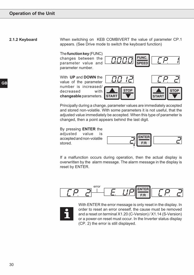
When switching on KEB COMBIVERT the value of parameter CP.1appears. (See Drive mode to switch the keyboard function)
The function key (FUNC)changes between theparameter value andparameter number.
With UP and DOWN thevalue of the parameternumber is increased/decreased withchangeable parameters.
Principally during a change, parameter values are immediately acceptedand stored non-volatile. With some parameters it is not useful, that theadjusted value immediately be accepted. When this type of parameter ischanged, then a point appears behind the last digit.
By pressing ENTER theadjusted value isaccepted and non-volatilestored.
If a malfunction occurs during operation, then the actual display isoverwritten by the alarm message. The alarm message in the display isreset by ENTER.
With ENTER the error message is only reset in the display. Inorder to reset an error oneself, the cause must be removedand a reset on terminal X1.20 (C-Version) / X1.14 (S-Version)or a power-on reset must occur. In the Inverter status display(CP. 2) the error is still displayed.
Operation of the Unit
2.1.2 Keyboard
errorENTER
F/R
START
STOP
START
STOP
FUNC.
SPEED
ENTER
F/R
31
GB
Operation of the Unit
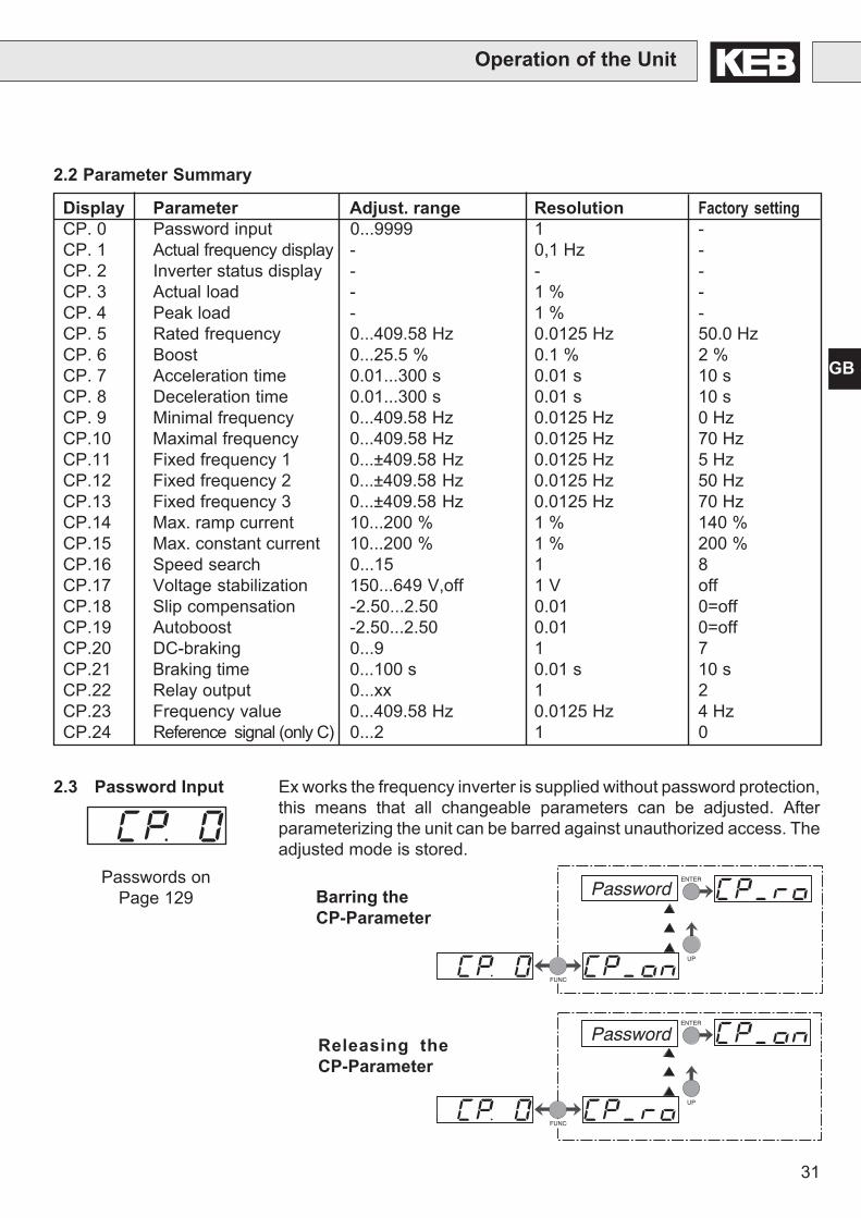
2.2 Parameter Summary
Display Parameter Adjust. range Resolution Factory settingCP. 0 Password input 0...9999 1 -CP. 1 Actual frequency display - 0,1 Hz -CP. 2 Inverter status display - - -CP. 3 Actual load - 1 % -CP. 4 Peak load - 1 % -CP. 5 Rated frequency 0...409.58 Hz 0.0125 Hz 50.0 HzCP. 6 Boost 0...25.5 % 0.1 % 2 %CP. 7 Acceleration time 0.01...300 s 0.01 s 10 sCP. 8 Deceleration time 0.01...300 s 0.01 s 10 sCP. 9 Minimal frequency 0...409.58 Hz 0.0125 Hz 0 HzCP.10 Maximal frequency 0...409.58 Hz 0.0125 Hz 70 HzCP.11 Fixed frequency 1 0...±409.58 Hz 0.0125 Hz 5 HzCP.12 Fixed frequency 2 0...±409.58 Hz 0.0125 Hz 50 HzCP.13 Fixed frequency 3 0...±409.58 Hz 0.0125 Hz 70 HzCP.14 Max. ramp current 10...200 % 1 % 140 %CP.15 Max. constant current 10...200 % 1 % 200 %CP.16 Speed search 0...15 1 8CP.17 Voltage stabilization 150...649 V,off 1 V offCP.18 Slip compensation -2.50...2.50 0.01 0=offCP.19 Autoboost -2.50...2.50 0.01 0=offCP.20 DC-braking 0...9 1 7CP.21 Braking time 0...100 s 0.01 s 10 sCP.22 Relay output 0...xx 1 2CP.23 Frequency value 0...409.58 Hz 0.0125 Hz 4 HzCP.24 Reference signal (only C) 0...2 1 0
Password
FUNC
ENTER
UP
Releasing theCP-Parameter
FUNC
ENTER
UP
PasswordBarring theCP-Parameter
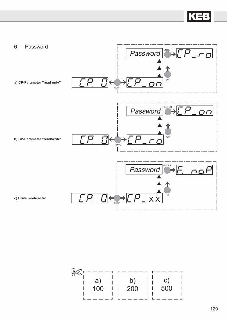
2.3 Password Input Ex works the frequency inverter is supplied without password protection,this means that all changeable parameters can be adjusted. Afterparameterizing the unit can be barred against unauthorized access. Theadjusted mode is stored.
Passwords onPage 129
32
GB
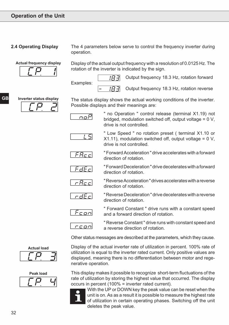
The 4 parameters below serve to control the frequency inverter duringoperation.
Display of the actual output frequency with a resolution of 0.0125 Hz. Therotation of the inverter is indicated by the sign.
Output frequency 18.3 Hz, rotation forwardExamples:
Output frequency 18.3 Hz, rotation reverse
The status display shows the actual working conditions of the inverter.Possible displays and their meanings are:
" no Operation " control release (terminal X1.19) notbridged, modulation switched off, output voltage = 0 V,drive is not controlled.
" Low Speed " no rotation preset ( terminal X1.10 orX1.11), modulation switched off, output voltage = 0 V,drive is not controlled.
" Forward Acceleration " drive accelerates with a forwarddirection of rotation.
" Forward Deceleration " drive decelerates with a forwarddirection of rotation.
" Reverse Acceleration " drives accelerates with a reversedirection of rotation.
" Reverse Deceleration " drive decelerates with a reversedirection of rotation.
" Forward Constant " drive runs with a constant speedand a forward direction of rotation.
" Reverse Constant " drive runs with constant speed anda reverse direction of rotation.
Other status messages are described at the parameters, which they cause.
Display of the actual inverter rate of utilization in percent. 100% rate ofutilization is equal to the inverter rated current. Only positive values aredisplayed, meaning there is no differentiation between motor and rege-nerative operation.
This display makes it possible to recognize short-term fluctuations of therate of utilization by storing the highest value that occurred. The displayoccurs in percent (100% = inverter rated current).
With the UP or DOWN key the peak value can be reset when theunit is on. As as a result it is possible to measure the highest rateof utilization in certain operating phases. Switching off the unitdeletes the peak value.
Operation of the Unit
2.4 Operating Display
Actual frequency display
Inverter status display
Actual load
Peak load
33
GB
Operation of the Unit
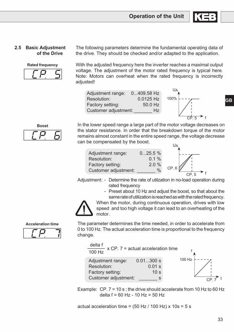
2.5 Basic Adjustmentof the Drive
The following parameters determine the fundamental operating data ofthe drive. They should be checked and/or adapted to the application.
With the adjusted frequency here the inverter reaches a maximal outputvoltage. The adjustment of the motor rated frequency is typical here.Note: Motors can overheat when the rated frequency is incorrectlyadjusted!
Adjustment range: 0...409.58 HzResolution: 0.0125 HzFactory setting: 50.0 HzCustomer adjustment: _______ Hz
Rated frequency
UA
f
100%
CP. 5
Boost
UA
fCP. 5CP. 6
Acceleration time
In the lower speed range a large part of the motor voltage decreases onthe stator resistance. In order that the breakdown torque of the motorremains almost constant in the entire speed range, the voltage decreasecan be compensated by the boost.
Adjustment range: 0...25.5 %Resolution: 0.1 %Factory setting: 2.0 %Customer adjustment: _______ %
Adjustment: - Determine the rate of utilzation in no-load operation duringrated frequency
- Preset about 10 Hz and adjust the boost, so that about thesame rate of utilization is reached as with the rated frequency.
When the motor, during continuous operation, drives with lowspeed and too high voltage it can lead to an overheating of themotor.
The parameter determines the time needed, in order to accelerate from0 to 100 Hz. The actual acceleration time is proportional to the frequencychange.
delta f x CP. 7 = actual acceleration time100 Hz
Adjustment range: 0.01...300 sResolution: 0.01 sFactory setting: 10 sCustomer adjustment: _______ s
Example: CP. 7 = 10 s ; the drive should accelerate from 10 Hz to 60 Hzdelta f = 60 Hz - 10 Hz = 50 Hz
actual acceleration time = (50 Hz / 100 Hz) x 10s = 5 s
f
t
100 Hz
CP. 7
34
GB
Operation of the Unit
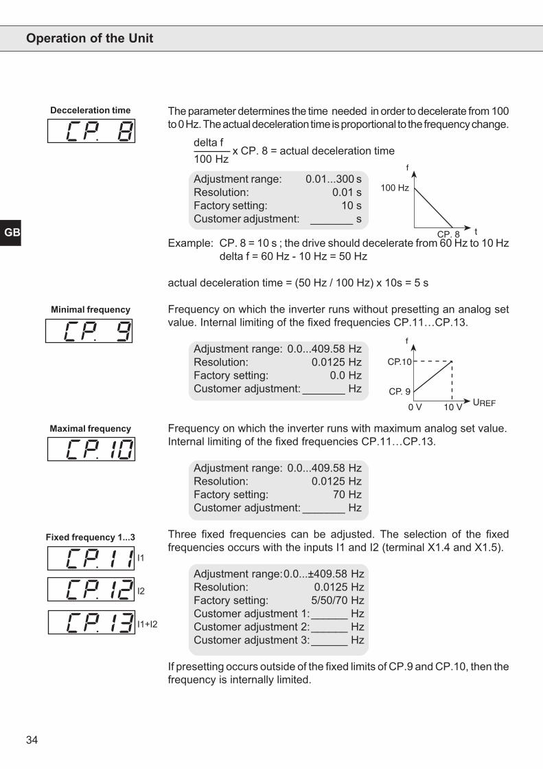
Decceleration time
Maximal frequency
f
t
100 Hz
CP. 8
f
UREFCP. 9
CP.10
10 V0 V
Minimal frequency
The parameter determines the time needed in order to decelerate from 100to 0 Hz. The actual deceleration time is proportional to the frequency change.
delta f x CP. 8 = actual deceleration time100 Hz
Adjustment range: 0.01...300 sResolution: 0.01 sFactory setting: 10 sCustomer adjustment: _______ s
Example: CP. 8 = 10 s ; the drive should decelerate from 60 Hz to 10 Hzdelta f = 60 Hz - 10 Hz = 50 Hz
actual deceleration time = (50 Hz / 100 Hz) x 10s = 5 s
Frequency on which the inverter runs without presetting an analog setvalue. Internal limiting of the fixed frequencies CP.11…CP.13.
Adjustment range: 0.0...409.58 HzResolution: 0.0125 HzFactory setting: 0.0 HzCustomer adjustment: _______ Hz
Frequency on which the inverter runs with maximum analog set value.Internal limiting of the fixed frequencies CP.11…CP.13.
Adjustment range: 0.0...409.58 HzResolution: 0.0125 HzFactory setting: 70 HzCustomer adjustment: _______ Hz
Three fixed frequencies can be adjusted. The selection of the fixedfrequencies occurs with the inputs I1 and I2 (terminal X1.4 and X1.5).
Adjustment range:0.0...±409.58 HzResolution: 0.0125 HzFactory setting: 5/50/70 HzCustomer adjustment 1:______ HzCustomer adjustment 2:______ HzCustomer adjustment 3:______ Hz
If presetting occurs outside of the fixed limits of CP.9 and CP.10, then thefrequency is internally limited.
Fixed frequency 1...3
I1
I2
I1+I2
35
GB
Operation of the Unit
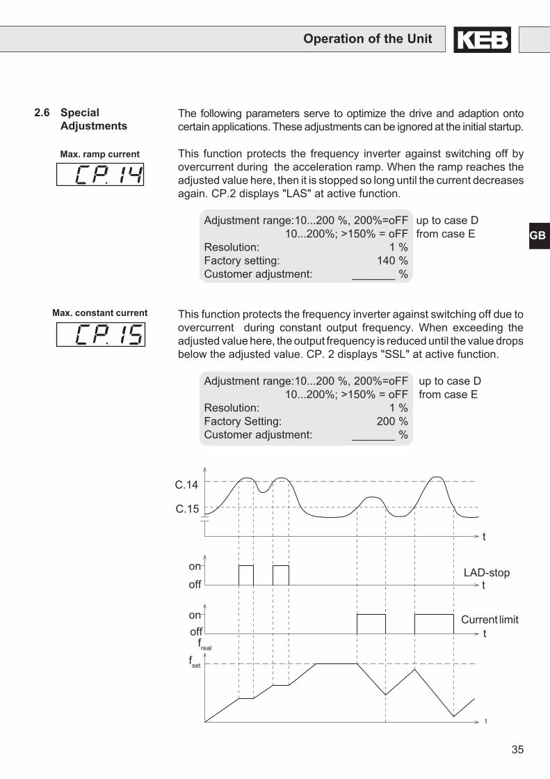
2.6 SpecialAdjustments
The following parameters serve to optimize the drive and adaption ontocertain applications. These adjustments can be ignored at the initial startup.
This function protects the frequency inverter against switching off byovercurrent during the acceleration ramp. When the ramp reaches theadjusted value here, then it is stopped so long until the current decreasesagain. CP.2 displays "LAS" at active function.
Adjustment range:10...200 %, 200%=oFF up to case D10...200%; >150% = oFF from case E
Resolution: 1 %Factory setting: 140 %Customer adjustment: _______ %
This function protects the frequency inverter against switching off due toovercurrent during constant output frequency. When exceeding theadjusted value here, the output frequency is reduced until the value dropsbelow the adjusted value. CP. 2 displays "SSL" at active function.
Adjustment range:10...200 %, 200%=oFF up to case D10...200%; >150% = oFF from case E
Resolution: 1 %Factory Setting: 200 %Customer adjustment: _______ %
Max. ramp current
Max. constant current
t
fset
freal
onoff
onoff
C.15
C.14
LAD-stop
Current limit
t
t
t
36
GB
Operation of the Unit
Speed search When connecting the frequency inverter onto a decelerating motor, anerror can be triggered by the differing rotating field frequencies. Atactivated on speed search the inverter searches the actual motor speed,adapts its output frequency and accelerates with the adjusted ramp ontothe given set value. During speed search CP.2 displays "SSF". Theparameter determines, under what conditions the functions operate. Withseveral conditions the sum of the value must be entered. Example: CP.16= 12 means after reset and after auto-reset UP
Adjustment range: 0...15 Value CondtionResolution: 1 0 function offFactory setting: 8 1 at control releaseCustomer adjustment: _______ 2 at switch on
4 after reset8 after Auto-Reset UP
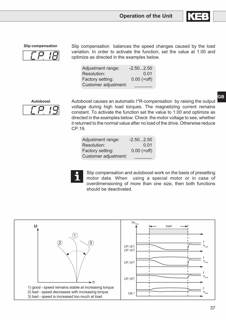
Voltage stabilization This parameter can adjust a regulated output voltage in relation to therated frequency. Because of this voltage variations at the input as well asin the intermediate circuit only have a small influence on the output voltage(U/f-characteristic). The function allows, among other things, an adaptionof the output voltage onto the special motors. In the example below theoutput voltage is stabilized onto 230 V (0% boost).
Adjustment range:150...649 V, oFFResolution: 1 VFactory setting: oFFCustomer adjustment: _______ V
250 V
CP.17 = 230 V
190 V
CP.5 = 50 Hzf
UN/UA
UA at UN = 250V stabilized
UA at UN = 250V unstabilized
UA at UN = 190V stabilizedUA at UN = 190V unstabilized
UA= output voltageUN = mains voltage
37
GB
Operation of the Unit
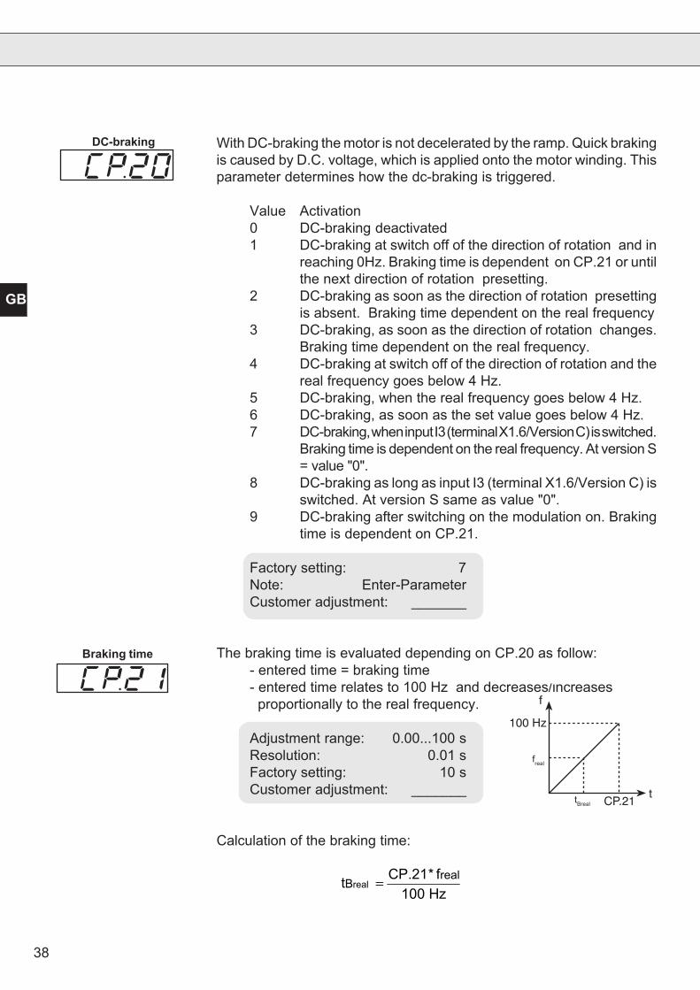
1) good - speed remains stable at increasing torque2) bad - speed decreases with increasing torque3) bad - speed is increased too much at load =
=
=
=
nreal
f
nreal
f
nreal
f
nreal
f
CP.18
OK !
CP.19
CP.18CP.19
loadf/nreal
M
n
1
2 3
Slip compensation Slip compensation balances the speed changes caused by the loadvariation. In order to activate the function, set the value at 1.00 andoptimize as directed in the examples below.
Adjustment range: -2.50...2.50Resolution: 0.01Factory setting: 0.00 (=off)Customer adjustment: _______
Autoboost causes an automatic I*R-compensation by raising the outputvoltage during high load torques. The magnetizing current remainsconstant. To activate the function set the value to 1.00 and optimize asdirected in the examples below. Check the motor voltage to see, whetherit returned to the normal value after no load of the drive. Otherwise reduceCP.19.
Adjustment range: -2.50...2.50Resolution: 0.01Factory setting: 0.00 (=off)Customer adjustment: _______
Slip compensation and autoboost work on the basis of presettingmotor data. When using a special motor or in case ofoverdimensioning of more than one size, then both functionsshould be deactivated.
Autoboost
38
GB
With DC-braking the motor is not decelerated by the ramp. Quick brakingis caused by D.C. voltage, which is applied onto the motor winding. Thisparameter determines how the dc-braking is triggered.
Value Activation0 DC-braking deactivated1 DC-braking at switch off of the direction of rotation and in
reaching 0Hz. Braking time is dependent on CP.21 or untilthe next direction of rotation presetting.
2 DC-braking as soon as the direction of rotation presettingis absent. Braking time dependent on the real frequency
3 DC-braking, as soon as the direction of rotation changes.Braking time dependent on the real frequency.
4 DC-braking at switch off of the direction of rotation and thereal frequency goes below 4 Hz.
5 DC-braking, when the real frequency goes below 4 Hz.6 DC-braking, as soon as the set value goes below 4 Hz.7 DC-braking, when input I3 (terminal X1.6/Version C) is switched.
Braking time is dependent on the real frequency. At version S= value "0".
8 DC-braking as long as input I3 (terminal X1.6/Version C) isswitched. At version S same as value "0".
9 DC-braking after switching on the modulation on. Brakingtime is dependent on CP.21.
Factory setting: 7Note: Enter-ParameterCustomer adjustment: _______
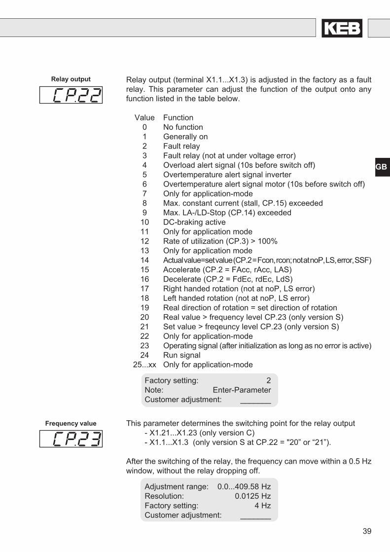
The braking time is evaluated depending on CP.20 as follow:- entered time = braking time- entered time relates to 100 Hz and decreases/increases proportionally to the real frequency.
Adjustment range: 0.00...100 sResolution: 0.01 sFactory setting: 10 sCustomer adjustment: _______
Calculation of the braking time:
f
t
fist
CP.21
100 Hz
tBist
DC-braking
Braking time
freal
tBreal
t CP.21* f100 Hz
Breal
real =
39
GB
Relay output Relay output (terminal X1.1...X1.3) is adjusted in the factory as a faultrelay. This parameter can adjust the function of the output onto anyfunction listed in the table below.
Value Function0 No function1 Generally on2 Fault relay3 Fault relay (not at under voltage error)4 Overload alert signal (10s before switch off)5 Overtemperature alert signal inverter6 Overtemperature alert signal motor (10s before switch off)7 Only for application-mode8 Max. constant current (stall, CP.15) exceeded9 Max. LA-/LD-Stop (CP.14) exceeded
10 DC-braking active11 Only for application mode12 Rate of utilization (CP.3) > 100%13 Only for application mode14 Actual value=set value (CP.2 = Fcon, rcon; not at noP, LS, error, SSF)15 Accelerate (CP.2 = FAcc, rAcc, LAS)16 Decelerate (CP.2 = FdEc, rdEc, LdS)17 Right handed rotation (not at noP, LS error)18 Left handed rotation (not at noP, LS error)19 Real direction of rotation = set direction of rotation20 Real value > frequency level CP.23 (only version S)21 Set value > freqeuncy level CP.23 (only version S)22 Only for application-mode23 Operating signal (after initialization as long as no error is active)24 Run signal
25...xx Only for application-mode
Factory setting: 2Note: Enter-ParameterCustomer adjustment: _______
This parameter determines the switching point for the relay output- X1.21...X1.23 (only version C)- X1.1...X1.3 (only version S at CP.22 = "20” or “21”).
After the switching of the relay, the frequency can move within a 0.5 Hzwindow, without the relay dropping off.
Adjustment range: 0.0...409.58 HzResolution: 0.0125 HzFactory setting: 4 HzCustomer adjustment: _______
Frequency value
40
GB
Operation of the Unit
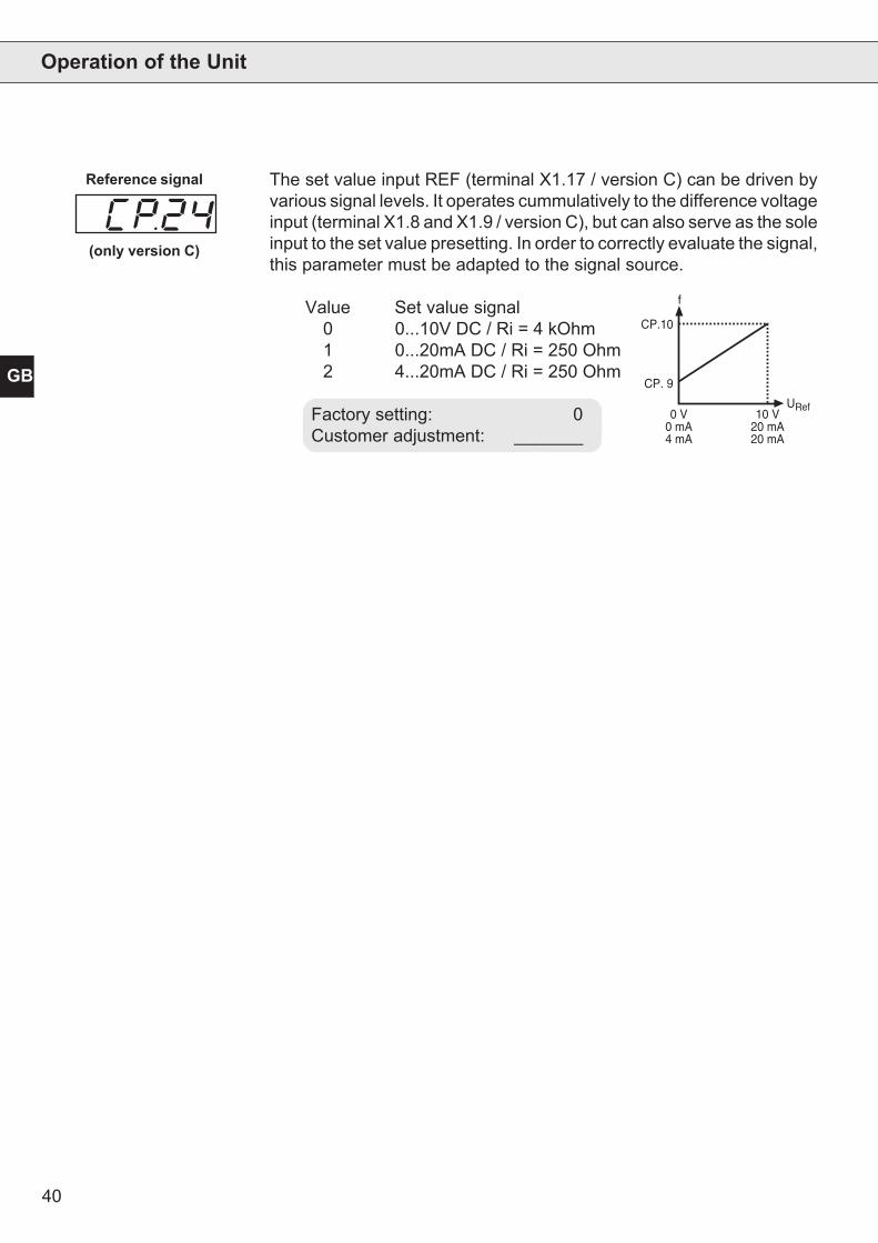
The set value input REF (terminal X1.17 / version C) can be driven byvarious signal levels. It operates cummulatively to the difference voltageinput (terminal X1.8 and X1.9 / version C), but can also serve as the soleinput to the set value presetting. In order to correctly evaluate the signal,this parameter must be adapted to the signal source.
Value Set value signal0 0...10V DC / Ri = 4 kOhm1 0...20mA DC / Ri = 250 Ohm2 4...20mA DC / Ri = 250 Ohm
Factory setting: 0Customer adjustment: _______
Reference signal
(only version C)
CP.10
CP. 9
URef
f
0 V0 mA4 mA
10 V20 mA20 mA
41
GB
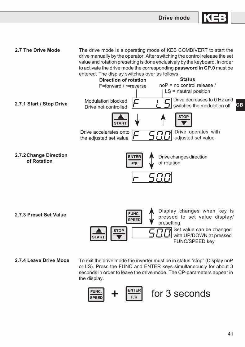
2.7 The Drive Mode The drive mode is a operating mode of KEB COMBIVERT to start thedrive manually by the operator. After switching the control release the setvalue and rotation presetting is done exclusively by the keyboard. In orderto activate the drive mode the corresponding password in CP.0 must beentered. The display switches over as follows.
Direction of rotationF=forward / r=reverse
StatusnoP = no control release /
LS = neutral position
Set value can be changedwith UP/DOWN at pressedFUNC/SPEED key
2.7.1 Start / Stop Drive
2.7.3 Preset Set Value
2.7.2Change Directionof Rotation
FUNC.
SPEED
STOP
START
ENTER
F/R
To exit the drive mode the inverter must be in status “stop” (Display noPor LS). Press the FUNC and ENTER keys simultaneously for about 3seconds in order to leave the drive mode. The CP-parameters appear inthe display.
2.7.4 Leave Drive Mode
Drive mode
START
STOP
Modulation blockedDrive not controlled
Drive decreases to 0 Hz andswitches the modulation off
Drive accelerates ontothe adjusted set value
Drive operates withadjusted set value
Drive changes directionof rotation
Display changes when key ispressed to set value display/presetting
FUNC.
SPEED + ENTER
F/R for 3 seconds
42
GB
Error Diagnosis
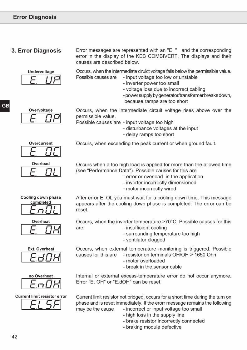
Error messages are represented with an "E. " and the correspondingerror in the display of the KEB COMBIVERT. The displays and theircauses are described below.
Occurs, when the intermediate ciruict voltage falls below the permissible value.Possible causes are - input voltage too low or unstable
- inverter power too small- voltage loss due to incorrect cabling- power supply by generator/transformer breaks down, because ramps are too short
Occurs, when the intermediate circuit voltage rises above over thepermissible value.Possible causes are - input voltage too high
- disturbance voltages at the input- delay ramps too short
Occurs, when exceeding the peak current or when ground fault.
Occurs when a too high load is applied for more than the allowed time(see "Performance Data"). Possible causes for this are
- error or overload in the application- inverter incorrectly dimensioned- motor incorrectly wired
After error E. OL you must wait for a cooling down time. This messageappears after the cooling down phase is completed. The error can bereset.
Occurs, when the inverter temperature >70°C. Possible causes for thisare - insufficient cooling
- surrounding temperature too high- ventilator clogged
Occurs, when external temperature monitoring is triggered. Possiblecauses for this are - resistor on terminals OH/OH > 1650 Ohm
- motor overloaded- break in the sensor cable
Internal or external excess-temperature error do not occur anymore.Error "E. OH" or "E.dOH" can be reset.
Current limit resistor not bridged, occurs for a short time during the turn onphase and is reset immediately. If the erorr message remains the followingmay be the cause - incorrect or input voltage too small
- high loss in the supply line- brake resistor incorrectly connected- braking module defective
3. Error Diagnosis
Undervoltage
Overvoltage
Overcurrent
Overload
Cooling down phasecompleted
Overheat
no Overheat
Ext. Overheat
Current limit resistor error
43
GB
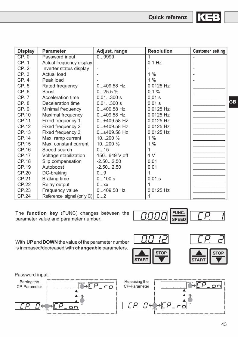
Display Parameter Adjust. range Resolution Customer settingCP. 0 Password input 0...9999 1 -CP. 1 Actual frequency display - 0,1 Hz -CP. 2 Inverter status display - - -CP. 3 Actual load - 1 % -CP. 4 Peak load - 1 % -CP. 5 Rated frequency 0...409.58 Hz 0.0125 Hz ____________CP. 6 Boost 0...25.5 % 0.1 % ____________CP. 7 Acceleration time 0.01...300 s 0.01 s ____________CP. 8 Deceleration time 0.01...300 s 0.01 s ____________CP. 9 Minimal frequency 0...409.58 Hz 0.0125 Hz ____________CP.10 Maximal frequency 0...409.58 Hz 0.0125 Hz ____________CP.11 Fixed frequency 1 0...±409.58 Hz 0.0125 Hz ____________CP.12 Fixed frequency 2 0...±409.58 Hz 0.0125 Hz ____________CP.13 Fixed frequency 3 0...±409.58 Hz 0.0125 Hz ____________CP.14 Max. ramp current 10...200 % 1 % ____________CP.15 Max. constant current 10...200 % 1 % ____________CP.16 Speed search 0...15 1 ____________CP.17 Voltage stabilization 150...649 V,off 1 V ____________CP.18 Slip compensation -2.50...2.50 0.01 ____________CP.19 Autoboost -2.50...2.50 0.01 ____________CP.20 DC-braking 0...9 1 ____________CP.21 Braking time 0...100 s 0.01 s ____________CP.22 Relay output 0...xx 1 ____________CP.23 Frequency value 0...409.58 Hz 0.0125 Hz ____________CP.24 Reference signal (only C) 0...2 1 ____________
Quick referenz
The function key (FUNC) changes between theparameter value and parameter number.
With UP and DOWN the value of the parameter numberis increased/decreased with changeable parameters.
START
STOP
START
STOP
FUNC.
SPEED
Password input:Releasing theCP-Parameter Password
FUNC
ENTER
UP
FUNC
ENTER
UP
PasswordBarring the
CP-Parameter

128
129
6. Password
FUNC
ENTER
UP
Password
Password
FUNC
ENTER
UP
Password
FUNC
ENTER
UP
X Xc) Drive mode activ
a)100
c)500
b)200
b) CP-Parameter "read/write"
a) CP-Parameter "read only"

130
GB Prior to delivery all products pass several quality and performance inspections so that malfunctions canbe ruled out. When used in accordance with the operating instructions failure is most unlikely. However,if you have cause for complaint the unit should be returned stating invoice number, delivery date, causeof failure and field conditions. We do not accept the responsibility for failures due to misuse, wrongstorage or similar causes. Leaflets, catalogues and quotations contain only standard values. We reservethe right to make technical changes without obligation. All rights reserved. Any piratic printing,mimeograhing or photomechanical reproduction, even in extracts, is strictly prohibited.
E Antes de ser enviados todos los productos pasan severos controles de calidad por lo que puedendescartarse defectos. Cuando sea utilizado de acuerdo con las instrucciones de operación una averíano es nada probable. Sin embargo, si tiene motivo de reclamación la unidad podría devolverseindicando número de factura, fecha de entrega, causa del fallo y condiciones de instalación. Nosotrosno aceptamos la responsabilidad por fallos debidos a mal uso, almacenaje incorrecto o causa similar.Los folletos, catalogues y ofertas contienen sólo valores estándar. Nos reservamos el derecho demodificar el equipo sin ninguna obligación. Todos los derechos reservados. Cualquier impresión pirata,reproducción mimeógrafia o fotomecanica, incluso en parte, está estrictamente prohibida.
I Prima di essere spediti, tutti i nostri prodotti sono soggetti a severi controlli di qualità e funzionamento,questo al fine di evitare malfunzionamenti. Se utilizzati seguendo il manuale di istruzione si evitaqualsiasi malfunzionamento. Comunque, qualora dovesse verificarsi un guasto, l’unità dovrà essererispedita specificando il numero di bolla, la data di spedizione, i dettagli del guasto ed il tipo diapplicazione. Non si assumono responsabilità per errori dovuti a manomissioni, cattivo stoccaggio osimili. Ci riserviamo di effettuare qualsiasi modifica senza preavviso alcuno. Tutti i diritti sono riservati.Qualsiasi riproduzione non autorizzata, anche parziale, è rigorosamente proibita.
Vor Auslieferung durchlaufen alle Produkte mehrfach eine Qualitäts- und Funktionskontrolle, so daßFehler auszuschließen sind. Bei Beachtung unserer Betriebsanleitung sind keine Störungen zuerwarten. Sollte sich trotzdem ein Grund zur Reklamation ergeben, so ist das Gerät mit Angabe derRechnungsnummer, des Lieferdatums, der Fehlerursache und den Einsatzbedingungen an unszurückzusenden. Für Fehler, die aufgrund falscher Behandlung, falscher Lagerung oder sonstigenallgemeinen Irrtümern auftreten, übernehmen wir keine Verantwortung. Prospekte, Kataloge undAngebote enthalten nur Richtwerte. Technische Änderungen jeder Art behalten wir uns vor. Alle Rechtevorbehalten. Nachdruck, Vervielfältigung und fotomechanische Wiedergabe sind ohne schriftlicheGenehmigung durch KEB auch auszugsweise verboten.
D
F Avant la livraison tous les produits passent par différents contrôles fonctionnels et qualitatifs de manièreà éliminer les mauvais fonctionnements. L'apparition de défauts sur ces produits est très improbable s'ilssont raccordés et utilisés selon les recommandations des manuels d'instructions. Néanmoins, si undéfaut apparaissait, le matériel doit être retourné en indiquant le numéro du bon de livraison, la dated'expédition et les détails apparents du défaut ainsi que le type d'application. Un mauvais emploi, demauvaises conditions de stockage ou d'autres causes de ce type excluent notre responsabilité en casde défectuosité. Les documents techniques et commerciaux, les offres de prix ne contiennent que desvaleurs standards. Nous nous réservons le droit de procéder à des modifications techniques sanspréavis. Tout droit réservé. Toutes contrefaçons imprimées, ou reproductions photomécaniques; mêmepartielles, sont strictement interdites.
Перед отгрузкой все изделия неоднократно проходят проверку на предмет качества иработоспособность, так что брак исключается. При соблюдении нашего руководства поэксплуатации появление неисправностей не ожидается. Если вопреки этому, всё таки появятсяоснования для рекламации, изделие необходимо отправить на наш адрес с указанием номеровтоварной накладной и счёта, датой поставки, причиной приведшей к выходу изделия из строяи условий эксплуатации.Фирма КЕВ не несёт ответственность за выход изделий из строя по причинам не правильногохраненя, транспортировки, неправильного обращения и других ошибочных действий. Проспекты,каталоги и коммерческие предложения содержат только ориентировочные значения. Мыоставляем, за собой право вносить технические изменения любого рода. Все права принадлежатнам. Размножение, перепечатывание, фотомеханическое воспроизведение, даже частичное,без письменного разрешения на то фирмы КЕВ запрещено.
RU
©K
EB
00.F
4.C
0B-K
110
2/20
04
Karl E. Brinkmann GmbHFörsterweg 36-38 • D-32683 Barntrup
fon: +49 5263 401-0 • fax: +49 5263 401-116net: www.keb.de • mail: [email protected]
KEB Antriebstechnik GmbH & Co. KGWildbacher Str. 5 • D–08289 Schneebergfon: +49 3772 67-0 • fax: +49 3772 67-281
mail: [email protected]
KEB Antriebstechnik Austria GmbHRitzstraße 8 • A-4614 Marchtrenk
fon: +43 7243 53586-0 • fax: +43 7243 53586-21Kostelni 32/1226 • CZ-370 04 Ceské Budejovicefon: +420 38 7319223 • fax: +420 38 7330697
net: www. keb.at • mail: [email protected]
KEB AntriebstechnikHerenveld 2 • B-9500 Geraadsbergen
fon: +32 5443 7860 • fax: +32 5443 7898mail: [email protected]
KEB CHINA Karl E. Brinkmann GmHShanghai Representative Office
(Xinmao Building, Caohejing Development Zone)No. 99 Tianzhou Road (No.9 building, Room 708)
CHN-200233 Shanghai, PR. Chinafon: +86 21 54503230-3232 • fax: +86 21 54450115
net: www.keb.cn • mail: [email protected]
KEB CHINA Karl E. Brinkmann GmHBeijing Representative Office
No. 36 Xiaoyun Road • Chaoyang DistrictCHN-10027 Beijing, PR. China
fon: +86 10 84475815 + 819 • fax: +86 10 84475868net: www.keb.cn • mail: [email protected]
Société Française KEBZ.I. de la Croix St. Nicolas • 14, rue Gustave Eiffel
F-94510 LA QUEUE EN BRIEfon: +33 1 49620101 • fax: +33 1 45767495
net: www.keb.fr • mail: [email protected]
KEB (UK) Ltd.6 Chieftain Buisiness Park, Morris Close
Park Farm, Wellingborough GB-Northants, NN8 6 XFfon: +44 1933 402220 • fax: +44 1933 400724
net: www.keb-uk.co.uk • mail: [email protected]
KEB Italia S.r.l.Via Newton, 2 • I-20019 Settimo Milanese (Milano)
fon: +39 02 33500782 • fax: +39 02 33500790net: www.keb.it • mail: [email protected]
KEB - YAMAKYU Ltd.15–16, 2–Chome, Takanawa Minato-ku
J–Tokyo 108-0074fon: +81 33 445-8515 • fax: +81 33 445-8215
mail: [email protected]
KEB - YAMAKYU Ltd.711, Fukudayama, Fukuda
J–Shinjo-Shi, Yamagata 996 - 0053fon: +81 233 29-2800 • fax: +81 233 29-2802
mail: [email protected]
KEB NederlandLeidsevaart 126 • NL–2013 HD Haarlem
fon: +31 23 5320049 • fax: +31 23 5322260mail: [email protected]
KEB PortugalAvenida da Igreja – Pavilão A n. º 261 Mouquim
P-4770 - 360 MOUQUIM V.N.F.fon: +351 252 371318 + 19 • fax: +351 252 371320
mail: [email protected]
KEB Taiwan Ltd.No.8, Lane 89, Sec.3; Taichung Kang Rd.
R.O.C.-Taichung City / Taiwanfon: +886 4 23506488 • fax: +886 4 23501403
mail: [email protected]
KEB SverigeBox 265 (Bergavägen 19)
S-4393 Hälsöfon: +46 31 961520 • fax: +46 31 961124
mail: [email protected]
KEBCO Inc.1335 Mendota Heights Road
USA-Mendota Heights, MN 55120fon: +1 651 4546162 • fax: +1 651 4546198
net: www.kebco.com • mail: [email protected]