Embed Size (px)
Citation preview
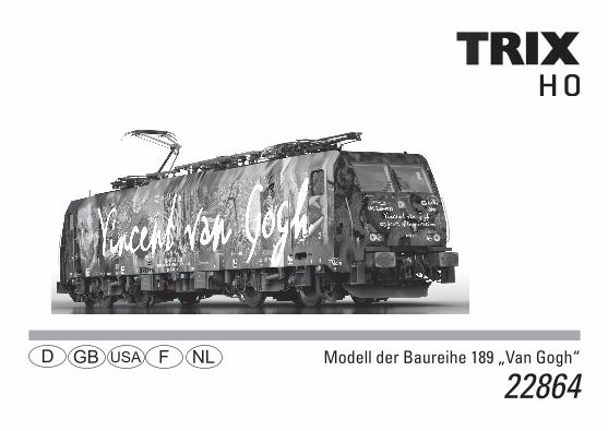
Modell der Baureihe 189 „Van Gogh“
22864F D GB USA NL
2Titel: Foto des Vorbilds, mit freundlicher Genemigung der ERS Railays
3
Inhaltsverzeichnis: SeiteInformationen zum Vorbild 4Sicherheitshinweise 6Wichtige Hinweise 6Multiprotokollbetrieb 6Schaltbare Funktionen 9Parameter/Register 10Betriebshinweise 26Wartung und Instandhaltung 27Ersatzteile 34
Table of Contents: Page Information about the prototype 4Safety Notes 11Important Notes 11Multi-Protocol Operation 11Controllable Functions 14Parameter/Register 15Information about operation 26Service and maintenance 27Spare Parts 34
Sommaire : PageInformations concernant la locomotive réelle 5Remarques importantes sur la sécurité 16Information importante 16Mode multiprotocole 16Fonctions commutables 19Paramètre/Registre 20Remarques sur l’exploitation 26Entretien et maintien 27Pièces de rechange 34
Inhoudsopgave: PaginaInformatie van het voorbeeld 5Veiligheidsvoorschriften 21Belangrijke aanwijzing 21Multiprotocolbedrijf 21Schakelbare functies 24Parameter/Register 25Opmerkingen over de werking 26Onderhoud en handhaving 27Onderdelen 34
4
Informationen zum VorbildDie von Siemens Transportation System (TS) entwickelte Mehrsystemlok ES 64 wurde für den schweren Güterdienst in ganz Europa bestellt. Sie kann unter Wechselstromsystemen in Deutschland, Österreich, Schweiz, Schweden und Nor-wegen (15 kV, 16,7 Hz) bzw. in Dänemark, Luxemburg, Nord-frankreich und Ungarn (25 kV, 50 Hz) betrieben werden. Ihr Einsatzgebiet unter Gleichstromsystemen erstreckt sich auf Belgien, Italien und Polen (3 kV), bzw. Südfrankreich und die Niederlande (1,5 kV). Der europaweite Einsatz erforderte auch eine hohe Flexibilität bei der Signallichtausrüstung: Die Leuchten für verschiedene Leuchtstärken und Farben sind in LED-Technologie ausgeführt, die zahlreiche Vorteile bietet, wie geringe Ausfallwahrschein-lichkeit, verschiedene Lichtstärken durch Zu- bzw. Abschalten von LED-Gruppen, Integration verschiedener Farben in einer Leuchte sowie geringere Verluste durch Wärmeentwicklung. Durch einen kleinen Umbau kann die Lok auch für den hoch-wertigen Personenzugdienst eingesetzt werden, wobei die Höchstgeschwindigkeit dann bei 230 km/h liegt.
Information about the PrototypeThe class ES 64 general-purpose locomotive developed by Siemens Transportation System (TS) was ordered all over Europe for heavy freight service. It can be run on alternating current systems in Germany, Austria, Switzerland, Sweden, and Norway (15 kilovolts, 16.7 Hertz) and in Denmark, Luxem-bourg, Northern France, and Hungary (25 kilovolts, 50 Hertz). Its area of use on direct current systems ranges from Belgi-um, Italy, and Poland (3 kilovolts), to Southern France and the Netherlands (1.5 kilovolts). This locomotive’s use all over Europe also requires a high level of flexibility in the headlights / marker lights used on it: The lights for different light intensities and colors are done with LED technology, which has numerous advantages such as a low probability of malfunctioning, different light inten-sities by turning groups of LED’s on and off, integration of different colors in a light as well as lower losses from heat generation. A small conversion process allows this locomotive to also be used for high quality passenger service in which the maxi-mum speed is then 230 km/h or 144 mph.
5
Informations concernant la locomotive réelle La locomotive polycourant ES 64 développée par Siemens Transportation System (TS) a été utilisée dans toute l’Europe pour le transport de marchandises lourdes. Elle peut fonction-ner sur les réseaux à courant alternatif d’Allemagne, d’Au-triche, de Suisse, de Suède et de Norvège (15 kV, 16,7 Hz) ou du Danemark, du Luxembourg, du nord de la France et de la Hongrie (25 kV, 50 Hz). Son domaine d’utilisation sur les réseaux à courant continu s’étend à la Belgique, à l’Italie et à la Pologne (3 kV) ou au sud de la France et aux Pays-Bas (1,5 kV). L’utilisation à l’échelle européenne exigea également une flexibilité élevée en termes de feux de signal : les diverses intensités et couleurs des feux sont obtenues avec la techno-logie DEL (diodes électroluminescentes) qui présente de nom-breux avantages, notamment la réduction des défaillances, les différentes intensités lumineuses par l’acti-vation ou la désac-tivation de groupes de DEL, l’intégration de plusieurs couleurs dans un seul feu ainsi que les faibles pertes thermiques. Grâce à une petite conversion, la locomotive peut également être utilisée pour le transport haut de gamme de passagers, car la vitesse de pointe atteint alors 230 km/h.
Informatie van het voorbeeld De bestellingen, van de door Siemens Transport Systems (TS) ontwikkelde meer-systemen loc ES 64 voor de zware goede-rendienst, kwamen uit heel Europa. Hij kan zowel gebruikt worden op het wisselstroomsysteem in Duitsland, Oosten-rijk, Zwitserland, Zweden, en Noorwegen (15 kV, 16,7 Hz), als in Denemarken, Luxemburg, Noord-Frankrijk en Hongarije (25 kV, 50 Hz). Het gebruiksgebied op het gelijkstroomsysteem strekt zich uit van België, Italië en Polen (3 kV) tot Zuid-Fran-krijk en Nederland (1,5 kV). Voor het gebruik in heel Europa was er ook een grote flexibiliteit van de seinverlichting nodig. De lampen voor de verschillende lichtsterktes en kleuren is in LED-technologie uitgevoerd. Dit biedt talrijke voordelen zoals geringe uitval, verschillende lichtsterktes door bij- of afschakelen van LED-groepen, integratie van verschillende kleuren in één sein-lamp en geringe verliezen door warmteontwikkeling. Door een kleine ombouw kan de loc ook voor de hoog-waar-dige reizigersdienst ingezet worden waarbij een maximums-nelheid van 230 km/h gehaald kan worden.
6
Sicherheitshinweise • DieLokdarfnurmiteinemdafürbestimmtenBetriebssy-
stem eingesetzt werden.• Analogmax.15Volt=,digitalmax.22Volt~.• DieLokdarfnurauseinerLeistungsquelleversorgtwer-
den.• BeachtenSieunbedingtdieSicherheitshinweiseinder
Bedienungsanleitung zu Ihrem Betriebssystem.•FürdenkonventionellenBetriebderLokmussdasAn-
schlussgleis entstört werden. Dazu ist das Entstörset 611 655 zu verwenden. Für Digitalbetrieb ist das Entstörset nicht geeignet.
• ACHTUNG! Funktionsbedingte scharfe Kanten und Spitzen.•SetzenSiedasModellkeinerdirektenSonneneinstrah-
lung, starken Temperaturschwankungen oder hoher Luftfeuchtigkeit aus.
•VerbauteLED`sentsprechenderLaserklasse1nach Norm EN 60825-1.
Wichtige Hinweise •DieBedienungsanleitungunddieVerpackungsindBe-
standteile des Produktes und müssen deshalb aufbewahrt sowie bei Weitergabe des Produktes mitgegeben werden.
•FürReparaturenoderErsatzteilewendenSiesichbitteanIhren Trix-Fachhändler.
•GewährleistungundGarantiegemäßderbeiliegendenGarantieurkunde.
•Entsorgung:www.maerklin.com/en/imprint.html•DervolleFunktionsumfangistnurunterTrixSystems,DCC
und unter mfx verfügbar.
• Eingebaute,fahrtrichtungsabhängigeStirnbeleuchtung. Im Digitalbetrieb schaltbar.
•BefahrbarerMindestradius360mm.
Multiprotokollbetrieb AnalogbetriebDer Decoder kann auch auf analogen Anlagen oder Gleis-abschnitten betrieben werden. Der Decoder erkennt die analoge Gleichspannung (DC) automatisch und passt sich der analogen Gleisspannung an. Es sind alle Funktionen, die unter mfx oder DCC für den Analogbetrieb eingestellt wurden aktiv (siehe Digitalbetrieb).
DigitalbetriebDer Decoder ist ein Multiprotokolldecoder. Der Decoder kann unter folgenden Digital-Protokollen eingesetzt werden: mfx oder DCC. Das Digital-Protokoll mit den meisten Möglichkeiten ist das höchstwertige Digital-Protokoll. Die Reihenfolge der Digital-Protokolle ist in der Wertung fallend: Priorität 1: mfx Priorität 2: DCC Priorität 3: DCHinweis: Wenn zwei oder mehr digital-Protokolle am Gleis erkannt werden, wählt der Decoder automatisch das höchstwertige Protokoll. Wird z.B. mfx und DCC erkannt, wählt der Decoder mfx.
7
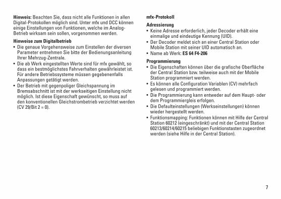
Hinweis: Beachten Sie, dass nicht alle Funktionen in allen Digital-Protokollen möglich sind. Unter mfx und DCC können einige Einstellungen von Funktionen, welche im Analog-Betrieb wirksam sein sollen, vorgenommen werden.
Hinweise zum Digitalbetrieb • DiegenaueVorgehensweisezumEinstellenderdiversen
Parameter entnehmen Sie bitte der Bedienungsanleitung Ihrer Mehrzug-Zentrale.
•DieabWerkeingestelltenWertesindfürmfxgewählt,sodass ein bestmöglichstes Fahrverhalten gewährleistet ist. Für andere Betriebssysteme müssen gegebenenfalls Anpassungen getätigt werden.
• DerBetriebmitgegenpoligerGleichspannungimBremsabschnitt ist mit der werkseitigen Einstellung nicht möglich. Ist diese Eigenschaft gewünscht, so muss auf den konventionellen Gleichstrombetrieb verzichtet werden (CV29/Bit2=0).
mfx-Protokoll
Adressierung • KeineAdresseerforderlich,jederDecodererhälteine
einmalige und eindeutige Kennung (UID).• DerDecodermeldetsichaneinerCentralStationoder
Mobile Station mit seiner UID automatisch an.•NameabWerk:ES 64 F4-206
Programmierung• DieEigenschaftenkönnenüberdiegrafischeOberfläche
der Central Station bzw. teilweise auch mit der Mobile Station programmiert werden.
• EskönnenalleConfigurationVariablen(CV)mehrfachgelesen und programmiert werden.
• DieProgrammierungkannentwederaufdemHaupt-oderdem Programmiergleis erfolgen.
• DieDefaulteinstellungen(Werkseinstellungen)könnenwieder hergestellt werden.
• Funktionsmapping:FunktionenkönnenmitHilfederCentralStation 60212 (eingeschränkt) und mit der Central Station 60213/60214/60215 beliebigen Funktionstasten zugeordnet werden (siehe Hilfe in der Central Station).
8
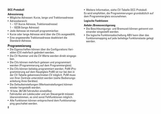
DCC-Protokoll
Adressierung• MöglicheAdressen:Kurze,langeundTraktionsadresse• Adressbereich:
1 – 127 (kurze Adresse, Traktionsadresse) 1 – 10239 (lange Adresse)• JedeAdresseistmanuellprogrammierbar.•KurzeoderlangeAdressewirdüberdieCVsausgewählt.• EineangewandteTraktionsadressedeaktiviertdie
Standard-Adresse.
Programmierung• DieEigenschaftenkönnenüberdieConfigurationsVari-
ablen (CV) mehrfach geändert werden. • DieCV-NummerunddieCV-Wertewerdendirekteingege-
ben.• DieCVskönnenmehrfachgelesenundprogrammiert
werden (Programmierung auf dem Programmiergleis).• DieCVskönnenbeliebigprogrammiertwerden.PoM(Pro-
grammierung auf dem Hauptgleis PoM) ist nur bei den in der CV-Tabelle gekennzeichneten CV möglich. PoM muss von Ihrer Zentrale unterstützt werden (siehe Bedienungs-anleitung ihres Gerätes).
• DieDefaulteinstellungen(Werkseinstellungen)könnenwieder hergestellt werden.
• 14bzw.28/126Fahrstufeneinstellbar. Fahrstufen am Lokdecoder und am Steuergerät müssen übereinstimmen, es sind sonst Fehlfunktionen möglich.
• AlleFunktionenkönnenentsprechenddemFunktionsmap-ping geschaltet werden.
• WeitereInformation,sieheCV-TabelleDCC-Protokoll.Es wird empfohlen, die Programmierungen grundsätzlich auf dem Programmiergleis vorzunehmen.
Logische Funktionen
Anfahr-/Bremsverzögerung• DieBeschleunigungs-undBremszeitkönnengetrenntvon
einander eingestellt werden. • DielogischeFunktionsabschaltungABVkannüberdas
Funktionsmapping auf jede beliebige Funktionstaste gelegt werden.
9
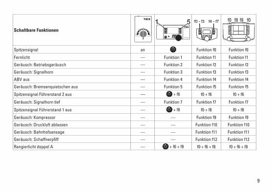
Schaltbare Funktionen
Spitzensignal an Funktion f0 Funktion f0
Fernlicht — Funktion 1 Funktion f1 Funktion f1
Geräusch: Betriebsgeräusch — Funktion 2 Funktion f2 Funktion f2
Geräusch: Signalhorn — Funktion 3 Funktion f3 Funktion f3
ABV aus — Funktion 4 Funktion f4 Funktion f4
Geräusch: Bremsenquietschen aus — Funktion 5 Funktion f5 Funktion f5
Spitzensignal Führerstand 2 aus — + f6 f0 + f6 f0 + f6
Geräusch: Signalhorn tief — Funktion 7 Funktion f7 Funktion f7
Spitzensignal Führerstand 1 aus — + f8 f0 + f8 f0 + f8
Geräusch: Kompressor — — Funktion f9 Funktion f9
Geräusch: Druckluft ablassen — — Funktion f10 Funktion f10
Geräusch: Bahnhofsansage — — Funktion f11 Funktion f11
Geräusch:Schaffnerpfiff — — Funktion f12 Funktion f12
Rangierlicht doppel A — + f6 + f8 f0 + f6 + f8 f0 + f6 + f8
STOP mobile station
1 5 f0 f8 f0f8f0 - f3 f4 - f7
10
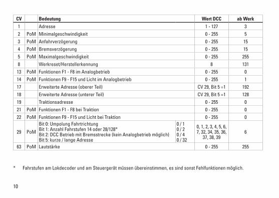
CV Bedeutung Wert DCC ab Werk
1 Adresse 1 - 127 3 2 PoM Minimalgeschwindigkeit 0 - 255 53 PoM Anfahrverzögerung 0 - 255 154 PoM Bremsverzögerung 0 - 255 155 PoM Maximalgeschwindigkeit 0 - 255 2558 Werkreset/Herstellerkennung 8 131
13 PoM Funktionen F1 - F8 im Analogbetrieb 0 - 255 014 PoM Funktionen F9 - F15 und Licht im Analogbetrieb 0 - 255 117 Erweiterte Adresse (oberer Teil) CV29,Bit5=1 19218 Erweiterte Adresse (unterer Teil) CV29,Bit5=1 12819 Traktionsadresse 0 - 255 021 PoM Funktionen F1 - F8 bei Traktion 0 - 255 022 PoM Funktionen F9 - F15 und Licht bei Traktion 0 - 255 0
29 PoM
Bit 0: Umpolung Fahrtrichtung Bit 1: Anzahl Fahrstufen 14 oder 28/128* Bit 2: DCC Betrieb mit Bremsstrecke (kein Analogbetrieb möglich) Bit 5: kurze / lange Adresse
0 / 1 0 / 2 0 / 4 0 / 32
0, 1, 2, 3, 4, 5, 6, 7, 32, 34, 35, 36,
37, 38, 396
63 PoM Lautstärke 0 - 255 255
* Fahrstufen am Lokdecoder und am Steuergerät müssen übereinstimmen, es sind sonst Fehlfunktionen möglich.
11
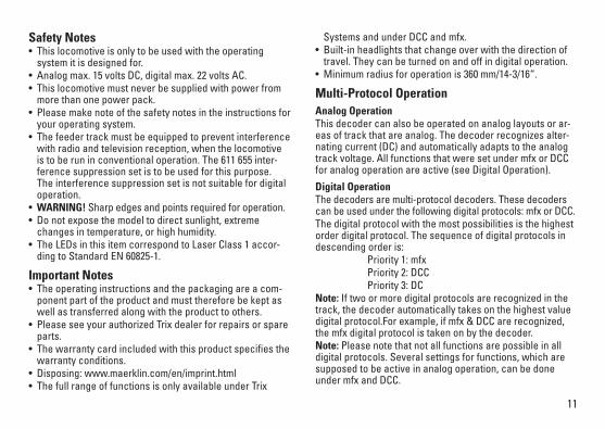
Systems and under DCC and mfx.• Built-inheadlightsthatchangeoverwiththedirectionof
travel. They can be turned on and off in digital operation. •Minimumradiusforoperationis360mm/14-3/16“.
Multi-Protocol Operation Analog OperationThis decoder can also be operated on analog layouts or ar-eas of track that are analog. The decoder recognizes alter-nating current (DC) and automatically adapts to the analog track voltage. All functions that were set under mfx or DCC for analog operation are active (see Digital Operation).
Digital OperationThe decoders are multi-protocol decoders. These decoders can be used under the following digital protocols: mfx or DCC.The digital protocol with the most possibilities is the highest order digital protocol. The sequence of digital protocols in descending order is: Priority 1: mfx Priority 2: DCC Priority 3: DCNote: If two or more digital protocols are recognized in the track, the decoder automatically takes on the highest value digital protocol.For example, if mfx & DCC are recognized, the mfx digital protocol is taken on by the decoder.Note: Please note that not all functions are possible in all digital protocols. Several settings for functions, which are supposed to be active in analog operation, can be done under mfx and DCC.
Safety Notes• Thislocomotiveisonlytobeusedwiththeoperating
system it is designed for.• Analogmax.15voltsDC,digitalmax.22voltsAC.• Thislocomotivemustneverbesuppliedwithpowerfrom
more than one power pack.• Pleasemakenoteofthesafetynotesintheinstructionsfor
your operating system.•Thefeedertrackmustbeequippedtopreventinterference
with radio and television reception, when the locomotive is to be run in conventional operation. The 611 655 inter-ference suppression set is to be used for this purpose. The interference suppression set is not suitable for digital operation.
•WARNING! Sharp edges and points required for operation.•Donotexposethemodeltodirectsunlight,extreme
changes in temperature, or high humidity. •TheLEDsinthisitemcorrespondtoLaserClass1accor-
ding to Standard EN 60825-1.
Important Notes•Theoperatinginstructionsandthepackagingareacom-
ponent part of the product and must therefore be kept as well as transferred along with the product to others.
•PleaseseeyourauthorizedTrixdealerforrepairsorspareparts.
•Thewarrantycardincludedwiththisproductspecifiesthewarranty conditions.
•Disposing:www.maerklin.com/en/imprint.html•ThefullrangeoffunctionsisonlyavailableunderTrix
12
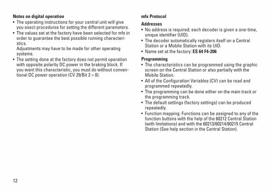
Notes on digital operation •Theoperatinginstructionsforyourcentralunitwillgive
you exact procedures for setting the different parameters. •Thevaluessetatthefactoryhavebeenselectedformfxin
order to guarantee the best possible running characteri-stics. Adjustments may have to be made for other operating systems.
• Thesettingdoneatthefactorydoesnotpermitoperationwith opposite polarity DC power in the braking block. If you want this characteristic, you must do without conven-tionalDCpoweroperation(CV29/Bit2=0).
mfx Protocol
Addresses •Noaddressisrequired;eachdecoderisgivenaone-time,uniqueidentifier(UID).
•ThedecoderautomaticallyregistersitselfonaCentralStation or a Mobile Station with its UID.
•Namesetatthefactory:ES 64 F4-206
Programming •Thecharacteristicscanbeprogrammedusingthegraphic
screen on the Central Station or also partially with the Mobile Station.
•AlloftheConfigurationVariables(CV)canbereadandprogrammed repeatedly.
•Theprogrammingcanbedoneeitheronthemaintrackorthe programming track.
•Thedefaultsettings(factorysettings)canbeproducedrepeatedly.
•Functionmapping:Functionscanbeassignedtoanyofthefunction buttons with the help of the 60212 Central Station (with limitations) and with the 60213/60214/60215 Central Station (See help section in the Central Station).
13
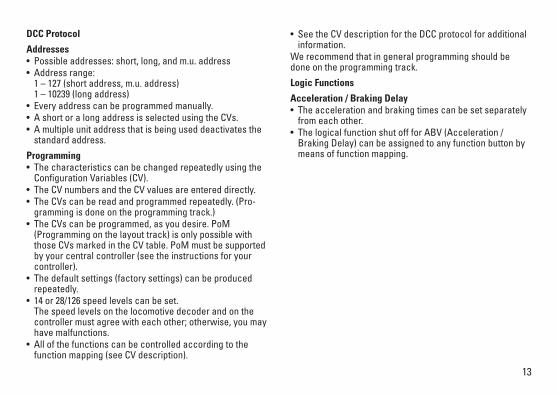
DCC Protocol
Addresses • Possibleaddresses:short,long,andm.u.address• Addressrange:
1 – 127 (short address, m.u. address) 1 – 10239 (long address)
•Everyaddresscanbeprogrammedmanually.•AshortoralongaddressisselectedusingtheCVs.•Amultipleunitaddressthatisbeinguseddeactivatesthe
standard address.
Programming•ThecharacteristicscanbechangedrepeatedlyusingtheConfigurationVariables(CV).
•TheCVnumbersandtheCVvaluesareentereddirectly.•TheCVscanbereadandprogrammedrepeatedly.(Pro-
gramming is done on the programming track.)•TheCVscanbeprogrammed,asyoudesire.PoM
(Programming on the layout track) is only possible with those CVs marked in the CV table. PoM must be supported by your central controller (see the instructions for your controller).
•Thedefaultsettings(factorysettings)canbeproducedrepeatedly.
•14or28/126speedlevelscanbeset. The speed levels on the locomotive decoder and on the controllermustagreewitheachother;otherwise,youmayhave malfunctions.
•Allofthefunctionscanbecontrolledaccordingtothefunction mapping (see CV description).
•SeetheCVdescriptionfortheDCCprotocolforadditionalinformation.
We recommend that in general programming should be done on the programming track.
Logic Functions
Acceleration / Braking Delay• Theaccelerationandbrakingtimescanbesetseparately
from each other. • ThelogicalfunctionshutoffforABV(Acceleration/
Braking Delay) can be assigned to any function button by means of function mapping.
14
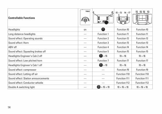
Controllable Functions
Headlights on Function f0 Function f0
Long distance headlights — Function 1 Function f1 Function f1
Sound effect: Operating sounds — Function 2 Function f2 Function f2
Sound effect: Horn — Function 3 Function f3 Function f3
ABV off — Function 4 Function f4 Function f4
Sound effect: Squealing brakes off — Function 5 Function f5 Function f5
Headlights Engineer‘s Cab 2 off — + f6 f0 + f6 f0 + f6
Sound effect: Low pitched horn — Function 7 Function f7 Function f7
Headlights Engineer‘s Cab 1 off — + f8 f0 + f6 f0 + f8
Sound effect: compressor — — Function f9 Function f9
Sound effect: Letting off air — — Function f10 Function f10
Sound effect: Station announcements — — Function f11 Function f11
Sound effect: Conductor whistle — — Function f12 Function f12
Double A switching light — + f6 + f8 f0 + f6 + f8 f0 + f6 + f8
STOP mobile station
1 5 f0 f8 f0f8f0 - f3 f4 - f7
15
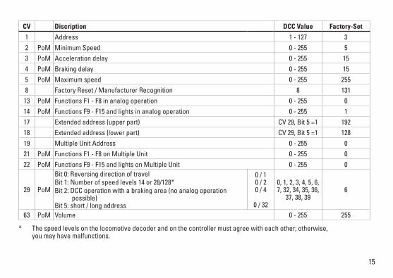
* Thespeedlevelsonthelocomotivedecoderandonthecontrollermustagreewitheachother;otherwise, you may have malfunctions.
CV Discription DCC Value Factory-Set
1 Address 1 - 127 3 2 PoM Minimum Speed 0 - 255 53 PoM Acceleration delay 0 - 255 154 PoM Braking delay 0 - 255 155 PoM Maximum speed 0 - 255 2558 Factory Reset / Manufacturer Recognition 8 13113 PoM Functions F1 - F8 in analog operation 0 - 255 014 PoM Functions F9 - F15 and lights in analog operation 0 - 255 117 Extended address (upper part) CV29,Bit5=1 19218 Extended address (lower part) CV29,Bit5=1 12819 Multiple Unit Address 0 - 255 021 PoM Functions F1 - F8 on Multiple Unit 0 - 255 022 PoM Functions F9 - F15 and lights on Multiple Unit 0 - 255 0
29 PoM
Bit 0: Reversing direction of travel Bit 1: Number of speed levels 14 or 28/128*Bit 2: DCC operation with a braking area (no analog operation possible) Bit 5: short / long address
0 / 1 0 / 2 0 / 4
0 / 32
0, 1, 2, 3, 4, 5, 6, 7, 32, 34, 35, 36,
37, 38, 396
63 PoM Volume 0 - 255 255
16
Remarques importantes sur la sécurité • Lalocomotivenepeutêtreutiliséequ‘aveclesystème
d‘exploitation indiqué.• Analogiquemax.15Volt=,digitalmax.22Volt~.• Lalocomotivenepeutpasêtrealimentéeélectriquement
par plus d‘une source de courant à la fois.• Ilestimpératifdetenircomptedesremarquessurla
sécurité décrites dans le mode d‘emploi de votre système d‘exploitation.
•Pour l’exploitation de la locomotive en mode conventi-onnel, la voie de raccordement doit être déparasitée. A cet effet, utiliser le set de déparasitage réf. 611 655. Le set de déparasitage ne convient pas pour l’exploitation en mode numérique.
• ATTENTION! Pointes et bords coupants lors du fonctionne-ment du produit.
•Nepasexposerlemodèleàunensoleillementdirect,àdefortes variations de température ou à un taux d‘humidité important.
•LesDELinstalléescorrespondentàlaclasselaser1selonla norme EN 60825-1.
Information importante•Lanoticed‘utilisationetl’emballagefontpartieintégranteduproduit;ilsdoiventdoncêtreconservéset,lecaséchéant, transmis avec le produit.
•Pourtouteréparationouremplacementdepièces,adressez vous à votre détaillant-spécialiste Trix.
•Garantielégaleetgarantiecontractuelleconformémentaucertificatdegarantieci-joint.
•Elimination:www.maerklin.com/en/imprint.html•L’intégralitédesfonctionsestdisponibleuniquementen
exploitation Trix Systems, DCC et mfx. • Feuxdesignalisations‘inversantselonlesensdemarche;
feux commutables en exploitation digital. •Rayonminimald’inscriptionencourbe360mm.
Mode multiprotocole Mode analogiqueOn peut aussi faire fonctionner le décodeur sur des instal-lations ou des sections de voie analogiques. Le décodeur identifieautomatiquementlatensiondevoieanalogique(DC). Toutes les fonctions qui ont été paramétrée pour le mode analogique sous mfx ou sous DCC sont actives (voir mode numérique).
Mode numériqueLes décodeur sont des décodeur multiprotocole. Le décodeur peut être utilisé avec les protocoles numériques suivants : mfx, DCCLe protocole numérique offrant les possibilités les plus nombreuses est le protocole numérique à bit de poids fort. La hiérarchisation des protocoles numériques est descendante : Priorité 1 : mfx Priorité 2 : DCC Priorité 3 : DCIndication : Si deux ou plus de deux protocoles numériques sont reconnus sur la voie, le décodeur choisit automatique-mentleprotocolenumériqueleplussignificatif.Entrelesprotocoles mfx & DCC par exemple, le décodeur choisira le
17
protocole numérique mfx.Indication : remarquez que toutes les fonctions ne peuvent pas être actionnées dans tous les protocoles numériques. Sous mfx et sous DCC, il est possible de procéder à quelques paramétrages de fonctions devant être actives dans le cadre de l’exploitation analogique.
Remarques relatives au fonctionnement en mode digital •Encequiconcernelaprocédurederéglagedesdiverspa-
ramètres, veuillez vous référer au mode d‘emploi de votre centrale de commande multitrain.
•Lesvaleursparamétréesd’usinesontchoisiespourmfxdemanière à garantir le meilleur comportement de roulement possible. Pour d’autres systèmes d’exploitation, ces valeurs devront éventuellement être adaptées.
• L’exploitationaveccourantcontinudepolaritéinversedans les sections de freinage n’est pas possible avec le réglage d’usine. Si cette propriété est désirée, il faut alors renoncer à l’exploitation conventionnelle en courant conti-nu(CV29/Bit2=0).
Protocole mfx
Adressage • Aucuneadressen’estnécessaire,ledécodeurreçoittoutefoisuneidentificationuniqueetnonéquivoque(UID).
• AvecsonUID,ledécodeurindiqueautomatiquementà une station centrale ou à une station mobile qu’il est connecté.
•Nomencodeeenusine:ES 64 F4-206
Programmation• Lescaractéristiquespeuventêtreprogramméespar
l’intermédiaire de la couche graphique de la station cen-trale, voire en partie aussi au moyen de la station mobile.
• Touteslesconfigurationsvariables(CV)peuventêtreluesetprogramméesdefaçonréitérée.
• Laprogrammationpeutêtreréaliséesoitsurlavoieprinci-pale, soit sur la voie de programmation.
• Lesparamétragespardéfaut(paramétragesusine)peuvent être rétablis.
• Mappagedesfonctions:lesfonctionspeuventêtreaffectées à de quelconques touches de fonction au moyen de la station centrale (60212) (restreinte) et avec la station centrale 60213/60214/60215 (voir Aide au niveau de la station centrale).
18
Protocole DCC
Adressage• Adressepossibles:Courtes,longuesetadressesdetraction• Catégoried’adresse:
1 à 127 (adresses courtes, adresses de traction) 1 à 10239 (adresses longues)
• Chaqueadresseestprogrammablemanuellement.•L’adressebrèveoulongueestchoisieparl’intermédiaire
des CVs.• Uneadressedetractionutiliséedésactivel’adresse
standard.
Programmation• Lescaractéristiquespeuventêtremodifiéesdefaçonréitéréeparl’intermédiairedesvariablesdeconfiguration(CVs).
• Touteslesconfigurationsvariables(CV)peuventêtreluesetprogramméesdefaçonréitérée.
• Laprogrammationpeutêtreréaliséesoitsurlavoieprinci-pale, soit sur la voie de programmation.
• LesCVpeuventêtreprogramméeslibrement.LaPoM(programmation sur la voie principale) est possible uniquement pour les CV signalées dans le tableau des CV. La PoM doit être prise en charge par votre centrale (voir la notice d’utilisation de votre appareil).
• Lesparamétragespardéfaut(paramétragesusine)peuvent être rétablis.
• 14voire28/126cransdemarchesontparamétrables. Pour éviter tout dysfonctionnement, les crans de marche sur le décodeur de loco doivent impérativement coïncider
avec ceux de l’appareil de commande.• Touteslesfonctionspeuventêtrecommutéesenfonction
du mappage des fonctions (voir le descriptif des CVs).• Pourtouteinformationcomplémentaire,voirletableaudes
CVs, protocole DCC. Il est recommandé, de réaliser la programmation, fonda-mentalement, sur la voie de programmation.
Fonctions logiques
Temporisation d’accélération et de freinage (TAF)• Lestempsd’accélérationetdefreinagepeuventêtredéfinisindépendammentl’undel’autre.
• LadésactivationdelafonctionlogiqueTAFpeutêtreaffectée à n’importe quelle touche de fonction via le mappage de fonctions.
19
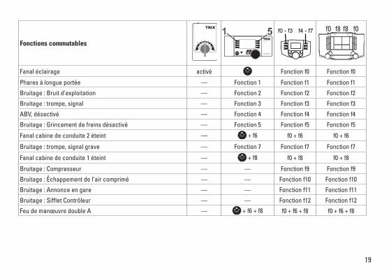
Fonctions commutables
Fanal éclairage activé Fonction f0 Fonction f0
Phares à longue portée — Fonction 1 Fonction f1 Fonction f1
Bruitage : Bruit d’exploitation — Fonction 2 Fonction f2 Fonction f2
Bruitage : trompe, signal — Fonction 3 Fonction f3 Fonction f3
ABV, désactivé — Fonction 4 Fonction f4 Fonction f4
Bruitage : Grincement de freins désactivé — Fonction 5 Fonction f5 Fonction f5
Fanal cabine de conduite 2 éteint — + f6 f0 + f6 f0 + f6
Bruitage : trompe, signal grave — Fonction 7 Fonction f7 Fonction f7
Fanal cabine de conduite 1 éteint — + f8 f0 + f8 f0 + f8
Bruitage : Compresseur — — Fonction f9 Fonction f9
Bruitage : Échappement de l‘air comprimé — — Fonction f10 Fonction f10
Bruitage : Annonce en gare — — Fonction f11 Fonction f11
Bruitage : Siffl et Contrôleur — — Fonction f12 Fonction f12
Feu de manœuvre double A — + f6 + f8 f0 + f6 + f8 f0 + f6 + f8
STOP mobile station
1 5 f0 f8 f0f8f0 - f3 f4 - f7
20
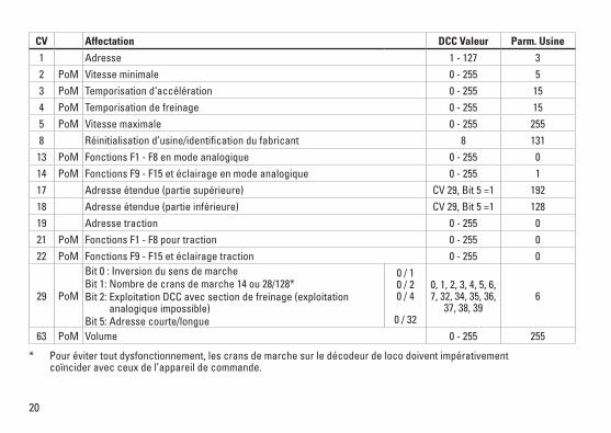
CV Affectation DCC Valeur Parm. Usine
1 Adresse 1 - 127 3 2 PoM Vitesse minimale 0 - 255 53 PoM Temporisation d‘accélération 0 - 255 154 PoM Temporisation de freinage 0 - 255 155 PoM Vitesse maximale 0 - 255 2558 Réinitialisationd’usine/identificationdufabricant 8 131
13 PoM Fonctions F1 - F8 en mode analogique 0 - 255 014 PoM Fonctions F9 - F15 et éclairage en mode analogique 0 - 255 117 Adresse étendue (partie supérieure) CV29,Bit5=1 19218 Adresse étendue (partie inférieure) CV29,Bit5=1 12819 Adresse traction 0 - 255 021 PoM Fonctions F1 - F8 pour traction 0 - 255 022 PoM Fonctions F9 - F15 et éclairage traction 0 - 255 0
29 PoM
Bit 0 : Inversion du sens de marche Bit 1: Nombre de crans de marche 14 ou 28/128*Bit 2: Exploitation DCC avec section de freinage (exploitation analogique impossible) Bit 5: Adresse courte/longue
0 / 1 0 / 2 0 / 4
0 / 32
0, 1, 2, 3, 4, 5, 6, 7, 32, 34, 35, 36,
37, 38, 396
63 PoM Volume 0 - 255 255
* Pour éviter tout dysfonctionnement, les crans de marche sur le décodeur de loco doivent impérativement coïncider avec ceux de l’appareil de commande.
21
Veiligheidsvoorschriften• Delocmagalleenmeteendaarvoorbestemdbedrijfssys-
teem gebruikt worden.• Analoogmax.15Volt=,digitaalmax.22Volt~.• Delocmagnietvanuitmeerdanéénstroomvoorziening
gelijktijdig gevoed worden.• Leesookaandachtigdeveiligheidsvoorschrifteninde
gebruiksaanwijzing van uw bedrijfssysteem. •Voorhetconventionelebedrijfmetdelocdientde
aansluitrail te worden ontstoort. Hiervoor dient men de ontstoor-set 611 655 te gebruiken. Voor het digitale bedrijf is deze ontstoor-set niet geschikt.
• OPGEPAST! Functionele scherpe kanten en punten.•Stelhetmodelnietblootaanindirectezonnestraling,
sterke temperatuurwisselingen of hoge luchtvochtigheid.•IngebouwdeLED’skomenovereenmetdelaserklasse1
volgens de norm EN 60825-1.
Belangrijke aanwijzing•Degebruiksaanwijzingendeverpakkingzijneenbestand-
deel van het product en dienen derhalve bewaard en meegeleverd te worden bij het doorgeven van het product.
•VoorreparatiesenonderdelenkuntzichtotUwTrixhan-delaar wenden.
•Vrijwaringengarantieovereenkomstighetbijgevoegdegarantiebewijs.
•Afdanken:www.maerklin.com/en/imprint.html•Devolledigetoegangtotallefunctiesisalleenmogelijk
met Trix Systems, DCC of met mfx bedrijf.• Ingebouwde,rijrichtingsafhankelijkefrontverlichtingisin
het digitaalsysteem schakelbaar. •Minimaleteberijdenradius:360mm.
MultiprotocolbedrijfAnaloogbedrijfDe decoder kan ook op analoge modelbanen of spoortra-jecten gebruikt worden. De decoder herkent de analoge gelijkspanning (DC) automatisch en past zich aan de analoge railspanning aan. Alle functies die onder mfx of DCC voor het analoge bedrijf zijn ingesteld, worden geactiveerd (zie digitaalbedrijf).
DigitaalbedrijfDe Decoder is een multiprotocoldecoder. De decoder kan onder de volgende digitale protocollen ingezet worden: mfx, DCC. Het digitaalprotocol met de meeste mogelijkheden is het primaire digitaalprotocol. De volgorde van de digitaalproto-collen is afnemend in mogelijkheden: Prioriteit 1: mfx Prioriteit 2: DCC Prioriteit 3: DCOpmerking: Als er twee of meer digitale protocollen op de rails worden herkend, dan neemt de decoder automa-tischhethoogwaardigsteprotocolover;bijv.wordmfx&DCC herkend, dan wordt het mfx signaal door de decoder overgenomen.Opmerking: let er op dat niet alle functies in alle digitaal-protocollen mogelijk zijn. Onder mfx of DCC kunnen enkele instellingen, welke in analoogbedrijf werkzaam moeten zijn, ingesteld worden.
22
Aanwijzingen voor digitale besturing •Hetopdejuistewijzeinstellenvandediverseparame-
ters staat beschreven in de handleiding van uw digitale Centrale.
•Fabrieksmatigzijndewaardenvoormfxzoingesteltdatoptimale rijeigenschappen gegarandeerd zijn. Voor andere bedrijfssystemen moeten eventueel aanpas-singen uitgevoerd worden.
• Hetbedrijfmettegengepooldegelijkspanningindeafrem-sectie is met de fabrieksinstelling niet mogelijk. Indien deze eigenschap wenselijk is, dan moet worden afgezien van het conventioneelgelijkstroombedrijf(CV29/Bit2=0).
mfx-protocol
Adressering •Eenadresisnietnodig,elkedecoderheefteenéénmalig
en éénduidig kenmerk (UID).•DedecodermeldtzichvanzelfaanbijhetCentralStation
of Mobile Station met zijn UID.•Naamafdefabriek:ES 64 F4-206
Programmering •Deeigenschappenkunnenm.b.v.hetgrafischeschermop
het Central Station resp. deels ook met het Mobile Station geprogrammeerd worden.
•Alleconfiguratievariabelen(CV)kunnenvakergelezenengeprogrammeerd worden.
•Deprogrammeringkanzowelophethoofdspooralsophetprogrammeerspoor gebeuren.
•Dedefault-instellingen(fabrieksinstelling)kunnenweerhersteld worden.
•Functiemapping:functieskunnenmetbehulpvanhetCentral Station 60212 (met beperking) en met het Central Station 60213/60214/60215 aan elke gewenste functietoets worden toegewezen (zie het helpbestand in het Central Station).
23
DCC-protocol
Adressering • Mogelijkeadressen:kort,langentractieadres• Adresbereik:
1 – 127 (kort adres, tractieadres) 1 – 10239 (lange adres)
•Elkadresishandmatigprogrammeerbaar.•KortoflangadreswordtviadeCVgekozen.•Eentoegepasttractieadresdeactiveerthetstandaarda-
dres.
Programmering•Deeigenschappenvandedecoderkunnenviadeconfigu-
ratie variabelen (CV) vaker gewijzigd worden.•DeCV-nummersendeCV-waardenwordendirectingevo-
erd.•DeCV’skunnenvakergelezenengeprogrammeerdwor-
den (programmering op het programmeerspoor).•DeCVskunnennaarwensgeprogrammeerdworden.PoM
(Programmering op het hoofdspoor) is alleen mogelijk bij de in de CV-tabel gemerkte CV. PoM moet door uw centra-le ondersteund worden (zie de gebruiksaanwijzing van uw centrale).
•Dedefault-instellingen(fabrieksinstelling)kunnenweerhersteld worden.
•14resp.28/126rijstappeninstelbaar. De rijstappen instelling op de decoder en het bestu-ringsapparaat moeten met elkaar overeenkomen anders kunnen er storingen optreden.
•Allefunctieskunnenovereenkomstigdefunctiemapping
geschakeld worden (zie CV-beschrijving).•Voorverdereinformatie,ziedeCV-tabelDCC-protocol.Het is aan te bevelen om het programmeren alleen op het programmeerspoor uit te voeren.
Fysieke functies
Optrek en afremvertraging• Deoptrek-enafremvertragingkunnenonafhankelijkvan
elkaar ingesteld worden. • DelogischeuitschakelfunctieABV(optrek-enafremver-
traging) kan met de functiemapping aan elke gewenste functietoets toegewezen worden.
24
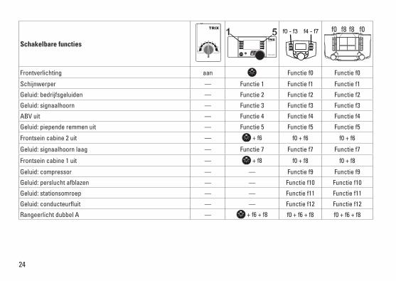
Schakelbare functies
Frontverlichting aan Functie f0 Functie f0
Schijnwerper — Functie 1 Functie f1 Functie f1
Geluid: bedrijfsgeluiden — Functie 2 Functie f2 Functie f2
Geluid: signaalhoorn — Functie 3 Functie f3 Functie f3
ABV uit — Functie 4 Functie f4 Functie f4
Geluid: piepende remmen uit — Functie 5 Functie f5 Functie f5
Frontsein cabine 2 uit — + f6 f0 + f6 f0 + f6
Geluid: signaalhoorn laag — Functie 7 Functie f7 Functie f7
Frontsein cabine 1 uit — + f8 f0 + f8 f0 + f8
Geluid: compressor — — Functie f9 Functie f9
Geluid: perslucht afblazen — — Functie f10 Functie f10
Geluid: stationsomroep — — Functie f11 Functie f11
Geluid: conducteurfl uit — — Functie f12 Functie f12
Rangeerlicht dubbel A — + f6 + f8 f0 + f6 + f8 f0 + f6 + f8
STOP mobile station
1 5 f0 f8 f0f8f0 - f3 f4 - f7
25
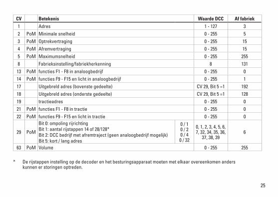
* De rijstappen instelling op de decoder en het besturingsapparaat moeten met elkaar overeenkomen anders kunnen er storingen optreden.
CV Betekenis Waarde DCC Af fabriek
1 Adres 1 - 127 3 2 PoM Minimale snelheid 0 - 255 53 PoM Optrekvertraging 0 - 255 154 PoM Afremvertraging 0 - 255 155 PoM Maximumsnelheid 0 - 255 2558 Fabrieksinstelling/fabriekherkenning 8 13113 PoM functies F1 - F8 in analoogbedrijf 0 - 255 014 PoM functies F9 - F15 en licht in analoogbedrijf 0 - 255 117 Uitgebreld adres (bovenste gedeelte) CV29,Bit5=1 19218 Uitgebreld adres (onderste gedeelte) CV29,Bit5=1 12819 tractieadres 0 - 255 021 PoM functies F1 - F8 in tractie 0 - 255 022 PoM functies F9 - F15 en licht in tractie 0 - 255 0
29 PoM
Bit 0: ompoling rijrichting Bit 1: aantal rijstappen 14 of 28/128*Bit 2: DCC bedrijf met afremtraject (geen analoogbedrijf mogelijk) Bit 5: kort / lang adres
0 / 1 0 / 2 0 / 4
0 / 32
0, 1, 2, 3, 4, 5, 6, 7, 32, 34, 35, 36,
37, 38, 396
63 PoM Volume 0 - 255 255
26
2. 2.
1.
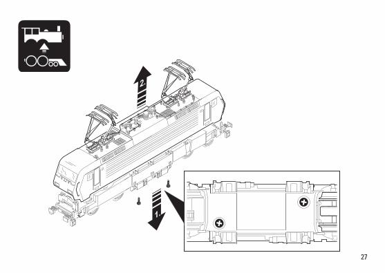
27
1.
2.
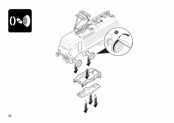
28
4.
4.
1.
1. 2.
3.
5.
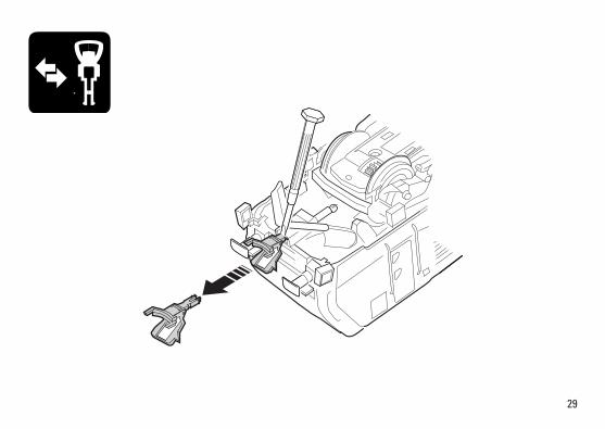
29
30
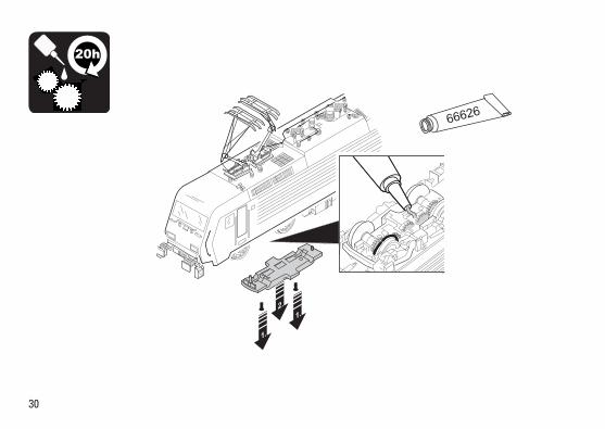
1.
1. 2.
20h
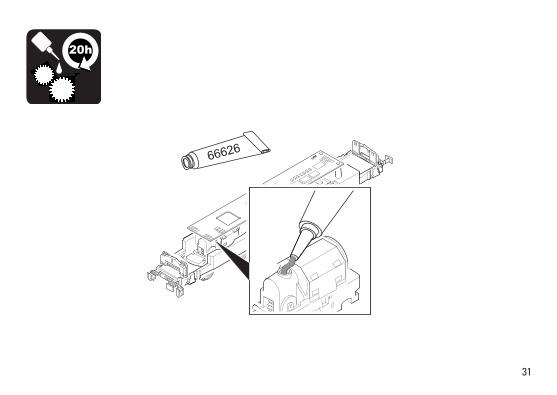
31
20h
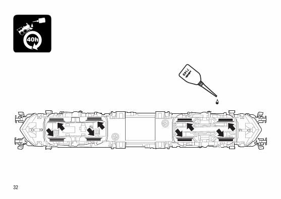
32
40h

33
34
3
2 4
12 17
18
1719
7
7
21
2221
21
2323
2323
20
20
1315
16
13
526 28
25 10
9
6
6
5
55
4
11
26 27
24
12
1411
15 19
2116
18
14
1
8 88
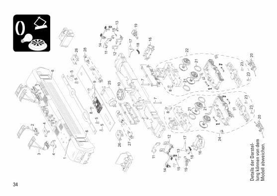
Det
ails
der
Dar
stel
-lu
ng k
önne
n vo
n de
m
Mod
ell a
bwei
chen
.
35
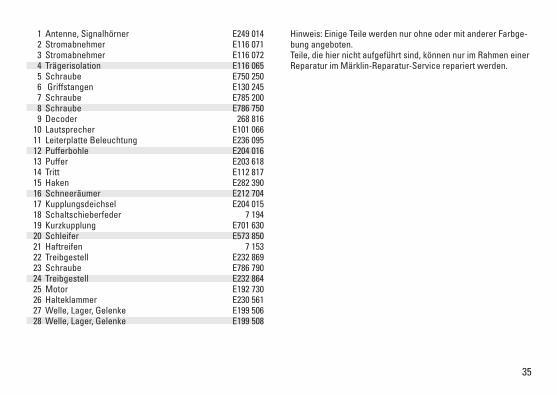
1 Antenne, Signalhörner E249 014 2 Stromabnehmer E116 071 3 Stromabnehmer E116 072 4 Trägerisolation E116 065 5 Schraube E750 250 6 Griffstangen E130 245 7 Schraube E785 200 8 Schraube E786 750 9 Decoder 268 816 10 Lautsprecher E101 066 11 Leiterplatte Beleuchtung E236 095 12 Pufferbohle E204 016 13 Puffer E203 618 14 Tritt E112 817 15 Haken E282 390 16 Schneeräumer E212 704 17 Kupplungsdeichsel E204 015 18 Schaltschieberfeder 7 194 19 Kurzkupplung E701 630 20 Schleifer E573 850 21 Haftreifen 7 153 22 Treibgestell E232 869 23 Schraube E786 790 24 Treibgestell E232 864 25 Motor E192 730 26 Halteklammer E230 561 27 Welle, Lager, Gelenke E199 506 28 Welle, Lager, Gelenke E199 508
Hinweis: Einige Teile werden nur ohne oder mit anderer Farbge-bung angeboten. Teile, die hier nicht aufgeführt sind, können nur im Rahmen einer Reparatur im Märklin-Reparatur-Service repariert werden.
Due to different legal requirements regarding electro-magnetic compatibility, this item maybeusedintheUSAonlyafterseparatecertificationforFCCcomplianceandanadjustment if necessary.
UseintheUSAwithoutthiscertificationisnotpermittedandabsolvesusofanyliability.Ifyoushouldwantsuchcertificationtobedone,pleasecontactus–alsoduetotheadditional costs incurred for this.
Gebr. Märklin & Cie. GmbH StuttgarterStraße55-5773033 Göppingen Germanywww.trix.de
269153/1215/Sm1EfÄnderungen vorbehalten
© Gebr. Märklin & Cie. GmbHwww.maerklin.com/en/imprint.html