Embed Size (px)
Citation preview

1 UF 6925 / 04.10.18 de / 025A
SAFEMASTER Not-Aus-Modul UF 6925
0275136
Datenblatt / Betriebsanleitung DEUTSCH
E. DOLD & SÖHNE KGPostfach 1251 • 78114 Furtwangen • DeutschlandTelefon +49 7723 6540 • Fax +49 7723 [email protected] • www.dold.com
Original
DE
EN
FR

2 UF 6925 / 04.10.18 de / 025A
Inhaltsverzeichnis
Symbol- und Hinweiserklärung ..........................................................................................................................................3
Allgemeine Hinweise ........................................................................................................................................................3
Bestimmungsgemäße Verwendung ...................................................................................................................................3
Sicherheitshinweise ...........................................................................................................................................................3
Produktbeschreibung .........................................................................................................................................................5
Funktionsdiagramm ...........................................................................................................................................................5
Schaltbilder ........................................................................................................................................................................5
Zulassungen und Kennzeichen .........................................................................................................................................5
Anwendungen ....................................................................................................................................................................5
Geräteanzeigen .................................................................................................................................................................5
Anschlussklemmen ............................................................................................................................................................6
Blockschaltbilder ................................................................................................................................................................6
Hinweise ............................................................................................................................................................................6
Technische Daten ..............................................................................................................................................................7
Technische Daten ..............................................................................................................................................................7
UL-Daten ...........................................................................................................................................................................7
Standardtype .....................................................................................................................................................................7
Varianten ...........................................................................................................................................................................8
Vorgehen bei Störungen ....................................................................................................................................................8
Wartung und Instandsetzung .............................................................................................................................................8
Kennlinien ..........................................................................................................................................................................8
Anwendungsbeispiel ..........................................................................................................................................................9
Sicherheitsfunktionen für Geräte mit Querschlusserkennung (Bitte Hinweis "Geräteprogrammierung" beachten!) .........9
Sicherheitsfunktionen für Geräte ohne Querschlusserkennung (Bitte Hinweis "Geräteprogrammierung" beachten!) ......9
Beschriftung und Anschlüsse ..........................................................................................................................................31
Maßbild (Maße in mm) ....................................................................................................................................................32
Geräteprogrammierung ...................................................................................................................................................32
Sicherheitstechnische Kenndaten ...................................................................................................................................33
EG-Konformitätserklärung ...............................................................................................................................................34
Notizen ............................................................................................................................................................................35
3 UF 6925 / 04.10.18 de / 025A
Sicherheitshinweise
WARNUNG
Gefahr durch elektrischen Schlag! Lebensgefahr oder schwere Verletzungsgefahr.• Stellen Sie sicher, dass Anlage und Gerät während der elektrischen Installation in spannungsfreiem Zustand sind und bleiben.• Das Gerät darf nur für die in der mitgeltenden Betriebsanleitung / Daten-
blatt vorgesehenen Einsatzfälle verwendet werden. Die Hinweise in den zugehörigen Dokumentationen müssen beachtet werden. Die zulässigen Umgebungsbedingungen müssen eingehalten werden.
• Beachten Sie die VDE- sowie die örtlichen Vorschriften, insbesondere hinsichtlich Schutzmaßnahmen.
WARNUNG
Brandgefahr oder andere thermische Gefahren! Lebensgefahr, schwere Verletzungsgefahr oder Sachschäden.• Das Gerät darf nur für die in der mitgeltenden Betriebsanleitung / Daten-
blatt vorgesehenen Einsatzfälle verwendet werden. Die Hinweise in den zugehörigen Dokumentationen müssen beachtet werden. Die zulässigen Umgebungsbedingungen müssen eingehalten werden. Insbesondere muss die Stromgrenzkurve beachtet werden.
• Das Gerät darf nur von sachkundigen Personen installiert und in Betrieb genommen werden, die mit dieser technischen Dokumentation und den geltenden Vorschriften über Arbeitssicherheit und Unfallverhütung vertraut sind.
WARNUNG
Funktionsfehler! Lebensgefahr, schwere Verletzungsgefahr oder Sachschäden.• Das Gerät darf nur für die in der mitgeltenden Betriebsanleitung / Daten-
blatt vorgesehenen Einsatzfälle verwendet werden. Die Hinweise in den zugehörigen Dokumentationen müssen beachtet werden. Die zulässigen Umgebungsbedingungen müssen eingehalten werden.
• Das Gerät darf nur von sachkundigen Personen installiert und in Betrieb genommen werden, die mit dieser technischen Dokumentation und den geltenden Vorschriften über Arbeitssicherheit und Unfallverhütung vertraut sind.
• Montieren Sie das Gerät in einen Schaltschrank mit IP 54 oder besser; Staub und Feuchtigkeit können sonst zur Beeinträchtigung der Funktion führen.
WARNUNG
Installationsfehler! Lebensgefahr, schwere Verletzungsgefahr oder Sachschäden. • Sorgen Sie an allen Ausgangskontakten bei kapazitiven und induktiven
Lasten für eine ausreichende Schutzbeschaltung.
! Achtung! • Die Sicherheitsfunktion muss bei Inbetriebnahme des Gerätes ausgelöst werden.• Wird der Leitungsschluss beim bestromten Gerät beseitigt, schaltet das Gerät durch.• Die Schalter S1 und S2 dürfen nicht bei bestromtem Gerät betätigt werden.• AUTOMATISCHER START ! Gemäß IEC/EN 60 204-1 Punkt 9.2.5.4.2 darf nach dem Stillsetzen im Notfall kein automatischer Start erfolgen. Deshalb muss in den Betriebs- arten mit automatischem Start, eine übergeordnete Steuerung einen automatischen Start nach einem Not-Aus verhindern.• Durch Öffnen des Gehäuses oder eigenmächtige Umbauten erlischt jegliche Gewährleistung.
GEFAHR
GEFAHR: Bedeutet, dass Tod oder schwere Körperverletzung eintreten
wird, wenn die entsprechenden Vorsichtsmaßnahmen nicht ge-troffen werden.
WARNUNG
WARNUNG: Bedeutet, dass Tod oder schwere Körperverletzung eintreten
kann, wenn die entsprechenden Vorsichtsmaßnahmen nicht getroffen werden.
VORSICHT
VORSICHT: Bedeutet, dass eine leichte Körperverletzung eintreten kann,
wenn die entsprechenden Vorsichtsmaßnahmen nicht getroffen werden.
! ACHTUNG:
Warnt vor Handlungen, die einen Schaden oder eine Fehlfunktion des Gerätes, der Geräteumgebung oder der Hard-/Software zur Folge haben können.
nfo INFO:
Bezeichnet Informationen, die Ihnen bei der optimalen Nutzung des Produktes behilflich sein sollen.
Die hier beschriebenen Produkte wurden entwickelt, um als Teil einer Gesamtanlage oder Maschine sicherheitsgerichtete Funktionen zu über-nehmen. Ein komplettes sicherheitsgerichtetes System enthält in der Regel Sensoren, Auswerteeinheiten, Meldegeräte und Konzepte für si-chere Abschaltungen. Es liegt im Verantwortungsbereich des Herstellers einer Anlage oder Maschine die korrekte Gesamtfunktion sicherzustellen. DOLD ist nicht in der Lage, alle Eigenschaften einer Gesamtanlage oder Maschine, die nicht durch DOLD konzipiert wurde, zu garantieren. Das Gesamtkonzept der Steuerung, in die das Gerät eingebunden ist, ist vom Benutzer zu validieren. DOLD übernimmt auch keine Haftung für Empfeh-lungen, die durch die nachfolgende Beschreibung gegeben bzw. impliziert werden. Aufgrund der nachfolgenden Beschreibung können keine neuen, über die allgemeinen DOLD-Lieferbedingungen hinausgehenden Garan-tie-, Gewährleistungs- oder Haftungsansprüche abgeleitet werden.
Allgemeine Hinweise
Symbol- und Hinweiserklärung
Installation nur durch Elektrofachkraft!
Nicht im Hausmüll entsorgen! Das Gerät ist in Übereinstimmung mit den national gültigen Vorgaben und Bestimmungen zu entsorgen.
Aufbewahren für späteres Nachschlagen
Um Ihnen das Verständnis und das Wiederfinden bestimmter Textstellen und Hinweise in der Betriebsanleitung zu erleichtern, haben wir wichtige Hinweise und Informationen mit Symbolen gekennzeichnet.
Vor der Installation, dem Betrieb oder der Wartung des Gerätes muss diese Anleitung gelesen und verstanden werden.
Bestimmungsgemäße Verwendung
Das UF 6925 dient dem sicherheitsgerichteten Unterbrechen eines Sicher-heitsstromkreises. Es kann zum Schutz von Personen und Maschinen in Anwendungen mit Not-Halt-Tastern und Schutztüren verwendet werden.Bei bestimmungsgemäßer Verwendung und Beachtung dieser Anleitung sind keine Restrisiken bekannt. Bei Nichtbeachtung kann es zu Personen- und Sachschäden kommen.

4 UF 6925 / 04.10.18 de / 025A

5 UF 6925 / 04.10.18 de / 025A
0275
136
Ihre Vorteile• für Sicherheitsanwendungen bis PL e / Kat. 4 bzw. SIL 3• geringer Platzbedarf• frontseitiger Geräteanschluss• manueller oder automatischer Start• geeignet auch für Schutztüren• Leitungsschlusserkennung am Ein-Taster
Merkmale• entspricht
- Performance Level (PL) e und Kategorie 4 nach EN ISO 13849-1 - SIL-Anspruchsgrenze (SIL CL) 3 nach IEC/EN 62061 - Safety Integrity Level (SIL) 3 nach IEC/EN 61508 und IEC/EN 61511
• nach EN 50156-1 für Feuerungsanlagen• 2-kanaliger Aufbau• zwangsgeführte Ausgangskontakte• mit oder ohne Querschlusserkennung im Steuerkreis, Schalter S1• Aktivierung über die Ein-Taste oder automatische Ein-Funktion, Schalter S2• LED-Anzeigen für Kanal 1, 2 und Netz• 17,5 mm Baubreite
Schutz von Personen und Maschinen• Not-Aus-Schaltungen von Maschinen• Überwachung der Stellung von Positionsschaltern an einer Schutztür
Das Not-Aus-Modul UF 6925 dient dem Schutz von Personen und Ma-schinen durch sicherheitsgerichtetes Freigeben und Unterbrechen eines Sicherheitsstromkreises. Es findet Anwendung zusammen mit Not-Halt-Tastern und Schutztüren.
grüne LED Netz: leuchtet bei anliegender Betriebsspannunggrüne LED K1: leuchtet bei bestromten Relais K1grüne LED K2: leuchtet bei bestromten Relais K2
Not-Aus
Ein-Taster
K2
K1
M11581 Geräteanzeigen
Anwendungen
Zulassungen und KennzeichenFunktionsdiagramm
Produktbeschreibung
Sicherheitstechnik
SAFEMASTERNot-Aus-ModulUF 6925
Canada / USA
S11
A2
A1
+
M11947
13
K1
K2
23
14 24
S22
S21
S12
S34
S33
24
23
13
14
S11
A2
A1
+
M11315
13
K1
K2
23
14 24
33
34
S22
S21
S12
S34
S33
13
34
33
23
14
24
S11
A2
A1
+
M11314
13
K1
K2
23
14 24
31
32
S22
S21
S12
S34
S33
13
32
31
23
14
24
UF 6925.03 UF 6925.22
Schaltbilder
UF 6925.02
Alle Angaben in dieser Liste entsprechen dem technischen Stand zum Zeitpunkt der Ausgabe. Technische Verbesserungen und Änderungen behalten wir uns jederzeit vor.

6 UF 6925 / 04.10.18 de / 025A
Einstellung Betriebsart QuerschlusserkennungDie Wahl der Betriebsart mit oder ohne Querschlusserkennung am Not-Aus-Taster bzw. an der Schutztür erfolgt über den Schalter S1. Der Gerä-teanschluss ist gemäß Anwendungsbeispiel vorzunehmen. Die Einstellung an S1 muss vor Inbetriebnahme des Gerätes erfolgen.
! ACHTUNG! Der Schalter S1 darf nicht bei bestromtem Gerät betätigt werden.
Einstellung Start-ModusDer Schalter S2 dient zur Wahl von automatischem oder Hand-Start. Für die Funktion "Auto-Start" sind die Klemmen S33 und S34 zu überbrücken. Bei der Funktion "Hand-Start" ist ein Ein-Taster zwischen die Klemmen S33 und S34 zu schalten. Der Startvorgang wird bei der fallenden Flanke des Starttasters erkannt. Der Geräteanschluss ist gemäß Anwendungsbeispiel vorzunehmen. Die Einstellung an S2 muss vor Inbetriebnahme des Gerätes erfolgen.
! ACHTUNG! Der Schalter S2 darf nicht bei bestromtem Gerät betätigt werden.
Leitungsschlusserkennung des Ein-TastersLiegt ein Leitungsschluss über dem Ein-Taster vor, lassen sich die Ausgangskontakte nicht einschalten. Ein Leitungsschluss über dem Ein-Taster, der nach der Aktivierung des Gerätes (Ausgangskontakte sind eingeschaltet) aufgetreten ist, wird beim erneuten Einschaltvorgang erkannt und das Einschalten der Ausgangskontakte verhindert.
! ACHTUNG! Wird der Leitungsschluss beim bestromten Gerät beseitigt, schaltet das Gerät ein.
Hinweise
UF 6925.03
A1+ A2 S11 S12 S22 S33 S34 13 23
M10783_a S21 14 24
K1
K2
K1
Netz
24V K2
K2K1
Überspannung- und
Kurzschlußschutz
Überwachungs-
Logik
33
34
A1+ A2 S11 S12 S22 S33 S34 13 23
M11313 S21 14 24
K1
K2
K1
Netz
24V K2
K2K1
Überspannung- und
Kurzschlußschutz
Überwachungs-
Logik
31
32
UF 6925.22
Blockschaltbilder
UF 6925.02
A1+ A2 S11 S12 S22 S33 S34 13 23
M11928 S21 14 24
K1
K2
K1
Netz
24V K2
K2K1
Überspannung- und
Kurzschlußschutz
Überwachungs-
Logik
Klemmenbezeichnung SignalbeschreibungA1+ +
A2 -
S12, S22, S34 Steuereingänge
S11, S21, S33 Steuerausgänge
13, 14, 23, 24, 33,34Schließer zwangsgeführt für Freigabekreis
31, 32 Meldeausgang zwangsgeführt
Anschlussklemmen

7 UF 6925 / 04.10.18 de / 025A
Eingang
Nennspannung UN: DC 24 V, DC 8 ... 36 V Das Netzteil muss die Anforderungen von SELV / PELV erfüllenSpannungsbereichDC 24V: 0,8 ... 1,1 UNNennverbrauch bei DC 24 V: < 1,6 WDC 8 ... 36 V: < 2,2 WMindestausschaltdauer: 150 msSteuerspannung an S11 bei nicht aktiviertem Gerät: DC 23 V bei UNSteuerstrom (typ.) über S12 oder S22: 30 mA bei UNMindestspannungan Klemme S12 bei nicht aktiviertem Gerät: DC 19 VAbsicherung des Gerätes: Intern mit PTCÜberspannungsschutz: Intern durch VDR
Ausgang
KontaktbestückungUF 6925.02: 2 SchließerUF 6925.03: 3 SchließerUF 6925.22: 2 Schließer, 1 Öffner
Die Schließer-Kontakte können für Sicherheitsabschaltungen verwendet werden.Der Öffner-Kontakt 31-32 ist nur als Meldekontakt verwendbar.
Einschaltzeit bei UN: < 350 msAbschaltzeit bei UN: bei Unterbrechung derVersorgungsspannung: DC 24 V: < 20 msDC 8 ... 36 V: < 90 msbei Unterbrechung in S12, S22: < 25 msKontaktart: Relais, zwangsgeführtThermischer Strom Ith: max. 8 A (siehe Summenstromgrenzkurve)Schaltvermögen nach AC 15Schließer: 3 A / AC 230 V IEC/EN 60 947-5-1Öffner: 1 A / AC 230 V IEC/EN 60 947-5-1nach DC 13Schließer: 2 A / 24 V IEC/EN 60 947-5-1Öffner: 2 A / 24 V IEC/EN 60 947-5-1in Anlehnung an DC 13Schließer: 4 A / 24 V bei 0,1 Hz IEC/EN 60 947-5-1Öffner: 4 A / 24 V bei 0,1 Hz IEC/EN 60 947-5-1Elektrische Lebensdauer bei AC 230 V, 8 A, cos ϕ = 1: > 1,0 x 10⁵ Schaltspiele (bei 1 s Ein, 1s Aus)Zulässige Schalthäufigkeit: max. 1 200 Schaltspiele / hKurzschlußfestigkeit max. Schmelzsicherung: 8 A gG / gL IEC/EN 60 947-5-1Sicherungsautomat: B 6 AMechanische Lebensdauer: > 40 x 106 Schaltspiele
Allgemeine Daten
Nennbetriebsart: DauerbetriebTemperaturbereichBetrieb: - 25 ... + 55 °CLagerung : - 25 ... + 85 °CBetriebshöhe: < 2.000 mLuft- und KriechstreckenBemessungsstoßspannung /Verschmutzungsgrad: 4 kV / 2 IEC 60 664-1EMV: IEC/EN 61 326-3-1Funkentstörung DC 24 V: Grenzwert Klasse B EN 55 011DC 8 ... 36 V: Grenzwert Klasse A*) EN 55 011 *) Das Gerät ist für den Einsatz in einer industriellen Umgebung (Klasse A, EN 55011) vorgesehen. Beim Anschluss an ein Niederspannungs- Versorgungsnetz (Klasse B, EN 55011) können Funkstörungen entstehen. Um dies zu verhindern, sind geeignete Maßnahmen zu ergreifen.
Technische Daten
Schutzart: Gehäuse: IP 40 IEC/EN 60 529Klemmen: IP 20 IEC/EN 60 529Gehäuse: Thermoplast mit V0-Verhalten nach UL Subject 94Rüttelfestigkeit: Amplitude 0,35 mm Frequenz 10 ... 55 Hz, IEC/EN 60 068-2-6Klimafestigkeit: 25 / 055 / 04 IEC/EN 60 068-1Klemmenbezeichnung: EN 50 005Schnellbefestigung: Hutschiene IEC/EN 60 715Nettogewicht: 140 g
Geräteabmessungen
Breite x Höhe x Tiefe: 17,5 x 110 x 120 mm
Technische Daten
Die Sicherheitsfunktionen des Gerätes wurden nicht durch die UL untersucht. Die Zulassung bezieht sich auf die Forderungen des Standards UL60947, “general use applications“
Normen: - ANSI/UL 60947-1, 5th Edition (Low-Voltage Switchgear and Controlgear
Part1: General rules) - ANSI/UL 60947-5-1, 3th Edition (Low-Voltage Switchgear and Controlgear
Part5-1: Control circuit Devices an Switching Elements - Electro- mechanical Control Circuits Devices) - CAN/CSA-C22.2 No. 60947-1-13, 2nd Edition (Low-Voltage Switch-
gear and Controlgear - Part1: General rules) - CAN/CSA-C22.2 No. 60947-1-14, 1st Edition (Low-Voltage Switch-
gear and Controlgear - Part5-1: Control circuit Devices an Switching Elements - Electromechanical Control Circuits Devices)
SchaltvermögenUF 6925.03: Pilot duty B300, Q300 6A 250Vac Resistive 6A 24Vdc Resistive
UF 6925.02, UF 6925.22: Pilot duty B300, Q300 8A 250Vac Resistive 8A 24Vdc Resistive
Leiteranschluss: min. 60°C Kupferleiter AWG 28 - 14
nfoFehlende technische Daten, die hier nicht explizit angegeben sind, sind aus den allgemein gültigen technischen Daten zu entnehmen.
UL-Daten
UF 6925.03/61 DC 8 ... 36 VArtikelnummer: 0067556• Ausgang: 3 Schließer• Nennspannung UN: DC 8 ... 36 V• Baubreite: 17,5 mm
Standardtype

8 UF 6925 / 04.10.18 de / 025A
M11444
25
I2
(A )2
75
100
125
50
0 10 20 30 40 6050T ( C)°
- Strom in den KontaktpfadenI , I1 2
� I = I + I2 2 2
1 2
Gerät angereiht, mit Fremderwärmung
durch Geräte gleicher Last
Max. zulässiger Strom bei 55°C über
2 Kontaktreihen = 4A = 2x4 A = 32A2 2 2
^
Gerät freistehend
Max. Strom bei 55°C über
2 Kontaktreihen = 8A = 2x8 A = 128A2 2 2
^
Summenstromgrenzkurve DC 24 V
M11441
25
I2
(A )2
75
100
125
50
0 10 20 30 40 6050T ( C)°
- Strom in den KontaktpfadenI , I1 2
� I = I + I2 2 2
1 2
Gerät angereiht, mit Fremderwärmung
durch Geräte gleicher Last
Max. zulässiger Strom bei 55°C über
2 Kontaktreihen = 2A = 2x2 A = 8A2 2 2
^
Gerät freistehend
Max. Strom bei 55°C über
2 Kontaktreihen = 8A = 2x8 A = 128A2 2 2
^
Summenstromgrenzkurve DC 8 - 36 V
Kennlinien
Varianten
UF 6925._ _ /1 _ _:Schalten von Kleinlasten 10 mVA ... 12 VA bzw. 10 mW ... 12 W im Bereich von 2 ... 60 V und 2 ... 300 mA. Das Gerät eignet sich auch zum Schalten des max. Schaltstromes. Dabei wird jedoch die Goldauflage der Kontakte abgebrannt, so daß danach das Schalten von Kleinlasten nicht mehr möglich ist.
Bestellbeispiel für Varianten
UF 6925 .03 /_ _ _ /61 DC 8 ... 36 V
Nennspannung DC 8 ... 36 V
UL- Zulassung
Querschlusserkennung 0 = einstellbar
Start-Modus 0 = einstellbar
Schaltleistung 0 = Standard 1 = für Kleinlasten (2 ...60 V, 2...300 mA)
Kontaktbestückung .02 = 2 Schließer .03 = 3 Schließer .22 = 2 Schließer, 1 Öffner
Gerätetype
Fehler mögliche Ursache
LED "Netz" leuchtet nicht - Versorgungsspannung nicht angeschlossen- Querschluß zwischen S11 und S21
LED "K1" leuchtet, aber "K2" nicht
- Sicherheitsrelais K1 ist verschweißt (Gerät austauschen)- Es hat eine 1-kanalige Abschaltung an S12 stattgefunden (Kanal an S22 abschalten)
LED "K2" leuchtet, aber "K1" nicht
- Sicherheitsrelais K2 ist verschweißt (Gerät austauschen)- Es hat eine 1-kanalige Abschaltung an S22 stattgefunden (Kanal an S12 abschalten)
Gerät kann nicht gestartet werden
- Ein Sicherheitsrelais ist verschweißt (Gerät austauschen)- Schalter S1 hat falsche StellungHandstart-Modus:- Leitungsschluß am Ein-Taster (Versorgungsspannung trennen und Fehler beheben)Auto-Start-Modus:- S33-S34 nicht gebrückt
- Das Gerät enthält keine Teile, die einer Wartung bedürfen.- Bei vorliegenden Fehlern das Gerät nicht öffnen, sondern an den Hersteller zur Reparatur schicken.
Vorgehen bei Störungen
Wartung und Instandsetzung
UF 6925 .02 /_ _ _ /61 DC 24 V
Nennspannung DC 24V
UL-Zulassung
Querschlusserkennung 1 = ohne Querschlusserkennung 2 = mit Querschlusserkennung
Start-Modus 1 = Auto-Start 2 = Hand-Start
Schaltleistung 0 = Standard
Kontaktbestückung .02 = 2 Schließer .03 = 3 Schließer
Gerätetype

9 UF 6925 / 04.10.18 de / 025A
Anwendungsbeispiel
Sicherheitsfunktionen für Geräte mit Querschlusserkennung (Bitte Hinweis "Geräteprogrammierung" beachten!)
Sicherheitsfunktionen für Geräte ohne Querschlusserkennung (Bitte Hinweis "Geräteprogrammierung" beachten!)
S22 S11 S12
M10757
Not-
Aus
S21 S21 S22 S11 S12
Schiebeschutztür
geschlossen
M10756
Fkt.: Not-Aus SIL 3, PL e, Kat. 4
Fkt.: Schutztür SIL 3, PL e, Kat. 4
S22 S11 S12
M10753
Not-
Aus
S21 S21 S22 S11 S12
Schiebeschutztür
geschlossen
M10752
Fkt.: Not-Aus SIL 3, PL e, Kat. 4 1)
Fkt.: Schutztür SIL 3, PL e, Kat. 4 1)
1) Um die Sicherheitsklassifizierungen zu erreichen ist eine querschlusssichere Verdrahtung sicherzustellen.
Für automatische Ein-Funktion ist eine Brücke S33 - S34 zu setzen. Der Ein-Taster entfällt. Die gewünschte Start-Funktion muss über den Schalter S2 vor Inbetriebnahme des Gerätes eingestellt werden (siehe Hinweis "Geräteprogrammierung"). Die Funktion der externen Schütze wird durch Einschleifen der Öffnerkontakte in den Einschaltkreis (Klemmen S33 - S34) überwacht.
DC24V
M10784_a
0V
A2
A1+ S21S33 S34 S22 S11 S12
UF6925
13 23
14 24
Ein K3
K4
K3 K4
33
34
Sicherheitsfunktion

10 UF 6925 / 04.10.18 de / 025A
E. DOLD & SÖHNE KG • D-78120 Furtwangene-mail: [email protected] • internet: http://www.dold.com
• Bregstraße 18 • Telefon 0 77 23 / 654-0 • Telefax 0 77 23 / 654-356
11 UF 6925 / 04.10.18 en / 025A
SAFEMASTER Emergency Stop Module UF 6925
0275136
Datasheet / Operating Instructions ENGLISH
E. DOLD & SÖHNE KGP.O. Box 1251 • D-78114 Furtwangen • GermanyTel: +49 7723 6540 • Fax +49 7723 [email protected] • www.dold.com
Translation of the original instructions

12 UF 6925 / 04.10.18 en / 025A
Contents
Symbol and Notes Statement ..........................................................................................................................................13
General Notes .................................................................................................................................................................13
Designated Use ...............................................................................................................................................................13
Safety Notes ....................................................................................................................................................................13
Product Description .........................................................................................................................................................15
Function Diagram ............................................................................................................................................................15
Circuit Diagrams ..............................................................................................................................................................15
Approvals and Markings ..................................................................................................................................................15
Applications .....................................................................................................................................................................15
Indicators .........................................................................................................................................................................15
Connection Terminals ......................................................................................................................................................16
Block Diagrams ...............................................................................................................................................................16
Notes ...............................................................................................................................................................................16
Technical Data .................................................................................................................................................................17
Technical Data .................................................................................................................................................................17
UL-Data ...........................................................................................................................................................................17
Standard Type ..................................................................................................................................................................17
Variants ............................................................................................................................................................................18
Troubleshooting ...............................................................................................................................................................18
Maintenance and repairs .................................................................................................................................................18
Characteristics .................................................................................................................................................................18
Application Examples ......................................................................................................................................................19
Safety function for units with cross fault detection (pay attention to "Unit Programming"!) ..............................................19
Safety function for units without cross fault detection (pay attention to "Unit Programming"!) .........................................19
Labeling and connections ................................................................................................................................................31
Dimensions (dimensions in mm) .....................................................................................................................................32
Setting .............................................................................................................................................................................32
Safety Related Data ........................................................................................................................................................33
CE-Declaration of Conformity ..........................................................................................................................................34
Notice ..............................................................................................................................................................................35
13 UF 6925 / 04.10.18 en / 025A
Safety Notes
WARNING
Risk of electrocution! Danger to life or risk of serious injuries. • Disconnect the system and device from the power supply and ensure they remain disconnected during electrical installation.• The device may only be used for the applications described in the mu-
tually applicable operating instructions / data sheet. The notes in the respective documentation must be heeded. The permissible ambient conditions must be observed.
• Note the VDE and local regulations, particularly those related to protec-tive measures.
WARNING
Risk of fire or other thermal hazards! Danger to life, risk of serious injuries or property damage. • The device may only be used for the applications described in the mutually
applicable operating instructions / data sheet. The notes in the respective documentation must be heeded. The permissible ambient conditions must be observed. In particular, the current limit curve must be heeded.
• The device may only be installed and put into operation by experts who are familiar with this technical documentation and the applicable health and safety and accident prevention regulations.
WARNING
Functional error! Danger to life, risk of serious injuries or property damage. • The device may only be used for the applications described in the mu-
tually applicable operating instructions / data sheet. The notes in the respective documentation must be heeded. The permissible ambient conditions must be observed.
• The device may only be installed and put into operation by experts who are familiar with this technical documentation and the applicable health and safety and accident prevention regulations.
• The unit should be panel mounted in an enclosure rated at IP 54 or superior. Dust and dampness may lead to malfunction.
WARNING
Installation fault! Danger to life, risk of serious injuries or property damage. • Make sure of sufficient protection circuitry at all output contacts for
capacitive and inductive loads.
! Attention! • The safety function must be triggered during commissioning.• If a line fault occurs after the voltage has been connected to S12, S22, the unit will be activated because this line fault is similar to the normal On-function.• Switches S1 and S2 must not be set while device is under supply voltage. • AUTOMATIC START ! According to IEC/EN 60 204-1 part 9.2.5.4.2 and 10.8.3 it is not allowed to restart automatically after emergency stop. Therefore the machine control has to disable the automatic start after emergency stop.• Opening the device or implementing unauthorized changes voids any warranty
DANGER
DANGER: Indicates that death or severe personal injury will result if
proper precautions are not taken.
WARNING
WARNING: Indicates that death or severe personal injury can result if
proper precautions are not taken.
CAUTION
CAUTION: Indicates that a minor personal injury can result if proper
precautions are not taken.
! ATTENTION:
Warns against actions that can cause damage or malfunction of the device, the device environment or the hardware / software result.
nfo INFO:
Referred information to help you make best use of the product.
Symbol and Notes Statement
The installation must only be done by a qualified electrican!
Do not dispose of household garbage! The device must be disposed of in compliance with nationally
applicable rules and requirements.
To help you understand and find specific text passages and notes in the operating instructions, we have important information and information marked with symbols.
Before installing, operating or maintaining this device, these in-structions must be carefully read and understood.
The product hereby described was developed to perform safety functions as a part of a whole installation or machine. A complete safety system normally includes sensors, evaluation units, signals and logical modules for safe disconnections. The manufacturer of the installation or machine is responsible for ensuring proper functioning of the whole system. DOLD cannot guarantee all the specifications of an installation or machine that was not designed by DOLD. The total concept of the control system into which the device is integrated must be validated by the user. DOLD also takes over no liability for recommendations which are given or implied in the following description. The following description implies no modification of the general DOLD terms of delivery, warranty or liability claims.
General Notes
Designated Use
The UF 6925 is used to interrupt a safety circuit in a safe way. It can be used to protect people and machines in applications with e-stop buttons and safety gates.When used in accordance with its intended purpose and following these operating instructions, this device presents no known residual risks. Non-observance may lead to personal injuries and damages to property.
Storage for future reference

14 UF 6925 / 04.10.18 en / 025A

15 UF 6925 / 04.10.18 en / 025A
Function Diagram
0275
136
Your Advantages• For safety applications up to PL e / Cat. 4 e.g. SIL 3• Space saving• Connection front side• Manual or automatic start• Can be used also for safety gate• Line fault detection on On-button
Features• According to
- Performance Level (PL) e and category 4 to EN ISO 13849-1 - SIL Claimed Level (SIL CL) 3 to IEC/EN 62061 - Safety Integrity Level (SIL) 3 to IEC/EN 61508 and IEC/EN 61511
• According to EN 50156-1 for furnaces• 2-channel operation• Forcibly guided output contacts• With or without cross fault monitoring in the E-stop loop, switch S1• Manual restart or automatic restart, switch S2• LED indicator for channel 1, 2 and Netz• Width 17,5 mm
Protection of people and machines• Emergency stop circuits on machines• Monitoring of position switches on a safety gate
The Emergency-Stop-Module UF 6925 is suitable to protect men and machine by safety related enabling or disabling of a safety circuit. It is used in applications with e-stop buttons and safety gates.
green LED Netz: on when supply connectedgreen LED K1: on when relay K1 energizedgreen LED K2: on when relay K2 energized
Indicators
Applications
Approvals and Markings
Product Description
Safety Technique
SAFEMASTEREmergency Stop ModuleUF 6925
emergency-stop
push button on
K2
K1
M11689
Canada / USA
Circuit Diagrams
S11
A2
A1
+
M11947
13
K1
K2
23
14 24
S22
S21
S12
S34
S33
24
23
13
14
S11
A2
A1
+
M11315
13
K1
K2
23
14 24
33
34
S22
S21
S12
S34
S33
13
34
33
23
14
24
S11
A2
A1
+
M11314
13
K1
K2
23
14 24
31
32
S22
S21
S12
S34
S33
13
32
31
23
14
24
UF 6925.03 UF 6925.22UF 6925.02
All technical data in this list relate to the state at the moment of edition. We reserve the right for technical improvements and changes at any time.
16 UF 6925 / 04.10.18 en / 025A
Notes
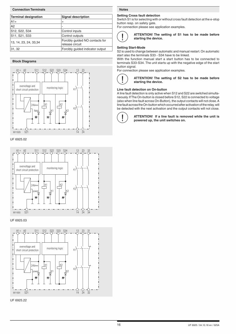
Setting Cross fault detectionSwitch S1 is for selecting with or without cross fault detection at the e-stop button resp. on safety gate.For connection please see application examples.
! ATTENTION! The setting of S1 has to be made before starting the device.
Setting Start-ModeS2 is used to change between automatic and manual restart. On automatic start also the terminals S33 - S34 have to be linked.With the function manual start a start button has to be connected to terminals S33-S34. The unit starts up with the negative edge of the start button signal.For connection please see application examples.
! ATTENTION! The setting of S2 has to be made before starting the device.
Line fault detection on On-buttonA line fault detection is only active when S12 and S22 are switched simulta-neously. If The On-button is closed before S12, S22 is connected to voltage (also when line fault across On-Button), the output contacts will not close. A line fault across the On-button which occurred after activation of the relay, will be detected with the next activation and the output contacts will not close.
! ATTENTION! If a line fault is removed while the unit is powered up, the unit switches on.
UF 6925.03
UF 6925.02
UF 6925.22
Block Diagrams
A1+ A2 S11 S12 S22 S33 S34 13 23
M11691 S21 14 24
K1
K2
K1
24V K2
K2K1
31
32
power
overvoltage and
short circuit protectionmonitoring logic
A1+ A2 S11 S12 S22 S33 S34 13 23
M11693 S21 14 24
K1
K2
K1
power
24V K2
K2K1
33
34
overvoltage and
short circuit protectionmonitoring logic
A1+ A2 S11 S12 S22 S33 S34 13 23
M11929 S21 14 24
K1
K2
K1
Netz
24V K2
K2K1
overvoltage and
short circuit protectionmonitoring logic
Connection Terminals
Terminal designation Signal descriptionA1+ +
A2 -
S12, S22, S34 Control inputs
S11, S21, S33 Control outputs
13, 14, 23, 24, 33,34Forcibly guided NO contacts for release circuit
31, 32 Forcibly guided indicator output

17 UF 6925 / 04.10.18 en / 025A
Technical Data Technical Data
Standard Type
Input
Nominal Voltage UN: DC 24 V, DC 8 ... 36 V The power supply shall meet the requirements of SELV / PELVVoltage rangeDC 24 V: 0.8 ... 1.1 UN
Nominal consumption at DC 24 V: < 1.6 WDC 8 ... 36 V: < 2.2 WMin. Off-time: 150 msControl voltage on S11 at not activated device: DC 23 V at UNControl current typ. overS12, S22: 30 mA at UN
Min. voltage on terminal S12at not activated device: DC 19 VShort-circuit protection: Internal PTCOvervoltage protection: Internal VDR
Output
ContactsUF 6925.02: 2 NO contactsUF 6925.03: 3 NO contactsUF 6925.22: 2 NO contacts, 1 NC contact
The NO contacts are safety contacts.The NC contacts 31-32 can only be used for monitoring.
Operating time at UN: < 350 msRelease delay at UN: in case of break ofsupply voltage: DC 24 V: < 20 msDC 8 ... 36 V: < 90 msin case of break of S12, S22: < 25 msContact type: Relay, forcibly guidedThermal current Ith: max. 8 A (see quadratic total current limit curve)Switching capacity to AC 15NO contact: 3 A / AC 230 V IEC/EN 60 947-5-1NC contact: 1 A / AC 230 V IEC/EN 60 947-5-1to DC 13NO contact: 2 A / 24 V IEC/EN 60 947-5-1NC contact: 2 A / 24 V IEC/EN 60 947-5-1to DC 13NO contact: 4 A / 24 V at 0.1 Hz IEC/EN 60 947-5-1NC contact: 4 A / 24 V at 0.1 Hz IEC/EN 60 947-5-1Electrical life at AC 230 V, 8 A, cos ϕ = 1: > 1.0 x 10⁵ switching cycles (at 1 s On, 1s Off)Permissible operatingfrequency: max. 1 200 Schaltspiele / hShort circuit strength max. fuse rating: 8 A gG / gL IEC/EN 60 947-5-1line circuit breaker: B 6 AMechanical life: > 40 x 106 switching cycles
General Data
Operating mode: Continuous operationTemperature rangeOperation: - 25 ... + 55 °CStorage: - 25 ... + 85 °CAltitude: < 2,000 mClearance and creepagedistancesRated impuls voltage / pollution degree: 4 kV / 2 IEC 60 664-1EMC: IEC/EN 61 326-3-1Interference suppression DC 24 V: Limit value class B EN 55 011DC 8 ... 36 V: Limit value class A*) EN 55 011 *) The device is designed for the usage under industrial conditions (Class A, EN 55011). When connected to a low voltage public system (Class B, EN 55011) radio interference can be generated. To avoid this, appropriate measures have to be taken.
Degree of protection: Housing: IP 40 IEC/EN 60 529Terminals: IP 20 IEC/EN 60 529Housing: thermoplastic with V0 behaviour according to UL subject 94Vibration resistance: Amplitude 0,35 mm Frequenz 10 ... 55 Hz, IEC/EN 60 068-2-6Climate resistance: 25 / 055 / 04 IEC/EN 60 068-1Terminal designation: EN 50 005Mounting: DIN rail IEC/EN 60 715Weight: 140 g
Dimensions
Width x height x depth: 17.5 x 110 x 120 mm
UF 6925.03/61 DC 8 ... 36 VArticle number: 0067556• Output: 3 NO contacts• Nominal voltage UN: DC 8 ... 36 V• Width: 17.5 mm
The safety functions were not evaluated by UL. Listing is accomplishedaccording to requirements of Standard UL60947, “general useapplications”
Standards: - ANSI/UL 60947-1, 5th Edition (Low-Voltage Switchgear and Controlgear
Part1: General rules) - ANSI/UL 60947-5-1, 3th Edition (Low-Voltage Switchgear and Controlgear
Part5-1: Control circuit Devices an Switching Elements - Electro- mechanical Control Circuits Devices) - CAN/CSA-C22.2 No. 60947-1-13, 2nd Edition (Low-Voltage Switch-
gear and Controlgear - Part1: General rules) - CAN/CSA-C22.2 No. 60947-1-14, 1st Edition (Low-Voltage Switch-
gear and Controlgear - Part5-1: Control circuit Devices an Switching Elements - Electromechanical Control Circuits Devices)
Switching capacity:UF 6925.03: Pilot duty B300, Q300 6A 250Vac Resistive 6A 24Vdc Resistive
UF 6925.02, UF 6925.22: Pilot duty B300, Q300 8A 250Vac Resistive 8A 24Vdc Resistive
Wire connection: min. 60°C copper conductors AWG 28 - 14
nfoTechnical data that is not stated in the UL-Data, can be found in the technical data section.
UL-Data

18 UF 6925 / 04.10.18 en / 025A
M11445
25
I2
(A )2
75
100
125
50
0 10 20 30 40 6050T ( C)°
- current in contact pathsI , I1 2
� I = I + I2 2 2
1 2
device mounted without distance heated by
devices with same load,
max. current at over
4A = 2x4 A = 32A
55°C
2 contact path =2 2 2
^
device free-standing
max. current at 55°C over
2 contact path = 8A = 2x8 A = 128A2 2 2
^
Quadratic total current limit curve DC 24 V
M11442
25
I2
(A )2
75
100
125
50
0 10 20 30 40 6050T ( C)°
- current in contact pathsI , I1 2
� I = I + I2 2 2
1 2
device mounted without distance heated by
devices with same load,
max. current at over
4A = 2x4 A = 32A
55°C
2 contact path =2 2 2
^
device free-standing
max. current at 55°C over
2 contact path = 8A = 2x8 A = 128A2 2 2
^
Quadratic total current limit curve DC 8 - 36 V
Characteristics
Failure Potential cause
LED "Power" does not light up - Power supply not connected- Cross fault between S11 and S21
LED "K1" lights up, but "K2" remains off
- Safety relay K1 is welded (replace device)- A 1-channel switch-off occurred on S12 (switch channel off on S22)
LED "K2" lights up, but "K1" remains off
- Safety relay K2 is welded (replace device)- A 1-channel switch-off occurred on S22 (switch channel off on S12)
Device cannot be activated - A safety relay is welded (replace device)- Incorrect setting of switch S1Manual start mode:- Line fault on start-button (disconnect power supply and remove fault)Automatic start mode:- S33-S34 not bridged
- The device contains no parts that require maintenance.- In case of failure, do not open the device but send it to manufacturer for repair.
Troubleshooting
Maintenance and repairsVariants
UF 6925._ _ /1 _ _:For switching small loads of 10 mVA ... 12 VA bzw. 10 mW ... 12 W in the ranges 2 ... 60 V und 2 ... 300 mA. The device is also suitable for switching the maximum switching current.However, this will burn off the gold plating of the contacts, so that switchingof small loads is no longer possible afterwards.
Ordering example for variants
UF 6925 .03 /_ _ _ /61 DC 8 ... 36 V
Nominal voltage DC 8 ... 36 V
UL-approval
Cross fault detection 0 = adjustable
Start-Mode 0 = adjustable
Switching capacity 0 = Standard 1 = for small loads (2 ...60 V, 2...300 mA)
Contacts .02 = 2 NO contacts .03 = 3 NO contacts .22 = 2 NO contacts, 1 NC contact
Type
UF 6925 .02 /_ _ _ /61 DC 24 V
Nominal voltage DC 24V
UL-approval
Cross fault detection 1 = without cross fault detection 2 = with cross fault detection
Start-Mode 1 = Auto-Start 2 = Manual-Start
Switching capacity 0 = Standard
Contacts .02 = 2 NO contacts .03 = 3 NO contacts
Type

19 UF 6925 / 04.10.18 en / 025A
Application Examples
Safety function for units with cross fault detection (pay attention to "Unit Programming"!)
Safety function for units without cross fault detection (pay attention to "Unit Programming"!)
S22 S11 S12
M10768
emergency
stop
S21 S21 S22 S11 S12
Sliding door
is closed
M10778
Fct.: E-stop SIL 3, PL e, Cat. 4
Fct.: Safety gate SIL 3, PL e, Kat. 4
S22 S11 S12
M10772
emergency
stop
S21 S21 S22 S11 S12
Sliding door
is closed
M10770
Fct.: E-stop SIL 3, PL e, Cat. 4 1)
Fkt.: Safety gate SIL 3, PL e, Cat. 4 1)
1) To achieve the safety classifications a crossfault safe wiring has to be installed.
A jumper must be fitted S33 - S34 for the automatic On function. The On pushbutton is not required. The required start function has to be selected on switch S1 before starting the device. (see "Unit Programming"). Functioning of the external contactors is monitored by looping the NC contacts into the closing circuit (terminals S33 - S34).
DC24V
M11695
0V
A2
A1+ S21S33 S34 S22 S11 S12
UF6925
13 23
14 24
on K3
K4
K3 K4
33
34
safety function

20 UF 6925 / 04.10.18 en / 025A
E. DOLD & SÖHNE KG • D-78114 Furtwangene-mail: [email protected] • internet: http://www.dold.com
• PO Box 1251 • Telephone (+49) 77 23 / 654-0 • Telefax (+49) 77 23 / 654-356

21 UF 6925 / 04.10.18 fr / 025A
SAFEMASTER Module d'arrêt d'urgence UF 6925
0275136
Fiche Technique / Manuel d'utilisation FRANÇAIS
E. DOLD & SÖHNE KGB.P. 1251 • 78114 Furtwangen • AllemagneTél. +49 7723 6540 • Fax +49 7723 [email protected] • www.dold.com
Traduction de la notice originale

22 UF 6925 / 04.10.18 fr / 025A
Tables des matières
Explication des symboles et remarques ..........................................................................................................................23
Remarques ......................................................................................................................................................................23
Usage approprié ..............................................................................................................................................................23
Consignes de sécurité .....................................................................................................................................................23
Description du produit .....................................................................................................................................................25
Diagramme de fonctionnement ........................................................................................................................................25
Schémas ..........................................................................................................................................................................25
Homologations et sigles ..................................................................................................................................................25
Utilisations .......................................................................................................................................................................25
Affichages ........................................................................................................................................................................25
Borniers ...........................................................................................................................................................................26
Schémas-bloc ..................................................................................................................................................................26
Remarques ......................................................................................................................................................................26
Caractéristiques techniques ............................................................................................................................................27
Caractéristiques techniques ............................................................................................................................................27
Données UL .....................................................................................................................................................................27
Version standard ..............................................................................................................................................................27
Variantes ..........................................................................................................................................................................28
Diagnostics des défauts ..................................................................................................................................................28
Entretien et remise en état ..............................................................................................................................................28
Courbes caractéristiques .................................................................................................................................................28
Exemples d‘utilisation ......................................................................................................................................................29
Fonctions de sécurité pour les appareils avec détection des courts-circuits transversaux (Tenir compte de la remarque "Programmati-
on de l‘appareil") ..............................................................................................................................................................29
Fonctions de sécurité pour les appareils sans détection des courts-circuits transversaux (Tenir compte de la remarque "Programmati-
on de l‘appareil") ..............................................................................................................................................................29
Marquage et raccordements ............................................................................................................................................31
Dimensions (dimensions en mm) ....................................................................................................................................32
Programmation de l'appareil ............................................................................................................................................32
Données techniques sécuritaires ....................................................................................................................................33
Déclaration de conformité européenne ...........................................................................................................................34
Note .................................................................................................................................................................................35

23 UF 6925 / 04.10.18 fr / 025A
Consignes de sécurité
AVERTISSEMENT
Risque d'électrocution ! Danger de mort ou risque de blessure grave.• Assurez-vous que l'installation et l'appareil est et rese en l'état hors tension pendant l'installation électrique.• L'appareil peut uniquement être utilisé dans les cas d'application pré-
vus dans le mode d'emploi / la fiche technique. Les instructions de la documentation correspondante doivent être respectées. Les conditions ambiantes autorisées doivent être respectées.
• Respecter les prescriptions de la VDE et les prescriptions locales, et tout particulièrement les mesures de sécurité.
AVERTISSEMENT
Risques d'incendie et autres risques thermiques ! Danger de mort, risque de blessure grave ou dégâts matériels. • L'appareil peut uniquement être utilisé dans les cas d'application prévus
dans le mode d'emploi / la fiche technique. Les instructions de la documen-tation correspondante doivent être respectées. Les conditions ambiantes autorisées doivent être respectées. Respectez tout particulièrement la courbe des seuils de courant.
• L'appareil peut uniquement être installé et mis en service par un personnel dûment qualifié et familier avec la présente documentation technique et avec les prescriptions en vigueur relatives à la sécurité du travail et à la préservation de l'environnement.
AVERTISSEMENT
Erreur de fonctionnement ! Danger de mort, risque de blessure grave ou dégâts matériels. • L'appareil peut uniquement être utilisé dans les cas d'application pré-
vus dans le mode d'emploi / la fiche technique. Les instructions de la documentation correspondante doivent être respectées. Les conditions ambiantes autorisées doivent être respectées.
• L'appareil peut uniquement être installé et mis en service par un personnel dûment qualifié et familier avec la présente documentation technique et avec les prescriptions en vigueur relatives à la sécurité du travail et à la préservation de l'environnement.
• Le relais doit être monté en armoire ayant un indice de protection au moins IP 54; la poussière et l'humidité pouvant entraîner des disfonctionnements.
AVERTISSEMENT
Erreur d'installation ! Danger de mort, risque de blessure grave ou dégâts matériels. • Veillez à protéger suffisamment les contacts de sortie de charges ca-
pacitives et inductives.
! Attention! • La fonction de sécurité doit être activée lors de la mise en service.• L'élimination d'une erreur de ligne pendant que l'appareil est sous tension provoque l'enclenchement des contacts.• Ne pas commuters S1 et S2 pendant que l'appareil est sous tension. • ATTENTION - Démarrage Automatique ! Selon IEC/EN 60 204-1 Art. 9.2.5.4.2 il est interdit d’effectuer un re- démarrage automatique après un Arrêt d’urgence. Losqu’un démarrage automatique est toutefois demandé, il est necéssaire de assurer qu’une commande prioritaire effectue le blocage après une action d’arrêt d’urgence.• L'ouverture de l'appareil ou des transformations non autorisées annulent la garantie.
DANGER
DANGER: Indique que la mort ou des blessures graves vont survenir en
cas de non respect des précautions demandées.
AVERTISSEMENT
AVERTISSEMENT: Indique que la mort ou des blessures graves peuvent survenir
si les précautions appropriées ne sont pas prises.
PRUDENCE
PRUDENCE: Signifie qu'une blessures légère peut survenir si les précautions
appropriées ne sont pas prises.
! ATTENTION:
Met en garde contre les actions qui peuvent causer des dommages au materiel Software ou hardware suite à un mauvais fonctionne-ment de l'appareil ou de l'environnement de l'appareil.
nfo INFO:
Concerne les informations qui vous sont mises à disposition pour le meilleur usage du produit.
Explication des symboles et remarques
L'installation ne doit être effectuée que par un electricien qualifié
Ne pas jeter aux ordures ménagères! L'appareil doit être éliminé conformément aux prescriptions et
directives nationales en vigueur.
Pour vous aider à comprendre et trouver des passages et des notes de texte spécifiques dans les instructions d'utilisation, nous avons marquées les informations importantes avec des symboles.
Avant l'installation, la mise en service ou l'entretien de cet appareil, on doit avoir lu et compris ce manuel d'utilisation.
Usage approprié
Le produit décrit ici a été développé pour remplir les fonctions de sécurité en tant qu'élément d'une installation globale ou d'une machine. Un systè-me de sécurité complet inclut habituellement des détecteurs ainsi que des modules d'évaluation, de signalisation et de logique aptes à déclencher des coupures de courant sûres. La responsabilité d'assurer la fiabilité de l'ensemble de la fonction incombe au fabricant de l'installation ou de la ma-chine. DOLD n'est pas en mesure de garantir toutes les caractéristiques d'une installation ou d'une machine dont la conception lui échappe. C'est à l'utilisateur de valider la conception globale du système auquel ce relais est connecté. DOLD ne prend en charge aucune responsabilité quant aux recommandations qui sont données ou impliquées par la description sui-vante. Sur la base du présent manuel d'utilisation, on ne pourra déduire aucune modification concernant les conditions générales de livraison de DOLD, les exigences de garantie ou de responsabilité.
Remarques
Le UF 6925 permet le déclenchement d’un circuit électrique sécuritaire. Peut être utilisé pour la protection de personnes et de machines en com-binaison avec des BP d’arrêt d’urgence et portes de sécurité.En cas d'emploi approprié et d'observation de ces instructions, on ne connaît aucun risque résiduel. Dans le cas contraire, on encourt des riques de dommages corporels et matériels.
Stockage pour référence future

24 UF 6925 / 04.10.18 fr / 025A

25 UF 6925 / 04.10.18 fr / 025A
0275
136
Vos avantages• Pour applications sécuritaires jusqu’à Pl e / Cat 4 resp. SIL 3 • Encombrement réduit• Raccordement de l'appareil frontal• Démarrage manuel ou automatique• Convient également pour des portes de protection• Détection de défaut de court-circuit sur le bouton Marche
Propriétés• Satisfait aux exigences: - Performance Level (PL) e et Catégorie 4 selon EN ISO 13849-1 - Valeur limite SIL demandée (SIL CL) 3 selon IEC/EN 62061 - Safety Integrity Level (SIL) 3 selon IEC/EN 61508 et IEC/EN 61511• Selon EN 50156-1 pour installations de chauffage• Exécution à 2 canaux• Contacts de sorties liés• Avec ou sans détection des courts-circuits transversaux dans le circuit de commande, commutateur S1• Activation manuelle par le bouton Marche ou fonction Marche automatique, commutateur S2• Visualisation par DEL pour canal 1 / 2 et réseau• Largeur utile 17,5 mm
• Protection des personnes et machines• Couplages d'arrêt d'urgence des machines• Contrôle des interrupteurs de position sur une porte de protection
Le module d'arrêt d'urgence UF 6925 protège les personnes et machines grâce à l'acquittement et l'interruption sécuritaire des circuits de sécurité. Il est utilisé en association avec des boutons d'arrêt d'urgence et des portes de protection.
DEL verte réseau: allumée en présence de la tension de serviceDEL verte K1: allumée quand le relais K1 est alimentéDEL verte K2: allumée quand le relais K2 est alimenté
bouton d‘arrêt
d‘urgence
bouton marche
K2
K1
M11690
Technique de sécurité
SAFEMASTERModule d'arrêt d'urgence UF 6925
Description du produit
Diagramme de fonctionnement
Utilisations
Affichages
Homologations et sigles
Canada / USA
Schémas
S11
A2
A1
+
M11947
13
K1
K2
23
14 24
S22
S21
S12
S34
S33
24
23
13
14
S11
A2
A1
+
M11315
13
K1
K2
23
14 24
33
34
S22
S21
S12
S34
S33
13
34
33
23
14
24
S11
A2
A1
+
M11314
13
K1
K2
23
14 24
31
32
S22
S21
S12
S34
S33
13
32
31
23
14
24
UF 6925.03 UF 6925.22UF 6925.02
Toutes les caractéristiques données dans cette notice correspondent à l’édition en cours. Nous nousréservons le droit de procéder à tout moment aux améliorations ou modifications techniques nécessaires.
26 UF 6925 / 04.10.18 fr / 025A
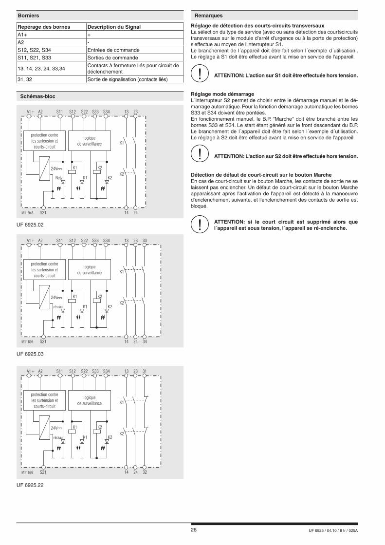
Réglage de détection des courts-circuits transversauxLa sélection du type de service (avec ou sans détection des courtscircuits transversaux sur le module d'arrêt d'urgence ou à la porte de protection) s'effectue au moyen de l'interrupteur S1.Le branchement de l´appareil doit être fait selon l´exemple d´utilisation.. Le règlage à S1 doit être effectué avant la mise en service de l'appareil.
! ATTENTION: L'action sur S1 doit être effectuée hors tension.
Réglage mode démarrageL´interrupteur S2 permet de choisir entre le démarrage manuel et le dé-marrage automatique. Pour la fonction démarrage automatique les bornes S33 et S34 doivent être pontées.En fonctionnement manuel, le B.P. "Marche" doit être branché entre les bornes S33 et S34. Le start étant généré sur le front descendant du B.P. Le branchement de l´appareil doit être fait selon l´exemple d´utilisation. Le réglage à S2 doit être effectué avant la mise en service de l'appareil.
! ATTENTION: L'action sur S2 doit être effectuée hors tension.
Détection de défaut de court-circuit sur le bouton MarcheEn cas de court-circuit sur le bouton Marche, les contacts de sortie ne se laissent pas enclencher. Un défaut de court-circuit sur le bouton Marche apparaissant après l'activation de l'appareil est détecté à la manoeuvre d'enclenchement suivante, et l'enclenchement des contacts de sortie est bloqué.
! ATTENTION: si le court circuit est supprimé alors que l´appareil est sous tension, l´appareil se ré-enclenche.
RemarquesBorniers
Repérage des bornes Description du SignalA1+ +
A2 -
S12, S22, S34 Entrées de commande
S11, S21, S33 Sorties de commande
13, 14, 23, 24, 33,34Contacts à fermeture liés pour circuit de déclenchement
31, 32 Sortie de signalisation (contacts liés)
UF 6925.03
UF 6925.02
A1+ A2 S11 S12 S22 S33 S34 13 23
M11694 S21 14 24
K1
K2
K1
24V K2
K2K1
33
34
réseau
protection contre
les surtension et
courts-circuit
logique
de surveillance
A1+ A2 S11 S12 S22 S33 S34 13 23
M11692 S21 14 24
K1
K2
K1
24V K2
K2K1
31
32
réseau
protection contre
les surtension et
courts-circuit
logique
de surveillance
UF 6925.22
Schémas-bloc
A1+ A2 S11 S12 S22 S33 S34 13 23
M11946 S21 14 24
K1
K2
K1
Netz
24V K2
K2K1
protection contre
les surtension et
courts-circuit
logique
de surveillance

27 UF 6925 / 04.10.18 fr / 025A
Entrée
Tension assignée UN: DC 24 V, DC 8 ... 36 V L‘alimentation devant répondre aux exigences d‘une alimentation TBTS/TBTPPlage de tension DC 24 V: 0,8 ... 1,1 UNConsom. nominale sousDC 24 V: < 1,6 WDC 8 ... 36 V: < 2,2 WDurée minimale de coupure: 150 msTension de commandesur S11, appareil non activé: DC 23 V sous UNCourant de commande (typ.) par S12 ou S22: 30 mA sous UNTension minimale sur borne S12, appareil non activé: DC 19 VProtection du module: interne par PTCProtection contre lessurtensions: interne par VDR
Sortie
Garnissage en contactsUF 6925.02: 2 contacts NOUF 6925.03: 3 contacts NOUF 6925.22: 2 contacts NO, 1 contact NF
Les lignes de contacts à fermeture peuvent être utilisées pour des déclenchements sécuritaires. Les contacts de la ligne 31-32 sont des contacts de signalisation.Temps de réponse sous UN: < 350 msTemps de retombée sous UN:en cas de coupure de latension d'alimentation: DC 24 V: < 20 msDC 8 ... 36 V: < 90 mssi interruption dans S12, S22: < 25 msType de contacts: relais, contacts liésCourant thermique Ith: max. 8 A (voir courbe limite de totalisation de courant)Pouvoir de coupure selon AC 15contact NO: 3 A / AC 230 V IEC/EN 60 947-5-1contact NF: 1 A / AC 230 V IEC/EN 60 947-5-1selon DC 13contact NO: 2 A / 24 V IEC/EN 60 947-5-1contact NF: 2 A / 24 V IEC/EN 60 947-5-1basée sur DC 13contact NO: 4 A / 24 V à 0,1 Hz IEC/EN 60 947-5-1contact NF: 4 A / 24 V à 0,1 Hz IEC/EN 60 947-5-1Longévité électrique en AC 230 V, 8 A, cos ϕ = 1: > 1,0 x 10⁵ manoeuvres (pour 1 s marche, 1 s arrêt)Cadence admissible: 1 200 manoeuvres / h max. Tenue aux courts-circuitscalibre max. de fusible: 8 A gG / gL IEC/EN 60 947-5-1disjoncteur: B 6 ALongévité mécanique: > 40 x 106 manoeuvres
Caractéristiques générales
Type nominal de service: service permanentPlage de températuresopération: - 25 ... + 55 °Cstockage: - 25 ... + 85 °CAltitude: < 2.000 mDistances dans l'airet lignes de fuitecatégorie de surtension /degré de contamination: 4 kV / 2 IEC 60664-1CEM: IEC/EN 61 326-3-1AntiparasitageDC 24 V: seuil classe B EN 55011DC 8 ... 36 V: seuil classe A*) EN 55011 *) L'appareil est prévu pour une utilisation en environnement industriel (Classe A, EN 55011). Le branchement de l'appareil à un réseau basse tension (Classe B, EN 55011) peut générer des probèmes radio. Des mesures d'immunisation consé quentes doivent être installées.
Degré de protectionboîtier: IP 40 IEC/EN 60529bornes: IP 20 IEC/EN 60529Boîtiers: thermoplastique à comportement V0 selon UL Subj. 94Résistance aux vibrations: Amplitude 0,35 mm Frequenz 10 ... 55 Hz, IEC/EN 60 068-2-6Résistance climatique: 25 / 055 / 04 IEC/EN 60068-1Repérage des bornes: EN 50005Fixation instantanée: sur rail IEC/EN 60715Poids net: 140 g
Dimensions largeur x hauteur x profondeur
17,5 x 110 x 120 mm
UF 6925.03/61 DC 8 ... 36 VRéférence: 0067556• Sortie: 3 contacts NO• Tension assignée UN: DC 8 ... 36 V• Largeur utile: 17,5 mm
Caractéristiques techniques Caractéristiques techniques
Version standard
Les fonctions sécuritaires de l‘appareil n‘ont pas été analyséespar UL. Le sujet de l‘homologation est la conformité aux standardsUL60947, “general use applications“
Standards: - ANSI/UL 60947-1, 5th Edition (Low-Voltage Switchgear and Controlgear
Part1: General rules) - ANSI/UL 60947-5-1, 3th Edition (Low-Voltage Switchgear and Controlgear
Part5-1: Control circuit Devices an Switching Elements - Electro- mechanical Control Circuits Devices) - CAN/CSA-C22.2 No. 60947-1-13, 2nd Edition (Low-Voltage Switch-
gear and Controlgear - Part1: General rules) - CAN/CSA-C22.2 No. 60947-1-14, 1st Edition (Low-Voltage Switch-
gear and Controlgear - Part5-1: Control circuit Devices an Switching Elements - Electromechanical Control Circuits Devices)
Pouvoir de coupureUF 6925.03: Pilot duty B300, Q300 6A 250Vac Resistive 6A 24Vdc Resistive
UF 6925.02, UF 6925.22: Pilot duty B300, Q300 8A 250Vac Resistive 8A 24Vdc Resistive
Connectique: min. 60°C conducteur cuivre AWG 28 - 14
nfoLes valeurs techniques qui ne sont pas spécifiées ci-dessussont spécifiées dans les valeurs techniques générales.
Données UL
28 UF 6925 / 04.10.18 fr / 025A
M11446
25
I2
(A )2
75
100
125
50
0 10 20 30 40 6050T ( C)°
- Courant dans les lignes de contactsI , I1 2
� I = I + I2 2 2
1 2
Appareils accolés, échauffement externe supplémentaire
par d’autres appareils adjacents
courant max à 55°C au travers
des 2 lignes de contacts 4A = 2x4 A = 32A=2 2 2
^
appareil autonome
max. intensité à 55°C par
=des 2 lignes de contacts 8A = 2x8 A = 128A2 2 2
^
Courbe limite de courant totalisateur DC 24 V
M11443
25
I2
(A )2
75
100
125
50
0 10 20 30 40 6050T ( C)°
- Courant dans les lignes de contactsI , I1 2
� I = I + I2 2 2
1 2
Appareils accolés, échauffement externe supplémentaire
par d’autres appareils adjacents
courant max à 55°C au travers
des 2 lignes de contacts 4A = 2x4 A = 32A=2 2 2
^
appareil autonome
max. intensité à 55°C par
=des 2 lignes de contacts 8A = 2x8 A = 128A2 2 2
^
Courbe limite de courant totalisateur DC 8 - 36 V
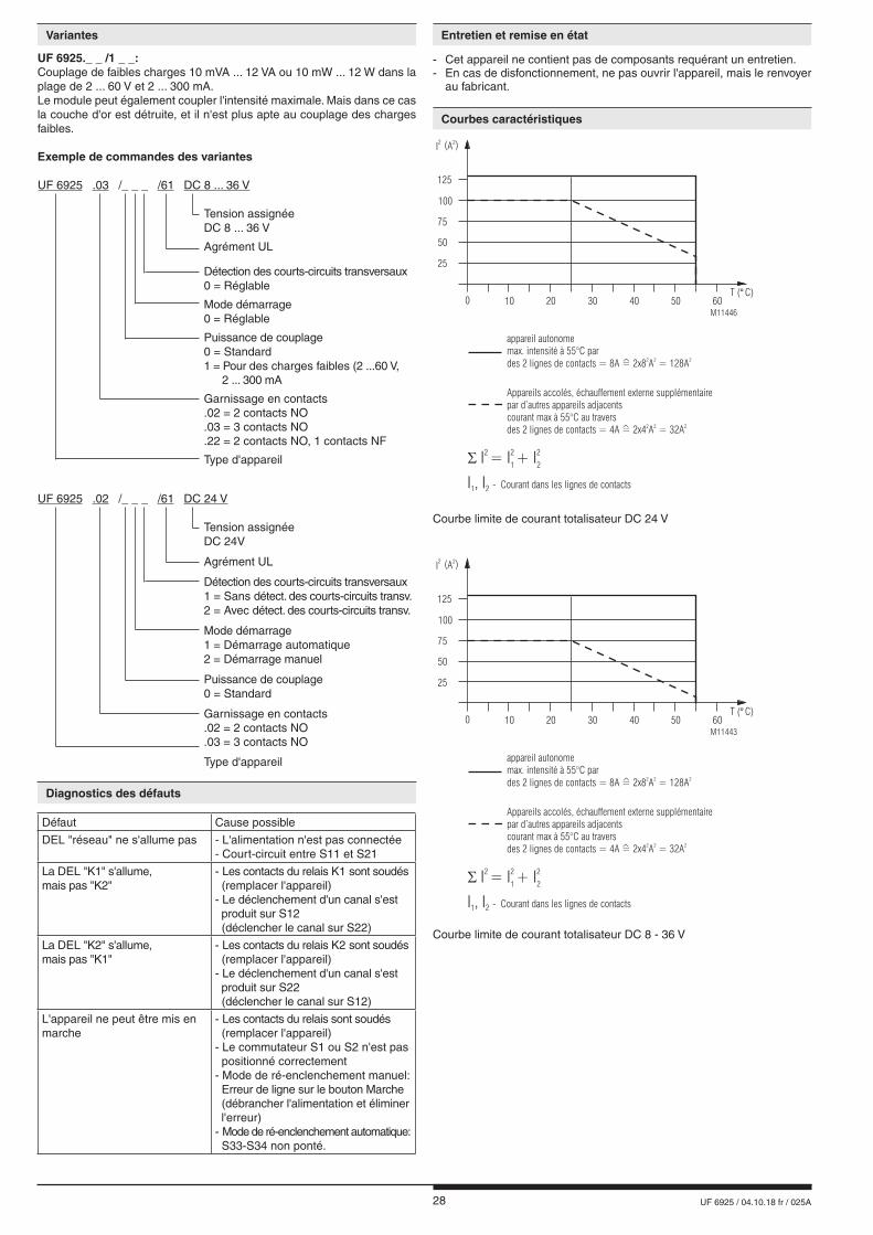
Courbes caractéristiques
Diagnostics des défauts
Entretien et remise en état
Défaut Cause possible
DEL "réseau" ne s'allume pas - L'alimentation n'est pas connectée- Court-circuit entre S11 et S21
La DEL "K1" s'allume,mais pas "K2"
- Les contacts du relais K1 sont soudés (remplacer l'appareil) - Le déclenchement d'un canal s'est produit sur S12 (déclencher le canal sur S22)
La DEL "K2" s'allume,mais pas "K1"
- Les contacts du relais K2 sont soudés (remplacer l'appareil) - Le déclenchement d'un canal s'est produit sur S22 (déclencher le canal sur S12)
L'appareil ne peut être mis en marche
- Les contacts du relais sont soudés (remplacer l'appareil) - Le commutateur S1 ou S2 n'est pas positionné correctement- Mode de ré-enclenchement manuel: Erreur de ligne sur le bouton Marche (débrancher l'alimentation et éliminer l'erreur) - Mode de ré-enclenchement automatique: S33-S34 non ponté.
- Cet appareil ne contient pas de composants requérant un entretien.- En cas de disfonctionnement, ne pas ouvrir l'appareil, mais le renvoyer au fabricant.
Variantes
UF 6925._ _ /1 _ _:Couplage de faibles charges 10 mVA ... 12 VA ou 10 mW ... 12 W dans laplage de 2 ... 60 V et 2 ... 300 mA. Le module peut également coupler l'intensité maximale. Mais dans ce cas la couche d'or est détruite, et il n'est plus apte au couplage des charges faibles.
Exemple de commandes des variantes
UF 6925 .03 /_ _ _ /61 DC 8 ... 36 V
Tension assignée DC 8 ... 36 V
Agrément UL
Détection des courts-circuits transversaux 0 = Réglable
Mode démarrage 0 = Réglable
Puissance de couplage 0 = Standard 1 = Pour des charges faibles (2 ...60 V, 2 ... 300 mA
Garnissage en contacts .02 = 2 contacts NO .03 = 3 contacts NO .22 = 2 contacts NO, 1 contacts NF
Type d'appareil
UF 6925 .02 /_ _ _ /61 DC 24 V
Tension assignée DC 24V
Agrément UL
Détection des courts-circuits transversaux 1 = Sans détect. des courts-circuits transv. 2 = Avec détect. des courts-circuits transv.
Mode démarrage 1 = Démarrage automatique 2 = Démarrage manuel
Puissance de couplage 0 = Standard
Garnissage en contacts .02 = 2 contacts NO .03 = 3 contacts NO
Type d'appareil
29 UF 6925 / 04.10.18 fr / 025A
S22 S11 S12
M10769
d'arrêt
d'urgence
S21 S21 S22 S11 S12
Porte coulissante
est fermeé
M10779
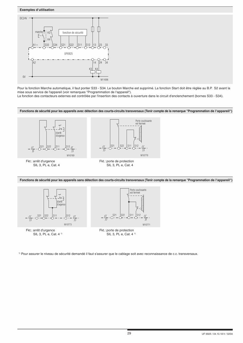
Fkt.: arrêt d'urgence SIL 3, PL e, Cat. 4
Fkt.: porte de protection SIL 3, PL e, Cat. 4
S22 S11 S12
M10773
d'arrêt
d'urgence
S21 S21 S22 S11 S12
Porte coulissante
est fermeé
M10771
Fkt.: arrêt d'urgence SIL 3, PL e, Cat. 4 1)
Fkt.: porte de protection SIL 3, PL e, Cat. 4 1)
1) Pour assurer le niveau de sécurité demandé il faut s'assurer que le cablage soit avec reconnaissance de c.c. transversaux.
Pour la fonction Marche automatique, il faut ponter S33 - S34. Le bouton Marche est supprimé. La fonction Start doit être règlée au B.P. S2 avant la mise sous service de l'appareil (voir remarques "Programmation de l‘appareil"). La fonction des contacteurs externes est contrôlée par l'insertion des contacts à ouverture dans le circuit d'enclenchement (bornes S33 - S34).
DC24V
M11696
0V
A2
A1+ S21S33 S34 S22 S11 S12
UF6925
13 23
14 24
marche K3
K4
K3 K4
33
34
fonction de sécurité
Exemples d‘utilisation
Fonctions de sécurité pour les appareils avec détection des courts-circuits transversaux (Tenir compte de la remarque "Programmation de l‘appareil")
Fonctions de sécurité pour les appareils sans détection des courts-circuits transversaux (Tenir compte de la remarque "Programmation de l‘appareil")

30 UF 6925 / 04.10.18 fr / 025A
E. DOLD & SÖHNE KG • D-78114 Furtwangene-mail: [email protected] • internet: http://www.dold.com
• B.P. 1251 • Téléphone (+49) 77 23 / 654-0 • Téléfax (+49) 77 23 / 654-356

31 UF 6925 / 04.10.18 de / en / fr / 025A
DE Beschriftung und Anschlüsse
EN Labeling and connections
FR Marquage et raccordements
M11697
DIN 5264-A; 0,5 x 3
M10248
A A = 8 mm1 x 0,2 ... 1,5 mm2
1 x AWG 24 to 16
M10249
A A = 8 mm1 x 0,25 ... 0,75 mm2
1 x AWG 24 to 16
M10250
A A = 8 mm1 x 0,2 ... 1,5 mm2
1 x AWG 24 to 16

32 UF 6925 / 04.10.18 de / en / fr / 025A
DE Maßbild (Maße in mm)
EN Dimensions (dimensions in mm)
FR Dimensions (dimensions en mm)
DE Geräteprogrammierung
EN Setting
FR Programmation de l'appareil
DE Zur Einstellung der Funktionen Automatischer Start, Hand-Start und mit oder ohne Querschlusserkennung sind die Schalter S1 und S2 vorgesehen. Diese Schalter befinden sich hinter der Abdeckplatte auf der Unterseite des Gerätes. Die Schalter S1 und S2 dürfen nur bei unbestromtem Gerät betätigt werden!Die Schalterstellung zeigt den Lieferzustand.
EN The selection of the functions auto start, manual start, with or without cross fault monitoring is done with switches S1 and S2. These switches are located behind a cover at the bottom of the device. The setting of S1 and S2 has to be made before starting the device. Disconnect unit before setting of S1 and S2!Drawing shows setting at the state of delivery.
FR Pour les choix d'options (démarrage automatique, démarrage manuel et arrêt d'urgence avec ou sans détection des courts-circuits transver-saux), on dispose des interrupteurs S1 et S2 situés derrière la plaque de dessous de l'appareil. Commutation de S1et S2 uniquement hors tension!Appareil livré tel que sur le schéma.
M2
0189_
a
M11589_a
DE S1 Querschlußerkennung mit ohne
FR S1 Transversal avec sans
DE S2 Start Hand Auto
FR S2 Reset Manu Auto
M2
01
91_
a
17,5 - 0
0,5+
122,6 - 0
0,7+
115,3 - 0
0,7+
106,9
35

33 UF 6925 / 04.10.18 de / en / fr / 025A
DE Sicherheitstechnische Kenndaten
EN Safety Related Data
FR Données techniques sécuritaires
nfo
DE Die angeführten Kenndaten gelten für die Standardtype. Sicherheitstechnische Kenndaten für andere Geräteausführungen erhalten Sie auf Anfrage.
Die sicherheitstechnischen Kenndaten der kompletten Anlagemüssen vom Anwender bestimmt werden.
EN The values stated above are valid for the standard type.Safety data for other variants are available on request.
The safety relevant data of the complete system has to be determined by the manufacturer of the system.
FR Les valeurs données sont valables pour les produits standards.Les valeurs techniques sécuritaires pour d‘autres produits spéciaux sont disponibles sur simple demande.
Les données techniques sécuritaires de l'installation complète doivent être définies par l'utilisateur.
Anforderung seitens der Sicherheits- funktion an das Gerät im High Demand Mode
Intervall für zyklische Überprüfung der Sicherheitsfunktion
Demand to our device based on the evaluated neccessary safety level of the application at High Demand Mode
Intervall for cyclic test of the safety function
Consigne résultante de la fonction sécuritaire de l'appareilau High Demand Mode
Intervale du contrôle cyclique de la fonction sécuritaire
nach, acc. to, selonEN ISO 13849-1
PL e with Cat. 3 or Cat. 4
einmal pro Monatonce per monthmensuel
PL d with Cat. 3
einmal pro Jahronce per yearannuel
nach, acc. to, selon IEC/EN 62061, IEC/EN 61508
SIL CL 3,SIL 3with HFT = 1
einmal pro Monatonce per monthmensuel
SIL CL 2,SIL 2with HFT = 1
einmal pro Jahronce per yearannuel
EN ISO 13849-1:
Kategorie / Category: 4
PL: e
MTTFd: 284,6 a (year)
DCavg: 99,0 %
dop: 365 d/a (days/year)
hop: 24 h/d (hours/day)
tcycle: 3600 s/cycle
= 1 /h (hour)
IEC/EN 62061IEC/EN 61508IEC/EN 61511:
SIL CL: 3 IEC/EN 62061
SIL 3 IEC/EN 61508 /IEC/EN 61511
HFT*): 1
DC: 99,0 %
PFHD: 8,30E-11 h-1
PFDAVG: 9,10E-05 (Low Demand Mode)
T1: 20 a (year)*) HFT = Hardware-Fehlertoleranz Hardware failure tolerance Tolérance défauts Hardware
34 UF 6925 / 04.10.18 de / en / fr / 025A
DE EG-Konformitätserklärung
EN CE-Declaration of Conformity
FR Déclaration de conformité européenne
35 UF 6925 / 04.10.18 de / en / fr / 025A
DE Notizen
EN Notice
FR Note

36 UF 6925 / 04.10.18 de / en / fr / 025A
E. DOLD & SÖHNE KG • D-78114 Furtwangene-mail: [email protected] • internet: http://www.dold.com
• Postfach 1251 • Telefon 0 77 23 / 654-0 • Telefax 0 77 23 / 654-356