Embed Size (px)
Citation preview

DE DE
DE
EN
Montage- und Betriebsanleitung | Installation and Operating Instructions
WECHSELKOPF-BOHRER TTD TRITAN REPLACEABLE HEAD DRILL TTD TRITAN

Montage- und Betriebsanleitung Installation and Operating Instructions
3
E DE
Inhaltsverzeichnis
Ziel der Betriebsanleitung .................................................................................... 4 1
Kontakt ..................................................................................................................... 4 2
Sicherheit ................................................................................................................. 5 3
3.1 Zielgruppe .................................................................................................................................. 5
3.2 Bestimmungsgemäße Verwendung ..................................................................................... 5
3.3 Nicht bestimmungsgemäße Verwendung .......................................................................... 5
3.4 Gewährleistung ........................................................................................................................ 5
3.5 Allgemeine Warn- und Sicherheitshinweise ..................................................................... 6
Allgemeine Informationen ................................................................................... 7 4
4.1 Darstellung eines Wechselkopf-Bohrers TTD Tritan mit Zubehör ................................. 7
4.2 Darstellung eines Wechsel-Bohrkopfs ................................................................................ 8
4.3 Darstellung der Unterseite des Wechselkopf-Halters ..................................................... 9
4.4 Schnittwertempfehlung ...................................................................................................... 10
4.5 Benötigte Werkzeuge, Hilfs- und Betriebsstoffe ........................................................... 12
4.6 Technische Daten .................................................................................................................. 12
4.7 Zubehör ................................................................................................................................... 12
Werkzeugmontage ...............................................................................................13 5
5.1 Montieren der Spezialspannschraube am Wechsel-Bohrkopf ................................... 13
5.2 Montieren des Wechsel-Bohrkopfs am Wechselkopf-Halter ..................................... 14
5.3 Lösen des Wechsel-Bohrkopfs ........................................................................................... 17
Hinweise für die Praxis .......................................................................................18 6
4
Montage- und Betriebsanleitung Installation and Operating Instructions Installation and Operating Instructions
DE
Ziel der Betriebsanleitung 1Die vorliegende Montage- und Betriebsanleitung beschreibt die richtige Bedie-nung des Wechselkopf-Bohrers TTD Tritan. Im Detail erhalten Sie Informationen, wie Sie den Wechsel-Bohrkopf am Wechselkopf-Halter TTS montieren und de-montieren. Zusätzlich werden die wichtigsten Sicherheitshinweise beim Umgang mit dem Wechselkopf-Bohrer TTD Tritan erläutert. Der Wechsel-Bohrkopf TTD Tritan wird zukünftig im Dokument als Wechsel-Bohrkopf bezeichnet. Der Wechselkopf-Halter TTS wird zukünftig im Dokument als Wechselkopf-Halter be-zeichnet.
Nachfolgend erhalten Sie in Kapitel 5 eine detaillierte Beschreibung der einzelnen Funktionen und Handlungsschritte, die zum erfolgreichen Montieren und Lösen des Wechselkopf-Bohrers notwendig sind.
Die Montage- und Betriebsanleitung ist Bestandteil des Wechselkopf-Bohrers und muss in unmittelbarer Nähe des Wechselkopf-Bohrers für das Personal jederzeit zugänglich aufbewahrt werden. Grundvoraussetzung für sicheres Arbeiten ist die Einhaltung aller angegebenen Sicherheitshinweise und Handlungsanweisungen in dieser Montage- und Betriebsanleitung.
Darüber hinaus gelten die örtlichen Arbeitsschutzvorschriften und allgemeinen Sicherheitsbestimmungen für den Einsatzbereich des Wechselkopf-Bohrers. Ab-bildungen in dieser Montage- und Betriebsanleitung dienen dem grundsätzlichen Verständnis und können von der tatsächlichen Ausführung abweichen.
Kontakt 2
MAPAL Fabrik für Präzisionswerkzeuge Dr. Kress KG
Adresse Obere Bahnstraße 13 D-73431 Aalen
Telefon +49 (0) 7361 585-0
Fax +49 (0) 7361 585-1029
E-Mail [email protected]
Internet www.mapal.com
Montage- und Betriebsanleitung Installation and Operating Instructions
5
DE
Sicherheit 3
3.1 Zielgruppe
Die Bedienung des Wechselkopf-Bohrers darf nur durch ausgebildetes, autorisier-tes und zuverlässiges Fachpersonal erfolgen. Das Fachpersonal muss Gefahren er-kennen und vermeiden können und muss hierzu dieses Dokument vor der Ver-wendung des Wechselkopf-Bohrers gelesen und verstanden haben.
Die Unfallverhütungsvorschriften, Sicherheitsbestimmungen und -vorschriften des Maschinenherstellers sind dem Fachpersonal bekannt und vom Fachpersonal bei der Bedienung des Wechselkopf-Bohrers zu beachten und einzuhalten.
3.2 Bestimmungsgemäße Verwendung
Der Wechselkopf-Bohrer dient ausschließlich der zerspanenden Fertigung von metallischen Werkstoffen in Bearbeitungsmaschinen im industriellen Einsatz.
Der Wechselkopf-Bohrer darf nur verwendet werden, wenn die Einhaltung aller Angaben dieser Betriebsanleitung gewährleistet ist.
3.3 Nicht bestimmungsgemäße Verwendung
Der Wechselkopf-Bohrer darf nur entsprechend der technischen Daten ein-gesetzt werden (siehe Kapitel 4.6 Technische Daten).
Der Wechselkopf-Bohrer und seine Komponenten dürfen nicht verändert und für andere Anwendungen erschlossen werden.
Im Falle von eigenmächtigen Veränderungen am Wechselkopf-Bohrer oder von nicht bestimmungsgemäßer Verwendung erlischt der Gewährleistungs-anspruch gegenüber MAPAL.
Für Schäden aus einer nicht bestimmungsgemäßen Verwendung haftet der Hersteller nicht.
3.4 Gewährleistung
Die Gewährleistung gilt für einen Zeitraum von 24 Monaten und beginnt mit dem Lieferdatum ab Werk. Die Gewährleistung beschränkt sich auf den 1-Schicht-Betrieb.
Der Wechselkopf-Bohrer TTD Tritan inklusive all seiner Komponenten darf nicht verändert und für unbefugte Anwendungen erschlossen werden. Jegliche Verän-derung des Wechselkopf-Bohrers TTD Tritan oder unbefugte Verwendung führt zum Erlöschen des Gewährleistungsanspruchs gegenüber MAPAL.
MAPAL lehnt ausdrücklich jegliche Haftung für Schäden durch schadhafte Werk-zeuge oder schadhafte Maschinenteile ab. Verschleißteile unterliegen nicht der Gewährleistung.
6
Montage- und Betriebsanleitung Installation and Operating Instructions Installation and Operating Instructions
DE
3.5 Allgemeine Warn- und Sicherheitshinweise
WARNUNG
Gefahr durch unausgebildetes und unautorisiertes Personal!
Das Spannen von Werkzeugen und Einbringen in eine Werkzeugmaschine kann durch unausgebildetes und unautorisiertes Personal zu gefährlichen Situationen führen.
Ausschließlich ausgebildetes, autorisiertes und zuverlässiges Fachpersonal darf Werkzeuge spannen und in eine Werkzeugmaschine einbringen.
Das Fachpersonal muss Gefahren erkennen und vermeiden können.
WARNUNG
Missachten der technischen Daten!
Das Missachten der technischen Daten kann zu schweren Verletzungen des Be-dieners und zu Sachschaden führen.
Die technischen Daten und deren Einhaltung in Kapitel 4.6 beachten.
WARNUNG
Nicht ausreichendes Anziehen der Spezialspannschraube!
Durch nicht ausreichendes Anziehen der Spezialspannschraube kann sich der Wechsel-Bohrkopf geschossartig lösen und zu schweren Verletzungen führen.
Die Spezialspannschraube bis zum Anschlag am Wechsel-Bohrkopf eindre-hen.
VORSICHT
Scharfe Schneidkanten am Werkzeug!
Scharfe Schneidkanten können Schnittverletzungen verursachen.
Beim Werkzeugwechsel Schutzhandschuhe tragen.
Montage- und Betriebsanleitung Installation and Operating Instructions
7
DE
Allgemeine Informationen 4
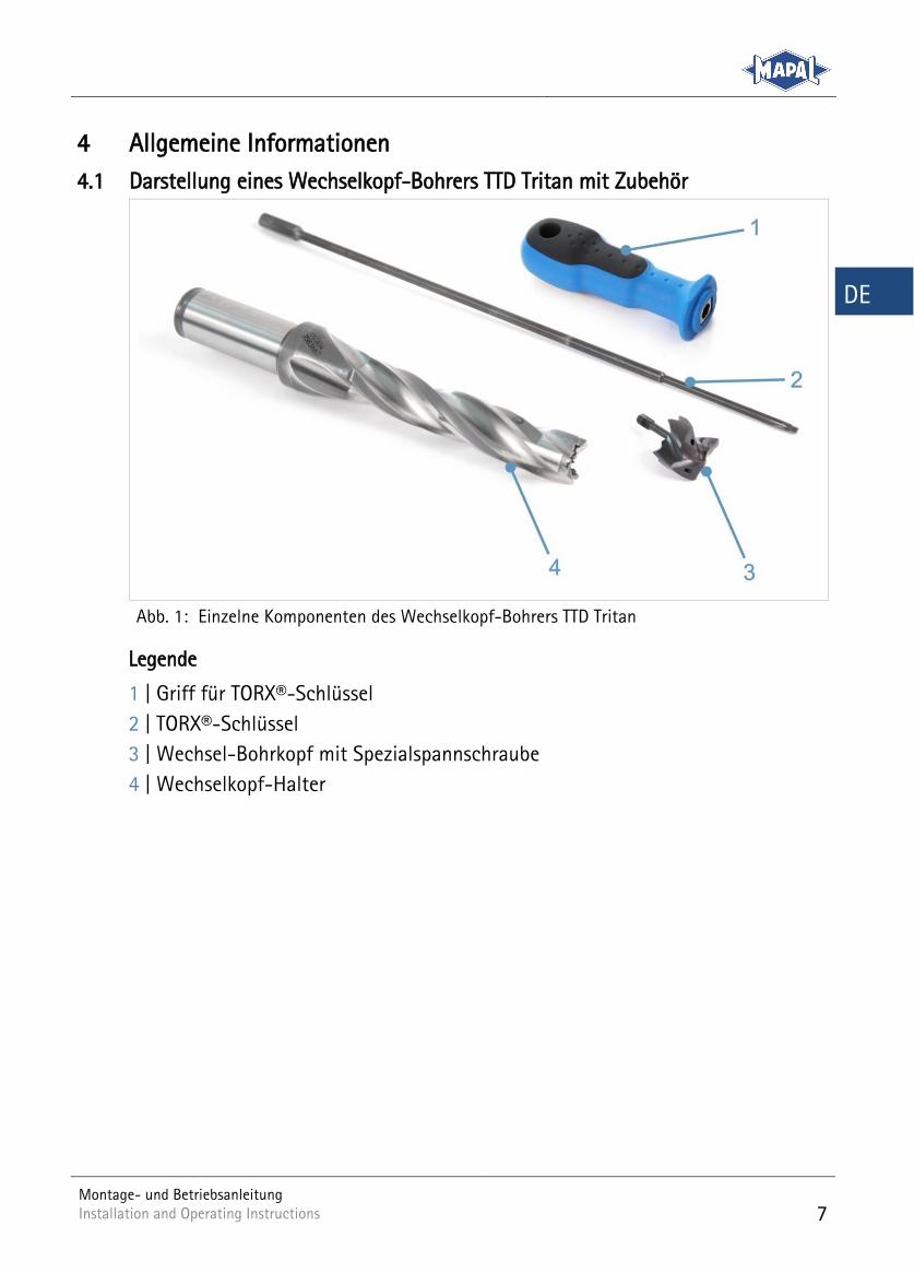
4.1 Darstellung eines Wechselkopf-Bohrers TTD Tritan mit Zubehör
Einzelne Komponenten des Wechselkopf-Bohrers TTD Tritan Abb. 1:
Legende
1 | Griff für TORX®-Schlüssel
2 | TORX®-Schlüssel
3 | Wechsel-Bohrkopf mit Spezialspannschraube
4 | Wechselkopf-Halter
8
Montage- und Betriebsanleitung Installation and Operating Instructions Installation and Operating Instructions
DE
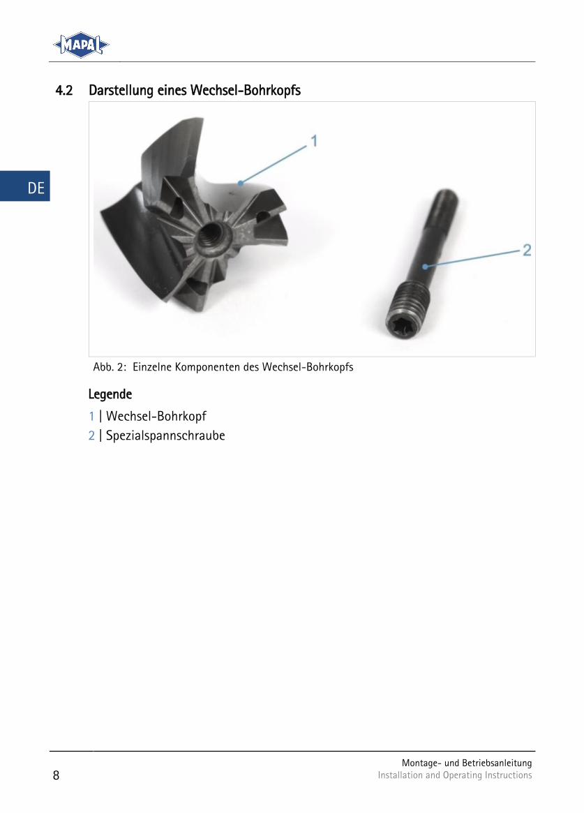
4.2 Darstellung eines Wechsel-Bohrkopfs
Einzelne Komponenten des Wechsel-Bohrkopfs Abb. 2:
Legende
1 | Wechsel-Bohrkopf
2 | Spezialspannschraube
Montage- und Betriebsanleitung Installation and Operating Instructions
9
DE
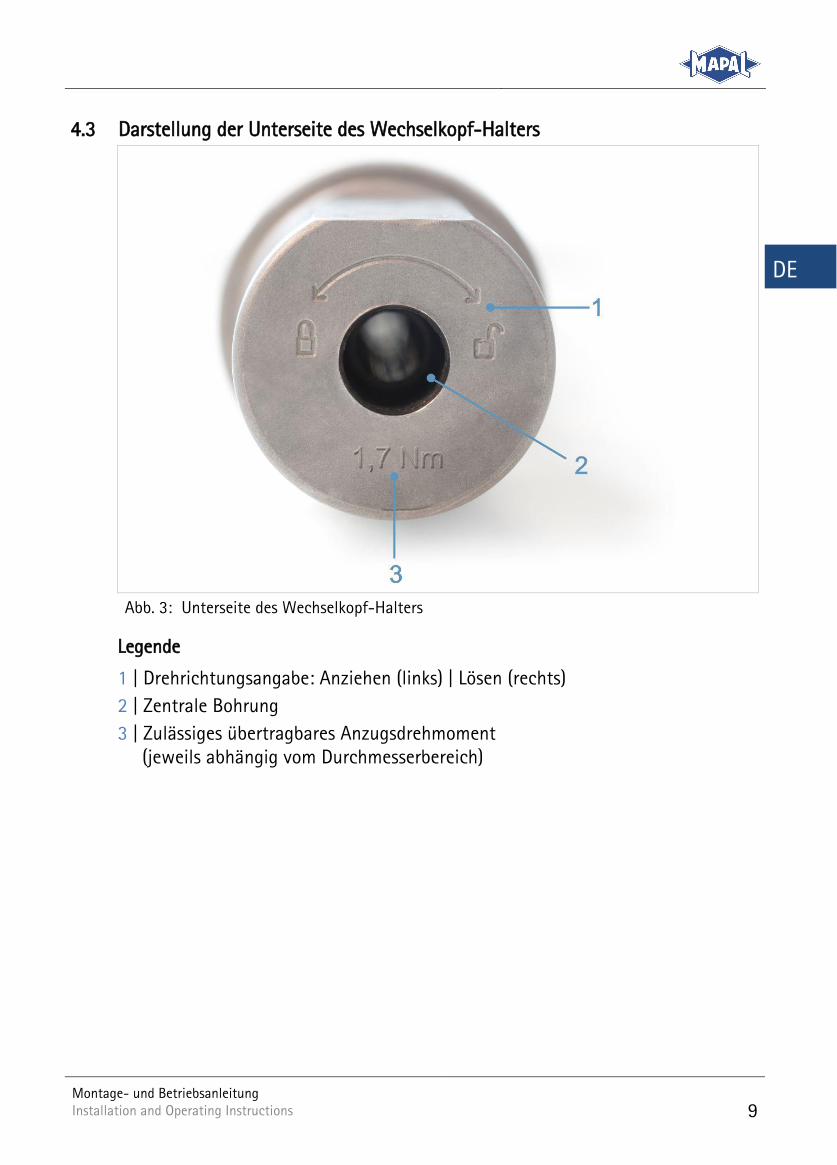
4.3 Darstellung der Unterseite des Wechselkopf-Halters
Unterseite des Wechselkopf-Halters Abb. 3:
Legende
1 | Drehrichtungsangabe: Anziehen (links) | Lösen (rechts)
2 | Zentrale Bohrung
3 | Zulässiges übertragbares Anzugsdrehmoment (jeweils abhängig vom Durchmesserbereich)
10
Montage- und Betriebsanleitung Installation and Operating Instructions Installation and Operating Instructions
E DE
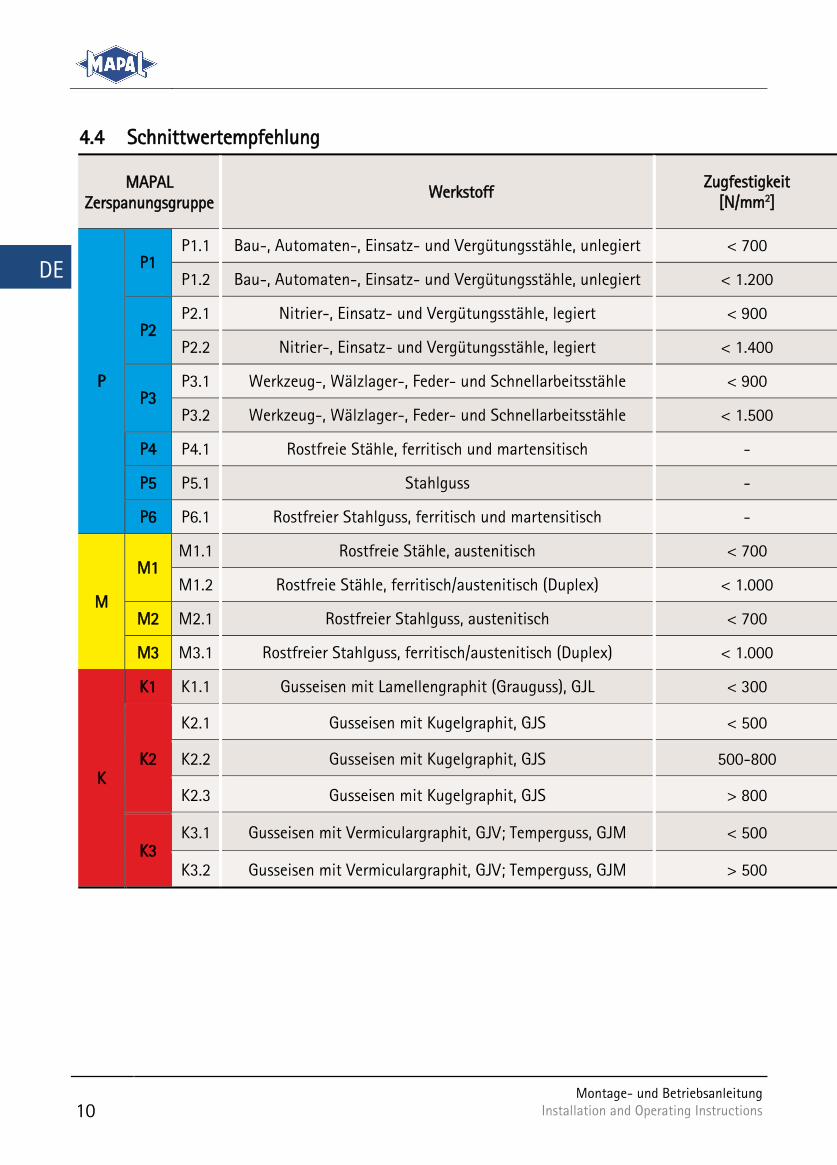
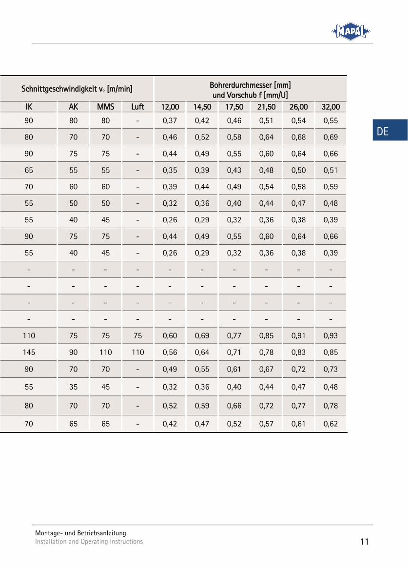
4.4 Schnittwertempfehlung
MAPAL Zerspanungsgruppe
Werkstoff Zugfestigkeit
[N/mm2]
P
P1 P1.1 Bau-, Automaten-, Einsatz- und Vergütungsstähle, unlegiert < 700
P1.2 Bau-, Automaten-, Einsatz- und Vergütungsstähle, unlegiert < 1.200
P2 P2.1 Nitrier-, Einsatz- und Vergütungsstähle, legiert < 900
P2.2 Nitrier-, Einsatz- und Vergütungsstähle, legiert < 1.400
P3 P3.1 Werkzeug-, Wälzlager-, Feder- und Schnellarbeitsstähle < 900
P3.2 Werkzeug-, Wälzlager-, Feder- und Schnellarbeitsstähle < 1.500
P4 P4.1 Rostfreie Stähle, ferritisch und martensitisch -
P5 P5.1 Stahlguss -
P6 P6.1 Rostfreier Stahlguss, ferritisch und martensitisch -
M
M1 M1.1 Rostfreie Stähle, austenitisch < 700
M1.2 Rostfreie Stähle, ferritisch/austenitisch (Duplex) < 1.000
M2 M2.1 Rostfreier Stahlguss, austenitisch < 700
M3 M3.1 Rostfreier Stahlguss, ferritisch/austenitisch (Duplex) < 1.000
K
K1 K1.1 Gusseisen mit Lamellengraphit (Grauguss), GJL < 300
K2
K2.1 Gusseisen mit Kugelgraphit, GJS < 500
K2.2 Gusseisen mit Kugelgraphit, GJS 500-800
K2.3 Gusseisen mit Kugelgraphit, GJS > 800
K3 K3.1 Gusseisen mit Vermiculargraphit, GJV; Temperguss, GJM < 500
K3.2 Gusseisen mit Vermiculargraphit, GJV; Temperguss, GJM > 500
Montage- und Betriebsanleitung Installation and Operating Instructions
11
DE
Schnittgeschwindigkeit vc [m/min] Bohrerdurchmesser [mm] und Vorschub f [mm/U]
IK AK MMS Luft 12,00 14,50 17,50 21,50 26,00 32,00
90 80 80 - 0,37 0,42 0,46 0,51 0,54 0,55
80 70 70 - 0,46 0,52 0,58 0,64 0,68 0,69
90 75 75 - 0,44 0,49 0,55 0,60 0,64 0,66
65 55 55 - 0,35 0,39 0,43 0,48 0,50 0,51
70 60 60 - 0,39 0,44 0,49 0,54 0,58 0,59
55 50 50 - 0,32 0,36 0,40 0,44 0,47 0,48
55 40 45 - 0,26 0,29 0,32 0,36 0,38 0,39
90 75 75 - 0,44 0,49 0,55 0,60 0,64 0,66
55 40 45 - 0,26 0,29 0,32 0,36 0,38 0,39
- - - - - - - - - -
- - - - - - - - - -
- - - - - - - - - -
- - - - - - - - - -
110 75 75 75 0,60 0,69 0,77 0,85 0,91 0,93
145 90 110 110 0,56 0,64 0,71 0,78 0,83 0,85
90 70 70 - 0,49 0,55 0,61 0,67 0,72 0,73
55 35 45 - 0,32 0,36 0,40 0,44 0,47 0,48
80 70 70 - 0,52 0,59 0,66 0,72 0,77 0,78
70 65 65 - 0,42 0,47 0,52 0,57 0,61 0,62
12
Montage- und Betriebsanleitung Installation and Operating Instructions Installation and Operating Instructions
DE
4.5 Benötigte Werkzeuge, Hilfs- und Betriebsstoffe
Im Lieferumfang enthalten:
Wechselkopf-Halter
TORX®-Schlüssel
Griff für TORX®-Schlüssel
Nicht im Lieferumfang enthalten:
Wechsel-Bohrkopf
Spezialspannschraube
Drehmomentschlüssel mit Innensechs-kant-Bit (siehe Kapitel 4.7 Zubehör)
Hochdruckpistole
4.6 Technische Daten
Technische Daten zu Durchmesserbereich, Gewinde des Wechselkopf-Halters, Torx-Größe und zulässiges übertragbares Anzugsdrehmoment der Spezial-spannschraube
Durchmesser-bereich [mm]
Gewinde Wechselkopf-Halter
Torx-Größe
Zul. übertragbares Anzugsdrehmoment
[Nm]
12,0-13,99 M3 x 0,5 T6 0,4
14,0-17,49 M3,5 x 0,6 T7 0,7
17,5-19,49 M4 x 0,7 T8 1,3
19,5-24,49 M5 x 0,8 T10 2,0
24,5-28,49 M6 x1,0 T15 3,1
28,5-32,49 M6 x 1,0 T15 5,6
Durchmesserbereich, Gewindegröße, Torx-Größe und zulässiges übertragba-Tab. 1:res Anzugsdrehmoment
4.7 Zubehör
Zubehör Anzugsdrehmoment-bereich [Nm]
Bestell-Nr.
Drehmomentschlüssel
0,2 – 1,2 30911425
Drehmomentschlüssel
1,0 – 6,0 30911426
Zubehör Tab. 2:
Montage- und Betriebsanleitung Installation and Operating Instructions
13
DE
Werkzeugmontage 5
VORSICHT
Scharfe Schneidkanten am Werkzeug!
Scharfe Schneidkanten können Schnittverletzungen verursachen.
Beim Werkzeugwechsel Schutzhandschuhe tragen.
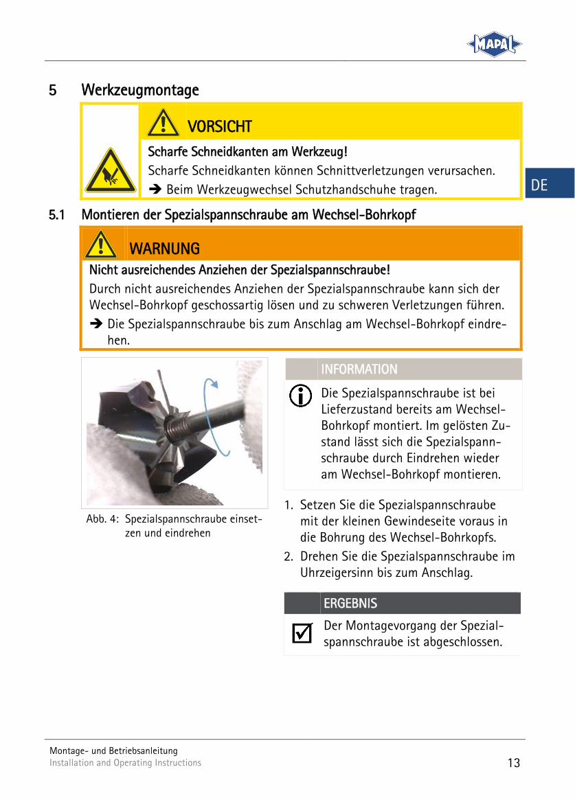
5.1 Montieren der Spezialspannschraube am Wechsel-Bohrkopf
WARNUNG
Nicht ausreichendes Anziehen der Spezialspannschraube!
Durch nicht ausreichendes Anziehen der Spezialspannschraube kann sich der Wechsel-Bohrkopf geschossartig lösen und zu schweren Verletzungen führen.
Die Spezialspannschraube bis zum Anschlag am Wechsel-Bohrkopf eindre-hen.
INFORMATION
Die Spezialspannschraube ist bei Lieferzustand bereits am Wechsel-Bohrkopf montiert. Im gelösten Zu-stand lässt sich die Spezialspann-schraube durch Eindrehen wieder am Wechsel-Bohrkopf montieren.
1. Setzen Sie die Spezialspannschraube mit der kleinen Gewindeseite voraus in die Bohrung des Wechsel-Bohrkopfs.
2. Drehen Sie die Spezialspannschraube im Uhrzeigersinn bis zum Anschlag.
ERGEBNIS
Der Montagevorgang der Spezial-spannschraube ist abgeschlossen.
Spezialspannschraube einset-Abb. 4:zen und eindrehen
14
Montage- und Betriebsanleitung Installation and Operating Instructions Installation and Operating Instructions
DE
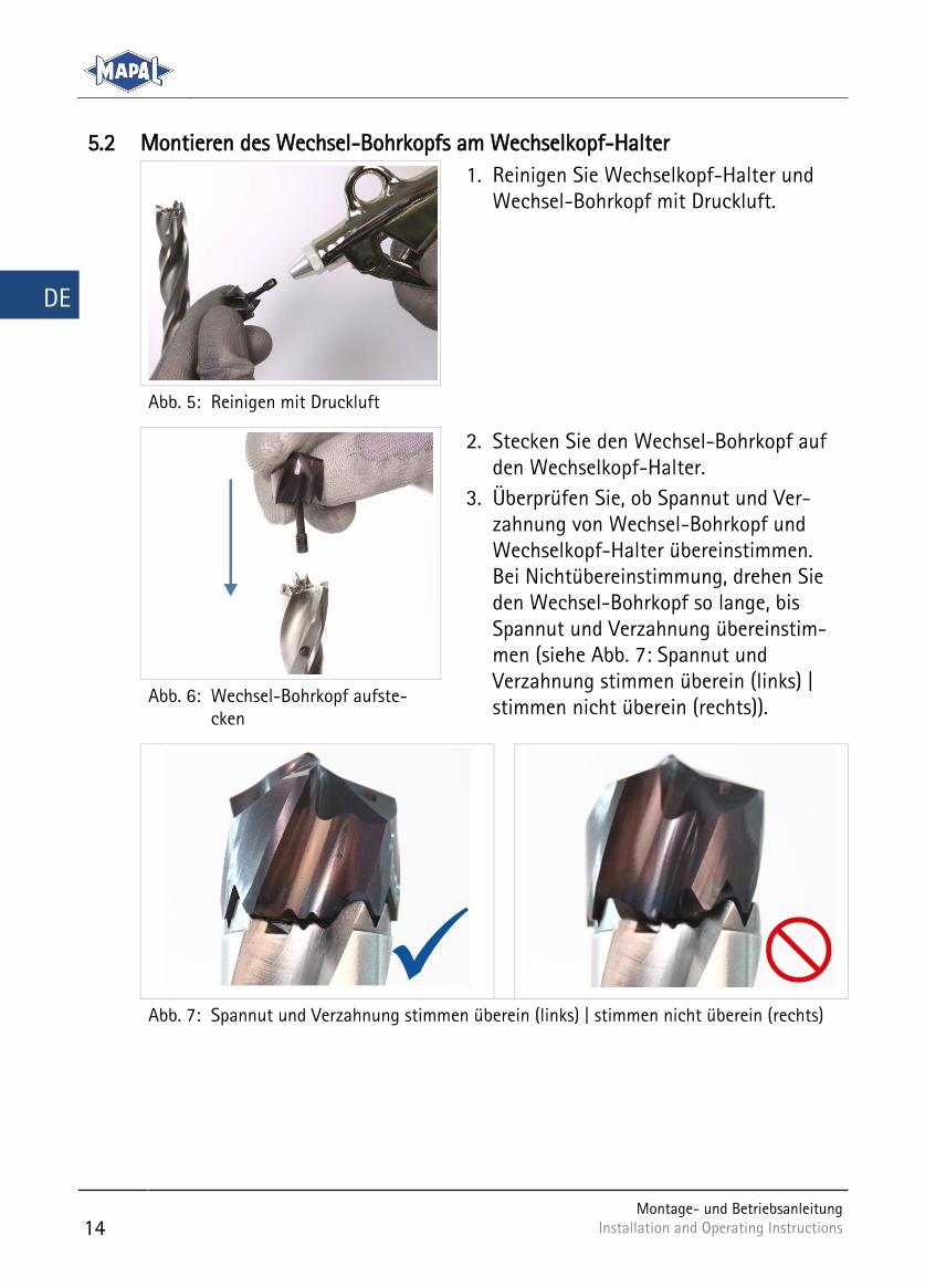
5.2 Montieren des Wechsel-Bohrkopfs am Wechselkopf-Halter
1. Reinigen Sie Wechselkopf-Halter und Wechsel-Bohrkopf mit Druckluft.
Reinigen mit Druckluft Abb. 5:
2. Stecken Sie den Wechsel-Bohrkopf auf den Wechselkopf-Halter.
3. Überprüfen Sie, ob Spannut und Ver-zahnung von Wechsel-Bohrkopf und Wechselkopf-Halter übereinstimmen. Bei Nichtübereinstimmung, drehen Sie den Wechsel-Bohrkopf so lange, bis Spannut und Verzahnung übereinstim-men (siehe Abb. 7: Spannut und Verzahnung stimmen überein (links) | stimmen nicht überein (rechts)).
Wechsel-Bohrkopf aufste-Abb. 6:cken
Spannut und Verzahnung stimmen überein (links) | stimmen nicht überein (rechts) Abb. 7:
Montage- und Betriebsanleitung Installation and Operating Instructions
15
DE
INFORMATION
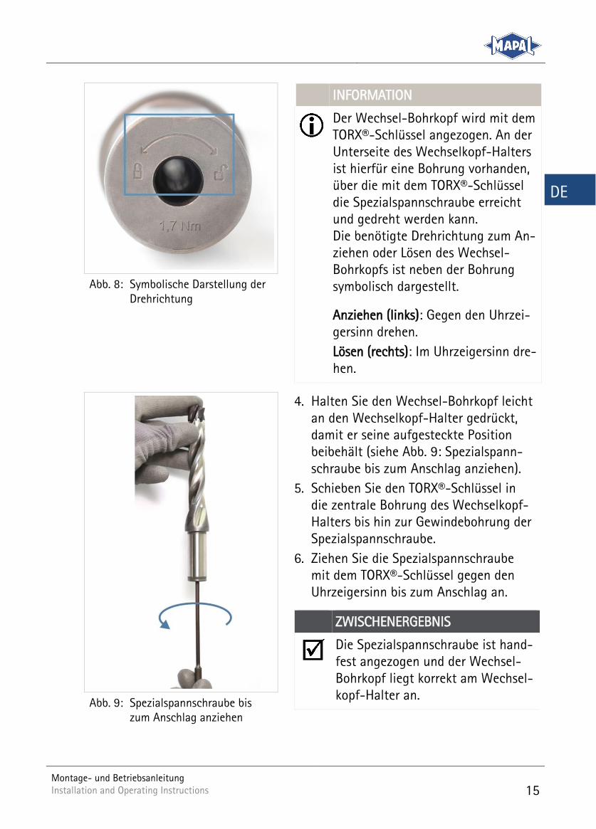
Der Wechsel-Bohrkopf wird mit dem TORX®-Schlüssel angezogen. An der Unterseite des Wechselkopf-Halters ist hierfür eine Bohrung vorhanden, über die mit dem TORX®-Schlüssel die Spezialspannschraube erreicht und gedreht werden kann. Die benötigte Drehrichtung zum An-ziehen oder Lösen des Wechsel-Bohrkopfs ist neben der Bohrung symbolisch dargestellt.
Anziehen (links): Gegen den Uhrzei-gersinn drehen.
Lösen (rechts): Im Uhrzeigersinn dre-hen.
Symbolische Darstellung der Abb. 8:Drehrichtung
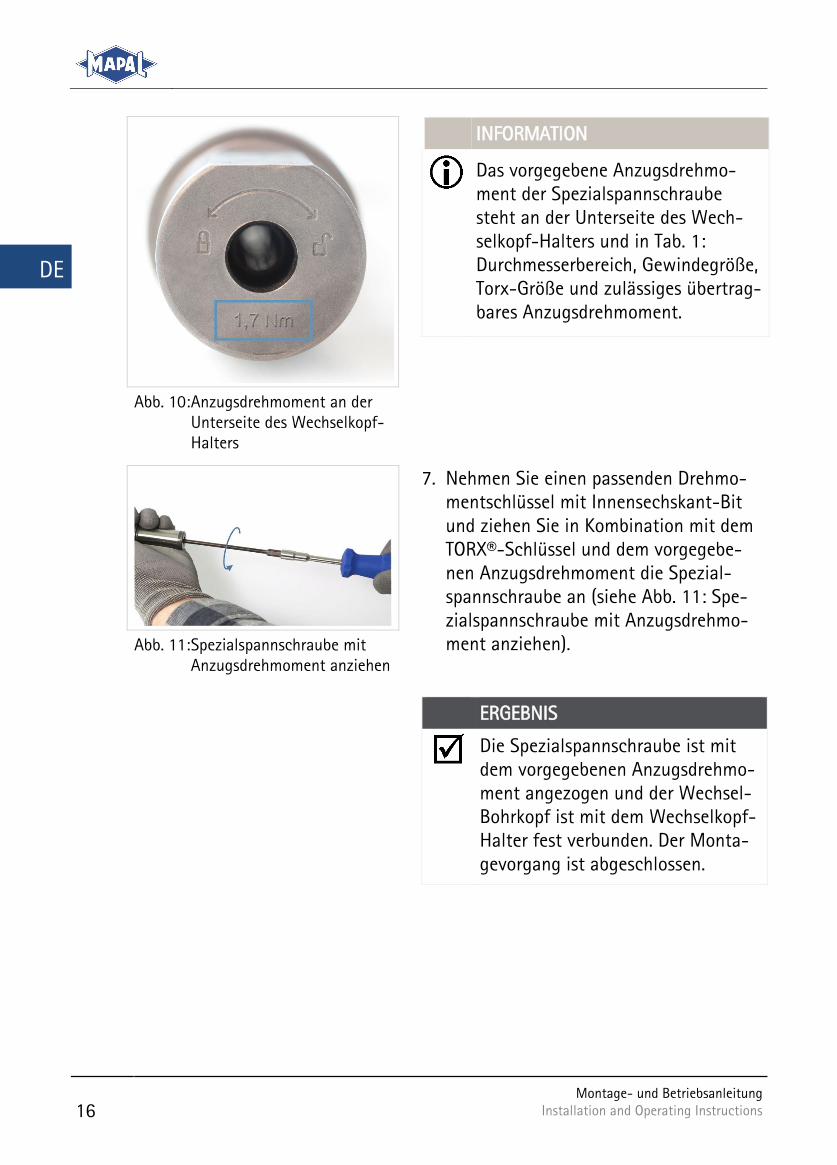
4. Halten Sie den Wechsel-Bohrkopf leicht an den Wechselkopf-Halter gedrückt, damit er seine aufgesteckte Position beibehält (siehe Abb. 9: Spezialspann-schraube bis zum Anschlag anziehen).
5. Schieben Sie den TORX®-Schlüssel in die zentrale Bohrung des Wechselkopf-Halters bis hin zur Gewindebohrung der Spezialspannschraube.
6. Ziehen Sie die Spezialspannschraube mit dem TORX®-Schlüssel gegen den Uhrzeigersinn bis zum Anschlag an.
ZWISCHENERGEBNIS
Die Spezialspannschraube ist hand-fest angezogen und der Wechsel-Bohrkopf liegt korrekt am Wechsel-kopf-Halter an.
Spezialspannschraube bis Abb. 9:zum Anschlag anziehen
16
Montage- und Betriebsanleitung Installation and Operating Instructions Installation and Operating Instructions
DE
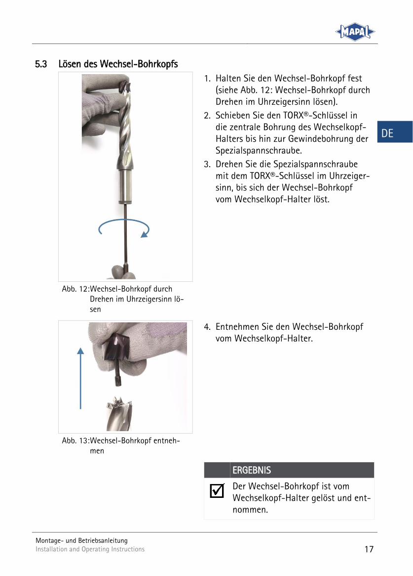
INFORMATION
Das vorgegebene Anzugsdrehmo-ment der Spezialspannschraube steht an der Unterseite des Wech-selkopf-Halters und in Tab. 1: Durchmesserbereich, Gewindegröße, Torx-Größe und zulässiges übertrag-bares Anzugsdrehmoment.
Anzugsdrehmoment an der Abb. 10:Unterseite des Wechselkopf-Halters
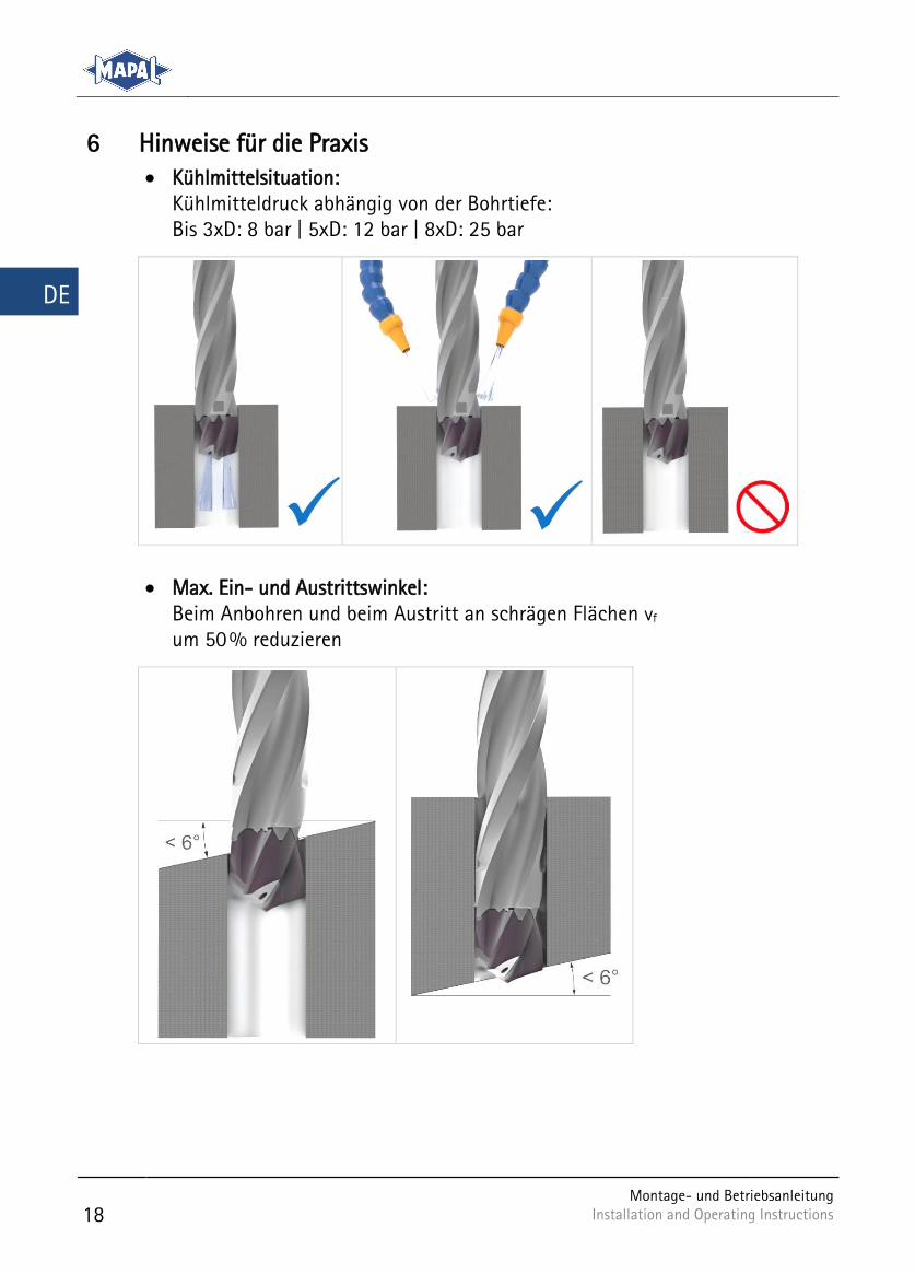
7. Nehmen Sie einen passenden Drehmo-mentschlüssel mit Innensechskant-Bit und ziehen Sie in Kombination mit dem TORX®-Schlüssel und dem vorgegebe-nen Anzugsdrehmoment die Spezial-spannschraube an (siehe Abb. 11: Spe-zialspannschraube mit Anzugsdrehmo-ment anziehen).
Spezialspannschraube mit Abb. 11:Anzugsdrehmoment anziehen
ERGEBNIS
Die Spezialspannschraube ist mit dem vorgegebenen Anzugsdrehmo-ment angezogen und der Wechsel-Bohrkopf ist mit dem Wechselkopf-Halter fest verbunden. Der Monta-gevorgang ist abgeschlossen.
Montage- und Betriebsanleitung Installation and Operating Instructions
17
DE
5.3 Lösen des Wechsel-Bohrkopfs
1. Halten Sie den Wechsel-Bohrkopf fest (siehe Abb. 12: Wechsel-Bohrkopf durch Drehen im Uhrzeigersinn lösen).
2. Schieben Sie den TORX®-Schlüssel in die zentrale Bohrung des Wechselkopf-Halters bis hin zur Gewindebohrung der Spezialspannschraube.
3. Drehen Sie die Spezialspannschraube mit dem TORX®-Schlüssel im Uhrzeiger-sinn, bis sich der Wechsel-Bohrkopf vom Wechselkopf-Halter löst.
Wechsel-Bohrkopf durch Abb. 12:Drehen im Uhrzeigersinn lö-sen
4. Entnehmen Sie den Wechsel-Bohrkopf vom Wechselkopf-Halter.
Wechsel-Bohrkopf entneh-Abb. 13:men
ERGEBNIS
Der Wechsel-Bohrkopf ist vom Wechselkopf-Halter gelöst und ent-nommen.
18
Montage- und Betriebsanleitung Installation and Operating Instructions Installation and Operating Instructions
DE
Hinweise für die Praxis 6 Kühlmittelsituation:
Kühlmitteldruck abhängig von der Bohrtiefe: Bis 3xD: 8 bar | 5xD: 12 bar | 8xD: 25 bar
Max. Ein- und Austrittswinkel: Beim Anbohren und beim Austritt an schrägen Flächen vf um 50 % reduzieren
Montage- und Betriebsanleitung Installation and Operating Instructions
19
DE
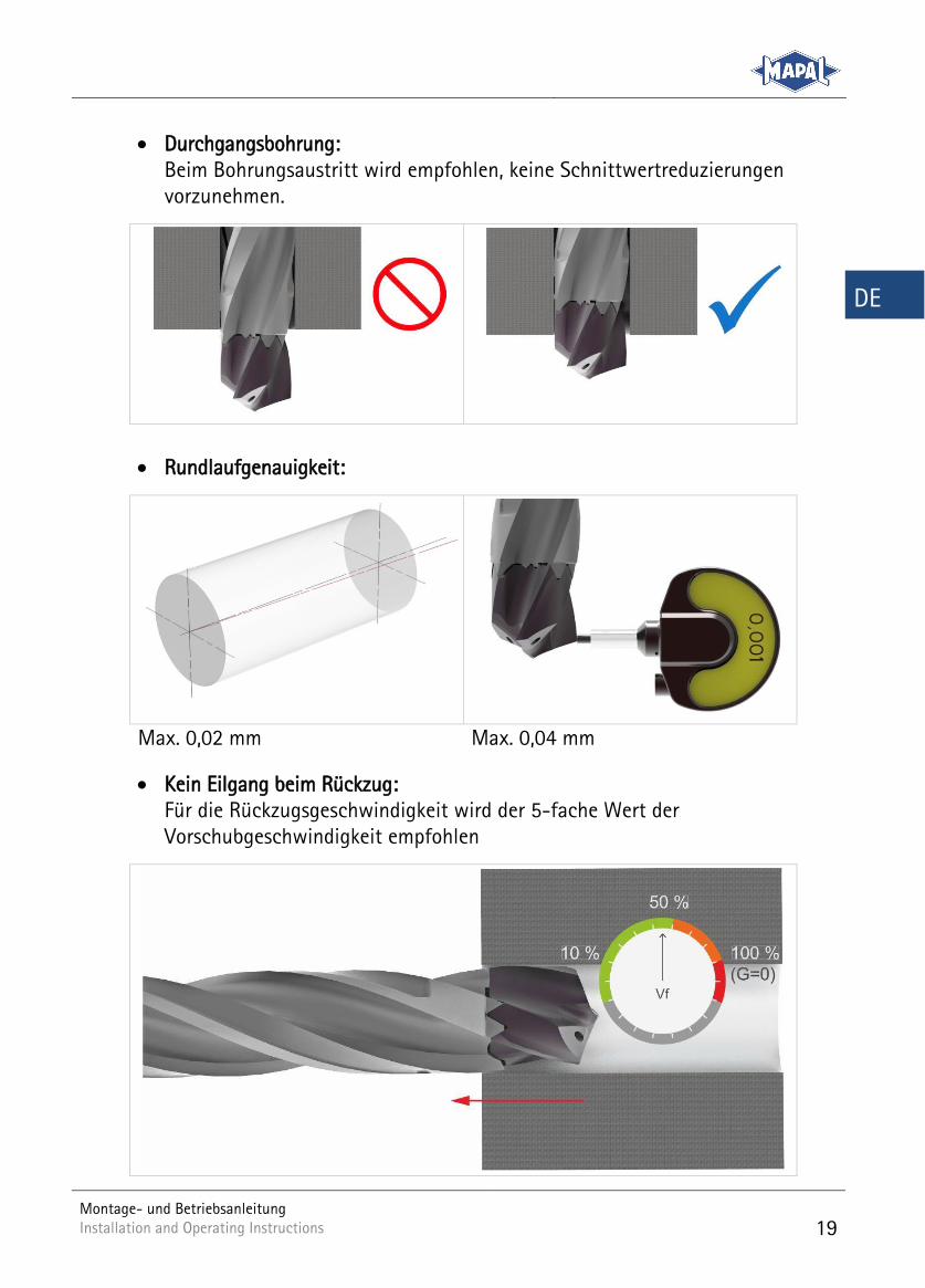
Durchgangsbohrung: Beim Bohrungsaustritt wird empfohlen, keine Schnittwertreduzierungen vorzunehmen.
Rundlaufgenauigkeit:
Max. 0,02 mm Max. 0,04 mm
Kein Eilgang beim Rückzug: Für die Rückzugsgeschwindigkeit wird der 5-fache Wert der Vorschubgeschwindigkeit empfohlen
20
Montage- und Betriebsanleitung Installation and Operating Instructions Installation and Operating Instructions
DE
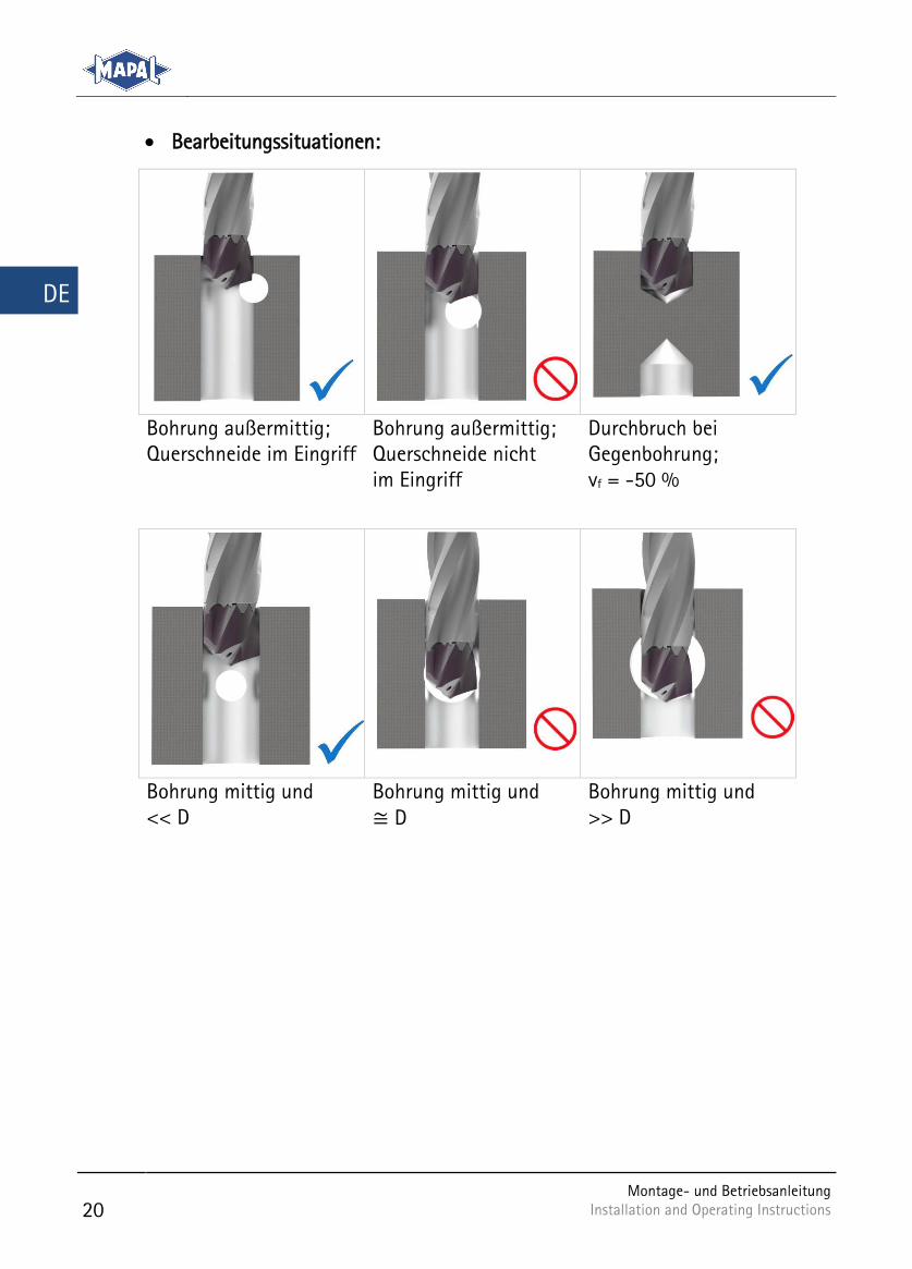
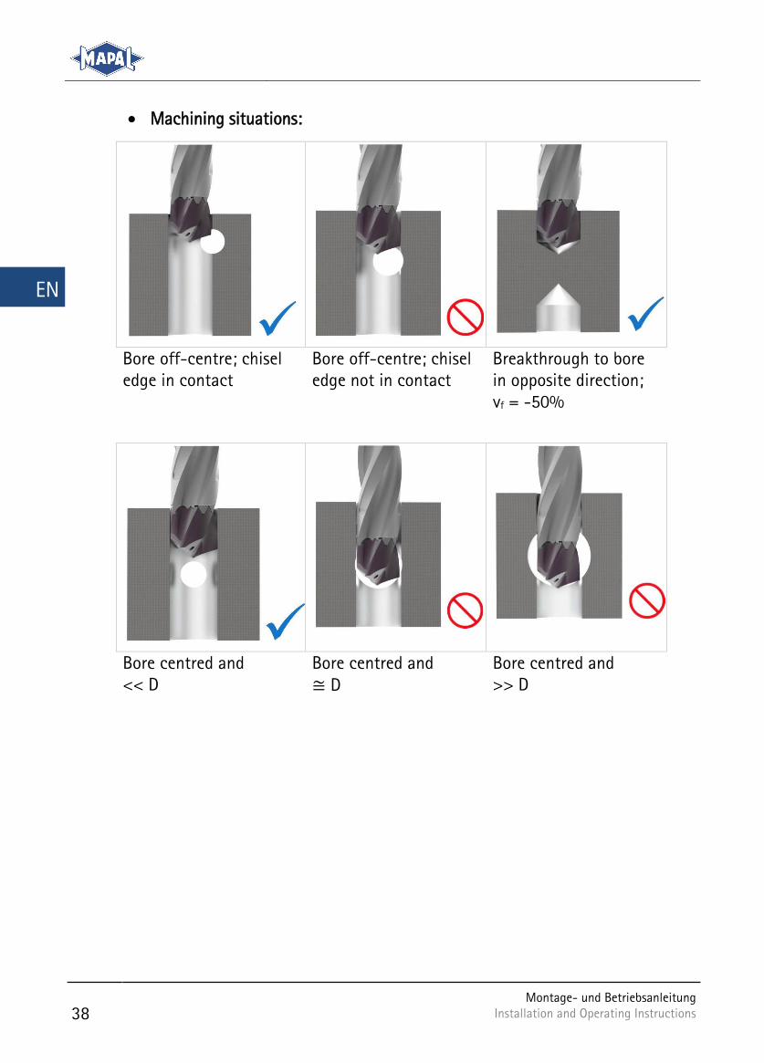
Bearbeitungssituationen:
Bohrung außermittig; Querschneide im Eingriff
Bohrung außermittig; Querschneide nicht im Eingriff
Durchbruch bei Gegenbohrung; vf = -50 %
Bohrung mittig und << D
Bohrung mittig und ≅ D
Bohrung mittig und >> D

22
Montage- und Betriebsanleitung Installation and Operating Instructions Installation and Operating Instructions
EN
Table of contents
Purpose of the Installation and Operating Instructions ............................ 23 1
Contact ................................................................................................................... 23 2
Safety ...................................................................................................................... 24 3
3.1 Target group ............................................................................................................................ 24
3.2 Intended use ........................................................................................................................... 24
3.3 Incorrect use ........................................................................................................................... 24
3.4 Warranty .................................................................................................................................. 24
3.5 General warnings and safety instructions ....................................................................... 25
General information ............................................................................................ 26 4
4.1 Illustration of a TTD Tritan replaceable head drill with accessories .......................... 26
4.2 Illustration of a replaceable drill head ............................................................................. 27
4.3 Illustration of the underside of the replaceable head holder ..................................... 27
4.4 Cutting data recommendation ........................................................................................... 28
4.5 Tools and materials required ............................................................................................... 30
4.6 Technical data ........................................................................................................................ 30
4.7 Accessories .............................................................................................................................. 30
Tool assembly ........................................................................................................ 31 5
5.1 Installing the special clamping screw on the replaceable drill head ........................ 31
5.2 Installing replaceable drill head on replaceable head holder ..................................... 32
5.3 Removal of replaceable drill head ..................................................................................... 35
Practical notes ...................................................................................................... 36 6

Montage- und Betriebsanleitung Installation and Operating Instructions
23
EN
Purpose of the Installation and Operating Instructions 1These present Installation and Operating Instructions describe the proper opera-tion of the replaceable head drill TTD Tritan. In particular they contain infor-mation on how you should install and remove the replaceable drill head on the replaceable head holder TTS. In addition, the most important safety instructions on handling the replaceable head drill TTD Tritan are explained. In the further course of this document, the replaceable drill head TTD Tritan is referred to simply as replaceable drill head. In the further course of this document, the replaceable head holder TTS is referred to simply as replaceable head holder.
In chapter 5 you will find a detailed description of the individual functions and actions necessary to successfully install and remove the replaceable head drill.
The installation and operating instructions form an integral part of the replacea-ble head drill and must be kept in the immediate vicinity of the replaceable head drill where it is accessible to the personnel at all times. A basic precondition for safe working is compliance with all the safety precautions and instructions for working given in these installation and operating instructions.
The local safety at work regulations and the general safety regulations for the field of application of the replaceable head drill must also be observed. Illustra-tions in these installation and operating instructions are provided for general un-derstanding and may differ from the actual appearance.
Contact 2
MAPAL Fabrik für Präzisionswerkzeuge Dr. Kress KG
Address Obere Bahnstrasse 13
D-73431 Aalen, GERMANY
Telephone +49 (0) 7361 585-0
Fax +49 (0) 7361 585-1029
E-mail [email protected]
Internet www.mapal.com
24
Montage- und Betriebsanleitung Installation and Operating Instructions Installation and Operating Instructions
EN
Safety 3
3.1 Target group
The replaceable head drill may only be operated by trained, authorised and de-pendable specialist personnel. The specialist personnel must be able to recognise and avoid hazards and for this purpose must have read this document before us-ing the replaceable head drill.
The specialist personnel is familiar with the health and safety regulations, safety stipulations and instructions from the machine manufacturer, which must be fol-lowed and observed during operation of the replaceable head drill.
3.2 Intended use
The replaceable head drill is intended only for machining manufacture of metallic materials on machine tools for industrial applications.
The replaceable head drill may only be used when the observance of all the instructions given in this manual is assured.
3.3 Incorrect use
The replaceable head drill may only be used in accordance with the technical data (see chapter 4.6 Technical data).
The replaceable head drill and its components must not be modified or used for any other applications.
In the case of unauthorised modifications to the replaceable head drill or incorrect use, all warranty claims against MAPAL will be rendered void.
The manufacturer assumes no liability for accidents or damage resulting from use for other than the intended purpose.
3.4 Warranty
The warranty period is 24 months and begins with the delivery date from the fac-tory. The warranty is limited to 1-shift operation.
The replaceable head drill TTD Tritan including all its components must not be modified or used for unauthorised applications. Any modification to the replacea-ble head drill TTD Tritan or any unauthorised use will void all warranty claims against MAPAL. MAPAL expressly declines any liability for accidents or damage resulting from the use of damaged tools or damaged machine parts coming into contact with the machine. Wear parts are not covered by the warranty.
Montage- und Betriebsanleitung Installation and Operating Instructions
25
EN
3.5 General warnings and safety instructions
WARNING
Danger from use by untrained and unauthorised personnel!
The installation of tools and their use on a machine tool by untrained and un-authorised personnel can lead to hazardous situations.
Only trained, authorised and dependable specialist personnel may install tools and use them on a machine tool.
The specialist personnel must be able to recognise and avoid hazards.
WARNING
Failure to observe the technical data!
Failure to observe the technical data can result in serious injury to the operator and in machine damage.
Observe the technical data given in chapter 4.6
WARNING
Inadequate tightening of the special clamping screw!
Inadequate tightening of the special clamping screw can lead to the replacea-ble drill head being released at high projectile speeds and resulting in serious injuries.
Tighten the special clamping screw up to the stop on the replaceable drill head.
CAUTION
Sharp cutting edges on the tool!
Sharp cutting edges may cause cutting injuries.
Wear protective gloves during tool changes.
26
Montage- und Betriebsanleitung Installation and Operating Instructions Installation and Operating Instructions
EN
General information 4
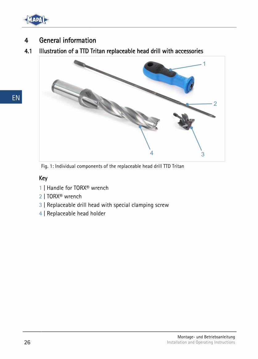
4.1 Illustration of a TTD Tritan replaceable head drill with accessories
Individual components of the replaceable head drill TTD Tritan Fig. 1:
Key
1 | Handle for TORX® wrench
2 | TORX® wrench
3 | Replaceable drill head with special clamping screw
4 | Replaceable head holder
Montage- und Betriebsanleitung Installation and Operating Instructions
27
EN
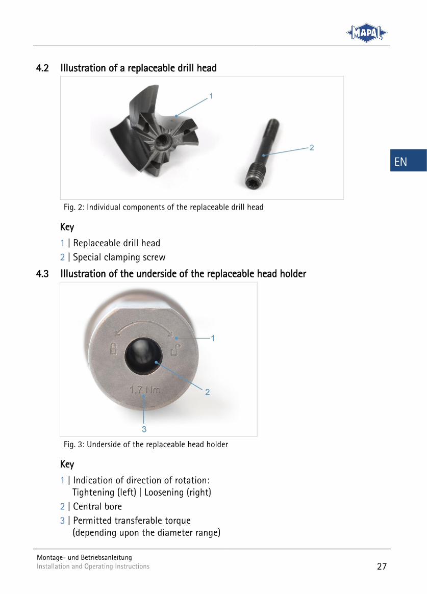
4.2 Illustration of a replaceable drill head
Individual components of the replaceable drill head Fig. 2:
Key
1 | Replaceable drill head
2 | Special clamping screw
4.3 Illustration of the underside of the replaceable head holder
Underside of the replaceable head holder Fig. 3:
Key
1 | Indication of direction of rotation: Tightening (left) | Loosening (right)
2 | Central bore
3 | Permitted transferable torque (depending upon the diameter range)
28
Montage- und Betriebsanleitung Installation and Operating Instructions Installation and Operating Instructions
EN
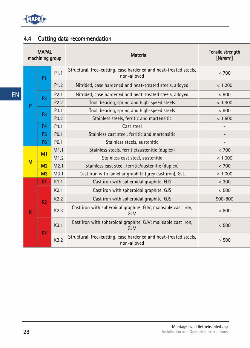
4.4 Cutting data recommendation
MAPAL machining group
Material Tensile strength
[N/mm2]
P
P1 P1.1
Structural, free-cutting, case hardened and heat-treated steels, non-alloyed
< 700
P1.2 Nitrided, case hardened and heat-treated steels, alloyed < 1.200
P2 P2.1 Nitrided, case hardened and heat-treated steels, alloyed < 900
P2.2 Tool, bearing, spring and high-speed steels < 1.400
P3 P3.1 Tool, bearing, spring and high-speed steels < 900
P3.2 Stainless steels, ferritic and martensitic < 1.500
P4 P4.1 Cast steel -
P5 P5.1 Stainless cast steel, ferritic and martensitic -
P6 P6.1 Stainless steels, austenitic -
M
M1 M1.1 Stainless steels, ferritic/austenitic (duplex) < 700
M1.2 Stainless cast steel, austenitic < 1.000
M2 M2.1 Stainless cast steel, ferritic/austenitic (duplex) < 700
M3 M3.1 Cast iron with lamellar graphite (grey cast iron), GJL < 1.000
K
K1 K1.1 Cast iron with spheroidal graphite, GJS < 300
K2
K2.1 Cast iron with spheroidal graphite, GJS < 500
K2.2 Cast iron with spheroidal graphite, GJS 500-800
K2.3 Cast iron with spheroidal graphite, GJV; malleable cast iron,
GJM > 800
K3
K3.1 Cast iron with spheroidal graphite, GJV; malleable cast iron,
GJM < 500
K3.2 Structural, free-cutting, case hardened and heat-treated steels,
non-alloyed > 500
Montage- und Betriebsanleitung Installation and Operating Instructions
29
EN
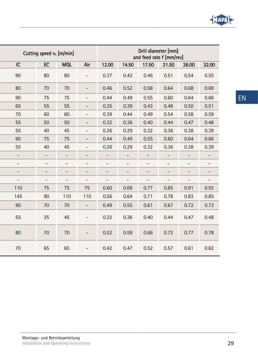
Cutting speed vc [m/min] Drill diameter [mm] and feed rate f [mm/rev]
IC EC MQL Air 12.00 14.50 17.50 21.50 26.00 32.00
90 80 80 - 0.37 0.42 0.46 0.51 0.54 0.55
80 70 70 - 0.46 0.52 0.58 0.64 0.68 0.69
90 75 75 - 0.44 0.49 0.55 0.60 0.64 0.66
65 55 55 - 0.35 0.39 0.43 0.48 0.50 0.51
70 60 60 - 0.39 0.44 0.49 0.54 0.58 0.59
55 50 50 - 0.32 0.36 0.40 0.44 0.47 0.48
55 40 45 - 0.26 0.29 0.32 0.36 0.38 0.39
90 75 75 - 0.44 0.49 0.55 0.60 0.64 0.66
55 40 45 - 0.26 0.29 0.32 0.36 0.38 0.39
- - - - - - - - - -
- - - - - - - - - -
- - - - - - - - - -
- - - - - - - - - -
110 75 75 75 0.60 0.69 0.77 0.85 0.91 0.93
145 90 110 110 0.56 0.64 0.71 0.78 0.83 0.85
90 70 70 - 0.49 0.55 0.61 0.67 0.72 0.73
55 35 45 - 0.32 0.36 0.40 0.44 0.47 0.48
80 70 70 - 0.52 0.59 0.66 0.72 0.77 0.78
70 65 65 - 0.42 0.47 0.52 0.57 0.61 0.62
30
Montage- und Betriebsanleitung Installation and Operating Instructions Installation and Operating Instructions
EN
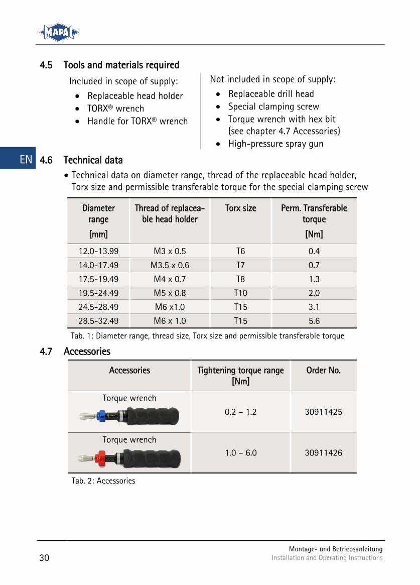
4.5 Tools and materials required
Included in scope of supply:
Replaceable head holder
TORX® wrench
Handle for TORX® wrench
Not included in scope of supply:
Replaceable drill head
Special clamping screw
Torque wrench with hex bit (see chapter 4.7 Accessories)
High-pressure spray gun
4.6 Technical data
Technical data on diameter range, thread of the replaceable head holder, Torx size and permissible transferable torque for the special clamping screw
Diameter range
[mm]
Thread of replacea-ble head holder
Torx size Perm. Transferable torque
[Nm]
12.0-13.99 M3 x 0.5 T6 0.4
14.0-17.49 M3.5 x 0.6 T7 0.7
17.5-19.49 M4 x 0.7 T8 1.3
19.5-24.49 M5 x 0.8 T10 2.0
24.5-28.49 M6 x1.0 T15 3.1
28.5-32.49 M6 x 1.0 T15 5.6
Diameter range, thread size, Torx size and permissible transferable torque Tab. 1:
4.7 Accessories
Accessories Tightening torque range [Nm]
Order No.
Torque wrench
0.2 – 1.2 30911425
Torque wrench
1.0 – 6.0 30911426
Accessories Tab. 2:
Montage- und Betriebsanleitung Installation and Operating Instructions
31
EN
Tool assembly 5
CAUTION
Sharp cutting edges on the tool!
Sharp cutting edges may cause cutting injuries.
Wear protective gloves during tool changes.
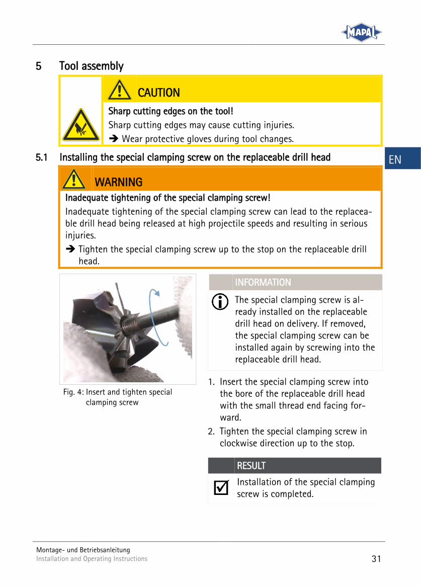
5.1 Installing the special clamping screw on the replaceable drill head
WARNING
Inadequate tightening of the special clamping screw!
Inadequate tightening of the special clamping screw can lead to the replacea-ble drill head being released at high projectile speeds and resulting in serious injuries.
Tighten the special clamping screw up to the stop on the replaceable drill head.
INFORMATION
The special clamping screw is al-ready installed on the replaceable drill head on delivery. If removed, the special clamping screw can be installed again by screwing into the replaceable drill head.
1. Insert the special clamping screw into the bore of the replaceable drill head with the small thread end facing for-ward.
2. Tighten the special clamping screw in clockwise direction up to the stop.
RESULT
Installation of the special clamping screw is completed.
Insert and tighten special Fig. 4:clamping screw
32
Montage- und Betriebsanleitung Installation and Operating Instructions Installation and Operating Instructions
EN
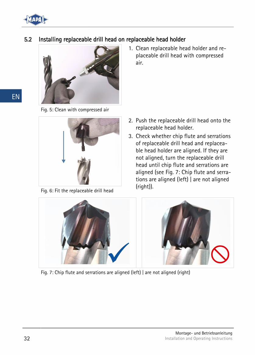
5.2 Installing replaceable drill head on replaceable head holder
1. Clean replaceable head holder and re-placeable drill head with compressed air.
Clean with compressed air Fig. 5:
2. Push the replaceable drill head onto the replaceable head holder.
3. Check whether chip flute and serrations of replaceable drill head and replacea-ble head holder are aligned. If they are not aligned, turn the replaceable drill head until chip flute and serrations are aligned (see Fig. 7: Chip flute and serra-tions are aligned (left) | are not aligned (right)).
Fit the replaceable drill head Fig. 6:
Chip flute and serrations are aligned (left) | are not aligned (right) Fig. 7:
Montage- und Betriebsanleitung Installation and Operating Instructions
33
EN
INFORMATION
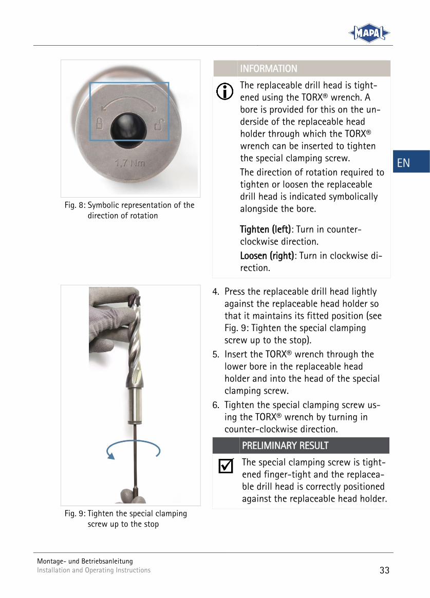
The replaceable drill head is tight-ened using the TORX® wrench. A bore is provided for this on the un-derside of the replaceable head holder through which the TORX® wrench can be inserted to tighten the special clamping screw.
The direction of rotation required to tighten or loosen the replaceable drill head is indicated symbolically alongside the bore.
Tighten (left): Turn in counter-clockwise direction.
Loosen (right): Turn in clockwise di-rection.
Symbolic representation of the Fig. 8:direction of rotation
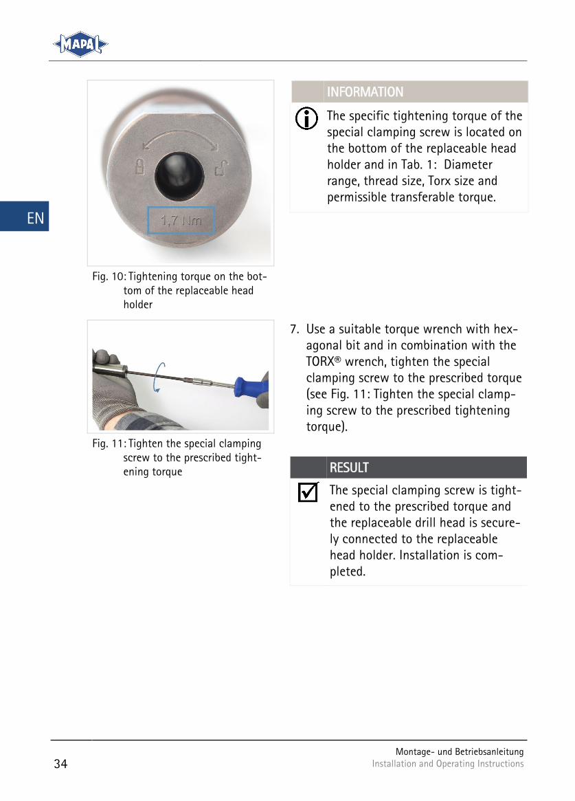
4. Press the replaceable drill head lightly against the replaceable head holder so that it maintains its fitted position (see Fig. 9: Tighten the special clamping screw up to the stop).
5. Insert the TORX® wrench through the lower bore in the replaceable head holder and into the head of the special clamping screw.
6. Tighten the special clamping screw us-ing the TORX® wrench by turning in counter-clockwise direction.
PRELIMINARY RESULT
The special clamping screw is tight-ened finger-tight and the replacea-ble drill head is correctly positioned against the replaceable head holder.
Tighten the special clamping Fig. 9:screw up to the stop
34
Montage- und Betriebsanleitung Installation and Operating Instructions Installation and Operating Instructions
EN
INFORMATION
The specific tightening torque of the special clamping screw is located on the bottom of the replaceable head holder and in Tab. 1: Diameter range, thread size, Torx size and permissible transferable torque.
Tightening torque on the bot-Fig. 10:tom of the replaceable head holder
7. Use a suitable torque wrench with hex-agonal bit and in combination with the TORX® wrench, tighten the special clamping screw to the prescribed torque (see Fig. 11: Tighten the special clamp-ing screw to the prescribed tightening torque).
RESULT
The special clamping screw is tight-ened to the prescribed torque and the replaceable drill head is secure-ly connected to the replaceable head holder. Installation is com-pleted.
Tighten the special clamping Fig. 11:screw to the prescribed tight-ening torque
Montage- und Betriebsanleitung Installation and Operating Instructions
35
EN
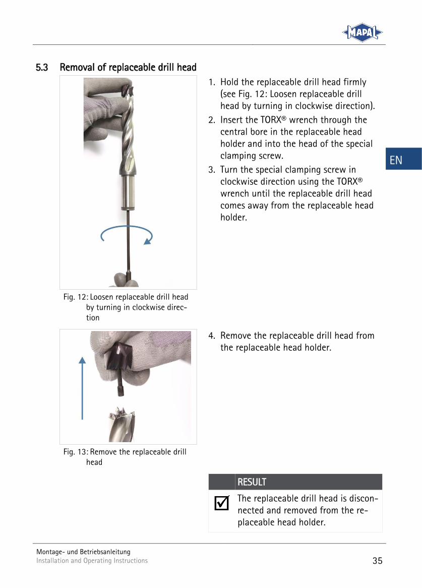
5.3 Removal of replaceable drill head
1. Hold the replaceable drill head firmly (see Fig. 12: Loosen replaceable drill head by turning in clockwise direction).
2. Insert the TORX® wrench through the central bore in the replaceable head holder and into the head of the special clamping screw.
3. Turn the special clamping screw in clockwise direction using the TORX® wrench until the replaceable drill head comes away from the replaceable head holder.
Loosen replaceable drill head Fig. 12:by turning in clockwise direc-tion
4. Remove the replaceable drill head from the replaceable head holder.
Remove the replaceable drill Fig. 13:head
RESULT
The replaceable drill head is discon-nected and removed from the re-placeable head holder.
36
Montage- und Betriebsanleitung Installation and Operating Instructions Installation and Operating Instructions
EN
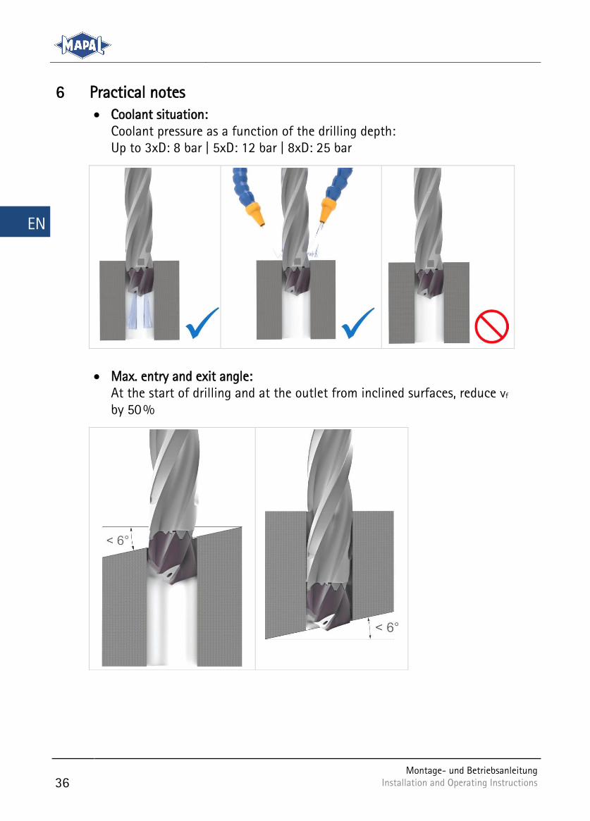
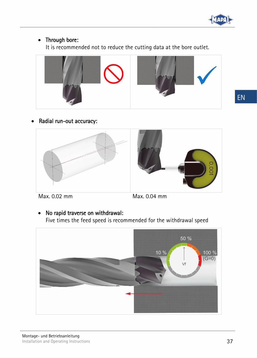
Practical notes 6 Coolant situation:
Coolant pressure as a function of the drilling depth: Up to 3xD: 8 bar | 5xD: 12 bar | 8xD: 25 bar
Max. entry and exit angle: At the start of drilling and at the outlet from inclined surfaces, reduce vf by 50 %
Montage- und Betriebsanleitung Installation and Operating Instructions
37
EN
Through bore: It is recommended not to reduce the cutting data at the bore outlet.
Radial run-out accuracy:
Max. 0.02 mm Max. 0.04 mm
No rapid traverse on withdrawal: Five times the feed speed is recommended for the withdrawal speed
38
Montage- und Betriebsanleitung Installation and Operating Instructions Installation and Operating Instructions
EN
Machining situations:
Bore off-centre; chisel edge in contact
Bore off-centre; chisel edge not in contact
Breakthrough to bore in opposite direction; vf = -50%
Bore centred and << D
Bore centred and ≅ D
Bore centred and >> D

KAL-TTD TRITAN-D/E-02-0419
Bestellnummer / Order number: 10155738
Montage- und Betriebsanleitung | Wechselkopf-Bohrer TTD Tritan Installation and Operating Instructions | Replaceable Head Drill TTD Tritan
MAPAL Dr. Kress KG, Aalen
Gültig für: / Applies for:
2. Auflage April 2019 / 2nd issue April 2019
© MAPAL Präzisionswerkzeuge Dr. Kress KG
Kein Teil dieser Anleitung darf in irgendeiner Form (Druck, Fotokopie, Mikrofilm oder einem anderen Verfahren) ohne schriftliche Zustimmung der Firma MAPAL Präzisionswerkzeuge Dr. Kress KG, Aalen, reproduziert oder unter Verwendung elektronischer Systeme verarbeitet werden.
No part of this manual is allowed to be copied or processed using electronic systems, in any form (print, photocopy, microfilm or any other method) without the written approval of MAPAL Präzisionswerkzeuge Dr. Kress KG, Aalen, Germany.
Alle in diesem Handbuch genannten Bezeichnungen von Erzeugnissen sind Warenzeichen der jeweili-gen Firmen.
All the product names stated in this manual are trademarks of the related organisations.
Technische Änderungen vorbehalten. /
We reserve the right to make technical changes without notice.
KA
L-TT
D T
rita
n-D
/E-0
2-1
00-0
419-F
A P
rint
ed in
Ger
man
y. R
ight
of
tech
nica
l mod
ific
atio
n re
serv
ed.