Embed Size (px)
Citation preview
Vol. 9, No. 5/May 1992/J. Opt. Soc. Am. A 725
Dependence of two- and three-dimensional opticaltransfer functions on pinhole radius in a coherent
confocal microscope
Valter Drazic
Institut fur Mess- und Regelungstechnik, Universitait (Technische Hochschule) Karlsruhe, Postfach 69 80,D-7500 Karlsruhe, Germany
Received April 24, 1991; revised manuscript received October 30, 1991; accepted November 12, 1991
Previous papers about coherent scanning optical microscopes took into account two types of microscope: thosewith a point detector called type-II or confocal microscopes and those with an infinitely large area detectorcalled type-I or conventional microscopes. Here the pinhole size of a type-II microscope was permitted to vary,and it is shown how the size could affect the imaging properties of a real microscope. The three-dimensionaloptical transfer function is established, and we discuss in particular the resolution capabilities, lateral as wellas longitudinal, of a scanning microscope with a given pinhole size or detector area. Finally, a rigorous confo-cality criterion, which will answer the question of how small the pinhole should be made to give confocal imag-ing properties to a scanning microscope, is given.
1. INTRODUCTION
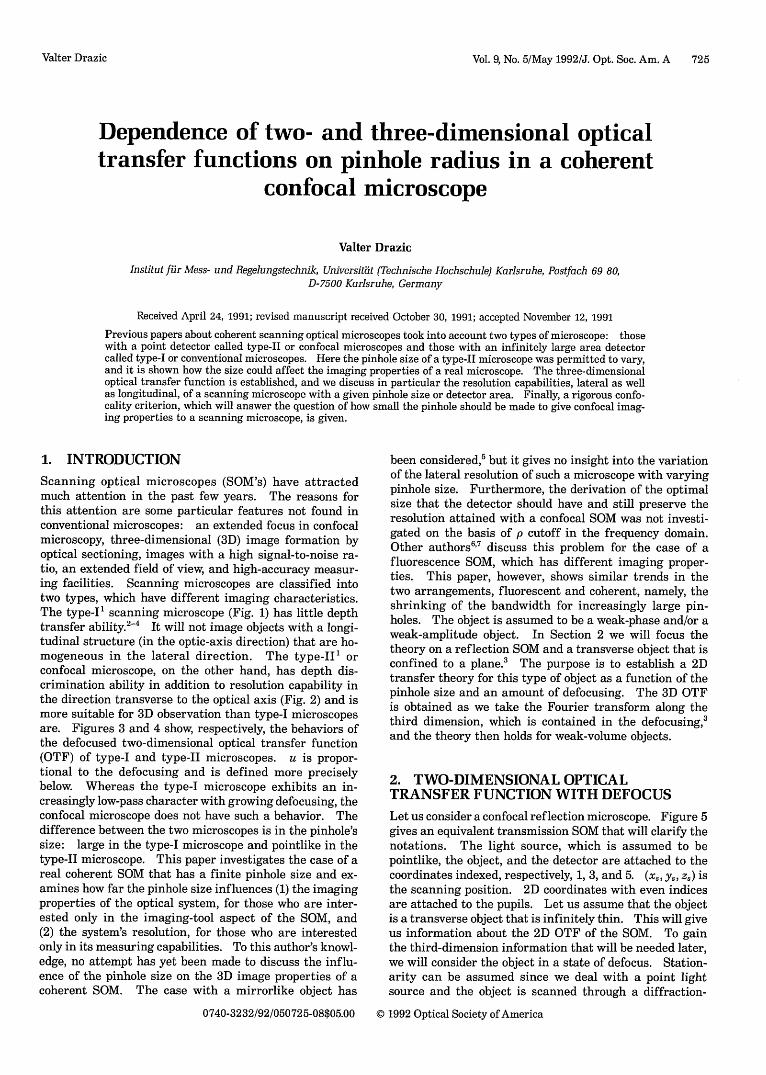
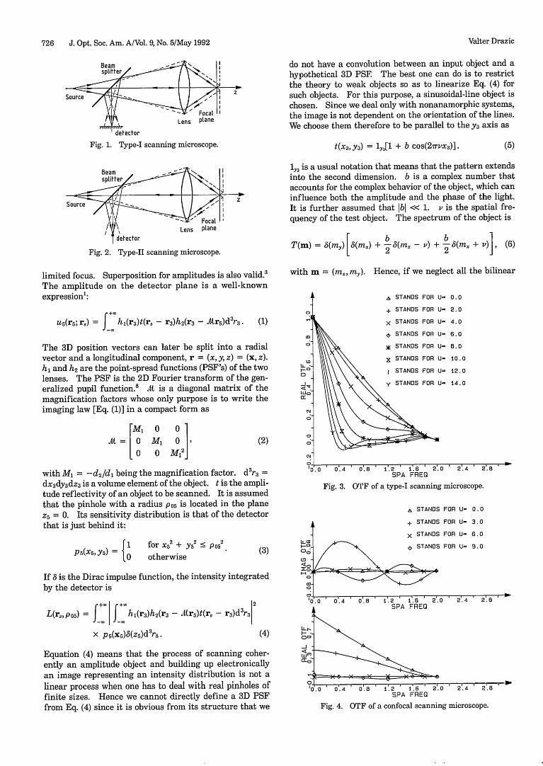
Scanning optical microscopes (SOM's) have attractedmuch attention in the past few years. The reasons forthis attention are some particular features not found inconventional microscopes: an extended focus in confocalmicroscopy, three-dimensional (3D) image formation byoptical sectioning, images with a high signal-to-noise ra-tio, an extended field of view, and high-accuracy measur-ing facilities. Scanning microscopes are classified intotwo types, which have different imaging characteristics.The type-I' scanning microscope (Fig. 1) has little depthtransfer ability.2 4 It will not image objects with a longi-tudinal structure (in the optic-axis direction) that are ho-mogeneous in the lateral direction. The type-II' orconfocal microscope, on the other hand, has depth dis-crimination ability in addition to resolution capability inthe direction transverse to the optical axis (Fig. 2) and ismore suitable for 3D observation than type-I microscopesare. Figures 3 and 4 show, respectively, the behaviors ofthe defocused two-dimensional optical transfer function(OTF) of type-I and type-II microscopes. u is propor-tional to the defocusing and is defined more preciselybelow. Whereas the type-I microscope exhibits an in-creasingly low-pass character with growing defocusing, theconfocal microscope does not have such a behavior. Thedifference between the two microscopes is in the pinhole'ssize: large in the type-I microscope and pointlike in thetype-II microscope. This paper investigates the case of areal coherent SOM that has a finite pinhole size and ex-amines how far the pinhole size influences (1) the imagingproperties of the optical system, for those who are inter-ested only in the imaging-tool aspect of the SOM, and(2) the system's resolution, for those who are interestedonly in its measuring capabilities. To this author's knowl-edge, no attempt has yet been made to discuss the influ-ence of the pinhole size on the 3D image properties of acoherent SOM. The case with a mirrorlike object has
been considered,5 but it gives no insight into the variationof the lateral resolution of such a microscope with varyingpinhole size. Furthermore, the derivation of the optimalsize that the detector should have and still preserve theresolution attained with a confocal SOM was not investi-gated on the basis of p cutoff in the frequency domain.Other authors6' 7 discuss this problem for the case of afluorescence SOM, which has different imaging proper-ties. This paper, however, shows similar trends in thetwo arrangements, fluorescent and coherent, namely, theshrinking of the bandwidth for increasingly large pin-holes. The object is assumed to be a weak-phase and/or aweak-amplitude object. In Section 2 we will focus thetheory on a reflection SOM and a transverse object that isconfined to a plane.' The purpose is to establish a 2Dtransfer theory for this type of object as a function of thepinhole size and an amount of defocusing. The 3D OTFis obtained as we take the Fourier transform along thethird dimension, which is contained in the defocusing,3
and the theory then holds for weak-volume objects.
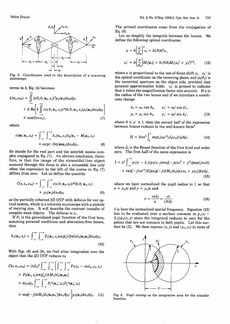
2. TWO-DIMENSIONAL OPTICALTRANSFER FUNCTION WITH DEFOCUSLet us consider a confocal reflection microscope. Figure 5gives an equivalent transmission SOM that will clarify thenotations. The light source, which is assumed to bepointlike, the object, and the detector are attached to thecoordinates indexed, respectively, 1, 3, and 5. (x, Ys, z) isthe scanning position. 2D coordinates with even indicesare attached to the pupils. Let us assume that the objectis a transverse object that is infinitely thin. This will giveus information about the 2D OTF of the SOM. To gainthe third-dimension information that will be needed later,we will consider the object in a state of defocus. Station-arity can be assumed since we deal with a point lightsource and the object is scanned through a diffraction-
0740-3232/92/050725-08$05.00 C 1992 Optical Society of America
Valter Drazic
726 J. Opt. Soc. Am. A/Vol. 9, No. 5/May 1992
Beam I -
Splte -.
Sourc 7 - .AFAR~~~~~~~~~Lens plane
detector
Fig. 1. Type-I scanning microscope.
z
do not have a convolution between an input object and ahypothetical 3D PSE The best one can do is to restrictthe theory to weak objects so as to linearize Eq. (4) forsuch objects. For this purpose, a sinusoidal-line object ischosen. Since we deal only with nonanamorphic systems,the image is not dependent on the orientation of the lines.We choose them therefore to be parallel to the y3 axis as
t(x3, Y3) = l13[1 + b cos(27rvx3)]. (5)
l43 is a usual notation that means that the pattern extendsinto the second dimension. b is a complex number thataccounts for the complex behavior of the object, which caninfluence both the amplitude and the phase of the light.It is further assumed that bI << 1. v is the spatial fre-quency of the test object. The spectrum of the object is
f etector
Fig. 2. Type-II scanning microscope.
limited focus. Superposition for amplitudes is also valid.3
The amplitude on the detector plane is a well-knownexpression':
u5(rs; rs) J hi(r3 )t(rs - r3)h2 (r3 - .Ar5)d 3r3. (1)
The 3D position vectors can later be split into a radialvector and a longitudinal component, r = (x, y, z) = (x, z).h, and h2 are the point-spread functions (PSF's) of the twolenses. The PSF is the 2D Fourier transform of the gen-eralized pupil function. A is a diagonal matrix of themagnification factors whose only purpose is to write theimaging law [Eq. (1)] in a compact form as
M 0 0
Al= 0 ml 0 O M M12
(2)
with M, = -d2 /d, being the magnification factor. dr 3 =
dx~dY3 dz3 is a volume element of the object. t is the ampli-tude reflectivity of an object to be scanned. It is assumedthat the pinhole with a radius P05 is located in the planeZ5 = 0. Its sensitivity distribution is that of the detectorthat is just behind it:
[ 1 or x2 + y 2 < po2ps(xs, ys) = for X5 + y Po otherwise
(3)
T(m) = (m) [8(mx) + 2 6(m, - v) + 2 5(mx + v)1, (6)
with m = (ms, my). Hence, if we neglect all the bilinear
A STANDS FOR U- 0.0
+ STANDS FOR U- 2.0
X STANDS FOR U- 4.0
0 STANDS FOR U- 6.0
x STANDS FOR U- 6.0
X STANDS FOR U- 10.0
I STANDS FOR U- 12.0
, STANDS FOR U- 14.0
Fig. 3. OTF of a type-I scanning microscope.
A STANDS FOR U- 0. 0
+ STANDS FOR U- 3.0
LLW
05c3
O.
If 5 is the Dirac impulse function, the intensity integratedby the detector is
+L +d 2L(rs, P05) = | | hi(r3)h2(r3 - Ars~t(r - r3)d3 r3
x p5(x5)6(z5)d3r5. (4)
Equation (4) means that the process of scanning coher-ently an amplitude object and building up electronicallyan image representing an intensity distribution is not alinear process when one has to deal with real pinholes offinite sizes. Hence we cannot directly define a 3D PSFfrom Eq. (4) since it is obvious from its structure that we
X S
S SI
*O.O
*ANOS FOR U- 6.0
FANDS FOR U- 9.0
0. 4 '. 8 ' i. 2 1t. 6 2 .. 0 2 .4 2 .SPA FREG
Fig. 4. OTF of a confocal scanning microscope.
r as
. . . . _l
Valter Drazic
k
Vol. 9, No. 5/May 1992/J. Opt. Soc. Am. A 727
The primed coordinates come from the conjugation ofEq. (8).
Let us simplify the integrals between the braces. Wedefine the following optical coordinates:
U = k(a-) Zs = k(NA)2z0,
V5' = k(d-)Mi1Ix511 = k(NA)Ml(x52 + y52)1/2,
Fig. 5. Coordinates used in the description of a scanningmicroscope.
terms in b, Eq. (4) becomes+x0
L(r 3, po5) = if IC(, 0; X5 , ZJ) 2ps(xs)dxsdy5
+ 2 Re[b if C(v, 0; X5, Z,)C*(0, 0; X 5 , Zs)P5(X5)dX 5dY 5]
X cos(27rvx,),
where
c(m; X5, Z) =1 f hl(x3, z 8)h2(x3 - MiX5, Z)
x exp(-27rjmX3)dx3dy3 .
(7)
(8)
Re stands for the real part and the asterisk means com-plex conjugated in Eq. (7). An obvious conclusion, there-fore, is that the image of the sinusoidal-line objectscanned through the focus is also a sinusoidal line onlywhen the expression to the left of the cosine in Eq. (7)differs from zero. Let us define the quantity
C(V Zs, Po5) = J C(V, 0; X5 , Z)C*(O, 0; X5, Zs)
x p5(x5)dx5dy5 (9)
as the partially coherent 2D OTF with defocus for our op-tical system, which is a coherent microscope with a pinholeof varying size. It will describe the contrast transfer ofcomplex weak objects. The defocus is z,.
If P, is the generalized pupil function of the first lens,assuming paraxial conditions and aberration-free lenses,then
where u is proportional to the out-of-focus shift z,. v' isthe optical coordinate on the receiving plane, and (a/d2 ) isthe numerical aperture on the object side, provided thatparaxial approximation holds. V5 ' is primed to indicatethat it takes the magnification factor into account. If a isthe radius of the two lenses and if we introduce a coordi-nate change
X = p5 cos 15, X4 = ap' cos 04',
Y5 = P5 sin 0, Y4 = ap' sin 04', (13)
where 0 p' 1, then the second half of the expressionbetween braces reduces to the well-known form9
II = 27a 2 ' exp(jup' 2 )J0(vs5p')p'dp', (14)
where Jo is the Bessel function of the first kind and orderzero. The first half of the same expression is
I = a2 J fp(X - y)p2(x,y)exp[-ju(x + y2)]exp(juxi)
x exp[-j(u 2 /2)]exp[-j(kM1/d2)a(xx5 + yy5)]dxdy,(15)
where we have normalized the pupil radius to 1 so thatx = x4/a andy = y4 /a and
- vAd2 vAv = =
a (NA)(16)
v is here the normalized spatial frequency. Equation (15)has to be evaluated over a surface common to p(x -vAy)p2 (x,y) since the integrand reduces to zero for thepoints that are not common to both pupils. Let this sur-face be (). We then express (x, y) and (X5, ys) in term of
h(x, z) =E _ Pl(X2, z0)exp[j(2v/Ad2)x3x2]dx2dy2.(10)
With Eqs. (8) and (9), we find after integration over theobject that the 2D OTF reduces to
C(V, Zs, PO5) = (Ad 2 )2J+X +0
X0 L 0 11* X1::X P(X 4 - vAd2, Y4 Zs)
x P2(x 4, z.)exp[j(kMi/d2 )x4 x5]
x d 4 dy 4 J f Pl*(X4 z 0)P2 *(x 4 Z)
x exp[-j(kM/d 2)x5x 4 ']dx4'dy 4' }5(x5)dx5dy.5. (11) Fig. 6. Pupil overlap as the integration area for the transferfunction.
Y3-YS ,zXS
_Z3,ZS
(12)
Valter Drazic
728 J. Opt. Soc. Am. A/Vol. 9, No. 5/May 1992
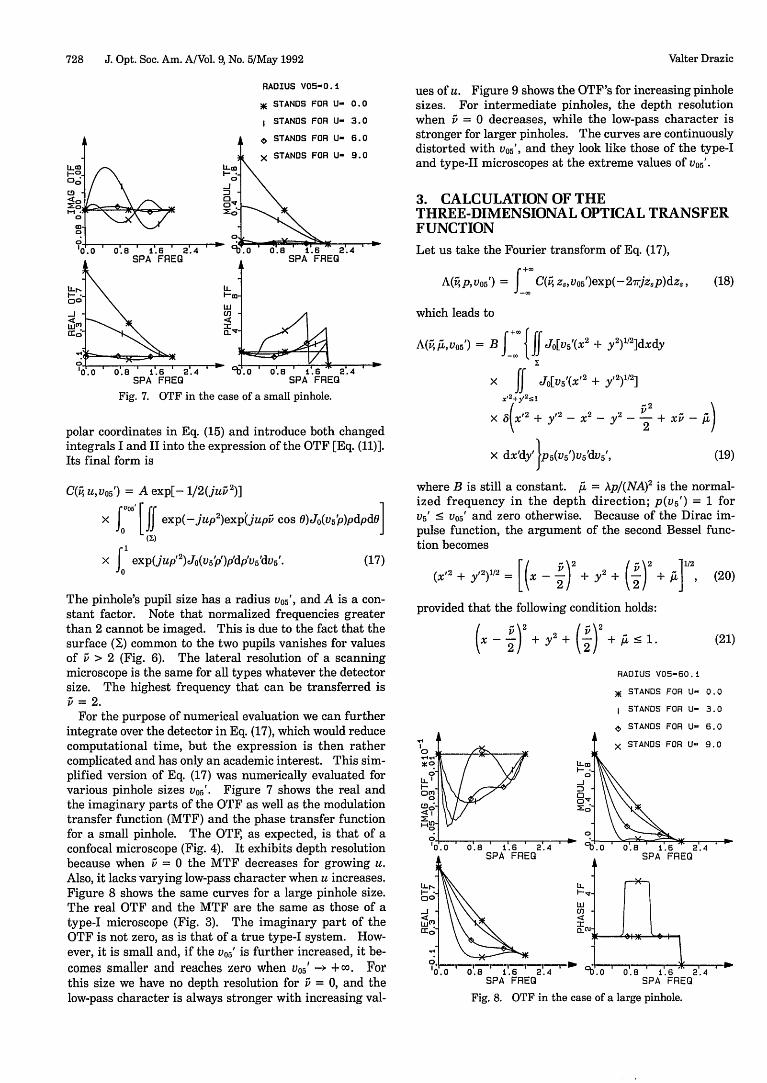
RADIUS V05-0.1
STANDS FOR U- 0.0
STANDS FOR U- 3.0
NE
Fig. 7. OTF in the case of a small pinhole.
polar coordinates in Eq. (15) and introduce both changedintegrals I and II into the expression of the OTF [Eq. (11)].Its final form is
C(Q4 u,V05 ') = A exp[- 1/2(jui 2 )]
x |5 [if exp(-jup 2 )exptjupi cos 0)Jo(Vs'p)pdpd0l(Y)
x f' exp(jup'2 )Jo(Vsp')p'dp'us'dvs'.
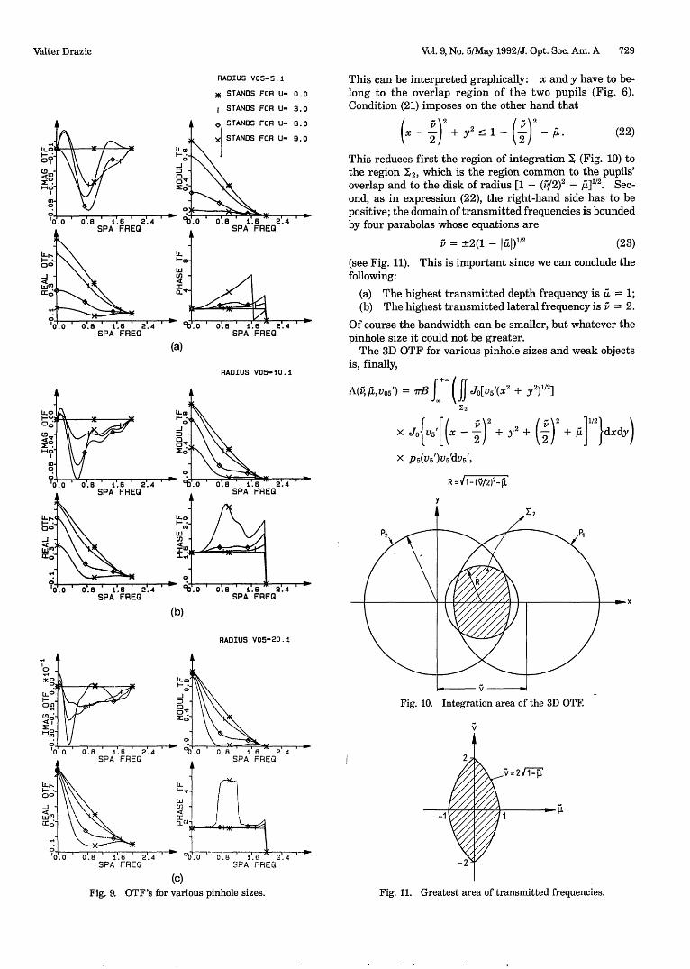
ues of u. Figure 9 shows the OTF's for increasing pinholesizes. For intermediate pinholes, the depth resolutionwhen = 0 decreases, while the low-pass character isstronger for larger pinholes. The curves are continuouslydistorted with v05 ', and they look like those of the type-Iand type-II microscopes at the extreme values of V05'.
3. CALCULATION OF THETHREE-DIMENSIONAL OPTICAL TRANSFERFUNCTION
Let us take the Fourier transform of Eq. (17),
A(i, p, V0 5 ') = fC(iv Zs, V0s5)exp(- 2^Trjzp)dz., (18)
which leads to
A(iv A, V05) = B f Jo[V5,(x2+ y
2) "2]dxdy
x if JO[V5 (X 2 + y2)12]
X 2
+y 2 S
X +12 + y 2 - - Y2 _-+ x -A/2
x dx'dy' p5(v5')vs5dV5', (19)
where B is still a constant. Ai = Ap/(NA)2 is the normal-ized frequency in the depth direction; p(V5') = 1 forU5' < 0 5 ' and zero otherwise. Because of the Dirac im-pulse function, the argument of the second Bessel func-tion becomes
(17)
The pinhole's pupil size has a radius 05', and A is a con-stant factor. Note that normalized frequencies greaterthan 2 cannot be imaged. This is due to the fact that thesurface () common to the two pupils vanishes for valuesof > 2 (Fig. 6). The lateral resolution of a scanningmicroscope is the same for all types whatever the detectorsize. The highest frequency that can be transferred is
= 2.For the purpose of numerical evaluation we can further
integrate over the detector in Eq. (17), which would reducecomputational time, but the expression is then rathercomplicated and has only an academic interest. This sim-plified version of Eq. (17) was numerically evaluated forvarious pinhole sizes 05'. Figure 7 shows the real andthe imaginary parts of the OTF as well as the modulationtransfer function (MTF) and the phase transfer functionfor a small pinhole. The OTF, as expected, is that of aconfocal microscope (Fig. 4). It exhibits depth resolutionbecause when = 0 the MTF decreases for growing u.Also, it lacks varying low-pass character when u increases.Figure 8 shows the same curves for a large pinhole size.The real OTF and the MTF are the same as those of atype-I microscope (Fig. 3). The imaginary part of theOTF is not zero, as is that of a true type-I system. How-ever, it is small and, if the V05' is further increased, it be-comes smaller and reaches zero when V05' -+ -oo. Forthis size we have no depth resolution for = 0, and thelow-pass character is always stronger with increasing val-
(20)[( 2) (2~) 12(X'2 + y 2)"/2 = [( - + y2 + +
provided that the following condition holds:
( )2 (2
*00o
I-ocr'
Hit
0D;cD5I
t-u,
(21)
RADIUS V05-60.i
ae STANDS FOR U- 0.0
I STANDS FOR U- 3.0
, STANDS FOR U- 6.0
i X STANDS FOR U- 9. 0
°V.o 0'.8 i.6 2.4SPA FREQ
:,Vi
- I _ 8 1 l,* 0.8 i.6 2.4 -0.0 0.8 i.6 2.4SPA FREG SPA FREG
Fig. 8. OTF in the case of a large pinhole.
.0
I-..00-J cc
crcc;
0O'.0
LLm
-J
0o
0
.o 0'.8 i.6 2.4SPA FREO
L
I-U
'a
T*H- - X - r--n - l---r--v->
Valter Drazie
. . . . . . .
Vol. 9, No. 5/May 1992/J. Opt. Soc. Am. A 729
RADIUS V05-5.1
XE STANDS FOR U- 0.0
i STANDS FOR U- 3.0
0 STANDS FOR U- 6.0
(a)
RADIUS V05-10.i
This can be interpreted graphically: x and y have to be-long to the overlap region of the two pupils (Fig. 6).Condition (21) imposes on the other hand that
(x 2 + y_ _ 1 (i\22/2 (22)
This reduces first the region of integration X (Fig. 10) tothe region 12, which is the region common to the pupils'overlap and to the disk of radius [1 - (/2) 2 - /1]112. Sec-ond, as in expression (22), the right-hand side has to bepositive; the domain of transmitted frequencies is boundedby four parabolas whose equations are
= ±2(1 - 1) 12 (23)
(see Fig. 11). This is important since we can conclude thefollowing:
(a) The highest transmitted depth frequency is Ft. = 1;(b) The highest transmitted lateral frequency is v = 2.
Of course the bandwidth can be smaller, but whatever thepinhole size it could not be greater.
The 3D OTF for various pinhole sizes and weak objectsis, finally,
A(, A, vo5') = 7rB jj (| Jo[V5'(X 2 + y 2)1/2 ]
Y2
X JOV5'[(x - +,
X p 5 (V5 )u5'dV5',
y
(b)
RADIUS V05-20.1
Y2+ (v) + d ]}dxdy)
Fig. 10. Integration area of the 3D OTF.
(c)
Fig. 9. OTF's for various pinhole sizes.
v=21W1
Fig. 11. Greatest area of transmitted frequencies.
Valter Drazic
730 J. Opt. Soc. Am. A/Vol. 9, No. 5/May 1992
I V05= 7.5X V05= 5.0
aLO V05= 2.5 , =L'001i X V05= 0. -
o 0
cb.0 o 0.4 ' O'.8 1'. 2 'a 10.0
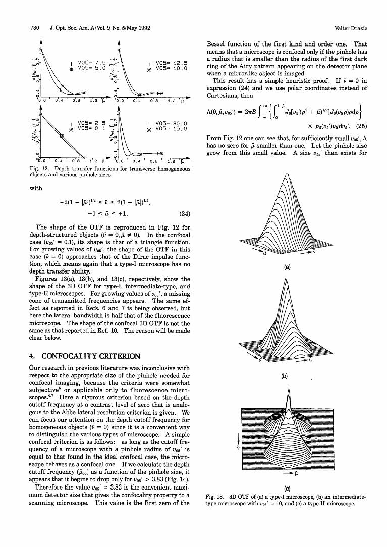
Fig. 12. Depth transfer functions forobjects and various pinhole sizes.
I V05= 12.5K V05= 10.0
1.2
V05= 30.0X V05= 15.0
Bessel function of the first kind and order one. Thatmeans that a microscope is confocal only if the pinhole hasa radius that is smaller than the radius of the first darkring of the Airy pattern appearing on the detector planewhen a mirrorlike object is imaged.
This result has a simple heuristic proof. If v = 0 inexpression (24) and we use polar coordinates instead ofCartesians, then
A(°~osV0) = 27TB f | Jo[v5'(p 2 + )1/2]Jo(usp)pdp}
x p5(u5')v'dv5'. (25)
From Fig. 12 one can see that, for sufficiently small V05 ', Ahas no zero for ,. smaller than one. Let the pinhole sizegrow from this small value. A size V5c' then exists for
0ta 4 0svr h o 2 u
transverse homogeneous
with
-2( - l)1'2 1 v s 2(1 - I)I2
-1 s < +1.
The shape of the OTF is reproduced in Fig. 12 fordepth-structured objects ( = 0,,a X 0). In the confocalcase ( 5' = 0.1), its shape is that of a triangle function.For growing values of v05', the shape of the OTF in thiscase ( = 0) approaches that of the Dirac impulse func-tion, which means again that a type-I microscope has nodepth transfer ability.
Figures 13(a), 13(b), and 13(c), repectively, show theshape of the 3D OTF for type-I, intermediate-type, andtype-II microscopes. For growing values of v05 ', a missingcone of transmitted frequencies appears. The same ef-fect as reported in Refs. 6 and 7 is being observed, buthere the lateral bandwidth is half that of the fluorescencemicroscope. The shape of the confocal 3D OTF is not thesame as that reported in Ref. 10. The reason will be madeclear below.
4. CONFOCALITY CRITERION
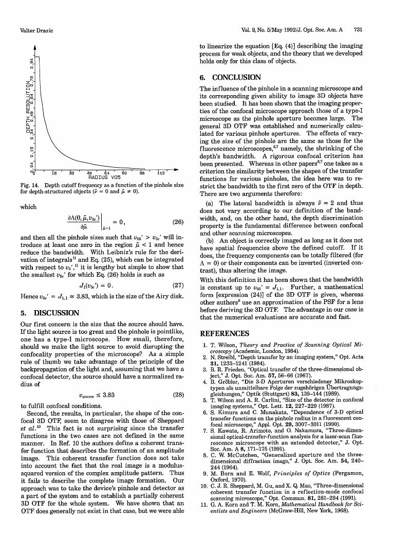
Our research in previous literature was inconclusive withrespect to the appropriate size of the pinhole needed forconfocal imaging, because the criteria were somewhatsubjective 5 or applicable only to fluorescence micro-scopes.6'7 Here a rigorous criterion based on the depthcutoff frequency at a contrast level of zero that is analo-gous to the Abbe lateral resolution criterion is given. Wecan focus our attention on the depth cutoff frequency forhomogeneous objects ( = 0) since it is a convenient wayto distinguish the various types of microscope. A simpleconfocal criterion is as follows: as long as the cutoff fre-quency of a microscope with a pinhole radius of v05' isequal to that found in the ideal confocal case, the micro-scope behaves as a confocal one. If we calculate the depthcutoff frequency (o) as a function of the pinhole size, itappears that it begins to drop only for v 5' > 3.83 (Fig. 14).
Therefore the value V05' 3.83 is the convenient maxi-mum detector size that gives the confocality property to ascanning microscope. This value is the first zero of the
(a)
(b)
(C)Fig. 13. 3D OTF of (a) a type-I microscope, (b) an intermediate-type microscope with v05' = 10, and (c) a type-II microscope.
(24)
Valter Drazic
Vol. 9, No. 5/May 1992/J. Opt. Soc. Am. A 731
'b' ' i6 2 48 4 0 56 1 12RADIUS V05
Fig. 14. Depth cutoff frequency as a function of the pinhole sizefor depth-structured objects (i = 0 and Au • 0).
which
dA(0,Xv&') = 0, (26)
and then all the pinhole sizes such that 05' > V5e' will in-troduce at least one zero in the region A < 1 and hencereduce the bandwidth. With Leibniz's rule for the deri-vation of integrals" and Eq. (25), which can be integratedwith respect to v5','1 it is lengthy but simple to show thatthe smallest v5,j for which Eq. (26) holds is such as
J(vs,') = 0. (27)
Hence V5,' = J 3.83, which is the size of the Airy disk.
5. DISCUSSION
Our first concern is the size that the source should have.If the light source is too great and the pinhole is pointlike,one has a type-I microscope. How small, therefore,should we make the light source to avoid disrupting theconfocality properties of the microscope? As a simplerule of thumb we take advantage of the principle of thebackpropagation of the light and, assuming that we have aconfocal detector, the source should have a normalized ra-dius of
Vsource < 3.83 (28)
to fulfill confocal conditions.Second, the results, in particular, the shape of the con-
focal 3D OTF, seem to disagree with those of Sheppardet al."0 This fact is not surprising since the transferfunctions in the two cases are not defined in the samemanner. In Ref. 10 the authors define a coherent trans-fer function that describes the formation of an amplitudeimage. This coherent transfer function does not takeinto account the fact that the real image is a modulus-squared version of the complex amplitude pattern. Thusit fails to describe the complete image formation. Ourapproach was to take the device's pinhole and detector asa part of the system and to establish a partially coherent3D OTF for the whole system. We have shown that anOTF does generally not exist in that case, but we were able
to linearize the equation [Eq. (4)] describing the imagingprocess for weak objects, and the theory that we developedholds only for this class of objects.
6. CONCLUSION
The influence of the pinhole in a scanning microscope andits corresponding given ability to image 3D objects havebeen studied. It has been shown that the imaging proper-ties of the confocal microscope approach those of a type-Imicroscope as the pinhole aperture becomes large. Thegeneral 3D OTF was established and numerically calcu-lated for various pinhole apertures. The effects of vary-ing the size of the pinhole are the same as those for thefluorescence microscopes,6' 7 namely, the shrinking of thedepth's bandwidth. A rigorous confocal criterion hasbeen presented. Whereas in other papers6 7 one takes as acriterion the similarity between the shapes of the transferfunctions for various pinholes, the idea here was to re-strict the bandwidth to the first zero of the OTF in depth.There are two arguments therefore:
(a) The lateral bandwidth is always v = 2 and thusdoes not vary according to our definition of the band-width, and, on the other hand, the depth discriminationproperty is the fundamental difference between confocaland other scanning microscopes.
(b) An object is correctly imaged as long as it does nothave spatial frequencies above the defined cutoff. If itdoes, the frequency components can be totally filtered (forA = 0) or their components can be inverted (inverted con-trast), thus altering the image.With this definition it has been shown that the bandwidthis constant up to vo5' = J,,. Further, a mathematicalform [expression (24)] of the 3D OTF is given, whereasother authors6 use an approximation of the PSF for a lensbefore deriving the 3D OTE The advantage in our case isthat the numerical evaluations are accurate and fast.
REFERENCES
1. T. Wilson, Theory and Practice of Scanning Optical Mi-croscopy (Academic, London, 1984).
2. N. Streibl, "Depth transfer by an imaging system," Opt. Acta31, 1233-1241 (1984).
3. B. R. Frieden, "Optical transfer of the three-dimensional ob-ject," J. Opt. Soc. Am. 57, 56-66 (1967).
4. B. Grobler, "Die 3-D Aperturen verschiedener Mikroskop-typen als unmittelbare Folge der zugehbrigen Ubertragungs-gleichungen," Optik (Stuttgart) 83, 139-144 (1989).
5. T. Wilson and A. R. Carlini, "Size of the detector in confocalimaging systems," Opt. Lett. 12, 227-229 (1987).
6. S. Kimura and C. Munakata, "Dependence of 3-D opticaltransfer functions on the pinhole radius in a fluorescent con-focal microscope," Appl. Opt. 29, 3007-3011 (1990).
7. S. Kawata, R. Arimoto, and 0. Nakamura, "Three-dimen-sional optical-transfer-function analysis for a laser-scan fluo-rescence microscope with an extended detector," J. Opt.Soc. Am. A 8, 171-175 (1991).
8. C. W McCutchen, "Generalized aperture and the three-dimensional diffraction image," J. Opt. Soc. Am. 54, 240-244 (1964).
9. M. Born and E. Wolf, Principles of Optics (Pergamon,Oxford, 1970).
10. C. J. R. Sheppard, M. Gu, and X. Q. Mao, "Three-dimensionalcoherent transfer function in a reflection-mode confocalscanning microscope," Opt. Commun. 81, 281-284 (1991).
11. G. A. Korn and T. M. Korn, Mathematical Handbook for Sci-entists and Engineers (McGraw-Hill, New York, 1968).
Valter Drazic
![High harmonic generation from relativistic plasma · sub-attosecond4 pulses [14]. 1.3 Coherent X-rays from Plasma The rst observation of high harmonic generation from plasma was accomplished](https://img.pdfslide.org/doc/110x75/5eaae210d038d77f81302c8c/high-harmonic-generation-from-relativistic-plasma-sub-attosecond4-pulses-14-13.jpg)