Embed Size (px)
Citation preview
�
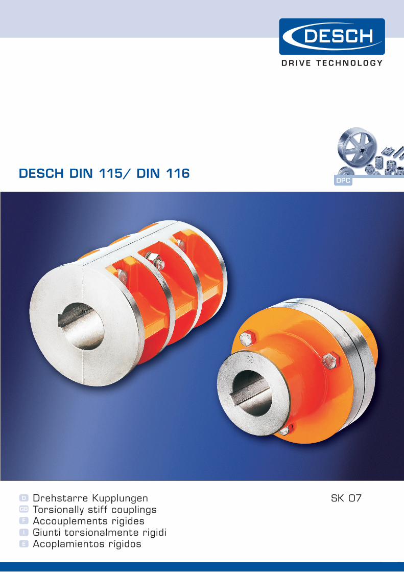
DESCH DIN 115/ DIN 116
SK 07D
GB
F
I
E
Drehstarre Kupplungen Torsionally stif f couplings Accouplements rigidesGiunti torsionalmente rigidiAcoplamientos rígidos

w h e n f u l l p o w e r i S n e e D e D
�
Drehstarre Kupplungen
Scheibenkupplungen DIN 116
Scheibenkupplungen sind drehstarre, besonders robuste und zuverlässige Wellenverbindungen, die Stöße und radial oder axial wirkende Belastungen
ertragen können. Die gekuppelten Wellen müssen genau fluchten. Die Scheibenkupplungen Form C sind mit einer Ausdrehung für Axialdruck- scheiben nach DIN 28135 versehen. (Anwendung z. B. bei senkrechten Rührwellen). Axialdruckscheiben gehören nicht zum Lieferumfang und sind gesondert zu bestellen. Die Anschlussmaße der Scheiben-
kupplungen entsprechen der DIN 116, die Zentrierung der Kupplungsteile erfolgt jedoch nur über Passschrauben. Normalausführung mit Passfedernut nach DIN 6885/1. Keilnuten nach DIN 6886 oder DIN 6887 auf Anfrage. Bei Wellenverbindungen mit unter-schiedlichen Wellendurchmessern wird die dem größten Wellendurchmesser zugeordnete Kupplungsgröße eingesetzt
(Reduzierkupplung).
D
Horizontale Anordnung: Form A Vertikale Anordnung: Form C Werkstoff: Normalausführung EN-GJL nach DIN EN 1561. Auf Anfrage in Stahl bis Größe 100 und in Stahlguss ab Größe 110
Schalenkupplungen DIN 115
Schalenkupplungen sind drehstarre und zuverlässige Wellenverbindungen, die Stöße und radial oder axial wirkende Belastungen ertragen können. Die gekuppelten Wellen müssen genau fluchten. Durch die beiden Schalen, die miteinander verschraubt werden, sind die Kupplungen sehr montage-freundlich und eignen sich daher aus-gezeichnet für hintereinander geschal-tete Wellen (z. B. Transmissionswellen). Beim Kuppeln von Wellen mit ver-schiedenen Durchmessern empfehlen wir, das dickere Wellenende auf den Durchmesser des dünneren abzuset-zen. Wenn dies nicht möglich ist, wird das dem größeren Wellendurchmesser entsprechende Modell mit abgesetz-ter Bohrung verwendet (Form B). Schalenkupplungen können auch mit einem Schutzmantel aus Stahlblech (Form AS; BS oder CS) geliefert werden. Alle Schalenkupplungen sind mit Passfedernut nach DIN 6885/1.
Horizontale Anordnung: Form A für Wellenenden mit gleichen Durchmessern Form B für Wellenenden mit unter-schiedlichen Durchmesser Vertikale Anordnung: Form A mit Hängefeder nach DIN 28134 Form C mit Eingegeringen nach DIN 115 Bl. 2 Werkstoff: Normalausführung EN-GJL nach DIN EN 1561. GS-45 auf Anfrage
Bitte beachten:
Bei Wellenverbindungen durch starre Kupplungen müssen die Wellen genau fluchten. Um eine übermäßige Biegebeanspruchung der Kupplung zu vermeiden, sind bei langen Wellen oder hohen Drehzahlen beidseits der Kupplungen Lager anzuordnen.
Schalenkupplungen DIN 115
Scheibenkupplungen DIN 116
�
Torsionally stiff couplingsGB
Clamp couplings DIN 115
Flange couplings DIN 116
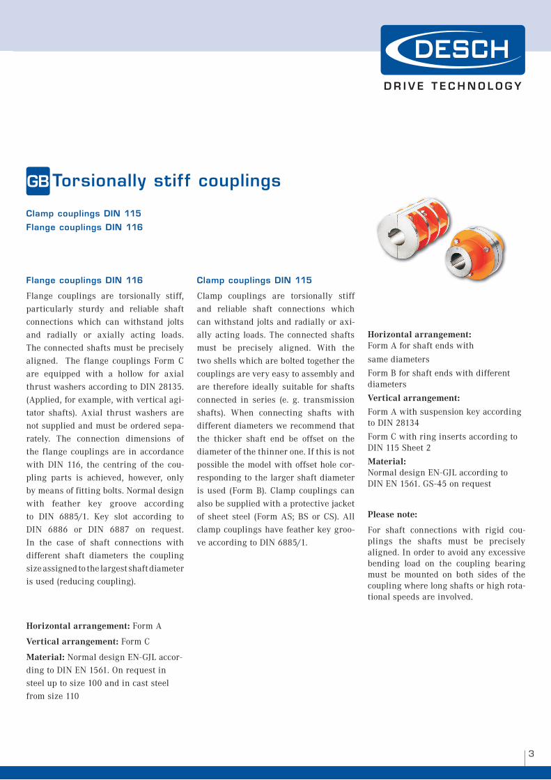
Flange couplings DIN 116
Flange couplings are torsionally stiff, particularly sturdy and reliable shaft connections which can withstand jolts and radially or axially acting loads.
The connected shafts must be precisely aligned. The flange couplings Form C are equipped with a hollow for axial thrust washers according to DIN 28135. (Applied, for example, with vertical agi-tator shafts). Axial thrust washers are not supplied and must be ordered sepa-rately. The connection dimensions of the flange couplings are in accordance with DIN 116, the centring of the cou-
pling parts is achieved, however, only by means of fitting bolts. Normal design with feather key groove according to DIN 6885/1. Key slot according to DIN 6886 or DIN 6887 on request. In the case of shaft connections with different shaft diameters the coupling size assigned to the largest shaft diameter is used (reducing coupling).
Horizontal arrangement: Form A
Vertical arrangement: Form C
Material: Normal design EN-GJL accor-ding to DIN EN 1561. On request in steel up to size 100 and in cast steel from size 110
Clamp couplings DIN 115
Clamp couplings are torsionally stiff and reliable shaft connections which can withstand jolts and radially or axi-ally acting loads. The connected shafts must be precisely aligned. With the two shells which are bolted together the couplings are very easy to assembly and are therefore ideally suitable for shafts connected in series (e. g. transmission shafts). When connecting shafts with different diameters we recommend that the thicker shaft end be offset on the diameter of the thinner one. If this is not possible the model with offset hole cor-responding to the larger shaft diameter is used (Form B). Clamp couplings can also be supplied with a protective jacket of sheet steel (Form AS; BS or CS). All clamp couplings have feather key groo-ve according to DIN 6885/1.
Horizontal arrangement: Form A for shaft ends with
same diameters
Form B for shaft ends with different diameters
Vertical arrangement:
Form A with suspension key according to DIN 28134
Form C with ring inserts according to DIN 115 Sheet 2
Material: Normal design EN-GJL according to DIN EN 1561. GS-45 on request
Please note:
For shaft connections with rigid cou-plings the shafts must be precisely aligned. In order to avoid any excessive bending load on the coupling bearing must be mounted on both sides of the coupling where long shafts or high rota-tional speeds are involved.
w h e n f u l l p o w e r i S n e e D e D
�
Accouplements rigidesF
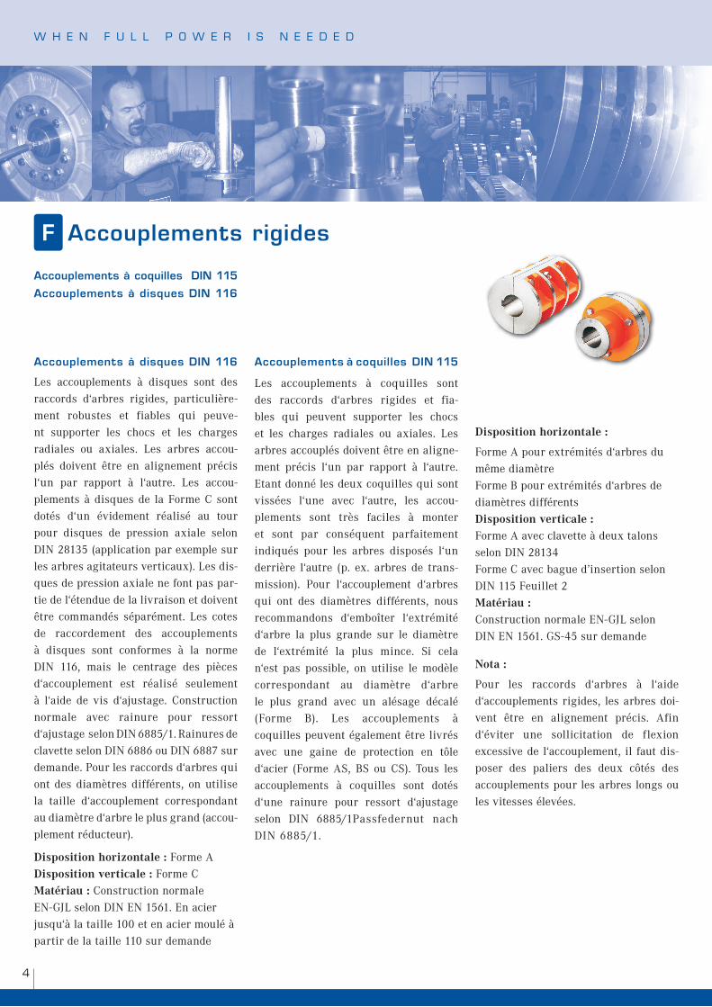
Accouplements à disques DIN 116
Les accouplements à disques sont des raccords d‘arbres rigides, particulière-ment robustes et fiables qui peuve-nt supporter les chocs et les charges radiales ou axiales. Les arbres accou-plés doivent être en alignement précis l‘un par rapport à l‘autre. Les accou-plements à disques de la Forme C sont dotés d‘un évidement réalisé au tour pour disques de pression axiale selon DIN 28135 (application par exemple sur les arbres agitateurs verticaux). Les dis-ques de pression axiale ne font pas par-tie de l‘étendue de la livraison et doivent être commandés séparément. Les cotes de raccordement des accouplements à disques sont conformes à la norme DIN 116, mais le centrage des pièces d‘accouplement est réalisé seulement à l‘aide de vis d‘ajustage. Construction normale avec rainure pour ressort d‘ajustage selon DIN 6885/1. Rainures de clavette selon DIN 6886 ou DIN 6887 sur demande. Pour les raccords d‘arbres qui ont des diamètres différents, on utilise la taille d‘accouplement correspondant au diamètre d‘arbre le plus grand (accou-plement réducteur).
Disposition horizontale : Forme A Disposition verticale : Forme C Matériau : Construction normale EN-GJL selon DIN EN 1561. En acier jusqu‘à la taille 100 et en acier moulé à partir de la taille 110 sur demande
Accouplements à coquilles DIN 115
Les accouplements à coquilles sont
des raccords d‘arbres rigides et fia-bles qui peuvent supporter les chocs et les charges radiales ou axiales. Les
arbres accouplés doivent être en aligne-ment précis l‘un par rapport à l‘autre. Etant donné les deux coquilles qui sont vissées l‘une avec l‘autre, les accou-plements sont très faciles à monter et sont par conséquent parfaitement indiqués pour les arbres disposés l‘un derrière l‘autre (p. ex. arbres de trans-mission). Pour l‘accouplement d‘arbres qui ont des diamètres différents, nous recommandons d‘emboîter l‘extrémité d‘arbre la plus grande sur le diamètre de l‘extrémité la plus mince. Si cela n‘est pas possible, on utilise le modèle correspondant au diamètre d‘arbre le plus grand avec un alésage décalé (Forme B). Les accouplements à coquilles peuvent également être livrés avec une gaine de protection en tôle d‘acier (Forme AS, BS ou CS). Tous les
accouplements à coquilles sont dotés d‘une rainure pour ressort d‘ajustage selon DIN 6885/1Passfedernut nach DIN 6885/1.
Disposition horizontale :
Forme A pour extrémités d‘arbres du même diamètre Forme B pour extrémités d‘arbres de diamètres différents Disposition verticale : Forme A avec clavette à deux talons selon DIN 28134 Forme C avec bague d’insertion selon DIN 115 Feuillet 2 Matériau : Construction normale EN-GJL selon DIN EN 1561. GS-45 sur demande
Nota :
Pour les raccords d‘arbres à l‘aide d‘accouplements rigides, les arbres doi-vent être en alignement précis. Afin d‘éviter une sollicitation de flexion excessive de l‘accouplement, il faut dis-poser des paliers des deux côtés des accouplements pour les arbres longs ou les vitesses élevées.
Accouplements à coquilles DIN 115
Accouplements à disques DIN 116
�
Giunti torsionalmente rigidiI
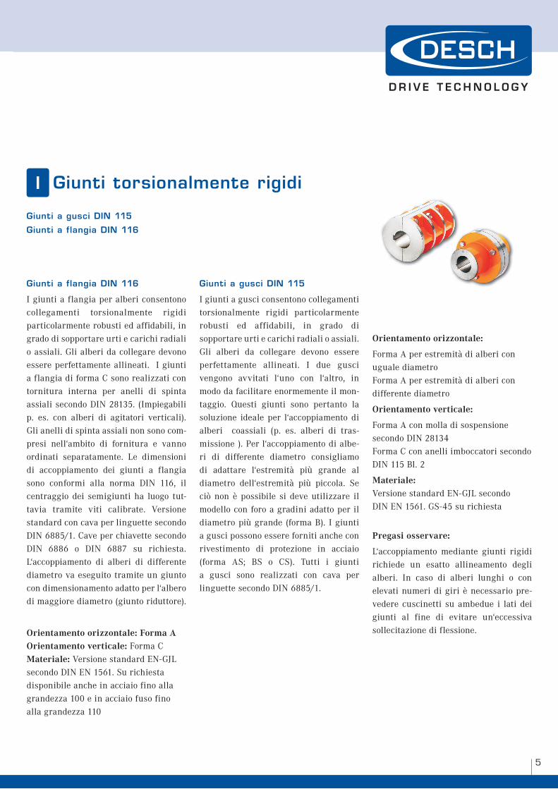
Giunti a flangia DIN 116
I giunti a flangia per alberi consentono collegamenti torsionalmente rigidi particolarmente robusti ed affidabili, in grado di sopportare urti e carichi radiali o assiali. Gli alberi da collegare devono essere perfettamente allineati. I giunti a flangia di forma C sono realizzati con tornitura interna per anelli di spinta assiali secondo DIN 28135. (Impiegabili p. es. con alberi di agitatori verticali). Gli anelli di spinta assiali non sono com-presi nell‘ambito di fornitura e vanno ordinati separatamente. Le dimensioni di accoppiamento dei giunti a flangia sono conformi alla norma DIN 116, il centraggio dei semigiunti ha luogo tut-tavia tramite viti calibrate. Versione standard con cava per linguette secondo DIN 6885/1. Cave per chiavette secondo DIN 6886 o DIN 6887 su richiesta. L‘accoppiamento di alberi di differente diametro va eseguito tramite un giunto con dimensionamento adatto per l‘albero di maggiore diametro (giunto riduttore).
Orientamento orizzontale: Forma A Orientamento verticale: Forma C Materiale: Versione standard EN-GJL secondo DIN EN 1561. Su richiesta disponibile anche in acciaio fino alla grandezza 100 e in acciaio fuso fino alla grandezza 110
Giunti a gusci DIN 115
I giunti a gusci consentono collegamenti
torsionalmente rigidi particolarmente robusti ed affidabili, in grado di sopportare urti e carichi radiali o assiali.
Gli alberi da collegare devono essere perfettamente allineati. I due gusci vengono avvitati l‘uno con l‘altro, in modo da facilitare enormemente il mon-taggio. Questi giunti sono pertanto la soluzione ideale per l‘accoppiamento di alberi coassiali (p. es. alberi di tras-missione ). Per l‘accoppiamento di albe-ri di differente diametro consigliamo di adattare l‘estremità più grande al diametro dell‘estremità più piccola. Se ciò non è possibile si deve utilizzare il modello con foro a gradini adatto per il diametro più grande (forma B). I giunti a gusci possono essere forniti anche con rivestimento di protezione in acciaio (forma AS; BS o CS). Tutti i giunti a gusci sono realizzati con cava per linguette secondo DIN 6885/1.
Orientamento orizzontale:
Forma A per estremità di alberi con uguale diametro Forma A per estremità di alberi con differente diametro
Orientamento verticale:
Forma A con molla di sospensione secondo DIN 28134 Forma C con anelli imboccatori secondo DIN 115 Bl. 2
Materiale: Versione standard EN-GJL secondo DIN EN 1561. GS-45 su richiesta
Pregasi osservare:
L‘accoppiamento mediante giunti rigidi richiede un esatto allineamento degli alberi. In caso di alberi lunghi o con elevati numeri di giri è necessario pre-vedere cuscinetti su ambedue i lati dei giunti al fine di evitare un‘eccessiva sollecitazione di flessione.
Giunti a gusci DIN 115
Giunti a flangia DIN 116
w h e n f u l l p o w e r i S n e e D e D
�
Acoplamientos rígidosE
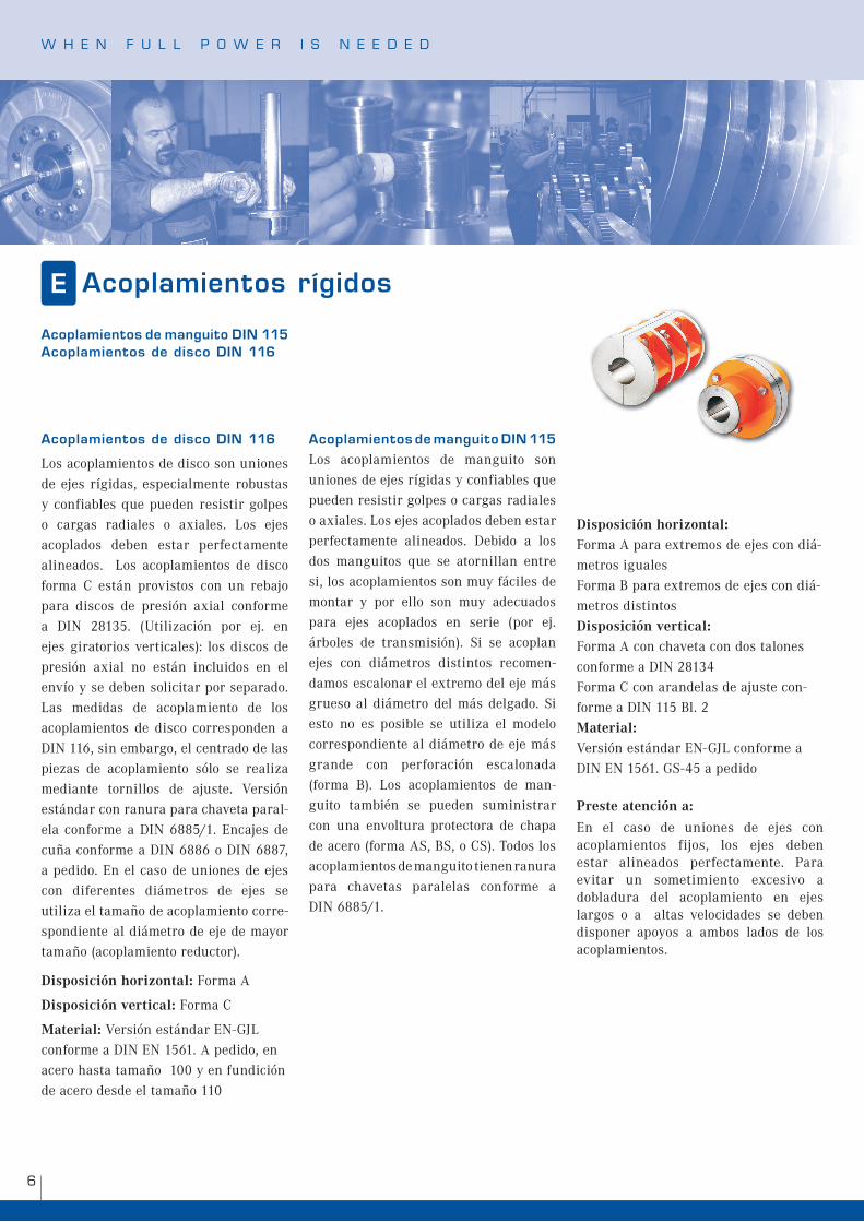
Acoplamientos de disco DIN 116
Los acoplamientos de disco son uniones de ejes rígidas, especialmente robustas y confiables que pueden resistir golpes o cargas radiales o axiales. Los ejes
acoplados deben estar perfectamente alineados. Los acoplamientos de disco forma C están provistos con un rebajo para discos de presión axial conforme a DIN 28135. (Utilización por ej. en ejes giratorios verticales): los discos de presión axial no están incluidos en el envío y se deben solicitar por separado. Las medidas de acoplamiento de los acoplamientos de disco corresponden a DIN 116, sin embargo, el centrado de las piezas de acoplamiento sólo se realiza mediante tornillos de ajuste. Versión estándar con ranura para chaveta paral-ela conforme a DIN 6885/1. Encajes de
cuña conforme a DIN 6886 o DIN 6887, a pedido. En el caso de uniones de ejes con diferentes diámetros de ejes se utiliza el tamaño de acoplamiento corre-spondiente al diámetro de eje de mayor tamaño (acoplamiento reductor).
Disposición horizontal: Forma A
Disposición vertical: Forma C
Material: Versión estándar EN-GJL conforme a DIN EN 1561. A pedido, en acero hasta tamaño 100 y en fundición de acero desde el tamaño 110
Acoplamientos de manguito DIN 115
Los acoplamientos de manguito son uniones de ejes rígidas y confiables que pueden resistir golpes o cargas radiales o axiales. Los ejes acoplados deben estar perfectamente alineados. Debido a los dos manguitos que se atornillan entre si, los acoplamientos son muy fáciles de montar y por ello son muy adecuados para ejes acoplados en serie (por ej. árboles de transmisión). Si se acoplan ejes con diámetros distintos recomen-damos escalonar el extremo del eje más grueso al diámetro del más delgado. Si esto no es posible se utiliza el modelo
correspondiente al diámetro de eje más grande con perforación escalonada (forma B). Los acoplamientos de man-guito también se pueden suministrar con una envoltura protectora de chapa de acero (forma AS, BS, o CS). Todos los acoplamientos de manguito tienen ranura para chavetas paralelas conforme a DIN 6885/1.
Disposición horizontal: Forma A para extremos de ejes con diá-metros iguales Forma B para extremos de ejes con diá-metros distintos Disposición vertical: Forma A con chaveta con dos talones conforme a DIN 28134 Forma C con arandelas de ajuste con-forme a DIN 115 Bl. 2 Material: Versión estándar EN-GJL conforme a DIN EN 1561. GS-45 a pedido
Preste atención a:
En el caso de uniones de ejes con acoplamientos fijos, los ejes deben estar alineados perfectamente. Para evitar un sometimiento excesivo a dobladura del acoplamiento en ejes largos o a altas velocidades se deben disponer apoyos a ambos lados de los acoplamientos.
Acoplamientos de manguito DIN 115 Acoplamientos de disco DIN 116
7
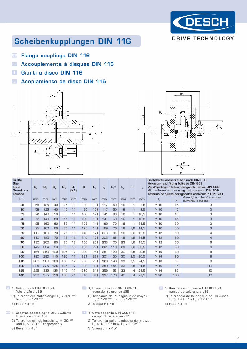
Scheibenkupplungen DIN 116
Flange couplings DIN 116
Accouplements á disques DIN 116
Giunti a disco DIN 116
Acoplamiento de disco DIN 116
GB
F
I
E
Größe Size Taille Grandezza Tamaño
D2 D3 D4 D5 D6(H7)
K L1 L2 L32) L4 F3) T1
Sechskant-Passschrauben nach DIN 609Hexagon-head fitting bolts to DIN 609Vis d‘ajustage à têtes hexagonales selon DIN 609Viti calibrate a testa esagonale secondo DIN 609Tornillos de ajuste hexagonales conforme a DIN 609
D��) mm mm mm mm mm mm mm mm mm mm mm mm D7 l�
Anzahl/ number/ nombre/ numero/ cantidad
25 �8 ��� �0 �� �� 90 �0� ��7 �0 �� � 8,� M �0 �� �
30 �8 ��� �0 �� �� 90 �0� ��7 �0 �� � 8,� M �0 �� �
35 7� ��0 �0 �� �� �00 ��� ��� �0 �� � �0,� M �0 �� �
40 7� ��0 �0 �� �� �00 ��� ��� �0 �� � �0,� M �0 �� �
45 9� ��0 �0 �� �� ��� ��� ��9 70 �8 � ��,� M �0 �0 �
50 9� ��0 �0 �� �� ��� ��� ��9 70 �8 �,� ��,� M �0 �0 �
55 ��0 �80 70 7� �� ��0 �7� �0� 8� �8 �,� ��,� M �� �0 �
60 ��0 �80 70 7� �� ��0 �7� �0� 8� �8 �,� ��,� M �� �0 �
70 ��0 �00 80 8� �� ��0 �0� ��� �00 �� �,� ��,� M �� �0 �
80 ��� ��� 90 9� �� �80 ��� ��� ��0 �� �,� �0,� M �� �0 8
90 ��� ��0 �00 �0� �7 �00 ��� �8� ��0 �0 �,� �0,� M �� 80 8
100 �80 �80 ��0 ��0 �7 ��� ��� �0� ��0 �0 �,� �0,� M �� 80 8
110 �00 �00 ��0 ��0 �7 ��0 �8� ��9 ��0 �� �,� ��,� M �� 8� 8
120 ��� ��� ��� ��� �7 �80 ��� ��9 ��� �� �,� ��,� M �� 8� �0
125 ��� ��� ��� ��� �7 �80 ��� ��9 ��� �� � ��,� M �� 8� �0
140 ��0 �7� ��0 ��0 �� ��0 ��� �97 �70 �0 � �8,� M �0 �00 �0
�) nuten nach Din ��8�/�; Toleranzfeld JS9
�) Toleranz der nabenlänge: l� ��0:+0,� bzw. l� > ��0:+0,�
�) fase f x ��°
�) Grooves according to Din ��8�/�; tolerance zone JS9
�) Tolerance of hub length: l� ��0:+0,� and l� > ��0:+0,� respectively
�) Bevel f x ��°
F
GB I
D E�) rainures selon Din ��8�/� ; zone de tolérance JS9
�) Tolérance de la longueur de moyeu : l� ��0:+0,� ou l� > ��0:+0,�
�) Biseau f x ��°
�) Cave secondo Din ��8�/�; campo di tolleranza JS9
�) Tolleranza della lunghezza del mozzo: l� ��0:+0,� bzw. l� > ��0:+0,�
�) Smusso f x ��°
�) ranuras conforme a Din ��8�/�; campo de tolerancia JS9
�) Tolerancia de la longitud de los cubos: l� ��0:+0,� o l� > ��0:+0,�
�) fase f x ��°
w h e n f u l l p o w e r i S n e e D e D
8
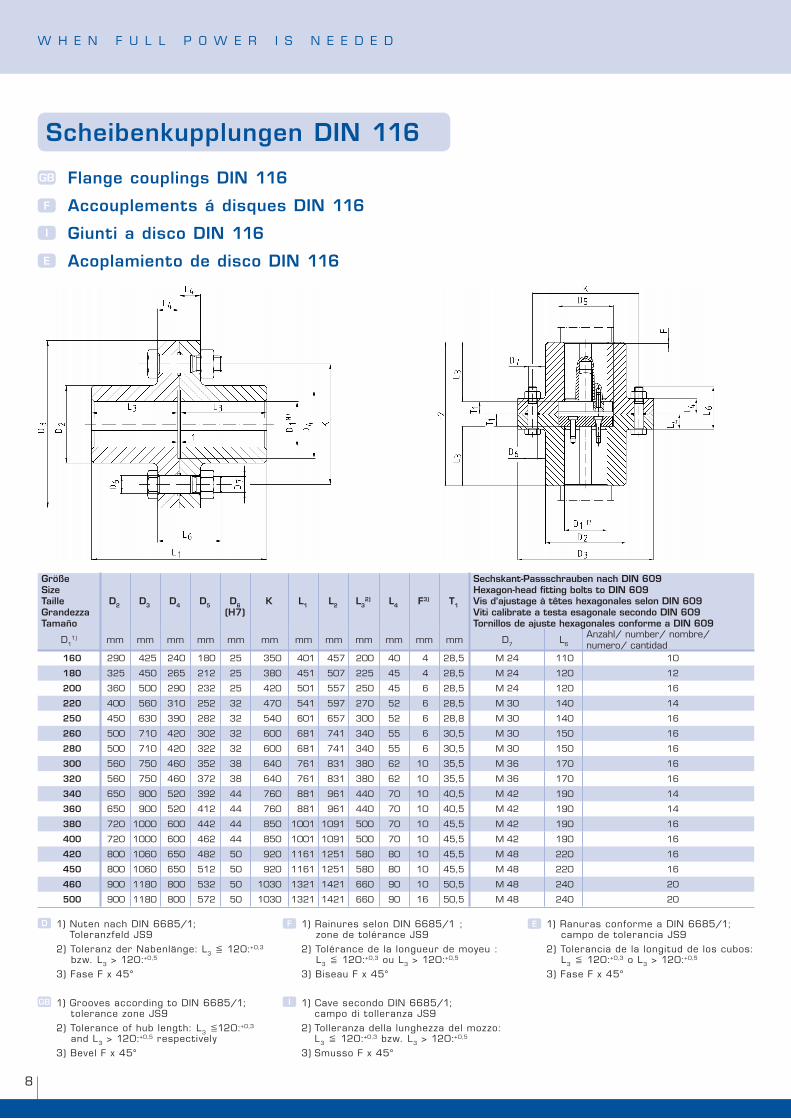
Scheibenkupplungen DIN 116
Flange couplings DIN 116
Accouplements á disques DIN 116
Giunti a disco DIN 116
Acoplamiento de disco DIN 116
GB
F
I
E
Größe Size Taille Grandezza Tamaño
D2 D3 D4 D5 D6(H7)
K L1 L2 L32) L4 F3) T1
Sechskant-Passschrauben nach DIN 609Hexagon-head fitting bolts to DIN 609Vis d‘ajustage à têtes hexagonales selon DIN 609Viti calibrate a testa esagonale secondo DIN 609Tornillos de ajuste hexagonales conforme a DIN 609
D��) mm mm mm mm mm mm mm mm mm mm mm mm D7 l�
Anzahl/ number/ nombre/ numero/ cantidad
160 �90 ��� ��0 �80 �� ��0 �0� ��7 �00 �0 � �8,� M �� ��0 �0
180 ��� ��0 ��� ��� �� �80 ��� �07 ��� �� � �8,� M �� ��0 ��
200 ��0 �00 �90 ��� �� ��0 �0� ��7 ��0 �� � �8,� M �� ��0 ��
220 �00 ��0 ��0 ��� �� �70 ��� �97 �70 �� � �8,� M �0 ��0 ��
250 ��0 ��0 �90 �8� �� ��0 �0� ��7 �00 �� � �8,8 M �0 ��0 ��
260 �00 7�0 ��0 �0� �� �00 �8� 7�� ��0 �� � �0,� M �0 ��0 ��
280 �00 7�0 ��0 ��� �� �00 �8� 7�� ��0 �� � �0,� M �0 ��0 ��
300 ��0 7�0 ��0 ��� �8 ��0 7�� 8�� �80 �� �0 ��,� M �� �70 ��
320 ��0 7�0 ��0 �7� �8 ��0 7�� 8�� �80 �� �0 ��,� M �� �70 ��
340 ��0 900 ��0 �9� �� 7�0 88� 9�� ��0 70 �0 �0,� M �� �90 ��
360 ��0 900 ��0 ��� �� 7�0 88� 9�� ��0 70 �0 �0,� M �� �90 ��
380 7�0 �000 �00 ��� �� 8�0 �00� �09� �00 70 �0 ��,� M �� �90 ��
400 7�0 �000 �00 ��� �� 8�0 �00� �09� �00 70 �0 ��,� M �� �90 ��
420 800 �0�0 ��0 �8� �0 9�0 ���� ���� �80 80 �0 ��,� M �8 ��0 ��
450 800 �0�0 ��0 ��� �0 9�0 ���� ���� �80 80 �0 ��,� M �8 ��0 ��
460 900 ��80 800 ��� �0 �0�0 ���� ���� ��0 90 �0 �0,� M �8 ��0 �0
500 900 ��80 800 �7� �0 �0�0 ���� ���� ��0 90 �� �0,� M �8 ��0 �0
�) nuten nach Din ��8�/�; Toleranzfeld JS9
�) Toleranz der nabenlänge: l� ��0:+0,� bzw. l� > ��0:+0,�
�) fase f x ��°
�) Grooves according to Din ��8�/�; tolerance zone JS9
�) Tolerance of hub length: l� ��0:+0,� and l� > ��0:+0,� respectively
�) Bevel f x ��°
F
GB I
D E�) rainures selon Din ��8�/� ; zone de tolérance JS9
�) Tolérance de la longueur de moyeu : l� ��0:+0,� ou l� > ��0:+0,�
�) Biseau f x ��°
�) Cave secondo Din ��8�/�; campo di tolleranza JS9
�) Tolleranza della lunghezza del mozzo: l� ��0:+0,� bzw. l� > ��0:+0,�
�) Smusso f x ��°
�) ranuras conforme a Din ��8�/�; campo de tolerancia JS9
�) Tolerancia de la longitud de los cubos: l� ��0:+0,� o l� > ��0:+0,�
�) fase f x ��°
9
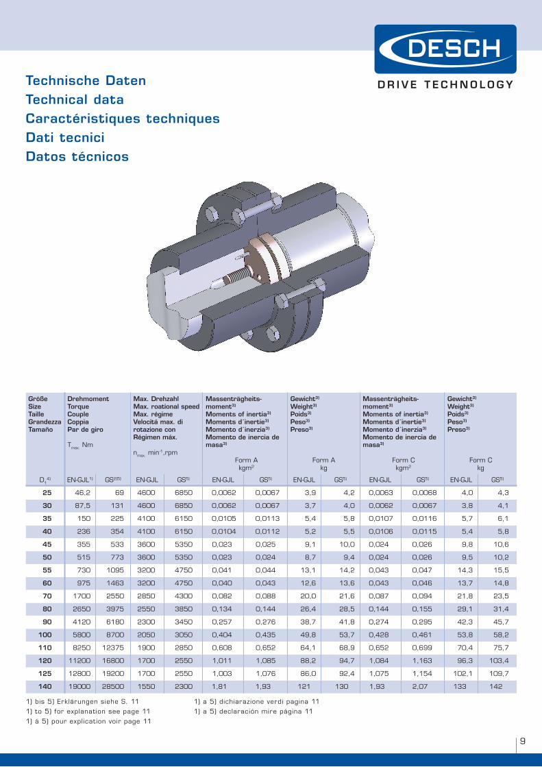
Größe SizeTailleGrandezzaTamaño
DrehmomentTorqueCoupleCoppia Par de giro
Tmax. nm
Max. DrehzahlMax. roational speedMax. régimeVelocitá max. di rotazione conRégimen máx.
nmax. min-�,rpm
Massenträgheits- moment3)
Moments of inertia3) Moments d´inertie3) Momento d´inerzia3) Momento de inercia de masa3)
form A kgm�
Gewicht3)
Weight3)
Poids3)
Peso3)
Preso3)
form Akg
Massenträgheits- moment3)
Moments of inertia3) Moments d´inertie3) Momento d´inerzia3) Momento de inercia de masa3)
form C kgm�
Gewicht3)
Weight3)
Poids3)
Peso3)
Preso3)
form Ckg
D��) en-GJl�) GS�)�) en-GJl GS�) en-GJl GS�) en-GJl GS�) en-GJl GS�) en-GJl GS�)
25 ��,� �9 ��00 �8�0 0,00�� 0,00�7 �,9 �,� 0,00�� 0,00�8 �,0 �,�
30 87,� ��� ��00 �8�0 0,00�� 0,00�7 �,7 �,0 0,00�� 0,00�7 �,8 �,�
35 ��0 ��� ��00 ���0 0,0�0� 0,0��� �,� �,8 0,0�07 0,0��� �,7 �,�
40 ��� ��� ��00 ���0 0,0�0� 0,0��� �,� �,� 0,0�0� 0,0��� �,� �,8
45 ��� ��� ��00 ���0 0,0�� 0,0�� 9,� �0,0 0,0�� 0,0�� 9,8 �0,�
50 ��� 77� ��00 ���0 0,0�� 0,0�� 8,7 9,� 0,0�� 0,0�� 9,� �0,�
55 7�0 �09� ��00 �7�0 0,0�� 0,0�� ��,� ��,� 0,0�� 0,0�7 ��,� ��,�
60 97� ���� ��00 �7�0 0,0�0 0,0�� ��,� ��,� 0,0�� 0,0�� ��,7 ��,8
70 �700 ���0 �8�0 ��00 0,08� 0,088 �0,0 ��,� 0,087 0,09� ��,8 ��,�
80 ���0 �97� ���0 �8�0 0,��� 0,��� ��,� �8,� 0,��� 0,��� �9,� ��,�
90 ���0 ��80 ��00 ���0 0,��7 0,�7� �8,7 ��,8 0,�7� 0,�9� ��,� ��,7
100 �800 8700 �0�0 �0�0 0,�0� 0,��� �9,8 ��,7 0,��8 0,��� ��,8 �8,�
110 8��0 ���7� �900 �8�0 0,�08 0,��� ��,� �8,9 0,��� 0,�99 70,� 7�,7
120 ���00 ��800 �700 ���0 �,0�� �,08� 88,� 9�,7 �,08� �,��� 9�,� �0�,�
125 ��800 �9�00 �700 ���0 �,00� �,07� 8�,0 9�,� �,07� �,��� �0�,� �09,7
140 �9000 �8�00 ���0 ��00 �,8� �,9� ��� ��0 �,9� �,07 ��� ���
Technische DatenTechnical data Caractéristiques techniquesDati tecniciDatos técnicos
�) bis �) erklärungen siehe S. ��
�) to �) for explanation see page ��
�) á �) pour explication voir page ��
�) a �) dichiarazione verdi pagina ��
�) a �) declaración mire página ��
w h e n f u l l p o w e r i S n e e D e D
�0
Größe SizeTailleGrandezzaTamaño
DrehmomentTorqueCoupleCoppia Par de giro
Tmax. nm
Max. DrehzahlMax. roational speedMax. régimeVelocitá max. di rotazione conRégimen máx.
nmax. min-�,rpm
Massenträgheits- moment3)
Moments of inertia3) Moments d´inertie3) Momento d´inerzia3) Momento de inercia de masa3)
form A kgm�
Gewicht3)
Weight3)
Poids3)
Peso3)
Preso3)
form Akg
Massenträgheits- moment3)
Moments of inertia3) Moments d´inertie3) Momento d´inerzia3) Momento de inercia de masa3)
form C kgm�
Gewicht3)
Weight3)
Poids3)
Peso3)
Preso3)
form Ckg
D��) en-GJl�) GS�)�) en-GJl GS�) en-GJl GS�) en-GJl GS�) en-GJl GS�) en-GJl GS�)
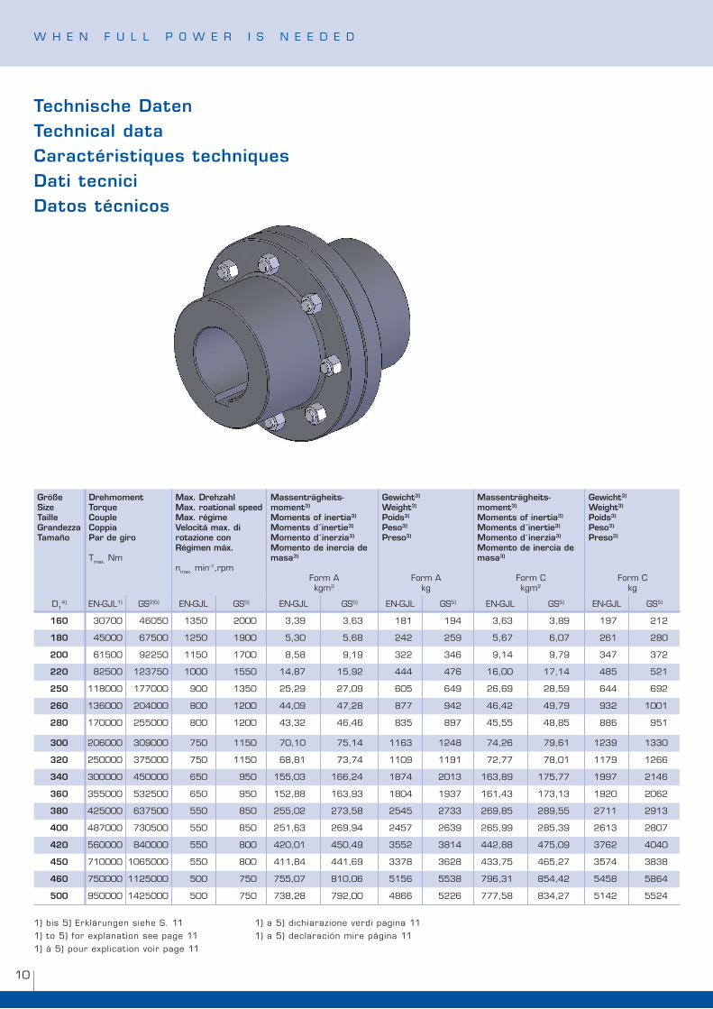
160 �0700 ��0�0 ���0 �000 �,�9 �,�� �8� �9� �,�� �,89 �97 ���
180 ��000 �7�00 ���0 �900 �,�0 �,�8 ��� ��9 �,�7 �,07 ��� �80
200 ���00 9���0 ���0 �700 8,�8 9,�9 ��� ��� 9,�� 9,79 ��7 �7�
220 8��00 ���7�0 �000 ���0 ��,87 ��,9� ��� �7� ��,00 �7,�� �8� ���
250 ��8000 �77000 900 ���0 ��,�9 �7,09 �0� ��9 ��,�9 �8,�9 ��� �9�
260 ���000 �0�000 800 ��00 ��,09 �7,�8 877 9�� ��,�� �9,79 9�� �00�
280 �70000 ���000 800 ��00 ��,�� ��,�� 8�� 897 ��,�� �8,8� 88� 9��
300 �0�000 �09000 7�0 ���0 70,�0 7�,�� ���� ���8 7�,�� 79,�� ���9 ���0
320 ��0000 �7�000 7�0 ���0 �8,8� 7�,7� ��09 ��9� 7�,77 78,0� ��79 ����
340 �00000 ��0000 ��0 9�0 ���,0� ���,�� �87� �0�� ���,89 �7�,77 �997 ����
360 ���000 ����00 ��0 9�0 ���,88 ���,9� �80� �9�7 ���,�� �7�,�� �9�0 �0��
380 ���000 ��7�00 ��0 8�0 ���,0� �7�,�8 ���� �7�� ��9,8� �89,�� �7�� �9��
400 �87000 7�0�00 ��0 8�0 ���,�� ��9,9� ���7 ���9 ���,99 �8�,�9 ���� �807
420 ��0000 8�0000 ��0 800 ��0,0� ��0,�9 ���� �8�� ���,88 �7�,09 �7�� �0�0
450 7�0000 �0��000 ��0 800 ���,8� ���,�9 ��78 ���8 ���,7� ���,�7 ��7� �8�8
460 7�0000 ����000 �00 7�0 7��,07 8�0,0� ���� ���8 79�,�� 8��,�� ���8 �8��
500 9�0000 ����000 �00 7�0 7�8,�8 79�,00 �8�� ���� 777,�8 8��,�7 ���� ����
Technische DatenTechnical data Caractéristiques techniquesDati tecniciDatos técnicos
�) bis �) erklärungen siehe S. ��
�) to �) for explanation see page ��
�) á �) pour explication voir page ��
�) a �) dichiarazione verdi pagina ��
�) a �) declaración mire página ��
��
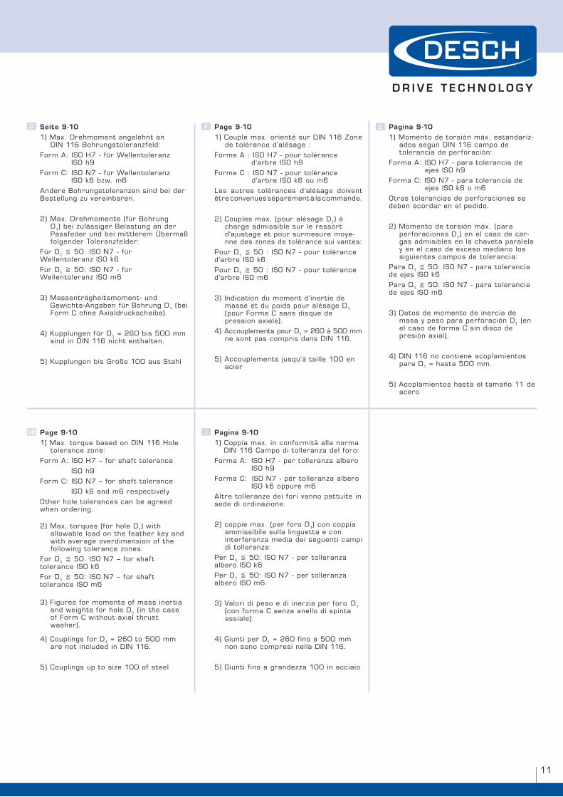
Seite 9-10�) Max. Drehmoment angelehnt an Din ��� Bohrungstoleranzfeld:
form A: iSo h7 - für wellentoleranz iSo h9
form C: iSo n7 - für wellentoleranz iSo k� bzw. m�
Andere Bohrungstoleranzen sind bei der Bestellung zu vereinbaren.
�) Max. Drehmomente (für Bohrung D�) bei zulässiger Belastung an der passfeder und bei mit t lerem Übermaß folgender Toleranzfelder:
für D� �0: iSo n7 - für wellentoleranz iSo k�
für D� �0: iSo n7 - für wellentoleranz iSo m�
�) Massenträgheitsmoment- und Gewichts-Angaben für Bohrung D� (bei form C ohne Axialdruckscheibe).
�) Kupplungen für D� = ��0 bis �00 mm sind in Din ��� nicht enthalten.
�) Kupplungen bis Größe �00 aus Stahl
GB
F
I
D E
Page 9-10�) Max. torque based on Din ��� hole tolerance zone:
form A: iSo h7 – for shaf t tolerance
iSo h9
form C: iSo n7 – for shaf t tolerance
iSo k� and m� respectively
other hole tolerances can be agreed when ordering.
�) Max. torques (for hole D�) with allowable load on the feather key and with average overdimension of the following tolerance zones:
for D� �0: iSo n7 – for shaf t tolerance iSo k�
for D� �0: iSo n7 – for shaf t tolerance iSo m�
�) figures for moments of mass inertia and weights for hole D� (in the case of form C without axial thrust washer).
�) Couplings for D� = ��0 to �00 mm are not included in Din ���.
�) Couplings up to size �00 of steel
Page 9-10�) Couple max. orienté sur Din ��� Zone de tolérance d‘alésage :
forme A : iSo h7 - pour tolérance d‘arbre iSo h9
forme C : iSo n7 - pour tolérance d‘arbre iSo k� ou m�
les autres tolérances d‘alésage doivent être convenues séparément à la commande.
�) Couples max. (pour alésage D�) à charge admissible sur le ressort d‘ajustage et pour surmesure moye- nne des zones de tolérance sui vantes: pour D� �0 : iSo n7 - pour tolérance d‘arbre iSo k�
pour D� �0 : iSo n7 - pour tolérance d‘arbre iSo m�
�) indication du moment d‘inertie de masse et du poids pour alésage D� (pour forme C sans disque de pression axiale).
�) Accouplements pour D� = ��0 à �00 mm ne sont pas compris dans Din ���.
�) Accouplements jusqu‘à taille �00 en acier
Pagina 9-10�) Coppia max. in conformità alla norma Din ��� Campo di tolleranza del foro:
forma A: iSo h7 - per tolleranza albero iSo h9
forma C: iSo n7 - per tolleranza albero iSo k� oppure m�
Altre tolleranze dei fori vanno pattuite in sede di ordinazione.
�) coppie max. (per foro D�) con coppia ammissibile sulla linguetta e con interferenza media dei seguenti campi di tolleranza:
per D� �0: iSo n7 - per tolleranza albero iSo k�
per D� �0: iSo n7 - per tolleranza albero iSo m�
�) Valori di peso e di inerzia per foro D� (con forma C senza anello di spinta assiale).
�) Giunti per D� = ��0 fino a �00 mm non sono compresi nella Din ���.
�) Giunti f ino a grandezza �00 in acciaio
Página 9-10�) Momento de torsión máx. estandariz- ados según Din ��� campo de tolerancia de perforación:
forma A: iSo h7 - para tolerancia de ejes iSo h9
forma C: iSo n7 - para tolerancia de ejes iSo k� o m�
otras tolerancias de perforaciones se deben acordar en el pedido.
�) Momento de torsión máx. (para perforaciones D�) en el caso de car- gas admisibles en la chaveta paralela y en el caso de exceso mediano los siguientes campos de tolerancia:
para D� �0: iSo n7 - para tolerancia de ejes iSo k�
para D� �0: iSo n7 - para tolerancia de ejes iSo m�
�) Datos de momento de inercia de masa y peso para perforación D� (en el caso de forma C sin disco de presión axial).
�) Din ��� no contiene acoplamientos para D� = hasta �00 mm.
�) Acoplamientos hasta el tamaño �� de acero
w h e n f u l l p o w e r i S n e e D e D
��
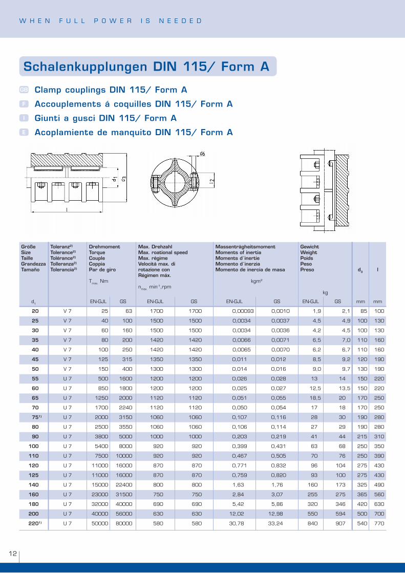
Schalenkupplungen DIN 115/ Form A
Clamp couplings DIN 115/ Form A
Accouplements á coquilles DIN 115/ Form A
Giunti a gusci DIN 115/ Form A
Acoplamiente de manquito DIN 115/ Form A
GB
F
I
E
Größe Size Taille Grandezza Tamaño
Toleranz2)
Tolerance2)
Tolérance2)
Tolleranza2)
Tolerancia2)
DrehmomentTorqueCoupleCoppia Par de giro
Tmax. nm
Max. DrehzahlMax. roational speedMax. régimeVelocitá max. di rotazione conRégimen máx.
nmax. min-�,rpm
Massenträgheitsmoment
Moments of inertia Moments d´inertie Momento d´inerzia Momento de inercia de masa
kgm�
GewichtWeightPoidsPesoPreso
kg
d3 l
d� en-GJl GS en-GJl GS en-GJl GS en-GJl GS mm mm
20 V 7 �� �� �700 �700 0,0009� 0,00�0 �,9 �,� 8� �00
25 V 7 �0 �00 ��00 ��00 0,00�� 0,00�7 �,� �,9 �00 ��0
30 V 7 �0 ��0 ��00 ��00 0,00�� 0,00�� �,� �,� �00 ��0
35 V 7 80 �00 ���0 ���0 0,00�� 0,007� �,� 7,0 ��0 ��0
40 V 7 �00 ��0 ���0 ���0 0,00�� 0,0070 �,� �,7 ��0 ��0
45 V 7 ��� ��� ���0 ���0 0,0�� 0,0�� 8,� 9,� ��0 �90
50 V 7 ��0 �00 ��00 ��00 0,0�� 0,0�� 9,0 9,7 ��0 �90
55 u 7 �00 ��00 ��00 ��00 0,0�� 0,0�8 �� �� ��0 ��0
60 u 7 8�0 �800 ��00 ��00 0,0�� 0,0�7 ��,� ��,� ��0 ��0
65 u 7 ���0 �000 ���0 ���0 0,0�� 0,0�� �8,� �0 �70 ��0
70 u 7 �700 ���0 ���0 ���0 0,0�0 0,0�� �7 �8 �70 ��0
751) u 7 �000 ���0 �0�0 �0�0 0,�07 0,��� �8 �0 �90 �80
80 u 7 ��00 ���0 �0�0 �0�0 0,�0� 0,��� �7 �9 �90 �80
90 u 7 �800 �000 �000 �000 0,�0� 0,��9 �� �� ��� ��0
100 u 7 ��00 8000 9�0 9�0 0,�99 0,��� �� �8 ��0 ��0
110 u 7 7�00 �0000 9�0 9�0 0,��7 0,�0� 70 7� ��0 �90
120 u 7 ��000 ��000 870 870 0,77� 0,8�� 9� �0� �7� ��0
125 u 7 ��000 ��000 870 870 0,7�9 0,8�0 9� �00 �7� ��0
140 u 7 ��000 ���00 800 800 �,�� �,7� ��0 �7� ��� �90
160 u 7 ��000 ���00 7�0 7�0 �,8� �,07 ��� �7� ��� ��0
180 u 7 ��000 �0000 �90 �90 �,�� �,8� ��0 ��� ��0 ��0
200 u 7 �0000 ��000 ��0 ��0 ��,0� ��,98 ��0 �9� �00 700
2201) u 7 �0000 80000 �80 �80 �0,78 ��,�� 8�0 907 ��0 770
��
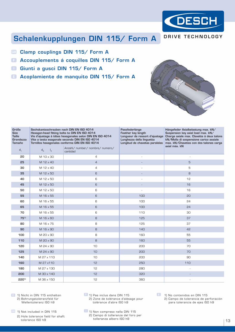
�) nicht in Din ��� enthalten �) Bohrungstoleranzfeld für wellentoleranz iSo h9
�) not included in Din ���
�) hole tolerance f ield for shaf t tolerance iSo h9
D F
GB I
E�) pas inclus dans Din ��� �) Zone de tolérance d‘alésage pour tolérance d‘abre iSo h9
�) non compreso nella Din ��� �) Campo di tolleranza del foro per tolleranza albero iSo h9
�) no contenidos en Din ��� �) Campo de tolerancia de perforación para tolerancia de ejes iSo h9
Größe Size Taille Grandezza Tamaño
Sechskantsschrauben nach DIN EN ISO 4014Hexagon-head fitting bolts to DIN EN ISO 4014 Vis d‘ajustage à têtes hexagonales selon DIN EN ISO 4014 Vite a testa esagonale secondo DIN EN ISO 4014Tornillos hexagonales conforme DIN EN ISO 4014
PassfederlängeFeather key lengthLongueur de ressort d‘ajustageLunghezza della linguettaLongitud de chavetas paralelas
Hängefeder Axialbelastung max. kN/Suspension key axial load max. kN/Charge axiale max. Clavette à deux talons kN/Molla di sospensione carico assiale max. kN/Chavetas con dos talones carga axial máx. kN
d� d� l�Anzahl/ number/ nombre/ numero/ cantidad
20 M �0 x �0 � - -
25 M �� x �0 � - �
30 M �� x �0 � - �
35 M �� x �0 � - 8
40 M �� x �0 � - ��
45 M �� x �0 � - ��
50 M �� x �0 � - ��
55 M �� x �� � �00 �0
60 M �� x �� � �00 ��
65 M �� x �� � �00 ��
70 M �� x �� � ��0 �0
751) M �� x �0 8 ��� �7
80 M �� x 7� 8 ��� �7
90 M �� x 90 8 ��0 ��
100 M �0 x 90 8 ��0 ��
110 M �0 x 90 8 ��0 ��
120 M �� x 90 �0 �00 70
125 M �� x 90 �0 �00 70
140 M �7 x ��0 �0 �00 90
160 M �7 x��0 �� ��0 ��0
180 M �7 x ��0 �� �80 -
200 M �0 x ��0 �� ��0 -
2201) M �� x ��0 �� ��0 -
Schalenkupplungen DIN 115/ Form A
Clamp couplings DIN 115/ Form A
Accouplements á coquilles DIN 115/ Form A
Giunti a gusci DIN 115/ Form A
Acoplamiente de manquito DIN 115/ Form A
GB
F
I
E
w h e n f u l l p o w e r i S n e e D e D
��
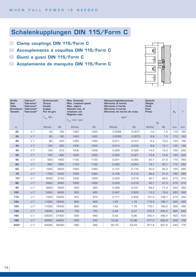
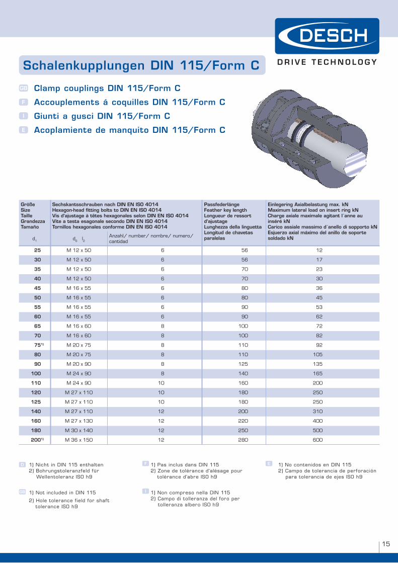
Schalenkupplungen DIN 115/Form C
Clamp couplings DIN 115/Form C
Accouplements á coquilles DIN 115/Form C
Giunti a gusci DIN 115/Form C
Acoplamiente de manquito DIN 115/Form C
GB
F
I
E
Größe Size Taille Grandezza Tamaño
Toleranz2)
Tolerance2)
Tolérance2)
Tolleranza2)
Tolerancia2)
DrehmomentTorqueCoupleCoppia Par de giro
Tmax. nm
Max. DrehzahlMax. roational speedMax. régimeVelocitá max. di rotazione conRégimen máx.
nmax. min-�,rpm
Massenträgheitsmoment
Moments of inertia Moments d´inertie Momento d´inerzia Momento de inercia de masa
kgm�
GewichtWeightPoidsPesoPreso
kg
d3 l
d� en-GJl GS en-GJl GS en-GJl GS en-GJl GS mm mm
25 V 7 �0 �00 ���0 ���0 0,00�� 0,007� 7,0 7,� ��0 ��0
30 V 7 �0 ��0 ���0 ���0 0,00�� 0,0070 �,8 7,� ��0 ��0
35 V 7 80 �00 ���0 ���0 0,0�� 0,0�� 9,� �0,0 ��0 �90
40 V 7 �00 ��0 ��00 ��00 0,0�� 0,0�� 9,9 �0,7 ��0 �90
45 V 7 ��� ��� ��00 ��00 0,0�� 0,0�8 ��,� ��,� ��0 ��0
50 V 7 ��0 �00 ��00 ��00 0,0�� 0,0�7 ��,8 ��,8 ��0 ��0
55 u 7 �00 ��00 ���0 ���0 0,0�� 0,0�� �0,� ��,� �70 ��0
60 u 7 8�0 �800 ���0 ���0 0,0�0 0,0�� �8,7 �0,� �70 ��0
65 u 7 ���0 �000 �0�0 �0�0 0,�07 0,��� �0,0 ��,� �90 �80
70 u 7 �700 ���0 �0�0 �0�0 0,�0� 0,��� �9,� ��,� �90 �80
751) u 7 �000 ���0 �000 �000 0,�0� 0,��9 ��,� �8,� ��� ��0
80 u 7 ��00 ���0 �000 �000 0,�0� 0,��9 ��,7 �7,0 ��� ��0
90 u 7 �800 �000 9�0 9�0 0,�99 0,��� ��,� 7�,� ��0 ��0
100 u 7 ��00 8000 9�0 9�0 0,��7 0,�0� 7�,� 79,9 ��0 �90
110 u 7 7�00 �0000 870 870 0,77� 0,8�� �0�,0 �08,7 �7� ��0
120 u 7 ��000 ��000 800 800 �,�� �,7� �7�,� �8�,7 ��� �90
125 u 7 ��000 ��000 800 800 �,�� �,7� �70,� �8�,0 ��� �90
140 u 7 ��000 ���00 7�0 7�0 �,8� �,07 �7�,� �9�,� ��� ��0
160 u 7 ��000 ���00 �90 �90 �,�� �,8� ���,� ��8,� ��0 ��0
180 u 7 ��000 �0000 ��0 ��0 ��,0� ��,98 �77,0 ��0,8 �00 700
2001) u 7 �0000 ��000 �80 �80 �0,78 ��,�� 87�,8 9�7,9 ��0 770
��
Größe Size Taille Grandezza Tamaño
Sechskantsschrauben nach DIN EN ISO 4014Hexagon-head fitting bolts to DIN EN ISO 4014 Vis d‘ajustage à têtes hexagonales selon DIN EN ISO 4014 Vite a testa esagonale secondo DIN EN ISO 4014Tornillos hexagonales conforme DIN EN ISO 4014
PassfederlängeFeather key lengthLongueur de ressort d‘ajustageLunghezza della linguettaLongitud de chavetas paralelas
Einlegering Axialbelastung max. kNMaximum lateral load on insert ring kNCharge axiale maximale agitant l´anne au inséré kNCarico assiale massimo d´anello di sopporto kNEsjuerzo axial máximo del anillo de soporte soldado kNd� d� l�
Anzahl/ number/ nombre/ numero/ cantidad
25 M �� x �0 � �� ��
30 M �� x �0 � �� �7
35 M �� x �0 � 70 ��
40 M �� x �0 � 70 �0
45 M �� x �� � 80 ��
50 M �� x �� � 80 ��
55 M �� x �� � 90 ��
60 M �� x �� � 90 ��
65 M �� x �0 8 �00 7�
70 M �� x �0 8 �00 8�
751) M �0 x 7� 8 ��0 9�
80 M �0 x 7� 8 ��0 �0�
90 M �0 x 90 8 ��� ���
100 M �� x 90 8 ��0 ���
110 M �� x 90 �0 ��0 �00
120 M �7 x ��0 �0 �80 ��0
125 M �7 x ��0 �0 �80 ��0
140 M �7 x ��0 �� �00 ��0
160 M �7 x ��0 �� ��0 �00
180 M �0 x ��0 �� ��0 �00
2001) M �� x ��0 �� �80 �00
�) nicht in Din ��� enthalten �) Bohrungstoleranzfeld für wellentoleranz iSo h9
�) not included in Din ���
�) hole tolerance f ield for shaf t tolerance iSo h9
D F
GB I
E�) pas inclus dans Din ��� �) Zone de tolérance d‘alésage pour tolérance d‘abre iSo h9
�) non compreso nella Din ��� �) Campo di tolleranza del foro per tolleranza albero iSo h9
�) no contenidos en Din ��� �) Campo de tolerancia de perforación para tolerancia de ejes iSo h9
Schalenkupplungen DIN 115/Form C
Clamp couplings DIN 115/Form C
Accouplements á coquilles DIN 115/Form C
Giunti a gusci DIN 115/Form C
Acoplamiente de manquito DIN 115/Form C
GB
F
I
E
w h e n f u l l p o w e r i S n e e D e D
��
ww
w.d
esch
.deDESCH Drive Technology
postbox �� �0 D-�97�� Arnsberg/Germany Kleinbahnstraße �� D-�97�9 Arnsberg/GermanyTelephone +�9 (0) �9 �� - � 00 - 0 fax +�9 (0) �9 �� - � 00 - 899internet www.desch.de e-mail [email protected]
DESCH Drive Technology limited partnership��0 Shearson Crescent Cambridge, ontario Canada n �T �J�Telephone +�800 - � �� �8 �� +���9 - � �� �� �0 fax +���9 - � �� �� �9internet www.desch.on.ca e-mail [email protected]
Telefon-Anschlüsse im Stammhaus Arnsberg/ Telephone numbers of our head office in Arnsberg/ Numéros de téléphone de notre siège Arnsberg/ Numeri di telefono della nostra sede di Arnsberg/ Números de teléfono en la central en Arnsberg Phone FaxDES DeSCh engineering Service +�9 (0) �9 �� �00 - �00 �00 - 8��DPC DeSCh power Transmission Center +�9 (0) �9 �� �00 - �0� �00 - 8�0DCT DeSCh Clutch Technology +�9 (0) �9 �� �00 - �70 �00 - �0DGP DeSCh Gearbox and press Drives +�9 (0) �9 �� �00 - ��� �00 - 8��
DESCH Drive Technology ufficio di rappresentanza in italia Via Cavriana, � i-�0��� MilanoTelephone +�90� - 7 �9 �� 80 fax +�90� - 7 �9 �� 8�internet www.desch.de e-mail [email protected]
DESCH ist MitgliedDESCH is a member of DESCH est membre de DESCH è membro DESCH es un miembro
LieferprogrammSchaltbare Kupplungen elastische Kupplungen Drehstarre Kupplungen pressenantriebe Gleitlager riementriebe planeten und Sondergetriebe Komplette Antriebslösungen
D
GB
F
I E
Programme de LivraisonAccouplements commutables Accouplements élastiques Accouplements rigides entraînements de presses paliers lisses engrenages planétaires et spéciaux engrenages complètes
Delivery ProgrammeClutches flexible couplings rigid couplings press drives plain bearings Belt drives planetary gears and special gears Complete drive solutions
Programma di Vendita frizioni Giunti elastici Giunti rigidi Azionamenti per presse Sopporti con bronzina Trasmissioni a cinghia riduttori epicicloidali e speciali Soluzioni e azionamenti completi
Gama de SuministroAcoplamientos conmutables Acoplamientos elásticos Acoplamientos rígidos Transmisiones de prensas Cojinetes de deslizamiento Mecanismos de correa engranajes planetarios y especiales Soluciones de transmisión integrales
Technische Änderungen vorbehalten Technical changes reserved Sous réserve de modif ications techniques Ci riserviamo eventuali modif iche tecniche reservado el derecho a realizar modif icaciones técnicas © DeSCh Antriebstechnik Gmbh & Co. KG · SK 07