Embed Size (px)
Citation preview
Institut für Chemie
Arbeitskreis Angewandte Polymerchemie
Development of Functional Hydrogels for
Sensor Applications
Dissertation
zur Erlangung des akademischen Grades
“doctor rerum naturalium” (Dr. rer. nat.)
in der Wissenschaftsdisziplin Polymerchemie
eingereicht an der
Mathematisch-Naturwissenschaftlichen Fakultät
der Universität Potsdam
von
M.Sc. Sandor Dippel
Potsdam, den 30. November 2016

This work is licensed under a Creative Commons License: Attribution – Share Alike 4.0 International To view a copy of this license visit http://creativecommons.org/licenses/by-sa/4.0/ Published online at the Institutional Repository of the University of Potsdam: URN urn:nbn:de:kobv:517-opus4-398252 http://nbn-resolving.de/urn:nbn:de:kobv:517-opus4-398252

3
4
Acknowledgements
Zu allererst möchte ich Herrn Prof. Laschewsky herzlich dafür danken in seiner
Arbeitsgruppe über dieses interessanten Thema promovieren zu können, für alle
spannenden Diskussionen und seine weitreichende Unterstützung.
Vielen Dank auch an Herrn Dr. Wischerhoff für die Betreuung im Alltag und Anstöße
für neue Ideen.
Dank der Kooperation zwischen der Universität Potsdam und dem Fraunhofer Institut
für Angewandte Polymerforschung(IAP) konnte ich die Räumlichkeiten und
technischen Möglichkeiten des IAP mitbenutzen, dafür danke ich stellvertretend dem
Institutsleiter Herrn Prof. Böker danken.
Meine Arbeit war nur möglich durch die engagierte Kooperation und Austausch im
Rahmen des Taschentuchlabor-Projekts mit Dr. Memczak, Dr. Michel, Dr. Stöcklein,
Dr. Tang, Dr. Hettrich, Dr. Inal, Dr. Rötch, R . Bernin, Dr. Kölsch und Dr. Hildebrand –
vielen Dank!
Ein großes Dankeschön auch an das FB 4 Team für die warme Aufnahme und die
gute Atmosphäre bei der Arbeit. „Meinen“ Studenten Faty Makthoum, Nicole Sickert,
Dr. Kamil Kaminski und Raphael Suminski vielen Dank für die Zusammenarbeit und
das Interesse – durch euch konnte auch ich viel lernen!
Ein besonders liebes Dankeschön an die Doktorandentruppe – Jens, Martin, Jean-
Phillipe, Robert, Viet, Jonas, Laura, Frank, Anne & Anna aber natürlich auch Geri,
Clara und Sandra – die Zeit mit euch war großartig.
Ganz zuletzt meiner Mutter und meiner Schwester einen herzlichen Dank für die
Unterstützung über all die Jahre, ebenso meiner lieben Claudia – ohne di was ned
halb so schee!
5
Selbständigkeitserklärung
Hiermit erkläre ich an Eides statt, dass ich die vorliegende Arbeit selbstständig
verfasst und nur unter Verwendung der angegebenen Quellen und Hilfsmittel
angefertigt habe. Weder diese noch eine andere Arbeit wurde von mir an einer
anderen Universität oder Hochschule zum Zwecke der Einleitung eines
Promotionsverfahrens vorgelegt.
Olching , den 29. November 2016 Sandor Dippel
Abstract
6
Abstract
In this work, a sensor system based on thermoresponsive materials is developed by
utilizing a modular approach. By synthesizing three different key monomers containing
either a carboxyl, alkene or alkyne end group connected with a spacer to the
methacrylic polymerizable unit, a flexible copolymerization strategy has been set up
with oligo ethylene glycol methacrylates. This allows to tune the lower critical solution
temperature (LCST) of the polymers in aqueous media. The molar masses are
variable thanks to the excurse taken in polymerization in ionic liquids thus stretching
molar masses from 25 to over 1000 kDa. The systems that were shown shown to be
effective in aqueous solution could be immobilized on surfaces by copolymerizing
photo crosslinkable units. The immobilized systems were formulated to give different
layer thicknesses, swelling ratios and mesh sizes depending on the demand of the
coupling reaction.
The coupling of detector units or model molecules is approached via reactions of the
click chemistry pool, and the reactions are evaluated on their efficiency under those
aspects, too. These coupling reactions are followed by surface plasmon resonance
spectroscopy (SPR) to judge efficiency. With these tools at hand, Salmonella
saccharides could be selectively detected by SPR. Influenza viruses were detected in
solution by turbidimetry in solution as well as by a copolymerized solvatochromic dye
to track binding via the changes of the polymers’ fluorescence by said binding event.
This effect could also be achieved by utilizing the thermoresponsive behavior. Another
demonstrator consists of the detection system bound to a quartz surface, thus allowing
the virus detection on a solid carrier.
The experiments show the great potential of combining the concepts of
thermoresponsive materials and click chemistry to develop technically simple sensors
for large biomolecules and viruses.
Zusammenfassung
7
Zusammenfassung
Diese Arbeit befasst sich mit der Entwicklung von Sensorsystemen für biologische
Analyten wie Bakterien und Viren. Die Sensoren beruhen auf thermoresponsiven
Polymeren und die Entwicklung wird Schritt für Schritt ausgehend von der
Monomersynthese dargelegt. Die Grundidee ist es alle Einzelschritte so modular wie
möglich zu halten. Die Kopplungseinheiten für die späteren Erkennungsgruppen
bestehen aus Carboxyl, Alken und Alkinfunktionalitäten, die zuerst mit einem
Ethylenglycolspacer mit variabler Länge verknüpft werden und dann mit der
polymerisierbaren Methylmethacrylatgruppe versehen werden. Diese koppelbaren
Monomere werden mit Di- oder (Oligoethylenglycol)methacrylaten copolymerisiert. Je
nach Verhältnis ist so auch die untere kritische Entmischungstemperatur (LCST)
einstellbar. Mit der Erweiterung der Polymerisationstechnik um ionische Flüssigkeiten
als Lösemittel lassen sich Molmassen von 25 bis über 1000 kDa einstellen. Um die
Polymere funktionell zu erweitern, lassen sich auch benzophenonhaltige Monomere
zur Vernetzung oder Immobilisierung copolymerisieren. Naphthalsäureimidhaltige
Monomere wiederum dienen als Signaleinheit, da sie durch Verändern der Polarität
ihrer Umgebung solvatochrom reagieren. Durch Aufschleudern und UV-Vernetzen
lassen sich Gelschichten mit guter Schichtdickenkontrolle herstellen. Dabei sind die
Substrate nur auf den jeweiligen Zweck beschränkt. Dank des Baukastenprinzips kann
auch die Maschenweite oder der Quellgrad der Gele eingestellt werden.
Die Polymere oder Hydrogele werden mit Hilfe von effizienten Reaktionen swe
aogenannten „Click Chemie“ umgesetzt und die Reaktionen werden durchleuchtet, ob
sie diesen Ansprüchen gerecht werden. Je nach Möglichkeit wird das Anknüpfen
mittels Oberflächenplasmonenresonanzspektroskopie(SPR) verfolgt, so wie zum
Beispiel die Kopplung eines Phagen-Oberflächenproteins und das selektive Binden
eines Membransaccharids des Salmonellen Bakteriums. Influenza Viren werden
selektiv mit Hilfe eines Erkennungspeptids gebunden und mit Hilfe von
Trübungsspektroskopie bzw. dem thermoresponsiven Verhalten des Trägerpolymers
nachgewiesen. Ein weiterer dargelegter Ansatz ist das Nachweisen von geringen
Virenkonzentrationen mit Hilfe eines Hydrogels oder von Polymeren in Lösung, die
jeweils mit einem solvatochromen Farbstoff ausgestattet sind, der auf die
Umgebungsänderung durch den Virus reagiert.

Zusammenfassung
8
Die Experimente zeigen das große Potential von geschickt kombinierten
thermoresponsiven Materialien, die mittels Funktionalisierung durch Click-Chemie zu
technisch einfachen Nachweissystemen für Biomoleküle und sogar ganze Zellen
entwickelt werden können
Contents
9
Contents
Abstract ................................................................................................................................................... 6
Zusammenfassung .................................................................................................................................. 7
Contents .................................................................................................................................................. 9
Abbrevations ......................................................................................................................................... 13
1. Introduction ............................................................................................................................. 14
2. Objectives and Outline ............................................................................................................. 16
3. Concepts of this Work .............................................................................................................. 18
3.1. Theoretical Background ........................................................................................................ 18
3.2. Free Radical Polymerization .................................................................................................. 18
3.3. Thermoresponsive Polymers ................................................................................................ 20
3.3.1. Thermoresponsive Behavior ......................................................................................... 20
3.3.2. Thermoresponsive Polymers and Materials ................................................................. 22
3.3.3. Analysis of Thermoresponsive Polymers ...................................................................... 24
3.4. Hydrogels on Surfaces ........................................................................................................... 24
3.4.1. Hydrogels ...................................................................................................................... 24
3.4.2. Surface Immobilization of Hydrogels ............................................................................ 26
3.4.3. Thin Film Analysis by Ellipsometry ................................................................................ 28
3.4.4. Surface Plasmon Resonance Spectroscopy of Hydrogels ............................................. 30
3.5. Click Chemistry for Post-Polymerization Modifications........................................................ 32
3.6. Thermoresponsive Materials as Biosensors ......................................................................... 33
4. Carboxyl Based Coupling Systems ........................................................................................... 37
4.1. Monomer Synthesis .............................................................................................................. 37
4.2. Polymer Synthesis ................................................................................................................. 38
4.3. Hydrogels .............................................................................................................................. 39
4.4. Activated Esters for Amide Bonds ......................................................................................... 40
4.5. Results ................................................................................................................................... 42
4.5.1. Experiments in Solution ................................................................................................ 42
4.5.2. Hydrogel Formation ...................................................................................................... 45
4.5.3. The Tailspike Protein – Salmonella Polysaccaride Recognition System ........................ 49
4.5.4. Hydrogel Systems Based on Improved Polymer Synthesis ........................................... 52
4.5.5. Influenza Virus Detection Demonstrator System ......................................................... 60
4.6. Summary ............................................................................................................................... 69
5. Alkene Based Systems.............................................................................................................. 71
Contents
10
5.1. Thiol-Ene Reactions ............................................................................................................... 71
5.2. Synthesis ............................................................................................................................... 73
5.2.1. Monomer Synthesis ...................................................................................................... 73
5.2.2. Polymer Synthesis ......................................................................................................... 75
5.2.3. Thiol-Ene coupling and diversifying the polymer functionality .................................... 77
5.3. Results ................................................................................................................................... 78
5.3.1. LCST Behavior ................................................................................................................ 78
5.3.2. Consequences for Bioconjugation ................................................................................ 81
5.3.3. Outlook.......................................................................................................................... 82
6. Alkyne Based Coupling Systems ............................................................................................... 83
6.1. Introduction .......................................................................................................................... 83
6.1.1. Radical Thiol Additions to Triple bonds ........................................................................ 83
6.1.2. Huisgen Cycloadditions ................................................................................................. 84
6.2. Synthesis ............................................................................................................................... 85
6.2.1. Radical Addition to Alkyne Functionalized Polymers .................................................... 86
6.2.2. Huisgen Cycloadditions to Alkyne Functionalized Polymers ........................................ 87
6.3. Outlook ................................................................................................................................. 88
7. Summary and Conclusion ........................................................................................................ 89
8. Experimental Part .................................................................................................................... 91
8.1. Monomer Synthesis .............................................................................................................. 93
8.1.1. tert-Butyl 2-(2-(2-(2-hydroxyethoxy)ethoxy)ethoxy)acetate (1) .................................. 93
8.1.2. 13,13-Dimethyl-11-oxo-3,6,9,12-tetraoxatetradecyl methacrylate (2) ........................ 94
8.1.3. 3,6,9,12-Tetraoxapentadec-14-en-1-ol (3) ................................................................... 95
8.1.4. 3,6,9,12-Tetraoxapentadec-14-en-1-yl methacrylate (4) ............................................. 95
8.1.5. 6,9,12-Tetraoxapentadec-14-yn-1-ol (5) ....................................................................... 96
8.1.6. 3,6,9,12-Tetraoxapentadec-14-yn-1-yl methacrylate (6) ............................................. 97
8.1.7. 6-(Dimethylamino)-2-(2-hydroxyethyl)-1H-benzo[de]isoquinoline-1,3(2H)-dione (7) . 97
8.1.8. 2-(6-(Dimethylamino)-1,3-dioxo-1H-benzo[de]isoquinolin-2(3H)-yl)ethyl methacrylate
(8)……………………………………………………………………………………………………………………………………….98
8.2. Polymerizations in Ethanol ................................................................................................... 99
8.2.1. Poly(oligo(ethylene glycole) methylether methacrylate475 -stat-di (ethylene glycol)
methylether methacrylate-stat-3,6,9,12-tetraoxapentadec-14-en-1-yl methacrylate) (9) .. 100
8.2.2. Poly(oligo(ethylene glycole) methylether methacrylate475-stat-di(ethylene glycol)
methylether methacrylate-stat-3,6,9,12-tetraoxapentadec-14-yn-1-yl methacrylate) (10) . 101
8.2.3. Poly(oligo(ethylene glycole) methylether methacrylate475-stat-di(ethylene glycol)
methylether methacrylate-stat- methacrylic acid) (11) ........................................................ 102
Contents
11
8.2.4. Poly(oligo(ethylene glycole) methylether methacrylate475-stat-di(ethylene glycol)
methylether methacrylate-stat- 13,13-Dimethyl-11-oxo-3,6,9,12-tetraoxatetradecyl
methacrylate) (12) ................................................................................................................. 103
8.2.5. Poly(oligo(ethylene glycole) methylether methacrylate475-stat-di(ethylene glycol)
methylether methacrylate-stat- 13,13-Dimethyl-11-oxo-3,6,9,12-tetraoxatetradecyl
methacrylate –stat- 2-(4-benzoylphenoxy)ethyl methacrylate)(13) ..................................... 104
8.2.6. Poly(N-isopropyl methacrylamide-stat- 13,13-dimethyl-11-oxo-3,6,9,12-
tetraoxatetradecyl methacrylate)(14) ................................................................................... 105
8.3. Polymerizations in Ionic Liquids .......................................................................................... 106
8.3.1. Poly(oligo(ethylene glycole) methylether methacrylate475-stat-di(ethylene glycol)
methylether methacrylate)(15) ............................................................................................. 107
8.3.2. Poly(oligo(ethylene glycole) methylether methacrylate475-stat-di(ethylene glycol)
methylether methacrylate-stat- 13,13-dimethyl-11-oxo-3,6,9,12-tetraoxatetradecyl
methacrylate –stat- 2-(4-benzoylphenoxy)ethyl methacrylate)(16) ..................................... 108
8.3.3. Poly(N-isopropyl methacryamide-stat- 13,13-dimethyl-11-oxo-3,6,9,12-
tetraoxatetradecyl methacrylate stat- 2-(4-benzoylphenoxy)ethyl methacrylate –stat -2-(6-
(dimethylamino)-1,3-dioxo-1H-benzo[de]isoquinolin-2(3H)-yl)ethyl)(17) ............................ 109
8.4. Post Polymerization Reactions ............................................................................................ 110
8.4.1. Coupling Reactions with Benzylamine (18a-b) ........................................................... 110
8.4.2. General Procedure for Deprotecting Carboxylic Groups ............................................ 111
8.4.3. Active Ester Couplings with Peptides (19) .................................................................. 111
8.4.4. UV Induced Thiol-Ene Coupling (21) ........................................................................... 112
8.4.5. UV Induced Thiol-Yne Coupling (22) ........................................................................... 112
8.4.6. Cycloadditions of Azido-Sugars to Alkyne Containing Polymers(23) .......................... 113
8.4.7. Tris(triphenylphosphine)Copper(I)-Bromide (24) ....................................................... 114
8.5. Preparation of Silicon Wafers and Glass Surfaces for Polymer Coatings ............................ 114
8.6. Preparation of Gold Chips for Polymer Coatings ................................................................ 115
8.7. Ellipsometry ........................................................................................................................ 115
8.8. Gel Permeation Chromatography (GPC) ............................................................................. 116
8.9. Nuclear Magnetic Resonance Spectroscopy (NMR) ........................................................... 116
8.10. Surface Plasmon Resonance Spectroscopy (SPR) ........................................................... 116
8.11. Spin Coating .................................................................................................................... 116
8.12. Turbidity Measuremnts................................................................................................... 117
8.13. UV-Crosslinking ............................................................................................................... 117
9. Literature ............................................................................................................................... 118
10. List of Publications ................................................................................................................. 127
10.1. Publications ..................................................................................................................... 127
10.2. Poster: ............................................................................................................................. 127

Contents
12
Appendix ............................................................................................................................................. 128
A1. 1H-NMR Spectra ........................................................................................................................ 128
A2. List of tables .............................................................................................................................. 131
A3.List of Figures ............................................................................................................................. 132
Abbrevations
13
Abbrevations
LCST Lower critical solution temperature
SPR Surface plasmon resonance
AIBN Azobisisobutyronitrile
ATRP Atom-transfer radical-polymerization
DCM Dichloromethane
DMF Dimethylformamide
EDC 1-Ethyl-3-(3-dimethylaminopropyl)carbodiimide
EMIM PF6 1-Ethyl-3-methylimidazolium Hexafluorophosphate
HEPES 2-[4-(2-hydroxyethyl)piperazin-1-yl]ethanesulfonic acid
IL Ionic liquid
LOD Limit of detection
MEO2MA Methoxy diethyleneglycole methacrylate
NHS N-Hydroxy succinimide
NIPMAM N-Isopropyl-methacrylamide
OEGMA Oligo-ethylenglycol methacrylate
PHEMA Poly-(hydroxyethylmethacrylate)
PMMA Poly-(methylmethacrylate)
PNIPMAM Poly-N-Isopropylacrylamide
RAFT Reversible addition−fragmentation chain-transfer (polymerization)
SR Swelling ratio
TEA Triethanolamine
TEG Tetraethylenglycol
THF Tetrahydrofurane
TLC Thin layer chromatography
UCST Upper critical solution temperature
Introduction
14
1. Introduction
Smart materials are a more and more commonly used term to describe polymers or
polymer based materials that show a stimuli responsive behavior. By applying a
stimulus to the system, a change is induced in the material. A stimulus can be light (1,
2), ionic strength(3, 4), pH(5-7) or temperature(8-14). The responsive behavior can
consist of a phase change (15) or a change in optical properties(16) as an example.
There is a clear distinction to a reaction, as no material is exchanged, added or lost.
These changes can be reversible but they need not have to be.
Stimuli responsive materials can be found in nature, alginate is pH responsive(17) and
gelatin is thermoresponsive(18) to name two simple examples. Science is picking up
concepts and ideas from such materials in order to understand them better and
transfer them to applications. The motivation behind this is manifold. Especially
biomedical applications are on the rise. This ranges from tissue engineering (19), drug
delivery and release systems(20, 21), biomimetics(22) or coatings for cell ad- or
desorption(23). The detection of biological analytes is also a point of interest (24, 25).
A common denominator for those systems is that they should be water based as in
vitro and in vivo environments are targeted, and naturally, they are water based, too.
While in vivo applications tissue engineering has to struggle with toxicity and rejection
reaction, in vitro systems and especially any sensor application faces the challenge of
the complexity of fluids from biological sources. These samples are highly complex in
their mixture, be it by pH, salts or interfering cells or molecules. To counter this these
interferences cause signal noise or cause the detection to fail (26). This is why these
unspecific interactions have to be eliminated by choosing the right materials,
commonly referred to as anti-fouling properties(27, 28).
From an application design perspective, utilizing surfaces as carrier for sensor
application is a good idea. By selecting them properly, multiple analysis methods are
opened up and even detection of different parameters on the same material are
possible. The ease of handling especially comes into play if samples can be sputtered
on surfaces or micropipettes can be used for micro well based system and so on. This
is important simply because low amounts of material available is a common issue for
biomedical applications.

Introduction
15
The development of new responsive materials and the design of analytical systems
on surfaces is still a challenge, as is the proper integration of recognition and signaling
systems. The interaction between these parts has to be better understood and
analyzed to make steps towards better biosensors.
Objectives and Outline
16
2. Objectives and Outline
In this work an exemplary pathway for the development of a surface bound sensor for
biomolecules is outlined beginning with the synthesis of the monomer units, the
polymerization technique and the immobilization on surfaces to the detection of virus
cells. The detection concept is to bind recognition units like peptides or proteins to the
functional polymers or polymer modified surfaces. The reaction of these modified
polymer systems to an addition of the analyte substances like bacteria fragments or
said viruses are monitored via different analytical methods. Changes in the phase
transition temperature of the modified polymer system reacting to the analyte are used
for signal generation, if applicable.
This work is sectioned into three major parts, divided by the chemistry used to bind
potential recognition units to a thermoresponsive polymer backbone. In chapter 4, the
focus lies on identifying the requirements from a synthetic point of view, such as the
special requirements on material purity and the polymer composition. Especially the
composition is identified as a major parameter for the performance of the materials,
and designing them for binding partners will be discussed. The physical properties of
the resulting polymers and hydrogels will be characterized. In the end, two different
methods for virus detection will be used as demonstrators to show the viability of using
a thermoresponsive material as a starting point for sensor systems. One pathway
relies solely on the shift in cloud point and the resulting turbidity, whereas the other
pathway utilizes the phase transition to influence the emission spectra of a fluorescent
dye. Carboxylic groups are used as coupling units for the more advanced systems.
This approach was chosen due to the availability of biologically relevant recognition
units and especially their analytes. The chemistry for said attachment of the
recognition unit to the polymeric background relies on activated ester chemistry
between the carboxylic group and the amine terminal end of amino acids from peptides
and proteins. As the systems are water based, amines were preferred to hydroxylic
group to make the reaction more efficient and specific. This conjugation techniques
are embedded in the “click chemistry” terminology coined by Barry Sharpless (29).
In Chapters 4 and 5 the idea of utilizing click chemistry is followed up with alkene and
alkyne binding groups. Both are able to undergo a radical thiol addition, which will be

Objectives and Outline
17
tested for model substrates. They have the advantage of not being influenced by water
and are very specific in their reaction. Alkynes also undergo a cycloaddition with
azides which will be discussed in terms of catalysis and the limits of the “click
chemistry” descriptor. These three different approaches of binding a receptor unit are
set up orthogonal to each other, meaning that each one could react independently of
the other and thus additions can be made sequentially. This gives a flexibility to
integrate more sensor units for the analyte, additional signaling units or for
immobilization on surfaces and crosslinking.
In order to characterize the system, the main analytical tools used are turbidity
measurements, surface plasmon resonance spectroscopy, ellipsometry and
fluorescence. This work has a very broad scope of goals to follow through and topics
to span, so the focus is set more on the step by step development of the different
sensor systems and not the very last detail of effects. This is partially due to time and
material availability constraints of such a work, but is also chosen in order to show
how to walk the line to a surface bound, smart polymer dependent biosensor from start
to finish.
Concepts of this Work
18
3. Concepts of this Work
3.1. Theoretical Background
In this chapter, the general concepts that will be used throughout the different parts of
this work will be explained. While in no way as exhaustive as a matching text book
dedicated to the subject, a broad overview is presented.
3.2. Free Radical Polymerization
Radical polymerization describes a reaction mechanism of polymer growth that follows
a chain growth profile (over a step growth one) of one or more types of monomer units
with an active center on the end of the chain. The polymerization has three main steps,
the initiation of the reactive site - basically the radical generation-, then the growth or
propagation step, and finally the termination. In addition, chain-transfer is a possibility,
too – this event causes the reactive center to be transferred to another chain. This
does not stop the polymerization per se, but instead transfers the growing radical to
another site; this e.g. is one of the main causes for branching.
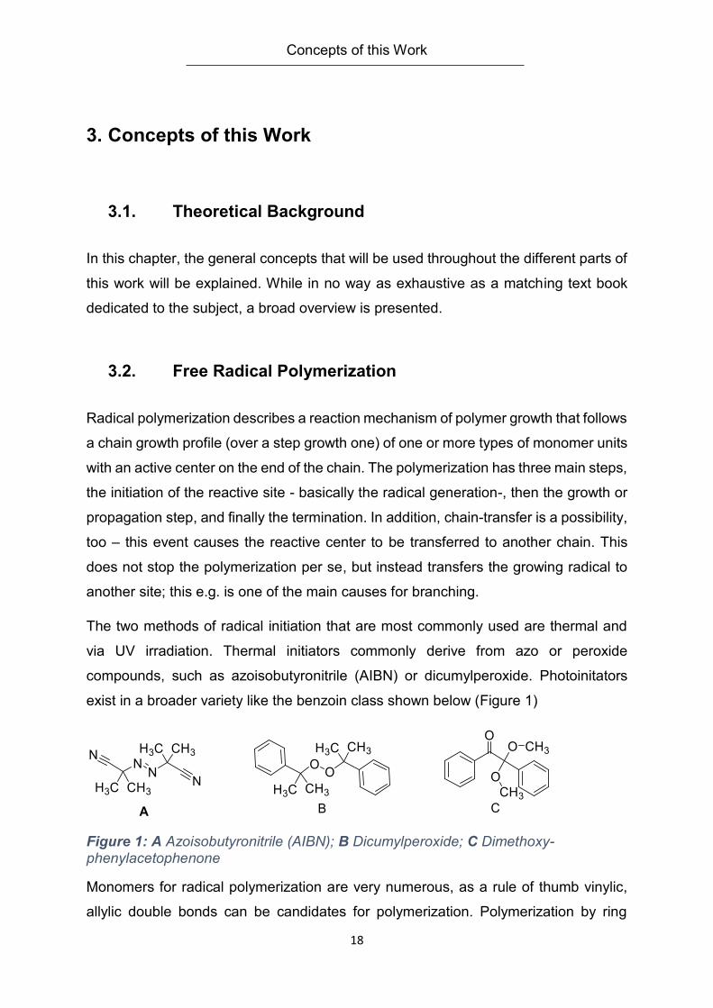
The two methods of radical initiation that are most commonly used are thermal and
via UV irradiation. Thermal initiators commonly derive from azo or peroxide
compounds, such as azoisobutyronitrile (AIBN) or dicumylperoxide. Photoinitators
exist in a broader variety like the benzoin class shown below (Figure 1)
Figure 1: A Azoisobutyronitrile (AIBN); B Dicumylperoxide; C Dimethoxy-phenylacetophenone
Monomers for radical polymerization are very numerous, as a rule of thumb vinylic,
allylic double bonds can be candidates for polymerization. Polymerization by ring
Concepts of this Work
19
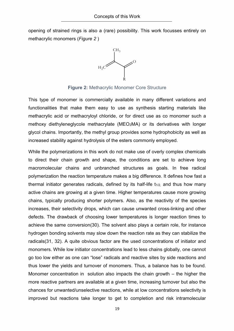
opening of strained rings is also a (rare) possibility. This work focusses entirely on
methacrylic monomers (Figure 2 )
Figure 2: Methacrylic Monomer Core Structure
This type of monomer is commercially available in many different variations and
functionalities that make them easy to use as synthesis starting materials like
methacrylic acid or methacryloyl chloride, or for direct use as co monomer such a
methoxy diethyleneglycole methacrylate (MEO2MA) or its derivatives with longer
glycol chains. Importantly, the methyl group provides some hydrophobicity as well as
increased stability against hydrolysis of the esters commonly employed.
While the polymerizations in this work do not make use of overly complex chemicals
to direct their chain growth and shape, the conditions are set to achieve long
macromolecular chains and unbranched structures as goals. In free radical
polymerization the reaction temperature makes a big difference. It defines how fast a
thermal initiator generates radicals, defined by its half-life t1/2, and thus how many
active chains are growing at a given time. Higher temperatures cause more growing
chains, typically producing shorter polymers. Also, as the reactivity of the species
increases, their selectivity drops, which can cause unwanted cross-linking and other
defects. The drawback of choosing lower temperatures is longer reaction times to
achieve the same conversion(30). The solvent also plays a certain role, for instance
hydrogen bonding solvents may slow down the reaction rate as they can stabilize the
radicals(31, 32). A quite obvious factor are the used concentrations of initiator and
monomers. While low initiator concentrations lead to less chains globally, one cannot
go too low either as one can “lose” radicals and reactive sites by side reactions and
thus lower the yields and turnover of monomers. Thus, a balance has to be found.
Monomer concentration in solution also impacts the chain growth – the higher the
more reactive partners are available at a given time, increasing turnover but also the
chances for unwanted/unselective reactions, while at low concentrations selectivity is
improved but reactions take longer to get to completion and risk intramolecular
Concepts of this Work
20
reactions.(33, 34). A final remark on the polymerization itself is the question of
monomer distribution. This work is based entirely on copolymerizations of different
monomers. Their close to random distribution is essential for this work as a block-like
polymerization is unwanted for functionality. Functional groups such as coupling
groups, should be distributed evenly across the chain to have the same impact
everywhere. The “filler” and co-crosslinking monomers should behave the same to
avoid clusters with e.g. a different, local LCST behavior and so on. This is also one of
the main reason that only methacrylics were chosen, as for the esters at least, the
copolymerization behavior is generally close to ideal azeotropic, thus avoiding
compositional drifts(32).
3.3. Thermoresponsive Polymers
3.3.1. Thermoresponsive Behavior
Thermoresponsive behavior of polymer solutions is one of the major themes of this
work. The idea is to induce an a priori thermal phase transition of a polymer
isothermally upon specific binding events. This concept is followed through for
solutions of polymers as well as hydrogels on surfaces.
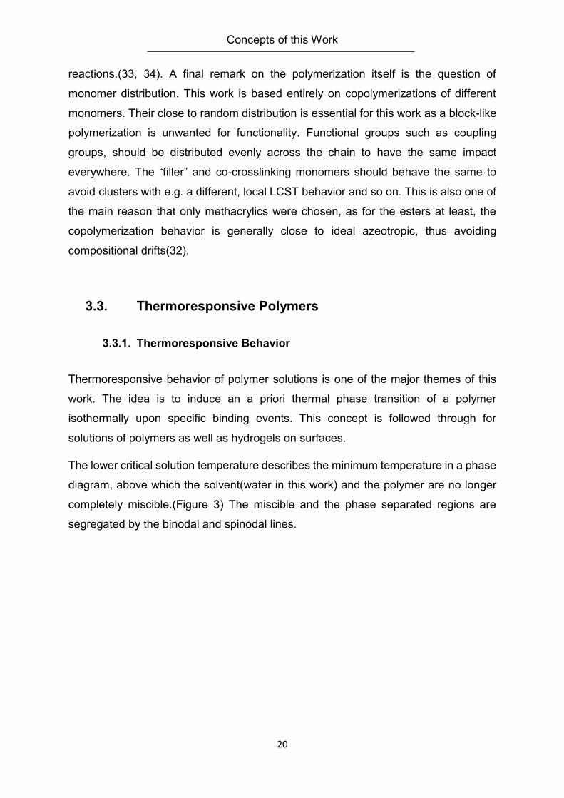
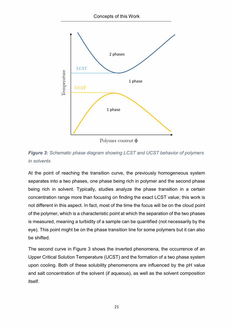
The lower critical solution temperature describes the minimum temperature in a phase
diagram, above which the solvent(water in this work) and the polymer are no longer
completely miscible.(Figure 3) The miscible and the phase separated regions are
segregated by the binodal and spinodal lines.
Concepts of this Work
21
Figure 3: Schematic phase diagram showing LCST and UCST behavior of polymers
in solvents
At the point of reaching the transition curve, the previously homogeneous system
separates into a two phases, one phase being rich in polymer and the second phase
being rich in solvent. Typically, studies analyze the phase transition in a certain
concentration range more than focusing on finding the exact LCST value; this work is
not different in this aspect. In fact, most of the time the focus will be on the cloud point
of the polymer, which is a characteristic point at which the separation of the two phases
is measured, meaning a turbidity of a sample can be quantified (not necessarily by the
eye). This point might be on the phase transition line for some polymers but it can also
be shifted.
The second curve in Figure 3 shows the inverted phenomena, the occurrence of an
Upper Critical Solution Temperature (UCST) and the formation of a two phase system
upon cooling. Both of these solubility phenomenons are influenced by the pH value
and salt concentration of the solvent (if aqueous), as well as the solvent composition
itself.
2 phases
1 phase
1 phase
Concepts of this Work
22
How can this behavior be explained from a thermodynamic point of view? The key
driving force is entropy as seen in Equation 1 below.
∆𝐺𝑚𝑖𝑥 = ∆𝐻𝑚𝑖𝑥 − 𝑇∆𝑆𝑚𝑖𝑥
Equation 1
In order to allow mixing, the free enthalpy ∆𝐺𝑚𝑖𝑥has to be negative. Concerning the
mixing enthalpy ∆𝐻𝑚𝑖𝑥, the hydrogen bonds between the solvent (water) and the
polymer units, which are energetically favorable, render ∆𝐻𝑚𝑖𝑥 negative. The overall
mixing entropy ∆𝑆𝑚𝑖𝑥 however is negative due to the well-organized hydration shell
built around the hydrophobic parts of the polymer upon solvation. The higher the
temperature gets, the bigger is the effect of this entropic factor on ∆𝐺𝑚𝑖𝑥. Thus, as
soon as the entropy gained by “freeing” the hydration shell outweighs the energy
gained by polymer-water-hydrogen bonds, the demixing is taking place.
3.3.2. Thermoresponsive Polymers and Materials
Thermoresponsive polymers share some structural requirements. There has to be a
structural balance between hydrophilic and hydrophobic parts. The hydrophobic parts
for most terms consist of hydrocarbon fragments. The hydrophilic parts are typically
amides, alcohols, ethers, esters or other groups that act as hydrogen bond donors or
acceptors. Exact predictions on how these groups interact to induce a lower or upper
critical solution temperature are hard to make especially in copolymers or modified
polymers, where the nature of repeat units can shift LCSTs of the parent homopolymer
considerably(10, 11). A homopolymer in a defined solvent gives a typical value though.
Polymer classes as peptides, polyacrylamides, polymethacrylamides, polyviny ethers,
polyphosphonates or the already mentioned (meth) acrylic esters with oligo
ethyleneglycol side chains are just examples of the most common ones (12, 13, 35,
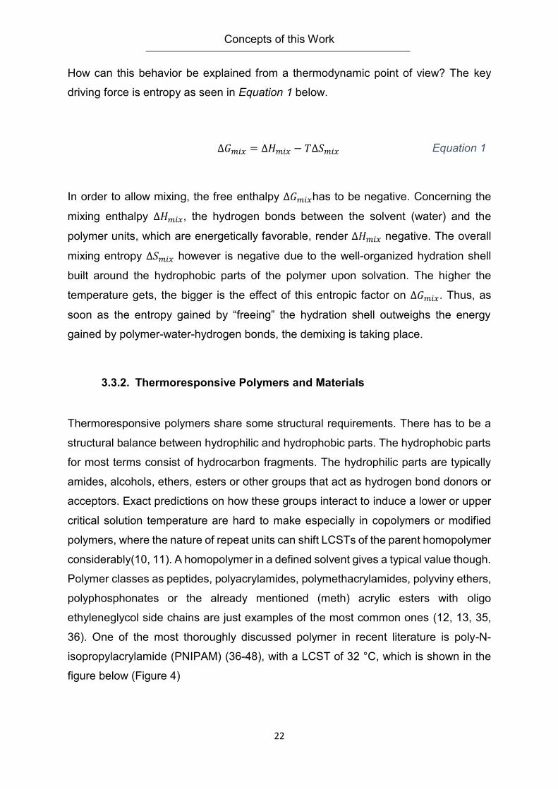
36). One of the most thoroughly discussed polymer in recent literature is poly-N-
isopropylacrylamide (PNIPAM) (36-48), with a LCST of 32 °C, which is shown in the
figure below (Figure 4)
Concepts of this Work
23
Figure 4: Poly-N-isopropyl acrylamide constitutional repeat unit
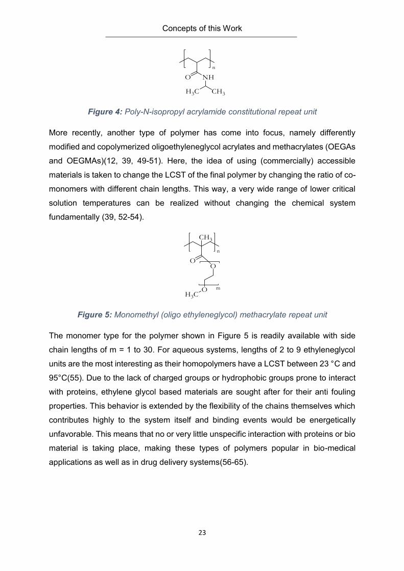
More recently, another type of polymer has come into focus, namely differently
modified and copolymerized oligoethyleneglycol acrylates and methacrylates (OEGAs
and OEGMAs)(12, 39, 49-51). Here, the idea of using (commercially) accessible
materials is taken to change the LCST of the final polymer by changing the ratio of co-
monomers with different chain lengths. This way, a very wide range of lower critical
solution temperatures can be realized without changing the chemical system
fundamentally (39, 52-54).
Figure 5: Monomethyl (oligo ethyleneglycol) methacrylate repeat unit
The monomer type for the polymer shown in Figure 5 is readily available with side
chain lengths of m = 1 to 30. For aqueous systems, lengths of 2 to 9 ethyleneglycol
units are the most interesting as their homopolymers have a LCST between 23 °C and
95°C(55). Due to the lack of charged groups or hydrophobic groups prone to interact
with proteins, ethylene glycol based materials are sought after for their anti fouling
properties. This behavior is extended by the flexibility of the chains themselves which
contributes highly to the system itself and binding events would be energetically
unfavorable. This means that no or very little unspecific interaction with proteins or bio
material is taking place, making these types of polymers popular in bio-medical
applications as well as in drug delivery systems(56-65).
Concepts of this Work
24
3.3.3. Analysis of Thermoresponsive Polymers
Depending on the general structure of the polymer, different types of analytical options
are possible. Taking into account that aqueous systems are in focus, temperature
ranges are realistically between 1°C and roughly 80-90°C depending on the time the
procedure takes for evaporation and concentration changes as the application of
pressure on the system by using a closed vessel is to be avoided. Thermoresponsive
in this work also means that the effect of an exterior stimulus is happening within a
certain, reasonable time frame. So while minutes are certainly within the scope and
one to two hours might be viable, too, longer response times are not practical and
therefore avoided.
For polymers in solution, this work utilizes turbidimetry as method of choice to follow
phase transitions induced by temperature changes and binding events. The principle
is rather simple: a light source, for example a UV/Vis spectrometer equipped with a
heated sample cell is set to a fitting wavelength of the cuvette used and the solvent of
choice. The absorbance is measured as a heat gradient is applied or another external
stimuli such as analyte addition is applied. The absorbance will change as soon as the
previously dissolved polymers are agglomerating together, increasing the scattering
of the light, and thus the absorbance. This phenomenon is visible by the eye, too, by
seeing a clear solution going turbid. The time for this transformation can differ from
polymer from polymer, and varies with the solvent as well (66, 67). Therefore care has
to be taken to allow the system enough response time. If the phase change is spread
out over a broader temperature window instead of inducing a sharp transition, and a
pronounced hysteresis might appear as well in heating/cooling cycles.
3.4. Hydrogels on Surfaces
3.4.1. Hydrogels
By the broadest definition a network swollen with water or an aqueous solvent mix that
shows a yield point can be considered a hydrogel. So a Jell-O would fall under this
definition as well as a contact lens made of Poly-(hydroxyethylmethacrylate)
Concepts of this Work
25
(PHEMA). Hydrogels can be relatively hard and resilient or soft and jelly like. While
consisting mostly out of water, they behave like a compact elastic solid. Responsible
for this behavior is the continuous, solid phase – a network of molecules that is
crosslinked. Crosslinking can be either physical, chemical in or via electrostatic
interactions(68).
Hydrogels are used in many applications. Lately focus has been on biomedical ones
as wound treatment, drug delivery or tissue engineering(69). The materials in use are
manifold from purely synthetic materials as PMMA to bioinspired ones as saccharides,
peptides(69-71) or collagen (72).
Expanding the possibilities further, thermoresponsive hydrogels can change their
swelling ratio upon a temperature stimulus. The swelling ratio (SR) is defined by
Equation 2. Φ is the volume fraction of the polymer, m describes the mass of the
hydrogel in the swollen or unswollen state.
𝑆𝑅 =𝛷𝑑𝑟𝑦 𝑝𝑜𝑙𝑦𝑚𝑒𝑟
𝛷𝑤𝑒𝑡 𝑝𝑜𝑙𝑦𝑚𝑒𝑟 ≈
𝑚𝑠𝑤𝑜𝑙𝑙𝑒𝑛 ℎ𝑦𝑑𝑟𝑜𝑔𝑒𝑙
𝑚𝑑𝑟𝑦 ℎ𝑦𝑑𝑟𝑜𝑔𝑒𝑙 Equation 2
This equation will be further utilized in chapter 4.3. In order to describe the hydrogel in
more detail, one can look at the process of swelling a gel. The first step is to solubilize
the hydrophilic compounds of the polymer network and building up a hydration shell.
In the next step, the osmotic pressure causes more water to diffuse into the system.
This only happens until a certain point where the pressure equals the retraction force
of the polymer network(73). This balance limits the elongation a polymer chain in the
gel at a given temperature and solvent. The limit is defined by the junction points of
the polymer chains– with chemically bound hydrogels as used in this work, this would
be a covalent bond formed between originally different polymer chains. Expanded into
three dimensions, this is the mesh size of the hydrogel. The Flory-Rehner-Theory that
connects swelling ratio with the amount of monomer units between crosslinking points
(NC) can now be used
𝑆𝑅 ∝ 𝑁𝐶
53 Equation 3
Concepts of this Work
26
to connect the physical properties with the chemical structure in Equation 3 (74, 75).
Predicting the exact behavior of a thermoresponsive hydrogel is still difficult though.
By putting the system above the LCST transition of the polymer, the retracting force
adds up with the force from the phase shifts desolution which is powered by the
entropy gained as shown in Equation 1. Both oppose the osmotic force driving the
water back into the gel matrix. In the systems shown in this work, no bonds are broken,
so the process is reversible: upon cooling an LCST type hydrogel, it will swell with
water again.
3.4.2. Surface Immobilization of Hydrogels
Surface immobilization is a step used in this work to make hydrogels easier to handle
physically, and also to have a platform to manipulate and analyze them conveniently
during reactions and binding experiments. A hydrogel immobilized on a surface can
be washed with different buffers or reactive media without complicated clean up
methods. Depending on the goal, different surfaces were used in this work; choices
mostly related to the analytics performed during or after the experiment. The scope
ranges from silicon wafers, gold, polyethylene, poly (methacrylic acid), glass to quartz
glass.
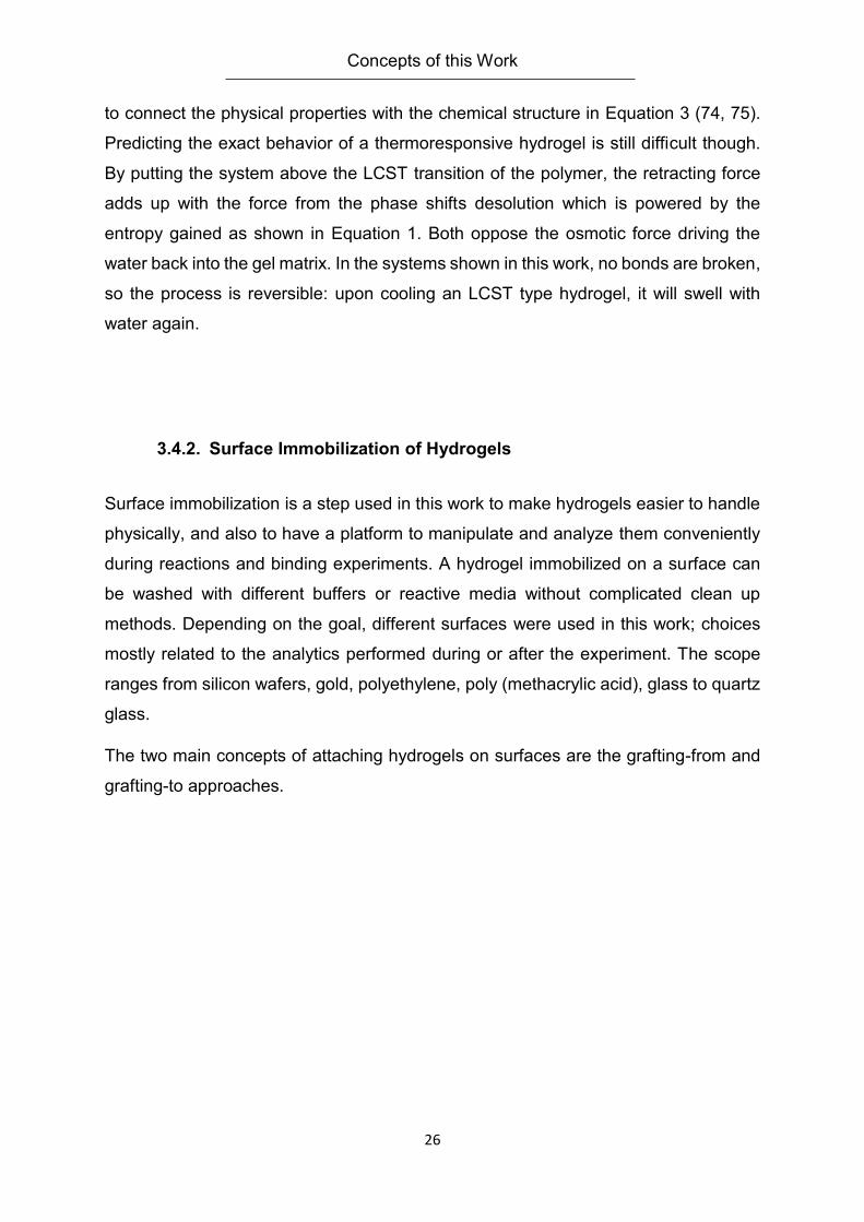
The two main concepts of attaching hydrogels on surfaces are the grafting-from and
grafting-to approaches.
Concepts of this Work
27
Figure 6: Grafting-from and grafting-to approaches in surface modification
In Figure 6, these concepts are exemplified. The left side shows the grafting-from
process, the right presents the grafting-to case. The surface is prepared for the
modification. Gold surfaces are often modified by thiols (optionally with secondary
functionalities)(76, 77), materials such glass or pure silicon can be silanized with a
multitude of functionalized silanes (78, 79). Then, depending on the polymerization
technique used, the polymer is grown directly from the surface. Staying with the
example, a peptide could be grown from it by step polymerization (80), alternate
possibilities include free radical polymerization or RAFT methods (81). The advantage
of this pathway is that the chains can be more dense on the surface in comparison
with the grafting-to strategy (77). Crosslinking the polymer chains has to be done
separately, either by using reactive groups within the polymer or by using a separate
crosslinker.
The grafting-to approach uses premade polymers instead, that can either be
immobilized by reacting an end group in a targeted fashion, as often done with peptide
chains via amide bonds (82). Alternatively, it can be done in a more randomized way
Concepts of this Work
28
utilizing radicals generated on the polymer chain, e.g. by benzophenone groups (83,
84) that get activated by UV-light. In the latter example, the crosslinking occurs at the
same time as the surface fixation. Also, the density of the polymer chains would be
lower due to the steric repulsion caused by dangling polymer chains in their vicinity.
The grafting-from approach is less used in scientific studies as the resulting surface
layer tends to be thinner and, more importantly, the analysis of the resulting polymer
is inherently limited by being surface bound. An advantage for the grafting-to method
is the general flexibility, being able to mix and match different types of polymers
depending on the task at hand. For instance, one could combine different
polymerization techniques and use the same surface to graft onto in order to gain
composite materials. For this work, polymer chain length is a key parameter, if the
hydrogels should become flexible towards the kind of recognition units or bonding sites
they can accommodate. As explained before, the mesh size is directly related to
polymer chain length. The need for large mesh sizes becomes even more pronounced
when dealing with analytes that are as large as viruses(5-300 nm (85)) and bacteria(up
to 0,75 mm (86)). From a practical perspective, only having to pretreated surfaces to
incorporate sites that can couple with a given polymer, is simpler than fixing a multitude
of different initiator group-containing molecules on different surfaces.
3.4.3. Thin Film Analysis by Ellipsometry
Ellipsometry is a method to analyze thin films by measuring the change of polarization
of incident light in relation to the reflected light upon hitting said film. These
measurements give primarily information about dielectric properties, as the complex
refractive index and permittivity. These measurements can be translated into more
material properties such as layer thickness, surface roughness and composition of the
film. For hydrogels, it is a convenient method to determine the swelling ratio of
immobilized films, and the mesh size of the gel as well as swelling or deswelling upon
temperature stimuli. It is also possible to follow chemical modifications of end groups
and the impact of analyte binding events, too.
Concepts of this Work
29
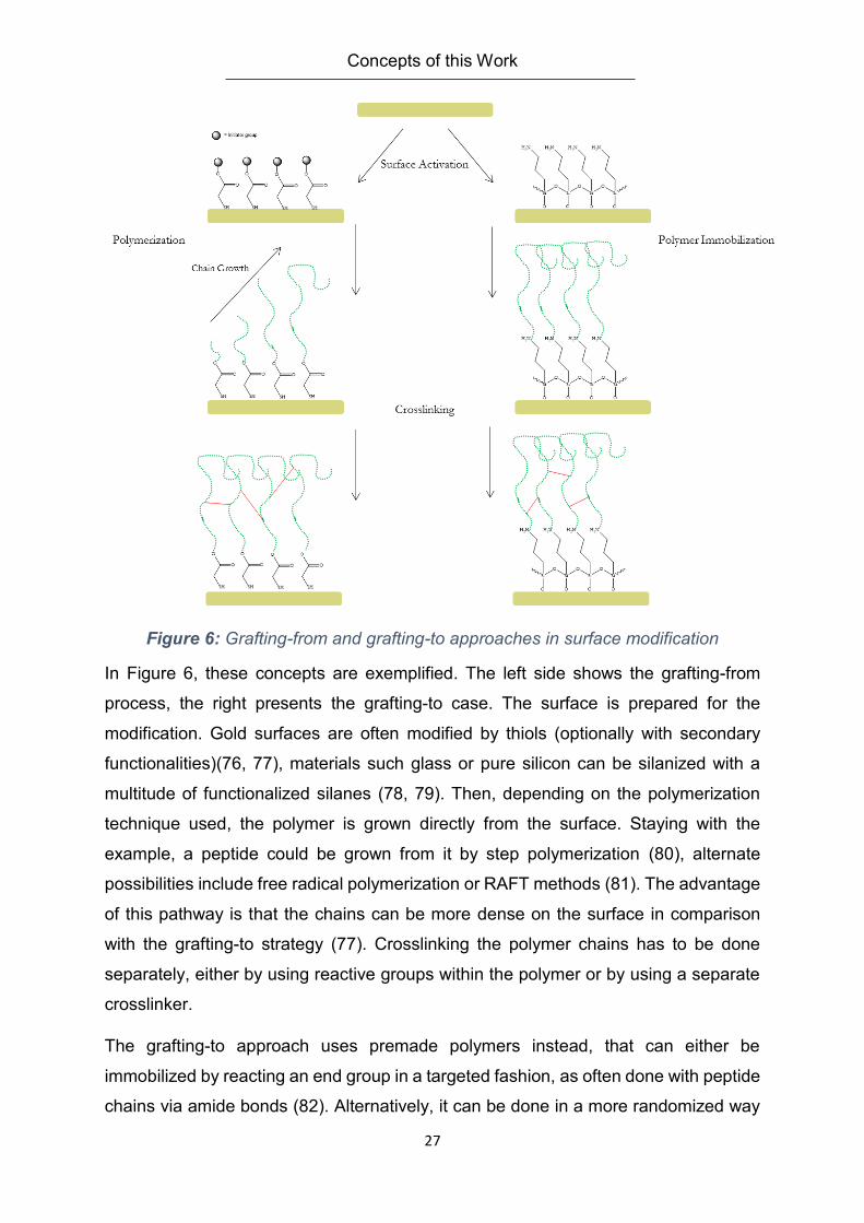
Figure 7: Setup of an ellipsometry measurement(87).
Figure 7 shows the schematic setup of the experiment. The laser light beam gets
polarized linearly or circularly. It might be sent through a compensator quarter wave
plate, or optical glass as in submersed measurements, before it hits the sample. The
beam is reflected and refracted and scattered at the sample film. The reflected light
leaves in the angle Φ, and might hit a quarter wave plate again. It passes through a
second polarizer, the analyzer, before reaching the detector. The analyzer is the only
moving part in this setup and changes its angular position perpendicular to the beam,
the detector picks up the intensity of the light that is left behind the analyzer.
The incident beam and the reflected beam define a plane by their direction. The light
beam itself can be separated into the component parallel to this plane, called p-
polarized. The component perpendicular to this plane is called s-polarized. Both have
an amplitude component Ψ and a phase difference Δ. If linearly polarized light hits the
surface, it is refracted and defracted. The defracted part is reflected at the end of the
layer it is moving through – in this case the hydrogel (it can be defracted again,
depending on the system). The reflected beam would get to the surface to be reflected
internally or diffracted outside the sample and so on. The light moving from the sample
to the detector has changed polarization through this process to an ellipsoid
polarization, meaning that the p and s components have different amplitudes and
phases now. This relation is expressed in the ratio 𝜌 in Equation 4
𝜌 =
𝑟𝑝
𝑟𝑠= tan (Ψ)𝑒𝑖∆
Equation 4
Concepts of this Work
30
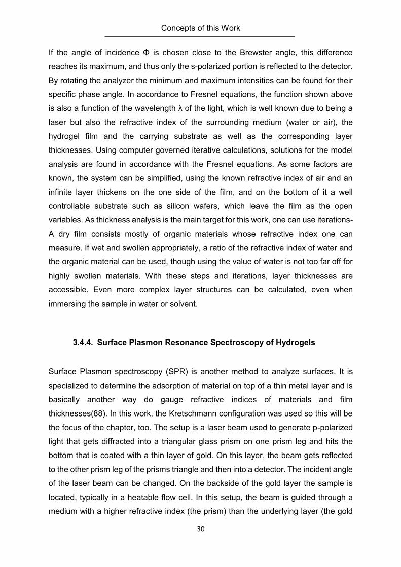
If the angle of incidence Φ is chosen close to the Brewster angle, this difference
reaches its maximum, and thus only the s-polarized portion is reflected to the detector.
By rotating the analyzer the minimum and maximum intensities can be found for their
specific phase angle. In accordance to Fresnel equations, the function shown above
is also a function of the wavelength λ of the light, which is well known due to being a
laser but also the refractive index of the surrounding medium (water or air), the
hydrogel film and the carrying substrate as well as the corresponding layer
thicknesses. Using computer governed iterative calculations, solutions for the model
analysis are found in accordance with the Fresnel equations. As some factors are
known, the system can be simplified, using the known refractive index of air and an
infinite layer thickens on the one side of the film, and on the bottom of it a well
controllable substrate such as silicon wafers, which leave the film as the open
variables. As thickness analysis is the main target for this work, one can use iterations-
A dry film consists mostly of organic materials whose refractive index one can
measure. If wet and swollen appropriately, a ratio of the refractive index of water and
the organic material can be used, though using the value of water is not too far off for
highly swollen materials. With these steps and iterations, layer thicknesses are
accessible. Even more complex layer structures can be calculated, even when
immersing the sample in water or solvent.
3.4.4. Surface Plasmon Resonance Spectroscopy of Hydrogels
Surface Plasmon spectroscopy (SPR) is another method to analyze surfaces. It is
specialized to determine the adsorption of material on top of a thin metal layer and is
basically another way do gauge refractive indices of materials and film
thicknesses(88). In this work, the Kretschmann configuration was used so this will be
the focus of the chapter, too. The setup is a laser beam used to generate p-polarized
light that gets diffracted into a triangular glass prism on one prism leg and hits the
bottom that is coated with a thin layer of gold. On this layer, the beam gets reflected
to the other prism leg of the prisms triangle and then into a detector. The incident angle
of the laser beam can be changed. On the backside of the gold layer the sample is
located, typically in a heatable flow cell. In this setup, the beam is guided through a
medium with a higher refractive index (the prism) than the underlying layer (the gold

Concepts of this Work
31
layer) with a lower refractive index with an angle of incidence above the total reflection,
so no light is diffracted into the gold layer. Still, an evanescent field is generated by
the beam in the gold layer. The field gets dampened within the layers interfaces without
losing energy. If there is a layer of energy absorbing material on the gold film, e.g. a
hydrogel film, the intensity of the reflected light is lowered. By changing the angle of
incidence, this intensity can be brought to a minimum, this angle is called the angle of
resonance. Measuring at this angle causes the photons of the beam resonate with the
electrons of the gold layer. This means that the electron density is oscillating, this
coupling effect is called a Plasmon. The oscillation in turn generates an
electromagnetic field that is declining exponentially but still reaching the sample. If the
sample properties change, as with an absorption or binding event, the refractive index
(and the thickness) of the layer changes, thus influencing the electromagnetic field.
This in turn changes the angle of resonance in order to obtain the resonant plasmon
wave. For the practical application, this means that the angle of resonance and the
change of it is proportional to the change in the refractive index and the layer thickness
of the sample. If the angle is kept fixed, the intensity of the reflected beam is following
proportionally. A fixed angle is used to study kinetics of adsorption or desorption, if it
can be assumed that the layer structure is not changing drastically.
Concepts of this Work
32
3.5. Click Chemistry for Post-Polymerization Modifications
“Click chemistry” has become a widely used label to describe many different reactions.
Originally click chemistry was a selection of reactions by Sharpless et al. as well as a
guide which other or new reactions would also fit into this group by definition(29). He
sets up the following requirements: A “click” reaction has to be:
Modular and wide in scope
High yielding
Giving only inoffensive byproducts that are easily removable without
chromatography
Regio- or possibly stereospecific
Using simple reaction conditions, ideally being water and oxygen tolerant
Using readily available reagents and reactants
Solvent -free or preferably working with water or other nontoxic solvents that
are easily removed
Even though the reactions he proposed were not new, the idea of click chemistry is to
use modular building blocks in clever combinations. Sharpless favored carbon-
heteroatom-bonds over carbon-carbon bonds with a few exceptions. In any case,
energetically spring loaded reactions are his mainstay motivator for the click
nomenclature. Some prominent examples include 1,3- dipolar cycloadditions of azides
and alkynes, Diels-Alder cyclizations, nucleophilic ring openings of epoxides or
aziridines, selected reactions of the carbonyl groups like (thio)urea and amide
formation as well as additions to favorable double bonds, epoxide ring openings and
even more so Michael additions.
These concepts from Sharpless original paper, while coming from a more
pharmaceutical point of view, were quickly adopted to polymer chemistry. Reviews try
to categorize and focus on specific parts of the concept (56, 89-96). While the lively
discussion and ongoing discoveries broaden the “click” horizon, one may question if
every reaction labeled as “click” fulfills all or at least most of the criteria defined by
Sharpless (97). Through the different chapters of this work, typical click reactions will
Concepts of this Work
33
be presented in detail as tools for modifying polymers and hydrogels. The major
advantage of choosing click reactions as a guidance comes from practical
considerations. Water, buffered systems, or water miscible mild solvents are
necessary for sensible peptides and cells – while possibly more or less significant
traces of unremoved solvent could cause problems. Solvent removal by dialysis is one
of the most convenient methods for polymers, while simple washing is sufficient for
surface bound hydrogels. While little is cared for stereospecific reactions, high yields
in the post polymerization reactions are mandatory simply because the coupling
partners are hard to come by and the spring loadedness of the reactions is the
selection criterion for this work. This of course implies that the starting products and
reagents are not easily obtainable, especially as soon as the conjugates become
peptides. The question if a certain reaction or experiment is conform to the “click
concept” will be issued and critically discussed.
3.6. Thermoresponsive Materials as Biosensors
Thermoresponsive materials have been used for biosensors before, with different
approaches. They often have in common that they use recognition sites to bind
biomolecules, forming a bioconjugate. Examples of different concepts are hydrogel
coated particles able to collect inflammatory cells by attaching to proteins and then
getting concentrated by heat switching(98), or enzymes blocked by a
thermoresponsive modified “plug” type analyte, which is removed. This activates the
enzyme by collapsing the polymer and thus removing it from the binding site (99).
Dostalek et al. show that with a combination of a modified poly-NIPAM hydrogel on a
surface plasmon spectrometer (SPR) modified with a fluorescence spectrometer and
a fast heatable/coolable setup. By expanding and collapsing the hydrogel he can make
binding sites available, resulting in a strong fluorescence signal, or collapse the gel,
omitting binding and a signal increase(100). Blocking binding sites by utilizing LCST
polymers and their phase transition has also been shown as a viable approach for a
size selective sensor by Hofman (101). A different approach was followed by the group
of Vee-Sin Lee. They used a thermoresponsive hydrogel modified with a recognition
Concepts of this Work
34
unit to form networks of colloidal crystals in combination with the analyte – producing
a visible optical change by this network build up. The thermoresponsive aspect can be
used to tune the optical properties further (102).
The sensors envisioned in this work follow some of these concepts. It is hydrogel
based and targets a narrow set of analytes. The gel portion may be used as a carrier
but the signal is ideally boosted by signal amplification or signal cascading, which
would translate in a change of the physical properties of the hydrogel, either collapsing
or swelling. This amplification is needed in order to lower the limit of detection (LOD).
Ideally, the limit of detection should to be in the lower µg/ml area, between 1 -100
µg/ml. Examples from medical studies can be found at around 95 µg/ml with
salmonella as analyte for other rapid testing methods (103). These rely on analyte pre-
concentration, so in order to be viable for a test without purification, an order of
magnitude lower would be highly favorable.
Concepts of this Work
35
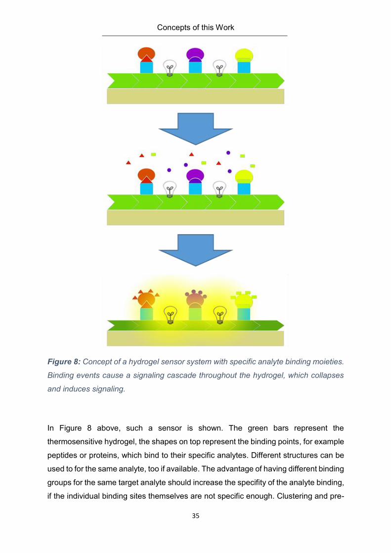
Figure 8: Concept of a hydrogel sensor system with specific analyte binding moieties.
Binding events cause a signaling cascade throughout the hydrogel, which collapses
and induces signaling.
In Figure 8 above, such a sensor is shown. The green bars represent the
thermosensitive hydrogel, the shapes on top represent the binding points, for example
peptides or proteins, which bind to their specific analytes. Different structures can be
used to for the same analyte, too if available. The advantage of having different binding
groups for the same target analyte should increase the specifity of the analyte binding,
if the individual binding sites themselves are not specific enough. Clustering and pre-
Concepts of this Work
36
orienting different binding sites together would be a possibility to enhance this effect
even further, if enough knowledge about the analyte is available. The bulbs symbolize
the signaling units, which may be integrated into the hydrogel, such as a
solvatochromic dye. Alternatively be the hydrogel itself may show structural color.
They might be integrated into the binding sites to interact with the analyte. The general
principle stays the same: a fluid containing the analyte is brought onto or into the
hydrogel, options would be static contact, like putting a drop onto a coated surface
and letting it diffuse into the matrix. Another option is to use a more active method as
pushing the fluid through a filter, for example a syringe filter, to increase the possible
contact volume and giving a possibility of a concentration increase of the analyte within
the matrix. It is only logical that the sensor needs some reaction time to accumulate
enough binding events to cross over the LOD threshold and incur a reaction of the
system. Hypothetically, a cascade could be induced by a contraction or expansion of
the hydrogel mesh that would influence the adjacent mesh cells, so each singular
signal would be multiplied by a certain factor. On the other hand, by using a purely
additive signaling method, as a changing binding pocket that does not further influence
the system at large, the LOD is higher. Thus, the first case – the interaction of the
binding event with the whole system, is the more favorable case.
Carboxyl Based Coupling Systems
37
4. Carboxyl Based Coupling Systems
This chapter showcases the different factors that need to come together to gain a
viable sensor system. The special requirements during monomer and polymer
synthesis for the demonstrator hydrogel system are discussed. The focus lies on the
hydrogel systems which are increasing in components and complexity. Different solid
substrates are used to enable the analysis of binding reactions and recognition events.
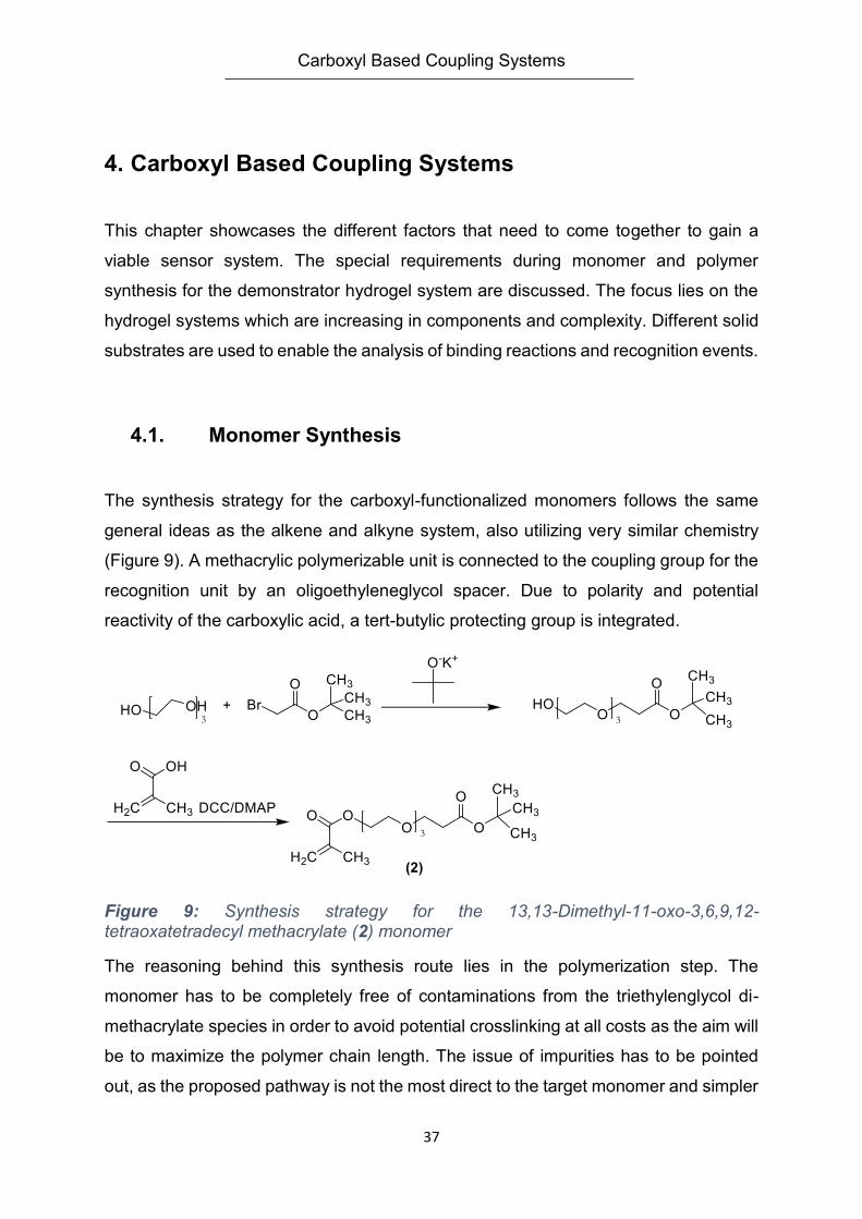
4.1. Monomer Synthesis
The synthesis strategy for the carboxyl-functionalized monomers follows the same
general ideas as the alkene and alkyne system, also utilizing very similar chemistry
(Figure 9). A methacrylic polymerizable unit is connected to the coupling group for the
recognition unit by an oligoethyleneglycol spacer. Due to polarity and potential
reactivity of the carboxylic acid, a tert-butylic protecting group is integrated.
Figure 9: Synthesis strategy for the 13,13-Dimethyl-11-oxo-3,6,9,12-tetraoxatetradecyl methacrylate (2) monomer
The reasoning behind this synthesis route lies in the polymerization step. The
monomer has to be completely free of contaminations from the triethylenglycol di-
methacrylate species in order to avoid potential crosslinking at all costs as the aim will
be to maximize the polymer chain length. The issue of impurities has to be pointed
out, as the proposed pathway is not the most direct to the target monomer and simpler
Carboxyl Based Coupling Systems
38
ways without a protective group are readily imaginable. From the experience of this
work, most impurities come from insufficient work up, whether the carboxylic group is
integrated without the tert-butyl unit, is generated via oxidation, or if the synthetic route
is started form the modification of methacrylic acid with the spacer first. As work up
strategy a vast set of different eluent mixtures have been tried for column
chromatography, as well as (high) vacuum distillation and ion exchange
chromatography. In the end, taking the setback of having to remove a protective group
was accepted as a necessity to keep the monomer available in decent quantities for
polymerization.
4.2. Polymer Synthesis
In order to demonstrate the viability of the concept for as large as possible and
available analytes, certain requirements for the polymer system have to be met. If
possible hydrogels have to be driven to an as large as possible molar mass in order
to keep the amount of necessary crosslinker concentration as low as possible. This in
turn enables a larger mesh size of the resulting hydrogel and eases the penetration of
the gel layer by the recognition unit and later on the analyte. From a statistical point of
view, a polymer chain will need more than one crosslinker unit per chain to form a
hydrogel, not accounting for loop formations or non-reacting crosslinker groups. This
need for long, flexible chains is directly opposed to the need of mechanical stability of
the resulting system.
Organic solvent based radical polymerization does have its limits in adjustability, so in
order to improve on molecular size and to compare the viability of the approach,
polymerizations are also performed in ionic liquids. This technique does not have an
overly longstanding tradition in comparison to synthesis of “small” molecules, as a
product purification via distillation is not viable for polymers (104). Ionic liquids still
bring some advantages, having no vapor pressure, low toxicity and, if done properly,
are recyclable, which is a positive aspect due to their high price in comparison to
regular solvents. Due to their ionic nature, they are highly polar and many are water
miscible as well as thermally stable.
Carboxyl Based Coupling Systems
39
Radical polymerization in ionic liquids has stirred some interest in the beginning of this
century, as higher than otherwise usual molar masses for reactions in organic solvents
or bulk have been achieved (105-107). The group of M. Haddleton performed pulsed
laser polymerization experiments on methacrylic monomers in order to explain the
effect better (104, 108). Their main findings were twofold – depending on the ionic
liquid used in combination with the monomers, the rate of propagation (kp) has
increased due to a lowered activation energy mediated by from charge transfer effects
in the transition state, caused by the ionic nature of the solvent. The other effect they
put emphasis on was the rate of termination (kt) of the polymerization, which seems to
be significantly lowered due to the high viscosity of the reaction medium. While these
effects are the ones targeted at in this chapter, caution has to be taken to not
generalize or overestimate the possible results. Even for the narrowed down group of
imidazolium based ionic liquids the resulting polymers made from methacrylic
monomers vary widely (109, 110) while keeping reaction conditions identical. What
seems to be a common denominator, though, is that the monomers and the resulting
polymers should be decently soluble within the ionic liquid. While a pre-concentration
of monomer units around the wrong polymer chain might be helpful or non-hindering
to some extent, an actual full separation of reagents, polymer chains and reaction
media is detrimental to the reaction.
Separation of the product and the ionic liquid as well as the recycling may not be
neglected. In this work, a strategy of dissolving the polymer product and the ionic liquid
in hot ethanol and then separating the two by cooling and recrystallization steps is
employed.
4.3. Hydrogels
Independently of the chosen synthesis pathway, the functional polymers may be
easier to analyze and handle immobilized on a surface. This is mostly due to the fact
that the post polymer modifications consist of spacious macromolecules themselves.
While working in solution might give an easier time binding to such molecules, the risk
of simply wrapping a protein in a “hull” of polymer is high, making it inaccessible for
potential analytes. From a handling perspective, hydrogels on surfaces are easy to
Carboxyl Based Coupling Systems
40
store in either dry or swollen state and are ready-to-use tools. In many cases, one
surface can even be utilized for multiple experiments by simply washing off a reagent,
switching a buffer and so on – this easy to clean prospect is especially valuable for
post polymerization modifications. As mentioned in the introduction, benzophenone
groups are used as main method for immobilization and crosslinking. The adjustment
of layer thickness can be done by adjusting the amount of polymer brought on the
surface and the spin coating speed and duration if utilized. The parameters for very
similar polymer structures were described in detail by J. Buller (83, 84) and were used
as a reliable starting point.
4.4. Activated Esters for Amide Bonds
Amide bonds are ubiquitous in nature, peptides and proteins use them as backbones.
The idea to use those biomolecules to immobilize them on synthetic materials is not a
new one, but has been around since the last half of the last century (111-113). Due to
the nature of amino acids, using either their carboxylic acid or amine functionality for
this cause was a logical choice.
While forming an amide is an equilibrium reaction, it may require significant activation
to proceed as the equilibrium lies on the side of the hydrolysis(114). Thus, this
condensation type reaction needs to be shifted in its equilibrium. This can be done
either by heating and removal of water during the reaction (115), which might cause a
series of unwanted side reactions especially with complex functional molecules like
proteins. Or a more refined and selective method is utilized. The most common
general method is to activate the carboxylic acid and transform it to a more reactive
species in order to undergo an aminolysis with the target amine. While nature can rely
on enzymes for peptide synthesis, common methods for the chemist are the formation
of acyl chlorides with the aid of thionyl chloride (116), by formation of acyl azides (117)
or utilizing anhydrides of carboxylic acids (118). A very popular way of using
anhydrides is to react the carboxylic acid with carbodiimides, forming an acylurea in
the intermediate step. Activation reagents are dicyclohexyl carbodiimide (DCC) or
ethyl-dimethylaminocarbodiimide (EDC) (119, 120). These two compounds and their
reaction can be made more efficient (and less prone to side reactions) by utilizing
Carboxyl Based Coupling Systems
41
activated ester intermediate, commonly referred to as activated ester. These, often
aromatic, chemicals have the advantage of reacting under very mild conditions, with
demanding coupling partners and with no or very few side reactions. The coupling with
DCC and the aromatic partner 4-dimethylaminopyridine (DMAP) has been utilized in
this work for monomer synthesis, the second example used is the combination of EDC
and N-Hydroxysuccinimide (NHS). Both coupling strategies are widely known and
used in organic synthesis as well as bioconjugation (11, 72, 121-130). While the
combination of DCC and DMAP is commonly used in organic environments as the
urea resulting of reaction is typically insoluble and can be removed by filtration, easing
the work-up. EDC and NHS are often utilized in aqueous systems, as the resulting
NHS-ester is more hydrolytically stable and can be isolated and stored. This coupling
strategy has been published first by G. Anderson in 1963(131).
Coupling reactions using this type of chemistry are a prime example for click chemistry,
as the reagents are readily available and easy to remove by aqueous work up. The
requirements are mostly on the side of steric demands of the coupling partners,
otherwise active esters are widely open to use with all kinds of substrates. The
reactions can be driven to high yields and the materials used are non-toxic. For
bioconjugation specifity and the lack of side reactions has to be viewed carefully
though. Starting from small peptides to proteins other reactive groups like alcohols,
thiols and amines that are not intended to couple are readily available. This is why a
protective group strategy might be needed depending on the requirements of the
resulting conjugate. An example of this strategy would be solid phase peptide
synthesis where amino acid side chains that might interfere with the coupling are
equipped with protective groups, and the terminal group attached to the resin is the
only reactive partner remaining on the peptide after cleavage from the resin(80).
In this chapter, the reaction efficiency and the mild conditions of the coupling reactions
are capitalized to the fullest in order to immobilize peptides and proteins as recognition
units for virus and bacteria recognition, where a denaturalization of a protein might
cause the whole sensor to fail.
Carboxyl Based Coupling Systems
42
4.5. Results
In this chapter a path to the development of a sensor system is proposed. Starting
from trials in solution, the systems used will be adapted to the changing requirements
of the more and more complex systems. Surface bound hydrogels will be modified in
their macroscopic behavior to match the growing size of the sensor units as well as of
the analytes.
4.5.1. Experiments in Solution
To discern the phase behavior and to gather experiences with the system, polymers
11 and 12a-d were synthesized under standard conditions (Figure 10). Whereas
polymer 11 consists of purely commercial monomers, the series of 12 was made to
test copolymerization behavior of monomer 2. Within the precision of the NMR
analysis comparing methyl end groups (3,4 ppm) and protons of the t-butyl group (1,4
ppm) of the carboxyl functionality, the synthesis is a success and the monomers are
integrated with the feed input ratio (between 15 and 30 %). In a first step, the efficiency
of the oligoethyleneglycol spacer in polymer 12d is put to the test as it represents the
targeted concentration of functional groups in this work, balancing between a good
amount of binding opportunities, but keeping the framework somewhat predictable in
its behavior. While the spacer is longer than the MEO2MA side chain, it is still open for
discussion if this difference is paying off in solution, before going one step further and
immobilizing the polymers on a surface. In order to remove the tert-butyl protective
group, the polymer is treated with trifluoroacetic acid (TFA) and then dialyzed.
Carboxyl Based Coupling Systems
43
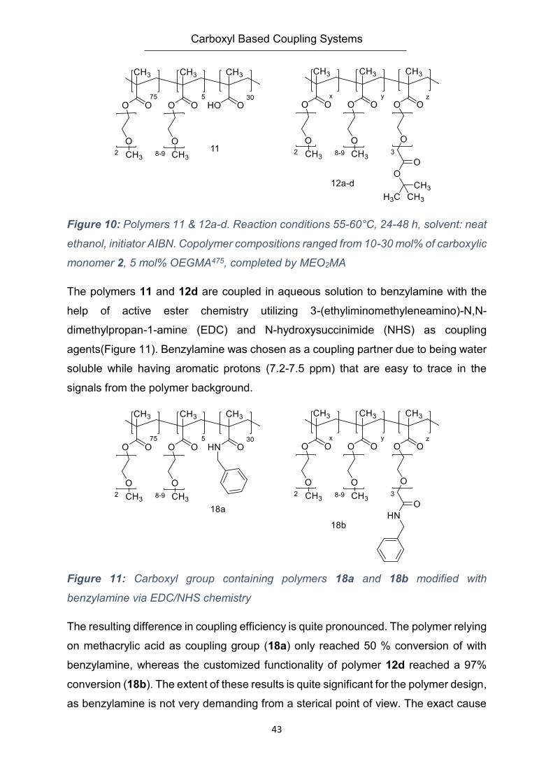
Figure 10: Polymers 11 & 12a-d. Reaction conditions 55-60°C, 24-48 h, solvent: neat
ethanol, initiator AIBN. Copolymer compositions ranged from 10-30 mol% of carboxylic
monomer 2, 5 mol% OEGMA475, completed by MEO2MA
The polymers 11 and 12d are coupled in aqueous solution to benzylamine with the
help of active ester chemistry utilizing 3-(ethyliminomethyleneamino)-N,N-
dimethylpropan-1-amine (EDC) and N-hydroxysuccinimide (NHS) as coupling
agents(Figure 11). Benzylamine was chosen as a coupling partner due to being water
soluble while having aromatic protons (7.2-7.5 ppm) that are easy to trace in the
signals from the polymer background.
Figure 11: Carboxyl group containing polymers 18a and 18b modified with
benzylamine via EDC/NHS chemistry
The resulting difference in coupling efficiency is quite pronounced. The polymer relying
on methacrylic acid as coupling group (18a) only reached 50 % conversion of with
benzylamine, whereas the customized functionality of polymer 12d reached a 97%
conversion (18b). The extent of these results is quite significant for the polymer design,
as benzylamine is not very demanding from a sterical point of view. The exact cause
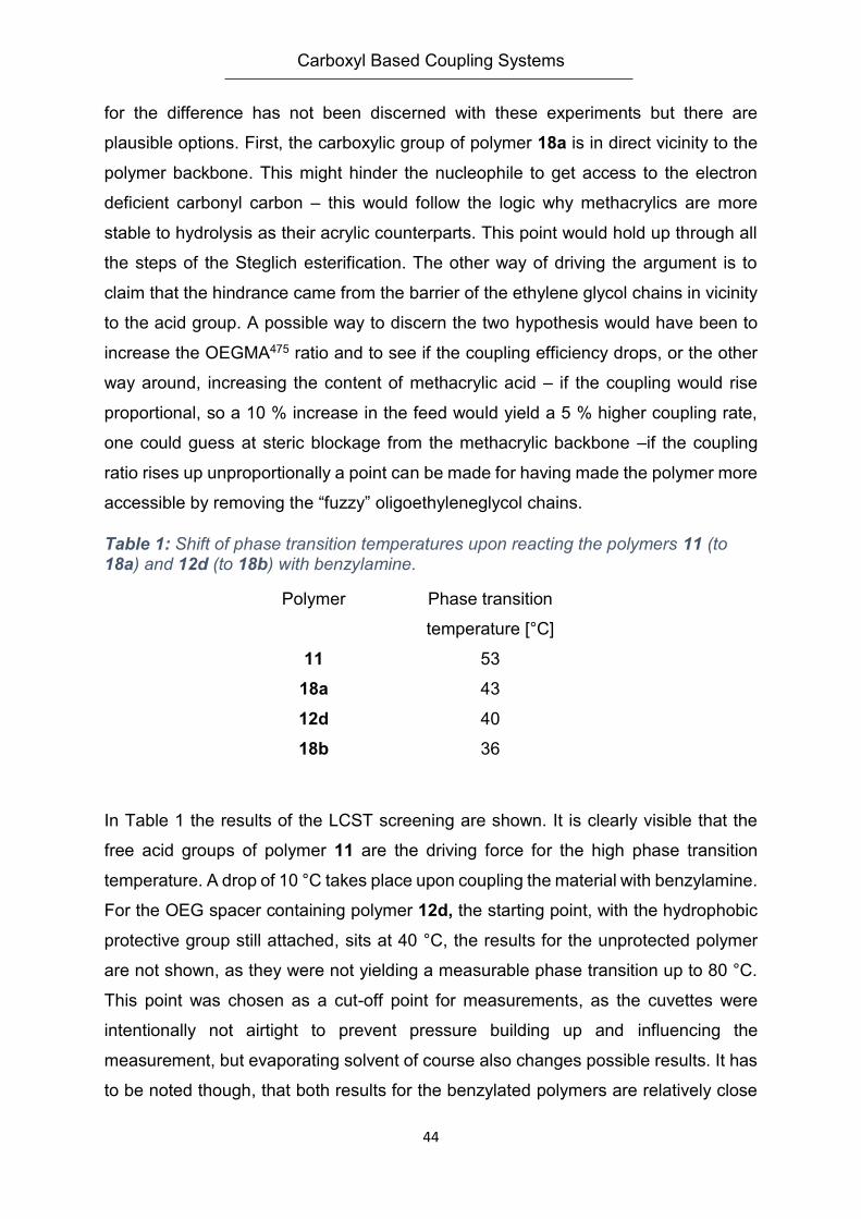
Carboxyl Based Coupling Systems
44
for the difference has not been discerned with these experiments but there are
plausible options. First, the carboxylic group of polymer 18a is in direct vicinity to the
polymer backbone. This might hinder the nucleophile to get access to the electron
deficient carbonyl carbon – this would follow the logic why methacrylics are more
stable to hydrolysis as their acrylic counterparts. This point would hold up through all
the steps of the Steglich esterification. The other way of driving the argument is to
claim that the hindrance came from the barrier of the ethylene glycol chains in vicinity
to the acid group. A possible way to discern the two hypothesis would have been to
increase the OEGMA475 ratio and to see if the coupling efficiency drops, or the other
way around, increasing the content of methacrylic acid – if the coupling would rise
proportional, so a 10 % increase in the feed would yield a 5 % higher coupling rate,
one could guess at steric blockage from the methacrylic backbone –if the coupling
ratio rises up unproportionally a point can be made for having made the polymer more
accessible by removing the “fuzzy” oligoethyleneglycol chains.
Table 1: Shift of phase transition temperatures upon reacting the polymers 11 (to 18a) and 12d (to 18b) with benzylamine.
Polymer Phase transition
temperature [°C]
11 53
18a 43
12d 40
18b 36
In Table 1 the results of the LCST screening are shown. It is clearly visible that the
free acid groups of polymer 11 are the driving force for the high phase transition
temperature. A drop of 10 °C takes place upon coupling the material with benzylamine.
For the OEG spacer containing polymer 12d, the starting point, with the hydrophobic
protective group still attached, sits at 40 °C, the results for the unprotected polymer
are not shown, as they were not yielding a measurable phase transition up to 80 °C.
This point was chosen as a cut-off point for measurements, as the cuvettes were
intentionally not airtight to prevent pressure building up and influencing the
measurement, but evaporating solvent of course also changes possible results. It has
to be noted though, that both results for the benzylated polymers are relatively close
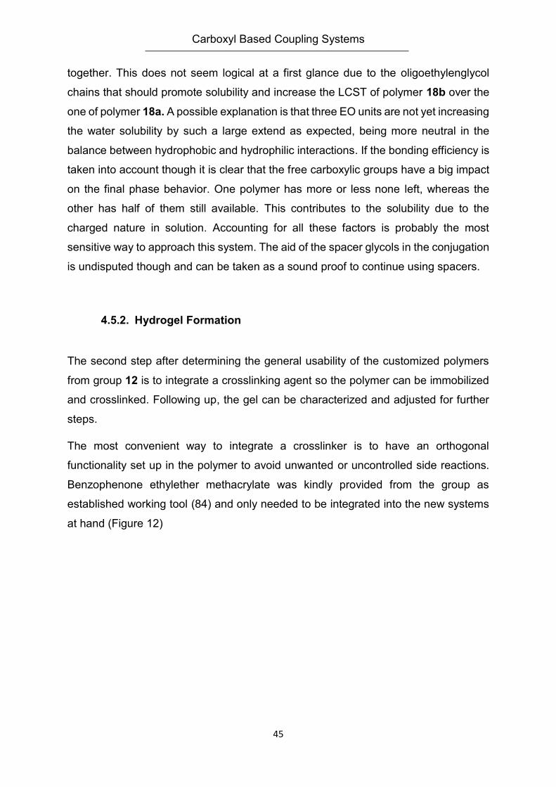
Carboxyl Based Coupling Systems
45
together. This does not seem logical at a first glance due to the oligoethylenglycol
chains that should promote solubility and increase the LCST of polymer 18b over the
one of polymer 18a. A possible explanation is that three EO units are not yet increasing
the water solubility by such a large extend as expected, being more neutral in the
balance between hydrophobic and hydrophilic interactions. If the bonding efficiency is
taken into account though it is clear that the free carboxylic groups have a big impact
on the final phase behavior. One polymer has more or less none left, whereas the
other has half of them still available. This contributes to the solubility due to the
charged nature in solution. Accounting for all these factors is probably the most
sensitive way to approach this system. The aid of the spacer glycols in the conjugation
is undisputed though and can be taken as a sound proof to continue using spacers.
4.5.2. Hydrogel Formation
The second step after determining the general usability of the customized polymers
from group 12 is to integrate a crosslinking agent so the polymer can be immobilized
and crosslinked. Following up, the gel can be characterized and adjusted for further
steps.
The most convenient way to integrate a crosslinker is to have an orthogonal
functionality set up in the polymer to avoid unwanted or uncontrolled side reactions.
Benzophenone ethylether methacrylate was kindly provided from the group as
established working tool (84) and only needed to be integrated into the new systems
at hand (Figure 12)
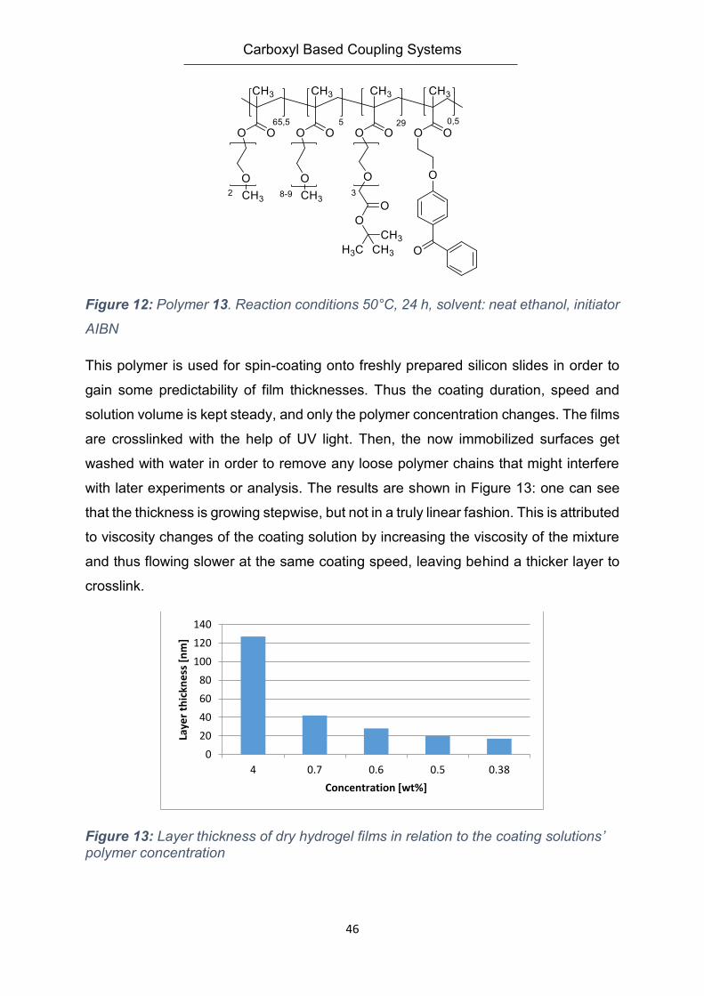
Carboxyl Based Coupling Systems
46
Figure 12: Polymer 13. Reaction conditions 50°C, 24 h, solvent: neat ethanol, initiator
AIBN
This polymer is used for spin-coating onto freshly prepared silicon slides in order to
gain some predictability of film thicknesses. Thus the coating duration, speed and
solution volume is kept steady, and only the polymer concentration changes. The films
are crosslinked with the help of UV light. Then, the now immobilized surfaces get
washed with water in order to remove any loose polymer chains that might interfere
with later experiments or analysis. The results are shown in Figure 13: one can see
that the thickness is growing stepwise, but not in a truly linear fashion. This is attributed
to viscosity changes of the coating solution by increasing the viscosity of the mixture
and thus flowing slower at the same coating speed, leaving behind a thicker layer to
crosslink.
Figure 13: Layer thickness of dry hydrogel films in relation to the coating solutions’ polymer concentration
0
20
40
60
80
100
120
140
4 0.7 0.6 0.5 0.38
Laye
r th
ickn
ess
[n
m]
Concentration [wt%]
Carboxyl Based Coupling Systems
47
The layers have to be characterized by their mesh size before attaching other
materials in order to be able to better understand the results. Therefore, the swelling
ratio (SR) is used. The swelling ratio has been introduced by equations 2 and 3 in the
introduction, but for practical use it has to be expanded and connected to the mesh
size ε (132).
𝜖 = 𝑆𝑅1/3 ∗ 𝑟 Equation 5
𝑟 = 𝑑𝑐−𝑐 ∗ (2𝑁𝑐)12 ∗ 𝐶𝑛
1/2
Equation 6
The connection is made via the equations above, where the factor r defines the
distance between two crosslinking points of the polymer. Cn is a static factor, for
methacrylic polymers its value is 6.9; dC-C describes the distance bridged by C-C
bonds while Nc is the amount of monomer units between two crosslinking points.
For polymer 13 a mesh size of 6 nm was determined this way for optimum conditions.
The first coupling target on was the small protein Lysozyme with a maximum
dimension of about 5x3x3 nm (133). As a precaution, the mesh size was considered
to be too small, so a practical approach was chosen: polymer 13 was blended 1:1 with
polymer 12d as their main difference is the lack of a crosslinker. The goal was to
reduce the crosslinker concentration and thus increase the distance Nc between two
crosslinking units. The polymer blend was processed normally and then remeasured
yielding a new mesh size of 11 nm. With these results at hand, gold chips were coated
with the polymer blend in order to gain live insights into protein coupling. The targeted
size for all hydrogels in the swollen state was between 400 and 500 nm. From a
process point of view, safe for the coating and the crosslinking of the hydrogel, all
further reactions are done in the SPR spectrometer as well as the deprotection of the
carboxylic group and its activation, too. This means that the system shows a decent
mechanical strength as the solvent is changed from water to acetate buffer and the
different reagents which inflicts quite some osmotic stress on the hydrogel layer. The
method of choice for the coupling reaction was the known EDC/NHS activate ester
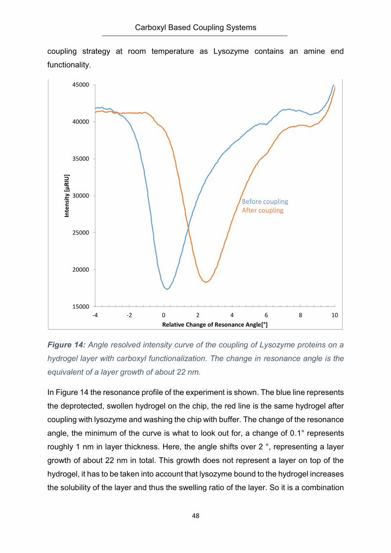
Carboxyl Based Coupling Systems
48
coupling strategy at room temperature as Lysozyme contains an amine end
functionality.
Figure 14: Angle resolved intensity curve of the coupling of Lysozyme proteins on a
hydrogel layer with carboxyl functionalization. The change in resonance angle is the
equivalent of a layer growth of about 22 nm.
In Figure 14 the resonance profile of the experiment is shown. The blue line represents
the deprotected, swollen hydrogel on the chip, the red line is the same hydrogel after
coupling with lysozyme and washing the chip with buffer. The change of the resonance
angle, the minimum of the curve is what to look out for, a change of 0.1° represents
roughly 1 nm in layer thickness. Here, the angle shifts over 2 °, representing a layer
growth of about 22 nm in total. This growth does not represent a layer on top of the
hydrogel, it has to be taken into account that lysozyme bound to the hydrogel increases
the solubility of the layer and thus the swelling ratio of the layer. So it is a combination
15000
20000
25000
30000
35000
40000
45000
-4 -2 0 2 4 6 8 10
Inte
nsi
ty [
µR
IU]
Relative Change of Resonance Angle[°]
Before couplingAfter coupling
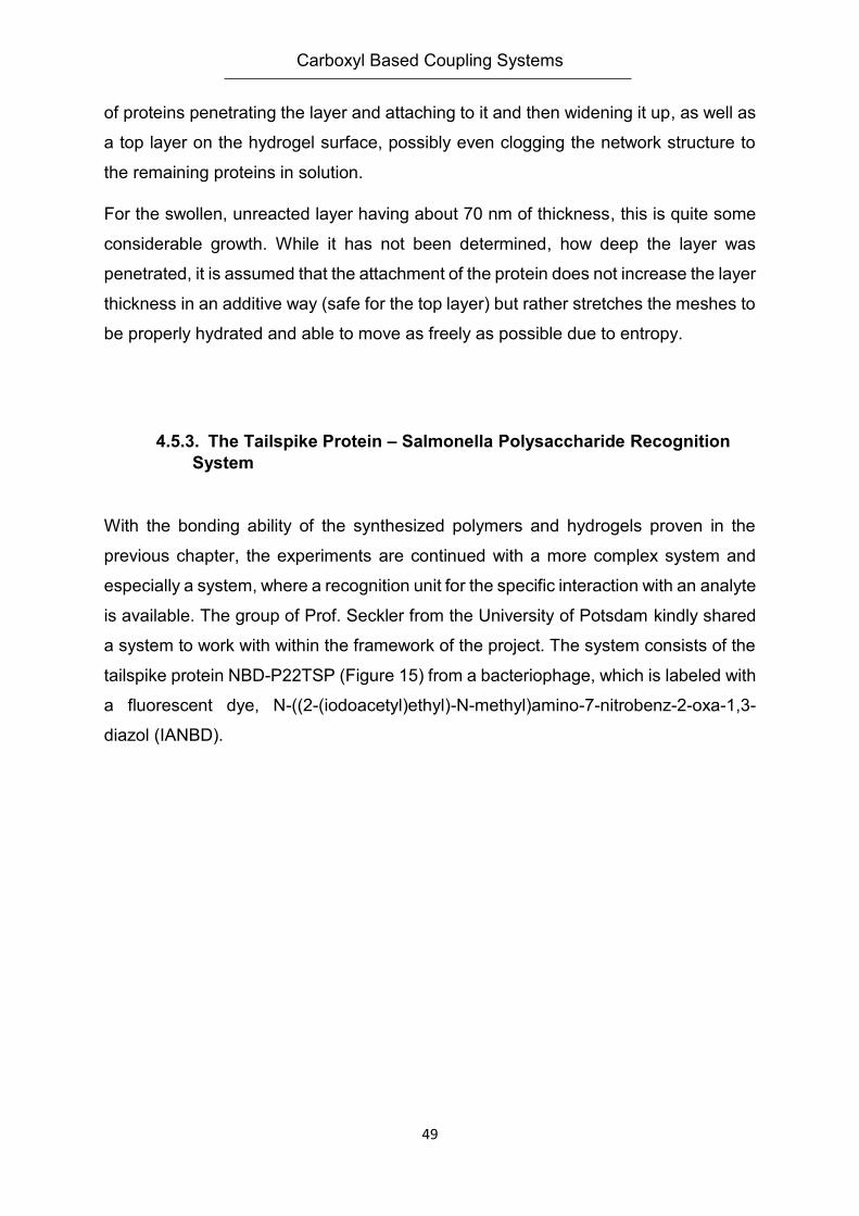
Carboxyl Based Coupling Systems
49
of proteins penetrating the layer and attaching to it and then widening it up, as well as
a top layer on the hydrogel surface, possibly even clogging the network structure to
the remaining proteins in solution.
For the swollen, unreacted layer having about 70 nm of thickness, this is quite some
considerable growth. While it has not been determined, how deep the layer was
penetrated, it is assumed that the attachment of the protein does not increase the layer
thickness in an additive way (safe for the top layer) but rather stretches the meshes to
be properly hydrated and able to move as freely as possible due to entropy.
4.5.3. The Tailspike Protein – Salmonella Polysaccharide Recognition
System
With the bonding ability of the synthesized polymers and hydrogels proven in the
previous chapter, the experiments are continued with a more complex system and
especially a system, where a recognition unit for the specific interaction with an analyte
is available. The group of Prof. Seckler from the University of Potsdam kindly shared
a system to work with within the framework of the project. The system consists of the
tailspike protein NBD-P22TSP (Figure 15) from a bacteriophage, which is labeled with
a fluorescent dye, N-((2-(iodoacetyl)ethyl)-N-methyl)amino-7-nitrobenz-2-oxa-1,3-
diazol (IANBD).
Carboxyl Based Coupling Systems
50
Figure 15: Fluorescent labeled tailspike protein of phage 22 (134, 135)
The tailspike protein is intended to be bound to the hydrogel layer and with its binding
pocket it is able to selectively bind to the T400C polysaccharide of Salmonella
Typhimurium. This saccharide consists of fragments of 10, 20 and 60 kDA units. With
this kind of selective bonding it should be possible to monitor the binding process via
SPR spectroscopy but, due to the fluorescence label, also with different fluorescence
methods as the fluorescence intensity is claimed to be up to ten times higher in a
binding state than in a non-binding state at 540 nm (136).
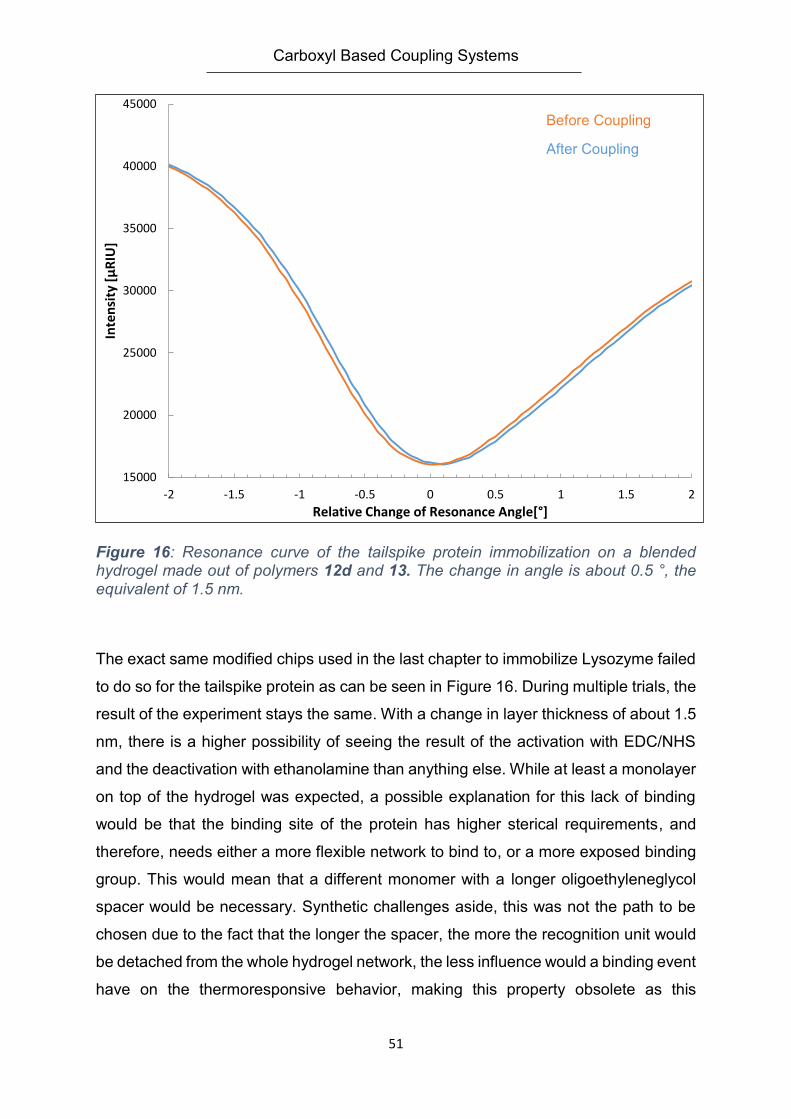
Carboxyl Based Coupling Systems
51
Figure 16: Resonance curve of the tailspike protein immobilization on a blended hydrogel made out of polymers 12d and 13. The change in angle is about 0.5 °, the equivalent of 1.5 nm.
The exact same modified chips used in the last chapter to immobilize Lysozyme failed
to do so for the tailspike protein as can be seen in Figure 16. During multiple trials, the
result of the experiment stays the same. With a change in layer thickness of about 1.5
nm, there is a higher possibility of seeing the result of the activation with EDC/NHS
and the deactivation with ethanolamine than anything else. While at least a monolayer
on top of the hydrogel was expected, a possible explanation for this lack of binding
would be that the binding site of the protein has higher sterical requirements, and
therefore, needs either a more flexible network to bind to, or a more exposed binding
group. This would mean that a different monomer with a longer oligoethyleneglycol
spacer would be necessary. Synthetic challenges aside, this was not the path to be
chosen due to the fact that the longer the spacer, the more the recognition unit would
be detached from the whole hydrogel network, the less influence would a binding event
have on the thermoresponsive behavior, making this property obsolete as this
15000
20000
25000
30000
35000
40000
45000
-2 -1.5 -1 -0.5 0 0.5 1 1.5 2
Inte
nsi
ty [
µR
IU]
Relative Change of Resonance Angle[°]
Before Coupling
After Coupling
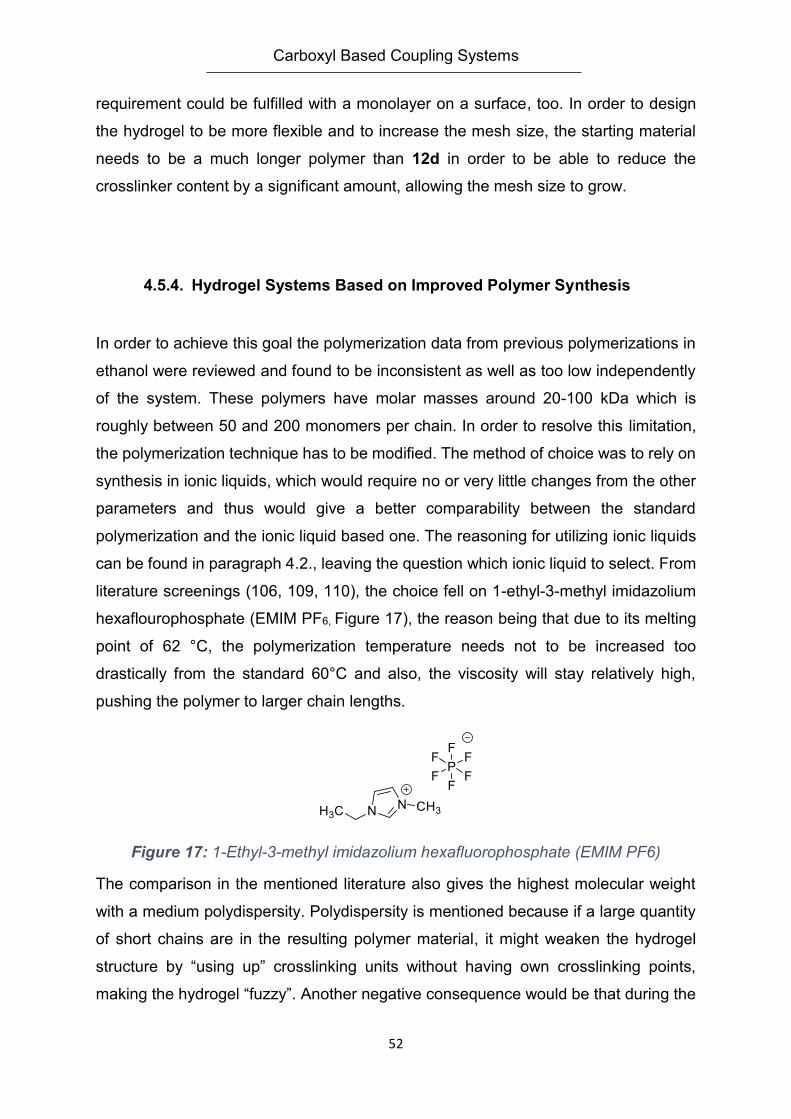
Carboxyl Based Coupling Systems
52
requirement could be fulfilled with a monolayer on a surface, too. In order to design
the hydrogel to be more flexible and to increase the mesh size, the starting material
needs to be a much longer polymer than 12d in order to be able to reduce the
crosslinker content by a significant amount, allowing the mesh size to grow.
4.5.4. Hydrogel Systems Based on Improved Polymer Synthesis
In order to achieve this goal the polymerization data from previous polymerizations in
ethanol were reviewed and found to be inconsistent as well as too low independently
of the system. These polymers have molar masses around 20-100 kDa which is
roughly between 50 and 200 monomers per chain. In order to resolve this limitation,
the polymerization technique has to be modified. The method of choice was to rely on
synthesis in ionic liquids, which would require no or very little changes from the other
parameters and thus would give a better comparability between the standard
polymerization and the ionic liquid based one. The reasoning for utilizing ionic liquids
can be found in paragraph 4.2., leaving the question which ionic liquid to select. From
literature screenings (106, 109, 110), the choice fell on 1-ethyl-3-methyl imidazolium
hexaflourophosphate (EMIM PF6, Figure 17), the reason being that due to its melting
point of 62 °C, the polymerization temperature needs not to be increased too
drastically from the standard 60°C and also, the viscosity will stay relatively high,
pushing the polymer to larger chain lengths.
Figure 17: 1-Ethyl-3-methyl imidazolium hexafluorophosphate (EMIM PF6)
The comparison in the mentioned literature also gives the highest molecular weight
with a medium polydispersity. Polydispersity is mentioned because if a large quantity
of short chains are in the resulting polymer material, it might weaken the hydrogel
structure by “using up” crosslinking units without having own crosslinking points,
making the hydrogel “fuzzy”. Another negative consequence would be that during the
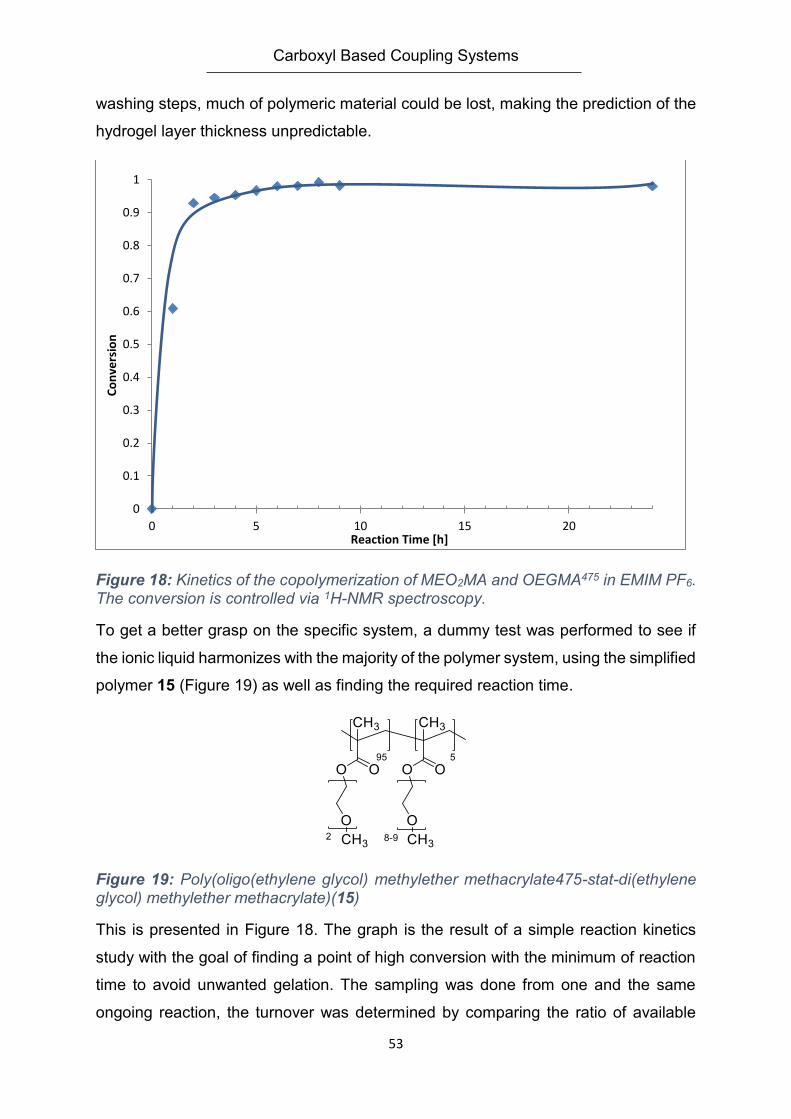
Carboxyl Based Coupling Systems
53
washing steps, much of polymeric material could be lost, making the prediction of the
hydrogel layer thickness unpredictable.
Figure 18: Kinetics of the copolymerization of MEO2MA and OEGMA475 in EMIM PF6. The conversion is controlled via 1H-NMR spectroscopy.
To get a better grasp on the specific system, a dummy test was performed to see if
the ionic liquid harmonizes with the majority of the polymer system, using the simplified
polymer 15 (Figure 19) as well as finding the required reaction time.
Figure 19: Poly(oligo(ethylene glycol) methylether methacrylate475-stat-di(ethylene glycol) methylether methacrylate)(15)
This is presented in Figure 18. The graph is the result of a simple reaction kinetics
study with the goal of finding a point of high conversion with the minimum of reaction
time to avoid unwanted gelation. The sampling was done from one and the same
ongoing reaction, the turnover was determined by comparing the ratio of available
0
0.1
0.2
0.3
0.4
0.5
0.6
0.7
0.8
0.9
1
0 5 10 15 20
Co
nve
rsio
n
Reaction Time [h]
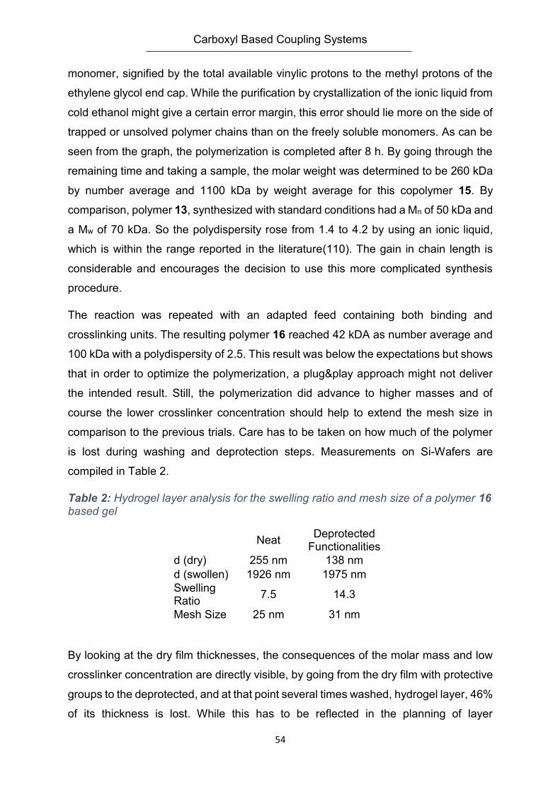
Carboxyl Based Coupling Systems
54
monomer, signified by the total available vinylic protons to the methyl protons of the
ethylene glycol end cap. While the purification by crystallization of the ionic liquid from
cold ethanol might give a certain error margin, this error should lie more on the side of
trapped or unsolved polymer chains than on the freely soluble monomers. As can be
seen from the graph, the polymerization is completed after 8 h. By going through the
remaining time and taking a sample, the molar weight was determined to be 260 kDa
by number average and 1100 kDa by weight average for this copolymer 15. By
comparison, polymer 13, synthesized with standard conditions had a Mn of 50 kDa and
a Mw of 70 kDa. So the polydispersity rose from 1.4 to 4.2 by using an ionic liquid,
which is within the range reported in the literature(110). The gain in chain length is
considerable and encourages the decision to use this more complicated synthesis
procedure.
The reaction was repeated with an adapted feed containing both binding and
crosslinking units. The resulting polymer 16 reached 42 kDA as number average and
100 kDa with a polydispersity of 2.5. This result was below the expectations but shows
that in order to optimize the polymerization, a plug&play approach might not deliver
the intended result. Still, the polymerization did advance to higher masses and of
course the lower crosslinker concentration should help to extend the mesh size in
comparison to the previous trials. Care has to be taken on how much of the polymer
is lost during washing and deprotection steps. Measurements on Si-Wafers are
compiled in Table 2.
Table 2: Hydrogel layer analysis for the swelling ratio and mesh size of a polymer 16 based gel
Neat Deprotected
Functionalities
d (dry) 255 nm 138 nm
d (swollen) 1926 nm 1975 nm
Swelling Ratio
7.5 14.3
Mesh Size 25 nm 31 nm
By looking at the dry film thicknesses, the consequences of the molar mass and low
crosslinker concentration are directly visible, by going from the dry film with protective
groups to the deprotected, and at that point several times washed, hydrogel layer, 46%
of its thickness is lost. While this has to be reflected in the planning of layer
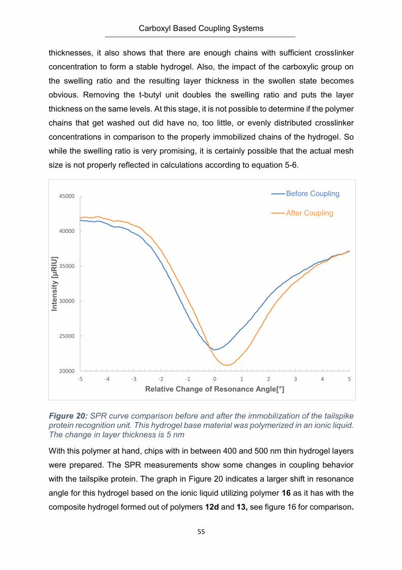
Carboxyl Based Coupling Systems
55
thicknesses, it also shows that there are enough chains with sufficient crosslinker
concentration to form a stable hydrogel. Also, the impact of the carboxylic group on
the swelling ratio and the resulting layer thickness in the swollen state becomes
obvious. Removing the t-butyl unit doubles the swelling ratio and puts the layer
thickness on the same levels. At this stage, it is not possible to determine if the polymer
chains that get washed out did have no, too little, or evenly distributed crosslinker
concentrations in comparison to the properly immobilized chains of the hydrogel. So
while the swelling ratio is very promising, it is certainly possible that the actual mesh
size is not properly reflected in calculations according to equation 5-6.
Figure 20: SPR curve comparison before and after the immobilization of the tailspike protein recognition unit. This hydrogel base material was polymerized in an ionic liquid. The change in layer thickness is 5 nm
With this polymer at hand, chips with in between 400 and 500 nm thin hydrogel layers
were prepared. The SPR measurements show some changes in coupling behavior
with the tailspike protein. The graph in Figure 20 indicates a larger shift in resonance
angle for this hydrogel based on the ionic liquid utilizing polymer 16 as it has with the
composite hydrogel formed out of polymers 12d and 13, see figure 16 for comparison.
20000
25000
30000
35000
40000
45000
-5 -4 -3 -2 -1 0 1 2 3 4 5
Inte
nsit
y [
µR
IU]
Relative Change of Resonance Angle[°]
Before Coupling
After Coupling
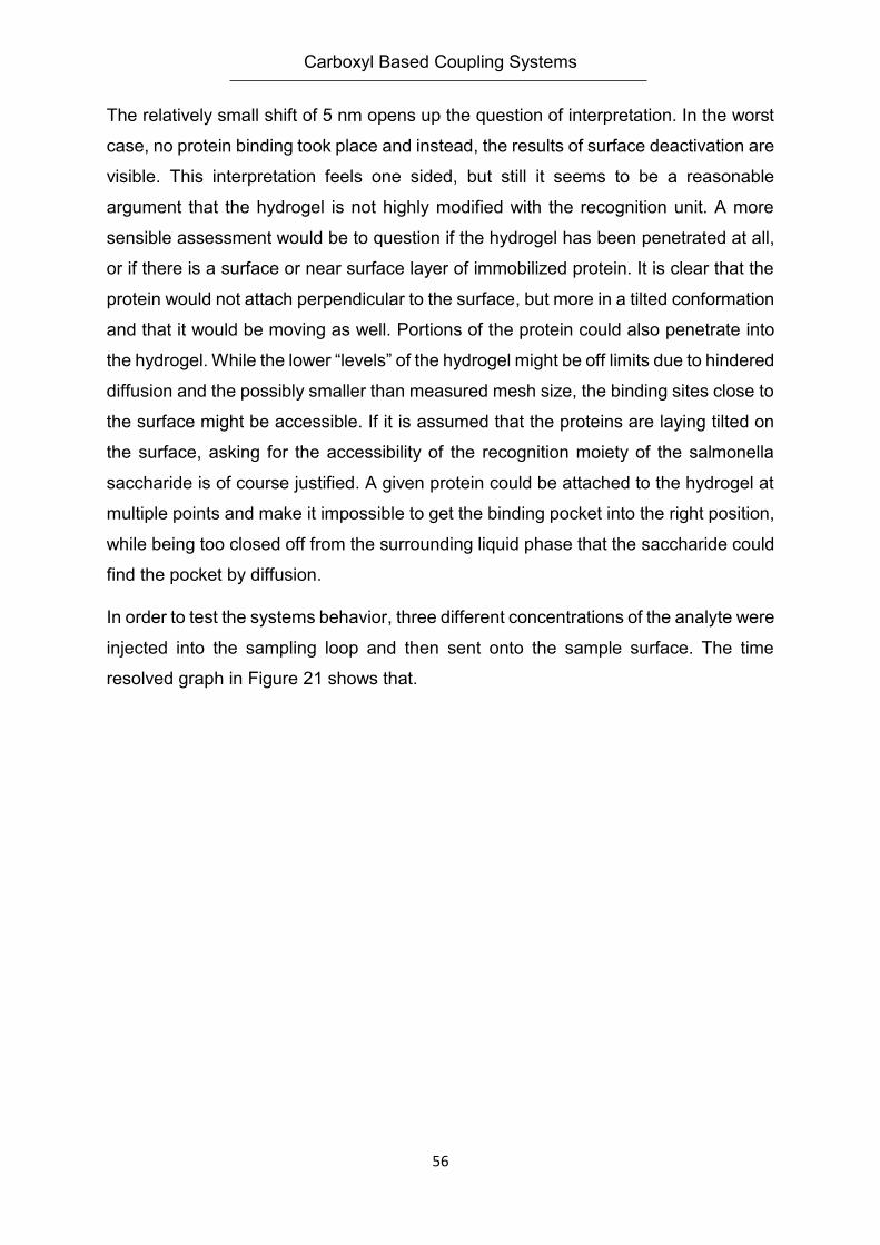
Carboxyl Based Coupling Systems
56
The relatively small shift of 5 nm opens up the question of interpretation. In the worst
case, no protein binding took place and instead, the results of surface deactivation are
visible. This interpretation feels one sided, but still it seems to be a reasonable
argument that the hydrogel is not highly modified with the recognition unit. A more
sensible assessment would be to question if the hydrogel has been penetrated at all,
or if there is a surface or near surface layer of immobilized protein. It is clear that the
protein would not attach perpendicular to the surface, but more in a tilted conformation
and that it would be moving as well. Portions of the protein could also penetrate into
the hydrogel. While the lower “levels” of the hydrogel might be off limits due to hindered
diffusion and the possibly smaller than measured mesh size, the binding sites close to
the surface might be accessible. If it is assumed that the proteins are laying tilted on
the surface, asking for the accessibility of the recognition moiety of the salmonella
saccharide is of course justified. A given protein could be attached to the hydrogel at
multiple points and make it impossible to get the binding pocket into the right position,
while being too closed off from the surrounding liquid phase that the saccharide could
find the pocket by diffusion.
In order to test the systems behavior, three different concentrations of the analyte were
injected into the sampling loop and then sent onto the sample surface. The time
resolved graph in Figure 21 shows that.
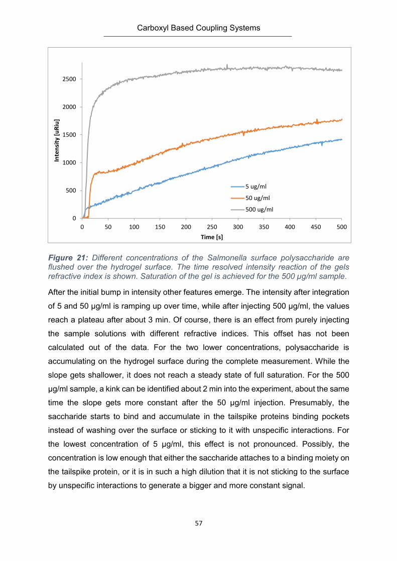
Carboxyl Based Coupling Systems
57
Figure 21: Different concentrations of the Salmonella surface polysaccharide are flushed over the hydrogel surface. The time resolved intensity reaction of the gels refractive index is shown. Saturation of the gel is achieved for the 500 µg/ml sample.
After the initial bump in intensity other features emerge. The intensity after integration
of 5 and 50 µg/ml is ramping up over time, while after injecting 500 µg/ml, the values
reach a plateau after about 3 min. Of course, there is an effect from purely injecting
the sample solutions with different refractive indices. This offset has not been
calculated out of the data. For the two lower concentrations, polysaccharide is
accumulating on the hydrogel surface during the complete measurement. While the
slope gets shallower, it does not reach a steady state of full saturation. For the 500
µg/ml sample, a kink can be identified about 2 min into the experiment, about the same
time the slope gets more constant after the 50 µg/ml injection. Presumably, the
saccharide starts to bind and accumulate in the tailspike proteins binding pockets
instead of washing over the surface or sticking to it with unspecific interactions. For
the lowest concentration of 5 µg/ml, this effect is not pronounced. Possibly, the
concentration is low enough that either the saccharide attaches to a binding moiety on
the tailspike protein, or it is in such a high dilution that it is not sticking to the surface
by unspecific interactions to generate a bigger and more constant signal.
0
500
1000
1500
2000
2500
0 50 100 150 200 250 300 350 400 450 500
Inte
nsi
ty [
uR
iu]
Time [s]
5 ug/ml
50 ug/ml
500 ug/ml
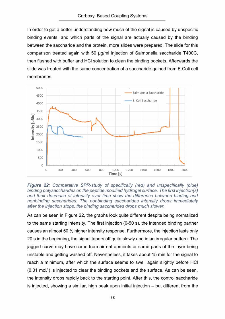
Carboxyl Based Coupling Systems
58
In order to get a better understanding how much of the signal is caused by unspecific
binding events, and which parts of the signal are actually caused by the binding
between the saccharide and the protein, more slides were prepared. The slide for this
comparison treated again with 50 µg/ml injection of Salmonella saccharide T400C,
then flushed with buffer and HCl solution to clean the binding pockets. Afterwards the
slide was treated with the same concentration of a saccharide gained from E.Coli cell
membranes.
Figure 22: Comparative SPR-study of specifically (red) and unspecifically (blue) binding polysaccharides on the peptide modified hydrogel surface. The first injection(s) and their decrease of intensity over time show the difference between binding and nonbinding saccharides: The nonbinding saccharides intensity drops immediately after the injection stops, the binding saccharides drops much slower.
As can be seen in Figure 22, the graphs look quite different despite being normalized
to the same starting intensity. The first injection (0-50 s), the intended binding partner
causes an almost 50 % higher intensity response. Furthermore, the injection lasts only
20 s in the beginning, the signal tapers off quite slowly and in an irregular pattern. The
jagged curve may have come from air entrapments or some parts of the layer being
unstable and getting washed off. Nevertheless, it takes about 15 min for the signal to
reach a minimum, after which the surface seems to swell again slightly before HCl
(0.01 mol/l) is injected to clear the binding pockets and the surface. As can be seen,
the intensity drops rapidly back to the starting point. After this, the control saccharide
is injected, showing a similar, high peak upon initial injection – but different from the
0
500
1000
1500
2000
2500
3000
3500
4000
4500
5000
0 200 400 600 800 1000 1200 1400 1600 1800 2000
Inte
nsi
ty [
uR
iu]
Time [s]
Salmonella Saccharide
E. Coli Saccharide
Carboxyl Based Coupling Systems
59
original analyte, the intensity drops off almost immediately after the injection was
stopped, and falls down to a lower value. For a perfect theoretical system, this would
mean that the intensity should fall back to its base value (here it would be normalized
as 0); this step should be repeatable. Hypothetically, both saccharides should be
removable completely, giving a long enough washing procedure even without HCl. In
these experiments however, this seems not to be the case, which means unwanted
processes are happening. The more obvious conclusion is that the hydrogel exhibits
unspecific interactions with the analyte. The carboxylic groups should have been
deactivated by the reaction with ethanolamine after the tailspike proteins
immobilization. If the process is not complete, this might very well be the case. What
might add up to this is the thickness of the gels – while standard inactivation
procedures were utilized, they may have been not sufficient to ensure that the
carboxylic groups within the hydrogel were fully inactivated (or activated in the first
place even). Additionally, the surface layer of the chip is a hydrogel of considerable
mesh size instead of a monolayer of polymers or a dense polymer layer, and the
analyte is in comparison a quite small polysaccharide by pure dimensions. This could
cause diffusion of the polysaccharides into the layer, where they get trapped and do
not diffuse out of the hydrogel fast enough in relation to the used time scale.
Nevertheless, the graph of Figure 22 makes it clear that the hydrogels response is
certainly different for the two different polysaccharides, with the targeted analyte
having a much higher retention time on the layer than the control material. This shows
that enough tailspike protein was bound to the gel to generate a signal and that the
tailspike protein is not blocked off in a way that it can no longer interact with its analyte,
meaning that this is a viable approach to detect the salmonella polysaccharide with
this system, making up an already relative complex demonstrator.
These experiments were meant to be control experiments and used as a proof of
concept before doing any further steps. The intention of this segment was to analyze
the binding and recognition behavior of the tailspike protein – polysaccharide system
with the help of fluorescence spectroscopy, as it is fitted with a chromophore that
changes its fluorescence intensity upon binding. For this, glass slides were coated
with the hydrogel system based on polymer 16 and prepared to the point of the
tailspike protein being immobilized in two different concentrations and the layer
deactivated with ethanolamine. As comparison, commercial Glymo and Epoxide slides
Carboxyl Based Coupling Systems
60
were spotted with the recognition unit as well as with their standard procedures. In
summary, the analyte was used in different concentrations, the control polysaccharide,
too, as well as polyvinylalcohol and blank fields were set up. Clearly, immobilization
was taking place as there is no change in fluorescence for any of the slide types or the
offered analyte at all. This leaves the question open if the chosen system was truly
fitting for this kind of demonstrator. Of course handling errors cannot be fully excluded
though the materials were handled with utmost care and by experienced application
users. These results show that, while being promising, biosensors of such complexity
are not as plug and play as other, simpler demonstrator systems and need a much
more preparation to be viable as demonstrator tool for hydrogels.
4.5.5. Influenza Virus Detection Demonstrator System
The previous demonstrator system aiming for salmonella detection has shown some
of the shortcomings of a large detector unit, namely a difficult integration onto the
polymer or hydrogel system as well as the possibility of having a hard to control
amount of inaccessible binding sites. Furthermore, with the fluorescent signaling unit
being placed within the binding pocket, the spectroscopic detection can be problematic
as well.
A different approach is to include the signaling unit into the polymer chain itself instead
of at the receptor unit. This demands that there is an interaction that spans from the
analyte to the detector unit to the polymer chain and then to the signaling unit.
H. Memczak from the former Fraunhofer IBMT kindly provided the basis of the system.
MX-31 type influenza virus samples, a binding peptide specific to surface proteins of
this virus stem as well as a control peptide that would work for other stems (compare
Figure 23 for the sequence). The supplied peptides have their carboxylic groups
protected by t-butyl protective groups, which were removed with TFA after coupling
according to the standard procedure.
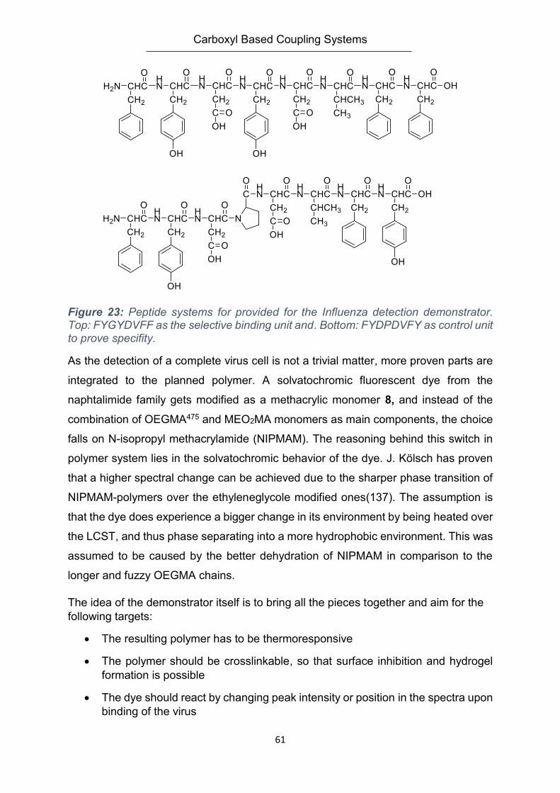
Carboxyl Based Coupling Systems
61
Figure 23: Peptide systems for provided for the Influenza detection demonstrator. Top: FYGYDVFF as the selective binding unit and. Bottom: FYDPDVFY as control unit to prove specifity.
As the detection of a complete virus cell is not a trivial matter, more proven parts are
integrated to the planned polymer. A solvatochromic fluorescent dye from the
naphtalimide family gets modified as a methacrylic monomer 8, and instead of the
combination of OEGMA475 and MEO2MA monomers as main components, the choice
falls on N-isopropyl methacrylamide (NIPMAM). The reasoning behind this switch in
polymer system lies in the solvatochromic behavior of the dye. J. Kölsch has proven
that a higher spectral change can be achieved due to the sharper phase transition of
NIPMAM-polymers over the ethyleneglycole modified ones(137). The assumption is
that the dye does experience a bigger change in its environment by being heated over
the LCST, and thus phase separating into a more hydrophobic environment. This was
assumed to be caused by the better dehydration of NIPMAM in comparison to the
longer and fuzzy OEGMA chains.
The idea of the demonstrator itself is to bring all the pieces together and aim for the
following targets:
The resulting polymer has to be thermoresponsive
The polymer should be crosslinkable, so that surface inhibition and hydrogel
formation is possible
The dye should react by changing peak intensity or position in the spectra upon
binding of the virus
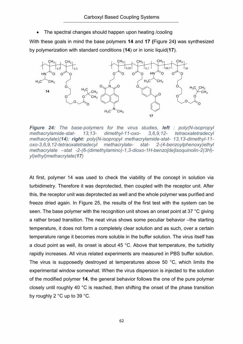
Carboxyl Based Coupling Systems
62
The spectral changes should happen upon heating /cooling
With these goals in mind the base polymers 14 and 17 (Figure 24) was synthesized
by polymerization with standard conditions (14) or in ionic liquid(17).
Figure 24: The base-polymers for the virus studies, left : poly(N-isopropyl methacrylamide-stat- 13,13- dimethyl-11-oxo- 3,6,9,12- tetraoxatetradecyl methacrylate)(14); right: poly(N-isopropyl methacrylamide-stat- 13,13-dimethyl-11-oxo-3,6,9,12-tetraoxatetradecyl methacrylate- stat- 2-(4-benzoylphenoxy)ethyl methacrylate –stat -2-(6-(dimethylamino)-1,3-dioxo-1H-benzo[de]isoquinolin-2(3H)-yl)ethyl)methacrylate(17)
At first, polymer 14 was used to check the viability of the concept in solution via
turbidimetry. Therefore it was deprotected, then coupled with the receptor unit. After
this, the receptor unit was deprotected as well and the whole polymer was purified and
freeze dried again. In Figure 25, the results of the first test with the system can be
seen. The base polymer with the recognition unit shows an onset point at 37 °C giving
a rather broad transition. The neat virus shows some peculiar behavior –the starting
temperature, it does not form a completely clear solution and as such, over a certain
temperature range it becomes more soluble in the buffer solution. The virus itself has
a cloud point as well, its onset is about 45 °C. Above that temperature, the turbidity
rapidly increases. All virus related experiments are measured in PBS buffer solution.
The virus is supposedly destroyed at temperatures above 50 °C, which limits the
experimental window somewhat. When the virus dispersion is injected to the solution
of the modified polymer 14, the general behavior follows the one of the pure polymer
closely until roughly 40 °C is reached, then shifting the onset of the phase transition
by roughly 2 °C up to 39 °C.
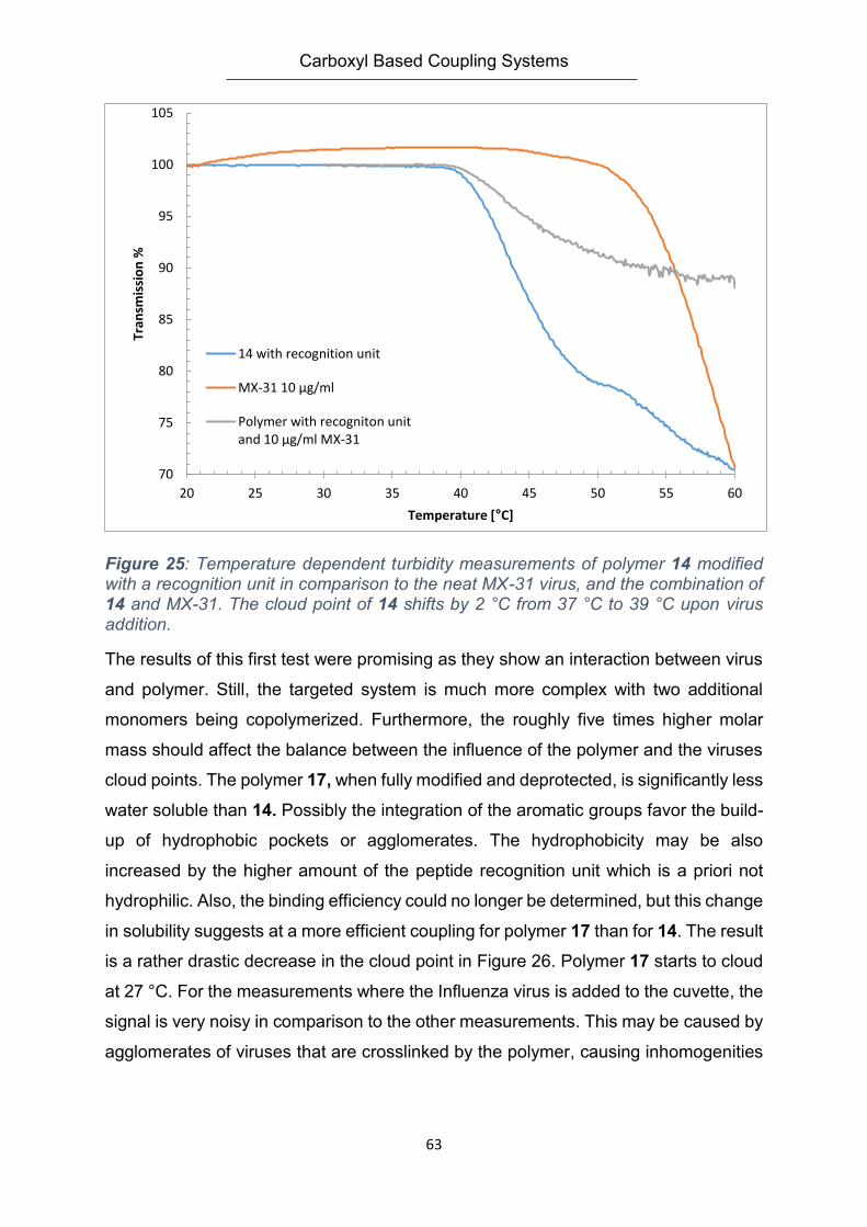
Carboxyl Based Coupling Systems
63
Figure 25: Temperature dependent turbidity measurements of polymer 14 modified with a recognition unit in comparison to the neat MX-31 virus, and the combination of 14 and MX-31. The cloud point of 14 shifts by 2 °C from 37 °C to 39 °C upon virus addition.
The results of this first test were promising as they show an interaction between virus
and polymer. Still, the targeted system is much more complex with two additional
monomers being copolymerized. Furthermore, the roughly five times higher molar
mass should affect the balance between the influence of the polymer and the viruses
cloud points. The polymer 17, when fully modified and deprotected, is significantly less
water soluble than 14. Possibly the integration of the aromatic groups favor the build-
up of hydrophobic pockets or agglomerates. The hydrophobicity may be also
increased by the higher amount of the peptide recognition unit which is a priori not
hydrophilic. Also, the binding efficiency could no longer be determined, but this change
in solubility suggests at a more efficient coupling for polymer 17 than for 14. The result
is a rather drastic decrease in the cloud point in Figure 26. Polymer 17 starts to cloud
at 27 °C. For the measurements where the Influenza virus is added to the cuvette, the
signal is very noisy in comparison to the other measurements. This may be caused by
agglomerates of viruses that are crosslinked by the polymer, causing inhomogenities
70
75
80
85
90
95
100
105
20 25 30 35 40 45 50 55 60
Tran
smis
sio
n %
Temperature [°C]
14 with recognition unit
MX-31 10 µg/ml
Polymer with recogniton unitand 10 µg/ml MX-31
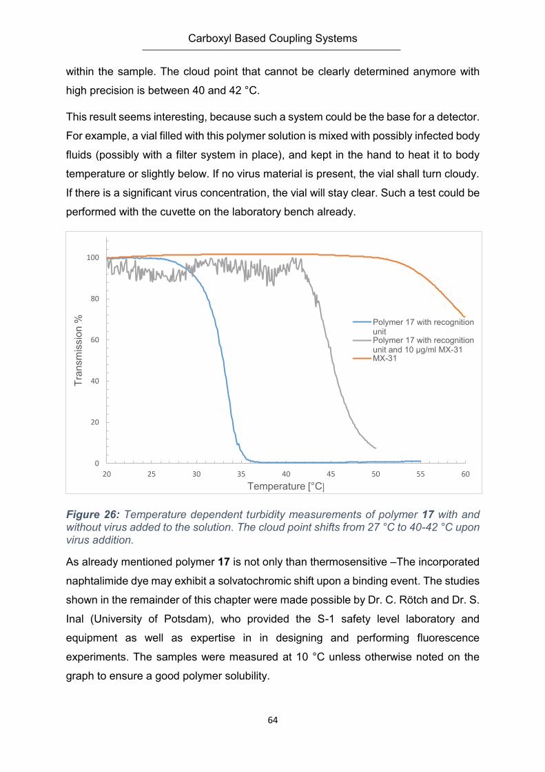
Carboxyl Based Coupling Systems
64
within the sample. The cloud point that cannot be clearly determined anymore with
high precision is between 40 and 42 °C.
This result seems interesting, because such a system could be the base for a detector.
For example, a vial filled with this polymer solution is mixed with possibly infected body
fluids (possibly with a filter system in place), and kept in the hand to heat it to body
temperature or slightly below. If no virus material is present, the vial shall turn cloudy.
If there is a significant virus concentration, the vial will stay clear. Such a test could be
performed with the cuvette on the laboratory bench already.
Figure 26: Temperature dependent turbidity measurements of polymer 17 with and without virus added to the solution. The cloud point shifts from 27 °C to 40-42 °C upon virus addition.
As already mentioned polymer 17 is not only than thermosensitive –The incorporated
naphtalimide dye may exhibit a solvatochromic shift upon a binding event. The studies
shown in the remainder of this chapter were made possible by Dr. C. Rötch and Dr. S.
Inal (University of Potsdam), who provided the S-1 safety level laboratory and
equipment as well as expertise in in designing and performing fluorescence
experiments. The samples were measured at 10 °C unless otherwise noted on the
graph to ensure a good polymer solubility.
0
20
40
60
80
100
20 25 30 35 40 45 50 55 60
Tra
nsm
issio
n %
Temperature [°C]
Polymer 17 with recognitionunitPolymer 17 with recognitionunit and 10 µg/ml MX-31MX-31
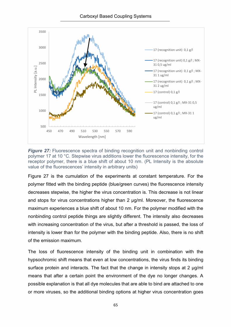
Carboxyl Based Coupling Systems
65
Figure 27: Fluorescence spectra of binding recognition unit and nonbinding control polymer 17 at 10 °C. Stepwise virus additions lower the fluorescence intensity, for the receptor polymer, there is a blue shift of about 10 nm. (PL Intensity is the absolute value of the fluorescences’ intensity in arbitrary units)
Figure 27 is the cumulation of the experiments at constant temperature. For the
polymer fitted with the binding peptide (blue/green curves) the fluorescence intensity
decreases stepwise, the higher the virus concentration is. This decrease is not linear
and stops for virus concentrations higher than 2 µg/ml. Moreover, the fluorescence
maximum experiences a blue shift of about 10 nm. For the polymer modified with the
nonbinding control peptide things are slightly different. The intensity also decreases
with increasing concentration of the virus, but after a threshold is passed, the loss of
intensity is lower than for the polymer with the binding peptide. Also, there is no shift
of the emission maximum.
The loss of fluorescence intensity of the binding unit in combination with the
hypsochromic shift means that even at low concentrations, the virus finds its binding
surface protein and interacts. The fact that the change in intensity stops at 2 µg/ml
means that after a certain point the environment of the dye no longer changes. A
possible explanation is that all dye molecules that are able to bind are attached to one
or more viruses, so the additional binding options at higher virus concentration goes
500
1000
1500
2000
2500
3000
3500
450 470 490 510 530 550 570 590
PL
Inte
nsi
ty [
a.u
.]
Wavelength [nm]
17 (recognition unit) 0,1 g/l
17 (recognition unit) 0,1 g/l ; MX-31 0,5 ug/ml
17 (recognition unit) 0,1 g/l ; MX-31 1 ug/ml
17 (recognition unit) 0,1 g/l ; MX-31 2 ug/ml
17 (control) 0,1 g/l
17 (control) 0,1 g/l ; MX-31 0,5ug/ml
17 (control) 0,1 g/l ; MX-31 1ug/ml
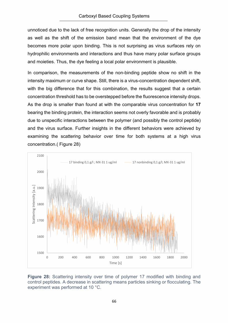
Carboxyl Based Coupling Systems
66
unnoticed due to the lack of free recognition units. Generally the drop of the intensity
as well as the shift of the emission band mean that the environment of the dye
becomes more polar upon binding. This is not surprising as virus surfaces rely on
hydrophilic environments and interactions and thus have many polar surface groups
and moieties. Thus, the dye feeling a local polar environment is plausible.
In comparison, the measurements of the non-binding peptide show no shift in the
intensity maximum or curve shape. Still, there is a virus-concentration dependent shift,
with the big difference that for this combination, the results suggest that a certain
concentration threshold has to be overstepped before the fluorescence intensity drops.
As the drop is smaller than found at with the comparable virus concentration for 17
bearing the binding protein, the interaction seems not overly favorable and is probably
due to unspecific interactions between the polymer (and possibly the control peptide)
and the virus surface. Further insights in the different behaviors were achieved by
examining the scattering behavior over time for both systems at a high virus
concentration.( Figure 28)
Figure 28: Scattering intensity over time of polymer 17 modified with binding and control peptides. A decrease in scattering means particles sinking or flocculating. The experiment was performed at 10 °C.
1500
1600
1700
1800
1900
2000
2100
0 200 400 600 800 1000 1200 1400 1600 1800 2000
Scat
teri
ng
Inte
nsi
ty [
a.u
.]
Time [s]
17 binding 0,1 g/l ; MX-31 1 ug/ml 17 nonbinding 0,1 g/l; MX-31 1 ug/ml
Carboxyl Based Coupling Systems
67
For the experiment, the polymer was pre-solved. While stirring, the virus was added.
After 10 s for mixing, the stirrer was stopped. The orange line represents the control
polymer without a selectively binding peptide you can see that there is quite a large
amount of noise in the scattered signal, most probably due to the size of the viruses
forming inhomogeneous zones in the cuvette. Still, over the course of roughly 30 min
the signal remains more or less constant indicating that the virus dispersion is stable.
Compared with Figure 28, at this virus concentration, some process are already well
underway causing a change in fluorescence by hydrophilic interactions. This means
that the loss of intensity is caused by minor or short termed interactions that are
unspecific. This point is supported by taking the scattering behavior over time of the
polymer with an attached recognition unit into account. While the scattering starts off
higher it slowly drops over time. This would either mean that some material got
dissolved and does no longer contribute to scattering, or that particles or aggregates
were formed and caused the higher scattering intensity are either sedimenting or
flocculating. By checking the sample, it became clear that sedimentation occurred.
This behavior fits to the theory that the binding polymer acts like a glue to the virus
cells, binding to them first, and then building a network structure that coagulates over
time. The initial phase is dominated by peptide binding single chains to the virus and
the binding moieties. The remainder of the now dangling polymer chain has the option
to attach further peptide units to the same virus, forming a network on its surface –
and losing entropy by each binding and “stiffening” of its chain. The other option for
the polymer is to dangle in the solution and possibly at some point hitting another virus
cell. When repeating this step, a network will form and separate from aqueous solution
and keeping the connecting polymer chain flexible in movement.
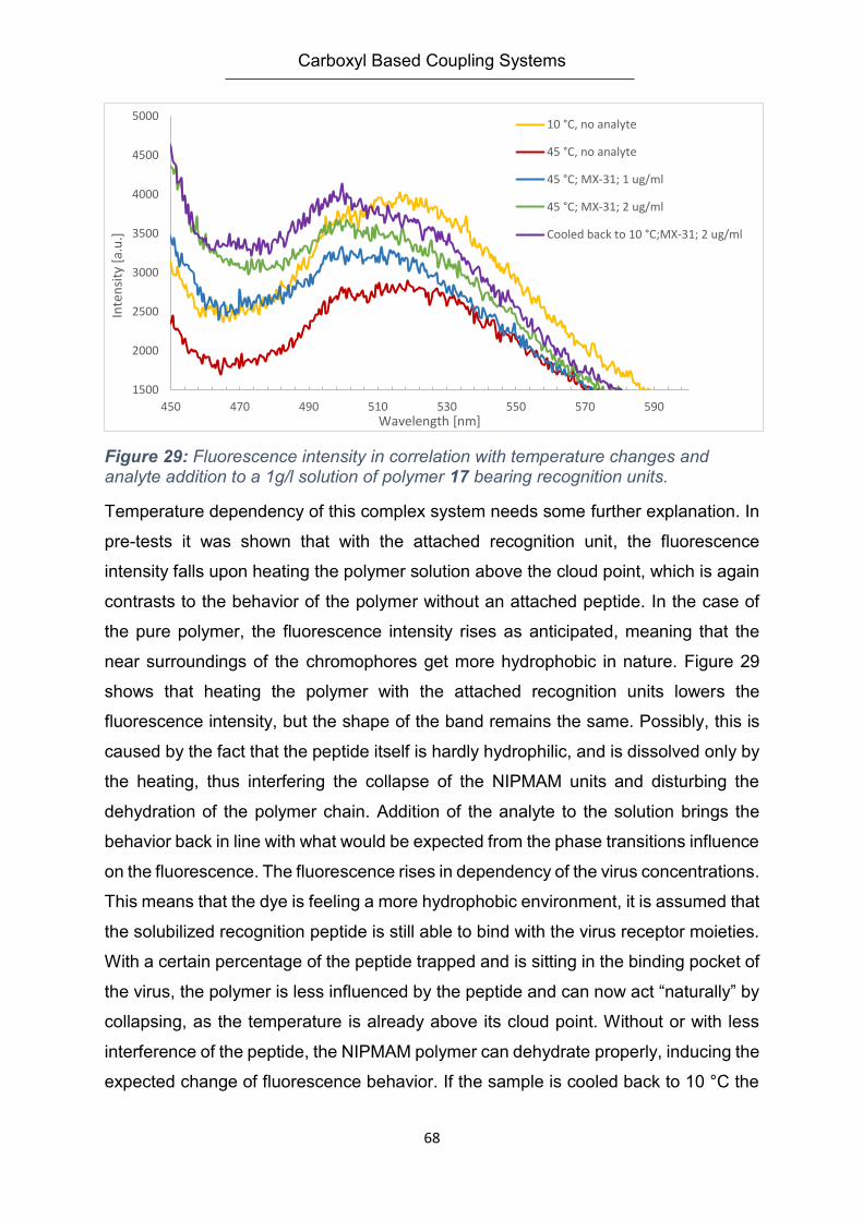
Carboxyl Based Coupling Systems
68
Figure 29: Fluorescence intensity in correlation with temperature changes and analyte addition to a 1g/l solution of polymer 17 bearing recognition units.
Temperature dependency of this complex system needs some further explanation. In
pre-tests it was shown that with the attached recognition unit, the fluorescence
intensity falls upon heating the polymer solution above the cloud point, which is again
contrasts to the behavior of the polymer without an attached peptide. In the case of
the pure polymer, the fluorescence intensity rises as anticipated, meaning that the
near surroundings of the chromophores get more hydrophobic in nature. Figure 29
shows that heating the polymer with the attached recognition units lowers the
fluorescence intensity, but the shape of the band remains the same. Possibly, this is
caused by the fact that the peptide itself is hardly hydrophilic, and is dissolved only by
the heating, thus interfering the collapse of the NIPMAM units and disturbing the
dehydration of the polymer chain. Addition of the analyte to the solution brings the
behavior back in line with what would be expected from the phase transitions influence
on the fluorescence. The fluorescence rises in dependency of the virus concentrations.
This means that the dye is feeling a more hydrophobic environment, it is assumed that
the solubilized recognition peptide is still able to bind with the virus receptor moieties.
With a certain percentage of the peptide trapped and is sitting in the binding pocket of
the virus, the polymer is less influenced by the peptide and can now act “naturally” by
collapsing, as the temperature is already above its cloud point. Without or with less
interference of the peptide, the NIPMAM polymer can dehydrate properly, inducing the
expected change of fluorescence behavior. If the sample is cooled back to 10 °C the
1500
2000
2500
3000
3500
4000
4500
5000
450 470 490 510 530 550 570 590
Inte
nsi
ty [
a.u
.]
Wavelength [nm]
10 °C, no analyte
45 °C, no analyte
45 °C; MX-31; 1 ug/ml
45 °C; MX-31; 2 ug/ml
Cooled back to 10 °C;MX-31; 2 ug/ml
Carboxyl Based Coupling Systems
69
polymer does not dissolve or separate properly anymore. This lack of reversibility
might be due to slow kinetics or the possible damage to the virus cells by the heating.
In any case, aggregates that were formed during the heating of the sample do not
break up anymore. The turbidity might be caused by lowering the solubility of the
peptide further and other solvent effects.
4.6. Summary
In this chapter, a primitive biosensor demonstrator was prepared. Starting from
building the basis of a thermoresponsive polymer system as well as identifying efficient
coupling reactions a starting point to expand upon has been established. The
incorporation of functional groups for immobilization makes the systems easier to
prepare, opens up more methods for analysis, and also show how they could be used
in real applications simply by being flexible on the surface used as well as portable,
storable and easy to manufacture. It has been shown that the approach of using
methacrylates as the backbone of the materials is indeed adaptable to the
experimental conditions. Hydrogels and soluble polymers were prepared in manifold
combinations. The thermoresponsive behavior has been shown to be an accessible
way of detecting analytes, whereas fluorescence, while viable, requires more
equipment to do so.
From a synthetic point of view, many options remain to be explored. Changing the
spacer length of the carboxyl coupling group could improve the coupling yield; this
would have to be balanced with setting binding and sensing groups not too far off the
remaining system that is equipped with signal amplifiers or the signal units themselves.
Also, the “backbone” is open for improvements – tuning the systems LCST closer to
body temperature might help in applications with body fluids, while setting it lower
would help scientific studies – in this case having more heating options or a larger
safety margin for not destroying biological material. Polymerization is another issue
discussed that has a wide-ranging impact. Polymerization in ionic liquid is not very
widespread, especially not for complex copolymerization systems. This chapter has
shown that is possible to improve free radical polymerization in solution by utilizing
Carboxyl Based Coupling Systems
70
ionic liquids, which generally tend to increase molar masses. For an optimized sensor
system the hydrogel matrix the average chain lengths could be further improved,
opening up more options for test systems and possibly increasing the mechanical
strength, too. This could be achieved by further investigating polymerizations in ionic
liquids. In order to get more out of the limited biological samples and
recognition/control units available, miniaturization, e.g. utilizing a spotter for
preparation would greatly increase the efficiency of the experiments. This way, more
details like variants in the coupling chemistry, hydrogel composition on a macroscopic
and molecular level and control experiments could be looked into to improve the
overall system.
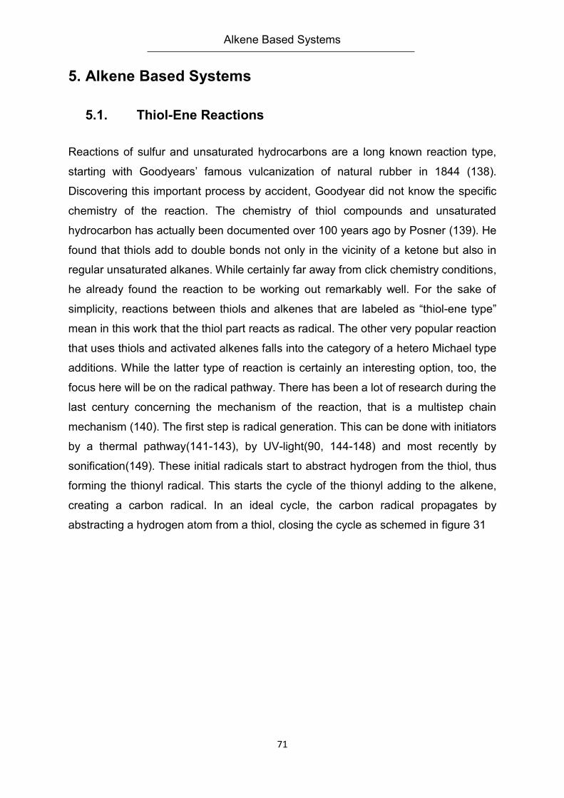
Alkene Based Systems
71
5. Alkene Based Systems
5.1. Thiol-Ene Reactions
Reactions of sulfur and unsaturated hydrocarbons are a long known reaction type,
starting with Goodyears’ famous vulcanization of natural rubber in 1844 (138).
Discovering this important process by accident, Goodyear did not know the specific
chemistry of the reaction. The chemistry of thiol compounds and unsaturated
hydrocarbon has actually been documented over 100 years ago by Posner (139). He
found that thiols add to double bonds not only in the vicinity of a ketone but also in
regular unsaturated alkanes. While certainly far away from click chemistry conditions,
he already found the reaction to be working out remarkably well. For the sake of
simplicity, reactions between thiols and alkenes that are labeled as “thiol-ene type”
mean in this work that the thiol part reacts as radical. The other very popular reaction
that uses thiols and activated alkenes falls into the category of a hetero Michael type
additions. While the latter type of reaction is certainly an interesting option, too, the
focus here will be on the radical pathway. There has been a lot of research during the
last century concerning the mechanism of the reaction, that is a multistep chain
mechanism (140). The first step is radical generation. This can be done with initiators
by a thermal pathway(141-143), by UV-light(90, 144-148) and most recently by
sonification(149). These initial radicals start to abstract hydrogen from the thiol, thus
forming the thionyl radical. This starts the cycle of the thionyl adding to the alkene,
creating a carbon radical. In an ideal cycle, the carbon radical propagates by
abstracting a hydrogen atom from a thiol, closing the cycle as schemed in figure 31
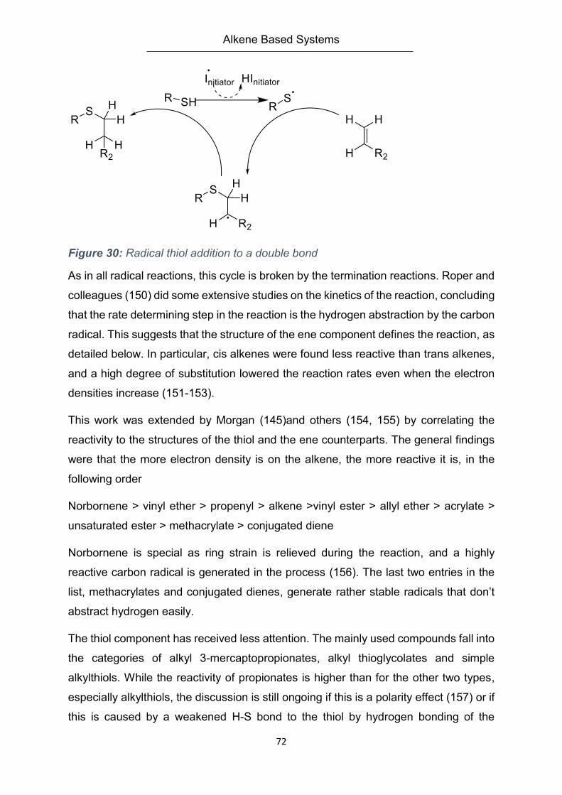
Alkene Based Systems
72
Figure 30: Radical thiol addition to a double bond
As in all radical reactions, this cycle is broken by the termination reactions. Roper and
colleagues (150) did some extensive studies on the kinetics of the reaction, concluding
that the rate determining step in the reaction is the hydrogen abstraction by the carbon
radical. This suggests that the structure of the ene component defines the reaction, as
detailed below. In particular, cis alkenes were found less reactive than trans alkenes,
and a high degree of substitution lowered the reaction rates even when the electron
densities increase (151-153).
This work was extended by Morgan (145)and others (154, 155) by correlating the
reactivity to the structures of the thiol and the ene counterparts. The general findings
were that the more electron density is on the alkene, the more reactive it is, in the
following order
Norbornene > vinyl ether > propenyl > alkene >vinyl ester > allyl ether > acrylate >
unsaturated ester > methacrylate > conjugated diene
Norbornene is special as ring strain is relieved during the reaction, and a highly
reactive carbon radical is generated in the process (156). The last two entries in the
list, methacrylates and conjugated dienes, generate rather stable radicals that don’t
abstract hydrogen easily.
The thiol component has received less attention. The mainly used compounds fall into
the categories of alkyl 3-mercaptopropionates, alkyl thioglycolates and simple
alkylthiols. While the reactivity of propionates is higher than for the other two types,
especially alkylthiols, the discussion is still ongoing if this is a polarity effect (157) or if
this is caused by a weakened H-S bond to the thiol by hydrogen bonding of the
Alkene Based Systems
73
carbonyl (158). Of course this is not an exhaustive thiol list. The structures used can
be much more complex, especially in the application discussed later in this chapter.
Literature agrees though that not all kinetic steps and processes involved are fully
understood yet.
Importantly, the thiol ene reaction excels over many other radical chain reactions or
polymerizations, to their robustness towards oxygen and water, to a point where
presence of oxygen is not inhibiting the reaction at all. This is caused by the still
effective abstraction of the hydrogen from the thiol even if oxygen reacts with the
carbon radical formed from the alkene, thus allowing the cycle to continue (159). This
is a very useful trait for the robustness of the coupling method, and broadens the
possibilities for use.
5.2. Synthesis
5.2.1. Monomer Synthesis
As pointed out in the introduction, the goal of the monomer synthesis is to establish a
modular pool of reactions that will see different iterations throughout this work. The
polymerizable group through this thesis is the methacrylic moiety, which presumably
is interchangeable with an acrylic moiety without too much change in the procedure.
The spacer group consists of tetraethyleneglycol (TEG). This spacer was chosen due
to its commercial availability as nearly pure compound. This point is important for
analytical experiments and repeatability. Furthermore, TEG has the advantage that it
can still be purified by fractioned distillation relatively easily, thus removing water and
shorter glycols with the pre run while leaving longer glycols in the feed. The titular
alkene unit is kept rather simple as allyl ether. The terminal double bond has a higher
reactivity to the thiol radical addition than higher substituted analogs. The allylic
structure does not provide a particularly high electron density, but clearly favors the
radical reaction pathway of thiol addition.
The first reaction in the monomer synthesis is the nucleophilic substitution of allyl
bromide by tetraethyleneglycole alcoholate in THF (Figure 31). From a practical point
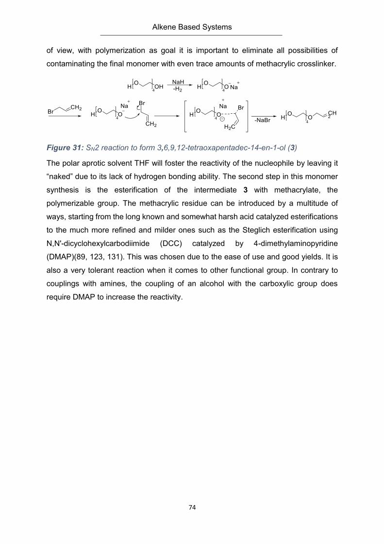
Alkene Based Systems
74
of view, with polymerization as goal it is important to eliminate all possibilities of
contaminating the final monomer with even trace amounts of methacrylic crosslinker.
Figure 31: SN2 reaction to form 3,6,9,12-tetraoxapentadec-14-en-1-ol (3)
The polar aprotic solvent THF will foster the reactivity of the nucleophile by leaving it
“naked” due to its lack of hydrogen bonding ability. The second step in this monomer
synthesis is the esterification of the intermediate 3 with methacrylate, the
polymerizable group. The methacrylic residue can be introduced by a multitude of
ways, starting from the long known and somewhat harsh acid catalyzed esterifications
to the much more refined and milder ones such as the Steglich esterification using
N,N'-dicyclohexylcarbodiimide (DCC) catalyzed by 4-dimethylaminopyridine
(DMAP)(89, 123, 131). This was chosen due to the ease of use and good yields. It is
also a very tolerant reaction when it comes to other functional group. In contrary to
couplings with amines, the coupling of an alcohol with the carboxylic group does
require DMAP to increase the reactivity.
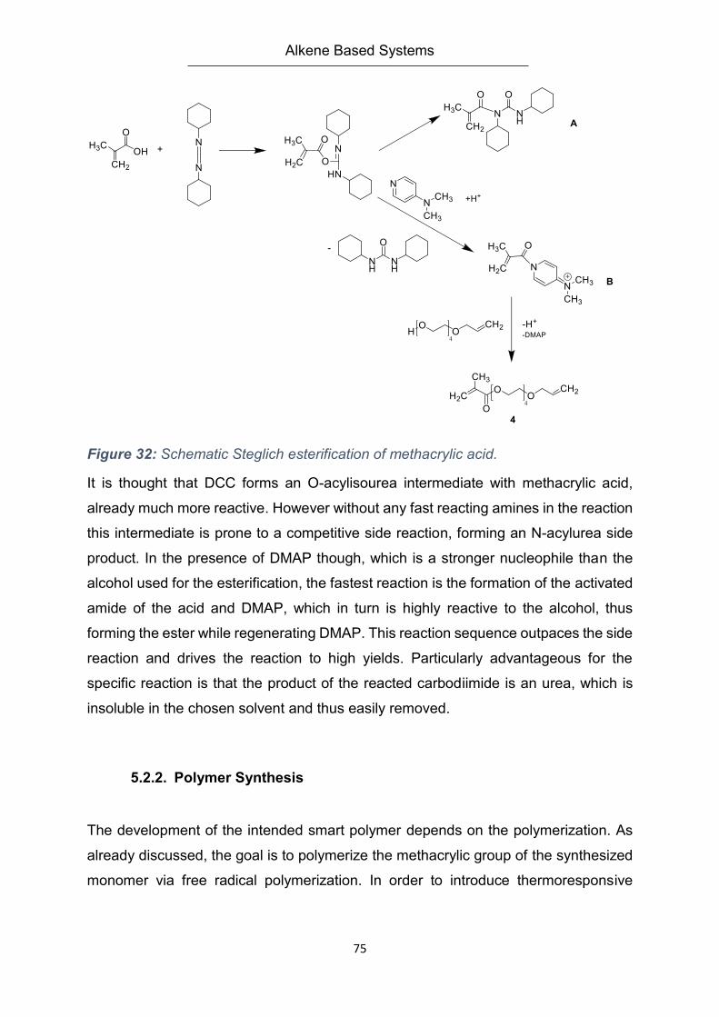
Alkene Based Systems
75
Figure 32: Schematic Steglich esterification of methacrylic acid.
It is thought that DCC forms an O-acylisourea intermediate with methacrylic acid,
already much more reactive. However without any fast reacting amines in the reaction
this intermediate is prone to a competitive side reaction, forming an N-acylurea side
product. In the presence of DMAP though, which is a stronger nucleophile than the
alcohol used for the esterification, the fastest reaction is the formation of the activated
amide of the acid and DMAP, which in turn is highly reactive to the alcohol, thus
forming the ester while regenerating DMAP. This reaction sequence outpaces the side
reaction and drives the reaction to high yields. Particularly advantageous for the
specific reaction is that the product of the reacted carbodiimide is an urea, which is
insoluble in the chosen solvent and thus easily removed.
5.2.2. Polymer Synthesis
The development of the intended smart polymer depends on the polymerization. As
already discussed, the goal is to polymerize the methacrylic group of the synthesized
monomer via free radical polymerization. In order to introduce thermoresponsive
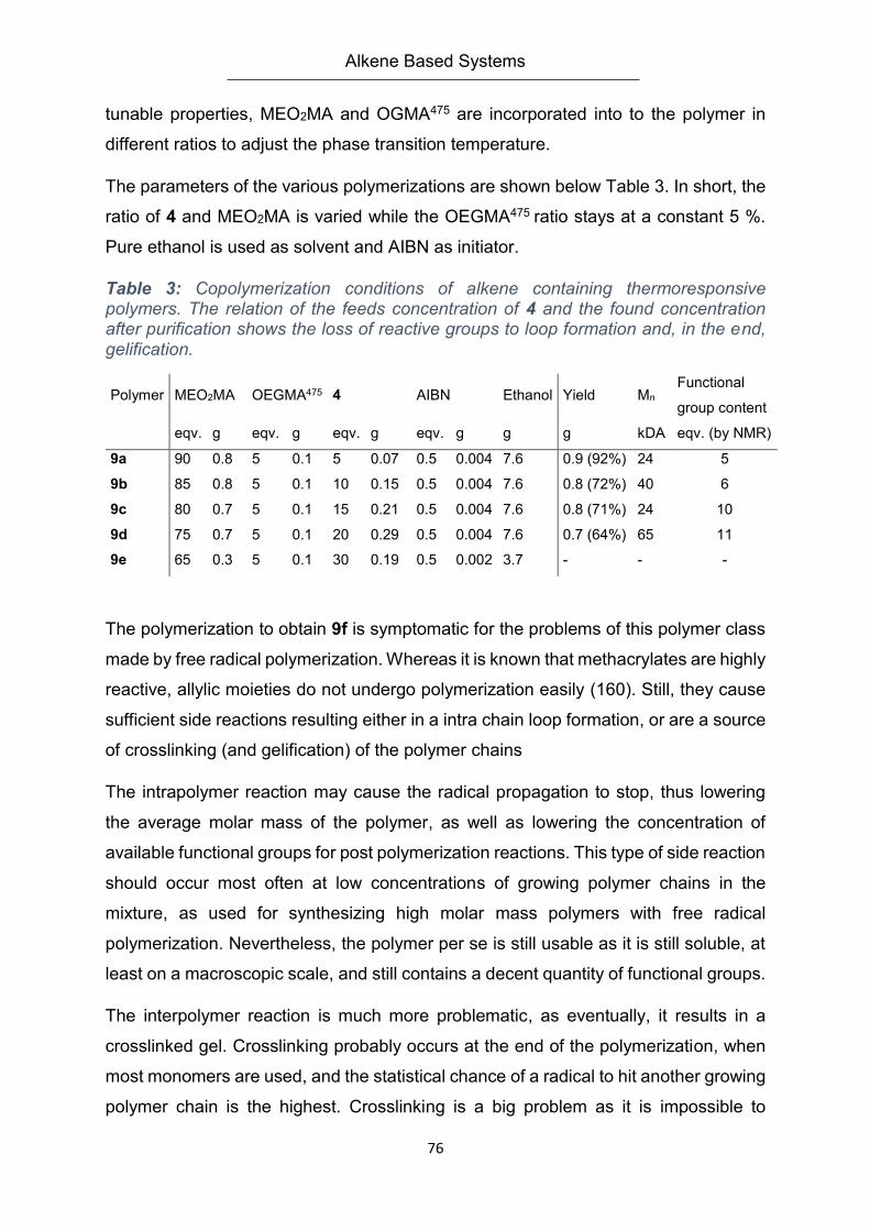
Alkene Based Systems
76
tunable properties, MEO2MA and OGMA475 are incorporated into to the polymer in
different ratios to adjust the phase transition temperature.
The parameters of the various polymerizations are shown below Table 3. In short, the
ratio of 4 and MEO2MA is varied while the OEGMA475 ratio stays at a constant 5 %.
Pure ethanol is used as solvent and AIBN as initiator.
Table 3: Copolymerization conditions of alkene containing thermoresponsive polymers. The relation of the feeds concentration of 4 and the found concentration after purification shows the loss of reactive groups to loop formation and, in the end, gelification.
Polymer MEO2MA OEGMA475 4 AIBN Ethanol Yield Mn Functional
group content
eqv. g eqv. g eqv. g eqv. g g g kDA eqv. (by NMR)
9a 90 0.8 5 0.1 5 0.07 0.5 0.004 7.6 0.9 (92%) 24 5
9b 85 0.8 5 0.1 10 0.15 0.5 0.004 7.6 0.8 (72%) 40 6
9c 80 0.7 5 0.1 15 0.21 0.5 0.004 7.6 0.8 (71%) 24 10
9d 75 0.7 5 0.1 20 0.29 0.5 0.004 7.6 0.7 (64%) 65 11
9e 65 0.3 5 0.1 30 0.19 0.5 0.002 3.7 - - -
The polymerization to obtain 9f is symptomatic for the problems of this polymer class
made by free radical polymerization. Whereas it is known that methacrylates are highly
reactive, allylic moieties do not undergo polymerization easily (160). Still, they cause
sufficient side reactions resulting either in a intra chain loop formation, or are a source
of crosslinking (and gelification) of the polymer chains
The intrapolymer reaction may cause the radical propagation to stop, thus lowering
the average molar mass of the polymer, as well as lowering the concentration of
available functional groups for post polymerization reactions. This type of side reaction
should occur most often at low concentrations of growing polymer chains in the
mixture, as used for synthesizing high molar mass polymers with free radical
polymerization. Nevertheless, the polymer per se is still usable as it is still soluble, at
least on a macroscopic scale, and still contains a decent quantity of functional groups.
The interpolymer reaction is much more problematic, as eventually, it results in a
crosslinked gel. Crosslinking probably occurs at the end of the polymerization, when
most monomers are used, and the statistical chance of a radical to hit another growing
polymer chain is the highest. Crosslinking is a big problem as it is impossible to

Alkene Based Systems
77
separate crosslinked and uncrosslinked material with a decent amount of work within
the scope of the project needs.
In the light of these two side reactions one, the data from Table 3 may be explained:
The general reaction conditions are the same. Only the concentration of functional
monomer is varied. The more of the latter is in the feed, the lower is the amount of the
OEGMA monomers. At low concentrations of the allylic monomer the reactions
progress as intended. If polymers are synthesized with a higher starting concentration
of allylic groups and the polymer was still able to be purified and are not gelled, then
the allylic groups cannot be found in the intended concentration via NMR
spectroscopy. At 10 % and 15 % overall concentration of 4 in the feed, roughly 40 %
of the allyl groups are lost. The polymer with the highest content of 4 in the feed that
could be isolated, 9d had to be separated by first dialyzing and then dissolving in
DMSO and filtrating the soluble polymer off from the remaining swollen gel pieces.
This polymer lost already 90 % of its functionality by side reactions. Increasing the
concentration of 4 in the feed further only led to completely gelled reaction vessels. If
the double bonds found in the polymers are correlated with their molar masses, it is
possible to see that the crosslinking step is the smaller (but deciding) factor. The first
three polymers 9a to 9c give, using a very rough estimation, 50, 84 and 50 monomers
units per chain. This translates to 2.5, 8.4 and 3.3 allylic double bonds expected per
respective chain in theory. The experiment shows that 2.5, 5.0 and 2.2 discrete units
remain. As the molar masses don’t increase drastically, whereas the yield drops down
much more prominently, the result suggests that loop formation is the more common
reaction. The lowered yields suggest that a non-negligible amount of free radicals is
lost due to the allylic groups’ side reaction.
5.2.3. Thiol-Ene coupling and diversifying the polymer functionality
In order to prove the capabilities of the synthesized polymers a model reaction was
needed. The conjugation partner was selected to couple in solution, for the ease of
handling. Namely, mercaptopropionic acid was chosen for practical reasons: first, it is
soluble in water as well as organic solutions, has little inclination towards side
reactions and offers an easily accessible thiol group. Being a model system, the ease
Alkene Based Systems
78
of analysis and interpretation is also an important factor. For the experiments the
commercially available photo initiator system Irgacure 2020 was used, which is of the
acyl phospine type of initiator. This choice was made even though, other kinds of
radical starters would work for this type of reaction and were tested, too. The UV-
initiator was chosen over thermally induced radicals (using AIBN) as those caused
gelification of the samples across the board with temperature ranges between 50 to
70 °C and varying polymer concentrations and despite the advantage of being able to
stir and properly purge with nitrogen. While this phenomenon was not fully analyzed,
a possible interpretation is that the heating caused the alkene groups to react before
they could combine with the radicals generated by an AIBN initiator. As the gelification
did not happen with the usage of the UV chamber is probably due to the fact that the
reaction was done in flat dishes that were cooled to 14-18 °C from the water cooling
system in the bottom of the box, thus it seems that the UV irradiation was selective
enough to only drive the radical generation and reaction forward. The modified
polymers could once again be purified by dialysis in almost quantitative yields.
The most efficient way to analyze of the product was by 1H NMR spectroscopy. The
relative amount of allylic end groups is obtained by comparing the vinylic proton
integral (= 5.9 ppm) to the integral of the methoxy end groups of the OEGMA475 and
MEO2MA units (= 3.4 ppm) integrals. This procedure can be extended to the signal
of the newly formed thio-ether bonds ( ~ 2.6-2.8 ppm) integrals
5.3. Results
5.3.1. LCST Behavior
One of the most important features of the polymers explored in this work is the
occurrence of a lower critical solution temperature in aqueous solution. As already
stated much work has been done to quantify the range of temperature for copolymers
having different OEGMA475 and MEO2MA compositions(161). Even though the base
polymers in this work are all water soluble below their LCST, integrating a ternary
comonomer into these copolymers can drastically change the hydrophilic-hydrophobic
balance, thus changing said LCST. While it is certainly possible to have an educated
guess about the effect of the monomer in question, a reliable prediction is always
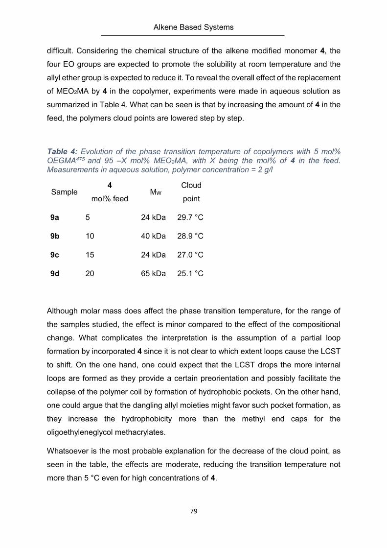
Alkene Based Systems
79
difficult. Considering the chemical structure of the alkene modified monomer 4, the
four EO groups are expected to promote the solubility at room temperature and the
allyl ether group is expected to reduce it. To reveal the overall effect of the replacement
of MEO2MA by 4 in the copolymer, experiments were made in aqueous solution as
summarized in Table 4. What can be seen is that by increasing the amount of 4 in the
feed, the polymers cloud points are lowered step by step.
Table 4: Evolution of the phase transition temperature of copolymers with 5 mol% OEGMA475 and 95 –X mol% MEO2MA, with X being the mol% of 4 in the feed. Measurements in aqueous solution, polymer concentration = 2 g/l
Sample 4
mol% feed MW
Cloud
point
9a 5 24 kDa 29.7 °C
9b 10 40 kDa 28.9 °C
9c 15 24 kDa 27.0 °C
9d 20 65 kDa 25.1 °C
Although molar mass does affect the phase transition temperature, for the range of
the samples studied, the effect is minor compared to the effect of the compositional
change. What complicates the interpretation is the assumption of a partial loop
formation by incorporated 4 since it is not clear to which extent loops cause the LCST
to shift. On the one hand, one could expect that the LCST drops the more internal
loops are formed as they provide a certain preorientation and possibly facilitate the
collapse of the polymer coil by formation of hydrophobic pockets. On the other hand,
one could argue that the dangling allyl moieties might favor such pocket formation, as
they increase the hydrophobicity more than the methyl end caps for the
oligoethyleneglycol methacrylates.
Whatsoever is the most probable explanation for the decrease of the cloud point, as
seen in the table, the effects are moderate, reducing the transition temperature not
more than 5 °C even for high concentrations of 4.
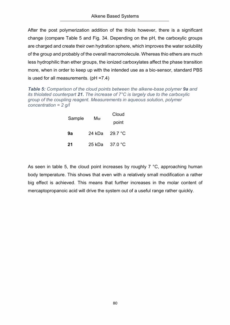
Alkene Based Systems
80
After the post polymerization addition of the thiols however, there is a significant
change (compare Table 5 and Fig. 34. Depending on the pH, the carboxylic groups
are charged and create their own hydration sphere, which improves the water solubility
of the group and probably of the overall macromolecule. Whereas thio ethers are much
less hydrophilic than ether groups, the ionized carboxylates affect the phase transition
more, when in order to keep up with the intended use as a bio-sensor, standard PBS
is used for all measurements. (pH =7.4)
Table 5: Comparison of the cloud points between the alkene-base polymer 9a and its thiolated counterpart 21. The increase of 7°C is largely due to the carboxylic group of the coupling reagent. Measurements in aqueous solution, polymer concentration = 2 g/l
Sample MW Cloud
point
9a 24 kDa 29.7 °C
21 25 kDa 37.0 °C
As seen in table 5, the cloud point increases by roughly 7 °C, approaching human
body temperature. This shows that even with a relatively small modification a rather
big effect is achieved. This means that further increases in the molar content of
mercaptopropanoic acid will drive the system out of a useful range rather quickly.
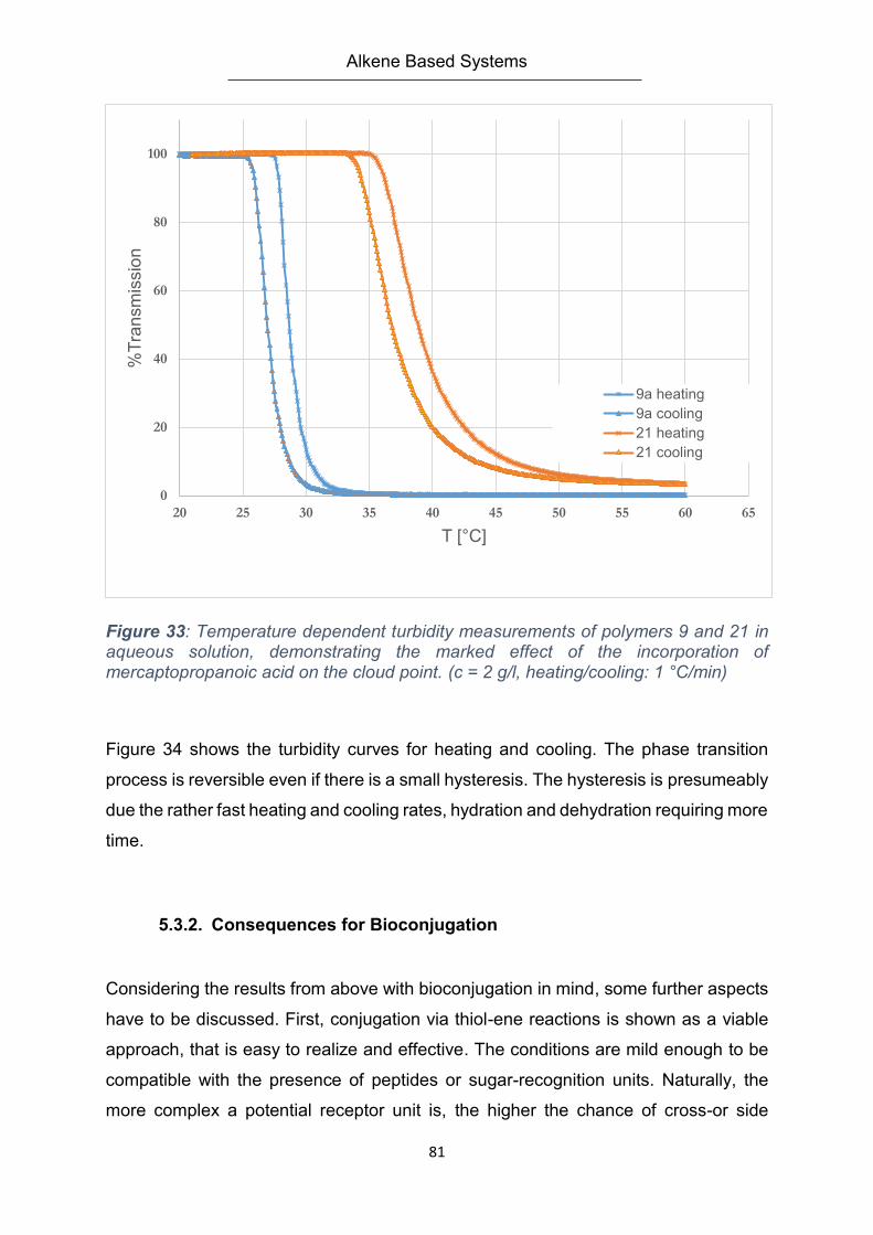
Alkene Based Systems
81
Figure 33: Temperature dependent turbidity measurements of polymers 9 and 21 in aqueous solution, demonstrating the marked effect of the incorporation of mercaptopropanoic acid on the cloud point. (c = 2 g/l, heating/cooling: 1 °C/min)
Figure 34 shows the turbidity curves for heating and cooling. The phase transition
process is reversible even if there is a small hysteresis. The hysteresis is presumeably
due the rather fast heating and cooling rates, hydration and dehydration requiring more
time.
5.3.2. Consequences for Bioconjugation
Considering the results from above with bioconjugation in mind, some further aspects
have to be discussed. First, conjugation via thiol-ene reactions is shown as a viable
approach, that is easy to realize and effective. The conditions are mild enough to be
compatible with the presence of peptides or sugar-recognition units. Naturally, the
more complex a potential receptor unit is, the higher the chance of cross-or side
0
20
40
60
80
100
20 25 30 35 40 45 50 55 60 65
%T
ran
sm
issio
n
T [°C]
9a heating
9a cooling
21 heating
21 cooling
Alkene Based Systems
82
reactions. In the case of large recognition units, steric hindrance has to be taken into
account as well –hindering the coupling reaction, or requiring the utilization of a
spacer; which, in turn sets the recognition unit further apart from the polymer, and thus
might decouple the binding event of an analyte from influencing the LCST transition
that is needed for signaling. This means the compromise between ease of access and
influence on the phase transition has to be found.
5.3.3. Outlook
Using a relatively simple allyl capped monomer as co-monomer for a potential
biosensor has some drawbacks, mostly due to the side reactions of the double bonds
which limit the extend of usability for this project’s goals down to an example of what
could be instead of a true model system or even a workhorse system to truly expand
on. On the flipside– the reaction efficiency of the, in itself limited, number of coupling
groups within the polymer and the ease of the modification step via the UV induced
coupling surely fulfills the requirement of a click reaction usable for this kind of
biosensor. How could this monomer concept be improved? Generally searching a
better compromise between the thiol-ene reactivity and the stability during
polymerization is the way to go. This would enable a higher content of coupling groups,
making the system more viable for demonstrator experiments with large biomolecules
or cells. One possibility would be to use a 2-butene ether kind of end-cap adding a
small steric hindrance to possibly ward of the side reaction during polymerization
without stabilizing the radical further and somewhat slowing down the thiolation as
well, possibly not to an extend that would block the reaction from being efficient
enough. This would also have the benefit of not adding too much complexity to the
system that might have more unwanted side effects on the polymer or hydrogel like
changing the LCST too much or adding potential reactive partners and so on.
Alkyne Based Coupling Systems
83
6. Alkyne Based Coupling Systems
6.1. Introduction
This chapter discusses another option for bioconjugateable base polymers that is in
close relation to alkene systems. The alkyne based polymers have the option to either
undergo a thiol-yne reaction, similar to the thiol –ene reaction, but with a two-step
addition process that adds two reaction partners to the triple bond(90). The other
option is to utilize the 3+2 dipolar cycloaddition with an azide compound, also known
as Huisgen cycloaddition. The polymers will be reacted with simple model molecules
in order to show the viability of this approach for rendering hydrogel systems more
complex and for adjusting them to the challenges of bio-sensor application.
6.1.1. Radical Thiol Additions to Triple bonds
With their C-C triple bonds, alkynes show some common features with the alkenes,
sharing many reactions and their reactive behavior to a certain extent. Terminal
alkynes are more acidic than typical hydrocarbons due to their sp-hybridization (162).
Thiols undergo a radical addition with alkynes just as to alkenes, though with certain
differences, as described by K. Griesbaum(143):
The rate of radical addition to triple bonds is generally slower than for the double bonds
of alkene compounds with similar structure and under the same reaction conditions.
The addition converts the alkyne to an alkene that can react further. Dependent on the
coupling partner used, the reactivity of this second addition step can be higher or
lower. The first addition produces the anti-Markovnikov product, as do alkenes, and
as expected for a radical addition. The second reaction step, adding a thiol to a newly
formed vinylether compound, is faster. This difference in reactivity has been used to
perform stepwise additions to mixed alkene-alkyne materials(163, 164). The beauty of
the reaction is that it is catalyst-free, tolerant to many other chemical species and
environments, yet sensitive to oxygen(165). The reaction technique has been used to
synthesize star polymers(164), end-capping and modification of RAFT polymers(163),
photo pattering of surfaces with brush polymers(166), biomimetics(167, 168), for the
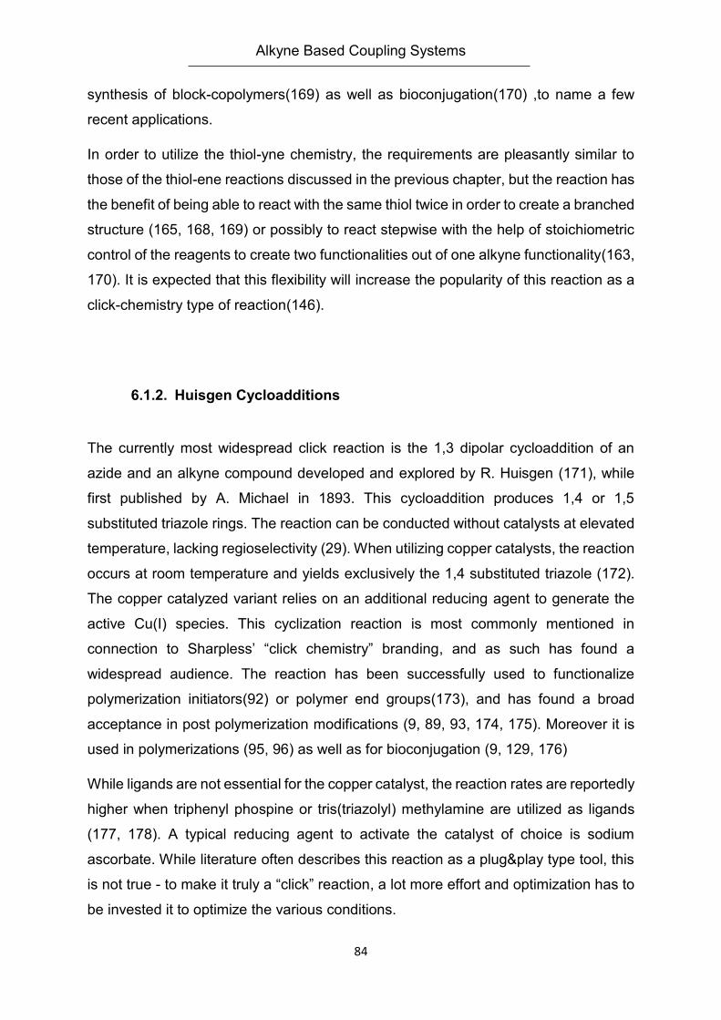
Alkyne Based Coupling Systems
84
synthesis of block-copolymers(169) as well as bioconjugation(170) ,to name a few
recent applications.
In order to utilize the thiol-yne chemistry, the requirements are pleasantly similar to
those of the thiol-ene reactions discussed in the previous chapter, but the reaction has
the benefit of being able to react with the same thiol twice in order to create a branched
structure (165, 168, 169) or possibly to react stepwise with the help of stoichiometric
control of the reagents to create two functionalities out of one alkyne functionality(163,
170). It is expected that this flexibility will increase the popularity of this reaction as a
click-chemistry type of reaction(146).
6.1.2. Huisgen Cycloadditions
The currently most widespread click reaction is the 1,3 dipolar cycloaddition of an
azide and an alkyne compound developed and explored by R. Huisgen (171), while
first published by A. Michael in 1893. This cycloaddition produces 1,4 or 1,5
substituted triazole rings. The reaction can be conducted without catalysts at elevated
temperature, lacking regioselectivity (29). When utilizing copper catalysts, the reaction
occurs at room temperature and yields exclusively the 1,4 substituted triazole (172).
The copper catalyzed variant relies on an additional reducing agent to generate the
active Cu(I) species. This cyclization reaction is most commonly mentioned in
connection to Sharpless’ “click chemistry” branding, and as such has found a
widespread audience. The reaction has been successfully used to functionalize
polymerization initiators(92) or polymer end groups(173), and has found a broad
acceptance in post polymerization modifications (9, 89, 93, 174, 175). Moreover it is
used in polymerizations (95, 96) as well as for bioconjugation (9, 129, 176)
While ligands are not essential for the copper catalyst, the reaction rates are reportedly
higher when triphenyl phospine or tris(triazolyl) methylamine are utilized as ligands
(177, 178). A typical reducing agent to activate the catalyst of choice is sodium
ascorbate. While literature often describes this reaction as a plug&play type tool, this
is not true - to make it truly a “click” reaction, a lot more effort and optimization has to
be invested it to optimize the various conditions.
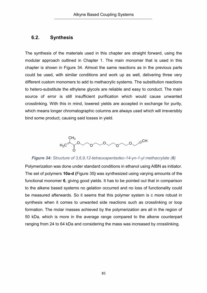
Alkyne Based Coupling Systems
85
6.2. Synthesis
The synthesis of the materials used in this chapter are straight forward, using the
modular approach outlined in Chapter 1. The main monomer that is used in this
chapter is shown in Figure 34. Almost the same reactions as in the previous parts
could be used, with similar conditions and work up as well, delivering three very
different custom monomers to add to methacrylic systems. The substitution reactions
to hetero-substitute the ethylene glycols are reliable and easy to conduct. The main
source of error is still insufficient purification which would cause unwanted
crosslinking. With this in mind, lowered yields are accepted in exchange for purity,
which means longer chromatographic columns are always used which will irreversibly
bind some product, causing said losses in yield.
Figure 34: Structure of 3,6,9,12-tetraoxapentadec-14-yn-1-yl methacrylate (6)
Polymerization was done under standard conditions in ethanol using AIBN as initiator.
The set of polymers 10a-d (Figure 35) was synthesized using varying amounts of the
functional monomer 6, giving good yields. It has to be pointed out that in comparison
to the alkene based systems no gelation occurred and no loss of functionality could
be measured afterwards. So it seems that this polymer system is c more robust in
synthesis when it comes to unwanted side reactions such as crosslinking or loop
formation. The molar masses achieved by the polymerization are all in the region of
50 kDa, which is more in the average range compared to the alkene counterpart
ranging from 24 to 64 kDa and considering the mass was increased by crosslinking.
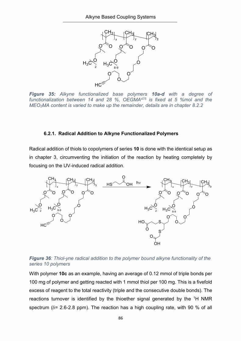
Alkyne Based Coupling Systems
86
Figure 35: Alkyne functionalized base polymers 10a-d with a degree of functionalization between 14 and 28 %, OEGMA475 is fixed at 5 %mol and the MEO2MA content is varied to make up the remainder, details are in chapter 8.2.2
6.2.1. Radical Addition to Alkyne Functionalized Polymers
Radical addition of thiols to copolymers of series 10 is done with the identical setup as
in chapter 3, circumventing the initiation of the reaction by heating completely by
focusing on the UV-induced radical addition.
Figure 36: Thiol-yne radical addition to the polymer bound alkyne functionality of the series 10 polymers
With polymer 10c as an example, having an average of 0.12 mmol of triple bonds per
100 mg of polymer and getting reacted with 1 mmol thiol per 100 mg. This is a fivefold
excess of reagent to the total reactivity (triple and the consecutive double bonds). The
reactions turnover is identified by the thioether signal generated by the 1H NMR
spectrum (= 2.6-2.8 ppm). The reaction has a high coupling rate, with 90 % of all
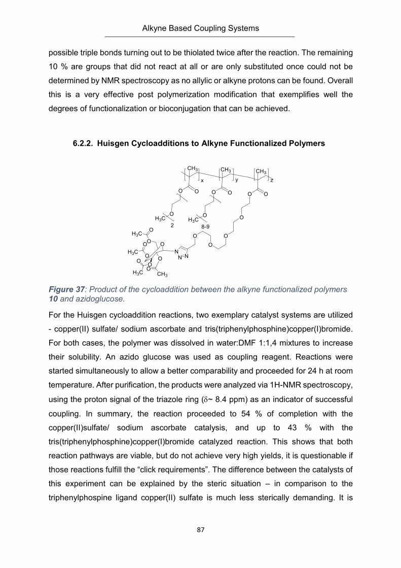
Alkyne Based Coupling Systems
87
possible triple bonds turning out to be thiolated twice after the reaction. The remaining
10 % are groups that did not react at all or are only substituted once could not be
determined by NMR spectroscopy as no allylic or alkyne protons can be found. Overall
this is a very effective post polymerization modification that exemplifies well the
degrees of functionalization or bioconjugation that can be achieved.
6.2.2. Huisgen Cycloadditions to Alkyne Functionalized Polymers
Figure 37: Product of the cycloaddition between the alkyne functionalized polymers 10 and azidoglucose.
For the Huisgen cycloaddition reactions, two exemplary catalyst systems are utilized
- copper(II) sulfate/ sodium ascorbate and tris(triphenylphosphine)copper(I)bromide.
For both cases, the polymer was dissolved in water:DMF 1:1,4 mixtures to increase
their solubility. An azido glucose was used as coupling reagent. Reactions were
started simultaneously to allow a better comparability and proceeded for 24 h at room
temperature. After purification, the products were analyzed via 1H-NMR spectroscopy,
using the proton signal of the triazole ring (~ 8.4 ppm) as an indicator of successful
coupling. In summary, the reaction proceeded to 54 % of completion with the
copper(II)sulfate/ sodium ascorbate catalysis, and up to 43 % with the
tris(triphenylphosphine)copper(I)bromide catalyzed reaction. This shows that both
reaction pathways are viable, but do not achieve very high yields, it is questionable if
those reactions fulfill the “click requirements”. The difference between the catalysts of
this experiment can be explained by the steric situation – in comparison to the
triphenylphospine ligand copper(II) sulfate is much less sterically demanding. It is
Alkyne Based Coupling Systems
88
better soluble, too, which might help to cope with the generally hydrophilic environment
of the polymer.
6.3. Outlook
This chapter has shown that starting from the same base polymers two completely
different reactions can be used to couple potential binding groups. The radical thiol-
yne addition, is highly efficient and very easy to use, in agreement to the spirit of the
“click” principles. In the future, it should be possible to integrate this system into
hydrogel based structures. Given the availability of suited recognition units and
analytes, this appears to be the next logical step. Furthermore, the reaction using
mercaptopropioic acid seems also an ideal starting point for carboxyl based
recognition units, if an increased local concentration of binding units is wanted.
Another approach is to use this dual-addition to halve the amount of long ethylene
glycol units in order to keep the LCST of the polymers low, or to facilitate its
modulation.
The Huisgen cycloaddition leaves room for systematic improvements. On the one
hand, steric reasons may be the reason for the rather low yields. On the other hand,
effects of solvent or reactant could also play a role. As eliminating the catalyst and
using the purely thermally activated reaction variant might be hard to realize for LCST
polymers, a solvent-based system would be needed which would cause this reaction
to lose some viability with the aspects of bioconjugation. Careful optimization of the
reaction conditions and reagent screening are probably the best way to proceed. In
any case, the results certainly show that alleged click reactions are not always easy
to use and require a certain degree of optimization, instead of working straight out of
the box as often insinuated in literature.
Summary and Conclusion
89
7. Summary and Conclusion
The goal of this work was to show an exemplary pathway of how a sensor for
biologically relevant analytes can be designed. Two major systems are the result.
(1) A surface bound sensor that is able to detect the binding of a surface saccharide
of salmonella bacteria with the help of SPR spectroscopy.
(2) A hydrogel coated on a quartz surface that is able to change the fluorescent
behavior when in contact with a specific influenza virus.
Monomer synthesis was done by forming alcoholates of tri- or tetraethyleneglycol
chains that undergo a nucleophile substitution with the bromide of the desired
functionality. This was done for t-butyl bromoacetate, allylbromide and
propargylbromide. In a second step the polymerizable group was introduced either by
DCC/DMAP coupling or by utilizing methacryloylchloride as reaction partner. Utmost
care has to be taken with the purification steps to exclude any possibly crosslinking
species for the polymerization. To form thermoresponsive polymers, the new
functional monomers were copolymerized with MEO2MA and OEGMA475 for water
soluble systems. In order to immobilize and crosslink the polymer into a hydrogel
BPMA was added in small concentrations. Carboxyl functionalized systems were also
synthesized in combination with NIPMAM and a napthalimide dye. Most of the
polymerizations underwent free radical polymerization in ethanol initialized by AIBN.
In order to increase the polymers chain length and molar mass, polymerization in the
ionic liquid EMIM PF6 was done with good results, achieving molar masses of over
1000 kDA.
Hydrogels were characterized by their swelling ratio in order to get an estimated mesh
size and to tailor them better to binding groups and analytes. The deposition thickness
was also tested in dependence of the applied polymer amount. The hydrogels were
immobilized on SPR chips to follow the coupling of a small protein, Lysozyme. After
successful experiments, a tailspike protein extracted from a phage that selectively
binds to a surface bound salmonella polysaccharide was utilized as conjugation
partner. The protein was only immobilized in a low concentration and probably only in
the surface layer. Nevertheless this demonstrator system showed a concentration
depended reaction and a much smaller (and non-binding) reaction to an E.Coli surface
saccharide.
Summary and Conclusion
90
By utilizing a solvatochromic napthalimide dye as an indicator, a carboxyl containing
polymer was modified with a peptide or a non-binding control peptide to target the MX-
31 influenza stem. The binding has shown to be specific by scattering and
fluorescence experiments. Binding with the detection polymer, a temperature
dependent solvatochromic shift and a change in fluorescence can be detected even
at very low virus concentrations. Binding occurs in solution or with hydrogels bound to
surfaces. Furthermore, utilizing turbidimetry, the virus binding induces a temperature
shift of the cloud point making it possible to identify the virus by simply warming up a
virus – polymer mixture.
The flexibility of the chosen approach was demonstrated by the alkene and alkine
functionalized polymers. They showed a high coupling efficiency towards radical thiol
reactions that can be used to diversify the polymers or to increase a localized
concentration of, for example, carboxylic groups. The possibility to attach an azido
saccharide with the aid of a 2+3 copper catalyzed cycloaddition was also shown,
diversifying the potential binding partners. With these four independent and orthogonal
coupling options, a number of possibilities for different hydrogel applications are given.
The polymers can be photocrosslinked easily even if only one polymer of the blend
contains benzophenone crosslinkers.
From a practical point of view, the biggest limiting factor is the availability of test
substrates in combination with recognition units and control units to check for specifity.
Furthermore, an important point to focus on in the future would be the optimization of
the polymerization in ionic liquids. Reaching reliably ultra-high molar masses should
be a major goal, as the longer chain polymers offer more possibilities for receptor units
and analytes to penetrate the hydrogels by allowing lower crosslinker concentrations.
Obviously, there will be a lower limit due to reduced mechanical robustness that has
not yet been reached though. More detailed research in singular systems and methods
are certainly an approach to optimization that can follow up on the results presented
in this thesis
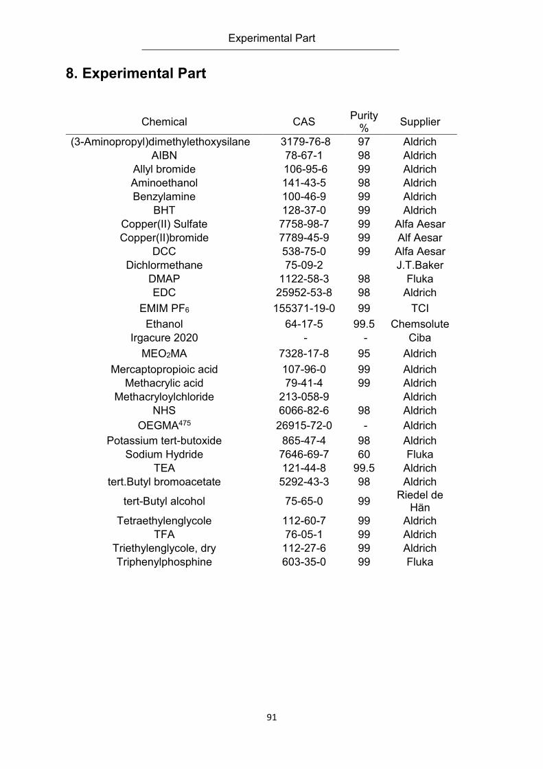
Experimental Part
91
8. Experimental Part
Chemical CAS Purity
% Supplier
(3-Aminopropyl)dimethylethoxysilane 3179-76-8 97 Aldrich
AIBN 78-67-1 98 Aldrich
Allyl bromide 106-95-6 99 Aldrich
Aminoethanol 141-43-5 98 Aldrich
Benzylamine 100-46-9 99 Aldrich
BHT 128-37-0 99 Aldrich
Copper(II) Sulfate 7758-98-7 99 Alfa Aesar
Copper(II)bromide 7789-45-9 99 Alf Aesar
DCC 538-75-0 99 Alfa Aesar
Dichlormethane 75-09-2 J.T.Baker
DMAP 1122-58-3 98 Fluka
EDC 25952-53-8 98 Aldrich
EMIM PF6 155371-19-0 99 TCI
Ethanol 64-17-5 99.5 Chemsolute
Irgacure 2020 - - Ciba
MEO2MA 7328-17-8 95 Aldrich
Mercaptopropioic acid 107-96-0 99 Aldrich
Methacrylic acid 79-41-4 99 Aldrich
Methacryloylchloride 213-058-9 Aldrich
NHS 6066-82-6 98 Aldrich
OEGMA475 26915-72-0 - Aldrich
Potassium tert-butoxide 865-47-4 98 Aldrich
Sodium Hydride 7646-69-7 60 Fluka
TEA 121-44-8 99.5 Aldrich
tert.Butyl bromoacetate 5292-43-3 98 Aldrich
tert-Butyl alcohol 75-65-0 99 Riedel de
Hän
Tetraethylenglycole 112-60-7 99 Aldrich
TFA 76-05-1 99 Aldrich
Triethylenglycole, dry 112-27-6 99 Aldrich
Triphenylphosphine 603-35-0 99 Fluka
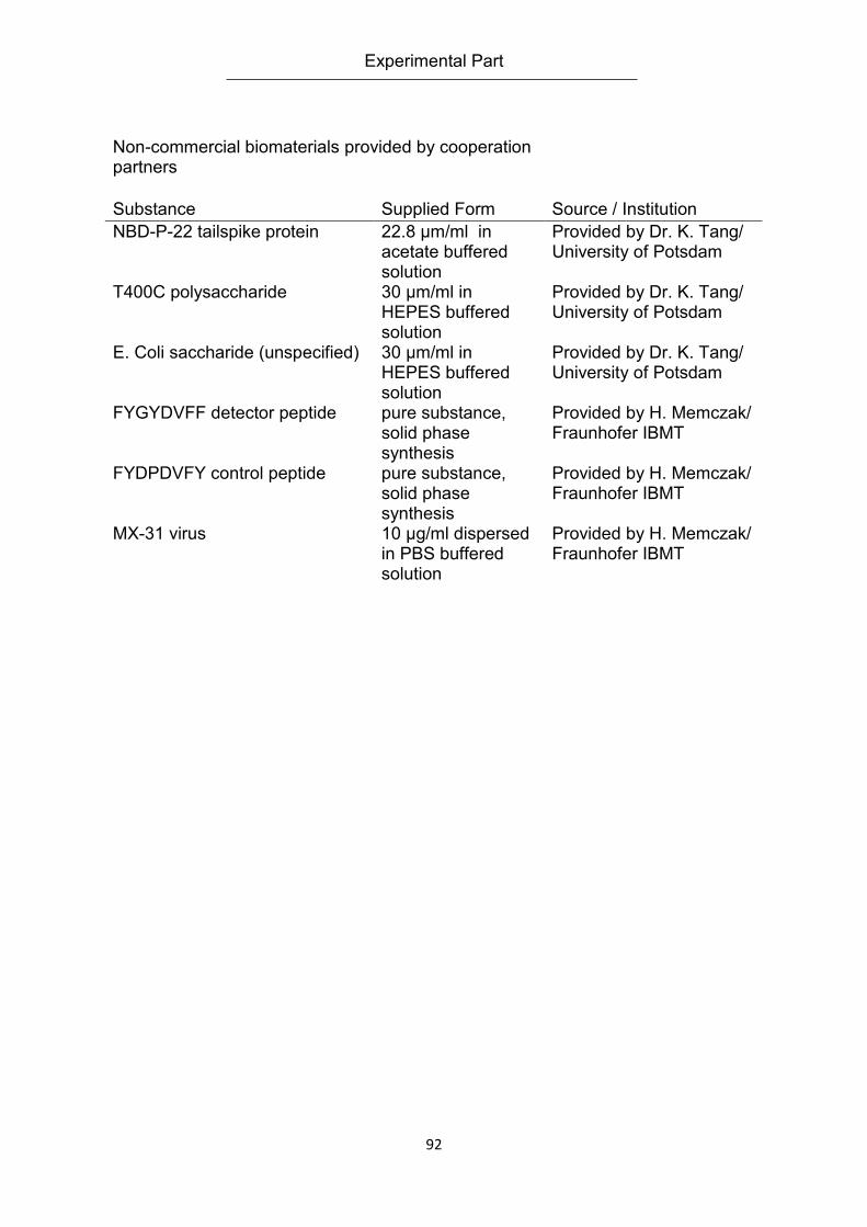
Experimental Part
92
Non-commercial biomaterials provided by cooperation partners
Substance Supplied Form Source / Institution
NBD-P-22 tailspike protein 22.8 µm/ml in acetate buffered solution
Provided by Dr. K. Tang/ University of Potsdam
T400C polysaccharide 30 µm/ml in HEPES buffered solution
Provided by Dr. K. Tang/ University of Potsdam
E. Coli saccharide (unspecified) 30 µm/ml in HEPES buffered solution
Provided by Dr. K. Tang/ University of Potsdam
FYGYDVFF detector peptide pure substance, solid phase synthesis
Provided by H. Memczak/ Fraunhofer IBMT
FYDPDVFY control peptide pure substance, solid phase synthesis
Provided by H. Memczak/ Fraunhofer IBMT
MX-31 virus 10 µg/ml dispersed in PBS buffered solution
Provided by H. Memczak/ Fraunhofer IBMT
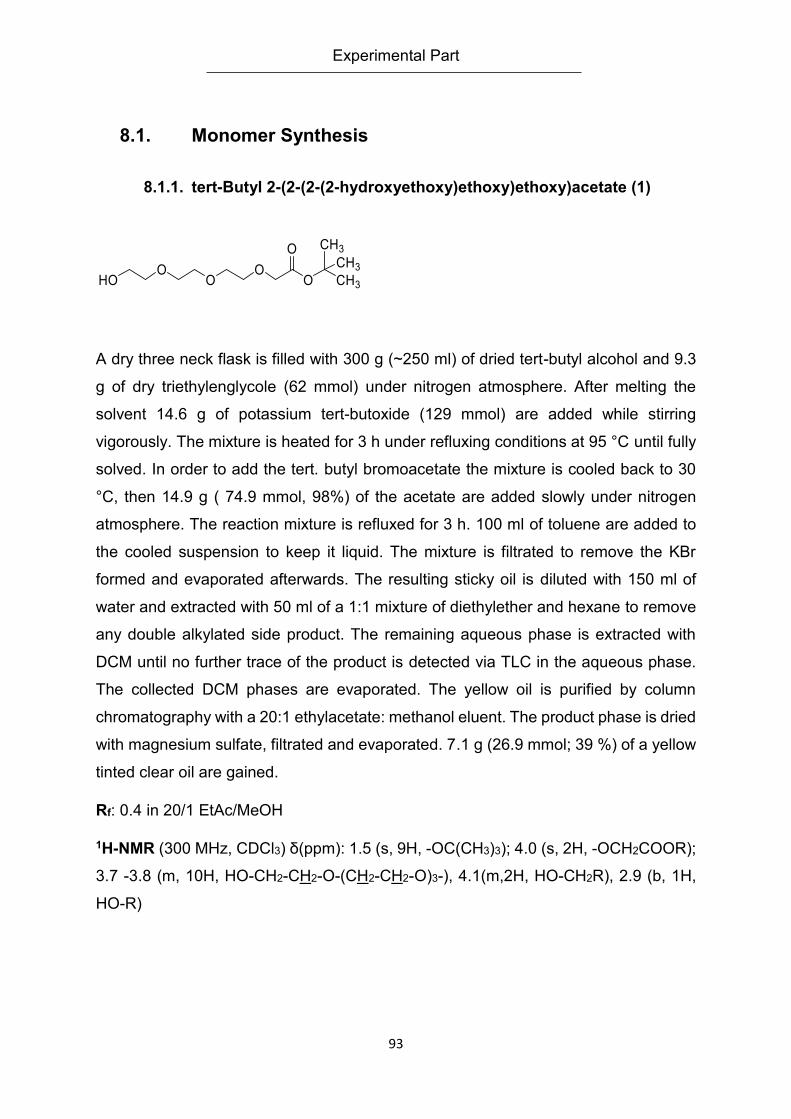
Experimental Part
93
8.1. Monomer Synthesis
8.1.1. tert-Butyl 2-(2-(2-(2-hydroxyethoxy)ethoxy)ethoxy)acetate (1)
A dry three neck flask is filled with 300 g (~250 ml) of dried tert-butyl alcohol and 9.3
g of dry triethylenglycole (62 mmol) under nitrogen atmosphere. After melting the
solvent 14.6 g of potassium tert-butoxide (129 mmol) are added while stirring
vigorously. The mixture is heated for 3 h under refluxing conditions at 95 °C until fully
solved. In order to add the tert. butyl bromoacetate the mixture is cooled back to 30
°C, then 14.9 g ( 74.9 mmol, 98%) of the acetate are added slowly under nitrogen
atmosphere. The reaction mixture is refluxed for 3 h. 100 ml of toluene are added to
the cooled suspension to keep it liquid. The mixture is filtrated to remove the KBr
formed and evaporated afterwards. The resulting sticky oil is diluted with 150 ml of
water and extracted with 50 ml of a 1:1 mixture of diethylether and hexane to remove
any double alkylated side product. The remaining aqueous phase is extracted with
DCM until no further trace of the product is detected via TLC in the aqueous phase.
The collected DCM phases are evaporated. The yellow oil is purified by column
chromatography with a 20:1 ethylacetate: methanol eluent. The product phase is dried
with magnesium sulfate, filtrated and evaporated. 7.1 g (26.9 mmol; 39 %) of a yellow
tinted clear oil are gained.
Rf: 0.4 in 20/1 EtAc/MeOH
1H-NMR (300 MHz, CDCl3) δ(ppm): 1.5 (s, 9H, -OC(CH3)3); 4.0 (s, 2H, -OCH2COOR);
3.7 -3.8 (m, 10H, HO-CH2-CH2-O-(CH2-CH2-O)3-), 4.1(m,2H, HO-CH2R), 2.9 (b, 1H,
HO-R)
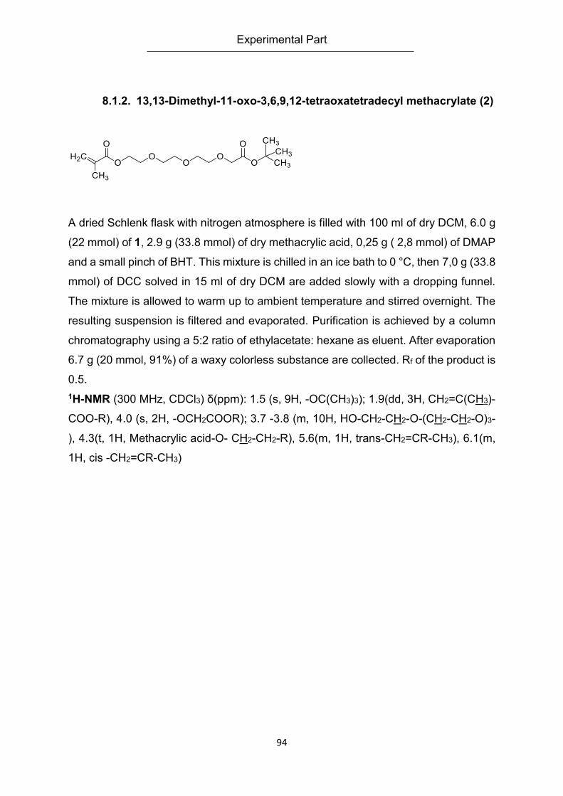
Experimental Part
94
8.1.2. 13,13-Dimethyl-11-oxo-3,6,9,12-tetraoxatetradecyl methacrylate (2)
A dried Schlenk flask with nitrogen atmosphere is filled with 100 ml of dry DCM, 6.0 g
(22 mmol) of 1, 2.9 g (33.8 mmol) of dry methacrylic acid, 0,25 g ( 2,8 mmol) of DMAP
and a small pinch of BHT. This mixture is chilled in an ice bath to 0 °C, then 7,0 g (33.8
mmol) of DCC solved in 15 ml of dry DCM are added slowly with a dropping funnel.
The mixture is allowed to warm up to ambient temperature and stirred overnight. The
resulting suspension is filtered and evaporated. Purification is achieved by a column
chromatography using a 5:2 ratio of ethylacetate: hexane as eluent. After evaporation
6.7 g (20 mmol, 91%) of a waxy colorless substance are collected. Rf of the product is
0.5.
1H-NMR (300 MHz, CDCl3) δ(ppm): 1.5 (s, 9H, -OC(CH3)3); 1.9(dd, 3H, CH2=C(CH3)-
COO-R), 4.0 (s, 2H, -OCH2COOR); 3.7 -3.8 (m, 10H, HO-CH2-CH2-O-(CH2-CH2-O)3-
), 4.3(t, 1H, Methacrylic acid-O- CH2-CH2-R), 5.6(m, 1H, trans-CH2=CR-CH3), 6.1(m,
1H, cis -CH2=CR-CH3)
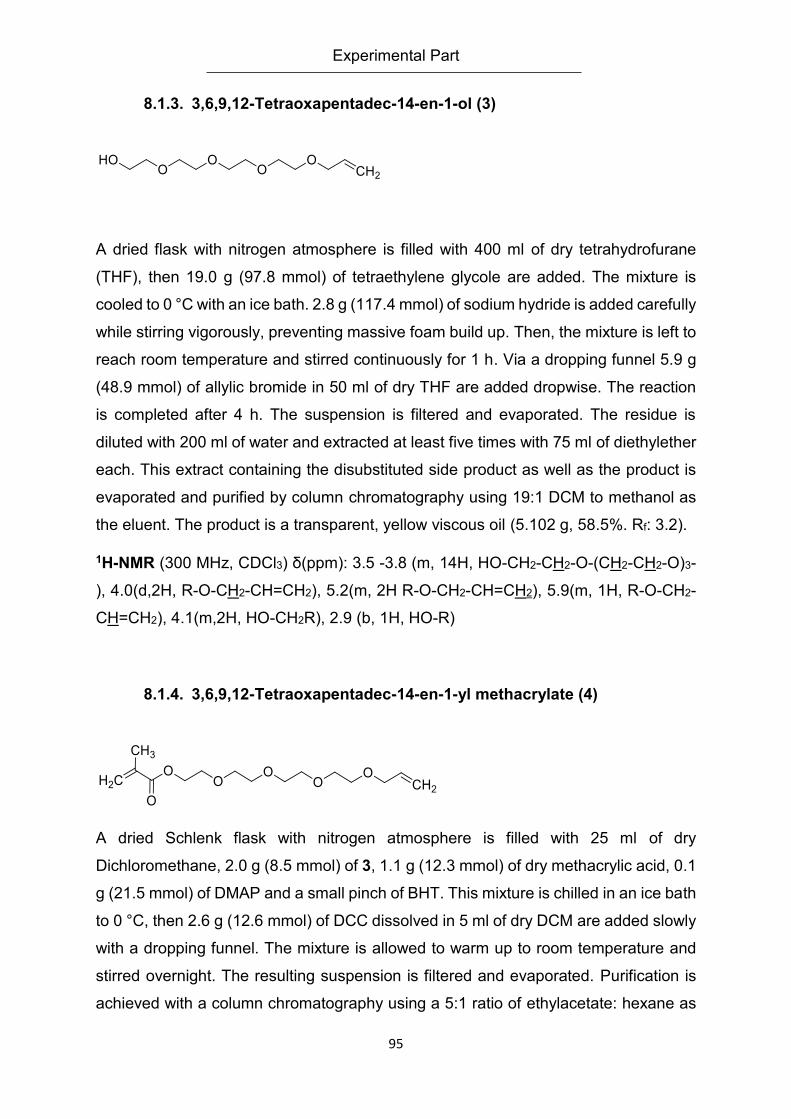
Experimental Part
95
8.1.3. 3,6,9,12-Tetraoxapentadec-14-en-1-ol (3)
A dried flask with nitrogen atmosphere is filled with 400 ml of dry tetrahydrofurane
(THF), then 19.0 g (97.8 mmol) of tetraethylene glycole are added. The mixture is
cooled to 0 °C with an ice bath. 2.8 g (117.4 mmol) of sodium hydride is added carefully
while stirring vigorously, preventing massive foam build up. Then, the mixture is left to
reach room temperature and stirred continuously for 1 h. Via a dropping funnel 5.9 g
(48.9 mmol) of allylic bromide in 50 ml of dry THF are added dropwise. The reaction
is completed after 4 h. The suspension is filtered and evaporated. The residue is
diluted with 200 ml of water and extracted at least five times with 75 ml of diethylether
each. This extract containing the disubstituted side product as well as the product is
evaporated and purified by column chromatography using 19:1 DCM to methanol as
the eluent. The product is a transparent, yellow viscous oil (5.102 g, 58.5%. Rf: 3.2).
1H-NMR (300 MHz, CDCl3) δ(ppm): 3.5 -3.8 (m, 14H, HO-CH2-CH2-O-(CH2-CH2-O)3-
), 4.0(d,2H, R-O-CH2-CH=CH2), 5.2(m, 2H R-O-CH2-CH=CH2), 5.9(m, 1H, R-O-CH2-
CH=CH2), 4.1(m,2H, HO-CH2R), 2.9 (b, 1H, HO-R)
8.1.4. 3,6,9,12-Tetraoxapentadec-14-en-1-yl methacrylate (4)
A dried Schlenk flask with nitrogen atmosphere is filled with 25 ml of dry
Dichloromethane, 2.0 g (8.5 mmol) of 3, 1.1 g (12.3 mmol) of dry methacrylic acid, 0.1
g (21.5 mmol) of DMAP and a small pinch of BHT. This mixture is chilled in an ice bath
to 0 °C, then 2.6 g (12.6 mmol) of DCC dissolved in 5 ml of dry DCM are added slowly
with a dropping funnel. The mixture is allowed to warm up to room temperature and
stirred overnight. The resulting suspension is filtered and evaporated. Purification is
achieved with a column chromatography using a 5:1 ratio of ethylacetate: hexane as
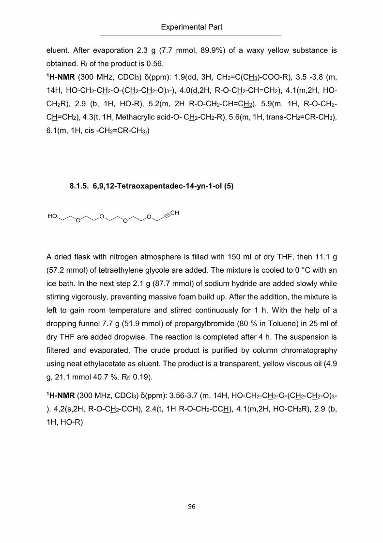
Experimental Part
96
eluent. After evaporation 2.3 g (7.7 mmol, 89.9%) of a waxy yellow substance is
obtained. Rf of the product is 0.56.
1H-NMR (300 MHz, CDCl3) δ(ppm): 1.9(dd, 3H, CH2=C(CH3)-COO-R), 3.5 -3.8 (m,
14H, HO-CH2-CH2-O-(CH2-CH2-O)3-), 4.0(d,2H, R-O-CH2-CH=CH2), 4.1(m,2H, HO-
CH2R), 2.9 (b, 1H, HO-R), 5.2(m, 2H R-O-CH2-CH=CH2), 5.9(m, 1H, R-O-CH2-
CH=CH2), 4.3(t, 1H, Methacrylic acid-O- CH2-CH2-R), 5.6(m, 1H, trans-CH2=CR-CH3),
6.1(m, 1H, cis -CH2=CR-CH3))
8.1.5. 6,9,12-Tetraoxapentadec-14-yn-1-ol (5)
A dried flask with nitrogen atmosphere is filled with 150 ml of dry THF, then 11.1 g
(57.2 mmol) of tetraethylene glycole are added. The mixture is cooled to 0 °C with an
ice bath. In the next step 2.1 g (87.7 mmol) of sodium hydride are added slowly while
stirring vigorously, preventing massive foam build up. After the addition, the mixture is
left to gain room temperature and stirred continuously for 1 h. With the help of a
dropping funnel 7.7 g (51.9 mmol) of propargylbromide (80 % in Toluene) in 25 ml of
dry THF are added dropwise. The reaction is completed after 4 h. The suspension is
filtered and evaporated. The crude product is purified by column chromatography
using neat ethylacetate as eluent. The product is a transparent, yellow viscous oil (4.9
g, 21.1 mmol 40.7 %. Rf: 0.19).
1H-NMR (300 MHz, CDCl3) δ(ppm): 3.56-3.7 (m, 14H, HO-CH2-CH2-O-(CH2-CH2-O)3-
), 4,2(s,2H, R-O-CH2-CCH), 2.4(t, 1H R-O-CH2-CCH), 4.1(m,2H, HO-CH2R), 2.9 (b,
1H, HO-R)
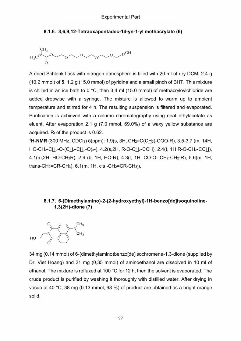
Experimental Part
97
8.1.6. 3,6,9,12-Tetraoxapentadec-14-yn-1-yl methacrylate (6)
A dried Schlenk flask with nitrogen atmosphere is filled with 20 ml of dry DCM, 2.4 g
(10.2 mmol) of 5, 1.2 g (15.0 mmol) of pyridine and a small pinch of BHT. This mixture
is chilled in an ice bath to 0 °C, then 3.4 ml (15.0 mmol) of methacryloylchloride are
added dropwise with a syringe. The mixture is allowed to warm up to ambient
temperature and stirred for 4 h. The resulting suspension is filtered and evaporated.
Purification is achieved with a column chromatography using neat ethylacetate as
eluent. After evaporation 2.1 g (7.0 mmol, 69.0%) of a waxy yellow substance are
acquired. Rf of the product is 0.62.
1H-NMR (300 MHz, CDCl3) δ(ppm): 1.9(s, 3H, CH2=C(CH3)-COO-R), 3.5-3.7 (m, 14H,
HO-CH2-CH2-O-(CH2-CH2-O)3-), 4.2(s,2H, R-O-CH2-CCH), 2.4(t, 1H R-O-CH2-CCH),
4.1(m,2H, HO-CH2R), 2.9 (b, 1H, HO-R), 4.3(t, 1H, CO-O- CH2-CH2-R), 5.6(m, 1H,
trans-CH2=CR-CH3), 6.1(m, 1H, cis -CH2=CR-CH3)),
8.1.7. 6-(Dimethylamino)-2-(2-hydroxyethyl)-1H-benzo[de]isoquinoline-
1,3(2H)-dione (7)
34 mg (0.14 mmol) of 6-(dimethylamino)benzo[de]isochromene-1,3-dione (supplied by
Dr. Viet Hoang) and 21 mg (0,35 mmol) of aminoethanol are dissolved in 10 ml of
ethanol. The mixture is refluxed at 100 °C for 12 h, then the solvent is evaporated. The
crude product is purified by washing it thoroughly with distilled water. After drying in
vacuo at 40 °C, 38 mg (0.13 mmol, 98 %) of product are obtained as a bright orange
solid.
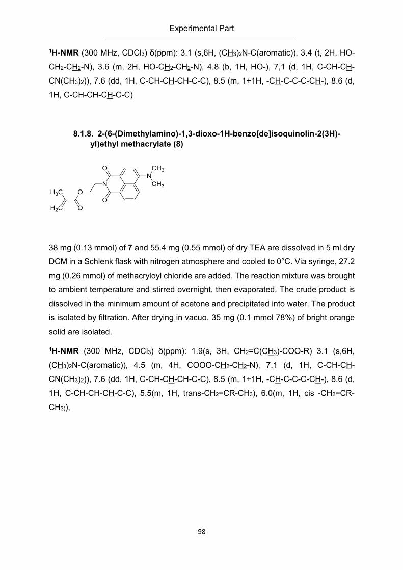
Experimental Part
98
1H-NMR (300 MHz, CDCl3) δ(ppm): 3.1 (s,6H, (CH3)2N-C(aromatic)), 3.4 (t, 2H, HO-
CH2-CH2-N), 3.6 (m, 2H, HO-CH2-CH2-N), 4.8 (b, 1H, HO-), 7,1 (d, 1H, C-CH-CH-
CN(CH3)2)), 7.6 (dd, 1H, C-CH-CH-CH-C-C), 8.5 (m, 1+1H, -CH-C-C-C-CH-), 8.6 (d,
1H, C-CH-CH-CH-C-C)
8.1.8. 2-(6-(Dimethylamino)-1,3-dioxo-1H-benzo[de]isoquinolin-2(3H)-
yl)ethyl methacrylate (8)
38 mg (0.13 mmol) of 7 and 55.4 mg (0.55 mmol) of dry TEA are dissolved in 5 ml dry
DCM in a Schlenk flask with nitrogen atmosphere and cooled to 0°C. Via syringe, 27.2
mg (0.26 mmol) of methacryloyl chloride are added. The reaction mixture was brought
to ambient temperature and stirred overnight, then evaporated. The crude product is
dissolved in the minimum amount of acetone and precipitated into water. The product
is isolated by filtration. After drying in vacuo, 35 mg (0.1 mmol 78%) of bright orange
solid are isolated.
1H-NMR (300 MHz, CDCl3) δ(ppm): 1.9(s, 3H, CH2=C(CH3)-COO-R) 3.1 (s,6H,
(CH3)2N-C(aromatic)), 4.5 (m, 4H, COOO-CH2-CH2-N), 7.1 (d, 1H, C-CH-CH-
CN(CH3)2)), 7.6 (dd, 1H, C-CH-CH-CH-C-C), 8.5 (m, 1+1H, -CH-C-C-C-CH-), 8.6 (d,
1H, C-CH-CH-CH-C-C), 5.5(m, 1H, trans-CH2=CR-CH3), 6.0(m, 1H, cis -CH2=CR-
CH3)),
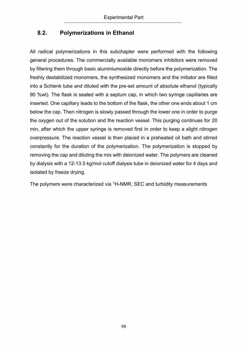
Experimental Part
99
8.2. Polymerizations in Ethanol
All radical polymerizations in this subchapter were performed with the following
general procedures. The commercially available monomers inhibitors were removed
by filtering them through basic aluminiumoxide directly before the polymerization. The
freshly destabilized monomers, the synthesized monomers and the initiator are filled
into a Schlenk tube and diluted with the pre-set amount of absolute ethanol (typically
90 %wt). The flask is sealed with a septum cap, in which two syringe capillaries are
inserted. One capillary leads to the bottom of the flask, the other one ends about 1 cm
below the cap. Then nitrogen is slowly passed through the lower one in order to purge
the oxygen out of the solution and the reaction vessel. This purging continues for 20
min, after which the upper syringe is removed first in order to keep a slight nitrogen
overpressure. The reaction vessel is then placed in a preheated oil bath and stirred
constantly for the duration of the polymerization. The polymerization is stopped by
removing the cap and diluting the mix with deionized water. The polymers are cleaned
by dialysis with a 12-13.5 kg/mol cutoff dialysis tube in deionized water for 4 days and
isolated by freeze drying.
The polymers were characterized via 1H-NMR, SEC and turbidity measurements
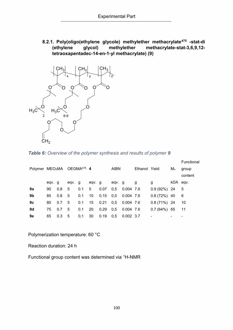
Experimental Part
100
8.2.1. Poly(oligo(ethylene glycole) methylether methacrylate475 -stat-di
(ethylene glycol) methylether methacrylate-stat-3,6,9,12-
tetraoxapentadec-14-en-1-yl methacrylate) (9)
Table 6: Overview of the polymer synthesis and results of polymer 9
Polymer MEO2MA OEGMA475 4 AIBN Ethanol Yield Mn
Functional
group
content
eqv. g eqv. g eqv. g eqv. g g g kDA eqv.
9a 90 0.8 5 0.1 5 0.07 0,5 0.004 7.6 0.9 (92%) 24 5
9b 85 0.8 5 0.1 10 0.15 0,5 0.004 7.6 0.8 (72%) 40 6
9c 80 0.7 5 0.1 15 0.21 0,5 0.004 7.6 0.8 (71%) 24 10
9d 75 0.7 5 0.1 20 0.29 0,5 0.004 7.6 0.7 (64%) 65 11
9e 65 0.3 5 0,1 30 0.19 0,5 0.002 3.7 - - -
Polymerization temperature: 60 °C
Reaction duration: 24 h
Functional group content was determined via 1H-NMR
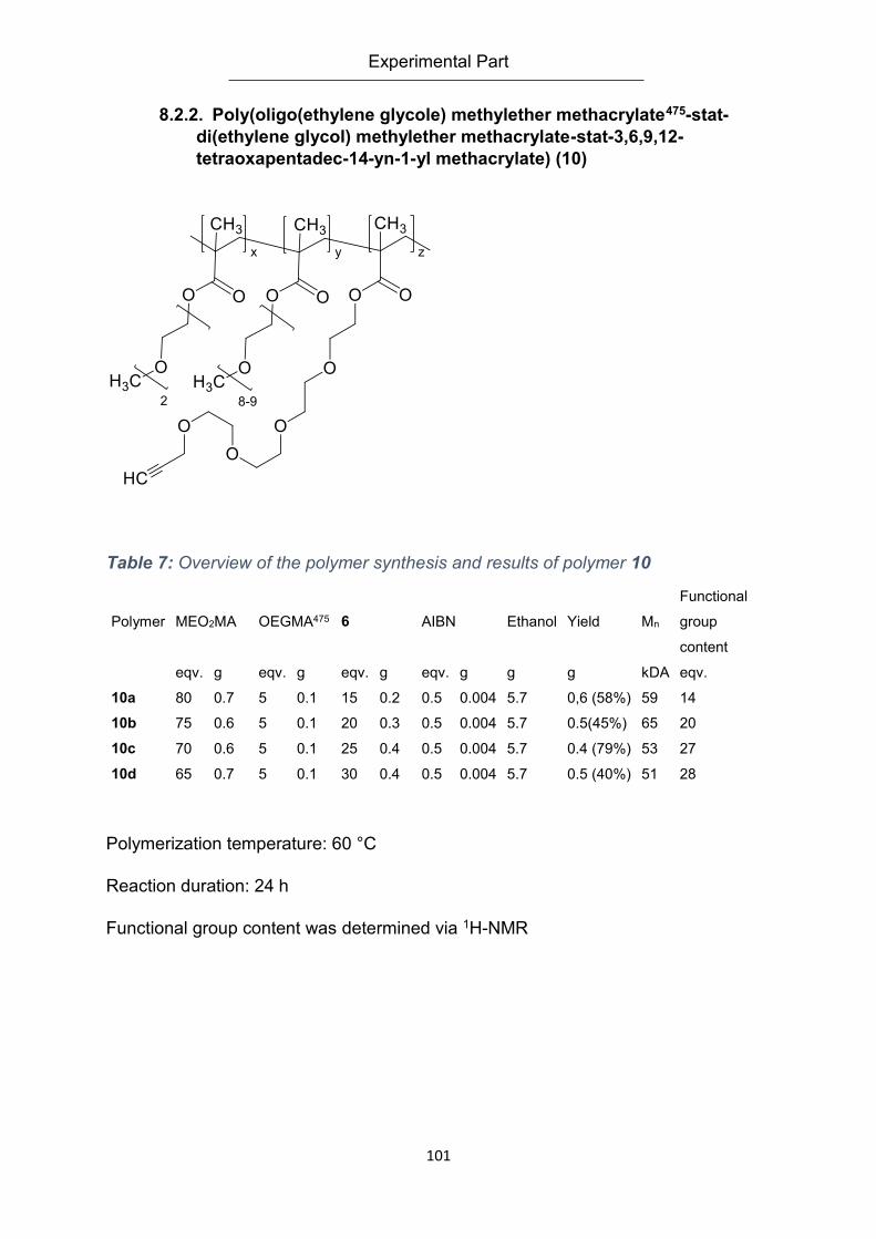
Experimental Part
101
8.2.2. Poly(oligo(ethylene glycole) methylether methacrylate475-stat-
di(ethylene glycol) methylether methacrylate-stat-3,6,9,12-
tetraoxapentadec-14-yn-1-yl methacrylate) (10)
Table 7: Overview of the polymer synthesis and results of polymer 10
Polymer MEO2MA OEGMA475 6 AIBN Ethanol Yield Mn
Functional
group
content
eqv. g eqv. g eqv. g eqv. g g g kDA eqv.
10a 80 0.7 5 0.1 15 0.2 0.5 0.004 5.7 0,6 (58%) 59 14
10b 75 0.6 5 0.1 20 0.3 0.5 0.004 5.7 0.5(45%) 65 20
10c 70 0.6 5 0.1 25 0.4 0.5 0.004 5.7 0.4 (79%) 53 27
10d 65 0.7 5 0.1 30 0.4 0.5 0.004 5.7 0.5 (40%) 51 28
Polymerization temperature: 60 °C
Reaction duration: 24 h
Functional group content was determined via 1H-NMR
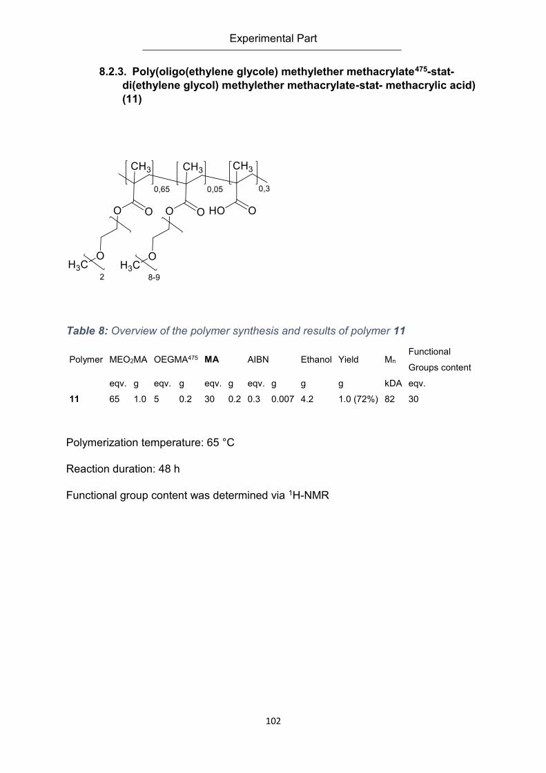
Experimental Part
102
8.2.3. Poly(oligo(ethylene glycole) methylether methacrylate475-stat-
di(ethylene glycol) methylether methacrylate-stat- methacrylic acid)
(11)
Table 8: Overview of the polymer synthesis and results of polymer 11
Polymer MEO2MA OEGMA475 MA AIBN Ethanol Yield Mn Functional
Groups content
eqv. g eqv. g eqv. g eqv. g g g kDA eqv.
11 65 1.0 5 0.2 30 0.2 0.3 0.007 4.2 1.0 (72%) 82 30
Polymerization temperature: 65 °C
Reaction duration: 48 h
Functional group content was determined via 1H-NMR
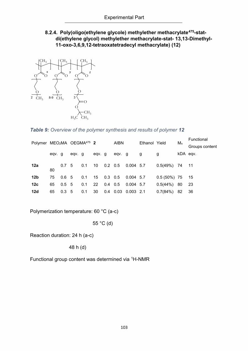
Experimental Part
103
8.2.4. Poly(oligo(ethylene glycole) methylether methacrylate475-stat-
di(ethylene glycol) methylether methacrylate-stat- 13,13-Dimethyl-
11-oxo-3,6,9,12-tetraoxatetradecyl methacrylate) (12)
Table 9: Overview of the polymer synthesis and results of polymer 12
Polymer MEO2MA OEGMA475 2 AIBN Ethanol Yield Mn Functional
Groups content
eqv. g eqv. g eqv. g eqv. g g g kDA eqv.
12a 80
0.7 5 0.1 10 0.2 0.5 0.004 5.7 0.5(49%) 74 11
12b 75 0.6 5 0.1 15 0.3 0.5 0.004 5.7 0.5 (50%) 75 15
12c 65 0.5 5 0.1 22 0.4 0.5 0.004 5.7 0.5(44%) 80 23
12d 65 0.3 5 0.1 30 0.4 0.03 0.003 2.1 0.7(84%) 82 36
Polymerization temperature: 60 °C (a-c)
55 °C (d)
Reaction duration: 24 h (a-c)
48 h (d)
Functional group content was determined via 1H-NMR
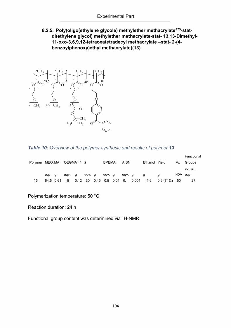
Experimental Part
104
8.2.5. Poly(oligo(ethylene glycole) methylether methacrylate475-stat-
di(ethylene glycol) methylether methacrylate-stat- 13,13-Dimethyl-
11-oxo-3,6,9,12-tetraoxatetradecyl methacrylate –stat- 2-(4-
benzoylphenoxy)ethyl methacrylate)(13)
Table 10: Overview of the polymer synthesis and results of polymer 13
Polymer MEO2MA OEGMA475 2 BPEMA AIBN Ethanol Yield Mn
Functional
Groups
content
eqv. g eqv. g eqv. g eqv. g eqv. g g g kDA eqv.
13 64.5 0.61 5 0.12 30 0.45 0.5 0.01 0.1 0.004 4.9 0.9 (74%) 50 27
Polymerization temperature: 50 °C
Reaction duration: 24 h
Functional group content was determined via 1H-NMR
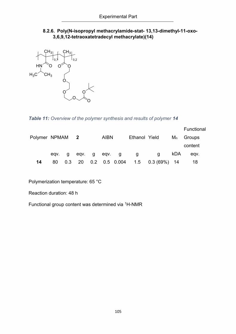
Experimental Part
105
8.2.6. Poly(N-isopropyl methacrylamide-stat- 13,13-dimethyl-11-oxo-
3,6,9,12-tetraoxatetradecyl methacrylate)(14)
Table 11: Overview of the polymer synthesis and results of polymer 14
Polymerization temperature: 65 °C
Reaction duration: 48 h
Functional group content was determined via 1H-NMR
Polymer NPMAM 2 AIBN Ethanol Yield Mn
Functional
Groups
content
eqv. g eqv. g eqv. g g g kDA eqv.
14 80 0.3 20 0.2 0.5 0.004 1.5 0.3 (69%) 14 18
Experimental Part
106
8.3. Polymerizations in Ionic Liquids
Polymerizations in ionic liquids often require different procedures as those in ethanol.
The ionic liquid (IL) used, generally 1-ethyl-3-methyl imidazolium hexafluorophosphate
has to be molten at 70 °C in an oil bath while being purged with nitrogen. After the IL
is liquefied, all the used monomers (freed of inhibitors) are added. The weight ratio of
added monomers is 10% in relation to the IL. The monomer addition has to be done
very carefully in order to keep the IL in the reaction vessel molten and not forming
clumps on the walls and so on. If possible monomers are added via syringe. The
mixture has to be stirred vigorously at all times, watching carefully to keep the
complete solution liquid. The nitrogen purging continues for 2 h. After this time the
initiator, AIBN, is added. It is imperative that the material is properly pushed into the
solution and not blown out or on the walls of the reaction vessel. Afterwards the
nitrogen purging syringes are removed and the vessel is properly sealed. The reaction
time was 8 h, in order to stop the reaction, and to isolate the product the still hot IL
solution is poured into a beaker. With the help of a minimum amount of 30°C warm
ethanol, the last residues can be procured. The ionic liquid is regained by solving it in
said beaker with small amounts of ethanol at 30°C – then the solution is cooled in the
refrigerator at 4 °C and filtrated. The remaining liquid can be cooled again, the filtered
solids can be recrystallized 3 times each to gain the IL back. Afterwards it is dried at
50° in a vacuum oven with Sicapent for 2 days. This way about 80 % of the IL can be
recovered.
The ethanol-polymer mixture is dialyzed for a week with a 12 kDa cutoff tube
(Zellutrans) against deionized water and freeze dried to yield the pure polymer.
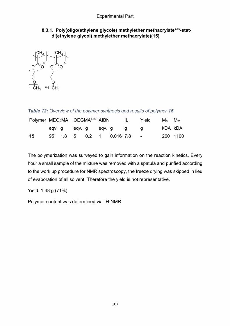
Experimental Part
107
8.3.1. Poly(oligo(ethylene glycole) methylether methacrylate475-stat-
di(ethylene glycol) methylether methacrylate)(15)
Table 12: Overview of the polymer synthesis and results of polymer 15
Polymer MEO2MA OEGMA475 AIBN IL Yield Mn Mw
eqv. g eqv. g eqv. g g g kDA kDA
15 95 1.8 5 0.2 1 0.016 7.8 - 260 1100
The polymerization was surveyed to gain information on the reaction kinetics. Every
hour a small sample of the mixture was removed with a spatula and purified according
to the work up procedure for NMR spectroscopy, the freeze drying was skipped in lieu
of evaporation of all solvent. Therefore the yield is not representative.
Yield: 1.48 g (71%)
Polymer content was determined via 1H-NMR
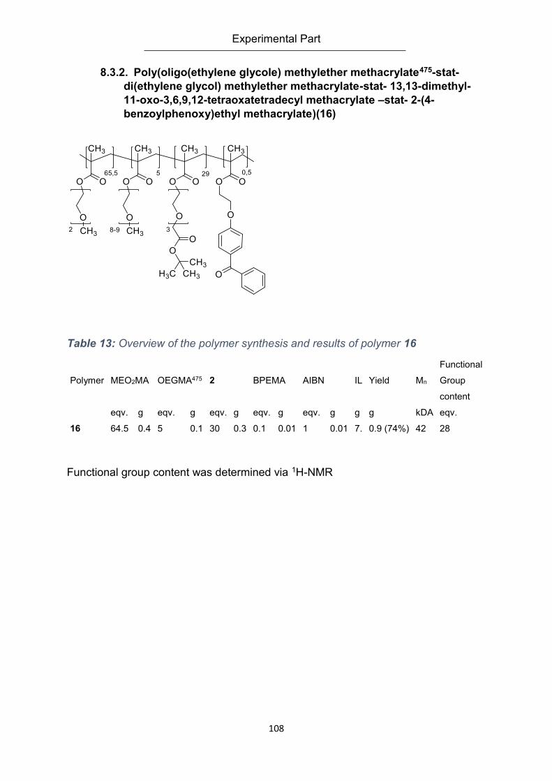
Experimental Part
108
8.3.2. Poly(oligo(ethylene glycole) methylether methacrylate475-stat-
di(ethylene glycol) methylether methacrylate-stat- 13,13-dimethyl-
11-oxo-3,6,9,12-tetraoxatetradecyl methacrylate –stat- 2-(4-
benzoylphenoxy)ethyl methacrylate)(16)
Table 13: Overview of the polymer synthesis and results of polymer 16
Polymer MEO2MA OEGMA475 2 BPEMA AIBN IL Yield Mn
Functional
Group
content
eqv. g eqv. g eqv. g eqv. g eqv. g g g kDA eqv.
16 64.5 0.4 5 0.1 30 0.3 0.1 0.01 1 0.01 7. 0.9 (74%) 42 28
Functional group content was determined via 1H-NMR
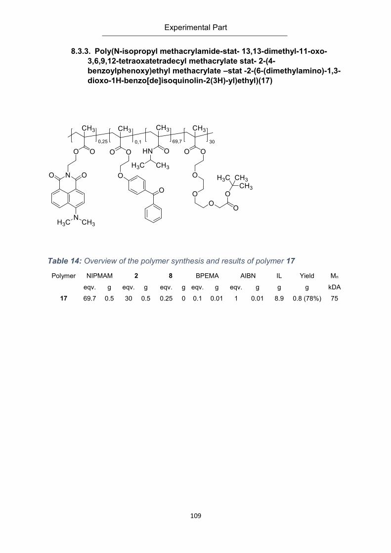
Experimental Part
109
8.3.3. Poly(N-isopropyl methacrylamide-stat- 13,13-dimethyl-11-oxo-
3,6,9,12-tetraoxatetradecyl methacrylate stat- 2-(4-
benzoylphenoxy)ethyl methacrylate –stat -2-(6-(dimethylamino)-1,3-
dioxo-1H-benzo[de]isoquinolin-2(3H)-yl)ethyl)(17)
Table 14: Overview of the polymer synthesis and results of polymer 17
Polymer NIPMAM 2 8 BPEMA AIBN IL Yield Mn
eqv. g eqv. g eqv. g eqv. g eqv. g g g kDA
17 69.7 0.5 30 0.5 0.25 0 0.1 0.01 1 0.01 8.9 0.8 (78%) 75
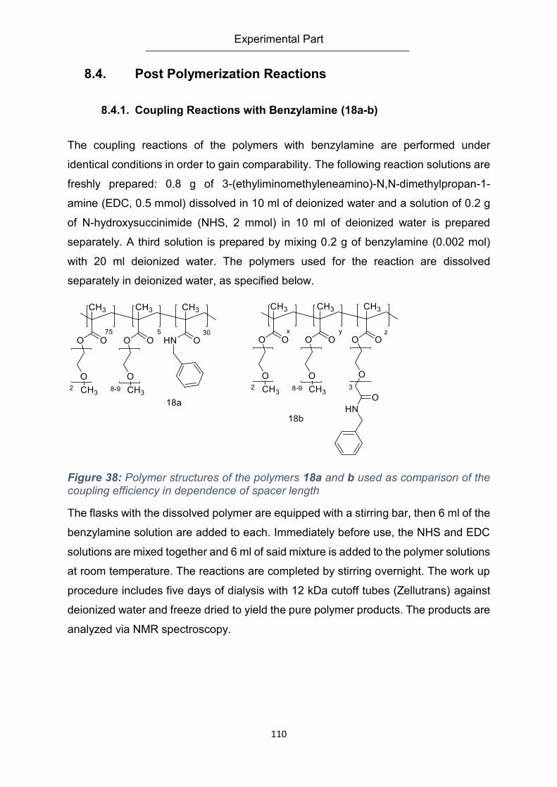
Experimental Part
110
8.4. Post Polymerization Reactions
8.4.1. Coupling Reactions with Benzylamine (18a-b)
The coupling reactions of the polymers with benzylamine are performed under
identical conditions in order to gain comparability. The following reaction solutions are
freshly prepared: 0.8 g of 3-(ethyliminomethyleneamino)-N,N-dimethylpropan-1-
amine (EDC, 0.5 mmol) dissolved in 10 ml of deionized water and a solution of 0.2 g
of N-hydroxysuccinimide (NHS, 2 mmol) in 10 ml of deionized water is prepared
separately. A third solution is prepared by mixing 0.2 g of benzylamine (0.002 mol)
with 20 ml deionized water. The polymers used for the reaction are dissolved
separately in deionized water, as specified below.
Figure 38: Polymer structures of the polymers 18a and b used as comparison of the coupling efficiency in dependence of spacer length
The flasks with the dissolved polymer are equipped with a stirring bar, then 6 ml of the
benzylamine solution are added to each. Immediately before use, the NHS and EDC
solutions are mixed together and 6 ml of said mixture is added to the polymer solutions
at room temperature. The reactions are completed by stirring overnight. The work up
procedure includes five days of dialysis with 12 kDa cutoff tubes (Zellutrans) against
deionized water and freeze dried to yield the pure polymer products. The products are
analyzed via NMR spectroscopy.
Experimental Part
111
8.4.2. General Procedure for Deprotecting Carboxylic Groups
The removal of the tert-butyl protective group is done as a post polymerization step. If
applicable, it can be done after immobilizing the polymer on a substrate or after
crosslinking. For best results, the material has to be as dry as possible. The
deprotecting agent is a 1 vol% solution of trifluoroacetic acid in dry DCM. The polymer
is dissolved in this freshly prepared mixture. The deprotecting mix is added in excess,
approximately 5 ml per 100 mg of polymer. The solution is stirred for 8 h, then it is
poured into distilled water. The DCM is evaporated, the aqueous polymer solution is
dialyzed (Zellutrans) for one week against deionized water. After freeze drying the
polymer is ready for further use.
8.4.3. Active Ester Couplings with Peptides (19)
The coupling reactions of the carboxyl containing polymers with peptides are
performed under standard conditions. Exemplary, 178 mg of 13 in its deprotected state
is dissolved under a nitrogen atmosphere in 10 ml of dried DCM. 50 mg (0.04 mmol)
of peptide are added, as well as 11.6 mg of DMAP (94.7 mmol). While stirring, the
solution is cooled in an ice bath to 0 °C. 183 mg of DCC (887 mmol), dissolved in 1.5
ml of dry DCM are added slowly with a dropping funnel. The solution is allowed to
reach room temperature and stirred overnight. For ease of handling, the solution is
filtered with a Büchner funnel, then the solvent is evaporated in vacuo. The residue is
diluted with water as needed and transferred into a dialysis tube, then it is dialyzed
(Zellutrans) against deionized water for a week and freeze dried. This precursor
polymer is deprotected in order to remove the protective groups of the peptide. The
functionalized polymer can be analyzed with NMR and turbidity measurements.
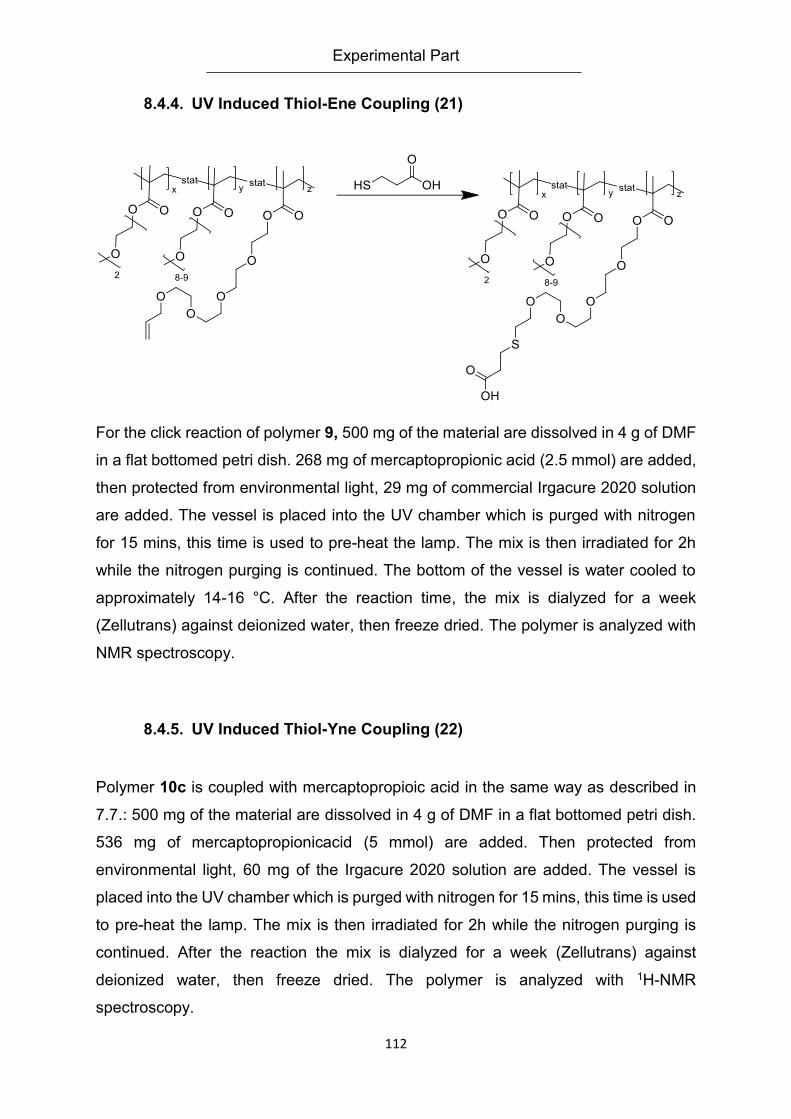
Experimental Part
112
8.4.4. UV Induced Thiol-Ene Coupling (21)
For the click reaction of polymer 9, 500 mg of the material are dissolved in 4 g of DMF
in a flat bottomed petri dish. 268 mg of mercaptopropionic acid (2.5 mmol) are added,
then protected from environmental light, 29 mg of commercial Irgacure 2020 solution
are added. The vessel is placed into the UV chamber which is purged with nitrogen
for 15 mins, this time is used to pre-heat the lamp. The mix is then irradiated for 2h
while the nitrogen purging is continued. The bottom of the vessel is water cooled to
approximately 14-16 °C. After the reaction time, the mix is dialyzed for a week
(Zellutrans) against deionized water, then freeze dried. The polymer is analyzed with
NMR spectroscopy.
8.4.5. UV Induced Thiol-Yne Coupling (22)
Polymer 10c is coupled with mercaptopropioic acid in the same way as described in
7.7.: 500 mg of the material are dissolved in 4 g of DMF in a flat bottomed petri dish.
536 mg of mercaptopropionicacid (5 mmol) are added. Then protected from
environmental light, 60 mg of the Irgacure 2020 solution are added. The vessel is
placed into the UV chamber which is purged with nitrogen for 15 mins, this time is used
to pre-heat the lamp. The mix is then irradiated for 2h while the nitrogen purging is
continued. After the reaction the mix is dialyzed for a week (Zellutrans) against
deionized water, then freeze dried. The polymer is analyzed with 1H-NMR
spectroscopy.
Experimental Part
113
8.4.6. Cycloadditions of Azido-Sugars to Alkyne Containing Polymers
(23)
Variant A
Polymer 10c (100 mg) is dissolved in 1.75 ml of DMF. 32 mg of azide-sugar are added
(azidoglucose ((2R,3R,4S,5R,6S)-2-(acetoxymethyl)-6-azidotetrahydro-2H-pyran-
3,4,5-triyl triacetate) , 0.1 mmol, supplied by Robert Bernin) to the solution as well as
1 mg of sodium ascorbate (0.005 mmol) and 0.12 mg of copper(II)sulfate (0.5 µmol)
dissolved in 125 ml of deionized water. This mixture was stirred on a stirring plate for
12 h, then purified via dialysis (Zellutrans) against deionized water for a week. The
resulting polymer was freeze dried, then analyzed via 1H-NMR spectroscopy.
Variant B
Polymer 10c (100 mg) is dissolved in 1.75 ml of DMF. To the solution, 32 mg of azide-
sugar (azidoglucose ((2R,3R,4S,5R,6S)-2-(acetoxymethyl)-6-azidotetrahydro-2H-
pyran-3,4,5-triyl triacetate), 0.1 mmol) as well as the catalyst 24 dissolved in 125 ml of
deionized water are added. This mixture was stirred on a stirring plate for 12 h, then
purified via dialysis (Zellutrans) against deionized water for a week. The polymer was
freeze dried, then analyzed via 1H-NMR spectroscopy.
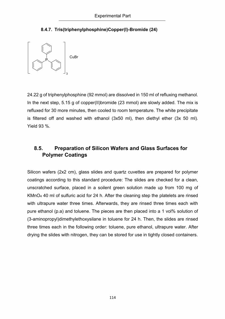
Experimental Part
114
8.4.7. Tris(triphenylphosphine)Copper(I)-Bromide (24)
24.22 g of triphenylphosphine (92 mmol) are dissolved in 150 ml of refluxing methanol.
In the next step, 5.15 g of copper(II)bromide (23 mmol) are slowly added. The mix is
refluxed for 30 more minutes, then cooled to room temperature. The white precipitate
is filtered off and washed with ethanol (3x50 ml), then diethyl ether (3x 50 ml).
Yield 93 %.
8.5. Preparation of Silicon Wafers and Glass Surfaces for
Polymer Coatings
Silicon wafers (2x2 cm), glass slides and quartz cuvettes are prepared for polymer
coatings according to this standard procedure: The slides are checked for a clean,
unscratched surface, placed in a soilent green solution made up from 100 mg of
KMnO4 40 ml of sulfuric acid for 24 h. After the cleaning step the platelets are rinsed
with ultrapure water three times. Afterwards, they are rinsed three times each with
pure ethanol (p.a) and toluene. The pieces are then placed into a 1 vol% solution of
(3-aminopropyl)dimethylethoxysilane in toluene for 24 h. Then, the slides are rinsed
three times each in the following order: toluene, pure ethanol, ultrapure water. After
drying the slides with nitrogen, they can be stored for use in tightly closed containers.
Experimental Part
115
8.6. Preparation of Gold Chips for Polymer Coatings
Gold chips (1,2 cm x1,2 cm; Ssens, Netherlands) coated with a 50 nm gold layer are
prepared for polymer coatings according to this standard procedure: The chips are
checked for a clean, unscratched surface, placed in a “piranha acid” solution made up
a 1:1 vol% mix of concentrated hydrogen Peroxide in water and concentrated sulfuric
acid for 24 h. After the cleaning step the platelets are rinsed with ultrapure water three
times. Afterwards, they are rinsed three times each with pure ethanol. The pieces are
now placed in a 1 mM solution of mercaptopropioic acid in ethanol for 24 h. Then the
slides are rinsed three times each in the following order: pure Ethanol, ultrapure water.
After drying the slides with nitrogen, they can be stored for use in tightly closed
containers.
8.7. Ellipsometry
All ellipsometric measurements were done with an Optrel Multiscope (Germany) in a
rotating analyzer setup. Measurements done with solvents were transduced with a 60
° flow cell provided by Optrel. All measurements were performed at a fixed angle of 60
°. The silicon wafers used in all experiments were bought from Si-Mat and had a
defined SiO2 layer with a thickness of 1 nm.
All data were processed with the Elli software provided by Optrel. The layer thickness
calculations followed the assumption of a four layer system. In dry measurements,
layers were as follows; layer 1 – air (n=1.000; k=0), layer 2 polymer layer (n=1.4800;
k=0), layer 3 SiO2 (n=1.4580; d=1.0 nm), layer 4 silicone (n=3.8858; k=-0.02). For all
measurements with the flow cell layers 1 and 2 were adjusted: layer 1 water
(n=1.3323; k=0), layer 2 swollen polymer layer (n=1.3700; k =0). For all experiments
with the flow cell, the samples were left submersed in the cell for 30 min prior to
measurements to adjust to the solvent environment.
Experimental Part
116
8.8. Gel Permeation Chromatography (GPC)
All GPC measurements were processed on a setup consisting of a single channel
degasser (WEG Dr. Bures, Germany), an isocratic pump P 1000 (Spectra Physics,
USA), PolarGel columns (Guard 7,5 x 75 mm, PolarGel L 7,5 x 300 mm; Polymer
Laboratory, USA) and detection by a UV/vis-detector SEC-3010 and refractometer
SEC 3010 (WEG Dr. Bures). Measurements were done with a flow rate of 1ml/min at
50 °C using polystyrene standards in DMF ( PSS, Germany)
8.9. Nuclear Magnetic Resonance Spectroscopy (NMR)
NMR spectra were recorded on an Avance 300 spectrometer (Bruker, USA), fitted with
an automatic sampler. 1H spectra were recorded at 300 MHz, 13C at 75 MHz. The peak
used for reference was either the TMS signal if added or the typical solvent peak.
8.10. Surface Plasmon Resonance Spectroscopy (SPR)
Surface plasmon resonance experiments were conducted on a dual channel
SR7000DC unit (Reichert, USA). The standard flow used was 50 µL/min, the injection
of reagents was done via a 1 ml injection loop. The sample chamber was kept at a
constant temperature of 25 °C. Samples were immobilized on SPR chips (Ssens,
Netherlands) with a gold layer thickness of 50 nm
8.11. Spin Coating
Spin coating of silicon wafers, glass slides and gold chips was done with a KL-SCV
coater (Schaefer Technologie GmbH, Germany). Samples were fixed to the plate by
vacuum, then revved to a constant 50 rps before the polymer solutions were dropped
onto the surface. The treated samples were spun for 30 s before removal and further
treatments.
Experimental Part
117
8.12. Turbidity Measuremnts
Turbidity was measured on a Cary 50 UV-Vis spectrometer (Agilent, Germany) fitted
with a Peltier element for heating and cooling. If not noted otherwise, the
heating/cooling rate was 1 °C per minute. Measurement wavelength was 700 nm and
the standard polymer concentration was 2 g/l.
8.13. UV-Crosslinking
UV induced crosslinking was performed with a UVA Cube 100 (Hönle, Germany), fitted
with a 100 W Iron- doped mercury lamp, which was filtered with a 315 nm cut-off
window. A nitrogen hose was used to purge and fill the chamber constantly with
nitrogen
Literature
118
9. Literature
1. Jochum FD, Theato P. Temperature-and light-responsive polyacrylamides prepared by a double polymer analogous reaction of activated ester polymers. Macromolecules. 2009;42(16):5941-5. 2. Kungwatchakun D, Irie M. Photoresponsive polymers. Photocontrol of the phase
separation temperature of aqueous solutions of poly‐[N‐isopropylacrylamide‐co‐N‐(4‐phenylazophenyl) acrylamide]. Die Makromolekulare Chemie, Rapid Communications. 1988;9(4):243-6.
3. Mi P, Chu LY, Ju XJ, Niu CH. A Smart Polymer with Ion‐Induced Negative Shift of the Lower Critical Solution Temperature for Phase Transition. Macromolecular Rapid Communications. 2008;29(1):27-32. 4. Jia Y-g, Zhu X, Liu L-y, Li J. Multi-responsive properties of a poly (ethylene glycol)-grafted alternating copolymers of distyrenic monomer with maleic anhydride. Langmuir. 2012;28(9):4500-6. 5. Pietsch C, Hoogenboom R, Schubert US. Soluble polymeric dual sensor for temperature and pH value. Angewandte Chemie International Edition. 2009;48(31):5653-6. 6. Li D, He Q, Yang Y, Mohwald H, Li J. Two-stage pH response of poly (4-vinylpyridine) grafted gold nanoparticles. Macromolecules. 2008;41(19):7254-6. 7. Schmaljohann D. Thermo-and pH-responsive polymers in drug delivery. Advanced drug delivery reviews. 2006;58(15):1655-70. 8. Harada A, Johnin K, Kawamura A, Kono K. Preparation of temperature-responsive polymer gels physically immobilizing core-shell type bioconjugates. Journal of Polymer Science Part A: Polymer Chemistry. 2007;45(24):5942-8. 9. Li M, De P, Gondi SR, Sumerlin BS. Responsive Polymer-Protein Bioconjugates Prepared by RAFT Polymerization and Copper-Catalyzed Azide-Alkyne Click Chemistry. Macromolecular Rapid Communications. 2008;29(12-13):1172-6. 10. Hanyková L, Spěváček J, Radecki M, Zhigunov A, Šťastná J, Valentová H, et al. Structures and interactions in collapsed hydrogels of thermoresponsive interpenetrating polymer networks. Colloid and Polymer Science. 2015;293(3):709-20. 11. Laschewsky A, Rekaï ED, Wischerhoff E. Tailoring of Stimuli-Responsive Water Soluble Acrylamide and Methacrylamide Polymers. Macromolecular Chemistry and Physics. 2001;202(2):276-86. 12. Gao W, Xu D, Lim DW, Craig SL, Chilkoti A. In situ growth of a thermoresponsive polymer from a genetically engineered elastin-like polypeptide. Polymer Chemistry. 2011;2(7):1561-6. 13. Robinson JW, Secker C, Weidner S, Schlaad H. Thermoresponsive Poly(N-C3 glycine)s. Macromolecules. 2013;46(3):580-7. 14. Wischerhoff E, Zacher T, Laschewsky A, Rekaï ED. Direct Observation of the Lower Critical Solution Temperature of Surface-Attached Thermo-Responsive Hydrogels by Surface Plasmon Resonance. Angewandte Chemie International Edition. 2000;39(24):4602-4. 15. Heskins M, Guillet JE. Solution Properties of Poly(N-isopropylacrylamide). Journal of Macromolecular Science: Part A - Chemistry. 1968;2(8):1441-55. 16. Irie M. Photochromism: Memories and SwitchesIntroduction. Chemical Reviews. 2000;100(5):1683-4. 17. Ju HK, Kim SY, Kim SJ, Lee YM. pH/temperature‐responsive semi‐IPN hydrogels composed of alginate and poly (N‐isopropylacrylamide). Journal of applied polymer science. 2002;83(5):1128-39. 18. Acharya G, Shin CS, McDermott M, Mishra H, Park H, Kwon IC, et al. The hydrogel template method for fabrication of homogeneous nano/microparticles. Journal of Controlled Release. 2010;141(3):314-9.
Literature
119
19. Oliveira MB, Mano JF. Natural-Based and Stimuli-Responsive Polymers for Tissue Engineering and Regenerative Medicine. Polymers in Regenerative Medicine: John Wiley & Sons, Inc; 2014. p. 49-90. 20. Hoffman AS. The origins and evolution of “controlled” drug delivery systems. Journal of Controlled Release. 2008;132(3):153-63. 21. Jhaveri SJ, Hynd MR, Dowell-Mesfin N, Turner JN, Shain W, Ober CK. Release of nerve growth factor from HEMA hydrogel-coated substrates and its effect on the differentiation of neural cells. Biomacromolecules. 2008;10(1):174-83. 22. Liu Z, Calvert P. Multilayer hydrogels as muscle‐like actuators. Advanced Materials. 2000;12(4):288-91. 23. Mendes PM. Stimuli-responsive surfaces for bio-applications. Chemical Society Reviews. 2008;37(11):2512-29. 24. Tokarev I, Minko S. Stimuli-responsive hydrogel thin films. Soft Matter. 2009;5(3):511-24. 25. Anker JN, Hall WP, Lyandres O, Shah NC, Zhao J, Van Duyne RP. Biosensing with plasmonic nanosensors. Nature materials. 2008;7(6):442-53. 26. Cheng G, Xue H, Zhang Z, Chen S, Jiang S. A switchable biocompatible polymer surface with self‐sterilizing and nonfouling capabilities. Angewandte Chemie International Edition. 2008;47(46):8831-4. 27. Trmcic-Cvitas J, Hasan E, Ramstedt M, Li X, Cooper MA, Abell C, et al. Biofunctionalized protein resistant oligo (ethylene glycol)-derived polymer brushes as selective immobilization and sensing platforms. Biomacromolecules. 2009;10(10):2885-94. 28. Gautrot JE, Trappmann B, Oceguera-Yanez F, Connelly J, He X, Watt FM, et al. Exploiting the superior protein resistance of polymer brushes to control single cell adhesion and polarisation at the micron scale. Biomaterials. 2010;31(18):5030-41. 29. Kolb HC, Finn MG, Sharpless KB. Click Chemistry: Diverse Chemical Function from a Few Good Reactions. Angewandte Chemie International Edition. 2001;40(11):2004-21. 30. Ponnuswamy SR, Penlidis A, Kiparissides C. Batch solution polymerization of methyl methacrylate: Parameter estimation. The Chemical Engineering Journal. 1988;39(3):175-83. 31. Kuchta F-D, van Herk AM, German AL. Propagation Kinetics of Acrylic and Methacrylic Acid in Water and Organic Solvents Studied by Pulsed-Laser Polymerization. Macromolecules. 2000;33(10):3641-9. 32. Graeme Moad DHS. The Chemistry of Radical Polymerization. 2nd ed. Netherlands: Elsevier; 2006. 33. Carswell TG, Hill DJT, Londero DI, O'Donnell JH, Pomery PJ, Winzor CL. Kinetic parameters for polymerization of methyl methacrylate at 60°C. Polymer. 1992;33(1):137-40. 34. Beuermann S, Buback M, Davis TP, Gilbert RG, Hutchinson RA, Olaj OF, et al. Critically evaluated rate coefficients for free-radical polymerization, 2.. Propagation rate coefficients for methyl methacrylate. Macromolecular Chemistry and Physics. 1997;198(5):1545-60. 35. Zhang D, Lahasky SH, Guo L, Lee C-U, Lavan M. Polypeptoid Materials: Current Status and Future Perspectives. Macromolecules. 2012;45(15):5833-41. 36. Zhang N, Salzinger S, Rieger B. Poly(vinylphosphonate)s with Widely Tunable LCST: A Promising Alternative to Conventional Thermoresponsive Polymers. Macromolecules. 2012;45(24):9751-8. 37. Gandhi A, Paul A, Sen SO, Sen KK. Studies on thermoresponsive polymers: Phase behaviour, drug delivery and biomedical applications. Asian Journal of Pharmaceutical Sciences. 2015;10(2):99-107. 38. Feoktistova N, Stoychev G, Puretskiy N, Leonid I, Dmitry V. Porous thermo-responsive pNIPAM microgels. European Polymer Journal. 2015;68:650-6. 39. Lutz J-F, Akdemir Ö, Hoth A. Point by Point Comparison of Two Thermosensitive Polymers Exhibiting a Similar LCST: Is the Age of Poly(NIPAM) Over? Journal of the American Chemical Society. 2006;128(40):13046-7. 40. Roy D, Brooks WLA, Sumerlin BS. New directions in thermoresponsive polymers. Chemical Society Reviews. 2013;42(17):7214-43.
Literature
120
41. Liu R, Fraylich M, Saunders BR. Thermoresponsive copolymers: from fundamental studies to applications. Colloid and Polymer Science. 2009;287(6):627-43. 42. Puoci F, Iemma F, Picci N. Stimuli-Responsive Molecularly Imprinted Polymers for Drug Delivery: A Review. Current Drug Delivery. 2008;5(2):85-96. 43. Aoshima S, Kanaoka S. Synthesis of Stimuli-Responsive Polymers by Living Polymerization: Poly(N-Isopropylacrylamide) and Poly(Vinyl Ether)s. Wax Crystal Control · Nanocomposites · Stimuli-Responsive Polymers. Berlin, Heidelberg: Springer Berlin Heidelberg; 2008. p. 169-208. 44. Djokpé E, Vogt W. N-Isopropylacrylamide and N-Isopropylmethacryl-amide: Cloud Points of Mixtures and Copolymers. Macromolecular Chemistry and Physics. 2001;202(5):750-7. 45. Winnik FM. Phase transition of aqueous poly-(N-isopropylacrylamide) solutions: a study by non-radiative energy transfer. Polymer. 1990;31(11):2125-34. 46. Suzuki A, Kojima S. Phase transition in constrained polymer gels. The Journal of Chemical Physics. 1994;101(11):10003-7. 47. Zhang Y, Furyk S, Bergbreiter DE, Cremer PS. Specific Ion Effects on the Water Solubility of Macromolecules: PNIPAM and the Hofmeister Series. Journal of the American Chemical Society. 2005;127(41):14505-10. 48. Plamper FA, Steinschulte AA, Hofmann CH, Drude N, Mergel O, Herbert C, et al. Toward Copolymers with Ideal Thermosensitivity: Solution Properties of Linear, Well-Defined Polymers of N-Isopropyl Acrylamide and N,N-Diethyl Acrylamide. Macromolecules. 2012;45(19):8021-6. 49. Lutz J-F, Weichenhan K, Akdemir Ö, Hoth A. About the Phase Transitions in Aqueous Solutions of Thermoresponsive Copolymers and Hydrogels Based on 2-(2-methoxyethoxy)ethyl Methacrylate and Oligo(ethylene glycol) Methacrylate. Macromolecules. 2007;40(7):2503-8. 50. Miasnikova A, Laschewsky A. Influencing the phase transition temperature of poly(methoxy diethylene glycol acrylate) by molar mass, end groups, and polymer architecture. Journal of Polymer Science Part A: Polymer Chemistry. 2012;50(16):3313-23. 51. Skrabania K, Kristen J, Laschewsky A, Akdemir Ö, Hoth A, Lutz J-F. Design, Synthesis, and Aqueous Aggregation Behavior of Nonionic Single and Multiple Thermoresponsive Polymers. Langmuir. 2007;23(1):84-93. 52. Lutz J. Sci. Part A: Polym Chem. 2008;46:3459-70. 53. Han S, Hagiwara M, Ishizone T. Synthesis of thermally sensitive water-soluble polymethacrylates by living anionic polymerizations of oligo (ethylene glycol) methyl ether methacrylates. Macromolecules. 2003;36(22):8312-9. 54. Weber C, Hoogenboom R, Schubert US. Temperature responsive bio-compatible polymers based on poly (ethylene oxide) and poly (2-oxazoline) s. Progress in Polymer Science. 2012;37(5):686-714. 55. Aseyev V, Tenhu H, Winnik FM. Non-ionic Thermoresponsive Polymers in Water. In: Müller AHE, Borisov O, editors. Self Organized Nanostructures of Amphiphilic Block Copolymers II. Berlin, Heidelberg: Springer Berlin Heidelberg; 2011. p. 29-89. 56. Lutz J-F, Börner HG. Modern trends in polymer bioconjugates design. Progress in Polymer Science. 2008;33(1):1-39. 57. Singh N, Blackburn WH, Lyon A. Bioconjugation of Soft Nanomaterials: John Wiley & Sons, Inc.; 2007. 61-91 p. 58. Peppas NA, Keys KB, Torres-Lugo M, Lowman AM. Poly(ethylene glycol)-containing hydrogels in drug delivery. Journal of Controlled Release. 1999;62(1–2):81-7. 59. Knop K, Hoogenboom R, Fischer D, Schubert US. Poly(ethylene glycol) in Drug Delivery: Pros and Cons as Well as Potential Alternatives. Angewandte Chemie International Edition. 2010;49(36):6288-308. 60. Dong Y, Feng S-S. Methoxy poly(ethylene glycol)-poly(lactide) (MPEG-PLA) nanoparticles for controlled delivery of anticancer drugs. Biomaterials. 2004;25(14):2843-9. 61. Sousa-Herves A, Riguera R, Fernandez-Megia E. PEG-dendritic block copolymers for biomedical applications. New Journal of Chemistry. 2012;36(2):205-10.
Literature
121
62. Harris JM, Dust JM, McGill RA, Harris PA, Edgell MJ, Sedaghat-Herati RM, et al. New Polyethylene Glycols for Biomedical Applications. Water-Soluble Polymers. ACS Symposium Series. 467: American Chemical Society; 1991. p. 418-29. 63. Shalaby SW, McCormick CL, Butler GB. Water-Soluble Polymers: American Chemical Society; 1991. 548 p. 64. Harris JM, Zalipsky S. Poly(ethylene glycol): American Chemical Society; 1997. 508 p. 65. Zalipsky S, Harris JM. Introduction to Chemistry and Biological Applications of Poly(ethylene glycol). Poly(ethylene glycol). ACS Symposium Series. 680: American Chemical Society; 1997. p. 1-13. 66. Geever LM, Nugent MJD, Higginbotham CL. The effect of salts and pH buffered solutions on the phase transition temperature and swelling of thermoresponsive pseudogels based on N-isopropylacrylamide. Journal of Materials Science. 2007;42(23):9845-54. 67. Du H, Wickramasinghe R, Qian X. Effects of Salt on the Lower Critical Solution Temperature of Poly (N-Isopropylacrylamide). The Journal of Physical Chemistry B. 2010;114(49):16594-604. 68. Bruck SD. Aspects of three types of hydrogels for biomedical applications. Journal of Biomedical Materials Research. 1973;7(5):387-404. 69. Caló E, Khutoryanskiy VV. Biomedical applications of hydrogels: A review of patents and commercial products. European Polymer Journal. 2015;65:252-67. 70. Kopeček J. Hydrogel biomaterials: A smart future? Biomaterials. 2007;28(34):5185-92. 71. Annabi N, Tamayol A, Uquillas JA, Akbari M, Bertassoni LE, Cha C, et al. 25th Anniversary Article: Rational Design and Applications of Hydrogels in Regenerative Medicine. Advanced Materials. 2014;26(1):85-124. 72. Van Vlierberghe S, Dubruel P, Schacht E. Biopolymer-Based Hydrogels As Scaffolds for Tissue Engineering Applications: A Review. Biomacromolecules. 2011;12(5):1387-408. 73. Hoffman AS. Hydrogels for biomedical applications. Advanced Drug Delivery Reviews. 2012;64, Supplement:18-23.
74. Flory PJ, Rehner J. Statistical Mechanics of Cross‐Linked Polymer Networks II. Swelling. The Journal of Chemical Physics. 1943;11(11):521-6. 75. Flory PJ. Statistical Mechanics of Swelling of Network Structures. The Journal of Chemical Physics. 1950;18(1):108-11. 76. Laschewsky A, Ouari O, Mangeney C, Jullien L. Reactive hydrogels grafted on gold surfaces. Macromolecular Symposia. 2001;164(1):323-40. 77. Minko S. Grafting on Solid Surfaces: “Grafting to” and “Grafting from” Methods. In: Stamm M, editor. Polymer Surfaces and Interfaces: Characterization, Modification and Applications. Berlin, Heidelberg: Springer Berlin Heidelberg; 2008. p. 215-34. 78. Halliwell CM, Cass AEG. A Factorial Analysis of Silanization Conditions for the Immobilization of Oligonucleotides on Glass Surfaces. Analytical Chemistry. 2001;73(11):2476-83. 79. Brzoska JB, Azouz IB, Rondelez F. Silanization of Solid Substrates: A Step Toward Reproducibility. Langmuir. 1994;10(11):4367-73. 80. Merrifield RB. Solid Phase Peptide Synthesis. I. The Synthesis of a Tetrapeptide. Journal of the American Chemical Society. 1963;85(14):2149-54. 81. Barbey R, Lavanant L, Paripovic D, Schüwer N, Sugnaux C, Tugulu S, et al. Polymer Brushes via Surface-Initiated Controlled Radical Polymerization: Synthesis, Characterization, Properties, and Applications. Chemical Reviews. 2009;109(11):5437-527. 82. Pengo P, Broxterman QB, Kaptein B, Pasquato L, Scrimin P. Synthesis of a Stable Helical Peptide and Grafting on Gold Nanoparticles. Langmuir. 2003;19(6):2521-4. 83. Buller J. Entwicklung neuer stimuli-sensitiver Hydrogelfilme als Plattform für die Biosensorik: Universitätsbibliothek der Universität Potsdam; 2013. 84. Buller J, Laschewsky A, Wischerhoff E. Photoreactive oligoethylene glycol polymers - versatile compounds for surface modification by thin hydrogel films. Soft Matter. 2013;9(3):929-37.
Literature
122
85. Boundless. Boundless Microbiology2016 2016/05/26.86. and HNS, Jørgensen BB. Big Bacteria. Annual Review of Microbiology.2001;55(1):105-37.87. Buntgarn/Stannered. Ellipsometry setup.jpg www.wikipedia.com2008 [cited 2016 11/13/2016]. Available from: https://en.wikipedia.org/wiki/File:Ellipsometry_setup.svg.88. Schasfoort RB, Tudos AJ. Handbook of surface plasmon resonance: Royal Society of Chemistry; 2008.89. Binder WH, Sachsenhofer R. ‘Click’ Chemistry in Polymer and Materials Science. Macromolecular Rapid Communications. 2007;28(1):15-54.90. Gokmen MT, Brassinne J, Prasath RA, Du Prez FE. Revealing the nature of thio-click reactions on the solid phase. Chemical Communications. 2011;47(16):4652-4.91. Lowe AB. Thiol-ene "click" reactions and recent applications in polymer and materials synthesis. Polymer Chemistry.1(1):17-36.92. Mansfeld U, Pietsch C, Hoogenboom R, Becer CR, Schubert US. Clickable initiators, monomers and polymers in controlled radical polymerizations - a prospective combination in polymer science. p. -.93. Sumerlin BS, Vogt AP. Macromolecular Engineering through Click Chemistry and Other Efficient Transformations. Macromolecules. 2009;43(1):1-13.94. Hoyle CE, Bowman CN. Thiol–Ene Click Chemistry. Angew Chem, Int Ed.2010;49:1540.95. Golas PL, Matyjaszewski K. Marrying click chemistry with polymerization: expanding the scope of polymeric materials. Chemical Society Reviews. 2010;39(4):1338-54.96. Qin A, Lam JWY, Tang BZ. Click Polymerization: Progresses, Challenges, and Opportunities. Macromolecules. 2010;43(21):8693-702.97. Barner-Kowollik C, Du Prez FE, Espeel P, Hawker CJ, Junkers T, Schlaad H, et al.“Clicking” Polymers or Just Efficient Linking: What Is the Difference? Angewandte Chemie International Edition. 2011;50(1):60-2.98. Hoshino A, Ohnishi N, Yasuhara M, Yamamoto K, Kondo A. Separation of Murine Neutrophils and Macrophages by Thermoresponsive Magnetic Nanoparticles. Biotechnology Progress. 2007;23(6):1513-6.99. Tatsuma T, Mori H, Takahashi H, Fujishima A. Activity Control of a Heme Peptide-Modified Electrode by an Inhibitor Bound to a Thermoresponsive Polymer. Electrochemical and Solid-State Letters. 2001;4(2):E5-E7.100. Toma M, Jonas U, Mateescu A, Knoll W, Dostalek J. Active Control of SPR by Thermoresponsive Hydrogels for Biosensor Applications. The Journal of Physical Chemistry C. 2013;117(22):11705-12.101. Ding Z, Fong RB, Long CJ, Stayton PS, Hoffman AS. Size-dependent control of thebinding of biotinylated proteins to streptavidin using a polymer shield. Nature.2001;411(6833):59-62.102. Ayi T-C, Tong JM-M, Lee PV-S, editors. Optically tunable hydrogel biosensormaterial2006.103. Jeníková G, Pazlarová J, Demnerová K. Detection of Salmonella in food samples bythe combination of immunomagnetic separation and PCR assay. International Microbiology.2010;3(4):225-9.104. Harrisson S, Mackenzie SR, Haddleton DM. Unprecedented solvent-inducedacceleration of free-radical propagation of methyl methacrylate in ionic liquids. ChemicalCommunications. 2002(23):2850-1.105. Carmichael AJ, Haddleton DM, Bon SA, Seddon KR. Copper (I) mediated livingradical polymerisation in an ionic liquid. Chemical Communications. 2000(14):1237-8.106. Hong K, Zhang H, Mays JW, Visser AE, Brazel CS, Holbrey JD, et al. Conventionalfree radical polymerization in room temperature ionic liquids: a green approach to commoditypolymers with practical advantages. Chemical communications. 2002(13):1368-9.107. Rogers RD, Seddon KR, editors. Ionic liquids(industrial applications for greenchemistry). A C S symposium series; 2002: American Chemical Society.
Literature
123
108. Harrisson S, Mackenzie SR, Haddleton DM. Pulsed Laser Polymerization in an Ionic Liquid: Strong Solvent Effects on Propagation and Termination of Methyl Methacrylate. Macromolecules. 2003;36(14):5072-5. 109. Schmidt-Naake G, Woecht I, Schmalfuß A, Glück T. Free Radical Polymerization in Ionic Liquids – Solvent Influence of New Dimension. Macromolecular Symposia. 2009;275–276(1):204-18. 110. Strehmel V, Laschewsky A, Wetzel H, Görnitz E. Free Radical Polymerization of n-Butyl Methacrylate in Ionic Liquids. Macromolecules. 2006;39(3):923-30. 111. Drobník J, Vlasák J, Pilař J, Svec F, Kálal J. Synthetic model polymers in the study of protein immobilization on glycidyl methacrylate carriers. Enzyme and Microbial Technology. 1979;1(2):107-12. 112. Chang TMS. Removal of endogenous and exogenous toxins by a microencapsulated absorbent. Canadian Journal of Physiology and Pharmacology. 1969;47(12):1043-5. 113. Campbell DH, Luescher E, Lerman LS. Immunologic adsorbents I. Isolation of antibody by means of a cellulose-protein antigen. Proceedings of the National Academy of Sciences. 1951;37(9):575-8. 114. Stryer L. Biochemistry. 4th ed. New York: W H Freeman; 1995. 115. Jursic BS, Zdravkovski Z. A simple preparation of amides from acids and amines by heating of their mixture. Synthetic communications. 1993;23(19):2761-70. 116. Zabicky J. chemistry of amides. 1970. 117. Curtius T. Synthetische Versuche mit Hippurazid. Berichte der deutschen chemischen Gesellschaft. 1902;35(3):3226-8. 118. Wittenberger SJ, McLaughlin MA. Preparation of endothelin antagonist ABT-627. Tetrahedron Letters. 1999;40(40):7175-8. 119. Sheehan J, Cruickshank P, Boshart G. Notes-A Convenient Synthesis of Water-Soluble Carbodiimides. The Journal of Organic Chemistry. 1961;26(7):2525-8. 120. Sheehan JC, Hess GP. A new method of forming peptide bonds. Journal of the American Chemical Society. 1955;77(4):1067-8. 121. Ryu Y, Scott AI. Self-condensation of activated malonic acid half esters: a model for the decarboxylative Claisen condensation in polyketide biosynthesis. Tetrahedron letters. 2003;44(40):7499-502. 122. Devouge S, Salvagnini C, Marchand-Brynaert J. A practical molecular clip for immobilization of receptors and biomolecules on devices’ surface: Synthesis, grafting protocol and analytical assay. Bioorganic & medicinal chemistry letters. 2005;15(13):3252-6.
123. Mädler S, Bich C, Touboul D, Zenobi R. Chemical cross‐linking with NHS esters: a systematic study on amino acid reactivities. Journal of mass spectrometry. 2009;44(5):694-706. 124. Zhao X, Milton Harris J. Novel degradable poly (ethylene glycol) hydrogels for controlled release of protein. Journal of pharmaceutical sciences. 1998;87(11):1450-8. 125. Elia G. Biotinylation reagents for the study of cell surface proteins. Proteomics. 2008;8(19):4012-24. 126. Wojtyk JT, Morin KA, Boukherroub R, Wayner DD. Modification of porous silicon surfaces with activated ester monolayers. Langmuir. 2002;18(16):6081-7. 127. Cengiz N, Kabadayioglu H, Sanyal R. Orthogonally functionalizable copolymers based on a novel reactive carbonate monomer. Journal of Polymer Science Part A: Polymer Chemistry.48(21):4737-46. 128. Swamy KCK, Kumar NNB, Balaraman E, Kumar KVPP. Mitsunobu and Related Reactions: Advances and Applications. Chemical Reviews. 2009;109(6):2551-651. 129. Wang X, Liu L, Luo Y, Zhao H. Bioconjugation of Biotin to the Interfaces of Polymeric Micelles via In Situ Click Chemistry. Langmuir. 2008;25(2):744-50. 130. Dhanikula RS, Hildgen P. Synthesis and Evaluation of Novel Dendrimers with a Hydrophilic Interior as Nanocarriers for Drug Delivery. Bioconjugate Chemistry. 2005;17(1):29-41. 131. Anderson GW, Zimmerman JE, Callahan FM. N-Hydroxysuccinimide Esters in Peptide Synthesis. Journal of the American Chemical Society. 1963;85(19):3039-.
Literature
124
132. Pinyou P, Ruff A, Pöller S, Barwe S, Nebel M, Alburquerque NG, et al. Thermoresponsive amperometric glucose biosensor. Biointerphases. 2016;11(1):011001. 133. Matthews BW, Remington SJ. The Three Dimensional Structure of the Lysozyme from Bacteriophage T4. Proceedings of the National Academy of Sciences. 1974;71(10):4178-82. 134. Müller JJ, Barbirz S, Heinle K, Freiberg A, Seckler R, Heinemann U. An Intersubunit Active Site between Supercoiled Parallel β Helices in the Trimeric Tailspike Endorhamnosidase of Shigella flexneri Phage Sf6. Structure. 2008;16(5):766-75. 135. Tang K, Seckler R. Autonomer phagenbasierter Salmonellenbiosensor. Google Patents; 2015. 136. Kerstin Tang RS, inventorAutonomous phage based Salmonellenbiosensor. Germany2014. 137. Inal S, Kolsch JD, Chiappisi L, Janietz D, Gradzielski M, Laschewsky A, et al. Structure-related differences in the temperature-regulated fluorescence response of LCST type polymers. Journal of Materials Chemistry C. 2013;1(40):6603-12. 138. Goodyear C, inventorImprovement in India Rubber Fabrics. USA patent US 3633. 1844 Jun 15, 1844. 139. Posner T. Beiträge zur Kenntniss der ungesättigten Verbindungen. II. Ueber die Addition von Mercaptanen an ungesättigte Kohlenwasserstoffe. Berichte der deutschen chemischen Gesellschaft. 1905;38(1):646-57. 140. M.S. Kharasch JR, F.R.Mayo. Chem Ind (London). 1938;57:752. 141. Kasprzak SE, Martin B, Raj T, Gall K. Synthesis and thermomechanical behavior of (qua)ternary thiol-ene(/acrylate) copolymers. Polymer. 2009;50(23):5549-58. 142. Ipatieff VN, Friedman BS. Reaction of Thiol Compounds with Aliphatic Olefins. Journal of the American Chemical Society. 1939;61(1):71-4. 143. Griesbaum K. Problems and Possibilities of the Free-Radical Addition of Thiols to Unsaturated Compounds. Angewandte Chemie International Edition in English. 1970;9(4):273-87. 144. ten Brummelhuis N, Diehl C, Schlaad H. Thiol−Ene Modification of 1,2-Polybutadiene Using UV Light or Sunlight. Macromolecules. 2008;41(24):9946-7. 145. Morgan CR, Magnotta F, Ketley AD. Thiol/ene photocurable polymers. Journal of Polymer Science: Polymer Chemistry Edition. 1977;15(3):627-45. 146. Lowe AB. Thiol-ene "click" reactions and recent applications in polymer and materials synthesis: a first update. Polymer Chemistry. 2014;5(17):4820-70. 147. Li Q, Zhou H, Hoyle CE. The effect of thiol and ene structures on thiol–ene networks: Photopolymerization, physical, mechanical and optical properties. Polymer. 2009;50(10):2237-45. 148. Dondoni A. Die Entwicklung der Thiol-En-Kupplung als Klick-Prozess für die Materialwissenschaften und die bioorganische Chemie. Angewandte Chemie. 2008;120(47):9133-5. 149. Skinner EK, Whiffin FM, Price GJ. Room temperature sonochemical initiation of thiol-ene reactions. Chemical Communications. 2012;48(54):6800-2. 150. Roper TM, Guymon CA, Jönsson ES, Hoyle CE. Influence of the alkene structure on the mechanism and kinetics of thiol–alkene photopolymerizations with real-time infrared spectroscopy. Journal of Polymer Science Part A: Polymer Chemistry. 2004;42(24):6283-98. 151. Jacobine AF. In Radiation Curing in Polymer Science and Technology III. London: Elsevier; 1993. 152. Cramer NBB, C. N. Investigation into the kinetics of thiol-ene and thiol-acrylate photopolymerizations using real-time FTIR. Polymer Preprints (American Chemical Society, Division of Polymer Chemistry). 2001;42(2):699. 153. Roper TM, Kwee T, Lee TY, Guymon CA, Hoyle CE. Photopolymerization of pigmented thiol–ene systems. Polymer. 2004;45(9):2921-9. 154. Chiou B-S, Khan SA. Real-Time FTIR and in Situ Rheological Studies on the UV Curing Kinetics of Thiol-ene Polymers. Macromolecules. 1997;30(23):7322-8.
Literature
125
155. Jacobine AF, Glaser DM, Grabek PJ, Mancini D, Masterson M, Nakos ST, et al. Photocrosslinked norbornene–thiol copolymers: Synthesis, mechanical properties, and cure studies. Journal of Applied Polymer Science. 1992;45(3):471-85. 156. Claisse JA, Davies DI. The addition of thiols to 5,6-dimethylenenorborn-2-ene, and its reactivity towards thiol addition relative to the reactivity of other bridged polycyclic olefins. Journal of the Chemical Society C: Organic. 1966(0):1045-50. 157. Stock LM. The origin of the inductive effect. Journal of Chemical Education. 1972;49(6):400. 158. Cole MC. Photopolymerizationof Vinyl Donor/Vinyl Acceptor Systems and Thiol-Ene Systems [PhD Thesis]. University of Southern
Mississippi2002. 159. Patai S. The chemistry of the thiol group: Wiley; 1974. 160. Inoue S, Kumagai T, Tamezawa H, Aota H, Matsumoto A, Yokoyama K, et al. Predominant methyl radical initiation preceded by [beta]-scission of alkoxy radicals in allyl polymerization with organic peroxide initiators at elevated temperatures. Polym J. 2010;42(9):716-21. 161. Jonas AM, Glinel K, Oren R, Nysten B, Huck WTS. Thermo-Responsive Polymer Brushes with Tunable Collapse Temperatures in the Physiological Range. Macromolecules. 2007;40(13):4403-5. 162. Vollhardt KPC, Schore NE. Organische chemie: John Wiley & Sons; 2011. 163. Chan JW, Hoyle CE, Lowe AB. Sequential Phosphine-Catalyzed, Nucleophilic Thiol− Ene/Radical-Mediated Thiol− Yne Reactions and the Facile Orthogonal Synthesis of Polyfunctional Materials. Journal of the American Chemical Society. 2009;131(16):5751-3. 164. Fairbanks BD, Sims EA, Anseth KS, Bowman CN. Reaction Rates and Mechanisms for Radical, Photoinitated Addition of Thiols to Alkynes, and Implications for Thiol− Yne Photopolymerizations and Click Reactions. Macromolecules. 2010;43(9):4113-9. 165. Hoogenboom R. Thiol–Yne Chemistry: A Powerful Tool for Creating Highly Functional Materials. Angewandte Chemie International Edition. 2010;49(20):3415-7. 166. Hensarling RM, Doughty VA, Chan JW, Patton DL. “Clicking” Polymer Brushes with Thiol-yne Chemistry: Indoors and Out. Journal of the American Chemical Society. 2009;131(41):14673-5. 167. Naik SS, Chan JW, Comer C, Hoyle CE, Savin DA. Thiol–yne ‘click’chemistry as a route to functional lipid mimetics. Polymer Chemistry. 2011;2(2):303-5. 168. Huang Y, Zeng Y, Yang J, Zeng Z, Zhu F, Chen X. Facile functionalization of polypeptides by thiol-yne photochemistry for biomimetic materials synthesis. Chemical communications. 2011;47(26):7509-11. 169. Konkolewicz D, Poon CK, Gray-Weale A, Perrier S. Hyperbranched alternating block copolymers using thiol–yne chemistry: materials with tuneable properties. Chemical Communications. 2011;47(1):239-41. 170. Massi A, Nanni D. Thiol–yne coupling: revisiting old concepts as a breakthrough for up-to-date applications. Organic & biomolecular chemistry. 2012;10(19):3791-807. 171. Huisgen R. Proceedings of the Chemical Society. October 1961. Proceedings of the Chemical Society. 1961(October):357-96. 172. Himo F, Lovell T, Hilgraf R, Rostovtsev VV, Noodleman L, Sharpless KB, et al. Copper(I)-Catalyzed Synthesis of Azoles. DFT Study Predicts Unprecedented Reactivity and Intermediates. Journal of the American Chemical Society. 2005;127(1):210-6. 173. Lutz J-Fo, Börner HG, Weichenhan K. Combining ATRP and “Click― Chemistry:  a Promising Platform toward Functional Biocompatible Polymers and Polymer Bioconjugates. Macromolecules. 2006;39(19):6376-83. 174. Yang SK, Weck M. Modular Covalent Multifunctionalization of Copolymers. Macromolecules. 2007;41(2):346-51. 175. Kakwere H, Perrier Sb. Orthogonal “Relay― Reactions for Designing Functionalized Soft Nanoparticles. Journal of the American Chemical Society. 2009;131(5):1889-95.
Literature
126
176. Zhang J, Wang X, Wu D, Liu L, Zhao H. Bioconjugated Janus Particles Prepared by in Situ Click Chemistry. Chemistry of Materials. 2009;21(17):4012-8. 177. Wang K, Bi X, Xing S, Liao P, Fang Z, Meng X, et al. Cu 2 O acting as a robust catalyst in CuAAC reactions: water is the required medium. Green Chemistry. 2011;13(3):562-5. 178. Liang L, Astruc D. The copper (I)-catalyzed alkyne-azide cycloaddition (CuAAC)“click” reaction and its applications. An overview. Coordination Chemistry Reviews. 2011;255(23):2933-45.
List of Publications
127
10. List of Publications
10.1. Publications PEG Hydrogels – Versatile Materials for Biomedical Applications. E. Wischerhoff, A.
Laschewsky, J. Buller, S. Dippel, D. Stöbener,Proceedings of 9. ThGOT Thementage
Grenz- und Oberflächentechnik & 9. Thüringer Biomaterialkolloquium, 3-5.Sept. 2013,
Zeulenroda (Germany).
10.2. Poster: Towards Bio-responsive Hydrogels.A. Laschewsky*, J. Buller, S. Dippel, J. Kölsch, M.
Sütterlin, Ch. Wieland, J. Buchs, D. Janietz, E. Wischerhoff,Potsdam Days on Bioanalysis
2011, 9-10.11.2011, Potsdam (Germany)
Responsive Polymer Hydrogels and their Modulation by Molecular Recognition J.
Buller, S. Dippel, A. Laschewsky, M. Sütterlin, M. Päch, E. Wischerhoff, Makromolekulares
Kolloquium Freiburg, 23-25.02.2012, Freiburg (Germany)
Bioconjugable Monomers for Smart Hydrogel Systems Aimed at Bioanalytics. S.
Dippel, R. Bernin, J. Buller, M. Sütterlin, E. Wischerhoff, A. Laschewsky,27.Tag der Chemie
Berlin-Brandenburg 2012, 28.06.2012, TU Berlin, Berlin-Charlottenburg
New water-soluble polyacrylates bearing azobenzene side chains: Combining photo-
with thermo-sensitive behaviour .A. Miasnikova, A. Benítez-Montoya, S.Dippel, A.
Laschewsky, M. Päch,Polydays 2012: Polymers and Light, 30.09-02.10.2012, Berlin
(Germany)
Bioconjugable Monomers for Smart Hydrogel Systems Aimed at Bioanalytics. S.
Dippel, R. Bernin, J. Buller, M. Sütterlin, E. Wischerhoff, A. Laschewsky,Potsdam Days on
Bioanalysis 2012, 08.11.2012, Potsdam-Golm (Germany)
Synthesis of block, star and star block copolymers by RAFT polymerization: New
pathways to associative thickeners .C. Herfurth, S. Dippel, A. Miasnikova, C. Wieland,
A. Laschewsky,Makromolekulares Kolloquium Freiburg, 21-23.02.2013, Freiburg
(Germany)
From Monomers to Hydrogels – Smart, Bioconjugable Systems for Bioanalytics .S.
Dippel, J. Buller, N. Sickert, E. Wischerhoff, A. Laschewsky,28. Tag der Chemie Berlin-
Brandenburg 2013, 27.06.2013 (Potsdam-Golm)
From Monomer Synthesis to Smart Bioconjugable Hydrogels .S. Dippel, J. Buller, J.-
Ph. Couturier, E. Wischerhoff, A. Laschewsky,5th Potsdam Days on Bioanalysis 2013, 07-
08.11.2013, Potsdam-Golm (Germany)
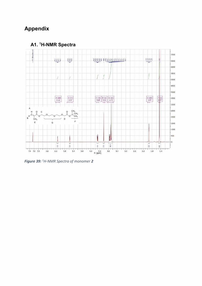
Appendix
A1. 1H-NMR Spectra
Figure 39: 1H-NMR Spectra of monomer 2
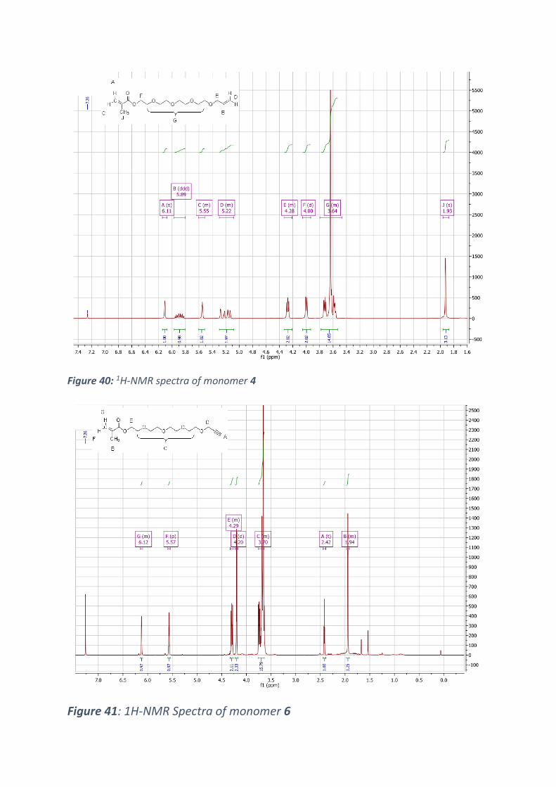
Figure 40: 1H-NMR spectra of monomer 4
Figure 41: 1H-NMR Spectra of monomer 6
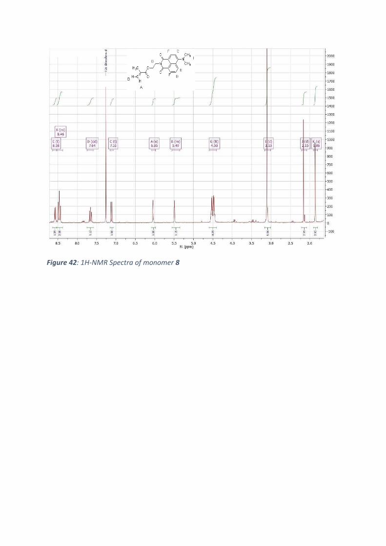
Figure 42: 1H-NMR Spectra of monomer 8
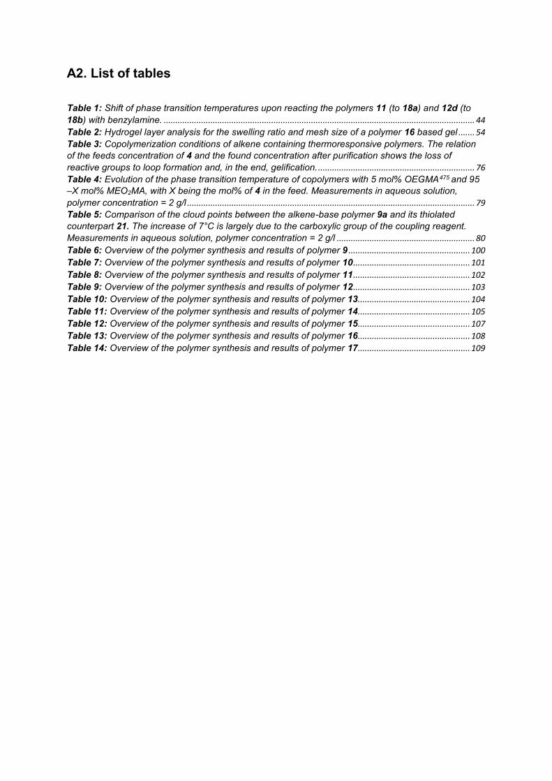
A2. List of tables
Table 1: Shift of phase transition temperatures upon reacting the polymers 11 (to 18a) and 12d (to
18b) with benzylamine. ..................................................................................................................................... 44 Table 2: Hydrogel layer analysis for the swelling ratio and mesh size of a polymer 16 based gel ....... 54 Table 3: Copolymerization conditions of alkene containing thermoresponsive polymers. The relation
of the feeds concentration of 4 and the found concentration after purification shows the loss of
reactive groups to loop formation and, in the end, gelification. ................................................................... 76 Table 4: Evolution of the phase transition temperature of copolymers with 5 mol% OEGMA475 and 95
–X mol% MEO2MA, with X being the mol% of 4 in the feed. Measurements in aqueous solution,
polymer concentration = 2 g/l ........................................................................................................................... 79 Table 5: Comparison of the cloud points between the alkene-base polymer 9a and its thiolated
counterpart 21. The increase of 7°C is largely due to the carboxylic group of the coupling reagent.
Measurements in aqueous solution, polymer concentration = 2 g/l ........................................................... 80 Table 6: Overview of the polymer synthesis and results of polymer 9 .................................................... 100 Table 7: Overview of the polymer synthesis and results of polymer 10 .................................................. 101 Table 8: Overview of the polymer synthesis and results of polymer 11 .................................................. 102 Table 9: Overview of the polymer synthesis and results of polymer 12 .................................................. 103 Table 10: Overview of the polymer synthesis and results of polymer 13 ................................................ 104 Table 11: Overview of the polymer synthesis and results of polymer 14 ................................................ 105 Table 12: Overview of the polymer synthesis and results of polymer 15 ................................................ 107 Table 13: Overview of the polymer synthesis and results of polymer 16 ................................................ 108 Table 14: Overview of the polymer synthesis and results of polymer 17 ................................................ 109
A3.List of Figures
Figure 1: A Azoisobutyronitrile (AIBN); B Dicumylperoxide; C Dimethoxy-phenylacetophenone ........ 18 Figure 2: Methacrylic Monomer Core Structure ........................................................................................... 19 Figure 3: Schematic phase diagram showing LCST and UCST behavior of polymers in solvents ...... 21 Equation 1 ........................................................................................................................................................... 22 Figure 4: Poly-N-isopropyl acrylamide constitutional repeat unit............................................................... 23 Figure 5: Monomethyl (oligo ethyleneglycol) methacrylate repeat unit .................................................... 23 Figure 6: Grafting-from and grafting-to approaches in surface modification ............................................ 27 Figure 7: Setup of an ellipsometry measurement(87). ................................................................................ 29 Figure 8: Concept of a hydrogel sensor system with specific analyte binding moieties. Binding events
cause a signaling cascade throughout the hydrogel, which collapses and induces signaling. .............. 35 Figure 9: Synthesis strategy for the 13,13-Dimethyl-11-oxo-3,6,9,12-tetraoxatetradecyl methacrylate
(2) monomer ....................................................................................................................................................... 37 Figure 10: Polymers 11 & 12a-d. Reaction conditions 55-60°C, 24-48 h, solvent: neat ethanol,
initiator AIBN. Copolymer compositions ranged from 10-30 mol% of carboxylic monomer 2, 5 mol%
OEGMA475, completed by MEO2MA................................................................................................................ 43 Figure 11: Carboxyl group containing polymers 18a and 18b modified with benzylamine via
EDC/NHS chemistry .......................................................................................................................................... 43 Table 1: Shift of phase transition temperatures upon reacting the polymers 11 (to 18a) and 12d (to
18b) with benzylamine. ..................................................................................................................................... 44 Figure 12: Polymer 13. Reaction conditions 50°C, 24 h, solvent: neat ethanol, initiator AIBN ............. 46 Figure 13: Layer thickness of dry hydrogel films in relation to the coating solutions’ polymer
concentration ...................................................................................................................................................... 46 Equation 5 ........................................................................................................................................................... 47 Equation 6 ........................................................................................................................................................... 47 Figure 14: Angle resolved intensity curve of the coupling of Lysozyme proteins on a hydrogel layer
with carboxyl functionalization. The change in resonance angle is the equivalent of a layer growth of
about 22 nm. ....................................................................................................................................................... 48 Figure 15: Fluorescent labeled tailspike protein of phage 22 (134, 135) ................................................. 50 Figure 16: Resonance curve of the tailspike protein immobilization on a blended hydrogel made out
of polymers 12d and 13. The change in angle is about 0.5 °, the equivalent of 1.5 nm. ........................ 51 Figure 17: 1-Ethyl-3-methyl imidazolium hexafluorophosphate (EMIM PF6) .......................................... 52 Figure 18: Kinetics of the copolymerization of MEO2MA and OEGMA475 in EMIM PF6. The conversion
is controlled via 1H-NMR spectroscopy. ......................................................................................................... 53 Figure 19: Poly(oligo(ethylene glycol) methylether methacrylate475-stat-di(ethylene glycol)
methylether methacrylate)(15) ......................................................................................................................... 53 Table 2: Hydrogel layer analysis for the swelling ratio and mesh size of a polymer 16 based gel ....... 54 Figure 20: SPR curve comparison before and after the immobilization of the tailspike protein
recognition unit. This hydrogel base material was polymerized in an ionic liquid. The change in layer
thickness is 5 nm................................................................................................................................................ 55 Figure 21: Different concentrations of the Salmonella surface polysaccharide are flushed over the
hydrogel surface. The time resolved intensity reaction of the gels refractive index is shown. Saturation
of the gel is achieved for the 500 µg/ml sample. ........................................................................................... 57 Figure 22: Comparative SPR-study of specifically (red) and unspecifically (blue) binding
polysaccharides on the peptide modified hydrogel surface. The first injection(s) and their decrease of
intensity over time show the difference between binding and nonbinding saccharides: The nonbinding
saccharides intensity drops immediately after the injection stops, the binding saccharides drops much
slower. ................................................................................................................................................................. 58 Figure 23: Peptide systems for provided for the Influenza detection demonstrator. Top: FYGYDVFF
as the selective binding unit and. Bottom: FYDPDVFY as control unit to prove specifity. ..................... 61 Figure 24: The base-polymers for the virus studies, left : poly(N-isopropyl methacrylamide-stat-
13,13- dimethyl-11-oxo- 3,6,9,12- tetraoxatetradecyl methacrylate)(14); right: poly(N-isopropyl
methacrylamide-stat- 13,13-dimethyl-11-oxo-3,6,9,12-tetraoxatetradecyl methacrylate- stat- 2-(4-
benzoylphenoxy)ethyl methacrylate –stat -2-(6-(dimethylamino)-1,3-dioxo-1H-benzo[de]isoquinolin-
2(3H)-yl)ethyl)methacrylate(17) ....................................................................................................................... 62 Figure 25: Temperature dependent turbidity measurements of polymer 14 modified with a recognition
unit in comparison to the neat MX-31 virus, and the combination of 14 and MX-31. The cloud point of
14 shifts by 2 °C from 37 °C to 39 °C upon virus addition. .......................................................................... 63 Figure 26: Temperature dependent turbidity measurements of polymer 17 with and without virus
added to the solution. The cloud point shifts from 27 °C to 40-42 °C upon virus addition...................... 64 .............................................................................................................................................................................. 65 Figure 27: Fluorescence spectra of binding recognition unit and nonbinding control polymer 17 at 10
°C. Stepwise virus additions lower the fluorescence intensity, for the receptor polymer, there is a blue
shift of about 10 nm. (PL Intensity is the absolute value of the fluorescences’ intensity in arbitrary
units) .................................................................................................................................................................... 65 Figure 28: Scattering intensity over time of polymer 17 modified with binding and control peptides. A
decrease in scattering means particles sinking or flocculating. The experiment was performed at 10
°C. ........................................................................................................................................................................ 66 Figure 29: Fluorescence intensity in correlation with temperature changes and analyte addition to a
1g/l solution of polymer 17 bearing recognition units. .................................................................................. 68 Figure 30: Radical thiol addition to a double bond ....................................................................................... 72 Figure 31: SN2 reaction to form 3,6,9,12-tetraoxapentadec-14-en-1-ol (3) .............................................. 74 Figure 32: Schematic Steglich esterification of methacrylic acid. .............................................................. 75 Table 3: Copolymerization conditions of alkene containing thermoresponsive polymers. The relation
of the feeds concentration of 4 and the found concentration after purification shows the loss of
reactive groups to loop formation and, in the end, gelification. ................................................................... 76 Table 4: Evolution of the phase transition temperature of copolymers with 5 mol% OEGMA475 and 95
–X mol% MEO2MA, with X being the mol% of 4 in the feed. Measurements in aqueous solution,
polymer concentration = 2 g/l ........................................................................................................................... 79 Table 5: Comparison of the cloud points between the alkene-base polymer 9a and its thiolated
counterpart 21. The increase of 7°C is largely due to the carboxylic group of the coupling reagent.
Measurements in aqueous solution, polymer concentration = 2 g/l ........................................................... 80 Figure 33: Temperature dependent turbidity measurements of polymers 9 and 21 in aqueous
solution, demonstrating the marked effect of the incorporation of mercaptopropanoic acid on the cloud
point. (c = 2 g/l, heating/cooling: 1 °C/min) .................................................................................................... 81 Figure 34: Structure of 3,6,9,12-tetraoxapentadec-14-yn-1-yl methacrylate (6) ..................................... 85 Figure 35: Alkyne functionalized base polymers 10a-d with a degree of functionalization between 14
and 28 %, OEGMA475 is fixed at 5 %mol and the MEO2MA content is varied to make up the
remainder, details are in chapter 8.2.2 ........................................................................................................... 86 Figure 36: Thiol-yne radical addition to the polymer bound alkyne functionality of the series 10
polymers .............................................................................................................................................................. 86 Figure 37: Product of the cycloaddition between the alkyne functionalized polymers 10 and
azidoglucose. ...................................................................................................................................................... 87 Table 6: Overview of the polymer synthesis and results of polymer 9 .................................................... 100 Table 7: Overview of the polymer synthesis and results of polymer 10 .................................................. 101 Table 8: Overview of the polymer synthesis and results of polymer 11 .................................................. 102 Table 9: Overview of the polymer synthesis and results of polymer 12 .................................................. 103 Table 10: Overview of the polymer synthesis and results of polymer 13 ................................................ 104 Table 11: Overview of the polymer synthesis and results of polymer 14 ................................................ 105 Table 12: Overview of the polymer synthesis and results of polymer 15 ................................................ 107 Table 13: Overview of the polymer synthesis and results of polymer 16 ................................................ 108 Table 14: Overview of the polymer synthesis and results of polymer 17 ................................................ 109 Figure 38: Polymer structures of the polymers 18a and b used as comparison of the coupling
efficiency in dependence of spacer length ................................................................................................... 110 Figure 39: 1H-NMR Spectra of monomer 2 ......................................................................................................... 128 Figure 40: 1H-NMR spectra of monomer 4 ......................................................................................................... 129

Figure 41: 1H-NMR Spectra of monomer 6 ........................................................................................................ 129 Figure 42: 1H-NMR Spectra of monomer 8 ........................................................................................................ 130
![Zum Quellungsdruck von polymeren Hydrogelen · anionischen Hydrogels. 40 Bild 3.6 Ersatzschaltbild eines Voigt-Festkörpers und Verhalten im Kriechversuch [Pahl91]. 46. Bildverzeichnis](https://img.pdfslide.org/doc/110x75/5e133382f5c45f110525b518/zum-quellungsdruck-von-polymeren-hydrogelen-anionischen-hydrogels-40-bild-36-ersatzschaltbild.jpg)